Comparison of MOCVD and MBE Regrowth for CAVET ... - MDPI
9
electronics Article Comparison of MOCVD and MBE Regrowth for CAVET Fabrication Simon Kotzea 1, * , Wiebke Witte 1 , Birte-Julia Godejohann 2 , Mathias Marx 1,3 , Michael Heuken 1,3 , Holger Kalisch 1 and Rolf Aidam 2 and Andrei Vescan 1 1 Compound Semiconductor Technology (CST), RWTH Aachen University, Sommerfeldstr. 18, 52074 Aachen, Germany; [email protected] (W.W.); [email protected] (M.M.); [email protected] (M.H.); [email protected] (H.K.); [email protected] (A.V.) 2 Fraunhofer-Institut für Angewandte Festkörperphysik (IAF), Tullastr. 72, 79108 Freiburg, Germany; [email protected] (B.-J.G.); [email protected] (R.A.) 3 AIXTRON SE, Dornkaulstr. 2, 52134 Herzogenrath, Germany * Correspondence: [email protected] Received: 6 March 2019; Accepted: 23 March 2019; Published: 28 March 2019 Abstract: In this paper, we demonstrate the fabrication of current aperture vertical electron transistors (CAVET) realized with two different epitaxial growth methods. Templates with a p-GaN current blocking layer (CBL) were deposited by metal organic chemical vapor deposition (MOCVD). Channel and barrier layers were then regrown by either molecular beam epitaxy (MBE) or MOCVD. Scanning electron microscope (SEM) images and atomic force microscope (AFM) height profiles are used to identify the different regrowth mechanisms. We show that an AlN interlayer below the channel layer was able to reduce Mg diffusion during the high temperature MOCVD regrowth process. For the low-temperature MBE regrowth, Mg diffusion was successfully suppressed. CAVET were realized on the various samples. The devices suffer from high leakage currents, thus further regrowth optimization is needed. Keywords: CAVET; current aperture vertical electron transistor; gallium nitride; vertical power devices 1. Introduction The research on wide-bandgap semiconductor power devices is driven by the need for efficient transistors. The superior material properties of e.g., GaN or SiC allow for higher reverse bias and elevated operating temperature limits, compared to lower-bandgap Si-based devices. Lateral high electron mobility transistors (HEMT) have already entered the market in the medium power conversion range, achieving blocking voltages of 600 V [1]. For high-power applications, a vertical geometry is preferred over a lateral one, particularly due to better scaling possibilities and an improved breakdown voltage. The peak electric field is located in the bulk of the semiconductor for most vertical designs and a more uniform electric field distribution is achieved [2], reducing the need for complex field-plate structures [3]. Several device concepts are currently investigated, such as vertical trench metal oxide semiconductor field effect transistor (FET) [4,5], finFET [6,7] or vertical junction FET [8–10]. Another promising design is the CAVET [11–17]. Here, a two-dimensional electron gas (2DEG) with high carrier mobility is formed above a CBL with an aperture. It combines the mobility advantage of the HEMT with a vertical device design to increase the blocking voltage without enlarging chip size. However, selective doping or etching [18] is necessary in order to fabricate the aperture. While selective air-gap etching moves the peak electric field back to the semiconductor surface, selective doping can be realized by either implantation or regrowth [19]. In this study, we investigate both MOCVD and MBE Electronics 2019, 8, 377; doi:10.3390/electronics8040377 www.mdpi.com/journal/electronics
-
Upload
khangminh22 -
Category
Documents
-
view
2 -
download
0
Transcript of Comparison of MOCVD and MBE Regrowth for CAVET ... - MDPI

electronics
Article
Comparison of MOCVD and MBE Regrowth forCAVET Fabrication
Simon Kotzea 1,* , Wiebke Witte 1, Birte-Julia Godejohann 2, Mathias Marx 1,3,Michael Heuken 1,3, Holger Kalisch 1 and Rolf Aidam 2 and Andrei Vescan 1
1 Compound Semiconductor Technology (CST), RWTH Aachen University, Sommerfeldstr. 18,52074 Aachen, Germany; [email protected] (W.W.); [email protected] (M.M.);[email protected] (M.H.); [email protected] (H.K.); [email protected] (A.V.)
2 Fraunhofer-Institut für Angewandte Festkörperphysik (IAF), Tullastr. 72, 79108 Freiburg, Germany;[email protected] (B.-J.G.); [email protected] (R.A.)
3 AIXTRON SE, Dornkaulstr. 2, 52134 Herzogenrath, Germany* Correspondence: [email protected]
Received: 6 March 2019; Accepted: 23 March 2019; Published: 28 March 2019
Abstract: In this paper, we demonstrate the fabrication of current aperture vertical electron transistors(CAVET) realized with two different epitaxial growth methods. Templates with a p-GaN currentblocking layer (CBL) were deposited by metal organic chemical vapor deposition (MOCVD). Channeland barrier layers were then regrown by either molecular beam epitaxy (MBE) or MOCVD. Scanningelectron microscope (SEM) images and atomic force microscope (AFM) height profiles are used toidentify the different regrowth mechanisms. We show that an AlN interlayer below the channellayer was able to reduce Mg diffusion during the high temperature MOCVD regrowth process.For the low-temperature MBE regrowth, Mg diffusion was successfully suppressed. CAVET wererealized on the various samples. The devices suffer from high leakage currents, thus further regrowthoptimization is needed.
Keywords: CAVET; current aperture vertical electron transistor; gallium nitride; vertical powerdevices
1. Introduction
The research on wide-bandgap semiconductor power devices is driven by the need for efficienttransistors. The superior material properties of e.g., GaN or SiC allow for higher reverse bias andelevated operating temperature limits, compared to lower-bandgap Si-based devices. Lateral highelectron mobility transistors (HEMT) have already entered the market in the medium power conversionrange, achieving blocking voltages of 600 V [1]. For high-power applications, a vertical geometry ispreferred over a lateral one, particularly due to better scaling possibilities and an improved breakdownvoltage. The peak electric field is located in the bulk of the semiconductor for most vertical designsand a more uniform electric field distribution is achieved [2], reducing the need for complex field-platestructures [3]. Several device concepts are currently investigated, such as vertical trench metal oxidesemiconductor field effect transistor (FET) [4,5], finFET [6,7] or vertical junction FET [8–10]. Anotherpromising design is the CAVET [11–17]. Here, a two-dimensional electron gas (2DEG) with high carriermobility is formed above a CBL with an aperture. It combines the mobility advantage of the HEMTwith a vertical device design to increase the blocking voltage without enlarging chip size. However,selective doping or etching [18] is necessary in order to fabricate the aperture. While selective air-gapetching moves the peak electric field back to the semiconductor surface, selective doping can berealized by either implantation or regrowth [19]. In this study, we investigate both MOCVD and MBE
Electronics 2019, 8, 377; doi:10.3390/electronics8040377 www.mdpi.com/journal/electronics

Electronics 2019, 8, 377 2 of 9
regrowth to fabricate CAVET. The growth mechanisms of the two techniques on the patterned apertureregion will be compared and evaluated regarding CAVET fabrication and properties.
2. Experiment
Templates for both regrowth techniques were grown on sapphire in an AIXTRON PlanetaryMOCVD tool. Due to the insulating substrates, a quasi-vertical design has to be employed.Trimethylgallium (TMGa) and ammonia were used as precursors, silane and magnesocene for n-and p-type doping, respectively. The carrier gas was hydrogen. The complete template stack isdepicted in Figure 1a. No additional preparation of the sapphire wafers was carried out before growth.After AlN nucleation on sapphire, 2 µm n+-GaN were deposited, forming the backside contact layer.Above, a 700-nm-thick drift layer with a doping concentration of ND = 5× 1016 cm−3 was grown.Thickness and ND were chosen for low RON with respect to the VBR trade-off [20]. The epitaxialstack was completed with a 250-nm-thick p+-GaN layer, possessing a high acceptor concentration ofNA = 1.3× 1019 cm−3. This layer serves as CBL.
n-GaN drift layer
backside contact layer
AlN + sapphire
p-GaN CBL
drift layer
CBL
drift layer
regrown channelAlGaN barrier
CBL
D
SS G
CBL
(a) (b)
(c) (d)
LG
2DEG
LAP
Figure 1. Basic process flow for the fabrication of a CAVET and important parameters for thedevice geometry. (a) Epitaxial stack of template; (b) Dry etching of aperture; (c) Idealized schematicafter MOCVD/MBE regrowth of channel and barrier layer; (d) Backside contact layer exposure andcontact deposition.
After template growth, patterned samples were fabricated by etching the aperture into the p-GaN,utilizing a two-step Cl-based etch process (Figure 1b). At first, a high-power inductively coupledplasma reactive-ion etching (ICP-RIE) is employed to expose the drift layer. It was optimized forsteep sidewalls [21]. Subsequently, a low-damage cyclic ICP etch process is used to carefully removeetch-damaged material [22]. This second process leads to a smooth surface with low rms roughnessof 1.2 nm. Both processes combined yield an etch depth of 300 nm. The templates were dipped inHCl and BOE consecutively for one minute each in order to remove surface contamination and forregrowth preparation [23].
Then, a GaN HEMT structure consisting of a GaN channel layer and an AlGaN barrier wasregrown with MOCVD and MBE, respectively (Figure 1c). The regrowth process fills the previouslyetched aperture with GaN.
MOCVD regrowth was performed at Tgrowth = 1050 °C and two samples were prepared(CVD-A and CVD-B). The regrowth of sample CVD-A consists of a 300-nm-thick GaN channel withND = 2× 1016 cm−3, which was capped by a 25-nm-thick Al0.25Ga0.75N barrier layer. For sampleCVD-B, a 5 nm AlN interlayer was regrown below the GaN channel to block Mg-diffusion from thep-GaN CBL [24].
MBE regrowth was carried out at Tgrowth = 750 °C. The lower growth temperature suppressesMg diffusion [25,26]. Two samples (MBE-C and MBE-D) with different GaN channel thicknesses,but without AlN interlayer, were regrown. Sample MBE-C had a 300-nm-thick channel layer, whereas

Electronics 2019, 8, 377 3 of 9
sample MBE-D was fabricated with a 450-nm-thick channel. Both were doped with ND = 2× 1016 cm−3
and capped by the same 25-nm-thick Al0.25Ga0.75N barrier. For sample MBE-D, a more conductive2DEG is expected, due to the increased distance between 2DEG and regrowth interface.
Following the regrowth, CAVET were fabricated (Figure 1d). The backside contact layer wasexposed by ICP dry-etching utilizing a 450-nm-thick Cr hard mask. Subsequently, the sample wasdipped in diluted HCl before e-beam evaporation of the ohmic contact metals. The drain andsource contact stacks, consisting of Ti/Al/Ni/Au (15 nm/100 nm/40 nm/50 nm), were depositedand annealed at 825 °C to ensure an ohmic characteristic. Finally, the Ni/Au (50 nm/200 nm) gatecontact was formed on top of the aperture region.
Additionally, three lateral HEMT reference samples without p-GaN CBL were grown. All samplesconsist of a 300-nm-thick GaN channel layer and a 25 nm Al0.25Ga0.75N barrier layer, analog to theone mentioned above, to serve as reference for a Mg-free (re)growth. The epitaxial layer stack forreference sample 1 was continuously grown with MOCVD. The HEMT structure for reference 2 and 3was regrown on lowly n-doped GaN templates with MOCVD and MBE, respectively. A brief summaryof all fabricated templates is given in Table 1.
Table 1. Samples overview.
Sample Technique Tgrowth Remark
CVD-A MOCVD 1050 °C -CVD-B MOCVD 1050 °C 5 nm AlN interlayerMBE-C MBE 750 °C 300 nm channelMBE-D MBE 750 °C 450 nm channelRef. 1 MOCVD 1050 °C continuously grownRef. 2 MOCVD 1050 °C regrown on n-GaNRef. 3 MBE 750 °C regrown on n-GaN
SEM images and AFM surface profiles of the aperture region after regrowth were used to identifythe growth mechanisms of the different regrowth techniques on patterned samples. Eddy-currentand, after ohmic contact deposition, Hall measurements were conducted to characterize the 2DEGproperties. I-V measurements were carried out to investigate the CAVET performance. The contactresistances were determined with transfer length method (TLM) measurements.
3. Results and Discussion
3.1. Structural Characterization
3.1.1. MOCVD Regrowth
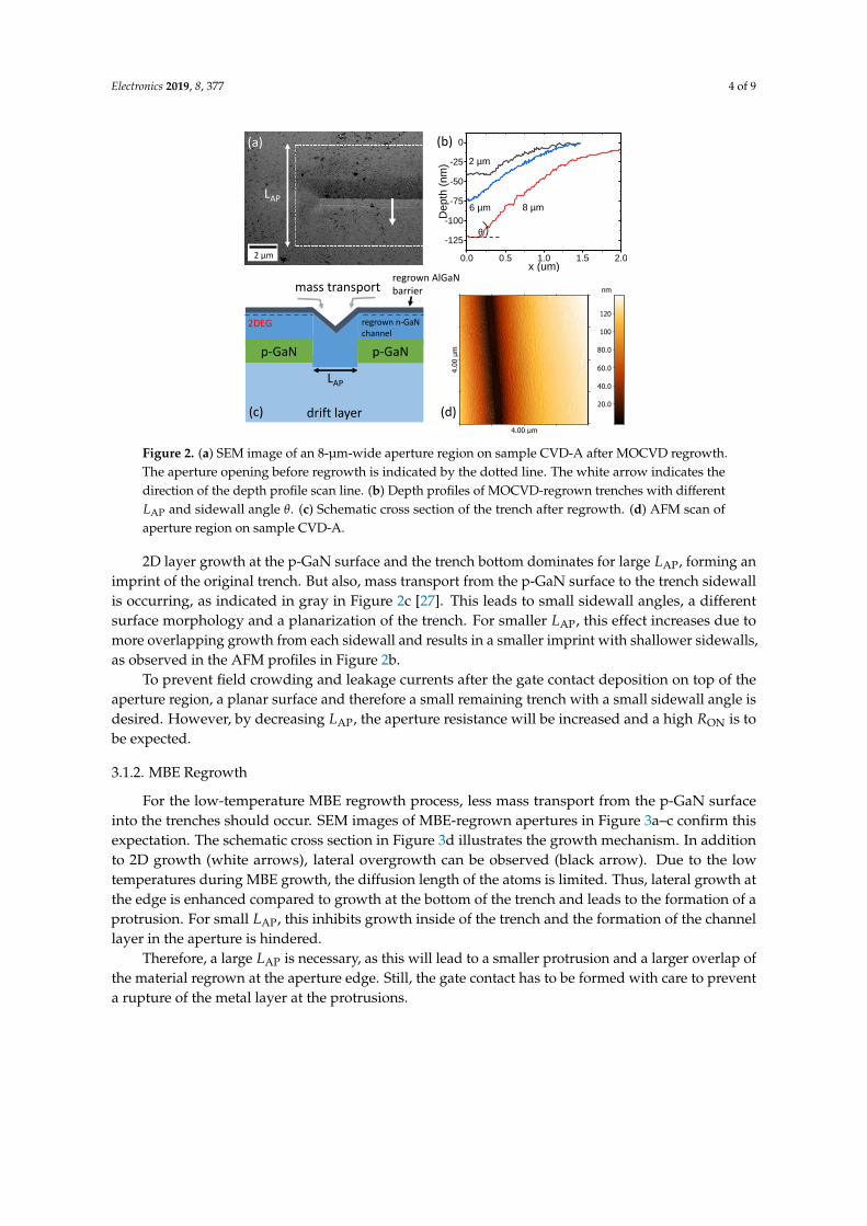
Figure 2a shows the MOCVD-regrown region of an 8-µm-wide aperture on sample CVD-A.The previously 300-nm-deep etched aperture, indicated by the dotted line, is completely filled.A narrower imprint of the opening is still visible. AFM depth profiles of the MOCVD-regrownaperture with various widths (LAP) are plotted in Figure 2b, confirming residual trenches after regrowth.The remaining trench depth increases from 40 nm for LAP = 2 µm to 120 nm for LAP = 8 µm. Also,the sidewall angle θ is increased from 3° to 7° for larger LAP. The growth morphology is different onthe sidewalls compared to a planar regrown surface in the vicinity of a trench, as shown in Figure 2d,but rms roughness is similar.
Electronics 2019, 8, 377 4 of 9
0.0 0.5 1.0 1.5 2.0
-125
-100
-75
-50
-25
0
De
pth
(n
m)
x (um)
8 µm6 µm
2 µm
(b)
p-GaN
drift layer
p-GaN
mass transport
LAP
2 µm
θ
LAP
regrown AlGaNbarrier
regrown n-GaN channel
2DEG
(a)
(c) (d)
[ 138 nm ] 141 nm Topography
4.0
0 µ
m
4.00 µm
20.0
40.0
60.0
80.0
100
120
nm
Figure 2. (a) SEM image of an 8-µm-wide aperture region on sample CVD-A after MOCVD regrowth.The aperture opening before regrowth is indicated by the dotted line. The white arrow indicates thedirection of the depth profile scan line. (b) Depth profiles of MOCVD-regrown trenches with differentLAP and sidewall angle θ. (c) Schematic cross section of the trench after regrowth. (d) AFM scan ofaperture region on sample CVD-A.
2D layer growth at the p-GaN surface and the trench bottom dominates for large LAP, forming animprint of the original trench. But also, mass transport from the p-GaN surface to the trench sidewallis occurring, as indicated in gray in Figure 2c [27]. This leads to small sidewall angles, a differentsurface morphology and a planarization of the trench. For smaller LAP, this effect increases due tomore overlapping growth from each sidewall and results in a smaller imprint with shallower sidewalls,as observed in the AFM profiles in Figure 2b.
To prevent field crowding and leakage currents after the gate contact deposition on top of theaperture region, a planar surface and therefore a small remaining trench with a small sidewall angle isdesired. However, by decreasing LAP, the aperture resistance will be increased and a high RON is tobe expected.
3.1.2. MBE Regrowth
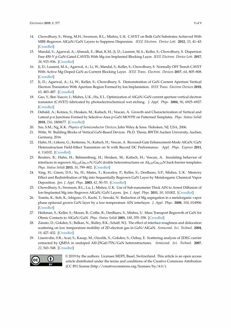
For the low-temperature MBE regrowth process, less mass transport from the p-GaN surfaceinto the trenches should occur. SEM images of MBE-regrown apertures in Figure 3a–c confirm thisexpectation. The schematic cross section in Figure 3d illustrates the growth mechanism. In additionto 2D growth (white arrows), lateral overgrowth can be observed (black arrow). Due to the lowtemperatures during MBE growth, the diffusion length of the atoms is limited. Thus, lateral growth atthe edge is enhanced compared to growth at the bottom of the trench and leads to the formation of aprotrusion. For small LAP, this inhibits growth inside of the trench and the formation of the channellayer in the aperture is hindered.
Therefore, a large LAP is necessary, as this will lead to a smaller protrusion and a larger overlap ofthe material regrown at the aperture edge. Still, the gate contact has to be formed with care to preventa rupture of the metal layer at the protrusions.

Electronics 2019, 8, 377 5 of 9
drift layer
p-GaN
n-GaN
/ growth direction
1 µm 1 µm
2 µm1 µm
G
/ drain / leakage current
S S
bottom contact layerD D
2DEG
(a) (b)
(c)(d)
Figure 3. (a–c) SEM images of 1 µm, 2 µm and 8 µm wide aperture regions (LAP) after the regrowth ofsample MBE-C. The trench opening before regrowth is indicated by the dotted line. (d) Schematic crosssection of MBE regrowth on a patterned sample. The drain current (solid) and source-drain leakagecurrent (dashed) paths are indicated by the red arrows (cf. Section 3.2.3).
3.2. Electrical Characterization
3.2.1. Planar 2DEG Properties
Eddy-current and Hall measurements were carried out to investigate the 2DEG formation in thelayers on top of the CBL. Statistics of these measurements of several positions on each sample arepresented in Figure 4. All p-GaN samples showed a sheet resistance Rsheet in the order of 50,000 Ω/sqbefore regrowth. The strong decrease of Rsheet for all samples cannot solely be explained by regrowingthe lowly doped n-GaN channel layer and thus the formation of a 2DEG at the AlGaN/GaN interfaceappears plausible. For the continuously MOCVD-grown reference sample 1, the lowest Rsheet =
340 Ω/sq and highest mobility µ = 2000 cm2/Vs can be extracted. Also, the sheet carrier concentrationis nS = 10× 1012 cm−2, which is expected for the given AlGaN thickness and Al content.
(b) (c)
(a)Ref. 1 Ref. 2 Sample
CVD-A
Sample
CVD-B
Ref. 3 Sample
MBE-C
Sample
MBE-D
102
103
104
Rsheet (W
/sq
)
Ref. 1 Ref. 2 Sample
CVD-B
Ref. 3 Sample
MBE-C
Sample
MBE-D
1
10
100
ns (
·10
12 c
m−2)
Ref. 1 Ref. 2 Sample
CVD-B
Ref. 3 Sample
MBE-C
Sample
MBE-D
0
500
1000
1500
2000
2500
µ (
cm
2/V
s)
Figure 4. (a) Eddy-current measurement results after regrowth. (b) Sheet carrier concentration nS and(c) mobility µ extracted from Hall measurements.

Electronics 2019, 8, 377 6 of 9
A slightly increased Rsheet is obtained for the regrown reference sample 2, probably due toincreased interface roughness or defect scattering, introduced by the regrowth. Low-temperature Hallmeasurements at 77 K (not shown here) still reveal a reduced mobility compared to reference sample 1and confirm the proposed scattering mechanisms, as all other are frozen out at 77 K [28,29].
For the MOCVD-regrown samples on p-GaN, a dramatic increase in Rsheet is observed. The highestRsheet = 5900 Ω/sq is obtained for sample CVD-A, as no measures were taken to inhibit Mg diffusion.The AlN interlayer introduced in sample CVD-B is also not able to suppress the Mg diffusioncompletely, resulting in an increased sheet resistance of 3200 Ω/sq and reduced nS = 2.2× 1012 cm−2.For sample CVD-A, no Hall data is available.
All MBE-regrown samples (reference 3, MBE-C and MBE-D) achieve the expectednS = 10× 1012 cm−2 and are comparable to reference sample 2 in terms of Rsheet. This indicates asuccessful suppression of Mg diffusion for the low temperature MBE regrowth. The increased mobilityfor sample MBE-D could be attributed to an improved AlGaN/GaN interface quality due to a largerdistance to the regrowth interface. However, both samples show the same rms surface roughnessof 1 nm.
Overall, improved 2DEG properties are achieved with the MBE regrowth, compared to thehigh-temperature MOCVD regrowth process. The lower Tgrowth suppresses Mg diffusion effectively.Hence, the acceptor concentration near the 2DEG is supposed to be low. The AlN interlayer in CVD-Bdid improve Rsheet and may be a viable option to enable an MOCVD regrowth for CAVET after furtheroptimization. However, the AlN interlayer will introduce an additional energy barrier for the draincurrent through the aperture when regrown below the channel layer. Therefore, sample CVD-A andMBE-D were chosen to compare the properties of CAVET fabricated with each regrowth techniqueand are analyzed in the following.
3.2.2. MOCVD-Regrown CAVET (CVD-A)
Deduced from the Hall measurements, a low maximum available drain current is to be expectedfor the MOCVD-regrown CAVET. Source contacts on top of the AlGaN barrier show a contact resistanceof RC,S = 7 Ωmm, the drain contact resistance RC,D is 1.7 Ωmm. The high RC,S may be caused by Mgdiffusion into the regrown n-GaN.
A CAVET with a gate length of LG = 2 µm and a LAP = 1 µm is discussed here (cf. Figure 1 forgeometry). All currents are normalized to the active area, which is the distance between the sourcecontacts multiplied by the gate width of 54 µm.
The output characteristic of the transistor is presented in Figure 5a. VGS was varied from +2 Vto −8 V in 1 V steps. No drain current saturation and a delayed turn-ON of the transistor can beobserved. Both effects are most likely caused by parasitic series resistances of the 2DEG, apertureand source contacts. A simple DC equivalent circuit model of a CAVET is depicted in Figure 5b andcomprises the following resistances: the contact resistances (RC,S, RC,D), the lateral 2DEG resistanceR2DEG, the aperture resistance Rap, the drift layer resistance Rdrift and the backside contact layerresistance Rbcl. Our calculations, based on measurements of lumped-element model test structures(e.g., TLM structures and lateral HFETs regrown on CBL with and without aperture), led to an apertureresistance Rap of approx. 10 MΩ. The reason for this high Rap may be, that the aperture is partiallydepleted from the lateral p-n junction, formed by the p-GaN CBL and the n-GaN aperture, or Mg hasdiffused into the regrown aperture during the high temperature MOCVD regrowth, compensatingthe n-doping. However, the large Rap and low 2DEG conductivity limit the maximum availabledrain current to ID,max = 1.3 A/cm2 and cause a high turn-ON voltage. The weak pinch-off can beimproved by increasing LG, as shown in the inset of Figure 5a. LAP is 6 µm for these devices. With alarger LG, the gate control of the regrown GaN is enhanced and the source-drain leakage current iseffectively suppressed.

Electronics 2019, 8, 377 7 of 9
G
(a)
p-GaN
bottom contact layer
S
D
RC,S
R2DEG
Rap
RdriftRbcl
RC,D
0 2 4 6 8 10 12 14 16 18 200.0
0.2
0.4
0.6
0.8
1.0
1.2
-8 -7 -6 -5 -4 -3 -2 -1 0 110-3
10-2
10-1
LG
1 µm
3 µm
4 µm
ID
I D,
I G (
A/c
m2)
VGS (V)
IG
VDS = 10 V
DVGS = -1 V
I D [A
/cm
2]
VDS [V]
VGS = 2 V
(b)
Figure 5. (a) Output characteristic of an MOCVD-regrown CAVET with LG = 2 µm and LAP = 1 µm.Inset: transfer characteristics of transistors with various LG and LAP = 6 µm. (b) DC equivalent circuitmodel comprising all series resistances.
Destructive breakdown occurs below the gate at VDS = −140 V. This results in a critical electricalfield of Ecrit = 2.8 MV/cm, by assuming a complete depletion of the 1-µm-long gate-drain distance.
3.2.3. MBE-Regrown CAVET (MBE-D)
An improved regrowth quality and lower Mg diffusion are expected for the MBE-regrown CAVET,compared to the CAVET with MOCVD regrowth. The source contact resistance of the MBE-regrowndevice is RC,S = 0.4 Ωmm, already indicating a lower Mg concentration at the surface. The draincontact resistance is RC,D = 2 Ωmm.
The output characteristic of devices with LG = 2 µm and LAP = 8 µm, 6 µm and 2 µm are depictedin Figure 6a. In contrast to the MOCVD-regrown CAVET, current saturation, a larger maximum draincurrent density of ID,max = 4 kA/cm2 for VGS = 2 V and low RON = 2 mΩ cm2 are achieved.
Figure 6b shows the transfer characteristics of the same devices. The transistors suffer from highOFF-state and gate leakage currents. Possible OFF-state drain leakage current paths, i.e., along theetched sidewall to the quasi-backside contact and through the CBL, can be excluded, as previousexperiments on these building blocks show the suppression of leakage currents [21]. The most probabledrain leakage current path for the transitor with LAP = 8 µm is through the lowly doped GaN channeland aperture as indicated in Figure 3d by the dashed arrow. As observed in the previous Section 3.1.2,the overlap between the regrown GaN channel in- and alongside the aperture is reduced for smallerapertures. This cuts off this drain leakage current path at the cost of a smaller ID,max, as can be seen inFigure 6b and increases the ON/OFF ratio to 2.3× 10³ [ID(VGS = 0 V)/ID(VGS = −8 V)] for the devicewith LAP = 2 µm. However, the transistors are still limited by gate leakage currents, probably due tothe gate deposition on the non-planarized regrown-aperture region.
(a) (b)0 2 4 6 8 10 12 14 16 18 20
0.0
0.5
1.0
1.5
2.0
2.5
3.0
3.5
LAP
8 µm
6 µm
2 µm
I D (
kA
/cm
2)
VDS (V)
VGS = 2 V; DVGS = -1 V
-14 -12 -10 -8 -6 -4 -2 0 210-3
10-2
10-1
100
101
102
103
104
LAP
8 µm
6 µm
2 µm
I D, I G
(A
/cm
2)
VDS = 10 V
-14 -12 -10 -8 -6 -4 -2 0 2
VGS (V)
IG
Figure 6. (a) Output characteristics of MBE-regrown CAVET with LG = 2 µm and LAP = 8 µm, 6 µmand 2 µm. (b) Transfer characteristics of the same devices for VDS = 10 V.

Electronics 2019, 8, 377 8 of 9
4. Summary and Conclusions
Two different regrowth techniques were used to fabricate CAVET. The regrowth wasconducted after aperture patterning on MOCVD-grown CBL with MBE and MOCVD, respectively.MOCVD-regrown aperture regions showed small imprints of the etched aperture opening with smallsidewall angles. This was correlated with mass transport into the trench during regrowth. On theother hand, protrusions were formed at apertures after the low-temperature MBE regrowth.
For the high-temperature MOCVD-regrown transistors, no current saturation and low ID,max
were measured, which is probably due to Mg diffusion into the regrown aperture.The MBE-regrown CAVET showed improved ON characteristics but suffered from high gate
and OFF-state leakage currents. Regrowth thickness and channel layer doping concentration shouldbe decreased to allow for low drain leakage currents. A planarization of the aperture region or anoptimized aperture width to height ratio may also help to suppress leakage currents.
Author Contributions: Conceptualization, W.W., M.M., S.K., H.K. and A.V.; formal analysis, W.W.; investigation,W.W., B.-J.G. and M.M.; supervision, M.H., H.K., R.A. and A.V.; visualization, S.K. and W.W.; writing–originaldraft, S.K.; writing–review & editing, S.K.
Funding: Funding of BMBF under grant nr. 16ES0147 is acknowledged.
Conflicts of Interest: The authors declare no conflict of interest. The funders had no role in the design of thestudy; in the collection, analyses, or interpretation of data; in the writing of the manuscript, or in the decision topublish the results.
References
1. Jones, E.A.; Wang, F.F.; Costinett, D. Review of Commercial GaN Power Devices and GaN-Based ConverterDesign Challenges. IEEE J. Emerg. Sel. Top. Power Electron. 2016, 4, 707–719. [CrossRef]
2. Chowdhury, S. GaN-on-GaN power device design and fabrication. In Wide Bandgap Semiconductor PowerDevices; Elsevier: Amsterdam, The Netherlands, 2019; pp. 209–248.
3. Chowdhury, S.; Mishra, U.K. Lateral and Vertical Transistors Using the AlGaN/GaN Heterostructure.IEEE Trans. Electron Devices 2013, 60, 3060–3066. [CrossRef]
4. Li, W.; Chowdhury, S. Design and fabrication of a 1.2 kV GaN-based MOS vertical transistor for single chipnormally off operation. Phys. Status Solidi 2016, 213, 2714–2720. [CrossRef]
5. Gupta, C.; Lund, C.; Chan, S.H.; Agarwal, A.; Liu, J.; Enatsu, Y.; Keller, S.; Mishra, U.K. In Situ Oxide, GaNInterlayer-Based Vertical Trench MOSFET (OG-FET) on Bulk GaN substrates. IEEE Electron Device Lett. 2017,38, 353–355. [CrossRef]
6. Sun, M.; Zhang, Y.; Gao, X.; Palacios, T. High-Performance GaN Vertical Fin Power Transistors on Bulk GaNSubstrates. IEEE Electron Device Lett. 2017, 38, 509–512. [CrossRef]
7. Zhang, Y.; Sun, M.; Piedra, D.; Hu, J.; Liu, Z.; Lin, Y.; Gao, X.; Shepard, K.; Palacios, T. 1200 V GaN verticalfin power field-effect transistors. In Proceedings of the 2017 IEEE International Electron Devices Meeting(IEDM), San Francisco, CA, USA, 2–6 December 2017.
8. Kizilyalli, I.; Aktas, O. Characterization of vertical GaN p-n diodes and junction field-effect transistors onbulk GaN down to cryogenic temperatures. Semicond. Sci. Technol. 2015, 30, 124001. [CrossRef]
9. Ji, D.; Chowdhury, S. Design of 1.2 kV Power Switches With Low RON Using GaN-Based Vertical JFET.IEEE Trans. Electron Devices 2015, 62, 2571–2578.
10. Kotzea, S.; Debald, A.; Heuken, M.; Kalisch, H.; Vescan, A. Demonstration of a GaN-Based Vertical-ChannelJFET Fabricated by Selective-Area Regrowth. IEEE Trans. Electron Devices 2018, 65, 5329–5336. [CrossRef]
11. Ben-Yaacov, I. AlGaN/GaN Current Aperture Vertical Electron Transistors. Ph.D. Thesis, University ofCalifornia, Santa Barbara, CA, USA, 2004.
12. Ben-Yaacov, I.; Seck, Y.K.; Mishra, U.K.; DenBaars, S.P. AlGaN/GaN current aperture vertical electrontransistors with regrown channels. J. Appl. Phys. 2004, 95, 2073–2078. [CrossRef]
13. Chowdhury, S. Aluminum Gallium Nitride/Gallium Nitride CAVETs for High Power Switching Application.Ph.D. Thesis, University of California, Santa Barbara, CA, USA, 2010.
Electronics 2019, 8, 377 9 of 9
14. Chowdhury, S.; Wong, M.H.; Swenson, B.L.; Mishra, U.K. CAVET on Bulk GaN Substrates Achieved WithMBE-Regrown AlGaN/GaN Layers to Suppress Dispersion. IEEE Electron. Device Lett. 2012, 33, 41–43.[CrossRef]
15. Mandal, S.; Agarwal, A.; Ahmadi, E.; Bhat, K.M.; Ji, D.; Laurent, M.A.; Keller, S.; Chowdhury, S. DispersionFree 450-V p GaN-Gated CAVETs With Mg-ion Implanted Blocking Layer. IEEE Electron. Device Lett. 2017,38, 933–936. [CrossRef]
16. Ji, D.; Laurent, M.A.; Agarwal, A.; Li, W.; Mandal, S.; Keller, S.; Chowdhury, S. Normally OFF Trench CAVETWith Active Mg-Doped GaN as Current Blocking Layer. IEEE Trans. Electron. Devices 2017, 64, 805–808.[CrossRef]
17. Ji, D.; Agarwal, A.; Li, W.; Keller, S.; Chowdhury, S. Demonstration of GaN Current Aperture VerticalElectron Transistors With Aperture Region Formed by Ion Implantation. IEEE Trans. Electron Devices 2018,65, 483–487. [CrossRef]
18. Gao, Y.; Ben-Yaacov, I.; Mishra, U.K.; Hu, E.L. Optimization of AlGaN/GaN current aperture vertical electrontransistor (CAVET) fabricated by photoelectrochemical wet etching. J. Appl. Phys. 2004, 96, 6925–6927.[CrossRef]
19. Debald, A.; Kotzea, S.; Heuken, M.; Kalisch, H.; Vescan, A. Growth and Characterization of Vertical andLateral p-n Junctions Formed by Selective-Area p-GaN MOVPE on Patterned Templates. Phys. Status Solidi2018, 216, 1800677. [CrossRef]
20. Sze, S.M.; Ng, K.K. Physics of Semiconductor Devices; John Wiley & Sons: Hoboken, NJ, USA, 2006.21. Witte, W. Building Blocks of Vertical GaN-Based Devices. Ph.D. Thesis, RWTH Aachen University, Aachen,
Germany, 2016.22. Hahn, H.; Lükens, G.; Ketteniss, N.; Kalisch, H.; Vescan, A. Recessed-Gate Enhancement-Mode AlGaN/GaN
Heterostructure Field-Effect Transistors on Si with Record DC Performance. Appl. Phys. Express 2011,4, 114102. [CrossRef]
23. Reuters, B.; Hahn, H.; Behmenburg, H.; Heuken, M.; Kalisch, H.; Vescan, A. Insulating behavior ofinterfaces in regrown Al0.23Ga0.77N/GaN double heterostructures on Al0.07Ga0.93N back-barrier templates.Phys. Status Solidi 2013, 10, 799–802. [CrossRef]
24. Xing, H.; Green, D.S.; Yu, H.; Mates, T.; Kozodoy, P.; Keller, S.; DenBaars, S.P.; Mishra, U.K. MemoryEffect and Redistribution of Mg into Sequentially Regrown GaN Layer by Metalorganic Chemical VaporDeposition. Jpn. J. Appl. Phys. 2003, 42, 50–53. [CrossRef]
25. Chowdhury, S.; Swenson, B.L.; Lu, J.; Mishra, U.K. Use of Sub-nanometer Thick AlN to Arrest Diffusion ofIon-Implanted Mg into Regrown AlGaN/GaN Layers. Jpn. J. Appl. Phys. 2011, 50, 101002. [CrossRef]
26. Tomita, K.; Itoh, K.; Ishiguro, O.; Kachi, T.; Sawaki, N. Reduction of Mg segregation in a metalorganic vaporphase epitaxial grown GaN layer by a low-temperature AlN interlayer. J. Appl. Phys. 2008, 104, 014906.[CrossRef]
27. Heikman, S.; Keller, S.; Moran, B.; Coffie, R.; DenBaars, S.; Mishra, U. Mass Transport Regrowth of GaN forOhmic Contacts to AlGaN/GaN. Phys. Status Solidi 2001, 188, 355–358. [CrossRef]
28. Zanato, D.; Gokden, S.; Balkan, N.; Ridley, B.K.; Schaff, W.J. The effect of interface-roughness and dislocationscattering on low temperature mobility of 2D electron gas in GaN/AlGaN. Semicond. Sci. Technol. 2004,19, 427–432. [CrossRef]
29. Lisesivdin, S.B.; Acar, S.; Kasap, M.; Ozcelik, S.; Gokden, S.; Ozbay, E. Scattering analysis of 2DEG carrierextracted by QMSA in undoped Al0.25Ga0.75N/GaN heterostructures. Semicond. Sci. Technol. 2007,22, 543–548. [CrossRef]
© 2019 by the authors. Licensee MDPI, Basel, Switzerland. This article is an open accessarticle distributed under the terms and conditions of the Creative Commons Attribution(CC BY) license (http://creativecommons.org/licenses/by/4.0/).