Comparison of Different Modulation Techniques Using VBlast Mimo System in Rayleigh Channel
10
International Journal of Engineering Research and Development e-ISSN: 2278-067X, p-ISSN: 2278-800X, www.ijerd.com Volume 4, Issue 2 (October 2012), PP. 91-100 91 Comparison of Different Modulation Techniques Using V- Blast Mimo System in Rayleigh Channel Gurpreet Singh 1 , Pardeep Sharma 2 and Aman Goyal 3 1 Shaheed Bhagat Singh State Technical Campus Department of Electronics and Communication, Moga Road (NH-95), Ferozepur-152004, India 2 Shaheed Bhagat Singh State Technical Campus Department of Electronics and Communication, Moga Road (NH-95), Ferozepur-152004, India 3 Desh Bhagat University, Department of Electronics and Communication, Mandi Gobindgarh, Punjab, India Abstract:- Multiple Input Multiple Output (MIMO) systems have been extensively studied in context of wireless communication system, which promising the both increased capacity and link level reliability. In this paper we will present an analysis of the Vertical Bell Laboratories Layered Space-Time (V-BLAST) system at high signal- to noise ratio (SNR) region using BPSK, QPSK and 16-QAM modulation technique by using various decoding techniques. We will consider a point-to-point MIMO communications over an independent, identically distributed (i.i.d) Rayleigh flat fading channel with ‗N‘ transmitting antennas and ‗M‘ (M≥N) receiving antennas. We will analyze the zero-forcing V-BLAST (ZF-V-BLAST), minimum mean-squared-error (MMSE-V-BLAST), zero- forcing + Ordered Serial Interference Cancellation V-BLAST (ZF+OSIC V-BLAST), minimum mean-squared- error + Ordered Serial Interference Cancellation V-BLAST (MMSE+OSIC V-BLAST) and Maximum Likelihood V-BLAST (ML-V-BLAST) decoding techniques with respect to their BER performances. V-BLAST system is compared with different modulation technique and system gets better result in BPSK modulation. Finally we will conclude that ML-VBLAST decoding technique gives the better performance than other decoding techniques using BPSK modulation. Further simulation results for BPSK modulation with only ML decoding technique using various antennas at input and output. In this we got more optimal result for 4 x 4 antennas for V-BLAST system. Keywords:- Multiple input multiple output (MIMO), Vertical Bell Laboratories Layered Space-Time (V- BLAST), zero-forcing V-BLAST (ZF--BLAST), minimum mean-squared-error (MMSE-V-BLAST), Maximum Likelihood (ML) Ordered Serial Interference Cancellation (OSIC). I. INTRODUCTION Wireless communication system with multi-antenna arrays has been a field of intensive research on the last years. The use of multiple antennas at both the transmitter and the receiver sides can drastically improve the channel capacity and data rate. The study of the performance limits of MIMO system [1] becomes very important since it will give lot ideas in understanding and designing the practical MIMO systems [1]. There are many schemes that can be applied to MIMO systems such as space time block codes, space time trellis codes and the Vertical Bell Labs Space-Time system (V-BLAST). In this paper, we study the general V-BLAST system with Maximum Likelihood (ML), Zero Forcing (ZF) and Minimum Mean Squared Error (MMSE) detectors in fading channels by using various modulation techniques such as BPSK, QPSK and 16-QAM. Space Time Layered Architecture offers a big increase in capacity and data rate, promising a linear growth with the size of antenna array under some circumstances [3]. First Bell Laboratories Layered Space-Time Architecture now widely known as D-BLAST [2] is one of the approaches to increase the data rate and capacity of the system. D-BLAST has a computational complexity. To mitigate the computational complexity of D-BLAST [2], we will use a simplified version of BLAST known as Vertical-Bell Laboratories Layered Space-Time (V-BLAST) [3]. In V-BLAST at the transmitter de-multiplexes the input data streams into ‗n‘ independent sub-streams, which are transmitted in parallel over the ‗n‘ transmitting antennas. At the receiver end, antennas receive the sub-streams, which are mixed and superimposed by noise. Detection of sub-streams at receiver of V-BLAST [2] is done by applying Order determination, Sequential interference nulling and Signal Cancellation [3]. Although V-BLAST is known equivalent to a Decision Feedback Equalizer (DFE) [9] and is optimal in terms of achieving the channel capacity [4]. In an i.i.d Rayleigh Flat fading channel with ‗N‘ transmitting antennas and ‗M‘ receiving antennas (M≥N), the first detected sub-stream has a diversity gain of only M-N+1.The first sub stream is the bottleneck which limits the overall performance of the scheme. One can apply the optimal ordering technique to mitigate this bottleneck effect [3]. At each detection step the receiver should detect the data sub-stream with the largest post processing Signal to Noise Ratio (SNR). However, it is shown in [5] optimal ordering does not improve the diversity gain when there are two transmitting antennas (N=2) but diversity gain remains unknown if we applying optimal ordering and help to improve in general cases [6].
-
Upload
lovely-professional-university -
Category
Documents
-
view
2 -
download
0
Transcript of Comparison of Different Modulation Techniques Using VBlast Mimo System in Rayleigh Channel

International Journal of Engineering Research and Development
e-ISSN: 2278-067X, p-ISSN: 2278-800X, www.ijerd.com
Volume 4, Issue 2 (October 2012), PP. 91-100
91
Comparison of Different Modulation Techniques Using V-
Blast Mimo System in Rayleigh Channel
Gurpreet Singh1, Pardeep Sharma
2 and Aman Goyal
3
1Shaheed Bhagat Singh State Technical Campus Department of Electronics and Communication, Moga Road (NH-95),
Ferozepur-152004, India 2Shaheed Bhagat Singh State Technical Campus Department of Electronics and Communication, Moga Road (NH-95),
Ferozepur-152004, India 3Desh Bhagat University, Department of Electronics and Communication, Mandi Gobindgarh, Punjab, India
Abstract:- Multiple Input Multiple Output (MIMO) systems have been extensively studied in context of wireless
communication system, which promising the both increased capacity and link level reliability. In this paper we
will present an analysis of the Vertical Bell Laboratories Layered Space-Time (V-BLAST) system at high signal-
to noise ratio (SNR) region using BPSK, QPSK and 16-QAM modulation technique by using various decoding
techniques. We will consider a point-to-point MIMO communications over an independent, identically distributed
(i.i.d) Rayleigh flat fading channel with ‗N‘ transmitting antennas and ‗M‘ (M≥N) receiving antennas. We will
analyze the zero-forcing V-BLAST (ZF-V-BLAST), minimum mean-squared-error (MMSE-V-BLAST), zero-
forcing + Ordered Serial Interference Cancellation V-BLAST (ZF+OSIC V-BLAST), minimum mean-squared-
error + Ordered Serial Interference Cancellation V-BLAST (MMSE+OSIC V-BLAST) and Maximum Likelihood
V-BLAST (ML-V-BLAST) decoding techniques with respect to their BER performances. V-BLAST system is
compared with different modulation technique and system gets better result in BPSK modulation. Finally we will
conclude that ML-VBLAST decoding technique gives the better performance than other decoding techniques
using BPSK modulation. Further simulation results for BPSK modulation with only ML decoding technique using
various antennas at input and output. In this we got more optimal result for 4 x 4 antennas for V-BLAST system.
Keywords:- Multiple input multiple output (MIMO), Vertical Bell Laboratories Layered Space-Time (V-
BLAST), zero-forcing V-BLAST (ZF--BLAST), minimum mean-squared-error (MMSE-V-BLAST), Maximum
Likelihood (ML) Ordered Serial Interference Cancellation (OSIC).
I. INTRODUCTION Wireless communication system with multi-antenna arrays has been a field of intensive research on the last years.
The use of multiple antennas at both the transmitter and the receiver sides can drastically improve the channel capacity and
data rate. The study of the performance limits of MIMO system [1] becomes very important since it will give lot ideas in
understanding and designing the practical MIMO systems [1]. There are many schemes that can be applied to MIMO
systems such as space time block codes, space time trellis codes and the Vertical Bell Labs Space-Time system (V-BLAST).
In this paper, we study the general V-BLAST system with Maximum Likelihood (ML), Zero Forcing (ZF) and Minimum
Mean Squared Error (MMSE) detectors in fading channels by using various modulation techniques such as BPSK, QPSK
and 16-QAM.
Space Time Layered Architecture offers a big increase in capacity and data rate, promising a linear growth with
the size of antenna array under some circumstances [3]. First Bell Laboratories Layered Space-Time Architecture now
widely known as D-BLAST [2] is one of the approaches to increase the data rate and capacity of the system. D-BLAST has a
computational complexity.
To mitigate the computational complexity of D-BLAST [2], we will use a simplified version of BLAST known as
Vertical-Bell Laboratories Layered Space-Time (V-BLAST) [3]. In V-BLAST at the transmitter de-multiplexes the input
data streams into ‗n‘ independent sub-streams, which are transmitted in parallel over the ‗n‘ transmitting antennas. At the
receiver end, antennas receive the sub-streams, which are mixed and superimposed by noise. Detection of sub-streams at
receiver of V-BLAST [2] is done by applying Order determination, Sequential interference nulling and Signal Cancellation
[3]. Although V-BLAST is known equivalent to a Decision Feedback Equalizer (DFE) [9] and is optimal in terms of
achieving the channel capacity [4]. In an i.i.d Rayleigh Flat fading channel with ‗N‘ transmitting antennas and ‗M‘ receiving
antennas (M≥N), the first detected sub-stream has a diversity gain of only M-N+1.The first sub stream is the bottleneck
which limits the overall performance of the scheme. One can apply the optimal ordering technique to mitigate this bottleneck
effect [3]. At each detection step the receiver should detect the data sub-stream with the largest post processing Signal to
Noise Ratio (SNR). However, it is shown in [5] optimal ordering does not improve the diversity gain when there are two
transmitting antennas (N=2) but diversity gain remains unknown if we applying optimal ordering and help to improve in
general cases [6].

Comparison of Different Modulation Techniques Using V-Blast Mimo System In Rayleigh Channel
92
II. MIMO SYSTEM MODEL We consider single user MIMO communication system [2] with 2 antennas at the transmitter and 2 antennas at the
receiver. Consider that we have a transmission sequence is {x1, x2,...........,xn}. In normal transmission, we send x1 in the first
time slot, x2 in the second time slot and xn in the nth time slot. Now we have two transmit antennas, we may groups the
symbols into groups of two. In the first time slot, send x1 and x2 from the first and second antenna. In the second time slot,
send x3 and x4 from the first and second antenna and in next time slot x5 and x6 and so on. Let us consider for 2 x 2 MIMO
System
Fig.1. 2 x 2 MIMO system model
The received signal on the first receive antenna is
r1 = h11s1 + h12s2 + n1
(1)
The received signal on the second receive antenna is
r2 = h21s1 + h22s2 + n2
(2)
where, 𝑦1 𝑎𝑛𝑑 𝑦2 are the received symbol on the first and second antenna respectively,ℎ11 is the channel from 1𝑠𝑡 transmit
antenna to 1𝑠𝑡 receive antenna,ℎ12 is the channel from 2𝑛𝑑 transmit antenna to 2𝑛𝑑 receive antenna,ℎ21 is the channel
from 1𝑠𝑡 transmit antenna to 2𝑛𝑑 receive antenna, ℎ22 is the channel from 2𝑛𝑑 transmit antenna to 2𝑛𝑑 receive antenna,
𝑠1𝑎𝑛𝑑 𝑠2 are the transmitted symbols and 𝑛1𝑎𝑛𝑑 𝑛2 is the noise on 1𝑠𝑡 𝑎𝑛𝑑 2𝑛𝑑 receive antennas respectively.
𝐸𝑞𝑛 (1) and 𝐸𝑞𝑛 (2) can be represented in matrix form
y1
y2 =
h11 h12
h21 h22
s1
s2 +
n1
n2
(3)
The sampled baseband representation of signal is given by
y = Hx + n (4)
And the complex baseband representation of signal [15 ] is given by
𝑦 = 𝑃
𝑀𝐻𝑥 + 𝑛
(5)
where 1 NCy is the received signal vector,
1 MCx is the transmitted signal vector with zero mean and unit
variance, P is the total transmit power, MNCH is the channel response matrix with possibly correlated fading
coefficients. In order to access the performance of V-BLAST in correlated channel, we adopted a correlation-based channel
model which is expressed as
𝐻~𝑅𝑅𝑥
12 𝐻𝑤 𝑅𝑇𝑥
1\2
𝑇
(6)
where x ~ y denotes that x and y are identical in distribution, RxR and TxT are the normal correlation distribution matrices
at the Rx and transmitter (Tx) respectively, and MN
W CH contains i.i.d complex Gaussian entries with zero mean and
unit variance.
For a system with 𝑀𝑇 transmit antennas and 𝑀𝑅 receive antennas, the MIMO channel at a given time instant may be
represented as a 𝑀𝑅 × 𝑀𝑇 matrix
H =
H1,1 H1,2 ⋯ H1,MT
H2,1 H2,2 … H2,MT
⋮ ⋮ ⋱ ⋮HMR,1 HMR,2 ⋯ HMR,MT
(7)
Rx
1
Rx
2
Tx
2
Tx
1 ℎ12 ℎ21
ℎ11
ℎ22
Transmitter
Receiver
Comparison of Different Modulation Techniques Using V-Blast Mimo System In Rayleigh Channel
93
III. SYSTEM MODEL OF V-BLAST SYSTEM The V-BLAST system [3] is simplified version of D-BLAST [5] that tries to reduce its computational complexity.
But in doing so transmit diversity is loss. A high-level block diagram of a V-BLAST system is shown in Fig.1
3.1 Encoder
A single data stream is de-multiplexed into m sub-streams, and each sub-stream is then encoded into symbols and
fed to its respective transmitter. Transmitters 1-m operate co-channel at symbol rate 1/T symbols/sec, with synchronized
symbol timing. The power launched by each transmitter is proportional to 1/m so that the total radiated power is constant and
independent of ‗m‘. At a certain symbol instant, the output of the transmission antenna array is a vector [11]
𝑎 = 𝑎1 , 𝑎2, 𝑎3 … . . 𝑎𝑚 𝑇 (8)
3.2 Decoder
The decoder needs to demodulate the symbols on the received vector. If channel encoding is used, then the demodulated
symbols need to be buffered until the whole block can be decoded. Otherwise, the demodulation can be done immediately.
Several decoders are possible for this architecture and these decoders are explained bellow one by one.
IV. DECODING ALGORITHM FOR V-BLAST SYSTEM One approach to a lower complexity design of the receiver is to use a ―divide-and-conquer‖ strategy instead of
decoding all symbols jointly. First, the algorithm decodes the strongest symbol. Then, canceling the effects of this strongest
symbol from all received signals, the algorithm detects the next strongest symbol. The algorithm continues by canceling the
effects of the detected symbol and the decoding of the next strongest symbol until all symbols are detected. The optimal
detection order is from the strongest symbol to the weakest one. This is the original decoding algorithm [9] of V-BLAST
preset. It only works if the number of receive antennas is more than the number of transmit antennas, that is M x N.
Decoding Algorithm of V-BLAST is shown in Figure.3
The algorithm includes three steps:
ordering;
interference cancellation;
Interference nulling.
Fig.3 VBLAST Decoder block diagram
+ 𝑐 2 𝑐 1
𝑐 1
r3 - +
r
𝑐 2
Decode c1 𝑐 1𝐻2
Decode c2 𝑐 2𝐻2 ∑ ∑
Tx data
a4
a3
a1
a2
Vector
Encoder
Tx
Tx
Tx
Tx
Rayleigh
Fading
Channel
VBLAST Signal
Processing: estimate
and decode
Rx
Rx
Rx
Rx
Rx
Rx
Fig.2 V-BLAST MIMO System Model

Comparison of Different Modulation Techniques Using V-Blast Mimo System In Rayleigh Channel
94
3.3 Optimal Ordering
One approach to a lower complexity design of the receiver is to use a ―divide-and-conquer‖ strategy instead of decoding
all symbols jointly. First, the algorithm decodes the strongest symbol. Then, canceling the effects of this strongest symbol
from all received signals, the algorithm detects the next strongest symbol [12]. The algorithm continues by canceling the
effects of the detected symbol and the decoding of the next strongest symbol until all symbols are detected. The optimal
detection order is from the strongest symbol to the weakest one. This is the original decoding algorithm of V-BLAST preset
[3]. It only works if the number of receive antennas is more than the number of transmit antennas, that is M ≥ N.
In decoding the first symbol, the interference from all other symbols is considered as noise. After finding the best
candidate for the first symbol, the effects of this symbol in all of the receiver equations are canceled. Then, the second
symbol is detected from the new sets of equations. The effects of the second detected symbol are canceled next to derive a
new set of equations. The process continues until all symbols are detected. Of course, the order in which the symbols are
detected will impact the final solution.
3.4 Interference Cancellation
At stage n of the algorithm, when 𝑐𝑛 is being detected, symbols 𝑐1, 𝑐2, . . . , 𝑐𝑛−1 have been already detected. Let us
assume a perfect decoder, that is the decoded symbols 𝑐1 , 𝑐2 ,…… . . , 𝑐 𝑛−1 are the same as the transmitted symbols
𝑐1, 𝑐2, . . . , 𝑐𝑛−1.
One can subtract 𝑐𝑖𝐻𝑖𝑛−1𝑖=1 from the received vector r to derive an equation that relates remaining undetected symbols to the
received vector:
𝑟𝑛 = 𝑟 − 𝑐𝑖𝐻𝑖 + 𝑁,
𝑛−1
𝑖=1
(9)
𝑟𝑛 = 𝑐𝑖𝐻𝑖 + 𝑁, 𝑛 = 1,2 … . 𝑁 − 1
𝑁
𝑖=𝑛
(10)
In fact, by using induction in addition to the convention 𝑟1 = 𝑟 ,one can show that
𝑟𝑛+1 = 𝑟𝑛 − 𝑐𝑛𝐻𝑛 , 𝑛 = 1,2,3 … . . 𝑁 − 1 (11)
Therefore, at the 𝑛𝑡ℎ stage of the algorithm after detecting the nth symbol as 𝑐 𝑛 , its effect is canceled from the equations by
𝑟𝑛+1 = 𝑟𝑛 + 𝑐 𝑛𝐻𝑛 (12)
This interference cancelation is conceptually similar to DFE [9].
3.5 Interference nulling
Interference nulling is the process of detecting 𝑐𝑛 from 𝑟𝑛 by first removing the effects of undetected symbols. Basically, in
this step the nth symbol is detected by nulling the interference caused by symbols 𝑐𝑛+1 , 𝑐𝑛+2, . . . , 𝑐𝑁 . Like any other
interference suppression problem, there are many different methods to detect a symbol in the presence of interference [8]
3.5.1 Zero Forcing Interference Nulling
Using zero-forcing [15] for interference nulling is common in practice. First, let us assume perfect detection of
symbols as in 𝑒𝑞𝑛 (12) We would like to separate the term 𝑐𝑛𝐻𝑛 from 𝑟𝑛 .This can be done through multiplying 𝑟𝑛 by an M
× 1 vector 𝑊𝑛 that is orthogonal to interference vectors 𝐻𝑛+1 ,𝐻𝑛+2 , … . 𝐻𝑁 but not orthogonal to 𝐻𝑛 .In other words, 𝑊𝑛
should be such that
𝐻𝑖 .𝑊𝑛 = 0, 𝑖 = 𝑛 + 1,𝑛 + 2 …… . . 𝑁
(13)
𝐻𝑛 . 𝑊𝑛 = 1 (14)
𝑊𝑛= Zero-Forcing Nulling vector with minimum norm.
Such a vector is uniquely calculated from the channel matrix H. To calculate 𝑊𝑛 from H, for M ≥ N first we should replace
the rows 1, 2...., n − 1of H by zero.
Let us denote the resulting matrix by Z. Then, 𝑊𝑛 is the nth column of 𝑍+ the Moore–Penrose generalized inverse [13],
pseudo-inverse, of Z [10]
Using the error-free detection formula for 𝑟𝑛 in (12) and 𝑤𝑛 in (14), we have
𝑟𝑛𝑊𝑛 = 𝑐𝑛 + 𝑁𝑊𝑛 (15)
The noise in (15) is still Gaussian and the symbol 𝑐𝑛 can be easily decoded. The decoded symbol 𝑐 𝑛 is the closest
constellation point to 𝑟𝑛 .𝑊𝑛 . The noise enhancing factor is
𝐸 𝑁.𝑊𝑛 𝐻 . 𝑁. 𝑊𝑛 = 𝑊𝑛
𝐻 . 𝐸 𝑁𝐻 . 𝑁 𝑊𝑛 (16)
= 𝑁0 𝑊𝑛 2 (17)
We know that zero forcing is given by
𝑊𝑍𝐹 = (𝐻∗𝐻)𝐻 (18)
Comparing (17) with (18) demonstrates why adding an interference cancelation step improves the performance. Using the
combination of canceling and nulling in a ZF-DFE [8] structure enhances the noise by a factor of ||𝑊𝑛||2. Vector 𝑊𝑛 is
orthogonal to N − n rows of the channel matrix H. On the other hand, using a pure interference nulling method like ZF, the
corresponding vector that detects the nth symbol, the 𝑛𝑡ℎ column of the pseudo-inverse, is orthogonal to N − 1 rows of the

Comparison of Different Modulation Techniques Using V-Blast Mimo System In Rayleigh Channel
95
channel matrix H. Using the Cauchy–Schwartz inequality [10], it can be shown that the norm of a vector is larger if it has to
be orthogonal to a greater number of rows. Therefore, the enhancing factor for the case of nulling alone, ZF, is more than
that of the canceling and nulling, ZF-DFE [9]
3.5.2 MMSE-Interference Nulling
Another approach for interference nulling is MMSE [7]. Let us assume that the trans-mitted vector is a zero-mean random
vector that is uncorrelated to the noise. Considering the received vector r in (19) as a noisy observation of the input C, the
linear least-mean-squares estimator of C is
𝑀 = 𝐻𝐻 .
𝐼𝑁
𝛾+ 𝐻.𝐻𝐻
−1
(19)
Note that in the nth stage of the algorithm, the effects of 𝑐1, 𝑐2, . . . , 𝑐𝑛−1 have been canceled. Therefore, similar to the ZF
nulling, to calculate 𝑐𝑛 , first we should replace the rows 1, 2, . . . ,𝑛 − 1 of H by zero. Let us denote the resulting matrix by Z
as we did in the ZF case. Now, to find the best estimate of the nth symbol, that is 𝑐 𝑛 , we replace H with Z in (20) to
calculate the best linear MMSE estimator at stage n as
𝑀 = 𝑍𝐻 .
𝐼𝑁
𝛾+ 𝑍. 𝑍𝐻
−1
(20)
Then, the nth column of M, denoted by 𝑀𝑛 is utilized as the MMSE nulling vector for the 𝑛𝑡ℎ symbol. In other words, the
decoded symbol 𝑐 𝑛 is the closest constellation point to 𝑟𝑛 .𝑀𝑛
V. V-BLAST SYSTEM DECODERS 3.6 Maximum Likelihood Decoder
The ML receiver [7] performs optimum vector decoding and is optimal in the sense of minimizing the error
probability. ML receiver is a method that compares the received signals with all possible transmitted signal vectors which is
modified by channel matrix H and estimates transmit symbol vector C according to the Maximum Likelihood principle,
which is shown as:
C = argminC
r − C′H F
2 (21)
where F is the Frobenius norm. Expanding the cost function using Frobenius norm given by
C = argmin
C
Tr r − C′H H
. r00 − C′H (22)
C = argminC
Tr rH . r + HH . C′H . C′. H − HH . C′H . r − rH . C′. H (23)
Considering rH . r is independent of the transmitted codeword so can be rewritten as
C = argminC
Tr HH . C′H . C′. H − 2. Real Tr HH . C′H . r (24)
Equation ―(20)‖ can be rewritten for multiple receivers as shown in
C = argminC
HmH . C′H . C′. Hm
MR
m=1
− 2. Real HmH . C′. rm
(25)
where .H is a Hermition operator [13]. We can write the cost function for only one receiving antenna and then added up to
achieve for MR receiving antenna.
HmH . C′H . C′. Hm − 2. Real Hm
H . C′. rm (26)
where the minimization is performed over all possible transmit estimated vector symbols. Although ML detection offers
optimal error performance, it suffers from complexity issues.
3.7 V-BLAST Zero Forcing Decoder
Zero Forcing is the linear MIMO technique. The processing takes place at the receiver where, under the
assumption that the channel matrix H is invertible, H is inverted and the transmitted MIMO vector ‗s‘ is estimated by
𝑠𝑒𝑠𝑡 = 𝐻−1𝑥 (27)
The solution of ZF is given by:
For Zero Forcing, nulling of the ―interferers‖ can be performed by choosing 1 x N dimensional weight vectors iw (with i=1,
2……..M), referred to as nulling vectors, such that
𝑤𝑖ℎ𝑝 =
0 ,𝑝 ≠ 𝑖1 ,𝑝 = 𝑖
(28)
where h denotes the p-the column of channel matrix H. Let iw be the i-th row of the matrix W, then it follows that
𝑊 = 𝐻𝐼𝑁 (29)
Where W is the matrix that represents the linear processing of in the receiver. So, by forcing the ―interferers‖ to zero, each
desired element of s can be estimated.
If H is not square, W equals the pseudo-inverse of H [9] denoted byH
𝑊 = 𝐻+ = 𝐻𝐻𝐻 −1𝐻𝐻 (30)

Comparison of Different Modulation Techniques Using V-Blast Mimo System In Rayleigh Channel
96
If elements of H are assumed to be i.i.d [10], the pseudo-inverse [9] exists, when M≥N. For M≤N, HH His singular and
its inverse does not exists [9]. When the pseudo-inverse exits, the estimates of s (given by ests ) can be given by
𝑠𝑒𝑠𝑡 = 𝑊𝑥 = H+ = 𝐻𝐻𝐻 −1𝐻𝐻x (31)
𝑠𝑒𝑠𝑡 = s+ 𝐻𝐻𝐻 −1𝐻𝐻n (32)
The disadvantage of Zero Forcing [13] is that it suffers from noise enhancement. This can readily observed from above
equation.
This leads to estimation error and given by following equation
𝜖 = 𝑠𝑒𝑠𝑡 − s = 𝐻𝐻𝐻 −1𝐻𝐻n (33)
The ZF receiver converts the joint decoding problem into M single stream decoding problems thereby significantly reducing
receiver complexity. This complexity reduction comes, however at the expense of noise enhancement which results in a
significant performance degradation.
3.8 V-BLAST Minimum Mean Square Error (MMSE)
The MMSE [15] receiver suppresses both the interference and noise components, whereas, ZF receiver removes
only the interference components. This implies that the mean square error between the transmitted symbols and the estimate
of the receiver is minimized. Hence MMSE is superior to ZF in the presence of noise. At low SNR, MMSE becomes
matched filter and at high SNR, MMSE becomes Zero Forcing (ZF). For MMSE-V-BLAST [10], the nulling vector for the i-
th layer is
𝑤𝑖 = 𝐻𝑖𝐻𝑖
∗ +1
𝑠𝑛𝑟𝐼
−1
ℎ𝑖 , 𝑖 = 1,2 ……𝑁 (34)
Where iM
i CH consists of the first I columns of H. Then the post-processing SNR of the i-th layer is
𝜌𝑖𝑀𝑀𝑆𝐸 =
ℎ𝑖∗ 2
𝑤𝑖∗ 𝐻𝑖−1𝐻𝑖−1
∗ + 𝑠𝑛𝑟−1𝐼 𝑤𝑖
(35)
Inserting (18) into (19), we can simplify via some straight forward calculations that are
𝜌𝑖𝑀𝑀𝑆𝐸 = ℎ𝑖
∗𝐶𝑖−1ℎ𝑖 i = 1,2 …… . . N (36)
where, 𝐶𝑖−1 = 𝐻𝑖−1𝐻𝑖−1
∗ + 𝑠𝑛𝑟−1𝐼, applying the matrix inversion, we obtain
𝐶𝑖−1 = 𝑠𝑛𝑟 I − 𝐻𝑖−1𝐻𝑖−1
∗ + 𝑠𝑛𝑟−1𝐼 −1Hi−1∗
Inserting (21) into (20) we get
𝜌𝑖𝑀𝑀𝑆𝐸 = 𝑠𝑛𝑟ℎ 𝑖
∗𝑃1
𝐻𝑖−1ℎ 𝑖 + 𝑠𝑛𝑟�𝑖
∗𝐻𝑖−1 𝐻𝑖−1𝐻𝑖−1∗ −1 − 𝐻𝑖−1𝐻𝑖−1
∗ + 𝑠𝑛𝑟−1𝐼 −1 Hi−1∗ hi
𝜌𝑖𝑀𝑀𝑆𝐸 = ρ
iZF + 𝑠𝑛𝑟ℎ𝑖
∗𝐻𝑖−1 𝐻𝑖−1𝐻𝑖−1∗ −1 − 𝐻𝑖−1𝐻𝑖−1
∗ + 𝑠𝑛𝑟−1𝐼 −1 Hi−1∗ hi (39)
Hence, MMSE receiver approaches the ZF receiver and therefore realizes (N-M+1)th order diversity [5] for each data
stream.
3.9 V-BLAST Zero Forcing with OSIC
OSIC is basically based on subtraction of interference of already detected elements of s from the receiver vector x. This
results in a modified receiver vector in which effectively fewer interferers are present. Decoding algorithm consists of
basically three steps which are summarizing
1) ComputeH , find the minimum squared length row of
H , say it is the p-th and permute it to be last row.
Permute columns of H accordingly.
2) From the estimate of the corresponding elements of s. In case of ZF:
xWs n
pest
Where the weight vector nW equals row Nt of the permuted
H
3) While M-1>0 go back to step 1, but now with: 11
1 ........
M
M hhHH
So we can see here with respect to ZF, the ZF with OSIC algorithm introduces extra complexity.
3.10 V-BLAST Minimum Mean Square Error (MMSE) with OSIC
In order to do OSIC with MMSE, then the algorithm resulting as follows
Covariance matrix can be written as
PHHIssss n
H
n
H
estest
212
Covariance matrix of the estimation error estss will be used to determine good ordering for detection.
1) Compute W (P is obtained while determining W). Find the smallest diagonal entry of P and suppose this is the p th
entry. Permute the pth column of H to be last column and permute the rows of W accordingly.

Comparison of Different Modulation Techniques Using V-Blast Mimo System In Rayleigh Channel
97
2) From the estimate of the corresponding elements of s. In case of MMSE:
xWs M
pest
Where the weight vector MW equals row M (number of transmitting antennas) of the permuted W
3) While M-1>0 go back to step 1, but now with: 11
1 ........
M
M hhHH So here we can see that we get optimal ordering by using MMSE with OSIC
VI. FADING Fading is used to describe the rapid fluctuations of the amplitudes, phases or multipath delays of a radio signal
over a short period of time or travel distance, so that large scale path loss effect may be ignored [5]. Fading, or equivalently
small-scale fading, is caused by interference between two or more versions of the transmitted signal which arrive at the
receiver at slightly different times. These signals, called multipath waves, combine at the receiver antenna and the
corresponding matched filter and provide an effective combined signal. This resulting signal can vary widely in amplitude
and phase. The rapid fluctuation of the amplitude of a radio signal over a short period of time, equivalently a short travel
distance, is such that the large-scale path loss effects may be ignored. Multipath in the radio channel creates small-scale
fading effects. The three most important effects are:
Rapid changes in signal strength over a small travel distance or time interval
Random frequency modulation due to varying Doppler shifts on different multipath signals
Time dispersion caused by multipath propagation delays
In built up urban areas, fading occurs because the height of mobile antennas are well below the height of
surrounding structures, so there is no single line of sight (LOS) the base station [5]. The signal received by mobile at any
point in space may consist of large number of waves having randomly distributed amplitudes, phases and angles of arrival.
These multipath components combine vectorially at the receiver antenna, and because the signal received by mobile is fade
[12]. Due to relative motion between the mobile and the base station, each multipath wave experiences an apparent shift in
frequency. The shift in received signal frequency due to motion is called Doppler shift, and is directly proportional to the
velocity and direction of motion of the mobile with respect to the direction of arrival of the received multipath wave. If the
signal bandwidth is wider than the coherence bandwidth then different frequencies undergo independent fading and the result
is inter-symbol-interference (ISI).
VII. RAYLEIGH FADING CHANNEL The fading effect is usually described statistically using the Rayleigh distribution [7]. The amplitude of two
quadrature Gaussian signals follows the Rayleigh distribution whereas the phase follows a uniform distribution. The
probability distribution function (PDF) of a Rayleigh distribution is given by [12]
𝑝 𝑟 =
𝑟
𝜎2 𝑒𝑥𝑝 −𝑟2
2𝜎2 (0 ≤ 𝑟 ≤ ∞
0 (𝑟 < 0)
(1.16)
where σ is the RMS (amplitude) value of the received signal and 𝜎2 is the average power.
VIII. SIMULATION AND RESULTS In this paper, we used MATLAB 7.0 software for simulation for the Bit Error Rate (BER) Performance of the
VBLAST System [13]. We simulated the BER performance of VBLAST MIMO System Rayleigh flat fading channel [5] by
using the different modulation techniques like BPSK, QPSK and 16-QAM
Comparison of Different Modulation Techniques Using V-Blast Mimo System In Rayleigh Channel
98
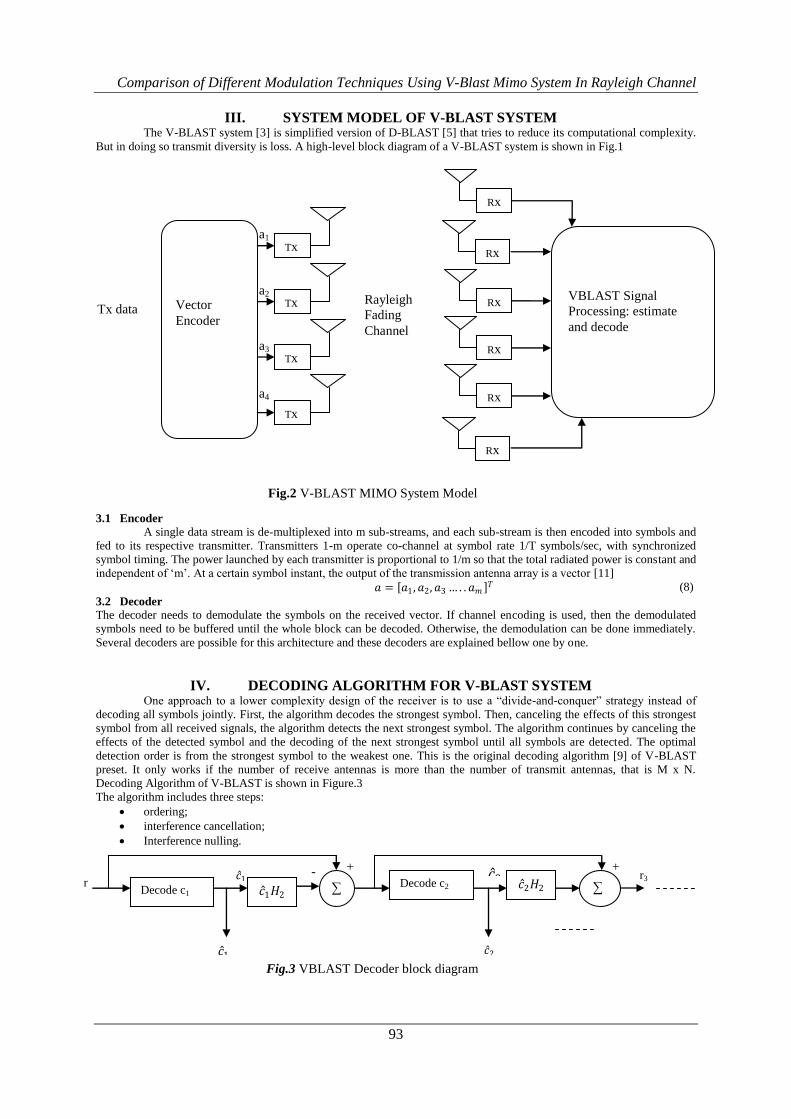
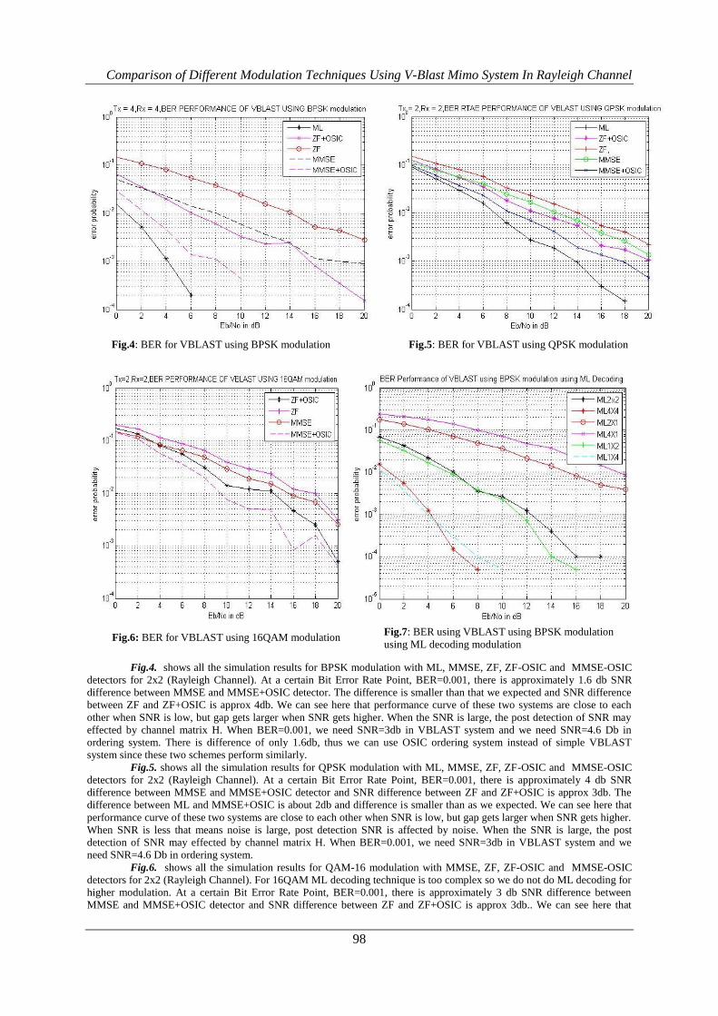
Fig.4. shows all the simulation results for BPSK modulation with ML, MMSE, ZF, ZF-OSIC and MMSE-OSIC
detectors for 2x2 (Rayleigh Channel). At a certain Bit Error Rate Point, BER=0.001, there is approximately 1.6 db SNR
difference between MMSE and MMSE+OSIC detector. The difference is smaller than that we expected and SNR difference
between ZF and ZF+OSIC is approx 4db. We can see here that performance curve of these two systems are close to each
other when SNR is low, but gap gets larger when SNR gets higher. When the SNR is large, the post detection of SNR may
effected by channel matrix H. When BER=0.001, we need SNR=3db in VBLAST system and we need SNR=4.6 Db in
ordering system. There is difference of only 1.6db, thus we can use OSIC ordering system instead of simple VBLAST
system since these two schemes perform similarly.
Fig.5. shows all the simulation results for QPSK modulation with ML, MMSE, ZF, ZF-OSIC and MMSE-OSIC
detectors for 2x2 (Rayleigh Channel). At a certain Bit Error Rate Point, BER=0.001, there is approximately 4 db SNR
difference between MMSE and MMSE+OSIC detector and SNR difference between ZF and ZF+OSIC is approx 3db. The
difference between ML and MMSE+OSIC is about 2db and difference is smaller than as we expected. We can see here that
performance curve of these two systems are close to each other when SNR is low, but gap gets larger when SNR gets higher.
When SNR is less that means noise is large, post detection SNR is affected by noise. When the SNR is large, the post
detection of SNR may effected by channel matrix H. When BER=0.001, we need SNR=3db in VBLAST system and we
need SNR=4.6 Db in ordering system.
Fig.6. shows all the simulation results for QAM-16 modulation with MMSE, ZF, ZF-OSIC and MMSE-OSIC
detectors for 2x2 (Rayleigh Channel). For 16QAM ML decoding technique is too complex so we do not do ML decoding for
higher modulation. At a certain Bit Error Rate Point, BER=0.001, there is approximately 3 db SNR difference between
MMSE and MMSE+OSIC detector and SNR difference between ZF and ZF+OSIC is approx 3db.. We can see here that
Fig.6: BER for VBLAST using 16QAM modulation Fig.7: BER using VBLAST using BPSK modulation
using ML decoding modulation
Fig.4: BER for VBLAST using BPSK modulation Fig.5: BER for VBLAST using QPSK modulation

Comparison of Different Modulation Techniques Using V-Blast Mimo System In Rayleigh Channel
99
performance curve of these two systems are close to each other when SNR is low, but gap does not gets larger when SNR
gets higher as we expected.
IX. CONCLUSION In this paper, we studied MIMO V-BLAST system performance under i.i.d Rayleigh channel. Further this system is
compared with different modulation technique and system gets better result in BPSK modulation .Fig.7 shows the
simulation results for BPSK modulation with only ML decoding technique using various antennas at input and output. In this
we will more optimal result for 4 x 4 antennas for V-BLAST system.
REFERENCES [1]. R. U. Nabar A. J. Paulraj, D. A. Gore and H. Bolcskei, ―An overview of MIMO communications—a key to gigabit
wireless,‖ Proceedings of the IEEE, vol. 92, no. 2, pp. 198–218, Feb. 2004.
[2]. G.D.Golden, G.J.Foschini, R.A. Valenzuela, and P.W.Wolniasky, ―Detection algorithm and initial laboratory
results using the V-BLAST space-time communication architecture,” Electron Lett., vol.35, no.1, pp.1415, 1999.
[3]. P.Wolniosky, G.J.Foschini, G.D.Golden and R.A. Valenzuela,‖ V-BLAST: An Architecture for realizing very high
data rates over rich scattering wireless channel‖ URSI International Symposium on Signals, Systems and
Electronics, 1998. ISSSE 98, 1998.
[4]. A.Paulraj and R.J.Heath, ―Characterization of MIMO Channels for Spatial Multiplexing Systems ―IEEE
International Conference on Communications, vol.2, no.11-14,pp-591-595,June 2001.
[5]. R.U. Nabar, H.Boleskei and A.J. Paulraj,‖ Diversity and outage performance in Space Time Block Coded Rician
MIMO Channels‖ IEEE Trans. Wireless Commun. Vol.4, pp.1102-1111, May 2005.
[6]. G. J. Foschini, ―Layered space–time architecture for wireless communication in a fading environment using multi–
element antennas,‖ Bell-Labs Techn. J., pp. 41–59, 1996.
[7]. C.Windpassinger and RF.H Fischer, ―Low-complexity need-Maximum Likelihood detection and precoding for
MIMO systems‖ in ITW 2003, Paris, France, March 31-April-4, 2003.
[8]. M.Varanasi and T.Guess, ―Optimum decision feedback multiuser equalization with successive decoding achieves
the total capacity of the Gaussian multiple-access channel,‖ Conference Record of the Thirty-First Asilomar
Conference on signals, Systems and computers, vol. 2, pp. 1405-1409, Nov-2-5 1997.
[9]. G.Ginis and J.M.Cioffi, ―On the relationship between V-BLAST and GDFE,‖ IEEE Communications letters, vol.
5, pp. 364-366, September 2001.
[10]. A.M.Tulino and S.Verdu, Random Matrix Theory and Wireless Communications. Hanover, MA 02339, USA: now
publishers Inc., 2004.
[11]. H. El Gamal and A.R. Hammons, ―The layered space-time architecture: a new perspective‖, IEEE Trans. Inform.
Theory, vol. 47, pp. 2321–2334, Sept. 2001.
[12]. I.E. Telatar, ―Capacity of multi-antenna Gaussian channels, ―European Transactions on Telecommunications, vol.
10, no.6, pp.585-595, November/December 1999.
[13]. A. Paulraj, R.Nabar and D.Gore, ―Introduction to Space Time Wireless Communications‖, Cambridge University
Press, May 2003.
[14]. X.Li, H.Huang, G.J.Foschini, and R.A.Valenzu, ―Effects of Iterative Detection and Decoding on the Performance
of BLAST", IEEE Global Telecommunications Conference, vol.2, pp.1061-10066, Nov 2000.
[15]. Choi, J,, Yu,H., and Lee, Y.H.(2005) ―Adaptive MIMO decision Feedback Equalization for Receivers with time
varying channels‖, IEEE transaction on signal processing, vol.55, No. 7, pp.3405-3416
BIOGRAPHY
Mr.Gurpreet Singh received M.Tech degree in Electronics and Communication Engineering degree
from Jaypee University of Information and Technology, Solan in 2012 and received B.Tech degree from Lovely Institutes of
Technology in Electronics and Communication Engineering from Lovely Institutes of Technology, Phagwara in 2010 with
distinction. Currently, he is working as a Assistant Professor in Shaheed Bhagat Singh State Technical Campus, Ferozpur,
Punjab. His area of interest is signal processing, MIMO, Wireless Mobile Communication Engineering, high speed digital
communications, Digital Signal processing, VHDL, Digital Design and Analysis and 4G Wireless Communications
Pardeep Sharma received a M.Tech degree in Electronics and Communication Engineering from Sant
Longowal Institute of Engineering & Technology in 2012 and received B.Tech degree in Electronics and Communication
Engineering form Swami Vivekanand Institutes of Engineering & Technology, Banur in 2010. Currently, he is working as a

Comparison of Different Modulation Techniques Using V-Blast Mimo System In Rayleigh Channel
100
Assistant Professor in Shaheed Bhagat Singh State Technical Campus, Ferozepur, Punjab. His area of interest is Digital
Signal processing, VHDL, Wireless Mobile Communication Engineering, Digital Design and Analysis
Mr. Aman Goyal received his B.Tech degree from Lovely Institutes of Technology, Phagwara, PTU,
Jalandhar in May, 2010 and pursuing M.Tech degree from Baba Banda Singh Bahadur Engineering College, Fatehgarh
Sahib. He is working as Asst. Professor in ECE department in Desh Bhagat University,Mandi Gobindgarh. His area of
interest in MIMO Technologies, Digital electronics, Analog electronics, semiconductor devices and Wireless
Communications