COMPACTEST: a method to generate compact test sets for combinational circuits
10
1040 IEEE TRANSACTIONS ON COMPUTER-AIDED DESIGN OF INTEGRATED CIRCUITS AND SYSTEMS, VOL. 12, NO. 7, JULY 1993 COMPACTEST: A Method to Generate Compact Test Sets for Combinational Circuits Irith Pomeranz, Member, IEEE, Lakshmi N. Reddy, Student Member, IEEE, and Sudhakar M. Reddy, Fellow, IEEE Abstract-Heuristics to aid the derivation of small test sets that detect single stuck-at faults in combinational logic circuits are proposed. The heuristics can be added to existing test pat- tern generators without compromising fault coverage. Experi- mental results obtained by adding the proposed heuristics to a simple PODEM procedure and applying it to the ISCAS-85 and fully-scanned ISCAS-89 benchmark circuits are presented to substantiate the effectiveness of the proposed heuristics. I. INTRODUCTION S test generation procedures for combinational cir- A cuits [ 11-[ 101 are practically capable of achieving complete coverage of single stuck-at faults in a cost-ef- fective manner, the problem of deriving small (compact) test sets gains importance. The advantages of a small test set, justifying the extra effort required for its derivation, are the following. (1) Test application time is shorter. This is especially significant for scan designs [ 1 11, where the application of each test requires a number of time units which may equal the number of memory elements in the scan register. (2) Storage requirements of tests in the test- ing hardware are reduced. In this paper, we present an automatic test pattern generation procedure called COM- PACTEST, which is aimed at producing small test sets in a cost-effective way. The procedures described in [1]-[lo] are aimed at re- ducing test generation time, and little or no attention is paid to obtaining small test sets. In DALG [l], PODEM [23, FAN [3], TOPS [4], [8], and [9], no attempts are made to reduce the test size. In SOCRATES [5], [6], and in [7], reverse order fault simulation is performed to re- duce the test set obtained. Compaction of test vectors is performed in [ 121, with the aim of generating test sets in which a test covers as many faults as possible. Both static compaction [ 131, performed after the generation of all test vectors is complete, and dynamic compaction [14], per- formed for every test vector separately, have been sug- Manuscript received August 21, 1991; revised October 8, 1992. This paper was supported in part by the SDIOIIST under Contract N00014-90- J-1793, managed by the U.S. Office of Naval Research. This paper was recommended by Associate Editor B. Krishnamurthy. I. Pomeranz and S. M. Reddy are with the Department of Electrical and Computer Engineering, University of Iowa, Iowa City, IA 52242. L. N. Reddy was with the Department of Electrical and Computer En- gineering, University of Iowa, Iowa City, IA. He is currently with IBM Corporation, Poughkeepsie, NY. IEEE Log Number 9206839. gested. A procedure specifically aimed at generating tests where each test detects a subset of faults, thus potentially reducing test generation time and test set size, is pre- sented in [15], [16]. Another method directly aimed at obtaining small test sets was presented in [17], and is based on the notion of independent faults. A set of faults is said to be independent if no test exists that detects two different faults in the set. Independent faults are good tar- get faults for test generation, as the minimum test set size cannot be smaller than the size of a largest set of inde- pendent faults. However, all direct attempts at test set re- duction produce test set sizes which are in most cases larger than the sizes in [5]-[7]. In this paper, we present a test generation procedure for single stuck-at faults which combines the high fault coverage achievable by existing test generation procedures with heuristics which are di- rectly aimed at obtaining small test sets. These heuristics include the use of independent faults for fault ordering, a test compaction method that leads to tests that detect large numbers of faults, and a dynamic line justification method, again aimed at the detection of as many faults as possible by a single test vector. The heuristics employed can be added to any existing test generation procedure (a simple version of PODEM was used for our experiments). The extended test generation procedure, which includes the proposed heuristics, is comparable in run time and fault coverage to the original test generation procedure. The paper is organized as follows. Section I1 gives a brief overview of previous works on test set reduction, and introduces COMPACTEST. Section I11 describes the preprocessing stage done in COMPACTEST. The main test generation procedure is presented in Section IV. Sec- tion V contains experimental results. Conclusions are given in Section VI. 11. PREVIOUS WORK In the following, an overview of the work done previ- ously towards reducing the test set size is presented, and the new procedures, described later in detail, are intro- duced. The problem of generating a minimum size test set for general combinational circuits is NP-Hard [ 181. How- ever, minimum size test sets can be computed in time polynomial in the size of the circuit for certain classes of combinational circuits [ 191-[21]. The labeling algorithm 0278-0070/93$03.00 0 1993 IEEE
-
Upload
independent -
Category
Documents
-
view
0 -
download
0
Transcript of COMPACTEST: a method to generate compact test sets for combinational circuits
1040 IEEE TRANSACTIONS ON COMPUTER-AIDED DESIGN OF INTEGRATED CIRCUITS AND SYSTEMS, VOL. 12, NO. 7 , JULY 1993
COMPACTEST: A Method to Generate Compact Test Sets for Combinational Circuits Irith Pomeranz, Member, IEEE, Lakshmi N. Reddy, Student Member, IEEE,
and Sudhakar M . Reddy, Fellow, IEEE
Abstract-Heuristics to aid the derivation of small test sets that detect single stuck-at faults in combinational logic circuits are proposed. The heuristics can be added to existing test pat- tern generators without compromising fault coverage. Experi- mental results obtained by adding the proposed heuristics to a simple PODEM procedure and applying it to the ISCAS-85 and fully-scanned ISCAS-89 benchmark circuits are presented to substantiate the effectiveness of the proposed heuristics.
I. INTRODUCTION S test generation procedures for combinational cir- A cuits [ 11-[ 101 are practically capable of achieving
complete coverage of single stuck-at faults in a cost-ef- fective manner, the problem of deriving small (compact) test sets gains importance. The advantages of a small test set, justifying the extra effort required for its derivation, are the following. (1) Test application time is shorter. This is especially significant for scan designs [ 1 11, where the application of each test requires a number of time units which may equal the number of memory elements in the scan register. (2) Storage requirements of tests in the test- ing hardware are reduced. In this paper, we present an automatic test pattern generation procedure called COM- PACTEST, which is aimed at producing small test sets in a cost-effective way.
The procedures described in [1]-[lo] are aimed at re- ducing test generation time, and little or no attention is paid to obtaining small test sets. In DALG [ l ] , PODEM [23, FAN [3], TOPS [4], [8], and [9], no attempts are made to reduce the test size. In SOCRATES [5], [6], and in [7], reverse order fault simulation is performed to re- duce the test set obtained. Compaction of test vectors is performed in [ 121, with the aim of generating test sets in which a test covers as many faults as possible. Both static compaction [ 131, performed after the generation of all test vectors is complete, and dynamic compaction [14], per- formed for every test vector separately, have been sug-
Manuscript received August 21, 1991; revised October 8, 1992. This paper was supported in part by the SDIOIIST under Contract N00014-90- J-1793, managed by the U.S. Office of Naval Research. This paper was recommended by Associate Editor B. Krishnamurthy.
I . Pomeranz and S . M. Reddy are with the Department of Electrical and Computer Engineering, University of Iowa, Iowa City, IA 52242.
L. N. Reddy was with the Department of Electrical and Computer En- gineering, University of Iowa, Iowa City, IA. He is currently with IBM Corporation, Poughkeepsie, NY.
IEEE Log Number 9206839.
gested. A procedure specifically aimed at generating tests where each test detects a subset of faults, thus potentially reducing test generation time and test set size, is pre- sented in [15], [16]. Another method directly aimed at obtaining small test sets was presented in [17], and is based on the notion of independent faults. A set of faults is said to be independent if no test exists that detects two different faults in the set. Independent faults are good tar- get faults for test generation, as the minimum test set size cannot be smaller than the size of a largest set of inde- pendent faults. However, all direct attempts at test set re- duction produce test set sizes which are in most cases larger than the sizes in [5]-[7]. In this paper, we present a test generation procedure for single stuck-at faults which combines the high fault coverage achievable by existing test generation procedures with heuristics which are di- rectly aimed at obtaining small test sets. These heuristics include the use of independent faults for fault ordering, a test compaction method that leads to tests that detect large numbers of faults, and a dynamic line justification method, again aimed at the detection of as many faults as possible by a single test vector. The heuristics employed can be added to any existing test generation procedure (a simple version of PODEM was used for our experiments). The extended test generation procedure, which includes the proposed heuristics, is comparable in run time and fault coverage to the original test generation procedure.
The paper is organized as follows. Section I1 gives a brief overview of previous works on test set reduction, and introduces COMPACTEST. Section I11 describes the preprocessing stage done in COMPACTEST. The main test generation procedure is presented in Section IV. Sec- tion V contains experimental results. Conclusions are given in Section VI.
11. PREVIOUS WORK In the following, an overview of the work done previ-
ously towards reducing the test set size is presented, and the new procedures, described later in detail, are intro- duced.
The problem of generating a minimum size test set for general combinational circuits is NP-Hard [ 181. How- ever, minimum size test sets can be computed in time polynomial in the size of the circuit for certain classes of combinational circuits [ 191-[21]. The labeling algorithm
0278-0070/93$03.00 0 1993 IEEE
I
POMERANZ et a / . : COMPACTEST: METHOD FOR COMBINATIONAL CIRCUITS 1041
presented in [20] for computing the minimum test set size in fanout free circuits is extended in [22] to the compu- tation of a set independent faults. A test generation pro- cedure which is based on independent faults is presented in [17]. In [17], a maximal set of independent faults is computed, and tests are generated for this set using a spe- cially developed value system. The same process is then repeated for a different maximal set of independent faults. An attempt is then made to merge the two test sets into a single set, smaller than the union of the two sets. Un- specified values are used for this purpose. This procedure is then repeated for other maximal sets of independent faults, until all faults are treated. No results (test set sizes) for benchmark circuits (e.g. ISCAS-85 circuits [23] or IS- CAS-89 circuits [24]) are given in [ 171. However, the re- sults for a test generation procedure based on [ 171, called MULTI-TEST, were given in [25]. Good results were achieved only for the smaller ISCAS-85 benchmark cir- cuits, while for the larger ones, the test set sizes of [5]- [7] are smaller. Independent faults are used in the work presented here for determining the order by which the dif- ferent faults are considered. The conventional set of col- lapsed faults constitutes the set of target faults. Fault col- lapsing [13] is performed to reduce the size of the target fault list. Instead of using all stuck-at faults as target faults, equivalent faults are found, and only one repre- sentative of every equivalence class is selected. To sim- plify the computation, only equivalent faults on the inputs and output of the same gate are used. The target faults are ordered such that the largest sets of independent faults appear first. Due to the complexity of computing sets of independent faults, independent faults are computed only within maximal fanout free regions, defined as follows. A subcircuit C’ is a maximal fanout free region if the in- puts of C’ are primary inputs or fanout branches, the (sin- gle) output of C‘ is either a primary output or a fanout stem, and C’ does not contain fanout points. For maximal fanout free regions, an efficient method for computing maximal sets of independent faults is given. Computation of independent faults and fault ordering is done in a pre- processing stage of COMPACTEST. (Alternatively, in- dependent fault sets can be computed in restricted fanout regions, defined in [21].)
In an attempt to generate tests for subsets of faults, an extension to the D-algorithm, called “Subscripted D-al- gorithm,” is proposed in [15], [16], [26]. The concept of “gang testing” is used to speed up the test generation process and to reduce the test set size. After a certain fault coverage is achieved, tests are generated for subsets of faults by constructing multiple simultaneous observation paths. Conflicts between the separate observation paths constructed for several faults are resolved (if possible) us- ing the unspecified inputs, thereby reducing the test set size. However, the test set sizes for all ISCAS-85 com- binational benchmark circuits are much larger than the test sets obtained in [ 5 ] , where the only procedure aimed at test set reduction is reverse order fault simulation. In COMPACTEST, subsets of faults are considered in all
stages of the test generation process, and heuristics are used for generating small numbers tests, each detecting as many faults as possible.
Typically, the tests generated by a fault-oriented test generation procedure (i.e., a test generation procedure which generates tests for a given set of target faults), are only partially specified, leaving some inputs unspecified. If two such test vectors do not conjict in any bit position (a conjict occurs if one of the vectors has the value 1 on some input while the other vector has the value 0 on the same input), both vectors can be combined into a single vector, thereby reducing the test set size. This technique is called static compaction [ 131. Optimal static compac- tion, that yields a minimum result, is very expensive; therefore, heuristics are used to reduce the test set size as much as possible. Unlike static compaction, in dynamic compaction [14], every partially specified test vector is processed immediately after its generation by trying to use only the unspecified inputs in the test vector to derive a test to detect additional fault(s) by the same vector. A different dynamic compaction approach, presented in [lo], relies on a close interaction with fault simulation by crit- ical path tracing. The results of critical path tracing are used to select other faults which are activated by a par- tially generated vector and/or whose effects can be easily propagated to a primary output. A modified version of dynamic compaction, called maximal test compaction, is used in COMPACTEST. The procedure consists of un- specifying some of the primary input values specified as 1 or 0 in a test vector for a fault, sayf, even if the result- ing vector may not remain a test forf. Unspecifying of values is done such that inputs which are signiJicant in ensuring a test for the original fault f a r e kept, while oth- ers are unspecified to allow other faults to be detected by the same vector.
In addition to fault ordering and test compaction, the third component of COMPACTEST is related to the line justification process. Instead of using testability measures (e.g. [27]) for determining the objectives of line justifi- cation, the objectives are dynamically changed to allow different faults to be potentially detected.
Each step of COMPACTEST is described in detail in the succeeding sections.
111. PREPROCESSING In this section, the preprocessing stage of the proposed
test generation procedure is described. In all fault-ori- ented test generation procedures [ 11-[ lo], the test gener- ator is given an ordered list of all collapsed faults, ordered according to some criteria. Whenever a test is found for the fault at the top of the fault list, the test is fault-simu- lated, and all the faults detected by the test are dropped from the fault list. This process continues until either the fault list is empty or all the faults in the fault list are se- lected once. The order of the faults in the fault list has a significant effect on test generation time and on test set size. The following preprocessing steps are aimed at or-
- -
1042 IEEE TRANSACTIONS ON COMPUTER-AIDED DESIGN OF INTEGRATED CIRCUITS AND SYSTEMS, VOL. 12, NO. 7 . JULY 1993
dering the fault list such that tests for faults appearing at the top of the list would potentially detect faults appearing later in the fault list, thus reducing the total number of tests required.
The importance of independent fault sets (IFS’S) in the reduction of test set size has been established in [ 171, [22]. A set of independent faults of maximum cardinality in a circuit is called a maximum independently fault set (MIFS). The problem of computing an MIFS in a general circuit is NP-HARD [18]. A polynomial time algorithm to compute an MIFS in a fanout free circuit, or in a fanout free region (FFR) of a general circuit, has been presented in [22]. A different, more efficient, procedure is used in COMPACTEST, that computes an MIFS which is con- tained in the set of collapsed faults. We show later that an MIFS of an FFR of a circuit is also an IFS for the complete circuit. The MIFS’s obtained for the maximal FFR’s of the circuit under test (CUT) are used to order the fault list as follows. The fault list is constructed by placing the largest MIFS at the top, followed by the next largest MIFS, and so on. All the remaining collapsed faults not included in any MIFS are added at the end of the fault list. As MIFS’s are computed, information which helps in reducing the number of test vectors needed to detect all the faults in the maximal FFR’s of the CUT is gathered. The basic idea is to associate with every fault in the MIFS other faults which can potentially be tested by the same test vector. Such information is readily avail- able from the computation of the MIFS, as subsequently explained. The information gathered is used during the test generation phase of COMPACTEST.
We proceed to describe a procedure to identify the maximal FFR’s of the CUT. The labeling algorithm given in [20] for computing the minimum test set size for fanout free circuits is then briefly reviewed with the help of an example. Next, the labeling algorithm is extended to compute an MIFS. Finally, the information gathering process is described.
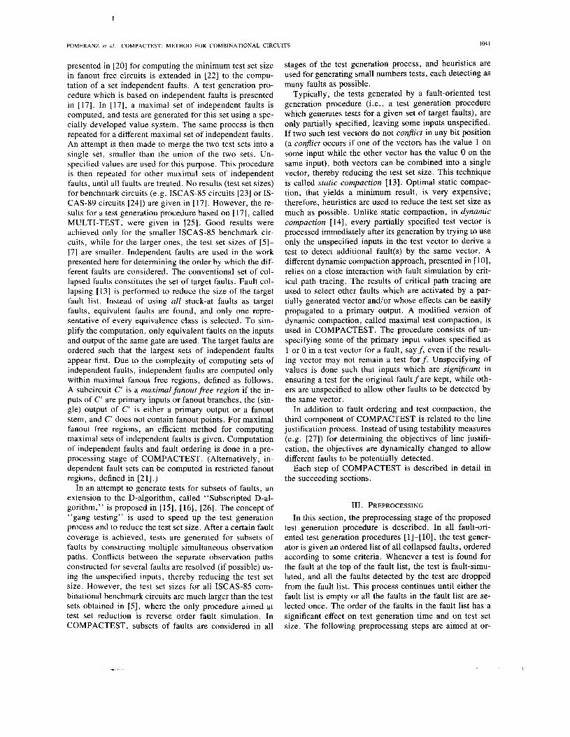
A CUT can be partitioned into FFR’s in one backward pass over the circuit. This is done by tracing the circuit backwards from every primary output and fanout stem, and stopping whenever a primary input or a fanout branch is reached. The maximal FFR’s of the circuit in Fig. l(a) are circled in the figure.
As in [20], let 1 (essential 1) denote the value of a line in a test that detects the stuck-at 0 fault on that line. Let 0 (essential 0) denote the value of a line in a test that detects the stuck-at 1 fault on that line. Let ui (zi) denote the number of tests in which line i assumes the value 1 (0) in a minimum test set. The computation of U and z throughout the circuit is based on the observation that every test set that detects all the faults on the inputs of a fanout free circuit (or FFR) detects all faults in the circuit (or FFR) (e.g., [19]). It is, therefore, sufficient to prop- agate one essential 1 and one essential 0 from every pri- mary input to the output in order to test a fanout free cir- cuit (or FFR) completely. The minimum number of tests for the circuit is the value of U + z on the output. The
(a)
6 (1.3) I ( 1 . 1 )
3 (1.1) r* 4 (1.1) 8(2.3)
7 (1.2)
(b) Fig, 1 , An example of fanout free regions.
TABLE 1 RULES FOR LABELING BY ( U , Z )
GATE U Z
rules for computing the label (U, z ) on the output of a gate, when the labels (ui, zi) on its inputs are known, are illus- trated by the following example and summarized in Table I.
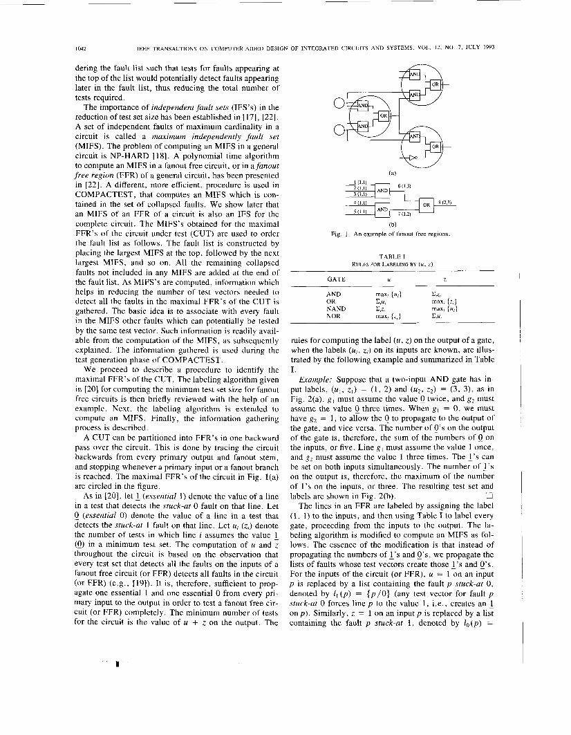
Example: Suppose that a two-input AND gate has in- put labels, ( U , , z,) = (1, 2) and (u2, z2) = (3, 3), as in Fig. 2(a). gl must assume the value 0 twice, and g2 must assume the value 0 three times. When g l = 0, we must have g2 = 1 , to allow the 0 to propagate to the output of the gate, and vice versa. The number of 0’s on the output of the gate is, therefore, the sum of the numbers of 0 on the inputs, or five. Line g l must assume the value 1 once, and g, must assume the value 1 three times. The 1’s can be set on both inputs simultaneously. The number of 1’s on the output is, therefore, the maximum of the number of i ’ s on the inputs, or three. The resulting test set and
U The lines in an FFR are labeled by assigning the label
(1, 1) to the inputs, and then using Table I to label every gate, proceeding from the inputs to the output. The la- beling algorithm is modified to compute an MIFS as fol- lows. The essence of the modification is that instead of propagating the numbers of 1’s and e’s, we propagate the lists of faults whose test vectors create those 1’s and 0’s. For the inputs of the circuit (or FFR), U = 1 on an input p is replaced by a list containing the fault p stuck-at 0, denoted by I , ( p ) = { p / O } (any test vector for fault p stuck-at 0 forces line p to the value 1, i .e., creates an 1 on p ) . Similarly, z = 1 on an input p is replaced by a list containing the fault p stuck-at 1, denoted by Zo(p) =
labels are shown in Fig. 2(b).
I
POMERANZ er a / . : COMPACTEST: METHOD FOR COMBINATIONAL CIRCUITS 1043
11100000 g,(3,5)
(b) Fig. 2. An example of labeling by (U, z ) .
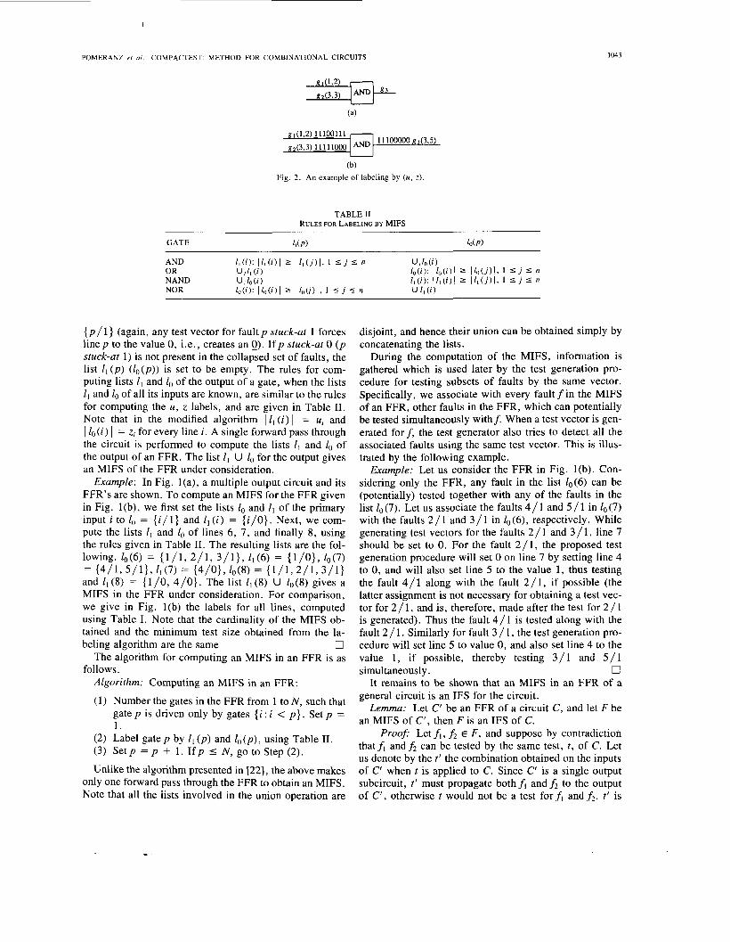
TABLE I1 RULES FOR LABELING BY MIFS
{ p / l } (again, any test vector for fault p stuck-at 1 forces line p to the value 0, i.e., creates an Q). If p stuck-at 0 ( p stuck-at 1) is not present in the collapsed set of faults, the list lI ( p ) ( l o ( p ) ) is set to be empty. The rules for com- puting lists l1 and lo of the output of a gate, when the lists I , and lo of all its inputs are known, are similar to the rules for computing the U , z labels, and are given in Table 11. Note that in the modified algorithm I lI ( i ) I = ui and 1 l o ( i ) 1 = zi for every line i. A single forward pass through the circuit is performed to compute the lists lI and lo of the output of an FFR. The list Z l U lo for the output gives an MIFS of the FFR under consideration.
Example: In Fig. l(a), a multiple output circuit and its FFR’s are shown. To compute an MIFS for the FFR given in Fig. l(b), we first set the lists lo and ll of the primary input i to lo = {i / l} and Z l ( i ) = { i / O } . Next, we com- pute the lists Z l and lo of lines 6 , 7, and finally 8, using the rules given in Table 11. The resulting lists are the fol- lowing. Zo(6) = { l / l , 2 /1 , 3/1}, ll(6) = {l/O}, 10(7) = {4/1,5/1}, l1(7) = {4/0}, lo (8) = { 1 / 1 , 2 / 1 , 3 / 1 } and l1 (8) = {l /O, 4/0}. The list ZI (8) U l o ( 8 ) gives a MIFS in the FFR under consideration. For comparison, we give in Fig. l(b) the labels for all lines, computed using Table I. Note that the cardinality of the MIFS ob- tained and the minimum test size obtained from the la-
0 The algorithm for computing an MIFS in an FFR is as
Algorithm: Computing an MIFS in an FFR:
(1) Number the gates in the FFR from 1 to N , such that gate p is driven only by gates { i : i < p } . Set p = 1.
beling algorithm are the same
follows.
(2) Label gate p by Z1 ( p ) and lo ( p ) , using Table 11. (3) Set p = p + 1. I f p I N , go to Step (2).
Unlike the algorithm presented in [22], the above makes only one forward pass through the FFR to obtain an MIFS. Note that all the lists involved in the union operation are
disjoint, and hence their union can be obtained simply by concatenating the lists.
During the computation of the MIFS, information is gathered which is used later by the test generation pro- cedure for testing subsets of faults by the same vector. Specifically, we associate with every fault f in the MIFS of an FFR, other faults in the FFR, which can potentially be tested simultaneously withf. When a test vector is gen- erated forf, the test generator also tries to detect all the associated faults using the same test vector. This is illus- trated by the following example.
Example: Let us consider the FFR in Fig. l(b). Con- sidering only the FFR, any fault in the list lo(6) can be (potentially) tested together with any of the faults in the list lo (7). Let us associate the faults 4 / 1 and 5 / 1 in lo (7) with the faults 2 / 1 and 3 / 1 in Zo(6), respectively. While generating test vectors for the faults 2 / 1 and 3 / 1, line 7 should be set to 0. For the fault 2 / 1, the proposed test generation procedure will set 0 on line 7 by setting line 4 to 0, and will also set line 5 to the value 1, thus testing the fault 4 / 1 along with the fault 2 /1 , if possible (the latter assignment is not necessary for obtaining a test vec- tor for 2 / 1, and is, therefore, made after the test for 2 / 1 is generated). Thus the fault 4 / 1 is tested along with the fault 2 / 1. Similarly for fault 3 / 1, the test generation pro- cedure will set line 5 to value 0, and also set line 4 to the value 1, if possible, thereby testing 3 / 1 and 5 / 1
It remains to be shown that an MIFS in an FFR of a general circuit is an IFS for the circuit.
Lemma: Let C’ be an FFR of a circuit C , and let F be an MIFS of C‘, then F is an IFS of C.
Pi-oofi Let f i , fi E F, and suppose by contradiction thatfi andfi can be tested by the same test, t , of C. Let us denote by the t’ the combination obtained on the inputs of C‘ when t is applied to C . Since C’ is a single output subcircuit, t‘ must propagate bothf, andfi to the output of C‘ , otherwise t would not be a test forfi andfi. t’ is
simultaneously. 0
1044 IEEE TRANSACTIONS ON COMPUTER-AIDED DESIGN OF INTEGRATED CIRCUITS AND SYSTEMS, VOL. 12, NO. 7. JULY 1993
therefore a test for both f, and f2 in C ’ , in contradiction 0
To summarize, in the preprocessing stage of the pro- posed test generation procedure, an ordered fault list is derived using MIFSs for FFRs. Information that the test generator uses to reduce the number of vectors generated for FFRs is also obtained at this preprocessing stage.
to the assumption that f, , f2 E F.
IV. THE MAIN PROCEDURE OF COMPACTEST In this section, the heuristics employed in COMPAC-
TEST are described. The maximal compaction heuristic is described in Section 4.1. The rotating backtrace heu- ristic is described in Section 4.2. The proposed heuristics can be added to most conventional fault-oriented ATPG procedures, to achieve small test sets. The fault coverage achieved and the time taken for the overall test generation process depend on the underlying ATPG used. Experi- mental results show that the test reduction heuristics im- prove the fault coverage, although they are not designed for this purpose.
4.1 Maximal Compaction We start with a description of the main procedure of
COMPACTEST and proceed to describe the maximal compaction heuristic in detail.
The general description of the main procedure is as fol- lows. The fault at the top of the previously ordered fault list, called the primary target fault, is selected. A test is generated for the primary target fault, if possible. During the test generation process for the primary target fault, the test generator uses the information obtained during pre- processing to obtain a test that detects additional faults in the FFR to which the primary target fault belongs. The result is a test vector, which detects the primary target fault, and possibly other faults in the same FFR. The test vector is then maximally compacted by reducing to a min- imum the number of primary inputs which are set to either 0 or 1 (as explained in detail later). At this point, the compacted vector may not be a test for the primary fault any more. In this way, maximum flexibility in detecting additional faults by the same test vector is achieved, in most cases without compromising the detection of the pri- mary target fault. The test generation process is entered again with another target fault, called a secondary target fault. This fault is the first fault in the ordered fault list which can potentially be detected by the test vector gen- erated. The test generation process tries to detect the sec- ondary target fault starting from the maximally com- pacted vector previously obtained, and setting only the unspecified inputs in the vector. The inputs already set in the partially specified vector are not changed. The test generator again tries to detect other faults present in the FFR of the secondary target fault. Finally, the part of the vector that was specified to detect the secondary target fault is maximally compacted. If a test for the secondary target fault cannot be found, all the primary inputs set in the search for a test are unspecified. This process is re-
peated until either all the inputs are specified or all the faults in the fault list are tried as secondary target faults. At the end, if there are any unspecified inputs in the test vector, they are specified randomly. The test vector ob- tained is fault simulated, and all the faults it detects are removed from the fault list. A new primary target fault is then selected from the top of the fault list, and the above process is repeated. The entire process continues until either the fault list is empty or all the faults in the fault list have been tried once as primary target faults.
A procedure called maximal compaction is employed in COMPACTEST to maximize the number of unspecified values in a test vector, last updated for fault f, before an- other target fault is selected. Given a test vector, the com- paction procedure proceeds as follows. A primary input p whose value was specified (i.e., set to 0 or 1) for the first time by test generation for f is selected. The value as- signed to p is complemented. Implication is then per- formed for the altered vector, to check if the altered vec- tor is still a test forf. If the check is successful, i.e., if the altered vector is a test for f , p is marked; otherwise p is left unmarked. In either case, the value of p is restored to its original value (by complementing p a second time). This procedure is repeated for every primary input which was first specified during test generation forf. All the pri- mary inputs which were marked during the compaction process are then unspecified. The following example il- lustrates the maximal compaction process.
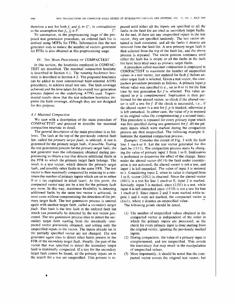
Example: Consider the circuit of Fig. 3 with the fault line 1 stuck-at 0. Let the test vector generated for this fault be (1 11 1). The compaction process starts by chang- ing the value of primary input 1 from 1 to 0. Implication is performed to determine the effect of the change. Since under the altered vector (01 11) the fault under consider- ation is not activated, the altered vector is not a test, and input 1 is left unmarked. The value of input 1 is restored to 1. Considering input 2, when its value is changed from 1 to 0, vector (101 1) is obtained. Since the altered vector (1011) is a test for line 1 stuck-at 0, input 2 is marked. Similarly, input 3 is marked, since (1 101) is a test, while input 4 is left unmarked since (1 110) is not a test for line 1 stuck-at 0. Since inputs 2 and 3 were marked while in- puts 1 and 4 were not marked, the compacted vector is
0 (lxxl), where x denotes an unspecified value. The following points should be noted.
(1) The number of unspecified values obtained in the compacted vector is independent of the order in which the primary inputs are processed, as the check for every primary input is done starting from the original vector, ignoring the previously marked inputs.
(2) During compaction, the value of a primary input is complemented, and not unspecified. This avoids the inaccuracy that may result in the manipulation of unspecified values.
( 3 ) More importantly, it should be noted that the com- pacted vector covers the original test vector, but
1
I
POMERANZ et al . : COMPACTEST: METHOD FOR COMBINATIONAL CIRCUITS 1045
II
Fig. 3 . An example of maximal compaction.
not necessarily any specification of the unspecified values in the compacted test vector would result in a test for the fault for which the original test was designed. This point is illustrated by the following example.
Example: We consider the circuit of Fig. 3 again, with the same fault, input 1 stuck-at 0. The original test, (1 1 1 l ) , was compacted into (lxxl) , which covers (1 1 1 1 ) . Suppose that during second- ary test generation, both unspecified values are set to zero. The vector (1001) is not a test for the fault input 1 stuck-at 0, for which it was designed. How- ever, if either input 2 or input 3 is specified to l , the resulting vector detects input 1 stuck-at 0. U
In practice, we found that it is very rare that, when all primary inputs of a compacted vector are specified by subsequent applications of the second- ary test generation procedure, the test vector does not detect the original target fault for which it was designed. This can be explained by the selection of the values to be unspecified. The compaction pro- cedure differentiates between values on inputs which are necessary for the test (when comple- mented, such inputs render the test invalid), and values on inputs which are not necessary for the test (inputs that can be complemented without in- validating the test). The former values contain in- formation which is essential for the test. The latter values are not essential, and are, therefore, un- specified. In most cases, many specifications of the unspecified values result in a test (in the previous example, three out of four possible specifications would yield a test). For the rare cases where the original target fault is not detected by the final vec- tor obtained, we record all the faults for which a test has been found at some point. At the end of the test generation process, if any of these faults remains undetected, a test for this fault is re- couped. However, this process was required in very few cases in our experiments.
The maximal compaction procedure can be entered after any basic test generation procedure. The secondary test generation procedure is similar to the primary test gen- eration procedure, and the same procedure, with minor changes, can be used for both.
4.2. Rotating Backtrace In addition to fault selection and test compaction as de-
scribed above, the backtrace procedure in COMPAC-
TEST is modified, with the aim of sensitizing different paths every time a value on a line is to be justified. As a consequence, different faults, which propagate along dif- ferent paths, are potentially detected by the test vectors generated. The following example illustrates the impor- tance of the rotating backtrace idea.
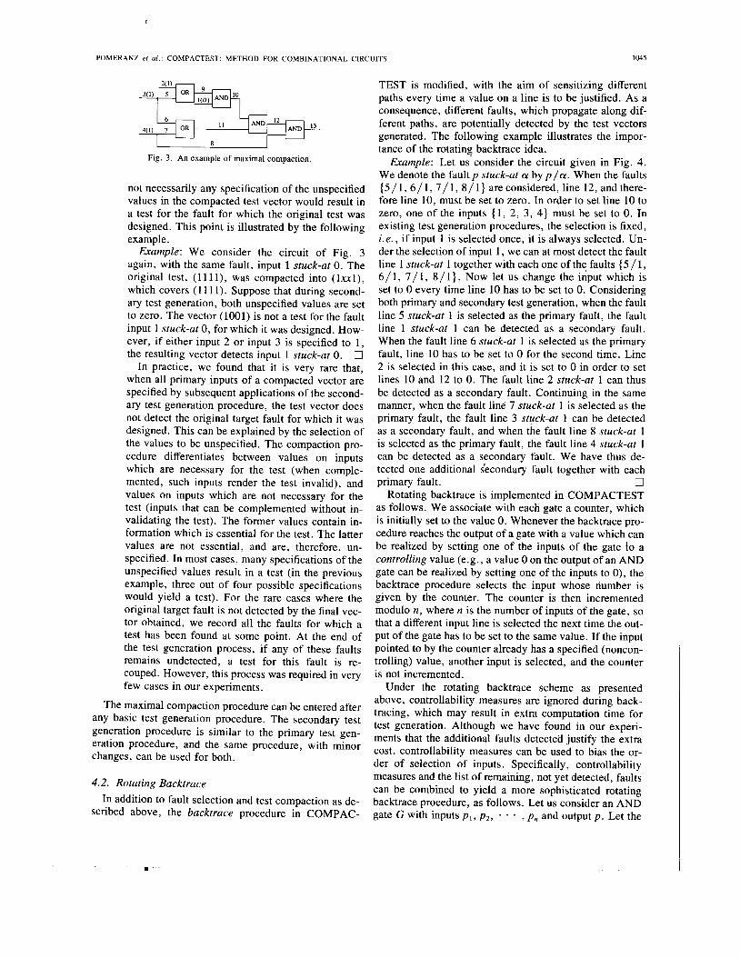
Example: Let us consider the circuit given in Fig. 4. We denote the fault p stuck-at a by p / a . When the faults { 5 / 1 , 6 / 1 , 7/1, 8/1} areconsidered, line 12, andthere- fore line 10, must be set to zero. In order to set line 10 to zero, one of the inputs { 1 , 2, 3 , 4) must be set to 0. In existing test generation procedures, the selection is fixed, i . e . , if input 1 is selected once, it is always selected. Un- der the selection of input 1 , we can at most detect the fault line 1 stuck-at 1 together with each one of the faults { 5 / 1 , 6 /1 , 7/1, 8/1}. Now let us change the input which is set to 0 every time line 10 has to be set to 0. Considering both primary and secondary test generation, when the fault line 5 stuck-at 1 is selected as the primary fault, the fault line 1 stuck-at 1 can be detected as a secondary fault. When the fault line 6 stuck-at 1 is selected as the primary fault, line 10 has to be set to 0 for the second time. Line 2 is selected in this case, and it is set to 0 in order to set lines 10 and 12 to 0. The fault line 2 stuck-at 1 can thus be detected as a secondary fault. Continuing in the same manner, when the fault line 7 stuck-at 1 is selected as the primary fault, the fault line 3 stuck-at 1 can be detected as a secondary fault, and when the fault line 8 stuck-at 1 is selected as the primary fault, the fault line 4 stuck-at 1 can be detected as a secondary fault. We have thus de- tected one additional secondary fault together with each
Rotating backtrace is implemented in COMPACTEST as follows. We associate with each gate a counter, which is initially set to the value 0. Whenever the backtrace pro- cedure reaches the output of a gate with a value which can be realized by setting one of the inputs of the gate lo a controlling value (e.g., a value 0 on the output of an AND gate can be realized by setting one of the inputs to 0), the backtrace procedure selects the input whose number is given by the counter. The counter is then incremented modulo n, where n is the number of inputs of the gate, so that a different input line is selected the next time the out- put of the gate has to be set to the same value. If the input pointed to by the counter already has a specified (noncon- trolling) value, another input is selected, and the counter is not incremented.
Under the rotating backtrace scheme as presented above, controllability measures are ignored during back- tracing, which may result in extra computation time for test generation. Although we have found in our experi- ments that the additional faults detected justify the extra cost, controllability measures can be used to bias the or- der of selection of inputs. Specifically, controllability measures and the list of remaining, not yet detected, faults can be combined to yield a more sophisticated rotating backtrace procedure, as follows. Let us consider an AND gate G with inputs pl , p 2 , - - , p n and output p . Let the
l
primary fault. U
I
1046 IEEE TRANSACTIONS ON COMPUTER-AIDED DESIGN OF INTEGRATED CIRCUITS AND SYSTEMS, VOL. 12, NO. 7 , JULY 1993
:w AND l4
Fig. 4. An example of rotating backtrace.
0-controllability measure associated with input pi be ci, and let ni = 1 denote the existence of faults which are yet undetected, and can potentially be propagated to pi with a fault free value of 0 (ni can reduce to 0 as more faults are detected). The inputs can then be ordered by decreas- ing value of ci * ni. During test generation, whenever p is to be set to 0, the rotating backtrace counter is initialized to point to the input for which ni ci is maximum (ni = 1 and ci is maximum). If backtracing is required, the counter is advanced to point to the input for which ni ci is the second largest, and so on. The inputs for which ni = 0 can also be ordered by decreasing value of ci, to give precedence to the selection of inputs with high control- labilities. The effect of controllability measures can thus be retained, while incorporating rotating backtrace to re- duce test set size. In our experiments, however, no con- trollability measures were used.
Finally, rotating backtrace as well as preprocessing can easily be added to any existing test generation procedure.
V. EXPERIMENTAL RESULTS The proposed test generation procedure was imple-
mented in the C programming language. The underlying test generator system is a simple implementation of PO- DEM with a deductive fault simulator written by S. Patil when he was at the University of Illinois. The underlying test generator is augmented as follows. (1) Preprocessing, described in Section 3 , is performed before the test gen- eration procedure is entered. (2) Maximal compaction and rotating backtrace, presented in Section IV, are added to the main test generation procedure. To ascertain that the proposed heuristics help achieve compact test sets, we also added the heuristics to the underlying test generator, each by itself. An independent fault simulator was also imple- mented to study the effect of reverse order fault simulation on test set size. Assuming the test sets obtained are com- pact, reverse order fault simulation should have little or no effect on test set size. The independent fault simulator used for reverse order fault simulation also provides a way of ensuring that all the faults declared tested by COM- PACTEST are actually detected.
The simple PODEM used as the underlying test gen- erator typically does not achieve 100 % fault efficiency for the benchmark circuits. (100% fault efficiency implies that for every fault, either a test is found or the fault is iden- tified as undetectable. Fault efficiency is computed as the
number of faults detected divided by the number of de- tectable faults.) While the fault efficiency achieved by the proposed test generator is at least as good as that of the underlying test generator, it is not guaranteed to be higher. In order to improve the fault coverage, the proposed test generation procedure processes all the aborted faults again. In this case, rotating backtrace is removed, and backtracing decisions are based on testability measures. Typically, very few faults in only a few circuits benefit from this phase. Aborted faults can be avoided altogether if the underlying test generator uses any of the redun- dancy identification techniques [6] and techniques to de- rive tests with small numbers of backtracks. In addition, the extra computation due to the processing of redundant faults as secondary target faults can also be avoided if redundancy identification techniques are used.
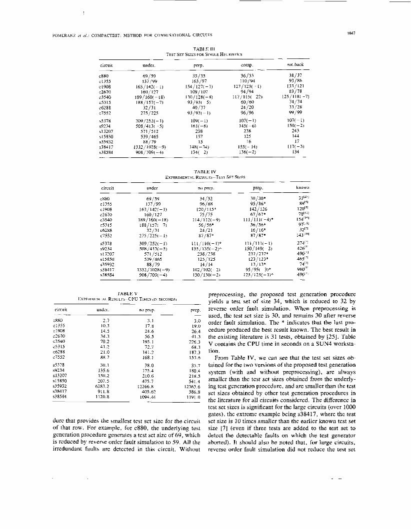
The program was run on the ISCA-85 combinational benchmark circuits and on fully scanned versions of the ISCAS-89 sequential benchmark circuits. The test set sizes achieved by the underlying ATPG by itself, and with the heuristics added on one at a time, are reported in Ta- ble 111. In Table 111, after circuit name, the number of tests generated by the underlying test pattern generator is given, followed by the test set size achieved by adding preprocessing, by adding maximal compaction and by adding rotating backtrace, each one separately. The two numbers under the test set size columns, separated by ‘ ‘ 1 ”, are the test set sizes before and after reverse order fault simulation. The negative numbers given in parentheses for some of the entries are the number of irredundant faults on which the test generator aborted. The number of re- dundant faults in all the circuits are taken from [7]. As can be seen from Table 111, each heuristic in general de- creases the test set sizes obtained by the underlying ATPG. In this part of the experiment, the backtrack limit was set to 25. The test set sizes obtained when more than one heuristic was used and the CPU time are given in Tables IV and V, respectively. A backtrack limit of 25 was used for primary and secondary test generation for the ISCAS-85 combinational benchmark circuits. For the ISCAS-89 sequential benchmark circuits, a backtrack limit of 25 is used for the primary test generation proce- dure. For secondary test generation, a backtrack limit of 1 was initially set, which was increased to 3 once the fault coverage reached 90%. In Tables IV and V, the column header “under.” refers to the underlying test pattern gen- erator without any of the test set reduction techniques. The column header “no prep.” indicates that maximal compaction and rotating backtrace were added to the un- derlying test generator, while preprocessing was omitted. The column header “prep.” indicates that all three tech- niques, i .e . preprocessing, maximal compaction, and ro- tating backtrace are used. In Table IV, the header “known” stands for the smallest test set size found in the literature. The superscripts in the last column of Table IV give the reference number for the test pattern generator that produced the smallest previously known test set size. A superscript of “*” indicates the test generation proce-
POMERANZ ef a / . : COMPACTEST: METHOD FOR COMBINATIONAL CIRCUITS 1047
TABLE 111 TEST SET SIZES FOR SINGLE HEURISTICS
circuit under
c880 c1355 c1908 c2670 c3540 c5315 c6288 c7552
s5378 s9234 s 13207 ~ 1 5 8 5 0 ~35932 ~38417 ~38584
69/59 137/99
163/142(-1) 160/127
189 / 160( - 18) 188/157( -7)
32/31 275/225
309/252( - 1) 508/4 13( -5)
571/512 539/465
88/79 1 332 / 1028( - 9) 908/709( -4)
Prep.
35/35 163/97
154/127(-1) 1091 107
130/ 128( -8)
40/37 93/93( - 5 )
93/93(-1)
109( - 1) 161 ( - 6)
238 157
15 148( -34) 134( -2)
cornp. rot. back ~
36/33 110/94
127/123( - 1)
117 / 1 IS( -22) 60/60 24 /20 96/96
107( - 1) 145( -6)
238 125
16 155(-14) 136( -2)
94/94
38/37 93/86
133/121 83/78
125/118(-7)
33/28 74/74
99/99
107( - 1) 150( -2)
243 144
17 117( -3)
134
TABLE IV EXPERIMENTAL RESULTS-TEST SET SIZES
circuit under. no prep. Prep. known ~~
c880 c 1355 c 1908 c2670 c3540 c5315 c6288 c7552
s5378 s9234 ~ 1 3 2 0 7 SI5850 ~35932 ~38417 ~38584
~~
69/59 137/99
163/ 142( - 1) 160/127
189 / 160( - 18) 188 / 157( - 7)
32/31 275/225( - 1)
309/252( - 1) 508/413( - 5 )
571/512 539/465
88/79 13 32 / 1028( - 9) 908/709( -4)
34/32 96/88
120/1 15* 75/75
114/112( -9) 56/56* 24/21 87/87*
11 I / l lO(- I )* 135/ 135(-2)*
238/238 125/125
141 14
130/ 130( - 2) 102 / 102( - 2)
30/30* 95/86* 142/ 126 67/67*
111/111(-4)* 56/56* 16/16* 87/87*
111/111(-1) 150/ 149( -2)
237/237* 123/123*
13/13*
125/125(- I )* 95/95( -3)*
3 1 I251
1201~1 781'01
1 54[25' 971101 3217'
143r'01
27417' 42617' 49017] 46517'
7417' 98017' 490"'
8815'
TABLE V EXPERIMENTAL RESULTS-CPU TIMES ( I N SECONDS)
circuit under. no prep. Prep.
c880 c1355 c1908 c2670 c3540 c5315 c6288 c7552
s5378 s9234 ~13207 s15850 ~35932 ~38417 ~38584
2.7 10.3 14.5 34.3 70.2 41.2 21.0 88.7
30.1 135.6 150.2 207.5
6283.2 911.8
1120.8
3.1 17.8 24.6 56.5
195.1 72.7
141.2 168.1
38.0 175.4 210.6 475.7
12266.8 405.62
1094.44
3.0 19.0 26.4 41.3
226.3 68.3
187.3 153.6
33.7 180.4 218.5 541.4
12363.6 386.8
1191.0
dure that provides the smallest test set size for the circuit of that row. For example, for c880, the underlying test generation procedure generates a test set size of 69, which is reduced by reverse order fault simulation to 59. All the irredundant faults are detected in this circuit. Without
preprocessing, the proposed test generation procedure yields a test set of size 34, which is reduced to 32 by reverse order fault simulation. When preprocessing is used, the test set size is 30, and remains 30 after reverse order fault simulation. The * indicates that the last pro- cedure produced the best result known. The best result in the existing literature is 31 tests, obtained by [25]. Table V contains the CPU time in seconds on a SUN4 worksta- tion.
From Table IV, we can see that the test set sizes ob- tained for the two versions of the proposed test generation system (with and without preprocessing), are always smaller than the test set sizes obtained from the underly- ing test generation procedure, and are smaller than the test set sizes obtained by other test generation procedures in the literature for all circuits considered. The difference in test set sizes is significant for the large circuits (over 1000 gates), the extreme example being ~38417 , where the test set size is 10 times smaller than the earlier known test set size [7] (even if three tests are added to the test set to detect the detectable faults on which the test generator aborted). It should also be noted that, for large circuits, reverse order fault simulation did not reduce the test set
1-
1048 IEEE TRANSACTIONS ON COMPUTER-AIDED DESIGN OF INTEGRATED CIRCUITS AND SYSTEMS, VOL. 12, NO. 7, JULY 1993
sizes obtained by COMPACTEST. This is an indirect in- dication on the compactness (i.e. irredundancy) of the test sets derived. In Table IV another point to note is the test set reduction and (sometimes) improved fault efficiency by the proposed strategy compared to the underlying test pattern generator. For example, for c3540, the underlying test pattern generator generates 160 tests and drops 18 ir- redundant faults, whereas COMPACTEST with prepro- cessing generates 111 tests and drops only 4 irredundant faults. It should also be pointed out that, in the worst case, one may have to add 4 tests to detect the dropped faults, thus bringing the total number of tests for COMPAC- TEST to 115, which would still be smaller than the test set sizes for earlier procedures.
In Table V the CPU times for COMPACTEST are compared with the CPU times for the underlying test pat- tern generator. Clearly, COMPACTEST most often re- quires more time than the underlying test pattern genera- tor. However, we believe that the percentage increase in time would be considerably smaller when more robust test pattern generators, such as those described in [3]-[7], are used as the underlying test pattern generator. This is based on the fact that these test pattern generators determine tests and/or identify redundant faults with very few backtracks. Possibly, test generation time would be reduced by COM- PACTEST, since fewer tests are generated. It is also in- teresting to note that, for the circuit ~38417 , the proposed test pattern generator requires less than half the time re- quired for the underlying test pattern generator, which can be explained by the small number of tests generated.
VI. CONCLUSION
A set of heuristics to derive compact (small) test sets for combinational logic circuits was proposed. The heu- ristics include preprocessing for fault ordering, improved test vector compaction, and an improved backtracing pro- cedure. The heuristics can be added to any existing test pattern generator. Experiments using a simple PODEM algorithm indicate the high effectiveness of the proposed heuristics.
The work reported in this paper extends in two direc- tions. (1) A static compaction method, called ROTCO (Reverse Order Test Compaction) is proposed in [28], that combines reverse order fault simulation with test gen- eration to further reduce the test sets obtained. (2) Appli- cation of the heuristics to faults requiring two-pattern tests has shown that significant improvements in test set sizes can be obtained for such fault models as well [29].
REFERENCES
[ l ] J. P. Roth, “Diagnosis of automata failures: A calculus and a method,” IBMJ. Develop., vol. 10, pp. 278-291, July 1966.
[2] P. Goel, “An implicit enumeration algorithm to generate tests for combinational logic circuits,” IEEE Trans. Computers, vol. C-30, pp. 215-222, Mar. 1981.
[31 H. Fujiwara and T. Shimono, “On the acceleration of test generation
algorithms,” IEEE Trans. Computers, vol. C-32, pp. 1137-1144, Dec. 1983.
[4] T. Kirkland and M. R. Mercer, “A topological search algorithm for ATPG,” in Proc. 24th ACMIIEEE Design Automation Conf., pp. 502-508, June 1987.
[5] M. Schulz et a l . , “SOCRATES: A highly efficient automatic test pat- tern generation system, ” IEEE Trans. on Computer-Aided Design, pp. 126-137, Jan. 1988.
[6] M. Schulz and E. Auth, “Advanced automatic test pattern generation and redundancy identification techniques,” FTCS-18, pp. 30-35, June 1988.
[7] J. A. Waicukauski e t a l . , “ATPG for ultra-large structured designs,” in Proc. 1990 International Test Conf., pp. 44-51.
[8] K. T. Cheng and V. D. Agarwal, “A simulation-based direction- search method for test generation,” in Proc. Int. Conf. Comp. Des. ,
[9] Y. Takamatsu and K. Kinoshita, “CONT: A concurrent test genera- tion algorithm,” FTCS-17, pp. 22-27, July 1987.
101 M. Abramovici et a l . , “SMART and FAST: Test generation for VLSI scan-design circuits,” IEEE Design and Test of Computers, vol. 3,
111 E. B. Eichelberger and T. W. Williams, “A logic design structure for LSI testability,” in Proc. I4th Design Automation Conf., 1977,
121 P. Goel and B. C. Rosales, “PODEM-X: An automatic test genera- tion system for VLSI logic structures,” in Proc. 18th Design Auto- mation Conf., pp. 260-268, 1981.
[13] M. Abramovici et a l . , Digital Systems Testing and Testable Design. Rockville, MD: Computer Science, 1990.
[14] P. Goel and B. C. Rosales, “Test generation and dynamic compac- tion of tests,” Digest of Papers 1979 Int. Test Conf., pp. 189-192, Oct. 1979.
[15] A. N. Airapetian and J . F. McDonald, “Improved test set generation algorithm combinational circuit control,” FTCS, pp. 133-136, 1979.
[16] J. F. McDonald and C. Benmehrez, “Test set reduction using the subscripted D-Algorithm,” 1983 Int. Test Conf., pp. 115-121, Aug. 1983.
[17] S. B. Akers et a l . , “on the role of independent fault sets in the gen- eration of minimal test sets,” 1987Int. Test Conf., pp. 1100-1107, Aug. 1987.
[18] B. Krishnamurthy and S. B. Akers, “On the complexity of estimating the size of a test set,” IEEE Trans. Computers, vol. C-33, pp. 750- 753, August 1984.
[19] I. Berger and 2. Kohavi, “Fault detection in fanout free combina- tional networks,” IEEE Trans. Computers, vol. C-22, pp. 908-914, Oct. 1973.
[20] J. P. Hayes and A. D. Friedman, “Test point placement to simplify fault detection,” IEEE Trans. Computers, vol. C-23, pp. 727-735, July 1974.
1211 I. Pomeranz and 2. Kohavi, “The minimum test set problem for cir- cuits with nonreconvergent fanout,” J . Electronic Testing: Theory and Application, pp. 339-349, Nov. 1991.
[22] S. B. Akers and B. Krishnamurthy, “On the application of test count- ing to VLSI testing,” Computer Research Laboratory, Tektronix Laboratories, Technical Report No. CR-85-12, Apr. 1985.
[23] F. Brglez and H. Fujiwara, “A neutral netlist of 10 combinational benchmark designs and a special translator in Fortran, ” International Symposium on Circuits and Systems, June 1985.
[24] F. Brglez et a l . , “Combinational profiles of sequential benchmark circuits, ’’ in Proc. International Symposium on Circuits and Systems, pp. 1929-1934, May 1989.
[25] S. B. Akers and W. Jansz, “Test set embedding in a built-in self-test environment,” in Proc. I989 Int. Test Conf., pp. 257-263, Aug. 1989.
[26] M. Ladjadj and J. F. McDonald, “Benchmark runs of the subscripted D-Algorithm with observation path mergers on the Brglez-Fujiwara circuits,” in Proc. 24th ACMIIEEE Design Automation Conf., pp.
[27] L. H. Goldstein, E. L. Thigpen, “SCOAP: Sandia controllability/ observability analysis program,” in Proc. I7rh Design Automation Conf., pp. 190-196, June 1980.
[28] L. N. Reddy, I. Pomeranz, and S. M. Reddy, “ROTCO: A Reverse Order Test Compaction Technique,” in Proc. EURO-ASIC 92 , June 1992.
[29] L. N. Reddy, I. Pomeranz, and S. M. Reddy, “COMPACTEST-11: A method to generate compact two-pattern test sets for combinational logic circuits,” Intl. Conf. on CAD, pp. 568-574, 1992.
pp. 48-51, Oct. 1987.
pp. 43-54, Aug. 1986.
pp. 462-468.
509-515, 1987.
I
POMERANZ rf ul. : COMPACTEST: METHOD FOR COMBINATIONAL CIRCUITS 1049
search interests are test 5i5. and design verifical
Irith Pomeranz (M’89) was born in Tel-Aviv, Is- rael. She received the B.Sc. degree (Summa cum Laude) in computer engineering and the D.Sc. de- gree from the Department of Electrical Engineer- ing at the Technion-Israel Institute of Technology in 1985 and 1989, respectively.
From 1989 to 1990 she was a lecturer in the Department of Computer Science at the Technion. She is currently an Assistant Professor in the De- partment of Electrical and Computer Engineering at the University of Iowa, Iowa City, IA. Her re-
ing of VLSI circuits, design for testability, synthe- tion.
Lakshmi N. Reddy (S’87) received the B.E. de- gree with distinction in electronics and commu- nication engineering from the Osmania Univer- sity, Hyderabad, India, in 1987, and the Ph.D. degree in electrical and computer engineering from the University of Iowa, Iowa City, IA, in 1992.
Currently, he is a staff member at the IBM Cor- poration, Poughkeepsie, New York. He worked at the IBM T. J . Watson Research Center, Yorktown Heights, NY, in the summer of 1991 and was with the Motorola ASIC CAD division, Chandler, AZ,
during the summer of 1990. His research interests are testing of VLSI cir- cuits, design for testability, synthesis, and design verification.
Sudhakar M. Reddy (S’68-M’68-SM’84-F’87) received the undergraduate degree in electrical and communication engineering from Osmania Uni- versity, the M.S. degree from the Indian Institute of Science, and the Ph.D. degree in electrical en- gineering from the University of Iowa, Iowa City, I A .
He has been active in the areas of testable de- signs and test generation for logic circuits since 1972. He has been an associate editor and twice a guest editor of IEEE Transacfions on Compurers.
He is currently on the editorial board of the Journal of Electronic Tesring: Theory and Applications. Since 1968, he has been a member of the faculty of the Department of Electrical and Computer Engineering, University of Iowa, where he is currently Department Chairman. In 1990 he was made a University of Iowa Foundation Distinguished Professor.
Dr. Reddy is a member of Tau Beta Pi, Era Kappa Nu, and Sigma Xi.