Compact actuator for integer indexing that allows easy ...
16
(Flexible actuator) Highly flexible indexing equipment used for automated assembly systems are required to provide an agile positioning function with a high degree of freedom, which is shown in workpiece changeover and sorting.One general example is stepping motors but they raise fears of various adverse effects including the restriction of the number of indexes (number of divisions) when direct rotation of the table is attempted and accuracy degradation caused by shaft deflection or play. Another method is transmission to the output shaft via a timing belt but it requires a large space and the number of parts tends to increase as well. “Capability of constant high-accuracy positioning without the restriction of the number of indexes and easy mounting of a table” is the challenge we have met by applying the original technology for high-accuracy long-life reduction mechanism we have developed over the years and incorporating new ideas. Use this flexible actuator that realizes high-accuracy positioning for automated assembly and inspection systems and other factory automation plans. The high-accuracy positioning actuator is equipped with a proven planet reduction gear accommodating numbers of indexes that cannot be handled directly with a stepping motor (3, 6, 9, 12...). Compact actuator for integer indexing that allows easy mounting of a table or arm
-
Upload
khangminh22 -
Category
Documents
-
view
2 -
download
0
Transcript of Compact actuator for integer indexing that allows easy ...

(Flexible actuator)
Highly flexible indexing equipment used for automated assembly systems are required to provide an agile positioning function with a high degree of freedom, which is shown in workpiece changeover and sorting.One general example is stepping motors but they raise fears of various adverse effects including the restriction of the number of indexes (number of divisions) when direct rotation of the table is attempted and accuracy degradation caused by shaft deflection or play. Another method is transmission to the output shaft via a timing belt but it requires a large space
and the number of parts tends to increase as well.“Capability of constant high-accuracy positioning without the restriction of the number of indexes and easy mounting of a table” is the challenge we have met by applying the original technology for high-accuracy long-life reduction mechanism we have developed over the years and incorporating new ideas. Use this flexible actuator that realizes high-accuracy positioning for automated assembly and inspection systems and other factory automation plans.
The high-accuracy positioning actuator is equipped with a proven planet reduction gear accommodating numbers of indexes that cannot be handled directly with a stepping motor (3, 6, 9, 12...).
Compact actuator for integer indexing that allows easy mounting of a table or arm

E-1
Flexible actuator
Flexible actuator
PageIndex
E-2
E-4
E-6
E-10
E-12
E-14
Model selection
Descriptions
X3101/X3102
Precautions
Technical sheet
Applications Flexible actuator

(Flexible actuator)Fle
xible
actua
tor
E-2
■ Model listBasic step angle Type PageModel No.
5-phase
● Models with the output shaft are also available. ● For restriction of applications and safety precautions, see E-14. ● For precautions, see E-10.
E-6X31010.1°
2-phase E-6X31020.2°
Model selection
Output shaft

Model selectionFlexible actuator
E-3
■ Characteristics of FLA
-To +ToTorque
Hysteresis loss
Tors
ion
angl
e
B
A
0
B'
A'
●
●
The displacement of the result of the output shaft rotational angle relative to the specified angle (accuracy). Measuring procedure: With no load on the output shaft, find the value for the positioning display angle (B) after rotation of the output shaft relative to the specified angle (A). X1 = (A - B): Absolute value
Positioning accuracy (X1): within ±4 minutes
●
●
Return repeatability achieved when rotated in the forward and reverse directions relative to the stop position (origin). Measuring procedure:
(1)
(2)
(3)
After rotating in the forward direction by a certain angle from the origin, rotate in the reverse direction by the same angle and measure the difference from the initial value at the origin (A). After rotating in the reverse direction by the same angle as (1) from the origin, carry out the return-to-origin operation and measure the difference from the initial value (B). The maximum difference between (A) and (B) is the lost motion.
Lost motion: within 2 minutes
●●
Output shaft returning characteristic. Measuring procedure:
(1)
(2)
After applying the rated torque in the forward direction (A), apply no load and measure the remaining difference from the initial value (B). After applying the rated torque in the reverse direction (A'), measure the value as described above (B'). (A) + (B) = Hysteresis loss
Hysteresis loss: within 4 minutes

E-4
Flexib
le ac
tuator
(Flexible actuator)
X3101, X3102
5-phase: 0.1° 2-phase: 0.2° FLA basic step (with full step)
With direct drive of a stepping motor, it may be impossible to feed to an arbitrary position on the circumference.
10°/0.72° = 13.888 pulses → 14 pulses14 pulses x 0.72° = 10.08°
5-phase
FLA 5-phase typeFLA 5-phase type10°/0.1° = 100 pulses100 pulses x 0.1° = 10°
Integer indexing actuatorInteger indexing actuatorInteger indexing actuator
To feed in units of 10°, for example:
■ Direct table mountingIf the output section is of a shaft type, a flange is required for mounting a table, which causes problems such as “inability to save space,” “a large number of parts” and “accuracy degradation due to the effect of rigidity.” FLA allows direct mounting of a table and realizes simple, space-saving and stable-accuracy tooling.
■ Backlashless mechanism adopted
Lost motion of within 2 minutes has been realized. No looseness at start/stop and eliminates the need for a wait in operation.
■ Manual adjustmentThe shaft of the motor rear section can be rotated, which allows easy maintenance.
■ Output shaft options available
Options with shaft have been added. Can be selected according to the application.
■ CompactnessThe drive section does not project out of the main body, which contributes to size reduction of the equipment.
■ High-accuracy positioning of ±4 minutes
The high-accuracy reduction mechanism realizes high-accuracy positioning.
■ 2-phase and 5-phase stepping motors available
Can be selected according to the application.
Direct drive
A displacement of as muchas 0.08° (4 minutes 48 seconds)
per feed is generated!!
The output shaft feeds in units of 0.1°, which offers a complete
agreement.

Flexible actuator
E-5
Descriptions
■ How to utilize
Pick & place unit
Index table
CylinderArm
Table
Main body mounting tap
Table mounting tap
Positioning pin hole
Main body mounting tap
Table fitting
Output shaft section
Stepping motor
Manual adjustment shaft(rotating shaft)
Main body fitting
Main body fitting

E-6
(Flexible actuator)
X3101, X3102
X3102
X3101
Product number configuration
X310 -Model No.
P0Output shaft optionNo symbol: Not providedP0: Output shaft provided
X310□-P0
1: 0.1° step (5-phase)2: 0.2° step (2-phase)
■ Variations
*Basic step angle: with full step
Model No. Basic step angle
X3101
X3102
Model No.
×5-phase 2-phase
×
0.1°
0.2°
● Direct table mountingIf the output section is of a shaft type, a flange is required for connection, which causes problems such as “inability to save space,” “a large number of parts” and “accuracy degradation due to the effect of rigidity.” A table can be directly mounted, which realizes simple, space-saving and stable-accuracy tooling.
● High-accuracy The high-accuracy reduction mechanism realizes high-accuracy positioning.

E-7
Flexible actuator
Flexible actuator
■ Basic specifications
Operation method
Within ±4 minutes
Within 2 minutes
Within 4 minutes
Planet gear type
■ AccuracyPositioning accuracy
Lost motion
Hysteresis loss (residual stress)
The displacement of the output shaft angle relative to the specified angle (indexing accuracy)
Within 0.03 mmOutput shaft surface runout Runout of the output shaft flange surface (with no load)
Displacement of angle at the same point when rotation is reversed
Driving method Stepping motor
Ambient temperature 5 to 50°C
Lubricant Grease filled Non-lubrication use
Mass 1.4 kg
Allowable thrust load 100 N (10 kgf)
Allowable moment load 2N•m (20 kgf•cm)
■ Input/output shaft specifications
Model No.
*Input shaft equivalent GD2 includes the inertia moment of the motor rotor. *The output shaft allowable torque is an allowable torque accepted by this product and is not an output torque.
Output shaft specifications
X3101 1.16
Input shaft specifications
Equivalent GD2
(kgf•cm2)Allowable rotating speed
(rpm)
X3102 1.23
7.2
Allowable torque(kg•cm)
Allowable rotating speed(rpm)
Basic step angle(Deg)
9.0
416
333
0.1
0.2
3,000
3,000
■ Motor specifications
Model No.
*PK566H-B special: motor shaft diameter φ6
X3101 PK566H-B special
Motor product name(Manufacturer: Oriental Motor)
X3102 PK266-02B
0.72
Basicstep angle
Amperage(A/phase)
1.8
1.4
Winding resistance(Ω/phase)
1.1
1.8
Rotor inertia moment(kgf•cm2)
0.28
0.3
Voltage(V)
-
3.6
■ Driver (recommended)
2
Thrust
Moment
Model No.
X3101
Manufacturer: Oriental
RKD514L-A (100 V) RKD514L-C (single phase 200 V)
X3102 CMD2120P (24 VDC)
* Must be provided by the customer. * The performance of the stepping motor depends on the driver. See the driver catalog for details.
Refers to a total of the differences between the initial value and the value after the rated torque is applied in the forward and reverse directions at the same point and no load applied.

E-8
(Flexible actuator)
X3101, X3102
■ Feeding time and table size
■ Jig dimensions/material
■ Acceleration/deceleration time standard
■ PrecautionsFlexible
actuator
250
200
150
100
50
00 0.1 0.2 0.3 0.4 0.5 0.6 0.7
Number of indexes: 12 (30° division)
Feeding time (sec)
0.3Feeding time (sec)
Tabl
e di
amet
er (m
m)
250
200
150
100
50
00 0.1 0.2 0.4 0.5 0.6 0.7
Number of indexes: 12 (30° division)
Tabl
e di
amet
er (m
m)
250
200
150
100
50
00 0.1 0.2 0.3 0.4 0.5 0.6 0.7
Number of indexes: 10 (36° division)
Feeding time (sec)
0.3Feeding time (sec)
Tabl
e di
amet
er (m
m)
250
200
150
100
50
00 0.1 0.2 0.4 0.5 0.6 0.7
Number of indexes: 10 (36° division)
Tabl
e di
amet
er (m
m)
250
200
150
100
50
00 0.1 0.2 0.3 0.4 0.5 0.6 0.7
Number of indexes: 8 (45° division)
Feeding time (sec)
0.3Feeding time (sec)
Tabl
e di
amet
er (m
m)
250
200
150
100
50
00 0.1 0.2 0.4 0.5 0.6 0.7
Number of indexes: 8 (45° division)
Tabl
e di
amet
er (m
m)
250
200
150
100
50
00 0.1 0.2 0.3 0.4 0.5 0.6 0.7
Number of indexes: 6 (60° division)
Feeding time (sec)
0.3Feeding time (sec)
Tabl
e di
amet
er (m
m)
Number of indexes: 4 (90° division) Number of indexes: 4 (90° division)
250
200
150
100
50
00 0.1 0.2 0.4 0.5 0.6 0.7
Number of indexes: 6 (60° division)
Tabl
e di
amet
er (m
m)
250
200
150
100
50
00 0.1 0.2 0.3 0.4 0.5 0.6 0.7
Feeding time (sec)
0.3Feeding time (sec)
Tabl
e di
amet
er (m
m)
250
200
150
100
50
00 0.1 0.2 0.4 0.5 0.6 0.7
Tabl
e di
amet
er (m
m)
X3101 (5-phase) X3102 (2-phase)φD
Table diameter
Jig(For number of indexes)
D/2
t
10
Aluminum table
No jig0.05 kg: φ20 x 20 Fe0.10 kg: φ38 x 18 Fe0.25 kg: φ40 x 25 Fe
T
Time
Spe
ed
T/2 T/2
* With the acceleration/deceleration time set at 1/2 of the feeding time (T), feeding time for a given table diameter has been found.
・
・
・
・
・
These are values when there is no load resistance from the outside during feeding. If there is sliding resistance, etc., the table diameter becomes further smaller. These are values with horizontal operation (table top facing upward). When the iron table is used, the cycle time is selected for the plate thickness 3.3 mm. The performance may be degraded depending on the performance of the driver.
(mm)
(mm)

E-9
Flexible actuator
Flexible actuator
■ Dimensional drawing (mm)
±0.0
215
4-M3 Depth 6
4-M4 Depth 84-M5
P・C・Dφ53P・C・Dφ72
P・C・
Dφ20
3
φ82 h7φ60 h7φ44 h7φ38 h7φ13 H7
φ6
φ3H7 Depth 3
45°
□60 10 leads300 mm
57.5
1774
.510
3.5
13.5
4555
129.
5
±0.0
215
□56.4
4-M3 Depth 6
4-M4 Depth 8
φ6.35
5416
125
70
P・C・Dφ53P・C・Dφ72
P・C・
Dφ20
3
φ82 h7φ60 h7φ44 h7φ38 h7φ13 H7
4-M5
φ3H7 Depth 3
45°
10
3.5
13.5
4555
X3101 (5-phase)
X310□-P0
X3102 (2-phase)
6 leads300 mm
2432
.538
.5
12
φ8h8
φ10
7.2 (D cut)
Dimensions of optional output shaft

E-10
(Flexible actuator)
Precautions
■ Mounting precautions● Since the parts D2 and D3 are finished to h7,
mount by using four mounting holes with the F1 and F2 as location faces for the fitting. If it is difficult to mount in this direction, secure it from the motor side with D1 as the fitting. Mounting from the motor side requires relief for motor and lead wiring.
■ Detection of indexing and origin positions●
●
In principle, mount a dog and sensor on the output side for detecting the indexing completion position and the origin position.
For the numbers of divisions shown below, a slit dog can be mounted on the motor shaft to use for detection.
●
●
Secure the table onto the end of the output shaft using the screw. The fitting part of 13 mm diameter is chamfered to C0.3. Install the table side at R0.2 or less.
For positioning in the direction of rotation, press-fit the diamond pin on the table side and insert into the output shaft. (Do not press-fit on the output side.)
●
●
●
●
If the driven side is guided with a ball bearing, etc., be sure to use a coupling.
The mounting direction is arbitrary.
For the optional model with the output shaft, use the D cut part made in the shaft to secure the attachment on the output shaft. The mounting can be further secured by using a split clamp, friction fastening element, etc.
The optional output shaft is provided with a positioning pin.
F1
F2D3
D2
D1
5-phaseMotor feed angle Number of slits
2-phaseMotor feed angle Number of slits
18° 20 divisions18036° 10 divisions 45° 8 divisions72
72° 5 divisions4572° 5 divisions 90° 4 divisions36
180° 2 divisions18360° 1 division9
2°5°8°
10°20°40°
Flexib
le ac
tuator
No press-fittingWith
in 3
mm
No press-fitting
R0.2 or less
Output shaft number of divisions
Output shaft angle

E-11
Flexible actuator
Precautions
■ Handling precautions●
●
●
●
●
●
●
Make sure that the load capacity on the output shaft is within the output shaft allowable torque.
The moment load and thrust load may have a significant impact on the bearing life and shaft strength. Make sure that they do not exceed the allowable values.
Ensure interlock with other devices to prevent interference.
Ensure that the temperature on the surface of the motor case does not exceed 75°C in use. In view of the life of the gears, bearings, etc. in the product, mounting on a metal plate, etc. with high thermal conductivity and use at as low a temperature as possible is recommended.
Disassembling or modifying the product may significantly affect the performance and life. Never disassemble or modify the product.
This product is comprised of precision parts. Do not allow any excessive force applied on the product. It may cause damage and/or accuracy degradation.
Before use, read and understand the instruction manual for correct use.
■ Example of mounting of detection sensor
Origin
Limit
Sensor bracket
Detection dog
Swiveling arm
Sensor bracket Table
(Reference: SUNX PM-U24)Photomicrosensor Detection pin
( )Reference: SUNX PM-F24PM-R24
Photomicrosensor
● For swiveling arm
● For table
(Flexible actuator)Fle
xible
actua
tor
E-12
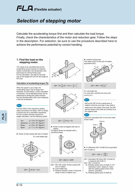
Calculate the accelerating torque first and then calculate the load torque. Finally, check the characteristics of the motor and reduction gear. Follow the steps in the description. For selection, be sure to use the procedure described here to achieve the performance potential by correct handling.
Calculation of accelerating torque (Ta)
► Center of load coaxial with axis of rotation
► To determine GD2 of shaft (2) as equivalent GD2 of shaft (1)
W: Load weight (kg)
Step 1
D1
D2
IronAluminumBrassNylon
ρ = 7.9 x 10⁻³ (kg/cm3)ρ = 2.8 x 10⁻³ (kg/cm3)ρ = 8.5 x 10⁻³ (kg/cm3)ρ = 1.1 x 10⁻³ (kg/cm3)
GD2 = W (D12 + D22)21
Step 2
Convert to equivalent GD2 on the drive shaft (motor shaft).
Step 3
► Linearly moving loadThe value is GD2 on the axis of rotation (equivalent GD2).
GD2 = WD2 = W
► Center of load not aligned with axis of rotationThe figure shows an example with a cylindrical shape.
GD2 = W (a2 + b2)31
GD2 = W (D12 + D22) + L341
31
LD1
D2
πL
R
a
b
Shaft (1)
Shaft (2)
DL
GD2 = [GD02] + 4WR2
GD2 = GD22 x N1
N2
When the speed in use is high, the accelerating torque may be larger than expected. For that reason, correct calculation is important. The accelerating torque can be determined by finding the inertia moment from the flywheel effect (GD2) and multiplying it with the acceleration.
Find the (GD2) of the respective rotating object according to its shape. (GD2) is simply a symbol and not a calculation expression. For the constant (density) required for weight calculation, use the following values.
The values to be calculated first are the accelerating torque required for indexing rotation acceleration and deceleration and load torque for driving friction load. For the calculation, use (kgf) for the load, (kg) for the weight and (cm) for the length as the units.
2
Add up the GD2 for the coaxial axes of rotation to find the sum total. If any relief is made due to the shape of the load, find GD2 with the shape of the relief and subtract it as the negative load.
2
Selection of stepping motor
1. Find the load on the stepping motor.
W: Load weight (kg)For screw feed, substitute the screw pitch (cm/rev) for L.
GD02: GD2 with center of load coaxial with axis of rotation
W: Load weight (kg) R: Distance between center of load and
center of axis of rotation (cm)
GD12: Equivalent GD when GD22 of shaft (2) is replaced with shaft (1)
GD22: GD22 of shaft (2) N1: Rotating speed (rpm) of shaft (1): For
selecting a motor, replace N1 value with the rotating speed of the motor shaft for calculation.
N2: Rotating speed (rpm) of shaft (2)

The flexible actuator reduces the step angle of the stepping motor by the backlashless planet gear mechanism for an integer angle. Convert GD2 of the output shaft to GD2 of the motor shaft to check the performance.
Flexible actuator
Selection of stepping motor
E-13
Find the inertia moment (I) from GD2 in the drive section.
I: Inertia moment (kgf•cm•sec2)g: Gravitational acceleration 980.7 (cm•sec2)
ω N1
N2
f1
f2
θS
t
Step 4
Step 5
ω = = x602π
t x180(N2•N1) π•θS
t(f2 - f1)
I = 4 gGD2
and
► Rotating load
► Linearly moving load
f1 = x60N1
θs360
f2 = x60N2
θs360
TL = •S (kgf•cm)x2μWD
N1
N2
Ta = I x ω x S
T = Ta + TL (kgf•cm)
Equivalent GD2 on FLA input shaft (kgf・cm2)Specifications
With 2-phase motor
1:9 1.23
1:7.2 1.16
X3102
X3101With 5-phase motor
Model No. Reduction ratio GD2
t
N1 (f1)
N2 (f2)
Step 6
TL = S (kgf•cm)x2FD
N1
N2 x
Calculation of load torque (TL)Check on characteristics ofmotor and reduction gear
Calculation of required torque (T)
D
D
A
AB
B
Point B
f2f1
Ta
T
Starting characteristics
Point A
Slewingcharacteristics
F
Input shaftMotor
Solar gear
Planet gear
Carrier
Internal gear (fixed)
Output shaft
Find the angular acceleration based on the operation mode of the stepping motor.
Calculate the required torque for rotating the load based on the accelerating torque (Ta) and load torque (TL).
Determine the accelerating torque (Ta) from the inertia moment (I) and angular acceleration (ω).
2. When the load on the stepping motor has been calculated, check the compatibility with the reduction gear.
See the torque and speed characteristics (figure) and check the points below.
● Points to checkThe desired stepping motor can be used as long as the answers to all of the questions 1 to 3 below are YES. If any of the requirements is not met, review the load and operation mode. 1. Is point A within the range of starting
characteristics? 2. Is point B within the range of slewing
characteristics? 3. Is the required torque (T) value within the
range of output shaft allowable torque of the reduction gear?
The sum total of the GD2 for all axes of rotation converted to equivalent GD2 on the drive shaft is the GD2 value on the drive shaft. Add GD2 of the motor and reduction gear.
: Angular acceleration (Rad/sec2): Rotating speed at start of stepping motor (rpm)
: Rotating speed at high speed of stepping motor (rpm)
: Pulse speed at start of stepping motor (PPS)
: Pulse speed at high speed of stepping motor (PPS)
: Step angle of stepping motor (deg): Acceleration (deceleration) time (sec)
Ta: Accelerating torque on drive shaft (motor shaft) (kg•cm)
I: Sum total of inertia moments on drive shaft (kgf•cm•sec2)
ω: Max. angular acceleration of drive shaft (Rad/sec2)
S: Service factor (factor = 1.5 to 2)
F: Force at start of shaft rotation (kgf)N1: Rotating speed of motor shaft (rpm)N2: Rotating speed of output shaft of
reduction gear (rpm) S: Service factor (factor = 1.5 to 2)
W: Load weight (kg) μ: Friction coefficientN1: Rotating speed of motor shaft (rpm)N2: Rotating speed of output shaft of reduction
gear (rpm) S: Service factor (factor = 1.5 to 2)
N1: Rotating speed at start of stepping motor (rpm)
θS: Step angle of stepping motor (deg)
N2: Rotating speed at high speed of stepping motor (rpm)
θS: Step angle of stepping motor (deg)

(Flexible actuator)Fle
xible
actua
tor
E-14
This FLA (flexible actuator) is a stepping motor-driven table type actuator incorporating a backlashless reduction gear and is intended to serve as a device for precision indexing (indexing, pitch feed, etc.) and precision positioning.
DANGER
● Do not use the product for the following applications.
● Do not use the product in a place where hazardous substances such as combustible or flammable substances exist. There is a possibility of the product catching fire.
● Never modify the product. Doing so may cause injury due to abnormal operation, electric shock, fire, etc.
● Do not perform improper disassembly/assembly that affects the product's basic structure, performance, or functions.
● Do not pour water on the product. Pouring water on the product, washing it or using it immersed in water may cause injury due to abnormal operation, electric shock, fire, etc.
1. Medical devices related to the support and maintenance of human life and body
2. Mechanisms and machinery used for the purpose of moving and transporting people
3. Important security components of machineryThis product is not developed or designed for applications that require a high degree of safety. Use of this product for such applications may cause death.
WARNING
● Be sure to confirm the safety of the operating range of devices before supplying power to and operating the product. If the power is supplied improperly, there is a risk of electric shock and injury caused by contact with a movable part.
● Keep away from the operating range of machinery when a product is in operation or ready to operate. Failure to do so may result in injury due to unexpected operation of the product.
● Do not touch the terminal blocks or switches while the power is turned on. There is a risk of abnormal operation and electric shock.
● Do not damage any of the cables. Damaging, forcibly bending, pulling, winding or pinching cables, placing heavy objects on them may cause electric shock, abnormal operation, etc.
● Do not get on top of the product, use it as a foothold or put any object on it. It may cause an accidental fall, tumbling of the product, injury due to a fall, damage to the product or malfunction due to damage.
● Do not throw the product into the fire. The product may explode or poisonous gases may be discharged.
● Be sure to completely remove the supply of electricity before performing various tasks such as maintenance, inspection, service, or replacement.
Applications
1. Restriction of applications
2. Safety precautions

Flexible actuator
E-15
●
●
●
●
Use protective covers to prevent the moving parts of machinery from coming in direct contact with human body.
When working on the product, ensure safety by wearing protective gloves, safety glasses, safety shoes, etc. as required.
When the product has become unserviceable or unnecessary, dispose of it properly as industrial waste.
As you incorporate the products into your system, add all safety information to the instruction manual of your system and make sure the operators of the system follow the instructions. Be sure to add to the instruction manual all new safety information that needs to be provided as a result of the incorporation.
CAUTION
● When mounting the product, ensure reliable retention and securing. Otherwise, fall or abnormal operation of the product may cause injury.
● This product is not equipped with a non-excitation brake. If there is any possibility that the output shaft load is moved by external load (gravity, spring force, etc.), provide a braking mechanism. Otherwise it may cause damage to the machine or injury.
● Do not use this product in places subjected to direct sunlight (ultraviolet light) or dust, iron, iron powder, or in an atmosphere containing organic solvent, phosphate-ester hydraulic oil, sulphurous acid gas, chlorine gas, acids, etc. The product may stop functioning in a short period of time, or the performance may be deteriorated and the lifetime of the product may be significantly reduced.
Applications