Commercial 0G 948 16 060 - DTIC
50
AD-A283 500 DOT/F:AA/c-o4/2 Development of an Automated #"*al hi o wk Nondestructive Inspection N.J. w"r Commercial ircraft: Phase I Flna ReortAUG 1 7 1994 D 0G 94-25884 F~ idndretonO QUALMT Inmpw3 I 948 16 060
-
Upload
khangminh22 -
Category
Documents
-
view
2 -
download
0
Transcript of Commercial 0G 948 16 060 - DTIC
AD-A283 500
DOT/F:AA/c-o4/2 Development of an Automated#"*al hi o wk Nondestructive Inspection
N.J. w"r Commercialircraft: Phase I
Flna ReortAUG 1 7 1994 D
0G
94-25884 F~ idndretonO QUALMT Inmpw3 I
948 16 060
NOTICE
This document is disseminated under the sponsorshipof the U. S. Department of Transportation in the interestof information exchange. The United States Governmentassumes no liability for the contents or use thereof.
The United States Government does not endorse productsor manufacturers. Trade or manufacturers' names appearherein solely because they are considered essential to theobjective of this report.
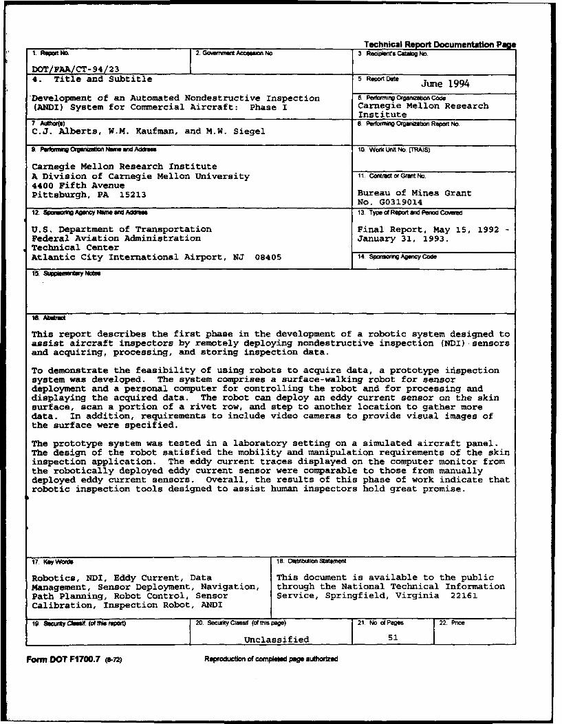
Technical Report Documentation Pig1 Raewt NM 2. GoCveinM tAcw eons No 3 Recpenfs Cataog No.
DOT.FAA.CT-94/23 _
4. Title and Subtitle 5 Repor Date June 1994
Development of an Automated Nondestructive Inspection 6. PeftwogOrgariZatj Code(ANDI) System for Commercial Aircraft: Phase I Carnegie Mellon Research
Institute7. Aulitos) 8. Pefomwig Organiaon Rapo No,C.J. Alberts, W.M. Kaufman, and M.W. Siegel
9 Pwebmmg Orga•na Nuels ar•id dress 10 Work Unit No. (TRA• )
Carnegie Mellon Research InstituteA Division of Carnegie Mellon University 11. ContWactGrant No4400 Fifth AvenuePittsburgh, PA 15213 Bureau of Mines Grant
No. G031901412. Spomoft AgencyNme and Address 13. Type d Repont ad Period Coved
U.S. Department of Transportation Final Report, May 15, 1992Federal Aviation Administration January 31, 1993.Technical CenterAtlantic City International Airport, NJ 08405 14 SponsooAgerwc Code
15. Seppamenwtes
16. Aditact
This report describes the first phase in the development of a robotic system designed toassist aircraft inspectors by remotely deploying nondestructive inspection (NDI) .sensors
and acquiring, processing, and storing inspection data.
To demonstrate the feasibility of using robots to acquire data, a prototype inispectionsystem was developed. The system comprises a surface-walking robot for sensordeployment and a personal computer for controlling the robot and for processing anddisplaying the acquired data. The robot can deploy an eddy current sensor on the skinsurface, scan a portion of a rivet row, and step to another location to gather moredata. In addition, requirements to include video cameras to provide visual images ofthe surface were specified.
The prototype system was tested in a laboratory setting on a simulated aircraft panel.The design of the robot satisfied the mobility and manipulation requirements of the skininspection application. The eddy current traces displayed on the computer monitor fromthe robotically deployed eddy current sensor were comparable to those from manuallydeployed eddy current sensors. Overall, the results of this phase of work indicate thatrobotic inspection tools designed to assist human inspectors hold great promise.
17. Key Words 18 Distribution Statement
Robotics, NDI, Eddy Current, Data This document is available to the publicManagement, Sensor Deployment, Navigation, through the National Technical InformationPath Planning, Robot Control, Sensor Service, Springfield, Virginia 22161Calibration, Inspection Robot, ANDI
19. Sc "xtcy'Che .Jles tdttsreport) 20. SecurityClassf (cihispage) 21. No. of Pages 22. Price
Unclassified 51
Form.DOT F1700.7 (72) Reproduction of completed pge authorized
TABLE OF CONTENTS
Page
EXECUTIVE SUMMARY vii
INTRODUCTION 1
Background I
Objectives 3
RESULTS AND DISCUSSION 6
System Implementation 6
Mechanical System Design 9
Sensors 28
Cahlbration 31
Control System Design 34
Data Management 39
System Performance 41
CONCLUSIONS 42
REFERENCES 43
Accesion For
NTIS CRAWlDTIC TABUnannounced 0Justification
Distribution I
Availability Codes
Avail an~dl/orDist SpecialI
401

LIST OF ILLUSTRATIONS
Figure Page
1. Prototype Robotic System 7
2. Lab Set-Up 93. Drawing Of The Cruciform Robot 11
4. Robot Dimensions (Overhead View) 125. Robot Dimensions (Side View) 12
6. Reference Directions 137. Drawing Of The Stabilizer Bridge 14
8. Stabilizer Bridge Motions 159. Pivot Lock Schematic (Unlocked) 15
10. Pivot Lock Schematic (Locked) 16
11. Drawing Of The Sensor Bridge 1612. Drawing Of The Spine Assembly 1713. Photograph Of The Robot 18
14. Eddy Current Sensor Deployed By Robot 1815. Unaligned Robot (Overhead View) 1916. Unaligned Robot (Side View) 20
17. Step 1 Of Alignment Process 20
18. Step 2 Of Alignment Process 21
19. Aligned Robot (Overhead View) 21
20. Robot Steering 2221. Direction Of Scanning Motion 22
22. Robot's Position After Scanning Motion 23
23. Initial Configuration For Walking 23
24. Walking Motion: Spine Assembly Raised 2325. Walking Motion: Spine Assembly Motion 24
26. Walking Motion: Spine Assembly Lowered 24
27. Walking Motion: Stabilizer Bridge Moved Into Position 24
28. Robot Tethered To Bottom Of Aircraft 2629. Tether Limitation 2630. Special-Case Tether 2731. Reflectance Eddy Current Sensor 29
32. Camera Placement 30
iv
LIST OF ILLUSTRATIONS (continued)
Figure Page
33. Calibration Standard (Front) 3134. Calibration Standard (Back) 3235. Eddy Current Instrument Display For Subsurface Crack 3236. Eddy Current Instrument Display For Surface Crack 3337. Robot States 3438. Robot Initial State (Side View) 3639. Robot Initial State (Overead View) 3640. Operator Interface 3741. Alarm Region On An Impedance-Plane Display 40
EXECUTIVE SUM4ARY
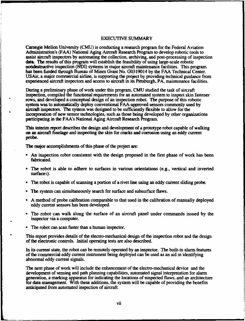
Carnegie Mellon University (CMU) is conducting a research program for the Federal AviationAdministration's (FAA) National Aging Aircraft Research Program to develop robotic tools toassist aircraft inspectors by automating the collection, archiving, and post-processing of inspectiondata. The results of this program will establish the feasibility of using large-scale roboticnondestructive inspection (NDI) systems in major aircraft maintenance facilities. This programhas been funded through Bureau of Mines Grant No. G0319014 by the FAA Technical Center.USAir, a major commercial airline, is supporting the project by providing technical guidance fromexperienced aircraft inspectors and access to aircraft in its Pittsburgh, PA, maintenance facilities.
During a preliminary phase of work under this program, CMU studied the task of aircraftinspection, compiled the functional requirements for an automated system to inspect skin fastenerrows, and developed a conceptual design of an inspection robot. The purpose of this roboticsystem was to automatically deploy conventional FAA-approved sensors commonly used byaircraft inspectors. The system was designed to be sufficiently flexible to allow for theincorporation of new sensor technologies, such as those being developed by other organizationsparticipating in the FAA's National Aging Aircraft Research Program.
This interim report describes the design and development of a prototype robot capable of walkingon an aircraft fuselage and inspecting the skin for cracks and corrosion using an eddy currentprobe.
The major accomplishments of this phase of the project are:
"* An inspection robot consistent with the design proposed in the first phase of work has beenfabricated.
"* The robot is able to adhere to surfaces in various orientations (e.g., vertical and invertedsurfaces).
"* The robot is capable of scanning a portion of a rivet line using an eddy current sliding probe.
"* The system can simultaneously search for surface and subsurface flaws.
"* A method of probe calibration comparable to that used in the calibration of manually deployededdy current sensors has been developed.
"* The robot can walk along the surface of an aircraft panel under commands issued by theinspector via a computer.
"* The robot can scan faster than a human inspector.
This report provides details of the electro-mechanical design of the inspection robot and the designof the electronic controls. Initial operating tests are also described.
In its current state, the robot can be remotely operated by an inspector. The built-in alarm featuresof the commercial eddy current instrument being deployed can be used as an aid in identifyingabnormal eddy current signals.
The next phase of work will include the enhancement of the electro-mechanical device and thedevelopment of sensing and path planning capabilities, automated signal interpretation for alarmgeneration, a marking apparatus for indicating the locations of suspected flaws, and an architecturefor data management. With these additions, the system will be capable of providing the benefitsanticipated from automated inspection of aircraft.
vii
INTRODUCTION
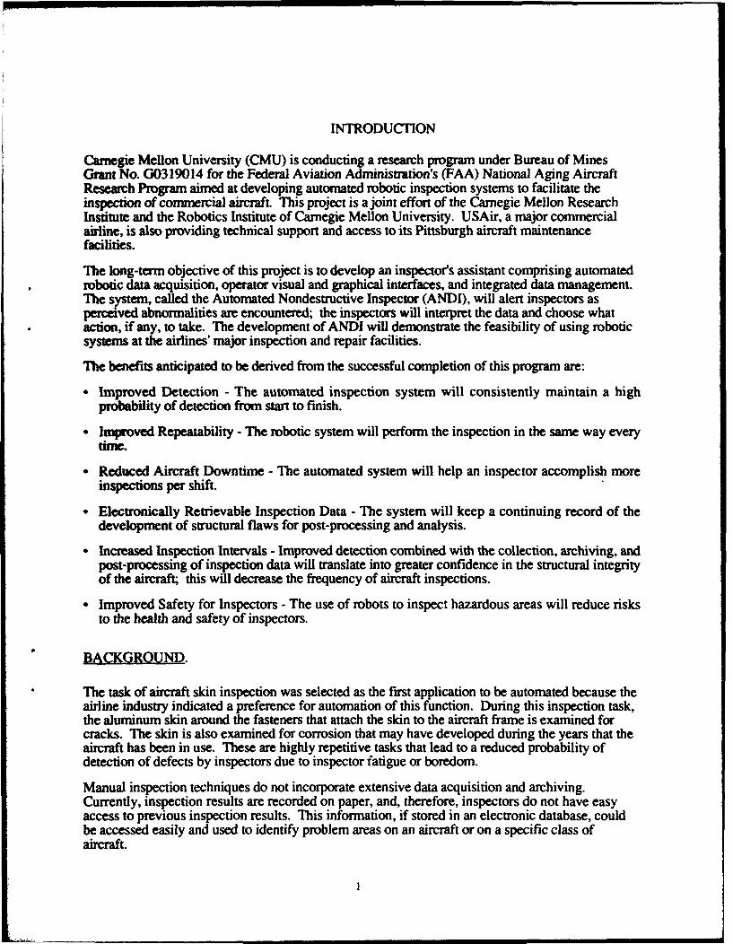
Carnegie Mellon University (CMU) is conducting a research program under Bureau of MinesGrant No. G0319014 for the Federal Aviation Administration's (FAA) National Aging AircraftResearch Program aimed at developing automated robotic inspection systems to facilitate theinspection of commercial aircraft. This project is a joint effort of the Carnegie Mellon ResearchInstitute and the Robotics Institute of Carnegie Mellon University. USAir, a major commercialairline, is also providing technical support and access to its Pittsburgh aircraft maintenancefacilities.
The long-term objective of this project is to develop an inspector's assistant comprising automatedrobotic data acquisition, operator visual and graphical interfaces, and integrated data management.The system, called the Automated Nondestructive Inspector (ANDI), will alert inspectors asperceived abnormalities are encountered; the inspectors will interpret the data and choose whataction, if any, to take. The development of ANDI will demonstrate the feasibility of using roboticsystems at the airlines' major inspection and repair facilities.
The benefits anticipated to be derived from the successful completion of this program are:
"* Improved Detection - The automated inspection system will consistently maintain a highprobability of detection from start to finish.
"* Improved Repeatability - The robotic system will perform the inspection in the same way everytime.
"* Reduced Aircraft Downtime - The automated system will help an inspector accomplish moreinspections per shift.
"* Electronically Retrievable Inspection Data - The system will keep a continuing record of thedevelopment of structural flaws for post-processing and analysis.
"* Increased Inspection Intervals - Improved detection combined with the collection, archiving, andpost-processing of inspection data will translate into greater confidence in the structural integrityof the aircraft; this will decrease the frequency of aircraft inspections.
"• Improved Safety for Inspectors - The use of robots to inspect hazardous areas will reduce risksto the health and safety of inspectors.
BACKGROUND.
The task of aircraft skin inspection was selected as the first application to be automated because theairline industry indicated a preference for automation of this function. During this inspection task,the aluminum skin around the fasteners that attach the skin to the aircraft frame is examined forcracks. The skin is also examined for corrosion that may have developed during the years that theaircraft has been in use. These are highly repetitive tasks that lead to a reduced probability ofdetection of defects by inspectors due to inspector fatigue or boredom.
Manual inspection techniques do not incorporate extensive data acquisition and archiving.Currently, inspection results are recorded on paper, and, therefore, inspectors do not have easyaccess to previous inspection results. This information, if stored in an electronic database, couldbe accessed easily and used to identify problem areas on an aircraft or on a specific class ofaircraft.
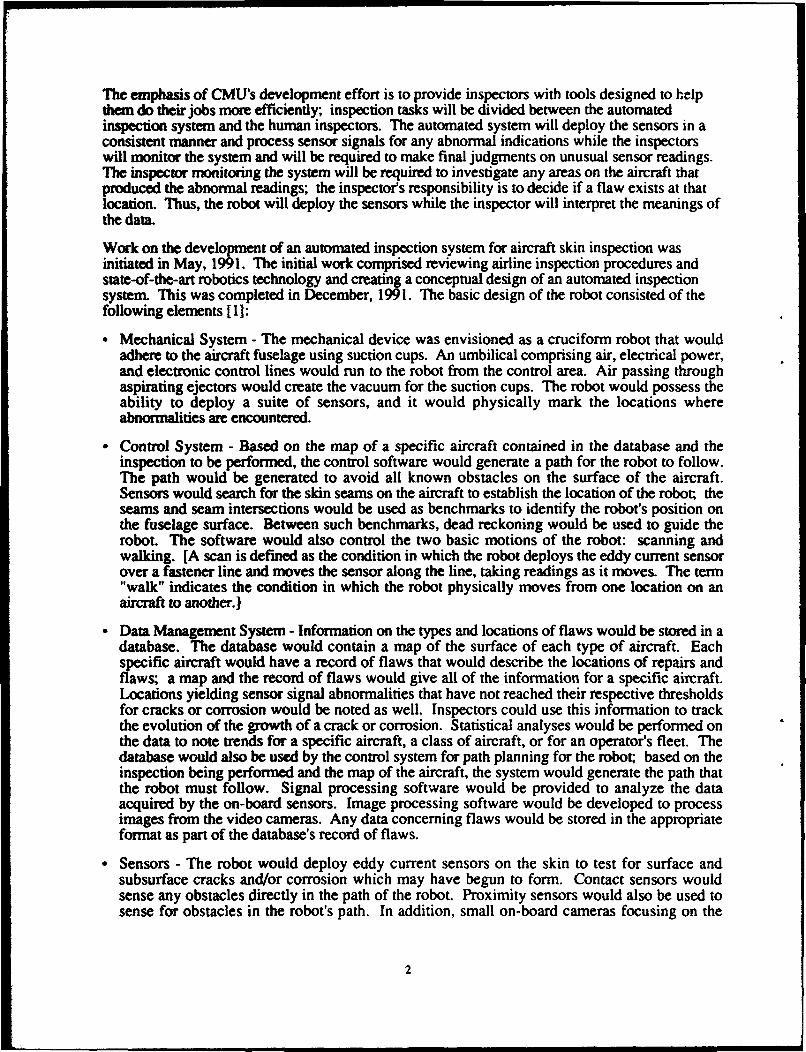
The emphasis of CMU's development effort is to provide inspectors with tools designed to helpthem do their jobs more efficiently; inspection tasks will be divided between the automatedinspection system and the human inspectors. The automated system will deploy the sensors in aconsistent manner and process sensor signals for any abnormal indications while the inspectorswill monitor the system and will be required to make final judgments on unusual sensor readings.The inspector monitoring the system will be required to investigate any areas on the aircraft thatproduced the abnormal readings; the inspector's responsibility is to decide if a flaw exists at thatlocation. Thus, the robot will deploy the sensors while the inspector will interpret the meanings ofthe data.
Work on the development of an automated inspection system for aircraft skin inspection wasinitiated in May, 1991. The initial work comprised reviewing airline inspection procedures andstate-of-the-art robotics technology and creating a conceptual design of an automated inspectionsystem. This was completed in December, 1991. The basic design of the robot consisted of thefollowing elements [1]:
"Mechanical System - The mechanical device was envisioned as a cruciform robot that wouldadhere to the aircraft fuselage using suction cups. An umbilical comprising air, electrical power,and electronic control lines would run to the robot from the control area. Air passing throughaspirating ejectors would create the vacuum for the suction cups. The robot would possess theability to deploy a suite of sensors, and it would physically mark the locations whereabnormalities are encountered.
" Control System - Based on the map of a specific aircraft contained in the database and theinspection to be performed, the control software would generate a path for the robot to follow.The path would be generated to avoid all known obstacles on the surface of the aircraft.Sensors would search for the skin seams on the aircraft to establish the location of the robot; theseams and seam intersections would be used as benchmarks to identify the robot's position onthe fuselage surface. Between such benchmarks, dead reckoning would be used to guide therobot. The software would also control the two basic motions of the robot: scanning andwalking. [A scan is defined as the condition in which the robot deploys the eddy current sensorover a fastener line and moves the sensor along the line, taking readings as it moves. The term"walk" indicates the condition in which the robot physically moves from one location on anaircraft to another.)
" Data Management System - Information on the types and locations of flaws would be stored in adatabase. The database would contain a map of the surface of each type of aircraft. Eachspecific aircraft would have a record of flaws that would describe the locations of repairs andflaws; a map and the record of flaws would give all of the information for a specific aircraft.Locations yielding sensor signal abnormalities that have not reached their respective thresholdsfor cracks or corrosion would be noted as well. Inspectors could use this information to trackthe evolution of the growth of a crack or corrosion. Statistical analyses would be performed onthe data to note trends for a specific aircraft, a class of aircraft, or for an operator's fleet. Thedatabase would also be used by the control system for path planning for the robot; based on theinspection being performed and the map of the aircraft, the system would generate the path thatthe robot must follow. Signal processing software would be provided to analyze the dataacquired by the on-board sensors. Image processing software would be developed to processimages from the video cameras. Any data concerning flaws would be stored in the appropriateformat as part of the database's record of flaws.
" Sensors - The robot would deploy eddy current sensors on the skin to test for surface andsubsurface cracks and/or corrosion which may have begun to form. Contact sensors wouldsense any obstacles directly in the path of the robot. Proximity sensors would also be used tosense for obstacles in the robot's path. In addition, small on-board cameras focusing on the
2
fuselage surface would provide the inspector with images of the skin. At least two cameraswould be used, one focusing at short distances to allow inspectors to view the fasteners and asecond focusing at long distances to allow inspectors to look at large areas of the fuselage.
Human-Machine Interface - This would comprise the following elements: video monitors,teleoperation controls, and a workstation with graphics capabilities. The video monitors wouldprovide operators with the visual images from the on-board cameras. The teleoperation controlswould allow the users to manually control the motion of the robot from the operator's consolefor those cases when manual control is necessary. The workstation would be capable ofproviding complete process information to the users. Before an inspection would be performed,the monitoring system would generate the robot's path, and the users would be given theopportunity to edit the path as appropriate. Automatically generated path plans would bepresented as graphics (perhaps overlaid on video); alternative plans could be presented forselection by the operator. During the inspection, the workstation would provide graphicalimages of the robot's position and orientation to the users. The operators would also use theworkstation to graphically view the locations of suspected defects on the aircraft. All relevantinspection data would be accessed via the workstation. In addition, all control functions for therobot would be run by the users from the workstation environment.
OBJECTWES.
The conceptual design described a very robust inspection system. The strategy employed by CMUwas to approach the system development in phases; the product of each phase would be a systemwith a useful subset of the complete system's capabilities. In addition, each system would beupwardly compatible with subsequent systems. The following lists are intended to convey thebasic goals of each phase of development as viewed following the completion of the conceptualdesign. As the development is in progress and more is learned, the goals may requiremodification.
Phase 1:
"• Mechanical System - The first prototype of the robotic system will be developed and tested. Theprototype will weigh approximately 30 pounds (14 kg), and it will be able to adhere to a surfaceand perform a scan.
"* Control System - The development of the control software will be initiated in this developmentphase. Thfe software will control the scanning motion of the mechanical device.
"• Data Management System - The data acquisition and analysis functions used by the systemduring this phase will be those available in commercial eddy current systems.
" Sensors - The mechanical device will deploy operator-accepted eddy current sensors over a rowof fasteners. In addition, experimentation with video cameras will begin, and a videospecification document will be written.
" Human-Machine Interface - The system functions will be controlled by a PC workstation. Asimple menu-driven interface will be provided for the operator. The output from the commercialeddy current system will be shown on the monitor.
At the conclusion of Phase 1, the system will possess several capabilities that are potentiallybeneficial to aircraft inspectors. The robot will perform a scan much faster than a human inspector,data will be acquired in a consistent manner resulting in a constant probability of detection; and thesystem will have the ability to record data electronically. The Phase I robotic system will bepotentially operable by one inspector.
3
Phase 2:
"Mechanical System - The weight of the device will be reduced to approximately 15-20 pounds(7-9 kg). Modifications will be made to the design based on experience from Phase Idevelopment. A device to physically mark the locations of defects (e.g., using washable paint)and a tether system to secure the robot will be developed. In addition, structural enhancementsto enable the device to walk along the fuselage surface will be made.
"Control System - Software development will continue with software enhancements being madeto instruct the device to walk along the fuselage surface. The walking and scanning motionswill be integrated with each other. Physical controls for the teleoperation of the system will bedeveloped. Work directed towards integrating the sensor data to allow for more autonomousmotion will begin.
" Data Management System - The development of signal processing software for the analysis ofinformation from the eddy current sensors will be initiated. Software development forprocessing of the images from the on-board cameras will also be initiated. A prototype databaseto support the signal and image processing activities will be developed, and a specification forthe long-term database requirements of the system will be written.
"* Sensors - Miniature cameras will be added to the mechanical device. Other sensors will betested, and appropriate sensors for collision avoidance and navigation will be added.
"* Human-Machine Interface - Graphical capabilities will be added to tlV - interface. Additionalfeatures will be developed based upon the experience gained from the testing of the Phase 1human-machine interface.
At the conclusion of Phase 2, the capabilities of the system will have increased substantially. Therobot will possess a degree of autonomous motion; it will have some ability to manage data; it willbe able to physically mark the surface when abnormalities are encountered; and the weight of therobot will be reduced. The Phase 2 robotic system will be operable by one inspector.
Phase 3:
"* Mechanical System - Modifications will be made to the design based on experience from Phase2 development. Efforts to improve the performance and to reduce the weight of the device willcontinue.
"* Control System - Path planning capabilities will be developed to enable the system to generate apath based on the map of the aircraft contained in the database. The navigation and sensor-integration capabilities initiated in Phase 2 will be enhanced.
" Data Management System - The signal and image processing capabilities will be furtherenhanced. The database to support the automated system will be developed according to thespecifications from Phase 2. The statistical routines to support the trend analyses will bedeveloped.
"* Sensors - If experience shows that they are needed, additional or alternative sensors will beintegrated with the system.
"- Human-Machine Interface - The graphical capabilities of the interface will be further developed.The control interface will be increased hierarchically to permit the operator to enter high-levelabstract instructions and have the computer plan the corresponding low-level specific actions.
At this point, the system will be fully functional. The robot will be autonomous once it has beenplaced on a fuselage; a database for post processing and statistical analysis of data will be
4
integrated with the system; the robot will be able to inspect faster than in previous phases; and itwiH be possible to incorporate other NDI sensors into the sensor suite. One inspector will be ableto monitor the entire inspection operation.
Following the third phase of development, any necessary modifications will be made to thesystem After all modifications nave been made, the main gmd will be to transfer the technology toindustry. A more detailed plan to transfer this technology will be developed later in the systemdevelopment cycle. The remainder of this report details the design and construction of the firstprototype of ANDI which follows the goals outlined above for Phase 1.
5
RESULTS AND DISCUSSION
SYSTEM IMPLEMENTATION.
The main objective of Carnegie Mellon University's Automated Inspection of Aircraft Project is todemonstrate the feasibility of using a robot to remotely deploy nondestructive inspection (NDI)sensors on the skin of an aircraft. This is a complex problem that comprises many technicaldisciplines. To adequately address all of the technical issues involved, the choice was made toapproach this objective in phases, as explained in the Introduction section of this document. Thefirst phase of development has been completed. The general objective of this phase was to developa lab prototype capable of both adhering to an aircraft panel and performing a multiple-sensor scanof a line of fasteners. The following are the specific system objectives used in the development ofthe first prototype of the automated aircraft inspection system:
" Mechanical Device - A robot will be designed to hold to the skin of an aircraft at all orientations(top, side, and underneath) in most locations. It will perform fine placement and movement of asensor platform with respect to the site on the skin being inspected, and t"-e sensor platform willtranslate along one axis.
During the initial phase of development, this general purpose robot will not be required toinspect the high-curvature areas such as the nose of the aircraft. Also, the robot will not berequired to move on the aircraft fuselage.
" Sensor Suite - At least three NDI sensors will be initially investigated for inclusion on the sensorplatform. One will be a high frequency eddy current probe for surface crack detection radiatingfrom fastener holes. The second will be a low frequency eddy current probe for both corrosionand subsurface crack detection, and the third will be a video camera for larger area examination.
" Calibration Routine - A method to ensure that the eddy current sensors of the automatedinspection system are properly calibrated will be designed. The calibration method will makeuse of airline calibration standards if possible; custom calibration fixtures will be designed andfabricated if necessary. The calibration protocol will be simple and will assure repeatable dataacquisition.
"* Control Software - In anticipation of the mechanical device becoming mobile and capable ofwalking, software development will be initiated for the guidance and control of the device. Thissoftware will be enhanced and refined in future phases of the project.
"* Data Management - An investigation into the data necessary for a data archiving system will beinitiated. The data acquisition and analysis functions used by the system will be those availablein commercial eddy current systems.
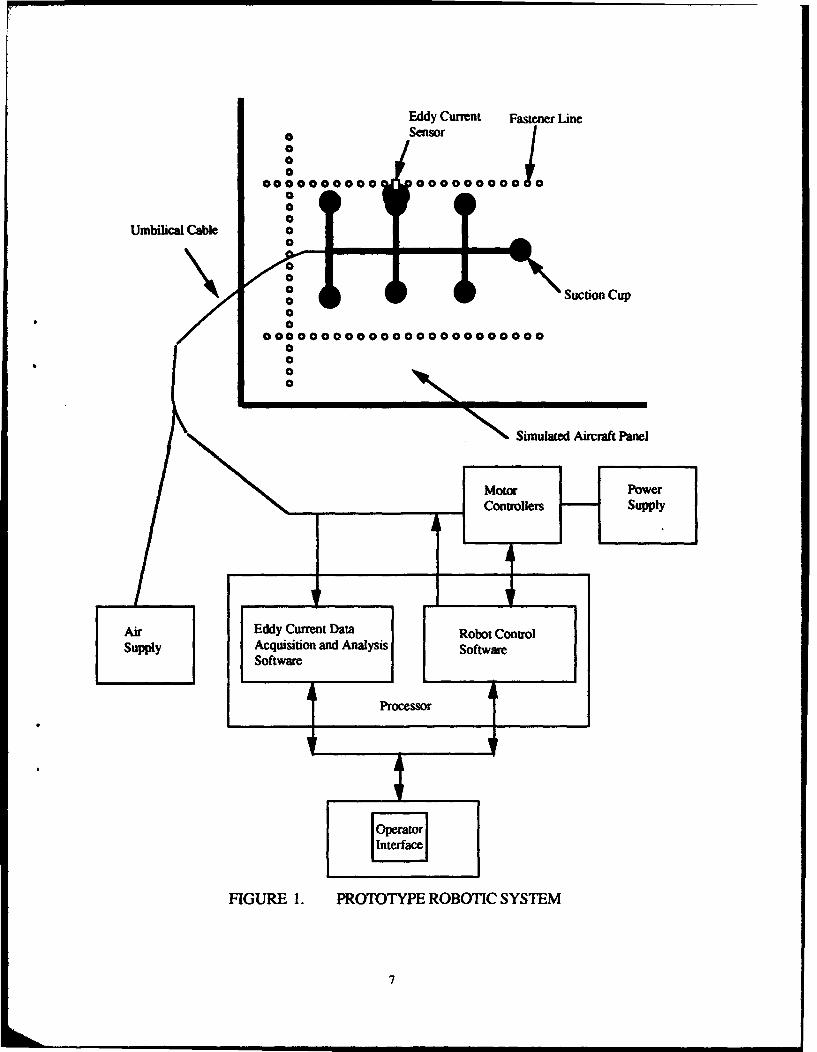
Figure 1 shows a diagram of the basic elements of the prototype robotic system implementedduring this phase of development. Each of the elements is briefly described below:
Eddy Current Sensor - A reflectance eddy current sensor (also known as a sliding probe) is usedin the prototype system. This sensor is run simultaneously at two frequencies searching forboth surface and subsurface defects; the electronics effectively makes this two independentsensors. The specific sensor used is the Nortec SPO-1958.
6
Eddy Current Fastener Line0 Sensor0
0010000000000 000000000
000
Umbilical Cable 00 -
0 -0 aSuction Cup
00000000000000000000000
wSimulated Aircraft Panel
Motor Power___ ___ ___Controllers Supply
AirEdyCretDtRooCotlsupply Acquisition and Analysis Sfwr
Processor
FIGURE 1. PROTOTYPE ROBOTIC SYSTEM
7
"• Simulated Aircraft Panel - A simulated aircraft panel manufactured by Foster-Miller, Inc. wasprovided to the CMU Automated Inspection of Aircraft Project by Sandia National Laboratories.The panel's curvature and fastener layout are similar to that of a Boeing 737.
"• Umbilical Cable - This consists of multiple lines running to the robot from the control area. Theumbilical comprises air, electrical, control, and sensor lines. A tether to support the robot if theair supply fails is planned for the next phase of development.
"* Air Supply - The system's source of air is an air tank; future versions of the system will makeuse of air compressors as an air source. Air is required for the on-board pneumatic cylindersand for the creation of a vacuum by passing the air through on-board aspirating ejectors.
"• Power Supply - DC, AC, and high-frequency electrical power is supplied to the on-board valvesand to the linear and lead screw motors.
"* Motor Controllers - RS-232 communication lines transmit command and status messagesbetween the computer's serial ports and controllers for the linear motors and lead screw motors.
"* Eddy Current Data Acquisition and Analysis Software - The eddy current data acquisition andanalysis software used in this phase of the project is a commercial package, SmartEDDYTM 3.0,developed by SE Systems, Inc.
"* Robot Control Software - The robot control software controls the walking and scanning motionsof the robot.
" Processor - A PC using a 486 50 MHz processor running DOS 5.0 is used to run the robotcontrol software and the eddy current data acquisition and analysis software.
"O Operator Interface - The operator interface to the robotic system is displayed on a 14 inch VGAolor monitor.
The above description gives a brief overview of the prototype aircraft robotic inspection system asit currently exists. The long-term architecture comprises additional elements such as a visionsystem, image and signal processing, and the design and implementation of a database ofnavigation landmarks and defects; these will be completed in future phases of development. Theremainder of this section gives a general description of the results of this phase of developmentwhile the sections that follow explain the mechanical, sensor, and control systems in more detailand give a more extensive review of the system capabilities.
During the initial phase of development, the simulated aircraft panel was mounted horizontally inthe lab; all testing on the panel during this phase was performed with the panel mounted in thisposition. Because the panel is a curved surface, the robot was tested on a modest slope during thisphase. The lab set-up is shown in figure 2.
The robot was able to adhere to the skin of the horizontally-mounted aircraft panel. In addition,during the course of experiments conducted to determine if the robot could hold to verticalsurfaces, the robot was successfully affixed to a wall.
Simultaneous high and low frequency scans were completed both on a calibration standard and onthe simulated aircraft panel. Scans were completed by translating the sensor platform along oneaxis; the results of the eddy current scans were displayed on a PC screen. Flaws were identifiedby examining the traces produced on the screen. Also, experiments were conducted with a videocamera to help determine the specifications necessary to include vision as a sensing means in futurephases of the project. A video specification document was written outlining the recommendedhardware and its placement on the robot. Prototype algorithms are being developed to enablemachine identification of lap joints and rivets and to aggregate rivets into rivet lines.
FIGURE 2. LAB SET-UP
A method to ensure that the eddy current sensors of the automated inspection system are properlycalibrated was designed. To keep the automated inspection system consistent with airlineprocedures, the calibration standards used in today's manual inspection procedures were also usedwith the robotic inspection system. During calibration, the robot deployed the eddy current sensorand scanned the two rows of fasteners on the standard. The parameters of the eddy currentsoftware were adjusted to obtain the standard calibration curves. In this way, the robotic systemwas calibrated simultaneously at both a high and a low frequency.
Software development was initiated for the guidance and control of the robot. The software wasused to control the robot as it positioned and moved an eddy current sensor along a length of skinseam. The walking motion of the robot was also successfully tested using the control software.By the end of the first development phase, the robot was able to scan a length of skin seam, take astep, and scan a second length of skin seam. This ability to scan and step was an additional systemcapability that went beyond the objectives of the grant for this phase of the project. The walkingmotion was not tested while the robot was affixed to a wall. This test was deferred until the nextphase of work when a tether will be present to prevent damage in case of any mishaps.
MECHANICAL SYSTEM DESIGN.
During this development phase, the main objectives in the mechanical design of the robot were toensure that the device would adhere to an aircraft at all orientations (top, side, and underneath) inmost locations and that it would be able to properly position and move an eddy current sensoralong a line of fasteners. The robot would not be required to move its position on the aircraft
9
fuselage at this point. (However, during this development phase, the robot was able tosuccessfully walk, exceeding the stated objectives.)
During the conceptual design phase, three basic approaches were considered for the automation ofaircraft skin inspection: an overhead robot, a ground-based robot, and a surface-walking robot.The overhead gantry-approach would consist of a permanent structure through which aircraftwould be towed for inspections; this is also called the "car wash" approach. This proved to beincompatible with airline maintenance procedures and infeasible from an economic point of view.The ground-based-robot approach would have a mobile platform that carries an arm and probemanipulator to areas of aircraft that need to be inspected. This type of robot would be di •t toincorporate into the crowded and cluttered hangar environments of commercial airlines. turdapproach, the surface-walking robot, would consist of small mobile robots that would cr,, overthe fuselage surface. This is compatible with airline maintenance procedures and could easily beinc e into the crowded hangar environments. These robots are also acceptable to humanaircraft inspectors who view them as inspection tools rather than as competitors for their jobs. Thedesign of the surface-walking robot created by members of the Carnegie Mellon team was drivenby the application for which it was to be used.
A fuselage is generally a cylindrical surface with orthogonal rows of rivets. The rivets tend to runin two directions: circumferentially around the fuselage, which is called the "vertical" direction inthis document, and approximately parallel to the horizontal axis of the aircraft from nose to tail,which is called the "horizontal" direction. An aircraft typically has more curvature and non-orthogonal rivet patterns at the nose and tail than at the main fuselage section; however, very fewinspections are required to be performed at the nose and tail. One of the main goals of the CarnegieMellon program is to develop useful inspection tools that have the potential to be commercializedquickly. Thus, the decision was made to design a tool that would perform most of theconventional inspections on the fuselage. At this time, developing a prototype to inspect areasrequiring few inspections is not considered a goal of this program. If the FAA and industry decidein the future that a robot should inspect areas such as the nose and tail, the design would bemodified or a special-purpose device would be designed and fabricated to inspect these areas.Inspection personnel from USAir and other airlines clearly indicated that the robot must be able toperform large-area inspections on the main fuselage sections of commercial aircraft. In addition,there are more inspections performed along the horizontal lines of fasteners than along the verticallines of fasteners, and there are repair patches and other obstructions located at random locationson any given aircraft. From this information, a decision regarding the minimum requirements forthe robot was reached. It would be required to move gracefully in the horizontal direction, to moveadequately in the vertical direction, and to possess some steering capability. A cruciform robotwith some degree of compliance between the axes would satisfy these walking requirements.
In addition, the weight of the robot must be kept to a minimum. Inspectors will be required to liftthe robot when they affix it to the aircraft surface before initiating an inspection procedure andwhen they remove it from the surface after an inspection has been completed. The robot must befight enough to enable inspectors to lift it. The ultimate goal is to produce a robot that weighsbetween 15 and 20 pounds (7 and 9 kg) and can both walk on the aircraft surface and deploysensors. However, for this phase of development, a heavier version of the robot was fabricated,and a strategy to reduce its weight was developed. This was done to reduce the time necessary tofabricate the first prototype of the robot and to allow system testing in the laboratory to beginsooner. Thus, for this phase of development, the goal was to produce a robot weighingapproximately 30 pounds (14 kg).
Adding additional mechanical elements (e.g., a robotic arm) to deploy NDI sensors would addsignificantly to the weight of the device. Weight would be saved if the same elements used by thesystem to walk were also used by the system to deploy sensors; this approach was chosen for the
10
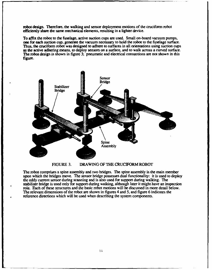
robot design. Therefore, the walking and sensor deployment motions of the cruciform robotefficiently share the same mechanical elements, resulting in a lighter device.
To affix the robot to the fuselage, active suction cups are used. Small on-board vacuum pumps,one for each suction cup, generate the vacuum necessary to hold the robot to the fuselage surface.Thus, the cruciform robot was designed to adhere to surfaces in all orientations using suction cupsas the active adhering means, to deploy sensors on a surface, and to walk across a curved surface.The robot design is shown in figure 3; pneumatic and electrical connections are not shown in thisfigure.
SensorBridge
FIGURE 3. DRAWING OF THE CRUCIFORM ROBOT
The robot comprises a spine assembly and two bridges. The spine assembly is the main memberupon which the bridges move. The sensor bridge possesses dual functionality: it is used to deploythe eddy current sensor during scanning and is also used for support during walking. Thestabilizer bridge is used only for support during walking, although later it might have an inspection
role. Each of these structur'es and the basic robot motions will be discussed in more detail below.The relevant dimensions of the robot are shown in figures 4 and 5, and figure 6 indicates thereference directions which will be used when describing the system components.
1ig
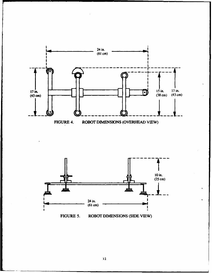
Igo_ _ 24 in.(61 cm)
I
17 In. 15 in. 17 in.
(43 an) •(38 cm) (43 cm)
FIGURE 4. ROBOT DIMENSIONS (OVERHEAD VIEW)
10 in.(25 cm)
24 in. .
(61 cm)II
FIGURE 5. ROBOT DIMENSIONS (SIDE VIEW)
12
HeadEnd
Left Right
TailEnd
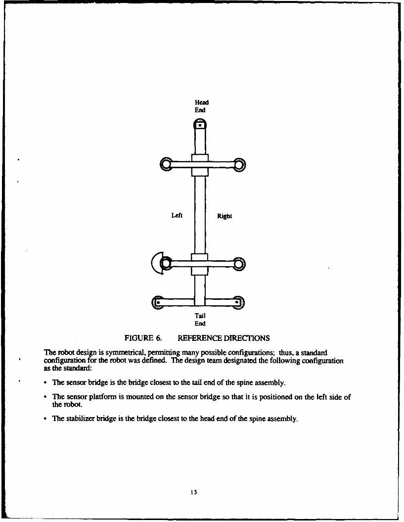
FIGURE 6. REFERENCE DIRECTIONS
The robot design is symmetrical, permitting many possible configurations; thus, a standardconfiguration for the robot was defined. The design team designated the following configurationas the standard:
• The sensor bridge is the bridge closest to the tail end of the spine assembly.
• The sensor platform is mounted on the sensor bridge so that it is positioned on the left side ofthe robot.
- The stabilizer bridge is the bridge closest to the head end of the spine assembly.
13
Lifters
Lead ScrewAssembly
Lock
L a Pump
Motor Suction
Cup
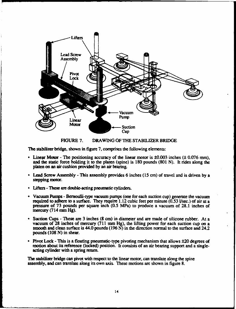
FIGURE 7. DRAWING OF THE STABILIZER BRIDGE
The stabilizer bridge, shown in figure 7, comprises the following elements:
"• Linear Motor - The positioning accuracy of the linear motor is ±0.003 inches (± 0.076 mm),and the static force holding it to the platen (spine) is 180 pounds (801 N). It rides along theplaten on an air cushion provided by an air bearing.
"* Lead Screw Assembly - This assembly provides 6 inches (15 cm) of travel and is driven by astepping motor.
"* Lifters - These are double-acting pneumatic cylinders.
" Vacuum Pumps - Bernoulli-type vacuum pumps (one for each suction cup) generate the vacuumrequired to adhere to a surface. They require 1.12 cubic feet per minute (0.53 I/sec.) of air at apressure of 73 pounds per square inch (0.5 MPa) to produce a vacuum of 28.1 inches ofmercury (714 nun Hg).
" Suction Cups - These are 3 inches (8 cm) in diameter and are made of silicone rubber. At avacuum of 28 inches of mercury (711 mm Hg), the lifting power for each suction cup on asmooth and clean surface is 44.0 pounds (196 N) in the direction normal to the surface and 24.2pounds (108 N) in shear.
"• Pivot Lock - This is a floating pneumatic-type pivoting mechanism that allows ±20 degrees ofmotion about its reference (locked) position. It consists of an air bearing support and a single-acting cylinder with a spring return.
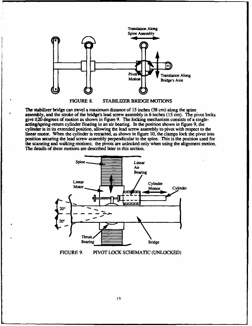
The stabilizer bridge can pivot with respect to the linear motor, can translate along the spineassembly, and can translate along its own axis. These motions are shown in figure 8.
14
Translation AlongSpine Assembly
pivot%. Translation Along
motion Bridge's Axis
FIGURE 8. STABILIZER BRIDGE MOTIONS
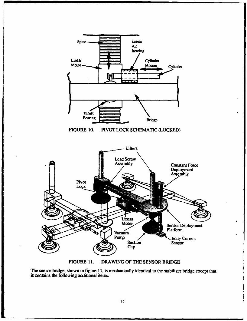
The stabilizer bridge can travel a maximum distance of 15 inches (38 cm) along the spineassembly, and the stroke of the bridge's lead screw assembly is 6 inches (15 cm). The pivot locksgive ±2 degrees of motion as shown in figure 9. The locking mechanism consists of a single-acting/spring-return cylinder floating in an air bearing. In the position shown in figure 9, thecylinder is in its extended position, allowing the lead screw assembly to pivot with respect to thelinear motor. When the cylinder is retracted, as shown in figure 10, the clamps lock the pivot intoposition securing the lead screw assembly perpendicular to the spine. This is the position used forthe scanning and walking motions; the pivots are unlocked only when using the alignment motion.The details of these motions are described later in this section.
Spine LineaAir
S~BearingLinear • Cy•linder•
motor Motion- Clne
200
T bru st/Bearing Bridge
FIGURE 9. PIVOT LOCK SCHEMATIC (UNLOCKED)
15
Spine LinearAir
Linear CylinderMotorn Cylinder
"ThrustBearing Bridge
FIGURE 10. PIVOT LOCK SCHEMATIC (LOCKED)
Lifters
Lead ScrewAssembly Constant Force
Deployment
Lock >
Motor Snsor Deployment
/ Platform,Pu~amp I-, Eddy Current
• • • • Suction CpSensor
FIGURE 11. DRAWING OF THE SENSOR BRIDGE
The sensor bridge, shown in figure 11, is mechanically identical to the stabilizer bridge except thatis contains the following additional items:
16
"• Sensor Deployment Platform - A suite of sensors can be mounted on this platform. It can beindexed to deploy a specific sensor and locked into position. During this phase, one reflectanceeddy current sensor is mounted on the platform.
"* Eddy Current Sensor - A reflectance-type Nortec SPO-1958 eddy current sensor is mounted onthe sensor platform.
"• Constant Force Deployment Assembly - A precision actuator (airpot) is used to deploy the eddycurrent sensor on the fuselage surface and to retract it from the surface. This assembly applies aconstant force during sensor deployment which can be set from 1-3 pounds (4-13 N).
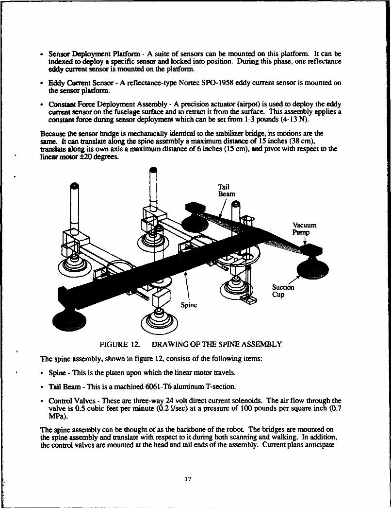
Because the sensor bridge is mechanically identical to the stabilizer bridge, its motions are thesame. It can translate along the spine assembly a maximum distance of 15 inches (38 cm),translate along its own axis a maximum distance of 6 inches (15 cm), and pivot with respect to thelinear motor ±20 degrees.
TailBeam
S• ' Vacuum
SpineCu
FIGURE 12. DRAWING OF THE SPINE ASSEMBLY
The spine assembly, shown in figure 12, consists of the following items:
- Spine - This is the platen upon which the linear motor travels.
- Tail Beam - This is a machined 6061-T6 aluminum T-section.
- Control Valves - These are three-way 24 volt direct current solenoids. The air flow through thevalve is 0.5 cubic feet per minute (0.2 1/sec) at a pressure of 100 pounds per square inch (0.7MPa).
The spine assembly can be thought of as the backbone of the robot. The bridges are mounted onthe spine assembly and translate with respect to it during both scanning and walking. In addition,the control valves are mounted at the head and tail ends of the assembly. Current plans antcipate
17
mounting three small video cameras on the spine assembly and a fourth on the sensor deploymentplatform; this is detailed in the Sensors section of this document.
Notably, all of the major parts used to fabricate the robot were standard off-the-shelf components;very few modifications were made to the parts. The reasons for using standard components wereto shorten the fabrication process and to keep fabrication costs to a minimum. To complete theassembly, designing and fabricating custom bracketing was necessary; detailed designs of thecustom bracketing are not provided in this report.
A photograph of the finished robot including the air and electrical supply lines is shown in figure13. A close-up photograph of the robot deploying the eddy current sensor on the simulated aircraftpanel is shown in figure 14.
FIGURE 13. PHOTOGRAPH OF THE ROBOT
FIGURE 14. EDDY CURRENT SENSOR DEPLOYED BY ROBOT
18
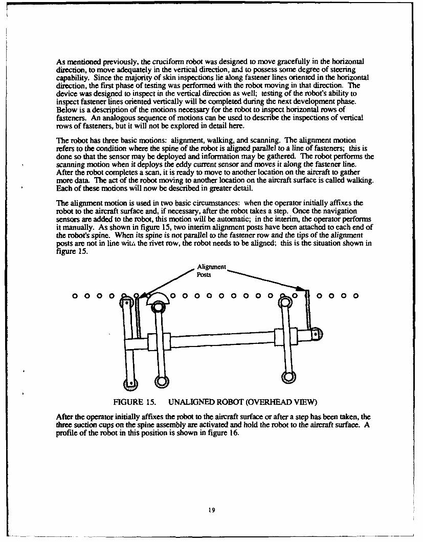
As mentioned previously, the cruciform robot was designed to move gracefully in the horizontaldirection, to move adequately in the vertical direction, and to possess some degree of steeringcapability. Since the majority of skin inspections lie along fastener lines oriented in the horizontaldirection, the first phase of testing was performed with the robot moving in that direction. Thedevice was designed to inspect in the vertical direction as well; testing of the robot's ability toinspect fastener lines oriented vertically will be completed during the next development phase.Below is a description of the motions necessary for the robot to inspect horizontal rows offasteners. An analogous sequence of motions can be used to describe the inspections of verticalrows of fasteners, but it will not be explored in detail here.
The robot has three basic motions: alignment, walking, and scanning. The alignment motionrefers to the condition where the spine of the robot is aligned parallel to a line of fasteners; this isdone so that the sensor may be deployed and information may be gathered. The robot performs thescanning motion when it deploys the eddy current sensor and moves it along the fastener line.After the robot completes a scan, it is ready to move to another location on the aircraft to gathermore data. The act of the robot moving to another location on the aircraft surface is called walking.Each of these motions will now be described in greater detail.
The alignment motion is used in two basic circumstances: when the operator initially affixes therobot to the aircraft surface and, if necessary, after the robot takes a step. Once the navigationsensors are added to the robot, this motion will be automatic; in the interim, the operator performsit manually. As shown in figure 15, two interim alignment posts have been attached to each end ofthe robot's spine. When its spine is not parallel to the fastener row and the tips of the alignmentposts are not in line wite. the rivet row, the robot needs to be aligned; this is the situation shown infigure 15.
A ligunmentPosts
0 0 00 0 0 0 0 0 0 0 0 0 0 0 0 0 0
FIGURE 15. UNALIGNED ROBOT (OVERHEAD VIEW)
After the operator initially affixes the robot to the aircraft surface or after a step has been taken, thethree suction cups on the spine assembly are activated and hold the robot to the aircraft surface. Aprofile of the robot in this position is shown in figure 16.
19
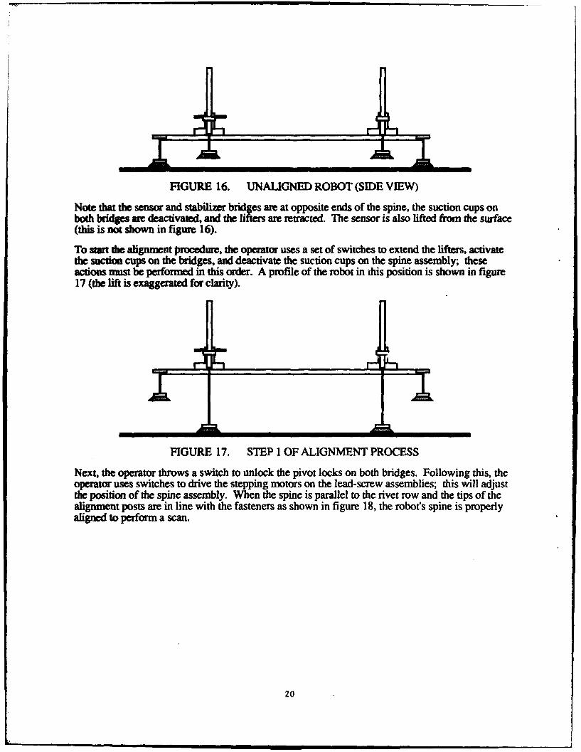
FIGURE 16. UNALIGNED ROBOT (SIDE VIEW)
Note that the sensor and stabilizer bridges are at opposite ends of the spine, the suction cups onboth bridges are deactivated, and the lifters are retracted. The sensor is also lifted from the swuface(this is not shown in figure 16).
To start the alignment procedure, the operator uses a set of switches to extend the lifters, activatethe suction cups on the bridges, and deactivate the suction cups on the spine assembly; theseactions must be performed in this order. A profile of the robot in (his position is shown in figure17 (the lift is exaggerated for clarity).
FIGURE 17. STEP 1 OF ALIGNMENT PROCESS
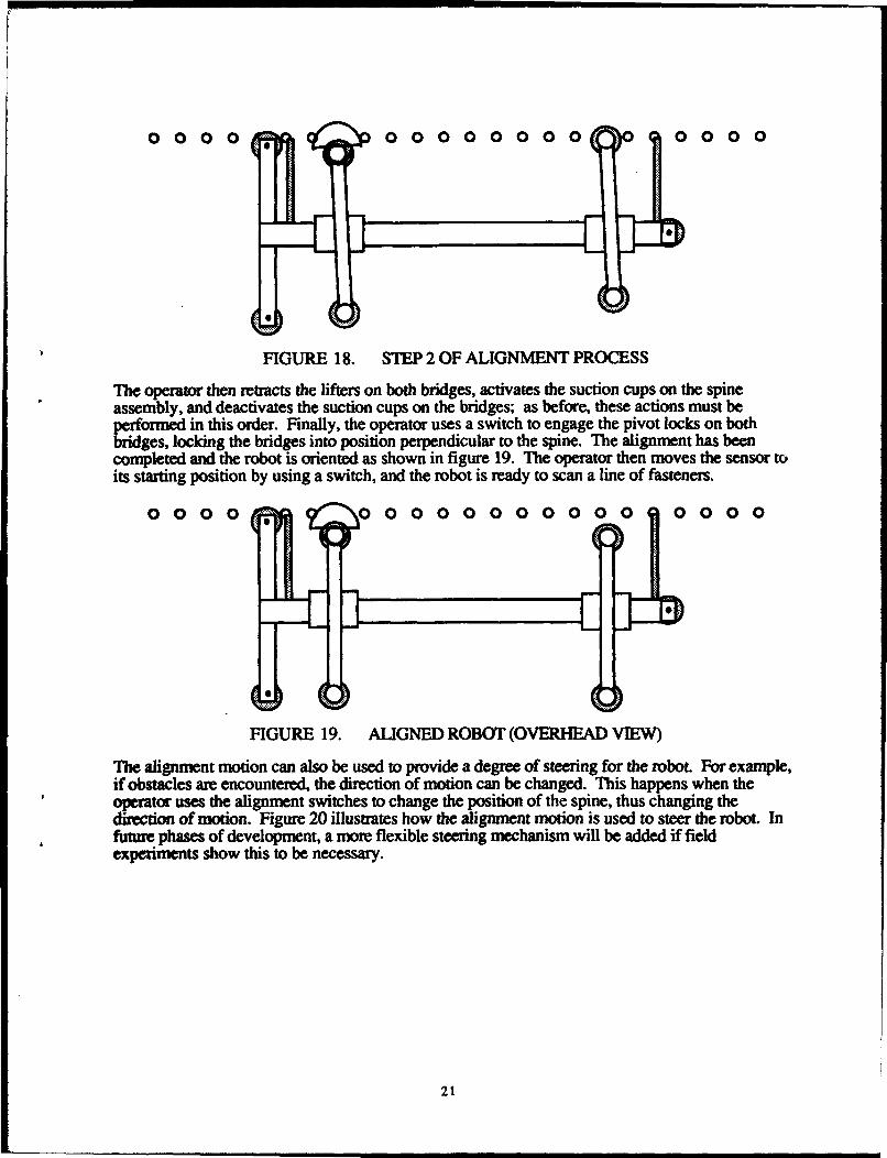
Next, the operator throws a switch to unlock the pivot locks on both bridges. Following this, theoperator uses switches to drive the stepping motors on the lead-screw assemblies; this will adjustthe position of the spine assembly. When the spine is parallel to the rivet row and the tips of thealignment posts are in line with the fasteners as shown in figure 18, the robot's spine is properlyaligned to perform a scan.
20
0 0 00 0 00 00 0 00 0 00 0
FIGURE 18. STEP 2 OF ALIGNMENT PROCESS
The operator then retracts the lifters on both bridges, activates the suction cups on the spineassembly, and deactivates the suction cups on the bridges; as before, these actions must beperformed in this order. Finally, the operator uses a switch to engage the pivot locks on bothbridges, locking the bridges into position perpendicular to the spine. The alignment has beencompleted and the robot is oriented as shown in figure 19. The operator then moves the sensor toits starting position by using a switch, and the robot is ready to scan a line of fasteners.
0 0 0 0O(0 0 0 0 0 0 0 0 0 0 0 0 0 0 0
FIGURE 19. ALIGNED ROBOT (OVERHEAD VIEW)
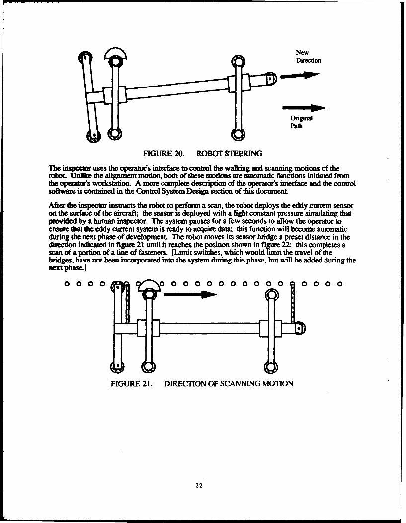
The alignment motion can also be used to provide a degree of steering for the robot. For example,if obstacles are encountered, the direction of motion can be changed. This happens when theoperator uses the alignment switches to change the position of the spine, thus changing thedirection of motion. Figure 20 illustrates how the alignment motion is used to steer the robot. Infutue phases of development, a more flexible steering mechanism will be added if fieldexperiments show this to be necessary.
21
NewDirection
aon-
Path
FIGURE 20. ROBOT STEERING
The inspccor uses the operato's interface to control the walking and scanning motions of therobot. Unlike the alignment motion, both of these motions are automatic functions initiated fromthe opealts workstation. A more complete description of the operator's interface and the controlsoftware is contained in the Control System Design section of this document.
After the inspector instructs the robot to perform a scan, the robot deploys the eddy current sensoron the surface of the aircraft; the sensor is deployed with a light constant pressure simulating thatprovided by a human inspector. The system pauses for a few seconds to allow the operator toensure that the eddy current system is ready to acquire data; this function will become automaticduring the next phase of development. The robot moves its sensor bridge a preset distance in thedirection indicated in figure 21 until it reaches the position shown in figure 22; this completes ascan of a portion of a line of fasteners. [Limit switches, which would limit the travel of thebridges, have not been incorporated into the system during this phase, but will be added during thenext phase.]
0 0 0 0 V 0 0 0 0 0 0 0 0 000 1 0 0 0 0
FIGURE 21. DIRECTION OF SCANNING MOTION
22
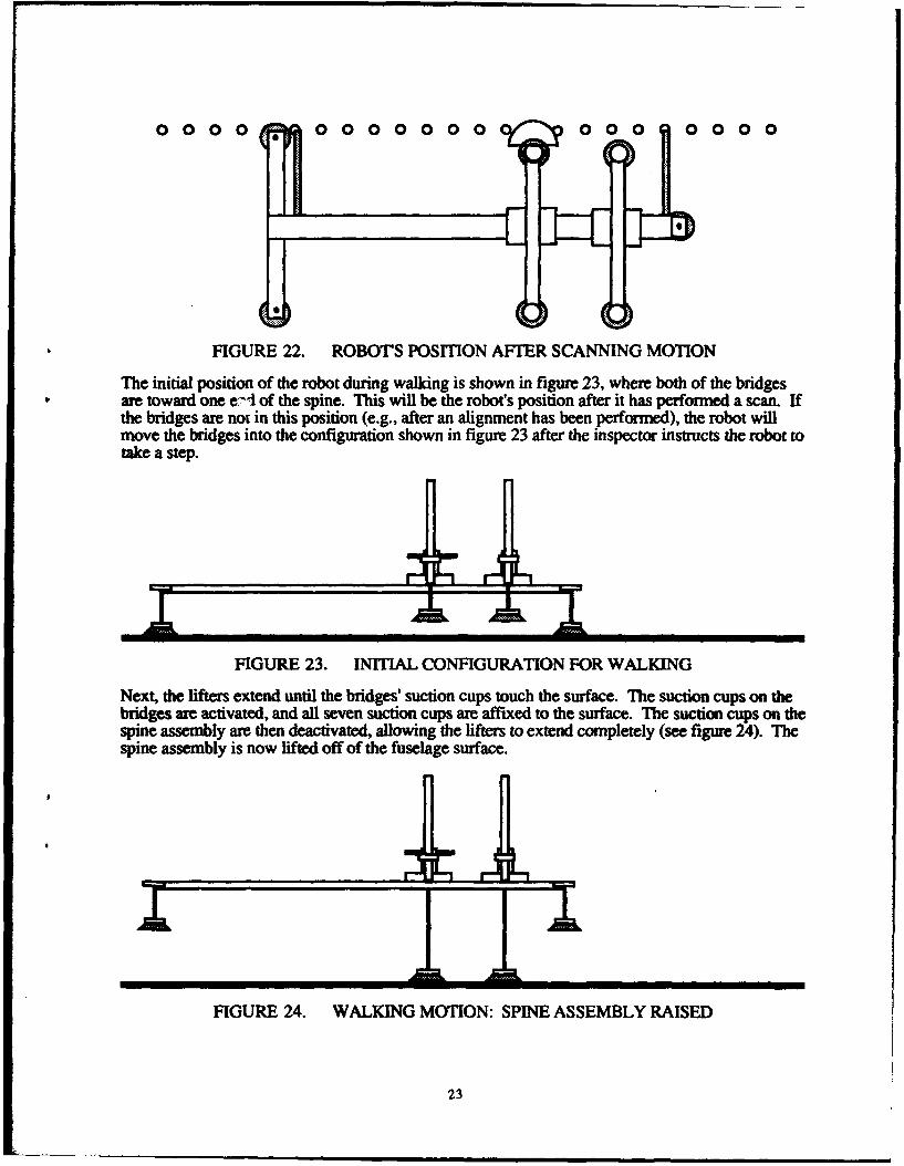
0000 0 00 0 0 0 0 0
FIGURE 22. ROBOT'S POSITION AFTER SCANNING MOTION
The initial position of the robot during walking is shown in figure 23, where both of the bridgesare toward one e--i of the spine. This will be the robot's position after it has performed a scan. Ifthe bridges are not in this position (e.g., after an alignment has been performed), the robot willmove the bridges into the configuration shown in figure 23 after the inspector instructs the robot totake a step.
FIGURE 23. INITIAL CONFIGURATION FOR WALKING
Next, the lifters extend until the bridges' suction cups touch the surface. The suction cups on thebridges are activated, and all seven suction cups are affixed to the surface. The suction cups on thespine assembly are then deactivated, allowing the lifters to extend completely (see figure 24). Thespine assembly is now lifted off of the fuselage surface.
FIGURE 24. WALKING MOTION: SPINE ASSEMBLY RAISED
23
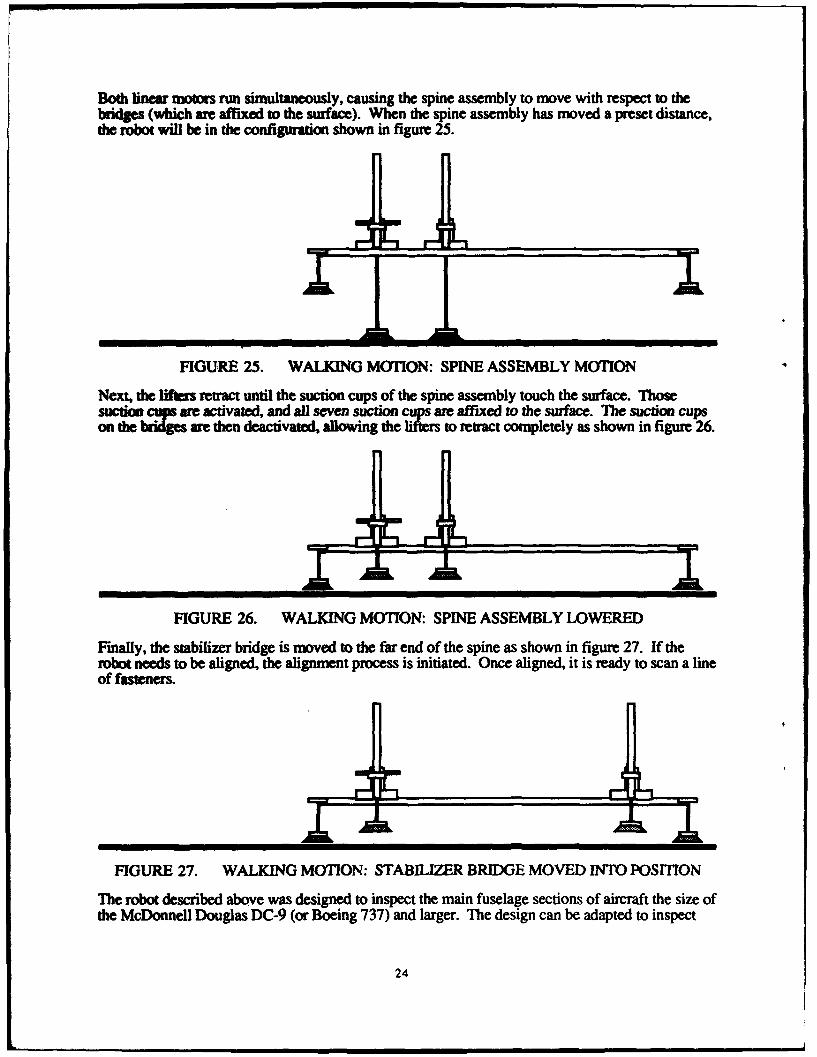
Both linear motors run simultaneously, causing the spine assembly to move with respect to thebridges (which are affixed to the surface). When the spine assembly has moved a preset distance,the robot will be in the configuration shown in figure 25.
A tt
FIGURE 25. WALKING MOTION: SPINE ASSEMBLY MOTION
Next, the lifters retract until the suction cups of the spine assembly touch the surface. Thosesuction cups are activated, and all seven suction cups are affixed to the surface. The suction cupson the briges awe then deactivated, allowing the lifters to retract completely as shown in figure 26.
FIGURE 26. WALKING MOTION: SPINE ASSEMBLY LOWERED
Finally, the stabilizer bridge is moved to the far end of the spine as shown in figure 27. If therobot needs to be aligned, the alignment process is initiated. Once aligned, it is ready to scan a lineof fasteners.
FIGURE 27. WALKING MOTION: STABILIZER BRIDGE MOVED INTO POSITION
The robot described above was designed to inspect the main fuselage sections of aircraft the size ofthe McDonnell Douglas DC-9 (or Boeing 737) and larger. The design can be adapted to inspect
24
highly curved areas such as the nose or tail, hard-to-reach areas such as those around windows ordoors, and smaller aircraft. The robot designed by the Carnegie Mellon team can be scaled eitherlarger or smaller, most components used to build the robot are commercially available in a varietyof sizes. Thus, for smaller aircraft or for areas on larger aircraft with greater curvature, a smallerversion of the prototype could be produced. This version would weigh less than the currentversion, but it would also have a much shorter maximum scanning distance. It would have to takeseveral steps to inspect the same number of fasteners that the current prototype can inspect in onestep.
When inspecting large aircraft such as the McDonnell Douglas DC-10 or the Boeing 747, it mightbe advantageous to build a large version of the robot to cover even greater distances with a singlescan. Of course, the larger versions would weigh more, so there is a practical limit to themaximum size. In addition, scaling relations favor smaller devices when suction cups are used asthe affixing means. Ultimately, the size of production versions will be driven by the requirementsof aircraft inspectors. During the testing of the system on aircraft owned by USAir and thoseowned by other airlines, it will be decided which aircraft are best suited to robotic inspection andwhich inspections benefit most from the automated deployment of sensors. This will determine theoptimum size of the robot. Several sizes of spine assemblies and bridges may be commerciallyproduced, allowing end users to buy robots to fit their needs.
In addition, special attachments could be developed to enable the robot to inspect hard-to-reachareas. For example, inspecting areas around the windows of an aircraft could prove troublesomebecause these are areas on the fuselage on which maneuvering might be difficult. If some type ofwindow inspection is required, a special attachment allowing access to the inspection area from anarea above (or below) the windows might be used.
The design can also be easily extended to incorporate other NDI sensors. During this phase ofdevelopment, the prototype can deploy a reflectance eddy current probe, and the basic requirementsfor mounting small cameras on the device have been written (see Sensors section below). In thefuture, a number of NDI sensors will be mounted on the sensor platform. Of the probescormmonly used by inspectors today, pencil eddy current sensors and ultrasonic sensors are goodcandidates for inclusion in the sensor suite. New NDI sensors, such as the magneto-optic sensordeveloped by Physical Research, Inc. [2], and new techniques, such as shearography [3], willbecome FAA-approved and operator-accepted in the next few years. As new sensor technologiesemerge, they will be evaluated and included as part of the sensor suite if appropriate.
A tether to secure the robot from above will be designed, built, and tested during the next phase ofdevelopment. If the air supply is lost during an inspection, the robot will no longer be able toadhere to the surface; the tether will prevent the robot from falling to the ground. As currentlyenvisioned, the tether will be secured to the safety lines already present for human inspectors;these safety lines are mounted on trolleys that run parallel to the horizontal axis of the aircraft fromnose to tail. The trolley-mounted safety lines give inspectors the freedom to move along the lengthof the aircraft and secure them from falling.
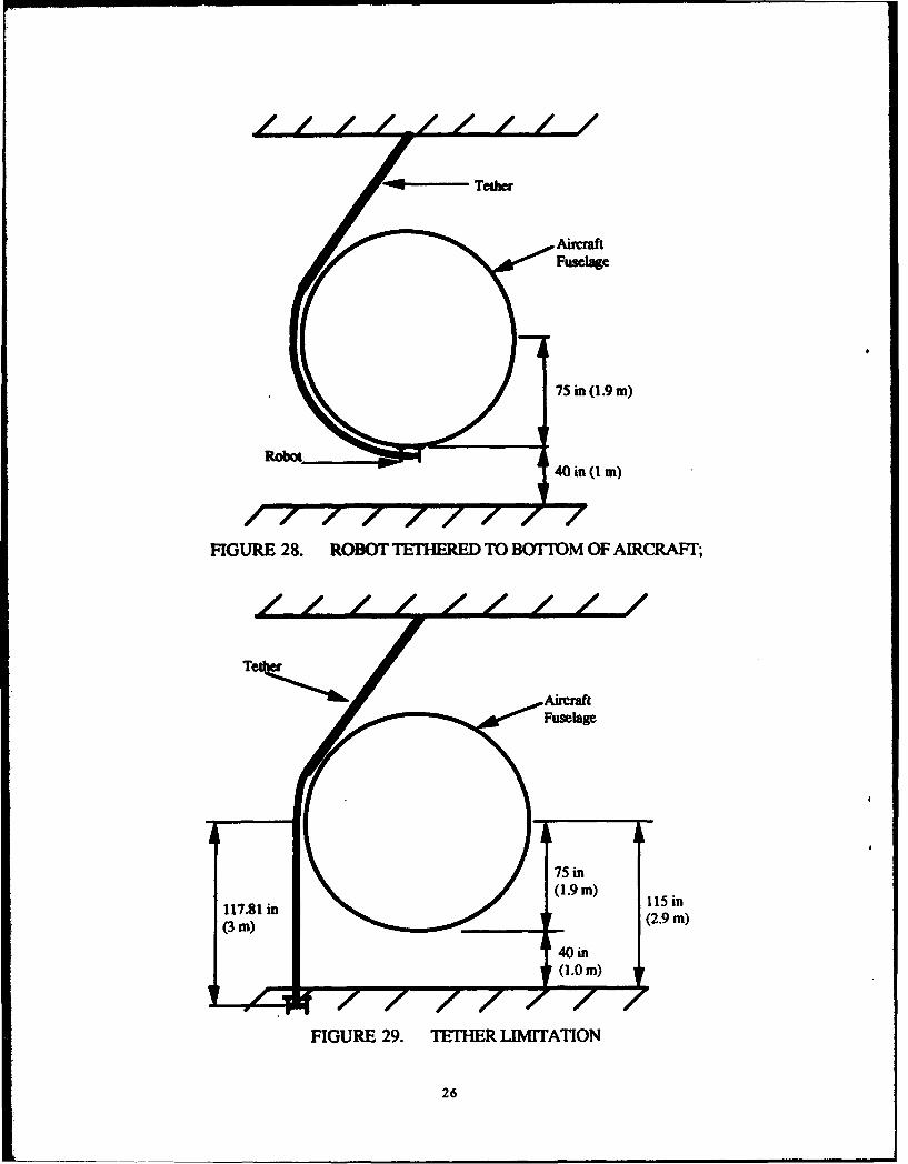
However, the tether arrangement for the robot will not work when the robot is positioned on the"belly" of the airaft. The clearance underneath a typical mid-size jet aircraft (e.g., McDonnellDouglas DC-9 or Boeing 737) is about 40 inches (1 m), and the approximate radius of the fuselageis 75 inches (1.9 m). If the robot were positioned on the "belly" of the aircraft as shown in figure28, the tether would follow the circumference of the fuselage to this point.
25
Fuselage
• 75 in (I.9 m)
401 in (I m)
FIGURE 28. ROBOT TETHERED TX) BOrPOM OF AIRCRAFT;
AircrafftFuselage
S'75 in
117.81 in (9M 115 in
(3 m) ti oe(2.9 m)
4[(10 in
FIGURE 29. TETHER IAM1TATION
26
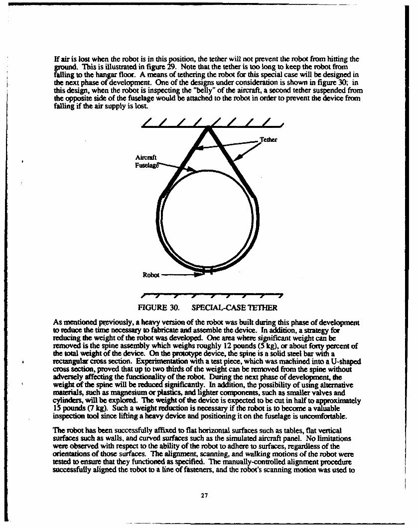
If air is lost when the robot is in this position, the tether will not prevent the robot from hitting theground. This is illustrated in figure 29. Note that the tether is too long to keep the robot fromfalling to the hangar floor. A means of tethering the robot for this special case will be designed inthe next phase of development. One of the designs under consideration is shown in figure 30; inthis design, when the robot is inspecting the "belly" of the aircraft, a second tether suspended fromthe opposite side of the fuselage would be attached to the robot in order to prevent the device fromfalling if the air supply is lost.
FIGURE 30. SPECIAL-CASE TETHER
As mentioned pixmviously, a heavy version of the robot was built during this phase of developmentto reduce the time necessary to fabricate and assemble the device. In addition, a strategy forreducing the weight of the robot was developed. One area where significant weight can beremoved is the spine assembly which weighs roughly 12 pounds (5 kg), or about forty percent ofthe total weight of the device. On the prototype device, the spine is a solid steel bar with arectangular cross section. Experimentation with a test piece, which was machined into a U-shapedcross section, proved that up to two thirds of the weight can be removed from the spine withoutadversely affecting the functionality of the robot. During the next phase of development, theweight of the spine will be reduced significantly. In addition, the possibility of using alumeativematrials, such as magnesium or plastics, and lighter components, such as smaller valves andcylinders, will be explored. The weight of the device is expected to be cut in half to approximately15 pounds (7 kg). Such a weight reduction is necessary if the robot is to become a valuableinspection tool since lifting a heavy device and positioning it on the fuselage is uncomfortable.
The robot has been successfully affixed to flat horizontal surfaces such as tables, flat verticalsurfaces such as walls, and curved surfaces such as the simulated aircraft panel. No limitationswere observed with respect to the ability of the robot to adhere to surfaces, regardless of theorientations of those surfaces. The alignment, scanning, and walking motions of the robot weretested to ensure that they functioned as specified. The manually-controlled alignment proceduresuccessfully aligned the robot to a line of fasteners, and the robot's scanning motion was used to
27
deploy a reflectance eddy current sensor and move it along a fastener line. The robot was able towalk along the aircraft panel, and a coordinated scan and walk motion was performed. Thus, thede .of the robot satisfied the mobility and manipulation requirements of the skin inspectionMEL-f
The implementation of the design resulted in a need to align the robot to the fastener line after eachstep; the accumulated error was too large. The robot strayed from its path approximately 0.125inches (3.2 mm) during each step due to excessive compliance in the system. With the reflectanceeddy current sensor requiring that it be aligned ±0.05 inches (±1.3 cm) from the center of afamener, an alignment was necessary after every step with the initial prototype. To correct theproblem of erro accumulation during walking, the design team decided to increase the stiffness ofthe system. The bearing arrangement holding the linear motors to the spine needs to be improved,and the stiffness of the lifters when fully extended also requires improvements. Theseenhancements to the system will be added early in the next phase of development.
Experiments measuring the leak rates at various positions on aircraft showed that vacuum pumpswith one half of the air consumption of those on the prototype could be used without sacrificingsystem performance. The performance of the reduced-flow vacuum pumps vis-a-vis leak rates onaircraft surfaces was nearly identical to the performance of the larger vacuum pumps.
SENSORS.
Visual inspections currently account for ninety percent (90%) of the inspections performed onaircraft; the remainder are other forms of nondestructive inspections, the majority of which areeddy current inspections. Thus, the major objective concerning the selection of sensors for therobotic inspection system was to be able to provide for both visual and eddy current inspections.The automated deployment of eddy current sensors was explored first because it is much easier toimplement than is an automated visual inspection system. More specifically, the objective used todevelop the sensor system was to initially investigate at least three NDI sensors for inclusion on thesensor platform: a high frequency eddy current sensor to find surface flaws, a low frequency eddycurrent sensor to find subsurface flaws, and video cameras for visual examination of the surfaceand for navigation.
There are many types of eddy current sensors used by inspectors to examine the fuselages ofaifraft. The philosophy used with regard to sensor selection for the robotic system was to choosesensors that are both FAA-approved and operator-accepted. A comparison of results can then bemade between the sensors that are deployed manually and those that are deployed robotically. Oneof the most popular types of sensors is the reflectance probe, also known as the sliding probe.Reflectance probes have separate driver and pickup coils and are deployed over a row of fastenersas shown in fig=ur 3 1. They are scanned over the fastener heads, and the differences in thecomplex impedance-plane displays for good fastener holes and those with cracks are noted.Because of its universal acceptance, the reflectance probe is a good choice to be included in therobotic system.
The Nortec SPO-1958 eddy current sensor is the reflectance-type sensor chosen for the roboticsystem. This probe can operate at frequencies between 100 Hz and 40 kHz, allowing for bothsubsurface crack detection at low frequencies and surface crack detection at high frequencies. Atits lowest frequencies, the SPO-1958 produces eddy currents that can penetrate up to a depth of0.50 inches (13 mm).
Various eddy current systems were evaluated with respect to their applicability to this project. SESystems SmartEDDY 3.0 system was chosen because it operated on a PC platform and couldeasily be integrated into the robotic system. The SmartEDDY 3.0 has a dual frequency feature,
28
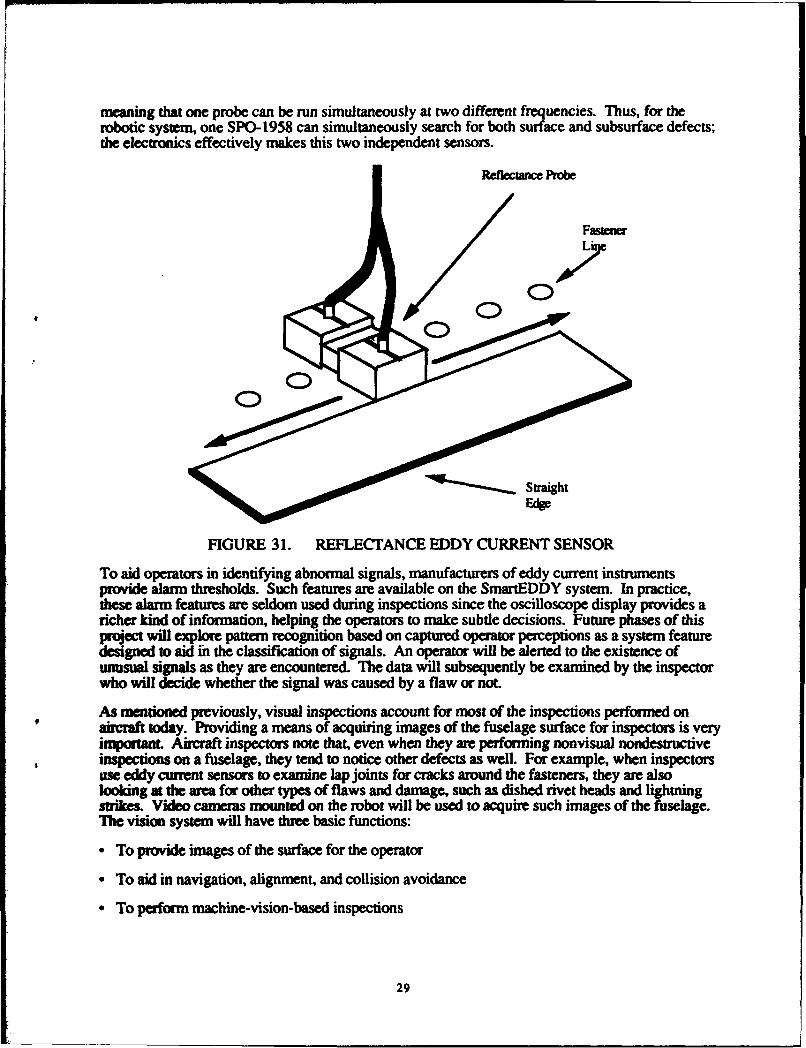
meaning that one probe can be run simultaneously at two different frequencies. Thus, for therobotic system, one SPO-1958 can simultaneously search for both surface and subsurface defects;the electronics effectively makes this two independent sensors.
Reflectance Probe
'17
FIGURE 31. REFLECTANCE EDDY CURRENT SENSOR
To aid operators in identifying abnormal signals, manufacturers of eddy current instrumentsprovide alarm thresholds. Such features are available on the SmartEDDY system. In practice,these alarm features are seldom used during inspections since the oscilloscope display provides aricher kind of information, helping the operators to make subtle decisions. Future phases of thisproject will explore pattern recognition based on captured operator perceptions as a system featuredesigned to aid in the classification of signals. An operator will be alerted to the existence ofunusual signals as they are encountered. The data will subsequently be examined by the inspectorwho will decide whether the signal was caused by a flaw or not.
As mentioned previously, visual inspections account for most of the inspections performed onaircraft today. Providing a means of acquiring images of the fuselage surface for inspectors is veryimportant. Aircraft inspectors note that, even when they are performing nonvisual nondestructiveinspections on a fuselage, they tend to notice other defects as well. For example, when inspectorsuse eddy current sensors to examine lap joints for cracks around the fasteners, they are alsolooking at the area for other types of flaws and damage, such as dished rivet heads and lightningstrikes. Video cameras mounted on the robot will be used to acquire such images of the fuselage.The vision system will have three basic functions:
"* To provide images of the surface for the operator
"• To aid in navigation, alignment, and collision avoidance
"• To perform machine-vision-based inspections
29
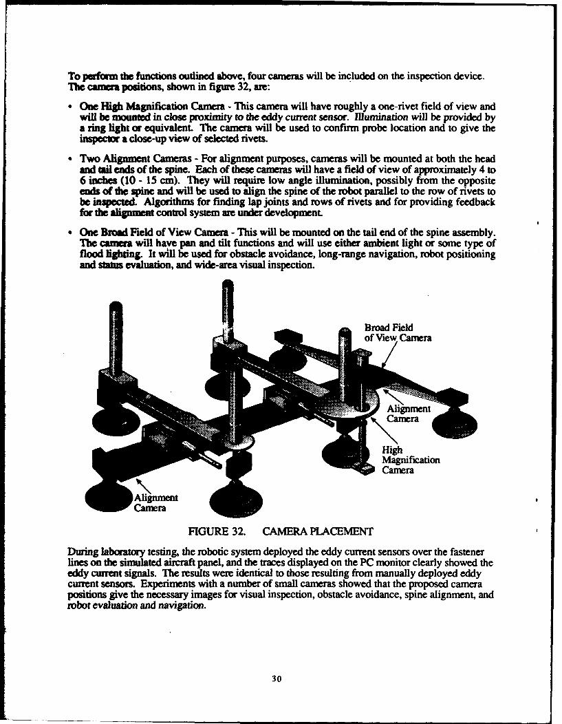
To perfor the functions outlined above, four cameras will be included on the inspection device.The camera positions, shown in figure 32, are:
" One High Magnification Camera - This camera will have roughly a one-rivet field of view andwill be mounted in close proximity to the eddy current sensor. Illumination will be provided bya ring light or equivalent. The camera will be used to confirm probe location and to give theinspector a close-up view of selected rivets.
" Two Alignment Cameras - For alignment purposes, cameras will be mounted at both the headand tail ends of the spine. Each of these cameras will have a field of view of approximately 4 to6 inches (10 - 15 cm). They will require low angle illumination, possibly from the oppositeends of die spine and will be used to align the spine of the robot parallel to the row of rivets tobe inspected. Algorithms for finding lap joints and rows of rivets and for providing feedbackfor the alignment control system are under development
"* One Broad Field of View Camera - This will be mounted on the tail end of the spine assembly.The camera will have pan and tilt functions and will use either ambient light or some type offlood lighting. It will be used for obstacle avoidance, long-range navigation, robot positioningand status evaluation, and wide-area visual inspection.
rodField
FIGURE 32. CAMERA PLACEMENT
During laboratory testing, the robotic system deployed the eddy current sensors over the fastenerlines on the simulated aircraft panel, and the traces displayed on the PC monitor clearly showed theeddy current signals. The results were identical to those resulting from manually deployed eddycurrent sensors. Experiments with a number of small cameras showed that the proposed camerapositions give the necessary images for visual inspection, obstacle avoidance, spine alignment, androbot evaluation and navigation.
30
CALIBRATION.
During the first phase of development, the main objective in the calibration of the robotic systemwas to ensure that the operator sees a clear and distinct separation of signals between thoseproduced by areas on an aircraft containing flaws and those produced by flaw-free areas. Inessence, during the calibration procedure, the operator is being calibrated with the eddy currentsensor. In future phases of the project, calibration techniques for other parts of the system, suchas the navigation subsystem (based on database and vision), will be developed.
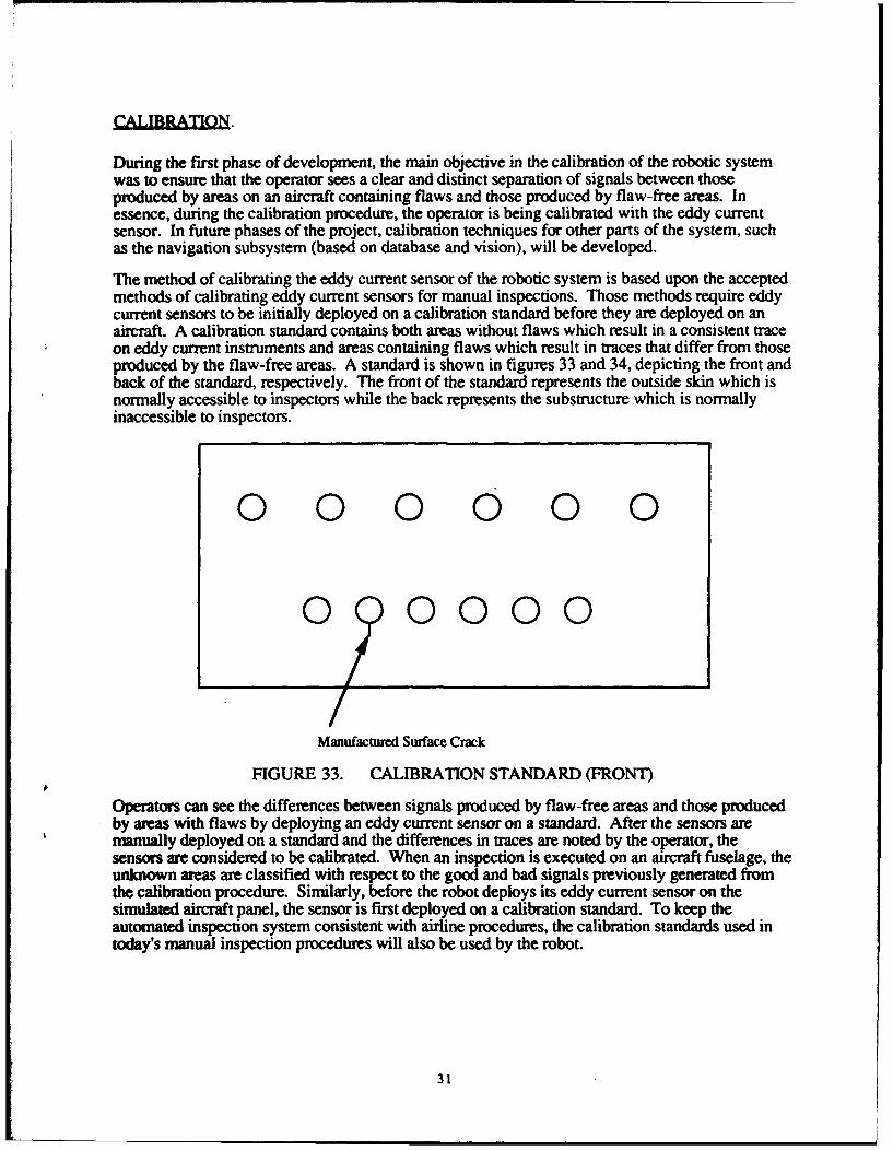
The method of calibrating the eddy current sensor of the robotic system is based upon the acceptedmethods of calibrating eddy current sensors for manual inspections. Those methods require eddycurrent sensors to be initially deployed on a calibration standard before they are deployed on anaircraft. A calibration standard contains both areas without flaws which result in a consistent traceon eddy current instruments and areas containing flaws which result in traces that differ from thoseproduced by the flaw-free areas. A standard is shown in figures 33 and 34, depicting the front andback of the standard, respectively. The front of the standard represents the outside skin which isnormally accessible to inspectors while the back represents the substructure which is normallyinaccessible to inspectors.
0 0 0 0 0 0
0 0000
Manufactured Surface Crack
FIGURE 33. CALIBRATION STANDARD (FRONT)
Operators can see the differences between signals produced by flaw-free areas and those producedby areas with flaws by deploying an eddy current sensor on a standard. After the sensors aremanually deployed on a standard and the differences in traces are noted by the operator, thesensors are considered to be calibrated. When an inspection is executed on an aircraft fuselage, theunknown areas are classified with respect to the good and bad signals previously generated fromthe calibration procedure. Similarly, before the robot deploys its eddy current sensor on thesimulated aircraft panel, the sensor is first deployed on a calibration standard. To keep theautomated inspection system consistent with airline procedures, the calibration standards used intoday's manual inspection procedures will also be used by the robot.
31
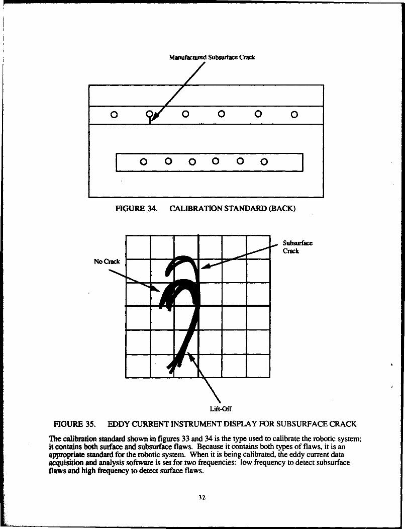
Manufacured Subsurface Crack
0 00 000
0 0O0 0 0 0
FIGURE 34. CALIBRATION STANDARD (BACK)
SubsurfaceCrack
Lift-Off
FIGURE 35. EDDY CURRENT INSTRUMENT DISPLAY FOR SUBSURFACE CRACK
The calibration standard shown in figures 33 and 34 is the type used to calibrate the robotic system;it contains both surface and subsurface flaws. Because it contains both types of flaws, it is anappropriate standard for the robotic system. When it is being calibrated, the eddy current dataacquisition and analysis- software is set for two frequencies: low frequency to detect subsurfaceflaws and high frequency to detect surface flaws.
32
The low frequency setting is calibrated when the robot deploys the sensor and scans the top row ofrivets in the standard. The system parameters for the low frequency calibration are set such that theeddy current instrument display resembles figure 35, which is a drawing representing theoscilloscope output that an operator sees. An x-y position on the display represents the complexnumber that characterizes the impedance of the metal under the probe; the curves in figure 35represent the variation of impedance as the probe is moved over several good fasteners and onecontaining a subsurface crack.
The signal produced by the subsurface crack is easily separated from the signals produced by theflaw-free areas. When this type of display is produced after the system has deployed the sensorover the top row of fasteners, the system has been calibrated to find subsurface cracks similar tothose found in the standard.
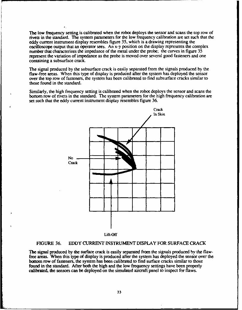
Similarly, the high frequency setting is calibrated when the robot deploys the sensor and scans thebottom row of rivets in the standard. The system parameters for the high frequency calibration areset such that the eddy current instrument display resembles figure 36.
CrackIn Skin
NoCrack
Lift-Off
FIGURE 36. EDDY CURRENT INSTRUMENT DISPLAY FOR SURFACE CRACK
The signal produced by the surface crack is easily separated from the signals produced by the flaw-free areas. When this type of display is produced after the system has deployed the sensor over thebottom row of fasteners, the system has been calibrated to find surface cracks similar to thosefound in the standard. After both the high and the low frequency settings have been properlycalibrated, the sensors can be deployed on the simulated aircraft panel to inspect for flaws.
33
The method described above to calibrate the system proved to work well. The system parametersfor both high and low frequencies were adjusted to produce signals comparable to those shown infigures 35 and 36, respectively, providing a clear separation of signals for the operator. Thus, theeddy current sensor on the robotic system was properly calibrated to find both surface andsubsurface cracks simultaneously.
CONTROL SYSTEM IGN.
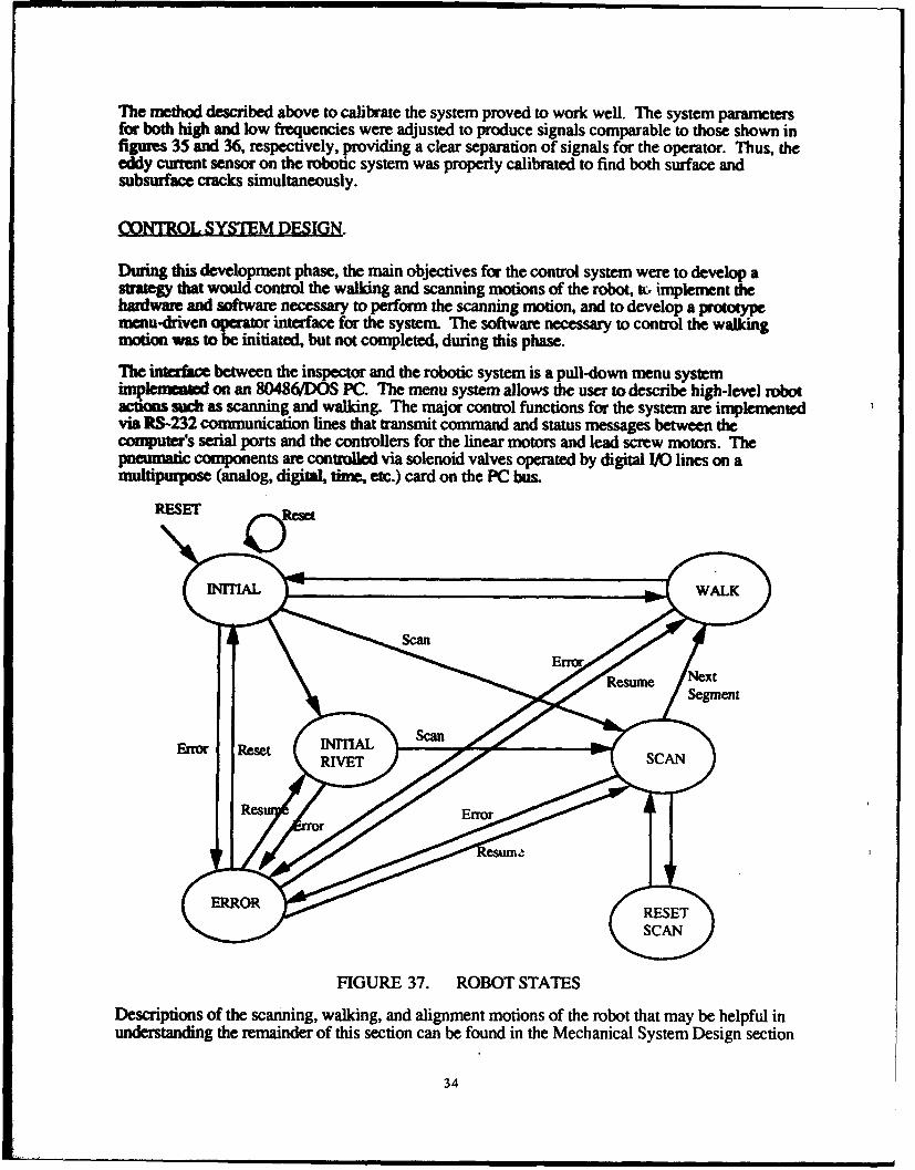
During this development phase, the main objectives for the control system were to develop astrategy that would control the walking and scanning motions of the robot, tc, implement thehardware and software necessary to perform the scanning motion, and to develop a prototypemenu-driven operaor interface for the system. The software necessary to control the walkingmotion was to be initiated, but not completed, during this phase.
The initace between the inspector and the robotic system is a pull-down menu systemimplemun on an 80486/DOS PC. The menu system allows the user to describe high-level robotactions such as scanning and walking. The major control functions for the system are implementedvia RS-232 communication lines that transmit command and status messages between thecomputer's serial ports and the controllers for the linear motors and lead screw motors. Thepneumatic components are contmled via solenoid valves operated by digital I/0 lines on amultipurpose (analog, digital, time, etc.) card on the PC bus.
RESET Reset
HNITIAL WALK
tesue /Segment
Error Reset M/IITIAL Scan
Res n Error
ERROR RESET
S~SCAN
FIGURE 37. ROBOT STATES
Descriptions of the scanning, walking, and alignment motions of the robot that may be helpful inunderstanding the remainder of this section can be found in the Mechanical System Design section
34
of this document. The operator interface for the system and the operational states that control therobot's motion are described in more detail below. Figure 37 shows the four defined states of therobot: INITIAL, ERROR, WALK, and SCAN.
The operator has four buttons that can be used to begin and end the inspection process; they arecurrently located on a switch box in the work space. In future phases of development, they will beplaced on the robot for operator convenience. The buttons are:
- Initialize - This function is used to define the INITIAL state of the robot which is done beforethe robot is placed on the aircraft. The robot's bridges are manually moved to their homepositions, and, when the Initialize button is pressed, this position is registered. In futurephases, sensors will be placed on the robot to define the home positions of the elements,eliminating the need for the Initialize button.
- Reset - When the operator presses this button, the robot will go to its INITIAL state, sending allem ts o their home positions.
- Affix - Pressing this button will activate the three suction cups on the spine assembly, allowingthe operator to affix the robot to an aircraft.
- Clear - When the operator presses this button, all suction cups are deactivated, allowing theoperator to remove the robot from the aircraft surface.
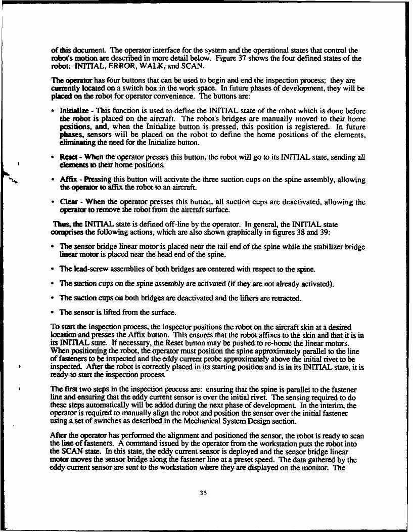
Thus, the INITIAL state is defined off-line by the operator. In general, the INITIAL statecomprises the following actions, which are also shown graphically in figures 38 and 39:
"* The sensor bridge linear motor is placed near the tail end of the spine while the stabilizer bridgelinear motor is placed near the head end of the spine.
"• The lead-screw assemblies of both bridges are centered with respect to the spine.
"* The suction cups on the spine assembly are activated (if they are not already activated).
"• The suction cups on both bridges are deactivated and the lifters are retracted.
"• The sensor is lifted from the surface.
To start the inspection process, the inspector positions the robot on the aircraft skin at a desiredlocation and presses the Affix button. This ensures that the robot affixes to the skin and that it is inits INITIAL state. If necessary, the Reset button may be pushed to re-home the linear motors.When positioning the robot, the operator must position the spine approximately parallel to the lineof fasteners to be inspected and the eddy current probe approximately above the initial rivet to beinspected. After the robot is correctly placed in its starting position and is in its INITIAL state, it isready to start the inspection process.
The first two steps in the inspection process are: ensuring that the spine is parallel to the fastenerline and ensuring that the eddy current sensor is over the initial rivet. The sensing required to dothese steps automatically will be added during the next phase of development. In the interim, theoperator is required to manually align the robot and position the sensor over the initial fastenerusing a set of switches as described in the Mechanical System Design section.
After the operator has performed the alignment and positioned the sensor, the robot is ready to scanthe line of fasteners. A command issued by the operator from the workstation puts the robot intothe SCAN state. In this state, the eddy current sensor is deployed and the sensor bridge linearmotor moves the sensor bridge along the fastener line at a preset speed. The data gathered by theeddy current sensor are sent to the workstation where they are displayed on the monitor. The
35
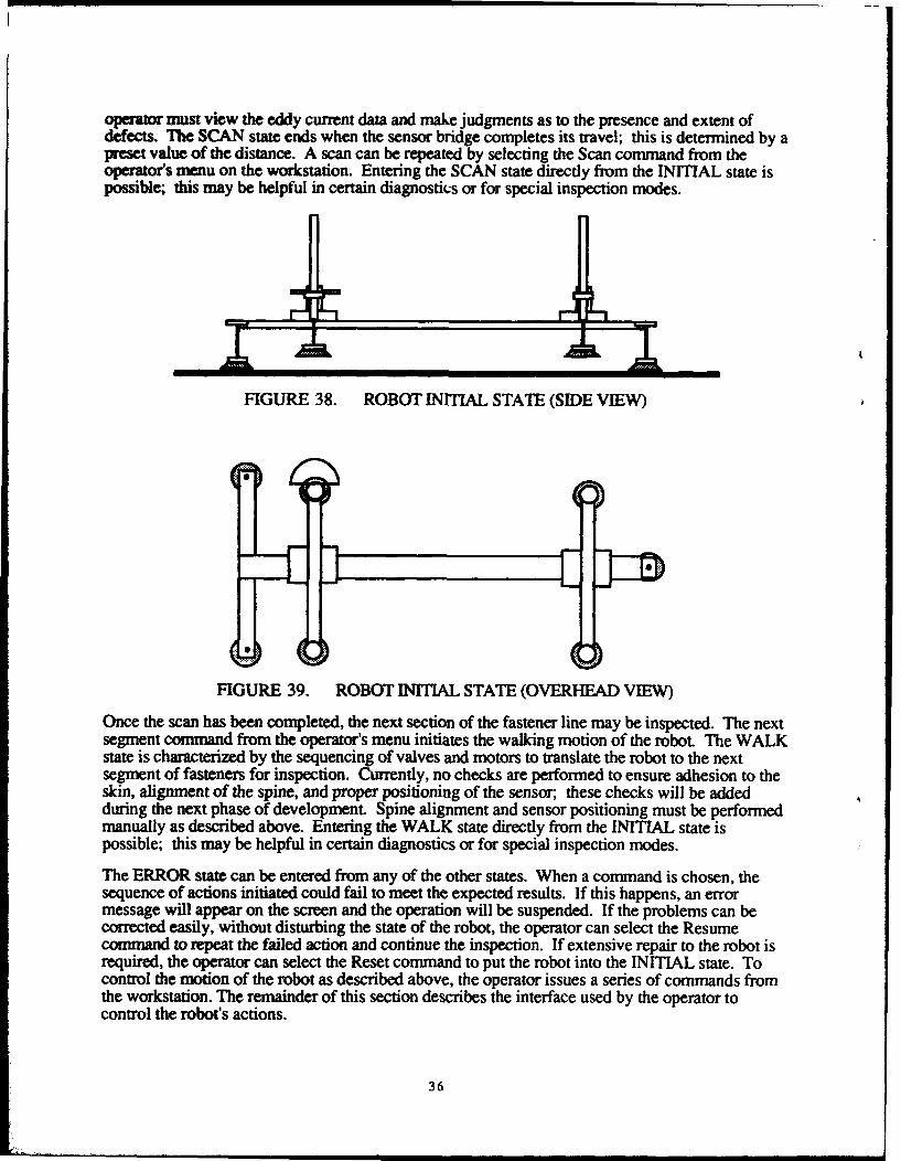
operator must view the eddy current data and make judgments as to the presence and extent ofdefects. The SCAN state ends when the sensor bridge completes its travel; this is determined by apreset value of the distance. A scan can be repeated by selecting the Scan command from theoperator's menu on the workstation. Entering the SCAN state directly from the INITIAL state ispossible; this may be helpful in certain diagnostics or for special inspection modes.
FIGURE 38. ROBOTINITIAL STATE (SIDE VIEW)
FIGURE 39. ROBOT INITIAL STATE (OVERHEAD VIEW)
Once the scan has been completed, the next section of the fastener line may be inspected. The nextsegment command from the operator's menu initiates the walking motion of the robot. The WALKstate is characterized by the sequencing of valves and motors to translate the robot to the nextsegment of fasteners for inspection. Currently, no checks are performed to ensure adhesion to theskin, alignment of the spine, and proper positioning of the sensor; these checks will be addedduring the next phase of development. Spine alignment and sensor positioning must be performedmanually as described above. Entering the WALK state directly from the INITIAL state ispossible; this may be helpful in certain diagnostics or for special inspection modes.
The ERROR state can be entered from any of the other states. When a command is chosen, thesequence of actions initiated could fail to meet the expected results. If this happens, an errormessage will appear on the screen and the operation will be suspended. If the problems can becorrected easily, without disturbing the state of the robot, the operator can select the Resumecommand to repeat the failed action and continue the inspection. If extensive repair to the robot isrequired, the operator can select the Reset command to put the robot into the INITIAL state. Tocontrol the motion of the robot as described above, the operator issues a series of commands fromthe workstation. The remainder of this section describes the interface used by the operator tocontrol the robot's actions.
36
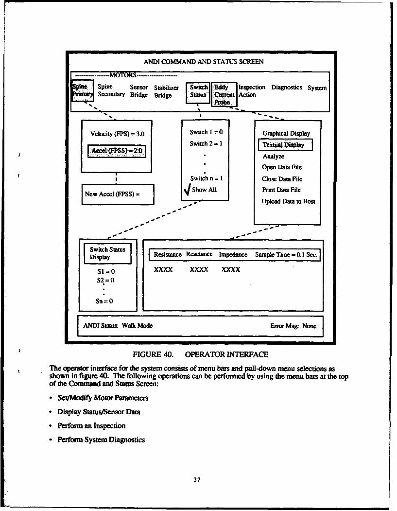
ANDI COMMAND AND STATUS SCREEN
- --.----.--..MOTORS -------------------
Spi, Sensor Stabilizer Edi [ Inspection Diagnostics SystemSecondary Bridge Bridge CaStatus1 Cunrrnt Action
Velocity (FPS) = 3.0 Switch I = 0 Graphical Display
Ace: FSS 20Switch 2 =1I Textual D)iapay
* Analyze
*_Open Data FileSwitch n = I Close Data File
New Accel S) Show All Print Data File
- - --' Upload Data to Host
Sit Sta Resistance Reactance Impedance Sample Time= 0.1 Sec.Display I I I
SI = 0 XXXX XXXX XXXX
S2 = 0
Sn=0
[ANDI Status: Walk Mode Error Msg. None
FIGURE 40. OPERATOR INTERFACE
The operator interface for the system consists of menu bars and pull-down menu selections asshown in figure 40. The following operations can be performed by using the menu bars at the topof the Command and Status Screen:
". Set/Modify Motor Parameters
"* Display Status/Sensor Data
"* Perform an Inspection
"* Perform System Diagnostics
37
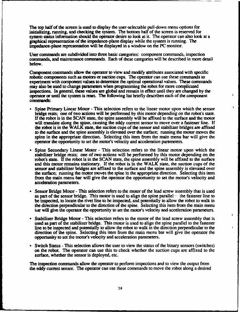
The top half of the screen is used to display the user-selectable pull-down menu options forinitializing, running, and checking the system. The bottom half of the screen is reserved forsystem status information should the operator desire to look at it. The operator can also look at agraphical representation of the impedance-plane display while the system is running. Theimpedance-plane representation will be displayed in a window on the PC monitor.
User commands are subdivided into three basic categories: component commands, inspectioncommands, and maintenance commands. Each of these categories will be described in more detailbelow.
Component commands allow the operator to view and modify attributes associated with specificrobotic components such as motors or suction cups. The operator can use these commands toexperiment with component values to determine the optimal operational values. These commandsmay also be used to change parameters when programming the robot for more complicatedinspections. In general, these values are global and remain in effect until they are changed by theoperator or until the system is reset. The following list briefly describes each of the componentconmmndss:
" Spine Primary Linear Motor - This selection refers to the linear motor upon which the sensorbridge rests; one of two actions will be performed by this motor depending on the robot's state.If the robot is in the SCAN state, the spine assembly will be affixed to the surface and the motorwill translate along the spine, causing the eddy current sensor to move over a fastener line. Ifthe robot is in the WALK state, the suction cups of the sensor and stabilizer bridges are affixedto the surface and the spine assembly is elevated over the surface; running the motor moves thespine in the appropriate direction. Selecting this item from the main menu bar will give theoperator the opportunity to set the motor's velocity and acceleration parameters.
" Spine Secondary Linear Motor - This selection refers to the linear motor upon which thestabilizer bridge rests; one of two actions will be performed by this motor depending on therobot's state. If the robot is in the SCAN state, the spine assembly will be affixed to the surfaceand this motor remains stationary. If the robot is in the WALK state, the suction cups of thesensor and stabilizer bridges are affixed to the surface and the spine assembly is elevated overthe surface; running the motor moves the spine in the appropriate direction. Selecting this itemfrom the main menu bar will give the operator the opportunity to set the motor's velocity andacceleration parameters.
" Sensor Bridge Motor - This selection refers to the motor of the lead screw assembly that is usedas part of the sensor bridge. This motor is used to align the spine parallel -ý the fastener line tobe inspected, to locate the rivet line to be inspected, and potentially to allow the robot to walk inthe direction perpendicular to the direction of the spine. Selecting this item from the main menubar will give the operator the opportunity to set the motor's velocity and acceleration parameters.
" Stabilizer Bridge Motor - This selection refers to the motor of the lead screw assembly that isused as part of the stabilizer bridge. This motor is used to align the spine parallel to the fastenerline to be inspected and potentially to allow the robot to walk in the direction perpendicular to thedirection of the spine. Selecting this item from the main menu bar will give the operator theopportunity to set the motor's velocity and acceleration parameters.
"* Switch Status - This selection allows the user to view the status of the binary sensors (switches)on the robot. The operator can use this to check whether the suction cups are affixed to thesurface, whether the sensor is deployed, etc.
The inspection commands allow the operator to perform inspections and to view the output fromthe eddy current sensor. The operator can use these commands to move the robot along a desired
38
path and to interact directly with the sensor. The following list briefl , describes each of theinspection commands:
"Eddy Current Probe - This selection allows the operator to view and store data acquired by theeddy current sensor. Selecting this item from the main menu bar will give the operator theopportunity to view either graphical or textual displays of the eddy current data; to access theSmartEDDY eddy current software; to open, close, or print a data file; and, in the future, toupload a data file over the Ethernet.
" Inspection Action - This selection allows the operator to instruct the robot to perform aninspection along a single line of rivets or to perform a sequence of motions that comprise anaction. Selecting this item from the main menu bar will give the operator the opportunity to resetthe robot to its INITIAL state, to locate a fastener, to scan a line of fasteners, and to step to thenext segment of the fastener line being inspected.
The maintenance commands allow the operator to directly control certain hardware on the roboLFor example, turning motors on/off and activating/deactivating specific suction cups can beaccomplished by using these commands. In addition, computer system functions such as escapingor exiting to DOS are included here. The following list briefly describes each of the maintenancecommands:
"• Diagnostics - This selection allows the operator to directly actuate all of the components of therobot. It functions primarily as an integrity check of the component selected in the pull-downmenu.
"* System - This selection allows the operator to interact with the computer's operating system.
The operator interface and control system described above were developed and successfully testedon the system; the 486 PC was sufficient to control the system. An integrated control system wasdesigned and developed, and the software was able to control both the walking and the scanningmotions of the robot; this was beyond the requirements of the grant which specified only that therobot be able to scan a length of skin seam. In addition, a coordinated walking and scanningmotion was achieved during the testing of the system.
DATA MANAGE
A major goal of the Automated Inspection of Aircraft Project is to develop a data managementsystem which includes both signal and image processing as well as a database of inspectioninformation. This will begin during the next phase of the project; however, some initialgroundwork for the development of the data management system was scheduled for the first phaseof the project. The primary objectives dining this phase were to investigate the data that are neededin a database of inspection information and to determine the techniques that are used by aircraftinspectors to classify eddy current signals. The data acquisition and analysis functions used by thesystem during this phase were confined to those available in commercial eddy current systems.
A lot of information can be stored about any given flaw found on the skin of an aircraft. Membersof the Carnegie Mellon team discussed this issue with USAir inspection managers and developed alist of data that the managers felt were the most relevant. The following items were identified bythe inspection managers:
"* The location of defectI
"* The descuiption of the defect
39
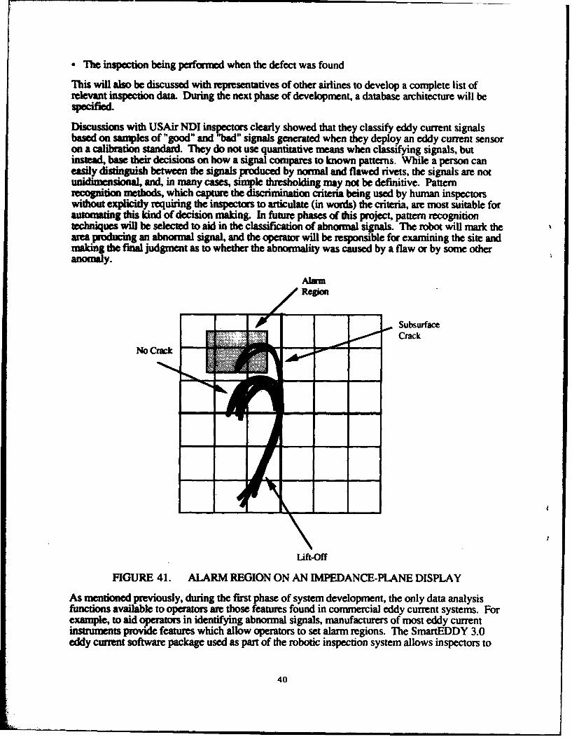
• The inspection being performed when the defect was found
This will also be discussed with representatives of other airlines to develop a complete list ofrelevant inspection data. During the next phase of development, a database architecture will bespecified.
Discussions with USAir NDI inspectors clearly showed that they classify eddy current signalsbased on samples of "good" and "bad" signals generated when they deploy an eddy current sensoron a calibration standard. They do not use quantitative means when classifying signals, butinstead, base their decisions on how a signal compares to known patterns. While a person caneasily distinguish between the signals produced by normal and flawed rivets, the signals are notunidimensional, and, in many cases, simple thresholding may not be definitive. Patternrecognition methods, which capture the discrimination criteria being used by human inspectorswithout explicitly requiring the inspectors to articulate (in words) the criteria, are most suitable forautomating this kind of decision making. In future phases of this project, pattern recognitiontechniques will be selected to aid in the classification of abnormal signals. The robot will mark thearea producing an abnormal signal, and the operator will be responsible for examining the site andmaking the final judgment as to whether the abnormality was caused by a flaw or by some otheranomaly.
SubsurfaceCrack
Lift-off
FIGURE 41. ALARM REGION ON AN IMPEDANCE-PLANE DISPLAY
As mentioned previously, during the first phase of system development, the only data analysisfunctions available to operators are those features found in commercial eddy current systems. Forexample, to aid operators in identifying abnormal signals, manufacturers of most eddy currentinstruments provide features which allow operators to set alarm regions. The SmartEDDY 3.0eddy current software package used as part of the robotic inspection system allows inspectors to
40
set such thresholds. As described previously in the Calibration section, to calibrate eddy currentsystems, inspectors deploy an eddy current sensor on a calibration standard and set the eddycurrent system's parameters to produce a clear separation between signals produced by fastenerswithout flaws and those produced by fasteners with flaws. Inspectors can also define a rectangulararea on the eddy current system's screen which will produce an audible and/or visual alarm if theimpedance-plane signal enters this region. A drawing depicting this situation is shown in figure41. In practice, these alarm features are seldom used during inspections; the oscilloscope tracesprovide better qualitative information for the operators to make intelligent decisions.
The SmartEDDY 3.0 software also has a dual frequency feature that allows one probe to be runsimultaneously at two different frequencies, allowing the system to acquire data at two differentfrequencies during the same scan. In the robotic system, this feature is used to look for bothsurface and subsurface cracks during a scan.
SYSTEM PERFRMANCE.
The time that it takes to complete one scan and the time that it takes to inspect a line of fasteners aretwo good parameters that help to define the inspection speed of the robot. During this phase, thescanning speed was measured, but because of the need for manual intervention in the alignmentmotion, the time required to automatically inspect a line of fasteners could not be quantitativelydefined; this will be deferred until the next development phase.
Manual inspectors move a reflectance eddy current sensor across a line of fasteners at an averagerate of 2.4 inches per second (6 cm/sec.). This number was acquired by having an NDI supervisortime eddy current inspections as they were performed at the USAir facilities in Pittsburgh,Pennsylvania, and by averaging the results. Although this is not an absolute number, it is a fairlygood estimate of the manual-scanning rate needed for a rough comparison to the automatedscanning speeds of the robot.
The robot's scanning rate is variable and can be set using the operator interface. During initialtesting, the robot was able to move the sensor at 5 inches per second (13 cm/sec) and still producehigh-quality traces on the PC monitor. This rate is considerably higher than the rate at whichinspectors move the same sensors. However, this is not the upper limit for the scanning speed.The finear motors which control the rate of scanning have a limit of 100 inches per second (2.5m/sec), and the SmartEDDY 3.0 can sample at a rate of approximately 3,600 data points persecond. During the next phase, the upper limit for the scanning speed will be experimentallydetermined. Thus, the scanning rate for the automated system is faster than that for manually-deployed sensors.
41
CONCLUSIONS
"* No limitations were observed with respect to the ability of the robot to adhere to surfaces,regaulless of the orientations of those surfaces.
"* The design of the robot satisfied the mobility and manipulation requirements of the skininspection application.
" Vacuum pumps that require one half of the air flow needed by those on the prototypecould be substituted. The reduced-flow vacuum pumps require less air than thosecurrently used, yet they are just as competent in keeping up with the leak rates commonlyfound on a surfaces.
"* The robot's weight must be reduced in the next phase of the project. The robot in itspresent form is uncomfortable to lift and position on the fuselage.
"* A large error accumulated while the system walked due to excessive compliance in theinitial prototype of the mechanical device. The structure must be made more rigid in thenext phase of the project.
7 U eddy curreat traces that appeared on the PC monitor when the robot deployed the eddycurrent sensor were identical to those from manually deployed eddy current sensors.
- The device will need a minimum of four cameras (two for alignment, one for close-upinspection, and one for long-range vision) to give the necessary images for visualinspection, obstacle avoidance, spine alignment, and robot evaluation and navigation.
- Calibration techniques similar to those used for calibrating manually-deployed eddy
current sensors are effective for calibrating robotically-deployed eddy current sensors.
- A PC-based control system is sufficient to control the robot's motions.
- The automated system completes a single scan faster than the average human inspectordoes. However, the upper limit for the scanning speed has not yet been determined.During the next phase of the project, the maximum scanning speed will be experimentallydetemined.
42
REFERENCES
1. Carnegie Mellon University, "Feasibility of Navigation (Guidance) of aMeasurement Unit Over the Surface of an Aircraft," Final Report for FederalAviation Administration, March 1992.
2. S. N. Bobo, "Magneto-Optic Imaging Inspection of Selected CorrosionSpecimens," Federal Aviation Administration Technical Note, Document NumberDOT/FAA/CT-TN92/20, July 1992.
3. S. N. Bobo, "Shearographic Inspection of a Boeing 737," Federal AviationAdministration Technical Note, Document Number DOT/FAA/CT-TN92/19, July1992.
"uJi GOW" NET PWITING OFFKX: 1994-504-078-00102
43