Command Talk-Back & Public Address System - Zenitel
68
Command Talk-Back & Public Address System ETB-5 / ETB-10 / ETB-10A / ETB-100 / ETB-100A A100K11162 v1 TECHNICAL MANUAL
-
Upload
khangminh22 -
Category
Documents
-
view
1 -
download
0
Transcript of Command Talk-Back & Public Address System - Zenitel

Command Talk-Back & Public Address System
ETB-5 / ETB-10 / ETB-10A / ETB-100 / ETB-100A
A100K11162 v1TECHNICAL MANUAL

About this Document
Document ScopeThis document is intended for qualified technicians who will install and commission the ETB-5/ETB-10/ETB-10A/ETB-100/ETB-100A Command Talk-Back & Public Address system on marine vessels. It also provides the end-user with all necessary instructions for operating the ETB central unit.
The following central units (panel version 8.0) are available for the ETB system:
Product Item Number
ETB-5 Central Unit, Panel Mounted, 5 Lines 3005020022
ETB-10 Central Unit, Panel Mounted, 10 Lines 3005020018
ETB-10A Central Unit, Panel Mounted, Public Address, 10 Lines 3005020021
ETB-100 Central Unit, Panel Mounted, 10 Lines 3005020019
ETB-100A Central Unit, Panel Mounted, Public Address, 10 Lines 3005020020
Publication LogRev. Date Author Description
1.0 21.11.2011 HKLPanel version 8.0Supersedes installation manuals for ETB-5/ETB-10 (A100K10868) and ETB-100 (A100K10867)
Related DocumentationDoc. no. Documentation
A100K11163 ETB Command Talk-Back & PA User Guide
Rules & Regulations The ETB-5/ETB-10/ETB-10A/ETB-100/ETB-100A system and its components has been tested according to following regulations:
● IEC 60533: Second edition, 1999 “Electrical and electronic installation in ships - Electromagnetic compatibility”
● IEC 60945: Fourth edition, 2002 “Maritime navigation and radio communication equipment and systems - General requirements - Methods of testing and required test results”
● IACS E10: Corr.1 July 2003 “Unified environmental test specification - Testing procedure for electric control and monitoring, safety and protection, onboard computer based systems and peripherals, loading instruments, internal communication and other electrical equipment as considered appropriate”
● Complies with DNV ship requirements - “Main Class Cargo Ship Vessels for two way voice communication”
L Does not comply with DNV ship requirements “C500 Nautical safety for two-way voice communication”

3ETB Command Talk-Back & Public Address SystemInstallation & Operation Manual
A100K11162 v1
Contents1 System Overview ............................................................................................................5
1.1 ETB-10 System Configuration ..................................................................................51.2 ETB-100 System Configuration ................................................................................61.3 Features ...................................................................................................................71.4 System Components .................................................................................................71.5 Functions ..................................................................................................................8
1.5.1 General ............................................................................................................81.5.2 Line Selection / Single Call ..............................................................................81.5.3 Group Call ........................................................................................................91.5.4 All Call ..............................................................................................................91.5.5 Call from a Substation ......................................................................................91.5.6 Parallel Communication ...................................................................................91.5.7 Signal and Extra Signal Device for Substations ...............................................91.5.8 Extra Signal in the ETB Central Unit ..............................................................101.5.9 Handsfree Operation ......................................................................................101.5.10 Privacy Function - STB-1 ...............................................................................101.5.11 Panel Loudspeaker ........................................................................................101.5.12 External Loudspeaker (Option) ............................................................ 111.5.13 Line Button Dimmer ....................................................................................... 111.5.14 Volume Adjustment ........................................................................................ 111.5.15 Power Supply SPS-4 (Option) ....................................................................... 111.5.16 Audio from External Systems (ETB-10A only) ............................................... 111.5.17 Simple Public Address (ETB-100A only) ........................................................121.5.18 Emergency Public Address (ETB-100A only) .................................................12
2 Installation&ConfigurationProcedures ....................................................................132.1 General ...................................................................................................................132.2 Mounting .................................................................................................................13
2.2.1 ETB Central Unit & Amplifier Cabinet RS-3C .................................................132.2.1.1 Identification Label for ETB Central Unit .............................................................. 13
2.2.2 Substations & Other Equipment .....................................................................132.2.2.1 Identification Label for Substation ........................................................................ 13
2.3 Placement of Substations and Loudspeakers .........................................................132.4 Terminal Configurations .........................................................................................14
2.4.1 ETB-100 Terminal Configurations on PCB .....................................................142.4.2 ETB-5/ETB-10 Terminal Configurations on PCB ...........................................15
2.5 Cable Requirements ...............................................................................................162.6 Power Supply Requirements ..................................................................................172.7 Volume Adjustment for Substation Lines ................................................................172.8 Extra Signal Device .................................................................................................172.9 Foot Switch for ETB Central Unit ............................................................................172.10 Microphone Setup ...................................................................................................172.11 Microphone Input Adjustment .................................................................................172.12 Set Up Single/Group PA (ETB-100/ETB-100A only) ...............................................182.13 Substation STB-1 ..........................................................................................182.14 Substation STB-3 ...........................................................................................182.15 Substation STB-5 ..........................................................................................18
3 Operating Instructions .................................................................................................193.1 Operation from ETB Central Unit ............................................................................19
3.1.1 Making a Call to a Substation ........................................................................203.1.2 Making a Call to a Group of Substations .......................................................213.1.3 Making an All Call ..........................................................................................223.1.4 Making a Handsfree Call Using Foot Switch ..................................................233.1.5 Sending Signal to Substations with Extra Signal Devices .............................233.1.6 Receiving a Call from a Substation ................................................................243.1.7 Receiving Calls from Two or More Substations .............................................25

4 A100K11162 v1ETB Command Talk-Back & Public Address SystemInstallation & Operation Manual
3.2 Parallel Communication ..........................................................................................263.2.1 Operation of Parallel Communication ............................................................27
3.3 Audio from External Systems (ETB-10A only) ........................................................293.4 Simple Public Address (ETB-100A only) .................................................................303.5 Emergency Public Address (ETB-100A only) ..........................................................31
3.5.1 Operation from PA Call Station 1 - ETB-100A ................................................333.5.2 Operation from PA Call Station 2 - VMT-603 .................................................333.5.3 Operation from PA Call Station 3 - VMP-603 .................................................33
3.6 Operation from Substations ....................................................................................343.6.1 Operation from Substation STB-1 ..................................................................343.6.2 Operation from Substation STB-2 ..................................................................353.6.3 Operation from Substation STB-3 ..................................................................363.6.4 Operation from Substation STB-5 ..................................................................373.6.5 Operation from Substation STB-5GN ............................................................383.6.6 Operation from Substation HE-112M / HE-112M-T ........................................393.6.7 Operation from Substation VH-10M / VH-10M-T ...........................................403.6.8 Operation from Substation VHM-10 / VHM-10-T ...........................................413.6.9 Operation from Substation NEBB-42EX ........................................................42
4 Commissioning .............................................................................................................434.1 General ...................................................................................................................434.2 Mechanical Inspection ............................................................................................434.3 Cable Inspection .....................................................................................................434.4 Check Configurations ..............................................................................................434.5 Identification Labels ................................................................................................434.6 Starting Up the System ...........................................................................................444.7 Functions Test Procedure .......................................................................................44
5 Troubleshooting ............................................................................................................46
6 Dimension Drawings ....................................................................................................486.1 ETB-5 ......................................................................................................................486.2 ETB-10/ETB-10A ....................................................................................................496.3 ETB-100/ETB-100A ................................................................................................50
7 Connection/Block/Single Line Diagrams ....................................................................517.1 ETB-100 Single Line Diagram ................................................................................517.2 ETB-5/ETB-10 Single Line Diagram .......................................................................527.3 ETB-100 PCB Layout ..............................................................................................537.4 ETB-5/ETB-10 PCB Layout ....................................................................................557.5 ETB-100 Block Diagram .........................................................................................577.6 ETB-5/ETB-10 Block Diagram ................................................................................587.7 ETB-100 Cable Connection Diagrams ....................................................................597.8 ETB-5/ETB-10 Cable Connection Diagrams ...........................................................63
Zenitel Norway AS and its subsidiaries assume no responsibilities for any errors that may appear in this publication nor for damages arising from the information in it. No information in this publication should be regarded as a warranty made by Zenitel Norway AS.
The information in this publication may be revised or changed without notice. Product names mentioned in this publication may be trademarks and are used only for purposes of identification.
Zenitel Norway AS © 2011

5ETB Command Talk-Back & Public Address SystemInstallation & Operation Manual
A100K11162 v1
1 System OverviewThe ETB-5 & ETB-10/ETB-10A is a Command Talk-Back system with 5 or 10 lines while the ETB-100/ETB-100A is a Command Talk-Back & Public Address system with 10 lines. The ETB-100A can also be used as an emergency Public Address system. The system comprises a central unit and a comprehensive range of substations and other field equipment for use indoors, outdoors, and in noisy areas on marine vessels. The physical dimensions of the units are based on the Euro DIN standard and fit neatly into integrated bridge solutions.
1.1 ETB-10SystemConfiguration
1
10m cable
EEx de IIC T6 PTB Nr.Ex-87.B.1009
Ui 690V
CEAG GHG 411
IN 16A
Parallel station STB-6GN
Parallel station SB-4
MB-30G
Foot switch
Signal unit
Substation STB-5 Line 7
ETC-1-TB
Foot switch
Substation STB-3 Line 9
Substation STB-1 Line 1
Substation STB-2 Line 3
Substation HE-112M Line 4
Substation VHM-10M Line 6
Substation VH-10M Line 5
EX Loudspeaker
Parallel station STB-6
Parallel station SB-4
Substation STB-5GN Line 8
EX Call Box
HAS-1
ETC-STB5
VML-1520
P-66
P-66
VML-1520
Signal unit
Signal unit
Signal Unit
VML-1520
VML-1520
P-MT7
P-66
CD-2
Substation STB-1 Line 2
Substation NEBB-42EXLine 10
SPS-4
Central unit ETB-10
ETC-1-TB
External Audio(ETB-10A)

6 A100K11162 v1ETB Command Talk-Back & Public Address SystemInstallation & Operation Manual
1.2 ETB-100SystemConfiguration
1
EEx de IIC T6 PTB Nr.Ex-87.B.1009
Ui 690V
CEAG GHG 411
IN 16A
Central Unit ETB-100
Parallel station STB-6GN
Parallel Station SB-4
MB-30G
Signal Unit
Substation STB-5 Line 8
Foot Switch
Substation STB-3 Line 9
Substation STB-1 Line 1
Substation STB-2 Line 3
Substation HE-112MT Line 4
100V EX Loudspeaker
Parallel Station STB-6
Parallel Station SB-4
EX Call Box
HAS-1
ETC-STB5
VML-1520
P-66
P-66
VML-1520
Signal Unit
Signal Unit
VML-15T
P-MT7
P-66
Substation STB-1 Line 2
Substation Line 10
NEBB-42EX
ON
OFF
VPA-120POWER AMPLIFIER
Power Amplifier
100V Loudspeaker Line Line 5
100V Loudspeaker Line Line 6
100V Loudspeaker Line Line 7
ETC-1-TB
ETC-1-TB
VINGTOR
Emergency PA Station VMT-603
PTT SWITCH
VMT-603

7ETB Command Talk-Back & Public Address SystemInstallation & Operation Manual
A100K11162 v1
1.3 Features ● Command Talk-Back
● Dimmable call light
● 5 or 10 line selection
● Step volume control
● All Call
● Output for extra signal device - all lines
● Handheld or gooseneck microphone
● Output for parallel microphone and loudspeaker
● Handsfree operation with foot switch
● Console or wall mounting
● Power: 24-32 VDC
● Audio Message from external system (ETB-10A)
● Public Address operation (ETB-100A)
● 100V line power amplifier (ETB-100/ETB-100A)
1.4 System ComponentsCentralUnits,Microphones&Amplifiers
Name Description Item No.ETB-5 Central Unit, panel mounted, IP44 - 5 lines 3005020022ETB-10 Central Unit, panel mounted, IP44 - 10 lines 3005020018ETB-10A Central Unit with external PA, panel mounted, IP44 - 10 lines 3005020021ETB-100 Central Unit, panel mounted, IP44 - 10 lines 3005020019ETB-100A Central Unit with external PA, panel mounted, IP44 - 10 lines 3005020020MB-30G Gooseneck Microphone with plug 3005020033ETC-1-TB Handheld microphone with curled cord and plug 3005020029VPA-120 120W Power amplifier (for ETB-100/ETB-100A) 3005010235VPA-240 240W Power amplifier (for ETB-100/ETB-100A) 3005010237VPA-400 400W Power amplifier (for ETB-100/ETB-100A) 3005010239RS-3C Cabinet for power amplifier (for ETB-100/ETB-100A) 3006206019
Substations & Complementary Equipment
Name Description Item No.STB-1 Substation, IP44, indoor, wall mounted with Call and Talk button 3005020057STB-2 Call Box, IP66, watertight, used with VML-15T speaker 3005020058STB-3 Combined Call/Plug Box, IP66, watertight, socket for mic &
P-MT7 headset, relay unit for loudspeaker, extra signal device3005020059
P-MT7 Headset w/ boom microphone, 10m cable and plug for STB-3 3005020050VML-15T/F Horn loudspeaker 15W 100V IP67 for STB-2 3006100090VML-1520 Horn loudspeaker 15W 20 ohm IP67 3006100088STB-5 Flush mounted substation, IP44, relay for microphone or handset 3005020060STB-5GN Flush mounted substation, IP44, relay & gooseneck microphone 3005020061HAS-1 Handset for STB-5 3005020032ETC-STB5 Handheld microphone with curled cord and plug for STB-5 3005020030VH-10M Portable deck loudspeaker with call box & 10m cable & plug 3006206030VH-10M-T Portable deck loudspeaker with call box & 10m cable & plug,
100V3006206032

8 A100K11162 v1ETB Command Talk-Back & Public Address SystemInstallation & Operation Manual
CD-2 Plug Box for VH-10M and VH-10M-T 1020600989VHM-10 Deck unit with hand microphone mounted in cabinet 3006206034VHM-10-T Deck unit, with hand microphone mounted in cabinet, 100V 3006206035HE-112M Outdoor loudspeaker with call button, watertight, IP66 3006206006HE-112M-T Outdoor loudspeaker, 100V with call button, watertight, IP66 3006206007NEBB-42EX Call Box, EX-approved, IP67 3006206015
Bridge Wing Substations & Microphones
Name Description Item No.STB-6 Flush mounted substation, IP44, for handheld mic ETC-1-TB 3005020062STB-6GN Flush mounted substation, IP44, with gooseneck microphone 3005020063SB-4 Plugbox for mic, headset, loudspeaker, wall mounted, watertight 3005020053P-66 Handheld microphone with curled cord and plug, watertight 3005020039P-66/10 Handheld microphone with 10m cable and plug, watertight 3005020040
Additional Equipment
Name Description Item No.WBOKS Wall mounted backbox for ETB-5/ETB-10/ETB-100 3005020065STBOKS5 Wall mounted backbox for STB-5/STB-5GN 3005010206STBOKS Wall mounted backbox for STB-6/STB-6GN 3005020064SPS-4 Power supply 115/230V AC 24V DC w/ automatic switchover relay 3005020055BLK5-24 Flash beacon 24V AC/DC 5 Joule, IP65 3006102023EHS-24 Rotary light 24V DC, IP54 3006102038A-100 Electronic alarm horn 24V DC, IP55, 100dB 3006102002U2410 Foot switch for handsfree operation 3006206029
1.5 Functions
1.5.1 GeneralThe system consists of one central unit, ETB-5, ETB-10, ETB-10A, ETB-100, or ETB-100A for use on the bridge console and a number of substations and loudspeakers for use indoors, outdoors, or in noisy areas.
The ETB-100 is for Command Talk-Back operation.
The ETB-100A is for Command Talk-Back and Public Address operation.
All the ETB central units have common functions except those that are specific to ETB-10A, ETB-100, or ETB-100A only (this will be indicated in the section heading).
1.5.2 Line Selection / Single Call
Up to 5 substations for ETB-5 and 10 substations for ETB-10/ETB-10A/ETB-100/ETB-100A can be selected by pressing the respective line button on the central unit.
Activation is indicated by a steady green LED.
VINGTOR

9ETB Command Talk-Back & Public Address SystemInstallation & Operation Manual
A100K11162 v1
1.5.3 Group Call
A group of substations can be selected by pressing the respective line buttons.
Activation is indicated by a steady green LED.
1.5.4 All Call
All call message can be distributed by pressing the ALL button.
Activation is indicated by a steady green LED in the ALL button.
1.5.5 Call from a Substation
Calls can be made from any substation to the ETB central unit.
Activation is indicated by a flashing green LED in the respective line button and a call tone from the panel speaker.
1.5.6 Parallel CommunicationOperation of the ETB central unit is made from parallel microphones/loudspeakers located on bridge wings or other locations where required.
L Note that line selection has to be set up from the central unit.
1.5.7 Signal and Extra Signal Device for Substations
A call signal can be given to selected station. The function will also activate an 24VDC max 50mA to substation with relay or direct connected external signal device
VINGTOR
VINGTOR
VINGTOR
VINGTOR
VINGTOR

10 A100K11162 v1ETB Command Talk-Back & Public Address SystemInstallation & Operation Manual
1.5.8 Extra Signal in the ETB Central Unit
An extra signal device can be activated when receiving calls from a substation through a potential-free contact in the central unit.
1.5.9 Handsfree OperationHandsfree operation of central unit or parallel station.
Option 1Central unit with gooseneck microphone MB-30G and foot switch U2410.
Option 2Parallel station type STB-6GN with gooseneck microphone MB-30G and foot switch U2410.
1.5.10 Privacy Function - STB-1Substation STB-1 is designed for indoor use such as cabins, mess rooms, etc. It is also equipped with a privacy function.
When the privacy function is enabled, it is not possible to hear communication from the STB-1 substation on the ETB central unit.
After a call is set up from the central unit, the operator of the STB-1 substation has to press the TALK button to communicate with the central unit.
STB-1 can also be set to normal talk-back function.
1.5.11 Panel Loudspeaker
The loudspeaker is located at the front panel of the ETB-100 and ETB-100A central unit for distribution of audio messages and alarm signals.
VINGTOR
VINGTOR
Foot Switch
Parallel Station STB-6GN
VINGTOR

11ETB Command Talk-Back & Public Address SystemInstallation & Operation Manual
A100K11162 v1
1.5.12 External Loudspeaker (Option) The optional external loudspeaker with 40W impedance is for improved and higher audio volume level.
The loudspeaker is connected in parallel with the monitor speaker and located close to the ETB central unit.
1.5.13 Line Button Dimmer
The intensity of the line button light can be adjusted by pressing the button labeled DIM.
1.5.14 Volume AdjustmentBy pressing the + or - buttons repeatedly, you can progressively increase or decrease the speaker volume in the central unit
This will also affect the volume for an external speaker connected to the panel.
● Press the + button to increase the volume
● Press the - button to decrease the volume
1.5.15 Power Supply SPS-4 (Option)
The power supply SPS-4 is designed with power failure contact and automatic switch-over relay.
This means that there is an indication and automatic switch-over to 24V DC emergency power supply when the mains supply or power module fails.
1.5.16 Audio from External Systems (ETB-10A only)Entertainment, message or alarm messages can be distributed through the ETB-10A system.
An potential-free contact and 0 dB signal from the external system activate the ETB-10A to send the message to all substations.
The TALK button on ETB-10A or the PTT switch on the handheld microphone will override the external audio.
Normal talk-back functions can not be used in this mode.
The external system may be:
- VHF radio - Entertainment system - Alarm system - Public Address
VINGTOR
VINGTOR

12 A100K11162 v1ETB Command Talk-Back & Public Address SystemInstallation & Operation Manual
1.5.17 Simple Public Address (ETB-100A only)
A single line or group of loudspeaker lines can be set to Simple PA mode.
Fixed settings for selected lines are made through DIP switches.
All lines can be set to this mode.
The remaining lines provide normal Talk-Back function.
1.5.18 Emergency Public Address (ETB-100A only)
In order to comply with PA requirements, the ETB-100A system is designed with a minimum of two PA call stations for Emergency PA for all lines.
Call station 1Central unit ETB-100A with hand microphone or gooseneck microphone.
Call station 2VMT-603 with hand microphone or gooseneck microphone
● Muting of the General Alarm System
● Overriding of all other input, including Talk-Back and simple Public Address Operation.
● ETB-100A has 1st priority and will override emergency call station 2.
VINGTOR
Line 5
Line 6
Line 7
VINGTOR

13ETB Command Talk-Back & Public Address SystemInstallation & Operation Manual
A100K11162 v1
2 Installation&ConfigurationProcedures
2.1 GeneralFor proper installation and operation of the ETB system, we recommend reading this section thoroughly together with technical and connection drawings in the section 7.
All configuration settings such as volume, foot switch, microphone, etc. are located on the ETB main board ETB510.
Refer to technical drawings in section 7 Connection/Block/Single Line Diagrams for more detailed information.
L In order to comply with DNV ship requirements, this section has to be followed strictly.
2.2 Mounting
2.2.1 ETBCentralUnit&AmplifierCabinetRS-3CThe ETB central unit is the basis of the system. It should be flush or bulkhead mounted in a normal and ventilated indoor environment with a temperature of maximum 55 ºC.
Make sure that there is sufficient space for cables and maintenance.
2.2.1.1 IdentificationLabelforETBCentralUnitA label with the line numbers for all substations should be placed close to the ETB central unit.
2.2.2 Substations & Other EquipmentSee the respective drawings for dimensions, cut-out and mounting of substations such as STB-1, STB-2, etc.
Make sure that there is sufficient space for cables and maintenance.
2.2.2.1 IdentificationLabelforSubstationA label with the substation number has to be placed on or close to each substation.
2.3 Placement of Substations and LoudspeakersTo avoid acoustic feedback, it is recommended to place the 100V loudspeakers such that they face away from the ETB central unit.
Line No. Substation
1 STB-12 STB-13 STB-24 HE-112M5 VH-10M6 VHM-107 STB-58 STB-5GN9 STB-310 NEBB-42EX

14 A100K11162 v1ETB Command Talk-Back & Public Address SystemInstallation & Operation Manual
2.4 TerminalConfigurationsPluggable screw terminals for cables of max. 2.5 mm2 are utilized.
Refer to technical drawings in section 7 Connection/Block/Single Line Diagrams for more detailed information.
2.4.1 ETB-100TerminalConfigurationsonPCB

15ETB Command Talk-Back & Public Address SystemInstallation & Operation Manual
A100K11162 v1
2.4.2 ETB-5/ETB-10TerminalConfigurationsonPCB
Terminal block C1 - C10 (ETB-100/ETB-100A only)
● No. 1-2 for substation line, low impedance
● No. 3-4 for substation line, 100V to extra signal device

16 A100K11162 v1ETB Command Talk-Back & Public Address SystemInstallation & Operation Manual
Terminal block K1 - K5 (for ETB-5)
Terminal block K1 - K10 (for ETB-10/ETB-100)
● No. 1-2: substation line for ETB-10 (not in use for ETB-100)
● No. 3-4: 24V DC to extra signal device
● No. 5: common ground point for each substation screen
Terminal block K11
● For power supply
Terminal block K12
● For power amplifier (NOT for ETB-5/ETB-10)
Terminal block K13
● Parallel microphone and parallel loudspeaker
Terminal block K14
● Potential-free contact for activating/muting external system or extra signal device
Terminal block C11 (ETB-100/ETB-100A only)
● 100V line in from power amplifier
Terminal block C12 (ETB-100/ETB-100A only)
● Muting of external alarm system
Terminal block K1 (ETB-100A only)
● Located on PCB labeled ETB-ALL-SUB ● For connection to Emergency PA station:
- No. 1-2 audio - No. 3-4 switch - No. 5 screen
2.5 Cable RequirementsAll signal cables have to be approved ship cable of type twisted-pair with outer braided copper shield.
L See cable connection diagrams in Section 7 for further details.
The screens must be interconnected in junction boxes and grounded in a common point in the central unit only.
Terminal block K1 – K10 no. 5 is the ground point for each substation screen.
The power cable must be approved ship cable of minimum 3 x 0.75 mm2.
Maximum cable length = 500 meters
L The central unit has to be connected to the vessel’s central ground. Proper grounding is essential for reliable operation.
L Ensure that signal cables are separated from power cables.

17ETB Command Talk-Back & Public Address SystemInstallation & Operation Manual
A100K11162 v1
2.6 Power Supply Requirements ● 24 VDC -10% + 33% (21.6 – 32 VDC)
● Current consumption max. 2A
System power supply should be wired and fused independently from other systems:
● 24V DC from ship’s 24V DC system.
● 24V DC from power supply SPS-4 230V AC / 24V DC with automatic switch to 24V DC emergency power supply.
2.7 Volume Adjustment for Substation LinesSystem volume for substations can be adjusted by separate trimmer for each group of 5 lines: master volume lines 1-5 and lines 6-10.
Volume is factory set and does not normally require any adjustment.
If the installation on some locations requires another sound pressure level, this can be changed to the desired audibility and volume.
2.8 Extra Signal DeviceThe maximum load for each substation line is 50 mA to substation with relay unit or signal device (connected on terminal block K1 – K10 no. 3-4). The maximum load from substations STB-3 and STB-5 is 2A.
2.9 Foot Switch for ETB Central UnitThe foot switch is used together with the ETB central unit and gooseneck microphone.
When the foot switch is used, the jumper labeled JUMPER FOR FOOT SWITCH on the main board has to be removed.
2.10 Microphone SetupThe jumper J8 has to be set to Microphone.
This is the default setting and does not normally need to be changed.
2.11 Microphone Input AdjustmentInput for microphones can be adjusted via the potentiometer labeled P1.
The input level is factory set and does not normally require any adjustment.

18 A100K11162 v1ETB Command Talk-Back & Public Address SystemInstallation & Operation Manual
2.12 Set Up Single/Group PA (ETB-100/ETB-100A only)
Each line can be set to Single or Group PA without talk-back.
The jumpers labeled J12 to J21 for each line (on ETB-100 main board) have to be set in position PA.
2.13 Substation STB-1 The default setting for substation STB-1 is PRIVACY.
Set jumper J1 on the PCB in substation STB-1 to Talk-Back if required.
2.14 Substation STB-3 The default setting for substation STB-3 is Headset. Set the two jumpers on the PCB in substation STB-3 to Microphone if required.
2.15 Substation STB-5 The default setting for substation STB-5 is HANDSET.
Set jumper J1 on the PCB in substation STB-3 to LOUDSPEAKER if required.
Installation & User Manual System ETB-100
11
3.10 Microphone input adjust.
Input for microphones can be adjusted by potentiometer marked VR1. Input level is factory adjusted and does not normally require any adjustment. Located on keyboard ETB510 See dwg. no. ETB-100_lo| for location.
3.11 Set up single / group of PA
Each line can be set to single or group of PA without talk back. Jumper marked J12 to J21 for each line (on ETB-100 board) have to be set in position PA.
3.12 Substation STB-1
Default setting is Privacy function, can be set to normal Talk Back Function. Talk Back Function; move the jumper J1 on PCB in STB-1
3.13 Substation STB-3
Default setting is for headset, can be set for microphone. Microphone; move the two jumpers on PCB - STB-3in position M
3.14 Substation STB-5
Default setting is for microphone or handset, can be set for re-entrant speaker only. Re-entrant speaker; move the jumper J1 on PCB in STB-5.

19ETB Command Talk-Back & Public Address SystemInstallation & Operation Manual
A100K11162 v1
3 Operating Instructions
3.1 Operation from ETB Central UnitThe ETB Talk-Back system comprises the ETB central unit and accessory equipment such as microphones and foot switch.
Central Unit ETB-5/ETB-10/ETB-10A/ETB-100/ETB-100AIngress Protection Rating = IP44
1. Loudspeaker: For communication and alarm signals
2. Line Buttons: Lines 1-5 for ETB-5, Lines 1-10 for ETB-10/ETB-10A and ETB-100/ETB-100A
3. Green LED: Indication light for each line button
4. Microphone Connector: For gooseneck or handheld microphone
5. VOLUME - +: Volume control buttons for panel loudspeaker
6. ALL: Button with indication LED for making All Call
7. DIM: Button for adjusting light intensity of indication LEDs
8. SIGN: Button for signal and activating extra signal device on substations
9. TALK: PTT switch for gooseneck microphone MB-30G
VINGTOR
1 2 4
5
1
6 7 8 9
3

20 A100K11162 v1ETB Command Talk-Back & Public Address SystemInstallation & Operation Manual
Gooseneck Microphone MB-30G Handheld Microphone ETC-1-TB with PTT switch
Foot Switch U2410 for handsfree operation of microphone MB-30G
PTT Switch
3.1.1 Making a Call to a SubstationYou can select the substation by pressing the desired line push button.
A steady green LED will indicate the activated line.
If desired, the signal button SIGN may be pressed to send a tone signal to the selected station. Pressing the TALK button enables talking from the ETB central unit. The central unit will be in listening mode as soon as a station is selected. To terminate the communication, press the selected line button again. The LED will stop being lit to indicate that the selected line is terminated.
● Press the line button - the call is set up, indicated by a steady green LED
● Press the SIGN button
A tone signal will be activated at the selected station as long as the SIGN button is kept pressed.
This will also activate an extra signal to substations equipped with these devices.
ETB central unit with gooseneck microphone MB-30G
● Press the TALK button
● Speak clearly into the microphone
When the TALK button is released, the ETB will be in listening mode and you will hear the communication from the selected station in the panel loudspeaker.

21ETB Command Talk-Back & Public Address SystemInstallation & Operation Manual
A100K11162 v1
ETB central unit with handheld microphone ETC-1-TB
● Press the PTT switch on the microphone
● Speak clearly into the microphone
When the PTT switch is released, the ETB will be in listening mode and you will hear the communication from the selected station in the panel loudspeaker.
● Press the line button once more to terminate the call.
When the call terminates, the LED will stop lighting.
3.1.2 Making a Call to a Group of SubstationsYou can select a group of substations by pressing the respective line buttons.
The ETB central unit always has the 1st priority and can select between the substations.
Only the ETB central unit can switch off and terminate the call.
● Press the required line buttons - The call is set up, indicated by the LEDs lighted a steady green in the selected buttons.
● Press the SIGN button - A tone signal will be broadcasted to the selected station as long as the SIGN button is kept pressed. This will also activate a signal to substations equipped with extra signal devices.
ETB central unit with gooseneck microphone MB-30G
● Press the TALK button
● Speak clearly into the microphone
When the TALK button is released, the ETB will be in listening mode, and you will hear the communication from the selected station.
ETB central unit with handheld microphone ETC-1-TB
● Press the PTT switch on the microphone
Speak clearly into the microphone. When the PTT switch button is released the ETB will be in listening mode, and you will hear the communication from the selected station.
PTT Switch
ETC-1-TB
PTT Switch
ETC-1-TB

22 A100K11162 v1ETB Command Talk-Back & Public Address SystemInstallation & Operation Manual
● Press the active line buttons once more to terminate the calls.
When the calls terminate, the LEDs will stop lighting.
3.1.3 Making an All CallThe message and signal from ETB will be given to all substations, as a one-way message.
It will be indicated by a steady green LED in the ALL button. Talk-back from substations is disabled in this mode.
● Press the ALL button - the call is set up, indicated by steady green LED in the ALL button
● Press the SIGN button - A tone signal will be broadcasted to the selected station as long as the SIGN button is kept pressed. This will also activate a signal to substations equipped with extra signal devices.
ETB central unit with gooseneck microphone MB-30G
● Press the TALK button
Speak clearly into the microphone. When the TALK button is released the ETB will be in listening mode, and you will hear the communication from the selected station.
ETB central unit with handheld microphone ETC-1-TB
● Press the PTT switch on the microphone
Speak clearly into the microphone. When the PTT switch button is released the ETB will be in listening mode, and you will hear the communication from the selected station.
● Press the ALL button once more to terminate the call
When the call terminates, the LED will stop lighting.
PTT Switch
ETC-1-TB

23ETB Command Talk-Back & Public Address SystemInstallation & Operation Manual
A100K11162 v1
3.1.4 Making a Handsfree Call Using Foot SwitchThe equipment required in making a handsfree call from the ETB central unit are a gooseneck microphone (MB-30G) and a foot switch (U2410).
● Press the foot switch
● Speak clearly into the microphone
When the foot switch is released, the ETB will be in listening mode, and you will hear the communication from the selected station.
L Jumper labeled Jumper for foot switch must be removed for this function.
3.1.5 Sending Signal to Substations with Extra Signal Devices
Substations STB-3, STB-5 and STB-5GN are equipped with a relay for activating extra signal devices.
An extra signal device can be a flashing beacon, rotary light, and alarm horn and bells.
On the ETB central unit:
● Press the SIGN button
A tone signal will be activated on the selected station as long as the SIGN button is kept pressed.
Indication 1There will be a tone signal from the panel loudspeaker of substation STB-5 or STB-5GN, or from the horn loudspeaker of substation STB-3.
Indication 2A signal will also be activated on the extra signal devices such as a flashing beacon, rotary light, alarm horn and bells.
VINGTOR

24 A100K11162 v1ETB Command Talk-Back & Public Address SystemInstallation & Operation Manual
3.1.6 Receiving a Call from a SubstationAn incoming call is indicated by a flashing green LED in the respective line button and a beeping tone in the panel loudspeaker.
It will also activate an extra signal unit if installed. Only the ETB central unit can terminate the call.
● Press the line button with the flashing green LED - the call is set up, indicated by a steady green LED
ETB central unit with gooseneck microphone MB-30G
● Press the TALK button
● Speak clearly into the microphone
When the TALK button is released the ETB will be in listening mode, and you will hear the communication from the selected station.
ETB central unit with handheld microphone ETC-1-TB
● Press the PTT switch on the microphone
● Speak clearly into the microphone
When the PTT switch button is released the ETB will be in listening mode, and you will hear the communication from the selected station.
● Press the line button once more to terminate the call.
When the call terminates, the LED will stop lighting.
PTT Switch
ETC-1-TB

25ETB Command Talk-Back & Public Address SystemInstallation & Operation Manual
A100K11162 v1
3.1.7 Receiving Calls from Two or More SubstationsCalls can be received from two or more substations at the same time. The ETB central unit has the 1st priority and can select between calls from the substations. Only the ETB central unit can terminate the calls.
Incoming calls are indicated by flashing green LEDs in the respective line buttons and a beeping tone in the panel loudspeaker.
The calls will also activate an extra signal unit if installed (only for the first call).
● Press the line buttons with the flashing green LEDs - the calls are set up, indicated by a steady green LED
The ETB central unit can select between substation lines and terminate calls by pressing the respective line buttons once more.
ETB central unit with gooseneck microphone MB-30G
● Press the TALK button
● Speak clearly into the microphone
When the TALK button is released the ETB will be in listening mode, and you will hear the communication from the selected station.
ETB central unit with handheld microphone ETC-1-TB
● Press the PTT switch on the microphone
● Speak clearly into the microphone
When the PTT switch button is released the ETB will be in listening mode, and you will hear the communication from the selected station.
● Press the active line buttons once more to terminate the calls.
When the calls terminate, the LEDs will stop lighting.
PTT Switch
ETC-1-TB

26 A100K11162 v1ETB Command Talk-Back & Public Address SystemInstallation & Operation Manual
3.2 Parallel CommunicationParallel communication functions with the operation of the ETB central unit from parallel microphones/loudspeakers located on bridge wings or other locations near the central unit where parallel microphones/loudspeakers are needed.
Two parallel stations can be connected. Communication is set up by the ETB central unit. The bridge wing unit will be in operation mode as soon as a station is selected on the ETB central unit.
3
PTT Switch
1 2
1. : Parallel to central unit2. : For microphone3. :
LoudspeakerConnectorMicrophone ETC-1-TB with PTT switch
Parallel Station STB-6
321
1. : Parallel to central unit2. : PTT switch for microphone 3.
LoudspeakerTALK
(Parallel to central unit): Parallel to PTT switchFoot Switch
Parallel Station STB-6GN
PTT Switch
1 2 3
1. : Parallel to central unit2. : For microphone 3. :
Loudspeaker
Microphone P-66 with PTT switch (parallel to microphone on central unit)
Connector
Parallel Station SB-4

27ETB Command Talk-Back & Public Address SystemInstallation & Operation Manual
A100K11162 v1
3.2.1 Operation of Parallel Communication
L Note that line selection and signal have to be set up from the ETB central unit.
ETB Central Unit
● Press the line button on the ETB central unit - the call is set up, indicated by a steady green LED
● Press the SIGN button on the ETB central unit
A tone signal will be sent to the selected station as long as the SIGN button is being pressed.
This will also activate a signal to substations equipped with extra signal devices.
Parallel Station STB-6 with Handheld MicrophoneIngress Protection Rating = IP44
● Press the PTT switch on the handheld microphone ETC-1-TB
● Speak clearly into the microphone
When the PTT switch button is released, the parallel station will be in listening mode and you will hear the communication from the selected station in the loudspeaker.
Parallel Station STB-6GN with Gooseneck MicrophoneIngress Protection Rating = IP44
● Press the TALK button on the STB-6GN station
● Speak clearly into the microphone
When the TALK button is released, the parallel station will be in listening mode, and you will hear the communication from the selected station in the panel loudspeaker.
PTT Switch
Parallel Station STB-6
Parallel Station STB-6GN

28 A100K11162 v1ETB Command Talk-Back & Public Address SystemInstallation & Operation Manual
Parallel Station STB-6GN Handsfree Operation Using Foot Switch
● Press the foot switch
● Speak clearly into the microphone
When the foot switch is released, the parallel station will be in listening mode, and you will hear the communication from the selected station in the panel loudspeaker.
Parallel Station SB-4 with Microphone & Horn LoudspeakerIngress Protection Rating = IP66
The parallel station comprises the SB-4 Plug box, P-66 microphone, and VML-1520 horn loudspeaker.
● Press the PTT switch on the handheld microphone P-66
● Speak clearly into the microphone.
When the PTT switch is released, the parallel station will be in listening mode and you will hear the communication from the selected station.
● Press the line button on the ETB central unit once more to terminate the call
When the call terminates, the line button LED will stop lighting.
Foot Switch
Parallel Station STB-6GN
Handsfree Operation
PTT SwitchParallel Station SB-4

29ETB Command Talk-Back & Public Address SystemInstallation & Operation Manual
A100K11162 v1
3.3 Audio from External Systems (ETB-10A only)Entertainment, message or alarm messages can be distributed by using the ETB-10A central unit and all substations.
An potential-free contact and 0 dB signal from the external system activate the ETB-10A to send the message to all substations.
The TALK button on ETB-10A or the PTT switch on the handheld microphone will override the external audio.
Normal talk-back functions can not be used during this mode.
An external system may be VHF radio, entertainment system, alarm system, and Public Address.
To start the function:
● Switch on the external equipment - the audio will be distributed to all substations and in the ETB-10A central unit.
To override the function using ETB-10A with gooseneck microphone MB-30G:
● Press the TALK button on the ETB-10A central unit
● Speak clearly into the gooseneck microphone - When the TALK button is released, the ETB-10A will be in external All Call mode again
To override the function using ETB-10A with handheld microphone ETC-1-TB:
● Press the PTT switch on the handheld microphone
● Speak clearly into the handheld microphone - When the PTT switch is released, the ETB-10A will revert back to All Call mode.
To terminate the function:
● Switch off the external equipment - the ETB-10A will revert back to normal Talk-Back mode
+
-
TUNER BAND
1 2 3 4 5 6
S
OFFPOTENTIAL-FREE CONTACT
0 dB AUDIO
+
-
TUNER BAND
1 2 3 4 5 6
S
ONPOTENTIAL-FREE CONTACT
0 dB AUDIO
PTT Switch
ETC-1-TB
+
-
TUNER BAND
1 2 3 4 5 6
S
OFFPOTENTIAL-FREE CONTACT
0 dB AUDIO
+
-
TUNER BAND
1 2 3 4 5 6
S
ONPOTENTIAL-FREE CONTACT
0 dB AUDIO

30 A100K11162 v1ETB Command Talk-Back & Public Address SystemInstallation & Operation Manual
3.4 Simple Public Address (ETB-100A only)A single line or group of loudspeaker lines must be set to Public Address as a fixed configuration.
The Public Address function is set by DIP switches (see section 3.11).
L The Talk-Back function can not be used for the lines that are configured for Public Address.
Single Call
● Press the line button - The call is set up, indicated by a steady green LED.
Group Call
● Press the required line buttons - The call is set up, indicated by the LEDs lighted a steady green in the selected buttons.
ETB central unit with gooseneck microphone MB-30G
● Press the TALK button
● Speak clearly into the microphone
ETB central unit with handheld microphone ETC-1-TB
● Press the PTT switch on the microphone
● Speak clearly into the microphone
Terminating the Calls
● Press the active line buttons once more to terminate the calls
When the calls terminate, the LEDs will stop lighting.
PTT Switch
ETC-1-TB

31ETB Command Talk-Back & Public Address SystemInstallation & Operation Manual
A100K11162 v1
3.5 Emergency Public Address (ETB-100A only)In order to comply with PA requirements, the system is designed with a minimum of two PA call stations. The configuration comprises an ETB-100A central unit with and call stations VMP-603 or VMT-603. The operation will mute the General Alarm system and override Talk-Back and single PA calls.
The ETB-100A central unit has 1st priority and will override PA call stations 2 and 3.
PACallStationsConfigurationwithGooseneckMicrophone
VINGTOR
PA Call Station 1ETB-100A
PA Call Station 3VMP-603
PA Call Station 2VMT-603
Mute

32 A100K11162 v1ETB Command Talk-Back & Public Address SystemInstallation & Operation Manual
PACallStationsConfigurationwithHandheldMicrophone
VINGTOR
PA Call Station 1ETB-100A
PA Call Station 3VMP-603
PA Call Station 2VMT-603
Mute

33ETB Command Talk-Back & Public Address SystemInstallation & Operation Manual
A100K11162 v1
3.5.1 Operation from PA Call Station 1 - ETB-100A
● Press the ALL button - the call is set up indicated by a steady green LED in the ALL button
ETB central unit with gooseneck microphone MB-30G
● Press the TALK button for Emergency PA - The operation will mute the General Alarm system and override Talk-Back and single PA calls. The ETB-100A central unit has 1st priority and will override ongoing PA calls from station 2 (VMT-603).
● Speak clearly into the microphone.
ETB central unit with handheld microphone ETC-1-TB
● Press the PTT switch for Emergency PA - The operation will mute the General Alarm system and override Talk-Back and single PA calls. The ETB-100A central unit has 1st priority and will override ongoing PA calls from station 2 (VMT-603).
● Speak clearly into the microphone
● Press the ALL button once more to terminate the PA call
When the call terminates, the LED will stop lighting.
3.5.2 Operation from PA Call Station 2 - VMT-603 ● Press the PTT switch for Emergency PA
- The operation will mute the General Alarm system and override Talk-Back and single PA calls. The ETB-100A central unit has 1st priority and will override ongoing PA calls from station 2 (VMT-603).
● Speak clearly into the microphone
When the PTT switch is released, the ETB-100A central unit will revert to normal Talk-Back mode.
3.5.3 Operation from PA Call Station 3 - VMP-603 ● Press the TALK button for Emergency PA
- The operation will mute the General Alarm system and override Talk-Back and single PA calls. The ETB-100A central unit has 1st priority and will override ongoing PA calls from station 3 (VMP-603).
● Speak clearly into the microphone
When the TALK button is released, the ETB-100A central unit will revert to normal Talk-Back mode.

34 A100K11162 v1ETB Command Talk-Back & Public Address SystemInstallation & Operation Manual
3.6 Operation from SubstationsCalls can be made from substations to the ETB central unit by pressing the CALL button. A call is indicated by a flashing green LED and a signal in the ETB central unit. The call is confirmed when the respective line button is pressed. Only the ETB central unit can terminate the call.
3.6.1 Operation from Substation STB-1Ingress Protection Rating = IP44
1
2 3
1. Re-entrant - For communication from central unit - Microphone for communication to central unit2. - Push button switch for call to central unit3. - PTT switch for talk to central unit
Loudspeaker
CALL
TALK
Substation STB-1
Substation Operation ETB Central Unit • Press the CALL button
- Indicated by flashing green LED for substation line and a signal in the ETB panel loudspeaker.
• Operator of the ETB presses the respective line button has a flashing green LED
- the call is set up, indicated by a steady green LED
Loudspeaker
• Press the TALK button• Speak clearly into the re-entrant
loudspeaker. - When TALK button is released, the STB-1 will be in listening mode and you will hear the communication from the ETB central unit.
• Operator of the ETB central unit terminates the call by pressing the line button once more.

35ETB Command Talk-Back & Public Address SystemInstallation & Operation Manual
A100K11162 v1
3.6.2 Operation from Substation STB-2Ingress Protection Rating = IP66
1 2
1. - Push button for calling central unit.2
CALL
. - Speaker receiving communication from central unit. - Microphone for communication to central unit.
Re-entrant Loudspeaker
Substation STB-2
Substation Operation ETB Central Unit • Press the CALL button
- Indicated by flashing green LED for substation line and a signal in the ETB panel loudspeaker.
• Operator of the ETB presses the respective line button and the call is set up.
- Indicated by steady green light in ETB
Loudspeaker
• Speak clearly into the re-entrant loudspeaker of STB-2.
- The same loudspeaker is used to send and receive communication to/from ETB.
• Operator of the ETB central unit terminates the call by pressing the line button once more.

36 A100K11162 v1ETB Command Talk-Back & Public Address SystemInstallation & Operation Manual
3.6.3 Operation from Substation STB-3Ingress Protection Rating = IP66
Substation Operation ETB Central Unit • Press the CALL button
- Indicated by flashing green LED for substation line and a signal in the ETB panel loudspeaker.
• Operator of the ETB presses the respective line button, setting up the call.
- Indicated by steady green light in ETB
With headset P-MT7
10m cable
• Speak clearly into the boom microphone on the headset.
- Receive communication from the ETB central unit in the headphones (and in the loudspeaker if installed)
• Operator of the ETB central unit terminates the call by pressing the line button once more.
With microphone P-66PTT Switch
• Press the PTT switch on the microphone.• Speak clearly into the microphone.
- When the PTT switch is released, the microphone will be in listening mode and you will hear the communication from the ETB central unit in the loudspeaker
• Operator of the ETB central unit terminates the call by pressing the line button once more.
1
1 2
10m cable
65 3
4
PTT Switch
1. For headset or microphone2. Push button for calling central unit3. For receiving communication from central unit 4. 5. P-MT7 with boom microphone6. P-66 with PTT switch
ConnectorCALLLoudspeaker
Headset Microphone
: :
:: Activated from central unit
::
Signal device
Substation STB-3

37ETB Command Talk-Back & Public Address SystemInstallation & Operation Manual
A100K11162 v1
3.6.4 Operation from Substation STB-5Ingress Protection Rating = IP44
Substation Operation ETB Central Unit • Press the CALL button
- Indicated by flashing green LED for substation line and a signal in the ETB panel loudspeaker.
• Operator of the ETB presses the respective line button, setting up the call
- Indicated by steady green light in ETB
With microphone ETC-1-B
PTT Switch
ETC-1-TB
• Press the PTT switch on the microphone.• Speak clearly into the microphone.
- When the PTT switch is released, the STB-5 will be in listening mode and you will hear the communication in the panel loudspeaker
• Operator of the ETB central unit terminates the call by pressing the line button once more.
With handset HAS-1
PTTSwitch
• Press the PTT switch on the handset.• Speak clearly into the handset.
- When the PTT switch is released, the STB-5 will be in listening mode and communication from the ETB comes from the handset’s speaker
• Operator of the ETB central unit terminates the call by pressing the line button once more.
• Speak clearly into the re-entrant loudspeaker of STB-5.
- The same loudspeaker is used to send and receive communication to/from ETB.
• Operator of the ETB central unit terminates the call by pressing the line button once more.
PTT Switch
PTT Switch
6 2 3 541
1. : For communication from central unit2. : Push button for calling central unit3. : For handset HAS-1 or microphone ETC-STB54. : HAS-1 with switch5. : ETC-STB5 with switch6. : Activated from central unit
Loudspeaker CALL Connector Handset Microphone Signal device
PTTPTT
Substation STB-5

38 A100K11162 v1ETB Command Talk-Back & Public Address SystemInstallation & Operation Manual
3.6.5 Operation from Substation STB-5GNIngress Protection Rating = IP44
1 2 3 4
1. : For communication from central unit2. : Push button for calling central unit3. : PTT switch for talking to central unit4. : Activated from central unit
LoudspeakerCALL TALKSignal device
Substation STB-5GN
Substation Operation ETB Central Unit • Press the CALL button
- Indicated by flashing green LED for substation line and a signal in the ETB panel loudspeaker.
• Operator of the ETB presses the respective line button and the call is set up.
- Indicated by steady green light in ETB• Press the TALK button on the STB-5GN• Speak clearly into the microphone
- When TALK button is released, the STB-5GN will be in listening mode and you will hear the communication the panel speaker.
• Operator of the ETB central unit terminates the call by pressing the line button once more.

39ETB Command Talk-Back & Public Address SystemInstallation & Operation Manual
A100K11162 v1
3.6.6 Operation from Substation HE-112M / HE-112M-TIngress Protection Rating = IP66
1 2
1. - Speaker for communication from central unit - Microphone for communication to central unit2. - Push button for calling central unit
Re-entrant Loudspeaker
CALL
Substation HE-112M
Substation Operation ETB Central Unit • Press the CALL button
- Indicated by flashing green LED for substation line and a signal in the ETB panel loudspeaker.
• Operator of the ETB presses the respective line button and the call is set up.
- Indicated by steady green light in ETB
• Speak clearly into the re-entrant loudspeaker of HE-112M/HE-112M-T
- The same loudspeaker is used to send/receive communication to/from ETB.
• Operator of the ETB central unit terminates the call by pressing the line button once more.

40 A100K11162 v1ETB Command Talk-Back & Public Address SystemInstallation & Operation Manual
3.6.7 Operation from Substation VH-10M / VH-10M-TIngress Protection Rating = IP65
Substation Operation ETB Central Unit • Press the CALL button
- Indicated by flashing green LED for substation line and a signal in the ETB panel loudspeaker.
• Operator of the ETB presses the respective line button and the call is set up.
- Indicated by steady green light in ETB• Speak clearly into the re-entrant horn
speaker of VH-10M/VH-10M-T - The same loudspeaker is used to send/receive communication to/from ETB.
• Operator of the ETB central unit ends the call by pressing the line button once more.
10m cable
1
2
1. - CD-2 for VH-10M2. - Push button for calling central unit 3. - Speaker for communication from central unit - Microphone for communication to central unit
Plugbox
CALL
Re-entrant Loudspeaker
3
Substation VH-10M
41ETB Command Talk-Back & Public Address SystemInstallation & Operation Manual
A100K11162 v1
3.6.8 Operation from Substation VHM-10 / VHM-10-TIngress Protection Rating = IP66
PTT Switch
1. For communication from central unit
Loudspeaker : 2. : Push button for calling central unit3. P-66 fixed connected with PTT switch
CALL Microphone :
CabinetSubstation VHM-10
Substation Operation ETB Central Unit • Press the CALL button
- Indicated by flashing green LED for substation line and a signal in the ETB panel loudspeaker.
• Operator of the ETB presses the respective line (1-10) button and the call is set up.
- Indicated by steady green light in ETBPTT Switch • Press the PTT switch on the microphone.
• Speak clearly into the microphone. - When the PTT switch is released, the VHM-10/VHM-10-T will be in listening mode and you will hear the communication in the loudspeaker
• Operator of the ETB central unit ends the call by pressing the line button once more.

42 A100K11162 v1ETB Command Talk-Back & Public Address SystemInstallation & Operation Manual
3.6.9 Operation from Substation NEBB-42EXIngress Protection Rating = IP67
Substation Operation ETB Central Unit • Press the call button
- Indicated by flashing green LED for substation line and a signal in the ETB panel loudspeaker.
• Operator of the ETB presses the respective line (1-10) button and the call is set up.
- Indicated by steady green light in ETB
• Speak clearly into the re-entrant EX loudspeaker
- The same loudspeaker is used to send/receive communication to/from ETB.
• Operator of the ETB central unit ends the call by pressing the line button once more.
EEx de IIC T6 PTB Nr.Ex-87.B.1009
Ui 690V
CEAG GHG 411
IN 16A
1. Call button2. Re-entrant Loudspeaker EX
Substation NEBB-42EX with EX Loudspeaker

43ETB Command Talk-Back & Public Address SystemInstallation & Operation Manual
A100K11162 v1
4 Commissioning
4.1 GeneralThe ETB central unit and all subsidiary equipment have been fully tested in our workshop before delivery.
To ensure that the system operates correctly after installation and configuration, carry out the following procedures before using the system.
4.2 Mechanical Inspection ● All equipment is well fastened in the console or wall.
● All cable and cable glands are well tightened and fastened.
4.3 Cable InspectionAll cables are connected according to cable connection diagrams in Section 7.
● All signal cables have to be min. 0.75 mm2, approved ship cable of type twisted-pair with outer braided copper screen
● Terminal block on main board K1 – K10 /no. 5 is ground point for each substation
● Power cable is 0.75 mm2 and connected to terminal block K11 (+ to terminal 1, - to terminal 2)
● The screen is grounded on terminal 3
● 0.75 mm2 cable is used for power to signal units
● Polarity for extra signal device is connected according to cable connection diagrams in Section 7.
4.4 CheckConfigurationsFor microphonesJumper J1 on the keyboard PCB has to be set to Microphone.
For ETB central unit with foot switchThe jumper marked jumper for foot switch on the main board has to be removed.
Public address operationJumpers J12 to J21 for each line (on ETB-100 board) have to be set in position PA.
Substation default settingsTo change the default settings for substation STB-1, STB-3, and STB-5, see sections 2.12, 2.13, 2.14.
Maximum loadMaximum load of directly connected extra signal device or substation with relay is 50 mA.
Maximum load of substation with relay is 2A.
4.5 IdentificationLabels ● A identification label with directory/extension number for all
substations should be placed close to the ETB central unit.

44 A100K11162 v1ETB Command Talk-Back & Public Address SystemInstallation & Operation Manual
● A sign plate with each substation number should be placed on or close to each substation.
4.6 Starting Up the SystemThe system has no On/Off switch for main power. Once it is plugged in, the system powers up and is ready for use. Indications that the system is powered up are the fact that button backlight is lit and the buttons can be activated.
4.7 Functions Test ProcedureThe following procedures have to be carried out before using the system. Carry out the test procedures for all equipment in the installation.
Basic Functions of ETB central unit
1. Carry out Commissioning according to sections 4.2, 4.3, 4.4 and 4.5
2. Power on ETB, 24V DC measured on terminal K11 no. 1-2
3. Power on 100V amplifier, 230V AC, indicated by green LED (ETB-100/ETB-100A)
4. Make a call to each substation. (section 3.1.1)
5. Make a call to a group of substations. (section 3.1.2)
6. Make All Call (section 3.1.3)
7. Give signal to substations with extra signal device. (section 3.1.5)
8. Receive a Call from an substation (section 3.1.6)
9. Receive a Call from two or more substations. (section 3.1.7)
10. Volume control of internal loudspeaker on ETB panel
11. Dimmer for light in Line button
Additional Functions ETB (if installed)
1. Make a handsfree call with foot switch. (section 3.1.4)
2. Simple Public Address Operation (ETB-100A). (section 3.4)
3. Emergency Public Address Operation (ETB-100A). (section 3.5)
Parallel Communication / Bridge Wing (section 3.2.1)
1. Operation with STB-6
2. Operation with STB-6GN
3. Operation with STB-6GN handsfree
4. Operation with SB-4
5. Call to two or more substations from parallel station
Power Supply SPS-4 (if installed)
1. Operating with 230V AC or 115V AC mains power supply. On terminals 3-4, check that green LED labeled DC OK is lit.
2. Operating with 24V DC emergency power supply. - Disconnect 230V AC or 115V AC mains power supply and check if the auto switch relay switches over to emergency 24V DC. On

45ETB Command Talk-Back & Public Address SystemInstallation & Operation Manual
A100K11162 v1
terminals 3-4, check that power failure contact labeled NC 6-7 is activated.
- Disconnect cables to + and – on the power supply module and check if the auto switch relay switches over to emergency 24V DC. On terminals 3-4, check that power failure contact labeled NC 6-7 is activated.
Substations
1. Operation from STB-1 (section 3.6.1)
2. Operation from STB-2 (section 3.6.2)
3. Operation from STB-3 (section 3.6.3)
4. Operation from STB-5 (section 3.6.4)
5. Operation from STB-5GN (section 3.6.5)
6. Operation from HE-112M/HE-112M-T (section 3.6.6)
7. Operation from VH-10M/VH-10M-T (section 3.6.7)
8. Operation from VHM-10/VHM-10-T (section 3.6.8)
9. Operation from NEBB-42EX / EX Loudspeaker (section 3.6.9)
Volume Control
● Adjust sound pressure level to convenient level if necessary for master volume lines 1-5 and 6-10.
- See section 2.6 and drawings in Section 7

46 A100K11162 v1ETB Command Talk-Back & Public Address SystemInstallation & Operation Manual
5 Troubleshooting L Use the troubleshooting procedures together with Section 2 Installation &
Configuration Procedures.
Problems When Operating from ETB Central UnitIssue/Failure Description/Indication Recommended Action
The whole system has shut down. No light indication in ETB panel.
1. No voltage measured on terminal block K11 no.1-2.
2. Correct voltage 24 – 32VDC measured on terminal block K11 no.1-2.
1. Check 24V DC mains power supply or power supply SPS-4.
2. Check fuse marked S1 2AT and S2 1AT (see PCB Layout drawings in Section 7)
SPS-4 power supply failure Indication from failure contact X2 No. 5-6(NO) or X2 No.6-7 (NC).No light in “DC OK”.Due to two possibilities:
1. 230V AC or 115V AC failed and has been switched to 24V DC emergency.
2. Power supply module has failed.
1. Check main power supply2. Check fuse 5.0AT, terminal marked 3
- If not successful, the power module has to be repaired/replaced.
General operating problems in several stations.
System Instability Check cable and termination blocks in the ETB panel for respective stations, and especially cable and termination blocks in junction boxes if in use.
One substation can not be operated. No contact between ETB panel and substation
1. Check cable and terminal block in the ETB panel for current extension.
2. Check cable and terminal block in the substation or plugbox.
3. Move this terminal block to another extension number.
If operation on new extension is OK, the substation has to be repaired.
Operation problem from a substation. Continuous beeping tone in the ETB central unit.
Change polarity in substation terminals no. 1-2
No signal in substation when using the SIGN button in the ETB central unit.
No audio 1 KHz tone in the substation. 1. Disconnect the substation.2. If 7V AC is measured on terminals 1-2 in the
ETB central unit, this unit is OK.3. If no voltage is measured, the ETB central
unit has to be repaired4. Connect the substation.
- If no voltage is measured on terminals 1-2 in substation, the fault must be in cable or the substation has to be repaired.
No signal in additional signal device when using the SIGN button.
Signal in substation, but no signal in the additional signal device.
Disconnect the substation.1. If no voltage is measured on terminals 3-4 in
the ETB central unit, check fuse S2 1A.2. If fuse S2 1A is OK,
- check automatic fuse by waiting 2-3 seconds. If 24V DC is measured, the load is too high - Max. 50 mA
Feedback problems Feedback from the ETB central unit Move substation or parallel equipment to another position.
System generated noise 1 Occurring both in ETB central unit and substations when using own 24V DC power supply.
Disconnect 24V DC and connect a separate power supply (SPS-4) or a DC 24V / 24V DCconverter.
System generated noise 2 Occurring both in ETB central unit and substations.
1. Check all cable connections, especially the screens. It is important that connections are done according to requirements in Section 2.4 and connection diagrams in Section 7.
2. If problem persists, try using a capacitor 1uF between terminals no. 1-2 block K11.
3. If problem still persists, it will require service from Zenitel.

47ETB Command Talk-Back & Public Address SystemInstallation & Operation Manual
A100K11162 v1
Problems When Operating from Substation or Parallel StationIssue/Failure Description/Indication Recommended Action
The substation can not be operated. No flashing green LED nor signal in the ETB monitor loudspeaker for the selected line.
1. Check cable and terminal block in the substation or plugbox.
2. Move this terminal block to another extension number.
If problem persists, substation has to be repaired. If substation operation is OK, ETB central unit has to be repaired
High background sound. Due to nearby substation. 1. Replace current substation with substation with headset or with external loudspeaker STB-2.
2. Adjust master volume lines 1-5 in ETB-5 or 6-10 in ETB-10 (see PCB Layout drawings in Section 7).
Operation from a parallel station can not be done.
Operation is possible from ETB central unit.
1. Check cable and connections between the parallel station and the ETB central unit.
2. Check microphones - If problem persists, the parallel station has to be repaired.
48 A100K11162 v1ETB Command Talk-Back & Public Address SystemInstallation & Operation Manual
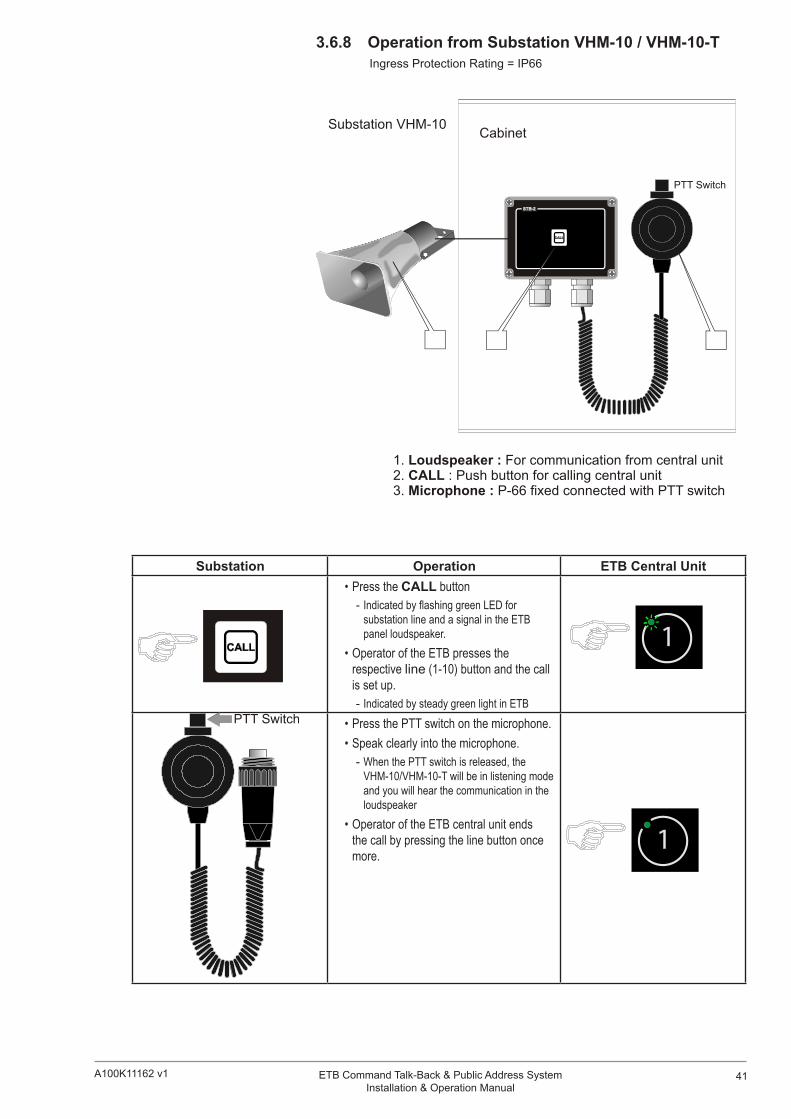
6 Dimension DrawingsAll dimensions shown are in mm.
6.1 ETB-5

49ETB Command Talk-Back & Public Address SystemInstallation & Operation Manual
A100K11162 v1
6.2 ETB-10/ETB-10A

50 A100K11162 v1ETB Command Talk-Back & Public Address SystemInstallation & Operation Manual
6.3 ETB-100/ETB-100A

51ETB Command Talk-Back & Public Address SystemInstallation & Operation Manual
A100K11162 v1
7 Connection/Block/Single Line Diagrams
7.1 ETB-100 Single Line DiagramZe
nite
l Mar
ine
Zenitel Marine Norway
VMT-603
VMP-603
TALK

52 A100K11162 v1ETB Command Talk-Back & Public Address SystemInstallation & Operation Manual
7.2 ETB-5/ETB-10 Single Line Diagram
Zeni
tel M
arin
e
Zenitel Marine Norway

53ETB Command Talk-Back & Public Address SystemInstallation & Operation Manual
A100K11162 v1
7.3 ETB-100 PCB Layout

54 A100K11162 v1ETB Command Talk-Back & Public Address SystemInstallation & Operation Manual

55ETB Command Talk-Back & Public Address SystemInstallation & Operation Manual
A100K11162 v1
7.4 ETB-5/ETB-10 PCB Layout

56 A100K11162 v1ETB Command Talk-Back & Public Address SystemInstallation & Operation Manual

57ETB Command Talk-Back & Public Address SystemInstallation & Operation Manual
A100K11162 v1
7.5 ETB-100 Block Diagram

58 A100K11162 v1ETB Command Talk-Back & Public Address SystemInstallation & Operation Manual
7.6 ETB-5/ETB-10 Block Diagram

59ETB Command Talk-Back & Public Address SystemInstallation & Operation Manual
A100K11162 v1
’
7.7 ETB-100 Cable Connection Diagrams

60 A100K11162 v1ETB Command Talk-Back & Public Address SystemInstallation & Operation Manual

61ETB Command Talk-Back & Public Address SystemInstallation & Operation Manual
A100K11162 v1

62 A100K11162 v1ETB Command Talk-Back & Public Address SystemInstallation & Operation Manual

63ETB Command Talk-Back & Public Address SystemInstallation & Operation Manual
A100K11162 v1
7.8 ETB-5/ETB-10 Cable Connection Diagrams

64 A100K11162 v1ETB Command Talk-Back & Public Address SystemInstallation & Operation Manual

65ETB Command Talk-Back & Public Address SystemInstallation & Operation Manual
A100K11162 v1

66 A100K11162 v1ETB Command Talk-Back & Public Address SystemInstallation & Operation Manual

67ETB Command Talk-Back & Public Address SystemInstallation & Operation Manual
A100K11162 v1

www.vingtor.com Zenitel Norway AS
VINGTOR products are developed and marketed by Zenitel Norway AS. The company’s Quality Assurance System is certified to meet the requirements in NS-EN ISO 9001:2008. Zenitel Norway AS reserves the right to modify designs and alter specifications without prior notice. ©2011 Zenitel Norway AS.
A100K11162 v1