DVC Digital Voice Command - FireSense
120
M2 P/N 52411:M2 ECN 15-0186 Document 52411 7/9/2015 Rev: Digital Audio DVC Digital Voice Command Installation, Programming and Operations Manual
-
Upload
khangminh22 -
Category
Documents
-
view
0 -
download
0
Transcript of DVC Digital Voice Command - FireSense

M2P/N 52411:M2 ECN 15-0186
Document 524117/9/2015 Rev:
Digital Audio
DVC Digital VoiceCommand
Installation, Programming andOperations Manual

2 DVC Manual — P/N 52411:M2 7/9/2015
Fire Alarm & Emergency Communication System LimitationsWhile a life safety system may lower insurance rates, it is not a substitute for life and property insurance!An automatic fire alarm system—typically made up of smoke detectors, heat detectors, manual pull stations, audible warning devices, and a fire alarm control panel (FACP) with remote notifi-cation capability—can provide early warning of a developing fire. Such a system, however, does not assure protection against property damage or loss of life resulting from a fire.
An emergency communication system—typically made up of an automatic fire alarm system (as described above) and a life safety communication system that may include an autonomous control unit (ACU), local operating console (LOC), voice commu-nication, and other various interoperable communication meth-ods—can broadcast a mass notification message. Such a system, however, does not assure protection against property damage or loss of life resulting from a fire or life safety event.
The Manufacturer recommends that smoke and/or heat detectors be located throughout a protected premises following the recommendations of the current edition of the National Fire Protection Association Standard 72 (NFPA 72), manufacturer's recommendations, State and local codes, and the recommendations contained in the Guide for Proper Use of System Smoke Detectors, which is made available at no charge to all installing dealers. This document can be found at http://www.systemsensor.com/appguides/. A study by the Federal Emergency Management Agency (an agency of the United States government) indicated that smoke detectors may not go off in as many as 35% of all fires. While fire alarm systems are designed to provide early warning against fire, they do not guarantee warning or protection against fire. A fire alarm system may not provide timely or adequate warning, or simply may not function, for a variety of reasons:
Smoke detectors may not sense fire where smoke cannot reach the detectors such as in chimneys, in or behind walls, on roofs, or on the other side of closed doors. Smoke detectors also may not sense a fire on another level or floor of a building. A second-floor detector, for example, may not sense a first-floor or basement fire.
Particles of combustion or “smoke” from a developing fire may not reach the sensing chambers of smoke detectors because:
• Barriers such as closed or partially closed doors, walls, chim-neys, even wet or humid areas may inhibit particle or smoke flow.
• Smoke particles may become “cold,” stratify, and not reach the ceiling or upper walls where detectors are located.
• Smoke particles may be blown away from detectors by air outlets, such as air conditioning vents.
• Smoke particles may be drawn into air returns before reach-ing the detector.
The amount of “smoke” present may be insufficient to alarm smoke detectors. Smoke detectors are designed to alarm at var-ious levels of smoke density. If such density levels are not cre-ated by a developing fire at the location of detectors, the detectors will not go into alarm.
Smoke detectors, even when working properly, have sensing limitations. Detectors that have photoelectronic sensing cham-bers tend to detect smoldering fires better than flaming fires, which have little visible smoke. Detectors that have ionizing-type sensing chambers tend to detect fast-flaming fires better than smoldering fires. Because fires develop in different ways and are often unpredictable in their growth, neither type of detector is necessarily best and a given type of detector may not provide adequate warning of a fire.
Smoke detectors cannot be expected to provide adequate warn-ing of fires caused by arson, children playing with matches (especially in bedrooms), smoking in bed, and violent explosions
(caused by escaping gas, improper storage of flammable materi-als, etc.).
Heat detectors do not sense particles of combustion and alarm only when heat on their sensors increases at a predetermined rate or reaches a predetermined level. Rate-of-rise heat detec-tors may be subject to reduced sensitivity over time. For this reason, the rate-of-rise feature of each detector should be tested at least once per year by a qualified fire protection specialist. Heat detectors are designed to protect property, not life.
IMPORTANT! Smoke detectors must be installed in the same room as the control panel and in rooms used by the system for the connection of alarm transmission wiring, communications, signaling, and/or power. If detectors are not so located, a devel-oping fire may damage the alarm system, compromising its abil-ity to report a fire.
Audible warning devices such as bells, horns, strobes, speakers and displays may not alert people if these devices are located on the other side of closed or partly open doors or are located on another floor of a building. Any warning device may fail to alert people with a disability or those who have recently consumed drugs, alcohol, or medication. Please note that:
• An emergency communication system may take priority over a fire alarm system in the event of a life safety emergency.
• Voice messaging systems must be designed to meet intelligi-bility requirements as defined by NFPA, local codes, and Authorities Having Jurisdiction (AHJ).
• Language and instructional requirements must be clearly dis-seminated on any local displays.
• Strobes can, under certain circumstances, cause seizures in people with conditions such as epilepsy.
• Studies have shown that certain people, even when they hear a fire alarm signal, do not respond to or comprehend the meaning of the signal. Audible devices, such as horns and bells, can have different tonal patterns and frequencies. It is the property owner's responsibility to conduct fire drills and other training exercises to make people aware of fire alarm signals and instruct them on the proper reaction to alarm sig-nals.
• In rare instances, the sounding of a warning device can cause temporary or permanent hearing loss.
A life safety system will not operate without any electrical power. If AC power fails, the system will operate from standby batteries only for a specified time and only if the batteries have been properly maintained and replaced regularly.
Equipment used in the system may not be technically compat-ible with the control panel. It is essential to use only equipment listed for service with your control panel.
Telephone lines needed to transmit alarm signals from a prem-ises to a central monitoring station may be out of service or tem-porarily disabled. For added protection against telephone line failure, backup radio transmission systems are recommended.
The most common cause of life safety system malfunction is inadequate maintenance. To keep the entire life safety system in excellent working order, ongoing maintenance is required per the manufacturer's recommendations, and UL and NFPA stan-dards. At a minimum, the requirements of NFPA 72 shall be fol-lowed. Environments with large amounts of dust, dirt, or high air velocity require more frequent maintenance. A maintenance agreement should be arranged through the local manufacturer's representative. Maintenance should be scheduled monthly or as required by National and/or local fire codes and should be per-formed by authorized professional life safety system installers only. Adequate written records of all inspections should be kept.
Limit-D-1-2013

DVC Manual — P/N 52411:M2 7/9/2015 3
Installation PrecautionsAdherence to the following will aid in problem-free installation with long-term reliability:WARNING - Several different sources of power can be connected to the fire alarm control panel. Disconnect all sources of power before servicing. Control unit and associ-ated equipment may be damaged by removing and/or insert-ing cards, modules, or interconnecting cables while the unit is energized. Do not attempt to install, service, or operate this unit until manuals are read and understood.
CAUTION - System Re-acceptance Test after Software Changes: To ensure proper system operation, this product must be tested in accordance with NFPA 72 after any pro-gramming operation or change in site-specific software. Re-acceptance testing is required after any change, addition or deletion of system components, or after any modification, repair or adjustment to system hardware or wiring. All compo-nents, circuits, system operations, or software functions known to be affected by a change must be 100% tested. In addition, to ensure that other operations are not inadvertently affected, at least 10% of initiating devices that are not directly affected by the change, up to a maximum of 50 devices, must also be tested and proper system operation verified.
This system meets NFPA requirements for operation at 0-49º C/32-120º F and at a relative humidity 93% ± 2% RH (non-condensing) at 32°C ± 2°C (90°F ± 3°F). However, the useful life of the system's standby batteries and the electronic com-ponents may be adversely affected by extreme temperature ranges and humidity. Therefore, it is recommended that this system and its peripherals be installed in an environment with a normal room temperature of 15-27º C/60-80º F.
Verify that wire sizes are adequate for all initiating and indi-cating device loops. Most devices cannot tolerate more than a 10% I.R. drop from the specified device voltage.
Like all solid state electronic devices, this system may operate erratically or can be damaged when subjected to light-ning induced transients. Although no system is completely immune from lightning transients and interference, proper grounding will reduce susceptibility. Overhead or outside aerial wiring is not recommended, due to an increased susceptibility to nearby lightning strikes. Consult with the Technical Ser-vices Department if any problems are anticipated or encoun-tered.
Disconnect AC power and batteries prior to removing or inserting circuit boards. Failure to do so can damage circuits.
Remove all electronic assemblies prior to any drilling, filing, reaming, or punching of the enclosure. When possible, make all cable entries from the sides or rear. Before making modifi-cations, verify that they will not interfere with battery, trans-former, or printed circuit board location.
Do not tighten screw terminals more than 9 in-lbs. Over-tightening may damage threads, resulting in reduced terminal contact pressure and difficulty with screw terminal removal.
This system contains static-sensitive components. Always ground yourself with a proper wrist strap before han-dling any circuits so that static charges are removed from the body. Use static suppressive packaging to protect electronic assemblies removed from the unit.
Follow the instructions in the installation, operating, and pro-gramming manuals. These instructions must be followed to avoid damage to the control panel and associated equipment. FACP operation and reliability depend upon proper installation.
Precau-D1-9-2005
FCC WarningWARNING: This equipment generates, uses, and can radiate radio frequency energy and if not installed and used in accordance with the instruction manual may cause interference to radio communications. It has been tested and found to comply with the limits for class A computing devices pursuant to Subpart B of Part 15 of FCC Rules, which is designed to provide reasonable protection against such interference when devices are operated in a commercial environment. Operation of this equipment in a residential area is likely to cause interfer-ence, in which case the user will be required to correct the interference at his or her own expense.
Canadian Requirements
This digital apparatus does not exceed the Class A limits for radiation noise emissions from digital apparatus set out in the Radio Interference Regulations of the Cana-dian Department of Communications.
Le present appareil numerique n'emet pas de bruits radi-oelectriques depassant les limites applicables aux appa-reils numeriques de la classe A prescrites dans le Reglement sur le brouillage radioelectrique edicte par le ministere des Communications du Canada.
HARSH™, NIS™, NOTI•FIRE•NET™, eVance™, and SWIFT™ are all trademarks; and Acclimate® Plus™, FlashScan®, FAAST Fire Alarm AspirationSensing Technology®, Intelligent FAAST®, NOTIFIER®, ONYX®, ONYXWorks®, VeriFire®, and VIEW® are all registered trademarks of HoneywellInternational Inc. Microsoft® and Windows® are registered trademarks of the Microsoft Corporation. Chrome™ and Google™ are trademarks of Google Inc.
©2015 by Honeywell International Inc. All rights reserved. Unauthorized use of this document is strictly prohibited.

4 DVC Manual — P/N 52411:M2 7/9/2015
Software DownloadsIn order to supply the latest features and functionality in fire alarm and life safety technology to our customers, we make frequent upgrades to the embedded software in our products. To ensure that you are installing and programming the latest features, we strongly recommend that you download the most current version of software for each product prior to commissioning any system. Contact Technical Support with any questions about software and the appropriate version for a specific application.
Documentation FeedbackYour feedback helps us keep our documentation up-to-date and accurate. If you have any comments or suggestions about our online Help or printed manuals, you can email us.
Please include the following information:
•Product name and version number (if applicable)
•Printed manual or online Help
•Topic Title (for online Help)
•Page number (for printed manual)
•Brief description of content you think should be improved or corrected
•Your suggestion for how to correct/improve documentation
Send email messages to:
Please note this email address is for documentation feedback only. If you have any technical issues, please contact Technical Services.

Table of Contents
DVC Manual — P/N 52411:M2 7/9/2015 5
Table of Contents
General Information.................................................................................................................9
Section 1: DVC Overview ....................................................................................................... 121.1: About This Manual ......................................................................................................................................121.2: Description...................................................................................................................................................13
1.2.1: Features..............................................................................................................................................161.2.2: Options ..............................................................................................................................................17
DVC-AO...............................................................................................................................................17DVC-KD...............................................................................................................................................17DS-FM, DS-SFM, DS-RFM.................................................................................................................17
1.2.3: Specifications ................................................................................................................................1724VDC Power - TB1 ............................................................................................................................17Digital Audio Ports A and B - TB2, TB3.............................................................................................17Auxiliary Input A (AUX A) - TB 4......................................................................................................18Auxiliary Input B (AUX B) - TB14 .....................................................................................................18Remote Microphone Interface - TB9 ...................................................................................................18Push-to-talk Interface - TB10...............................................................................................................18Alarm Bus - TB12 ................................................................................................................................18FFT Riser - TB13 .................................................................................................................................18Optional DVC-AO Analog Audio Output Circuits - TB5, TB6, TB7 and TB8 ..................................18
1.3: DVC Board Layout......................................................................................................................................191.3.1: Connections .......................................................................................................................................191.3.2: Switches and Indicators .....................................................................................................................20
Switch Functions ..................................................................................................................................20Indicators ..............................................................................................................................................21
1.4: Options.........................................................................................................................................................221.4.1: DVC-AO Analog Output Board Layout............................................................................................221.4.2: DVC-KD Keypad ..............................................................................................................................221.4.3: Fiber Option Boards ..........................................................................................................................23
Specifications.......................................................................................................................................23
Section 2: DVC Installation ....................................................................................................252.1: Overview......................................................................................................................................................25
2.1.1: Chassis ...............................................................................................................................................252.1.2: Doors and Dress Panels .....................................................................................................................25
Doors for CA-2 Installations ................................................................................................................25Doors for CA-1 Installations ................................................................................................................26Dress Panels for CA-2 Installations .....................................................................................................26Dress Panels for CA-1 Installations .....................................................................................................26
2.2: Prepare for Installation ................................................................................................................................262.3: Installation Checklist ...................................................................................................................................272.4: Cabinet .........................................................................................................................................................272.5: Mount DVC Option Boards.........................................................................................................................28
2.5.1: Installing Fiber Option Modules .......................................................................................................282.5.2: DVC-AO Analog Output Board ........................................................................................................292.5.3: DVC-KD Keypad ..............................................................................................................................29
2.6: Mount a Network Communications Module in a CA-1 or CA-2 Chassis ...................................................302.7: Mount a DVC Board in a CA-1 or CA-2 Chassis .......................................................................................312.8: Using a CFFT-1 with the CA-1 Chassis ......................................................................................................312.9: Move the Chassis for Wiring Access...........................................................................................................32
2.9.1: CA-1 ..................................................................................................................................................322.9.2: CA-2 ..................................................................................................................................................32
2.10: Wiring ........................................................................................................................................................332.10.1: DVC Board to 24V Power ..............................................................................................................332.10.2: Alarm Bus .......................................................................................................................................33

Table of Contents
6 DVC Manual — P/N 52411:M2 7/9/2015
2.10.3: Digital Audio Ports A and B............................................................................................................34Wire Terminals .....................................................................................................................................34Fiber Connections (Using Fiber Option Modules) ...............................................................................35
2.10.4: FFT Connectivity.............................................................................................................................36FFT Riser (TB13) .................................................................................................................................36
2.10.5: Auxiliary Inputs A and B.................................................................................................................37Auxiliary Input A..................................................................................................................................37Auxiliary Input B..................................................................................................................................37
2.10.6: Network Connection (NUP) Ports ...................................................................................................382.10.7: USB Ports ........................................................................................................................................382.10.8: Push-to-Talk Indicator .....................................................................................................................382.10.9: RM-1 Remote Microphone Interface...............................................................................................392.10.10: MIC-1 Local Microphone Interface...............................................................................................392.10.11: TELH-1 Local Phone Interface .....................................................................................................402.10.12: Analog Audio Outputs (DVC-AO)................................................................................................402.10.13: Wiring Fault Testing......................................................................................................................412.10.14: UL Power-limited (Class 2) Wiring Requirements .......................................................................42
2.11: Replacement of NVRAM Memory-Backup Battery..................................................................................42
Section 3: DVC Configuration and Programming................................................................ 433.1: Setting the Configuration Switches .............................................................................................................43
3.1.1: Piezo (Switch 5).................................................................................................................................433.1.2: 4WIRE (Switch 8) .............................................................................................................................43
3.2: Programming ..............................................................................................................................................433.2.1: Overview ...........................................................................................................................................433.2.2: Programming in VeriFire Tools.........................................................................................................43
DVC Special Function Zones ...............................................................................................................44VeriFire Tools Utilities .......................................................................................................................44
3.2.3: Special Applications: Mass Notification Systems ............................................................................443.2.4: VeriFire Tools Programming Interface .............................................................................................44
3.3: General Settings Branch ...........................................................................................................................463.3.1: General Settings Tab..........................................................................................................................47
General Settings Tab, Column 1...........................................................................................................47General Settings Tab, Column 2...........................................................................................................49General Settings Tab, Column 3: Mass Notification Settings..............................................................50
3.3.2: General Settings Branch, Program Settings Tab ..............................................................................51All Call Mapping, Special Paging Functions .......................................................................................51
3.4: KD Mapping DVC-KD................................................................................................................................533.5: DVC General Zones ....................................................................................................................................553.6: DAL Mapping .............................................................................................................................................56
3.6.1: Overview............................................................................................................................................563.6.2: DAA/DAX/DAA2 Amplifier Programming Options .......................................................................57
DAA-5025 PCA....................................................................................................................................57DAA-5025 PCB....................................................................................................................................57DAA-5070 PCA....................................................................................................................................57DAA-5070 PCB....................................................................................................................................57DAA-7525 PCB....................................................................................................................................58DAA2-5025 PCA..................................................................................................................................58DAA2-5070 PCA..................................................................................................................................58DAA2-7525 PCA..................................................................................................................................58DAX-3525 PCA....................................................................................................................................58DAX-3570 PCA....................................................................................................................................58DAX-5025 PCA....................................................................................................................................58DAX-5070 PCA....................................................................................................................................58
3.6.3: DAA/DAX/DAA2 Amplifier Field Definitions ...............................................................................58Basic DAL Device Settings (Top Half of DAL Mapping Screen).......................................................58General Settings Tab (Bottom Half of DAL Mapping Screen) ...........................................................59

Table of Contents
DVC Manual — P/N 52411:M2 7/9/2015 7
Speaker Circuits Tab (Bottom Half of DAL Mapping Screen) ........................................................603.6.4: DS-DB Programming Options ..........................................................................................................61
DS-DB PCA .........................................................................................................................................613.6.5: DS-DB Field Definitions ...................................................................................................................61
DS-DB General Settings Tab ...............................................................................................................61DS-DB Low-Level Output Tab ............................................................................................................62DS-DB Speaker Circuit Settings Tab ...................................................................................................62DS-DB Groups Tab ..............................................................................................................................63
3.6.6: DVC-RPU Programming Options .....................................................................................................63RPU-PCC .............................................................................................................................................63
3.6.7: DVC-RPU Field Definitions ............................................................................................................63General Settings Tab ............................................................................................................................63RPU-KD Tab .......................................................................................................................................63
3.7: Audio Message Programming Overview.....................................................................................................653.8: Audio Settings Branch ................................................................................................................................66
3.8.1: Message Segments.............................................................................................................................663.8.2: Message Sequences ..........................................................................................................................67
3.9: DVC Inputs Branch .....................................................................................................................................693.10: PAM Settings Branch ...............................................................................................................................72
3.10.1: Prioritized Audio Matrix (PAM) Programming Overview .............................................................72Addressing a PAM Point ......................................................................................................................72Activating a PAM Point .......................................................................................................................72
3.10.2: Network Paging ...............................................................................................................................743.10.3: Message Overrides ..........................................................................................................................763.10.4: Programming a PAM point .............................................................................................................76
3.11: Logic Equations Branch.............................................................................................................................773.11.1: Logic Equation Data-Entry Grid .....................................................................................................773.11.2: Logic Equation Builder ...................................................................................................................783.11.3: Edit and Save Changes (Logic Equation Commands).....................................................................783.11.4: Functions (Logic Equation Operators) ............................................................................................793.11.5: Points (Logic Equation Operands) ..................................................................................................793.11.6: DAL Device Alarm Bus Activation Using Logic Equation Programming .....................................81
3.12: Special Function Zones .............................................................................................................................813.13: Program Validation ...................................................................................................................................823.14: Reports ......................................................................................................................................................83
Section 4: DVC Operation ...................................................................................................... 844.1: Using the DVC-KD Keypad on the DVC....................................................................................................84
4.1.1: Pre-defined Buttons/Indicators ..........................................................................................................85Buttons When MN Mode = None ........................................................................................................85Buttons When MN Mode = ACU, LOC, or CCS.................................................................................86
4.1.2: LED Indicators ..................................................................................................................................864.1.3: 24 User-programmable Buttons.........................................................................................................86
4.2: Paging ..........................................................................................................................................................874.2.1: MIC-1 Microphone Paging................................................................................................................874.2.2: TELH-1 Telephone Paging................................................................................................................874.2.3: RM-1 Remote Microphone Paging....................................................................................................88
Configured with Annunciator...............................................................................................................88Configured with Keyswitch..................................................................................................................88
4.2.4: AUXA/AUXB Paging .......................................................................................................................884.2.5: FFT Paging ........................................................................................................................................89
4.3: Display and Control Center (DCC) .............................................................................................................894.4: Trouble Messages ........................................................................................................................................89
Non-displayed Events...........................................................................................................................89Read Status ...........................................................................................................................................89

Table of Contents
8 DVC Manual — P/N 52411:M2 7/9/2015
Appendix A: DAL Earth Fault Detection ............................................................................... 90
Appendix B: FFT Communication........................................................................................ 92B.1: FFT Paging..................................................................................................................................................92B.2: DVC Firefighter’s Telephone Network Communication ............................................................................92
B.2.1: FFT Communication Local to DVC Node........................................................................................92B.2.2: Point-to-point FFT Communication over Noti•Fire•Net (FFT-NFN) ..............................................94
Appendix C: Trouble Messages ............................................................................................ 99
Appendix D: Audio Groups.................................................................................................. 104D.1: Overview...................................................................................................................................................104D.2: Examples ...................................................................................................................................................104
D.2.1: One Amplifier Per Group ...............................................................................................................104D.2.2: Multiple Amplifiers Per Group.......................................................................................................106
D.3: Rules..........................................................................................................................................................108
Appendix E: DVC MN Modes ............................................................................................... 109E.1: DVC-KD Installation.................................................................................................................................109E.2: Programming .............................................................................................................................................110
Glossary ................................................................................................................................ 113
Index ...................................................................................................................................... 114

DVC Manual — P/N 52411:M2 7/9/2015 9
General Information
Standards and Other Documents
The Digital Voice Command and Digital Audio Amplifiers Series comply with the following standards:
• NFPA 72 2007 National Fire Alarm Code
• Underwriter Laboratories Standard UL 864
• Underwriter Laboratories of Canada (ULC) ULC-S527-99 Standard of Control Units for Fire Alarm Systems
• Part 15 Class A conducted and radiated emissions as required by the FCC
The installer should be familiar with the following documents and standards:
NFPA StandardsNFPA 72 National Fire Alarm Code
Underwriter LaboratoriesUL 464 Audible Signaling AppliancesUL 864 Standard for Control Unit and Accessories for Fire Alarm SystemsUL 1481 Power Supplies for Fire Protective Signaling SystemsUL 1638 Visual Signaling Appliances - Private-Mode Emergency and General Utility SignalingUL 1711 Amplifiers for Fire Protective Signaling SystemsUL 60950 Safety of Information Technology EquipmentUL 1971 Signaling Devices for the Hearing ImpairedUL 2572 Mass Notification Systems
Underwriters Laboratories of Canada (ULC)ULC-S527-99 Standard of Control Units for Fire Alarm Systems
OtherFCC Part 15 Class A Conducted and Radiated Emissions
UL 864 Ninth Edition Compliance
This product has been certified to comply with the requirements in the Standard for Control Units and Accessories for Fire Alarm Systems, UL 864 9th Edition.
Products Subject to AHJ Approval
The following products have not received UL 864 9th Edition certification and may only be used in retrofit applications. Operation of the DVC with products not tested for UL 864 9th Edition has not been evaluated and may not comply with NFPA 72 and/or the latest edition of UL 864. These applications will require the approval of the local Authority Having Jurisdiction (AHJ).
NFS-640 Fire Alarm Control Panel NFS-3030 Fire Alarm Control PanelNCA Network Control Annunciator AMG -1

10 DVC Manual — P/N 52411:M2 7/9/2015
General Information
Programming Features Subject to AHJ Approval
This product incorporates field-programmable software. The features and/or options listed below must be approved by the local AHJ.
Supplemental Documentation
The table below provides a list of documents referenced in this manual, as well as documents for selected other compatible devices.
This product incorporates field-programmable software. In order for the product to comply with the requirements in the Standard for Control Units and Accessories for Fire Alarm Systems, UL 864, certain programming features or options must be limited to specific values
or not used at all as indicated below.
Program Feature or Option Permitted in UL 864? (Y/N) Possible Settings Settings Permitted in UL 864
IP downloads over a local area network (LAN) or the Internet (Wide Area Network - WAN)
No YesNo
No
VeriFire Tools Help File and installation document VeriFire Tools Help File, 51690
Mass Notification System Manual LS10063-000NF-E
DAA2/DAX Devices Manual 53265
DS-DB Manual 53622
DVC-RPU UL Listing Document 50107424-001
DVC-RPU Manual 50107425-001
Wire Guide Addendum for Digital Audio Loops 52916ADD
DVC-AO Audio Option Board Installation Document 52728
DVC-KD Keypad Product Installation Document 52709
Heat Dissipation Calculations Document for Cabinets with Digital Audio Products 53645
CA-1 Chassis Product Installation Document 52474
CA-2 Chassis Product Installation Document 52455
CFFT-1 Chassis for Firefighter’s Telephone Product Installation Document 53289
CMIC-1 Chassis Product Installation Document 52476
NFS2-3030 Listing Document LS10006-051NF-E
NFS2-640 Listing Document 52741LD
NFS-320 Listing Document 52745LD
AMPS-24 Manual 51907
ACPS-610 Addressable Power Supply Manual 53018
NFS-640 Installation, Programming, Operations Manuals 51332, 51333, 51334
NFS-3030 Installation, Programming, Operations Manual 51330, 51345, 51344
NCA Network Control Annunciator Manual 51482
NCA-2 Network Control Annunciator Manual 52482
ONYXWorks Workstation: ONYXWORKS-WS Listing Document LS10050-003NF-E
ONYXWorks NOTIFY IP Manual 53620
Noti-Fire-Net Manual 51584
High-Speed Noti-Fire-Net Manual 54013
NCM Installation Document 51533
HS-NCM High Speed Network Communications Module Installation Document 54014
SLC Wiring Manual 51253
DAL Devices Product Information Sheet 52410
AA Series Audio Amplifier Manual 52526
ACS Annunciator Manual 15842
AFAWS Automatic Fire Alarm Warden Station 50705
FTM-1 Firephone Control Module I56-1391
ACT-4 Audio Coupling Transformer 53431
ACT-25 Audio Coupling Transformer 53432
ACT-70 Audio Coupling Transformer 53240
RM-1 Series Remote Microphones 51138
RPJ-1 Remote Paging Jack 15058

DVC Manual — P/N 52411:M2 7/9/2015 11
General Information
Related Documentation Table
Cautions and Warnings
This manual contains cautions and warnings to alert the reader as follows:
FPJ Firefighter’s Phone Jack 15510
CAB-4 Series Cabinets Installation Instructions 15330
EQ-CAB Series Installation Instructions 53412
Audio Fiber Links Document 52230
RSM-1A Residential Silence Module I56-006
AIM-1A Audible Isolation Module I56-006
CIM-2A/CSM-1A Isolator and Silencing Modules I56-2200
! CAUTION:INFORMATION ABOUT PROCEDURES THAT COULD CAUSE PROGRAMMING ERRORS, RUNTIME ERRORS, OR EQUIPMENT DAMAGE.
!WARNING:INDICATES INFORMATION ABOUT PROCEDURES THAT COULD CAUSE IRREVERSIBLE DAMAGE TO THE CONTROL PANEL, IRREVERSIBLE LOSS OF PROGRAMMING DATA, OR PERSONAL INJURY.
DVC Manual — P/N 52411:M2 7/9/2015 12
DVC Digital Voice Command
Section 1: DVC Overview
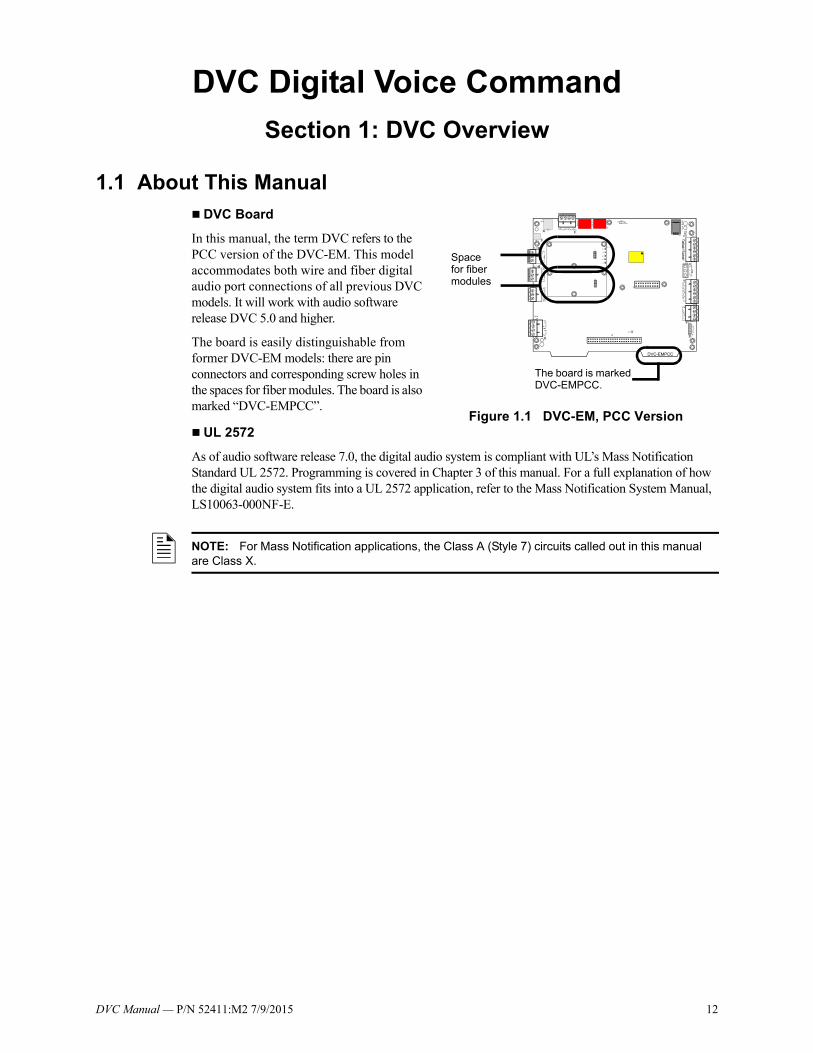
1.1 About This Manual DVC Board
In this manual, the term DVC refers to the PCC version of the DVC-EM. This model accommodates both wire and fiber digital audio port connections of all previous DVC models. It will work with audio software release DVC 5.0 and higher.
The board is easily distinguishable from former DVC-EM models: there are pin connectors and corresponding screw holes in the spaces for fiber modules. The board is also marked “DVC-EMPCC”.
UL 2572
As of audio software release 7.0, the digital audio system is compliant with UL’s Mass Notification Standard UL 2572. Programming is covered in Chapter 3 of this manual. For a full explanation of how the digital audio system fits into a UL 2572 application, refer to the Mass Notification System Manual, LS10063-000NF-E.
Figure 1.1 DVC-EM, PCC Version
Space for fiber modules
The board is marked DVC-EMPCC.
NOTE: For Mass Notification applications, the Class A (Style 7) circuits called out in this manual are Class X.

DVC Manual — P/N 52411:M2 7/9/2015 13
Description DVC Overview
UL 864 Low-Frequency Sounder Compliance
This product complies with the requirements for a low frequency sounder (520Hz) as specified in UL 464 when used as part of a system with the following amplifiers, communication devices, audio files, and speakers.
Amplifiers:
Communication Devices:
Audio Files:
Speakers:
For a complete list of speakers that can be used in a Digital Voice Command system with the above specifications, refer to the current version of the Device Compatibility document, p/n 15378.
1.2 DescriptionThe DVC is a multi-featured audio processor with digital audio functionality that operates as an event-driven audio message generator and router. It is designed for use with the DAA, DAA2, and DAX Series digital audio amplifiers, the DS-DB digital series distribution boards, and the DVC-RPU, in a single panel or networked environment. The DVC has two wire digital audio ports, each
Amplifier Combination Description
DAA2-5025 with or without a BDA-25V DAA2-5025: 120VAC 25VRMS digital audio amplifierBDA-25V: 25VRMS backup digital audio amplifier
DAA2-5070 with or without a BDA-70V DAA2-5070: 120VAC 70VRMS digital audio amplifierBDA-70V: 70VRMS backup digital audio amplifier
DAA2-7525 with or without a BDA-25V DAA2-7525: 120VAC 25VRMS digital audio amplifierBDA-25V: 25VRMS backup digital audio amplifier
DAX-5025 with or without a BDA-25V DAX-5025: 120VAC 25VRMS digital audio amplifierBDA-25V: 25VRMS backup digital audio amplifier
DAX-5070 with or without a BDA-70V DAX-5070: 120VAC 70VRMS digital audio amplifierBDA-70V: 70VRMS backup digital audio amplifier
DAX-3525 with or without a BDA-25V DAX-3525: 120VAC 25VRMS digital audio amplifierBDA-25V: 25VRMS backup digital audio amplifier
DAX-3570 with or without a BDA-70V DAX-3570: 120VAC 70VRMS digital audio amplifierBDA-70V: 70VRMS backup digital audio amplifier
DS-DB with a DS-AMP with or without a DS-XF70V
DS-DB: digital series distribution boardDS-AMP: digital series amplifierDS-XF70: step-up transformer required for 70V operation
DS-DB with a DS-BDA with or without a DS-XF70V
DS-DB: digital series distribution boardDS-BDA: backup digital series audio amplifierDS-XF70: step-up transformer required for 70V operation
Model Number Description
DS-FM Multi-mode fiber option module
DS-SFM Single-mode fiber option module
DS-RFM Multi-mode fiber option module
Name Description
520Hz temporal 3 HQ.wav Temporal Horn pattern with 520Hz for High Quality systems
520Hz temporal 3 SQ.wav Temporal Horn pattern with 520Hz for Standard Quality systems

14 DVC Manual — P/N 52411:M2 7/9/2015
DVC Overview Description
of which may be converted to a fiber port using a fiber option module. With the addition of the optional DVC-AO board, the DVC may also be used as an analog audio source in retrofit analog audio applications. (See Figure 1.2.)
The NFS2-640 and NFS2-3030 may be directly connected to the DVC for single panel applications. An NCA-2 is required with the NFS2-640 when a DAL (Digital Audio Loop) is part of the configuration. An NCA-2 is not required with the NFS2-640 when there is no DAL. Refer to Figure 1.2 for illustrations of single panel configurations.
Network configurations require an NCA-2 or NFS2-3030 programmed to display DVC troubles, and will support all Network Control-by-Event (CCBE) from the following panels: NFS2-640, NFS-640, NFS2-3030, NFS-3030, and NFS-320. A network workstation can be used to display troubles.
When used with the optional DVC-KD keypad and an NCA-2 or NFS2-3030, the DVC becomes the key component of an audio command center, accepting live paging from several sources and providing the ability to direct the paging to appropriate pre-programmed speaker zones in the system.
The DVC stores up to 32 minutes of standard quality audio (11.025 KHz sampling rate, 8 bit µ-law, mono), or 4 minutes of high quality audio (44.1 KHz sampling rate, 16 bit PCM, mono).
Figure 1.2 gives simplified overview illustrations of typical applications for the DVC and its Digital Audio Loop (DAL).
NOTE: The terms DAA, DAA2, DAX, DS-AMP and BDA are used in this manual to refer to all respective models of each type of amplifier. Individual part numbers are used only when it is necessary to distinguish features or functions that differ. Refer to the appropriate manual for individual model descriptions.
NOTE: Wire and fiber versions of all DVC and DAL devices are compatible on a DAL. Fiber option modules are required for fiber connections to new devices.

DVC Manual — P/N 52411:M2 7/9/2015 15
Description DVC Overview
Figure 1.2 Block Diagrams of DVC Applications
NFS2-3030 Single Panel Applications
Networked System
NFS2-3030
DVC
NFS2-640
NCA-2 or NFS2-3030
Noti
N
NCM
NCM
NCM
NCM
with DVC and Digital Audio Loop (DAL).
Optional Class A (Style 7) return
Networked System with Analog Equipment
NCM
DVC-AO
DAL
AA Series Audio AmplifiersLow level analog audio
NFS2-3030
Noti
NFS2-640
NCM
NCM
Optional Class A (Style 7) returnDAL
DALDevice
1 2 32
Optional Class A (Style 7) returnDAL
DVCNUP
Optional Class A (Style 7) returnDAL
DVC-AO
with DVC, DAL, and DVC-AO for retrofits.
NCM
NFS2-3030
NCM
NFS-320
NCM
NFS-320
* In this configuration, the DVC will only share General Zone activations with the NFS2-640. For example, logic zone activity in the DVC will not be usable in the NFS2-640.
1 2 32
DVC1 2 32
1 2 32DVC
NCA-2 or NFS2-3030
NFS2-640 Single Panel Applications
with DVC and DVC-AO for retrofits. DAL (digital audio loop) not compatible with this application.
with DVC, NCA-2, DAL, and DVC-AO for retrofits.*
DVCNUP
DVC-AO
NFS2-640
NFS2-3030
DVCNUP
Optional Class A (Style 7) returnDAL
DVC-AO
1 2 32
NFS2-640
AA Series Audio AmplifiersLow level analog
audioNCA-2 NUP
In this diagram, the term:• “NCM” includes all network control modules, including high-speed versions. Note, however, that high-speed and standard NCMs may not be mixed on a network.• “Noti•Fire•Net” includes standard and high-speed network versions.
DALDevice
DALDevice
DALDevice
DALDevice
DALDevice
DALDevice
DALDevice
DALDevice
DALDevice
DALDevice
DALDevice
DALDevice
DALDevice
DALDevice
An NFS2-3030 must be in Network Display Mode to display DVC troubles. Refer to the NFS2-3030 programming manual for information on this mode.
**
**
*
An NCA, NFS-640, or NFS-3030 with compatible software may be part of a network.
AA Series Audio AmplifiersLow level analog
audio
AA Series Audio AmplifiersLow level analog
audio

16 DVC Manual — P/N 52411:M2 7/9/2015
DVC Overview Description
1.2.1 Features• Programmable from NUP or USB port using VeriFire Tools.
• Paging inputs include local and remote microphones, FFT handsets, Firefighter’s Telephone, two auxiliary inputs (1 V p-p and 12 V p-p) and paging from ONYXWorks.
• ONYXWorks workstations or additional DVCs can act as Noti•Fire•Net paging sources.
• Storage for up to 32 minutes of audio (.wav files) for voice messages or tones. At optional high quality audio setting, 4 minutes of audio files can be stored at a 44K samples per second resolution.
• 1000 custom messages can be created by the creation of message strings that reuse common audio segments.
• Customizable message prioritization.
• Equations use flexible CCBE programming for distribution of messages.
• 8 channel digital audio using the DAL (Digital Audio Loop) when using standard quality audio.
• 1 audio channel on the DAL when using high quality audio.
• 4 channel analog audio supported by optional DVC-AO analog output card.
• 1 audio channel on a standard or high-speed Noti•Fire•Net.
• Digital audio ports for direct connection with up to 2 digital audio loop devices, for a total of up to 32 devices on one DAL.
• Operates as a node on a standard or high-speed Noti•Fire•Net.
• DCC (Display and Control Center) capabilities when used with the DVC-KD.
• Multiple audio command centers supported on Noti•Fire•Net.
• Optional remote microphone.
• Functional with NFS2-3030 or NFS2- 640 as a standalone system (without Noti•Fire•Net).
• Firefighter’s Telephones
• 5 FFT channels on the DAL
• Local FFT handset (optional)
• FFT riser on the DVC
• Additional FFT risers on DAA and DAA2 series amplifiers, as well as DS-DB distribution boards.
• FFT points can be answered or controlled via programmable DVC-KD points and/or ACS annunciator points.
• Broad paging functionality when used with DVC-KD via microphone, TELH-1 or FFT, RM-1, AUX A or AUX B inputs.
• Emergency paging buttons for All Call, Page Active Evac Areas, Page Active Alert Areas, and Page Inactive Areas.
NOTE:• Speaker placement must be given careful consideration when planning an audio system.• Place speakers from different DALs (Digital Audio Loops) so they are not within the audible
areas of other DALs.• Carefully consider the audible range of speakers within a DAL; overlapping audio messages
can be confusing.
NOTE: A maximum of 54 nodes may be used on a standard Noti•Fire•Net when digital audio messages will be broadcast over it. This limitation does not apply to a high-speed Noti•Fire•Net network, which accommodates up to 200 nodes with or without digital audio equipment.
DVC Manual — P/N 52411:M2 7/9/2015 17
Description DVC Overview
• Auxiliary input for 12V p-p analog low-level audio sources.
• Auxiliary input for 1V p-p, to be used for background music input, and interface with a telephone paging source, or other compatible audio sources. Includes user audio level adjustment feature.
• Push-to-talk relay.
• Isolated alarm bus input, to be used for backup activation of alarm messages from a local FACP.
• Meets UL THD Distortion requirements. Refer to the DAA2/DAX and DS-DB manuals for individual amplifier distortion specifications.
• Meets ULC THD Distortion requirements. Refer to the DAA2/DAX and DS-DB manuals for individual amplifier distortion specifications.
1.2.2 Options
DVC-AO
The DVC-AO audio output board has four low-level analog outputs. It mounts on the DVC and is compatible with AA-30/E, AA-100/E, and AA-120/E amplifier products. Refer to Section “Analog Audio Outputs (DVC-AO)” on page 40.
DVC-KD
The DVC-KD keypad is for local annunciation and controls. Refer to “Using the DVC-KD Keypad on the DVC” on page 84 and “DVC-KD Keypad” on page 29 for more information on the DVC-KD.
DS-FM, DS-SFM, DS-RFM
These fiber option modules convert the DVC from a wire to a single or multi-mode fiber board. Refer to “Fiber Option Boards” on page 23 for more information.
1.2.3 Specifications
24VDC Power - TB1
24VDC input, 300 mA, alarm or standby, non-resettable, power-limited (Class 2) by the source, non-supervised.
• If a DVC-KD is attached, add: 60 mA
• If a DVC-AO is attached, add: 175 mA
• If an RM-1 is attached, add: 75 mA
• If one fiber module is attached,add: 60 mA
• If another fiber module is attached,add another: 60 mA
• For a possible total of: 730 mA alarm or standby
Recommended wiring: 14-18 AWG twisted-pair (max. 14 AWG.)
Digital Audio Ports A and B - TB2, TB3
Refer to the Wiring Guide, p/n 52916ADD, for acceptable wire types.
EIA-485 format.
Power-limited (Class 2).
Refer to “Fiber Option Boards” on page 23 for fiber specification and connection information. When a fiber option module is mounted on a DVC, it disables the corresponding wire terminals. TB3 (Digital Audio Port A) is disabled when a fiber option board is connected at J15. TB2 (DAP B) is disabled when a fiber option board is connected at J16.
18 DVC Manual — P/N 52411:M2 7/9/2015
DVC Overview Description
Auxiliary Input A (AUX A) - TB 4
Signal strength from low-level analog audio input (such as background music or telephone paging): 1.6Vp-p max. for each circuit when both AUXA L and AUXA R are used. 3.2Vp-p max. for one when only one (AUXA L or AUXA R) is used.
Optional supervision through programming.
Recommended wiring: 18AWG, twisted-pair (max. 14 AWG).
Supervision programmable.
Auxiliary input source must be within 20 feet (6.01 m) of the DVC, and in the same room.
Auxiliary Input B (AUX B) - TB14
Signal strength from low-level analog audio input (AMG-style audio): 12Vp-p nominal, 15Vp-p max. Optional supervision through programming.
Recommended wiring: 14-18 AWG twisted-pair (max. 14 AWG.).
Supervision programmable.
Remote Microphone Interface - TB9
Recommended wiring: 14-18 AWG twisted-pair (max. 14 AWG.).
Nominal AC signal strength 2.5VRMS (3VRMS max).
Power-limited (Class 2).
Supervised.
Max distance between remote microphone and DVC: 1000 ft (300 m).
Push-to-talk Interface - TB10
Dry contact.
Common, non-supervised.
Recommended wiring: 14-18 AWG twisted-pair (max. 14 AWG).
Alarm Bus - TB12
Power-limited (Class 2) by source.
Non-supervised.
Recommended wiring: 14-18 AWG twisted-pair (max. 14 AWG.).
Requires 16 VDC minimum @ 20mA across the terminals to activate. Nominal 24VDC.
FFT Riser - TB13
Power-limited (Class 2) output.
Max: 15V, 75 mA AC.
Supervised.
Class A (Style Z) or Class B (Style Y) operation.
Style Y 2-wire connections require a 3.9k ohm 1/2 watt end-of-line resistor (P/N R-3.9K).
Max. wiring resistance (including individual telephone zone to last handset) permitted is 50 ohms, 10,000 ft. (3048 m) max. wiring distance at 14 AWG twisted-pair (shielded recommended) to last handset.
Optional DVC-AO Analog Audio Output Circuits - TB5, TB6, TB7 and TB8Power-limited (Class 2) outputs.Signal strength: 12Vp-p (max 15Vp-p 150 mA).Supervision programmable.Recommended wiring: 18 AWG max, twisted-pair (max. 14 AWG).Max impedance: 66 ohms.Distance based on impedance.Class A (Style Z) or Class B (Style Y) operation.

DVC Manual — P/N 52411:M2 7/9/2015 19
DVC Board Layout DVC Overview
1.3 DVC Board Layout
1.3.1 Connections
Board connections for the DVC are illustrated and identified in Figure 1.3.
Figure 1.3 Connections
ALM IN +ALM IN -
ALM OUT +ALM OUT -TB12
AlarmRefer topage 33
USB B Connector (Type B) J4Refer to page 38
NUP Port A Connector
J1Refer to page 38
USB A Connector (Mini AB) -J3Refer to page 38
NUP Port B Connector
J2Refer to page 38
TELH-1 Local PhoneJ8
Refer to page 40
DAPA REFDAPA -DAPA +
TB3 - DigitalAudio Port A
Refer topage 34
DAPB REFDAPB -DAPB +
TB2 - DigitalAudio Port B
Refer topage 34
COMNCNOTB10 -
PUSH-TO-TALKRefer to page 38
24V OUT -24V OUT +
24V IN -24V IN +
TB1 - PowerRefer topage 33
DVC-KD Connection - J6Refer to page 22, 29.
+ RISER OUT- RISER OUTSHLD RISER OUT+ RISER RTN- RISER RTNSHLD RISER RTN
FFT RiserTB 13
Refer to page 36
+ RMI AUDIO- RMI AUDIOSHLD RMI AUDIO+ RMI PWR- RMI PWRSHLD RMI PWR
TB
9R
emot
e M
icro
phon
eR
efe
r to
pa
ge39
+ AUXB- AUXBSHLD AUXB
+ AUXA R- AUXA R+ AUXA L- AUXA L
TB 14Refer to page 37
TB 4Refer to page 37
MIC-1 LOCAL MICJ5Refer to page 39
DVC-AO Connection - J10Refer to page 22. D
VC
-PC
C b
rd.w
mf
NVRAM lithium battery
Alignment Dot for Replacement
DVC board ID - DVC-EMPCC
J16J15
Fiber Module Pin Connections Refer to page 28

20 DVC Manual — P/N 52411:M2 7/9/2015
DVC Overview DVC Board Layout
1.3.2 Switches and Indicators
Switches and LED indicator locations on the DVC are illustrated in Figure 1.4.
Figure 1.4 LED Indicator and Switch Locations
Switch Functions
The switches described in Table 1.1 are for configuration or for diagnostic purposes. All are located as indicated in Figure 1.4.
Table 1.1 DVC Switches
Sw
L S
L
LL
L
LL
LL
L
D
L
L
LE
LE
LE
LE
Name Number Description Default
PIEZO SW5 Enable/disable the piezo. EN (enable/on)
4WIRE SW8 Changes FFT Riser indication to 2- or 4-wire, depending on whether the riser is wired Class B or Class A.
2-wire

DVC Manual — P/N 52411:M2 7/9/2015 21
DVC Board Layout DVC Overview
Indicators
The diagnostic LEDs indicate various conditions and troubles. All are located as indicated in Figure 1.4.
Table 1.2 DVC LED Indicators
LED Name Color Description LED #
RESET Yellow Factory use only 1
TRBL Yellow Illuminates when a trouble occurs. Blinks for an unacknowledged trouble, illuminates steadily for an acknowledged trouble.
3
AL BUS Red Illuminates steadily while the DVC’s alarm bus input is active. 4
PHONE ACT FFT
Green Illuminates steadily while at least one firefighter’s telephone is active on a DAL device riser. 5
AUX A Green Illuminates steadily while audio is detected on AUX IN A. 6
AUX B Green Illuminates steadily while audio is detected on AUX IN B. 7
ON 1 Green Illuminates steadily while analog signal is on audio output 1. 8
ON 2 Green Illuminates steadily while analog signal is on audio output 2. 9
ON 3 Green Illuminates steadily while analog signal is on audio output 3. 10
ON 4 Green Illuminates steadily while analog signal is on audio output 4. 11
MIC ACT Green Illuminates steadily while push-to-talk is activated on the MIC-1 microphone. 12
USBA Green Illuminates steadily when a connection is made. 13
USBB Green Illuminates steadily when a connection is made. 14
PWR Green Illuminates steadily while local 24V from power supply is present. 20
STATUS Green Blinks slowly (once a second) under normal operation, Blinks fast (4 times a second) when the DVC is in bootload or diagnostic mode. Does not blink when the board is not operational or starting up. Call the factory if this LED is off for a prolonged period of time.
21
TXA Green Illuminated while data is transmitted on Digital Audio Port (DAP) A. Illumination will flicker on wire versions, turning on when activity is detected and off when it is not. LED does not illuminate for fiber media.
22
TXB Green Illuminated while data is transmitted on Digital Audio Port (DAP) B. Illumination will flicker on wire versions, turning on when activity is detected and off when it is not. LED does not illuminate for fiber media.
23
RXA Green Illuminated while data is received on Digital Audio Port (DAP) A. Illumination will flicker on wire versions, turning on when activity is detected and off when it is not. LED does not illuminate for fiber media.
24
RXB Green Illuminated while data is received on Digital Audio Port (DAP) B. Illumination will flicker on wire versions, turning on when activity is detected and off when it is not. LED does not illuminate for fiber media.
25

22 DVC Manual — P/N 52411:M2 7/9/2015
DVC Overview Options
1.4 Options
1.4.1 DVC-AO Analog Output Board Layout
Refer to “Analog Audio Outputs (DVC-AO)” on page 40 for information on wiring these connections. See Figure 2.4, “Mounting a DVC-AO” on page 29 for information on mounting it onto a DVC.
Figure 1.5 DVC-AO Board Layout
1.4.2 DVC-KD Keypad
The DVC-KD is used for paging and message routing functions, with status LEDs for certain functions and 24 user-programmable annunciator-type buttons. Refer to Section 2.5.3 on page 29 for information on mounting the keypad and slide-in labels, and “Using the DVC-KD Keypad on the DVC” on page 84 for information on the keypad’s operation.
DV
CA
OP
CA
boa
rd.w
mf
Connector for DVC board
Analog 4 Out +
Analog 4 Out -Analog 4 Out SHLD
TB4
Analog 4 Ret +
Analog 4 Ret -
Analog 4 Ret SHLD
TB8
Analog 3 Out +
Analog 3 Out -Analog 3 Out SHLD
TB3
Analog 3 Ret +Analog 3 Ret -
Analog 3 Ret SHLD
TB7
Analog 1 Ret +
Analog 1 Ret -
Analog 1 Ret SHLDTB5
Analog 2 Ret +
Analog 2 Ret -Analog 2 Ret SHLD
TB6
Analog 2 Out +Analog 2 Out -
Analog 2 Out SHLD
TB2
Analog 1 Out +
Analog 1 Out -
Analog 1 Out SHLD
TB1Out (Bottom) - the row of terminal blocks closest to the board.
Return (Top) - the row of terminal blocks farthest from the board.
DV
CA
OP
CA
boa
rd.w
mf
The connector to the DVC board is on the back side of the DVC-KD. See Section 2.5.3 on page 29.
Slots for slide-in labels.
DV
C-K
D.w
mf
Figure 1.6 DVC-KD Keypad

DVC Manual — P/N 52411:M2 7/9/2015 23
Options DVC Overview
1.4.3 Fiber Option Boards
The DVC supports wire media as shipped. Use of fiber optic media requires the use of fiber option modules. Each DVC can be used with either one or two modules. This flexibility allows for the creation of digital audio networks with mixed wire, multi-mode fiber, and single-mode fiber segments on the same loop. Fiber option modules consist of the following models.
One or two fiber option modules may be connected to a DVC to convert it from a board with two wire DAP ports to:
• a board with one wire and one fiber port,
• a board with two single-mode fiber ports,
• a board with two multi-mode fiber ports, or
• a board with one single-mode and one multi-mode fiber port.
When a fiber option module is mounted on a DVC, it disables the corresponding wire terminals. TB3 (Digital Audio Port A) is disabled when a fiber option board is connected at J15. TB2 (DAP B) is disabled when a fiber option board is connected at J16.
Specifications
Single- and Multi-mode Fiber-Optic Digital Audio Ports
LC Style connection.
Supervised.
Fiber optic cable, multi-mode: 50/125 or 62.5/125 micrometers.
Fiber optic cable, single-mode: 9/125 micrometers.
Attenuation of cabling between two nodes (fiber-optic circuits are point-to-point) must not exceed the maximum attenuation, specified below.
To determine attenuation:
1. Find the rated dB loss per foot within the cable manufacturer’s specifications. Determine the total attenuation between the two nodes due to the cable.
Loss = (loss/ft.) x (length in feet)
2. Establish the dB loss for each connector and splice. Sum all the losses.
3. Total the attenuation factors obtained in steps 1 and 2. This will provide an approximate attenuation total. The actual attenuation should be measured end-to-end with fiber-optic industry standard equipment.
• DS-FM and DS-SFM (except when directly connected to a fiber DAA)
The maximum attenuation:• 6.5dB for multi-mode with 50/125 micrometer cable @ 1310 nm.
Model Fiber Type For direct fiber connection between the DVC and....
DS-FM multi-mode Any DAA2 or DAX model, DS-DB, or DVC-RPU. LC Style fiber connectors at both ends.
DS-SFM single-mode • Any DAA2 or DAX model, DS-DB, or DVC-RPU. LC Style fiber connectors at both ends.
• A single-mode fiber DAA Series amplifier. LC Style fiber connector at DVC end,
ST® style fiber connector at DAA end.
DS-RFM multi-mode A multi-mode fiber DAA Series amplifier. LC Style fiber connector at DVC end, ST® style fiber connector at DAA end.
NOTE: Whenever a fiber option module is used on a DAL device port, the next DAL device that is linked to that port must have the same model fiber option module or equivalent style DAA.

24 DVC Manual — P/N 52411:M2 7/9/2015
DVC Overview Options
• 10dB for multi-mode with 62.5/125 micrometer cable @ 1310 nm.• 30dB for single-mode with 9/125 micrometer cable @ 1310 nm.
• DS-SFM/Single-mode fiber DAA Connection
The maximum attenuation:• 17dB for single-mode with 9/125 micrometer cable at 1310 nm going from the
DS-SFM to the fiber DAA.• 4dB for single-mode with 9/125 micrometer cable going from fiber DAA to the
DS-SFM.The minimum attenuation:• 12dB minimum* going from the DS-SFM to the fiber DAA.
*If the length of the fiber run results in an attenuation of less than 12dB,
a suitable attenuator must be used.
• DS-RFM/Multi-mode fiber DAA Connection
Attenuation going from the fiber DAA to the DS-RFM:• 2dB maximum for multi-mode with 50/125 micrometer cable @ 850 nm for the
DS-RFM.• 4dB maximum for multi-mode with 62.5/125 micrometer cable @ 850 nm for the
DS-RFM.Attenuation going from the DS-RFM to the fiber DAA:• 12dB minimum*, 16dB maximum for both cable types.
*If the length of the fiber run results in an attenuation of less than 12dB,
a suitable attenuator must be used.
The DS-FM, DS-SFM and DS-RFM look the same. The silkscreened board name that applies will be visible: those that do not apply will be crossed off.
Figure 1.7 Fiber Option Module.
LED # NAME COLOR DESCRIPTION
1 TX Green Illuminates while data is transmitted on the digital audio port. Light will flicker, turning on when activity is detected and off when it is not.
2 RX Green Illuminates while data is received on the digital audio port. Light will flicker, turning on when activity is detected and off when it is not.
Fiber out
Fiber in
LED2 RX
LED1 TX
J1 Pin Connector

DVC Manual — P/N 52411:M2 7/9/2015 25
Section 2: DVC Installation
2.1 Overview
2.1.1 Chassis
DVC boards will mount in a size B, C or D CAB-4 series cabinet, in either one of the following chassis assemblies:
• CA-2 - This chassis assembly occupies two rows of a CAB-4 series enclosure. The left side accommodates a DVC board mounted on a half-chassis and one NFS2-3030 or NCA-2 mounted on a half-chassis. The right side houses a microphone and handset well. (Refer to Figure 2.1.)A MIC-1 microphone (not pictured) is included with the chassis assembly. A TELH-1 telephone handset may be ordered separately.
• CA-1 - This chassis occupies one row of a CAB-4 series enclosure. The left side accommodates one DVC board, and the right side houses an optional CMIC-1, which consists of a MIC-1 microphone and well.A CFFT-1 chassis for Firefighter’s Telephone may be used with the CA-1 to add an FFT. Refer to Section 2.8 on page 31 for information on this installation.
2.1.2 Doors and Dress Panels
Doors for CA-2 Installations
Doors with clear window space revealing the audio command center components may be ordered for the CAB-B4, CAB-C4 and CAB-D4 enclosures. Add the “R” for red doors/backboxes.
• ADDR-B4/R -This door reveals a CA-2 with NFS2-3030/NCA-2, DVC board with keypad, and microphone and handset in the two rows of the “B” size cabinet (P/Ns SBB-B4/R).
• ADDR-C4/R - This door reveals the top two rows the same as the ADDR-B4, but also reveals the third row of the “C” size cabinet (P/Ns SBB-C4/R).
• ADDR-D4/R - This door reveals the top three rows the same as the ADDR-C4, but also reveals the fourth row of the “D” size cabinet (P/Ns SBB-D4/R).
Figure 2.1 CA-2 Chassis Assembly
CA
2cha
ssis
asse
mbl
y.w
mf
Half-chassis for NFS2-3030 or NCA-2.
Half-chassis for DVC board.
Well for MIC-1 microphone and TELH-1 telephone handset.
Figure 2.2 CA-1 Chassis and CMIC-1
CMIC-1 microphone and well assembly.
CA-1 Chassis
ca1_
chas
sis.
wm
fcm
ic1
_in
_wel
l.wm
f

26 DVC Manual — P/N 52411:M2 7/9/2015
DVC Installation Prepare for Installation
Doors for CA-1 Installations
For CA-1 installations, use standard CAB-4 Series doors based on the cabinet size used. (P/Ns DR-A4/-A4R/-A4B/-A4BR for “A” size cabinets, DR-B4/-B4R/-B4B/-B4BR for the “B” size, DR-C4/-C4R/-C4B/-C4BR for the “C” size, DR-D4/-D4R/-D4B/-D4BR for the “D” size.
Dress Panels for CA-2 Installations
The DPA-2 dress panel has an opening revealing the audio command center components in a CA-2 chassis. It covers two rows in any CAB-4 series enclosure.
Requires a VP-2B ventilation panel if the CA-2 is in the top two rows.
Dress Panels for CA-1 Installations
The DPA-1 dress panel has an opening revealing a DVC keypad and CMIC-1.
The DPA-1A4 is used for applications without a CMIC-1, to cover the two empty right-hand spaces with blank plates, or to fill the right-hand spaces with annunciator or option cards.
The DP-1B blank dress panel may be used to completely cover an installation without a DVC-KD and CMIC-1.
The DP-CFFT covers the CFFT-1 chassis, which is used to mount a Firefighter’s Telephone and one optional ACS annunciator.
2.2 Prepare for InstallationCarefully unpack the equipment and inspect for shipping damage.
Before installation:
• Review the installation precautions at the front of this manual.
• Installers should be familiar with the standards and codes specified in “Standards and Other Documents” on page 9.
• Ensure all wiring will comply with national and local codes.
• Review installation instructions in “Installation Checklist” on page 27.
!WARNING:INSTALL THE SYSTEM COMPONENTS IN THE SEQUENCE LISTED BELOW. FAILURE TO DO SO CAN DAMAGE THE COMPONENTS.
!WARNING:WEAR A STATIC DISCHARGE STRAP ON WRIST TO PREVENT EQUIPMENT DAMAGE.

DVC Manual — P/N 52411:M2 7/9/2015 27
Installation Checklist DVC Installation
2.3 Installation Checklist
Table 2.1 DVC Installation Checklist
2.4 CabinetLocate the cabinet backbox on a surface that is in a clean, dry, vibration-free area. The top should be located so that all operational buttons, switches, displays, etc. are easily accessible and/or viewable to the operator - usually no more than 66 inches (1.7 m) above the floor. Allow sufficient clearance around the cabinet for the door to swing freely, and for easy installation and maintenance of equipment.
Use the four holes in the back surface of the backbox to provide secure mounting. Follow the instructions below.
1. Mark and pre-drill two holes for the keyhole mounting bolts. Install bolts.
2. Select and punch open the appropriate cabinet knock-outs.
Task Refer to:
Mount the cabinet backbox to the wall. “Cabinet” on page 27.
Mount the CA-1 or complete CA-2 chassis assembly into the backbox either at this point or after the components have been installed on the chassis.
CA-1 or CA-2 Chassis Product Installation Document.
Mount any option boards to the DVC.
1. Fiber option module(s)
2. DVC-AO.
3. DVC-KD.
1. Section 2.5.1 on page 28.
2. Section 2.5.2 on page 29.
3. Section 2.5.3 on page 29.
Load the CA-1 Chassis
1. Optional: Mount an NCM or HS-NCM to the chassis.
2. Mount the DVC in its chassis position.
3. Optional: Mount the CMIC-1 microphone and chassis well or CFFT-1.
1. Section 2.6 on page 30.
2. Section 2.7 on page 31.
3. CA-1, CMIC-1, and CFFT-1 Product Installation Document.
Load the CA-2 Chassis
1. Optional: Mount an NCM or HS-NCM onto the DVC half-chassis.
2. Mount the DVC onto its half-chassis.
3. Optional: Mount an LCM-320 or stacked LCM-320/LEM-320 onto the NFS2-3030 half-chassis.
4. Mount the NFS2-3030 or NCA-2 onto its half-chassis.
5. Mount the MIC-1 and optional TELH-1 handset into the chassis well.
1. Section 2.6 on page 30.
2. Section 2.7 on page 31.
3. NFS2-3030 installation manual.
4. NFS2-3030 installation manual or NCA-2 manual.
5. CA-2 installation document.
Slide chassis component(s) aside for wiring. CA-1 - Section 2.9.1 on page 32CA-2 - Section 2.9.2 on page 32
Wire and program the panel. NFS2-640, NFS2-3030 or NCA-2 manuals.
Wire and configure the DVC. Sections 2.10, "Wiring" and 3.1, "Setting the Configuration Switches" in this manual.
Program the DVC. Section 3.2, “Programming”, on page 43, and help files.
Install dress panels, doors and covers. Cabinet and Chassis Installation documents.
Test the system.

28 DVC Manual — P/N 52411:M2 7/9/2015
DVC Installation Mount DVC Option Boards
3. Using the keyholes, mount the backbox on the two bolts.
4. Mark the location for the two lower holes, remove the backbox and drill the mounting holes.
5. Mount the backbox over the top two screws, then install the remaining fasteners. Tighten all fasteners securely.
6. Feed wires through appropriate knockouts.
7. Install the Digital Voice Command according to this section before installing the door per the CAB-4 Series Cabinet Installation Document.
2.5 Mount DVC Option BoardsOption boards should be mounted to the DVC at this point. If both the DVC-AO and DVC-KD are used, the DVC-AO must be mounted first, as it fits behind the DVC-KD.
2.5.1 Installing Fiber Option Modules
Install fiber option modules as indicated in Figure 2.3 below.
Figure 2.3 DVC Fiber Option Module Installation
J16 J15
1. Screw in option module standoffs at holes indicated. Each module requires three standoffs, included.2. Align option module over the standoffs and plug into DVC at pin connector J15 or J16.3. Screw module to standoffs with three screws (included with option module).
Plugging a fiber option module into J15 disables TB3 (DAP A).Plugging a fiber option module into J16 disables TB2 (DAP B).

DVC Manual — P/N 52411:M2 7/9/2015 29
Mount DVC Option Boards DVC Installation
2.5.2 DVC-AO Analog Output Board
Mount the DVC-AO according the instructions in Figure 2.4.
2.5.3 DVC-KD Keypad
Mount the DVC-KD according to the instructions in Figure 2.5.
1. Position three 1-1/4” female aluminum standoffs (included) in holes in the DVC board where indicated.
2. Fasten them at the back of the board with three 4-40 screws (included).
4. Carefully plug the DVC-AO onto its connector pins.
DV
Cw
AO
stnd
offs
.wm
fD
VC
and
AO
.wm
f
5. Attach to the DVC with three 4-40 screws (included).
3. Carefully attach the DVC-AO pin connector (included) to the DVC board at J10.
Figure 2.4 Mounting a DVC-AO
DV
Can
dKD
pin
s.w
mf
CA
2dV
C_k
dstn
dffs
.wm
f
2. Carefully attach the DVC-KD pin connector (included) to the DVC board at J6.
1. Screw the four 2-3/4” male/female 4-40 metal standoffs (included) onto the DVC standoff studs on the back side of the DVC-KD.
DV
C_
ALL
.wm
f
3. Carefully plug the DVC-KD onto its connector pins. The metal standoffs will automatically fit into their standoff holes during this process.
DVC-KDDVC (shown
with DVC-AO)
4. Fasten the standoffs at the back of the DVC
board with four 4-40 KEPS nuts (included).
Figure 2.5 Mounting a DVC-KD

30 DVC Manual — P/N 52411:M2 7/9/2015
DVC Installation Mount a Network Communications Module in a CA-1 or CA-2 Chassis
Insert the slide-in labels that come with the DVC-KD keypad. Install the pre-printed labels in the two left slots. There are two labels with ALL CALL; one with and one without text descriptions of the bottom three buttons (See Figure 2.6). For single-channel systems where the Digital Voice Command and digital audio amplifiers will always play the same audio message, the three buttons have no function and the alternate label should be inserted.
The two right slots provide for 24 annunciator-type functions that can be programmed in VeriFire Tools. Once they are programmed, label accordingly. For a custom professional appearance, generate the labels with Notifier’s LabelEase.
2.6 Mount a Network Communications Module in a CA-1 or CA-2 Chassis
A standard (NCM-W/F) or high-speed (HS-NCM-W/SF/MF/SWF/WMF/MFSF) network communications module can be mounted behind a DVC board in either the CA-1 or CA-2 chassis. Figure 2.7 illustrates how to install it in a CA-1. Mounting is the same behind a DVC board in the lower half-chassis of a CA-2.
Figure 2.7 Installing a Network Communications Module (CA-1 Example)
CA-2 installations may require that a second network communications module be mounted in the cabinet; one for the DVC and another for the FACP or network annunciator. This will require another cabinet row. The network communications module may be mounted on a DAA chassis if one is installed in the cabinet (see the DAA2/DAX manual for details), or it may be mounted in any chassis that will accommodate it in the cabinet.
Figure 2.6 DVC-KD with Slide-in Labels
Two blank slide-in labels for other programmed functions
(P/N 52469).
DV
C-K
Da
.wm
f
ALL CALL
POWER
PAGE ACTIVE EVAC AREAS
PAGE ACTIVE ALERTAREAS
PAGE INACTIVE AREAS
ENABLE TELEPHONE PAGE
TROUBLE
DVC OFF-LINE
MICROPHONETROUBLE
PHONE TROUBLE
BUSY / WAIT
PAGE INHIBITED
LAMP TEST
Alternate “ALL CALL” slide-in label (P/N 52598) for single-channel systems.
POWER
ALL CALL
PRE-ANNOUNCE
TROUBLE
DVC OFF-LINE
MICROPHONETROUBLE
PHONE TROUBLE
BUSY / WAIT
PAGE INHIBITED
LAMP TEST
PRE-ANNOUNCE
POWER
Level 1
Level 2
Level 3
When DVC Mode = “None”, use P/N 52467 for the first (left) column, P/N 52468 for the second column.
When DVC Mode = “ACU”, “LOC”, “CCS”, or “Subsidiary”, use P/N 50116871-001 for the first (left) column, P/N 50107432-001 for the second column. Refer to Appendix E, “DVC MN Modes”, on page 109 for more information.
1. Align network communications module over four PEM studs of the CA-1 chassis as indicated.
2. Fasten with the four 4-40, 1/4” screws provided with the module.
CA
1NC
M_i
nst
.wm
f
CA
1NC
M.w
mf
Chassis cutaway view

DVC Manual — P/N 52411:M2 7/9/2015 31
Mount a DVC Board in a CA-1 or CA-2 Chassis DVC Installation
2.7 Mount a DVC Board in a CA-1 or CA-2 ChassisFigure 2.8 illustrates a CA-1 installation. Mounting is the same in the lower half-chassis of a CA-2.
Figure 2.8 Chassis Mounting (CA-1 Example)
2.8 Using a CFFT-1 with the CA-1 ChassisThe CFFT-1 Chassis for Firefighter’s Telephone may be used to add a Firefighter’s Telephone (and one optional ACS annunciator) to a DVC mounted in a CA-1 chassis. The CFFT-1 must be mounted in the row directly under the CA-1 chassis (see Figure 2.9 at right).
A DP-CFFT dress panel can be used to cover the row. Refer to the CFFT-1 product installation document for installation details.
DV
C_a
ll.w
mf
CA
1_ch
assi
s.w
mf
DV
C_i
nCA
1.w
mf
2) Fasten with two 4-40, 1/4” screws (included with the DVC) at the top as indicated.
1) Slide the tabs at the bottom of the DVC into the slots at the bottom of the chassis.
Figure 2.9 CFFT-1 Under a CA-1
CFFT-1 with FFT connected to the DVC.
DVC

32 DVC Manual — P/N 52411:M2 7/9/2015
DVC Installation Move the Chassis for Wiring Access
2.9 Move the Chassis for Wiring Access
2.9.1 CA-1
The CMIC-1 chassis can be moved aside on the CA-1 to provide more space around the field-wiring connections. Loosen hex nuts and move the chassis to the side as indicated in Figure 2.10.
2.9.2 CA-2
To provide more space around the field-wiring connections, loosen hex nuts and move chassis components to the side. Each half-chassis slides to the left; the double-well slides to the right.
! CAUTION: RE-SECURE THE HEX NUTS TO PREVENT EQUIPMENT DAMAGE.AFTER RETURNING THE CMIC-1 CHASSIS TO ITS STANDARD POSITION, TIGHTEN ALL HEX NUTS. IF THE NUTS ARE NOT RE-SECURED, THEY COULD CONTINUE TO LOOSEN EACH TIME THE WELL IS MOVED AND MAY EVENTUALLY FALL OFF.
Loosen Hex Nuts
Slide Chassis Well tothe Side
Figure 2.10 Moving the CMIC-1 Chassis Aside for Wiring Access
! CAUTION: RE-SECURE THE HEX NUTS TO PREVENT EQUIPMENT DAMAGE.AFTER RETURNING THE DOUBLE-WELL AND HALF-CHASSIS TO THEIR STANDARD POSITION, TIGHTEN ALL HEX NUTS. IF THE NUTS ARE NOT RE-SECURED, THEY COULD CONTINUE TO LOOSEN EACH TIME THE DOUBLE-WELL IS MOVED AND MAY EVENTUALLY FALL OFF.
Loosen Hex Nuts Slide Chassis Components to the Side
Figure 2.11 Moving Aside the CA-2 Chassis Components for Wiring Access

DVC Manual — P/N 52411:M2 7/9/2015 33
Wiring DVC Installation
2.10 Wiring
2.10.1 DVC Board to 24V Power
TB1 IN
• Connect to a non-resettable +24V output of an ONYX® panel or a local power supply capable of supplying the DVC’s power requirements. (For requirements, see “24VDC Power - TB1” on page 17.) Refer to the appropriate panel or power supply manual for connections.
• Power-limited (Class 2) by the source.
• The power supply must be monitored from an ONYX® panel or an NCA-2.
TB1 OUT - Typically used to power annunciators.
Figure 2.12 TB1 - 24 Volt Power Connections
2.10.2 Alarm Bus The TB12 general alarm connections provide the option of receiving general alarm messages from an FACP via an SLC device, or via a Notification Appliance Circuit of an FACP or power supply.
Figure 2.13 Alarm Bus Connections to FCM-1
+24V IN-24V IN +24V OUT
-24V OUT
From control panel or local monitored power supply 24VDC connections.
24VDC OUT
DV
C24
Vtb
1.w
mf
DVC Board
ALARM Bus to next DVCELR-47K, 1/2 watt resistor
DVC
FM
M-1
.wm
f
FCM-1*
DV
CA
LA
RM
tb1
2.w
mf
TB12 TB12
14-18 AWG twisted-pair recommended.
+
-
Program the control module at the FACP with an appropriate alarm Type ID code per the FACP manual.
Alarm Bus requires 16VDC minimum @ 20mA across the terminals to activate. Nominal 24 VDC.
*If the SLC device does not match the one in this figure, refer to the SLC manual appendix, which contains wiring conversion charts for type V and type H modules.
To Power Supply
+ -
SLC to next device
- SLC from FACP+
- +

34 DVC Manual — P/N 52411:M2 7/9/2015
DVC Installation Wiring
Figure 2.14 Alarm Bus Connections to NAC
Refer to the SLC manual and specific panel or power supply manual for more information.
2.10.3 Digital Audio Ports A and B
Connections between these ports provide a Digital Audio Loop (DAL) for programming, for alarm, control, trouble, automatic audio messages, and for address and Firefighter’s Telephone data, as well as live voice paging communications.
Wire Terminals
Digital Audio Ports A and B (DAP A and DAP B) support a direct connection with digital audio loop devices that have wire DAP terminals.
Figure 2.15 Wire DAL Connections
NAC Circuit
A -
A +
B +
B -
ALARM Bus to next DVC
DVC
TB12 TB12
DV
CA
LA
RM
tb1
2.w
mf
14-18 AWG twisted-pair recommended.
ELR per panel or power supply manual.
Listed compatible panel or power supply with on-board NAC circuits.
Alarm Bus requires 16VDC minimum @ 20mA across the terminals to activate. Nominal 24 VDC.
DAA, DAA2 or DAX
DAP A DAP B
SHIELDSHIELD
DS-DB
DAP A+
DAP A-
REF A
DAP B+
DAP B-
REF B
DVC-RPU
DAP A+
DAP A-
REF A
DAP B+
DAP B-
REF B
Connections are polarity sensitive.Connections are port sensitive. Always connect Port A to Port B.DVCDAP A+
DAP A-
REF A
DAP B+
DAP B-
REF B
Optional Class A (Style 7) return
See “Digital Audio Ports A and B - TB2, TB3” on page 17 as well as the Wiring Guide, p/n 52916ADD, for cable types and associated distances between ports.NOTE: Do not splice a cable. Splicing will degrade the signal, and the recommended distance will no longer apply.
TB3
TB2

DVC Manual — P/N 52411:M2 7/9/2015 35
Wiring DVC Installation
Refer to Appendix A, “DAL Earth Fault Detection”, on page 90, for information on enabling earth fault detection on a Digital Audio Loop that contains a DAA.
Fiber Connections (Using Fiber Option Modules)
When a fiber option module is used to convert the DVC’s wire digital audio port to a fiber port, the DVC will provide a direct connection to any fiber DAL device.
Refer to “Fiber Option Boards” on page 23 for module usage. Note that the fiber option modules use LC style fiber connectors.
Figure 2.16 Fiber DAL Connections
NOTE: Digital Audio Ports A and B must be wired in Class B (Style 4) or Class A (Style 7) configuration. Do not wire them in bus configuration.
NOTE: Class B (Style 4) configuration must be installed in accordance with the requirements for survivability from attack by fire in the National Fire Alarm Code, NFPA 72.
NOTE: Class B (Style 4) configuration must be installed in accordance with the requirements for survivability from attack by fire in the National Fire Alarm Code, NFPA 72.
Fiber Modules on DVC
Fiber DAA
Optional Class A (Style 7 return
FiberModuleson DALdevice.
Consult fiber manufacturer’s guidelines for minimum radius of bend for fiber optic media.
DV
C-P
CC
fib
er d
al.w
mf

36 DVC Manual — P/N 52411:M2 7/9/2015
DVC Installation Wiring
2.10.4 FFT Connectivity
FFT Riser (TB13)
The Firefighter’s Telephone Riser connections (TB13) provide for the use of Firefighter’s Telephones (FFTs) on an analog network. They are a means of connecting various FFT telephone control modules and devices, such as FTM-1 modules, AFAWS, FPJ, or RPJ-1, to the DVC. The FFT riser may be wired in NFPA Class A (4-Wire) or Class B (2-Wire) configuration. VeriFire Tools must be used to select 4-Wire or 2-Wire for trouble supervision. A 3.9k 1/2 watt end-of-line resistor (included, P/N R-3.9K) is required for 2-wire configurations.
Firefighter’s Telephones must be connected to FTM-1 telephone modules.
Figure 2.17 FFT Riser on DVC Board (4-Wire Example)
An FHS firefighter handset may be used with the phone jacks in Figure 2.17. For a description of the Firefighter’s Telephone network operation, refer to “FFT Paging” on page 92. An FFT on this riser may be used for paging locally or to a standard or high-speed Noti•Fire•Net.
Telephone Control Module
FPJ/RPJ-1 Firefighter’s Phone Jack
DVC
AFAWS Fire Alarm Warden
Station
TB13
Max wiring resistance (including individual
telephone zone to last handset) permitted is 50
ohms. 10,000 ft. (3048 m) max. wiring distance at 14
AWG to last handset.
Telephone Control Module
Telephone Control Module
FPJ/RPJ-1 Firefighter’s Phone Jack
DV
CF
FT
riser
.wm
f
FHS
FHS
pho
neha
nds
et.w
mf
pho
neha
ndse
trt.w
mf
Telephone Control Module
NOTE: For supervision of the FFT riser when using an AMPS-24/E to power the DVC, use assembly AMPS-24PCD or higher of the AMPS-24/E. Do not use AMPS-24PCC or less.The power supply’s metal cover must be removed to view the board’s assembly name. Refer to the illustration at right for location.All assemblies labeled AMPS-K2 may be used for supervision.
NOTE: Digital audio software Version 2.0 and above does not support FFT risers on first release DAA boards, which are marked “PCA”. Refer to the DAA appendix in the DAA2/DAX manual for how to determine board type. Check VeriFire or an appropriate network display to determine the software version. This note does not apply to the DAA2, DAX and DS-DB.
Location of assembly name on the AMPS-24/E board. Look for AMPS-24PCD or higher.
Metal Cover
AMPS-24/E

DVC Manual — P/N 52411:M2 7/9/2015 37
Wiring DVC Installation
2.10.5 Auxiliary Inputs A and B
The DVC provides two analog audio connections. Auxiliary inputs allow external audio sources to be used as audio inputs for the DVC.
Auxiliary Input A
Auxiliary Input A (AUXA) provides a high-fidelity connection to external paging sources and provides a connection to common audio appliances such as a radio, CD player, MP3/MP4 player, portable audio device, tape deck, or to a telephone paging source. It can be used for background music. Two-channel stereo signals are changed to monophonic signals. AHJ approval required.
VeriFire Tools programming determines if signal supervision of AUXA is enabled or disabled, and also determines whether the sound is standard or high-fidelity.
Figure 2.18 AUXA Auxiliary Audio Input
Auxiliary Input B
Auxiliary Input B (AUXB) is provided to accept low-level analog audio (AMG-style audio) input at 12Vp-p nominal, 15Vp-p max. The messages are then transmitted out to speaker circuits as designated by programming.
VeriFire Tools programming determines if signal supervision of AUXB is enabled, and also determines whether the sound is standard or high-quality.
Figure 2.19 AUXB Auxiliary Audio Input
Radio, CD player, portable audio
device, MP3/MP4 player, telephone paging source, or
tape deck.
_+
_+
Left audio signal
Right audio signal
DVC AUXA
DV
CA
UX
Atb
4.w
mf
TB4
Stereo input shown. Monophonic input may connect to either AUXA R or AUXA L.
Signal strength from low-level analog audio input:1.6VP-P max. for each when both AUXA L and AUXA R are used.3.2VP-P max. for one when only one (AUXA L or AUXA R) is used.
18 AWG twisted unshielded pair recommended.
DVC AUXB
AMG-1 style low-level Audio
TB 14
DV
CA
UX
Btb
14.
wm
f
14-18 AWG twisted-pair recommended.
Low-level analog audio output, 12Vp-p nominal, 15Vp-p max.

38 DVC Manual — P/N 52411:M2 7/9/2015
DVC Installation Wiring
2.10.6 Network Connection (NUP) Ports
NUP Ports A and B (J1 and J2 on the DVC board) are functionally the same, and either may be used to connect the DVC to:
• either NUP port (not both) on a network communications module,
• to an NFS2-3030 or NFS2-640, or to an NCA-2 if it is connected to an NFS2-640, to VeriFire Tools.
NUP cables are included with NCM and HS-NCM modules and also with the DVC.
2.10.7 USB Ports
The USB ports (USB A, J3, and USB B, J4) are functionally the same, and either may be used to connect the DVC to a PC with VeriFire Tools to perform uploads and downloads.
2.10.8 Push-to-Talk Indicator
The DVC PTT contacts (TB10) provide contact closure when the push-to-talk (PTT) button on the DVC local microphone (CMIC-1) is pressed. These contacts may be used to activate a monitor module, which can in turn be used to initiate a CBE event based on a microphone PTT press.
NFS2-3030 or NFS2-640
Figure 2.20 DVC NUP Connections and Configurations
NU
Pcn
ctr.
wm
f
NUP Port A or B(J1 or J2)
NUP Cable
DVC
DVC
NCM-W/F VeriFire Tools
VeriFire Tools, or NCA-2 (only if it is connected to an
NFS2-640)
NUP Connections
NUP Connections
Acceptable DVCconfigurations are shownat right. Do not connect anetwork communications
module and an NFS2-640or NFS2-3030 to a DVC at
the same time.
Figure 2.21 DVC USB Port Connections
USB Cable (Mini AB)
USB Cable(Type B)
J3 - USB (Mini AB)
J4 - USB B Connector
DV
C m
ini A
B U
SB
cbl
.wm
fD
VC
B U
SB
cb
l.wm
f
NOTE: As of DVC software 4.0 or higher, push-to-talk operands are available for use in DVC logic equations. (See Section 3.11 on page 77 for information.) When logic equations are built using a PTT operand to activate CBE, an SLC module is not necessary.

DVC Manual — P/N 52411:M2 7/9/2015 39
Wiring DVC Installation
2.10.9 RM-1 Remote Microphone Interface
The Remote Microphone Interface (RMI, TB9) accommodates one RM-1 Series microphone, providing the DVC with remote paging and/or message override capabilities. The RM-1 may be used for paging locally or to a standard or high-speed Noti•Fire•Net. Refer to Figure 2.22 for DVC connection to a single RM-1.
Figure 2.22 RM-1 to DVC Connections
See the RM-1 Series document for more information on this product. Refer only to single-microphone applications: multiples (e.g. daisy-chaining) are not compatible with the DVC.
An “RM-1 PTT” point is available in logic equation programming. Refer to “Logic Equations Branch” on page 77.
2.10.10 MIC-1 Local Microphone Interface
The local microphone interface (J5) is a plug-in connection for the cable on the MIC-1 microphone, which provides the DVC with paging capabilities. The microphone connection will be monitored for continuity when MIC-1 is enabled in VeriFire Tools.
The DVC PTT contacts (see Section 2.10.8 on page 38) and related logic equation(s) will activate when the microphone’s push-to-talk button is pressed.
DVC RMITB 9
+24VDC
DC Common
Earth
DV
CR
MItb
9.w
mf
RM
1bo
ard
.wm
f
RM-1 board
14-18 AWG twisted-pair recommended.
Max. distance between remote microphone and DVC: 1000 ft. (300m).
R-47K ohm resistor
Figure 2.23 MIC-1 Microphone Interface
DVC Local Mic
J5
MIC-1 Cable
DV
Cto
CM
ICcx
j5.w
mf

40 DVC Manual — P/N 52411:M2 7/9/2015
DVC Installation Wiring
2.10.11 TELH-1 Local Phone Interface
The local phone interface (J8) is a plug-in connection for the cable on the TELH-1 Firefighter’s Telephone handset. This provides a connection to the analog FFT riser, and gives the DVC paging capabilities (selectable from the DVC-KD and utilization of the phone’s push-to-talk button). The TELH-1 will be supervised for short or open circuit conditions when “Local FFT” is selected in VeriFire Tools.
2.10.12 Analog Audio Outputs (DVC-AO)
The DVC-AO option board generates low-level analog audio messages that may be used as inputs to AA-Series audio amplifier and ACT-4 audio coupling transformers.
Figure 2.25 through Figure 2.26 give examples of how the DVC-AO may be used. For more complete wiring instructions on the AA-Series amplifiers and Audio Coupling Transformers, refer to the documentation that accompanies these devices.
Figure 2.24 TELH-1 Telephone Interface
DV
CL
oca
lPho
neJ8
.wm
f
DVC Local Phone
J8
TELH-1 Cable

DVC Manual — P/N 52411:M2 7/9/2015 41
Wiring DVC Installation
2.10.13 Wiring Fault Testing
Test wire-to-wire faults with 0 (zero) ohm impedance.
Figure 2.25 Wiring the DVC-AO Board, Example A
DV
CA
Oa
pp.w
mf
AA
-30
.wm
f
Low
-leve
l ana
log
audi
o to
AA
-Ser
ies
audi
o am
plifi
er
DVC-AO Outputs 1 - 4
Opt
iona
l 4-w
ire r
etu
rn
AA-Seriesaudio amplifier terminals
S + -Low-level audio IN
Low-level audio RET
S + -
AA-Seriesaudio amplifier terminals
Low-level audio IN
Low-level audio RET
AA-Seriesaudio amplifier terminals
Low-level audio IN
Low-level audio RET
AA-Seriesaudio amplifier
terminals
Low-level audio IN
Low-level audio RET
S + - S + -S + - S + -
S + - S + -
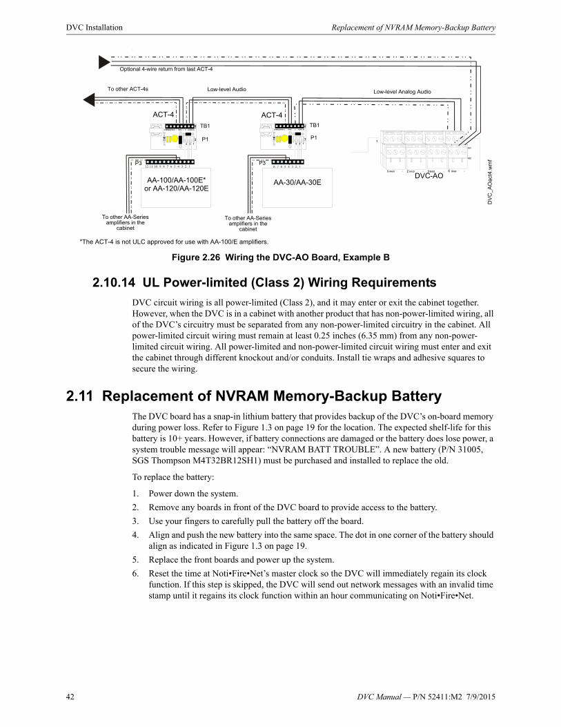
42 DVC Manual — P/N 52411:M2 7/9/2015
DVC Installation Replacement of NVRAM Memory-Backup Battery
\
Figure 2.26 Wiring the DVC-AO Board, Example B
2.10.14 UL Power-limited (Class 2) Wiring Requirements
DVC circuit wiring is all power-limited (Class 2), and it may enter or exit the cabinet together. However, when the DVC is in a cabinet with another product that has non-power-limited wiring, all of the DVC’s circuitry must be separated from any non-power-limited circuitry in the cabinet. All power-limited circuit wiring must remain at least 0.25 inches (6.35 mm) from any non-power-limited circuit wiring. All power-limited and non-power-limited circuit wiring must enter and exit the cabinet through different knockout and/or conduits. Install tie wraps and adhesive squares to secure the wiring.
2.11 Replacement of NVRAM Memory-Backup BatteryThe DVC board has a snap-in lithium battery that provides backup of the DVC’s on-board memory during power loss. Refer to Figure 1.3 on page 19 for the location. The expected shelf-life for this battery is 10+ years. However, if battery connections are damaged or the battery does lose power, a system trouble message will appear: “NVRAM BATT TROUBLE”. A new battery (P/N 31005, SGS Thompson M4T32BR12SH1) must be purchased and installed to replace the old.
To replace the battery:
1. Power down the system.
2. Remove any boards in front of the DVC board to provide access to the battery.
3. Use your fingers to carefully pull the battery off the board.
4. Align and push the new battery into the same space. The dot in one corner of the battery should align as indicated in Figure 1.3 on page 19.
5. Replace the front boards and power up the system.
6. Reset the time at Noti•Fire•Net’s master clock so the DVC will immediately regain its clock function. If this step is skipped, the DVC will send out network messages with an invalid time stamp until it regains its clock function within an hour communicating on Noti•Fire•Net.
AA-100/AA-100E* or AA-120/AA-120E
AA-30/AA-30E
Low-level Analog Audio
Optional 4-wire return from last ACT-4
To other ACT-4s
P3
TB1
P1
TB1
P1
P3
ACT-4
DVC-AO
ACT-4
To other AA-Series amplifiers in the
cabinet
To other AA-Series amplifiers in the
cabinet
DV
C_A
Oa
ct4.
wm
f
Low-level Audio
*The ACT-4 is not ULC approved for use with AA-100/E amplifiers.

DVC Manual — P/N 52411:M2 7/9/2015 43
Section 3: DVC Configuration and Programming
3.1 Setting the Configuration Switches
3.1.1 Piezo (Switch 5)
The DVC has a piezo that arrives from the factory enabled. It will sound during a DVC trouble event, and may be acknowledged at a network workstation, NCA-2, or an NFS2-3030 or NFS2-640 that is not on Noti•Fire•Net. However, it will resound if another trouble event occurs within the DVC.The piezo can be disabled or enabled using SW5. Disabling the piezo causes a trouble to be sent to the panel or network annunciator and/or network workstation.
3.1.2 4WIRE (Switch 8)
The FFT riser may be wired in a Class A (4-wire) or a Class B (2-wire) configuration. For Class A installations, enable the switch. For Class B, disable the switch.
VeriFire Tools programming must be set the same as this switch.
3.2 Programming
3.2.1 Overview
Most DVC programming is done in VeriFire Tools and downloaded to the DVC.
The one exception is when the DVC is acting as an audio command center: In this case, volume control settings for the DVC originate at the NFS2-3030 or NCA-2. This programming can be done at the panel itself or through VeriFire Tools. Refer to the point programming sections of these manuals for more information, as well as to the annunciator programming sections for relevant ACS programming instructions.
All other programming is stored in the DVC itself and is done in VeriFire Tools. Digital Audio Loop (DAL) device programming can be routed through the DVC, allowing code to be loaded simultaneously into multiple devices.
3.2.2 Programming in VeriFire Tools
The current version of DVC can be programmed with VeriFire Tools 8.00 and higher or VeriFire Tools 7.10. This manual describes programming with VeriFire Tools version 8.00. (See “VeriFire Tools Programming Interface” on page 44.) Earlier versions of VeriFire Tools will differ in options and appearance. Older versions of the DVC can be programmed with the current edition of VeriFire Tools. Download VeriFire Tools and the optional DVC Audio Files from esd.notifier.com.
Figure 3.1 Piezo Enable/Disable
SW5 in enabled position.
To disable, push the switch towards DIS.
DV
Cpi
ezo
enab
l.wm
f
Figure 3.2 4WIRE Enable/Disable
SW8 in enabled position.
To disable, push the switch towards DIS.
44 DVC Manual — P/N 52411:M2 7/9/2015
DVC Configuration and Programming Programming
In VeriFire Tools version 8.00 and higher, click on the Edit Session tree for a DVC node to view the programming options:
• General Settings
– General Settings tab (See “General Settings Tab” on page 47.)
– Program Settings tab (See “General Settings Branch, Program Settings Tab” on page 51.)
• DAL Mapping (See “DAL Mapping” on page 56.)
• KD Mapping (See “KD Mapping DVC-KD” on page 53.)
• General Zones (See “DVC General Zones” on page 55.)
• Audio Settings (See “Audio Message Programming Overview” on page 65.)
• DVC Inputs (See “DVC Inputs Branch” on page 69.)
• PAM Settings (See “Prioritized Audio Matrix (PAM) Programming Overview” on page 72.)
• Logic Equations (See “Logic Equations Branch” on page 77.)
These branches are opened up together, grouped as “System Programming”: General Settings, Program Settings, KD Mapping, and General Zones. Note that the DAL Mapping branch is not part of the System Programming tab, although it appears before KD Mapping in the Edit Session Tree. This manual keeps the System Programming tab group together; DAL Mapping is discussed after General Zones. Note that PAM points must be programmed after audio messages and logic equations have been created.
DVC Special Function Zones
DVC provides special functions zones which can be referenced by (but not changed by) VeriFire Tools. See “Special Function Zones” on page 81.
VeriFire Tools Utilities
VeriFire Tools provides utilities to validate programs and generate reports. This information is also available in the online help file; press F1 when within the program.
• See “Program Validation” on page 82.
• See “Reports” on page 83.
3.2.3 Special Applications: Mass Notification Systems
DVC can be programmed for use in a Mass Notification system. Requirements and specific instructions for such a system are provided in the Mass Notification System manual, P/N LS10063-000NF-E. The steps for creating and programming MN Active Tone and Fire Active Tone are in the Mass Notification System manual.
3.2.4 VeriFire Tools Programming Interface
VeriFire Tools 8.00 and higher has a streamlined programming interface. The following features are used to program the DVC. The VeriFire Tools help file contains additional tips, tricks, and training materials. Open the help file by pressing F1 inside VeriFire Tools, or by clicking the Help File icon on the BackStage screen (located where earlier editions of Windows put the File Menu).

DVC Manual — P/N 52411:M2 7/9/2015 45
Programming DVC Configuration and Programming
Project Files - All nodes of a networked system are now maintained within one VeriFire Tools project. Projects can be created new or from existing node databases, and additional existing nodes can be imported into the project.
From the “Startup Services” tab, click <Create Project> and select “New Project”, “New Project from Existing Database”, or “Import Database.”
To import data from an existing fire alarm system, create a project, then log onto the existing network and upload the node information into VeriFire Tools.
To log on, physically connect your VeriFire Tools computer to the local or remote network as described in the VeriFire Tools Installation Sheet. From the Startup Services tab, select the type of network connection used by your active system. Log onto one node, click “Upload/Download”, and follow the on-screen instructions. See your VeriFire Tools helpfile for screenshots and examples.
Assigning a node - The DVC node number is assigned when the node is added to the project. The DVC must always be assigned a unique node address, even when used with a standalone FACP. That is, when used with a standalone FACP, the DVC must be assigned a node number different from that FACP. This number can be reassigned; see the VeriFire Tools online help file.
Edit Session Tree - The Edit Session Tree displays links to all project nodes in outline format. Click on the “+” sign to expand the individual node; this displays to programming branches. Click on a branch to open it for viewing and editing. Right-click on the project name at the top to add a new node or expand all branches. Right-click on a branch to see context-sensitive menu choices.
The Online Session Tree is an equivalent screen area that displays information for the system (local or remote network) that VeriFire Tools is currently logged into. To log onto a node, right-click the node’s branch in the Online Session Tree.
Data-entry grid - VeriFire Tools calls its spreadsheet-style interface the “data-entry grid”.
Open an Edit Session Tree branch to view and edit grids of programming information. For each row, data can be entered or selected from a list of drop-down options. Fields that display in gray are unavailable due to current settings or missing information, or are display-only.
Click into fields with the mouse to enter data, or move around the grid with the tab and arrow keys. Single-clicking into a cell will highlight it ("Highlight/Focus mode"). Double-click to select the cell's contents ("Edit mode") or simply start typing to overwrite it with new contents. Users who prefer to work without a mouse should refer to the Help File for keyboard shortcut instructions. Sort the information in a column by clicking on its header row.

46 DVC Manual — P/N 52411:M2 7/9/2015
DVC Configuration and Programming General Settings Branch
In some branches, clicking into a row with an installed device will open the bottom half of the screen to display detailed options for that specific device.
In other branches, each row is expandable to display options specific to the device or programming feature listed in that row.
Save - Click <Save> at the bottom of a screen to save changes made to one programming branch. Click <Save> on the Startup Services tab or on the Quick Access Toolbar to save the entire project.
Undo changes - Click <Cancel> at the bottom of a screen to undo programming changes to one screen.
3.3 General Settings Branch Settings for the DVC itself can be accessed from this branch of the Edit Session tree. It will bring up General Settings tab, the Program Settings tab, the DVC-KD tab, and General Zones tab. DAL Mapping has been given its own Edit Session Tree branch and must be clicked separately to open in an independent tab.
In VeriFire Tools 8.00 and higher, click on the General Settings Branch of the Edit Session Tree to bring up these tabs. The General Settings tab groups several sub-sections that can be expanded or hidden. Some “General” Screens from VeriFire Tools 7.10 and lower have been separated out to take full advantage of the new interface. See Section 3.3.2, “General Settings Branch, Program Settings Tab” and Section 3.6, “DAL Mapping”.

DVC Manual — P/N 52411:M2 7/9/2015 47
General Settings Branch DVC Configuration and Programming
3.3.1 General Settings Tab
Figure 3.3 DVC General Settings
General Settings Tab, Column 1
DVC Label: Enter the network node label for this DVC. You may enter up to 40 characters.
Analog Outputs: Describe the configuration for DVC’s Analog Output A, B, C, D (“Not Installed”, “Installed, Class A,” or “Installed, Class B”) on the DVC. Requires DVC-AO. “Installed” analog outputs will be represented in the PAM columns as output circuits for DVC-0. (PAM programming is described in “Prioritized Audio Matrix (PAM) Programming Overview” on page 72.)
Common Settings: The following settings are grouped together: Local Microphone, Remote Microphone, Local Control, DVC Model (DVC), Fidelity Selection (Standard Quality), NFN Audio Paging, IP Accessibility, DAP Wiring Style (Style 4. Style 7), Trouble Reminder Options.
• Local/Remote Microphone: Select to install the local and/or remote microphone. See the RM-1 Series document for more information on the remote microphone.
ima
ge8
2DV
Cg
ene
ral2
.gif
Historical Note: Before release of VeriFire Tools 8.00, columns named “General Settings 2” and “General Settings 3” were on the programming screen called “General III”.

48 DVC Manual — P/N 52411:M2 7/9/2015
DVC Configuration and Programming General Settings Branch
• Local Control: Select to enable local DVC control of the following DVC-KD keys: ALL CALL, PAGE ACTIVE EVAC AREAS, PAGE ACTIVE ALERT AREAS, PAGE INACTIVE AREAS, and ENABLE TELEPHONE PAGE.
• DVC Model: Choose from the drop-down menu to indicate if the DVC is the standard (DVC) or an extended memory (DVC-EM) version. The DVC-EM Extended Memory versions contain up to 32 minutes of standard quality (11.025 kHz sampling rate, 8 bit µ-law, mono) audio storage, or 4 minutes of high quality (44.1 kHz sampling rate, 16 bit PCM, mono).
• Fidelity Selection: Choose the desired audio quality (standard or high). A message saved as high quality requires more storage space than the same message saved as standard quality.
– Standard quality - 11.025 kHz sampling rate, 8 bit µ-law, mono.
– High quality - 44.1 kHz sampling rate, 16 bit PCM, mono..
• NFN Audio Paging: Check this box if network paging from any of the DVC’s live inputs to outputs on other DVCs is desired. Live inputs can include the DVC’s local microphone, the microphone attached to DVC-RPU, an RM-1 remote microphone, a Firefighter’s Telephone, or a live input from an AUXA or AUXB connection. A check here creates the “Network” column in the PAM. (See “Prioritized Audio Matrix (PAM) Programming Overview” on page 72.) If this box is not checked, network paging is disabled.
• IP Accessibility: Check to enable IP Access. This setting allows the disabling/enabling of commands, downloads and programming from a Remote Network. To initiate downloads to the DVC, go to the Online Services ribbon menu and click on Upload/Download. (VeriFire Tools must be connected to the network for the icon to be selectable.) DVC downloads have a six-hour window to be completed.
• DAP Wiring Style: Select Class B (Style 4) or Class A (Style 7).
• Trouble Reminder Options: Check to enable a 24 hour reminder.
Auxiliary Inputs. This groups AUX Input A Settings and Aux Input B Settings.
• AUX Input A and AUX Input B: Check to install input(s).
• Aux Input A/B Supervision: Check to enable supervision of the specified inputs.
NOTE: The DVC uses:• 8 audio channels on the DAL (digital audio loop) with the standard quality
audio setting.• 1 audio channel on the DAL with the high quality audio setting.• 1 audio channel on a standard or high-speed Noti•Fire•Net
! CAUTION: DVC MODEL/FIDELITY SELECTIONDO NOT MODIFY SETTINGS FOR “DVC MODEL” OR FIDELITY PROGRAMMING ONCE PAM POINTS AND AUDIO MESSAGES ARE INSTALLED. CHANGING THESE SELECTIONS WILL DELETE ALL PAM POINTS AND AUDIO MESSAGING INFORMATION.
NOTE: For a standard Noti•Fire•Net, the number of nodes allowed is limited to 54 when NFN Audio Paging is selected. This limitation does not apply to a high-speed Noti•Fire•Net.
NOTE: Use of the IP Accessibility feature is subject to the approval of the local AHJ.

DVC Manual — P/N 52411:M2 7/9/2015 49
General Settings Branch DVC Configuration and Programming
• Aux Input A/B AGC: Check to enable automatic gain control. This feature will smooth an incoming signal to produce a consistent sound.
• Aux Input A/B Background Music: Check if the input is to be used for background music. Background music will be disabled during AC Fail and will not play out of a DAA or DAA2 that has a battery charge rate greater than 1 amp (Battery size is greater than 26 AH and batteries are being charged).
Firefighter’s Telephone Settings. The following settings are grouped together: Local FFT, FFT Riser Wire Selection, Busy Tone, and Busy Tone Segment Numbering.
• Local FFT: Select when a local TELH-1 FFT is installed. The connection will be supervised for open and short circuit conditions.
• FFT Riser Wire Selection (Uninstalled. Installed, 2 Wire. Installed, 4 Wire.) Select to describe the wiring style, 2 WIRE (Class B) or 4 WIRE (Class A) of the FFT riser. Switch 8 (Refer to “4WIRE (Switch 8)” on page 43) must be set the same as this selection. Select UNINSTALLED if there is no FFT riser installed.
• Busy Tone: Check to select a message segment that will play when there is still no telephone circuit available after the phone has rung several times. The SEGMENT selection box will light up when this field is checked. This selection will apply to all FFT risers on the DAL (Digital Audio Loop). If BUSY TONE is not selected, the phone will continue to ring until answered. Refer to Appendix B on page 92 for an example.
• Busy Tone Segment Numbering: Select a segment that will play while the line is busy. This segment plus the emergency/non-emergency segments have a limit of 106 seconds for standard fidelity and for high fidelity.
Wiring Style: Select according to your network’s configuration CLASS B (STYLE 4) or Class A (STYLE 7). Refer to standard and high-speed Noti•Fire•Net Manuals for more information.
NFN Media Interface Settings: Set MIB Threshold to establish tolerable noise thresholds for network communications. Select PortA:High, PortB:High. PortA:Low, PortB:High. PortA:Low, PortB:Low. PortA:Low, PortB:Low. Not applicable for high-speed Noti•Fire•Net Systems.
General Settings Tab, Column 2
DAL Backup Tones: Defines the message segments (usually tones) that will be broadcast during the loss of DAP communication. These backup messages are stored within each DAA/DAA2/DAX/DS-DB for activation when communication is lost. These tones, in addition to the “Busy Tone”, are limited to 106 seconds combined.
• Emergency Backup Tones: The message segment selected will broadcast when a DAL device’s alarm bus is active and the unit is offline to the DVC. (Emergency Tone, Emergency Tone Segment)
• Non-Emergency: The message segment selected will broadcast when the DAL device’s alarm bus is inactive and the unit is offline to the DVC. This message will not broadcast during AC failure. (Non-emergency Tone, Non-emergency Tone Segment)
DCC Settings: The DCC Settings box appears when the MN Mode type is “None” in the DVC Mass Notification Settings. It defines whether the DVC will participate in DCC operation for paging functions, and if so, which network control node it will be associated with. See Section 4.3, “Display and Control Center (DCC)” as well as the glossary.
• DCC Operation: Check to enable DCC participation.
• Associated Node Number: Map a DCC-designated DVC to a network control node through which it will be able to assert network control for network paging purposes.
NOTE: Enable automatic gain control only in applications where the input is a voice input, such as from a telephone paging system. Do not enable automatic gain control when using background music.

50 DVC Manual — P/N 52411:M2 7/9/2015
DVC Configuration and Programming General Settings Branch
Canadian Operations:
• Pre-Announce, Pre-Announce Sequence: To enable the Pre-Announce feature, click Pre-Announce, then select an audio sequence. The selected sequence will play before all pages from the DVC’s MIC-1 local microphone, the TELH-1 local telephone, and the RM-1. The “Pre-Announce” LED on the DVC-KD will light for the duration of the pre-announce.
• Page Inhibit, Page Inhibit Logic Equations: The Page Inhibit selection applies to the ALL CALL, PAGE ACTIVE EVAC AREAS, PAGE ACTIVE ALERT AREAS, and PAGE INACTIVE AREAS buttons on the DVC-KD. To enable, check the box and select a logic equation that will inhibit the page while the logic equation is active. The “Page Inhibit” LED on the DVC-KD will light for the duration of the page inhibit.
• DVC-KD Inhibit, DVC-KD Inhibit Logic: The DVC-KD Inhibit selection applies to the 24 buttons on the right half of the DVC-KD. To enable, check the box and select a logic equation that inhibits the DVC-KD while the logic equation is active.
IBC Settings, Paging Timeout: Check this box to allow an interruption of an automatic EVAC or ALERT message by three minutes of live paging. Paging will be shut off automatically after three minutes.
General Settings Tab, Column 3: Mass Notification Settings
DVC Mass Notification Settings: This section defines what node the DVC is associated with to form a mass notification station. The LOC, ACU and CCS settings determine what inputs are used by the three ALL CALL buttons, and what inputs can be used for DVC-KD programming. See the Mass Notification System manual, P/N LS10063-000NF-E, for instructions on correctly configuring a Mass Notification system.
MN Mode: (Default: NONE) When changing from “None” to any of the three Mass Notification modes, the DVC will add and rename the appropriate “live” inputs from their original meaning, and display the changed meanings in a dialog box.
• None: The DVC will not act in MN mode. This mode is only for DVCs that are part of a network with no mass notification.
• LOC, ACU, CCS: The DVC will act in the mass notification mode selected. The LOC, ACU, and CCS settings determine what inputs are used by the three All Call buttons, and what inputs can be used in DVC-KD programming.
– The All Call buttons in the second column of the DVC-KD will have Level buttons (see Appendix E, “DVC MN Modes”, on page 109).
– The microphone will use MN inputs (see Table 3.4, “First 14 Default Input Priorities (DVC Configured for Mass Notification),” on page 72).
• Subsidiary: Use this setting only when the DVC is present on an MN network, but is not part of an ACU, LOC, or CCS.
• Paging Level 1: Check this box to enable ALL CALL paging from the top button in column two of the DVC-KD. (Refer to “DVC Inputs Branch” on page 69.) Paging Level 1 has the highest priority of the paging levels. Not applicable in “None” Mode.
• Paging Level 2: Check this box to enable ALL CALL paging from the second button down in column two of the DVC-KD. (Refer to “DVC Inputs Branch” on page 69.) Paging Level 2 has a priority less than Paging Level 1, and greater than Paging Level 3. Not applicable in “None” Mode
NOTE: DVC’s that are part of a mass notification network must be assigned a mode of LOC, ACU, CCS, or Subsidiary. DVC’s that are not part of a mass notification network must be assigned the mode NONE.

DVC Manual — P/N 52411:M2 7/9/2015 51
General Settings Branch DVC Configuration and Programming
• Paging Level 3: Check this box to enable ALL CALL paging from the third button down in column two of the DVC-KD. (Refer to “DVC Inputs Branch” on page 69.) Paging Level 3 has a lesser priority than Paging Levels 1 and 2. Not applicable in “None” Mode.
• Quick Paging: When Quick Paging is enabled, a DVC-RPU button push is not required for paging. Pressing the push-to-talk button on the microphone is sufficient to initiate an ALL CALL page at the Paging Level programmed (1, 2, or 3).
3.3.2 General Settings Branch, Program Settings Tab
All Call Mapping, Special Paging Functions
The interface for setting All call Mapping and Special Paging Functions is similar: check the node number(s) that should respond to conditions configured elsewhere in VeriFire Tools. Nodes should be other DVCs or a panel with SLC speaker points. Buttons at the top enable the userto clear all nodes, and to select all nodes.
ALL CALL paging - When the ALL CALL button is pressed on the current DVC’s DVC-KD, all checked nodes will receive and broadcast the ALL CALL message.
SPECIAL PAGING FUNCTIONS - This screen configures the following DVC-KD buttons: PAGE ACTIVE EVAC AREAS, PAGE ACTIVE ALERT AREAS, and PAGE INACTIVE AREAS.
• In multi-channel applications where audio message sequences are saved in standard fidelity format, these special functions can override the message sequence types they describe (EVAC or ALERT messages that are active), or can page to areas where no messages are active.
• In single-channel applications, where audio message sequences are saved in high fidelity format, these pages are disabled and the column will be grayed out.
• In mass notification applications, Special Paging Functions are not available. MN Mode must be set to “None” in order to use Special Paging Functions.
Starting with VeriFire Tools 6.0, alarm bus programming is performed using logic equations. For “Alarm Bus Maps” see “Logic Equations Branch” on page 77.
NOTE: One, two, or all three Paging Levels may be checked when the MN Mode is ACU, LOC or CCS. MN paging levels are not available when the MN Mode is Subsidiary.
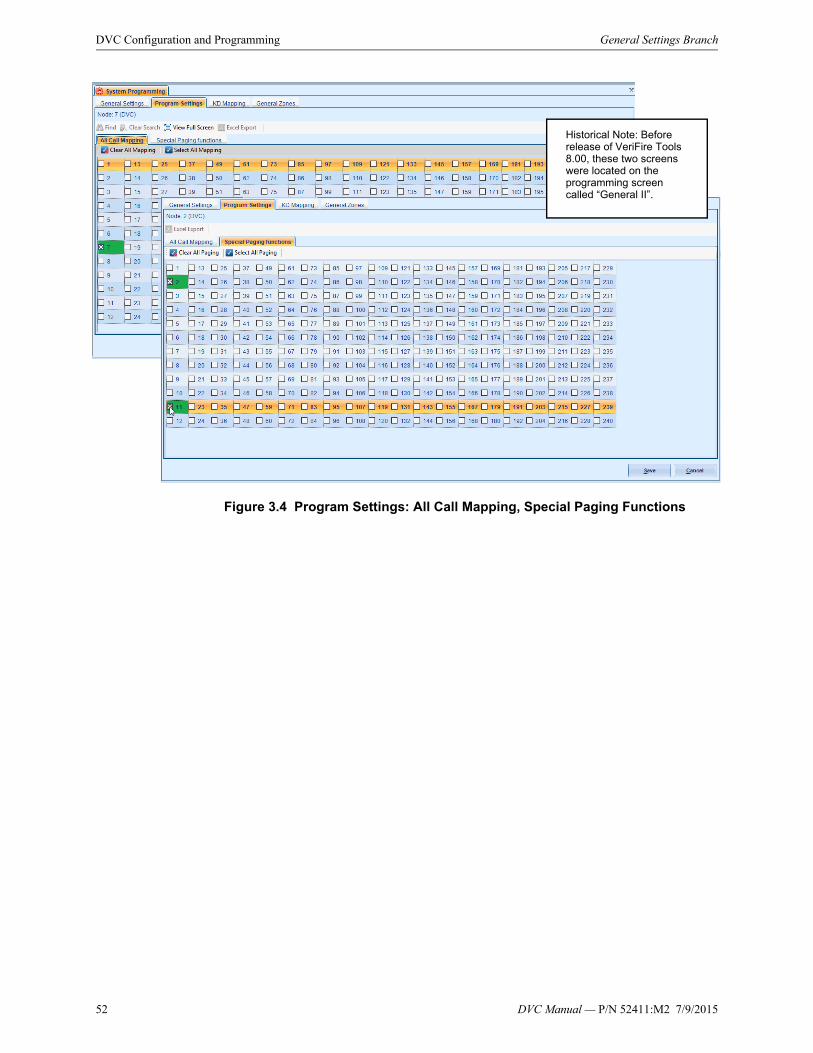
52 DVC Manual — P/N 52411:M2 7/9/2015
DVC Configuration and Programming General Settings Branch
Figure 3.4 Program Settings: All Call Mapping, Special Paging Functions
Historical Note: Before release of VeriFire Tools 8.00, these two screens were located on the programming screen called “General II”.

DVC Manual — P/N 52411:M2 7/9/2015 53
KD Mapping DVC-KD DVC Configuration and Programming
3.4 KD Mapping DVC-KDProgram the user-defined keys on the DVC-KD. Map a function to a node, module, detector, panel circuit point, zone, or PAM point. If the DVC-RPU keyboard has already been programmed, those settings can be cloned by clicking <Clone From RPU>. Single keys can be duplicated by copy/paste, as with copy/paste as in other VeriFire Tools data-entry grids.
Figure 3.5 DVC System Programming Service – DVC-KD
DVC-KD Field Definitions
KEY -There are 24 user-defined keys on a DVC-KD. Refer to Figure 4.1 on page 84 for the numbering format.
FUNCTION - Select from None, Control, Monitor, Telephone, All Call, Page Evac, Page Alert, Page Inactive, Enable Paging, FFT-NFN, Disable.
• Control - select to program a button to activate paging or control points.
• Monitor - select to program a button that will monitor a point for activity.
• Telephone - select to program a button for a phone connection local to the DVC’s DAL (digital audio loop).
• All Call - select to program nodes to the “ALL CALL” button, which initiates ALL CALL paging.
• Page Evac - select to program nodes to the “PAGE ACTIVE EVAC AREAS” button, which initiates paging to active evacuation areas in the assigned nodes.

54 DVC Manual — P/N 52411:M2 7/9/2015
DVC Configuration and Programming KD Mapping DVC-KD
• Page Alert - select to program nodes to the “PAGE ACTIVE ALERT AREAS” button, which initiates paging to active alert areas in the assigned nodes.
• Page Inactive - select to program nodes to the “PAGE INACTIVE AREAS” button, which initiates paging to inactive areas in the assigned nodes.
• Enable Paging - select to program a button to enable paging from AUX A, AUX B, or RM-1.
• FFT-NFN - select to program a button to broadcast from a Firefighter’s Telephone over Noti•Fire•Net. The FFT-NFN function is used for FFT communication between two DVCs. Refer to Appendix B.2.2 on page 94.
• Disable - select to create a button that will disable a single local or network DAL device speaker circuit point, or all the speaker circuits on a DAL device.
• None - Default. The key is not programmed.
MAPPING - Enter the points, nodes or zones to be mapped. VeriFire Tools provides Source Syntax for each Function type; drag over the orange bar to display it on the right side of the screen. The syntax for each type of entry is also in Table 3.1 below.
• Monitor function - Map one source address. Must be a detector, module, panel or bell circuit point, zone, logic zone, trouble zone, releasing zone, special zone, PAM point or speaker point.
• Control function - Map up to 8 points. Source must be a module, panel or bell circuit point, PAM point or general zone.
• Telephone function -
– map one telephone control module’s address, or
– map to one FFT riser that has no telephone control modules Use the address NxxxAyyT, where N = node number, yy = the DAL device address [1 - 32].
• All Call, Page Evac, Page Alert, and Page Inactive functions for the user-programmable keys - Map up to 8 network nodes. These nodes do not have to be any of the nodes selected to function with the All Call, Page Active EVAC areas, Page Active ALERT area, or Page INACTIVE area buttons on the left side of the DVC-KD.
• Enable Paging function - AUX A or AUX B will be selectable from a pull-down menu when this function is chosen.
• FFT-NFN function -
– map two DVC network nodes. A telephone control module is optional, or...
– map two DVC network nodes and one DAL device FFT riser that has no installed telephone control modules.
• Disable function -
– map to one local speaker circuit point.
– map to one network speaker circuit point.
– map to disable all speaker circuits on a local DAL device.
– map to disable all speaker circuits on a network DAL device.

DVC Manual — P/N 52411:M2 7/9/2015 55
DVC General Zones DVC Configuration and Programming
3.5 DVC General Zones DVC general zones may be monitored from anywhere in the system to annunciate active paging from a location. The DVC supports up to 500 user-programmed general zones (Z1 - Z500).
These user-programmed zones can be activated by up to 1044 PAM points. This gives the user the option of creating general zones for each PAM point: these zones will activate when the PAM point activates. Using these general zones in logic equations enables further granularity of the type of page being performed.
DVC general zone labels prefill with their Zone number. Labels can be customized using the data-entry grid shown in Figure 3.6. Text can be copied from other Windows programs and pasted into these fields. Labels may be up to 20 characters.
The following General Zones are reserved for specific use and are not programmable:
• General Alarm Zone Z0 may be used as a general activation zone that will activate when any PAM point activates. DVC General Zones can also be controlled on/off by the DVC-KD or ACS points. Local Zone, Label (“0” is reserved for General Alarm; the rest prefill with zone address e.g. Zone Z001.) Note that General Zone Z0 can be relabelled, but its function is reserved.
Type of Entry Syntax* Explanation
detector LxxDyyy xx = panel loop number, yyy = detector SLC address
module LxxMyyy xx = panel loop number, yyy = module SLC address
panel circuit Px.y x = panel circuit address, y = panel circuit point address
bell circuit Bx x = bell circuit address
zone Zx x = zone number
logic zone ZLx x = logic zone number
trouble zone ZTx x = trouble zone number
releasing zone ZRx x = releasing zone number
special zone ZFx x = special zone number
PAM point IxxxxAyySz x = input number, y = DAL device address, z = speaker circuit address
speaker point AxxSy xx = DAL device address, y = speaker circuit address
Node Nxxx xxx = Noti•Fire•Net. node address
FFT riser with no installed telephone control modules
AxT x = DAL device address where the FFT riser resides
(disable) all speaker points AAxxD xx = address of DAL device where all speakers will be disabled
*NOTE: Add Nxxx, where xxx = network node number, at the beginning of the syntax entry if the entry is for a point on a different network node.
Table 3.1 Point Mapping Syntax
Figure 3.6 DVC General Zones

56 DVC Manual — P/N 52411:M2 7/9/2015
DVC Configuration and Programming DAL Mapping
• General Zones 501-533 activate whenever microphone paging is active from a DVC, DVC-RPU, or ONYXWorks.
• General Zones 501-532 activate with paging from DVC-RPU addresses 1-32.
• General Zone 533 activates with paging from the DVC, or ONYXWorks.
Note: General zones & Logic equations must be set up before PAM Programming can reference them. (See “Prioritized Audio Matrix (PAM) Programming Overview” on page 72.)
For a related topic, see Appendix 3.12, “Special Function Zones”, on page 81.
3.6 DAL Mapping
3.6.1 Overview
Use the DAL Mapping branch to assign addresses to Digital Audio Loop (DAL) devices. For each DAL Address, enter the Device Type to be installed by selecting it from the drop-down box as shown in Figure 3.7. After entering Device Type, fill out the relevant fields for that address: Backup Address, BDA Card Mode (Dual Channel, Backup), and DAL Mode (Primary or Backup). The “Backup address” field of a Primary device must reference a DAL device that is configured as Backup.
When an address with an installed Device Type is selected, the bottom half of the screen will display appropriate options for that Device Type. Device settings are organized by tabs: General Settings, Speaker Circuit Settings, Low-Level Outputs, Groups, and RPU KD.
This section lists the options available to particular device types, followed by definitions of those options and the fields where VeriFire Tools stores their definitions.
• See “DAA/DAX/DAA2 Amplifier Programming Options” on page 57.
• See “DAA/DAX/DAA2 Amplifier Field Definitions” on page 58.
• See “DS-DB Programming Options” on page 61.
• See “DS-DB Field Definitions” on page 61.
• See “DVC-RPU Programming Options” on page 63.
• See “DVC-RPU Field Definitions” on page 63.
When fields are unavailable, that field will be grayed out. This can be because a particular field is not available to a product, or because of programming prerequisites. For example, the BDA Card Mode field will be grayed out on an original DAA series audio amplifiers because those did not offer BDA Card Mode. As a second example, “backup address” field will be grayed out for a DAL device that is configured as a backup. Before the Device Type is assigned, all fields are grayed out.
NOTE: Press “Clear All Amplifiers” to erase all DAL Mapping for this DVC. All DAL addresses will be cleared back to default.

DVC Manual — P/N 52411:M2 7/9/2015 57
DAL Mapping DVC Configuration and Programming
3.6.2 DAA/DAX/DAA2 Amplifier Programming Options
Use the following services to program associated amplifiers and speaker points with individual settings.
DAA-5025 PCA• General Settings Tab - Auxiliary A, Auxiliary B, AGC, Supervision, Speaker1 - Speaker4,
Speaker Riser Mode, Speaker Wiring Configuration, Battery Size, Disable Charger.
• Speaker Circuit Settings - Speaker Circuit 1 - 4, Custom Label, Extended Label.
DAA-5025 PCB• General Settings - Auxiliary A, Auxiliary B, AGC, Supervision, Speaker1 - Speaker4,
Speaker Riser Mode, Speaker Wiring Configuration, Battery Size, Disable Charger, Install FTM Module, FFT Riser Wire Selection.
• Speaker Circuit Settings - Speaker Circuit 1 - 4, Custom Label, Extended Label.
DAA-5070 PCA• General Settings - Auxiliary A, Auxiliary B, AGC, Supervision, Speaker1 - Speaker4,
Speaker Riser Mode, Speaker Wiring Configuration, Battery Size, Disable Charger.
• Speaker Circuit Settings - Speaker Circuit 1 - 4, Custom Label, Extended Label.
DAA-5070 PCB• General Settings - Auxiliary A, Auxiliary B, AGC, Supervision, Speaker1 - Speaker4,
Speaker Riser Mode, Speaker Wiring Configuration, Battery Size, Disable Charger, FTM Module, FFT Riser Wire Selection.
• Speaker Circuit Settings - Speaker Circuit 1 - 4, Custom Label, Extended Label.
Figure 3.7 DAL Mapping - Install a Specific Device to View and Program Its Settings
58 DVC Manual — P/N 52411:M2 7/9/2015
DVC Configuration and Programming DAL Mapping
DAA-7525 PCB
• General Settings - Auxiliary A, Auxiliary B, AGC, Supervision, Speaker1 - Speaker4, Speaker Riser Mode, Speaker Wiring Configuration, Install FTM Module, FFT Riser Wire Selection.
• Speaker Circuit Settings - Speaker Circuit 1 - 4, Custom Label, Extended Label.
DAA2-5025 PCA
• General Settings - Auxiliary A, AGC, Supervision, Speaker1 - Speaker4, Speaker Riser Mode, Speaker Wiring Configuration, DAL Group, BDA Group, Install RM1, Send RM1 Audio to DVC, Local RM1 Mode, Battery Size, Install Disable Charger, Install FTM Module, FFT Riser Wire Selection.
• Speaker Circuit Settings - Speaker Circuit 1 - 4, Custom Label, Extended Label.
DAA2-5070 PCA
• General Settings - Auxiliary A, AGC, Supervision, Speaker1 - Speaker4, Speaker Riser Mode, Speaker Wiring Configuration, DAL Group, BDA Group, Install RM1, Send RM1 Audio to DVC, Local RM1 Mode, Battery Size, Disable Charger, Install FTM Module, FFT Riser Wire Selection.
• Speaker Circuit Settings - Speaker Circuit 1 - 4, Custom Label, Extended Label.
DAA2-7525 PCA
• General Settings - Auxiliary A, AGC, Supervision, Speaker1 - Speaker4, Speaker Riser Mode, Speaker Wiring Configuration, DAL Group, BDA Group, Install RM1, Send RM1 Audio to DVC, Local RM1 Mode, Disable Charger, Battery Size, Install FTM Module, FFT Riser Wire Selection.
• Speaker Circuit Settings - Speaker Circuit 1 - 4, Custom Label, Extended Label.
DAX-3525 PCA
• General Settings - Speaker Riser Mode, Disable Charger, Speaker Wiring Configuration, Battery Size.
• Speaker Circuit Settings - Speaker Circuit 1 - 2, Custom Label, Extended Label.
DAX-3570 PCA
• General Settings - Speaker Riser Mode, Disable Charger, Speaker Wiring Configuration, Battery Size.
• Speaker Circuit Settings - Speaker Circuit 1 - 2, Custom Label, Extended Label.
DAX-5025 PCA
• General Settings - Speaker Riser Mode, Speaker Wiring Configuration.
• Speaker Circuit Settings - Speaker Circuit 1 - 2, Custom Label, Extended Label.
DAX-5070 PCA
• General Settings - Speaker Riser Mode, Speaker Wiring Configuration
• Speaker Circuit Settings - Speaker Circuit 1 - 2, Custom Label, Extended Label.
3.6.3 DAA/DAX/DAA2 Amplifier Field Definitions
Basic DAL Device Settings (Top Half of DAL Mapping Screen)
Amplifier settings
• AMPLIFIER MODE – Select PRIMARY or BACKUP from the pull-down menu.
• BDA CARD MODE – Select NOT INSTALLED, DUAL CHANNEL, or BACKUP from the pull-down menu.
• BACKUP AMPLIFIER ADDRESS – Select the backup amplifier address, or NO BACKUP, from the pull-down menu. Only backup amplifiers with matching BDA, speaker, group and riser mode settings will be available.

DVC Manual — P/N 52411:M2 7/9/2015 59
DAL Mapping DVC Configuration and Programming
General Settings Tab (Bottom Half of DAL Mapping Screen)
Firefighter’s Telephone Settings - These fields do not display for DAA PCA boards or DAX boards.
• FFT RISER WIRE SELECTION –
– For DAA amplifiers - Select the wiring style (INSTALLED 2 WIRE or INSTALLED 4 WIRE) according to the configuration of the analog network. Select UNINSTALLED when the FFT riser is not installed.
– For DAA2 or DS-DB - Select INSTALLED or UNINSTALLED to indicate if there is a riser or not.
• INSTALL FTM MODULES – Check this box if there are FTMs installed on the FFT riser with its Firefighter’s Telephones. When this box is not checked, the address NxxxAyyT - where N = node number, yy = the DAL device address (1 - 32) - can be used for FFT for mapping.
Auxiliary Input Source - These fields do not display for DAX boards.
• AUXILIARY A – Check to install the AUXA analog input into the database.
• AUXILIARY B - Check to install the AUXB analog input into the database (DAA-PCB and DAA-PCA boards only).
• AGC – Check to enable automatic gain control. This feature will smooth an incoming signal to produce a consistent sound.
• SUPERVISION – Check to enable or disable supervision of the auxiliary input.
• AUXILIARY ACTIVATION – Check which speaker circuits on the amplifier will be activated when amplifying data from the AUX input.
Speaker Settings
• SPEAKER RISER MODE – A DAL device can have only one Riser Mode type: the riser mode type chosen will be applied to all speaker circuits on the DAL device. Backup amplifiers must be programmed with the same riser mode type as the primary amplifiers. Select from the following DAL device Riser Mode types.
– NORMAL - Select NORMAL when the DAL device will not be used for riser or room isolator applications.
– RISER TO ADDITIONAL AMPLIFIERS - Select when the DAL device’s output will be used with one or more audio coupling transformers to drive additional amplifiers. (ACT-70 for 70V amplifiers, ACT-25 for 25V amplifiers.) Only one DAL device speaker circuit may be installed when operating in this mode. This selection provides a 200 Hz tone that is required for additional analog amplifiers. Refer to the DAA2/DAX manual.
– RISER TO ADDITIONAL CONTROL MODULES - Select when the DAL device’s output will be routed to multiple speaker circuits using control modules. In this mode, the DAL device will provide speaker circuit supervision only when idle. Only one DAL device speaker circuit may be installed when operating in this mode. Do not use background music on the DAL device in this mode. Refer to the DAA2/DAX manual.
– RSM OR AIM SERIES ROOM ISOLATORS - Select when connecting these modules to the DAL device’s speaker circuits. Only one DAL device speaker circuit may be installed when operating in this mode. These modules are for specific Canadian applications. Refer to the DAA2/DAX manual for more information.
NOTE: Enable automatic gain control only in applications where the input is a voice input, such as from a telephone paging system. Do not enable automatic gain control when using background music.

60 DVC Manual — P/N 52411:M2 7/9/2015
DVC Configuration and Programming DAL Mapping
– CIM OR CSM SERIES ROOM ISOLATORS - Select when connecting these modules to the DAL device’s speaker circuits. Only one DAL device speaker circuit may be installed when operating in this mode. Do not use background music on the DAL device in this mode. These modules are for specific Canadian applications. Refer to the DAA2/DAX manual for more information.
• SPEAKER WIRING CONFIGURATION – Make selection to program speaker circuit pairs (1/2 and 3/4.) Selection must reflect physical configuration (All Class A; All Class B; 1 and 2 = Class A, 3 and 4 = Class B; 1 and 2 = Class B, 3 and 4 = Class A). Refer to the DAA2/DAX manual for wiring illustrations.
Power Supply Settings
• BATTERY SIZE: AMP HOURS - Select the size of the secondary power source.
• DISABLE CHARGER - Check to disable the charger on this DAL device. The charger should be disabled if this DAL device is sharing batteries with at least one other DAL device, and is not the DAL device that will supply the battery charging. See the battery sharing section for the appropriate device.
Group Settings (DAA2 only)
Groups consist of a collection of speaker circuits on a DAA2 with one or more amplifiers assigned to it. Refer to Appendix D, “Audio Groups”, on page 104 for more information.
• AMPLIFIER GROUP - Select the group number for the digital amplifier.
• BDA GROUP - Select the group number for the BDA amplifier.
RM-1 Settings (DAA2 only)
• INSTALL RM-1 - Check this box to activate the circuit for supervision.
• SEND RM-1 AUDIO TO DVC - Check this box to make the audio available as a source to the I1038 PAM row. The first DAA2 with an active push-to-talk (PTT) will be the source. Once the PTT is released, the next active PTT will become the source of the audio. Any DAA2’s RM-1 audio takes priority over the DVC RM-1 audio.
• LOCAL RM-1 MODE - This setting will adjust the priority of the RM-1 to its own DAA2.
– Override DVC audio to all speakers - Select to make the local RM-1 the highest priority audio source for that DAA2.
– Override DVC background music to all speakers - Select to give the RM-1 priority over background music only.
– Let DVC control RM-1 routing - With this selection, the RM-1 will not perform any local paging, and the DVC PAM controls where the RM-1 audio is routed.
If the DAA2 loses communication with the DVC, the local RM-1 will take priority over the non-emergency and emergency tones.
Speaker Circuits Tab (Bottom Half of DAL Mapping Screen)
• SPEAKER CIRCUIT - Select the speaker circuit to be labeled and grouped.
• CUSTOM LABEL – Enter up to 20 characters to identify this speaker circuit. By default, this prefills with speaker address reference (e.g. DAA01SPK1).
• EXTENDED LABEL – Enter up to an additional 12 characters for more specific identification of the speaker circuit.
! CAUTION: DO NOT CHANGE WIRING CONFIGURATION AFTER SPEAKER CIRCUIT PROGRAMMING.CHANGING THE WIRING CLASS CONFIGURATION AFTER THE SPEAKER CIRCUITS HAVE BEEN PROGRAMMED MAY DELETE THE SPEAKER CIRCUIT PROGRAMMING! (SEE PAGE 60.)

DVC Manual — P/N 52411:M2 7/9/2015 61
DAL Mapping DVC Configuration and Programming
• GROUP NUMBER – Select the group number for this speaker circuit. Groups consist of a collection of speaker circuits on a DAA2 with one or more amplifiers assigned to it. Refer to Appendix D, “Audio Groups”, on page 104 for more information.
3.6.4 DS-DB Programming Options
Highlight a DAL address configured as a DS-DB to program the device and its associated amplifiers and speaker points.
DS-DB PCA• General Settings - Speaker Riser Mode, Power Supply Installed, Install FTM Module, FFT
Riser Wire Selection
• Low Level Outputs - Check to install for Connection1 and for Connection 2: Low-Level Output 1 - 4, High-level Input Primary, Mode, DSBus, Group.
• Speaker Circuit Settings - Check to install Speaker Circuit 1 - 8, Group, Wiring Configuration
• Groups - Check to install Group 1 - 4; Group Label and Extended Label prefill with speaker-group address reference (e.g. DSDB01GRP1)
3.6.5 DS-DB Field Definitions
DS-DB General Settings Tab
• SPEAKER RISER MODE – Select desired riser mode from the pull-down menu. A DS-DB can have only one riser mode type: the riser mode type chosen will be applied to all speaker circuits on the DS-DB. Backups must be programmed with the same riser mode type as the primaries. Selecting a Riser Mode setting other than NORMAL limits each DS-DB group to one speaker circuit.
– NORMAL - Select NORMAL when the DAL device will not be used for riser or room isolator applications.
– RISER TO ADDITIONAL CONTROL MODULES - Select when the DAL device’s output will be routed to multiple speaker circuits using control modules. In this mode, the DAL device will provide speaker circuit supervision only when idle. Only one DAL device speaker circuit per group may be installed when operating in this mode. Do not use background music on the DAL device in this mode. Refer to the DS-DB manual.
– RSM OR AIM SERIES ROOM ISOLATORS - Select when connecting these modules to the DAL device’s speaker circuits. Only one DAL device speaker circuit per group may be installed when operating in this mode. Refer to the appropriate DAL device documentation for more information.
– CIM OR CSM SERIES ROOM ISOLATORS - Select when connecting these modules to the DAL device’s speaker circuits. Only one DAL device speaker circuit per group may be installed when operating in this mode. Do not use background music on the DAL device in this mode. Refer to the DS-DB manual.
• POWER SUPPLY INSTALLED - Check this box if an AMPS-24 power supply is connected to the DS-BUS of this DS-DB.
• INSTALL FTM MODULES - Check this box if there are FTMs installed on the FFT riser with its Firefighter’s Telephones. When this box is not checked, the address NxxxAyyT - where N = node number, yy = the DAL device address (1 - 32) - can be used for FFT for mapping.
• FFT RISER WIRE SELECTION - Select INSTALLED or UNINSTALLED to indicate if there is a riser or not.

62 DVC Manual — P/N 52411:M2 7/9/2015
DVC Configuration and Programming DAL Mapping
DS-DB Low-Level Output Tab
The DS-DB provides up to four low-level outputs (LLO). Each DS-DB low level output can accommodate connection to two devices.
“Connection 1 Settings” allows primary or backup amplifier designation and appears in a column with a green header. “Connection 2 Settings” allows backup amplifier designation only and appears in a column with a blue header (see Figure 3.8).
For each LLO to be programmed at a selected DAL address, enter the following information:
Connection 1 Settings
• DEVICE - Select a device to map it to the low-level DS-DB output. Selection must reflect physical configuration.
• HIGH LEVEL INPUT PRIMARY - Select the number (1, 2, 3 or 4) of the DS-DB high-level input to be mapped to this device. Selection must reflect physical configuration.
• MODE - Select the amplifier’s function: Primary or Backup.
• DS-BUS - Select a DS-BUS address for this amplifier. The DS-BUS accommodates four amplifier addresses. For the DS-BDA, enter the DS-BUS address of the DS-AMP to which it is attached.
• GROUP - If this amplifier will be part of an audio group, select the group number here. Refer to Appendix D, “Audio Groups”, on page 104, for an explanation of audio groups.
Connection 2 Settings
• DEVICE - Select the device that will act as a backup to map it as a second connection to the low-level DS-DB output. Selection must reflect physical configuration.
• MODE - Connection 2 Mode must be Backup.
• HIGH LEVEL INPUT BACKUP - This field displays the high-level input to which this backup amplifier is being mapped.
• DS-BUS - Select the DS-BUS address at which the backup resides. For the DS-BDA, enter the DS-BUS address of the DS-AMP to which it is attached.
Figure 3.8 DS-DB Programming – Low-Level Output Tab
DS-DB Speaker Circuit Settings Tab
• SPEAKER CIRCUIT - Check to install each DS-DB speaker circuit (1 through 8). The default is 8 speaker circuits. Click to uncheck the number of any speaker circuit that is not physically installed on the DS-DB.
• GROUP - If this speaker circuit will be part of an audio group, select the group number here. Refer to the Appendix D, “Audio Groups”, on page 104 for an explanation of audio groups.
• WIRING CONFIGURATION - Select Class A or Class B to reflect actual wiring configuration.

DVC Manual — P/N 52411:M2 7/9/2015 63
DAL Mapping DVC Configuration and Programming
DS-DB Groups Tab
A Group consists of a collection of speaker circuits on a DS-DB with one or more amplifiers assigned to it. Refer to Appendix D, “Audio Groups”, on page 104 for more information.
• GROUPS - Check to install each group to be labeled.
• GROUP LABEL - Enter up to 20 characters to identify each speaker circuit.
• EXTENDED LABEL - Enter up to an additional 12 characters for more specific identification of the speaker circuit.
3.6.6 DVC-RPU Programming Options
RPU-PCC• General Settings - Paging Level 1 - 3, Quick Paging, Page Inhibit, Page Inhibit Logic
Equation, KD Inhibit, KD Inhibit Logic Equation, RPU Label.
• RPU KD - RPU Keypad Interface Function, Mapping.
3.6.7 DVC-RPU Field Definitions
Use the General Settings Tab to enter information about general behavior of the DVC-RPU in a system. Use the RPU-KD tab to define functions of specific keys on the RPU Keypad.
General Settings Tab
• PAGING LEVEL 1 - Check this box to enable ALL CALL paging from the top button in column two of the DVC-KD. This button is set to the fixed input number 3. (Refer to “DVC Inputs Branch” on page 69.) Paging Level 1 has the highest priority of the paging levels.
• PAGING LEVEL 2 - Check this box to enable ALL CALL paging from the second button down in column two of the DVC-KD. This button is set to the fixed input number 5. (Refer to “DVC Inputs Branch” on page 69.) Paging Level 2 has a priority less than Paging Level 1, and greater than Paging Level 3.
• PAGING LEVEL 3 - Check this box to enable ALL CALL paging from the third button down in column two of the DVC-KD. This button is set to the fixed input number 13. (Refer to “DVC Inputs Branch” on page 69.) Paging Level 3 has a lesser priority than Paging Levels 1 and 2.
• QUICK PAGING - When Quick Paging is enabled, a DVC-RPU button push is not required for paging. Pressing the push-to-talk button on the microphone is sufficient to initiate an ALL CALL page at the Paging Level programmed (1, 2, or 3).
• PAGE INHIBIT/PAGE INHIBIT LOGIC EQUATION - Check this box to shut down paging when a logic equation goes active. Enter the logic equation that will activate this function.
• KD INHIBIT/KD INHIBIT LOGIC EQUATION - Check this box to lock out all DVC-KD columns when a logic equation is active. Enter the logic equation that willa ctivate this function.
• RPU LABEL - Type a label of up to 20 characters; this will identify the individual DVC-RPU at the selected DAL Address.
RPU-KD Tab
There are 24 user-defined keys on a DVC-KD. Refer to Figure 4.1 on page 84 for the numbering format.
• FUNCTION - For each of the 24 user-defined keys on the RPU Keypad Interface, select a Function from the drop-down list: Control, Monitor, Disable.
NOTE: One, two, or all three Paging Levels may be checked. In Fire only applications, the levels are the DVC-RPU inputs in Table 3.3. In applications with mass notification, the levels are the LOC and general inputs in Table 3.4. See the Mass Notification System manual, P/N LS10063-000NF-E, for more information.

64 DVC Manual — P/N 52411:M2 7/9/2015
DVC Configuration and Programming DAL Mapping
– Monitor - The key will monitor a point for activity.
– Control - The key will activate paging or control points.
– Disable - The key will disable a single local or network DAL device speaker circuit point, or all the speaker circuits on a DAL device.
– None - Default. The key is not programmed.
• MAPPING - Enter an address to be controlled, monitored, or disabled as set in the Function field. This must be the address of a specific module, detector, panel circuit point, zone, DAL speaker circuit, or PAM point. VeriFire Tools will validate the mapping’s syntax and source type on entry. Once a Function type is selected, the right side of the screen will display a summary of correct syntax (relevant rules for mapping an appropriate device). The settings will be shared with all the DVC-RPUs connected to the DAL network at the network node address. The syntax for each type of entry is in Table 3.1 below; this is also available on the right side of the VeriFire Tools screen as shown in Figure 3.9.
– Monitor function - Map one source address. Must be a detector, module, panel or bell circuit point, zone, logic zone, trouble zone, releasing zone, special zone, PAM point or speaker point.
– Control function - Map up to 8 points. Source must be a module, panel or bell circuit point, PAM point or general zone.
– Disable function -
• map to one local speaker circuit point.
• map to one network speaker circuit point.
• map to disable all speaker circuits on a local DAL device.
• map to disable all speaker circuits on a network DAL device.
Note: If the DVC’s keyboard has been previously programmed and should be duplicated at the DVC-RPU, click the button CLONE FROM DVC to copy all keypad mappings.
Type of Entry Syntax* Explanation
detector LxxDyyy xx = panel loop number, yyy = detector SLC address
module LxxMyyy xx = panel loop number, yyy = module SLC address
panel circuit Px.y x = panel circuit address, y = panel circuit point address
bell circuit Bx x = bell circuit address
zone Zx x = zone number
logic zone ZLx x = logic zone number
trouble zone ZTx x = trouble zone number
releasing zone ZRx x = releasing zone number
special zone ZFx x = special zone number
PAM point IxxxxAyySz x = input number, y = DAL device address, z = speaker circuit address
speaker point AxxSy xx = DAL device address, y = speaker circuit address
Node Nxxx xxx = Noti•Fire•Net. node address
(disable) all speaker points AAxxD xx = address of DAL device where all speakers will be disabled
*NOTE: Add Nxxx, where xxx = network node number, at the beginning of the syntax entry if the entry is for a point on a different network node.
Table 3.2 Point Mapping Syntax

DVC Manual — P/N 52411:M2 7/9/2015 65
Audio Message Programming Overview DVC Configuration and Programming
s.
3.7 Audio Message Programming OverviewUp to 1000 message sequences may be created using a sound library available for download with VeriFire Tools and/or separate sound files created through the recommended Goldwave Digital Audio Editor.
These message sequences are assigned DVC Input numbers for use in PAM Programming and Logic Equations. For the equipment requirements for creating a sound library, see the VeriFire Tools Installation Document (PN 51690).
1. Open the Audio Settings Branch (see page 66).
– Create message segments from .WAV files.
– Create message sequences by combining commands and message segments/
2. Open the DVC Inputs Branch (see page 69).
– Set priorities of message sequences on the DVC Inputs branch.
– Messages 1-1000 appear as Inputs 31-1030 on the DVC Inputs branch.
3. Open the PAM Settings Branch (see page 72).
Figure 3.9 DAL Mapping - RPU-KD Keypad Assignment (Sample Shows Syntax & Validation Message for Function Type “Control”)
NOTE: The DVC Audio Files are available for download in .zip format from esd.notifier.com. Select standard- or high-quality to match the Fidelity settings for your DVC installation. Sound files used as message segments must be accessible when downloading to a DVC.
• They must be consistently mapped - that is, the path must remain unchanged if a database is exported onto another PC.
• When accessed from external devices such as a CD drive, copy audio files onto your PC’s hard drive, or always ensure that external media containing these files is in the drive when downloading to the DVC.
The preferred digital audio editor must be entered into Preferences on the View menu of VeriFire Tools before it can be used: open the preferences window, click BROWSE, and navigate to the editor.

66 DVC Manual — P/N 52411:M2 7/9/2015
DVC Configuration and Programming Audio Settings Branch
– Select and program PAM points for activation; save project.
– If any points reference a Logic Equation, see Step 4.
4. Open the Logic Equations Branch (see page 77).
– Create Logic Equations by typing directly or by using the Logic Equation Builder.
– Create any Logic Equations that will be referenced by a PAM Point; save project.
– If a Logic Equation references an unavailable PAM Point, return to Step 3.
5. Repeat Step 3 and Step 4 as necessary.
6. If the DVC is configured as a Mass Notification System, see the Mass Notification System manual, P/N LS10063-000NF-E, for instructions on Active Tone Programming.
3.8 Audio Settings Branch
3.8.1 Message Segments
Message segments are sound files that can be used as part of a message sequence. To select and catalog sound files, click on the Audio Settings Branch, and use the Message Segment tab (see Figure 3.10).
Up to 1000 message segments can be stored in the segment library. The actual number may be smaller depending on their size, fidelity, and the DVC board used (DVC or DVC-EM/F/SF).
Fidelity is recorded as “audio type”, which is configured in DVC General Settings. See “Fidelity Selection” on page 48 of Section 3.3.2, “General Settings Branch, Program Settings Tab” for definition of standard- and high-quality .wav files. This setting, and the available message time are displayed as a reminder at the top left of the Message Segments screen. Total time of selected sound files is displayed at the top right of the screen.
Segment Time - Displays length of a specific message segment, in minutes/seconds/decimals (mm:ss:tt).
Segment File - To create a segment file, highlight a Segment Number. Click the BROWSE button, navigate to the location where .wav files are stored, and select one to install it.
Message Segment Commands
• EDIT AUDIO - Click to open the audio editor configured in VeriFire Tools Preferences. Preferences. (Goldwave Digital Audio Editor or equivalent is recommended.) Create and/or edit sound files with this software program.
• CLEAR AUDIO - Click to delete the highlighted Segment Number. This also deletes any message sequences that use the highlighted Segment Number.
• PLAY AUDIO - Click to select a .wav file; start and stop playback by using the audio playback buttons in the bottom left of the screen.

DVC Manual — P/N 52411:M2 7/9/2015 67
Audio Settings Branch DVC Configuration and Programming
3.8.2 Message Sequences
Build audio message sequences by combining message segments and sequence commands. A sequence may have up to 125 steps.
Create an audio sequence:
1. Select a Sequence Number on the MESSAGE SEQUENCES data-entry grid. Assign the sequence an ALERT, EVAC, or OTHER message type.
2. Optional: Type a Sequence Label (up to 20 characters) to identify the audio sequence.
3. Click the plus icon to expand a Message Sequence Number to view the sequence-step set-up grid.
4. Use the drop-down selections to Assign Sequence Commands (Command File. Wave File, None).
– For steps configured as “Command File”, select Sequence Value as Play Forever, End Play, or Play [#] Times (up to 14 times). VeriFire Tools will check these values against existing system configurations and prompt for a change if the selection is inappropriate.
– For steps configured as “Wave File, select from a drop-down list of installed message segments.
Figure 3.10 Audio Message Programming Service – Message Segments
Total duration time• Audio Type (Fidelity and format programmed for sound files.)• Total available message storage at this fidelity.
NOTE: Only ALERT and EVAC may be used when a DVC with DVC-AO is directly connected to an NFS2-640 panel.

68 DVC Manual — P/N 52411:M2 7/9/2015
DVC Configuration and Programming Audio Settings Branch
5. Segments may be grouped together and the group or individual segment may be played up to 14 times. An individual segment or group may also be commanded to play forever.
Each PLAY... command (PLAY X TIMES, PLAY FOREVER) must be completed with an END PLAY command. Segments without a PLAY.../END PLAY command will play only once. Note that the PLAY... and END PLAY commands are comparable to open (PLAY X TIMES, PLAY FOREVER) and closed (END PLAY) brackets of a logic equation.
Sequences may be nested, as shown in Figure 3.11.
Figure 3.11 Nested Sequence
Sample Message Sequence
One typical message sequence is shown in Figure 3.12: Step 1. Sequence Command is a Command File set to “Play Forever”.Step 2. Sequence Command is a Wave File selected from those configured in Message Segments.Step 3. Sequence Command is a Command File set to “End Play”.
NOTE: For public mode signaling, messages activated during fire events must repeat indefinitely (the PLAY FOREVER command must be used).For private mode signaling, fire alarm messages may be of finite length (the PLAY X TIMES command may be used), but they must then be assigned the “OTHER” category.Security, supervisory, trouble, all finite-length messages, and all messages not activated by fire events must be assigned “OTHER” in VeriFire Tools.
1. Play Forever2. Play 3 Times3. AbortON.wav4. End Play5. Play 3 Times6. ACFail.wav7. End Play8. End Play
The AbortOn.wav file will play 3 times and stop.The ACFail.wav file will play 3 times and stop.
Sequences A and B will play forever.
Sequence A
Sequence B
Figure 3.12 Audio Message Programming Service – Message Sequences

DVC Manual — P/N 52411:M2 7/9/2015 69
DVC Inputs Branch DVC Configuration and Programming
Message Sequence Commands
• CLEAR SEQUENCE - Click this button to delete all steps in a sequence. If VeriFire Tools displays a checkmark in the “Used” column, the deletion will affect at least one Logic Equation or PAM Point. VeriFire Tools will prompt before deleting, but it is advisable to review where a sequence is used before deleting it.
• PLAY SEQUENCE - Click this button to select and listen to the sequence as a test; start and stop playback by using the audio playback buttons in the bottom left of the screen. . During this test, the PLAY FOREVER command will only play 200 times. When this sequence is activated in a non-test situation, PLAY FOREVER will play indefinitely.
3.9 DVC Inputs BranchThe DVC Inputs branch displays all inputs available for the currently configured system so the relative priority of events can be easily viewed and edited.
Each input source, live or recorded, is assigned a fixed input number and a programmable priority number. Use the Inputs service to program each input’s priority. The lower the priority number, the higher the priority. Fixed Input Numbers are used to program logic equations, and they create the input row address in PAM processing.
Note that Inputs 31–1030 only display if an Audio Message Sequence has been created for that row (See “Audio Message Programming Overview” on page 65.)
Fire System vs Mass Notification System: The fixed inputs for the first fourteen rows of a system have a different setting depending on whether the DVC is configured as a Fire System or as a Mass Notification System. Table 3.3 on page 71 describes all the input rows for a DVC system that is configured as a standard fire system. Table 3.4 describes the first fourteen input rows that are different for UL 2572 mass notification applications. See the Mass Notification System manual, P/N LS10063-000NF-E, for more information.
Click on a header to sort by the contents of that column.
To reassign input priority: Type a new number in the priority fieldORHighlight a row and click Up/Down.
Rows between Input 31 and Input 1030 only display if an Audio Message Sequence has been created for that row. See See “Audio Message Programming Overview” on page 65.
Figure 3.13 DVC Inputs

70 DVC Manual — P/N 52411:M2 7/9/2015
DVC Configuration and Programming DVC Inputs Branch
UP/DOWN - Highlight an input and click “Up” or “Down” to change its order in the priority sequence. It is also possible to type a new number to reassign the priority of an individual input. For example, in Figure 3.13 on page 69, to move “evac 1 (Sequence 1)” ahead of “Network Test”, highlight Input 31 and click “Up”. Another way too get the same result, is to retype the priority for Input 31 as “32”.
RENUMBER - Click the button to sequentially reassign priorities to all inputs.
RESTORE DEFAULTS - Click this button to re-apply default priorities to all inputs. See Table 3.3 on page 71 for defaults.
! CAUTION:1. DO NOT PROGRAM FFT-NFN WITH A PRIORITY GREATER THAN ANY INPUT USED FOR EMERGENCY PAGING OVER NFN OR IT WILL BE PRE-EMPTED WHEN FFT-NFN IS IN USE. THE DVC ENDPOINTS OF AN FFT-NFN LINK MUST BE PROGRAMMED WITH THE SAME FFT-NFN PRIORITY.
NOTE: Local DVC-RPU input priority values must maintain the following relationship:Local RPU Level 1 < Local RPU Level 2 < Local RPU Level 3

DVC Manual — P/N 52411:M2 7/9/2015 71
DVC Inputs Branch DVC Configuration and Programming
Table 3.3 Default Input Priorities (DVC Configured for Fire System, Not for Mass Notification)
Input Number Input Source Default Priority
1 Local Microphone Page 1
2 Network Microphone Page 2
3 DVC-RPU Local Page Level 1 3
4 DVC-RPU Network Level 1 4
5 - 9 RESERVED —
9 DVC-RPU Level 2 9
10 Network DVC-RPU Level 2 10
11 - 12 RESERVED 11
13 DVC-RPU Level 3 13
14 Network DVC-RPU Level 3 14
15 RESERVED 15
16 Local Telephone Page 16
17 Network Telephone Page 17
18 – 30 RESERVED —
31 Message Sequence 1 31
32 ...
1029
Message Sequence 2...
Message Sequence 999
32...
1029
1030 Message Sequence 1000 1030
1031 – 1033 RESERVED —
1034 RESERVED —
1035 Network Workstation 1035
1036 RESERVED —
1037 Network Remote Workstation 1037
1038 Local RM-1 1038
1039 Network RM-1 1039
1040 Local AUXB 1040
1041 Network AUXB 1041
1042 FFT-NFN 1042
1043 Local AUXA 1043
1044 Network AUXA 1044
NOTE: Keying the local microphone will switch the paging source to the local microphone regardless of priorities when paging functions are active from a source other than the local microphone. Paging functions are ALL CALL, PAGE ACTIVE EVAC AREAS, PAGE ACTIVE ALERT AREAS, and PAGE INACTIVE AREAS.

72 DVC Manual — P/N 52411:M2 7/9/2015
DVC Configuration and Programming PAM Settings Branch
Table 3.4 First 14 Default Input Priorities (DVC Configured for Mass Notification)
3.10 PAM Settings Branch Open the PAM Settings branch for Prioritized Audio Matrix (PAM) Programming. This data-entry grid allows editing of all programmed inputs and outputs.
• Inputs are represented by rows.
• Outputs are represented by columns.
• A PAM point is the intersection between an input and an output.
The PAM Settings branch in VeriFire Tools provides a blue column of information about a particular input, followed by columns for all outputs on the network.
Input priority is assigned when the DVC Inputs are configured; see Section 3.9, “DVC Inputs Branch”. Backup digital amplifiers (DAA/DAA2/DAX) are not valid outputs; their programming will match that of their primary device.
Outputs are arranged in order of node and speaker number; columns are color-coded by DAL device.
When a cell is highlighted for editing, the current PAM point address will display at the top of the PAM Settings data-entry grid.
3.10.1 Prioritized Audio Matrix (PAM) Programming Overview
Addressing a PAM Point
A PAM point address describes its input (I) number, amplifier (A) number, and speaker circuit (S) number (IXXXXAXXSX). Local DVC analog outputs use amplifier number zero. Where live paging over a standard or high-speed Noti•Fire•Net is employed, Noti•Fire•Net is considered an output on the source DVC. The points associated with the intersection of the live inputs with Noti•Fire•Net have a PAM point address of IxxxxNET, where “I” is the input number.
Activating a PAM Point
Following are the means to activate a PAM point:
• Logic Equation.
• ACS control (ACS mapping on NFS2-3030, or NCA-2).
Input Number Input Source Default Priority Category
1 ACU Local Paging Level 1 1
Level 1Fire, MN or
General
2 ACU Network Paging Level 1 2
3 LOC Local Paging Level 1 3
4 LOC Network Paging Level 1 4
5 CCS Local Paging Level 1 5
6 CCS Network Paging Level 1 6
7 ACU Local Paging Level 2 7
Level 2Fire, MN or
General
8 ACU Network Paging Level 2 8
9 LOC Local Paging Level 2 9
10 LOC Network Paging Level 2 10
11 CCS Local Paging Level 2 11
12 CCS Network Paging Level 2 12
13 Local General Paging 13General
14 Network General Paging 14

DVC Manual — P/N 52411:M2 7/9/2015 73
PAM Settings Branch DVC Configuration and Programming
• Point control (“Force On”/”Force Off” commands - network workstation, NCA-2, or NFS2-3030).
• DVC-KD (Pre-set paging buttons (ALL CALL, etc) and user-programmed buttons).
The PAM Programming screen shown in Figure 3.14 allows the programmer to select and program points for activation using a specific logic equation. ACS control, point control and DVC-KD activators do not display on this screen. To display and edit the full configuration for one speaker, select its cell; the full configuration for the selected speaker displays in the bottom half of the screen.
The programmer may also program the point for signal silence participation and switch inhibit, as described in Table 3.7 on page 77.
As information is entered for a particular input, it drops to the bottom of the list until the grid is next sorted.
PAM View - Click the PAM View button to filter the data-entry grid to display and edit all of one type of information for all installed speakers. Available types are Logic equation, Silenceable, Switch inhibit, CBE-1 - CBE-4, and All CBEs. When “Logic equation” is selected, for example, all programmed logic equations are available at the drop-down list. “Silenceable” starts with the default settings for all speakers. “Switch Inhibit” defaults to uninstalled.
PAM Legend - Click the “PAM Legend” button in the lower right corner to display a list of keyboard shortcuts. VeriFire Tools uses standard Windows shortcuts such as moving from cell to cell with arrow keys. Additional keyboard shortcuts are provided to make it possible to navigate the PAM Settings branch without a mouse.
NOTE:• Logic Equations must be programmed and the VeriFire Tools project must be saved before
those Logic Equations are available for PAM Point Programming.• Logic equations may not be mapped to DVC-RPU rows.

74 DVC Manual — P/N 52411:M2 7/9/2015
DVC Configuration and Programming PAM Settings Branch
3.10.2 Network Paging
When “NFN Audio Paging” is selected in the DVC General Settings (see page 48), the DVC is configured to send live audio to a standard or high-speed Noti•Fire•Net for audible output by other DVCs on the network.
The live audio present on the network can be used as input audio by another DVC on Noti•Fire•Net, and may be played on any output circuit on that DVC.
Inputs designated as “Local” in the PAM of the source DVC become “Network” inputs of the same type in the PAM of all other network DVCs. (See Table 3.5.)
Programming options for PAM point activation. See “Programming a PAM point” on page 76.
Address for the selected PAM point
Inputs are represented by rows. Example: Input 38 Row. The selected cell in the row is a PAM point. When Logic Equation 8 is activated, Speaker Circuit 1 on Group 1 of DAA2 Address 10 will broadcast evac sequence 8
Click to hide the bottom half of the screen.
Click to display PAM keyboard shortcuts
Outputs are represented by columns. Example: Output circuit Column for DAA2, Address 10, Speaker Circuit 1 in Group 1. The selected cell in the column is a PAM point in the row designated Input 38, and has a PAM point address of I38A10S1. When Logic Equation 8 (the “8” that is being selected in the drop-down list) is activated, Input 38 will broadcast Sequence 8 on this output. This output can also be activated by other PAM points in its column.
Select any previously programmed Logic Equation.
Figure 3.14 PAM Programming Screen
PAM View allows quick filtering to outputs of particular types; this example shows Logic Equations.
Input Name on Source DVCInput Name on Other Network
DVC
Local Mic Network Mic
Local Tel Network Tel
Local RM-1 Network RM-1
Local Aux B Network Aux B
Local Aux A Network Aux A
Table 3.5 Local and Network Inputs

DVC Manual — P/N 52411:M2 7/9/2015 75
PAM Settings Branch DVC Configuration and Programming
A DVC configured for network audio output may be commanded to transmit a live audio message to Noti•Fire•Net in a variety of ways. An MIC-1 Local Mic will always (provided the audio channel is free, or the input has sufficient priority to pre-empt another audio source using the channel) transmit its audio to Noti•Fire•Net when the Push-to-talk button on the microphone is depressed.
Live inputs from other than the MIC-1 may be activated to transmit to Noti•Fire•Net using “Enable Paging from input name” buttons programmed to an annunciator button on an NCA-2, NFS2-3030 or DVC-KD. A pre-defined button labeled “Enable Telephone Page” exists on the DVC-KD for this purpose.
Live inputs may also be activated to Noti•Fire•Net using a logic equation. This programming is done in the PAM Programming Service, by mapping the logic equation to the NET column of the desired local input. The NET column appears only when “Paging to Network” is selected in the DVC Programming Service.
Network Paging From this DVC, RM-1 Example
The RM-1 at this DVC is configured with an NCA-2 or NFS2-3030 annunciator (one button with a mode of ENABLE PAGING FROM RM-1, one button with a mode of ALL CALL) and programmed to transmit an ALL CALL message to other nodes.
When the RM-1 is activated for network paging (by first pressing the two annunciator buttons, then the microphone’s push-to-talk button), it will send a live ALL CALL message out to Noti•Fire•Net through the PAM’s Local RM-1 input (Input 1038).
Network Paging to this DVC, RM-1 Example
An RM-1 at another node initiates a live ALL CALL page over a standard or high-speed Noti•Fire•Net to this DVC.
The message will be sent to the target output(s) through the PAM’s Network RM-1 Input (1039).
Input Priority Input Name NET
1038 1038 Local RM-1
1039 1039 Network RM-1
Prioritized Audio Matrix Rows
Live Page from Local
RM-1
ALL CALL message to Noti•Fire•Net.
Figure 3.15 Network Paging from This DVC
Input Priority Input Name NET
1038 1038 Local RM-1
1039 1039 Network RM-1
Prioritized Audio Matrix Rows
Live Page from Remote
RM-1
to ALL CALL outputs at this DVC node
Figure 3.16 Network Paging to This DVC

76 DVC Manual — P/N 52411:M2 7/9/2015
DVC Configuration and Programming PAM Settings Branch
3.10.3 Message Overrides
When a PAM point is activated, its input will broadcast on its output. If more than one PAM point activates for a particular output, the PAM point with the highest priority input will play first, and it will pre-empt active messages of lesser priority. The pre-empted message will be set to either pending or turned off, as shown in Table 3.6 below.
Live - an input that was not created by Audio Sequence programming (that is, paging, telephone communication).
Evac, Alert, Other - Message type assigned to an audio sequence through Audio Sequence programming.
Pending - means the new input will pre-empt the active input, but will allow that input to resume its broadcasting once the new input has completed its broadcast.
OFF - means the new input will pre-empt the active input, and will turn it off.
Message Override Example
A live page with a priority of one (1) occurs while an “Evac” message, initiated by a logic equation, is broadcasting. The live input has a higher priority than the “Evac” message. Table 3.6 shows that the new live message will cause the “Evac” message to be placed in a pending state. (The table cell where the “Live” row intersects with the “Evac, PAM point turned on by logic equation” column says “Pending”.) The “Evac” message will resume once the live page is completed.
3.10.4 Programming a PAM point
Select a cell at the intersection of an input and an output. The point address will display at the lower right corner of the service. Choose how the PAM point will activate, and whether signal silence participation and switch inhibit will be enabled.
LOGIC EQUATION – Enter a logic equation to have the PAM point activate when the conditions set in the logic equation are met. Choose from the logic equations displayed in the “Available Logic Equations” part of the screen. The Logic Equation Builder on page 77 describes how to set up these logic equations.
SILENCEABLE – This field determines whether the user can manually silence a PAM point. Based on the value chosen from the list below, a Signal Silence command at a network annunciator, or at a single-panel NFS2-640 or NFS2-3030 directly connected to a DVC, will silence a PAM point, as described in Table 3.7.
Live Evac Alert Other
PAM point turned on by
logic equation
PAM point turned on by
user (annunciator
button or Alter Status)
PAM point turned on by
logic equation
Turned on by user
(annunciator button or Alter
Status)
PAM point turned on by
logic equation
Turned on by user
(annunciator button or Alter
Status)
PAM point turned on by
logic equation
Turned on by user
(annunciator button or Alter
Status)
Live Pending OFF Pending OFF Pending OFF Pending OFF
Evac Pending OFF Pending OFF OFF OFF OFF OFF
Alert Pending OFF Pending OFF Pending OFF OFF OFF
Other Pending OFF Pending OFF Pending OFF Pending OFF
Table 3.6 Operation of Message Overrides
DVC Manual — P/N 52411:M2 7/9/2015 77
Logic Equations Branch DVC Configuration and Programming
SWITCH INHIBIT – When this selection is enabled, the PAM point will disregard any ACS control.
CONTROL-BY-EVENT - Type in up to four DVC General Zones to map these zones to the PAM point being programmed. When that PAM point activates, it will in turn activate any of its mapped general zones. (For a related topic, see “DVC General Zones” on page 55.)
3.11 Logic Equations BranchVeriFire Tools allows the programmer to set up Control-by-Event requirements for audio events in two different ways. Users can type established Logic Equations directly into the data-entry grid. (Note that this includes copying equations from other Windows programs and pasting them into the cells in this data-entry grid.) Users also can use the Logic Equation Builder. This provides a graphic point-and-click method to build the equation by choosing from lists of available operators and operands as the equation is built at the top of the screen.
Both methods do basic error-checking before writing equations to the database; users are prompted with the source of error. The Program Validation Service should also be run after equations are complete.
Select the Logic Equations branch on the Edit Session Tree. The screen’s left side provides the equation data-entry grid, containing completed equations. The right side provides the DVC Logic Equation Builder. At the bottom of the screen are three overall function buttons: View All System Trouble Descriptions, Save, and Cancel.
3.11.1 Logic Equation Data-Entry Grid
The Logic Equation data-entry grid allows you to select, view, or navigate through up to 2000 (ZL1 – ZL2000) logic equations. This data-entry grid can be sorted, filtered, and exported to Excel.
LOGIC EQUATION - Type an equation directly into this field, paste text in from another source, or highlight this row to activate the Logic Equation Builder on the right side of the screen.
LABEL - Use this field to enter a label (up to 100 characters) for the logic equation. Labels are accessible by viewing the database using VeriFire Tools.
Pull-down Menu Selections
Description Resound
NO Not manually silenceable N/A
YES w/RESOUND FIRE Silenceable, resound on fire alarm events Network and Local Resound
YES w/RESOUND SUPERV Silenceable, resound on supervisory events Network and Local Resound
YES w/RESOUND SECURITY Silenceable, resound on security event Network and Local Resound
YES w/RESOUND TROUBLE Silenceable, resound on local DVC trouble event Network and Local Resound
YES w/o RESOUND Silenceable No Resound
Table 3.7 Silenceable Settings
NOTE: Recorded messages programmed to activate based on security events must be programmed as non-silenceable; NO must be selected.

78 DVC Manual — P/N 52411:M2 7/9/2015
DVC Configuration and Programming Logic Equations Branch
3.11.2 Logic Equation Builder
The top of the Logic Equation Builder screen displays the ID number of the logic equation number being worked on, with the current equation being programmed. A Comments field is provided for identifying notes that do not affect DVC programming. The rest of the screen is divided into three sections:
• Edit and Save Changes.
• Functions.
• Points.
Figure 3.17 Logic Equation Builder Service
3.11.3 Edit and Save Changes (Logic Equation Commands)• UNDO - This button will undo the last function that was executed. You can press the UNDO
button until the entire entered equation is erased.
• REDO - This button will reverse the action of the UNDO button. The REDO button can be pressed until the entire function is recovered.
• SAVE - This button saves the current equation to the database, and writes it to the list on the left side of the screen.
• CANCEL - This button will erase the current equation so that a new equation can be entered. Once the CANCEL button is pressed, both the UNDO and REDO button will become unavailable.

DVC Manual — P/N 52411:M2 7/9/2015 79
Logic Equations Branch DVC Configuration and Programming
3.11.4 Functions (Logic Equation Operators)
The Functions section lists the available operators to use. For every step that can be performed, the available choices will be left enabled, while unavailable options will be grayed out. Following is a description of each function. Refer to the VeriFire Tools help file for more information.
• AND - Requires that each argument be active.
• OR - Requires that any argument be active.
• NOT - Inverts the state of the argument (activated to deactivated OR deactivated to activated).
• ONLY1 - Requires that only one argument be active.
• ANYX - Requires that the amount of arguments specified by the number preceding the arguments be active.
• TBL - Requires the system trouble(s) listed to activate.
• DEL - Used for delayed operations.
• SDEL - A latched version of the DEL function. Once the equation evaluates true, it remains activated until a reset, even if the internal equation becomes false.
• TIM - The TIM function specifies activation on specific days of the week or year.
• RANGE - Each argument within the range must conform to the requirements of the governing function. The range limit is 20 consecutive arguments.
• ) - Closes a logic equation.
3.11.5 Points (Logic Equation Operands)
The Points section allows the user to select operands that can be added to an equation. Pressing one of these buttons will bring up a dialog box to help you enter the appropriate address for the device or zone being used in the equation. The address formats shown in Table 3.8 are enforced by VeriFire Tools.
NOTE: A PAM Point must be programmed and the VeriFire Tools project must be saved before that PAM Point is available for reference by Logic Equations.

80 DVC Manual — P/N 52411:M2 7/9/2015
DVC Configuration and Programming Logic Equations Branch
Point Format Description
Detector NxxxLyyDzzz xxx = node #, yy = loop #, zzz = detector address
Module NxxxLyyMzzz xxx = node #, yy = loop #, zzz = module address
Panel Circuit NxxxPyy.z xxx = node #, yy = panel circuit #, z = panel circuit point
Zone NxxxZyyy xxx = node #, yyy = zone #
Logic Zone NxxxZLyyyy xxx = node #, yyyy = logic zone #
Trouble Zone NxxxZTyyy xxx = node #, yyy = trouble zone #
Special Function NxxxZFyy xxx = node #, yy = special function zone #
System Trouble NxxxTyyy xxx = node #, yyy = system trouble
Speaker Circuit (DAL Device) NxxxAyySz xxx = node #, yy = 1-32 (DAL device address), z = speaker circuit
PAM NnnnIxxxxAyySz nnn = node #, xxxx = Input #, yy = 0-32 (0 = DVC, 1-32 = DAL device address)
PAM (net) NnnnIxxxxNET nnn = node #, xxxx = input #
Local Microphone PTT (over Noti•Fire•Net network)
NxxxMIC xxx = node #
Local Microphone PTT (local DVC)
MIC n/a
RM-1 PTT (over Noti•Fire•Net network)
NxxxAyyRM xxx = node #, yy = 0-32 (0 = DVC, 1-32 = DAA2 address)
RM-1 PTT (local DVC DAL) AxxRM xx = 0-32 (0 = DVC, 1-32 = DAL device address)
Local Phone PTT (over Noti•Fire•Net network)
NxxxAyyTELE xxx = node #, yy = 0-32 (0 = DVC, 1-32 = DAL device address)
Local Phone PTT (local DVC DAL)
AxxTELE xx = 0-32 (0 = DVC, 1-32 = DAL device address)
Alarm Bus (over Noti•Fire•Net network)
NxxxAyyBUS xxx = node #, yy = 0-32 (0 = DVC, 1-32 = DAL device address)
Alarm Bus (local DVC DAL) AxxBUS xx = 0-32 (0 = DVC, 1-32 = DAL device address)
Table 3.8 Point Address Format

DVC Manual — P/N 52411:M2 7/9/2015 81
Special Function Zones DVC Configuration and Programming
3.11.6 DAL Device Alarm Bus Activation Using Logic Equation Programming
DVC software 4.0 and higher provides the ability to program DAL device speaker circuits to activate based on the following two conditions:
1. Loss of communication with the local FACP.
2. Active input on the DAL device’s local alarm bus.
A DVC can now be programmed to activate the DAL device and play a specific message for these conditions. A logic equation must be created that includes the two conditions.
Figure 3.18 Alarm Bus Activation Conditions with Programming Example
3.12 Special Function Zones The DVC has four special function zones resident within it that may be used to activate outputs in logic equations, and may be directly monitored by KD points. These are hard-coded into the device, and not changeable by VeriFire Tools; they may only be referenced by VeriFire Tools programming.
ZF1 - This special function zone will go active whenever a DVC system trouble is active. It can be used in a DVC logic equation to activate outputs on the DVC. A logic equation with ZF1 in it may also be used to combine the activation of any system trouble with another condition.
Examples:
• To activate an output when any system trouble is active on the DVC, program the logic equation “OR(ZF1)” into the input’s PAM row.
• To activate an output when any system trouble is active on the DVC and there is also an active monitor module, program “AND(ZF1,NxxxMyyy) - where xxx = node number, yyy = module number - into the output’s PAM row.
System trouble index numbers are listed in Table C.1 on page 99. They may be used in logic equations without Special Function Zone ZF1 to activate an output when a specific DVC system trouble goes active.
ZF16 - This special function zone will go active whenever a network drill is initiated. It can be used in logic equations to activate outputs on the DVC in the event of a network drill.
FACPNode 3
DAL Device
Address 12
(HS-)NCM
(HS-)NCM
(HS-)NCM
FACP/NCA-2Node 2
DVCNode 1
X
Condition 1: Interruption of Noti•Fire•Net communications with Node 3.
Condition 2: Active input on local alarm bus from Node 3.
A DVC logic equation that includes the Node 3 off-line condition and the active alarm bus in this example would be:
AND(A12BUS,TBL(N3T243))
This logic equation can be used to activate PAM points for the DAL device at address 12 with the desired message.
Note that T243 (System Trouble 243, Node xxx Communications Failure) is used for all nodes for this condition.
Noti-Fire-Net
Noti-Fire-Net
Digital Audio Loop
activ
e al
arm
bus

82 DVC Manual — P/N 52411:M2 7/9/2015
DVC Configuration and Programming Program Validation
Example:
• To use ZF16 at the DVC to activate a PAM point when a network drill is initiated at any node, program the logic equation “OR(ZF16)” into the input’s PAM row.NOTE: To use a specific node’s ZF16 to activate a PAM point when that node initiates a network drill, program the logic equation “OR(NxxxZF16)” into the input’s PAM row.A “MAN EVAC RECEIVED” trouble will be generated whenever ZF16 is active.
ZF20 - This special function zone will go active whenever an MN (mass notification) alarm is activated. An active ZF20 suppresses fire activations in MN-mapped nodes in networks where MN is the highest priority. ZF20 may be used in logic equations to activate outputs when an MN alarm occurs. It is required in the logic equation for the MN Active Tone. (See the Mass Notification System manual, P/N LS10063-000NF-E, for more information.)
ZF21 - This special function zone will go active whenever an MN (mass notification) supervisory is activated. It can be used in logic equations to activate outputs on the DVC when an MN supervisory message activates. (See the Mass Notification System manual, P/N LS10063-000NF-E, for more information.)
3.13 Program Validation The message sequences created through audio message programming are prioritized in this part of VeriFire Tools programming.
Use Program Validation before you attempt to download a new database. In VeriFire Tools 8.00 and higher, select the Utilities tab, and click the Program Validation tab. This can also be done from Edit Session tree; right-click on a node and select Validate. This function will check the validity of the program that was created for a DVC. VeriFire Tools checks the following items:
• Check message segments. Any message segments that are not in the correct format will be flagged.
• Check message sequences. Any message segments in the sequences that are not programmed will be flagged. Any message segments which are programmed, but the wave file does not exist, will also be flagged. Any message sequences that are not syntactically correct will also be flagged.
• Check logic equations. If a logic equation specifies a logic zone that does not have a logic equation, an error is flagged. When a logic equation is entered, forward reference checking is performed so that a logic equation cannot contain a logic zone that is the same or greater than the logic zone being programmed.
• Check PAM points. Any referenced logic zones that are not programmed will be flagged. In addition, these unreferenced logic zones will also be removed from the database. Any PAM points that reference the alarm bus will be flagged if the alarm bus does not have any nodes mapped.
• Check logic zone references. Any logic zones that have a logic equation specified must appear in another logic equation or in the PAM. If it does not appear in any of these locations, an error is flagged with a note that the logic zone may be used in another node’s zone map or logic equation.
• Check local emergency and non-emergency message segments. If the message segment is not programmed, it will be flagged. If the message segment is programmed, but the .wav file does not exist, it will also be flagged. If the duration of the messages exceed 106 seconds, an error will flag it.
• Check pre-announce messages. If the message sequence is empty, it will be flagged.
• Check group settings. Each group needs at least one amplifier and at least one speaker circuit assigned to it.
If the Program Validator detects errors in the database, a warning message will appear and the Program Validation Results screen will display all detected errors. Clicking on each parameter listed under the Cause or Effect column will bring up the appropriate programming screen for editing.

DVC Manual — P/N 52411:M2 7/9/2015 83
Reports DVC Configuration and Programming
VALIDATE - Click this button to validate the database.
EXPORT TO PDF/EXPORT TO EXCEL - Click this button to save the validation results to a file for storage or printing.
CAUSE/EFFECT - Click in a cell to jump to the location where invalid programming can be fixed.
3.14 Reports VeriFire Tools generate printed reports and electronic exports. The selections can be viewed, sorted, and printed from the drop-down Reports Menu. Select the “Reports” or the “Compare Nodes” icon. Each report option is clearly named to indicate the type of included information:
• General Settings.
• All Call & Special Function Map.
• DAA/DAA2/DAX Mappings.
• DS-DB Mappings.
• DVC-RPU.
• KD Mapping.
• General Zones.
• Audio Messages.
• Audio Sequences.
• DVC Inputs.
• PAM Settings.
• Logic Equations.
• Complete Panel Report.
• Compare Nodes. This separate report icon allows the user to select two DVC nodes with the same database version; nodes can be in the same or different projects. Specify type of data to compare; differences will be highlighted.

84 DVC Manual — P/N 52411:M2 7/9/2015
Section 4: DVC Operation
4.1 Using the DVC-KD Keypad on the DVCWhen a DVC is used with a DVC-KD keypad, it operates with a network annunciator or NFS2-3030 as an audio command center, accepting and routing live paging, with LED status indicators for paging and other functions.
The DVC-KD contains push-button switches and indicators of two types:
• Those with pre-set functionality, all located along the two left columns.
• Twenty-four user-programmable buttons similar to those on the ACM-24AT annunciators, all located along the two right columns.
Figure 4.1 DVC-KD Keypad
LAMP TEST
TROUBLE
DVC OFF-LINE
MICROPHONE TROUBLE
PHONE TROUBLE
BUSY / WAIT
ENABLE TELEPHONE PAGE
POWER
ALL CALL
PAGE ACTIVE EVAC AREAS
PAGE ACTIVE ALERT AREAS
PAGE INACTIVE AREAS
FFT CAFETERIA
User-programmable buttons. Refer to
“Programming” on page 43.
Pre-defined buttons.See descriptions below this
figure.
PAGEFRONT DESK
DV
C-K
Da.
wm
f
FFT EAST WING
REMOTE MIC
PAGE 2nd FLOORMUSIC to AUDITORIUM
LEFT COLUMNS RIGHT COLUMNS
Buttons 1 - 12.Button 1 is at the top, button 12 is at the bottom.
Buttons 13 - 24.Button 13 is at
the top, button 24 is at the bottom.
PRE-ANNOUNCE
The labels in the first and second column are different when an MN mode other than “None” is enabled. Refer to Appendix E, “DVC MN Modes”, on page 109.
PAGE INHIBITED

DVC Manual — P/N 52411:M2 7/9/2015 85
Using the DVC-KD Keypad on the DVC DVC Operation
4.1.1 Pre-defined Buttons/Indicators
Buttons When MN Mode = None
Figure 4.1 illustrates the label configuration in the two left columns when MN Mode = None.
LAMP TEST
Press and hold to perform a lamp test of all the LEDs on the keypad. LEDs on the DVC will also be tested with the following exceptions: Reset, TXA, TXB, RXA and RXB.
ENABLE TELEPHONE PAGE
Press this button to engage/disengage ALL CALL, PAGE ACTIVE EVAC AREAS, PAGE ACTIVE ALERT AREAS and PAGE INACTIVE AREAS paging from the DVC’s TELH-1 telephone handset or an FFT on a DVC or DAL device riser.
ALL CALL
Press this button to initiate ALL CALL paging. DVC nodes that will receive the ALL CALL message are determined by VeriFire Tools programming. The green “active” LED will light if any of the mapped nodes are online. When one or more nodes are off-line, the yellow “trouble” LED will blink. If both the green and yellow LEDs are lit, paging can still proceed, broadcasting to all mapped nodes that are online.
PAGE ACTIVE EVAC AREAS
Press this button to initiate paging to active evacuation areas. This feature is only available for standard fidelity DVCs (multi-channel). Nodes that will receive the PAGE ACTIVE EVAC AREAS message are determined by VeriFire Tools programming. The green “active” LED will light if any of the mapped nodes are online. When one or more nodes are off-line, the yellow “trouble” LED will blink. If both the green and yellow LEDs are lit, paging can still proceed, broadcasting to all mapped nodes that are online.
PAGE ACTIVE ALERT AREAS
Press this button to initiate paging to active alert areas. This feature is only available for standard fidelity DVCs (multi-channel). Nodes that will receive the PAGE ACTIVE ALERT AREAS message are determined by VeriFire Tools programming. The green “active” LED will light if any of the mapped nodes are online. When one or more nodes are off-line, the yellow “trouble” LED will blink. If both the green and yellow LEDs are lit, paging can still proceed, broadcasting to all mapped nodes that are online.
PAGE INACTIVE AREAS
Press this button to initiate paging to inactive areas. This feature is only available for standard fidelity DVCs (multi-channel). Nodes that will receive the PAGE INACTIVE AREAS message are determined by VeriFire Tools programming. The green “active” LED will light if any of the mapped nodes are online. When one or more nodes are off-line, the yellow “trouble” LED will blink. If both the green and yellow LEDs are lit, paging can still proceed, broadcasting to all mapped nodes that are online. Paging to inactive areas will only work when the bandwidth is available, and will not take priority over messages currently playing. For example if the system is using all eight channels to play different EVAC messages to different outputs, it is not going to pre-empt the lowest priority EVAC to page to the inactive areas.
NOTE: The ALL CALL, PAGE ACTIVE EVAC AREAS, PAGE ACTIVE ALERT AREAS, and PAGE INACTIVE AREAS buttons will function only when “Local Control” has been selected in VeriFire Tools programming.
NOTE: A local microphone page, initiated at the DVC’s MIC-1, will pre-empt a local telephone page from the DVC’s TELH-1 or an FFT on the DVC or a DAL device riser.

86 DVC Manual — P/N 52411:M2 7/9/2015
DVC Operation Using the DVC-KD Keypad on the DVC
Buttons When MN Mode = ACU, LOC, or CCS
Figure E.1 on page 109 illustrates the label configuration in the two left columns when MN Mode = ACU, LOC or CCS.
LAMP TEST
Press and hold to perform a lamp test of all the LEDs on the keypad. LEDs on the DVC will also be tested with the following exceptions: Reset, TXA, TXB, RXA and RXB.
Level 1 (User Labeled)
Press the highest button in column 2 to create an ALL CALL page at the highest priority.
• If the Level 1 input category is MN, pressing this button will create an MN page locally and to all MN mapped nodes, initiating an MN alarm.
• If the Level 1 input category is Fire, pressing this button will create an ALL CALL fire page locally and to all mapped nodes.
Level 2 (User Labeled)
Press the second button down in column 2 to create an ALL CALL page at level 2 priority.
• If the Level 2 input category is MN, pressing this button will create an MN page locally and to all MN mapped nodes, initiating an MN alarm.
• If the Level 2 input category is Fire, pressing this button will create an ALL CALL fire page locally and to all mapped nodes.
Level 3 (User Labeled)
Press the 3rd button down in column 2 to create an ALL CALL general page at level 3 priority locally and to all mapped nodes.
4.1.2 LED Indicators• Trouble - Illuminates steady during system initialization and when there are acknowledged
troubles at the DVC node. Blinks for unacknowledged troubles.
• DVC Offline - Illuminates when the DVC is not providing fire protection. For example, there is a problem with the DVC that requires service.
• Microphone Trouble - Illuminates when a connection failure exists, or when a DVC microphone page has been initiated but no microphone activity has occurred for 17 seconds.
• Phone Trouble - Illuminates when a connection failure exists, or when a DVC telephone page has been initiated but no telephone activity has occurred for 17 seconds.
• Busy/Wait - Illuminates when a code or database download from the DVC to DAL devices is in effect.
• Page Inhibited - Illuminates when a page ends, as the system inhibits another page from being initiated for 3 seconds. It will also illuminate when another node has assumed paging control and locked out paging from this DVC. This occurs when the DVC requests paging permission over a standard or high-speed Noti•Fire•Net from the DCC node (refer to “Display and Control Center (DCC)” on page 89), and the DCC has not granted it. Also illuminates when the Page Inhibit feature is active.
• Pre-Announce - Illuminates while the pre-announce sequence is playing before paging from the DVC’s MIC-1 local microphone.
4.1.3 24 User-programmable Buttons
These buttons are programmed in VeriFire Tools to perform annunciator-type control, monitor and telephone functions within the system.

DVC Manual — P/N 52411:M2 7/9/2015 87
Paging DVC Operation
4.2 PagingThe MIC-1 microphone, TELH-1 telephone handset, RM-1 remote microphone, and AUXA and AUXB inputs can perform paging operations to their local DVC or across a standard or high-speed Noti•Fire•Net to another DVC.
FFTs on the DVC/DAL device FFT risers can perform paging operations to the DVC node or the network.
4.2.1 MIC-1 Microphone Paging
To page using the MIC-1:
1. Remove the microphone from its cradle.
2. Press the DVC-KD button for the desired paging zone (for this example, ALL CALL). The green LED at the ALL CALL button will light steady.
3. Press the push-to-talk button on the microphone. If there is a pre-announce tone, it will play at this time and the Pre-Announce LED will light as it plays. Wait until this LED goes off before paging.
4. Page.
5. Release the push-to-talk button on the microphone.
6. Press the ALL CALL button to disengage the ALL CALL function. The green LED will turn off.
4.2.2 TELH-1 Telephone Paging
To page using the TELH-1:
1. Remove the handset from its cradle.
2. Press the ENABLE TELEPHONE PAGE button. The green LED at the button will light steady.
3. Press the DVC-KD or annunciator button for the desired paging zone (for this example, ALL CALL). The green LED at the ALL CALL button will light steady.
4. If there is a pre-announce tone, it will play at this time and the Pre-Announce LED will light as it plays. Wait until it ends before paging.
5. Press the handset’s push-to-talk button.
6. Page.
7. Release the push-to-talk button on the TELH-1.
8. Press the ENABLE TELEPHONE PAGE button to disengage the ALL CALL function. The green LEDs at the ALL CALL and ENABLE TELEPHONE PAGE buttons will turn off.
NOTE: The DVC-KD Microphone Trouble LED will illuminate briefly if paging is initiated but there is no activity for 17 seconds. After the 17 seconds have elapsed, the LED will light, MIC-1 microphone paging will terminate, and the LED will go out.
NOTE: The DVC-KD Telephone Trouble LED will illuminate briefly if paging is initiated but there is no activity for 17 seconds. After the 17 seconds have elapsed, the LED will light, TELH-1 telephone paging will terminate, and the LED will go out.

88 DVC Manual — P/N 52411:M2 7/9/2015
DVC Operation Paging
4.2.3 RM-1 Remote Microphone Paging
To page using a DVC’s RM-1:
Configured with Annunciator
1. Remove the microphone from its cradle.
2. Press the annunciator button(s) mapped to the RM-1.
• Specific Local Paging (when there is no ENABLE PAGING button) - Press the single button for the specific area to be paged (i.e. Cafeteria) to enable paging. The annunciator LED will blink.
• Specific Network Paging - Press the ENABLE PAGING button, then press the button for the specific area to be paged (i.e. Cafeteria, East Wing). The annunciator LEDs will blink.
• General Local and General Network Paging - Press the ENABLE PAGING button, then press the button for the type of paging desired (ALL CALL, PAGE EVAC, PAGE ALERT, PAGE INACTIVE). The annunciator LED(s) will blink.
3. If there is a pre-announce tone, it will play at this time and the Pre-Announce LED will light as it plays. Wait until it ends before paging.
4. Press the push-to-talk button.
5. Page.
6. To end the page, release the push-to-talk button and press the paging function button (not the ENABLE PAGING button) to deactivate. The annunciator LED(s) will turn off.
Configured with Keyswitch1. Remove the microphone from its cradle.
2. Insert and turn the key in the keyswitch. (A monitor module must monitor the keyswitch that will drive logic to turn on the necessary PAM points)
3. If there is a pre-announce tone, it will play at this time and the Pre-Announce LED will light as it plays. Wait until it ends before paging.
4. Press the push-to-talk button.
5. Page.
6. To end the page, release the push-to-talk button and turn the key back to its original position.
4.2.4 AUXA/AUXB Paging
To page using a DVC’s AUXA or AUXB inputs:
1. Activate the AUXA or AUXB input.
2. Press the annunciator button(s) mapped to it.
• Specific Local Paging (when there is no ENABLE PAGING button) - Press the single button for the specific area to be paged (i.e. Cafeteria) to enable paging. The annunciator LED(s) will blink.
• Specific Network Paging - Press the ENABLE PAGING button, then press the button for the specific area to be paged (i.e. Cafeteria, East Wing). The annunciator LEDs will blink.
• General Local and General Network Paging - Press the ENABLE PAGING button, then press the button for the type of paging desired (ALL CALL, PAGE EVAC, PAGE ALERT, PAGE INACTIVE). The annunciator LED(s) will blink.
3. Press the push-to-talk button.
4. Page.
5. To end the page, release the push-to-talk button and press the paging function button (not the ENABLE PAGING button) to deactivate. The annunciator LED(s) will turn off.

DVC Manual — P/N 52411:M2 7/9/2015 89
Display and Control Center (DCC) DVC Operation
4.2.5 FFT Paging
To page using an FFT handset on the DVC’s FFT riser or the FFT riser on one of its DAL devices, refer to Appendix B.1, “FFT Paging”, on page 92.
4.3 Display and Control Center (DCC)A Display and Control Center (DCC) is a display location which can respond to events occurring at other participating locations. While there may be multiple Display and Control Centers on a network, an individual location can only accept the commands of one DCC at a time. The user’s actions at any participating station, panel, or remote display determine which location will be the DCC.
VeriFire Tools programming determines whether a DVC has or does not have DCC capabilities. The DVC does not have a display or indicator showing it has DCC control, and so it must be mapped in VeriFire Tools to an NCA-2 or network workstation. When the ALL CALL, PAGE ACTIVE ALERT AREAS, PAGE ACTIVE EVAC AREAS, PAGE INACTIVE AREAS, or ENABLE TELEPHONE PAGE button is pressed at a DCC-designated DVC, the DVC will attempt to get control of the network for its associated NCA-2 or network workstation. The “Controls Active” LED on the panel will light when control has been granted, and paging can proceed. When the NCA-2 gets control, it will be in control of itself, the DVC, and all the nodes in the ALL CALL list.
DCC is not used in a Mass Notification system. Refer to the section titled Mass Notification Control Operation in the Mass Notification manual.
4.4 Trouble MessagesRefer to Appendix C, “Trouble Messages”, on page 99 for troubles generated by the Digital Voice Command system.
Non-displayed Events
The DVC will generate messages for activations/deactivations that do not normally display at network annunciators. They can be displayed at a network workstation by viewing the Background Activations screen. Refer to the network workstation manual. The notation will appear as IxxxxAyySz, where xxxx equals the input number, yy equals the DAL device address, and z equals the speaker circuit (1, 2, 3, or 4).
Read Status
The NCA-2, NFS2-3030, a network workstation, as well as a computer running VeriFire Tools and connected to the NUP port of the DVC, will be able to read the status of a DVC. Refer to the appropriate panel manual or VeriFire Tools for Read Status display information.

90 DVC Manual — P/N 52411:M2 7/9/2015
Appendix A: DAL Earth Fault DetectionDetection of earth faults on the DAL (Digital Audio Loop) falls into two categories, depending on the model.
When devices are sharing batteries, only one device in the sharing set may have its earth fault switch enabled or its JP2 jumper left intact. If an earth fault occurs anywhere on the DAL segments in the set, an earth fault error will generate for the device with its switch enabled or its jumper intact. Refer to the battery sharing sections of each device for more information on wiring this configuration.
Refer to Figure A.1 on page 91 for an illustration.
Category Models in this Category Description
Two Earth Fault Switches
DVC-EM (PCA and PCB versions)All DAA wire models
There are two earth fault switches on a wire DVC and DAA - EFA and EFB - one for each isolated digital audio port. These switches can be set to detect earth faults on a specific section of the DAL. The earth fault switch is enabled at the end of the DAL segment that will do the earth fault detection. When an earth fault occurs on that segment, a specific earth fault error is generated for the DAA/ DVC that has its switch enabled.All other earth faults are indicated by the power supply powering the DAL device when earth fault detection is enabled.
One or No Earth Fault Switches
DVC-EM (PCC and higher versions)All DAA2 modelsAll DAX modelsDS-DBDVC-RPU
There are no earth fault switches for specific digital audio ports on a DVC-EMPCC, DAA2, DAX, DS-DB, and DVC-RPU. Enabling the power supply’s earth fault switch will initiate detection on the device as well as on the section of DAL being monitored. If there is an earth fault anywhere, a general earth fault error for that device will generate. Only DAP A (Digital Audio Port A) is isolated. Earth fault detection is always off at DAP A. Supervision is performed at the other end of the connection.The DAX-50 does not have general earth fault detection. The device charging the DAX-50’s batteries must have earth fault detection enabled, to provide earth fault notification for the DAX-50.
Table A.1 Earth Fault Detection Categories

DVC Manual — P/N 52411:M2 7/9/2015 91
DAL Earth Fault Detection
Figure A.1 DAL Earth Fault Settings Illustration
Legend:
= Isolated Connection
= Wire Connection
= Fiber Connection
EFA = DAPA Earth Fault Switch
EFB = DAPB Earth Fault Switch
EFS = General Earth Fault Switch on device power supply
DAP A
DAP B
DAP A
DAP B
DAP A
DAP B
DAP A
DAP B
DAP A
DVC-EMPCC
DAX*
DAA
DAX*
DAA2DAA2
DAP A
DAP B
DAX*
DAP A
DAP B
DAA2
DAPx
Battery Sharing - If these three devices share batteries, one device must have the earth fault switch enabled. The other two must have the switch disabled.* When an earth fault occurs for any reason on any of these three devices, a general earth fault error will generate for the device with its switch enabled.
DAP A
DAP B
DAX*
EFS = EnableThe DVC monitors for earth faults on DAL Section 1. It generates specific DAP earth fault errors for its address.
EFS = Enable.This DAX monitors for earth faults on DAL Section 2. It generates general earth fault errors for its address. EFA = Disable
EFB = EnableThis DAA monitors for earth faults on DAL Section 3. It generates specific DAP earth fault errors for its address.
DAL Section 1 DAL Section 2 DAL Section 3 DAL Section 4
DAL Section
5
DAL Section6
DAL Section 7
DAL Section 9
EFS = Enable.This DAX monitors for earth faults on DAL Section 4. It generates general earth fault errors for its address.
Optional Class A Return
EFS = Disable.This DAX shares batteries with two other DAL devices. Because the EFS is set to disable, it does not monitor for earth faults.
EFS = Enable.This DAX shares batteries with two other DAL devices. It monitors for earth faults on all three devices in the set, including DAL Sections 5, 6 and 7. It generates general earth fault errors for its address.
EFS = DisableThis DAX shares batteries with two other DAL devices. Because the EFS is set to disable, it does not monitor for earth faults.
EFS = Enable• The DAX that checks for earth faults in the battery-sharing set monitors for earth faults on DAL Section 7.
• DAL Section 8 is fiber and does not generate earth fault errors.
EFS = EnableThis DAA2 monitors for earth faults on DAL Section 9. It generates general earth fault errors for its address.
DAL Section 8(fiber)
DAP B
DAP A
DAP B
*DAX-50s do not have general earth fault detection. Earth fault detection must be provided by what is charging the DAX-50’s batteries.

92 DVC Manual — P/N 52411:M2 7/9/2015
Appendix B: FFT Communication
B.1 FFT PagingTo page using an FFT handset on the DVC’s FFT riser or the FFT riser on one of its DAL (Digital Audio Loop) devices, follow the instructions below.
Configured with Annunciator
1. Activate the handset for FFT communication by lifting the receiver or plugging in the phone jack.
2. Press the annunciator button(s) mapped to the FFT.
• Specific Local Paging (when there is no ENABLE PAGING button) - Press the single button for the specific area to be paged (i.e. Cafeteria) to enable paging. The annunciator LED(s) will blink.
• Specific Network Paging - Press the ENABLE PAGING button, then press the button for the specific area to be paged (i.e. Cafeteria, East Wing). The annunciator LEDs will blink.
• General Local and General Network Paging - Press the ENABLE PAGING button, then press the button for the type of paging desired (ALL CALL, PAGE EVAC, PAGE ALERT, PAGE INACTIVE). The annunciator LED(s) will blink.
3. Press the push-to-talk button.
4. Page.
5. To end the page, release the push-to-talk button and press the paging function button (not the ENABLE PAGING button) to deactivate. The annunciator LED(s) will turn off.
Configured with Keyswitch
1. Activate the handset for FFT communication by lifting the receiver or plugging in the phone jack.
2. Insert and turn the key in the keyswitch. (A monitor module needs to monitor the keyswitch that will drive logic to turn on the necessary PAM points)
3. Press the push-to-talk button.
4. Page.
5. To end the page, release the push-to-talk button and turn the key back to its original position.
Not Configured for Paging
1. The DVC operator must press the ENABLE TELEPHONE PAGE button, then the paging function button.
2. Press the push-to-talk button to page.
3. When paging is complete, release the push-to-talk button. The DVC operator must press the ALL CALL button, then the ENABLE TELEPHONE PAGE button to end the page.
B.2 DVC Firefighter’s Telephone Network Communication
B.2.1 FFT Communication Local to DVC Node
The DVC Firefighter’s Telephone network consists of the DVC’s own analog riser and the analog risers that exist on any of the (up to) 32 DAL devices connected to the DVC. (For FFT communication over Noti•Fire•Net, refer to “Point-to-point FFT Communication over Noti•Fire•Net (FFT-NFN)” on page 94).
FFT network activation (that is, when a handset on one of these risers is granted a connection by the operator) allows intercommunication between the DVC’s FFT analog riser and up to four other dynamically-changing sets of FFT risers on the DAL devices. Each riser can sustain seven active

DVC Manual — P/N 52411:M2 7/9/2015 93
DVC Firefighter’s Telephone Network Communication FFT Communication
FFT handsets, so 35 handsets may be active within the network at the same time. If this number is exceeded, a short circuit trouble will be generated by the DVC; however, FFT communications will continue.
Figure B.1 and the text that follows gives an example of how activated analog FFT risers interact with the DAL.
Figure B.1 Active DVC Firefighter’s Telephone Network
1. A firefighter at DAA2 1 activates a handset (A) on the analog FFT riser by lifting the receiver or plugging in a phone jack. An operator at the DVC grants the firefighter a connection.
• (A) will be able to communicate with other phones that activate on the DAA2 1 analog FFT riser.
• (A) will automatically be granted a Digital Audio Loop (DAL) connection.
1 (DAA2 1) analog riser + 1 (DVC) analog riser = 2 risers interconnected on the DAL.
2. Subsequently, firefighters at DAA2 14 (B), DAA2 24 (C), and DAA2 32 (D) activate handsets and are granted connections by the operator.
• (B), (C), and (D) will be able to communicate with other phones on their respective FFT analog risers.
• (B), (C), and (D) will automatically be granted DAL connections.
4 (DAA2 1, 14, 24 and 32) analog risers +1 (DVC) analog riser = 5 risers - the maximum allowed -interconnected on the DAL.
NOTE: The FFT riser on the DVC is always one of the five active risers. Four FFT risers can be active on digital audio amplifiers at the same time.
NOTE: An active RM-1 remote microphone on a DAA2 will take up one of the five FFT riser channels, and will take propriety over local FFT communication. Refer to “RM-1 Settings (DAA2 only)” on page 60 for more information.
NOTE: The DVC’s TELH-1 connection (J8) always counts as one of the seven active FFT handsets on the DVC, whether there is a TELH-1 handset connected to it or not.
DVC
DAA21
DAA214
Optional Class A (Style 7) return
A B
C
DE
DAA216
DAA224
DAA232
FF
T a
nalo
g r
iser
FF
T a
nalo
g r
iser
FF
T a
nal
og r
iser
FF
T a
nalo
g ri
ser
FF
T a
nalo
g ris
er
FF
T a
nalo
g ris
er
Digital Audio Loop (DAL)
DAP A
DAP B
phon
eha
ndse
t.w
mf
pho
neha
ndse
trt.w
mf

94 DVC Manual — P/N 52411:M2 7/9/2015
FFT Communication DVC Firefighter’s Telephone Network Communication
3. A firefighter at DAA2 16 activates a handset (E) and is granted a connection by the operator.
• (E) will hear a ring tone on his handset.
• (E) will be placed in a queue for the next available connection, because the maximum of five risers on the DAL has already been reached. (E) will hear the ring tone until either (A), (B), (C), or (D) is disconnected by the operator.
B.2.2 Point-to-point FFT Communication over Noti•Fire•Net (FFT-NFN)
DVC software release 3.2 and higher supports FFT communications between two DVC digital audio loops on the same standard or high-speed Noti•Fire•Net network. All DVC systems must be running DVC software Version 3.2 and NCM software Version 3.40 or higher or any HS-NCM software, as well as NFS2-3030/NCA-2 software Version 14.1 or higher. All DVCs and DAAs must be PCB version hardware (not PCA versions) or higher.
Example 1
Refer to Figures B.2 and B.3 for this example.
A call initiated at an FFT (C) on a DVC node can be answered at another DVC (A). This will require turning on two communication links:
1. the link between the FFT (C) and its DVC (B), and
2. the link between DVC (A) and DVC (B) (the FFT-NFN link on a standard or high-speed Noti•Fire•Net).
Figure B.2 FFT-NFN Communication Links Example 1
One DVC-KD or ACS annunciator point is required to establish and terminate this communication. The point must be programmed with the ACS function/mode “FFT-NFN”. Figure B.3 shows the point programming.
Figure B.3 Point Programming for Figure B.2 Example
This setup would operate as follows:
1. A firefighter jacks in at (C). Point 1 rings at (A). Both LEDs flash.
2. The operator at (A) presses the point button, programmed as shown in Figure B.2, turning on the point. The point active LEDs will light steady on, and the yellow LEDs will go off. Communication is established between (C) and the local telephone at (A).
• The N3,N7 portion of the point programming controls the network communication - (A) to (B) in this example.
DVCN3
DVCN7
A
C
DALDAL
Device
FF
T r
iser
FFT-NFN Link on a standard or high-speed
Noti•Fire•Net B
NCM or
N1L1M2
HS-NCMNCM orHS-NCM
N3,N7,N1L1M2
DVC-KD or Annunciator at (A)
Point mapping - connects (A) to (B) to (C)
DVC-KD or ACS programming:ACS function/mode = FFT-NFNMapping: as indicated in point label

DVC Manual — P/N 52411:M2 7/9/2015 95
DVC Firefighter’s Telephone Network Communication FFT Communication
• The N1L1M2 portion of the point programming controls the telephone communication between the field telephone and the DVC at node 3. (In this example, N1 would be the panel controlling the telephone module.)
3. When the FFT-NFN connection is no longer needed, the operator at (A) disconnects the call by pressing the point button to disconnect. The FFT-NFN link will be automatically disconnected, because no other points are active at the DVC-KD or annunciator on the (A) to (B) link. The link will close once all the active FFT-NFN points mapped to the DVC-KD or annunciator have been turned off.
Example 2
Refer to Figures B.4 and B.5 for this example.
Calls initiated at more than one FFT on a DVC node can be answered at another DVC. This communication requires turning on the following communication links:
1. the links between the FFTs and their local DVC (B) to (C), (D), and (E), and
2. the link between DVC (A) and DVC (B) (the FFT-NFN link on Noti•Fire•Net).
Figure B.4 FFT-NFN Communication Links Example 2
DVC-KD or ACS annunciator points are required to establish and terminate this communication. These points must be programmed with the ACS function/mode “FFT-NFN”. Figure B.5 shows the point programming.
Figure B.5 Point Programming for Figure B.4 Example
This setup would operate as follows:
1. A firefighter jacks in at (C). Point 1 rings at (A). Both LEDs flash (green and yellow at the DVC-KD, point active and yellow at the annunciator).
NOTE: The FFT-NFN link will accommodate communication between two DVCs at a time. If the FFT-NFN link is in use by two other DVCs when the Point 2 button is pressed, the attempt to link (A) and (B) will be denied.
DVCN3
DVCN7
A
C
DAL
FF
T r
iser
B
N1L1M2
D
FF
T r
iser
E
FF
T r
iser
N1L1M5
N7A2T
DALDevice
DALDevice
FFT-NFN Link on a standard or high-speed
Noti•Fire•Net
NCM orHS-NCM
NCM orHS-NCM
N3,N7,N7A2T
DVC-KD or Annunciator at Node 3
N3,N7,N1L1M2Point 1
Point 2
N3,N7,N1L1M5Point 3
Point 1 mapping - connects (A) to (B) to (C)
Point 2 mapping - connects (A) to (B) to (D)
Point 3 mapping - connects (A) to (B) to (E)
DVC-KD or ACS programming:ACS function/mode = FFT-NFNMapping: as indicated in point label

96 DVC Manual — P/N 52411:M2 7/9/2015
FFT Communication DVC Firefighter’s Telephone Network Communication
2. The operator presses Point 1, turning on the point. The point active LEDs will light steady on, and the yellow LEDs will turn off. Communication is established between (C) and the local telephone at (A). If pressing Point 1 activates (C) but does not open the FFT-NFN link, the (A) and (C) point LEDs will continue to flash because the FFT-NFN link is not available.
3. Firefighters jack in at (D) and (E). Points 2 and 3 ring at (A), the point active LEDs light steady and the yellow LEDs flash. The operator at (A) presses the Point 2 and 3 buttons (either the Point 2 and 3 DVC-KD buttons or the Point 2 and 3 ACS annunciator buttons), programmed as shown in Figure B.2, turning on the points. The yellow LEDs will turn off. Communication is established between the field telephones at (C), (D) and (E) and the local telephone at (A). (A) through (E) are now in communication.
4. (C) jacks out. The operator presses Point 1 to terminate the connection with (C). Points (D) and (E) are still active, and continue to communicate over the FFT-NFN link.
5. (D) and (E) jack out. The operator presses Points 2 and 3 to terminate these connections. The FFT-NFN link automatically terminates, because no FFT-NFN programmed points remain active on it.
Example 3
Refer to Figures B.6 and B.7 for this example.
A call initiated at an FFT on a DVC node can be connected to an FFT on another DVC’s digital audio riser. This communication requires turning on three communication links:
1. the link between the FFT (F) and its DVC (A).
2. the link between DVC (A) and DVC (B) (the FFT-NFN link on a standard or high-speed Noti•Fire•Net).
3. the link between the FFT (C) and its DVC (B).
Figure B.6 FFT-NFN Communication Links Example 3
NOTE: (D) is on a riser with no telephone control modules installed, so mapping is to the DAL device in the format NxAxT, where A = device address on the DAL (digital audio loop).
A
C
DAL
FF
T r
iser
B
N1L1M2
DF
FT
ris
er
E
FF
T r
iser
N1L1M5
N7A2T
F
FF
T r
iser
N9L1M8
DALDevice
DALDevice
FFT-NFN Link on a standard or high-speed
Noti•Fire•Net
NCM orHS-NCM
NCM orHS-NCMDVC
N3DVCN7

DVC Manual — P/N 52411:M2 7/9/2015 97
DVC Firefighter’s Telephone Network Communication FFT Communication
DVC-KD or annunciator points are required to establish and terminate this communication. These points must be programmed with the ACS function/mode “FFT-NFN”. Figure B.7 shows the point programming.
Figure B.7 Point Programming for Figure B.6
This setup would operate as follows:
1. A firefighter jacks in at (C). Point 1 rings at (A), and both LEDs flash. The operator presses Point 1, turning on the point. The point active LED will light steady on, and the yellow LED will turn off. Communication is established between the field telephone at (C) and the local telephone at (A).
2. A firefighter jacks in at (F). Point 4 rings at (A), the point active LED lights steady, and the yellow LED flashes. The operator presses Point 4, turning on the point. The yellow LED will turn off. Communication is established between the field telephones at (F) and (C).
3. (C) and (F) jack out. The operator presses Points 1 and 4 to terminate these connections. The FFT-NFN link automatically terminates, because no FFT-NFN programmed points remain active on it.
Example 4
Refer to Figures B.8 and B.9 for this example.
A DVC can communicate directly with another DVC via the FFT-NFN connection. The local phone at one DVC node can be connected to another: the link between DVC (A) and DVC (B) (the FFT-NFN link on Noti•Fire•Net).
Figure B.8 FFT-NFN Communication Links Example 4
N3,N7,N1L1M2Point 1
Point 2
N3,N7,N1L1M5
N3,N7,N7A2T
Point 3
Point 4 N3,N7,N9L1M8
Point 1 Mapping - Connects (A) to (B) to (C)
Point 2 Mapping - Connects (A) to (B) to (D)
Point 3 Mapping - Connects (A) to (B) to (E)
Point 4 Mapping - Connects (B) to (A) to (F)
DVC-KD or ACS programming:ACS function/mode = FFT-NFNMapping: as indicated in point label
DVC-KD or Annunciator at Node 3
DVCN3
DVCN7
A BLocal phone
Local phone
NCM orHS-NCM
NCM orHS-NCMFFT-NFN Link on a
standard or high-speed Noti•Fire•Net

98 DVC Manual — P/N 52411:M2 7/9/2015
FFT Communication DVC Firefighter’s Telephone Network Communication
DVC-KD or annunciator points are required to establish and terminate this communication. These points must be programmed with the ACS function/mode “FFT-NFN”. Figure B.9 shows the point programming. There must be a programmed point at each DVC for this link to function.
Figure B.9 Point Programming for Figure B.8 Example
This setup would operate as follows:
1. The DVC operator at node 3 (A) picks up the local DVC telephone and presses Point 1, turning on the point and making the FFT-NFN connection. The local DVC telephone at node 7 (B) rings, and both LEDs flash.
2. The DVC operator at node 7 (B) answers by picking up the phone and pressing Point 1 to speak. (A) and (B) are now in communication over the FFT-NFN link. The point active LEDs at both points light steady, and the yellow LEDs turn off.
3. To end the connection, one of the operators presses the Point 1 button to disconnect the FFT-NFN link.
N3,N7Point 1Point 1 Mapping - Connects (A) to (B))
DVC-KD or ACS programming:ACS function/mode = FFT-NFNMapping: as indicated in point label
DVC-KD or Annunciator at Node 7
N3,N7
DVC-KD or Annunciator at Node 3
Point 1

DVC Manual — P/N 52411:M2 7/9/2015 99
Appendix C: Trouble MessagesTables C.1 and C.2 list and describe the system and point trouble messages that can be generated by a DVC and its DAL (digital audio loop) devices. These messages pass along the wire or fiber DAL to the DVC, then to a panel network annunciator or workstation, to display as a trouble. System troubles can be used in logic equations (see “Logic Equations Branch” on page 77): the system trouble index number is listed next to each system trouble in Table C.1 for this function.
A DAA can also send trouble messages to the panel, network annunciator, or workstation through its trouble relay. The trouble relay sends a general trouble message to the panel, and the trouble must then be investigated at the DAA by checking the LED indicators. The trouble relay is used mainly as a backup in the event the monitoring panel loses communication with the DVC over a standard or high-speed Noti•Fire•Net.
The specific trouble message generated by the device appears on the panel or network annunciator’s screen as a trouble. The specific trouble message displayed will identify the digital audio component that generated it by displaying its address: the network node number of the DVC, next the device’s DAL address (1 - 32), if applicable. If the trouble is a speaker circuit trouble, the address will also contain the speaker circuit. The format will be AxxSz, where xx is the digital amplifier address, and z is the speaker circuit number.
NOTE: If the DVC is directly connected to an NFS2-3030 (that is, they are not connected through a network communication module), the NFS2-3030 will display specific troubles. An NFS2-640 will require a network annunciator to view DAL device troubles.
When the DVC is a node on a standard or high-speed Noti•Fire•Net, specific troubles will display at the network annunciator, workstation, or NFS2-3030 running in “Network Display Mode”.
System Trouble Description To ResolveSystem Trouble Index Number
AC FAIL Loss of AC power.Note: When AC power is lost, the DAL device does not broadcast non-emergency backup tones.
Investigate whether there is an AC power loss, or whether the power supply is correctly installed and wired.
1
AMPLIFIER LIMIT The DAA, DAA2 or DAX is overloaded. The audio output will be distorted.
Remove outputs to lower the load on the speaker circuits. If the problem persists, call Technical Services.
590
AMPLIFIER SUPERVISION The DAA, DAA2 or DAX amplifier’s internal supervision has identified a failure.
Ensure the amplifier is playing audio of sufficient amplitude or is idle. If the problem persists, call Technical Services.
591
ANALOG OUTPUT x TROUBLE
A trouble has occurred on DVC-AO analog output x (1-4). The analog output is configured for Class A (Style 7), but no audio signal is returned.
Investigate and fix. 584 (1)585 (2)586 (3)587 (4)
AUDIO LIBRARY CORRUPTED
The audio library is corrupt. The database and audio library must be re-downloaded. If the trouble still does not clear, call Technical Services.
605
AUDIO LIBRARY INCOMPATIBLE
The audio library is not compatible with the programming database.
Check the version in VeriFire Tools. Correct and re-download the database and audio library.
607
Table C.1 System Trouble Messages

100 DVC Manual — P/N 52411:M2 7/9/2015
Trouble Messages
AUXIN TROUBLE This trouble will be generated when the auxiliary input is supervised (as determined by VeriFire Tools programming) and insufficient signal is detected on the input.
Check the wiring and source. 575
BACKUP AMP LIMIT The BDA on a DAA2 or DAX is overloaded. The audio will be distorted.
Remove outputs to lower the load on the speaker circuits. If the problem persists, call Technical Services
630
BACKUP AMP NOT INSTALLED
The database has a BDA programmed for that address but it is either disconnected or configured incorrectly.
Confirm it is the correct product attached. Investigate the cable harnesses to make sure both are connected. Check the switch settings for proper adjustments.
679
BACKUP AMP x FAIL Internal supervision is not working on the DS-DB backup input x (1-4).
Ensure the amplifier is playing audio of sufficient amplitude or is idle, and the wiring is correct. If the problem does not clear, call Technical Services.
675 (1)676 (2)677 (3)678 (4)
BACKUP AMP x HARDWARE FAIL
The DS-BDA at DS-BUS address x (1-4) is not functioning correctly.
Contact Customer Service for replacement.
620 (1)621 (2)623 (3)624 (4)
BACKUP AMP x LIMIT The DS-BDA at DS-BUS address x (1-4) is overloaded. The audio will be distorted.
Remove outputs to lower the load on the speaker circuits. Ensure the wiring is correct. If the problem persists, call Technical Services.
635 (1)636 (2)637 (3)638 (4)
BACKUP AMP x NOT INSTALLED
The database has a DS-BDA at DS-BUS address x (1-4) and it is disconnected or defective.
Confirm the DS-BDA has power. Investigate the cable harnesses to make sure both are connected.
680 (1)681 (2)682 (3)683 (4)
BACKUP AMP x OVERCURRENT
The DS-BDA at DS-BUS address x (1-4) is drawing more current from the power supply than expected, but is still in operation.
Removed outputs to lower the load on the speaker circuits. Ensure the DS-BDA is programmed to the same group as the DS-AMP and wired correctly.
643 (1)644 (2)645 (3)646 (4)
BACKUP AMP x TRIP The DS-BDA at DS-BUS address x (1-4) is drawing more current from the power supply than expected, and has been disabled.
Remove outputs to lower the load on the speaker circuits. Ensure the DS-BDA is programmed and wired to the same group as the DS-AMP. Press TEST on the DS-DB to clear the trip. If the trouble returns, contact Technical Services.
651 (1)652 (2)653 (3)654 (4)
BATTERY The amplifier’s battery voltage is too high or too low.
Check the batteries for problems. Replace batteries if necessary.
2
BUZZER OFF-LINE The DVC’s piezo is disabled. Re-enable the piezo at switch 5. 201
CHARGER FAIL The amplifier’s battery charger is not functioning.
Investigate and correct the charger problem.
83
DAL ADDRESS CONFLICT More than one DAL device has the same address.
Re-address DAL device(s). 592
DAL DOWNLOAD IN PROGRESS
The DVC is currently downloading to a DAL device.
n/a 608
System Trouble Description To ResolveSystem Trouble Index Number
Table C.1 System Trouble Messages

DVC Manual — P/N 52411:M2 7/9/2015 101
Trouble Messages
DAL NO ANSWER The DAL device is not communicating. The DAL device address will display at the panel or network level. Check for proper address settings on the unit and confirm the unit is powered and operational.
615
DAP PORT x FAILURE Digital Audio Port x (A or B), wire or fiber, is not communicating due to a break in the connection, a short, or faulty hardware.
Locate and fix the break or short. If the problem is not a short or break, contact Customer Service for replacement.
579 (Port A)580 (Port B)
DATABASE CORRUPTED The database that houses the DVC/DAL device programming is corrupt.
The database must be re-downloaded, or all programming must be cleared and re-entered. If the trouble still does not clear, call Technical Services.
604
DATABASE INCOMPATIBLE The programming database version is not compatible with application version.
The correct application or version must be downloaded.
606
DSBUS x AC FAIL DS-BUS device at address x (1-4) has a loss of AC power.
Investigate whether there is an AC power loss, or whether the power supply is correctly wired.
655 (1)656 (2)657 (3)658 (4)
DS-BUS x COMMUNICATIONS FAILURE
There is a communication failure at the DS-AMP amplifier at address x (address determined by the address switch setting at the amplifier).
Investigate the DS-BUS connections.
624 (1)625 (2)626 (3)627 (4)
DSBUS x LOW BATT DS-BUS device at address x (1-4) has batteries that are too low.
Confirm that a power supply capable of charging batteries is attached. Check the batteries for problems. Replace batteries if necessary.
663 (1)664 (2)665 (3)666 (4)
DSBUS x HIGH BATT DS-BUS device at address x (1-4) has batteries that are too high.
Check the batteries or charger for problems. Replace batteries if necessary.
659 (1)660 (2)661 (3)662 (4)
DSBUS x SELF TEST FAIL DS-BUS device at address x (1-4) failed a diagnostic test.
Contact Customer Service for replacement.
667 (1)668 (2)669 (3)670 (4)
DVC COMM LOSS The DAL device is not in communication with the DVC.
The DVC will generate a DAL NO ANSWER error to the panel or network annunciator for investigation.
245
EXCEEDED CONNECTION LIMIT
The high-speed NCM has exceeded its limit of 2 devices connected to its NUP and USB ports.
Remove the additional node from the HS-NCM.
613
EXTERNAL RAM ERROR The internal RAM test failed on the DVC or DAL device.
Contact Customer Service for replacement.
9
FLASH IMAGE ERROR The DVC or DAL device software is corrupt.
Re-download the DVC/DAL device code software from VeriFire Tools. If the trouble still does not clear, call Technical Services.
588
GENERAL PS FAULT General fault from the power supply at the indicated address.
Refer to the power supply’s manual. For example, if the power supply is an AMPS-24, refer to its manual, p/n 51907.
232
System Trouble Description To ResolveSystem Trouble Index Number
Table C.1 System Trouble Messages

102 DVC Manual — P/N 52411:M2 7/9/2015
Trouble Messages
GROUND FAULT There is a general ground fault on the DAL device other than at Digital Audio Port A (DAPA) or Auxiliary input A.
Locate and fix the ground fault. 0
GROUND FAULT PORT x A ground fault has occurred on Digital Audio Port (DAP) x. Wire versions only.
Locate the ground fault and repair.
572 (Port A)573 (Port B)
HARDWARE MISMATCH The DAL device at a particular address does not match the database selection.
Confirm the address on the DAL unit and check the database setting. Re-download the database if necessary.
614
HS-NCM SNIFFER MODE ACTIVE
HS-NCM is in a network diagnostic mode Cycle power on the HS-NCM or call technical services.
612
LOADING....NO SERVICE The DVC or DAL device is in bootloader mode. The DVC/DAL device is NOT providing fire protection communication while this trouble is active.
Proper authorities should be notified while this trouble is active so that other means of fire protection can be supplied, if necessary.
91
LOCAL MIC TROUBLE The local microphone is in trouble. There is no communication, or paging has been enabled for over 17 seconds and no signal has been received.
Investigate whether the microphone is plugged in, or whether there is a problem with the local microphone.
582
LOCAL PHONE TROUBLE The local FFT handset is in trouble. There is either a failure with the local handset, or paging from FFT has been enabled for over 17 seconds and no signal has been received.
Investigate whether the handset is plugged into the DVC, or whether there is a problem with the handset.
583
MAN EVAC RECEIVED A network drill has been initiated. Perform a network reset to clear the drill.
109
MAX NFN CHANNEL LIMIT A DVC is attempting to page to the NFN network that is already in use with a page of higher or equal priority.
Reduce the number of DVCs attempting to page over the NFN. NFN only supports one channel at a time.
629
NCM COMM FAILURE Communication lost between NCM/HS-NCM and the DVC.
Investigate cause and restore communication.
211
NETWORK FAIL PORT x Communication lost between standard or high-speed Noti•Fire•Net Port x and corresponding node.
Investigate the cause and restore communication.
79 (Port A)80 (Port B)
NFPA 24HR REMINDER Daily reminder of unresolved troubles. Acknowledge reminder. 93
NVRAM BATT TROUBLE Battery backup and/or clock backup is low. Replace the battery. 94
PHONE CHANNEL LIMIT EXCEEDED
The digital bandwidth of the FFT system has been exceeded.
Turn off unused telephone points, reduce the number of active risers on a DVC/DAL network to 5 or less.
611
POWER SUPPLY COMM FAILURE
There is a communication failure with the DS-DB external power supply on the DS-BUS.
Investigate the cause at the power supply and cable. Verify the power supply is programmed to the proper communications settings.
449
POWER SUPPLY TROUBLE There is a communication failure between the DAA lower board and its upper power supply board, or between the DAA2 lower board and its upper CPS-24 power supply board.
Contact Customer Service for replacement.
589
System Trouble Description To ResolveSystem Trouble Index Number
Table C.1 System Trouble Messages

DVC Manual — P/N 52411:M2 7/9/2015 103
Trouble Messages
PRIMARY AMP x FAIL Internal supervision is not working on amplifier x (For a DS-DB, x = DS-DB primary input 1-4. For a DAA2 or DAX, x = 1 for the primary amplifier, 2 for the BDA.).
Ensure the amplifier is playing audio of sufficient amplitude or is idle. For a DS-DB, ensure the wiring is correct. If the problem does not clear, call Technical Services.
671 (1)672 (2)673 (3)674 (4)
PRIMARY AMP x HARDWARE FAIL
The DS-AMP at DS-BUS address x (1-4) is not functioning correctly.
Contact Customer Service for replacement.
616 (1)617 (2)618 (3)619 (4)
PRIMARY AMP x LIMIT The DS-AMP at DS-BUS address x (1-4) is overloaded.
Remove outputs to lower the load on the speaker circuits.
631 (1)632 (2)633 (3)634 (4)
PRIMARY AMP x OVERCURRENT
The DS-AMP at DS-BUS address x (1-4) is drawing more current than expected, but is still in operation.
Remove outputs to lower the load on the speaker circuits. Ensure the BDA is programmed to the same group as the DS-AMP and wired correctly.
639 (1)640 (2)641 (3)642 (4)
PRIMARY AMP x TRIP The DS-AMP at DS-BUS address x (1-4) is drawing more current than expected, and has been disabled.
Remove outputs to lower the load on the speaker circuits. Press TEST on the DS-DB to clear the trip. If the trouble returns, contact Technical Services.
647 (1)648 (2)649 (3)650 (4)
REMOTE MIC TROUBLE The remote microphone is in trouble. It is installed and supervised, but no signal is coming from it.
Investigate and fix. Inspect wiring, microphone connection, termination.
578
SELF TEST FAILED Diagnostic test failed. Reboot the unit. If the problem does not clear, contact Customer Service for replacement.
250
SOFTWARE MISMATCH The DAL device has a software revision that is incompatible with the DVC’s software.
Correct the software revision. 503
System Trouble Description To ResolveSystem Trouble Index Number
Table C.1 System Trouble Messages
Point Point Trouble Description To Resolve
Speaker OPEN CIRCUIT There is a break in the wiring of a speaker circuit.
Verify the proper ELR and investigate for a break.
Speaker SHORT CIRCUIT There is a short circuit between the output and input of the speaker circuit.
Investigate for a short or for Class A wiring getting crossed between output and input.
FFT Riser OPEN CIRCUIT There is a break in the wiring of an FFT riser.
Verify the proper ELR and investigate for a break.
FFT SHORT CIRCUIT There is a short circuit between the output and input of the speaker circuit.
Investigate for a short or for Class A wiring getting crossed between output and input.
Table C.2 Point Trouble Messages

104 DVC Manual — P/N 52411:M2 7/9/2015
Appendix D: Audio Groups
D.1 OverviewAn audio group consists of a collection of speaker circuits on a single DS-DB or DAA2 with one or more amplifiers assigned to it. A group can be as small as one amplifier and one speaker circuit, or as large (if you use a DS-DB) as four amplifiers and eight speaker circuits. A DAA2 can have up to two groups: a DS-DB can have up to four groups. Implementing groups eliminates the possibility of overloading amplifiers while retaining flexibility that covers most applications. Group elements are linked through VeriFire Tools programming.
The number of channels a group can play is limited by the number of amplifiers assigned to the group. For example, a group that consists of a DAA2 and its four speaker circuits with no BDA acting as a second channel will only be able to play one channel at a time. A group that consists of a DAA2, BDA used as a second channel, and speaker circuits would be able to play two channels simultaneously.
Refer to the programming section of the Digital Voice Command manual or the VeriFire Tools Help file for programming instructions for groups.
D.2 Examples
D.2.1 One Amplifier Per Group
The group examples in this section are single-channel group configurations. Each group can use only one of the digital audio system’s eight channels at a time.
1. Figure D.1 shows a DS-DB with four groups. Each of the DS-DB amplifiers (all DS-AMP’s in this example) is in a group with a single speaker circuit that has a load not exceeding the amplifier’s 120 watt capacity.
Each group can play one message at a time. Since there are four groups, each capable of broadcasting a single channel, this DS-DB system can broadcast up to four different messages at a time.
Figure D.1 DS-DB, One Amplifier and One Speaker Circuit per Group, No BDAs
DS-DB
DS-AMP #1
DS-AMP #2
DS-AMP #3
DS-AMP #4
Group 4, 4th floor - 120 W
Group 3, 3rd floor - 120 W
Group 2, 2nd floor - 120 W
Group 1, 1st floor - 120 W
Group 1 - DS-AMP #1 and 1st floor speaker circuit.Group 2 - DS-AMP #2 and 2nd floor speaker circuit.Group 3 - DS-AMP #3 and 3rd floor speaker circuit.Group 4 - DS-AMP #4 and 4th floor speaker circuit.
Group 4
Group 3
Group 2
Group 1

DVC Manual — P/N 52411:M2 7/9/2015 105
Examples Audio Groups
2. Figure D.2 shows a group that consists of a DAA2 amplifier and all its speaker circuits. The load on all four speaker circuits does not exceed the DAA2’s 50 watt capacity. This group is capable of broadcasting one channel at a time.
Figure D.2 DAA2 - One Amplifier and All Speaker Circuits per Group, No BDA
3. Figure D.3 shows a DAA2 with a BDA used as a primary amplifier. Each amplifier is in a separate group with a speaker circuit. Each amplifier supports a 50 watt load, and each group can play one message at a time. The DAA2’s battery charger will be disabled automatically.
Figure D.3 DAA2 - One Amplifier, One Speaker Circuit per Group, BDA
4. Figure D.4 shows a DS-DB with one group. The DS-AMP amplifier is in a group with all eight of the DS-DB’s speaker circuits. The load on all eight circuits does not exceed the DS-AMP’s capacity of 120 watts.
Since the group has one amplifier, capable of broadcasting a single channel, this DS-DB system can broadcast one channel at a time.
Figure D.4 DS-DB - One Amplifier per Group, All Speaker Circuits
5. Figure D.5 shows a DS-DB with four groups. Each DS-AMP amplifier is in a group with speaker circuits whose load does not exceed the amplifier’s 120 watt capacity.
DAA2-50 4th floor - 10 W
3rd floor - 10 W
2nd floor - 15 W
1st floor - 15 W
Group = DAA2-50 and all four speaker circuits
DAA2-50 Group 2, 2nd floor - 50 W
Group 1, 1st floor - 50 W
Group 1 - DAA2-50 and 1st floor speaker circuit.Group 2 - BDA-25V/70V (used as a primary amp) and 2nd floor speaker circuit.
BDA-25V/70VGroup 2
Group 1
DS-DB
DS-AMP
4th floor - 15 W
3rd floor - 15 W
2nd floor - 15 W
1st floor - 15 W
Group = DS-AMP and all eight speaker circuits.
8th floor - 15 W
7th floor - 15 W
6th floor - 15 W
5th floor - 15 W

106 DVC Manual — P/N 52411:M2 7/9/2015
Audio Groups Examples
Since there are four groups, each capable of broadcasting a single channel, the DS-DB can broadcast up to four different messages simultaneously. Not all the outputs in each group have to activate at the same time; for instance, in group 4, the speaker circuit for the 7th floor could remain inactive while the 6th and 5th floors broadcast, but the 6th and 5th floors would broadcast the same message from a single channel.
Figure D.5 DS-DB - One Amplifier per Group, Various Speaker Circuit Configurations
D.2.2 Multiple Amplifiers Per Group
The examples in these configurations are capable of multi-channel operation within a group, using more than one of the digital audio system’s eight channels at a time.
1. Figure D.6 shows a DS-DB with one group that is assigned two DS-AMP amplifiers. The group contains speaker circuits with loads that do not exceed the capacity of a single amplifier in the group (in this case, 120 watts).
Because two amplifiers are grouped with multiple speaker circuits, the group is capable of broadcasting two channels simultaneously. In the example below, EVAC is broadcast through one amplifier, ALERT through the other, while some speaker circuits in the group do not broadcast.
Figure D.6 DS-DB - Two-channel System
DS-DB
DS-AMP #1
Group 3, 4th floor - 30 W
Group 3, 3rd floor - 30 W
Group 3, 2nd floor - 60 W
Group 2, 1st floor - 120 W
Group 1, S
tairwe
ll - 120 W
Group 4, 7th floor - 30 W
Group 4, 6th floor - 30 W
Group 4, 5th floor - 30 W
DS-AMP #2
DS-AMP #3
DS-AMP #4
Group 1 - DS-AMP #1 and stairwell speaker circuit.Group 2 - DS-AMP #2 and 1st floor speaker circuit.Group 3 - DS-AMP #3 and 2nd, 3rd and 4th floor speaker circuits.Group 4 - DS-AMP #4 and 5th, 6th and 7th floor speaker circuit.
Group 4
Group 3
Group 2
Group 1
DS-DB4th floor - 15 W (EVAC)
3rd floor - 15 W (ALERT)
2nd floor - 15 W (inactive)
1st floor - 15 W (inactive)
8th floor - 15 W (inactive)
7th floor - 15 W (inactive)
6th floor - 15 W (inactive)
5th floor - 15 W (ALERT)
DS-AMP #1
DS-AMP #2
Group = DS-AMP #1 and #2, and all speaker circuits.
ALERT
EVAC

DVC Manual — P/N 52411:M2 7/9/2015 107
Examples Audio Groups
2. Figure D.7 shows a DS-DB with two groups. Group 1 is assigned three DS-AMP amplifiers. Group 2 is assigned one DS-AMP amplifier. Each group contains speaker circuits with loads that do not exceed the capacity of a single amplifier in the group (in this case, 120 watts for group 1, and 20 watts for group 2).
Group 1 is configured for multi-channel use, and is capable of broadcasting three channels simultaneously. Group 2 has one amplifier assigned, and so is capable of broadcasting one channel. This DS-DB system is altogether capable of broadcasting four channels simultaneously. Group 1 is performing the following functions: FIRE is broadcast through one amplifier, another amplifier broadcasts to the floor above, one amplifier broadcasts to the floor below, while some speaker circuits are inactive. Group 2 broadcasts a single channel to the stairwell speaker circuit.
Figure D.7 Three-channel System
3. Figure D.8 shows a two-channel system with a DAA2 and BDA in the same group. The group contains speaker circuit loads that do not exceed the capacity of a single amplifier (50 watts in this example).
Because the two primary amplifiers are in the same group along with multiple speaker circuits, the group is capable of broadcasting two channels simultaneously. In the example below, EVAC is broadcast through one amplifier, ALERT through the other, while some speaker circuits in the group do not broadcast.
The DAA2 has full battery charging capabilities.
Figure D.8 DAA2 - Two-channel System
DS-DB Group 1, 4th floor - 15 W (FIRE)
Group 1, 3rd floor - 15 W (below)
Group 1, 2nd floor - 15 W (inactive)
Group 1, 1st floor - 30 W (inactive)
Group 2, S
tairwell - 20 W
Group 1, 7th floor - 15 W (inactive)
Group 1, 6th floor - 15 W (above)
Group 1, 5th floor - 15 W (FIRE)
DS-AMP #2
Group 1 - DS-AMP #1, #2 and #3 speaker circuits, floors 1 through 7.Group 2 - DS-AMP #4, stairwell speaker circuit.
Group 1 - above
DS-AMP #1Group 1 - FIRE
DS-AMP #4Group 2-stairwell
DS-AMP #3Group 1 - below
DAA2-50
2nd floor - 15 W EVAC
Group = DAA2-50, BDA-25V/70V as a primary amplifier, and all speaker circuits
BDA-25V/70V
1st floor - 15 W (inactive)
3rd floor - 10 W ALERT
4th floor - 10 W (inactive)

108 DVC Manual — P/N 52411:M2 7/9/2015
Audio Groups Rules
D.3 RulesDAA2 and DS-DB amplifiers and speaker circuits must be assigned to groups in VeriFire Tools programming. In order to assign them properly, apply the following rules.
• The sum of the load (in watts) of the group must be equal to or less than the wattage of a single amplifier in that group.
An amplifier must be capable of supporting the entire group of speaker circuits. For example, a DS-AMP by itself can support a group of up to 120 watts of speaker load.
• Groups can not overlap. A speaker circuit can not be assigned to more than one group.
• A group may not be assigned to more than one DS-DB or DAA2. It can not bridge between DS-DBs and/or DAA2s.
• At least one amplifier is required for each channel that will be played simultaneously with another channel in the group.
For example, if ALERT and EVAC channels will be played at the same time in a group, at least two amplifiers are necessary.
• If a DS-BDA is used as a primary, it must be in the same group as its DS-AMP.

DVC Manual — P/N 52411:M2 7/9/2015 109
Appendix E: DVC MN ModesWhen the DVC is set to an MN Mode of ACU, LOC, CCS, or Subsidiary (see “General Settings Tab, Column 3: Mass Notification Settings” on page 50, DVC MN Mode section):
• The first column will not have an Enable Telephone Page button.
• The second column will use the top three buttons for different level All Calls, and quick paging may be performed, for the ACU, LOC, and CCS. All Call levels are not enabled for a Subsidiary DVC.
• For the ACU, LOC, and CCS, the microphone will use MN inputs (see Table 3.4, “First 14 Default Input Priorities (DVC Configured for Mass Notification),” on page 72.)
All other DVC functions remain the same: auxiliary inputs, remote microphone interface, alarm bus, FFT riser and DVC-AO board are still available for use.
E.1 DVC-KD InstallationThe DVC-KD is installed per instructions on page 29. The two right-column slide-in labels will also be the same. The two left columns use label 50116871 in the left-most column, and label 50107432-001 must be used in the second column.
MNPAGE
POWER
TROUBLE
DVC OFF-LINE
MICROPHONETROUBLE
PHONE TROUBLE
BUSY / WAIT
PAGE INHIBITED
LAMP TEST
PRE-ANNOUNCE
FFT CAFETERIA
PAGEFRONT DESK
FFT EAST WING
REMOTE MIC
PAGE 2nd FLOOR
MUSIC to AUDITORIUM
POWER
FIREPAGE
GENERALPAGE
Each of the top three buttons in the second column has a different paging level. Label 50107432-001 must be used in the second column. Label each programmed level button according to its function. (Example shows three programmed buttons - MN Page, Fire Page, General Page.)Note: the paging levels are not enabled for a Subsidiary DVC.
Level 1
Level 2
Level 3
TROUBLE
DVC OFF-LINE
MICROPHONETROUBLE
PHONE TROUBLE
BUSY / WAIT
PAGE INHIBITED
LAMP TEST
PRE-ANNOUNCE
Label 50116871-001 is used in the first (left-most) column.
Figure E.1 DVC-KD Keypad, ACU, LOC or CCS Mode

110 DVC Manual — P/N 52411:M2 7/9/2015
DVC MN Modes Programming
E.2 ProgrammingVeriFire Tools is used to set the DVC mode, and paging types must be selected. Refer to the DVC MNS Mode section in “General Settings Tab, Column 3: Mass Notification Settings” on page 50 for instructions.

DVC Manual — P/N 52411:M2 7/9/2015 111
Notes

112 DVC Manual — P/N 52411:M2 7/9/2015
Notes

DVC Manual — P/N 52411:M2 7/9/2015 113
Glossary –
GlossaryA
All Call Paging to audio outputs mapped to the DVC-KD ALL CALL button, or to a user-pro-grammable DVC-KD button with its function set to ALL CALL.
Audio Command Center Comprised of a DVC, DVC-KD and NCA-2 or NFS2-3030, an audio command center accepts live paging from several sources, provides the ability to direct paging to pre-programmed speaker zones.
C
Control Module An addressable module that a) switches power to a Style Y or Style Z NAC, or b) functions as a Form-C control relay.
Control-by-Event A software function that provides a means to program a variety of output responses based on various initiating events. Networked CBE is sometimes referred to as CCBE (Cooperative Control-by-Event).
D
DAL (Digital Audio Loop) Comprised of a DVC, digital audio devices, and the wire or fi-ber between them connected at the digital audio ports.
DCC (Display and Control Center) A dis-play location, programmed to participate in DCC, when it has control of Acknowledge, Sig-nal Silence, System Reset, Drill, and network paging functions.
F
FFT Firefighter’s telephone.
H
High Quality Audio 44.1 kHz sampling rate, 16 bit PCM, mono.
L
Logic Equation Programmed expression of initiating events that provides the means to trig-ger various output events. A logic zone consists of a logic equation.
M
Message Segment A .wav file used to create an
audio message sequence for alert, evacuation, or other messages. The .wav is either provided by the sound library supplied with VeriFire Tools or created by the user.
Message Sequence An audio message se-quence comprised of at least one audio message segment and the commands to govern its broad-cast.
N
Node Equipment that connects to Noti•Fire•Net and communicates with other equipment using that network may be referred to as a node. The minimum hardware require-ment for Noti•Fire•Net is two nodes connected via wire or fiber optic cable.
P
PAM point Address of the intersection be-tween an audio input and output in the Priori-tized Audio Matrix. When a PAM point is activated the input will broadcast on its outputs.
Prioritized Audio Matrix (PAM) Database section of the DVC programmed to link priori-tized audio inputs to audio outputs.
S
SPECIAL PAGING FUNCTIONS Paging to audio outputs mapped to the PAGE ACTIVE EVAC AREAS, PAGE ACTIVE ALERT AR-EAS, and PAGE INACTIVE AREAS buttons on the DVC-KD.
Standard Quality Audio 11.025 kHz sam-pling rate, 8 bit µ-law, mono.
V
VeriFire Tools A software program utility for uploading and downloading system program-ming and databases between a personal com-puter and the control panel through compatible ports.

114 DVC Manual — P/N 52411:M2 7/9/2015
Numerics–C Index
Index
Numerics24VDC Power
Specifications 17Wiring 33
4WIRE Switch 43
AAA Series analog audio amplifiers 40AA-100/AA-100E 17, 42AA-120/AA-120E 17, 42AA-30/AA-30E 17, 42AC FAIL and non-emergency backup tones 99ACT-25 42, 59ACT-4 40ACT-70 59Activating a PAM Point 72Active Tone, see Mass Notification System Man-ualADDR-B4/R door 25ADDR-C4/R door 25ADDR-D4/R door 25Addressing a PAM Point 72AFAWS 36Alarm Bus
Specifications 18Wiring 33
ALL CALLProgramming 51
All Call Mapping 51AMG-1 9Amplifier Field Definitions 58Amplifier Programming Options 57AMPS-24/E 36Application Block Diagrams 15Audio
groups 104high quality 14, 48standard quality 14, 48
Audio command center 14, 16, 25, 26, 84Audio Message Programming 65
See also "Programming, Audio Messages"Audio Settings Branch 66Audio storage
DVC 14, 48DVC-EM 14, 48
Auxiliary Input A (AUX A)Default Input Priority 71Paging 88Signal Supervision option 37, 48Specifications 18VeriFire Tools Programming 59Wiring 37
Auxiliary Input B (AUX B)Default Input Priority 71Paging 88Signal Supervision option 37, 48Specifications 18Wiring 37
BBackup Tones 49Battery, Lithium
location and alignmentDVC 19
replacement procedureDVC 42
BDA 14, 58, 60, 104, 105, 107, 108
CCA-1 Chassis 25
Mounting 31Sliding CMIC-1 for Wiring Access 32
CA-2 Chassis 25Mounting 31Sliding chassis aside for Wiring Access 32
CAB-4 Series Cabinets 25Canadian Operations 50Canadian Room Isolator Modules, programming59CAUTION
Certain modifications will delete all PAMpoints and audio messaging infor-mation. 48
Changing wiring class configuration maydelete some speaker points. 60
FFT-NFN Priority 70Re-secure hex nuts to prevent equipment
damage. 32CFFT-1 25, 31Channels, number of on DAL 16Chassis
See CA-1See CA-2See CFFT-1See CHS-BH1
CMIC-1 25Sliding for Wiring Access 32
Configuration Switches4WIRE 43Piezo 43Setting 43
Connector pinsDVC-AO 29DVC-KD 29

DVC Manual — P/N 52411:M2 7/9/2015 115
Index D–L
Control-By-Event 77Controls Active panel LED 89create a segment file 66
DDAA 13, 30, 36, 49, 59, 60, 72, 83, 94DAA2 13, 34, 57, 59, 60, 83, 91, 93, 104, 105DAL 14, 34
Earth fault detection 90Mapping 56Number of Channels 16
DAL Device Alarm Bus Activation 81DAL Mapping branch 56DAPs
Class B (Style 4), Class A ( Style 7) 35Specifications 17Wiring 34
data-entry grid 45DAX 13, 34, 57, 59, 60, 83, 91DCC 16, 89
Settings 49Default Input Priorities 71Default Input Priorities, MNS 72Digital Audio Loop, See DALDigital Audio Ports, see DAPsDisplay and Control Center, see DCCDPA-1 dress panel 26DPA-1A4 dress panel 26DPA-2 dress panel 26DS-AMP 14, 104, 105, 106, 107, 108DS-BDA 108DS-DB 13, 34, 59, 61, 62, 63, 83, 104DS-DB Field Definitions 61DS-DB General Settings Tab 61DS-DB Groups Tab 63DS-DB Low-Level Output Tab 62DS-DB Speaker Circuit Settings Tab 62DS-RFM 24DVC
Board Layout, wire 19Node number assignment 45See also "Programming, DVC"Specifications 17
DVC Inputs Branch 69DVC-AO 17
Board Layout 22Mounting to DVC 29Specifications 18Wiring 40
DVC-EMAudio Storage 48Board Layout, wire 19Specifications 17VeriFire Tools Programming 46
DVC-KD 17, 22Indicators 85
Labels 30Mapping 53, 63Mounting to DVC 29Operation 84Pre-defined Buttons 85Slide-in labels 30
DVC-KD Point Mapping Syntax 55DVC-RPU 13, 23, 63, 83DVC-RPU Programming 63
EEarth fault detection
DAL 90Edit Session Tree 45Edit session tree 43, 44
FFCM-1 33FFT
Communication 92Network and Examples 92–94
FFT RiserNFPA Class A or B configuration 36
DAA programming 59DS-DB programming 49, 61
Specifications 18Wiring 36
FFT-NFN 94Fire Active Tone, see Mass Notification SystemManualFPJ-1 36FTM-1 36
GGeneral Settings Branch 46Goldwave software program 66Groups, audio 104
HHigh quality audio 14, 48
IInput Priorities, Defaults, Fire System 71, 72Installation 25
Kkeypad
Mapping 63Keypad, see DVC-KD
LLabelEase 30Labels for DVC-KD keypad 30

116 DVC Manual — P/N 52411:M2 7/9/2015
M–P Index
LED IndicatorDescriptions 21DVC-KD 86Locations 20
Lithium BatterySee Battery, Lithium
Local Control 48Local Microphone Interface
Wiring 39Local Phone Interface 40Logic Equation
Functions 79Branch 77Builder 78DAL Device Alarm Bus Activation 81Data-Entry Grid 77Edit and Save Changes 78Logic Equation Commands 78Note on mapping 73Operands 79Operators 79PAM point activation 76Point Address Format 80Points 79
MMapping, DAL 56Mass Notification 44Media Interface Settings 49Message Overrides 76Message Segments 66
Duration Time 67Library 66Number assignment 66
Message Sequences 67Message Types 67MIC-1 25, 39
Cable 39MN Active Tone, see Mass Notification SystemManualMN Mode 50MNS Default Input Priorities 72Multi-channel applications 51
NNCA 9, 15NCA-2 33, 43, 72, 89Network Connection Ports, see NUP PortsNetwork Control Module
Mounting in CA-1 or CA-2 30Network Paging 75Network Paging, functional/programming over-view 74Networked System 15NFN, FFT communication 94
NFS2-3030 38, 43, 72, 76, 89, 99NFS2-3030 single panel application 15NFS2-640 15, 38, 43, 76NFS-3030 9, 15NFS-640 9, 15Node limitation on standard Noti-Fire-Net 16, 48Node number assignment 45Non-displayed Events 89non-emergency backup tones 99Noti•Fire•Net 39Noti-Fire-Net 36, 81NUP Ports 38NVRAM battery
See Battery, Lithium
OOnline Session Tree 45Overrides, messages 76
PPaging 87
ALL CALL button 85AUXA and AUXB 88DVC-KD Inhibit 50FFT 89MIC-1 local mic 87Network 74PAGE ACTIVE ALERT AREAS button
85PAGE ACTIVE EVAC AREAS button 85PAGE INACTIVE AREAS button 85Page inhibit 50RM-1 Remote Mic 88TELH-1 local phone 87
Paging Level 50PAM point
activation 72address 72Programming 72
PAM Point Programming 76PAM Settings Branch 72Piezo 43Play commands 68Point-to-point FFT communication over NFN 94Programming 43
ALL CALL 51Analog Output Wiring Class 47Audio Messages
Play Commands 68Segments 66Sequences 68
Control-By-Event 77DAA
Backup Tones 49Battery Size 60Disable Charger 60

DVC Manual — P/N 52411:M2 7/9/2015 117
Index Q–W
FFT Riser 59FTM Modules Installed 59
DAA2Backup Tones 49Disable Charger 60FFT Riser 59FTM Modules Installed 59
DAXBackup Tones 49Disable Charger 60
DCC 49DS-DB 61
Backup Tones 49FFT Riser 59FTM Modules Installed 59, 61
DVCExpander Board 48FFT Riser 49Label 47Local Control 48Node number assignment 45
DVC-KD 55DVC-KD key mapping 53DVC-RPU 63General zones 55Import .wav files into segment library 66Input Source
Default Priorities 71Fixed number 69Priority Number 69
Labels 60Logic Equation Builder 77Mass Notification Control 50Microphones 47Node number assignment 45PAM (Prioritized Audio Matrix) 72PAM Point 76PAM Programming 72Reports 83Riser Modes 59, 61Special function zones 81TELH-1 local FFT 49Validation 82
Push-to-talk InterfaceSpecifications 18Wiring 38
QQuick Paging 51
RR-3.9k 18, 36Read Status 89Remote Microphone Interface
Specifications 18Wiring 39
Reports from VeriFire Tools 83Resound PAM points 77RM-1 75RM-1 Series microphone 39
See also Remote Microphone Interface 39Room Isolator Modules, Canadian, programming60RPU-PCC 63
SSegments, Audio Message 66Sequencing Audio Messages 68Silenceable settings 77Silenceable settings, PAM point 76Single panel application, NFS2-3030, NFS2-64015Single-channel applications 51Special Function Zones 44, 81SPECIAL PAGING FUNCTIONS
Programming 51Special Paging Functions 51Specifications
DVC 17DVC-AO 18DVC-AO, current draw 17DVC-KD, current draw 17RM-1, current draw 17
Standard quality audio 14, 48Subsidiary 50Supervision Programming
AUX A and AUX B 48, 49, 59TELH-1 local phone 49
Switch Inhibit, PAM point 77Switches 20
TTELH-1 25, 40, 49Trouble messages 89
UUL 864 Ninth Edition Compliance 9UL Power-limited Wiring Requirements 42User-programmable Buttons 86
VValidation, Program 82VeriFire Tools Programming 43
See also, "Programming"VeriFire Tools project 45Volume Control, point programming 43
WWARNING
Install the system components in the se-

118 DVC Manual — P/N 52411:M2 7/9/2015
W–W Index
quence listed .... 26Wear a static discharge strap... 26
Wiring24VDC Power, DVC 33Alarm Bus 33Auxiliary Inputs A and B 37Digital Audio Ports A and B 34DVC-AO 40FFT Riser 36Local Microphone Interface 39Network Connection (NUP) Ports 38Push-to-talk Indicator 38Remote Microphone Interface 39

Manufacturer Warranties and Limitation of LiabilityManufacturer Warranties. Subject to the limitations set forth herein,Manufacturer warrants that the Products manufactured by it in itsNorthford, Connecticut facility and sold by it to its authorizedDistributors shall be free, under normal use and service, from defectsin material and workmanship for a period of thirty six months (36)months from the date of manufacture (effective Jan. 1, 2009). TheProducts manufactured and sold by Manufacturer are date stamped atthe time of production. Manufacturer does not warrant Products thatare not manufactured by it in its Northford, Connecticut facility butassigns to its Distributor, to the extent possible, any warranty offeredby the manufacturer of such product. This warranty shall be void if aProduct is altered, serviced or repaired by anyone other thanManufacturer or its authorized Distributors. This warranty shall alsobe void if there is a failure to maintain the Products and the systems inwhich they operate in proper working conditions.
MANUFACTURER MAKES NO FURTHER WARRANTIES, ANDDISCLAIMS ANY AND ALL OTHER WARRANTIES, EITHEREXPRESSED OR IMPLIED, WITH RESPECT TO THE PRODUCTS,TRADEMARKS, PROGRAMS AND SERVICES RENDERED BYMANUFACTURER INCLUDING WITHOUT LIMITATION,INFRINGEMENT, TITLE, MERCHANTABILITY, OR FITNESS FORANY PARTICULAR PURPOSE. MANUFACTURER SHALL NOT BELIABLE FOR ANY PERSONAL INJURY OR DEATH WHICH MAYARISE IN THE COURSE OF, OR AS A RESULT OF, PERSONAL,COMMERCIAL OR INDUSTRIAL USES OF ITS PRODUCTS.
This document constitutes the only warranty made by Manufacturerwith respect to its products and replaces all previous warranties and isthe only warranty made by Manufacturer. No increase or alteration,written or verbal, of the obligation of this warranty is authorized.Manufacturer does not represent that its products will prevent any lossby fire or otherwise.
Warranty Claims. Manufacturer shall replace or repair, atManufacturer's discretion, each part returned by its authorizedDistributor and acknowledged by Manufacturer to be defective,provided that such part shall have been returned to Manufacturer withall charges prepaid and the authorized Distributor has completedManufacturer's Return Material Authorization form. The replacementpart shall come from Manufacturer's stock and may be new orrefurbished. THE FOREGOING IS DISTRIBUTOR'S SOLE ANDEXCLUSIVE REMEDY IN THE EVENT OF A WARRANTY CLAIM.
Warn-HL-08-2009.fm
DVC Manual — P/N 52411:M2 7/9/2015 119

World Headquarters12 Clintonville Road
Northford, CT 06472-1610 USA203-484-7161
fax 203-484-7118
www.notifier.com