Combining variational and model-based techniques to register PET and MR images in hand...
16
Combining variational and model-based techniques to register PET and MR images in hand osteoarthritis This article has been downloaded from IOPscience. Please scroll down to see the full text article. 2010 Phys. Med. Biol. 55 4755 (http://iopscience.iop.org/0031-9155/55/16/009) Download details: IP Address: 129.11.76.229 The article was downloaded on 24/09/2010 at 08:22 Please note that terms and conditions apply. View the table of contents for this issue, or go to the journal homepage for more Home Search Collections Journals About Contact us My IOPscience
Transcript of Combining variational and model-based techniques to register PET and MR images in hand...

Combining variational and model-based techniques to register PET and MR images in hand
osteoarthritis
This article has been downloaded from IOPscience. Please scroll down to see the full text article.
2010 Phys. Med. Biol. 55 4755
(http://iopscience.iop.org/0031-9155/55/16/009)
Download details:
IP Address: 129.11.76.229
The article was downloaded on 24/09/2010 at 08:22
Please note that terms and conditions apply.
View the table of contents for this issue, or go to the journal homepage for more
Home Search Collections Journals About Contact us My IOPscience

IOP PUBLISHING PHYSICS IN MEDICINE AND BIOLOGY
Phys. Med. Biol. 55 (2010) 4755–4769 doi:10.1088/0031-9155/55/16/009
Combining variational and model-based techniques toregister PET and MR images in hand osteoarthritis
Derek Magee1,5, Steven F Tanner2, Michael Waller3, Ai Lyn Tan3,4,Dennis McGonagle3,4 and Alan P Jeavons2
1 School of Computing, University of Leeds, Leeds, UK2 Division of Medical Physics, University of Leeds, Leeds, UK3 Leeds Teaching Hospitals NHS Trust, Leeds, UK4 Section of Musculoskeletal Disease, Leeds Institute of Molecular Medicine, University ofLeeds, Leeds, UK
E-mail: [email protected]
Received 29 January 2010, in final form 14 May 2010Published 30 July 2010Online at stacks.iop.org/PMB/55/4755
AbstractCo-registration of clinical images acquired using different imaging modalitiesand equipment is finding increasing use in patient studies. Here we presenta method for registering high-resolution positron emission tomography (PET)data of the hand acquired using high-density avalanche chambers with magneticresonance (MR) images of the finger obtained using a ‘microscopy coil’. Thisallows the identification of the anatomical location of the PET radiotracer andthereby locates areas of active bone metabolism/‘turnover’. Image fusioninvolving data acquired from the hand is demanding because rigid-bodytransformations cannot be employed to accurately register the images. Thenon-rigid registration technique that has been implemented in this study usesa variational approach to maximize the mutual information between imagesacquired using these different imaging modalities. A piecewise model ofthe fingers is employed to ensure that the methodology is robust and that itgenerates an accurate registration. Evaluation of the accuracy of the techniqueis tested using both synthetic data and PET and MR images acquired frompatients with osteoarthritis. The method outperforms some established non-rigid registration techniques and results in a mean registration error that is lessthan approximately 1.5 mm in the vicinity of the finger joints.
(Some figures in this article are in colour only in the electronic version)
1. Introduction
Clinically studies of human diseases increasingly combine information obtained from differentimaging modalities. The images are either acquired using a single multimodal imaging
5 Author to whom any correspondence should be addressed.
0031-9155/10/164755+15$30.00 © 2010 Institute of Physics and Engineering in Medicine Printed in the UK 4755

4756 D Magee et al
appliance or they have to be registered when data are obtained from separate devices. Here,we present a non-rigid registration methodology for combining positron emission tomography(PET) and magnetic resonance (MR) data of the hand and fingers. Our study acquires imagesfrom patients with osteoarthritis and involves very high resolution PET data acquired froma scanner based on high-density avalanche chambers (HIDAC) (Jeavons et al 1999) and MRimages obtained using a so-called microscopy coil (Tan et al 2005).
In previous high-resolution MR studies of the fingers in human arthritis patients, wehave shown image features corresponding to abnormal tendons and ligaments, bone oedemaand cartilage loss as well as areas where bone has undergone remodelling (Tan et al 2005).Whilst these MR data are good at revealing tissue abnormalities, they do not show whereactive bone metabolism occurs. Such ‘bone turnover’ information is of particular interest instudies of arthritis and can be obtained from PET data. Thus, imaging using HIDAC PETand 18F-labelled sodium fluoride should be capable of indicating bone metabolic activity atsub-millimetre spatial resolution. However, it is difficult to identify the precise anatomicallocus of such high-resolution metabolic information from the PET data alone. Registering thePET to the MR images is therefore desirable, not only to locate the area of bone turnover butalso to show the relationship of this activity to areas of tissue abnormality revealed by the MRimaging. This fusion process is not trivial when images are acquired using different devices.It is likely, therefore, that in data acquired from a given individual, the relative positioning ofthe hand will differ in separate PET and MR measurements.
PET-MR co-registration has become routine in clinical studies of the brain (Myers 2002)and is increasingly used in the study of cardiac function (Makela et al 2002). In bothapplications, a rigid transform is estimated from the image data by optimizing a statisticalsimilarity measure (e.g. mutual information). Parameterized non-rigid transforms, such asthin-plate splines (Meyer et al 1997), second-order polynomials (Woods et al 1998) orB-splines (Rueckert et al 1999), have been used successfully for inter-patient and patient-atlasregistration for various anatomies using the same similarity measure optimization paradigm.It has been suggested that there is no clear benefit of using a non-rigid transform for single-patient PET-MR brain registration (West et al 1997). Further, a rigid transform is unsuitablefor registering high-resolution in vivo images from a non-rigid structure like the hand.
An alternative approach to image co-registration involves calculating dense (local)registration fields (i.e. the calculation of a transform vector for each voxel or block of voxels).This process requires a ‘regularization method’ to ensure transform realism/smoothness inthe presence of local matching ambiguity and noise. This regularization can be based, forexample, on an elastic finite element model (d’Aische et al 2005), a fluid model (D’Agostinoet al 2003), or simply a low pass filter (Kjems et al 1999). Tai et al (1997) calculated a localregistration field by block matching with an elastic regularization term for non-rigid multi-modal (PET-CT) registration of the thorax. Hermosillo et al (2002) propose a variational(partial differential equation-based) approach to the calculation of such a dense registrationfield. We also use this approach as part of our registration method.
Other studies of image co-registration have used kinematic model-based approaches. Inone application of such approaches, a deformable template model was fitted to each data setand a rigid transformation was then used to register different images of the lung (Makelaet al 2003). Huesman et al (2003) presented a piecewise rigid transform (with interpolation)for the MR-CT registration of the lumbar spine. Bois d’Aische et al (2007) registered spineimages by using a model based on a manual segmentation (an idea that is also used in ourstudy), and interpolation between rigid model elements was performed using a finite elementapproach. Martin-Fernandez et al (2005, 2009) also used a piecewise approach based on a wiremodel (with an interpolation function) and manually specified landmarks for 2D registration

Registration of PET and MR hand images 4757
of radiographs of hands. Rhee et al (2010) manually define phalange regions in a templateMR volume and register by minimizing sum of squared differences for each phalange (withmanual initialization) to recover hand motion in MR sequences.
In this study, we register high-resolution PET and MR images by combining a variationalregistration technique (Hermosillo et al 2002) with a global model-based approach. We testthe efficacy of registration using both synthetic data and in real images acquired from patientswith osteoarthritis.
2. Methods
2.1. Imaging
High-resolution PET data were obtained in list mode using a 16-module QuadHIDAC PETscanner. The images were acquired 40 min after intravenous injection of 100 MBq of 18F-labelled sodium fluoride (NaF) in physiological saline (PETNET UK Ltd). Each hand wasscanned separately for approximately 20 min. Images were reconstructed using the FAIR(fast accurate iterative reconstruction) algorithm (Reader et al 1998), developed specificallyfor list-mode PET data. The linear dimension of the cubic voxels in the reconstruction matrixwas chosen to be 0.5 mm (0.125 mm3 in volume).
MR images of a single selected finger joint were acquired from each patient using a 1.5TGyroscan ACS-NT scanner (Philips, Best, The Netherlands) equipped with 23 mm diametersurface ‘microscopy’ coil. Data were obtained at high resolution (voxel size ≈ 0.1 × 0.1 ×1.0 mm). The 2D T1-weighted spin-echo imaging sequence employed TR/TE values of475/18 ms. Details are provided elsewhere (Tan et al 2005).
Nine patients with osteoarthritis were included in the study which had received priorethical approval from the local research ethics committee. In five patients, the PET andMR examinations occurred on the same day; in two patients, there was a gap of 1 weekbetween these examinations and in the remaining two patients there was a period of 1 monthbetween the PET and MR scans. Both MR and PET data were acquired from the handplaced with the palm on a flat surface within the bore of the scanners. An immobilizationdevice might have been used to facilitate the co-registration of the images acquired usingthese different imaging modalities. This was deemed to be impractical because it was notpossible to guarantee that patients would have their PET and MR examinations on the sameday. Further, the osteoarthritis patients examined often experience hand pain. Placing a smalldiameter MR receiver coil over the finger joints on an immobilized hand may have causedadditional discomfort. Furthermore, use of an immobilization device is not practical withthe HIDAC PET scanner due to the limited size of the small bore where the hand is placedfor scanning, as it is a modified small animal PET scanner allowing only the positioning ofa hand and no further space for anything else. The decision to allow the hand to adopt twodifferent positions in the imaging measurements would result in different relative soft tissuedeformations in the two image data sets. Registration techniques based solely on the use ofa rigid transform will therefore not give accurate relative alignment of the MR and PET dataunder these circumstances.
2.2. Registration methodology
In this study, we have combined a previously presented (variational-based) image registrationmethod (Hermosillo et al 2002) with a kinematic model to co-register the high-resolution PETand MR images. The variational approach adopted results in the generation of a displacement
4758 D Magee et al
Initial transform estimation(based on hand specifiedsimple 2 cylinder model)
Variational registration Calculation of modelparameters
Final densetransform field
Regularised dense transform field
Calculated dense transformfield (based on registration)
Initial dense transform field(based on simple model)
Initial transform estimation(based on hand specifiedsimple 2 cylinder model)
Initial transform estimation(based on hand specifiedsimple 2 cylinder model)
Variational registrationVariational registration Calculation of modelparametersCalculation of modelparameters
Final densetransform field
Regularised dense transform field
Calculated dense transformfield (based on registration)
Initial dense transform field(based on simple model)
Figure 1. Overview of the iterative co-registration procedure.
or transform field that defines how PET voxels are transformed in order to maximize themutual information between the image data sets and thereby bring about correspondencewith the MR data. An initial estimate for the transform field was calculated from a simplemanually initialized kinematic model (described below). In practice, this variational approachapplied to noisy PET data containing local areas of very high signal intensity (‘hot spots’)led to the generation of transform fields that differed from what is physically reasonable (i.e.to the deformation of phalanges into anatomically impossible configurations). Variationalregistration was therefore combined with a piecewise rigid model transformation involvingmanually segmented voxels in the MR data corresponding to the finger bones. This modeltransform was used to re-initialize the dense transform periodically throughout the iterativeregistration process to ensure a near rigid transform for each phalange and smoothness in softtissue areas. Registration was carried out over multiple image scales, starting with a relativelycoarse field to generate results that served as an initial estimate for registration at the next finerlevel. This iterative procedure is shown in figure 1 and the following sections describe theimage registration process in more detail.
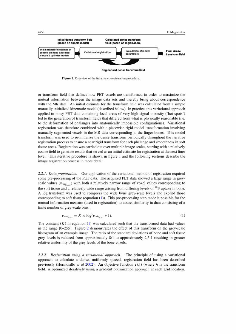
2.2.1. Data preparation. Our application of the variational method of registration requiredsome pre-processing of the PET data. The acquired PET data showed a large range in grey-scale values (νorigx,y,z
) with both a relatively narrow range of voxel values corresponding tothe soft tissue and a relatively wide range arising from differing levels of 18F uptake in bone.A log transform was used to compress the wide bone grey-scale levels and expand thosecorresponding to soft tissue (equation (1)). This pre-processing step made it possible for themutual information measure (used in registration) to assess similarity in data consisting of afinite number of grey-scale bins:
νnewx,y,z = K × log(νorigx,y,z+ 1). (1)
The constant (K) in equation (1) was calculated such that the transformed data had valuesin the range [0–255]. Figure 2 demonstrates the effect of this transform on the grey-scalehistogram of an example image. The ratio of the standard deviations of bone and soft tissuegrey levels is reduced from approximately 8:1 to approximately 2.5:1 resulting in greaterrelative uniformity of the grey levels of the bone voxels.
2.2.2. Registration using a variational approach. The principle of using a variationalapproach to calculate a dense, uniformly spaced, registration field has been describedpreviously (Hermosillo et al 2002). An objective function I (h) (where h is the transformfield) is optimized iteratively using a gradient optimization approach at each grid location.

Registration of PET and MR hand images 4759
0 5 10 15 20 25 30 35 40Greylevel
Re
lativ
eF
req
ue
ncy
Soft TissueBone
0 50 100 150 200 250 300Greylevel
Re
lativ
eF
req
ue
ncy
Soft TissueBone
Figure 2. Histogram showing how the grey-level log transform reduces the relative variation inthe bone and soft tissue voxel levels.
The objective function is typically made up of two terms, an image similarity term (T (h)) anda transform smoothness term (R(h)):
I (h) = T (h) + R(h). (2)
Here, we used global mutual information (M.I.) between the one image and the correspondingtransformed image for the image similarity term (T (h)):
T (h) = M.I.(X, h(Y ))∑
g1∈[0,1]
∑
g2∈G
P (Xg1, h(Y )g2) logP(Xg1, h(Y )g2)
P (Xg1)P (h(Y )g2). (3)
X is the fixed image (the segmented MR data set), h(Y ) is the corresponding transformedmoving (PET) image and G is the set of grey-level histogram bins (typically ten bins wereused6). Whilst a global calculation of mutual information might seem relatively ‘computa-tionally expensive’, in practice it is not necessary to repeat many of the computational steps inequation (3) for calculating a small (single vector) change in h. For example, recalculatingP(h(Y )g2) is only necessary for two bins of G (corresponding to the previous and new greylevels at that voxel) and can be achieved with a single addition and a single subtraction.Similarly, the overall sum can similarly be re-calculated in a computationally efficient mannerby considering only the changed elements.
The smoothness term(R(h)), or rather its differential, was calculated from the vectorbetween the current value of hX (the vector of the field h at location x) and the mean of the sixneighbouring voxel transform vectors. This is illustrated (for a 2D case) in figure 3.
The complete update equation for each element of h (hX) is
h′x = Kt(Ki∇hT (hx) + Ks∇hR(hx)). (4)
The two constants Ki and Ks weight the relative contribution of the similarity and smoothnessterms, respectively. Typical constant values are Kt = 0.05, Ki = 1000 and Ks = 1.
To implement this variational method, an initial estimate is required for the displacementfield. This was obtained using a method described in our previous work (Magee et al 2005).The middle and distal bones (phalanges) forming each finger are approximately represented
6 Choice of the number of bins is a tradeoff between specificity (i.e. representing different tissues as different bins)and generality (i.e. representing the same tissue with as few bins as possible). Ten bins (resulting in a bin width of25.5 greylevels) is a good compromise for the Log transformed image data (figure 2).

4760 D Magee et al
Neighbouring voxel, andassociated transformvector
Voxel to be updated, andassociated transformvector
Mean transform vector ofneighbours
∇hR(h)
Figure 3. Schematic representation showing the calculation (in 2D) of the smoothness differential.
by two cylinders. These were simply defined by interactively selecting four points from theMR and PET data sets. Three of these points define the long axes of the two cylinders. One ofthese three points was chosen at the distal end of the distal phalange and in the middle of thebone. The second was selected in the middle of the joint and the third at the proximal end ofthe middle phalange, again in the middle of the bone. The fourth point defines both the radiusof the two cylinders and the dorsal direction and was chosen at the end and at the appropriateedge of one of the two phalanges. Initial estimates for use in our variational method werethen generated from this cylinder-based model of the phalanges (Magee et al 2005). Thispiecewise rigid transform is similar to that outlined in section 2.2.3 (below) except that itemploys cylinders rather than segmented bones.
To increase computational efficiency and overcome local optima in the objective functionbeing optimized, image registration was carried out over multiple image scales. Volumes werere-sampled to generate cubic voxels using tri-linear interpolation (for up-sampling) and voxelaveraging (for down-sampling by a factor of 2) to generate volumes with voxels of dimensionsof 4, 2, 1 and 0.5 mm, respectively.
2.2.3. Regularization using a piecewise linear bone model. The variational process describedin section (ii) works well for data that are reasonably homogeneous. However, the PET dataacquired from arthritis patients were markedly inhomogeneous in that they contained localareas of relatively intense tracer uptake. This together with the high levels of image noise oftenled to calculated transforms that differed substantially from what is physically possible (i.e.generating bones that are significantly deformed). To prevent this occurring, the registrationprocess had to be ‘regularized’. Our approach for regularization (inspired by our previouswork (Magee et al 2005)) manually segmented the bone from the MR data using a standardinteractive tool. This resulted in a so-called piecewise rigid kinematic model consistingof separate phalanges allowing relative movement of the fingers to be modelled as a rigidtransformation, with soft tissue deformation modelled using interpolation between bone andglobal rigid transformations. The rigid transformations (translation + rotation) for each bonewere calculated from the part of the deformation field h associated with that bone. A set of 3Dpoint pairs (original and transformed locations) was formed, and the closed-form, least-squareserror minimizing method of Horn (1987) used to estimate the transform (Tn). A normalizedGaussian interpolation scheme was employed to calculate the transform at non-bone pixels.
Methods also had to be introduced preventing bones from intersecting as a result of theestimated model transform. Such intersections were detected (in a computationally efficientway) by identifying voxels that were transformed beyond their neighbour in the direction of

Registration of PET and MR hand images 4761
(a) (b)
Figure 4. (a) Synthetic PET data (see the text). (b) PET data acquired from a patient withosteoarthritis (coronal view of the hand).
that neighbour. This was corrected by re-calculating the rigid transform with an offset to eachbone away from the voxel pair(s) that overlap. This was achieved by defining this vector basedon ‘overlapping’ voxel pairs as
Dn = 1
Nψ
∑
m=ψ
Cn − Om, (5)
where ψ is the set of overlapping pairs of voxels, Om is the mean location of overlappingpair m, Cn is the centroid of bone n, and Nψ is the number of overlapping voxel pairs. Therigid transform for each bone was iteratively updated with the addition of an offset of KcDn
(where Kc is typically 0.1) until Nψ is reduced to a minimal number of voxel pairs (<10). Theremaining overlaps were usually small and tended to be corrected by the variational update,where the smoothness term biases against non-invertible transforms.
To measure the efficacy of our registration technique, we generated synthetic PET andMR data using a finite element technique. This approach was inspired by work carriedout by Schnabel et al (2003), who used finite elements to construct data for validating theregistration of MR breast images. Synthetic PET images were created from CT data acquiredfrom a phantom consisting of human bones set in an acrylic resin. These CT data were thentransformed using a method previously employed to generate synthetic ultrasound images(Zhu et al 2006). Figure 4 compares a representative slice from this synthetic PET data witha genuine PET image acquired as part of this study.
The synthetic MR data consisting of the four fingers (each finger consisting of threephalanges, two joints plus soft tissue) were then obtained from a sub-volume of the syntheticPET data. A 1 mm3 finite element mesh (FEM) was then generated from a binary segmentationof these images. Relative displacement of the simulated MR data was generated by movingthe mesh at points corresponding to the ends of each phalange such that this displacementmaintained the overall length of each bone. Deformations of the FEM were calculated usingthe Abacus FEM program7 with values of Young’s modulus of 1.66 × 10⁸ for the bone and4.00 × 106 for the soft tissue element, a Poisson ratio of 0.3 and a density of 1 for all elements.A dense transform field represented as [dx,dy, dz] on a 0.5 × 0.5 × 0.5 mm uniform grid wascalculated and smoothed by median filtering in these orthogonal directions to remove boundaryeffects between the different tissue elements. This transform field moved the synthetic MR
7 http://www.simulia.com.
4762 D Magee et al
data relative to the PET data such that the relative displacement of any given point withinthe data was known. The relative displacements between the PET and MR images variedacross these two image data sets and were consistent with expected movement of the handbetween the imaging examinations. Thus, a displacement of up to 15 mm was generated withrotation of the distal phalange by 10◦–15◦ and the proximal phalange by 35◦–40◦. The smallerrotation approximates the displacement one might expect when using a bespoke patient handrestraint with minimal delay between the acquisitions of the image data. The larger waschosen to represent more extreme relative movement of the hand between the MR and PETexaminations.
Our iterative registration protocol was executed in a series of steps (or ‘scales’) in whichinitial relatively coarse fields served as an initial estimate for registration at the next finer level.The synthetic data were used to evaluate this methodology with iterations made over differentnumbers of scales related to 4, 2, 1 and 0.5 mm voxel sizes. The registration methodologyalso required the manual segmentation of bone. This procedure is therefore subject to operatorerror reflecting the operator skills. The effect of errors in bone segmentation on registrationaccuracy was therefore measured when 500 voxels were randomly added or subtracted to/fromthe segmented border.
Our registration method was also compared with existing, established rigid- and non-rigidregistration techniques. These used a gradient-based optimizer and mutual information as ametric to apply rigid (translational and rotational) or B-spline-based transforms to the data.These methods were taken from the Insight toolkit (ITK) (Ibanez et al 2005).
The registration protocol which gave the most accurate registration of the synthetic datawas used to register PET and MR images acquired from nine patients who had been diagnosedwith osteoarthritis in the hand. An assessment of registration accuracy in the patient data wasmade using an equivalent axial single slice from the MR and PET data sets. This slice waschosen as one in which there would be strong PET uptake and yet which would not includethe joint where bone margins can be difficult to define. The chosen section was thereforespecified by identifying that slice containing the joint gap and then choosing the third sliceaway from that gap on the proximal side of the joint. In-plane registration accuracy in thisslice was determined by manually defining (segmenting) the margins of the phalange in theMR data and then measuring the shortest distance between margin points in the registeredPET data and this segmentation using a Euclidean distance transform. Identifying phalangemargin points in PET images is a subjective process. Where this was not possible, these partsof the contour were excluded from the annotation.
2.2.4. Technical implementation. Our registration method was implemented in C++using Microsoft Visual StudioTM 2005 on the Microsoft Windows XPTM operating system.Experiments were performed using a PC with 2 GB memory and a 32 bit dual core IntelXeonTM processor.
3. Results
Registration was carried out over a ‘number of scales’ (from coarse to fine). Each successiveevaluation run used an additional (coarser) scale, with scale 1 registering only at 0.5 mm,scale 2 registering at 1 mm, then 0.5 mm, and so on. The results in figure 5 show that theoptimal number of scales is 3 (2 mm, then 1 mm, and finally 0.5 mm), and this was used in allsubsequent registrations involving our protocol.

Registration of PET and MR hand images 4763
0.50
1.00
1.50
2.00
2.50
0/Initial 1 2 3 4
# Scales in Registration
Mea
nB
on
eE
rro
r(m
m)
F1_1
F1_2
F2_1
F2_2
F3_1
F3_2
Figure 5. Mean error in bone registration as a function of the ‘number of scales’—see the text.The level 0/initial scale refers to the initial registration (after the initial transform estimation basedon the hand specified simple two-cylinder finger model outlined in figure 1). The smallest erroroccurred when using three levels of registration. The fingers and joints are labelled as F∗ #; where∗ and # indicate the finger and joint number respectively. Finger 1 is the finger immediatelyadjacent to the thumb and joint 1 is the distal interphalangeal joint.
0.50
1.00
1.50
0.8 1.3 1.8 2.3
Initial Mean Bone Error (mm)
Fin
alM
ean
Bo
ne
Err
or
(mm
)
Figure 6. Errors in registration as a function of initial relative displacement of synthetic PET andMR image data. Initially, relative displacements of up to 15 mm were introduced. However, theseare typically reduced to approximately 2.5 mm or less in the initial transform estimation based onthe hand specified simple two-cylinder finger model outlined in figure 1.
Our image registration technique required a manual segmentation of the bone from theMR images. The effects of inaccurate segmentation on the quality of registration were studiedby randomly adding or subtracting voxels from the margins of the segmented bone. Resultsshowed that the accuracy of the overall registration was remarkably insensitive to errors insegmentation (data not shown).
Assessments of the performance of our registration technique showed that the initialrelative positions of the PET and MR synthetic data did influence the accuracy of registration.Figure 6 shows that if there are large differences between the PET and MR positions in the

4764 D Magee et al
Table 1. Comparison of errors (mm) between our registration method and that resulting from theuse of the Insight Toolkit (ITK)-rigid and non-rigid registration. Values show the mean (maximum,standard deviation) error. Registration was carried out over the optimum number of three scales(i.e. 1 mm voxels).
Non-rigid Non-rigidOur method Our method Rigid ITK Rigid ITK ITK ITK Bone
Data Overall Bone only Overall Bone only Overall only
F1 1 1.203 0.958 3.910 1.798 9.094 8.163(6.860, (2.402, (9.642, (5.445, (17.833, (14.930,0.540) 0.315) 2.375) 1.136) 2.899) 1.720)
F1 2 1.374 1.326 1.332 0.560 1.442 1.121(3.033, (1.809, (3.952, (1.944, (4.541, (3.641,0.273) 0.254) 0.799) 0.293) 0.717) 0.533)
F2 1 1.890 (8.561, 1.441 (3.808, 4.078 (10.962, 2.077 (5.604, 12.141 12.2860.971) 0.634) 2.492) 1.277) (27.374 (23.375
5.208) 5.528)F2 2 1.298 1.175 1.377 0.568 2.379 1.671
(3.589, (2.286, (4.900, (2.376, (6.6994, (4.794,0.382) 0.245) 0.858) 0.302) 1.016) 0.7759)
F3 1 1.616 (9.252, 1.297 (2.157, 4.196 (11.582, 2.114 (6.174, 13.976 14.5700.672) 0.220) 2.646) 1.387) (24.377, (22.845,
4.120) 3.258)F3 2 1.299 1.142 1.101 0.431 1.221 1.310
(2.230, (1.815, (3.771, (1.554, (4.404, (3.306,0.423) 0.211) 0.664) 0.239) 0.732) 0.559)
input data, then the errors in the final registration are also likely to be relatively large. However,these data indicated that even when differences between the hand positions in the syntheticMR and PET data were large, there was an upper bound to the registration errors.
Results comparing existing rigid body registration methods provided by the Insight toolkit(ITK) and our registration technique are displayed in table 1. The non-rigid-ITK method isclearly sub-optimal, producing larger errors than the rigid method. A plot of the spatialdistribution of registration errors (figure 7) shows that whilst the errors are essentially uniformacross the image when using our registration technique, the rigid ITK method produces errorsthat are distinctly heterogeneous. Our method significantly outperforms the rigid method fromITK in all three fingers for the distal interphalangeal joint (F∗ 1) where the most nonlineardeformations are present. For the more proximal interphalangeal joint (data set F∗ 2), thepicture is less clear. The rigid ITK method results in lower mean errors in the bone regionbut larger maximum errors (in 2/3 cases) and a higher standard deviation of the mean error.Table 1 shows that in bone our method has registered the synthetic PET and MR images suchthat the mean registration error is less than 1.5 mm and the maximum error is less than 4 mm(typically occurring far from the joint, which is our area of interest). There are several error‘hot-spots’ (see figure 7) resulting from the use of our methodology that appear to be verylarge (i.e. > 9 mm). However, these occur in regions corresponding to the skin (boundaryeffects) and will therefore have no affect on assessments of bone turnover.

Registration of PET and MR hand images 4765
Data Our Method ITK Bone Segmentation
F1_1
F1_2
Figure 7. Images showing the spatial variation of the registration error across the width of the finger(sagittal view). Brighter voxels represent higher errors. These images show that whilst there are avery few areas of relatively high registration inaccuracy when using our method, the ITK techniqueresults in generally poorer and more non-uniform registration (see the text). The right-hand binaryimages show the relative position of the segmented bone within the finger. (Fingers/joints definedin the legend to figure 5.)
(a) (b) (c) (d)
Figure 8. (a) An axial MR image of the distal interphalangeal joint in a patient with osteoarthritis.The arrows indicate osteophytes on the dorsal aspect of this bone in close proximity to the distalinterphalangeal joint. Registered (b) axial, (c) coronal and (d) sagittal grey-scale MR and PETimages of a phalange in the same patient. The PET data are displayed as a colour overlay with‘warm’ colours indicating relatively high uptake. These images show high uptake of 18F in boneregions corresponding to osteophytes (see the text). (The sagittal and coronal MR images werereconstructed from 2D images acquired in the axial plane and are therefore displayed at relativelylower resolution than images in (a) and (b).)
Figure 8 shows grey-scale MR images (a)–(d) and superimposed PET data (b)–(d) acquiredfrom a patient with osteoarthritis. The PET data are displayed as a ‘heat map’ and wasregistered to the MR images using the technique described in this study. Examination of thesedata (and images obtained from other patients—not shown) indicates that the registration errorsare consistent with those determined in our study of synthetic data. This is evident in figure 8which shows that areas of high PET activity coincide well with areas within the MR imagescorresponding to bone. Further, where the MR data show pathology in the form of osteophytes(regions of high bone turnover), there is corresponding evidence of a well-registered area ofhigh PET activity.
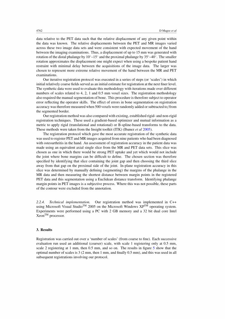
Figure 9 shows grey-scale T1-weighted axial (a) and coronal (b) and (c) MR images ofthe distal interphalangeal joint acquired from a different patient to that shown in figure 8.These images show evidence of both joint subluxation and joint bone remodelling resultingin an irregular interface between the distal and intermediate phalanges. Data in figure 9(b)have been reconstructed from the axial data and are therefore displayed at relatively lower
4766 D Magee et al
(a) (b) (c)
Figure 9. (a) T1-weighted axial and (b) and (c) coronal images of the distal interphalangeal jointin a patient with osteoarthritis. The data shown in (b) have been reconstructed from 2D imagesacquired in the axial plane and are therefore displayed at relatively lower resolution. The imageshown in (c) was acquired in the coronal plane and is therefore displayed at relatively higherresolution than (b) facilitating the comparison between uptake at the joint and the joint anatomy.
1 2 3 4 5 6 7 8 9
0
0.5
1
1.5
2
2.5
3
3.5
In-p
lane
conto
ur:
con
tourdis
tan
ce(m
m)
Patient
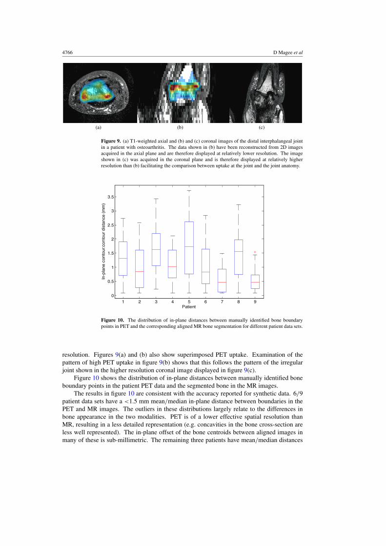
Figure 10. The distribution of in-plane distances between manually identified bone boundarypoints in PET and the corresponding aligned MR bone segmentation for different patient data sets.
resolution. Figures 9(a) and (b) also show superimposed PET uptake. Examination of thepattern of high PET uptake in figure 9(b) shows that this follows the pattern of the irregularjoint shown in the higher resolution coronal image displayed in figure 9(c).
Figure 10 shows the distribution of in-plane distances between manually identified boneboundary points in the patient PET data and the segmented bone in the MR images.
The results in figure 10 are consistent with the accuracy reported for synthetic data. 6/9patient data sets have a <1.5 mm mean/median in-plane distance between boundaries in thePET and MR images. The outliers in these distributions largely relate to the differences inbone appearance in the two modalities. PET is of a lower effective spatial resolution thanMR, resulting in a less detailed representation (e.g. concavities in the bone cross-section areless well represented). The in-plane offset of the bone centroids between aligned images inmany of these is sub-millimetric. The remaining three patients have mean/median distances
Registration of PET and MR hand images 4767
of 1.5–2 mm. On inspection these patients have much lower PET tracer (18F) uptake thanthe other patients, and thus registration is a more challenging task (bone is very difficult todifferentiate from soft tissue even by eye). Even in these data sets, the offset of the in-planebone centroids in the two modalities is <2 mm. Additionally, the two data sets with the lowestmean error (∼0.5 mm) have the strongest tracer uptake.
4. Discussion
This study has presented a method for the co-registration (or fusion) of high-resolution MRand HIDAC PET images. The principal components of the method are (i) the use of mutualinformation as a similarity metric applied to a binary (segmented) MR volume and (logtransformed) PET data, (ii) the optimization of this similarity metric using a variationalregistration scheme and (iii) the use of a model-based approach to regularize this image-basedregistration. The method has been evaluated both quantitatively using synthetic data generatedusing a finite element method (FEM) and qualitatively using patient data. The mean accuracyof the technique is better than approximately 1.5 mm, or 10–15% of a finger width or less than3 PET voxel widths.
Table 1 and figure 7 show that the method of image co-registration implemented heregave more uniform and generally more accurate results compared with those obtainedwhen using the ITK rigid registration technique. The relatively heterogeneous registrationaccuracy resulting from the rigid ITK method is to be expected given that a single lineartransform is approximating an essentially piecewise linear transform. It might be expectedthat a more appropriate registration method would employ a non-rigid transform (e.g. aB-spline). However, the opposite was true with the rigid-body approach outperforming non-rigid registration. This indicated that the non-rigid procedure was finding unrealistic solutionsthat optimized mutual information resulting in inaccurate registration. The use of eithervariational or model-based approaches to image registration is not new. However, this studysuggests that it can be beneficial to combine these methods in situations like those encounteredhere, where data are noisy and shows large variations in grey-scale levels within the sametissue.
Previous studies have used FEMs to generate synthetic data (e.g. for the validation ofnon-rigid unimodal registration of PET breast images (Schnabel et al 2003)) and to co-registerMR and computed tomography data for radiotherapy planning (Hensel et al 2007). Our useof synthetic data to assess registration accuracy will provide results relevant to the registrationinvolving real patient data carried out here. Signal-to-noise levels in our synthetic PET imagesare comparable to those obtained clinically (figure 4). These synthetic images are registeredto a binary mask defining bone in the MR data and we feel that the results of our evaluation ofregistration methods based on these data are, in fact, applicable to actual patient data.
The techniques developed here provide powerful tools both for registering images andassessing the efficacy of a given registration technique. A detailed analysis of the utility of ourmethods for registering PET and MR hand images in osteoarthritis (OA) patients is currentlybeing carried out. The preliminary results presented here indicate that our methods have beensuccessful in co-registering data obtained using different imaging modalities and are of value indefining the anatomical location of active bone metabolism. We have shown that osteophytes(defined within the MR image) can give relatively high PET uptake (figure 8). The coronaland sagittal registered images in figures 8(c) and (d) show maximum PET activity occurringon the proximal side of the distal interphalangeal joint, consistent with the known location ofthe largest osteophyte in this patient. These observations are not surprising, as osteophytes areassociated with bone remodelling and therefore show active bone metabolism. Further, data
4768 D Magee et al
in figure 9 indicate that the highest PET activity follows the shape of the joint interface wherethere is evidence that bone remodelling has resulted in an irregular and abnormal joint. Thistogether with the data in figure 8 suggests that the MR and PET data have been registered veryaccurately with registration errors being less than approximately 1.0 mm in these data sets.
Our techniques have resulted in a mean accuracy in registration of less than 1.5 mmand a maximum error of 4 mm. Whilst the larger registration errors may be problematic instudies of small joints, the administered PET activity employed was deliberately kept low inthis exploratory study. If higher levels of activity had been used, this would have improvedsignal-to-noise levels within the PET data and may have resulted in further improvements inthe accuracy of image co-registration when employing the methods described here.
Manual input (segmentation plus specification of four landmarks per volume) is less than10 min per data set. Natural variation in this input does not greatly affect the efficacy of ourmethod. Computer runtime for registering a volume pair is less than 5 min on modest PChardware.
Our registration technique has the potential to be used in applications beyond the scopeof the work described here. Although QuadHIDAC PET imaging is not widely employed,the registration techniques described in this study could be used to register SPECT and MRimages. These methods are ideally suited to the fusion of images obtained using differentmodalities, particularly in settings where rigid body registration is inappropriate. It may beargued that such registration techniques will not be required with the advent of hybrid imagingtechnology in which image data from two (or more) modalities (i.e. CT with PET or SPECT,or PET with MR) are acquired from a patient using a single integrated device. Whilst PETand CT or SPECT and CT scanners are becoming more prevalent, hybrid equipment involvingMR imaging is still under development. Peng et al (2010) have described how interfacingPET and MR scanners can impact negatively on the performance of both imaging modalities.The high static magnetic field associated with MR can affect the PET light collection. Further,it is possible for radiofrequency (rf) crosstalk between the MR and PET electronics. No doubtinstrumentation development will continue to address these challenges over time. However,there will remain groups of patients who are contraindicated for MRI (e.g. those with cardiacpacemakers). There will also remain many real-life clinical situations in which the fusion ofpreviously acquired images with images from another modality will be required (or preferredto further subjecting the patient to additional radiation exposures). It is likely therefore thatimage registration techniques such as those presented here will be needed for some time.
References
Bois d’Aische A du, Craene M D, G X, Gregoire V, Macq B and Warfield S 2007 Estimation of the deformationsinduced by articulated bodies: registration of the spinal column Biomed. Signal Process. Control 2 16–24
D’Agostino E, Maes F, Vandermeulen D and Suetens P 2003 A viscous fluid model for multimodal non-rigid imageregistration using mutual information Med. Image Anal. 7 565–75
d’Aische A, Craene M, Geets X, Gregoire V, Macq B and Warfield S 2005 Efficient multi-modal dense field non-rigidregistration: alignment of histological and section images Med. Image Anal. 9 538–46
Hermosillo G, Chefd’Hotel C and Faugeras O 2002 Variational methods for multimodal image matching Int. J.Comput. Vis. 50 329–43
Hensel J, Menard C, Chung P, Milosevic M, Kirilova A, Moseley J, Haider M and Brock K 2007 Development ofmultiorgan finite element-based prostate deformation model enabling registration of endorectal coil magneticresonance imaging for radiotherapy planning Int. J. Radiat. Oncol. Biol. Phys. 68 1522–8
Horn B 1987 Closed-form solution of absolute orientation using unit quaternions J. Opt. Soc. Am. 4 629–42Huesman R, Klein G, Kimdon J, Kuo C and Majumdar S 2003 Deformable registration of multimodal data including
rigid structures IEEE Trans. Nucl. Sci. 50 389–92Ibanez L, Schroeder W, Ng L and Cates J 2005 The ITK Software Guide (Clifton Park, NY: Kitware)

Registration of PET and MR hand images 4769
Jeavons A, Chandler R and Dettmar A 1999 A 3D HIDAC-PET camera with sub-millimetre resolution IEE Trans.Nucl. Sci. 46 468–73
Kjems U, Strother S, Anderson J, Law I and Hansen L 1999 Enhancing the multivariate signal of 15-O water PETstudies with a new nonlinear neuroanatomical registration algorithm IEEE Trans. Med. Imaging 18 306–19
Magee D, Tanner S, Waller M, McGonagle D and Jeavons A 2005 Registration of PET and MR hand volumes usingBayesian networks Proc ICCV Workshop on Computer Vision for Biomedical Image Applications ed Y Liu,T Jiang and C Zhang (Berlin: Springer) pp 437–48
Makela T, Clarysse P, Sipila O, Pham N P nad Q-, Katila T and Magnin I 2002 A review of cardiac image registrationmethods IEEE Trans. Med. Imaging 21 1011–21
Makela T et al 2003 A 3D model-based registration approach for the PET, MR and MCG cardiac data fusionMed. Image Anal. 7 377–89
Martin-Fernandez M, Martin-Fernandez M and Alberola-Lopez C 2009 A log-Euclidean polyaffine registration forarticulated structures in medical images Proc. Med. Image Comput. Comput. Assist. Interv. 1 156–64
Martin-Fernandez M, Munoz-Moreno E, Martin-Fernandez M and Alberola-Lopez C 2005 Articulated registration:elastic registration based on a wire model Proc. SPIE 5747 182–91
Meyer C, Boes, Kim J, Bland P, Zasadny K, Kison P, Koral K, Frey K and Wahl R 1997 Demonstration of accuracy andclinical versatility of mutual information for automatic multimodality image fusion using affine and thin-platespline warped geometric deformations Med. Image Anal. 1 195–206
Myers R 2002 The application of PET-MR image registration in the brain Br. J. Radiol. 75 31–5Peng B, Walton J, Cherry S and Willig-Onwuachi J 2010 Studies of the interactions of an MRI system with the
shielding in a combined PET/MRI scanner Phys. Med. Biol. 55 265–80Reader A, Erandsson K, Flower M and Ott R 1998 Fast accurate iterative reconstruction for low-statistics positron
volume imaging Phys. Med. Biol. 43 835–46Rhee T, Lewis J, Neumann U and Nayak K 2010 Scan-based volume animation driven by locally adaptive articulated
registrations IEEE Trans. Vis. Graphics at pressRueckert D, Sonoda L, Hayes C, Hill D, Leach M and Hawkes D 1999 Nonrigid registration using free-form
deformations: application to breast MR images IEEE Trans. Med. Imaging 18 712–21Schnabel J, Tanner C, Castellano-Smith A, Dagenhard A, Leach M, Hose D, Hill D and Hawkes D 2003 Validation of
nonrigid image registration using finite-element methods: application to breast MR images IEEE Trans. Med.Imaging 22 238–47
Tai Y-C, Lin K, Hoh C, Huang S and Hoffman E 1997 Utilization of 3D elastic transformation in the registration ofchest x-ray CT and whole body PET IEEE Trans. Nucl. Sci. 44 1606–12
Tan A-L, Grainger A, Tanner S, Shelly D, Pease C, Emerey P and McGonagle D 2005 High-resolution magneticresonance imaging for the assessment of hand osteoarthritis Arthritis Rheum. 52 2355–65
West J et al 1997 Comparison and evaluation of retrospective intermodality brain image registration techniquesJ. Comput. Assist. Tomogr. 21 554–66
Woods R, Grafton S, Watson J, Sicotte N and Mazziotta J 1998 Automated image registration: II. Intersubjectvalidation of linear and nonlinear models J. Comput. Assist. Tomogr. 22 153–65
Zhu Y, Magee D, Ratnalingam R and Kessel D 2006 A virtual ultrasound imaging system for the simulation ofultrasound-guided needle insertion procedures Proc. Medical Image Understanding and Analysis (MIUA) vol 1pp 61–5