Accurate Approximate and Analytical Methods for Vibration ...

Combined use of Photogrammetric and Computer Vision techniques for fully automated and accurate 3D modeling of terrestrial objects
Luigi Barazzettia, Fabio Remondinob, Marco Scaionia
a Politecnico di Milano, P.za Leonardo da Vinci 32, Milan, Italy
Email: <luigi.barazzetti><marco.scaioni>@polimi.it, Web: http://www.polimi.it b 3D Optical Metrology – Bruno Kessler Foundation (FBK) Trento, Italy
Email: [email protected], Web: http://www.fbk.eu
ABSTRACT
Nowadays commercial software able to automatically create an accurate 3D model from any sequence of terrestrial images is not available. This paper presents a methodology which is capable of processing markerless block of terrestrial digital images to perform a twofold task: (i) determine the exterior orientation parameters by using a progressive robust feature-based matching followed by a Least Squares Matching refining and a bundle adjustment; (ii) extract a dense point-clouds by using a multi-image matching based on diverse image primitives. The final result is an accurate surface model with characteristics similar to those achievable with range-based sensors. In the whole processing workflow the natural texture of the object is used, thus images and calibration parameters are the only inputs. The method exploits Computer Vision and Photogrammetric techniques and combines their advantages in order to automate the process. At the same time it ensures a precise and reliable solution. To verify the accuracy of the developed methodology, several comparisons with manual measurements, total station data and 3D laser scanner were also carried out.
Keywords: Photogrammetry, Automation, Image matching, 3D modeling
1. INTRODUCTION Automatic analysis of markerless image blocks is an issue still open in Close-Range Photogrammetry and Computer Vision (CV). In several applications (e.g. computer graphics, robotics, cultural heritage documentation, etc) 3D models are often requested products. The characteristics of a 3D model can be really variable in terms of accuracy, completeness and resolution and all depends on the used procedures. Several packages for image-based 3D modeling are available, but a commercial solution capable to derive an accurate and detailed 3D model in a fully automatic way from a generic set of terrestrial images is still missing. Thus, interactive measurements are still mandatory, in particular for the orientation phase and the 3D reconstruction of architectural features. In terrestrial applications, automation can be apparently reached with the application of coded targets, which are automatically found and matched in the images. Thus it is possible to automatically orient the images and calibrate the camera ([1] [2]), but targets can be rarely used for the reconstruction of an object. Moreover, in some cases targets cannot be placed on the object. In practical situations, the camera is firstly calibrated in laboratory and then used with the same setting on the field to acquire a set of images with the aim of 3D reconstruction. The orientation process is generally carried out with a manual or semi-automatic determination of the tie-points, while automatic photogrammetric solutions for the surface reconstruction are already available [3]. On the other hand, the CV community developed several automated orientation and image matching techniques (“Structure from Motion”) for terrestrial images, but their accuracy seems really far from the requirements of standard photogrammetric projects. Several differences separate photogrammetry and CV, starting from the resolution of the adopted sensors, the number of images, the orientation algorithms, the automation of the procedure and the accuracy of the solution. CV’s methods are termed uncalibrated, i.e. the interior orientation parameters are not given and can be directly estimated from the available images (“self-calibration”). Low resolution sensors are often used, but the number of images that can be analyzed can be huge [4]. A most common approach uses image pairs [5] or triplets [6] to progressively concatenate all images in a global adjustment. The reconstruction with uncalibrated methods has a projective ambiguity that can be removed with self-calibration methods [7]. The whole process is highly automated thanks to some procedures which do not require initial approximations, but its accuracy is rarely checked out and most results are good mainly for visualization purposes. On the other hand, the sensors used in photogrammetric applications

feature a higher geometric and radiometric resolution and are always calibrated. Indeed most of the sequences acquired on the field do not allow for a complete and accurate camera calibration [8]. The mathematical model for image orientation is based on collinearity equations, which is more stable if compared to projective methods. Last but not least, accuracy is a goal of fundamental relevance and the user interaction is not neglected, especially in case of convergent images without targets.
In this paper we present a method for the automatic reconstruction of 3D models by using terrestrial markerless images. This method allows the elaboration of a generic block of images captured with a fully calibrated camera. It is quite robust to change in illumination of the scene and variations in rotation and scale. The whole procedure is constituted by (i) an image orientation step and (ii) a surface measurement and interpolation phase. The method makes use of several CV and photogrammetric methods for image matching during the preliminary detection of image correspondences, while the orientation phase is based on a rigorous photogrammetric bundle adjustment via a Least Squares (LS) Gauss-Markov solution, which is the most precise and accurate method to retrieve the exterior orientation (EO) parameters [9]. The approach is similar to a “Structure from Motion” procedure but with collinearity equations as a mathematical model. The computed solution is the starting point for a multi-image matching based on the Multi-Photo Geometrically Constrained (MPGC) framework proposed by Gruen and Baltasavias [10], which makes possible the extraction of dense and accurate point clouds from images.
The next sections show the functioning of the algorithm and several numerical results to demonstrate the accuracy of the implemented methodology. The general scheme of the method is shown in Fig. 1.
Fig. 1. Fully automatic generation of detailed and accurate surface models from an unoriented and markerless set of
terrestrial images acquired with a calibrated camera: (i) the exterior orientation parameters and a sparse geometry are automatically recovered by using scale invariant features while (ii) the object’s surface is measured with a Multi-photo Geometrically Constrained Matching.
2. IMAGE ORIENTATION 2.1 Overview
The main problem during the automatic orientation of markerless image blocks is related to the determination of the image correspondences. Although in aerial cases this task has been solved since many years, it can be a real challenge in case of convergent or widely separated terrestrial images. Commercial automatic solutions are based on coded targets, which are easy to match on images and represent a valid solution for automatic camera calibration. However, for 3D reconstruction purposes, targets can rarely be applied onto the object and only interactive measurements allow the determination of the tie points. From this point of view, the CV community developed matchers capable to automatically determine image correspondences between convergent images, which are invariant for rotation around the optical axis of the camera and scale and robust to illumination changes. In our approach, these features are the starting point for the automated image orientation strategy, but are then refined using a Least Squares Matching (LSM) procedure [11] to achieve sub-pixel accuracy. After the identification of the image correspondences, a photogrammetric bundle adjustment is carried out to retrieve the exterior orientation parameters. In this step it would be possible to determine also the interior

orientation parameters, but the geometry of the image block used for the reconstruction of the object does not generally provide a reliable and accurate solution. Consequently each camera is always calibrated independently in the lab. The main problem during the orientation phase regards the determination of approximate values for the linearization (with the Taylor expansion) of the collinearity equations. However, several solutions can be found in literature and the problem can be considered solved. Generally, a basic approach starts with the relative orientation of an image pair, then a progressive combination of space resections and intersections [12] provides good approximate values for the final bundle adjustment.
2.2 Image correspondences extraction and matching
In case of terrestrial images, an automatic operator should be able to detect the same interest points or regions in images taken from different point of views (repeatability). Several operators were developed (e.g. [13] [14] [15] [16] [17]) but only two are at the moment integrated in the algorithm: SIFT [18] and SURF [19]. Both are composed of a detector and a descriptor. The detector extracts the features, while the descriptor assigns a vector (in the used implementation with 128 elements) which identifies each feature. A preliminary detection of the image correspondences is carried out by comparing all the descriptors ni and nj extracted from the two images i and j, respectively. In particular, descriptors are analyzed by using the norm of the difference between the two vectors (Euclidean distance). All distances are ordered from the shortest (r) on and then the two higher in the rank (r, r-1) are compared as follows:
1. each feature m (with descriptor mDr
) of the image i is analyzed alternatively;
2. all features n (with descriptor nDr
) of the image j is compared to the feature m, and the distance between them computed:
nm DDrr
− ;
3. all the pairs m-n are ordered according to the computed distance from the shortest to the largest;
4. the two best pairs in the rank are compared, and the best one (rank r) is selected as correspondence only if:
tDDDDrnmrnm ⋅−<−−1
rrrr.
This means that a correspondence is established only if it is the shortest either in the absolute ranking and with respect to the second best descriptors pair (r-1). For our tests the ratio t between both pairs of descriptors ranged from 0.5 to 0.7. This criterion ensures a good robustness of the method and help to discriminate ambiguous pairs. A comparison between all matched features can be carried out in three different ways, which depend on the geometry of the image block. These procedures, which the user has to select at the beginning of the process, are:
• small sparse block: in this case all descriptors of one image are compared with all descriptors of the other images. This choice should be used when a block is composed of a small number of images (Fig. 2a), because of the huge computational cost of the process;
• large sparse block (Fig. 2b): to reduce the computational cost of the procedure, a k-d tree [20] optimization on the descriptors is used;
• ordered sequence: this choice is a good solution when images form an ordered sequence (Fig. 2c). In this case, the whole sequence of n images is divided into n-2 triplets. If i is a generic image, each triplet assumes the form Ti = (i, i+1, i+2), thus the next triplet is made up of the images (i+1, i+2, i+3), and so on. Then, each triplet is matched in order to detect its correspondences. In this step triplets are considered as independent elements. First of all, the first image (i) of the triplet is matched with the second (i+1), while the second one (i+1) is matched with the third one (i+2). A matching between the first (i) and the third (i+2) images is not necessary, because it is sufficient to compare the matched points between the previous combinations to extract the correspondences in the whole triplet. After the single triplet matching, a concatenation between consecutive triplets is carried out to track the same point along the sequence. This operation is always possible because each triplet shares two images with the next one.

(a) (b) (c) Fig. 2. The network geometry of the image blocks modifies the correspondences searching procedure. The developed
method allows the processing of small image block (a) with the exhaustive analysis of all image combinations, while for large image block (b) a k-d tree technique is implemented to speed up the elaboration. For ordered image sequences (c) a fast strategy to connect consecutives images is used.
2.3 Outlier removal and Least Squares Matching refining
SIFT and SURF demonstrated a high correctness and repeatability during the extraction and identification of tie points. However, some outliers can still be present after the automatic comparison of the descriptors. To detect (and remove) these outliers a strategy based on the robust estimation of the essential E or fundamental matrix F is used. Both matrices encapsulate the geometry of a stereo pair for calibrated and uncalibrated cameras, respectively. Outliers can be detected by verifying that a point in one image lies on the epipolar lines given by the point in the first image in which it was detected. The estimation of E (or F) is carried out with random sampling techniques based on Least Median of Squares [21] principle, as a closed form solution for this problem is not available. Fig. 3 shows some typical results before and after the check of the epipolar geometry with the implemented techniques.
Fig. 3. An image pair before the identification of tie-points with the descriptor (several outliers remain) and after the control
based on the estimation of the essential matrix (outlier removal).
Afterwards the (matched) features can be used for a Least Squares Matching (LSM) refinement, in order to improve the precision of image coordinates. Although an orientation with SIFT and SURF features demonstrated a sub-pixel precision, the results with the application of LSM gives better results in terms of precision. Indeed, LSM is the most precise measurement algorithm today and allows to include compressed images in the feature-based matching phase of our method. The use of LSM allows the analysis of low resolution images (by using a coarse-to-fine approach) with SIFT and SURF. This limits the number of extracted points and speeds up the comparison of the descriptors. These points are then projected onto the original images by considering the applied compression factor and provide good approximate values for the LSM refining. Furthermore, in case of widely separated and convergent images, the descriptor values can be used as initial approximation for the LSM iteration [22].
Once that all the image correspondences are extracted, a bundle adjustment is run to derive all the exterior orientation parameters and a first sparse 3D point cloud of the extracted correspondences.
3. SURFACE MEASUREMENT Starting from the recovered image geometry and from the known camera parameters, an automated surface measurement method is then applied to extract the fine geometric details and achieve accurate point-cloud reconstructions. The method is a multi-image matching based on the Multi-Photo Geometrically Constrained (MPGC) framework of Gruen and Baltsavias [10], originally developed by Zhang and Gruen [23] for linear array sensors and then adapted and extended to terrestrial convergent images [3]. Now the software (CLORAMA) is sold by the ETH spin-off 4DiXplorer (www.4dixplorer.com). CLORAMA uses a coarse-to-fine hierarchical solution on image pyramids combining different image primitives (interest points, grid points, edges - Fig. 4) and matching algorithms (cross-correlation, least squares and relational matching) together with an automatic quality control. Within the pyramid levels, the point and edge matching is performed with an extension of the standard cross-correlation (Geometrically Constrained Cross-Correlation - GC3) technique. The GC3 method is based on windows warping and guidance from object space, knowing an approximate surface model (initially derived using the corresponding points of the orientation phase). Finally, at the original image resolution level, an MPCG LSM and Least Squares B-Spline Snakes [24] can be used as an option to achieve potentially sub-pixel accuracy matches and derive accurate and dense-point clouds. CLORAMA obtains highly redundant results thanks to the multi-image concept which reduces multiple solutions or occlusion problems and removes ambiguities with the multiple epipolar line intersections. A point is matched simultaneously in all the images where it is visible (Fig. 5) and, at the same time, exploiting the collinearity constraint, the 3D coordinates are directly computed, together with their accuracy values.
(a) (b)
(c) (d)
Fig. 4. Example of multiple image features extracted and then combined for the surface reconstruction. Part of the original enhanced image (a), interest points (b), regular grid points (c) and edges (d) are respectively shown.

Fig. 5. The multi-image least squares matching concept: the image patches are resampled according to a reference
template (left windows) while the affine parameters converge during the iterations. Once the image location is computed with sub-pixel accuracy, the object coordinates are computed through MPCG LSM.
4. IMAGE ACQUISITION: WHY IS NETWORK’S GEOMETRY SO IMPORTANT? 4.1 3D modeling using an image sequence
An image sequence is generally composed of frames taken in a progressive order (e.g. Fig. 2c) and its analysis in carried out by dividing the whole sequence in triplets. The surveyed object is a Mayan mask in the archeological site of Copan (Honduras). Eight images were acquired with a calibrated Kodak full frame camera (image resolution is 4500×3000 pixels) equipped with a 35 mm lens. The analysis was carried out by considering full resolution images and extracting tie-points for each triplet using the SURF operator (Fig. 6).
1 2 3 4 5 ….
Fig. 6. Consecutive matched triplets of the Copan sequence with the homologues points extracted and matched using the
SURF operator and a successive LSM refinement.
Afterwards, using the single triplet matching, the image coordinates of points in consecutive triplets are compared in order to determine correspondences in the whole sequence. In particular, the triplet Ti and the next one Ti+1 share two images and the homologues points can be determined simply comparing the image coordinates. This method has a linear computational time with respect to the number of images. To verify the accuracy and effectiveness of the automated orientation procedure, several bundle adjustments were carried out, where the number of tie-points was progressively reduced by considering the multiplicity of the points. Results are shown in Tab. 1, where N represents the minimum number of images in which a point is visible, while Fig. 7 shows the computed exterior orientation parameters and the 3D sparse geometry of the scene. The entire orientation phase took approximately 20 minutes.

N σ0 RMS (pixel) 3D points 3 0.369 0.405 8004 4 0.383 0.445 3819 5 0.393 0.471 1940 6 0.401 0.491 973 7 0.416 0.517 410 8 0.407 0.508 178
Tab. 1. Bundle adjustment statistics after the progressive removal of tie-points (redundancy increment). The estimated σ0 does not change significantly (a priori σ0 = 1).
Fig. 7. Recovered cameras poses and 3D points for the adjustment with tie-points visible in at least 4 images.
As it can be seen, N does not significantly modify the computed σ0 (a priori σ0 was set to 1). This means that a reduction of the number of tie-points based on the image multiplicity can be carried out when points are visible in many images. The main advantage of this procedure is related to the possibility to reduce the number of equations and speed up the elaboration. This strategy can be applied before the computation of exterior orientation parameters, while other techniques for data decimation need the determination of statistics parameters, available only after a bundle adjustment.
Finally, starting from the computed exterior orientation parameters, a DSM with a spatial resolution of 3 mm was created using the CLORAMA multi-image matching software. The derived geometric model and the final textured 3D model are shown in Fig. 8. The DSM was derived in approximately 2 hours.
Fig. 8. 3D model of the Copan mask derived automatically from a sequence of 8 images and shown in color-code and
texture mode.
4.2 3D modeling using a small image block
In case of a sparse image block (e.g. Fig. 2a), the implemented matching procedure determines the image correspondences by checking all possible image combinations. In particular, the descriptors of a generic image i are compared with all descriptors of the remaining images j, with the condition that j > i. This means that a global number of (n2-n)/2 image combinations should be analyzed. The quadratic form of the computational cost implicates a processing time which rapidly increases with the number of images, thus only small image blocks (less than 20 images) can be analyzed with this strategy. On the other hand, the comparison of the descriptors for a generic image pair i↔j is based on the brutal estimation of the Euclidean distance between all descriptors (Di
h↔Djk). Thus, for a fixed image pair another
computation with a quadratic cost should be considered. A strategy reducing the computational cost during the comparison of the descriptors is related to the use of a “k-d tree” on every pair of image, but for this example it was not used. On the other hand, a fast elaboration is not an issue of primary importance in this work, but the solution must guarantee a good accuracy, similar to that of manual measurements.

The block analyzed and shown in Fig. 9 is made up of 15 images, distributed in 3 strips and acquired with a calibrated Nikon D80 camera equipped with a 20 mm lens (image resolution is 3872×2592 pixels). The SURF operator was used to seek for the tie points, while points on the background were removed with a mask. The main difference between the proposed image pair- and triplet-based correspondences matching approach regards the possibility to determine tie-points between images which are not consecutives. Fig. 9 shows some results related to the feature-based matching to find the tie points. The theoretical precision of the computed object coordinates at the end of the bundle adjustment are σx=0.13mm, σy=0.10mm, σz=0.24mm (z is the depth), with an object size of roughly 1400×1200×300 mm. The entire orientation procedure took approximately 4 hours.
In the successive step, the object is digitally reconstructed with the multi-image method implemented in CLORAMA to derive a dense and detailed surface model (Fig. 10).
Fig. 10. The recovered camera poses of the sparse block (3 strips, 15 images). The reconstructed surface model of the bas-relief is shown in color-code and textured mode.
Fig. 9. A bas-relief in Malesco (Italy) imaged with 15 pictures. Some matched image pairs (image 2 with some others before
the removal of points on the background), are shown.

The extension of the method to a large image block (e.g. Fig. 2b) can be performed by using a “k-d tree” approach, which avoids the quadratic form of the computational cost during the comparison of the descriptors. This choice ensures a rapid analysis and several automatic orientations of a huge number of images are reported in literature (more than 2600 images in [4]). For photogrammetric applications, the number of images is generally more limited, but the method is really powerful and fast to seek all the possible image combinations with common tie points.
5. ACCURACY ANALYSIS 5.1 Overview
The image orientation and surface measurement results were checked to determine the accuracy of the methodology. As also shown in [25], the expected accuracy of the orientation phase (in terms of theoretical precision and sigma naught) should be similar to that of traditional (manual) orientations, achievable with any photogrammetric software. On the other hand, the image-based surface measurement results are compared with range-based point clouds.
5.2 Comparison with Total Station measurements: the My Son temple survey
The My Son sanctuary (Vietnam) comprehends several ancient Hindu temples. The temple named “G1” was surveyed by using images which were afterwards automatically oriented with the proposed method. In this case 41 images taken under a circular motion around the temple were automatically oriented with the sequence procedure [26]. On the façades of the temple several targets were applied and measured with a total station. 3D target coordinates were also computed for the photogrammetric project, but their image coordinates were not included in the bundle adjustment (only an intersection of homologous rays to determine 3D coordinates). The quality control was carried out by comparing the distances between all target combinations for the four facades. Results are shown in Tab. 2, where it can be seen how the standard deviation of the differences is lower than 1 cm, while a systematic error can be found (exception made for the South facade). In fact, a free-net adjustment presents a scale ambiguity, which can be removed by fixing one distance. For this survey, the used known distance was fixed on the South façade, and this is the reason why in this facade biases were removed. However, maximum and minimum values are less then 2 cm and demonstrated a relative accuracy of ca 1:2000, which is more than sufficient for this kind of survey (the object is 15 m large, the average image scale is ca 1:800).
Façade North South East West mean (mm) 5 0 10 14
std.dev (mm) 3 5 7 8 max (mm) 13 14 27 34 min (mm) -1 -26 -4 -17
Tab. 2. Differences between total station and photogrammetric measurement on the My Son temple (approximately 15×10×6 meters).
Fig. 11. Some frames of the My Son temple sequence (above) and the automatically recovered camera poses with the sparse 3D geometry of the temple (below).
5.3 Manual vs automatic image orientation
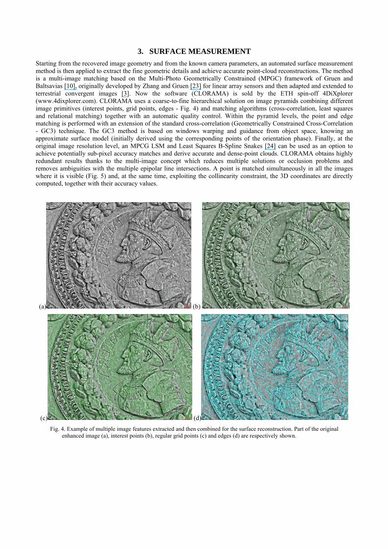
A standard method in photogrammetry used to check the accuracy of automated procedures is to compare the achieved results with ground-truth data derived using manual measurements (of an expert operator). Therefore the results of the implemented strategy for image orientation were compared with those obtainable with manual measurements performed by an expert user. Three image sets were analyzed comparing the results in terms of RMSE (i.e. reprojection error), σ0 and theoretical precision of the computed object coordinates (σx,y,z). The results are shown in Tab. 3. The σ0 is slightly better with the automated approach, most probably due to the LSM image measurements, but the manual approach provides a generally better theoretical precision of the computed object coordinates, probably due to the higher redundancy of the measured tie points.
Number of
images 6 9 5
Image size (pix) 2816 × 2112 1856 × 1392 4500 × 3000
Object size (m) 1.2 × 1 × 1 7 × 1.5 × 2 5 × 1 × 2
Bundle adjustment statistics
auto man auto man auto man
# 3D points 61 26 185 20 549 17
σ0 (pix) 0.28 0.32 0.29 0.45 0.81 1.25
RMSE (pix) 0.25 0.35 0.28 0.44 0.83 1.33
σx (mm) 0.3 0.2 2.6 2.3 0.6 0.8
σy (mm) 0.4 0.1 1.4 1.5 1.1 1.1
σz (mm) 0.7 0.4 5.9 3.8 2.1 1.9
Tab. 3. Comparison between manual and automatic image orientation at the end of the photogrammetric bundle adjustment. First and last images of the three sequences in analysis are shown.
5.4 Surface measurement analysis
After the determination of exterior orientation parameters, the object’s surface is reconstructed with a multi-image matching algorithm. The accuracy of the image matching method was checked using two image blocks and comparing the derived surface models with those obtained with range sensors’ results (Fig. 12). The surface models are aligned with an ICP-based algorithm and then a 3D-compare analysis is performed to derive the statistics of the differences between the patches of the two surfaces. For the first survey (Fig. 12a-b), 5 images taken with a tele-lens (camera-object distance was ca 20 m) were used, while the range data were acquired with a Leica HDS 3000. The second object (Fig. 12b-c) was reconstructed using 25 images and the range data acquired with a stripe projection system (Breuckmann Opto-Top SE).

Photogrammetric and active sensors point-clouds were aligned by minimizing the distance between homologous areas and the derived statistics demonstrated not significant discrepancies between the two methodologies.
(a) (c)
(b) (d) Fig. 12. Comparison between image- and range-based surface models. Some original images (a, c) and the achieved image-
based surface models are reported (b, d). The range data (ground truth) were acquired with a TOF scanner (b) or structured light system (d). The achieved standard deviations of the differences between the 2 surface models (respectively 3 mm and 0.17 mm) are totally in agreement with the specifications of the used active sensors and show the potentiality of the reported image-based modeling methodology.
6. CONCLUSIONS AND OUTLOOK The paper presented a methodology capable of creating 3D detailed and accurate models from terrestrial digital images, with an accuracy similar to that achievable with expensive range-based sensors. The whole procedure is highly automated and targets are not necessary. The integration of Computer Vision techniques into Photogrammetry (and vice versa) allows to automate the 3D modeling pipeline without loosing accuracy.
The procedure has been applied to different architectural and cultural heritage objects with satisfactory results. Different tests have been carried out to check the quality of the final 3D models in terms of accuracy, robustness and completeness. Comparisons with manual orientations have allowed validating the automatic exterior orientation procedure, while some 3D models captured by active sensors have been used to assess the surface reconstruction stage.
Further developments include a more robust technique for the automatic detection of mismatches during the identification of the tie points by using the descriptor of SIFT and SURF (such as RANSAC or MAPSAC). Moreover a strategy for an intelligent reduction of the generally numerous extracted tie points should be implemented. Finally, the combined use of interest operators (e.g. FAST [17]) and features points (e.g. SIFT or SURF) should allow a better distribution of the extracted tie points and also an improvement in the precision of the solution.
REFERENCES
[1] Ganci, G., Hanley, H., Automation in videogrammetry. IAPRS, 32(5): 53-58 (1998). [2] Cronk, S., Fraser, C., Hanley, H., Automatic metric calibration of colour digital cameras. The Photogrammetric
Record, 21(116): 355-372 (2006). [3] Remondino, F., El-Hakim, S., Gruen, A., Zhang, L., Development and performance analysis of image matching for
detailed surface reconstruction of heritage objects. IEEE Signal Processing Magazine, 25(4): 55-65 (2008).

[4] Snavely, N., Seitz, S.M., Szelinski, R., Modelling the World from Internet Photo Collections. International Journal of Computer Vision, 80(2): 189-210 (2008).
[5] Pollefeys, M., Van Gool, L., Vergauwen, M., Verbiest, F., Cornelis, K., Tops, J., Koch, R., Visual modeling with a hand-held camera. International Journal of Computer Vision, 59(3): 207-232 (2004).
[6] Hao, X., Mayer, H., Orientation and Auto-Calibration of Image Triplets and Sequences. IAPRS&SIS, 34(3/W8): 73-78 (2003).
[7] Hartley R., Zisserman A., Multiple View Geometry in computer vision. Cambridge University Press (2004). [8] Remondino, F., Fraser, C., Digital camera calibration methods: considerations and comparisons. IAPRS&SIS 36(5):
266-272 (2006). [9] Mikhail, E.M., Bethel J.S., McGlone, J.C, Introduction to Modern Photogrammetry. John Wiley & Sons, Inc.
(2001). [10] Gruen, A., Baltasavias, E. Geometrically constrained multiphoto matching. Photogrammetric Engineering and
Remote Sensing, 54(5): 633-641 (1988). [11] Gruen, A., 1985: Adaptive least square correlation: a powerful image matching technique. South African Journal of
PRS and Cartography, 14(3): 175-187. [12] Luhmann, T., Robson, S., Kyle, S., Harley, I., Close Range Photogrammetry: Principles, Techniques and
Applications, John Wiley & Sons, Inc. (2006). [13] Förstner, W. and Guelch, E., A fast operator for detection and precise location of distinct points, corners and center
of circular features. ISPRS Conference on Fast Processing of Photogrammetric Data, Interlaken, Switzerland, pp. 281-305 (1987).
[14] Harris, C. and Stephens, M., A combined corner and edge detector. Proceedings of the Alvey Vision Conference (1988).
[15] Mikolajczyk, K. and Schmid, C., Indexing based on scale invariant interest points. In ICCV, Vol. 1 (2001). [16] Kadir, T.and Brady, M., Scale, saliency and image description. International Journal of Computer Vision, 45(2): 83-
105 (2001). [17] Rosten E., Drummond, T., Machine learning for high-speed corner detection. Proc. of ECCV2006, pp. 430-443
(2006). [18] Lowe, D., Distinctive image features from scale-invariant keypoints. International Journal of Computer Vision,
60(2): 91-110 (2004). [19] Bay, H., Ess., A., Tuytelaars, T., Van Gool, L., SURF: Speeded Up Robust Features. Computer Vision and Image
Understanding, 110(3): 346-359 (2008). [20] Beis, J., Lowe, D., Shape indexing using approximate nearest-neighbor search in high-dimensional spaces. Proc.
CVPR: 1000-1006 (1997). [21] Rousseeuw, P.J., Leroy, A.M., Robust Regression and Outliers Detection. John Wiley, New York (1987). [22] Remondino, F., Detectors and descriptors for photogrammetric applications. IAPRS&SIS, 36(3): 49-54 (2006). [23] Zhang, L., Gruen, A., Automatic DSM generation from linear array imagery data. IAPRS&SIS, 35(3): 128-133
(2004). [24] Li, H., Semi-automatic road extraction from satellite and aerial images. Ph. D. Thesis Nr. 61, Institute of Geodesy
and Photogrammetry, ETH Zurich, Switzerland (1997). [25] Remondino, F., Ressl, C., Overview and experience in automated markerless image orientation. IAPRS&SIS 36(3):
248-254 (2006). [26] Barazzetti, L., Binda, L., Cucchi, M., Scaioni, M., Taranto, P., Photogrammetric reconstruction of the My Son G1
temple in Vietnam. IAPRS&SIS 37(5/W1) (2009).
Copyright © 2022 FDOKUMEN