Simple, Accurate, and Robust Projector-Camera Calibration
8
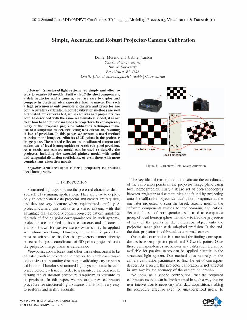
Simple, Accurate, and Robust Projector-Camera Calibration Daniel Moreno and Gabriel Taubin School of Engineering Brown University Providence, RI, USA Email: {daniel moreno,gabriel taubin}@brown.edu Abstract—Structured-light systems are simple and effective tools to acquire 3D models. Built with off-the-shelf components, a data projector and a camera, they are easy to deploy and compare in precision with expensive laser scanners. But such a high precision is only possible if camera and projector are both accurately calibrated. Robust calibration methods are well established for cameras but, while cameras and projectors can both be described with the same mathematical model, it is not clear how to adapt these methods to projectors. In consequence, many of the proposed projector calibration techniques make use of a simplified model, neglecting lens distortion, resulting in loss of precision. In this paper, we present a novel method to estimate the image coordinates of 3D points in the projector image plane. The method relies on an uncalibrated camera and makes use of local homographies to reach sub-pixel precision. As a result, any camera model can be used to describe the projector, including the extended pinhole model with radial and tangential distortion coefficients, or even those with more complex lens distortion models. Keywords-structured-light; camera; projector; calibration; local homography; I. I NTRODUCTION Structured-light systems are the preferred choice for do-it- yourself 3D scanning applications. They are easy to deploy, only an off-the-shelf data projector and camera are required, and they are very accurate when implemented carefully. A projector-camera pair works as a stereo system, with the advantage that a properly chosen projected pattern simplifies the task of finding point correspondences. In such systems, projectors are modeled as inverse cameras and all consid- erations known for passive stereo systems may be applied with almost no change. However, the calibration procedure must be adapted to the fact that projectors cannot directly measure the pixel coordinates of 3D points projected onto the projector image plane as cameras do. Viewpoint, zoom, focus, and other parameters ought to be adjusted, both in projector and camera, to match each target object size and scanning distance; invalidating any previous calibration. Therefore, structured-light systems must be cali- brated before each use in order to guaranteed the best result, turning the calibration procedure simplicity as valuable as its precision. In this paper, we present a new calibration procedure for structured-light systems that is both very easy to perform and highly accurate. Figure 1. Structured-light system calibration The key idea of our method is to estimate the coordinates of the calibration points in the projector image plane using local homographies. First, a dense set of correspondences between projector and camera pixels is found by projecting onto the calibration object identical pattern sequence as the one later projected to scan the target, reusing most of the software components written for the scanning application. Second, the set of correspondences is used to compute a group of local homographies that allow to find the projection of any of the points in the calibration object onto the projector image plane with sub-pixel precision. In the end, the data projector is calibrated as a normal camera. Our main contribution is a method for finding correspon- dences between projector pixels and 3D world points. Once those correspondences are known any calibration technique available for passive stereo can be applied directly to the structured-light system. Our method does not rely on the camera calibration parameters to find the set of correspon- dences. As a result, the projector calibration is not affected in any way by the accuracy of the camera calibration. We show, as a second contribution, that the proposed calibration method can be implemented in such a way that no user intervention is necessary after data acquisition, making the procedure effective even for unexperienced users. To 2012 Second Joint 3DIM/3DPVT Conference: 3D Imaging, Modeling, Processing, Visualization & Transmission 978-0-7695-4873-9/12 $26.00 © 2012 IEEE DOI 10.1109/3DIMPVT.2012.77 464
-
Upload
independent -
Category
Documents
-
view
0 -
download
0
Transcript of Simple, Accurate, and Robust Projector-Camera Calibration
Simple, Accurate, and Robust Projector-Camera Calibration
Daniel Moreno and Gabriel Taubin
School of EngineeringBrown University
Providence, RI, USAEmail: {daniel moreno,gabriel taubin}@brown.edu
Abstract—Structured-light systems are simple and effectivetools to acquire 3D models. Built with off-the-shelf components,a data projector and a camera, they are easy to deploy andcompare in precision with expensive laser scanners. But sucha high precision is only possible if camera and projector areboth accurately calibrated. Robust calibration methods are wellestablished for cameras but, while cameras and projectors canboth be described with the same mathematical model, it is notclear how to adapt these methods to projectors. In consequence,many of the proposed projector calibration techniques makeuse of a simplified model, neglecting lens distortion, resultingin loss of precision. In this paper, we present a novel methodto estimate the image coordinates of 3D points in the projectorimage plane. The method relies on an uncalibrated camera andmakes use of local homographies to reach sub-pixel precision.As a result, any camera model can be used to describe theprojector, including the extended pinhole model with radialand tangential distortion coefficients, or even those with morecomplex lens distortion models.
Keywords-structured-light; camera; projector; calibration;local homography;
I. INTRODUCTION
Structured-light systems are the preferred choice for do-it-
yourself 3D scanning applications. They are easy to deploy,
only an off-the-shelf data projector and camera are required,
and they are very accurate when implemented carefully. A
projector-camera pair works as a stereo system, with the
advantage that a properly chosen projected pattern simplifies
the task of finding point correspondences. In such systems,
projectors are modeled as inverse cameras and all consid-
erations known for passive stereo systems may be applied
with almost no change. However, the calibration procedure
must be adapted to the fact that projectors cannot directly
measure the pixel coordinates of 3D points projected onto
the projector image plane as cameras do.
Viewpoint, zoom, focus, and other parameters ought to be
adjusted, both in projector and camera, to match each target
object size and scanning distance; invalidating any previous
calibration. Therefore, structured-light systems must be cali-
brated before each use in order to guaranteed the best result,
turning the calibration procedure simplicity as valuable as
its precision. In this paper, we present a new calibration
procedure for structured-light systems that is both very easy
to perform and highly accurate.
Figure 1. Structured-light system calibration
The key idea of our method is to estimate the coordinates
of the calibration points in the projector image plane using
local homographies. First, a dense set of correspondences
between projector and camera pixels is found by projecting
onto the calibration object identical pattern sequence as the
one later projected to scan the target, reusing most of the
software components written for the scanning application.
Second, the set of correspondences is used to compute a
group of local homographies that allow to find the projection
of any of the points in the calibration object onto the
projector image plane with sub-pixel precision. In the end,
the data projector is calibrated as a normal camera.
Our main contribution is a method for finding correspon-
dences between projector pixels and 3D world points. Once
those correspondences are known any calibration technique
available for passive stereo can be applied directly to the
structured-light system. Our method does not rely on the
camera calibration parameters to find the set of correspon-
dences. As a result, the projector calibration is not affected
in any way by the accuracy of the camera calibration.
We show, as a second contribution, that the proposed
calibration method can be implemented in such a way that no
user intervention is necessary after data acquisition, making
the procedure effective even for unexperienced users. To
2012 Second Joint 3DIM/3DPVT Conference: 3D Imaging, Modeling, Processing, Visualization & Transmission
978-0-7695-4873-9/12 $26.00 © 2012 IEEE
DOI 10.1109/3DIMPVT.2012.77
464

this purpose, we have made a calibration software package,
which we plan to make publicly available for anyone inter-
ested in structured-light applications to try. Concisely, our
software requires two actions:
1) Project a sequence of gray code patterns onto a
static planar checkerboard placed within the working
volume. Capture one image for each pattern and store
them all in the same directory. Repeat this step for
several checkerboard poses until properly cover all
the working volume. Use a separate directory for each
sequence.
2) Execute the calibration software and select the direc-
tory containing all the sequences. Enter the checker-
board dimensions. Click on “Calibrate” button. The
software will automatically decode all the sequences,
find corner locations, and calibrate both projector and
camera. The final calibration will be saved to a file for
later use.
A. Related Work
Many projector calibration procedures exist, however,
we have not found any satisfying the following two key
properties: easy-to-perform for the common user and high
precision to enable accurate 3D reconstructions. Several
methods ([1], [2], [3], [4], [5], and [6]) use a pre-calibrated
camera to find world coordinates in some calibration artifact,
which in turn they use to assign projector correspondences.
These methods might be simple to perform, but all of them
lack of accuracy in the projector parameters due to their
dependence on the camera calibration. The inaccuracies are
a direct consequence of their approach: even small camera
calibration errors could result into large world coordinate
errors. Their failure point is to estimate the projector pa-
rameters from those, far from accurate, world coordinates
decreasing the complete system precision.
A different approach is adopted in [7], [8], and [9] where,
neither a calibrated camera, nor a printed pattern is required.
Instead, they ask the user to move the projector to several
locations so that the calibration pattern—projected onto a
fix plane—changes its shape. We argue that moving the
projector might be inconvenient, or impossible in general
(e.g. a system mounted on a rig). Moreover, these methods
are not applicable if a metric reconstruction is mandatory
because their result is only up-to-scale.
Other authors have proposed algorithms ([10], [11], [12],
and [13]) where a projected pattern is iteratively adjusted
until they overlap a printed pattern. The overlap is measured
with help of an uncalibrated camera. Since both patterns
must be clearly identified, the classic black and white pattern
is replaced by color versions of it—a color camera is also
mandatory. In practice, switching to color patterns make
color calibration unavoidable—printed and camera colors
seldom match—imposing an extra requirement to the user.
Besides, this calibration scheme demands continuous input
from a camera to run, rendering impossible to separate the
capture stage from the calibration algorithm, which is a
common and useful practice in the field.
A common practice among projector calibration methods
([3], [7], [8], [10], and [12]) is to find one homography
transformation between a calibration plane and the projector
image plane. Despite the elegance of the concept, being
homographies linear operators, they cannot model non-linear
distortions as the ones introduced by projector lenses.
In [14], the authors claim to get very accurate results
with their method that involves projecting patterns on a
“flat aluminum board mounted on a high precision moving
mechanism”. Our complain is that such a special equipment
is not available to the common user, limiting its general
applicability. We disregard this method as non-practical.
Finally, Zhang and Huang [15], and others ([7], [16])
employ structured-light patterns similarly to us, however, in-
stead of computing projector point correspondences directly
from the images as captured by the camera, they create
new synthetic images from the projector’s viewpoint and
feed them to standard camera calibration tools. The inter-
mediate step of creating synthetic images at the projector’s
resolution, usually low, might discard important information
being undesirable. On the contrary, the method we propose
finds projector point correspondences from structured-light
patterns directly at the camera resolution. No synthetic
projector image is created.
The rest of the paper is organized as follows: Section II
explains the calibration method, Section III expands the
previous section with implementation details, Section IV
discusses the experiments done to verify the precision of
the method and presents a comparison with other calibration
software, finally Section V concludes our work.
II. METHOD
Our setup comprises one projector and one camera be-
having as a stereo pair. We describe them both using the
pinhole model extended with radial and tangential distortion,
an advantage over several methods ([3], [5], [6], [7], [8],
[9], and [12]), which fail to compensate for distortions
in the projected patterns. Moreover, we have seen in our
experiments that most projectors have noticeable distortions
outside their focus plane, distortions that affects the accuracy
of the final 3D models.
We took Zhang’s method [17] as inspiration in favor of
its simplicity and well-known accuracy. It uses a planar
checkerboard as calibration artifact, which is easy-to-make
for anyone with access to a printer. In Zhang’s camera
calibration, the user captures images of a checkerboard
of known dimensions at several orientations and the al-
gorithm calculates the camera calibration parameters using
the relation between the checkerboard corners in a camera
coordinate system and a world coordinate system attached
to the checkerboard plane.
465
A. Projector and camera models
The proposed calibration method allows to choose any
parametric model to describe the projector and camera. Our
implementation uses the pinhole model extended with radial
and tangential distortion for both projector and camera. Let
be X ∈ R3 a point in a world coordinate system with origin
at the camera center, and let u ∈ R2 the pixel coordinates
of the image of X in the camera plane, then X and u are
related by the following equations:
X =
⎡⎣ x
yz
⎤⎦ , u =
[ux
uy
]=
[x/zy/z
](1)
u = Kc · L(u) (2)
Kc =
⎡⎣ fx γ ox
0 fy oy0 0 1
⎤⎦ (3)
L(u) =
[u · (1 + k1r
2 + k2r4) + Δt(u)
1
](4)
Δt(u) =
[2k3uxuy + k4(r
2 + 2u2x)
k3(r2 + 2u2
y) + 2k4uxuy
](5)
r2 = u2x + u2
y (6)
where Kc is known as camera intrinsic calibration, k1 and k2as radial distortion coefficients, and k3 and k4 as tangential
distortion coefficients. Similarly, if R and T are a rotation
matrix and a translation vector that encode the pose of
the projector’s center of projection in the world coordinate
system defined above, and let v ∈ R2 the pixel coordinates
of the image of X in the projector plane, then
X ′ =
⎡⎣ x′
y′
z′
⎤⎦ = R ·X + T, v =
[x′/z′
y′/z′
](7)
v = Kp · L(v) (8)
where the projector is described by its intrinsic calibra-
tion Kp, and the pair (R, T ) is known as the stereo system
extrinsic calibration.
B. Data acquisition
Camera calibration involves collecting images of a planar
checkerboard. We have modified this acquisition step to
make possible to calibrate both camera and projector. The
new data acquisition is: for each plane orientation, instead
of capturing only one image, the user must project and cap-
ture a complete structured-light pattern sequence. Although
any structured-light pattern sequence would work, we have
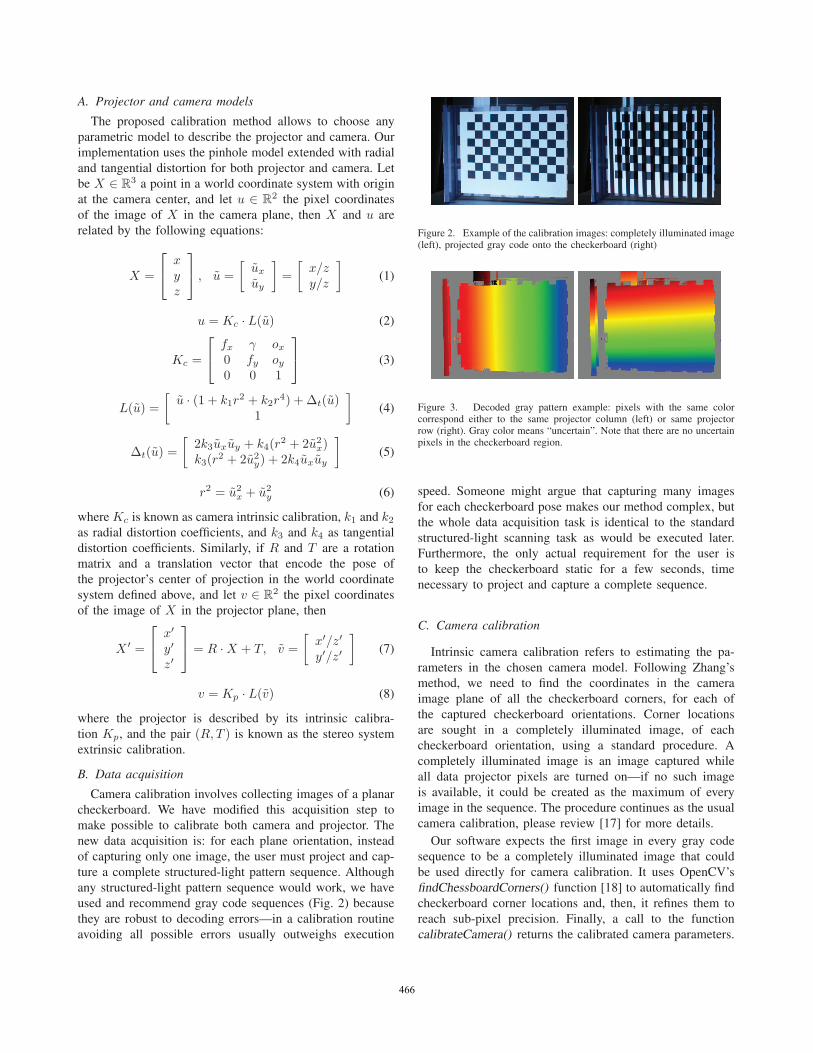
used and recommend gray code sequences (Fig. 2) because
they are robust to decoding errors—in a calibration routine
avoiding all possible errors usually outweighs execution
Figure 2. Example of the calibration images: completely illuminated image(left), projected gray code onto the checkerboard (right)
Figure 3. Decoded gray pattern example: pixels with the same colorcorrespond either to the same projector column (left) or same projectorrow (right). Gray color means “uncertain”. Note that there are no uncertainpixels in the checkerboard region.
speed. Someone might argue that capturing many images
for each checkerboard pose makes our method complex, but
the whole data acquisition task is identical to the standard
structured-light scanning task as would be executed later.
Furthermore, the only actual requirement for the user is
to keep the checkerboard static for a few seconds, time
necessary to project and capture a complete sequence.
C. Camera calibration
Intrinsic camera calibration refers to estimating the pa-
rameters in the chosen camera model. Following Zhang’s
method, we need to find the coordinates in the camera
image plane of all the checkerboard corners, for each of
the captured checkerboard orientations. Corner locations
are sought in a completely illuminated image, of each
checkerboard orientation, using a standard procedure. A
completely illuminated image is an image captured while
all data projector pixels are turned on—if no such image
is available, it could be created as the maximum of every
image in the sequence. The procedure continues as the usual
camera calibration, please review [17] for more details.
Our software expects the first image in every gray code
sequence to be a completely illuminated image that could
be used directly for camera calibration. It uses OpenCV’s
findChessboardCorners() function [18] to automatically find
checkerboard corner locations and, then, it refines them to
reach sub-pixel precision. Finally, a call to the function
calibrateCamera() returns the calibrated camera parameters.
466
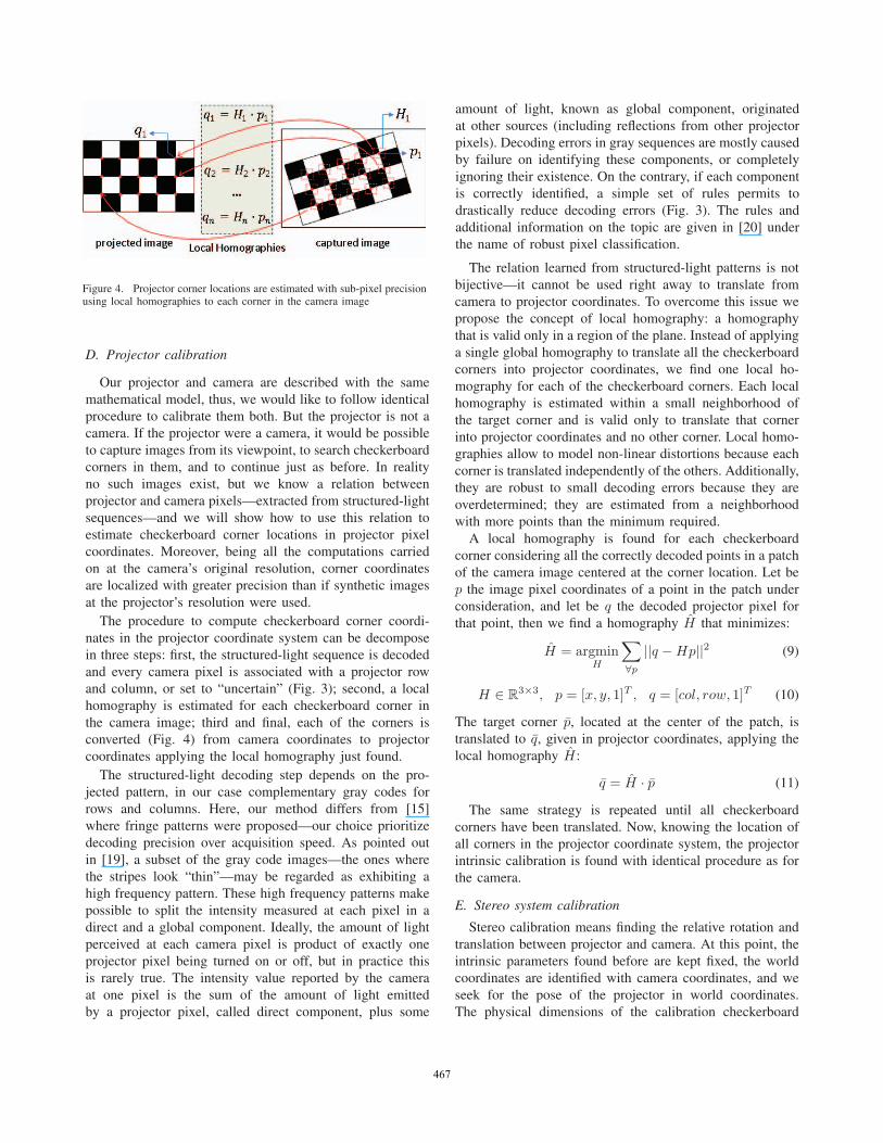
Figure 4. Projector corner locations are estimated with sub-pixel precisionusing local homographies to each corner in the camera image
D. Projector calibration
Our projector and camera are described with the same
mathematical model, thus, we would like to follow identical
procedure to calibrate them both. But the projector is not a
camera. If the projector were a camera, it would be possible
to capture images from its viewpoint, to search checkerboard
corners in them, and to continue just as before. In reality
no such images exist, but we know a relation between
projector and camera pixels—extracted from structured-light
sequences—and we will show how to use this relation to
estimate checkerboard corner locations in projector pixel
coordinates. Moreover, being all the computations carried
on at the camera’s original resolution, corner coordinates
are localized with greater precision than if synthetic images
at the projector’s resolution were used.
The procedure to compute checkerboard corner coordi-
nates in the projector coordinate system can be decompose
in three steps: first, the structured-light sequence is decoded
and every camera pixel is associated with a projector row
and column, or set to “uncertain” (Fig. 3); second, a local
homography is estimated for each checkerboard corner in
the camera image; third and final, each of the corners is
converted (Fig. 4) from camera coordinates to projector
coordinates applying the local homography just found.
The structured-light decoding step depends on the pro-
jected pattern, in our case complementary gray codes for
rows and columns. Here, our method differs from [15]
where fringe patterns were proposed—our choice prioritize
decoding precision over acquisition speed. As pointed out
in [19], a subset of the gray code images—the ones where
the stripes look “thin”—may be regarded as exhibiting a
high frequency pattern. These high frequency patterns make
possible to split the intensity measured at each pixel in a
direct and a global component. Ideally, the amount of light
perceived at each camera pixel is product of exactly one
projector pixel being turned on or off, but in practice this
is rarely true. The intensity value reported by the camera
at one pixel is the sum of the amount of light emitted
by a projector pixel, called direct component, plus some
amount of light, known as global component, originated
at other sources (including reflections from other projector
pixels). Decoding errors in gray sequences are mostly caused
by failure on identifying these components, or completely
ignoring their existence. On the contrary, if each component
is correctly identified, a simple set of rules permits to
drastically reduce decoding errors (Fig. 3). The rules and
additional information on the topic are given in [20] under
the name of robust pixel classification.
The relation learned from structured-light patterns is not
bijective—it cannot be used right away to translate from
camera to projector coordinates. To overcome this issue we
propose the concept of local homography: a homography
that is valid only in a region of the plane. Instead of applying
a single global homography to translate all the checkerboard
corners into projector coordinates, we find one local ho-
mography for each of the checkerboard corners. Each local
homography is estimated within a small neighborhood of
the target corner and is valid only to translate that corner
into projector coordinates and no other corner. Local homo-
graphies allow to model non-linear distortions because each
corner is translated independently of the others. Additionally,
they are robust to small decoding errors because they are
overdetermined; they are estimated from a neighborhood
with more points than the minimum required.
A local homography is found for each checkerboard
corner considering all the correctly decoded points in a patch
of the camera image centered at the corner location. Let be
p the image pixel coordinates of a point in the patch under
consideration, and let be q the decoded projector pixel for
that point, then we find a homography H that minimizes:
H = argminH
∑∀p||q −Hp||2 (9)
H ∈ R3×3, p = [x, y, 1]T , q = [col, row, 1]T (10)
The target corner p, located at the center of the patch, is
translated to q, given in projector coordinates, applying the
local homography H:
q = H · p (11)
The same strategy is repeated until all checkerboard
corners have been translated. Now, knowing the location of
all corners in the projector coordinate system, the projector
intrinsic calibration is found with identical procedure as for
the camera.
E. Stereo system calibration
Stereo calibration means finding the relative rotation and
translation between projector and camera. At this point, the
intrinsic parameters found before are kept fixed, the world
coordinates are identified with camera coordinates, and we
seek for the pose of the projector in world coordinates.
The physical dimensions of the calibration checkerboard
467
are known. The checkerboard corner projections onto both
camera and projector image planes are also known—they
were found in the previous steps. The calibration of the
projector-camera stereo system, therefore, is identical to the
calibration of any other camera-camera system.
Our software calls OpenCV’s stereoCalibrate() function
with the previously found checkerboard corner coordinates
and their projections, the output is a rotation matrix R and
a translation vector T relating the projector-camera pair.
F. Algorithm
The complete calibration procedure can be summarized
in simple steps and implemented as a calibration algorithm:
1) Detect checkerboard corner locations for each plane
orientation in the completely illuminated images.
2) Estimate global and direct light components for each
set using gray code high frequency patterns.
3) Decode structured-light patterns into projector row
and column correspondences by means of robust pixel
classification, considering pixel global and direct com-
ponents from step 2.
4) Take small image patches centered at the checkerboard
corner coordinates from step 1 (e.g. a 47x47 pixels
square) and use all the correctly decoded pixels in
each patch to compute a local homography that con-
verts from camera to projector coordinates. Correspon-
dences were obtained in step 3.
5) Translate corner locations (step 1) from camera to
projector coordinates using patch local homographies
from step 4.
6) Fix a world coordinate system to the checkerboard
plane and use Zhang’s method to find camera intrinsics
using camera corner locations from step 1.
7) Fix a world coordinate system to the checkerboard
plane and use Zhang’s method to find projector intrin-
sics using projector corner locations from step 5.
8) Fix camera and projector intrinsics (steps 6 and 7)
and use world, camera, and projector corner locations
(steps 1 and 5) to estimate stereo extrinsic parameters.
9) Optionally, all the parameters, intrinsic and extrinsic,
can be bundle-adjusted together to minimize the total
reprojection error.
III. CALIBRATION SOFTWARE
We have implemented the algorithm in Section II-F into
a complete structured-light system calibration software. The
purpose is two-fold: first, to prove that our method can be
executed fully automatic provided the calibration images are
available; second, to facilitate the access to high quality 3D
scans for a broad range of users—we think that structured-
light systems are the key. Our experience says that cali-
brating structured-light systems accurately is a cumbersome
and time consuming task. In hopes of ease the task, we have
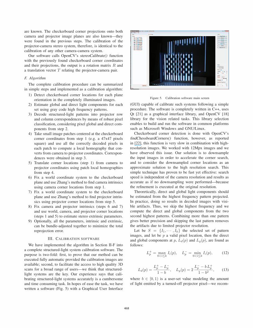
written a software (Fig. 5) with a Graphical User Interface
Figure 5. Calibration software main screen
(GUI) capable of calibrate such systems following a simple
procedure. The software is completely written in C++, uses
Qt [21] as a graphical interface library, and OpenCV [18]
library for the vision related tasks. This library selection
enables to build and run the software in common platforms
such as Microsoft Windows and GNU/Linux.
Checkerboard corner detection is done with OpenCV’s
findChessboardCorners() function, however, as reported
in [22], this function is very slow in combination with high-
resolution images. We worked with 12Mpx images and we
have observed this issue. Our solution is to downsample
the input images in order to accelerate the corner search,
and to consider the downsampled corner locations as an
approximate solution to the high resolution search. This
simple technique has proven to be fast yet effective: search
speed is independent of the camera resolution and results as
accurate as if no downsampling were performed—because
the refinement is executed at the original resolution.
Theoretically, direct and global light components should
be estimated from the highest frequency pattern projected.
In practice, doing so results in decoded images with visi-
ble artifacts. Thus, we skip the highest frequency and we
compute the direct and global components from the two
second highest patterns. Combining more than one pattern
gives better precision and skipping the last pattern removes
the artifacts due to limited projector resolution.
Let be S = {I1, · · · , Ik} the selected set of pattern
images, and let be p a valid pixel location, then the direct
and global components at p, Ld(p) and Lg(p), are found as
follows:
L+p = max
0<i≤kIi(p), L−p = min
0<i≤kIi(p), (12)
Ld(p) =L+p − L−p1− b
, Lg(p) = 2L−p − b L+
p
1− b2, (13)
where b ∈ [0, 1) is a user-set value modeling the amount
of light emitted by a turned-off projector pixel—we recom-
468
mend the reader to study [19] for more details. We have
set b = 0.3 in our setup.
Finally, local homographies are estimated from fix size
image patches; we have, therefore, to select a proper patch
size for them. If the chosen size is too small, the algorithm
becomes very sensitive to decoding errors. On the contrary,
if the patch is too large, the algorithm is robust to errors, but
unable to cope with strong lens distortions. Experimentally,
we have found a patch size of 47x47 pixels to perform well
in our system; we have used this value in all our tests.
Nevertheless, a more rigorous analysis is required to decide
the optimum size given the system parameters.
IV. RESULTS
We have developed this calibration method to enable high
precision 3D scanning. In consequence, we think the best
calibration quality evaluation is to scan objects of known
geometry and to compare their 3D models with ground
truth data. Additionally, we think that an evaluation would
not be complete without a comparison with other avail-
able calibration methods. We have searched and found that
Samuel Audet’s ProCamCalib [10] and Projector-Camera
Calibration Toolbox (also procamcalib) [1] are publicly
available tools. We have tried both, but Audet’s tool current
version cannot be used with our camera, for that reason, we
will compare our method with Projector-Camera Calibration
Toolbox [1] only, from now on just “procamcalib”.
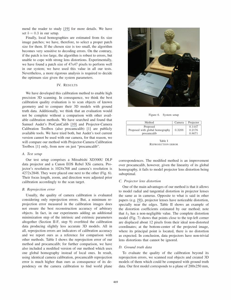
A. Test setup
Our test setup comprises a Mitsubishi XD300U DLP
data projector and a Canon EOS Rebel XSi camera. Pro-
jector’s resolution is 1024x768 and camera’s resolution is
4272x2848. They were placed one next to the other (Fig. 6).
Their focus length, zoom, and direction were adjusted prior
calibration accordingly to the scan target.
B. Reprojection error
Usually, the quality of camera calibration is evaluated
considering only reprojection errors. But, a minimum re-
projection error measured in the calibration images does
not ensure the best reconstruction accuracy of arbitrary
objects. In fact, in our experiments adding an additional
minimization step of the intrinsic and extrinsic parameters
altogether (Section II-F, step 9) overfitted the calibration
data producing slightly less accurate 3D models. All in
all, reprojection errors are indicators of calibration accuracy
and we report ours as a reference for comparison with
other methods. Table I shows the reprojection error of our
method and procamcalib; for further comparison, we have
also included a modified version of our method which uses
one global homography instead of local ones. In result,
using identical camera calibration, procamcalib reprojection
error is much higher than ours as consequence of its de-
pendency on the camera calibration to find world plane
Figure 6. System setup
Method Camera Projector
Proposed0.3288
0.1447Proposed with global homography 0.2176
procamcalib 0.8671
Table IREPROJECTION ERROR
correspondences. The modified method is an improvement
over procamcalib, however, given the linearity of its global
homography, it fails to model projector lens distortion being
suboptimal.
C. Projector lens distortion
One of the main advantages of our method is that it allows
to model radial and tangential distortion in projector lenses
the same as in cameras. Opposite to what is said in other
papers (e.g. [9]), projector lenses have noticeable distortion,
specially near the edges. Table II shows an example of
the distortion coefficients estimated by our method; note
that k2 has a non-negligible value. The complete distortion
model (Fig. 7) shows that points close to the top-left corner
are displaced about 12 pixels from their ideal non-distorted
coordinates; at the bottom-center of the projected image,
where its principal point is located, there is no distortion
as expected. In conclusion, data projectors have non-trivial
lens distortions that cannot be ignored.
D. Ground truth data
To evaluate the quality of the calibration beyond its
reprojection errors, we scanned real objects and created 3D
models of them which could be compared with ground truth
data. Our first model corresponds to a plane of 200x250 mm,
469

k1 k2 k3 k4
-0.0888 0.3365 -0.0126 -0.0023
Table IIPROJECTOR DISTORTION COEFFICIENTS: k1 AND k2 RADIAL
DISTORTION, k3 AND k4 TANGENTIAL DISTORTION
Figure 7. Projector distortion model: points are displaced about 12 pixelsnear the top-left corner
for which we created one 3D model with each of both
calibrations in the previous section. The ground truth data
for these models are points sampled from an ideal plane.
The error distribution of the model reconstructed with our
calibration (Fig. 8 top) resembles a Gaussian distribution
where 95% of its samples are errors equal or less than
0.33 mm. On the other hand, the reconstruction made with
procamcalib’s calibration (Fig. 8 bottom) has an irregular
error distribution denoting calibration inaccuracy. The results
are summarized in Table III.
Our next model is a statue head scanned both with our
structured-light system and with a commercial laser scanner.
The laser scanner is a NextEngine Desktop Scanner 2020i.
Both 3D models are compared with the Hausdorff distance
and the result is shown as an image (Fig. 9). The color
scale denotes the distance between both meshes ranging
from 0 to 1 mm. The error reaches its maximum only in
Method Max. Error Mean Error Std. Dev.
Proposed 0.8546 0.000042 0.1821procamcalib 1.6352 0.000105 0.2909
Table IIIIDEAL AND RECONSTRUCTED PLANE COMPARISON
Figure 8. Plane error histogram: error between an ideal plane and a scannedplane recontructed using the proposed calibration (top) and procamcalibcalibration (bottom)
Figure 9. Structured-light versus laser scanner: Hausdorff distance betweenmeshes from 0mm to 1mm
regions that were in shadow during scanning. In the face
region the error is 0.5 mm at most.
Finally, we scanned a statue from six different viewpoints
and, after manual alignment and merging, we created a
complete 3D model using Smooth Signed Distance (SSD)
surface reconstruction ([23], [24]). The final mesh preserves
(Fig. 10) even small details.
V. CONCLUSION
We have introduced a new method to calibrate projector-
camera systems that is simple to implement and more
accurate than previous methods because it uses a full pinhole
model—including radial and tangential lens distortions—to
describe both projector and camera behaviors and computes
sub-pixel resolution 3D point projections from uncalibrated
470
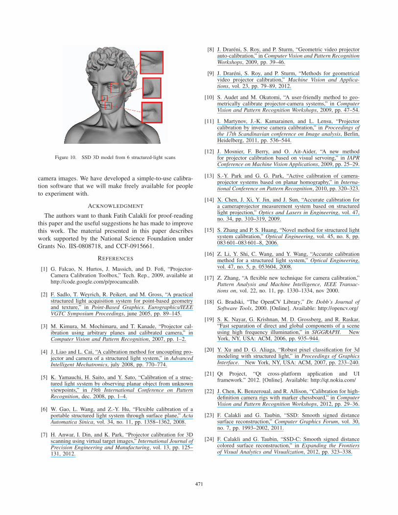
Figure 10. SSD 3D model from 6 structured-light scans
camera images. We have developed a simple-to-use calibra-
tion software that we will make freely available for people
to experiment with.
ACKNOWLEDGMENT
The authors want to thank Fatih Calakli for proof-reading
this paper and the useful suggestions he has made to improve
this work. The material presented in this paper describes
work supported by the National Science Foundation under
Grants No. IIS-0808718, and CCF-0915661.
REFERENCES
[1] G. Falcao, N. Hurtos, J. Massich, and D. Fofi, “Projector-Camera Calibration Toolbox,” Tech. Rep., 2009, available athttp://code.google.com/p/procamcalib.
[2] F. Sadlo, T. Weyrich, R. Peikert, and M. Gross, “A practicalstructured light acquisition system for point-based geometryand texture,” in Point-Based Graphics. Eurographics/IEEEVGTC Symposium Proceedings, june 2005, pp. 89–145.
[3] M. Kimura, M. Mochimaru, and T. Kanade, “Projector cal-ibration using arbitrary planes and calibrated camera,” inComputer Vision and Pattern Recognition, 2007, pp. 1–2.
[4] J. Liao and L. Cai, “A calibration method for uncoupling pro-jector and camera of a structured light system,” in AdvancedIntelligent Mechatronics, july 2008, pp. 770–774.
[5] K. Yamauchi, H. Saito, and Y. Sato, “Calibration of a struc-tured light system by observing planar object from unknownviewpoints,” in 19th International Conference on PatternRecognition, dec. 2008, pp. 1–4.
[6] W. Gao, L. Wang, and Z.-Y. Hu, “Flexible calibration of aportable structured light system through surface plane,” ActaAutomatica Sinica, vol. 34, no. 11, pp. 1358–1362, 2008.
[7] H. Anwar, I. Din, and K. Park, “Projector calibration for 3Dscanning using virtual target images,” International Journal ofPrecision Engineering and Manufacturing, vol. 13, pp. 125–131, 2012.
[8] J. Drareni, S. Roy, and P. Sturm, “Geometric video projectorauto-calibration,” in Computer Vision and Pattern RecognitionWorkshops, 2009, pp. 39–46.
[9] J. Drareni, S. Roy, and P. Sturm, “Methods for geometricalvideo projector calibration,” Machine Vision and Applica-tions, vol. 23, pp. 79–89, 2012.
[10] S. Audet and M. Okutomi, “A user-friendly method to geo-metrically calibrate projector-camera systems,” in ComputerVision and Pattern Recognition Workshops, 2009, pp. 47–54.
[11] I. Martynov, J.-K. Kamarainen, and L. Lensu, “Projectorcalibration by inverse camera calibration,” in Proceedings ofthe 17th Scandinavian conference on Image analysis, Berlin,Heidelberg, 2011, pp. 536–544.
[12] J. Mosnier, F. Berry, and O. Ait-Aider, “A new methodfor projector calibration based on visual servoing,” in IAPRConference on Machine Vision Applications, 2009, pp. 25–29.
[13] S.-Y. Park and G. G. Park, “Active calibration of camera-projector systems based on planar homography,” in Interna-tional Conference on Pattern Recognition, 2010, pp. 320–323.
[14] X. Chen, J. Xi, Y. Jin, and J. Sun, “Accurate calibration fora cameraprojector measurement system based on structuredlight projection,” Optics and Lasers in Engineering, vol. 47,no. 34, pp. 310–319, 2009.
[15] S. Zhang and P. S. Huang, “Novel method for structured lightsystem calibration,” Optical Engineering, vol. 45, no. 8, pp.083 601–083 601–8, 2006.
[16] Z. Li, Y. Shi, C. Wang, and Y. Wang, “Accurate calibrationmethod for a structured light system,” Optical Engineering,vol. 47, no. 5, p. 053604, 2008.
[17] Z. Zhang, “A flexible new technique for camera calibration,”Pattern Analysis and Machine Intelligence, IEEE Transac-tions on, vol. 22, no. 11, pp. 1330–1334, nov 2000.
[18] G. Bradski, “The OpenCV Library,” Dr. Dobb’s Journal ofSoftware Tools, 2000. [Online]. Available: http://opencv.org/
[19] S. K. Nayar, G. Krishnan, M. D. Grossberg, and R. Raskar,“Fast separation of direct and global components of a sceneusing high frequency illumination,” in SIGGRAPH. NewYork, NY, USA: ACM, 2006, pp. 935–944.
[20] Y. Xu and D. G. Aliaga, “Robust pixel classification for 3dmodeling with structured light,” in Proceedings of GraphicsInterface. New York, NY, USA: ACM, 2007, pp. 233–240.
[21] Qt Project, “Qt cross-platform application and UIframework.” 2012. [Online]. Available: http://qt.nokia.com/
[22] J. Chen, K. Benzeroual, and R. Allison, “Calibration for high-definition camera rigs with marker chessboard,” in ComputerVision and Pattern Recognition Workshops, 2012, pp. 29–36.
[23] F. Calakli and G. Taubin, “SSD: Smooth signed distancesurface reconstruction,” Computer Graphics Forum, vol. 30,no. 7, pp. 1993–2002, 2011.
[24] F. Calakli and G. Taubin, “SSD-C: Smooth signed distancecolored surface reconstruction,” in Expanding the Frontiersof Visual Analytics and Visualization, 2012, pp. 323–338.
471