![_P8LPI]P ;LP;LP;LP 5ZL1F DF8[ - WordPress.com](https://static.fdokumen.com/doc/165x107/631d1be4b8a98572c10d3520/p8lpip-lplplp-5zl1f-df8-wordpresscom.jpg)
Projector LP-WU6600 / LP-WU6700 User's Manual
98
Projector LP-WU6600 / LP-WU6700 User's Manual Thank you for purchasing this product. Please read this manual before you operate your projector. Save it for future reference.
-
Upload
khangminh22 -
Category
Documents
-
view
1 -
download
0
Transcript of Projector LP-WU6600 / LP-WU6700 User's Manual
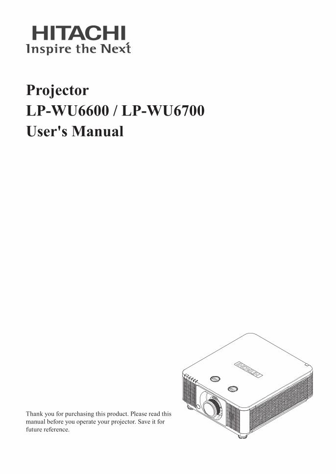
ProjectorLP-WU6600 / LP-WU6700User's Manual
Thank you for purchasing this product. Please read this manual before you operate your projector. Save it for future reference.

2
INDEXWarning, Notices and Safety Instructions 4
Projector parts and functions 18
Front view 18LED Indicator 18
Rear view 19Projector keypad 19
I/O Control (Input / Output) 20
Bottom view 21
Remote control 22
Range of effective remote control signal reception 24Installing batteries in the remote control 24
Projector installation 26
Installing or removing the optional lens 26Installing the new lens 26
Removing the existing lens from the projector 27
Throw distance 28Modes of installation 28
Projection 28
Horizontal and vertical lens shift 30Lens shift 30
Moving the lens vertically 32
Moving the lens horizontally 32
Connecting the projector 33HDMI / MHL / DVI connection 33
RGB connection 34
HDBaseT connection 36
12V Trigger connection 37
RJ45 connection 37
USB POWER (5V/1.5A) connection 38
3D SYNC (5V) connection 38
VIDEO connection 39
SERVICE connection 39
RS232C connection 40
Audio IN (L/R) connection 40
Audio OUT (L/R) connection 41
Audio IN (Mini jack) connection 41
WIRE REMOTE connection 42
Powering the projector on or off 43Powering on the projector 43
Connect the power cord to the projector 43
Turning off the projector 43
Selecting an input source 44Setting an access password (security lock) 45Choosing a location 47
Adjusting the projector's angle 48Adjusting the projector’s zoom and focus 48
Zoom 48
Focus 49
Correcting keystone 49
OSD menu tree 50
OSD description 54
Image 54Display Mode 54
Brightness 55
Contrast 55
Computer 56
Auto Image 57
Advanced 57
Color Manager 59
Settings 1 60Source 60
Projection 60
Aspect Ratio 61
Keystone 61
Digital Zoom 61
Audio 61
Advanced 1 62
Advanced 2 63
4 Corner 63
Settings 2 64Auto Source 64
No Signal Power Off 64
Auto Power On 64
Light Mode 64
Reset All 65
Status 65
Advanced 1 65
Advanced 2 74
Custom Light 74
Cleaning 75
Cleaning the cabinet 75Cleaning the lens 75
Using the Kensington® lock 76
Simple troubleshooting 77
LED status 78
3
Specifications 80
Specifications 80Supported signal input modes 813D timing format 82Dimensions 83
Communication settings 84
RS-232 communication 84Connection 84
Command control via the network 86Connection 86
Communication port 86
Command control settings 87
Communication command table 87PJLink command 94
Copyright information 96Copyright 96
Trademark 96
Warranty and after-service 96

Warning, Notices and Safety Instructions
4
Warning, Notices and Safety InstructionsNoticeThis product is intended for the adults who have the ability to operate this machine.
Please write down your projector model number and serial number and keep the information for maintenance purposes in the future. Should the equipment be lost or stolen, the information could also be used for the police report.Model number:Serial number:
Please check the accessories that come with the projector with the following list. Should you find any missing accessory, contact your dealer immediately.
1. AC Power Cord US 125V 4. Remote control 7. Printed Manual 10. WEEE Manual 2. AC Power Cord EU 5. AAA battery 2pcs 8. EAC Document 11. 3D Sync cable 2pcs3. Wire Remote Cable 6. CD-ROM 9. EU Recycle Sheet 12. RGB cable
Do not open
CAUTION
RISK OF ELECTRIC SHOCKDO NOT OPEN
The lightning flash with an arrowhead within a triangleis intended to tell the user that inside this productmay cause risk of electrical shock to persons.
The exclamation point within a triangle is intended to tellthe user that important operating and/or servicing instructionsare included in the technical documentation for this equipment.
CAUTION / TO REDUCE THE RISK OF ELECTRIC SHOCKDO NOT REMOVE COVER(OR BACK)
NO USER-SERVICEABLE PARTS INSIDEREFER SERVICING TO QUALIFIED SERVICE PERSONNEL
This is a Class A product. In a domestic environment this product may cause radio interference in which case the user may be required to take adequate measures.
Description pertaining to FCC Rules Part 15This device complies with Part 15 of the FCC Rules. Operation is subject to the following two conditions: (1) this device may not cause harmful interference, and (2) this device must accept any interference received, including interference that may cause undesired operation.
This device has been tested and found to comply with the limits for a Class A digital device, pursuant to Part 15 of the FCC Rules. These limits are designed to provide reasonable protection against harmful interference in a residential installation.This equipment generates, uses and can radiate radio frequency energy. If not installed and used in accordance with the instructions, may cause harmful interference to radio or television reception. However, there is no guarantee that interference will not occur in a particular installation. If this equipment does cause interference to radio or television reception, which can be determined by turning the equipment off and on, the user is encouraged to try to correct the interference by one or the following measures:
• Reorient or relocate the receiving antenna.• Increase the separation between the equipment and receiver.

Warning, Notices and Safety Instructions
5
• Connect the equipment into an outlet on a circuit different from that to which the receiver is connected.
• Consult the dealer or an experienced radio/TV technician for help.Caution: Changes or modifications not expressly approved by the manufacturer void the user’s
authority to operate the equipment.
This Class A digital apparatus meets all requirements of the Canadian ICES-003 Standards.Cet appareil numérique de la classe A est conforme à la norme NMB-003 du Canada.
Information for users applicable in European Union countriesInformation for users applicable in European Union countries
This symbol on the product or on its packaging means that your electrical and electronic equipment should be disposed at the end of life separately from your household wastes. There are separate collection systems for recycling in EU.For more information, please contact the local authority or the dealer where you purchased the product.
About Waste Electrical and Electronic Equipment
The mark is in compliance with the Waste Electrical and Electronic Equipment Directive 2002/96/EC (WEEE).The mark indicates the requirement NOT to dispose the equipment including any spent or discarded batteries or accumulators as unsorted municipal waste, but use the return and collection systems available. If the batteries or accumulators included with this equipment, display the chemical symbol Hg, Cd, or Pb, then it means that the battery has a heavy metal content of more than 0.0005% Mercury or more than, 0.002% Cadmium, or more than 0.004% Lead.
Sun light WarningAvoid using this projector in direct sun light.Sun light on the projector lens can severely damage the Digital Mirror Devices (DMD™).
Never look into the projector light source directlyWhen turn on the projector, make sure nobody's eye will effects by the projection of light. Always avoid to let eyes contact to the light.As with any bright source, do not stare into the direct beam, RG2 IEC 62471-5:2015.
Electric shockTo protect your projector, avoid turning on the projector during lightning storms and unplug it from the wall outlet. This will prevent sudden electrical surges caused by the lightning from damaging the projector.
Warning, Notices and Safety Instructions
6
Do not overload wall outlets/extension cordsPay attention to the current load of the outlet you are using, be it wall outlet or extension cord outlet to prevent fire or electric shock.
CleaningWhen cleaning the projector, be sure to unplug it from the wall outlet to prevent electric shock.Do not use liquid or aerosol cleaners. Use a dry/damp cloth with excessive moisture removed for cleaning. Be sure to use cleaning cloth designed to clean monitors for the projector to prevent damages to the projector casing due to abrasion.
Dampness, smoke, steam, dust, high temperature and direct exposure to sunlightDo not operate the projector in environments where it could be expose to dampness, smoke, steam, dust, high temperature or direct sunlight. For example: bathroom, kitchen, adjacent to washing machine, damp basement rooms, electric heaters or similar environments. Keeping or operating the projector in the above-mentioned environment could lead to discoloration, mold formation, grease or damages to the projector.
VentilationThe projector case is designed with slots and openings to remove the heat inside the projector so that it will not overheat and damage the components. Be sure to operate the projector in an environment with ideal ventilation and don't operate it on a sofa, rug or other closed-in environments that could obstruct ventilation.
Intrusion of foreign objectsBe sure to keep all foreign objects away from entering the projector because it could be exposed to hazardous voltages and cause parts to short circuit. This could in turn lead to fire hazard or electric shock. Examples of foreign objects include: cockroach, screws, liquid and so forth.In addition, never spill liquid into the projector.
CoolingfluidWhen the projector is damaged, cooling fluid may come out of internal radiator or the tank. Never touch and drink it. When the fluid are swallowed or contacted with your eyes, Please have doctor's medical examination immediately.
Carrying the projector
The projector net weight is 23kg (not include lens). When moving the projector on a cart, be sure to handle the cart with care as abrupt stops, jolts of excessive force or uneven ground could lead the projector to topple.

Warning, Notices and Safety Instructions
7
Please install the projector on an even and stable surfaceAvoid placing the projector on unstable cart, tripod, table and so forth to prevent the projector from falling, becoming damaged or causing injuries.
ServicingShould you encounter problem with the projector, please seek assistance from your local dealer or qualified service personnel. Do not attempt to service the projector by yourself so that you would not be exposed to high voltage or other potential hazards.
No service is allowed except by authorized personnel.
Should you encounter any of the following situation, please unplug your projector from the wall outlet and contact a qualified service personnel for assistance:
• Damaged power cord or power plug.• If a foreign object has fallen into the projector or if you have spilled water or other liquid into the
projector.• If the projector has been dropped accidentally or damaged.• If you experience noticeably poor performance or malfunctioning with the projector despite having
followed instructions for normal operation.
Changing partsShould any part of the projector be damaged, check with your servicing personnel that only manufacturer certified parts were used for replacement. Used of non-certified parts may result in damages to the projector or hazards such as fire or electric shock. After changing parts, be sure to remind the servicing personnel to perform safety inspections to ensure that the projector operates normally.
No maintenance allowed by end user, Do not open the cabinet.No user serviceable part inside.

Warning, Notices and Safety Instructions
8
Power cordDon't place the projector where the cord can be walked on. This may result in fraying or damage to the power cord, especially at the plug and the point of connection between the power cord and the projector.Please use the power cord that comes with the projector or the type of power cord specified for the projector (refer to the descriptions printed on the power cord). If you are not sure of the power available at the region you are in, consult your local power company to prevent damages to the projector due to the use of wrong power cord or potential fire hazards due to current overload.Depending on the country and region you are in, the voltage and type of socket of the wall outlet may be different from the projector. If you are unable to fit the power plug into the wall outlet, contact your local dealer and do not remove the extra pin on the power plug to forcibly fit it to the socket at the risk of your own safety.Connect the ground terminal for the AC inlet of this unit to the ground terminal of the building using an appropriate power cord (bundled).
Install the projector where you can access the power outlet easily.
Safety markENGLISH FRANÇAIS DEUTSCH ESPAÑOL PORTUGUÊS
Descriptions of the symbols displayed on the projector
Les descriptions de ces symboles sont affichées sur le projecteur
Beschreibungen der am Projektor angezeigten Symbole
Descripciones de los símbolos mostrados en el proyector
Descrições dos símbolos apresentados no projector
Alternating Current Courant Alternatif Wechselstrom Corriente alterna Corrente alternada
Standby (Power) Veille (Alimentation) Bereitschaft (Stromversorgung) En espera (Alimentación) Em espera (Alimentação)
On (Power) Marche (Alimentation) Ein (Stromversorgung) Encendido (Alimentación) Ligado (Alimentação)
Off (Power) Arrêt (Alimentation) Aus (Stromversorgung) Apagado (Alimentación) Desligue (Alimentação)
WARNING / CAUTION AVERTISSEMENT / ATTENTION
WARNUNG / VORSICHT
ADVERTENCIA / PRECAUCIÓN AVISO / PRECAUÇÃO
HIGH TEMPERATURE HAUTE TEMPERATURE HOHE TEMPERATUR ALTA TEMPERATURA TEMPERATURA ALTA
HIGH VOLTAGE HAUTE TENSION HOCHSPANNUNG ALTO VOLTAJE VOLTAGEM ALTA
HIGH PRESSURE HAUTE PRESSION HOCHDRUCK ALTA PRESIÓN PRESSÃO ALTA
PROJECTOR NOT FOR CONSUMER USE
PROJECTEUR DESTINÉ À UN USAGE PROFESSIONNEL
PROJEKTOR NICHT FÜR DEN PRIVATEN GEBRAUCH
PROYECTOR NO DESTINADO A USO POR PARTE DE CONSUMIDORES
PROJECTOR NÃO DESTINADO AO USO DE CONSUMIDORES
OPTICAL RADIATION WARNING
ATTENTION RAYONNEMENT LASER
WARNUNG! OPTISCHE STRAHLUNG
ADVERTENCIA SOBRE LA RADIACIÓN ÓPTICA
AVISO DE RADIAÇÃO ÓPTICA
Kensington Kensington Kensington Kensington Kensington

Warning, Notices and Safety Instructions
9
ENGLISH FRANÇAIS DEUTSCH ESPAÑOL PORTUGUÊS
Descriptions of the symbols displayed on the projector
Les descriptions de ces symboles sont affichées sur le projecteur
Beschreibungen der am Projektor angezeigten Symbole
Descripciones de los símbolos mostrados en el proyector
Descrições dos símbolos apresentados no projector
Hg MERCURY CONTAINED
CONTIENT DU MERCURE QUECKSILBERHALTIG CONTIENE MERCURIO CONTÉM MERCÚRIO
RG2
RG2 caution ATTENTION: RG2 Achtung! RG2 Precaución sobre RG2 Atenção RG2
AVOID EYE CONTACT TO THE LIGHT
DO NOT LOOK INTO THE BEAM
NE PAS REGARDER DANS LE FAISCEAU
NICHT IN DEN STRAHL BLICKEN NO MIRE AL HAZ NÃO OLHE PARA O
FEIXE
Laser Warning Avertissement Relatif au Laser Warnhinweis zum Laser Advertencia Relacionada
con el Láser Aviso Relativo ao Laser
中文 한국어 РУССКИЙ 日本語
投影机上显示的标志符号说明
프로젝터에 표시되 어 있는 기호에 대 한 설명
Описания символов, отображаемых на проекторе
機器上に表示しているシンボル説明
交流电 교류 전류 Переменный ток 交流電流
待机(电源) 스탠바이(전원) Ожидание (питание) スタンバイ(電源)
开启(电源) 온(전원) Включено (питание) オン(電源)
关闭(电源) 끄기 (전원) выключено (питание) オフ (電源)
警告 / 注意事项 경고 / 주의 ПРЕДУПРЕЖДЕНИЕ / ВНИМАНИЕ 注意 / 警告
小心高温 고온 주의 ВЫСОКАЯ ТЕМПЕРАТУРА 高温注意
小心触电 감전 주의 ВЫСОКОЕ НАПРЯЖЕНИЕ 感電注意
小心破裂 파열 주의 ВЫСОКОЕ ДАВЛЕНИЕ 破裂注意
该投影机非普通消费者使用 비소비자용 프로젝 터
ПРОЕКТОР НЕ ПРЕДНАЗНАЧЕН ДЛЯ ПОТРЕБИТЕЛЬСКОГО ИСПОЛЬЗОВАНИЯ
民生用では無い機器
光辐射警告 광 방사 경고ПРЕДУПРЕЖДЕНИЕ ОБ ОПТИЧЕСКОМ ИЗЛУЧЕНИИ
光放射警告
Kensington Kensington Kensington Kensington
Hg 含水银 수은 함유 РТУТОСОДЕРЖАЩИЙ 水銀含有
RG2
小心RG2 RG2 주의 Внимание RG2 RG2 注意 (覗き込み禁止)
AVOID EYE CONTACT TO THE LIGHT
禁止直视光束 빔을 들여다 보지 마십시오
НЕ СМОТРИТЕ НА ЛУЧ 覗き込み禁止
激光警告 레이저 경고 Предупреждение o Лазерноем Излучении レーザーに関する警告

Warning, Notices and Safety Instructions
10
Notices you should read prior to the installation of the projectorTake frequent breaks to let your eyes restProlonged viewing of the projector screen could strain your eyes. Please be sure to rest your eyes adequately.
Installation environment for the projectorYou should avoid installing the projector at place of excessive dampness, dust or smoke. If installation in such environment is unavoidable, be sure to have the interior of the projector.Cleaned routinely to prolong the projector's lifecycle. Cleaning of the projector's interior should only be performed by qualified service personnel dispatched by your local dealer and you should not attempt to clean the inside of the projector by yourself.If other light source is directly projected onto the projector screen, the color of the picture from the projector will appear to be pale and the picture quality will be lower. In addition, your eyes would be more prone to fatigue. Therefore, it is recommended that the projector be installed in places without direct exposure to sunlight or other sources of intense light.The ideal operating temperature range for the projector is between 0°C ~ 40°C (32°F ~ 104°F)The ideal storage temperature range for the projector is between -10°C~ 60°C (14°F ~ 140°F)
ConfigurationsforprojectoroperationathighaltitudesWhen operating the projector at higher altitudes, be sure to manually set the fan mode to "High" or it could shorten the life of the optical system in the projector. High altitude is defined as places being 1219 meters (4000 feet) or higher.Please refer to “ Page 66 : Fan Speed ”.
Protect the projector with careWhen placing the projector at a high position, be sure to secure the projector firmly so that it would not fall and cause injuries. Take care to protect the projector's lens from collision, abrasion or other damages. Be sure to close the lens cover or cover the projector with a dust cover if you need to store the projector or if it will not be used for an extended time.
Keep the projector's ventilation inlets and outlets free from obstructionsNote the direction of air flow at the designated spot of installation. Do not let the hot air released from the outlet flow back to the inlet as it will prevent proper cooling and lead to damage of the projector's internal structure.In the event of high temperature due to malfunctioning of the internal cooling fan caused by clogging at the ventilation inlets and outlets, the projector will activate its automatic protection mode and shutdown. When this happens, it does not necessary mean that the equipment is malfunctioning. Try to unplug the power cord from the wall outlet and wait for approximately 15 minutes before operating the projector again (remember to remove the objects that have caused poor ventilation so that the projector will not go into the protection mode again).

Warning, Notices and Safety Instructions
11
Description: The regulation of temperature inside the projector by the cooling fan is automatic. And as such, the sound of cooling fan changing its operating speed does not imply that a problem has occurred with the projector.
Distance must
≥50cm (19.7 inch) Lens
If there has the obstacles on projector both sides.
Distance must
≥30cm (11.8 inch)
Distance must
≥30cm (11.8 inch)
If there has the obstacles on projector rear side.
Positioning precautionsThis projector can be installed 360° range (include portrait). But life of optical parts will be shorten as following situation:
1. If the projector installed when the lens faces downward.2. If the projector installed when the IO connect side upward at the portrait situation.
270°
90°
0°180°
Tilt area Portrait area
Not suggest to let theIO side upwardNot suggest to let the
lens faces downward

Warning, Notices and Safety Instructions
12
Caution for 3D• Don't let children view the 3D by themselves , please always be accompanied by an adult.• Although more than six years old can view the 3D. But children may not tell you if they are feeling
unwell when viewing 3D content, so always be sure to check with the child.• When viewing 3D content, be sure you are at an appropriate distance from the front of the screen.
Suggest keep at least three times the height of the screen away from the screen.• Check that the settings are correct and that the 3D effect is being correctly applied. If the image is
inversed and the left and right eye images are swapped, the 3D effect does not work, which could cause eye strain or cause you to feel unwell.
3D content not suitable for below situation, it could aggravate their pre-existing conditions.• People with a history of photosensitive epilepsy.• People has heart disease.• Pregnant women.• People with serious illnesses.• People with a history of epileptic seizures.
Suggest stop to view the 3D, if has below situation:• When you feel unwell , tired, sleep deprived, fatigued or inebriated.• The 3D image doubled or not clear.• Enjoying 3D content that rotates, rolls, or shakes, some person may feel they are moving and
trigger a form of “sea sickness”.• Take too long time for viewing 3D content, be sure to take regular breaks to avoid cause eyestrain.

Warning, Notices and Safety Instructions
13
LASER WARNING
This symbol indicates that there is a potential hazard of eye exposure to laser radiation unless the instructions are closely followed.
CLASS 3R LASER PRODUCTThis Laser Product is designated as Class 3R during all procedures of operation. LASER LIGHT - AVOID DIRECT EYE EXPOSURE.Do not point laser or allow laser light to be directed or reflected toward other people or reflective objects.Direct or scattered light can be hazardous to eyes and skin.There is a potential hazard of eye exposure to laser radiation if the included instructions are not followed.Caution – use of controls or adjustments or performance of procedures other than those specified herein may result in hazardous radiation exposure.
Laser parametersWavelengthMode of operationPulse widthPulse repetition rateMaximum laser energyTotal internal powerApparent source sizeDivergence
450nm - 460nm (Blue)Pulsed, due to frame rate0.74ms240Hz0.376mJ>100W>10mm, at lens stop>100 mili Radian

Warning, Notices and Safety Instructions
14
Product labelsBelow drawing show the label's location.
Manufacturer’s ID1
Serial No.2

Warning, Notices and Safety Instructions
15
Hazard Warning Symbol, Aperture Label, Certification Statement Label and Explanatory Label
3
POW
ER FAN
LIG
HT
TEM
P.
LENS SHIFT
a b
c
d
Warning, Notices and Safety Instructionsa. Hazard Warning Symbolb. Aperture Labelc. Certification Statement Labeld. Explanatory Label

Warning, Notices and Safety Instructions
16
Location of laser apertureBelow drawing is the laser aperture location. Be careful not to let the eye see the light directly.
Laser aperture Interlock switchesThis machine has interlock switches to protect the laser light leakage.
2 1
1. Switch will power-off the system when the Top cover is opened.2. Switch Will power-off the system individually when the lens is removed or not install correctly.

Warning, Notices and Safety Instructions
17
Name and quantity of toxic/hazardous substances/elements contained in the productPlease refer to below table for the names and contents of the toxic or hazardous substances or elements contained in electronic information products.
Marking Styles for Names and Contents of Toxic or Hazardous Substances or Elements
Part Name Toxic or hazardous Substances and Elements
Lead (Pb)
Mercury (Hg)
Cadmium (Cd)
Hexavalent Chromium (Cr(VI))
Polybrominated biphenyls (PBB)
Polybrominated diphenyl ethers (PBDE)
Optical Engine O O O O O O
Optical Module X O O O O O
Fans assy X O O O O O
Metal bracket O O O O O O
Plastic bracket O O O O O O
Metal (Copper Pillars, Copper Nut etc.)
X O O O O O
Temperature switch O O O O O O
PCB assy X O O O O O
Cable O O O O O O
Power Cord O O O O O O
Power Inlet O O O O O O
Remote controller X O O O O O
O: Indicates that this toxic or hazardous substance contained in all of the homogeneous materials for this part is below the| limit requirement in SJ/T11363-2006.
X: Indicates that this toxic or hazardous substance contained in at least one of the homogeneous materials used for this part is above the limit requirement in SJ/T11363- 2006.
(Enterprises may further provide in this box technical explanation for marking “X” based on their actual conditions.)

Projector parts and functions
18
Projector parts and functionsFront view
2
3
467
8
1
9
10
1155
9
LED Indicator
1 2 3 4
1. LENS SHIFTAdjust the projected image position.
2. LED Indicator3. Infrared receiver4. Zoom
Zoom in or zoom out the projected image5. Speaker6. Focus
Adjust the projected image’s focus.7. LENS RELEASE8. Adjustable foot
Adjust the height and angle of the projector with the adjustable foot.
9. Ventilation inletThe internal cooling fan draws cool air from the ventilation inlet into the projector.
10. Ventilation outletThe hot air generated inside the projector is dispersed through the ventilation slot. Make sure the ventilation slot is free from obstruction.
11. Lens
1. POWER (LED)The indicator that shows the projector's power status.
2. LIGHT (LED)The indicator that shows the projector is on or off.
3. TEMP. (LED)The indicator that shows the projector's error message.
4. FAN (LED)The indicator that shows the projector's fan error message.

Projector parts and functions
19
1. Infrared sensor2. Kensington® lock3. Security Bar4. Ventilation outlet
5. Projector keypad6. Speaker7. I/O control8. Power inlet
1. ▲/Use this button to make your selection or configure, adjust configuration.Hotkeys for 2D keystone adjustment menu.
2. MENUDisplays or hides the OSD adjustment screen.
3. ◄/Use this button to make your selection or configure, adjust configuration.Hotkeys for 2D keystone adjustment menu.
4. SOURCEUsed to toggle between different input signal source.
5. ▼/Use this button to make your selection or configure, adjust configuration.Hotkeys for 2D keystone adjustment menu.
6. ENTERPress to select items in the menu or confirm the settings you have changed.
7. Press to power on or down the projector.
8. ►/Use this button to make your selection or configure, adjust configuration.Hotkeys for 2D keystone adjustment menu.
9. AUTOAuto adjust the signal synchronization.
Rear view
1
2
4
3
5
76
8
Projector keypad
16
2
3
4
5
7
8
9

Projector parts and functions
20
I/O Control (Input / Output)
1 2 643 5 7 8 12119 10
13 14 15 16 17 181. RJ45
Connect a LAN cable from Ethernet.2. MONITOR OUT
Standard 15-pin VGA connection socket to connect to a display monitor. Loop thru only for COMPUTER IN.
3. USB POWERConnect a USB cable for USB host. (Support 5V/1.5A output as long as the projector Power On.)
4. COMPUTER INStandard 15-pin VGA connection socket to connect to RGB, high-definition component input or PC. The projector will automatically detect the resolution of the input signal.
5. 3D SYNC (5V)IN: Connect 3D-sync in cable from a
computer or an enabled device.OUT: Connect 3D IR glasses receiver unit.
6. HDBaseTHDBaseT is a technology to transmit image, sound, Ethernet or serial control signal via LAN cable.
7. DVI-DConnect to DVI source.
8. VIDEOConnect the composite cable from a video device.
9. SERVICEFor service personnel only.
10. HDMI 1HDCP compatible digital picture input; connects to sources using HDMI or DVI.
11. HDMI 2 / MHLConnect to a MHL-compatible device by using an HDMI/MHL cable.
12. RS-232CIN: 9-pin D-sub socket. Connects your
PC or automatic home theater /control system.
OUT: Connects to another projector (same model) for RS-232 control.
13. BNCConnects to five BNC inputs for PC (R/B/G/H/V) or for component (YPbPr) picture source and channel (Hs, Vs) source.
14. AUDIO IN (L/R)Stand RCA connector. Connect an audio source input. (Available for Component (Computer) or Video source.)
15. AUDIO OUT (L/R)Stand RCA connector. Connector to an audio amplifier device.
16. AUDIO IN (Mini jack)3.5 mm, mini phone jack. Connect an audio source input. (Available for Computer, BNC, DVI source.)
17. WIRED REMOTEIN: Usable wired-remote-control with
accessory cable.OUT: Connect to another projector (same
model) “WIRE REMOTE IN” for serial control.
18. 12V TRIGGER (3.5mm, mini phone jack)Offers 12V (+/- 1.5) of output for 350 mA monitor relay with short circuit protection.

Projector parts and functions
21
Bottom view
175.00 175.00
300.00
470.00
517.00
Mounting bracket screw holeThese screw holes are used to mount the projector to its designated mounting bracket using 6 M6x12L screws. The dimensions of the screw holes are shown in the picture below.
Adjustable footAdjust the height and angle of the projector with the adjustable foot.

Remote control
22
Remote control
Light
1
2
3
54
6
8
10
12
7
9
11
14
13
16
17
19
15
18
2021222324
25
26
27
28
29
30
31
32
33
34
35
36
37
1. IR transmitter2. ON
This button is used to turn on the projector.
3. PCDisplays the PC source selection.
4. HDMIDisplays the HDMI 1/HDMI 2/DVI source selection (toggle).
5. HDBaseTDisplays the HDBaseT source selection.
6. USBN/A.
7. ▲/Use this button to make your selection or configure, adjust configuration.Hotkeys for 2D keystone adjustment menu.
8. MENUDisplays or hides the OSD adjustment screen.
9. (ENTER)Press to select items in the menu or confirm the settings you have changed.
10. ◄/Use this button to make your selection or configure, adjust configuration.Hotkeys for 2D keystone adjustment menu.
11. ▼/Use this button to make your selection or configure, adjust configuration.Hotkeys for 2D keystone adjustment menu.
12. KeystonePress to open 2D keystone adjustment menu.
13. Play or pause video/music for MHL.
14. Reverse in set increments for MHL.
15. Stop video/music playing for MHL.
16. Play the previous item on the programming list for MHL.
17. SourceAlternate input source.Combo key function for Remote Control customer code settings (Press ID button + Number for 3 seconds).
Remote control
23
18. Auto / 0This button is used to Resync the picture; when the picture signal becomes unstable or picture quality deteriorates simply press this button and the projector will automatically adjust the screen dimension, phase, timing and so forth.Number for Remote ID setting used.
19. BrightnessDisplays the brightness setting bar.
20. Contrast / 2Displays the Contrast settings bar.Number for Remote ID setting used.
21. LightDisplays the light source selections.
22. Zoom / 4Displays the digital zoom settings bar. Number for Remote ID setting used.
23. FreezeFreezes/unfreezes the on-screen picture.
24. Blank / 6Makes the screen blank.Number for Remote ID setting used.
25. STANDBYThis button is used to turn off the projector.
26. Video / S-VideoDisplays the Video source selection.
27. NetworkOpen the OSD Network menu.
28. EXITPress this button to exit, hide the OSD menu or return to previous OSD menu level.
29. ►/Use this button to make your selection or configure, adjust configuration.Hotkeys for 2D keystone adjustment menu.
30. MHLDisplays the MHL source selection.
31. Forward in set increments for MHL.
32. Play the following item on the programming list for MHL.
33. Volume / 1Displays the Volume setting bar.Number for Remote ID setting used.
34. Mute /3Mutes the built-in speaker.Number for Remote ID setting used.
35. 3D / 5Open the OSD 3D Setting menu.Number for Remote ID setting used.
36. Status / 7Opens the OSD Status menu (the menu only opens when an input device is detected).Number for Remote ID setting used.
37. Wire jack Connect wire remote to the projector.Note:
Remote Combo Key Settings: ID+0: Reset Remote Control customer code to default settings. ID+1: Set Remote Control customer code to "1". ~ ID+7: Set Remote Control customer code to "7". Projector also need setting ID for unique control. Refer to “ Page 66 : Remote ID ”.
Note: When the projector is under MHL mode, The keypad on projector should be with the same definition of the key on remote control. When MHL function: MENU for App settings, ▲ Up, ▼ Down, ◄ Left and ► Right are used as directional arrows, also included ENTER and EXIT. Controlling your smart device with the remote control: When the projector projects the contents from your MHL compatible smart device, you can use the remote control to control your smart device. To enter the MHL mode, the following buttons are available for controlling your smart device, Arrow keys (▲ Up, ▼ Down, ◄ Left, ► Right), MENU, EXIT, MHL control buttons.

Remote control
24
Range of effective remote control signal receptionThe diagram below illustrates the range of effective remote control signal reception (Unused new battery).
30°
30°
7mNote: Avoid placing the remote control at places of high temperature or humidity as it could
cause the remote control to malfunction.
Installing batteries in the remote control1. Remove the cover by sliding it in the direction indicated by the arrow.2. Insert two new AAA batteries (observe the polarity).3. Replace the cover.
1
+
+ -
-
2
+
3
Note: Be sure to insert the batteries in the corresponding orientations to match the polarities.Note: Do not mix new batteries with used batteries as it would shorten the life of new batteries
or cause leakage.Note: Only used AAA batteries as instructed; do not attempt to insert different types of batteries
into the remote control.Note: If the remote is going to be unused for long periods of time, be sure to remove the batteries
to prevent leakage, which could damage the remote control.Note: The liquid contents in the batteries is harmful to the skin; do not touch the leakage with
your bare hands directly. When installing fresh batteries, be sure to clean up the leakage thoroughly.
Note: Under most circumstances, you only need to point the remote control towards the screen and the IR signal would be reflected off the screen and picked up by the IR sensor on the

Remote control
25
projector. But under specific circumstances, the projector may fail to receive signals from the remote control due to environmental factors. When this happens, orient the remote control at the projector and try again.
Note: If the range of effective remote control signal reception decreases or if the remote control stops working, replace the batteries.
Note: If the infrared receiver is exposed to fluorescent lamp or strong sunlight, the remote control may not operate normally.
Note: Refer to the regulations enforced by your local government on the disposal of used batteries; improper disposal could damage the environment.
Caution: RISK OF THE EXPLOSION IF BATTERY IS REPLACED BY ANY INCORRECT TYPE.
Caution: DISPOSE OF USED BATTERIES ACCORDING TO THE INSTRUCTIONS.

Projector installation
26
Projector installationInstalling or removing the optional lens
Caution: Do not shake or place excessive pressure on the projector or the lens components as the projector and lens components contain precision parts.
Caution: Before removing or installing the lens, be sure to turn off the projector, wait until the cooling fans stop, and turn off the main power switch.
Caution: Do not touch the lens surface when removing or installing the lens.Caution: Keep fingerprints, dust or oil off the lens surface. Do not scratch the lens surface.Caution: Work on a level surface with a soft cloth under it to avoid scratching.Caution: If you remove and store the lens, attach the lens cap to the projector to keep off dust
and dirt.
Installing the new lensRemove both end caps from the lens.
Note: Removal of the plastic body cap before inserting a lens for the first time.1. Align the flange and correctly position at the 11 o’clock position as shown in the picture.
Flange
Note: Flange must be positioned at the 11 o'clock position, direction as shown in the picture.2. Rotate the lens clockwise until you feel it click into place.

Projector installation
27
Removing the existing lens from the projector1. Press the LENSE RELEASE button to the unlock position.
2. Grasp the lens.3. Rotate the lens counterclockwise. The existing lens will be disengaged.
4. Pull out the existing lens slowly.

Projector installation
28
Throw distanceThrow Distance (TD) = Screen Width (W) x Throw Ratio (TR)
Throw Distance (TD)Screen Width (W)
Coupled with the available projection lenses, the projector offers the following throw ratios:• SD-63 (SDT Lens) (1.54~1.93 : 1 36.1~211inch)• SL-62 (Semi Short Throw Lens) (1.1~1.3 : 1 35.8~379.8inch)• ML-64 (Long Throw Lens) (1.93~2.9 : 1 32.1~481inch)
Note: Projection lenses are optional accessories. Please contact your local dealer to acquire the projection lens that suits your need most.
Modes of installation• Install the projector in an environment below 40°C (104°F). The projector should be kept clear
from sources of heat and / or ventilation openings of air conditioner.• The projector should be kept away from devices that emit electromagnetic energy, such as motor
and transformer. Common devices that emit electromagnetic energy include slideshow system, speakers, power amplifiers and elevators.
• If you choose to install the projector on the ceiling, be sure to use the ceiling installation components manufactured by manufacturer-certified vendors. For details, please contact your local dealer.
Projection
NormalAdvantages: easy to install can be easily moved
or adjusted easy to operate.Disadvantage: occupies floor space and limits
seating capacity.
Lotus

Projector installation
29
CeilingRefer to “ Page 47 : Ceiling ”Advantage: does not occupy floor space does not
draw attention to it. Eliminates the possibility that someone would accidentally move the projector.
Disadvantage: stricter installation requirements and conditions; care should be taken during the installation to ensure the projector has been securely mounted. Operation of the projector becomes inconvenient without the remote control.
LotusLottus
RearRefer to “ Page 47 : Rear ”Advantage: the projector is completely hidden
from plain view the projector can be easily operated this setup usually offers better reduction of ambient noise.
Disadvantage: requires an additional room for installation relatively higher costs for installation.
Lotus
Rear + CeilingRefer to “ Page 48 : Rear + Ceiling ”Advantage: the projector is completely hidden
from plain view this setup usually offers better reduction of ambient noise.
Disadvantage: requires an additional room for installation. Stricter installation requirements and conditions; care should be taken during the installation to ensure the projector has been securely mounted. Operation of the projector becomes inconvenient without the remote control.
LotusLottus
Rear with a MirrorIf you wish to have a rear projection setup with limited space to the rear of the projector, you can use a mirror to reflect the light path.However, both the projector and the mirror have to be precisely located. If you are considering such installation, please contact your dealer for assistance.Advantage: the projector is completely hidden
from plain view this setup usually offers better reduction of ambient noise.
Disadvantage: requires an additional room for installation relatively higher costs for installation.
Screen Mirror
Projector installation
30
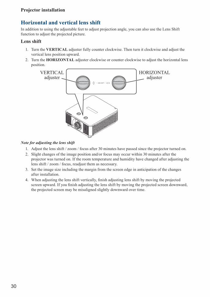
Horizontal and vertical lens shiftIn addition to using the adjustable feet to adjust projection angle, you can also use the Lens Shift function to adjust the projected picture.
Lens shift1. Turn the VERTICAL adjuster fully counter clockwise. Then turn it clockwise and adjust the
vertical lens position upward.2. Turn the HORIZONTAL adjuster clockwise or counter clockwise to adjust the horizontal lens
position.
VERTICALadjuster
HORIZONTALadjuster
Note for adjusting the lens shift1. Adjust the lens shift / zoom / focus after 30 minutes have passed since the projector turned on.2. Slight changes of the image position and/or focus may occur within 30 minutes after the
projector was turned on. If the room temperature and humidity have changed after adjusting the lens shift / zoom / focus, readjust them as necessary.
3. Set the image size including the margin from the screen edge in anticipation of the changes after installation.
4. When adjusting the lens shift vertically, finish adjusting lens shift by moving the projected screen upward. If you finish adjusting the lens shift by moving the projected screen downward, the projected screen may be misaligned slightly downward over time.

Projector installation
31
Note for adjusting the lens shift1. You can feel the rotational resistance of the lens adjuster increasing if the lens shift exceed its
range. Do not turn the lens adjuster further. If the lens adjuster is turned excessively, it runs idle by a clutch mechanism inside the adjuster. Although it makes a clicking sound, it is not a malfunction. Turn the lens adjuster to the opposite direction to adjust the lens shift.
2. Keep turning the lens adjuster while pressing it downward if the adjuster is turned to the opposite direction with a clicking sound and the lens shift does not work after the adjuster has been turned exceeding the lens shift range. You need to turn the lens adjuster for a while until the lens shift starts.
3. Do not turn the lens adjuster while pressing it downward out of the lens shift range. The lens shift may be locked because a clutch mechanism does not work. In such a case, keep turning the lens adjuster while pressing it downward like 2.
4. When adjusting the lens shift to the maximal oblique direction, the periphery of the projected screen may be dark or a shadow may be cast.Caution: Operate the lens adjusters gently as the lens may malfuction when subjected to shocks.

Projector installation
32
Moving the lens verticallyThe distance of vertical lens movement is +55% , -15% of the screen height in both directions. For instance, if you are using a 2.15m × 1.35m (100”) screen, you will be able to move the picture upwards no more than 74.3cm or downwards no more than 20.3cm.
Range of vertical lens shift adjustment
Range of vertical lens shift adjustment
This illustration shows normal vertical lens shift without the use of special specification lens or projector.
Note: Please make sure the center of lens is rectangular to the center of the screen. The value indicates in the case of SD-63 lens.
Moving the lens horizontallyThe distance of horizontal lens movement is 5% of the screen width in both directions. For instance, if you are using a 2.15m × 1.35m (100”) screen, you will be able to move the picture left or right by no more than 10.8cm.
H: Range of Horizontal lens shift adjustment
H H
This illustration shows normal horizontal lens shift without the use of special specification lens or projector.
Note: The value indicates in the case of SD-63 lens.

Projector installation
33
Connecting the projectorHDMI / MHL / DVI connectionSignals from picture source offer the best projection picture quality when sent through HDMI/DVI. Therefore, try to use input devices with HDMI/DVI output as the source of picture.
HDMI input source(BD/HD-DVD/DVD player, HD set-top-box, gaming consoles and so forth)
HDMI/MHL input source(BD/HD-DVD/DVD player, HD set-top-box, gaming consoles and smart devices)
Projector installation
34
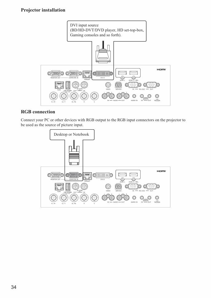
DVI input source(BD/HD-DVT/DVD player, HD set-top-box,Gaming consoles and so forth).
RGB connectionConnect your PC or other devices with RGB output to the RGB input connectors on the projector to be used as the source of picture input.
Desktop or Notebook
Projector installation
35
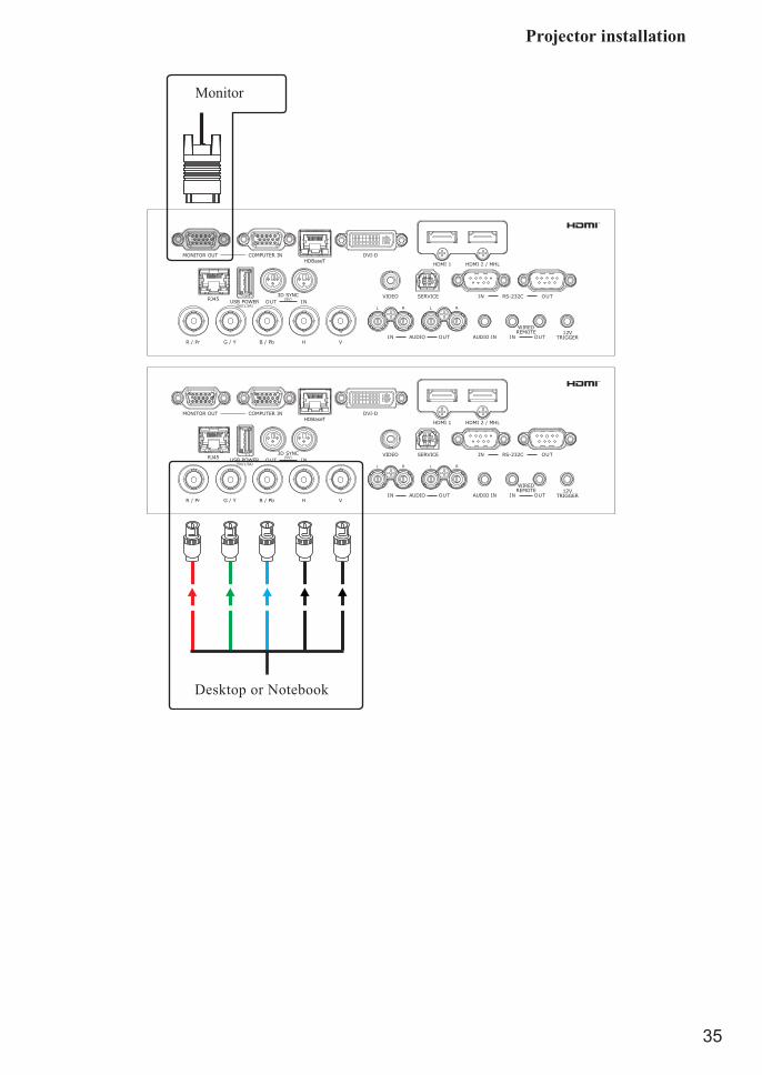
Monitor
B/Pb R/Pr H V
Desktop or Notebook

Projector installation
36
HDBaseT connectionHDBaseT is a technology to transmit image signal using a LAN cable.Connect Cat5e/Cat6 cable from HDBaseT TX Box for HDBaseT signal received.LAN Connection - When this connector to be the LAN (RJ-45) function. Connect it to computer or Hub. Key in the correct IP Address or the computer host name which same as the projector’s host name then you can remote control the projector by internet.Video Signal - When this connector to be the video signal input. Connect it to HDBaseT output equipment(Such as high-definition TV source, Blu-ray Player....etc).RS-232 Connection: When the projector connects to HDBaseT by RS-232 communication, the projector can be controlled with RS-232 commands from the computer. For details of RS-232 commands, refer to RS-232 Communication command table.Use LAN cables of up to 100m long. Exceeding this length, the image will be deteriorated, and even experience malfunction on LAN transmission.
Lan: PC, HubVideo: HDBaseT output equipment (Such as high-definition TV source, Blu-ray Player ... etc.)

Projector installation
37
12V Trigger connectionIf your home theater system includes a projector screen, screen cover or other 12V Trigger equipment, please connect such device/equipment to the projector’s 12V Trigger output as illustrated. After you have done so your screen will lower automatically whenever you turn on your projector for your convenience.
Retractable screen or other 12V device.
RJ45 connectionConnect it to computer or Hub. Key in the correct IP Address or the computer host name which same as the projector’s host name then you can remote control the projector by internet.
Desktop or Hub
Projector installation
38
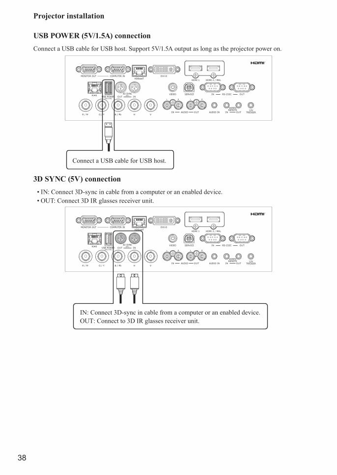
USB POWER (5V/1.5A) connectionConnect a USB cable for USB host. Support 5V/1.5A output as long as the projector power on.
Connect a USB cable for USB host.
3D SYNC (5V) connection• IN: Connect 3D-sync in cable from a computer or an enabled device.• OUT: Connect 3D IR glasses receiver unit.
IN: Connect 3D-sync in cable from a computer or an enabled device.OUT: Connect to 3D IR glasses receiver unit.

Projector installation
39
VIDEO connectionConnect the composite cable from a video device.
Connect the composite cable from a video device.
SERVICE connectionFor service personnel only.
For service personnel only.

Projector installation
40
RS232C connection• IN: Connects to the computer by RS-232 communication, the projector can be controlled with
RS-232 commands from the computer.• OUT: Connects to another projector RS-232 IN (same model) for RS-232 serial control.
IN: Connects to the computer by RS-232 communication, the projector can be controlled with RS-232 commands from the computer.
OUT: Connects to another projector RS-232 IN (same model) for RS-232 serial control.
Audio IN (L/R) connectionConnect an audio source input (Available for component (computer) or video source).
Connect an audio source input (Available for component (computer) or video source).

Projector installation
41
Audio OUT (L/R) connectionConnect to an audio amplifier device.
Connect to an audio amplifier device.
Audio IN (Mini jack) connectionConnect an audio source input (Available for computer, BNC, DVI source).
Connect to an audio source input (Available for computer, BNC, DVI source).

Projector installation
42
WIRE REMOTE connection• IN: Connect the wire remote from remote control to the projector for wire remote control.• OUT: Connect “WIRE REMOTE OUT” to another projector WIRE REMOTE IN (same model)
for serial control.
IN: Connect wired-remote-control cable.OUT: Connect to another projector (same model) for serial control.

Projector installation
43
Powering the projector on or offPowering on the projector
Press on the projector or on the remote control to start up the projector.The POWER LED will now flash green. The startup screen will display in approximately 30 seconds. The first time you use the projector, you can select your preferred language from quick menu after the startup screen display.If security lock is enabled. Refer to “ Page 45 : Setting an access password (security lock) ”.
Connect the power cord to the projector
Connect the female side of the power cord to power input socket of projector.
Turning off the projector
Press on the projector or on the remote control. The message “Power Off? /Press Power again” will appear on the screen. Press the button again while the message appears. When the projector has been turned off, the cooling fan will remain in operation for approximately 10 seconds.
Projector installation
44
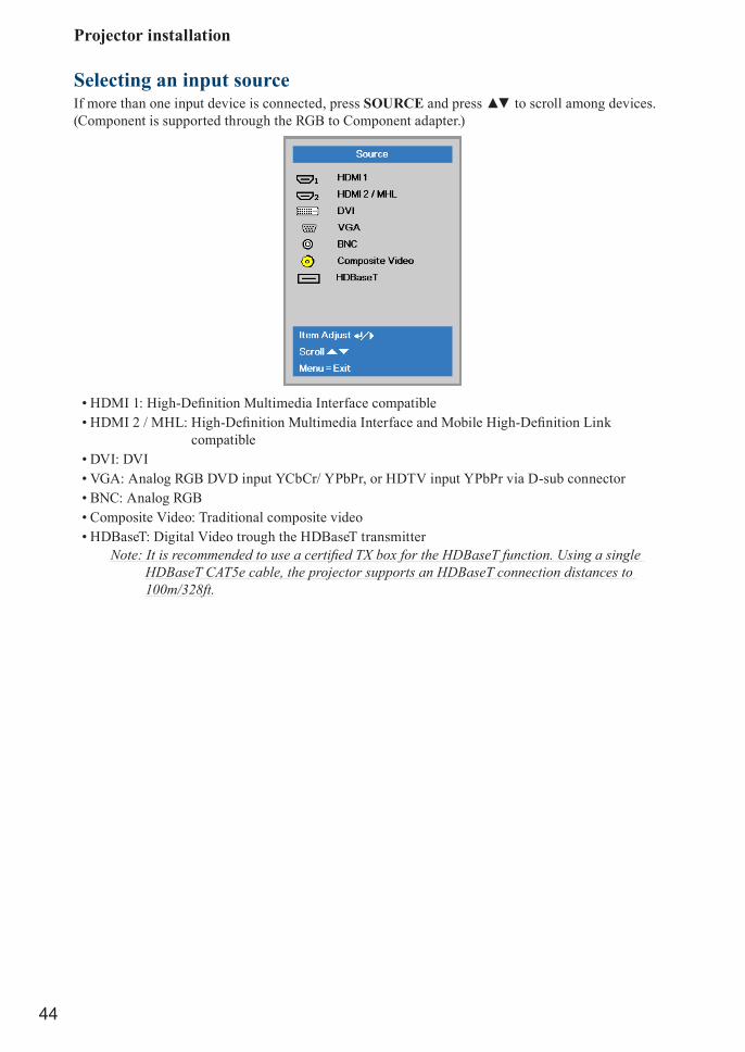
Selecting an input sourceIf more than one input device is connected, press SOURCE and press ▲▼ to scroll among devices. (Component is supported through the RGB to Component adapter.)
• HDMI 1: High-Definition Multimedia Interface compatible• HDMI 2 / MHL: High-Definition Multimedia Interface and Mobile High-Definition Link
compatible• DVI: DVI• VGA: Analog RGB DVD input YCbCr/ YPbPr, or HDTV input YPbPr via D-sub connector• BNC: Analog RGB• Composite Video: Traditional composite video• HDBaseT: Digital Video trough the HDBaseT transmitter
Note: It is recommended to use a certified TX box for the HDBaseT function. Using a single HDBaseT CAT5e cable, the projector supports an HDBaseT connection distances to 100m/328ft.

Projector installation
45
Setting an access password (security lock)You can use the four (arrow) buttons to set a password and prevent unauthorized use of the projector. When enabled, the password must be entered after you power on the projector.
Note: Keep the password in a safe place. Without the password, you will not be able to use the projector. If you lose the password, contact your reseller for information on clearing the password.
1. Press MENU to open the OSD menu.
2. Press ◄► to move to the Settings 1 menu and press ▲▼ to select Advanced 1.

Projector installation
46
3. Press ENTER / ► to enter the Advanced 1 sub menu. Press ▲▼ to select Security Lock.4. Press ◄► to enter and enable or disable security lock function.
A password dialog box automatically appears.5. Press ▲▼◄► either on keypad or IR remote control for password entry. You can use any
combination including the same arrow five times, but not less than five.
Press ▲▼◄► in any order to set the password. Push MENU button to exit the dialog box.
6. The password confirm menu appears when user presses the power-on key in case the Security Lock is enabled. Enter the password in the order you set it at step 5. In case you forget the password, please contact the service center.The service center will validate the owner and help reset the password.
Projector installation
47
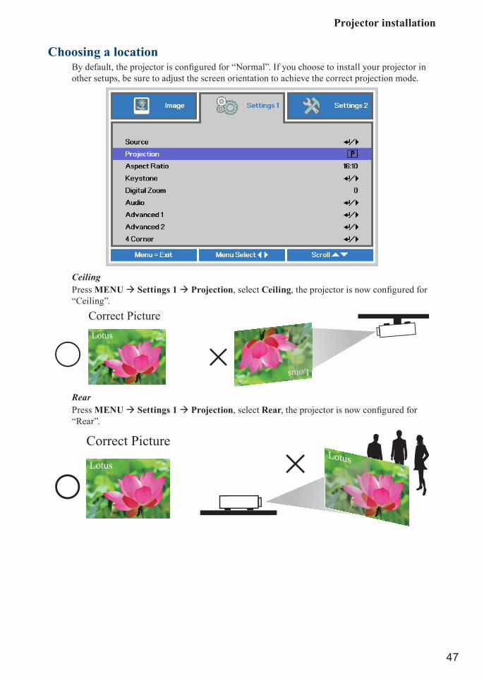
Choosing a locationBy default, the projector is configured for “Normal”. If you choose to install your projector in other setups, be sure to adjust the screen orientation to achieve the correct projection mode.
CeilingPress MENU Settings 1 Projection, select Ceiling, the projector is now configured for “Ceiling”.
Correct PictureLotus
Lotus Lottus+RearPress MENU Settings 1 Projection, select Rear, the projector is now configured for “Rear”.
Lotus
Correct PictureLotus

Projector installation
48
Rear + CeilingPress MENU Settings 1 Projection, select Rear + Ceiling, the projector is now configured for “Rear + Ceiling”.
+ Lotus
Correct Picture
Lotus
Adjusting the projector's angleUse the adjustable feet to change the angle of the projector in order to achieve the most suitable angle for projection on the screen.
Adjusting the projector’s zoom and focusZoom
Projector installation
49
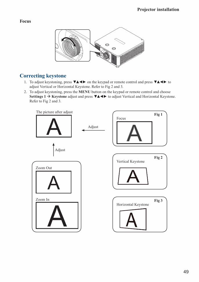
Focus
Correcting keystone1. To adjust keystoning, press ▼▲◄► on the keypad or remote control and press ▼▲◄► to
adjust Vertical or Horizontal Keystone. Refer to Fig 2 and 3.2. To adjust keystoning, press the MENU button on the keypad or remote control and choose
Settings 1 Keystone adjust and press ▼▲◄►to adjust Vertical and Horizontal Keystone. Refer to Fig 2 and 3.
The picture after adjust
Adjust
Adjust
Zoom Out
Fig 1Focus
Fig 2Vertical Keystone
Fig 3Horizontal Keystone
Zoom In

OSD menu tree
50
OSD menu tree1st layer 2nd layer 3rd layer 4th layer Selections
Image
Display ModePresentation, Bright, Game, Movie, Vivid, TV, sRGB, DICOM SIM., User1̧ User2
Brightness 0 ~ 100
Contrast 0 ~ 100
Computer
Horizontal Position -5 ~ 5 (depend on Auto Sync)
Vertical Position -5 ~ 5 (depend on Auto Sync)
H Phase 0 ~ 31
Tracking -5 ~ 5
Auto Image
Advanced
Brilliant Color 0 ~ 10
Sharpness 0 ~ 31
Gamma 1.8, 2.0, 2.2, 2.4, B&W, Linear
Color Temperature Warm, Normal, Cold
Video AGC Off, On
Video Saturation 0 ~ 100
Video Tint 0 ~ 100
White Balance
R Gain 0 ~ 200
G Gain 0 ~ 200
B Gain 0 ~ 200
R Offset -100 ~ 100
G Offset -100 ~ 100
B Offset -100 ~ 100

OSD menu tree
51
1st layer 2nd layer 3rd layer 4th layer Selections
Image Color Manager
Red
Hue 0 ~ 100
Saturation 0 ~ 100
Gain 0 ~ 100
Green
Hue 0 ~ 100
Saturation 0 ~ 100
Gain 0 ~ 100
Blue
Hue 0 ~ 100
Saturation 0 ~ 100
Gain 0 ~ 100
Cyan
Hue 0 ~ 100
Saturation 0 ~ 100
Gain 0 ~ 100
Magenta
Hue 0 ~ 100
Saturation 0 ~ 100
Gain 0 ~ 100
Yellow
Hue 0 ~ 100
Saturation 0 ~ 100
Gain 0 ~ 100
White
Red 0 ~ 100
Green 0 ~ 100
Blue 0 ~ 100
1st layer 2nd layer 3rd layer 4th layer Selections
Settings 1
Source HDMI 1, HDMI 2 / MHL, DVI, VGA, BNC, Composite Video, HDBaseT
Projection Normal, Rear, Ceiling, Rear+Ceiling
Aspect Ratio 16:10, 4:3, 16:9, Letter Box, Native, 2.35:1
Keystone H: -50 ~ +50 V: -60 ~ +60
Digital Zoom -10 ~ 10
Audio
Volume 0~10
Mute Off, On
Internal Speaker Off, On

OSD menu tree
52
1st layer 2nd layer 3rd layer 4th layer Selections
Settings 1
Advanced 1
Language
ENGLISH, FRENCH, GERMAN, SPANISH, PORTUGUESE, SIMPLIFIED_CHINESE, TRADITIONAL_CHINESE, ITALIAN, NORWEGIAN, SWEDISH, DUTCH, RUSSIAN, POLISH, FINNISH, GREEK, KOREAN, HUNGARIAN, CZECH, ARABIC, TURKISH, VIETNAMESE, JAPANESE, THAI, FARSI, HEBREW, DANISH, FRENCH CANADIAN
Security Lock Off, On
Splash Logo Std, Black, Blue
Closed Captioning Off, On
Keypad Lock Off, On
3D Setting
3D Off, DLP-Link, IR
3D Sync Invert Off, On
3D FormatFrame Sequential, Top/Bottom, Side-By-Side, Frame Packing (3D FramePacking HDMI source only)
3D Sync Out delay 0 ~ 359
3D Sync Input Off, On
Advanced 2
Test Pattern
None, RGB Ramps, Color Bars, Step Bars, Checkboard, Grid, Horizontal lines, Vertical lines, Diagonal lines, Horizontal Ramp, Vertical Ramp, White, Red, Green, Blue, Black
H Image Shift -50 ~ 50
V Image Shift -50 ~ 50
4 Corner
1st layer 2nd layer 3rd layer 4th layer Selections
Settings 2
Auto Source Off, On
No Signal Power Off 0 ~ 180
Auto Power On Off, On
Light Mode Normal, Eco, Eco Plus, Dimming, Extreme Dimming, Custom Light
Reset All
Status
Active Source
Video Information
Laser Hours
Software Version
Remote ID
Serial Number

OSD menu tree
53
1st layer 2nd layer 3rd layer 4th layer Selections
Settings 2
Advanced 1
Menu Position Center, Down, Up, Left, Right
Translucent Menu 0%, 25%, 50%, 75%, 100%
Low Power Mode On, On by LAN
Fan Speed Normal, High
Light Info
Remote ID Default, 1, 2, 3, 4, 5, 6, 7
Network
Network State
DHCP
IP Address
Subnet Mask
Gateway
DNS
Apply
HDBaseT/IR
HDBaseT– IR/RS232/RJ45
Off, On
Front IR On, Off
Rear IR On, Off
Advanced 2
Sleep Timer 0 ~ 600
Source Filter
HDMI 1 Disable, Enable
HDMI 2 / MHL Disable, Enable
DVI Disable, Enable
VGA Disable, Enable
BNC Disable, Enable
Composite Video Disable, Enable
HDBaseT Disable, Enable
Custom Light 25 ~ 100

OSD description
54
OSD description1. Press MENU on the remote control or on the side of the projector to bring up the OSD menu.2. You will see three main menus (Image, Settings 1 and Settings 2).3. Press ◄► to move to the main menu. Press ▲▼ to select the desired sub menu. Press ◄► to
enter and change values for settings.4. Press MENU to return to the previous menu.5. From the main menu, press MENU to close the OSD menu.6. Some items do not work at the condition of Source, Input signal and Menu setting.7. Picture may be incorrect when the parameter value is exceeded.
Image
Display ModePress ◄► to select a display mode.
• PresentationWhen projector is in the office to do the presentation. You can select this mode. This mode brightness is between Bright and Video.
• BrightWhen projector in the high ambient light conditions. You can select this mode to get the brightness image Performance.
• GameSuitable for playing video games in a bright living room.
• MovieFor home theater.
• VividWith well-saturated color, fine-tuned sharpness and a higher brightness level, this is perfect for watching movies in a living room where there is a small amount of ambient light.
• TVDisplay mode adjusts the settings to offer a more television-like experience.
• sRGBMaximizes the purity of RGB colors to provide true-to-life images regardless of brightness setting. It is most suitable for viewing photos taken with an sRGB compatible and properly calibrated camera, and for viewing PC graphic and drawing applications such as AutoCAD.

OSD description
55
• DICOM SIMThis display mode simulates the grayscale/gamma performance of equipment used for “Digital Imaging and Communications in Medicine” (DICOM).
Important: This mode should NEVER be used for medical diagnosis, it is for education/training purposes only.
• User1, User2Recalls the settings customized based on the current available picture modes.
BrightnessPress ◄► to adjust the brightness of the projected picture. You can connect the projector to an external picture source to display an picture resembling the one shown (PLUGE: Picture Line-Up Generation Equipment) for adjustment. Although there are numerous versions of PLUGE picture, they are typically comprised of blocks of black, white and gray on top of a black background.
It is recommended that you adjust the picture to the following status:• The darkest black bar of the picture should disappear into the
background.• The dark gray area should be barely visible.• The light gray area should be clearly visible.• The white area should appear real and mellow.• The picture should only display black, gray and white (with no
other colors).Above Black
Below BlackNote: Contrast, Brightness, Color and Tint are interrelated options that affect one another; when
you adjust one of them, you might have to fine tune other settings to get the best projection results.
The picture Fig 4 illustrates the results of direct brightness adjustment using a random picture:
ContrastPress ◄► to adjust the contrast of the projected picture. You can connect the projector to an external picture source to display an picture resembling the one shown below for adjustment. It is recommended that you adjust the projected picture according to the results shown below so that the brightness of the spectrum remains constant throughout and achieve maximum contrast between black and white.
The picture Fig 5 illustrates the results of direct contrast adjustment using a random picture:

OSD description
56
ComputerPress ENTER / ► to enter the Computer menu.
• Horizontal PositionPress ◄► to adjust the projected picture’s horizontal position.If the projected picture is not at the center of the screen (i.e. shifted to right or left) and ends up being cropped, use this function to adjust the picture’s horizontal position. The following picture is an example of test picture from an external signal source:
Native picture SkewedRightLeft
• Vertical PositionPress ◄► to adjust the projected picture’s vertical position.If the projected picture is not at the center of the screen (i.e. shifted up or down) and ends up being cropped, use this function to adjust the picture’s vertical position. The following picture is an example of test picture from an external signal source:
Native picture SkewedDownUp
It is recommended that when adjusting the picture, the horizontal total should be adjusted before the horizontal phase. However, if the picture still flickers even after you have adjusted both, try lowering the picture noise.
• H PhasePress ◄► to adjust the projected picture’s phase.Use this function to adjust the phase of pixel sampling clock (relative to input signal). Should the picture still flicker or show noise (i.e. edges on texts) after optimization, adjust phase accordingly.
• TrackingPress ◄► to enter and adjust the A/D sampling dot.

OSD description
57
Auto ImageWhen Auto image was selected in the OSD menu, press ENTER to execute the automatic picture adjustment function.By executing this function, the projector will resync the picture. Use this function when the picture source is unstable or when you notice deterioration in picture quality and the projector will automatically adjust the picture size, phase and timing. (The adjustment also applies to PinP input source).This function is identical to AUTO on the remote control. You can simply use the hot key on the remote control to execute this function.
AdvancedPress ENTER / ► to enter the Advanced menu.
• Brilliant ColorPress ◄► to adjust the brilliant color of the projected image.This feature utilizes a new color-processing algorithm and system level enhancements to enable higher brightness while providing truer, more vibrant colors in picture.
• SharpnessThe adjustment of sharpness primarily changes the value of high frequency detail. You can connect the projector to an external picture source to display an picture resembling the one shown below to adjust the picture sharpness.
The picture Fig 8 illustrates the results of direct sharpness adjustment using a random picture:• Gamma
Using different color gamut will create different color presentation in the projected picture. Generally speaking, when the surrounding are darker, it is recommended that Gamma be set higher to yield better picture quality in darker regions by sacrificing details in brighter areas. In contrast, when projecting brighter pictures, you can set the Gamma lower to give up details in the darker areas to make the brighter areas more visible.The options are 1.8, 2.0, 2.2, 2.4, B&W and Linear.
• Color TemperatureYou can choose from Warm, Normal and Cold.Color temperature refers to the change in light color under different energies that is perceived by the naked eye. The change of color temperature from Warm to Cold for visible light goes from orange red → white → blue .As color temperature rises, the picture will appear to be bluer; as it decreases, the picture will appear redder. When you choose “Native”, the projector will disable the white adjustment function of the input device.
• Video AGCPress ◄► to enter and enable or disable the Automatic Gain Control for video source.

OSD description
58
• Video SaturationPress ◄► to adjust the color saturation of the projected image.The picture Fig 6 illustrates the results of direct brightness adjustment using a random picture:
• Video TintPress ◄► to adjust the ratio of red to green in the color portion of the image.The picture Fig 7 illustrates the results of direct brightness adjustment using a random picture:
◄ Reduced brightness
Enhanced brightness ►
Fig 4
◄ Reduced tint
Enhanced tint ►
Fig 7
◄ Lowered contrast
Enhanced contrast ►
Fig 5
◄ Reduced sharpness
Enhanced sharpness ►
Fig 8
◄ Reduced color
Enhanced color ►
Fig 6
Original picture
OSD description
59
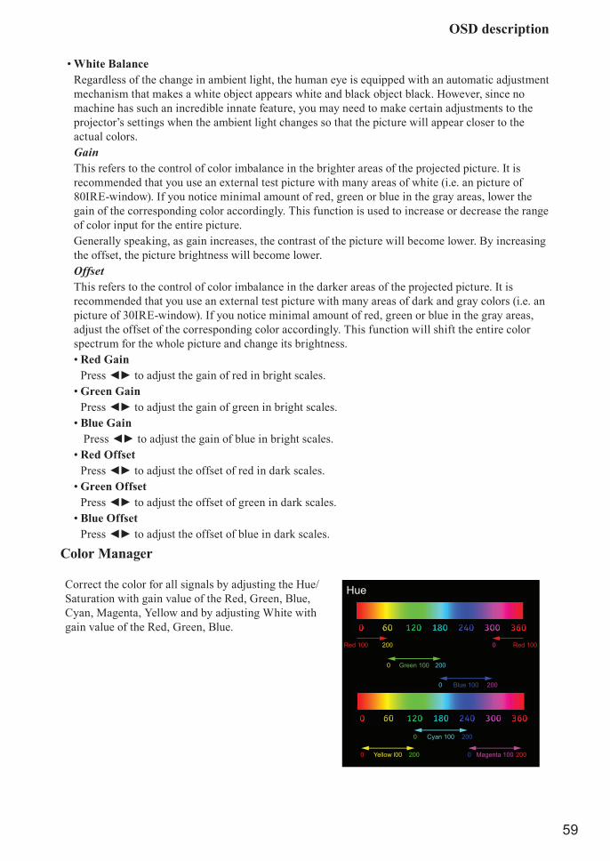
• White BalanceRegardless of the change in ambient light, the human eye is equipped with an automatic adjustment mechanism that makes a white object appears white and black object black. However, since no machine has such an incredible innate feature, you may need to make certain adjustments to the projector’s settings when the ambient light changes so that the picture will appear closer to the actual colors.GainThis refers to the control of color imbalance in the brighter areas of the projected picture. It is recommended that you use an external test picture with many areas of white (i.e. an picture of 80IRE-window). If you notice minimal amount of red, green or blue in the gray areas, lower the gain of the corresponding color accordingly. This function is used to increase or decrease the range of color input for the entire picture.Generally speaking, as gain increases, the contrast of the picture will become lower. By increasing the offset, the picture brightness will become lower.OffsetThis refers to the control of color imbalance in the darker areas of the projected picture. It is recommended that you use an external test picture with many areas of dark and gray colors (i.e. an picture of 30IRE-window). If you notice minimal amount of red, green or blue in the gray areas, adjust the offset of the corresponding color accordingly. This function will shift the entire color spectrum for the whole picture and change its brightness.• Red Gain
Press ◄► to adjust the gain of red in bright scales.• Green Gain
Press ◄► to adjust the gain of green in bright scales.• Blue Gain
Press ◄► to adjust the gain of blue in bright scales.• Red Offset
Press ◄► to adjust the offset of red in dark scales. • Green Offset
Press ◄► to adjust the offset of green in dark scales. • Blue Offset
Press ◄► to adjust the offset of blue in dark scales.
Color Manager
Correct the color for all signals by adjusting the Hue/Saturation with gain value of the Red, Green, Blue, Cyan, Magenta, Yellow and by adjusting White with gain value of the Red, Green, Blue.
Hue
Red 100 200 Red 1000
Green 100 2000
Blue 100 2000
Cyan 100 2000
Yellow l00 2000 Magenta 100 2000

OSD description
60
Settings 1
SourceThis function is same as the hotkey which on Remote controller. You can use remote controller or this function to select the correct input source.
• HDMI1HDMI input from PC or media device.
• HDMI2 / MHLConnect to a MHL-compatible device by using an HDMI/MHL cable.
• DVIDVI input from PC.
• VGAAnalog RGB from PC.
• BNCAnalog interface from media device.
• Composite VideoVideo input from traditional composite video.
• HDBaseTUncompressed digital video from HDBaseT device.
ProjectionUse these function to install the projection mode. Has below 4 mode can select:
• NormalRefer to “ Page 28 : Normal ” for detail information.
• CeilingRefer to “ Page 29 : Ceiling ” for detail information.
• RearRefer to “ Page 29 : Rear ” for detail information.
• Rear + CeilingRefer to “ Page 29 : Rear + Ceiling ” for detail information.

OSD description
61
Aspect RatioUse this function to adjust the aspect ratio of the projected picture. Press ◄► to adjust the ratio of picture length and width. The projector’s full picture size is 16:10 (1920×1200 dots).The following diagram illustrates the difference in various aspect ratio settings:
16:10
16:10
Native Letter Box 2.35:1
Letter Box 2.35:1Native
4:3 16:9
4:3 16:9
16:10
(1920*1200)
4:3
(800*600)
Native input Output aspect ratio
Cropped portion of the image
Note: When used for commercial purposes, including: projection of picture in movie theaters, hotels, cafeteria and other public venues, compression or extension of picture achieved through the change of aspect ratio may constitute copyright infringement to the rightful owner of the picture. Please do so at your own discretion.
KeystonePress ▲▼◄► to correct horizontal keystone due to projection angle. Refer to “ Page 49 : Correcting keystone ”.
Digital ZoomPress ◄► to zoom in the projected image.
AudioPress ENTER / ► to enter the Audio menu.
• VolumePress ◄► to enter and adjust the audio volume.
• MutePress ◄► to enter and turn on or off the speaker.
• Internal SpeakerPress ◄► to select internal speaker output on or off.

OSD description
62
Advanced 1Press ENTER / ► to enter the Advanced 1 menu.
• LanguageYou can use this function to select the language you wish for the OSD menu to be displayed in. The options are English, French, German, Spanish, Portuguese, Simplified_Chinese, Traditional_Chinese, Italian, Norwegian, Swedish, Dutch, Russian, Polish, Finnish, Greek, Korean, Hungarian, Czech, Arabic, Turkish, Vietnamese, Japanese, Thai, Farsi, Hebrew, Danish, French Canadian.
• Security LockPress ◄► to enter and enable or disable security lock function.
• Splash LogoYou can use this function to have the projector display the HITACHI logo in the start up screen. Set On to display the HITACHI logo during start up and Off to display a blank picture.If you hope to disapper the logo while no input detect, you can change setting to Black or Blue.
• Closed CaptioningPress ◄► to enter and enable or disable Closed Captioning.
• Keypad LockPress ◄► to enter and enable or disable keys can be work on keypad.
Note: Hold ▼ on keypad for 5 seconds to unlock keypad.• 3D Setting
Press ENTER / ► to enter the 3D Setting menu.• 3D
Press ◄► to enter and select different 3D mode. The options are Off, DLP-Link and IR.• 3D Sync Invert
Press ◄► to enable or disable 3D Sync Invert.• 3D Format
Press ◄► to select the 3D format. The options are Frame Sequential, Top/Bottom, Side-By-Side, Frame Packing.
Note: 3D Frame Packing HDMI source only.• 3D Sync Out delay
Press ◄► to adjust 3D sync out signal delay.• 3D Sync Input
Press ◄► to enter and enable or disable 3D Sync input.Note: The 3D OSD menu item is gray if there is no appropriate 3D source. This is the default
setting.Note: When the projector is connected to an appropriate 3D source, the 3D OSD menu item is
enabled for selection.Note: Use 3D glasses to view a 3D image.Note: You need 3D content from a 3D DVD or 3D media file.

OSD description
63
Note: You need to enable the 3D source (some 3D DVD content may have a 3D on-off selection feature).
Note: You need DLP link 3D or IR 3D shutter glasses. With IR 3D shutter glasses, you need to install a driver on your PC and connect a USB emitter.
Note: The 3D mode of the OSD needs to match the type of glasses (DLP link or IR 3D).Note: Power on the glasses. Glasses normally have a power on -off switch. Each type of glasses
has their own configuration instructions. Please follow the configuration instructions that come with your glasses to finish the setup process.
Note: Passive 3D is not going to support thru 3D Sync In/Out.Note: Since different types of glass (DLP link or IR shutter glass) have their own setting
instructions, Please follow the guide to finish the setup process.
Advanced 2Press ENTER / ► to enter the Advanced 2 menu.
• Test PatternThe projector comes with some standard built-in patterns for testers to calibrate the equipment. The options are RGB Ramps, Color Bars, Step Bars, Checkboard, Grid, Horizontal lines, Vertical lines, Diagonal lines, Horizontal Ramp, Vertical Ramp, White, Red, Green, Blue, Black and Off.
• H Image Shift Press ◄► to enter and set whole Image horizontal shift without cropped.
• V Image ShiftPress ◄► to enter and set whole Image vertical shift without cropped.
4 CornerPress ▲▼◄► to correct 4 corner picture bias.
Press ▲▼◄► to correct top left corner picture bias
Press ▲▼◄► to correct top left corner picture bias
Press ▲▼◄► to correct bottom left corner picture bias
Press ▲▼◄► to correct bottom right corner picture bias

OSD description
64
Settings 2
Auto Source• ON
By enabling this function, the projector will automatically determine the source of input every time it is turned on so that the user will not have to make the selection on the OSD menu.
• OFFSetting the function off will require the user to specify source of picture input on the OSD Menu in order for the projector to display the intended picture.
No Signal Power OffAllows the projector to turn off automatically if no input signal is detected after a set period of time.
Auto Power OnThe default value is Off. If you set it to ON, the projector will automatically start up when it is connected to AC power. If you plug the projector’s power cord into an AC socket with a AC switch on, you can use this function to start up the projector using the socket’s switch instead of the remote. If you do not need this function, please set it to Off.
Note: When the standby power set off. Even direct AC off, the LED light still keep lighting until 25 seconds. During this period, the machine maybe can't power on normally.
Light Mode• Normal
Brightness will 100% when set to Normal mode. If the projection environment requires brighter picture, you can set the power mode to Normal for the highest projection brightness.
• EcoWhen set to Eco mode, the brightness will 80% of the normal brightness.
• Eco PlusWhen set to Eco Plus mode, the brightness will 60% of the normal brightness.
• DimmingWhen set to Dimming mode, the brightness will 40% of the normal brightness.
OSD description
65
• Extreme DimmingWhen set to Extreme Dimming mode, the brightness will 25% of the normal brightness. Operate temperature must lower then 35°C. The cooling fan will auto slow down the speed. If the surrounding environment is sufficiently dark or if you do not require intense brightness, you can set the power mode to Extreme Dimming to save the power.
Note: Extreme Dimming is automatically selected between 35~40°C(95~104°F), when the temperature is higher then 35°C. The fan speed will fully operational to exhaust the heat. This situation will not save the power.
• Custom LightIf the picture brightness at Extreme Dimming mode is too dark for you and the Normal mode gets too bright, you can set it to custom to specify the power mode to make fine adjustments to the brightness of the projected picture. You could encounter situations where the picture from projector A being brighter than projector B. When this occurs, you can use this function you could encounter situations where the picture from projector A being brighter than projector B. When this occurs, you can use this function to fine tune the brightness of the two projectors to achieve consistent picture brightness. To access this function, go to the MENU Settings 2 Light Mode Custom Light and adjust accordingly.
Reset AllPress ENTER / ► to reset all settings to default values.
Note: All of OSD function are reset to default except Language, Security Lock, Source, 3D(include Sync Invert & Format), Test Pattern, Remote ID, Network.
StatusPress ENTER / ► to enter the Status menu.
• Active SourceDisplay the activated source.
• Video InformationDisplays resolution/video information for RGB source and color standard for Video source.
• Laser HoursLaser hour used information is displayed.
• Software VersionShowing system software version.
• Remote IDShowing Remote Controller ID.
• Serial NumberShowing serial number of product.
Advanced 1Press ENTER / ► to enter the Advanced 1 menu.
• Menu PositionYou can use this function to designate which area on the picture the OSD menu will appear. As you can see from the diagram below, there are five positions where you can choose to have the OSD menu displayed. The default setting is “Center”.
• Translucent MenuPress ◄► to enter and select OSD background translucent level.
• Low Power ModePress ◄► to enter and turn Low Power Mode On or On By Lan.
Note: About “On By Lan”, RJ45 will support to be waked up in this mode(Under 3W) but scalar won’t.

OSD description
66
• Fan SpeedUse this function to control the projector's cooling fan. You can set it to Normal or High. The default setting is Normal.Under normal circumstances, the projector will operate normally with this function set to Normal. By default, the projector will detect the temperature of the surrounding environment to regulate the speed of the cooling fan. When the ambient temperature rises, fan speed will increase (generates louder noise) to make sure the heat inside the projector gets discharged and keep the projector working normally.However, if you were to operate the projector in environment of excessive heat or in areas of high altitude, the projector may automatically shut down. When this happens, you can enable this function by setting it to High to force the cooling fan to work at a full speed to regulate the temperature inside the projector.
Note: We recommend selecting high speed in high temperatures, high humidity, or high altitude (higher than 1500m/4921ft) areas.
Note: Due to the air thinning substantially at high altitudes, the result of cooling achieved by the cooling fan is significantly reduced compared to operation on level ground. With low atmospheric pressure and high operating temperature, the cooling fan will not be able to disperse the heat adequately.
• Light InfoPress ENTER / ► to enter the Light Info menu to display the light hours for each light mode.
• Remote IDPress ◄► to select remote ID to fit the current remote ID settings.
Note: Remoter with Default customer code will be available for any Remote ID setting on the OSD.
Note: Status key will be available for any Remote ID setting on the OSDNote: IF users forget the current Remote ID setting, please press the Status key to call out the
Status OSD to check the current Remote ID setting and then adjust the ID on the remoter to meet the OSD setting.
Note: After adjusting Remote ID from OSD, only if the OSD Menu has been closed then the new ID value can be taken effected and memorized.
Note: The setting value “Default” means ID 0 on the remoter.• Network
Press ENTER / ► to enter the Network menu.• Network State
Projector Control: Choice this fuction to control the projector via the web.On: This function only for the professional service person. For download command use.
• DHCPIf the projector installation environment has the Dynamic Host Configuration Protocol server. You can set this function “ON” to let the projector get the auto ID from server. If no DHCP, even you set “ON” for this function. You still need to input the projector ID by yourself.
• IP AddressIf has DHCP server and the function is on. The ID address will auto display here , or you need to enter ID by yourself.
• Subnet MaskIf has DHCP server and the function is on. The Subnet Mask address will auto display here , or you need to enter it value by yourself.

OSD description
67
• GatewayIf has DHCP server and the function is on. The Gateway address will auto display here , or you need to enter it value by yourself.
• DNSIf has DHCP server and the function is on. The DNS address will auto display here , or you need to enter it value by yourself.
• ApplyPress ENTER / ► to confirm settings.
LAN_RJ45
(Ethernet)
Wired LAN terminal functionalitesRemote control and monitoring of a projector from a PC (or laptop) via wired LAN is also possible. Compatibility with Crestron / AMX (Device Discovery) control boxes enables not only collective projector management on a network but also management from a control panel on a PC (or Laptop) browser screen.• Crestron is a registered trademark of Crestron Electronics, Inc. of the United States.• AMX is a registered trademark of AMX LLC of the United States.• PJLink applied for trademark and logo registration in Japan, the United States of America, and
other countries by JBMIA.
Supported External DevicesThis projector is supported by the specified commands of the Crestron Electronics controller and related software (ex, RoomView®).
http://www.crestron.com/This projector is supported by AMX (Device Discovery).
http://www.amx.com/This projector supports all commands of PJLink Class1 (Version 1.00).
http://pjlink.jbmia.or.jp/english/
For more detail of information about the diverse types of external devices which can be connected to the LAN/RJ45 port and remote/control the projector, as well as the related control commands supporting for each external device, kindly please get contact with the Support-Service team directly.

OSD description
68
LAN_RJ451. Connect an RJ45 cable to RJ45 ports on the projector and the PC (Laptop).
LAN
RJ45 or HDBaseT port
2. On the PC (Laptop), select Start Control Panel Network and Internet.
3. Right-click on Local Area Connection, and select Properties.

OSD description
69
4. In the Properties window, select the Networking tab, and select Internet Protocol (TCP/IP).5. Click Properties.
6. Click Use the following IP address and fill in the IP address and Subnet mask, then click OK.
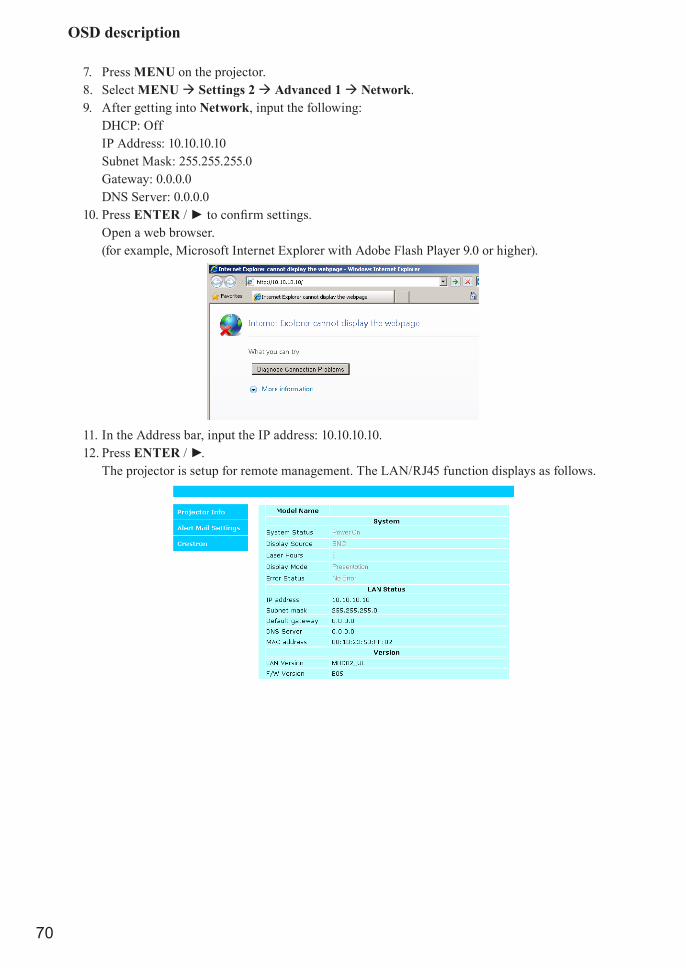
OSD description
70
7. Press MENU on the projector.8. Select MENU Settings 2 Advanced 1 Network.9. After getting into Network, input the following:
DHCP: OffIP Address: 10.10.10.10Subnet Mask: 255.255.255.0Gateway: 0.0.0.0DNS Server: 0.0.0.0
10. Press ENTER / ► to confirm settings.Open a web browser.(for example, Microsoft Internet Explorer with Adobe Flash Player 9.0 or higher).
11. In the Address bar, input the IP address: 10.10.10.10.12. Press ENTER / ►.
The projector is setup for remote management. The LAN/RJ45 function displays as follows.
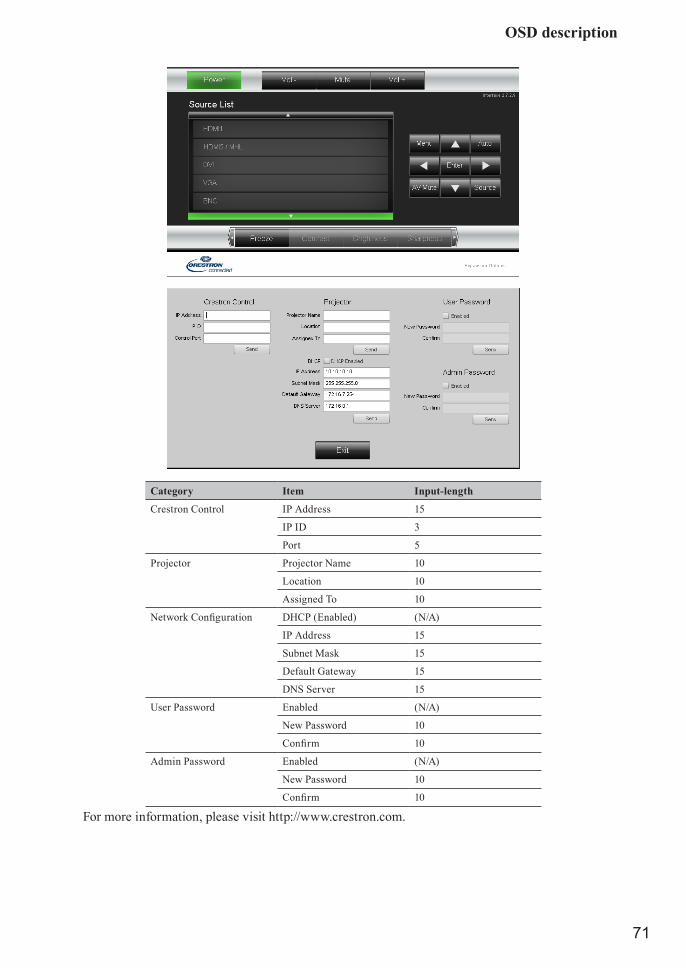
OSD description
71
Category Item Input-length
Crestron Control IP Address 15
IP ID 3
Port 5
Projector Projector Name 10
Location 10
Assigned To 10
Network Configuration DHCP (Enabled) (N/A)
IP Address 15
Subnet Mask 15
Default Gateway 15
DNS Server 15
User Password Enabled (N/A)
New Password 10
Confirm 10
Admin Password Enabled (N/A)
New Password 10
Confirm 10
For more information, please visit http://www.crestron.com.

OSD description
72
Preparing email alerts1. Make sure that user can access the homepage of LAN RJ45 function by web browser (for ex-
ample, Microsoft Internet Explorer v6.01/v8.0).2. From the homepage of LAN/RJ45, click Alert Settings.
3. By default, these input boxes in Alert Settings are blank.

OSD description
73
4. For Sending alert mail, input the following:The SMTP field is the mail server for sending out email (SMTP protocol). This is a required field.The To field is the recipient’s email address (for example, the projector administrator). This is a required field.The Cc field sends a carbon copy of the alert to the specified email address. This is an optional field (for example, the projector administrator’s assistant).The From field is the sender’s email address (for example, the projector administrator). This is a required field. Select the alert conditions by checking the desired boxes.
Note: Fill in all fields as specified. User can click Send Test Mail to test what setting is correct. For successful sending an e-mail alert, you must select alert conditions and enter a correct e-mail address.
RS232 by telnet functionBesides projector connected to RS232 interface with “Hyper-Terminal” communication by dedicated RS232 command control, there is alternative RS232 command control way, so called “RS232 by TELNET” for LAN/RJ45 interface.Specsheet for “RS232 by TELNET”:1. Telnet: TCP2. Telnet port: 23
(for more detail, kindly please get contact with the service agent or team)

OSD description
74
• HDBaseT/IRPress ENTER / ► to enter the HDBaseT/IR menu.• HDBaseT– IR/RS232/RJ45
Press ◄► to enter and enable or disable HDBaseT–IR/RS232/RJ45 Control.• Front IR
Press ◄► to enter and enable or disable Front IR.• Rear IR
Press ◄► to enter and enable or disable Rear IR.Note: Enable HDBaseT– IR/RS232/RJ45 control function when you desire to use HDBaseT TX
box. (Remove RS232 and RJ45/LAN control function from Projector to HDBaseT TX box.) See HDBaseT– IR/RS232/RJ45 control function table.
Note: When HDBaseT– IR/RS232/RJ45 enable, Low Power Mode will auto set to On by Lan.Note: HDBaseT– IR/RS232/RJ45 control is disabled when the HDBaseT TX box signal is cutoff.
HDBaseT– IR/RS232/RJ45 control function table
Control Side Function
Projector Mode
RemarkLow Power Mode On (<0.5W)
Low Power Mode On by Lan (<3W)
HDBaseT control Enable Low Power Mode On by HDBaseT (<6W)
Projector
Front-IR (wireless) O O O (Can disable by OSD)
Rear-IR (wireless) O O O (Can disable by OSD)
RS-232 O ORJ45/LAN X OWired remote O O
HDBaseT TX Box
HDBT-IR (wireless) X X ORS-232 X X ORJ45/LAN X X O
Wired remote X X O
User can connect wired remote at HDBaseT TX side to get the wired function.
O: Enable X: Disable
Advanced 2Press ENTER / ► to enter the Advanced 2 menu.
• Sleep TimerPress ◄► to enter and set sleep timer. The projector automatically turns off after the preset period of time.
• Source FilterPress ENTER / ► to enter the Source Filter menu.Press ◄► to enter and enable or disable the desire source.
Custom LightIn Custom Light mode press ◄► to enter and adjust the brightness of the projectors to similarity.
Note: When Light Mode set to Custom Light, Custom Light function Enable.

Cleaning
75
CleaningTurn off the projector and unplug the power before cleaning. Suggest to wait at least 45 minute to let the projector cool down.
Cleaning the cabinet• Use a dry soft cloth to wipe off the cabinet dust.
Note: Not suggest to use cleanser. If too dirty, only use little neutral detergent to clean the cabinet.
• Use a vacuum cleaner to clean the cabinet.Note: Poor ventilation causes overheat and reducing the life of the laser module.Note: Need to clean the interior of machine, please contact your dealer.
Cleaning the lens• Cleaning tool should include soft fur air brush, lens cleaning paper, lens cleaning fluid, soft cloth.
Note: You can buy these items from the Camera stores.• Use soft fur air brush to blow off dust on the lens surface. Then gently brush the surface dust.
Note: The action should be gentle.• Fold the lens cleaning paper and add few drops of cleaning liquid on paper, follow the clockwise or
counterclockwise direction to wipe lightly from center to outside.Note: Cleaning liquid can't be added directly to the lens surface.
To avoide scratch the lens, do not wipe straightly back and forth.• After the lens cleaning fluid a little dry. Get a new clean cleaning paper and using the same method
to clean the lens.• Finally, wipe the lens with a soft cloth.
Note: Not every time need to use the above method to clean the lens in the case that the lens has a difficulty to remove soiled place.

Using the Kensington® lock
76
Using the Kensington® lockWorry about the security of the projector. You can use Kensington lock the projector to avoid it be stolen.
Note: For Kensington lock detail installation inormation. Please contact to the dealer.
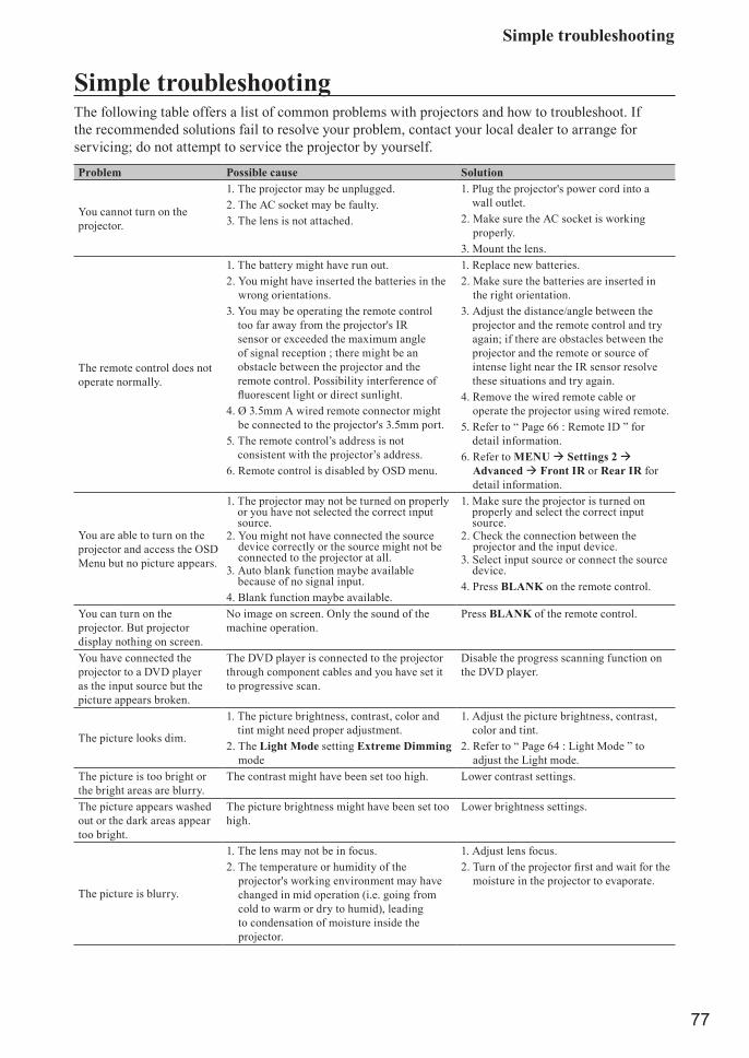
Simple troubleshooting
77
Simple troubleshootingThe following table offers a list of common problems with projectors and how to troubleshoot. If the recommended solutions fail to resolve your problem, contact your local dealer to arrange for servicing; do not attempt to service the projector by yourself.
Problem Possible cause Solution
You cannot turn on the projector.
1. The projector may be unplugged.2. The AC socket may be faulty.3. The lens is not attached.
1. Plug the projector's power cord into a wall outlet.
2. Make sure the AC socket is working properly.
3. Mount the lens.
The remote control does not operate normally.
1. The battery might have run out.2. You might have inserted the batteries in the
wrong orientations.3. You may be operating the remote control
too far away from the projector's IR sensor or exceeded the maximum angle of signal reception ; there might be an obstacle between the projector and the remote control. Possibility interference of fluorescent light or direct sunlight.
4. Ø 3.5mm A wired remote connector might be connected to the projector's 3.5mm port.
5. The remote control’s address is not consistent with the projector’s address.
6. Remote control is disabled by OSD menu.
1. Replace new batteries.2. Make sure the batteries are inserted in
the right orientation.3. Adjust the distance/angle between the
projector and the remote control and try again; if there are obstacles between the projector and the remote or source of intense light near the IR sensor resolve these situations and try again.
4. Remove the wired remote cable or operate the projector using wired remote.
5. Refer to “ Page 66 : Remote ID ” for detail information.
6. Refer to MENU Settings 2 Advanced Front IR or Rear IR for detail information.
You are able to turn on the projector and access the OSD Menu but no picture appears.
1. The projector may not be turned on properly or you have not selected the correct input source.
2. You might not have connected the source device correctly or the source might not be connected to the projector at all.
3. Auto blank function maybe available because of no signal input.
4. Blank function maybe available.
1. Make sure the projector is turned on properly and select the correct input source.
2. Check the connection between the projector and the input device.
3. Select input source or connect the source device.
4. Press BLANK on the remote control.
You can turn on the projector. But projector display nothing on screen.
No image on screen. Only the sound of the machine operation.
Press BLANK of the remote control.
You have connected the projector to a DVD player as the input source but the picture appears broken.
The DVD player is connected to the projector through component cables and you have set it to progressive scan.
Disable the progress scanning function on the DVD player.
The picture looks dim.
1. The picture brightness, contrast, color and tint might need proper adjustment.
2. The Light Mode setting Extreme Dimming mode
1. Adjust the picture brightness, contrast, color and tint.
2. Refer to “ Page 64 : Light Mode ” to adjust the Light mode.
The picture is too bright or the bright areas are blurry.
The contrast might have been set too high. Lower contrast settings.
The picture appears washed out or the dark areas appear too bright.
The picture brightness might have been set too high.
Lower brightness settings.
The picture is blurry.
1. The lens may not be in focus.2. The temperature or humidity of the
projector's working environment may have changed in mid operation (i.e. going from cold to warm or dry to humid), leading to condensation of moisture inside the projector.
1. Adjust lens focus.2. Turn of the projector first and wait for the
moisture in the projector to evaporate.

Simple troubleshooting
78
Problem Possible cause Solution
The color of the picture looks pale.
1. The input signal type might not have been connected properly.
2. The Color is not correct setting.
1. Check to make sure that the connections between the projector and the input device are correct.
2. Press Menu to adjust the color related setting.
The picture flashes occasionally.
1. The cables might not have been properly connected or the input device itself may be faulty.
1. Make sure the connector and the input device have been properly connected; check to see if the input device is in normal working order.
The colors of the projected picture are out of place (i.e. displaying red as blue).
The G/Y, R/Pr, B/Pb cables from the input might have been incorrectly connected to the input.
Please make sure the input source has been correctly connected to the projector.
The noise from the cooling fan suddenly grew louder.
1. The temperature inside the projector might have risen.
2. The OSD menu set the High mode
1. When the temperature inside the projector rises, the cooling fan will operate at a higher speed to discharge the internal heat more rapidly.
2. Set the Fan Speed to Normal if the projector is under 4000ft. Refer to “ Page 66 : Fan Speed ”.
The LED indicator on the projector’s top panel is blinking in red.
The cooling fan, power....etc. could be faulty. Refer to the definition of “ Page 78 : LED status ”.
1. During projection, the light suddenly goes off and the picture disappears.
2. The lights does not turn on even when the projector has been turned on.
The light module might have been damaged; check the LED indicator on the front of the projector and see if it is blinking in red.
The light module has reached the end of its service life; please replace it.
LED status
Error DetailLED
Power Light Temp Fan
SYS_ERR_NO_ERROR System working well Fix - - -
SYS_ERR_OVERTEMP Over temperature on system (Reserved) - - Fix -
SYS_ERR_T1 T1 sensor open error (Reserved) 3 1 - -
SYS_ERR_THSENSOR0 Thermistor sensor 0 open (Reserved) 3 2 - -
SYS_ERR_THSENSOR1 Thermistor sensor 1 open (Reserved) 3 3 - -
SYS_ERR_THBREAK Thermal break sensor error 4 - - -
SYS_ERR_G794 Thermal IC initial failed (Reserved) 4 1 - -
SYS_ERR_G7932 Fan control IC initial failed Fan1~Fan4 4 2
SYS_ERR_G7931_1 Fan control IC initial failed Fan5~Fan7 4 3
SYS_ERR_G7931_2 Fan control IC initial failed Fan8~Fan9 4 4
SYS_ERR_G781_1 Thermal sensor IC initial failed (CW T2) 4 5
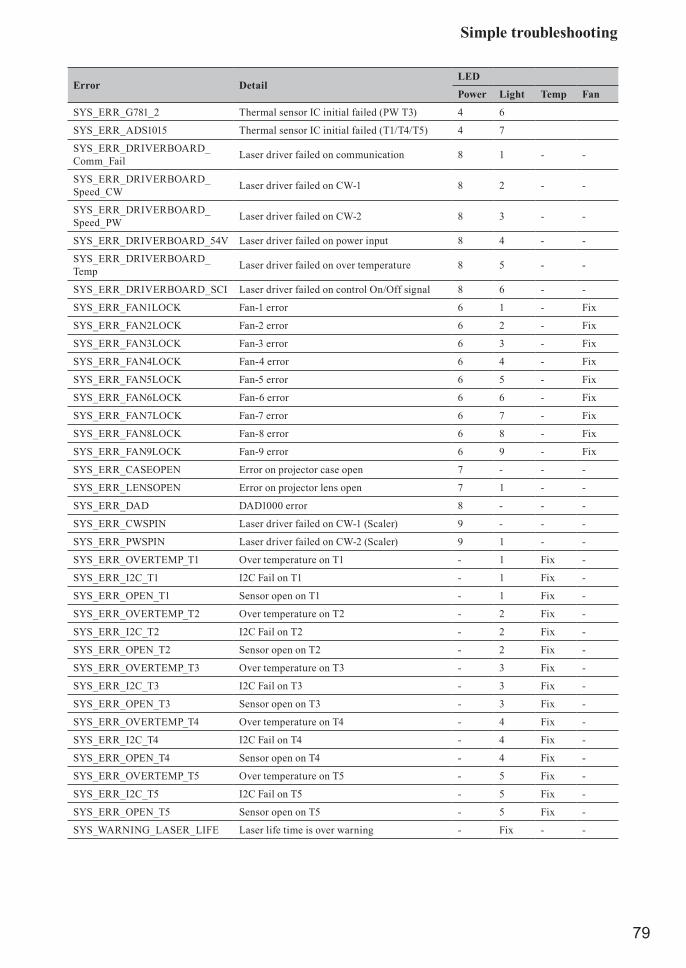
Simple troubleshooting
79
Error DetailLED
Power Light Temp Fan
SYS_ERR_G781_2 Thermal sensor IC initial failed (PW T3) 4 6
SYS_ERR_ADS1015 Thermal sensor IC initial failed (T1/T4/T5) 4 7
SYS_ERR_DRIVERBOARD_Comm_Fail Laser driver failed on communication 8 1 - -
SYS_ERR_DRIVERBOARD_Speed_CW Laser driver failed on CW-1 8 2 - -
SYS_ERR_DRIVERBOARD_Speed_PW Laser driver failed on CW-2 8 3 - -
SYS_ERR_DRIVERBOARD_54V Laser driver failed on power input 8 4 - -
SYS_ERR_DRIVERBOARD_Temp Laser driver failed on over temperature 8 5 - -
SYS_ERR_DRIVERBOARD_SCI Laser driver failed on control On/Off signal 8 6 - -
SYS_ERR_FAN1LOCK Fan-1 error 6 1 - Fix
SYS_ERR_FAN2LOCK Fan-2 error 6 2 - Fix
SYS_ERR_FAN3LOCK Fan-3 error 6 3 - Fix
SYS_ERR_FAN4LOCK Fan-4 error 6 4 - Fix
SYS_ERR_FAN5LOCK Fan-5 error 6 5 - Fix
SYS_ERR_FAN6LOCK Fan-6 error 6 6 - Fix
SYS_ERR_FAN7LOCK Fan-7 error 6 7 - Fix
SYS_ERR_FAN8LOCK Fan-8 error 6 8 - Fix
SYS_ERR_FAN9LOCK Fan-9 error 6 9 - Fix
SYS_ERR_CASEOPEN Error on projector case open 7 - - -
SYS_ERR_LENSOPEN Error on projector lens open 7 1 - -
SYS_ERR_DAD DAD1000 error 8 - - -
SYS_ERR_CWSPIN Laser driver failed on CW-1 (Scaler) 9 - - -
SYS_ERR_PWSPIN Laser driver failed on CW-2 (Scaler) 9 1 - -
SYS_ERR_OVERTEMP_T1 Over temperature on T1 - 1 Fix -
SYS_ERR_I2C_T1 I2C Fail on T1 - 1 Fix -
SYS_ERR_OPEN_T1 Sensor open on T1 - 1 Fix -
SYS_ERR_OVERTEMP_T2 Over temperature on T2 - 2 Fix -
SYS_ERR_I2C_T2 I2C Fail on T2 - 2 Fix -
SYS_ERR_OPEN_T2 Sensor open on T2 - 2 Fix -
SYS_ERR_OVERTEMP_T3 Over temperature on T3 - 3 Fix -
SYS_ERR_I2C_T3 I2C Fail on T3 - 3 Fix -
SYS_ERR_OPEN_T3 Sensor open on T3 - 3 Fix -
SYS_ERR_OVERTEMP_T4 Over temperature on T4 - 4 Fix -
SYS_ERR_I2C_T4 I2C Fail on T4 - 4 Fix -
SYS_ERR_OPEN_T4 Sensor open on T4 - 4 Fix -
SYS_ERR_OVERTEMP_T5 Over temperature on T5 - 5 Fix -
SYS_ERR_I2C_T5 I2C Fail on T5 - 5 Fix -
SYS_ERR_OPEN_T5 Sensor open on T5 - 5 Fix -
SYS_WARNING_LASER_LIFE Laser life time is over warning - Fix - -

Specifications
80
SpecificationsSpecificationsDescription Specifications
Model Name LP-WU6600 LP-WU6700
Resolution 1920 × 1200 (Native)
Micro display 1 x 0.67" WUXGA DMD
Contrast 1300:1(Native) / 20000:1 (Dynamic Dimming or other equivalent)
Luminance uniformity ≥ 90%
LightLaser Diode: 6 BanksGreen and Red by laser phosphorBlue by diffuse laser
Laser Diode: 8 BanksGreen and Red by laser phosphorBlue by diffuse laser
Projection lens - projection ratio
SD-63 (SDT Lens) (1.54~1.93: 1 36.1~211inch)SL-62 (Semi Short Throw Lens) (1.1~1.3: 1 35.8~379.8inch)ML-64 (Long Throw Lens) (1.93~2.9: 1 32.1~481inch)
Input/Output ports
1 x 3.5mm Mini Jack for 12V Trigger1 x Computer In (5BNC RGBHV/YPbPr/YCbCr)1 x COMPUTER IN (D-SUB)1 x RS-2321 x Wire Remote1 x HDBaseT1 x RJ451 x USB Power1 x 3D Sync In1 x Video1 x Service1 x Audio In (L/R)1 x Audio In1 x HDMI1 x HDMI/MHL1 x DVI -D1 x Monitor Out1 x Wire Remote Out1 x 3D Sync Out1 x RS232 Out1 x Audio Out (L/R)
Primary voltage range 100V - 130V (±10%) / 200V - 240V (±10%)
Standby power consumption 0.5W max power when Standby Power setting is disabled
Maximum input resolution 1920 × 1200
Operating temperature 0~40°C
Weight 23 kg (Without PJ Lens) 23.5 kg (Without PJ Lens)
Optional partsCeiling mount equipmentHAS-204L (Standard ceiling mount)
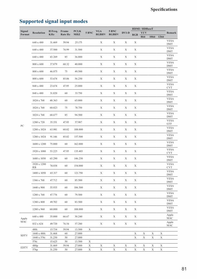
Specifications
81
Supported signal input modes
Signal Format Resolution H Freq.
KHzFrame Rate Hz
PCLK MHZ 5 BNC VGA
RGBHV5 BNC RGBHV DVI-D
HDMI / HDBaseTRemark
RGBYUV8bit 10bit 12bit
PC
640 x 480 31.469 59.94 25.175 X X X X VESA DMT
640 x 480 37.500 74.99 31.500 X X X X VESA DMT
640 x 480 43.269 85 36.000 X X X X VESA DMT
800 x 600 37.879 60.32 40.000 X X X X VESA DMT
800 x 600 46.875 75 49.500 X X X X VESA DMT
800 x 600 53.674 85.06 56.250 X X X X VESA DMT
848 x 480 23.674 47.95 25.000 X X X X VESA CVT
848 x 480 31.020 60 33.750 X X X X VESA DMT
1024 x 768 48.363 60 65.000 X X X X VESA DMT
1024 x 768 60.023 75 78.750 X X X X VESA DMT
1024 x 768 68.677 85 94.500 X X X X VESA DMT
1280 x 720 35.531 47.95 57.987 X X X X VESA GTF
1280 x 1024 63.981 60.02 108.000 X X X X VESA DMT
1280 x 1024 91.146 85.02 157.500 X X X X VESA DMT
1600 x 1200 75.000 60 162.000 X X X X VESA DMT
1920 x 1080 53.225 47.95 135.403 X X X X VESA CVT
1680 x 1050 65.290 60 146.250 X X X X VESA DMT
1920 x 1200 RB 74.038 60 154.000 X X X X VESA
CVT
1400 x 1050 65.317 60 121.750 X X X X VESA DMT
1366 x 768 47.712 60 85.500 X X X X VESA DMT
1440 x 900 55.935 60 106.500 X X X X VESA DMT
1280 x 768 47.776 60 79.500 X X X X VESA DMT
1280 x 800 49.702 60 83.500 X X X X VESA DMT
1280 x 960 60.000 60 108.000 X X X X VESA DMT
Apple MAC
640 x 480 35.000 66.67 30.240 X X X X Apple MAC
832 x 624 49.720 74.54 57.280 X X X X Apple MAC
SDTV
480i 15.734 59.94 13.500 X1440 x 480i 31.468 60 27.000 X X X X1440 x 576i 31.250 50 27.000 X X X X576i 15.625 50 13.500 X
EDTV480p 31.469 59.94 27.000 X X X X X X X X576p 31.250 50 27.000 X X X X X X X X

Specifications
82
Signal Format Resolution H Freq.
KHzFrame Rate Hz
PCLK MHZ 5 BNC VGA
RGBHV5 BNC RGBHV DVI-D
HDMI / HDBaseTRemark
RGBYUV8bit 10bit 12bit
HDTV
1035i 33.750 60 74.250 X X X X X X X X1080i 28.125 50 74.250 X X X X X X X X1080i 33.716 59.94 74.176 X X X X X X X X1080i 33.750 60 74.250 X X X X X X X X720p 37.500 50 74.250 X X X X X X X X720p 44.955 59.94 74.176 X X X X X X X X720p 45.000 60 74.250 X X X X X X X X1080p 26.973 23.98 74.176 X X X X X X X X1080p 27.000 24 74.250 X X X X X X X X1080p 28.125 25 74.250 X X X X X X X X1080p 33.716 29.97 74.176 X X X X X X X X1080p 33.750 30 74.250 X X X X X X X X1080p 56.250 50 148.500 X X X X X X X X1080p 67.433 59.94 148.352 X X X X X X X X1080p 67.500 60 148.500 X X X X X X X X
3D timing formatStandard Resolution V-Freq
(Hz)V-Total H-Freq
(kHz)HDBaseT (*1)
HDMI1/2 (*1)
DVI-D (*2)
Remarks
720p50 Frame Packing 1280x720 50 1470 37.5 √ √ *3720p59 Frame Packing 1280x720 59.94 1470 44.96 √ √ *3720p60 Frame Packing 1280x720 60 1470 45 √ √ *3720p50 Top-and-Bottom 1280x720 50 750 37.5 √ √ √ *3720p59 Top-and-Bottom 1280x720 59.94 750 44.96 √ √ √ *3720p60 Top-and-Bottom 1280x720 60 750 45 √ √ √ *31080p23 Frame Packing 1920x1080 23.98 2205 26.97 √ √1080p24 Frame Packing 1920x1080 24 2205 27 √ √1080i50 Side-by-Side (Half) 1920x1080 50 1125 56.25 √ √ √ *31080i59 Side-by-Side (Half) 1920x1080 59.94 1125 67.43 √ √ √ *31080i60 Side-by-Side (Half) 1920x1080 60 1125 67.5 √ √ √ *31080p50 Side-by-Side (Half) 1920x1080 50 1125 56.25 √ √ √ *31080p59 Side-by-Side (Half) 1920x1080 59.94 1125 67.43 √ √ √ *31080p60 Side-by-Side (Half) 1920x1080 60 1125 67.5 √ √ √ *31080p50 Top-and-Bottom 1920x1080 50 1125 56.25 √ √ √ *31080p59 Top-and-Bottom 1920x1080 59.94 1125 67.43 √ √ √ *31080p60 Top-and-Bottom 1920x1080 60 1125 67.5 √ √ √ *31080p50 Frame Sequential 1920x1080 50 1125 56.25 √ √ √ *31080p59 Frame Sequential 1920x1080 59.64 1125 67.43 √ √ √ *31080p60 Frame Sequential 1920x1080 60 1125 67.5 √ √ √ *3
*1: Base on IT6802 chip specification*2: Base on IT6633 chip specification*3: Frame drop at scaler and frame doubling at formatter

Specifications
83
Dimensions470.00
517.00
202.00
216.60
LIGH
T
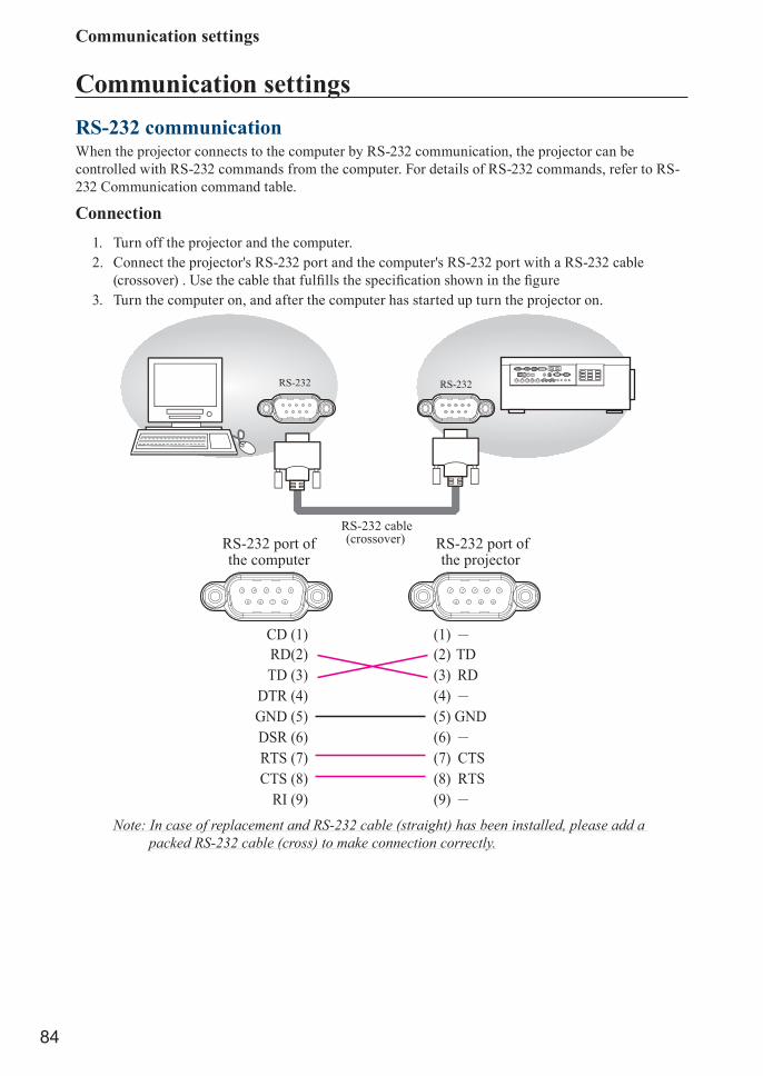
Communication settings
84
Communication settingsRS-232 communicationWhen the projector connects to the computer by RS-232 communication, the projector can be controlled with RS-232 commands from the computer. For details of RS-232 commands, refer to RS-232 Communication command table.
Connection1. Turn off the projector and the computer.2. Connect the projector's RS-232 port and the computer's RS-232 port with a RS-232 cable
(crossover) . Use the cable that fulfills the specification shown in the figure 3. Turn the computer on, and after the computer has started up turn the projector on.
CD (1) (1) RD(2) (2) TDTD (3) (3) RD
DTR (4) (4) GND (5) (5) GNDDSR (6) (6) RTS (7) (7) CTSCTS (8) (8) RTS
RI (9) (9)
RS-232 cable(crossover)
RS-232 RS-232
4 5321
9876
2 1345
6789
RS-232 port ofthe computer
RS-232 port ofthe projector
Note: In case of replacement and RS-232 cable (straight) has been installed, please add a packed RS-232 cable (cross) to make connection correctly.

Communication settings
85
1. Protocol19200bps,8N1
2. Command format("h" shows hexadecimal)
Byte Number 60 1 2 3 4 5 7 8 9 1110 12
Command
Action
Header DataHeader
code PacketDatasize
CRC flag Action Type Setting
codeL H L H L H L H L H L H
<SET> Change setting to desired value [(cL)(cH)] by [(bL)(bH)].
BEh EFh 03h 06h 00h
(aL) (aH) 01h 00h (bL) (bH) (cL) (cH)
<GET> Read projector internal setup value [(bL)(bH)] .
(aL) (aH) 02h 00h (bL) (bH) 00h 00h
<INCREMENT> Increment setup value [(bL)(bH)] by 1.
(aL) (aH) 04h 00h (bL) (bH) 00h 00h
<DECREMENT> Decrement setup value [(bL)(bH)] by 1.
(aL) (aH) 05h 00h (bL) (bH) 00h 00h
<EXECUTE> Run a command [(bL)(bH)] . (aL) (aH) 06h 00h (bL) (bH) 00h 00h
[Header code] [Packet] [Data size]Set [BEh, EFh, 03h, 06h, 00h] to byte number 0~4.[CRCflag]For byte number 5, 6, refer to RS-232 Communication command table.[Action]Set functional code to byte number 7, 8.<SET> = [01h, 00h], <GET> = [02h, 00h], <INCREMENT> =[04h, 00h]<DECREMENT> = [05h, 00h], <EXECUTE> = [06h, 00h]Refer to RS232 Communication command table [Type] [Setting code]For byte number 9~12 , , refer to RS-232 Communication command table.
3. Response code / Error code("h" shows hexadecimal)1. ACK reply: 06h
When the projector receives the Set, Increment, Decrement or Execute , command correctly, the projector changes the setting data for the specified , item by [Type], and it returns the code.
2. NAK reply: 15hWhen the projector cannot understand the received command, the projector , returns the error code. In such a case, check the sending code and send the same command again.
3. Error reply: 1Ch + 0000hWhen the projector cannot execute the received command for any reasons, the projector returns the error code. In such a case, check the sending code and the setting status of the projector.

Communication settings
86
4. Data reply: 1Dh + xxxxhWhen the projector receives the GET command correctly, the projector returns the response code and 2 bytes of data.Note: For connecting the projector to your devices, please read the manual for each devices, and
connect them correctly with suitable cables.Note: Operation cannot be guaranteed when the projector receives an undefined command or
data.Note: Provide an interval of at least 40ms between the response code and any other code.Note: The projector outputs test data when the power supply is switched ON, and when the light
is lit. Ignore this data.Note: Commands are not accepted during warm-up.Note: When the data length is greater than indicated by the data length code, the projector
ignore the excess data code. Conversely when the data length is shorter than indicated by the data length code, the projector returns the error code to the computer.
Command control via the networkWhen the projector connects network, the projector can be controlled with RS-232C commands from the computer with web browser. For details of RS-232C commands, refer to RS-232C Communication / Network command table.
Connection1. Turn off the projector and the computer.2. If you use wired LAN, connect the projector’s RJ45 port to the computer’s LAN or HDBaseT
port with a LAN cable. Use the cable that fulfills the specification shown in figure.3. Turn the computer on, and after the computer has started up turn the projector on.
LAN
RJ45 or HDBaseT port
• LAN cable (CAT-5e or greater)or
• For HDBaseT connection - CAT-5e or greater - shielded type (connectors included) - straight cable - single cable
Communication portThe following two ports are assigned for the command control.
TCP #23
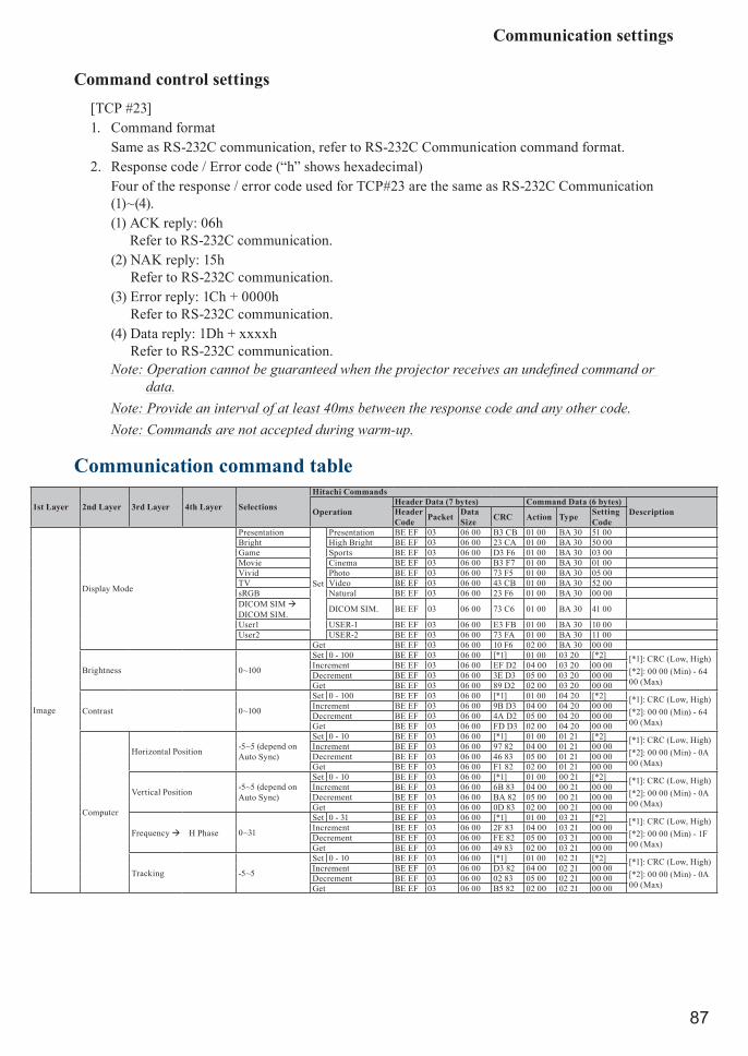
Communication settings
87
Command control settings[TCP #23]1. Command format
Same as RS-232C communication, refer to RS-232C Communication command format.2. Response code / Error code (“h” shows hexadecimal)
Four of the response / error code used for TCP#23 are the same as RS-232C Communication (1)~(4).(1) ACK reply: 06h
Refer to RS-232C communication.(2) NAK reply: 15h
Refer to RS-232C communication.(3) Error reply: 1Ch + 0000h
Refer to RS-232C communication.(4) Data reply: 1Dh + xxxxh
Refer to RS-232C communication.Note: Operation cannot be guaranteed when the projector receives an undefined command or
data.Note: Provide an interval of at least 40ms between the response code and any other code.Note: Commands are not accepted during warm-up.
Communication command table
1st Layer 2nd Layer 3rd Layer 4th Layer Selections
Hitachi Commands
OperationHeader Data (7 bytes) Command Data (6 bytes)
DescriptionHeader Code Packet Data
Size CRC Action Type Setting Code
Image
Display Mode
Presentation
Set
Presentation BE EF 03 06 00 B3 CB 01 00 BA 30 51 00Bright High Bright BE EF 03 06 00 23 CA 01 00 BA 30 50 00Game Sports BE EF 03 06 00 D3 F6 01 00 BA 30 03 00Movie Cinema BE EF 03 06 00 B3 F7 01 00 BA 30 01 00Vivid Photo BE EF 03 06 00 73 F5 01 00 BA 30 05 00TV Video BE EF 03 06 00 43 CB 01 00 BA 30 52 00sRGB Natural BE EF 03 06 00 23 F6 01 00 BA 30 00 00DICOM SIM DICOM SIM. DICOM SIM. BE EF 03 06 00 73 C6 01 00 BA 30 41 00
User1 USER-1 BE EF 03 06 00 E3 FB 01 00 BA 30 10 00User2 USER-2 BE EF 03 06 00 73 FA 01 00 BA 30 11 00
Get BE EF 03 06 00 10 F6 02 00 BA 30 00 00
Brightness 0~100
Set 0 - 100 BE EF 03 06 00 [*1] 01 00 03 20 [*2] [*1]: CRC (Low, High)[*2]: 00 00 (Min) - 64 00 (Max)
Increment BE EF 03 06 00 EF D2 04 00 03 20 00 00Decrement BE EF 03 06 00 3E D3 05 00 03 20 00 00Get BE EF 03 06 00 89 D2 02 00 03 20 00 00
Contrast 0~100
Set 0 - 100 BE EF 03 06 00 [*1] 01 00 04 20 [*2] [*1]: CRC (Low, High)[*2]: 00 00 (Min) - 64 00 (Max)
Increment BE EF 03 06 00 9B D3 04 00 04 20 00 00Decrement BE EF 03 06 00 4A D2 05 00 04 20 00 00Get BE EF 03 06 00 FD D3 02 00 04 20 00 00
Computer
Horizontal Position -5~5 (depend on Auto Sync)
Set 0 - 10 BE EF 03 06 00 [*1] 01 00 01 21 [*2] [*1]: CRC (Low, High)[*2]: 00 00 (Min) - 0A 00 (Max)
Increment BE EF 03 06 00 97 82 04 00 01 21 00 00Decrement BE EF 03 06 00 46 83 05 00 01 21 00 00Get BE EF 03 06 00 F1 82 02 00 01 21 00 00
Vertical Position -5~5 (depend on Auto Sync)
Set 0 - 10 BE EF 03 06 00 [*1] 01 00 00 21 [*2] [*1]: CRC (Low, High)[*2]: 00 00 (Min) - 0A 00 (Max)
Increment BE EF 03 06 00 6B 83 04 00 00 21 00 00Decrement BE EF 03 06 00 BA 82 05 00 00 21 00 00Get BE EF 03 06 00 0D 83 02 00 00 21 00 00
Frequency H Phase 0~31
Set 0 - 31 BE EF 03 06 00 [*1] 01 00 03 21 [*2] [*1]: CRC (Low, High)[*2]: 00 00 (Min) - 1F 00 (Max)
Increment BE EF 03 06 00 2F 83 04 00 03 21 00 00Decrement BE EF 03 06 00 FE 82 05 00 03 21 00 00Get BE EF 03 06 00 49 83 02 00 03 21 00 00
Tracking -5~5
Set 0 - 10 BE EF 03 06 00 [*1] 01 00 02 21 [*2] [*1]: CRC (Low, High)[*2]: 00 00 (Min) - 0A 00 (Max)
Increment BE EF 03 06 00 D3 82 04 00 02 21 00 00Decrement BE EF 03 06 00 02 83 05 00 02 21 00 00Get BE EF 03 06 00 B5 82 02 00 02 21 00 00

Communication settings
88
1st Layer 2nd Layer 3rd Layer 4th Layer Selections
Hitachi Commands
OperationHeader Data (7 bytes) Command Data (6 bytes)
DescriptionHeader Code Packet Data
Size CRC Action Type Setting Code
Image
Auto Image Execute BE EF 03 06 00 91 D0 06 00 0A 20 00 00
Advanced
Brilliant Color 0~10
Set 0 - 10 BE EF 03 06 00 [*1] 01 00 9C 22 [*2] [*1]: CRC (Low, High)[*2]: 00 00 (Min) - C8 00 (Max)
Increment BE EF 03 06 00 3B 5D 04 00 9C 22 00 00Decrement BE EF 03 06 00 EA 5C 05 00 9C 22 00 00Get BE EF 03 06 00 5D 5D 02 00 9C 22 00 00
Sharpness 0~31
Set 0 - 31 BE EF 03 06 00 [*1] 01 00 01 22 [*2] [*1]: CRC (Low, High)[*2]: 00 00 (Min) - 1F 00 (Max)
Increment BE EF 03 06 00 97 72 04 00 01 22 00 00Decrement BE EF 03 06 00 46 73 05 00 01 22 00 00Get BE EF 03 06 00 F1 72 02 00 01 22 00 00
Gamma
1.8
Set
1.8 BE EF 03 06 00 3B 86 01 00 A0 30 B4 002.0 2.0 BE EF 03 06 00 FB A6 01 00 A0 30 C8 002.2 2.2 BE EF 03 06 00 FB A9 01 00 A0 30 DC 002.4 2.4 BE EF 03 06 00 3B B5 01 00 A0 30 F0 00B&W B&W BE EF 03 06 00 EB F1 01 00 A0 30 FD FF Get first byte onlyLinear Linear BE EF 03 06 00 1B F1 01 00 A0 30 FE FF Get first byte only
Get BE EF 03 06 00 08 F1 02 00 A0 30 00 00
Color Temperature
WarmSet
Low BE EF 03 06 00 6B F4 01 00 B0 30 01 00Normal Mid-1 BE EF 03 06 00 9B F4 01 00 B0 30 02 00Cold High BE EF 03 06 00 0B F5 01 00 B0 30 03 00
Get BE EF 03 06 00 C8 F5 02 00 B0 30 00 00
Video AGCOff Set Off BE EF 03 06 00 92 5C 01 00 9D 22 00 00On On BE EF 03 06 00 02 5D 01 00 9D 22 01 00
Get BE EF 03 06 00 A1 5C 02 00 9D 22 00 00
Video Saturation 0~100
Set 0 - 100 BE EF 03 06 00 [*1] 01 00 02 22 [*2] [*1]: CRC (Low, High)[*2]: 00 00 (Min) - 64 00 (Max)
Increment BE EF 03 06 00 D3 72 04 00 02 22 00 00Decrement BE EF 03 06 00 02 73 05 00 02 22 00 00Get BE EF 03 06 00 B5 72 02 00 02 22 00 00
Video Tint 0~100
Set 0 - 100 BE EF 03 06 00 [*1] 01 00 03 22 [*2] [*1]: CRC (Low, High)[*2]: 00 00 (Min) - 64 00 (Max)
Increment BE EF 03 06 00 2F 73 04 00 03 22 00 00Decrement BE EF 03 06 00 FE 72 05 00 03 22 00 00Get BE EF 03 06 00 49 73 02 00 03 22 00 00
White Balance
R Gain 0 ~ 200
Set 0 - 200 BE EF 03 06 00 [*1] 01 00 B1 30 [*2] [*1]: CRC (Low, High)[*2]: 00 00 (Min) - C8 00 (Max)
Increment BE EF 03 06 00 52 F4 04 00 B1 30 00 00Decrement BE EF 03 06 00 83 F5 05 00 B1 30 00 00Get BE EF 03 06 00 34 F4 02 00 B1 30 00 00
G Gain 0 ~ 200
Set 0 - 200 BE EF 03 06 00 [*1] 01 00 B2 30 [*2] [*1]: CRC (Low, High)[*2]: 00 00 (Min) - C8 00 (Max)
Increment BE EF 03 06 00 16 F4 04 00 B2 30 00 00Decrement BE EF 03 06 00 C7 F5 05 00 B2 30 00 00Get BE EF 03 06 00 70 F4 02 00 B2 30 00 00
B Gain 0 ~ 200
Set 0 - 200 BE EF 03 06 00 [*1] 01 00 B3 30 [*2] [*1]: CRC (Low, High)[*2]: 00 00 (Min) - C8 00 (Max)
Increment BE EF 03 06 00 EA F5 04 00 B3 30 00 00Decrement BE EF 03 06 00 3B F4 05 00 B3 30 00 00Get BE EF 03 06 00 8C F5 02 00 B3 30 00 00
R Offset 0 ~ 200
Set 0 - 200 BE EF 03 06 00 [*1] 01 00 B5 30 [*2] [*1]: CRC (Low, High)[*2]: 00 00 (Min) - C8 00 (Max)
Increment BE EF 03 06 00 62 F5 04 00 B5 30 00 00Decrement BE EF 03 06 00 B3 F4 05 00 B5 30 00 00Get BE EF 03 06 00 04 F5 02 00 B5 30 00 00
G Offset 0 ~ 200
Set 0 - 200 BE EF 03 06 00 [*1] 01 00 B6 30 [*2] [*1]: CRC (Low, High)[*2]: 00 00 (Min) - C8 00 (Max)
Increment BE EF 03 06 00 26 F5 04 00 B6 30 00 00Decrement BE EF 03 06 00 F7 F4 05 00 B6 30 00 00Get BE EF 03 06 00 40 F5 02 00 B6 30 00 00
B Offset 0 ~ 200
Set 0 - 200 BE EF 03 06 00 [*1] 01 00 B7 30 [*2] [*1]: CRC (Low, High)[*2]: 00 00 (Min) - C8 00 (Max)
Increment BE EF 03 06 00 DA F4 04 00 B7 30 00 00Decrement BE EF 03 06 00 0B F5 05 00 B7 30 00 00Get BE EF 03 06 00 BC F4 02 00 B7 30 00 00
Color Manager
Red
Hue 0~100
Set 0 - 100 BE EF 03 06 00 [*1] 01 00 00 27 [*2] [*1]: CRC (Low, High)[*2]: 00 00 (Min) - 64 00 (Max)
Increment BE EF 03 06 00 6A 63 04 00 00 27 00 00Decrement BE EF 03 06 00 BB 62 05 00 00 27 00 00Get BE EF 03 06 00 0C 63 02 00 00 27 00 00
Saturation 0~100
Set 0 - 100 BE EF 03 06 00 [*1] 01 00 10 27 [*2] [*1]: CRC (Low, High)[*2]: 00 00 (Min) - 64 00 (Max)
Increment BE EF 03 06 00 AA 67 04 00 10 27 00 00Decrement BE EF 03 06 00 7B 66 05 00 10 27 00 00Get BE EF 03 06 00 CC 67 02 00 10 27 00 00
Gain 0~100
Set 0 - 100 BE EF 03 06 00 [*1] 01 00 20 27 [*2] [*1]: CRC (Low, High)[*2]: 00 00 (Min) - 64 00 (Max)
Increment BE EF 03 06 00 AA 68 04 00 20 27 00 00Decrement BE EF 03 06 00 7B 69 05 00 20 27 00 00Get BE EF 03 06 00 CC 68 02 00 20 27 00 00
Green
Hue 0~100
Set 0 - 100 BE EF 03 06 00 [*1] 01 00 02 27 [*2] [*1]: CRC (Low, High)[*2]: 00 00 (Min) - 64 00 (Max)
Increment BE EF 03 06 00 D2 62 04 00 02 27 00 00Decrement BE EF 03 06 00 03 63 05 00 02 27 00 00Get BE EF 03 06 00 B4 62 02 00 02 27 00 00
Saturation 0~100
Set 0 - 100 BE EF 03 06 00 [*1] 01 00 12 27 [*2] [*1]: CRC (Low, High)[*2]: 00 00 (Min) - 64 00 (Max)
Increment BE EF 03 06 00 12 66 04 00 12 27 00 00Decrement BE EF 03 06 00 C3 67 05 00 12 27 00 00Get BE EF 03 06 00 74 66 02 00 12 27 00 00
Gain 0~100
Set 0 - 100 BE EF 03 06 00 [*1] 01 00 22 27 [*2] [*1]: CRC (Low, High)[*2]: 00 00 (Min) - 64 00 (Max)
Increment BE EF 03 06 00 12 69 04 00 22 27 00 00Decrement BE EF 03 06 00 C3 68 05 00 22 27 00 00Get BE EF 03 06 00 74 69 02 00 22 27 00 00

Communication settings
89
1st Layer 2nd Layer 3rd Layer 4th Layer Selections
Hitachi Commands
OperationHeader Data (7 bytes) Command Data (6 bytes)
DescriptionHeader Code Packet Data
Size CRC Action Type Setting Code
Image Color Manager
Blue
Hue 0~100
Set 0 - 100 BE EF 03 06 00 [*1] 01 00 04 27 [*2] [*1]: CRC (Low, High)[*2]: 00 00 (Min) - 64 00 (Max)
Increment BE EF 03 06 00 5A 62 04 00 04 27 00 00Decrement BE EF 03 06 00 8B 63 05 00 04 27 00 00Get BE EF 03 06 00 3C 62 02 00 04 27 00 00
Saturation 0~100
Set 0 - 100 BE EF 03 06 00 [*1] 01 00 14 27 [*2] [*1]: CRC (Low, High)[*2]: 00 00 (Min) - 64 00 (Max)
Increment BE EF 03 06 00 9A 66 04 00 14 27 00 00Decrement BE EF 03 06 00 4B 67 05 00 14 27 00 00Get BE EF 03 06 00 FC 66 02 00 14 27 00 00
Gain 0~100
Set 0 - 100 BE EF 03 06 00 [*1] 01 00 24 27 [*2] [*1]: CRC (Low, High)[*2]: 00 00 (Min) - 64 00 (Max)
Increment BE EF 03 06 00 9A 69 04 00 24 27 00 00Decrement BE EF 03 06 00 4B 68 05 00 24 27 00 00Get BE EF 03 06 00 FC 69 02 00 24 27 00 00
Cyan
Hue 0~100
Set 0 - 100 BE EF 03 06 00 [*1] 01 00 03 27 [*2] [*1]: CRC (Low, High)[*2]: 00 00 (Min) - 64 00 (Max)
Increment BE EF 03 06 00 2E 63 04 00 03 27 00 00Decrement BE EF 03 06 00 FF 62 05 00 03 27 00 00Get BE EF 03 06 00 48 63 02 00 03 27 00 00
Saturation 0~100
Set 0 - 100 BE EF 03 06 00 [*1] 01 00 13 27 [*2] [*1]: CRC (Low, High)[*2]: 00 00 (Min) - 64 00 (Max)
Increment BE EF 03 06 00 EE 67 04 00 13 27 00 00Decrement BE EF 03 06 00 3F 66 05 00 13 27 00 00Get BE EF 03 06 00 88 67 02 00 13 27 00 00
Gain 0~100
Set 0 - 100 BE EF 03 06 00 [*1] 01 00 23 27 [*2] [*1]: CRC (Low, High)[*2]: 00 00 (Min) - 64 00 (Max)
Increment BE EF 03 06 00 EE 68 04 00 23 27 00 00Decrement BE EF 03 06 00 3F 69 05 00 23 27 00 00Get BE EF 03 06 00 88 68 02 00 23 27 00 00
Magenta
Hue 0~100
Set 0 - 100 BE EF 03 06 00 [*1] 01 00 05 27 [*2] [*1]: CRC (Low, High)[*2]: 00 00 (Min) - 64 00 (Max)
Increment BE EF 03 06 00 A6 63 04 00 05 27 00 00Decrement BE EF 03 06 00 77 62 05 00 05 27 00 00Get BE EF 03 06 00 C0 63 02 00 05 27 00 00
Saturation 0~100
Set 0 - 100 BE EF 03 06 00 [*1] 01 00 15 27 [*2] [*1]: CRC (Low, High)[*2]: 00 00 (Min) - 64 00 (Max)
Increment BE EF 03 06 00 66 67 04 00 15 27 00 00Decrement BE EF 03 06 00 B7 66 05 00 15 27 00 00Get BE EF 03 06 00 00 67 02 00 15 27 00 00
Gain 0~100
Set 0 - 100 BE EF 03 06 00 [*1] 01 00 25 27 [*2] [*1]: CRC (Low, High)[*2]: 00 00 (Min) - 64 00 (Max)
Increment BE EF 03 06 00 66 68 04 00 25 27 00 00Decrement BE EF 03 06 00 B7 69 05 00 25 27 00 00Get BE EF 03 06 00 00 68 02 00 25 27 00 00
Yellow
Hue 0~100
Set 0 - 100 BE EF 03 06 00 [*1] 01 00 01 27 [*2] [*1]: CRC (Low, High)[*2]: 00 00 (Min) - 64 00 (Max)
Increment BE EF 03 06 00 96 62 04 00 01 27 00 00Decrement BE EF 03 06 00 47 63 05 00 01 27 00 00Get BE EF 03 06 00 F0 62 02 00 01 27 00 00
Saturation 0~100
Set 0 - 100 BE EF 03 06 00 [*1] 01 00 11 27 [*2] [*1]: CRC (Low, High)[*2]: 00 00 (Min) - 64 00 (Max)
Increment BE EF 03 06 00 56 66 04 00 11 27 00 00Decrement BE EF 03 06 00 87 67 05 00 11 27 00 00Get BE EF 03 06 00 30 66 02 00 11 27 00 00
Gain 0~100
Set 0 - 100 BE EF 03 06 00 [*1] 01 00 21 27 [*2] [*1]: CRC (Low, High)[*2]: 00 00 (Min) - 64 00 (Max)
Increment BE EF 03 06 00 56 69 04 00 21 27 00 00Decrement BE EF 03 06 00 87 68 05 00 21 27 00 00Get BE EF 03 06 00 30 69 02 00 21 27 00 00
White
Red 0~100
Set 0 - 100 BE EF 03 06 00 [*1] 01 00 28 27 [*2] [*1]: CRC (Low, High)[*2]: 00 00 (Min) - 64 00 (Max)
Increment BE EF 03 06 00 CA 6A 04 00 28 27 00 00Decrement BE EF 03 06 00 1B 6B 05 00 28 27 00 00Get BE EF 03 06 00 AC 6A 02 00 28 27 00 00
Green 0~100
Set 0 - 100 BE EF 03 06 00 [*1] 01 00 2A 27 [*2] [*1]: CRC (Low, High)[*2]: 00 00 (Min) - 64 00 (Max)
Increment BE EF 03 06 00 72 6B 04 00 2A 27 00 00Decrement BE EF 03 06 00 A3 6A 05 00 2A 27 00 00Get BE EF 03 06 00 14 6B 02 00 2A 27 00 00
Blue 0~100
Set 0 - 100 BE EF 03 06 00 [*1] 01 00 2C 27 [*2] [*1]: CRC (Low, High)[*2]: 00 00 (Min) - 64 00 (Max)
Increment BE EF 03 06 00 FA 6B 04 00 2C 27 00 00Decrement BE EF 03 06 00 2B 6A 05 00 2C 27 00 00Get BE EF 03 06 00 9C 6B 02 00 2C 27 00 00
Settings 1
Source
HDMI 1
Set
HDMI 1 BE EF 03 06 00 0E D2 01 00 00 20 03 00HDMI 2 / MHL HDMI 2 / MHL BE EF 03 06 00 6E D6 01 00 00 20 0D 00DVI DVI-D BE EF 03 06 00 AE D4 01 00 00 20 09 00VGA Computer in 1 BE EF 03 06 00 FE D2 01 00 00 20 00 00BNC Computer in 2 BE EF 03 06 00 3E D0 01 00 00 20 04 00Composite Video Video BE EF 03 06 00 6E D3 01 00 00 20 01 00HDBaseT HDBaseT BE EF 03 06 00 AE DE 01 00 00 20 11 00
Get BE EF 03 06 00 CD D2 02 00 00 20 00 00
Projection
Normal / Front
Set
Front Tabletop BE EF 03 06 00 C7 D2 01 00 01 30 00 00Rear Rear Tabletop BE EF 03 06 00 57 D3 01 00 01 30 01 00Ceiling Front Ceiling BE EF 03 06 00 37 D2 01 00 01 30 03 00Rear + Ceiling Rear Ceiling BE EF 03 06 00 A7 D3 01 00 01 30 02 00
Get BE EF 03 06 00 F4 D2 02 00 01 30 00 00
Aspect Ratio
Fill
Set
16:10 BE EF 03 06 00 3E D6 01 00 08 20 0A 004:3 4:3 BE EF 03 06 00 9E D0 01 00 08 20 00 0016:9 16:9 BE EF 03 06 00 0E D1 01 00 08 20 01 00Letter Box Letter Box BE EF 03 6 00 3E D3 01 00 08 20 06 00 Movie-1Native Native BE EF 03 6 00 5E D7 01 00 08 20 08 002.35:1 2.35:1 BE EF 03 6 00 0E D4 01 00 08 20 0D 00
Get BE EF 03 06 00 AD D0 02 00 08 20 00 00

Communication settings
90
1st Layer 2nd Layer 3rd Layer 4th Layer Selections
Hitachi Commands
OperationHeader Data (7 bytes) Command Data (6 bytes)
DescriptionHeader Code Packet Data
Size CRC Action Type Setting Code
Settings 1
Keystone
H: -25 ~ +25 -50 ~ +50
Set 0 - 100 BE EF 03 06 00 [*1] 01 00 0B 20 [*2] [*1]: CRC (Low, High)[*2]: 00 00 (Min) - 64 00 (Max)
Increment BE EF 03 06 00 8F D0 04 00 0B 20 00 00Decrement BE EF 03 06 00 5E D1 05 00 0B 20 00 00Get BE EF 03 06 00 E9 D0 02 00 0B 20 00 00
V: -30 ~ +30 -60 ~ +60
Set 0 - 120 BE EF 03 06 00 [*1] 01 00 07 20 [*2] [*1]: CRC (Low, High)[*2]: 00 00 (Min) - 78 00 (Max)
Increment BE EF 03 06 00 DF D3 04 00 07 20 00 00Decrement BE EF 03 06 00 0E D2 05 00 07 20 00 00Get BE EF 03 06 00 B9 D3 02 00 07 20 00 00
Digital Zoom -10~10
Set 90 - 110 BE EF 03 06 00 [*1] 01 00 94 22 [*2] [*1]: CRC (Low, High)[*2]: 5A 00 (Min) - 6E 00 (Max)
Increment BE EF 03 06 00 5B 5F 04 00 94 22 00 00Decrement BE EF 03 06 00 8A 5E 05 00 94 22 00 00Get BE EF 03 06 00 3D 5F 02 00 94 22 00 00
Audio
Volume 0~20
Set 0 - 20 BE EF 03 06 00 [*1] 02 00 01 20 [*2] [*1]: CRC (Low, High)[*2]: 00 00 (Min) - 14 00 (Max)
Increment BE EF 03 06 00 57 D3 04 00 01 20 00 00Decrement BE EF 03 06 00 86 D2 05 00 01 20 00 00Get BE EF 03 06 00 31 D3 02 00 01 20 00 00
MuteOff Set OFF BE EF 03 06 00 46 D3 01 00 02 20 00 00On ON BE EF 03 06 00 D6 D2 01 00 02 20 01 00
Get BE EF 03 06 00 75 D3 02 00 02 20 00 00
Internal SpeakerOff Set OFF BE EF 03 06 00 6E D5 01 00 1C 20 00 00On ON BE EF 03 06 00 FE D4 01 00 1C 20 01 00
Get BE EF 03 06 00 5D D5 02 00 1C 20 00 00
Advanced 1
Language
0 ENGLISH
Set
English BE EF 03 06 00 F7 D3 01 00 05 30 00 001 FRENCH French BE EF 03 06 00 67 D2 01 00 05 30 01 002 GERMAN German BE EF 03 06 00 97 D2 01 00 05 30 02 003 SPANISH Spanish BE EF 03 06 00 07 D3 01 00 05 30 03 004 PORTUGUESE Portuese BE EF 03 06 00 C7 D1 01 00 05 30 07 00
5 SIMPLIFIED_CHINESE
Chinese Simplified BE EF 03 06 00 A7 D5 01 00 05 30 09 00
6 TRADITIONAL_CHINESE
Chinese Traditional BE EF 03 06 00 37 DE 01 00 05 30 10 00
7 ITALIAN ITALIANO BE EF 03 06 00 37 D1 01 00 05 30 04 008 NORWEGIAN NORSK BE EF 03 06 00 A7 D0 01 00 05 30 05 009 SWEDISH SVENSKA BE EF 03 06 00 C7 D4 01 00 05 30 0B 0010 DUTCH NEDERLANDS BE EF 03 06 00 57 D0 01 00 05 30 06 0011 RUSSIAN PYCCKNN BE EF 03 06 00 F7 D6 01 00 05 30 0C 0012 POLISH POLSKI BE EF 03 06 00 97 D7 01 00 05 30 0E 0013 FINNISH SUOMI BE EF 03 06 00 67 D7 01 00 05 30 0D 0014 GREEK ギリシャ語 BE EF 03 06 00 07 DC 01 00 05 30 17 0015 KOREAN Korean BE EF 03 06 00 57 D5 01 00 05 30 0A 0016 HUNGARIAN ハンガリー語 BE EF 03 06 00 C7 DE 01 00 05 30 13 0017 CZECH チェコ語 BE EF 03 06 00 57 DF 01 00 05 30 12 0018 ARABIC アラビア語 BE EF 03 06 00 37 DB 01 00 05 30 1C 0019 TURKISH トルコ語 BE EF 03 06 00 07 D6 01 00 05 30 0F 0020 VIETNAMESE ベトナム語 BE EF 03 06 00 37 CA 01 00 05 30 20 0021 JAPANESE Japanese BE EF 03 06 00 37 D4 01 00 05 30 08 0022 THAI タイ語 BE EF 03 06 00 07 D9 01 00 05 30 1B 0023 FARSI ペルシャ語 BE EF 03 06 00 A7 DA 01 00 05 30 1D 0024 HEBREW ヘブライ語 BE EF 03 06 00 A7 CB 01 00 05 30 21 0025 DANISH デンマーク語 BE EF 03 06 00 A7 DF 01 00 05 30 11 00
26 FRENCH CANADIAN
FRENCH CANADIAN BE EF 03 06 00 57 CB 01 00 05 30 22 00
Get BE EF 03 06 00 C4 D3 02 00 05 30 00 00
Security LockOff Set Off BE EF 03 06 00 FA 37 01 00 10 36 00 00 非対応On On BE EF 03 06 00 6A 36 01 00 10 36 01 00 非対応
Get BE EF 03 06 00 C9 37 02 00 10 36 00 00 0: Off, 1:On
Blank Screen
Black
Set
Black BE EF 03 06 00 9B D0 01 00 00 30 06 00Red Red BE EF 03 06 00 3B D3 01 00 00 30 00 00Green Green BE EF 03 06 00 5B D2 01 00 00 30 02 00Blue Blue BE EF 03 06 00 CB D3 01 00 00 30 03 00White White BE EF 03 06 00 6B D0 01 00 00 30 05 00
Get BE EF 03 06 00 08 D3 02 00 00 30 00 00
Splash Logo
Std Set Logo BE EF 03 06 00 CB E3 01 00 04 30 40 00Black Black BE EF 03 06 00 AB D1 01 00 04 30 06 00Blue Blue BE EF 03 06 00 FB D2 01 00 04 30 03 00
Get BE EF 03 06 00 38 D2 02 00 04 30 00 00
Closed CaptioningOff Set Off BE EF 03 06 00 FA 62 01 00 00 37 00 00On On BE EF 03 06 00 6A 63 01 00 00 37 01 00
Get BE EF 03 06 00 C9 62 02 00 00 37 00 00
Keypad Lock
Off
Set
Off BE EF 03 06 00 03 96 01 00 11 24 00 00
On On BE EF 03 06 00 93 97 01 00 11 24 01 00実動作はAll?keypad only, not include remote controller
Get BE EF 03 06 00 30 96 02 00 11 24 00 00 --> change parameter
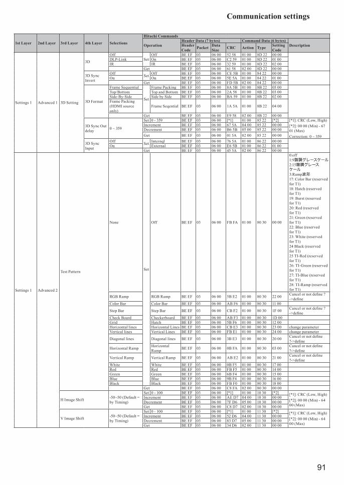
Communication settings
91
1st Layer 2nd Layer 3rd Layer 4th Layer Selections
Hitachi Commands
OperationHeader Data (7 bytes) Command Data (6 bytes)
DescriptionHeader Code Packet Data
Size CRC Action Type Setting Code
Settings 1 Advanced 1 3D Setting
3D
OffSet
Off BE EF 03 06 00 52 58 01 00 8D 22 00 00DLP-Link On BE EF 03 06 00 C2 59 01 00 8D 22 01 00IR IR BE EF 03 06 00 32 59 01 00 8D 22 02 00
Get BE EF 03 06 00 61 58 02 00 8D 22 00 00
3D Sync Invert
Off Set Off BE EF 03 06 00 CE 5B 01 00 84 22 00 00On On BE EF 03 06 00 5E 5A 01 00 84 22 01 00
Get BE EF 03 06 00 FD 5B 02 00 84 22 00 00
3D Format
Frame Sequential
Set
Frame Packing BE EF 03 06 00 8A 5B 01 00 8B 22 05 00Top/Bottom Top and Bottom BE EF 03 06 00 2A 58 01 00 8B 22 03 00Side-By-Side Side by Side BE EF 03 06 00 BA 59 01 00 8B 22 02 00Frame Packing (HDMI source only)
Frame Seqential BE EF 03 06 00 1A 5A 01 00 8B 22 04 00
Get BE EF 03 06 00 E9 58 02 00 8B 22 00 00
3D Sync Out delay 0 ~ 359
Set 0 - 359 BE EF 03 06 00 [*1] 01 00 85 22 [*2] [*1]: CRC (Low, High)[*2]: 00 00 (Min) - 67 01 (Max)Correction: 0 ~ 359
Increment BE EF 03 06 00 67 5A 04 00 85 22 00 00Decrement BE EF 03 06 00 B6 5B 05 00 85 22 00 00Get BE EF 03 06 00 01 5A 02 00 85 22 00 00
3D Sync Input
Off Set Internql BE EF 03 06 00 76 5A 01 00 86 22 00 00On External BE EF 03 06 00 E6 5B 01 00 86 22 01 00
Get BE EF 03 06 00 45 5A 02 00 86 22 00 00
Settings 1 Advanced 2
Test Pattern
None
Set
Off BE EF 03 06 00 FB FA 01 00 80 30 00 00
0:off 1:9諧調グレースケール 2:15諧調グレースケール 3:Ramp波形 17: Color Bar (reserved for T1) 18: Hatch (reserved for T1) 19: Burst (reserved for T1) 20: Red (reserved for T1) 21: Green (reserved for T1) 22: Blue (reserved for T1) 23: White (reserved for T1) 24 Black (reserved for T1) 25 TI-Red (reserved for T1) 26: TI-Green (reserved for T1) 27: TI-Blue (reserved for T1) 28: TI-Ramp (reserved for T1)
RGB Ramp RGB Ramp BE EF 03 06 00 5B E2 01 00 80 30 22 00 Cancel or not define ? ->define
Color Bar Color Bar BE EF 03 06 00 AB F6 01 00 80 30 11 00
Step Bar Step Bar BE EF 03 06 00 CB F2 01 00 80 30 1F 00 Cancel or not define ? ->define
Check Board Checkerboard BE EF 03 06 00 AB F3 01 00 80 30 1D 00Grid Hatch BE EF 03 06 00 5B F6 01 00 80 30 12 00Horizontal lines Horizontal Lines BE EF 03 06 00 CB E3 01 00 80 30 23 00 change parameterVertical lines Vertical Lines BE EF 03 06 00 FB E1 01 00 80 30 24 00 change parameter
Diagonal lines Diagonal lines BE EF 03 06 00 3B E3 01 00 80 30 20 00 Cancel or not define ?->define
Horizontal Ramp Horizontal Ramp BE EF 03 06 00 0B FA 01 00 80 30 03 00 Cancel or not define
?->define
Vertical Ramp Vertical Ramp BE EF 03 06 00 AB E2 01 00 80 30 21 00 Cancel or not define ?->define
White White BE EF 03 06 00 0B F5 01 00 80 30 17 00Red Red BE EF 03 06 00 FB F5 01 00 80 30 14 00Green Green BE EF 03 06 00 6B F4 01 00 80 30 15 00Blue Blue BE EF 03 06 00 9B F4 01 00 80 30 16 00Black Black BE EF 03 06 00 FB F0 01 00 80 30 18 00
Get BE EF 03 06 00 C8 FA 02 00 80 30 00 00
H Image Shift -50~50 (Default = by Timing)
Set 0 - 100 BE EF 03 06 00 [*1] 01 00 10 30 [*2] [*1]: CRC (Low, High)[*2]: 00 00 (Min) - 64 00 (Max)
Increment BE EF 03 06 00 AE D7 04 00 10 30 00 00Decrement BE EF 03 06 00 7F D6 05 00 10 30 00 00Get BE EF 03 06 00 C8 D7 02 00 10 30 00 00
V Image Shift -50~50 (Default = by Timing)
Set 0 - 100 BE EF 03 06 00 [*1] 01 00 11 30 [*2] [*1]: CRC (Low, High)[*2]: 00 00 (Min) - 64 00 (Max)
Increment BE EF 03 06 00 52 D6 04 00 11 30 00 00Decrement BE EF 03 06 00 83 D7 05 00 11 30 00 00Get BE EF 03 06 00 34 D6 02 00 11 30 00 00

Communication settings
92
1st Layer 2nd Layer 3rd Layer 4th Layer Selections
Hitachi Commands
OperationHeader Data (7 bytes) Command Data (6 bytes)
DescriptionHeader Code Packet Data
Size CRC Action Type Setting Code
Settings 1 4 Corner
Top Left Corner - x 0~60
Set 0 - 100 BE EF 03 06 00 [*1] 01 00 21 21 [*2] [*1]: CRC (Low, High)[*2]: 00 00 (Min) - 3C 00 (Max)
Increment BE EF 03 06 00 57 89 04 00 21 21 00 00Decrement BE EF 03 06 00 86 88 05 00 21 21 00 00Get BE EF 03 06 00 31 89 02 00 21 21 00 00
Top Left Corner - y 0~60
Set 0 - 100 BE EF 03 06 00 [*1] 01 00 22 21 [*2] [*1]: CRC (Low, High)[*2]: 00 00 (Min) - 3C 00 (Max)
Increment BE EF 03 06 00 13 89 04 00 22 21 00 00Decrement BE EF 03 06 00 C2 88 05 00 22 21 00 00Get BE EF 03 06 00 75 89 02 00 22 21 00 00
Top Right Corner - x 0~60
Set 0 - 60 BE EF 03 06 00 [*1] 01 00 23 21 [*2] [*1]: CRC (Low, High)[*2]: 00 00 (Min) - 3C 00 (Max)
Increment BE EF 03 06 00 EF 88 04 00 23 21 00 00Decrement BE EF 03 06 00 3E 89 05 00 23 21 00 00Get BE EF 03 06 00 89 88 02 00 23 21 00 00
Top Right Corner - y 0~60
Set 0 - 60 BE EF 03 06 00 [*1] 01 00 24 21 [*2] [*1]: CRC (Low, High)[*2]: 00 00 (Min) - 3C 00 (Max)
Increment BE EF 03 06 00 9B 89 04 00 24 21 00 00Decrement BE EF 03 06 00 4A 88 05 00 24 21 00 00Get BE EF 03 06 00 FD 89 02 00 24 21 00 00
Bottom Left Corner - x 0~60
Set 0 - 60 BE EF 03 06 00 [*1] 01 00 25 21 [*2] [*1]: CRC (Low, High)[*2]: 00 00 (Min) - 3C 00 (Max)
Increment BE EF 03 06 00 67 88 04 00 25 21 00 00Decrement BE EF 03 06 00 B6 89 05 00 25 21 00 00Get BE EF 03 06 00 01 88 02 00 25 21 00 00
Bottom Left Corner - y 0~60
Set 0 - 60 BE EF 03 06 00 [*1] 01 00 26 21 [*2] [*1]: CRC (Low, High)[*2]: 00 00 (Min) - 3C 00 (Max)
Increment BE EF 03 06 00 23 88 04 00 26 21 00 00Decrement BE EF 03 06 00 F2 89 05 00 26 21 00 00Get BE EF 03 06 00 45 88 02 00 26 21 00 00
Bottom Right Corner - x 0~60
Set 0 - 60 BE EF 03 06 00 [*1] 01 00 27 21 [*2] [*1]: CRC (Low, High)[*2]: 00 00 (Min) - 3C 00 (Max)
Increment BE EF 03 06 00 DF 89 04 00 27 21 00 00Decrement BE EF 03 06 00 0E 88 05 00 27 21 00 00Get BE EF 03 06 00 B9 89 02 00 27 21 00 00
Bottom Right Corner - y 0~60
Set 0 - 60 BE EF 03 06 00 [*1] 01 00 28 21 [*2][*1]: CRC (Low, High)[*2]: 00 00 (Min) - 3C 00 (Max)
Increment BE EF 03 06 00 CB 8A 04 00 28 21 00 00Decrement BE EF 03 06 00 1A 8B 05 00 28 21 00 00Get BE EF 03 06 00 AD 8A 02 00 28 21 00 00Execute BE EF 03 06 00 F1 99 06 00 72 21 00 00
Settings 2
Auto SourceOff Set Off BE EF 03 06 00 B6 D6 01 00 16 20 00 00On On BE EF 03 06 00 26 D7 01 00 16 20 01 00
Get BE EF 03 06 00 85 D6 02 00 16 20 00 00
No Signal Power Off 0~180
Set 0-180 BE EF 03 06 00 [*1] 01 00 10 31 [*2] [*1]: CRC (Low, High)[*2]: 00 00 (Min) - B4 00 (Max)
Increment BE EF 03 06 00 6E 86 04 00 10 31 00 00Decrement BE EF 03 06 00 BF 87 05 00 10 31 00 00Get BE EF 03 06 00 08 86 02 00 10 31 00 00
Auto Power OnOff Set Off BE EF 03 06 00 3B 89 01 00 20 31 00 00On On BE EF 03 06 00 AB 88 01 00 20 31 01 00
Get BE EF 03 06 00 08 89 02 00 20 31 00 00
Light Mode
Normal
Set
Normal BE EF 03 06 00 3B 23 01 00 00 33 00 00Eco Eco-1 BE EF 03 06 00 AB 22 01 00 00 33 01 00Eco Plus Eco-2 BE EF 03 06 00 5B 22 01 00 00 33 02 00Dimming Dimming BE EF 03 06 00 CB 23 01 00 00 33 03 00
Extreme Dimming Extreme Dimming BE EF 03 06 00 FB 21 01 00 00 33 04 00
Custom Light. Custom BE EF 03 06 00 3B 37 01 00 00 33 30 00Get BE EF 03 06 00 08 23 02 00 00 33 00 00
Reset All Execute BE EF 03 06 00 98 8D 06 00 30 71 00 00
Status
Active Source Get BE EF 03 06 00 CD D2 02 00 00 20 00 00
Video Information
Get BE EF 03 06 00 7A 86 02 00 12 11 00 00 垂直解像度Get BE EF 03 06 00 7A 89 02 00 22 11 00 00 水平解像度
Get BE EF 03 06 00 8A 83 02 00 06 11 00 00 垂直周波数, fV[Hz]*100
Light Hours Get BE EF 03 06 00 2A FD 02 00 9E 10 00 00Get BE EF 03 06 00 C2 FF 02 00 90 10 00 00
Software VersionSet 0 - 25 BE EF 03 06 00 [*1] 01 00 1C 10 [*2] [*1]: CRC (Low, High)
[*2]: 00 00 (Min) - A7 00 (Max)
Get BE EF 03 06 00 52 D5 02 00 1C 10 00 00Get BE EF 03 06 00 AE D4 02 00 1D 10 00 00
Remote ID Get BE EF 03 06 00 AC 30 02 00 08 26 00 00
Serial NumberSet 0 - 25 BE EF 03 06 00 [*1] 01 00 18 10 [*2] [*1]: CRC (Low. High)
[*2]: 00 00 (Min) - 0F 00 (Max)
Get BE EF 03 06 00 C0 57 02 00 18 10 00 00Get BE EF 03 06 00 9E D5 02 00 19 10 00 00
Air Filter Hour Get BE EF 03 06 00 D6 FC 02 00 9F 10 00 00 System will ready soonGet BE EF 03 06 00 C2 F0 02 00 A0 10 00 00
Advanced 1
Menu Position
Center
Set
center BE EF 03 06 00 97 D7 01 00 1D 30 04 00 command build, but item not match, need reconfirm new item with customer, OSD will change as well. ->change parameter
Down Down BE EF 03 06 00 97 D8 01 00 1D 30 10 00Up Up BE EF 03 06 00 07 D9 01 00 1D 30 11 00Left Left BE EF 03 06 00 F7 D9 01 00 1D 30 12 00Right Right BE EF 03 06 00 67 D8 01 00 1D 30 13 00
Get BE EF 03 06 00 64 D5 02 00 1D 30 00 00
Translucent Menu
0%
Set
0% BE EF 03 06 00 E6 5A 01 00 9A 22 00 00 25% 25% BE EF 03 06 00 76 56 01 00 9A 22 19 0050% 50% BE EF 03 06 00 86 48 01 00 9A 22 32 0075% 75% BE EF 03 06 00 16 6B 01 00 9A 22 4B 00100% 100% BE EF 03 06 00 26 77 01 00 9A 22 64 00
Get BE EF 03 06 00 D5 5D 02 00 9A 22 00 00
Low Power Mode
On Set Saving BE EF 03 06 00 46 D3 01 00 01 60 01 00 (RJ45 Power Off)(RJ45 Power On by WOL)->change parameter
On by LAN Normal BE EF 03 06 00 D6 D2 01 00 01 60 00 00
Get BE EF 03 06 00 E5 D2 02 00 01 60 00 00

Communication settings
93
1st Layer 2nd Layer 3rd Layer 4th Layer Selections
Hitachi Commands
OperationHeader Data (7 bytes) Command Data (6 bytes)
DescriptionHeader Code Packet Data
Size CRC Action Type Setting Code
Settings 2
Advanced 1
Fan SpeedNormal Set Normal BE EF 03 06 00 E3 12 01 00 00 4C 00 00High High BE EF 03 06 00 73 13 01 00 00 4C 01 00
Get BE EF 03 06 00 D0 12 02 00 00 4C 00 00
Light Info
Normal Get BE EF 03 06 00 31 54 02 00 B1 22 00 00Get BE EF 03 06 00 CD 55 02 00 B0 22 00 00
Eco Get BE EF 03 06 00 89 55 02 00 B3 22 00 00Get BE EF 03 06 00 75 54 02 00 B2 22 00 00
Eco Plus Get BE EF 03 06 00 01 55 02 00 B5 22 00 00Get BE EF 03 06 00 FD 54 02 00 B4 22 00 00
Dimming Get BE EF 03 06 00 B9 54 02 00 B7 22 00 00Get BE EF 03 06 00 45 55 02 00 B6 22 00 00
Extreme Dimming Get BE EF 03 06 00 51 56 02 00 B9 22 00 00Get BE EF 03 06 00 AD 57 02 00 B8 22 00 00
Custom Light. Get BE EF 03 06 00 E9 57 02 00 BB 22 00 00 system create new itemGet BE EF 03 06 00 15 56 02 00 BA 22 00 00 system create new item
Projector ID 0-98
Set 0 - 98 BE EF 03 06 00 [*1] 01 00 9B 22 [*2] [*1]: CRC (Low, High)*2]: 00 00 (Min) - 62 00 (Max)
Increment BE EF 03 06 00 4F 5C 04 00 9B 22 00 00Decrement BE EF 03 06 00 9E 5D 05 00 9B 22 00 00Get BE EF 03 06 00 29 5C 02 00 9B 22 00 00
Remote ID
Default / 0
Set
All BE EF 03 06 00 9F 30 01 00 08 26 00 001 1 BE EF 03 06 00 0F 31 01 00 08 26 01 002 2 BE EF 03 06 00 FF 31 01 00 08 26 02 003 3 BE EF 03 06 00 6F 30 01 00 08 26 03 004 4 BE EF 03 06 00 5F 32 01 00 08 26 04 005 5 BE EF 03 06 00 CF 33 01 00 08 26 05 006 6 BE EF 03 06 00 3F 33 01 00 08 26 06 007 7 BE EF 03 06 00 AF 32 01 00 08 26 07 00
Get BE EF 03 06 00 AC 30 02 00 08 26 00 00
Network
Network State
Connect Get BE EF 03 06 00 B5 5F 02 00 92 22 00 00 Diconnect; 0Disconnect Get Connect; 1
DHCP Off Get BE EF 03 06 00 0F 06 02 00 10 29 00 00 Off; 0On Get On; 1
IP Address 0 ~ 255.0 ~ 255. 0 ~ 255. 0 ~ 255
Get BE EF 03 06 00 F3 07 02 00 11 29 00 00Get BE EF 03 06 00 B7 07 02 00 12 29 00 00Get BE EF 03 06 00 4B 06 02 00 13 29 00 00Get BE EF 03 06 00 3F 07 02 00 14 29 00 00
Subnet Mask 0 ~ 255.0 ~ 255. 0 ~ 255. 0 ~ 255
Get BE EF 03 06 00 C3 06 02 00 15 29 00 00Get BE EF 03 06 00 87 06 02 00 16 29 00 00Get BE EF 03 06 00 7B 07 02 00 17 29 00 00Get BE EF 03 06 00 6F 04 02 00 18 29 00 00
Gateway 0 ~ 255.0 ~ 255. 0 ~ 255. 0 ~ 255
Get BE EF 03 06 00 93 05 02 00 19 29 00 00Get BE EF 03 06 00 D7 05 02 00 1A 29 00 00Get BE EF 03 06 00 2B 04 02 00 1B 29 00 00Get BE EF 03 06 00 5F 05 02 00 1C 29 00 00
DNS 0 ~ 255.0 ~ 255. 0 ~ 255. 0 ~ 255
Get BE EF 03 06 00 F3 08 02 00 21 29 00 00Get BE EF 03 06 00 B7 08 02 00 22 29 00 00Get BE EF 03 06 00 4B 09 02 00 23 29 00 00Get BE EF 03 06 00 3F 08 02 00 24 29 00 00
Apply
HDBaseT HDBaseT/IR
HDBaseT HDBaseT - IR/RS232
Off Set Off BE EF 03 06 00 2A 5D 01 00 9F 22 00 00On On BE EF 03 06 00 BA 5C 01 00 9F 22 01 00
Get BE EF 03 06 00 19 5D 02 00 9F 22 00 00
Front IROn Set Off BE EF 03 06 00 FF 32 01 00 00 26 00 00Off On BE EF 03 06 00 6F 33 01 00 00 26 01 00
Get BE EF 03 06 00 CC 32 02 00 00 26 00 00
Rear IROn Set Off BE EF 03 06 00 03 33 01 00 01 26 00 00Off On BE EF 03 06 00 93 32 01 00 01 26 01 00
Get BE EF 03 06 00 30 33 02 00 01 26 00 00
Advanced 2
Sleep Timer (min) 0~600 (5min/step)
Set 0-600 BE EF 03 06 00 [*1] 01 00 9E 22 [*2] [*1]: CRC (Low, High) 1 step = 5 min[*2]: 00 00 (Min) - 58 02 (Max)
Increment BE EF 03 06 00 83 5C 04 00 9E 22 00 00Decrement BE EF 03 06 00 52 5D 05 00 9E 22 00 00Get BE EF 03 06 00 E5 5C 02 00 9E 22 00 00
Source Filter
HDMI 1Disable Set SKIP BE EF 03 06 00 2A 79 01 00 23 22 01 00Enable NORMAL BE EF 03 06 00 BA 78 01 00 23 22 00 00
Get BE EF 03 06 00 89 78 02 00 23 22 00 00
HDMI 2 / MHL
Disable Set SKIP BE EF 03 06 00 C2 7B 01 00 2D 22 01 00Enable NORMAL BE EF 03 06 00 52 7A 01 00 2D 22 00 00
Get BE EF 03 06 00 61 7A 02 00 2D 22 00 00
DVIDisable Set SKIP BE EF 03 06 00 F2 7A 01 00 29 22 01 00Enable NORMAL BE EF 03 06 00 62 7B 01 00 29 22 00 00
Get BE EF 03 06 00 51 7B 02 00 29 22 00 00
VGA1Disable Set SKIP BE EF 03 06 00 6E 79 01 00 20 22 01 00Enable NORMAL BE EF 03 06 00 FE 78 01 00 20 22 00 00
Get BE EF 03 06 00 CD 78 02 00 20 22 00 00
BNCDisable Set SKIP BE EF 03 06 00 5E 78 01 00 24 22 01 00Enable NORMAL BE EF 03 06 00 CE 79 01 00 24 22 00 00
Get BE EF 03 06 00 FD 79 02 00 24 22 00 00
Composite Video
Disable Set SKIP BE EF 03 06 00 92 78 01 00 21 22 01 00Enable NORMAL BE EF 03 06 00 02 79 01 00 21 22 00 00
Get BE EF 03 06 00 31 79 02 00 21 22 00 00
HDBaseTDisable Set SKIP BE EF 03 06 00 26 EB 01 00 D6 20 01 00Enable NORMAL BE EF 03 06 00 B6 EA 01 00 D6 20 00 00
Get BE EF 03 06 00 85 EA 02 00 D6 20 00 00Air Filter Timer Reset Execute BE EF 03 06 00 98 C6 06 00 40 70 00 00

Communication settings
94
1st Layer 2nd Layer 3rd Layer 4th Layer Selections
Hitachi Commands
OperationHeader Data (7 bytes) Command Data (6 bytes)
DescriptionHeader Code Packet Data
Size CRC Action Type Setting Code
Settings 2 Custom Light 25~100
Set 25 - 100 BE EF 03 06 00 [*1] 01 00 07 33 [*2] [*1]: CRC (Low, High) [*2]: 19 00 (Min) - 64 00 (Max)
Increment BE EF 03 06 00 1A 22 04 00 07 33 00 00Decrement BE EF 03 06 00 CB 23 05 00 07 33 00 00Get BE EF 03 06 00 7C 22 02 00 07 33 00 00
PJLink command
POWR Power Control0 = Standby
1 = Power On
POWR ? Power Status inquiry
0 = Standby
1 = Power On
2 = Cool Down
INPT Input Source selection
11 = COMPUTER IN
12 = BNC
23 = Video
31 = HDMI 1
32 = DVI-D
33 = HDMI 2 / MHL
36 = HDBaseT
INPT ? Input Source inquiry
11 = COMPUTER IN
12 = BNC
23 = Video
31 = HDMI 1
32 = DVI-D
33 = HDMI 2 / MHL
36 = HDBaseT
AVMT AV Mute30 = AV Mute off
31 = AV Mute on
AVMT ? AV Mute inquiry30 = AV Mute off
31 = AV Mute on
ERST ? Error Status inquiry
1st byte: Refers to Fan error; one of 0 to 2
2nd byte: Refers to Laser error; one of 0 to 2
3rd byte: Refers to Temperature error; one of 0 to 2
4th byte: Refers to Cover error; one of 0 to 2
6th byte: Refers to Other error; one of 0 to 2
The meaning of 0 to 2 is as given below
0 = Error is not detected 1 = Warning 2 = Error
LAMP ? Laser Status inquiry1st number (digits 1 to 5): Laser Hours
2nd number: 0 = Lamp off, 1 = Lamp on
INST ? Input Source List inquiry 11 12 23 31 32 33 36
NAME ? Projector Name inquiry Responds with the name set in the item PROJECTOR NAME of the Crestron
INF1 ? Manufacturer's Name inquiry HITACHI

Communication settings
95
INF2 ? Model Name inquiry LP-WU6600
CLSS ? Class Information inquiry 1
Note: For specifications of PJLinkTM, see the web site of the Japan Business Machine and Information System Industries Association.
URL: http://pjlink.jbmia.or.jp/

Copyright information
96
Copyright informationCopyrightCopyright 2017. All rights reserved. No part of this publication may be reproduced, transmitted, transcribed, stored in a retrieva l system or translated into any language or computer language, in any form or by any means, electronic, mechanical, magnetic, optical, chemical, manual or otherwise, without the prior written permission of this company.The reproduction, transfer or copy of all or any part of this document is not permitted without express written consent.
DisclaimerThis company makes no representations or warranties, either expressed or implied, with respect to the contents hereof and specifically disclaims any warranties, merchantability or fitness for any particular purpose. Further, this company reserves the right to revise this publication and to make changes from time to time in the contents hereof without obligation to notify any person of such revision or changes. The illustrations in this manual are for illustrative purposes. They may differ slightly from your projector.
Trademark• DLP and Digital Micromirror Device (DMD) are trademarks of Texas Instruments. Others are
copyrights of their respective companies or organizations.• Registered trademarks of HDMI Licensing LLC in the United States and other countries.• Trademark PJLink is a trademark applied for trademark rights in Japan, the United States of
America and other countries and areas.• Crestron®, Crestron e-Control®, e-Control®, Crestron Connected™, Fusion RV®, Crestron
RoomView® and RoomView™ are trademarks or registered trademarks of Crestron Electronics, Inc. in the United States and other countries.
• DICOM® is the registered trademark of the National Electrical Manufacturers Association for its standards publications relating to digital communications of medical information.
• HDBaseT™ and the HDBaseT Alliance logo are trademarks of the HDBaseT Alliance.
All other trademarks are the properties of their respective owners.
Warranty and after-serviceIf an abnormal operation (such as smoke, strange odor or excessive sound) should occur, stop using the projector immediately, then turn off the AC power , contact the dealer or service. Otherwise if a problem occurs with the projector, first refer to “Troubleshooting”, and run through the suggested checks. If this does not resolve the problem, please consult your dealer or service company. They will tell you what warranty condition is applied. Coolingfluidisneedtocheck3yearslaterafterpurchase.Pleaseconsultthedealerorservice.