FLM HD20 - Projector Central
241
FLM HD20 User guide R59770180/04 15/03/2010
-
Upload
khangminh22 -
Category
Documents
-
view
3 -
download
0
Transcript of FLM HD20 - Projector Central

FLM HD20
User guide
R59770180/0415/03/2010

Barco nv Media & Entertainment DivisionNoordlaan 5, B-8520 KuurnePhone: +32 56.36.82.11Fax: +32 56.36.883.86E-mail: [email protected] us at the web: www.barco.com
Printed in Belgium

ChangesBarco provides this manual ’as is’ without warranty of any kind, either expressed or implied, including but not limited to the implied war-ranties or merchantability and fitness for a particular purpose. Barco may make improvements and/or changes to the product(s) and/or theprogram(s) described in this publication at any time without notice.
This publication could contain technical inaccuracies or typographical errors. Changes are periodically made to the information in thispublication; these changes are incorporated in new editions of this publication.
Copyright ©All rights reserved. No part of this document may be copied, reproduced or translated. It shall not otherwise be recorded, transmitted orstored in a retrieval system without the prior written consent of Barco.
TrademarksBrand and product names mentioned in this manual may be trademarks, registered trademarks or copyrights of their respective holders.All brand and product names mentioned in this manual serve as comments or examples and are not to be understood as advertising forthe products or their manufacturers.
Federal Communications Commission (FCC Statement)This equipment has been tested and found to comply with the limits for a class A digital device, pursuant to Part 15 of the FCC rules.These limits are designed to provide reasonable protection against harmful interference when the equipment is operated in a commercialenvironment. This equipment generates, uses, and can radiate radio frequency energy and, if not installed and used in accordance withthe instruction manual, may cause harmful interference to radio communications. Operation of this equipment in a residential area maycause harmful interference, in which case the user will be responsible for correcting any interference at his own expense
EN55022/CISPR22 Class A ITE (Information Technology Equipment)Class A ITE is a category of all other ITE which satisfies the class A ITE limits but not the class B ITE limits. Such equipment should notbe restricted in its sale but the following warning shall be included in the instructions for use:
Warning : This is a class A product. In a domestic environment this product may cause radio interference in which case the user may berequired to take adequate measures.
Software License AgreementYou should carefully read the following terms and conditions before using this software. Your use of this software indicates your acceptanceof this license agreement and warranty.
Terms and Conditions:1. No redistribution of the software is allowed.2. Reverse-Engineering. You may not reverse engineer, decompile, disassemble or alter anyhow this software product.
Disclaimer of Warranty:
This software and the accompanying files are sold “as is” and without warranties as to performance or merchantability or any other war-ranties whether expressed or implied. In no event shall Barco be liable for damage of any kind, loss of data, loss of profits, businessinterruption or other pecuniary loss arising directly or indirectly. Any liability of the seller will be exclusively limited to replacement of theproduct or refund of purchase price.
GNU-GPL codeIf you would like a copy of the GPL source code contained in this product shipped to you on CD, please contact Barco. The cost of preparingand mailing a CD will be charged.
Disposal InformationThis equipment has required the extraction and use of natural resources for its production. It may contain hazardous substances for healthand environment. In order to avoid the dissemination of those substances in the environment and to diminish the pressure on naturalresources, we encourage you to use the appropriate take-back systems. Those systems will reuse or recycle most of the materials of yourend of life equipment in a sound way.

The crossed-out wheeled bin symbol invites you to use those systems. If you need more information on the collection, reuse and recyclingsystems, please contact your local or regional waste administrator. You can also contact us for more information on the environmentalperformances of our products.

Table of contents
TABLE OF CONTENTS
1. Safety . . . . . . . . . . . . . . . . . . . . . . . . . . . . . . . . . . . . . . . . . . . . . . . . . . . . . . . . . . . . . . . . . . . . . . . . . . . . . . . . . . . . . . . . . . . . . . . . . . . . . . . . . . . . . . . . . 51.1 General . . . . . . . . . . . . . . . . . . . . . . . . . . . . . . . . . . . . . . . . . . . . . . . . . . . . . . . . . . . . . . . . . . . . . . . . . . . . . . . . . . . . . . . . . . . . . . . . . . . . . . . . . . . . . . . . . . . . . . . . . . . . . . . 51.2 Important safety instructions . . . . . . . . . . . . . . . . . . . . . . . . . . . . . . . . . . . . . . . . . . . . . . . . . . . . . . . . . . . . . . . . . . . . . . . . . . . . . . . . . . . . . . . . . . . . . . . . . . . . . . . . . 61.3 Important warnings concerning FLM flight cases. . . . . . . . . . . . . . . . . . . . . . . . . . . . . . . . . . . . . . . . . . . . . . . . . . . . . . . . . . . . . . . . . . . . . . . . . . . . . . . . . . . . 9
2. General . . . . . . . . . . . . . . . . . . . . . . . . . . . . . . . . . . . . . . . . . . . . . . . . . . . . . . . . . . . . . . . . . . . . . . . . . . . . . . . . . . . . . . . . . . . . . . . . . . . . . . . . . . . . . . 112.1 Installation requirements . . . . . . . . . . . . . . . . . . . . . . . . . . . . . . . . . . . . . . . . . . . . . . . . . . . . . . . . . . . . . . . . . . . . . . . . . . . . . . . . . . . . . . . . . . . . . . . . . . . . . . . . . . . . 112.2 Unpacking the projector . . . . . . . . . . . . . . . . . . . . . . . . . . . . . . . . . . . . . . . . . . . . . . . . . . . . . . . . . . . . . . . . . . . . . . . . . . . . . . . . . . . . . . . . . . . . . . . . . . . . . . . . . . . . . 122.3 Box content . . . . . . . . . . . . . . . . . . . . . . . . . . . . . . . . . . . . . . . . . . . . . . . . . . . . . . . . . . . . . . . . . . . . . . . . . . . . . . . . . . . . . . . . . . . . . . . . . . . . . . . . . . . . . . . . . . . . . . . . . . 132.4 FLM flight case . . . . . . . . . . . . . . . . . . . . . . . . . . . . . . . . . . . . . . . . . . . . . . . . . . . . . . . . . . . . . . . . . . . . . . . . . . . . . . . . . . . . . . . . . . . . . . . . . . . . . . . . . . . . . . . . . . . . . . 142.5 Projector configurations . . . . . . . . . . . . . . . . . . . . . . . . . . . . . . . . . . . . . . . . . . . . . . . . . . . . . . . . . . . . . . . . . . . . . . . . . . . . . . . . . . . . . . . . . . . . . . . . . . . . . . . . . . . . . 142.6 Projector air inlets and outlets. . . . . . . . . . . . . . . . . . . . . . . . . . . . . . . . . . . . . . . . . . . . . . . . . . . . . . . . . . . . . . . . . . . . . . . . . . . . . . . . . . . . . . . . . . . . . . . . . . . . . . . 182.7 Free download of Projector Toolset . . . . . . . . . . . . . . . . . . . . . . . . . . . . . . . . . . . . . . . . . . . . . . . . . . . . . . . . . . . . . . . . . . . . . . . . . . . . . . . . . . . . . . . . . . . . . . . . . 18
3. Physical installation . . . . . . . . . . . . . . . . . . . . . . . . . . . . . . . . . . . . . . . . . . . . . . . . . . . . . . . . . . . . . . . . . . . . . . . . . . . . . . . . . . . . . . . . . . . . . .193.1 Remote control unit (RCU) . . . . . . . . . . . . . . . . . . . . . . . . . . . . . . . . . . . . . . . . . . . . . . . . . . . . . . . . . . . . . . . . . . . . . . . . . . . . . . . . . . . . . . . . . . . . . . . . . . . . . . . . . . 19
3.1.1 RCU battery installation. . . . . . . . . . . . . . . . . . . . . . . . . . . . . . . . . . . . . . . . . . . . . . . . . . . . . . . . . . . . . . . . . . . . . . . . . . . . . . . . . . . . . . . . . . . . . . . . . . . . . . . 203.1.2 RCU rugged case installation . . . . . . . . . . . . . . . . . . . . . . . . . . . . . . . . . . . . . . . . . . . . . . . . . . . . . . . . . . . . . . . . . . . . . . . . . . . . . . . . . . . . . . . . . . . . . . . . 213.1.3 RCU XLR adaptor installation . . . . . . . . . . . . . . . . . . . . . . . . . . . . . . . . . . . . . . . . . . . . . . . . . . . . . . . . . . . . . . . . . . . . . . . . . . . . . . . . . . . . . . . . . . . . . . . . 213.1.4 Using the XLR adaptor of the RCU. . . . . . . . . . . . . . . . . . . . . . . . . . . . . . . . . . . . . . . . . . . . . . . . . . . . . . . . . . . . . . . . . . . . . . . . . . . . . . . . . . . . . . . . . . . 213.1.5 RCU usage possibilities . . . . . . . . . . . . . . . . . . . . . . . . . . . . . . . . . . . . . . . . . . . . . . . . . . . . . . . . . . . . . . . . . . . . . . . . . . . . . . . . . . . . . . . . . . . . . . . . . . . . . . 22
3.2 Lenses . . . . . . . . . . . . . . . . . . . . . . . . . . . . . . . . . . . . . . . . . . . . . . . . . . . . . . . . . . . . . . . . . . . . . . . . . . . . . . . . . . . . . . . . . . . . . . . . . . . . . . . . . . . . . . . . . . . . . . . . . . . . . . . 233.2.1 Available lenses. . . . . . . . . . . . . . . . . . . . . . . . . . . . . . . . . . . . . . . . . . . . . . . . . . . . . . . . . . . . . . . . . . . . . . . . . . . . . . . . . . . . . . . . . . . . . . . . . . . . . . . . . . . . . . . 233.2.2 Lens selection. . . . . . . . . . . . . . . . . . . . . . . . . . . . . . . . . . . . . . . . . . . . . . . . . . . . . . . . . . . . . . . . . . . . . . . . . . . . . . . . . . . . . . . . . . . . . . . . . . . . . . . . . . . . . . . . . 233.2.3 Lens formulas . . . . . . . . . . . . . . . . . . . . . . . . . . . . . . . . . . . . . . . . . . . . . . . . . . . . . . . . . . . . . . . . . . . . . . . . . . . . . . . . . . . . . . . . . . . . . . . . . . . . . . . . . . . . . . . . . 243.2.4 Lens installation . . . . . . . . . . . . . . . . . . . . . . . . . . . . . . . . . . . . . . . . . . . . . . . . . . . . . . . . . . . . . . . . . . . . . . . . . . . . . . . . . . . . . . . . . . . . . . . . . . . . . . . . . . . . . . . 243.2.5 Lens removal . . . . . . . . . . . . . . . . . . . . . . . . . . . . . . . . . . . . . . . . . . . . . . . . . . . . . . . . . . . . . . . . . . . . . . . . . . . . . . . . . . . . . . . . . . . . . . . . . . . . . . . . . . . . . . . . . . 26
3.3 Alignment of a table mount FLM projector. . . . . . . . . . . . . . . . . . . . . . . . . . . . . . . . . . . . . . . . . . . . . . . . . . . . . . . . . . . . . . . . . . . . . . . . . . . . . . . . . . . . . . . . . . 273.4 Alignment of a ceiling mount FLM projector . . . . . . . . . . . . . . . . . . . . . . . . . . . . . . . . . . . . . . . . . . . . . . . . . . . . . . . . . . . . . . . . . . . . . . . . . . . . . . . . . . . . . . . . 273.5 Suspension of the FLM projector with rigging clamps. . . . . . . . . . . . . . . . . . . . . . . . . . . . . . . . . . . . . . . . . . . . . . . . . . . . . . . . . . . . . . . . . . . . . . . . . . . . . . 28
4. Stacking FLM projectors .. . . . . . . . . . . . . . . . . . . . . . . . . . . . . . . . . . . . . . . . . . . . . . . . . . . . . . . . . . . . . . . . . . . . . . . . . . . . . . . . . . . . . . . .314.1 Stacking FLM projectors . . . . . . . . . . . . . . . . . . . . . . . . . . . . . . . . . . . . . . . . . . . . . . . . . . . . . . . . . . . . . . . . . . . . . . . . . . . . . . . . . . . . . . . . . . . . . . . . . . . . . . . . . . . . 314.2 Aligning stacked FLM projectors . . . . . . . . . . . . . . . . . . . . . . . . . . . . . . . . . . . . . . . . . . . . . . . . . . . . . . . . . . . . . . . . . . . . . . . . . . . . . . . . . . . . . . . . . . . . . . . . . . . . 33
5. Connections. . . . . . . . . . . . . . . . . . . . . . . . . . . . . . . . . . . . . . . . . . . . . . . . . . . . . . . . . . . . . . . . . . . . . . . . . . . . . . . . . . . . . . . . . . . . . . . . . . . . . . . .355.1 Power connection . . . . . . . . . . . . . . . . . . . . . . . . . . . . . . . . . . . . . . . . . . . . . . . . . . . . . . . . . . . . . . . . . . . . . . . . . . . . . . . . . . . . . . . . . . . . . . . . . . . . . . . . . . . . . . . . . . . 355.2 Input source connections. . . . . . . . . . . . . . . . . . . . . . . . . . . . . . . . . . . . . . . . . . . . . . . . . . . . . . . . . . . . . . . . . . . . . . . . . . . . . . . . . . . . . . . . . . . . . . . . . . . . . . . . . . . . 375.3 Communication connections . . . . . . . . . . . . . . . . . . . . . . . . . . . . . . . . . . . . . . . . . . . . . . . . . . . . . . . . . . . . . . . . . . . . . . . . . . . . . . . . . . . . . . . . . . . . . . . . . . . . . . . . 38
6. Getting started .. . . . . . . . . . . . . . . . . . . . . . . . . . . . . . . . . . . . . . . . . . . . . . . . . . . . . . . . . . . . . . . . . . . . . . . . . . . . . . . . . . . . . . . . . . . . . . . . . . . .436.1 RCU & Local keypad . . . . . . . . . . . . . . . . . . . . . . . . . . . . . . . . . . . . . . . . . . . . . . . . . . . . . . . . . . . . . . . . . . . . . . . . . . . . . . . . . . . . . . . . . . . . . . . . . . . . . . . . . . . . . . . . 436.2 Terminology overview . . . . . . . . . . . . . . . . . . . . . . . . . . . . . . . . . . . . . . . . . . . . . . . . . . . . . . . . . . . . . . . . . . . . . . . . . . . . . . . . . . . . . . . . . . . . . . . . . . . . . . . . . . . . . . . 436.3 Operating the projector . . . . . . . . . . . . . . . . . . . . . . . . . . . . . . . . . . . . . . . . . . . . . . . . . . . . . . . . . . . . . . . . . . . . . . . . . . . . . . . . . . . . . . . . . . . . . . . . . . . . . . . . . . . . . . 45
6.3.1 Switching on. . . . . . . . . . . . . . . . . . . . . . . . . . . . . . . . . . . . . . . . . . . . . . . . . . . . . . . . . . . . . . . . . . . . . . . . . . . . . . . . . . . . . . . . . . . . . . . . . . . . . . . . . . . . . . . . . . . 456.3.2 Errors, warnings and messages during start up . . . . . . . . . . . . . . . . . . . . . . . . . . . . . . . . . . . . . . . . . . . . . . . . . . . . . . . . . . . . . . . . . . . . . . . . . . . . . 466.3.3 Switching to standby . . . . . . . . . . . . . . . . . . . . . . . . . . . . . . . . . . . . . . . . . . . . . . . . . . . . . . . . . . . . . . . . . . . . . . . . . . . . . . . . . . . . . . . . . . . . . . . . . . . . . . . . . . 466.3.4 Switching off. . . . . . . . . . . . . . . . . . . . . . . . . . . . . . . . . . . . . . . . . . . . . . . . . . . . . . . . . . . . . . . . . . . . . . . . . . . . . . . . . . . . . . . . . . . . . . . . . . . . . . . . . . . . . . . . . . . 47
6.4 Using the RCU. . . . . . . . . . . . . . . . . . . . . . . . . . . . . . . . . . . . . . . . . . . . . . . . . . . . . . . . . . . . . . . . . . . . . . . . . . . . . . . . . . . . . . . . . . . . . . . . . . . . . . . . . . . . . . . . . . . . . . . 476.5 Quick setup adjustments . . . . . . . . . . . . . . . . . . . . . . . . . . . . . . . . . . . . . . . . . . . . . . . . . . . . . . . . . . . . . . . . . . . . . . . . . . . . . . . . . . . . . . . . . . . . . . . . . . . . . . . . . . . . 49
6.5.1 Text boxes ON or OFF. . . . . . . . . . . . . . . . . . . . . . . . . . . . . . . . . . . . . . . . . . . . . . . . . . . . . . . . . . . . . . . . . . . . . . . . . . . . . . . . . . . . . . . . . . . . . . . . . . . . . . . . 496.5.2 Quick Lens Adjustment . . . . . . . . . . . . . . . . . . . . . . . . . . . . . . . . . . . . . . . . . . . . . . . . . . . . . . . . . . . . . . . . . . . . . . . . . . . . . . . . . . . . . . . . . . . . . . . . . . . . . . . 49
6.5.2.1 Quick Lens Adjustment via LENS key . . . . . . . . . . . . . . . . . . . . . . . . . . . . . . . . . . . . . . . . . . . . . . . . . . . . . . . . . . . . . . . . . . . . . . . . . . . . . . . . . 496.5.2.2 Direct Lens Adjustment (RCU). . . . . . . . . . . . . . . . . . . . . . . . . . . . . . . . . . . . . . . . . . . . . . . . . . . . . . . . . . . . . . . . . . . . . . . . . . . . . . . . . . . . . . . . . 50
6.5.3 Quick picture in picture . . . . . . . . . . . . . . . . . . . . . . . . . . . . . . . . . . . . . . . . . . . . . . . . . . . . . . . . . . . . . . . . . . . . . . . . . . . . . . . . . . . . . . . . . . . . . . . . . . . . . . . 506.5.4 Quick layout selection with Rigging key. . . . . . . . . . . . . . . . . . . . . . . . . . . . . . . . . . . . . . . . . . . . . . . . . . . . . . . . . . . . . . . . . . . . . . . . . . . . . . . . . . . . . . 516.5.5 Quick language selection . . . . . . . . . . . . . . . . . . . . . . . . . . . . . . . . . . . . . . . . . . . . . . . . . . . . . . . . . . . . . . . . . . . . . . . . . . . . . . . . . . . . . . . . . . . . . . . . . . . . . 51
6.6 Projector address . . . . . . . . . . . . . . . . . . . . . . . . . . . . . . . . . . . . . . . . . . . . . . . . . . . . . . . . . . . . . . . . . . . . . . . . . . . . . . . . . . . . . . . . . . . . . . . . . . . . . . . . . . . . . . . . . . . . 526.6.1 Displaying and Programming addresses. . . . . . . . . . . . . . . . . . . . . . . . . . . . . . . . . . . . . . . . . . . . . . . . . . . . . . . . . . . . . . . . . . . . . . . . . . . . . . . . . . . . . 526.6.2 Controlling the projector . . . . . . . . . . . . . . . . . . . . . . . . . . . . . . . . . . . . . . . . . . . . . . . . . . . . . . . . . . . . . . . . . . . . . . . . . . . . . . . . . . . . . . . . . . . . . . . . . . . . . . 53
6.7 Source selection . . . . . . . . . . . . . . . . . . . . . . . . . . . . . . . . . . . . . . . . . . . . . . . . . . . . . . . . . . . . . . . . . . . . . . . . . . . . . . . . . . . . . . . . . . . . . . . . . . . . . . . . . . . . . . . . . . . . . 536.8 Controlling the Projector. . . . . . . . . . . . . . . . . . . . . . . . . . . . . . . . . . . . . . . . . . . . . . . . . . . . . . . . . . . . . . . . . . . . . . . . . . . . . . . . . . . . . . . . . . . . . . . . . . . . . . . . . . . . . 54
7. Start up of the Adjustment Mode .. . . . . . . . . . . . . . . . . . . . . . . . . . . . . . . . . . . . . . . . . . . . . . . . . . . . . . . . . . . . . . . . . . . . . . . . . . . . . .557.1 About the adjustment mode . . . . . . . . . . . . . . . . . . . . . . . . . . . . . . . . . . . . . . . . . . . . . . . . . . . . . . . . . . . . . . . . . . . . . . . . . . . . . . . . . . . . . . . . . . . . . . . . . . . . . . . . . 557.2 About the use of the remote control and the local keypad . . . . . . . . . . . . . . . . . . . . . . . . . . . . . . . . . . . . . . . . . . . . . . . . . . . . . . . . . . . . . . . . . . . . . . . . . 557.3 Start up the adjustment mode. . . . . . . . . . . . . . . . . . . . . . . . . . . . . . . . . . . . . . . . . . . . . . . . . . . . . . . . . . . . . . . . . . . . . . . . . . . . . . . . . . . . . . . . . . . . . . . . . . . . . . . 557.4 Navigation and adjustments. . . . . . . . . . . . . . . . . . . . . . . . . . . . . . . . . . . . . . . . . . . . . . . . . . . . . . . . . . . . . . . . . . . . . . . . . . . . . . . . . . . . . . . . . . . . . . . . . . . . . . . . . 567.5 On screen menus versus LCD display menus . . . . . . . . . . . . . . . . . . . . . . . . . . . . . . . . . . . . . . . . . . . . . . . . . . . . . . . . . . . . . . . . . . . . . . . . . . . . . . . . . . . . . 567.6 Test patterns in adjustment mode. . . . . . . . . . . . . . . . . . . . . . . . . . . . . . . . . . . . . . . . . . . . . . . . . . . . . . . . . . . . . . . . . . . . . . . . . . . . . . . . . . . . . . . . . . . . . . . . . . . 577.7 Menu memory . . . . . . . . . . . . . . . . . . . . . . . . . . . . . . . . . . . . . . . . . . . . . . . . . . . . . . . . . . . . . . . . . . . . . . . . . . . . . . . . . . . . . . . . . . . . . . . . . . . . . . . . . . . . . . . . . . . . . . . 57
R59770180 FLM HD20 15/03/2010 1

Table of contents
8. Input menu .. . . . . . . . . . . . . . . . . . . . . . . . . . . . . . . . . . . . . . . . . . . . . . . . . . . . . . . . . . . . . . . . . . . . . . . . . . . . . . . . . . . . . . . . . . . . . . . . . . . . . . . .598.1 Overview flow. . . . . . . . . . . . . . . . . . . . . . . . . . . . . . . . . . . . . . . . . . . . . . . . . . . . . . . . . . . . . . . . . . . . . . . . . . . . . . . . . . . . . . . . . . . . . . . . . . . . . . . . . . . . . . . . . . . . . . . . 598.2 Slot module type . . . . . . . . . . . . . . . . . . . . . . . . . . . . . . . . . . . . . . . . . . . . . . . . . . . . . . . . . . . . . . . . . . . . . . . . . . . . . . . . . . . . . . . . . . . . . . . . . . . . . . . . . . . . . . . . . . . . . 59
8.2.1 About Input Setup. . . . . . . . . . . . . . . . . . . . . . . . . . . . . . . . . . . . . . . . . . . . . . . . . . . . . . . . . . . . . . . . . . . . . . . . . . . . . . . . . . . . . . . . . . . . . . . . . . . . . . . . . . . . . 598.2.2 Input configuration . . . . . . . . . . . . . . . . . . . . . . . . . . . . . . . . . . . . . . . . . . . . . . . . . . . . . . . . . . . . . . . . . . . . . . . . . . . . . . . . . . . . . . . . . . . . . . . . . . . . . . . . . . . . 60
8.3 Input locking . . . . . . . . . . . . . . . . . . . . . . . . . . . . . . . . . . . . . . . . . . . . . . . . . . . . . . . . . . . . . . . . . . . . . . . . . . . . . . . . . . . . . . . . . . . . . . . . . . . . . . . . . . . . . . . . . . . . . . . . . 618.4 Minimum delay. . . . . . . . . . . . . . . . . . . . . . . . . . . . . . . . . . . . . . . . . . . . . . . . . . . . . . . . . . . . . . . . . . . . . . . . . . . . . . . . . . . . . . . . . . . . . . . . . . . . . . . . . . . . . . . . . . . . . . . 638.5 Native resolution . . . . . . . . . . . . . . . . . . . . . . . . . . . . . . . . . . . . . . . . . . . . . . . . . . . . . . . . . . . . . . . . . . . . . . . . . . . . . . . . . . . . . . . . . . . . . . . . . . . . . . . . . . . . . . . . . . . . . 638.6 Source switching . . . . . . . . . . . . . . . . . . . . . . . . . . . . . . . . . . . . . . . . . . . . . . . . . . . . . . . . . . . . . . . . . . . . . . . . . . . . . . . . . . . . . . . . . . . . . . . . . . . . . . . . . . . . . . . . . . . . 658.7 No signal . . . . . . . . . . . . . . . . . . . . . . . . . . . . . . . . . . . . . . . . . . . . . . . . . . . . . . . . . . . . . . . . . . . . . . . . . . . . . . . . . . . . . . . . . . . . . . . . . . . . . . . . . . . . . . . . . . . . . . . . . . . . . 65
8.7.1 Background color . . . . . . . . . . . . . . . . . . . . . . . . . . . . . . . . . . . . . . . . . . . . . . . . . . . . . . . . . . . . . . . . . . . . . . . . . . . . . . . . . . . . . . . . . . . . . . . . . . . . . . . . . . . . . 668.7.2 Shutdown setting. . . . . . . . . . . . . . . . . . . . . . . . . . . . . . . . . . . . . . . . . . . . . . . . . . . . . . . . . . . . . . . . . . . . . . . . . . . . . . . . . . . . . . . . . . . . . . . . . . . . . . . . . . . . . . 668.7.3 Shutdown retarding time. . . . . . . . . . . . . . . . . . . . . . . . . . . . . . . . . . . . . . . . . . . . . . . . . . . . . . . . . . . . . . . . . . . . . . . . . . . . . . . . . . . . . . . . . . . . . . . . . . . . . . 66
9. Image menu ... . . . . . . . . . . . . . . . . . . . . . . . . . . . . . . . . . . . . . . . . . . . . . . . . . . . . . . . . . . . . . . . . . . . . . . . . . . . . . . . . . . . . . . . . . . . . . . . . . . . . .699.1 Overview flow. . . . . . . . . . . . . . . . . . . . . . . . . . . . . . . . . . . . . . . . . . . . . . . . . . . . . . . . . . . . . . . . . . . . . . . . . . . . . . . . . . . . . . . . . . . . . . . . . . . . . . . . . . . . . . . . . . . . . . . . 699.2 How to select the image adjustments? . . . . . . . . . . . . . . . . . . . . . . . . . . . . . . . . . . . . . . . . . . . . . . . . . . . . . . . . . . . . . . . . . . . . . . . . . . . . . . . . . . . . . . . . . . . . . 709.3 Image Settings. . . . . . . . . . . . . . . . . . . . . . . . . . . . . . . . . . . . . . . . . . . . . . . . . . . . . . . . . . . . . . . . . . . . . . . . . . . . . . . . . . . . . . . . . . . . . . . . . . . . . . . . . . . . . . . . . . . . . . . 70
9.3.1 Contrast . . . . . . . . . . . . . . . . . . . . . . . . . . . . . . . . . . . . . . . . . . . . . . . . . . . . . . . . . . . . . . . . . . . . . . . . . . . . . . . . . . . . . . . . . . . . . . . . . . . . . . . . . . . . . . . . . . . . . . . 719.3.2 Brightness . . . . . . . . . . . . . . . . . . . . . . . . . . . . . . . . . . . . . . . . . . . . . . . . . . . . . . . . . . . . . . . . . . . . . . . . . . . . . . . . . . . . . . . . . . . . . . . . . . . . . . . . . . . . . . . . . . . . . 719.3.3 Saturation . . . . . . . . . . . . . . . . . . . . . . . . . . . . . . . . . . . . . . . . . . . . . . . . . . . . . . . . . . . . . . . . . . . . . . . . . . . . . . . . . . . . . . . . . . . . . . . . . . . . . . . . . . . . . . . . . . . . . 729.3.4 Tint (hue) . . . . . . . . . . . . . . . . . . . . . . . . . . . . . . . . . . . . . . . . . . . . . . . . . . . . . . . . . . . . . . . . . . . . . . . . . . . . . . . . . . . . . . . . . . . . . . . . . . . . . . . . . . . . . . . . . . . . . . 739.3.5 Phase. . . . . . . . . . . . . . . . . . . . . . . . . . . . . . . . . . . . . . . . . . . . . . . . . . . . . . . . . . . . . . . . . . . . . . . . . . . . . . . . . . . . . . . . . . . . . . . . . . . . . . . . . . . . . . . . . . . . . . . . . . 739.3.6 Sharpness. . . . . . . . . . . . . . . . . . . . . . . . . . . . . . . . . . . . . . . . . . . . . . . . . . . . . . . . . . . . . . . . . . . . . . . . . . . . . . . . . . . . . . . . . . . . . . . . . . . . . . . . . . . . . . . . . . . . . 749.3.7 Noise reduction . . . . . . . . . . . . . . . . . . . . . . . . . . . . . . . . . . . . . . . . . . . . . . . . . . . . . . . . . . . . . . . . . . . . . . . . . . . . . . . . . . . . . . . . . . . . . . . . . . . . . . . . . . . . . . . 759.3.8 Color temperature. . . . . . . . . . . . . . . . . . . . . . . . . . . . . . . . . . . . . . . . . . . . . . . . . . . . . . . . . . . . . . . . . . . . . . . . . . . . . . . . . . . . . . . . . . . . . . . . . . . . . . . . . . . . . 76
9.3.8.1 Predefined color temperature . . . . . . . . . . . . . . . . . . . . . . . . . . . . . . . . . . . . . . . . . . . . . . . . . . . . . . . . . . . . . . . . . . . . . . . . . . . . . . . . . . . . . . . . . . 769.3.8.2 Set a custom color temperature . . . . . . . . . . . . . . . . . . . . . . . . . . . . . . . . . . . . . . . . . . . . . . . . . . . . . . . . . . . . . . . . . . . . . . . . . . . . . . . . . . . . . . . 77
9.3.9 Input balance. . . . . . . . . . . . . . . . . . . . . . . . . . . . . . . . . . . . . . . . . . . . . . . . . . . . . . . . . . . . . . . . . . . . . . . . . . . . . . . . . . . . . . . . . . . . . . . . . . . . . . . . . . . . . . . . . . 789.3.9.1 Introduction to Input Balance . . . . . . . . . . . . . . . . . . . . . . . . . . . . . . . . . . . . . . . . . . . . . . . . . . . . . . . . . . . . . . . . . . . . . . . . . . . . . . . . . . . . . . . . . . 789.3.9.2 Adjusting the input balance . . . . . . . . . . . . . . . . . . . . . . . . . . . . . . . . . . . . . . . . . . . . . . . . . . . . . . . . . . . . . . . . . . . . . . . . . . . . . . . . . . . . . . . . . . . . 79
9.4 Aspect ratio . . . . . . . . . . . . . . . . . . . . . . . . . . . . . . . . . . . . . . . . . . . . . . . . . . . . . . . . . . . . . . . . . . . . . . . . . . . . . . . . . . . . . . . . . . . . . . . . . . . . . . . . . . . . . . . . . . . . . . . . . . 829.5 Timings. . . . . . . . . . . . . . . . . . . . . . . . . . . . . . . . . . . . . . . . . . . . . . . . . . . . . . . . . . . . . . . . . . . . . . . . . . . . . . . . . . . . . . . . . . . . . . . . . . . . . . . . . . . . . . . . . . . . . . . . . . . . . . . 83
9.5.1 Source timings . . . . . . . . . . . . . . . . . . . . . . . . . . . . . . . . . . . . . . . . . . . . . . . . . . . . . . . . . . . . . . . . . . . . . . . . . . . . . . . . . . . . . . . . . . . . . . . . . . . . . . . . . . . . . . . . 839.5.2 Advanced settings . . . . . . . . . . . . . . . . . . . . . . . . . . . . . . . . . . . . . . . . . . . . . . . . . . . . . . . . . . . . . . . . . . . . . . . . . . . . . . . . . . . . . . . . . . . . . . . . . . . . . . . . . . . . 849.5.3 Advanced settings, film mode detection . . . . . . . . . . . . . . . . . . . . . . . . . . . . . . . . . . . . . . . . . . . . . . . . . . . . . . . . . . . . . . . . . . . . . . . . . . . . . . . . . . . . . 86
9.6 Image files services . . . . . . . . . . . . . . . . . . . . . . . . . . . . . . . . . . . . . . . . . . . . . . . . . . . . . . . . . . . . . . . . . . . . . . . . . . . . . . . . . . . . . . . . . . . . . . . . . . . . . . . . . . . . . . . . . 879.6.1 Files and file manipulations. . . . . . . . . . . . . . . . . . . . . . . . . . . . . . . . . . . . . . . . . . . . . . . . . . . . . . . . . . . . . . . . . . . . . . . . . . . . . . . . . . . . . . . . . . . . . . . . . . . 879.6.2 Manual Load file . . . . . . . . . . . . . . . . . . . . . . . . . . . . . . . . . . . . . . . . . . . . . . . . . . . . . . . . . . . . . . . . . . . . . . . . . . . . . . . . . . . . . . . . . . . . . . . . . . . . . . . . . . . . . . 889.6.3 Delete file. . . . . . . . . . . . . . . . . . . . . . . . . . . . . . . . . . . . . . . . . . . . . . . . . . . . . . . . . . . . . . . . . . . . . . . . . . . . . . . . . . . . . . . . . . . . . . . . . . . . . . . . . . . . . . . . . . . . . . 899.6.4 Delete all custom files . . . . . . . . . . . . . . . . . . . . . . . . . . . . . . . . . . . . . . . . . . . . . . . . . . . . . . . . . . . . . . . . . . . . . . . . . . . . . . . . . . . . . . . . . . . . . . . . . . . . . . . . 899.6.5 Rename a file . . . . . . . . . . . . . . . . . . . . . . . . . . . . . . . . . . . . . . . . . . . . . . . . . . . . . . . . . . . . . . . . . . . . . . . . . . . . . . . . . . . . . . . . . . . . . . . . . . . . . . . . . . . . . . . . . 909.6.6 Copy a file . . . . . . . . . . . . . . . . . . . . . . . . . . . . . . . . . . . . . . . . . . . . . . . . . . . . . . . . . . . . . . . . . . . . . . . . . . . . . . . . . . . . . . . . . . . . . . . . . . . . . . . . . . . . . . . . . . . . . 919.6.7 File options . . . . . . . . . . . . . . . . . . . . . . . . . . . . . . . . . . . . . . . . . . . . . . . . . . . . . . . . . . . . . . . . . . . . . . . . . . . . . . . . . . . . . . . . . . . . . . . . . . . . . . . . . . . . . . . . . . . . 91
9.7 Save custom settings. . . . . . . . . . . . . . . . . . . . . . . . . . . . . . . . . . . . . . . . . . . . . . . . . . . . . . . . . . . . . . . . . . . . . . . . . . . . . . . . . . . . . . . . . . . . . . . . . . . . . . . . . . . . . . . . 92
10. Layout menu .. . . . . . . . . . . . . . . . . . . . . . . . . . . . . . . . . . . . . . . . . . . . . . . . . . . . . . . . . . . . . . . . . . . . . . . . . . . . . . . . . . . . . . . . . . . . . . . . . . . . . .9510.1 Overview flow. . . . . . . . . . . . . . . . . . . . . . . . . . . . . . . . . . . . . . . . . . . . . . . . . . . . . . . . . . . . . . . . . . . . . . . . . . . . . . . . . . . . . . . . . . . . . . . . . . . . . . . . . . . . . . . . . . . . . . . . 9510.2 Main window . . . . . . . . . . . . . . . . . . . . . . . . . . . . . . . . . . . . . . . . . . . . . . . . . . . . . . . . . . . . . . . . . . . . . . . . . . . . . . . . . . . . . . . . . . . . . . . . . . . . . . . . . . . . . . . . . . . . . . . . . 95
10.2.1 Source selection . . . . . . . . . . . . . . . . . . . . . . . . . . . . . . . . . . . . . . . . . . . . . . . . . . . . . . . . . . . . . . . . . . . . . . . . . . . . . . . . . . . . . . . . . . . . . . . . . . . . . . . . . . . . . . 9610.2.2 Size adjustment . . . . . . . . . . . . . . . . . . . . . . . . . . . . . . . . . . . . . . . . . . . . . . . . . . . . . . . . . . . . . . . . . . . . . . . . . . . . . . . . . . . . . . . . . . . . . . . . . . . . . . . . . . . . . . . 9610.2.3 Position adjustment . . . . . . . . . . . . . . . . . . . . . . . . . . . . . . . . . . . . . . . . . . . . . . . . . . . . . . . . . . . . . . . . . . . . . . . . . . . . . . . . . . . . . . . . . . . . . . . . . . . . . . . . . . . 99
10.3 PIP window . . . . . . . . . . . . . . . . . . . . . . . . . . . . . . . . . . . . . . . . . . . . . . . . . . . . . . . . . . . . . . . . . . . . . . . . . . . . . . . . . . . . . . . . . . . . . . . . . . . . . . . . . . . . . . . . . . . . . . . . .10010.3.1 Introduction to PIP . . . . . . . . . . . . . . . . . . . . . . . . . . . . . . . . . . . . . . . . . . . . . . . . . . . . . . . . . . . . . . . . . . . . . . . . . . . . . . . . . . . . . . . . . . . . . . . . . . . . . . . . . . .10010.3.2 Picture in Picture activation. . . . . . . . . . . . . . . . . . . . . . . . . . . . . . . . . . . . . . . . . . . . . . . . . . . . . . . . . . . . . . . . . . . . . . . . . . . . . . . . . . . . . . . . . . . . . . . . . .10110.3.3 Picture in Picture source selection . . . . . . . . . . . . . . . . . . . . . . . . . . . . . . . . . . . . . . . . . . . . . . . . . . . . . . . . . . . . . . . . . . . . . . . . . . . . . . . . . . . . . . . . . .10110.3.4 Picture in Picture size of the window . . . . . . . . . . . . . . . . . . . . . . . . . . . . . . . . . . . . . . . . . . . . . . . . . . . . . . . . . . . . . . . . . . . . . . . . . . . . . . . . . . . . . . . .10210.3.5 Picture in Picture, position window . . . . . . . . . . . . . . . . . . . . . . . . . . . . . . . . . . . . . . . . . . . . . . . . . . . . . . . . . . . . . . . . . . . . . . . . . . . . . . . . . . . . . . . . . .105
10.4 Layout file services . . . . . . . . . . . . . . . . . . . . . . . . . . . . . . . . . . . . . . . . . . . . . . . . . . . . . . . . . . . . . . . . . . . . . . . . . . . . . . . . . . . . . . . . . . . . . . . . . . . . . . . . . . . . . . . . .10610.4.1 Load layout . . . . . . . . . . . . . . . . . . . . . . . . . . . . . . . . . . . . . . . . . . . . . . . . . . . . . . . . . . . . . . . . . . . . . . . . . . . . . . . . . . . . . . . . . . . . . . . . . . . . . . . . . . . . . . . . . . .10610.4.2 Rename a layout . . . . . . . . . . . . . . . . . . . . . . . . . . . . . . . . . . . . . . . . . . . . . . . . . . . . . . . . . . . . . . . . . . . . . . . . . . . . . . . . . . . . . . . . . . . . . . . . . . . . . . . . . . . . .10710.4.3 Delete a layout . . . . . . . . . . . . . . . . . . . . . . . . . . . . . . . . . . . . . . . . . . . . . . . . . . . . . . . . . . . . . . . . . . . . . . . . . . . . . . . . . . . . . . . . . . . . . . . . . . . . . . . . . . . . . . .10710.4.4 Copy / Save as a layout . . . . . . . . . . . . . . . . . . . . . . . . . . . . . . . . . . . . . . . . . . . . . . . . . . . . . . . . . . . . . . . . . . . . . . . . . . . . . . . . . . . . . . . . . . . . . . . . . . . . .108
10.5 Zoom - Focus . . . . . . . . . . . . . . . . . . . . . . . . . . . . . . . . . . . . . . . . . . . . . . . . . . . . . . . . . . . . . . . . . . . . . . . . . . . . . . . . . . . . . . . . . . . . . . . . . . . . . . . . . . . . . . . . . . . . . . .109
11. Lamp menu .. . . . . . . . . . . . . . . . . . . . . . . . . . . . . . . . . . . . . . . . . . . . . . . . . . . . . . . . . . . . . . . . . . . . . . . . . . . . . . . . . . . . . . . . . . . . . . . . . . . . . . .11111.1 Overview flow. . . . . . . . . . . . . . . . . . . . . . . . . . . . . . . . . . . . . . . . . . . . . . . . . . . . . . . . . . . . . . . . . . . . . . . . . . . . . . . . . . . . . . . . . . . . . . . . . . . . . . . . . . . . . . . . . . . . . . . 11111.2 Lamp power mode. . . . . . . . . . . . . . . . . . . . . . . . . . . . . . . . . . . . . . . . . . . . . . . . . . . . . . . . . . . . . . . . . . . . . . . . . . . . . . . . . . . . . . . . . . . . . . . . . . . . . . . . . . . . . . . . . . 11111.3 Lamp power. . . . . . . . . . . . . . . . . . . . . . . . . . . . . . . . . . . . . . . . . . . . . . . . . . . . . . . . . . . . . . . . . . . . . . . . . . . . . . . . . . . . . . . . . . . . . . . . . . . . . . . . . . . . . . . . . . . . . . . . . 11211.4 Lamp Identification . . . . . . . . . . . . . . . . . . . . . . . . . . . . . . . . . . . . . . . . . . . . . . . . . . . . . . . . . . . . . . . . . . . . . . . . . . . . . . . . . . . . . . . . . . . . . . . . . . . . . . . . . . . . . . . . . 11311.5 Z-axis adjustment. . . . . . . . . . . . . . . . . . . . . . . . . . . . . . . . . . . . . . . . . . . . . . . . . . . . . . . . . . . . . . . . . . . . . . . . . . . . . . . . . . . . . . . . . . . . . . . . . . . . . . . . . . . . . . . . . . . 113
12. Alignment menu .. . . . . . . . . . . . . . . . . . . . . . . . . . . . . . . . . . . . . . . . . . . . . . . . . . . . . . . . . . . . . . . . . . . . . . . . . . . . . . . . . . . . . . . . . . . . . . . . 11512.1 Overview flow. . . . . . . . . . . . . . . . . . . . . . . . . . . . . . . . . . . . . . . . . . . . . . . . . . . . . . . . . . . . . . . . . . . . . . . . . . . . . . . . . . . . . . . . . . . . . . . . . . . . . . . . . . . . . . . . . . . . . . . 11512.2 Orientation . . . . . . . . . . . . . . . . . . . . . . . . . . . . . . . . . . . . . . . . . . . . . . . . . . . . . . . . . . . . . . . . . . . . . . . . . . . . . . . . . . . . . . . . . . . . . . . . . . . . . . . . . . . . . . . . . . . . . . . . . . 11612.3 Lens adjustment . . . . . . . . . . . . . . . . . . . . . . . . . . . . . . . . . . . . . . . . . . . . . . . . . . . . . . . . . . . . . . . . . . . . . . . . . . . . . . . . . . . . . . . . . . . . . . . . . . . . . . . . . . . . . . . . . . . . 11712.4 Side keystone. . . . . . . . . . . . . . . . . . . . . . . . . . . . . . . . . . . . . . . . . . . . . . . . . . . . . . . . . . . . . . . . . . . . . . . . . . . . . . . . . . . . . . . . . . . . . . . . . . . . . . . . . . . . . . . . . . . . . . . 118
2 R59770180 FLM HD20 15/03/2010

Table of contents
12.5 Warp geometry settings . . . . . . . . . . . . . . . . . . . . . . . . . . . . . . . . . . . . . . . . . . . . . . . . . . . . . . . . . . . . . . . . . . . . . . . . . . . . . . . . . . . . . . . . . . . . . . . . . . . . . . . . . . . . 11912.5.1 About Warp geometry settings . . . . . . . . . . . . . . . . . . . . . . . . . . . . . . . . . . . . . . . . . . . . . . . . . . . . . . . . . . . . . . . . . . . . . . . . . . . . . . . . . . . . . . . . . . . . . . 11912.5.2 Warp Status . . . . . . . . . . . . . . . . . . . . . . . . . . . . . . . . . . . . . . . . . . . . . . . . . . . . . . . . . . . . . . . . . . . . . . . . . . . . . . . . . . . . . . . . . . . . . . . . . . . . . . . . . . . . . . . . . .12012.5.3 Horizontal keystone correction . . . . . . . . . . . . . . . . . . . . . . . . . . . . . . . . . . . . . . . . . . . . . . . . . . . . . . . . . . . . . . . . . . . . . . . . . . . . . . . . . . . . . . . . . . . . . .12112.5.4 Vertical keystone correction . . . . . . . . . . . . . . . . . . . . . . . . . . . . . . . . . . . . . . . . . . . . . . . . . . . . . . . . . . . . . . . . . . . . . . . . . . . . . . . . . . . . . . . . . . . . . . . . .12212.5.5 Rotation . . . . . . . . . . . . . . . . . . . . . . . . . . . . . . . . . . . . . . . . . . . . . . . . . . . . . . . . . . . . . . . . . . . . . . . . . . . . . . . . . . . . . . . . . . . . . . . . . . . . . . . . . . . . . . . . . . . . . .12312.5.6 Pincushion - Barrel correction . . . . . . . . . . . . . . . . . . . . . . . . . . . . . . . . . . . . . . . . . . . . . . . . . . . . . . . . . . . . . . . . . . . . . . . . . . . . . . . . . . . . . . . . . . . . . . .12412.5.7 4 corner correction . . . . . . . . . . . . . . . . . . . . . . . . . . . . . . . . . . . . . . . . . . . . . . . . . . . . . . . . . . . . . . . . . . . . . . . . . . . . . . . . . . . . . . . . . . . . . . . . . . . . . . . . . . .12512.5.8 Reset warp settings . . . . . . . . . . . . . . . . . . . . . . . . . . . . . . . . . . . . . . . . . . . . . . . . . . . . . . . . . . . . . . . . . . . . . . . . . . . . . . . . . . . . . . . . . . . . . . . . . . . . . . . . . .12612.5.9 Load warp file . . . . . . . . . . . . . . . . . . . . . . . . . . . . . . . . . . . . . . . . . . . . . . . . . . . . . . . . . . . . . . . . . . . . . . . . . . . . . . . . . . . . . . . . . . . . . . . . . . . . . . . . . . . . . . . .127
12.6 Contrast enhancement . . . . . . . . . . . . . . . . . . . . . . . . . . . . . . . . . . . . . . . . . . . . . . . . . . . . . . . . . . . . . . . . . . . . . . . . . . . . . . . . . . . . . . . . . . . . . . . . . . . . . . . . . . . . .12812.7 Blanking. . . . . . . . . . . . . . . . . . . . . . . . . . . . . . . . . . . . . . . . . . . . . . . . . . . . . . . . . . . . . . . . . . . . . . . . . . . . . . . . . . . . . . . . . . . . . . . . . . . . . . . . . . . . . . . . . . . . . . . . . . . . .12812.8 Gamma . . . . . . . . . . . . . . . . . . . . . . . . . . . . . . . . . . . . . . . . . . . . . . . . . . . . . . . . . . . . . . . . . . . . . . . . . . . . . . . . . . . . . . . . . . . . . . . . . . . . . . . . . . . . . . . . . . . . . . . . . . . . .13012.9 Internal pattern. . . . . . . . . . . . . . . . . . . . . . . . . . . . . . . . . . . . . . . . . . . . . . . . . . . . . . . . . . . . . . . . . . . . . . . . . . . . . . . . . . . . . . . . . . . . . . . . . . . . . . . . . . . . . . . . . . . . . .13012.10 Color space . . . . . . . . . . . . . . . . . . . . . . . . . . . . . . . . . . . . . . . . . . . . . . . . . . . . . . . . . . . . . . . . . . . . . . . . . . . . . . . . . . . . . . . . . . . . . . . . . . . . . . . . . . . . . . . . . . . . . . . . .13112.11 ScenergiX . . . . . . . . . . . . . . . . . . . . . . . . . . . . . . . . . . . . . . . . . . . . . . . . . . . . . . . . . . . . . . . . . . . . . . . . . . . . . . . . . . . . . . . . . . . . . . . . . . . . . . . . . . . . . . . . . . . . . . . . . . .132
12.11.1 Introduction. . . . . . . . . . . . . . . . . . . . . . . . . . . . . . . . . . . . . . . . . . . . . . . . . . . . . . . . . . . . . . . . . . . . . . . . . . . . . . . . . . . . . . . . . . . . . . . . . . . . . . . . . . . . . . . . . . .13212.11.2 Preparations. . . . . . . . . . . . . . . . . . . . . . . . . . . . . . . . . . . . . . . . . . . . . . . . . . . . . . . . . . . . . . . . . . . . . . . . . . . . . . . . . . . . . . . . . . . . . . . . . . . . . . . . . . . . . . . . . .13312.11.3 ScenergiX activation . . . . . . . . . . . . . . . . . . . . . . . . . . . . . . . . . . . . . . . . . . . . . . . . . . . . . . . . . . . . . . . . . . . . . . . . . . . . . . . . . . . . . . . . . . . . . . . . . . . . . . . . .13312.11.4 ScenergiX overlap zone (horizontal ScenergiX) . . . . . . . . . . . . . . . . . . . . . . . . . . . . . . . . . . . . . . . . . . . . . . . . . . . . . . . . . . . . . . . . . . . . . . . . . . . .13412.11.5 ScenergiX overlap zone (vertical ScenergiX) . . . . . . . . . . . . . . . . . . . . . . . . . . . . . . . . . . . . . . . . . . . . . . . . . . . . . . . . . . . . . . . . . . . . . . . . . . . . . . .13512.11.6 ScenergiX size adjustment (White level) . . . . . . . . . . . . . . . . . . . . . . . . . . . . . . . . . . . . . . . . . . . . . . . . . . . . . . . . . . . . . . . . . . . . . . . . . . . . . . . . . . . .13712.11.7 Adjusting the black level of the images . . . . . . . . . . . . . . . . . . . . . . . . . . . . . . . . . . . . . . . . . . . . . . . . . . . . . . . . . . . . . . . . . . . . . . . . . . . . . . . . . . . . .139
13. Projector control . . . . . . . . . . . . . . . . . . . . . . . . . . . . . . . . . . . . . . . . . . . . . . . . . . . . . . . . . . . . . . . . . . . . . . . . . . . . . . . . . . . . . . . . . . . . . . . . 14313.1 Overview flow. . . . . . . . . . . . . . . . . . . . . . . . . . . . . . . . . . . . . . . . . . . . . . . . . . . . . . . . . . . . . . . . . . . . . . . . . . . . . . . . . . . . . . . . . . . . . . . . . . . . . . . . . . . . . . . . . . . . . . .14313.2 Projector address . . . . . . . . . . . . . . . . . . . . . . . . . . . . . . . . . . . . . . . . . . . . . . . . . . . . . . . . . . . . . . . . . . . . . . . . . . . . . . . . . . . . . . . . . . . . . . . . . . . . . . . . . . . . . . . . . . .144
13.2.1 Individual projector address . . . . . . . . . . . . . . . . . . . . . . . . . . . . . . . . . . . . . . . . . . . . . . . . . . . . . . . . . . . . . . . . . . . . . . . . . . . . . . . . . . . . . . . . . . . . . . . . .14413.2.2 Common address . . . . . . . . . . . . . . . . . . . . . . . . . . . . . . . . . . . . . . . . . . . . . . . . . . . . . . . . . . . . . . . . . . . . . . . . . . . . . . . . . . . . . . . . . . . . . . . . . . . . . . . . . . . .145
13.3 Serial communication. . . . . . . . . . . . . . . . . . . . . . . . . . . . . . . . . . . . . . . . . . . . . . . . . . . . . . . . . . . . . . . . . . . . . . . . . . . . . . . . . . . . . . . . . . . . . . . . . . . . . . . . . . . . . . .14613.3.1 Baud rate setup . . . . . . . . . . . . . . . . . . . . . . . . . . . . . . . . . . . . . . . . . . . . . . . . . . . . . . . . . . . . . . . . . . . . . . . . . . . . . . . . . . . . . . . . . . . . . . . . . . . . . . . . . . . . . .14613.3.2 Interface standard. . . . . . . . . . . . . . . . . . . . . . . . . . . . . . . . . . . . . . . . . . . . . . . . . . . . . . . . . . . . . . . . . . . . . . . . . . . . . . . . . . . . . . . . . . . . . . . . . . . . . . . . . . . .14613.3.3 RS422 termination . . . . . . . . . . . . . . . . . . . . . . . . . . . . . . . . . . . . . . . . . . . . . . . . . . . . . . . . . . . . . . . . . . . . . . . . . . . . . . . . . . . . . . . . . . . . . . . . . . . . . . . . . . .147
13.4 Network . . . . . . . . . . . . . . . . . . . . . . . . . . . . . . . . . . . . . . . . . . . . . . . . . . . . . . . . . . . . . . . . . . . . . . . . . . . . . . . . . . . . . . . . . . . . . . . . . . . . . . . . . . . . . . . . . . . . . . . . . . . . .14713.4.1 Introduction to a Network connection . . . . . . . . . . . . . . . . . . . . . . . . . . . . . . . . . . . . . . . . . . . . . . . . . . . . . . . . . . . . . . . . . . . . . . . . . . . . . . . . . . . . . . .14813.4.2 DHCP setup . . . . . . . . . . . . . . . . . . . . . . . . . . . . . . . . . . . . . . . . . . . . . . . . . . . . . . . . . . . . . . . . . . . . . . . . . . . . . . . . . . . . . . . . . . . . . . . . . . . . . . . . . . . . . . . . . .14813.4.3 IP-address set up . . . . . . . . . . . . . . . . . . . . . . . . . . . . . . . . . . . . . . . . . . . . . . . . . . . . . . . . . . . . . . . . . . . . . . . . . . . . . . . . . . . . . . . . . . . . . . . . . . . . . . . . . . . .14913.4.4 Subnet-mask set up. . . . . . . . . . . . . . . . . . . . . . . . . . . . . . . . . . . . . . . . . . . . . . . . . . . . . . . . . . . . . . . . . . . . . . . . . . . . . . . . . . . . . . . . . . . . . . . . . . . . . . . . . .14913.4.5 Default Gateway set up . . . . . . . . . . . . . . . . . . . . . . . . . . . . . . . . . . . . . . . . . . . . . . . . . . . . . . . . . . . . . . . . . . . . . . . . . . . . . . . . . . . . . . . . . . . . . . . . . . . . . .150
13.5 IR control switching. . . . . . . . . . . . . . . . . . . . . . . . . . . . . . . . . . . . . . . . . . . . . . . . . . . . . . . . . . . . . . . . . . . . . . . . . . . . . . . . . . . . . . . . . . . . . . . . . . . . . . . . . . . . . . . . .15113.6 Art-Net DMX . . . . . . . . . . . . . . . . . . . . . . . . . . . . . . . . . . . . . . . . . . . . . . . . . . . . . . . . . . . . . . . . . . . . . . . . . . . . . . . . . . . . . . . . . . . . . . . . . . . . . . . . . . . . . . . . . . . . . . . .151
13.6.1 DMX address. . . . . . . . . . . . . . . . . . . . . . . . . . . . . . . . . . . . . . . . . . . . . . . . . . . . . . . . . . . . . . . . . . . . . . . . . . . . . . . . . . . . . . . . . . . . . . . . . . . . . . . . . . . . . . . . .15213.6.2 DMX universe . . . . . . . . . . . . . . . . . . . . . . . . . . . . . . . . . . . . . . . . . . . . . . . . . . . . . . . . . . . . . . . . . . . . . . . . . . . . . . . . . . . . . . . . . . . . . . . . . . . . . . . . . . . . . . . .15213.6.3 DMX monitor . . . . . . . . . . . . . . . . . . . . . . . . . . . . . . . . . . . . . . . . . . . . . . . . . . . . . . . . . . . . . . . . . . . . . . . . . . . . . . . . . . . . . . . . . . . . . . . . . . . . . . . . . . . . . . . . .15313.6.4 DMX mode . . . . . . . . . . . . . . . . . . . . . . . . . . . . . . . . . . . . . . . . . . . . . . . . . . . . . . . . . . . . . . . . . . . . . . . . . . . . . . . . . . . . . . . . . . . . . . . . . . . . . . . . . . . . . . . . . . .15413.6.5 Art-Net activation. . . . . . . . . . . . . . . . . . . . . . . . . . . . . . . . . . . . . . . . . . . . . . . . . . . . . . . . . . . . . . . . . . . . . . . . . . . . . . . . . . . . . . . . . . . . . . . . . . . . . . . . . . . . .15513.6.6 Home lens at startup. . . . . . . . . . . . . . . . . . . . . . . . . . . . . . . . . . . . . . . . . . . . . . . . . . . . . . . . . . . . . . . . . . . . . . . . . . . . . . . . . . . . . . . . . . . . . . . . . . . . . . . . .155
13.7 Buttons . . . . . . . . . . . . . . . . . . . . . . . . . . . . . . . . . . . . . . . . . . . . . . . . . . . . . . . . . . . . . . . . . . . . . . . . . . . . . . . . . . . . . . . . . . . . . . . . . . . . . . . . . . . . . . . . . . . . . . . . . . . . . .15613.7.1 Standby button . . . . . . . . . . . . . . . . . . . . . . . . . . . . . . . . . . . . . . . . . . . . . . . . . . . . . . . . . . . . . . . . . . . . . . . . . . . . . . . . . . . . . . . . . . . . . . . . . . . . . . . . . . . . . . .15613.7.2 APA (auto) button . . . . . . . . . . . . . . . . . . . . . . . . . . . . . . . . . . . . . . . . . . . . . . . . . . . . . . . . . . . . . . . . . . . . . . . . . . . . . . . . . . . . . . . . . . . . . . . . . . . . . . . . . . . .15713.7.3 Shortcut keys. . . . . . . . . . . . . . . . . . . . . . . . . . . . . . . . . . . . . . . . . . . . . . . . . . . . . . . . . . . . . . . . . . . . . . . . . . . . . . . . . . . . . . . . . . . . . . . . . . . . . . . . . . . . . . . . .157
13.8 Menu position . . . . . . . . . . . . . . . . . . . . . . . . . . . . . . . . . . . . . . . . . . . . . . . . . . . . . . . . . . . . . . . . . . . . . . . . . . . . . . . . . . . . . . . . . . . . . . . . . . . . . . . . . . . . . . . . . . . . . . .15813.8.1 On screen menu . . . . . . . . . . . . . . . . . . . . . . . . . . . . . . . . . . . . . . . . . . . . . . . . . . . . . . . . . . . . . . . . . . . . . . . . . . . . . . . . . . . . . . . . . . . . . . . . . . . . . . . . . . . . .15813.8.2 Bar scale . . . . . . . . . . . . . . . . . . . . . . . . . . . . . . . . . . . . . . . . . . . . . . . . . . . . . . . . . . . . . . . . . . . . . . . . . . . . . . . . . . . . . . . . . . . . . . . . . . . . . . . . . . . . . . . . . . . . .159
13.9 Local LCD. . . . . . . . . . . . . . . . . . . . . . . . . . . . . . . . . . . . . . . . . . . . . . . . . . . . . . . . . . . . . . . . . . . . . . . . . . . . . . . . . . . . . . . . . . . . . . . . . . . . . . . . . . . . . . . . . . . . . . . . . . .15913.9.1 Local LCD time out. . . . . . . . . . . . . . . . . . . . . . . . . . . . . . . . . . . . . . . . . . . . . . . . . . . . . . . . . . . . . . . . . . . . . . . . . . . . . . . . . . . . . . . . . . . . . . . . . . . . . . . . . . .15913.9.2 Local LCD contrast. . . . . . . . . . . . . . . . . . . . . . . . . . . . . . . . . . . . . . . . . . . . . . . . . . . . . . . . . . . . . . . . . . . . . . . . . . . . . . . . . . . . . . . . . . . . . . . . . . . . . . . . . . .160
13.10 Language selection. . . . . . . . . . . . . . . . . . . . . . . . . . . . . . . . . . . . . . . . . . . . . . . . . . . . . . . . . . . . . . . . . . . . . . . . . . . . . . . . . . . . . . . . . . . . . . . . . . . . . . . . . . . . . . . . .160
14. Service menu.. . . . . . . . . . . . . . . . . . . . . . . . . . . . . . . . . . . . . . . . . . . . . . . . . . . . . . . . . . . . . . . . . . . . . . . . . . . . . . . . . . . . . . . . . . . . . . . . . . . . 16314.1 Overview flow. . . . . . . . . . . . . . . . . . . . . . . . . . . . . . . . . . . . . . . . . . . . . . . . . . . . . . . . . . . . . . . . . . . . . . . . . . . . . . . . . . . . . . . . . . . . . . . . . . . . . . . . . . . . . . . . . . . . . . .16314.2 Identification . . . . . . . . . . . . . . . . . . . . . . . . . . . . . . . . . . . . . . . . . . . . . . . . . . . . . . . . . . . . . . . . . . . . . . . . . . . . . . . . . . . . . . . . . . . . . . . . . . . . . . . . . . . . . . . . . . . . . . . .16314.3 Diagnosis . . . . . . . . . . . . . . . . . . . . . . . . . . . . . . . . . . . . . . . . . . . . . . . . . . . . . . . . . . . . . . . . . . . . . . . . . . . . . . . . . . . . . . . . . . . . . . . . . . . . . . . . . . . . . . . . . . . . . . . . . . .165
14.3.1 How to start up the diagnosis? . . . . . . . . . . . . . . . . . . . . . . . . . . . . . . . . . . . . . . . . . . . . . . . . . . . . . . . . . . . . . . . . . . . . . . . . . . . . . . . . . . . . . . . . . . . . . .16514.3.2 Versions . . . . . . . . . . . . . . . . . . . . . . . . . . . . . . . . . . . . . . . . . . . . . . . . . . . . . . . . . . . . . . . . . . . . . . . . . . . . . . . . . . . . . . . . . . . . . . . . . . . . . . . . . . . . . . . . . . . . . .16514.3.3 Voltages . . . . . . . . . . . . . . . . . . . . . . . . . . . . . . . . . . . . . . . . . . . . . . . . . . . . . . . . . . . . . . . . . . . . . . . . . . . . . . . . . . . . . . . . . . . . . . . . . . . . . . . . . . . . . . . . . . . . . .16614.3.4 I²C diagnosis . . . . . . . . . . . . . . . . . . . . . . . . . . . . . . . . . . . . . . . . . . . . . . . . . . . . . . . . . . . . . . . . . . . . . . . . . . . . . . . . . . . . . . . . . . . . . . . . . . . . . . . . . . . . . . . . .16714.3.5 Temperatures . . . . . . . . . . . . . . . . . . . . . . . . . . . . . . . . . . . . . . . . . . . . . . . . . . . . . . . . . . . . . . . . . . . . . . . . . . . . . . . . . . . . . . . . . . . . . . . . . . . . . . . . . . . . . . . .16714.3.6 Fan speeds overview . . . . . . . . . . . . . . . . . . . . . . . . . . . . . . . . . . . . . . . . . . . . . . . . . . . . . . . . . . . . . . . . . . . . . . . . . . . . . . . . . . . . . . . . . . . . . . . . . . . . . . . .16814.3.7 SPI. . . . . . . . . . . . . . . . . . . . . . . . . . . . . . . . . . . . . . . . . . . . . . . . . . . . . . . . . . . . . . . . . . . . . . . . . . . . . . . . . . . . . . . . . . . . . . . . . . . . . . . . . . . . . . . . . . . . . . . . . . . .16914.3.8 Error logging overview . . . . . . . . . . . . . . . . . . . . . . . . . . . . . . . . . . . . . . . . . . . . . . . . . . . . . . . . . . . . . . . . . . . . . . . . . . . . . . . . . . . . . . . . . . . . . . . . . . . . . . .170
14.4 Convergence . . . . . . . . . . . . . . . . . . . . . . . . . . . . . . . . . . . . . . . . . . . . . . . . . . . . . . . . . . . . . . . . . . . . . . . . . . . . . . . . . . . . . . . . . . . . . . . . . . . . . . . . . . . . . . . . . . . . . . .17014.5 Internal service patterns . . . . . . . . . . . . . . . . . . . . . . . . . . . . . . . . . . . . . . . . . . . . . . . . . . . . . . . . . . . . . . . . . . . . . . . . . . . . . . . . . . . . . . . . . . . . . . . . . . . . . . . . . . . .17114.6 Restore factory defaults . . . . . . . . . . . . . . . . . . . . . . . . . . . . . . . . . . . . . . . . . . . . . . . . . . . . . . . . . . . . . . . . . . . . . . . . . . . . . . . . . . . . . . . . . . . . . . . . . . . . . . . . . . . .17214.7 Reset formatter . . . . . . . . . . . . . . . . . . . . . . . . . . . . . . . . . . . . . . . . . . . . . . . . . . . . . . . . . . . . . . . . . . . . . . . . . . . . . . . . . . . . . . . . . . . . . . . . . . . . . . . . . . . . . . . . . . . . .17314.8 Save custom settings. . . . . . . . . . . . . . . . . . . . . . . . . . . . . . . . . . . . . . . . . . . . . . . . . . . . . . . . . . . . . . . . . . . . . . . . . . . . . . . . . . . . . . . . . . . . . . . . . . . . . . . . . . . . . . .174
R59770180 FLM HD20 15/03/2010 3

Table of contents
14.9 Refill mode . . . . . . . . . . . . . . . . . . . . . . . . . . . . . . . . . . . . . . . . . . . . . . . . . . . . . . . . . . . . . . . . . . . . . . . . . . . . . . . . . . . . . . . . . . . . . . . . . . . . . . . . . . . . . . . . . . . . . . . . . .17414.10 Broadcast mode . . . . . . . . . . . . . . . . . . . . . . . . . . . . . . . . . . . . . . . . . . . . . . . . . . . . . . . . . . . . . . . . . . . . . . . . . . . . . . . . . . . . . . . . . . . . . . . . . . . . . . . . . . . . . . . . . . . .17514.11 USB memory . . . . . . . . . . . . . . . . . . . . . . . . . . . . . . . . . . . . . . . . . . . . . . . . . . . . . . . . . . . . . . . . . . . . . . . . . . . . . . . . . . . . . . . . . . . . . . . . . . . . . . . . . . . . . . . . . . . . . . .176
15. Maintenance. . . . . . . . . . . . . . . . . . . . . . . . . . . . . . . . . . . . . . . . . . . . . . . . . . . . . . . . . . . . . . . . . . . . . . . . . . . . . . . . . . . . . . . . . . . . . . . . . . . . . . 17915.1 Replacement of the dust filter on the front side . . . . . . . . . . . . . . . . . . . . . . . . . . . . . . . . . . . . . . . . . . . . . . . . . . . . . . . . . . . . . . . . . . . . . . . . . . . . . . . . . . .17915.2 Replacement of the dust filter on the bottom side . . . . . . . . . . . . . . . . . . . . . . . . . . . . . . . . . . . . . . . . . . . . . . . . . . . . . . . . . . . . . . . . . . . . . . . . . . . . . . . . .18015.3 Replacement of the dust filter on the top side . . . . . . . . . . . . . . . . . . . . . . . . . . . . . . . . . . . . . . . . . . . . . . . . . . . . . . . . . . . . . . . . . . . . . . . . . . . . . . . . . . . . .18115.4 Pressure verification of the liquid cooling circuit. . . . . . . . . . . . . . . . . . . . . . . . . . . . . . . . . . . . . . . . . . . . . . . . . . . . . . . . . . . . . . . . . . . . . . . . . . . . . . . . . . .18115.5 Cleaning the lens . . . . . . . . . . . . . . . . . . . . . . . . . . . . . . . . . . . . . . . . . . . . . . . . . . . . . . . . . . . . . . . . . . . . . . . . . . . . . . . . . . . . . . . . . . . . . . . . . . . . . . . . . . . . . . . . . . .18215.6 Cleaning the exterior of the projector . . . . . . . . . . . . . . . . . . . . . . . . . . . . . . . . . . . . . . . . . . . . . . . . . . . . . . . . . . . . . . . . . . . . . . . . . . . . . . . . . . . . . . . . . . . . . .182
16. Servicing. . . . . . . . . . . . . . . . . . . . . . . . . . . . . . . . . . . . . . . . . . . . . . . . . . . . . . . . . . . . . . . . . . . . . . . . . . . . . . . . . . . . . . . . . . . . . . . . . . . . . . . . . . 18316.1 Removal of the lamp house . . . . . . . . . . . . . . . . . . . . . . . . . . . . . . . . . . . . . . . . . . . . . . . . . . . . . . . . . . . . . . . . . . . . . . . . . . . . . . . . . . . . . . . . . . . . . . . . . . . . . . . .18316.2 Removal of the input & communication unit . . . . . . . . . . . . . . . . . . . . . . . . . . . . . . . . . . . . . . . . . . . . . . . . . . . . . . . . . . . . . . . . . . . . . . . . . . . . . . . . . . . . . . .18416.3 Removal of an input module . . . . . . . . . . . . . . . . . . . . . . . . . . . . . . . . . . . . . . . . . . . . . . . . . . . . . . . . . . . . . . . . . . . . . . . . . . . . . . . . . . . . . . . . . . . . . . . . . . . . . . .18516.4 Installation of the lamp house . . . . . . . . . . . . . . . . . . . . . . . . . . . . . . . . . . . . . . . . . . . . . . . . . . . . . . . . . . . . . . . . . . . . . . . . . . . . . . . . . . . . . . . . . . . . . . . . . . . . . .18616.5 Installation of the input & communication unit . . . . . . . . . . . . . . . . . . . . . . . . . . . . . . . . . . . . . . . . . . . . . . . . . . . . . . . . . . . . . . . . . . . . . . . . . . . . . . . . . . . . .18716.6 Installation of an input module . . . . . . . . . . . . . . . . . . . . . . . . . . . . . . . . . . . . . . . . . . . . . . . . . . . . . . . . . . . . . . . . . . . . . . . . . . . . . . . . . . . . . . . . . . . . . . . . . . . . .18816.7 Realignment of the lamp in its reflector . . . . . . . . . . . . . . . . . . . . . . . . . . . . . . . . . . . . . . . . . . . . . . . . . . . . . . . . . . . . . . . . . . . . . . . . . . . . . . . . . . . . . . . . . . . .189
17. Removal of the projector covers .. . . . . . . . . . . . . . . . . . . . . . . . . . . . . . . . . . . . . . . . . . . . . . . . . . . . . . . . . . . . . . . . . . . . . . . . . . . . 19117.1 Removal of the front cover . . . . . . . . . . . . . . . . . . . . . . . . . . . . . . . . . . . . . . . . . . . . . . . . . . . . . . . . . . . . . . . . . . . . . . . . . . . . . . . . . . . . . . . . . . . . . . . . . . . . . . . . .19117.2 Removal of the side cover. . . . . . . . . . . . . . . . . . . . . . . . . . . . . . . . . . . . . . . . . . . . . . . . . . . . . . . . . . . . . . . . . . . . . . . . . . . . . . . . . . . . . . . . . . . . . . . . . . . . . . . . . .19217.3 Removal of the lamp cover. . . . . . . . . . . . . . . . . . . . . . . . . . . . . . . . . . . . . . . . . . . . . . . . . . . . . . . . . . . . . . . . . . . . . . . . . . . . . . . . . . . . . . . . . . . . . . . . . . . . . . . . .19317.4 Removal of the input cover. . . . . . . . . . . . . . . . . . . . . . . . . . . . . . . . . . . . . . . . . . . . . . . . . . . . . . . . . . . . . . . . . . . . . . . . . . . . . . . . . . . . . . . . . . . . . . . . . . . . . . . . .19317.5 Installation of the front cover . . . . . . . . . . . . . . . . . . . . . . . . . . . . . . . . . . . . . . . . . . . . . . . . . . . . . . . . . . . . . . . . . . . . . . . . . . . . . . . . . . . . . . . . . . . . . . . . . . . . . . .19417.6 Installation of the side cover . . . . . . . . . . . . . . . . . . . . . . . . . . . . . . . . . . . . . . . . . . . . . . . . . . . . . . . . . . . . . . . . . . . . . . . . . . . . . . . . . . . . . . . . . . . . . . . . . . . . . . .19517.7 Installation of the lamp cover. . . . . . . . . . . . . . . . . . . . . . . . . . . . . . . . . . . . . . . . . . . . . . . . . . . . . . . . . . . . . . . . . . . . . . . . . . . . . . . . . . . . . . . . . . . . . . . . . . . . . . .19617.8 Installation of the input cover. . . . . . . . . . . . . . . . . . . . . . . . . . . . . . . . . . . . . . . . . . . . . . . . . . . . . . . . . . . . . . . . . . . . . . . . . . . . . . . . . . . . . . . . . . . . . . . . . . . . . . .197
18. Dimensions.. . . . . . . . . . . . . . . . . . . . . . . . . . . . . . . . . . . . . . . . . . . . . . . . . . . . . . . . . . . . . . . . . . . . . . . . . . . . . . . . . . . . . . . . . . . . . . . . . . . . . . 19918.1 Dimensions of the FLM HD20. . . . . . . . . . . . . . . . . . . . . . . . . . . . . . . . . . . . . . . . . . . . . . . . . . . . . . . . . . . . . . . . . . . . . . . . . . . . . . . . . . . . . . . . . . . . . . . . . . . . . .19918.2 Dimensions of the FLM flight case . . . . . . . . . . . . . . . . . . . . . . . . . . . . . . . . . . . . . . . . . . . . . . . . . . . . . . . . . . . . . . . . . . . . . . . . . . . . . . . . . . . . . . . . . . . . . . . . .20018.3 Dimensions of the rigging clamps. . . . . . . . . . . . . . . . . . . . . . . . . . . . . . . . . . . . . . . . . . . . . . . . . . . . . . . . . . . . . . . . . . . . . . . . . . . . . . . . . . . . . . . . . . . . . . . . . .201
19. Standard Source Files . . . . . . . . . . . . . . . . . . . . . . . . . . . . . . . . . . . . . . . . . . . . . . . . . . . . . . . . . . . . . . . . . . . . . . . . . . . . . . . . . . . . . . . . . . 20319.1 Table overview . . . . . . . . . . . . . . . . . . . . . . . . . . . . . . . . . . . . . . . . . . . . . . . . . . . . . . . . . . . . . . . . . . . . . . . . . . . . . . . . . . . . . . . . . . . . . . . . . . . . . . . . . . . . . . . . . . . . . .203
20. DMX chart. . . . . . . . . . . . . . . . . . . . . . . . . . . . . . . . . . . . . . . . . . . . . . . . . . . . . . . . . . . . . . . . . . . . . . . . . . . . . . . . . . . . . . . . . . . . . . . . . . . . . . . . . 20520.1 DMX chart, basic . . . . . . . . . . . . . . . . . . . . . . . . . . . . . . . . . . . . . . . . . . . . . . . . . . . . . . . . . . . . . . . . . . . . . . . . . . . . . . . . . . . . . . . . . . . . . . . . . . . . . . . . . . . . . . . . . . .20520.2 DMX chart, Extended. . . . . . . . . . . . . . . . . . . . . . . . . . . . . . . . . . . . . . . . . . . . . . . . . . . . . . . . . . . . . . . . . . . . . . . . . . . . . . . . . . . . . . . . . . . . . . . . . . . . . . . . . . . . . . .20620.3 DMX chart, Full . . . . . . . . . . . . . . . . . . . . . . . . . . . . . . . . . . . . . . . . . . . . . . . . . . . . . . . . . . . . . . . . . . . . . . . . . . . . . . . . . . . . . . . . . . . . . . . . . . . . . . . . . . . . . . . . . . . . .207
21. Troubleshooting .. . . . . . . . . . . . . . . . . . . . . . . . . . . . . . . . . . . . . . . . . . . . . . . . . . . . . . . . . . . . . . . . . . . . . . . . . . . . . . . . . . . . . . . . . . . . . . . . 21121.1 Error codes . . . . . . . . . . . . . . . . . . . . . . . . . . . . . . . . . . . . . . . . . . . . . . . . . . . . . . . . . . . . . . . . . . . . . . . . . . . . . . . . . . . . . . . . . . . . . . . . . . . . . . . . . . . . . . . . . . . . . . . . . 211
22. Specifications. . . . . . . . . . . . . . . . . . . . . . . . . . . . . . . . . . . . . . . . . . . . . . . . . . . . . . . . . . . . . . . . . . . . . . . . . . . . . . . . . . . . . . . . . . . . . . . . . . . . 21922.1 Specifications FLM HD20 . . . . . . . . . . . . . . . . . . . . . . . . . . . . . . . . . . . . . . . . . . . . . . . . . . . . . . . . . . . . . . . . . . . . . . . . . . . . . . . . . . . . . . . . . . . . . . . . . . . . . . . . . .21922.2 Specifications FLM 5 cable input (multi purpose) . . . . . . . . . . . . . . . . . . . . . . . . . . . . . . . . . . . . . . . . . . . . . . . . . . . . . . . . . . . . . . . . . . . . . . . . . . . . . . . . .22222.3 Specifications FLM HDSDI – SDI input . . . . . . . . . . . . . . . . . . . . . . . . . . . . . . . . . . . . . . . . . . . . . . . . . . . . . . . . . . . . . . . . . . . . . . . . . . . . . . . . . . . . . . . . . . . .22322.4 Specifications FLM DVI input . . . . . . . . . . . . . . . . . . . . . . . . . . . . . . . . . . . . . . . . . . . . . . . . . . . . . . . . . . . . . . . . . . . . . . . . . . . . . . . . . . . . . . . . . . . . . . . . . . . . . .22422.5 Specifications FLM DVI HDCP input. . . . . . . . . . . . . . . . . . . . . . . . . . . . . . . . . . . . . . . . . . . . . . . . . . . . . . . . . . . . . . . . . . . . . . . . . . . . . . . . . . . . . . . . . . . . . . .225
23. Order information .. . . . . . . . . . . . . . . . . . . . . . . . . . . . . . . . . . . . . . . . . . . . . . . . . . . . . . . . . . . . . . . . . . . . . . . . . . . . . . . . . . . . . . . . . . . . . . 22723.1 Spare part order info . . . . . . . . . . . . . . . . . . . . . . . . . . . . . . . . . . . . . . . . . . . . . . . . . . . . . . . . . . . . . . . . . . . . . . . . . . . . . . . . . . . . . . . . . . . . . . . . . . . . . . . . . . . . . . .227
Glossary .. . . . . . . . . . . . . . . . . . . . . . . . . . . . . . . . . . . . . . . . . . . . . . . . . . . . . . . . . . . . . . . . . . . . . . . . . . . . . . . . . . . . . . . . . . . . . . . . . . . . . . . . . . . . . . 229Index. . . . . . . . . . . . . . . . . . . . . . . . . . . . . . . . . . . . . . . . . . . . . . . . . . . . . . . . . . . . . . . . . . . . . . . . . . . . . . . . . . . . . . . . . . . . . . . . . . . . . . . . . . . . . . . . . . . . 231
4 R59770180 FLM HD20 15/03/2010

1. Safety
1. SAFETY
1.1 General
WARNING: Ensure you understand and follow all the safety guidelines, safety instructions, warnings andcautions mentioned in this manual.
WARNING: Be aware of suspended loads.
WARNING: Wear a hard hat to reduce the risk of personal injury.
WARNING: Be careful while working with heavy loads.
WARNING: Mind your fingers while working with heavy loads.
CAUTION: High pressure lamp may explode if improperly handled.
Notice on safetyThis equipment is built in accordance with the requirements of the international safety standards IEC60950-1, EN60950-1,UL60950-1 and CAN/CSA C22.2 No.60950-1, which are the safety standards of information technology equipment includingelectrical business equipment. These safety standards impose important requirements on the use of safety critical components,materials and insulation, in order to protect the user or operator against risk of electric shock and energy hazard, and havingaccess to live parts. Safety standards also impose limits to the internal and external temperature rises, radiation levels, mechanicalstability and strength, enclosure construction and protection against the risk of fire. Simulated single fault condition testing ensuresthe safety of the equipment to the user even when the equipment’s normal operation fails.
Restricted access locationThe FLM HD20 must be installed in a restricted access location, due to the temperature rise of parts of the equipment (air outlet).
Restricted access location
A location for equipment where both of the following paragraphs apply:
1) Access can only be gained by SERVICE PERSONS or by USERS who have been instructed about the reasons forthe restriction applied to the location and about the precautions that shall be taken.
2) Access is through the use of the tool or lock and key, or other means of security, and is controlled by the authorityresponsible for the location.
R59770180 FLM HD20 15/03/2010 5

1. Safety
1.2 Important safety instructions
To prevent the risk of electrical shock
• This product should be operated from a mono phase AC power source. Power input voltage range must be between 200-240VAC, 50/60Hz, 20 amps at 230 VAC.
• The power cord of the FLM HD20 is equipped with a 3-wire grounding plug, a plug having a third (grounding) pin. This plug willonly fit into a grounding-type IEC 60309 power outlet. This is a safety feature. Mains power cord with IEC 60309 plug:
IEC60309E
N L
Warning: This apparatus must be grounded (earthed) via the supplied 3 conductor AC power cable. If the supplied powercable is not the correct one, consult your dealer.If you are unable to insert the plug into the outlet, contact your electrician to replace your obsolete outlet with respect to thelocal regulations. Do not defeat the purpose of the grounding-type plug.
• Do not allow anything to rest on the power cord. Do not locate this product where persons will walk on the cord. To disconnectthe cord, pull it out by the plug. Never pull the cord itself.
• If an extension cord is used with this product, make sure that the total of the ampere ratings on the products plugged into theextension cord does not exceed the extension cord ampere rating.
• Use only the power cord supplied with your device. While appearing to be similar, other power cords have not been safetytested at the factory and may not be used to power the device. For a replacement power cord, contact your dealer.
• Never push objects of any kind into this product through cabinet slots as they may touch dangerous voltage points or short outparts that could result in a risk of fire or electrical shock.
• Never spill liquid of any kind on the product. Should any liquid or solid object fall into the cabinet, unplug the set and have itchecked by qualified service personnel before resuming operations.
• Lightning - For added protection for this video product during a lightning storm, or when it is left unattended and unused for longperiods of time, unplug it from the wall outlet. This will prevent damage to the device due to lightning and AC power-line surges.
6 R59770180 FLM HD20 15/03/2010

1. Safety
To prevent personal injury
• Isolated electrically before re-lamping. Caution : hot lamp (house).• Caution: High pressure lamp may explode if improperly handled. Refer servicing to qualified service personnel. The customer
should never attempt to disassemble the lamp casing or to dispose of the lamp casing other than by returning it to Barco.• To reduce the lamp heat of the projector, switch the projector first to standby and let the projector lamp cool down for at least 5
minutes. Then the projector may be switched off with the power switch.• To prevent injury and physical damage, always read this manual and all labels on the system before inserting the lamp casing,
connecting to the wall outlet or adjusting the projector.• To prevent injury, take note of the weight of the projector. Minimum 4 persons are needed to carry the FLM HD20.• To prevent injury, ensure that the lens and all cover plates are correctly installed. See installation procedures.• Warning: high intensity light beam. NEVER look into the lens ! High luminance could result in injury to the eye.• Before attempting to remove any of the projector’s covers, you must disconnect from the wall outlet.• When performing setup work to a ceiling mounted projector, to prevent injury caused by falling objects or the system, set out
a keep out area.• Consult a professional structural engineer prior to suspending the projector from a structure not intended for that use. Always
ensure that the working load limit of the structure can handle the load of the projector.• Never stack more than two (2) FLM projectors in a hanging configuration (truss) and never stack more than three (3) FLM
projectors in a base stand configuration (table mount).• The power input at the projector side is considered as the disconnect device. When required to switch off the device, to access
parts inside, always disconnect the power cord at the base of the device. In case the power input at the base of the device isnot accessible (e.g. ceiling mount), the socket outlet supplying the device shall be installed nearby the device and be easilyaccessible, or a readily accessible general disconnect device shall be incorporated in the fixed wiring.
• Do not place this equipment on an unstable cart, stand, or table. The product may fall, causing serious damage to it andpossible injury to the user.
• When mounting the device to the ceiling or to a rigging system, always mount security chains.• It is hazardous to operate without lens or shield. Shields, lenses or utra-vilolet screens shall be changed if they have become
visible damaged to such an extent that their effectiveness is impaired. For example by cracks or deep scratches.• Warning: Protection from ultraviolet radiation: Do not look directly in the light beam. The lamp contained in this product is
an intense source of light and heat. One component of the light emitted from this lamp is ultraviolet light. Potential eye and skinhazards are present when the lamp is energized due to ultraviolet radiation. Avoid unnecessary exposure. Protect yourself andyour employees by making them aware of the hazards and how to protect themselves. Protecting the skin can be accomplishedby wearing tightly woven garments and gloves. Protecting the eyes from UV can be accomplished by wearing safety glassesthat are designed to provide UV protection. In addition to the UV, the visible light from the lamp is intense and should also beconsidered when choosing protective eye wear.
• Exposure to UV radiation: Some medications are known to make individuals extra sensitive to UV radiation. The AmericanConference of Governmental Industrial Hygienists (ACGIH) recommends occupational UV exposure for an-8hour day to beless than 0.1 microwatts per square centimeters of effective UV radiation. An evaluation of the workplace is advised to assureemployees are not exposed to cumulative radiation levels exceeding these government guidelines.
• Cooling liquid circuit. The device head contains a cooling circuit filled with Blue antifreeze diluted (1/3 ethanediol – 2/3 Demiwater).When the cooling circuit leaks, switch off the device and contact a service technician.The liquid is not for household use. Keep out of reach of children. Harmful by oral intake. Avoid exposure to pregnant women.Avoid contact with eyes, skin and clothing. Avoid inhale of the noxious fumes.
To prevent device damage
• The FLM HD20 has been designed for use with a specific lamp (house) type. See installation instructions for its correct type.• If the air filters are not regularly replaced, the air flow inside the projector could be disrupted, causing overheating. Overheating
may lead to the projector shutting down during operation.• In order to ensure that correct airflow is maintained, and that the device complies with electromagnetic compatibility (EMC)
requirements, and for safety requirements, it should always be operated with all of it’s covers in place.• Slots and openings in the cabinet are provided for ventilation. To ensure reliable operation of the product and to protect it from
overheating, these openings must not be blocked or covered. The openings should never be blocked by placing the producton a bed, sofa, rug, or other similar surface. This product should never be placed near or over a radiator or heat register. Thedevice should not be placed in a built-in installation or enclosure unless proper ventilation is provided.
• Do not block the projector cooling fans or free air movement under and around the projector. Loose papers or other objectsmay not be nearer to the projector than 10 cm (4") on any side.
• The device must always be mounted in a manner which ensures free flow of air into its air inlets and unimpeded evacuation ofthe hot air exhausted from its cooling system. Heat sensitive materials should not be placed in the path of the exhausted air.Leave at least a free safety area of 1 meter (40”) at the rear of the projector.
• Ensure that nothing can be spilled on, or dropped inside the projector. If this does happen, switch off and unplug the mainssupply immediately. Do not operate the projector again until it has been checked by qualified service technicians.
• Consult a professional structural engineer when you have the intention to use this projector as ceiling mounted projector. Alwaysensure the working load limit of the structure supporting the projector.
• Do not use this equipment near water.
R59770180 FLM HD20 15/03/2010 7

1. Safety
• Special Care for Laser Beams: Special care should be used when DLP projectors are used in the same room as high powerlaser equipment. Direct or indirect hitting of a laser beam on to the lens can severely damage the Digital Mirror DevicesTM inwhich case there is a loss of warranty.
• Never place a FLM HD20 in direct sun light. Sun light on the lens can severely damage the Digital Mirror DevicesTM in whichcase there is a loss of warranty.
• Save the original packing material; they will come in handy if you ever have to ship your equipment. For maximum protection,repack your set as it was originally packed at the factory.
• Unplug this product from the wall outlet before cleaning. Do not use liquid cleaners or aerosol cleaners. Use a damp cloth forcleaning. Never use strong solvents, such as thinner or benzine, or abrasive cleaners, since these will damage the cabinet.Stubborn stains may be removed with a cloth lightly dampened with mild detergent solution.
• To ensure the highest optical performance and resolution, the projection lenses are specially treated with an anti-reflectivecoating, therefore, avoid touching the lens. To remove dust on the lens, use a soft dry cloth. Do not use a damp cloth, detergentsolution, or thinner.
• Rated maximum ambient temperature, ta = 40 °C (104°F).• The lamp house shall be replaced if it has become damaged or thermally deformed.
To prevent battery explosion
• Danger of explosion if battery is incorrectly installed.• Replace only with the same or equivalent type recommended by the manufacturer.• Dispose of used batteries according to the manufacturer’s instruction.
To prevent fire hazard
• Warning “Risk of fire”. Do not place flammable or combustible materials near the projector !This projector radiates heat on its external surfaces and from ventilation ducts during normal operation, which is both normaland safe. Exposing flammable or combustible materials into close proximity of this projector could result in the spontaneousignition of that material, resulting in a fire. For this reason, it is absolutely necessary to leave an “exclusion zone” around allexternal surfaces of the projector whereby no flammable or combustible materials are present. The exclusion zone must be notless than 40 cm (18”). The exclusion zone on the lens side must be at least 2 m (80”).
• Do not cover the projector or the lens with any material while the projector is in operation.• Mount the device in a well ventilated area away from sources of ignition and out of direct sun light.• Never expose the projector to rain or moisture.• In the event of fire, use sand, CO2, or dry powder fire extinguishers; never use water on an electrical fire.• This product should never be placed near or over a radiator or heat register.• This projector should not be placed in a built-in installation or enclosure unless proper ventilation is provided.• The operation room must be well ventilated or cooled in order to avoid build up of heat.
On servicing
• Do not attempt to service this product yourself, as opening or removing covers may expose you to dangerous voltage potentialsand risk of electric shock.
• Refer all servicing to qualified service personnel.• Fence off a restricted area of at least 3 meters around the projector using an eye-catching fence and “KEEP OUT” signs. This
to prevent unauthorized persons coming near the projector during servicing.• Unplug this product from the wall outlet and refer servicing to qualified service technicians under the following conditions:
- When the power cord or plug is damaged or frayed.- If liquid has been spilled into the equipment.- If the product has been exposed to rain or water.- If the product does not operate normally when the operating instructions are followed. Adjust only those controls that are
covered by the operating instructions since improper adjustment of the other controls may result in damage and will oftenrequire extensive work by a qualified technician to restore the product to normal operation.
- If the product has been dropped or the cabinet has been damaged.- If the product exhibits a distinct change in performance, indicating a need for service.
• Replacement parts: When replacement parts are required, be sure the service technician has used original Barco replace-ment parts. Unauthorized substitutions may result in degraded performance and reliability, fire, electric shock or other hazards.Unauthorized substitutions may void warranty.
• Safety check: Upon completion of any service or repairs to this device, ask the service technician to perform safety checks todetermine that the product is in proper operating condition.
• Lamp replacement: high pressure lamp may explode if improperly handled.
8 R59770180 FLM HD20 15/03/2010

1. Safety
1.3 Important warnings concerning FLM flight cases
Important warnings concerning stacking/transporting FLM rental flight cases
• Stack maximum two (2) FLM rental flight cases high. Never higher.• Surface on which flight case is standing must be level to ensure that the total load is evenly spread out among the four wheels.
The surface must also be able to support the load safely.• Before stacking or transporting flight cases, check the wheels and their fixation screws for wear or defects.• Before stacking or transporting flight cases, check that the four lock handles on each flight case are in good working order and
locked securely.• When stacked, make sure the wheels of the upper flight case are precisely positioned in the stacking dishes of the flight case
below.• Stacked flight cases may not be moved. Before stacking, the lower flight case must already be in its final resting position before
placing the second upon it.• Never stack loaded flight cases in a truck or other transport medium, unless each flight case is rigidly strapped tight.• In the event of a wheel breaking, flight cases must be rigidly strapped tight to prevent a stack collapsing.• Use an appropriate forklift to raise flight cases and take the necessary precautions to avoid personnel injury.
R59770180 FLM HD20 15/03/2010 9

1. Safety
10 R59770180 FLM HD20 15/03/2010

2. General
2. GENERAL
About this chapterRead this chapter before installing your FLM HD20. It contains important information concerning installation requirements for theFLM HD20, such as minimum and maximum allowed ambient temperature, humidity conditions, required safety area around theinstalled projector, required power net, compatible signal sources, etc.
Furthermore, careful consideration of things such as image size, ambient light level, projector placement and type of screen to useare critical to the optimum use of the projection system.
Overview
• Installation requirements• Unpacking the projector• Box content• FLM flight case• Projector configurations• Projector air inlets and outlets• Free download of Projector Toolset
2.1 Installation requirements
Ambient temperature conditionsThe maximum allowed ambient temperature for an operating Barco FLM HD20 may not exceed +40 ºC (+104 ºF).
The minimum allowed ambient temperature for an operating Barco FLM HD20 may not drop below +10 ºC (+50 ºF).
The projector will not operate if the ambient air temperature falls outside this range (+10 ºC → +40 ºC or +50 ºF → +104 ºF). Beaware that room heat rises to the ceiling. Check if the temperature near the installation site is not excessive.
The minimum storage temperature is -35 ºC (-31 ºF) and the maximum storage temperature is +65 ºC (+149 ºF).
Humidity conditionsStorage: 0 to 98% relative humidity, non-condensing.
Operation: 0 to 95% relative humidity, non-condensing.
Projector weightDo not underestimate the weight of one Barco FLM HD20, which is about ±100 kg (±225 lb.). Be sure that the table or truss instal-lation on which the projector(s) has to be installed is capable of handling five (5) times the complete load of the complete system.
Power requirementsOne Barco FLM HD20 requires 200-240 VAC, 50/60Hz, 20 amps at 230 VAC.
Clean air environmentA projector must always be mounted in a manner which ensures the free flow of clean air into the projectors ventilation inlets. Forinstallations in environments where the projector is subject to airborne contaminants such as that produced by smoke machines orsimilar (these deposit a thin layer of greasy residue upon the projectors internal optics and imaging electronic surfaces, degradingperformance), then it is highly advisable and desirable to have this contamination removed prior to it reaching the projectors cleanair supply. Devices or structures to extract or shield contaminated air well away from the projector are a prerequisite, if this is not afeasible solution then measures to relocate the projector to a clean air environment should be considered.
Only ever use the manufacturer’s recommended cleaning kit which has been specifically designed for cleaning optical parts, neveruse industrial strength cleaners on the projector’s optics as these will degrade optical coatings and damage sensitive optoelectronicscomponents. Failure to take suitable precautions to protect the projector from the effects of persistent and prolonged air contam-inants will culminate in extensive and irreversible ingrained optical damage. At this stage cleaning of the internal optical units willbe noneffective and impracticable. Damage of this nature is under no circumstances covered under the manufacturer’s warrantyand may deem the warranty null and void. In such a case the client shall be held solely responsible for all costs incurred during anyrepair. It is the clients responsibility to ensure at all times that the projector is protected from the harmful effects of hostile airborneparticles in the environment of the projector. The manufacturer reserves the right to refuse repair if a projector has been subject toknowingly neglect, abandon or improper use.
Which screen type ?There are two major categories of screens used for projection equipment. Those used for front projected images and those for rearprojection applications.
R59770180 FLM HD20 15/03/2010 11

2. General
Screens are rated by how much light they reflect (or transmit in the case of rear projection systems) given a determined amountof light projected toward them. The ‘GAIN’ of a screen is the term used. Front and rear screens are both rated in terms of gain.The gain of screens range from a white matte screen with a gain of 1 (x 1) to a brushed aluminized screen with a gain of 10 (x 10)or more. The choice between higher and lower gain screens is largely a matter of personal preference and another considerationcalled the viewing angle. In considering the type of screen to choose, determine where the viewers will be located and go for thehighest gain screen possible. A high gain screen will provide a brighter picture but reduce the viewing angle. For more informationabout screens, contact your local screen supplier.
What image size? How big should the image be?The projector is designed for projecting an image size : minimum 1 meter (3.3 ft.) to maximum 18 meter (59 ft.) (depending on theambient light conditions), with an aspect ratio of 16 to 9 (recommended between 1 m (3.3ft) - 12 m (39.4ft)).
2.2 Unpacking the projector
What has to be done ?At delivery the projector is packed in a carton box upon a wooden pallet and secured with banding and fastening clips. Furthermore,to provide protection during transportation, the projector is surrounded with foam. Once the projector is arrived at the installationsite, it has to be removed from the carton box and wooden pallet in a safe manner without damaging the projector.
Necessary tools• Side cutter.• 8 mm Allen key.
How to unpack the projector ?1. Remove the banding around the carton box, by releasing the fastening clips as illustrated, and remove the top cover.
Image 2-1
2. Remove the power cord, which is attached to the packaging with a cable ties, and the two smaller carton boxes, located betweenthe inner carton sleeve and outer carton box.Note: The two smaller carton boxes contain the manuals, the remote control unit (RCU), two standard batteries size AA and
four rigging clamps for projector suspension.
Image 2-2
12 R59770180 FLM HD20 15/03/2010

2. General
3. Remove the carton box, the inner carton sleeve and the foam around the projector. See image 2-2.Note: The projector is still attached to a wooden plate, which is detached from the below pallet.
4. Gently turn the projector upside down to gain access to the four bolts, which secure the projector. Note that this wooden plate isdetached from the pallet.Tip: Lay a blanket (or the earlier removed foam) on the floor to protect the projector housing form scratches while turning.
Image 2-3
5. Remove the wooden plate from the projector bottom, by releasing the four bolts. Use an 8 mm Allen key. See image 2-3.
6. Gently turn the projector back on its feet.
7. Remove the foam rubber around the carrying handle.
Save the original shipping carton and packing material, they will be necessary if you ever have to ship yourprojector. For maximum protection, repack your projector as it was originally packed at the factory.
A rubber foam inside a plastic bag is placed into the lens opening of the projector. It’s recommended to reusethis foam and plastic back each time you transport the projector. This to prevent intrusion of dust and foreignparticles.
2.3 Box contentContent
• One Barco FLM HD20, weight ±100 kg (±225 lb.).• One Remote Control Unit (RCU).• Two AA size batteries for the RCU.• One power cord of 2,5 meter with EN60-309 plug.• Four rigging clamps for projector suspension.• One user manual.
Initial inspectionBefore shipment, the projector was inspected and found to be free of mechanical and electrical defects. As soon as the projector isunpacked, inspect for any damage that may have occurred in transit. Save all packing material until the inspection is completed. Ifdamaged is found, file claim with carrier immediately. The Barco sales and service office should be notified as soon as possible.
The packaging of the FLM HD20 is provided with a shock-watch label. If this shock-watch label was triggered(red colored at arrival) during transport, indicates that the package was possibly roughly handled by the trans-port company. In this case, the instructions mentioned on the label, should be followed, which are: addinga note on the “bill of lading” and informing the transport company and the Barco sales and service office assoon as possible.
Mechanical checkThis check should confirm that there are no broken knobs or connectors, that the cabinet and panel surfaces are free of dents andscratches, and that the meter face and operating panel are not scratched of cracked. The Barco sales and service office should benotified as soon as possible.
R59770180 FLM HD20 15/03/2010 13

2. General
2.4 FLM flight case
Introduction of the FLM flight caseThe FLM flight case is designed to transport the FLM HD20 in a safe and secure manner. The four caster wheels, provided withbreaks, and the eight handles make the FLM flight case easy to handle. The floor of the flight case wagon is equipped with twosmall covered compartments to store the remote control and the rigging clamps. Furthermore, three Velcro strips are attached tothe bottom for fastening the power cord of the projector.
Image 2-4FLM flight case (R9854510).
The dimensions of the FLM flight case are optimal for maximum utilization of the floor area of a truck. The cover of the FLM flightcase has four stacking dishes, which allows to stack the flight cases.
2400 mm
160 0
mm
Image 2-5
WARNING: Maximum stack two (2) FLM flight cases high. Never higher.
CAUTION: Prior to inserting projector in flight case turn in the adjustable feet and interlocking adapters fully.
2.5 Projector configurations
The different configurationsDepending on the installation the projector can be mounted in different ways, the 4 different configurations are:1. Front / Table (F/T)2. Front / Ceiling (F/C)3. Rear / Table (R/T)4. Rear / Ceiling (R/C)
Front projectionThe projector is installed, either in a table mount or ceiling mount configuration, at the same side of the screen as the audience.
14 R59770180 FLM HD20 15/03/2010

2. General
F/C
AUDIENCE
F/T
FLOOR
SCR
EEN
Image 2-6
Rear projectionThe projector is installed, either in a table mount or ceiling mount configuration, at the other side of the screen opposite the audience.
AUDIENCE BACKSTAGE
R/C
R/T
FLOOR
SCRE
EN
Image 2-7
R59770180 FLM HD20 15/03/2010 15

2. General
Positioning the projector
FLOOR
SCR
EEN
SCR
EEN
PD
AC
D
SCREEN
SW
SW
SHB
SHB
CD
Image 2-8
The projector should be installed at right angles (horizontally and vertically) to the screen at a distance PD. Note the distance (A)between lens centre and table surface is slightly variable. This distance (A) is nominal 35 cm in case all feet are turned in completelyand the vertical lens shift is set to zero (0).
On-Axis / Off-Axis projectionThe position of the projector with reference to the screen may also be different depending on the installation. Basically the projectorcan be positioned in On-Axis or Off-Axis configuration. On-Axis configuration means that the projector is positioned so as to havethe centre of the lens coinciding with the centre of the screen. Off-Axis projection is obtained by shifting the lens up, down, left orright. Several parameters can be calculated determining the position in any installation.
Formula to calculate the distance CD for On-Axis projection: CD = SH/2 + B - A
Shift rangeThe lens can be shifted with respect to the DMD (P) which result in a shifted image on the screen (Off-Axis). A 100% shift means thatthe centre point of the projected image is shifted by half the screen size. In other words, the centre point of the projected image fallstogether with the outline of the image in an On-Axis projection. Due to mechanical and optical limitations it’s recommended to keepthe shift values within the field of view (F) as illustrated below. Within these shift ranges the projector and lens perform excellently.Configuring the projector outside these shift ranges will result in a slight decline of image quality.
16 R59770180 FLM HD20 15/03/2010

2. General
U+110%
-110%
-52% +52%
D
L R
P
F
U
D
SIDE VIEW
P
F +110%
-110%
TOP VIEWP
FL
R
-52%
+52%Image 2-9P DMD.F Field of view.
It’s mechanical possible to shift outside the recommended field of view (±120% UP/DOWN and ±70%LEFT/RIGHT), but this will result in a slightly decline of image quality depending on the used lens and thezoom position of the used lens. Furthermore, shifting too much in both directions will result in a blurredimage corner.
Best image quality is projected in the On-Axis configuration.
Horizontal and vertical projector tilt rangesThe projector can be rotated and mounted at any vertical angle. In other words, you can tilt the lens side of the projector as muchas desired for your application. Side to side tile, however, must not exceed ±15°. This limit ensures that the lamp in the projectoroperates properly and safely. More tilting within area C is allowed but lamp flicker can happen.
MAX MAX
15° 15°360°
15° 15°A
B
C
A
Image 2-10A Tilting allowed without problemsB No tilting allowed in this areaC Tilting allowed but lamp flicker possible
CAUTION: Always respect the allowed tilt range of the projector. Neglecting this will result in lamp flicker,which reduces the light output and the life span of the lamp substantially. Furthermore, in the long term, thepossibility exist that the lamp explodes.
R59770180 FLM HD20 15/03/2010 17

2. General
2.6 Projector air inlets and outlets
Air inlets and outlets
Image 2-11
The FLM HD20 has 5 air inlet channels and one air outlet. The air outlet is located at the rear of the projector. The air inlets arelocated at the front, bottom, top and right side of the projector.
2.7 Free download of Projector Toolset
About Projector ToolsetProjector Toolset is a software tool to set up, configure, manage and control Barco projectors.
The concept of this Projector Toolset software is modular. The basic package can be extended with several optional device plug-inmodules, now and in the future available.
The Projector Toolset software works with configurations that can be loaded. Within a configuration, different snapshots can betaken. A snapshot represents a current state of a configuration and can be reloaded to return to this typical state. These terms willbe used through the complete software.
Projector Toolset is a stand-alone application that runs on a Java Virtual Machine and that does not require extra services to run.
Several configurations can be controlled simultaneously. Even when the configurations are connected via different ways.
Projector Toolset is only available in a download version, no CD can be ordered.
Where to find the download file(s)The program and all necessary plug-ins, as well as the Reference manual can be downloaded for free from Barco’s Partnerzone,URLhttps:\\my.barco.com. Registration is necessary.
If you are not yet registered, click on Partnerzone registration and follow the instructions. With the created login and password, it ispossible to enter the partnerzone where you can download the Projector Toolset software and the device plug-in updates as well asthe corresponding reference manual.
When downloading the complete Projector Toolset, this software contains already the latest device plug-ins. When you already havethe latest core version of Projector Toolset, it is possible to download only device plug-in updates from the same web site location.
As Projector Toolset is a stand alone application, it is not necessary to install any other software. A Java virtual machine is includedwith this download.
InstallationDownload first the reference manual (Part number: R59770052) and follow the installation instructions as written in this manual.
18 R59770180 FLM HD20 15/03/2010

3. Physical installation
3. PHYSICAL INSTALLATION
About this chapterThis chapter explains how to install and set up your FLM projector. If you are familiar with the projector and want to quickly set itup for temporary use, follow the “Quick setup” instructions below. For a more complete setup, follow the instructions and guidescovered in the remaining subsections.
Quick setupThe following steps describe briefly how to setup your FLM projector in a table mount front projection. Note that each step refers toa corresponding procedure, which is more detailed and illustrated.1. Install the batteries of the remote control, see "RCU battery installation", page 20.2. Place the projector on a solid table in front of the screen at the expected throw distance. Ensure that the projector is installed
at right angles (horizontally and vertically) with the screen.3. Select and install an appropriate lens, which covers the throw ratio ( = screen size / projector screen distance). For more details
see "Lens selection", page 23, and "Lens installation", page 24.4. Connect the projector with the local power net, see "Power connection", page 35.5. Connect your source to the appropriate input module, see "Input source connections", page 37.6. Switch ON the projector, see procedure"Switching on", page 45.7. Select the input slot at which your source is connected with. Do this by pressing the numeric key “1”, “2”, “3” or “4” on the
remote control unit or on the local keypad, see chapter "Source selection", page 53.8. Zoom and shift the lens until the image is properly projected on the screen, Do this by using the “ZOOM” and “FOCUS” key on
the remote control unit or on the local keypad, see"Quick Lens Adjustment via LENS key", page 49 or "Direct Lens Adjustment(RCU)", page 50. If necessary, level the projector from side to side by turning the adjustable feet in or out, see "Alignment of atable mount FLM projector", page 27.
3.1 Remote control unit (RCU)
IntroductionThe remote control unit (A) of the FLM projector is equipped with a rugged case (B) and an XLR adaptor (C). The remote controlunit can be used wired via mini-jack or via rugged XLR. Note that the backlight, of the remote control unit, illuminate continuouslywhen wire connected.
C
B
A
Image 3-1A Remote control unit (RCU).B Rugged case.C XLR adaptor.
R59770180 FLM HD20 15/03/2010 19

3. Physical installation
Overview
• RCU battery installation• RCU rugged case installation• RCU XLR adaptor installation• Using the XLR adaptor of the RCU• RCU usage possibilities
3.1.1 RCU battery installation
Where to find the batteries for the remote control ?The batteries are not placed in the remote control unit to avoid control operation in its package, resulting in a shorter battery lifetime. At delivery the batteries can be found in a separated bag attached to the remote control unit. Before using your remote control,install the batteries first.
How to install the batteries in the remote control ?1. Push the battery cover tab with the fingernail a little backwards (1) and pull, at the same time, the cover upwards (2).
1 2
Image 3-2
2. Insert the two AA size batteries, making sure the polarities match the + and - marks inside the battery compartment.
++
--
Image 3-3
3. Insert (1) the lower tab of the battery cover in the gap at the bottom of the remote control, and press (2) the cover until it clicksin place.
++
-- 1
2
Image 3-4
To prevent battery explosion
• Danger of explosion if battery is incorrectly installed.• Replace only with the same or equivalent type recommended by the manufacturer.• Disposal of used batteries must be done according to the manufacturer’s instruction.
20 R59770180 FLM HD20 15/03/2010

3. Physical installation
3.1.2 RCU rugged case installation
How to install the rugged case of the remote control ?1. Slide the bottom of the RCU into the rugged case and then pull the top of the rugged case over the top of the RCU as illustrated.
Image 3-5
3.1.3 RCU XLR adaptor installation
Install the rugged case before installing the XLR adaptor. Vice-versa, remove the XLR adaptor before removingthe rugged case from the RCU.
Necessary tools5 mm flat screw driver.
How to install the XLR adaptor of the remote control unit ?1. Push the XLR adaptor (C) upon the rugged case of the remote control unit as illustrated.Note: Ensure that the text of the XLR adaptor is on top.
S
C
S
Image 3-6
2. Fasten the two screws (S) of the XLR adaptor. Turn each screw repeatedly one or two turns until both screws are tight.
3.1.4 Using the XLR adaptor of the RCU
How to use the XLR adaptor of the remote control unit ?1. Connect a cable with XLR plug into the XLR adaptor.
2. Connect the other end of the cable with your FLM HD20.
3. Push the XLR adaptor completely against the rugged case of the remote control unit, as illustrated in the left image below, forwired communication. Pull out the XLR adaptor (about 8 mm) to switch over to wireless communication.
R59770180 FLM HD20 15/03/2010 21

3. Physical installation
Image 3-7
3.1.5 RCU usage possibilities
Summarized possibilitiesRef. Possibility description Commenta. RCU not wired
b. RCU wired (mini-jack) Backlight illuminates continuously when wire is connected. Infra reddisabled.
c. RCU with rugged case not wired
d. RCU with rugged case wired (mini-jack) Backlight illuminates continuously when wire is connected. Infra reddisabled.
e. RCU with rugged case and XLR adaptorpulled out “REMOTE” and not wired
The XLR adaptor must be in the pulled out position “REMOTE”, otherwisethe RCU will not function.
f. RCU with rugged case and XLR adaptorpulled out “REMOTE” and wired
The RCU will send the commands via infra red to the projector.
g. RCU with rugged case and XLR adaptorpushed in “WIRED” and wired
The RCU will send the commands via the cable connected with the XLRadaptor to the projector. Backlight illuminates continuously when wireis connected. Infra red disabled.
a b c d f ge
Image 3-8
22 R59770180 FLM HD20 15/03/2010

3. Physical installation
3.2 Lenses
3.2.1 Available lenses
Available lenses for the FLM HD20 projectorThe TLD HB (High Brightness) lens series can be used on the FLM HD20 projector.
Image 3-9R9842040: TLD HB fixed lens (0.8 : 1)
Image 3-10R9840770: TLD fixed lens (1.2 : 1)
Image 3-11R9840775: TLD+ (1.2 : 1) fixed lens
Image 3-12R9842060: TLD HB zoom lens (1.6 - 2.0 : 1)
Image 3-13R9842080: TLD HB zoom lens (2.0 - 2.8 : 1)
Image 3-14R9842100: TLD HB zoom lens (2.8 - 5.0 : 1)
Image 3-15R9842120: TLD HB zoom lens (5.0 - 8.0 : 1)
3.2.2 Lens selection
How to select the right lens for your application ?1. Determine the required screen width (SW).
2. Determine the position of the projector in the projection room with regard to the screen and measure the projector-screen distance(PD).
R59770180 FLM HD20 15/03/2010 23

3. Physical installation
3. Use the lens formulas to find the best corresponding PD with regard to the measured projector-screen distance for the requiredscreen width SW.Tip: Divide PD by SW to determine the approximate throw ratio. Choose a Lens, which captures the calculated throw ratio.
Use the lens formula of the chosen Lens to recalculate exactly.
SC
RE
EN
PD SW
Image 3-16
3.2.3 Lens formulas
FormulasLens Throw ratio for
FLM HDMetric formulas (meter) Inch formulas (inch)
TLD HB (0.8 : 1) 0.7 PD = (0.71 x SW ) + 0.05 PD = (0.71 x SW ) + 1.97
TLD (1.2 : 1) 1.1 PD = (1.03 x SW ) - 0.01 PD = (1.03 x SW ) - 0.39
TLD+(1.2:1) 1.2 PD= (1.14 x SW) + 0.11 PD = (1.14 x SW) + 4.33
TLD HB (1.6 – 2.0: 1)
1.35 – 1.70 PDmin = (1.36 x SW ) - 0.09
PDmax = (1.71 x SW ) - 0.13
PDmin = (1.36 x SW ) - 3.54
PDmax = (1.71 x SW ) - 5.12
TLD HB (2.0 – 2.8: 1)
1.70 – 2.42 PDmin = (1.71 x SW ) - 0.17
PDmax = (2.42 x SW ) - 0.24
PDmin = (1.71 x SW ) - 6.69
PDmax = (2.42 x SW ) - 9.45
TLD HB (2.8 – 5.0: 1)
2.42 – 4.35 PDmin = (2.38 x SW ) - 0.16
PDmax = (4.35 x SW ) - 0.38
PDmin = (2.38 x SW ) - 6.30
PDmax = (4.35 x SW ) - 14.96
TLD HB (5.0 – 8.0: 1)
4.35 – 6.95 PDmin = (4.17 x SW ) - 0.01
PDmax = (6.95 x SW ) - 0.29
PDmin = (4.17 x SW ) - 0.39
PDmax = (6.95 x SW ) - 11.42
TLD+(7.5 – 11.2 :1)
6.93 - 10.34 PDmin = (6.93 x SW ) - 0.2
PDmax = (10.34 x SW ) - 0.32
PDmin = (6.93 x SW ) - 7.88
PDmax = (10.34 x SW ) - 12.60
3.2.4 Lens installation
How to install a lens into the projector lens holder ?1. Remove the foam rubber in the opening of the lens holder if not removed yet.
2. Take the lens assembly out of its packing material and remove the lens caps on both sides.
3. Place the lens holder in the “unlocked” position by moving the lens lock handle (A) towards the lens power supply socket (B) asillustrated.
24 R59770180 FLM HD20 15/03/2010

3. Physical installation
B
A
Image 3-17
4. Ensure that the lens holder stands in the On-Axis position (horizontal and vertical mid position).Note: The lens holder is placed default in the On-Axis position at factory.
5. Gently insert the lens in such a way that the lens connector matches the socket (B).
Image 3-18
6. Insert the lens until the connector seats into the socket.Warning: Do not release the Lens yet, as the Lens may fall out of the Lens Holder.
7. Secure the lens in the lens holder by sliding the lens lock handle into the “locked” position, which is away from the lens powersupply socket. Ensure the lens touches the front plate of the lens holder.
Image 3-19
8. Check if the lens is really secured by trying to pull the lens out of the lens holder.
R59770180 FLM HD20 15/03/2010 25

3. Physical installation
CAUTION: Never transport the projector with a Lens mounted in the Lens Holder. Always remove the Lensbefore transporting the projector. Neglecting this can damage the Lens Holder and Prism.
3.2.5 Lens removal
How to remove a lens from the projector lens holder ?1. Support the lens with one hand while you unlock the lens holder by sliding the lock handle towards the “unlocked” position as
illustrated.
Image 3-20
2. Gently pull the lens out of the lens holder.
Image 3-21
It’s recommended to place the Lens caps of the original Lens packaging, back on both sides of the removedLens to protect the optics of the Lens.
It’s recommended to place the foam rubber of the original projector packaging, back in the Lens opening toprevent intrusion of dust. Note that this foam rubber is packed in a plastic bag to prevent the dust, emitted bythe foam, from entering the projector.
26 R59770180 FLM HD20 15/03/2010

3. Physical installation
3.3 Alignment of a table mount FLM projector
How to align a table mount FLM projector ?1. Place the projector in the desired location. Take into account the zoom range of the used lens and the size of the screen.
2. Project one of the internal hatch patterns on the screen.
3. Turn the adjustable feet in or out until the projected hatch pattern is perfectly rectangle shaped and leveled.
Image 3-22
When this is achieved, the projector is set horizontal and vertical at right angles to the screen.SC
REE
N
SCR
EEN
Image 3-23
3.4 Alignment of a ceiling mount FLM projector
Necessary tools17 mm open ended spanner.
How to align a ceiling mount FLM projector ?1. Install the projector in the desired location. See installation procedure "Suspension of the FLM projector with rigging clamps",
page 28. Take into account the zoom range of the used lens and the size of the screen.
2. Project one of the internal hatch patterns on the screen.
3. Release the lock nut (ref B image 3-24) of the rigging clamps.
4. Adjust the height of the rigging clamps with respect to the projector, until the projected hatch pattern is perfectly rectangle shapedand leveled.
B
Image 3-24
R59770180 FLM HD20 15/03/2010 27

3. Physical installation
When this is achieved, the projector is set horizontal and vertical at right angles to the screen.
SCR
EEN
SCR
EEN
Image 3-25
5. Fasten the lock nut (B) of the rigging clamps.
3.5 Suspension of the FLM projector with rigging clamps
Rigging points and rigging clampsThe carrying handle, at the bottom side of the projector, is provided with eight slots. Four slots are longitudinally (A) oriented andfour slots are transversely (B) oriented. Each slot contains a rigging point of which the position in the slot can be adjusted dependingon the size of the truss installation. The rigging clamps (C) can be attached to those rigging points, which allows an easy and fastphysical setup of the projector in a hanging configuration.
AB
C
Image 3-26
Necessary tools• 24 mm open ended spanner.• 17 mm open ended spanner.
Necessary parts• Four rigging clamps (R820411).• Safety chains.
How to install and to use the rigging clamps ?1. Measure the distance, center tube as reference, between the two used support bars of the truss.
X mm
Image 3-27
2. Turn the projector upside down and slide the rigging points on there place in the slots, according the measured distance andsecure this position. To release the nuts of the rigging points use a 24 mm open ended spanner. Ensure that the rigging pointsare symmetrically lined up, so that the projector will hang in balance.Warning: Be careful while working with heavy loads.
Warning: Always secure the rigging points after adjustment.
28 R59770180 FLM HD20 15/03/2010

3. Physical installation
X mm
N
Image 3-28
3. Turn in the rigging clamps (A) into the rigging points using a 17 mm open ended spanner and secure the rigging clamps by turningthe safety nut (B) on the rigging clamp against the rigging point using a 17 mm open ended spanner.Warning: Always use four (4) rigging points, equally spread, to suspend the projector.
A
B
B
Image 3-29
4. Place all four rigging clamps in open position as illustrated.
Image 3-30
5. Place the projector (upside down) under the truss installation and lower the truss until the support bars of the truss are nearbythe rigging clamps mounted on the projector.
R59770180 FLM HD20 15/03/2010 29

3. Physical installation
Image 3-31
6. Lift up the projector and hook the four rigging clamps over the support bars of the truss.
7. Lock all four rigging clamps.
8. Install a safety chain (S) around both sides of the carrying handle and around the truss.
S
S
Image 3-32
9. Lift up the truss with attached projector to the desired height.
Proceed with the alignment procedure, see "Alignment of a ceiling mount FLM projector", page 27.
30 R59770180 FLM HD20 15/03/2010

4. Stacking FLM projectors
4. STACKING FLM PROJECTORS
GeneralThree interlocking adapters at the top and at the bottom of the FLM projector allows an easy and fast stacking without using extratools or accessories.
WARNING: Maximum stack three (3) FLM projectors in a table mount configuration.
Maximum stack two (2) FLM projectors in a ceiling mount configuration.
Overview
• Stacking FLM projectors• Aligning stacked FLM projectors
4.1 Stacking FLM projectors
How to stack FLM projectors ?1. Turn in the four feet of the projector you want to stack.
2. Place the projectors on top of each other. Ensure that all three interlocking pins (A) match with their corresponding interlockingsockets (B).Tip: In case of stacking projectors for a ceiling mount configuration, first turn the projectors upside down before placing the
projectors on top of each other.
A
B
Image 4-1
3. Attach the two projectors together by closing all three interlocking adapters as illustrated.
A B C D
Image 4-2
R59770180 FLM HD20 15/03/2010 31

4. Stacking FLM projectors
4. Are these projectors stacked for a ceiling mount configuration?If yes, secure the projectors with safety chains as follows:a) Release the safety hook (H) at both sides of the lowest projector and guide the safety cable around its carrying handle (C) as
illustrated.
C
H
Image 4-3
b) Guide the safety cable around the carrying handle of the projector above and clasp the safety hook around the safety cableas illustrated.
Image 4-4
WARNING: Always use both safety cables of the lowest projector to secure a stacked projector in a ceilingmount configuration.
How to open an interlocking adapter ?1. Open an interlocking adaptor as illustrated.
D
CBA
Image 4-5
32 R59770180 FLM HD20 15/03/2010

4. Stacking FLM projectors
WARNING: Never open an interlocking adapter of a stacked projector which is still suspended. First placethe stacked projectors on the floor.
4.2 Aligning stacked FLM projectors
Necessary tools8 mm Allen key.
How to align two stacked FLM projectors ?1. Make sure that the internal hatch pattern projected by the reference projector is sharp and has a perfect rectangle outline. If this
is not the case, readjust the reference projector before aligning the other stacked projector(s) with the reference hatch pattern.Note: The reference projector in a stacked configuration is the lowest projector in case of table mount and the uppermost
projector in case of ceiling mount.
2. Project with the stacked projector the same internal hatch pattern as the reference projector.Tip: Use a white colored hatch pattern for the reference projector and e.g. green colored for the stacked projector. This
makes it easier to see the difference between both hatch patterns projected.
3. If necessary, adjust the rotation of the stacked projector with respect to the reference projector by turning in or out the heightadjustment ring of the interlocking adaptors at the rear of the stacked projector. Adjust until the outline of the hatch pattern ismost symmetric with the reference hatch pattern.Tip: You can increase leverage by using a screw driver in the holes of the adjustment ring
Rotation
Image 4-6
4. If necessary, adjust the inclination of the stacked projector with respect to the reference projector by turning the height adjustmentring of the interlocking adaptor at the front of the stacked projector in or out. Adjust until the outline of the hatch pattern is mostsymmetric with the reference hatch pattern.
Inclination
Image 4-7
5. If necessary, adjust the skew of the stacked projector with respect to the reference projector by turning the screw Q in or outusing a 8 mm Allen key. The screw Q is located behind the cover of the lamp, just above the volt meter. Adjust until the outlineof the hatch pattern is most symmetric with the reference hatch pattern.Note: See procedure "Removal of the lamp cover", page 193, to access the skew adjustment screw Q.
R59770180 FLM HD20 15/03/2010 33

4. Stacking FLM projectors
Skew
Q
Image 4-8
6. Shift the hatch pattern horizontally and vertically until the outline of the hatch pattern is most symmetrically placed with respectto the reference hatch pattern.Note: Note that the “Shift” function is motorized, which means that you have to access the projector software, via the local
keypad or remote control unit, to operate the “Shift” function.
Shift
Image 4-9
7. Zoom the hatch pattern in or out until the outline of the hatch pattern matches exactly the outline of the reference hatch pattern.Note: Note that the “Zoom” function is motorized, which means that you have to access the projector software, via the local
keypad or remote control unit, to operate the “Zoom” function.
Zoom
Image 4-10
8. If necessary, repeat from step 2 until the hatch pattern of the stacked projector is perfectly aligned with the hatch pattern of thereference projector.
In case of a triple stacked table mount projector configuration adjust and align first the bottommost projector(reference), than the projector in the middle and finally the uppermost projector.
34 R59770180 FLM HD20 15/03/2010

5. Connections
5. CONNECTIONS
About this chapterThis chapter describes more in detail the power (P), the input source (S) and the communication (C) connections of the FLM HD20.
P C S
Image 5-1
Overview
• Power connection• Input source connections• Communication connections
5.1 Power connection
CAUTION: Use only the power cord provided with the projector.
How to connect your projector with the local power net ?1. Ensure that the power switch (S) stands in the “0” (OFF) position.
2. Connect the power cord (P) with the power input socket of the projector as illustrated below.
3. Secure the power plug by locking the plug holder clamp (H).
4. Connect the other end of the power cord with the local power net.Caution: Ensure that the power net meets the power requirements of the projector, which are: 200-240 VAC, 50/60Hz, 20
amps at 230 VAC.
R59770180 FLM HD20 15/03/2010 35

5. Connections
The voltmeter (M) will immediately indicate the value of the mains voltage as soon as the projector is connected with the powernet.
1
2
M
S
H
P
Image 5-2
WARNING: Do not attempt operation if the AC supply and cord are not within the specified voltage and powerrange.
CAUTION: Once the projector is switched to standby, the lamp cooling fans will continue to run for approx-imately five minutes to ensure that the projector and lamp have sufficiently cooled, at which point the fanswill automatically decrease to standby. To avoid thermal stress that can lead to premature lamp failure, neverunplug the power cord while the lamp cooling fans are running. Never unplug the power cord to power downthe projector, first switch off the power switch and then unplug the power cord.
FusesThe projector is protected with an automatic circuit breaker of 35 A which is built in into the power switch.
Volt meterAfter starting up the projector (lamp ignition) check if the value indicated by the volt meter is still within the specified power range ofthe projector. Note that in case the power net drops significantly during start up, the lamp will fail the ignite. If this is the case, takethe necessary measures to reinforce the power net to the projector before starting up the projector again.
Spare power plugThe projector is delivered with a spare power plug. This spare power plug is attached behind the nameplate of the projector. Removethe cover of the lamp first to access this spare power plug, see "Removal of the lamp cover", page 193. Note that only qualifiedtechnical personnel may install a new power plug.
4 3
2 1N L
PE HAN Q4/2 +
Image 5-3Pin configuration power plug HAN Q4/2 + PE.
36 R59770180 FLM HD20 15/03/2010

5. Connections
5.2 Input source connections
GeneralThe input and communication unit is equipped with four input slots, which accept any type of input module designed for the FLMprojector. The modularity of the input modules makes the FLM projector very flexible regarding input source connectivity. Note thatthe slot numbering is done from top to bottom. So, the uppermost slot is slot number “1”, the second is slot number “2”... etc. Allinput modules have two status LED’s. The green LED lights up if the input module is selected as the active input module. The yellowLED lights up if the input module has detected valid input syncs.
Y
1
2
3
4
G
Image 5-4
CAUTION: Always install a cover plate on an unused input slot. This to prevent dust intrusion into the pro-jector.
Available input modules
Image 5-55 Cable input (Multi purpose) (R9854430).
Image 5-65 Cable input (Multi purpose) (R9854435).
Image 5-7HDSDI - SDI input (R9854450).
Image 5-8DVI input (R9854460).
Image 5-9HDCP DVI input (R9854465).
Image 5-10Cover plate for unused input slot (R848607).
R59770180 FLM HD20 15/03/2010 37

5. Connections
The FLM HD20 is standard equipped with one 5 cable input module, one HDSDI - SDI input module and oneDVI input module. Input slot number 4 (lowermost) is covered with a input cover plate.
For more information about the FLM input modules see chapter “Specifications”.
5.3 Communication connectionsCommunication interface
1 23
2 13
PUSH
PC CARD
PORT 1 PORT 2
10/100 BASE-T
USB
OK REC
DIAGNOSTIC CODE IR RECEIVER
STBY / ON
WARNING IR
REMOTECTRL IN
REMOTECTRL OUT
RS232 / 422 OUT
RS232 / 422 IN
F G H I J K L M N O
EDCBA
Image 5-11A Warning LED.B Projector status LED.C Two digit LED display for diagnostic code.D IR-receiver (side).E RS232/422 loop through output port.F Ethernet port 1.G Ethernet port 2.H USB port.I IR signal received LED.J IR signal acknowledged LED.K PCMCIA card-bus (slot).L Mini-jack input port for remote control.M XLR input port for remote control.N XLR output port for remote control.O RS232/422 input port.
Projector statusThe projector “status” LED (B) lights up green while in operation. The same LED lights up red when the projector is switched tostandby.
Besides the projector status LED (B) the communication interface has also a “warning” LED (A) which blinks in case the projectorencounters an internal problem concerning fan speed, temperature, supply voltages, ... etc. These type of problems still allowsthe projector to operate (the show can go on) but an action will be required within a short time period. More information about theinvolved problem is given on the local LCD display of the projector.
A two character 7-segment display (C) shows, during normal operation, the selected input slot number. If an error has occurred thenan error code appears on this two digit LED display.
IR communication (RC5)An IR receiver (D) is mounted on the communication interface. Note that there is also an IR receiver mounted at the front and at therear of the projector. When using the remote control unit (wired or wireless), the “IR REC” (I) and the “IR OK” (J) LED’s will light upindicating an IR signal was received and recognized.
Wired remote controlIf desired the remote control unit can be wired and plugged in into the 3,5 mm mini jack socket (L) or, when using a rugged wirewith XLR plugs, plugged in into the male XLR port (M) on the communication interface. Besides the XLR input port a female XLRconnector (N) for wired RC5 output is provided. This connector creates a buffered RC5 signal, available for the next projector inthe daisy chain. Whenever the projector has no power, a passive loop through is created from the remote control input port to the
38 R59770180 FLM HD20 15/03/2010

5. Connections
female XLR output port (N). So, the following projector in the daisy chain will still receive his RC5 code. Note that the RC5 in/outsignals are without carrier.
Mini jack plug XLR – Remote CTRL in XLR – Remote CTRL out
Pin Description Pin Description Pin Description
S GND 1 GND 1 GND
T RC5 in 2 RC5 in 2 RC5 out
R n.c. or GND 3 XLR present sense 3 XLR present sense
S R T
A B C
1 23
2 13
PUSH
Image 5-12A Mini stereo jack plug.
• S : SLeeve (shield)• R : Ring• T : Tip
B Male XLR socket.C Female XLR socket.
RS232/422 serial communicationThe communication interface of the FLM HD20 supports RS232 and RS422 serial communication. You can use the RS232/RS422input port (O) to connect a local PC to your FLM projector. This way you can configure and control your FLM projector from yourlocal PC.
Do not forget to set the projector’s baud rate (default = 115200) to match that of the computer.
The communication interface has also an active RS232/RS422 loop through output port (E). Whenever the projector has no power, apassive loop through is created from the RS232/RS422 input port (O) to the RS232/RS422 output port (E). So, the following projectorin the daisy chain will still receive his RS232/RS422 commands.
Advantages of using RS232/RS422 serial communication:
• easy adjustment of the projector via PC (or MAC).• allow storage of multiple projector configurations and set ups.• wide range of control possibilities.• address range from 0 to 255.• sending data to the projector (update).• copying data from the projector (backup).
RS232/422 input port RS232/422 output port
Pin Description Pin Description
1 DCD : Data Carrier Detect 1 — (not connected) —
2 RXD- : Receive Data 2 RXD- : Receive Data
3 TXD- : Transmitted Data 3 TXD- : Transmitted Data
4 DTR : Data Terminal Ready [RS232]
TXD+ : Transmitted Data [RS422]
4 DTR : Data Terminal Ready [RS232]
TXD+ : Transmitted Data [RS422]
5 GND : Ground 5 GND : Ground
6 DSR : Data Set Ready [RS232]
RXD+ : Received Data [RS422]
6 DSR : Data Set Ready [RS232]
RXD+ : Received Data [RS422]
7 — (not connected) — 7 — (not connected) —
R59770180 FLM HD20 15/03/2010 39

5. Connections
RS232/422 input port RS232/422 output port
Pin Description Pin Description
8 CTS : Clear To Send 8 — (not connected) —
9 RI : Ring Indicator 9 — (not connected) —
54321 123459876 6789
A B
Image 5-13A Pin numbering male DB–9 connector.B Pin numbering female DB-9 connector.
RS232
An Electronic Industries Association (EIA) serial digital interface standard specifying the characteristics of the commu-nication path between two devices using either D-SUB 9 pins or D-SUB 25 pins connectors. This standard is used forrelatively short-range communications and does not specify balanced control lines. RS-232 is a serial control standardwith a set number of conductors, data rate, word length and type of connector to be used. The standard specifies com-ponent connection standards with regard to computer interface. It is also called RS-232-C, which is the third versionof the RS-232 standard, and is functionally identical to the CCITT V.24 standard. Logical ’0’ is > + 3V, Logical ’1’ is < -3V. The range between -3V and +3V is the transition zone.
RS422
An EIA serial digital interface standard that specifies the electrical characteristics of balanced (differential) voltage,digital interface circuits. This standard is usable over longer distances than RS-232. This signal governs the asyn-chronous transmission of computer data at speeds of up to 920,000 bits per second. It is also used as the serial portstandard for Macintosh computers. When the difference between the 2 lines is < - 0.2V that equals with a logical ’0’.When the difference is > +0.2V that equals to a logical ’1’..
Ethernet network communicationThe FLM projector can be connected to a LAN (local area network) using port 1 (F) or port 2 (G) on the communication interface.Once connected to the LAN, users are capable of accessing the projector from any location, inside or outside (if allowed) theircompany network using the FLM control software: Projector Toolset. This toolset locates the projector on the network in case thereis a DHCP server or the user can insert the correct IP-address of the projector to access the projector. Once accessed, it is possibleto check and manipulate all the projector settings. Remote diagnostics, control and monitoring of the projector can then become adaily and very simple operation. The network connectivity permits to detect potential errors and consequently improve the time toservicing.
As there is a need to daisy chain projectors when they are in Ethernet network, an Ethernet switch is build in. the incoming networkis hereby available for the internal PC and for the next device in the chain. In this way a ’star’ network interconnection can be avoid.The switch used is a stand alone 10/100Mbit Ethernet switch. This assures no influence on the network speed. Whenever a slow(10Mbit) device is connected the speed between the 100Mbit devices remains 100Mbit.
Both Ethernet ports (F & G) are equipped with a yellow and green a LED. The yellow LED lights up in case the port is connectedwith a 100Mbit network. The green LED blinks in case there is network activity.
The connectors used for both Ethernet ports (F & G) are of rugged Neutrik EtherCon RJ45 type, which iscompatible with standard RJ45 cable connector. Straight (most common) as well as cross linked networkcables can be used. The 2 ports are functionally identical. Both ports are connected via the projector hub(Auto sensing enabled).
10/100 Base-T — RJ45 port
Pin Description
1 TXD+
2 TXD-
3 RXD+
4 —
5 —
6 RXD-
40 R59770180 FLM HD20 15/03/2010

5. Connections
10/100 Base-T — RJ45 port
Pin Description
7 —
8 —
USB portThe communication interface is equipped with a master USB port, type “A” connector (H). This USB port will simplify the serviceprocedures for taking backup files from the projector without network connection. An USB-stick is plugged into the USB port andfiles can be transferred from or to the projector using the local or remote control unit. Note that the USB-stick has to be FAT16compatible.
Card bus connector (PCMCIA)No cards supported yet.
R59770180 FLM HD20 15/03/2010 41

5. Connections
42 R59770180 FLM HD20 15/03/2010

6. Getting started
6. GETTING STARTED
About this chapterThis chapter describes the functions on the remote control and local keypad and gives an overview how to start up the projector. Ifgives also a brief overview of the direct adjustment possible with these controls.
Overview
• RCU & Local keypad• Terminology overview• Operating the projector• Using the RCU• Quick setup adjustments• Projector address• Source selection• Controlling the Projector
6.1 RCU & Local keypad
How controlling the projector ?The projector can be controlled by the local keypad or by the remote control unit.
Location of the local keypad ?The local keypad is located on the input side of the projector.
Remote control functions.This remote control includes a battery powered infrared (IR) transmitter that allows the user to control the projector remotely. Thisremote control is used for source selection, control, adaptation and set up.
Other functions of the remote control are :• switching between stand by and operational mode.• switching to "pause" (blanked picture, full power for immediate restarting)• direct access to all connected sources.
6.2 Terminology overview
OverviewThe following table gives an overview of the different functionality of the keys.
R59770180 FLM HD20 15/03/2010 43

6. Getting started
MENU EXIT
ENT ER
PAUSE TEXT
PHASE
TINT
COLOR
BRIGHTN
CONTR
9 0
7 8
5 6
3 4
1 2
LENS
LENS
ZOOM
LENS
SHIFT
LENS
FOCUS
1 22
2
3
4
5
6
7
8
9
10
1112
13
14
17
15
16
19
20
18
SHARPN
LENS
SHIFT
21
1 2 3 4 5
6 7 8 9 0
MENU EXIT
ENTER
RGB
STBY PAUSE TEXT
PATTERN WINDOW PIP LENS
RIGGINGAUTO
310 10 19
175821920166172
Image 6-1Local keypad & remote control
Ind. Key name Description
1 Pattern key Direct access key to the internal pattern selection menu.
or when an on-screen menu was displayed, the pattern is displayed immediately.
2 RGB Toggle key to enable and disable colors in the adjustment mode. Toggle between red,green, blue and full RGB.
3 MENU Access key to the menu structure and key to quickly quit the adjustment menus.
4 Address key (recessed key), to enter the address of the projector (between 0 and 9) in the remotecontrol. Press the recessed address key with a pencil, followed by pressing one digitbutton between 0 and 9.
5 LENS Direct access key to the lens adjustment menus. Toggling this key will change theprojected pattern.
6 PAUSE To stop projection for a short time, press ’PAUSE’. The image disappears but full poweris retained for immediate restarting. Shutter is closed.
7 STBY Standby function switch off the lamp and lamp electronics. The lamp cooling fans remainactive for about 5 minutes. The speed of the other fans is reduced.
8 Rigging Direct access key to layout selection. Rigging key + sequence number opens directlythe desired layout.
9 Auto image Direct access key to automatically project the correct image.
10 Digit buttons Direct input selection or menu short cuts or numeric entries
11 Lens zoom/focus Zoom and focus controls of the lens
12 Lens shift Shift control of the lens, to shift the lens up/down or left/right
13 Picture controls Use these buttons to obtain the desired picture level.
44 R59770180 FLM HD20 15/03/2010

6. Getting started
Ind. Key name Description
14 PHASE Used to remove the horizontal instability of the image (usually for RGB source). It adjuststhe phase of the pixel sampling clock relative to the incoming signal.
15 FREEZE To freeze the actual projected image. Freeze sign is displayed in the upper left corner (ashort press on the key).
When pressing for 5 sec, the projector goes into stand-by. The lamp cooling fans remainactive for about 5 minutes. The speed of the other fans is reduced.
16 TEXT Toggle key to activate or deactivate on screen text boxes while adjusting a setting.
When adjusting one of the image controls, e.g.during a meeting, the normally displayedbar scale can be deactivated by pressing ’TEXT’ key first. To re-display the bar scaleon the screen, press ’TEXT’ key again. When TEXT is ’off’, no adjustment menu’swill be displayed on the screen when entering the adjustment mode. All menus andadjustments remain active on the local LCD panel.
17 ENTER Key to confirm an adjustment or selection in the adjustment mode.
18 Cursor keys To make menu selections when in the adjustment mode
19 EXIT Key to go one menu stage higher than the actual position when in the adjustment mode.
20 WINDOW Selection of the active window, also in PIP mode.
21 PIP Direct access key for picture in picture selection.
22 RC Operating indication Lights up when a button on the remote control is pressed. (This is a visual indicator tocheck the operation of the remote control)
Table 6-1
6.3 Operating the projector
Overview
• Switching on• Errors, warnings and messages during start up• Switching to standby• Switching off
6.3.1 Switching on
How to switch on.1. Press the power switch to switch on the projector.
Image 6-2Switching on
- When ’0’ is visible, the projector is switched off.- When ’1’ is visible, the projector is switched on.
The projector starts up in standby. The menus are accessible via the local LCD panel.
To display an image, the standby key must be pressed once.
R59770180 FLM HD20 15/03/2010 45

6. Getting started
The actual input voltage is indicated on the voltmeter just above the power switch.
Starting image projection via the standby key.1. Press Stand by key once on the local keypad or on the remote control.
MENU EXIT
ENTER
PAUSE TEXT
PHASE
TINT
COLOR
BRIGHTN
CONTR
9 0
7 8
5 6
3 4
1 2
LENS
LENSZOOM
LENSSHIFT
LENSFOCUS
SHARPN
LENSSHIFT
1 2 3 4 5
6 7 8 9 0MENU EXIT
ENTER
RGB
STBY PAUSE TEXT
PATTERN WINDOW PIP LENS
RIGGINGAUTO
A
B
Image 6-3Stand by indication
A Stand by indication on local keypadB Stand by indication on remote control
The projector status LED lights up.
The projector starts up on the last saved source.
Some lamp and runtime warnings can be displayed when an image is displayed after a start up.
6.3.2 Errors, warnings and messages during start up
Temperature error DMDWhen the temperature of one of the DMD’s is too low or too high the projector is switched automatically to standby. An error codewill be displayed on the local LCD panel. For a list of possible error codes, see "Error codes", page 211.
6.3.3 Switching to standby
How to switch to standby?1. Press Standby to switch the projector to standby.
A cool-down counter (after cooling) starts counting down for 5 minutes (only visible on the local LCD panel). During this periodthe fans are still running.
A restart is possible during this period.
46 R59770180 FLM HD20 15/03/2010

6. Getting started
Switching to Standby. When the projector is running and you want to go to standby, press the standby keyfor 2 seconds. Do not press any longer on the standby key otherwise the projector will restart.
All custom settings are written to the internal backup device. A message ’Save data ...’ indicates this process.Never switch off the projector while this message is displayed.
When pressing for at least 5 seconds on the Freeze button, the projector goes to standby without the risk ofrestart..
6.3.4 Switching off
How to switch off the projector?1. Press first Standby.
2. Let cool down the projector until the fans decrease, at least 5 min.
3. Switch off the projector with the power switch.
CAUTION: Never switch off the projector while the message ’Save data ... ’ is displayed !
6.4 Using the RCU
Pointing to the reflective screen1. Point the front of the RCU to the reflective screen surface.
F1F2F3F4 F5
ADJEXIT ENTER
PAUSE PHASETEXT SHARPN TINT COLOR BRIGHTN CONTR TREBLEBALANCE BASSVOL90 78
56
34 12
IR Sensor (C)
Screen (B)
Remote Control (A)Image 6-4IR control via the reflective screen
A Remote controlB ScreenC Front IR-sensor
Hardwired Remote Input1. Plug one end of the remote cable in the connector on the bottom of the RCU.
R59770180 FLM HD20 15/03/2010 47

6. Getting started
1 2 3 4 56 7 8 9 0
ME N U EXI T
EN TE R
R GB
ST BY PA US ETEX T
PA TT ERNW I N DOWPI P L EN S
R I GGI N GA UT O
2 13
P US H
2 13
P US H
P C Ca rd
Po rt 1 Po rt 210 /1 00 Ba sed -T
U SB
Di agno sti c c ode IR rec ei ver
S td /ONWa rn in g I R
R em ot eCT RL in
R em ot eCT RL o ut RS 23 2/ 42 2 ou t
RS 23 2/ 422 i n
HD SD I - SDI i np ut
In pu t 1 In pu t 2 Lo op o ut put S yn c OK
Sel
S yn c OK
Sel
S yn c OK
Sel
DV I i np ut
5-cab le inp ut
R /P r G/ Y/ Vi deo B/ Pb H/ S V/ Cs
Image 6-5
2. Plug the other end in the small connector in the input panel of the projector labeled Remote CTRL in.
The Remote connection uses a standard two wire cable terminated on each end with a 3.5 mm male(mono/stereo) phone jack.
This cable is not delivered but is available in most electronic or audio shops.
Hardwired to the XLR input1. Plug one end of the remote cable in the connector on the bottom of the RCU
2. Plug the other end in the big connector in the input panel of the projector labelled Remote CTRL in.
Directly to one of the IR sensorsWhen using the wireless remote control, make sure you are within the effective operating distance (30m, 100ft in a straight line). Theremote control unit will not function properly if strong light strikes the sensor window or if there are obstacles between the remotecontrol unit and the projector IR sensor.
1 2 3 4 5
6 7 8 9 0
ME N U EXI T
EN TE R
R GB
ST BYPA US ETEX T
PA TT ERNW I N DOWPI P L EN S
R I GGI N GA UT O
2 13
P US H2 1
3
P US H
P C Ca rd
Po rt 1 Po rt 210 /1 00 Ba se d-T
U SB
Di agn osti c c ode IR rec ei ve rS td /ON
Wa rn in gI RR em ot eCT RL in
R em ot eCT RL o utRS 23 2/ 42 2 ou t
RS 23 2/ 422 i n
HD SD I - SDI i np ut
In pu t 1In pu t 2 Lo op o ut putS yn c OK
Sel
S yn c OK
Sel
S yn c OK
Sel
DV I i np ut
5-cab le inp ut
R /P rG/ Y/ Vi deoB/ Pb H/ S V/ Cs
F1 F2 F3 F4 F5
ADJ E XI T
E NT ER
P AUSE
PHASE
T EXT
SHARPN
T INT
C OL OR
B RI GHTN
C ONTR
T REBL E B AL ANCEB ASS VOL
9 0
7 8
5 6
3 4
1 2
F1 F2 F3 F4 F5
ADJ E XI T
E NT ER
P AUSE
PHASE
T EXT
SHARPN
T INTC OL OR
B RI GHTN
C ONTR
T REBL E B AL ANCE
B ASS VOL
9 0
7 8
5 6
3 4
1 2
F1 F2 F3 F4 F5
ADJ E XI T
E NT ER
P AUSE
PHASE
T EXT
SHARPN
T INTC OL OR
B RI GHTN
C ONTR
T REBL E B AL ANCE
B ASS VOL
9 0
7 8
5 6
3 4
1 2
45° 45° 45° 45° 45° 45°
Image 6-6RCU to one of the IR sensors
48 R59770180 FLM HD20 15/03/2010

6. Getting started
6.5 Quick setup adjustments
Overview
• Text boxes ON or OFF• Quick Lens Adjustment• Quick picture in picture• Quick layout selection with Rigging key• Quick language selection
6.5.1 Text boxes ON or OFF
Text toggle functionThe on-screen text boxes can be switched OFF so that an adjustment during the operation of the projector are not visible on thescreen. The adjustment indication remains visible on the local LCD screen.
To toggle Text ON or OFF, press the TEXT key on the remote control or local keypad.
6.5.2 Quick Lens Adjustment
6.5.2.1 Quick Lens Adjustment via LENS key
Quick zoom/focus adjustment1. Press the LENS key on the remote control or local keypad.
The zoom/focus menu will be displayed.
Image 6-7
2. Push the cursor key ▲ or ▼ to zoom and ◄ or ► to focus the image.
3. When finished, press EXIT key to return or ENTER to continue to the shift adjustment.
Press the LENS key to switch to another pattern. Different patterns are available.
Quick shift adjustment1. Press the LENS key on the remote control or local keypad.
The zoom/focus menu will be displayed.
Image 6-8
2. Press ENTER.
R59770180 FLM HD20 15/03/2010 49

6. Getting started
The shift menu will be displayed.
Image 6-9
3. Push the cursor key ▲ or ▼ to shift the image up or down and ◄ or ► to shift the image left or right.
4. When finished, press EXIT key to return or ENTER to continue to zoom/focus.
Press the LENS key to switch to another pattern. Different patterns are available.
6.5.2.2 Direct Lens Adjustment (RCU)
Lens adjustment buttons on the Remote ControlOn the Remote Control four buttons with double action are provided, allowing direct alignment for lens ZOOM, FOCUS, HORIZON-TAL SHIFT and VERTICAL SHIFT.1. Press LENS ZOOM button [-] or [+] (A) for correct image size on the screen.
CONTR1 2
LENSZOOM
LENSSHIFT
LENSFOCUS
LENSSHIFT
A
C
B
D
Image 6-10Direct lens adjustment keys
A ZoomB Vertical shiftC FocusD Horizontal shift
2. Press LENS FOCUS button [-] or [+] (C) for an overall focus of the image.
3. Press ▲ LENS SHIFT ▼ button for correct vertical position of the image on the screen.
4. Press ◄ LENS SHIFT ► button for correct horizontal position of the image on the screen.
6.5.3 Quick picture in picture
Quick On - OffPress on the PIP key on the remote control or the local keypad to activate the Load layout window.
Use the ▲ ▼ key to scroll to the desired layout and press ENTER to activate.
Select Main full screen to switch off PIP.
50 R59770180 FLM HD20 15/03/2010

6. Getting started
Image 6-11
6.5.4 Quick layout selection with Rigging key
What can be done ?When the projector is playing, changing from one layout to another is possible without displaying any on screen selection menu.The current image is not disturbed as long no selection is made. Press the Rigging key followed by one or two digits to jump to anew layout.
When Rigging is pressed, an overview of the possible layouts with a sequence number is given on the local LCD panel. Thatsequence number is the number that should be pressed after Rigging is pressed to change the layout to the new selection.
How to make a selection1. Press Rigging followed by one or two digits and wait.Note: If you press only one digit, the projector wait a few time to check if a second digit will follow. If not, it switches to the
selected layout.
The selected layout is loaded.Or,press Rigging.
The layout selection menu is displayed on the local LCD panel.
Image 6-12
2. Enter the digit or the two digits of your choice.
The selected layout is loaded.Or,scroll with the arrow keys to the desired layout and press ENTER.
The selected layout is loaded.
When no digit is pressed after Rigging is pressed, the layout selection menu disappears after a few secondswithout a layout change.
6.5.5 Quick language selection
Language selection1. Press Menu to activate the menus and select with the ▲ or ▼ key Projector Control and press ENTER.
2. Select with the ▲ or ▼ key Language and press ENTER.
The language menu opens.
3. Select with the ▲ or ▼ key the desired language and press ENTER to activate.
R59770180 FLM HD20 15/03/2010 51

6. Getting started
The current active language is indicated with an asterisk (*).
Image 6-13 Image 6-14
Image 6-15
6.6 Projector address
6.6.1 Displaying and Programming addresses
Displaying the Projector Address on the Screen.1. Press Address key (recessed key on the RCU) with a pencil.
The projector’s address is displayed as first item in the Identification screen.
Image 6-16
To continue using the RCU with that specific address, it is necessary to enter the same address with thedigit buttons (address between 0 and 9) within 5 seconds after pushing the address key. For example : if theAddress key displays projector address 003, then press "3" digit button on the RCU to set the RCU’s addressto match the projector’s address. Do not press 003 digits. This will address the remote control to ’0’ andcontrol all projectors in the room. If the address is not entered within 5 seconds, the RCU returns to its defaultaddress (zero address) and control all projectors in the room.
How to Program an Address into the RCU?1. Press the Address key (recessed key on the RCU) with a pencil.
2. Enter the address with the digit buttons within 5 seconds after pushing the address key.Note: That address can be any digit between 0 and 9.
The LED on the remote control must lit up while pressing a digit key. Otherwise the address is not entered inthe remote control.
52 R59770180 FLM HD20 15/03/2010

6. Getting started
6.6.2 Controlling the projector
Projector address
Address installed in the projector to be individually controlled.
Common address
Projector will always execute the command coming from a RCU programmed with that common address.
Why a projector address ?As more than one projector can be installed in a room, each projector should be separately addressable with an RCU or computer.Therefore each projector has its own address.
Set up an individual Projector Address.The set up of a projector address can be done via the software. See chapter ’Projector Control’, ’Projector address’.
Projector controlling.Every projector requires an individual address between 0 and 255 which can be set in the Service mode.
When the address is set, the projector can be controlled now:• RCU for addresses between 0 and 9.• computer, e.g. IBM PC (or compatible), Apple MAC, etc. for addresses between 0 and 255.
Common AddressEvery projector has a common address ’0’ or ’1’. The choice between ’0’ and ’1’ can be selected in Projector Control → Projectoraddress → Common address.
6.7 Source selectionSource selection when no picture in picture is activeUse the digit keys on the remote control or local keypad to active the desired source.
Source selection when picture in picture is activeUse the Window button on the remote control or the local keypad to select the main window or the picture in picture (PiP) window.
MENU EXIT
ENTER
PAUSE TEXT
PHASE
LENS
1 2 3 4 5
6 7 8 9 0MENU EXIT
ENTER
RGB
STBY PAUSE TEXT
PATTERN WINDOW PIP LENS
RIGGINGAUTO
Image 6-17Window selection button
The outline of the selected window gets a colored rectangle to indicate the selection. For the main window, the color is blue. For thepicture in picture window, the color is orange.
Once the desired window is activated (main window or picture in picture window) all keys on the remote control or local keypad cannow control that selected window.
To select the source for the picture in picture window, press Window button until PiP window is activated and then select the desiredsource with the digit keys.
To select the source for the main window, press Window button until the main window is activated and then select the desired sourcewith the digit keys.
R59770180 FLM HD20 15/03/2010 53

6. Getting started
6.8 Controlling the Projector
Picture ControlsWhen an image control is pressed, a text box with a bar scale, icon and function name of the control, e.g. ’brightness...’ appears onthe screen (only if text is ON). See example screen. The length of the bar scale and the value of the numeric indication indicate thecurrent memorized setting for this source. The bar scale changes as the control buttons on the RCU are pressed.
Brightness A correct ’brightness’ setting is important for good image reproduction.
Use the + button for a higher brightness.
Use the - button for a lower brightness.
Contrast A correct ’contrast’ setting is important for good image reproduction. Adjust the contrast to the levelyou prefer, according to room lighting conditions.
Use the + button for a higher contrast.
Use the - button for lower contrast.
Color Color saturation is only active for all type of video sources, such as Video, S-Video, SDI, HDSDI.Adjust the color intensity of the picture.
Use the + button for richer colors.
Use the - button for lighter colors.
Tint Tint is only active for Video and S-Video when using the NTSC 4.43 or NTSC 3.58 system.
Use the + button for more tint
Use the - button for less tint.
Sharpness The sharpness function is used to adjust the image sharpness of video signals.
Use the + button for more sharpness
Use the - button for less sharpness
Phase Use the + or - side of the phase control button to adjust the phase.
The Pause KeyWhen the Pause key is pressed, the image projection is stopped, a black screen will be displayed and the projector remains with fullpower for immediate restart. The 7-segment display on the projector will show a "P". The shutter is closed.
To restart the image, press one of the following keys:• Press Pause key.• Select a source number.
The Stand-by KeyWhen the Stand-by key is pressed, the image projection is stopped and the projector goes to stand-by. This situation is used whena projection stop is planned for a longer period. All custom settings are saved to an internal backup device. A message ’Save data...’ is displayed during this backup operation.
The Freeze keyWhen pressing for 5 seconds on the Freeze button, the projector goes to stand-by. This function is very useful when multiple projec-tors have to be switched to stand-by. Set the RCU address to the common address and press Freeze for 5 seconds. All projectorsgo to stand-by without the risk of restart.
When pressing shortly on Freeze, the current image is frozen.
54 R59770180 FLM HD20 15/03/2010

7. Start up of the Adjustment Mode
7. START UP OF THE ADJUSTMENT MODE
Overview
• About the adjustment mode• About the use of the remote control and the local keypad• Start up the adjustment mode• Navigation and adjustments• On screen menus versus LCD display menus• Test patterns in adjustment mode• Menu memory
7.1 About the adjustment mode
OverviewAs the adjustment mode is the central place to control and align the projector, the following functions can be done:
• Input setup: the different inputs can be configured for a specific format or input source.• Image adjustment: these adjustments are organized per image source and contain the aspect ratio, timings and image settings.• Layout adjustment: set up of the main window and the picture in picture window.• Lamp: manage the lamp mode, the lamp use, lamp type and history• Alignment: groups all controls necessary during the setup of the projector onto a screen.• Projector control: contains the accessibility settings of the projector, such as address and communication setup.• Service: contains information about how the projector is performing. This information will be useful when calling for a service
intervention.
7.2 About the use of the remote control and the local keypad
OverviewAll navigations and adjustments can be done either with the remote control or with the local keypad.
Almost all the keys on the remote control have an equivalent on the local keypad.
Exceptions:• ▲ on the remote control corresponds with the up + key on the local keypad.• ▼ on the remote control corresponds with the down - key on the local keypad.• ◄ on the remote control corresponds with the left - key on the local keypad• ► on the remote control corresponds with the right + key on the local keypad
7.3 Start up the adjustment mode
Start up toolsTo start up the adjustment mode, use the remote control or the local keypad.
How to start up?1. Press Menu on the remote control (RCU) or on the local keypad to start up the Adjustment mode.
R59770180 FLM HD20 15/03/2010 55

7. Start up of the Adjustment Mode
The main menu of the adjustment mode opens.
Image 7-1
7.4 Navigation and adjustments
How to navigate in the menu structure?Once in the menu structure, use the ▲ or ▼ keys on the remote control (or the ▲ or ▼ (+ or -) key on the local keypad) to scrollthrough the items in the displayed menu. The selected item will get a background color. To activate a selected submenu or function,press ENTER.
When on a submenu, to return one step to the parent menu, press EXIT.
To escape the menu structure when on a menu, press MENU.
How to make an adjustment?With the remote control, press the ▲ or ▼ keys until the desired value (setup) is reached. Press EXIT to finalize the adjustment.
With the local keypad, press the ▲ or ▼ (+ or -) keys until the desired value (setup) is reached. Press EXIT to finalize the adjustment.
All adjustments will be indicated with an on-screen box with the name of the adjustment in the title bar, the length of the progressbar indicates the actual value. The value at the start and at the end of the progress bar indicates the adjustment ranges.
Image 7-2
While a bar scale is displayed, it is also possible to enter the desired value directly with the digit keys. Therefore, press ENTER.The menu changes to a Enter new value menu with the current value filled out. The first digit is selected.
Image 7-3
Use the ◄ or ► key to jump to the next digit or enter a new value for the selected digit with the digit keys and then the selection willjump also to the next digit. Repeat this action for all other digits and press ENTER to finalize the input.
If applicable in direct input, toggle between + and - with the left arrow key (◄).
7.5 On screen menus versus LCD display menus
OverviewAs the projector is equipped with an 8 lines LCD panel, the on-screen menus are also displayed on that LCD panel in the samestructure as the on screen menus. These menus can be used in the same way as the on-screen menus.
The menus on the LCD panel are still reachable even when the projector lamp is not activated and when Text is in the off mode.
56 R59770180 FLM HD20 15/03/2010

7. Start up of the Adjustment Mode
When quitting the menu structure, the backlighting of the LCD panel is switched off after a few seconds.
7.6 Test patterns in adjustment mode
OverviewWhen the adjustment mode is started, a test pattern can be called at any moment just by pressing the Pattern key on the RCU or thelocal key path. Press as many times on the Pattern key as necessary to display the desired test pattern. The test pattern remainson the screen as long as the adjustment mode is selected, even when selecting other menus. When leaving the adjustment mode,the selected test pattern is cleared and the normal image is displayed again.
7.7 Menu memory
OverviewEach menu with sub menus, remembers its last selected sub item even when leaving the menu structure and that as long as theprojector is running. When restarting the projector from stand-by, the menu memory is reset.
After re-opening the main menu and selecting an item, the previous selected sub item of that selected item is highlighted and canbe opened just by pressing ENTER.
R59770180 FLM HD20 15/03/2010 57

7. Start up of the Adjustment Mode
58 R59770180 FLM HD20 15/03/2010

8. Input menu
8. INPUT MENU
Overview
• Overview flow• Slot module type• Input locking• Minimum delay• Native resolution• Source switching• No signal
8.1 Overview flowOverview
Level 1 Level 2 Level 3
Input
Slot module type 5-cable
HD-SDI - SDI
DVI
DVI HDCP
Input locking Free running
Automatic
Input 1 to 4
Minimum delay [On/Off]
Native resolution [On/Off]
Source switching Effect
Effect time
No signal Color [black/blue]
Shutdown [Off/On]
Shutdown time
8.2 Slot module type
Overview
• About Input Setup• Input configuration
8.2.1 About Input Setup
OverviewEach input module must be configured before these module can be used. This configuration is necessary so that the projector knowswhich type of signal is connected to its input.
The projector has 4 input slots and these slots can be filled up in a random order with the available modules. Identical modules areallowed.
For more information about the available input modules and how to install, see "Input source connections", page 37.
R59770180 FLM HD20 15/03/2010 59

8. Input menu
CAUTION: Always install a cover plate on an unused input slot. This to prevent dust intrusion into the pro-jector.
8.2.2 Input configuration
How to change?1. Press MENU to activate the menus.
2. Use the ▲ or ▼ key to select Input and press ENTER.
The Input menu is displayed.
3. Use the ▲ or ▼ key to select Slot module type and press ENTER.
The slot overview window is displayed with the actual situation filled out.
4. Use the ▲ or ▼ key to select a slot.Press ENTER to open the selection menu which will be different from input type to input type (except for DVI, see DVI equaliza-tion).
Image 8-1
Image 8-2Image 8-3
For a 5 cable moduleWhen ENTER is pressed on a 5 cable module, the following menu appears:
Image 8-4
Use the ▲ or ▼ key to select the desired configuration and press ENTER to select.
When e.g. RGB AUTO is selected, the projector discovers itself which type of RGB signal is connected to it and loads the correctsettings.
For RGB selections, advanced settings are possible. To adjust these advanced settings, use the ▲ or ▼ key to select Advancedsettings and press ENTER. The advanced settings menu opens:
60 R59770180 FLM HD20 15/03/2010

8. Input menu
Image 8-5
Press ENTER to toggle between [Analog] and [TTL].
For a HDSDI - SDI moduleWhen ENTER is pressed on a HDSDI or SDI module, the following menu appears:
Image 8-6
Use the ▲ or ▼ key to select the desired configuration and press ENTER to select.
When an input with priority is selected, then if a signal is connected to both inputs the input indicated has the priority. If there is nosignal on the priority input, the signal of the other input is displayed.
DVI equalizationWhen a DVI module (DVI or DVI HDCP) is selected, press ENTER to go in edit mode. Use ◄ or ► to key to change the equalizationvalue.
Default value = 13.
For non DVI-compliant transmitter, stronger equalization may be necessary even for shorter cables.
For longer cables adjust between 0 and 13 (more equalization).
For shorter cables adjust between 13 and 15 (least equalization).
8.3 Input locking
What is possible?The output signal can be locked on an internal sync signal or on the sync signal of one of the input sources. Input locking can avoidthat some windows in the output signal are slowly moving or trembling.
When automatic is selected, the lock will be set on the input signal of the main window.
How to set up?1. Press MENU to activate the menus.
2. Use the ▲ or ▼ key to select Input and press ENTER.
The Input menu is displayed.
3. Use the ▲ or ▼ key to select Input locking and press ENTER.
The input locking window is displayed. The actual selected locking method is indicated by an arrow.
4. Use the ▲ or ▼ key to select the desired locking and press ENTER.
R59770180 FLM HD20 15/03/2010 61

8. Input menu
Image 8-7
Image 8-8
Image 8-9
When:
Free run Output is locked on an internal sync (60 Hz)
Automatic Output is locked on the selected input for the main window
Input 1 Output is locked on source 1
Input 2 Output is locked on source 2
Input 3 Output is locked on source 3
Input 4 Output is locked on source 4
The options menu changes depending on the selection.
When Input locking is set to Automatic or on a specific input and there is no sync signal available, the lockingwill be switched to Free run without changing the user settings. Once the sync is available, it applies againthe user settings.
Options for Free runWhen Free run is selected (arrow in front of it) and then the Options are selected, the following menu appears:
Image 8-10
Use the ▲ or ▼ key to select Manual lock and press ENTER to toggle between On and Off.
Manual lock on : locking is done on the indicated vertical frequency which can be changed by the user.
Manual lock off : locking is done on an internal sync (60 Hz).
To change the locking frequency for manual lock on, use the ▲ or ▼ key to select Vert freq and press ENTER to activate. The firstdigit is selected.
Use the ▲ or ▼ key to select the desired digit and press ◄ or ► key to select the next digit in the address or enter the value withthe digit keys on the remote control or local keypad. The next digit in the value will be automatically selected.
Options for Automatic or specific inputWhen Automatic or specific input is selected (arrow in front of it) and then the Options are selected, the following menu appears:
Image 8-11
Use the ▲ or ▼ key to select Genlock and press ENTER to toggle between On and Off.
62 R59770180 FLM HD20 15/03/2010

8. Input menu
Genlock off (default position) locking done on input source of main window, when automatic was selected or on theselected input source when a specific input was selected. Projector detects automatically the verticalfrequency and clock frequency of the input signal. A slightly difference with the source is possible.
Genlock on locking done on indicated vertical frequency and clock frequency. This vertical frequency and clock frequencymust be exactly the same as those of the source.
Only use genlock ON for very stable sources and preferable for broadcast sources.
For Genlock on,
to change the locking frequency, use the ▲ or ▼ key to select Vert freq and press ENTER to activate. The first digit is selected.
Use the ▲ or ▼ key to select the desired digit and press ◄ or ► key to select the next digit in the address or enter the value withthe digit keys on the remote control or local keypad. The next digit in the value will be automatically selected.
to change the clock frequency, use the ▲ or ▼ key to select Clock freq and press ENTER to activate. The first digit is selected.
Use the ▲ or ▼ key to select the desired digit and press ◄ or ► key to select the next digit in the address or enter the value withthe digit keys on the remote control or local keypad. The next digit in the value will be automatically selected.
For older custom files, created with software packages older than package 1.5.6, the Genlock function willbe grayed out. If you want to use this genlock function, a new custom file must be created starting from thestandard file. Copying the custom file in a new file do not solve this issue.
8.4 Minimum delay
PurposeIn normal mode, the processing (scaling and de-interlacing) in DLP projectors introduces a few frames delay (from input to screen).Setting the option Minimum Delay to "ON" disables all scaling and de-interlacing in the processing and reduces frame delay of theprojector (from input to screen) to ONE frame, caused by the formatter board (DLP technology restriction). The intended use of thisoption is to apply native and progressive data to the projector and displaying it with minimum delay, using the full resolution of theprojector. Other formats will be displayed either unscaled and/or interlaced.
This feature can be used if additional delay in the projector is not acceptable. For instance if a projector is showing the DVI loop outof another DLP or if an external scaler/de-interlacer does the processing.
How to toggle the delay?1. Press MENU to activate the menus.
2. Use the ▲ or ▼ key to select Input and press ENTER.
The Input menu is displayed.
3. Use the ▲ or ▼ key to select Minimum delay and press ENTER to toggle between [On] and [Off].
Image 8-12
Image 8-13
8.5 Native resolutionWhat can be doneThe aim here is to always show the resolution of the source independently of the resolution of the DMD panels.
R59770180 FLM HD20 15/03/2010 63

8. Input menu
Image 8-14
When the show native resolution function is in the ON position, the projector handles the source as follows:
Source Projected image
Name Ratio Resolution Ratio Resolution
XGA 4:3 1024x768 4:3 1024x768 image projected with blackborders
SXGA 5:4 1280x1024 5:4 1280x1024 image projected with blackborders
SXGA+ 4:3 1400x1050 4:3 1400x1050 image projected with blackborders
UXGA 4:3 1600x1200 4:3 1600x1200 part of the image displayed,image scroll possible
Black borders left and right.
16:9 1920x1080 16:9 1920x1080 normal image projected
How to toggle to native resolution?1. Press MENU to activate the menus.
2. Use the ▲ or ▼ key to select Input and press ENTER.
The Input menu is displayed.
3. Use the ▲ or ▼ key to select Native resolution and press ENTER to toggle between [On] and [Off].
[On] : images displayed in native resolution
[Off] : images scaled to fill the complete screen
Image 8-15
Image 8-16
64 R59770180 FLM HD20 15/03/2010

8. Input menu
When native resolution is on, some other menus such as Aspect ratio, timings are greyed out.
8.6 Source switching
Switching from one source to anotherTo minimize undesired effects when switching from one source to another one can use the switching mode, using the fade effect.
Image 8-17Example of fade effect
Switching mode set up1. Press MENU to activate the menus.
2. Use the ▲ or ▼ key to select Input and press ENTER.
The Input menu is displayed.
3. Use the ▲ or ▼ key to select Source switching and press ENTER.
The Source switching menu is displayed.
4. Use the ▲ or ▼ key to select Effect and press ENTER to toggle between No transition and Fade.
No transition No source switching effect is activated.
Fade Fade in, fade out effect is activated. Transition time can be set up.
5. Use the ▲ or ▼ key to select Effect time and press ENTER.
6. Enter the desired time with the digit keysOr,use the ▲ or ▼ key to scroll until the desired time is reached. Press ENTER to activate.
Image 8-18
Image 8-19
Image 8-20
8.7 No signal
Overview
• Background color• Shutdown setting• Shutdown retarding time
R59770180 FLM HD20 15/03/2010 65

8. Input menu
What can happen when no signalWhen no signal available, a blue or black background color can be displayed or the projector can be shutdown with a certain retardingtime.
8.7.1 Background color
How to change the color1. Press MENU to activate the menus.
2. Use the ▲ or ▼ key to select Input and press ENTER.
The Input menu is displayed.
3. Use the ▲ or ▼ key to select No signal and press ENTER to toggle between [Black] and [Blue].
Image 8-21
Image 8-22
Image 8-23
8.7.2 Shutdown setting
How to change the shutdown setting1. Press MENU to activate the menus.
2. Use the ▲ or ▼ key to select Input and press ENTER.
The Input menu is displayed.
3. Use the ▲ or ▼ key to select Shutdown and press ENTER to toggle between [On] and [Off].
Image 8-24
Image 8-25
Image 8-26
8.7.3 Shutdown retarding time
Only accessible when Shutdown is set to [On].
How to set the retarding time?1. Press MENU to activate the menus.
2. Use the ▲ or ▼ key to select Input and press ENTER.
66 R59770180 FLM HD20 15/03/2010

8. Input menu
The Input menu is displayed.
3. Use the ▲ or ▼ key to select Shutdown time and press ENTER.
4. Use the ▲ or ▼ key to change the value.Or,enter the desired value with the keyboard.
When trying to exceed the maximum allowed value, the system will set it back to the maximum value.
Image 8-27
Image 8-28
Image 8-29
R59770180 FLM HD20 15/03/2010 67

8. Input menu
68 R59770180 FLM HD20 15/03/2010

9. Image menu
9. IMAGE MENU
Overview
• Overview flow• How to select the image adjustments?• Image Settings• Aspect ratio• Timings• Image files services• Save custom settings
9.1 Overview flowOverview
Level 1 Level 2 Level 3 Level 4
Image
Image settings
Contrast
Brightness
Saturation
Tint
Phase
Sharpness
Noise reduction
Color temperature
Projector white
Computer 9300K
Video 6500K
Film 5400K
Broadcast 3200K
Custom balance
Input balance
Aspect ratio
4/3
16/9
5/4
2.35
1.88
1.78
Custom
Timings
Total pixels
Active pixels
Horizontal start
Period
Total lines
Active lines
R59770180 FLM HD20 15/03/2010 69

9. Image menu
Level 1 Level 2 Level 3 Level 4
Vertical start
Advanced settings Clamp delay
Clamp width
Field polarity
Film mode detection
Image file services
Manual load
Delete
Delete all
Rename
Copy
Options
Load file
Save custom settings
9.2 How to select the image adjustments?
Start up1. Use the ▲ or ▼ key to select Image.
2. Press ENTER to select.
The Image menu opens.
Image 9-1
Image 9-2
9.3 Image Settings
Overview
• Contrast• Brightness• Saturation• Tint (hue)• Phase• Sharpness• Noise reduction• Color temperature• Input balance
70 R59770180 FLM HD20 15/03/2010

9. Image menu
9.3.1 Contrast
About ContrastThe contrast function is used to adjust the contrast between the light and dark areas of the displayed image.
How to change the contrast?1. Press MENU to activate the menus.
2. Use the ▲ or ▼ key to select Image and press ENTER.
3. Use the ▲ or ▼ key to select Image settings and press ENTER.
4. Use the ▲ or ▼ key to select Contrast and press ENTER.
The Contrast progress bar appears.
5. Use ◄ or ► to change the contrast.
The higher the value, the higher the contrast.
Image 9-3
Image 9-4
Image 9-5
Image 9-6
9.3.2 Brightness
About BrightnessThe Brightness function is used to adjust the overall light output.
How to change the brightness?1. Press MENU to activate the menus.
2. Use the ▲ or ▼ key to select Image and press ENTER.
3. Use the ▲ or ▼ key to select Image settings and press ENTER.
4. Use the ▲ or ▼ key to select Brightness and press ENTER.
The Brightness progress bar appears.
5. Use ◄ or ► to change the brightness.
R59770180 FLM HD20 15/03/2010 71

9. Image menu
The higher the value, the higher the brightness.
Image 9-7
Image 9-8
Image 9-9
Image 9-10
9.3.3 Saturation
About (color) saturationThe color function is used to adjust the color saturation levels.
How to change the saturation?1. Press MENU to activate the menus.
2. Use the ▲ or ▼ key to select Image and press ENTER.
3. Use the ▲ or ▼ key to select Image settings and press ENTER.
4. Use the ▲ or ▼ key to select Saturation and press ENTER.
The Saturation progress bar appears.
5. Use ◄ or ► to change the color saturation.
The higher the value, the higher the color saturation.
Image 9-11
Image 9-12
Image 9-13
Image 9-14
72 R59770180 FLM HD20 15/03/2010

9. Image menu
9.3.4 Tint (hue)
About TintThe Tint function is used to adjust color hue to obtain true color reproduction and is only active for Video and S-Video when theNTSC color system is used. For PAL and SECAM sources, Tint is not accessible.
How to change the saturation?1. Press MENU to activate the menus.
2. Use the ▲ or ▼ key to select Image and press ENTER.
3. Use the ▲ or ▼ key to select Image settings and press ENTER.
4. Use the ▲ or ▼ key to select Tint and press ENTER.
The Tint progress bar appears.
5. Use ◄ or ► to change the tint.
The higher the value, the higher the tint.
Image 9-15
Image 9-16
Image 9-17
Image 9-18
9.3.5 Phase
About Phase adjustmentWhen displaying computer patterns or graphics (RGB or YUV signals) which are very detailed (tilting, vertical stripes, etc. ), jitterin picture (mis-sampling) may occur, causing horizontal stripes in portions of the screen. When this jitter occurs, adjust ’Phase’ foroptimum image.
Image 9-19Jittering on image
R59770180 FLM HD20 15/03/2010 73
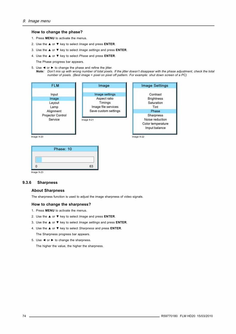
9. Image menu
How to change the phase?1. Press MENU to activate the menus.
2. Use the ▲ or ▼ key to select Image and press ENTER.
3. Use the ▲ or ▼ key to select Image settings and press ENTER.
4. Use the ▲ or ▼ key to select Phase and press ENTER.
The Phase progress bar appears.
5. Use ◄ or ► to change the phase and refine the jitter.Note: Don’t mix up with wrong number of total pixels. If the jitter doesn’t disappear with the phase adjustment, check the total
number of pixels. (Best image = pixel on pixel off pattern. For example: shut down screen of a PC)
Image 9-20
Image 9-21
Image 9-22
Image 9-23
9.3.6 Sharpness
About SharpnessThe sharpness function is used to adjust the image sharpness of video signals.
How to change the sharpness?1. Press MENU to activate the menus.
2. Use the ▲ or ▼ key to select Image and press ENTER.
3. Use the ▲ or ▼ key to select Image settings and press ENTER.
4. Use the ▲ or ▼ key to select Sharpness and press ENTER.
The Sharpness progress bar appears.
5. Use ◄ or ► to change the sharpness.
The higher the value, the higher the sharpness.
74 R59770180 FLM HD20 15/03/2010

9. Image menu
Image 9-24
Image 9-25
Image 9-26
Image 9-27
9.3.7 Noise reduction
About Noise reductionReduces noise and pixel jitter in all video sources.
How to change?1. Press MENU to activate the menus.
2. Use the ▲ or ▼ key to select Image and press ENTER.
3. Use the ▲ or ▼ key to select Image settings and press ENTER.
4. Use the ▲ or ▼ key to select Noise reduction and press ENTER.
The Noise reduction progress bar appears.
5. Use ◄ or ► to change the noise reduction.
The higher the value, the higher the noise reduction.
Image 9-28
Image 9-29
Image 9-30
Image 9-31
R59770180 FLM HD20 15/03/2010 75

9. Image menu
9.3.8 Color temperature
What can be done ?The color temperature can be selected according to the type of source:
There are 5 different preset color temperatures:
• Projector white• computer : 9300 K• Video : 6500 K• Film : 5400 K• Broadcast : 3200 K
These calibrated presets can be selected and will provide optimum color tracking, the projector allows however the setting of apersonal color temperature, this is done in custom balance
Color temperature selection is only possible when Color space is OFF
Color temperature
The coloration (reddish, white, bluish, greenish, etc.) of white in an image, measured using the Kelvin (degrees K)temperature scale. Higher temperatures output more light.
9.3.8.1 Predefined color temperature
Projector white will provide maximum projector light output. The calibrated ’Broadcast’, ’Film’, ’Video’ and’Computer’ presets will provide optimum color tracking.
How to select?1. Press MENU to activate the menus.
2. Use the ▲ or ▼ key to select Image and press ENTER.
3. Use the ▲ or ▼ key to select Image settings and press ENTER.
4. Use the ▲ or ▼ key to select Color temperature and press ENTER.
5. Use the ▲ or ▼ key to select a predefined color temperature value, e.g. Video, and press ENTER.
The colors of the image is switched to the selected value.
Image 9-32
Image 9-33
Image 9-34
76 R59770180 FLM HD20 15/03/2010

9. Image menu
Image 9-35
9.3.8.2 Set a custom color temperature
How to enter a custom value?1. Press MENU to activate the menus.
2. Use the ▲ or ▼ key to select Image and press ENTER.
3. Use the ▲ or ▼ key to select Image settings and press ENTER.
4. Use the ▲ or ▼ key to select Color temperature and press ENTER.
5. Use the ▲ or ▼ key to select Custom balance and press ►.
The Gain adjustment bar scales are displayed.
6. Adjust gain red with ◄ or ► key and gain blue with ▲ or ▼ key. Adjust gain blue in the same way as gain red.
7. When gain adjustment is finished press ENTER.
Image 9-36
Image 9-37
Image 9-38
Image 9-39 Image 9-40
R59770180 FLM HD20 15/03/2010 77

9. Image menu
9.3.9 Input balance
Overview
• Introduction to Input Balance• Adjusting the input balance
9.3.9.1 Introduction to Input Balance
Introduction: Unbalanced color signalsWhen transporting signals, there is always a risk of deterioration of the information contained in the signals.
In case of information contained in the amplitude of the signals which is the case of data color signals (R, G, B),image 9-41 , we arequite sure that the amplitude of these color signals is subject to alterations.
An example of alteration may be a DC component added to the signal, in the form of a DC offset repositioning the black level, sincethis black level (“brightness”) will become crucial later on (clamping circuit) it will result in “black not being black”.
Another value that is subject to alteration is the amplitude of the signal, resulting in an altered “Gain” of the signal (“white level” orcontrast).
The alterations of the three color signals will happen independently i.e. the colors will end to be unbalanced, image 9-42
B
Black level
0.7V
Image 9-41
Black level
ΔG ΔΒΔR
RG B
Image 9-42
One can conclude here that a good color tracking can only be met by using three previously (input) balancedcolor signals
Analog Digital ConversionThe analog color signals must pass through an Analog/Digital conversion circuit prior to any digital processing in the PMP.
A typical ADC transforms the analog value into an 8 bit coded digital signal.
The graphic shows that when converting a signal containing a DC offset component the range of the converter is not optimally used.
Black levelΔ
R
ADC
0
255
i1 : superfluous information
i2 : video information
Image 9-43
78 R59770180 FLM HD20 15/03/2010

9. Image menu
One can conclude here that a good data conversion can only be met by using three previously (input) balancedcolor signals
The objective of input balancingThe objective in input balancing is to “set” the same black level and the same white level for the three colors of a particular inputsource.
Black level setting : brightness
White level setting : contrast
The same absolute black and white level for the three colors allows the same reference for Brightness and Contrast control of thepicture !
These two references also set the range in which the ADC will work for that particular source (this explains also why each inputbalance setting is linked to a particular source and thus saved in the image file).
9.3.9.2 Adjusting the input balance
How can it be done ?To balance the three color signals of a particular source there are conditions; in fact we must know the black and the white level ofthe source i.e. :1. The source in question must be able to generate a white signal, ideally a 100% white (background) full screen pattern2. The source in question must be able to generate a black signal, ideally a 100% black (background) full screen pattern
A B
Image 9-44
White balance : In the projector, we will set the contrast for each color until we get a 100% light output picture when projecting a100% white image (image A)
Black balance : In the projector, we will set the brightness for each color until we get a 0% light output picture when projecting a100% black image (image B).
The changeover from min to max is indicated by the apparition of bright spots also called “digital noise”
R59770180 FLM HD20 15/03/2010 79

9. Image menu
An alternative to a full screen White/black pattern is the standard gray scale pattern, the white bar will be usedfor white balance and the black bar for black balance.
Image 9-45
Black balance1. Press MENU to activate the menus.
2. Use the ▲ or ▼ key to select Image and press ENTER.
3. Use the ▲ or ▼ key to select Image settings and press ENTER.
4. Use the ▲ or ▼ key to select Input balance and press ENTER.
5. Do you want to use an internally generated test pattern ?If yes, Use the ▲ or ▼ key to select Test pattern and press ENTER to toggle between [on] and [off]If no, Adjust on the selected source.
6. Use the ▲ or ▼ key to select Black balance and press ENTER.
Depending whether a test pattern is selected or not, the adjustment image is displayed.
7. Toggle with ▲ or ▼ key to select Black balance red.
Image 9-46
Image 9-47
Image 9-48
Image 9-49
Image 9-50
8. Adjust the red black level on a minimal value
9. Toggle with ▲ or ▼ key to Black balance blue and adjust the blue black level on a minimal value.Note: This minimal value is not necessary , provided that the 2 other colors are not influencing too much the color to be adjusted,
in fact the aim is to minimize the effect of the two other colors since there is a risk of reaching too soon the 50% transitiondue to the contribution of these two other colors signals.
10.Toggle with ▲ or ▼ key to Black balance green and adjust the Green black level until bright spots appear on the screen.
11.Toggle with ▲ or ▼ key to Black balance blue adjust the Blue black level until bright spots appear on the screen.
12.Toggle with ▲ or ▼ key to Black balance red adjust the Red black level until bright spots appear on the screen.
80 R59770180 FLM HD20 15/03/2010

9. Image menu
The projected image should now be noisy full black
If one uses a gray scale pattern, the bright spots should appear in the black bar.
Performing White input balance1. Connect the source you want to project.
2. Press MENU to activate the menus.
3. Use the ▲ or ▼ key to select Image and press ENTER.
4. Use the ▲ or ▼ key to select Image settings and press ENTER.
5. Use the ▲ or ▼ key to select Input balance and press ENTER.
6. Do you want to use an internally generated test pattern?If yes, Use the ▲ or ▼ key to select Test pattern and press ENTER to toggle between [on] and [off]If no, select a white pattern (or gray scale as alternative).
7. Use the ▲ or ▼ key to select White balance and press ENTER.
The white balance bar scale for a typical color is displayed.
8. Toggle with the ▲ or ▼ key to select White balance red.
Image 9-51
Image 9-52
Image 9-53
Image 9-54
Image 9-55
9. Adjust the red white level (gain) on a minimal value
10.Toggle with ▲ or ▼ key to White balance blue and adjust the blue white level (gain) on a minimal value.Note: This minimal value is not necessary , provided that the 2 other colors are not influencing too much the color to be adjusted,
in fact the aim is to minimize the effect of the two other colors since there is a risk of reaching too soon the transition(bright spots) due to the contribution of these two other colors signals.
11.Toggle with ▲ or ▼ key to White balance green and adjust the Green white level (gain) until bright spots appear on the screen.
12.Toggle with ▲ or ▼ key to White balance blue adjust the Blue white level (gain) until bright spots appear on the screen.
13.Toggle with ▲ or ▼ key to White balance red adjust the Red white level (gain) until bright spots appear on the screen.
The projected image should now be noisy neutral gray.
R59770180 FLM HD20 15/03/2010 81

9. Image menu
9.4 Aspect ratio
Aspect ratio
Relation between the horizontal & vertical dimension in which the window will be displayed, e.g. 4 by 3 or 16 by 9.Can also be expressed as a decimal number, such as 1.77. The larger the ratio or decimal, the wider are less squarethe image.
What can be done?The aspect ratio setting forces the projector to project an image using a defined aspect ratio.
Aspect ratio Description
4:3 Standard television format
16:9 Wide screen television format / anamorphic format
5:4 Workstation format
2.35 Film format
1.88
1.78 Wide screen television format / anamorphic format
Custom Any custom format can be set up
Some example images:
4/3 signal 16/9 RGB signal
Image 9-56Example images aspect ratio
How to select an Aspect ratio?1. Press MENU to activate the menus.
2. Use the ▲ or ▼ key to select Image and press ENTER.
3. Use the ▲ or ▼ key to select Aspect ratio and press ENTER.
The aspect ratio menu will be displayed.
4. Use the ▲ or ▼ key to select the desired aspect ratio and press ENTER.
Image 9-57
Image 9-58
Image 9-59
How to set up a custom aspect ratio?1. Select first Custom and press ENTER to activate.
The Custom aspect ratio dialog box opens.
2. Use the ▲ or ▼ key to adjust the vertical size of the image.
82 R59770180 FLM HD20 15/03/2010

9. Image menu
Use the or key to adjust the horizontal size of the image.When the desired aspect ratio is obtained, press EXIT.
Image 9-60
Image 9-61
9.5 Timings
9.5.1 Source timings
Adjustable items
• Horizontal start in pixels : number of pixels between the beginning of the input signal and the start of the video information inthe signal.
• Width = Active horizontal pixels : determine the width of the window on the screen. This value is normally given in the sourcespecifications. If not, adjust until full image is displayed (no missing pixels).
• Vertical start in lines : number of lines between the start of the input signal and start of the image on the screen.• Height = Active vertical lines : number of horizontal lines determining the height of the projected image. this value is normally
given in the specification of the source. If not, adjust until full image height is displayed (no missing lines).• Total pixels: Total horizontal pixels in the source. If the value is wrong, sampling mistakes (small vertical bars in the projected
image) will be seen in the image.• Total lines: Total vertical lines in the source.
How to start up?1. Press MENU to activate the menus.
2. Use the ▲ or ▼ key to select Image and press ENTER.
3. Use the ▲ or ▼ key to select Timings and press ENTER.
The timings menu will be displayed.
Image 9-62
Image 9-63
Image 9-64
4. To change a setting, use the ▲ or ▼ key to select and press ENTER.
R59770180 FLM HD20 15/03/2010 83

9. Image menu
The corresponding adjustment box is displayed. E.g. Horizontal total pixels.
Image 9-65
5. Use the ▲ or ▼ key (or ◄ or ► key) to change the value.
6. Press ENTER to activate the new value.
7. If necessary to change other settings, repeat from step 4.
9.5.2 Advanced settings
About the advanced settingsClamp delay The time between the leading edge of the clamp pulse and the locked edge of the sync pulse. Can be
any value between 0 and 255.
Clamp width The width of the clamp pulse can be any value between 0 and 255.
Syncpulse
Clamppulse
Clampdelay
Clampwidth
Lead
ing
edge
Trai
lingi
ng e
dge
Image 9-66
Field polarity The field polarity function is used for interlaced images. Both rasters of the image could be shifted in awrong way (double lines are visible in the image). This can be corrected by forcing the field polarityto [neg] or [pos].
How to change the clamp delay - clamp width?1. Press MENU to activate the menus.
2. Use the ▲ or ▼ key to select Image and press ENTER.
3. Use the ▲ or ▼ key to select Timings and press ENTER.
4. Use the ▲ or ▼ key to select Advanced settings and press ENTER.
The Advanced settings menu is displayed.
5. Use the ▲ or ▼ key to select Clamp delay or Clamp width and press ENTER.
A progress bar appears.
6. Use the ▲ or ▼ key to change the setting.
84 R59770180 FLM HD20 15/03/2010

9. Image menu
Image 9-67
Image 9-68
Image 9-69
Image 9-70
How to change the field polarity?1. Press MENU to activate the menus.
2. Use the ▲ or ▼ key to select Image and press ENTER.
3. Use the ▲ or ▼ key to select Advanced settings and press ENTER.
The Advanced settings menu is displayed.
4. Use the ▲ or ▼ key to select Field polarity and press ENTER to toggle between [neg] or [pos].
Image 9-71
Image 9-72
Image 9-73
R59770180 FLM HD20 15/03/2010 85

9. Image menu
Image 9-74
9.5.3 Advanced settings, film mode detection
About film mode detectionThis mode detects whether film or video is displayed.
When enabled, the hardware looks for tell-tale signs of 3:2 or 2:2 pull-down sequences. These are the result of converting cinemamaterial recorded at 24 frames-per-second to the television frequencies of 60 or 50 interlaced fields per second respectively. WhenFILM conversion is detected, the original 24 frames-per-second are restored. This avoids deinterlacing artefacts, and results in aperfect artefact-free display. Note that in some cases (video clips, scrolling newstickers,...) FILM and VIDEO material are mixedon one screen. This may confuse the detector and cause it to go into FILM restoration mode. This will cause "jaggies" or motionartefacts. In such cases, disabling FILM mode processing is the best cure.
Film mode detection is only for interlaced sources.
3:2 pull-down
Method used to map the 24 fps of film onto the 30 fps (60 fields) or 25 fps (50 fields), so that one film frame occupiesthree video fields, the next two, etc. It means the two fields of every other video frame come from different film framesmaking operations such as rotoscoping impossible, and requiring care in editing. Some sophisticated equipment canunravel the 3:2 sequence to allow frame-by-frame treatment and subsequently re-compose 3:2. The 3:2 sequencerepeats every five video frames and four film frames, the latter identified as A-D. Only film frame A is fully on a videoframe and so exists at one time code only, making it the editable point of the video sequence.
2:2 pull-down
The process of transferring 24-frames/sec film format into video by repeating each frame (used for PAL DVD’s) as twovideo fields. ( AD )
Artefacts
Undesirable elements or defects in a video picture. These may occur naturally in the video process and must beeliminated in order to achieve a high-quality picture. Most common in analog are cross color and cross luminance.Most common in digital are macroblocks, which resemble pixelation of the video image.
How to set up1. Press MENU to activate the menus.
2. Use the ▲ or ▼ key to select Image and press ENTER.
3. Use the ▲ or ▼ key to select Advanced settings and press ENTER.
The Advanced settings menu is displayed.
4. Use the ▲ or ▼ key to select Film mode and press ENTER to toggle between [auto] or [off].
86 R59770180 FLM HD20 15/03/2010

9. Image menu
Auto Detects for film and it starts to avoid deinterlacing artefacts, and it results in a perfect artefact-free display.
Off no detection for film mode.
When film with a banner is projected at the same time, and film mode is auto, the banner will shown possible artefacts as thesoftware will detect a film.
Image 9-75
Image 9-76
Image 9-77
Image 9-78
9.6 Image files services
Overview
• Files and file manipulations• Manual Load file• Delete file• Delete all custom files• Rename a file• Copy a file• File options
9.6.1 Files and file manipulations
Connecting a new source.Before using a new source, a correct file has to be installed. The projector’s memory contains a list of files corresponding to the mostused sources. When the new source corresponds with one of these files, the file can be loaded and saved for future use. Whenthere is a little difference, the file can also be loaded and then edited until the source specs are reached.
VESA standards and video standards are pre-programmed.
R59770180 FLM HD20 15/03/2010 87

9. Image menu
Possible file ManipulationsThe following file manipulations are possible :• Load : installation of a file for a new source.• Rename : renaming a file.• Delete : deleting a file (only custom files)• Delete all : delete all custom files• Options : way of loading a file when a source is selected.
A loaded file can be edited via the Timings menu. Once a file is edited, it will be saved with the same name as the original file,followed by a sequence number between rounded brackets.
9.6.2 Manual Load file
How to load?1. Press MENU to activate the menus.
2. Use the ▲ or ▼ key to select Image and press ENTER.
3. Use the ▲ or ▼ key to select File services and press ENTER.
The File service menu is displayed.
4. Use the ▲ or ▼ key to select Manual load and press ENTER.
The manual load window opens.
Image 9-79
Image 9-80
Image 9-81
Image 9-82
Depending on the filter setup, the following is displayed:- Fit: only fitting files for the selected source will be in the list- All: all files in the system will be in the list.
5. Do you want to see only the fitting file in the manual load menu?If yes, Select Filter and use ► till [FIT] is on the menu.If no, Select Filter and use ► till [ALL] is on the menu.
6. Use the ▲ or ▼ key to select the appropriate file. While scrolling over the files, a preview is shown on the screen.
7. Press ENTER to select.
The selected file is loaded.
The image is not perfect?If the displayed image is not correct after selecting the best fitting file, go to the Timings menu and change the file settings.
88 R59770180 FLM HD20 15/03/2010

9. Image menu
9.6.3 Delete file
How to delete?1. Press MENU to activate the menus.
2. Use the ▲ or ▼ key to select Image and press ENTER.
3. Use the ▲ or ▼ key to select File services and press ENTER.
The File service menu is displayed.
4. Use the ▲ or ▼ key to select Delete and press ENTER.
The delete window opens.
5. Use the ▲ or ▼ key to select the file which must be deleted.Note: Only custom files can be deleted.
6. Press ENTER to delete the selected file.
Image 9-83
Image 9-84
Image 9-85
Image 9-86
No recovery possible !
9.6.4 Delete all custom files
How to delete?1. Press MENU to activate the menus.
2. Use the ▲ or ▼ key to select Image and press ENTER.
3. Use the ▲ or ▼ key to select File services and press ENTER.
The File service menu is displayed.
4. Use the ▲ or ▼ key to select Delete all and press ENTER.
A delete all confirmation window opens.
5. Use the ▲ or ▼ key to select Yes if you are sure to delete all custom files and press ENTER to activate the selection.
R59770180 FLM HD20 15/03/2010 89

9. Image menu
Image 9-87
Image 9-88
Image 9-89
Image 9-90
Or,if you are not sure to delete all custom files, select No and press ENTER to activate the selection.
9.6.5 Rename a file
How to rename?1. Press MENU to activate the menus.
2. Use the ▲ or ▼ key to select Image and press ENTER.
3. Use the ▲ or ▼ key to select File services and press ENTER.
The File service menu is displayed.
4. Use the ▲ or ▼ key to select Rename and press ENTER.
The rename window opens.
5. Use the ▲ or ▼ key to select the file which must be renamed.Note: Only custom files can be renamed.
6. Press ENTER to select.
The rename window opens. The first character is selected.
7. Use the ▲ or ▼ key to change the selected character.Use the ◄ or ► key to selected another character.Note: Digits can be entered with the digit keys on the remote control or on the local keypad. When a digit is entered in that
way, the next character will be selected automatically.
8. Press ENTER to finalize the rename action.
Image 9-91
Image 9-92
Image 9-93
90 R59770180 FLM HD20 15/03/2010

9. Image menu
Image 9-94
Image 9-95
9.6.6 Copy a file
How to copy?1. Press MENU to activate the menus.
2. Use the ▲ or ▼ key to select Image and press ENTER.
3. Use the ▲ or ▼ key to select File services and press ENTER.
The File service menu is displayed.
4. Use the ▲ or ▼ key to select Copy and press ENTER.
The copy window opens.
5. Use the ▲ or ▼ key to select the file which must be copied.
6. Press ENTER to select.
The copy window opens. The first character is selected.
7. Use the ▲ or ▼ key to change the selected character.Use the ◄ or ► key to selected another character.Note: Digits can be entered with the digit keys on the remote control or on the local keypad. When a digit is entered in that
way, the next character will be selected automatically.
8. Press ENTER to finalize the copy action.
Image 9-96
Image 9-97
Image 9-98
Image 9-99
Image 9-100
9.6.7 File options
How to set the options?1. Press MENU to activate the menus.
R59770180 FLM HD20 15/03/2010 91

9. Image menu
2. Use the ▲ or ▼ key to select Image and press ENTER.
3. Use the ▲ or ▼ key to select Image services and press ENTER.
The Image service menu is displayed.
4. Use the ▲ or ▼ key to select Options and press ENTER.
Image 9-101
Image 9-102
Image 9-103
The options window opens.
5. Use the ▲ or ▼ key to select Load file and press ENTER to toggle between [Automatic], [Manual] and [Custom only].- [Automatic]: correct file will be loaded automatically.- [Manual]: correct file has to be loaded manually.- [Custom only]: correct file will be loaded automatically out of the available custom files.
Image 9-104
6. Use the ▲ or ▼ key to select Auto picture alignment and press ENTER to toggle between [Off], [Always] and [File load].
Image 9-105
- [Off]: no auto picture alignment activated.- [Always]: always auto picture alignment activated. When sync disappears and comes back, an auto picture alignment is
executed.- [Load file]: auto picture alignment executed each time a new file is loaded.
9.7 Save custom settings
What is done?The current custom settings can be saved to the internal backup device in the same way as it would be done when the projectorwas switched to standby.
How to save1. Press MENU to activate the menus.
2. Use the ▲ or ▼ key to select Image and press ENTER.
3. Use the ▲ or ▼ key to select Save custom settings and press ENTER.
92 R59770180 FLM HD20 15/03/2010

9. Image menu
The custom settings are written to the internal backup device. A message menu “Save data ...” is displayed during the saveoperation.
Image 9-106 Image 9-107
Image 9-108
R59770180 FLM HD20 15/03/2010 93

9. Image menu
94 R59770180 FLM HD20 15/03/2010

10. Layout menu
10. LAYOUT MENU
Overview
• Overview flow• Main window• PIP window• Layout file services• Zoom - Focus
10.1 Overview flowOverview
Level 1 Level 2 Level 3 Level 4
Layout
Main window
Source
Size
Position
PIP window
PIP window [ON/OFF]
Source
Size
Position
Layout file services
Load
Main full screen
PIP top right
Split top bottom
Rename
Delete
Copy / Save as
Zoom/Focus Same for each layout yes
no
10.2 Main windowOverview
• Source selection• Size adjustment• Position adjustment
When active layout is read onlyWhen the active layout is a read only layout, the projector will ask to create a new layout.
Use the ▲ or ▼ key to select Yes or No and press ENTER.
If Yes is selected an Enter layout name window opens.
R59770180 FLM HD20 15/03/2010 95

10. Layout menu
Image 10-1
Image 10-2
The first character is highlighted. Use the ▲ or ▼ key to select the desired character and press or key to select the nextcharacter in the name.
Press EXIT to return. The new file is generated.
10.2.1 Source selection
What can be done ?The source of the main window can be selected via the Main window menu.
How to select a source1. Press MENU to activate the menus.
2. Use the ▲ or ▼ key to select Layout and press ENTER.
3. Use the ▲ or ▼ key to select Main Window and press ENTER.
The main window opens.
4. Use the ▲ or ▼ key to select Source and press ENTER.
The source selection window opens.
5. Use the ▲ or ▼ key to select the desired source and press ENTER to activate.
Image 10-3
Image 10-4
Image 10-5
Image 10-6
10.2.2 Size adjustment
What can be done?The size of the main window can be adjusted until the desired window dimensions are reached.
96 R59770180 FLM HD20 15/03/2010

10. Layout menu
Image 10-7Size adjustment main window
A width adjustmentB height adjustment
The size can be changed with respect to the original aspect ratio.
How to adjust with respect to the original aspect ratio?1. Press MENU to activate the menus.
2. Use the ▲ or ▼ key to select Layout and press ENTER.
3. Use the ▲ or ▼ key to select Main Window and press ENTER.
The main window opens.
4. Use the ▲ or ▼ key to select Size and press ENTER.
The size adjustment window opens.
Image 10-8
Image 10-9
Image 10-10
5. Toggle with ENTER till Lock is set to [x].
R59770180 FLM HD20 15/03/2010 97

10. Layout menu
Image 10-11
[ ] = no lock between height and width.
[x] = width and height are locked.
6. Use or▲ ▼ to adjust the size with respect to the original aspect ratio.When the desired size is reached, press EXIT.
A Save window opens.
Image 10-12
How to adjust height and width separately?1. Press MENU to activate the menus.
2. Use the ▲ or ▼ key to select Layout and press ENTER.
3. Use the ▲ or ▼ key to select Main Window and press ENTER.
The main window opens.
4. Use the ▲ or ▼ key to select Size and press ENTER.
The size adjustment window opens.
Image 10-13
Image 10-14
Image 10-15
5. Toggle with ENTER till Lock is set to [ ].
98 R59770180 FLM HD20 15/03/2010

10. Layout menu
Image 10-16
[ ] = no lock between height and width.
[x] = width and height are locked.
6. Use the ▲ or ▼ key to adjust the height.Use the ◄ or ► key to adjust the width.When the desired size is reached, press EXIT.
A Save window opens.
Image 10-17
7. Select with the ▲ or ▼ key Yes and press ENTER.Select with the ▲ or ▼ key No, when no save is desired and press ENTER.
10.2.3 Position adjustment
What can be done?The main window can be repositioned on the screen. The upper left corner is the reference.
Image 10-18Positioning the window
How to position?1. Press MENU to activate the menus.
2. Use the ▲ or ▼ key to select Layout and press ENTER.
3. Use the ▲ or ▼ key to select Main Window and press ENTER.
The main window opens.
4. Use the ▲ or ▼ key to select Position and press ENTER.
The position adjustment window opens.
5. Use the ▲ or ▼ key to adjust top start point.
R59770180 FLM HD20 15/03/2010 99

10. Layout menu
Use the ◄ or ► key to adjust left start point.When the desired size is reached, press EXIT.
A Save window opens.
Image 10-19
Image 10-20
Image 10-21
Image 10-22
Image 10-23
6. Select with the ▲ or ▼ key Save and press ENTER.Select with the ▲ or ▼ key Delete, when no save is desired and press ENTER.
10.3 PIP windowOverview
• Introduction to PIP• Picture in Picture activation• Picture in Picture source selection• Picture in Picture size of the window• Picture in Picture, position window
10.3.1 Introduction to PIP
PiP
PiP stands for "Picture in Picture" and allows to display multiple windows containing each of them an image. Thewindows may be of the video or data type.
What are the different possibilities within the PiP mode ?The input section of the projector allows a combinations of different input signals which may be projected in the 2 windows of thePiP screen. The PiP window can be placed anywhere, with any dimensions, on the screen by changing its position and its size.
100 R59770180 FLM HD20 15/03/2010

10. Layout menu
Image 10-24Position of PiP
A Top positionB Left position
10.3.2 Picture in Picture activation
How to activate PIP?1. Press MENU to activate the menus.
2. Use the ▲ or ▼ key to select Layout and press ENTER.
3. Use the ▲ or ▼ key to select PIP Window and press ENTER.
The PIP window opens.
4. Use the ▲ or ▼ key to select On or Off and press ENTER to toggle between [On] and [Off].
Image 10-25
Image 10-26 Image 10-27
5. Press EXIT to quit the menu.
When PIP is activated (ON state), the PIP window becomes the active window. Switching to the main windowis still possible with the window button on the RCU.
10.3.3 Picture in Picture source selection
What can be done ?The input source for the picture in picture window can be selected.
How to select a source1. Press MENU to activate the menus.
2. Use the ▲ or ▼ key to select Window and press ENTER.
3. Use the ▲ or ▼ key to select PIP Window and press ENTER.
The PIP window dialog opens.
4. Use the ▲ or ▼ key to select Source and press ENTER.
R59770180 FLM HD20 15/03/2010 101

10. Layout menu
The source selection window opens.
5. Use the ▲ or ▼ key to select the desired source and press ENTER to activate this source.
Image 10-28
Image 10-29 Image 10-30
Image 10-31
10.3.4 Picture in Picture size of the window
What can be done?The width and height of the picture in picture window can be changed till the desired dimensions are obtained.
Image 10-32Size PIP window
A Width PIP windowB Height PIP window
The size of the picture in picture window can be changed with respect to the original aspect ratio of the PIP image.
Remark: when e.g. the PIP window is a 4 by 3 window and the projected image has a 16 by 9 format, then it is possible that imagejumps inside the PIP window during a re-scaling. Due to the fact that the re-scale is done on the vertical dimensions of the PIPwindow and the image inside it will be re-scaled so that the aspect ratio is still correct.
102 R59770180 FLM HD20 15/03/2010

10. Layout menu
Image 10-33Size PIP window remark
How to change the size with respect to the aspect ratio?1. Press MENU to activate the menus.
2. Use the ▲ or ▼ key to select Window and press ENTER.
3. Use the ▲ or ▼ key to select PIP Window and press ENTER.
The main window opens.
4. Use the ▲ or ▼ key to select Size and press ENTER.
The size adjustment window opens.
Image 10-34
Image 10-35 Image 10-36
5. Toggle with ENTER till Lock is set to [x]].
Image 10-37
[ ] = no lock between height and width.
[x] = width and height are locked.
6. Use the ▲ ▼ or ◄ ►key to adjust the size with respect to the aspect ratio.When the desired size is reached, press EXIT.
R59770180 FLM HD20 15/03/2010 103

10. Layout menu
A Save window opens.
Image 10-38
7. Select with the ▲ or ▼ key Yes and press ENTER.Select with the ▲ or ▼ key No, when no save is desired and press ENTER.
How to change the height and width separately?1. Press MENU to activate the menus.
2. Use the ▲ or ▼ key to select Window and press ENTER.
3. Use the ▲ or ▼ key to select PIP Window and press ENTER.
The main window opens.
Image 10-39
Image 10-40 Image 10-41
4. Use the ▲ or ▼ key to select Size and press ENTER.
The size adjustment window opens.
5. Toggle with ENTER till Lock is set to [ ].
Image 10-42
[ ] = no lock between height and width.
[x] = width and height are locked.
6. Use the ▲ or ▼ key to adjust the height.Use the ◄ or ► key to adjust the width.When the desired size is reached, press EXIT.
104 R59770180 FLM HD20 15/03/2010

10. Layout menu
A Save window opens.
Image 10-43
7. Select with the ▲ or ▼ key Yes and press ENTER.Select with the ▲ or ▼ key No, when no save is desired and press ENTER.
10.3.5 Picture in Picture, position window
What can be done?The picture in picture window can be position on any place on the display just by changing its start coordinates. The reference isthe upper left corner of the window.
How to position?1. Press MENU to activate the menus.
2. Use the ▲ or ▼ key to select Window and press ENTER.
3. Use the ▲ or ▼ key to select PIP Window and press ENTER.
The PIP window opens.
4. Use the ▲ or ▼ key to select Position and press ENTER.
The size adjustment window opens.
5. Use the ▲ or ▼ key to adjust TopUse the ◄ or ► key to adjust LeftWhen the desired position is reached, press EXIT.
A Save window opens.
Image 10-44
Image 10-45 Image 10-46
Image 10-47
Image 10-48
6. Select with the ▲ or ▼ key Yes and press ENTER.Select with the ▲ or ▼ key No, when no save is desired and press ENTER.
R59770180 FLM HD20 15/03/2010 105

10. Layout menu
10.4 Layout file services
Overview
• Load layout• Rename a layout• Delete a layout• Copy / Save as a layout
10.4.1 Load layout
When loading a layout which required two sources, the PIP window On/Off setting will be switched to ON.
How to load?1. Press MENU to activate the menus.
2. Use the ▲ or ▼ key to select Window and press ENTER.
3. Use the ▲ or ▼ key to select Layout and press ENTER.
The layout services window opens.
4. Use the ▲ or ▼ key to select Load and press ENTER.
The load layout window opens.
Image 10-49
Image 10-50
Image 10-51
Image 10-52
5. Use the ▲ or ▼ key to select the desired layout and press ENTER to select.
The first 4 layouts are default layouts, all others are customer created layouts. The menu shows only the first 10 layouts, but usethe ▼ to scroll through the rest of the layouts until the desired layout is found.
Rigging key + sequence number opens directly the desired layout.
106 R59770180 FLM HD20 15/03/2010

10. Layout menu
10.4.2 Rename a layout
Only custom created layouts can be renamed.
How to rename?1. Press MENU to activate the menus.
2. Use the ▲ or ▼ key to select Window and press ENTER.
3. Use the ▲ or ▼ key to select Layout and press ENTER.
The layout services window opens.
4. Use the ▲ or ▼ key to select Rename and press ENTER.
The Rename layout location window opens.
5. Use the ▲ or ▼ key to select the layout to rename and press ENTER.
The edit layout name window opens. The first character is selected.
6. Use the ▲ or ▼ key to change the selected character.Use the ◄ or ► key to selected another character.Note: Digits can be entered with the digit keys on the remote control or on the local keypad. When a digit is entered in that
way, the next character is selected automatically.
7. Press ENTER to save the new name.
Image 10-53
Image 10-54
Image 10-55
Image 10-56
10.4.3 Delete a layout
What is possible?Custom created layouts can be removed from the projector memory.
How to delete?1. Press MENU to activate the menus.
2. Use the ▲ or ▼ key to select Window and press ENTER.
3. Use the ▲ or ▼ key to select Layout services and press ENTER.
R59770180 FLM HD20 15/03/2010 107

10. Layout menu
The layout services window opens.
4. Use the ▲ or ▼ key to select Delete and press ENTER.
The Delete window opens.
Image 10-57
Image 10-58
Image 10-59
Image 10-60
The first 3 layouts are default layouts and cannot be delete.
5. Use the ▲ or ▼ key to select the layout that must be deleted.
6. Press ENTER to finalize the delete operation.
10.4.4 Copy / Save as a layout
What is possible,An existing layout, system layout or custom created layout, can be copied into a new file.
How to copy / save as?1. Press MENU to activate the menus.
2. Use the ▲ or ▼ key to select Window and press ENTER.
3. Use the ▲ or ▼ key to select Layout and press ENTER.
The layout services window opens.
4. Use the ▲ or ▼ key to select Copy/Save as and press ENTER.
The Save layout location window opens.
5. Use the ▲ or ▼ key to select the layout to copy/save as and press ENTER.
The edit layout name window opens. The first character is selected.
6. Use the ▲ or ▼ key to change the selected character.Use the ◄ or ► key to selected another character.Note: Digits can be entered with the digit keys on the remote control or on the local keypad. When a digit is entered in that
way, the next character is selected automatically.
7. Press ENTER to copy to the new name.The new layout will be added to the list of layouts.
108 R59770180 FLM HD20 15/03/2010

10. Layout menu
Image 10-61
Image 10-62
Image 10-63
Image 10-64
10.5 Zoom - FocusWhat can be done ?When changing from one layout to another, the zoom/focus settings can be different for each layout or they can be kept the samefor all layouts.
How to set the zoom - focus setting1. Press MENU to activate the menus.
2. Use the ▲ or ▼ key to select Window and press ENTER.
3. Use the ▲ or ▼ key to select Layout and press ENTER
The layout window opens.
4. Use the ▲ or ▼ key to select Zoom/Focus as and press ENTER.
The Zoom/Focus window opens.
5. Press ENTER to toggle between [No] and [Yes].
[No] = each layout will use its own zoom/focus settings.
[Yes] = each layout will use the same zoom/focus settings. That means that the zoom/focus settings of the previous selectedlayout will be applied to the next selected layouts.
R59770180 FLM HD20 15/03/2010 109

10. Layout menu
Image 10-65
Image 10-66
Image 10-67
110 R59770180 FLM HD20 15/03/2010

11. Lamp menu
11. LAMP MENU
Overview
• Overview flow• Lamp power mode• Lamp power• Lamp Identification• Z-axis adjustment
11.1 Overview flowOverview
Level 1 Level 2 Level 3 Level 4
Lamp
Power
Mode
Normal
Economic
Power
CLO mode [On / Off]
CLO target lumens
Identification
Serial number
Article number
Run time
Remaining run time
Strikes
Version
Z-axis
11.2 Lamp power mode
What can be done?The lamp power mode can be switched between Normal and Economic. When playing in Economic mode, the lamp life time willincrease.
Normal : maximum allowed powers is fed to the lamp. Maximum light output is reached in this way.
Economic : a reduced wattage is fed to the lamp. Reduced light output but a longer life time for the lamp.
How to switch?1. Press MENU to activate the menus.
2. Use the ▲ or ▼ key to select Lamp and press ENTER.
3. Use the ▲ or ▼ key to select Power and press ENTER.
4. Use the ▲ or ▼ key to select Mode.
5. Press ENTER to toggle between [Normal] and [Economic].
R59770180 FLM HD20 15/03/2010 111

11. Lamp menu
Image 11-1
Image 11-2Image 11-3
Remarks1. When mode is set to [Normal], then CLO mode can be switched on and off.2. When switching the power mode to [Economic] while the CLO mode is On, then the CLO mode is switched to Off.3. When the power mode is [Economic] and the CLO mode is switched to the [On] mode, then the power mode will be switched
to the [Normal] mode.
11.3 Lamp power
What can be done?Within a certain power mode, the light output of the lamp can be reduced.
How to reduce the lamp power?1. Press MENU to activate the menus.
2. Use the ▲ or ▼ key to select Lamp and press ENTER.
3. Use the ▲ or ▼ key to select Power and press ENTER.
4. Use the ▲ or ▼ key to select Power and press ENTER.
5. Use the ▲ or ▼ key to change the lamp power.
Image 11-4
Image 11-5Image 11-6
Image 11-7
112 R59770180 FLM HD20 15/03/2010

11. Lamp menu
11.4 Lamp Identification
AboutThe lamp identification menu gives an overview of the most important parameters of the used lamp.
These parameters are:• Serial number lamp• Article number of the used lamp• Run time since first start up of the lamp• Remaining run time for a safe operation of the lamp• Number of strikes since the first start up of the lamp
These parameters are useful when calling for a service intervention.
How to display?1. Press MENU to activate the menus.
2. Use the ▲ or ▼ key to select Lamp and press ENTER.
3. Use the ▲ or ▼ key to select Identification and press ENTER.
The identification overview is displayed.
Image 11-8
Image 11-9
Image 11-10
11.5 Z-axis adjustment
What can be done?This menu item gives the current light output of the projector. This light output indication can be used to readjust the lamp position inthe lamp casing (also called Z-axis adjustment of the lamp). With higher run times, the light output of the lamp will decrease, whichresults in a lower light output on the screen. This light output decrease can be compensated by readjusting the position of the lamp.For the realignment procedure, see "Realignment of the lamp in its reflector", page 189.
How to display the light output1. Press MENU to activate the menus.
2. Use the ▲ or ▼ key to select Lamp and press ENTER.
3. Use the ▲ or ▼ key to select Z-axis and press ENTER.
R59770180 FLM HD20 15/03/2010 113

11. Lamp menu
The Z-axis dialog box is display and indicates the current light output..
Image 11-11
Image 11-12
Image 11-13
114 R59770180 FLM HD20 15/03/2010

12. Alignment menu
12. ALIGNMENT MENU
About this chapterThis chapter describes the alignment of the projector once the physical installation is finished. Via the software, the image will beperfectly aligned on the screen.
Overview
• Overview flow• Orientation• Lens adjustment• Side keystone• Warp geometry settings• Contrast enhancement• Blanking• Gamma• Internal pattern• Color space• ScenergiX
12.1 Overview flowOverview
Level 1 Level 2 Level 3
Alignment
Orientation
Front Table
Front Ceiling
Rear Table
Rear Ceiling
Lens
Zoom/Focus
Shift
Mid position
Side keystone
Warp
Horizontal keystone
Vertical keystone
Rotation
Pincushion / Barrel
4 corners
Load file
Blanking
Top
Bottom
Left
Right
Reset
Contrast enhancement
R59770180 FLM HD20 15/03/2010 115

12. Alignment menu
Level 1 Level 2 Level 3
Gamma
Internal patterns
Checker board
Color bars
Convergence
Focus
Full screen black
Full screen blue
Full screen green
Full screen red
Full screen white
Hatch
Outline
Color space
Projector
EBU
SMPTE
Custom
ScenergiX
Status
White level
Black level
Show pattern
Reset
12.2 OrientationWhat can be done?The way of physical installation of the projector can be defined to the projector.
The following installation are possible:• front/table• front/ceiling• rear/table• rear/ceiling
Set up the correct orientation1. Press MENU to activate the menus.
2. Use the ▲ or ▼ key to select Alignment and press ENTER.
3. Use the ▲ or ▼ key to select Orientation and press ENTER.
4. Use the ▲ or ▼ key to select the correct orientation and press ENTER.
116 R59770180 FLM HD20 15/03/2010

12. Alignment menu
Image 12-1 Image 12-2
Image 12-3
For more information about the physical installation, see chapter “General”, “Projector configurations”.
12.3 Lens adjustment
Quick way to enter the lens adjustment setting; press the lens button on the local keypad or the remote control.
Access to the lens adjustments1. Press MENU to activate the menus.
2. Use the ▲ or ▼ key to select Alignment and press ENTER.
3. Use the ▲ or ▼ key to select Lens and press ENTER.
The lens adjustment menu is displayed.
Image 12-4 Image 12-5
Image 12-6
Zoom/focus the lens1. Use the ▲ or ▼ key to select Zoom/Focus and press ENTER.
Image 12-7Image 12-8
R59770180 FLM HD20 15/03/2010 117

12. Alignment menu
2. Use the ▲ or ▼ key to zoom the lens.Use the ◄ or ► key to focus the lens.
3. Press ENTER to go to the shift adjustments.
Lens shift1. Use the ▲ or ▼ key to select Shift and press ENTER or when in the Zoom/Focus menu press ENTER to toggle to the Shift menu.
Image 12-9Image 12-10
2. Use the ▲ or ▼ key to shift the lens upwards or downwards.Use the ◄ or ► key to shift the lens to the left or to the right.
Mid position1. Use the ▲ or ▼ key to select Mid position and press ENTER.
The lens will move to its mid position. During this operation, a message is displayed: “Motor running ...”.
Image 12-11
12.4 Side keystone
Only available when the Warp status is Off.
What can be done?The side keystone adjustment is used to align the image if the projector is mounted at a non standard projection angle.
Image 12-12Side keystone
A Keystone adjustment with positive valuesB Keystone adjustment with negative values
Side keystone adjustment1. Press MENU to activate the menus.
118 R59770180 FLM HD20 15/03/2010

12. Alignment menu
2. Use the ▲ or ▼ key to select Alignment and press ENTER.
3. Use the ▲ or ▼ key to select Side keystone and press ENTER.
The keystone dialog box appears.
4. Use the ◄ or ► key to adjust the keystone of the image.
When the upper part of the image is wider than the lower part of the image, push the ◄ key. The value below the bar scale willbe negative.
When the upper part of the image is smaller than the lower part of the image, push the ► key. The value below the bar scalewill be positive.
Image 12-13 Image 12-14
Image 12-15
12.5 Warp geometry settings
When the Warp geometry settings are used, the normal side keystone setting is disabled.
Overview
• About Warp geometry settings• Warp Status• Horizontal keystone correction• Vertical keystone correction• Rotation• Pincushion - Barrel correction• 4 corner correction• Reset warp settings• Load warp file
12.5.1 About Warp geometry settings
WarpingImage warping is the process of digitally manipulating an image such that any shapes portrayed in the image have been significantlydistorted. Warping is used for correcting image distortion so that a correct image is displayed.
While an image can be transformed in various ways, pure warping means that points are mapped to points without changing thecolors.
Some examples of projected images which need to be corrected with the warp geometry settings:
R59770180 FLM HD20 15/03/2010 119

12. Alignment menu
Image 12-16Example 1 : distorted image
Image 12-17Example 2 : distorted image
The Warp functions can slow down the switching from one source to another when Input locking is set toautomatic and there is a difference in frequency between both sources.
12.5.2 Warp Status
Different modesThe warp distortion can have 3 states:• Off : no warp distortion can be adjusted. Only the normal Side keystone can be used.• Manual : the distortion functions inside the projector are available. Combinations of these adjustments can be used to correct
the image. When using a setting to correct a part of the image, that can cause that other settings in the menu are grayed out.E.g. Using the keystone functions will gray out the 4 corners setting.
• File : an external created file is used to correct the image. More precise corrections are possible on a lot of more points in theimage.
When switching the warp status from Manual or File to Off and back again, the latest used warp settings will be loaded again.
How to set the status1. Press MENU to activate the menus.
2. Use the ▲ or ▼ key to select Alignment and press ENTER.
3. Use the ▲ or ▼ key to select Warp and press ENTER.
The warp dialog box appears.
4. Use the ▲ or ▼ key to select Status and press ENTER to toggle between [Manual], [File] or [Off]- [Manual] : projector functions for warp are available.- [File] : Sophisticated warp adjustments can be loaded via a file. The projector warp functions are not available.- [Off] : No warp adjustments used in the projected image.
Image 12-18 Image 12-19 Image 12-20
120 R59770180 FLM HD20 15/03/2010

12. Alignment menu
12.5.3 Horizontal keystone correction
What can be done?Horizontal keystone adjustment is used to align the image if the projector is mounted at a non standard projection angle. In somecases, horizontal keystone has to be used in combination with vertical keystone. When adjusting the keystone adjustment, theaspect ratio of the image is not changed.
Image 12-21Horizontal keystone correction
When the keystone is adjusted, the 4 corners adjustment is disabled.
How to set the status1. Press MENU to activate the menus.
2. Use the ▲ or ▼ key to select Alignment and press ENTER.
3. Use the ▲ or ▼ key to select Warp and press ENTER.
The warp dialog box appears.
4. Use the ▲ or ▼ key to select Horizontal keystone and press ENTER.
5. Use ◄ or ► to change the horizontal keystone.
Image 12-22 Image 12-23 Image 12-24
R59770180 FLM HD20 15/03/2010 121

12. Alignment menu
Image 12-25
12.5.4 Vertical keystone correction
What can be done ?Vertical keystone adjustment is used to align the image if the projector is mounted at a non standard projection angle. In some cases,vertical keystone has to be used in combination with horizontal keystone. When adjusting the keystone adjustment, the aspect ratioof the image is not changed.
Image 12-26Vertical keystone correction
When the keystone is adjusted, the 4 corners adjustment is disabled.
How to set the status1. Press MENU to activate the menus.
2. Use the ▲ or ▼ key to select Alignment and press ENTER.
3. Use the ▲ or ▼ key to select Warp and press ENTER.
The warp dialog box appears.
4. Use the ▲ or ▼ key to select Vertical keystone and press ENTER.
5. Use ◄ or ► to change the vertical keystone.
122 R59770180 FLM HD20 15/03/2010

12. Alignment menu
Image 12-27 Image 12-28 Image 12-29
Image 12-30
12.5.5 Rotation
What can be done ?A rotation is used to turn the image on the projection surface when the projector is slightly rotated around its axes.
Image 12-31Rotation
How to rotate1. Press MENU to activate the menus.
2. Use the ▲ or ▼ key to select Alignment and press ENTER.
3. Use the ▲ or ▼ key to select Warp and press ENTER.
The warp dialog box appears.
4. Use the ▲ or ▼ key to select Rotation and press ENTER.
5. Use ◄ or ► to change the rotation angle.
R59770180 FLM HD20 15/03/2010 123

12. Alignment menu
Image 12-32 Image 12-33 Image 12-34
Image 12-35
12.5.6 Pincushion - Barrel correction
What can be done ?A barrel distortion or pincushion distortion can adjusted so that a normal image is displayed. Positive adjustments introduce morebarrel distortion. Negative adjustments introduce more pincushion distortion.
Image 12-36Barrel and pincushion distortion
How to correct the distortion1. Press MENU to activate the menus.
2. Use the ▲ or ▼ key to select Alignment and press ENTER.
3. Use the ▲ or ▼ key to select Warp and press ENTER.
The warp dialog box appears.
4. Use the ▲ or ▼ key to select Pincushion/Barrel and press ENTER.
5. Use ◄ or ► to adjust the pincushion or the barrel distortion.
124 R59770180 FLM HD20 15/03/2010

12. Alignment menu
Image 12-37 Image 12-38 Image 12-39
Image 12-40
12.5.7 4 corner correction
What can be done ?Each corner of the image can be moved individually in the X and Y direction to correct a distortion. Take in account that the aspectratio can be changed while moving one of the corners.
The following adjustments are possible:• Top left X• Top left Y• Top right X• Top right Y• Bottom left X• Bottom left Y• Bottom right X• Bottom right Y
Image 12-41
Once an adjustment is done in one of the 4 corners, the horizontal and vertical keystone corrections are disabled.
How to move a corner1. Press MENU to activate the menus.
2. Use the ▲ or ▼ key to select Alignment and press ENTER.
3. Use the ▲ or ▼ key to select Warp and press ENTER.
The warp dialog box appears.
4. Use the ▲ or ▼ key to select 4 corners and press ENTER.
R59770180 FLM HD20 15/03/2010 125

12. Alignment menu
5. Use the ▲ or ▼ key to select a corner and press ENTER.
6. Use ▲ or ▼ key to move the selected point in the X position and use ◄ or ► key to move the selected point in the Y position.
Image 12-42 Image 12-43 Image 12-44
Image 12-45
Image 12-46
12.5.8 Reset warp settings
What can be done ?The current warp settings can be reset or returned to zero (0). At that moment all functions within the warping menu are availableagain.
How to correct the distortion1. Press MENU to activate the menus.
2. Use the ▲ or ▼ key to select Alignment and press ENTER.
3. Use the ▲ or ▼ key to select Warp and press ENTER.
The warp dialog box appears.
4. Use the ▲ or ▼ key to select Reset and press ENTER.
All warp settings are reset. The Status is set to [Off].
126 R59770180 FLM HD20 15/03/2010

12. Alignment menu
Image 12-47 Image 12-48 Image 12-49
12.5.9 Load warp file
What can be done ?Special corrections which are not possible with the functions inside the projector are possible by loading a file which contains thesecorrections. This file should be created on an external computer and then stored on the projector using Projector Toolset. For moreinformation about a free download of Projector Toolset, see "Free download of Projector Toolset", page 18.
Image 12-50
How to load a file1. Press MENU to activate the menus.
2. Use the ▲ or ▼ key to select Alignment and press ENTER.
3. Use the ▲ or ▼ key to select Warp and press ENTER.
The warp dialog box appears.
4. Use the ▲ or ▼ key to select Load file and press ENTER.
The load file menu opens
5. Use the ▲ or ▼ key to select the desired file out of the list and press ENTER.
The file is loaded and the corrections are applied.
Image 12-51 Image 12-52 Image 12-53
R59770180 FLM HD20 15/03/2010 127

12. Alignment menu
Image 12-54
12.6 Contrast enhancementPurposeIncrease the contrast for all video and data sources.
How to change1. Press MENU to activate the menus.
2. Use the ▲ or ▼ key to select Alignment and press ENTER.
3. Use the ▲ or ▼ key to select Contrast enhancement and press ENTER.
The current selected contrast setting is indicated with an arrow.
4. Use the ▲ or ▼ key to select the desired setting and press ENTER.
The following settings are possible:
Normal contrast
High contrast
Custom any value between normal and high contrast can be selected.
Image 12-55 Image 12-56
Image 12-57
5. When Custom is selected, the contrast menu is displayed.
6. Use the ▲ or ▼ key to select the desired adjustment and press ENTER. Press EXIT to return.
Image 12-58
12.7 Blanking
What can be done ?Blanking adjustments affect only the edges of the projected image and are used to frame the projected image on to the screen andto hide or black out unwanted information (or noise). A ’0’ on the bar scale indicates no blanking.
128 R59770180 FLM HD20 15/03/2010

12. Alignment menu
Which blanking adjustments are available ?
• top blanking• bottom blanking• left blanking• right blanking
Image 12-59Blanking
A Top blankingB Bottom blankingC Left blankingD Right blanking
The reset function brings all blanking settings back to zero.
How to adjust the blanking?1. Press MENU to activate the menus.
2. Use the ▲ or ▼ key to select Alignment and press ENTER.
3. Use the ▲ or ▼ key to select Blanking and press ENTER.
4. Use the ▲ or ▼ key to select the desired blanking adjustment and press ENTER.
5. Use the ▲ or ▼ key to adjust until the desired blanking is reached.
6. Press EXIT to return.
Image 12-60 Image 12-61
Image 12-62
R59770180 FLM HD20 15/03/2010 129

12. Alignment menu
12.8 GammaAbout GammaGamma is an image quality enhancement function that offers a richer image by brightening the already darker portions of the imagewithout altering the brightness of the brighter portions (contrast feeling enhanced).
How to adjust gamma?1. Press MENU to activate the menus.
2. Use the ▲ or ▼ key to select Alignment and press ENTER.
3. Use the ▲ or ▼ key to select Gamma and press ENTER.
The Gamma progress bar appears.
4. Use ◄ or ► key to change the gamma setting and press EXIT.Gamma can be set to one of the 8 available steps.
Image 12-63 Image 12-64
Image 12-65
12.9 Internal pattern
What can be done with these patterns?The projector is equipped with different internal patterns which can be used for measurement and alignment purposes.
How to select?1. Press MENU to activate the menus.
2. Use the ▲ or ▼ key to select Alignment and press ENTER.
3. Use the ▲ or ▼ key to select Internal patterns and press ENTER.
The internal patterns menu is displayed.
4. Use the ▲ or ▼ key to scroll through the possible selection and press ENTER to activate the selected pattern.Select ▲ or ▼ in the menu to display the previous or next page with possible internal patterns.
Image 12-66 Image 12-67
Image 12-68
130 R59770180 FLM HD20 15/03/2010

12. Alignment menu
The selected pattern is displayed.The following patterns are available:- Checker board- Color bars- Convergence- Focus- Full screen black- Full screen blue- Full screen green- Full screen red- Full screen white- Hatch- Outline- Purity- ScenergiX
12.10 Color space
Color space
A color space or color standard is a mathematical representation for a color. For example the RGB color space isbased on a Cartesian coordinate system.
What can be adjusted ?The color space (gamut), the collection of colors which can be reproduced by the projector, can be adjusted to 4 predefined storedvalues (one projector specific, 2 international standards and one custom preset). A temporary custom adjustment is possible. Themaximum color space which can be displayed is the projector color space. This color space is measured at the factory and storedinside the projector.
How to select a color standard?1. Press MENU to activate the menus.
2. Use the ▲ or ▼ key to select Alignment and press ENTER.
3. Use the ▲ or ▼ key to select Color space and press ENTER.
4. Use the ▲ or ▼ key to select the [On] or [Off] selection and ENTER to toggle color space on or off.
5. When color space is [On], use the ▲ or ▼ key to select the desired color standard and press ENTER to activate. Use the ► keyto view the details or to edit the details when Custom is selected.
Projector Maximum color space
EBU European Broadcasting Union. This organization defines a European standard.
SMPTE American standard.
Custom The user can define the x and y coordinates for red, green and blue which forms the corners of the color space.By changing the coordinates, the color reproduction can be changed.
Image 12-69 Image 12-70
Image 12-71
R59770180 FLM HD20 15/03/2010 131

12. Alignment menu
6. When custom is selected, use the ► key to view the details. To adjust the custom values, select the desired color point usingthe ▲ or ▼ key and change the value with ◄ or ► key until the desired value is reached. When finished, press EXIT to return.
Image 12-72
12.11 ScenergiX
Overview
• Introduction• Preparations• ScenergiX activation• ScenergiX overlap zone (horizontal ScenergiX)• ScenergiX overlap zone (vertical ScenergiX)• ScenergiX size adjustment (White level)• Adjusting the black level of the images
12.11.1 Introduction
Why ScenergiX ?When working in a multichannel setup the FLM HD20 and its Soft Edge possibilities enable an image blending that gives the ap-pearance of a single view, thus achieving realistic immersion for the majority of wide screen applications.
Image 12-73Why Soft Edge?
What is the Basic Principal of ScenergiX ?The principle of edge blending is achieved by linear modulation of the light output in the overlap zone so that the light output in thatzone equals the light output of the rest of the image.
132 R59770180 FLM HD20 15/03/2010

12. Alignment menu
Adjustable overlapping area
50%
100%
50%
100%
image 2image 1
image 2image 1
Light output per image
Total composite light output
Image 12-74ScenergiX Basic Principle
12.11.2 Preparations
ScenergiX PreparationsTo ensure proper ScenergiX adjustment, be sure that the following adjustments are done perfectly on all projectors:• Convergence• Geometry• Color Matching (Color Temperature, Color Standard, Input Balance, Gamma)
12.11.3 ScenergiX activation
How to activate?1. Press MENU to activate the menus.
2. Use the ▲ or ▼ key to select Alignment and press ENTER.
3. Use the ▲ or ▼ key to select ScenergiX and press ENTER.
4. Use the ▲ or ▼ key to select Status and press ENTER to toggle between [On] and [Off].
On ScenergiX is active
Off ScenergiX is not active
Image 12-75 Image 12-76
Image 12-77
R59770180 FLM HD20 15/03/2010 133

12. Alignment menu
12.11.4 ScenergiX overlap zone (horizontal ScenergiX)
Definitions
Image 12-78ScenergiX set up
Overlap : number of pixels that overlap
Horizontal resolution of 1 projector
Total horizontal screen resolution : [(horizontal resolution of 1 projector) x 2] minus overlap.
Horizontal Resolution source : number of active pixels of the source.
How to set for the first projector1. Go to Layout → Main window → Size
2. Enter the value for the Width as follow: Total horizontal screen resolution / 2 - 0.5 x overlap zone.
3. Position remains the same.
Image 12-79
Image 12-80
Image 12-81
Image 12-82
134 R59770180 FLM HD20 15/03/2010

12. Alignment menu
How to set for the second projector1. Go to Layout → Main window → Size
2. Enter the value for the Width as follow: Total horizontal screen resolution / 2 - 0.5 x overlap zone.
3. Position = original start + horizontal width of projector 1 - overlap zone
Image 12-83
Image 12-84
Image 12-85
Image 12-86
Image 12-87
12.11.5 ScenergiX overlap zone (vertical ScenergiX)
Definitions
Image 12-88Scenergix overlap zone vertical
Overlap : number of pixels that overlap
Vertical resolution of 1 projector
Total vertical screen resolution : [(Vertical resolution of 1 projector) x 2] minus (overlap)
Vertical Resolution source : number of active lines of the source
R59770180 FLM HD20 15/03/2010 135

12. Alignment menu
How to set for the first projector1. Go to Layout → Main window → Size
2. Enter the value for the Height as follow: Total Vertical screen resolution / 2 - 0.5 x overlap zone.
3. Position remains the same.
Image 12-89
Image 12-90
Image 12-91
Image 12-92
How to set for the second projector1. Go to Layout → Main window → Size
2. Enter the value for the Width as follow: Total Vertical screen resolution / 2 - 0.5 x overlap zone.
3. Position = original start + Vertical height projector 1 - overlap zone
Image 12-93
Image 12-94
Image 12-95
136 R59770180 FLM HD20 15/03/2010

12. Alignment menu
Image 12-96
Image 12-97
12.11.6 ScenergiX size adjustment (White level)
What can be done with the white level menu?The white level menu contains top, bottom, left or right item to set the blending zone.
The ScenergiX menu items are only accessible when status is [On].
How to set the blending zone?1. Press MENU to activate the menus.
2. Use the ▲ or ▼ key to select Alignment and press ENTER.
3. Use the ▲ or ▼ key to select ScenergiX and press ENTER.
4. Use the ▲ or ▼ key to select White level and press ENTER.
5. Use the ▲ or ▼ key to select one of the four size adjustments and press ENTER.
Image 12-98 Image 12-99
Image 12-100
Image 12-101
R59770180 FLM HD20 15/03/2010 137

12. Alignment menu
A pattern with the different areas is displayed.
Image 12-102Width selections
6. Use the cursor keys to move the border of the overlap area to the desired position.Set first the width for the first projector and repeat for the second one.
Image 12-103Width set up for projector 1
138 R59770180 FLM HD20 15/03/2010

12. Alignment menu
Image 12-104Width set up for projector 2
12.11.7 Adjusting the black level of the images
Why black level adjustmentFor dark images, the overlap zone will be brighter then the rest of the images. Typically for DLP projectors, next to the overlapzone, a brighter area is recognized. This area is known as a DLP leakage area. This area must also be exclude for the black leveladjustment. Therefore we can rise the black level of the remaining image (excluding the overlap zone and the DLP leakage area).
First, the width of the leakage area must be set. The white cursor line indicates the border of the overlap area. The green cursorline indicates the current installed DLP leakage area border and starts at the position of the white cursor line (no width installed).This green line can be moved to the border of the DLP leakage area with the cursor keys.
Image 12-105DLP Leakage area set up
After the area is set, use TEXT key to remove the area border lines when adjusting the black level.
How to set the leakage area width1. Press MENU to activate the menus.
2. Use the ▲ or ▼ key to select Alignment and press ENTER.
3. Use the ▲ or ▼ key to select ScenergiX and press ENTER.
4. Use the ▲ or ▼ key to select Black level and press ENTER.
R59770180 FLM HD20 15/03/2010 139

12. Alignment menu
5. Use the ▲ or ▼ key to select one of the four size adjustments and press ENTER.
Image 12-106 Image 12-107
Image 12-108
Image 12-109
Image 12-110DLP leakage area
1 Overlap area2 DLP Leakage area
6. Use the cursor keys to move the green border line to the desired position.
140 R59770180 FLM HD20 15/03/2010

12. Alignment menu
The leakage area for this overlap is defined and will be excluded during black level adjustment.
How to adjust1. Press MENU to activate the menus.
2. Use the ▲ or ▼ key to select Alignment and press ENTER.
3. Use the ▲ or ▼ key to select ScenergiX and press ENTER.
4. Use the ▲ or ▼ key to select Black level and press ENTER.
Image 12-111 Image 12-112
Image 12-113
Image 12-114
5. Adjust the black level of area A until the black level of area A, B and C are equal. Use the Adjust function All, Red, Green andBlue in the Black level menu.
A CB
121311
RGB
RGB
Image 1 Image 2
Image 12-115Black level adjustment
Use the Reset function to bring all ScenergiX settings back to zero.
R59770180 FLM HD20 15/03/2010 141

12. Alignment menu
142 R59770180 FLM HD20 15/03/2010

13. Projector control
13. PROJECTOR CONTROL
About this chapterThis chapter explains the setup of the control part of the software such as projector address and all types of communication with theexternal world.
Overview
• Overview flow• Projector address• Serial communication• Network• IR control switching• Art-Net DMX• Buttons• Menu position• Local LCD• Language selection
13.1 Overview flowOverview
Level 1 Level 2 Level 3
Projector control
Projector address
Projector address
Common address
Serial communication
Baud rate [115200]
Interface standard [RS232/RS422]
RS422 termination [Off/On]
Network
DHCP [ON/OFF]
IP-address
Subnet mask
Default gateway
IR control
IR Front [On/Off]
IR Back [On/Off]
IR Side [On/Off]
ART DMX
DMX address
DMX universe
DMX monitor
DMX mode [Basic/Extended/Full]
Home lens at startup [No/Yes]
Buttons
Standby
APA
R59770180 FLM HD20 15/03/2010 143

13. Projector control
Level 1 Level 2 Level 3
Shortcut keys
Menu position
Menu
Bar scale
Local LCD
Local LCD time out
Local LCD contrast
Language
English
Français
Deutsch
Español
Italiano
13.2 Projector address
Overview
• Individual projector address• Common address
13.2.1 Individual projector address
About individual projector addressBefore a projector, and only this projector, can be controlled via a remote control, an individual address must be entered in theprojector.
This individual projector address can then be used to control the projector via remote control or via a serial connection.
Next to an individual projector address, each projector has also a common address for group control.
How to set an individual address?1. Press MENU to activate the menus.
2. Use the ▲ or ▼ key to select Projector control and press ENTER.
3. Use the ▲ or ▼ key to select Projector address and press ENTER.
4. Use the ▲ or ▼ key to select Projector Address and press ENTER.
The edit projector address window opens.
5. Use the ▲ or ▼ key to select a new valueOr,enter a new value with the digit keys on the remote control or local keypad.
6. Use the ◄ or ► key to select the next digit and repeat step 5.
7. When the desired address is entered, press ENTER to store that address.
144 R59770180 FLM HD20 15/03/2010
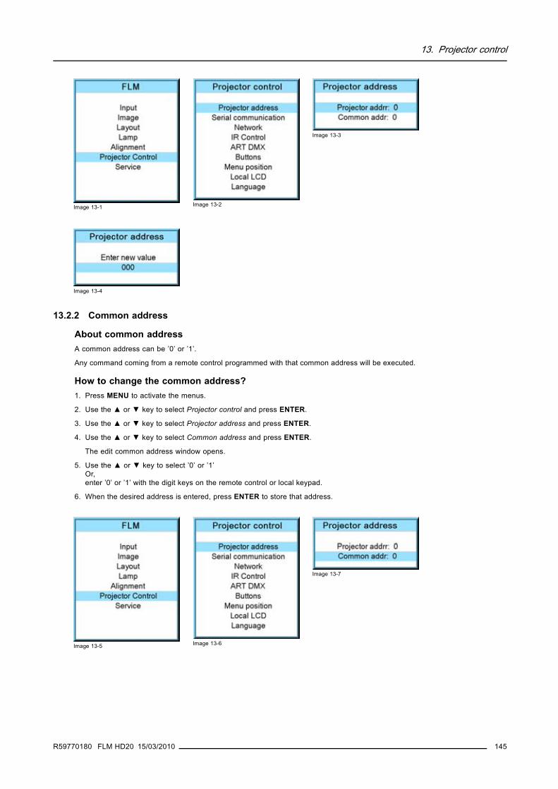
13. Projector control
Image 13-1 Image 13-2
Image 13-3
Image 13-4
13.2.2 Common address
About common addressA common address can be ’0’ or ’1’.
Any command coming from a remote control programmed with that common address will be executed.
How to change the common address?1. Press MENU to activate the menus.
2. Use the ▲ or ▼ key to select Projector control and press ENTER.
3. Use the ▲ or ▼ key to select Projector address and press ENTER.
4. Use the ▲ or ▼ key to select Common address and press ENTER.
The edit common address window opens.
5. Use the ▲ or ▼ key to select ’0’ or ’1’Or,enter ’0’ or ’1’ with the digit keys on the remote control or local keypad.
6. When the desired address is entered, press ENTER to store that address.
Image 13-5 Image 13-6
Image 13-7
R59770180 FLM HD20 15/03/2010 145

13. Projector control
Image 13-8
13.3 Serial communicationOverview
• Baud rate setup• Interface standard• RS422 termination
13.3.1 Baud rate setup
What can be done?The baudrate for a serial connection with a computer can be set up.
How to set up?1. Press MENU to activate the menus.
2. Use the ▲ or ▼ key to select Projector control and press ENTER.
3. Use the ▲ or ▼ key to select Serial communication and press ENTER.
The serial communication menu opens.
4. Use the ▲ or ▼ key to select Baudrate and press ENTER to toggle between the available baud rates.The following baud rates can be selected:- 9600- 19200- 38400- 57600- 115200
5. Press EXIT to return.
Image 13-9 Image 13-10
Image 13-11
13.3.2 Interface standard
What can be done?The communication protocol for the communication between the projector and a computer can be set to RS232 or RS422.
How to set up1. Press MENU to activate the menus.
2. Use the ▲ or ▼ key to select Projector control and press ENTER.
146 R59770180 FLM HD20 15/03/2010

13. Projector control
3. Use the ▲ or ▼ key to select Serial communication and press ENTER.
The serial communication menu opens.
4. Use the ▲ or ▼ key to select Interface standard and press ENTER to toggle between [RS232] or [RS422]..
Default: [RS232]
Image 13-12 Image 13-13
Image 13-14
13.3.3 RS422 termination
What can be done?When the interface standard is set to RS422, the last projector in a line should be RS422 terminated (ON position). All others in theline should be in the OFF position.
How to set1. Press MENU to activate the menus.
2. Use the ▲ or ▼ key to select Projector control and press ENTER.
3. Use the ▲ or ▼ key to select Serial communication and press ENTER.
The serial communication menu opens.
4. Use the ▲ or ▼ key to select RS422 termination and press ENTER to toggle between [On] or [Off].
Default: [On]
Image 13-15 Image 13-16
Image 13-17
13.4 NetworkOverview
• Introduction to a Network connection• DHCP setup• IP-address set up• Subnet-mask set up• Default Gateway set up
R59770180 FLM HD20 15/03/2010 147

13. Projector control
13.4.1 Introduction to a Network connection
DHCP
Dynamic host configuration protocol. DHCP is a communications protocol that lets network administrators managecentrally and automate the assignment of IP addresses in an organization’s network. Using the Internet Protocol, eachmachine that can connect to the Internet needs a unique IP address. When an organization sets up its computer userswith a connection to the Internet, an IP address must be assigned to each machine. Without DHCP, the IP addressmust be entered manually at each computer and, if computers move to another location in another part of the network,a new IP address must be entered. DHCP lets a network administrator supervise and distribute IP addresses froma central point and automatically sends a new IP address when a computer is plugged into a different place in thenetwork.
IP
Internet Protocol. The network layer of TCP/IP. Required for communication with the internet.
Subnet mask
A number that is used to identify a subnetwork so that IP addresses can be shared on a local area network.
Default Gateway
A router that serves as an entry point into and exit point out of a network. For example, a local network (LAN) mayneed a gateway to connect it to a wide area network (WAN) or to the Internet.
MAC address
Media Access Control address. Unique hardware number, used in combination with the IP-address to connect to thenetwork (LAN or WAN).
What should be set up for an Ethernet address?2 ways can be used to assign an address:• use the DHCP setting so that an automatic address will be assigned.• Assign manually an IP address, Net-mask (subnet-mask), (default) gateway address.
- Set the IP-Address field to the desired value. This must NOT be 0.0.0.0 for static IP-Address assignment. The IP addressidentifies a projector’s location on the network in the same way a street address identifies a house on a city block. Just asa street address must identify a unique residence, an IP address must be globally unique and have a uniform format.
- Set the Subnet-Mask as appropriate for the local subnet.- Set the Default-Gateway to the IP-Address of the local router (MUST be on the local subnet!) on the same network as this
projector that is used to forward traffic to destinations beyond the local network. This must not be 0.0.0.0. If there is norouter on the projector’s local subnet then just set this field to any IP-Address on the subnet.
13.4.2 DHCP setup
How to switch DHCP setting?1. Press MENU to activate the menus.
2. Use the ▲ or ▼ key to select Projector control and press ENTER.
3. Use the ▲ or ▼ key to select Ethernet and press ENTER.
The Ethernet menu opens.
4. Use the ▲ or ▼ key to select DHCP.
5. Press ENTER to toggle the DHCP setting.
148 R59770180 FLM HD20 15/03/2010

13. Projector control
[ON] = DHCP is activated. Automatic assigning of an address is activated.
[OFF ] = DHCP is deactivated. A fixed address will be used.
Image 13-18 Image 13-19
Image 13-20
13.4.3 IP-address set up
How to set up?1. Press MENU to activate the menus.
2. Use the ▲ or ▼ key to select Projector control and press ENTER.
3. Use the ▲ or ▼ key to select Network and press ENTER.
The Network menu opens.
4. Use the ▲ or ▼ key to select IP-address and press ENTER to select.Note: An address contains 4 octets with a maximum value of 255.
This must NOT be 0.0.0.0 for static IP-Address assignment.
5. Use the ▲ or ▼ key to select the desired digit and press ◄ or ► key to select the next digit in the address.Or,enter the value with the digit keys on the remote control or local keypad. The next digit in the address will be selected automati-cally.
6. Press EXIT to return.
Image 13-21 Image 13-22
Image 13-23
Image 13-24
13.4.4 Subnet-mask set up
How to set up?1. Press MENU to activate the menus.
R59770180 FLM HD20 15/03/2010 149

13. Projector control
2. Use the ▲ or ▼ key to select Projector control and press ENTER.
3. Use the ▲ or ▼ key to select Network and press ENTER.
The Ethernet menu opens.
4. Use the ▲ or ▼ key to select Subnet mask and press ENTER to select.Note: An address contains 4 octets with a maximum value of 255.
Fill out the 4 fields as appropriate for the local subnet.
5. Use the ▲ or ▼ key to select the desired digit and press ◄ or ► key to select the next digit in the address.Or,enter the value with the digit keys on the remote control or local keypad. The next digit in the address will be selected automati-cally.
6. Press EXIT to return.
Image 13-25 Image 13-26
Image 13-27
Image 13-28
13.4.5 Default Gateway set up
How to set up?1. Press MENU to activate the menus.
2. Use the ▲ or ▼ key to select Projector control and press ENTER.
3. Use the ▲ or ▼ key to select Network and press ENTER.
The Ethernet menu opens.
4. Use the ▲ or ▼ key to select Default Gateway and press ENTER to select.Note: An address contains 4 octets with a maximum value of 255.
Set the default gateway to the IP-address of the router (MUST be on the local subnet!). If there is no router on the projector’slocal subnet then just set this field to any IP-address on the subnet.
5. Use the ▲ or ▼ key to select the desired digit and press ◄ or ► key to select the next digit in the address.Or,enter the value with the digit keys on the remote control or local keypad. The next digit in the address will be selected automati-cally.Note: This must NOT be 0.0.0.0
150 R59770180 FLM HD20 15/03/2010

13. Projector control
Image 13-29 Image 13-30
Image 13-31
Image 13-32
6. Press EXIT to return.
13.5 IR control switching
What can be done?Each IR receiver inside the projector can be activated or deactivated. When an IR receiver is deactivated, no IR signal send to thisIR receiver will be processed.
How to switch1. Press MENU to activate the menus.
2. Use the ▲ or ▼ key to select Projector control and press ENTER.
3. Use the ▲ or ▼ key to select IR Control and press ENTER.
4. Use the ▲ or ▼ key to select the desired IR receiver and press ENTER to toggle this receiver [on] or [off].
Image 13-33 Image 13-34
Image 13-35
13.6 Art-Net DMX
DMX
DMX-512 Lighting protocol, here used over Ethernet. Carries information of 512 channels from a lighting controller tolighting devices. Standardized by USITT.
R59770180 FLM HD20 15/03/2010 151

13. Projector control
Overview
• DMX address• DMX universe• DMX monitor• DMX mode• Art-Net activation• Home lens at startup
Art-Net DMXWhen using a DMX console compatible with Art-Net, the Ethernet network serves as the link for DMX control.
Make sure that your lighting desk and all projectors are within the same IP address range. It can be necessary to set DHCP to [Off]for each projector and to enter an IP address manually which is in the IP address range of the lighting console.
13.6.1 DMX address
What should be done ?Before a projector can execute DMX commands, a unique address, called DMX address, should be given to the projector. Thisaddress can vary from to 512.
How to set a DMX address1. Press MENU to activate the menus.
2. Use the ▲ or ▼ key to select Projector control and press ENTER.
3. Use the ▲ or ▼ key to select ART DMX and press ENTER.
4. Use the ▲ or ▼ key to select DMX address and press ENTER.
The edit DMX address window opens.
5. Use the ▲ or ▼ key to select a new valueOr,enter a value with the digit keys on the remote control or local keypad.
6. Use the ◄ or ► key to select the next digit and repeat step 5.
7. When the desired address is entered, press ENTER to store that address.
Image 13-36 Image 13-37
Image 13-38
Image 13-39
13.6.2 DMX universe
What can be done ?Depending on the DMX mode, one DMX universe can contain a different number of projectors. E.g. DMX mode = basis, the DMXuniverse can contain up to 256 projectors
152 R59770180 FLM HD20 15/03/2010

13. Projector control
How to set a DMX universe1. Press MENU to activate the menus.
2. Use the ▲ or ▼ key to select Projector control and press ENTER.
3. Use the ▲ or ▼ key to select ART DMX and press ENTER.
4. Use the ▲ or ▼ key to select DMX universe and press ENTER.
5. Use the ▲ or ▼ key to select a new valueOr,enter a value with the digit keys on the remote control or local keypad.
6. Use the ◄ or ► key to select the next digit and repeat step 5.
7. When the desired universe value is entered, press ENTER to store that value.
Image 13-40 Image 13-41
Image 13-42
Image 13-43
13.6.3 DMX monitor
What can be done ?If a DMX device is connected, the settings per channel can be displayed in an on screen menu.
How to start up the monitoring1. Press MENU to activate the menus.
2. Use the ▲ or ▼ key to select Projector control and press ENTER.
3. Use the ▲ or ▼ key to select ART DMX and press ENTER.
4. Use the ▲ or ▼ key to select DMX monitor and press ENTER.
The DMX monitor window opens. Depending on the DMX mode, a different view of the DMX monitor window opens.
Example in dialog box is Extended mode
R59770180 FLM HD20 15/03/2010 153

13. Projector control
Image 13-44 Image 13-45
Image 13-46
Image 13-47
When selecting DMX monitor and no DMX device is connected, the message “No DMX data, check connection<ENTER> to display channels” appears on the screen. When ENTER is pressed the same window appears asDMX Monitor but without values.
13.6.4 DMX mode
What can be done ?3 modes for DMX are available:• Basic which has currently 2 channels implemented.• Extended which has currently 10 channels implemented• Full which has currently 9 channels implemented and 10th free channel.
Depending on the DMX application the correct mode has to be selected.
For the complete DMX chart of each mode, see "DMX chart", page 205.
How to set the mode1. Press MENU to activate the menus.
2. Use the ▲ or ▼ key to select Projector control and press ENTER.
3. Use the ▲ or ▼ key to select ART DMX and press ENTER.
4. Use the ▲ or ▼ key to select DMX mode and press ENTER to toggle between [basic], [extended] or [full].
154 R59770180 FLM HD20 15/03/2010

13. Projector control
Image 13-48 Image 13-49
Image 13-50
13.6.5 Art-Net activation
What can be done ?DMX via Art-Net can be activated [On] or blocked [Off].
Default value : off
How to toggle1. Press MENU to activate the menus.
2. Use the ▲ or ▼ key to select Projector control and press ENTER.
3. Use the ▲ or ▼ key to select ART DMX and press ENTER.
4. Use the ▲ or ▼ key to select ArtNet and press ENTER to toggle between [Off] or [On].
Image 13-51 Image 13-52
Image 13-53
13.6.6 Home lens at startup
What can be done ?At power On the lens will search for its minimum and its maximum position. These minimum and maximum values will be usedduring this sessions to control the lens exactly. Once the lens limits are found, the lens returns to original position.
This full process takes about 3 to 4 minutes. During the homing cycle, all functions in the projector are blocked.
How to set1. Press MENU to activate the menus.
2. Use the ▲ or ▼ key to select Projector control and press ENTER.
3. Use the ▲ or ▼ key to select ART DMX and press ENTER.
4. Use the ▲ or ▼ key to select Home lens at startup and press ENTER to toggle between [On] or [Off].
R59770180 FLM HD20 15/03/2010 155

13. Projector control
[On] : home lens will be executed during power on.
[Off] : home lens will not be executed during power on.
Image 13-54 Image 13-55
Image 13-56
13.7 ButtonsFunctionalitySome buttons on the RCU or local keypad can have a different functionality depending on the need of the projector owner.
Overview
• Standby button• APA (auto) button• Shortcut keys
13.7.1 Standby button
What is possible?When going to standby by pressing the standby button, the following can happen:• Only the lamp will be switched off.• The lamp and the power will be switched off.
How to set1. Press MENU to activate the menus.
2. Use the ▲ or ▼ key to select Projector control and press ENTER.
3. Use the ▲ or ▼ key to select Buttons and press ENTER.
4. Use the ▲ or ▼ key to select Standby and press ENTER to toggle between [Lamp on/off] and [Power up/down].
Image 13-57 Image 13-58
Image 13-59
156 R59770180 FLM HD20 15/03/2010

13. Projector control
13.7.2 APA (auto) button
What can be done?The function of the APA (auto) button can be configured according the wishes of the user.
The function can be:• Align only (only aligning of the preview window is executed)• Auto-image menu. This function opens an auto image menu where the user can make his choice between auto align, auto
contrast/brightness and auto phase.
How to configure the APA (auto) button1. Press MENU to activate the menus.
2. Use the ▲ or ▼ key to select Projector control and press ENTER.
3. Use the ▲ or ▼ key to select Buttons and press ENTER.
4. Use the ▲ or ▼ key to select APA and press ENTER to toggle between [Align only] and [Auto-image menu].
Image 13-60 Image 13-61
Image 13-62
13.7.3 Shortcut keys
What can be done?An overview of the shortcut allocations with the corresponding menu is given. Those printed in bold are allocated.
The allocated shortcut keys can be cleared within this menu.
How to clear a shortcut key1. Press MENU to activate the menus.
2. Use the ▲ or ▼ key to select Projector control and press ENTER.
3. Use the ▲ or ▼ key to select Buttons and press ENTER.
4. Use the ▲ or ▼ key to select Shortcut keys and press ENTER.
5. Use the ▲ or ▼ key to select a shortcut with allocation and press ENTER to remove the allocation.
The indication becomes No allocation and the key is free again for a new shortcut association.
Image 13-63 Image 13-64
Image 13-65
R59770180 FLM HD20 15/03/2010 157

13. Projector control
Image 13-66
13.8 Menu position
Overview
• On screen menu• Bar scale
13.8.1 On screen menu
What is possible?The on screen menu can be positioned on 3 different places on the screen but always vertically centered on the screen.
The horizontal position can be:• Centered• Top aligned• Bottom aligned
Menu position
Menu [center]Barscale [center]
Menu position
Menu [top]Barscale [center]
Menu position
Menu [bottom]Barscale [center]
Image 13-67Menu position
How to change the position1. Press MENU to activate the menus.
2. Use the ▲ or ▼ key to select Projector control and press ENTER.
3. Use the ▲ or ▼ key to select Menu position and press ENTER.
4. Use the ▲ or ▼ key to select Menu and press ENTER to toggle between [Center], [Top] and [Bottom].
Image 13-68 Image 13-69
Image 13-70
158 R59770180 FLM HD20 15/03/2010

13. Projector control
13.8.2 Bar scale
What is possible?The bar scale can be positioned on 3 different places on the screen but always vertically on the right side.
The horizontal position can be:• Centered• Top aligned• Bottom aligned
Brightness: 60
0 100
Brightness: 60
0 100
Brightness: 60
0 100
Image 13-71Bar scale position
How to change the position1. Press MENU to activate the menus.
2. Use the ▲ or ▼ key to select Projector control and press ENTER.
3. Use the ▲ or ▼ key to select Menu position and press ENTER.
4. Use the ▲ or ▼ key to select Menu and press ENTER to toggle between [Center], [Top] and [Bottom].
Image 13-72 Image 13-73
Image 13-74
13.9 Local LCDOverview
• Local LCD time out• Local LCD contrast
13.9.1 Local LCD time out
What can be done ?The backlight time of the local LCD after a command is given can be set.
How to change1. Press MENU to activate the menus.
2. Use the ▲ or ▼ key to select Projector control and press ENTER.
3. Use the ▲ or ▼ key to select Local LCD and press ENTER.
4. Use the ▲ or ▼ key to select Local LCD time out and press ENTER to toggle between [Off], [5sec], [10sec] and [15sec].
R59770180 FLM HD20 15/03/2010 159

13. Projector control
Image 13-75 Image 13-76
Image 13-77
13.9.2 Local LCD contrast
What is possible?The contrast of the local LCD can be adapted the needs of the environment.
How to change?1. Press MENU to activate the menus.
2. Use the ▲ or ▼ key to select Projector control and press ENTER.
3. Use the ▲ or ▼ key to select Local LCD and press ENTER.
4. Use the ▲ or ▼ key to select Local LCD contrast and press ENTER
5. Use the ▲ or ▼ key to adjust the local contrast.
Image 13-78 Image 13-79
Image 13-80
Image 13-81
13.10 Language selection
What can be done?The user can change the language of the on screen menus and the local display menus to one of the available languages.
160 R59770180 FLM HD20 15/03/2010

13. Projector control
The following languages are available:• English• French• German• Spanish• Italians
All available languages are indicated in the language of the country. The current active language is indicated by an asterisk (*).
How to change the language1. Press MENU to activate the menus.
2. Use the ▲ or ▼ key to select Projector control and press ENTER.
3. Use the ▲ or ▼ key to select Language and press ENTER.
4. Use the ▲ or ▼ key to select the desired language. The change will take effect immediately.
Image 13-82 Image 13-83
Image 13-84
R59770180 FLM HD20 15/03/2010 161

13. Projector control
162 R59770180 FLM HD20 15/03/2010

14. Service menu
14. SERVICE MENU
About this chapterThis chapter refers to the Service menu in which the customer can find valuable information when calling the Barco help desk.
14.1 Overview flowOverview
Level 1 Level 2 Level 3
Service
Identification
Diagnosis
Version
Voltages
Temperatures
Fan speeds
I2C
SPI
Error logging
Convergence
Internal service patterns
PNP IN
OSD
PMP OUT
FIB
Formatter
Restore factory defaults
Reset formatter
Save custom settings
Refill mode
Broadcast mode
USB memory
14.2 IdentificationWhat can be seen on the identification screen?The identification screen shows the general information about the projector.
R59770180 FLM HD20 15/03/2010 163

14. Service menu
The following items will be displayed:• Projector address• Type of projector• Package• Configuration• Baud rate• IP address• MAC address• Text• Serial number of projector: this number can be useful when calling for technical assistance.• Runtime• Lamp runtime• Customer ID
How to display the screen?1. Press MENU to activate the menus.
2. Use the ▲ or ▼ key to select Service and press ENTER.
The service window opens.
3. Use the ▲ or ▼ key to select Identification and press ENTER.
The identification screen is displayed.
Image 14-1Image 14-2
Image 14-3
Add a customer ID to identification windowWhen on the identification window:1. Use the ▲ or ▼ key to select Customer ID and press ENTER.
The Customer ID input window opens.
Image 14-4
2. Use the ▲ or ▼ key to change the selected character.Use the ◄ or ► key to selected another character.Note: Digits can be entered with the digit keys on the remote control or on the local keypad. When a digit is entered in that
way, the next character will be selected automatically.
164 R59770180 FLM HD20 15/03/2010

14. Service menu
14.3 Diagnosis
What can be seen?The diagnosis menu gives the possibility to get an overview of the working of the projector.
14.3.1 How to start up the diagnosis?
Start up1. Press MENU to activate the menus.
2. Use the ▲ or ▼ key to select Service and press ENTER.
The service window opens.
3. Use the ▲ or ▼ key to select Diagnosis and press ENTER.
The diagnosis screen will be displayed.
Image 14-5Image 14-6
Image 14-7
Those menus who contain measured values, indicate also the limits if these are available.
14.3.2 Versions
How to display an overview?1. Press MENU to activate the menus.
2. Use the ▲ or ▼ key to select Service and press ENTER.
The service window opens.
3. Use the ▲ or ▼ key to select Diagnosis and press ENTER.
The diagnosis screen is displayed.
4. Use the ▲ or ▼ key to select Versions and press ENTER.
The Versions overview is displayed.
Image 14-8Image 14-9
Image 14-10
R59770180 FLM HD20 15/03/2010 165

14. Service menu
Image 14-11
Use the ▲ or ▼ item in the menu to select the previous or next page with information.
14.3.3 Voltages
How to display an overview?1. Press MENU to activate the menus.
2. Use the ▲ or ▼ key to select Service and press ENTER.
The service window opens.
3. Use the ▲ or ▼ key to select Diagnosis and press ENTER.
The diagnosis screen will be displayed.
4. Use the ▲ or ▼ key to select Voltages and press ENTER.
The Voltage overview menu will be displayed.
Image 14-12Image 14-13
Image 14-14
Image 14-15
166 R59770180 FLM HD20 15/03/2010

14. Service menu
Use the ▲ or ▼ item in the menu to select the previous or next page with information.
14.3.4 I²C diagnosis
How to select?1. Press MENU to activate the menus.
2. Use the ▲ or ▼ key to select Service and press ENTER.
The service window opens.
3. Use the ▲ or ▼ key to select Diagnosis and press ENTER.
The diagnosis screen is displayed.
4. Use the ▲ or ▼ key to select I2C and press ENTER.
The I²C diagnosis overview is displayed.
Image 14-16Image 14-17
Image 14-18
Image 14-19
14.3.5 Temperatures
How to get an overview?1. Press MENU to activate the menus.
2. Use the ▲ or ▼ key to select Service and press ENTER.
The service window opens.
3. Use the ▲ or ▼ key to select Diagnosis and press ENTER.
The diagnosis screen will be displayed.
4. Use the ▲ or ▼ key to select Temperatures and press ENTER.
R59770180 FLM HD20 15/03/2010 167

14. Service menu
The Temperature overview menu will be displayed.
Image 14-20Image 14-21
Image 14-22
Image 14-23
Use the ▲ or ▼ item in the menu to select the previous or next page with information.
14.3.6 Fan speeds overview
How to get an overview?1. Press MENU to activate the menus.
2. Use the ▲ or ▼ key to select Service and press ENTER.
The service window opens.
3. Use the ▲ or ▼ key to select Diagnosis and press ENTER.
The diagnosis screen will be displayed.
4. Use the ▲ or ▼ key to select Fan speeds and press ENTER.
The Fan speeds overview menu will be displayed.
168 R59770180 FLM HD20 15/03/2010

14. Service menu
Image 14-24Image 14-25
Image 14-26
Image 14-27
Use the ▲ or ▼ item in the menu to select the previous or next page with information.
14.3.7 SPI
How to get an overview1. Press MENU to activate the menus.
2. Use the ▲ or ▼ key to select Service and press ENTER.
The service window opens.
3. Use the ▲ or ▼ key to select Diagnosis and press ENTER.
The diagnosis screen will be displayed.
4. Use the ▲ or ▼ key to select SPI and press ENTER.
The SPI overview menu will be displayed.
Image 14-28Image 14-29
Image 14-30
R59770180 FLM HD20 15/03/2010 169

14. Service menu
Image 14-31
14.3.8 Error logging overview
How to get an overview?1. Press MENU to activate the menus.
2. Use the ▲ or ▼ key to select Service and press ENTER.
The service window opens.
3. Use the ▲ or ▼ key to select Diagnosis and press ENTER.
The diagnosis screen will be displayed.
4. Use the ▲ or ▼ key to select Error logging and press ENTER.
The Error logging overview menu is displayed.
For more explanation about the stored error message, see chapter "21. Troubleshooting", "Error codes", page 211.
Image 14-32Image 14-33
Image 14-34
14.4 Convergence
What can be done?The convergence patterns can be used to check the convergence alignment of red, green and blue. If there is a misalignment of atleast one 1 pixel, an electronic realignment is possible.
Mechanical realignment of the convergence can only be done by a qualified service technician.
How to display the convergence patterns and how to adjust1. Press MENU to activate the menus.
2. Use the ▲ or ▼ key to select Service and press ENTER.
The service window opens.
3. Use the ▲ or ▼ key to select Convergence and press ENTER.
4. Use the ▲ or ▼ key to select the desired pattern and press ENTER.
170 R59770180 FLM HD20 15/03/2010

14. Service menu
The convergence pattern is displayed. Press ENTER to toggle to another pattern. Press EXIT to return to the menu.
Image 14-35Image 14-36
Image 14-37
5. To adjust the convergence of the selected pattern, use the ◄ or ► for a horizontal adjustment and ▲ or ▼ for a vertical adjust-ment.
Image 14-38
Image 14-39
Adjust until the crossing of the center Green (Red) convergence pattern coincide with the diagonal line of the center Blue con-vergence pattern.
14.5 Internal service patterns
How to select1. Press MENU to activate the menus.
2. Use the ▲ or ▼ key to select Service and press ENTER.
The service window opens.
3. Use the ▲ or ▼ key to select Internal service patterns and press ENTER.
R59770180 FLM HD20 15/03/2010 171
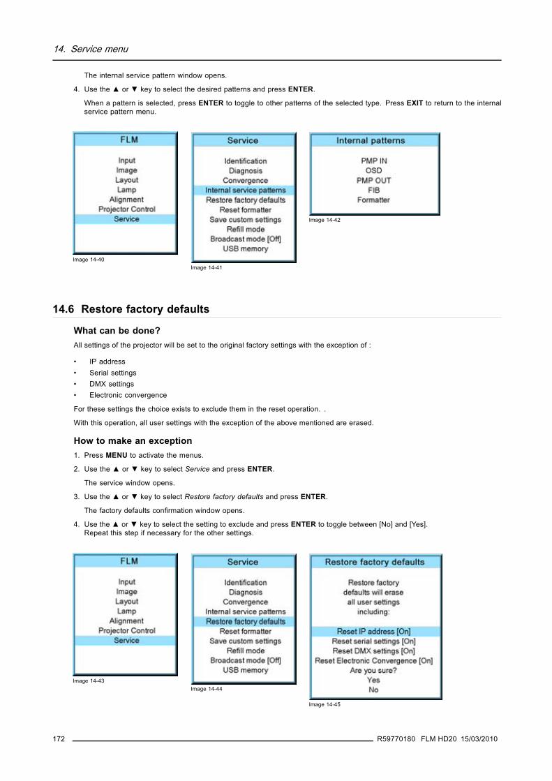
14. Service menu
The internal service pattern window opens.
4. Use the ▲ or ▼ key to select the desired patterns and press ENTER.
When a pattern is selected, press ENTER to toggle to other patterns of the selected type. Press EXIT to return to the internalservice pattern menu.
Image 14-40Image 14-41
Image 14-42
14.6 Restore factory defaults
What can be done?All settings of the projector will be set to the original factory settings with the exception of :
• IP address• Serial settings• DMX settings• Electronic convergence
For these settings the choice exists to exclude them in the reset operation. .
With this operation, all user settings with the exception of the above mentioned are erased.
How to make an exception1. Press MENU to activate the menus.
2. Use the ▲ or ▼ key to select Service and press ENTER.
The service window opens.
3. Use the ▲ or ▼ key to select Restore factory defaults and press ENTER.
The factory defaults confirmation window opens.
4. Use the ▲ or ▼ key to select the setting to exclude and press ENTER to toggle between [No] and [Yes].Repeat this step if necessary for the other settings.
Image 14-43Image 14-44
Image 14-45
172 R59770180 FLM HD20 15/03/2010

14. Service menu
How to return to the default settings1. Press MENU to activate the menus.
2. Use the ▲ or ▼ key to select Service and press ENTER.
The service window opens.
3. Use the ▲ or ▼ key to select Restore factory defaults and press ENTER.
The factory defaults confirmation window opens.
4. Use the ▲ or ▼ key to select Yes or No and press ENTER.
If you are sure to restore the factory defaults and to erase the custom settings, select Yes.
If you are not sure, select No.
Image 14-46Image 14-47
Image 14-48
14.7 Reset formatterHow to reset1. Press MENU to activate the menus.
2. Use the ▲ or ▼ key to select Service and press ENTER.
The service window opens.
3. Use the ▲ or ▼ key to select Reset formatter and press ENTER.
The formater reset confirmation window opens.
4. Use the ▲ or ▼ key to select Yes or No and press ENTER.
If you want to reset the formatter, select Yes.
If you do not want to reset the formatter, select No.
Image 14-49Image 14-50
Image 14-51
R59770180 FLM HD20 15/03/2010 173

14. Service menu
14.8 Save custom settings
What is done?The current custom settings can be saved to the internal backup device in the same way as it would be done when the projectorwas switched to standby.
How to save1. Press MENU to activate the menus.
2. Use the ▲ or ▼ key to select Service and press ENTER.
The service window opens.
3. Use the ▲ or ▼ key to select Save custom settings and press ENTER.
The custom settings are written to the internal backup device. A message menu “Save data ...” is displayed during the saveoperation.
Image 14-52Image 14-53
14.9 Refill mode
Before selecting Refill mode, take first all preparations necessary to refill the cooling circuit.
What can be done?When all preparations are taken, the refill mode will automatically activate the refill process.
How to start the refill mode1. Press MENU to activate the menus.
2. Use the ▲ or ▼ key to select Service and press ENTER.
The service window opens.
3. Use the ▲ or ▼ key to select Refill mode and press ENTER.
A refill confirmation message is displayed.
4. Use the ▲ or ▼ key to select Yes or No and press ENTER.
174 R59770180 FLM HD20 15/03/2010

14. Service menu
Yes will switch the projector in refill mode.
When No is selected, the projector stays in normal mode.
Image 14-54Image 14-55
Image 14-56
CAUTION: Restart of the projector is necessary to terminate the refill mode. Before restarting, switch off theprojector and reinstall first the cooling circuit.
14.10 Broadcast mode
Only accessible for HD projectors
What can be done ?"Broadcast mode" enables special sequences for the DMD’s to support specific sources such as the Thompson Grass Valley World-cam. It shouldn’t be used in any other circumstances as it would cause image flicker and dimmed images with normal sources.
Default position : [Off]
How to set up1. Press MENU to activate the menus.
2. Use the ▲ or ▼ key to select Service and press ENTER.
The service window opens.
3. Use the ▲ or ▼ key to select Broadcast mode and press ENTER to toggle between [Off] and [On].
Image 14-57Image 14-58
R59770180 FLM HD20 15/03/2010 175

14. Service menu
When Broadcast mode ON, switch also Genlock to ON (Input → Input locking → Automatic + Options) andenter the correct values for this source.
14.11 USB memory
What is possible with an USB device?An USB device, FAT 16 formatted can be used, to save custom settings from the projector or to load custom settings to the projector.This function is very handy to clone projectors.
The following settings can be transported via an USB device:
• baudrate• address• common address• orientation• text on/off• file load mode• eco mode & dimming• rs232 interface & rs232 termination• no signal setup settings• IR receiver settings• native resolution• min delay• current language of on screen menus• customer id• Network settings (DHCP, IP address, net mask, gateway address)• blanking & keystone• ScenergiX• gamma• color standard• source switching• effect settings• broadcast mode• menu position• button settngs• locking settings
Saving custom settings1. Connect a FAT 16 formatted USB device to the USB port.
2. Press MENU to activate the menus.
3. Use the ▲ or ▼ key to select Service and press ENTER.
The service window opens.
4. Use the ▲ or ▼ key to select USB memory and press ENTER.
5. Use the ▲ or ▼ key to select Save custom settings and press ENTER.
176 R59770180 FLM HD20 15/03/2010

14. Service menu
The custom settings on the projector are stored on the USB device together with the serial number of the projector. Differentsaves can be made from different projectors on the same USB device.
When there is no USB device connected to the USB slot, a message, No USB device found, is displayed.
Image 14-59Image 14-60
Image 14-61
Load custom settings1. Connect a FAT 16 formatted USB device to the USB port.
2. Press MENU to activate the menus.
3. Use the ▲ or ▼ key to select Service and press ENTER.
The service window opens.
4. Use the ▲ or ▼ key to select USB memory and press ENTER.
5. Use the ▲ or ▼ key to select Load custom settings and press ENTER.
An list of serial numbers is given.
6. Use the ▲ or ▼ key to select the serial number to start from to load the settings.
The settings from the selected projector on the USB device are loaded into the current attached projector. The current projectorsettings are overwritten with these settings.
Image 14-62Image 14-63
Image 14-64
Image 14-65
R59770180 FLM HD20 15/03/2010 177

14. Service menu
178 R59770180 FLM HD20 15/03/2010

15. Maintenance
15. MAINTENANCE
About this chapterThis chapter contains detailed maintenance procedures like dust filter replacement, lens cleaning etc. These procedures can easilybe performed by the operator of the projector.
CAUTION: All HEPA filters of the projector must be replaced on a regular basis, depending on the environmentconditions of the projector.
CAUTION: The pressure of the Liquid Cooling Circuit should be checked regularly. This pressure, indicatedon the internal manometer, should be between 0,5 and 1 bar. If not, corrective action should be taken byqualified technical service personnel.
HEPA
High Efficiency Particulate Absorbing
Overview
• Replacement of the dust filter on the front side• Replacement of the dust filter on the bottom side• Replacement of the dust filter on the top side• Pressure verification of the liquid cooling circuit• Cleaning the lens• Cleaning the exterior of the projector
15.1 Replacement of the dust filter on the front side
Necessary partsNew HEPA dust filter for the front side (R9854470).
How to replace the HEPA dust filter on the front side of the projector ?1. Remove the front cover of the projector, see "Removal of the front cover", page 191.
2. Remove the HEPA dust filter on the front side by pulling the two spring clamps away from the filter and then moving the filterforwards.
2
1
Image 15-1
3. Insert a new HEPA1 filter by pulling the two spring clamps away and move the filter into position.Caution: Make sure that the airflow indicated on the dust filter match with the airflow of the fans.
4. Reinstall the front cover of the projector, see "Installation of the front cover", page 194.
1. High Efficiency Particulate Arrestant
R59770180 FLM HD20 15/03/2010 179

15. Maintenance
CAUTION: Never install a used HEPA filter. Always install a new HEPA filter.
15.2 Replacement of the dust filter on the bottom side
Necessary parts• New HEPA dust filter for the bottom side (R9854480).• 2.5 mm Allen key.
How to replace the HEPA dust filter on the bottom side of the projector ?1. Remove the side cover of the projector, see "Removal of the side cover", page 192.
2. Release (not remove) the two wedge lock screws (A) using a 2.5 mm Allen key as illustrated.
A A
Image 15-2
3. Remove the filter (F) on the bottom side by pulling out the filter holder (H) as illustrated.
F
HH
Image 15-3
4. Place a new HEPA dust filter in the filter holder.Caution: Make sure that the airflow indicated on the dust filter match with the airflow of the fans.
5. Reinstall the filter holder containing the new HEPA filter.
6. Fasten the two wedge lock screws (A) using a 2.5 mm Allen key as illustrated.
180 R59770180 FLM HD20 15/03/2010

15. Maintenance
A A
Image 15-4
7. Reinstall the side cover of the projector, see "Installation of the side cover", page 195.
CAUTION: Never install a used HEPA filter. Always install a new HEPA filter.
15.3 Replacement of the dust filter on the top side
Necessary partsNew HEPA dust filter for the top side (R9854480).
How to replace the HEPA dust filter on the top side of the projector ?1. Remove the side cover of the projector, see "Removal of the side cover", page 192.
2. Remove the filter (F) on the top side by pulling out the filter holder (H) as illustrated.
F
HImage 15-5
3. Place a new HEPA dust filter in the filter holder.Caution: Make sure that the airflow indicated on the dust filter match with the airflow of the fans.
4. Reinstall the filter holder containing the new HEPA filter.
5. Reinstall the side cover of the projector, see "Installation of the side cover", page 195.
CAUTION: Never install a used HEPA filter. Always install a new HEPA filter.
15.4 Pressure verification of the liquid cooling circuit
How to check the pressure of the liquid cooling circuit inside the projector ?1. Remove the side cover of the projector, see "Removal of the side cover", page 192.
R59770180 FLM HD20 15/03/2010 181

15. Maintenance
2. Check the pressure indicated on the internal manometer of the liquid cooling circuit.
1
0.5
Image 15-6
3. This pressure should be between 0,5 and 1 bar. If the pressure, indicated on the manometer, is out of range, inform the respon-sible and qualified technicians, so they may take necessary corrective action.
4. Reinstall the side cover of the projector, see "Installation of the side cover", page 195.
15.5 Cleaning the lens
To minimize the possibility of damage to optical coatings, or scratches to lens surfaces, we have developedrecommendations for cleaning. FIRST, we recommend you try to remove any material from the lens by blowingit off with clean, dry deionized air. DO NOT use any liquid to clean the lenses.
Necessary toolsTorayseeTM cloth (delivered together with the lens kit). Order number : R379058.
How to clean the lens ?1. Always wipe lenses with a CLEAN TorayseeTM cloth.
2. Wipe lenses in a one single direction.Warning: Do not wipe back and forwards across the lens surface as this tends to grind dirt into the coating.
3. Do not leave the cleaning cloth in either an open room or lab coat pocket, as doing so can contaminate the cloth.
4. If smears occur when cleaning lenses, replace the cloth. Smears are the first indication of a dirty cloth.
CAUTION: Do not use fabric softener when washing the cleaning cloth or softener sheets when drying thecloth.
Do not use liquid cleaners on the cloth as doing so will contaminate the cloth.
Other lenses can also be cleaned safely with this TorayseeTM cloth.
15.6 Cleaning the exterior of the projector
How to clean the exterior of the projector ?1. Switch off the projector and unplug the power cord at the projector side.
2. Clean the housing of the projector with a damp cloth. Stubborn stains may be removed with a cloth lightly dampened with a milddetergent solution.
182 R59770180 FLM HD20 15/03/2010

16. Servicing
16. SERVICING
About this chapterThis chapter contains general servicing procedures like lamp replacement, input unit replacement etc. Note that some of theseprocedures may only be performed by qualified technical service personnel.
Overview
• Removal of the lamp house• Removal of the input & communication unit• Removal of an input module• Installation of the lamp house• Installation of the input & communication unit• Installation of an input module• Realignment of the lamp in its reflector
Extra service informationExtra service information for qualified service technicians can be found on Barco’s Partnerzone (URL:www.partner-zone.events.barco.com). Registration is necessary.
If you are not yet registered, click on Partnerzone registration and follow the instructions. With the created login and password, it ispossible to enter the partnerzone where you can find extra service information about the projector.
16.1 Removal of the lamp house
WARNING: This procedure may only be performed by qualified technical service personnel.
CAUTION: Never attempt to disassemble the lamp from its housing or to dispose of it. Return it to Barco.Due to its high internal pressure, the lamp may explode in either hot or cold states if improperly handled.
Necessary tools7 mm flat screw driver.
How to remove the lamp house of the projector ?1. Switch off the projector and unplug the power cord at the projector side.
2. Remove the lamp cover, see "Removal of the lamp cover", page 193.
3. Release the three spring lock screws of the lamp house as illustrated.
Image 16-1
R59770180 FLM HD20 15/03/2010 183

16. Servicing
4. Clasp the lamp house by the handles and pull the lamp house out of the projector.
Image 16-2
While starting up the projector, the electronics detect if a lamp is installed. If no lamp is installed, it is notpossible to start up the projector.
16.2 Removal of the input & communication unit
WARNING: This procedure may only be performed by qualified technical service personnel.
Necessary tools7 mm flat screw driver.
How to remove the input & communication unit from the projector ?1. Switch off the projector and unplug the power cord at the projector side. See procedure "Switching off", page 47.
2. Ensure that no cables are connected to one of the ports of the input & communication unit.
3. Remove the input cover, see "Removal of the input cover", page 193.
4. Release the four captive screws in the corners of the input and communication unit as illustrated.
Image 16-3
5. Pull the input & communication unit out of its compartment, using the side handles provided.
184 R59770180 FLM HD20 15/03/2010

16. Servicing
Image 16-4
16.3 Removal of an input module
The procedure below is applicable to all input modules of the input & communication unit of the projector.
Necessary toolsPhillips screw driver PH1.
How to remove an input module out of the input & communication unit of the projector ?1. Switch off the projector and unplug the power cord at the projector side.
2. Release the two captive screws of the input module using a Phillips screw driver PH1.
Image 16-5
3. Pull the input module out of the input & communication unit, via the two knobs provided.
R59770180 FLM HD20 15/03/2010 185

16. Servicing
Image 16-6
CAUTION: Ensure that all unused input slots of the input & communication unit are always covered with adummy front plate. After removing one of the input modules, immediately replace with an other one or installa dummy front cover on the unused input slot.
16.4 Installation of the lamp house
WARNING: This procedure may only be performed by qualified technical service personnel.
CAUTION: Never attempt to disassemble the lamp from its housing or to dispose of it. Return it to Barco.Due to its high internal pressure, the lamp may explode in either hot or cold states if improperly handled.
Necessary tools7 mm flat screw driver.
How to install the lamp house of the projector ?1. Ensure the projector is switched off and the power cord at the projector side is unplugged.
2. Remove the lamp cover, if not removed yet. See "Removal of the lamp cover", page 193.
3. Clasp the lamp house by its handles and gently slide the lamp house into its socket. Note that the compartment is provided withguides (G) to position the lamp house correctly.
G
C
Image 16-7
186 R59770180 FLM HD20 15/03/2010

16. Servicing
4. Push the lamp house forward until it slides fully into the projector.
5. Secure the correct position of the lamp house by tightening all three spring lock screws as illustrated.
Image 16-8
6. Reinstall the lamp cover of the projector, see "Installation of the lamp cover", page 196.
While starting up the projector, the electronics detect if a lamp is installed. If no lamp is installed, it is notpossible to start up the projector.
16.5 Installation of the input & communication unit
WARNING: This procedure may only be performed by qualified technical service personnel.
Necessary tools7 mm flat screw driver.
How to install the input & communication unit of the projector ?1. Ensure that the projector is switched off and the power cord at the projector side is unplugged.
2. Remove the input cover, if not removed yet. See "Removal of the input cover", page 193.
3. Hold the input & communication unit by its handles and gently slide the unit into the guides at the bottom of the input & commu-nication socket inside the projector.
R59770180 FLM HD20 15/03/2010 187

16. Servicing
Image 16-9
4. Push the input & communication unit forward until you feel the connectors of the unit fit in their sockets. The back of the frontplate of the unit must touch the chassis of the projector.
5. Secure the input & communication unit by fastening the four captive screws in the corners of the unit.
Image 16-10
16.6 Installation of an input module
The procedure below is applicable to all input modules of the input & communication unit of the projector.
Necessary toolsPhillips screw driver PH1.
How to install an input module into the input & communication unit of the projector ?1. Switch off the projector and unplug the power cord at the projector side.
2. Slide the input module into the guides of the input slot.
188 R59770180 FLM HD20 15/03/2010

16. Servicing
G
Image 16-11
3. Push the input module forward until you feel that the connector of the input module fit in the socket of the input slot. The back ofthe front plate of the module must touch the front plate of the input & communication unit.
4. Secure the input module by fastening both captive screws in the top corners of the module.
Image 16-12
16.7 Realignment of the lamp in its reflector
Why realigning the lamp ?With longer run times, the light output of the lamp will decrease, which results in a lower light output on the screen. This light outputdecrease can be compensated by readjusting the Z-position of the lamp.
WARNING: This procedure may only be performed by qualified technical service personnel.
How to realign the lamp in its reflector ?1. Remove the cover of the lamp, see "Removal of the lamp cover", page 193.
2. Connect the projector to the local power net, see "Power connection", page 35.
3. Start up the projector, enter the menu structure and select Lamp / Z-axis (for more explanation, see "Z-axis adjustment", page113)
4. Carefully turn the thumb screw (A) at the rear of the lamp house clockwise for maximum light output. Once over the maximum,turn slightly counterclockwise to reach the maximum light output again.
R59770180 FLM HD20 15/03/2010 189

16. Servicing
A
Image 16-13
5. Switch off the projector, wait five minutes and unplug the power cord at the projector side.
6. Reinstall the cover of the lamp, see "Installation of the lamp cover", page 196.
190 R59770180 FLM HD20 15/03/2010

17. Removal of the projector covers
17. REMOVAL OF THE PROJECTOR COVERS
About this chapterMost maintenance and servicing procedures demand removing one or more of the projector covers to gain access to the parts tomaintain or to service. To avoid redundancy, all procedures about cover removing or installing are grouped together in this chapter.The maintenance and servicing procedures also refer to this chapter if required. The procedures in this chapter describe, withdetailed step by step actions and illustrations, how to remove or install the projector covers. Note that some covers may only beremoved by qualified service personnel, see remarks above each procedure.
WARNING: Always switch off the projector and unplug the power cord at the projector side before removingone of the covers.
Overview
• Removal of the front cover• Removal of the side cover• Removal of the lamp cover• Removal of the input cover• Installation of the front cover• Installation of the side cover• Installation of the lamp cover• Installation of the input cover
17.1 Removal of the front coverNecessary tools7 mm flat screw driver.
How to remove the front cover of the projector ?1. Remove the lens. See chapter "Lens removal", page 26.
2. Remove the rubber dust ring from the lens holder. See image 17-1.
3. Release the captive screw at the middle bottom of the front cover, using a flat screw driver.
Image 17-1
4. Remove the front cover from the projector doing the following:a) standing in front of the projector, pull the right side of the front cover toward you until the latches release (left side is hinged)b) then slide the front cover to the right to release it from the hinging points.
R59770180 FLM HD20 15/03/2010 191

17. Removal of the projector covers
Image 17-2
17.2 Removal of the side cover
CAUTION: Remove the side cover of the projector only in a clean and dust free area. Never remove the sidecover in an area which is subject to airborne contaminants such as that produced by smoke machines orsimilar.
Necessary tools7 mm flat screw driver.
How to remove the side cover of the projector ?1. Release the captive screw at the middle bottom of the side cover, using a flat screw driver.
Image 17-3
2. Remove the side cover from the projector doing the following:a) gently pull out the bottom corners (A) of the side cover,b) then gently pull out the top corners (B) of the side cover,c) then move the side cover away from the projector (C).
Image 17-4
192 R59770180 FLM HD20 15/03/2010

17. Removal of the projector covers
17.3 Removal of the lamp cover
WARNING: This procedure may only be performed by qualified technical service personnel.
Necessary tools7 mm flat screw driver.
How to remove the lamp cover of the projector ?1. Release the two captive screws at the top and bottom right side of the lamp cover, using a flat screw driver.
Image 17-5
2. Remove the lamp cover from the projector doing the following:a) gently pull out the left bottom corner (A) of the lamp cover,b) then gently pull out the left top corner (B) of the lamp cover,c) then move the lamp cover away from the projector (C).
Image 17-6
17.4 Removal of the input cover
WARNING: This procedure may only be performed by qualified technical service personnel.
Necessary tools7 mm flat screw driver.
How to remove the input cover of the projector ?1. Release the two captive screws at the top and bottom left side of the input cover, using a flat screw driver.
R59770180 FLM HD20 15/03/2010 193

17. Removal of the projector covers
Image 17-7
2. Remove the input cover from the projector doing the following:a) gently pull out the right bottom corner (A) of the input cover,b) then gently pull out the right top corner (B) of the input cover,c) then move the input cover away from the projector (C).
Image 17-8
17.5 Installation of the front coverNecessary tools7 mm flat screw driver.
How to install the front cover of the projector ?1. Check if the front filter is present.
2. Ensure that no lens is mounted.
3. Install the front cover of the projector doing the following:a) first hook in the side of the front cover at the front filter,b) then gently push the other side of the front cover into position,c) ensure that the locking studs in the corners click into their receivers.
194 R59770180 FLM HD20 15/03/2010

17. Removal of the projector covers
Image 17-9
4. Secure the front cover by locking the captive screw in the middle at the bottom of the front cover.
Image 17-10
5. Reinstall the rubber dust ring around the lens holder. See image 17-10.
17.6 Installation of the side coverNecessary tools7 mm flat screw driver.
How to install the side cover of the projector ?1. Check if the bottom and top filters are present.
2. Check the pressure indicated on the internal manometer of the liquid cooling circuit. This pressure should be between 0,5 and 1bar. If the pressure is out of range, inform the responsible and qualified technician, so he may take necessary corrective action.
1
0.5
Image 17-11
3. Install the side cover of the projector doing the following:a) Bring the side cover towards its final position (A),b) then gently push the locking studs of the top corners (B) into their receivers,c) then gently push the locking studs of the bottom corners (C) into their receivers.
R59770180 FLM HD20 15/03/2010 195

17. Removal of the projector covers
Image 17-12
4. Secure the side cover by locking the captive screw in the middle at the bottom of the side cover.
Image 17-13
17.7 Installation of the lamp cover
Necessary tools7 mm flat screw driver.
How to install the lamp cover of the projector ?1. Install the lamp cover of the projector doing the following:
a) Bring the lamp cover towards its final position (A),b) then gently push the locking stud at the left top corner (B) into its receiver,c) then gently push the locking stud at the left bottom corner (C) into its receiver.
Image 17-14
2. Secure the lamp cover by locking the two captive screws at the right side of the lamp cover.
Image 17-15
196 R59770180 FLM HD20 15/03/2010

17. Removal of the projector covers
17.8 Installation of the input cover
Necessary tools7 mm flat screw driver.
How to install the input cover of the projector ?1. Install the input cover of the projector doing the following:
a) Bring the input cover towards its final position (A),b) then gently push the locking stud at the right top corner (B) into its receiver,c) then gently push the locking stud at the right bottom corner (C) into its receiver.
Image 17-16
2. Secure the input cover by locking the two captive screws at the left side of the input cover.
R59770180 FLM HD20 15/03/2010 197

17. Removal of the projector covers
198 R59770180 FLM HD20 15/03/2010

18. Dimensions
18. DIMENSIONS
Overview
• Dimensions of the FLM HD20• Dimensions of the FLM flight case• Dimensions of the rigging clamps
18.1 Dimensions of the FLM HD20Dimensions
730250
520643
14.8
130
148
148
480
485 459
485643
676.1771.1
771.
1
1040
598.
05
483.
5
512.
6
310.
5
47.5
115
25
78.0
5
47.5
43.5
(+9)
Image 18-1Dimensions given in millimeters.
R59770180 FLM HD20 15/03/2010 199

18. Dimensions
Point of gravity
233
359 22
4.5
Image 18-2Dimensions given in millimeters.
18.2 Dimensions of the FLM flight case
Dimensions
1194
660
817.
5
808
1175819800
Image 18-3Dimensions given in millimeters.
200 R59770180 FLM HD20 15/03/2010

18. Dimensions
18.3 Dimensions of the rigging clamps
Dimensions
99
50
M10
26.5
18
SW17
40
45
30
30
75
29.8
2
120
Image 18-4Dimensions given in millimeters.
R59770180 FLM HD20 15/03/2010 201

18. Dimensions
202 R59770180 FLM HD20 15/03/2010

19. Standard Source Files
19. STANDARD SOURCE FILES
19.1 Table overviewTable overviewThe following standard image files are pre-programmed in the projector.
Name2 Fvert
Hz3FHor
kHz4Fpix
MHz5Ptot6 Pact7 Ltot8 Lact9
640x350@85 85,079 37,860 31,500 832 640 445 350
640x400@85 85,079 37,860 31,500 832 640 445 400
640x480@60 59,940 31,668 25,175 800 640 525 480
640x480@72 72,888 30,288 19,687 832 640 520 480
640x480@75 74,999 37,500 31,500 840 640 500 480
640x480@85 85,009 43,270 36,000 832 640 509 480
720x400@85 85,040 37,928 35,500 936 720 446 400
800x600@56 56,251 35,157 36,001 1024 800 625 600
800x600@60 60,317 37,879 40,000 1056 800 628 600
800x600@72 72,188 48,077 50,000 1040 800 666 600
800x600@75 75,001 46,876 49,501 1056 800 625 600
800x600@85 85,062 53,674 56,250 1048 800 631 600
848x480@60 60,000 31,020 33,750 1088 848 517 480
1024x768@60 60,004 48,363 65,000 1344 1024 806 768
1024x768@70 70.068 56,475 74,999 1328 1024 806 768
1024x768@75 75,030 60,024 78,751 1312 1024 800 768
1024x768@85 84,996 68,677 94,499 1376 1024 808 768
1152x864@75 74,999 67,499 107,999 1600 1152 900 864
1280x768@60 59,870 47,776 79,499 1664 1280 798 768
1280x768@75 74,992 60,288 102,249 1696 1280 805 768
1280x768@85 84,838 68,634 117,502 1712 1280 809 768
1280x768RB@60 59,994 47,396 68,250 1440 1280 790 768
1280x960@60 59,999 59,999 107,998 1800 1280 1000 960
1280x960@85 85,005 85,940 128,505 1728 1280 1011 960
1280x1024@60 60,018 63,980 107,997 1688 1280 1066 1024
1280x1024@75 75,023 79,974 134,997 1688 1280 1066 1024
1280x1024@85 85,027 91,149 157,506 1728 1280 1072 1024
1360x768@60 59,898 47,619 85,333 1792 1360 795 768
1400x1050@50 50,015 54,517 94,641 1736 1400 1090 1050
1400x1050@60 59,979 65,317 121,751 1864 1400 1089 1050
1400x1050@75 74,866 82,277 155,998 1896 1400 1099 1050
1400x1050@85 84,958 93,879 179,497 1912 1400 1105 1050
2. Name: name of file, contains the settings.3. Fvert Hz: vertical frame frequency of the source4. FHor kHz: horizontal frequency of the source5. Fpix MHz: pixel frequency6. Ptot : total pixels on one horizontal line.7. Pact: active pixels on one horizontal line.8. Ltot: total lines in one field9. Lact: active lines in one field.
R59770180 FLM HD20 15/03/2010 203

19. Standard Source Files
Name2 Fvert
Hz3FHor
kHz4Fpix
MHz5Ptot6 Pact7 Ltot8 Lact9
1400x1050RB@60 59,946 64,742 100,997 1560 1400 1080 1050
1600x1200@60 60,001 75,002 162,004 2160 1600 1250 1200
1600x1200@65 64,998 81,248 175,496 2160 1600 1250 1200
1600x1200@70 69,997 87,497 188,993 2160 1600 1250 1200
1600x1200@75 74,998 93,747 202,414 2160 1600 1250 1200
1600x1200@85 84,998 106,247 229,494 2160 1600 1250 1200
1792x1344@60 60,000 83,640 204,751 2448 1792 1394 1344
1792x1344@75 74,996 106,270 260,999 2456 1792 1417 1344
1856x1392@60 59,995 86,333 218,251 2528 1856 1439 1392
1920x1140@60 60,001 90,001 234,002 2600 1920 1500 1140
1920x1200@60 59,883 74,555 193,235 2592 1920 1245 1200
1920x1200RB@60 59,952 74,041 154,006 2080 1920 1235 1200
1920x1440@60 60,001 90,001 234,002 2600 1920 1500 1200
hd-1280x720@60p 60,001 45,000 74,251 1650 1280 750 720
hd-1920x1035@30i 60,000 33,720 74,184 2200 1920 562 517
hd-1920x1080@24p 24,000 27,000 74,250 2750 1920 1125 1080
hd-1920x1080@24sf 48,001 54,002 148,504 2750 1920 1125 1080
hd-1920x1080@25i 50,044 28,125 74,249 2640 1920 562 540
hd-1920x1080@25p 25,000 28,125 74,249 2640 1920 1125 1080
hd-1920x1080@30i 60,000 33,720 74,184 2200 1920 562 540
hd-1920x1080@30p 30,000 33,750 74,249 2200 1920 1125 1080
hd-1920x1080@25i 50,000 31.25 74,250 2376 1920 625 540
hd-1920x1080@60p 60,011 67,513 148,528 2200 1920 1125 1080
VIDEO525 62,437 15,734 13,500 858 712 252 242
VIDEO525p 59,940 31,468 27,000 858 712 525 484
VIDEO625 50,080 15,625 13,500 864 702 312 287
VIDEO625p 50,080 31,250 27,000 864 702 625 574
no-signal 100,00 20,000 8,000 400 300 200 100
no-signal-i 100,00 20,000 8,000 400 300 200 100
Table 19-1
204 R59770180 FLM HD20 15/03/2010

20. DMX chart
20. DMX CHART
Overview
• DMX chart, basic• DMX chart, Extended• DMX chart, Full
20.1 DMX chart, basic
OverviewChan-nel
Function Value Action
0 - 5 Mechanical shutter1 Intensity
0 - 255 Electronic contrast
2 Function selection 0 - 7 no function
8 - 15 Layout 1
16 - 23 Layout 2
24 - 31 Layout 3
32 - 39 Layout 4
40 - 47 Layout 5
48 - 55 Layout 6
56 - 63 Layout 7
64 - 71 Layout 8
72 - 79 Layout 9
80 - 87 Layout 10
88 - 95 Input select 1
96 - 103 Input select 2
104 - 111 Input select 3
112 - 119 Input select 4
120 - 127
128 - 135
136 - 143
144 - 151
152 - 159
160 - 167
168 - 175
176 - 183
184 - 207
208 - 215 Power On / Lamp On
216 - 223 Power Off / Lamp Off
224 - 255
R59770180 FLM HD20 15/03/2010 205

20. DMX chart
20.2 DMX chart, Extended
OverviewChan-nel
Function Value Default Actions
0 - 5 Mechanical shutter closed1 Intensity
0 - 255 Contrast 0 - channel 3
2 Brightness 0 - 255 128 Adjusts the brightness between 0 and 100% (SLM/XLM doesn’t adjuston DVI)
3 Contrast 0 - 255 128 Adjusts the contrast between 0 and 100% (SLM/XLM doesn’t adjust on DVI)
0 - 7 No function
8 - 15 Layout 1 (execution takes 5 sec)
16 - 23 Layout 2 (execution takes 5 sec)
24 - 31 Layout 3 (execution takes 5 sec)
32 - 39 Layout 4 (execution takes 5 sec)
40 - 47 Layout 5 (execution takes 5 sec)
48 - 55 Layout 6 (execution takes 5 sec)
56 - 63 Layout 7 (execution takes 5 sec)
64 - 71 Layout 8 (execution takes 5 sec)
72 - 79 Layout 9 (execution takes 5 sec)
80 - 87 Layout 10 (execution takes 5 sec)
88 - 95 Input select 1
96 - 103 Input select 2
104 - 111 Input select 3
112 - 119 Input select 4
120 - 127
128 - 135
136 - 143
144 - 151
152 - 159
160 - 167
168 - 175
176 - 183
4 Input selection
184 - 255 No function
0 - 7 No function
8 - 15 Lens shift Right
16 - 23 No function
24 - 31 Lens shift Left
32 - 39 No function
40 - 47 Lens shift up
48 - 55 No function
56 - 63 Lens shift down
64 - 231 No function
232 - 239 Return lens to center (if held for 5 seconds)
240 - 247 Calibrate lens zoom + focus (if held for 5 seconds and channel 1 < 6
5 Lens control
248 - 255 No function
6 Foxus (MSB) 0 - 255 Coarse focus adjustment
7 Focus (LSB) 0 - 255 Fine focus adjustment
8 Zoom (MSB) 0 - 255 Coarse zoom adjustment
206 R59770180 FLM HD20 15/03/2010

20. DMX chart
Chan-nel
Function Value Default Actions
9 Zoom (LSB) 0 - 255 Fine zoom adjustment
0 - 7 Lamp power 100%
8 - 15 Lamp power 98%
16 - 23 Lamp power 96%
24 - 31 Lamp power 94%
32 - 39 Lamp power 91%
40 - 47 Lamp power 89%
48 - 55 Lamp power 86%
56 - 63 Lamp power 84%
64 - 71 Lamp power 82%
72 - 79 Lamp power 80%
80 - 87 Lamp power 78%
88 - 95 Lamp power 76%
96 - 103 Lamp power 74%
104 - 111 Lamp power 72%
112 - 119 Lamp power 70%
120 - 127 Lamp power 68%
128 - 135 Lamp power 66%
136 - 143 Lamp power 64%
144 - 151 Lamp power 62%
152 - 159 Lamp power 60%
160 - 167 No function
168 - 175 DMX buffer 4 (Not used)
176 - 183 DMX buffer 8 (Not used)
184 - 191 DMX buffer off (Not used)
192 - 199 DMX buffer clear (Not used)
200 - 207 No function
208 - 215 Power On / Lamp On (if held for 5 seconds)
216 - 223 Stand by / Lamp Off (if held for 5 seconds)
10 Control
224 - 255 No function
20.3 DMX chart, Full
OverviewChan-nel
Function Value Default Action
0 - 5 Mechanical shutter closed1 Intensity
6 - 255 Contrast 0 - channel 3
2 Brightness 0 - 255 128 Adjusts the brightness between 0 and 100% (SLM/XLM doesn’tadjust on DVI)
3 Contrast 0 - 255 128 Together with channel 1
R59770180 FLM HD20 15/03/2010 207

20. DMX chart
Chan-nel
Function Value Default Action
0 - 7 No function
8 - 15 Layout 1 (execution takes 5 sec)
16 - 23 Layout 2 (execution takes 5 sec)
24 - 31 Layout 3 (execution takes 5 sec)
32 - 39 Layout 4 (execution takes 5 sec)
40 - 47 Layout 5 (execution takes 5 sec)
48 - 55 Layout 6 (execution takes 5 sec)
56 - 63 Layout 7 (execution takes 5 sec)
64 - 71 Layout 8 (execution takes 5 sec)
72 - 79 Layout 9 (execution takes 5 sec)
80 - 87 Layout 10 (execution takes 5 sec)
88 - 95 Input select 1
96 - 103 Input select 2
104 - 111 Input select 3
112 - 119 Input select 4
120 - 127
128 - 135
136 - 143
144 - 151
152 - 159
160 - 167
168 - 175
176 - 183
4 Input selection
184 - 255 No function
0 - 31 No function
32 - 63 Focus motor
64 - 95 Zoom motor
96 - 127 Lens shift Right Left
128 - 159 Lens shift Up Down
160 - 191 Power On / Lamp On (together with channel 6 and 7 held in 255for 5 sec)
192 - 223 Stand By / Lamp Off (together with channel 6 and 7 held in 255for 5 sec)
5 Function select
224 - 255 Return lens to center position (if held for 5 seconds)
0 - 31 Stop
32 - 63 Run
64 - 223 No function
6 Motor Go >>
224 - 255 Command (see channel 5)
0 - 31 Stop
32 - 63 Run
64 - 223 No function
7 Motor Go <<
224 - 255 Command (see channel 5)
8 Free 0 - 255
208 R59770180 FLM HD20 15/03/2010

20. DMX chart
Chan-nel
Function Value Default Action
0 - 26 0 Powered at 100%
27 - 52 Powered at 98%
53 - 79 Powered at 96%
80 - 105 Powered at 94%
106 - 131 Powered at 91%
132 - 157 Powered at 89%
158 - 183 Powered at 86%
184 - 209 Powered at 84%
210 - 235 Powered at 82%
9 Lamp Power
236 - 255 Powered at 80%
10 Free 0 - 255
R59770180 FLM HD20 15/03/2010 209

20. DMX chart
210 R59770180 FLM HD20 15/03/2010

21. Troubleshooting
21. TROUBLESHOOTING
21.1 Error codesOverviewWhen the error code is preceded by a ’-’ sign, then the error means a real error for the projector.
When the error code is preceded by a ’+’ sign, then the error code means a warning. The projector does not fail yet, but take carefor the warning and try to resolve the problem. A warning state can turn into an error state.
Not all error codes can have two states. When the state is available, it is indicated by a Yes in the overview table. When the stateis not available, it is indicated by a No.
Errorcode
Description Error Warning Caused by Action
1000
↓
1017
Wrong lampparameters
Yes - Wrong lamp/ no communicationwith lamp
Check lamp type
Call a qualified service engineer
1499
1498
1699 Formatter busy
1698 Formatteraddress
1697 Formatter initfailed
Yes - no communication with formatterctrl
Call a qualified service engineer
1696 Formatter ctrlinit failed
Yes - no communication with formatterctrl
Call a qualified service engineer
1695 Red form. startfailed
Yes - no communication with redformatter
Call a qualified service engineer
1694 Green form.start failed
Yes - no communication with greenformatter
Call a qualified service engineer
1693 Blue form. startfailed
Yes - no communication with blueformatter
Call a qualified service engineer
1692 Form.PWRGood
Yes - formatter ’Power Good’ signal notOK
Call a qualified service engineer
2000 No lps detected Yes - no communication with lamp powersupply
Call a qualified service engineer
2001 Mains voltagetoo low
Yes - mains voltage too low
2002 Lamp startfailed
Yes - Hot restrike
Lamp with many strikes
maximum run time exceeded
Lamp or LPS or SPG failed
Let cool down the lamp for at least5 minutes. Retry a few times.
Replace the lamp with a new one
Replace LPS or SPG or cabling.
2003 Main voltagetoo high
Yes - mains voltage too high
2004 Lamp goes out Yes - Call qualified service engineer
2005 Lamp stopfailed
Yes - Call qualified service engineer
2201 PFC start failed Yes - LPS (address 0x20) Replace LPS
2501 PFC start failed Yes - LPS (address 0x22) Replace LPS
2801 PFC start failed Yes - LPS (address 0x28) Replace LPS
2202 LPS start failed Yes - LPS (address 0x20) Replace LPS
2502 LPS start failed Yes - LPS (address 0x22) Replace LPS
R59770180 FLM HD20 15/03/2010 211

21. Troubleshooting
Errorcode
Description Error Warning Caused by Action
2802 LPS start failed Yes - LPS (address 0x28) Replace LPS
2203 BOOST startfailed
Yes - LPS (address 0x20) Replace LPS
2503 BOOST startfailed
Yes - LPS (address 0x22) Replace LPS
2803 BOOST startfailed
Yes - LPS (address 0x28) Replace LPS
2206 Lamp ignitionfailed
Yes - hot restrike,
lamp with many strikes, maximumrun time exceeded
Let cool down the lamp for at least 3minutes. Replace the lamp or SPGwith a new one If problem persists,call a qualified service engineer
2506 Lamp ignitionfailed
Yes - hot restrike,
lamp with many strikes, maximumrun time exceeded
Let cool down the lamp for at least 3minutes. Replace the lamp or SPGwith a new one If problem persists,call a qualified service engineer
2806 Lamp ignitionfailed
Yes - hot restrike,
lamp with many strikes, maximumrun time exceeded
Let cool down the lamp for at least 3minutes. Replace the lamp or SPGwith a new one If problem persists,call a qualified service engineer
2207 Lamp voltagerange
Yes - lamp voltage too high or too low Replace lamp
2507 Lamp voltagerange
Yes - lamp voltage too high or too low Replace lamp
2807 Lamp voltagerange
Yes - lamp voltage too high or too low Replace lamp
2208 Lamp powerrange
Yes - lamp voltage too high or too low Replace lamp
2508 Lamp powerrange
Yes - lamp voltage too high or too low Replace lamp
2808 Lamp powerrange
Yes - lamp voltage too high or too low Replace lamp
4000 Incompatiblehardware
Yes No Incompatible hardware used Change to correct hardware
4199 FIB reset failed Yes - no communication with FIB Call a qualified service engineer
5098 Flash full Yes - Internal Backup device has reachedits maximum capacity
Call a qualified service engineer
5097 Flashmanagementfull
Yes - Internal Backup device has reachedits maximum capacity
Call a qualified service engineer
5096 Storingunsuccessful
Yes - Storing the custom settings intointernal backup device has failed
If problem persists, call a qualifiedservice engineer
5095 Restoringunsuccessful
Yes - Restoring the custom settings frominternal backup device has failed
If problem persists, call a qualifiedservice engineer
6099
6098
7698 Light pipe temphigh
Yes Yes High temperature on light pipe entry If problem persists, call a qualifiedservice engineer
7697 Light pipe tempopen
Yes Yes Temperature sensor on light pipenot connected
Call a qualified service engineer
7696 Light pipe tempshort
Yes Yes Temperature sensor on light pipeshorted
Call a qualified service engineer
7695 Red front DMDtemp low
No Yes Low temperature on red DMD Switching on the lamp will heat upthe DMD
212 R59770180 FLM HD20 15/03/2010

21. Troubleshooting
Errorcode
Description Error Warning Caused by Action
7694 Red front DMDtemp high
Yes Yes High temperature on red DMD Check if air slots are free.
Clean air filters.
If problem persists, call a qualifiedservice engineer
7693 Red front DMDtemp open
Yes Yes Temperature sensor on Red DMDnot connected
Call a qualified service engineer
7692 Red front DMDtemp short
Yes Yes Temperature sensor on Red DMDshorted
Call a qualified service engineer
7691 Green frontDMD temp low
No Yes Low temperature on green DMD Switching on the lamp will heat upthe DMD
7690 Green frontDMD temp high
Yes Yes High temperature on green DMD Check if air slots are free.
Clean air filters.
If problem persists, call a qualifiedservice engineer
7689 Green frontDMD tempopen
Yes Yes Temperature sensor on green DMDnot connected
Call a qualified service engineer
7888 Green frontDMD tempshort
Yes Yes Temperature sensor on green DMDshorted
Call a qualified service engineer
7687 Blue front DMDtemp low
Yes - Low temperature on blue DMD Switching on the lamp will heat upthe DMD
7686 Blue front DMDtemp high
Yes Yes High temperature on blue DMD Check if air slots are free.
Clean air filters.
If problem persists, call a qualifiedservice engineer
7685 Blue front DMDtemp open
Yes Yes Temperature sensor on blue DMDnot connected
Call a qualified service engineer
7684 Blue front DMDtemp short
Yes Yes Temperature sensor on blue DMDshorted
Call a qualified service engineer
7676 Front blocktemp high
Yes Yes High temperature on front DMDcooling block
Check if air slots are free.
Clean air filters.
If problem persists, call a qualifiedservice engineer
7675 Front blocktemp open
Yes Yes Temperature sensor on front coolingblock not connected
Call a qualified service engineer
7674 Front blocktemp short
Yes Yes Temperature sensor on front coolingblock shorted
Call a qualified service engineer
7672 Red block temphigh
Yes Yes High temperature on red DMDcooling block
Check if air slots are free.
Clean air filters.
If problem persists, call a qualifiedservice engineer
7671 Red block tempopen
Yes Yes Temperature sensor on red DMDcooling block not connected
Call a qualified service engineer
7670 Red block tempshort
Yes Yes Temperature sensor on red DMDcooling block shorted
Call a qualified service engineer
7668 Green blocktemp high
Yes Yes High temperature on green DMDcooling block
Check if air slots are free.
Clean air filters.
If problem persists, call a qualifiedservice engineer
7667 Green blocktemp open
Yes Yes Temperature sensor on green DMDcooling block not connected
Call a qualified service engineer
7666 Green blocktemp short
Yes Yes Temperature sensor on green DMDcooling block shorted
Call a qualified service engineer
R59770180 FLM HD20 15/03/2010 213

21. Troubleshooting
Errorcode
Description Error Warning Caused by Action
7664 Blue blocktemp high
Yes Yes High temperature on blue DMDcooling block
Check if air slots are free.
Clean air filters.
If problem persists, call a qualifiedservice engineer
7663 Blue blocktemp open
Yes Yes Temperature sensor on blue DMDcooling block not connected
Call a qualified service engineer
7662 Blue blocktemp short
Yes Yes Temperature sensor on blue DMDcooling block shorted
Call a qualified service engineer
7660 Engine air temphigh
Yes Yes High temperature on engine Check if air slots are free.
Clean air filters.
If problem persists, call a qualifiedservice engineer
7659 Engine air tempopen
Yes Yes Temperature sensor on engine notconnected
Call a qualified service engineer
7658 Engine air tempshort
Yes Yes Temperature sensor on engineshorted
Call a qualified service engineer
7999 Fan speedcathode toolow
Yes Yes fan is running too slow or not at all If problem persists, call a qualifiedservice engineer
7998 Fan speedcathode high
- Yes
7997 Fan speedanode too low
Yes Yes fan is running too slow or not at all If problem persists, call a qualifiedservice engineer
7996 Fan speedanode high
- Yes
7995 Fan speedengine too low
Yes Yes fan is running too slow or not at all If problem persists, call a qualifiedservice engineer
7994 Fan speedengine high
- Yes
7993 Fan speed coldmirror too low
Yes Yes fan is running too slow or not at all If problem persists, call a qualifiedservice engineer
7992 Fan speed coldmirror high
7991 Fan speed heatex. too low
Yes Yes fan is running too slow or not at all If problem persists, call a qualifiedservice engineer
7990 Fan speed heatex. high
- Yes
7989 Fan speedsmps 1 too low
Yes Yes fan is running too slow or not at all If problem persists, call a qualifiedservice engineer
7987 Fan speedsmps 2 too low
Yes Yes fan is running too slow or not at all If problem persists, call a qualifiedservice engineer
7985 Red DMD templow
No Yes low temperature on dmd turning on the lamp will heat up thedmd
7984 Red DMD temphigh
Yes Yes high temperature on dmd check if air slot are free; clean airfilters
If problem persists, call a qualifiedservice engineer
7983 Green DMDtemp low
No Yes low temperature on dmd turning on the lamp will heat up thedmd
7982 Green DMDtemp high
Yes Yes high temperature on dmd check if air slot are free; clean airfilters
If problem persists, call a qualifiedservice engineer
7981 Blue DMDtemp low
No Yes low temperature on dmd turning on the lamp will heat up thedmd
214 R59770180 FLM HD20 15/03/2010

21. Troubleshooting
Errorcode
Description Error Warning Caused by Action
7980 Blue DMDtemp high
Yes Yes high temperature on dmd check if air slot are free; clean airfilters
If problem persists, call a qualifiedservice engineer
7978 Lamp temphigh
Yes Yes high temperature lamp check if air slot are free; clean airfilters If problem persists, call aqualified service engineer
7976 SMPS HS temphigh
Yes Yes high temperature on smps check if air slot are free; clean airfilters If problem persists, call aqualified service engineer
7974 Ambient temphigh
Yes Yes ambient temperature abovespecification
check ambient conditions
check if air slot are free; clean airfilters
7973 Fan 1 voltagelow
Yes Yes voltage on fan group 1 too low (=cathode fan)
Hardware problem in Fan controlboard, call a qualified serviceengineer
7972 Fan 1 voltagehigh
- Yes voltage on fan group 1 too high Hardware problem in Fan controlboard, call a qualified serviceengineer
7971 Fan 2 voltagelow
Yes Yes voltage on fan group 2 too low (=anode fan)
Hardware problem in Fan controlboard, call a qualified serviceengineer
7970 Fan 2 voltagehigh
- Yes voltage on fan group 2 too high Hardware problem in Fan controlboard, call a qualified serviceengineer
7969 Fan 3 voltagelow
Yes Yes voltage on fan group 3 too low (=engine fan)
Hardware problem in Fan controlboard, call a qualified serviceengineer
7968 Fan 3 voltagehigh
- Yes voltage on fan group 3 too high Hardware problem in Fan controlboard, call a qualified serviceengineer
7967 Fan 4 voltagelow
Yes Yes voltage on fan group 4 too low (=cold mirror + head ex. fan)
Hardware problem in Fan controlboard, call a qualified serviceengineer
7966 Fan 4 voltagehigh
- Yes voltage on fan group 4 too high (=cold mirror + head ex. fan)
Hardware problem in Fan controlboard, call a qualified serviceengineer
7965 Fan 5 voltagelow
Yes Yes voltage on fan group 5 too low (=mains input fan)
Hardware problem in Fan controlboard, call a qualified serviceengineer
7964 Fan 5 voltagehigh
- Yes voltage on fan group 5 too highmains input fan)
Hardware problem in Fan controlboard, call a qualified serviceengineer
7963 Fan 6 voltagelow
Yes Yes voltage on fan group 6 too low (=smps fan)
Hardware problem in Fan controlboard, call a qualified serviceengineer
7962 Fan 6 voltagehigh
- Yes voltage on fan group 6 too low (=smps fan)
Hardware problem in Fan controlboard, call a qualified serviceengineer
7959 Pump voltagelow
Yes Yes voltage on pump too low If problem persists, call a qualifiedservice engineer
7958 Pump voltagehigh
- Yes voltage on pump too high If problem persists, call a qualifiedservice engineer
7957 30V voltagelow
No Yes supply voltage for fans too low If problem persists, call a qualifiedservice engineer
7956 30V voltagehigh
No Yes supply voltage for fans too high If problem persists, call a qualifiedservice engineer
7955 VTEC voltagelow
No Yes supply voltage for DMD cooling toolow
If problem persists, call a qualifiedservice engineer
R59770180 FLM HD20 15/03/2010 215

21. Troubleshooting
Errorcode
Description Error Warning Caused by Action
7954 VTEC voltagehigh
No Yes supply voltage for DMD cooling toohigh
If problem persists, call a qualifiedservice engineer
7953 VMTR voltagelow
No Yes supply voltage for motors too low If problem persists, call a qualifiedservice engineer
7952 VMTR voltagehigh
No Yes supply voltage for motors too high If problem persists, call a qualifiedservice engineer
7945 5V voltage low No Yes supply voltage for electronics toolow
If problem persists, call a qualifiedservice engineer
7944 5V voltage high No Yes supply voltage for electronics toohigh
If problem persists, call a qualifiedservice engineer
7943 5V FIB voltagelow
No Yes supply voltage for engineelectronics too low
If problem persists, call a qualifiedservice engineer
7942 5V FIB voltagehigh
No Yes supply voltage for engineelectronics too high
If problem persists, call a qualifiedservice engineer
7941 5V PMPvoltage low
No Yes supply voltage for drawerelectronics too low
If problem persists, call a qualifiedservice engineer
7940 5V PMPvoltage high
No Yes supply voltage for drawerelectronics too high
If problem persists, call a qualifiedservice engineer
7939 Prism No Yes projection lens to close to prism move lens away from prism (upand/or right)
7938 Lamp notinserted well
Yes No lamp module not correctly inserted reinsert lamp module and screwfirmly
7937 Waterflow Yes No bad or no water flow in coolingcircuit
If problem persists, call a qualifiedservice engineer
7936 Tilt No Yes tilt angle is out of specifications Correct projection installation.
Change the tilting so that thetilt angle becomes within thespecifications.
7935 Engine not wellinserted
Yes No engine is not correctly inserted If problem persists, call a qualifiedservice engineer
7934 FIB notinserted well
Yes No formatter interface board is notcorrectly inserted
If problem persists, call a qualifiedservice engineer
7931 PFC HS hightemp
Yes Yes high temperature on smps check if air slot are free; clean airfilters If problem persists, call aqualified service engineer
7929 SMPS HS hightemp
Yes Yes high temperature on smps check if air slot are free; clean airfilters If problem persists, call aqualified service engineer
7928 Overtemp Yes No extreme overheating of dmd’s orlamp
If problem persists, call a qualifiedservice engineer
7927 fan speedmains inputtoo low
Yes Yes fan is not running or is running tooslow
If problem persists, call a qualifiedservice engineer
7926 fan speedmains inputhigh
- Yes
8000 Openingshutter failed
No Yes If problem persists, call a qualifiedservice engineer
8001 Closing shutterfailed
No Yes If problem persists, call a qualifiedservice engineer
8002 LampEEPROM
No Yes If problem persists, call a qualifiedservice engineer
9000 Scaler unitfailed
Yes - Initialization of the scaler failed If problem persists, call a qualifiedservice engineer
9198 Scaler pixelclock too high
Yes - BW or refresh rate of input sourcetoo high
216 R59770180 FLM HD20 15/03/2010

21. Troubleshooting
Errorcode
Description Error Warning Caused by Action
9398 Maximumimage filesreached
Yes No Reaching the maximum allowednumber of files
Delete some unnecessary files
10498 Unsupportedmodule
Yes No Module with obsolete firmware Call a qualified service engineer
R59770180 FLM HD20 15/03/2010 217

21. Troubleshooting
218 R59770180 FLM HD20 15/03/2010

22. Specifications
22. SPECIFICATIONS
Overview
• Specifications FLM HD20• Specifications FLM 5 cable input (multi purpose)• Specifications FLM HDSDI – SDI input• Specifications FLM DVI input• Specifications FLM DVI HDCP input
22.1 Specifications FLM HD20
Overview
Light Output
20,000 Center lumens
Resolution
1,920 x 1,080 (native)
Contrast ratio
1800 : 1 (full field)
high contrast mode:
2400 : 1 (full field)
Lamp
3.5 kW Xenon
Warranty universal lamphouse: 750 Hrs
Power consumption
4200 W
Mains Voltage
200 - 240 V
Weight
99 kg (220 lbs)
Dimensions
WxLxH:
707 x 1025 x 548 mm
(27.8 x 40.3 x 21.5 inch)
incl. carrying handle + rigging points
ScenergiX
Standard horizontal & vertical electronic edge blending
Network connection
10/100 base-T
Picture-in-picture
2 sources simultaneously
R59770180 FLM HD20 15/03/2010 219

22. Specifications
Ambient Temperature
Max 40°C (104°F)
Inputs
• configurable 5 cable (BNC)• DVI• (HD)SDI (+ loop through)
Input source compatibility
max. input: up to QXGA (2048 x 1536)
Dust filters
Dense, high quality microfilters, also available as spare kit
Brightness uniformity
> 90 % for the total screen
Display
3-chip DLP HD (1920 x 1080 pixels, aspect ratio 16:9)
Lens Shift
Vertical: -10% to +110%
Horizontal: -30% to +30%
(small differences exist per lens type, e.g. short throw lenses have less shift)
On board display server
Ethernet control standard
remote control projector over ethernet via Projector Toolset
Outputs
HDSDI/ SDI loop out
Communication
• 1x RS-232C IN (D-9 connector)• 1x RS-232C OUT (D-9 connector)• 1x RS-232C IN (XLR connector)• 2x prop. protocol (RJ45 connector)• xlr and mini-jack for wired remote control
Compatibility
• All current video sources (PAL, SECAM, NTSC) in Composite, S-Video, Component or RGB formats• All current HDTV sources• All computer graphics formats from VGA, SVGA, XGA, SXGA, full HD, UXGA to QXGA• Most Macintosh computers• Electronic workstations with a resolution up to QXGA (2048 x 1536 pixels @ 60 Hz)• Most computer sources with a pixel clock up to 300 MHz• DVI sources up to DC2K (2048 x 1080)
Power Dissipation
max 13,300BTU/h
220 R59770180 FLM HD20 15/03/2010

22. Specifications
Features
• Picture-in-picture• Seamless switching with effects• Standard light shutter• Rigging points• Carrying handle• High contrast mode• P7 color processing
Screen size
From 1 - 12m / 3 - 39ft. recommended
Scan Frequencies
pixel clock >162Mhz (up to QXGA @ 60Hz)
Lens encoders
On zoom and focus (with TLD lenses)
Safety Regulations
Compliant with UL1950 and EN60950
Electromagnetic Interference
complies with FCC rules & regulations, part 15 Class A and CE EN55022 Class A
Throw Ratio
Lens Throw ratio
TLD (HB) 0.8 0.75
TLD (HB) 1.2 1.1
TLD (HB) 1.2+ 1.23
TLD (HB) 1.6 - 2.0 1.45 - 1.85
TLD (HB) 2.0 - 2.8 1.85 - 2.55
TLD (HB) 2.8 - 5.0 2.55 - 4.55
TLD (HB) 5.0 - 8.0 4.55 - 7.3
Noise Level
58 dBA (at 40°C)
Order Information
Projector: R9004510
Spare lamp: R9854540
6-pack dust filters: R9454470
24-pack dust filters: R9454480
RGB HV module: R9854440
FLM/SLM adaptor plate: R9854490
FLM carry handle: R9854530
FLM flight case: R9854510
Lenses
Lens Order nr
TLD (HB) 0.8 R9842040
TLD (HB) 1.2 R9840770
R59770180 FLM HD20 15/03/2010 221

22. Specifications
TLD (HB) 1.2+ R9840775
TLD (HB) 1.6 - 2.0 R9842060
TLD (HB) 2.0 - 2.8 R9842080
TLD (HB) 2.8 - 5.0 R9842100
TLD (HB) 5.0 - 8.0 R9842120
Convergence
Max allowed convergence drift is 0.5 pixel.
This is checked on vertical and horizontal midlines only.
Corners are not applicable for convergence error.
This is measure with TLD 1.2 lens on axis.
Shipping Dimensions
Width: 92 cm
Height: 95 cm
Depth: 123 cm
Floor Space: 1,1316 m²
Volume: 1,075020 m³
Gross Weight: 161 kg
22.2 Specifications FLM 5 cable input (multi purpose)
Front view 5 cable input
SYCN OK
SEL
5-CABLE INPUT
R/PR G/Y/VIDEO B/PB H/S V/CR
Image 22-1
Signal connectivityInput signal R / PR G / Y / VIDEO B / PB H / S V / CR
RGBHV R G B H V
RGBS R G B S
composite sync or VIDEO
as sync
—
RGsB R Gs
sync on green
B — —
Composite Video — VIDEO — — —
Super Video — Y
Luma
— — C
Chroma
Component Video- SS
PR / (R - Y) Y PB / (B - Y) S
composite sync or VIDEO
as sync
—
Component Video- SOY
PR / (R - Y) Ys PB / (B - Y) — —
222 R59770180 FLM HD20 15/03/2010

22. Specifications
Specifications
• Data and HD sources RGB and YUV [HS/VS, CS or SOG(Y)]:- Pixel clock maximum 275 MHz- 8 bit digital output
• Video sources CVBS, S-VIDEO, RGB and YUV [CS, CV or SOG(Y)]:- PAL B/D/I/G/H, PAL60, PAL M, PAL N, PAL Nc- NTSC M/J, NTSC 4.43- SECAM B/D/G/K/L- 525i, 625i, 525p, 625p- Macrovision copy protection robust- 10 bit digital output- Standard images “video525” and “video625”
• Automatic detection of sync inputs but with manual override:- automatic modes : RGB, YUV, VIDEO- manual modes : RGB HS/VS - CS, RGB CV, RGB SOG, YUV HS/VS - CS, YUV CV, YUV SOY, CVBS, S-VIDEO
• Possible to disconnect 75 Ohm terminations on HS and VS (TTL sync level selection)• Signal requirements:
- Component Video (BNC)o R-Y : 0,7Vpp ±3dB 75 Ohm termination.o Ys : 1Vpp ±3dB (0,7V Luma +0,3V Sync) 75 Ohm termination.o B-Y : 0,7Vpp ±3dB 75 Ohm termination.
- RG(s)Bo R : 0,7Vpp ±3dB 75 Ohm termination.o G(s) : 1Vpp ±3dB (0,7Vpp G + 0,3Vpp Sync) 75 Ohm termination.o B : 0,7Vpp ±3dB 75 Ohm termination.
• Diagnostic LED’s on front panel:- Green LED: Lights up in case input module is selected- Yellow LED: Lights up in case sync detected
22.3 Specifications FLM HDSDI – SDI input
Input front view HDSDI – SDI input
HDSDI - SDI input
Input 1 Input 2 Loop output Sync OK
Sel
Image 22-2
Specifications
• SD SMPTE 259M-C and HD SMPTE 292M input data• 2 inputs (BNC), 1 active loop-through output (BNC) of selected input• Automatic selection of active input with manual override• 10 bit digital output• Diagnostic LED’s on front panel:
- Green LED: Lights up in case input module is selected- Yellow LED: Lights up in case sync detected
• SDI: 270 Mbit/s transmission (SMPTE 259M-C).• SDI: 525/625 interlaced.• Coax (75 Ohm).
R59770180 FLM HD20 15/03/2010 223

22. Specifications
• Supported HDSDI standards:- Progressive:
o 1280x720/60/1:1/ (SMPTE 296M)o 1280x720/59.94/1:1/ (SMPTE 296M)o 1920x1080/30/1:1/ (SMPTE 274M)o 1920x1080/29.97/1:1/ (SMPTE 274M)o 1920x1080/25/1:1/ (SMPTE 274M)o 1920x1080/24/1:1/ (SMPTE 274M)o 1920x1080/23.98/1:1/ (SMPTE 274M)
- Interlaced:o 1920x1035/60/2:1/ (SMPTE 260M)o 1920x1035/59.94/2:1/ (SMPTE 260M)o 1920x1080/60/2:1/ (SMPTE 274M)o 1920x1080/59.94/2:1/ (SMPTE 274M)o 1920x1080/50/2:1/ (SMPTE 274M)o 1920/1080/50/2:1 (1250)/ (SMPTE 295M)o 1920x1080/24/Segmented/ (SMPTE 274M)o 1920x1080//23.98/Segmented/ (SMPTE 274M)
22.4 Specifications FLM DVI input
Input front view
Sync OK
Sel
DVI input
Image 22-3
Specifications
• DVI type: DVI-I (DVI-Integrated), but the analog signals are not supported. Single-link configuration.• Single link dvi for pixelclocks up to 165MHz• Vertical frequencies: 24 - 75 Hz• Horizontal frequencies: 20 - 90 kHz• Supported resolutions: up to UXGA (1600 x 1200) at 60 Hz.• Cable lengths: up to 3 meter at UXGA speed.• Compliance: DDC2B support according to VESA EDID Version 1.2• Diagnostic LED’s on front panel:
- Green LED: Lights up in case input module is selected- Yellow LED: Lights up in case sync detected
224 R59770180 FLM HD20 15/03/2010

22. Specifications
22.5 Specifications FLM DVI HDCP input
Input front view
Sync OK
Sel
HDCP DVI input
Image 22-4
Specifications
• DVI type: DVI-I (DVI-Integrated), but the analog signals are not supported. Single-link configuration.• Supports UXGA Resolution (1600 x 1200) (Output Pixel Rates up to 165 MHz)• True-Color, 24 Bits/Pixel, 48-Bit Dual Pixel Output Mode, 16.7M Colors at 1 or 2 Pixels Per Clock• Digital Visual Interface (DVI) and High-Bandwidth Digital Content Protection (HDCP) Specification Compliant• Vertical frequencies: 24 - 75 Hz• Horizontal frequencies: 20 - 90 kHz• Cable lengths: up to 3 meter at UXGA speed.• Compliance: DDC2B support according to VESA EDID Version 1.2• Diagnostic LED’s on front panel:
- Green LED: Lights up in case input module is selected- Yellow LED: Lights up in case sync detected
R59770180 FLM HD20 15/03/2010 225

22. Specifications
226 R59770180 FLM HD20 15/03/2010

23. Order information
23. ORDER INFORMATION
23.1 Spare part order info
Order info:Order info Description
R9854490 FLM/SLM adaptor plate (for stacking an SLM projector upon an FLM projector).
R9854420 FLM lamp house (3kW lamp included).
R9854520 FLM lamp house refurbish (3kW lamp included).
R9854430 5 Cable input module.
R9854440 High bandwidth data input module (RGB).
R9854450 HDSDI - SDI input module.
R9854460 DVI input module.
R9854465 DVI HDCP input module
R848607 Cover plate for unused input slot.
R9854470 FLM front, top and bottom filters (6 pieces each).
R9854480 FLM front, top and bottom filters (24 pieces each).
R9854510 FLM flight case.
R764988 FLM remote control unit (RCU)
R820411 One rigging clamp for truss installations.
Z3499178 FLM power cord.
R9842040 TLD HB fixed lens (0.8 : 1)
R9840770 TLD HB fixed lens (1.2 : 1)
R9840775 TLD HB fixed lens (1.2+ : 1)
R9842060 TLD HB zoom lens (1.6 - 2.0 : 1)
R9842080 TLD HB zoom lens (2.0 - 2.8 : 1)
R9842100 TLD HB zoom lens (2.8 - 5.0 : 1)
R9842120 TLD HB zoom lens (5.0 - 8.0 : 1)
R59770180 FLM HD20 15/03/2010 227

23. Order information
228 R59770180 FLM HD20 15/03/2010

Glossary
GLOSSARY
2:2 pull-down
The process of transferring 24-frames/sec film format into video by repeating each frame (used for PAL DVD’s) as two video fields.( AD )
3:2 pull-down
Method used to map the 24 fps of film onto the 30 fps (60 fields) or 25 fps (50 fields), so that one film frame occupies three videofields, the next two, etc. It means the two fields of every other video frame come from different film frames making operationssuch as rotoscoping impossible, and requiring care in editing. Some sophisticated equipment can unravel the 3:2 sequence toallow frame-by-frame treatment and subsequently re-compose 3:2. The 3:2 sequence repeats every five video frames and four filmframes, the latter identified as A-D. Only film frame A is fully on a video frame and so exists at one time code only, making it theeditable point of the video sequence.
Art-Net DMX
DMX protocol over an Ethernet network.
Artefacts
Undesirable elements or defects in a video picture. These may occur naturally in the video process and must be eliminated inorder to achieve a high-quality picture. Most common in analog are cross color and cross luminance. Most common in digital aremacroblocks, which resemble pixelation of the video image.
Aspect ratio
Relation between the horizontal & vertical dimension in which the window will be displayed, e.g. 4 by 3 or 16 by 9. Can also beexpressed as a decimal number, such as 1.77. The larger the ratio or decimal, the wider are less square the image.
Color space
A color space or color standard is a mathematical representation for a color. For example the RGB color space is based on aCartesian coordinate system.
Color temperature
The coloration (reddish, white, bluish, greenish, etc.) of white in an image, measured using the Kelvin (degrees K) temperaturescale. Higher temperatures output more light.
Common address
Projector will always execute the command coming from a RCU programmed with that common address.
Default Gateway
A router that serves as an entry point into and exit point out of a network. For example, a local network (LAN) may need a gatewayto connect it to a wide area network (WAN) or to the Internet.
DHCP
Dynamic host configuration protocol. DHCP is a communications protocol that lets network administrators manage centrally andautomate the assignment of IP addresses in an organization’s network. Using the Internet Protocol, each machine that can connectto the Internet needs a unique IP address. When an organization sets up its computer users with a connection to the Internet,an IP address must be assigned to each machine. Without DHCP, the IP address must be entered manually at each computerand, if computers move to another location in another part of the network, a new IP address must be entered. DHCP lets a networkadministrator supervise and distribute IP addresses from a central point and automatically sends a new IP address when a computeris plugged into a different place in the network.
DMX
DMX-512 Lighting protocol, here used over Ethernet. Carries information of 512 channels from a lighting controller to lighting de-vices. Standardized by USITT.
Gamma
“Gamma” is a global setting that determines what gray shades are displayed between minimum input (black) and maximum input(white) for all signals. A good gamma setting helps to optimize blacks and whites while ensuring smooth transitions for the “in-between” values utilized in other colors. Thus, unlike “Brightness” and “Contrast” controls, the overall tone of your images can belightened or darkened without changing the extremes, and all images will be more vibrant while still showing good detail in darkareas.
R59770180 FLM HD20 15/03/2010 229

Glossary
HDCP
High-bandwidth Digital Content Protection (HDCP) is a form of digital copy protection developed by Intel Corporation to protect digitalaudio and video content as it travels across DisplayPort, Digital Visual Interface (DVI), High-Definition Multimedia Interface (HDMI),Gigabit Video Interface (GVIF), or Unified Display Interface (UDI) connections. The specification is proprietary, and implementingHDCP requires a license.
HEPA
High Efficiency Particulate Absorbing
IP
Internet Protocol. The network layer of TCP/IP. Required for communication with the internet.
MAC address
Media Access Control address. Unique hardware number, used in combination with the IP-address to connect to the network (LANor WAN).
PiP
PiP stands for "Picture in Picture" and allows to display multiple windows containing each of them an image. The windows may beof the video or data type.
Projector address
Address installed in the projector to be individually controlled.
Restricted access location
A location for equipment where both of the following paragraphs apply:
1) Access can only be gained by SERVICE PERSONS or by USERS who have been instructed about the reasons for the restrictionapplied to the location and about the precautions that shall be taken.
2) Access is through the use of the tool or lock and key, or other means of security, and is controlled by the authority responsible forthe location.
RS232
An Electronic Industries Association (EIA) serial digital interface standard specifying the characteristics of the communication pathbetween two devices using either D-SUB 9 pins or D-SUB 25 pins connectors. This standard is used for relatively short-rangecommunications and does not specify balanced control lines. RS-232 is a serial control standard with a set number of conductors,data rate, word length and type of connector to be used. The standard specifies component connection standards with regard tocomputer interface. It is also called RS-232-C, which is the third version of the RS-232 standard, and is functionally identical to theCCITT V.24 standard. Logical ’0’ is > + 3V, Logical ’1’ is < - 3V. The range between -3V and +3V is the transition zone.
RS422
An EIA serial digital interface standard that specifies the electrical characteristics of balanced (differential) voltage, digital interfacecircuits. This standard is usable over longer distances than RS-232. This signal governs the asynchronous transmission of computerdata at speeds of up to 920,000 bits per second. It is also used as the serial port standard for Macintosh computers. When thedifference between the 2 lines is < - 0.2V that equals with a logical ’0’. When the difference is > +0.2V that equals to a logical ’1’..
Subnet mask
A number that is used to identify a subnetwork so that IP addresses can be shared on a local area network.
230 R59770180 FLM HD20 15/03/2010

Index
INDEXAAddress 52
Program 52RCU 52
Adjustment 49–50Quick set up 49–50
Lens 49Lens functions 50Lens key 49PIP 50
Adjustment mode 55–57About 55LCD display menus 56Local keypad 55Menu memory 57Navigation 56On screen menus 56RCU 55Start up 55Test patterns 57
Air flow 18Align 27, 33
Ceiling mount 27Stacked 33Table mount 27
Alignment 115–128, 130–135, 137, 139, 143Blanking 128Color space 131Color standard 131Contrast enhancement 128Gamma 130Internal pattern 130Lens 117
Focus 117Mid position 117Shift 117Zoom 117
Lens adjustment 117Orientation 116Overview flow 115, 143ScenergiX 132–135, 137, 139
Activation 133Black level 139Horizontal overlap 134Introduction 132Preparations 133Size adjustment 137Vertical overlap 135White level 137
Side keystone 118Warp 119–127
4 corners 125About 119Barrel correction 124Horizontal keystone 121Load warp file 127Pincushion correction 124Reset 126Rotation 123Status 120Vertical keystone 122
Art-Net activation 155Art-Net DMX 151–155
Art-Net activation 155DMX address 152DMX mode 154DMX monitor 153DMX universe 152Home lens at startup 155
Aspect ratio 82Custom 82
BBackground color 66
No signal 66Blanking 128Box content 13Brightness 71Broadcast mode 175Buttons 156–157
APA 157Auto 157Shortcut keys 157Standby 156
CCard bus 41Ceiling mount 27
Align 27cleaning 182
lens 182Cleaning 182
Exterior 182Color saturation 72Color space 131Color standard 131Color temperature 76–77
Custom values 77Predefined values 76
Communication 38Connection 38
Configurations 14–15Front projection 14Rear projection 15
Connection 35, 37–38Communication 38Power 35Source 37
Connections 35, 47Switching off 47
Contrast 71Contrast enhancement 128Convergence 170
Service patterns 170Cooling circuit 181
Pressure 181Cooling liquid circuit warning 7Copy 108
Layout 108Cover 191
Removal 191Custom aspect ratio 82Custom color temperature 77
DDelete 107
Layout 107Diagnosis 165, 167–169
Fan speeds 168SPI 169Start up 165, 167Temperatures 167
Dimensions 199–201Flight case 200Projector 199Rigging clamps 201
DMX address 152DMX chart 205–207
Basic 205Extented 206Full 207
DMX mode 154
R59770180 FLM HD20 15/03/2010 231

Index
DMX monitor 153DMX universe 152Download plug-in 18Download Projector Toolset 18Dust filter 179–181
Bottom 180Front 179Top 181
EError codes 211Error logging 170
Start up 170Ethernet 40Exterior 182
Cleaning 182
FFan speeds 168
Diagnosis 168File services 88
Manual load file 88Film mode detection 86Flight case 14Front projection 14Fuses 36
GGamma 130General 18
Download plug-in 18Download Projector Toolset 18
General info 11Getting started 43, 45, 49, 52–53
Operating 45Projector address 52Quick setup 49Source selection 53Terminology overview 43
Getting Started 43, 45, 47, 54Controlling the projector 54RCU & local keypad 43Switching on 45Using the RCU 47
HHang up 28
Projector 28Hue 73
IIdentification 113
Lamp 113Image 69–76, 78–79, 82–84, 86–92
Advanced settings 84, 86Clamp delay 84Clamp width 84Field polarity 84Film mode detection 86
Aspect ratio 82File services 88
Manual load file 88Film mode detection 86Image file services 87Image services 87, 89–91
Copy file 91Delete file 89File manipulations 87File options 91
Files 87Rename file 90
Image settings 70–76, 78–79Brightness 71Color saturation 72Color temperature 76Contrast 71Hue 73Input balance 78Input balance adjusting 79Noise reduction 75Phase 73Saturation 72Sharpness 74Tint 73
Overview flow 69Save custom settings 92Source timings 83Start up 70Timings 83–84
Advanced settings 84Image file services 87Image files 203
standard 203Image services 87, 89–92
Copy file 91Delete file 89File manipulations 87File options 91Files 87Rename file 90Save custom settings 92
Infra red 38Input 59–61, 63, 65–66
Configuration 60Input locking 61Minimum delay 63Module type 59Native resolution 63No signal 65–66
Background color 66Shutdown 66Shutdown retarding time 66
Overview flow 59Slot module type 59Source switching 65
Input & communication unit 184, 187Install 187Remove 184
Input balance 78–81Adjusting 79Black balance 80Introduction 78White balance 81
Input module 185, 188Install 188Remove 185
Input setup 59About 59
Install 186–188, 194–197Front cover 194Input & communication unit 187Input cover 197Input module 188Lamp cover 196Lamp house 186Side cover 195
Installation 11, 19Requirements 11
Installation requirements 11–12Ambient temperature 11Clean air 11Humidity 11Image size 12Projector weight 11Screen type 11
232 R59770180 FLM HD20 15/03/2010

Index
Internal pattern 130Selection 130
IR communication 38IR control 151
KKeystone 118
LLamp 111–113, 189
Identification 113Overview flow 111Power 112Power mode 111Realign 189Z-axis 113
Lamp house 183, 186Install 186Remove 183
Lamp identification 113Lamp power 112Lamp power mode 111Language 51, 160
Selection 51, 160Laser Beams 8Layout 95–96, 99, 101–102, 105–109
Copy 108Delete 107Layout file services 106Layout services 106–108
Copy 108Delete 107Load 106Rename 107Save as 108
Load 106Main window 95–96, 99
Position 99Size 96Source 96
Overview flow 95PIP 101–102, 105
Activation 101Position 105Size 102Source 101
Rename 107Save as 108Zoom - Focus 109
LCD display menus 56lens 182
cleaning 182Lens 23–24, 26, 117
Available 23Focus 117Formulas 24Install 24Mid position 117Removal 26Selection 23Shift 117Zoom 117
Lens adjustment 117Lenses 23Load 106
Layout 106
MMaintenance 179Menu memory 57Menu position 158–159
Bar scale 159
On screen menu 158Minimum delay 63
NNative resolution 63Navigation 56
Adjustment mode 56Network 147–150
DHCP 148Gateway 150Introduction 148IP-address 149Subnet-mask 149
No signal 65–66Background color 66Shutdown 66Shutdown retarding time 66
Noise reduction 75Notice on safety 5
OOff-Axis 16On screen menus 56On-Axis 16Order information 227Orientations 14–15
Front projection 14Rear projection 15
PPCMCIA 41Phase 73Physical installation 23
Lenses 23PIP 100–102, 105
Activation 101Introduction 100Position 105Size 102Source 101
Position 99Main window 99
Positioning 16Power 35
Connection 35Preset color temperature 76Pressure 181
Cooling circuit 181Prevent 6–8, 20
Battery explosion 8, 20Device damage 7Electrical shock 6Fire hazard 8Personal injury 7
Projector 14, 16–18Air inlets 18Air outlets 18Configurations 14Orientations 14Positioning 16Shift range 16Tilt range 17
Projector address 52–53, 144–145Address 144Common address 145Controlling 53
Projector control 143–160Art-Net DMX 151–155
Art-Net activation 155DMX address 152DMX mode 154DMX monitor 153
R59770180 FLM HD20 15/03/2010 233

Index
DMX universe 152Home lens at startup 155
Buttons 156–157APA 157Auto 157Shortcut keys 157Standby 156
IR control 151Language 160
Selection 160Local LCD 159Local LCD contrast 160Local LCD time out 159Menu position 158–159
Bar scale 159On screen menu 158
Network 147–150DHCP 148Gateway 150Introduction 148IP-address 149Subnet-mask 149
Projector address 144–145Address 144Common address 145
Serial communication 146–147Baud rate setup 146Interface standard 146RS422 termination 147
Projector status 38
QQuick language 51
Selection 51Quick layout 51
Rigging key 51Selection 51
Quick set up 49–50Lens 49–50
Lens functions 50LENS key 49
PIP 50Text on/off 49
Quick setup 19
RRCU 19, 21–22
Possibilities 22Rugged case 21XLR adaptor 21
Realign 189Lamp 189
Rear projection 15Refill mode 174Remote control 19–20, 38
Battery 20Remote Control 50
Lens functions 50PIP 50
Remove 183–185, 191–193Front cover 191Input & communication unit 184Input module 185Lamp cover 193Lamp house 183Side cover 192
Rename 107Layout 107
Replace 179–181Dust filter 179–181
Bottom 180Front 179Top 181
Reset formatter 173Restore factory defaults 172Rigging clamps 28Rigging key 51
Quick layout selection 51Rigging points 28RS232 39RS422 39
SSafety 5–9, 20
Battery explosion 20Cooling liquid circuit 7Device damage 7Electrical shock 6Fire hazard 8Flight cases 9General 5Important instructions 6Personal injury 7Replacement parts 8Servicing 8
Saturation 72Save as 108
Layout 108Save custom settings 174ScenergiX 132–135, 137, 139
Activation 133Black level 139Horizontal overlap 134Introduction 132Preparations 133Size adjustment 137Vertical overlap 135White level 137
Serial communication 39, 146–147Baud rate setup 146Interface standard 146RS422 termination 147
Service 163, 165–176Broadcast mode 175Convergence 170Diagnosis 165, 167–169
Fan speeds 168SPI 169Start up 165, 167Temperatures 167
Error logging 170Start up 170
Identification 163Internal service patterns 171Overview flow 163Refill mode 174Reset formatter 173Restore factory defaults 172Save custom settings 174USB memory 176Versions 165
Start up 165Voltages 166
Start up 166Service patterns 171
Internal patterns 171Servicing 183Sharpness 74Shift range 16Shutdown, automatic 66
No signal 66Retarding time 66
Side keystone 118Size 96
Main window 96Source 37
Connection 37Source files 203
234 R59770180 FLM HD20 15/03/2010

Index
Source selection 53Source switching 65Source timings 83Spare parts 227Spare power plug 36Specifications 219, 222–225
5 cable input 222DVI HDCP 225DVI input 224FLM HD20 219HDSDI–SDI input 223
SPI 169Diagnosis 169
Stacked 33Align 33
Stacking 31Start up 46, 55
Adjustment mode 55Errors and warnings 46
Startup errors 46Startup warnings 46Suspend 28
Projector 28Switching off 47Switching to standby 46
TTable mount 27
Align 27Temperatures 167
Diagnosis 167Test patterns 57
Adjustment mode 57Text on/off 49Tilt range 17Timings 83Tint 73Troubleshooting 211
Error codes 211
UUnpacking 12USB memory 176USB port 41
VVersions 165
Start up 165Volt meter 36Voltages 166
Start up 166
WWarnings 7
Cooling liquid circuit 7Warp geometry settings 119–127
4 corners 125About 119Barrel correction 124Horizontal keystone 121Load warp file 127Pincushion correction 124Reset 126Rotation 123Vertical keystone 122Warp status 120
Window 95, 100PIP window 100
ZZ-axis 113
Lamp 113Z-axis adjustment 113Zoom - Focus 109
Layout 109
R59770180 FLM HD20 15/03/2010 235

Index
236 R59770180 FLM HD20 15/03/2010

Revision Sheet
To:
Barco nv Media & Entertainment Division/DocumentationNoordlaan 5, B-8520 KuurnePhone: +32 56.36.82.11, Fax: +32 56.36.88.24E-mail: [email protected], Web: www.barco.com
From:
Date:
Please correct the following points in this documentation (R59770180/04):
page wrong correct
R59770180 FLM HD20 15/03/2010