
Accurate Sound AS200 TE manual (1989)
29
ACCURATE SOUND CORPORATION 3515 Edison Way, Men- loPark, CA 94025 (415) 365-2843 ; l'elex: 34-8327 Fax October OPERATION AND SERVICE :'MANUAL '- , AS200-TE TAPE EVALUATOR MANUFACTUR ING PROFESSIONAL EQ UIPMENT SALES AND SERVICE STUDIO DESIGN CONSULTING 4, 1989
-
Upload
khangminh22 -
Category
Documents
-
view
2 -
download
0
Transcript of Accurate Sound AS200 TE manual (1989)

ACCURATE SOUND CORPORATION
3515 Edison Way, Men-loPark, CA 94025 (415) 365-2843 ; l'elex: 34-8327
Fax (415) ' 365~3057
October
OPERATION AND SERVICE :'MANUAL '- ,AS200-TE
TAPE EVALUATOR
MANUFACTUR ING
PROFESSIONAL EQUIPMENT SALES AND SERVICE
STUDIO DESIGN
CONSULTING
4, 1989

COMPUTER INTERFACE CIRCUIT
The computer interface circuit provides 3 functions:
1. A control button interface 2. A capstan tach. interface 3. A computer controlled capstan clock
The following text will provide a basic description of each function along with electrical interface specifications and programming considerations.
1. THE CONTROL BUTTON INTERFACE
This circuit provides the remote control of the following:
Ready Button - Tensions tape. If pressed simultaneously with STOP tension is disabled.
Stop - Stops tape motion
Forward - Starts forward motion. The speed is defined by the capstan clock.
Rewind - Starts reverse motion. The speed is defined by the capstan clock.
Tension - This switch is not on the deck. It is only accessible thru the computer interface. The function is to reduce the reel servo gain by 30%. Reducing the servo gain may be necessary in some cases such as:
slow speed small or plastic reels very thin tape
Remote Enable- This is only accessible thru the computer interface. It does two things:
Disables all the deck buttons except STOP. (Unless JMP-l is installed, in which case STOP is also disabled.)
Switches the clock from the manual preset speed to the computer control.
The control button interface also ' provides sense outputs to the computer so that it can monitor deck status. The button light signals for READY, STOP, FORWARD and REVERSE are all sent to the computer. Additionally, the Sync light and End of Tape sense are sent to the computer. The SYNC light turns on if the capstan phase lock loop is locked on the clock.
-1

•
(control button interface, cont.)
ELECTRICAL:
All interconnects are opto isolated.
Inputs will require a ground completion of 10-15 mao (active low)
Outputs will provide a ground completion thru an open collector drive. 5ma. max.
The 20 Pin Ribbon connector has the following connections:
+5 2 1 Reverse Sw. +5 4 3 Stop Sw. +5 6 5 Forward Sw. +5 8 7 Ready Sw.
Low Torque Comd. 10 9 Enable E.O.T. Semse 12 11 Ready Sense
Gnd. 14 13 Reverse Sense Gnd. 16 15 Forward Sense Gnd. 18 17 Sync Sense Gnd. 20 19 Stop Sense
2. THE CAPSTAN TACH INTERFACE
The capstan tach interface provides buffering and direction sensing logic for the capstan tach.
The capstan puck (rubber roller) is ground to have a circumference of 8 inches. The Capstan tachometer generates 1000 pulses per revolution. Some useful values are:
30,000 pulses for 240 inches of tape. (20 feet) 0.24 inches of tape per pulse.
ELECTRICAL
The tach outputs to the computer are thru high speed opto couplers. They will require 50 ma. of current at 5v.d.c. for power. The outputs are T.T.L. compatible.
The connector is a 10 pin ribbon.
Gnd. 2 1 Direction Out - Low on forward Gnd. 4 3 :+-5 Gnd. 6 5 Direction Out - Low on reverse Gnd. 8 7 +5 Gnd. 10 9 Tape Tach. Pulse
-2

3. CAPSTAN CLOCK CIRCUIT
The capstan clock circuit consists of three functions:
A data selector c ircuit that selects between a 7 bit computer input or a 7 bit programming switch. The programming switch permits a preset speed when the computer is not in control.
A crystal controlled clock and divider chain controlled by 7 bit data word.
A Ramp-up circuit that automatically ramps up the clock output to the selected value when starting in either direction. This circuit will also engage if an abrupt increase in clock frequency occurs. It will not engage if a Decrease in frequency occurs. (The user is cautioned that they must take care to not decrease speed too abruptly.) The Capstan circuit only drives the motor it does not hold back, thus 25% to 50% steps down in speed are usually acceptable as the system momentum will cause a ramping effect.
PROGRAMMING:
The following chart will help in setting RP2,the fixed speed selector.
IPS CLK FREQ. sl s2 s3 s4 s5 s6 s7 JMP3 JMP3 KHz (p 5) (p 6) (p 1) (p 2) (p 3) RST DIV 2-3 1-2
960 60 on on on on off off off x x 800 50 on on off off off off off x x 640 37.5 on on off on on off on on off 480 30 on off on off on off off x x 320 20 on off on off off off off x x 240 15 on off off on on off off x x 192 12 on off off on off off off x x 160 10 on off off off on off off x x 120 7.5 on off on off on off on on off
96 6 off on on on on off off x x 80 5 on off on off off off on on off 60 3.75 on off off on on off on on off 48 3 off on on off on off off x x 32 2 off on on off off off off x x 24 1.5 off on off on on off off x x 16 I off on off off on off off x x 12 0.75 off on on off on off on on off
8 0.5 off on off o 'ff off off off x x 4 0.25 off on off off on off on on off
x - Means Don't Care
-3

(capstan clock cont.)
S1 thru S5 (p5, p6, p1, p2, p3) control the dividers of the crystal oscillator.
S6 initiates a reset which stops the clock - no tape motion.
S7 enables a second divider that is selectable for dive 2 or 4. JMP3 (1-2) sets Div. by 2 while JMP3 (2-3) sets Div. by 4.
The following chart will help program the computer port:
IPS CONNECTOR PIN NUMBERS HEX 15 13 11 9 7 5 3 1
960 o o o o 1 1 1 OF 800 o o 1 1 1 1 1 3F 640 o o 1 o o 1 o D 25 480 o 1 o 1 o 1 1 A 57 320 o 1 o 1 1 1 1 T 5F 240 o 1 1 o o 1 1 A 67 192 o 1 1 o 1 1 1 6F 160 o 1 1 1 o 1 1 C 77 120 o 1 o 1 o 1 o L 55
96 1 o o o o 1 1 o 87 80 o 1 o 1 1 1 o C 5D 60 o 1 1 o o 1 o K 65 48 1 o o 1 o 1 1 97 32 1 o o 1 1 1 1 L 9F 24 1 o 1 o o 1 1 I A7 16 1 o 1 1 o 1 1 N B7 12 1 o o 1 o 1 o E 95
8 1 o 1 1 1 1 1 BF 4 1 o 1 1 o 1 o B5
The HEX value assumes that pin 1 = DO thru Pin 15 = D7 Pin 1 is the data strobe line. Data is latched on a high , to low transistion of DO. Load the Hex value then load the value minus 1.
JUMPERS:
There are several jumpers in the clock circuit.
JMP2 - Shifts clock to 10 frequency. Do not use.
JMP3 - A 3 pin, 2 position jumper. Center to one side sets added divider for dive by 2. Center to the other side sets for div. by 4. (1-2 dive by 2, 2-3 dive by 4)
JMP4 - Connects clock to output. This should always be used.
-4

4. ADJUS'.lMENr AND ALI<DIENl' -----------------------________
4.1 General
The AS200-A system has been conscientiously engineered for long-term stability and reliability. Both mechanical and electrical adjustments have been factory aligned and adjusted for optimum performance and tape handling. The ,procedures described in this section should, therefore, be necessary only when component replacement occurs as a result of normal system wear due to useage.
When adjustment and alignment becomes necessary, the following equipment is recarmended: .
- Tentelane,ter and/or spring type tension gauge (0 - 12 ounces) - Calibration tapes appropriate to system head format, speed and EO - Dual-channel oscilloscope with a bandwidth of OC to at least 25 MHz - AC Volbneter (HP 400 F or equivalent) - Audio Oscillator (HP 204D or equivalent): mimimum, sweep generator;
recarmended - Test Cables (2 each) - Head de-gausser
~dable materials you will need include:
- Cotton head cleaning swabs - Head and tape guide cleaning solvent
As a general rule, the gain, frequency response, and head condition should be checked every 100 to 150 hours of operation, depending on useage.
4.2 Transport Setup am Adjustment
4.2.1 General
Precise control of the tape tension over the heads is maintained by the supply and takeup reel servo systems. Freedom of movement of mechanical guides, arms and rollers is essential to proper operation of the servo system. Regular cleaning and inspection of these components for mechanical freedom should therefore, be considered as part of a routine maintenance procedure. Should a problem with tape handling occur, perform these inspections first.
4-1

Generally, tape tension is an accurate indicator of the relative condition of the transport tape handling system. During normal operation, tape tension should be in the range of 4 to 6 ounces. Refer to Figure 4-3A for specific tension measurement points.
4.2.2 Tension Sensor Alignment
The following steps are performed with the power removed from the slave or master machine on which the adjustment is performExl. Offered as a recommended procedure, these steps may be tailored to your specific practices.
1. Using a tape "noose" on the supply tension sensor arm, measure the force necessary to maintain the sensor arm at its center position. Awroximately 6 to 6.5 ounces yields a 4 ounce running tension measured at the head (see Figure 4-2), and a 5 ounce packing tension at the takeup reel.
2. If adjustment is required, unplug the head connector on the record bay (below the transport--slaves only). The transport must then be tilted out of the cabinet as illustrated in figure 4-1. Use a wooden or metal rod about 12 to 14 inches in length to prop the deck open.
",
0,
Figure 4-1, Transport Position for Tension Adjustment
3. Disable dashpot by unscrewing the valve screw out (counterclockwise) about 1 and 1/4 turns.
4. Locate the knurled tension spring adjustment knob under the supply sensor arm (Figure 4-3). Determine the direction of the required adjustment: clockwise = less1 counterclockwise = more. Loosen the setscrew and move the knob slightly in the required direction. Tighten .the setscrew and remeasure tension per step 1.
Repeat this procedure as necessary to obtain the desired tension.
4-2
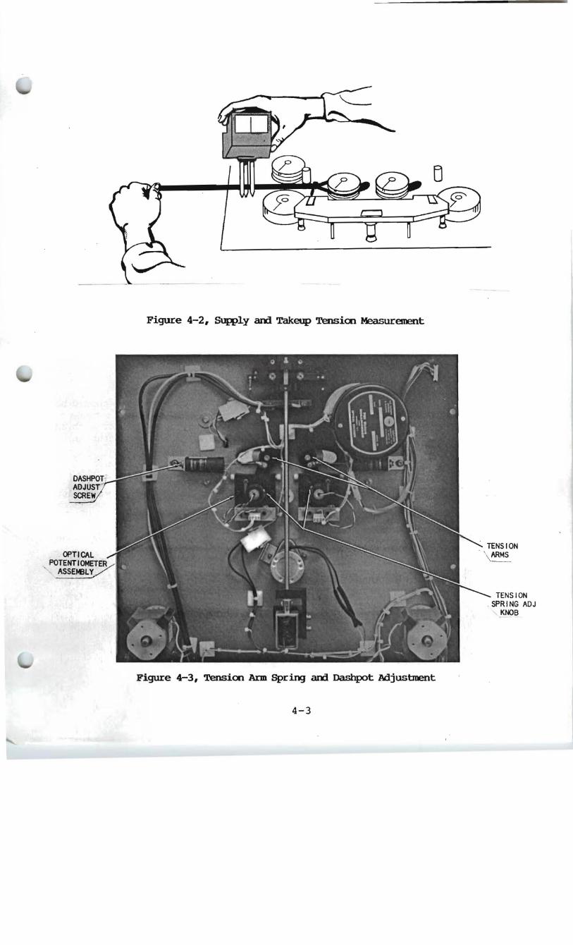
Figure 4-2, SUpply arxl Takeup Tensicn MeasurE!OOllt
TENSION . \ ARMS
' -
TENSION SPRING ADJ
KNOB
Figure 4-3, Tension Arm Spring arxl Dashpot AdjusbDent
4-3

5. Adjust the dashpot for proper dampening. Using the tape noose, slowly pull the sensor arm from its inner position toward the outer position while observing the force required to move it from the resting position. Adjust the dashpot valve for awroximately 8 to 9 ounces of force.
6. Repeat steps 1 - 3 for the takeup tension arm, except that the desired tension force should be 7 to 7.5 ounces in order to maintain a 5 ounce tension on the takeup reel (see Figure 4-3A).
7. Remove the prop, re-install the head connector, lower the transport into its normal position, and install the four securing screws (Figure 4-1).
4.2.3 Reel l-btor Direction Rotation
Insure that the direction of motor rotation and tension arm control operation is correct before proceeding with the tension adjustments.
4.2.3.1 Supply Motor ,
When the supply tension arm is in the rest position, the motor .should be driven clockwise. Moving the arm to the opposite extreme should reverse motor direction. Perform this test by blocking the EOT sensor with an opaque material, pressing READY and observing the direction of supply JIK)tor rotation.
4.2.3.2 Takeup Motor
When the take-up tension arm is in the rest position, the motor should be driven counter-clockwise. When the arm is moved outward to the other extreme, the motor should stop. Perform this test by blocking the ror sensor with an opaque material, pressing READY arrl observing the supply motor operation.
4.2.4 Tension Arm Range Centering
The tension arm range centering adjustment must be performed with tape threaded on the deck, 1C, power applied, and the deck "tensioned" (in the ready state) •
1. Open the rear door to expose the Servo board. Use a small flat.-blade screwdriver to make any adjustments.
2. For Takeup tension arm centering, adjust potentiometer VR3 so that the takeup sensor arm rests in the center of its travel range (see F.'igure 4-4).
3. For Supply tension arm centering adjust potentiometer VR4 EO that the supply sensor arm rests in the center of its travel range (see Figure 4-4).
4-4

VRI EOT
DELAY
m:~.- .I ••• IIIII
II VR3 TAKEUP
TENSION ARM CENTERING
VR4 SUPPLY
TENSION ARM CENTERING
Figure 4-4, Servo Board Adjustments
4.2.5 End-of-tape (EXJl') Sensor Adjustment
The AS200 transports are equipped with a no-tape sense circuit that shuts off all servo systems if tape is either not threaded properly, or runs out during normal operation. The EXJl' sense circuit consists of a optoelectrical sensor on the top plate through which the tape passes.
The EXJl' adjustment (VRl on the Servo tx:>ard) establishes the voltage threshold at which all servos are shut off. VRl also adjusts the time-delay after which a no-tape concHtion is sensed and the servos are shut off. The delay can vary from zero (servos cannot be activated by READy) to infinite (servos continue running when a no-tape condition is sensed). The optimum setting is made so that when READY is pressed (without tape threaded), reel servos are turned on for approximately one-half second, then turn off. When adjusted in this manner and tape is threaded, the reel motors are driven for a sufficient time per iod to "tension-up" the tape and maintain the servo-ready condition. Zero time delay (READY does not activate the servos) is set by adjusting VRl fully clockwise. Infinite time delay (a no-tape condition does not shut off the servos) is set by adjusting VRl fully counter-clockwise.
VRl setting is typically between 9-11 o'clock (1/3 to 1/2 of the resistance) for correct operation.
On the master, end-of-tape sense is normally delayed about 2 seconds to permit the use of transparent windows in the tape (used for the Auto-Cue function).
4-5

:. . .. '", O#. ; ~.;..: ., . • . . • . ...•. :.-: '~; ~.,
. .'
o
../
.' , ACCl,.Il"'o,t,, · Sound Corp, TITLEI TAPE PATH FOR
TYPE C DECK, ~S-2 QO-===- ,. . l'I:DWt \. \hiM
- -ijE701-D-1210 113 . I -SHT.l OF 1DCc..,.t _ ..!..(IICftIII
I I I I I I I I I I I I I I I I I I I I I,-, I ___::...!2-!.. _________ ._______ ..1
\
... ..
. . . . . ,:.
::'.
, .

R[~S 1.,..1
+8',1
READY CD 4013 8
J 7 OS3632 .'8Vr~2K rNt 1'1-<190
r------ --- .., Rl 113 1READY
",,1/2 IRfADY
C040018
RIO a.? K
1 91~, , 1 C2
":;it%·,I ,01 10%
3 2 ~ ,U C6
I 'O;O%
CI9 IUF R32 10 % 68K2%
+8',1
1--(_,.;~'-+)- ........-~
LU~
I I Lf)W SPEED
.,.~
:51 tz~ 112W
C04011 8 D Q I GO
9 1.5--:-1 13 FWD
1 /l 1 ~ ", 1/2 , IREV
I~LOWSPECO
+8',1
1/
'*
1<8
V2W820
J9
~~~~ I I ~ I I R I08 15 ?7i2
1<5 820
'3 1/2W
R4 820 112W
'-2
GATED CLOCK
';;f,~ f,~ , . 3
J (Jr2f!,LOGAl STOP
~ -0 0
LOCAL FWD ,~~ 9
LOGAl REV I --IL 5
I
2
8 ' IevTO L AMPS 10
J8
REMOTE 5 TOP 1 2 I
REMOTE FwD 1 6
REMOTE REv I 9 I
Uj 620 , 13+BY 9 SD Q .--------..61 '5 Y 2W IA'Nlfjl r " C ,el ~~ 15 CD4 023'8 UIO ~ '-,..J3 ~ , /"-''''<701 . )1( 1ID 1/ _C5 I I I ~ un.JIAlr .<
"3 ,13 ,
L. __ ____ _ _ ...J
" 1'7 READY L~D, ----------1 19 STOP , lED
6'I
S10PP[D IJ7
FWP RUNNIN6
I REv RUNNIN:O
131 FWD L~D
15 RE V LE[7
'~YN L~D
'1MUTE
+sv /I
12
J +18v J8
TACH JI2
I'.[V / AJ.:! .VII ~ -< K2
~ /?3FWD RUN 4 1(MDA J 13 - 10) VV\r
5 -1 1:
.?1/.5 704 / ~
LM339
~~~ \~ J ~~9 OSQI/3- UI6
TP2
30 IPS 3 ' CLOCK ~
I /I C al12
,) '4 _L-___ ,~
L_ R
10m.i. QIj "
8
<iMPl
60 IPS #07£ :_
1 _ * B CJ/1/Z £) /oft/DIF/ED P..(./~ Y M;"'DV ~ by Z Ig IIS cD CJM A 1£ LIAI£ EMCCO£R. f
2,- " 'I DE , CD..f"_r"'6 uPACIToes , 101 AND Aef !JOT 5Hcvv 0-.) De,..o,JJ-.l6-,
\o(In I :JF 3
' .. · _-.;" ....'1 U /Io.""- . .....~ .... '-. I'la
" O'-,VIC 16",.,4
cc·
Ifl"I$~S
' J6 +8v
+8_ 2
3
+SV \3
RI9 -t ev ----vvv---r--r
TP6
B2K 1'20
4,3K
elGATfO CLOCK
1 I<
R29 6.8K
I
TP3
LM339
617+ TP4
• JOfLAYED CLOCK
U Ii-
1BV ( ;; ) TACH p"
+ev T;::\C;'
CAPST.... N P HASC e:RR~ SIC,p...lA L
"--------+.......,0 OVERSPffD
~ TP5 ,:r
~o,..KAf~ii.-A ~""~A'A --...L--T- ...... v-- T 't vv- v ... ...-- i
TLOB4
R51 lOOK 1%
C30 ,110%
TL084
R49 ~~ K
REAOY @j(SERVOS 0 ,,",-1
04 IOOPF 5%
14
L CAPSTAN C.APSTANCHArm CLOCK
f:i 1SYNC
GATED CLOCK
MODE U CON mOL -<1-500 NS ',[, ~r) .10«"
, 8
I' R36
- 6v- ...... v JI2
<
QI(MDA J13-5)CJ6
IE OG~O~A_ , IN ..L
41481°1 rU2J- 1'5
~~ I • 1_
16 'V ' ; _I J
RS5 4.7K
2 , ( 'IDA .JI3· 9)
NOA J II GNDr--j+BV REF
3 'i~nI Lf2T" PEWINDOW R37 R5~SENSfNG 120X2%~+9V (MDA J13 -4)o(J':-'}
TP9R31 ).- t,l lll~' ~ EDT CA .-?S T4N 3 (JI -, ) 12 loorl% MOTOR
CURR£I ,'TJ I - ~ V\~,~" "" -:L i.~~K
r-------~----- - -- - - - - - ----I RIIO r - - - - - - I - - I U17
r : AUTOCUEwlNDOW S 27 , : 3: :~ L~ __ =- _____ _ ___ _ I A0 Tc--:: .
2 0<'9I<=D /-1?'OIFIGO ~//Lr'/- -::/// /1£ / .J -i- by 2 ;..: ;,.<: ':-C CI/ /I J A: £ 1//'; £,uCC;O:c,e:c
I NT' . "<J--Q:= ' . rR ill i d II 2~ AlL OE-CCt..l PlI,.... (;. 0 ... ~c.r:.l!.s. . Iv' t\..... c. lI;:f ..v~ r .sH OWN 0 ..") Drl..W!"'.JG
: 27 " ~. _ ____ _ ~ 8J ~0 I I US3632 Cc. i :Jl! C I ~T , 'OT I
L _ _____ __ _ ___ _ ____ _ _____ _ __ __ _ ____ ___ _ ___ _ : s:.E: ~''::' __ J ~~~','::r~:'~,I.;: p ,, ""'.... , ~ , · _.• n
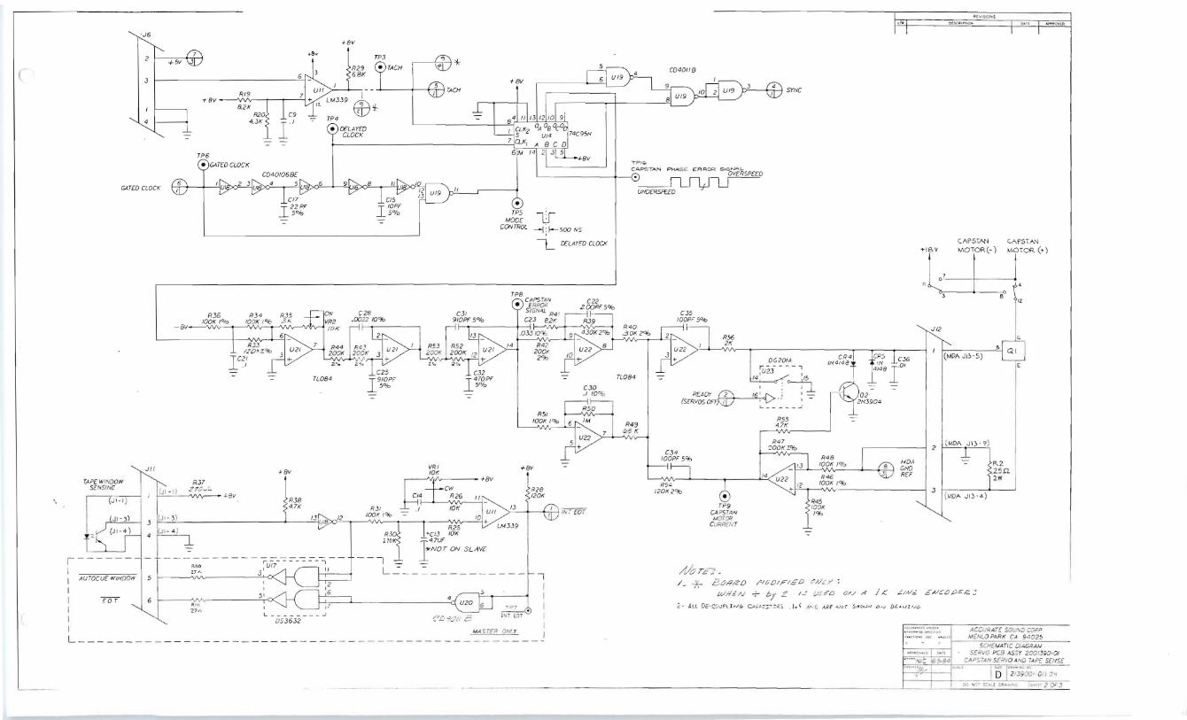
ACCu,q~rE SOU....:; COrP MEJ.Jr..O P.l RK C..,l 9": 025
SCH f AJATI C CI~Gi/,w Sf." .:rvo pes AsSr 2001~90· 0!
CA Psr-=..v S!RYO At'O lA P:: S£NS~ ...-0... " ~bo'l
' .' - ~ .'IJ':: S: _~a.; -·~"i"O"j~~L.. I''''1-"".. " ~D 21~9:Xh· OI, j,
:l'J "I~ ' ::':.>4,!. CiIl&", " .:; ....rr 2 .,.. J

-:.""':..:~. "I - , - - ~ - . .... . --
,)2
+8V
R62 10K
R6; '..~.; 10K .
'-.31' ... , ., '1_ · 1-8~ SLl"PLYARM .t::ij• .' . ... , POSITION ADJ. 14'
-::: nNSION ' -·:S UPP..LY .· .
.. .. .:
of
J"AKLUP '
2
J4 ' +BV =
- -'- . • P+~ 3 : . _ (,)1-1 l.
. .' " OU,T Q(JI-.3) · 1
P''V{JI.Z)
:-='''SUPPLY 5(NSOR •
-==-~ TAJ<,[ ' UP .SENSOR ·· f __ p+ ..
IRI :::'(J 1-1) . ~ _4_
510>2
II t
~ '0/, '\
. TAP~ UFT SOL[NOID
+ 18vOC
GNO
, -;18 vOC
s .5
J I3
4
.)1
if ·
UII 2
5 +
LM3.J9
-8V TME UP ARM POSITIDNAl).).~ CW
~R ~ 'R70
KJK~ R73
I"
r _ . e.S~~3~ _ • ., , - - - - -;,;:, -,
61 U3 1 I ' R14 1 I ~~~~ . 5 I
4.7K - T?,,'1/5 f
.Iev
-IBV
15 14
12 C Q 10
UI5 IIJ 0 9
13
).ICI453BB
MTD.O'JI HEAT I SINK I CRI I
I -.Q&iY ..L'N4001 I L _ _ _ __ .:__ .J
1- , + 8V
- 8V
UA 79M08C
2a8£5..
2,9~011 IfU20 • 1. 8.13 10 +
C0401/B n084
R66 10K 2°,b
R63 10K 2'lb
+5V
.• .;"'-# •
~STUS£O
~ C. 7-1 U 28
t--cRI7 .) 13
vR 4
REG 3
Q 9 .)MP 2
7 P I7
R57 2K
N(JTUSEO
R1Z,~ !? z4,f8,1$/~
C4S; £8, Co, '''1-71
JMPI
+BV
-8V
t---+(';;'.f-l') (s~S)
----:-1 r - U2J,~"o 1
I/ ~-~<-fl 1 .J_L ____ _
CR7 IN4 148
R94 IK20f0
L...~___""'_•• -I8V
R58 4.7K
R.,9 lOOK I'*>
MOA ~GNO
lOOK l"fo RB3 lOOK l"fo
REF
SUPPL'(+!~V MOTOR(Io1~ SUPPLY ' c . MOTOR(M'~)~'----~
B /MDA JI2·.,)
TMt UP . TAK[ ~ ~OTOR ("1 <) "I0TOR(M-)
'" I R4 . 4-> 1,2.1/'Iev~
C44 101
R60 -=
c.s-A 1. 8 '7J3 SUo'
' . . c..
(MDA JI2'15) E
TAKE UP MOTOR
CURRENT • TPI2 - 03
2N3904 RI04 4.3K
lOOK I'*> R65
3 ' (!.IDA JI2'\7)
R£FO£5JG I.C. TYPE !+8V -IN
iuI3.4,5,17,Z 053632 B U2 PJ"049U; I
U6 C04023B I.
U7,12 CD4DOIB 14
UB./9.20 CD40IIB 14
U9, IO)5 CQ4013 8 14
UII LM339 3 UIJ CD4070 8 14
UI4 74C95N 4
UIS .fC}45388 16
UI8 jro40068 14
V20'.."'lal TL084CN 4 1/
U2J. 2S 106201), 13 4
GND IBrn>SS C
• 8 .01
7
7
7
7 .01
12 .1
7
/I .01
8 .01
7
.IEA.RA.ft
5 IlEA RA IL
OCSCRIPTION
1001( 1°J:> R64 lOOK 1%
DUAL 2·INPIJT HAND BUFFFR
HEX INVEFrTING 8UFFER
TRIPLE 3 INPUT NAND
QUAD 21NPIJT NOR
QUAD 2 INPUT NAND
DU'L o·rrPE FLIP· FLOP
OUAO COMPARATOR
QUAD EXCLUSI VE: OR
481T L/R SHIFT REGISTER
DUAL MONOMLUIVIBRA TOR
HEX SCHMITT TRIGGER
QUAD OP'AMP
OV-'D ANALOG SWlrCH
-=
.ZS.JL
Zw
NOTE , All o<· cruP't!.u~ CAP.c.Toti ./,.""'0 AU /Jof S How.oJ ON CRA'-o.II-ub.
~'''NJC 1O·5-8~
SCHEMA7JC DIAGRAM ' . SERvO PC 8 ASSY 2001390·0/ TAKE UPANDSUPPLYREEL
''', ra 3 or 3

,.
(
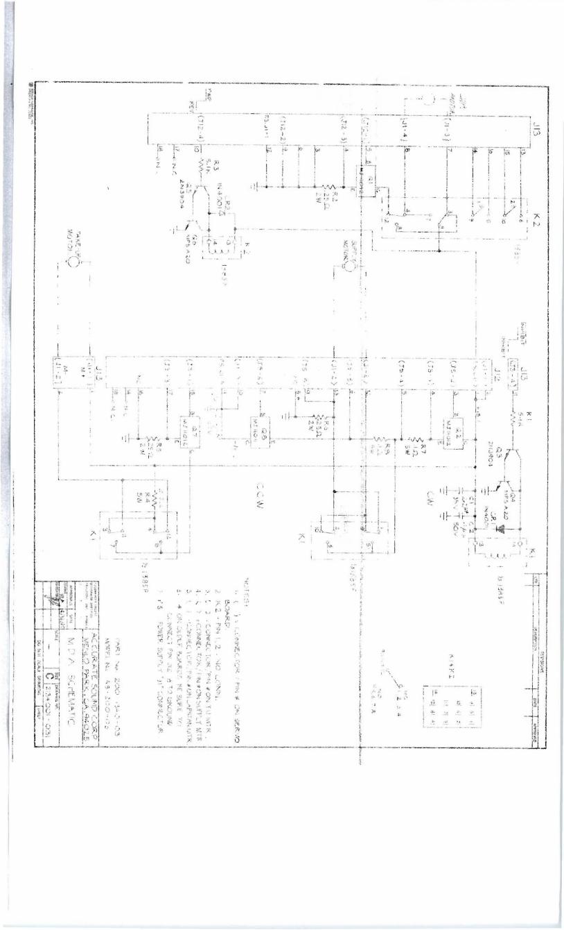
REVI SIONSJ13 . K2 O[SCRIPT IOI'IKI APPAOv(ORI 1::-,[-O~ -l1385P INHIBIT JI:) 5·IK
(J3 -4 \I 114~ I:'''-'0 II"
--,
15
16
7
~ lNHIf5,IT'_ . I ,V3 4385PJI2 ICRI---r----:--o 5 I 1 13 I
P.S. J I-!>1
1°"'9 I _J .2. 91 51 II
6t'i3J 101 61 21(J5-2) ~I KI .. K2 "I 71 31
Jl(P"(l1 l J I 3]
-6 ( J5-, ) 14 CW .'±. IZI 61 ~I Y
II 00-4) 0'---_ _
R7 .In. 5'/.1
NC
/1'2'~' 4 J 9 ,10, 11,12Ui~'-4)
; :., ,,_:
(J1 2 -2 )
r.S. JI-1
( JI 2-4)
1 3
6
rI9'-----'
12.
~
f--<' N-C. ~N.C
. 12 1'I.31385P NO
°S,6 ,7, 8
("'-,) I SOP?" _
. ~- (J5- 5) ~6__- 6 I MOTOR . . . ... R6 --.J
. .2551. 1<...1 2'/.1
-'-
E.
(SS -6)1 7 1I 1 1""'~",~ 1 CCW
b,. ' NOTE5 :o
(J I - 5 ) 1-/8 v I· ( ) = CONNE.CTOR. / PIN #- ON SEf<.VO. \I E>OAR.D.
P5JI-5, .l z. Z/F 2 . K2 - PIN 1,2 : NO C.ONN.
('3 ~ 3£"VFWP 3. [ J 'CONNECTOR/PIN~ONTUMTR.. ~ 1 4. <.) =C.ONNECTOR. /PIN<I'ONSUPPLiMTK.REV (J 3 -1 )IIS e.r Q7 IC
M.J II 0 12 r.~T---------~ 5. ~ } ,CONNECTOR./P\N"ONGN'STAN MTR. 'E - - n 6· l' ON OLl)[R. \)OI'RDS ~f. SURE TO
(n - 3)rll_7- -C.:12. 1 1 C.ONNECT PIN JI2 - B TO 0RDUN(7.
<: R5 Z . S..J11.....-J ] I 7· PS ,POWER SUPPLY 'J\' CONNECTOR.. ..2sn
4 " IY31385PNC.816 2w SW I I
N.e.
18 N.C.. \I
7 I PAR.T Nc. 200 -I~O- 03Pl6L ~~ ~Pf~ !~c:", ~7', - ~,?O-03013 IOUov... ::tS U", \ U:.1<.1 onu:._ u;[ 1o .....C1f1 (D ACCUR ATE. SOUND CORP.
I M+ --- --![JI - IJI I
MENLO PARK. CA.'14025TAKE· up. . . MOTOR.. I M~ M [) A SCH[MATIC
-- ---IeJ 1 - 2] i2. ~u I Silt IDRAWIM e HO
~ :~'c"'f/'d!~~..c.. l .. :
, . _ _. _ , DAn ,
~ .....~ " 4 /!:J /rc; ~r;; "lD if.. 7J
v 9i!n

( LINE fiLTER
II
L_
MOLE X CONN.~ • . B PIN "1
I
I
I I
I VOTA GE: SWITCH
ISET AT 117
1
I'~ .1 2 3 I 1 0-<>"0
4 0 1
Il b ~ d11 --.J
I I"/
~ I 1 I
GND +15 -15 25 YI'IC I I 3 ~ 91 I- - 5
2 "461 s 101
GND -24 +2.4 IOO VAC
VIEW FROM OUTSIDE. ( FEMI'ILE.) IQ PIN PSU PLUG SCA LE: ; NONE
,... ,--,
I WHT / R.E:D6 1~ 10 I >- 17
I >-1
,~ I~ ~I > WHT/ YE.l
1 >- 16
121 ~ rl >
14 1 >- I WHT/ BLU
I .15
13 i ~ E(m 151 .1 GRN
' 3
1 ~I r .1 Bl U 1 '2
L- _ I ----.J
_L- WHT - -
-
REVI SIONS
O[SCRIPlIOH .......ovtD
~ MOlEX CONN.
~ 6 PIN JI
I r-- 7
25V AC ' 9
I
I - -1 8 V
L3,OOO;d 5
Ii<. I 'T40 V GNPI I IW
h ~3,OOO,li.f I
I Ii<. IW 'T40V
.18 V 3
I
I I 1
I
Y -'24Y
6
..123,OOo."JI
IK
~ IW T4<:lV GND 2
I 1 ..in,ooodIK
I ~IIV T40V
4-24V
I 8
IO OVAC 10
I - '
~,~~~~~:o ACCURATE SOUND C ORP. ,~."',.. "" '"GU" ~ 1 ENLO PARK. Ci" .. g40 25
"'?ORO"'~LS o~ rr
...m ~ :'11.~;1 :;':Z~;~~ ' ..~

./
TAPE TACH SENSOR
+5V
(22 ohm ( < 4.7k
< .1UF_L- _L- 4.7uF
-;;.. :;;;:,
~ ~> 2K
>
1 7400 3 SIG
1- - ----- -.., 1 1 ~ 1 "'\I 1 ~ l:
T 2
1 : _ _ _ _ _: OPB730 '-- GND
ACCURATE SOUND CORPORATION AS-200 TE System Wiring 9/22/89Tape Tach Sensor
,>t '
'" . '. ,
~ .. " ~" .,

1Y
INTERFACE BOARD J1
~ '. I - 20 PIN Al.sON CONNECTOA '1'
DO NO PUT IN CONNECTION. (NOTE: CONNECTOR IS ON ANOTHER DRAWING)
ENTRY
SERVO BOARD J11
6 PIN
09-50-'3061
3
BOARD J9
S
SERVO BOARD J6
4 PIN (01 GIT AL BOARD)
09-50-3041 J7
SERVO
4 PIN
09-50-3041
SERVO BOARD J10
10 PIN A'
09-50-'3101
SERVO BOARD J2
(MARKED PIN 3 AND 1 ON SERVO BOARD)
INTERFACE BOARD TO SERVO BOARD Accurate Sound Corporation AS-200 TE System Wiring 9/22/89 Interface Board to Servo Board

I
TO INTERFACE BOARD ~6
.. PIN "p'\ '\ '\ ~'--
TO SERVO
p8 PIN '\
"'\ '\ '\ "'\ ",'-
TO MDA ~13
I'\rp18 PIN ~
~ ~ ~ ~ ~ 1'\
~ ~ ~'-
TO MDA ~12
['\'1='" 18 PIN 1'\
~ .
~ ~ ~ ~ ~ ~ [\
~-
i . RED ' . , . ~ -2 WH' , :3 BI_K
09-50-3041
BOARD ~1 '. .. ~.
2. RED ' '
A WHT POWER CONNECTOR
fi BLK
GRY ) 2
BRN ) A09-50-30B1 RED
ORN ; :( BLK
~ J3RN~BGA TAKE-UP SERVO BOARD BJ.K_2aGA k ;a: VIO 2 VEL i8GA MOTOR 09-50-3041
BLK 22GA ~ ~ 1~V VI 4 WHT/BLU 20GA '-' '-'
5 WH'IV 2 ' ISA ~ ~ 2 B _K J.8GA !"IN ~ CAPSTAN I '--~
S-310-AB 8 B U 18GA P N .. MOTOR DRIVE ~ONES 9 W /ORN 20GA 1 /YEI 21 GA
~ 11 1BGA 12 IY
1 ~/NOT USED: 3.6. 13. 14. /
15. 16, 17. 18 3 /A /
09-50-3181 SERVO BOARD
FAN CLEANER MOTORS
09-50-3041
1 DAN ~ ....... V BL U3 2 ~4 ORN :3
5 V .. ~ ~X 6 YE 5
I'\F7 GAY 6 ~ ~ RED 8 GRY ~ .2 WH' 9 SRN 8 ~ 3 BLK
~'-11 BBN ~ TO REPRO HEAD AMP 12 YEL 18GA ~13 BLK 18GA J31
SERVOBOARD 16 GRY 09-50-3121
09-50-3181 POWER DISTRIBUTION AND MOTORS Accurate Sound Corporation AS-200 TE System Wiring 9/ 22 / 89 Power Distribution and Motors

.ERVO SOARD ·",t ., . ~
0.-::-':041 rl -. : :: :::: ~ TO ::::N~I:TER
.ERVO SOARD "4 ~ ~TI I 7 "HT 22.. A ~ _~r'\ ___ ..
+ no, CFDe
-4 PIN ..J34 TENSION SUPPLY SENSOR8 PIN • . +
09-50-3081
-4 PIN ..J35+ 1 ]JUT TENSION TAKE-UP SENSOROUT ~ . ~
SERVO BOARD ..J11
3
+15
IN-8 GND
-4 PIN AMP (FEMALE)6 PIN
*1-48042-5 09-50-3061
I L _____________________ YELLOW WIRE FROM INTERFACE
BOARD. SEE I N T ~p~ ~ T, ~=Ar RV'
SCHEMATIC.
MISCELLANEOUS CONNECT I o~~ s
Accurate Sound CorporationAS-200 TE System Wiring 9/ 22/ 89 Miscellaneous Connections
I .. .~--' ~':'- .
J..
07 TRANSPORT LOGIC
"-. ~
08 \12 PIN)
REMOTE STOP. FWD. REV
09 D 14 PIN) 06 (4 PIN)
CAPSTAN TACH
010
\10 PIN)CLOCK. RTN
011 \6 PIN)
EOT SENSOR
012 (4 PIN)
TO MDA ASSY.
I 01
. .
TO
TO
TENSION
TO
-
I 18 PIN)
POHER
r-
01 3 L
TAPE LIFTERS
MDA
T.U./SUP.
02 .-
'--
03 ASSY.
.---
'--
\8
04 PIN)
r-
L......
.-05
MDA ASSY.
~ -
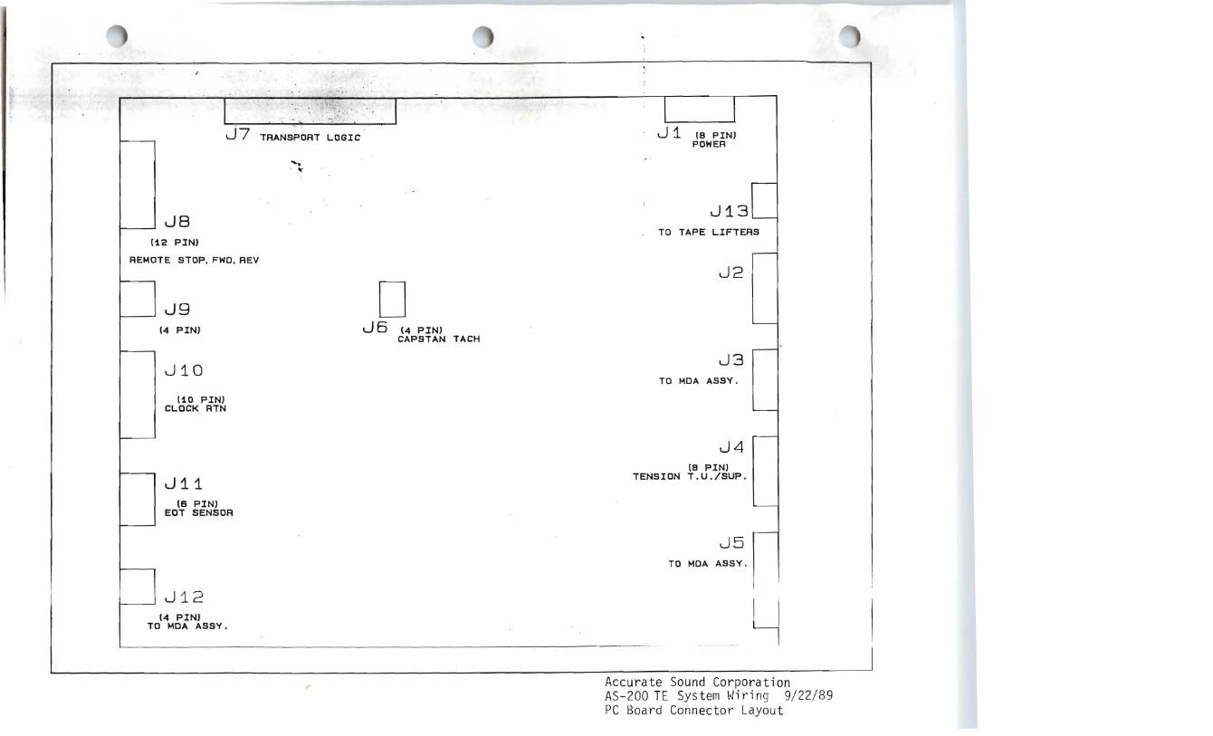
Accurate Sound Corporation AS-200 TE System Wiring 9/22/89 PC Board Connector Layout

~ CONDUCTOR NUMBERS
19
5
5
3
9
I
L:
STOP
READY
REWIND
FORWARD
SYNC
CLOSE TO HEAD BRIDGE
~ RIBBON CABLE
' ...
20 PIN RIBBON HEADER
[
~2 ON INTERFACE BOARD
DECK SWITCH WIRING Accurate Sound Corporation AS-200 TE System Wiring 9/22/89 Deck Switch Wiring

o •• "".,1141 ... .. " ..
"' ~ ,- _ _ __ w. _ _ -..', . ., ,
, . ..., . , ,-) . 0
J, .l n , I . !
_21 , i-, -0, . L.._.h- -.l \.-.....-,
~ ~ " '1 ~ ·~
t r- ,
..... '*
to I r ..,.: ( • ~ I
i
I
1. " -'It I
~
,. , ~ 4 ""1" ., ,1'- ~ oj . -~ ... .....J r-.::'lJ....I
I!' ~ i:
L _ ~. r··
I IIl
~L .. c·
.".-. ,~ 0 0
,.
I
I ,--,----
_ .. J . ..,
. .~ t ,. ,
" .... -
, ~tilttY~
r I
-1
It
~ I
. ,
'. . ~
.: : ·il I
-- .. ~
r I
• • J
,1 ,. 11..-- "--4Ir---' ..
d ===-i- - 1 - .- . -_ 1'-_
I .
11I . ; I! i! ~ j ;- .... -. ~ , . !SJ
tI ~
II: . I
~'! . .JJ ~
I II ..~~__ ' Y
H . . ---, •
II I ~ 1
t
i~
> ~ ~ ~, . J, ~, I ~ . ~ "' _. :s i ,L
(~ -- . r \ 1 1 iI ~~________ ~, ~. I I , ~ !~ ·_i--_I_~j.- I ~ !. j ' .;. ~ ' '''' .' ~ ~ i. ... H. .~ . .\.. ___ ~ - ·, . F~ -' ____________~________________
'11 . , T J , . . ~t } ':'?------' -1
. , ; I
' ; I III .. Po I I I :I;
,~
I J I ,. I
. :
.......

1 .
!~
, ,
1
~ ~ . " f
-----'SOJL~· ~~' .!a:r"..,Jl&_" .
~'.
I '- If "::' 1",'~':"".....: -; •~~1II1111 ~ i'
I " ,1
.. " .. .. ... . ..~ ~
~ - - - ~ - -
; :t : , - '. : !
'. . -.--- . .. ~-.!il um:: - ~
J - ..,1~..(4<-'""",o!*-.........II'III'I.....t-~I~-
I.
~ ...!.-1 -; 1':; ~ ~ ·. : - "'r rt" .-- .....i. _~~\ >.., J ... !;; ;; ~ r. .f~!
! I~:r;
-----------~.,-.--
----.------~ . --~ .- .-- .
I;' ~ i I _I -V - ~ ~
I;) : ~~ .~ . .';;" ' -1::::_._ - -" ---,-, ! L.
'"I!..• ,... -~ - l~
~ ~ pi
z .:1---- ..i.t
- i ' .... _1 --i -, 'l - i
I •. -·11 () .,. y,
~.- {:>!'~ ),. . • _ .1- J", , / ! . ,
,1r", ! « ~ I~. /1.. ,. I ;~ " , j '. ~ t ---. ~.. J-.~~i' , , ,_1
--, ,;. >. I ¢~ ~ . ,-" JO 1 .. .. .-. . .__......-
.~. i 1 .".. ,- ~ . } }. , ,"
. ( / r
" .-,
z t}
:! __J ~; r I -1I
l r "" f _ "
<-. ;. L '../JI ~ ~ 0;
'I ' ( .'; I',
I ~ .;£ 1 Ill'1. ,
J ., '
: .! l i fo " ;.~ "
J- ).I . "\l· ~ -6. ~ () ~ ,
r 'i J III nIl ;-. ".r. L , 2. f):':. . I" .1) 'J '. I
_ _ ....J 1 I o ,(
- -t - .. ~ I.... : ~ !
,, ( , l -- - J
I i 1 ~.- -.:-,.
-i- . lOt ~-
1...? r-
L_ --~ i I
_ J
". I. if. ..= I~T ~'. N
:,0 . " ~: I
U '
r' ".::
f... Z \ ~r'.i T I.
/ .
'r..
I II" I ..
til J
I I i I '!i I !~! I i 1;;: 1 ..,. 1 I" I! IIII
--tl, " ,~, I ." I I
-T1 -. ~; r AIIt ,q l ~ I ~ I ..+------.----.---.____ __-DJ. , t i

~ J' . ·t
1'. r, I'
, -, .....
"'"' '.
., I ~
,I
'•• ....Jt:. rr I ,~ I ~
1 , ... ." I
. , . ,I t ! I ., . .........
.. I.... • l .. ,.- " .... r i I
L 1,T
~ ~ J-: i. - -..,.i! '1 1
T. , I :.
' j; .......... 1, i I : f ; •
...' .;. I
1
• j I
.I 'I L .... .rI-,' I, I S~ , \ ~
r .. I!
~ "." ,f' . ' . ~ !fl ';to .. I
.~
'. I'" . "
-...... ... - -I8
t ~ ~ 'I ;'"'
, f. _" I' I. \ ;
"

r
..
-. t. . .
..
.!

'.
. . .,
. .~
""',
f' " i l