Combined Micro-Channel Heat Sink Optimization for Cooled Electronics
9
Proceedings of HT2007 2007 ASME-JSME Thermal Engineering Summer Heat Transfer Conference July 8-12, 2007, Vancouver, British Columbia, CANADA HT2007-321049 COMBINED MICRO-CHANNEL HEAT SINK OPTIMIZATION FOR COOLED ELECTRONICS Tunde Bello-Ochende Department of Mechanical and Aeronautical Engineering, University of Pretoria, South Africa Josua P. Meyer Department of Mechanical and Aeronautical Engineering, University of Pretoria, South Africa ABSTRACT This paper documents the geometric optimization of a three dimensional micro-channel heat sink with hydraulic diameter greater than 10μm. Two methods of analysis were used to perform the optimization; approximate relation using scale analysis and numerical method using a finite volume code. The micro-channel heat sink is treated as a combined unit. The effect of void fraction and pressure drop on the aspect ratio, hydraulic diameter and peak temperature on the micro-channel heat sink were investigated. The numerical simulation was carried out on a unit cell with volume of 0.9 mm 3 and pressure differences between 10 kPa and 75 kPa. The optimal configurations obtained numerically were compared with those obtained from approximate relationship using scale analysis and the trends are found to be in good agreement. Keywords: Constructal, maximal heat transfer density, peak temperature, Micro-channel heat sinks, Conductance, optimal geometry NOMENCLATURE A channel cross-sectional area, m 2 AR Aspect ratio, H/G Be Bejan number based on a unit volume, ∆PV 2/3 /αμ Be L Bejan number based on L, ∆PL 2 /αμ B channels width, m C dimensionless global conductance C p specific heat at constant pressure, J/kg.K d length scale, m D h hydraulic diameter, m f friction factor G width of computational domain (B+ t 1 ), m H height, m H c channel height, m k thermal conductivity, W/mK L axial length, m n normal num number of channels P pressure, Pa P c perimeter of micro-channel, m Po Poiseuille number based on hydraulic diameter Pr Prandtl number q total heat transfer, W q ′ ′ heat flux, W/m 2 R thermal resistance, Kcm 2 /W Re Dh Reynolds number based on hydraulic diameter Re L Reynolds number based on L T temperature, K T w,L exit temperature, K T in inlet temperature, K T max maximum temperature, K t 1 half thickness of vertical solid, m t 2 base thickness, m t 3 top thickness, m U average velocity, m/s U r velocity vector, [m/s] V volume, m 3 W heat sink width, m 1 Copyright © 2007 by ASME
Transcript of Combined Micro-Channel Heat Sink Optimization for Cooled Electronics

Proceedings of HT2007
2007 ASME-JSME Thermal Engineering Summer Heat Transfer Conference July 8-12, 2007, Vancouver, British Columbia, CANADA
HT2007-321049
COMBINED MICRO-CHANNEL HEAT SINK OPTIMIZATION FOR COOLED ELECTRONICS
Tunde Bello-Ochende
Department of Mechanical and Aeronautical Engineering, University of Pretoria, South Africa
Josua P. Meyer Department of Mechanical and Aeronautical
Engineering, University of Pretoria, South Africa ABSTRACT This paper documents the geometric optimization of a three dimensional micro-channel heat sink with hydraulic diameter greater than 10µm. Two methods of analysis were used to perform the optimization; approximate relation using scale analysis and numerical method using a finite volume code. The micro-channel heat sink is treated as a combined unit. The effect of void fraction and pressure drop on the aspect ratio, hydraulic diameter and peak temperature on the micro-channel heat sink were investigated. The numerical simulation was carried out on a unit cell with volume of 0.9 mm3 and pressure differences between 10 kPa and 75 kPa. The optimal configurations obtained numerically were compared with those obtained from approximate relationship using scale analysis and the trends are found to be in good agreement. Keywords: Constructal, maximal heat transfer density, peak temperature, Micro-channel heat sinks, Conductance, optimal geometry NOMENCLATURE A channel cross-sectional area, m2
AR Aspect ratio, H/G
Be Bejan number based on a unit volume, ∆PV2/3/αµ
BeL Bejan number based on L, ∆PL2/αµ
B channels width, m
C dimensionless global conductance
Cp specific heat at constant pressure, J/kg.K
d length scale, m
Dh hydraulic diameter, m
f friction factor
G width of computational domain (B+ t1), m
H height, m
Hc channel height, m
k thermal conductivity, W/mK
L axial length, m
n normal
num number of channels
P pressure, Pa
Pc perimeter of micro-channel, m
Po Poiseuille number based on hydraulic diameter
Pr Prandtl number
q total heat transfer, W
q ′′ heat flux, W/m2
R thermal resistance, Kcm2/W
ReDh Reynolds number based on hydraulic diameter
ReL Reynolds number based on L
T temperature, K
Tw,L exit temperature, K
Tin inlet temperature, K
Tmax maximum temperature, K
t1 half thickness of vertical solid, m
t2 base thickness, m
t3 top thickness, m
U average velocity, m/s
Ur
velocity vector, [m/s]
V volume, m3
W heat sink width, m
1 Copyright © 2007 by ASME

x,y,z Cartesian coordinates, m
Greek Symbols
α thermal diffusivity, m2/s
∆ difference
µ viscosity, kg/sm
ν kinematic viscosity, m2/s
ρ density, kg/m3
φ volume fraction of solid material
τ shear stress, Pa
Ω interface between the solid and fluid
Subscripts
c channel
f fluid
h hydraulic diameter
in inlet
max maximum
min minimum
opt optimum
out outlet
s solid
1. INTRODUCTION The quest for better designs for the cooling of heat generating devices has been a driving force for innovation and new fundamentals for heat transfer engineering and science. Micro-channel are currently in the forefront of cooling technologies, because of the difficulties of meeting with air cooling techniques the cooling needs of devices with high heat flux (projected to exceed 100W/cm2 [1-3]). In modern heat transfer, the challenge is how to cool, manufacture, decreasing cost and optimize performance. To solve these problems, several novel techniques have been proposed and studied theoretically, numerically and experimentally. A review of these techniques has been conducted by Dirker et al. [1].
With the recent development of reliable numerical packages and their easy availability, optimization of coupled convective flow (forced and natural) and conduction heat transfer has become easier to implement, and more popular. A review of the subject has been given by Bejan [3, 4], which focuses on the generation of shape and structure in freely morphing convective systems, by maximizing global performance subject to global constraints. This view is known as constructal theory. An area where this theory is of utmost
importance is in heat transfer augmentation [5-8] were volumes reserved for fluids that act as a heating or cooling agent are optimized.
Significant research [9-10] has also been conducted on the flow and heat transfer characteristics of micro-channel heat-sinks, because of their promise to cool areas with high heat flux. These studies relied on numerical techniques and experiments [11-17] to study the flow and heat transfer characteristics of micro-channel heat sinks.
In the present paper, starting from a basic construction unit (the elemental volume is the constructal approach), we determine numerically the best possible geometry for a micro-channel heat sink. The total elemental volume and axial length of the micro-channel heat sink is fixed. We seek to determine the best channel dimensions and system configuration that minimizes the peak temperature when the pressure difference across the elemental volume is fixed.
Figure 1 Micro-channel computational unit cell of a heat sink
2. MODEL AND MATHEMATICAL FORMULATION Figure 1 shows a drawing of the physical model and the computational domain for a micro-channel heat sink. Heat is supplied to a highly conductive silicon substrate with known thermal conductivity from a heating area located at the bottom of the heat sink. The heat is then removed by a fluid flowing through a number of micro-channels. Using the advantage of symmetry, we select for analysis an elemental volume (unit cell) consisting of a micro-channel and the surrounding solid, as is shown in Fig. 2. This work was based on the model of Qu and Mudawar [12] and Kawano et al [17].
The heat transfer in the elemental volume is a conjugate problem that combines heat conduction in the solid and convective heat transfer in the liquid. The two heat transfer mechanisms are coupled through the continuity of temperature and heat flux at the interface between the fluid and the solid. The fluid with inlet temperature Tin is driven through the micro-channel by a fixed pressure difference ∆P = P(z = 0) – P(z = L), which is maintained between the channel inlet and outlet. The objective of the following analysis is to determine the heat transfer characteristics for a given micro-channel, and
2 Copyright © 2007 by ASME

the best possible configuration (L, t1/t2, t2/t3, AR) that corresponds to the maximal global thermal conductance, or global minimal thermal resistance.
Figure 2 Computational domain of micro-channel heat-sink.
The following assumptions were made to model the heat transfer and fluid flow in the elemental volume: the hydraulic diameter of the micro-channel under analysis is greater than 10 µm; for water, the continuum regime applies hence the Navier-Stokes and Fourier equations can still be used to describe the transport processes; steady state conditions for flow and heat transfer; incompressible flow; the properties of the solid and fluid are constant; and the heat transfer due to radiation and natural convection is negligible. It also assumed that the number of elemental micro-channels is large.
Based on these assumptions, the continuity, momentum and energy equations for the cooling fluid are
( ) 0Uρ =∇r
(1)
( ) UµP UUρ 2 rrr∇+∇−=∇⋅ (2)
( ) Tk TUρC 2fP ∇=∇⋅
r (3)
where , and the origin of the Cartesian frame (x, y, z) is located in the bottom left corner of the computational domain. For the volume occupied by solid, the momentum equation is simply
2222 z/y/x/ ∂∂+∂∂+∂∂=∇
0 U =
r (4)
and the energy equation is (5) 0Tk 2
s =∇The entire elemental volume is treated as a continuous
domain. The geometric boundary conditions for the computational domains are indicated in Fig. 2. The flow
boundary conditions are that no-slip occurs on the walls inside the channel. At the entrance of the channel, the pressure boundary conditions become
P V
Be P out2/3 +=αµ (6)
where, Be is the dimensionless pressure drop number based on the elemental volume (the Bejan number, cf. Refs. [18, 19]).
= 1 atm, at the channel outlet, and T = 20 P oC at the channel inlet. The thermal boundary conditions consist of an assumed uniform heat flux that is imposed at the bottom of the heat sink
qyTks ′′−=∂∂ (7)
The remaining outside walls and the plane of
symmetry of the heat sink were modeled as adiabatic. The continuity of the temperature and flux at the interface of the solid and fluid surfaces requires
Ωf
Ω
ss n
TknT
k∂∂
−=∂∂
− (8)
Where, in each case, n is the direction normal to the wall. The shapes of the heat sink and cooling channels are
allowed to vary, by changing G, H, t1, t2 and t3. We are interested in the geometric configuration that maximizes the overall global thermal conductance of the geometry, which in dimensionless form is defined as
)Tk(T
Lq)Tk(T
Lq CinLw,inmax −
′′≅
−′′
= (9)
Here q ′′ is the heat flux from the base of the micro-channel heat sink, k is the thermal conductivity of the fluid, and L is the length of the computational domain of the unit volume. The global conductance C is a dimensionless way of expressing the ratio of the total heat transfer rate q divided by the largest excess temperature (Tw,L − T0) reached at any point in the micro-channel heat sink. The maximum temperature is expected to occur in the exit plane of the micro-channel heat sink. The reciprocal of C is the dimensionless global thermal resistance. Table 1. Dimensions of micro-channel heat sink [11]. Case H
(µm) G
(µm) t1
(µm) t2
(µm) H-(t2+t3)
(µm) G-2t1
(µm) φ
L (mm)
1 900 100 22.5 270 180 28 0.66 10 The thermal conductivity of silicon substrate is 148 W/mK. 3. NUMERICAL METHOD
3 Copyright © 2007 by ASME

The finite volume code (FluentTM) method was used to solve the continuity, momentum and energy equations. The second order upwind scheme was used to model the combined convection-diffusion effect in the transport equations. The resulting algebraic equations were solved using a line-by-line tri-diagonal matrix inversion algorithm. The SIMPLE algorithm [20] was then applied to solve the coupled systems of equations.
Convergence is obtained when the residuals for the mass and momentum equation are smaller than 10-4, and the residual of the energy equation becomes less than 10-9. A grid independence text was carried out for the micro-channel heat sink with the dimension given in Table 1. Tests show that for a control volume with a mesh size of 25 in the x-direction, 50 in the y-direction and 150 in the z-directions assures a grid independent solution in which the maximum thermal resistance changes less than 2.5% when the mesh is sequentially doubled. This mesh also guaranteed that the numerical results obtained in this work are comparable with predictions and data obtained from experimental and numerical work.
The numerical results generated were compared with the numerical results of Qu and Mudawar [11] for their case when the heating component in Fig. 1 was placed on top of the micro-channel heat sink. Figure 3 compare the thermal resistances, R, for both the inlet and the outlet resistance. The comparison was made using the Reynolds number in the range 90 ≤ Re ≤ 400. These parameter are defined as
q
TT(x)R(x) 0′′−
= (10)
where x is distance from the entrance, which in this case are located at x = 0, and x = L. The Reynolds number
ν
hUD Re = (11)
and the hydraulic diameter are
))tt(2tG2(H)2t(G))t(t4(H
)H2(B4BH
P4A
D321
122
c
c
c
ch ++−+
−×+−=
+=≡ (12)
where Ac is channel cross sectional area and Pc is the perimeter of the micro-channel. It can be seen in Fig. 3 that the present numerical model captures the work of Qu and Mudawar [11], and it predicts very well the inlet and outlet thermal resistances. The maximum difference is 1.8% for the inlet and 1.5% for the outlet. Note also that Qu and Mudawar [11], validated their result by comparing it with the experimental data of Kawano et al [15].
Once the model adopted in this work has been validated, numerical optimization was conducted to determine the optimal geometry of the micro-channel using the constrained optimization outlined in the next section. The above code
verification and grid independent test provide confidence in the numerical code used in this work.
Figure 3 Comparison of numerical predictions at inlet thermal resistance, and outlet thermal resistance.
5. SCALE ANALYSIS
In this section we present the use of a scaling argument to predict the optimal channel geometry that minimizes the global thermal resistance or the maximum global thermal conductance. The following assumptions are made throughout the analysis: uniform flow distribution (equal flow in all the channels, constant cross-sectional area of the channels, and no inlet or exit plenum losses), the Prandtl number range Pr > 0.5, negligible axial conduction, and the thermal conductivity of the solid substrate is much greater than that of the fluid. The existence of an optimal arrangement can be expected based on the trade off demonstrated in the forced convection cooling of electronics packages [8], and the method outlined by Muzychka [21]. To determine the optimal channel dimensions we use the method of intersections of asymptotes [6] for a unit micro channel as shown in Fig. 2. The global thermal conductance scales are evaluated in two extreme limits (small channel and large channels).
In the limit of small channels, the micro channel length is covered mainly by fully developed flow and the flow is mainly Hagen-Poiseuille flow, the maximum temperature difference occurs between in the outlet wall and the inlet temperature of the micro channel heat sink. Assuming the total heat generated at the base of the micro-channel is conducted and deposited as heat current at the inner surface of the duct, the total heat transfer for small duct for fully developed flow gives
)T(TUCρA q inLw,pcsmall −= (18) where U is the average velocity defined as
LPoµP
D ∆P AUc
hc= (19)
Po is the Poiseuille number based on hydraulic diameter, and Po = fReDh/2, therefore Eqn (18) reduces to
4 Copyright © 2007 by ASME
Oc
h2cP
inLw,small LPµP∆PDAρC
)T(T q −= (20)
The resulting expression for the total heat transfer is
O
L3h
c
2c
inLw,fsmall PBe
LD
PA)T(Tkq −= (21)
BeL is the Bejan number based on the channel length (BeL = ∆PL2/αµ). The resulting expression for dimensionless global thermal conductance is
O
1/3
2h
small PBe
LVD
25.0C = (22)
The above expression shows that for small channel the dimensionless thermal conductance, Csmall is directly proportional to . 2
hDIn the opposite extreme, for large channels the flow is
essentially a boundary layer flow, and the maximum temperature difference across the thermal boundary layer is given by )T(TLPh q inLw,clarge −= (23) 1/2
L1/3
f RePr0.453kLh ≅ (0.5 < Pr < 10) (24) where,
ν
LUReL∞= (25)
The core velocity U∞ serves as the free stream velocity for the boundary layer. This velocity follows from the longitudinal pressure force balance on the control volume inscribed inside one channel, LPτ∆PA cc ≅ (26) where τ is, the mean wall shear stress is obtained from the boundary layer solution over the length L 1/2
L2 Re U0.664ρτ −∞= (27)
Finally, combining Eqs. (25), (26) and (27) yields
2/3
c2
c
Pν0.664PA
Re ⎟⎟⎠
⎞⎜⎜⎝
⎛ ∆=
ρL
(28)
Putting Eq. (28) into Eq. (23), the total heat transfer becomes
( ) 3/11/3
2
2cc
inLw,flarge Prρν
LP∆PATT0.5192kq ⎟
⎟⎠
⎞⎜⎜⎝
⎛−≅ (29)
or in terms of BeL,
( ) 1/3L
1/32cc
inLw,flarge BeLPA
TTk 0.5192q ⎟⎟⎠
⎞⎜⎜⎝
⎛−≅ (30)
In dimensionless form the global thermal conductance becomes
1/32/3h
1/31/9
large BeD
LV31.1C = (31)
The above expression shows that, Clarge is directly proportional to . The dimensionless version of the equations obtained in the two limits, Eqs. (22) and (31), are reported in Fig. 4. The optimal channel shape can be approximated as the D
-2/3hD
h value where the two curve intersect,
(32) ( ) 1/4-3/81/63opth, BePo VL 1.86D ≈
Po can be approximated using a single term approximation for the Poiseuille number [6, 21, 22] for Hc > B
⎥⎦
⎤⎢⎣
⎡⎟⎠
⎞⎜⎝
⎛−⎟⎟⎠
⎞⎜⎜⎝
⎛+
=
BH
2πtanh
HB
π1921
HB1
12Poc
c5
2
c
(33)
Equation (32) can be introduced in Eq. (22) or Eq. (31) to determine the maximum dimensionless global thermal conductance
1/4
1/2
al theoreticmax, PoBe0.864 C ≈ (34)
As shown above, the intersection of asymptotes method and scale analysis are powerful tools that allows engineers and scientists to estimate trends and optimal configurations [ see Ref. [6], preface]. It is important though to understand the limits of the theoretical results obtained from Eqs. (32) and (34). There are only rough estimates of the results and the trends. They have to be compared with the results obtained from numerical optimization. The above relations are valid for large Be. According to Knight et al. [12], the realistic dimensionless pressure drop number through micro-chips should be typically in the range of 108 and 1012.
5 Copyright © 2007 by ASME

Figure 4 The global thermal conductance in the limit of large channel/duct and small channel and the asymptote method 6. NUMERICAL RESULTS AND DISCUSSION
A series of numerical optimizations and calculations are conducted in this section, and the results are presented in order to show the effects of pressure drop, solid materials and the effect of the external aspect ratio for a fixed set of internal aspect ratios (the ratio of base solid thickness to vertical thickness) on the optimal micro-channel geometry. Some important fluid flow and heat transfer parameters that are employed in this study are summarized in Table 1. The thermo-physical properties of water used in this study are based on water at 20 oC. The volume of the micro-channel is fixed and it is based on the data given by Qu and Mudawar [11]. The applied heat flux at the bottom of the micro-channel was fixed at 100 W/cm2. We seek to determine the best geometry that minimizes the maximum excess temperature, Tmax or the overall global conductance.
The micro-channel heat sink has five degrees of freedom, L, AR, t1/t2, t2/t3 and . For this study three degrees of freedom was fixed L, t
φ1/t2 and t2/t3 while the other two were
allowed to vary with the assumed pressure drop. In the first stage of the optimization, we fixed the internal structure of the micro-channel by setting (t1/t2 = 0.08, t2/t3 = 1 and φ = 0.8). The total volume of the unit micro-channel was fixed at 0.9 mm3, also fixed is the axial length of the micro-channel at 10 mm. The micro-channel heat sink is expected to occupy a total base surface area of 10 mm × 10 mm.
The pressure drop across a unit cell was set at 50 kPa, the total unit volume of 0.9 mm3 was used for the first optimization. Figure 5 shows how the external shape H/G varies with Tmax. It shows that there exists an optimal micro-channel cross-section that minimizes the maximum temperature at any point in the micro-channel arrangement. Figure 5 shows that the minimum peak temperature is relatively symmetric about the minimum point and the effect of the aspect for ( AR >
ARopt) and AR < ARopt on the minimum peak temperature is the same .
Figure 5 The effect of aspect ratio on the maximum temperature.
This procedure was repeated for different values of φ . Figure 6 suggest that there is an optimal allocation of solid fraction that will minimize the maximum temperatures. At φ > 0.6, the convective resistance increases significantly due to decrease in the hydraulic diameter and hence the fluid becomes overworked. This leads to a jump in the peak temperature, and might account for the behavior of the curves for φ > 0.6
Figure 6 The effect of aspect ratio and solid volume fraction on the maximum temperature.
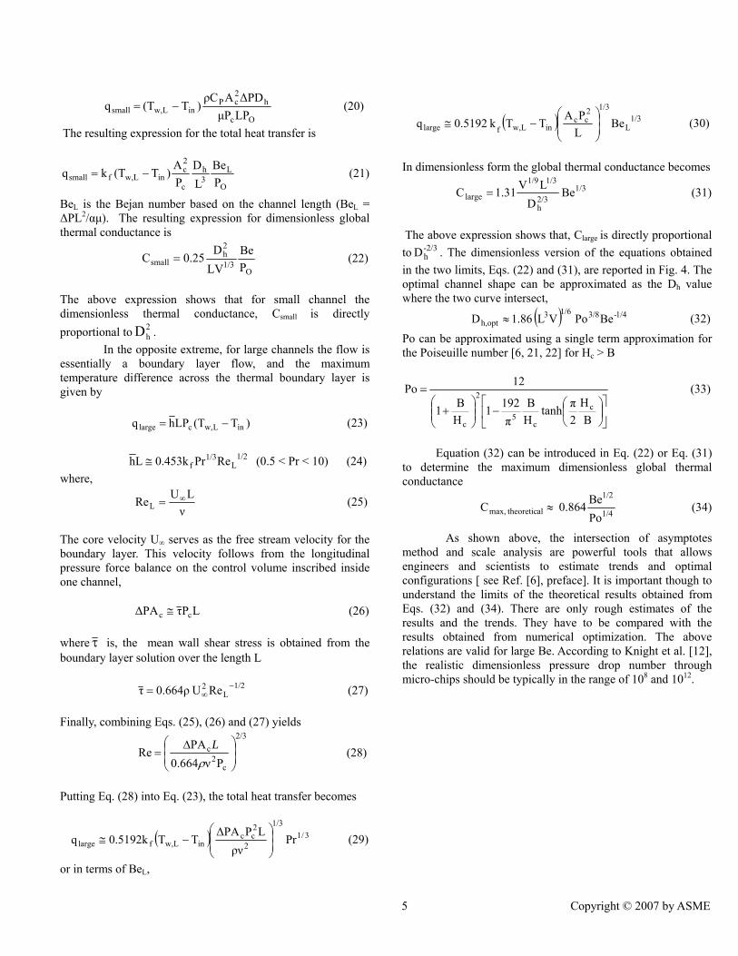
Figure 7 summarizes the effects of pressure drop on the optimal external aspect ratio, in the range 10 kPa ≤ ∆P ≤ 75 kPa. For a fixed solid fraction, the optimal external aspect ratio exhibits two types of behavior, as shown in Fig. 8. At low pressure drops the optimized ARopt increases with an increase in the pressure drop, while for ∆P ≥ 50 kPa, ARopt increased slightly with increases in the pressure drop, and is almost
6 Copyright © 2007 by ASME
invariant for = 0.8. Similarly, the optimized external aspect ratio AR
φopt decreases with an increase in the solid volume
fraction for the range of geometric parameters used in this study. As the aspect ratio increases the cross sectional area of the micro-channel becomes slender in the vertical direction and the value of the hydraulic diameter changes.
Figure 7 The effect of pressure drop and solid volume fraction on the optimized aspect ratio.
Figure 8 shows the behavior of the optimal micro-
channel geometry represented by the optimal hydraulic diameter. Dh,opt decreases with an increase in the pressure drop, as suggested from the theoretical derivation of Eq. (32) for a fixed solid volume fraction, and decreases as the volume fraction increases. The minimum optimal hydraulic diameter of is more than 100 µm. For the entire range, the optimal hydraulic diameter lies in the continuum region and gives us confidence in our continuum assumption.
Figure 8 The effect of pressure drop and solid volume fraction on the optimized channel hydraulic diameter.
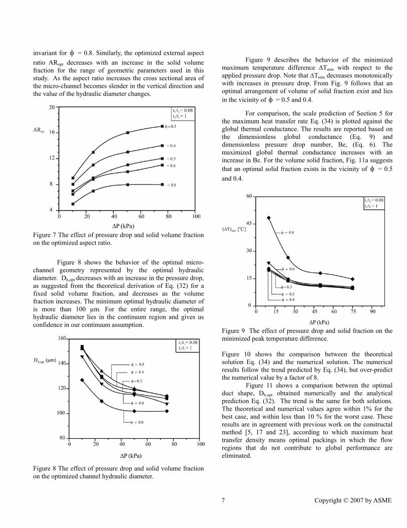
Figure 9 describes the behavior of the minimized maximum temperature difference ∆Tmin with respect to the applied pressure drop. Note that ∆Tmin decreases monotonically with increases in pressure drop. From Fig. 9 follows that an optimal arrangement of volume of solid fraction exist and lies in the vicinity of φ = 0.5 and 0.4.
For comparison, the scale prediction of Section 5 for the maximum heat transfer rate Eq. (34) is plotted against the global thermal conductance. The results are reported based on the dimensionless global conductance (Eq. 9) and dimensionless pressure drop number, Be, (Eq. 6). The maximized global thermal conductance increases with an increase in Be. For the volume solid fraction, Fig. 11a suggests that an optimal solid fraction exists in the vicinity of φ = 0.5 and 0.4.
Figure 9 The effect of pressure drop and solid fraction on the minimized peak temperature difference. Figure 10 shows the comparison between the theoretical solution Eq. (34) and the numerical solution. The numerical results follow the trend predicted by Eq. (34), but over-predict the numerical value by a factor of 8.
Figure 11 shows a comparison between the optimal duct shape, Dh,opt obtained numerically and the analytical prediction Eq. (32). The trend is the same for both solutions. The theoretical and numerical values agree within 1% for the best case, and within less than 10 % for the worst case. These results are in agreement with previous work on the constructal method [5, 17 and 23], according to which maximum heat transfer density means optimal packings in which the flow regions that do not contribute to global performance are eliminated.
7 Copyright © 2007 by ASME

Figure 10 The effect of dimensionless pressure drop number and solid volume fraction on the dimensionless global thermal conductance.
Figure 11 The optimal micro-channel shape (hydraulic diameter) for maximum global conductance CONCLUSIONS
In this paper we showed numerically and theoretically that the global thermal conductance for a micro-channel heat sink can be maximized by optimizing the aspect ratio, AR, and therefore the channel hydraulic diameter for laminar forced conjugate heat transfer. The numerical simulations, which were conducted in the range 10 kPa ≤ ∆P ≤ 75 kPa, and V = 0.9mm3, show that the optimal aspect ratio ARopt increases as the pressure difference (∆P) increases, for a fixed volume (V). An optimal allocation of solid volume fraction exists in the φ range from 0.4 to 0.5. Numerical optimization results further show that the optimal micro-channel shape (Dh,opt) and the minimized peak temperature (maximized global thermal conductance) are functions of the applied pressure difference
and solid volume fraction. Comparisons of the results obtained numerically with approximate solutions based on scale analysis shows excellent agreement for optimal micro-channel dimensions. The approximate dimensionless global thermal conductance predicts the trend obtained numerically. It is expected that the conceptual design of micro-channel heat sinks using the constructal method will lead to better and faster design of micro–channel heat sinks with improved performance and higher global thermal conductance. ACKNOWLEDGMENTS Dr. Bello-Ochende acknowledges the support received for the post-doctoral research from the University of Pretoria and National Research Foundation of the Republic of South Africa. REFERENCES [1] Dirker, J., Liu W., Van Wyk, D., Meyer, J. P., and
Malan, A. G., 2005, “Embedded solid state heat extraction in integrated power electronic modules”, IEEE Transaction on Power Electronics No. 3 20, pp. 694 – 703.
[2] Webb, R., 2005, “Next generation devices for electronic cooling with heat rejection to the air”, J. Heat Transfer, 127, pp. 2 – 9.
[3] Bejan, A., 2000, Shape and Structure, from
Engineering to Nature, Cambridge University Press, Cambridge, UK.
[4] Bejan, A., and Lorente, S., 2006, “Constructal theory of generation and configuration in nature and engineering”, Journal of Applied Physics, 100, 041301.
[5] Bar-Cohen, A., and Rohsenow, W. M., 1984, “Thermally optimum spacing of vertical, natural convection cooled, parallel plates”, J. Heat Transfer, 106, pp. 116-123.
[6] Bejan, A., 2004, Convection Heat Transfer, 3rd edition, Wiley, New York.
[7] Bello-Ochende, T. and Bejan, A., 2003, “Fitting the duct to the “body” of the convective flow”, Int. J. Heat and Mass Transfer, 46, pp. 1693-1701.
[8] Bejan, A., and Sciubba, E., 1992, “The optimal spacing for parallel plates cooled by forced convection”, Int. J. Heat Mass Transfer, 35, pp. 3259-3264.
[9] Tuckerman, D. B., and Pease, R.F.W., 1981, “High-performance heat sinking for VLSI”, IEEE Electron. Dev. Lett. EDL-2, pp. 126 – 129.
[10] Toh, K. C., Chen, X. Y., and Chai, J. C., 2002, “Numerical computation of fluid flow and heat
8 Copyright © 2007 by ASME

transfer in micro-channels”, Int. J. Heat Mass Transfer, 45, pp. 5133-5141.
[11] Qu, W., and Mudawar, I., 2002, “Analysis of three-dimensional heat transfer in micro-channel heat sinks”, Int. J. Heat Mass Transfer, 45, pp. 3973-3985.
[ 12] Knight, R. W., Hall, D. J., Goodling, J. S., and Jaeger, C. J., 1992, “Heat sink optimization with application to microchannels”, IEEE Transaction of Component, Hybrids, and Manufacturing Technology, 15, No. 5, pp. 832 – 842.
[13] Fedorov, A. G., and Viskanta, R., 2000, “Three-dimensional conjugate heat transfer in the micro-channel heat sink for electronic packaging”, Int. J. Heat Mass Transfer, 43, pp. 399-415.
[14] Li, J., Peterson, G. P., and Cheng, P., 2004, “Three-dimensional analysis of heat transfer in a micro-heat sink with single phase flow”, Int. J. Heat Mass Transfer, 47, pp. 4215 – 4231.
[15] Kawano, K. Minikami, K., Iwasaki, H., and Ishizuka, M., 1998, “Micro channel heat exchanger for cooling electrical equipment, Application of Heat Transfer in Equipment, Systems and Education”, ASME HTD – 361-3/PID-3, pp. 173-180.
[16] Foli, K., Okabe, T., Olhofer, M., Jin, Y., and Sendhoff, B., 2006, “Optimization of micro heat exchanger: CFD, analytical approach and multi-objective evolutionary algorithms”, Int. J. Heat Mass Transfer, 49, pp. 1090-1099.
[17] Favre-Marinet, M., Le Person, S., and Bejan, A., 2004, “Maximum heat transfer rate density in two dimensional mini-channels and micro-channels”, Microscale Thermophysical Engineering, pp. 225-237.
[18] Bhattacharjee, S., and Grosshandler, W. L., 1988, “The formation of wall jet near a high temperature wall under microgravity environment”, ASME HTD, 96, pp. 711-716.
[19] Petrescu, S., 1994, “Comments on the optimal spacing of parallel plates cooled by forced convection”, Int. J. Heat Mass Transfer, 37, pp. 1283.
[20] Patankar, S. V., 1980, Numerical Heat Transfer and Fluid flow, Hemisphere, New York.
[21] Muzychka, Y. S., 2005, “Constructal design of forced convection cooled micro-channel heat sinks and exchanger”, Int. J. Heat Mass Transfer, 48, pp. 3119 – 3124.
[22] Shah, R. K., and London, A. L., 1978, Laminar Flow Forced Convection in Ducts, Academic Press, NY, 1978, pp. 78-283.
[23] Yilmaz, A., and Buyukalaca, O., and Yilmaz, T. , 2000, “Optimum shape and dimensions of channel for convective heat transfer in laminar flow at constant wall temperature”, In. J. Heat Mass Transfer, 43, pp. 767 – 775.
9 Copyright © 2007 by ASME