Collapse of the Lake View Drive Bridge over Interstate 70
14
14 JURNAL TEKNIKA, Edisi 14, No. 2, November 2014: 14 - 27 INTRODUCTION Noncomposite adjacent precast prestressed concrete box beam bridge systems are a popular form of construction in the United States. These types of bridge designs start- ed in the 1950‟s and continue today. The precast box girders have vertical shear keys in the webs intended to transfer force between adjacent girders. The box girders are typically post-tensioned with lateral ties that are fully grouted during assembly. An asphalt wearing surface is placed on the adjacent box girder bridge system. This type of bridge design is popular because it lends itself to a quick construction time, with most of the fabrication done offsite. As of 2007, over 19,000 adjacent box girder bridges were in service in the United States, with 3,291 in Pennsylvania (PA) [1] . Degradation problems have arose with the adjacent precast concrete box girder bridges due to the age, detailing practice, and heavy damage to the box girders and lateral tie Fundamental Study of Corrosion of Prestressing Strands in Concrete Case Study: Collapse of the Lake View Drive Bridge over Interstate 70 Rilya Rumbayan, Geertje E. Kandiyoh (Staf Pengajar Teknik Sipil Politeknik Negeri Manado) Abstract; The Lake View Drive Bridge over Interstate-70 in Washington, Pennsylvania is a precast, prestressed concrete adjacent box-girder bridge. On December 27, 2005, the fascia girder of the 45 year old the Lake View Drive Bridge suddenly collapsed, resulting in minor injuries to three motorists on I- 70 below. Bridge inspections of the bridge had been conducted on a biennial basis, with the most recent inspection being conducted in August, 2004. Some deterioration and corrosion of the prestressing strands and surrounding concrete was identified during the inspection, but the bridge remained opened. The corrosion and rupture of the prestressing stands was found to be the cause of the collapse. The goals of this paper are (1) to describe collapse of the Lake View Drive Bridge over Interstate 70 caused by corrosion of the prestressing strands, (2) to study the mechanisms of corrosion of steel in concrete, and (3) to introduce some engineering techniques to protect corrosion. Keywords; corrosion, prestressing strand, reinforcing steel, and concrete bridge. Abstrak; Jembatan Lake View yang terletak di atas jalan Interstate-70 di Washington, Pennsylvania adalah jembatan beton prategang pracetak yang terdiri dari balok-balok penopang utama yang berbentuk kotak berongga. Pada tanggal 27 Desember 2005, balok utama dari jembatan Lake View Drive Bridge yang berusia 45 tahun tiba-tiba runtuh dan mengakibatkan luka ringan bagi tiga pengendara pada Inter- state-70. Pemeriksaan struktur jembatan ini telah dilakukan setiap dua tahun, dengan pemeriksaan terbaru yang dilakukan pada bulan Agustus, 2004. Beberapa kerusakan dan korosi dari kabel strands pratekan dan beton sekitarnya telah diidentifikasi selama pemeriksaan, namun jembatan tetap dibuka. Korosi dari kabel strands pratekan ditemukan menjadi penyebab keruntuhan. Tujuan dari tulisan ini adalah (1) untuk mendeskripsikan runtuhnya Jembatan Lake View yang disebabkan oleh korosi dari kabel strands pratekan, (2) untuk mempelajari mekanisme korosi baja pada beton, dan (3) untuk mem- perkenalkan beberapa teknik rekayasa untuk perlindungan terhadap korosi. Kata-kata Kunci; korosi, kabel strand, baja tulangan, dan jembatan beton.
-
Upload
khangminh22 -
Category
Documents
-
view
7 -
download
0
Transcript of Collapse of the Lake View Drive Bridge over Interstate 70

14 JURNAL TEKNIKA, Edisi 14, No. 2, November 2014: 14 - 27
INTRODUCTION
Noncomposite adjacent precast prestressed concrete box beam bridge systems are a
popular form of construction in the United States. These types of bridge designs start-
ed in the 1950‟s and continue today. The precast box girders have vertical shear keys
in the webs intended to transfer force between adjacent girders. The box girders are
typically post-tensioned with lateral ties that are fully grouted during assembly. An
asphalt wearing surface is placed on the adjacent box girder bridge system. This type
of bridge design is popular because it lends itself to a quick construction time, with
most of the fabrication done offsite. As of 2007, over 19,000 adjacent box girder
bridges were in service in the United States, with 3,291 in Pennsylvania (PA) [1].
Degradation problems have arose with the adjacent precast concrete box girder bridges
due to the age, detailing practice, and heavy damage to the box girders and lateral tie
Fundamental Study of Corrosion of Prestressing Strands in Concrete Case Study: Collapse of the Lake View Drive Bridge over Interstate 70
Rilya Rumbayan, Geertje E. Kandiyoh
(Staf Pengajar Teknik Sipil Politeknik Negeri Manado)
Abstract; The Lake View Drive Bridge over Interstate-70 in Washington, Pennsylvania is a precast, prestressed concrete adjacent box-girder bridge. On December 27, 2005, the fascia girder of the 45 year old the Lake View Drive Bridge suddenly collapsed, resulting in minor injuries to three motorists on I-70 below. Bridge inspections of the bridge had been conducted on a biennial basis, with the most recent inspection being conducted in August, 2004. Some deterioration and corrosion of the prestressing strands and surrounding concrete was identified during the inspection, but the bridge remained opened. The corrosion and rupture of the prestressing stands was found to be the cause of the collapse. The goals of this paper are (1) to describe collapse of the Lake View Drive Bridge over Interstate 70 caused by corrosion of the prestressing strands, (2) to study the mechanisms of corrosion of steel in concrete, and (3) to introduce some engineering techniques to protect corrosion. Keywords; corrosion, prestressing strand, reinforcing steel, and concrete bridge.
Abstrak; Jembatan Lake View yang terletak di atas jalan Interstate-70 di Washington, Pennsylvania adalah jembatan beton prategang pracetak yang terdiri dari balok-balok penopang utama yang berbentuk kotak berongga. Pada tanggal 27 Desember 2005, balok utama dari jembatan Lake View Drive Bridge yang berusia 45 tahun tiba-tiba runtuh dan mengakibatkan luka ringan bagi tiga pengendara pada Inter-state-70. Pemeriksaan struktur jembatan ini telah dilakukan setiap dua tahun, dengan pemeriksaan terbaru yang dilakukan pada bulan Agustus, 2004. Beberapa kerusakan dan korosi dari kabel strands pratekan dan beton sekitarnya telah diidentifikasi selama pemeriksaan, namun jembatan tetap dibuka. Korosi dari kabel strands pratekan ditemukan menjadi penyebab keruntuhan. Tujuan dari tulisan ini adalah (1) untuk mendeskripsikan runtuhnya Jembatan Lake View yang disebabkan oleh korosi dari kabel strands pratekan, (2) untuk mempelajari mekanisme korosi baja pada beton, dan (3) untuk mem-perkenalkan beberapa teknik rekayasa untuk perlindungan terhadap korosi. Kata-kata Kunci; korosi, kabel strand, baja tulangan, dan jembatan beton.

15
system of the first generation of these bridges. Inspections in 2007 indicated 590 adja-
cent box girder bridges to be structurally deficient in Pennsylvania alone. These in-
spections have indicated longitudinal cracking of the bottom flange, corrosion and
fracture of prestressing strands, spalling, efflorescence, and leakage between beams.
These problems potentially lower the dead load (asphalt wearing surface and structural
dead load) and service live loads (truck and vehicles) that an adjacent box girder
bridge can withstand without being overstressed.
THE TIMELINE OF THE LAKEVIEW DRIVE BRIDGE
The Lake View Drive Bridge was built in 1960 and is a four span adjacent precast,
prestressed concrete box girder overpass bridge that crosses I-70 in Washington, PA.
The bridge has eight precast concrete box girders supported on two abutments and
three piers, with pier 1and 3 on either side of the four lane I-70 roadway and pier 2 in
the median of I-70 as shown in Figure 1. The span lengths vary between 53ft 10 ½ in.
to 88ft 9 ¾ in. and 88ft 9 ¾ in. to 42 ft. 1 ½ in.
The bridge was designed in accordance with the 1953 Standard Specifications for
Highway Bridges [2]. The girders were fabricated with Grade 250 prestressing steel
strands. Each precast concrete box girder span had 60 prestressed 3/8 in. 7-wire strand
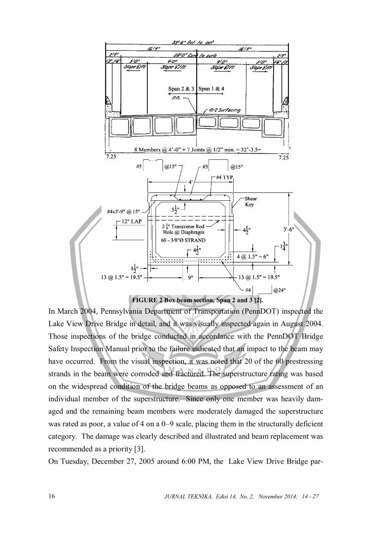
reinforcement in the bottom flange of the box girder as shown in Figure 2. The eight
bridge girders were connected together with transverse posttensioning, utilizing 2 ¼ in.
lateral rods (Figure 2). The posttensioning had to be staggered along each span to ac-
commodate the 39 degree skew that existed in the bridge. The posttensioning with lat-
eral rods or other reinforcement between prestressed concrete box girders is what
makes this bridge a concrete adjacent box-girder bridge [2].
FIGURE 1 Bridge side elevation [3].
FUNDAMENTAL STUDY OF CORROSION OF PRESTRESSING STRANDS IN CONCRETE CASE STUDY: COLLAPSE OF THE LAKE VIEW DRIVE BRIDGE OVER INTERSTATE 70
(Rilya Rumbayan, Geertje E. Kandiyoh)
16 JURNAL TEKNIKA, Edisi 14, No. 2, November 2014:
FIGURE 2 Box beam section, Span 2 and 3 [2].
In March 2004, Pennsylvania Department of Transportation (PennDOT) inspected the
Lake View Drive Bridge in detail, and it was visually inspected again in August 2004.
Those inspections of the bridge conducted in accordance with the PennDOT Bridge
Safety Inspection Manual prior to the failure indicated that an impact to the beam may
have occurred. From the visual inspection, it was noted that 20 of the 60 prestressing
strands in the beam were corroded and fractured. The superstructure rating was based
on the widespread condition of the bridge beams as opposed to an assessment of an
individual member of the superstructure. Since only one member was heavily dam-
aged and the remaining beam members were moderately damaged the superstructure
was rated as poor, a value of 4 on a 0–9 scale, placing them in the structurally deficient
category. The damage was clearly described and illustrated and beam replacement was
recommended as a priority [3].
On Tuesday, December 27, 2005 around 6:00 PM, the Lake View Drive Bridge par-
14 - 27

17
tially collapsed onto the highway below, which is Interstate 70. The collapsed portion
consisted of Beam 1 in Span 3 over the eastbound lanes of I-70, which is the north ele-
vation fascia beam. The reinforced concrete bridge parapet and metal railing of Span 3
also fell with the beam, as shown in Figure 3 [2]. One vehicle carrying a driver and
two passengers traveling on the highway below struck the collapsed bridge. However,
the injuries sustained by the motorist did were minor in nature and did not require ad-
ditional hospitalization after being taken to the emergency room for examinations.
FIGURE 3 Span 3 failure from the Lake View Drive Bridge [2].
In 2006, post-collapse inspection of the remaining beam by Michael Baker Inc. (Hartle
2006) revealed that in fact 39 of the 60 prestressing strands had exhibited corrosion
related failure of individual wires or strands. Post-collapse inspection also revealed
heavy spalling and corrosion of the strands on the bottom flange of the failed concrete
box beam. This corrosion of the prestressing strands lead to the fracture of the strands
and failure of Span 3 of the Lake View Drive Bridge. Similar damage was noted on the
adjacent members and spans. As a safety precaution, the bridge was decommissioned
and a number of beams were saved for forensic investigation and load testing. The
bridge was repaired and reopened 6 months later.
TESTING AND RESPONSE TO THE COLLAPSE
In response to the collapse, PennDOT initiated and sponsored testing on the Lake
View Drive Bridge. Dr. Kent Harries lead the investigation, which sought to further
understand the mechanisms for collapse to prevent similar happenings. Dr. Harries,
Assistant Professor, and his colleagues in the Civil and Environmental Department at
FUNDAMENTAL STUDY OF CORROSION OF PRESTRESSING STRANDS IN CONCRETE CASE STUDY: COLLAPSE OF THE LAKE VIEW DRIVE BRIDGE OVER INTERSTATE 70
(Rilya Rumbayan, Geertje E. Kandiyoh)

18 JURNAL TEKNIKA, Edisi 14, No. 2, November 2014:
the University of Pittsburg conducted the testing of the girders. Two girders were se-
lected for study: the girder directly adjacent to the failed exterior girder, called the inte-
rior girder, and the furthest-most girder, directly opposite the failed girder, called the
exterior girder [2].
The girders were tested until failure over a smaller span (84ft 2 in.) than the original
bridge (88ft 10 in.). The load was induced by two frames placed 48 in apart across the
midspan through four hydraulic cylinders, with two cylinders per frame. Loads were
applied in cycles, with the interior girder being irreparably damaged at 41 kips, and the
exterior girder having significant cracks and rupture of the prestressing strands at 60
kips [2].
Based on this testing, as well as detailed visual inspection, PennDOT developed a new,
more detailed protocol for prestressed concrete box beam bridges. A moratorium was
placed on new construction of certain types of prestressed concrete box beam bridges
until more capable inspection technologies were developed. PennDOT developed and
released detailed guidelines for rating existing bridges. The Department also adjusted
rating protocol on box girder bridges so that the condition of a bridge is rated in re-
spect to its weakest member. Thus, if one member is noted to be structurally deficient,
the whole bridge is considered to be as structurally deficient [3].
CORROSION OF REINFORCING STEELS IN CONCRETE
Corrosion of steel in concrete is a relevant topic to the bridge engineer, as made evi-
dent in part by the Lake View Drive collapse. Some corroded members of the Lake
View Drive Bridge were said to either be reduced in diameter or be lost entirely [5].
This loss is critically important to the overall strength of the bridge, because the pre-
stressed strands are intended to provide compression and to reduce cracking in the con-
crete. Thus, to fully appreciate the mechanisms of the Lake View Drive collapse, it is
necessary to understand the mechanisms of corrosion of steel in concrete [6] including
electrochemical process, protective layer provided by concrete, rate of corrosion, car-
bonation, chloride and diffusion process, corrosion of prestressed steels, and protecting
steel from corrosion.
Mechanical Properties
The corrosion process is important to the engineer, because many relevant physical
properties are associated with corrosion, including an increase in volume and a de-
14 - 27

19
crease in strength. Corroded steel can grow in volume as much as 6x its original vol-
ume [7]. This increase in volume can result in cracking and spalling of the concrete,
further exposing the metal to air and water, thus accelerating the corrosion process [7].
Corrosion is detrimental to a reduction in the cross-section area in prestressing steel
due to general or pitting corrosion. In a cross-sectional area with partial corrosion, the
corroded area contributes increasing the net stress in prestressing and possibly leading
to local yielding and fracture [6, 9]. For instance, in the report of the Lake View Drive
Bridge collapse by Naito et al. [6], prestressed strands were categorized by cross-
sectional area lost due to corrosion. The corroded strands were categorized as: mini-
mal, minimal to 20%, above 20%, and entirely corroded (or entirely lost).
Rate of Corrosion
The rate of corrosion of steel is governed by the current which results from rate of re-
lease of electrons from the iron. The rate is modeled by an equation called Faraday‟s
Law which states:
where M is the mass of the material corroded, t is time, I is current, is the atomic
weight, n is the valency, and F is Faraday‟s constant (96,500 C/m). Note that the rate
of corrosion is directly proportional to current (or rate of electrons released from the
iron) and atomic weight. For steel, the rate of corrosion, after M is divided by the den-
sity of steel, is calculated to be = 11.8 μm/yr [8]. In concrete, the release of electrons
from the iron, which is the current that affects the rate of corrosion, can be influenced
by several factors such as heterogeneity of the steel and concrete, pH of the concrete
pore water, and stray currents.
Electrochemical Process
Corrosion is primarily an electrochemical process which typically occurs in the pres-
ence of air and water. When an iron atom comes in contact with water, it is stripped
from two of its electrons: Fe → Fe2+ + 2 e−. These two electrons freely travel across
the conductor, but if water and oxygen are present along the steel, they will combine to
create hydroxide: O2 + 4 e- + 2 H2O → 4 OH-. These two equations are the most note-
worthy to the engineer, because they show the necessity constituents which lead to cor-
rosion. However, corrosion proceeds when hydroxide recombines with the positively
FUNDAMENTAL STUDY OF CORROSION OF PRESTRESSING STRANDS IN CONCRETE CASE STUDY: COLLAPSE OF THE LAKE VIEW DRIVE BRIDGE OVER INTERSTATE 70
(Rilya Rumbayan, Geertje E. Kandiyoh)
20 JURNAL TEKNIKA, Edisi 14, No. 2, November 2014:
14 - 27
charged iron:
Fe2+ + 2OH- → Fe (OH)2 (ferrous hydroxide)
4 Fe (OH)2 + O2 + 2 H2O → 4 Fe (OH)3 (ferric hydroxide)
4 Fe (OH)3 → Fe2 O3 H2O + 2 H2O (hydrated ferric hydroxide) (rust)
This set of reactions, set on simply by the presence of iron, water and oxygen, is one
electrochemical example of how rust is formed. However, this is not the only way that
rust developed. Many other acidic elements can corrode steel. For example, salt
(chloride) used in icy conditions on roadways accelerates corrosion of prestressed
strands in box girder bridges.
Prestressed Steels
A loss of area due to corrosion is a particularly noteworthy issue in prestressed steels.
First, these prestressed steels utilize a significant amount of their ultimate tensile
strength (55% - 65%). A relatively small loss in cross-sectional will critically diminish
the member‟s factor of safety. Furthermore, this cross-sectional loss due to corrosion
is more rapid in prestressed strands. Strands are not made of a continuous piece of
metal, but rather six supporting strands wrapped around a central, straight strand.
Thus, the surface area of the prestressed strand bundle exposed to corrosion is higher
than the surface area of a single bar. Consequently, corrosion rates are higher in pre-
stressed steels than in single bars [9].
Protective Layer
Because metals corrode in acidic environments, a metal can be protected by an alkaline
film which neutralizes the pH level. Such is the case with steel in concrete. Concrete
pores contain elements such as calcium, sodium and potassium, which form alkalinic
hydroxides when water is present. The pH of this environment is between 12 and 13
[7]. However, this protective layer is not indestructible. Bridge engineers are able to
plan accordingly, but if the lifetime of the bridge is miscalculated, or the weather
brings unforeseen rain and snow, the protective layer will not withstand the ingress of
acidic elements [8]. The success of corrosion protection is primarily a function of
strengthening and sustaining this protective layer.
Corrosion by Carbonation
Carbonation is the general term given to the neutralization of concrete by reaction be-

21
tween the alkaline components of the cement paste and carbon dioxide (CO2) in the
atmosphere. Carbonation generally proceeds in the concrete as a front, beyond which
the concrete not effected, but when the carbonation front reaches the steel, general de-
passivation over large area or over the whole steel surface can occur and general corro-
sion can be initiated.
Carbonation has important effects on corrosion of embedded steel. The first conse-
quence is that the pH of the pore solution drops from its normal values of pH 13 to 14,
to values approaching neutrality (pH 8 to 9). A second consequence of carbonation is
that chloride bound in the form of calcium chloroaluminate hydrates and otherwise
bound to hydrated phases may be liberated, making the pore solution even more ag-
gressive [7].
A carbonation front proceeds into the concrete roughly following diffusion phenome-
na. The rate of progress of carbonation is given by the equation:
where d is carbonation depth in mm, A is a carbonation coefficient, t is time in the
years and n is an exponent, usually ½. This is a simple derivation of the Fick‟s laws of
diffusion that says the rate of diffusion is proportional to the thickness being diffused
through:
where x is thickness, t is time.
The carbonation coefficient can be assumed as the measure of the rate of penetration of
carbonation for given concrete and environmental conditions. The rate of carbonation
depends on both environmental factor (humidity, temperature, concentration of carbon
dioxide) and factor related to the concrete (alkalinity and permeability) [7]. The in-
gress of gases is higher at low relative humidity, but the reaction between the gas and
the cement paste takes place in solution and is higher at high humidity. Therefore, the
most aggressive environment for concrete neutralization will be that of alternate wet
and dry cycles and high temperature [8]. The carbonation rate is a function of cover
thickness, so good cover is essential to resist carbonation. A high cement content pro-
vides a good reserve of alkali to protect against possible carbonation. The diffusion
process is made easier if the concrete has an open pore structure. On the macroscopic
scale this means that there should be good compaction. On a microscopic scale well
cured concrete has small pores and lower connectivity of pores so the CO2 has a harder
job moving through the concrete. Microsilica and other additives can block pores or
FUNDAMENTAL STUDY OF CORROSION OF PRESTRESSING STRANDS IN CONCRETE CASE STUDY: COLLAPSE OF THE LAKE VIEW DRIVE BRIDGE OVER INTERSTATE 70
(Rilya Rumbayan, Geertje E. Kandiyoh)

22 JURNAL TEKNIKA, Edisi 14, No. 2, November 2014:
reduce pores sizes [7].
Corrosion by Chlorides
This section discusses the role of chlorides in the corrosion process. The source of
chlorides may be admixtures, contaminants, marine environments, industrial brine, or
deicing salts. The use of calcium chloride (CaCl2) as a set accelerator for concrete has
been the most common source of intentionally added chlorides. Chlorides added to the
mixture as accelerator for concrete have three additional effects on subsequent corro-
sion rates. First, it has been shown that the accelerating effect of the chlorides results
in a coarser capillary pore-size distribution at a constant water-cement ratio (w/c),
which allows faster ingress of additional chlorides, faster carbonation rates, and also
reduces the resistivity of the concrete. Second, the chlorides increase the ionic concen-
tration of the pore solution and its electrical conductivity. Both of these factors lead to
an increase in the corrosion rate. Third, the chlorides alter the pH of the concrete pore
solution, sodium chloride (NaCl) and potassium chloride (KCl) increase the pH where-
as CaCl2, in high concentrations, reduces the pH.
Chloride also has been added in the concrete mixing water, aggregates (for instance by
using sea sand and gravel without washing them with chloride-free water). The other
main source of chloride in concrete is penetration from the environment. This occurs,
for instance, in marine environments or in road structures in regions where chloride
bearing deicing salts are used in wintertime.
The Diffusion of Chlorides
The transport mechanism of chloride is following the laws of diffusion
where [Cl- ] is the chloride concentration at depth x at time t . and Do is the diffusion
coefficient (usually of the order 10-10 m2/sec) [7]. By using the parabolic approxima-
tion developed by Poulsen, the solution can be simplified using
where C(x,t) is the chloride concentration at time t and depth x, Ci is the initial chloride
concentration, Cs is the surface chloride concentration and erf ( ) is the error function
of the value of the argument in brackets. The rate of diffusion depends strongly on a
number of factors, including the water cement ratio, type of cement, temperature, and
14 - 27

23
maturity of the concrete [7].
In chloride environment, the initiation of corrosion occurs only when the chloride con-
tent is higher than the chloride threshold value. The consequence of chloride ions in
the corrosion of steel in concrete has led to the concept of a chloride threshold level
(CTL). The CTL can be defined as the content of chloride at the steel depth that is
necessary to sustain local passive film breakdown and hence initiate the corrosion pro-
cess [12]. It is usually obtained as the ratio of chloride to hydroxyl ions, the free chlo-
ride content or the percentage of the total chloride content relative to the weight of ce-
ment.
Assessment of the CTL is important in predicting the service life of structures exposed
to chlorides. One possible definition of the service life is the time required for
transport processes to increase the chloride level at the depth of the steel to the CTL.
The measurement of CTL performed by using a synthetic concrete solution with a [Cl-
]:[OH-] ratio of 0.6. The relationship between chloride and hydroxyl ions is described
by the equation
where n and K are constants. This implies that the ratio [Cl-]:[OH-] represents a con-
stant with n is 0.8 for corrosion prevention. The ratio of [Cl-]:[OH-] has been consid-
ered functional, because it reflects the corrosion risk that is induced by either chloride
alone, or carbonation and chloride in combination [12].
To measure the CTL, the time of initial of corrosion and the chloride content at the
steel depth must be identified. The initial of corrosion can be detected by monitoring
the macrocell current between an anode and a cathode, measuring half-cell potential or
monitoring the corrosion rate measured by the polarization technique or AC imped-
ance method [12].
Measurement of the chloride content or profile to determine the CTL is performed by
adopting method for measuring total chloride content uses acid soluble extraction, in
which it is assumed that both bound and free chlorides are soluble in acid. Measure-
ment of acid soluble chloride (total chloride) may be made using a chloride ion sensi-
tive electrode or by titration. X-ray fluorescence can also be used to determine the
chloride content. The representation of the CTL by the total chloride level is the most
widely used approach, and is the approach adopted in standards. Table 1 gives the
chloride limits for concrete, expressed as a percentage by mass of cement, from each
standard [12].
FUNDAMENTAL STUDY OF CORROSION OF PRESTRESSING STRANDS IN CONCRETE CASE STUDY: COLLAPSE OF THE LAKE VIEW DRIVE BRIDGE OVER INTERSTATE 70
(Rilya Rumbayan, Geertje E. Kandiyoh)
24 JURNAL TEKNIKA, Edisi 14, No. 2, November 2014:
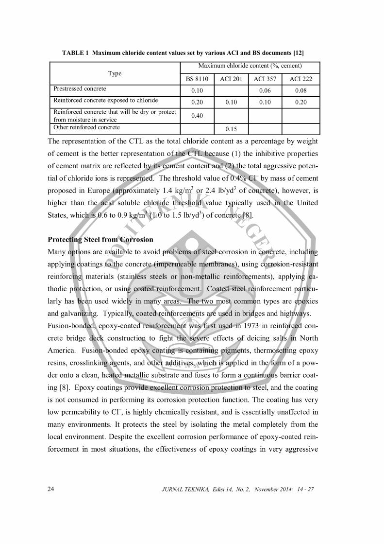
TABLE 1 Maximum chloride content values set by various ACI and BS documents [12]
The representation of the CTL as the total chloride content as a percentage by weight
of cement is the better representation of the CTL because (1) the inhibitive properties
of cement matrix are reflected by its cement content and (2) the total aggressive poten-
tial of chloride ions is represented. The threshold value of 0.4% Cl– by mass of cement
proposed in Europe (approximately 1.4 kg/m3 or 2.4 lb/yd3 of concrete), however, is
higher than the acid soluble chloride threshold value typically used in the United
States, which is 0.6 to 0.9 kg/m3 (1.0 to 1.5 lb/yd3) of concrete [8].
Protecting Steel from Corrosion
Many options are available to avoid problems of steel corrosion in concrete, including
applying coatings to the concrete (impermeable membranes), using corrosion-resistant
reinforcing materials (stainless steels or non-metallic reinforcements), applying ca-
thodic protection, or using coated reinforcement. Coated steel reinforcement particu-
larly has been used widely in many areas. The two most common types are epoxies
and galvanizing. Typically, coated reinforcements are used in bridges and highways.
Fusion-bonded, epoxy-coated reinforcement was first used in 1973 in reinforced con-
crete bridge deck construction to fight the severe effects of deicing salts in North
America. Fusion-bonded epoxy coating is containing pigments, thermosetting epoxy
resins, crosslinking agents, and other additives, which is applied in the form of a pow-
der onto a clean, heated metallic substrate and fuses to form a continuous barrier coat-
ing [8]. Epoxy coatings provide excellent corrosion protection to steel, and the coating
is not consumed in performing its corrosion protection function. The coating has very
low permeability to Cl–, is highly chemically resistant, and is essentially unaffected in
many environments. It protects the steel by isolating the metal completely from the
local environment. Despite the excellent corrosion performance of epoxy-coated rein-
forcement in most situations, the effectiveness of epoxy coatings in very aggressive
Type
Maximum chloride content (%, cement)
BS 8110 ACI 201 ACI 357 ACI 222
Prestressed concrete 0.10 0.06 0.08
Reinforced concrete exposed to chloride 0.20 0.10 0.10 0.20
Reinforced concrete that will be dry or protect
from moisture in service 0.40
Other reinforced concrete 0.15
14 - 27

25
environments has been questioned recently, primarily because the coating has naturally
occurring holidays, which is discontinuity in a coating that is not visible to a person
with normal or corrected vision, and may be damaged during transportation and fabri-
cation. Consequently, a great deal of emphasis is placed on the careful handling and
storage of epoxy-coated reinforcement to minimize abrasion and mechanical damage
[10]. In addition, epoxy-coated reinforcement is smooth and concrete does not adhere
well to its surface, bond strength develops primarily through mechanical bearing. Dif-
ferent studies have given different results, but most give values of 65 to 90% as the
relative level of bond strength for epoxy-coated bar compared to black bar [10].
Galvanized reinforcement has been in use since the 1930s. Because the steel rein-
forcement is hot dipped into molten Zn at 460°C, galvanizing produces a metallurgi-
cally alloyed coating integrally bound to the steel substrate. The alloy layers are
strong, resist mechanical damage, and afford sacrificial protection to the steel. Zn is
passivated in concrete and can remain passivated to lower pH levels (as low as pH 9.5)
than that which causes corrosion of black steel (pH < 11.5). Galvanizing thus offers
substantial protection against the effects of carbonation in concrete. Galvanized rein-
forcement also can withstand exposure to Cl– concentrations several times higher than
that which causes corrosion of black steel in concrete [10].
CONCLUSION
The Lake View Drive Bridge was a four span adjacent precast, prestressed concrete
box girder overpass bridge. The fascia girder that collapsed onto I-70 in Washington,
PA on December 27, 2005 caused minor injuries to three motorists. The bridge was
found to have extensive corrosion of prestressing strands in the bottom flange of the
concrete box girders. This corrosion leads to the rupturing of the strands and collapse
of the bridge onto I-70. Post-collapse inspection and testing was conducted to deter-
mine the cause of the collapse and to assist in development of new inspection protocol
to be implemented. The failure of the Lake View Drive Bridge brought additional at-
tention to the failure modes of pre-cast, prestressed concrete box girder bridges and the
problems that corrosion of prestressing strands cause to these types of bridges.
The damage mode of corrosion process for steel in concrete was explored. The study
included: (1) electrochemical process, (2) protective layer provided by concrete, (3)
rate of corrosion, (4) carbonation, (5) chloride and diffusion process, (6) corrosion of
prestressed steels, and (7) protecting steel from corrosion. Based on this study on cor-
FUNDAMENTAL STUDY OF CORROSION OF PRESTRESSING STRANDS IN CONCRETE CASE STUDY: COLLAPSE OF THE LAKE VIEW DRIVE BRIDGE OVER INTERSTATE 70
(Rilya Rumbayan, Geertje E. Kandiyoh)
26 JURNAL TEKNIKA, Edisi 14, No. 2, November 2014:
rosion of steels in concrete, the following conclusions can be made:
The corrosion of steel in concrete is caused by two electrochemical reactions: (1) an
anodic reaction, capable of producing electrons, and oxidizing iron and (2) a catho-
lic reaction, capable of consuming electrons.
In general, an appropriately made concrete is very alkaline and exhibits a high pH. As
a result the electrochemical reaction typically results in the formation of iron ox-
ides which form a protective layer around the steel.
The major mechanisms of steel corrosion in concrete are localized breakdown of the
passive film on the steel by chloride ions and general breakdown of passivity by
neutralization of concrete, predominantly by reaction with carbon dioxide, namely
carbonation.
The steel in reinforced concrete structures is susceptible to corrosion when penetration
of chloride at the surface of the steel exceeds a chloride threshold level (CTL).
The effect of corrosion of steel in concrete is an increase in volume that may be suffi-
cient to causing cracking and spalling of the concrete cover. The magnitude and
consequences of corrosion in prestressing steels are much more severe than in rein-
forcing steels.
Fusion-bonded epoxy coated reinforcement and galvanization have been used to pro-
tect the embedded steel in concrete from chloride or carbonation attack. However,
defects at the steel–concrete interface (i.e. a reduction of bond between steel rein-
forcement and concrete), which may be attributed to hydrogen evolution or smooth
surface of coating, restricts the use of fusion-bonded epoxy coated reinforcement
in concrete structures.
REFERENCES
Hanna, K. E. “Transverse post-tensioning design and detailing of precast, prestressed
concrete adjacent-box-girder bridges.” PCI Journal 54 4 (2009): 160-174.
Print.
Harries, K. A. "Structural testing of prestressed concrete girders from the Lake View
Drive Bridge." Journal of Bridge Engineering 14 2 (2009): 78-92. Print.
Naito, C., et al. "Forensic examination of a noncomposite adjacent precast prestressed
concrete box beam bridge." Journal of Bridge Engineering 15 4 (2010): 408-
18. Print.
Hanna, K. E. “Transverse post-tensioning design and detailing of precast, prestressed
14 - 27

27
concrete adjacent-box-girder bridges.” PCI Journal 54 4 (2009): 160-174.
Print.
Harries, K. A. "Structural testing of prestressed concrete girders from the Lake View
Drive Bridge." Journal of Bridge Engineering 14 2 (2009): 78-92. Print.
Naito, C., et al. "Forensic examination of a noncomposite adjacent precast prestressed
concrete box beam bridge." Journal of Bridge Engineering 15 4 (2010): 408-
18. Print.
Broomfield, J. P. Corrosion of Steel in Concrete, Understanding, Investigation and Re-
pair. Oxon: Taylor and Francis, 2007.
ACI Committee 222, “Protection of Metals in Concrete Against Corrosion.” ACI 222R
(2001): 1-41. Print.
ACI Committee 222, “Corrosion of Prestressing Steels.” ACI 222.2 (2001): 1-43. Print.
Yeomans, S.R. “Performance of black, galvanized, and epoxy-coated reinforcing steels
in chloride-contaminated concrete” Journal Corrosion 50 1 (January, 1994): 72
-81. Print.
ASTM. 2007. "Standard Specification for Epoxy-Coated Reinforcing Stee1
Bars," (ASTM A775lA775M-07b), 2007 Annual Book for ASTM Standards,
Vol 01.04, American Society for Testing Materials, West Conshohocken PA.
Ann K.Y, Song HW. “Chloride threshold level for corrosion of steel in concrete”. Cor-
rosion Science 49 (2007): 4113-4133.
FUNDAMENTAL STUDY OF CORROSION OF PRESTRESSING STRANDS IN CONCRETE CASE STUDY: COLLAPSE OF THE LAKE VIEW DRIVE BRIDGE OVER INTERSTATE 70
(Rilya Rumbayan, Geertje E. Kandiyoh adalah Dosen di Jurusan Teknik Sipil pada Politeknik Negeri Manado)