
Cobalt Oxide Synthesis via Flame Spray Pyrolysis as Anode ...
9
Citation: Pozio, A.; Bozza, F.; Lisi, N.; Chierchia, R.; Migliorini, F.; Dondè, R.; De Iuliis, S. Cobalt Oxide Synthesis via Flame Spray Pyrolysis as Anode Electrocatalyst for Alkaline Membrane Water Electrolyzer. Materials 2022, 15, 4626. https://doi.org/10.3390/ma15134626 Academic Editor: Bo Xiao Received: 31 May 2022 Accepted: 29 June 2022 Published: 1 July 2022 Publisher’s Note: MDPI stays neutral with regard to jurisdictional claims in published maps and institutional affil- iations. Copyright: © 2022 by the authors. Licensee MDPI, Basel, Switzerland. This article is an open access article distributed under the terms and conditions of the Creative Commons Attribution (CC BY) license (https:// creativecommons.org/licenses/by/ 4.0/). materials Article Cobalt Oxide Synthesis via Flame Spray Pyrolysis as Anode Electrocatalyst for Alkaline Membrane Water Electrolyzer Alfonso Pozio 1, *, Francesco Bozza 1 , Nicola Lisi 1 , Rosa Chierchia 1 , Francesca Migliorini 2 , Roberto Dondè 2 and Silvana De Iuliis 2 1 ENEA, C.R. Casaccia, Via Anguillarese 301, 00123 Rome, Italy; [email protected] (F.B.); [email protected] (N.L.); [email protected] (R.C.) 2 CNR-ICMATE, Institute of Condensed Matter Chemistry and Technology for Energy, Via Cozzi 53, 20125 Milano, Italy; [email protected] (F.M.); [email protected] (R.D.); [email protected] (S.D.I.) * Correspondence: [email protected] Abstract: Nanostructured cobalt oxide powders as electro catalysts for the oxygen evolution reaction (OER) in an alkaline membrane electrolysis cell (AME) were prepared by flame spray synthesis (FS); an AME’s anode was then produced by depositing the FS prepared cobalt oxide powders on an AISI-316 sintered metal fiber by the electrophoretic deposition (EPD) method. FS powders and the composite electrode were characterized by SEM, XRD, and XPS analysis. The electrode showed an increase in the OER catalytic activity in a KOH 0.5 M solution with respect to commercial materials commonly applied in alkaline electrolysis, demonstrating that the flame spray synthesis of nanoparticles combined with the electrophoretic deposition technique represent an effective methodology for producing an anodic catalyst for alkaline membrane electrolyzers. Keywords: flame spray pyrolysis; electrolysis; AME; cobalt oxide; OER 1. Introduction Hydrogen generation from renewable energy sources (solar, wind, etc.) is one of the most promising options for long-term energy storage [1–3]. In particular, water electrolysis is a valid and effective way to produce this energy vector [4]. There are various technologies for water electrolysis that differ in materials, operating temperature, electrolytes, and cata- lysts. Among the low temperature operating technologies, alkaline electrolyzers (AE) are already industrially widespread and mature [5–7]. In particular, membrane-based alkaline electrolyzers (AEM) represent the most interesting technology, thanks to the characteristics of compactness, ease of use, low maintenance, and high pressure performance [8,9]. It has the prerogative to be able to produce hydrogen directly under pressure, which is a fundamental aspect for applications using hydrogen as an energy vector system. Moreover, while other membrane technologies such as PEM need precious metals of the platinum group as electro catalysts, the AE and AEM systems have the advantage of using transition metals such as Co, Ni, and Fe. The biggest contribution to the cost of hydrogen in this type of technology is the elec- tricity consumption, followed by the cost of the plant. To decrease the hydrogen production price, therefore, it is necessary to both increase the electrolysis efficiency to reduce the elec- trical consumption and the limitation of the production costs of the components (catalysts, membrane, electrode, etc.). About the efficiency of electrolysis, it must be considered from a thermodynamic perspective that the major limitation of an electrolysis system is related to the slow oxygen evolution reaction (OER) at the anode. Therefore, a high efficiency anode catalyst would go in the direction indicated above. Since AMEs work in an alkaline environment (0.1–1 M KOH), a stable catalyst under alkaline conditions is required. To this purpose, Ni- and Co-based oxides were shown to be effective as OER electro catalysts and an effective way to improve their catalytic efficiency consists of the optimization of Materials 2022, 15, 4626. https://doi.org/10.3390/ma15134626 https://www.mdpi.com/journal/materials
-
Upload
khangminh22 -
Category
Documents
-
view
1 -
download
0
Transcript of Cobalt Oxide Synthesis via Flame Spray Pyrolysis as Anode ...

Citation: Pozio, A.; Bozza, F.; Lisi, N.;
Chierchia, R.; Migliorini, F.; Dondè,
R.; De Iuliis, S. Cobalt Oxide
Synthesis via Flame Spray Pyrolysis
as Anode Electrocatalyst for Alkaline
Membrane Water Electrolyzer.
Materials 2022, 15, 4626.
https://doi.org/10.3390/ma15134626
Academic Editor: Bo Xiao
Received: 31 May 2022
Accepted: 29 June 2022
Published: 1 July 2022
Publisher’s Note: MDPI stays neutral
with regard to jurisdictional claims in
published maps and institutional affil-
iations.
Copyright: © 2022 by the authors.
Licensee MDPI, Basel, Switzerland.
This article is an open access article
distributed under the terms and
conditions of the Creative Commons
Attribution (CC BY) license (https://
creativecommons.org/licenses/by/
4.0/).
materials
Article
Cobalt Oxide Synthesis via Flame Spray Pyrolysis as AnodeElectrocatalyst for Alkaline Membrane Water ElectrolyzerAlfonso Pozio 1,*, Francesco Bozza 1, Nicola Lisi 1 , Rosa Chierchia 1, Francesca Migliorini 2, Roberto Dondè 2
and Silvana De Iuliis 2
1 ENEA, C.R. Casaccia, Via Anguillarese 301, 00123 Rome, Italy; [email protected] (F.B.);[email protected] (N.L.); [email protected] (R.C.)
2 CNR-ICMATE, Institute of Condensed Matter Chemistry and Technology for Energy, Via Cozzi 53, 20125Milano, Italy; [email protected] (F.M.); [email protected] (R.D.); [email protected] (S.D.I.)
* Correspondence: [email protected]
Abstract: Nanostructured cobalt oxide powders as electro catalysts for the oxygen evolution reaction(OER) in an alkaline membrane electrolysis cell (AME) were prepared by flame spray synthesis(FS); an AME’s anode was then produced by depositing the FS prepared cobalt oxide powderson an AISI-316 sintered metal fiber by the electrophoretic deposition (EPD) method. FS powdersand the composite electrode were characterized by SEM, XRD, and XPS analysis. The electrodeshowed an increase in the OER catalytic activity in a KOH 0.5 M solution with respect to commercialmaterials commonly applied in alkaline electrolysis, demonstrating that the flame spray synthesisof nanoparticles combined with the electrophoretic deposition technique represent an effectivemethodology for producing an anodic catalyst for alkaline membrane electrolyzers.
Keywords: flame spray pyrolysis; electrolysis; AME; cobalt oxide; OER
1. Introduction
Hydrogen generation from renewable energy sources (solar, wind, etc.) is one of themost promising options for long-term energy storage [1–3]. In particular, water electrolysisis a valid and effective way to produce this energy vector [4]. There are various technologiesfor water electrolysis that differ in materials, operating temperature, electrolytes, and cata-lysts. Among the low temperature operating technologies, alkaline electrolyzers (AE) arealready industrially widespread and mature [5–7]. In particular, membrane-based alkalineelectrolyzers (AEM) represent the most interesting technology, thanks to the characteristicsof compactness, ease of use, low maintenance, and high pressure performance [8,9]. Ithas the prerogative to be able to produce hydrogen directly under pressure, which is afundamental aspect for applications using hydrogen as an energy vector system. Moreover,while other membrane technologies such as PEM need precious metals of the platinumgroup as electro catalysts, the AE and AEM systems have the advantage of using transitionmetals such as Co, Ni, and Fe.
The biggest contribution to the cost of hydrogen in this type of technology is the elec-tricity consumption, followed by the cost of the plant. To decrease the hydrogen productionprice, therefore, it is necessary to both increase the electrolysis efficiency to reduce the elec-trical consumption and the limitation of the production costs of the components (catalysts,membrane, electrode, etc.). About the efficiency of electrolysis, it must be considered froma thermodynamic perspective that the major limitation of an electrolysis system is relatedto the slow oxygen evolution reaction (OER) at the anode. Therefore, a high efficiencyanode catalyst would go in the direction indicated above. Since AMEs work in an alkalineenvironment (0.1–1 M KOH), a stable catalyst under alkaline conditions is required. Tothis purpose, Ni- and Co-based oxides were shown to be effective as OER electro catalystsand an effective way to improve their catalytic efficiency consists of the optimization of
Materials 2022, 15, 4626. https://doi.org/10.3390/ma15134626 https://www.mdpi.com/journal/materials
Materials 2022, 15, 4626 2 of 9
their size and surface area. In this paper, we propose a method for the preparation ofAEM anodes functionalized by nano structured catalysts, combining the flame spray (FS)synthesis for the production of nanopowders with the electrophoretic deposition technique(EPD) for the deposition of the catalysts on a suitable anode support.
FS represents a well-established, easy to handle, and cost effective technique for thesynthesis of nanopowders. Compared to other synthesis techniques such as solid statereaction, spray pyrolysis, or wet methods, it has the advantage of avoiding detrimental stepssuch as grinding, intensive milling, washing, or heat treatment. Several studies confirmthe feasibility of the FSS technique in energetic application, such as the preparation ofelectrodes for SOFCs [10], electrolyte materials for SOFCs [11], electrodes for batteries [12],or catalysts for EAM anodes [13].
In the perspective of industrial applications, however, a cost effective and easy toscale up technique for the deposition of the electrocatalysts on a suitable anode substrateis required. In a previous work, the authors reported for the first time the preparationof an AEM anode by employing the electrophoretic deposition technique (EPD) for thedeposition of commercial cobalt oxide nanopowders on metal fiber stainless steel sinteredsubstrate [14]. This technique (EPD) has the advantage of being easily scalable, low cost, andwidely used in industrial applications [15,16]. In the present work, we report the synthesisand the EPD of cobalt oxide nanopowders prepared by the FS method. The powders as wellas the AME’s anode obtained are characterized by SEM, XRD, and XPS analysis. Resultsconcerning catalytic activity are presented and compared with measurements obtainedwith commercial powders.
2. Experimental Procedure2.1. Materials and Electrode Preparation2.1.1. Flame Spray Synthesis
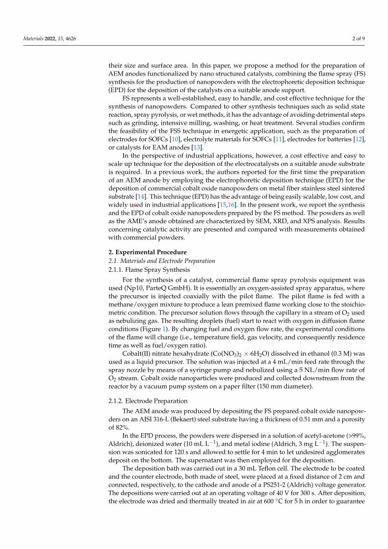
For the synthesis of a catalyst, commercial flame spray pyrolysis equipment wasused (Np10, ParteQ GmbH). It is essentially an oxygen-assisted spray apparatus, wherethe precursor is injected coaxially with the pilot flame. The pilot flame is fed with amethane/oxygen mixture to produce a lean premixed flame working close to the stoichio-metric condition. The precursor solution flows through the capillary in a stream of O2 usedas nebulizing gas. The resulting droplets (fuel) start to react with oxygen in diffusion flameconditions (Figure 1). By changing fuel and oxygen flow rate, the experimental conditionsof the flame will change (i.e., temperature field, gas velocity, and consequently residencetime as well as fuel/oxygen ratio).
Cobalt(II) nitrate hexahydrate (Co(NO3)2 × 6H2O) dissolved in ethanol (0.3 M) wasused as a liquid precursor. The solution was injected at a 4 mL/min feed rate through thespray nozzle by means of a syringe pump and nebulized using a 5 NL/min flow rate ofO2 stream. Cobalt oxide nanoparticles were produced and collected downstream from thereactor by a vacuum pump system on a paper filter (150 mm diameter).
2.1.2. Electrode Preparation
The AEM anode was produced by depositing the FS prepared cobalt oxide nanopow-ders on an AISI 316-L (Bekaert) steel substrate having a thickness of 0.51 mm and a porosityof 82%.
In the EPD process, the powders were dispersed in a solution of acetyl-acetone (>99%,Aldrich), deionized water (10 mL L−1), and metal iodine (Aldrich, 3 mg L−1). The suspen-sion was sonicated for 120 s and allowed to settle for 4 min to let undesired agglomeratesdeposit on the bottom. The supernatant was then employed for the deposition.
The deposition bath was carried out in a 30 mL Teflon cell. The electrode to be coatedand the counter electrode, both made of steel, were placed at a fixed distance of 2 cm andconnected, respectively, to the cathode and anode of a PS251-2 (Aldrich) voltage generator.The depositions were carried out at an operating voltage of 40 V for 300 s. After deposition,the electrode was dried and thermally treated in air at 600 ◦C for 5 h in order to guarantee
Materials 2022, 15, 4626 3 of 9
cohesion between the deposited Co3O4 particles and to eliminate solvent residues. In thiscase, the EPD composite electrode was also compared with a commercial NiFe2O4 (dioxidematerials) anode used in several works as a reference standard [17,18].
Materials 2022, 15, x FOR PEER REVIEW 3 of 10
Figure 1. Flame spray pyrolysis apparatus.
2.1.2. Electrode Preparation
The AEM anode was produced by depositing the FS prepared cobalt oxide na-
nopowders on an AISI 316-L (Bekaert) steel substrate having a thickness of 0.51 mm and
a porosity of 82%.
In the EPD process, the powders were dispersed in a solution of acetyl-acetone
(>99%, Aldrich), deionized water (10 mL L−1), and metal iodine (Aldrich, 3 mg L−1). The
suspension was sonicated for 120 s and allowed to settle for 4 min to let undesired ag-
glomerates deposit on the bottom. The supernatant was then employed for the deposi-
tion.
The deposition bath was carried out in a 30 mL Teflon cell. The electrode to be
coated and the counter electrode, both made of steel, were placed at a fixed distance of 2
cm and connected, respectively, to the cathode and anode of a PS251-2 (Aldrich) voltage
generator. The depositions were carried out at an operating voltage of 40 V for 300 s.
After deposition, the electrode was dried and thermally treated in air at 600 °C for 5 h in
order to guarantee cohesion between the deposited Co3O4 particles and to eliminate sol-
vent residues. In this case, the EPD composite electrode was also compared with a
commercial NiFe2O4 (dioxide materials) anode used in several works as a reference
standard [17,18].
2.2. Surface Analysis
SEM micrographs were acquired with a field emission gun scanning electron mi-
croscope Leo 1530 model. XRD measurements were conducted by a RIGAKU Smartlab
X-ray diffractometer. XPS analysis was performed with an Escalab MKII equipped with a
twin anode, non-monochromated X-ray source. The core level spectra of Co, Fe, C, and O
were recorded using Mg (1254eV) for all sample electrodes before and after exposure to
the alkaline cell environment.
Figure 1. Flame spray pyrolysis apparatus.
2.2. Surface Analysis
SEM micrographs were acquired with a field emission gun scanning electron micro-scope Leo 1530 model. XRD measurements were conducted by a RIGAKU Smartlab X-raydiffractometer. XPS analysis was performed with an Escalab MKII equipped with a twinanode, non-monochromated X-ray source. The core level spectra of Co, Fe, C, and O wererecorded using Mg (1254 eV) for all sample electrodes before and after exposure to thealkaline cell environment.
2.3. Electrochemical Measurements
The electrochemical performance of the anode was verified in a three-electrode celland in a small electrolyzer at room temperature. The cell with three Plexiglas electrodeswas made with a flat platinum counter electrode (area 10 cm2) and a standard calomelreference (SCE) through a Luggin capillary positioned as close as possible to the surfaceof the working electrode. The sample with an exposed active surface of 0.785 cm2 wasimmersed in a solution of 0.5 M KOH and placed parallel to the counter electrode at adistance of 1.5 cm.
Potentiodynamic tests were performed with a 1287 potentiostat (Solartron) at a scanrate of 1 mV s−1 in the potential range−0.24÷ 1.74 V vs. NHE. Electrochemical impedancespectroscopy (EIS) measurements were performed in the 300 kHz–1 Hz frequency range atopen circuit potential (OCP) and with an AC signal amplitude of 10 mVpp.

Materials 2022, 15, 4626 4 of 9
To evaluate the performance of the membrane, a lab-scale 2 cm2 electrolyzer wasemployed, with SS as a cathode and a commercial anionic membrane (Fumasep FAA-3PK-130) as an electrolyte and gas separation system. The cell hardware was made of steel onboth cathode and anodic sides. The anodic side can be fed with distilled water or a KOHsolution, contained in a 500 mL polyethylene tank using a metering pump (KMS), in PTFEwith a flow of 100 mL min−1.
3. Results and Discussion3.1. Flame Spray Synthesis of Nanopowders and Their EPD on Anode Substrate
Figure 2 reports the morphology of cobalt oxide nanopowders prepared by FS. Thepowders show a bimodal size distribution, with spherical particles of submicrometric sizesurrounded by nanoparticles having a size below 30 nm. The nanosized particles are formedthrough a gas-to-particle conversion mechanism which consists of the evaporation of theprecursors, nucleation in the gas phase, and particle growth. The formation of the largeparticles can be explained with the existence of the crystal water in the nitrate precursor,which then forms a mixed ethanol/water solvent when dissolved in ethanol: duringsynthesis, the faster evaporation of ethanol from the droplet leads to the supersaturationand reaction of the precursors on the droplet surface or inside the droplets; the subsequentdensification then leads to the formation of the dense large particles [10].
Materials 2022, 15, x FOR PEER REVIEW 4 of 10
2.3. Electrochemical Measurements
The electrochemical performance of the anode was verified in a three-electrode cell
and in a small electrolyzer at room temperature. The cell with three Plexiglas electrodes
was made with a flat platinum counter electrode (area 10 cm2) and a standard calomel
reference (SCE) through a Luggin capillary positioned as close as possible to the surface
of the working electrode. The sample with an exposed active surface of 0.785 cm2 was
immersed in a solution of 0.5 M KOH and placed parallel to the counter electrode at a
distance of 1.5 cm.
Potentiodynamic tests were performed with a 1287 potentiostat (Solartron) at a scan
rate of 1 mV s−1 in the potential range −0.24 ÷ 1.74 V vs. NHE. Electrochemical impedance
spectroscopy (EIS) measurements were performed in the 300 kHz–1 Hz frequency range
at open circuit potential (OCP) and with an AC signal amplitude of 10 mVpp.
To evaluate the performance of the membrane, a lab-scale 2 cm2 electrolyzer was
employed, with SS as a cathode and a commercial anionic membrane (Fumasep
FAA-3PK-130) as an electrolyte and gas separation system. The cell hardware was made
of steel on both cathode and anodic sides. The anodic side can be fed with distilled water
or a KOH solution, contained in a 500 mL polyethylene tank using a metering pump
(KMS), in PTFE with a flow of 100 mL min−1.
3. Results and Discussion
3.1. Flame Spray Synthesis of Nanopowders and Their EPD on Anode Substrate
Figure 2 reports the morphology of cobalt oxide nanopowders prepared by FS. The
powders show a bimodal size distribution, with spherical particles of submicrometric
size surrounded by nanoparticles having a size below 30 nm. The nanosized particles are
formed through a gas-to-particle conversion mechanism which consists of the evapora-
tion of the precursors, nucleation in the gas phase, and particle growth. The formation of
the large particles can be explained with the existence of the crystal water in the nitrate
precursor, which then forms a mixed ethanol/water solvent when dissolved in ethanol:
during synthesis, the faster evaporation of ethanol from the droplet leads to the super-
saturation and reaction of the precursors on the droplet surface or inside the droplets; the
subsequent densification then leads to the formation of the dense large particles [10].
Figure 2. SEM image of synthesized cobalt oxide powder prepared by the flame spray method.
A bimodal behavior of the FS powders is observed also in the XRD phase composi-
tion (Figure 3A): the powders exhibit sharp Co3O4 peaks, which can be associated withthe
submicrometric particles, together with broader CoO peaks which are indicative of a
nanosized morphology. The average crystallite size of the nanoparticles calculated ac-
cording to Debye–Scherrer’s equation was 27 nm for the smaller particles, confirming the
SEM images.
Figure 2. SEM image of synthesized cobalt oxide powder prepared by the flame spray method.
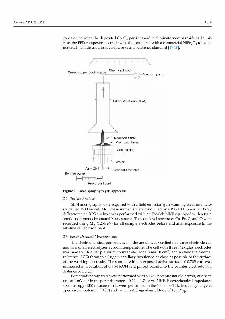
A bimodal behavior of the FS powders is observed also in the XRD phase composition(Figure 3A): the powders exhibit sharp Co3O4 peaks, which can be associated withthesubmicrometric particles, together with broader CoO peaks which are indicative of a nano-sized morphology. The average crystallite size of the nanoparticles calculated according toDebye–Scherrer’s equation was 27 nm for the smaller particles, confirming the SEM images.
As the FS powder has first been EPD deposited on the anode support and then calcinedat 600 ◦C to form an AEM anode, we have investigated the crystallographic behavior of thecatalyst with the processing steps. As shown in Figure 3B, the lonely EPD process does notaffect the phase composition of the catalyst since the mixed CoO and the Co3O4 phaseshave been detected both in the as-prepared powders and in the EPD deposited powders.The following calcination step, however, tends to oxidize the CoO phase to form merelythe Co3O4 phase (Figure 3C). After calcination at 600 ◦C, however, only the Co3O4 phase(Figure 3C) can be detected, since the CoO phase tends to form Co3O4 when heated in airbetween 600 and 900 ◦C [19].
Materials 2022, 15, 4626 5 of 9Materials 2022, 15, x FOR PEER REVIEW 5 of 10
Figure 3. XRD of flame spray catalyst (A), after EPD (B), and after EPD and thermal treatment at
600°C in air for 5 h (C).
As the FS powder has first been EPD deposited on the anode support and then cal-
cined at 600°C to form an AEM anode, we have investigated the crystallographic behav-
ior of the catalyst with the processing steps. As shown in Figure 3B, the lonely EPD pro-
cess does not affect the phase composition of the catalyst since the mixed CoO and the
Co3O4 phases have been detected both in the as-prepared powders and in the EPD de-
posited powders. The following calcination step, however, tends to oxidize the CoO
phase to form merely the Co3O4 phase (Figure 3C). After calcination at 600°C, however,
only the Co3O4 phase (Figure 3C) can be detected, since the CoO phase tends to form
Co3O4 when heated in air between 600 and 900 °C [19].
Figure 4 reports the SEM images of the heat treated FS-EPD anode. The anode shows
a non-uniform distribution of the catalyst on the fibers, probably as a consequence of the
non-homogeneity of the electric field during the EPD process.
At a more detailed analysis, the FS catalyst still retains its nanostructure after the
calcination process, since nanometric particles spread all over the fibers’ surface are visi-
0 20 40 60 80 100
(A)
CoO
Co3O
4
FS catalyst
2/°
(B)
(C)
SS/EPD-FS thermal treated
Inte
nsi
ty/u
.a.
SS/EPD-FS as produced
Figure 3. XRD of flame spray catalyst (A), after EPD (B), and after EPD and thermal treatment at600 ◦C in air for 5 h (C).
Figure 4 reports the SEM images of the heat treated FS-EPD anode. The anode showsa non-uniform distribution of the catalyst on the fibers, probably as a consequence of thenon-homogeneity of the electric field during the EPD process.
At a more detailed analysis, the FS catalyst still retains its nanostructure after thecalcination process, since nanometric particles spread all over the fibers’ surface are visible.The larger submicrometric particles are less evident, because of the sedimentation processbefore EPD, which selects the heavier particles.
3.2. Electrochemical Characterization of Electrodes
The electrochemical performance of the SS/EPD-Co-FS anode was compared with theSS steel support after high temperature heat treatment and with a commercial SS/NiFe2O4electrode. The impedance of the cell was measured before potentiodynamics to verify theohmic drop and confirm that the observed difference was due only to the anodes showinga constant area surface resistance of 4.3 ohm cm2.

Materials 2022, 15, 4626 6 of 9
Materials 2022, 15, x FOR PEER REVIEW 6 of 10
ble. The larger submicrometric particles are less evident, because of the sedimentation
process before EPD, which selects the heavier particles.
Figure 4. SEM image of an AEM anode obtained by depositing FS prepared cobalt oxide on an AI-
SI-316 sintered metal fiber by EPD followed by sintering at 600°C in air.
3.2. Electrochemical Characterization of Electrodes
The electrochemical performance of the SS/EPD-Co-FS anode was compared with
the SS steel support after high temperature heat treatment and with a commercial
SS/NiFe2O4 electrode. The impedance of the cell was measured before potentiodynamics
to verify the ohmic drop and confirm that the observed difference was due only to the
anodes showing a constant area surface resistance of 4.3 ohm cm2.
The voltammetries (Figure 5) show different performances for the three electrodes.
The value of the maximum current density follows the trend SS/EPD-Co-FS> SS/NiFe2O4>
SS. The increase in current density at 1.25V vs. NHE for SS/EPD-Co-FS is +85% compared
to SS without catalyst and +30% compared to commercial SS/NiFe2O4. The formation of
surface oxides of Fe and Ni with greater catalytic activity for OER [20], caused by the heat
treatment on steel, produces an increase in the maximum current of about 21% at 1.75 V
compared to NHE [14]; this is probably due to the formation of surface oxides of Fe and
Ni with greater catalytic activity for OER [21]. The deposition of Co3O4 catalyst and the
subsequent heat treatment further enhances the current.
Figure 4. SEM image of an AEM anode obtained by depositing FS prepared cobalt oxide on anAISI-316 sintered metal fiber by EPD followed by sintering at 600 ◦C in air.
The voltammetries (Figure 5) show different performances for the three electrodes. Thevalue of the maximum current density follows the trend SS/EPD-Co-FS> SS/NiFe2O4> SS.The increase in current density at 1.25V vs. NHE for SS/EPD-Co-FS is +85% comparedto SS without catalyst and +30% compared to commercial SS/NiFe2O4. The formation ofsurface oxides of Fe and Ni with greater catalytic activity for OER [20], caused by the heattreatment on steel, produces an increase in the maximum current of about 21% at 1.75 Vcompared to NHE [14]; this is probably due to the formation of surface oxides of Fe andNi with greater catalytic activity for OER [21]. The deposition of Co3O4 catalyst and thesubsequent heat treatment further enhances the current.
The onset potential for O2 discharge shows the opposite trend, decreasing from about0.80 V vs. NHE for SS, 0.78 V for SS/NiFe2O4, down to about 0.71 V for SS/EPD-Co-FS. Considering the thermodynamic potential for the discharge of oxygen in an alkalineenvironment (0.401 V vs. NHE, for Equation (1)), the electrode potential in Figure 5, up tothis constant, represents the overvoltage for the OER:
2OH− → 1/2O2 + 2e− + H2O (1)
In addition, the Tafel slope and the exchange current density were, respectively, 35 mV/decand 1.0 × 10⁻⁵ A cm−2 for the SS/EPD-Co-FS and 64 mV/dec and 8.5× 10⁻⁶ A cm−2 forSS/NiFe2O4. The better performance of the FS catalyst could be due to the catalyst mor-phology, which permits easy access of the electrolyte to the entire surface of Co3O4 andeasy escape of the generated oxygen from the electrode. Therefore, the data show that theflame pyrolysis production process is capable of obtaining better results with respect to thecommercial one by reducing the overvoltage of almost 80 mV.

Materials 2022, 15, 4626 7 of 9Materials 2022, 15, x FOR PEER REVIEW 7 of 10
Figure 5. Voltammetries (1 mV s−1) in 0.5 M KOH at 25 °C for SS/EPD˗Co3O4˗FS, SS/NiFe3O4, and SS.
The onset potential for O2 discharge shows the opposite trend, decreasing from
about 0.80 V vs. NHE for SS, 0.78 V for SS/NiFe2O4, down to about 0.71 V for
SS/EPD-Co-FS. Considering the thermodynamic potential for the discharge of oxygen in
an alkaline environment (0.401 V vs. NHE, for Equation (1)), the electrode potential in
Figure 5, up to this constant, represents the overvoltage for the OER:
OHeOOH 22 22/12 ++→ −−
(1)
In addition, the Tafel slope and the exchange current density were, respectively, 35
mV/dec and 1.0×10⁻⁵ A cm−2 for the SS/EPD-Co-FS and 64 mV/dec and 8.5×10⁻⁶ A cm-2 for
SS/NiFe2O4. The better performance of the FS catalyst could be due to the catalyst mor-
phology, which permits easy access of the electrolyte to the entire surface of Co3O4 and
easy escape of the generated oxygen from the electrode. Therefore, the data show that the
flame pyrolysis production process is capable of obtaining better results with respect to
the commercial one by reducing the overvoltage of almost 80 mV.
The XPS analysis of the surface on SS/EPD-Co-FS before and after electrolysis
measurement shows the presence of Co (Figure 6) oxides [21]. Particularly, the Co 2p
peak position and shape confirms that the surface of the as-prepared spray pyrolysis
samples is mainly composed of Co3O4. After the use inside the electrochemical cell, a
small shift of the Co 2p peak to higher binding energy (0.8 eV) occurs; following reference
[21], the shift indicates that the main surface phase is now cobalt hydroxide Co(OH)2.
-0.2 0.0 0.2 0.4 0.6 0.8 1.0 1.2 1.4 1.6
-20
0
20
40
60
80
100
120
140
160
Curr
ent
Den
sity
/ma
cm-2
Electrode Potential/V vs NHE
SS/EPD-Co-FS
SS/NiFe2O
4
SS
Figure 5. Voltammetries (1 mV s−1) in 0.5 M KOH at 25 ◦C for SS/EPD-Co3O4-FS, SS/NiFe3O4,and SS.
The XPS analysis of the surface on SS/EPD-Co-FS before and after electrolysis mea-surement shows the presence of Co (Figure 6) oxides [21]. Particularly, the Co 2p peakposition and shape confirms that the surface of the as-prepared spray pyrolysis samples ismainly composed of Co3O4. After the use inside the electrochemical cell, a small shift ofthe Co 2p peak to higher binding energy (0.8 eV) occurs; following reference [21], the shiftindicates that the main surface phase is now cobalt hydroxide Co(OH)2.
Materials 2022, 15, x FOR PEER REVIEW 8 of 10
Figure 6. XPS spectra of SS/EPD˗Co˗FS as prepared and after testing electrolysis.
Figure 7 finally shows the polarization results of an electrolysis cell, with the
SS/EPD-Co-FP anode, providing direct evidence of the effect of the flame pyrolysis cata-
lyst in obtaining good current density in the range of 2–3 V. In subsequent tests, it will be
necessary to check the stability for long time frames and the effect of temperature on the
catalytic activity.
820 810 800 790 780 770 760
-0.2
0.0
0.2
0.4
0.6
0.8
1.0
1.2
Counts
/s
Binding Energy/eV
As prepared
After electrolysis testing
-100 0 100 200 300 400 500 600 700 800
1.0
1.5
2.0
2.5
3.0
3.5
Cel
l V
olt
age/
V
Current Density/mA cm-2
SS/EPD-Co-FS
Figure 6. XPS spectra of SS/EPD-Co-FS as prepared and after testing electrolysis.
Figure 7 finally shows the polarization results of an electrolysis cell, with the SS/EPD-Co-FP anode, providing direct evidence of the effect of the flame pyrolysis catalyst in

Materials 2022, 15, 4626 8 of 9
obtaining good current density in the range of 2–3 V. In subsequent tests, it will be nec-essary to check the stability for long time frames and the effect of temperature on thecatalytic activity.
Materials 2022, 15, x FOR PEER REVIEW 8 of 10
Figure 6. XPS spectra of SS/EPD˗Co˗FS as prepared and after testing electrolysis.
Figure 7 finally shows the polarization results of an electrolysis cell, with the
SS/EPD-Co-FP anode, providing direct evidence of the effect of the flame pyrolysis cata-
lyst in obtaining good current density in the range of 2–3 V. In subsequent tests, it will be
necessary to check the stability for long time frames and the effect of temperature on the
catalytic activity.
820 810 800 790 780 770 760
-0.2
0.0
0.2
0.4
0.6
0.8
1.0
1.2
Counts
/s
Binding Energy/eV
As prepared
After electrolysis testing
-100 0 100 200 300 400 500 600 700 800
1.0
1.5
2.0
2.5
3.0
3.5
Cel
l V
olt
age/
V
Current Density/mA cm-2
SS/EPD-Co-FS
Figure 7. Cell voltage vs. current density for an electrolysis cell with SS/EPD-Co-FS, fed with KOH0.5 M on the anode side at 100 mL min−1. Cell temperature 25 ◦C.
4. Conclusions
In this preliminary work, a nanostructured cobalt oxide powder was prepared byflame spray synthesis and deposited on sintered metal fiber by EPD. The prepared electrodeshowed an increase in the OER catalytic activity with respect to commercial materials com-monly applied in alkaline electrolysis. The flame spray synthesis of nanoparticles combinedwith the electrophoretic deposition technique showed to be an effective methodology forproducing catalyzed anodes for alkaline membrane electrolyzers.
Author Contributions: Data curation, A.P., F.B., N.L., R.C. and S.D.I.; Investigation, A.P., F.B., N.L.,R.C., F.M., R.D. and S.D.I.; Methodology, F.M., R.D. and S.D.I.; Writing—original draft, A.P. and F.B.;Writing—review & editing, A.P. and S.D.I. All authors have read and agreed to the published versionof the manuscript.
Funding: This research received no external funding.
Institutional Review Board Statement: Not applicable.
Informed Consent Statement: Not applicable.
Data Availability Statement: The data presented in this study are available on request from thecorresponding author.
Conflicts of Interest: The authors declare no conflict of interest.
References1. Wang, M.; Wang, Z.; Gong, X.; Guo, Z. The intensification technologies to water electrolysis for hydrogen production—A review.
Renew. Sustain. Energy Rev. 2014, 29, 573–588. [CrossRef]2. Kiaee, M.; Infield, D.; Cruden, A. Utilisation of alkaline electrolysers in existing distribution networks to increase the amount of
integrated wind capacity. J. Energy Storage 2018, 16, 8–20. [CrossRef]
Materials 2022, 15, 4626 9 of 9
3. Matute, G.; Yusta, J.M.; Correas, L.C. Techno-economic modelling of water electrolysers in the range of several MW to providegrid services while generating hydrogen for different applications: A case study in Spain applied to mobility with FCEVs. Int. J.Hydrogen Energy 2019, 44, 17431–17442. [CrossRef]
4. Chisholm, G.; Cronin, L. Chapter 16—Hydrogen from Water Electrolysis. In Storing Energy; Elsevier: Amsterdam, The Netherlands,2016; pp. 315–353.
5. Colli, A.N.; Girault, H.H.; Battistel, A. Non-Precious Electrodes for Practical Alkaline Water Electrolysis. Materials 2019, 12, 1336.[CrossRef] [PubMed]
6. Perez-Alonso, F.J.; Adan, C.; Rojas, S.; Pena, M.A.; Fierro, J.L.G. Ni/Fe electrodes prepared by electrodeposition method overdifferent substrates for oxygen evolution reaction in alkaline medium. Int. J. Hydrogen Energy 2014, 39, 5204–5212. [CrossRef]
7. Marini, S.; Salvi, P.; Nelli, P.; Pesenti, R.; Villa, M.; Berrettoni, M.; Zangaric, G.; Kiros, Y. Advanced alkaline water electrolysis.Electrochim. Acta 2012, 82, 384–391. [CrossRef]
8. Leng, Y.; Chen, G.; Mendoza, A.J.; Tighe, T.B.; Hickner, M.A.; Wang, C.Y. Solid-State Water Electrolysis with an AlkalineMembrane. J. Am. Chem. Soc. 2012, 134, 9054–9057. [CrossRef] [PubMed]
9. Vincent, I.; Bessarabov, D. Low cost hydrogen production by anion exchange membrane electrolysis: A review. Renew. Sustain.Energy Rev. 2018, 81, 1690–1704. [CrossRef]
10. Heel, A.; Holtappels, P.; Hug, P.; Graule, T. Flame Spray Synthesis of Nanoscale La0.6Sr0.4Co0.2Fe0.8O3–δ and Ba0.5Sr0.5Co0.8Fe0.2O3–δas Cathode Materials for Intermediate Temperature Solid Oxide Fuel Cells. Fuel Cells 2010, 10, 419–432. [CrossRef]
11. Bozza, F.; Arroyo, Y.; Graule, T. Flame spray synthesis of BaZr0.8Y0.2O3–δ electrolyte nanopowders for intermediate temperatureproton conducting fuel cells. Fuel Cells 2015, 15, 588–594. [CrossRef]
12. Zang, G.; Zhang, J.; Xu, S.; Xing, Y. Techno-economic analysis of cathode material production using flame-assisted spray pyrolysis.Energy 2021, 218, 119504. [CrossRef]
13. Fabbri, E.; Nachtegaal, M.; Binninger, T.; Cheng, X.; Kim, B.J.; Durst, J.; Bozza, F.; Graule, T.; Schäublin, R.; Wiles, L.; et al. Dynamicsurface self-reconstruction is the key of highly active perovskite nano-electrocatalysts for water splitting. Nat. Mater. 2017, 16,925–931. [CrossRef] [PubMed]
14. Pozio, A.; Bozza, F.; Lisi, N.; Mura, F. Electrophoretic deposition of cobalt oxide anodes for alkaline membrane water electrolyzer.Int. J. Energy Res. 2022, 46, 952–963. [CrossRef]
15. Gurrappa, I.; Binder, L. Electrodeposition of nanostructured coatings and their characterization—A review. Sci. Technol. Adv.Mater. 2008, 9, 043001–043012. [CrossRef] [PubMed]
16. Bozza, F.; Schafbauer, W.; Meulenberg, W.A.; Bonanos, N. Characterization of La0.995Ca0.005NbO4/Ni anode functional layer byelectrophoretic deposition in a La0.995Ca0.005NbO4 electrolyte based PCFC. Int. J. Hydrogen Energy 2012, 37, 8027–8032. [CrossRef]
17. Motealleh, B.; Liu, Z.; Masel, R.I.; Sculley, J.P.; Ni, Z.R.; Meroueh, L. Next-generation anion exchange membrane water electrolyzersoperating for commercially relevant lifetimes. Int. J. Hydrogen Energy 2021, 46, 3379–3386. [CrossRef]
18. Liu, Z.; Sajjad, S.D.; Gao, Y.; Yang, H.; Kaczur, J.J.; Masel, R.I. The effect of membrane on an alkaline water electrolyzer. Int. J.Hydrogen Energy 2017, 42, 29661–29665. [CrossRef]
19. Riley, R.F. Handbook of Preparative Inorganic Chemistry; Academic Press: New York, NY, USA, 1963; p. 1520.20. Cossar, E.; Barnett, A.O.; Seland, F.; Baranova, E.A. The Performance of Nickel and Nickel-Iron Catalysts Evaluated as Anodes in
Anion Exchange Membrane Water Electrolysis. Catalysts 2019, 9, 814. [CrossRef]21. Biesinger, M.C.; Payne, B.P.; Grosvenor, A.P.; Lau, L.W.M.; Gerson, A.R.; Smart, R.S.C. Resolving surface chemical states in XPS
analysis of first row transition metals, oxides and hydroxides: Cr, Mn, Fe, Co and Ni. Appl. Surf. Sci. 2011, 257, 2717–2730.[CrossRef]