
CO2 geological storage: hydro-chemo-mechanical analyses and implications
16
1 © 2014 Society of Chemical Industry and John Wiley & Sons, Ltd | Greenhouse Gas Sci Technol. 1–16 (2014); DOI: 10.1002/ghg Received August 19, 2013; revised January 27, 2014; accepted January 28, 2014 10.1002/ghg.1421 Published online at Wiley Online Library (wileyonlinelibrary.com). DOI: Modeling and Analysis CO 2 geological storage: hydro- chemo-mechanical analyses and implications Seunghee Kim, J. Carlos Santamarina, University of Texas at Austin, TX, USA Georgia Institute of Technology, Atlanta, GA, USA Abstract: The injectivity of CO 2 and the integrity of the reservoir-caprock system are affected by CO 2 invasion, water-CO 2 -mineral reactions, and ensuing mineral dissolution and precipitation. We identify different zones around an injection well and investigate the effects of these hydro-chemo-mechanical interactions. Geochemical analyses combine a comprehensive mass balance formulation with chemi- cal calculations using published equations and PHREEQC. This analysis framework is used to assess near-well, pool, and far-field conditions, and to determine species concentrations, pH, changes in brine density, and changes in mineral and fluid volume in the reservoir. Results show that the brine density may increase by as much as 1.2% and can sustain convective flow of CO 2 dissolved brine; the characteristic time scale for convection can be as short as a few years in some permeable formations currently being considered for storage. The precipitation of secondary minerals near the injection well increases the mineral volume by a maximum of 5%, yet, only a minor decrease in CO 2 permeability is anticipated. Dissolution may result in unsupported caprock (the span should not exceed 20% of the caprock thickness to prevent failure), and may cause compaction-driven shear failure of the reservoir. Finally, the analysis of lateral capillary trapping shows that the CO 2 pool is only a few meters thick in leveled caprock interfaces and in the absence of geometric traps. © 2014 Society of Chemical Industry and John Wiley & Sons, Ltd CO Keywords: 2 geological storage; carbonate reservoir; mineral dissolution; mineral precipitation; mass balance formulation; hydro-geomechanical implication Correspondence to: Seunghee Kim, Bureau of Economic Geology, The University of Texas at Austin, University Station, Box X, Austin, TX 78713, USA. E-mail: [email protected]/[email protected] Introduction: reservoir zones T he injectivity of CO 2 and the integrity of the storage reservoir-caprock system are affected by mineral dissolution and precipitation, 1 and their consequences on porosity, permeability, and stress field. Hydro-chemo-mechanically coupled processes vary across the reservoir. e CO 2 storage reservoir can be analyzed into four different zones around a CO 2 injection well (Fig. 1). e far-field Zone I is not affected by CO 2 injection and brine saturation is S B = 1. Acidified brine domi- nates Zone II and mineral dissolution prevails over precipitation; loaded with dissolved CO 2 and miner- als, denser brine experiences convection and sustains further dissolution in this zone. 2–5 In Zone III, the ionic strength in brine increases as water is removed by the injected CO 2 , and salt precipitation may occur; in fact, brine acidification by CO 2 dissolution and brine dissolution into CO 2 coexist in the transition
-
Upload
johnjanovy -
Category
Documents
-
view
0 -
download
0
Transcript of CO2 geological storage: hydro-chemo-mechanical analyses and implications

1© 2014 Society of Chemical Industry and John Wiley & Sons, Ltd | Greenhouse Gas Sci Technol. 1–16 (2014); DOI: 10.1002/ghg
Received August 19, 2013 ; revised January 27, 2014 ; accepted January 28, 2014 10.1002/ghg.1421Published online at Wiley Online Library (wileyonlinelibrary.com). DOI:
Modeling and Analysis
CO 2 geological storage: hydro-chemo-mechanical analyses and implications Seunghee Kim , J. Carlos Santamarina , University of Texas at Austin , TX , USA Georgia Institute of Technology , Atlanta, GA , USA
Abstract: The injectivity of CO 2 and the integrity of the reservoir-caprock system are affected by CO 2 invasion, water-CO 2 -mineral reactions, and ensuing mineral dissolution and precipitation. We identify different zones around an injection well and investigate the effects of these hydro-chemo-mechanical interactions. Geochemical analyses combine a comprehensive mass balance formulation with chemi-cal calculations using published equations and PHREEQC. This analysis framework is used to assess near-well, pool, and far-fi eld conditions, and to determine species concentrations, pH, changes in brine density, and changes in mineral and fl uid volume in the reservoir. Results show that the brine density may increase by as much as 1.2% and can sustain convective fl ow of CO 2 dissolved brine; the characteristic time scale for convection can be as short as a few years in some permeable formations currently being considered for storage. The precipitation of secondary minerals near the injection well increases the mineral volume by a maximum of 5%, yet, only a minor decrease in CO 2 permeability is anticipated. Dissolution may result in unsupported caprock (the span should not exceed 20% of the caprock thickness to prevent failure), and may cause compaction-driven shear failure of the reservoir. Finally, the analysis of lateral capillary trapping shows that the CO 2 pool is only a few meters thick in leveled caprock interfaces and in the absence of geometric traps. © 2014 Society of Chemical Industry and John Wiley & Sons, Ltd
CO Keywords: 2 geological storage ; carbonate reservoir ; mineral dissolution ; mineral precipitation ; mass balance formulation ; hydro-geomechanical implication
Correspondence to: Seunghee Kim, Bureau of Economic Geology, The University of Texas at Austin, University Station, Box X, Austin, TX 78713,
USA. E-mail: [email protected] / [email protected]
Introduction: reservoir zones
The injectivity of CO 2 and the integrity of the storage reservoir-caprock system are aff ected by mineral dissolution and precipitation, 1 and their
consequences on porosity, permeability, and stress fi eld. Hydro-chemo-mechanically coupled processes vary across the reservoir.
Th e CO 2 storage reservoir can be analyzed into four diff erent zones around a CO 2 injection well (Fig. 1 ).
Th e far-fi eld Zone I is not aff ected by CO 2 injection and brine saturation is S B = 1. Acidifi ed brine domi-nates Zone II and mineral dissolution prevails over precipitation; loaded with dissolved CO 2 and miner-als, denser brine experiences convection and sustains further dissolution in this zone. 2–5 In Zone III, the ionic strength in brine increases as water is removed by the injected CO 2 , and salt precipitation may occur; in fact, brine acidifi cation by CO 2 dissolution and brine dissolution into CO 2 coexist in the transition

S Kim and J C Santamarina Modeling and Analysis: CO2 geological storage: hydro-chemo-mechanical analyses and implications
2 © 2014 Society of Chemical Industry and John Wiley & Sons, Ltd | Greenhouse Gas Sci Technol. 1–16 (2014); DOI: 10.1002/ghg
Zone III and there is partial compensation between mineral dissolution and precipitation. Th e continuous infl ux of ‘dry’ CO 2 in Zone IV around the injection well, fi rst displaces brine and then dries all the residual brine, resulting in salt precipitation while CO 2 saturation approaches S CO2 ≈ 1.
In this manuscript, we analyze the diff erent zones in the reservoir around the injection well to identify potential phenomena in each zone. First, we examine geochemical changes in each zone as a function of parameters such as temperature, pressure, brine salinity, and porosity for a carbonate reservoir.
Figure 1. Zones around a CO 2 injection well (see also Azaroual et al., 2007). 48 The far-fi eld Zone I is not affected by CO 2 injection and brine saturation is S B = 1. Brine acidifi es in the proximity of the CO 2 pool in Zone II (0.95 ≤ S B ≤ 1). Loaded with dis-solved CO 2 and minerals, denser brine experiences convection and sustains further mineral dissolution. Brine and CO 2 coexist and mutually dissolve in Zone III (0.2 ≤ S B ≤ 0.95). The continuous infl ux of CO 2 in Zone IV results in salt precipitation while CO 2 saturation approaches S CO2 ≈ 1 ( S B ≈ 0). Symbols: M Mineral, B Brine, and CO 2 . Saturations: S CO2 for CO 2 , and S B for brine.
SCO2=1 SCO2=0.05-0.8SB=0.2-0.95
SCO2=0-0.05SB=0.95-1
SB=1
M
CO2B
M
CO2 B+CO2(dissolution)
M M
B
QCO2
ZoneIV IIIIII
CO2 saturation, SCO2 Brine saturation, SB
Water in CO2
CO2 in Water
acidificationconvectiondrying
dry CO2
wet CO2
Salt precipitation Convection-sustained dissolution
HR
CO2
NaClCaCO3
CO2
CO2(aq)
H2CO3
HCO3-
CO32-
H+
OH-
Ca2+
Na+
Cl-
CaCO3
CO2(aq)
H2CO3
HCO3-
CO32-
H+
OH-
Ca2+
Na+
Cl-
CaCO3
H2CO3
HCO3-
CO32-
H+
OH-
Ca2+
Na+
Cl-
CaCO3
Major species:
Phases:
CO2 Pool

Modeling and Analysis: CO2 geological storage: hydro-chemo-mechanical analyses and implications S Kim and J C Santamarina
3© 2014 Society of Chemical Industry and John Wiley & Sons, Ltd | Greenhouse Gas Sci Technol. 1–16 (2014); DOI: 10.1002/ghg
Th en, we assess prevalent hydro-geomechanical phenomena that could arise in each zone as a result of geochemical interactions. Th ese zone-specifi c analyses provide robust guidelines to understand the short and long-term reservoir performance.
Geochemical analyses Sandstones and carbonates are common candidate formations for CO 2 geological storage. 6,7 Table 1 summarizes the mineralogical composition of sand-stone and carbonate formations being considered for CO 2 storage. Sandstone reservoirs are made of oxides (e.g. quartz and hematite), and some aluminosilicates (e.g. various feldspars, micas, and clays) and carbon-ates (e.g. calcite, dolomite, and siderite). Calcite is the dominant mineral in carbonate reservoirs, followed by a small fraction of aluminosilicates and clays; this mineralogy is common in CO 2 -enhanced oil recovery (CO 2 -EOR) and depleted oil/gas reservoirs. 8,9 In this study, we consider calcite as the single mineral constituent to simplify analyses to gain clear conclu-sions (the study can be readily extended to other mineralogies). Th e four diff erent zones that develop around injection wells at CO 2 storage sites are ana-lyzed next (Fig. 1 ).
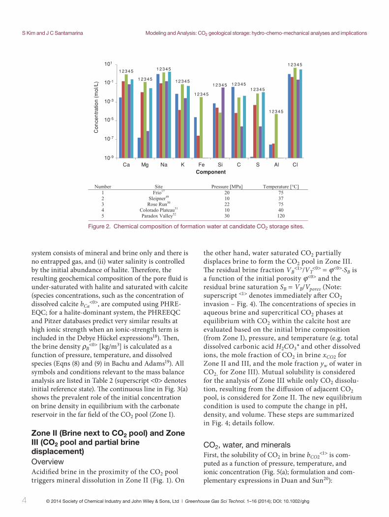
Far-fi eld Zone I Th e formation water in a geologic basin originates from the subaerial evaporation of sea water, the subsurface dissolution of minerals including evapo-rates, membrane fi ltration, and dilution by meteoric water. 10–14 Prevailing ions are either Na - Cl or Na - Ca - Cl at most candidate sites for CO 2 storage (Fig. 2 ). Th e pore fl uid evolves towards equilibrium with the formation minerals, but the time interval may be insuffi cient for complete equilibrium in relatively active systems. 14–16 Formation waters may be supersaturated when minerals have low growth rates at low tempera-tures, however, in most cases formation waters: (i) are under-saturated in terms of evaporate minerals such as halite and anhydrite, and (ii) are either under-saturated or in equilibrium with other minerals in the formation (see estimation in Xu et al. ). 10,17
In this analysis, we consider a single mineral forma-tion, we select calcite ( CaCO 3 ) for its prominence and reactivity, and we assume that equilibrium has been reached. 15 Th e formation water retains its original halite ( NaCl ) concentration ranging from Sal = 0 to 6 [mol/kg-water] and is in equilibrium with the formation calcite. Two assumptions are made to formulate the mass balance calculations: (i) the initial
Sandstone Carbonate
Mineral (1) (2) (3) (4) (5) (6) (7) (8)
Quartz 58 70 77 60 75 80 30 0
Calcite 1.93 8 1.3 0 3 0 45 70
Dolomite 0 13.8 0 0 0 0 0 10
Siderite 0 0.2 0 0 0 2 0 5
Kaolinite 2.02 1 2.25 0 0 3 0 0
Illite 1 0 0 11 0 10 5 5
Oligoclase 19.8 0 0 15 0 0 7 0
K-feldspar 8.2 5 0.6 3 13 1 8 5
Albite 0 1 0.6 0 3 2 0 5
Anorthite 0 0 0.66 0 0 0 0 0
Na-smectite 4 0 2.25 0 0 0 0 0
Chlorite 4.55 0 0 11 0 0 4 0
Hermatite 0.5 0 0 0 0 0 1 0
Data source: (1) Gulf Coast, Frio, 17 (2) Rose Run, Ohio, 50 (3) Colorado Plateau, Utah, 51 (4)&(7) Arno River Plain, Italy, 53 (5) Utsira, Sleipner, 54 (6) Hettangium and Contorta, Germany, 55 (8) Dogger, France. 56
Table 1. Mineralogical composition (volume percentage) of potential reservoir sites for CO 2 geological storage.
S Kim and J C Santamarina Modeling and Analysis: CO2 geological storage: hydro-chemo-mechanical analyses and implications
4 © 2014 Society of Chemical Industry and John Wiley & Sons, Ltd | Greenhouse Gas Sci Technol. 1–16 (2014); DOI: 10.1002/ghg
Figure 2. Chemical composition of formation water at candidate CO 2 storage sites.
Number Site Pressure [MPa] Temperature [°C] 1 Frio17 57 02 2 Sleipner49 73 01 3 Rose Run50 57 22 4 Colorado Plateau51 10 40 5 Paradox Valley52 30 120
Ca Mg Na K Fe Si C S Al ClComponent
101
10-1
10-3
10-5
10-7
10-9
Con
cen
tratio
n (m
ol/L
)
1 2 34 5
1 234 5
1 23 45
12 34 5
12 34 5
12 34 5
12 34 5 1 23 451 23 45
12 34 5
system consists of mineral and brine only and there is no entrapped gas, and (ii) water salinity is controlled by the initial abundance of halite. Th erefore, the resulting geochemical composition of the pore fl uid is under-saturated with halite and saturated with calcite (species concentrations, such as the concentration of dissolved calcite b Ca <0> , are computed using PHRE-EQC; for a halite-dominant system, the PHREEQC and Pitzer databases predict very similar results at high ionic strength when an ionic-strength term is included in the Debye Hückel expressions 18 ). Th en, the brine density ρ B <0> [kg/m 3 ] is calculated as a function of pressure, temperature, and dissolved species (Eqns (8) and (9) in Bachu and Adams 19 ). All symbols and conditions relevant to the mass balance analysis are listed in Table 2 (superscript <0> denotes initial reference state). Th e continuous line in Fig. 3 (a) shows the prevalent role of the initial concentration on brine density in equilibrium with the carbonate reservoir in the far fi eld of the CO 2 pool (Zone I).
Zone II (Brine next to CO 2 pool) and Zone III (CO 2 pool and partial brine displacement) Overview Acidifi ed brine in the proximity of the CO 2 pool triggers mineral dissolution in Zone II (Fig. 1 ). On
the other hand, water saturated CO 2 partially displaces brine to form the CO 2 pool in Zone III. Th e residual brine fraction V B <1> / V T <0> = ϕ <0> · S B is a function of the initial porosity ϕ <0> and the residual brine saturation S B = V B / V pores (Note: superscript < 1 > denotes immediately aft er CO 2 invasion – Fig. 4 ). Th e concentrations of species in aqueous brine and supercritical CO 2 phases at equilibrium with CO 2 within the calcite host are evaluated based on the initial brine composition (from Zone I), pressure, and temperature (e.g. total dissolved carbonic acid H 2 CO 3 * and other dissolved ions, the mole fraction of CO 2 in brine x CO2 for Zone II and III, and the mole fraction y w of water in CO 2, for Zone III). Mutual solubility is considered for the analysis of Zone III while only CO 2 dissolu-tion, resulting from the diff usion of adjacent CO 2 pool, is considered for Zone II. Th e new equilibrium condition is used to compute the change in pH, density, and volume. These steps are summarized in Fig. 4 ; details follow.
CO 2 , water, and minerals First, the solubility of CO 2 in brine b CO2 <1> is com-puted as a function of pressure, temperature, and ionic concentration (Fig. 5 (a); formulation and com-plementary expressions in Duan and Sun 20 ):
Modeling and Analysis: CO2 geological storage: hydro-chemo-mechanical analyses and implications S Kim and J C Santamarina
5© 2014 Society of Chemical Industry and John Wiley & Sons, Ltd | Greenhouse Gas Sci Technol. 1–16 (2014); DOI: 10.1002/ghg
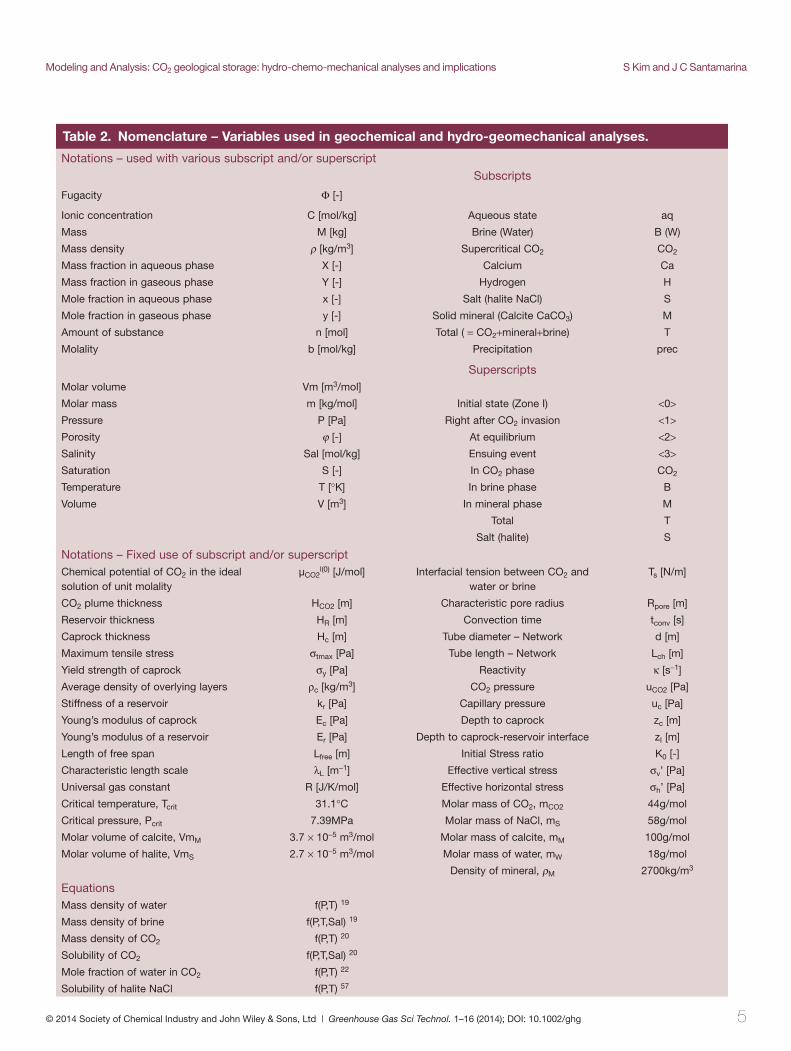
Table 2. Nomenclature – Variables used in geochemical and hydro-geomechanical analyses.
Notations – used with various subscript and/or superscript
Subscripts
Fugacity Φ [-]
Ionic concentration C [mol/kg] Aqueous state aq
Mass M [kg] Brine (Water) B (W)
Mass density ρ [kg/m 3 ] Supercritical CO 2 CO 2
Mass fraction in aqueous phase X [-] Calcium Ca
Mass fraction in gaseous phase Y [-] Hydrogen H
Mole fraction in aqueous phase x [-] Salt (halite NaCl) S
Mole fraction in gaseous phase y [-] Solid mineral (Calcite CaCO 3 ) M
Amount of substance n [mol] Total ( = CO 2 +mineral+brine) T
Molality b [mol/kg] Precipitation prec
SuperscriptsMolar volume Vm [m 3 /mol]
Molar mass m [kg/mol] Initial state (Zone I) <0>Pressure P [Pa] Right after CO 2 invasion <1>Porosity ϕ [-] At equilibrium <2>Salinity Sal [mol/kg] Ensuing event <3>Saturation S [-] In CO 2 phase CO 2
Temperature T [°K] In brine phase B
Volume V [m 3 ] In mineral phase M
Total T
Salt (halite) S
Notations – Fixed use of subscript and/or superscriptChemical potential of CO 2 in the ideal solution of unit molality
µ CO2 l(0) [J/mol] Interfacial tension between CO 2 and water or brine
T s [N/m]
CO 2 plume thickness H CO2 [m] Characteristic pore radius R pore [m]
Reservoir thickness H R [m] Convection time t conv [s]
Caprock thickness H c [m] Tube diameter – Network d [m]
Maximum tensile stress σ tmax [Pa] Tube length – Network L ch [m]
Yield strength of caprock σ y [Pa] Reactivity κ [s −1 ]
Average density of overlying layers ρ c [kg/m 3 ] CO 2 pressure u CO2 [Pa]
Stiffness of a reservoir k r [Pa] Capillary pressure u c [Pa]
Young’s modulus of caprock E c [Pa] Depth to caprock z c [m]
Young’s modulus of a reservoir E r [Pa] Depth to caprock-reservoir interface z I [m]
Length of free span L free [m] Initial Stress ratio K 0 [-]
Characteristic length scale λ L [m −1 ] Effective vertical stress σ v ’ [Pa]
Universal gas constant R [J/K/mol] Effective horizontal stress σ h ’ [Pa]
Critical temperature, T crit 31.1°C Molar mass of CO 2 , m CO2 44g/mol
Critical pressure, P crit 7.39MPa Molar mass of NaCl, m S 58g/mol
Molar volume of calcite, Vm M 3.7 × 10 −5 m 3 /mol Molar mass of calcite, m M 100g/mol
Molar volume of halite, Vm S 2.7 × 10 −5 m 3 /mol Molar mass of water, m W 18g/mol
Density of mineral, ρ M 2700kg/m 3
EquationsMass density of water f(P,T) 19
Mass density of brine f(P,T,Sal) 19
Mass density of CO 2 f(P,T) 20
Solubility of CO 2 f(P,T,Sal) 20
Mole fraction of water in CO 2 f(P,T) 22
Solubility of halite NaCl f(P,T) 57

S Kim and J C Santamarina Modeling and Analysis: CO2 geological storage: hydro-chemo-mechanical analyses and implications
6 © 2014 Society of Chemical Industry and John Wiley & Sons, Ltd | Greenhouse Gas Sci Technol. 1–16 (2014); DOI: 10.1002/ghg
Figure 3. Brine density in the far fi eld of a CaCO 3 reservoir – Zone I and next to the CO 2 pool – Zones II and III. (a) Change in the brine density and (b) the percentage of change in brine density due to CO 2 (CaCO 3 formation; storage depth ∼ 1 km; P = 10 MPa, T = 40 °C; see also Bachu and Adams, 2003; Yan et al., 2011; Pruess and Zhang, 2008). 19,24 , 26
900
1000
1100
1200
1300
0 1 2 3 4 5 60
0.2
0.4
0.6
0.8
1
1.2
1.4
0 1 2 3 4 5 6
Salinity [mol/kg water] Salinity [mol/kg water]
Brin
e de
nsi
ty [k
g/m
3 ]
Brin
e de
nsi
ty in
crea
se [%
]
(a) (b)
Initial value in equilibrium withthe CaCO3 reservoir (Zone I)
In the presence of CO2
(Zone II & III)
Figure 4. Mass balance formulation for Zones II & III. Symbols: M mass, V volume, C ionic concentra-tion, S saturation, ϕ porosity, ρ density, P pressure, T temperature. Subscripts: M mineral, B brine, W water, T total, S salt. Superscripts: <0> reference state, <1> right after CO 2 invasion, <2> at equilibrium. Once all species concentrations are determined after reaching equilibrium <2>, the densities of brine and CO 2 are updated. Then, the total mass of all involved phases are obtained from mass balance considerations. Finally, the volumes of all phase are computed from density and mass information.
M
B (W+S+M)
CO2
M
B (W+S+M+CO2)
CO2 (+W)VCO2<1>
VB<1>
VM<1>
Volume
VT<0>
At equilibrium:
S
><
><><>< +=
0
1120
T
BCO
V
VVφ
><><
><
+=
112
1
BCO
BB VV
VS BCO SS −= 12 ),,(2
2 TPCfCO =><ρ
),,(2 TPCfB =><ρ
><>< = 12MM ρρ
Mass:
><><><>< ⋅⋅−⋅= 02
0012 )1( COTBCO VSM ρφ
><><><>< ⋅⋅⋅= 0001BTBB VSM ρφ
( ) ><><><><><><><>< ⋅⋅⋅⋅+⋅⋅−= 00000001 1 BTBMMTM VSCVM ρφρφ
><><><><>< ⋅⋅⋅⋅= 00001BTBSS VSCM ρφ
),,(2 TPCfCCOW =
),,(2 TPCfC BCO =
),,( TPCfC BM =
Mass:
><><>< += BCO
COCO
TCO MMM ,2
22,2
2,22
><><>< += 2,2,2,2 COW
BB
TB MMM
><><>< += BM
MM
TM MMM ,2,2,2
><><>< += BS
SS
TS MMM ,2,2,2
><><>< += 2,22,22
22
COW
COCOCO MMM
><><><><>< +++= BS
BM
BB
BCOB MMMMM ,2,2,2,2
22
><>< = MMM MM ,22
><>< = SSS MM ,22
><
><>< =
22
222
2CO
COCO
MV
ρ
><
><>< =
2
22
B
BB
MV
ρ
><
><>< =
2
22
M
MM
MV
ρ
At equilibrium
Spycher et al. (2003)
Duan and Sun (2003)
PHREEQC
Total CO2 mass
Total brine mass
Total mineral mass
Total salt mass
Mass of CO2
Mass of brine
Mass of mineral
Mass of salt
Volume of CO2
Volume of brine
Volume of mineral

Modeling and Analysis: CO2 geological storage: hydro-chemo-mechanical analyses and implications S Kim and J C Santamarina
7© 2014 Society of Chemical Industry and John Wiley & Sons, Ltd | Greenhouse Gas Sci Technol. 1–16 (2014); DOI: 10.1002/ghg
and a new equilibrium is reached. Computed values include the concentrations of species such as H 2 CO 3 * , H + , Ca 2+ , HCO 3 − , and CO 3 2− at equilibrium – b CO2 <2> , b H <2> , b Ca <2> , b HCO3 <2> , and b CO3 <2> (in [mol/kg-water]; superscript <2> denotes equilibrium). We note that the total dissolved carbonic acid H 2 CO 3 * is the sum of aqueous carbon dioxide CO 2(aq) and carbonic acid H 2 CO 3 . Th e total calcite dissolution as a function of CO 2 solubility is plotted in Fig. 5 (b). Water also dissolves in the CO 2 phase (Zone III); the mole fraction of water in the CO 2 phase y w is computed from the mole fraction of CO 2 in brine x CO2 and the fugacity of water using published equations: 21,22
where y CO2 denotes the mole fraction of CO 2 in supercritical CO 2 , μ CO2 l(0) represents the chemical potential of CO 2 in a unit molality solution, R is the gas constant, Φ CO2 is the fugacity of CO 2 , symbols λ and ζ are interaction parameters, and subscripts c and a denote cations and anions.
Th en, molality of dissolved CO 2 is input as a reaction amount in the ‘reaction’ block in PHREEQC, and the species concentrations ‘ b’ in brine at equilibrium when CO 2 and mineral dissolve to maximum solubility are evaluated as a function of the initial brine NaCl salinity Sal , CO 2 dissolution, pressure P and tempera-ture T . Calcite dissolution responds to acidifi cation
∑ ∑ ∑∑μ λ∑ ζ( ) Φ −⎡
⎣⎣⎣
⎤
⎦⎥⎤⎤
⎦⎦< >
−b (=⎣⎣⎣
< >
RTnλ∑ λ∑ n n
⎡
⎣⎢⎡⎡
⎣⎣lμ)− +
μ(( n ∑Φ −COCOlμμ
COc
C∑ λ∑∑ λ∑ O aa
a C∑∑ C∑∑ ζ O c− a cn aac
1 2(0)
2 ∑∑ na− a C∑∑ ζ O (1)
Figure 5. Dissolution of CO 2 , mineral, and water in Zone II. (a) CO 2 solubility in brine (formulae from Duan and Sun, 2003), 20 (b) calcite dissolution as a function of CO 2 solubility (dots: computations from PHREEQC, solid line: power type regression), and (c) water solubility in CO 2 with respect to the brine salinity (formulae from Spycher et al. 2003 and Hassanzadeh et al. 2008). 21,22 Conditions: pressure P = 10 MPa and temperature T = 40 °C.
0
0.01
0.02
0.03
0.04
0.05
0.06
0 0.5 1 1.5
0
0.002
0.004
0.006
0.008
0 1 2 3 4 5 6
Salinity [mol/kg water]
Wat
er s
olu
bilit
y [m
ole
frac
tion
]
0
0.5
1
1.5
0 1 2 3 4 5 6
Salinity [mol/kg water]
CO
2so
lubi
lity
[mol
/kg
wat
er]
(a) CO2 retaw ni noitulossid eticlaC )b(retaw ni ytilibulos
(c) Water solubility in CO2
CO2 solubility [mol/kg water]
Cal
cite
dis
solu
tion
[mol
/kg
wat
er]
y=0.053x0.4

S Kim and J C Santamarina Modeling and Analysis: CO2 geological storage: hydro-chemo-mechanical analyses and implications
8 © 2014 Society of Chemical Industry and John Wiley & Sons, Ltd | Greenhouse Gas Sci Technol. 1–16 (2014); DOI: 10.1002/ghg
ρ B <2> is computed using the following empirical equation:
ρ ρ ⋅< > T l X+ kg m( ,P , )Sal 210( /kg )B Bρ ρρ ρ CO2 0ρ> <
23 (5)
where ρ B <0> is the initial brine density from Zone I. We obtained Eqn (5) by fi tting published experimen-tal data; 24 this simple expression predicts almost identical values to those computed with the semi-empirical formulation by Garcia. 25 Th e rest of the analysis assumes that the density of CO 2 ρ CO2 <2> is constant given the small solubility of water in CO 2 .
Th e density of brine next to the CO 2 pool increases as CO 2 and mineral dissolution takes place (Fig. 3 (a)). Th e increase in brine density is higher when the initial far-fi eld brine salinity is lower because the solubility of CO 2 decreases with increasing salt concentration (Fig. 3 (b)). Th e impact of calcite dissolution on brine density is negligible compared with the change in density due to CO 2 dissolution. For conditions occurring at a 1km storage depth ( P ≈ 10 MPa and T ≈ 40 °C), the maximum increase in brine density is ∼1.2% in a carbonate formation (Fig. 3 (b) – see also Pruess and Zhang 26 ).
Porosity Th e total mass of brine M B <2> , supercritical CO 2 M CO2 <2> , and mineral M M <2> aft er reaching equilib-rium can be obtained from initial conditions and the mass fractions of each component. Imposing mass conservation (Fig. 4 ; derivation in the Appendix):
ρ φ φ( )=
⋅φ ⋅ ⋅−
< >< > < > <φ >
MV)⋅) Y Sρ φ− ⋅φ<φφ V Y⋅>
Y X⋅ Y X⋅BCOρρ T) VV) W BρYY ρ B TVV COYY
W CY XY O CY O BX2 2
0 0φ> <φφ 0 0> <Y ρ 0 0> <S> V <2
CYY O
ρ φ φ( )
=⋅φ ⋅ ⋅
−< >
< > < > <φ >
MV)⋅) X Sρ φ− ⋅φ<φφ V X⋅>
X Y⋅ X Y⋅COCOρρ T) VV) B Bρρ B TVV CO
B CYY O CX O WYY22 2
0 0φ> <φφ 0 0> <X ρ 0 0> <S> V <2
CX O
( )−< > <M M=< m (⋅( M)⋅M MM M (( B) M)2 1> <M> 2 (6)
Knowing the mass and mass density of each compo-nent, the volume of each phase i is V i <2> = M i <2> / ρ i <2> (Fig. 4 ).
Minerals are the dominant phase in CO 2 geological storage. Without advection, the maximum decrease in the normalized mineral volume is ΔV M /V M ∼ 0.2% for zero brine salinity (for a depth ∼ 1 km – Fig. 6 ). Note that a single-mineral composition is considered in this
( )( )
=Φ
⎛
⎝⎜⎛⎛
⎝⎝
⎞
⎠⎟⎞⎞
⎠⎠y
K (P
VRT
expxWW ((
W
WVV0
(2)
where the parameters are the equilibrium constant K W 0 at the reference state, fugacity of water Φ W and reference pressure P 0 (1 bar). Th e average partial molar volume of H 2 O over the pressure interval P 0 -to- P is VWVV = 18.1 cm 3 /mol. 21 Figure 5 (c) shows that the water solubility in CO 2 is almost constant with respect to brine salt concentration.
Without any buff ering by mineral dissolution, the dissolution of CO 2 acidifi es brine to pH = ∼3 (for a depth ∼1 km, pressure P ≈ 10 MPa, and temperature T ≈ 40 °C). Acidifi cation is more pronounced when the brine salinity is low as the presence of salt hinders CO 2 solubility, i.e. salting-out eff ect. If mineral dissolution is accounted for, the pH of brine converges to around 5 for the same P - T conditions. Subsequent calculations assume that brine is under-saturated in terms of halite.
Brine and CO 2 density Equilibrium concentrations computed above are combined to determine the mass fractions of CO 2 X CO2 , water+salt X B , and calcite-mineral X M in the aqueous brine phase: 23
=+ + +
< >
< > < >Xb m⋅< >
b m⋅< > Sal m⋅ b m⋅< >1COCO CO
CO CO S C+b a Mm22
22
22
22
=+
+ + +< > < >XSal m⋅
b m⋅< > Sal m⋅ b m⋅< >
11B
S
CO CO S C+b a Mm22
22
=+ + +
< >
< > < >Xb m⋅< >
b m⋅< > Sal m⋅ b m⋅< >1MCa M
CO CO S C+b a Mm
2
22
22 (3)
where molar masses m [kg/mol] corresponds to m CO2 : CO 2 , m S : salt NaCl , and m M : calcite. Th e mass frac-tions of water Y w and CO 2 Y CO2 in the supercritical CO 2 phase are:
=⋅ +
Yy m⋅
y m⋅ y m⋅COYY CO CO
CO CO Wm22mCO
2mCO
=⋅ +
Yy m⋅
y m⋅ y m⋅WYY Wm
CO CO Wm2mCO
(4)
where the mole fraction of CO 2 in the supercritical CO 2 phase is y CO2 = 1- y w . Th en the density of brine

Modeling and Analysis: CO2 geological storage: hydro-chemo-mechanical analyses and implications S Kim and J C Santamarina
9© 2014 Society of Chemical Industry and John Wiley & Sons, Ltd | Greenhouse Gas Sci Technol. 1–16 (2014); DOI: 10.1002/ghg
Chemo-hydro-mechanical effects In this section, we investigate potentially critical hydro-geomechanical implications associated to geochemical processes identifi ed above.
CO 2 plume thickness and fl uid pressure Th e quasi-static lateral spread of the CO 2 plume in the absence of geometric or stratigraphic features is determined by the balance between the excess buoyant pressure in the CO 2 pool ( ρ B <2> - ρ CO2 <2> )· g · H CO2 and the capillary entry pressure 2 T s / R pore required to invade the storage reservoir as predicted by Laplace’s equation. Th erefore, the CO 2 plume thickness H CO2 [m] is a function of the interfacial tension between CO 2 and brine T s [mN/m], the characteristic pore radius in the storage reservoir R pore [m], and the unit weights of CO 2 and brine, γ CO2 = ρ CO2 <2> · g and γ B [N/m 3 ] = ρ B <2> · g :
( )γ γ≤
⋅(γHT
R2
COsTT
pore γ2 (8)
For example, the plume thickness cannot exceed H CO2 = 2.5 m in a reservoir with characteristic pore size R pore = 10 μm (assumed: T s = 50 mN/m and γ B - γ CO2 = 4 kN/m 3 for P = 10 MPa and T = 40 °C). In general, we can anticipate that the thickness of CO 2 plumes in fl at layered sediments will be smaller than H CO2 < 10 m in most cases (see also Bielinski, 23 Hesse et al., 29 and Pruess 30 ) thicker accumulations will require geometric traps. Furthermore, this analysis shows that while higher injectivity is attainable in
analysis. Precipitation of secondary minerals can cause smaller changes in porosity (see examples: basalt aquifers 27 and siliciclastic reservoirs 17,28 ).
Zone IV – water drying near the injection well Th e injection of CO 2 displaces brine near the well leaving behind a residual brine saturation S B . Th e residual brine phase gradually dries when exposed to the continuous infl ux of dry CO 2 near the injection well, and dissolved minerals precipitate (i.e. halite and calcite that were dissolved in the brine phase). Th e maximum increase in mineral volume fraction ΔV prec <3> is computed from equilibrium conditions attained in Zone III (<3> denotes ensuing event – water evaporation):
ρ φΔ ⋅ ⋅ ⋅φ ⋅< > < > <φφ >V b=< M V⋅< m S+VV al S V⋅ VmprecVV Ca B MVmVV B Bρ φρ S T SVV Vm3 2> <b> 2 0ρ> <V> m S+V l 0 0> <S V
(7)
where Vm M [m 3 /mol] denotes the molar volume of calcite, and Vm S the molar volume of salt. Th e increase in the mineral volume fraction aft er salt precipitation is more pronounced at higher residual brine saturations S B and initial brine salinity Sal [mol/kg-water] as shown in Fig. 7 . Th e maximum increase in mineral volume is 5% for an initial salinity of Sal = 4 mol/kg-water and a rock porosity ϕ <0> = 0.286 when the reservoir is at 1km depth ( P ≈ 10 MPa and T ≈ 40 °C). Note that cyclic fl uid replenishment with limited time for diff usive homogenization would lead to higher salt accumulation.
Figure 6. Normalized change in mineral volume ΔV M /V M <1> for Zone II. Note: Maximum CO 2 solubility is considered for this analysis (Conditions: P = 10 MPa, T = 40 °C).
Salinity [mol/kg water]
Nor
mal
ized
cha
nge
in m
iner
alvo
lum
e, Δ
VM/V
M<1
>
-0.0025
-0.002
-0.0015
-0.001
0 1 2 3 4 5 6
Figure 7. Normalized change in mineral volume ΔV M /V M <1> for Zone IV as residual brine is dried by CO 2 fl ushing (Conditions: P = 10 MPa, T = 40 °C, and initial porosity ϕ <0> = 0.286).
0
0.01
0.02
0.03
0.04
0.05
0 0.2 0.4 0.6 0.8 1
Residual water saturation, SB
Nor
mal
ized
ch
ange
in m
iner
alvo
lum
e, Δ
VM
/VM
<1>
4
3
2
1
0
Salinity [mol/kg water]
Field situation

S Kim and J C Santamarina Modeling and Analysis: CO2 geological storage: hydro-chemo-mechanical analyses and implications
10 © 2014 Society of Chemical Industry and John Wiley & Sons, Ltd | Greenhouse Gas Sci Technol. 1–16 (2014); DOI: 10.1002/ghg
η= ⋅
tH
k gρ⋅Δ ⋅convR (10)
For a typical storage reservoir with permeability k = 200 mD, thickness H R = 10 m, and density diff erence Δρ = 20 kg/m 3 , the Rayleigh number is Ra = 4.4·10 3 > 4π 2 , convective fi ngering will take place, and convec-tive fi ngers will touch the bottom of the reservoir aft er t conv ≈ 9 years. Th e mineral fl ux rate due to convection is in the order of ΔV M · ρ M / t conv . While mineral dissolu-tion may be low, short convection times can accumu-late substantial mineral fl ux in Zone II through the design time.
Compaction-driven shear failure Convection-sustained mineral dissolution causes settlement and change in the state of stress under constant overburden stress conditions. In particular, the ratio between horizontal eff ective stress to vertical eff ective stress at zero-lateral strain K 0 = σ h ’ / σ v ’ 33,34 may decrease as a result of mineral dissolution, and cause the system to reach the Rankine active failure condition K a . 35–37 In fact, mineral dissolution may cause shear failure within the reservoir in Zone II (Fig. 1 ).
Caprock bending failure In addition, convective fl ow and sustained dissolution may result in a poorly supported span beneath the caprock (details in Kim; 38 Fig. 9 (a)). Let’s consider a
formations with larger pore size, capillary constrained CO 2 pools will be thinner.
Excess pressure is applied during CO 2 injection to cause the required pressure gradient needed for a desired fl ow rate. Th e excess injection pressure gradually vanishes once injection stops. Th e asymp-totic long term CO 2 pressure within the reservoir results from buoyancy and capillary entry pressure at the plume boundaries. Short-term and long-term CO 2 pressures for horizontal caprocks and geometric traps are illustrated in Fig. 8 .
Implications of dissolution (Zone II) Convection Th e Rayleigh number Ra compares convective and diff usive transport. For a storage reservoir thickness H R [m] with permeability k [mD], diff usivity D [m 2 /s], fl uid with viscosity μ [Pa·s], and density diff erence Δρ [kg/m 3 ] the Rayleigh number is: 2
η
= ⋅⋅
Rak gρ⋅Δ ⋅ H
DR (9)
Denser CO 2 -dissolved brine triggers instability when Ra > 4π 2 . 3,31 Persistent convective fl ow may sustain CO 2 dissolution in brine, brine acidifi cation, and ensuing mineral dissolution. Th e time for convection is t conv = H R / v conv where the Darcy velocity v conv [m/s] = k · Δρ · g / η is a function of the fl uid density diff erence Δρ , the permeability k , and the fl uid viscosity η : 32
Figure 8. CO 2 pressure u CO2 . (a) Horizontal caprock upper boundary. (b) Geometric trap. Note: depth to caprock-reservoir boundary z I [m], thickness of CO 2 pool H CO2 [m], CO 2 pressure u CO2 [Pa], brine and CO 2 unit weights γ B [N/m 3 ] γ CO2 [N/m 3 ], interfacial tension between CO 2 and brine T s [N/m], characteristic pore radius in the storage reservoir R pore [m], and capillary pressure u c [Pa].
zI
HCO2
ACO2
Caprock
Long term:
pore
sICO R
Tzu
22 += γ
Long term:(capillarity vanishes along lower boundary)
( )222 COBCOICO Hzu γγγ −+=
part cirtemoeG )b(kcorpac latnoziroH )a(
@A: @A:
zI
HCO2
Caprock A
CO2
B B

Modeling and Analysis: CO2 geological storage: hydro-chemo-mechanical analyses and implications S Kim and J C Santamarina
11© 2014 Society of Chemical Industry and John Wiley & Sons, Ltd | Greenhouse Gas Sci Technol. 1–16 (2014); DOI: 10.1002/ghg
where gz L
Hd H, ,
Hc cgz
y
free
cL cH1 2, 3π ρ
σπ πand,f λ= π (11)
Figures 9 (b) and 9 (c) show the maximum free span length to avoid bending failure of the caprock for conditions that resemble the Frio project (USA) 40 and the Weyburn project (Canada). 9 Results suggest that the free span cannot exceed 20% of the caprock thickness, L free / H c ≤ 0.2; consequently, injection strategies should prevent fi ngered CO 2 invasion so that dissolution is not localized.
Porosity and permeability changes due to precipitation (Zone IV) and dissolution (Zone II) Mineral precipitation or dissolution change porosity and aff ect the fl uid permeability. 41 Th e Kozeny-Carman
uniformly-distributed load on a 2D beam overlying an elastic foundation. Th e maximum tensile stress σ tmax [kPa] that develops at the bottom of the caprock at depth z c [m] in the middle of the soft er or unsup-ported span is a function of the average density of overlying layers ρ c [kg/m 3 ], the thickness H c [m] and yield strength of the caprock σ y [kPa], and the length of the free span L free [m]. Th e characteristic length scale of the system is λ L [m −1 ] = (k r /4E c I c ) 1/4 , where k r [kPa] is the stiff ness of the reservoir, E c [kPa] the Young’s modulus of caprock, and I c [m 4 ] the moment of inertia of caprock. Th en, assuming lateral boundar-ies at infi nite, the maximum tensile stress in the caprock is: 39
σσ
π ππ
( )π π( )π π
= +π π π−⎛
⎝⎜⎛⎛
⎝⎝
⎞
⎠⎟⎞⎞
⎠⎠3 1
46
6π ( ,t
y
max1 2ππ 2
π 2
3 ( π
Figure 9. Mineral dissolution-induced bending failure of the caprock (Zone II). (a) Uniformly distributed loading over a dissolved free span (dimensionless ratios: π 1 = ρ c gz c /σ y , π 2 = L free /H c , π 3 = λ L H c , and π 4 = σ tmax / σ y ; characteristic length λ L = ( k r /4 E c I c ) 1/4 where I c = L op H c 3 /12). Application to CO 2 sequestration projects ( L free varies from 0 to 10 m): (b) Frio project (USA; depth of caprock z c = 1500 m, thickness of caprock H c = 24 m) and (c) Weyburn project (Canada; z c = 1450 m, H c = 10m). Assumed values: average density of overlying layer ρ c = 2500 kg/m 3 , Young’s modulus of caprock and reservoir E c = E r = 10 GPa, Poisson’s ratio ν = 0.2, stiffness of reservoir k r = 1.6· E r ·(1- ν )/(2·(1+ ν )·(1–2 ν )), yield strength of caprock σ y = 5 MPa, out-of-plane length L op = unit length.
0
1
2
3
4
5
6
0 0.2 0.4 0.6 0.8 10
1
2
0 0.1 0.2 0.3 0.4 0.5
(a) Uniformly distributed loading over a dissolved free span
(b) Frio project (USA; 1=7.36, 3=2.55) (c) Weyburn project (Canada; 1=7.11, 3=2.05)
2 (Lfree/HC)
4(
tmax
/y)
4(
tmax
/y)
2 (Lfree/HC)
zc
Hc
Lfree
Caprock: Ec (Young’s modulus), y (Yield strength)
Stiffness: krReservoir

S Kim and J C Santamarina Modeling and Analysis: CO2 geological storage: hydro-chemo-mechanical analyses and implications
12 © 2014 Society of Chemical Industry and John Wiley & Sons, Ltd | Greenhouse Gas Sci Technol. 1–16 (2014); DOI: 10.1002/ghg
and coeffi cient of variation COV = 0.4. All tubes have identical length L ch = 200 μm. Th e 50 × 50 network has periodic boundary conditions transverse to the fl ow.
Precipitation – Zone IV Th e network is fi lled with brine at the beginning of the simulation, and non-wetting CO 2 invades at the inlet at constant fl ow rate until it percolates the pore network. 45–47 (Algorithm described in Kim. 38 ) Th en, we reduce the diameter of tubes where residual brine remains to mimic salt precipitation as a result of continuous infl ux of dry CO 2 (brine salinity is set at
type equation 42 leads to a power-law relationship between normalized porosity ϕ/ϕ 0 and normalized permeability k/k 0 for systems that experience homo-geneous distributed changes: k/k 0 = (ϕ/ϕ 0 ) α where ϕ 0 and k 0 are initial values for porosity and permeability, and the exponent ranges between α = 3 and 6. 43 ; 44
But, changes in porosity may not be homogeneously distributed in CO 2 storage. Let’s explore both the case of dissolution in Zone II and precipitation in Zone IV using a 2D network model made of tubes that inter-sect at nodes (Figs 10 (a) and 10 (c)). Tube diameters d are log-normally distributed with a mean d 0 = 20 μm
Figure 10. Change in the permeability of CO 2 after mineral precipitation and dissolution. (a) Pore network model to simulate CO 2 invasion into porous media that is fi lled with brine. (b) Distribution of original tube diameters (solid line) as well as after dissolution (Zone II) and precipitation (Zone IV). (c) CO 2 invades residual brine in the pore space (Zone IV). And (d) Ratio of modifi ed maximum attainable CO 2 permeability. Dots are obtained from pore network model simulations for CO 2 invasion (Note: 50 × 50 pore network model, the average diameter of tubes d 0 = 20 µm, the length of each tube L ch = 200 µm, the coeffi cient of variation of tube diameter COV = 0.4, the viscosity of water η w = 10 −3 Pa·s, the viscosity of CO 2 η CO2 = 5 × 10 −4 Pa·s, the density of water ρ w = 1000 kg/m 3 , both interfacial tension between CO 2 and water T s and hydraulic gradient i h is artifi cially changed 1 mN/m ≤ T s ≤ 35 mN/m and 10 4 ≤ i h ≤ 10 5 for each network simulation to obtain various CO 2 saturation S CO2 as a result of CO 2 invasion).
0
0.05
0.1
0.15
0.2
0.25
1 2 3 4 5
Tube diameter in log[d/µm]
Pro
babi
lity
Dissolution (Zone II)
Precipitation (Zone IV)
0
0.2
0.4
0.6
0.8
1
0 0.2 0.4 0.6 0.8 1
CO2
Brine
(a)
(c) (d)
Per
mea
bilit
y ra
tio, k
CO
2m/k
CO
2
Initial CO2 saturation, SCO2
0.8 0.6 0.4 0.2 01
Residual brine saturation, SB
Porous network(Saturated with brine)
Lch d
Fixed flow rate
Free flow condition
CO2invasion
(b)
kCO2m=kCO2(1-0.35SB)

Modeling and Analysis: CO2 geological storage: hydro-chemo-mechanical analyses and implications S Kim and J C Santamarina
13© 2014 Society of Chemical Industry and John Wiley & Sons, Ltd | Greenhouse Gas Sci Technol. 1–16 (2014); DOI: 10.1002/ghg
Sal = 4 mol/kg-water so the increase in mineral volume = 5%). Simulations are repeated for various interfacial tensions 1 mN/m ≤ T s ≤ 35 mN/m and hydraulic gradients 10 4 ≤ i h ≤ 10 5 to obtain a wide range of residual brine saturations 0.2 < S B < 0.7. Network simulation results show the quasi-linear trend between the decrease in CO 2 permeability and the residual brine saturation S B (dots in Fig. 10 (d)). Th e maximum decrease in CO 2 permeability is ∼35% when salt precipitates in all tubes (i.e. in the extreme case where all of original brine completely evaporates S B = 100%→ S CO2 ≈ 100%). In cases with realizable residual brine saturations, CO 2 permeability decreases by 20% or less from the maximum value attainable by pumping CO 2 in the dry reservoir (residual brine saturation 0.3 < S B < 0.5).
Dissolution – Zone II Th e same network is subjected to reactive fl uid transport and mineral dissolution (algorithm details in Kim 38 ). In this case, we varied the fl ow rate q to attain diff erent ratios between reactivity κ and transport (Damköhler number varies between 10 −5 ≤ Da = κL ch / q ≤ 10 −2 ). Permeability increases in all cases and may exceed 3% per pore volume when full reaction is attained.
Comparison Th e original pore size distribution and the distribu-tions aft er dissolution (Zone II) and precipitation (Zone IV) are compared in Fig. 10 (b). Positive feed-back between dissolution and transport promotes dissolution localization along the largest intercon-nected pores, and the upper tail of the histogram shift s towards even higher values (long-dashed line in Fig. 10 (b)). Instead, the whole histogram shift s to-wards lower values in the case of precipitation; this implies that patches with residual saturation have similar statistics as the whole medium (short-dashed line in Fig. 10 (b).
Conclusions Four diff erent zones are identifi ed in the storage reservoir around injection wells. Geochemical analy-ses and mass balance calculations anticipate mineral dissolution, precipitation, and fl uid density changes while hydro-mechanical analyses predict fl uid convec-tion, changes in CO 2 conductivity, and stress changes. In particular, results show that:
• In leveled sediments (i.e. no geometric trap), the CO 2 pool thickness will be limited by lateral capillary trapping rather than by the sediment layer thickness. Typical pools will be only a few meters thick in the absence of geometric traps.
• Brine densifi es as CO 2 and minerals in the reservoir dissolve. Density changes are more pronounced when the brine salinity is low; the maximum in-crease in brine density is ∼1.2%. Th e ensuing convec-tion may have a characteristic time scale as short as a few years in permeable reservoirs. Th e maximum decrease in mineral volume at equilibrium is ΔV M /V M ≤ 0.2% for a closed carbonate reservoir system. Th e associated increase in permeability can be as high as 3% for each pore volume of brine that completely reacts with the host medium. Dissolution localization and convective currents with short time scale can signifi cantly magnify dissolution eff ects and lead to pronounced long-term consequences.
• Convection-sustained mineral dissolution causes a decrease in horizontal eff ective stress and the sediment may reach the Rankine active failure condition. Either compaction-driven shear failure of the reservoir or caprock bending failure above dissolving reservoir zones may occur as a result of mineral dissolution. In particular, the unsupported free span of the caprock cannot exceed 20% of the caprock thickness for typical reservoir conditions.
• Th e continuous infl ux of dry CO 2 dries residual brine near the wellbore. Th e precipitation of secondary minerals increases the mineral volume by a maximum of 5% in the patches with residual brine saturation. Th e anticipated decrease in CO 2 permeability is less than 20%.
Acknowledgements Primary support for this research was provided by the US Department of Energy project DE-FE0001826 with additional funding by the Goizueta Foundation. Any opinion, fi ndings, conclusions, or recommendations expressed herein are those of the authors and do not necessarily refl ect the views of funding organizations. A. Mezencevova provided insightful comments. F. J. Santamarina carefully edited the manuscript. Publica-tion authorized by the Director, Bureau of Economic Geology, Jackson School of Geosciences, Th e Univer-sity of Texas at Austin.

S Kim and J C Santamarina Modeling and Analysis: CO2 geological storage: hydro-chemo-mechanical analyses and implications
14 © 2014 Society of Chemical Industry and John Wiley & Sons, Ltd | Greenhouse Gas Sci Technol. 1–16 (2014); DOI: 10.1002/ghg
Appendix – Mass Balance Formulation Th e volume of each phase immediately aft er CO 2 partially displaces brine is (Fig. 4 ):
VVolume of : (V 1 )SCOV B TVV)22 :VCOVV 1 0 0ϕ ⋅)S<1 >0 < >0 (A.1)
⋅< > < >V Sϕ= ⋅ϕ< > VVolume of residual brine : B BϕV SV ϕ TVV1 0> <ϕ> < 0 (A.2)
< > < >V Vϕ= − ⋅< >Volume of mineral : )M TϕV VV Vϕ( )1 0> <ϕ> <( 0 (A.3)
< > < >V < V V V<and the total volume is +=>V V=< V <
T TV VV V COVV B MV VV V0 1> <V> <V>2
1 1 1> < > <V V> < >>
Aft er equilibrium, the masses of CO 2 and water are:
=< > < > < >M M< > X M⋅Mass of CO in brine phase :CO COB
CO B22 Min brine phase CO2 B
22,
22
(A.4)
⋅
< >
< > < >
M
M Y=< > M
Mass of CO in CO phase :MCO
COCO
COYY CO
2 2in CO 22 B
22 2
2 2MCO2 (A.5)
⋅
< >
< > < >
M
M Y=< > M
Mass of water in CO phase :W
WCO
W CYY M O
22,CO2
2 22
2 (A.6)
⋅
< >
< > < >
M
M X=< > M
Mass of water in brine phase :MBB
BB
B BM
2
2 2 (A.7)
where the total mass of CO 2 M CO2 <2> and the total mass of brine M B <2> (H 2 O + salt + dissolved CO 2 + dissolved calcite) at equilibrium are obtained from mass conservation between masses right aft er inva-sion <1> and aft er equilibrium <2>,
+< > < > < >M M=< > M
Mass conservatirr on of CO :
CO COB
COCO
2
21
22
22, 2
(A.8)
+< >M =< M
Mass conservatirr on of brine :
B BM BW
CO1 2> <M> , 2+> <MB , 2CO (A.9)
Combining Equations A.1 ∼ A.9,
ρ φ φ( )=
⋅φ ⋅ ⋅−
< >
< >< > < > <φ >
MV)⋅) Y Sρ φ− ⋅φ<φφ V Y⋅>
Y X⋅ Y X⋅
Total mass of brine phase M :B
BCOρρ T) VV) W BρρYY ρ B TVV COYY
W CY XY O CY O BX
2
2 20 0φ> <φφ 0 0> <Y ρ 0 0> <S> V <
2
CYY O (A.10)
ρ φ φ( )=
⋅φ ⋅ ⋅−
< >
< >< > < > <φ >
MV)⋅) X Sρ φ− ⋅φ<φφ V X⋅>
X Y⋅ X Y⋅
Total mass of CO phase M :< >
COCOρρ T) VV) B Bρρρ B TVV CO
B CYY O CX O WYY
2 Cphase M O22
22 2
0 0φ> <φφ 0 0> <X ρ 0 0> <S> V <2
CX O (A.11)
Finally, the total mass of the mineral phase is obtained by subtracting calcite dissolution:
( )−
< >
< > < >M M=< m (⋅( M)⋅
Total mass of mineral M :< >
M MM M (( B) M)M
2
2 1> <M> 2 (A.12)
Note that the total mass of salt in aqueous brine
phase remains constant:
ρ φ⋅ ⋅φ
< >
< > < > < >M S=< > al S V⋅
Total mass of salt M :
SB
B Bρ φρ S TVVS
2,B
2 0 0φ> <φφ 0 (A.13)
References Gaus I , Audigane P , Andre L , Lions J , Jacquemet N , Durst P 1. et al., Geochemical and solute transport modelling for CO 2 storage, what to expect from it ? Int J Greenhouse Gas Control 2 ( 4 ): 605 – 625 ( 2008 ).
Hassanzadeh H , Pooladi Darvish M and Keith DW , Scaling 2. behavior of convective mixing, with application to geological storage of CO 2 . AIChE J . 53 ( 5 ): 1121 – 1131 ( 2007 ).
Kneafsey TJ and Pruess K , Laboratory fl ow experiments for 3. visualizing carbon dioxide-induced, density-driven brine convection . Transport Porous Med 82 ( 1 ): 123 – 139 ( 2010 ).
Riaz A , Hesse M , Tchelepi HA and Orr FM , Onset of convec-4. tion in a gravitationally unstable diffusive boundary layer in porous media . J Fluid Mech 548 ( 1 ): 87 – 111 ( 2006 ).
Weir GJ , White SP and Kissling WM , Reservoir storage and 5. containment of greenhouse gases . Transport Porous Med 23 ( 1 ): 37 – 60 ( 1996 ).
Dooley JJ , Dahowski RT , Davidson CL , Wise MA , Gupta N , 6. Kim SH et al., Carbon dioxide capture and geologic storage: A core element of a global energy technology strategy to address climate change . Joint Global Change Research Institute (JGCRI), Battelle Memorial Institute , College Park, Maryland ( 2006 ).
Gale J , Geological storage of CO 7. 2 : What do we know, where are the gaps and what more needs to be done ? Energy 29 ( 9/10 ): 1329 – 1338 ( 2004 ).
Gherardi F , Xu T and Pruess K , Numerical modeling of 8. self-limiting and self-enhancing caprock alteration induced by CO 2 storage in a depleted gas reservoir . Chem Geol 244 ( 1/2 ): 103 – 129 ( 2007 ).
White DJ , Burrowes G , Davis T , Hajnal Z , Hirsche K , 9. Hutcheon I , et al., Greenhouse gas sequestration in aban-doned oil reservoirs: The International Energy Agency Weyburn pilot project . GSA Today 14 ( 7 ): 4 – 10 ( 2004 ).
Connolly CA , Walter LM , Baadsgaard H and Longstaffe FJ , 10. Origin and evolution of formation waters, Alberta basin,

Modeling and Analysis: CO2 geological storage: hydro-chemo-mechanical analyses and implications S Kim and J C Santamarina
15© 2014 Society of Chemical Industry and John Wiley & Sons, Ltd | Greenhouse Gas Sci Technol. 1–16 (2014); DOI: 10.1002/ghg
western Canada sedimentary basin. I. chemistry . Appl Geochem 5 ( 4 ): 375 – 395 ( 1990 ).
Hanor JS , Physical and chemical controls on the composition 11. of waters in sedimentary basins . Mar Petrol Geol 11 ( 1 ): 31 – 45 ( 1994 ).
Kharaka YK , Cole DR , Hovorka SD , Gunter WD , Knauss KG 12. and Freifeld BM , Gas-water-rock interactions in Frio forma-tion following CO 2 injection: Implications for the storage of greenhouse gases in sedimentary basins . Geology 34 ( 7 ): 577 – 580 ( 2006 ).
Land LS and Prezbindowski DR , The origin and evolution of 13. saline formation water, Lower Cretaceous carbonates, South-Central Texas, USA . J Hydrol 54 ( 1/3 ): 51 – 74 ( 1981 ).
Pauwels H , Fouillac C and Fouillac AM , Chemistry and 14. isotopes of deep geothermal saline fl uids in the Upper Rhine Graben: Origin of compounds and water-rock interactions . Geochim Cosmochim Acta 57 ( 12 ): 2737 – 2749 ( 1993 ).
Baines SJ and Worden RH , The long-term fate of CO 15. 2 in the subsurface: Natural analogues for CO 2 storage . Spec Pub Geol Soc London 233 ( 1 ): 59 – 85 ( 2004 ).
Lagneau V , Pipart A and Catalette H , Reactive transport 16. modelling of CO 2 sequestration in deep saline aquifers . Oil Gas Sci Technol-Revue de l’IFP-Institut Francais du Petrole . 60 ( 2 ): 231 – 248 ( 2005 ).
Xu T , Apps JA and Pruess K , Mineral sequestration of carbon 17. dioxide in a sandstone-shale system . Chem Geol 217 ( 3/4 ): 295 – 318 ( 2005 ).
Parkhurst DL , Appelo C and Survey G , 18. User's guide to PHREEQC (Version 2): A computer program for speciation, batch-reaction, one-dimensional transport, and inverse geochemical calculations . US Geological Survey , Reston, VA ( 1999 ).
Bachu S and Adams JJ , Sequestration of CO 19. 2 in geological media in response to climate change: Capacity of deep saline aquifers to sequester CO 2 in solution . Energ Convers Manage 44 ( 20 ): 3151 – 3175 ( 2003 ).
Duan Z and Sun R , An improved model calculating CO 20. 2 solubility in pure water and aqueous NaCl solutions from 273 to 533 K and from 0 to 2000 bar . Chem Geol 193 ( 3/4 ): 257 – 271 ( 2003 ).
Hassanzadeh H , Pooladi-Darvish M , Elsharkawy AM , 21. Keith DW and Leonenko Y , Predicting PVT data for CO 2 -brine mixtures for black-oil simulation of CO 2 geological storage . Int J Greenhouse Gas Control 2 ( 1 ): 65 – 77 ( 2008 ).
Spycher N , Pruess K and Ennis-King J , CO 22. 2 -H 2 O mixtures in the geological sequestration of CO 2 . I. Assessment and calculation of mutual solubilities from 12 to 100 C and up to 600 bar . Geochim Cosmochim Acta 67 ( 16 ): 3015 – 3031 ( 2003 ).
Pruess K , 23. ECO2M: A TOUGH2 fl uid property module for mixtures of water, NaCl, and CO 2 , including super-and sub-critical conditions, and phase change between liquid and gaseous CO 2 , Contract No: LBNL-4590E . Lawrence Berkeley National Laboratory , Berkeley, CA ( 2011 ).
Yan W , Huang S and Stenby EH , Measurement and modeling 24. of CO 2 solubility in NaCl brine and CO 2 –saturated NaCl brine density . Int J Greenhouse Gas Control 5 ( 6 ): 1460 – 1477 ( 2011 ).
Garcia JE , 25. Density of aqueous solutions of CO 2 , Contract No: Report LBNL-49023 . Lawrence Berkeley National Laboratory , Berkeley, CA ( 2001 ).
Pruess K and Zhang K , 26. Numerical modeling studies of the dissolution-diffusion-convection process during CO 2 storage
in saline aquifers , Contract No: Report LBNL-1243E . Law-rence Berkeley National Laboratory , Berkeley, CA ( 2008 ).
Pham V , Aagaard P and Hellevang H , On the potential for CO 27. 2 mineral storage in continental fl ood basalts–PHREEQC batch-and 1D diffusion–reaction simulations . Geochem Trans 13 ( 1 ): 5 ( 2012 ).
Pham V , Lu P , Aagaard P , Zhu C and Hellevang H , On the 28. potential of CO 2 –water–rock interactions for CO 2 storage using a modifi ed kinetic model . Int J Greenhouse Gas Control 5 ( 4 ): 1002 – 1015 ( 2011 ).
Bielinski A , Numerical simulation of CO 29. 2 sequestration in geological formations . Universitat Stuttgart , Stuttgart ( 2007 ).
Hesse M , Tchelepi H and Orr F , 30. Scaling analysis of the migration of CO 2 in saline aquifers . SPE Annual Technical Conference and Exhibition, 24–27 September ; San Antonio, TX ( 2006 ).
Nield DA and Bejan A , 31. Convection in Porous Media . Springer , New York, USA ( 2006 ).
Ennis-King J and Paterson L , Role of convective mixing in the 32. long-term storage of carbon dioxide in deep saline forma-tions . SPE J 10 ( 3 ): 349 – 356 ( 2005 ).
Jaky J , The coeffi cient of earth pressure at rest . 33. J Soc Hungarian Arch Eng 7 : 355 – 358 ( 1944 ).
Mayne PW and Kulhawy FH , K 34. 0 -OCR Relationships in Soil . J Geotech Eng ASCE 108 ( 6 ): 851 – 872 ( 1982 ).
Cha MS , 35. Consequences of Mineral Dissolution in Sediments . Georgia Institute of Technology , Atlanta, GA ( 2012 ).
Shin H and Santamarina JC , Mineral Dissolution and the 36. Evolution of k 0 . J Geotech Geoenviron Eng 135 ( 8 ): 1141 – 1147 ( 2009 ).
Shin H , Santamarina JC and Cartwright JA , Displacement fi eld 37. in contraction-driven faults . J Geophys Res 115 : B07408 ( 2010 ).
Kim S , 38. CO 2 geological storage: Hydro-chemo-mechanically coupled phenomena and engineered injection . Georgia Institute of Technology , Atlanta, GA ( 2012 ).
Hetényi M , 39. Beams on elastic foundation . University of Michigan Press, Ann Arbor, MI ( 1946 ).
Doughty C , Freifeld BM and Trautz RC , Site characterization 40. for CO 2 geologic storage and vice versa: The Frio brine pilot, Texas, USA as a case study . Environ Geol 54 ( 8 ): 1635 – 1656 ( 2008 ).
Phillips OM , 41. Geological Fluid Dynamics: Sub-Surface Flow and Reactions . Cambridge University Press, Cambridge, UK ( 2009 ).
Carman PC , 42. Flow of Gases Through Porous Media . Butter-worths Scientifi c Publications London, UK and San Diego, CA ( 1956 ).
Wellman T , Grigg R , McPherson B , Svec R and Peter C , 43. editors, Evaluation of CO 2 -brine-reservoir rock interaction with laboratory fl ow tests and reactive transport modeling . SPE International Syposium on Oilfi eld Chemistry , February 5–7 ; Houston, TX ( 2003 ).
Mohamed I and Nasr-El-Din H , Formation damage due to 44. CO 2 sequestration in deep saline carbonate aquifers . SPE International Symposium and Exhibition on Formation Damage Control , Lafayette, Louisiana, USA ( 2012 ).
Aker E , JØrgen MÅlØy K , Hansen A and Batrouni G , A 45. two-dimensional network simulator for two-phase fl ow in porous media . Transport Porous Med 32 ( 2 ): 163 – 186 ( 1998 ).
Ferer M , Bromhal GS and Smith DH , Pore-level modeling of 46. immiscible drainage: Validation in the invasion percolation

S Kim and J C Santamarina Modeling and Analysis: CO2 geological storage: hydro-chemo-mechanical analyses and implications
16 © 2014 Society of Chemical Industry and John Wiley & Sons, Ltd | Greenhouse Gas Sci Technol. 1–16 (2014); DOI: 10.1002/ghg
CO 2 -liquid interface during CO 2 injection into a carbonate reservoir, the Dogger aquifer (Paris Basin, France) . Energ Convers Manage 48 ( 6 ): 1782 – 1797 ( 2007 ).
Sawamura S , Egoshi N , Setoguchi Y and Matsuo H , Solubility 57. of sodium chloride in water under high pressure . Fluid Phase Equilib 254 ( 1/2 ): 158 – 162 ( 2007 ).
and DLA limits . Physica A: Stat Mech Appl 319 : 11 – 35 ( 2003 ).
Lenormand R , Touboul E and Zarcone C , Numerical models 47. and experiments on immiscible displacements in porous media . J Fluid Mech 189 ( 1 ): 165 – 187 ( 1988 ).
Azaroual M , Pruess K and Fouillac C , editors, Feasibility of 48. using supercritical CO 2 as heat transmission fl uid in the EGS (Enhanced Geothermal Systems) integrating the carbon storage constraints . ENGINE – Enhanced Geothermal Innovative Network for Europe Workshop 2: Exploring high temperature reservoirs: New challenges for geothermal energy , 1–4 April , Volterra, Italy ( 2007 ).
Gaus I , Azaroual M and Czernichowski-Lauriol I , Reactive 49. transport modelling of the impact of CO 2 injection on the clayey cap rock at Sleipner (North Sea) . Chem Geol 217 ( 3/4 ): 319 – 337 ( 2005 ).
Zerai B , Saylor BZ and Matisoff G , Computer simulation of 50. CO 2 trapped through mineral precipitation in the Rose Run Sandstone, Ohio . Appl Geochem 21 ( 2 ): 223 – 240 ( 2006 ).
White SP , Allis RG , Moore J , Chidsey T , Morgan C and 51. Gwynn W , Simulation of reactive transport of injected CO 2 on the Colorado Plateau, Utah, USA . Chem Geol 217 ( 3/4 ): 387 – 405 ( 2005 ).
Rosenbauer RJ , Koksalan T and Palandri JL , Experimental 52. investigation of CO 2 -brine-rock interactions at elevated temperature and pressure: Implications for CO 2 sequestration in deep-saline aquifers . Fuel Process Technol 86 ( 14/15 ): 1581 – 1597 ( 2005 ).
Biagi S , Gherardi F , Gianelli G , A simulation study of CO 53. 2 sequestration in the Arno River plain (Tuscany, Italy) . Energy Source 28 ( 9/12 ): 923 – 932 ( 2006 ).
Chadwick R , Zweigel P , Gregersen U , Kirby G , Holloway S 54. and Johannessen P , Geological reservoir characterization of a CO 2 storage site: The Utsira Sand, Sleipner, northern North Sea . Energy 29 ( 9 ): 1371 – 1381 ( 2004 ).
Meyer R , May F , Müller C , Geel K and Bernstone C , Regional 55. search, selection and geological characterization of a large anticlinal structure, as a candidate site for CO 2 -storage in northern Germany . Environ Geol 54 ( 8 ): 1607 – 1618 ( 2008 ).
André L , Audigane P , Azaroual M and Menjoz A , Numerical 56. modeling of fl uid-rock chemical interactions at the supercritical
Seunghee Kim
Seunghee Kim is a geotechnical engineer and a postdoctoral fellow at the Bureau of Economic Geology, The University of Texas at Austin. He holds a PhD in Civil and Environmental Engineering from the Georgia Institute of Technology, and has been working on laboratory tests and numerical
simulations in relevance to CO 2 geologic storage and other energy-geotechnology issues. His current research interests include hydro-chemo-thermo-me-chanically coupled processes for energy-related situations such as CO 2 sequestration, underground storage, and geothermal energy.
J. Carlos Santamarina
J. Carlos Santamarina is a Professor of Civil and Environmental Engineering at the Georgia Institute of Technology, Atlanta, where he holds the Goizueta Foundation Faculty Chair. His research team explores the scientifi c founda-tions of soil behavior and subsurface processes using innovative particle-
and pore-scale testing methods combined with high resolution process monitoring systems and inversion techniques.