PREPARATORY SURVEY REPORT ON THE HYDRO ...
415
Jebba Hydro Electric Plc. The Federal Republic of Nigeria PREPARATORY SURVEY REPORT ON THE HYDRO POWER REHABILITATION PROJECT IN THE FEDERAL REPUBLIC OF NIGERIA JANUARY 2012 JAPAN INTERNATIONAL COOPERATION AGENCY YACHIYO ENGINEERING CO., LTD. AFD CR(10) 12-001
-
Upload
khangminh22 -
Category
Documents
-
view
1 -
download
0
Transcript of PREPARATORY SURVEY REPORT ON THE HYDRO ...

Jebba Hydro Electric Plc. The Federal Republic of Nigeria
PREPARATORY SURVEY REPORT ON
THE HYDRO POWER REHABILITATION PROJECT
IN THE FEDERAL REPUBLIC
OF NIGERIA
JANUARY 2012
JAPAN INTERNATIONAL COOPERATION AGENCY
YACHIYO ENGINEERING CO., LTD.
AFD
CR(10)
12-001


Preparatory Survey for the Hydro Power Rehabilitation Project in Nigeria
i
Summary
The Federal Republic of Nigeria (hereinafter referred as “Nigeria”) is faced with an absolute
shortage of electricity supply amidst burgeoning demand to cater for the needs of Nigeria’s
population of approximately 150 million. Under a background of sluggish investment, existing
facilities are becoming increasingly deteriorated and reliable plant capacity (average actual
capacity in 2010) is only 3,825 MW with respect to estimated demand of 6,836 MW. In
addition, due to the fragile transmission and distribution infrastructure, only around 60 percent
of the population has access to electricity and rolling blackouts frequently occur in the cities.
Under such stagnant situation of the power sector in Nigeria, the present administration of
President Jonathan has revitalised the power sector reform through establishment of the
Presidential Task Force on Power backed up with formulation of Roadmap for Power Sector
Reform in August 2010 in order to drive the power sector from the Government of the Federal
Republic of Nigeria (FGN) regulated subsidised structure to a challenging market oriented
privatised mechanism.
In the past, hydropower generation has maintained a constant level of total output of
approximately 7,000GWh, however, since such constant contribution by hydropower relied on
the existing highly deteriorated generation facilities without overhaul and the construction of
new hydropower plants is far away, it is obvious that rehabilitation of the existing hydropower
generation facilities is the only practical but indispensable way to sustain 30 percent of power
generation in Nigeria by maintaining the present hydropower generation level in the
hydropower generation stations.
Jebba Hydro Power Station (JHPS), which is the target of the Project, is composed of six hydro
power generation units with rated output of 578.4MW (96.4MW x six units) and vertical axis
fixed propeller turbines with rated head of 27.6m and maximum discharge per unit of
380m3/sec. JHPS is a major facility that accounts for roughly 12.5 percent of Nigeria’s total
generating capacity, however, it hasn’t undergone a full-scale overhaul since being
commissioned in 1985 and the advancing deterioration of equipment at the station signifies
that it is in urgent need of rehabilitation. The Project aims to rehabilitate the existing hydro
power generation units, namely 2G1, 2G2, 2G3 and 2G5 under Japanese ODA Loan Scheme.
Additionally, since stabilisation of generating capacity at the said electric power station will
contribute to the state power policies of stabilising power supply and diversifying energy
sources in Nigeria, where the power demand and supply situation is very tight, the Project fits
with JICA’s priority assistance sectors. The Project will help mitigate greenhouse gas
emissions by alleviating the risk of breakdown at JHPS.
As a result of field investigation by the Preparatory Survey Team (Team) dispatched by Japan
International Cooperation Agency (JICA), it was confirmed that the power generation facility

Preparatory Survey for the Hydro Power Rehabilitation Project in Nigeria
ii
is remarkably deteriorated and need some replacement of parts due to the long-term operation.
Necessary actions need to be implemented to recover their capacity of power generation.
Operating conditions of turbine 2G1, 2G2, 2G3 and 2G5 are in acceptable level, however,
there are some defects to be considered for its repair. In terms of control/ equipment,
oil-leaking was detected at HV bushing of 2G3 main transformer. Two 225/50/15 ton overhead
travelling cranes in the powerhouse are currently out of service and is in the process of
rehabilitation by own fund of Jebba Hydro Electric Plc. (JHEP). All civil structures are
maintained in good condition.
Jebba reservoir is located downstream of Kainji reservoir and has been depended largely on
water discharge from Kainji reservoir especially during dry season. Therefore, an integrated
reservoir operation system between Kainji and Jebba is presently in practice to maintain
planned water discharge taking expected water inflow, high water level operation and no
overflow without power generation, etc. into consideration.
JHPS has total staff strength of 446 as of 28th July, 2011. Departmental staff strength extends
as Administrative Division, Maintenance Division and Operation Division with staff strengths
of 210, 161 and 75, respectively. As some of the technical personnel of JHPS have worked
there since the plant commenced operation, technology has been passed on to a certain degree.
These employees have conducted routine O & M and all repairs at the station over 27 years
and have kept the equipment in good condition over this time. Moreover, since the station
adopts the old style control system and most operations are conducted based on the manual,
the fact that personnel have continued O & M without mishaps indicates that they have a high
degree of technical proficiency. JHPS also holds up the management strategy goals in its
company’s statement and has been practicing the plant management based on Maintenance
Management System in order to maintain high level of O & M of the power station.
Concerning the financial capacity of JHEP, since revenue is covered by government grants,
JHEP has a steady source of revenue. That is, since the O & M costs incurred by JHEP are
guaranteed by FGN, there is no risk that O & M will be affected by lack of funding. However,
FGN is currently aiming to “conduct a review of the pricing system including power tariff
hikes and to promote the introduction of competitive principles such as the creation of a power
trading market based on a power pooling system” with a view to realising further reform of the
power sector, and it is likely that JHEP will need to adopt a management structure that does not
depend on government grants and strive to introduce power tariffs that are sufficient to cover
costs.
The result of power demand-and-supply forecast over 20 years shows that in terms of annual
power balance for the entire country, in case of without new IPP projects scenario, supply
capacity exceeds demand for both peak load and power consumption in 2023. Even though

Preparatory Survey for the Hydro Power Rehabilitation Project in Nigeria
iii
new IPP projects would be installed between 2015 and 2018, it will still be necessary to install
the coal fired generation plants in 2023. In case of without new IPP projects scenario, if power
shortage in 2013 would be resolved, the annual balance of power supply will be sufficient by
2023. In case of with new IPP projects scenario, the annual balance of power supply will be
sufficient by 2024. Therefore, it is recommended that the Federal Ministry of Power (FMOP)
is required to start the preparation of installation of coal fired generation plants to resolve
shortfall of power, to import power from the neighbouring countries or to take necessary
recuperative measures in advance with due appropriation of his investment budget.
Deterioration of main parts of generation unit is classified into two types of deterioration, i.e. i)
deterioration of dielectric strength for electrical insulation parts, and ii) deterioration caused by
mechanical stresses for mechanical supporting parts. As a result of combined progress of the
above two deteriorations, the generation unit has gradually declined in terms of performance
and it is approaching the end of its service life.
The scope of rehabilitation of 1) generators, 2) turbines and governors, and 3) control
equipment has been elaborated through discussion with the related officers in JHPS based on
the field investigation results by the Team. For generators, the stators, rotors, exciters and
metal bearing parts will mainly be rehabilitated. For turbines and governors, the wicket gate
levers, links and bushing, main shaft seals and regulating rings will be rehabilitated. And for
control equipment, overhaul of four main transformers will be conducted.
The priority of rehabilitation of the four generation units, namely 2G1, 2G2, 2G3 and 2G5, is
in the order from highest priority, 2G5, 2G1, 2G3 and 2G2.
Three options of Project Plan have been proposed in the range of project scale between 5
billion Japanese Yen (JPY) and 10 billion JPY as follows:
Option 1: Rehabilitation of 2G5 and 2G1
Option 2: Rehabilitation of 2G5, 2G1 and 2G3
Option 3: Rehabilitation of 2G5, 2G1, 2G3 and 2G2
Project components in all options are the same and include the renovation works for generator,
hydro turbine and governors, and main transformers.
The total Project cost for the above three options is as follows:
Unit: Billion
Case Project Component
PROJECT COST Procurement
and Installation
(JPY)
Counterpart Fund
(NGN)
Consultant Fee
(JPY)
TOTALof
ODA Loan(JPY)
Option 1 Renovation work for Unit 2G5 and 2G1 5.115 2.162
(JPY1.081) 0.410 5.525

Preparatory Survey for the Hydro Power Rehabilitation Project in Nigeria
iv
Option 2 Renovation work for Unit 2G5, 2G1, and 2G3 7.084 2.838
(JPY1.419) 0.520 7.604
Option 3 Renovation work for Unit 2G5, 2G1, 2G3 and 2G2 9.095 3.514
(JPY1.757) 0.633 9.728
Project periods of Option 1, Option 2 and Option 3 are 69 months, 81 months and 93 months,
respectively, all of which include 24 months of defect liability period for the last rehabilitated
unit.
The Project provides capacity development of JHPS staff through OJT during site
rehabilitation work and technical overseas training to be conducted in the contractor’s
workshop as well as at JHPS.
Result of Financial Analysis per option is shown below:
Option 1 2 units
Option 2 3 units
Option 3 4 units
FIRR (Project FIRR) - 10.84% 12.93%
NPV under Loan Interest Rate (1.4%) -155,502 335,919 694,029
B/C under Loan Interest Rate (1.4%) 0.86 1.27 1.49
Result of Economic Analysis per option is shown below:
Option 1 2 units
Option 2 3 units
Option 3 4 units
EIRR (Project EIRR) 36.68% 40.97% 39.73%
NPV under 12% Discount Rate 360,186 596,973 737,756
B/C under 12% discount Rate 5.23 7.69 8.67
As a result of the implementation of the rehabilitation work under Japanese ODA Loan
Scheme, the following Project effect indicators are considered as quantitatively monitored:
(1) Maintenance and improvement of plant safety and reliability,
(2) Extension of the equipment service limit and recovery of performance,
(3) Reduction of maintenance cost,
(4) Environmental improvement, and
(5) Ratio of utilisation of the facilities.
The emission reductions of the Project are deemed to be equal to the baseline emission because
the Project itself does not produce any other emission.
CO2 Emissions Reduction
Total
Contributing Output for CO2
Amount of baseline
emissions
Amount of emissions from project (tCO2)
Leakage (tCO2)
Total emission reductions
(tCO2)

Preparatory Survey for the Hydro Power Rehabilitation Project in Nigeria
v
Reduction (Gwh) (tCO2/Mwh)
Option 1 (2 Units Rehabilitation)
26,158 22,076,600 0 0 17,661,600
Option 2 (3 Units Rehabilitation)
38,870 32,805,170 0 0 26,244,800
Option 3 (4 Units Rehabilitation)
46,175 38,971,036 0 0 31,177,600
It is conservatively assumed that 80% of expected average power output will be generated for
the prolonged period due to deterioration of turbine, because turbines are out of scope of this
rehabilitation. As a result, the emission reduction will be 17,661,600 tCO2, 26,244,800 tCO2,
and 31,177,600 tCO2 in cases of two units (Option 1), three units (Option 2) and four units
(Option 3) are rehabilitated respectively.
Concerning the Project impact on the natural environment, the examination was conducted
over three phases, i.e. (1) before Project implementation, (2) during Project implementation,
and (3) during Project operation and it was concluded that there is no adverse impact on the
environment, except appropriate treatment and disposal of asbestos contained waste. Such
waste shall be properly removed, transported and disposed of by a certified person by
NESREA.
The Project site is located more than 300 kilometres from the capital Abuja and is also remote
from the nearest towns, and the entrance to the power station is under constant guard, therefore,
impacts on third parties will be negligible. Moreover, since most of the work will be conducted
indoors, there will be little impact in terms of vibration, particulate or noise. In addition, since
inhabited areas are far away from the station, there will be no impact on local residents.
It is recommended that Nigerian side shall undertake the following works in order to ensure
the smooth implementation of the Project through Japanese ODA Loan Scheme, if it were
approved by GOJ:
(1) FGN’s budget allocation 2012-2020 for the counterpart fund
(2) Proposed High-Level Steering Committee
(3) Project implementation schedule
(4) Monitoring for environmental and social considerations
(5) Proper operation and maintenance of the rehabilitated facilities
(6) Proper involvement for auditing, submission of reports and evaluation made by JICA
The necessity and feasibility of the Project and the importance of maintaining high reliability
of the performance of the power generation units in JHPS in Nigerian power sector have been
confirmed. This Project provides considerable benefit and effect mentioned above to Nigeria
and contributes to the improvement of stabilisation of power generation in the country.


Preparatory Survey for the Hydro Power Rehabilitation Project in Nigeria
Table of Contents
Page
Summary
Table of Contents
Location Map
List of Figures and Tables
Abbreviations
Chapter 1 Outline of Preparatory Survey ............................................................................................. 1-1
1.1 Introduction .............................................................................................................................. 1-1
1.2 Objectives of the Survey ......................................................................................................... 1-1
1.3 Status of the Survey ................................................................................................................. 1-2
1.4 Scope of the Project ................................................................................................................. 1-2
1.5 Scope of Work ......................................................................................................................... 1-2
1.6 Project Site .............................................................................................................................. 1-2
Chapter 2 Present Situation of Nigeria .............................................................................................. 2-1
2.1 Overall Perspective of Power Sector ....................................................................................... 2-1
2.1.1 Present Situation of Power Sector in Nigeria ................................................................... 2-1
2.1.2 Power Sector Development Policy of Nigeria .................................................................. 2-1
2.1.3 Power Sector Development Policy of Japan ..................................................................... 2-2
2.2 Social and Economic Situation in Nigeria ............................................................................... 2-2
2.2.1 Social Situation in Nigeria ................................................................................................ 2-2
2.2.2 Economic Situation in Nigeria .......................................................................................... 2-3
2.3 Development Plan in Nigeria .................................................................................................. 2-3
2.3.1 National Development Plans ............................................................................................ 2-3
2.3.2 Power Sector Development Plans ..................................................................................... 2-5
2.3.3 Transition of Nigerian Power Sector................................................................................. 2-6
2.3.4 Privatisation Trends in the Power Sector .......................................................................... 2-7
2.4 Assistance by Other Donors .................................................................................................... 2-8
Chapter 3 Necessity for the Project ................................................................................................... 3-1
3.1 Background of the Project ....................................................................................................... 3-1
3.1.1 Present Conditions and Issues in Electric Power Sector ................................................... 3-1

Preparatory Survey for the Hydro Power Rehabilitation Project in Nigeria
3.2 Present Situation of Target Generation Facility and Issues ................................................... 3-10
3.2.1 Outline of Jebba Hydroelectric Power Station ................................................................ 3-10
3.2.2 Outline Features of Generation Facility ........................................................................... 3-11
3.2.3 Present Situation of Generation Unit and Auxiliary Facility .......................................... 3-12
3.2.3.1 Generator ................................................................................................................. 3-12
3.2.3.2 Turbine ..................................................................................................................... 3-16
3.2.3.3. Control/Equipment .................................................................................................. 3-20
3.2.3.4 Auxiliary Equipment ................................................................................................ 3-24
3.2.3.5 Civil Structure .......................................................................................................... 3-25
3.3 Present Situation of Operation and Maintenance and Issues ................................................. 3-37
3.3.1 Overall Situation of Operation and Maintenance ........................................................... 3-37
3.3.2 Executing and Implementation Agency .......................................................................... 3-39
3.3.3 Overall Operating Condition of Power Station Equipment ............................................ 3-48
3.4 Power Demand-and-Supply Analysis .................................................................................... 3-50
3.5 Expected Project Effect ......................................................................................................... 3-57
Chapter 4 Project Plan ....................................................................................................................... 4-1
4.1 Site Conditions ........................................................................................................................ 4-1
4.1.1 Natural Conditions ............................................................................................................ 4-1
4.1.2 Related Infrastructure Conditions ..................................................................................... 4-3
4.2 Scale of the Project .................................................................................................................. 4-4
4.3 Physical Planning of the Project .............................................................................................. 4-4
4.3.1 Policies for Physical Planning .......................................................................................... 4-4
4.3.1.1 Basic Policies ............................................................................................................. 4-4
4.3.1.2 Policies regarding Natural Conditions ....................................................................... 4-5
4.3.1.3 Policies regarding Social and Economical Considerations ........................................ 4-5
4.3.1.4 Policies regarding Installation/ Procurement and Local Contractor .......................... 4-5
4.3.1.5 Policies regarding Operation and Maintenance ......................................................... 4-6
4.3.1.6 Policies regarding Scope of Procurement and Technical Level ................................. 4-6
4.3.1.7 Policies regarding Installation/Procurement Methods and Installation Period .......... 4-7
4.3.2 Prioritisation of Parts to be Renovated under the Project ................................................. 4-8
4.3.2.1 Specific Features of Deterioration of parts of Generation Unit ................................. 4-8
4.3.2.2 Deterioration by Mechanical Stress for Mechanical Supporting parts ...................... 4-9
4.3.2.3 Basic Principles for Prioritisation .............................................................................. 4-9

Preparatory Survey for the Hydro Power Rehabilitation Project in Nigeria
4.3.2.4 Basic Items to be Rehabilitated ............................................................................... 4-10
4.3.2.5 Prioritisation of Generation Units for Rehabilitation ............................................... 4-12
4.4 Physical Design of the Project ............................................................................................... 4-12
4.4.1 Overall Plan .................................................................................................................... 4-12
4.4.2 Design Conditions........................................................................................................... 4-13
4.4.3 Components to be rehabilitated ...................................................................................... 4-14
4.4.4 Basic Options for Rehabilitation ..................................................................................... 4-14
Chapter 5 Project Cost and Financing Plan ....................................................................................... 5-1
5.1 General .................................................................................................................................... 5-1
5.2 Project Cost ............................................................................................................................. 5-1
5.2.1 Fixed Percentage Financing ............................................................................................ 5-1
5.2.2 Composition of Project Cost ............................................................................................. 5-2
5.2.3 Conditions of Project Cost Estimation .............................................................................. 5-3
5.2.4 Rehabilitation Cost ........................................................................................................... 5-3
5.2.5 Cost for Consulting Services ............................................................................................ 5-4
5.2.6 Cost to be borne by Nigeria .............................................................................................. 5-5
5.2.7 Contingency ...................................................................................................................... 5-5
5.3 Financing Plan ......................................................................................................................... 5-5
5.3.1 Schedule for Annual Fund Requirement ........................................................................... 5-6
5.3.2 Budgeting .......................................................................................................................... 5-6
5.3.3 Re-lending ......................................................................................................................... 5-6
Chapter 6 Project Implementation, Operation and Maintenance Plan .............................................. 6-1
6.1 Related Agencies for Project Implementation ......................................................................... 6-1
6.1.1 Responsible Agency for Project Implementation ............................................................. 6-1
6.1.2 Consulting Services ........................................................................................................ 6-1
6.1.3 Contractor ....................................................................................................................... 6-2
6.2 Project Implementation ........................................................................................................... 6-2
6.3 Implementation Programme .................................................................................................... 6-3
6.3.1 Development of Implementation Programme ................................................................... 6-3
6.3.2 Concurrence by JICA ...................................................................................................... 6-4
6.4 Procurement ............................................................................................................................. 6-4
6.4.1 Procurement Procedure ..................................................................................................... 6-4

Preparatory Survey for the Hydro Power Rehabilitation Project in Nigeria
6.4.1.1 Relevant Laws and Regulations ................................................................................. 6-4
6.4.2 Procurement Method......................................................................................................... 6-4
6.4.3 Tendering Package ............................................................................................................ 6-5
6.5 Rehabilitation Plan .................................................................................................................. 6-6
6.5.1 Rehabilitation Method ...................................................................................................... 6-6
6.5.2 Supervision ....................................................................................................................... 6-8
6.5.3 Rehabilitation Schedule ................................................................................................... 6-11
6.6 Operation and Maintenance System ....................................................................................... 6-11
6.7 Technical Assistance and Transfer ......................................................................................... 6-16
Chapter 7 Financial and Economic Evaluation ................................................................................. 7-1
7.1 Method for Financial and Economic Evaluation ..................................................................... 7-1
7.2 Financial Evaluation ................................................................................................................ 7-2
7.2.1 JHEP’s Management and Financial Status ....................................................................... 7-2
7.2.2 Costs ................................................................................................................................. 7-2
7.2.3 Revenues ........................................................................................................................... 7-3
7.2.4 Result of Financial Evaluation .......................................................................................... 7-6
7.3 Economic Evaluation............................................................................................................... 7-7
7.3.1 Costs ................................................................................................................................. 7-7
7.3.2 Revenues .......................................................................................................................... 7-8
7.3.3 Result of Economic Evaluation ........................................................................................ 7-9
Chapter 8 Project Effect Indicators ................................................................................................... 8-1
8.1 Project Effect Indicators .......................................................................................................... 8-1
8.1.1 Quantitative Effects .......................................................................................................... 8-1
8.1.2 Qualitative Effects .......................................................................................................... 8-12
8.2 Reduction of Greenhouse Gas Ex-ante Estimation of Emission Reductions
over Chosen Period ......................................................................................................... 8-15
8.2.1 Project Boundary ............................................................................................................ 8-15
8.2.2 Baseline and its Development ........................................................................................ 8-15
8.2.3 Explanation of Methodology .......................................................................................... 8-16
8.2.4 Ex-ante Estimation of Emission Reductions .................................................................. 8-19
8.2.5 Summary of the Ex-ante Estimation of Emission Reductions ........................................ 8-24

Preparatory Survey for the Hydro Power Rehabilitation Project in Nigeria
Chapter 9 Environmental and Social Considerations ........................................................................ 9-1
9.1 Environmental Consideration .................................................................................................. 9-1
9.1.1 Environmental Impact Assessment ................................................................................... 9-1
9.2 Social Consideration ................................................................................................................ 9-2
9.3 Treatment and Disposal of Waste containing Asbestos ........................................................... 9-3
9.3.1 General ............................................................................................................................. 9-3
9.3.2 Environmental Regulations regarding Asbestos in Nigeria .............................................. 9-3
9.3.3 Treatment of Waste ........................................................................................................... 9-4
9.3.4 Safety Measures during Work .......................................................................................... 9-4
Chapter 10 Concluding Remarks .................................................................................................... 10-1
10.1 Recommendations ............................................................................................................... 10-1
10.2 Concluding Remarks ........................................................................................................... 10-2
Appendices
Appendix-1 Member List of the Survey Team
Appendix-2 Field Survey Schedule
Appendix-3 List of Parties Concerned in Recipient Country
Appendix-4 Japanese ODA Project Loan Scheme
Appendix-5 Profit/Loss of Jebba Hydro Electric Power PLC (latest 5 years)
Appendix-6 Inspection Report of Generators
Appendix-7 Inspection Report of Turbine & Turbine and Governor
Appendix-8 The List of Major Trouble
Appendix-9 Basic Scope of Rehabilitation
Appendix-10 Project Implementation Schedule of Rehabilitation Work
Appendix-11 Terms of Reference for Consulting Services
Appendix-12 Scope of Rehabilitation Works
Appendix-13 Power Sector Rehabilitation Plan
Appendix-14 Environmental Checklist
Appendix-15 Monitoring Form


Preparatory Survey for the Hydro Power Rehabilitation Project in Nigeria
Location Map
Federal Republic of Nigeria

Preparatory Survey for the Hydro Power Rehabilitation Project in Nigeria
List of Figures and Tables
Figures
Figure 3-1 Movements and Balance in Hydroelectric
and Thermal Power Generating Facilities ............................................................ 3-3
Figure 3-2 Movements in Annual Generated Electric Energy ............................................... 3-6
Figure 3-3 Dilapidated status of the Power Station ............................................................... 3-7
Figure 3-4 Layout of Jebba Dam and Facilities................................................................... 3-10
Figure 3-5 Basic Concept of the Dam-type Power Station .................................................. 3-11
Figure 3-6 Composition of the Vertical Axis Fixed Blade Propeller Turbine
and Generator ..................................................................................................... 3-11
Figure 3-7 General Plan of Jebba Hydro Power Station ...................................................... 3-27
Figure 3-8 Leakage Water Auxiliary Dam 3 ........................................................................ 3-30
Figure 3-9 Leakage Water Powerhouse and Intake ............................................................. 3-32
Figure 3-10 Organisation Chart of FMOP ............................................................................. 3-41
Figure 3-11 Jebba Hydroelectric Power Station Organisation Chart .................................... 3-43
Figure 3-12 Value Chain in Fuel Suppliers and Power Sectors ............................................. 3-46
Figure 3-13 Contract Structures among Power Producers, Bulk Traders and Distributers ... 3-47
Figure 3-14 Jebba Hydroelectric Power Station Single-line Diagram .................................. 3-49
Figure 3-15 Demand Forecast not taking IPP Projects into account
due to uncertainty of installation (Case-1) ......................................................... 3-54
Figure 3-16 Demand Forecast taking IPP Projects into account (Case-2) ............................. 3-55
Figure 4-1 Monthly Highest Temperature at JHPS ............................................................... 4-2
Figure 4-2 Precipitation ......................................................................................................... 4-2
Figure 6-1 Stakeholders Relationship regarding to the Project Implementation ................. 6-10
Figure 6-2 Basic Principles of O&M of Hydropower Station ............................................. 6-12
Figure 7-1 Nigerian Electricity Supply Industry Structure .................................................... 7-3
Figure 7-2 Energy Supply of Rehabilitation and Rehabilitation Cases ................................. 7-4
Figure 8-1 Relation between Deterioration and Failure Rate ................................................ 8-5
Figure 8-2 Schedule for Assessment ..................................................................................... 8-6
Figure 8-3 Temperature at Stator Coil ................................................................................... 8-7
Figure 8-4 Temperature at Stator Core .................................................................................. 8-8
Figure 8-5 Temperature at Rotor Coil ................................................................................... 8-8
Figure 8-6 Temperature at Thrust Bearing Shoe ................................................................... 8-9
Figure 8-7 Temperature at Guide Bearing Shoe .................................................................... 8-9
Figure 8-8 Average Monthly MW Availability of Major Power Plants from 2007 to 2010 8-13
Figure 8-9 Histogram of Major Trouble from 2004 to 2011 ............................................... 8-14
Figure 8-10 Project Boundary ............................................................................................... 8-15
Figure 8-11 Operating Margin and Build Margin ................................................................. 8-16

Preparatory Survey for the Hydro Power Rehabilitation Project in Nigeria
Figure 8-12 National Power Grid in Nigeria ......................................................................... 8-18
Figure 8-13 OM Flow Chart .................................................................................................. 8-19
Tables
Table 2-1 World Bank’s Roadmap of Assistance for the Power Sector ............................... 2-9
Table 2-2 Assistance made by other Donor Countries/ International Agencies
(Energy and Power Sector) .................................................................................. 2-9
Table 3-1 Actual Generation Capacity of Grid Connected Power Plants ............................ 3-2
Table 3-2 GTG Power Stations in Nigeria (under implementation) .................................... 3-4
Table 3-3 Targets for Introduction of Renewable Energy in Nigeria ................................... 3-5
Table 3-4 Main Power Generating Facilities in Nigeria ...................................................... 3-6
Table 3-5 Performance of Power Transmission Sector ........................................................ 3-8
Table 3-6 Outline Specifications of Equipment at Jebba Hydroelectric Power Station ..... 3-12
Table 3-7 Operating Modes of Pumps ............................................................................... 3-20
Table 3-8 Summary of Control/Equipment ........................................................................ 3-21
Table 3-9 Main Dam .......................................................................................................... 3-28
Table 3-10 No. of Measuring Instruments in JHPS Structures ............................................ 3-28
Table 3-11 Auxiliary Dams .................................................................................................. 3-29
Table 3-12 Leakage Water Auxiliary Dam 2 ........................................................................ 3-29
Table 3-13 Leakage Water Auxiliary Dam 4 ........................................................................ 3-30
Table 3-14 Leakage Water Auxiliary Dam 3 ........................................................................ 3-31
Table 3-15 Auxiliary Dam 1 and Saddle Dam ..................................................................... 3-31
Table 3-16 Powerhouse ........................................................................................................ 3-32
Table 3-17 Leakage Water Powerhouse and Intake ............................................................. 3-32
Table 3-18 Intake ................................................................................................................. 3-33
Table 3-19 Spillways ............................................................................................................ 3-34
Table 3-20 Hydro-mechanical Equipment in Jebba ............................................................. 3-35
Table 3-21 Rainfall Harvest (mm) in Jebba from 2005 to 2009 .......................................... 3-36
Table 3-22 System Collapsed/Forced Outage as of 2009 .................................................... 3-37
Table 3-23 Operating Record of Jebba HPS ........................................................................ 3-38
Table 3-24 Plant Factor, Operation factor etc., Other Operation Index (from 2002 to 2010) ... 3-39
Table 3-25 Departmental Staff Strength as at 28th July, 2011 ............................................. 3-42
Table 3-26 Staff Strength of JHPS ....................................................................................... 3-43
Table 3-27 Generating Performance of JHPS in 2010 ......................................................... 3-48
Table 3-28 Power Demand Forecast .................................................................................... 3-51
Table 3-29 Comparison Table of Peak Demand Forecasting ............................................... 3-53
Table 3-30 Historical Census Data in Nigeria...................................................................... 3-56
Table 4-1 Climate Zones in Nigeria ..................................................................................... 4-1

Preparatory Survey for the Hydro Power Rehabilitation Project in Nigeria
Table 4-2 Dielectric strength and the status of generator ..................................................... 4-8
Table 4-3 Details of Rehabilitation Items and Contents .................................................... 4-10
Table 4-4 Turbine and Governor ........................................................................................ 4-11
Table 4-5 Applicable Design Codes and Standards ........................................................... 4-13
Table 5-1 Project Cost Components ..................................................................................... 5-2
Table 5-2 Cost Items for Consulting Services ..................................................................... 5-4
Table 5-3 Project Cost Cash Flow (Preliminary) ................................................................. 5-6
Table 6-1 Regular Inspection Items for Standard Facilities: Generator ............................. 6-13
Table 6-2 Regular inspection items for standard facilities: Turbines ................................. 6-15
Table 7-1 Generation Performance of JHPS ........................................................................ 7-4
Table 7-2 Wholesale Generation Price by NERC ................................................................ 7-5
Table 7-3 Electricity Distribution and Income of JHEP ...................................................... 7-5
Table 7-4 Result of Financial Analysis ................................................................................ 7-6
Table 7-5 Result of Sensitivity Analysis .............................................................................. 7-7
Table 7-6 Tax Payment of JHEP .......................................................................................... 7-8
Table 7-7 Tariff in Nigeria ................................................................................................... 7-8
Table 7-8 Result of Economic Analysis ............................................................................... 7-9
Table 7-9 Result of Sensitivity Analysis ............................................................................ 7-10
Table 8-1 Average inflow from 1999 to 2008 ...................................................................... 8-2
Table 8-2 Total Output of JHPS and the Water Volume used for Generation ...................... 8-2
Table 8-3 Total output of JHPS (Normalised) ...................................................................... 8-3
Table 8-4 Targeted total output of each option .................................................................... 8-3
Table 8-5 Baseline Value and Target Value of Temperature of Rehabilitated Parts ............. 8-7
Table 8-6 Maintenance and Repair Cost of JHPS .............................................................. 8-10
Table 8-7 CO2 Emission Reduction ................................................................................... 8-11
Table 8-8 Reduction of Asbestos in Generation Facilities ................................................. 8-11
Table 8-9 Improvement of Utilization Rate of Monitoring Devices .................................. 8-12
Table 8-10 Inflow Rate of Water into Jebba Reservoir ........................................................ 8-13
Table 8-11 Records of Thermal and Hydro Power Generation from 2008 to 2010 ........... 8-20
Table 8-12 Average Net Calorific value (NCV)................................................................... 8-20
Table 8-13 Average operating margin (OM) ........................................................................ 8-22
Table 8-14 Five Power Stations Constructed Recently (as of 2011) .................................... 8-22
Table 8-15 Build Margin (BM) ............................................................................................ 8-23
Table 8-16 Estimation of Emission Reduction..................................................................... 8-24
Table 9-1 Parts and materials containing asbestos ............................................................... 9-3

Preparatory Survey for the Hydro Power Rehabilitation Project in Nigeria
Abbreviations
ACM Approved Consolidated Methodology
AFREN African Rural Electrification Network
AGM Assistant General Manager
APL Adaptable Programme Lending
AT & P African Timber and Plywood Company
B/C Benefit by cost
BBC Brown, Boveri & Cie
BM Build Margin
BPE Bureau of Public Enterprises
BPP Bureau of Public Procurement
CDF Comprehensive Development Framework
CO2 Carbon dioxide
Consultant
Guidelines
Guidelines for the Employment of Consultants under Japanese ODA Loans
DISCO Distribution company
EIRR Economic Internal Rate of Return
ECN the Energy Commission of Nigeria
E/N the Exchange of Notes
EOI Expression of Interest
EPSR Act Electric Power Sector Reform Act
EPIC Electric Power Implementation Committee
FIRR Financial Internal Rate of Return
FGN Government of the Federal Republic of Nigeria
FMOF Federal Ministry of Finance
FMOP Federal Ministry of Power
FNIP the First National Implementation Plan
GDP Gross Domestic Product
GNI Gross National Income
GOJ Government of Japan
GWh Gigawatt Hour
HV High Voltage
IDA International Development Association
IEC International Electrotechnical Commission
IPCC Intergovernmental Panel on Climate Change
IPP Independent Power Producer
JHEP Jebba Hydro Electric Plc.
JHPS Jebba Hydro Power Station

Preparatory Survey for the Hydro Power Rehabilitation Project in Nigeria
JICA Japan International Cooperation Agency
JPY Japanese Yen
KEPCO Korea Electric Power Corporation
KV Kilovolt
L/A Loan Agreement
LLI Long lead items
MO Market Operations
MVA Mega Volt Ampere
MVAr Mega Volt Ampere Reactive
MW Megawatt
MWh Megawatt Hour
MYTO Multi Year Tariff Order
NAPTIN National Power Training Institute of Nigeria
NBET Nigeria Bulk Electricity Trading Co. Plc.
NCP National Council on Privatisation
NCV Net Calorific Value
NDI Non Destructive Inspection
NBET Nigeria Bulk Electricity Trading Co. Plc.
NEEDS National Empowerment Economic Development Strategy
NEGIP Nigeria Electricity and Gas Improvement Project
NELMCO Nigerian Electricity Liability Management Company
NEPA Nigerian Electric Power Authority
NERC Nigerian Electricity Regulatory Commission
NESCO Nigeria Electric Supply Company
NESREA National Environmental Standards and Regulations Enforcement Agency
NGN Nigerian Naira
NIPP National Integrated Power Project
NITEL Nigeria Telecommunications Plc
NGO Non-Governmental Organisation
NPV Net Present Value
ODA Official Development Assistance
OJT On-the-job training
O & M Operation and management
OM Operating Margin
OPEC Organization of the Petroleum Exporting Countries
PHCN Power Holding Company of Nigeria
Plc. Public Liability Company
PM Principal Manager
PPA Power Purchase Agreement
PPA Public Procurement Act

Preparatory Survey for the Hydro Power Rehabilitation Project in Nigeria
Procurement
Guidelines
Guidelines for Procurement under Japanese ODA Loans
PRG Partial Risk Guarantee
PRSP Poverty Reduction Strategy Papers
QCBS Quality- and Cost-Based Selection
REB Regional Electricity Boards
ROADMAP Roadmap for Power Sector Reform
SLI Short Lead Items
SO System Operation
TB Tenders Board
TCN Transmission Company of Nigeria
TICAD-IV Tokyo International Conference on African Development-IV
TSP Transmission Service Provider
UNDP United Nations Development Programme
USAID United States Agency for International Development
VAT Value Added Tax
WB World Bank
WHT Withholding Tax
WRDSEM Water Resources Development and Sustainable Ecosystems Management


Chapter 1
Outline of Preparatory Survey


Preparatory Survey for the Hydro Power Rehabilitation Project in Nigeria
1-1
Chapter 1 Outline of Preparatory Survey
1.1 Introduction
In November 2010, the Government of the Federal Republic of Nigeria (FGN) made a request
for ODA Loan for the Hydro Power Rehabilitation Project in Nigeria (hereinafter referred to as
“the Project”) to the Government of Japan (GOJ). GOJ entrusted the survey to examine the
viability of this request to the Japan International Cooperation Agency (JICA), the official
agency implementing Japanese Government’s technical assistance and expediting proper
execution of Japanese ODA Loan. JICA, in consultation with GOJ, decided to conduct a
Preparatory Survey (hereinafter referred to as “the Survey”) and sent the survey team
(hereinafter referred to as “the Team”), headed by Mr. Toshio YANO (Department Manager,
Electric Power System and Plant Department), Yachiyo Engineering Co., Ltd.
The Team has conducted the series of field surveys; i.e. the first field survey from 12 July 2011
until 6 August 2011, the second field survey from 18 September 2011 until 23 October 2011,
and the third field survey from 27 November 2011 until 16 December 2011. The first field
survey included (1) explanation on Japanese ODA Loan Scheme, (2) the characteristics,
objectives and methods of the Survey, (3) Site investigation to identify the present situations of
the Jebba Hydro Power Station (JHPS), and (4) confirmation of mutual understandings
regarding basic items of the Project through discussions with the Nigerian officers concerned.
The second field survey covered (1) confirmation of the contents of Interim Report, (2)
establishment of rehabilitation items of generation facilities to be covered by the Project, (3)
development of Project Implementation Schedule, (4) confirmation of required procedures and
process for project implementation, (5) additional site investigation and survey, and (6)
preparation for budgetary allocation. The third field survey deals with (1) explanation and
discussion on the contents of Draft Final Report. For details of field survey schedule, refer to
Appendix-2.
This Preparatory Survey Report is prepared by the Team based on the findings and information
obtained in the field surveys and analysis in Japan for the purpose of reporting (1) necessity of
the Project, (2) present situation of target generation facility, (3) present condition of operation
and maintenance (O & M), (4) proposed draft ODA Project Loan plans, (5) Project cost
estimates and (6) Project implementation schedule to serve as a reference for decision to be
made by GOJ on the implementation of the Project under Japanese ODA Loan Scheme.
1.2 Objectives of the Survey
JHPS (rated output 578.4 MW), which is the target of this Survey, is a major facility that
accounts for roughly 12.5 percent of Nigeria’s total generating capacity, however, it hasn’t
undergone a full-scale overhaul since the commencement of commercial operation in 1985 and
the advancing deterioration of equipment at the station signifies that it is in urgent need of
rehabilitation. Additionally, since stabilisation of generating capacity at the said electric power

Preparatory Survey for the Hydro Power Rehabilitation Project in Nigeria
1-2
station will contribute to the state power policies of stabilising power supply and diversifying
energy sources in Nigeria, where the power demand and supply situation is very tight, the
Project fits with JICA’s priority assistance sectors. Also, since it will be necessary to
compensate with power supply from other thermal power stations in the event where JHPS
breaks down, the Project will help mitigate greenhouse gas emissions by alleviating the risk of
breakdown at JHPS. In this respect, the Project may also be regarded as an undertaking to
mitigate climate change.
1.3 Status of the Survey
The aims of the Survey are to formulate the Project to meet the conditions of Japanese ODA
Loan. The field survey is divided into three stages; first field survey, second field survey and
third field survey; i.e. explanation of a draft final report.
It is important for both sides to understand that at the stage of the Survey no commitment is
made from the Japanese side concerning the realisation of the Project through Japanese ODA
Loan.
This preparatory survey report will serve as reference for FGN and JICA to set up the actual
scope of works to be included in the scheme of Japanese ODA Loan through discussion at the
time of Project appraisal by JICA. Based on JICA’s reporting to GOJ on appraisal results, the
GOJ will decide whether or not to pledge the implementation of the Project under Japanese
ODA Loan.
1.4 Scope of the Project
Rehabilitation of hydroelectric power generation units 2G1, 2G2, 2G3 and 2G5
(Rehabilitation of 2G4 and 2G6 is excluded from the Scope of the Project.)
1.5 Scope of Work
- Consulting services required for selection of contractor and supervision of rehabilitation
works
- Design, fabrication, transportation, replacement and/or repair of deteriorated parts, and
comprehensive overhaul of the generation units concerned
- Institutional and capacity development of JHPS
1.6 Project site
JHPS is located at N = 9°08 14.53 and E = 4°47 32.89 on the border between Kwara State and
Niger State in the central western part of Nigeria.
Location map of the Project Site is as shown on the page after the Summary in this Report.

Chapter 2
Present Situation of Nigeria


Preparatory Survey for the Hydro Power Rehabilitation Project in Nigeria
2-1
Chapter 2 Present Situation of Nigeria
2.1 Overall Perspective of Power Sector
2.1.1 Present Situation of Power Sector in Nigeria
The Federal Republic of Nigeria (hereinafter referred to as “Nigeria”) is faced with an absolute
shortage of electricity supply amidst burgeoning demand to cater for the needs of Nigeria’s
population of approximately 150 million. Under a background of sluggish investment, existing
facilities are becoming increasingly deteriorated and reliable plant capacity (average actual
capacity in 2010) is only 3,825 MW with respect to estimated demand of 6,836 MW. In addition,
due to the fragile transmission and distribution infrastructure, only around 60 percent of the
population has access to electricity and rolling blackouts frequently occur in the cities. Since
this current situation in the electric power sector is the single largest impediment to economic
growth and improvement to living standards in the country, the stable supply of electricity is a
matter requiring urgent attention. Moreover, as consumption of petroleum is expected to grow
in line with the rapid economic growth of Nigeria, from the viewpoint of energy security there
is a need to move away from the conventional electric power policy that is dependent on oil.
2.1.2 Power Sector Development Policy of Nigeria
FGN adopted the National Electric Power Policy in 2001/2002 with the promulgation of the
Electric Power Sector Reform Act (EPSR Act) in 2005 geared to improving efficiency
throughout the sector and expanding electric power supply through private investment.
Regarding expansion of power generating capacity, it commenced the National Integrated
Power Project (NIPP) as a fast-track undertaking with funding from the Excess Crude Oil
account and NIPP has been targeted to add an approximate total of 4,800MW by 2013. FGN
regards the power sector as an important area within the 7-point Agenda that had been adopted
and maintained over the previous two administrations, and the present administration is also
working to improve efficiency in existing power stations under the First National
Implementation Plan for NV20:2020. The present administration has established the
Presidential Task Force on Power in June 2010 to drive the implementation of the reform of
Nigeria’s power sector under the proactive initiative through the Presidential Action Committee
on Power chaired by the President Jonathan ensuring that issues connected to the power sector
benefit priority attention at the highest level. FGN has built the Roadmap for Power Sector
Reform (ROADMAP) in August 2010 on the foundation of the National Electric Power Policy
and the EPSR Act in 2005 in order to ensure that the fundamental changes to the ownership,
control and regulation of the sector envisaged by the legislation are achieved and the
downstream benefits are realised. Concerning thermal power stations, FGN is encouraging entry
by Independent Power Producers (IPPs) through preparing the legal environment and so on,
while in the hydroelectric power sector, development of power sources by public agencies is
likely to continue for the immediate future. Furthermore, based on the National Energy Policy

Preparatory Survey for the Hydro Power Rehabilitation Project in Nigeria
2-2
that was formulated in 2003, FGN is aiming to reduce dependence on petroleum and diversify
energy sources to include more electric power, natural gas and solar energy. Through restoring
the generating capacity of existing electric power stations via this undertaking, Nigeria will be
able to make some contribution to stabilising power supply and diversifying electric power
sources.
2.1.3 Power Sector Development Policy of Japan
GOJ, based on the basic policy that was agreed in bilateral policy discussions with FGN in 2005
and 2007, regards regional and rural development (regional electrification, regional water
supply, sanitation, agriculture and rural community development) as a key area in its support for
Nigeria. In the regional electrification field, Japan has provided financial support via the Cross
River and Akwa Ibom Rural Electrification Project (grant aid, 2006~2008) and institutional
support via the Master Plan for Photovoltaic Energy Utilisation (development study, 2006) and
so on. In the Rolling Plan for Nigeria currently under revision, the GOJ regards the resolution of
issues in power generation, transmission and distribution as priority development issues and is
advancing the electric power programme according to this understanding. Moreover, in the
TICAD-IV Yokohama Action Plan, Japan has expressed its intention to provide Japanese ODA
loans worth up to US$4 billion to Africa in the infrastructure sector including electric power.
2.2 Social and Economic Situation in Nigeria
2.2.1 Social Situation in Nigeria
Two major rivers extending over the land of Nigeria characterise the climate zones in Nigeria as
two zones, i.e. the semi-dry zone of sub-Saharan climate observed in the northern part, and the
wetland zone in the southern part, which have resulted in development of a variety of cultures in
the country. There are more than 250 tribes, who speak more than 500 languages including
regional dialects. Major tribes, i.e. Hausa and Frani that mainly reside in the northern part of the
country occupy approximately 30 percent of whole population, and Yoruba Tribe whose major
resident area is south-western part of Nigeria holds approximately 20 percent of population. Ibo
Tribe mainly lives in south and south eastern part with approximately 18 percent of population.
In terms of religious distribution in Nigeria, the population ratios among Islam, Christianity and
traditional religions are approximately 50 percent, 40 percent and 10 percent respectively, and
moving deeper into the north of the territory, the influence of Islam becomes stronger. Official
language in Nigeria is English, and some of the local languages spoken by major tribes such as
Hausa, Yoruba and Ibo can also be used in assemblies and governmental organisations. Local
languages are applied for classes up to the third grade of elementary education, while English is
used from the fourth grade. However, English is hardly understood in rural areas and there are a
plenty of people who cannot even understand Hausa, Yoruba or Ibo languages.

Preparatory Survey for the Hydro Power Rehabilitation Project in Nigeria
2-3
2.2.2 Economic Situation in Nigeria
Nigeria has a per capita Gross National Income (GNI) of US$1,118 (the World Bank, 2009) and
is Africa’s largest oil producer and holder of natural gas reserves, giving it the second highest
Gross Domestic Product (GDP) in Africa. Nigeria produces approximately 2,130,000 barrels of
oil a day, making it the sixth largest OPEC producer, and it relies on oil to provide
approximately 40 percent of GDP, 85 percent of total revenue and 99 percent of total export
value. Nigeria previously struggled with an accumulated debt burden of around US$40 billion,
however, reforms by the civil administration of President Obasanjo, who came to power in 1999,
earned international praise, and the Paris Club nations agreed to reduce Nigeria’s debt of US$30
billion by 60 percent at the summit that was held in October 2005. The present administration of
President Jonathan inherited the 7-Point Agenda of his predecessor and is tackling for
stimulating Nigeria’s economic growth and launching country onto a path of sustained and rapid
socio-economic development through realisation of First Implementation Plan under Nigeria
Vision 20: 2020.
2.3 Development Plan in Nigeria
2.3.1 National Development Plans
(1) National Empowerment Economic Development Strategy (NEEDS)
FGN compiled NEEDS in 2004. Corresponding to the poverty reduction strategy papers (PRSP)
of other developing countries, the NEEDS indicated Nigeria’s poverty reduction strategy up to
2007. According to this, the following goals were raised for the power sector:
- Promote the power sector reform program,
- Increase generating capacity by 2007 (4,200MW up to10,000MW),
- Increase capacity of transmission lines (5,838MVA up to 9,340MVA),
- Increase capacity of distribution lines (8,425MVA up to15,165MVA),
- Reduction of transmission and distribution losses (45% down to15%),
- Conduct development of alternative energies such as coal, solar power, wind power
and hydropower,
- Improve the collection rate of electricity charges (70% up to 95%), and
- Promote deregulation of the power sector in order to encourage entry by private sector
corporations.
The NEEDS also stated that promotion of agriculture and the food processing industry and
enhancement of education and medical facilities were essential for regional development, and it
was anticipated that stable power supply would facilitate the development of the region;
however, the above target values have still not been attained.
Accordingly, FGN in May 2007 formulated a new 7-point Agenda encompassing urgent energy

Preparatory Survey for the Hydro Power Rehabilitation Project in Nigeria
2-4
measures, security measures concerning life and property, land reforms, human resources
development, compulsory education, poverty reduction and transport and infrastructure
development, and embarked on economic development based on this. Under this, in order to
boost power generating capacity under the top priority heading of urgent energy measures, FGN
launched the NIPP entailing construction of power stations with combined capacity of 6,000
MW in the south of the country, and these facilities are scheduled to be successively completed
in 2011 and 2012.
(2) First National Implementation Plan for NV20: 2020
The First National Implementation Plan (FNIP) is one of the core components to realise the
Nigeria Vision 20:2020 and it covers the development plan from 2010 to 2013. Vision 20:2020
is a comprehensive national development plan and its goal is that Nigeria will become one of
the 20 largest economies in the world.
- Expansion of investments in critical infrastructure
- Fostering private sector-led non-oil growth to build the foundation for economic
diversification
- Investing in human capital development to enhance national competitiveness
- Changing the value system to encourage honesty, industry and eliminating the culture
of worshipping money
- Entrenching merit as a fundamental principle and core value
- Addressing threats to national security
- Deepening reforms in the social sector and extending reforms to the states and local
governments
- Correcting the weaknesses inherent in the revenue allocation framework
- Intensifying the war against corruption
- Establishing the process for free and fair elections
On the basis of Vision 20:2020, the FNIP aims to promote sustainable social and economic
development in a competitive and environmentally friendly way. The FNIP sets six thematic
areas, and one of areas is “Physical Infrastructure Development (power, transport, oil and gas
infrastructure, housing and water resources)”. The current power sector faces difficulties such as
poor maintenance system of power infrastructure and unfavourable enabling environment for
private sector participation. Thus, the FNIP suggests the necessity of overhauling and
rehabilitating the existing power plants. In addition, the massive rehabilitation and expansion of
transmission and distribution infrastructure will enhance the current capacity, provide
redundancies in the transmission and distribution systems and ensure a fully-integrated network
which minimises transmission and distribution losses.

Preparatory Survey for the Hydro Power Rehabilitation Project in Nigeria
2-5
2.3.2 Power Sector Development Plans
(1) National Energy Policy
The draft version of the National Energy Policy was formulated in 1993 by the Energy
Commission of Nigeria (ECN) as a general energy policy covering multiple energy sources such
as petroleum, natural gas, electric power and renewable energies, and the final version was
completed in August 2005. According to this policy, the following goals have been raised for
the electric power sector:
- Secure stable power supply (not limited to grid electrification) for 75 percent of the
population by 2020,
- Complete electrification to all state capitals, local government headquarters (774) and
major cities by 2010 (note: currently 661 local government headquarters have been
electrified),
- Promote introduction of the private sector assuming participation by citizens of
Nigeria, and
- Promote industrial development of regional areas and limit migration from the regions
to the cities.
Hydropower is one of the major sources of base load electricity generation. Despite its high
initial capital cost, hydropower provides one of the cheapest and cleanest sources of electricity.
The total technically exploitable large scale hydropower potential of the country is estimated at
over 10,000 MW, capable of producing 36,000 GWh of electricity annually. Only about one
fifth of this potential had been developed as of 2001. Hydropower generation accounts for a
substantial part of the total electricity generation mix. National Energy Policy bears its policy of
hydropower development in fully harnessing the hydropower potential available in the country
in an environmentally sustainable manner under the strategies of establishing and maintaining
multilateral agreements to monitor and regulate the use of water in international rivers flowing
through the country, ensuring increased indigenous participation in the planning, design and
construction of hydropower stations, providing basic engineering infrastructure for the
production of hydropower plants, equipment and accessories and initiating and updating data on
the hydro potential of Nigerian rivers and identifying all the possible locations for dams.
Accordingly, the ultimate goal is to increase the percentage contribution of hydroelectricity to
the total energy mix, to conserve non-renewable resources used in the generation of electricity,
to diversify the energy resource base and to ensure minimum damage to the ecosystem arising
from hydropower development.
(2) Roadmap For Power Sector Reform
According to the ROADMAP, that was compiled in August 2010, it is planned to develop
generating capacity of 40,000 MW over the coming 10 years, as the target of Vision 20:2020 is
set, and efforts are currently being made to improve efficiency at existing power stations,
construct new power stations based on private sector investment and reduce loss factor in the

Preparatory Survey for the Hydro Power Rehabilitation Project in Nigeria
2-6
existing transmission and distribution systems. The ROADMAP outlines the plan to accelerate
the pace of activity with respect to reforms mandated under the EPSR Act. The ROADMAP
specified that the promotion of the power sector reform and the EPSR Act will be achieved by
the following items:
- The establishment of an appropriate pricing regime,
- The establishment of a bulk purchaser,
- The provision of FGN Credit Enhancement,
- Creating an efficient and motivated workforce,
- Operating the Nigerian Electricity Liability Management Company,
- Contracting out the management of the Transmission Company of Nigeria,
- Clarifying and strengthening the licensing regime, and
- Strengthening the Nigerian Electricity Regulatory Commission (NERC).
With regards to the above items, it is worth for pointing that the ROADMAP suggests that the
development of generating capacity of 40,000 MW will be realised if the ownership and control
of energy sector is changed from the public sector to the private sector. In other words, the
ROADMAP mentions that the construction of new power plants should be mainly financed by
the private sector. However, it also describes that the FGN itself plans to make available public
finance for the construction of new power plant. The ROADMAP stipulates that the FGN obtain
the necessary capital through the renovation of tariff system on power supply without relying on
utilising national capital directly. Generation of 40,000 MW is an ambitious goal and to satisfy
it, the FGN needs to implement a dramatic change of the power system for encouraging the
participation of private sector and generating the public fund.
2.3.3 Transition of Nigerian Power Sector
The Electric Power Reform started in 2000 with the inauguration of Electric Power
Implementation Committee (EPIC). The National Electric Power Policy document was
approved by FGN in 2001. Nigerian Electric Power Authority (NEPA) was vertically unbundled
into generation, transmission and distribution in 2004. The EPSR Act became law on 11th
March 2005. NEPA was transformed into Power Holding Company of Nigeria Plc. (PHCN) as a
holding company for the assets, liabilities, employees, rights and obligations of NEPA. The
process of incorporation of PHCN was concluded on 5th May 2005. NCP by an Order published
in a Federal Gazette gave 1st July 2005 as the initial transfer date of assets, liabilities and staff
of NEPA to PHCN. NERC was inaugurated in October 2005 as the sector regulator. In
November 2005, 18 new successor companies comprising of six generation companies, one
transmission company and 11 distribution companies were incorporated. The Market Rules to
guide the operations in the electricity industry were approved in 2008. Relevant market codes
(grid, distribution, performance, metering, etc.) have been issued. Companies to carry on the

Preparatory Survey for the Hydro Power Rehabilitation Project in Nigeria
2-7
role of bulk trading in transition and liability management have been incorporated as Nigeria
Bulk Electricity Trading Co. Plc. (NBET) and Nigerian Electricity Liability Management
Company (NELMCO). Rural Electrification policy developed by the Bureau of Public
Enterprises (BPE) was approved in 2006 and the Agency established but operations suspended
in 2009. On 1st July 2006, the assets, liabilities and staff of PHCN were transferred to the
successor companies, thereby granting the latter greater operational autonomy.
Power shortages continue despite FGN efforts re-emphasise the need for private sector
intervention. Available information indicates that all the plants in the unbundled PHCN are in
poor condition with several of the units and supporting services completely down. There are
capacity constraints in the transmission and distribution networks needing significant
investment in better technology and management. The transmission and distribution capacity is
still below 4000 MW. It is estimated that the sum of US$ 40 billion (NGN 6 Trillion) will be
required to meet Nigeria’s electric power requirement between now and 2020.
2.3.4 Privatisation Trends in the Power Sector
Nigeria embarked on privatization of the power sector under supervision by the Federal
Ministry of Power (FMOP) in 2006, and PHCN currently has jurisdiction over six power
companies (hydropower and thermal power stations), one transmission company (transmission
lines and substations) and 11 distribution companies (distribution lines and distribution
substations). However, due to the lack of maintenance and suspension of new investment
brought about by recession of the Nigerian economy, PHCN-owned facilities have become
increasingly deteriorated and large-scale power interruptions have become regular occurrences
even in the cities. For this reason, many corporations and large-scale consumers operate private
generating facilities. In order to counter this deterioration of generating facilities, FGN drew up
plans to rapidly attract IPPs and raise generating plant capacity to 10,000 MW by December
2010, however, due to the major delays in NIPP projects described earlier, little progress has
been made in resolving the power shortages.
Under such circumstances, the President’s Office announced future reform of the power sector
to power business investors in October 2010. According to this, the thermal power stations
indicated in Table 3-3 will be sold off to the private sector in their current state and FGN will
purchase power from them. As for hydroelectric power stations, these will remain under state
ownership but their O & M will be contracted to the private sector. Further to the work plan
approved under the ROADMAP document, BPE had published advertisement, between
December 13 and 20, 2010, in both local and international media inviting prospective investors
to express interest in the privatisation of PHCN successor distribution and generation companies.
Following this announcement, the Secretariat of the National Council on Privatisation (NCP)
had harvested 929 bids for individual successor companies from 331 Expressions of Interest
(EOIs) received from prospective investors. 525 bids for the successor companies created from

Preparatory Survey for the Hydro Power Rehabilitation Project in Nigeria
2-8
PHCN have been shortlisted for the next stage in the privatisation of the electricity utility. BPE
developed evaluation criteria in accordance with the requirements of the EOI. A strong
inter-agency team constituted the evaluation committee that undertook the assignment. The List
of companies shortlisted for the next stage of the privatisation of PHCN successor companies
was press-released on June 7, 2011. The List includes. 40 companies for hydro generation
companies, 87 for thermal generation companies and 80 for distribution companies. 31
companies out of 40 are shortlisted for Kainji, while 35 companies out of 40 are for Shiroro.
The O & M of JHPS is also included in the scope of companies shortlisted for Kainji because
the operation of JHPS is closely linked with that of Kainji. The deadline for submission of bids
for the generation companies is January 30, 2012 whereas that for distribution companies is
February13, 2012. The bid evaluation process for the distribution firms will be completed on
March 2, 2012 while that for the distribution companies will be finalised on March 12, 2012. In
case of JHPS, according to the concession schedule proposed by FGN, the tender shall be
carried out by the end of January 2012, and the negotiation and conclusion of the contract will
be completed by the end of June 2012.
In Nigeria’s foregoing privatisation exercise, Korea Electric Power Corporation (KEPCO) was
contracted to implement repairs at Egbin thermal power station in May 2007, however, it will
still take time to take over the station by KEPCO due to delay in settlement of labour issues.
2.4 Assistance by Other Donors
(1) Overall Perspective
The World Bank (WB) plans to provide a positive cooperation for the assist of power sector in
order to renovate “the improvement of inferior power provision and low ratio of electrification”
to Nigeria. The summary of this cooperation scheme is indicated in Table1 2-1.
Also, WB planned to implement the project of African Rural Electrification Network (AFREN)
in Nigeria which WB has already been implementing in various areas in Africa. However, this
project aimed to support these communities situating far from existing national power system
and requiring low power demand by electrifying through solar photovoltaic system and the
achievement ratio is extremely low. In Nigeria, the preparation for creating Comprehensive
Development Framework (CDF), which WB has been implementing all over the world,
commenced in February 2000. This programme was examined with feedback from a wide range
of stakeholders such as representatives of each region, NGOs, and private sectors. This
programme prioritised the following items and rural electrification project implemented by
Japan’s grant aid scheme is posited in the CDF as an infrastructure upgrading indispensable for
poverty eradication.
Renovation of governmental mechanism (anti-corruption, renovation of management
mechanism)

Preparatory Survey for the Hydro Power Rehabilitation Project in Nigeria
2-9
Economic development (Infrastructure upgrading such as enhancement of power provision
system)
Poverty eradication (Improvement of rural residents’ lives by means of infrastructure
upgrading such as rural electrification)
Table 2-1 World Bank’s Roadmap of Assistance for the Power Sector
Issues Solution Countermeasures
(1) Inferior power supply
Induction of market principle
Establish the joint investment company by dividing generator, transmission, distribution and supply of electricity divisions owned by NEPA based on facility and duty. (Through this, NEPA is reorganised into six generation companies, one transmission company and 11 distribution companies under PHCN at present.)
As for generation and distribution divisions, they will be divided into more companies. (The ROADMAP stipulates to strongly promote private investment to each division.)
To promote the induction of competitive principle of power dealing market by review of power tariff system including increase of power tariff and power pool system.
(2) Low ratio of power system connection (electrification ratio)
Improvement of electrification ratio
Under newly established electrification system as well as power company, the electrification shall be promoted by regional joint association style and/or induction of private investment.
To position joint association to an important role player of electrification by means of electrification such as expansion of new distribution line (power will be purchased from newly divided generation company), installation of generators in line with implementation of unique business operation including revision of power tariff.
WB, together with cooperative finance from Germany and United Kingdom, implemented
“Power system preservation and rehabilitation project” to NEPA in August 1989 amounting up
to US$70 million. This project aimed for assistance for constitutional improvement for major
transmission/distribution facilities such as Kainji Hydroelectric Power Station, Sapele Afam
Thermal electric Power Station. However, although this project was completed in December
1995 two years later than the original schedule, the output was less than expected. Table 2-2
illustrates assistances for this sector extended by other donors.
Table 2-2 Assistance made by other Donor Countries/ International Agencies (Energy and
Power Sector) (Unit: US$ thousand)
Year Donor Project title Amount Scheme Outline
2006~2007
UNDP
Rural Electrification Project by Photovoltaic
- Grant aid
Installation of mini-grid system to six communities in Nigeria. Power supply to 1000 residents on maximum, well pump and public facilities

Preparatory Survey for the Hydro Power Rehabilitation Project in Nigeria
2-10
Year Donor Project title Amount Scheme Outline
Mini-grid
2009~2012
USAID Energy/Climate Change Programme
1,200 Technical
cooperation
Assistance for institution renovation for reviving IPP Generation by utilising flare gas burning in oil fields.
2009~2014
World Bank
Nigeria Electricity and Gas Improvement Project
200,000
Financing, technical
cooperation and
guarantee
i) Reinforcement of facilities for reduction of transmission/ distribution loss, ii) policy advocacy to the power sector reform and iii) guarantee on construction of gas transportation lines for existing thermal electric power stations.
(2) Outline of Nigeria Electricity and Gas Improvement Project implemented by the
World Bank
WB implemented Nigeria Electricity and Gas Improvement Project (NEGIP) from 2009 and the
project is scheduled to be completed by 2014. The project aims to (i) improve the availability
and reliability of gas supply to increase power generation in existing public sector power plants,
and (ii) improve the power network’s capacity and efficiency to transmit and distribute quality
electricity to the consumers, at a cost of US$200 million with IDA partial risk guarantees in the
amount of US$400 million. There are three components to the project which are (i) risk
mitigation through a series of partial risk guarantees in support of gas supply to increase power
generation from existing public sector power plants, (ii) enhancement of transmission and
distribution infrastructure by reinforcing distribution networks to increase electricity supply in
selected cities including Kano, Kaduna, Eko, Ikeja, Ibadan, Abuja, Benin, Port Harcourt, Yola,
Jos and Enugu, and (iii) technical advisory services required to sustain ongoing reforms
undertaken by the recipients to improve the performance of the power sector. As at 27th of
March 2011, the project has not been restructured and overall rating is satisfactory. The Project
is underpinned by the gradual adoption of a new contractual structure for gas sales, supply
aggregation and transfer agreements to the power sector as well as a sound gas pricing scheme
to create a commercially enforceable contracting structure and adequate incentives for
supplying and converting gas to power. The IDA credit was declared effective in July 2010
following delays. The US$200 million investment component is proceeding on implementation
with approximately 75% of the credit proceeds in bidding stage with two large tenders
representing US$123 million out of the US$200 million due to be contracted in the next three to
five months from March 2011. The initial PRG’s, between PHCN and Chevron Nigeria Ltd. and
Shell Petroleum Development Company respectively, are in final stages of negotiations and
expected to be in place in the next six months from March 2011.1
1 Source: (1) Nigeria-Electricity and Gas Improvement Project: Report No: 47945-NG, WB; (2)
Nigeria-Electricity and Gas Improvement Project (NEGIP): P106172-Implementation Status Results
Report: Sequence 03

Preparatory Survey for the Hydro Power Rehabilitation Project in Nigeria
2-11
(3) Niger River Basin Water Resources Development And Sustainable Ecosystems
Management Adaptable Programme Lending Project implemented by the World Bank
WB also implements a project named Niger River Basin Water Resources Development And
Sustainable Ecosystems Management (WRDSEM) Adaptable Programme Lending (APL)
Project in support of the first phase of the Niger River Basin Water Resources Development And
Sustainable Ecosystems Management Program. The programme is implemented in the area of
Niger river basin commenced in 2007. The programme has two phases and includes Nigeria,
Republics of Benin, Guinea, Mali, Niger, Burkina Faso, Cote d’Ivoire, Chad and Cameroon
included as borrower. Credits/Grants are mainly from IDA which is 186 million US Dollars for
the first phase and US$314 million for the second phase. The total amount of Credits/Grants is
to be US$233.20 million for the first phase and US$200.00 million for the second phase,
donated by IDA as well as European Union, French Development Agency, Canadian
International Development Agency and African Development Bank. The overall Programme
objective is to enhance regional coordination, development and sustainability of water resources
management in the Niger River Basin. The expected outcomes would include: (i) improved
institutional coordination for regional management and development of water resources in the
Niger River Basin; (ii) improved performances of rehabilitated hydroelectric plants in targeted
areas; (iii) improved irrigated agriculture in targeted areas; and (iv) improved watershed
management in targeted areas. The programme is to be completed in 2013. The overall
Programme outcomes would be measured by:
・Percentage of activities implemented according to the Sustainable Development Action Plan,
・Hydropower capacity (MW) rehabilitated/installed throughout the Niger Basin,
・Increased hectares of irrigated surface,
・Percentage of watershed area within the Niger River Basin using agro-forestry, river bank
stabilization, silt and sedimentation control.
The overall programme is expected, after completion of the full implementation period, to have
benefited five million people in the Basin and indirectly benefited approximately 10 million
people.
The project development objective is the same as the programme objective. However, the
project outcomes are targeted to the five Niger Basin countries participating in the first phase.
The key project outcome indicators, accordingly, will be:
・Percentage of activities implemented according to the Sustainable Development Action Plan;
・Hydropower capacity (MW) rehabilitated at Kainji and Jebba hydropower plants;
・Increased hectares of irrigated surface in Mopti region (Mail), Tillaberi region (Niger),
Karimama and Malanville districts (Benin); and
・Percentage of watershed area in Faranah region (Guinea), Mopti region(Mali), Dosso and
Tillaberi regions (Niger) and Alibori region (Benin) using agro- forestry, river bank
stabilization, silt and sedmentation control.

Preparatory Survey for the Hydro Power Rehabilitation Project in Nigeria
2-12
The proposed ecosystems management activities will provide locally and regionally ecological
services to improve both the quantity and quality of the basin water resources. Increased water
availability associated with the rehabilitation of Kainji and Jebba hydropower dams will
augment the energy production with more reliable electricity supply to Nigeria in neighbouring
countries including Niger and Benin. One of the project components includes rehabilitation,
optimisation and development of regional infrastructure such as Kainji and Jebba hydropower
plants since they have the potential to increase the energy production at a low cost and to supply
additional energy to Niger and Benin. Several agreements are already in place to support the
regional dimension and complement the benefits to be accrued from the dams and hydropower
plants rehabilitation. These agreements include: (i) the 1972 bilateral agreement between
Nigeria and Niger to provide 40 MW of firm power supply over a 20 year period from Kainji
hydropower plants; (ii) the 1992 re-negotiated bilateral agreement to allow the export of an
additional 30 MW to Niger; and (iii) the extension of the existing bilateral agreements to 2007.
These agreements will be further expanded and consolidated throughout the Basin in addition to
the transmission lines to transport the generated electricity from these hydropower plants and
other facilities through activities under the Northern Corridor to be included in the third phase
of the West African Power Pool. The sub component includes rehabilitation of Kainji dam and
hydropower plant (115.88 million US dollar equivalent). This subcomponents include: (i)
rehabilitation and harmonization of productive electromechanical equipment to restore the
available capacity of 760 MW; (ii) rehabilitation of auxiliary services; (iii) rehabilitation of the
navigation lock; (iv) upgrading instrumentation and monitoring equipment; (v) improvement of
the flood warning systems and development of a decision support and management system; (vi)
implementation of the environmental action plan to mitigate potential impact of the
rehabilitation of Kainji and Jebba sites; and (vii) operational support and reinforcement of
PHCN and the National Focal Structure in Nigeria. And the subcomponents also include
rehabilitation of Jebba hydropower dam (US$11.67milllion equivalent). This subcomponent
consists of: (i) selected rehabilitation of electro-mechanical equipment to ensure the availability
of the entire installed capacity of 578 MW; (ii) rehabilitation of auxiliary services; (iii) civil
works for stabilisation of the tailrace channel and rehabilitation of upper navigation lock; (iv)
upgrading of instrumentation and monitoring equipment; (v) prevention of tree invasion; and
(vi) reinforcement of the maintenance workshops. The Niger Basin Authority would be
responsible for the overall implementation and coordination of WRDSEM 1 on behalf of the
five riparian countries participating in the First Phase Project.

Chapter 3
Necessity for the Project


Preparatory Survey for the Hydro Power Rehabilitation Project in Nigeria
3-1
Chapter 3 Necessity for the Project
3.1 Background of the Project
3.1.1 Present Conditions and Issues in Electric Power Sector
(1) Power Situation in Nigeria
1) Overlook of Power Sector in Nigeria
The power sector in Nigeria is governed by PHCN whose shares are held by the Federal
Ministry of Finance (FMOF) and BPE. Subsidiary companies of PHCN supply most of the
power consumed in Nigeria supplemented with power purchase from private owned plants. In
Nigeria, there is widespread private provision of power usually referred to as captive power
supply. In the most cases, captive power supply serves as supplementary power source to
irregular public power generation and transmission.
Before the dawn of hydropower generation from the Kainji Hydropower Station, the power
supply in the country had been largely dependent on thermal power generation. Even though
the implementation of commercial operation of Kainji Hydropower Station ushered in the
shifting of power generation to hydropower in the early 1970s, thermal power generation
dominated again some years later. This was due to rapid growth of power demand, the
uncertain water-inflow at Kainji reservoir from the River Niger, cost escalation of hydropower
construction and the long lead time for construction and generation.
Power generation in Nigeria is characterised by inadequate supply capacity in contrast with
installed capacity. It is observed that only one third of installed capacity can correspond to the
peak demand because of the non-availability of spare parts and poor maintenance. A
poorly-motivated workforce, vandalism and theft of cables and other vital equipment,
accidental destruction of distribution lines, illegal connections and resultant over-loading of
distribution lines are additional serious problems and threat to PHCN. These have caused
unannounced load shedding/power cut, prolonged and intermittent power outages which most
power consumers have been struggling with over the years. Power sector reform was initiated
to improve these undesirable situations.
PHCN has a monopoly of public generation and distribution of power in Nigeria. PHCN also
purchases power from private sector such as Nigeria Electric Supply Company (NESCO),
Shell Company and African Timber and Plywood Company (AT & P) and the power is
transmitted by the Transmission Company of Nigeria (TCN) and is distributed and sold by
subsidiary distribution companies of PHCN to consumers.
Every consumer is supposed to receive a two-months’ bill based on estimated consumption and
a third or quarterly bill which reflects actual consumption after the meter readings. In some
cases the meters are not read in six months and in other cases the estimates are arbitrary. There
is need for a better billing system and motivation for meter-reading staff to improve their
performance.

Preparatory Survey for the Hydro Power Rehabilitation Project in Nigeria
3-2
2) Current actual generation capacity of grid connected power system
As of July 2010, the total actual (on-grid) power generation capacity stood at 4,612 MW, of
which the thermal power plants accounted for 3,382 MW and the hydro power plants
accounted for 1,230 MW. However, not all of this actual capacity can be mobilised full-time
throughout the year because of the following reasons:
- The average annual generation capacity from the three Hydropower plants (Kainji, Jebba,
and Shiroro) is capped at an average of 950 MW per annum due to the available
year-round water flow volume.
- The total actual generation capacity of the thermal plants (3,382 MW) is significantly less
than their total installed capacity (6,539 MW), and the actual generation capacity of 3,382
MW should correspond to the annual average generation.
- In practice, however, much of the gap between total installed capacity and actual
generation capacity can only be restored through rehabilitation. And in the meantime, the
currently available units will still be exposed to temporary equipment failures and the
need for routine maintenance and repair.
Hence, only 85 percent (2,875 MW) of the actual generation capacity of the thermal units can
be treated as the available annual average generation capacity.
Thus, as shown in Table 3-1, the annual average generation for all grid-connected power plants
as of July 2010 stood at approximately 3,825 MW.
Table 3-1 Actual Generation Capacity of Grid Connected Power Plants
As of 2010
PHCN NIPP IPP Total Available average
capacity (MW)
Remarks
Hydro 1,230 0 0 1,230 950 Given available water inflow
Thermal 1,862 0 1,520 3,382 2,875 85% capacity factor assumed
Total 3,092 0 1,520 4,612 3,825
This figure of 3,825 MW is just above the higher end of the peak generation figures recorded
in July 2010.
As described above, although power demand in Nigeria has reached approximately 6,836 MW,
power supply output is still only 3,825 MW in spite of installed capacity of 6,600 MW holding
in the existing power stations. This discrepancy in plant capacity and supply arises from
deterioration of generation facilities in the hydropower stations of Kainji, Jebba and Shiroro.
Also in thermal power stations, since some units have ceased operation due to deterioration of
equipment and lack of maintenance, current output is only about 58 percent of the installed
capacity.

Preparatory Survey for the Hydro Power Rehabilitation Project in Nigeria
3-3
Figure 3-1 shows Nigeria’s electricity generation by source, i.e. hydropower generation and
thermal power generation. In the last 16 years, hydropower generation maintains its constant
level of total output of approximately 7,000 GWh, while thermal power generation reached to
17,600 GWh which is more than double from that in 1995. However, since the above constant
contribution by hydropower relied on the existing highly deteriorated generation facilities
without overhaul and the construction of new hydropower plant is far distant, it is obvious that
rehabilitation of the existing hydropower generation facility is only practical but indispensable
way to sustain 30 percent of power generation in Nigeria by maintaining the present
hydropower generation level in the hydropower generation stations.
*Note that values of Hydroelectricity and Conventional thermal in 2006 are presumed values.
Figure 3-1 Movements and Balance in Hydroelectric and Thermal Power
Generating Facilities
3) State-sponsored Power Generation
Table 3-2 shows the state-sponsored power generation (gas turbine) projects currently being
implemented by Japanese and other overseas corporations in the south of Nigeria. Since these
facilities will supplement 60 percent of the power shortage when they are successively
completed, they will go a long way to alleviating power interruptions in the country.
Meanwhile, since the demand for power is increasing every year, there is still urgent need to
secure new power sources and improve efficiency in existing generating facilities.

Preparatory Survey for the Hydro Power Rehabilitation Project in Nigeria
3-4
Table 3-2 GTG Power Stations in Nigeria (under implementation)
Project Name State
(Location) Output(MW)
Completion(Year)
Contractors
PHCN Alaoji Power Station (Combined Cycle)
Abia State 1,074 2012 Rockson Engineering
NIPP Egbema Power Station Imo State 340 2013 Rockson Engineering NIPP Gbarain Power Station Bayelsa State 230 2013 Rockson Engineering NIPP Omoku Power Station River State 252 2013 Rockson Engineering NIPP Ihovbor Power Station Edo State 450 2012 Marubeni Corporation NIPP Sapele Power Station Delta State 450 2011 Marubeni Corporation NIPP Calabar Power Station Cross River State 560 2013 Marubeni Corporation NIPP Olorunsogo Power Station Ogun State 750 2011 SEPCO NIPP Omotosho Power Station Ondo State 500 2013 CMEC SPDC Afam VI Power Station Rivers State 650 2010 Daewoo NIPP Gerugu Power Station Kogi State 750 2013 SIEMENS
TOTAL 6,006
The GTG Unit/Simple or Combined Cycle NIPP is currently being advanced in the south of
Nigeria as shown in Table 3-2, however, since output from the project facilities will only be
just under 4,000 MW when complete, total output will still be less than 10,000 MW. Since this
still accounts for around just 70 percent of total power demand in Nigeria, even though these
projects will help mitigate power interruptions, major improvement will still be a distant
prospect.
Furthermore, since the above projects only pertain to construction of power stations and do not
cover fuel (gas) supply facilities or power transmission lines, even when the power stations are
completed, more time will be needed in order to realise power generation and transmission.
4) Foregoing Privatisation of Thermal Power Generation
KEPCO, on May 1, 2007, announced that it had received an order worth US$27 million from
FGN to restore boilers and normalise the power station at Egbin in the south of the country.
This power station, which has six units of 220 MW each, is located at 60 kilometres east of the
country’s economic centre of Lagos. Two generators at this power station were previously
rendered inoperable by a boiler explosion. It will still take time to take over the station by
KEPCO due to delay in settlement of labour issues.
5) Hydropower Generation
In Nigeria, hydropower accounts for approximately 30 percent of total generating output,
making it the second most important source of power behind thermal generation (70 percent).
Existing hydroelectric power stations comprise Kainji Hydroelectric Power Station2 (rated
output: 760 MW, potential generating output: 412 MW (efficiency 54 percent)) on the River
Niger, Jebba Hydroelectric Power Station (rated output: 540 MW, potential generating output:
454 MW (efficiency 79 percent)) also on the Niger, and Shiroro Hydroelectric Power Station
2 In 1972, 1.5 billion yen of loan assistance was provided by the Overseas Economic Cooperation Fund (OECF), and this was followed by a 2.5 billion yen loan in 1974.

Preparatory Survey for the Hydro Power Rehabilitation Project in Nigeria
3-5
(rated output: 600 MW, potential generating output: 480 MW (efficiency 80 percent)) on a
tributary to the River Niger; however, due to generator breakdowns and operation suspensions
due to water level adjustments, these power stations have a lot of idle time and cannot provide
ample power supply. In particular, the large capacity Kainji Hydroelectric Power Station has
badly deteriorated generating efficiency. The same thing is also happening at the other two
hydroelectric stations and all facilities are in need of rehabilitation. Concerning future
hydroelectric generation potential, since Nigeria has two major waterways in the River Niger
and Benue River, there is potential for 10,000 MW, of which generating capacity of 734 MW
has been confirmed in micro hydropower facilities (UNDP Report: Renewable Energy
Resources in Nigeria, 2005).
6) Diversification of power source
FMOP has taken the initiative in compiling the Renewable Electricity Policy Guidelines as a
policy guideline for expanding use of electricity generated from renewable energy, and this
will be followed up as an indicator of future development.
According to these guidelines, in order to boost electric power supply capacity suited to
economic and social development, diversify power resources from the viewpoint of energy
security, as well as promote and improve regional electrification, it is necessary to promote
power supply utilising renewable energies. The Renewable Electricity Action Programme is
currently being formulated to provide concrete measures for realizing the said guidelines in
future. According to this, the goal for renewable energy introduction over a decade between
2007 and 2016 has been set as shown in Table3-3. According to this, approximately 54 percent
of the generation potential of micro hydropower will be achieved by 2016. This only
represents 7 percent of the current deficit with respect to total demand; however, in terms of
securing power sources and enabling low tariffs in the drive for regional electrification, this
will be essential for raising the electrification rate.
Table 3-3 Targets for Introduction of Renewable Energy in Nigeria
Type Target year for introduction
2007 2010 2016
Micro hydropower 50MW 100MW 400MW Solar power 10MW 20MW 130MW Wind power 0 20MW 100MW Biomass (bagasse) 0 15MW 105MW
Total 60MW 155MW 735MW
(2) Current Condition of Generating Facilities
Power supply in Nigeria is generated by thermal power stations operated by PHCN, and IPPs
on the southern coast and three hydroelectric power stations located in central and western
highlands, and this is supplied throughout the country via 330 kV and 132 kV trunk
transmission lines. Table 3-4 outlines the current conditions of existing generating facilities

Preparatory Survey for the Hydro Power Rehabilitation Project in Nigeria
3-6
and this shows that thermal power accounts for 70 percent of overall plant capacity and
hydropower for 30 percent. Meanwhile, Figure 3-2 shows generated electric power. According
to this, whereas hydropower accounted for 54 percent and thermal power for 46 percent in
1995, the situation has been reversed with thermal power (especially gas turbines) rising to 75
percent and hydropower declining to 25 percent by 2010. The power generating facilities are
operated by independent power companies and IPPs separate from PHCN.
Table 3-4 Main Power Generating Facilities in Nigeria
Owner Power Station
Generating Method
Rated Output (MW)
Potential Generating
Output (2010 mean)
(MW)
Annual Utilisation
Factor (%)
PHCN
Kainji/ Jebba Hydro Electric Plc.
Kainji Hydropower 760 412 54Jebba Hydropower 578 320 56
Shiroro Hydro Power Plc. Shiroro Hydropower 600 480 80Egbin Electric Power Business Unit (EEPBU)
Egbin (Lagos) Steam power 1,320 1,148 87
Ughelli Power Plc. Delta Gas turbine 972 393 43Sapele Power Plc. Sapele Steam power 1,020 105 10Afam Power Plc. Afam Gas turbine 776 221 36Ajaokuta Ajaokuta Steam power 55 25 46Ijora Thermal Power Station Ijora Diesel 65 0 0
IPP
AES AES Gas turbine 270 235 87Okpai Okpai Gas turbine 450 262 58Calabar Thermal Power Station Calabar Diesel 6.6 4.4 0
Total 6,656 3,736 56Source: Opportunities for Investors in Nigeria’s Power Sector, October 2010)
*Note that values of Hydro power, Steam Turbine, Gas Turbine and Diesel in 2006 are presumed values. Source: PHCN
Figure 3-2 Movements in Annual Generated Electric Energy

Preparatory Survey for the Hydro Power Rehabilitation Project in Nigeria
3-7
Since Nigeria’s major power stations were constructed during the period from the mid-1960s
to the late 1980s, equipment has become badly deteriorated; moreover, since the stations have
no spare capacity, they cannot implement overhauls, while there are shortages of spare parts
and engineers and so on. As a result, generating output as of 2005 was 3,736 MW, accounting
for only around 60 percent of rated output. Figure 3-3 shows the state of deterioration of
generating facilities owned by PHCN. According to this, approximately 65 percent of facilities
are operating beyond their statutory service life of 15 years and are in need of urgent repairs.
Source: PHCN
Figure 3-3 Dilapidated status of the Power Station
(3) Current Condition of Transmission Facilities
TCN is made up of the Corporate Headquarters at Abuja, the National Control Centre (NCC) at
Osogbo, two Supplementary NCC located at Benin and Shiroro, eight Regional Transmission
Headquarters located at Bauchi, Benin, Enugu, Kaduna, Lagos, Osogbo, Port-Harcourt and
Shiroro, and 32 work centres spread around the eight Regions. TCN, by virtue of its operating
license, carries out the functions of Transmission Service Provider (TSP), System Operations
(SO) and Market Operations (MO). Transmission Network is currently inadequate and
inefficient in transmitting the current generated power to the places of demand. There have
also been high transmission losses.
FGN will stop operating the current system: FGN will still maintain ownership of major
portions of the system and will have a strong shareholding in the rest. All the Distribution
Companies will be offered for sale to private sector investors based on sale of a minimum of
51 percent of FGN's equity in the companies. TCN will be handed over to a credible private
sector company under a management contract.
Power transmission has improved significantly during the past years. Capacity of the system
was increased, the amount of power that transmitted through the system increased by 25
percent and the number of system collapses was reduced to 13 cases and 17 cases during the
0-9 10-15 15-20 21-30 32-40 41-50
Operation time (years)
504540353025201510
50
Tota
l av
aila
ble
pow
er o
utp
ut
(%)

Preparatory Survey for the Hydro Power Rehabilitation Project in Nigeria
3-8
last two years. Large-scale improvements in the infrastructure include:
1) 986.5km of 330kV lines out of which 50% have been completed.
2) 705.3km of 132kV lines out of which 396.8km, more than 50%, have been completed.
3) 1350MVA transformer capacity at 330/132kV out of which some 900MVA, more than 50
percent, have been completed.
4) 3000MVA capacity of 132/33kV transformers out of which 960 MVA, more than 50
percent, have been completed.
The power sector performance in the last two years is shown in Table 3-5.
Table 3-5 Performance of Power Transmission Sector
Source: 2010 Ministerial Briefing, FMOP
NIPP Critical T/L (330KV) Projects Super Grid Plan (700KV)
(4) Basic concept of Power tariff renovation plan (MYTO)
NERC’s commitment and mission are to ensure adequate, safe, reliable and affordable
electricity provision. In January 2006, PHCN requested an average increase in its tariff by 60%
S/N FACTOR 2009 2010
1 Energy Wheeled (MWh) 12,914,271.69 16,279,718.93
2 Capacity 330/132kV (MVA) 6,848 7,088
3 Capacity 132/33kV (MVA) 8,590 8,925
4 Number of 330kV Substations 32 32
5 Number of 132kV Substations 107 108
6 Total Number of 330kV Circuits 70 70
7 Total Number of 132kV Circuits 179 179
8 Length of 330kV Lines (km) 4,955.4 4,955.4
9 Length of 132kV Lines (km) 6,749 6,749
10 Average Transmission Loss (%) 8.04 8.75
11 Number of National Control Centres 1 1
12 Number of Supplementary NCC 2 2
13 Number of System Collapses 17 13
TRANSMISSION GRID STRUCTURE WITH THE SUPER GRID IN PLACE
O NITSH A
KAINJI
JEBBA/GS
JEBBA/T S
SHIRORO
AJAOKUTA
Abeokuta
Ikeja
Akure
Benin
Asaba
PortHarcour t
Owerr i
Uyo
ALAGBADO
BirninKebbi
Minna
Kaduna
Abuja
Jos
Bauchi
Gombe
Damaturu
Maidugur iKano
IIorin
AdoEkiti
Lokoja
Lafia
Makurdi
MAKURDI
EnuguAkwa
U muahia
Ibadan
Sokoto
Gusau
Katsina
Hadejia
Jalingo
Yola
Abakaliki
Calabar
JIGAWA
KANO
KATSINA
SOKOTO
ZAMFARA
KEBBI
KWARA
KADUNA
ABUJA
NIGER
NASSARAWA
TARABA
YOBE
PLATEAU
BENUE
EBON YI
CROSSRIVER
AN AMBRA
OSUN
BAYELSA
KOGI
EDO
ABIA
RIVERSDELTA
ONDO
OYO
ENUGU
IMO
ADAMAWA
BORNO
GOMBE
BAUCHI
EKITI
LAGOS
AKWAIBOM
ATLANTIC OCEAN
NIGER
REPUBLICOF BENIN
REPUBLICOF CAMEROON
REPUBLICOFCHAD
TRANSMISSION LINE LEGEND
BULK SUPPLY POIN T
HYDROELECTRIC POWER STATION
THERMAL POWER STATI ONS
330 KV
H
SAPELEP/ST.
DELTAPOWER ST.
OGUN
Osogbo
EGBINP/ST.
NIGERIA
Pot iskum
Niame y
132 kV
2
3
2
3
4
2
2
Aliade
Mambila
Bali
2
AFAMPOWER ST.
2
2
330KV LINES – MULTIPLE CIRCUITS
330KV LINES - EXISTING
2
2
2005 : n ew
2
2015 : new
2015 : ne w
2015 : new
2015 : 3rd Circuit
2010 : new
2015 : new
2010: new
2
2
42015 : new
SAPELE
P/ST.
Okitipupa
Geregu
2015 : 2nd Circu it
Agip
Zaria
2015 : n ew
2015 : new
2015 : ne w
2015 : new
700KV LINES – SUPER GR ID
700 / 330KV SUBSTATION
Mambila Hydro
Some 330kV lines especially in Lagos and Delta areas could not be indicated on this geographicalMap.See attached single diagram for Details.
NOTE:
TRANSMISSION GRID STRUCTURE WITH THE SUPER GRID IN PLACE
O NITSH A
KAINJI
JEBBA/GS
JEBBA/T S
SHIRORO
AJAOKUTA
Abeokuta
Ikeja
Akure
Benin
Asaba
PortHarcour t
Owerr i
Uyo
ALAGBADO
BirninKebbi
Minna
Kaduna
Abuja
Jos
Bauchi
Gombe
Damaturu
Maidugur iKano
IIorin
AdoEkiti
Lokoja
Lafia
Makurdi
MAKURDI
EnuguAkwa
U muahia
Ibadan
Sokoto
Gusau
Katsina
Hadejia
Jalingo
Yola
Abakaliki
Calabar
JIGAWA
KANO
KATSINA
SOKOTO
ZAMFARA
KEBBI
KWARA
KADUNA
ABUJA
NIGER
NASSARAWA
TARABA
YOBE
PLATEAU
BENUE
EBON YI
CROSSRIVER
AN AMBRA
OSUN
BAYELSA
KOGI
EDO
ABIA
RIVERSDELTA
ONDO
OYO
ENUGU
IMO
ADAMAWA
BORNO
GOMBE
BAUCHI
EKITI
LAGOS
AKWAIBOM
ATLANTIC OCEAN
NIGER
REPUBLICOF BENIN
REPUBLICOF CAMEROON
REPUBLICOFCHAD
TRANSMISSION LINE LEGEND
BULK SUPPLY POIN T
HYDROELECTRIC POWER STATION
THERMAL POWER STATI ONS
330 KV
H
SAPELEP/ST.
DELTAPOWER ST.
OGUN
Osogbo
EGBINP/ST.
NIGERIA
Pot iskum
Niame y
132 kV
2
3
2
3
4
2
2
Aliade
Mambila
Bali
2
AFAMPOWER ST.
2
2
330KV LINES – MULTIPLE CIRCUITS
330KV LINES - EXISTING
2
2
2005 : n ew
2
2015 : new
2015 : ne w
2015 : new
2015 : 3rd Circuit
2010 : new
2015 : new
2010: new
2
2
42015 : new
O NITSH A
KAINJI
JEBBA/GS
JEBBA/T S
SHIRORO
AJAOKUTA
Abeokuta
Ikeja
Akure
Benin
Asaba
PortHarcour t
Owerr i
Uyo
ALAGBADO
BirninKebbi
Minna
Kaduna
Abuja
Jos
Bauchi
Gombe
Damaturu
Maidugur iKano
IIorin
AdoEkiti
Lokoja
Lafia
Makurdi
MAKURDI
EnuguAkwa
U muahia
Ibadan
Sokoto
Gusau
Katsina
Hadejia
Jalingo
Yola
Abakaliki
Calabar
JIGAWA
KANO
KATSINA
SOKOTO
ZAMFARA
KEBBI
KWARA
KADUNA
ABUJA
NIGER
NASSARAWA
TARABA
YOBE
PLATEAU
BENUE
EBON YI
CROSSRIVER
AN AMBRA
OSUN
BAYELSA
KOGI
EDO
ABIA
RIVERSDELTA
ONDO
OYO
ENUGU
IMO
ADAMAWA
BORNO
GOMBE
BAUCHI
EKITI
LAGOS
AKWAIBOM
ATLANTIC OCEAN
NIGER
REPUBLICOF BENIN
REPUBLICOF CAMEROON
REPUBLICOFCHAD
TRANSMISSION LINE LEGEND
BULK SUPPLY POIN T
HYDROELECTRIC POWER STATION
THERMAL POWER STATI ONS
330 KV
H
SAPELEP/ST.
DELTAPOWER ST.
OGUN
Osogbo
EGBINP/ST.
NIGERIA
Pot iskum
Niame y
132 kV
22
33
22
33
44
22
22
Aliade
Mambila
Bali
22
AFAMPOWER ST.
22
22
330KV LINES – MULTIPLE CIRCUITS
330KV LINES - EXISTING
22
22
2005 : n ew
22
2015 : new2015 : new
2015 : ne w2015 : ne w
2015 : new2015 : new
2015 : 3rd Circuit2015 : 3rd Circuit
2010 : new2010 : new
2015 : new2015 : new
2010: new2010: new
22
22
442015 : new2015 : new
SAPELE
P/ST.
Okitipupa
Geregu
2015 : 2nd Circu it
Agip
Zaria
2015 : n ew
2015 : new
2015 : ne w
2015 : new
700KV LINES – SUPER GR ID
700 / 330KV SUBSTATION
Mambila Hydro
Some 330kV lines especially in Lagos and Delta areas could not be indicated on this geographicalMap.See attached single diagram for Details.
NOTE:

Preparatory Survey for the Hydro Power Rehabilitation Project in Nigeria
3-9
from the one that had been operative since 2002. NERC considered this request along with the
industry’s performance in recent years. The Commission found it necessary to adopt a holistic
and scientific approach in order to amend pricing of electricity in the long term and to ensure
gradual sector development through a cost reflective and fair tariff regime. The process took
into consideration the interest of consumers and investors in simultaneously addressing the
problems of electricity supply and proper pricing of power in Nigeria.
Commercial viability of the industry is a main issue to solve the problems of the power sector
in Nigeria. NERC needed to develop a new tariff order for the industry predicated on revenue
requirement and sustainability of the incumbent operators and new entrants as the industry had
been barely able to generate enough revenue to cover its operating cost let alone meet its
considerable capital expenditure needs. The industry was also not in a position to attract
investment from the private sector, which is much needed if the twin problems of inadequate
and unreliable electricity services are to be tackled. Cost-reflectivity was therefore a key
consideration in the new tariff order for NERC although the impact of any tariff reviews on
consumers was considered. At the centre of the new tariff order was a multi-year tariff model,
which calculated electricity prices based on revenue requirements of the whole industry. This
approach was introduced, aiming at ensuring the necessary support for operating and capital
expenditures of the various sub-sectors of the industry, i.e. generation, transmission and
distribution.
NERC established the schedule of tariffs to be paid each year for the following Nigerian
Electricity Supply Industry (NESI) charges over the period 1 July 2008 to 30 June 2013:
Wholesale price of generated electricity sold to the national grid;
Transmission charges;
Retail tariff schedules;
Transmission system operator charge;
PHCN Headquarters charge;
Regulatory charge; and
Payment and level of tariff equalisation payments between distributors in order to continue to maintain a national uniform tariff.
These regulated charges were established pursuant to the authority given under Section 76 of
the EPSR Act (2005). The tariff path set for the five years was derived from a regulatory model
of the NESI. The model was developed from historical data of the industry and forecasts
provided by PHCN and its predecessor as well as adopted by NERC. This approach forms the
basis of a Multi-Year Tariff Order (MYTO), applying an industry wide determination of
current and future costs. NERC also carried out wide consultation with the industry operators,
labour unions, consumer advocacy groups, the legislature and relevant government
departments on both the MYTO methodology and tariff.
Retail tariff schedules have been reviewed each year and changes were and will be made to the

Preparatory Survey for the Hydro Power Rehabilitation Project in Nigeria
3-10
regulated charges if there are material variations greater than plus or minus 5 percent (in
magnitude) in the inflation rate, exchange rate and cost of gas. A major review of all inputs to
the tariff calculation will be undertaken in 2012 and serve as the basis for a new MYTO to be
used for next five years starting from 1 July 2013.
To avoid rate shock, the tariffs paid by consumers were set as less than cost reflective values
over the first three years of the introduction of MYTO. However, federal government support
has been provided in a form of subsidy to make up the shortfall caused by the difference
between actual and cost reflective tariffs over this period, while the tariff moves gradually
towards viable levels. The subsidy has been also ready to compensate the shortfall incurred
when the tariffs are lower than the costs. Efforts to make the tariffs reach viable levels little by
little have been made to lessen the burden on consumers while allowing them to gradually
adjust to the new price level. The subsidy comes to an end when the price reaches the level
reflecting the cost (i.e. in the 4th year).
3.2 Present Situation of Target Generation Facility and Issues
3.2.1 Outline of Jebba Hydroelectric Power Station
Jebba Dam is located at N =
9°08 14.53 and E = 4°47 32.89 on the
border between Kwara State and Niger
State in the central western part of
Nigeria. When the reservoir is full, the
surface of dam lake reaches an elevation
of EL = 103 m and covers an area of
303 km2 and has capacity of
1,000,000,000 m3, making it the
country’s second largest reservoir
behind that of Kainji Dam. The main
structure is a rock fill dam stretching for
670 m, and the main body is a straight
gravity concrete dam with total length
of 337 m. The dam and hydroelectric
power station were completed in 1983
and commissioning test started in the
same year. Although it was in 1985
when commercial operation
commenced, the generating equipment
has not undergone any overhaul in the
26 years since. This hydroelectric power
Hydroelectric Power
Station
Figure 3-4 Layout of Jebba Dam and Facilities

Preparatory Survey for the Hydro Power Rehabilitation Project in Nigeria
3-11
station comprises six turbine and generator units and has rated generation capacity of 578.4
MW (96.4 MW/unit x six units); however, generating efficiency has declined due to
deterioration of equipment and the current capacity is only around 80 percent. Currently, 2G6
is not operating due to breakdown.
3.2.2 Outline Features of Generation Facility
JHPS is a dam-type power station as indicated in Figures 3-5 and 3-6 and it uses vertical axis
fixed propeller turbines made by Escher Wyss, Austria. The generators are made by Hitachi,
Ltd., Japan.
Figure 3-5 Basic Concept of the Dam-type Power Station
Figure 3-6 Composition of the Vertical Axis Fixed Blade Propeller Turbine and Generator
The turbines at JHPS are the vertical axis fixed
blade propeller type made by Escher Wyss, Austria,
and are the largest turbines out of those installed in
African nations. The turbine propeller comprises
five fixed blades and has a diameter of 7.1 m. The
manufacturer received the order for the turbines
from Niger Dam Authority in 1978 and
manufactured them at a factory in Germany. The
turbines took approximately seven years from
manufacture to commissioning (the picture on the
left shows the vertical axis propeller turbine at the
power station when it was first manufactured, taken from the company’s homepage). Table 3-6
gives an outline of equipment specifications at JHPS.

Preparatory Survey for the Hydro Power Rehabilitation Project in Nigeria
3-12
Table 3-6 Outline Specifications of Equipment at Jebba Hydroelectric Power Station
Item/Contents Unit No.
2G1 2G2 2G3 2G4 2G5 2G6
1. Turbine Fixed Blade Propeller Single Runner
(1) Manufacturer Escher Wyss/Vatech/ANDRIZ, Austria
(2) Turbine Blades 5 blades (blade diameter at time of installation: 7,100mm)
(3) Guide Vane (Wicket Gate) 24
(4) Head (m) Min.25.0m~Max.29.7m (5) Effective water volume
(m3/sec) 380m3/sec.
(6) Effective water level during operation (m) 99.0m~103.0m
(7) Peak output (‘MW) 96.4 MW (Output at Max. Rated Head: 102.9 MW)
(8) Revolutions (rpm) 93.75 rpm, Runner Away Speed: 179 rpm
2. Generator Type : Synchronous (Commissioning Year 1985)
(1) Manufacturer HITACHI, Japan
(2) Output (MVA/MW) 103.5MVA/96.4MW (3) Revolutions (rpm), rotating
direction 93.75 rpm/clockwise
(4) Cooling method Air Cooling, 12 Air Coolers/ One Generator
(5) Power factor 0.85
(6) Voltage (kV), current (A) 16,000V/3,735A
(7) Frequency (Hz) 50 Hz
(8) Poles 64
(9) Applicable standard ANSI C50.12 (1965)
3. Auxiliary equipment
(1) Control system Analogue local control for UG4, UG5 & UG6 and
digital local control for UG1, UG2 & UG3 (2) Main transformer 16/330 kV, 119 MVA x 6
(3) Maintenance overhead crane Main crane 225 ton x 2 units (auxiliary crane 50 ton/15 ton)
(4) In-station transformer 11kV/415V, 2 MVA x 4
3.2.3 Present Situation of Generation Unit and Auxiliary Facility
3.2.3.1 Generator
(1) Summary
As the scope of the Project indicates, site inspections of generators 2G1, 2G2, 2G3 and 2G5
have been carried out during the survey period. As a result, it was confirmed that the power
generation facility is remarkably deteriorated and needs some replacement of parts due to the
long-term operation. Necessary actions need to be implemented to recover their ability of
power generation.
(2) Key results
1) Stator

Preparatory Survey for the Hydro Power Rehabilitation Project in Nigeria
3-13
During this site inspection, contamination by oil leakage and oil mist was observed on the
surface of the stator. The insulation deterioration such as transformation of insulation cap at
the turbine side and powder’s occurrence was confirmed (Photo 3.1-1 - Photo 3.1-3). In
addition, loosening of the stator wedge caused by the electro-magnetic vibration at normal
operation was confirmed.
2) Rotor
Although the observation did not detect major defects, since the insulation deterioration occurs
after more than 25 years operation in general, the possibility of insulation deterioration was
presumed. Also, because accidents of crack development happened previously in the rotor
spiders of 2G3 and 2G5, similar diagnosis are also presumed to occur in 2G1 and 2G2 (Photo
3.1-4 and Photo 3.1-5).
Photo 3.1-1 Insulation cap
Photo 3.1-2 Powder occurrence on coil end
Photo 3.1-3 Tapping of stator wedge
Photo 3.1-5 Present condition of rotor spider (2G2)
Photo 3.1-4 Repaired rotor Spider (2G5)

Preparatory Survey for the Hydro Power Rehabilitation Project in Nigeria
3-14
3) Collector ring
Although the observation did not detect major defects, since the insulation deterioration occurs
after more than 25 years operation in general, the possibility of insulation deterioration was
presumed. Photo 3.1-6 shows the current condition of collector ring.
4) Bearing and surrounding devices
Although thrust bearings were not dismantled during this site inspection, the following items
were presumed.
Occurrence of the fretting wear on the thrust runner
Wearing off the rubbing parts on thrust bearings and guide bearings
Occurrence of deterioration in functioning by heat contact stress of 1,665 ton thrust
bearing load on spring supports for Hitachi pivot spring
5) Oil cooler and air cooler
Although defects such as water-leaking were not detected, flaws, oil-stain and dust of air
cooler fin were confirmed (Photo 3.1-7 and Photo 3.1-8). Performance degradation and/or the
thickness decreasing of the cooling pipes were confirmed.
Photo 3.1-6: Collector ring
Photo 3.1-7 Damage of air cooler fin
Photo 3.1-8 Oil-stain and dust of
air cooler fin
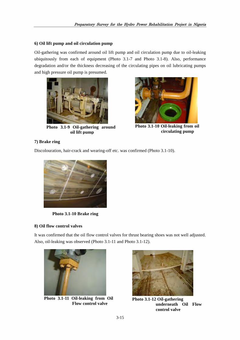
Preparatory Survey for the Hydro Power Rehabilitation Project in Nigeria
3-15
6) Oil lift pump and oil circulation pump
Oil-gathering was confirmed around oil lift pump and oil circulation pump due to oil-leaking
ubiquitously from each of equipment (Photo 3.1-7 and Photo 3.1-8). Also, performance
degradation and/or the thickness decreasing of the circulating pipes on oil lubricating pumps
and high pressure oil pump is presumed.
7) Brake ring
Discolouration, hair-crack and wearing-off etc. was confirmed (Photo 3.1-10).
8) Oil flow control valves
It was confirmed that the oil flow control valves for thrust bearing shoes was not well adjusted.
Also, oil-leaking was observed (Photo 3.1-11 and Photo 3.1-12).
Photo 3.1-10 Oil-leaking from oil
circulating pump
Photo 3.1-9 Oil-gathering around
oil lift pump
Photo 3.1-10 Brake ring
Photo 3.1-12 Oil-gathering
underneath Oil Flow control valve
Photo 3.1-11 Oil-leaking from Oil
Flow control valve

Preparatory Survey for the Hydro Power Rehabilitation Project in Nigeria
3-16
9) Space heater
Cover was deformed. (Photo 3.1-13).
10) Instruments
Indication error in the instruments and wire-breaking were confirmed (Photo 3.1-14 and Photo
3.1-15). It was confirmed that some displays of instruments were unreliable.
For further detail of result of generator inspection, reference shall be made to the Appendix-6.1
and 6.2.
3.2.3.2 Turbine
(1) Summary
The Team implemented the unwater site inspection solely for turbine 2G2 due to the time
constraint, which JHPS can share from operation time of available generation units, for the
inspection. At the same time, it was difficult for JHPS to share from operation time of other
units for the inspection in order not to interrupt the power supply to the demand.
Photo 3.1-13 Deformation of space
heater covers were detected
Photo 3.1-14 Indication error of resistance thermal detector (RTD) thermometer
Photo 3.1-15 Oil temperature sensor

Preparatory Survey for the Hydro Power Rehabilitation Project in Nigeria
3-17
The Team accepted the above proposal from JHPS because the running hours of 2G2 in the last
five years are not so different from those of other units, namely 35,208 hours for 2G1, 24,769
hours for 2G2, 34,556 hours for 2G3 and 29,881 for 2G5, and the actual operating conditions
of other units are almost similar to those of 2G2 considering the uniformity in operation
conditions such as head for power generation, and water temperature and quality.
On the other hand, inspection of turbine 2G1, 2G3 and 2G5 was carried out through observing
their operations. The Team found the followings:
1) Parts in the water passage of 2G2 have been deteriorated over the past 28 years of
operation.
2) It is presumed that parts in the water passage of 2G1, 2G3 and 2G5 are almost similar to
2G2.
3) Operating conditions of turbine 2G1, 2G2, 2G3 and 2G5 are at an acceptable level,
however, there are some defects to be considered for repair.
(2) Key results of turbine 2G2
1) Runner
Cavitation corrosion on bottom surface of the blade was not observed. It was observed that it
has been repaired during recent maintenance (Photo 3.2-1).
2) Shaft seal
Present status of shaft seal is not in satisfactory condition. (Photo 3.2-2 - Photo 3.2-5).
Much leakage water was found (see “Operating modes of pumps” for water drainage pumps
described hereunder).
Discharge of water supply - 150 lit/min.
Pressure of supply of water is not measured continuously. Water pressure gauge is not installed
in the pipeline.
There is uneven wear on the working surfaces of Teflon segments. (Photo 3.2-6 – Photo 3.2-7)
Photo 3.2-1 The bottom surface of
the blade

Preparatory Survey for the Hydro Power Rehabilitation Project in Nigeria
3-18
According to JHPS’s information,
- Teflon segment has been replaced every two to three years,
- Filter (Photo 3.2-8) does not fully clean the supply water to the shaft seal, and
- Shaft seals are important parts for turbine operation, but repaired seals in the 2G2 turbine
do not work properly.
Photo 3.2-2 Shaft seal
Photo 3.2-3 Shaft seal
Photo 3.2-4 Water level in shaft seal
Photo 3.2-5 Shaft seal
Photo 3.2-6 Teflon segments
(replaced)
Photo 3.2-7 Teflon segments
(replaced)

Preparatory Survey for the Hydro Power Rehabilitation Project in Nigeria
3-19
3) Drainage pump and Water supply pump
Both drainage pumps (first-direct current: DC, second - alternating current: AC) were already
worn. (Photo 3.2-9).
- Water supply pumps for shaft seal do not provide required quantity of clean water (Photo
3.2-10).
- A filter does not provide quality of cleaning water for supply to the seals shafts.
4) Wicket Gate
Regulation ring of 2G2 is moving smoothly.
According to JHPS’s information:
- Mechanical servo locks for the regulating ring are damaged and replacement is needed
for all the units. (Photo 3.2-11).
There is leakage oil through servomotor seals at all units (Photo 3.2-12)
Drainage through pistons of servomotors also is increased; refer to Table 3-7 for pumps oil
pressure units.
Photo 3.2-8 Filter for Shaft Seal Supply Water
Photo 3.2-9 Drainage Pump
Photo 3.2-10 Water supply pump

Preparatory Survey for the Hydro Power Rehabilitation Project in Nigeria
3-20
Leakage water through upper seals of vanes stems are as shown below.
- 2G1: Approx. 0.15 litre/sec.
- 2G2: Practically no leakage
- 2G3: Approx. 1.0 litre/sec.
- 2G5: Approx. 0.3 litre/sec.
There is backlash in link No.16 (joint with pin of regulation ring) at 2G1.
Table 3-7 Operating Modes of Pumps
Operation No operation Working cycle – Operation/ No operation
2G1 pump oil pressure unit 56 second 12 minute 1/12
2G3 pump oil pressure unit 47 second 7 minute 1/9
2G1 water drainage pump 5 minute 8 minute 1/1,6
2G3 water drainage pump 1 hour and 24 minute 6 minute 14/1
For further detail of result of turbine inspection, reference shall be made to Appendix-7.1.
3.2.3.3 Control/Equipment
(1) Summary
The investigation was carried out through discussions with O & M staffs of JHPS and
observation of equipment. According to the O & M staffs, there was no flaw in 2G1, 2G2, 2G3
and 2G4. Although the Team confirmed that the equipment successfully display the output of
generated power, the Team could not thoroughly confirm the present condition of control
system. However, since nearly 30 years have passed since the commencement of operation, the
measurement display equipment on the mimic board and fault recorder etc. were found to be
left broken down. There seems not to be a problem in the O & M of the power station and
switchyard. However, the facilities are getting too old and the procurement of these repair parts
is becoming difficult. Summary of findings is shown in Table 3-8.
Photo 3.2-11 Stopper of Regulation
Ring
Photo 3.2-12 Oil on Turbine Cover

Preparatory Survey for the Hydro Power Rehabilitation Project in Nigeria
3-21
Table 3-8 Summary of Control/Equipment
Equipment 2G1 2G2 2G3 2G5
Control panel Generator control panel, protective relay panel, switchboard, transmission line panel
Some of analogue and digital meters are out of order. According to the interviews, the protection panels are working properly. However, there is concern about the failure due to aging of components that have been used beyond their durable period.
Storage battery
Battery, charger Bank A of station storage batteries are already updated. According to the interviews, the charger is working properly. However, there is concern about the failure due to aging of components that have been used beyond their durable period.
330kV Circuit breakers
Circuit breaker, disconnecting switch, PT, CT
The three circuit breakers are already updated. According to the interviews, the switchyard equipment is working properly. However, there is concern about the failure due to aging of components that have been used beyond their durable period.
Transformers Transformer, bushing None None Oil leakage None Cable Control cable, power
cable In the exterior, a problem was not seen.
(2) Control and Protection Panel
1) Control desk
Start and stop operation of the generator is done by push-button switch on the analogue type
control desk (each unit). The circuit breakers for power generation have been installed on the
HV (330kV) side of the main transformer, and are installed in the Switchyard.
Operator connects the generated power in JHPS to the national grid by different switch
(Discrepancy switch) while checking the grid voltage and frequency on synchronised panel.
If the circuit breaker is not turned on by input signals to the breaker, repeat the blinking light
of this discrepancy switch. If successfully operated, the lamp goes out.
In addition, the generator voltage, the current, the power and power factor, etc. are indicated in
analogue meter on the control desk.
Photo 3.3-1 Control desk
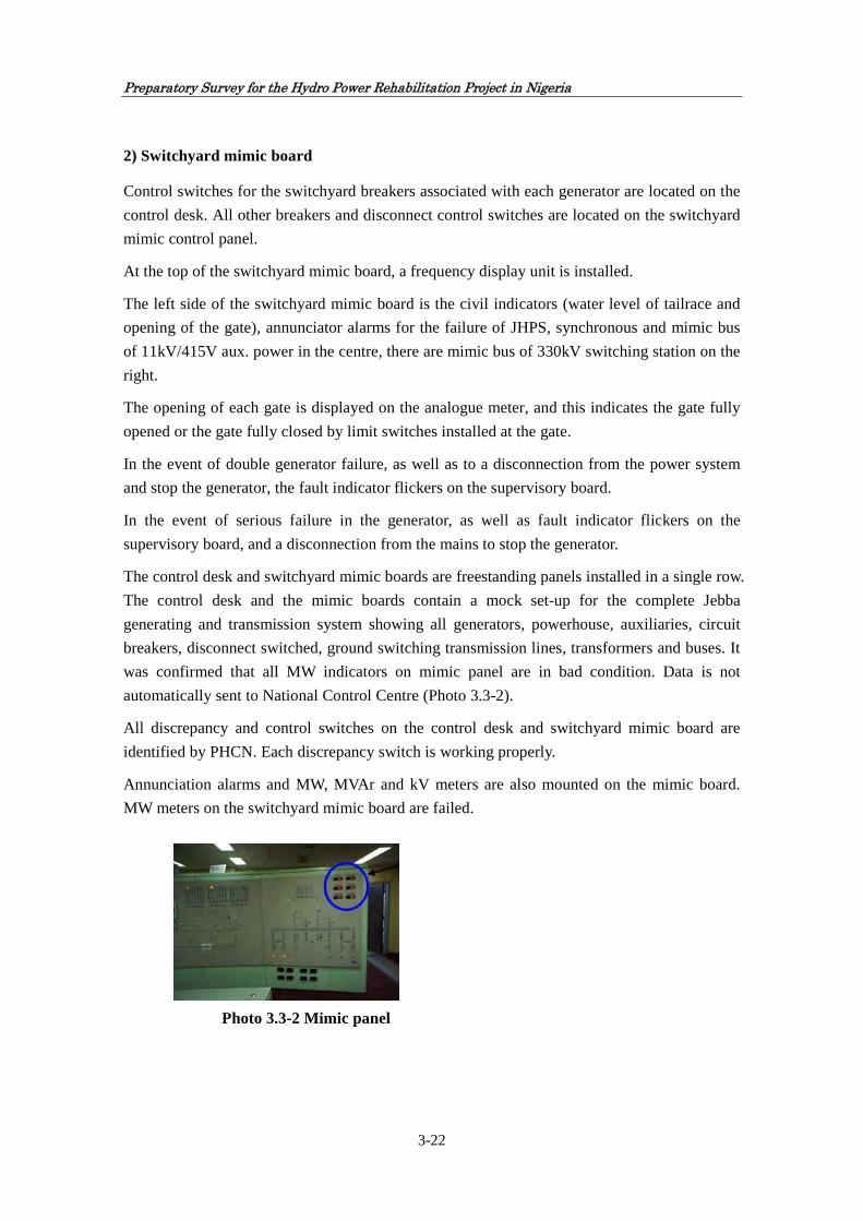
Preparatory Survey for the Hydro Power Rehabilitation Project in Nigeria
3-22
2) Switchyard mimic board
Control switches for the switchyard breakers associated with each generator are located on the
control desk. All other breakers and disconnect control switches are located on the switchyard
mimic control panel.
At the top of the switchyard mimic board, a frequency display unit is installed.
The left side of the switchyard mimic board is the civil indicators (water level of tailrace and
opening of the gate), annunciator alarms for the failure of JHPS, synchronous and mimic bus
of 11kV/415V aux. power in the centre, there are mimic bus of 330kV switching station on the
right.
The opening of each gate is displayed on the analogue meter, and this indicates the gate fully
opened or the gate fully closed by limit switches installed at the gate.
In the event of double generator failure, as well as to a disconnection from the power system
and stop the generator, the fault indicator flickers on the supervisory board.
In the event of serious failure in the generator, as well as fault indicator flickers on the
supervisory board, and a disconnection from the mains to stop the generator.
The control desk and switchyard mimic boards are freestanding panels installed in a single row.
The control desk and the mimic boards contain a mock set-up for the complete Jebba
generating and transmission system showing all generators, powerhouse, auxiliaries, circuit
breakers, disconnect switched, ground switching transmission lines, transformers and buses. It
was confirmed that all MW indicators on mimic panel are in bad condition. Data is not
automatically sent to National Control Centre (Photo 3.3-2).
All discrepancy and control switches on the control desk and switchyard mimic board are
identified by PHCN. Each discrepancy switch is working properly.
Annunciation alarms and MW, MVAr and kV meters are also mounted on the mimic board.
MW meters on the switchyard mimic board are failed.
Photo 3.3-2 Mimic panel
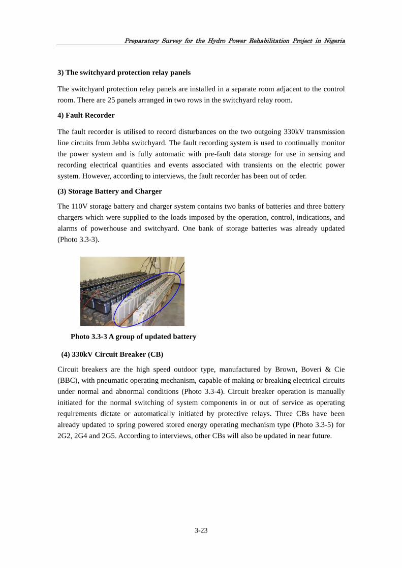
Preparatory Survey for the Hydro Power Rehabilitation Project in Nigeria
3-23
3) The switchyard protection relay panels
The switchyard protection relay panels are installed in a separate room adjacent to the control
room. There are 25 panels arranged in two rows in the switchyard relay room.
4) Fault Recorder
The fault recorder is utilised to record disturbances on the two outgoing 330kV transmission
line circuits from Jebba switchyard. The fault recording system is used to continually monitor
the power system and is fully automatic with pre-fault data storage for use in sensing and
recording electrical quantities and events associated with transients on the electric power
system. However, according to interviews, the fault recorder has been out of order.
(3) Storage Battery and Charger
The 110V storage battery and charger system contains two banks of batteries and three battery
chargers which were supplied to the loads imposed by the operation, control, indications, and
alarms of powerhouse and switchyard. One bank of storage batteries was already updated
(Photo 3.3-3).
(4) 330kV Circuit Breaker (CB)
Circuit breakers are the high speed outdoor type, manufactured by Brown, Boveri & Cie
(BBC), with pneumatic operating mechanism, capable of making or breaking electrical circuits
under normal and abnormal conditions (Photo 3.3-4). Circuit breaker operation is manually
initiated for the normal switching of system components in or out of service as operating
requirements dictate or automatically initiated by protective relays. Three CBs have been
already updated to spring powered stored energy operating mechanism type (Photo 3.3-5) for
2G2, 2G4 and 2G5. According to interviews, other CBs will also be updated in near future.
Photo 3.3-3 A group of updated battery

Preparatory Survey for the Hydro Power Rehabilitation Project in Nigeria
3-24
(5) 119MVA Transformers (16/330kV)
The six transformers are installed in the area between the
powerhouse and the dam at elevation 86.0m in bay adjacent to the
upstream wall of the powerhouse. Each transformer is located off
centre to the North of the respective generator and connected
directly with bus duct. As for the B phase of the HV bushing of
2G3, oil-leaking was detected (Photo 3.3-6).
On the other hand, the life of the diaphragm in conservator on the
top of the transformer is 15 years. The replacement is
recommended.
(6) Cable
All cables are put on the cable trays in the power station, the switchyard equipment and the
administration building. The cable trays are installed on the side walls of the switchyard trenches
and cable tunnel to administration building. All cables from switchyard to administration building
are sealed at the cable entrance to prevent any water from entering into the cable tunnel. All cable
trenches in the switchyard and power station are covered with concrete covers and steel plates. As
for the cable insert of the boards and cubicles, cable glands have been used. Major problems were
not observed in the present situation.
3.2.3.4 Auxiliary Equipment
The two 225/50/15 ton cranes installed inside the powerhouose are currently out of operation due
to failure of the brakes, control circuits and power collectors. Since these cranes are indispensible
for carrying out normal maintenance work as well as upgrading the existing generators, FGN will
need to repair and restore these cranes before the start of the rehabilitation work.
Moroever, because the wire rope and other parts have gone beyond their service life, it will be
Photo 3.3-5 New 330kV circuit Breaker (Areva GL315 2010)
Photo 3.3-4 Old 330kV circuit breaker (BBC ELF 362 nc 2a 1983)
Photo 3.3-6 Oil-leaking on B phase of 2G3

Preparatory Survey for the Hydro Power Rehabilitation Project in Nigeria
3-25
desirable to replace such parts during the rehabilitation and restoration work.
JHPS is in the final stage of selection of the contractor for rehabilitation of these cranes. The
Bureau of Public Procurement (BPP) approved the rehabilitation work of crane in the
powerhouse and as of December 2011, the original equipment manufacturer (OEM) has just
been selecterd as the contractor. The overall rehabilitation work is projected to be completed
by the middle of 2012.
Photo 3.4-1 Overhead Crane Full View Photo 3.4-2 Main Crane winch Section
3.2.3.5 Civil Structure
(1) Summary
The Jebba reservoir depends solely on the discharge from Kainji Dam during dry season
(December to March). During rainy season, some tributaries downstream of Kainji flow into
Jebba reservoir in addition to Kainji discharge. This inflow and effective water management by
JHPS allow the operation through the year round.
All concrete structures in JHPS on the upstream/downstream surface have similar deterioration
which includes general roughness of 5 to 10mm along the shoreline due to aging. Also it is
observed some holes and honeycombs found on concrete surface caused by loss of coarse
aggregates, and those are obviously caused by wave action for long periods.
The complete or partial losses of concrete joint sealing materials on all the expansion joints are
observed. A few other deteriorations such as concrete bit are observed at some locations.
Intake, spillway and auxiliary concrete dams are generally in good condition. No remarkable
erosion and/or other damages are observed.
In comprehensive inspection report3 as of year 2000 and annual technical reports as of years
2008 and 2009, the following deficiencies have been pointed out:
3 The Report was prepared by JHPS based on the survey carried out in May 2000, and covered visual as well as
video inspection of powerhouse, intake, spillway and underwater portion of appurtenant structures of Auxiliary 2, 3, and 4.

Preparatory Survey for the Hydro Power Rehabilitation Project in Nigeria
3-26
1) Draft tube concrete has still sound surface irrespective of the fact that high velocity flow of
water with some sort of suspended debris has passed through it. No crack was found except
No.5 north draft tube opening which seems like local crack width about 10mm.
2) At main spillway areas, loose rock and infract boulders are observed being piled up to the
level of stoplog gate sill especially in the middle of upstream channel. Serious signs of
erosion and deposition are noted in the upstream discharge channel. Minor damage to lip
concrete is also observed on some stoplog gate sills.
3) The flow from drain hole AD53 in Auxiliary Dam 3 remains within the range from 100.20
to 151.80 1itres/minute which is considered excessive in spite of water head from the
reservoir levels. Comparison with the data in 2010 shows that the flow rate is increasing.
This abnormal flow has been continuing since 2000, and JHPS has already started
investigation study and will take countermeasures against it.
4) North wall of main spillway discharge channel collapsed in 1991, and the south wall of the
channel, where the riprap rock fill have been dropped into the channel, has also eroded
progressively. Both the north and south walls of the channel are progressively collapsing,
depositing and accumulating debris of rocks into the channel.
In the first field survey by the Team conducted in July 2011, the above-mentioned issues were
not considered serious judging from the Team’s experiences, because water volume of leakage
water from Auxiliary Dam 3 is not so high, and the collapse and erosion of Main Spillway
channel would not seriously affect the flood control function at present.
Therefore, it can be said that the structures are maintained in good working condition and are
in no way threatened by any of observed deficiencies mentioned above.

Preparatory Survey for the Hydro Power Rehabilitation Project in Nigeria
3-27
Figure 3-7 General Plan of Jebba Hydro Power Station
(2) Main Dam
JHPS structures are mainly constructed on sound rock while the main dam is built on 40-60m
deep alluvial deposit foundation of loose non-compacted sand which was vibro-compacted and
properly treated prior to construction. The main dam, spillway, intake, powerhouse and
emergency spillway are linked by small auxiliary dams to form continuous structures with
crest length of about 2,000 metres.
N
Photo 3.5-2Photo 3.5-1 View of main structures from
upstream
Photo 3.5-2 View of rock-fill dam
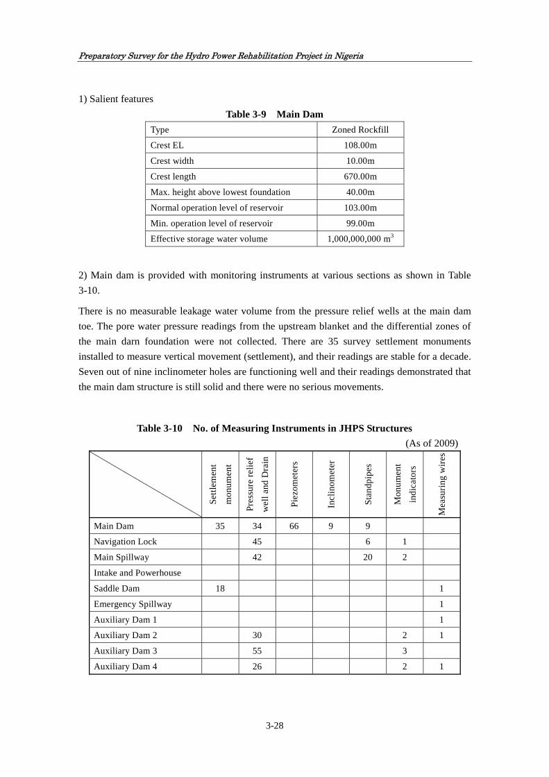
Preparatory Survey for the Hydro Power Rehabilitation Project in Nigeria
3-28
1) Salient features
Table 3-9 Main Dam
Type Zoned Rockfill
Crest EL 108.00m
Crest width 10.00m
Crest length 670.00m
Max. height above lowest foundation 40.00m
Normal operation level of reservoir 103.00m
Min. operation level of reservoir 99.00m
Effective storage water volume 1,000,000,000 m3
2) Main dam is provided with monitoring instruments at various sections as shown in Table
3-10.
There is no measurable leakage water volume from the pressure relief wells at the main dam
toe. The pore water pressure readings from the upstream blanket and the differential zones of
the main darn foundation were not collected. There are 35 survey settlement monuments
installed to measure vertical movement (settlement), and their readings are stable for a decade.
Seven out of nine inclinometer holes are functioning well and their readings demonstrated that
the main dam structure is still solid and there were no serious movements.
Table 3-10 No. of Measuring Instruments in JHPS Structures
(As of 2009)
Set
tlem
ent
mon
umen
t
Pre
ssur
e re
lief
wel
l and
Dra
in
Pie
zom
eter
s
Incl
inom
eter
Sta
ndpi
pes
Mon
umen
t
indi
cato
rs
Mea
suri
ng w
ires
Main Dam 35 34 66 9 9
Navigation Lock 45 6 1
Main Spillway 42 20 2
Intake and Powerhouse
Saddle Dam 18 1
Emergency Spillway 1
Auxiliary Dam 1 1
Auxiliary Dam 2 30 2 1
Auxiliary Dam 3 55 3
Auxiliary Dam 4 26 2 1

Preparatory Survey for the Hydro Power Rehabilitation Project in Nigeria
3-29
Judging from visual inspection done by the Team in July 2011, Main Dam is considered as in
good condition, because no remarkable leakage water from dam and no deterioration of dam
body except aging phenomena are found.
(3) Auxiliary Dams 2, 3 and 4
Auxiliary Dams 2, 3 and 4 form a part of the reservoir impounding structure. Auxiliary Dam 2
is located north of Intake structure, Auxiliary Dam 3 is between intake and spillway structure,
and Auxiliary Dam 4 is between spillway and navigation lock structure. All auxiliary dams
mentioned-above are of non-overflow mass concrete gravity type. Four storage chambers with
slots are provided in Auxiliary Dam 3 for storing intake bulkhead gates, trash rack panels and
spillway emergency gate. The 400 ton gantry crane travels on the deck of Auxiliary Dam 3 on
which it moves between intake and main spillway structure.
1) Salient features
Table 3-11 Auxiliary Dams
Auxiliary Dam 2 Auxiliary Dam 3 Auxiliary Dam 4
Type Concrete gravity Concrete gravity Concrete gravity
Crest Elevation 108.00m 108.00m 108.00m
Crest Length 93.00m 167.00m 71.50m
Max. Height 26.5m 24.5m 22m
Max. Base Width 18m 16m 14m
2) Auxiliary Dams 2 and 4
Auxiliary Dams 2 and 4 are in good condition. Leakage water through the drains is in the
range between 1.60 and 4.44 litres/min. and between 2.64 and 3.09 1itres/min., respectively
and these values are within the tolerable limit judging from the experience of the Team.
Leakage water records in 2009 are shown in Tables 3-12 and 3-13.
Table 3-12 Leakage Water Auxiliary Dam 2
Month Reservoir water level(m)
Tailrace water level(m)
Leakage water volume(litre/min)(2009)
Jan 101.38 73.60 4.44 Feb 101.36 74.20 4.20
Mar 100.80 73.20 3.60
Apr 100.78 74.00 2.04
May 100.17 74.00 2.10
Jun 99.29 73.50 1.90
Jul 99.06 73.90 1.76
Aug 99.42 73.80 1.60
Sep 102.37 74.90 4.20
Oct 101.42 74.90 3.30
Nov 102.99 74.30 3.72
Dec 100.73 74.40 2.02

Preparatory Survey for the Hydro Power Rehabilitation Project in Nigeria
3-30
Table 3-13 Leakage Water Auxiliary Dam 4
Month Reservoir water level(m)
Tailrace water level(m)
Leakage water volume(litre/min)(2009)
Jan 101.28 74.00 2.82
Feb 101.74 74.60 2.86
Mar 101.08 74.00 2.75
Apr 99.88 74.20 2.70
May 100.01 74.00 2.77
Jun 99.10 72.40 2.65
Jul 99.12 73.50 2.64
Aug 99.32 74.80 2.65
Sep 102.89 74.90 3.08
Oct 101.39 74.20 2.88
Nov 102.69 75.00 3.09
Dec 100.86 74.80 2.88
3) Auxiliary Dam 3
Leakage water from the pressure relief drains in Auxiliary Dam 3 fluctuates between 6.77 and
10.24 1itres/min. which is not so serious and within the assumed limit. On the other hand, the
flow from drain hole AD53 in Auxiliary Dam 3 remains in the flow range from 100.20 to
151.80 1itres/min., which is considered excessive in spite of water head from the reservoir
levels. In comparison with the data in 2010, it is shown that the flow rate is getting higher and
higher gradually. This abnormal flow has been continuing since 2000, and JHPS has already
started investigation study and will take countermeasures against it.
The oozing downstream slab of Auxiliary Dam 3 is also unusual, which is seen like shallow
puddle. This leakage may be bypassing the drain holes through open joints.
Both of abnormal water leakage from drain hole AD53 and oozing of downstream slab are
under study for detection of causes and countermeasures by French consultant.
Figure 3-8 Leakage Water Auxiliary Dam 3

Preparatory Survey for the Hydro Power Rehabilitation Project in Nigeria
3-31
(4) Auxiliary Dam 1 and Saddle Dam
1) Salient features
Table 3-15 Auxiliary Dam 1 and Saddle Dam
Auxiliary Dam 1 Saddle Dam
Type Zoned earth and rockfill Zoned earth and rockfill
Crest Elevation 108.00m 108.00m
Crest Length 275m 540m
Crest Width 7m 7m
Max. Height 14m 29m
2) Auxiliary Dam 1 is maintained regularly and in
good condition. Leakage water from saddle dam
is monitored at the downstream toe, and it varies
from 9.09 to 23.60litres/min. It will be correlated
with the reservoir water level, and is not so
remarkable volume compared to the similar scale
of dam. Saddle dam is maintained regularly and
in good condition.
(5) Powerhouse
1) Salient feature
Photo 3.5-3 Saddle dam from right abutment
Table 3-14 Leakage Water Auxiliary Dam 3 Month Reservoir
water level(m) Tailrace water
level(m) Leakage water
volume (litre/min)(2009)
Jan 101.62 74.00 124.40
Feb 101.36 74.20 128.58
Mar 100.80 74.20 118.57
Apr 99.84 74.20 151.02
May 100.00 74.00 120.27
Jun 99.29 73.60 121.19
Jul 99.06 73.90 117.19
Aug 99.42 73.80 94.65
Sep 102.37 74.90 122.44
Oct 101.32 73.80 114.14
Nov 102.80 75.00 125.92
Dec 100.19 74.40 127.71

Preparatory Survey for the Hydro Power Rehabilitation Project in Nigeria
3-32
Table 3-16 Powerhouse
Type Surface
No. of Unit 6
Length of powerhouse 206m
Width of powerhouse 36m
Max. Height from bottom 54.5m
2) The portion below EL.86.00m is considered as the powerhouse structure. It comprises draft
tube, foundation of turbines/generators for six units and erection bay. Foundation and draft
tube of each unit are separated from other unit on each side by expansion joints. The erection
bay (service bay) is located at north end of powerhouse with two stories, where upper level is
for erection and lower level is for workshop and storage.
Photo 3.5-4 Powerhouse and tailrace
afterbay
Table 3-17 Leakage Water Powerhouse and
Intake
Month Reservoir water
level(m)
Tailrace water
level(m)
Leakage water volume
(litre/min)(2009)
Jan 101.69 74.00 18.58
Feb 101.30 74.70 16.76
Mar 100.79 74.30 14.79
Apr 100.52 71.00 13.47
May 100.12 74.00 11.61
Jun 99.48 74.00 11.38
Jul 99.18 73.50 9.88
Aug 100.04 73.50 12.17
Sep 102.37 74.90 20.96
Oct 101.22 74.80 15.29
Nov 103.10 74.30 24.53
Dec 100.64 74.40 13.78
Figure 3-9 Leakage Water Powerhouse and Intake
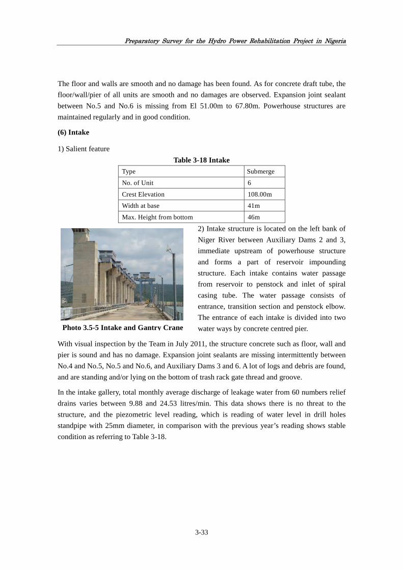
Preparatory Survey for the Hydro Power Rehabilitation Project in Nigeria
3-33
The floor and walls are smooth and no damage has been found. As for concrete draft tube, the
floor/wall/pier of all units are smooth and no damages are observed. Expansion joint sealant
between No.5 and No.6 is missing from El 51.00m to 67.80m. Powerhouse structures are
maintained regularly and in good condition.
(6) Intake
1) Salient feature
Table 3-18 Intake
Type Submerge
No. of Unit 6
Crest Elevation 108.00m
Width at base 41m
Max. Height from bottom 46m
2) Intake structure is located on the left bank of
Niger River between Auxiliary Dams 2 and 3,
immediate upstream of powerhouse structure
and forms a part of reservoir impounding
structure. Each intake contains water passage
from reservoir to penstock and inlet of spiral
casing tube. The water passage consists of
entrance, transition section and penstock elbow.
The entrance of each intake is divided into two
water ways by concrete centred pier.
With visual inspection by the Team in July 2011, the structure concrete such as floor, wall and
pier is sound and has no damage. Expansion joint sealants are missing intermittently between
No.4 and No.5, No.5 and No.6, and Auxiliary Dams 3 and 6. A lot of logs and debris are found,
and are standing and/or lying on the bottom of trash rack gate thread and groove.
In the intake gallery, total monthly average discharge of leakage water from 60 numbers relief
drains varies between 9.88 and 24.53 litres/min. This data shows there is no threat to the
structure, and the piezometric level reading, which is reading of water level in drill holes
standpipe with 25mm diameter, in comparison with the previous year’s reading shows stable
condition as referring to Table 3-18.
Photo 3.5-5 Intake and Gantry Crane

Preparatory Survey for the Hydro Power Rehabilitation Project in Nigeria
3-34
(7) Spillways
1) Main spillway is located on the left bank
of Niger River between Auxiliary Dams 3
and 4 with six radial gates of 12m wide and
9.5m height. The spillway is designed to
control design flood safety discharged from
dam at all times. The flow through the
spillway is controlled by six radial gates,
operated by means of hydraulic cylinders
provided on the both abutment.
Emergency spillway is provided at left
bank
between Auxiliary Dams 1 and 2 for
discharging excess water of design flood.
2) Salient features
Table 3-19 Spillways
Main Spillway Emergency Spillway
Type Underflow with flip bucket Free flow
Total Length 108m 220m
Gate No. 6 (Width12m, Height9.5m) -
Design Flood 13,600m3/sec 16,400m3/sec
3) With visual inspection by the Team in July 2011, as for main spillway, no damage or debris
is accumulated in upstream approach channel including apron slab. The concrete surface of
stoplog bottom seal beam areas is fairly rough. The guide wall and flip bucket concrete is in
good condition and no debris/materials are deposited in flip bucket. Expansion joint sealants
are missing intermittently. In the main spillway gallery, which provides water drain for
leaking water and applied for inspection purpose of main spillway body, most of relief drain
readings are less than 1 litre/min. and this shows very little quantity of leakage water from
upstream taking hydraulic pressure and reservoir volume into consideration. The piezometric
level readings are also normal. Therefore, no evidence of abnormal distortion to the structure is
found.
As for emergency spillway, the overflow weir and surroundings are maintained regularly and
in good condition.
4) North and south walls of main spillway channel are collapsed, debris are depositing and
accumulating in the discharge channel. The north damage, which riprap rocks have been
eroded into the channel, is more serious than the south one.
Photo 3.5-6 Main Spillway from
downstream

Preparatory Survey for the Hydro Power Rehabilitation Project in Nigeria
3-35
In the field survey by the Team in July 2011, the above-mentioned collapses are not so serious
judging from their experiences, because the collapse and erosion of main spillway channel
would not seriously affect the flood control function at present. Therefore, it can be said that
the structures are maintained in good working condition and are in no way threatened by any
of observed deficiencies mentioned above.
(8) Gates
Gates for O & M are provided for each structure, and those are in good operation except No.4
Intake Gate of which the top seal rubber should be exchanged due to water leakage caused by
deterioration. Gates provided are shown in Table 3-20.
Table 3-20 Hydro-mechanical Equipment in Jebba
Facilities Type Size Nos.
Main Spillway Radial gate, Hydraulic Ope. B×H=12m×9.5m 1×6= 6
Emergency closure gate B×H=12m×16m 1×6= 6
Stoplog B×H=12m×12.3m 1
Intake Vertical slide gate B×H=9m×19m 2×6= 12
Stoplog B×H=9m×19m 2
Tailrace Vertical slide gate B×H=10m×6.6m 2×2= 4
Navigation Lock (Upstream) Sector gate B×H=12.2m×10.5m 1
(Downstream) Vertical slide gate B×H=12.2m×18.5m 1
Gantry Crane Rail travelling 400t for Intake,70t for Tailrace
1+1
Filling Valve Provided in intake pier 12 inches siameter 6
(9) Reservoir Operation
1) Jebba reservoir with gross storage volume of
3.88×10⁹m3 and effective storage volume of
1.08×10⁹m3. Kainji reservoir, which is located
on the upstream of Niger River, has 12 and 15
billion as gross and effective volume,
respectively. Rainfall usually starts in the month
of April, and will drops sharply in the beginning
of October. The annual average rainfall in total
reaches approximate 1,000mm, and it is
harvested in consecutive months from April to
October. Robust inflow into the reservoir
Photo 3.5-7 View of reservoir from
upstream

Preparatory Survey for the Hydro Power Rehabilitation Project in Nigeria
3-36
sustained Jebba power generation. Inflow to Jebba reservoir makes up of Kainji discharge and
inflow from tributaries.
In 2008, Jebba reservoir recorded annual inflow of 40.866×10⁹m3, and this represents reservoir
replenishing rate of about 11 taking Jebba effective storage volume into consideration. Normal
annual reservoir operation is that the reservoir level reaches full surface level of EL.103.00m
in October and recedes down to minimum level of EL.99.00m in April.
Table 3-21 Rainfall Harvest (mm) in Jebba from 2005 to 2009
Month
2005 2006 2007 2008 2009
Precipitation (mm)
No of rain days
Precipitation (mm)
No of rain days
Precipitation (mm)
No of rain days
Precipitation (mm)
No of rain days
Precipitation (mm)
No of rain days
Jan - - - - - - - - - -
Feb - - 30.1 1 - - - - - -
Mar 1.0 1 - - 2.0 1 - - - -
Apr 123.7 3 7.0 1 71.0 3 93.8 5 128.6 7
May 69.0 8 143.5 10 178.0 9 79.6 7 37.5 6
Jun 154.1 12 144.5 9 140.0 9 189.0 9 99.6 12
Jul 94.9 10 145.5 14 249.0 10 242.8 13 127.0 14
Aug 177.1 7 252.5 11 327.0 17 192.9 16 227.5 14
Sep 240.5 14 217.3 16 121.0 11 185.8 13 172.2 16
Oct 77.0 5 62.5 7 48.0 4 54.3 4 141.4 8
Nov - - - - - - - - - -
Dec - - - - - - 3.4 1 - -
Total 937.3 60 1002.9 69 1136.0 64 1041.6 68 933.7 78
2) Sedimentation in reservoir
The surrounding area of JHPS, which is located in the Niger River, comprises mountains of
elevation from 70m to 200m at the downstream areas of the Niger River. The downstream area
of the Niger River shows gentle topography of elevation 0m to 50m. The length and drainage
area of the Niger Rriver are approximately 4,180 km and 2,092,000 km2 respectively.
Jebba Dam is located at just downstream of Kainji Dam, whose reservoir volume is 4 times of
Jebba reservoir, the inflow of suspended sediment to Jebba reservoir is restricted due to Kainji
reservoir. Taking the situation of Jebba reservoir into account, the amount of sedimentation
inflow to Jebba resrvoir is assumed to be very low. Deposition of earth and sand of this dam is
small. At present, the flood damage caused by the sedimentation influence at upstream of
Jebba reservoir is not generated.

Preparatory Survey for the Hydro Power Rehabilitation Project in Nigeria
3-37
3.3 Present Situation of Operation and Maintenance and Issues
3.3.1 Overall Situation of Operation and Maintenance
(1) General
Jebba Hydro Electric Plc.(Public Liability Company) (JHEP) is developing its business as
limited to the role of power generation. The main categories of business are generating power
and evacuating power through its transmission line and selling power to transmission
companies. Current status of O & M of JHEP is performed smoothly for 24 hours by three
shifts with four turns. The number of staffs is 466 persons in total as of July 2011, which
includes the staffs of school and hospital operation inside of premises of JHPS. Visual
inspection of civil structures is done by Dam Instrumention Deparement with seven staffs and
is carried out everyday, and the observation/measuring of leakage water at various points is
done twice in every month and its data are recorded but have not been sorted out and
computerised. Reservoir operation, which means reservoir level control and flood control, is
carried out by the Hydrology Department with 12 staffs.
The operation outages, which caused system collapse and forced outage, were recorded 47
times in 2008 and 44 times in 2009, respectvely. Those occurances per month in 2009 are
shown in Table-3-22. The large-scale accident on civil structures have not occurred since
commissioning of commercial operation.
Predictive maintenance actions, such as early repair/exchange of parts etc., have been taken,
and technical transferring and on the job-training (OJT) have been carried out. Therefore, it
must be said that JHEP provides sufficient operation and maintenance technique and
management and organisation.
Table 3-22 System Collapsed/Forced Outage as of 2009
Month Total/Partial System Induced Equipment/ TotalJan 1 1 Feb 3 2 5 Mar 3 1 4 Apr 3 1 4 May 3 2 5 Jun 5 2 7 Jul 5 5
Aug 4 4 Sep 1 1 Oct 2 1 3 Nov 1 2 3 Dec 1 1 2
Total 30 8 6 44 Notes: 1) Total/Partial Collapsed: Those disturbances that resulted in total system collapsed or partial
collapsed. 2) System Induced: Those disturbances that influenced the tripping of some units. 3) Equipment/ Breakdown: Fired outages due to breakdown of machines.
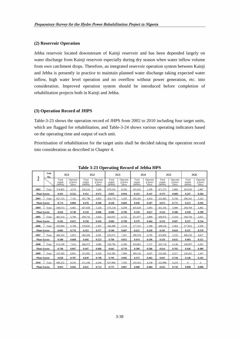
Preparatory Survey for the Hydro Power Rehabilitation Project in Nigeria
3-38
(2) Reservoir Operation
Jebba reservoir located downstream of Kainji reservoir and has been depended largely on
water discharge from Kainji reservoir especially during dry season when water inflow volume
from own catchment drops. Therefore, an integrated reservoir operation system between Kainji
and Jebba is presently in practice to maintain planned water discharge taking expected water
inflow, high water level operation and no overflow without power generation, etc. into
consideration. Improved operation system should be introduced before completion of
rehabilitation projects both in Kainji and Jebba.
(3) Operation Record of JHPS
Table-3-23 shows the operation record of JHPS from 2002 to 2010 including four target units,
which are flagged for rehabilitation, and Table-3-24 shows various operating indicators based
on the operating time and output of each unit.
Prioritisation of rehabilitation for the target units shall be decided taking the operation record
into consideration as described in Chapter 4.
Table 3-23 Operating Record of Jebba HPS
Yea
r
Unit
No. 2G1 2G2 2G3 2G4 2G5 2G6
Total output (MWh)
Operating hours (Hrs)
Total output (MWh)
Operating hours (Hrs)
Total output (MWh)
Operating hours (Hrs)
Total output (MWh)
Operating hours (Hrs)
Total output (MWh)
Operating hours (Hrs)
Total output (Mwh)
Operating hours (Hrs)
2002 Total 374,805 4,576 256,224 3,260 679,216 8,182 101,652 1,290 471,573 5,860 203,030 2,487
Plant Factor 0.455 0.522 0.311 0.372 0.825 0.934 0.123 0.147 0.573 0.669 0.247 0.284
2003 Total 637,125 7,745 391,748 4,902 434,779 5,293 345,565 4,443 555,483 6,790 206,341 2,562
Plant Factor 0.774 0.884 0.476 0.560 0.528 0.604 0.420 0.507 0.675 0.775 0.251 0.292
2004 Total 540,013 6,481 427,028 5,326 575,118 6,209 435,629 5,493 431,192 5,080 294,769 3,491
Plant Factor 0.656 0.740 0.519 0.608 0.698 0.709 0.529 0.627 0.524 0.580 0.358 0.398
2005 Total 465,233 5,700 294,732 3,645 563,057 6,725 311,977 3,890 438,475 5,319 194,756 2,051
Plant Factor 0.565 0.651 0.358 0.416 0.684 0.768 0.379 0.444 0.532 0.607 0.237 0.234
2006 Total 563,904 6,798 259,643 3,302 444,490 5,316 177,331 2,188 448,556 5,464 277,823 3,309
Plant Factor 0.685 0.776 0.315 0.377 0.540 0.607 0.215 0.250 0.545 0.624 0.337 0.378
2007 Total 484,345 5,853 366,209 4,581 625,671 7,451 390,559 4,785 455,856 5,535 406,259 4,827
Plant Factor 0.588 0.668 0.445 0.523 0.760 0.851 0.474 0.546 0.554 0.632 0.493 0.551
2008 Total 614,190 7,416 368,472 4,086 528,796 6,296 418,801 5,137 505,718 6,146 358,997 4,281
Plant Factor 0.746 0.847 0.447 0.466 0.642 0.719 0.509 0.586 0.614 0.702 0.436 0.489
2009 Total 535,585 6,891 525,995 6,556 653,385 7,900 309,142 4,047 532,495 6,517 120,455 1,447
Plant Factor 0.650 0.787 0.639 0.748 0.793 0.902 0.375 0.462 0.647 0.744 0.146 0.165
2010 Total 686,252 8,250 511,168 6,244 637,860 7,593 335,563 4,238 522,898 6,219 0 0
Plant Factor 0.833 0.942 0.621 0.713 0.775 0.867 0.408 0.484 0.635 0.710 0.000 0.000

Preparatory Survey for the Hydro Power Rehabilitation Project in Nigeria
3-39
Table 3-24 Plant Factor, Operation factor etc., Other Operation Index (from 2002 to
2010)
2G1 2G2 2G3 2G5
Average Plant Factor 0.661 0.459 0.694 0.589
Average Operation Factor 0.757 0.531 0.773 0.671
Operating Efficiency(/hr) 0.873 0.864 0.897 0.877
Nos. of months operated for less than 1 week 4 16 11 5
Total Output for 9 years(MW) 4,901,452 3,401,219 5,142,372 4,362,246
Total Operation Hours in 9 years(hr) 59,709 41,903 60,965 52,930
Output per hour (MWh/hr) 82.088 81.170 84.349 82.416
Note: *1) Calculation period from 2002 to 2010 *2) Plant Factor = Total Output/Possible Output in total *3) Operation Factor = Total Operating Hours/Possible Operation Hours in total *4) Number of month which operating hours are less than one week (168hrs in total). *5) Operating Efficiency = Total Output / (Possible Output x Total Operation Hours) *6) #6 Unit has been stopped operation from April, 2009 *7) Output per unit operating hour = Output in nine years total/Operating Hours in nine years total
Like other power stations in this country, including thermal and hydro power stations, JHEP
formulates a schedule of power generation such as target annual and monthly power generations.
This schedule is required to be submitted to PHCN in accordance with Service Agreement. Each
power station shall report the actual records of output made in previous year and month to PHCN
every following year and month respectively. Also, in case that actual output is far less than the
target output, penalty will be imposed.
3.3.2 Executing and Implementation Agency
(1) Operation and Maintenance by Executing and Implementing Agency
As some of the technical personnel of JHPS have worked there since the plant commenced
operation, technology has been passed on to a certain degree. These employees have conducted
routine O & M and all repairs at the station over 27 years and have kept the equipment in good
condition over this time. Moreover, since the station adopts the old style control system and
most operations are conducted based on the manual, the fact that personnel have continued O
& M without mishaps indicates that they have a high degree of technical proficiency.
Since the turbine and generator rehabilitation work here will largely entail replacement of
existing equipment, instruments and parts, it will be possible to operate and maintain the
equipment using conventional technology.
However, although station personnel possess routine O & M capacity, they have also
experienced the operating accident that made rehabilitation necessary in 2009 and they need to
receive equipment operation training in predictive and preventive maintenance measures and
measures based on simulations of various accident situations. Therefore, to ensure that the
station personnel can operate and maintain the facilities immediately after rehabilitation, the

Preparatory Survey for the Hydro Power Rehabilitation Project in Nigeria
3-40
following equipment predictive and preventive maintenance measures and operation training
techniques are recommended:
Maintenance consists of the following three types:
1) Periodic maintenance entails securing the reliability of equipment through implementing
inspections and repairs according to predetermined cycles and schedule. Such cycles are
determined equipment by equipment based on their respective past performances. This is
the type of maintenance that is currently conducted. Contents are usually prescribed in the
form of safety regulations or in-company standards.
2) Preventive maintenance entails securing the reliability of equipment through implementing
inspections and repairs at regular or irregular intervals according to equipment
characteristics with a view to preventing in advance occurrence of critical failures. Such
maintenance may sometimes be termed as periodic maintenance.
3) Predictive maintenance entails appropriately implementing repairs and upgrades just
before problems are about to become manifested (on the service limit of equipment) in line
with the progress of degradation of equipment. The timing of such repairs and upgrades is
determined based on the monitored state of equipment. Examples of such maintenance
include deciding the renewal period of coils based on insulation diagnosis of stators or
setting the repair and renewal schedule for mechanical parts based on the results of
non-destructive inspections.
(2) Examination of the Project implementation structure
1) General
In the Nigerian power sector, FMOP conducts supervision, while at present PHCN is
responsible for operating and maintaining all power generating, transmission and distribution
facilities throughout the country. Also, there are areas where regional electricity boards (REB)
belonging to state governments plan and operate electrical facilities and other areas where IPPs
such as NESCO and AES, etc. operate facilities. Nigeria is promoting a power sector reform
programme according to the NEEDS, and following approval of the Electric Power Sector
Reform Bill in March 2005, the EPSR Act officially came into force. The PHCN is divided
into six power generating companies, one transmission company and 11 distribution
companies, and PHCN as a holding company for the assets, liabilities, employees, rights and
obligations of NEPA was established in May 2005. In July 2006, the assets, liabilities and staff
of PHCN were transferred to the successor companies.
2) Federal Ministry of Power (FMOP)
FMOP, the supervisory government agency for the Project, is divided into seven departments
(Power Department, Electrical Inspectorate Service, Investment and Sector Development
Department, Procurements Department, Planning, Research and Statistics Department, Finance

Preparatory Survey for the Hydro Power Rehabilitation Project in Nigeria
3-41
and Accounting Department and Human Resource Management Department) as shown in
Figure 3-10. It has 15 branch offices throughout the country and possesses 907 employees as
of October 2010. Moreover, following reform of the power sector, FMOP became the ultimate
supervisory agency concerning policy planning and implementation for regional electrification
and it conducts monitoring and assessment of regional electrification programs from the policy
perspective. Japan has previously conducted the regional electrification project and master
plan survey for utilisation of solar energy with FMOP, which is the supervisory agency in the
particular project. In these undertakings, since technical personnel from FMOP implemented
comprehensive survey work jointly with the Japanese consultants and produced results that
were in no way inferior, they are deemed to possess technical understanding.
Notes: (1) The blue coloured department is in charge of the Project, and the figures in parentheses show the number of employees.
(2) The current President jointly holds the post of FMOP as of October 2010, while the Minister of State is in charge of practical affairs.
(3) FMOP has a work force of 907 employees (as of October 2010).
Source: FMOP
Figure 3-10 Organisation Chart of FMOP
3) Jebba Hydro Electric Plc. (JHEP)
JHEP will be the executing and implementing agency when it comes to Project implementation.
It is also scheduled for JHEP to directly implement O & M of the repaired and renovated
equipment. The staff of JHEP is likely to continue to operate and maintain JHEP in immediate
future in spite of the Nigerian policy on privatisation and commercialisation.
Figure 3-11 shows the organisation chart of JHEP. There are three divisions in JHEP; namely
Planning, Research
& Statistics Dept.
Minister
Accounting
Permanent Secretary (PS)
Finance &Procurements
Investment &Sector Dev.
Electrical Inspectorate
Service
Human Resource
Management
UnitUnitPPP UnitSERVI-COLegal Audit
RelationUnitAnti-Corruption Public
(47 staff)
Power

Preparatory Survey for the Hydro Power Rehabilitation Project in Nigeria
3-42
Administrative Division including CEO’s office under direct control of CEO, Maintenance
Division under control of Assistant General Manager (Maintenance) and Operation Division
under control of Assistant General Manager (Operation). Under Administrative Division, there
are 12 offices including CEO Office. Maintenance Division has twelve offices and Operation
Division has four offices.
Table 3-25 Departmental Staff Strength as at 28th July, 2011
Source: JHPS
JHPS has total staff strength of 446 as of 28th July, 2011 as shown in Table 3-25. Departmental
staff strength is also shown in Table 3-25 and Administrative Division, Maintenance Division
and Operation Division have staff strengths of 210, 161 and 75, respectively.
S/No. Department TotalCEO Office
1 Chief Executive Officer Office 4 Subtotal 4
Maintenance Division 1 Asst. General Manager (Maintenance) Office 52 Principal Manager (Auto Mech.) Office 123 Principal Manager (Auxiliary) Office 144 Principal Manager (Elect.) Office 165 Principal Manager (Estate) Office 306 Principal Manager (Gen./Workshop) Office 127 Principal Manager (PC&M) Office 78 Principal Manager (R&A) Office 89 Principal Manager (Planning) Office 4
10 Principal Manager (T/S) Office 1511 Principal Manager (Turbine) Office 1312 Principal Manager (Water Works) Office 25
Subtotal 161Operation Division
1 Asst. General Manager (Operations) Office 42 Principal Manager (Generation) Office 523 Principal Manager (Hydrology) Office 124 Principal Manager (Geology; Dam Instrumentation) Office 7 Subtotal 75
Administration Division (CEO’s direct control)1 Industrial Relations Office 12 Principal Manager (HR) Office 553 Principal Manager (Audit) Office 24 Principal Manager (Performance Mgt.) Office 25 Principal Manager (F&A) Office 176 Principal Manager (Medical) Office 607 Principal Manager (Procurement) Office 38 Principal Manager (School I) Office 279 Senior Manager (School II) Office 24
10 Senior Manager (Legal) Office 111 Manager (Fire/Safety) Office 14 Subtotal 206 Grand Total 446

Preparatory Survey for the Hydro Power Rehabilitation Project in Nigeria
3-43
Total staff strength of JHPS in the last seven years is as shown in Table 3-26. On rough
average, total staff strength is in the level of 450 with technical 210 and non-technical 240.
Technical staff strength is almost constant in the last seven years and it is reasonable since the
number of generation facilities subject for O & M are constant since start of its operation in
1983. However, as Table 3-26 shows, the number of total staff in December 2010 plummets by
25 comparing previous year. This is because during this month, mass-retirement of staff was
generated. In this sense, this figure, 425 is considered to indicate the momentary value of staff
strength. As a matter of fact, the total number of staff recovered to 446 as of July, 2011 due to
recruitment of sufficient number of staff to compensate the mass number of retirement as Table
3-25 indicates.
Table 3-26 Staff Strength of JHPS
Year Technical Non-Technical Total
Dec. 2004 207 240 447
Dec. 2005 209 242 451
Dec. 2006 208 247 455
Dec. 2007 211 261 472
Dec. 2008 210 246 456
Dec. 2009 215 235 450
Dec. 2010 210 215 425
Source: JHPS
Figure 3-11 Jebba Hydroelectric Power Station Organisation Chart

Preparatory Survey for the Hydro Power Rehabilitation Project in Nigeria
3-44
(3) Technical Capacity of Executing and Implementing Agency
As some of the technical personnel of JHPS have worked there since the plant commenced
operation, technical skills have been passed on to a certain degree. These employees have
conducted routine O & M and all repairs at the station over 27 years and have kept the
equipment in relatively good condition in spite of their long-term operation. Moreover, since
the station adopts the old style control system and most operations are conducted based on the
manual, the fact that personnel have continued O & M without mishaps indicates that they
have a high degree of technical proficiency.
Training/skill-up of operation/maintenance technology for staffs has been carried out at
appropriate intervals, and the National Power Training Institute of Nigeria (NAPTIN) was
established to take over taining/capacity building for power sector improvement. Therefore, it
is admitted that JHPS provides some structures of operation/maintenance of its facilities such
as quality of staff assignment, engineer level and organization.
Since the turbine and generator rehabilitation work under the Project here will largely entail
replacement of existing equipment, instruments and parts, it will be possible to operate and
maintain the equipment using conventional technology.
JHPS holds up the following strategy goals in its company’s statement in order to maintain
high level of O & M of the power station:
1) Strategy I: Ensuring that maintenance programme / schedules are adhered to.
JHPS has a documentation called Maintenance Management System (MMS). MMS includes
detailed procedures and schedules of maintenance management. Staffs submit their report to
their PM by 3:00pm every working day and it will be reviewed and any rectification will also
be made, if necessary, by each PM within the same day. The overall report will be made by
each PM to their AGM and the feedback to the staffs will be revealed at 8:30am in the
following morning.
2) Strategy II: Ensuring availability of adequate spare parts for prompt rectification of
faults.
The procedure of procurement of new spare parts was clarified by JHPS. After the CEO’s
approval of procuring new parts was given, it will be transferred to Store Section under
Department of Technical Services. Department of T/S is responsible for keeping all kinds of
spare parts in JHPS. Procurement Planning Committee is organised under the CEO and it
decides Annual procurement plan.
3) Strategy III: Improve on the clear cut maintenance culture that is already on ground.
It was confirmed that the technical skills/ expertise were transmitted to other staffs through
OJT.
4) Strategy IV: Maintain high level of discipline amongst staff through leadership by

Preparatory Survey for the Hydro Power Rehabilitation Project in Nigeria
3-45
example.
Performances of heads of subsection are evaluated by PMs.
5) Strategy V: Maintain a high level professional / skilled managers through well packaged and coordinated training programme to meet the current challenges in Engineering and overall human resources development.
National Power Training Institute and (National) Society of Engineers provide workshops and
trainings. In addition, JHPS organises in-house training and induction, especially to new
comers. JHPS also engages consultants to organize training, if necessary.
However, although station personnel possess routine O & M capacity through the above
mentioned quality control efforts, they have also experienced the operating accident that made
rehabilitation necessary in 2009 and they need to receive equipment operation training in
predictive and preventive maintenance measures and based on simulations of various accident
situations. Therefore, to ensure that the station personnel can operate and maintain the
facilities immediately after rehabilitation by the Project, it is recommended for JHPS to
implement equipment predictive and preventive maintenance measures and operation training
techniques as specified in Chapter 6. The proposed capacity development programme for the
station personnel in the implementation stage of the Project and details of these measures and
programme are described in Chapter 6.
(4) Financial Capacity of Executing and Implementing Agency
Concerning the financial capacity of the implementing agency, i.e. JHEP, since revenue is
covered by government grants, JHEP has a steady source of revenue as shown in Appendix-5.
That is, since the O & M costs incurred by JHEP are guaranteed by FGN, there is no risk that
O & M will be affected by lack of funding. However, Nigeria is currently aiming to “conduct a
review of the pricing system including power tariff hikes and to promote the introduction of
competitive principles such as the creation of a power trading market based on a power
pooling system” with a view to realising further reform of the power sector, and it is likely that
JHEP will need to adopt a management structure that doesn’t depend on government grants
and strive to introduce power tariffs that are sufficient to cover costs.
The income of JHEP is composed both of capacity charge (constant cost for power capacity
provided) and energy charge (valuable cost for generating power). All of wholesale power
tariff for the share of JHEP is paid as subsidy called MYTO as shown in Figure 3-12.
Moreover, the stable income has been secured with the charge of cost cover level set by NERC.
It means that JHEP is guaranteed its operating cost for healthy O & M of power station and
avoids inferior influences on O & M due to its problems of financial affairs. Even if
distribution companies were in arrears with their power purchase agreement (PPA) payment to
NBET as bulk power trader, NBET should pay their arrears to JHEP based on PPA instead of
distribution companies. The value chain between power sectors and FGN involved and
contract structure among power producers, NBET and distributers are shown in Figures 3-12
and 3-13, respectively.

Preparatory Survey for the Hydro Power Rehabilitation Project in Nigeria
3-46
Source: PHCN, FMOP, 2011
Figure 3-12 Value Chain in Fuel Suppliers and Power Sectors
Nigerian electricity Regulatory Commission(NERC)
Evaluation of Electricity Tariff
Federal Government of Nigeria(FGN) MYTO Approved
Central Bank of Nigeria
Subsidy Payment Gas Supply Aggregate Agreement
Payment of Fuel Charge
Payment of Transportation
Charge
Gas Supply Company
Gas
Transportation
Generation Companies
TransmissionCompany (Market
Operator)
DistributionCompanies
Costumers
PPA Agreement
Electricity Bill
Nigeria Bulk Energy Trader(NBET)
Payment of Wheeling
Charge Payment of Bill
Gas Transport Bill
Gas Supply Bill
Transmission Bill
PPA Agreement
Note: MYTO: Multi Year Tariff Order as same meaning as Subsidy PPA: Power Purchase Agreement

Preparatory Survey for the Hydro Power Rehabilitation Project in Nigeria
3-47
Source: PHCN, FMOP, 2011
Figure 3-13 Contract Structures among Power Producers, Bulk Traders and Distributers
Concerning the financial capacity of the company that owns JHPS, assessment has been made
whether or not the company has the ability to appropriately implement O & M at the plant
using its own funds upon examining financial indicators such as profit performance (net
profit/net fixed assets), financial robustness (own capital ratio = capital (borrowing + capital)),
cash management (own fund ratio = own funds/new investment) and liability ratio (liability
ratio = own funds/debt repayments). For details, reference shall be made to Chapter 7.
Gas Supply Company
Gas Supply Aggregate Agreements(GSAA)
Gen Cos. Existing
IPPs. Gen Cos.
Power Purchase Agreements(PPA)
Nigeria Bulk Energy Trader(NBET)
Vesting Contracts
Dis Cos.
Retail Contracts
Customers Customers Customers
Customers
PPAsGas Supply Company
Note: Vesting contract means wholesale contract
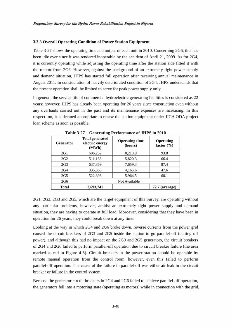
Preparatory Survey for the Hydro Power Rehabilitation Project in Nigeria
3-48
3.3.3 Overall Operating Condition of Power Station Equipment
Table 3-27 shows the operating time and output of each unit in 2010. Concerning 2G6, this has
been idle ever since it was rendered inoperable by the accident of April 21, 2009. As for 2G4,
it is currently operating while adjusting the operating time after the station side fitted it with
the rotator from 2G6. However, against the background of an extremely tight power supply
and demand situation, JHPS has started full operation after receiving annual maintenance in
August 2011. In consideration of heavily deteriorated condition of 2G4, JHPS understands that
the present operation shall be limited to serve for peak power supply only.
In general, the service life of commercial hydroelectric generating facilities is considered as 22
years; however, JHPS has already been operating for 26 years since construction even without
any overhauls carried out in the past and its maintenance expenses are increasing. In this
respect too, it is deemed appropriate to renew the station equipment under JICA ODA project
loan scheme as soon as possible.
Table 3-27 Generating Performance of JHPS in 2010
Generator Total generated electric energy
(MWh)
Operating time (hours)
Operating factor (%)
2G1 686,252 8,213.9 93.8
2G2 511,168 5,820.3 66.4
2G3 637,869 7,659.3 87.4
2G4 335,563 4,165.6 47.6
2G5 522,898 5,964.5 68.1
2G6 Not Available
Total 2,693,741 72.7 (average)
2G1, 2G2, 2G3 and 2G5, which are the target equipment of this Survey, are operating without
any particular problems, however, amidst an extremely tight power supply and demand
situation, they are having to operate at full load. Moroever, considering that they have been in
operation for 26 years, they could break down at any time.
Looking at the way in which 2G4 and 2G6 broke down, reverse currents from the power grid
caused the circuit breakers of 2G3 and 2G5 inside the station to go parallel-off (cutting off
power), and although this had no impact on the 2G3 and 2G5 generators, the circuit breakers
of 2G4 and 2G6 failed to perform parallel-off operation due to circuit breaker failure (the area
marked as red in Figure 4-5). Circuit breakers in the power station should be operable by
remote manual operation from the control room, however, even this failed to perform
parallel-off operation. The cause of the failure in parallel-off was either air leak in the circuit
breaker or failure in the control system.
Because the generator circuit breakers in 2G4 and 2G6 failed to achieve parallel-off operation,
the generators fell into a motoring state (operating as motors) while in connection with the grid,

Preparatory Survey for the Hydro Power Rehabilitation Project in Nigeria
3-49
resulting in the generators becoming overheated and damaged. Moreover, when this accident
occurred, the above four generators were in operation, but fortunately 2G1 and 2G2 were not
operating at the time.
G4G3 G5 G6G1 G2
LEGEND
1
2
3
4
POTENTIAL TRANSFORMER 330kV
330kV SF 5 CIRCUIT BREAKER
MOTORIZED PANTOGRAPH
MOTORIZED DISCONNECT SW
GROUND SWITCH
11kV AND 415V BREAKER
Jebba
LINE 2LINE 1
330kV EAST BUS BAR
330kV WEST BUS BAR
T1 T2 T3 T4 T5 T6
SS5SS3SS1
AT1
11kV BUS
415V NORTH
JEBBA
SPARE AT2
SOUTH
SPAREAT3 AT4
NAVIGATION LOCK
GENERATOR(2G1-2G6) 16kV, 119MVA each
GENERATOR TRANSFORMER(T1-T6) 16/330KV 119MVA each
UNIT STATION SERVICE TRANSFORMER(1,3&5) 16/11 kV 4MVA each
SUB STATION AUXLIARY TRANSFORMER(1-4) 11kV 11kV/415V 2MVA each
Figure 3-14 Jebba Hydroelectric Power Station Single-line Diagram
Jebba Hydroelectric Power Station
Control Room
Substation Circuit Breaker Remote Control Panel (Jebba Hydroelectric Power Station Control Room)

Preparatory Survey for the Hydro Power Rehabilitation Project in Nigeria
3-50
3.4 Power Demand-and-Supply Analysis
(1) General
Power demand forecast, which is the nationwide power demand/supply balance over
electrified and non-electrified areas, is made based on power sector development plans in
future covering power generation, transmission and distribution, which depend on power sales
to all categories of consumers. To be precise, the amount of power generation from private
owned power plants, which sell a significant amount of power to consumers, only accounts for
the surplus power from the private generators after deducting the power for internal use from
the total generated power by the said private generators. Appropriate energy mix with thermal,
hydro, nuclear and renewable energy etc. and energy balance between domestic use and power
import/export have to be considered for the purpose of national energy security.
Stable power supply is indispensable as economic infrastructure for the development of
Nigeria. The capacity, efficiency and stability of power supply not only influence investment
by existing enterprise but also play major roles in the economic environment creation.
Power generation and consumption data are not available in digital format at present. PHCN is
requested to focus its attention in respect of data collection and its analysis on the following
items: PHCN is requested to issue the report of energy statistics every year.
Power generation statistics,
Transmission statistics,
Distribution statistics, and
Power sales statistics.
Each of the statistics has to include the following information:
Name of power station,
Number of generating unit,
Generation type,
Turbine set,
Quantity of power generated in GWh (giga-watt hours), and
Installed capacity in GW (giga-watt)
All the statistical information on power supply and demand shall be produced in the course of
day-to-day administration.
(2) Method adopted in Power Demand Forecast
Based on the survey of actual power utilisation, the total power consumption per consumer
(per capita) of each sector (domestic, commercial, industry and public, etc.) was estimated.
Applying the power consumption to the number of consumers and considering the growth rate
of consumption in each sector, the power demand forecast for the specified year of 2010 was
elaborated as a base year for the forecast. The forecast was carried out for 20 years from 2010

Preparatory Survey for the Hydro Power Rehabilitation Project in Nigeria
3-51
up to 2030. This extended forecast was prepared by following the same trend for the forecast
demand.
The average annual economic growth rate at national level is assumed to be in the same trend
of GDP growth rate as referred to Table3-30 (Historical Census Data in Nigeria) of the
projected peak demand, namely in the period of 2010 to 2015 it is 5 percent, in the period of
2016 to 2020 it is 6 percent and in the period of 2021 to 2030 it is 7 percent. System loss
which includes technical loss and commercial loss in 2010 is estimated 32 percent and it is
assumed to be improved by 1 percent per year up to 2020 and 0.5 percent per year up to 2030.
Annual power requirements are estimated by adding power losses worked out at the assumed
loss rates to the projected power consumption. The annual peak demand is estimated with an
assumed load factor.
Two cases of analysis are carried out under the scenarios of medium growth and high growth
as follows:
Case-1: Not taking IPP projects into account because of the reasons of uncertainty of
developing scale and implementation schedule
Case-2: Taking IPP projects into account to compensate the shortage of power supply capacity
(3) Results of the Power Demand Forecast
The maximum peak demand at the national level would be 10,179 MW in 2020 and 18,818
MW in 2030, and the average monthly energy consumption would be estimated around 4,830
GWh in 2020 and 8,929 GWh in 2030. The peak load of 0.046kW per capita in 2011 is
expected to increase to 0.054kW per capita in 2020 and 0.089kW per capita in 2030. The
average monthly power consumption is expected to increase from 22kWh per capita in 2011 to
26kWh in 2020 and 42kWh in 2030.
Table 3-28 Power Demand Forecast
Year 2011 2015 2020 2025 2030
Peak Demand MW 7,074 8,128 10,179 13,834 18,818
Annual Growth Rate % 5 5 6 6 7
Energy Requirement GWh 40,280 46,278 57,961 78,769 107,149
Expected System loss % 32 27 22 19.5 17
At the national level, by 2030 the total peak load will increase to 2.7 times of the 2011 level.
The average annual growth rate for the total peak load over the same period is 5.3 percent, and
the estimated peak load will be 18,818 MW in 2030 and the annual power demand will be
107,149 GWh. The power market in Nigeria is largely influenced by the industrial sector. Thus,
the forecast demand should be frequently reviewed after any changes in socio-economic

Preparatory Survey for the Hydro Power Rehabilitation Project in Nigeria
3-52
circumstances, changes in development plans of each sector and other related events.
The results of examining the demand and supply balance are as follows:
a) Annual balance for the entire country: In case without new IPP projects, supply capacity
exceeds demand for both peak load and power consumption in 2023. Even though new IPP
projects would be installed between 2015 and 2018, it will still be necessary to install the coal
fired generation plants in 2023.
b) If NIPP Project is delayed in implementation, the balance in 2013 would fall in a slight
shortfall in power supply. However, this shortfall will be fully offset by commissioning of new
IPP projects, therefore, the decision making of introducing IPP is seriously considered.
c) In case without new IPP projects, if power shortage in 2013 would be resolved, the annual
balance of power supply will be sufficient by 2023. In case with new IPP projects, the annual
balance of power supply will be sufficient by 2024.
d) The following shortfalls are observed:
Under the medium growth scenario (demand growth rate: 5 to 7%): The shortage of peak
load is foreseen after 2028.
Under the high growth scenario (demand growth rate: 5 to 9%): The shortage of peak load is
foreseen after 2025.
Therefore, it is recommended that FMOP is required to start the preparation of installation of
coal fired generation plants to resolve shortfall of power, to import power from the
neighbouring countries or to take necessary recuperative measures in advance with due
appropriation of his investment budget.
(4) Comparison of demand forecasting
The following data regarding power demand forecasting are available:
1) ROADMAP issued in August 2010 by FGN,
2) Capacity projection in September 2011 by FMOP,
3) Electricity demand and supply projections for Nigeria in July 2008 at National
Workshop, and
4) MYTO2 (Multi Year Tariff Order 2) issued in May 2011 by NERC.
Table 3-29 shows comparison among these demand projections and JICA Survey Team
forecasting.

Preparatory Survey for the Hydro Power Rehabilitation Project in Nigeria
3-53
Table 3-29 Comparison Table of Peak Demand Forecasting
ROADMAP Capacity Projection
Electricity Demand and Supply
Projections for Nigeria
MYTO 2(Multi Year Tariff Order)
JICA Forecasting
Published year Aug. 2010 Sep. 2011 Jul. 2008 May 2011 Oct. 2011
Published by FGN FMoP National Workshop NERC JICA Survey
Team
Installed capacity planned
Installed capacity planned
Demand Installed capacity planned
Demand
Installed
Capacity
planed
Demand
Installed capacity planned
2005 5,746 2010 7,033 4,337 15,730 17,303 6,836 6,054 2011 9,767 5,326 - - 3,952 7,074 6,463 2012 11,879 7,731 - - 4,096 5,750 7,322 7,698 2013 14,218 11,879 - - 4,546 7,500 7,580 8,647 2014 - 16,646 - - 8,288 9,061 7,848 8,879 2015 - 18,566 28,360 31,197 8,660 10,071 8,128 9,690 2020 - - 50,820 55,903 10,062 10,179 12,3082025 - - 77,450 85,196 13,834 14,8862030 - - 119,200 131,122 18,818 17,436
Note - -
GDP growth
rate 7%
-
GDP growth
rate 5 - 7%
-
Annual average
increment by 2015
2,395 2,846 2,526 2,779 1,177 1,440 258 727

Preparatory Survey for the H
ydro Pow
er Rehabilitation P
roject in Nigeria
3-54
Figure 3-15 Demand Forecast not taking IPP Projects into account due to uncertainty of installation (Case-1)

Preparatory Survey for the H
ydro Pow
er Rehabilitation P
roject in Nigeria
3-55
Figure 3-16 Demand Forecast taking IPP Projects into account (Case-2)
5,000
6,000
7,000
8,000
9,000
10,000
11,000
12,000
13,000
14,000
15,000
16,000
17,000
18,000
2010 2012 2014 2016 2018 2020 2022 2024 2026 2028 2030
Cap
aci
ty (M
W)
Years
Peak Demand Forecast and Installed Capacity
Peak Demand(MW) GDP(5~7%) Installed capacity(MW)
Peak Demand(MW) GDP(5~9%)
Peak Demand Curve(GDP growth rate 5~7%/year)
Installed Capacity
NIPP Project2011~2018
Manbilla HP Project2022~2023
New IPP Project2015~2018
Zungeru HP Project2020~2021
Peak Demand Curve(GDP growth rate 5~9%/year)
Coal‐fired projects should be provided from 2024.
Gerara Expansiona HP Project2021~2022
PHCN Project

Preparatory Survey for the H
ydro Pow
er Rehabilitation P
roject in Nigeria
3-56
Table 3-30 Historical Census Data in Nigeria
Year 2000 2001 2002 2003 2004 2005 2006 2007 2008 2009 2010 Mean Value
Population(×10^6person) 123.337 126.636 129.935 133.882 137.253 128.772 131.86 135.031 146.255 149.229 152.217
Population Growth Rate(%) 2.67 2.61 2.54 2.53 2.45 2.37 2.38 3.38 2.03 2.00 1.97 2.45
Inflation Rate(%) 12.50 6.50 14.90 14.20 13.80 16.50 13.50 10.50 5.40 11.60 11.50 11.90
Industrial Production Growth Rate(%) 1.50 -0.30 0.40 2.30 1.80 3.80 -1.60 3.20 2.80 0.60 1.45
GDP Growth Rate(%) 2.70 3.50 3.50 3.00 7.10 6.20 6.90 5.30 6.40 5.30 5.60 5.05
Power Production(×10^9kWh) 14.75 18.7 15.9 15.67 15.67 19.85 15.59 19.06 22.11 22.11 21.92
Growth Rate (%) 26.78 -14.97 -1.45 0.00 26.68 -21.46 22.26 16.00 0.00 -0.86 5.30
Power Consumption(×10^9kWh) 13.72 17.37 14.77 14.55 14.55 18.43 14.46 17.71 15.85 15.85 19.21
Growth Rate (%) 26.60 -14.97 -1.49 0.00 26.67 -21.54 22.48 -10.50 0.00 21.20 4.84
Power Export(×10^6kWh) 19 19 20 20 30 40 20
Actual Power Consumption(×10^9kWh) 13.72 17.35 14.75 14.53 14.53 18.4 14.42 17.69 15.85 15.85 19.21
Growth Rate (%) 26.47 -14.98 -1.50 0.00 26.63 -21.63 22.68 -10.40 0.00 21.20 4.85
Per Capita Power Consumption (×10^9kWh) 111 137 114 109 106 143 109 131 108 106 126
Growth Rate (%) 23.17 -17.14 -4.40 -2.46 34.97 -23.47 19.80 -17.28 -1.99 18.82 3.00

Preparatory Survey for the Hydro Power Rehabilitation Project in Nigeria
3-57
3.5 Expected Project Effect
Operation and effect indicators were conceived to quantitatively measure the Project’s
operational performance and effects in light of its objectives. These indicators, including target
figures shall be subject to continuous follow-up at various stages of the project cycle, including
intermediate supervision during implementation, and post completion monitoring and ex-post
evaluation by JICA.
Generally speaking, equipment is rehabilitated as it approaches the service limit, and the
potential effect indicators from the following improvement effects can be adopted for
consideration. These effects are usually manifested in various combinations.
(1) Maintenance and improvement of plant safety and reliability
Risk of major accidents threatening human life and property and affecting stable operation
can be reduced. As a result of higher reliability achieved through rehabilitation, forced
shutdowns can be reduced and higher revenue can be anticipated from JHPS.
(2) Extension of the equipment service limit and recovery of performance
The service life of equipment can be extended through restoring degraded equipment and
recovering performance. Rehabilitation sometimes gives rise to an incidence where
problems exist in the initial performance but performance is enhanced through subsequent
technical improvement.
(3) Reduction of maintenance cost
It is common knowledge that maintenance costs generally tend to rise in line with
degradation of installed equipment over time. This is because it is necessary to conduct
inspections at shorter intervals than usual in order to preserve a certain degree of
performance and costs increase as more repair work is conducted each time. Moreover, it is
necessary to implement more frequent special inspections and measurements geared to
monitoring status and conducting preventive maintenance in line with degradation over
time. Since this leads to higher maintenance costs and detracts from plant economy, the
plant rehabilitation of this Project can be expected to reduce maintenance costs.
Furthermore, through such measures as reducing the number of units, adopting oil-less
instruments and using maintenance-free instruments, the resulting energy saving can be
expected to reduce maintenance costs.
(4) Improvement in output, efficiency and generated power
Through restoring the performance of degraded equipment with reduced efficiency,
reduced reliability, and limited operation, the power generation can be increased.
(5) Environmental improvement
Rehabilitation can be expected to reduce pollutants in water, mitigate hazardous wastes in
the power station, improve oxygen concentration in water, alleviate impacts on fish and

Preparatory Survey for the Hydro Power Rehabilitation Project in Nigeria
3-58
shellfish (reduction of water pressure changes), mitigate climate change through reduction
of greenhouse emission and so on. Going by past examples, measures to conduct labour
saving in maintenance have included adoption of oil-less bearings, adoption of powered
hydraulic instruments and so on. Such measures also have an environmental positive effect
in terms of preventing oil leaks at times of accidents.
(6) Revision of conditions of use and specifications
There are cases where equipment specifications need to be changed in line with climate
changes or changes to operating conditions. There are also cases where rehabilitation needs
to be conducted in response to revisions to regulations on the river maintenance flow and
surrounding social factors. When the share of hydroelectric power within the general grid
becomes smaller, it is sometimes necessary to limit functions and improve economy
through enhancing efficiency. (For example, reduced generator output = higher power
factor).
(7) Ratio of utilisation of the facilities
This indicator correlates to the stability of facilities. For example, breakdown can be
considered as a main factor to reduce the utilisation of facilities. The reduction of
possibility of breakdown which will be realised through the implementation of this Project
will directly improve the ratio of utilisation of the facilities.
(8) Electric power at generation end
The quantity of electric power at generation end indicates a reliable generated power which
leads to be transmitted to the national grid from the power plant. On the other hand, electric
power at transmission end is affected by external factors such as power sending loss within
the power station and loss caused by transformer which increases the voltage to the suitable
level for transmission. Thus, the electric power at generation end is more suitable to
measure the improvement of power generation, capability of the power plant through this
Project.
(9) Unplanned stoppage-time of operation
Unplanned stoppage-time of operation is, in other words, an uncontrolled stoppage of
operation of facility. However, due to some of causes derived from natural factors, it is
difficult to prevent unplanned stoppage thoroughly. For example, ground fault led to loss of
power supply to sustain auxiliaries, and failure of 330kV circuit breakers to open led to
monitoring of units 2G4 and 2G6. However, there is still such an unplanned stoppage-time
of operation which is preventable by prior action especially with regards to the stability of
facilities.
In the rehabilitation of JHPS, it is anticipated that Project implementation will lead to (1)
maintenance and improvement of plant safety and reliability, (2) extension of the equipment
service limit and recovery of performance, (3) reduction of maintenance cost and (4)

Preparatory Survey for the Hydro Power Rehabilitation Project in Nigeria
3-59
improvement in output, efficiency and generated electrical energy. Decrease in plant shutdown
duration other than those under planning or in response to less power demand can also be a
measure of the Project’s effect. In terms of operation effect indicators, it will be appropriate to
conduct assessment based on generated electrical energy (including output and efficiency),
stoppage time, maintenance cost and profit.
The Result of the analysis is fully described in Chapter 8.


Chapter 4
Project Plan


Preparatory Survey for the Hydro Power Rehabilitation Project in Nigeria
4-1
Chapter 4 Project Plan
4.1 Site Conditions
4.1.1 Natural Conditions
(1) Climate Conditions
Nigeria’s climate is divided into five climate zones. Distributions and characteristics of each
zone are shown in Table 4-1. JHPS belongs to Guiana-Sudan Climate Zone.
Table 4-1 Climate Zones in Nigeria
Climate Zone Distribution Characteristic
Sahel Northern end, approximately northern part from north latitude 12 degree
Annual precipitation 500~700mm
Sudan-Sahel Southern part from North latitude 12 degree, including Abuja, Kaduna and Jos
Annual precipitation 1,000mm, 1,500mm in Jos Plateau
Guiana-Sudan Southern part of Niger-Berue Trough and perimeter of Minna Basin
Annual precipitation 1,300~1,500mm, 1,000~1,200mm at Niger-Berue Trough
Forest Sahel Approximately between North Latitude 7°30’ and 6°30’
Annual precipitation 1,500~2,000mm
Forest belt Approximately southern part of North latitude 6°30’
Annual precipitation is approximately 2,000mm, western part from East Longitude 5° is 1,500~2,000mm, eastern part from East Longiture 5° is 2,000~3,000mm
In Nigeria, a sand storm containing sand dust from Sahara desert called “Harmatthan”
frequently blows throughout the country from December to next February every year. In this
period, the visibility is around 200m and blasts of wind blowing with the speed of 30m/s can
happen. During rainy season, south-west seasonal wind carries high-temperature and humid air
from the gulf of Guinea and causes rain. From afternoon to evening, squalls with lightening can
frequently happen. Moreover, since a blast of wind sometimes blows before squall starts in the
same way as Harmatthan, it is necessary to prevent packages of materials carried in the site
from scattering. Also, it is possible that heavy rain with lightening occurs from midnight to
dawn. According to the data of the Federal Ministry of Aviation, the number of day with
lightening is approximately 80 days on average per year. During squalls with lightening, the
atmosphere becomes unstable, and lightning and thunderbolts happen continuously.
(2) Temperature
According to the statistics of the last five years from 2006 to 2010, the highest temperature of
area surrounding JHPS is 40 oC and the temperature tends to be high during dry season and low
during rainy season. Figure 4-1 indicates the monthly highest temperatures of the Project site.

Preparatory Survey for the Hydro Power Rehabilitation Project in Nigeria
4-2
Figure 4-1 Monthly Highest Temperature at JHPS
(3) Precipitation
The average annual precipitation at Jebba in the last five years from 2006 to 2010 is 1,050.9mm.
Generally, the period from November to next March is dry season. Although 30mm of
precipitation was recorded in February 2006, it rarely rains in dry season. Rainy season ranges
from April to October and especially monthly precipitation in July and August exceeds over
200mm. The precipitation of the Project site is illustrated in Figure 4-2.
Figure 4-2 Precipitation
0.0
50.0
100.0
150.0
200.0
250.0
300.0
350.0
Jan Feb Mar Apr May Jun Jul Aug Sep Oct Nov Dec
2006
2007
2008
2009
2010
Tem
pera
ture
(o C
) P
reci
pita
tion
(m
m)

Preparatory Survey for the Hydro Power Rehabilitation Project in Nigeria
4-3
4.1.2 Related Infrastructure Conditions
(1) Power Supply
As mentioned earlier, power infrastructure in Nigeria is operated and managed by subsidiaries
of PHCN under the supervision and responsibility of FMOP. Low-voltage distribution for
general consumers is 415/240V and frequency is 50Hz. In Nigeria, short-term outage of power
frequently happens due to shortage of distribution power and/or climatic conditions such as
strong wind and rain, however, the power outage in and around JHPS is rare and it is relatively
stable.
(2) Road
The road connecting capital city Abuja and regional capital city Minna has two lanes with
complete asphalt pavement and there are two access ways from Minna to Jebba: North route via
Tegina and South route passing through southern part of Niger State. In the South route,
although the road until Bida is relatively fine, plenty of holes are observed on the road surface
after Bida to Jebba whose distance is 169km in total due to peeling off the asphalt pavement of
road and vehicles are forced to reduce the speed to avert these holes. Thus, it will require much
time to pass. Therefore, although the total driving distance is longer, it is desirable to utilise the
North route via Tegina to reach Jebba.
Road from Apapa port, Lagos to JHPS also has two traffic lanes paved with asphalt and is
approximately 410km long. Quarter of the road is rough as the same condition as road to Abuja
from Jebba.
(3) Communication
Fixed phones in Nigeria are operated and maintained by Nigeria Telecommunications Plc
(NITEL) and as for mobile phones (GSM method), services operated by plural companies such
as MTN Nigeria, M-Tel, and glo Mobile are prevalent. Also, several providers hold permission
for internet and wireless broadband service is offered. As for mobile phone communication
condition in Jebba, network coverage operated by MTN Nigeria, one of major communication
companies is not covered and only a few communication companies such as glo Mobile are
available. Also, as for the internet connection, suburbs of JHPS are out of coverage of wireless
broadband, and internet connection through this service is impossible. Hence, because the
environment of internet connection and email service is not prepared, in case that Japanese
experts stay during the Project design and implementation period, it is desirable to secure
communication devices such as Inmarsat for daily safety control and rapid/smooth contact to
Japan side.

Preparatory Survey for the Hydro Power Rehabilitation Project in Nigeria
4-4
4.2 Scale of the Project
The target facilities of the Project are 2G1, 2G2, 2G3 and 2G5 at JHPS. When compiling the
Project Plan for the target package of improvement of the target facilities, three optional
packages will be proposed over the total project cost range of 5 to 10 billion yen. GOJ will
decide the size of loan in consideration of degree of necessity and urgency.
4.3 Physical Planning of the Project
4.3.1 Policies for Physical Planning
4.3.1.1 Basic Policies
Concerning the target unit, the outline design is elaborated based on the information collected in
the field surveys by the Team. The Survey aims to improve the generating capacity of 2G1, 2G2,
2G3 and 2G5 at JHPS and to confirm the validity of parts in need of repair taking into account
the state of rehabilitation currently in progress on 2G6. Concerning repair of this hydroelectric
power station, it is necessary to examine the following three features:
(1) Overhaul
JHPS started commercial operation in 1985 after two years of initial operation, however, the
products and members used in it were manufactured around 1981 and have been passed for 30
years. Most products and members have already surpassed their useful service life and, even
judging from the service life of commercial power generating facilities, JHPS is in need of
major overhaul. The power station comprises electrical equipment such as generators, turbines,
transformers and circuit breakers, as well as auxiliary equipment such as a regulator for
adjusting the turbine speed and ensuring stable operation and a static exciter for stable electric
power generation. As it is likely that primarily the moving parts of this equipment suffer from
wear and tear so called mechanical stress, it is necessary to consider overhaul including
replacement of parts and so on. Hydroelectric power stations in Japan adopt generally the
Francis type turbine that utilises head of around 80 meters, and such facilities generally require
major overhaul once every 10 years. However, since JHPS adopts fixed blade propeller turbines
that utilize water from a low head dam and have slower rotation speeds, there is less wear and
tear in the turbines and the overhaul interval can be extended.
(2) Restoration of areas damaged by accidents
Ground fault led to loss of power supply to station auxiliaries, and failure of 330kV circuit
breakers to open led to motoring of units 2G4 and 2G6.
(3) Equipment improvement: renewal with more efficient and environmentally superior
products
Assuming that it would cost around 2 billion yen to replace one stator and rotor coil in a target
generator, it would be very costly to completely repair all four turbines and generators at the

Preparatory Survey for the Hydro Power Rehabilitation Project in Nigeria
4-5
station. Therefore, it is necessary to enhance the Project effect through conducting investigation
of the necessary areas and only repairing the minimum necessary parts.
4.3.1.2 Policies regarding Natural Conditions
(1) Design in consideration of temperature and humidity
Although the atmospheric temperature in the area around JHPS is as high at 30 oC to 40 oC
throughout year, it is not necessary to consider atmospheric temperature and heat generated by
operation of generation facility because parts procured under the Project will be furnished to
generation units located in the powerhouse and under JHPS’s long experience of plant operation
over 27 years. Also, the Project does not require procurement of precision instruments/parts
which need to be kept away from high temperature and high humidity.
(2) Design in consideration of precipitation
High precipitation is observed from May to October, however, the highest precipitation is
limited to July and August. Since the deterioration of road condition is presumed on the roads
connecting to JHPS, it is necessary to make a procurement schedule of equipment, devices and
parts avoiding the said period as much as possible. However, most of installation work will be
implemented inside the powerhouse, it is not necessary to consider the effects of precipitation in
the outline design of these equipment, devices and parts procured under the Project.
4.3.1.3 Policies regarding Social and Economical Considerations
The contents of rehabilitation work do not substantially change the operational and
environmental conditions of the power plant.
The Project site is situated far from town of Jebba and there are security gates to access the
power station, thus, the influence to the Project by third parties is negligible. Also, there will be
no influence to neighbouring residents because noise generated by the power station is small
and the distance from residential areas is far enough.
It will be necessary to pay respect to religious festive days and national holidays when the
implementation schedule is studied.
4.3.1.4 Policies regarding Installation/ Procurement and Local Contractor
(1) Policy regarding local conditions on installation/procurement
All large-scale hydropower stations in Nigeria, namely Kainji, Jebba and Shiroro, were
constructed and commissioned by foreign enterprises and manufacturers. Even in recent years,
there is still no record that power stations are constructed by domestic enterprises and

Preparatory Survey for the Hydro Power Rehabilitation Project in Nigeria
4-6
manufacturers. Therefore, experts for the rehabilitation of equipment, devices and parts required
for the project implementation will be dispatched from overseas countries and local staffs will
be engaged to support these foreign experts and to provide skilled or unskilled labour as
necessary.
As record of O & M of JHPS demonstrates, there are varieties of materials which can be
procured locally. In the outline design of procurement for the Project, the use of local available
materials shall be encouraged to maximise the local contents.
(2) Policy of utilising local enterprises
In Nigeria, there are local companies under foreign capital for general construction, mechanical
and electrical works and others. Thus, it is relatively easy to procure labour, transportation
vehicles and machinery and materials for installation works locally. Companies for inland
transportation of machinery and materials from the port to JHPS are also available.
On the other hand, although there are some local enterprises and technicians available in
handling installation of power station machinery, materials and auxiliary, they do not have
experiences of rehabilitation works on the same scale as the Project, and highly skilled
technicians are required for the rehabilitation of machinery and materials as well as adjustment
and examination in the rehabilitation works. Hence, when such machinery and materials
procured under the Project are installed, it will be necessary to dispatch technicians from
overseas countries such as Japan and to provide management of quality and schedule and
technical guidance to the local parties.
4.3.1.5 Policies regarding Operation and Maintenance
Since the commencement of operation in 1983, JHPS has an actual successful work record of O
& M by its own staffs up to date, thus, technical staffs are highly skilled and experienced. Also,
since the rehabilitation of generation units through the Project is mainly replacement and
overhaul of existing materials, machinery and parts, O & M method that has already been
established in JHPS can be sufficiently and fully utilised. However, in order to avoid the
accident experienced in 2009, it will be required to conduct emergency-stop training of facilities
on the assumption of various accidental situations. Also, daily maintenance and assurance
activities will be required to make sure the normal operations of the rehabilitated generation
units are organised and qualified at all times.
4.3.1.6 Policies regarding Scope of Procurement and Technical Level
In consideration of the above-mentioned conditions and policies, the procurement of machinery,
materials and parts, and the scope of procurement and technical criteria shall be formulated
based on the following basic principles:

Preparatory Survey for the Hydro Power Rehabilitation Project in Nigeria
4-7
(1) Policies regarding the scope of procurement of facilities, machinery and materials
To facilitate a technically and financially adequate outline design, specifications of materials
shall be standard materials which comply with international specifications such as IEC. The
minimisation of number of items and the high compatibility of materials and equipment shall
result in the best selected components of rehabilitation works, specifications and quantities.
(2) Policies regarding technical level
Specifications of each machinery, material and equipment required for rehabilitation of the
target generation units shall be designed in consideration of technical level of O&M Division of
JHPS, which will be the implementation body of O & M after the completion of the Project, and
avoidance of complicated structure and technical requirements.
4.3.1.7 Policies regarding Installation/Procurement Methods and Installation Period
Marine transportation shall be the main method to transport procured goods and materials from
Japan or the third country to Nigeria. Inland transportation distance is approximately 410km
from Apapa Port, Lagos to JHPS, the Project site. Since the transportation distance is long as
such and quarter of the transportation road is rough, it will be necessary to pay extra attention
for packing and protection of goods and materials, and implementing safe and secured
procurement without causing any traffic hindrance.
Currently, generator parts and so forth are procured from Japan. Considering this situation,
when the procurement schedule of goods and materials is formulated for the Project, since there
is no direct shipment from from Japan to a port in Nigeria, it will be required to trans-ship at
near foreign port such as Korea, China or Singapore, and thus the duration requires
approximately two months. Two months of transportation period will be enough in the case
where European contractor would be awarded.
Since the contents of procurement for the Project include long lead items (LLI) and short lead
items (SLI), the Project Implementation Schedule shall be developed in consideration of such
difference in procurement period per goods to be procured under the Project so as to minimise
the overall Project period. In particular, rotor pole is one of the LLI and requires 10 months
solely for manufacturing and will finally require in total approximately one year from the
purchase order to arrival at site. Therefore, the procurement period of rotor poles dominates in
the total Project Period, but at the same time it is necessary to minimise period required for
preparation of drawings, their approval and factory inspection in order to minimise the overall
Project Period.

Preparatory Survey for the Hydro Power Rehabilitation Project in Nigeria
4-8
4.3.2 Prioritisation of Parts to be Renovated under the Project
4.3.2.1 Specific Features of Deterioration of Parts of Generation Unit
(1) General
Deterioration of main parts of generation unit is classified in two types of deterioration, i.e. i)
deterioration of dielectric strength for electrical insulation parts, and ii) deterioration caused by
mechanical stress for mechanical supporting parts. As a result of combination of progress of the
above two deteriorations, the generation unit has gradually declining performance and is
approaching the end of its service life.
(2) Deterioration of dielectric strength for electrical insulation parts
Dielectric breakdown occurs when an applied voltage exceeds the electrical limit or dielectric
strength of an electric insulation material. According to the manufacturer of the existing
generation units, in assessment of insulation quality of the unit, dielectric strength is expressed
as percentage of the remaining dielectric breakdown voltage to the test voltage. Initial dielectric
strength of generation unit is 100 percent, which means that the remaining dielectric breakdown
voltage is two times higher than the test voltage. When dielectric strength becomes lower than
50 percent, which means that the remaining dielectric breakdown voltage becomes lower than
the test voltage due to deterioration, it is recommended to replace the deteriorated parts with
new ones, considering insulation coordination with circuit breakers discharge starting voltage by
lightning surge. According to IEC-60216, this 50 percent deteriorated point from initial value is
applied as end-point of electrical insulation material. Moreover, when the remaining dielectric
strength reaches 25 percent, which means that the remaining dielectric breakdown voltage
becomes lower than the rated voltage including voltage fluctuation range, it is presumed that
such equipment could not keep operation and reaches to the actual end of service life. The
above discussion is summarised in Table 4-2, where the rate voltage of targeted generation unit
is marked E = 16kV and test voltage is 33kV (2×16kV+1).
Table 4-2 Dielectric strength and the status of generator
Dielectric Strength (%)
Value of remaining dielectric breakdown voltage
Generator’s status
100 to 50 66kV: (2 × (2E+1) × 100/100) or less
Normal operation
50 to 25 33kV: (2 × (2E + 1)× 50/100) or less
Replacement recommended
Less than 25 16.5kV: (2 × (2E + 1) × 25/100) or less
End of service life
Deterioration of dielectric strength for electrical insulation parts is caused by five factors:
namely, thermal (chemical decomposing), mechanical (vibration) electrical, heat cycle, and

Preparatory Survey for the Hydro Power Rehabilitation Project in Nigeria
4-9
environmental. According to a manufacturer of generator, thermal factor is the most influential
one in deterioration of dielectric strength, followed by mechanical (vibration) factor and
electrical factor. These five factors complexly affect the deterioration of dielectric strength for
electrical insulation parts of generator.
4.3.2.2 Deterioration by mechanical stress for mechanical supporting parts
Deterioration by mechanical stress for mechanical supporting parts is caused by fretting wear of
joint parts, wearing of rubbing parts, and cracking of fatigue failure parts, which are stressed by
vibration, thrust bearing load, and centrifugal force, etc. occurred by normal or abnormal
operation condition. As one of the actual deterioration results, some cracks and deformation of
insulation cap at the coil-end were confirmed at the first site investigation. It is considered that,
when copper constructing inside of coil repeats shrinking and stretching due to heat cycle
(heating and cooling) during the operation, it evidently causes the deterioration of coil. And
this internal influence finally appears as a deformation of coil-end part. At this part, the crack of
insulation cap varnish, which proofs the progress of deformation and deterioration by
mechanical stress, also occurs.
4.3.2.3 Basic Principles for Prioritisation
(1) Generators
Parts, which exhibited more than two of the following diagnostics in the site investigation by
the Team, shall be given priority in rehabilitation under the Project:
1) Parts whose dielectric strength has been deteriorated (stator coil core, rotor pole), parts
which have been deteriorated due to mechanical stress (bearing parts) 2) Parts with rehabilitation period more than one month 3) Parts which can only be renovated after extraction of rotor 4) Parts which have been malfunctioned, damaged and/or deteriorated and judged to need
renovation urgently (2) Turbines
Parts, which have been malfunctioned, damaged and/or deteriorated and judged to need
renovation urgently, shall have priority in rehabilitation under the Project.
(3) Control/Equipment
Analogue control and protection systems and related facilities will be considered for
rehabilitation under the Project depending on the total budget for the Project.

Preparatory Survey for the Hydro Power Rehabilitation Project in Nigeria
4-10
4.3.2.4 Basic Items to be Rehabilitated
(1) General
Scope of rehabilitation of 1) generators, 2) turbines and governors and 3) control equipment has
been elaborated through discussion with the related officers in JHPS as follows:
(2) Generator
The following components have been proposed for rehabilitation based on the results of site
investigation by the Team and discussions with JHPS:
Table 4-3 Details of Rehabilitation Items and Contents
Category No. Item Rehabilitation contents Remarks
1-1 Stator 1 Stator coil Replacement for 4 units Deterioration due to heat is significant. Also, the removal of asbestos is recommended.
2 Stator Core Replacement for 4 units Deterioration of varnish caused by heat seems to be significant. Also, the removal of asbestos is recommended.
3 Stator frame One unit will be brand-new; the others will be reused (refurbished).
1-2 Rotor 1 Pole Replacement for 4 units Spare parts: 2 pcs of first end pole and 2 pcs of last end pole
If the Project budget is limited, replacement for 1 unit and reuse after maintenance for other 3 units. Also, the removal of asbestos is recommended.
2 Countermeasure of Rotor Rim Support
Reinforcement for 2G1 and 2G2 only
Reinforcement for 2G3 and 2G5 has already been done in 2001.
1-3 Exciter 1 Collector Ring Two brand new collector rings will be installed for 2G5 and 2G1. Replacement and maintenance of 2G3 and 2G2 will be included in the Project. No collector ring will be spared.
1-4 Metal 1 Bearing Parts Replacement for 4 units 1-7 Others 1 Items 1 to 5 Replacement for 4 units Removal of rotor is necessary
since these parts exist inside of oil tank
Items 10 to 11 Replacement for 4 units Items 14 and 15 Replacement for 4 units
2 Item 1-4 Supply 1set for 4 units Item 5 Procurement for 4 units
3 Training Contents of training will be proposed by the Team.
4 Spare parts Items 5 and 6 4 pcs and 22 pcs, respectively
Items 9 18 pcs

Preparatory Survey for the Hydro Power Rehabilitation Project in Nigeria
4-11
(3) Turbines and Governors
The following components have been proposed for rehabilitation based on the results of site
investigation and discussions with JHPS:
Table 4-4 Turbine and Governor
No. Item Remarks
Refurbish wicket gate levers, links and bushing, main shaft seal and regulating ring.
1 Inspect the draft tube lining and runner blades for cavitations. Weld-fill, grind and paint the draft tube with high grade anti-rust paint.
2 Complete maintenance of the wicket gate The wicket gate bearing bushing and Pak-O-Pak seal should be replaced and new spring loaded safety levers installed.
3 Inspect runner, stay ring and discharge ring for cavitation and erosion and effect repair
4 Replacement of all seals with new ones. 5 Align Turbine shaft 6 Complete maintenance of the turbine guide bearing 7 Refurbish the spiral casing drain valve 8 Comprehensive overhaul of the turbine head cover (shaft
seal and stuffing box assembly)
9 Replacement of the AC and DC inner head cover pumps 10 Overhaul the existing 4 nos. Servo motors with provision of
lifting device for seal replacement
11 Service the hydraulic governor system: (1) Replacement of cooling oil duplex filter assembly (2) Replacement of governor oil (3) Replacement of pilot filter assembly
12 Replacement of all gauges 13 Replacement of complete shaft seal duplex filter assembly
(DFLN330-50PN16)
14 Digitalisation of electronic governor of 2G5 15 Spare parts
(4) Transformers
The following items are proposed to be rehabilitated:
1) Overhaul of four units will be done in the Project including replacement of diaphragms in
conservator, insulation oil and gaskets. However, overhaul of transformer for 2G3 will be the
top priority in consideration of actual oil leakage observed and needs urgent repair
2) Generator Circuit Breaker (GCB) 16kV is not required. The scope of rehabilitation of generators, turbines and control/equipment was discussed
between JHPS and the Team based on the findings in the Site Investigations conducted by the

Preparatory Survey for the Hydro Power Rehabilitation Project in Nigeria
4-12
Team in the Field Surveys. Basic scope of rehabilitation per generator unit is shown in
Appendix-9.
4.3.2.5 Prioritisation of Generation Units for Rehabilitation
The priority of rehabilitation of four generation units, namely 2G1, 2G2, 2G3 and 2G5, are as
follows:
1st priority: 2G5
2nd priority: 2G1
3rd priority: 2G3
4th priority: 2G2
The above priority is confirmed by JHPS and the Team in consideration of the following
features for evaluation of urgency of rehabilitation:
(1) Station Power Supply Service
Station power supply service is very important to maintain the function of the hydroelectric
power station. JHPS is of the opinion that the units in station power supply service shall have
the top priority in rehabilitation. 2G1, 2G3 and 2G5 undertake the station power service, thus
2G2 shall be the last priority in rehabilitation among the four target units.
(2) Total Output; Reliability in power generation
The total output is a parameter to demonstrate the reliability in power generation. JHPS is of
the opinion that the least reliable unit among the remaining units of 2G1, 2G3 and 2G5 shall
have the highest priority. Therefore, since 2G5 demonstrated the lowest total output among
the remaining three units in the last five years, 2G5 shall be rehabilitated first.
(3) Total Running Hours; Deterioration or fatigue of generation unit
The total running time (hours) is a parameter to indicate the degree of deterioration or fatigue
of the unit. When total running hours are high, total output is also high. Noting that there is a
contradiction between the criteria of total output (reliability) and total running hours
(deterioration), JHPS is of the opinion that the most deteriorated or fatigued unit in terms of
total running hours among the remaining two units of 2G1 and 2G3 shall take the second
priority for rehabilitation. Therefore, 2G1 is the highest total running hours and shall be
rehabilitated second.
4.4 Physical Design of the Project
4.4.1 Overall Plan
As mentioned in 4.3, the rehabilitation works for the Project will include renovation and
overhaul of stator, rotor, exciter, metal, cooling system, hydraulic devices, instrument and
overhaul parts for generators, refurbishment of wicket gate levers, links, bushing, main shaft

Preparatory Survey for the Hydro Power Rehabilitation Project in Nigeria
4-13
seal and regulating ring for turbine and governor, and overhaul of main transformers.
4.4.2 Design Conditions
(1) General
In preparation for the determination of scale and specifications for the Project, the following
design conditions have been elaborated based on the results of examination of the above
mentioned policies, principles and conditions:
(2) Proposed place of rehabilitation work
Place of rehabilitation work: JHPS Existing generator unit 2G1, 2G2, 2G3, and 2G5
(3) Climate Conditions and Site Conditions
Designed atmospheric temperature: 40 degree Celsious (Highest)
Designed relative humidity: 95% (Highest: Dewfall shall not occur)
Site condition: Altitude (from the mean sea level): 100m
(4) Applicable Design Codes and Standards
Table 4-5 Applicable Design Codes and Standards
Codes and Standards Application
1 International Electrotechnical Commission (IEC) General electric appliances
2 International Organisation for Standardisation (ISO) General industrial products
3 Japanese Industrial Standards (JICS) General industrial products
4 The Institute of Electrical Engineers of Japan, Japanese
Electrotechnical Committee (JEC)
General electric appliances
5 The Japan Electrical Manufacturers’ Association (JEM) General electric appliances
6 The Japan Electric Association Committee (JEAC) General electric appliances
7 Japanese Cable Makers’ Association Standard (JCS) Electric cable
8 Electronic Industries Association of Japan(EIAJ) General electric appliances
9 Electric Technology Research Association General electric appliances
10 National Electrical Manufacturers Association (NEMA) General electric appliances
Other international design code and standards equivalent to the above can also be applied.
(5) Units
In principle, the international unit system (SI Unit) shall be applied.

Preparatory Survey for the Hydro Power Rehabilitation Project in Nigeria
4-14
4.4.3 Components to be rehabilitated
(1) Configuration of parts
Configuration of parts to be rehabilitated shall be as per Appendix-9.
(2) Parts Procurement Planning
Coil shall have class B insulation of IEC. Hazardous materials for insulation such as asbestos
shall not be used.
4.4.4 Basic Options for Rehabilitation
For the purpose of securing reliability and effect of rehabilitation under the Project, the
following options for rehabilitation are recommended by the Team in consideration of (1)
rehabilitation per generation unit, (2) quantitative evaluation of rehabilitation effect, (3) present
reliability in operation of existing generation unit, and (4) economic and financial aspects.
Option 1 Scope of Works Quantity
1. Generator 2. Turbine and Governor
2 Units
Option 2 Scope of Works Quantity
1. Generator 2. Turbine and Governor
3 Units
Option 3 Scope of Works Quantity
1. Generator 2. Turbine and Governor
4 Units
Rehabilitation of control and protection system and related facilities will be included depending
on the total budget for the Project.
The Project cost shall be estimated per options as mentioned above in Chapter 5.

Chapter 5
Project Cost and Financing Plan


Preparatory Survey for the Hydro Power Rehabilitation Project in Nigeria
5-1
Chapter 5 Project Cost and Financing Plan
5.1 General
The Project Cost includes the costs of material procurement, manufacturing, installation,
consultant fees and contingency costs, etc. within the scope of Japanese ODA loan and shall be
estimated based on confirmation of the conditions including the state of deterioration of the
target generation units, missing items and the past records of repair and inspection. The Project
cost estimation shall be made in consideration of the order of priority based on the need of
repairs and restoration through observation of present conditions of generation units and the
generating efficiency. The total Project costs for three options of the Project plans will be
presented within the range of the Project scale between 5 billion Japanese yen (JPY) and 10
billion JPY.
The target generation units were installed and started operation in 1985. The turbines, which
were made by Austrian manufacturer, and the generators, which were made by Japanese
manufacturer, have not undergone overhaul in the past 28 years of operation. Accordingly, the
basis of the Project cost will be elaborated through investigation of the availability and unit
prices of parts and materials from the manufacturers of the original units by referring to the
parts numbers identified in comparison with the existing maintenance manual.
Reference shall also be made to “ODA Inspection and Improvement 2007; Japan’s Ministry of
Foreign Affairs” and “ODA General Improvement Program” and, based on the information and
materials collected in the Preparatory Survey, examination of the methods and technology of
rehabilitation works and the contract details, compare and examine the standard rehabilitation
plan and alternative plans that will enable cost reduction, and compile the most efficient and
optimum Project plan.
5.2 Project Cost
5.2.1 Fixed Percentage Financing
Developing countries often find it difficult to make public investments due to their domestic
budgetary constraints. To meet part of local currency funding needs, JICA introduced
fixed-percentage financing criteria in fiscal 1989.
The criteria set a certain percentage of the total Project cost as the upper limit of Japanese ODA
loan financing regardless of the distinction between foreign and domestic currency components
in the total Project cost. The percentage will vary depending on per capita GNI in the borrowing
country.
However, when the proportion of foreign currency component in the total Project cost is greater
than the percentage of Japanese ODA loan financing set by the criteria, the foreign currency
cost, in principle, becomes the maximum amount of Japanese ODA loan to be provided for the

Preparatory Survey for the Hydro Power Rehabilitation Project in Nigeria
5-2
projects.
In case of Nigeria, the proportion of JICA’s lending in the total Project cost is maximum 85
percent, thus, minimum 15 percent of the total Project cost will be borne by FGN.
5.2.2 Composition of Project Cost
The Project cost, as is described above, consists of the ODA project loan portion provided by
Japan and the local portion to be provided by FGN. The Project cost is used to achieve the
objectives of the Project, namely to contribute to the stable power supply by rehabilitating 4
hydroelectric power generation units 2G1, 2G2, 2G3 and 2G5. The components of the Project
cost are listed in Table 5-1.
Table 5-1 Project Cost Components
Funding Source
Type of currency
Cost components Description of costs
Japan’s Loan (JPY and/or NGN)
Yen or other major currency
Cost for procurement and rehabilitation works
Cost for procurement of materials and parts, and their installation for rehabilitation to be incurred in Japan or other overseas countries
Consultant fee Cost of consulting services for preparation of tender documents and tender evaluation, and site supervision, and direct costs to be incurred in Japan or other overseas countries
Local currency
Cost for procurement and rehabilitation works
Cost for procurement of materials and parts, and their installation for rehabilitation to be paid in Nigeria
Consultant fee Cost for local consultants and local staff and direct costs to be paid in Nigeria
Nigeria’s Counterpart Fund (NGN)
Yen or other major currency
Cost for purchase of Spare parts
Cost for partial purchase of spare parts for O & M of the rehabilitated generation units
Local currency
Amount payable by Nigerian side to compensate exempted Import Duty
Equivalent amount to import duty to be imposed on imported electrical materials, equipment and parts
Amount payable by Nigerian side to compensate exempted tax
Equivalent amount to tax and levies to be imposed to contractors and consultants and value-added tax on local contents
Salaries and pensions for JHPS staffs in project implementation
Salaries and pensions for JHPS officers in charge of project implementation and for skilled staff to be engaged for rehabilitation work under responsibility of the contractor
Internet System Cost required for coverage of wireless internet service in offices and accommodations for staffs of consultant and contractor within the premises of JHPS
Construction cost of Ware House
Cost for construction of warehouse for storage of materials, equipment and parts required for rehabilitation

Preparatory Survey for the Hydro Power Rehabilitation Project in Nigeria
5-3
Nigeria’s Counterpart Fund (NGN)
Local currency
Construction cost of accommodation for consultant staff
Cost for construction of 5 houses (3 bed rooms per house) for the use of consultant staff
Cost for purchase of Spare parts
Cost for partial purchase of spare parts for O & M of the rehabilitated generation units
Land rent fee, cost for disposal of waste, cost for water, electricity and environmental inspector
- Land rent fee for the contractor’s staff quarter (100m3) to cater for 300 workers
- Cost for water and electricity to be consumed by consultant and contractor
- Cost for disposal and treatment of waste such as removed Stator Cores and Coils, which contain asbestos
- Cost for engagement of environmental inspectorInterest and commitment charge
0.1% per annum for undisbursed principal of the Japanese ODA loan
5.2.3 Conditions of Project Cost Estimation
The total Project cost was estimated in accordance with the procedures for Japanese ODA loan
with reference to the Project cost components for the respective funding portion from Japan and
Nigeria as described above.
The total Project costs for three options of the Project plans were estimated in the range of the
project scale between 5 billion JPY and 10 billion JPY in due consideration of economy of costs
of the components.
Project cost is to be estimated taking into account the condition listed below and being based on
the rules and methods of Japanese ODA loan projects.
Items Contents Conditions
Rate of exchange Japanese Yen Nigeria Naira United State Dollar
Yen/USD 1USD=80.51Yen USD/Naira 1USD=151.57Naira Naira/Yen 1Naira=0.532Yen
Reserve fund Price Contingency Physical Contingency
Price Escalation, FC:1.6%,LC:5.1% Construction, Consultant:5%
Tax Import Duty Valuable Added Tax
5% (Electrical Goods) VAT 5%
Rate of Interest during construction
Construction Consultant
0.3% 0.01%
Rate of Commitment Charge 0.1%
5.2.4 Rehabilitation Cost
The materials, equipment and parts required for the rehabilitation of generation units under the
Project are to be imported from outside of Nigeria and the cost for the rehabilitation is estimated
in Japanese Yen or other major currency, i.e., US dollar, Euro and etc. The rehabilitation cost is
estimated for the items listed below:

Preparatory Survey for the Hydro Power Rehabilitation Project in Nigeria
5-4
(1) procurement cost for members, parts and equipment,
(2) cost for transportation of the above items and insurance for transportation,
(3) cost for removal of the existing parts and equipment and assembly and installation of the
new members, equipment and parts, and
(4) cost for test and commissioning after assembly and installation.
Project cost for each component is as listed below. Project cost refers to 4.3.2.4 Basic Items to
be rehabilitated and Appendix-9.
Unit: Billion
Case Project Component
PROJECT COST Procurement
and Installation
(JPY)
Counterpart Fund
(NGN)
Consultant Fee
(JPY)
TOTALof
ODA Loan(JPY)
Opt
ion
1 Renovation work for: Unit 2G5 and 2G1, hydro turbine and governors for same units and main transformers of same number shall be renovated.
5.115 2.162 (JPY1.081) 0.410 5.525
Opt
ion
2 Renovation work for: Unit 2G5, 2G1, and 2G3, hydro turbine and governors for same units and main transformers of same number shall be renovated.
7.084 2.838 (JPY1.419) 0.520 7.604
Opt
ion
3
Renovation work for: Unit 2G5, 2G1, 2G3 and 2G2, hydro turbine and governors for same units and main transformers of same number shall be renovated.
9.095 3.514 (JPY1.757) 0.633 9.728
Notes: Above amount including the price escalation and physical contingency
5.2.5 Cost for Consulting Services
Table 5-2 summarises the cost required for the consulting services to execute and encompass the
task assignment described in Section 6.1.2.
Table 5-2 Cost Items for Consulting Services
No. Description Items Currency portion
Foreign Local
1 Professional Staff Costs
1) Basic Design and Tender Stage
Manpower costs for international consultants, local consultants and local staff
2) Site Supervising Stage
3) Defect Liability Period
2 Reimbursable Costs
1) Basic Design and Tender Stage
- International travel costs - Miscellaneous travel expenses

Preparatory Survey for the Hydro Power Rehabilitation Project in Nigeria
5-5
2) Site Supervising Stage - Excess baggage cost - Per Diem allowance for consultant staff - Lodging allowance for consultant staff - Costs for local transport for consultant
staff including purchase of vehicles - Communication costs - Costs for printing of documents and
reports - Costs for office accommodation and
consumables - Costs for training of JHPS staff including
accommodation and subsistence costs, local travel and transport costs and costs for training materials
3) Defect Liability Period
5.2.6 Cost to be borne by Nigeria
The cost of the Project which FGN needs to budget is 15 percent of the total Project cost and
will be properly appropriated and disbursed throughout the Project implementation period.
Therefore, annual budgetary allocation shall be provided based on the cash flow plan per cost
component as mentioned in Nigeria’s Counterpart Fund in Table 5-1 in Sub section 5.2.2
Composition of Project Cost.
While budget of this Project by Nigeria side occupies 15 percent of the total Project cost, local
currency is to be applied to the settlement of major components. As is described or listed
already, the cost is embarked as direct staff fees, cost for tax, indirect cost and etc. Budget of
Nigeria side is to be estimated following the applicability criteria and the rate of related items.
Local currency portion of Nigeria side’s budget follows what is mentioned as Counterpart Fund
(Nigeria Naira) in 5.3.1 Schedule for annual fund requirement
5.2.7 Contingency
There are two types of contingency fund: provision for an increase in prices (price contingency)
and provision for increase in physical works due to unforeseen factors (physical contingency).
Price contingency is determined based on the trend of price indices, while physical contingency
depends on the nature of the Project.
The cost estimation of the Project shall consider following values for such as contingency.
Price Contingency (Price Escalation): Foreign Currency 1.6 percent, Local Currency 5.1 percent
Physical Contingency: 5 percent (consultant fee shall apply same value)
5.3 Financing Plan
Since funding for the Project consists of Japanese ODA loan and domestic budget of FGN,
close coordination among authorities concerned in particular in Nigerian side is important in

Preparatory Survey for the Hydro Power Rehabilitation Project in Nigeria
5-6
order to make sure timely budgetary allocation and disbursement toward successful
implementation and completion of the Project.
5.3.1 Schedule for annual fund requirement
Annual funding for the Project shall be allocated in accordance with the Project cost cash flow
as shown in Table 5-3.
Table 5-3 Project Cost Cash Flow (Preliminary) Unit: Billion
Items 2012 2013 2014 2015 2016 2017 2018 2019 2020 TOTAL Remarks
Japan’s Loan (Japanese Yen: JPY, and Nigeria Naira: NGN)*
Consultant Yen Portion JPY0.060 JPY 0.160 JPY 0.080 JPY 0.080 JPY 0.080 JPY 0.080 JPY 0.070 JPY 0.010 JPY 0.010 JPY 0.630*These amounts of Japan’s loan are tentatively calculated maximum amounts, and are subject to be changed by GOJ.
Consultant Naira Portion NGN0.013 NGN 0.027 NGN 0.015 NGN 0.018 NGN 0.018 NGN 0.018 NGN 0.018 NGN 0.001 NGN 0.005 NGN 0.133
Contractor Yen Portion JPY 0.660 JPY 1.410 JPY 1.130 JPY 1.130 JPY 1.130 JPY 1.130 JPY 6.590
Contractor Naira Portion NGN 0.560 NGN 1.000 NGN 1.000 NGN 1.000 NGN 1.000 NGN 1.050 NGN 5.610
Japan’s Loan Total of Yen Portion JPY 0.060 JPY 0.820 JPY 1.490 JPY 1.210 JPY 1.210 JPY 1.210 JPY 1.200 JPY 0.010 JPY 0.010 JPY 7.220JPY 10.14893
Japan’s Loan Total of Naira Portion NGN 0.013 NGN 0.587 NGN 1.015 NGN 1.018 NGN 1.018 NGN 1.018 NGN 1.088 NGN 0.001 NGN 0.005 NGN 5.743
Nigeria’s Counterpart Fund (Nigerian Naira: NGN)
Import Duty (5%) 0.280 0.280 0.560 Electrical Goods
Estimated Tax Amount 0.006 0.099 0.177 0.153 0.153 0.153 0.154 0.001 0.001 0.895 30% taxation
Estimated VAT Amount 0.001 0.022 0.039 0.034 0.034 0.034 0.034 0.0002 0.0002 0.199 4% taxation
Manpower Cost 0.002 0.002 0.002 0.002 0.002 0.002 0.002 0.014 Administration
Internet System 0.010 0.001 0.001 0.001 0.001 0.001 0.001 0.001 0.001 0.018
Construction of Accommodation 0.350 0.003 0.003 0.003 0.003 0.003 0.003 0.368 5 Houses
Ware House for Goods 0.093 0.093
Land Rent Fee 0.070 0.070 0.070 0.070 0.070 0.350 300workers
Light and Water Expenses 0.025 0.025 0.025 0.025 0.025 0.025 0.150 193 workers
Disposal for Waste Material 0.003 0.003 100m3
Environmental Inspector 0.020 0.020 0.020 0.020 0.080
Skilled Labor 0.031 0.074 0.074 0.074 0.050 0.303
Spare Parts 0.080 0.080 0.070 0.070 0.300
Commitment Charge 0.024 0.022 0.018 0.015 0.019 0.008 0.005 0.111 0.10%
Nigeria’s Counterpart Fund total NGN 0.393 NGN 0.174 NGN 0.740 NGN 0.759 NGN 0.480 NGN 0.459 NGN 0.434 NGN 0.002 NGN 0.002 NGN 3.444 JPY 1.75669
5.3.2 Budgeting
The funding arrangements should be planned so as to ensure that costs not covered by Japanese
ODA loan will be adequately funded from other financing sources, such as national or local
budget, the implementing agency’s internal funds, borrowings form commercial financial
sources or loans or grants from prospective co-financing institution(s). JICA studies the
financial soundness and financing procedures of such sources to ascertain whether the funds
required will certainly be available for the Project.
JHEP as implementing agency is required to apply for fund needed annually without delay to
FMOP and FMOP is requested to apply to FMOF to budget the applied fund.
5.3.3 Re-lending
FMOF is the borrower of Japanese ODA loan lending and bears overall responsibility for
smooth Project implementation, effective use of the fund and repayment. However there is no
re-lending from FMOF to FMOP or JHEP since the facilities to be rehabilitated will remain the
property of FGN.

Chapter 6
Project Implementation, Operation
and Maintenance Plan


Preparatory Survey for the Hydro Power Rehabilitation Project in Nigeria
6-1
Chapter 6 Project Implementation, Operation and Maintenance Plan
6.1 Related Agencies for Project Implementation
6.1.1 Responsible Agency for Project Implementation
The borrower of the Project is FMOF with overall responsibility for smooth Project
implementation, effective use of the fund and repayment. Executing and implementing agency
is JHEP responsible for smooth implementation of the Project and appropriate O & M of the
rehabilitated facility under the Project after completion of the Project. JHEP shall maintain close
discussions and communications with the consultant and contractors selected by JHEP abiding
by the cooperation scheme as stipulated in the loan agreement to be concluded between FMOF
and JICA. JHEP is also responsible for liaison with JICA with assistance from the consultant.
As the responsible agency for implementation of the Project, JHEP is responsible for obtaining
the cooperation from residents around JHPS for the implementation of Project by explaining the
contents of the Project sufficiently and obtaining the understanding.
6.1.2 Consulting Services
The consultant for the Project shall be selected through international competitive bidding based
on Quality- and Cost-Based Selection (QCBS) in accordance with Nigerian regulations and
practice and JICA’s related guidelines for procurement of consultants. The consultant shall
undertake the following services:
(1) Overall Project management,
(2) Review of pre-investment studies.
(3) Basic design reports,
(4) Preparation of documents for expression of interest (pre-qualification) and evaluation,
(5) Preparation of tender documents,
(6) Tender Assistance,
(7) Conclusion of contract with the successful tenderer,
(8) Renovation work supervision,
(9) Environmental monitoring,
(10) Capacity development,
(11) Institutional strengthening for project sustainability,
(12) Financial management,
(13) Liaison with JICA,
(14) Monitoring and evaluation,
(15) Documentation of replicable experiences, and
(16) Services during defect liability period (DLP).
Terms of Reference (TOR) of consulting services is attached in Appendix-11.

Preparatory Survey for the Hydro Power Rehabilitation Project in Nigeria
6-2
6.1.3 Contractor
The contractor for the Project shall also be selected through international competitive bidding in
accordance with Nigerian regulations and practice, and JICA’s related guidelines for
procurement of contractor/ manufacturer. The contractor shall undertake the procurement of
good and materials required for the renovation works, manufacturing equipment and parts, site
renovation works and works required during defect liability period.
Rehabilitation of targeted facilities, generator unit 2G1, 2G2, 2G3, and 2G5 are large-scale
generation units whose rated capacity is 96.4MW and are produced by Japanese manufacturer.
Therefore, the qualified contractors/manufacturers for bidding for the Project shall be heavy
industry hydropower electric machinery manufacturers with experiences in the similar scale of
installation and/or rehabilitation of hydropower generation units.
The contractor shall also be responsible for after sales services such as to supply spare parts at
commercial basis, to provide repair works in case of emergency, and to undertake overhauls
upon request by JHPS. Therefore, the contractor shall maintain close communication with JHPS
after completion of the Project.
6.2 Project Implementation
Target generator units of the Project are to be rehabilitated one by one in consideration of the
following:
(1) Limited work space for pre-assembly at erection bay in the powerhouse,
(2) Time required for unit shut down for rehabilitation work at site, and
(3) Full units operation during peak months of generation in order to secure power supply and
power sales revenue.
Prioritised order of rehabilitation of target units is in the order of 2G5, 2G1, 2G3 and 2G2 as
described in 4.3.2.5. Stator frame of 2G5 which is the first stator to be rehabilitated will be
replaced with new stator frame, while those for units 2G1, 2G3 and 2G2 are rehabilitated ones
removed from the existing generator units after complete repair at the site so that the total
Project Cost can be reduced. Project implementation schedule shown below is for the case that
all four target units will be rehabilitated, namely for Option 3 in Sub section 4.4.4. The schedule
for three units rehabilitation, i.e. Option 2, will be one year shorter than that of Option 3 and
likewise the schedule for two units rehabilitation for Option 1 will be another one year shorter
than Option 2.

Preparatory Survey for the Hydro Power Rehabilitation Project in Nigeria
6-3
6.3 Implementation Programme
6.3.1 Development of Implementation Programme
The Project shall be implemented by Japanese ODA Loan scheme and it will be started after the
conclusion of the Exchange of Notes (E/N) between both governments and Loan Agreement
(L/A) between FGN and JICA. JHEP will engage the consultant and the contractor through the
selection processes as stated in Sub sections 6.1.2 and 6.1.3 and the rehabilitation work will be
commenced. The implementation of the Project is mainly divided into five stages; namely i)
selection of the consultant, ii) selection of the contractor, iii) procurement and manufacturing of
equipment and parts for renovation works, iv) site renovation works, and v) defect liability
period.
Estimated milestones and periods for major activities in the Project implementation are as
follows:
(1) Executed date of effectuation of L/A: March 2012
(2) Selection of consultant: eight months from April 2012 until November 2012
(3) Selection of contractor: 11 months from December 2012 until October 2013
(4) Procurement, manufacturing and transportation: nine months from November 2013
(5) Pre-assembly work of new stator frame: five months from August 2014
(6) Site renovation work of the unit 2G5: eight months from January 2015 until August 2015
(7) Full operation of all generation units available during peak months: four months from
September 2015 until December 2015.
(8) DLP for the unit 2G5: 24 months from September 2015
(9) Rehabilitation work for the unit 2G1: 15 months from June 2015 in the same sequence of
works as 1st unit
(10) DLP for the unit 2G1: 24 months from September 2016
(11) Rehabilitation work for the unit 2G3: 15 months from June 2016 in the same sequence of
works as the unit 2G1 (Option 2 and Option 3 only)
(12) DLP for the unit 2G3: 24 months from September 2017 (Option 2 and Option 3 only)
(13) Rehabilitation work for the unit 2G2: 15 months from June 2017 in the same sequence of
works as the unit 2G1 (Option 3 only)
(14) DLP for the unit 2G2: 24 months from September 2018 until August 2020 and the Project
completion (Option 3 only)
It shall be noted that the delay in selections of the consultant and the contractor may easily lead
to one year delay if JHEP will place priority on peak operation of the power plant with all
available units in operation, therefore, the related agencies in Nigerian side shall properly
monitor and manage the selection process so that the above proposed milestones can be
completed as scheduled.
Project Implementation Schedule is as shown in Appendix-10.

Preparatory Survey for the Hydro Power Rehabilitation Project in Nigeria
6-4
6.3.2 Concurrence by JICA
The employment of consultants and procurement of goods and services under projects financed
by ODA Loans from JICA are carried out in accordance with the general principles and
procedures laid down in the Guidelines for the Employment of Consultants under Japanese
ODA Loans (Consultant Guidelines) and the Guidelines for Procurement under Japanese ODA
Loans (Procurement Guidelines) respectively.
In the course of implementation of Japanese ODA Loan projects, the following concurrence by
JICA shall be obtained by JHPS:
(1) Short list of consultants
(2) Evaluation results of consultants
(3) Consultancy agreement
(4) P/Q documents for contractors/suppliers
(5) Evaluation results of P/Q of contractors/suppliers
(6) Tender Documents
(7) Evaluation results of tender
(8) Contractor/supplier agreement
6.4 Procurement
6.4.1 Procurement Procedure
6.4.1.1. Relevant Laws and Regulations
(1) Public Procurement Act (PPA) 2007
(2) Guidelines for the Employment of Consultants under Japanese ODA Loans, March 2009,
JICA
(3) Guidelines for Procurement under Japanese ODA Loans, March 2009, JICA
6.4.2 Procurement Method
JHEP will procure consultant and contractor in conformity to PPA 2007. According to the PPA,
procuring entity will be JHEP and approval will be needed by two levels of Tenders Board (TB).
One is parastatal TB, which is internally organised in JHEP to be chaired by JHEP-CEO. All
board members are from JHEP. The other is Federal TB which posits as the federal level,
chaired by the President of FGN. All members of the Federal TB are federal ministers.
Federal TB will be convened for the procurement with amount more than or equal to 1 billion
NGN. Federal TB, i.e. Federal Executive Council will be held once in every two weeks.
In addition, approval by the BPP also required. The procuring entity (JHEP) shall forward the
tender evaluation results of consultant and contractor for approval by Bureau of Public
Procurement (BPP). BPP will issue the certificate of “No objection” upon approval of the

Preparatory Survey for the Hydro Power Rehabilitation Project in Nigeria
6-5
evaluation results for contract award.
Judging from the contents of equipment and instruments procurement in the Project, since there
will be a mixture of products with short delivery times and long delivery times, the Team will
formulate a method for transporting when the short delivery time products are completed and
consider the installation process according to this. Moreover, concerning the items that require
long delivery times (rotor pole and so on), since manufacture alone will take around 10 months,
when transportation is also taken into account, around one year will be required from ordering
(contracting with the supplier). Therefore, since the overall schedule and works period will be
influenced by the manufacturing lead time of such long delivery time products, it will be
necessary to compile a schedule with no element of waste in preparation of shop drawings,
approval work and plant inspections, etc.
(1) Target generation units
The Project will target 2G1, 2G2, 2G3 and 2G5 currently in operation in JHPS for rehabilitation.
Accordingly, in the Survey, it was necessary to completely grasp the state of equipment, parts
and instruments, etc. in need of replacement when the units have been totally stopped for annual
inspections at the power station.
(2) Preconditions for selecting major equipment specifications
Since the Project rehabilitation will entail replacing equipment, parts and instruments that are
already installed, the Team will basically adhere to existing specifications, however, it is
possible that some equipment, parts and instruments are no longer in production because the
existing equipment has been in operation over 27 years beyond the designated service life.
Moreover, as it is likely that equipment and part materials have undergone revisions and
improvements since initial installation, it will be necessary to compile specifications while
taking manufacturer’s specifications into account.
(3) Transportation of procured equipment and materials
Japanese corporations and the generator manufacturer implemented the installation of
equipment at JHPS before it was completed in 1985, and these Japanese corporations have
continued to supply generator parts and instruments, etc. ever since. In view of this situation,
since there are no ships travelling directly from Japan to Nigerian ports, when compiling the
equipment and instruments procurement schedule, it will be necessary to assume around two
months for transportation including reloading at nearby ports in South Korea, China or
Singapore.
6.4.3 Tendering Package
Tendering package for the Project will be roughly divided into two.

Preparatory Survey for the Hydro Power Rehabilitation Project in Nigeria
6-6
(1) Selection of the Consultant
Nigeria Public Procurement Act 2007 and JICA Guidelines for the Employment of Consultants
under Japanese ODA Loans must be applied for selection of the Consultant. Procedure such as
solicitation, progress control, examination and employment with QCBS system must be carried
out without delay as mentioned in the Guidelines above-mentioned. Moreover, examination and
approval of Nigerian side, and approval by JICA shall be obtained at each process. It is
necessary to satisfy the following contents for selection of the Consultant.
(a) Preparation of a short list of consultants;
(b) Preparation of the request for proposals;
(c) Invitation to submit proposals;
(d) Evaluation of proposals; and
(e) Negotiation and conclusion of a contract.
(2) Selection of the Contractor for Procurement and Installation
Nigeria Public Procurement Act 2007 and JICA Guidelines for the Employment of Contractor
under Japanese ODA Loan must be applied for selection of the Contractor in the same way as
for the Consultant. In order to select the Contractor, International Competitive Bidding (ICB)
system is adopted in principle. However, it shall be possible to adopt other systems such as
Local Competitive Bidding (LCB) for consideration of special reasons in consultation with
JICA in advance.
It shall also be possible to select procurement system and services by leaving LCB with
Counterpart Fund (Local Currency Portion) to Nigerian discretion. Moreover, examination and
approval of Nigerian side, approval by JICA shall be obtained at each process. In order to secure
appropriate qualification for the Project, PQ for the Tender shall be conducted.
Main component of the Project shall be procurement and installation of rehabilitation equipment
and parts for generators and necessary adjustment and test for the facilities.
All the works above-mentioned shall be implemented as a blanket contract system on turnkey
basis.
6.5 Rehabilitation Plan
6.5.1 Rehabilitation Method
General sequence of the on-site rehabilitation work for generator is shown as follows: The
sequence of work outlines the magnitude of the basic work process to be followed in the
disassembly and re-assembly of the generator. This is not purported to completely describe the
work required or to be entirely accurate in its requirements.

Preparatory Survey for the Hydro Power Rehabilitation Project in Nigeria
6-7
(1) General sequence of on-site rehabilitation work <Stator pre-assembly work at the erection bay, before unit shut down> ① Preparation of working area, facilities, utilities, tools, etc. ② Disassembly of stator winding (for 2nd to 4th unit only) ③ Disassembly of stator core laminations (for 2nd to 4th unit only) ④ Roundness check and adjustment of stator frame ⑤ Total re-stacking work of core laminations, and acceptance tests ⑥ Winding work of stator coils, and acceptance tests after completion of stator
<Rehabilitation work, after unit shut down> ① Preparation of working area, facilities, utilities, tools and etc. ② Disassembly of generator ③ Disassembly of stator winding and exchange from old to new stator ④ Trimming, finishing, inspection and cleaning of disassembled parts ⑤ Disassembly of rotor pole and exchange from old to new rotor pole ⑥ Modification of rotor rim support ⑦ Assembly of the generator ⑧ Commissioning tests of the generator ⑨ Site clearance (demolition and close-out) ⑩ Reporting at site
All equipment and materials shall be installed in accordance with the contract specifications,
drawings, and instructions.
The contractor’s supervisor shall give the detailed instructions and may make changes or
revisions in some parts of instructions for the purpose of making them conform to the
circumstances specially arise in the site.
Should JHPS and/or the consultant disagree with some portions of instructions or have not well
understood the same, the supervisor of the contractor is required to provide and additional
information and cooperate with JHPS to achieve the successful completion of rehabilitation

Preparatory Survey for the Hydro Power Rehabilitation Project in Nigeria
6-8
work. The contractor is requested not to start the site work before JHPS can comprehend the
methods and procedures of the work. Otherwise the misunderstanding may result in the
unexpected faulty assembly or installation.
The grade or standard of the work for the generator rehabilitation is JIS, ANSI, NEMA, IEEE,
ASME, ASTM or equivalent international standards.
6.5.2 Supervision
(1) Planning on work supervision and procurement management
JHEP shall employ a consulting firm being in charge of implementation design and work
supervision based on the institution of procurement of Nigeria and loan cooperation scheme of
Japan, and implements the work smoothly. JHEP shall arrange implementation superintendent
during the work period and carry out work schedule supervision, quality control, security
management and fund management together with employed consultant. Moreover, expert
technician participates in factory inspection and pre-delivery inspection depending on necessity
so that some troubles after materials are transported to the project site can be prevented in
advance.
(2) Basic principle of work supervision
JHEP shall monitor and manage the progress of work to complete the work by designated
timeline, and manage and provide necessary instructions or take countermeasures to secure the
quality stipulated in the contract and realise the safe implementation of work with the
cooperation by the consultant.
Primary points for work management are shown below:
1) Work schedule management
Work schedule planned at the time of contract with a contractor shall be monitored in
comparison with the actual progress of work based on the following items every month and
week, and in case that delaying of actual work is observed, the contractor is warned and is
requested to submit a recuperative plan and given directions to complete the work in accordance
with the contract by the time for completion.
Confirmation of amount of work done
Confirmation of record of actual brought-in materials to the project site
Confirmation of the actual unit work volume against planned ones for engineers and labours
etc.
2) Quality management
Supervision shall be implemented for confirming whether quality of facilities and materials is
secured by the contractor in accordance with technical specification and detailed design. When
quality of work is not satisfactory to the consultant, the contractor is required to correct, change

Preparatory Survey for the Hydro Power Rehabilitation Project in Nigeria
6-9
and modify the work to the satisfaction of the consultant.
Verification of design drawings and specification of materials
Verification of the result of factory inspection of parts and materials and/or witness to
inspection
Verification of installation manuals, trial operation at site, adjustment, inspection manuals
and working drawings
Supervision of installation work at site and witness to trial operation, adjustment and
inspection
3) Safety management
JHPS with assistance by the consultant shall discuss and cooperate with the resident
representative of the contractor to prevent labour disaster and accident at project site from
occurring in advance. The followings are points to be considered for safety management at site.
Establishment of safety management rule and appointment of person in charge
Disaster prevention through implementation of regular inspection of construction
machinery
Establishment of operation routes of vehicles (mobile equipment) and construction
machinery, and thorough operation of slow driving within the site
Practice of welfare support and holiday acquisition to labours
4) Fund management
Total project cost stipulated in the E/N between FGN and GOJ shall be properly disbursed by
JHEP, the implementing agency of the Project. After L/A is concluded, the project cost shall be
transacted from the GOJ to FGN. Payment to the consultant and the contractor shall be made by
the agency in accordance with the payment conditions in the contracts.
(3) Overall relation with regards to project implementation
Figure 6-1 illustrates the relationship among stakeholders regarding the Project, including the
Project implementation stage.

Preparatory Survey for the Hydro Power Rehabilitation Project in Nigeria
6-10
Figure 6-1 Stakeholders Relationship regarding to the Project Implementation
1) Superintendent of work implementation
Based on the contract with JHEP, the contractor shall implement procurement and rehabilitation
work. Whilst the contractor is in charge of work schedule management, quality management
and safety management, a consultant employed by JHEP shall assist JHEP to provide
instructions to contractors as and when required to let them carry out necessary management.
2) Quality management organisation
A site resident engineer from the consultant shall supervise the quality of materials and works in
accordance with stipulation in the contract documents such as technical requirement and
detailed design are secured based on the following items: When quality of contractor’s work is
not satisfactory to the consultant, the contractor shall be requested to rectify the work according
to the consultant’s instruction. The consultant on behalf of JHEP assures the performance status
of the work supervision and provides necessary instructions.
Verifications of design drawings and specification of materials
Attendance to factory inspection and/or verification of the report of factory inspection
Verification of packing, transportation and tentative storage at site
Verification of working drawings and installation manual for parts and materials
Verification of manual regarding factory inspection and site inspection, trial operation,
adjustment and inspection.
Supervision of installation work of parts and materials at site and witness to trial operation,
adjustment and site inspection.
Federal Government of
Nigeria
Government of Japan
Exchange of Notes
Jebba Hydro Power Plc.
JICA
Transfer/On-lend/Grant Policy and Budget Control
Monitoring Concurrence
Loan Agreement
Consultant Contractor
Work Contract Consulting Contract
Supervision

Preparatory Survey for the Hydro Power Rehabilitation Project in Nigeria
6-11
Verification of completion documents including as-built drawings.
6.5.3 Rehabilitation Schedule
The number of shutdown generators should be minimised because of limitation of the work
field and necessity of power supply at peak demand. Therefore, rehabilitation work shall be
executed one by one as following work plan in consideration of prioritisation.
Rehabilitation for the first shutdown generator shall be started after the period of peak demand
in 2014 and make it possible to operate in eight months. Other generators shall be rehabilitated
as same as the first shutdown generator, and are expected to be completed by August, 2018.
6.6 Operation and Maintenance System
(1) Basic principles
As some of the technical personnel of JHEP have worked there since the plant commenced
operation, technical skills have been passed on to a certain degree. These employees have
conducted O & M and all repairs at the station over 27 years and have kept the equipment in
relatively good condition in spite of their long-term operation, However, for the purpose of
securing more stable management of hydropower station, it is essential to execute appropriate O
& M of generation units and to secure surrounding environment. Hence, proper implementation
of preventive maintenance and O & M is required for reducing the occurrence of the accidents
to enhance the reliability, safety and efficiency of management.
Figure 6-2 shows basic principle with regards to the O&M of hydropower station. Through this,
O & M of facilities and materials which shall be procured and installed under the Project should

Preparatory Survey for the Hydro Power Rehabilitation Project in Nigeria
6-12
be implemented mainly focused on preventive maintenance.
Figure 6-2 Basic Principles of O&M of Hydropower Station
During implementation of the Project, OJT to the staff of JHPS for O & M of the turbines and
generators shall be implemented by technicians dispatched by the contractor during the period
of rehabilitation work. In line with it, necessary spare parts, instruments for inspection and tools
for maintenance, O&M manuals and suggestions on O&M system after the commencement of
operation shall be provided by the contractor. This will make it possible to achieve the sufficient
effect of training.
(2) O&M Management Structure
JHEP, which is in charge of O&M after the implementation of this project, is planning the O &
M implementation system illustrated in 3.3.2 (2) 3) under the supervision of JHEP CEO. Thus
organisation and structure which enable to operate a suitable power business is expected.
(3) Items of regular inspection
1) Regular inspection of generators and turbines
Standard items of regular inspection for generation units procured and installed by the Project
are indicated in Table 6-2 The inspection of the facility is divided into three types: i) visual
inspection which is conducted daily by maintenance staff through observing such as
extraordinary heat and abnormal noises of facilities, ii) normal inspection which inspects
electric charge parts that cannot be inspected by daily visual inspection, and iii) precise
inspection which inspects functions such as stator rotor, guide vanes, bearing governors and
Proper O&M of
hydropower station
Enhancement of Reliability
Improvement of power quality Prevention of accident Minimisation of influence of accident Rapid restoration from accident Restraint of deterioration caused by long-period operation
Enhancement of Safety
Protection from natural disaster Protection against human error
Enhancement of
Efficiency
Improvement of maintenance efficiency Improvement of operational efficiency

Preparatory Survey for the Hydro Power Rehabilitation Project in Nigeria
6-13
exciter, and maintain the precision of metres.
Normal inspection shall be implemented once in one to two years and precise inspection shall
be done once in four years. Also, it is desirable to change some parts, whose function, insulation
performance are deteriorated, point of contact is worn out on characteristic performance
changes, such as metres and relays if necessary during normal inspection and/or precise
inspection.
Table 6-1 Regular Inspection Items for Standard Facilities: Generator
Parts Name Inspection item
Time
Inst
alla
tion
Bef
ore
and
/or
Un
der
Op
erat
ion
Regular
Eve
ry 6
mon
ths
Eve
ry o
ne
year
Eve
ry 2
yea
rs
Eve
ry 5
yea
rs
1. Rotor hub
Cracking
2. Rotor (1) Pole core Rust
(2) Field coil Dirt of windings
Insulation resistance
(3) Damper winding
Sparking at starting Brazing strip
Cracking
Transformation of bars
(4) Fans Tightness of bolts 3. Air gap Compare with the size at installation 4. Stator (1) Stator core Transformation damage
Signs of overheat
Rust
(2) Stator winding
Dirt of surface of windings
Deterioration of insulating material
Insulation resistance
(3) Core ducts Dirt of ducts
(4) Wedges Tightness of wedges
(5) Frame Looseness of base clamping bolts and
foundation bolts
5. Bearings (1) Bearings Damage or cracking
Operation temperature
(2) Oil boxes Oil leakage (3) Lubricating
oil Oil quantity (Standard oil level and oil flows)
Deterioration, mixture of water
(4) Shaft insulation
Insulation resistance
Inspect shaft voltage at shaft insulation parts

Preparatory Survey for the Hydro Power Rehabilitation Project in Nigeria
6-14
Parts Name Inspection item
Time
Inst
alla
tion
Bef
ore
and
/or
Un
der
Op
erat
ion
Regular
Eve
ry 6
mon
ths
Eve
ry o
ne
year
Eve
ry 2
yea
rs
Eve
ry 5
yea
rs
(5) Bracket Looseness of clamping bolts to stator frame Vibration 6. Space heater
Snapping of heater Are there any inflammable matters such as oil
near space heater?
Insulation resistance
7. Oil or Air cooler
Air vent Oil or water leakage
Rust and dirt 8. Piping Air, water or oil leakage 9. Oil circulating pump
Oil leakage Cleaning of filter Temperature of pumps and motors Pressure Vibration of oil pipes and pumps
Insulation resistance of motors Abnormal sound
10. Break Shoe wear 11. Collector ring
Spark on brush
Brush pressure
Brush wear
Collector ring surface
Dust
12. Others Abnormal sound and vibration
Contacting with rotor and stator parts
Interlock circuit
Protective circuit
Stopper of rotor part
Storage of spare parts

Preparatory Survey for the Hydro Power Rehabilitation Project in Nigeria
6-15
Table 6-2 Regular inspection items for standard facilities: Turbines
Inspection item
Contents (Method) Visual
inspectionRegular
inspectionPrecise
inspection
Turbine
Guide vane operation Water leakage from guide vane bearing and condition of shear pin or shear bar
Oil leakage from joint parts Oil level and quantity of supply oil to main guide bearing
Temperature and quantity of cooling water supply to main guide bearing
Abnormal vibration or noise Abnormal condition of temperature indicator’s element, relay and wiring
Relation between turbine output and guide vane opening angle
Measurement of vibration Wear of main guide bearing metal Wear of main shaft sleeve and wear of shaft seal packing
Wear on runner and measurement of gap between runner blade and discharge ring
Measurement of guide vane shutter surface and gap between guide vane and top cover/ bottom ring
Wear of guide bearing bush
Governor
Condition of governor potentiometre and dust on converter
Excess heating, discoloration or wire breakage of governor resistor
Condition of link pin and wiring tension in return mechanism
Clogging of governor oil strainer Oil lubricating condition of governor moving portion
Oil pressure device
Operation of pressure oil pump, noise or unusual smell Oil level and pressure of pressure oil system Oil leakage from piping or cage Oil temperature and quantity of cooling water supply to oil sump tank
Wear of gear pump and side gap measurement Wear of pressure oil pump bearing and motor bearing Wear and wrapping of pilot valve Contamination of foreign substances or existence of sludge in pressure oil
Other devices
Oil leakage from pipes and fittings in lubrication system
Operation of level switch and limit switch for oil sump tank
Quantity and level of lubrication oil supply device Clogging of strainer for water supply device Water leakage or clogging of pipes in water supply system
Quantity of water from water supply device and operation of water flow relay
Condition of water level detector in water discharge

Preparatory Survey for the Hydro Power Rehabilitation Project in Nigeria
6-16
Inspection item
Contents (Method) Visual
inspectionRegular
inspectionPrecise
inspectionsystem Excess heating or vibration, water discharge performance and oil lubrication in water discharge system
6.7 Technical Assistance and Transfer
(1) General
Technical assistance in the framework of Japanese ODA loans is extremely useful for ensuring
the sustainability of benefits and effects generated by the Project. Technical assistance and
transfer in the implementation of the Project is planned based on the evaluation result of the O
& M capacity of JHPS.
JHPS, since its commencement of operation in 1983, has an actual successful work record of O
& M by its own staffs up to date, thus, technical staffs are highly skilled and experienced. Also,
O & M method has already been established in JHPS. However, as described in Sub section
3.3.2, although station personnel possess routine O & M capacity through the established
quality control efforts, they have also experienced the operating accident that made
rehabilitation necessary in 2009 and they need to receive equipment operation training in
predictive and preventive maintenance measures and based on simulations of various accident
situations. Therefore, to ensure that the station personnel can operate and maintain the facilities
immediately after rehabilitation by the Project, it is recommended for JHPS to implement
equipment predictive and preventive maintenance measures and operation techniques. Training
for daily maintenance and assurance activities are also required to make sure the normal
operations of the rehabilitated generation units in organised and qualified manner at all times.
(2) Technical OJT for generator
OJT will be conducted during the implementation of the Project for the purpose of not only
training and improving JHPS engineers’ technical skills and knowledge, but also proceeding the
on-site work efficiently with JHPS engineers’ active participation on site.
OJT includes provision of technical advice on documentation, reporting, procedures and quality
control/ management of on-going work and demonstration of the work procedure to JHPS
engineers, upon request on site during the implementation of the Project.
(3) Technical Overseas Training for generator
The technical lecture course at manufacture’s shop will be executed for the purpose of training
and improving JHPS engineers’ technical skills and knowledge such as,
1) Design and manufacturing method of a generator and components,
2) How to proceed with disassembly and re-assembly of generator and tolerances,

Preparatory Survey for the Hydro Power Rehabilitation Project in Nigeria
6-17
3) How to replace stator including use of jigs and work equipment,
4) How to replace rotor pole including use of jigs and work equipment,
5) How to repair components including use of jigs and work equipment,
6) How to perform tests,
7) Emergency response training, and
8) Others including Q&A.
Basically, this training will be performed through classroom lectures and some workshop tours.
A total of fifteen (15) personnel will be made available to benefit from the training programme.
The area covered by the training will be generator, turbine and governor and transformer within
the scope of the contracts of the rehabilitation works to be implemented under the Project.


Chapter 7
Financial and Economic Evaluation


Preparatory Survey for the Hydro Power Rehabilitation Project in Nigeria
7-1
Chapter 7 Financial and Economic Evaluation
7.1 Method for Financial and Economic Evaluation
As for four generators namely 2G1, 2G2, 2G3 and 2G5, financial and economic evaluation is
conducted by comparing the results of the following three options: i) rehabilitation of two units of
the generators (Option 1); ii) rehabilitation of three units (Option 2); and iii) rehabilitation of four
units (Option 4). The financial evaluation is aimed at analysing financial profitability from the
viewpoint of the project implementer named Jebba Hydro Electric Plc. (JHEP), and financial
internal rate of return (FIRR) is calculated. The economic evaluation is aimed at reviewing the
Project implementation from the viewpoint of national economics. Through the analysis, effects
with the Project implementation are compared with those without project implementation. To this
end, economic internal rate of return (EIRR) is also calculated. Since the Project targets four units,
even in Option 2 (three units rehabilitation) and Option 1 (two units rehabilitation), the financial and
economic evaluation analysis is conducted on the basis of the cost for 4 units and revenue for
numbers of units subject for rehabilitation respectively. Thereby, each case can be compared on the
same basis. The evaluation targets a period of 37 years starting from the Project launching in 2018
until 2055.
Evaluation indices used for financial and economic analysis is defined as follows:
(1) NPV (Net Present Value):
Total of present value of cash inflow (benefit) caused from the Project, and cash outflow (cost)
related to the Project. Present value is related with the value at the investment time by the expected
rate of return acquired by investment. When NPV is higher than zero, it is considered that the
Project is worth for being invested.
(2) B/C(benefit by cost):
The ratio of total of benefit divided by total of cost
(3) IRR
The discount rate when set to NPV=0. It is considered as the size of the benefit obtained from the
Project.
(4) FIRR:
IRR calculated considering cash inflow as a financial benefit (income) from the Project.
(5) EIRR:
IRR calculated considering cash inflow as a benefit (increase in added value) to the national
economy from the Project.

Preparatory Survey for the Hydro Power Rehabilitation Project in Nigeria
7-2
7.2 Financial Evaluation
7.2.1 JHEP’s Management and Financial Status
As for before-tax profit/loss concerning JHEP’s five year operation, each fiscal year indicates
surplus (Refer to Appendix-5-1). JHEP therefore is regarded as a business body that has been
steadily operating. According to JHEP’s balance sheet in 2011, the proportion of debt to asset
accounts for 63.5 percent. However, 95.7 percent of the debt comes from trade debtors for market
operators (Refer to Appendix-5-2). As JHEP is scarcely indebted to financial markets, its financial
constitution looks significantly sound. In light of its management and finance, no particular concerns
are identified to implement the Project.
7.2.2 Costs
(1) Investment cost
Based on the Project cost and schedules set by the Team, the Project cost disbursement was
estimated for each year. The Project cost disbursement schedules were proposed for the above 3
options. Since the consumer price index (CPI) has been increasing on average 10.65 percent for six
years till 2009, this survey presumed that the Project cost disbursement would be increased at the
same rate as the inflation rate. Any loss on disposal of remaining value of existing facilities after
their depreciation was not included in the Project cost disbursement. The survey assumed that it
would not influence this analysis because of the following reasons:
1) After almost 30 years have passed since the instalment of the power facilities, their
depreciation has been almost completed. Even if it has not reached the end, the remaining
proportion would be minuscule;
2) From the moment that the facilities were installed to the present, consumer prices of
commodities in Nigeria reached about 150 times higher. The cost therefore accounts for
only one one-hundred-fiftieth of the investment, when reviewed with the current value.
(2) Operation and maintenance cost
O&M cost in years 2009 and 2010 sharply increased compared with the previous years due to, for
example, repair cost caused by troubles of generators 2G4 and 2G6. Taking this situation into
consideration, the financial analysis was carried out based on the operating cost of the year 2008.
The O&M cost involves not only JHEP’s operating cost but also its administrative cost.
Applying a cost removing the depreciation cost from the O&M cost of 2008, one sixth of the total
O&M cost was set as an O&M cost for one unit of generator (Refer to Appendix-5-1). Since the
survey assumed that the total O&M cost would not fluctuate during the rehabilitation period, it
included the estimated O&M unit cost (exclude maintenance and repairs costs) into the total costs to
be incurred during the rehabilitation. Even if the generator without rehabilitation is not capable of
generating electricity, the fixed cost except maintenance and repair costs of such generator shall be
added up as cost to be considered in the survey. The above fixed costs consist of staff salaries and

Preparatory Survey for the Hydro Power Rehabilitation Project in Nigeria
7-3
wages, administrative costs and so on. However, a decrease of 5 percent in the O&M cost after the
completion of the rehabilitation would be foreseen thanks to the improvement of operating
effectiveness as well as a decrease of maintenance and repair cost. The survey also estimated that
the increase rate of the O&M cost would be 11.0%, adopting an annual average increase rate for the
three years till 2008. In order to maintain a power generation function, the survey set to carry out
overhaul after rehabilitation every ten years. Overhaul cost of 200million Yen at the present price is
included in the financial evaluation.
7.2.3 Revenues
(1) Flow of Electric Power Supply and Receipts
According to PHCN, TCN and NERC, Nigerian electric power is supplied following the flow as
shown in Figure 7-1. The flow of charges from power sales is indicated as the opposite direction of
the electric power supply flow.
(a) Present Structure (b) Future Structure Source: PHCN
Figure7-1 Nigerian Electricity Supply Industry Structure
Power distribution companies collect electricity charges and pay remaining charges to TCN after
deducting their own revenue, and then TCN issues the receipts to each power generation company.
Market operator in TCN is currently managing this flow. It is however intended that the Bulk
Electricity Trader would holistically manage the transactions of the wholesale market in the future.
FGN directly provides subsidies to the distribution companies. In principle, the distribution
companies need to collect about 10N/kWh on average following their tariffs; however, in reality,
they are able to collect only 7N/kWh. The difference is paid by FGN to the distribution companies
as subsidies. FGN does not provide any subsidies to the generation companies in order to
compensate their O&M costs regularly incurred. In case that the generation companies need large
investment and the FGN’s support is required, they apply for a governmental grant. If FGN decides
to provide a grant, an amount of financial assistance is added to the budget and directly transfers to
the generation companies as capital investment.
IPP
PHCN
DISCO
PHCN
GENCO
IPP
NESCO
STATE
POWER IPP SELF
GENERATION
RENTAL
POWER
CONSUMER
LARGE
CONSUMER
WHOLESALE MARKET
TCN
DISCO DISCO
STATE POWER
COMPANY
IPP
DISCO
STATE
POWERIPP SELF
GENERATION
RENTAL
POWER
CONSUMER
LARGE
CONSUMER
WHOLESALE MARKET
TCN
DISCO DISCO
STATE POWER
COMPANY
PHCN
GENCO
RENTAL
POWER
CONSUMER

Preparatory Survey for the Hydro Power Rehabilitation Project in Nigeria
7-4
(2) Energy Supply
Table 7-1 indicates power generation performance of JHPS from 2007 to 2010. It shows that JHPS
supplied almost all generated energy to the national grid except electricity consumed in JHPS.
Table 7-1 Generation Performance of JHPS Year 2007 2008 2009 2010
1.Power Generation Performance
Total Generation (MWh) 2,728,463 2,825,204 2,664,692 2,745,376Average Available Capacity (MW) 576 538 458 444Energy Delivered (MWh) 2,695,720 2,820,809 2,663,519 2,741,116Installed Capacity (MW) 578 553 578 578Average Actual Generation (MW) 357 373 342 379
2.Generation reliability Data Number of Unit in Service 6 6 5 5Total Period of time in service (Hours) 8,782 8,832 8,760 8,736
Source:JHPS
Generators 2G4 and 2G6 suffered from troubles in 2009 and 2010, which halted 2G6’s operation
and hindered 2G4 from full operation. Given this circumstance, this survey considered that the data
of the year until 2008 would indicate JHPS’s regular situation of power generation and energy
delivery. For this reason, the production of electricity of each option was set up based on the
production of electricity in ten years from 1999 until 2008. First, generators are divided into the
group of the generators 2G1, 2G3, 2G5 which supplies station power, and the other group of 2G2,
2G4, 2G6. The average value of the production of electricity for ten years of each group is
calculated, and the production of electricity of each option is set up. The electricity sales are
assumed to occupy 99.611 percent of generated electricity from the past record.
In case that the generators are not rehabilitated, energy supply decreases at the rate of 2 percent per
year from the year 2008 due to the degradation of dielectric strength as explored. It means that the
stability of the energy generation would be ensured only by 2020 when 37 years of service life will
be over. The study therefore presumed that no electricity would be provided after 2021. For eight
months during which each respective generator is being rehabilitated, it cannot perform and supply
electricity. Figure 7-2 illustrates the two conditional scenarios, such as “without rehabilitation”
scenario and “with rehabilitation” scenario.
Figure 7-2 Energy Supply of Rehabilitation and Rehabilitation Cases
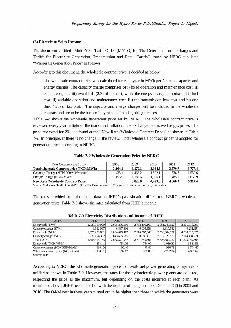
Preparatory Survey for the Hydro Power Rehabilitation Project in Nigeria
7-5
(3) Electricity Sales Income
The document entitled ”Multi-Year Tariff Order (MYTO) for The Determination of Charges and
Tariffs for Electricity Generation, Transmission and Retail Tariffs” issued by NERC stipulates
“Wholesale Generation Price” as follows:
According to this document, the wholesale contract price is decided as below.
The wholesale contract price was calculated for each year in MWh per Naira as capacity and
energy charges. The capacity charge comprises of i) fixed operation and maintenance cost, ii)
capital cost, and iii) two thirds (2/3) of tax cost, while the energy charge comprises of i) fuel
cost, ii) variable operation and maintenance cost, iii) the transmission loss cost and iv) one
third (1/3) of tax cost. The capacity and energy charges will be included in the wholesale
contract and are to be the basis of payments to the eligible generators.
Table 7-2 shows the wholesale generation price set by NERC. The wholesale contract price is
reviewed every year in light of fluctuations of inflation rate, exchange rate as well as gas prices. The
price reviewed for 2011 is found at the “New Rate (Wholesale Contract Price)” as shown in Table
7-2. In principle, if there is no change in the review, “total wholesale contract price” is adopted for
generation price, according to NERC.
Table 7-2 Wholesale Generation Price by NERC
Year Commencing 1 July 2008 2009 2010 2011 2012 Total wholesale Contract price (NGN/MWh) 3,104.1 3,179.1 3,364.6 3,570.7 3,777.4Capacity Charge (NGN’000/MW/month) 1,435.1 1,468.2 1,502.1 1,536.8 1,559.6Energy Charge (NGN/MWh) 1,156.5 1,186.6 1,326.1 1,485.0 1,660.9New Rate (Wholesale Contract Price) 3,826.6 4,429.0 4,868.9 5,317.4Source: Multi-Year Tariff Order (MYTO) for The Determination of Charges and Tariffs for Electricity Generation
The rates provided from the actual data on JHEP’s past situation differ from NERC’s wholesale
generation price. Table 7-3 shows the rates calculated from JHEP’s income.
Table 7-3 Electricity Distribution and Income of JHEP SALES 2006 2007 2008 2009 2010
Energy sold (KWh) 2,138,780,000 2,698,296,000 2,762,190,160 2,381,249,922 2,365,316,993Capacity charges (KWh) 6,612,067 6,537,536 6,003,956 3,917,582 4,232,694Energy sold (NGN) 1,825,250,801 2,034,675,462 2,110,562,946 2,593,864,227 4,308,615,325Capacity charges (NGN) 730,174,352 643,695,585 590,986,418 3,912,525,525 7,214,434,271Total (NGN) 2,555,425,153 2,678,371,047 2,701,549,364 6,506,389,752 11,523,049,596Energy sold (NGN/WMh) 853.41 754.06 764.09 1,089.29 1,821.58Capacity charges (1000/GNN/MWh) 110.43 98.46 98.43 998.71 1,704.45Wholesale contract price (NGN/KWh) 1,194.81 992.62 978.05 2,732.34 4,871.67Source: JHPS
According to NERC, the wholesale generation price for fossil-fuel power generating companies is
unified as shown in Table 7-2. However, the rates for the hydroelectric power plants are adjusted,
respecting the price as the maximum, but depending on the costs incurred at each plant. As
mentioned above, JHEP needed to deal with the troubles of the generators 2G4 and 2G6 in 2009 and
2010. The O&M cost in these years turned out to be higher than those in which the generators were

Preparatory Survey for the Hydro Power Rehabilitation Project in Nigeria
7-6
operated without problems. The prices in 2009 and 2010 were therefore adjusted, being set at higher
levels. Taking into account this situation, this survey estimated JHEP’s income by using the data of
the year 2008 during which the generators normally operated, as previously calculated in the O&M
cost. As for the wholesale contract price provided by NERC from 2008 to 2012, 14.54 percent of the
annual rate is going up. This increasing rate is for implementing the policy objective of MYTO
which achieves the system of the wholesale contract price which covers cost. The policy objective
of MYTO will be accomplished in 2012. For this reason, it is expected that it becomes the wholesale
contract price increasing rate for covering the rise of cost after 2012. While the past increasing rate
of wholesale contract price is 14.5 percent, the increase rate of the past O&M cost is 11.0 percent.
Thus, as for a price increasing rate, it is recommendable to set up the rate within the range of 11.0 to
14.5 percent. The survey adopted the wholesale contract price increasing rate as 12.0 percent per
year.
7.2.4 Result of Financial Evaluation
(1) Result of FIRR and B/C
This survey carried out a financial evaluation for the three options. As described in Table 7-4, the
fact that FIRRs for options 2 and 3 are much higher than the loan interest rate indicates that the
Project is feasible. However, in option 1, the result was not feasible. The result showing the highest
FIRR under option 3 also indicates that the four generators should be rehabilitated, if possible. In
options 2 and 3 the result concerning B/C with 1.4 percent of the loan interest rate also reaches
much higher than 1.0, and option 3 provides the better result.
Table 7-4 Result of Financial Analysis
FIRR, NPV,B/C Option 1
2 units Option 2 3 units
Option 3 4 units
FIRR (Project FIRR) - 10.84% 12.93%
NPV under Loan Interest Rate (1.4%) -155,502 335,919 694,029
B/C under Loan Interest Rate (1.4%) 0.86 1.27 1.49
(2) Sensitivity Analysis
Taking Option 3 as the basis, this survey carried out the sensitive analysis with assumptions that the
O&M cost as well as the revenue are changed. Table 7-5 shows the result of all cases. If FIRR of the
column is coloured, it means the number is minus meaning that these cells are not feasible. In
Option 3, even if the revenue may decrease by 30 percent it will be feasible unless cost increase 10
percent. Even if conditions may change, the possibility of business success is high. In Option 2, the
cell which is not feasible has increased. Option 1 is turned out to be unfeasible, unless there is
reduction of cost and a rise of revenue.

Preparatory Survey for the Hydro Power Rehabilitation Project in Nigeria
7-7
Table 7-5 Result of Sensitivity Analysis
FIRR Sensitivity to Changes in Cost and Revenue (Option 1:2 units) Change in Cost
20% decrease 10% decrease Base case 10% increase 20% increase
Cha
nge
in R
even
ue 30% increase 16.6% 13.2% 9.3% 3.4% -
20% increase 13.7% 9.9% 4.5% -10.8% -
10% increase 10.6% 5.4% -8.1% - -
Base case 6.3% -5.6% - - -
10% decrease -3.1% - - - -
20% decrease - - - - -
30% decrease - - - - -
FIRR Sensitivity to Changes in Cost and Revenue (Option 2:3 units) Change in Cost
20% decrease 10% decrease Base case 10% increase 20% increase
Cha
nge
in R
even
ue 30% increase 20.8% 19.1% 17.4% 15.7% 13.9%
20% increase 18.9% 17.2% 15.4% 13.6% 11.7%
10% increase 17.0% 15.2% 13.3% 11.3% 8.9%
Base case 14.9% 13.0% 10.8% 8.4% 5.1%
10% decrease 12.6% 10.4% 7.7% 3.9% -4.1%
20% decrease 9.9% 6.9% 2.4% -11.4% -
30% decrease 6.0% 0.0% - - -
FIRR Sensitivity to Changes in Cost and Revenue (Option 3:4 units) Change in Cost
20% decrease 10% decrease Base case 10% increase 20% increase
Cha
nge
in R
even
ue 30% increase 20.5% 19.2% 18.0% 16.8% 15.5%
20% increase 19.0% 17.7% 16.4% 15.1% 13.8%
10% increase 17.4% 16.1% 14.8% 13.4% 12.0%
Base case 15.7% 14.4% 12.9% 11.4% 9.7%
10% decrease 13.9% 12.4% 10.8% 9.0% 6.8%
20% decrease 11.9% 10.1% 8.1% 5.5% 1.4%
30% decrease 9.4% 7.0% 3.7% -2.9% -
7.3 Economic Evaluation
7.3.1 Costs
For the economic evaluation, this survey used the same investment cost and the O&A cost as
adopted for the financial evaluation. The tax-related cost from 2006 to 2010 accounted for on
average 1.58 percent of the O&M cost. For the economic analysis, the tax-related cost was removed
from the O&M cost.

Preparatory Survey for the Hydro Power Rehabilitation Project in Nigeria
7-8
Table 7-6 Tax Payment of JHEP (unit:NGN)
VAT WHT Payee Total tax payment
O&M cost Tax ratein O&M
2006 13,975,699 15,647,494 12,131,261 41,754,455 2,047,028,967 2.04%2007 14,332,561 14,332,561 14,376,222 43,041,345 2,264,167,476 1.90%2008 13,210,226 12,556,286 16,717,617 42,484,128 2,521,018,918 1.69%2009 6,188,156 12,318,033 18,524,836 37,030,984 3,292,091,609 1.12%2010 30,725,802 29,215,940 19,264,780 79,206,521 6,872,547,853 1.15%
Average 1.58%Source: JHEP
7.3.2 Revenues
The economic evaluation is a tool to review projects from a viewpoint of the national economics.
“Revenues” therefore should be the total amount of tariffs that end-consumers paid rather than the
total amount of wholesale prices paid from TCN to PHCN. According to NERC, the average of the
tariffs is about 10N/kWh although different tariffs are proposed depending on customer types. This
survey therefore adopted for this analysis 10N/kWh as tariff. The survey also used 30 percent as a
rate of transmission loss.
Table 7-7 Tariff in Nigeria Tariff schedule or the year
(Unit: energy NGN/KWh) Year 2008 2009 2010 2011 2012
Residential Residential R1 1.2 1.3 1.8 2.2 2.2Residential R2 4.0 4.4 5.9 7.3 7.4Residential R3 6.0 6.6 8.9 11.0 11.2Residential R4 8.5 9.4 12.5 15.6 15.8Residential R5 8.5 9.4 12.5 15.6 15.8Commercial Commercial C1 6.5 7.4 9.4 11.1 11.3Commercial C2 8.5 9.7 12.3 14.5 14.8Commercial C3 8.5 9.7 12.3 14.5 14.8Commercial C4 8.5 9.7 12.3 14.5 14.8Industrial Industrial D1 6.5 7.9 9.8 11.7 12.1Industrial D2 8.5 10.3 12.9 15.2 15.8Industrial D3 8.5 10.3 12.9 15.2 15.8Industrial D4 8.5 10.3 12.9 15.2 15.8Industrial D5 8.5 10.3 12.9 15.2 15.8Special Special A1 5.7 6.9 8.6 11.2 11.6Special A2 5.7 6.9 8.6 11.2 11.6Special A2 5.7 6.9 8.6 11.2 11.6Special A2 5.7 6.9 8.6 11.2 11.6Street Lighting Street Lighting S1 6.5 5.9 6.8 8.6 9.6
Source: Multi-Year Tariff Order (MYTO) for The Determination of Charges and Tariffs for Electricity Generation

Preparatory Survey for the Hydro Power Rehabilitation Project in Nigeria
7-9
This analysis is also intended to compare a case with the implementation of the Project to that
without the implementation. For this purpose, this survey considered a gap between the total amount
of the collected tariffs when the Project was implemented and that without the Project as benefit.
Tariff is rising by 17.0 percent on the average till 2008 to 2012. This increasing rate is for
implementing the policy objective of MYTO which achieves the tariff which covers cost. The
policy objective of MYTO will be accomplished in 2012. For this reason, it is expected that it
becomes the tariff increasing rate for covering the rise of cost after 2012. While the past increasing
rate of tariff is 17.0 percent, the past O&M cost increasing rate is 11.0%. A price increasing rate is
recommended to be in the range of 11.0 to 17.0 percent. The survey adopted the tariff increasing
rate as 12.0 percent per year. The survey assumed, taking into account the case that rehabilitation
was not carried out, that power generation stops from 2021. For this reason, the saving effect of
alternative electricity purchase cost is included after 2021. The saving effect of alternative electricity
purchase cost is considered as difference of wholesale contract price of MYTO and the sales electric
charges of JHEP.
7.3.3 Result of Economic Evaluation
(1) Result of EIRR and B/C
An economic evaluation was carried out for the three options i.e. as described in Table 7-8, EIRRs
in all cases highly exceed 12.0 percent which is the standard indicator for economic analyses. It
implies that the economic benefit of the Project is significant. As the result shows the highest EIRR
under Option 2, it would be desirable to rehabilitate three generators. The results concerning NPV
and B/C with 12 percent of the discount rate also reach much higher than 1.0, and Option 3 provides
the better result.
Table 7-8 Result of Economic Analysis
EIRR, NPV, B/C
Option 1 2 units
Option 2 3 units
Option 3 4 units
EIRR (Project EIRR) 36.68% 40.97% 39.73%
NPV under 12% Discount Rate 360,186 596,973 737,756
B/C under 12% discount Rate 5.23 7.69 8.67
(2) Sensitivity Analysis
Taking Option 3 as the basis, the sensitive analysis was carried out with assumptions that the O&M
cost as well as the revenue are changed. Table 7-9 shows the result of all cases. In all three options,
EIRR highly exceeds 12.0 percent, in the condition that revenue decreases by 30 percent and cost
increases by 20 percent. All three options show that sufficient economic benefit will be generated,
even if conditions may change.

Preparatory Survey for the Hydro Power Rehabilitation Project in Nigeria
7-10
Table 7-9 Result of Sensitivity Analysis
EIRR Sensitivity to Changes in Cost and Revenue (Option 1:2 units) Change in Cost
20% decrease 10% decrease Base case 10% increase 20% increase
Cha
nge
in R
even
ue 30% increase 42.4% 41.7% 41.0% 40.3% 39.6%
20% increase 41.1% 40.4% 39.6% 38.9% 38.2%
10% increase 39.7% 39.0% 38.2% 37.5% 36.8%
Base case 38.2% 37.4% 36.7% 35.9% 35.2%
10% decrease 36.6% 35.8% 35.0% 34.3% 33.5%
20% decrease 34.8% 33.9% 33.2% 32.4% 31.7%
30% decrease 32.7% 31.9% 31.1% 30.3% 29.6%
EIRR Sensitivity to Changes in Cost and Revenue (Option 2:3 units) Change in Cost
20% decrease 10% decrease Base case 10% increase 20% increase
Cha
nge
in R
even
ue 30% increase 46.6% 46.0% 45.4% 44.8% 44.2%
20% increase 45.3% 44.6% 44.0% 43.4% 42.8%
10% increase 43.8% 43.2% 42.5% 41.9% 41.3%
Base case 42.3% 41.6% 41.0% 40.3% 39.7%
10% decrease 40.6% 39.9% 39.2% 38.6% 38.0%
20% decrease 38.7% 38.0% 37.3% 36.7% 36.1%
30% decrease 36.6% 35.9% 35.2% 34.6% 33.9%
EIRR Sensitivity to Changes in Cost and Revenue (Option 3:4 units) Change in Cost
20% decrease 10% decrease Base case 10% increase 20% increase
Cha
nge
in R
even
ue 30% increase 44.5% 44.0% 43.6% 43.1% 42.6%
20% increase 43.4% 42.9% 42.4% 41.9% 41.4%
10% increase 42.1% 41.6% 41.1% 40.6% 40.1%
Base case 40.8% 40.2% 39.7% 39.2% 38.7%
10% decrease 39.3% 38.7% 38.2% 37.7% 37.2%
20% decrease 37.6% 37.1% 36.5% 36.0% 35.5%
30% decrease 35.7% 35.2% 34.6% 34.1% 33.6%

Chapter 8
Project Effect Indicators

Preparatory Survey for the Hydro Power Rehabilitation Project in Nigeria
8-1
Chapter 8 Project Effect Indicators
8.1 Project Effect Indicators
8.1.1 Quantitative Effects
Generally speaking, equipment is replaced as it approaches the service limit, and the following
improvement effects can be anticipated in line with the implementation of the rehabilitation
work under the Japanese ODA Loan Scheme. These effects are usually manifested in various
combinations.
At the initial stage of the Preparatory Survey, the Team held up the following nine Project
effect indicators with potential quantitative nature for further study as stated in Section 3.5:
(1) Maintenance and improvement of plant safety and reliability,
(2) Extension of the equipment service limit and recovery of performance,
(3) Reduction of maintenance cost,
(4) Improvement in output, efficiency and generated power,
(5) Environmental improvement,
(6) Revision of conditions of use and specifications,
(7) Ratio of utilisation of the facilities,
(8) Electric power at generation end, and
(9) Unplanned stoppage-time of operation.
However, as a result of analysis of the data available in JHPS, it was found that some of the
nominated indicators, namely (4), (6), (8) and (9) will not represent the quantitative
improvement even after completion of the Project. Such Project effect will be evaluated as
qualitative one if such effect is confirmed.
(1) Maintenance and improvement of plant safety and reliability
1) Maintenance of stabilization of power generation
Function of generating units is to be improved through the rehabilitation of the Project. Total
output of the generator units can be used to assess the Project effect.
Meanwhile, the effective water volume which is used by one unit to generate power is 380m3/s.
The maximum water volume used by six units is 2,280m3/s; however such volume cannot be
obtained all through the year, since the inflow volumes into Jebba reservoir are less than the
above maximum water volume for generation, as shown in Table 8-1.
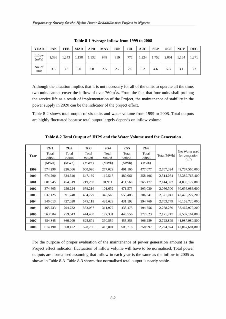
Preparatory Survey for the Hydro Power Rehabilitation Project in Nigeria
8-2
Table 8-1 Average inflow from 1999 to 2008
YEAR JAN FEB MAR APR MAY JUN JUL AUG SEP OCT NOV DEC
Inflow (m³/s)
1,336 1,243 1,138 1,132 948 819 771 1,224 1,752 2,001 1,164 1,271
No. of unit
3.5 3.3 3.0 3.0 2.5 2.2 2.0 3.2 4.6 5.3 3.1 3.3
Although the situation implies that it is not necessary for all of the units to operate all the time,
two units cannot cover the inflow of over 760m3/s. From the fact that four units shall prolong
the service life as a result of implementation of the Project, the maintenance of stability in the
power supply in 2020 can be the indicator of the project effect.
Table 8-2 shows total output of six units and water volume from 1999 to 2008. Total outputs
are highly fluctuated because total output largely depends on inflow volume.
Table 8-2 Total Output of JHPS and the Water Volume used for Generation
For the purpose of proper evaluation of the maintenance of power generation amount as the
Project effect indicator, fluctuation of inflow volume will have to be normalised. Total power
outputs are normalised assuming that inflow in each year is the same as the inflow in 2005 as
shown in Table 8-3. Table 8-3 shows that normalised total output is nearly stable.
Year
2G1 2G2 2G3 2G4 2G5 2G6
Total(MWh)Net Water used for generation
(m3)
Total output
Total output
Total output
Total output
Total output
Total output
(MWh) (MWh) (MWh) (MWh) (MWh) (Mwh)
1999 574,290 226,866 660,096 277,029 491,166 477,877 2,707,324 49,787,568,000
2000 674,290 334,640 647,169 119,518 480,061 258,406 2,514,084 38,389,766,400
2001 601,945 454,519 219,280 91,911 411,560 365,177 2,144,392 34,830,172,800
2002 374,805 256,224 679,216 101,652 471,573 203,030 2,086,500 30,658,089,600
2003 637,125 391,748 434,779 345,565 555,483 206,341 2,571,041 42,476,227,200
2004 540,013 427,028 575,118 435,629 431,192 294,769 2,703,749 40,158,720,000
2005 465,233 294,732 563,057 311,977 438,475 194,756 2,268,230 33,462,979,200
2006 563,904 259,643 444,490 177,331 448,556 277,823 2,171,747 32,597,164,800
2007 484,345 366,209 625,671 390,559 455,856 406,259 2,728,899 41,987,980,800
2008 614,190 368,472 528,796 418,801 505,718 358,997 2,794,974 42,067,684,800

Preparatory Survey for the Hydro Power Rehabilitation Project in Nigeria
8-3
Table 8-3 Total output of JHPS (Normalised)
Year
2G1 2G2 2G3 2G4 2G5 2G6 Total(MWh)
/Net Water of 2005(33,462,979,200m3)
Total output
Total output
Total output
Total output
Total output
Total output
(MWh) (MWh) (MWh) (MWh) (MWh) (MWh)
1999 385,989 152,480 443,661 186,195 330,120 321,188 1,819,634
2000 587,754 291,694 564,114 104,180 418,452 225,243 2,191,437
2001 578,317 436,678 210,673 88,303 395,405 350,843 2,060,218
2002 409,096 279,666 741,357 110,952 514,717 221,605 2,277,393
2003 501,930 308,621 342,521 272,238 437,612 162,556 2,025,479
2004 449,976 355,829 479,227 362,996 359,299 245,622 2,252,948
2005 465,233 294,732 563,057 311,977 438,475 194,756 2,268,230
2006 578,882 266,539 456,296 182,041 460,470 285,202 2,229,431
2007 386,006 291,856 498,638 311,262 363,302 323,774 2,174,839
2008 488,561 293,103 420,634 333,138 402,276 285,566 2,223,278
Average (1999-2008)
483,174 297,120 472,018 226,328 412,013 261,636 2,152,288
Looking at the Project’s target units of 2G1, 2G2, 2G3 and 2G5, as shown in Table 8-4, there
are some ups and downs for the total output of the four units in the range of plus or minus 15
percent even after normalisation.
Taking the situation into account, the baseline of the Project effect shall be set as the average
of total output of 2G1, 2G2, 2G3 and 2G5 from 1999 to 2008 with the range of plus or minus
15 percent. The baseline per portion shall be compared with the total output of units concerned
in the Ex-Post evaluation year which is two years after the completion of the rehabilitation
work of the lat unit per option as shown in Table 8-4. The Project effect as maintenance of
power output is to be confirmed if the total output of target units in evaluation year is in the
range of plus or minus 15 percent of the average total output of four units from 1999 to 2008.
Table 8-4 Targeted total output of each option
Option
2G1 2G2 2G3 2G5
Targeted annual output (MWh)
Ex-Post evaluation
year Total output Total output Total output Total output
(MWh) (MWh) (MWh) (MWh)
Option 1 483,174 Out of scope Out of scope 412,013 896,000 2018
Option 2 483,174 Out of scope 472,018 412,013 1,368,000 2019
Option 3 483,174 297,120 472,018 412,013 1,665,000 2020

Preparatory Survey for the Hydro Power Rehabilitation Project in Nigeria
8-4
The result shall be proved to be free from any accident by assessing the record of serious
accident, which it takes more than one month to recover in the evaluation year, because there is
a possibility for the total output to decrease in the range of 15 percent as described already and,
if such serious accident occurs in the year, it can cause the reduction of power generation. In
case there is any decrease in the total output in the year, the total output of six units and the
operating record of each unit shall be properly assessed.
2) Risk of major accidents threatening human life and property and affecting stable operation
can be reduced. As a result of higher reliability, stop by failure period can be reduced and
higher revenue can be anticipated from the power station. After completion of the Project, the
rehabilitated facilities will be operated and maintained by JHEP staffs. As JHEP assigns staffs
as O & M personnel for its rehabilitation after OJT and overseas training to be provided by the
consultant and the contractor for the Project, in particular junior JHEP staffs are inferred to
possess advanced basic O & M skills. The technical levels of maximum 20 staffs will be
improved through rehabilitation of four generation units, if realised, assuming that five staffs
have opportunities to receive technological guidance and to acquire experiences in the
rehabilitation of each generation unit.
Therefore, the number of JHPS staffs who receive OJT and overseas trainings in the course of
the Project implementation will be one of the quantitative Project effect indicators in terms of
the increase in capacity development.
Improvement of the plant safety and reliability can also be achieved during implementation of
the rehabilitation work at site through technology transfer as well as texts and OJTs offered by
engineers from the consultant and the contractor to JHPS staffs as mentioned above. However,
such effect will not be measurable quantitatively.
(2) Extension of the equipment service limit and recovery of performance
1) General
The service life of equipment can be extended through restoring degraded instruments and
recovering performance. This includes cases where problems exist in the initial performance
but performance is enhanced through subsequent technical improvement.

Preparatory Survey for the Hydro Power Rehabilitation Project in Nigeria
8-5
Figure 8-1 Relation between Deterioration and Failure Rate
If the rehabilitation project were implemented, it would extend the life of the generator
equipment to another 37 years as what was, if not carried out, the remaining life of the
generator is considered to be about 10 years. The generator units are severely degraded and
insulation aging occurred to the coils since the units have been in operation more than 25 years
without any major overhaul. There is a latent risk for a serious accident to happen during
operation. The functions of the generator units will be maintained and the lives of the units
will be prolonged through the implementation of the rehabilitation and stable power supply to
the grid in Nigeria will be expected.
Recovery of the dielectric strength, which means the remaining dielectric breakdown voltage,
of stator coils can be assessed quantitatively by so-called “D-map method” or “Maximum
partial discharge method”. The required data is measured by performing the non-destructive
test of insulation diagnosis when the machine is not operating with at least about seven days
short outage and partly disassembled condition, using special measuring equipment. The result
of D-map method is derived from discharge parameters and maximum discharge amount while
the result of maximum partial discharge method is derived from maximum discharge amount.
(a) Without rehabilitation
(b) With rehabilitation

Preparatory Survey for the Hydro Power Rehabilitation Project in Nigeria
8-6
Confirmation of the estimated dielectric strength after the completion of rehabilitation will be
one of the quantitative project effect indicator.
The measurement of dielectric strength for all of the units shall be done at the same time two
years after the completion of the rehabilitation of the last unit, which means, if four units were
rehabilitated, five years have passed since the completion of the rehabilitation of the first unit
as shown in Figure 8-2.
Figure 8-2 Schedule for Assessment
2) Recovery of Performance of Generation Facilities
As a result of implementation of the Project, the cooling function will be improved as
described in the following clause: Therefore cooling efficiency of target generation facilities
shall be adopted as a Project effect indicator. Although rehabilitation of the cooling system
itself is not included in the Project, the cooling efficiency is to be recovered by removal of
grease build-up and dust through the rehabilitation. Thus the temperature drop of main parts of
generator during rated operation is to be achieved by the Project. Main parts of generating
facilities are stator coil, stator core, rotor coil, thrust bearing shoe and guide bearing shoe. For
this reason, the Team set the temperature increase of main parts during rated operation as a
Project effect indicator. The baseline shall be the temperature increase of the main parts of
generator in 2011 and Project effect shall be assessed by confirming the temperature increase
of main parts in 2020 in case of Option 3. Since the temperatures measured in 2011 by the
Team is not the values during rated operation, normalised values as during rated operation is
adopted as the baseline. The target temperature increase in 2020 are estimated based on the
record of temperature increase at the time of construction of JHPS in 1983. It shall also be
taken into account the variation of some temperature indication because of aged deterioration
of the indicators. Operation records of other years shall be also referred to in order to minimise
the effect of such deterioration when the temperatures will be measured in 2020. The values of
the base line in 2011 and the target values in 2020 are shown in Table 8-5.

Preparatory Survey for the Hydro Power Rehabilitation Project in Nigeria
8-7
Table 8-5 Baseline Value and Target Value of Temperature of Rehabilitated Parts
Indicator Baseline;
Temperature increase in 2011
Target value (Estimated values for 2 years after the Project);
Temperature increase in 2020 Reduction of temperature increase (Recovery of cooling efficiency)
Stator coil: 63 K (Base temp. Temperature of outlet of air cooler)
Stator coil: 61 K (Base temp. Temperature of outlet of air cooler)
Stator core: 54 K (Base temp. Temperature of outlet of air cooler)
Stator Core: 50K (Base temp. Temperature of outlet of air cooler)
Rotor coil: 45 K (Base temp. Temperature of outlet of air cooler)
Rotor coil: 44.5 K (Base temp. Temperature of outlet of air cooler)
Thrust bearing shoe: 9 K (Base temp. Temperature of Bearing oil)
Thrust Bearing shoe: 8 K (Base temp. Temperature of Bearing oil)
Guide bearing shoe: 9K Base temp. Temperature of Bearing oil)
Guide bearing shoe: 8K (Base temp. Temperature of Bearing oil)
Recovery of performance of generation facilities in terms of cooling efficiency can be
measured quantitatively as follows:
Temperature decrease during rated operation in stator coil, stator core, rotor coil, thrust bearing
shoe and guide bearing shoe can be expected as a result of the Project since these equipment
becomes cleaner by the replacement and/or repaired through the rehabilitation. For this reason,
the degree of recovery of cooling efficiency can be taken as the Project Effect Indicator by
comparing data recorded by JHPS during normal operation before the commencement of
rehabilitation with those to be measured two years after the completion of rehabilitation.
i) Stator Coil
Figure 8-3 Temperature at Stator Coil

Preparatory Survey for the Hydro Power Rehabilitation Project in Nigeria
8-8
ii) Stator Core
Figure 8-4 Temperature at Stator Core
iii) Rotor Coil
Figure 8-5 Temperature at Rotor Coil

Preparatory Survey for the Hydro Power Rehabilitation Project in Nigeria
8-9
iv) Thrust Bearing Shoe
Figure 8-6 Temperature at Thrust Bearing Shoe
v) Guide Bearing Shoe
Figure 8-7 Temperature at Guide Bearing Shoe
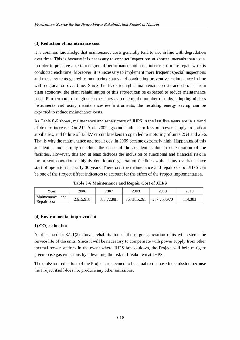
Preparatory Survey for the Hydro Power Rehabilitation Project in Nigeria
8-10
(3) Reduction of maintenance cost
It is common knowledge that maintenance costs generally tend to rise in line with degradation
over time. This is because it is necessary to conduct inspections at shorter intervals than usual
in order to preserve a certain degree of performance and costs increase as more repair work is
conducted each time. Moreover, it is necessary to implement more frequent special inspections
and measurements geared to monitoring status and conducting preventive maintenance in line
with degradation over time. Since this leads to higher maintenance costs and detracts from
plant economy, the plant rehabilitation of this Project can be expected to reduce maintenance
costs. Furthermore, through such measures as reducing the number of units, adopting oil-less
instruments and using maintenance-free instruments, the resulting energy saving can be
expected to reduce maintenance costs.
As Table 8-6 shows, maintenance and repair costs of JHPS in the last five years are in a trend
of drastic increase. On 21st April 2009, ground fault let to loss of power supply to station
auxiliaries, and failure of 330kV circuit breakers to open led to motoring of units 2G4 and 2G6.
That is why the maintenance and repair cost in 2009 became extremely high. Happening of this
accident cannot simply conclude the cause of the accident is due to deterioration of the
facilities. However, this fact at least deduces the inclusion of functional and financial risk in
the present operation of highly deteriorated generation facilities without any overhaul since
start of operation in nearly 30 years. Therefore, the maintenance and repair cost of JHPS can
be one of the Project Effect Indicators to account for the effect of the Project implementation.
Table 8-6 Maintenance and Repair Cost of JHPS
Year 2006 2007 2008 2009 2010
Maintenance and Repair cost
2,615,918 81,472,881 168,815,261 237,253,970 114,383
(4) Environmental improvement
1) CO2 reduction
As discussed in 8.1.1(2) above, rehabilitation of the target generation units will extend the
service life of the units. Since it will be necessary to compensate with power supply from other
thermal power stations in the event where JHPS breaks down, the Project will help mitigate
greenhouse gas emissions by alleviating the risk of breakdown at JHPS.
The emission reductions of the Project are deemed to be equal to the baseline emission because
the Project itself does not produce any other emissions.

Preparatory Survey for the Hydro Power Rehabilitation Project in Nigeria
8-11
Table 8-7 CO2 Emission Reduction
Total Contributing Output
for CO2 Reduction (GWh)
Amount of baseline
emissions (tCO2/MWh)
Amount of emissions from project
(tCO2)
Leakage (tCO2)
Total emission reductions
(tCO2)
Option 1 (2 Units
Rehabilitation) 26,158 22,076,600 0 0 17,661,600
Option 2 (3 Units
Rehabilitation) 38,870 32,805,170 0 0 26,244,800
Option 3 (4 Units
Rehabilitation) 46,175 38,971,036 0 0 31,177,600
It is conservatively assumed that 80% of expected average power output will be generated for
the prolonged period due to deterioration of turbine, because turbines are out of scope of this
rehabilitation but the total life of turbine were also estimated for about 40 years. As a result,
the emission reduction will be 17,661,600 tCO2, 26,244,800 tCO2, and 31,177,600 tCO2 in
case two units (Option 1), three units (Option 2) and four units (Option 3) are rehabilitated
respectively.
2) Reduction of hazardous materials in generation facilities
Generator component will be free of asbestos by renovating insulating layer for joints of stator
cores, high resistance corona shields for stator coils and layer insulation materials for rotor
coils, all of which contain asbestos. As a result, use of asbestos free parts in the rehabilitation
will be one of the Project effect indicators for environmental improvement by means of
reduction of hazardous substances in the generation units.
Table 8-8 Reduction of Asbestos in Generation Facilities
(1) Before rehabilitation work
No. Checked point Unit 2G1 2G2 2G3 2G5
1 Asbestos material usage for stator core (Insulation sheets for joints)
set 1 1 1 1
2 Asbestos material usage for stator coil (High resistance corona shields)
set 1 1 1 1
3 Asbestos material usage for rotor coil (Layer insulation material)
set 1 1 1 1
4 Usage of asbestos material set 3 3 3 3
5 Environment improvement - Required Required Required Required
(2) After rehabilitation work
No. Checked point Unit 2G1 2G2 2G3 2G5
1 Asbestos material usage for stator core (Insulation sheets for joints)
set 0 0 0 0
2 Asbestos material usage for stator coil (High resistance corona shields)
set 0 0 0 0

Preparatory Survey for the Hydro Power Rehabilitation Project in Nigeria
8-12
3 Asbestos material usage for rotor coil (Layer insulation material)
set 0 0 0 0
4 Usage of asbestos material set 0 0 0 0
5 Environment improvement - Improved Improved Improved Improved
(5) Ratio of utilization of the facilities
Rate of utilization of facilities (rate of utilization of measuring instruments to monitor the
status of generators)
The Project will renovate measuring instruments such as resistance temperature detector,
thermocouple and dial thermometer to monitor the operational status of generators. Rate of
utilization of such measuring instruments will be increased. Increase in quantity of renovated
instruments before the Project implementation will be one of the Project effect indicators.
Table 8-9 Improvement of Utilization Rate of Monitoring Devices
(1) Before rehabilitation work
No. Checked point Unit 2G1 2G2 2G3 2G5
A1-A5 The number of installed instruments pcs 33 33 33 33
B1-B5 The number of broken instruments pcs 5 8 1 6
C Instrument failure rate % 15 24 3 18
D Instrument availability ratio % 85 76 97 82
(2) After rehabilitation work
No. Checked point Unit 2G1 2G2 2G3 2G5
A1-A5 The number of installed instruments pcs 33 33 33 33
B1-B5 The number of broken instruments pcs 0 0 0 0
C Instrument failure rate % 0 0 0 0
D Instrument availability ratio % 100 100 100 100
8.1.2 Qualitative effects
(1) Maintaining Highly Reliable Operation
JHPS (rated output 578.4 MW) is a major facility that accounts for roughly 12.5 percent of
Nigeria’s total generating capacity and is highly reliable in terms of Average Monthly MW
Availability as shown in Figure 8-8. Maintenance of highly reliable operation and extension of
service life as a result of the Project implementation will lead to the stabilisation of generating
capacity of the target generation units in JHPS and will contribute to the state power policies
of stabilising power supply and diversifying energy sources in Nigeria, where the power
demand and supply situation is very tight.

Preparatory Survey for the Hydro Power Rehabilitation Project in Nigeria
8-13
source: NCC
Figure 8-8 Average Monthly MW Availability of Major Power
Plants from 2007 to 2010
(2) Capacity development for self-help maintenance of the power plant
JHPS does not have an experience of rehabilitation and overhaul since start of its operation in
1985. As a result of Project implementation, through technical training and technology transfer
to junior staffs of JHPS by engineers from the consultant and the contractor for the Project, the
technical level of Nigerian staffs will expect to increase and thus it will be possible to lay the
foundation for Nigerian staffs to be able to carry out the rehabilitation work by themselves in
future. Thus, the Project will assist the self- help effort by Nigerian staffs in the power sector.
(3) Improvement in output, efficiency and generated electrical energy
In general, it is expected that through the rehabilitation of units’ performance of degraded
equipment with reduced efficiency and reliability, the power output in a year or efficiency can
be increased. However, in case of JHPS, operating condition or performance of single
generation unit may not necessarily be the determining factor in the total power output because
of the following reasons:
1) Availability of water for power generation is less than the required water volume to sustain
full units operation particularly in dry season as shown in Table 8-5.
Table 8-10 Inflow Rate of Water into Jebba Reservoir (Average inflow rate from 2006 to 2010) (unit: m3/sec)
January February March April May June
Inflow rate 1,270 1,226 1,195 1,245 1,141 833
July August September October November December
Inflow rate 753 1,242 2,184 2,138 1,401 1,341 Note: (1) Inflow from Kainji Dam and tributaries of Jebba Reservoir, and evaporation loss are taken into account.
(2) Effective water volume for 6 units: 2,280m3/sec (6 units x 380m3/sec)
2) Due to the limited storage capacity of water in Jebba reservoir, the discharge from Kainji
reservoir is almost always regulated so as not to cause any unnecessary overflow from the
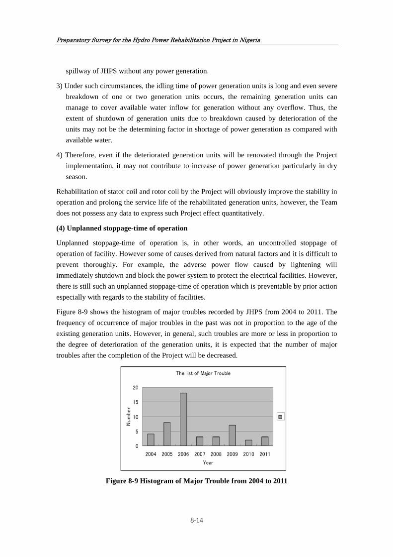
Preparatory Survey for the Hydro Power Rehabilitation Project in Nigeria
8-14
spillway of JHPS without any power generation.
3) Under such circumstances, the idling time of power generation units is long and even severe
breakdown of one or two generation units occurs, the remaining generation units can
manage to cover available water inflow for generation without any overflow. Thus, the
extent of shutdown of generation units due to breakdown caused by deterioration of the
units may not be the determining factor in shortage of power generation as compared with
available water.
4) Therefore, even if the deteriorated generation units will be renovated through the Project
implementation, it may not contribute to increase of power generation particularly in dry
season.
Rehabilitation of stator coil and rotor coil by the Project will obviously improve the stability in
operation and prolong the service life of the rehabilitated generation units, however, the Team
does not possess any data to express such Project effect quantitatively.
(4) Unplanned stoppage-time of operation
Unplanned stoppage-time of operation is, in other words, an uncontrolled stoppage of
operation of facility. However some of causes derived from natural factors and it is difficult to
prevent thoroughly. For example, the adverse power flow caused by lightening will
immediately shutdown and block the power system to protect the electrical facilities. However,
there is still such an unplanned stoppage-time of operation which is preventable by prior action
especially with regards to the stability of facilities.
Figure 8-9 shows the histogram of major troubles recorded by JHPS from 2004 to 2011. The
frequency of occurrence of major troubles in the past was not in proportion to the age of the
existing generation units. However, in general, such troubles are more or less in proportion to
the degree of deterioration of the generation units, it is expected that the number of major
troubles after the completion of the Project will be decreased.
Figure 8-9 Histogram of Major Trouble from 2004 to 2011

Preparatory Survey for the Hydro Power Rehabilitation Project in Nigeria
8-15
For the detail of troubles and repairs in JHPS, reference shall be made to Appendix-8.
8.2 Reduction of Greenhouse Gas
Ex-ante estimation of emission reductions over the chosen period
8.2.1 Project boundary
Project’s boundary includes all artificial greenhouse gas emission sources caused by the
implementation of the Project which are under the supervision of the Project participants
remarkably. Specifically, the Project boundary includes all power plants physically connected
to the power grid, connected to the Project site of JHPS. The Project supplies the generated
power to supply to Nigeria national power grid as Project boundary as shown in Figure 8-10.
8.2.2 Baseline and its development
A purpose of this estimation is to estimate CO2 emissions reduction by trying to prolong the
life of generators of JHPS. The reduction shall be achieved by supplying the power generated
from JHPS instead of supplying the power generated with fossil fuels. It is important to assess
carefully about which power source to substitute since the reduction largely depends on the
baseline emission factor of the power plant substituted in the Project. However, it is very
difficult to specify the alternative power source because the alternative power source is
influenced by various factors, such as the power configuration of a target power grid, power
demand-and-supply balance at present and in the future, the scale of the present Project and the
influence on the power grid, future power prediction, management policy of the relevant power
company, decision of the administrator of the power grid, etc. There are three simple methods
Niger River
Jebba reservoir
JHPS waterway (from
intake to Afterbay
through penstock pipe)
JHPS
JHPS switchyard
Nigeria national power grid
Consumers
Figure 8-10 Project Boundary
Project boundary

Preparatory Survey for the Hydro Power Rehabilitation Project in Nigeria
8-16
to estimate the CO2 emissions of the power plant to be substituted which are operating margin
(OM), build margin (BM) and combined margin (CM). CM for presumption of the baseline
emission factor is used to estimate CO2 emission comprehensively. CO2 emission reduction is
to be estimated quantitatively from the base-line emission based on CM (Figure 8-11).
Figure 8-11 Operating Margin and Build Margin
8.2.3 Explanation of Methodology
Four methods, which are (1) Dispatch Data Analysis OM, (2) Simple OM, (3) Simple Adjusted
OM and (4) Average OM, are proposed for estimation of OM as a part of constituting CM. An
applicable method is selected based on the OM inspection flow as shown in Figure 8-13.
Dispatch Data Analysis OM is the best way having the highest priority. With Dispatch Data
Analysis, the annual total CO2 emission reductions of the Project is calculated for all time
zones during which the power is supplied to the power grid through the implementation of the
Project. Specifically, the CO2 emission factor of Dispatch Data Analysis, OM is also
calculated every hour. To calculate Dispatch Data Analysis OM, the first step is to determine
the priority of power plant for all power plants based on the power supplied from in the
relevant power grid, and then power plants generating 10 percent of supplied power in
ascending order from the bottom. In this Project, however, it is difficult to collect hourly
power data supplied from all power plants in the power grid in which the Project is working,
and this is not realistic taking into account of the scale of the power grid which is very large
compared with the scale of the Project. Therefore, it can be said that the application of
Dispatch Data Analysis is very hard.
Generally, the low cost/must-run power source includes hydropower, wind power, biomass
and photovoltaic etc. It is clear from the share of power sources that the average ratio of the
low-cost/must-run power generation to the annual power production in the last five years is
Data of each power plant (2008, 2009
and 2010) that can be obtained from
PHCN
Data of five power plants established
most recently or data of power plants
established recently having a
generation capacity that accounts for
20 percent of the total power
production of the entire power grid
Operating margin
(OM)
Build margin
(BM)
Combined
margin
(CM)

Preparatory Survey for the Hydro Power Rehabilitation Project in Nigeria
8-17
50% or less. Therefore, gas thermal power is also included in the low-cost/must-run power
source. From these situations, it is not desirable to apply Dispatch Data Analysis OM, Simple
Adjusted OM or Average OM from OM inspection flow as shown in Figure 8-13 for OM
estimation, and therefore Simple OM is applied.
The baseline is calculated from past records (for the last three years), and the configuration of
national power grid in Nigeria is shown in Figure 8-12.

Preparatory Survey for the H
ydro Pow
er Rehabilitation P
roject in Nigeria
8-18
Figure 8-12 National Power Grid in Nigeria
Note: At present, transmission line is operated with 330KV and 132KV line, and in future 700KV line is considered as first transmission line.
Source: TCN, as of 2011

Preparatory Survey for the Hydro Power Rehabilitation Project in Nigeria
8-19
Source: ACM0002, UNFCCC
Figure 8-13 OM Flow Chart
8.2.4 Ex-ante Estimation of Emission Reductions
The amount of baseline emissions is estimated with the following steps: The amount of baseline
emissions is represented by a combined value of the operating margin (OM) and the build
margin (BM).
Step-1 Estimation of operating margin (OM)
Step-2 Estimation of build margin (BM)
Step-3 Estimation of baseline emission factor and combined margin (CM)
Step-4 Estimation of leakage
Step-5 Estimation of emission reductions

Preparatory Survey for the Hydro Power Rehabilitation Project in Nigeria
8-20
In estimations, sufficient data cannot be obtained for dispatch data analysis. The power
production from low-cost/must-run power plants is 21.7 percent which means 50 percent or less
of the annual total power production of the power grids. Therefore, estimations are performed
based on Simple OM from the estimation tree of the operating margin (OM) referring to Figure
8-13.
Table 8-11 shows the records of thermal and hydro power generation from 2008 to 2010.
Table 8-11 Records of Thermal and Hydro Power Generation from 2008 to 2010
(Unit: GWh) Year 2008 2009 2010
Thermal Total 13,866 13,429 17,604
Hydro Total 7,443 7,465 7,416
Hydro and Thermal Total
21,309 20,893 25,020
20% of Hydro and Thermal Total
4,262 4,179 5,004
20% Thermal Total 2,773 2,686 3,520
(1) Estimation of operating margin (OM)
Records for the last three years (2008, 2009 and 2010) are used as the total power production of
national power grid. The purchased power is subtracted as it is, and the power for station service
is subtracted from the power production of each power station.
The average of data announced is used for the average combustion characteristic value as Net
Calorific Value (NCV).
Table 8-12 Average Net Calorific value (NCV)
Fuel type Average Net Calorific Value
(NCV)(Mcal/fuel t) CO2 Emission Factor
(tCO2/fuel t)
Natural gas (NG) 11,717 2.733
Diesel (light oil) 8,670 2.659
1) Amount of emissions from natural gas (NG) thermal power
Amount of CO2 emissions from gas thermal power plant per unit (tCO2/MWh)
=Gas consumption per unit (gas t/MWh)×CO2 emission factor per unit of gas (tCO2/gas t)
CO2 emission factor (tCO2/gas t) per unit of gas
=Average NCV of gas (M cal/gas t)×IPCC emission factor of gas (tCO2/GJ)
×Oxidization coefficient of gas×Conversion factor from joule of calorie
=11,717×0.056×0.995×0.004186=2.733(tCO2/gas t)

Preparatory Survey for the Hydro Power Rehabilitation Project in Nigeria
8-21
Where, IPCC emission factor of gas=0.056 tCO2/GJ
Oxidization coefficient of gas=99.5%
Conversion factor from joule to calorie=4.186*10-3
(IPCC: Intergovernmental Panel on Climate Change)
Therefore, the default value of 2.733(tCO2/gas t) is applied as CO2 emission factor per unit of
gas.
Thermal efficiency of gas (%)
= NCV of gas (M cal/gas t)/Theoretical calorific value of gas (M cal/gas t)
=11,717÷13,019=0.9
Therefore, Annual amount of emissions (tCO2/y)
=2.733×Annual fuel consumption (M fuel t/year)÷Thermal efficiency of gas (%)
2) Amount of emissions from diesel (light oil) thermal power
IPCC emission factor of diesel=0.074 tCO2/GJ
Oxidization coefficient of gas=99%
Conversion factor from joule to calorie=4.186*10-3
Therefore, default value of 2.659 (tCO2/fuel t) is applied as CO2 emission factor per unit of
diesel oil.
Thermal efficiency of diesel (%)
= NCV of diesel (M cal/fuel t)/Theoretical calorific value of diesel (M cal/fuel t)
=8,670÷9,126=0.95
Annual amount of emissions (tCO2/y)
=2.659×Annual fuel consumption (M fuel t/year)÷Thermal efficiency of diesel (%)
3) Estimation of average operating margin (OM)
Average operating margin OM (EFOMy) (tCO2/MWh)
=Total amount of emissions (ktCO2)÷Total power production (GWh)

Preparatory Survey for the Hydro Power Rehabilitation Project in Nigeria
8-22
Table 8-13 Average operating margin (OM) 2008 2009 2010
Annual Power Production (GWh) 13,866* 13,429* 17,604* Amount of CO2 emissions
(ktCO2/MWh) 16,046 13,222 20,170
OM (tCO2/MWh) 1.157 0.985 1.145
Average OM (tCO2/MWh) 1.096 *source: Table 8-11 Records of Thermal and Hydro power generation from 2008 to 2010
(2) Estimation of build margin (BM)
As for build margin (BM) estimation, BM is calculated in advance based on the latest
information on power plants already constructed, because one period is applied due to
generator’s prolongation period of about seven years and there is much room for improvement
of transmission loss in national power grid of Nigeria.
For power plants subjected to estimation, one of the following two options, whichever having a
larger total annual power production, must be selected:
(a) Power production of five power plants recently constructed
(b) Power plants that account for 20 percent of the power production of the power grid out of
power plants recently constructed and added to the power grid
As of 2010, the power production of five power plants recently constructed is 1,214GWh, and
that accounts for 7 percent of the power production of the power grid, out of power plants
recently constructed and added to the power grid, is 17,604GWh. Therefore, the build margin
(BM) is calculated based on the value of (b).
Table 8-14 Five Power Stations Constructed Recently (as of 2011)
Name of Power Station Power plant capacity
(MW) Annual power production
(GWh)
Olorunsogo PS (thermal power) 225 270
Ajaokuta PS (thermal power) 55 266
Sapele PS (thermal power) 1,020 514
Calabar PS (thermal power) 6.6 32
Gurara HPS(hydropower) 30 132
Total 1,336.6 1,214
BM (EFOMy) (tCO2/MWh)
=Total amount of emissions (ktCO2)÷Total power production (GWh)

Preparatory Survey for the Hydro Power Rehabilitation Project in Nigeria
8-23
Table 8-15 Build Margin (BM)
2008 2009 2010
Annual Power Production(GWh) 4,262* 4,179* 5,004*
Amount of CO2 emissions(ktCO2/MWh)
3,209 2,644 4,034
BM (tCO2/MWh) 0.753 0.633 0.806
Average BM(tCO2/MWh) 0.731
*source: Table 8-11 Situation of Thermal and Hydro power generation from 2008 to 2010
(3) Estimation of baseline emission factor and combined margin (CM)
The baseline emission factor (EF) is calculated as a combined margin (CM) of the operating
margin (OM) and the build margin (BM).
CM=EF(tCO2/Mwh)=wOM×EFBM+wBM×EFOMy
wOM=wBM=0.5 is recommended for this estimation by ACM(Approved Consolidated
Methodology) in IPCC.
Therefore, EF(tCO2/Mwh)=0.5×1.096+0.5×0.731=0.913
(4) Estimation of leakage
Leakage in rehabilitation work and operation periods of JHPS is not taken into consideration.
(5) Estimation of emission reductions
This Project is equivalent to replacing the power supplied from power plants using fossil fuel to
the power grid with the power by hydropower generation at JHPS (using renewable energy).
ER=BE-PE-L
ER: Greenhouse gas emission reductions by the Project
BE: Amount of baseline emissions
PE: Amount of emissions from the Project (assumed to be 0 because of hydropower power
generation)
L: Leakage (0)
Therefore, ER=BE
Amount of baseline emissions (BE)
=Baseline emission factor (EF)×Generated power from the Project (EG)
The power generated from the Project (EG) equals the sum of received power at grid stations,
which is taking into consideration the power transmission loss in power grid with respect to
JHPS power production (that is, the Station service and the transmission loss of power grid are
deducted).

Preparatory Survey for the Hydro Power Rehabilitation Project in Nigeria
8-24
EBG: Total JHPS power production (MWh)
TDLb: Transmission loss in power grid (7.4%) + Station service at JHPS (0.16%) =7.56%
Amount of power received (EER) at grid stations= Power generated from the project (EG)
= (1-TDLb)×EBG
Therefore, the estimated emission reductions are obtained from the following multiplication:
ER=BE=EF*EG=0.913×(1-TDLb)×EBG=0.844EBG
8.2.5 Summary of the Ex-ante Estimation of Emission Reductions
The emission reductions of the Project are deemed to be equal to the baseline emission because
the Project itself does not produce any other emission. The expected reduction of CO2 of each
option is shown in Table 8-16..
Table 8-16 Estimation of Emission Reduction
Total Contributing Output for CO2
Reduction (GWh)
Amount of baseline
emissions (tCO2/MWh)
Amount of emissions from
project (tCO2)
Leakage (tCO2)
Total emission
reductions (tCO2)
Option 1 (2 Units
Rehabilitation) 26,158 22,076,600 0 0 17,661,600
Option 2 (3 Units
Rehabilitation) 38,870 32,805,170 0 0 26,244,800
Option 3 (4 Units
Rehabilitation) 46,175 38,971,036 0 0 31,177,600
It is conservatively assumed that 80 percent of expected average power output would be
generated for the prolonged period due to the deterioration of turbines, because turbines were
out of scope of this rehabilitation project.

Chapter 9
Environmental and Social Considerations


Preparatory Survey for the Hydro Power Rehabilitation Project in Nigeria
9-1
Chapter 9 Environmental and Social Consideration
9.1 Environmental Consideration
9.1.1 Environmental Impact Assessment
(1) General
In principle, JHPS as the implementing agency for the Project is responsible for environmental
impact surveys prior to implementing the Project in accordance with government directives.
However, the Project implementation will not entail any major problems based on the fact that
roads for the works are already in place, development of renewable energy is a national policy
and the Project entails rehabilitation of a power station that was constructed 27 years ago.
(2) Assessment
Concerning the Project impact on the natural environment, the following examination was
conducted by the Team over three phases, i.e. (1) before Project implementation, (2) during
Project implementation, and (3) during Project operation.
1) Before Project implementation
The target generation facilities were constructed 27 years ago and have been continuously
working in the enclosed environment in the power house. There is no emission of exhaust gas or
waste water. Therefore, the environmental impact before Project implementation is minimal.
2) During Project implementation
The rehabilitation works itself will be done in the enclosed environment inside of the existing
powerhouse in the premises of JHPS. The rehabilitation works will engage some welding
machines and heavy equipment but such works will be done inside of the powerhouse.
Therefore, there is no implication to the surrounding environment except the treatment and
disposal of replaced parts which contain asbestos. Such hazardous materials shall be treated
safely in accordance with Nigerian environmental standard with witness by the environmental
inspector to be appointed by JHPS as the responsibility of the Project implementing body. JHPS
will entrust such treatment and disposal to the qualified specialised company in Nigeria.
Detailed implications of the disposal of waste containing asbestos are described separately in
Section 9.3.
3) During Project operation
The Project is merely replacement of the existing deteriorated generation facilities with
rehabilitated ones having the same function but improved performances. Therefore, there is no
degradation in environmental impact after completion of the Project as compared to before
Project implementation.

Preparatory Survey for the Hydro Power Rehabilitation Project in Nigeria
9-2
(3) JICA Environmental Requirement
1) General
JICA environmental standard categorised this Project as Category B. Therefore, it becomes
obligatory for the project proponent to implement environmental monitoring in line with JICA’s
guideline.
2) Environmental Checklist
Environmental checklist was elaborated using JICA’s format ‘19.Other Infrastructure Projects’.
Impacts on environment by this Project are negligible because the rehabilitation work will be
carried out by way of changing parts inside of the existing powerhouse. On the other hand,
some parts include asbestos and it is necessary to treat these parts properly at the time of
replacement work in conformity with the related Nigerian environmental regulation.
Environmental checklist assesses environmental impacts caused by such hazardous materials.
The environmental and social considerations including major impacts and mitigation measures
for the Project especially appropriate treatment and disposal of asbestos-containing waste are
summarised in this checklist as shown in Appendix-14.
3) Monitoring Form
Monitoring items reflects on items marked as ‘Yes’ in the above-mentioned checklist. The
monitoring shall cover activities of international contractor for rehabilitation works and local
professional treatment company for final disposal of asbestos-containing waste. After hazardous
materials are passed on to the local company and brought outside of project site, monitoring will
not be necessary any more. The results of monitoring will be provided to JICA on a quarterly
basis until the completion of the work handling asbestos. Monitoring Form is attached in
Appendix-15.
9.2 Social Consideration
Considering that the Project almost totally entails indoor work for replacement of turbines and
generators, etc. in a hydroelectric power station that was built 27 years ago and the work period
at site will be approximately four years, JHPS believes that impacts on the landscape and social
environment in particular outside of the premises of JHPS will be negligible and local residents
will give their consent. The Project site is located approximately 300 kilometres from the capital
Abuja and is also remote from the nearest towns and the entrance to the power station is under
constant guard, therefore, impacts on third parties will be negligible. Moreover, since most of
the work will be conducted indoors, there will be little impact in terms of vibration, particulate
or noise. In addition, since inhabited areas are far away from the station, there will be no impact
on local residents.

Preparatory Survey for the Hydro Power Rehabilitation Project in Nigeria
9-3
9.3 Treatment and Disposal of Waste containing Asbestos
9.3.1 General
Since some wastes generated through disassembling generator parts contain asbestos, it is
necessary to make a proper working plan against these wastes during the rehabilitation work.
An international contractor appointed to this project will be responsible for establishing proper
countermeasure of treatment of waste containing asbestos and safety measure during work as
following sections describe: After these parts are removed, they will be carried away from the
project site by a local professional treatment company.
Parts and materials to be procured by this Project do not contain any hazardous substances such
as asbestos. Table 9-1 indicates the list regarding parts containing asbestos in the existing
generation units.
Table 9-1 Parts and materials containing asbestos
Name Q’ty Purpose Countermeasure
Joint insulation film installed between the contact surfaces of stator frame divided into six parts
1 set Stator frame is divided into six parts and the film is used at joint surface of stator frame as insulator
It is presumed that asbestos can scatter when cores are dismantled. Wet dismantling operation is required. Sufficient attention shall be paid to operation including countermeasures against scattering of asbestos.
High-resistant Colona shield
1 set Upper and lower parts of whole coil ends
Asbestos are stuck on the surface of coil with varnish, and are covered with exterior tapes. When coils are dismantled, it is probable that parts including asbestos will be damaged. Sufficient attention shall be paid to operation countermeasures against scattering of asbestos.
Layer insulation materials in field coils
1 set Spaces between all coils
Asbestos is laminate-coated internally and external surface is covered with varnish. When field coils are dismantled, it is probable that parts including asbestos will be damaged. Sufficient attention shall be paid to operation including countermeasures against scattering of asbestos.
9.3.2 Environmental Regulations regarding Asbestos in Nigeria
National Environmental (Construction Sector)Regulation, 2011 is published in FGN Official
Gazette No.46 Lagos-17th May, 2011 Vol.98. According to the contents, the following contents
are stipulated with regards to the treatment of asbestos:
1. The use of asbestos at construction sites is prohibited.
2. The operator/facility shall remove all asbestos-containing materials from a structure

Preparatory Survey for the Hydro Power Rehabilitation Project in Nigeria
9-4
being demolished or renovated before any activity is carried out that would break up,
dislodge or similarly disturb the materials or prevent access to materials for subsequent
removal.
3. Prior to the commencement of any demolition or renovation, the affected structure or
part of the structure where the work is to take place must be thoroughly inspected and
assessed for the presence of asbestos by person(s) certified by NESREA and other
relevant bodies.
4. The types and quantities of asbestos-containing materials shall be determined by the
inspector who shall make recommendations for the need to remove and dispose
appropriately, asbestos-containing materials.
5. Prior to all demolition activities, including those where no asbestos material is present, a
notification by the demolishing contractor must be sent to NESREA.
9.3.3 Treatment of Waste
Treatment and disposal of asbestos will be carried out in accordance with the relevant regulations in
a country where a selected international contractor belongs. The following procedure of treatment of
asbestos-containing parts complies with Japan’s relevant regulation:
i) The contractor will set up a temporary ‘clean room’ to cater for treatment of asbestos containing
parts. The room will also be kept in high moisture content by humidifier to prevent from
scattering of asbestos fibers.
ii) During a work, water mist is sprayed on asbestos containing parts to prevent asbestos from
scattering. At the same time, the room is kept under negative-pressure by the above mentioned
filter so that no air will leak out of the room.
iii) When the removal work of such parts finishes, asbestos containing waste are packed into
plastic bags in twofold for disposal.
iv) Removed wastes which contain asbestos shall be kept at the designated place outside of the
powerhouse until the local company will come to receive such waste for final treatment and
disposal under responsibility of the local company.
9.3.4 Safety Measures during Work
As for treatment of parts including asbestos, it is necessary to establish a countermeasure to
secure the safety of workers during the work implementation. In the Project, the work and
inspection will be implemented by technicians from the contractor. In addition to the previous
section, when workers enter into the clean room, they wear dust prevention gears against
asbestosis fibres such as masks, glasses and clothes. All used gears will be packed into plastic
bags in twofold for disposal. During the Project implementation, the removal work needs to be
implemented under the instruction of NESREA, and the contractor shall adopt the safer method
stipulated either in Nigerian regulations or those in country of the contractor.

Chapter 10
Concluding Remarks


Preparatory Survey for the Hydro Power Rehabilitation Project in Nigeria
10-1
Chapter 10 Concluding Remarks
10.1 Recommendations
It is recommended that the Nigerian side shall undertake the following works in order to ensure
the smooth implementation of the Project through Japanese ODA Loan scheme, if it is approved
by GOJ:
(1) FGN’s budget allocation 2012-2020 for the counterpart fund
In accordance with JICA’s criteria on application of Japanese ODA Loan to Nigeria, 15 percent
of the total Project Cost, i.e. 3.45 billion Naira as a maximum, shall be borne by FGN as the
counterpart fund for the Project. In consideration of the disbursement schedule for the Project
developed by the Team, approximately 0.4 billion Naira will have to be provided by FGN in
order to cater for the Project cost for 2012. Likewise FGN shall be responsible for appropriation
of the budget for counterpart fund in the subsequent years properly so as not to hider the
progress of the work due to lack of local fund. The related authorities, namely FMOF, FMOP
and JHEP, shall coordinate closely to secure the local fund.
(2) Proposed High-Level Steering Committee
As the borrower of Japanese ODA loan project, FMOF bears overall responsibility for Project
implementation. The Team proposed to constitute the High-Level Steering Committee with
participation of FMOP, International Economic Relations Department of FMOF (Director),
Budget Dapartment of FMOF (Director), JHEP (CEO), BPE (Director), National Planning
Commission (NPC) (Director) under chairmanship by FMOF in order to coordinate among
concerned organisations on pending issues which cannot be resolved in the lower level forums,
to decide on policy matters and to monitor the Project overall. JICA Nigeria Office (Chief
Representative) will attend the meeting as an observer.
(3) Project implementation schedule
FMOF placed the Project as a fast track project. If GOJ would approve the implementation of
the Project early in 2012, the rehabilitation work of generators under the Project shall start from
January 2015. In order to meet the said timeline in consideration of Loan Agreement (L/A) for
the Project expected to be concluded in the first quarter of 2012, the procurement of the
consultant and the contractor shall be completed by October 2013. The proposed duration of
selection is very short and tight compared with other Japanese ODA loan projects. The
concerned organisations shall take strong initiative with close coordination in expediting the
process.

Preparatory Survey for the Hydro Power Rehabilitation Project in Nigeria
10-2
(4) Monitoring for environmental and social considerations
JHEP is requested to conduct monitoring for environmental and social considerations based on
the environmental checklist and monitoring form attached in Appendix-14 and Appendix-15.
JHEP agreed that JICA may disclose monitoring results and further information when third
parties request, subject to approval of JHEP.
(5) Proper operation and maintenance of the rehabilitated facilities
To ensure that the station personnel can operate and maintain the facilities immediately after
rehabilitation by the Project, it is recommended for JHPS to implement equipment predictive
and preventive maintenance measures and operation techniques. Training for daily maintenance
and assurance activities are also required to ensure the normal operations of the rehabilitated
generation units in organised and qualified manner at all times.
(6) Proper involvement for auditing, submission of reports and evaluation made by JICA
To realise transparency of implementation of the Project, JHEP shall make necessary actions as
agreed and/or requested by JICA. As an example, JHEP needs to provide necessary financial
data to independent auditors appointed by JICA for implementation of auditing services. JHEP
also requested to submit necessary information for evaluation activities and reports of progress
and completion of the Project.
10.2 Concluding Remarks
The Preparatory Survey was conducted by Yachiyo Engineering Co., Ltd., under a contract to
JICA, during the period from July 2011 to December 2011. In conducting the survey, the Team
has examined the feasibility and rationale of the Project with due consideration of the present
situation of Nigeria and formulated the most appropriate design for the Project under Japanese
ODA Loan scheme.
In the past, hydropower generation has maintained its constant level of total output of
approximately 7,000GWh, however, since such constant contribution by hydropower relied on
the existing highly deteriorated generation facilities without overhaul and the construction of
new hydropower plants is far away, it is obvious that rehabilitation of the existing hydropower
generation facilities is the only practical but indispensable way to sustain 30 percent of power
generation in Nigeria by maintaining the present hydropower generation level in the
hydropower generation stations.
The Hydro Power Rehabilitation Project in Nigeria aims to rehabilitate the existing hydro power
generation units, namely 2G1, 2G2, 2G3 and 2G5 under Japanese ODA Loan scheme. Since
JHPS has not undergone a full-scale overhaul since its operational start in 1983, the timing of

Preparatory Survey for the Hydro Power Rehabilitation Project in Nigeria
10-3
the Project of which aims rehabilitation of JHPS is suitable for the stable power generation. This
Project will renovate the existing old equipment and this method is quite suitable for JHPS since
its staff knows the current equipment well. Hence, it is more sustainable than total replacement
to brand-new generators, in terms of stable operation and maintenance.
The Team confirmed the necessity and feasibility of the Project and the importance of the
security of maintenance of high reliability of the performance of the power generation units in
JHPS in the Nigerian power sector. This Project will provide considerable benefit and effect as
mentioned above to Nigeria and contribute to the stabilisation of power generation in the
country.


Appendices


Appendix-1
Member List of the Survey Team


AP1-1
Member List of the Survey Team
(1) First Field Survey Team Name Assignment Company
Mr. Toshio YANO Team Leader / Chief Consultant / Operation and Maintenance
Yachiyo Engineering Co., Ltd.
Mr. Yuya WATANABE Generator Yachiyo Engineering Co., Ltd. Mr. Satoshi ISHIKAWA Turbine Yachiyo Engineering Co., Ltd. Mr. Katsuhiro MORIYAMA Control / Equipment Yachiyo Engineering Co., Ltd. Mr. Kaoru NISHIWAKI Civil / Demand Analysis Yachiyo Engineering Co., Ltd. Mr. Tetsuo YATSU Procurement / Cost Estimation Yachiyo Engineering Co., Ltd. Mr. Yusuke HARADA Economic Financial Analysis Yachiyo Engineering Co., Ltd. Mr. Iurii PIROZHKOV Hydropower Facility Yachiyo Engineering Co., Ltd. Mr. Kazuaki KONDO Coordinator / Assistant to
Generator Yachiyo Engineering Co., Ltd.
(2) Second Field Survey Team
Name Assignment Company Mr. Toshio YANO Team Leader /
Chief Consultant / Operation and Maintenance
Yachiyo Engineering Co., Ltd.
Mr. Takashi TOBITA Generator Yachiyo Engineering Co., Ltd. Mr. Katsuhiro MORIYAMA Control / Equipment Yachiyo Engineering Co., Ltd. Mr. Kaoru NISHIWAKI Civil / Demand Analysis Yachiyo Engineering Co., Ltd. Mr. Tetsuo YATSU Procurement / Cost Estimation Yachiyo Engineering Co., Ltd. Mr. Yusuke HARADA Economic Financial Analysis Yachiyo Engineering Co., Ltd. Mr. Kazuaki KONDO Coordinator / Assistant to
Generator Yachiyo Engineering Co., Ltd.
(3) Third Field Survey Team
Name Assignment Company Mr. Toshio YANO Team Leader /
Chief Consultant / Operation and Maintenance
Yachiyo Engineering Co., Ltd.
Mr. Katsuhiro MORIYAMA Control / Equipment Yachiyo Engineering Co., Ltd. Mr. Yusuke HARADA Economic Financial Analysis Yachiyo Engineering Co., Ltd. Mr. Kazuaki KONDO Coordinator / Assistant to
Generator Yachiyo Engineering Co., Ltd.


Appendix-2
Field Survey Schedule


AP2-1
(1) First Field Survey
Mr. ToshioYano
Mr. TesuoYatsu
Mr. KatsuhiroMoriyama
Mr. SatoshiIshikawa
Mr. KaoruNishiwaki
Mr. YusukeHarada
Mr. KazuakiKondo
Mr. YuyaWatanabe
Mr. IuriiPirozhkov
1 10-Jul Sun On board
3 12-Jul Tue Abuja
4 13-Jul Wed Jebba/Abuja
5 14-Jul Thu
・Trip{ Narita →London}・Trip{London →Abuja}
Jebba/Abuja
6 15-Jul Fri Trip{→Abuja}Jebba/Abuja/On
board
7 16-Jul SatTrip{ Abuja →Jebba by Car}
Jebba/Abuja
8 17-Jul Sun Jebba/Abuja
9 18-Jul Mon
・Trip{Moscow→London}・Trip{London→Abuja}
Jebba/Abuja
10 19-Jul TueFMOP and JHEP:Technicaldiscussion
Trip{ Abuja →Jebba by Car}
・Trip{→Abuja}・Trip{ Abuja →Jebba by Car}
Jebba/Abuja
11 20-Jul Wed ・Internal meeting・Data collection
Field survey andtechnicaldiscussion
・Trip{Jebba→Abuja}・Internal meeting
Jebba/Abuja
12 21-Jul Thu Data collectionField survey andtechnicaldiscussion
・Trip{Abuja→London}
・Trip{London→Narita}
Jebba/On board
13 22-Jul FriDiscussion withFMOP and datacollection
Field survey andtechnicaldiscussion
・Trip{→Narita} Jebba/Abuja
14 23-Jul Sat・Trip{Abuja→Jebba}・Internal meeting
Data analysis andinternal meeting
Jebba
15 24-Jul Sun Field inspectionData analysis andinternal meeting
Jebba
16 25-Jul Mon Jebba
17 26-Jul Tue Jebba
18 27-Jul WedTrip{Jebba→Abuja}
Field survey andtechnicaldiscussion
Jebba/Abuja
19 28-Jul Thu
Report to JICANigeria FieldOffice and datacollection at
Field survey andtechnicaldiscussion
Jebba/Abuja
20 29-Jul Fri
・Trip{Abuja→London}
・Trip{London→Narita}
Field survey andtechnicaldiscussion
Jebba/On board
21 30-Jul Sat ・Trip{→ Narita}Refer to the rightcolumn
Jebba
22 31-Jul SunLeave the Teamfor a differentsurvey
Leave the Teamfor a differentsurvey
Jebba
23 1-Aug Mon Abuja
24 2-Aug Tue Abuja
25 3-Aug Wen Abuja
26 4-Aug Thu Abuja
27 5-Aug Fri Abuja
28 6-Aug Sat Abuja
29 7-Aug Sun
・Trip{Abuja →London}・Trip{London→Moscow}
On board
30 8-Aug Mon Trip{→Moscow}Trip{→ Narita 15:00}
・Nishiwaki, Harada: Technical discussion and data analysis・Watanabe, Iurii: Data analysis and preparation for the report・Kondo: Prepartion for the Field Survey Report
・Nishiwaki, Harada: Technical discussion and data analysis・Watanabe, Iurii: Data analysis and preparation for the report・Kondo: Prepartion for the Field Survey Report
・Nishiwaki, Harada: Technical discussion and data analysis・Watanabe, Iurii: Data analysis and preparation for the report・Kondo: Prepartion for the Field Survey Report
・Harada, Watanabe, Iurii, Kondo: Courtesy call to JICA Nigeria Office, preparation for thereport・Nishiwaki: Technical discussion with FMOP, preparation for the report
Internal meeting and data analysis
・Trip{Abuja 08:45 → London 15:05 by BA0082}・Trip{London 19:15 → Narita 15:00+1 by JL402}
Trip{Jebba→Abuja by car}
・All members: Data analysis and internal meeting・Watanabe, Kondo: Inspection of the generator 2G5
Data analysis and internal meeting
Field survey and technical discussion ・Watanabe, Kondo: Preparation for the inspection of the generator 2G3 (Cooling down)・Ishikawa, Nishiwaki, Harada, Iurii: Data collection and technical discussion
Field survey and technical discussion・Watanabe, Kondo: Inspection of the generator 2G3・Ishikawa, Iurii, Nishiwaki, Harada: Data collection and technical discussion
・Watanabe, Kondo: Preparation for the inspection of the generator 2G1 (Cooling down)・Ishikawa, Nishiwaki, Harada, Iurii: Data collection and technical discussion
・Watanabe, Kondo: Inspection of the generator 2G1・Ishikawa, Iurii, Nishiwaki, Harada: Data collection and technical discussion
・Watanabe, Kondo: Inspection of the generator 2G1・Ishikawa, Iurii, Nishiwaki, Harada: Data collection and technical discussion
All members including Mr. Yatsu・ Preparation of the Field Survey Report
Internal meeting and data analysis
・Watanabe, Kondo: Inspection of the generator 2G5・Ishikawa, Nishiwaki, Harada, Iurii: Data collection and technical discussion
・Discussion with JICA Nigeria Office・Field survey and technicaldiscussion
Field survey and technical discussion with JHEP
Field survey and technical discussion ・All members: Data analysis and internal meeting・Ishikawa: Preparation for the inspection of the turbine 2G2
Field survey and technical discussion Data analysis and internal meeting
JHEP: Technical discussion・Watanabe, Kondo:Preparation for the inspection of the generator 2G2 (Cooling down)・Moriyama, Ishikawa, Nishiwaki, Harada: Field survey and technical discussion
・Watanabe, Kondo: Inspection of the generator 2G2・Moriyama, Ishikawa, Nishiwaki, Harada: Data collection and technical discussion
・Watanabe, Kondo: Inspection of the generator 2G2・Ishikawa, Iurii: Inspection of the turbine 2G2・Nishiwaki, Harada: Data collection and technical discussion
・Watanabe, Kondo: Preparation for the inspection of the generator 2G5 (Cooling down), technical discussion・Ishikawa, Iurii: Inspection of the turbine 2G2・Nishiwaki, Harada: Data collection and technical discussion
・Courtesy call: National Planning Commission (NPC)・Meeting with Federal Ministry of Power (FMOP) and Jebba Hydro Electric Plc. (JHEP) regarding the field survey schedule includingthe adjustment with annual maintenance schedule for 2G1, 2G2, 2G3 and 2G5
Field survey and technical discussion Trip{ Abuja → Jebba by Car}
Field survey and technical discussion Field survey and technical discussion with JHEP
・Trip{Narita 11:45 → London 16:20 by JL401}・Trip{London 22:15 → Abuja 04:35+1 by BA0083}
2 11-Jul Mon・Trip{ → Abuja 04:35 by BA0083}
Abuja・Courtesy call: JICA Nigeria Office
No. Date Day
Contents
Place to stay

AP2-2
(2)Second Field Survey
Mr. Toshio Mr.Tetsuo Mr. Katsuhiro Mr. Kaoru Mr. Yusuke Mr. Kazuaki Mr. Takashi
YANO YATSU MORIYAMA NISHIWAKI HARADA KONDO TOBITA
1 09/18/11 Sun in Flight
2 09/19/11 Mon Abuja
3 09/20/11 Tue Jebba
4 09/21/11 Wed
Field survey at KainjiDam
Field survey atKainji Dam Jebba
5 09/22/11 ThuField survey atNational ControlCentre in Osogbo
Field survey at NationalControl Centre inOsogbo
Technicaldiscussion anddata analysis
Jebba
6 09/23/11 FriTechnicaldiscussion anddata analysis
Move to Abuja byCar (8Hrs)
JebbaAbuja
7 09/24/11 SatTechnicaldiscussion anddata analysis
Data Arrangementand PreparingReport
JebbaAbuja
8 09/25/11 SunData analysis andinternal meeting
Data Arrangementand PreparingReport
JebbaAbuja
9 09/26/11 MonTechnicaldiscussion anddata analysis
Data Arrangementand PreparingReport
Abuja
11 09/28/11 WedMove to Abuja byCar (8Hrs)
Data Arrangementand PreparingReport
Abuja
12 09/29/11 Thu Abuja
13 09/30/11 Fri
・Data arrangement
・Technicaldiscussion withFMOP
Traveling:[Abuja→London, London→Narita]
Abuja
14 10/01/11 SatTraveling:[→Narita]
Abuja
15 10/02/11 Sun Abuja
16 10/03/11 Mon Abuja
17 10/04/11 Tue Abuja
18 10/05/11 Wed Abuja
19 10/06/11 ThuTechnicaldiscussion withFMOP and PTFP
Technicaldiscussion withTCN
Technical discussionwith FMOP and PTFP
Abuja
20 10/07/11 FriTechnicaldiscussion withFMOP and PTFP
Technicaldiscussion withTCN
Technical discussionwith FMOP and PTFP
Abuja
21 10/08/11 Sat Abuja
22 10/09/11 Sun Abuja
23 10/10/11 MonTechnicaldiscussion withFMOP and PTFP
Data analysis andpreparing for the DraftFinal
Technicaldiscussion withNERC
Technical discussionwith FMOP and PTFP
Abuja
24 10/11/11 TueData analysis andpreparing for the DraftFinal
Abuja
25 10/12/11 WedTechnicaldiscussion withFMOP
Data analysis andpreparing for the DraftFinal
Technicaldiscussion withPHCN
Technical discussionwith FMOP
Abuja
26 10/13/11 ThuTechnicaldiscussion withPHCN
Technical discussionwith PHCN
Abuja
27 10/14/11 FriData analysis andpreparing for theDraft Final
Technical discussionwith the ClimateChange Unit
Abuja
28 10/15/11 Sat Abuja
29 10/16/11 Sun Abuja
30 10/17/11 MonTechnicaldiscussion withPHCN
Preparing for the draftfinal report
Technicaldiscussion withPHCN
Move to JHEP by Car Abuja
31 10/18/11 TueTechnicaldiscussion withPHCN
Technica discussionwith JHEP
Abuja
32 10/19/11 Wed・Technicaldiscussion withPHCN and JICA
・Move to Abuja by Car
・Technical discussionwith JICA and FMOP
Abuja
33 10/20/11 Thu Abuja
34 10/21/11 FriTechnical discussionwith FMOF
Abuja
35 10/22/11 Sat in Flight
36 10/23/11 Sun
PTFP: Presidential Task Force on Power FMOP: Federal Ministry of Power FMOF: Federal Ministry of Finance
NERC: Nigerial Electricity Reguratory Commission JICA: JICA Nigeria Office
Preparing for the draft final report
Technical discussion with FMOF Preparing for the draft final report
Traveling:[Abuja(08:45)BA082→London(15:05)/(19:15) JL402 →Narita]
Arraive Narita Airport 15:00
Internal meeting and data analysis
Move to JHEP by Car (7Hrs)
Technical discussion with JHEP Preparing for the draft final report
・Move to Abuja by Car (7Hrs)
・Technical discussion with JICA andFMOP
Technical discussion with JICA
Internal meeting and data analysis
Internal meeting and data analysis
Internal meeting and data analysis
Internal meeting and data analysis
Internal meeting and data analysis
Data analysis and preparing for theDraft Final
Data analysis and preparing for the Draft Final Technical discussion with PHCN
Data analysis and preparing for theDraft Final
Technical discussion with CEO ofJHEP at JICA Nigeria Office
Technical discussion with PHCN
Technical discussion with the Embassyof Japan
Data analysis and preparing for the DraftFinal
Internal meeting and data analysis
Internal meeting and data analysis
Internal meeting and data analysis
・Report to JICA Niegria Office
・Data arrangement and preparing report
・Technical discussion with FMOP
・Technical discussion with TCNInternal meeting and data analysis
Move to Abuja by Car (8Hrs)
Technical discussion and explanationof the Interim Report at FMOP
Data Arrangement and Preparing Report
Internal meeting and data arrangement Internal meeting and data arrangement
Abuja
Technical discussion and data analysis
Data analysis and internal meeting
Technical discussion and data analysis
10 09/27/11 TueTechnicaldiscussion anddata analysis
Data Arrangementand PreparingReport
Technical discussion and data analysis
Technical discussion and data analysis
Traveling:[Tokyo(11:45)JL401→London(16:20)/(22:15) BA083 →Abuja]
・Mission move to Jebba Hydro Electric Plc. (JHEP) by Car (8 hrs)
・Courtesy call to JHEP(CEO)
Explanation of the First Interim Report to JHEP (CEO andstaffs)
・Nishiwaki, Tobita: Field survey at Kainji Dam
Explanation of the First Interim Report toJHEP (CEO and staffs)
Field survey at National Control Centre in Osogbo
・[Arrive Abuja 04:35]→Hotel Check In(Golden Gate Hotel, Abuja)
・Courtesy call to JICA Nigeria Office and explanation about First Interim Report
Stay atNo.Date
(MM/DD/YY)
Consultant

AP2-3
(3)Third Field Survey
Mr. ToshioYano
Mr. KatsuhiroMoriyama
Mr. YusukeHarada
Mr. KazuakiKondo
1 27-Nov-11 Sun On board
3 29-Nov-11 Tue Jebba
4 30-Nov-11 Wed Jebba
5 1-Dec-11 Thu Jebba
6 2-Dec-11 FriTechnical discussion with PM(Procurement)
Technical discussion with PM(Procurement)
Jebba
7 3-Dec-11 Sat Jebba
8 4-Dec-11 Sun Jebba
9 5-Dec-11 Mon Abuja
11 7-Dec-11 WedData analysis and preparationof Final Report (FR)
Data analysis and preparationof FR
Abuja/Onboard
12 8-Dec-11 ThuData analysis and preparationof FR
Data analysis and preparationof FR
Abuja
13 9-Dec-11 FriData analysis and preparationof FR
Data analysis and preparationof FR
Abuja
14 10-Dec-11 SatData analysis onenvironmental checklist andmonitoring form
Data analysis onenvironmental checklist andmonitoring form
Abuja
15 11-Dec-11 SunTechnical discussion withJICA
Technical discussion withJICA
Abuja
16 12-Dec-11 MonData analysis on monitoringform
Data analysis on monitoringform
Abuja
Preparation of FR Preparation of FR
18 14-Dec-11 Wed Preparation of FR Preparation of FR Abuja
19 15-Dec-11 ThuTrip:[Abuja(10:05)BA082→London(15:30)/(19:00) JL402→Narita]
Trip:[Abuja(10:05)BA082→London(15:30)/(19:00) JL402→Narita]
On board
20 16-Dec-11 Fri Arrival at Narita Arrival at Narita
17 13-Dec-11 Tue Abuja
Trip:[Abuja(10:05)BA082→London(15:30)/(19:00) JL402→Narita]
Arrival at Narita
10 6-Dec-11 Tue Data analysis and internal meeting Abuja
・All members: Mission move to Abuja by Car (8 hrs)・All members: Technical discussion with JICA Nigeria Office・Yano and Kondo: Courtecy call to Honourable Minister of Power・Yano and Kondo: Technical discussion at the Federal Ministry of Power
・Trip{Narita 11:45 → London 15:25 by JL401}・Trip{London 22:15 → Abuja 05:35+1 by BA0083}
Field survey and data collection
Technical discussion on the Draft Final Report with staff of JHEPField survey and data collection
Data collection and analysis
Field survey and internal meeting
Data analysis and internal meeting
・Mission move to Jebba Hydro Electric Plc.(JHEP) by Car (9 hrs)
2 28-Nov-11 Mon・[Arrive Abuja 04:35]→Hotel Check In(Golden Gate Hotel, Abuja)・Courtesy call to JICA Nigeria Office and explanation of the Draft Final Report
Abuja
No. Date Day
Contents of survey
Place to stay


Appendix-3
List of Parties Concerned in Recipient Country


AP3-1
Agency / Name Position
National Planning Commission (NPC) Mr. Bassey Akpayumg Director (International Cooperation)
Mr. Abdullahi Yakubu Principal Planning Officer (Asia)
Ms. Blessing Ejeyeka Planning Officer II (Asia)
Federal Ministry of Finance (FMOF) Ms. Ihechukwu-Madubuike Ada A. Deputy Director, International Development Fund
Mr. Mgbenu D. O. Assistant Director (International Economic Relations
Mr. Akiorolabu O. B. Assistant Director (Policy)
Mr. Fagbade R. O. Principal Administration Officer
Federal Ministry of Power (FMOP)
Hon. Minister of Power Prof. Barth Nnaji
Engr. Sanusi Garba Director (Power)
Mr. Thelma Osuhor Technical Assistant to The Hon. Minister
Mr. Greyne Chukwuka Anosike Head Media/Public Relations
Engr. E. O. Ajayi Deputy Director (Power)
Engr. Eugene Ejeregbe Senior Engineer
Mr. Adamu David E. Electrical Engineer
Presidential Task Force on Power Engr. Simeon Atakulu Technical Advisor, Power Holding Company of Nigeria
Engr. Nasiru Y. Beli Technical Advisor, Performance Monitoring Team on Generation
Power Holding Company of Nigeria Engr. J. K. Achife General Manager (Gas/IPD)
Engr. J. O. Ebewele General Manager (Generation)
Jebba Hydro Electric Plc. (JHEP) Engr. Lamu Audu Chief Executive Officer
Engr. Felix U. Azogu Assistant General Manager (Maintenance)
Engr. D. J. Obadote Assistant General Manager (Operations)
Engr. O. G. Etibeng Principal Manager (Technical Services)
Engr. B. J. Awoderu Principal Manager (Procurement)
Engr. P. A. Ondachi Principal Manager (Generator and Workshop)
Engr. W. A. Ilori Principal Manager (Electrical)
Mr. Haji Gani Adesima Principal Manager (Protection Control and Metering)
Mr. Gilbert Onwudegu Principal Manager (Generation)
Mr. Umana M. D. Principal Manager (Planning)
Engr. A. R. Adesina Principal Manager (Estate and Civil Works)
Mr. M. A. Simon Principal Manager (Geography)

AP3-2
Engr. Habib T. J Principal Manager (Auxiliary)
Mr. Babade T. K Principal Manager (Turbine/Governor)
Mr. S. A. Moreinkeyi Principal Manager (Dam Instrument)
Mr. Ogwuru Danatus Senior Manager (Operations)
Mr. G. O. Ogolekwu Senior Manager (Hydrology)
Mr. J. O. Ademiyi Senior Manager (Dam Instrument)
Engr. B. G. Kachalla Manager (Procurement)
Mr. Y. M. Gano Manager (Performance Management)
Mr. Baba M. J. Manager (Planning)
Transmission Company of Nigeria (TCN) Engr. U. D. Achinanya Executive Director (Market Operations)
Embassy of Japan in Nigeria
Mr. Ryuichi Shoji Ambassador Extraordinary and Plenipotentiary
Mr. Takeshi Hagino First Secretary
Mr. Hiroshi Kawanobe First Secretary
Mr. Yudai Maeda First Secretary
JICA Nigeria Office
Mr. Yoshitaka Sumi Chief Representative
Mr. Ken Fujie Representative
Mr. Yoshiro Masuda Representative
Ms. Elizabeth Uluvbo Ejeregbe Consultant
Mr. Zacchaeus Ndaginusa Yisa Consultant

Appendix-4
Japanese ODA Loan Scheme


AP4-1
1. Project Preparation
A developing country draws up medium- and long-term development plans and carries out project identification with due consideration for targets and strategies in these plans. JICA conducts macroeconomic and sector surveys and examines the urgency and priority of the identified projects through policy dialogue with the governments of developing countries. Before moving to implementation, the project plan comes under further analysis with respect to economic, social, technical and environmental aspects. This feasibility study (F/S) is either carried out by the government of the developing country on its own or through technical assistance from JICA or other international organizations.
The series of steps in providing an ODA loan consists of project preparation, appraisal, signing of a loan agreement, implementation, and ex-post evaluation and monitoring after the project completion.
2. Loan Request
The government of developing countries files a loan application to GOJ, accompanied by documents produced in the project identification and preparation stages.
3. Examination/Appraisal and Ex-Ante Project Evaluation
JICA examines the loan application documents submitted by the governments of developing countries. At this point, GOJ may send a mission, if necessary, to consult with the country requesting the loan. Subsequently, JICA sends an appraisal mission to the requesting country for discussions with officials involved in the project and for field visits. The mission studies economic, social, technical and environmental aspects of the project in detail. For all ODA loan projects for which appraisal is carried out after April 1, 2001, JICA prepares the Ex-Ante Project Evaluation Report and posts it on its website soon after the signing of a loan agreement.
JICA will carry out a supplemental Survey if it is judged that the loan application documents require further clarifications in terms of economic, social, technical or environmental aspects of the project prior to JICA’s examination and appraisal.
4. Exchange of Notes and Loan Agreement
Based on the results of the appraisal conducted by JICA, GOJ makes a decision over loan provision as well as its amount, terms and conditions.
Based on the decision of the Cabinet, GOJ signs a diplomatic document, the exchange of notes (E/N), with the recipient government.
Thereafter, JICA and the borrower sign a loan agreement (L/A).
Figure AP4-1 Lending structure
Federal Government of
Nigeria
Government of Japan Exchange of Notes
Jebba Hydro Power Plc.
JICA
Transfer/On-lend/Grant Policy and Budget Control
Monitoring
Loan Agreement

AP4-2
5. Implementation
After the signing of the L/A, the project enters the implementation stage.
The employment of consultants and procurement of goods and services under projects financed by ODA Loans from JICA is carried out in accordance with the general principles and procedures laid down in the Guidelines for the Employment of Consultants under Japanese ODA Loans (hereinafter called Consultant Guidelines) and the Guidelines for Procurement under Japanese ODA Loans (hereinafter called Procurement Guidelines) respectively.
Essential inputs to the project—such as materials, equipment and civil works—will normally be procured through international competitive bidding, as it is the most economical and efficient method. Disbursements are made upon requests from the borrowing country. If deemed necessary, JICA conducts a Special Assistance for Procurement Management.
For the purpose of smooth preparation and implementation of selection of the contractor for the Project, it is recommended that the Borrower will use Sample Bidding Documents under Japanese ODA Loans for Procurement of Plant design, supply and Installation, which is provided by JICA in accordance with Procurement Guidelines.
In principle, funds are released as their needs actually arise with the progress of the project. The borrowing country is responsible for carrying out the project, while JICA offers advice as necessary for smooth project implementation.
6. Project Completion/Ex-Post Evaluation and Follow-Up Monitoring
JICA conducts ex-post evaluation for completed projects in order to draw lessons for future projects. Ex-post evaluation assesses the project implementation, post completion O & M of project facilities and development effectiveness of ODA loan-financed projects in comparison with the initial plan. In addition to individual projects, evaluation takes place at the program level, making a comprehensive assessment with respect to the economic and social impact of the project portfolio on a given region or sector.
The experience and lessons drawn from ex-post evaluation have been accumulated inside JICA and effectively fed back to the borrowers and project executing agencies to increase the effectiveness of development assistance.

AP4-3
7. Flow of Japanese ODA Loan Scheme

AP4-4
8. Tentative schedule and major milestones (subject to GOJ’s decision)
November 2010 Official request from FGN to GOJ July 2011 Preparatory Survey (feasibility study) by JICA launched December 2011 Preparatory Survey completed
GOJ’s approval for project appraisal Project appraisal by JICA (a Minutes of Discussion describing detailed project implementation plan will be signed)
January 2012 JICA’s reporting to GOJ on appraisal results February 2012 Pledge by GOJ
Consultation on Exchange of Notes and Loan Agreement March 2012 Exchange of Notes between FGN and GOJ
Loan Agreement between FGN and JICA 2012 Signing of consultancy contract 2013 Signing of works/supply contracts

Appendix-5
Profit/Loss of Jebba Hydro Electric Power PLC
(latest 5 years)


AP5-1
APPENDIX-5.1
Table Profit/Loss of Jebba Hydro Electric Power PLC (latest 5 years)
2,006 2,007 2,008 2,009 2,010Opereting Revenue:
Sale of electricity 2,555,425,153 2,678,371,047 2,701,549,364 6,506,389,752 11,523,049,596Engergy sold 1,825,250,801 2,034,675,462 2,110,562,946 2,593,864,227 4,308,615,325Capacity charges 730,174,352 643,695,585 590,986,418 3,912,525,525 7,214,434,271
Operating cost/overheads 927,364,147 1,083,868,981 1,320,122,845 2,111,718,944 3,158,672,474Wheeling & system operation charges(Transysco) 671,202,119 735,974,208 757,209,127 188,823,222 0Fuel 60,822,604 0 0 1,158,529,592 3,086,803,061Salaries & Wages(operatin & maintenance) 44,095,778 107,601,577 187,841,862 216,666,086 22,172,883Staff allowances associated with salaries 76,984,758 72,312,510 119,341,965 236,358,149 22,250,785Depreciation 71,642,970 77,425,006 77,316,699 61,473,759 24,520Maintenance and repaires costs 2,615,918 81,472,881 168,815,261 237,253,970 114,383Others 9,082,799 9,597,931 12,614,166 27,306,842
Operating Profit Before Other Income 1,628,061,006 1,594,502,066 1,381,426,519 4,394,670,808 8,364,377,122Sunmdry income 1,914,262 2,127,022 3,275,524 8,213,061 12,664,874
Bank interest received 175,482 219,505 323,220 335,403 201,774School fees 212,982 0 0 0 0Medical 654,800 0 0 0 0Other income 870,998 1,907,517 2,952,304 7,877,658 12,463,101
Administrative overheads & costs:-Head office & market operator charges 857,071,929 725,982,692 706,810,411 492,584,399 3,633,740,748
Market operator's charges 4,603,249 7,153,541 8,449,449 2,107,016 0Headquarter's administration charges 661,373,149 660,587,378 639,108,963 159,372,900 0Pension charges (net) 56,298,511 0 59,251,999 316,328,971 3,633,740,748Transition charges 112,597,020 0 0 0 0National Electricity Regulatory Commission charges 22,200,000 58,241,773 0 14,775,512 0
The above charges/fees were deducted at source by the market operator fromthe proceed of energy sold for the year.
Admin Staff cost 213,724,977 353,643,267 401,805,295 548,077,937 46,259,710Salaries & wages 125,240,137 202,097,811 238,984,412 235,740,311 21,156,067Allowances associated with salaries 88,484,840 151,545,456 162,820,883 312,337,626 25,103,643
ADMIN Depreciation 15,080,523 19,617,068 22,614,748 47,698,212 1,048,666Building 955,514 955,514 1,423,977 1,786,443 781,696Office building 77,601 77,601 77,601 77,601 0Staff housing 1,774,182 2,256,222 2,256,222 2,476,761 13,700Furniture & fittings 4,730,586 6,474,563 7,189,001 7,945,734 0Hospital equipment 1,234,322 1,447,520 1,447,520 1,540,442 0Motor vehicles 5,606,435 7,703,765 9,467,977 32,168,913 39,400Communication equipment 483,325 483,325 533,892 537,264 4,585Water supply scheme 218,558 218,558 218,558 1,165,054 209,285
Other admin expenses 120,510,884 178,097,542 169,597,066 201,184,088 33,899,441Repairs & maintenance 37,700,828 69,229,575 55,762,230 49,829,168 4,342,083Management courses & seminars 8,053,525 23,811,000 13,558,120 10,722,100 1,411,000Security expenses 8,170,030 16,419,962 18,801,483 20,608,278 3,155,562Corporate donation 539,000 1,828,000 1,771,600 1,072,500 170,000Medical expenses 37,147,020 23,032,201 18,511,702 12,552,501 452,845Transport & travelling 1,686,301 4,417,259 13,595,041 17,321,334 2,957,713Hotel and accomodation 6,623,845 10,276,505 14,584,627 20,077,085 2,964,900Printing & stationeries 3,248,603 2,446,721 3,843,510 8,958,563 697,881Others/Sundries 17,341,732 26,636,319 29,168,753 20,888,874 7,987,322Insurance 13,216,499 0Employees welfare 25,937,186 9,760,133
PROFIT BEFORE TAXATION (TRANSFER TO REVENUE 423,586,955 319,288,519 83,874,523 3,113,339,233 4,662,093,431

AP5-2
APPENDIX-5.2
Table Blance sheet of Jebba Hydro Electric Power PLC
2 010 2 0 0 9NOTES N N N N
ASSETS EMPLOYEDTangible fixed assets 8 2,071,656,228.00 2,025,798,219.00
CURRENT ASSETSStocks 9 1,703,653,445.77 1,463,779,965.00
Debtors 10 9,699,017,076.00 3,574,920,550.00
Other debtors & prepayments 11 126,099,084.07 60,791,096.00
Bank & cash balances 12 5,310,806,012.70 1,987,167,000.00 16,839,575,618.54
CURRENT LIABILITIES:
Trade creditors & other account payables 13 (3,476,262,989.60) (296,938,140.00)
Net Current Assets/(Liabilities) 13,363,312,628.94 (296,938,140.00) 15,434,968,856.94 8,815,518,690.00
NET ASSETS
FINANCED BY:-Accumulated fund 14 3,814,403,790.00 2,525,409,458.00
Capital grant 15 3,018,362,404.54 2,350,000,000.00
Revenue reserve 16 8,602,202,663.00 3,940,109,232.00
Capital & reserve 15,434,968,857.54 8,815,518,690.00
(As at 31st December, 2010)

Appendix-6
Inspection Report of Generators


Doc
.No.
JIT
R-F
S-1
1082
9
Re
v.0
Da
ted
on
Au
gust
29
th,
2011
P.
1/
36
AP6.1-1
FE
DE
RA
L R
EP
UB
LIC
OF
NIG
ER
IA
Jeb
ba H
ydro
Ele
ctric
PL
C
Jeb
ba P
ow
er
Sta
tion
Tab
le 1
In
spe
ctio
n r
esu
lts o
f ge
nera
tors
Thi
s in
spec
tion
was
per
form
ed a
t site
lim
ited
to t
he v
isib
le a
rea,
fr
om J
uly
16 to
31,
201
1 b
y Y.
Wat
anab
e.
Mar
ked
Par
t sh
ow
s pa
st in
spec
tion
resu
lts f
or r
efer
ence
.
No
. C
om
po
nen
t In
spe
ctio
n It
em
B
y m
ea
ns
of
Ob
serv
atio
ns /
Res
ults
R
em
ark
s
Un
it 2
G1
Un
it 2
G2
Un
it 2
G3
Un
it 2
G5
1
Co
nd
itio
n
be
fore
Insp
ect
ion
Op
era
tion
da
ta
Re
cord
ing
Ind
ica
tion
of
met
ers
in
con
tro
l
pane
ls
1)
In o
pe
ratio
n
2)
Re
fer
to t
he T
ab
les
2-1
,
2-2
& 2
-3.
At
sta
ndst
ill
(sta
nd
by)
1
) In
op
era
tion
2)
Ref
er
to t
he T
ab
les
2-1
,
2-2
& 2
-3.
At
sta
ndst
ill
(sta
nd
by)
1
Insp
ect
ion
Co
nd
itio
n
Op
era
tion
da
ta
Re
cord
ing
Ind
ica
tion
of
met
ers
in
con
tro
l
pane
ls
1)
In o
pe
ratio
n
2)
Re
fer
to t
he T
ab
les
2-1
,
2-2
& 2
-3.
1)
In o
pe
ratio
n
2)
Re
fer
to t
he T
ab
les
2-1
& 2
-2.
1)
In o
pe
ratio
n
2)
Ref
er
to t
he T
ab
les
2-1
& 2
-2.
No
te: T
he
re w
as
no
t
en
ou
gh
tim
e to
ch
eck
con
diti
on
of
Un
it #2
G5
20
09
Re
po
rt
2
Ge
ne
ral
1)
Ove
rall
Vis
ua
lly
an
d t
he f
ive
sens
es
Fo
llow
ing
s h
ave
be
en
ob
serv
ed d
uri
ng t
his
site
insp
ectio
n o
n a
ll un
its.
(1)
No
t we
ll a
dju
stin
g o
f the
oil
flow
co
ntr
ol v
alv
es
for
thru
st b
ea
rin
g sh
oes
an
d o
ne
of b
roke
n fl
ow
co
ntr
ol v
ale
ve
for
uni
t 2
G2
wa
s fo
und
.
(2)
Co
nta
min
atio
n b
y oi
l lea
kag
e a
nd
oil
mis
t at
the
su
rfac
e o
f th
e s
tato
r, r
oto
r, a
nd
au
xilia
ries
(3)
Th
e o
il-le
aki
ng
from
ea
ch f
lan
ge p
art
, bu
lbs
etc
. o
f th
e o
il ci
rcul
atio
n d
evi
ces
such
as
oil
lub
rica
ting
pu
mps
an
d h
igh
pre
ssu
re o
il p
ump
lifte
rs o
ccu
r.
(4)
Lo
ose
nin
g o
f th
e st
ato
r w
ed
ge
ca
use
d b
y th
e e
lect
ro-m
agn
etic
vib
ratio
n a
t n
orm
al o
pera
tion
.
(5)
Alm
ost
all
insu
latio
n c
aps
of
turb
ine
sid
e e
nd c
oils
wer
e f
oun
d b
ad
ly b
liste
red
(sw
elle
d)
an
d b
roke
n b
y
exc
ess
ive
he
atin
g.
(6)
De
via
tion
on
the
inst
rum
ents
an
d b
rea
kin
g o
f th
erm
al r
ela
y le
ad
we
re f
ou
nd
.
Mo
reo
ver,
th
e fo
llow
ing
ite
ms
are
pre
sum
ed
to
all
the
uni
ts d
ue t
o th
e lo
ng
-te
rm o
pera
tion
fo
r a
bove
th
irty
ye
ars
.
(1)
Occ
urr
ence
of
the
fre
ttin
g w
ea
r o
n t
he
thr
ust
ru
nne
r
(2)
Wea
ring
off
the
ru
bbi
ng
pa
rts
on
thru
st b
ea
ring
s, g
uid
e b
ea
rin
gs,
bra
ke r
ing
, co
llect
or
rin
gs,
an
d ca
rbo
n
bru
she
APPENDIX-6.1

Doc
.No.
JIT
R-F
S-1
1082
9
Re
v.0
Da
ted
on
Au
gust
29
th,
2011
P.
2/
36
AP6.1-2
No
. C
om
po
nen
t In
spe
ctio
n It
em
B
y m
ea
ns
of
Ob
serv
atio
ns /
Res
ults
R
em
ark
s
Un
it 2
G1
Un
it 2
G2
Un
it 2
G3
Un
it 2
G5
(3
) O
ccu
rren
ce o
f d
ete
riora
tion
in f
unc
tion
ing
by
he
rtz
con
tact
str
ess
of
1,6
65
ton
thru
st b
ea
rin
g ro
ad
on
spri
ng
sup
po
rts
for
Hita
chi p
ivo
t sp
ring
(4)
Pe
rfo
rma
nce
de
gra
da
tion
an
d/o
r th
e th
ickn
ess
dec
rea
sing
of t
he
co
olin
g p
ipes
on
oil
coo
lers
and
air
co
ole
rs.
(5)
Pe
rfo
rma
nce
de
gra
datio
n a
nd
/or
the
thic
kne
ss d
ecre
asi
ng
of
the
circ
ula
ting
pip
es o
n o
il lu
bric
atin
g p
umps
an
d h
igh
pre
ssu
re o
il p
ump
2
Ge
ne
ral
1)
Ove
rall
Th
e f
ive
se
nse
s
Sa
me
as U
#2
G6↓
1
) T
he
gen
era
tor
see
ms
to h
ave
bee
n m
ain
tain
ed
we
ll e
xce
pt
for
dirt
by
oil
. 2)
Cle
an
ing
wo
rk m
ust b
e
pla
nn
ed
an
d c
arr
ied
ou
t at
eve
ry m
ain
ten
anc
e w
ork
cha
nce
.
Sa
me
as
U#
2G
6 S
am
e a
s U
#2
G6
2
00
9 R
ep
ort
2
Ge
ne
ral
2)
Oth
ers
V
isu
ally
L
oo
ked
so
und
. S
am
e a
s U
#2
G1
Sa
me
as
U#
2G
1 S
am
e a
s U
#2
G1
2
Ge
ne
ral
2)
Oth
ers
No
fu
rth
er o
bse
rva
tions
N
o f
urt
her
ob
serv
atio
ns
No
fur
ther
ob
serv
atio
ns
2
00
9 R
ep
ort
3
Sta
tor
1)
De
form
atio
n
of
sta
tor
fram
e
by
he
at
cycl
e
Vis
ua
lly
Ab
no
rma
l co
nd
itio
n w
as
no
t o
bse
rve
d
Sa
me
as U
#2
G1
Sam
e as
U#2
G1
Sa
me
as
U#2
G1
Sin
ce ir
reg
ula
rity
va
lue
of a
ir g
ap
be
twe
en
sta
tor
and
ro
tor
of 2
G3
an
d 2
G5
wa
s cl
ose
to t
he
limit
of i
nsta
llatio
n c
rite
ria, s
tato
r fr
ame
rou
nd
nes
s ch
eck
an
d w
ell
ad
just
me
nt i
s re
qu
ired
in 2
00
1 o
f Hita
chi r
eco
rd.
3
Sta
tor
1)
De
form
atio
n
of
sta
tor
fra
me
by
he
at
cycl
e
Vis
ua
lly
Slip
pag
e o
f th
e s
tato
r fr
am
e o
n s
tato
r st
an
ds
wa
s n
ot
ob
serv
ed
.
Sa
me
as
U#
2G
1 S
am
e a
s U
#2
G1
2
00
9 R
ep
ort
3
Sta
tor
2)
Loc
k of
fou
nd
atio
n b
olts
a
nd
do
we
l pin
s
Vis
ua
lly
Ab
no
rma
l co
nd
itio
n w
as
no
t o
bse
rve
d
No
ck p
in w
as
fou
nd
to b
e
pu
lled
as
sho
wn
in t
he
Ph
oto
2.1
1 in
Ap
pen
dix-
6.2
Sa
me
as
U#
2G
1 N
ock
pin
wa
s fo
un
d to
be
pu
lled
as
sho
wn
in t
he
Ph
oto
5.8
in A
ppe
ndi
x-6
.2
3
Sta
tor
2)
Loc
k of
fou
nd
atio
n b
olts
an
d d
ow
el p
ins
Vis
ua
lly
Ab
no
rma
l co
nd
itio
n w
as
no
t o
bse
rve
d
Sa
me
as
U#
2G
1 S
am
e a
s U
#2
G1
2
00
9 R
ep
ort
3
Sta
tor
3)
Ge
ne
ratio
n o
f
rust
Vis
ua
lly
Co
nd
itio
n o
f pa
intin
g w
as
go
od
Sa
me
as
U#
2G
1 S
am
e a
s U
#2
G1
Sa
me
as
U#
2G
1

Doc
.No.
JIT
R-F
S-1
1082
9
Re
v.0
Da
ted
on
Au
gust
29
th,
2011
P.
3/
36
AP6.1-3
No
. C
om
po
nen
t In
spe
ctio
n It
em
B
y m
ea
ns
of
Ob
serv
atio
ns /
Res
ults
R
em
ark
s
Un
it 2
G1
Un
it 2
G2
Un
it 2
G3
Un
it 2
G5
3
Sta
tor
3)
Ge
ne
ratio
n o
f ru
st
Vis
ua
lly
Co
nd
itio
n o
f pa
intin
g w
as
go
od
as
sho
wn
in t
he
Ph
oto
s 1
36
an
d 1
38 in
Ap
pe
ndi
x-6
.2.
Co
nd
itio
n o
f pa
intin
g w
as
go
od
as
sho
wn
in t
he
Ph
oto
135
in A
pp
end
ix-
6.2
.
Sa
me
as
U#
2G
1 a
nd
2G
2.
2
00
9 R
ep
ort
3
Sta
tor
4)
Dir
t a
rou
nd
th
e s
tato
r V
isu
ally
1
) D
irt
by
du
st w
as
no
t re
ma
rka
ble
.
2)
Dir
t b
y o
il w
as
no
tice
ab
le a
s sh
ow
n in
the
Ph
oto
s 1
.1 t
o 1
.18
in A
ppe
ndi
x-6
.2
3)
Dir
t b
y w
ate
r le
aka
ge
wa
s n
ot
ob
serv
ed
.
Sa
me
as
U#
2G
1 S
am
e a
s U
#2
G1
Sa
me
as
U#
2G
1
3
Sta
tor
4)
Dir
t a
rou
nd
the
sta
tor
Vis
ua
lly
1)
Dir
t b
y d
ust
wa
s n
ot
rem
ark
abl
e.
2)
Dir
t b
y o
il w
as
no
tice
ab
le a
s sh
ow
n in
the
Ph
oto
s 3
1, 1
36
an
d
138
in A
ppe
ndi
x-6
.2.
3)
Dir
t b
y w
ate
r le
aka
ge
wa
s n
ot
ob
serv
ed
.
1)
Dir
t b
y d
ust
wa
s n
ot
rem
ark
abl
e.
2)
Dir
t b
y o
il w
as
no
tice
ab
le a
s sh
ow
n in
the
Ph
oto
13
5 in
Ap
pe
ndi
x-6
.2.
3)
Dir
t b
y w
ate
r le
aka
ge
wa
s n
ot
ob
serv
ed
.
Be
tter
tha
n U
#2
G1
an
d
2G
2 a
s sh
ow
n in
the
Ph
oto
133
in A
pp
end
ix-6
.2.
20
09
Re
po
rt
3
Sta
tor
5)
Evi
de
nce
of
ove
rhe
atin
g o
n
fan
gu
ide
(en
d
cove
r)
Vis
ua
lly
Ab
no
rma
l co
nd
itio
n w
as
no
t o
bse
rve
d S
am
e a
s U
#2
G1
Sa
me
as
U#
2G
1 S
am
e a
s U
#2
G1
3
Sta
tor
5)
Evi
de
nce
of
ove
rhe
atin
g o
n
fan
gu
ide
(en
d
cove
r)
Vis
ua
lly
1)
Lo
we
r fa
n g
uid
e lo
oke
d
sou
nd
.
2)
Up
pe
r fa
n g
uid
e w
as
no
t ch
eck
ed
.
1)
Lo
we
r fa
n g
uid
e lo
oke
d
sou
nd
as
sho
wn
in t
he
Ph
oto
32
in A
pp
end
ix-6
.2.
2)
Up
pe
r fa
n g
uid
e w
as
no
t ch
eck
ed
.
Sa
me
as
U#
2G
1
20
09
Re
po
rt

Doc
.No.
JIT
R-F
S-1
1082
9
Re
v.0
Da
ted
on
Au
gust
29
th,
2011
P.
4/
36
AP6.1-4
No
. C
om
po
nen
t In
spe
ctio
n It
em
B
y m
ea
ns
of
Ob
serv
atio
ns /
Res
ults
R
em
ark
s
Un
it 2
G1
Un
it 2
G2
Un
it 2
G3
Un
it 2
G5
3
Sta
tor
6)
Ap
pea
ran
ce
of
CTs
, a
nd
lin
e
& n
eu
tral
lea
ds
Vis
ua
lly
Lo
oke
d s
oun
d.
Sa
me
as
U#
2G
1 S
am
e a
s U
#2
G1
Sa
me
as
U#
2G
1
3
Sta
tor
6)
Ap
pea
ran
ce
of
CTs
, a
nd
lin
e
& n
eu
tral
lea
ds
Vis
ua
lly
Sa
me
as
U#
2G
4 S
am
e a
s U
#2
G4
Sa
me
as
U#
2G
4
20
09
Re
po
rt
In c
ase
of C
Ts,
pair
ing
is
imp
ort
an
t to
li3
S
tato
r 7
) O
the
rs
Vis
ua
lly
Lo
oke
d s
oun
d.
Sa
me
as
U#
2G
1 S
am
e a
s U
#2
G1
Sa
me
as
U#
2G
1
3
Sta
tor
7)
Oth
ers
V
isu
ally
N
o f
urt
her
ob
serv
atio
ns
No
fu
rth
er o
bse
rva
tions
N
o f
urth
er o
bse
rva
tions
20
09
Re
po
rt
4
Sta
tor
core
1)
D
ama
ge
of
core
lam
ina
tions
Vis
ua
lly
Se
rio
us d
amag
es
of c
ore
en
d p
ack
ets
suc
h a
s
me
ltin
g a
nd
bre
aka
ge
of
core
lam
ina
tion
s w
ere
no
t
ob
serv
ed
.
Sa
me
as
U#
2G
1 S
am
e a
s U
#2
G1
Sa
me
as
U#
2G
1
Re
pair
w
ork
fo
r d
am
ag
ed
st
ato
r c
ore
te
eth
la
min
atio
n
of
2G
3
wa
s re
com
me
nde
d in
20
01
of
Hita
chi r
eco
rd.
4
Sta
tor
core
1
) D
am
age
of
core
lam
ina
tions
Vis
ua
lly
[N/C
KD
] [N
/CK
D]
[N/C
KD
]
20
09
Re
po
rt
4
Sta
tor
core
2
) L
oo
se c
ore
lam
ina
tion
Vis
ua
lly
Lo
oke
d s
oun
d.
Sa
me
as
U#
2G
1 S
am
e a
s U
#2
G1
Sa
me
as
U#
2G
1
4
Sta
tor
core
2
) L
oo
se c
ore
la
min
atio
n V
isu
ally
[N
/CK
D]
[N/C
KD
] [N
/CK
D]
2
00
9 R
ep
ort
4
Sta
tor
core
3
) L
oo
se c
ore
cl
amp
ing
pla
te
Vis
ua
lly
Ab
no
rma
l co
nd
itio
n w
as
no
t o
bse
rve
d S
am
e a
s U
#2
G1
Sa
me
as
U#
2G
1 S
am
e a
s U
#2
G1
4
Sta
tor
core
3
) L
oo
se c
ore
clam
pin
g p
late
Vis
ua
lly
[N/C
KD
] [N
/CK
D]
[N/C
KD
]
20
09
Re
po
rt
4
Sta
tor
core
4
) W
avin
g/
de
form
atio
n o
f
sta
cke
d co
re
lam
ina
tion
Vis
ua
lly
As
sho
wn
in t
he
Ph
oto
1.4
in A
ppe
nd
ix-6
.2,
wa
vin
g d
efo
rma
tion
wa
s
ob
serv
ed
at j
oin
t fa
ce o
f
the
sta
tor
fra
me
.
Sa
me
as
U#
2G
1 S
am
e a
s U
#2
G1
Sa
me
as
U#
2G
1

Doc
.No.
JIT
R-F
S-1
1082
9
Re
v.0
Da
ted
on
Au
gust
29
th,
2011
P.
5/
36
AP6.1-5
No
. C
om
po
nen
t In
spe
ctio
n It
em
B
y m
ea
ns
of
Ob
serv
atio
ns /
Res
ults
R
em
ark
s
Un
it 2
G1
Un
it 2
G2
Un
it 2
G3
Un
it 2
G5
4
Sta
tor
core
4
) W
avin
g/
de
form
atio
n o
f
sta
cke
d co
re
lam
ina
tion
Vis
ua
lly
[N/C
KD
] [N
/CK
D]
[N/C
KD
]
20
09
Re
po
rt
4
Sta
tor
core
5
) D
irt
Vis
ua
lly
1)
Slig
ht
dir
t w
as
fou
nd a
t in
ne
r ci
rcum
fere
nce
of
the
sta
tor
core
as
sho
wn
in
the
Ph
oto
1.1
3 in
A
pp
en
dix-
6.2
2)
Ma
ny
sma
ll pa
rtic
les
an
d d
ust
we
re f
ou
nd
on
the
sta
tor
fra
me
as
sho
wn
in t
he P
hot
o 1
.13
in
Ap
pe
ndi
x-6
.2.
3)
Sta
tor
core
ba
ck w
as
smea
red
with
oil
mis
t, a
nd
rust
ge
ne
ratio
n w
as
fou
nd
as
sho
wn
in th
e P
hot
o 1
.4
in A
ppe
ndi
x-6
.2.
Sa
me
as
U#
2G
1 S
am
e a
s U
#2
G1
Sa
me
as
U#
2G
1 4
4
Sta
tor
core
5)
Dir
t V
isu
ally
[N
/CK
D]
[N/C
KD
] [N
/CK
D]
2
00
9 R
ep
ort
4
Sta
tor
core
6
) A
ir g
ap
me
asu
rem
en
t
Mo
tor
ga
p
ga
uge
No
t a
pp
lied
(No
t d
isa
sse
mb
ly
con
diti
on
of
up
pe
r co
vers
)
Sa
me
as
U#
2G
1 S
am
e a
s U
#2
G1
Sa
me
as
U#
2G
1
4
Sta
tor
core
6
) A
ir g
ap
me
asu
rem
en
t
Mo
tor
ga
p
ga
uge
[N/C
KD
] [N
/CK
D]
[N/C
KD
]
20
09
Re
po
rt
4
Sta
tor
core
7)
Th
erm
oco
up
les
Re
cord
ing
Ind
ica
tion
of
met
ers
in
con
tro
l
pane
ls
Lo
oke
d s
oun
d.
As
sho
wn
in t
he
Tab
les
2.1
, 2
.2 a
nd
2.3
, th
erm
oco
up
les
we
re in
tro
ub
le.
Sa
me
as
U#
2G
2 S
am
e a
s U
#2
G2

Doc
.No.
JIT
R-F
S-1
1082
9
Re
v.0
Da
ted
on
Au
gust
29
th,
2011
P.
6/
36
AP6.1-6
No
. C
om
po
nen
t In
spe
ctio
n It
em
B
y m
ea
ns
of
Ob
serv
atio
ns /
Res
ults
R
em
ark
s
Un
it 2
G1
Un
it 2
G2
Un
it 2
G3
Un
it 2
G5
4
Sta
tor
core
7)
T
he
rmo
cou
ple
s R
eco
rdin
g In
dic
atio
n
of
met
ers
in
con
tro
l
pane
ls
As
sho
wn
in t
he
Tab
les
2.1
, 2
.2 a
nd
2.3
, al
l
mo
nito
red
the
rmoc
oup
les
we
re in
tro
ub
le.
As
sho
wn
in t
he
Tab
les
2.1
and
2.2
, on
e
mo
nito
red
the
rmoc
oup
le
seem
ed
to
be
in n
orm
al
con
diti
on.
As
sho
wn
in t
he
Tab
les
21
an
d 2
.2,
one
mo
nito
red
the
rmo
- co
up
le s
eem
ed t
o
be
in t
rou
ble
.
2
00
9 R
ep
ort
4
Sta
tor
core
8
) O
the
rs
Vis
ua
lly
Lo
oke
d s
oun
d.
Sa
me
as
U#
2G
1 S
am
e a
s U
#2
G1
Sa
me
as
U#
2G
1
4
Sta
tor
core
8
) O
the
rs
Vis
ua
lly
No
fu
rth
er o
bse
rva
tion
No
fu
rth
er o
bse
rva
tion
No
fur
ther
ob
serv
atio
n
20
09
Re
po
rt
5
Sta
tor
win
din
g
1)
Insu
latio
n
resi
sta
nce
1,0
00
V
me
gg
er
/ 1
min
.
No
t a
pp
lied
(No
t d
isa
sse
mb
ly
con
diti
on
o
f lin
e le
ad
term
ina
l)
Sa
me
as
U#
2G
1 S
am
e a
s U
#2
G1
Sa
me
as
U#
2G
1
5
Sta
tor
win
din
g
1)
Insu
latio
n
resi
sta
nce
1,0
00
V
me
gg
er
/ 1
min
.
[N/C
KD
] [N
/CK
D]
[N/C
KD
]
20
09
Re
po
rt
5
Sta
tor
win
din
g
2)
Gro
un
din
g fa
ilure
V
isu
ally
N
o o
bse
rva
tion
Sa
me
as
U#
2G
1 S
am
e a
s U
#2
G1
Sa
me
as
U#
2G
1
5
Sta
tor
win
din
g
2)
Gro
un
din
g fa
ilure
V
isu
ally
N
/A
N/A
N
/A
2
00
9 R
ep
ort
5
Sta
tor
win
din
g
3)
Lo
ose
ne
ss o
f
sta
tor
we
dg
es
Tap
pin
g A
s th
e re
sult
of
insp
ect
ion
as
mu
ch a
s p
oss
ible
,
loo
sen
ing
wa
s fo
un
d.
Sa
me
as
U#
2G
1 S
am
e a
s U
#2
G1
Sa
me
as
U#
2G
1
5
Sta
tor
win
din
g
3)
Lo
ose
ne
ss o
f st
ato
r w
ed
ge
s Ta
pp
ing
Ra
nk
[N/C
KD
] [N
/CK
D]
[N/C
KD
]
20
09
Re
po
rt
5
Sta
tor
win
din
g
4)
Mig
ratio
n o
f
we
dg
es
/we
dg
e
sto
ppe
rs
Vis
ua
lly
Ab
no
rma
l co
nd
itio
n w
as
no
t fo
un
d.
Sa
me
as
U#
2G
1 S
am
e a
s U
#2
G1
Sa
me
as
U#
2G
1
5
Sta
tor
win
din
g
4)
Mig
ratio
n o
f
we
dg
es
/we
dg
e
sto
ppe
rs
Vis
ua
lly
[N/C
KD
] [N
/CK
D]
[N/C
KD
]
20
09
Re
po
rt

Doc
.No.
JIT
R-F
S-1
1082
9
Re
v.0
Da
ted
on
Au
gust
29
th,
2011
P.
7/
36
AP6.1-7
No
. C
om
po
nen
t In
spe
ctio
n It
em
B
y m
ea
ns
of
Ob
serv
atio
ns /
Res
ults
R
em
ark
s
Un
it 2
G1
Un
it 2
G2
Un
it 2
G3
Un
it 2
G5
5
Sta
tor
win
din
g
5)
Dis
colo
ratio
n
of
insu
latio
n a
nd
evi
de
nce
of
coro
na
dis
cha
rge
Vis
ual
ly
No
t ap
plie
d
(No
t d
isa
sse
mb
ly
con
diti
on
o
f ge
ne
rato
r
roto
r)
Sa
me
as
U#
2G
1 S
am
e a
s U
#2
G1
Sa
me
as
U#
2G
1
5
Sta
tor
win
din
g
5)
Dis
colo
ratio
n
of
insu
latio
n a
nd
evi
de
nce
of
coro
na
dis
cha
rge
Vis
ua
lly
[N/C
KD
] [N
/CK
D]
[N/C
KD
]
20
09
Re
po
rt
5
Sta
tor
win
din
g
6)
Evi
de
nce
of
ove
rhe
atin
g V
isu
ally
A
bn
orm
al c
on
diti
on
wa
s n
ot
fou
nd
. S
am
e a
s U
#2
G1
Sa
me
as
U#
2G
1 S
am
e a
s U
#2
G1
5
Sta
tor
win
din
g
6)
Evi
de
nce
of
ove
rhe
atin
g
Vis
ua
lly
[N/C
KD
] [N
/CK
D]
[N/C
KD
]
20
09
Re
po
rt
5
Sta
tor
win
din
g
7)
Ge
ne
ratio
n o
f
po
wd
er
Vis
ua
lly
So
me
po
wd
ers
we
re
occ
urr
ed
as
sho
wn
in t
he
Ph
oto
1.1
3 in
Ap
pen
dix
-
6.2
Sa
me
as
U#
2G
1 S
am
e a
s U
#2
G1
Sa
me
as
U#
2G
1
5
Sta
tor
win
din
g
7)
Ge
ne
ratio
n o
f
po
wd
er
Vis
ua
lly
[N/C
KD
] [N
/CK
D]
[N/C
KD
]
20
09
Re
po
rt
5
Sta
tor
win
din
g
8)
Lo
ose
n c
oil
en
d la
shin
g, c
oil
en
d s
pace
rs a
nd
sup
po
rt r
ings
Vis
ual
ly
Sa
me
as U
#2
G2
So
me
cra
ck o
f in
sula
tion
cap
we
re f
oun
d
as
sho
wn
in th
e P
ho
to2
.6 in
Ap
pe
ndi
x-6
.2
Sa
me
as
U#
2G
2 S
am
e a
s U
#2
G2
5
Sta
tor
win
din
g
8)
Lo
ose
n c
oil
en
d la
shin
g, c
oil
en
d s
pace
rs a
nd
su
pp
ort
rin
gs
Vis
ua
lly
[N/C
KD
] [N
/CK
D]
[N/C
KD
]
20
09
Re
po
rt
5
Sta
tor
win
din
g
9)
Lo
ose
n b
us
ba
r la
shin
g a
nd
sup
po
rts
Vis
ua
lly
Lo
oke
d s
oun
d S
am
e a
s U
#2
G1
Sa
me
as
U#
2G
1 S
am
e a
s U
#2
G1
5
Sta
tor
win
din
g
9)
Lo
ose
n b
us
ba
r la
shin
g a
nd
sup
po
rts
Vis
ua
lly
[N/C
KD
] [N
/CK
D]
[N/C
KD
]
20
09
Re
po
rt

Doc
.No.
JIT
R-F
S-1
1082
9
Re
v.0
Da
ted
on
Au
gust
29
th,
2011
P.
8/
36
AP6.1-8
No
. C
om
po
nen
t In
spe
ctio
n It
em
B
y m
ea
ns
of
Ob
serv
atio
ns /
Res
ults
R
em
ark
s
Un
it 2
G1
Un
it 2
G2
Un
it 2
G3
Un
it 2
G5
5
Sta
tor
win
din
g
10
) D
irt
Vis
ua
lly
En
tire
sta
tor
wa
s sl
igh
tly
con
tam
inat
ed
with
oil
mis
t.
Sa
me
as
U#
2G
1 S
am
e a
s U
#2
G1
Sa
me
as
U#
2G
1
5
Sta
tor
win
din
g
10)
Dir
t V
isu
ally
[N
/CK
D]
[N/C
KD
] [N
/CK
D]
2
00
9 R
ep
ort
5
Sta
tor
win
din
g
11)
Tem
pe
ratu
re
dete
ctor
s
Re
cord
ing
Ind
ica
tion
of
met
ers
in
con
tro
l
pane
ls
So
me
RT
Ds
we
re in
tro
ub
le a
s sh
ow
n in
th
e
Tab
le 2
.1, 2
.2, a
nd
2.3
.
Sa
me
as
U#
2G
1 S
am
e a
s U
#2
G1
Sa
me
as
U#
2G
1
5
Sta
tor
win
din
g
11)
Tem
pe
ratu
re
dete
ctor
s R
eco
rdin
g
Ind
ica
tion
of
met
ers
in
con
tro
l
pane
ls
1)
So
me
RT
Ds
we
re i
n
tro
ub
le a
s sh
ow
n i
n t
he
Tab
le 2
.3.
1) A
s fa
r as
RT
Ds
, w
hic
h
we
re b
ein
g m
onito
red
in
the
co
ntr
ol r
oo
m, a
re
conc
ern
ed
, th
ose
ele
men
ts s
ee
me
d to
be
in
no
rmal
con
diti
ons
as
sho
wn
in th
e T
ab
le 2
.1.
1) A
s fa
r as
RT
Ds,
wh
ich
we
re b
ein
g m
onito
red
in
the
co
ntr
ol r
oo
m, a
re
conc
ern
ed
, th
ose
ele
men
ts s
ee
me
d to
be
in
no
rmal
con
diti
ons
as
sho
wn
in th
e T
ab
le 2
.1.
2
00
9 R
ep
ort
5
Sta
tor
win
din
g
12
) O
the
rs
Vis
ua
lly
Lo
oke
d s
oun
d.
Sa
me
as
U#
2G
1 S
am
e a
s U
#2
G1
Sa
me
as
U#
2G
1
5
Sta
tor
win
din
g
12
) O
the
rs
N
o f
urt
her
ob
serv
atio
ns
No
fu
rth
er o
bse
rva
tion
No
fur
ther
ob
serv
atio
n
20
09
Re
po
rt
6
Ro
tor
1)
Ap
pea
ran
ce
of
Ro
tor
rim a
nd
rim
su
pp
ort
Vis
ual
ly
No
t ap
plie
d
(No
t d
isa
sse
mb
ly
con
diti
on
o
f ge
ne
rato
r
roto
r)
Sa
me
as
U#
2G
1 S
am
e a
s U
#2
G1
Sa
me
as
U#
2G
1 R
einf
orce
men
t of
rim s
uppo
rt w
as
real
ized
afte
r
trou
bles
on
U#2
G3
and
2G4
in20
01.
Re
info
rce
d r
oto
r o
f 2G
4 w
as
exch
an
ge
d in
to 2
G5
in 2
00
1 H
itach
i re
cord
bec
au
se o
f th
e t
hru
st b
ear
ing
tro
ubl
e o
f 2G
4.
(Op
era
tion
of
2G
5,
wh
ose
th
rust
bea
rin
g c
ond
itio
n
wa
s b
ett
er
tha
n 2
G4
, w
as
pri
orit
ize
d.)
No
t re
info
rce
d r
oto
r o
f 2G
5,
wh
ich
ha
s cr
ack
s o
n t
he r
oto
r rim
su
ppo
rt,
was
exc
ha
ng
ed
into
2G
4.
6
Ro
tor
1)
Ap
pea
ran
ce
of
Ro
tor
rim a
nd
rim
su
pp
ort
Vis
ua
lly
[N/C
KD
] [N
/CK
D]
[N/C
KD
]
20
09
Re
po
rt
Rei
nfor
cem
ent
of r
im s
uppo
rt
was
rea
lized
afte
r tr
oubl
es o
n
U#2
G3
and
2G4
in 2
001.

Doc
.No.
JIT
R-F
S-1
1082
9
Re
v.0
Da
ted
on
Au
gust
29
th,
2011
P.
9/
36
AP6.1-9
No
. C
om
po
nen
t In
spe
ctio
n It
em
B
y m
ea
ns
of
Ob
serv
atio
ns /
Res
ults
R
em
ark
s
Un
it 2
G1
Un
it 2
G2
Un
it 2
G3
Un
it 2
G5
6
Ro
tor
2)
Dir
t V
isu
ally
N
ot
ap
plie
d
(No
t d
isa
sse
mb
ly
con
diti
on
o
f ge
ne
rato
r
roto
r)
Sa
me
as
U#
2G
1 S
am
e a
s U
#2
G1
Sa
me
as
U#
2G
1
6
Ro
tor
2) D
irt
Vis
ua
lly
[N/C
KD
] [N
/CK
D]
[N/C
KD
]
20
09
Re
po
rt
6
Ro
tor
3)
Lo
ose
n
T-sh
ap
e c
ott
ers
for
roto
r rim
Vis
ual
ly
No
t ap
plie
d
(No
t d
isa
sse
mb
ly
con
diti
on
o
f ge
ne
rato
r
roto
r)
Sa
me
as
U#
2G
1 S
am
e a
s U
#2
G1
Sa
me
as
U#
2G
1
6
Ro
tor
3)
Lo
ose
n
T-sh
ap
e c
ott
ers
for
roto
r rim
Vis
ua
lly
[N/C
KD
] [N
/CK
D]
[N/C
KD
]
20
09
Re
po
rt
6
Ro
tor
4)
Ap
pea
ran
ce
of
cou
plin
g b
olts
be
twe
en
sp
ide
r
an
d g
en
era
tor
sha
ft
Vis
ua
lly
Lo
oke
d s
oun
d.
Sa
me
as
U#
2G
1 S
am
e a
s U
#2
G1
Sa
me
as
U#
2G
1
6
Ro
tor
4)
Ap
pea
ran
ce
of
cou
plin
g b
olts
be
twe
en
sp
ide
r
an
d g
en
era
tor
sha
ft
Vis
ua
lly
[N/C
KD
] [N
/CK
D]
[N/C
KD
]
20
09
Re
po
rt
6
Ro
tor
5)
Da
ma
ge o
n
bra
ke r
ing
surf
ace
Vis
ua
lly
Wea
ring
of b
rake
rin
g
surf
ace
wa
s fo
un
d a
s
sho
wn
in P
ho
to 1
.10
,1.1
1
in A
ppe
ndi
x-6
.2.
Sa
me
as
U#
2G
1 S
am
e a
s U
#2
G1
Sa
me
as
U#
2G
1
6
Ro
tor
5)
Da
ma
ge o
n
bra
ke r
ing
surf
ace
Vis
ua
lly
[N/C
KD
] [N
/CK
D]
[N/C
KD
]
20
09
Re
po
rt
6
Ro
tor
6)
Lo
ose
n
tigh
ten
ing
nu
ts o
f
bra
ke r
ing
Vis
ua
lly
Lo
oke
d s
oun
d.
Sa
me
as
U#
2G
1 S
am
e a
s U
#2
G1
Sa
me
as
U#
2G
1

Doc
.No.
JIT
R-F
S-1
1082
9
Re
v.0
Da
ted
on
Au
gust
29
th,
2011
P.
10/
36
AP6.1-10
No
. C
om
po
nen
t In
spe
ctio
n It
em
B
y m
ea
ns
of
Ob
serv
atio
ns /
Res
ults
R
em
ark
s
Un
it 2
G1
Un
it 2
G2
Un
it 2
G3
Un
it 2
G5
6
Ro
tor
6)
Lo
ose
n
tigh
ten
ing
nu
ts o
f
bra
ke r
ing
Vis
ua
lly
[N/C
KD
] [N
/CK
D]
[N/C
KD
]
20
09
Re
po
rt
6
Ro
tor
7)
Lo
ose
n
cou
plin
g b
olts
be
twe
en
ge
ne
rato
r sh
aft
an
d t
urb
ine
sh
aft
Vis
ua
lly
Tap
pin
g
No
t a
pp
lied
(No
t d
isa
sse
mb
ly
con
diti
on
o
f ge
ne
rato
r
roto
r)
Sa
me
as
U#
2G
1 S
am
e a
s U
#2
G1
Sa
me
as
U#
2G
1
6
Ro
tor
7)
Lo
ose
n
cou
plin
g b
olts
be
twe
en
ge
ne
rato
r sh
aft
an
d t
urb
ine
sh
aft
Vis
ua
lly
Tap
pin
g
[N/C
KD
] [N
/CK
D]
[N/C
KD
]
20
09
Re
po
rt
6
Ro
tor
8)
Oth
ers
V
isu
ally
L
oo
ked
so
und
. S
am
e a
s U
#2
G1
Sa
me
as
U#
2G
1 S
am
e a
s U
#2
G1
6
Ro
tor
8)
Oth
ers
No
fu
rth
er o
bse
rva
tions
N
o f
urt
her
ob
serv
atio
n N
o f
urth
er o
bse
rva
tion
2
00
9 R
ep
ort
7
File
d
Po
les,
and
lead
s
1)
Insu
latio
n
resi
sta
nce
50
0V
me
gg
er
/ 1
min
.
Mo
re t
ha
n 2
00
MΩ
/1m
in
(Me
asu
red
on
th
e
con
diti
on
of
rem
ova
l of
carb
on
bra
sh)
Sa
me
as
U#
2G
1 S
am
e a
s U
#2
G1
Sa
me
as
U#
2G
1
7
File
d
Po
les,
and
lead
s
1)
Insu
latio
n re
sist
anc
e 5
00
V
me
gg
er
/ 1
min
.
[N/C
KD
] [N
/CK
D]
[N/C
KD
]
20
09
Re
po
rt
7
File
d P
ole
s,
and
lead
s
2) D
ama
ge/
mig
ratio
n o
f
insu
latio
n c
olla
r
Vis
ua
lly
Tra
ce o
f mig
ratio
n w
as
no
t so
ob
vio
us
at t
his
insp
ectio
n.
(Vis
ible
are
a w
as
limite
d)
Sa
me
as
U#
2G
1 S
am
e a
s U
#2
G1
Sa
me
as
U#
2G
1
7
File
d
Po
les,
and
lead
s
2) D
ama
ge/
mig
ratio
n o
f
insu
latio
n c
olla
r
Vis
ua
lly
[N/C
KD
] [N
/CK
D]
[N/C
KD
]
20
09
Re
po
rt

Doc
.No.
JIT
R-F
S-1
1082
9
Re
v.0
Da
ted
on
Au
gust
29
th,
2011
P.
11/
36
AP6.1-11
No
. C
om
po
nen
t In
spe
ctio
n It
em
B
y m
ea
ns
of
Ob
serv
atio
ns /
Res
ults
R
em
ark
s
Un
it 2
G1
Un
it 2
G2
Un
it 2
G3
Un
it 2
G5
7
File
d
Po
les,
and
lead
s
3)
Mig
ratio
n o
f
laye
r in
sula
tion
an
d fi
led
co
il
con
duc
tor
Vis
ua
lly
Tra
ce o
f mig
ratio
n w
as
no
t
so o
bvi
ou
s at
thi
s
insp
ectio
n.
(Vis
ible
are
a w
as
limite
d)
Sa
me
as
U#
2G
1 S
am
e a
s U
#2
G1
Sa
me
as
U#
2G
1
7
File
d
Po
les,
a
nd le
ads
3)
Mig
ratio
n o
f
laye
r in
sula
tion
an
d fi
led
co
il
con
duc
tor
Vis
ua
lly
[N/C
KD
] [N
/CK
D]
[N/C
KD
]
20
09
Re
po
rt
7
File
d P
ole
s,
and
lead
s
4) D
ama
ge/
de
form
atio
n o
f
da
mpe
r b
ars
an
d
da
mpe
r
con
nec
tors
Vis
ua
lly
De
form
atio
n o
f da
mpe
r
pla
tes
an
d d
am
pe
r
con
nec
tors
wa
s n
ot s
o
ob
vio
us
at
this
insp
ectio
n.
(Vis
ible
are
a w
as
limite
d)
Sa
me
as
U#
2G
1 S
am
e a
s U
#2
G1
Sa
me
as
U#
2G
1
Re
pla
cem
en
t o
f
da
ma
ge
d
dam
per
co
nne
ctio
n
bo
lts
for
2
G3
w
as
reco
mm
end
ed
in 2
00
1 H
itach
i rec
ord
.
7
File
d
Po
les,
a
nd le
ads
4) D
ama
ge/
de
form
atio
n o
f
da
mpe
r b
ars
an
d
da
mpe
r t
Vis
ua
lly
[N/C
KD
] [N
/CK
D]
[N/C
KD
]
20
09
Re
po
rt
7
File
d
Po
les,
and
lead
s
5) D
ama
ge/
de
form
atio
n o
f
field
co
il
con
nec
tors
Vis
ua
lly
De
form
atio
n o
f fle
xib
le
con
nec
tors
wa
s n
ot s
o
ob
vio
us
at
this
insp
ectio
n.
(Vis
ible
are
a w
as
limite
d)
Sa
me
as
U#
2G
1 S
am
e a
s U
#2
G1
Sa
me
as
U#
2G
1
7
File
d P
ole
s,
and
lead
s
5) D
ama
ge/
de
form
atio
n o
f
field
co
il
con
nec
tors
Vis
ua
lly
[N/C
KD
] [N
/CK
D]
[N/C
KD
]
20
09
Re
po
rt
7
File
d
Po
les,
and
lead
s
6)
Dis
colo
ratio
n
of
pol
e s
urf
ace
Vis
ua
lly
Dis
colo
ratio
n o
f p
ole
su
rfac
e w
as
no
t so
ob
vio
us
at
this
insp
ectio
n.
(Vis
ible
are
a w
as
limite
d)
Sa
me
as
U#
2G
1 S
am
e a
s U
#2
G1
Sa
me
as
U#
2G
1
7
File
d
Po
les,
and
lead
s
6)
Dis
colo
ratio
n
of
pol
e s
urf
ace
Vis
ua
lly
[N/C
KD
] [N
/CK
D]
[N/C
KD
]
20
09
Re
po
rt

Doc
.No.
JIT
R-F
S-1
1082
9
Re
v.0
Da
ted
on
Au
gust
29
th,
2011
P.
12/
36
AP6.1-12
No
. C
om
po
nen
t In
spe
ctio
n It
em
B
y m
ea
ns
of
Ob
serv
atio
ns /
Res
ults
R
em
ark
s
Un
it 2
G1
Un
it 2
G2
Un
it 2
G3
Un
it 2
G5
7
File
d
Po
les,
and
lead
s
7) D
ama
ge/
De
form
atio
n o
f
file
d le
ad
an
d
flexi
ble
con
nec
tors
on
the
sp
ide
r a
nd
colle
cto
r rin
g
sha
f t
Vis
ua
lly
Da
ma
ge
/ D
efo
rmat
ion
of
file
d le
ad
an
d f
lexi
ble
con
nec
tors
on
the
sp
ide
r
an
d c
olle
cto
r ri
ng s
ha
ft
wa
s n
ot
so o
bvi
ou
s a
t th
is
insp
ectio
n.
(Vis
ible
are
a w
as
limite
d)
Sa
me
as
U#
2G
1 S
am
e a
s U
#2
G1
Sa
me
as
U#
2G
1
7
File
d
Po
les,
and
lead
s
7) D
ama
ge/
De
form
atio
n o
f
file
d le
ad
an
d
flexi
ble
con
nec
tors
on
the
sp
ide
r a
nd
colle
cto
r rin
g
sha
ft
Vis
ua
lly
[N/C
KD
] [N
/CK
D]
[N/C
KD
]
20
09
Re
po
rt
7
File
d
Po
les,
and
lead
s
8)
Lo
ose
n p
ole
cott
ers
Vis
ua
lly
Lo
oke
d s
oun
d S
am
e a
s U
#2
G1
Sa
me
as
U#
2G
1 S
am
e a
s U
#2
G1
7
File
d P
ole
s,
and
lead
s
8)
Lo
ose
n p
ole
co
tte
rs
Vis
ua
lly
[N/C
KD
] [N
/CK
D]
[N/C
KD
]
20
09
Re
po
rt
7
File
d
Po
les,
and
lead
s
9)
Dir
t V
isu
ally
F
ield
lea
ds o
n r
oto
r sp
ide
r
we
re o
bse
rve
d d
irty
Sa
me
as
U#
2G
1 S
am
e a
s U
#2
G1
Sa
me
as
U#
2G
1
7
File
d
Po
les,
and
lead
s
9) D
irt
Vis
ua
lly
[N/C
KD
] [N
/CK
D]
[N/C
KD
]
20
09
Re
po
rt
7
File
d
Po
les,
and
lead
s
10
) O
the
rs
Vis
ua
lly
Lo
oke
d s
oun
d.
Sa
me
as
U#
2G
1 S
am
e a
s U
#2
G1
Sa
me
as
U#
2G
1
7
File
d
Po
les,
and
lead
s
10
) O
the
rs
N
o f
urt
her
ob
serv
atio
ns
No
fu
rth
er o
bse
rva
tion
No
fur
ther
ob
serv
atio
n
20
09
Re
po
rt

Doc
.No.
JIT
R-F
S-1
1082
9
Re
v.0
Da
ted
on
Au
gust
29
th,
2011
P.
13/
36
AP6.1-13
No
. C
om
po
nen
t In
spe
ctio
n It
em
B
y m
ea
ns
of
Ob
serv
atio
ns /
Res
ults
R
em
ark
s
Un
it 2
G1
Un
it 2
G2
Un
it 2
G3
Un
it 2
G5
8
Th
rust
be
ari
ng
bra
cke
t
1)
Oil
lea
kag
e V
isu
ally
1
) E
ntir
e g
en
era
tor
wa
s
smea
red
with
oil
wh
ich
cam
e m
ain
ly f
rom
th
e
thru
st ta
nk a
s o
il m
ist.
2)
Oil
lea
kag
e f
rom
seve
ral f
lan
ges
of f
low
con
tro
l ch
eck
valv
es
loca
ted
un
der
the
th
rust
tan
k w
as
ob
serv
ed
Sa
me
as
U#
2G
1 S
am
e a
s U
#2
G1
Sa
me
as
U#
2G
1
8
Th
rust
b
ea
rin
g
bra
cke
t
1)
Oil
lea
kag
e V
isu
ally
1
) S
am
e a
s U
#2
G6
ite
m
1,
an
d U
#2
G2
item
3).
2)
Oil
lea
kag
e f
rom
seve
ral f
lan
ges
of f
low
con
tro
l ch
eck
valv
es
loca
ted
un
der
the
th
rust
tan
k w
as
ob
serv
ed
as
sho
wn
in th
e P
ho
to 3
0
in A
ppe
ndi
x-6
.2.
1)
Sa
me
as
U#
2G
6 it
em
1
an
d U
#2
G1
ite
m 2
.
2)
Oil
dro
ps w
ere
fo
und
at
split
fac
e o
f th
e lo
we
r fa
n
gu
ide
se
gm
en
ts a
s sh
ow
n
in t
he P
hot
o 3
2 in
Ap
pe
ndi
x-6
.2.
1)
Sam
e a
s U
#2
G6
ite
m
1,
U#2
G1
ite
m 2
an
d
U#
2G
2 it
em 3
.
2
00
9 R
ep
ort
8
Th
rust
b
ea
rin
g
bra
cke
t
2)
D
irt
a
rou
nd
the
th
rust
ta
nk
(lo
we
r e
nd
bra
cke
t)
Vis
ua
lly
1)
Dir
t b
y d
ust
wa
s n
ot
rem
ark
abl
e,
but
dirt
by
oil
wa
s n
otic
ea
ble
as
sho
wn
in t
he P
hot
o 1
.3 in
Ap
pe
ndi
x-6
.2.
2)
Dir
t b
y w
ate
r le
aka
ge
wa
s n
ot
ob
serv
ed
.
Sa
me
as
U#
2G
1 S
am
e a
s U
#2
G1
Sa
me
as
U#
2G
1

Doc
.No.
JIT
R-F
S-1
1082
9
Re
v.0
Da
ted
on
Au
gust
29
th,
2011
P.
14/
36
AP6.1-14
No
. C
om
po
nen
t In
spe
ctio
n It
em
B
y m
ea
ns
of
Ob
serv
atio
ns /
Res
ults
R
em
ark
s
Un
it 2
G1
Un
it 2
G2
Un
it 2
G3
Un
it 2
G5
8
Th
rust
be
ari
ng
bra
cke
t
2)
Dir
t a
rou
nd
the
th
rust
tank
(lo
we
r e
nd
bra
cke
t)
Vis
ua
lly
1)
Dir
t b
y d
ust
wa
s n
ot
rem
ark
abl
e,
but
dirt
by
oil
wa
s n
otic
ea
ble
as
sho
wn
in t
he P
hot
o 1
37
in
Ap
pe
ndi
x-6
.2.
2)
Dir
t b
y w
ate
r le
aka
ge
wa
s n
ot
ob
serv
ed
.
Sa
me
as
U#
2G
1 S
am
e a
s U
#2
G1
2
00
9 R
ep
ort
8
Th
rust
be
ari
ng
bra
cke
t
3)
Loo
sen
ess
of
fou
nd
atio
n b
olts
,
an
d lo
ck o
f
do
we
l pin
s
Vis
ua
lly
Tap
pin
g
Lo
oke
d s
oun
d S
am
e a
s U
#2
G1
Sa
me
as
U#
2G
1 S
am
e a
s U
#2
G1
8
Th
rust
be
ari
ng
bra
cke
t
3)
Loo
sen
ess
of
fou
nd
atio
n b
olts
,
an
d lo
ck o
f
do
we
l pin
s
Vis
ua
lly
Tap
pin
g
Lo
oke
d s
oun
d a
s sh
ow
n
in t
he P
hot
o 1
37
in
Ap
pe
ndi
x-6
.2.
Lo
oke
d s
oun
d.
Lo
oke
d s
oun
d.
2
00
9 R
ep
ort
8
Th
rust
b
ea
rin
g
bra
cke
t
4)
Air
gap
of o
il d
efle
cto
r G
ap
ga
ug
e N
ot
ap
plie
d (N
ot
dis
ass
em
bly
con
diti
on
of
up
pe
r co
vers
)
Sa
me
as
U#
2G
1 S
am
e a
s U
#2
G1
Sa
me
as
U#
2G
1
8
Th
rust
be
ari
ng
bra
cket
4)
Air
gap
of o
il
de
flect
or
Ga
p g
au
ge
[N/C
KD
] [N
/CK
D]
[N/C
KD
]
20
09
Re
po
rt
8
Th
rust
b
ea
rin
g
bra
cke
t
5)
Tem
pera
ture
d
ete
cto
rs a
nd
the
rma
l rel
ays
Re
cord
ing
Ind
ica
tion
of
met
ers
in
con
tro
l
pane
ls
Vis
ua
lly
Lo
oke
d s
oun
d R
TD
s fo
r T
hru
st b
ea
ring
oil
and
Tu
rbin
e g
uid
e
be
ari
ng
we
re in
tro
uble
as
sho
wn
in th
e T
ab
le 2
.3
Sa
me
as
U#
2G
1 1
) R
TD
s fo
r T
hru
st
be
ari
ng
oil
and
Tu
rbin
e
gu
ide
bea
rin
g w
ere
in
tro
ub
le a
s sh
ow
n in
th
e
Tab
le 2
.3
2)
B
rea
kin
g o
f th
erm
al
rela
y le
ad
wa
s fo
un
d a
s sh
ow
n in
the
Ph
oto
5.1
6
in A
ppe
ndi
x-6
.2.

Doc
.No.
JIT
R-F
S-1
1082
9
Re
v.0
Da
ted
on
Au
gust
29
th,
2011
P.
15/
36
AP6.1-15
No
. C
om
po
nen
t In
spe
ctio
n It
em
B
y m
ea
ns
of
Ob
serv
atio
ns /
Res
ults
R
em
ark
s
Un
it 2
G1
Un
it 2
G2
Un
it 2
G3
Un
it 2
G5
8
Th
rust
be
ari
ng
bra
cke
t
5)
Tem
pera
ture
de
tect
ors
an
d
the
rma
l rel
ays
Re
cord
ing
Ind
ica
tion
of
met
ers
in
con
tro
l
pane
ls
Vis
ua
lly
1)
Dia
l th
erm
om
ete
r fo
r oi
l
rese
rvo
ir w
as
in tr
ou
ble
as
sho
wn
in th
e T
ab
les
2.1
an
d 2
.2.
2) R
TD
s fo
r T
hrus
t
be
ari
ng
oil
and
Tu
rbin
e
gu
ide
bea
rin
g w
ere
in
tro
ub
le a
s sh
ow
n in
th
e
Tab
le 2
.3
1)
Dia
l th
erm
o-
me
ter
for
oil
rese
rvo
ir w
as
in t
rou
ble
as
sho
wn
in th
e T
ab
les
2.1
an
d 2
.2.
2) R
TD
s fo
r T
hrus
t
be
ari
ng
oil
and
Tu
rbin
e
gu
ide
bea
rin
g w
ere
no
t
chec
ked
.
1)
Dia
l th
erm
o-
me
ters
we
re in
no
rma
l
con
ditio
n a
s sh
ow
n in
th
e
Tab
les
2.1
an
d 2
.2.
2) R
TD
s fo
r T
hrus
t
be
arin
g o
il a
nd T
urb
ine
gu
ide
bea
rin
g w
ere
no
t
chec
ked
.
2
00
9 R
ep
ort
8
Th
rust
be
ari
ng
bra
cke
t
6)
Oth
ers
V
isu
ally
1
) C
on
diti
on o
f be
arin
g,
thru
st r
un
ner,
sp
ring
sup
port
s fo
r H
itach
i pic
ot
spri
ng w
as
no
t che
cke
d b
y
bo
th v
isu
ally
an
d o
the
r
me
ans
.
(No
t d
isa
ssem
bly
con
ditio
n o
f be
arin
gs)
2)
Occ
urr
enc
e o
f th
e
fre
ttin
g w
ea
r o
n th
e th
rust
run
ne
r a
re a
ssu
med
due
to a
roun
d 3
0 y
ea
rs’ l
on
g
op
era
tion
.
3)
Be
sid
es,
loo
ked
so
und
Sa
me
as
U#2
G1
Sa
me
as
U#2
G1
Sa
me
as
U#2
G1
8
Th
rust
b
ea
rin
g b
rack
et
6)
Oth
ers
No
fu
rth
er o
bse
rva
tions
N
o f
urt
her
ob
serv
atio
n N
o f
urth
er o
bse
rva
tion
2
00
9 R
ep
ort
9
Up
pe
r
bra
cke
t
1)
Loo
sen
ess
of
tigh
ten
ing
bo
lts
Vis
ua
lly
Lo
oke
d s
oun
d S
am
e a
s U
#2
G1
Sa
me
as
U#
2G
1 S
am
e a
s U
#2
G1
9
Up
pe
r
bra
cke
t
1)
Lo
ose
ne
ss o
f
tigh
ten
ing
bo
lts
Vis
ua
lly
[N/C
KD
] [N
/CK
D]
[N/C
KD
]
20
09
Re
po
rt
9
Up
pe
r
bra
cke
t
2)
Loc
k of
do
we
l
pin
s
Vis
ua
lly
Lo
oke
d s
oun
d.
Sa
me
as
U#
2G
1 S
am
e a
s U
#2
G1
Sa
me
as
U#
2G
1
1) Thrust b
earin
g of 2G4 was exchanged
to sp
are be
aring be
cause the
damage ware foun
d. The
dam
aged
thrust bearin
gs were kept with
no
repair cond
ition
in 2001 of Hita
chi record.
2) Cou
ntermeasure fo
r the
crack dam
age to th
e he
rtz c
ontact su
rface
of adjustm
ent b
olts of guide
bearin
gs was re
commende
d in 2001 of
Hit achi record.

Doc
.No.
JIT
R-F
S-1
1082
9
Re
v.0
Da
ted
on
Au
gust
29
th,
2011
P.
16/
36
AP6.1-16
No
. C
om
po
nen
t In
spe
ctio
n It
em
B
y m
ea
ns
of
Ob
serv
atio
ns /
Res
ults
R
em
ark
s
Un
it 2
G1
Un
it 2
G2
Un
it 2
G3
Un
it 2
G5
9
Up
pe
r
bra
cke
t
2)
Loc
k of
do
we
l
pin
s
Vis
ua
lly
[N/C
KD
] [N
/CK
D]
[N/C
KD
]
20
09
Re
po
rt
9
Up
pe
r
bra
cke
t
3)
Loc
k of
bol
ts
for
up
per
fan
gu
ide
Vis
ua
lly
Lo
oke
d s
oun
d.
Sa
me
as
U#
2G
1 S
am
e a
s U
#2
G1
Sa
me
as
U#
2G
1
9
Up
pe
r b
rack
et
3)
Loc
k of
bol
ts
for
up
per
fan
gu
ide
Vis
ua
lly
[N/C
KD
] [N
/CK
D]
[N/C
KD
]
20
09
Re
po
rt
9
Up
pe
r
bra
cke
t
4)
Ap
pea
ran
ce
of
file
d le
ad
s
Vis
ua
lly
Lo
oke
d s
oun
d.
Sa
me
as
U#
2G
1 S
am
e a
s U
#2
G1
Sa
me
as
U#
2G
1
9
Up
pe
r
bra
cke
t
4)
Ap
pea
ran
ce
of
file
d le
ad
s
Vis
ua
lly
[N/C
KD
] [N
/CK
D]
[N/C
KD
]
20
09
Re
po
rt
9
Up
pe
r
bra
cke
t
5)
Oth
ers
V
isu
ally
L
oo
ked
so
und
. S
am
e a
s U
#2
G1
Sa
me
as
U#
2G
1 S
am
e a
s U
#2
G1
9
Up
pe
r
bra
cke
t
5)
Oth
ers
No
fu
rth
er o
bse
rva
tions
N
o f
urt
her
ob
serv
atio
n N
o f
urth
er o
bse
rva
tion
2
00
9 R
ep
ort
10
Co
llect
or
rin
g
1)
Wea
ring
o
f
slid
ing
su
rfa
ce o
f
colle
cto
r rin
gs
Vis
ua
lly
Lo
oke
d s
oun
d S
am
e a
s U
#2
G1
Sa
me
as
U#
2G
1 S
am
e a
s U
#2
G1
10
Co
llect
or
rin
g
1)
Wea
rin
g o
f sl
idin
g s
urf
ace
of
colle
cto
r rin
gs
[N
/CK
D]
[N/C
KD
] [N
/CK
D]
2
00
9 R
ep
ort
10
Co
llect
or
rin
g
2)
Ap
pea
ran
ce
of
insu
latio
ns
Vis
ua
lly
Lo
oke
d s
oun
d.
Sa
me
as
U#
2G
1 S
am
e a
s U
#2
G1
Sa
me
as
U#
2G
1
10
Co
llect
or
rin
g
2)
Ap
pea
ran
ce
of
insu
latio
ns
[N
/CK
D]
[N/C
KD
] [N
/CK
D]
2
00
9 R
ep
ort
10
Co
llect
or
rin
g
3)
Dir
t V
isu
ally
In
sula
tion
of
file
d le
ads
at
colle
cto
r rin
g s
haft
wa
s
slig
htly
dir
ty w
ith o
il m
ist
an
d d
ust
, bu
t lo
oke
d
sou
nd
.
Sa
me
as
U#
2G
1 S
am
e a
s U
#2
G1
Sa
me
as
U#
2G
1
10
Co
llect
or
rin
g
3) D
irt
[N
/CK
D]
[N/C
KD
] [N
/CK
D]
2
00
9 R
ep
ort

Doc
.No.
JIT
R-F
S-1
1082
9
Re
v.0
Da
ted
on
Au
gust
29
th,
2011
P.
17/
36
AP6.1-17
No
. C
om
po
nen
t In
spe
ctio
n It
em
B
y m
ea
ns
of
Ob
serv
atio
ns /
Res
ults
R
em
ark
s
Un
it 2
G1
Un
it 2
G2
Un
it 2
G3
Un
it 2
G5
10
Co
llect
or
rin
g
4)
Oth
ers
V
isu
ally
L
oo
ked
so
und
Sa
me
as
U#
2G
1 S
am
e a
s U
#2
G1
Sa
me
as
U#
2G
1
10
Co
llect
or
rin
g
4)
Oth
ers
[N/C
KD
] [N
/CK
D]
[N/C
KD
]
20
09
Re
po
rt
11
Ro
cke
r d
evi
ce
1)
Cle
ara
nce
be
twe
en
bru
sh
ho
lde
rs a
nd
colle
cto
r rin
gs
Vis
ua
lly
Lo
oke
d s
oun
d S
am
e a
s U
#2
G1
Sa
me
as
U#
2G
1 S
am
e a
s U
#2
G1
11
Ro
cke
r
de
vice
1)
Cle
ara
nce
be
twe
en
bru
sh
ho
lde
rs a
nd
colle
cto
r rin
gs
[N
/CK
D]
[N/C
KD
] [N
/CK
D]
2
00
9 R
ep
ort
11
Ro
cke
r
de
vice
2)
Pre
ssu
re o
f
bru
sh h
old
ers
Me
asu
red
by
a s
prin
g
ba
lanc
e
No
t a
pp
lied
(No
sp
ring
ba
lanc
e)
Sa
me
as
U#
2G
1 S
am
e a
s U
#2
G1
Sa
me
as
U#
2G
1
11
Ro
cke
r
de
vice
2)
Pre
ssu
re o
f
bru
sh h
old
ers
[N/C
KD
] [N
/CK
D]
[N/C
KD
]
20
09
Re
po
rt
11
Ro
cke
r
de
vice
3)
Dir
t V
isu
ally
L
oo
ked
so
und
Sa
me
as
U#
2G
1 S
am
e a
s U
#2
G1
Sa
me
as
U#
2G
1
11
Ro
cke
r
de
vice
3) D
irt
[N
/CK
D]
[N/C
KD
] [N
/CK
D]
2
00
9 R
ep
ort
11
Ro
cke
r
de
vice
4)
Oth
ers
V
isu
ally
L
oo
ked
so
und
Sa
me
as
U#
2G
1 S
am
e a
s U
#2
G1
Sa
me
as
U#
2G
1
11
Ro
cke
r
de
vice
4)
Oth
ers
[N/C
KD
] [N
/CK
D]
[N/C
KD
]
20
09
Re
po
rt
12
Air
coo
lers
1
) W
ate
r le
aka
ge
fro
m
cool
ing
tu
bes
Vis
ua
lly
No
wa
ter
lea
kag
e w
as
ob
serv
ed
Sa
me
as
U#
2G
1 S
am
e a
s U
#2
G1
Sa
me
as
U#
2G
1
12
Air
coo
lers
1
) W
ate
r le
aka
ge
fro
m c
ool
ing
tub
es
Vis
ua
lly
No
wa
ter
lea
kag
e w
as
ob
serv
ed
as
sho
wn
in t
he
Ph
oto
31
in A
pp
end
ix-6
.2.
No
wa
ter
lea
kag
e w
as
ob
serv
ed
as
sho
wn
in t
he
Ph
oto
135
in A
pp
end
ix-
6.2
.
No
wa
ter
lea
kag
e w
as
ob
serv
ed
as
sho
wn
in t
he
Ph
oto
133
in A
pp
end
ix-
6.2
.
2
00
9 R
ep
ort
12
Air
coo
lers
2
) W
ate
r le
akag
e
fro
m h
ea
de
rs
Vis
ua
lly
No
wa
ter
lea
kag
e w
as
ob
serv
ed
.
Sa
me
as
U#
2G
1 S
am
e a
s U
#2
G1
Sa
me
as
U#
2G
1

Doc
.No.
JIT
R-F
S-1
1082
9
Re
v.0
Da
ted
on
Au
gust
29
th,
2011
P.
18/
36
AP6.1-18
No
. C
om
po
nen
t In
spe
ctio
n It
em
B
y m
ea
ns
of
Ob
serv
atio
ns /
Res
ults
R
em
ark
s
Un
it 2
G1
Un
it 2
G2
Un
it 2
G3
Un
it 2
G5
12
Air
coo
lers
2
) W
ate
r le
aka
ge
fro
m h
ea
de
rs
Vis
ua
lly
Ditt
o D
itto
Ditt
o
20
09
Re
po
rt
12
Air
coo
lers
3
) D
ama
ge
of
coo
ling
fin
s
Vis
ua
lly
Min
or
de
form
atio
n w
as
fou
nd
as
sho
wn
in t
he
P
ho
to 1
.5 in
Ap
pen
dix-
6.2
.
Sa
me
as
U#
2G
1 S
am
e a
s U
#2
G1
Sa
me
as
U#
2G
1
12
Air
coo
lers
3
) D
am
age
of
coo
ling
fin
s V
isu
ally
M
ino
r d
efo
rmat
ion
wa
s fo
un
d.
Min
or
de
form
atio
n w
as
fou
nd
. M
inor
d
efo
rma
tion
w
as
fou
nd.
20
09
Re
po
rt
12
Air
coo
lers
4
) C
lea
nlin
ess
(dir
t)
Vis
ua
lly
Co
nta
min
ate
d w
ith o
il a
s sh
ow
n in
the
Ph
oto
1.1
7
in A
ppe
ndi
x-6
.2.
Sa
me
as
U#
2G
1 S
am
e a
s U
#2
G1
Sa
me
as
U#
2G
1
12
Air
coo
lers
4
) C
lea
nlin
ess
(dir
t)
Vis
ua
lly
Co
nta
min
ate
d w
ith o
il a
s
sho
wn
in th
e P
ho
to 3
1 in
Ap
pe
ndi
x-6
.2.
Co
nta
min
atio
n w
ith o
il
wa
s n
ot
ob
serv
ed
as
sho
wn
in th
e P
ho
to 1
35
in A
ppe
ndi
x-6
.2.
Co
nta
min
atio
n w
ith o
il
wa
s no
t o
bse
rve
d a
s
sho
wn
in th
e P
ho
to 1
33
in A
ppe
ndi
x-6
.2.
2
00
9 R
ep
ort
12
Air
coo
lers
5)
RT
Ds
to
me
asu
re a
ir
tem
pera
ture
Vis
ua
lly
So
me
RT
D w
ere
fo
un
d
no
t p
rope
rly
mo
unte
d a
s
sho
wn
in th
e P
ho
to 1
.16
in A
ppe
ndi
x-6
.2.
Lo
oke
d s
oun
d S
am
e a
s U
#2
G1
Sa
me
as
U#
2G
1
12
Air
coo
lers
5)
RT
Ds
to
me
asu
re a
ir
tem
pera
ture
Vis
ua
lly
So
me
RT
D w
ere
fo
un
d
no
t p
rope
rly
mo
unte
d a
s
sho
wn
in th
e P
ho
to 1
38
in A
ppe
ndi
x-6
.2.
Lo
oke
d O
K.
Lo
oke
d O
K.
2
00
9 R
ep
ort
12
Air
coo
lers
6
) O
the
rs
Vis
ua
lly
Lo
oke
d s
oun
d S
am
e a
s U
#2
G1
Sa
me
as
U#
2G
1 S
am
e a
s U
#2
G1
12
Air
coo
lers
6
) O
the
rs
N
o f
urt
her
ob
serv
atio
ns
No
fu
rth
er o
bse
rva
tions
N
o f
urth
er o
bse
rva
tions
20
09
Re
po
rt
13
Pip
ing
for
air
co
ole
rs
1)
Wat
er
leak
ag
e V
isu
ally
L
oo
ked
so
und
Sa
me
as
U#
2G
1 S
am
e a
s U
#2
G1
Sa
me
as
U#
2G
1
13
Pip
ing
for
air
co
ole
rs
1)
Wat
er
leak
ag
e V
isu
ally
N
o le
aka
ge
wa
s
ob
serv
ed
.
No
lea
kag
e w
as
ob
serv
ed
.
No
lea
kag
e w
as
ob
serv
ed
.
20
09
Re
po
rt
13
Pip
ing
for
air
co
ole
rs
2)
Ge
ne
ratio
n o
f
rust
Vis
ua
lly
Lo
oke
d s
oun
d S
am
e a
s U
#2
G1
Sa
me
as
U#
2G
1 S
am
e a
s U
#2
G1

Doc
.No.
JIT
R-F
S-1
1082
9
Re
v.0
Da
ted
on
Au
gust
29
th,
2011
P.
19/
36
AP6.1-19
No
. C
om
po
nen
t In
spe
ctio
n It
em
B
y m
ea
ns
of
Ob
serv
atio
ns /
Res
ults
R
em
ark
s
Un
it 2
G1
Un
it 2
G2
Un
it 2
G3
Un
it 2
G5
13
Pip
ing
for
air
co
ole
rs
2)
Ge
ne
ratio
n o
f
rust
Vis
ua
lly
Ru
st g
en
era
tion
wa
s n
ot
ob
vio
us
as
sam
e a
s
U#
2G
2 a
nd
2G
3
Ru
st g
en
era
tion
wa
s n
ot
seri
ous
as
sho
wn
in t
he
Ph
oto
135
in A
pp
end
ix-
6.2
.
Ru
st g
en
era
tion
wa
s n
ot
seri
ous
as
sho
wn
in t
he
Ph
oto
133
in A
pp
end
ix-
6.2
.
2
00
9 R
ep
ort
13
Pip
ing
for
air
co
ole
rs
3)
Da
ma
ge o
f
de
w p
roo
f
insu
latio
n
Vis
ua
lly
Slig
htly
da
ma
ge
d b
ut
not
so s
eri
ous
Sa
me
as
U#
2G
1 S
am
e a
s U
#2
G1
Sa
me
as
U#
2G
1
13
Pip
ing
for
air
co
ole
rs
3)
Da
ma
ge o
f d
ew
pro
of
insu
latio
n
Vis
ua
lly
Sa
me
as
U#
2G
2.
Slig
htly
da
ma
ge
d b
ut
not
so s
eri
ous
as
sho
wn
in th
e
Ph
oto
135
in A
pp
end
ix-
6.2
.
Sa
me
as
U#
2G
2.
2
00
9 R
ep
ort
13
Pip
ing
for
air
co
ole
rs
4)
Lo
ose
n
sup
po
rtin
g b
olts
Vis
ua
lly
Lo
oke
d s
oun
d S
am
e a
s U
#2
G1
Sa
me
as
U#
2G
1 S
am
e a
s U
#2
G1
13
Pip
ing
for
air
co
ole
rs
4)
Lo
ose
n
sup
po
rtin
g b
olts
Vis
ua
lly
Sa
me
as
U#
2G
6.
Sa
me
as
U#
2G
6.
Sa
me
as
U#
2G
6.
2
00
9 R
ep
ort
13
Pip
ing
for
air
co
ole
rs
5)
Oth
ers
V
isu
ally
L
oo
ked
so
und
Sa
me
as
U#
2G
1 S
am
e a
s U
#2
G1
Sa
me
as
U#
2G
1
13
Pip
ing
for
air
co
ole
rs
5)
Oth
ers
No
fu
rth
er o
bse
rva
tions
N
o f
urt
her
ob
serv
atio
ns
No
fur
ther
ob
serv
atio
ns
2
00
9 R
ep
ort
14
Oil
coo
lers
1
) W
ate
r le
aka
ge
fro
m
cool
ing
tub
es
Pre
ssu
re te
s tN
ot
ap
plie
d
(No
pre
ssu
re t
est
kit)
Sa
me
as
U#
2G
1 S
am
e a
s U
#2
G1
Sa
me
as
U#
2G
1
14
Oil
coo
lers
1
) W
ate
r le
aka
ge
fro
m c
ool
ing
tub
es
Pre
ssu
re te
stV
isu
ally
[N
/CK
D]
[N/C
KD
] [N
/CK
D]
2
00
9 R
ep
ort
14
Oil
coo
lers
2
) W
ate
r le
akag
e
fro
m h
ea
de
rs
Vis
ua
lly
Lo
oke
d s
oun
d S
am
e a
s U
#2
G1
Sa
me
as
U#
2G
1 S
am
e a
s U
#2
G1
14
Oil
coo
lers
2
) W
ate
r le
aka
ge
fro
m h
ea
de
rs
Vis
ua
lly
No
t ch
eck
ed
. N
ot
che
cke
d.
No
t ch
eck
ed
.
20
09
Re
po
rt
14
Oil
coo
lers
3
) C
lea
nlin
ess
Vis
ua
lly
Lo
oke
d s
oun
d S
am
e a
s U
#2
G1
Sa
me
as
U#
2G
1 S
am
e a
s U
#2
G1

Doc
.No.
JIT
R-F
S-1
1082
9
Re
v.0
Da
ted
on
Au
gust
29
th,
2011
P.
20/
36
AP6.1-20
No
. C
om
po
nen
t In
spe
ctio
n It
em
B
y m
ea
ns
of
Ob
serv
atio
ns /
Res
ults
R
em
ark
s
Un
it 2
G1
Un
it 2
G2
Un
it 2
G3
Un
it 2
G5
14
Oil
coo
lers
3
) C
lea
nlin
ess
V
isu
ally
N
ot
che
cke
d.
No
t ch
eck
ed
. N
ot
che
cke
d.
2
00
9 R
ep
ort
14
Oil
coo
lers
4
) O
il ci
rcu
latin
g
pu
mp
Vis
ua
lly
Co
nta
min
ate
d w
ith o
il a
s
sho
wn
in th
e P
ho
to 1
.15
in A
ppe
ndi
x-6.
2.
Sa
me
as
U#
2G
1 S
am
e a
s U
#2
G1
Sa
me
as
U#
2G
1
14
Oil
coo
lers
4
) O
il ci
rcu
latin
g
pu
mp
Re
cord
ing
op
era
tion
da
ta
Vis
ua
lly
No
t ch
eck
ed
. N
ot
che
cke
d.
No
t ch
eck
ed
.
20
09
Re
po
rt
14
Oil
coo
lers
5
) O
the
rs
Vis
ua
lly
Lo
oke
d s
oun
d S
am
e a
s U
#2
G1
Sa
me
as
U#
2G
1 S
am
e a
s U
#2
G1
14
Oil
coo
lers
5
) O
the
rs
N
ot
che
cke
d.
No
t ch
eck
ed
. N
ot
che
cke
d.
2
00
9 R
ep
ort
15
Pip
ing
for
oil
co
ole
rs
Insi
de
of
ge
ne
rato
r
ho
usi
ng
1)
Wat
er
leak
ag
e V
isu
ally
N
o le
aka
ge
wa
s
ob
serv
ed
.
Sa
me
as
U#
2G
1 S
am
e a
s U
#2
G1
Sa
me
as
U#
2G
1
2
) G
en
era
tion
of
rust
V
isu
ally
Ru
st g
en
era
tion
wa
s n
ot
ob
vio
us.
S
am
e a
s U
#2
G1
Sa
me
as
U#
2G
1 S
am
e a
s U
#2
G1
15
Pip
ing
for
oil
coo
lers
Insi
de
of
ge
ne
rato
r
ho
usi
ng
1)
Wat
er
leak
ag
e V
isu
ally
N
o le
aka
ge
wa
s
ob
serv
ed
.
No
lea
kag
e w
as
ob
serv
ed
.
No
lea
kag
e w
as
ob
serv
ed
.
20
09
Re
po
rt
2
) G
en
era
tion
of
rust
V
isu
ally
Ru
st g
en
era
tion
wa
s n
ot
ob
vio
us.
R
ust
ge
ne
ratio
n w
as
no
t o
bvi
ou
s.
Ru
st g
en
era
tion
wa
s n
ot
ob
viou
s.
2
00
9 R
ep
ort
15
Pip
ing
for
oil
coo
lers
Insi
de
of
ge
ne
rato
r
ho
usi
ng
3)
Lo
ose
n
sup
po
rtin
g b
olts
Vis
ua
lly
Tap
pin
g
Lo
oke
d n
ot l
oos
en
. S
am
e a
s U
#2
G1
Sa
me
as
U#
2G
1 S
am
e a
s U
#2
G1
15
Pip
ing
for
oil
coo
lers
Insi
de
of
ge
ne
rato
r
ho
usi
ng
3)
Lo
ose
n
sup
po
rtin
g b
olts
Vis
ua
lly
Tap
pin
g
Lo
oke
d n
ot l
oos
en
. L
oo
ked
no
t lo
ose
n.
Lo
oke
d n
ot l
oos
en
.
20
09
Re
po
rt

Doc
.No.
JIT
R-F
S-1
1082
9
Re
v.0
Da
ted
on
Au
gust
29
th,
2011
P.
21/
36
AP6.1-21
No
. C
om
po
nen
t In
spe
ctio
n It
em
B
y m
ea
ns
of
Ob
serv
atio
ns /
Res
ults
R
em
ark
s
Un
it 2
G1
Un
it 2
G2
Un
it 2
G3
Un
it 2
G5
15
Pip
ing
for
oil
coo
lers
Insi
de
of
ge
ne
rato
r
ho
usi
ng
4)
Oth
ers
V
isu
ally
L
oo
ked
so
und
Sa
me
as
U#
2G
1 S
am
e a
s U
#2
G1
Sa
me
as
U#
2G
1
15
Pip
ing
for
oil
coo
lers
4)
Oth
ers
No
fu
rth
er o
bse
rva
tions
N
o f
urt
her
ob
serv
atio
ns
No
fur
ther
ob
serv
atio
ns
2
00
9 R
ep
ort
16
Hig
h
pre
ssu
re
oil
pum
p
(Oil
lifte
r),
an
d it
s
pip
ing
1)
Se
ttin
g o
f flo
w
con
tro
l ch
eck
valv
es
Vis
ua
lly
Op
en
ing
of
ma
ny
flow
con
tro
l ch
eck
valv
es
sho
wn
in th
e w
ere
no
t se
t
ad
eq
ua
tely
as
sho
wn
in
the
Ta
ble
3.
1)
Op
en
ing
of
ma
ny
flow
con
tro
l ch
eck
valv
es
sho
wn
in th
e w
ere
no
t se
t
ad
eq
ua
tely
as
sho
wn
in
the
Ta
ble
3.
2)
On
e o
f bro
ken
flo
w
con
tro
l va
lve
wa
s fo
und
Sa
me
as
U#
2G
1 S
am
e a
s U
#2
G1
16
Hig
h
pre
ssu
re
oil
pum
p
(Oil
lifte
r),
an
d it
s
pip
ing
1)
Se
ttin
g o
f flo
w
con
tro
l ch
eck
valv
es
Vis
ua
lly
Op
en
ing
of
ma
ny
flow
con
tro
l ch
eck
valv
es
sho
wn
in th
e P
ho
to 3
0 in
Ap
pe
ndi
x-6
.2 w
ere
no
t
set
ade
qu
ate
ly a
s
sho
wn
in t
he
Tab
le 3
.
Op
en
ing
of
ma
ny
flow
con
tro
l ch
eck
valv
es w
ere
no
t se
t ad
eq
ua
tely
as
sho
wn
in th
e T
ab
le 3
.
Op
eni
ng
of
ma
ny
flow
con
tro
l ch
eck
valv
es w
ere
no
t se
t ad
eq
ua
tely
as
like
oth
er
uni
ts #
2G
1,
2G
2
an
d 2
G4
.
2
00
9 R
ep
ort
16
Hig
h
pre
ssu
re
oil
pum
p
2)
Op
era
ting
pre
ssu
re
Vis
ua
lly
Lo
oke
d s
oun
d S
am
e a
s U
#2
G1
Sa
me
as
U#
2G
1 S
am
e a
s U
#2
G1
16
Hig
h
pre
ssu
re
oil
pum
p
2)
Op
era
ting
pre
ssu
re
Vis
ua
lly
[N/C
KD
] [N
/CK
D]
[N/C
KD
]
20
09
Re
po
rt
.
16
Hig
h
pre
ssu
re
oil
pum
p
3)
Dir
t o
f oil
filte
r V
isu
ally
N
ot
app
lied
(No
dis
ass
emb
ly o
f o
il
lifte
r)
Sa
me
as
U#
2G
1 S
am
e a
s U
#2
G1
Sa
me
as
U#
2G
1
16
Hig
h
pre
ssu
re
oil
pum
p
3)
Dir
t o
f oil
filte
r V
isu
ally
[N
/CK
D]
[N/C
KD
] [N
/CK
D]
2
00
9 R
ep
ort
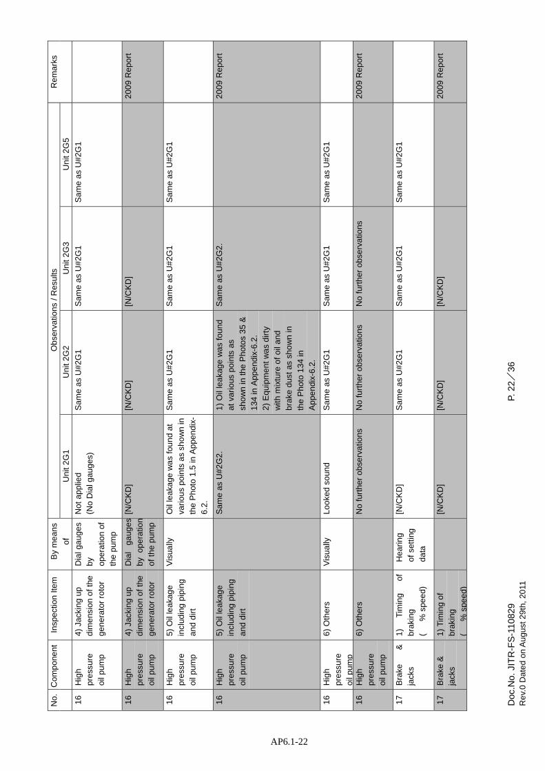
Doc
.No.
JIT
R-F
S-1
1082
9
Re
v.0
Da
ted
on
Au
gust
29
th,
2011
P.
22/
36
AP6.1-22
No
. C
om
po
nen
t In
spe
ctio
n It
em
B
y m
ea
ns
of
Ob
serv
atio
ns /
Res
ults
R
em
ark
s
Un
it 2
G1
Un
it 2
G2
Un
it 2
G3
Un
it 2
G5
16
Hig
h
pre
ssu
re
oil
pum
p
4)
Jack
ing
up
d
ime
nsio
n o
f th
e
ge
ne
rato
r ro
tor
Dia
l ga
ug
es
by
op
era
tion
of
the
pum
p
No
t a
pp
lied
(No
Dia
l ga
ug
es)
Sa
me
as
U#
2G
1 S
am
e a
s U
#2
G1
Sa
me
as
U#
2G
1
16
Hig
h
pre
ssu
re
oil
pum
p
4)
Jack
ing
up
dim
ens
ion
of
the
ge
ne
rato
r ro
tor
Dia
l g
aug
es
by
op
era
tion
of
the
pum
p
[N/C
KD
] [N
/CK
D]
[N/C
KD
]
20
09
Re
po
rt
16
Hig
h
pre
ssu
re
oil
pum
p
5)
Oil
lea
kag
e
incl
udin
g p
ipin
g
an
d d
irt
Vis
ua
lly
Oil
lea
kag
e w
as
fou
nd
at
vari
ou
s po
ints
as
sho
wn
in
the
Ph
oto
1.5
in A
ppe
nd
ix-
6.2
.
Sa
me
as
U#
2G
1 S
am
e a
s U
#2
G1
Sa
me
as
U#
2G
1
16
Hig
h
pre
ssu
re
oil
pum
p
5)
Oil
lea
kag
e
incl
udin
g p
ipin
g
an
d d
irt
S
am
e a
s U
#2
G2
. 1
) O
il le
aka
ge
wa
s fo
un
d
at
vari
ous
po
ints
as
sho
wn
in th
e P
ho
tos
35
&
134
in A
ppe
ndi
x-6
.2.
2)
Eq
uip
me
nt
wa
s d
irty
with
mix
ture
of
oil
an
d
bra
ke d
ust
as s
ho
wn
in
the
Ph
oto
13
4 in
Ap
pe
ndi
x-6
.2.
Sa
me
as
U#
2G
2.
2
00
9 R
ep
ort
16
Hig
h
pre
ssu
re
oil
pum
p
6)
Oth
ers
V
isu
ally
L
oo
ked
so
und
Sa
me
as
U#
2G
1 S
am
e a
s U
#2
G1
Sa
me
as
U#
2G
1
16
Hig
h
pre
ssu
re
oil
pum
p
6)
Oth
ers
No
fu
rth
er o
bse
rva
tions
N
o f
urt
her
ob
serv
atio
ns
No
fur
ther
ob
serv
atio
ns
2
00
9 R
ep
ort
17
Bra
ke
&
jack
s 1
) T
imin
g
of
bra
king
( %
spe
ed
)
He
ari
ng
of
sett
ing
da
ta
[N/C
KD
] S
am
e a
s U
#2
G1
Sa
me
as
U#
2G
1 S
am
e a
s U
#2
G1
17
Bra
ke &
jack
s
1)
Tim
ing
of
bra
king
( %
spe
ed
)
[N
/CK
D]
[N/C
KD
] [N
/CK
D]
2
00
9 R
ep
ort

Doc
.No.
JIT
R-F
S-1
1082
9
Re
v.0
Da
ted
on
Au
gust
29
th,
2011
P.
23/
36
AP6.1-23
No
. C
om
po
nen
t In
spe
ctio
n It
em
B
y m
ea
ns
of
Ob
serv
atio
ns /
Res
ults
R
em
ark
s
Un
it 2
G1
Un
it 2
G2
Un
it 2
G3
Un
it 2
G5
17
Bra
ke
&
jack
s
2)
Pe
riod
un
til
com
ple
te
stop
afte
r b
raki
ng
(
se
c)
Re
cord
ing
op
era
tion
da
ta
Vis
ua
lly
No
t a
pp
lied
(No
me
asu
rem
ent)
)
Sa
me
as
U#
2G
1 S
am
e a
s U
#2
G1
Sa
me
as
U#
2G
1
17
Bra
ke
&
jack
s
2)
Pe
riod
un
til
com
ple
te
stop
afte
r b
raki
ng
[N
/CK
D]
[N/C
KD
] [N
/CK
D]
2
00
9 R
ep
ort
17
Bra
ke
&
jack
s
3)
Wea
rin
g o
f
bra
ke s
ho
es
Me
asu
red
by
a s
cale
No
t a
pp
lied
(No
dis
ass
emb
ly o
f b
rake
& ja
ck)
Sa
me
as
U#
2G
1 S
am
e a
s U
#2
G1
Sa
me
as
U#
2G
1
17
Bra
ke
&
jack
s
3)
Wea
rin
g o
f
bra
ke s
ho
es
L
oo
ked
no
t ab
no
rma
l L
oo
ked
no
t ab
no
rma
l L
oo
ked
no
t ab
no
rma
l
20
09
Re
po
rt
17
Bra
ke
&
jack
s 4
) O
the
rs
Vis
ua
lly
Lo
oke
d s
oun
d S
am
e a
s U
#2
G1
Sa
me
as
U#
2G
1 S
am
e a
s U
#2
G1
17
Bra
ke
&
jack
s
4)
Oth
ers
No
fu
rth
er o
bse
rva
tion
s N
o f
urt
her
obs
erv
atio
ns
No
fur
ther
obs
erv
atio
ns
2009
Report
18
Spa
ce
he
ate
r 1
) A
pp
eara
nce
V
isua
lly
Co
ver
(bo
x) w
as
fou
nd
de
form
ed
as
sho
wn
in th
e
Ph
oto
1.1
4 in
App
end
ix-6
.2 S
am
e a
s U
#2
G1
Sa
me
as
U#
2G
1 S
am
e a
s U
#2
G1
18
Spa
ce
he
ate
r 1
) A
pp
eara
nce
V
isu
ally
C
ove
r (b
ox)
wa
s fo
un
d
de
form
ed
as
sho
wn
in t
he
Ph
oto
137
in A
pp
end
ix-
6.2
.
Sim
ilar
to U
#2G
1 S
imila
r to
U#2
G1
2
00
9 R
ep
ort
18
Spa
ce
he
ate
r
2)
Te
mp
era
ture
of
air
ho
usi
ng
Th
erm
o-m
e
ter
No
t in
se
rvic
e S
am
e a
s U
#2
G1
Sa
me
as
U#
2G
1 S
am
e a
s U
#2
G1
18
Spa
ce
he
ate
r
2)
Tem
pera
ture
of
air
ho
usi
ng
Th
erm
o-m
e
ter
No
t in
se
rvic
e N
ot
in s
erv
ice
No
t in
se
rvic
e
20
09
Re
po
rt
18
Spa
ce
he
ate
r
3)
Oth
ers
V
isu
ally
L
oo
ked
so
und
Sa
me
as
U#
2G
1 S
am
e a
s U
#2
G1
Sa
me
as
U#
2G
1
18
Spa
ce
he
ate
r
3)
Oth
ers
No
fu
rth
er o
bse
rva
tions
N
o f
urt
her
ob
serv
atio
ns
No
fur
ther
ob
serv
atio
ns
2
00
9 R
ep
ort

Doc
.No.
JIT
R-F
S-1
1082
9
Re
v.0
Da
ted
on
Au
gust
29
th,
2011
P.
24/
36
AP6.1-24
No
. C
om
po
nen
t In
spe
ctio
n It
em
B
y m
ea
ns
of
Ob
serv
atio
ns /
Res
ults
R
em
ark
s
Un
it 2
G1
Un
it 2
G2
Un
it 2
G3
Un
it 2
G5
19
Exc
iter
cub
icle
s
1)
Ap
pea
ran
ce
Vis
ua
lly
No
t a
pp
lied
(Ou
t o
f sc
ope
)
Sa
me
as
U#
2G
1 S
am
e a
s U
#2
G1
Sa
me
as
U#
2G
1
19
Exc
iter
cub
icle
s
1)
Ap
pea
ran
ce
Vis
ua
lly
[N/C
KD
] [N
/CK
D]
[N/C
KD
]
20
09
Re
po
rt
20
Oth
ers
1
) F
ield
lea
d
insi
de
of
ge
ne
rato
r
ho
usi
ng
(en
clo
sure
)
Vis
ua
lly
Lo
oke
d s
oun
d S
am
e a
s U
#2
G1
Sa
me
as
U#
2G
1 S
am
e a
s U
#2
G1
20
Oth
ers
1
) F
ield
lea
d
insi
de
of
ge
ne
rato
r
ho
usi
ng
(en
clo
sure
)
Vis
ua
lly
At
op
en
ing
for
the
filed
lea
ds a
t w
all
of
air
ho
usi
ng
, g
ap b
etw
ee
n t
he
left
sid
e fi
eld
lea
ds a
nd
the
wa
ll w
as
very
sm
all
as
sho
wn
in th
e P
ho
to 2
9 in
Ap
pe
ndi
x-6
.2.
Th
is
op
en
ing
mus
t be
mo
difi
ed
to h
ave
big
ger
gap
at t
he
ne
xt m
ain
ten
an
ce c
han
ce.
Sa
me
as
U#
2G
4.
Sa
me
as
U#
2G
4.
2
00
9 R
ep
ort
20
Oth
ers
2
) O
the
rs
Vis
ua
lly
Lo
oke
d s
oun
d S
am
e a
s U
#2
G1
Sa
me
as
U#
2G
1 S
am
e a
s U
#2
G1

Doc
.No.
JIT
R-F
S-1
1082
9
Re
v.0
Da
ted
on
Au
gust
29
th,
2011
P.
25/
36
AP6.1-25
No
. C
om
po
nen
t In
spe
ctio
n It
em
B
y m
ea
ns
of
Ob
serv
atio
ns /
Res
ults
R
em
ark
s
Un
it 2
G1
Un
it 2
G2
Un
it 2
G3
Un
it 2
G5
20
Oth
ers
2
) O
the
rs
N
o f
urt
her
obs
erv
atio
ns
No
fu
rth
er o
bse
rva
tion
s N
o f
urth
er o
bse
rva
tion
s
20
09
Rep
ort
20
Oth
ers
3
) S
pa
re p
art
s V
isua
lly
Alm
ost
of a
ll sp
are
pa
rts
are
no
t fo
und
. T
he
exi
stin
g s
pa
re p
arts
se
ems
to b
e r
equ
ited
re
pair
for
use
.
20
Oth
ers
3
) S
pa
re p
art
s
- 2
00
9 R
epo
rt
No.
Item
Num
un
it Num
ber
Cond
ition
1
Collector ring
1
set
2 Ca
rbon
brush
90
pcs
72
3
Brush ho
lders
2 pcs
4 Brush for creep
indicators
8 pcs
5 Stator coil (top coil)
10
pcs
Stator coil (bo
ttom
coil)
5 pcs
6 Field coil
1 pc
7 Guild bearin
g shoe
6
pcs
22
BAD
8 Thrust bearin
g runn
er plate
2 pcs
9 Brake liner (sho
e)
6 pcs
10
Curren
t trans fo
rmer
6 pcs
11
Thrust bearin
g shoe
18
pcs
6 BA
D 12
High
pressure oil lifter
1 set
2 BA
D

Doc
.No.
JIT
R-F
S-1
1082
9
Re
v.0
Da
ted
on
Au
gust
29
th,
2011
P.
26/
36
AP6.1-26
Ta
ble
2.1
Ope
ratio
n an
d Te
mpe
ratu
re d
ata
(Bef
ore
Insp
ectio
n)
(1/2
)
No
. It
em
It
em
B
y m
ea
ns
of
Un
it U
#1
U
#1
U
#2
U
#2
U
#3
U
#3
1
Op
era
tion
Da
te
Jun
e 2
4, ’
09
July
26,
‘11
Jun
e 2
4,
’09
Ju
ne
24
, ’0
9 Ju
ly 2
3, ‘1
1
D
ata
T
ime
1
5:2
3 1
6:2
0 1
5:2
4
15
:38
14
:00
Ou
tpu
t
MW
7
5 8
8 7
9 S
tan
d b
y 7
8 8
2
MV
AR
1
2 (
lag
) +
32
4 (
lag
)
-24
(le
ad)
-3
Term
inal
vo
ltage
kV
16
.8
15
.2
16
.8
1
7.0
1
6.3
AC
Cu
rre
nt
(Re
d p
hase
)
A
2,7
00
3,3
00
2,7
00
3
,00
0 3
,15
0
AC
Cu
rre
nt
(Ye
llow
ph
ase
)
A
2,8
00
3,4
50
2,9
00
3
,00
0 3
,15
0
AC
Cu
rre
nt
(Blu
e p
has
e)
A
2
,60
0 3
,15
0 2
,65
0
3,0
00
3,0
50
Exc
itatio
n V
olta
ge
V
150
1
90
1
60
170
Fie
ld C
urr
en
t
A
87
5 1
,06
0 9
00
9
50
1,0
00
2
Tem
pe
ratu
re
Sta
tor
win
din
g 1
R
TD
℃
5
0 6
1 6
6
52
65
Sta
tor
win
din
g 2
R
TD
℃
6
6 2
5
6
65
64
Sta
tor
win
din
g 3
R
TD
℃
6
2 7
5 5
4
76
80
Sta
tor
core
T
he
rmo
co
upl
e ℃
7
5
0 7
0
110
88
Th
rust
be
arin
g D
ial t
he
rmom
ete
r ℃
4
9 4
9 4
6
48
48
Gu
ide
be
arin
g D
ial t
he
rmom
ete
r ℃
4
6 4
6 4
9
49
51
3
Oil
leve
l O
il re
serv
oir
m
m
- +
39
30
5
5 +
43
4
Pre
ssu
re
Hig
h p
ress
ure
oil
pum
p
kg/c
m2
G
0
0
0
0
0
Air
for
Bra
kes
b
ar
13
-
11
1
0.8
-
Oil
Flo
w
5
V
ibra
tion
Sta
tor
fra
me
μ
m p
-p
T
hru
st ta
nk
μ
m p
-p
U
pp
er
bra
cke
t In
stal
led
me
ter
μm
p-p
-
1
2 7
5
30
20
※
Un
it 2
G2
wa
s n
o d
ata
be
caus
e s
tan
db
y
L
ow
tem
pe
ratu
re in
dic
atio
n
Co
mpa
red
with
oth
er
un
its

Doc
.No.
JIT
R-F
S-1
1082
9
Re
v.0
Da
ted
on
Au
gust
29
th,
2011
P.
27/
36
AP6.1-27
Ta
ble
2.1
Ope
ratio
n an
d Te
mpe
ratu
re d
ata
(Bef
ore
Insp
ectio
n 1)
(2
/2)
No
. It
em
It
em
B
y m
ea
ns
of
Un
it U
#4
U
#4
U
#5
U
#5
U
#6
U
#6
1
Op
era
tion
Da
te
Jun
e 2
4, ’
09
Jun
e 2
4, ’
09
Jun
e 2
4, ’
09
Da
ta
Tim
e
Ou
tpu
t M
W
Ou
t o
f se
rvic
e S
tan
d b
y S
tan
d b
y O
ut
of
serv
ice
MV
AR
Term
inal
vo
ltage
kV
AC
Cu
rre
nt
(Re
d p
hase
) A
AC
Cu
rre
nt
(Ye
llow
ph
ase
) A
AC
Cu
rre
nt
(Blu
e p
has
e)
A
Exc
itatio
n V
olta
ge
V
Fie
ld C
urr
en
t A
2
Tem
pe
ratu
re
Sta
tor
win
din
g 1
R
TD
℃
S
tato
r w
ind
ing
2
RT
D
℃
Sta
tor
win
din
g 3
R
TD
℃
S
tato
r co
re
Th
erm
o c
ou
ple
℃
Th
rust
be
arin
g D
ial t
he
rmom
ete
r ℃
G
uid
e b
ea
ring
Dia
l th
erm
ome
ter
℃
Oil
rese
rvo
ir D
ial t
herm
om
ete
r ℃
3
O
il le
vel
Oil
rese
rvo
ir m
m
4
Pre
ssu
re
Hig
h p
ress
ure
oil
pum
p kg
/cm
2G
Air
for
Bra
kes
ba
r
Oil
Flo
w
5 V
ibra
tion
S
tato
r fr
ame
μm
p-p
Thr
ust
tank
μ
m p
-p
Up
pe
r b
rack
et
I
nst
alle
d m
ete
r
μ
m p
-p
※U
nit
2G
5 w
as
no
da
ta b
eca
use
sta
nd
by

Doc
.No.
JIT
R-F
S-1
1082
9
Re
v.0
Da
ted
on
Au
gust
29
th,
2011
P.
28/
36
AP6.1-28
Ta
ble
2.2
Ope
ratio
n an
d Te
mpe
ratu
re d
ata
(Afte
r In
spec
tion)
(1
/2)
No
. It
em
It
em
B
y m
ea
ns
of
Un
it U
#1
U
#1
U
#2
U
#2
U
#3
U
#3
1
Op
era
tion
Da
te
Jun
e 2
5, ’
09
July
,30
, ‘1
1 Ju
ne
25
, ’0
9 Ju
ly 2
9, ‘1
1 Ju
ne
25
, ’0
9 Ju
ly 2
7, ‘1
1
Da
ta
Tim
e
11:0
0 1
4:4
0 11
:15
12
:00
11:2
8 1
6:3
0
Ou
tpu
t M
W
76
88
71
88
74
84
MV
AR
-3
2 (
lead
) -2
5 -1
5 (
lead
) +
45
0
-19
Term
inal
vo
ltage
kV
1
6.8
1
5.5
1
6.9
1
6.3
1
6.2
1
5.5
AC
Cu
rre
nt
(Re
d p
hase
) A
2
,70
0 3
,25
0 2
,35
0 3
,15
0 2
,80
0 3
,35
0
AC
Cu
rre
nt
(Ye
llow
ph
ase
) A
2
,85
0 3
,30
0 2
,60
0 3
,35
0 2
,90
0 3
,35
0
AC
Cu
rre
nt
(Blu
e p
has
e)
A
2,6
20
3,1
00
2,3
20
3,0
00
2,8
20
3,2
00
Exc
itatio
n V
olta
ge
V
150
1
50
150
1
50
190
1
70
Fie
ld C
urr
en
t A
8
20
920
9
50
1,0
00
1,0
00
95
0
2
Tem
pe
ratu
re
Sta
tor
win
din
g 1
R
TD
℃
5
0 6
0 6
5 5
2 6
5 6
5 S
tato
r w
ind
ing
2
RT
D
℃
56
2
50
58
62
61
Sta
tor
win
din
g 3
R
TD
℃
6
2 6
9 5
8 4
8 7
5 7
9 S
tato
r co
re
Th
erm
o c
ou
ple
℃
8
50
67
>15
0 5
3 8
5 T
hru
st b
ea
ring
Dia
l th
erm
ome
ter
℃
46
49
46
42
48
48
Gu
ide
be
arin
g D
ial t
he
rmom
ete
r ℃
5
0 4
5 5
0 4
2 4
9 5
0 3
O
il le
vel
Oil
rese
rvo
ir m
m
+4
2 +
42
+2
8 +
53
+5
4 +
43
4
Pre
ssu
re
Hig
h p
ress
ure
oil
pum
p kg
/cm
2G
0
0
0
0
0
0
Air
for
Bra
kes
bar
13
-
11.2
-
1
0.7
-
O
il F
low
5
Vib
ratio
n S
tato
r fr
am
e μ
m p
-p
Th
rust
tank
μ
m p
-p
Up
pe
r b
rack
et
Inst
alle
d m
ete
r μ
m p
-p
15
10
72
73
33
28
L
ow
tem
pe
ratu
re in
dic
atio
n
Co
mpa
red
with
oth
er
un
its
Ab
no
rma
l te
mp
era
ture
ind
ica
tion
(Dis
conn
ect
or
sho
rt c
on
diti
on
)

Doc
.No.
JIT
R-F
S-1
1082
9
Re
v.0
Da
ted
on
Au
gust
29
th,
2011
P.
29/
36
AP6.1-29
Ta
ble
2.2
Ope
ratio
n an
d Te
mpe
ratu
re d
ata
(Afte
r In
spec
tion)
(2
/2)
No
. It
em
It
em
B
y m
ea
ns
of
Un
it U
#4
U
#4
U
#5
U
#5
U
#6
U
#6
1
Op
era
tion
Da
te
Jun
e 2
5, ’
09
Jun
e 2
5, ’
09
July
28
, ’11
Ju
ne
25
, ’0
9
Da
ta
Tim
e
14
:15
Ou
tpu
t M
W
Ou
t o
f se
rvic
e S
tan
d b
y 8
4 O
ut
of
serv
ice
MV
AR
-1
5
Term
inal
vo
ltage
kV
1
5.4
AC
Cu
rre
nt
(Re
d p
hase
) A
3
,20
0
AC
Cu
rre
nt
(Ye
llow
ph
ase
) A
3
,25
0
AC
Cu
rre
nt
(Blu
e p
has
e)
A
3,2
00
Exc
itatio
n V
olta
ge
V
+18
0
Fie
ld C
urr
en
t A
9
40
2
Tem
pe
ratu
re
Sta
tor
win
din
g 1
R
TD
℃
2
6 S
tato
r w
ind
ing
2
RT
D
℃
25
Sta
tor
win
din
g 3
R
TD
℃
5
0 S
tato
r co
re
Th
erm
o c
ou
ple
℃
49
Th
rust
be
arin
g D
ial t
he
rmom
ete
r ℃
4
7 G
uid
e b
ea
ring
Dia
l th
erm
ome
ter
℃
45
3
Oil
leve
l O
il re
serv
oir
mm
+
48
4
Pre
ssu
re
Hig
h p
ress
ure
oil
pum
p kg
/cm
2G
0
Air
for
Bra
kes
bar
-
Oil
Flo
w
5
Vib
ratio
n S
tato
r fr
am
e μ
m p
-p
Th
rust
tank
μ
m p
-p
Up
pe
r b
rack
et
Inst
alle
d m
ete
r μ
m p
-p
55
L
ow
tem
pe
ratu
re in
dic
atio
n
Co
mpa
red
with
oth
er
un
its
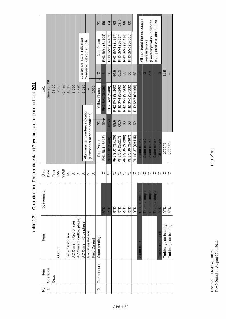
Doc
.No.
JIT
R-F
S-1
1082
9
Re
v.0
Da
ted
on
Au
gust
29
th,
2011
P.
30/
36
AP6.1-30
Tab
le 2
.3
Ope
ratio
n an
d Te
mpe
ratu
re d
ata
(Gov
erno
r co
ntro
l pan
el)
of U
nit 2
G1
No
. It
em
It
em
B
y m
ea
ns
of
Un
it U
#1
1
Op
era
tion
Da
te
Jun
e 2
6, ’
09
Da
ta
Tim
e
17
:00
Ou
tpu
t M
W
76
.5
MV
AR
+
5 (l
ag)
Term
inal
vo
ltage
kV
16
.15
AC
Cu
rre
nt
(Re
d p
hase
) A
2
,58
0
AC
Cu
rre
nt
(Ye
llow
ph
ase
) A
2
,72
0
Lo
w te
mp
era
ture
ind
ica
tion
AC
Cu
rre
nt
(Blu
e p
has
e)
A
Exc
itatio
n V
olta
ge
V
Ab
no
rma
l te
mp
era
ture
ind
ica
tion
(Dis
conn
ect
or
sho
rt c
ond
itio
n)
2,5
20
-
Co
mpa
red
with
oth
er
un
its
Fie
ld C
urr
en
t A
1
03
0
2
Tem
pe
ratu
re
Sta
tor
win
din
g R
ed
Ph
ase
℃
Y
ello
w P
ha
se
℃
Blu
e P
has
e ℃
R
TD
℃
P
H1
SU
1 (
S#
18
) 5
9 P
H2
SV
1 (
S#
39
) 2
P
H3
SW
1 (
S#
10
9)
59
RT
D
℃
PH
1 S
U2
(S
#6
0)
>1
50
PH
2 S
V2
(S
#8
0)
58
PH
3 S
W2
(S
#1
89
) 6
4
RT
D
℃
PH
1 S
U3
(S
#1
30
) 5
8.5
P
H2
SV
3 (
S#
16
0)
60
.5
PH
3 S
W3
(S
#2
67
) 6
3 R
TD
℃
P
H1
SU
4(S
#2
17
) 6
0.5
P
H2
SV
4 (
S#
24
6)
61
.5
PH
3 S
W4
(S
#3
37
) 6
2.5
R
TD
℃
P
H1
SU
5 (
S#
28
8)
60
PH
2 S
V5
(S
#3
09
) 5
5 P
H3
SW
5 (
S#
41
6)
88
RT
D
℃
PH
1 S
U6
(S
#3
67
) 5
3 P
H2
SV
6 (
S#
38
8)
56
PH
3 S
W6
(S
#5
01
) 8
0
RT
D
℃
PH
1 S
U7
(S
#4
45
) 5
9 P
H2
SV
7 (
S#
46
6)
68
Sta
tor
core
T
he
rmo
co
upl
e ℃
S
tato
r co
re 1
1
3 T
he
rmo
co
upl
e ℃
S
tato
r co
re 2
3
T
he
rmo
co
upl
e ℃
S
tato
r co
re 3
8
.5
Th
erm
o c
ou
ple
℃
Sta
tor
core
4
-
Th
rust
be
arin
g o
il R
TD
℃
O
il re
serv
oir
0
Tu
rbin
e g
uid
e b
ea
rin
g R
TD
℃
2
720
F1
11.5
T
urb
ine
gui
de
be
ari
ng
RT
D
℃
27
20F
2 -
-
All
mo
nito
red
th
erm
oco
upl
es
we
re in
tro
ub
le.
(Lo
w te
mp
era
ture
ind
ica
tion
)
(Co
mpa
red
with
oth
er
un
its)

Doc
.No.
JIT
R-F
S-1
1082
9
Re
v.0
Da
ted
on
Au
gust
29
th,
2011
P.
31/
36
AP6.1-31
10
0
Tab
le 2
.3
Ope
ratio
n an
d Te
mpe
ratu
re d
ata
(Gov
erno
r co
ntro
l pan
el)
of U
nit 2
G1
No
. It
em
It
em
B
y m
ea
ns
of
Un
it U
#1
1
Op
era
tion
Da
te
(Be
fore
Insp
ect
ion
) Ju
ly,2
6,’1
1 /
(A
fter
Insp
ectio
n)
July
,30,
‘11
Da
ta
Tim
e
16
:20/
14:
40
Ou
tpu
t M
W
88/
88
M
VA
R
+3
2/
-25
Term
inal
vo
ltag
e kV
1
5.2
/15
.5
AC
Cu
rre
nt
(Re
d p
hase
) A
3
,300
/3
,25
0 A
C C
urr
en
t (Y
ello
w p
ha
se)
A
3,4
50/
3,3
00
AC
Cu
rre
nt
(Blu
e p
has
e)
A
3,1
50/
3,
Lo
w te
mp
era
ture
ind
ica
tion
E
xcita
tion
Vo
ltage
V
A
bn
orm
al t
em
pe
ratu
re in
dic
atio
n
(Dis
conn
ect
or
sho
rt c
ond
itio
n)
-/
-
Co
mpa
red
with
oth
er
un
its
Fie
ld C
urr
en
t A
1
,06
0/
92
0
2
Tem
pe
ratu
re
Sta
tor
win
din
g R
ed
Ph
ase
℃
Y
ello
w P
ha
se
℃
Blu
e P
has
e ℃
@
Go
vern
or
RT
D
℃
PH
1 S
U1
(S
#1
8)
61/
60
PH
2 S
V1
(S
#3
9)
2/2
PH
3 S
W1
(S
#1
09
) 7
5/
69
co
ntr
ol p
ane
l R
TD
℃
P
H1
SU
2 (
S#
60
) >
15
0/
>1
50
PH
2 S
V2
(S
#8
0)
56/
60
PH
3 S
W2
(S
#1
89
) 7
5/
68
R
TD
℃
P
H1
SU
3 (
S#
13
0)
59/
59
PH
2 S
V3
(S
#1
60
) 6
2/
62
PH
3 S
W3
(S
#2
67
) 8
2/
72
R
TD
℃
P
H1
SU
4(S
#2
17
) 5
2/
51
PH
2 S
V4
(S
#2
46
) 6
4/
63
PH
3 S
W4
(S
#3
37
) 7
5/
68
R
TD
℃
P
H1
SU
5 (
S#
28
8)
61/
60
PH
2 S
V5
(S
#3
09
) 5
8/
55
PH
3 S
W5
(S
#4
16
) 5
8/
54
R
TD
℃
P
H1
SU
6 (
S#
36
7)
53/
54
PH
2 S
V6
(S
#3
88
) >
15/
40
PH
3 S
W6
(S
#5
01
) >
15
0/
>1
50
RT
D
℃
PH
1 S
U7
(S
#4
45
) 6
2/
62
PH
2 S
V7
(S
#4
66
) 8
6/
78
S
tato
r co
re
Th
erm
o c
ou
ple
℃
Sta
tor
core
1
50/
50
Th
erm
o c
ou
ple
℃
Sta
tor
core
2
52/
52
Th
erm
o c
ou
ple
℃
Sta
tor
core
3
50/
51
Th
erm
o c
ou
ple
℃
Sta
tor
core
4
41/
42
Th
rust
be
arin
g o
il R
TD
℃
O
il re
serv
oir
40/
40
A
bn
orm
al t
em
pe
ratu
re in
dic
atio
n
(Dis
conn
ect
or
sho
rt c
on
diti
on
)

Doc
.No.
JIT
R-F
S-1
1082
9
Re
v.0
Da
ted
on
Au
gust
29
th,
2011
P.
32/
36
AP6.1-32
Tab
le 2
.3
Ope
ratio
n an
d Te
mpe
ratu
re d
ata
(Gov
erno
r co
ntro
l pan
el)
of U
nit 2
G2
No
. It
em
It
em
B
y m
ea
ns
of
Un
it U
#2
1
Op
era
tion
Da
te
(Be
fore
Insp
ect
ion
) /
(A
fter
Insp
ect
ion
)
July
,29
,’11
Da
ta
Tim
e
/1
2:0
0 O
utp
ut
MW
/
88
MV
AR
/
+45
Te
rmin
al v
olta
ge
kV
/1
6.3
AC
Cu
rre
nt
(Re
d p
hase
) A
/
3,1
50
AC
Cu
rre
nt
(Ye
llow
ph
ase
) A
/
3,3
50
AC
Cu
rre
nt
(Blu
e p
has
e)
A
/3
,00
0 E
xcita
tion
Vo
ltage
V
-
/-
F
ield
Cu
rre
nt
A
/1
,00
0
Lo
w te
mp
era
ture
ind
ica
tion
Co
mpa
red
with
oth
er
un
its
2
Tem
pe
ratu
re
Sta
tor
win
din
g R
ed
Ph
ase
℃
Y
ello
w P
ha
se
℃
Blu
e P
has
e ℃
@
Go
vern
or
RT
D
℃
PH
1 S
U1
(S
#1
8)
/5
5 P
H2
SV
1 (
S#
39
) /
57
PH
3 S
W1
(S
#1
09
) /
52
con
tro
l pan
el
RT
D
℃
PH
1 S
U2
(S
#6
0)
/5
7 P
H2
SV
2 (
S#
80
) /
46
PH
3 S
W2
(S
#1
89
) /
59
RT
D
℃
PH
1 S
U3
(S
#1
30
) /
34
PH
2 S
V3
(S
#1
60
) /
58
PH
3 S
W3
(S
#2
67
) /
2
RT
D
℃
PH
1 S
U4
(S#
21
7)
/5
2 P
H2
SV
4 (
S#
24
6)
/6
2 P
H3
SW
4 (
S#
33
7)
/6
5 R
TD
℃
P
H1
SU
5 (
S#
28
8)
/5
2 P
H2
SV
5 (
S#
30
9)
/5
4 P
H3
SW
5 (
S#
41
6)
/1
44
RT
D
℃
PH
1 S
U6
(S
#3
67
) /
55
PH
2 S
V6
(S
#3
88
) /
47
PH
3 S
W6
(S
#5
01
) /
48
RT
D
℃
PH
1 S
U7
(S
#4
45
) /
61
PH
2 S
V7
(S
#4
66
) /
48
Sta
tor
core
T
he
rmo
co
upl
e ℃
S
tato
r co
re 1
/
-
Th
erm
o c
ou
ple
℃
Sta
tor
core
2
/5
7 T
he
rmo
co
upl
e ℃
S
tato
r co
re 3
/
137
T
he
rmo
co
upl
e ℃
S
tato
r co
re 4
/
-
Th
rust
be
arin
g o
il R
TD
℃
O
il re
serv
oir
/0
All
mo
nito
red
th
erm
oco
upl
es
we
re in
tro
ub
le.
(Lo
w te
mp
era
ture
ind
ica
tion
)
(Co
mpa
red
with
oth
er
un
its)
※U
nit
2G
2 w
as
no
da
ta b
eca
use
sta
nd
by
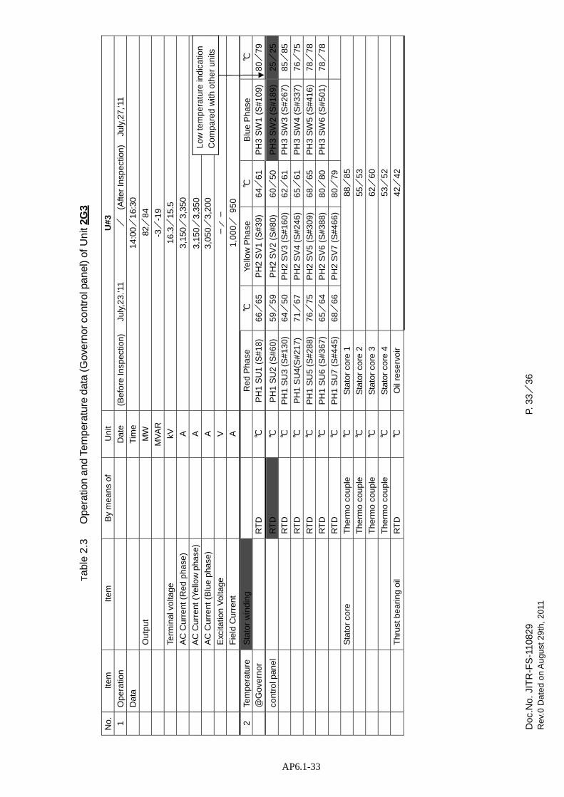
Doc
.No.
JIT
R-F
S-1
1082
9
Re
v.0
Da
ted
on
Au
gust
29
th,
2011
P.
33/
36
AP6.1-33
Tab
le 2
.3
Ope
ratio
n an
d Te
mpe
ratu
re d
ata
(Gov
erno
r co
ntro
l pan
el)
of U
nit 2
G3
N
o.
Ite
m
Ite
m
By
me
an
s o
f U
nit
U#
3
1
Op
era
tion
Da
te
(Be
fore
Insp
ectio
n)
July
,23
.’11
/
(Afte
r In
spec
tion
)
July
,27,
’11
D
ata
T
ime
1
4:0
0/
16:
30
Ou
tpu
t
MW
8
2/
84
MV
AR
-3
/-1
9
Term
inal
vo
ltag
e
kV
16
.3/
15.5
AC
Cu
rre
nt
(Re
d p
hase
)
A
3,1
50/
3,3
50
AC
Cu
rre
nt
(Ye
llow
ph
ase
)
A
3,1
50/
3,3
50
Lo
w te
mp
era
ture
ind
ica
tion
Co
mpa
red
with
oth
er
un
its
AC
Cu
rre
nt
(Blu
e p
has
e)
A
3
,050
/3
,20
0
Exc
itatio
n V
olta
ge
V
-
/-
F
ield
Cu
rre
nt
A
1
,00
0/
95
0
2
Tem
pe
ratu
re
Sta
tor
win
din
g
R
ed
Ph
ase
℃
Y
ello
w P
ha
se
℃
Blu
e P
has
e ℃
@G
ove
rno
r
RT
D
℃
PH
1 S
U1
(S
#1
8)
66/
65
PH
2 S
V1
(S
#3
9)
64/
61
PH
3 S
W1
(S
#1
09
) 8
0/
79
co
ntr
ol p
ane
l
RT
D
℃
PH
1 S
U2
(S
#6
0)
59/
59
PH
2 S
V2
(S
#8
0)
60/
50
P
H3
SW
2 (
S#
18
9)
25/
25
R
TD
℃
P
H1
SU
3 (
S#
13
0)
64/
50
PH
2 S
V3
(S
#1
60
) 6
2/
61
P
H3
SW
3 (
S#
26
7)
85/
85
R
TD
℃
P
H1
SU
4(S
#2
17
) 7
1/
67
PH
2 S
V4
(S
#2
46
) 6
5/
61
P
H3
SW
4 (
S#
33
7)
76/
75
R
TD
℃
P
H1
SU
5 (
S#
28
8)
76/
75
PH
2 S
V5
(S
#3
09
) 6
8/
65
P
H3
SW
5 (
S#
41
6)
78/
78
R
TD
℃
P
H1
SU
6 (
S#
36
7)
65/
64
PH
2 S
V6
(S
#3
88
) 8
0/
80
P
H3
SW
6 (
S#
50
1)
78/
78
R
TD
℃
P
H1
SU
7 (
S#
44
5)
68/
66
PH
2 S
V7
(S
#4
66
) 8
0/
79
S
tato
r co
re
Th
erm
o c
ou
ple
℃
Sta
tor
core
1
88/
85
T
he
rmo
co
upl
e ℃
S
tato
r co
re 2
5
5/
53
T
he
rmo
co
upl
e ℃
S
tato
r co
re 3
6
2/
60
T
he
rmo
co
upl
e ℃
S
tato
r co
re 4
5
3/
52
Th
rust
be
arin
g o
il R
TD
℃
O
il re
serv
oir
42/
42
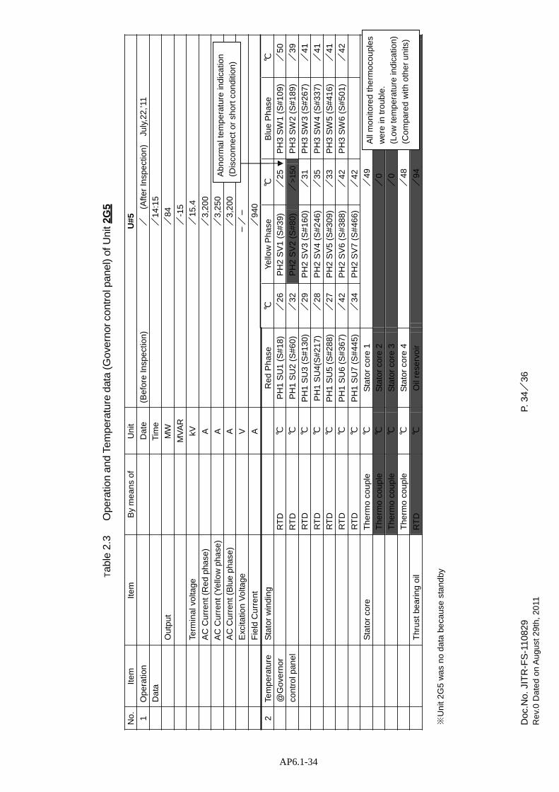
Doc
.No.
JIT
R-F
S-1
1082
9
Re
v.0
Da
ted
on
Au
gust
29
th,
2011
P.
34/
36
AP6.1-34
Tab
le 2
.3
Ope
ratio
n an
d Te
mpe
ratu
re d
ata
(Gov
erno
r co
ntro
l pan
el)
of U
nit 2
G5
No
. It
em
It
em
B
y m
ea
ns
of
Un
it U
#5
1
Op
era
tion
Da
te
(Be
fore
Insp
ect
ion
) /
(A
fter
Insp
ect
ion
)
July
,22
,’11
Da
ta
Tim
e
/1
4:1
5 O
utp
ut
MW
/
84
MV
AR
/
-15
Term
inal
vo
ltage
kV
/
15
.4
AC
Cu
rre
nt
(Re
d p
hase
) A
/
3,2
00
AC
Cu
rre
nt
(Ye
llow
ph
ase
) A
/
3,2
50
AC
Cu
rre
nt
(Blu
e p
has
e)
A
/3
,20
0 E
xcita
tion
Vo
ltage
V
-
/-
F
ield
Cu
rre
nt
A
/9
40
Ab
no
rma
l te
mp
era
ture
ind
ica
tion
(Dis
conn
ect
or
sho
rt c
on
diti
on
)
2
Tem
pe
ratu
re
Sta
tor
win
din
g R
ed
Ph
ase
℃
Y
ello
w P
ha
se
℃
Blu
e P
has
e ℃
@
Go
vern
or
RT
D
℃
PH
1 S
U1
(S
#1
8)
/2
6 P
H2
SV
1 (
S#
39
) /
25
PH
3 S
W1
(S
#1
09
) /
50
con
tro
l pan
el
RT
D
℃
PH
1 S
U2
(S
#6
0)
/3
2 P
H2
SV
2 (
S#
80
) /
>15
0 P
H3
SW
2 (
S#
18
9)
/3
9 R
TD
℃
P
H1
SU
3 (
S#
13
0)
/2
9 P
H2
SV
3 (
S#
16
0)
/3
1 P
H3
SW
3 (
S#
26
7)
/4
1 R
TD
℃
P
H1
SU
4(S
#2
17
) /
28
PH
2 S
V4
(S
#2
46
) /
35
PH
3 S
W4
(S
#3
37
) /
41
RT
D
℃
PH
1 S
U5
(S
#2
88
) /
27
PH
2 S
V5
(S
#3
09
) /
33
PH
3 S
W5
(S
#4
16
) /
41
RT
D
℃
PH
1 S
U6
(S
#3
67
) /
42
PH
2 S
V6
(S
#3
88
) /
42
PH
3 S
W6
(S
#5
01
) /
42
RT
D
℃
PH
1 S
U7
(S
#4
45
) /
34
PH
2 S
V7
(S
#4
66
) /
42
Sta
tor
core
T
he
rmo
co
upl
e ℃
S
tato
r co
re 1
/
49
Th
erm
o c
ou
ple
℃
Sta
tor
core
2
/0
T
he
rmo
co
upl
e ℃
S
tato
r co
re 3
/
0
Th
erm
o c
ou
ple
℃
Sta
tor
core
4
/4
8 T
hru
st b
ea
ring
oil
RT
D
℃
Oil
rese
rvoi
r /
94
All
mo
nito
red
th
erm
oco
upl
es
we
re in
tro
ub
le.
(Lo
w te
mp
era
ture
ind
ica
tion
)
(Co
mpa
red
with
oth
er
un
its)
※U
nit
2G
5 w
as
no
da
ta b
eca
use
sta
nd
by

Doc
.No.
JIT
R-F
S-1
1082
9
Re
v.0
Da
ted
on
Au
gust
29
th,
2011
P.
35/
36
AP6.1-35
Tab
le 3
A
s fo
und
se
ttin
g va
lue
of
oil
flow
co
ntr
ol c
he
ck v
alv
es
(1/2
) N
ot
we
ll a
dju
stin
g o
f th
e o
il flo
w
con
tro
l va
lve
s (u
neq
ua
l se
ttin
g)
U
nit
2G
1
V.
No.
S
ett
ing
(20
09
)
Se
ttin
g V
. N
o.
Se
ttin
g
(20
09
)
Se
ttin
g V
. N
o.
Se
ttin
g
(20
09
)
Se
ttin
g V
. N
o.
Se
ttin
g
(20
09
)
Set
ting
V.
No.
S
ett
ing
(20
09
)
Se
ttin
g V
. N
o.
Se
ttin
g
(20
09
)
Se
ttin
g
1-1
6.8
6
.0
4-1
5
.7
6.7
7
-1
6.2
5
.7
10
-1
7.0
5
.8
13
-1
6.8
6
.7
16
-1
6.6
5
.7
1-2
5.7
6
.2
4-2
7
.2
5.9
7
-2
6.8
7
.2
10
-2
5.8
6
.7
13
-2
6.0
7
.0
16
-2
5.8
6
.0
2-1
6.9
6
.5
5-1
6
.0
5.7
8
-1
7.0
6.8
11-1
5
.8
5.8
1
4-1
6
.3
6.7
1
7-1
5
.8
6.0
2-2
6.7
6
.8
5-2
6
.2
5.7
8
-2
5.3
6.7
11-2
5
.8
6.8
1
4-2
5
.7
6.8
1
7-2
6
.7
5.3
3-1
5.8
6
.8
6-1
7
.0
5.8
9
-1
5.8
5
.7
12
-1
6.7
5
.7
15
-1
6.0
5
.7
18
-1
6.0
5
.8
3-2
6.1
6
.2
6-2
6
.8
6.7
9
-2
6.0
5
.7
12
-2
6.6
6
.2
15
-2
6.6
6
.0
18
-2
5.7
6
.8
U
nit
2G
2 B
roke
n va
lve
wa
s fo
un
d
V.
No.
S
ett
ing
(20
09
)
Se
ttin
g V
. N
o.
Se
ttin
g
(20
09
)
Se
ttin
g V
. N
o.
Se
ttin
g
(20
09
)
Se
ttin
g V
. N
o.
Se
ttin
g
(20
09
)
Set
ting
V.
No.
S
ett
ing
(20
09
)
Se
ttin
g V
. N
o.
Se
ttin
g
(20
09
)
Se
ttin
g
1-1
6.9
6
.9
4-1
8
.8
8.6
7
-1
5.8
5
.8
10
-1
6.4
7
.3
13
-1
6.7
6
.8
16
-1
6.4
6
.4
1-2
6.8
6
.8
4-2
2
.0
5.6
7
-2
2.0
5
.7
10
-2
7.0
6
.8
13
-2
6.8
6
.8
16
-2
6.5
6
.5
2-1
5.6
5
.6
5-1
0
0
8
-1
5.8
5.8
11-1
6
.2
6.3
1
4-1
6
.7
6.7
1
7-1
6
.8
6.7
2-2
7.0
6
.8
5-2
7
.0
7.2
8
-2
6.8
6.8
11-2
6
.6
6.8
1
4-2
5
.9
5.9
1
7-2
6
.0
6.0
3-1
6.0
5
.8
6-1
6
.0
5.9
9
-1
5.8
5
.8
12
-1
5.8
5
.8
15
-1
5.5
5
.3
18
-1
10
.0
5.6
3-2
7.0
6
.7
6-2
6
.6
6.7
9
-2
6.4
6
.3
12
-2
6.8
6
.8
15
-2
6.7
6
.7
18
-2
6.8
6
.8
U
nit
2G
3
V.
No.
S
ett
ing
(20
09
)
Se
ttin
g V
. N
o.
Se
ttin
g
(20
09
)
Se
ttin
g V
. N
o.
Se
ttin
g
(20
09
)
Se
ttin
g V
. N
o.
Se
ttin
g
(20
09
)
Set
ting
V.
No.
S
ett
ing
(20
09
)
Se
ttin
g V
. N
o.
Se
ttin
g
(20
09
)
Se
ttin
g
1-1
-
6.7
4
-1
-
5.8
7
-1
-
6.7
1
0-1
-
6
.7
13
-1
-
6.8
1
6-1
-
6
.7
1-2
-
5.9
4
-2
-
5.8
7
-2
-
6.8
1
0-2
-
5
.7
13
-2
-
5.8
1
6-2
-
5
.8
2-1
-
5.8
5
-1
-
5.5
8
-1
-
6.8
11-1
-
5
.8
14
-1
-
6.7
1
7-1
-
5
.7
2-2
-
5.8
5
-2
-
6.8
8
-2
-
5.8
11-2
-
6
.8
14
-2
-
5.7
1
7-2
-
5
.8
3-1
-
6.7
6
-1
-
6.8
9
-1
-
5.8
1
2-1
-
5
.9
15
-1
-
5.8
1
8-1
-
6
.8
3-2
-
6.8
6
-2
-
6.7
9
-2
-
6.8
1
2-2
-
5
.8
15
-2
-
5.8
1
8-2
-
5
.8

Doc
.No.
JIT
R-F
S-1
1082
9
Re
v.0
Da
ted
on
Au
gust
29
th,
2011
P.
36/
36
AP6.1-36
U
nit
2G
5
Tab
le 3
A
s fo
und
se
ttin
g va
lue
of
oil
flow
co
ntr
ol c
he
ck v
alv
es
(2/2
)
No
t w
ell
ad
just
ing
of
the
oil
flow
con
tro
l va
lve
s (u
neq
ua
l se
ttin
g)
V.
No.
S
ett
ing
(20
09
)
Se
ttin
g V
. N
o.
Se
ttin
g
(20
09
)
Se
ttin
g V
. N
o.
Se
ttin
g
(20
09
)
Se
ttin
g V
. N
o.
Se
ttin
g
(20
09
)
Set
ting
V.
No.
S
ett
ing
(20
09
)
Se
ttin
g V
. N
o.
Se
ttin
g
(20
09
)
Se
ttin
g
1-1
-
6.8
4
-1
-
5.7
7
-1
-
6.8
1
0-1
-
5
.7
13
-1
-
6.9
1
6-1
-
5
.8
1-2
-
6.7
4
-2
-
6.8
7
-2
-
5.8
1
0-2
-
6
.7
13
-2
-
6.8
1
6-2
-
6
.8
2-1
-
7.4
5
-1
-
6.8
8
-1
-
6.8
11-1
-
5
.5
14
-1
-
6.6
1
7-1
-
5
.7
2-2
-
5.8
5
-2
-
6.9
8
-2
-
6.8
11-2
-
5
.7
14
-2
-
6.3
1
7-2
-
6
.7
3-1
-
6.7
6
-1
-
5.7
9
-1
-
6.7
1
2-1
-
5
.5
15
-1
-
5.7
1
8-1
-
5
.7
3-2
-
5.8
6
-2
-
6.9
9
-2
-
6.8
1
2-2
-
9
.7
15
-2
-
5.8
1
8-2
-
5
.7

AP6.2-1
Adjustment value Space heater Dirt and oil mist Deformation of cover
<Point of photography>
Collector ring Wearing of surface
Coil end of collector ring side Dirt and oil mist Generation of powder
Stator core back Deformation Dirt and oil mist
Spider Dirt and oil mist
Air cooler and stator base Dirt and oil mist Damages
Brake ring Wearing of surface
Flow control valve Adjustment value
Fan guide joint part Dirt and oil mist
Coil end of water turbine side Dirt and oil mist Damages of Insulation cap
Space heater Deformation of cover
Lower bracket Dirt and oil mist
Oil lifter Dirt and oil mist
Oil circulating pump Dirt and oil mist
RTD Indication
APPENDIX-6.2

AP6.2-2
Photo 1.1 2G1 Lower fan guide
Oil drops were found at split face of the fan guide segments.
Photo 1.2 2G1 Oil lift pump
Oil gathering was found at a flange adjacent to the pump.

AP6.2-3
Photo 1.3 2G1 Around lower bracket
Oil gathering was found at the lower bracket
Photo 1.4 2G1 Stator core back
Oil stain was found at the stator core back.
Photo 1.5 2G1 Air cooler
Damages were found at an air cooler fin.

AP6.2-4
Photo 1.6 2G1 Stator coil end
Oil stain was found at the turbine side of stator coil end.
Photo 1.7 2G1 Stator coil end
Insulation cap was transformed at the turbine side of stator coil end.
Photo 1.9 2G1 Stator base Oil stain was found at
the stator base.

AP6.2-5
Photo 1.10 2G1 Rotor spider
Oil gathering and dust accumulation were found on the rotor spider.
Photo 1.11 2G1 Break ring
Discoloration was found at the break ring.
Photo 1.12 2G1 Break ring
Wearing was found at the surface of break ring.

AP6.2-6
Photo 1.13 2G1 Stator coil
Occurrence of powder was found at the collector ring side of stator coil.
Photo 1.14 2G1 Space heater
Transformation of cover was found at space heaters.
Photo 1.15 2G1 Oil cooler circulation pump
Oil leakage was found at
the oil cooler circulation pump.

AP6.2-7
Photo 1.16 2G1 Control board
Deviation on the the RTD thermometer was found.
Photo 1.17 2G1 Air cooler
Oil stain was found at air cooler fins.
Photo 1.18 2G1 Collector ring
Wearing condition of the surface

AP6.2-8
Photo 2.1 2G2 Lower fan guide
Oil drops were found at split face of the fan guide segments.
Photo 2.2 2G2 Oil lift pump
Oil gathering was found at a flange adjacent to the pump.

AP6.2-9
Photo 2.3 2G2 Around lower bracket
Oil gathering was found at the lower bracket
Photo 2.4 2G2 Stator core
Oil stain was found at the stator core back.
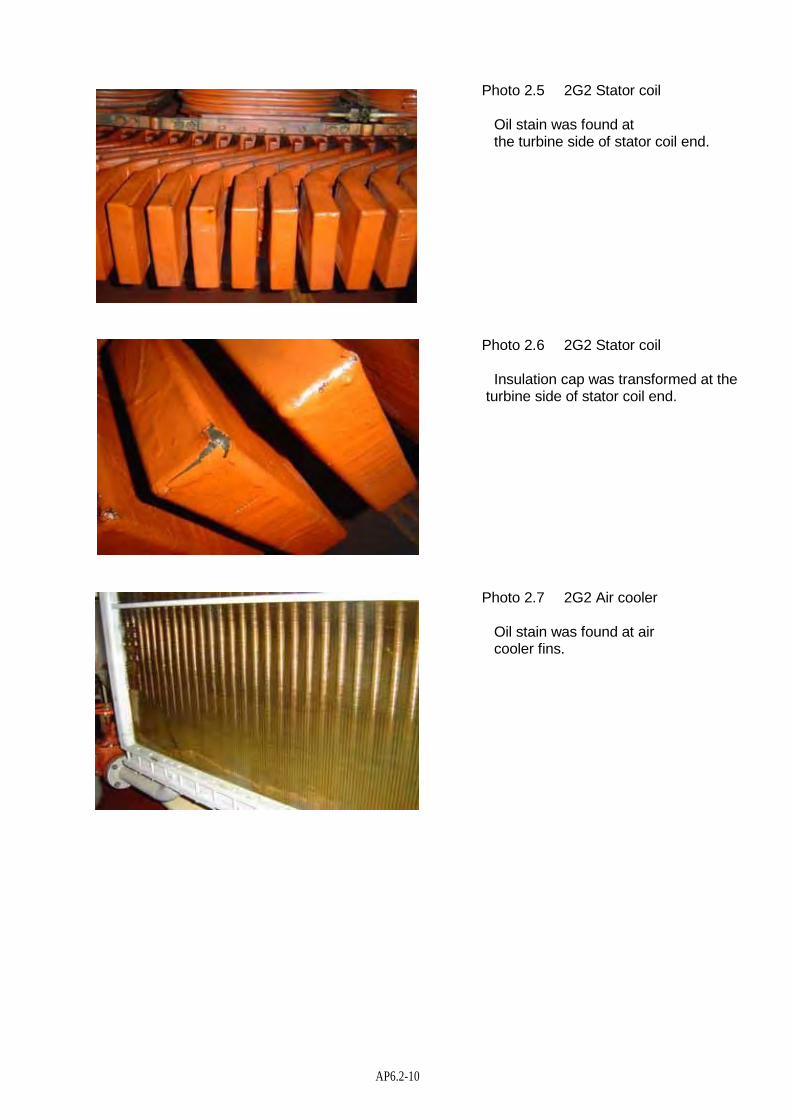
AP6.2-10
Photo 2.5 2G2 Stator coil
Oil stain was found at the turbine side of stator coil end.
Photo 2.6 2G2 Stator coil
Insulation cap was transformed at the turbine side of stator coil end.
Photo 2.7 2G2 Air cooler
Oil stain was found at air cooler fins.

AP6.2-11
Photo 2.8 2G2 Stator base
Oil stain was found at the stator base.
Photo 2.9 2G2 Break ring
Discoloration was found at the break ring.
Photo 2.10 2G2 Break ring
Wearing was found at the surface of break ring.

AP6.2-12
Photo 2.11 2G2 Stator base
Nock pin's pulling was found at the stator base.
Photo 2.12 2G2 Control board
Deviation on the the RTD thermometer was found.
Photo 2.13 2G2 Space heater
Transformation of cover was found at space heaters.

AP6.2-13
Photo 2.14 2G2 Oil cooler circulation pump
Oil leakage was found at the oil cooler circulation pump.
Photo 2.15 2G2 Air cooler
Damages were found at an air cooler fin.
Photo 2.16 2G2 Rotor spider
Oil gathering and dust accumulation were found on the rotor spider.
Photo 2.17 2G2 Collector ring
Wearing condition of the surface

AP6.2-14
Photo 3.1 2G3 Lower fan guide
Oil drops were found at split face of the fan guide segments.
Photo 3.2 2G3 Oil lift pump
Oil gathering was found at a flange adjacent to the pump.

AP6.2-15
Photo 3.3 2G3 Around lower bracket
Oil gathering was found at the lower bracket
Photo 3.4 2G3 Stator core
Waving deformation was found at a stator core back
Photo 3.5 2G3 Air cooler
Damages were found at an air cooler fin.

AP6.2-16
Photo 3.6 2G3 Stator coil
Oil stain was found at the turbine side of stator coil end.
Photo 3.7 2G3 Stator coil
Insulation cap was transformed at the turbine side of stator coil end.
Photo 3.8 2G3 Stator base
Oil stain was found at the stator base.

AP6.2-17
Photo 3.9 2G3 Rotor spider
Oil gathering and dust accumulation were found on the rotor spider.
Photo 3.10 2G3 Break ring
Discoloration was found at the break ring.
Photo 3.11 2G3 Break ring
Wearing was found at the surface of break ring.

AP6.2-18
Photo 3.12 2G3 Stator coil
Occurrence of powder was found at the collector ring side of stator coil.
Photo 3.13 2G3 Air cooler
Bad attachment of thermometer tap was found at the air cooler.
Photo 3.14 2G3 Oil cooler circulation pump
Oil leakage was found at the oil cooler circulation pump.
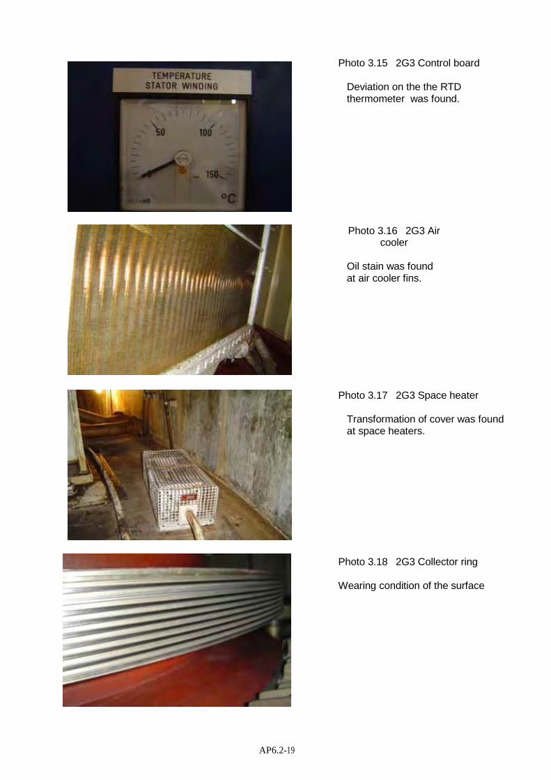
AP6.2-19
Photo 3.15 2G3 Control board
Deviation on the the RTD thermometer was found.
Photo 3.16 2G3 Air cooler
Oil stain was found at air cooler fins.
Photo 3.17 2G3 Space heater
Transformation of cover was found at space heaters.
Photo 3.18 2G3 Collector ring
Wearing condition of the surface

AP6.2-20
Photo 5.1 2G5 Lower fan guide
Oil drops were found at split face of the fan guide segments.
Photo 5.2 2G5 Oil lift pump
Oil gathering was found at a flange adjacent to the pump.

AP6.2-21
Photo 5.3 2G5 Around lower bracket
Oil gathering was found at the lower bracket
Photo 5.4 2G5 Stator core
Oil stain was found at the stator core back.
Photo 5.5 2G3 Air cooler
Oil stain was found at air cooler fins.

AP6.2-22
Photo 5.6 2G5 Stator coil
Oil stain was found at the turbine side of stator coil end.
Photo 5.7 2G5 Stator coil
Insulation cap was transformed at the turbine side of stator coil end.
Photo 5.8 2G5 Stator base
Nock pin's pulling was found at the stator base.

AP6.2-23
Photo 5.9 2G5 Stator base
Oil stain was found at the stator base.
Photo 5.10 2G5 Break ring
Discoloration was found at the break ring.
Photo 5.11 2G5 Break ring
Wearing was found at the surface of break ring.

AP6.2-24
Photo 5.12 2G5 Stator coil
Occurrence of powder was found at the collector ring side of stator coil.
Photo 5.13 2G5 Air cooler
Bad attachment of thermometer tap was found at the air cooler.
Photo 5.14 2G5 Oil cooler circulation pump
Oil leakage was found at the oil cooler circulation pump.

AP6.2-25
Photo 5.15 2G5 Control board
Deviation on the the RTD thermometer was found.
Photo 5.16 2G5 Thermal relay lead
Breaking Thermal relay lead was found.
Photo 5.17 2G5 Space heater
Transformation of cover was found at space heaters.
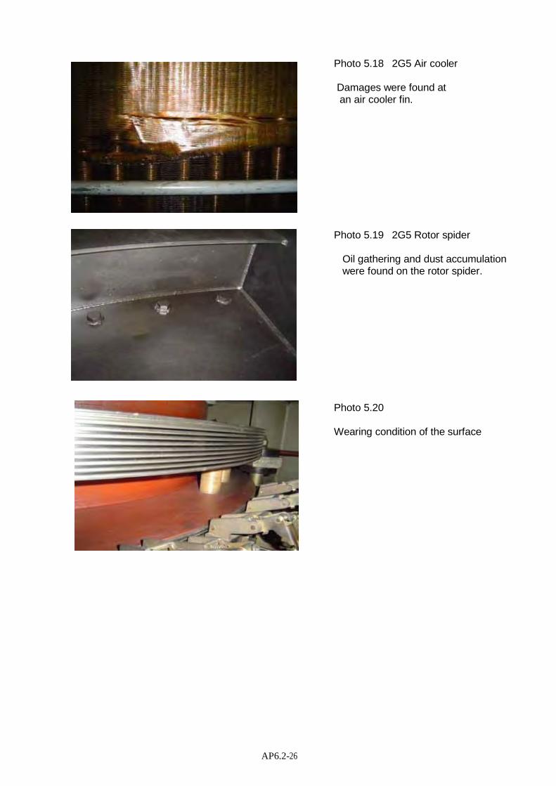
AP6.2-26
Photo 5.18 2G5 Air cooler
Damages were found at an air cooler fin.
Photo 5.19 2G5 Rotor spider
Oil gathering and dust accumulation were found on the rotor spider.
Photo 5.20
Wearing condition of the surface

Appendix-7
Inspection Report of Turbine and Governor

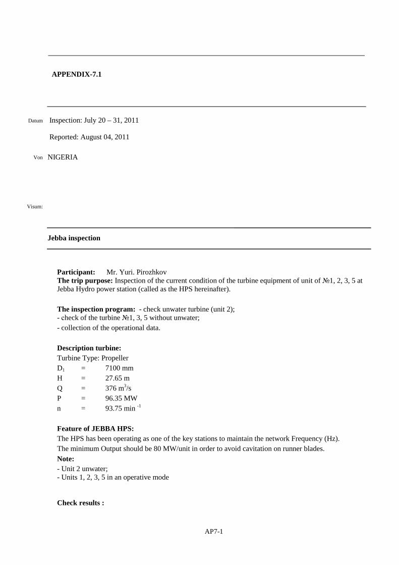
AP7-1
Datum Inspection: July 20 – 31, 2011
Reported: August 04, 2011
Von
Visum:
NIGERIA
Jebba inspection
Participant: Mr. Yuri. Pirozhkov The trip purpose: Inspection of the current condition of the turbine equipment of unit of №1, 2, 3, 5 at Jebba Hydro power station (called as the HPS hereinafter). The inspection program: - check unwater turbine (unit 2); - сheck of the turbine №1, 3, 5 without unwater; - collection of the operational data. Description turbine: Turbine Type: Propeller D1 = 7100 mm H = 27.65 m Q = 376 m3/s P = 96.35 MW n = 93.75 min -1
Feature of JEBBA HPS: The HPS has been operating as one of the key stations to maintain the network Frequency (Hz). The minimum Output should be 80 MW/unit in order to avoid cavitation on runner blades. Note: - Unit 2 unwater; - Units 1, 2, 3, 5 in an operative mode Check results :
APPENDIX-7.1

AP7-2
1. Draft tube cone (Unit 2): Flippers of cone have tracks to remove cavitation (photo-1). Original paint on the liner of cone generally has remained.
Poho-1 Repair welded at Flipper on Draft Tube Core
Recommended repair (replacement): Surfaces damages by cavitation should be restored to get original shape. 2. Runner chamber (Unit 2): The chamber has circular mechanical damages (scratches) in area of blades. Damages are caused by hit of firm particles in a gap between blades and chamber (Photo-2). Original paint on the liner of chamber has remained except for area of blades.
Photo-2 Damages on Runner Chamber
Recommended repair (replacement): Mechanical damages should be removed. After repair, repaint to get original condition.

AP7-3
3. Stay ring and spiral case (Unit 2):
Original paint on stay ring has minor local damages but total area is not more than 1m2 . (Photos 3, 4 &5)
Photo-3 Paint on Stay Ring and Stay Vane
Photo-4 Paint on Stay Vane
Photo-5 Paint on Stay Vane e

AP7-4
On some places, the paint has separated from metal and formed water bubbles (Photo-6).
Photo-6 Stay Vane (Paint separation and water bubble is found)
Paint of the spiral case was not damaged. (Photo 7 & 8)
Photo-7 Spiral case and stay ring
Photo-8 V Bottom ring of stay ring Bottom ring of stay ring
Recommended repair (replacement): Stay ring should be sandblasted, cleaned and repainted. Fillets of vanes of stay ring are necessary to be checked to confirm that there are no cracks.

AP7-5
4. Bottom ring wicket gate (Unit 2): Leaking water through bearings on bottom ring is not found out, but some rust tracks are visible. (Photo 9) The paint on a surface of bottom ring in an area of movement of vanes is completely damaged. (Photo 10). The reason: lowers end clearances = 0mm (vanes have sagged).
Photo-9 Bottom ring lower surface
Phote-10 Bottom Ring upper surface
The latest painted material is well visible (Photo 11) - where the paint is damaged, there is rust.
Photo-11 Rust on bottom ring
There is mechanical damage in depth up to 2mm on the bottom ring upper surface in the area of wicket gate movement.

AP7-6
Photo-12 Scratch by hit of firm particles in a gap between wicket gates and bottom ring.
Recommended repair (replacement): Lower bearings should be checked, and all seals and teflons should be replaced. Bottom ring should be sandblasted and painted again. Wicket Gates vertical position should be adjusted according to the drawing 5. Turbine Top Cover (Unit 2): There is no paint damage on the surface of turbine cover. (Photo 13)
Photo-13: Turbine Cover
There are minor tracks of erosion (visually found but almost no depth) on the turbine top cover in the area of wicket gate movement. (Photo 14)
Photo-14 Turbine Top Cover and Wicket Gate Vane
Recommended repair (replacement): To inspect a condition of major joining bolts. Seals shall be replaced.

AP7-7
6. Wicket gate vane (Unit 2): There are cling closes (one to another vanes) in wicker gate fully closed position. Erosion in area of vanes contact is not revealed, but only an easy trace. (Photo 15)
Photo-15: Vanes in contact place
Some trailing edges of vanes were injured. (Photo 16 and 17)
Photo-16 Trailing Edge of Wicket Gate Vane Photo-17 Trailing Edge of Wicket Gate Vane

AP7-8
Obviously sometime one vane was out of control. (Photo 18)
Photo-18 Circular track was found on the top cover
Paint on vanes has well remained. Where the paint has separated from metal, water bubbles were formed. (Photo 19)
Photo-19 Water bubbles on the vane
Recommended repair (replacement): Damages at trailing edges of vanes should be repaired. Uppers seals of vanes to be replaced. Vanes should be sandblasted and to be repainted.

AP7-9
7. Runner (Unit 2): Cavitation corrosion on bottom surface of the blade at the moment of survey was not found. Obviously, they have been repaired during recent maintenance. (Photo 20)
Photo-20 Bottom surface of the blade
Total cavitation area on the bottom surface of the blade is less than 0.3m2 on each blade. Cavitation is visible on ledge (depth of damages is less 3mm. (Photo-21)
Photo-21 Ledge of Runner Blade
Recommended repair (replacement): To check joining bolts (shaft - runner) to confirm that no cracks are exist by means of Non Destructive Inspection (NDI). Runner blades fillets should be checked to confirm that no cracks are exist by means of NDI. Surfaces damages by cavitation should be repaired.

AP7-10
The general conclusion in the water channel Unit 2 - quite satisfactory condition. 8. Wicket Gate (link mechanism, servomotor, regulation ring, locking device, etc.): Regulation ring of Unit 2 is moving smoothly. According to the Client information - stopper of regulation ring badly entered into the bush in all units. (Photo-22).
Photo-22 Stopper of Regulation Ring
There is leakage oil through servomotor seals at all units. (Photo 23) Oil leakage through servomotor pistons is also increased; refer to “Operating modes of pumps” for pumps oil pressure units. Leakage water through upper seals of vanes stems are as shown below. -Unit-1: Approx. 0.15 litter/sec. -Unit-2: practically not. -Unit-3: Approx. 1.0 litter/sec. -Unit-5: Approx. 0.3 litter/sec. There is backlash in link №16 (joint with pin of regulation ring) at the Unit 1.
Photo-23 Oil on Turbine Cover.
Recommended repair or replacement (all Units): Regulation ring – check wear of support elements. Stopper - dismantle and execute fitting pin with bush of regulation ring. Servomotors – dismantle and replace all seals. Link mechanism – dismantle, check joints, adjust clearances as designed, checking up on presence of cracks It is necessary to replace top stem seals of vanes. Also to replace all washers and sealing rings.

AP7-11
9. Turbine Shaft (all Units): Recommended repair or replacement (all units): Shaft fillets should be checked on presence of cracks by means of NDI. Bolts (turbine shaft to generator shaft) should be checked on presence of cracks. 10. Shaft seal (all Units): Present status of shaft seal is not satisfactory condition. (Photo 24 - 27). Much leakage water was found; refer to “Operating modes of pumps” for water drainage pumps described hereunder. Discharge of water supply - 150 lit/min. Pressure of supply of water is not measured continuously. Water pressure gauge is not installed in the pipeline. There is uneven wear on the working surfaces of Teflon’s Segments. (Photo 29 -32) According to the Client information: -Teflon segment has been replaced in every two-three years; - Filter (Photo 28) does not fully clean the supply water to the shaft seal. - Shaft seals are important parts for thrbine operation, but repaired seals in Unit 2 do not work properly.
Photo-24 Shaft Seal
Photo-25 Shaft Seal

AP7-12
Photo-26 Water level in shaft seal
Photo-27 Shaft Seal
Photo-28 Filter for Shaft Seal Supply Water
Photo-29 Teflon’s Segments
Photo-30 Teflon’s Segments
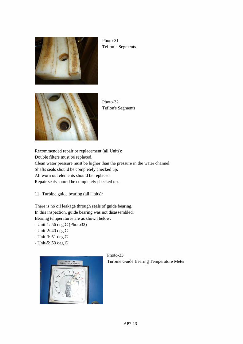
AP7-13
Photo-31 Teflon’s Segments
Photo-32 Teflon's Segments
Recommended repair or replacement (all Units): Double filters must be replaced. Clean water pressure must be higher than the pressure in the water channel. Shafts seals should be completely checked up. All worn out elements should be replaced Repair seals should be completely checked up. 11. Turbine guide bearing (all Units): There is no oil leakage through seals of guide bearing. In this inspection, guide bearing was not disassembled. Bearing temperatures are as shown below. - Unit-1: 56 deg.C (Photo33) - Unit-2: 40 deg.C - Unit-3: 51 deg.C - Unit-5: 50 deg C
Photo-33 Turbine Guide Bearing Temperature Meter

AP7-14
For comparison, Generator guide and thrust bearing temperatures are as shown below. -Unit-1 guide bearing: 46 deg.C -Unit-1 thrust bearing: 49 deg.C -Unit-5 guide bearing: 44 deg.C There are not complaints from the Customer. Recommended repair (replacement): After guide bearing dismantle: Check clearance between shaft and segment. Check condition of sliding surface of turbine shaft. Change lubrication oil. Continuously check the temperature of segments. 12. Auxiliary equipment (general) According to the Client information: Governors (all digital for Units 1, 2 & 3 and all analogue for Unit 4, 5, 6) have been operated without problem. Staffs have been satisfied in the governor performance. But the HPS management at a final meeting has declared desire to replace Governors on units 4, 5, 6 to the digital type. Feedback (Photo 34) on the Unit 4 was damaged in the area of connection of rod with flexball. It has been replaced with that on Unit 6 which turbine has been stopped.
Photo-34 Feedback
- Both drainage pumps (first-direct current: DC, second - alternating current: AC) were already worn. (Photo 35)
Photo-35 Drainage Pump -Water supply pumps for ahaft seal do not provide required quantity of clean water. (Photo 36)

AP7-15
-A filter does not provide enough quantity of clean water to be supplied to the shaft seal.
Photo-36 Water supply pump
- Overspeed device on Units 1, 2, 3 & 5 are working without problems. (Photo 37)
Photo-37 Overspeed device
Recommended repair (replacement): It is necessary to replace both drainage pumps. It is necessary to replace water supply pumps on seals of shafts. Operating modes of pumps:
Operation No operation Working cycle – Operation/ No operation
U-1 pump oil pressure unit 56 second 12 minute 1/12
U-3 pump oil pressure unit 47 second 7 minute 1/9
U-1 water drainage pump 5 minute 8 minute 1/1,6
U-3 water drainage pump 1 hour and 24 minute
6 minute 14/1

AP7-16
APPENDIX-7.2
Turbine and Governor
Serial Number
Item Remarks
- Refurbish wicket gate levers, links and bushing, main shaft seal and regulating ring.
(1) Inspect the draft tube lining and runner blades for cavitations. Weld-fill, grind and paint the draft tube with high grade anti-rust paint.
(2) Complete maintenance of the wicket gate The wicket gate bearing bushing and Pak-O-Pak seal should be replaced and new spring loaded safety levers installed.
(3) Inspect runner, stay ring and discharge ring for caviation and erosion and effect repair
(4) Replacement of all seals with new ones. (5) Align Turbine shaft (6) Complete maintenance of the turbine guide
bearing
(7) Refurbish the spiral casing drain valve (8) Comprehensive overhaul of the turbine head
cover (shaft seal and stuffing box assembly)
(9) Replacement of the AC and DC inner head cover pumps
(10) Overhaul the existing 4 nos. Servo motors (11) Service the hydraulic governor system including
all directional control valves and the pressure tank.
(12) Replacement of all gauges (13) Replacement of complete shaft seal duplex filter
assembly (DFLN330-50PN16)

Appendix-8
The List of Major Trouble Record


Jebb
a P
SN
o.D
ate
App
arat
us in
Tro
uble
Des
crip
tion
of
Tro
uble
Rea
son
for
Fai
lure
Rep
air
carr
ies
out
19-
Jun-
042G
3T
he u
nit f
aile
d to
pic
k lo
ad w
hen
sync
hron
ised
and
the
alar
m r
ecei
ved
atA
VR
is S
SC
F
Mal
func
tion
ing
of r
elay
K27
, K28
and
D.T
.LT
he r
elay
s w
ere
prop
erty
ser
vice
d an
dD
.T.L
was
res
et w
ith
Lif
e B
ook
com
pute
r
213
-Jul
-04
DC
Sys
tem
Ban
k "B
"D
C g
roun
d fa
ult a
larm
cam
e an
d pe
rsis
t on
Ban
k "B
"B
ad S
ump
pum
p 3
swit
ches
due
toco
rros
ion
Rep
lace
d w
ith
new
one
s
314
-Jul
-04
2G6
Vib
rati
on le
vel v
ery
high
120
@84
MW
The
vib
rati
on m
eter
was
cha
nged
yet
read
ing
rem
ains
the
sam
e (T
he u
nit w
asac
tual
ly v
ibra
ting
)
NIL
. It w
as r
efer
red
to m
echa
nica
lm
aint
enan
ce d
epar
tmen
t (M
MD
)
43-
Dec
-04
11kV
Bre
aker
SF
6F
aile
d to
clo
se a
uto
whe
n 2G
3 w
assy
nchr
onis
ed to
the
grid
Bre
aker
's a
uxil
iary
con
tact
pro
blem
Pro
perl
y m
aint
aine
d by
the
Ele
ctri
cal
mai
nten
ance
dep
artm
ent (
EM
D)
514
-Feb
-05
2G3
Fie
ld b
reak
erT
he b
reak
er f
aile
d to
ope
n at
uni
t shu
tdo
wn
and
exci
tati
on m
inor
trou
ble
(SS
CF
)ca
me
Ope
n ci
rcui
t on
the
fiel
d ci
rcui
t bre
aker
auxi
liar
y co
ntac
tT
he c
onta
ct w
as r
e-ad
just
ed a
nd c
lean
ed
625
-Feb
-05
Uni
t 2G
4T
he T
urbi
ne s
peed
was
obs
erve
d at
118
%w
hen
the
unit
was
test
run
and
mak
ing
itim
poss
ible
to s
ynch
roni
zati
onN
o ou
tput
sig
nal f
rom
spe
ed p
ick-
up -
F1
The
spe
ed p
ick-
up w
as p
rope
rly
re-a
djus
ted
719
-Jul
-05
2G4
Loa
ding
sys
tem
The
load
ing
beco
mes
ver
y sl
uggi
ng w
hen
the
unit
att
ains
70M
WS
peed
set
poi
nt c
ard
EM
S12
The
spe
ed s
et p
oint
car
d E
MS
12 w
asre
cali
brat
ed a
nd te
sted
O.K
.
816
-Sep
-05
2G6
trip
ped
on L
oad
(90M
W)
Tur
bine
pit
wat
er le
vel h
igh
alar
m r
ecei
ved
and
unit
trip
ped
on lo
ad (
90M
W)
Exc
essi
ve le
akag
e of
wat
er in
the
turb
ine
pit
Add
itio
nal p
ump
requ
ired
(R
efer
to M
NS
)
920
-Sep
-05
2G5
330k
V c
ircu
itbr
eake
r
Fai
led
to o
pen
whe
n th
e st
op b
utto
n w
asde
pres
sed
but l
ater
trip
ped
on r
ever
sepo
wer
pro
tect
ion.
LP
A, L
PM
ala
rm a
lso
obse
rved
at t
he A
VR
Ref
er to
Tra
nsm
issi
on s
tati
on P
C&
MD
epar
tmen
t
1019
-Oct
-05
2G56
spe
ed d
etec
tor
fail
ure
alar
mT
he a
larm
com
es u
p in
term
itte
ntly
whe
nth
e un
it is
in s
ervi
ce a
nd r
eset
The
spe
ed p
ick-
up F
3 go
t shi
fted
fro
m th
ese
t poi
nt.
Pro
perl
y re
set a
nd te
sted
O.K
.
119-
Nov
-05
2G1
Vib
ro m
onit
orR
egis
teri
ng z
ero
valu
e at
81M
W m
achi
nelo
adT
he p
ower
sup
ply
MC
B tr
ippe
d in
ser
vice
due
to f
ault
Fau
lt c
lear
ed b
y E
MD
and
MC
B r
eset
1220
-Dec
-05
2G2
Sha
ft S
eal C
ooli
ngw
ater
flo
w r
ate
met
erF
luct
uati
ng b
etw
een
zero
and
750
L/m
inB
lock
age
alon
g in
let a
nd o
utle
t wat
er p
ipe
line
The
line
s w
ere
bled
and
rea
ding
sta
bili
zed
on 1
50 L
/min
App
endi
x-8
T
he L
ist
of M
ajor
Tro
uble
Rec
ord
AP8-1
1/5

Jebb
a P
SN
o.D
ate
App
arat
us in
Tro
uble
Des
crip
tion
of
Tro
uble
Rea
son
for
Fai
lure
Rep
air
carr
ies
out
App
endi
x-8
T
he L
ist
of M
ajor
Tro
uble
Rec
ord
136-
Jan-
062G
3 &
2G
4 tu
rbin
e ai
rco
mpr
esso
r #2
Obs
erve
d no
t cut
ting
out
at 4
8bar
Fau
lty
auxi
liar
y R
elay
d2
Rep
lace
d w
ith
a ne
w o
ne.
1415
-Feb
-06
2G3
The
uni
t tri
pped
on
Gen
erat
or T
rans
form
erdi
ffer
enti
al p
rote
ctio
n al
arm
As
a re
sult
of
surg
e fr
om N
atio
nal g
rid
The
nec
essa
ry p
rote
ctiv
e re
lays
wer
ech
ecke
d an
d C
onfi
rmed
O.K
.T
he u
nit w
as r
e-sy
nchr
oniz
ed
1523
-Jan
-06
2G6
Gov
erno
r P
ress
ure
tank
Gov
erno
r oi
l pre
ssur
e ta
nk o
il le
vel h
igh
was
rec
eive
d an
d pe
rsis
ted
wit
h oi
l lev
elno
rmal
at 3
2 ba
rT
he c
am-s
wit
ch B
9 go
t off
-set
Pro
perl
y re
-ali
gned
1628
-Feb
-06
Fir
e bo
oste
r pu
mp
1 &
2N
ot c
utti
ng in
aut
o af
ter
the
jock
ey p
ump
was
shu
t dow
n fo
r co
mpl
ete
30 m
in.
Sti
cky
pres
sure
sw
itch
953
1e1
mec
hani
smP
rope
rly
mai
ntai
ned
173-
Mar
-06
2G3
The
uni
t tri
pped
on
unit
vib
rati
on a
nd th
evi
brat
ion
leve
l rec
orde
r 52μp
-p 8
5MW
No
faul
t was
fou
ndT
he u
nit w
as te
st r
un a
t var
ious
load
up
till
max
imum
. No
trip
was
rec
orde
d
1825
-Apr
-06
2G1
and
2G2
Tur
bine
Air
Com
pres
sor
#2T
he c
ompr
esso
r w
as o
bser
ved
runn
ing
cont
inuo
usly
Fau
lt ti
mer
Rel
ay 2
d8It
was
rep
lace
d w
ith
a ne
w o
ne.
1920
-May
-06
11kV
cir
cuit
bre
aker
SF
12
The
bre
aker
fai
led
to c
lose
aut
o w
hen
unit
5w
as s
hut d
own
as u
nit 1
and
5 a
re in
serv
ice.
Tim
er R
elay
X4
/24T
B13
def
ecti
veR
epla
ced
wit
h a
new
one
2025
-May
-06
415V
cir
cuit
bre
aker
"B"
The
bre
aker
fai
led
clos
e on
aut
oD
efec
tive
clo
sing
coi
lR
epla
ced
wit
h a
new
one
by
EM
D
2125
-Jun
-06
2G1
59/G
Tw
o le
vel
over
vol
tage
pro
tect
star
t ind
icat
ion
Fai
led
to r
eset
wit
h th
e un
it in
ser
vice
Fau
lty
Rel
ay o
f 59
/G ty
pe U
SX
115
Rep
lace
d w
ith
a ne
w o
nes
2220
-Jun
-06
2G5
Gat
e li
mit
erT
he g
ate
lim
iter
was
obs
erve
d dr
oppi
ng to
68%
whi
le th
e ga
te p
osit
ion
was
incr
easi
ngto
98%
whe
n op
enin
g co
mm
and
was
giv
en.
Dis
crep
ancy
in th
e G
over
nor
Fee
d-ba
cksy
stem
The
Gov
erno
r F
eed-
back
sys
tem
was
prop
erly
re-
alig
ned
2314
-Jul
-06
2G1
The
uni
t dro
pped
load
to 8
MW
and
trip
ped
on T
wo
step
rev
erse
Pow
er p
rote
ctio
nD
irty
ser
vo-v
alve
mic
ro-f
ilte
r w
hich
led
drop
in s
ervo
val
ve p
ress
ure.
MM
D w
ere
invi
ted
to r
ecti
fy th
e pr
oble
m
AP8-2
2/5

Jebb
a P
SN
o.D
ate
App
arat
us in
Tro
uble
Des
crip
tion
of
Tro
uble
Rea
son
for
Fai
lure
Rep
air
carr
ies
out
App
endi
x-8
T
he L
ist
of M
ajor
Tro
uble
Rec
ord
2430
-Aug
-06
2G6
Gen
erat
orT
rans
form
er o
il c
oole
rle
akag
e al
arm
The
Ala
rm c
ame
up a
nd p
ersi
sted
.A
ccum
ulat
ion
of w
ater
in th
e le
akag
ede
tect
or c
ompa
rtm
ent d
ue to
fau
lty
heat
exch
ange
r #1
and
#2
syst
em
The
wat
er w
as d
rain
ed, a
larm
res
et a
ndM
MD
wer
e as
ked
to e
ffec
t nec
essa
ryre
pair
.
254-
Oct
-06
2G3
It f
aile
d to
pic
k lo
ad w
hen
the
unit
was
sync
hron
ized
the
asso
ciat
ed b
reak
erob
serv
ed tr
ippe
d im
med
iate
ly.
Fau
lty
Rel
ay K
812
cont
acts
Rel
ay r
epla
ces
wit
h a
new
one
.
269-
Oct
-06
2G6
unit
cre
ep a
larm
Abo
ve a
larm
can
e up
and
fai
led
to r
eset
the
unit
was
sta
rted
Fau
lty
cree
p de
tect
or s
wit
chP
rope
rly
mai
ntai
ned
and
test
ed O
.K.
2715
-Oct
-06
2G4
cont
rol v
alve
sens
or f
ailu
re a
larm
The
ala
rm c
omes
up
whe
n th
e un
it is
sta
rted
and
pers
ists
.M
isal
ignm
ent o
n th
e co
ntro
l val
ve p
osit
ion
sens
ors
The
sen
sors
wer
e pr
oper
ly r
e-al
ignm
ente
dan
d st
arte
d O
.K.
2825
-Oct
-06
11kV
bre
aker
SF
5
The
bre
aker
was
obs
erve
d no
t clo
sed
whe
n2G
1 w
as s
hutd
own
and
11kV
bre
aker
SF
12cl
osed
.(2G
1 an
d 2G
5 in
ser
vice
bef
ore
2G1
was
shu
t dow
n.
Che
cks
Con
firm
ed th
at th
e P
robl
em w
asfr
om th
e br
eake
r S
F3
auxi
liar
y co
ntac
tE
MD
was
invi
ted
to r
ecti
fy th
e pr
oble
m
2912
-Dec
-06
2G5
The
uni
t tri
pped
on
rapi
d sh
utdo
wn
Blo
ckag
e al
ong
pipe
line
s to
the
flow
rat
em
eter
Pro
perl
y se
rvic
e an
d te
sted
O.K
.
3016
-Dec
-06
2G6
Exc
itat
ion
syst
emT
he u
nit t
ripp
ed o
n ex
cita
tion
Maj
ortr
oubl
e al
arm
(71
F2)
fai
led
to r
eset
Bro
wn
2 N
o th
yris
tor
fuse
sR
epla
ced
wit
h th
e un
it's
spa
re o
nes
3117
-Jan
-07
2G4
The
uni
t tri
pped
on
over
spee
d an
d he
adga
te s
hut d
own
Poo
l of
wat
er f
ound
in th
e ov
er s
peed
dete
ctor
sw
itch
com
part
men
t
Dra
ined
and
pro
perl
y se
rvic
ed. T
he u
nit
was
test
ed O
.K.
Bac
k to
ser
vice
3226
-Feb
-07
DC
sys
tem
gro
und
faul
tal
arm
The
ala
rm c
ame
on a
nd p
ersi
sted
The
turb
ine
guid
e be
arin
g oi
l pro
per
was
fail
ed w
ith
wat
erD
rain
ed, c
lean
ed a
nd C
onfi
rmed
O.K
.
3326
-Feb
-07
2G4
mai
n be
arin
gte
mpe
ratu
re m
eter
Per
man
entl
y in
dica
ting
6゜
CT
he m
eter
is f
ound
def
ecti
ve.
Rep
lace
d w
ith
a ne
w o
ne.
341-
Jun-
082G
1T
ripp
ed o
n lo
ss o
f ex
cita
tion
Tra
nsie
nt f
ault
Nec
essa
ry c
heck
s w
as c
arri
ed o
ut a
nd n
ofa
ult f
ound
. The
uni
t was
put
bac
k to
serv
ice.
AP8-3
3/5

Jebb
a P
SN
o.D
ate
App
arat
us in
Tro
uble
Des
crip
tion
of
Tro
uble
Rea
son
for
Fai
lure
Rep
air
carr
ies
out
App
endi
x-8
T
he L
ist
of M
ajor
Tro
uble
Rec
ord
3517
-Jun
-08
2G4
Gen
erat
orpr
otec
tion
trou
ble
alar
mT
he a
larm
cam
e up
and
fai
led
to r
eset
.R
elay
Rut
414
a O
pera
ted
The
rel
ay w
as r
eset
and
ala
rm c
ance
lled
3622
-Aug
-08
2G2
Tur
bine
pit
Tri
pped
on
Tur
bine
pit
wat
er le
vel h
igh.
Fau
lty
AC
inne
r he
ad c
over
pum
p au
toco
ntro
l sta
rt le
vel s
wit
chR
epla
ced
wit
h a
new
one
and
the
unit
retu
rned
bac
k to
sys
tem
.
3726
-Jan
-09
2G4
spee
d m
onit
orin
gsy
stem
Spe
ed d
etec
tor
fail
ure
alar
m c
ame
up a
ndpe
rsis
ted
turb
ine
spee
d ze
ro w
ith
the
unit
inse
rvic
e.
Blo
wn
fuse
6.3
A s
uppl
y to
the
spee
dm
onit
orin
g un
itR
epla
ced
wit
h a
new
one
. Ala
rm r
eset
and
spee
d re
adin
g 10
0%
386-
Feb
-09
2G6
The
uni
t sud
denl
y re
load
ed to
0M
W. G
ate
posi
tion
was
obs
erve
d fl
uctu
atin
g be
twee
n20
% a
nd 6
0% a
nd la
ter
trip
ped
on r
ever
sepo
wer
pro
tect
ion.
1.E
ract
ic b
evav
ior
of th
e el
ectr
onic
car
dR
pV10
(P
ropo
rtio
nal c
ontr
ol s
yste
m)
2. P
ole
disc
orda
nce
also
obs
erve
d.
1. C
ard
RP
V10
was
pro
perl
y re
-cal
ibra
ted.
2. T
he p
ole
disc
orda
nce
was
mai
ntai
ned
byth
e tr
ansm
issi
on m
aint
enan
ce m
en.
3917
-Feb
-09
2G2
Gen
erat
or h
ousi
ngvi
bro-
mon
itor
Obs
erve
d re
adin
g ze
ro w
hile
the
unit
is in
serv
ice
Fau
lty
cont
act o
f R
elay
K17
5R
epla
ce w
ith
a ne
w o
ne a
nd th
e vi
brat
ion
read
ing
48 r
ep-p
4025
-Mar
-09
Sta
tion
ser
vice
air
com
pres
sor
#2N
ot c
utti
ng o
ut o
n au
to a
t 7 b
ar.
Tim
er 2
-A w
as n
ot ti
min
g as
set
.It
was
pro
perl
y re
-cal
ibra
ted.
4126
-Mar
-09
2G1
The
uni
t fai
led
to s
ynch
roni
se a
uto
Dev
iati
on o
n th
e di
gita
l gov
erno
r sy
stem
sett
ings
It w
as r
e-pr
ogra
mm
ed a
nd s
ynch
roni
sed
toth
e sy
stem
.
4227
-Apr
-09
2G5
The
uni
t fai
led
to p
ick
load
aft
ersy
nchr
onis
ed a
nd tr
ippe
d on
rev
erse
pow
erpr
otec
tion
Fau
lty
Ele
ctro
nic
Car
d E
2DT
22 in
the
elec
tron
ic c
ontr
ol c
ubic
leR
epla
ced
wit
h a
new
one
and
uni
t tes
ted.
O.K
.
4321
-Dec
-09
2G1
Exc
itat
ion
syst
emT
he u
nit t
ripp
ed o
n ex
cite
r ex
it a
irte
mpe
ratu
re h
igh
and
exci
tati
on m
ajor
trou
ble.
Dus
ty a
ir f
ilte
rs (
Inle
t and
out
let)
Pro
perl
y cl
eane
d th
e ai
r fi
lter
s an
d w
asre
stor
ed b
ack
to s
ervi
ce.
4412
-Feb
-10
2G5
spee
d se
t poi
ntm
eter
Obs
erve
d re
adin
g 49
.4 H
z at
Max
load
of
90M
W.
Fau
lty
anal
ogue
out
put i
sola
tor
card
EIM
10R
epla
ced
wit
h a
knew
one
and
was
test
ed.
O.K
.
4514
-Apr
-10
2G2
H.P
Pum
pT
he p
ump
was
obs
erve
d ru
nnin
gco
ntin
uous
ly w
ith
the
unit
dow
n.F
ault
y T
imer
rel
ay 2
-2R
epla
ced
and
was
test
ed. O
.K.
AP8-4
4/5

Jebb
a P
SN
o.D
ate
App
arat
us in
Tro
uble
Des
crip
tion
of
Tro
uble
Rea
son
for
Fai
lure
Rep
air
carr
ies
out
App
endi
x-8
T
he L
ist
of M
ajor
Tro
uble
Rec
ord
465-
Mar
-11
2G5
and
2G6
Tur
bine
Air
com
pres
sor
#2O
bser
ved
not p
icki
ng lo
adO
pen
circ
uit o
n th
e oi
l pre
ssur
e sw
itch
The
pre
ssur
e sw
itch
was
pro
perl
y re
-ca
libr
atio
ned.
4728
-Feb
-11
2G2
cree
p de
tect
orsy
stem
Uni
t cre
ep a
larm
cam
e up
whe
n th
e un
itw
as s
tart
ed a
nd p
ersi
sted
.H
igh
cont
act r
esis
tanc
e fo
und
on th
e cr
eep
dete
ctor
sw
itch
Pro
perl
y m
aint
aine
d an
d te
sted
. O.K
.
4822
-Mar
-11
2G3
Tur
bine
pit
wat
erle
vel a
larm
No
audi
ble
and
visu
al a
larm
was
rec
eive
dat
the
UC
B w
hen
the
abov
e m
enti
oned
alar
m c
ame
up a
t the
con
trol
roo
m
1. F
ault
y 7-
chan
nnel
ala
rm c
ard
SB
7/S
Q2B
22.
Bur
nt a
larm
hor
n co
il
1. C
ard
repl
aced
wit
h a
new
one
2. A
larm
hon
e al
so r
epla
ces
AP8-5
5/5


Appendix-9
Basic Scope of Rehabilitation


APPENDIX-9FEDERAL REPUBLIC OF NIGERIA Jebba Hydro Electric PLCJebba Power Station
Basic Scope of Rehabilitaion
Long periodstoppage
Pulling offthe rotor Necessity Urgency 1 2 3 4
No Item Q'ty unit 2G5 2G1 2G3 2G2 Common Remarks1-1 Stator ① Stator coil Necessary Necessary High High
1 Stator coil 1008 pcs ● ● ● ●2 Wedge 1 set ● ● ● ●3 Coil support ring 1 set ● ● ● ●4 Bus bar 1 set ● ● ● ●5 Insulation cap 1 set ● ● ● ●6 Line and neutral lead 1 set ● ● ● ●7 Accessories for the above 1 set ● ● ● ●8 RTD for stator coil 20 pcs ● ● ● ●9 CT 1 set ● ● ● ●
② Stator Core Necessary Necessary High High1 Stator core 1 set ● ● ● ●2 Core duct 1 set ● ● ● ●3 End duct 1 set ● ● ● ●4 Core clamping plate 1 set ● ● ● ●5 Accessories for the above 1 set ● ● ● ●6 Thermo couple for stator core 4 pcs ● ● ● ●7 Finishing varnish for stator 1 set ● ● ● ●
③ Stator frame Necessary Necessary High1 Stator frame×1unit (Brand new( 1 set ●2 NDI of Stator frame at site 1 set ● ● ● NDI : Non-Destructive Inspection
1-2 Rotor ① Pole Necessary Necessary High High1 Pole 64 pcs ● Re-used Re-used Re-used2 Field lead connector 1 set ● Re-used Re-used Re-used3 Damper winding connector 1 set ● Re-used Re-used Re-used4 Pole cotter and liner 1 set ● Re-used Re-used Re-used5 Field lead (on the rotor) 1 set ● Re-used Re-used Re-used6 Finishing Varnish for Rotor 1 set ● ● ● ●
② Countermeasure of Rotor Rim Support1 Reinforcement parts of Rotor Rim Support Necessary Necessary High High1) Special tool for Rim reinforcement 1 set ●2) Repair material for damaged spider 1 set ● ●3) Rotor rim key 1 set ● ●4) Stopper for rotor rim key 1 set ● ●5) Distance piece (rotor rim support) 1 set ● ●
1-3 Exciter ① Collector Ring High 1st unit 2nd unit1 Collector ring (including shaft) 1 set ● ● No spare is required (1-7 ④ No.1)2 Carbon brush 44 pcs ● ● ● ●3 Carbon brush holder 44 pcs ● ● ● ●4 Carbon brush holder support 1 set ● ● ● ●
1-4 Metal ① Bearing Parts Necessary Necessary High High 1 Thrust bearing shoe 18 pcs ● ● ● ●
2 Thrust bearing support (for HITACHI PIVOT SPRING) 18 pcs ● ● ● ●3 Guide bearing shoe 22 pcs ● ● ● ●4 Adjusting bolt and nut for guide bearing 22 pcs ● ● ● ●5 Oil deflector 1 set ● ● ● ●6 Spring support (for HITACHI PIVOT SPRING) 18 pcs ● ● ● ●
1-5 Cooling ① Oil cooler system 1 Oil cooler 4 pcs High Re-used Re-used Re-used Re-used
2 Short piping for adjustment 1 set High Re-used Re-used Re-used Re-used1-6 Hydraulic ② Oil circulating systemdevices 1 Oil lubricating pump 1 set High Re-used Re-used Re-used Re-used
2 High pressure oil lifter 1 set High Re-used Re-used Re-used Re-used3 Flow control Valve 36 pcs High Re-used Re-used Re-used Re-used4 High pressure oil pipe (in the thrust tank) 18 pcs Necessary High Re-used Re-used Re-used Re-used5 Short piping for adjustment 1 set High Re-used Re-used Re-used Re-used
③ Air Cooler 1 Air cooler 12 pcs High Re-used Re-used Re-used Re-used2 Thermostat for Air cooler 10 pcs High Re-used Re-used Re-used Re-used3 Dial thermometer for Air cooler 6 pcs High Re-used Re-used Re-used Re-used4 Short piping for adjustment 1 set High Re-used Re-used Re-used Re-used
1-7 Others ① Instrument and Overhauling Parts1 Dial thermometer (for bearing) 2 pcs Necessary High High ● ● ● ●2 Dial thermometer (for oil cooler) 2 pcs Necessary High High ● ● ● ●3 Thermal relay (for bearing) 2 pcs Necessary High High ● ● ● ●4 RTD for Thrust bearing oil tank 1 pc Necessary High High ● ● ● ●5 Installation materials for beatings 1 set Necessary High High ● ● ● ●6 Creep detector 1 pc High Re-used Re-used Re-used Re-used7 Vibration detector and monitor 1 pc High Re-used Re-used Re-used Re-used8 Water flow relay (for oil cooler and air cooler) 2 pcs High Re-used Re-used Re-used Re-used9 Oil flow meter 1 pc High Re-used Re-used Re-used Re-used
10 Oil level gauge and switch 1 pc High High ● ● ● ●11 Limit switch for brake and jack 8 pcs High High ● ● ● ●12 Space heater (with reinforced cover) 12 pcs High Re-used Re-used Re-used Re-used Modification of setting place is planned.13 Brake liner (2pcs for 1 brake & jack) 16 pcs High Re-used Re-used Re-used Re-used14 Installation materials (Bolts, Nuts, etc) 1 set High High ● ● ● ●15 Wiring material (inside of generator terminal box) 1 set High High ● ● ● ●
② Tools for Assembly (including special tool)1 Pole Lifting Rug 1 set High ●2 Tools for Erection and stator core assembly 1 set High ●3 Tools for Stator coil assembly 1 set High ●4 High Voltage Test Kit 1 set High ●5 Consumable materials 1 set High ● ● ● ●
③ Training1 Training 1 set High ●
④ Spare Parts1 Carbon brush 180 pcs High No supply2 Brush holders 2 pcs High No supply3 Stator coil (top coil) 10 pcs High No supply4 Stator coil (bottom coil) 5 pcs High No supply5 Pole 4 pcs High ● First End Pole×2pcs, Last End Pole ×2pcs6 Guide bearing shoe 22 pcs High ●7 Thrust bearing runner plate 1 pcs High No supply8 Brake liner (shoe) 32 pcs High No supply9 Thrust bearing shoe 18 pcs High ●
10 High pressure oil lifter 1 set High No supply11 Flow control Valve 36 pcs High No supply12 Oil lifter suction line filter 50 pcs High No supply13 Oil lifter discharge line filter 50 pcs High No supply14 Brake ring 1 set High No supply15 Oil filter for oil circulation system 100 pcs High No supply
⑤ Supervisor High ● ● ● ●⑥ Others (Transportation, etc.) High ● ● ● ●
Reinforcement of Rotor Rim support wasrealized on unit 2G3 and 2G5 in 2001.
Requirement for change Importance Renovation Plan
AP9-1

FEDERAL REPUBLIC OF NIGERIA Jebba Hydro Electric PLCJebba Power Station
Basic Scope of Rehabilitation (Turbine)
1 2 3 4No Item Q'ty unit 2G5 2G1 2G3 2G2 Common Remarks
Turbine
No Item Q'ty unit 2G5 2G1 2G3 2G2 Common Remarks
(1)MainTransformer
●set1Overhaul of Main Transformer・Replacement of diaphragm in conservator・Replacement of the insulation oil・Replacement of Gaskets
●●●
Priority → 4321
Basic Scope of Rehabilitation (Main Transformer)
(14)
●Spare parts(15)
●set1Digitalization of electronic governor of 2G5
(12)
●●●●set1Replacement of complete shaft seal duplex filterassembly (DFLN330-50PN16)
(13)
●set1Replacement of all gauges
Overhaul the existing 4 nos. Servo motors ・Provision of lifting device for seal replacement●●
Replacement of the AC and DC inner head coverpumps
(9) ●●●
●●●
(10)
・Replacement of cooling oil duplex filter assembly・Replacement of governor oil・Replacement of the pilot filter assembly
●●●●set1Service the hydraulic governor system including alldirectional control valves and the pressure tank.
(11)
●
Refurbish the spiral casing drain valve(7)
●●●●set1Comprehensive overhaul of the turbine head cover(shaft seal and stuffing box assembly)
(8)
●●●
Align Turbine shaft (5)
●●●●set1Complete maintenance of the turbine guide bearing(6)
●●●
Complete maintenance of the wicket gate(2)
Inspect runner, stay ring and discharge ring forcavitations and erosion and effect repair
(3)
●●●●set1Replacement of all seals with new ones.(4)
●●●
●●●●set1Refurbish wicket gate levers, links and bushing, mainshaft seal and regulating ring.
-
(1)
The wicket gate bearing bushing and Pak-O-Pak sealshould be replaced and new spring loaded safety levers
●●●●set1
Renovation Plan
●●●●set1Inspect the draft tube lining and runner blades forcavitations. Weld-fill, grind and paint the draft tubewith high grade anti-rust paint.
Priority →
●set1
●set1
●set1
●
Renovation Plan
●
set1
set1
AP9-2

Appendix-10
Project Implementation schedule
of Rehabilitation Work


Sta
tor
Pre
-Ass
emb
ly W
ork
Pla
n
( 1
sta
tor
fram
e is
bra
nd n
ew, a
nd o
ther
1 fr
ame
is r
e-us
ed)
Ye
ar
Mo
nth
12
34
56
78
910
1112
12
34
56
78
910
1112
12
34
56
78
910
1112
12
34
56
78
910
1112
12
34
56
78
910
1112
12
34
56
78
910
1112
12
34
56
78
910
1112
12
34
56
78
910
1112
1 2 Sta
tor
Pre
-Ass
emb
ly W
ork
Pla
n
( 1
sta
tor
fram
e is
bra
nd n
ew, a
nd o
ther
2 fr
ames
are
re-
used
)Y
ear
Mo
nth
12
34
56
78
910
1112
12
34
56
78
910
1112
12
34
56
78
910
1112
12
34
56
78
910
1112
12
34
56
78
910
1112
12
34
56
78
910
1112
12
34
56
78
910
1112
12
34
56
78
910
1112
1 2 3 Sta
tor
Pre
-Ass
emb
ly W
ork
Pla
n
( 1
sta
tor
fram
e is
bra
nd n
ew, a
nd o
ther
3 fr
ames
are
re-
used
)Y
ear
Mo
nth
12
34
56
78
910
1112
12
34
56
78
910
1112
12
34
56
78
910
1112
12
34
56
78
910
1112
12
34
56
78
910
1112
12
34
56
78
910
1112
12
34
56
78
910
1112
12
34
56
78
910
1112
1 2 3 4
2G
5
2G
1
2017
2018
2019
2020
No.
Item
2013
2014
2015
2016
2020
No.
Item
2013
2014
2015
2016
2018
2019
2017
2018
2019
2G
5
2G
3
2014
No.
Item
2013
2017
2015
2016
2G
12
G3
2G
2
2020
2G
52
G1
Ten
tativ
e P
roje
ct S
ched
ule
for
Re
nova
tion
Wor
k (
optio
n 1)
9 m
on
ths
・P
rocure
men
t &
Manu
factu
rin
g
8 m
on
ths
Site
wo
rk
(Shu
tdo
wn )
keep
op
era
tio
n
7m
on
ths
・O
ld S
tato
r D
is-a
ssem
bly
wo
rk・N
ew
Sta
tor
8 m
on
ths
Site
wo
rk
(Sh
utd
ow
n )
5m
on
ths
・N
ew
Sta
tor
Pre
-ass
em
bly
keep
op
era
tio
n
Def
ect
Lia
bili
ty P
eri
od
(Aft
er
Co
mp
leti
on
of
Eac
h U
nit
)
APPENDIX-10-1
AP10.1-1
9 m
on
ths
・P
rocure
men
t &
Manu
factu
rin
g・T
ran
spo
rtati
on
8 m
on
ths
Site
wo
rk
(Shu
tdo
wn )
keep
op
era
tio
nke
ep o
pe
rati
on
7m
on
ths
・O
ld S
tato
r D
is-a
ssem
bly
wo
rk・N
ew
Sta
tor
P
re-a
ssem
bly
wo
rk
8 m
on
ths
Site
wo
rk
(Sh
utd
ow
n )
8 m
on
ths
Site
wo
rk
(Sh
utd
ow
n )
7m
on
ths
・O
ld S
tato
r D
is-a
sse
mb
ly w
ork
・N
ew
Sta
tor
P
re-a
ssem
bly
wo
rk
5m
on
ths
・N
ew
Sta
tor
Pre
-ass
em
bly
wo
rk
keep
op
era
tio
n
Def
ect
Lia
bil
ity
Per
iod
(Aft
er C
om
ple
tio
n o
f E
ach
Un
it)
Ten
tativ
e P
roje
ct S
ched
ule
for
Re
nova
tion
Wor
k (o
ptio
n3
)
9 m
on
ths
・P
rocu
rem
ent &
Man
ufa
ctu
ring
8 m
on
ths
Sit
ew
ork
(S
hut
dow
n )
keep
op
era
tio
nke
ep o
pe
rati
on
keep
op
era
tio
n
7m
on
ths
・O
ld S
tato
r D
is-a
ssem
bly
wo
rk・N
ew
Sta
tor
8 m
on
ths
Site
wo
rk
(Sh
utd
ow
n )
8 m
on
ths
Site
wo
rk
(Sh
utd
ow
n )
8 m
on
ths
Site
wo
rk
(Sh
utd
ow
n )
7m
on
ths
・O
ld S
tato
r D
is-a
sse
mb
ly w
ork
・N
ew
Sta
tor
P
re-a
ssem
bly
wo
rk
7m
on
ths
・O
ld S
tato
r D
is-a
ssem
bly
wo
rk・N
ew
Sta
tor
5m
on
ths
・N
ew
Sta
tor
keep
op
era
tio
n
Def
ect
Lia
bili
ty P
eri
od
(Aft
er
Co
mp
leti
on
of
Eac
h U
nit
)
Ten
tativ
e P
roje
ct S
ched
ule
for
Ren
ovat
ion
Wor
k (
optio
n 2
)


year
Month Legend ;
Item : Work in Japan
Exchange of Notes (E/N)
Loan Agreement (L/A)
Selection of Consultant
Required preparatory process in Nigeria
EOI: Advertisement and evaluation
Shortlist of consultant & JICA Concurrence
RFP
Evaluation Criteria
Tender Preparation
Tender Evaluation & JICA Concurrence
Parastatal Tenders Board (by JHPS)
Concurrence by JICA
Pre-award Negotiation
Concurrence by Federal Ministry of Power (FMoP)
Approval by Bureau of Public Procurement (BPP)
Approval by Federal Executive Council (FEC) (Cabinet: Federal Tenders Board)
Execution of Consultancy Agreement
Concurrence by JICA on Consultancy Agreement
Basic Design
Selection of Contractor
Preparation of EOI (PQ) document
EOI: Advertisement and preparation by interested companies
Evaluation of EOI
Parastatal Tenders Board
JICA Concurrence on EOI (PQ) Results
Preparation for Tender Document & JICA Concurrence
Preparation for Tender Proposal by the tenderers
Tender Evaluation
Parastatal Tenders Board (by JHPS)
Concurrence by JICA on evaluation results
Negotiation with Tenderer
Concurrence by FMoP & Approval by BPP
Approval by FEC (Cabinet: Federal Tenders Board)
Execution of Contract Agreement between JHEP and Contractor
Concurrence by JICA on Contract Agreement (90 MW×5 Units=450 MW) (90 MW×5 Units=450 MW)
Document Preparation2G5 Unit Complete Shutdown Keep Operation 2G1 Unit Complete Shutdown
2G5 Material Procurement & Manufacturing and Transportation First ShipmentFinal Shipment
(90 MW×6 Units=540 MW)
2G5 Renovation Work under unit shutdownNew Stator Pre-assembly Work
2G1 Material Procurement & Manufacturing and Transportation First ShipmentFinal Shipment
2G1 Renovation Work under unit shutdown2G5 Stator Frame Disassembly WorkNew Stator Pre-assembly Work
Water Turbine Repairing No.5 No.1
Main Transformer Repairing(16/330 kV,119MVA) No.5 No.1
Japan Nigeria
Grade (M/M) (M/M)
Site Representative 21 0 1 0 1 0 1 0 1 0 1 0 1 0 1 0 1 0 1 0 1 0 1 0 1 0 1 0 1 0 1 0 1 0 1 0 1 0 1 0 1 0 1 0 1 0 1 0 0 5 0 5 0 5 0 5 0 5 0 5
23.0 23.0
General Supervisor 30 5 1 0 1 0 1 0 1 0 1 0 1 0 1 0 1 0 1 0 1 0 1 0 1 0 1 0 1 0 1 0 1 0 1 0 1 0 1 0 0 5 0 5 0 5 0 5 0 5 0 5
19.5 19.5
Other Supervisors (13 persons) 33 0 3 0 3 0 3 0 3 0 4 0 4 0 4 0 5 0 6 0 7 0 6 0 4 0 2 0 2 0 2 0 2 0 4 0 4 0 4 0 5 0 6 0 7 0 6 0 4 0 0 5 0 5 0 5 0 5 0 5 0 5
103.0 103.0
Hydro Turbine Supervisor 30 5 1 0 1 0 0 7 1 0 0 3 0 5 1 0 1 0 0 7 1 0 0 3 0 5 0 5 0 5 0 5 0 5 0 5
9.0 9.0
Transformer Supervisor 31 0 1 0 1 0 1 0 0 5 0 5 0 5 0 5 0 5 0 5
4.0 4.0
Administration Manager 31 0 1 0 1 0 1 0 1 0 1 0 1 0 1 0 1 0 1 0 1 0 1 0 1 0 1 0 1 0 1 0 1 0 1 0 1 0 1 0 1 0 1 0 1 0 1 0 1 0
24.0 24.0
Administration Supporter 41 0 0 5 1 0 1 0 1 0 1 0 1 0 1 0 1 0 1 0 1 0 1 0 1 0 1 0 1 0 1 0 1 0 1 0 1 0 1 0 1 0
19.5 19.5
202.0 202.0
Supervising Engineer1 1 1 1 1 1 1 1 1 1 1 1 1 1 1 1 1 1 1 1 1 1 1 1 1
25.0
Supervisor(Mechanical/Electrical) 2 1 2 2 2 3 3 3 3 2 3 3 3 2 1 1 1 3 3 3 3 3 3 3 2
60.0
Mechanic3 3 3 3 6 18 18 12 6 10 8 12 8 3 3 3 6 18 18 12 6 10 8 12 8
217.0
Electrician2 2 2 2 2 4 6 2 10 12 12 7 5 2 2 2 2 4 6 2 10 12 12 7 5
134.0
Welder and Pipe Fitter4 4 4 4 6 4 5 2 4 4 4 4 6 4 5 2
66.0
Rigger2 2 2 2 3 3 3 2 4 3 2 3 2 2 2 2 2 3 3 2 4 3 2 3 2
63.0
Overhead Crane Operator1 1 1 1 1 2 2 2 2 2 2 2 1 1 1 1 1 2 2 2 2 2 2 2 1
39.0
Helper and Sweeper6 6 6 6 6 10 16 12 12 12 14 10 10 6 6 6 6 10 16 12 12 12 14 10 10
246.0
Store Keeper3 3 3 3 3 3 3 3 3 3 3 3 3 3 3 3 3 3 3 3 3 3 3 3 3
75.0
Office Work Assistants2 2 2 2 2 2 2 2 2 2 2 2 2 2 2 2 2 2 2 2 2 2 2 2 2
50.0
Office Boy1 1 1 1 1 2 2 2 2 2 2 2 2 1 1 1 1 2 2 2 2 2 2 2 2
41.0
1,016.0
Project Manager 21.0 1.0 1.0 1.0 1.0 1.0 1.0 1.0
8.0 8.00
Contract Management Engineer 31.0 1.0 1.0 1.0 1.0 1.0
6.0 6.00
Generator Engineer 31.0 1.0 1.0 1.0 1.0 1.0 1.0
1.0 7.0 8.00
Turbine/Governor Engineer 31.0 1.0
0.0 2.0 2.00
Control/Equipment Engineer 31.0 1.0 1.0 1.0 1.0
1.0 5.0 6.00
Procurement Engineer 31.0 1.0 1.0
1.0 3.0 4.00
Environmental Expert 41.0 1.0
2.0 2.00
Institutional and CapacityDevelopment Expert
41.0
1.0 1.00
3.0 34.0 37.00
1.0 1.0 1.0 1.0 1.05.0
Electrical Engineer1.0 1.0 1.0 1.0 1.0 1.0 1.0 1.0
8.0
Mechanical Engineer-11.0 1.0 1.0 1.0 1.0 1.0 1.0 1.0
8.0
Mechanical Engineer-21.0
1.0
Control/Equipment Engineer1.0 1.0 1.0
3.0
Procurement Engineer 0.0
Environmental Expert1.0
1.0
0.0 0.0 26.0
Administrative Manager 0.0
Chief Accountant 0.0
Computer Assistant 0.0
Office Assistant1.0 1.0 1.0 1.0 1.0 1.0 1.0 1.0
8.0
Driver1.0 1.0 1.0 1.0 1.0 1.0 1.0 1.0 1.0 1.0 1.0 1.0 1.0
13.0
Office Boy 0.0
0.0 0.0 21.0
Project Manager 21.0 1.0 1.0 1.0 1.0 1.0 1.0 1.0 1.0 1.0 1.0 1.0 1.0 1.0 1.0 1.0 1.0 1.0 1.0 1.0
16.0
Contract Management Engineer 31.0 1.0 0.0 0.0
2.0
Generator Engineer 31.0 1.0 1.0 1.0 1.0 1.0 1.0 1.0 1.0 1.0 1.0 1.0 1.0 1.0 1.0 1.0 1.0 1.0 1.0 1.0 1.0 1.0 1.0 1.0 2.0 3.0
19.0
Turbine/Governor Engineer 31.0 1.0 0.0 0.0
2.0
Control/Equipment Engineer 31.0 1.0
2.0
Procurement Engineer 31.0
1.0
Environmental Expert 41.0 1.0
2.0
Institutional and CapacityDevelopment Expert
41.0 1.0
2.0
0.0 46.0
Assistant Contract Management Engineer1.0 1.0 1.0 1.0 1.0 1.0 1.0
7.0
Electrical Engineer1.0 1.0 1.0 1.0 1.0 1.0 1.0 1.0 1.0 1.0 1.0 1.0 1.0 1.0 1.0 0 0
15.0
Mechanical Engineer-11.0 1.0 1.0 1.0 1.0 1.0 1.0 1.0 1.0 1.0 1.0 1.0 1.0 1.0 0 0
14.0
Mechanical Engineer-21.0 1.0
2.0
Control/Equipment Engineer1.0
1.0
Procurement Engineer1.0 1.0
2.0
Environmental Expert 0.0
0.0 0.0 41.0
Administrative Manager1.0 1.0 1.0 1.0 1.0 1.0 1.0 1.0 1.0 1.0 1.0 1.0 1.0 1.0
14.0
Chief Accountant1.0 1.0 1.0 1.0 1.0 1.0 1.0 1.0 1.0 1.0 1.0 1.0 1.0
13.0
Computer Assistant1.0 1.0 1.0 1.0 1.0 1.0 1.0 1.0
8.0
Office Assistant1.0 1.0 1.0 1.0 1.0 1.0 1.0 1.0 1.0 1.0 1.0 1.0
12.0
Driver1.0 1.0 1.0 1.0 1.0 1.0 1.0 1.0 1.0 1.0 1.0 1.0 1.0 1.0 1.0 1.0 1.0 1.0 1.0 1.0 1.0 1.0 1.0
23.0
Office Boy1.0 1.0 1.0 1.0 1.0 1.0 1.0 1.0 1.0 1.0 1.0 1.0
12.0
0.0 0.0 82.00 00 0 0 0 0 00 0 0 00 0 0 0 0 00 00 0 0 05 3 2 1 4 33 2 2 2 6 60 0 0 60 6 63 2 2 4 5 40 41
0 00 0 0 00 0
Loca
l Sta
ff
Total
0 0 0 0 0 00 00 00 0 0 0 0 02.0 2.0 1.0 1.01.0 0.0 2.0 3.00.0 0.0 0.0 3.0 2.0 1.02.0 2.02.0 1.0 2.0 2.0 2.0 3.0 1.0 1.02.0 0.0 0.0 3.0
Loca
l Eng
inee
r
Total
1.0 0.0 0.0 0.0 0.0 0.00.0 0.0 1.0 0.0 2.0 0.01.0 0.0 0.0 0.00.0 0.00.0 0.0 0.0 0.0 2.0 0.02.0 2.0 2.0 2.0 2.0 2.0 2.0 3.02.0 2.0 2.0 3.0 0.0 0.00.0 1.0 1.0 0.0 0.0 3.03.0 2.0 2.0 2.01.0 4.00.0
Site
Sup
ervi
sion
Japa
nese
Eng
inee
r
Total
1.0 1.0 2.0 2.0 2.0 0.0 0.02.0 2.0 2.0 1.0 1.0 2.0 2.0 1.0
Loca
l Sta
ff
Total
0.00.0 1.0 2.0 1.0 0.0 2.0 3.0 0.04.0 2.0
Loca
l Eng
inee
r
Assistant Contract ManagementEngineer
Total5.0 2.0 2.0 2.0
0.05.0 2.03.0 2.0 2.0 0.0 3.0 5.0
0 0 0 0
8.0 2.0 1.0 1.0 0.0
0 0 0 0
Per
sonn
el P
lan
of C
onsu
ltant
Det
ail D
esig
n /
Ten
der
Ass
ista
nce
Japa
nese
Eng
inee
r
Total
0 0 0 00 00 00 00 0 0 0 0 050 3822 25 51 60 56 5345 4952 60 45 48 56 53 21 223 0 50 3823 23 23 280 22
Loca
l Sta
ff/W
orke
rs f
or I
nsta
llatio
n W
ork
Total
0.0 0.0 0.0 2.50.0 0.0 0.0 0.0 0.0 2.5 0.0 0.02.5 0.0 0.0 2.5 0.0 0.011.0 8.3 0.0 2.52.5 0.0 0.0 0.04.0 5.0 8.5 9.0 9.0 10.0 11.0 11.75.0 5.02.0 9.0 9.0 10.0 11.0 11.7 11.0 8.30.0 5.0 5.0 5.0 5.0 6.03.0
58 59
LocalStaff
(M/M)
TOTAL(M/M)
Per
sonn
el P
lan
for
Con
trac
tor
Person in Charge
Japa
nese
Eng
inee
r in
Nig
eria
Total
74 75
cont
ract
ual
Det
aile
d D
esig
n
62 63 64 6556 57 76 7766 67 68 69 70 71 72 7360 6150 51 52 53 54 5540 41 42 43 46 47 48 4930 31 44 4534 35 36 37 38 3932 3322 23 24 25 26 27 28 2914 15 16 17 18 194 5 6 7 20 2110 11 12 13
5 6
8 9-2 -1 0 1 2 3
7 89 10 11 12 1 2 3 41 2 3 4 5 67 8 7 89 10 11 129 10 1 2 3 4 5 611 121 2 3 4 5 6 7 85 6 7 8 9 107 8 9 10 11 121 2 3 41 2 3 4 5 65 6 11 127 8 9 1011 12 1 2 11 123 4
DEFECT LIABILITY PERIOD2011 2012 2013 2014 2015 20172016 2018
(Nigerian Standard Contract Document)
(MICA Standard Contract Document)
(QCBS; T 80 : C 20)
Technical Eva. Commercial Eva.
APPENDIX10-2 Tentative Overall Project Implementation Schedule (Option 1)
AP10.2-1

year
Month Legend ;
Item : Work in Japan
Exchange of Notes (E/N)
Loan Agreement (L/A)
Selection of Consultant
Required preparatory process in Nigeria
EOI: Advertisement and evaluation
Shortlist of consultant & JICA Concurrence
RFP
Evaluation Criteria
Tender Preparation
Tender Evaluation & JICA Concurrence
Parastatal Tenders Board (by JHPS)
Concurrence by JICA
Pre-award Negotiation
Concurrence by Federal Ministry of Power (FMoP)
Approval by Bureau of Public Procurement (BPP)
Approval by Federal Executive Council (FEC) (Cabinet: Federal Tenders Board)
Execution of Consultancy Agreement
Concurrence by JICA on Consultancy Agreement
Basic Design
Selection of Contractor
Preparation of EOI (PQ) document
EOI: Advertisement and preparation by interested companies
Evaluation of EOI
Parastatal Tenders Board
JICA Concurrence on EOI (PQ) Results
Preparation for Tender Document & JICA Concurrence
Preparation for Tender Proposal by the tenderers
Tender Evaluation
Parastatal Tenders Board (by JHPS)
Concurrence by JICA on evaluation results
Negotiation with Tenderer
Concurrence by FMoP & Approval by BPP
Approval by FEC (Cabinet: Federal Tenders Board)
Execution of Contract Agreement between JHEP and Contractor
Concurrence by JICA on Contract Agreement (90 MW×5 Units=450 MW) (90 MW×5 Units=450 MW) (90 MW×5 Units=450 MW)
Document Preparation2G5 Unit Complete Shutdown Keep Operation 2G1 Unit Complete Shutdown Keep Operation 2G3 Unit Complete Shutdown
2G5 Material Procurement & Manufacturing and Transportation First ShipmentFinal Shipment
(90 MW×6 Units=540 MW) (90 MW×6 Units=540 MW)
2G5 Renovation Work under unit shutdownNew Stator Pre-assembly Work
2G1 Material Procurement & Manufacturing and Transportation First ShipmentFinal Shipment
2G1 Renovation Work under unit shutdown2G5 Stator Frame Disassembly Work
2G3 Material Procurement & Manufacturing and Transportation New Stator Pre-assembly Work First ShipmentFinal Shipment
2G3 Renovation Work under unit shutdown2G1 Stator Frame Disassembly WorkNew Stator Pre-assembly Work
Water Turbine Repairing No.5 No.1 No.3
Main Transformer Repairing(16/330 kV,119MVA) No.5 No.1 No.3
Japan Nigeria
Grade (M/M) (M/M)
Site Representative 21 0 1 0 1 0 1 0 1 0 1 0 1 0 1 0 1 0 1 0 1 0 1 0 1 0 1 0 1 0 1 0 1 0 1 0 1 0 1 0 1 0 1 0 1 0 1 0 1 0 1 0 1 0 1 0 1 0 1 0 1 0 1 0 1 0 1 0 1 0 0 5 0 5 0 5 0 5 0 5 0 5
34.0 34.0
General Supervisor 30 5 1 0 1 0 1 0 1 0 1 0 1 0 1 0 1 0 1 0 1 0 1 0 1 0 1 0 1 0 1 0 1 0 1 0 1 0 1 0 1 0 1 0 1 0 1 0 1 0 1 0 1 0 1 0 1 0 1 0 1 0 0 5 0 5 0 5 0 5 0 5 0 5
30.5 30.5
Other Supervisors (13 persons) 33 0 3 0 3 0 3 0 3 0 4 0 4 0 4 0 5 0 6 0 7 0 6 0 4 0 2 0 2 0 2 0 2 0 4 0 4 0 4 0 5 0 6 0 7 0 6 0 4 0 2 0 2 0 2 0 2 0 4 0 4 0 4 0 5 0 6 0 7 0 6 0 4 0 0 5 0 5 0 5 0 5 0 5 0 5
151.0 151.0
Hydro Turbine Supervisor 30 5 1 0 1 0 0 7 1 0 0 3 0 5 1 0 1 0 0 7 1 0 0 3 0 5 1 0 1 0 0 7 1 0 0 3 0 5 0 5 0 5 0 5 0 5 0 5
13.5 13.5
Transformer Supervisor 31 0 1 0 1 0 1 0 1 0 1 0 0 5 0 5 0 5 0 5 0 5 0 5
6.0 6.0
Administration Manager 31 0 1 0 1 0 1 0 1 0 1 0 1 0 1 0 1 0 1 0 1 0 1 0 1 0 1 0 1 0 1 0 1 0 1 0 1 0 1 0 1 0 1 0 1 0 1 0 1 0 1 0 1 0 1 0 1 0 1 0 1 0 1 0 1 0 1 0 1 0 1 0
35.0 35.0
Administration Supporter 41 0 0 5 1 0 1 0 1 0 1 0 1 0 1 0 1 0 1 0 1 0 1 0 1 0 1 0 1 0 1 0 1 0 1 0 1 0 1 0 1 0 1 0 1 0 1 0 1 0 1 0 1 0 1 0 1 0 1 0 1 0 1 0
30.5 30.5
300.5 300.5
Supervising Engineer1 1 1 1 1 1 1 1 1 1 1 1 1 1 1 1 1 1 1 1 1 1 1 1 1 1 1 1 1 1 1 1 1 1 1 1 1
37.0
Supervisor(Mechanical/Electrical) 2 1 2 2 2 3 3 3 3 2 3 3 3 2 1 1 1 3 3 3 3 3 3 3 2 1 1 1 3 3 3 3 3 3 3 2
86.0
Mechanic3 3 3 3 6 18 18 12 6 10 8 12 8 3 3 3 6 18 18 12 6 10 8 12 8 3 3 3 6 18 18 12 6 10 8 12 8
324.0
Electrician2 2 2 2 2 4 6 2 10 12 12 7 5 2 2 2 2 4 6 2 10 12 12 7 5 2 2 2 2 4 6 2 10 12 12 7 5
200.0
Welder and Pipe Fitter4 4 4 4 6 4 5 2 4 4 4 4 6 4 5 2 4 4 4 4 6 4 5 2
99.0
Rigger2 2 2 2 3 3 3 2 4 3 2 3 2 2 2 2 2 3 3 2 4 3 2 3 2 2 2 2 2 3 3 2 4 3 2 3 2
93.0
Overhead Crane Operator1 1 1 1 1 2 2 2 2 2 2 2 1 1 1 1 1 2 2 2 2 2 2 2 1 1 1 1 1 2 2 2 2 2 2 2 1
58.0
Helper and Sweeper6 6 6 6 6 10 16 12 12 12 14 10 10 6 6 6 6 10 16 12 12 12 14 10 10 6 6 6 6 10 16 12 12 12 14 10 10
366.0
Store Keeper3 3 3 3 3 3 3 3 3 3 3 3 3 3 3 3 3 3 3 3 3 3 3 3 3 3 3 3 3 3 3 3 3 3 3 3 3
111.0
Office Work Assistants2 2 2 2 2 2 2 2 2 2 2 2 2 2 2 2 2 2 2 2 2 2 2 2 2 2 2 2 2 2 2 2 2 2 2 2 2
74.0
Office Boy1 1 1 1 1 2 2 2 2 2 2 2 2 1 1 1 1 2 2 2 2 2 2 2 2 1 1 1 1 2 2 2 2 2 2 2 2
61.0
1,509.0
Project Manager 21.0 1.0 1.0 1.0 1.0 1.0 1.0 1.0
8.0 8.00
Contract Management Engineer 31.0 1.0 1.0 1.0 1.0 1.0
6.0 6.00
Generator Engineer 31.0 1.0 1.0 1.0 1.0 1.0
0.0 6.0 6.00
Turbine/Governor Engineer 31.0 1.0
0.0 2.0 2.00
Control/Equipment Engineer 31.0 1.0 1.0 1.0 1.0
1.0 5.0 6.00
Procurement Engineer 31.0 1.0 1.0
1.0 3.0 4.00
Environmental Expert 41.0 1.0
2.0 2.00
Institutional and CapacityDevelopment Expert
41.0
1.0 1.00
2.0 33.0 35.00
1.0 1.0 1.0 1.0 1.05.0
Electrical Engineer1.0 1.0 1.0 1.0 1.0 1.0 1.0 1.0
8.0
Mechanical Engineer-11.0 1.0 1.0 1.0 1.0 1.0 1.0 1.0
8.0
Mechanical Engineer-21.0
1.0
Control/Equipment Engineer1.0 1.0 1.0
3.0
Procurement Engineer 0.0
Environmental Expert1.0
1.0
0.0 0.0 26.0
Administrative Manager 0.0
Chief Accountant 0.0
Computer Assistant 0.0
Office Assistant1.0 1.0 1.0 1.0 1.0 1.0 1.0 1.0
8.0
Driver1.0 1.0 1.0 1.0 1.0 1.0 1.0 1.0 1.0 1.0 1.0 1.0 1.0
13.0
Office Boy 0.0
0.0 0.0 21.0
Project Manager 21.0 1.0 1.0 1.0 1.0 1.0 1.0 1.0 1.0 1.0 1.0 1.0 1.0 1.0 1.0 1.0 1.0 1.0 1.0 1.0 1.0 1.0 1.0 1.0 1.0 1.0 1.0 1.0
24.0
Contract Management Engineer 31.0 1.0 1.0 0.0 0.0
3.0
Generator Engineer 31.0 1.0 1.0 1.0 1.0 1.0 1.0 1.0 1.0 1.0 1.0 1.0 1.0 1.0 1.0 1.0 1.0 1.0 1.0 1.0 1.0 1.0 1.0 1.0 1.0 1.0 1.0 1.0 1.0 1.0 1.0 1.0 2.0 3.0
27.0
Turbine/Governor Engineer 31.0 1.0 1.0 0.0 0.0
3.0
Control/Equipment Engineer 31.0 1.0 1.0
3.0
Procurement Engineer 31.0
1.0
Environmental Expert 41.0 1.0
2.0
Institutional and CapacityDevelopment Expert
41.0 1.0 1.0
3.0
0.0 66.0
Assistant Contract Management Engineer1.0 1.0 1.0 1.0 1.0 1.0 1.0 1.0 1.0 1.0 1.0
11.0
Electrical Engineer1.0 1.0 1.0 1.0 1.0 1.0 1.0 1.0 1.0 1.0 1.0 1.0 1.0 1.0 1.0 1.0 1.0 1.0 1.0 1.0 1.0 0 0
21.0
Mechanical Engineer-11.0 1.0 1.0 1.0 1.0 1.0 1.0 1.0 1.0 1.0 1.0 1.0 1.0 1.0 1.0 1.0 1.0 1.0 1.0 1.0 0 0
20.0
Mechanical Engineer-21.0 1.0 1.0
3.0
Control/Equipment Engineer1.0
1.0
Procurement Engineer1.0 1.0
2.0
Environmental Expert 0.0
0.0 0.0 58.0
Administrative Manager1.0 1.0 1.0 1.0 1.0 1.0 1.0 1.0 1.0 1.0 1.0 1.0 1.0 1.0 1.0 1.0 1.0 1.0 1.0 1.0
20.0
Chief Accountant1.0 1.0 1.0 1.0 1.0 1.0 1.0 1.0 1.0 1.0 1.0 1.0 1.0 1.0 1.0 1.0 1.0 1.0 1.0
19.0
Computer Assistant1.0 1.0 1.0 1.0 1.0 1.0 1.0 1.0 1.0 1.0 1.0 1.0
12.0
Office Assistant1.0 1.0 1.0 1.0 1.0 1.0 1.0 1.0 1.0 1.0 1.0 1.0 1.0 1.0 1.0 1.0 1.0 1.0 1.0 1.0 1.0 1.0
22.0
Driver1.0 1.0 1.0 1.0 1.0 1.0 1.0 1.0 1.0 1.0 1.0 1.0 1.0 1.0 1.0 1.0 1.0 1.0 1.0 1.0 1.0 1.0 1.0 1.0 1.0 1.0 1.0 1.0 1.0 1.0 1.0 1.0
32.0
Office Boy1.0 1.0 1.0 1.0 1.0 1.0 1.0 1.0 1.0 1.0 1.0 1.0 1.0 1.0 1.0 1.0 1.0
17.0
0.0 0.0 122.00.00.0 0.0 0.00.0 0.0 0.0 0.0 0.0 0.0 0.0 0.00.0 0.0 0.0 0.0 0.00.0 0.0 0.0 0.0 0.02.0 1.0 4.0 3.0 0.00.04.0 3.0 6.0 6.00.0 0.0 0.0 6.0 5.0 3.06.0 6.00.0 0.0 0.0 6.0 5.0 3.0 2.0 1.06.04.0 3.0 3.0 4.0 5.0 4.0 3.0 2.0 2.01.0 0.0 6.02.00.0 5.0
Loca
l Sta
ff
Total
0.0 0.0 0.0 0.0 0.00.0 0.0 0.0 0.0 0.00.0 0.0 0.0 0.0 0.00.0 0.00.0 0.0 0.0 0.0 0.0 0.0 0.03.0 2.0 2.0 1.0 1.0 2.0 3.02.0 1.02.0 1.0 1.0 2.0 3.0 0.0 0.0 0.02.01.0 1.0 0.0 2.0 2.0 0.0 0.0 0.0 3.02.0 1.0 2.0 2.0 2.0 1.02.03.0 1.02.0 0.0 0.0 3.0
0.0 0.0
Loca
l Eng
inee
r
Total
0.0 0.0 0.0 2.0 0.0 1.01.0 1.0 0.0 0.0 0.01.0 0.0 0.0 0.0 1.02.0 3.0 0.0 0.00.0 0.0 0.0 0.00.0 0.0 2.0 2.0 2.0 2.0 2.0 2.00.0 3.02.0 2.0 2.0 2.0 2.0 2.0 2.0 3.02.0 2.0 2.0 3.0 0.0 0.00.0 1.0 1.0 0.0 0.0 3.03.0 2.0 2.0 2.01.0 4.00.0
Site
Sup
ervi
sion
Japa
nese
Eng
inee
r
Total
1.0 2.0 2.0 0.0 0.02.02.0 2.0 2.0 1.0 1.0 2.0 2.0 1.0
Loca
l Sta
ff
Total1.0
2.0 1.0 0.0 2.0 0.03.0 0.02.0 2.0 0.0 1.0 4.0 2.05.0 2.0
0.0 3.0 4.0 2.0 1.0 1.0 0.0 5.0 2.08.0 3.0 0.02.0 2.0
Per
sonn
el P
lan
of C
onsu
ltant
Det
ail D
esig
n /
Ten
der
Ass
ista
nce
Japa
nese
Eng
inee
r
Total
Loca
l Eng
inee
r
Assistant Contract ManagementEngineer
Total
0 0 0 0 0 00 0 0 0 00 0 0 0 00 00 0 0 0 0 045 49 56 5356 53 50 3822 22 21 25 52 6050 3821 22 22 25 51 60 45 4952 60 45 48 56 533 0 50 3823 23 23 280 22
Loca
l Sta
ff/W
orke
rs f
or I
nsta
llatio
n W
ork
Total
0.0 0.0 0.0 0.00.0 0.0 0.0 2.50.0 0.0 0.0 0.0 0.0 2.50.0 2.52.5 0.0 0.0 0.0 2.5 0.0 0.0 2.510.0 11.0 11.7 11.0 8.35.0 5.0 5.0 8.55.0 8.5 9.0 9.010.0 11.0 11.7 11.0 8.3 5.09.0 9.010.0 11.0 11.7 11.0 8.3 4.0 5.0 5.05.0 5.0 5.0 5.0 6.0 2.0 9.0 9.03.0 0.0
TOTAL(M/M)
Per
sonn
el P
lan
for
Con
trac
tor
Person in Charge
Japa
nese
Eng
inee
r in
Nig
eria
Total
89
cont
ract
ual
77 78 79 8069 70 85 8675 76 87 8871 72 73 74
Det
aile
d D
esig
n
LocalStaff
(M/M)
81 82 83 8466 67 6864 6556 57 58 59 60 6146 47 48 49 62 6352 53 54 5536 37 50 5140 41 42 43 44 4538 3928 29 30 31 32 33 34 3512 13 26 2716 17 18 19 20 216 7 8 9 10 11
5 6 7 8
14 15 22 23 24 25
7 8 9 10
-2 -1 0 1 4 5
1 2 3 4
2 3
11 125 64 5 3 49 10 11 12 1 210 11 3 6 7 86 7 8 91 432 12 1 256 7 8 9 10 111 21 34 52 3 5 1246 7 8 9 10 11 127 8 9 1011 12 3 63 4 11 1256 7 8 9 10
DEFECT LIABILITY PERIOD2011 2012 2013 2014 2015 2017 20182016 2019
5 41 211 12 1 2
(Nigerian Standard Contract Document)
(MICA Standard Contract Document)
(QCBS; T 80 : C 20)
Technical Eva. Commercial Eva.
Tentative Overall Project Implementation Schedule (Option 2)
AP10.2-2

year
Month Legend ;
Item : Work in Japan
Exchange of Notes (E/N)
Loan Agreement (L/A)
Selection of Consultant
Required preparatory process in Nigeria
EOI: Advertisement and evaluation
Shortlist of consultant & JICA Concurrence
RFP
Evaluation Criteria
Tender Preparation
Tender Evaluation & JICA Concurrence
Parastatal Tenders Board (by JHPS)
Concurrence by JICA
Pre-award Negotiation
Concurrence by Federal Ministry of Power (FMoP)
Approval by Bureau of Public Procurement (BPP)
Approval by Federal Executive Council (FEC) (Cabinet: Federal Tenders Board)
Execution of Consultancy Agreement
Concurrence by JICA on Consultancy Agreement
Basic Design
Selection of Contractor
Preparation of EOI (PQ) document
EOI: Advertisement and preparation by interested companies
Evaluation of EOI
Parastatal Tenders Board
JICA Concurrence on EOI (PQ) Results
Preparation for Tender Document & JICA Concurrence
Preparation for Tender Proposal by the tenderers
Tender Evaluation
Parastatal Tenders Board (by JHPS)
Concurrence by JICA on evaluation results
Negotiation with Tenderer
Concurrence by FMoP & Approval by BPP
Approval by FEC (Cabinet: Federal Tenders Board)
Execution of Contract Agreement between JHEP and Contractor
Concurrence by JICA on Contract Agreement (90 MW×5 Units=450 MW) (90 MW×5 Units=450 MW) (90 MW×5 Units=450 MW) (90 MW×5 Units=450 MW)
Document Preparation2G5 Unit Complete Shutdown Keep Operation 2G1 Unit Complete Shutdown Keep Operation 2G3 Unit Complete Shutdown Keep Operation 2G2 Unit Complete Shutdown
2G5 Material Procurement & Manufacturing and Transportation First ShipmentFinal Shipment
(90 MW×6 Units=540 MW) (90 MW×6 Units=540 MW) (90 MW×6 Units=540 MW)
2G5 Renovation Work under unit shutdownNew Stator Pre-assembly Work
2G1 Material Procurement & Manufacturing and Transportation First ShipmentFinal Shipment
2G1 Renovation Work under unit shutdown2G5 Stator Frame Disassembly Work
2G3 Material Procurement & Manufacturing and Transportation New Stator Pre-assembly Work First ShipmentFinal Shipment
2G3 Renovation Work under unit shutdown2G1 Stator Frame Disassembly Work
2G2 Material Procurement & Manufacturing and Transportation New Stator Pre-assembly Work First ShipmentFinal Shipment
2G2 Renovation Work under unit shutdown 2G3 Stator Frame Disassembly Work
Water Turbine Repairing No.5 No.1 No.3 New Stator Pre-assembly Work No.2
Main Transformer Repairing(16/330 kV,119MVA) No.5 No.1 No.3 No.2
Japan Nigeria
Grade (M/M) (M/M)
Site Representative 21 0 1 0 1 0 1 0 1 0 1 0 1 0 1 0 1 0 1 0 1 0 1 0 1 0 1 0 1 0 1 0 1 0 1 0 1 0 1 0 1 0 1 0 1 0 1 0 1 0 1 0 1 0 1 0 1 0 1 0 1 0 1 0 1 0 1 0 1 0 1 0 1 0 1 0 1 0 1 0 1 0 1 0 1 0 1 0 1 0 1 0 0 5 0 5 0 5 0 5 0 5 0 5
45.5 45.5
General Supervisor 30 5 1 0 1 0 1 0 1 0 1 0 1 0 1 0 1 0 1 0 1 0 1 0 1 0 1 0 1 0 1 0 1 0 1 0 1 0 1 0 1 0 1 0 1 0 1 0 1 0 1 0 1 0 1 0 1 0 1 0 1 0 1 0 1 0 1 0 1 0 1 0 1 0 1 0 1 0 1 0 0 5 0 5 0 5 0 5 0 5 0 5
39.5 39.5
Other Supervisors (13 persons) 33 0 3 0 3 0 3 0 3 0 4 0 4 0 4 0 5 0 6 0 7 0 6 0 4 0 2 0 2 0 2 0 2 0 4 0 4 0 4 0 5 0 6 0 7 0 6 0 4 0 2 0 2 0 2 0 2 0 4 0 4 0 4 0 5 0 6 0 7 0 6 0 4 0 2 0 2 0 2 0 2 0 4 0 4 0 4 0 5 0 6 0 7 0 6 0 4 0 0 5 0 5 0 5 0 5 0 5 0 5
199.5 199.5
Hydro Turbine Supervisor 30 5 1 0 1 0 0 7 1 0 0 3 0 5 1 0 1 0 0 7 1 0 0 3 0 5 1 0 1 0 0 7 1 0 0 3 0 5 1 0 1 0 0 7 1 0 0 3 0 5 0 5 0 5 0 5 0 5 0 5
18.0 18.0
Transformer Supervisor 31 0 1 0 1 0 1 0 1 0 1 0 1 0 1 0 0 5 0 5 0 5 0 5 0 5 0 5
8.0 8.0
Administration Manager 31 0 1 0 1 0 1 0 1 0 1 0 1 0 1 0 1 0 1 0 1 0 1 0 1 0 1 0 1 0 1 0 1 0 1 0 1 0 1 0 1 0 1 0 1 0 1 0 1 0 1 0 1 0 1 0 1 0 1 0 1 0 1 0 1 0 1 0 1 0 1 0 1 0 1 0 1 0 1 0 1 0 1 0 1 0 1 0 1 0 1 0 1 0
46.0 46.0
Administration Supporter 41 0 0 5 1 0 1 0 1 0 1 0 1 0 1 0 1 0 1 0 1 0 1 0 1 0 1 0 1 0 1 0 1 0 1 0 1 0 1 0 1 0 1 0 1 0 1 0 1 0 1 0 1 0 1 0 1 0 1 0 1 0 1 0 1 0 1 0 1 0 1 0 1 0 1 0 1 0 1 0 1 0 1 0 1 0
41.5 41.5
398.0 398.0
Supervising Engineer1 1 1 1 1 1 1 1 1 1 1 1 1 1 1 1 1 1 1 1 1 1 1 1 1 1 1 1 1 1 1 1 1 1 1 1 1 1 1 1 1 1 1 1 1 1 1 1
48.0
Supervisor(Mechanical/Electrical) 2 1 2 2 2 3 3 3 3 2 3 3 3 2 1 1 1 3 3 3 3 3 3 3 2 1 1 1 3 3 3 3 3 3 3 2 1 1 1 1 3 3 3 3 3 3 2
110.5
Mechanic3 3 3 3 6 18 18 12 6 10 8 12 8 3 3 3 6 18 18 12 6 10 8 12 8 3 3 3 6 18 18 12 6 10 8 12 8 3 3 3 6 18 18 12 6 10 8 12 8
431.0
Electrician2 2 2 2 2 4 6 2 10 12 12 7 5 2 2 2 2 4 6 2 10 12 12 7 5 2 2 2 2 4 6 2 10 12 12 7 5 2 2 2 2 4 6 2 10 12 12 7 5
266.0
Welder and Pipe Fitter4 4 4 4 6 4 5 2 4 4 4 4 6 4 5 2 4 4 4 4 6 4 5 2 4 4 4 4 6 4 5 2
132.0
Rigger2 2 2 2 3 3 3 2 4 3 2 3 2 2 2 2 2 3 3 2 4 3 2 3 2 2 2 2 2 3 3 2 4 3 2 3 2 2 2 2 2 3 3 2 4 3 2 3 2
123.0
Overhead Crane Operator1 1 1 1 1 2 2 2 2 2 2 2 1 1 1 1 1 2 2 2 2 2 2 2 1 1 1 1 1 2 2 2 2 2 2 2 1 1 1 1 1 2 2 2 2 2 2 2 1
77.0
Helper and Sweeper6 6 6 6 6 10 16 12 12 12 14 10 10 6 6 6 6 10 16 12 12 12 14 10 10 6 6 6 6 10 16 12 12 12 14 10 10 6 6 6 6 10 16 12 12 12 14 10 10
486.0
Store Keeper3 3 3 3 3 3 3 3 3 3 3 3 3 3 3 3 3 3 3 3 3 3 3 3 3 3 3 3 3 3 3 3 3 3 3 3 3 3 3 3 3 3 3 3 3 3 3 3 3
147.0
Office Work Assistants2 2 2 2 2 2 2 2 2 2 2 2 2 2 2 2 2 2 2 2 2 2 2 2 2 2 2 2 2 2 2 2 2 2 2 2 2 2 2 2 2 2 2 2 2 2 2 2 2
98.0
Office Boy1 1 1 1 1 2 2 2 2 2 2 2 2 1 1 1 1 2 2 2 2 2 2 2 2 1 1 1 1 2 2 2 2 2 2 2 2 1 1 1 1 2 2 2 2 2 2 2 2
81.0
1,999.5
Project Manager 21.0 1.0 1.0 1.0 1.0 1.0 1.0 1.0
8.0 8.00
Contract Management Engineer 31.0 1.0 1.0 1.0 1.0 1.0
6.0 6.00
Generator Engineer 31.0 1.0 1.0 1.0 1.0 1.0 1.0
1.0 7.0 8.00
Turbine/Governor Engineer 31.0 1.0
0.0 2.0 2.00
Control/Equipment Engineer 31.0 1.0 1.0 1.0 1.0
1.0 5.0 6.00
Procurement Engineer 31.0 1.0 1.0
1.0 3.0 4.00
Environmental Expert 41.0 1.0
2.0 2.00
Institutional and CapacityDevelopment Expert
41.0
1.0 1.00
3.0 34.0 37.00
1.0 1.0 1.0 1.0 1.05.0
Electrical Engineer1.0 1.0 1.0 1.0 1.0 1.0 1.0 1.0 1.0
9.0
Mechanical Engineer-11.0 1.0 1.0 1.0 1.0 1.0 1.0 1.0 1.0
9.0
Mechanical Engineer-21.0 1.0
2.0
Control/Equipment Engineer1.0 1.0 1.0 1.0 1.0 1.0 1.0 1.0 1.0 1.0
10.0
Procurement Engineer1.0 1.0 1.0 1.0 1.0 1.0
6.0
Environmental Expert1.0
1.0
0.0 0.0 42.0
Administrative Manager 0.0
Chief Accountant 0.0
Computer Assistant 0.0
Office Assistant1.0 1.0 1.0 1.0 1.0 1.0 1.0 1.0
8.0
Driver1.0 1.0 1.0 1.0 1.0 1.0 1.0 1.0 1.0 1.0 1.0 1.0 1.0
13.0
Office Boy 0.0
0.0 0.0 21.0
Project Manager 21.0 1.0 1.0 1.0 1.0 1.0 1.0 1.0 1.0 1.0 1.0 1.0 1.0 1.0 1.0 1.0 1.0 1.0 1.0 1.0 1.0 1.0 1.0 1.0 1.0 1.0 1.0 1.0 1.0 1.0 1.0 1.0 1.0 1.0 1.0 2.0 1.0
32.0 32.00
Contract Management Engineer 31.0 1.0 1.0 1.0 0.0 0.0
4.0 4.00
Generator Engineer 31.0 1.0 1.0 1.0 1.0 1.0 1.0 1.0 1.0 1.0 1.0 1.0 1.0 1.0 1.0 1.0 1.0 1.0 1.0 1.0 1.0 1.0 1.0 1.0 1.0 1.0 1.0 1.0 1.0 1.0 1.0 1.0 1.0 1.0 1.0 1.0 1.0 1.0 1.0 1.0 2.0 3.0
35.0 35.00
Turbine/Governor Engineer 31.0 1.0 1.0 1.0 0.0 0.0
4.0 4.00
Control/Equipment Engineer 31.0 1.0 1.0 1.0
4.0 4.00
Procurement Engineer 31.0
1.0 1.00
Environmental Expert 41.0 1.0
2.0 2.00
Institutional and CapacityDevelopment Expert
41.0 1.0 1.0 1.0
4.0 4.00
0.0 86.0 86.00
Assistant Contract Management Engineer1.0 1.0 1.0 1.0 1.0 1.0 1.0 1.0 1.0 1.0 1.0 1.0 1.0 1.0 1.0
15.0
Electrical Engineer1.0 1.0 1.0 1.0 1.0 1.0 1.0 1.0 1.0 1.0 1.0 1.0 1.0 1.0 1.0 1.0 1.0 1.0 1.0 1.0 1.0 1.0 1.0 1.0 1.0 1.0 1.0 0 0
27.0
Mechanical Engineer-11.0 1.0 1.0 1.0 1.0 1.0 1.0 1.0 1.0 1.0 1.0 1.0 1.0 1.0 1.0 1.0 1.0 1.0 1.0 1.0 1.0 1.0 1.0 1.0 1.0 1.0 1.0 1.0 1.0 1.0 1.0 1.0 1.0 0 0
33.0
Mechanical Engineer-21.0 1.0 1.0 1.0
4.0
Control/Equipment Engineer1.0
1.0
Procurement Engineer1.0 1.0
2.0
Environmental Expert 0.0
0.0 0.0 82.0
Administrative Manager1.0 1.0 1.0 1.0 1.0 1.0 1.0 1.0 1.0 1.0 1.0 1.0 1.0 1.0 1.0 1.0 1.0 1.0 1.0 1.0 1.0 1.0 1.0 1.0 1.0 1.0
26.0
Chief Accountant1.0 1.0 1.0 1.0 1.0 1.0 1.0 1.0 1.0 1.0 1.0 1.0 1.0 1.0 1.0 1.0 1.0 1.0 1.0 1.0 1.0 1.0 1.0 1.0 1.0
25.0
Computer Assistant1.0 1.0 1.0 1.0 1.0 1.0 1.0 1.0 1.0 1.0 1.0 1.0 1.0 1.0 1.0 1.0
16.0
Office Assistant1.0 1.0 1.0 1.0 1.0 1.0 1.0 1.0 1.0 1.0 1.0 1.0 1.0 1.0 1.0 1.0 1.0 1.0 1.0 1.0 1.0 1.0 1.0 1.0
24.0
Driver1.0 1.0 1.0 1.0 1.0 1.0 1.0 1.0 1.0 1.0 1.0 1.0 1.0 1.0 1.0 1.0 1.0 1.0 1.0 1.0 1.0 1.0 1.0 1.0 1.0 1.0 1.0 1.0 1.0 1.0 1.0 1.0 1.0 1.0 1.0 1.0 1.0 1.0 1.0 1.0 2.0
42.0
Office Boy1.0 1.0 1.0 1.0 1.0 1.0 1.0 1.0 1.0 1.0 1.0 1.0 1.0 1.0 1.0 1.0 1.0 1.0 1.0 1.0 1.0 1.0
22.0
0.0 0.0 155.0
2018 2019 2020
0-1-2
15 6
20172014 2015 2016
7 8 9 10 11 12
2011 2012 2013
11 12 1 2 3 4 8 9 4 512 12 3 4 5 2 310 116 7 12 16 7 8 9 10 11 6 7 8 92 3 4 5 2 3 4 510 11 12 1 10 11 12 16 7 8 9 6 7 8 92 3 4 5 82 3 4 5
1 2 3 4
6 710 11 12 1
9 10 11 125 6 7 8 17 18 19 2013 14 15 16 25 26 27 2821 22 23 24 33 34 35 3629 30 31 32 41 42 43 4437 38 39 40 49 50 51 5245 46 47 48 57 58 59 6053 54 55 56 61 7362 63 64 65 66 67 68 69 70 71 72 74 75 76 77
LocalStaff
(M/M)
TOTAL(M/M)
Per
sonn
el P
lan
for
Con
trac
tor
Person in Charge
Japa
nese
Eng
inee
r in
Nig
eria
Total
cont
ract
ual
Det
aile
d D
esig
n
3.0 5.0 5.0 5.0 6.00.0 5.0 11.0 11.7 11.0 8.32.0 9.0 9.0 10.0 8.5 9.0 9.0 10.04.0 5.0 5.0 5.0 5.0 5.0 5.0 5.011.0 11.7 11.0 8.3 11.0 11.7 11.0 8.38.5 9.0 9.0 10.0 11.0 8.37.5 9.0 9.0 10.0 11.0 11.75.0 4.0 4.0 6.0
Loca
l Sta
ff/W
orke
rs fo
r In
stal
latio
n W
ork
Total0 0 22 233 60 45 48 5623 23 28 52 22 22 25 5153 50 38 21 53 50 38 2260 45 49 56 60 45 49 5622 21 25 52 22 22 25 4953 49 38 22 53 50 3860 45 49 56
Per
sonn
el P
lan
of C
onsu
ltant
Det
ail D
esig
n / T
ende
r A
ssis
tanc
eJa
pane
se E
ngin
eer
Total
Site
Sup
ervi
sion
2.0 0.0 3.0 5.08.0 3.0 2.0 5.0 2.0 0.02.0 1.0 1.0 0.0
Loca
l Eng
inee
r
Assistant Contract ManagementEngineer
Total6.0 5.0 3.0 4.0 3.0 4.0 0.03.0 0.0 1.0 5.0 4.0 4.0 0.0 0.0
Loca
l Sta
ff
Total1.0 2.0 2.0 1.02.0 2.0 2.0 1.0 2.0 0.0 0.01.0 1.0 2.0 2.0
Japa
nese
Eng
inee
r
Total0.0 0.0 4.0 3.0 2.0 2.01.0 1.0 0.0 1.0 3.0 0.0 0.0 0.02.0 2.0 2.0 2.0 2.0 2.0 2.0 2.03.0 2.0 2.0 2.0 3.0 2.0 2.0 2.03.0 0.0 0.0 0.0 3.0 0.0 0.0 0.02.0 2.0 2.0 2.0 2.0 2.0 2.0 2.03.0 2.0 2.0 2.0 3.0
Loca
l Eng
inee
r
Total2.0 2.0 1.0 2.0 2.00.0 0.0 3.0 2.0 1.0 2.0 2.02.0 3.0 1.0 2.0 2.0 1.0 2.0 2.00.0 0.0 0.0 3.0 0.0 0.0 0.0 3.01.0 2.0 2.0 3.0 1.0 2.0 2.0 3.02.0 2.0 1.0 2.0 2.0 3.02.0 2.0 2.0 1.0 2.0 2.00.0 0.0 0.0 3.0
Loca
l Sta
ff
Total0.0 0.0 4.0 3.01.0 4.0 3.0 2.0 2.02.0 2.0 4.0 5.0 0.0 0.0 6.0 5.02.0 6.0 6.0 0.0 3.0 6.0 6.0 0.03.0 2.0 1.0 4.0 3.0 2.0 1.0 4.00.0 0.0 6.0 5.0 6.00.0 0.0 6.0 5.03.0 6.0 6.0 0.0
12 1 2
7.03.0 2.0 1.0 4.0 3.0
8
78 79 80 81 82 83
9 10 11
84 85 86 87 88
6 73 4 5
89
2.5 0.0 0.0 0.0 2.5 0.0 0.0 2.5 0.0 2.5
0 0 0 0 0 0 0 0 0 0 0
0.0 0.0
0
0.0 0.0 0.0 0.0 0.0 2.0 0.0 0.0 0.0 2.0 0.0 0.0
0.0 0.0 0.0 0.0 0.0 0.0 0.0 0.0 0.0 0.0
0.0 0.0 0.0 0.0 0.0 0.0 0.0 0.0 0.0 0.0 0.0
0.0 0.0
7 8
0.0
9 10 11 12 1
100
2
90 91 92 93
5
2.5 0.0
63 4
98 99
0.0
0
0.0
10194 95 96 97
0.0 2.50.00.0 0.0 0.0 0.0
0 0
0.0
0 0 0 0 00 0 0 0
1.0 0.0 0.0 0.0 0.0 0.0 2.0 0.01.0 0.0 0.0 0.0
0.0 0.00.0 0.0 0.0 0.0 0.0 0.0 0.0
0.0 0.0
0.0 0.0
0.0
0.0
DEFECT LIABILITY PERIOD
0.0 0.0 0.0 0.0 0.0 0.00.0 0.0 0.0
(Nigerian Standard Contract Document)
(MICA Standard Contract Document)
(QCBS; T 80 : C 20)
Technical Eva. Commercial Eva.
Tentative Overall Project Implementation Schedule (Option 3)
AP10.2-3

Appendix-11
Terms of Reference for Consulting Services


AP11-1
APPENDIX-11
Terms of Reference for Consulting Services
1. Project Information
1.1 Background Information
The Federal Republic of Nigeria (Nigeria) has been facing with an absolute shortage of electricity supply amidst burgeoning demand to sustain the living and activity of its population of approximately 150 million. Under a background of sluggish investment, existing facilities are becoming increasingly deteriorated and reliable plant capacity (average actual capacity in 2010) is only 3,825 MW with respect to estimated demand of 6,836 MW. Jebba Hydroelectric Power Station (JHPS) with rated output 578.4 MW is a major and most reliable facility that accounts for roughly 12.5 percent of Nigeria’s total generating capacity, however, it hasn’t undergone a full-scale overhaul since being its operational start in 1983 and the advancing deterioration of equipment at the station signifies that it is in urgent need of renovation. The Japan International Cooperation Agency (JICA) provides ODA Project Loan for the Project to renovate Jebba Hydroelectric Power Station in order to contribute to the state power policies of stabilizing power supply and diversifying energy sources in Nigeria and to mitigate greenhouse gas emissions by alleviating the risk of breakdown at the electric power station.
The Federal Government of Nigeria (FGN) shall use the proceeds of the Loan for purchase of goods and services (including consultant's services) for implementation of the Project.
1.2 Location of the Project
JHPS is located at N = 9°08 14.53 and E = 4°47 32.89 on the border between Kwara State and Niger State in the north central part of Nigeria. Location map of the Project Site is as shown in Figure -1.
1.3 Executing and Implementing Agencies
Borrower: Federal Ministry of Finance
Executing Agency: Jebba Hydro Electric Plc.
2. Other Relevant Information
2.1 Financing
The proceeds of the loan will be allocated to: - Consulting services, - Procurement of domestic and imported equipments/materials, and - Renovation works.
And not eligible for financing to: - General administration expenses, - Taxes and duties, - Purchase of land and other real property, - Compensation, and - Other indirect items.
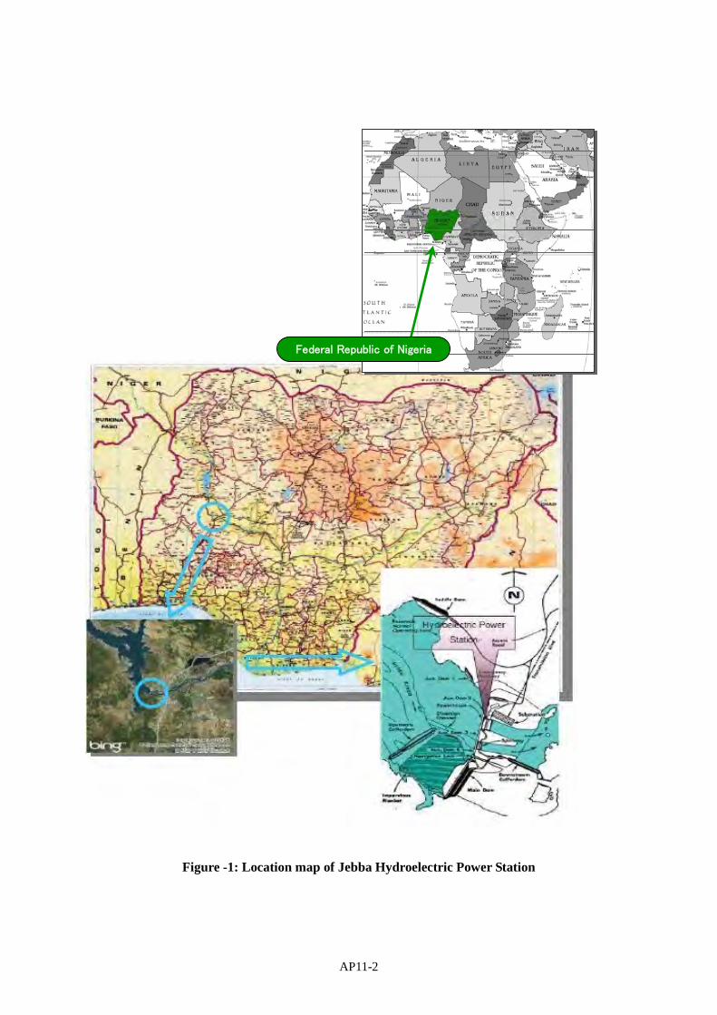
AP11-2
Figure -1: Location map of Jebba Hydroelectric Power Station
Federal Republic of Nigeria

AP11-3
2.2 Relevant Laws and Regulations
The Project must be carried out in accordance with the terms and conditions of the Loan Agreement, Guidelines for Employment of Consultants and Procurement of Goods and Services by JICA and the rules and regulations relating to construction investment and procurement of FGN.
3. General Terms of Reference
3.1 Objectives of the Project
Rehabilitation of the hydroelectric power generation units of [insert unit number from Note below depending on which option to be taken] at JHPS and strengthening of the capacity of implementation agency
[Note]
Option 1: 2G1 and 2G5 Option 2: 2G1, 2G3 and 2G5 Option 3: 2G1, 2G2, 2G3 and 2G5
3.2 Scope of Services
To achieve the above objectives of the Project to contribute to the state power policies of stabilising power supply and diversifying energy sources in Nigeria and to mitigate greenhouse gas emissions by alleviating the risk of breakdown at the electric power station, the consultant will undertake the following services: (1) Overall Project Management The consultant shall assist JHPS in overall management of the Project for all components on physical, financial and institutional matters including formulation of project management plans and other plans, monitoring, supervision, preparation of various reports including construction monthly reports and completion reports, and advice on problems/ bottlenecks prevailing or anticipated and countermeasures/ corrective actions required. (2) Review of Pre-investment Studies The consultant shall assist JHPS in review of pre-investment studies, including the JICA related studies. (3) Basic Design Reports The consultant shall prepare Basic Designs for the Project, Basic Design Reports for the Project, based on field investigation on the latest conditions of generation facilities and thorough examination of adequate technology and implementation measures particularly on rehabilitation of hydropower generation facilities, environmental impacts countermeasures, and facilities operations systems and seek for JHPS’s approval. During preparation of the Basic Design Reports the consultant shall seek concurrence from JHPS on every stage of preparation. Basic Design Reports shall include the contents described in Annex 1. (4) Preparation of Documents for Expression of Interest (Pre-qualification) and Evaluation The consultant shall assist JHPS in preparation of EOI (PQ) documents for the Project and seeking concurrence from JICA, evaluation of EOI proposals, preparation of EOI evaluation reports with recommendation for approval by JHPS and concurrence of JICA. (5) Preparation of Tender Documents The consultant shall assist JHPS in preparation of Tender documents for the Project based on Nigerian standard contract documents with adjustment if necessary to suit for JICA sample contract document

AP11-4
to facilitate concurrence from JICA. Tender Documents shall include the contents described in Annex 2. (7) Tender Assistance The consultant shall assist JHPS in handling tender procedures in accordance with JICA and Nigerian regulations. The services include preparation and arrangement for tender announcement, pre-bid meeting, site visit before tendering for interested tenderers, supply information or other necessary supports that tenderers may need including response to queries from tenderers and issuance of addendum if necessary, close and receipt of tender, tender opening, tender evaluation, clarification of tenders if required, preparation of tender evaluation report with recommendation for approval by JHPS and concurrence of JICA, preparation for tenders board and preparation of required documents for submission for approval to Bureau of Public Procurement and Federal Tenders Board and other documentations and actions as and when required by JHPS. (8) Conclusion of contract with the successful tenderer The consultant shall assist JHPS in conclusion of contract with the successful tenderer in accordance with JICA and Nigerian regulations. The services include preparation of draft contracts to be submitted to Nigerian authorities for approval and JICA for concurrence, support JHPS in contract negotiation with tenderes if necessary, preparation of all relevant contractual documents of works for the Project and assist in conclusion of contract between JHPS and the contractor. (9) Renovation Work Supervision The consultant shall assist JHPS in convening kick-off meetings for smooth commencement of the works, review of procedures, plan and detailed designs submitted by the contractor, suggestion of modifications and preparation of variation orders if required, monitoring of work progress, verification of invoices including measurement of works for payment, and dispute resolution. (10) Environmental Monitoring The consultant shall assist JHPS in preparation of JICA’s Monitoring Form through monitoring and supervision of removal, internal transportation and temporary storage of asbestos-containing wastes by the contractor and monitoring and supervision of hand over to a local professional treatment company of the wastes in coordination with the National Environmental Standards and Regulations Enforcement Agency. (11) Capacity Development The consultant shall assist JHPS in preparation of annual plans, implementation of training and study tours held locally and abroad (coverage of costs to be separately supplied), establishment of the management system for the operation and maintenance of the Project facilities and monitoring and evaluation related to Capacity Development. The capacity development components shall include operation and maintenance planning and implementation, and development of institutional and financial capabilities. JHPS shall designate the necessary staff and allocate them the time to undergo the capacity development program with the consultant. (12) Institutional Strengthening for Project Sustainability The consultant shall assist JHPS in preparing a post-implementation management plan with suggestions for necessary institutional strengthening for project sustainability and operation and maintenance of the assets renovated under the Project. (13) Financial Management The consultant shall assist and advise JHPS on matters related to project accounts, their maintenance, and preparation of disbursement requests.

AP11-5
(l4) Liaison with JICA The consultant shall assist JHPS in liaison with JICA including coordination between JICA and JHPS, providing advice on JICA’s procedures and facilitating to expedite documents, such as application for concurrence by JICA with regard to the procurement procedures, the progress reports (“P/R”) to JICA without delay on a quarterly basis until completion of the Project, and the project completion report (“PCR”) to JICA promptly in any event not later than 6 months after completion of the Project. (15) Monitoring and Evaluation The consultant shall assist JHPS in evaluation of the Project implementation progress at different stages of the Project, including establishment of baseline data and preparation of reports. (16) Documentation of Replicable Experiences The consultant shall assist JHPS in documentation of the useful and replicable lessons and experiences as a first-ever model project in Nigeria to be disseminated to other similar projects in Nigeria by synthesising project experiences and lessons, generalising them to become model for the other areas and preparing effective presentation materials. (17) Services during Defect Liability Period (DLP) The consultant shall assist JHPS in monitoring the performance and condition of renovated parts of generation facilities under the Project periodically based on site investigations and routine reporting to be prepared by JHPS on the matter. If any defect or other fault in the renovated works appears at any time prior to the end of the Defect Liability Period, the consultant shall assist JHPS in searching the cause of any defect or other fault and settling the matter in accordance with the provision of the contract. 3.3 Reports
The consultant shall prepare the following reports and documents in English and submit to JHPS both in hard and soft copies:
(1) Inception Report (2) Basic Design Reports (3) EOI (P/Q) Documents (4) Tender Documents (5) Tender Evaluation Reports (6) Construction Monthly Reports including quality analysis and quality control (7) Completion Reports
Other necessary reports and documents may be provided as required.
3.4 Implementation Period for the Project
The Project is expected to be completed in [insert number of months and completion year from Note below depending on which option to be taken].
[Note]
Option 1: 34 months by the end of August 2016 Option 2: 46 months by the end of August 2017 Option 3: 58 months by the end of August 2018
3.5 Requirements by JICA
(1) Difference of Opinion between the Borrower and the Consultant
In case of a difference of Opinion between the Borrower and the consultant on any important matters involving professional judgment that might affect the proper evaluation or execution of the Project, the

AP11-6
Borrower shall allow the consultants to submit promptly to the Borrower a written report and, simultaneously, to submit a copy to JICA. The Borrower shall forward the report to JICA with its comments in time to allow JICA to study it and communicate with the Borrower before any irreversible steps are taken on the matter. In cases of urgency, a consultant shall have the right to request the Borrower and/or JICA that the matter be discussed immediately between the Borrower and JICA.
(2) Monitoring by JICA
(1) The Borrower is responsible for supervising the consultant’s performance and ensuring that the consultant carries out the assignment in accordance with the contract. Without assuming the responsibilities of the Borrower or the consultant, JICA may monitor the work as necessary in order to satisfy itself that it is being carried out in accordance with appropriate standards and is based on acceptable data.
(2) As appropriate, JICA may take part in discussions between the Borrower and the consultant. However, JICA shall not be liable in any way for the implementation of the Project by reason of such monitoring or participation in discussions. Neither the Borrower nor the consultant shall be released from any responsibility for the Project by reason of JICA’s monitoring or participation in discussion.
(3) This provision shall be clearly stated in the agreement between the Borrower and the consultant.
4. Specific Terms of Reference
4.1 Responsibility of the consultant
(1) Project Manager (International)
The Project Manager (PM) is responsible for overall delivery of the proposed Project’s technical and contractual as well as managerial aspects, in addition to overall coordination as Team Leader. The roles of PM are, therefore, to assist JHPS in attaining smooth and efficient implementation of the Project and coordinating the activities of consultants in the respective expertise through the following services:
1) Review the deliverables to be prepared by the consultant,
2) Overview all activities to be performed by the consultant,
3) Assist JHPS in pre-qualification and selection through tender of the contractor for the Project,
4) Assist JHPS in negotiation and conclusion of the contract with the successful tenderer,
5) Assist JHPS in commencement of renovation works by the contractor,
6) Assist in monitoring and evaluation of the Project implementation including physical and financial progress,
7) Assist JICA loan procedures covering - Administration of the loan budget, and - Preparation of information and data for reporting to JICA,
8) Assist JHPS in conducting, monitoring and evaluating the training programs on Operation and Maintenance implementation for staffs of JHPS,
9) Assist JHPS in implementation, monitoring and evaluation of institutional and capacity development activities, and
10) Assist JHPS in monitoring of conditions and performance of the renovated parts under the Project during DLP, searching the cause of any defect or other default if appeared during DLP and settling the matter in accordance with the provision of the contract.

AP11-7
(2) Contract Management Engineer (International)/ Assistant Contract Management Engineer (Local)
The main objectives of the consulting services for the contract management engineer are to advise and assist JHPS in management of the contract for the Project. Contract management engineer shall compile tender document and contract document in viewpoint of contractual management, review and evaluate the compliance to the contract for the Project between JHPS and the contractor at the implementation stage to complete the renovation work. The main scope of work for the contract management engineer is as follows:
1) Review of the pre-investment study reports of the Project and provision of advice required for contract management of the Project,
2) Preparation of EOI (pre-qualification) documents, evaluation of the EOI documents submitted by interested companies and preparation of EOI evaluation reports,
3) Preparation of Tender documents and review of other part of Tender documents prepared by the assigned engineers of the consultant in terms of contractual consistency,
4) Assistance in commercial evaluation of tenders submitted by pre-qualified tenderers,
5) Assistance in negotiation with tenderers,
6) Assistance in preparation of contract document between JHPS and the contractor,
7) Assistance in monitoring and evaluation of the contractor’s compliance to the Contract for the Project,
8) Assistance in preparation of variation orders as and when required based on the review of the contractor’s claim evidence in compliance with the Contract, and
9) Assist JHPS in monitoring of conditions and performance of the renovated parts under the Project during DLP, searching the cause of any defect or other default if appeared during DLP and settling the matter in accordance with the provision of the contract.
(3) Generator Engineer (Internatinal)/ Electrical Engineer and Mechanical Engineer-1 (Local)
The main objectives of the consulting services for the generator engineer are to review the pre-investment study, to conduct field investigation of generators concerned, to prepare basic design, EOI (P/Q) documents and technical specification for tendering, to prepare evaluation report of EOI and tender, to review and evaluate the Project at the implementation stage to complete the renovation work with good quality and appropriate period, and to assist O&M planning for increase in sustainability of the Project. The main scope of work for the generator engineer is as follows:
1) Review of the pre-investment study reports of the Project and provision of advice for their improvement from a technical viewpoint, if necessary,
2) Conduct field investigation of generators subject for renovation under the Project in order to identify any additional recuperative measures to be included in the scope of the renovation works or not,
3) Review schedule and method of renovation work pertaining to generator including disassembly, internal transportation and temporary storage of asbestos-containing parts and wastes in the Project,
4) Preparation of basic design report and technical specifications in relation to renovation of generator including disassembly, internal transportation and temporary storage of asbestos-containing parts and wastes for tendering,
5) Preparation of EOI (pre-qualification) documents, evaluation of the EOI documents submitted by interested companies and preparation of EOI evaluation reports,
6) Assistance in pre-bid meeting, site visit before tendering for interested tenderers, supply information or other necessary supports that tenderers may need including response to queries

AP11-8
from tenderers and issuance of addendum if necessary in relation to generator including disassembly, internal transportation and temporary storage of asbestos-containing parts and wastes,
7) Assistance in evaluation and clarifications, if necessary, of technical proposals and preparation of tender evaluation report in relation to generator including disassembly, internal transportation and temporary storage of asbestos-containing parts and wastes submitted by pre-qualified tenderers,
8) Assistance in technical negotiation with tenderers in terms of generator including disassembly, internal transportation and temporary storage of asbestos-containing parts and wastes,
9) Assistance in preparation of technical portion of contract document,
10) Assistance in monitoring and evaluation of the Project implementation including performance, progress and quality control of the works undertaken by the contractor for the Project,
11) Assistance in assessment of variation orders in relation to generator if required,
12) Provide advice and support to the Project owners for effective operation and maintenance system,
13) Preparation of training program related to the Project, and
14) Assist JHPS in monitoring of conditions and performance of the renovated parts of generator under the Project during DLP, searching the cause of any defect or other default if appeared during DLP and settling the matter in accordance with the provision of the contract.
(4) Turbine/ Governor Engineer (International)/ Mechanical Engineer-2 (Local)
The main objectives of the consulting services for the turbine/ governor engineer are to review the pre-investment study, to conduct field investigation of turbines/ governors concerned, to prepare basic design, EOI (P/Q) documents and technical specification for tendering, to prepare evaluation report of EOI and tender, to review and evaluate the Project at the implementation stage to complete the renovation work with good quality and appropriate period, and to assist O&M planning for increase in sustainability of the Project. The main scope of work for the generator engineer is as follows:
1) Review of the pre-investment study reports of the Project and provision of advice for their improvement from a technical viewpoint, if necessary,
2) Conduct field investigation of turbines/ governors subject for renovation under the Project in order to identify any additional recuperative measures to be included in the scope of the renovation works or not,
3) Review schedule and method of renovation work pertaining to turbines/ governors in the Project,
4) Preparation of basic design report and technical specifications in relation to renovation of turbines/ governors for tendering,
5) Preparation of EOI (pre-qualification) documents, evaluation of the EOI documents submitted by interested companies and preparation of EOI evaluation reports,
6) Assistance in pre-bid meeting, site visit before tendering for interested tenderers, supply information or other necessary supports that tenderers may need including response to queries from tenderers and issuance of addendum if necessary in relation to turbines/ governors,
7) Assistance in evaluation and clarifications, if necessary, of technical proposals and preparation of tender evaluation report in relation to turbines/ governors submitted by pre-qualified tenderers,
8) Assistance in technical negotiation with tenderers in terms of turbines/ governors,
9) Assistance in preparation of technical portion of contract document,
10) Assistance in monitoring and evaluation of the Project implementation including performance, progress and quality control of the works undertaken by the contractor for the Project,
11) Assistance in assessment of variation orders in relation to turbines/ governors if required,

AP11-9
12) Provide advice and support to the Project owners for effective operation and maintenance system,
13) Preparation of training program related to the Project, and
14) Assist JHPS in monitoring of conditions and performance of the renovated parts of turbine/ governor under the Project during DLP, searching the cause of any defect or other default if appeared during DLP and settling the matter in accordance with the provision of the contract.
(5) Control/ Equipment Engineer (International and Local)
The main objectives of the consulting services for the control/ equipment engineer are to review the pre-investment study, to conduct field investigation of control/ equipment concerned, to prepare basic design, EOI (P/Q) documents and technical specification for tendering, to prepare evaluation report of EOI and tender, to review and evaluate the Project at the implementation stage to complete the renovation work with good quality and appropriate period, and to assist O&M planning for increase in sustainability of the Project. The main scope of work for the control/ equipment engineer is as follows:
1) Review of the pre-investment study reports of the Project and provision of advice for their improvement from a technical viewpoint, if necessary,
2) Conduct field investigation of control/ equipment subject for renovation under the Project in order to identify any additional recuperative measures to be included in the scope of the renovation works or not,
3) Review schedule and method of renovation work pertaining to control/ equipment in the Project,
4) Preparation of basic design report and technical specifications in relation to renovation of control/ equipment for tendering,
5) Preparation of EOI (pre-qualification) documents, evaluation of the EOI documents submitted by interested companies and preparation of EOI evaluation reports,
6) Assistance in pre-bid meeting, site visit before tendering for interested tenderers, supply information or other necessary supports that tenderers may need including response to queries from tenderers and issuance of addendum if necessary in relation to control/ equipment,
7) Assistance in evaluation and clarifications, if necessary, of technical proposals and preparation of tender evaluation report in relation to control/ equipment submitted by pre-qualified tenderers,
8) Assistance in technical negotiation with tenderers in terms of control/ equipment,
9) Assistance in preparation of technical portion of contract document,
10) Assistance in monitoring and evaluation of the Project implementation including performance, progress and quality control of the works undertaken by the contractor for the Project,
11) Assistance in assessment of variation orders in relation to control/ equipment if required,
12) Provide advice and support to the Project owners for effective operation and maintenance system,
13) Preparation of training program related to the Project, and
14) Assist JHPS in monitoring of conditions and performance of the renovated parts of control/ equipment under the Project during DLP, searching the cause of any defect or other default if appeared during DLP and settling the matter in accordance with the provision of the contract.
(6) Procurement Engineer (International and Local)
The main objectives of the consulting services for the procurement engineer are to review the pre-investment study, to conduct market research for project costs estimation, to prepare basic design and technical specification for tendering, to review and evaluate the Project at the implementation stage to complete the renovation work with good quality under appropriate period and reasonable Project cost. Procurement engineer will be assigned only for basic design / tendering stage. The main scope of work for the procurement engineer is as follows:

AP11-10
1) Review of the pre-investment study reports of the Project in consideration of market and economical conditions surrounding the Project at the time of basic design / tendering stage and provision of advice for their improvement from a viewpoint of procurement, if necessary,
2) Review schedule and method of renovation work pertaining to procurement for the Project,
3) Assistance in estimating the Project Cost to formulate the owner’s budget for Tendering,
4) Preparation of basic design report and technical specifications in relation to procurement for Tendering,
5) Preparation of EOI (pre-qualification) documents, evaluation of the EOI documents submitted by interested companies and preparation of EOI evaluation reports,
6) Assistance in pre-bid meeting, site visit before tendering for interested tenderers, supply information or other necessary supports that tenderers may need including response to queries from tenderers and issuance of addendum if necessary in relation to procurement,
7) Assistance in evaluation and clarifications, if necessary, of technical proposals and preparation of tender evaluation report in relation to procurement submitted by pre-qualified tenderers,
8) Assistance in technical negotiation with tenderers in terms of procurement, and
9) Assistance in preparation of technical portion of contract document.
(7) Environmental Expert (International and Local)
The main objectives of the consulting services for the environmental expert are to review the pre-investment study, to conduct field investigation regarding environmental protection and occupational health, to prepare basic design, EOI (P/Q) documents and technical specification for tendering, to prepare evaluation report of EOI and tender, to review and evaluate the Project at the implementation stage to complete the renovation work in terms of environmental and occupational health including asbestos-containing parts/wastes. The main scope of work for the environmental expert is as follows:
1) Review of the pre-investment study reports of the Project and provision of advice for their improvement from an environmental viewpoint, if necessary,
2) Conduct field investigation regarding environmental protection and occupational health associated with renovation work under the Project in order to identify any additional recuperative measures to be included in the scope of the renovation works or not,
3) Review schedule and method of renovation work pertaining to environmental protection and occupational health in the Project,
4) Preparation of basic design report and technical specifications in relation to environmental protection and occupational health associated with renovation work for tendering,
5) Assistance in preparation of environmental and occupational health portion of contract document,
6) Assistance in monitoring and evaluation of the Project implementation including performance, progress and quality control of the works in relation to environmental protection and occupational health undertaken by the contractor for the Project, and
7) Provide advice and support to the Project owners for effective transportation, disposal and treatment of hazardous waste, if necessary, in particular asbestos contained parts.
(8) Institutional and Capacity Development Expert (International)
The main objectives of the consulting services for the institutional and capacity development expert are to review the pre-investment study, to conduct investigation of latest situation of institution and capacity of staff in JHPS, to prepare basic design and technical specification for tendering, to assist JHPS for preparation of capacity development programs covering national workshop and training, overseas training and other programs related to the Project implementation, and operation and

AP11-11
maintenance of the station. The main scope of work for the expert is as follows:
1) Review of the pre-investment study reports of the Project and provision of advice for their improvement from a viewpoint of institutional and capacity development, if necessary,
2) Conduct field investigation regarding institutional and capacity development necessary for effective utilization of generation facilities after renovation work under the Project,
3) Review schedule and method of renovation work from a viewpoint of effective and timely execution of institutional and capacity development in the Project,
4) Preparation of basic design report and technical specifications in relation to institutional and capacity development program and training to be proposed by the tenderers along with the progress of renovation work, training including seminars, domestic trainings, on-the-job training, overseas trainings and other trainings, if necessary,
5) Assistance in preparation of technical portion of contract document in terms of institutional and capacity development / training,
6) Assistance in monitoring and evaluation of the Project implementation including performance, progress and quality control of the institutional and capacity development / training works undertaken by the contractor for the Project,
7) Assistance in assessment of variation orders in relation to institutional and capacity development / training,
8) Assist JHPS to implement and evaluate the capacity development programs, and
9) Prepare the training program reports using available information.
5. Staffing and Schedule
5.1 Staffing
It is estimated that the international and local consultants who shall be required for providing consulting services to implement the Projects are shown in the following table: However, the specialists proposed could be modified based on the actual requirement of the consulting services.
Table - 1 Estimated Input of International and Local Consultants and Local Staffs
Positions No. Option 1 Option 2 Option 3
Person-months
TotalPerson-months
TotalPerson-months
Total
1. Basic Design / Tender Assistance Stage
International Consultants
1) Project Manager 1 6.0 6.0 6.0 6.0 6.0 6.0
2) Contract Management Engineer
1 6.0 6.0 6.0 6.0 6.0 6.0
3) Generator Engineer 1 5.0 5.0 5.0 5.0 5.0 5.0
4) Turbine/ Governor Engineer
1 1.0 1.0 1.0 1.0 1.0 1.0
5) Control/Equipment Engineer
1 4.0 4.0 4.0 4.0 4.0 4.0
6) Procurement Engineer 1 2.0 2.0 2.0 2.0 2.0 2.0
7) Environmental Expert 1 2.0 2.0 2.0 2.0 2.0 2.0
8) Institutional and Capacity Development Expert
1 1.0 1.0 1.0 1.0 1.0 1.0
Sub-total 8 - 27.0 - 27.0 - 27.0

AP11-12
Local Consultants
1) Assistant Contract Management Engineer
1 5.0 5.0 5.0 5.0 5.0 5.0
2) Mechanical Engineer 1 1 6.0 6.0 6.0 6.0 6.0 6.0
3) Mechanical Engineer 2 1 1.0 1.0 1.0 1.0 1.0 1.0
4) Electrical Engineer 1 6.0 6.0 6.0 6.0 6.0 6.0
5) Control/Equipment Engineer
1 2.0 2.0 2.0 2.0 2.0 2.0
6) Environmental Expert 1 1.0 1.0 1.0 1.0 1.0 1.0
Sub-total 6 - 21.0 - 21.0 - 21.0
Local Staff
1) Office assistant 1 6.0 6.0 6.0 6.0 6.0 6.0
2) Driver 1 11.0 11.0 11.0 11.0 11.0 11.0
Sub-total 2 - 17.0 - 17.0 - 17.0
International Consultants 27.0 27.0 27.0
Local Consultants 21.0 21.0 21.0
Local Staff 17.0 17.0 17.0
Table - 1 Estimated Input of International and Local Consultants and Local Staffs (cont’d)
Positions No. Option 1 Option 2 Option 3
Person-months
TotalPerson-months
TotalPerson-months
Total
2. Site Supervision Stage
International Consultants
1) Project Manager 1 18.0 18.0 26.0 26.0 34.0 34.0
2) Contract Management Engineer
1 2.0 2.0 3.0 3.0 4.0 4.0
3) Generator Engineer 1 21.0 21.0 29.0 29.0 37.0 37.0
4) Turbine/ Governor Engineer
1 3.0 3.0 4.0 4.0 5.0 5.0
5) Control/Equipment Engineer
1 3.0 3.0 4.0 4.0 5.0 5.0
6) Procurement Engineer 1 2.0 2.0 2.0 2.0 2.0 2.0
7) Environmental Expert 1 2.0 2.0 2.0 2.0 2.0 2.0
8) Institutional and Capacity Development Expert
1 2.0 2.0 3.0 3.0 4.0 4.0
Sub-total 8 - 53.0 - 73.0 - 93.0
Local Consultants
1) Assistant Contract Management Engineer
1 7.0 7.0 11.0 11.0 15.0 15.0
2) Mechanical Engineer 1 1 16.0 16.0 22.0 22.0 28.0 28.0
3) Mechanical Engineer 2 1 2.0 2.0 3.0 3.0 4.0 4.0
4) Electrical Engineer 1 17.0 17.0 23.0 23.0 29.0 29.0

AP11-13
5) Control/Equipment Engineer
1 2.0 2.0 2.0 2.0 2.0 2.0
6) Procurement Engineer 1 2.0 2.0 2.0 2.0 2.0 2.0
Sub-total 6 - 46.0 - 63.0 - 80.0
Local Staff
1) Administrative manager 1 14.0 14.0 20.0 20.0 26.0 26.0
2) Chief accountant 1 13.0 13.0 19.0 19.0 25.0 25.0
3) Computer Assistant 1 8.0 8.0 12.0 12.0 16.0 16.0
4) Office assistant 1 14.0 14.0 20.0 20.0 26.0 26.0
5) Driver 1 25.0 25.0 34.0 34.0 43.0 43.0
6) Office Boy 1 12.0 12.0 17.0 17.0 22.0 22.0
Sub-total 6 - 86.0 - 122.0 - 158.0
International Consultants 53.0 73.0 93.0
Local Consultants 46.0 63.0 80.0
Local Staff 86.0 122.0 158.0
Table - 1 Estimated Input of International and Local Consultants and Local Staffs (cont’d)
Positions No. Option 1 Option 2 Option 3
Person-months
TotalPerson-months
TotalPerson-months
Total
3. Defect Liability Stage
International Consultants
1) Project Manager 1 2.0 2.0 2.0 2.0 2.0 2.0
3) Generator Engineer 1 5.0 5.0 5.0 5.0 5.0 5.0
Sub-total 2 - 7.0 - 7.0 - 7.0
International Consultants 7.0 7.0 7.0
Grand Total 257.0 330.0 403.0
International Consultants 87.0 107.0 127.0
Local Consultants 67.0 84.0 101.0
Local Staff 103.0 139.0 175.0
5.2 Qualifications
5.2.1 International Consultants
(1) Project Manager is professional engineer with at least 15 years in general and 10 years in design and construction supervision in power sector projects. Project Manager shall have been engaged as team leader or project manager in at least 2 international projects in design and construction supervision in power sector projects.
(2) Contract Management engineer is professional engineer with at least 10 working years and 7 years in design or supervision in international projects. Contract Management Engineer shall have work experience as contract engineer for at least 3 international projects of design and/or construction supervision projects.

AP11-14
(3) Generator Engineer is professional electro-mechanical engineer with at least 10 working years and 7 years in design and/or supervision of installation works of power generator. Generator Engineer shall have work experience as electro-mechanical engineer for at least 3 design and/or installation supervision projects.
(4) Turbine/ Governor Engineer is professional mechanical engineer with at least 10 working years and 7 years in design and/or supervision of installation works for water turbine/ governor. Turbine/ Governor Engineer shall have work experience as mechanical engineer for at least 3 design and/or installation supervision projects.
(5) Control/ Equipment Engineer is professional electrical engineer with at least 10 working years and 7 years in design and/or supervision of installation works of control/ equipment. Control/ Equipment Engineer shall have work experience as electrical engineer for at least 3 design and/or installation supervision projects.
(6) Procurement Engineer is professional engineer with at least 10 working years and 7 years in design and Tender assistance in the related installation field. Procurement Engineer shall have work experience as procurement engineer for at least 3 design and/or installation supervision projects.
(7) Environmental Expert is professional environment expert with at least 10 working years and 7 years in design and/or construction supervision for construction works. Environmental Expert shall have work experience as environmental expert for at least 3 design and/or construction supervision projects.
(8) Institutional and Capacity Development Expert is professional expert with at least 7 working years and 5 years in design and/or supervision for construction projects. Institutional and Capacity Development Expert shall have work experience as institutional and/or capacity development expert for at least 2 design and/or construction supervision projects.
(9) Other requirements: International Engineers and Experts must be proficient in English to express his professional views and advices, and prepare reports.
5.2.2 Local Consultants
(1) Assistant Contract Management engineer is local professional engineer with at least 7 working years and 5 years in design and/or supervision in domestic projects. Assistant Contract Management Engineer shall have been work experience as contract engineer for at least 2 projects of design and/or construction supervision.
(2) Mechanical Engineers 1 and 2 are local professional mechanical engineers with at least 7 working years and 5 years in design and/or supervision of installation works. Mechanical Engineers 1 and 2 shall have work experience as mechanical engineer for at least 2 design and/or installation supervision projects in Nigeria.
(3) Electrical Engineer is local professional electrical engineer with at least 7 working years and 5 years in design and/or supervision of installation works. Electrical Engineer shall have work experience as electrical engineer for at least 2 design and/or installation supervision projects.
(4) Procurement Engineer is local professional engineer with at least 5 working years and 3 years in design and Tender assistance in similar field. Procurement Engineer shall have work experience as procurement engineer for at least 2 design and/or installation supervision projects.
(5) Environmental Expert is local professional environment expert with at least 5 working years and 3 years in design and/or construction supervision works. Environmental Expert shall have work experience as environmental expert for at least 2 design and/or construction supervision projects.

AP11-15
Annex 1 Main Contents of the Basic Design Reports (BD/R)
Basic Design Report Contents
1. General 1.1 Background of the Project 1.2 Present Situation and Planning Framework of Power Sector in Nigeria 2. Basic Project Description 2.1 Objectives of the Project 2.2 Basic Specification 2.3 Physical Features of the Power Plant 3. Basic Design 3.1 Technical Outline of the Plant 3.2 Present status of the generation facilities 3.3 Criteria for selection of Renovation details 3.4 Generator 3.5 Turbine / Governor 3.6 Control / Equipment 4. Relevant Safety Measures 5. Operation and Maintenance 5.1 Operation and maintenance of the Plant 5.2 Operational and Institutional Framework 6. Renovation Works of the Generation Facilities 6.1 General 6.2 Preliminary Works 6.3 Manufacture Works 6.4 Generator Renovation Works 6.5 Turbine/ Governor Renovation Works 6.6 Control/ Equipment Renovation Works 6.7 Renovation Work Schedule 6.8 Safety, Security and Quality Assurance 7. Estimated Project Cost and Implementation Schedule 7.1 Estimated Project Cost to be covered by JICA ODA Loan 7.2 Estimated Project Cost to be covered by JHPS 7.3 Operation and Maintenance Cost 7.4 Implementation Schedule 8. Economic and Financial Analysis 8.1 Economic Analysis 8.2 Financial Analysis

AP11-16
Basic Design Report Contents
9. Appendices Appendix-1 Field Investigation Result: Generator Appendix-2 Field Investigation Result: Turbine/ Governor Appendix-3 Field Investigation Result: Control/ Equipment Appendix-4 Field Investigation Result: Institutional Framework and Capacity

AP11-17
Annex 2 Sample of Tender Documents PART 1
Item Contents
PART 1 – TENDERING PROCEDURES
Invitation for Tenders Standard form of Invitation for Tenders
Section I. Instructions to Tenderers (ITT)
A. General Scope of Tender; Source of Funds; Fraud and Corruption; Eligible Tenderers; Eligible Renovation Services B. Contents of Tender Documents Sections of Tender Documents; Clarification of Tender Documents; Site Visit; Pre-Tender Meeting; Amendment of Tender Documents C. Preparation of Tenders Cost of Tender; Language of Tender; Documents comprising the Tender; Letter of Tender and Schedules; Alternative Tenders; Documents Establishing the Eligibility of the Renovation Services; Documents Establishing the Eligibility and Qualification of the Tenderer; Documents Establishing Conformity of the Renovation Services; Tender Prices and Discounts; Currencies of Tender and Payment; Period of Validity of Tenders; Tender Security; Format and Signing of Tender D. Submission and Opening of Tenders Submission, Sealing and Marking of Tenders; Deadline for Submission of Tenders; Late Tenders; Withdrawal, Substitution, and Modification of Tenders; Tender Opening E. Evaluation and Comparison of Tenders Confidentiality; Clarification of Tenders; Deviations, Reservation, and Omissions; Determination of Responsiveness; Nonmaterial Nonconformities; Correction of Arithmetical Errors, Conversion to Single Currency; Evaluation of Tenders; Comparison of Tenders; Eligibility and Qualification of the Tenderer; Employer’s Right to Accept Any Tender, and to Reject Any or All Tenders F. Award of Contract Award Criteria; Notification of Award; Singing of Contract; Performance Security
Section II. Tender Data Sheet
JICA Standard Form which contains the following information: A. General B. Contents of Tender Documents C. Preparation of Tenders D. Submission and Opening of Tenders E. Evaluation and Comparison of Tenders
Section III. Evaluation and Qualification Criteria
1. Evaluation Technical Evaluation; Economic Evaluation(Time Schedule; Operation and Maintenance Costs; Functional Guarantees of the Renovation Services; Work, services, facilities, etc., to be provided by the Employer; Specific additional criteria); Technical Alternatives 2. Qualification Update of Information; Financial Resources; Personnel; Equipment; Subcontractors/ manufacturers

AP11-18
Item Contents
Section IV. Tendering Forms
1. Letter of Tender 2. Schedules of Rates and Prices Mandatory Parts Supplied from Abroad; Mandatory Parts Supplied from Nigeria; Design Services; Renovation and Other Services; Grand Summary; Recommended Spare Parts; Price Adjustment 3. Technical Proposal Site Organisation; Method Statement; Mobilisation Schedule; Construction Schedule; Renovation Details; Equipment; Functional Guarantee; Safety Plan; Proposed Personnel; Resume of Proposed Personnel; Proposed Subcontractors for Major Renovation Items and Services; Time Schedule 4. Tenderers Qualification following PQ Tenderer Information Sheet; JVA Partner Information Sheet; Historical Contract Non-Performance; Current Contract Commitments/ Works in Progress; Historical Financial Performance; Average Annual Turnover; Financial Resources; Acknowledgement of Compliance with Guidelines for Procurement under Japanese ODA Loans 5. Form of Tender Security (Bank Guarantee or Tender Bond) 6. Manufacturer’s Authorisation
Section V. List of Eligible Countries of Japanese ODA Loans
All countries
Sample of Tender Documents PART 2 and PART 3
Item Contents
PART 2 – EMPLOYER’S REQUIREMENTS
Section VI. Employer’s Requirements
1. Scope of Supply of Renovation Services by the Contractor 2. Specification 3. Forms and Procedures Form of Completion Certificate; Form of Operational Acceptance Certificate; Change Order Procedure and Forms; Change Order Procedure 4. Drawings 5. Supplementary Information
PART 3 – CONDITIONS OF CONTRACT AND CONTRACT FORMS Section VII. General Conditions of Contract
A. Contract and Interpretation Definitions; Contract Documents; Interpretation; Communications; Law and Language; Fraud and Corruption B. Subject Matter of Contract Scope of Facilities; Time for Commencement and Completion; Contractor’s Responsibilities; Employer’s Responsibilities C. Payment Contract Price; Terms of Payment; Securities; Taxes and Duties D. Intellectual Property License/ Use of Technical Information

AP11-19
Item Contents
Confidential Information E. Execution of the Facilities Representatives; Work Programme; Subcontracting; Design and Engineering; Procurement; Installation; Test and Inspection; Completion of Facilities; Commissioning and Operational Acceptance F. Guarantees and Liabilities Completion Time Guarantee; Defect Liability; Functional Guarantee; Patent Indemnity; Limitation of Liability G. Risk Distribution Transfer of Ownership; Care of Facilities; Loss or Damage to Property, Accident or Injury to Workers, Indemnification; insurance; Unforeseen Conditions; Change in Laws and Regulations; Force Majeure; War Risk; H. Change in Contract Elements Change in the Facilities; Extension of Time for Completion; Suspension; Termination; Assignment I. Claims, Disputes and Arbitration Contractor7s Claims; Disputes and Arbitration
Section VIII. Particular Conditions of Contract
The Particular Conditions (PC) complement the General Conditions (GC) to specify data and contractual requirements linked to the special circumstances of Nigeria, the Employer, or the overall project. Whenever there is a conflict, the provisions herein shall prevail over those in the GC. Clause numbers in the PC correspond to those in the GC.
Section IX. Contract Forms
1. Notification of Award – Letter of Acceptance 2. Contract Agreement Appendices: Terms and Procedures of Payment; Price Adjustment; Insurance Requirements; Time Schedule; List of Major Items of Renovation Services and List of Approved Subcontractors; Scope ofWorks and Supply by the Employer; List of Documents for Approval or Review; Functional Guarantees 3. Performance Security Forms – Bank Guarantee 4. Bank Guarantee - Conditional 5. Bank Guarantee Form for Advance Payment


Appendix-12
Scope of Rehabilitation works


Page 1 of 25 NOVEMBER 2011 Z1-GENERATOR SITE WORK PLAN 111125
Preliminary
AP12.1-1
1. SCOPE OF WORK
Replacement parts at this renovation work are shown as listed below.

Page 2 of 25 NOVEMBER 2011 Z1-GENERATOR SITE WORK PLAN 111125
Preliminary
AP12.1-2
2. ON-SITE WORK PLAN (1) General sequence of on-site work <Stator pre-assembly work at the erection bay, before unit shut down>
① Preparation of working area, facilities, utilities, tools, etc. ↓ ② Disassembly of stator winding (for 2nd to 4th unit only) ↓ ③ Disassembly of stator core laminations (for 2nd to 4th unit only) ↓ ④ Roundness check and adjustment of stator frame ↓ ⑤ Total re-stacking work of core laminations, and acceptance tests ↓ ⑥ Winding work of stator coils, and acceptance tests after completion of stator
<Renovation work, after unit shut down>
⑦ Preparation of working area, facilities, utilities, tools and etc. ↓ ⑧ Disassembly of generator ↓ ⑨ Disassembly of stator winding and exchange from old to new stator ↓ ⑩ Trimming, finishing, inspection and cleaning of disassembled parts ↓ ⑪ Disassembly of rotor pole and exchange from old to new rotor pole (for 1st unit only) ↓ ⑫ Modification of rotor rim support ↓ ⑬ Assembly of the generator ↓ ⑭ Commissioning tests of the generator ↓ ⑮ Site clearance (demolition and close-out) ↓ ⑯ Reporting at site

Page 3 of 25 NOVEMBER 2011 Z1-GENERATOR SITE WORK PLAN 111125
Preliminary
AP12.1-3
(2) On-site work plan In this section, procedure of the on-site work plan is described. The content of these plans is
included to indicate the outlined magnitude of the work plan to be followed in the disassembly and re-assembly of the generator. This is not purported to completely describe the work required or to be entirely accurate in its requirements. All equipment and materials shall be installed in accordance with the contract specifications,
drawings, instructions and these work plans. The contractor’s supervisor shall give the additional detailed instructions and may make change or
revisions in some parts of instructions for the purpose of making them conform to the special arising circumstances in the field. The instructions issued by the supervisor shall form part of these plans. Should JHEP disagree with some parts of instructions or have not well understanding of them, the
supervisor shall give the required information and cooperate with JHEP to achieve the construction successfully. Do not start work before JHEP can comprehend the methods and procedures of the work to be performed. Otherwise the misunderstanding may result in the unexpected faulty assembly or installation. Where the grade or standard of the work for the generator is not specifically indicated in the
drawings or in thee specifications including these plans, the JIS, ANSI, NEMA, IEEE, ASME, ASTM or equivalent are applicable. <Stator pre-assembly work at the erection bay, before unit shut down> ① Preparation of working area, facilities, utilities, tools, etc.
One of the main tasks of this renovation work is the stator pre-assembly work. This task must
be performed at the erection bay while generator unit keeping operation, and completed before the
renovation work starts.
101) Planning about time schedule of the site work, work procedures, work facilities, working space,
temporary storage area and lay down of disassembled equipment and components in the
Power House.
102) To supply special lifting device and slings by Contractor.
103) After the renovation work has been finished, the special lifting device and slings must be
properly stored and controlled by JHEP.
104) To make necessary working floor with scaffolding material and floor protection along with
necessary stand blocks to support generator components at the erection bay and in the
Power House for the renovation work. Basic idea is to be discussed later with JHEP.
105) To install the working floor with scaffolding and floor protection at the erection bay and the
Power House with suitable lighting and ventilation system along with electric power supply.

Page 4 of 25 NOVEMBER 2011 Z1-GENERATOR SITE WORK PLAN 111125
Preliminary
AP12.1-4
106) To prepare work facilities, equipment, electrical test equipment and tools.
107) To store the work facilities, electrical test equipment and tools in the Power House for the next
renovation work chance unless otherwise instructed to store in the warehouse or to remove
from the Power House by JHEP. To move and store in designated area or warehouse
nearby the Power House, if requested to remove them from the Power House.
② Disassembly of stator winding (for 2nd to 4th unit only)
201) Planning of the actual work such as preparation of hand tools, work equipment, consumable
material and organization of work team must be done jointly with JHEP based on work
procedures, time schedule, labor schedule.
202) To prepare and install of necessary working floor with scaffolding material and floor protection
at the erection bay. Basic idea is to be discussed later with JHEP.
203) To prepare work facilities, equipment, tools, safety equipment and material for the work of the
stator rewinding work shall be provide by Contractor.
204) To prepare work facilities and utilities other than the above item 203, and working area and
temporary storage area.
205) To supply of disposable working wear, masks, gloves, etc. for all JHEP’s personnel to work
with dirt.
206) Prepare necessary facilities, safety equipment and safety goods for Asbestos Abetment to
follow at least the related laws/regulations of Japan.
207) To perform seal wrapping of every stator bar with a plastic bag for storage/disposal.
208) To perform demolition, removal and disposal of coils, scrap and waste in an appropriate
manner following the local rules and regulations by JHEP.
209) To perform disassembly work of the coils with phase connection bus rings and terminal leads,
jumpers, wedges, coil end bracing and RTDs.
210) Careful attention and precaution must be paid to minimize scattering of dust and dirt during the
disassembly work at the erection bay.
211) Necessary and mandatory safety pre-caution and safety measures must be taken place at all
the time during the disassembly work and its preparation work including storage of parts and
material in order to protect personnel, environment and already installed equipment inside of
the site. The site manager must be responsible to induct all personnel to follow the site
safety regulations and guidance.
212) To store the work facilities, equipment and tools and surplus materials in the Power House for

Page 5 of 25 NOVEMBER 2011 Z1-GENERATOR SITE WORK PLAN 111125
Preliminary
AP12.1-5
the re-winding work unless otherwise instructed to store in the warehouse by JHEP.
213) Other activities than the above mentioned must be done by mutual consent with JHEP.
③ Disassembly of stator core laminations (for 2nd to 4th unit only)
301) Planning of the actual work such as preparation of hand tools, work equipment, consumable
material and organization of work team must be done jointly with JHEP based on work
procedures, time schedule, labor schedule.
302) To prepare and install of necessary working floor with scaffolding material and floor protection
at the erection bay. Basic idea is to be discussed later. The working floor must be
changed while the disassembly work is proceeding.
303) To assembly & maintenance of a temporary enclosure for Asbestos Abetment, if required
additionally, during disassembly work of existing core laminations, and removal of the
temporary enclosure after the work.
304) To prepare necessary facilities, safety equipment and safety goods for Asbestos Abetment to
follow at least the related laws/regulations of Japan.
305) To prepare work facilities, equipment, tools, safety equipment and material for the stator core
restacking work.
306) To supply of disposable working wears, masks, gloves, etc. for all JHEP’s personnel to work
with dirt
307) To prepare work facilities and utilities other than the above items 304, 305 and 306, and
working area and temporary storage.
308) To perform disassembly work of the core laminations as following work sequence.
1) To prepare necessary working platform and skids to keep disassembled core laminations.
2) To remove nuts for core tightening bolts.
3) To disassemble stator clamping plates at collector end.
4) To disassemble core laminations while changing elevation of the working floor.
5) To remove core end duct fingers at turbine end, and core keys.
6) Cleaning of the stator frame.
309) To perform seal wrapping of disassembled insulation sheets, which contain Asbestos, with a
plastic bag for storage/disposal.
310) To perform demolition, removal and disposal of disassembled stuff including core laminations
from the stator in an appropriate manner following the local rules and regulations by JHEP.
311) Careful attention and precaution must be paid to minimize scattering of dust and dirt during the

Page 6 of 25 NOVEMBER 2011 Z1-GENERATOR SITE WORK PLAN 111125
Preliminary
AP12.1-6
disassembly work at the erection bay.
312) Necessary and mandatory safety pre-caution and safety measures must be taken place at all
the time during the disassembly work and its preparation work including storage of parts and
material in order to protect personnel, environment and already installed equipment inside of
the site. The site manager must be responsible to induct all personnel to follow the site
safety regulations and guidance.
313) To store the work facilities in the Power House for the re-stacking work unless otherwise
instructed to store in the warehouse by JHEP.
314) Other activities than the above mentioned must be done by mutual consent with JHEP.
④ Roundness check and adjustment of stator frame
401) Planning of the actual work such as preparation of hand tools, work equipment, consumable
material and organization of work team must be done jointly with JHEP based on work
procedures, time schedule, labor schedule.
402) To prepare work facilities, equipment, and tools for the stator frame work.
403) To prepare work facilities and utilities including working area and temporary storage area at
the erection bay.
404) To deliver temporary stored components, parts, materials and tooling from the storage area to
the working area.
405) To assemble temporary work platform with scaffolding.
406) To perform centering/adjustment check and roundness measurement of the stator frame as
specified in the Inspection and test plan (hereafter “ITP”), then necessary adjustment must be
performed to adjust the stator in acceptable condition for the core stacking work. Final
measured data must be recorded on the QC record sheet. In case actual reading is out of
tolerance, remedial adjustment work must be done by mutual consent with JHEP.
407) To perform touch up painting for the stator frame by brushing or spraying.
408) To make the work area clean to proceed the core stacking work.
409) Careful attention and precaution must be paid to minimize scattering of dust and dirt.
410) Necessary and mandatory safety pre-caution and safety measures must be taken place at all
the time during the exchange work and its preparation work including storage of parts and
material in order to protect personnel, environment and already installed equipment inside of
the site. The site manager must be responsible to induct all personnel to follow the site
safety regulations and guidance.

Page 7 of 25 NOVEMBER 2011 Z1-GENERATOR SITE WORK PLAN 111125
Preliminary
AP12.1-7
411) To store the work facilities in the Power House for the next renovation work unless otherwise
instructed to store in the warehouse by JHEP.
412) Other activities than the above mentioned must be done upon mutual consent with JHEP.
⑤ Total re-stacking work of core laminations, and acceptance tests
501) Planning of the actual work such as preparation of hand tools, work equipment, consumable
material and organization of work team must be done jointly with JHEP based on work
procedures, time schedule, labor schedule .
502) To prepare work facilities, equipment, electrical test equipment and tools for the stator core
restacking work.
503) To prepare work facilities and utilities including working area and temporary storage area in the
Power House bay.
504) To deliver temporary stored components, parts, materials and tooling from the storage area to
the working area upon request.
505) To perform inspection of the temporarily stored components, parts and material prior to their
assembly.
506) To perform assembly of core keys and core end duct fingers at turbine end as following work
sequence:
1) To install new core keys while adjusting their pitch and verticality by welding, then apply
paint to the welded parts by brushing (touch-up).
2) To perform alignments check of the core keys.
3) To install new core end duct fingers at turbine end, then apply paint to the welded parts by
brushing (touch-up).
507) To perform core re-stacking work as following work sequence:
1) Every preparation work to start the core stacking work.
2) To stack core laminations having the dovetailed slots, which have interchangeability and
compatibility with original designed stator frame, by half lapping method using the core keys
and slot gauges as a guide, while checking if stacked laminations are exactly in a half lap.
3) To tighten stacked core laminations temporarily at every 500mm thickness by using
hydraulic jacks and special clamping jigs.
4) To perform heating of the stacked core laminations, after having reached at specified total
thickness.
5) To finally tighten the core with new core clamping plates, new tightening bolts and new nuts.

Page 8 of 25 NOVEMBER 2011 Z1-GENERATOR SITE WORK PLAN 111125
Preliminary
AP12.1-8
6) To perform visual check, dimension and roundness check of inner diameter, and tightness
check of core teeth, then tag weld tightening bolts as specified in the ITP.
7) To apply core varnish by spraying to the entire stator core, and dry in an atmospheric
condition and semi-conductive varnish to slots by brushing or spraying.
508) To supply of disposable working wear, masks, gloves, etc. for all JHEP’s personnel to work
with solvent, paint and varnish.
509) Surplus material must be kept in the Power House or disposed depending upon JHEP's
instruction.
510) All work and test data must be recorded on the QC record sheets timely during the work.
511) To perform technical advice about such as procedures and quality of on-going work, and
demonstration of the work procedure to JHEP, upon request and as an OJT or if required.
512) To maintain the erection bay as clean as possible during the entire work period for the purpose
of avoiding a trouble and/or a failure specially caused by foreign metallic particles. Working
shoes exclusive use for inside of the work platform must be prepared, and everyone must be
instructed to use them.
513) Careful attention and precaution must be paid to minimize scattering of dust and dirt during the
work.
514) Necessary and mandatory safety pre-caution and safety measures must be taken place at all
the time during the work and its preparation work including storage of parts and material in
order to protect personnel, environment and already installed equipment inside of the site.
The site manager must be responsible to induct all personnel to follow the site safety
regulations and guidance.
515) To store the work facilities in the Power House for the next renovation work unless otherwise
instructed to store in the warehouse by JHEP.
516) Other activities than the above mentioned must be done by mutual consent with JHEP.
⑥ Winding work of stator coils, and acceptance tests after completion of stator
601) Planning of the actual work such as preparation of hand tools, work equipment, consumable
material and organization of work team must be done jointly with JHEP based on work
procedures, time schedule, labor schedule .
602) To prepare work facilities, equipment, electrical test equipment and tools for the generator
stator rewinding work.
603) To prepare work facilities and utilities including working area and temporary storage area in the

Page 9 of 25 NOVEMBER 2011 Z1-GENERATOR SITE WORK PLAN 111125
Preliminary
AP12.1-9
Power House.
604) To prepare and install of necessary working floor with scaffolding material and floor protection.
605) To make clean flooring on the working floor, and to maintain cleanliness. All goods and stuff
must be kept free from foreign particles during the entire work period for the purpose of
avoiding a trouble and/or a failure. Working shoes exclusive use for on the working floor
must be prepared, and everyone must be instructed to use them.
606) To deliver temporary stored components, parts, materials and tooling from the storage area to
the working area upon request.
607) To perform inspection of the temporarily stored components, parts and material prior to their
assembly.
608) To supply of disposable working wear, masks, gloves, and clean safety shoes etc. for all
personnel to work.
609) To perform stator winding work as following work sequence:
1) To perform visual inspection of the stator core, and every preparation work to start the
winding work.
2) To assemble new coil end support rings, which have interchangeability and compatibility
with original designed stator frame, with brackets while binding with glass fiber cord
applying air dry varnish, and to lay RTD leads.
3) To assemble bottom bars with slot bottom fillers and side ripple springs by pressing with
temporary tapered wedges, while binding coil ends to the support rings, then to tie edge of
the side ripple spring with glass fiber tape applying air dry varnish.
4) To perform DC Hi-Pot test to all bottom bars.
5) To assemble RTDs and slot center fillers.
6) To assemble top bars with side ripple springs by pressing with temporary tapered wedges.
7) To drive slot wedges with top fillers.
8) To perform DC Hi-Pot test to all top & bottom bars while grounding RTDs.
9) To braze series connections, and insulate every series connections applying air dry varnish.
10) To assemble and braze jumpers and phase connection bus rings and terminal leads, then
to insulate every brazed connection applying air dry varnish.
11) To tie top coil ends, jumpers and leads while fitting coil end spacer and applying air dry
varnish.
12) To fix wedge stoppers, then to tie edge of the side ripple spring with glass fiber tape
applying air dry varnish.
13) To perform cleaning and perform visual inspection for the purpose of checking integrity of

Page 10 of 25 NOVEMBER 2011 Z1-GENERATOR SITE WORK PLAN 111125
Preliminary
AP12.1-10
the work done.
14) To apply varnish to the entire stator winding by spraying, then dry-out at an atmospheric
condition.
15) To perform electrical tests after completion of stator as specified in the ITP.
610) Brazing work must be performed only by skilled winders or welders who belong to JHEP.
Brazing method will be “Gas burner torch”. Those who are going to do brazing work must
receive a training of brazing with sample joints.
611) To supply of electrical tests equipment with certificate for;
a) Insulation resistance measurement, and Polarization Index test of the winding.
b) Winding resistance measurement
c) Polarity check
d) tan δ(Power Factor Tip Up) up to AC 16kV
e) Partial Discharge test up to AC 16kV
f) Dielectric test (DC Hi-Pot test) up to DC 56.1kV (=1.7x(2x16+1)kV)
g) AC Hi-Pot test up to AC 33kV.
612) To perform electrical tests mentioned in the item 611 while paying the most carefully attention
and taking necessary precautions to personnel around the stator and test equipment.
If failed, necessary actions must be determined by mutual consent with JHEP.
613) To supply of electricity (electric power supply) for the tests up to a distribution panel.
614) To perform cabling work and removing cables between the distribution panel and test
equipment.
615) To prepare electrical test equipment and instruments including necessary cables and FFBs
616) Surplus material must be kept in the power station or disposed depending upon JHEP's
instruction.
617) All work and test data must be recorded on the QC record sheets timely during the work.
618) To perform technical advice about such as procedures and quality of on-going work, and
demonstration of the work procedure to JHEP, upon request or if required.
619) To maintain the erection bay as clean as possible during the entire winding work period for the
purpose of avoiding a trouble and/or a failure specially caused by foreign metallic particles.
Working shoes for everybody must be exclusively used only for on the working floor.
620) Careful attention and precaution must be paid to minimize scattering of dust and dirt during the
work in the generator pit.
621) Necessary and mandatory safety pre-caution and safety measures must be taken place at all
the time during the winding work and its preparation work including storage of parts and

Page 11 of 25 NOVEMBER 2011 Z1-GENERATOR SITE WORK PLAN 111125
Preliminary
AP12.1-11
material in order to protect personnel, environment and already installed equipment inside of
the site. The site manager must be responsible to induct all personnel to follow the site
safety regulations and guidance.
622) To remove the temporary working floor with scaffolding material and floor protection along with
stairs/ladders and hand rails
623) To store the work facilities, equipment and tools in the Power House for the next renovation
work chance unless otherwise instructed to store in the warehouse by JHEP.
624) Surplus material must be kept in the Power House or disposed depending upon JHEP's
instruction.
625) Other activities than the above mentioned must be done by mutual consent with JHEP.
Page 12 of 25 NOVEMBER 2011 Z1-GENERATOR SITE WORK PLAN 111125
Preliminary
AP12.1-12
<Renovation work, after unit shut down> ⑦ Preparation of working area, facilities, utilities, tools, etc.
One of the main tasks of this renovation work is the stator pre-assembly work and replace work.
This task must be performed at the erection bay and in the generator pit, therefore, the generator
rotor and lower bearing bracket will be removed from the generator pit. Adequate working floor
and temporary turbine pit cover will be prepared and set for the purpose of realizing efficient stator
replace work while the renovation work for the turbine is proceeding in parallel, if required.
701) Planning about time schedule of the site work, work procedures, work facilities, working space,
temporary storage area and lay down of disassembled equipment and components in the
Power House.
702) Special lifting device and slings will be supplied by Contractor.
703) After the renovation work has been finished, the special lifting device and slings must be
properly stored and controlled by JHEP.
704) Making necessary working floor with scaffolding material and floor protection along with
necessary stand blocks to support generator components at the erection bay, in the generator
pit and in the Power House for the renovation work. Basic idea is to be discussed later with
JHEP.
705) To install the working floor with scaffolding and floor protection at the erection bay, in the
generator pit and the Power House with suitable lighting and ventilation system along with
electric power supply.
706) To prepare work facilities, equipment, electrical test equipment and tools.
707) To store the work facilities, electrical test equipment and tools in the Power House for the next
renovation work chance unless otherwise instructed to store in the warehouse or to remove
from the Power House by JHEP. To move and store in designated area or warehouse
nearby the Power House, if requested to remove them from the Power House.
⑧ Disassembly of generator
801) To disassemble oil defector from lower bearing bracket. To perform tests and measurement
of various dimension data as specified in the ITP, prior to starting disassembly work.
802) To identify every part by numbering and match- marking prior to starting disassembly.
803) To disassemble instruments with wiring, and to store in the designated place.
804) All work and test data must be recorded on the QC record sheets timely during the work as
specified in the ITP.

Page 13 of 25 NOVEMBER 2011 Z1-GENERATOR SITE WORK PLAN 111125
Preliminary
AP12.1-13
805) To disassemble space heaters.
806) To remove top cover. The disassembled top cover must be checked thoroughly.
807) To disassemble field leads on both upper bracket and generator rotor. Disassembled field
leads and brush holder gear must be properly packed for temporary storage purpose.
808) To drain bearing lubricating oil and disassemble oil piping. Opening (flange faces) of the
disassembled pipes must be temporarily covered or plugged properly to prevent inside of the
pipes from contamination with foreign particles and dust, and from generation of rust by
moisture.
809) To remove and dispose old lubricating oil must be done by JHEP
810) To drain cooling water and disassemble water piping. Opening (flange faces) of the
disassembled pipes must be temporarily covered or plugged properly to prevent inside of the
pipes from contamination with foreign particles and dust, and from generation of rust by
moisture.
811) To disassemble upper shaft with collector rings, and place it in the Power House with a
temporary cover for renovation work and temporary storage.
812) To disassemble air coolers from the stator, and place them in the Power House, with a proper
covers and seals to prevent them (specially cooling fins and inside of pipes) from
contamination with foreign particles and dust for maintenance work and temporary storage.
813) To disconnect damper connectors and field coil connectors, then to remove pole cotters and
disassemble field poles from rotor rim, and place the field poles in the erection bay with a
temporary cover.
814) To disassemble rotor spider with rotor rim, then to place it on rotor pedestal in the erection bay
for work and temporary storage. This task may be done after disassembly of existing stator
winding and core have been completed.
815) To drain oil and disassemble piping for brake & jacks, then store in the designated place.
Opening (flange faces) of the disassembled pipes must be temporarily covered or plugged
properly to prevent inside of the pipes from contamination with foreign particles and dust, and
from generation of rust by moisture.
816) To disassemble lower guide bearing and guide bearing frame, then place them in the Power
House with a temporary cover for maintenance work and temporary storage. The guide
bearing shoes must be coated with grease and properly packed. The other parts must be
temporarily covered or sealed properly to prevent surface of each part from contamination
with foreign particles and dust, and from generation of rust by moisture, then must be stored
properly at designated place.

Page 14 of 25 NOVEMBER 2011 Z1-GENERATOR SITE WORK PLAN 111125
Preliminary
AP12.1-14
817) To prepare tools for the shaft coupling work. This work will be done by turbine side.
818) To disconnect the generator shaft from turbine shaft. This work will be performed under
supervision of the turbine supervisor.
819) To disassemble the generator shaft, then place it in the erection bay with a temporary cover
and rust proof treatment of the machined surface for maintenance work and temporary
storage.
820) To disassemble lower (thrust) bearing bracket together with many parts, and place it in the
erection bay with a temporary cover for maintenance work and temporary storage.
821) To disassemble bearing parts inside of the lower bearing bracket, then place each part in
proper places or boxes with a temporary cover and rust proof treatment of the machined
surface of each component for maintenance work and temporary storage.
822) To disassemble line and neutral leads with CTs and their protection covers (fence) inside of the
generator pit, then place them in a proper place in the Power House with a temporary cover
for renovation work and temporary storage.
823) To assemble and install temporary turbine pit cover with the working platform and temporary
hand rails, for safety measure and efficient work.
824) To set up necessary working platform by scaffolding with stairs/ladders and hand rails.
825) To open and close the temporary turbine pit cover (temporary work floor for the generator) to
allow access to the turbine pit using overhead crane, if necessary.
826) To supply necessary tools, temporary covers, seals, plugs, parts boxes, temporary storage
boxes and consumable material.
827) During disassembly work, most careful attention must be paid not to overlook (miss) any
abnormal phenomenon such as flaw, cracking, wearing, displacement or deformation of each
component. Once it has been found, immediate report and necessary inspection must be
taken place. Necessary action (remedial work) to solve the trouble, which appeared as an
abnormal phenomenon, will be determined by mutual consent with JHEP.
828) To store the work facilities, equipment, tools in the Power House for re-assembly work and the
next renovation work unless otherwise instructed to store in the warehouse by JHEP.
829) Necessary and mandatory safety pre-caution and safety measures must be taken place at all
the time during the disassembly work and its preparation work including storage of parts and
material in order to protect personnel, environment and already installed equipment inside of
the site. The site manager of each party must be responsible to induct all personnel to follow
the site safety regulations and guidance.
830) Other activities than the above mentioned must be done by mutual consent with JHEP.

Page 15 of 25 NOVEMBER 2011 Z1-GENERATOR SITE WORK PLAN 111125
Preliminary
AP12.1-15
⑨ Disassembly of stator winding and exchange from old to new stator
901) To prepare and install of necessary working floor with scaffolding material and floor protection
at the erection bay. Basic idea is to be discussed later with JHEP.
902) To prepare work facilities, equipment, tools, safety equipment and material for the work of the
stator rewinding work shall be provide by Contractor.
903) To prepare work facilities and utilities other than the above item 902, and working area and
temporary storage area.
904) To supply of disposable working wear, masks, gloves, etc. for all JHEP’s personnel to work
with dirt.
905) Prepare necessary facilities, safety equipment and safety goods for Asbestos Abetment to
follow at least the related laws/regulations of Japan.
906) To perform seal wrapping of every stator bar with a plastic bag for storage/disposal.
907) To perform demolition, removal and disposal of coils, scrap and waste in an appropriate
manner following the local rules and regulations by JHEP.
908) To perform disassembly work of the coils just for the six segment slit part of stator with phase
connection bus rings and terminal leads, jumpers, wedges, coil end bracing and RTDs.
909) To perform removal of the disassembled six segment stator one by one to the erection bay
910) To perform level check of stator base as specified in the ITP, then necessary adjustment must
be performed to adjust the stator base in acceptable condition for the stator exchange work.
Final measured data must be recorded on the QC record sheet. In case actual reading is out
of tolerance, remedial adjustment work must be done by mutual consent with JHEP.
911) To perform removal of new complete stator from erection bay into the generator pit, and fix to
the stator base with fixing bolts. After this stator exchange work, turbine disassembly work is
to be started by opening and closing the temporary turbine pit cover (temporary work floor for
the generator) to allow access to the turbine pit using overhead crane.
912) Careful attention and precaution must be paid to minimize scattering of dust and dirt during the
disassembly and exchange work in the generator pit.
913) Necessary and mandatory safety pre-caution and safety measures must be taken place at all
the time during the disassembly and exchange work and its preparation work including
storage of parts and material in order to protect personnel, environment and already installed
equipment inside of the site. The site manager must be responsible to induct all personnel
to follow the site safety regulations and guidance.

Page 16 of 25 NOVEMBER 2011 Z1-GENERATOR SITE WORK PLAN 111125
Preliminary
AP12.1-16
914) To store the work facilities, equipment and tools and surplus materials in the Power House for
the next renovation work unless otherwise instructed to store in the warehouse by JHEP.
915) Other activities than the above mentioned must be done by mutual consent with JHEP.
⑩ Trimming, finishing, inspection and cleaning of disassembled parts
1001) Entire generator: To perform renovation work such as cleaning, trimming, inspection and test,
and touch-up painting at site for entire generator. All work and test data must be recorded on
the QC record sheets timely during the work as specified in the ITP.
1002) To install temporary working floor with scaffolding material and floor protection along with
stairs/ladders and hand rails in the Power House including the erection bay, if necessary.
1003) Air coolers: To clean headers, cooling pipes and cooling fins of the air coolers. To plug some
cooling pipes of the air coolers, if necessary as a result of the hydrostatic pressure tests.
The air coolers must be cleaned carefully.
1004) Water piping: To check condition inside of cooling pipes, and perform cleaning inside of the
pipes if requested by mutual agreement with JHEP. To replace all packing and gasket for
every flange. Because of replacement of water flow meters, minor modification work may
be required for water pipes. This modification work must be done during reassembly
period of said components if required.
1005) Hydrostatic pressure tests on;
a) Thrust bearing (external) existing oil coolers,
b) The air coolers, including preparation of stop flanges and test pump with a calibrated
pressure meter, if requested by JHEP.
1006) Finishing machined surface: To perform finishing machined surface of disassembled
components and parts to be re-used by oil stone and file, performing necessary NDI,
according to ITP, and cleaning, then applying rust preventive treatment for temporary
storage for such as;
a) Generator shaft and thrust collar
b) Thrust runner
c) Rotor spider
d) Upper shaft
e) Other parts specified in the ITP.
1007) Calibration of temperature instrument: Calibration of new dial thermometers and thermal
relays including preparation of necessary oil bath and calibrated thermometers.

Page 17 of 25 NOVEMBER 2011 Z1-GENERATOR SITE WORK PLAN 111125
Preliminary
AP12.1-17
1008) Rotor rim and spider: To perform modification of rotor rim support based on the instruction
prepared separately.
1009) To perform cleaning and visual inspection of the rotor rim and spider. If additional
abnormality is observed, its remedial work will be decided upon mutual consent with JHEP.
1010) Brake ring: To perform cleaning and visual inspection of the brake ring.
1011) Field leads: To disassemble existing field leads on the rotor, which are located between field
coils and collector rings, and to perform cleaning and visual inspection of insulation of the
re-used field leads on the stator, which are located on the upper bracket arm and air housing
wall.
1012) Collector rings: To disassemble existing collector rings, and install for new collector ring for 1st
and 2nd unit and re-used for 3rd and 4th unit must be cleaned carefully and visual inspected.
1013) Brake & jacks: To replace gaskets inside of cylinder of the brake & jacks, then to perform any
test to check integrity of the cylinders according to the ITP.
1014) Disposal of the worn brake gaskets will be done by JHEP.
1015) Oil piping: To disassemble all oil pipes and perform cleaning for every pipe. Opening
(flange faces) of disassembled pipes must be temporarily covered or plugged properly to
prevent inside of the pipes from contamination with foreign particles and dust, and from
generation of rust by moisture. Because of replacement of oil flow meters and oil lift pump
set, minor modification work will be required for oil pipes. This modification work must be
done during reassembly period of said components.
1016) Oil lift pump set: To disassemble existing oil lift pump set, and cleaning and visual inspection.
1017) Oil cooling system: To perform cleaning and visual inspection.
1018) Lower bearing bracket: To perform renovation work of the lower bearing bracket while
disassembling all components. To clean and finish machined surface of bearing
components with oil stone and other appropriate means, and to apply touch-up paint to
un-machined surface of bearing components and thrust tank, then to re-assemble the
bearing components. The thrust bearing shoes must be coated with grease and properly
packed. The other parts must be temporarily covered or sealed properly to prevent
surface of each part from contamination with foreign particles and dust, and from generation
of rust by moisture, then must be stored properly at site.
1019) To perform oil flushing of oil pipes and inside of thrust tank of the lower bearing bracket in the
erection bay prior to installing the bracket in the generator pit. For this flushing purpose,
temporary distant pieces will be used instead of oil flow control check valves. After
finishing the oil flushing, such distant pieces will be replaced with re-used oil flow control

Page 18 of 25 NOVEMBER 2011 Z1-GENERATOR SITE WORK PLAN 111125
Preliminary
AP12.1-18
check valves.
1020) CTs: To perform cleaning and visual inspection of the re-used CTs.
1021) Space heaters: To perform cleaning and visual inspection. Existing cable inside of the
generator housing will be re-used. Modification of setting place is planned to prevent being
stepped and damaged.
1022) Upper bracket and top cover: To perform cleaning and repair of one set of dowelling pin of the
upper bracket arm. The upper bracket must be touch-up painted after cleaning.
1023) CO2 Fire extinguishing system: To perform cleaning and touch-up paint CO2 extinguishing
system including piping inside of the generator housing, and to perform trial operation, if
requested by mutual agreement with JHEP.
1024) General: During the work, most careful attention must be paid not to overlook (miss) any
abnormal phenomenon such as flaw, cracking, wearing, displacement or deformation of
each component. Once such indication has been found or defects have been observed by
inspection, immediate report must be addressed to JHEP. Its remedial work will be
decided by mutual consent with JHEP.
1025) During the work and storage, necessary measures must be taken place to protect the
components and parts from contamination with foreign particles and dust, and from
generation of rust by moisture to protect insulation material from deterioration by moisture or
ultra violet rays.
1026) To supply necessary tools, temporary covers, seals, plugs, parts boxes, temporary storage
boxes and consumable material.
1027) Necessary and mandatory safety pre-caution and safety measures must be taken place at all
the time during the trimming & inspection work and its preparation work including storage of
parts and material in order to protect personnel, environment and already installed
equipment inside of the site. The site manager must be responsible to induct all personnel
to follow the site safety regulations and guidance.
1028) To store the work facilities equipment, tools in the Power House for the next renovation work
chance unless otherwise instructed to store in the warehouse by JHEP.
1029) Other activities than the above mentioned must be done by mutual consent with JHEP.

Page 19 of 25 NOVEMBER 2011 Z1-GENERATOR SITE WORK PLAN 111125
Preliminary
AP12.1-19
⑪ Disassembly of rotor pole and exchange from old to new rotor pole (for 1st unit only)
1101) Planning of the actual work such as preparation of hand tools, work equipment, consumable
material and organization of work team must be done jointly with JHEP based on work
procedures, time schedule and labor schedule. This work should be performed and
scheduled in the period of between rotor pole disassembly and re-assembly work.
1102) To prepare work facilities, equipment, and tools for the modification of rotor rim support work.
1103) To prepare work facilities and utilities including working area and temporary storage area at
the erection bay.
1104) To deliver temporary stored components, parts, materials and tooling from the storage area
to the working area.
1105) To assemble temporary work platform with scaffolding.
1106) To perform the rotor pole disassembly and re-assembly work as following work sequence for
1st unit.:
1) Disconnect the field coil connectors and damper connectors.
2) Remove the rotor pole and pole cotter from rotor rim using special lifting devises.
3) To perform cleaning and visual inspection of reused rotor rim dovetail slot.
4) To start the replace work after the modification of rotor rim support work is finished.
5) Insert field coil pushing springs and new rotor pole, which have interchangeability and
compatibility with original designed rotor rim, into rotor rim carefully. After the pole cotters
are tightened, the excess length should be cut off and the locked plates should be installed
over the dovetail slots.
6) Connect the field coil connectors and damper connectors and fixing the accessories.
7) To perform cleaning and perform visual inspection for the purpose of checking integrity of
the work done.
8) To apply varnish to the entire rotor pole, rotor rim and spider by spraying, then dry-out at an
atmospheric condition.
9) To perform electrical tests after completion of rotor as specified in the ITP.
1107) To perform cleaning and necessary inspection of the re-used field winding, according to ITP.
1108) To make the work area clean to proceed the other renovation work.
1109) Careful attention and precaution must be paid to minimize scattering of dust and dirt.
1110) Necessary and mandatory safety pre-caution and safety measures must be taken place at all
the time during the work and its preparation work including storage of parts and material in
order to protect personnel, environment and already installed equipment inside of the site.

Page 20 of 25 NOVEMBER 2011 Z1-GENERATOR SITE WORK PLAN 111125
Preliminary
AP12.1-20
The site manager must be responsible to induct all personnel to follow the site safety
regulations and guidance.
1111) To store the work facilities in the Power House for the next renovation work unless otherwise
instructed to store in the warehouse by JHEP. 1112) Other activities than the above mentioned must be done upon mutual consent with JHEP.
⑫ Modification of rotor rim support
1201) Planning of the actual work such as preparation of hand tools, work equipment, consumable
material and organization of work team must be done jointly with JHEP based on work
procedures, time schedule, and labor schedule. This work should be performed and
scheduled in the period of between rotor pole disassembly and re-assembly work.
1202) To prepare work facilities, equipment, and tools for the modification of rotor rim support work.
1203) To prepare work facilities and utilities including working area and temporary storage area at
the erection bay.
1204) To deliver temporary stored components, parts, materials and tooling from the storage area
to the working area.
1205) To assemble temporary work platform with scaffolding.
1206) To perform the modification of rotor rim support work, which have interchangeability and
compatibility with original designed rotor rim and spider, as following work sequence:
1) Scatter sand on the floor for leveling.
2) Arrange concrete blocks, jacks and pipe jacks.
3) Check level and height of upper shaft surface
4) Taking care of the reamer bolts, arrange jacks and pipe jacks under of the rotor rim for
supporting the rotor.
5) Check the level of the lower surface of rotor rim by adjusting the jacks and pipe jacks.
6) After removing field leads, pull the rotor rim keys.
7) Cut off by gas flame the spider key support part and replace new one.
8) Lift up the rotor spider and set the spider arm to the rotor spider.
9) Insert the lower rotor rim key to rotor spider and weld the spider arm.
11) To perform tests under this modification work as specified in the ITP.
1207) To make the work area clean to proceed the rotor pole re-assembly work.
1208) Careful attention and precaution must be paid to minimize scattering of dust and dirt.
1209) Necessary and mandatory safety pre-caution and safety measures must be taken place at all

Page 21 of 25 NOVEMBER 2011 Z1-GENERATOR SITE WORK PLAN 111125
Preliminary
AP12.1-21
the time during the work and its preparation work including storage of parts and material in
order to protect personnel, environment and already installed equipment inside of the site.
The site manager must be responsible to induct all personnel to follow the site safety
regulations and guidance.
1210) To store the work facilities in the Power House for the next renovation work unless otherwise
instructed to store in the warehouse by JHEP.
1211) Other activities than the above mentioned must be done upon mutual consent with JHEP.
⑬ Assembly of the generator
1301) Planning of the actual work such as preparation of hand tools, work equipment, consumable
material and organization of work team must be done jointly with JHEP based on work
procedures, time schedule, labor schedule.
1302) To prepare work facilities, equipment, electrical test equipment and tools for the generator
assembly and installation work.
1303) To prepare work facilities and utilities including working area and temporary storage area in
the Power House.
1304) To prepare and install of necessary working floor with scaffolding material and floor protection
inside of the generator pit.
1305) To make clean flooring on the lower bracket and the rotor, and to maintain cleanliness inside
of the generator. All goods and stuff must be kept free from foreign particles, and number
of all tools must be controlled strictly and properly during the entire work period for the
purpose of avoiding a trouble and/or a failure. Working shoes exclusive use for on the
lower bracket, rotor, stator and upper bracket must be prepared, and everyone must be
instructed to use them.
1306) To deliver temporary stored components, parts, materials and tooling from the storage area
to the working area.
1307) To perform inspection of the temporarily stored components, parts and material prior to their
assembly.
1308) To supply of disposable working wear, masks, gloves, and clean safety shoes etc. for all
JHEP’s personnel to work in the generator pit.
1309) To supply of written instruction of the work procedures and QC forms which cover
a) Welding,
b) Assembly and installation of the stator, thrust bearing, lower bearing bracket, poles, rotor,
Page 22 of 25 NOVEMBER 2011 Z1-GENERATOR SITE WORK PLAN 111125
Preliminary
AP12.1-22
upper shaft, collector rings, brush holder gear, piping, wiring, and etc.
c) Assembly and installation of auxiliary equipment.
d) Alignment and centering work, oil flushing, and etc. as specified in the ITP.
1310) To perform technical advice about such as procedures and quality of on-going work, and
demonstration of the work procedure to JHEP, upon request or if required.
1311) To perform generator re-assembly work as following work sequence;
1) To perform visual inspection of every component, and every preparation work to start the
reassembly work.
2) To pre-assemble bearing components in the lower bearing bracket, and to perform cleaning
and oil flushing. To install thrust runner in place, and check gaps between the thrust
runner and thrust bearing shoes.
3) To assemble and install generator auxiliary equipment.
4) To install and do centering of the lower bearing bracket and re-assemble oil piping after the
turbine shaft has been installed and aligned.
5) To assemble the generator shaft and thrust collar. Then to install to the lower bearing
bracket, and runout and alignment check of the generator shaft.
6) To adjust center and height of the stator frame, if necessary.
7) To assemble lower guide bearing and to perform oil flushing of the lower bearing bracket,
then to perform run-out check.
8) To connect the generator shaft with the turbine shaft and to check run-out and alignment
(plumbing) of the combined shafts. The coupling work must be performed by turbine
side.
9) To adjust center and level of the lower bearing bracket.
10) To install the rotor with rotor rims.
11) To assemble the rotor poles, and to perform run-out and alignment check of the combined
shafts again.
12) To measure air gap, and to adjust center and level of the stator if required.
13) To assemble the upper shaft with collector rings.
14) To assemble and install the upper bracket, and to assemble brush holder gear.
15) To connect the field leads,
16) To assemble line and neutral leads with CTs and their protection covers.
17) To restore instrumentation and wiring.
18) To assemble the air coolers and to restore cooling water piping.
19) To assemble miscellaneous parts and the top cover.

Page 23 of 25 NOVEMBER 2011 Z1-GENERATOR SITE WORK PLAN 111125
Preliminary
AP12.1-23
20) To apply touch-up painting
21) To perform final cleaning and to perform visual inspection as specified in the ITP.
1312) To connect the generator shaft with the turbine shaft.
1313) Welding work must be performed only by qualified skilled welders.
1314) To perform necessary checks and tests based on the ITP and the QC record sheets.
If obtained data are out of tolerance, necessary remedial actions must be determined by
mutual consent with JHEP.
1315) All work and test data must be recorded on the QC record sheets timely during the work as
specified in the ITP.
1316) To perform technical advice about such as procedures and quality of on-going work, and
demonstration of the work procedure to JHEP, upon request or if required.
1317) To maintain inside of the generator pit as clean as possible during the entire renovation work
period for the purpose of avoiding a trouble and/or a failure specially caused by foreign
metallic particles.
1318) Careful attention and precaution must be paid to minimize scattering of dust and dirt during
the work in the generator pit.
1319) Necessary and mandatory safety pre-caution and safety measures must be taken place at all
the time during the assembly and installation work and its preparation work including storage
of parts and material in order to protect personnel, environment and already installed
equipment inside of the site. The site manager must be responsible to induct all personnel
to follow the site safety regulations and guidance.
1320) To store the equipment, tools and surplus material in the Power House for the next
renovation work unless otherwise instructed to store in the warehouse by JHEP.
1321) To remove waste, packing material and surplus materials from the Power House to the
designated place for disposal.
1322) Site clearance after the assembly and installation work.
1323) Control of the work progress to keep and minimize the period of the work.
1324) Other activities than the above mentioned must be done by mutual consent with JHEP.

Page 24 of 25 NOVEMBER 2011 Z1-GENERATOR SITE WORK PLAN 111125
Preliminary
AP12.1-24
⑭ Commissioning tests of the generator
1401) To supply of the ITP, written instruction of the test procedure and test record forms on the
generator.
1402) To perform test without water under support by JHEP, under presence of Commissioning
engineer.
1403) To confirm completion of the installation work prior to starting the commissioning tests
1404) To perform test with water under presence of Commissioning engineer. Operation of the
generator and exciter under necessary control of associated equipment and facilities, for the
purpose of securing safety for the personnel and other area than the unit to be tested and
commissioned, under responsibility of JHEP.
1405) To perform field balancing of the rotor. Determine balancing weights, if out of tolerance.
1406) To fix balancing weights under advice.
1407) To develop a Punch List.
⑮ Site clearance (demolition and close-out)
1501) To store the work facilities in the Power House for the next renovation work chance unless
otherwise instructed to store in the warehouse by JHEP.
1502) To clear work site and site office, after removing all material, facilities, tools, equipment
prepared from the work site. Prior to removal of the above stuff from the work site, it is
necessary to obtain a written instruction issued by JHEP.
1503) Other activities than the above mentioned must be done by mutual consent with JHEP.
⑰ Reporting at site
1601) Submittal of the report of disassembly, inspection, assembly and installation work progress to
JHEP.
1602) Submittal of weekly work report to JHEP.
1603) Timely submittal of report of the work including the QC record sheets such as disassembly,
inspection, assembly and installation work.
1604) To prepare and submit of the site work report to JHEP.
1605) Making and submittal of the commissioning test reports to JHEP.
1606) To prepare the punch list
1607) In case that any un-anticipated damage or defect has been found on existing equipment,

Page 25 of 25 NOVEMBER 2011 Z1-GENERATOR SITE WORK PLAN 111125
Preliminary
AP12.1-25
components, parts and incoming goods, immediate report must be required for the purpose
of confirming it by Supervisors, specialists and commissioning engineers, and, if required,
JHEP. Then necessary report will be prepared for reporting/submitting to the insurance
company.
1608) To prepare a loss and damage report during disassembly, assembly and installation work to
JHEP, if such occasion happens
END
Attachment: INSPECTION AND TEST PLAN


Z2-
Atta
chm
ent I
TP
(111
125)
Pag
e 1
of 1
2
N
OV
EM
BE
R 2
011
Pre
limin
ary
AP12.2-1
INS
PE
CT
ION
AN
D T
ES
T P
LA
N F
OR
GE
NE
RA
TO
R
Gen
erat
or s
peci
ficat
ion
103,
500
kVA
, 16,
000
V, 5
0 H
z, 3
,735
A, 9
3.75
r/m
in, 6
4 po
les,
Pow
er a
ctor
0.8
5, V
TF
KW
-RD
1
App
lied
stan
dard
Mat
eria
l
: J
IS o
r eq
uiva
lent
Per
form
ance
/Tes
t :
AN
SI,
NE
MA
, IE
EE
, JIS
or
equi
vale
nt
Cri
teria
: M
anuf
actu
re’s
sta
ndar
d
Test
Cla
ssifi
catio
n
S
ymbo
ls o
f the
test
/ in
spec
tion
clas
sific
atio
n in
this
doc
umen
t are
def
ined
as
follo
ws.
W
: (1)
The
test
/insp
ectio
n sh
all b
e pe
rfor
med
und
er w
itnes
s of
the
Cus
tom
er.
(2)
The
test
/insp
ectio
n re
port
s sh
all b
e su
bmitt
ed to
the
Cus
tom
er.
C
: (1)
The
test
/insp
ectio
n sh
all b
e pe
rfor
med
by
man
ufac
ture
r hi
mse
lf.
(2)
The
test
/insp
ectio
n re
port
s sh
all b
e su
bmitt
ed to
the
Cus
tom
er.
I : (
1) T
he te
st/in
spec
tion
will
be
done
inte
rnal
ly w
ith n
o re
port
s su
bmis
sion
.
N
A
: (1)
The
test
/insp
ectio
n sh
all n
ot b
e ap
plie
d.

Z2-
Atta
chm
ent I
TP
(111
125)
Pag
e 2
of 1
2
N
OV
EM
BE
R 2
011
Pre
limin
ary
AP12.2-2
Mat
eria
l Ins
pect
ion
No.
C
ompo
nent
s Te
st It
em
Sta
ndar
d
T/C
R
emar
ks
1 C
oppe
r st
rand
for
stat
or b
ars
Dim
ensi
on
App
eara
nce
(Vis
ual i
nspe
ctio
n)
Die
lect
ric s
tren
gth
JIS
or
equi
vale
nt
C
Dou
ble
glas
sfib
er
cove
red
rect
angu
lar
copp
er m
agne
t wir
e
2 S
tato
r co
re
Siz
e
Cor
e lo
ss (
W15
/50)
Mag
netic
Indu
ctio
n (B
50)
JIS
or
equi
vale
nt
C
Non
-ori
ente
d
mag
netic
ste
el s
heet
3 C
oppe
r co
nduc
tor
for
field
coi
ls
Dim
ensi
on
App
eara
nce
(Vis
ual i
nspe
ctio
n)
Tens
ile s
tren
gth
JIS
or
equi
vale
nt
C
Cop
per
stri
p ba
r
4 P
ole
core
Fo
r 1st
un
it o
nly
Siz
e
Mag
netic
Indu
ctio
n (B
50)
JIS
or
equi
vale
nt
C
Hot
Rol
led
stee
l
shee
t
5 T
hrus
t bea
ring
pad
Siz
e
Tens
ile s
tren
gth
Che
mic
al c
ompo
sitio
n
JIS
or
equi
vale
nt
C
Hot
Rol
led
stee
l
plat
e
6 G
uide
bea
ring
pad
Siz
e
Tens
ile s
tren
gth
Che
mic
al c
ompo
sitio
n
JIS
or
equi
vale
nt
C
Hot
Rol
led
stee
l
plat
e

Z2-
Atta
chm
ent I
TP
(111
125)
Pag
e 3
of 1
2
N
OV
EM
BE
R 2
011
Pre
limin
ary
AP12.2-3
Fab
ricat
ion
Insp
ectio
n an
d Te
st (
befo
re s
hipp
ing)
No.
C
ompo
nent
s Te
st It
em
Test
Pro
cedu
re
T/C
R
emar
ks
1 S
tato
r ba
r S
tran
d in
sula
tion
chec
k Te
st v
olta
ge: 1
00V
, 50
Hz,
1m
in
I
App
eara
nce
Vis
ual i
nspe
ctio
n I
Insu
latio
n re
sist
ance
To
be
mea
sure
d by
100
0V m
egge
r, 1m
in
C
3 ba
rs
Tan δ
tes
t Te
st v
olta
ge: 2
kV, 9
.2kV
, 16k
V
C
(spo
t-sa
mpl
ing)
Dim
ensi
on
Mai
n di
men
sion
C
Die
lect
ric
test
Te
st v
olta
ge: 3
3kV
, 50
Hz,
1m
in
C
2 R
otor
pol
e an
d F
ield
coi
l D
imen
sion
M
ain
dim
ensi
on
C
F
or
1st u
nit
on
ly
Insu
latio
n re
sist
ance
To
be
mea
sure
d by
500
V m
egge
r, 1m
in
C
Die
lect
ric
test
Te
st v
olta
ge: 3
750V
, 50H
z, 1
min
C
App
eara
nce
Vis
ual i
nspe
ctio
n I
3 S
tato
r co
re la
min
atio
n A
ppea
ranc
e V
isua
l ins
pect
ion
I
Dim
ensi
on
Mai
n di
men
sion
C
3
shee
ts
(spo
t-sa
mpl
ing)
4 T
hrus
t bea
ring
sho
e A
ppea
ranc
e V
isua
l ins
pect
ion
I
Dim
ensi
on
Mai
n di
men
sion
C
Non
-des
truc
tive
Insp
ectio
n In
spec
tion
met
hod:
Liq
uid
pene
trat
e ex
amin
atio
n C
5 G
uide
bea
ring
shoe
A
ppea
ranc
e V
isua
l ins
pect
ion
I
Dim
ensi
on
Mai
n di
men
sion
C
Non
-des
truc
tive
Insp
ectio
n In
spec
tion
met
hod:
Liq
uid
pene
trat
e ex
amin
atio
n C
6 R
TD
Te
mpe
ratu
re r
esis
tanc
e
char
acte
ristic
s
Res
ista
nce
mea
sure
men
t of C
u el
emen
t C
Insu
latio
n re
sist
ance
To
be
mea
sure
d by
500
V m
egge
r C
Die
lect
ric
test
A
pplie
d vo
ltage
: 150
0 V
, 50
Hz,
1m
in
C
7 Te
mpe
ratu
re r
elay
O
pera
tion
test
M
anuf
actu
re’s
sta
ndar
d C
Insu
latio
n re
sist
ance
To
be
mea
sure
d by
500
V m
egge
r C
Die
lect
ric
test
A
pplie
d vo
ltage
: 150
0 V
, 50
Hz,
1m
in
C
App
eara
nce
Vis
ual i
nspe
ctio
n I

Z2-
Atta
chm
ent I
TP
(111
125)
Pag
e 4
of 1
2
N
OV
EM
BE
R 2
011
Pre
limin
ary
AP12.2-4
No.
C
ompo
nent
s Te
st It
em
Test
Pro
cedu
re
T/C
R
emar
ks
8 D
ial t
herm
omet
er
Ope
ratio
n te
st
Man
ufac
ture
’s s
tand
ard
C
Insu
latio
n re
sist
ance
To
be
mea
sure
d by
500
V m
egge
r C
Die
lect
ric
test
A
pplie
d vo
ltage
: 150
0 V
, 50
Hz,
1m
in
C
App
eara
nce
Vis
ual i
nspe
ctio
n I
9 O
il le
vel r
elay
O
pera
tion
test
M
anuf
actu
re’s
sta
ndar
d C
Insu
latio
n re
sist
ance
To
be
mea
sure
d by
500
V m
egge
r C
Die
lect
ric
test
A
pplie
d vo
ltage
: 150
0 V
, 50
Hz,
1m
in
C
App
eara
nce
Vis
ual i
nspe
ctio
n I
10
CT
C
hara
cter
istic
test
M
anuf
actu
re’s
sta
ndar
d C
Insu
latio
n re
sist
ance
To
be
mea
sure
d by
500
V m
egge
r C
Die
lect
ric
test
A
pplie
d vo
ltage
: 150
0 V
, 50
Hz,
1m
in
C
App
eara
nce
Vis
ual i
nspe
ctio
n I
11
Hig
h pr
essu
re o
il lif
ter
pum
p
Oil
pum
ping
cha
ract
eris
tics
Man
ufac
ture
’s s
tand
ard
C
Pre
ssur
e te
st
Test
pre
ssur
e;
for
high
pre
ssur
e si
de: 2
0.6M
Pa,
10m
in
for
low
pre
ssur
e si
de: 4
.9M
Pa,
10m
in
C
App
eara
nce
Vis
ual i
nspe
ctio
n I
12
Hig
h pr
essu
re o
il lif
ter
mot
or
Mot
or c
hara
cter
istic
s A
ccor
ding
to J
IS o
r eq
uiva
lent
C
App
eara
nce
Vis
ual i
nspe
ctio
n I
13
Cre
ep d
etec
tor
Dim
ensi
on
Mai
n di
men
sion
I
(C
reep
indi
cato
r)
App
eara
nce
Vis
ual i
nspe
ctio
n I
14
Vib
ratio
n de
tect
or a
nd m
onito
r O
pera
tion
test
M
anuf
actu
re’s
sta
ndar
d C
Insu
latio
n re
sist
ance
To
be
mea
sure
d by
500
V m
egge
r C
Die
lect
ric te
st
App
lied
volta
ge: 1
500
V, 5
0 H
z, 1
min
C
App
eara
nce
Vis
ual i
nspe
ctio
n I
15
Wat
er fl
ow r
elay
O
pera
tion
test
M
anuf
actu
re’s
sta
ndar
d C
Insu
latio
n re
sist
ance
To
be
mea
sure
d by
500
V m
egge
r C

Z2-
Atta
chm
ent I
TP
(111
125)
Pag
e 5
of 1
2
N
OV
EM
BE
R 2
011
Pre
limin
ary
AP12.2-5
No.
C
ompo
nent
s Te
st It
em
Test
Pro
cedu
re
T/C
R
emar
ks
Pre
ssur
e te
st
Test
pre
ssur
e: 1
.7M
Pa,
10m
in
C
App
eara
nce
Vis
ual i
nspe
ctio
n I
16
Oil
flow
met
er
Ope
ratio
n te
st
Man
ufac
ture
’s s
tand
ard
C
Insu
latio
n re
sist
ance
To
be
mea
sure
d by
500
V m
egge
r C
Pre
ssur
e te
st
Test
pre
ssur
e:1.
0MP
a,10
min
C
App
eara
nce
Vis
ual i
nspe
ctio
n I
17
Lim
it sw
itch
for
brak
e an
d ja
ck
Ope
ratio
n te
st
Man
ufac
ture
’s s
tand
ard
C
Insu
latio
n re
sist
ance
To
be
mea
sure
d by
500
V m
egge
r C
Die
lect
ric
test
A
pplie
d vo
ltage
: 150
0 V
, 50
Hz,
1m
in
C
App
eara
nce
Vis
ual i
nspe
ctio
n I
18
Car
bon
brus
h A
ppea
ranc
e V
isua
l ins
pect
ion
I
Dim
ensi
on
Mai
n di
men
sion
I
19
Spa
ce h
eate
r In
sula
tion
resi
stan
ce
To b
e m
easu
red
by 5
00 V
meg
ger
C
Die
lect
ric te
st
App
lied
volta
ge: 1
500
V, 5
0 H
z, 1
min
C
App
eara
nce
Vis
ual i
nspe
ctio
n C
Dim
ensi
on
Mai
n di
men
sion
I
20
Bra
ke s
hoe
App
eara
nce
Vis
ual i
nspe
ctio
n I
Dim
ensi
on
Mai
n di
men
sion
C
21
Oil
defle
ctor
A
ppea
ranc
e V
isua
l ins
pect
ion
I
Dim
ensi
on
Mai
n di
men
sion
C
22
Slip
rin
g D
imen
sion
M
ain
dim
ensi
on
C
(C
olle
ctor
rin
g)
Run
out c
heck
M
anuf
actu
re’s
sta
ndar
d C
F
or
1st u
nit
on
ly
App
eara
nce
Vis
ual i
nspe
ctio
n I
22
Spr
ing
supp
ort
App
eara
nce
Vis
ual i
nspe
ctio
n I
(f
or
HIT
AC
HI P
IVO
T S
PR
ING
) D
ime
nsi
on
Mai
n d
imen
sion
C
23
Sta
tor
fram
e A
ppea
ranc
e V
isua
l ins
pect
ion
I
F
or
1st u
nit
on
ly
Dim
ensi
on
Mai
n di
men
sion
C

Z2-
Atta
chm
ent I
TP
(111
125)
Pag
e 6
of 1
2
N
OV
EM
BE
R 2
011
Pre
limin
ary
AP12.2-6
Bef
ore
Dis
asse
mbl
ing
and
Dis
asse
mbl
ed P
arts
Insp
ectio
n an
d Te
st a
t S
ite
No.
C
ompo
nent
s Te
st It
em
Test
Pro
cedu
re
T/C
R
emar
ks
1 U
pper
and
Gen
erat
or s
haft
App
eara
nce
Vis
ual i
nspe
ctio
n C
2 T
hrus
t col
lar
A
ppea
ranc
e V
isua
l ins
pect
ion
C
3 T
hrus
t run
ner
A
ppea
ranc
e V
isua
l ins
pect
ion
C
4 T
hrus
t oil
tank
In
spec
t thr
ust o
il ta
nk
Vis
ual i
nspe
ctio
n C
5 B
rake
s &
Jac
ks
Vis
ual a
nd d
imen
sion
al
insp
ectio
n
Vis
ual i
nspe
ctio
n
Mai
n di
men
sion
C
Ope
ratio
n ch
eck
test
N
orm
al w
orki
ng p
ress
ure
for
air
: 1.0
MP
a
Nor
mal
wor
king
pre
ssur
e fo
r oi
l : 1
6.7M
Pa
C
Bef
ore
disa
ssem
bly
6 S
tato
r fr
ame
Ex
cep
t fo
r 1st
un
it
Insp
ectio
n an
d N
DI o
f mai
n
wel
ded
area
PT
(P
enet
rant
exa
min
atio
n te
st)
or
MT
(M
agne
tic p
artic
le e
xam
inat
ion
test
)
C
7 R
otor
spi
der
Fo
r 2G
1, 2
G3
on
ly
Insp
ectio
n an
d N
DI o
f rot
or
spid
er r
einf
orce
d ar
ea
PT
(P
enet
rant
exa
min
atio
n te
st)
or
MT
(M
agne
tic p
artic
le e
xam
inat
ion
test
)
C
8 R
otor
rim
A
ppea
ranc
e V
isua
l ins
pect
ion
C
9 F
ield
win
ding
A
ppea
ranc
e V
isua
l ins
pect
ion
C
Insu
latio
n re
sist
ance
test
To
be
mea
sure
d by
500
V m
egge
r, 1m
in
C
Vol
tage
dro
p te
st
Test
vol
tage
: 230
V, 5
0 H
z, 1
min
C
10
Pip
ings
for
oil c
oole
r Le
akag
e ch
eck
test
M
axim
um w
orki
ng p
ress
ure
for
wat
er :
0.6M
Pa
Nor
mal
wor
king
pre
ssur
e fo
r oi
l : 0
.3 M
Pa
C
Test
pre
ssur
e of
reus
ed p
arts
sha
ll
11
Pip
ings
for
Hig
h pr
essu
re o
il
lifte
r
Leak
age
chec
k te
st
Max
imum
wor
king
pre
ssur
e fo
r hi
gh :
13.7
MP
a
Test
pre
ssur
e fo
r lo
w :
4.9M
Pa
C
be d
iscu
ssed
late
r.
12
Pip
ings
for
air
cool
er
Leak
age
chec
k te
st
Max
imum
wor
king
pre
ssur
e fo
r w
ater
: 0.
6MP
a
C
The
se te
st w
ill b
e
perf
orm
ed b
efor
e
13
Pip
ings
for
Bra
ke &
Jac
k Le
akag
e ch
eck
test
N
orm
al w
orki
ng p
ress
ure
for
air
: 1.0
MP
a
Nor
mal
wor
king
pre
ssur
e fo
r oi
l : 1
6.7M
Pa
C
disa
ssem
bly.
14
Oth
er d
isas
sem
bled
and
reu
sed
part
s
App
eara
nce
Vis
ual i
nspe
ctio
n C

Z2-
Atta
chm
ent I
TP
(111
125)
Pag
e 7
of 1
2
N
OV
EM
BE
R 2
011
Pre
limin
ary
AP12.2-7
Und
er D
isas
sem
blin
g of
Gen
erat
or I
nspe
ctio
n an
d Te
st a
t Site
No.
A
rtic
les
Sta
ndar
d va
lue
not l
ess
or m
ore
than
T
/C
Rem
arks
1 Le
vel c
heek
1.
1 L
ower
bra
cket
bas
e
C
Str
aigh
t edg
e an
d
leve
l gau
ge
1.2
Sta
tor
base
C
1.3
Upp
er s
urfa
ce o
f mai
n sh
aft
C
Leve
l gau
ge
1.4
Low
er b
eari
ng b
rack
et
C
2 H
eigh
t che
ck
2.1
Low
er b
eari
ng b
rack
et to
Low
er b
rack
et
C
Leve
l and
sca
le
3 C
ente
r ch
eck
3.1
Low
er b
earing
bra
cket
C
M
icro
met
er
3.2
Sta
tor
core
C
3.3
Upp
er b
rack
et
C
3.4
Low
er b
rack
et to
sha
ft C
3.5
Tur
bine
sha
ft co
uplin
g to
Gen
erat
or s
haft
coup
ling
face
C
4 C
lear
ance
che
ck
5.1
Gen
erat
or a
ir g
ap
W
Gap
gau
ge
5.2
Gap
bet
wee
n br
ake
ring
and
bra
ke s
hoe
C
Sca
le
5.3
Bru
sh h
olde
r to
col
lect
or r
ing
C
5.4
Oil
defle
ctor
of l
ower
gui
de b
earin
g to
sha
ft C
5.5
Low
er g
uide
bea
ring
to s
haft
C
Gap
gau
ge
5.6
Gap
bet
wee
n lo
wer
sha
ft an
d C
O2
cove
r C
G
ap g
auge
5.7
Gap
bet
wee
n up
per
fan
guid
e an
d ro
tatin
g pa
rts
C
Sca
le
5.8
Gap
bet
wee
n lo
wer
fan
guid
e an
d ro
tatin
g pa
rts
C
5.9
Oth
er m
inim
um c
lear
ance
bet
wee
n st
atio
nary
par
t and
rot
atin
g pa
rt
C

Z2-
Atta
chm
ent I
TP
(111
125)
Pag
e 8
of 1
2
N
OV
EM
BE
R 2
011
Pre
limin
ary
AP12.2-8
Und
er A
ssem
blin
g (S
tato
r C
ore
Res
tack
ing
and
Sta
tor
Coi
l Rew
indi
ng)
Insp
ectio
n an
d Te
st a
t Site
No.
C
ompo
nent
s Te
st It
em
Test
Pro
cedu
re
T/C
R
emar
ks
1 S
tato
r co
re
App
eara
nce
Vis
ual i
nspe
ctio
n C
Cor
e te
eth
stiff
ness
che
ck
Man
ufac
ture
’s s
tand
ard
C
Dim
ensi
on c
heck
M
ain
dim
ensi
on
C
Rou
ndne
ss c
heck
M
anuf
actu
re’s
sta
ndar
d
C
2 S
tato
r co
il D
iele
ctric
test
Te
st v
olta
ge: D
C 5
6.1
kV, 1
min
C
B
efor
e co
nnec
ting
stat
or b
ars
3 R
TD
for
stat
or c
oil
Die
lect
ric
test
Te
st v
olta
ge: 1
500
V, 5
0 H
z, 1
min
C
B
efor
e co
nnec
ting
stat
or b
ars

Z2-
Atta
chm
ent I
TP
(111
125)
Pag
e 9
of 1
2
N
OV
EM
BE
R 2
011
Pre
limin
ary
AP12.2-9
Afte
r C
ompl
etio
n of
Sta
tor
Rew
indi
ng I
nspe
ctio
n an
d Te
st a
t Site
No.
C
ompo
nent
s Te
st It
em
Test
Pro
cedu
re
T/C
R
emar
ks
1 S
tato
r w
indi
ng
App
eara
nce
Vis
ual i
nspe
ctio
n C
Tapp
ing
test
of w
edge
s To
be
mea
sure
d by
tapp
ing
tool
C
Win
ding
Res
ista
nce
test
D
esig
n va
lue
±%
C
Insu
latio
n re
sist
ance
test
To
be
mea
sure
d by
100
0V m
egge
r, 1m
in
C
Die
lect
ric
test
Te
st v
olta
ge: 3
3 kV
, 50
Hz,
1m
in
W
Pol
arity
che
ck
To b
e m
easu
red
by D
C m
etho
d an
d co
mpa
ss
C
Afte
r C
ompl
etio
n of
Rot
or A
ssem
blin
g In
spec
tion
and
Test
at S
ite
No.
C
ompo
nent
s Te
st It
em
Test
Pro
cedu
re
T/C
R
emar
ks
1 F
ield
win
ding
A
ppea
ranc
e V
isua
l ins
pect
ion
C
Win
ding
Res
ista
nce
test
D
esig
n va
lue
±%
C
Insu
latio
n re
sist
ance
test
To
be
mea
sure
d by
500
V m
egge
r, 1m
in
C
Die
lect
ric
test
Te
st v
olta
ge: 3
750
V, 5
0 H
z, 1
min
W
F
or
1st u
nit
on
ly
Vol
tage
dro
p te
st
Test
vol
tage
: 230
V, 5
0 H
z, 1
min
C
Pol
arity
che
ck
To b
e m
easu
red
by D
C m
etho
d an
d co
mpa
ss
C

Z2-
Atta
chm
ent I
TP
(111
125)
Pag
e 10
of
12
N
OV
EM
BE
R 2
011
Pre
limin
ary
AP12.2-10
Und
er A
ssem
blin
g of
Gen
erat
or In
spec
tion
and
Test
at
Site
No.
A
rtic
les
Sta
ndar
d va
lue
not l
ess
or m
ore
than
T
/C
Rem
arks
1 Le
vel c
heek
1.
1 L
ower
bra
cket
bas
e
C
Str
aigh
t edg
e an
d
leve
l gau
ge
1.2
Sta
tor
base
C
1.2
Upp
er s
urfa
ce o
f mai
n sh
aft
C
Leve
l gau
ge
1.3
Low
er b
eari
ng b
rack
et
C
2 H
eigh
t che
ck
2.1
Low
er b
eari
ng b
rack
et to
Low
er b
rack
et
C
Leve
l and
sca
le
3 C
ente
r ch
eck
3.1
Low
er b
earing
bra
cket
C
M
icro
met
er
3.2
Sta
tor
core
C
3.3
Upp
er b
rack
et
C
3.4
Low
er b
rack
et to
sha
ft C
3.5
Tur
bine
sha
ft co
uplin
g to
Gen
erat
or s
haft
coup
ling
face
C
4 R
unou
t che
ck
4.1
Tur
bine
sha
ft at
gui
de b
earin
g: w
ith N
EM
A s
tand
ard
W
Dia
l ind
icat
or
4.2
Gen
erat
or lo
wer
sha
ft at
gui
de b
eari
ng jo
urna
l: w
ith N
EM
A s
tand
ard
W
5 C
lear
ance
che
ck
5.1
Gen
erat
or a
ir g
ap
W
Gap
gau
ge
5.2
Gap
bet
wee
n br
ake
ring
and
bra
ke s
hoe
C
Sca
le
5.3
Bru
sh h
olde
r to
col
lect
or r
ing
C
5.4
Oil
defle
ctor
of l
ower
gui
de b
earin
g to
sha
ft C
5.5
Low
er g
uide
bea
ring
to s
haft
C
Gap
gau
ge
5.6
Gap
bet
wee
n lo
wer
sha
ft an
d C
O2
cove
r C
G
ap g
auge
5.7
Gap
bet
wee
n up
per
fan
guid
e an
d ro
tatin
g pa
rts
C
Sca
le
5.8
Gap
bet
wee
n lo
wer
fan
guid
e an
d ro
tatin
g pa
rts
C
5.9
Oth
er m
inim
um c
lear
ance
bet
wee
n st
atio
nary
par
t and
rot
atin
g pa
rt
C
6 H
ydra
ulic
pre
ssur
e te
st
6.1
Air
coo
ler:
Max
imum
wor
king
pre
ssur
e fo
r w
ater
sid
e: 0
.6M
Pa,
10m
in
C
6.2
Oil
cool
er: M
axim
um w
orki
ng p
ress
ure
for
wat
er s
ide:
0.6
MP
a, 1
0min
C

Z2-
Atta
chm
ent I
TP
(111
125)
Pag
e 11
of
12
N
OV
EM
BE
R 2
011
Pre
limin
ary
AP12.2-11
No.
A
rtic
les
Sta
ndar
d va
lue
not l
ess
or m
ore
than
T
/C
Rem
arks
7 P
roof
of t
herm
omet
ers
6.
1 T
empe
ratu
re r
elay
C
6.2
Dia
l the
rmom
eter
C
Dry
Tes
t at
Site
afte
r C
ompl
etio
n of
Ass
embl
ing
No.
Te
st It
em
Test
Pro
cedu
re
T/C
R
emar
ks
1 S
tato
r w
indi
ng In
sula
tion
resi
stan
ce te
st
To b
e m
easu
red
by 1
000V
meg
ger,
1min
W
2 F
ield
win
ding
Insu
latio
n re
sist
ance
test
To
be
mea
sure
d by
500
V m
egge
r, 1m
in
W
3 R
TD
Tem
pera
ture
res
ista
nce
test
R
esis
tanc
e m
easu
rem
ent o
f Cu
elem
ent
W
4 O
il le
vel r
elay
ope
ratio
n ch
eck
Ope
ratio
n ch
eck
with
pow
er s
uppl
y W
5 B
rake
& J
ack
oper
atio
n ch
eck
Ope
ratio
n ch
eck
with
pow
er s
uppl
y W
6 H
igh
pres
sure
oil
lifte
r op
erat
ion
chec
k R
otor
lift
up c
heck
W
7 P
rote
ctio
n se
tting
poi
nt o
pera
tion
chec
k O
pera
tion
chec
k w
ith p
ower
sup
ply
W
8 C
T p
olar
ity c
heck
To
be
mea
sure
d by
DC
met
hod
and
com
pass
W
9 C
O2
fire
prot
ectio
n sy
stem
ope
ratio
n ch
eck
Ope
ratio
n ch
eck
with
pow
er s
uppl
y W
10
Thr
ust o
il pu
mp
oper
atio
n ch
eck
Ope
ratio
n ch
eck
with
pow
er s
uppl
y W
11
Cre
ep d
etec
tor
oper
atio
n ch
eck
Ope
ratio
n ch
eck
with
pow
er s
uppl
y W
12
Vib
ratio
n de
tect
or a
nd m
onito
r O
pera
tion
chec
k w
ith p
ower
sup
ply
W
13
Wat
er fl
ow r
elay
ope
ratio
n ch
eck
Ope
ratio
n ch
eck
with
pow
er s
uppl
y W
14
Oil
flow
met
er o
pera
tion
chec
k O
pera
tion
chec
k w
ith p
ower
sup
ply
W
15
Spa
ce h
eate
r op
erat
ion
chec
k O
pera
tion
chec
k w
ith p
ower
sup
ply
W

Z2-
Atta
chm
ent I
TP
(111
125)
Pag
e 12
of
12
N
OV
EM
BE
R 2
011
Pre
limin
ary
AP12.2-12
Wet
Tes
t at S
ite a
fter
Com
plet
ion
of A
ssem
blin
g
No.
Te
st It
em
Test
Pro
cedu
re
T/C
R
emar
ks
1 V
ibra
tion
mea
sure
men
t To
be
mea
sure
d by
vib
ratio
n m
onito
r W
2 B
earin
g ru
n B
earin
g te
mpe
ratu
re c
heck
W
3 M
easu
rem
ent o
f oil
defle
ctor
air
sea
l pre
ssur
e A
ir s
eal p
ress
ure
chec
k W
4 B
rake
ope
ratio
n To
be
App
lied
from
% o
f rat
ed s
peed
W
5 O
pen
circ
uit c
hara
cter
istic
s cu
rve
Up
to 1
20%
of r
ated
vol
tage
W
6 V
olta
ge b
alan
ce te
st
To b
e ch
ecke
d in
Item
No.
5 W
7 P
hase
seq
uenc
e te
st
To b
e ch
ecke
d w
ith r
esid
ual v
olta
ge o
f gen
erat
or
unex
cite
d co
nditi
on u
sing
pha
se r
otat
ion
met
er
W
8 M
easu
rem
ent o
f sha
ft vo
ltage
To
be
chec
ked
at c
olle
ctor
rin
g an
d lo
wer
sha
t W
9 H
eat r
un
To b
e ca
rrie
d ou
t usi
ng a
ctua
l tra
nsm
issi
on li
nes
Sta
tor,
Fie
ld w
indi
ng, b
earin
g t
empe
ratu
re c
heck
W
10
Load
rej
ectio
n te
st
To b
e ca
rrie
d ou
t at s
elec
ted
load
s us
ing
actu
al
tran
smis
sion
line
s
W
Per
form
ed b
y
Wat
er tu
rbin
e
supp
lier

Appendix-13
Power Sector Rehabilitation Plans
(1) Power Generation Plants
(2) Transmission Facilities


(1) Power Generation Plants
LOCATION UNIT TYPERATED
CAPACITY(MW)
AVAILABLE
CAPACITY(MW)
CASE OFDEFICIENCY
RESTORATIONPLANS
ESTIMATEDRECOVERYTIMELINES
REMARKS
411G1 150 150 NIL IN SERVICE IN SERVICE
411G2 150 0
GENERATOR EARTHFAULT AND NEED
FORCOMPREHENSIVE
OVERHAUL
UNDERGOINGREPAIRS ANDOVERHAUL
NOV., 2011
411G3 150 150 NIL
INSERVICE BUTPLANNED FOROVERHAUL IN
Q1/2012
3 MONTHS AFTERTAKE OFF
411G4 150 150 NIL IN SERVICE
1G05 120AWAITING
REHABILITATION
COMPREHENSIVEOVERHAUL/RET
ROFFITINGREQUIRED
WORLD BANKPHASE I PROJECT
BUT DELIVERYTIMELINE NOT
AVAILABLE YET
1G06 120 0
EXCESSIVE WATERLEAKAGE FROM
CRACKED THROATRING
COMPREHENSIVEOVERHAUL/RET
ROFFITINGREQUIRED
WORLD BANKPHASE I PROJECT
BUT DELIVERYTIMELINE NOT
AVAILABLE YET
1G07 80
OUT ON ROTOREARTH FAULT &
STATOR WINDINGINSULATIONRESISTANCE
FAULURE
RECOVERYCONTRACT TOBE HANDELDPARTLY BY
ALSTOM BUTTHE PROCESS IS
ON
TIMELINE DEPENDSON AWARD OFPROCUREMENTCONTRACT ANDTHE ASSEMBLYPROCESS BUT
EXPECTED TO BECOMPLETED BY
Q4/2012
1G08 80OUT ON GOVERNOR
FAULT
COMPREHENSIVEOVERHAUL/RET
ROFFITINGREQUIRED
Q2/2013
1G09 80 20
DERATED DUE TOAGEING ANDOBSOLETE
COMPONENTS
COMPREHENSIVEOVERHAUL/RET
ROFFITINGREQUIRED
OVERHAULCONTRACT YET TOBE AWARDED DUE
TO FUNDING ISSUES
1G10 80 20
LIMITED TO LOWLOAD DUE TO HIGHTHRUST BEARING
TEMPERATURE
COMPREHENSIVEOVERHAUL/RET
ROFFITINGREQUIRED
OVERHAULCONTRACT YET TOBE AWARDED DUE
TO FUNDING ISSUES
1G11 100ON FREE
GOVERNOR
NONE EXCEPTPLAN FOR
SUSTENANCE
REQUIRESOVERHAUL TOENHANCE AND
SUSTAINPERFORMANCE
OVERHAULCONTRACT YET TOBE AWARDED DUE
TO FUNDING ISSUES
1G12 100 100NONE EXCEPT
PLAN FORSUSTENANCE
REQUIRESCOMPREHENSIVEOVERHAUL/RETROFFITING TO
ENHANCEPERFORMANCE
OVERHAULCONTRACT YET TOBE AWARDED DUE
TO FUNDING ISSUES
2G01 94 90 AVAILABLE
REQUIRESOVERHAUL BUTNOT PLANNED
YET
IN SERVICE
2G02 94 90 AVAILABLE
REQUIRESOVERHAUL BUTNOT PLANNED
YET
IN SERVICE
2G03 94 90 AVAILABLE
REQUIRESOVERHAUL BUTNOT PLANNED
YET
IN SERVICE
2G04 94 90 AVAILABLE
REQUIRESOVERHAUL BUTNOT PLANNED
YET
IN SERVICE
2G05 94 90 AVAILABLE
REQUIRESOVERHAUL BUTNOT PLANNED
YET
IN SERVICE
2G06 94 NILDOWN DUE TOBURNT AVR
PROCUREMENTPROCESS FOR
FINAL AWARD OFRECOVERY
CONTRACT INPROGRESS
Q2/2012
ST01 220 220 AVAILABLE IN SERVICEST02 220 220 AVAILABLE IN SERVICEST03 220 220 AVAILABLE IN SERVICEST04 220 220 AVAILABLE IN SERVICEST05 220 220 AVAILABLE IN SERVICE
ST06 220 NILUNDERGOING LPROTOR REPAIR
LP ROTORREPAIRS ANDOTHER VITAL
WORKS TO FASTTRACK DELIVERY
Q2/2012
GT03 25 NILGENERATOR
WINDING FAULT
PLANT AUDITREQURED TOESTABLISHDELIVERYTIMELINE
2012
THERE ARE NOISSUESWITH GAS SUPPLY AND
EVACUATION BUT ACOMPREHENSIVE PLANT
AUDIT TO ASCERTAIN THE
DELTA GAS TURBINE PLANT
Jebba HYDRO-TURBINE PLANT REPAIR OF THE SPILLWAYGATE IN THE DAM
STRUCTURE IS CURRENTLYBEING UNDERTAKEN BYTHE WORLD BANK WHLE
OTHER FUNCTIONAL UNITSARE EXPECTED TO
UNDERGOUNPRECEDENTED
STATUTORY OVERHAUL TOENHANCE PERFORMANCE
REHABILITATION WORKSFOR THE RECOVERY OF
UNIT ST06 ONGOING.FUNDING AWAITED FOR
AWARD OF REASSEMBLYCONTRACT TO MARUBENI
BUT THERE ARE NO ISSUESOF GAS SUPPLY OR
EVACUATIONCONSTRAINTS
STEAM TURBINE PLANTEGBIN
THERE IS NEED TOSUSTAIN THE INITIATIVESFOR PLANNED OVERHAULOF ALL THE UNITS ONEAFTER THE OTHER AS
CURRENTLY UNDERTAKENIN THE STATION
HYDRO-TURBINE PLANTSHIRORO
THERE IS NEED FORCOMPREHENSIVE
OVERHAUL/RETROFFITTING OF ALL THE UNITS IN
THIS PLANT. THE WORLDBANK HAS UNDERTAEN TORECOVERED SOME OF THE
UNITS ON THE PHASE 1PLAN.
HYDRO-TURBINE PLANTKAINJI
AP13.1-1

LOCATION UNIT TYPERATED
CAPACITY(MW)
AVAILABLE
CAPACITY(MW)
CASE OFDEFICIENCY
RESTORATIONPLANS
ESTIMATEDRECOVERYTIMELINES
REMARKS
GT04 25 NIL
STATOR MOTORANDOTHERSTATUTORYINSPECTIONREQUIRED
IN-HOUSERECOVERY
WORKSONGOING
DECEMBER, 2011
GT05 25 NILGENERATOR
WINDING FAULT
PLANT AUDITREQURED TOESTABLISHDELIVERYTIMELINE
2012
GT06 25 NILHIGH VIBRATION
TROUBLE
PLANT AUDITREQURED TOESTABLISHDELIVERYTIMELINE
2012
GT07 25 NILEXCESSIVE OIL
LEAKAGE AT THEGENERATOR END
PLANT AUDITREQURED TOESTABLISHDELIVERYTIMELINE
2012
GT08 25 NILMECHANICAL
OVERSPED BOLTTROUBLE
PLANT AUDITREQURED TOESTABLISHDELIVERYTIMELINE
2012
GT09 25 NILHIGH VIBRATION
TROUBLE
PLANT AUDITREQURED TOESTABLISHDELIVERYTIMELINE
2012
GT10 25 NILHIGH VIBRATION
TROUBLE
PLANT AUDITREQURED TOESTABLISHDELIVERYTIMELINE
2012
GT11 25 25 NIL IN SERVICE N/AGT12 25 25 NIL IN SERVICE N/A
GT13 25HIGH VIBRATION
TROUBLE
PLANT AUDITREQURED TOESTABLISHDELIVERYTIMELINE
2012
GT14 25 0UNDERGOING
REPAIRS
PLANT AUDITREQURED TOESTABLISHDELIVERYTIMELINE
2012
GT15 100 0TURBINE BLADE
FAILURE
MAJORREHABILITATION
REQUIRED2013
GT16 100 100RUNNING ONGOVERNORCONTROL
IN SERVICE N/A
GT17 100 0
ACCESSORY GEARBOX AND MAJORREHABILITATION
WORKS
HIGH AND OTHERVITAL
RECOVERYWORKS
Q2/2012
GT18 100 0HGPI AND OTHERMAJOR REPAIR
WORKS
HGPI AND OTHERMAJOR REPAIR
WORKSDECEMBER, 2011
GT19 100 100ON FREE
GOVERNORIN SERVICE N/A
GT20 100 100ON FREE
GOVERNORIN SERVICE N/A
GT17 75 0UNDERGOING
REPAIRSDEC., 2011
COMPONENTUPGRADE FOROPERATIONAL
ENHANCEMENT MAYBE EFFECTED IN
Q2/2012
GT18 75 60OBSOLETE
INSTRUMENTATIONDEVICES
INSERVICE BUTREQUIRES
UPGRADE OFINSTRUMENTATION AND OTHER
MAJORCOMPONENTSTO ENHANCE
PERFORMANCE
IN SERVICE BUTCOMPONENT
UPGRADE WILLGUARANTEE
OPERATIONALENHANCEMENT. MAY
BE EFFECTED INQ2/2012
GT19 138 0MAJOR
REHABILITATIONREQUIRED
PLANNED FORMAJOR
OVERHAUL BUTDELIVERY LIKELY
IN Q4/2012 IFRECOVERYPROCESS ISINITIATED INGOOD TIME
GT20 138 0MAJOR
REHABILITATIONREQUIRED
PLANNED FORMAJOR
OVERHAUL BUTDELIVERY LIKELY
IN Q4/2012 IFRECOVERYPROCESS ISINITIATED INGOOD TIME
Q4/2012
HEALTH AND POSSIBILITYOF RECOVERY OF
NONFUNCTIONAL UNITSURGENTLY REQUIRED,
GOING FORWARD
AFAM GAS TURBINE PLANT PERENNIAL SYSTEMDISTURBANCES DUE TO
INADEQUATE EVACUATIONINFRASTRUCTURE MAJOR
CAUSES OF LOWPRODUTIVITIY ANDTROUBLES WITH
INSTRUMENTATION/ELECTRICAL DEVICES
AP13.1-2
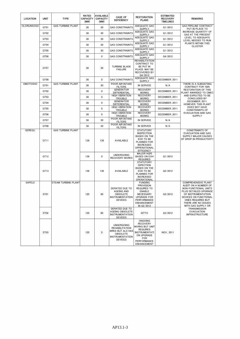
LOCATION UNIT TYPERATED
CAPACITY(MW)
AVAILABLECAPACITY
(MW)
CASE OFDEFICIENCY
RESTORATIONPLANS
ESTIMATEDRECOVERYTIMELINES
REMARKS
GT01 38 30 GAS CONSTRAINTSADEQUATE GAS
SUPPLYQ1/2012
GT02 38 30 GAS CONSTRAINTSADEQUATE GAS
SUPPLYQ1/2012
GT03 38 30 GAS CONSTRAINTSADEQUATE GAS
SUPPLYQ1/2012
GT04 38 30 GAS CONSTRAINTSADEQUATE GAS
SUPPLYQ1/2012
GT05 38 30 GAS CONSTRAINTSADEQUATE GAS
SUPPLYQ1/2012
GT06 38 0 GAS CONSTRAINTSADEQUATE GAS
SUPPLYQ4/2012
GT07 38 30TURBINE BLADE
FAILURE
REHABILITATIONCONTRACT TO
BE PUT INPLACE. MAY BERECOVERED BY
Q4/2012
GT08 38 0 GAS CONSTRAINTSADEQUATE GAS
SUPPLYDECEMBER, 2011
GT01 38 30POOR AIR INTAKE
FILTERSIN SERVICE N/A
GT02 38 0GENERATOR
DIFFERENTIALRECOVERY
WORKSDECEMBER, 2011
GT03 38 0HIGH VIBRATION
TROUBLERECOVERY
WORKSDECEMBER, 2011
GT04 38 0GENERATOR
DIFFERENTIALRECOVERY
WORKSDECEMBER, 2011
GT05 38 0HIGH VIBRATION
TROUBLERECOVERY
WORKSDECEMBER, 2011
GT06 38 0HIGH VIBRATION
TROUBLERECOVERY
WORKSDECEMBER, 2011
GT07 38 30POOR AIR INTAKE
FILTERSIN SERVICE N/A
GT08 38 30POOR AIR INTAKE
FILTERSIN SERVICE N/A
GT11 138 138 AVAILABLE
STATUTORYINSPECTION
BASED ON THEEOH TO BE
PLANNED FORINCREASED
OPPERATIONALEFFICENCY
GT12 138 0UNDERGOING
RECOVERY WORKS
MAJOR HGPIBASED ON EOH
REQUIREDQ1/2012
GT13 138 138 AVAILABLE
STATUTORYISPECTION
BASED ON THEEOH TO BE
PLANNED FORINCREASED
OPERATIONAL
Q2/2012
ST01 120 90
DERATED DUE TOAGEING ANDOBSOLETE
INSTRUMENTATIONDEVICES
FUNDINGPROVISION
REQUIRED TOENABLE
NECESSARYUPGRADE FORPERFORMANCEENHANCEMENT
IN Q2/2012
Q3/2012
ST02 120 80
DERATED DUE TOAGEING OBSOLETEINSTRUMENTATION
DEVICES
DITTO Q3/2012
ST03 120 0
UNDERGOINGREHABILITATION
WRKS BUT ALS HASOBSOLETE
INSTRUMENTATIONDEVICES
ONGOINGRECOVERY
WORKS BUT UNITREQUIRES
INSTRUMENTATION UPGRADE
FORPERFORMANCEENHANCEMENT
NOV., 2011
COMPREHENSIVE PLANTAUDIT ON A NUMBER OFNON-FUNCTIONAL UNITSPLUS DETAILED UPGRADE
OF INSTRUMENTATIONDEVICES ON FUNCTIONAL
ONES REQUIRED BUTTHERE ARE NO ISSUESWITH GAS SUPPLY OR
TRANSMISSIONEVACUATION
INFRASTRUCTURE
STEAM TURBINE PLANTSAPELE
OLORUNSOGO GAS TURBINE PLANT GAS PIPELINE CONTRACTPUT IN PLACE TO
INCREASE QUANTITY OFGAS AT THE PRESENTLEVEL TO ADEQUATE
LEVEL NEEDED TO RUNPLANTS WITHIN THIS
CLUSTER
THERE IS A SUBSISTINGCONTRACT FOR 100%
RESTORATION OF THISPLANT AWARDED TO CMEC
AND EXPECTED TO BECONCLUDED BYDECEMBER, 2011.
HOWEVER, THIS PLANTDOES NOT HAVECONSTRAINTS OF
EVACUATION AND GASSUPPLY
OMOTOSHO GAS TURBINE PLANT
CONSTRAINTS OFEVACUATION AND GAS
SUPPLY MAJOR CAUSESOF DROP IN PRODUCTIVITY
GAS TURBINE PLANTGEREGU
AP13.1-3


AP13.2-1
(2)
PHC
N –
TR
AN
SMIS
SIO
N C
OM
PAN
Y O
F N
IGE
RIA
(T
CN
)
PRO
JEC
T C
OM
PL
ET
ION
RE
POR
T (
SH
OR
T, M
ED
IUM
AN
D L
ON
G T
ER
MS)
S/
No
Pro
ject
Nam
e /
Con
trac
tor
Nam
e of
Con
trac
tor
Com
men
ce-
men
t D
ate
Exp
ecte
d C
ompl
etio
n D
ate
Der
ivab
le B
enef
its
of P
roje
ct
Con
stra
ints
S
HO
RT
TE
RM
1
Gom
be-Y
la-J
alin
go 3
30kv
SC
li
ne G
ombe
–Ada
maw
a-Ta
raba
S
tate
s/ C
hrom
e C
onso
rtiu
m-D
extr
on L
td
Chr
ome
Con
sort
ium
/Dex
tron
13
th D
ec, 2
001
July
, 201
0 Im
prov
ed v
olta
ge p
rofi
le t
o th
e N
orth
Eas
t Z
one
and
enha
ncem
ent
of s
ocio
-eco
nom
ic g
row
th o
f th
e ar
ea.
367.
5Km
of
330K
V L
ine
leng
th t
o be
add
ed
to th
e ne
twor
k to
impr
ove
TC
N w
heel
ing
capa
city
R
ecen
t va
ndal
isat
ion
of t
he l
ine
may
del
ay
com
plet
ion.
D
extr
on h
as h
owev
er p
rom
ised
to
com
plet
e pr
ojec
t by
July
201
0 2
Gom
be-D
amat
uru-
Mai
dugu
ri
330k
V li
ne G
ome-
Yob
e-B
orno
S
tate
s /K
EC
/New
s E
ngin
eeri
ng
Ltd
KE
C/N
EW
S
Eng
inee
ring
A
pr.,
2006
A
ug, 2
010
Impr
ove
volt
age
prof
ile
and
enha
ncem
ent
of
soci
o-ec
onom
ic g
row
th o
f th
e ar
ea.
G
ombe
-Dam
atur
u L
ine
com
pete
d.
D
amat
uru-
Mai
dugu
ri L
ine
– on
-goi
ng
D
amat
uru
T,
S.
– te
rmin
ated
an
d to
be
re
-aw
arde
d 3
Aku
re-A
do E
kiti
132
kv S
C li
ne
Ond
o-E
kiti
/Dex
tron
E
ngin
eeri
ng L
td
Dex
tron
E
ngin
eeri
ng L
td
May
, 200
3 Ju
ly, 2
010
Impr
ove
volt
age
prof
ile
and
enha
ncem
ent
of
soci
o-ec
onom
ic g
row
th o
f th
e ar
ea.
S
trin
ging
of
th
e en
tire
lin
e le
ngh
to
be
com
plet
ed b
y 10
th o
f Ju
y 20
10.
C
omm
issi
onin
g of
the
lin
e of
the
17th
of
July
, if
lin
e ba
y is
mad
e av
aila
ble
at A
kure
T.
S. b
y JK
N
4 A
fam
-PH
132
kv D
C tu
rnin
g in
and
out
at P
H m
ain
TS
A
BB
Pow
erli
nes
Oct
. 200
9 Ju
ly, 2
010
To
ensu
re
flex
ibili
ty
of
the
grid
in
th
e ev
acua
tion
of
RV
SG
pow
er g
ener
atio
n.
S
low
P
ace
of
wor
k by
A
BB
P
ower
line
s.
A
BB
P
ower
line
s P
roje
ct
Man
ager
pr
omis
ed t
o co
mpl
ete
it b
y th
e en
d of
Ju
ly, 2
010.
T
CN
req
uest
ed t
he E
PC
to
form
aliz
e th
e pr
omis
e in
wri
ting
to
TC
N &
the
M
inis
ter.
5 T
rans
mis
sion
—Y
ola
2 x
150M
V A
330
/132
kV S
/S
and
330k
V B
ay E
xten
sion
at
Gom
be A
dam
awa
Sta
te/M
BH
Pow
er L
td
MB
H P
ower
Ltd
. D
ec. 2
001
Sep
t. 20
08
Aug
, 201
0 Im
prov
emen
t of
ser
ious
low
bol
tage
pro
file
in
Yol
a an
d Ja
lingo
Trx
sta
tion
and
conn
ecti
on o
f ad
diti
onal
load
s in
Yol
a an
d en
viro
ns.
Ja
ling
o T
.S.
com
mis
sion
ed
in
Oct
. 20
09.
G
ombe
T.
S.
to
be
com
mis
sion
ed
by
20th
Ju
ly,
on
the
prov
isio
n th
at
Gom
be-Y
oka
330k
V
Lin
e is
m
ade
avai
labl
e by
Dex
tron
/Chr
ome.
6
Ado
-Eki
ti 1
32/3
3kV
su
bstr
atio
n an
d A
kure
13
2kV
line
bay
ext
ensi
on.
Eki
ti-O
ndo
Sta
tes
JKN
Lim
ited
M
ay, 2
001
Aug
, 201
0 Im
prov
emen
t of
qua
lity
and
qua
ntit
y of
pow
er
supp
ly
in
Ado
0Eki
ti
and
enha
ncem
ent
of
soci
o-ec
onom
ic g
row
th o
f E
kiti
Sta
te
P
re-C
omm
issi
onin
g of
the
Sub
stat
ion
– 90
% c
ompl
eted
. J
KN
yet
to
coll
ect
rela
y pa
ssw
ord
for
10%
re
mai
ning
pr
ecom
mis
sion
ing
wor
ks.
A
bove
is
due
to J
KN
out
stan
ding
deb
t to
Con
Cos
-AS
of S
outh
Afr
ica.
TC
N

AP13.2-2
S/N
o P
roje
ct N
ame
/ C
ontr
acto
r N
ame
of C
ontr
acto
r C
omm
ence
- m
ent
Dat
e
Exp
ecte
d C
ompl
etio
n D
ate
Der
ivab
le B
enef
its
of P
roje
ct
Con
stra
ints
med
iati
ng
betw
een
Con
CoS
-AS
&
JKN
for
pas
swor
d.
T
o fa
stra
ct c
ompl
etio
n, T
CN
has
loa
n to
JK
N e
quip
men
t pre
viou
sly
paid
for
. 7
Inst
alla
tion
of
1No
150M
VA
P
ower
Tra
nsfo
rmer
in K
ano
T/S
In h
ouse
Ju
ne
30th
Ju
ly,
2010
Im
prov
ed a
nd s
tabl
e S
uppl
y of
ele
ctri
city
to
Kan
o S
tate
. C
ompl
etio
n da
te r
eali
zabl
e.
F
iltr
atio
n of
tr
ansf
orm
er
oil
com
men
ced
– 5/
07/2
010.
P
re-c
omm
issi
onin
g te
sts
to c
omm
ence
- 11
/07/
2010
. A
wai
ting
as
buil
t dr
awin
g fr
om A
reva
to
ena
ble
tota
l pre
-com
mis
sion
ing
8 In
stal
lati
on o
f 1N
o 15
0MV
A
Pow
er T
rans
form
er in
A
kang
ba T
/S
In h
ouse
A
pr-1
0 A
ug-1
0 W
ill
rele
ase
Cus
tom
ers
cons
tant
ly
on
load
sh
eddi
ng
and
enha
nce
pow
er
evac
uati
on
capa
city
.
R
elis
able
dat
e of
com
mis
sion
ing.
9 In
stal
lati
on o
f 1N
o 15
0MV
A
Pow
er T
rans
form
er a
nd
Sep
erat
ion
of B
ank
75M
X
Rea
ctor
in O
sosg
bo T
/S
In h
ouse
A
pr-1
0 30
th
July
, 20
10
Impr
ove
volt
age
prof
ile,
po
wer
ev
acua
tion
ca
paci
ty a
nd m
anag
emen
t of
gri
d op
erat
ions
du
ring
hig
h vo
ltag
e su
rges
.
T
rans
form
er
inst
alla
tion
to
be
co
mpl
eted
by
July
, 201
0.
7
5MX
R
eact
or
to
be
com
plet
ed
by
Nov
. 201
0.
10
Inst
alla
tion
of
1No
150M
VA
P
ower
Tra
nsfo
rmer
in A
yede
T
/S
Mat
elec
M
ay-1
0 30
th
Aug
, 20
10
Enh
ance
pow
er e
vacu
atio
n ca
paci
ty.
T
CN
wou
ld c
ompl
ete
inst
alla
tion
and
m
ake
avai
labl
e th
e 15
0MV
A
Tra
nsfo
rmer
to
Mat
elec
by
15th
of
July
20
10.
D
elay
ed p
ace
of c
ontr
acto
r w
orks
due
to
out
age
cons
trai
nts
from
NC
C.
A
nd
need
no
t to
co
mpr
omis
e gr
id
stab
ilit
y du
ring
out
age.
N
CC
dir
ecte
d to
fac
ilit
ate
outa
ges.
M
atel
ec i
s to
for
mal
ize
the
prom
ise
to
com
plet
e th
e pr
ojec
t by
Aug
ust 2
010.
11
In
stal
lati
on o
f 1N
o 60
MV
A
Pow
er tr
ansf
orm
er in
C
alab
ar T
/S
In h
ouse
Ju
n-10
A
ug, 2
010
Impr
ove
evac
uati
on c
apac
ity
from
60M
VA
to
120M
VA
. D
eliv
ery
of E
arth
ing
Tra
nsfo
rmer
.
12
Inst
alla
tion
of
1No
60M
VA
P
ower
tran
sfor
mer
in D
akat
a T
/S
In h
ouse
Ju
n-10
30
th
Sep
t-20
10
Impr
ove
evac
uati
on c
apac
ity
from
60M
VA
to
120M
VA
M
odif
icat
ion
of p
lint
h in
pro
gres
s.
T
rans
form
er a
nd A
cces
sori
es o
n si
te.
13
Inst
alla
tion
of
1No
60M
VA
P
ower
tran
sfor
mer
in M
inna
T
/S
In h
ouse
M
ay-1
0 15
th
Aug
ust
2010
Im
prov
e ev
acua
tion
cap
acit
y.
Del
iver
y of
Ear
thin
g tr
ansf
orm
er 3
3kV
C
ircu
it B
reak
ers.
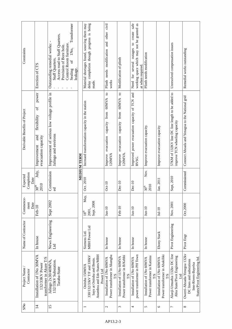
AP13.2-3
S/N
o P
roje
ct N
ame
/ C
ontr
acto
r N
ame
of C
ontr
acto
r C
omm
ence
- m
ent
Dat
e
Exp
ecte
d C
ompl
etio
n D
ate
Der
ivab
le B
enef
its
of P
roje
ct
Con
stra
ints
14
Inst
alla
tion
of
1No
30M
VA
13
2/33
KV
Pow
er
tran
sfor
mer
in A
kure
T/S
In h
ouse
F
eb-1
0 30
th
July
, 20
10
Impr
ovem
ent
and
flex
ibil
ity
of
pow
er
evac
uati
on c
apac
ity
Ere
ctio
n of
CT
S
15
Jali
ngo
2x30
/40M
VA
, 13
2/33
kV S
ubst
atio
n.
Tar
aba-
Sta
te
New
s E
ngin
eeri
ng
Ltd
S
ept 2
002
Com
mis
sion
ed
Impr
ovem
ent
of s
erio
us l
ow v
olta
ge p
rofi
le i
n Ja
lingo
and
env
iron
s O
utst
andi
ng r
emed
ial w
orks
: -
Sta
ff Q
uart
ers.
Acc
ess
road
to S
taff
Qua
rter
s.
Pro
visi
on o
f B
ore
hole
.
Con
trol
Roo
m f
urni
ture
.
Sea
ling
of
1N
o,
Tra
nsfo
rmer
le
akag
e.
ME
DIU
M T
ER
M
1 O
nits
ha 1
50M
VA
33
0/13
2/33
kV T
/F a
nd 3
30kV
ba
ys a
t Oni
tsha
and
Ben
in.
Ana
mbr
a an
d E
do S
tate
s/M
BH
P
ower
Ltd
Sie
men
s L
td.
MB
H P
ower
Ltd
18
th
May
, 20
01,
Sep
t. 20
08
Oct
. 201
0 In
crea
ed tr
ansf
orm
atio
n ca
paci
ty in
the
stat
ion
M
ater
ial
shor
tage
s fo
und,
sou
rcin
g th
em m
ay
dela
y co
mpl
etio
n th
ough
pro
gres
s is
be
ing
mad
e.
2 In
stal
lati
on o
f 1N
o 60
MV
A
Pow
er tr
ansf
orm
er in
Aka
ngba
T
/S
In h
ouse
Ju
n-10
O
ct-1
0 Im
prov
e ev
acua
tion
ca
paci
ty
from
60
MV
A
to
120M
VA
P
linth
ne
eds
mod
ific
atio
n an
d ot
her
civi
l w
orks
3 In
stal
lati
on o
f 11
No
60M
VA
P
ower
tran
sfor
mer
in B
/Keb
bi
T/S
In h
ouse
F
eb-1
0 D
ec-1
0 Im
prov
e ev
acua
tion
ca
paci
ty
from
60
MV
A
to
120M
VA
. M
odif
icat
ion
of p
linth
4 In
stal
lati
on o
f 1N
o 60
MV
A
pow
er tr
ansf
orm
er in
PH
Tow
n In
hou
se
Jun-
10
Dec
-10
Impr
oved
pow
er e
vacu
atio
n ca
paci
ty o
f T
CN
and
R
VS
G.
Nee
d fo
r se
vera
l ou
tage
s to
cr
eate
sa
fe
wor
king
spa
ce w
hich
may
not
be
gran
ted
as
at w
hen
requ
ired
. 5
Inst
alla
tion
of
1No
60M
VA
P
ower
tran
sfor
mer
in K
atsi
na
T/S
In h
ouse
Ju
n-10
30
th
Nov
. 20
10
Impr
ove
evac
uati
on c
apac
ity.
P
linth
nee
ds m
odif
icat
ion
6 In
stal
lati
on o
f 1N
o 60
MV
A
Pow
er tr
ansf
orm
er in
Aba
kili
ki
T/S
Ebo
ny S
tack
Ju
l-10
Ja
n. 2
011
Impr
ove
evac
uati
on c
apac
ity
7 A
laoj
i-U
mua
hia
132k
v D
C li
ne
Abi
a S
tate
/Piv
ot E
ngin
eeri
ng
Ltd
Piv
ot E
ngin
eeri
ng
Nov
. 200
1 S
ept,
2010
57
KM
of
132K
V li
ne D
C l
ine
leng
th to
be
adde
d to
im
prov
e T
CN
whe
elin
g ca
paci
ty
Unr
esol
ved
com
pens
atio
n is
sues
8 O
wer
ri-A
hoad
a-Y
eneg
oa 1
32kv
D
C li
nes
and
subs
tatio
ns
Imo-
Riv
ers-
Bay
elsa
S
tate
s/P
ivot
Eng
inee
ring
ltd.
Piv
ot E
ngr
Oct
.200
0 C
omm
issi
oned
C
onne
ct A
hoad
a an
d Y
enag
oa to
the
Nat
iona
l gri
d R
emed
ial w
orks
out
stan
ding

AP13.2-4
S/N
o P
roje
ct N
ame
/ C
ontr
acto
r N
ame
of C
ontr
acto
r C
omm
ence
- m
ent
Dat
e
Exp
ecte
d C
ompl
etio
n D
ate
Der
ivab
le B
enef
its
of P
roje
ct
Con
stra
ints
9 U
mua
hia
2x30
/40M
VA
13
2/33
kV S
ubst
atio
n A
bia/
Val
enz
Hol
ding
s (N
IG)
Ltd
.
Val
enz
Hol
ding
s (N
ig)
Ltd
. S
ept.
2001
S
ept,
2010
Im
prov
e po
wer
qua
lity
in te
sou
th E
ast
EP
C r
eque
st f
or e
acal
atio
n n
pric
es
10
Cal
abar
2x1
50M
VA
, 33
0/13
2/33
kV S
ubst
atio
ns a
nd
line
bay
at A
laoj
i Sub
stat
ions
. C
ross
Riv
er S
tate
s/ M
BH
P
ower
Ltd
MB
H o
wer
Ltd
. 16
th
Aug
. 20
08
Dec
. 201
0 Im
prov
e po
wer
su
pply
si
tuat
ion
I C
alab
ar
and
grea
ter
part
of
C
ross
R
iver
S
tate
an
d en
hanc
e so
cio-
econ
omic
life
.
Ste
alin
g of
po
wer
ca
ble,
re
plac
emen
t m
ay
dela
y D
ec, 2
010
com
plet
ion.
11
Roc
hukw
u 2x
30/4
0MV
A
132/
33kV
sub
stat
ion
Abi
a/O
men
Int
’l L
td.
Om
en L
nt’l
Ltd
. A
ug. 2
001
Sep
t, 20
10
Add
itio
n of
80
MV
A
Tra
nsfo
rmer
ca
paci
ty
at
132K
V le
vel t
o th
e ne
twor
k.
12
Mba
lano
-Oki
gwe
132k
v S
C
line
Abi
a /A
tlan
tic
Eng
inee
ring
&
Con
stru
ctio
n L
td
Atl
anti
c E
ngin
eeri
ng
&
Con
stru
ctio
n
Nov
. 200
1 D
ec. 2
010
22K
M o
f 13
2KV
lin
e le
ngth
to
be a
dded
to
the
netw
ork.
LO
NG
TE
RM
1
Oki
gwe
2x30
/40M
VA
13
2/33
kV S
ubst
atio
n A
bia
/Uni
on A
llie
d E
ngr’
g L
td.
Uni
on
All
ied
Eng
r’g
Ltd
. S
ept.
2001
M
arch
, 201
1 A
ddit
ion
of
80M
VA
T
rans
form
er
capa
city
at
12
2KV
leve
l to
the
netw
ork
Inab
ilit
y to
cle
ar g
oods
fro
m th
e P
orts
2 U
mua
hia-
Oha
fia
132k
v S
C li
ne
Abi
a /H
arle
sden
Eng
inee
ring
L
td
Har
lesd
en
Eng
inee
ring
Ltd
O
ct. 2
007
Jun.
201
1 A
ddit
ion
of
46.9
KM
of
13
2KV
lin
e le
ngth
to
im
prov
e T
CN
whe
elin
g ca
paci
ty.
3 O
hafi
a 2x
30/4
0MV
A 1
32/3
3kV
su
bsta
tion
. Abi
a/ U
nion
All
ied
Eng
r’g
Ltd
.
Uni
on
All
ied
Eng
r’g
Ltd
. S
ept.
2001
M
arch
, 201
1 A
ddit
ion
of
80M
VA
T
rans
form
er
capa
city
at
13
2KV
leve
l In
abil
ity
to c
lear
goo
ds f
rom
the
Por
ts
4 M
bala
no 2
x30/
40M
VA
13
2/33
kV s
ubst
atio
n. A
bia
/Uni
on A
llie
d E
ngr’
g L
td.
Uni
on
All
ied
Eng
r’g
Ltd
. M
ay, 2
001
July
, 201
0 A
ddit
ion
of
80M
VA
T
rans
form
er
capa
city
at
13
2KV
leve
l In
abil
ity
to c
lear
goo
ds f
rom
the
Por
ts
5 Ta
lata
Maf
ara
2x30
/40M
VA
13
2/33
kV s
ubst
atio
n Z
amfa
ra
Sta
te /C
onti
nent
al E
ngr’
g N
ig.
Ltd
.
Con
tinen
tal
Eng
r’g
Nig
. Ltd
. D
ec.,
2004
Add
itio
n of
80
MV
A
Tra
nsfo
rmer
ca
paci
ty
at
132K
V le
vel
Com
mis
sion
ed.
Rem
edia
l w
orks
/ S
taff
H
ousi
ng o
utst
andi
ng.
6 K
atam
pe-N
atio
nal S
tadi
um
132k
v D
C li
ne F
CT
– A
buja
/A
BB
Pow
erli
nes
AB
B P
ower
line
s D
ec.,
2004
Ju
n. 2
012
Add
itio
n of
19K
M o
f 13
2KV
line
leng
th
Term
inat
ed.
Sco
pe
of
wor
k to
ch
ange
an
d no
w to
be
part
ly u
nder
grou
nd.
7 D
amat
uru
1/15
0MV
A,
330/
132k
V S
ubst
atio
n Y
obe
Sta
te /P
arsi
an H
ihg
Vol
tage
Div
.
Par
sian
H
igh
Vol
tage
D
iv./
Car
tlar
k In
t’l L
td
Nov
. 200
8 D
ec, 2
010
Add
itio
n of
1x1
50M
VA
, at
330
kV t
o th
e ne
twor
k an
d im
prov
e po
wer
sup
ply
to Y
obe
Sta
te
Slo
w P
ace
of w
ork
by th
e E
PC
con
trac
tor.

AP13.2-5
S/N
o P
roje
ct N
ame
/ C
ontr
acto
r N
ame
of C
ontr
acto
r C
omm
ence
- m
ent
Dat
e
Exp
ecte
d C
ompl
etio
n D
ate
Der
ivab
le B
enef
its
of P
roje
ct
Con
stra
ints
and
Car
tlar
k In
t’l L
td
8 M
aidu
guri
330
/132
kV
Sub
stat
ion
Bor
no S
tate
/Cha
rnel
E
ngr.
Co.
Ltd
and
AY
- K
AY
Cha
rnel
E
ngr.
Co.
L
td. A
Y -
KA
Y
Dec
., 20
04
Jun.
201
1 Im
prov
emen
t of
pow
er s
uppl
y to
Mai
dugu
ri a
nd th
e en
viro
ns
Term
inat
ed P
rocu
rem
ent o
n-go
ing.
9 O
nits
ha-N
new
i-Ih
iala
132
kV
DC
line
Ana
mbr
a S
tate
/CC
C
Intl
. Ltd
and
Ele
men
ts C
omm
ns
Ltd
.
CC
C
Intl
. L
td
/ E
lem
ents
Com
mns
. S
ept,
2009
Ju
n. 2
011
To p
rovi
de a
ddit
iona
l 41K
M o
f 32
KV
line
leng
th.
Slo
w p
ace
of w
ork
by th
e E
PC
10
2nd B
enin
-Oni
tsha
330
kv S
C
line
Edo
-Del
ta-A
nam
bra
Sta
tes
/Dex
tron
Eng
inee
ring
ltd
Dex
tron
E
ngin
eeri
ng L
td
17th
S
ept.
2008
A
ug, 2
011
Rel
ieve
hea
vily
loa
ded
Ben
in-O
nits
ha 3
30kV
lin
e fo
r im
prov
ed g
rid
secu
rity
W
ayle
ave
/ Com
mun
ity
prob
lem
s
11
Nne
wi 2
x60M
VA
132
kV
subs
tati
on A
nam
bra
Sta
te
/Val
enz
Hol
ding
s (N
ig)
Ltd
Val
enz
Hol
ding
s (N
ig)
Ltd
. A
pr.,
2006
N
ov, 2
010
Add
itio
n of
12
0MV
A
tran
sfor
mer
ca
paci
ty
at
132K
V le
vel
132k
V li
ne to
sup
ply
the
subs
tatio
n no
t rea
dy.
12
Kad
una
– Jo
s 33
0KV
SC
L
ineP
late
au –
Jos
Sta
tes
BP
P ap
prov
al o
btai
ned,
FE
C a
ppro
val
bein
g aw
aite
d.
13
2x33
0KV
Lin
e ba
y ex
tens
ion
at
Kad
una,
Jos
and
Oni
tsha
K
adun
a-P
late
au-A
nam
bra
Sta
tes
/Val
enz
Hol
ding
Ltd
Val
enz
Hol
ding
Ltd
A
pr.,
2010
S
ept.
2011
To
pr
ovid
e ta
ke
off
prin
t fo
r th
e 2nd
B
enin
–
Oni
tsha
330
kV S
/C li
ne.
14
Nsu
kka
– A
yang
ba 1
32K
V D
C
Lin
e E
nugu
-Kog
i Sta
tes
/Val
enz
Hol
ding
Ltd
Val
enz
Hol
ding
Ltd
A
pr.,
2010
S
ept.
2011
To
pr
ovid
e ta
ke
off
poin
t fo
r th
e 2nd
B
enin
–
Oni
tsha
330
kV S
/C li
ne.
15
132/
33K
V S
/S a
t Aya
ngba
Kog
i S
tate
/ O
men
Int
ltd
Om
en I
nt lt
d A
ug.2
008
Apr
il, 2
011
To
prov
ide
120M
VA
tr
ansf
orm
er
capa
city
at
13
2KV
lev
el a
nd i
mpr
ove
pow
er s
uppl
y to
Kog
i st
ate.
16
Jos
– K
afan
chan
132
KV
D/C
L
ine
Pla
teau
– K
adun
a S
tate
s /E
nerg
o N
ig L
imit
ed
Ene
rgo
Nig
Lim
ited
D
ec.,
2007
M
arch
, 201
1 To
pro
vide
add
itio
nal 8
0KM
of
32K
V li
ne le
ngth
to
whe
el p
ower
to K
afan
chan
and
env
iron
s
17
Kaf
anch
san
132k
v 2x
60M
VA
S
ubst
atio
n K
adun
a S
tate
/V
alen
z H
oldi
ng L
td
Val
enz
Hol
ding
Ltd
S
ep.,
2007
M
arch
, 201
1 To
pr
ovid
e 12
0MV
A
tran
sfor
mer
ca
paci
ty
at
132K
V le
vel t
o K
afan
chan
and
its
envi
rons
.
18
Mak
ere
– P
anks
hin
132K
V D
C
Lin
e P
late
au S
tate
/Mog
as N
ig.
Ltd
Mog
abs
Nig
. Ltd
D
ec.,
2007
D
ec, 2
010
To r
ehab
ilit
ate
the
132k
V l
ine
and
whe
el p
ower
to
Mak
ere
– P
anks
hin
and
othe
r pa
rtso
f P
late
au s
tate
19
2x30
/40M
VA
132
/33K
V S
/S a
t P
anks
hin
and
Mak
eri /
Nor
th
Chi
na a
nd E
ES
E L
td
Nor
th C
hina
/EE
SE
D
ec.,
2007
D
ec, 2
010
To p
rovi
de 8
0MV
A t
rans
form
er c
apac
ity
at 1
32K
V
leve
l to
M
aker
e –
Pan
kshi
n an
d ot
her
part
s of
pl
atea
u st
ate

AP13.2-6
S/N
o P
roje
ct N
ame
/ C
ontr
acto
r N
ame
of C
ontr
acto
r C
omm
ence
- m
ent
Dat
e
Exp
ecte
d C
ompl
etio
n D
ate
Der
ivab
le B
enef
its
of P
roje
ct
Con
stra
ints
20
Gan
mo-
Ogb
omos
ho 1
32kV
DC
li
ne K
war
a –
Oyo
Sta
te
Bei
ng r
e-pr
ocur
ed
D
ec. 2
011
21
22
2x60
MV
A 1
32/3
3kV
S/S
at
Ogb
omos
ho 1
no. 1
32kV
Bay
E
xten
sion
at G
anm
o O
yo-I
lori
n S
tate
s /P
aym
a B
argh
and
C
artl
ark
Ltd
Pay
ma
Bar
gh/
Car
tlar
k D
ec.,
2007
M
arch
, 201
1 To
pr
ovid
e 12
0MV
A
tran
sfor
mer
ca
paci
ty
and
impr
ove
pow
er s
uppl
y in
Ogb
omos
ho a
nd o
ther
pa
rts
of O
yo s
tate
.
23
Kan
o-W
alal
anbe
132
KV
Lin
e (T
urn
in a
nd o
ut o
f D
an
agun
di-D
akat
a 13
2KV
sin
gle
Cct
Lin
e) a
nd 2
x30/
40M
VA
S/S
at
Wal
alam
be K
ano
Sta
te /G
IT
Ltd
GIT
D
ec.,
2007
M
arch
, 201
1 To
pr
ovid
e 80
MV
A
tran
sfor
mer
ca
paci
ty
and
to
impr
ove
pow
er s
uppl
y to
Kan
o st
ate
24
Yel
wa-
Yau
ri 2
x30/
40M
VA
S/S
an
d 10
0KM
of
33K
V L
ine
Keb
bi S
tate
/Vla
enz
and
Ele
ctro
mon
taz
Ltd
Val
enz/
E
lect
rom
onta
z D
ec.,
2007
M
arch
, 201
1 To
pr
ovid
e 80
MV
A
tran
sfor
mer
ca
paci
ty
and
impr
ovem
ent o
f po
wer
sup
ply
to K
ebbi
Sta
te
25
3rd B
enin
– O
nits
ha 3
30K
V D
C
Lin
e E
do –
Ana
mbr
a S
tate
s /K
EC
Int
erna
tiona
l Ltd
KE
C I
nter
natio
nal
Dec
., 20
07
Mar
ch, 2
011
Rel
ieve
hea
vily
loa
ded
Ben
in-O
nits
ha 3
30kV
lin
e fo
r im
prov
ed g
rid
secu
rity
26
Dar
ura
2/30
/40M
VA
S/S
and
2x
132k
v lin
e ba
y ex
t. at
Kat
sina
K
atsi
na S
tate
/NC
EP
NC
EP
D
ec.,
2007
Te
rmin
ated
. Re-
proc
urem
ent o
n-go
ing
27
Kat
sina
Dau
ra 1
32kv
DC
line
K
atsi
na S
tate
/Inc
ome
Ele
ctri
c L
td
Inco
me
Ele
ctri
c L
td
Dec
., 20
07
Term
inat
ed. T
o be
rep
rocu
red.
28
Obu
du –
Ogo
ja 1
32K
V D
C
Lin
e C
ross
Riv
er S
tate
/Jil
on
Ele
ct E
ngr;
Sin
otec
and
E
lem
ents
; Inc
ome
elec
tric
Ltd
Jiho
n E
lect
E
ngr;
S
inot
ec
/Ele
men
ts;
Inco
me
elec
tric
Dec
., 20
07
Nov
, 201
1 To
pro
vide
add
itio
nal 8
0KM
of
32K
V li
ne le
ngth
to
whe
el p
ower
to C
ross
Riv
er s
tate
29
2x30
/40M
VA
132
/33k
V S
/S a
t O
goja
– C
ross
Riv
er S
tate
/I
ncom
e E
lect
rix
Ltd
Inco
me
Ele
ctri
x L
td
Dec
., 20
07
Oct
, 201
0 To
pr
ovid
e 80
MV
A
tran
sfor
mer
ca
paci
ty
and
to
impr
ove
pow
er s
uppl
y to
Cro
ss R
iver
sta
te
30
Reh
abil
itat
ion
of S
okot
o –
Tala
tmaf
ara
132K
V D
C li
ne
/Dex
tron
Ltd
Dex
tron
O
ct, 2
009
Sep
t, 20
11
To r
ehab
ilit
ate
the
132k
V l
ine
and
whe
el p
ower
to
Sok
oto
and
Zan
fara
sta
tes
31
1x60
MV
A S
ubst
atio
n at
Ugh
elli
C
ontin
enta
l E
ngr’
g O
ct, 2
009
Dec
, 201
0 To
pr
ovid
e 60
MV
A
tran
sfor
mer
ca
paci
ty
and
to

AP13.2-7
S/N
o P
roje
ct N
ame
/ C
ontr
acto
r N
ame
of C
ontr
acto
r C
omm
ence
- m
ent
Dat
e
Exp
ecte
d C
ompl
etio
n D
ate
Der
ivab
le B
enef
its
of P
roje
ct
Con
stra
ints
Pow
er P
lant
N
ig. L
td
impr
ove
pow
er s
uppl
y D
elta
sta
te
32
2x60
MV
A, 1
32/3
3KV
AT
A
boh-
Mba
ise
S/S
A
shta
vina
yka/
Bra
n E
ngin
eeri
ng
Nov
., 20
09 A
pril
, 201
1
Nov
., 20
09
Apr
il, 2
011
120M
VA
Tra
nsfo
rmer
cap
acit
y at
132
KV
lev
el,
to
impr
ove
pow
er s
uppl
y to
Im
o st
ate
33
Tra
nsm
issi
on &
Sup
ply
of
Sub
stat
ion
at T
ambu
raw
a W
ater
F
acil
ity,
2x3
0/40
MV
A,
132/
33kV
S/S
at T
ambu
raw
a
NE
SPA
KI
Oct
., 20
09
Sep
t, 20
11
To s
uppl
y po
wer
to
the
Tam
bura
wa
wat
er p
roje
cts
and
envi
rons
.
34
2x60
MV
A, 1
32/3
3kV
su
bsta
tion
at O
ba a
nd 2
x132
KV
L
ine
Bay
s at
Nne
wi
Xia
n/G
IT
Eng
inee
ring
D
ec.,
2009
D
ec, 2
011
120M
VA
Tra
nsfo
rmer
cap
acit
y at
132
KV
lev
el,
to
impr
ove
pow
er
supp
ly to
Ana
mbr
a st
ate
Sit
e re
cent
ly
hand
ed
over
, E
num
erat
ion
on-g
oing
35
2x60
MV
A, 1
32/3
3 kV
su
bsta
tion
at I
deat
o an
d 2/
132K
V L
ine
Bay
s at
Oki
gwe
Ash
tavi
naya
ka/
Bra
n E
ngin
eeri
ng
Nov
., 20
09
Dec
, 201
1 12
0MV
A T
rans
form
er c
apac
ity
at 1
32K
V l
evel
, to
im
prov
e po
wer
sup
ply
to I
mo
stat
e N
ew P
roje
ct
36
Oni
sha
– O
ba-N
new
i-Id
eato
-Oki
gwe
132K
V D
C L
ine
To
su
pply
po
wer
to
O
ba,
Nne
wi,
Idea
tor,
and
Oki
gwe
132/
33kV
S/S
B
eing
rep
rocu
red,
Pro
ject
ste
pped
dow
n in
ye
ar 2
009
37
Ow
erri
– A
boh
Mba
ise
132K
V
DC
Lin
e
B
eing
rep
rocu
red
38
1x30
MV
A 1
32/3
3KV
SS
at
Kw
anar
Dan
gora
M
ATA
LE
C
Oct
., 20
09
Jun
2011
30
MV
A T
rans
form
er c
apac
ity
at 1
32K
V l
evel
, to
im
prov
e po
wer
sup
ply
to K
ano
stat
e
39
2x60
MV
A, 1
32/3
3KV
S
ubst
atio
n at
Kub
wa
/Shr
eem
/Jyo
ti/M
BH
Ltd
Shr
eem
/Jyo
ti/M
BH
L
td
Pro
pose
d da
te o
f co
mm
issi
onin
g:
26-3
1 Ju
ly 2
010


Appendix-14
Environmental Checklist


Env
iron
men
tal C
heck
list
: 19
. Oth
er I
nfra
stru
ctur
e P
roje
cts
Cat
egor
yE
nviro
nmen
tal
Item
Mai
n C
heck
Item
sY
es: Y
No:
NC
onfir
mat
ion
of E
nviro
nmen
tal C
onsi
dera
tions
(Rea
sons
, Miti
gatio
n M
easu
res)
(a)
Hav
e E
IA r
epor
ts b
een
alre
ady
prep
ared
in o
ffic
ial p
roce
ss?
(a)
N(a
) T
here
is n
o ne
ed o
f pr
epar
atio
n of
EIA
due
to th
e fa
ct th
at th
e sc
ope
ofth
is p
roje
ct is
the
repl
acem
ent o
f th
e ex
istin
g de
terio
rate
d ge
nera
tion
faci
litie
s, w
hich
hav
e be
en in
use
sin
ce 1
983,
with
the
new
one
s w
ithim
prov
ed p
erfo
rman
ce, h
ence
no
envi
ronm
enta
l deg
rada
tion
will
be
expe
cted
.
(b)
Hav
e E
IA r
epor
ts b
een
appr
oved
by
auth
oriti
es o
f th
e ho
st c
ount
ry's
gove
rnm
ent?
(b)
N(b
) N
ot a
pplic
able
bec
ause
of
the
reas
on s
tate
d ab
ove.
(c)
Hav
e E
IA r
epor
ts b
een
unco
nditi
onal
ly a
ppro
ved?
If c
ondi
tions
are
impo
sed
on th
e ap
prov
al o
f E
IA r
epor
ts, a
re th
e co
nditi
ons
satis
fied?
(c)
N(c
) N
ot a
pplic
able
bec
ause
of
the
reas
on s
tate
d ab
ove.
(d)
In a
dditi
on to
the
abov
e ap
prov
als,
hav
e ot
her
requ
ired
envi
ronm
enta
lpe
rmits
bee
n ob
tain
ed f
rom
the
appr
opria
te r
egul
ator
y au
thor
ities
of
the
host
cou
ntry
's g
over
nmen
t?
(d)
N(d
) T
here
is n
o en
viro
nmen
tal p
erm
it re
quire
d.
(a)
Hav
e co
nten
ts o
f th
e pr
ojec
t and
the
pote
ntia
l im
pact
s be
en a
dequ
atel
yex
plai
ned
to th
e Lo
cal s
take
hold
ers
base
d on
app
ropr
iate
pro
cedu
res,
incl
udin
g in
form
atio
n di
sclo
sure
? Is
und
erst
andi
ng o
btai
ned
from
the
Loca
lst
akeh
olde
rs?
(a)
N(a
) T
here
is n
o im
pact
to th
e Lo
cal s
take
hold
ers
beca
use
of th
e re
ason
stat
ed a
bove
and
the
proj
ect s
ite is
isol
ated
and
rem
ote
from
the
resi
dent
ial
area
.
(b)
Hav
e th
e co
mm
ent f
rom
the
stak
ehol
ders
(su
ch a
s lo
cal r
esid
ents
) be
enre
flect
ed to
the
proj
ect d
esig
n?(b
) N
(b)
Not
app
licab
le b
ecau
se o
f th
e re
ason
sta
ted
abov
e.
(3)
Exa
min
atio
nof
Alte
rnat
ives
(a)
Hav
e al
tern
ativ
e pl
ans
of th
e pr
ojec
t bee
n ex
amin
ed w
ith s
ocia
l and
envi
ronm
enta
l con
side
ratio
ns?
(a)
N(a
) T
here
is n
o po
ssib
le a
ltern
ativ
e pl
ans
exis
t sin
ce th
e pr
ojec
t is
the
repl
acem
ent o
f th
e ex
istin
g ge
nera
tion
faci
litie
s.
(a)
Do
air
pollu
tant
s, (
such
as
sulfu
r ox
ides
(S
Ox)
, nitr
ogen
oxi
des
(NO
x),
and
soot
and
dus
t) e
mitt
ed f
rom
the
prop
osed
infr
astr
uctu
re f
acili
ties
and
anci
llary
fac
ilitie
s co
mpl
y w
ith th
e co
untr
y's
emis
sion
sta
ndar
ds a
ndam
bien
t air
qual
ity s
tand
ards
? A
re a
ny m
itiga
ting
mea
sure
s ta
ken?
(a)
N(a
) T
here
is n
o po
ssib
ility
of
emis
sion
of
air
pollu
tant
s fr
om th
e re
habi
litat
edfa
cilit
ies
in th
e ex
istin
g hy
dro
elec
tric
pow
er s
tatio
n.
(b)
Are
ele
ctric
and
hea
t sou
rce
at a
ccom
mod
atio
n us
ed f
uel w
hich
emis
sion
fac
tor
is lo
w?
(b)
N(b
) T
here
is n
o fu
el u
sed
for
elec
tric
and
hea
t sou
rce
at a
ccom
mod
atio
nbe
caus
e th
e so
urce
is th
e el
ectr
ic p
ower
pro
duce
d in
the
hydr
o el
ectr
icpo
wer
sta
tion
in a
n en
viro
nmen
tall y
frie
ndly
man
ner.
(2)
Wat
er Q
ualit
y
(a)
Do
efflu
ents
or
leac
hate
s fr
om v
ario
us f
acili
ties,
suc
h as
infr
astr
uctu
refa
cilit
ies
and
the
anci
llary
fac
ilitie
s co
mpl
y w
ith th
e co
untr
y's
efflu
ent
stan
dard
s an
d am
bien
t wat
er q
ualit
y st
anda
rds?
(a)
N(a
) T
here
is n
o po
ssib
ility
of
efflu
ents
or
leac
hate
fro
m th
e re
habi
litat
edfa
cilit
ies.
(3)
Was
tes
(a)
Are
was
tes
from
the
infr
astr
uctu
re f
acili
ties
and
anci
llary
fac
ilitie
spr
oper
ly tr
eate
d an
d di
spos
ed o
f in
acc
orda
nce
with
the
coun
try'
sre
gula
tions
?
(a)
Y(a
) S
ome
of th
e pa
rts
subj
ect f
or r
ehab
ilita
tion
cont
ain
asbe
stos
. In
acco
rdan
ce w
ith N
atio
nal E
nviro
nmen
tal (
Con
stru
ctio
n S
ecto
r) R
egul
atio
n,20
11 p
ublis
hed
in F
NG
Off
ical
Gaz
zette
No.
46 L
agos
-17t
h M
ay 2
011
Vol
.98,
the
prop
onen
t will
app
oint
a lo
cal p
rofe
ssio
nal t
reat
men
t com
pany
whi
ch h
olds
a p
erso
n ce
rtifi
ed b
y th
e N
atio
nal E
nviro
men
tal S
tada
rds
and
Reg
ulat
ions
Enf
orce
men
t Age
ncy
(NE
SR
EA
) to
be
in c
harg
e of
insp
ectio
nan
d ev
alua
tion
for
the
pres
ence
of
asbe
stos
at t
he s
ite a
s w
ell a
s di
spos
alof
suc
h w
aste
. T
he a
bove
loca
l pro
fess
iona
l tre
atm
ent c
ompa
ny s
hall
beap
poin
ted
from
com
pani
es r
egis
tere
d by
the
Fed
eral
Min
istr
y of
Env
ironm
ent.
1 P
erm
its a
ndE
xpla
natio
n
2 P
ollu
tion
Con
trol
(2)
Exp
lana
tion
toth
e Lo
cal
Sta
keho
lder
s
(1)
Air
Qua
lity
(1)
EIA
and
Env
ironm
enta
lP
erm
its
AP14-1
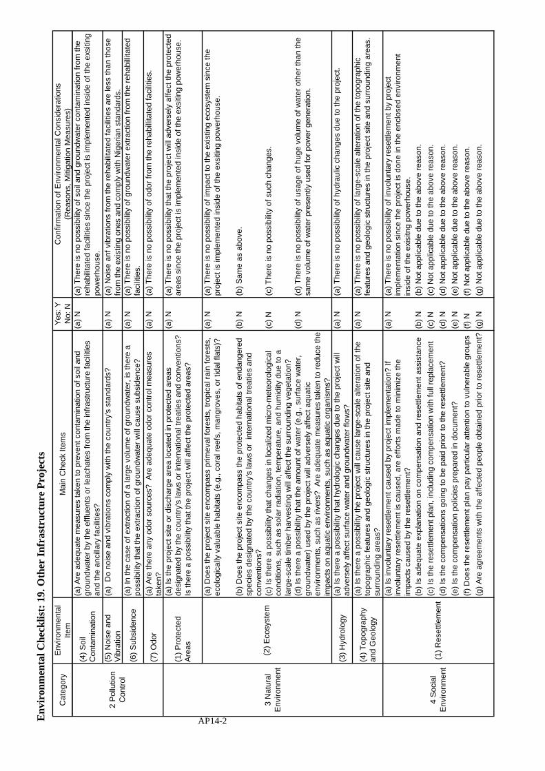
Env
iron
men
tal C
heck
list
: 19
. Oth
er I
nfra
stru
ctur
e P
roje
cts
Cat
egor
yE
nviro
nmen
tal
Item
Mai
n C
heck
Item
sY
es: Y
No:
NC
onfir
mat
ion
of E
nviro
nmen
tal C
onsi
dera
tions
(Rea
sons
, Miti
gatio
n M
easu
res)
(4)
Soi
lC
onta
min
atio
n
(a)
Are
ade
quat
e m
easu
res
take
n to
pre
vent
con
tam
inat
ion
of s
oil a
ndgr
ound
wat
er b
y th
e ef
fluen
ts o
r le
acha
tes
from
the
infr
astr
uctu
re f
acili
ties
and
the
anci
llary
fac
ilitie
s?
(a)
N(a
) T
here
is n
o po
ssib
ility
of
soil
and
grou
ndw
ater
con
tam
inat
ion
from
the
reha
bilit
ated
fac
ilitie
s si
nce
the
proj
ect i
s im
plem
ente
d in
side
of
the
exsi
ting
pow
erho
use.
(5)
Noi
se a
ndV
ibra
tion
(a)
Do
nois
e an
d vi
brat
ions
com
ply
with
the
coun
try'
s st
anda
rds?
(a)
N(a
) N
oise
anf
vib
ratio
ns f
rom
the
reha
bilit
ated
fac
ilitie
s ar
e le
ss th
an th
ose
from
the
exis
ting
ones
and
com
ply
with
Nig
eria
n st
anda
rds.
(6)
Sub
side
nce
(a)
In th
e ca
se o
f ex
trac
tion
of a
larg
e vo
lum
e of
gro
undw
ater
, is
ther
e a
poss
ibili
ty th
at th
e ex
trac
tion
of g
roun
dwat
er w
ill c
ause
sub
side
nce?
(a)
N(a
) T
here
is n
o po
ssib
ility
of
grou
ndw
ater
ext
ract
ion
from
the
reha
billi
tate
dfa
cilit
ies.
(7)
Odo
r(a
) A
re th
ere
any
odor
sou
rces
? A
re a
dequ
ate
odor
con
trol
mea
sure
sta
ken?
(a)
N(a
) T
here
is n
o po
ssib
ility
of
odor
fro
m th
e re
habi
llita
ted
faci
litie
s.
(1)
Pro
tect
edA
reas
(a)
Is th
e pr
ojec
t site
or
disc
harg
e ar
ea lo
cate
d in
pro
tect
ed a
reas
desi
gnat
ed b
y th
e co
untr
y's
law
s or
inte
rnat
iona
l tre
atie
s an
d co
nven
tions
?Is
ther
e a
poss
ibili
ty th
at th
e pr
ojec
t will
aff
ect t
he p
rote
cted
are
as?
(a)
N(a
) T
here
is n
o po
ssib
ility
that
the
proj
ect w
ill a
dver
sely
aff
ect t
he p
rote
cted
area
s si
nce
the
proj
ect i
s im
plem
ente
d in
side
of
the
exsi
ting
pow
erho
use.
(a)
Doe
s th
e pr
ojec
t site
enc
ompa
ss p
rimev
al f
ores
ts, t
ropi
cal r
ain
fore
sts,
ecol
ogic
ally
val
uabl
e ha
bita
ts (
e.g.
, cor
al r
eefs
, man
grov
es, o
r tid
al f
lats
)?(a
) N
(a)
The
re is
no
poss
ibili
ty o
f im
pact
to th
e ex
istin
g ec
osys
tem
sin
ce th
epr
ojec
t is
impl
emen
ted
insi
de o
f th
e ex
sitin
g po
wer
hous
e.
(b)
Doe
s th
e pr
ojec
t site
enc
ompa
ss th
e pr
otec
ted
habi
tats
of
enda
nger
edsp
ecie
s de
sign
ated
by
the
coun
try'
s la
ws
or i
nter
natio
nal t
reat
ies
and
conv
entio
ns?
(b)
N(b
) S
ame
as a
bove
.
(c)
Is th
ere
a po
ssib
ility
that
cha
nges
in lo
caliz
ed m
icro
-met
eoro
logi
cal
cond
ition
s, s
uch
as s
olar
rad
iatio
n, te
mpe
ratu
re, a
nd h
umid
ity d
ue to
ala
r ge-
scal
e tim
ber
harv
estin
g w
ill a
ffec
t the
sur
roun
ding
veg
etat
ion?
(c)
N(c
) T
here
is n
o po
ssib
ility
of
such
cha
nges
.
(d)
Is th
ere
a po
ssib
ility
that
the
amou
nt o
f w
ater
(e.
g., s
urfa
ce w
ater
,gr
ound
wat
er)
used
by
the
proj
ect w
ill a
dver
sely
aff
ect a
quat
icen
viro
nmen
ts, s
uch
as r
iver
s? A
re a
dequ
ate
mea
sure
s ta
ken
to r
educ
e th
eim
pact
s on
aqu
atic
env
ironm
ents
, suc
h as
aqu
atic
org
anis
ms?
(d)
N(d
) T
here
is n
o po
ssib
ility
of
usag
e of
hug
e vo
lum
e of
wat
er o
ther
than
the
sam
e vo
lum
e of
wat
er p
rese
ntly
use
d fo
r po
wer
gen
erat
ion.
(3)
Hyd
rolo
gy(a
) Is
ther
e a
poss
ibili
ty th
at h
ydro
logi
c ch
ange
s du
e to
the
proj
ect w
illad
vers
ely
affe
ct s
urfa
ce w
ater
and
gro
undw
ater
flo
ws?
(a)
N(a
) T
here
is n
o po
ssib
ility
of
hydr
aulic
cha
nges
due
to th
e pr
ojec
t.
(4)
Top
ogra
phy
and
Geo
logy
(a)
Is th
ere
a po
ssib
ility
the
proj
ect w
ill c
ause
larg
e-sc
ale
alte
ratio
n of
the
topo
grap
hic
feat
ures
and
geo
logi
c st
ruct
ures
in th
e pr
ojec
t site
and
surr
ound
ing
area
s?
(a)
N(a
) T
here
is n
o po
ssib
ility
of
larg
e-sc
ale
alte
ratio
n of
the
topo
grap
hic
feat
ures
and
geo
logi
c st
ruct
ures
in th
e pr
ojec
t site
and
sur
roun
ding
are
as.
(a)
Is in
volu
ntar
y re
settl
emen
t cau
sed
by p
roje
ct im
plem
enta
tion?
Ifin
volu
ntar
y re
settl
emen
t is
caus
ed, a
re e
ffor
ts m
ade
to m
inim
ize
the
impa
cts
caus
ed b
y th
e re
settl
emen
t?
(a)
N(a
) T
here
is n
o po
ssib
ility
of
invo
lunt
ary
rese
ttlem
ent b
y pr
ojec
tim
plem
enta
tion
sinc
e th
e pr
ojec
t is
done
in th
e en
clos
ed e
nviro
nmen
tin
side
of
the
exis
itng
pow
erho
use.
(b)
Is a
dequ
ate
expl
anat
ion
on c
ompe
nsat
ion
and
rese
ttlem
ent a
ssis
tanc
e(b
) N
(b)
Not
app
licab
le d
ue to
the
abov
e re
ason
.
(c)
Is th
e re
settl
emen
t pla
n, in
clud
ing
com
pens
atio
n w
ith f
ull r
epla
cem
ent
(c)
N(c
) N
ot a
pplic
able
due
to th
e ab
ove
reas
on.
(d)
Is th
e co
mpe
nsat
ions
goi
ng to
be
paid
prio
r to
the
rese
ttlem
ent?
(d)
N(d
) N
ot a
pplic
able
due
to th
e ab
ove
reas
on.
(e)
Is th
e co
mpe
nsat
ion
polic
ies
prep
ared
in d
ocum
ent?
(e)
N(e
) N
ot a
pplic
able
due
to th
e ab
ove
reas
on.
(f)
Doe
s th
e re
settl
emen
t pla
n pa
y pa
rtic
ular
atte
ntio
n to
vul
nera
ble
grou
ps(f
) N
(f)
Not
app
licab
le d
ue to
the
abov
e re
ason
.
(g)
Are
agr
eem
ents
with
the
affe
cted
peo
ple
obta
ined
prio
r to
res
ettl
emen
t?(g
) N
(g)
Not
app
licab
le d
ue to
the
abov
e re
ason
.
3 N
atur
alE
nviro
nmen
t(2
) E
cosy
stem
2 P
ollu
tion
Con
trol
4 S
ocia
lE
nviro
nmen
t(1
) R
eset
tlem
ent
AP14-2

Env
iron
men
tal C
heck
list
: 19
. Oth
er I
nfra
stru
ctur
e P
roje
cts
Cat
egor
yE
nviro
nmen
tal
Item
Mai
n C
heck
Item
sY
es: Y
No:
NC
onfir
mat
ion
of E
nviro
nmen
tal C
onsi
dera
tions
(Rea
sons
, Miti
gatio
n M
easu
res)
(h)
Is th
e or
gani
zatio
nal f
ram
ewor
k es
tabl
ishe
d to
pro
perly
impl
emen
tre
settl
emen
t? A
re th
e ca
paci
ty a
nd b
udge
t sec
ured
to im
plem
ent t
he p
lan?
(h)
N(h
) N
ot a
pplic
able
due
to th
e ab
ove
reas
on.
(i) A
re a
ny p
lans
dev
elop
ed to
mon
itor
the
impa
cts
of r
eset
tlem
ent?
(i) N
(i) N
ot a
pplic
able
due
to th
e ab
ove
reas
on.
(j) Is
the
grie
vanc
e re
dres
s m
echa
nism
est
ablis
hed?
(j) N
(j) N
ot a
pplic
able
due
to th
e ab
ove
reas
on.
(2)
Livi
ng a
ndLi
velih
ood
(a)
Is th
ere
a po
ssib
ility
that
the
proj
ect w
ill a
dver
sely
aff
ect t
he li
ving
cond
ition
s of
inha
bita
nts?
Are
ade
quat
e m
easu
res
cons
ider
ed to
red
uce
the
impa
cts,
if n
eces
sar y
?
(a)
N(a
) T
here
is n
o po
ssib
ility
of
impa
cts
to th
e liv
ing
cond
ition
s of
inha
bita
nts
sinc
e th
e pr
ojec
t site
is r
emot
e fr
om th
e re
side
ntia
l are
a.
(3)
Her
itage
(a)
Is th
ere
a po
ssib
ility
that
the
proj
ect w
ill d
amag
e th
e lo
cal a
rche
olog
ical
,hi
stor
ical
, cul
tura
l, an
d re
ligio
us h
erita
ge?
Are
ade
quat
e m
easu
res
cons
ider
ed to
pro
tect
thes
e si
tes
in a
ccor
danc
e w
ith th
e co
untr
y's
law
s?
(a)
N(a
) T
here
is n
o po
ssib
ility
of
adve
rse
impa
ct to
the
loca
l arc
heol
ogic
al,
hist
oric
al, c
ultu
ral,
and
relig
ious
her
itage
sin
ce th
e pr
ojec
t is
impl
emen
ted
insi
de o
f th
e ex
sitin
g po
wer
hous
e.
(a)
Is th
ere
a po
ssib
ility
that
the
proj
ect w
ill a
dver
sely
aff
ect t
he lo
cal
land
scap
e? A
re n
eces
sary
mea
sure
s ta
ken?
(a)
N(a
) T
here
is n
o po
ssib
ility
of
dam
age
to th
e lo
cal l
ands
cape
sin
ce th
epr
ojec
t is
impl
emen
ted
insi
de o
f th
e ex
sitin
g po
wer
hous
e.
(b)
Is th
ere
a po
ssib
ility
that
land
scap
e is
spo
iled
by c
onst
ruct
ion
of h
igh-
rise
build
ings
suc
h as
hug
e ho
tels
?(b
) N
(b)
The
re is
no
poss
ibili
ty o
f sp
oil t
o th
e lo
cal l
ands
cape
sin
ce th
e pr
ojec
t is
impl
emen
ted
insi
de o
f th
e ex
sitin
g po
wer
hous
e.
(a)
Are
con
side
ratio
ns g
iven
to r
educ
e im
pact
s on
the
cultu
re a
nd li
fest
yle
of e
thni
c m
inor
ities
and
indi
geno
us p
eopl
es?
(a)
N(a
) T
here
is n
o po
ssib
ility
of
impa
cts
on th
e cu
lture
and
life
styl
e of
eth
nic
min
oriti
es a
nd in
dige
nous
peo
ples
sin
ce th
e pr
ojec
t is
impl
emen
ted
insi
deof
the
exsi
ting
pow
erho
use.
(b)
Are
all
of th
e rig
hts
of e
thni
c m
inor
ities
and
indi
geno
us p
eopl
es in
rela
tion
to la
nd a
nd r
esou
rces
res
pect
ed?
(b)
N(b
) N
ot a
pplic
able
due
to th
e ab
ove
reas
on.
(a)
Is th
e pr
ojec
t pro
pone
nt n
ot v
iola
ting
any
law
s an
d or
dina
nces
asso
ciat
ed w
ith th
e w
orki
ng c
ondi
tions
of
the
coun
try
whi
ch th
e pr
ojec
tpr
opon
ent s
houl
d ob
serv
e in
the
proj
ect?
(a)N
(a)
The
pro
ject
pro
pone
t is
a lic
ense
d po
wer
pro
duce
r an
d is
not
vio
latin
gan
y la
ws
and
ordi
nanc
es a
ssoc
iate
d w
ith th
e w
orki
ng c
ondi
tions
of
Nig
eria
.
(b)
Are
tang
ible
saf
ety
cons
ider
atio
ns in
pla
ce f
or in
divi
dual
s in
volv
ed in
the
proj
ect,
such
as
the
inst
alla
tion
of s
afet
y eq
uipm
ent w
hich
pre
vent
sin
dust
rial a
ccid
ents
, and
man
agem
ent o
f ha
zard
ous
mat
eria
ls?
(b)
Y(b
) T
he p
roje
ct p
ropo
nent
will
req
uire
to th
e in
tern
atio
nal c
ontr
acto
r fo
rre
habi
litat
ion
wor
ks to
inst
all s
afet
y eq
uipm
ent a
nd p
rote
ctiv
e m
eans
whi
chpr
even
ts in
dust
rial a
ccid
ents
, and
man
agem
ent o
f as
best
os-c
onta
inin
gpa
rts.
The
pro
ject
pro
pone
nt w
ill a
lso
entr
ust t
he tr
eatm
ent a
nd d
ispo
sal o
fsu
ch w
aste
to th
e lo
cal p
rofe
ssio
nal t
reat
men
t com
pany
reg
iste
red
by th
eM
inis
try
of E
nviro
nmen
t.
(c)
Are
inta
ngib
le m
easu
res
bein
g pl
anne
d an
d im
plem
ente
d fo
r in
divi
dual
sin
volv
ed in
the
proj
ect,
such
as
the
esta
blis
hmen
t of
a sa
fety
and
hea
lthpr
ogra
m, a
nd s
afet
y tr
aini
ng (
incl
udin
g tr
affic
saf
ety
and
publ
ic h
ealth
) fo
rw
orke
rs e
tc.?
(c)
Y(c
) T
he p
roje
ct p
ropo
nent
will
req
uire
to th
e in
tern
atio
nal c
ontr
acto
r fo
rre
habi
litat
ion
wor
ks to
pro
vide
exe
cutio
n pr
ogra
mm
e in
clud
ing
safe
tym
anag
emen
t of
asbe
stos
to e
stab
lish,
im
plem
ent a
nd m
aint
ain
safe
ty a
ndhe
alth
of
wor
kers
aga
inst
ris
ks f
rom
asb
esto
s th
roug
hout
the
perio
d of
rem
oval
of
asbe
stos
-con
tain
ing
part
s.
(d)
Are
app
ropr
iate
mea
sure
s ta
ken
to e
nsur
e th
at s
ecur
ity g
uard
s in
volv
edin
the
proj
ect n
ot to
vio
late
saf
ety
of o
ther
indi
vidu
als
invo
lved
, or
loca
lre
side
nts?
(d)
Y(d
) T
he p
roje
ct p
ropo
nent
will
req
uire
to th
e in
tern
atio
nal c
ontr
acto
r fo
rre
habi
litat
ion
wor
ks to
pro
vide
exe
cutio
n pr
ogra
mm
e in
clud
ing
safe
tym
anag
emen
t of
asbe
stos
to m
ake
sure
that
the
safe
ty a
nd s
ecur
ity b
est
rictly
obs
erve
d an
d m
aint
aine
d in
all
aspe
cts
and
occa
sion
s du
ring
rem
oval
wor
k of
asb
esto
s-co
ntai
ning
par
ts.
(6)
Wor
king
Con
ditio
ns
(4)
Land
scap
e
(5)
Eth
nic
Min
oriti
es a
ndIn
dige
nous
Peo
ples
4 S
ocia
lE
nviro
nmen
t
(1)
Res
ettle
men
t
AP14-3

Env
iron
men
tal C
heck
list
: 19
. Oth
er I
nfra
stru
ctur
e P
roje
cts
Cat
egor
yE
nviro
nmen
tal
Item
Mai
n C
heck
Item
sY
es: Y
No:
NC
onfir
mat
ion
of E
nviro
nmen
tal C
onsi
dera
tions
(Rea
sons
, Miti
gatio
n M
easu
res)
(a)
Are
ade
quat
e m
easu
res
cons
ider
ed to
red
uce
impa
cts
durin
gco
nstr
uctio
n (e
.g.,
nois
e, v
ibra
tions
, tur
bid
wat
er, d
ust,
exha
ust g
ases
, and
was
tes)
?
(a)
N(a
) T
here
is n
o im
pact
of
nois
e, v
ibra
tions
, tur
bid
wat
er, d
ust a
nd e
xhau
stga
ses
durin
g co
nstr
uctio
n. H
ower
ver,
som
e of
the
part
s su
bjec
t for
reha
bilit
atio
n co
ntai
n as
best
os. I
n ac
cord
ance
with
Nat
iona
l Env
ironm
enta
l(C
onst
ruct
ion
Sec
tor)
Reg
ulat
ion,
201
1 pu
blis
hed
in F
NG
Off
ical
Gaz
zwtte
No.
46 L
agos
-17t
h M
ay 2
011
Vol
.98,
a lo
cal p
rofe
ssio
nal t
reat
men
tco
mpa
ny w
hich
hol
ds a
per
son
cert
ified
by
NE
SR
EA
will
car
ry o
utin
spec
tion
and
asse
ssm
ent f
or th
e pr
esen
ce o
f as
best
os a
t the
site
. The
proj
ect p
ropo
nent
will
eng
age
the
qual
ified
inte
rnat
iona
l con
trac
tor
for
disa
ssem
bly
of s
uch
was
te u
nder
the
scop
e of
con
trac
tual
wor
ks a
nden
trus
t the
trea
tmen
t and
dis
posa
l of
such
was
te to
the
abov
e lo
cal
prof
essi
onal
trea
tmen
t com
pany
reg
iste
red
by th
e F
eder
al M
inis
try
ofE
nviro
nmen
t.
(b)
If c
onst
ruct
ion
activ
ities
adv
erse
ly a
ffec
t the
nat
ural
env
ironm
ent
(eco
syst
em),
are
ade
quat
e m
easu
res
cons
ider
ed to
red
uce
impa
cts?
(b)
N(b
) T
here
is n
o po
ssib
ility
of
adve
rse
impa
ct to
the
natu
ral e
nviro
nmen
tdu
ring
reha
bilit
atio
n w
ork
sinc
e th
e pr
ojec
t is
impl
emen
ted
insi
de o
f th
eex
sitin
g po
wer
hous
e.
(c)
If c
onst
ruct
ion
activ
ities
adv
erse
ly a
ffec
t the
soc
ial e
nviro
nmen
t, ar
ead
equa
te m
easu
res
cons
ider
ed to
red
uce
impa
cts?
(c)
N(c
) T
here
is n
o po
ssib
ility
of
impa
ct to
the
soci
al e
nviro
nmen
t dur
ing
reha
bilit
atio
n w
ork
sinc
e th
e pr
ojec
t site
is r
emof
e fr
om th
e re
side
ntia
l are
a.
(a)
Doe
s th
e pr
opon
ent d
evel
op a
nd im
plem
ent m
onito
ring
prog
ram
for
the
envi
ronm
enta
l ite
ms
that
are
con
side
red
to h
ave
pote
ntia
l im
pact
s?(a
) Y
(a)
The
re is
no
need
of
mon
itorin
g of
asb
esto
s re
quire
d by
the
law
inN
iger
ia. H
owev
er, t
he p
ropo
nent
will
req
uire
to th
e in
tern
atio
nal c
ontr
acto
rfo
r re
habi
litat
ion
wor
ks to
dev
elop
and
impl
emen
t an
exec
utio
n pr
ogra
mm
efo
r tr
eatm
ent o
f an
d pr
otec
tion
from
the
asbe
stos
-con
tain
ing
was
tes
durin
gdi
sass
embl
y, in
tern
al tr
ansp
orta
tion
and
tem
pora
ry s
tora
ge a
t the
desi
gnat
ed p
lace
out
side
of
the
pow
erho
use.
The
pro
pone
nt w
ithas
sist
ance
fro
m th
e co
nsul
tant
will
mon
itor
and
supe
rvis
e th
ese
cont
ract
ors
wor
ks.
(b)
Wha
t are
the
item
s, m
etho
ds a
nd f
requ
enci
es o
f th
e m
onito
ring
prog
ram
?(b
) Y
(b)
As
show
n in
the
mon
itorig
for
m.
(c)
Doe
s th
e pr
opon
ent e
stab
lish
an a
dequ
ate
mon
itorin
g fr
amew
ork
(org
aniz
atio
n, p
erso
nnel
, equ
ipm
ent,
and
adeq
uate
bud
get t
o su
stai
n th
em
onito
ring
fram
ewor
k)?
(c)
N(c
) T
he e
mvi
ronm
enta
l off
icer
fro
m th
e pr
opon
ent t
oget
her
with
the
envi
ronm
enta
l spe
cial
ist f
rom
the
cons
ulta
nt w
ill m
onito
r an
d su
perv
ise
the
cont
ract
ors
perf
orm
ance
of
the
rela
ted
wor
ks in
acc
orda
nce
with
the
appr
oved
exe
cutio
n pr
ogra
mm
e. B
udge
t for
suc
h su
perv
isio
n w
ill b
epr
ovid
ed a
s a
part
of
coun
terp
art f
und.
(d)
Are
any
reg
ulat
ory
requ
irem
ents
per
tain
ing
to th
e m
onito
ring
repo
rtsy
stem
iden
tifie
d, s
uch
as th
e fo
rmat
and
fre
quen
cy o
f re
port
s fr
om th
epr
opon
ent t
o th
e re
gula
tory
aut
horit
ies?
(d)
N(d
) T
here
is n
o re
gula
tory
req
uire
men
t per
tain
ing
to th
e m
onito
ring
repo
rtsy
stem
. How
ever
, the
loca
l pro
fess
iona
l tre
atm
ent c
ompa
ny s
hall
beap
poin
ted
from
com
pani
es r
egis
terd
by
the
Fed
eral
Min
istr
y of
Env
ironm
ent.
5 O
ther
s
(2)
Mon
itorin
g
(1)
Impa
cts
durin
gC
onst
ruct
ion
AP14-4

Env
iron
men
tal C
heck
list
: 19
. Oth
er I
nfra
stru
ctur
e P
roje
cts
Cat
egor
yE
nviro
nmen
tal
Item
Mai
n C
heck
Item
sY
es: Y
No:
NC
onfir
mat
ion
of E
nviro
nmen
tal C
onsi
dera
tions
(Rea
sons
, Miti
gatio
n M
easu
res)
(a)
Whe
re n
eces
sary
, per
tinen
t ite
ms
desc
ribed
in th
e R
oads
, Rai
lway
s an
dB
ridge
s ch
eckl
ist s
houl
d al
so b
e ch
ecke
d (e
.g.,
proj
ects
incl
udin
g ac
cess
road
s to
the
infr
astr
uctu
re f
acili
ties)
.
(a)
N(a
) It
is n
ot n
eces
sary
to r
efer
to c
heck
list p
erga
inin
g to
oth
er s
ecto
rs s
ince
the
proj
ect i
s im
plem
ente
d in
the
encl
osed
env
ironm
ent i
nsid
e of
the
exis
itng
pow
erho
use.
(b)
For
pro
ject
s, s
uch
as in
stal
latio
n of
tele
com
mun
icat
ion
cabl
es, p
ower
line
tow
ers,
and
sub
mar
ine
cabl
es, w
here
nec
essa
ry, p
ertin
ent i
tem
sde
scrib
ed in
the
Pow
er T
rans
mis
sion
and
Dis
trib
utio
n Li
nes
chec
klis
tssh
ould
als
o be
che
cked
.
(b)
N(b
) It
is n
ot n
eces
sary
to r
efer
to c
heck
list p
erga
inin
g to
the
proj
ects
with
long
dis
tanc
e si
tes
sinc
e th
e pr
ojec
t is
impl
emen
ted
in th
e en
clos
eden
viro
nmen
t ins
ide
of th
e ex
isitn
g po
wer
hous
e.
Not
e on
Usi
ngE
nviro
nmen
tal
Che
cklis
t
(a)
If n
eces
sary
, the
impa
cts
to tr
ansb
ound
ary
or g
loba
l iss
ues
shou
ld b
eco
nfirm
ed (
e.g.
, the
pro
ject
incl
udes
fac
tors
that
may
cau
se p
robl
ems,
suc
has
tran
sbou
ndar
y w
aste
trea
tmen
t, ac
id r
ain,
des
truc
tion
of th
e oz
one
laye
r,or
glo
bal w
arm
ing)
.
(a)
N(a
) It
is n
ot n
eces
sary
to c
onfir
m tr
ansb
ound
ary
or g
loba
l iss
ues
sinc
e th
epr
ojec
t is
impl
emen
ted
in th
e en
clos
ed e
nviro
nmen
t ins
ide
of th
e ex
isitn
gpo
wer
hous
e.
1)
Re
ga
rdin
g t
he
te
rm “
Co
un
try'
s S
tan
da
rds”
me
ntio
ne
d in
th
e a
bo
ve t
ab
le,
in t
he
eve
nt
tha
t e
nvi
ron
me
nta
l sta
nd
ard
s in
th
e c
ou
ntr
y w
her
e t
he
pro
ject
is lo
cate
d d
ive
rge
sig
nifi
can
tly f
rom
inte
rna
tion
al s
tan
da
rds,
ap
pro
pria
te e
nvi
ron
me
nta
l co
nsi
de
ratio
ns
are
re
qu
ired
to
be
ma
de
.
In c
ase
s w
he
re lo
cal e
nvi
ron
me
nta
l re
gu
latio
ns
are
ye
t to
be
est
ab
lish
ed
in s
om
e a
rea
s, c
on
sid
era
tion
s sh
ou
ld b
e m
ad
e b
ase
d o
n c
om
paris
on
s w
ith a
pp
rop
riate
sta
nd
ard
s o
f o
the
r co
un
trie
s(in
clu
din
g J
ap
an
's e
xpe
rien
ce).
2)
En
viro
nm
en
tal c
he
cklis
t p
rovi
de
s g
en
era
l en
viro
nm
en
tal i
tem
s to
be
ch
eck
ed
. I
t m
ay
be
ne
cess
ary
to
ad
d o
r d
ele
te a
n it
em
ta
kin
g in
to a
cco
un
t th
e c
ha
ract
eris
tics
of
the
pro
ject
an
d t
he
pa
rtic
ula
r ci
rcu
mst
an
ces
of
the
co
un
try
an
d lo
calit
y in
wh
ich
th
e p
roje
ct is
loca
ted
.
6 N
ote
Ref
eren
ce to
Che
cklis
t of
Oth
erS
ecto
rs
AP14-5


Appendix-15
Monitoring Form


AP15-1
Appendix-15
MONITORING FORM -If environmental reviews indicate the need of monitoring by JICA, JICA undertakes monitoring for necessary items that are decided by environmental reviews. JICA undertakes monitoring based on regular reports including measured data submitted by the project proponent. When necessary, the project proponent should refer to the following monitoring form for submitting reports. -When monitoring plans including monitoring items, frequencies and methods are decided, project phase or project life cycle (such as construction phase and operation phase) should be considered. 1.Responses/Actions to Comments and Guidance from Government Authorities and the Public
Monitoring Item Monitoring Results during Report Period N/A 2.Mitigation Measures - Air Quality(Emission Gas / Ambient Air Quality) Not applicable.
Item
Unit
Measured
Value(Mean)
Measured
Value(Max.)
Country’s Standards
Referred
International Standards
Remarks (Measurement
Point, Frequency, Method, etc.)
SO2 N/A
NO2 N/A CO N/A O3 N/A Soot and dust N/A
SPM N/A Dust N/A Note: There is no regulation in terms of air quality in relation to treatment and/or disposal of asbestos. Treatment of asbestos during dismantle and removal shall be done as stated under “Waste” in accordance with National Environmental (Construction Sector) Regulation, 2011 published in FGN Official Gazette No.46 Lagos-17th May, 2011 Vol. 98 as per attached. - Water Quality(Effluent/Wastewater/Ambient Water Quality) Not applicable.
Item
Unit
Measured
Value (Mean)
Measured
Value(Max.)
Country’s Standards
Referred
International Standards
Remarks (Measurement
Point, Frequency,
Method, etc.) pH mg/l SS (Suspended Solid) mg/l
BOD/COD mg/l DO mg/l

AP15-2
Total Nitrogen NO3
mg/l
Total Phosphorus3
PO4
mg/l
Heavy Metals mg/l Hydrocarbons / Mineral Oils
mg/l
Phenols - Cyanide -
Temperature 0C - Waste
Monitoring Item Monitoring Results during Report Period Waste contained asbestos Refer to Note hereunder. (1) Appointment of international contractor for rehabilitation works by Jebba Hydro Power Station (JHEP)
Date of contract Name of company: Person in charge: Contact number
(2) Establishment of execution programme including safety management of asbestos for treatment of and protection from the asbestos-containing wastes during disassembly, internal transportation and temporary storage at site, by the contractor
Execution date:
(3) Appointment of local professional treatment company, which owns a person certified by NESREA, by JHPS
Date of contract Name of company: Person in charge: Contact number
(4) A notification from the contractor to the local professional treatment company
Execution date:
(5) Inspection and assessment of asbestos-containing parts by a person certified by NESREA who belongs to the local professional treatment company prior to the renovation work
Execution date: Name of a certified person in charge: Contact number of the person
(6) Determination of quantity and type of asbestos-containing materials, and recommendation by the above person in (6)
Execution date: Quantity of asbestos: Type of asbestos: Contents of recommendation:
(7) Execution of removal and internal transportation of asbestos-containing wastes to the designated temporary storage at site by the contractor
Duration: From …. to ….
(8) Receipt, transportation, treatment if necessary and disposal of asbestos-containing wastes by the local company
Execution date:
(9) Report of work by the international contractor regarding asbestos- containing wastes by the contractor to JHPS
Execution date:
(10) Report of work by the local company to JHPS by the local company
Execution date:
(11) Report of work by the certified person from the local company to NESREA
Execution date:
(12) Submission of the Monitoring Form to JICA as a part of periodical report prepared by JHPS to
Issue date of report:

AP15-3
JICA Note 1) Country’s Standard: Treatment of asbestos during dismantle and removal shall be done in accordance with National Environmental (Construction Sector) Regulation, 2011 published in FGN Official Gazette No.46 Lagos-17th May, 2011 Vol. 98. 2) Referred International Standards: Treatment and disposal of asbestos will be carried out in accordance with the relevant regulations in a country where a selected international contractor belongs to. In case of Japan, there is no legal duty to measure concentrations of asbestos during work of treatment and removal of asbestos in the Ordinance on Prevention of Health Impairment due to Asbestos. 3) Procedure of treatment of asbestos containing parts: The process of disassembly of the asbestos-containing parts shall comply with the following procedure: i) Prior to the commencement of any demolition or renovation, JHPS will appoint the local professional
treatment company (hereinafter referred to as “the local company”) who has a person certified by the National Environmental Standards and Regulations Enforcement Agency (NESREA) for assessment, treatment and disposal of asbestos-containing wastes (hereinafter referred to as “the inspector”).
ii) Prior to all demolition activities, including those where no asbestos material is present, a notification by the demolishing contractor (hereinafter referred to as “the contractor”) must be sent to the inspector.
iii) The affected structure/equipment or part of the structure/equipment where the work is to take place must be thoroughly inspected and assessed for the presence of asbestos by the inspector at a work implementation site.
iv) The types and quantities of asbestos-containing materials shall be determined by the inspector who shall make recommendations for the need to remove and dispose appropriately, asbestos-containing materials.
v) The contractor will set up a temporary ‘clean room’, generally made of plastic sheet with sufficient dimensions to be able to cater for treatment of asbestos containing parts inside of the room, at the site. The entrance/exit will be twofold closures with plastic sheet. Also, negative-pressure dust prevention filters (HEPA filter) will be provided on the wall of this room to keep the room under negative pressure as well as to remove floating asbestos fibers. The room will also be kept in high moisture content by humidifier to prevent from scattering of asbestos fibers.
vi) As workers enter into the room, they wear dust prevention gears against asbestos fibers such as masks, glasses and clothes. Also workers will take all gears off before leaving the room. All used gears will be packed into plastic bags in twofold for disposal.
vii) During a work, water mist is sprayed on asbestos containing parts to prevent asbestos from scattering. At the same time, the room is kept under negative-pressure by the above mentioned filter so that no air will leak out of the room.
viii) When the removal work of such parts finishes, asbestos containing waste are packed into plastic bags in twofold for disposal.
ix) Prior to dismantling the clean room, the inner space will be made free from asbestos by HEPA filtered vacuum cleaner under negative pressure created by the HEPA filter.
x) Removed wastes which contain asbestos shall be kept at the designated place outside of the powerhouse until the local company will come to receive such waste for final treatment and disposal under responsibility of the local company.
xi) The inspector will make report to NESREA upon completion of the disposal of asbestos-containing wastes.
xii) No further monitoring will be required once the above exercises are completed. - Noise / Vibration Not applicable

AP15-4
Item
Unit
Measured
Value (Mean)
Measured
Value (Max.)
Country’s Standards
Referred
International Standards
Remarks (Measurement
Point, Frequency,
Method, etc.)
Noise level Vibration level
- Odor
Monitoring Item Monitoring Results during Report Period N/A 3.Natural Environment - Ecosystem
Monitoring Item Monitoring Results during Report Period N/A 4.Social Environment - Resettlement
Monitoring Item Monitoring Results during Report Period N/A - Living / Livelihood
Monitoring Item Monitoring Results during Report Period N/A