Cisco UCS Manager Server Management Guide, Release 4.1
356
Cisco UCS Manager Server Management Guide, Release 4.1 First Published: 2020-02-20 Last Modified: 2022-01-31 Americas Headquarters Cisco Systems, Inc. 170 West Tasman Drive San Jose, CA 95134-1706 USA http://www.cisco.com Tel: 408 526-4000 800 553-NETS (6387) Fax: 408 527-0883
-
Upload
khangminh22 -
Category
Documents
-
view
0 -
download
0
Transcript of Cisco UCS Manager Server Management Guide, Release 4.1
Cisco UCS Manager Server Management Guide, Release 4.1First Published: 2020-02-20
Last Modified: 2022-01-31
Americas HeadquartersCisco Systems, Inc.170 West Tasman DriveSan Jose, CA 95134-1706USAhttp://www.cisco.comTel: 408 526-4000
800 553-NETS (6387)Fax: 408 527-0883

© 2020–2022 Cisco Systems, Inc. All rights reserved.

C O N T E N T S
Preface xvP R E F A C E
Audience xv
Conventions xv
Related Cisco UCS Documentation xvii
Documentation Feedback xvii
New and Changed Information 1C H A P T E R 1
New and Changed Information 1
Server Management Overview 5C H A P T E R 2
Server Management Overview 5
Cisco UCS Manager User CLI Documentation 6
Cisco UCS Manager User Documentation 7
Server License Management 9C H A P T E R 3
Licenses 9
C-Direct Rack Licensing Support 12
Obtaining the Host ID for a Fabric Interconnect 14
Obtaining a License 14
Downloading Licenses to the Fabric Interconnect from the Local File System 15
Downloading Licenses to the Fabric Interconnect from a Remote Location 16
Installing a License 17
Viewing the Licenses Installed on a Fabric Interconnect 17
Determining the Grace Period Available for a Port or Feature 18
Determining the Expiry Date of a License 18
Uninstalling a License 18
Cisco UCS Manager Server Management Guide, Release 4.1iii
Registering Cisco UCS Domains with Cisco UCS Central 21C H A P T E R 4
Registration of Cisco UCS Domains 21
Policy Resolution between Cisco UCS Manager and Cisco UCS Central 21
Registering a Cisco UCS Domain with Cisco UCS Central 23
Configuring Policy Resolutions between Cisco UCS Manager and Cisco UCS Central 24
Setting Cisco UCS Central Registration Properties in Cisco UCS Manager 24
Unregistering a Cisco UCS Domain from Cisco UCS Central 25
Power Capping and Power Management in Cisco UCS 27C H A P T E R 5
Power Capping in Cisco UCS 28
Power Policy Configuration 28
Power Policy for Cisco UCS Servers 28
Configuring the Power Policy 29
Power Supply for Redundancy Method 29
Configuring Policy Driven Chassis Group Power Capping 30
Policy Driven Chassis Group Power Capping 30
Power Control Policy 30
Creating a Power Control Policy 31
Deleting a Power Control Policy 36
Power Save Mode 36
Power Save Mode Policy 36
Creating a Power Save Policy 36
Acoustic Mode Fan Profile 37
Acoustic Mode Fan Profile 37
Configuring Acoustic Mode 37
Power Groups in UCS Manager 39
Creating a Power Group 41
Adding a Chassis to a Power Group 43
Removing a Chassis from a Power Group 43
Deleting a Power Group 43
Blade Level Power Capping 44
Manual Blade Level Power Cap 44
Setting the Blade-Level Power Cap for a Server 44
Cisco UCS Manager Server Management Guide, Release 4.1iv
Contents

Viewing the Blade-Level Power Cap 45
Global Power Profiling Policy Configuration 46
Global Power Profiling Policy 46
Configuring the Global Power Profile Policy 46
Global Power Allocation Policy Configuration 46
Global Power Allocation Policy 46
Configuring the Global Power Allocation Policy 47
Power Management During Power-on Operations 47
Power Sync Policy Configuration 48
Power Sync Policy 48
Power Synchronization Behavior 48
Creating a Power Sync Policy 49
Changing a Power Sync Policy 51
Deleting a Power Sync Policy 51
Rack Server Power Management 52
UCS Mini Power Management 52
Blade Server Hardware Management 53C H A P T E R 6
Blade Server Management 53
Guidelines for Removing and Decommissioning Blade Servers 54
Recommendations for Avoiding Unexpected Server Power Changes 54
Booting a Blade Server 55
Booting a Rack-Mount Server from the Service Profile 56
Determining the Boot Order of a Blade Server 56
Shutting Down a Blade Server 57
Shutting Down a Server from the Service Profile 57
Resetting a Blade Server 58
Resetting a Blade Server to Factory Default Settings 58
Reacknowledging a Blade Server 59
Removing a Server from a Chassis 60
Deleting the Inband Configuration from a Blade Server 60
Decommissioning a Blade Server 61
Removing a Non-Existent Blade Server Entry 61
Recommissioning a Blade Server 62
Cisco UCS Manager Server Management Guide, Release 4.1v
Contents
Reacknowledging a Server Slot in a Chassis 62
Removing a Non-Existent Blade Server from the Configuration Database 63
Turning the Locator LED for a Blade Server On and Off 63
Turning the Local Disk Locator LED on a Blade Server On and Off 64
Resetting the CMOS for a Blade Server 64
Resetting the CIMC for a Blade Server 65
Clearing TPM for a Blade Server 65
Viewing the POST Results for a Blade Server 66
Issuing an NMI from a Blade Server 66
Viewing Health Events for a Blade Server 67
Health LED Alarms 68
Viewing Health LED Alarms 69
Smart SSD 69
Monitoring SSD Health 70
Rack-Mount Server Hardware Management 71C H A P T E R 7
Rack-Mount Server Management 71
Rack-Enclosure Server Management 72
Guidelines for Removing and Decommissioning Rack-Mount Servers 72
Recommendations for Avoiding Unexpected Server Power Changes 73
Booting a Rack-Mount Server 74
Booting a Rack-Mount Server from the Service Profile 74
Determining the Boot Order of a Rack-Mount Server 75
Shutting Down a Rack-Mount Server 75
Shutting Down a Server from the Service Profile 76
Resetting a Rack-Mount Server 76
Resetting a Rack-Mount Server to Factory Default Settings 77
Persistent Memory Scrub 78
Reacknowledging a Rack-Mount Server 79
Deleting the Inband Configuration from a Rack-Mount Server 79
Decommissioning a Rack-Mount Server 80
Recommissioning a Rack-Mount Server 80
Renumbering a Rack-Mount Server 81
Removing a Non-Existent Rack-Mount Server from the Configuration Database 82
Cisco UCS Manager Server Management Guide, Release 4.1vi
Contents

Turning the Locator LED for a Rack-Mount Server On and Off 82
Turning the Local Disk Locator LED on a Rack-Mount Server On and Off 83
Resetting the CMOS for a Rack-Mount Server 83
Resetting the CIMC for a Rack-Mount Server 84
Clearing TPM for a Rack-Mount Server 84
Issuing an NMI from a Rack-Mount Server 85
Viewing Health Events for a Rack-Mount Server 85
Viewing the POST Results for a Rack-Mount Server 87
Viewing the Power Transition Log 87
Viewing Cisco UCS C125 M5 Server Slot ID 88
S3X60 Server Node Hardware Management 89C H A P T E R 8
Cisco UCS S3260 Server Node Management 89
Booting a Cisco UCS S3260 Server Node 90
Booting a Cisco UCS S3260 Server Node from the Service Profile 90
Determining the Boot Order of a Cisco UCS S3260 Server Node 90
Shutting Down a Cisco UCS S3260 Server Node 91
Shutting Down a Cisco UCS S3260 Server Node from the Service Profile 91
Resetting a Cisco UCS S3260 Server Node 92
Resetting a Cisco UCS S3260 Server Node to Factory Default Settings 93
Reacknowledging a Cisco UCS S3260 Server Node 94
Removing a Cisco UCS S3260 Server Node from a Chassis 94
Deleting the Inband Configuration from a Cisco UCS S3260 Server Node 95
Decommissioning a Cisco UCS S3260 Server Node 95
Recommissioning a Cisco UCS S3260 Server Node 96
Reacknowledging a Server Slot in a S3260 Chassis 96
Removing a Non-Existent Cisco UCS S3260 Server Node from the Configuration Database 97
Turning the Locator LED for a Cisco UCS S3260 Server Node On and Off 97
Turning the Local Disk Locator LED on a Cisco UCS S3260 Server Node On and Off 98
Resetting the CIMC for a Cisco UCS S3260 Server Node 98
Resetting the CMOS for a Cisco UCS S3260 Server Node 99
Issuing an NMI from a Cisco UCS S3260 Server Node 99
Viewing the POST Results for a Cisco UCS S3260 Server Node 100
Viewing Health Events for a Cisco UCS S3260 Server Node 100
Cisco UCS Manager Server Management Guide, Release 4.1vii
Contents

Health LED Alarms 102
Viewing Health LED Alarms 102
Server Pools 103C H A P T E R 9
Configuring Server Pools 103
Server Pools 103
Creating a Server Pool 103
Deleting a Server Pool 104
Adding Servers to a Server Pool 104
Removing Servers from a Server Pool 105
Configuring UUID Suffix Pools 105
UUID Suffix Pools 105
Creating a UUID Suffix Pool 105
Deleting a UUID Suffix Pool 107
Configuring IP Pools 107
IP Pools 107
Creating an IP Pool 108
Adding a Block to an IP Pool 109
Deleting a Block from an IP Pool 111
Deleting an IP Pool 111
Server Boot 113C H A P T E R 1 0
Boot Policy 113
UEFI Boot Mode 114
UEFI Secure Boot 115
CIMC Secure Boot 116
Determining the CIMC Secure Boot Status 117
Enabling CIMC Secure Boot on a Rack Server 117
Creating a Boot Policy 118
SAN Boot 119
Configuring a SAN Boot for a Boot Policy 119
iSCSI Boot 121
iSCSI Boot Process 121
iSCSI Boot Guidelines and Prerequisites 122
Cisco UCS Manager Server Management Guide, Release 4.1viii
Contents

Initiator IQN Configuration 123
Enabling MPIO on Windows 124
Configuring iSCSI Boot 125
Creating an iSCSI Adapter Policy 126
Deleting an iSCSI Adapter Policy 128
Creating an iSCSI Authentication Profile 128
Deleting an iSCSI Authentication Profile 129
Creating an iSCSI Initiator IP Pool 129
Creating an iSCSI Boot Policy 130
Creating an iSCSI vNIC for a Service Profile 131
Deleting an iSCSI vNIC from a Service Profile 133
Setting the Initiator IQN at the Service Profile Level 133
Changing the Initiator IQN at the Service Profile Level 134
Setting iSCSI Boot Parameters 134
Modifying iSCSI Boot Parameters 137
IQN Pools 142
Creating an IQN Pool 142
Adding a Block to an IQN Pool 143
Deleting a Block from an IQN Pool 144
Deleting an IQN Pool 145
LAN Boot 145
Configuring a LAN Boot for a Boot Policy 145
Local Devices Boot 146
Configuring a Local Disk Boot for a Boot Policy 147
Configuring a Virtual Media Boot for a Boot Policy 148
Configuring a NVMe Boot for a Boot Policy 150
Adding a Boot Policy to a vMedia Service Profile 150
Deleting a Boot Policy 152
UEFI Boot Parameters 153
Guidelines and Limitations for UEFI Boot Parameters 153
Setting UEFI Boot Parameters 153
Modifying UEFI Boot Parameters 154
Service Profiles 157C H A P T E R 1 1
Cisco UCS Manager Server Management Guide, Release 4.1ix
Contents
Service Profiles in UCS Manager 157
Service Profiles that Override Server Identity 158
Service Profiles that Inherit Server Identity 158
Guidelines and Recommendations for Service Profiles 159
Methods of Creating Service Profiles 159
Creating a Service Profile with the Expert Wizard 159
Creating a Service Profile that Inherits Server Identity 161
Creating a Hardware Based Service Profile for a Blade Server 161
Creating a Hardware Based Service Profile for a Rack-Mount Server 162
Inband Service Profiles 163
Deleting the Inband Configuration from a Service Profile 163
Service Profile Tasks 163
Renaming a Service Profile 163
Cloning a Service Profile 164
Changing the UUID in a Service Profile 164
Modifying the Boot Order in a Service Profile 166
Creating a vNIC for a Service Profile 168
Deleting a vNIC from a Service Profile 168
Creating a vHBA for a Service Profile 169
Changing the WWPN for a vHBA 169
Clearing Persistent Binding for a vHBA 170
Deleting a vHBA from a Service Profile 170
Adding a vHBA Initiator Group to a Service Profile 170
Deleting a Service Profile 172
Service Profile Association 173
Associating a Service Profile with a Server or Server Pool 173
Disassociating a Service Profile from a Server or Server Pool 174
Service Profile Templates 174
Initial and Existing Templates 174
Creating a Service Profile Template 175
Creating One or More Service Profiles from a Service Profile Template 176
Creating a Template Based Service Profile for a Blade Server 176
Creating a Template Based Service Profile for a Rack-Mount Server 177
Creating a Service Profile Template from a Service Profile 178
Cisco UCS Manager Server Management Guide, Release 4.1x
Contents

Setting an Asset Tag for a Service Profile 178
Service Profile Template Tasks 179
Binding a Service Profile to a Service Profile Template 179
Unbinding a Service Profile from a Service Profile Template 179
Changing the UUID in a Service Profile Template 180
Resetting the UUID Assigned to a Service Profile from a Pool in a Service Profile Template 180
Resetting the MAC Address Assigned to a vNIC from a Pool in a Service Profile Template 181
Resetting the WWPN Assigned to a vHBA from a Pool in a Service Profile Template 182
Deleting the Inband Configuration from a Service Profile Template 182
Service Profile Association 183
Associating a Service Profile with a Server or Server Pool 183
Associating a Service Profile Template with a Server Pool 184
Disassociating a Service Profile from a Server or Server Pool 184
Disassociating a Service Profile Template from its Server Pool 185
Server-Related Policies 187C H A P T E R 1 2
BIOS Settings 187
Server BIOS Settings 187
Server BIOS Settings 187
Intel Speed Select 257
BIOS Policy 259
Default BIOS Settings 259
Creating a BIOS Policy 260
Modifying the BIOS Defaults 261
Viewing the Actual BIOS Settings for a Server 262
Memory RAS Features 262
Post-Package Repair (PPR) 263
Enabling Post Package Repair 263
Limiting Presented Memory 263
Limiting Memory Size 264
Partial Memory Mirroring 264
Enabling Partial Memory Mirroring 265
Trusted Platform Module 266
Trusted Platform Module 266
Cisco UCS Manager Server Management Guide, Release 4.1xi
Contents
Intel Trusted Execution Technology 266
Configuring Trusted Platform 266
Configuring Trusted Platform 267
Viewing TPM Properties 268
Consistent Device Naming 268
Guidelines and Limitations for Consistent Device Naming 268
Configuring Consistent Device Naming in a BIOS Policy 271
Configuring a CDN Name for a vNIC 271
CIMC Security Policies 272
IPMI Access Profile 272
Creating an IPMI Access Profile 272
Deleting an IPMI Access Profile 273
KVMManagement Policy 274
Creating a KVM Management Policy 274
Graphics Card Policies 275
Creating a Graphics Card Policy 275
Local Disk Policies 276
Local Disk Configuration Policy 276
Guidelines for all Local Disk Configuration Policies 277
Guidelines for Local Disk Configuration Policies Configured for RAID 277
Creating a Local Disk Configuration Policy 278
Changing a Local Disk Configuration Policy 282
Deleting a Local Disk Configuration Policy 282
FlexFlash Support 283
FlexFlash FX3S Support 285
Starting Up Blade Servers with FlexFlash SD Cards 286
Enabling FlexFlash SD Card Support 287
Enabling Auto-Sync 287
Formatting the SD Cards 288
Resetting the FlexFlash Controller 288
Persistent Memory Modules 288
Scrub Policy 289
Scrub Policy Settings 289
Creating a Scrub Policy 291
Cisco UCS Manager Server Management Guide, Release 4.1xii
Contents
Deleting a Scrub Policy 292
DIMM Error Management 293
DIMM Correctable Error Handling 293
Resetting Memory Errors 293
DIMM Blacklisting 293
Enabling DIMM Blacklisting 293
Serial over LAN Policy Settings 295
Serial over LAN Policy Overview 295
Creating a Serial over LAN Policy 295
Deleting a Serial over LAN Policy 296
Server Autoconfiguration Policies 296
Server Autoconfiguration Policy Overview 296
Creating an Autoconfiguration Policy 297
Deleting an Autoconfiguration Policy 298
Server Discovery Policy Settings 298
Server Discovery Policy Overview 298
Creating a Server Discovery Policy 299
Deleting a Server Discovery Policy 300
Hardware Change Discovery Policy 300
Configuring Hardware Change Discovery Policy 300
Server Inheritance Policy Settings 301
Server Inheritance Policy Overview 301
Creating a Server Inheritance Policy 301
Deleting a Server Inheritance Policy 302
Server Pool Policy Settings 302
Server Pool Policy Overview 302
Creating a Server Pool Policy 302
Deleting a Server Pool Policy 303
Server Pool Policy Qualifications Settings 304
Server Pool Policy Qualification Overview 304
Creating Server Pool Policy Qualifications 304
Deleting Server Pool Policy Qualifications 309
Deleting Qualifications from Server Pool Policy Qualifications 309
vNIC/vHBA Placement Policy Settings 309
Cisco UCS Manager Server Management Guide, Release 4.1xiii
Contents

vNIC/vHBA Placement Policies 309
vCon to Adapter Placement 310
For N20-B6620-2 and N20-B6625-2 Blade Servers 311
vCon to Adapter Placement for All Other Supported Servers 311
vNIC/vHBA to vCon Assignment 312
Creating a vNIC/vHBA Placement Policy 314
Deleting a vNIC/vHBA Placement Policy 316
Explicitly Assigning a vNIC to a vCon 316
Explicitly Assigning a vHBA to a vCon 318
Placing Static vNICs Before Dynamic vNICs 319
vNIC/vHBA Host Port Placement 321
Configuring Host Port Placement 321
CIMC Mounted vMedia 322
Creating a vMedia Policy 322
Adding a vMedia Policy to a Service Profile 326
Viewing CIMC vMedia Policy 328
Firmware Upgrades 329C H A P T E R 1 3
Firmware Upgrades 329
Verifying Firmware Versions on Components 329
Diagnostics Configuration 331C H A P T E R 1 4
Overview of Cisco UCS Manager Diagnostics 331
Creating a Diagnostics Policy 331
Diagnostics Test on a Blade Server 332
Starting a Diagnostics Test on a Blade Server 332
Stopping a Diagnostics Test on a Blade Server 333
Diagnostics Test on a Rack Server 333
Starting a Diagnostics Test on a Rack Server 333
Stopping a Diagnostics Test on a Rack Server 333
Starting a Diagnostics Tests on All Servers 334
Stopping a Diagnostics Tests on All Servers 335
Viewing the Server Diagnostics Status/Result 335
Diagnostics Troubleshooting 336
Cisco UCS Manager Server Management Guide, Release 4.1xiv
Contents

Preface
• Audience, on page xv• Conventions, on page xv• Related Cisco UCS Documentation, on page xvii• Documentation Feedback, on page xvii
AudienceThis guide is intended primarily for data center administrators with responsibilities and expertise in one ormore of the following:
• Server administration
• Storage administration
• Network administration
• Network security
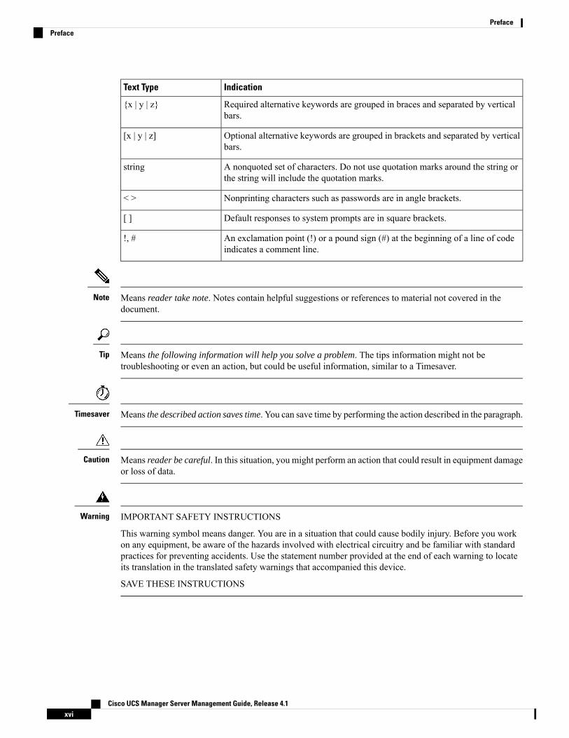
ConventionsIndicationText Type
GUI elements such as tab titles, area names, and field labels appear in this font.
Main titles such as window, dialog box, and wizard titles appear in this font.
GUI elements
Document titles appear in this font.Document titles
In a Text-based User Interface, text the system displays appears in this font.TUI elements
Terminal sessions and information that the system displays appear in thisfont.
System output
CLI command keywords appear in this font.
Variables in a CLI command appear in this font.
CLI commands
Elements in square brackets are optional.[ ]
Cisco UCS Manager Server Management Guide, Release 4.1xv
IndicationText Type
Required alternative keywords are grouped in braces and separated by verticalbars.
{x | y | z}
Optional alternative keywords are grouped in brackets and separated by verticalbars.
[x | y | z]
A nonquoted set of characters. Do not use quotation marks around the string orthe string will include the quotation marks.
string
Nonprinting characters such as passwords are in angle brackets.< >
Default responses to system prompts are in square brackets.[ ]
An exclamation point (!) or a pound sign (#) at the beginning of a line of codeindicates a comment line.
!, #
Means reader take note. Notes contain helpful suggestions or references to material not covered in thedocument.
Note
Means the following information will help you solve a problem. The tips information might not betroubleshooting or even an action, but could be useful information, similar to a Timesaver.
Tip
Means the described action saves time. You can save time by performing the action described in the paragraph.Timesaver
Means reader be careful. In this situation, you might perform an action that could result in equipment damageor loss of data.
Caution
IMPORTANT SAFETY INSTRUCTIONS
This warning symbol means danger. You are in a situation that could cause bodily injury. Before you workon any equipment, be aware of the hazards involved with electrical circuitry and be familiar with standardpractices for preventing accidents. Use the statement number provided at the end of each warning to locateits translation in the translated safety warnings that accompanied this device.
SAVE THESE INSTRUCTIONS
Warning
Cisco UCS Manager Server Management Guide, Release 4.1xvi
PrefacePreface
Related Cisco UCS DocumentationDocumentation Roadmaps
For a complete list of all B-Series documentation, see theCisco UCS B-Series Servers Documentation Roadmapavailable at the following URL: https://www.cisco.com/c/en/us/td/docs/unified_computing/ucs/overview/guide/UCS_roadmap.html
For a complete list of all C-Series documentation, see theCisco UCS C-Series Servers Documentation Roadmapavailable at the following URL: https://www.cisco.com/c/en/us/td/docs/unified_computing/ucs/overview/guide/ucs_rack_roadmap.html.
For information on supported firmware versions and supported UCS Manager versions for the rack serversthat are integrated with the UCS Manager for management, refer to Release Bundle Contents for Cisco UCSSoftware.
Other Documentation Resources
Follow Cisco UCS Docs on Twitter to receive document update notifications.
Documentation FeedbackTo provide technical feedback on this document, or to report an error or omission, please send your commentsto [email protected]. We appreciate your feedback.
Cisco UCS Manager Server Management Guide, Release 4.1xvii
PrefaceRelated Cisco UCS Documentation

Cisco UCS Manager Server Management Guide, Release 4.1xviii
PrefaceDocumentation Feedback
C H A P T E R 1New and Changed Information
• New and Changed Information , on page 1
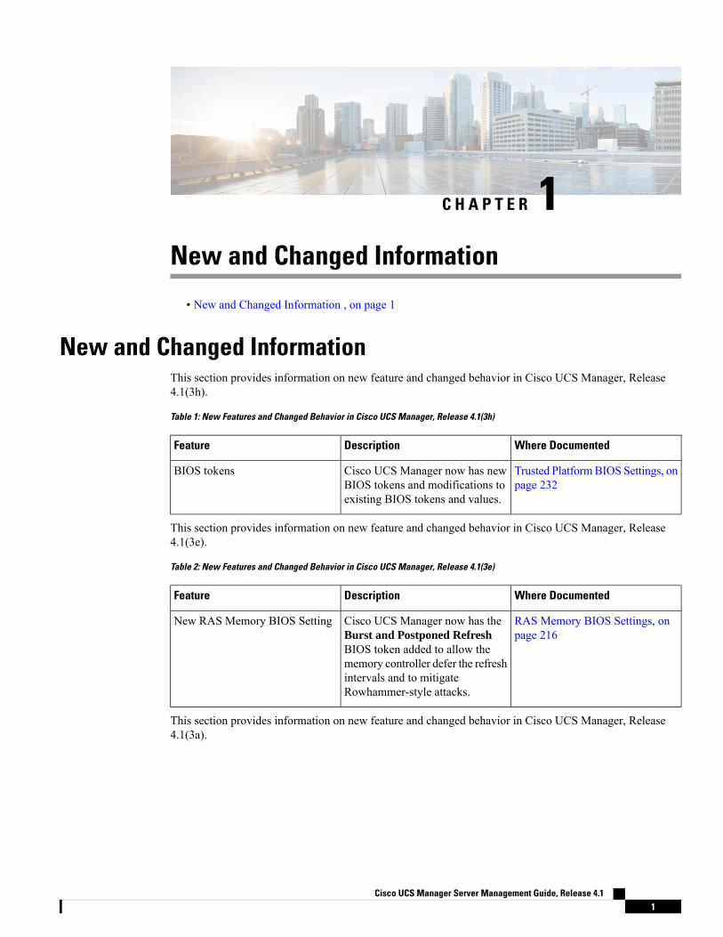
New and Changed InformationThis section provides information on new feature and changed behavior in Cisco UCS Manager, Release4.1(3h).
Table 1: New Features and Changed Behavior in Cisco UCS Manager, Release 4.1(3h)
Where DocumentedDescriptionFeature
Trusted PlatformBIOS Settings, onpage 232
Cisco UCS Manager now has newBIOS tokens and modifications toexisting BIOS tokens and values.
BIOS tokens
This section provides information on new feature and changed behavior in Cisco UCS Manager, Release4.1(3e).
Table 2: New Features and Changed Behavior in Cisco UCS Manager, Release 4.1(3e)
Where DocumentedDescriptionFeature
RAS Memory BIOS Settings, onpage 216
Cisco UCS Manager now has theBurst and Postponed RefreshBIOS token added to allow thememory controller defer the refreshintervals and to mitigateRowhammer-style attacks.
New RAS Memory BIOS Setting
This section provides information on new feature and changed behavior in Cisco UCS Manager, Release4.1(3a).
Cisco UCS Manager Server Management Guide, Release 4.11
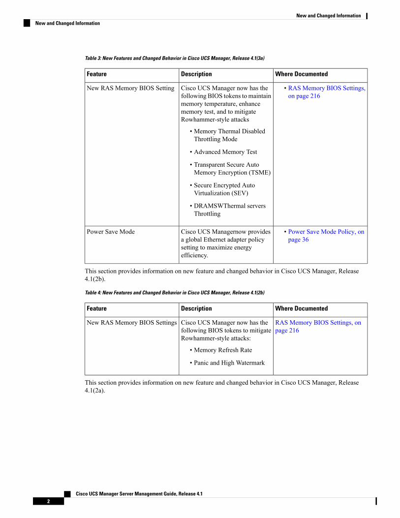
Table 3: New Features and Changed Behavior in Cisco UCS Manager, Release 4.1(3a)
Where DocumentedDescriptionFeature
• RAS Memory BIOS Settings,on page 216
Cisco UCS Manager now has thefollowing BIOS tokens to maintainmemory temperature, enhancememory test, and to mitigateRowhammer-style attacks
• Memory Thermal DisabledThrottling Mode
• Advanced Memory Test
• Transparent Secure AutoMemory Encryption (TSME)
• Secure Encrypted AutoVirtualization (SEV)
• DRAMSWThermal serversThrottling
New RAS Memory BIOS Setting
• Power Save Mode Policy, onpage 36
Cisco UCS Managernow providesa global Ethernet adapter policysetting to maximize energyefficiency.
Power Save Mode
This section provides information on new feature and changed behavior in Cisco UCS Manager, Release4.1(2b).
Table 4: New Features and Changed Behavior in Cisco UCS Manager, Release 4.1(2b)
Where DocumentedDescriptionFeature
RAS Memory BIOS Settings, onpage 216
Cisco UCS Manager now has thefollowing BIOS tokens to mitigateRowhammer-style attacks:
• Memory Refresh Rate
• Panic and High Watermark
New RAS Memory BIOS Settings
This section provides information on new feature and changed behavior in Cisco UCS Manager, Release4.1(2a).
Cisco UCS Manager Server Management Guide, Release 4.12
New and Changed InformationNew and Changed Information
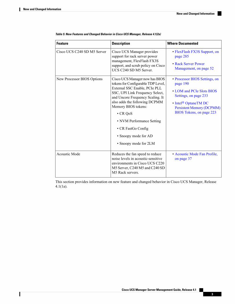
Table 5: New Features and Changed Behavior in Cisco UCS Manager, Release 4.1(2a)
Where DocumentedDescriptionFeature
• FlexFlash FX3S Support, onpage 285
• Rack Server PowerManagement, on page 52
Cisco UCS Manager providessupport for rack server powermanagement, FlexFlash FX3Ssupport, and scrub policy on CiscoUCS C240 SD M5 Server.
Cisco UCS C240 SD M5 Server
• Processor BIOS Settings, onpage 190
• LOM and PCIe Slots BIOSSettings, on page 233
• Intel® OptaneTM DCPersistentMemory (DCPMM)BIOS Tokens, on page 223
CiscoUCSManager now has BIOStokens for Configurable TDPLevel,External SSC Enable, PCIe PLLSSC, UPI Link Frequency Select,and Uncore Frequency Scaling. Italso adds the following DCPMMMemory BIOS tokens:
• CR QoS
• NVM Performance Setting
• CR FastGo Config
• Snoopy mode for AD
• Snoopy mode for 2LM
New Processor BIOS Options
• Acoustic Mode Fan Profile,on page 37
Reduces the fan speed to reducenoise levels in acoustic-sensitiveenvironments in Cisco UCS C220M5 Server, C240M5 and C240 SDM5 Rack servers.
Acoustic Mode
This section provides information on new feature and changed behavior in Cisco UCS Manager, Release4.1(1a).
Cisco UCS Manager Server Management Guide, Release 4.13
New and Changed InformationNew and Changed Information
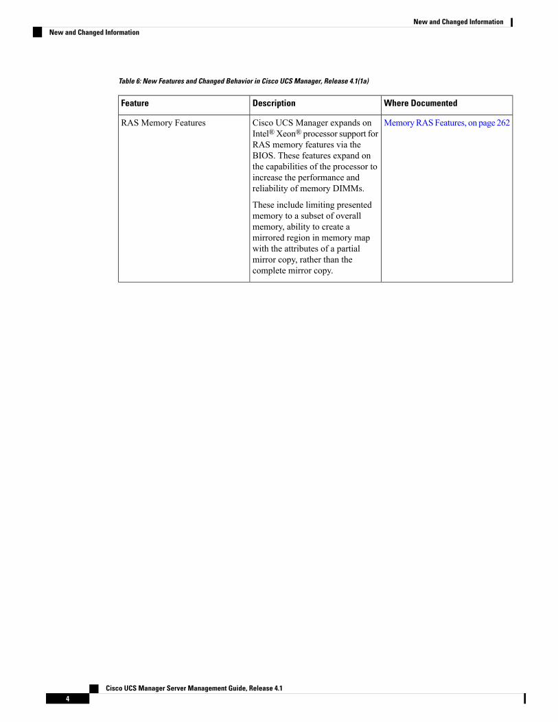
Table 6: New Features and Changed Behavior in Cisco UCS Manager, Release 4.1(1a)
Where DocumentedDescriptionFeature
MemoryRASFeatures, on page 262Cisco UCS Manager expands onIntel®Xeon® processor support forRAS memory features via theBIOS. These features expand onthe capabilities of the processor toincrease the performance andreliability of memory DIMMs.
These include limiting presentedmemory to a subset of overallmemory, ability to create amirrored region in memory mapwith the attributes of a partialmirror copy, rather than thecomplete mirror copy.
RAS Memory Features
Cisco UCS Manager Server Management Guide, Release 4.14
New and Changed InformationNew and Changed Information
C H A P T E R 2Server Management Overview
• Server Management Overview, on page 5• Cisco UCS Manager User CLI Documentation, on page 6• Cisco UCS Manager User Documentation, on page 7
Server Management OverviewCisco UCS Manager enables you to manage general and complex server deployments. For example, you canmanage a general deployment with a pair of Fabric Interconnects (FIs), which is the redundant server accesslayer that you get with the first chassis that can scale up to 20 chassis' and up to 160 physical servers. Thiscan be a combination of blades and rack mount servers to support the workload in your environment. As youadd more servers, you can continue to perform server provisioning, device discovery, inventory, configuration,diagnostics, monitoring, fault detection, and auditing.
Beginning with release 4.1(1), Cisco UCS Manager extends support for all existing features on Cisco UCS64108 Fabric Interconnect unless specifically noted.
Beginning with release 4.0(2a), Cisco UCSManager extends support for all existing features on the followingCisco UCS hardware unless specifically noted:
• Cisco UCS C480 M5 ML Server
• Cisco UCS VIC 1495
• Cisco UCS VIC 1497
Beginning with release 4.0(1a), Cisco UCSManager extends support for all existing features on the followingCisco UCS hardware unless specifically noted:
• Cisco UCS 6454 Fabric Interconnect
• Cisco UCS VIC 1455
• Cisco UCS VIC 1457
• Cisco UCS C125 M5 Server
Beginning with release 4.0(1a), Cisco UCS Manager does not support UCS M2 servers.
By default, the Cisco UCS 6400 Series Fabric Interconnects, the Cisco UCS 6332 Fabric Interconnects, theUCS Mini 6324 Fabric Interconnects, and the UCS 6200 Series Fabric Interconnects include centralized
Cisco UCS Manager Server Management Guide, Release 4.15

management. You can manage the UCS Blade Servers and Rack-Mount Servers that are in the same domainfrom one console. You can also manage the UCS Mini from the Cisco UCS Manager.
To ensure the optimum server performance, you can configure the amount of power that you allocate toservers. You can also set the server boot policy, the location from which the server boots, and the order inwhich the boot devices are invoked. You can create service profiles for the UCS B-Series Blade Servers andthe UCS Mini to assign to servers. Service profiles enable you to assign BIOS settings, security settings, thenumber of vNICs and vHBAs, and anything else that you want to apply to a server.
Cisco UCS Manager User CLI DocumentationCisco UCS Manager offers you a set of smaller, use-case based documentation described in the followingtable:
DescriptionGuide
Discusses Cisco UCS architecture and Day 0operations, including Cisco UCS Manager initialconfiguration, and configuration best practices.
Cisco UCS Manager Getting Started Guide
Discusses password management, role-based accessconfiguration, remote authentication, communicationservices, CIMC session management, organizations,backup and restore, scheduling options, BIOS tokensand deferred deployments.
Cisco UCS Manager Administration Guide
Discusses physical and virtual infrastructurecomponents used and managed by Cisco UCSManager.
Cisco UCS Manager Infrastructure ManagementGuide
Discusses downloading and managing firmware,upgrading through Auto Install, upgrading throughservice profiles, directly upgrading at endpoints usingfirmware auto sync, managing the capability catalog,deployment scenarios, and troubleshooting.
Cisco UCS Manager Firmware Management Guide
Discusses the new licenses, registering Cisco UCSdomains with Cisco UCS Central, power capping,server boot, server profiles and server-related policies.
Cisco UCS Manager Server Management Guide
Discusses all aspects of storage management such asSAN and VSAN in Cisco UCS Manager.
Cisco UCS Manager Storage Management Guide
Discusses all aspects of network management suchas LAN and VLAN connectivity in Cisco UCSManager.
Cisco UCS Manager Network Management Guide
Discusses all aspects of system and health monitoringincluding system statistics in Cisco UCS Manager.
Cisco UCS Manager System Monitoring Guide
Discusses all aspects of management of UCS S-Seriesservers that aremanaged throughCiscoUCSManager.
Cisco UCS S3260 Server Integration with Cisco UCSManager
Cisco UCS Manager Server Management Guide, Release 4.16
Server Management OverviewCisco UCS Manager User CLI Documentation

Cisco UCS Manager User DocumentationCisco UCSManager offers you a new set of smaller, use-case based documentation described in the followingtable:
DescriptionGuide
Discusses Cisco UCS architecture and Day 0operations, including Cisco UCS Manager initialconfiguration, and configuration best practices.
Cisco UCS Manager Getting Started Guide
Discusses password management, role-based accessconfiguration, remote authentication, communicationservices, CIMC session management, organizations,backup and restore, scheduling options, BIOS tokensand deferred deployments.
Cisco UCS Manager Administration Guide
Discusses physical and virtual infrastructurecomponents used and managed by Cisco UCSManager.
Cisco UCS Manager Infrastructure ManagementGuide
Discusses downloading and managing firmware,upgrading through Auto Install, upgrading throughservice profiles, directly upgrading at endpoints usingfirmware auto sync, managing the capability catalog,deployment scenarios, and troubleshooting.
Cisco UCS Manager Firmware Management Guide
Discusses the new licenses, registering Cisco UCSdomains with Cisco UCS Central, power capping,server boot, server profiles and server-related policies.
Cisco UCS Manager Server Management Guide
Discusses all aspects of storage management such asSAN and VSAN in Cisco UCS Manager.
Cisco UCS Manager Storage Management Guide
Discusses all aspects of network management suchas LAN and VLAN connectivity in Cisco UCSManager.
Cisco UCS Manager Network Management Guide
Discusses all aspects of system and health monitoringincluding system statistics in Cisco UCS Manager.
Cisco UCS Manager System Monitoring Guide
Discusses all aspects of management of UCS S-Seriesservers that aremanaged throughCiscoUCSManager.
Cisco UCS S3260 Server Integration with Cisco UCSManager
Cisco UCS Manager Server Management Guide, Release 4.17
Server Management OverviewCisco UCS Manager User Documentation

Cisco UCS Manager Server Management Guide, Release 4.18
Server Management OverviewCisco UCS Manager User Documentation
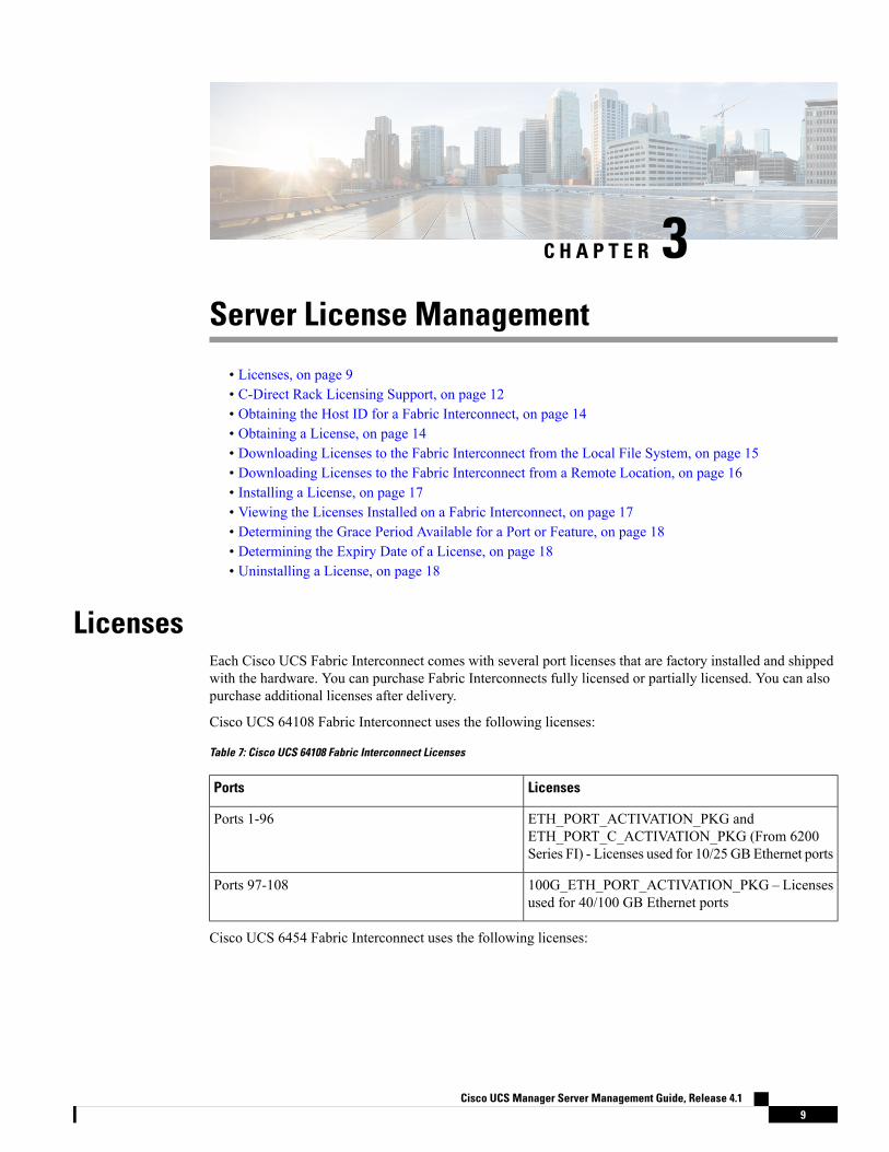
C H A P T E R 3Server License Management
• Licenses, on page 9• C-Direct Rack Licensing Support, on page 12• Obtaining the Host ID for a Fabric Interconnect, on page 14• Obtaining a License, on page 14• Downloading Licenses to the Fabric Interconnect from the Local File System, on page 15• Downloading Licenses to the Fabric Interconnect from a Remote Location, on page 16• Installing a License, on page 17• Viewing the Licenses Installed on a Fabric Interconnect, on page 17• Determining the Grace Period Available for a Port or Feature, on page 18• Determining the Expiry Date of a License, on page 18• Uninstalling a License, on page 18
LicensesEach Cisco UCS Fabric Interconnect comes with several port licenses that are factory installed and shippedwith the hardware. You can purchase Fabric Interconnects fully licensed or partially licensed. You can alsopurchase additional licenses after delivery.
Cisco UCS 64108 Fabric Interconnect uses the following licenses:
Table 7: Cisco UCS 64108 Fabric Interconnect Licenses
LicensesPorts
ETH_PORT_ACTIVATION_PKG andETH_PORT_C_ACTIVATION_PKG (From 6200Series FI) - Licenses used for 10/25 GB Ethernet ports
Ports 1-96
100G_ETH_PORT_ACTIVATION_PKG – Licensesused for 40/100 GB Ethernet ports
Ports 97-108
Cisco UCS 6454 Fabric Interconnect uses the following licenses:
Cisco UCS Manager Server Management Guide, Release 4.19

Table 8: Cisco UCS 6454 Fabric Interconnect Licenses
LicensesPorts
ETH_PORT_ACTIVATION_PKG andETH_PORT_C_ACTIVATION_PKG (From 6200Series FI) - Licenses used for 10/25 GB Ethernet ports
Ports 1-48
100G_ETH_PORT_ACTIVATION_PKG – Licensesused for 40/100 GB Ethernet ports
Ports 49-54
The following four licenses are for the 6300 Series FI and are only valid on the 6332 and 6332-16UP FIs.
• 40G_ETH_PORT_ACTIVATION_PKG – Licenses used for 40 GB Ethernet ports
• 40G_ETH_C_PORT_ACTIVATION_PKG – Licenses used for 40 GB Ethernet ports directly connectedto rack servers (C-Direct)
• 10G_C_PORT_ACTIVATION_PKG – Licenses used for the first 16 10 GB unified ports on the6332-16UP that are directly connected to rack servers (C-Direct)
• 10G_PORT_ACTIVATION_PKG – Licenses used for the first 16 10 GB unified ports on the 6332-16UP
The 10G_PORT_ACTIVATION_PKG and10G_C_PORT_ACTIVATION_PKG licenses are only valid for the6332-16UP FIs, and can only be installed on them.
Note
The following licenses are used when S3260 system is connected to FI as appliance (appliance port) or CiscoUCS Manager managed node (server port):
Table 9: S3260 system License Requirement
LicenseFI Model
ETH_PORT_ACTIVATION_PKG6200
40G_ETH_PORT_ACTIVATION_PKG6332
10G_PORT_ACTIVATION_PKG6332-16UP
40G_ETH_PORT_ACTIVATION_PKG6454 and 64108
Cisco UCSC125M5 Servers support only Cisco UCS 6400 Series Fabric Interconnect and 6300 Series FabricInterconnect.
At a minimum, each Fabric Interconnect ships with the following counted licenses pre-installed:
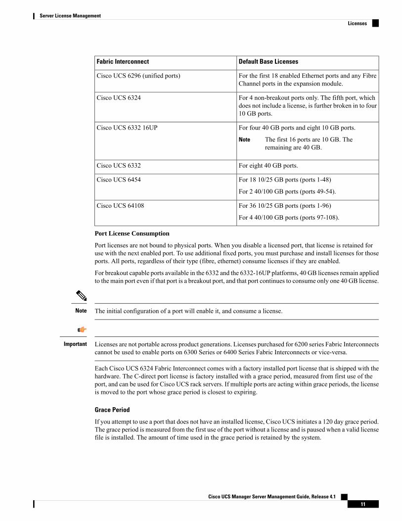
Default Base LicensesFabric Interconnect
For the 12 first enabled Ethernet ports and any FibreChannel ports in the expansion module.
Cisco UCS 6248 (unified ports)
Cisco UCS Manager Server Management Guide, Release 4.110
Server License ManagementLicenses
Default Base LicensesFabric Interconnect
For the first 18 enabled Ethernet ports and any FibreChannel ports in the expansion module.
Cisco UCS 6296 (unified ports)
For 4 non-breakout ports only. The fifth port, whichdoes not include a license, is further broken in to four10 GB ports.
Cisco UCS 6324
For four 40 GB ports and eight 10 GB ports.
The first 16 ports are 10 GB. Theremaining are 40 GB.
Note
Cisco UCS 6332 16UP
For eight 40 GB ports.Cisco UCS 6332
For 18 10/25 GB ports (ports 1-48)
For 2 40/100 GB ports (ports 49-54).
Cisco UCS 6454
For 36 10/25 GB ports (ports 1-96)
For 4 40/100 GB ports (ports 97-108).
Cisco UCS 64108
Port License Consumption
Port licenses are not bound to physical ports. When you disable a licensed port, that license is retained foruse with the next enabled port. To use additional fixed ports, you must purchase and install licenses for thoseports. All ports, regardless of their type (fibre, ethernet) consume licenses if they are enabled.
For breakout capable ports available in the 6332 and the 6332-16UP platforms, 40 GB licenses remain appliedto the main port even if that port is a breakout port, and that port continues to consume only one 40 GB license.
The initial configuration of a port will enable it, and consume a license.Note
Licenses are not portable across product generations. Licenses purchased for 6200 series Fabric Interconnectscannot be used to enable ports on 6300 Series or 6400 Series Fabric Interconnects or vice-versa.
Important
Each Cisco UCS 6324 Fabric Interconnect comes with a factory installed port license that is shipped with thehardware. The C-direct port license is factory installed with a grace period, measured from first use of theport, and can be used for Cisco UCS rack servers. If multiple ports are acting within grace periods, the licenseis moved to the port whose grace period is closest to expiring.
Grace Period
If you attempt to use a port that does not have an installed license, Cisco UCS initiates a 120 day grace period.The grace period is measured from the first use of the port without a license and is paused when a valid licensefile is installed. The amount of time used in the grace period is retained by the system.
Cisco UCS Manager Server Management Guide, Release 4.111
Server License ManagementLicenses
Each physical port has its own grace period. Initiating the grace period on a single port does not initiate thegrace period for all ports.
Note
If a licensed port is unconfigured, that license is transferred to a port functioning within a grace period. Ifmultiple ports are acting within grace periods, the license is moved to the port whose grace period is closestto expiring.
High Availability Configurations
To avoid inconsistencies during failover, we recommend that both Fabric Interconnects in the cluster havethe same number of ports licensed. If symmetry is not maintained and failover occurs, Cisco UCS enablesthe missing licenses and initiates the grace period for each port being used on the failover node.
C-Direct Rack Licensing SupportRelease 4.1(1a) and Higher
Beginning with release 4.1(1a), Cisco UCS 64108 Fabric Interconnects use theETH_C_PORT_ACTIVATION_PKG feature pack for C-Direct port licenses for ports 1-96. There are nodefault ETH_C_PORT_ACTIVATION_PKG licenses shipped with the Fabric Interconnect. Youmay purchasethem as required.
C-direct support is only applicable on ports that are connected to the rack servers. TheETH_C_PORT_ACTIVATION_PKG is added to the existing license package with all the same propertiesas the existing licensing feature. The Subordinate Quantity property is added to theETH_PORT_ACTIVATION_PKG to track ports connected to rack servers.
The License Tab in the Cisco UCS Manager GUI displays the new license and the Subordinate Quantityfor the license. You can also use the show feature and show usage commands under scope license to viewthe license feature, the vendor version type, and the grace period for each license.
Release 4.0(1a) and Higher
Beginning with release 4.0(1a), Cisco UCS 6454 Fabric Interconnects use theETH_C_PORT_ACTIVATION_PKG feature pack for C-Direct port licenses for ports 1-48. There are nodefault ETH_C_PORT_ACTIVATION_PKG licenses shipped with the Fabric Interconnect. Youmay purchasethem as required.
C-direct support is only applicable on ports that are connected to the rack servers. TheETH_C_PORT_ACTIVATION_PKG is added to the existing license package with all the same propertiesas the existing licensing feature. The Subordinate Quantity property is added to theETH_PORT_ACTIVATION_PKG to track ports connected to rack servers.
The License Tab in the Cisco UCS Manager GUI displays the new license and the Subordinate Quantityfor the license. You can also use the show feature and show usage commands under scope license to viewthe license feature, the vendor version type, and the grace period for each license.
Cisco UCS Manager Server Management Guide, Release 4.112
Server License ManagementC-Direct Rack Licensing Support

Release 3.2(3o) and Earlier
Each Cisco UCS Fabric Interconnect is shipped with a default number of port licenses that are factory licensedand shipped with the hardware. C-direct support is only applicable on ports that are connected to the rackservers. The 10G_C_PORT_ACTIVATION_PKG and the 40G_ETH_C_PORT_ACTIVATION _PKG areadded to the existing license package with all the same properties as the existing licensing feature. TheSubordinate Quantity property is added to the 10G_PORT_ACTIVATION_PKG and40G_ETH_PORT_ACTIVATION_PKG to track ports connected to rack servers.
The License Tab in the Cisco UCS Manager GUI displays the new license and the Subordinate Quantityfor the license. You can also use the show feature and show usage commands under scope license to viewthe license feature, the vendor version type, and the grace period for each license.
Ports connected to rack servers can use existing 10G_PORT_ACTIVATION_PKG,40G_ETH_PORT_ACTIVATION_PKG if the license is available or if the license is not in use. Otherwise,you must purchase a 10G_C_PORT_ACTIVATION_PKG, the 40G_ETH_C_PORT_ACTIVATION _PKGto avoid the license grace period.
There is no change in the 10 GB ports. The 10G_PORT_ACTIVATION_PKG and10G_C_PORT_ACTIVATION_PKG license packages include all of the same properties as the existing theETH_PORT_ACTIVATION_PKG and the ETH_PORT_C_ACTIVATION_PKG license features.
Configuration and Restrictions
• The C-Direct rack licensing feature accounts for the rack server ports that are directly connected tothe FI, but not to a CIMC port. The default quantity for the 10G_C_PORT_ACTIVATION_PKGand the 40G_ETH_C_PORT_ACTIVATION _PKG is always 0.
• When a 40 GB port, or a breakout port under a 40 GB breakout port is enabled without anyconnections, this port is allotted a license under the 40G_ETH_PORT_ACTIVATION_PKG, ifavailable. If this port is connected to a Direct-Connect rack server after a time lag, it triggers acomplete re-allocation of licenses, then this port passes through one of the following license allocationscenarios occurs:
When you enable a breakout port under a 40 GB breakout port, if that port is connected to aDirect-Connect rack server, and the 40G_C_PORT_ACTIVATION_PKG license files are installedon the FI, the following license allocation occurs:
• If no other ports under the breakout port are enabled, the parent 40 GB port is allotted a licenseunder the 40G_C_PORT_ACTIVATION_PKG, and the used quantity is incremented for thisinstance.
• If other ports are enabled, and if at least one port is not connected to a Direct Connect rackserver, even if the port is not being used, the parent 40 GB port is allotted a license under the40G_ETH_PORT_ACTIVATION_PKG, and the used quantity is incremented for this instance.
• When you enable a breakout port under a 40 GB breakout port and that port is connected to aDirect-Connect rack server, and the 40G_C_PORT_ACTIVATION_PKG license files are notinstalled on the FI, the following license allocation occurs:
• If no ports under the breakout port are enabled, the parent 40 GB port is allotted a license underthe 40G_ETH_PORT_ACTIVATION_PKG. The subordinate quantity is increased if thelicenses are available in the 40G_ETH_PORT_ACTIVATION_PKG. If the licenses are notavailable, the used quantity under this feature is increased and the entire port goes in to thegrace period.
Cisco UCS Manager Server Management Guide, Release 4.113
Server License ManagementC-Direct Rack Licensing Support
• If other ports are enabled and at least one port is not connected to a Direct Connect rack server,even if the port is not being used, the parent 40 GB port is allotted a license under the40G_ETH_PORT_ACTIVATION_PKG, and the used quantity is incremented for this instance.
Obtaining the Host ID for a Fabric InterconnectThe host ID is also known as the serial number.
Procedure
Step 1 In the Navigation pane, click Equipment.Step 2 Expand Equipment > Fabric Interconnects.Step 3 Click the node for the fabric interconnect for which you want to obtain the host ID.Step 4 In the Work pane, click the General tab.Step 5 In the Properties area, the host ID is listed in the Serial Number (SN) field.
What to do next
Obtain the required licenses from Cisco.
Obtaining a License
This process may change after the release of this document. If one or more of these steps no longer applies,contact your Cisco representative for information on how to obtain a license file.
Note
Before you begin
Obtain the following:
• Host ID or serial number for the fabric interconnect
• Claim certificate or other proof of purchase document for the fabric interconnect or expansion module
Procedure
Step 1 Obtain the product authorization key (PAK) from the claim certificate or other proof of purchase document.Step 2 Locate the website URL in the claim certificate or proof of purchase document.Step 3 Access the website URL for the fabric interconnect and enter the serial number and the PAK.
Cisco UCS Manager Server Management Guide, Release 4.114
Server License ManagementObtaining the Host ID for a Fabric Interconnect

Cisco sends you the license file by email. The license file is digitally signed to authorize use on only therequested fabric interconnect. The requested features are also enabled once Cisco UCSManager accesses thelicense file.
What to do next
Install the license on the fabric interconnect.
DownloadingLicensestotheFabric Interconnect fromtheLocalFile System
In a cluster setup, Cisco recommends that you download and install licenses to both fabric interconnects inmatching pairs. An individual license is only downloaded to the fabric interconnect that is used to initiate thedownload.
Note
Before you begin
Obtain the required licenses from Cisco.
Procedure
Step 1 In the Navigation pane, click Admin.Step 2 Expand All > License Management.Step 3 Click the node for the fabric interconnect to which you want to download the license.Step 4 In the Work pane, click the Download Tasks tab.Step 5 Click Download License.Step 6 In the Download License dialog box, click the Local File System radio button in the Location of the Image
File field.Step 7 In the Filename field, type the full path and name of the license file.
You cannot have spaces anywhere in the path name or the file name. For example,c:\Path\Folder_Name\License.lic is a valid path, butc:\Path\Folder Name\License.licis invalid due to the space in "Folder Name".
If you do not know the exact path to the folder where the license file is located, click Browse and navigateto the file.
Step 8 Click OK.
Cisco UCS Manager GUI begins downloading the license to the fabric interconnect.
Step 9 (Optional) Monitor the status of the download on the Download Tasks tab.
Cisco UCS Manager Server Management Guide, Release 4.115
Server License ManagementDownloading Licenses to the Fabric Interconnect from the Local File System
If Cisco UCS Manager reports that the bootflash is out of space, delete obsolete bundles on thePackages tab to free up space. To view the available space in bootflash, navigate to the fabricinterconnect, click Equipment, and expand the Local Storage Information area on the Generaltab.
Note
Step 10 Repeat this task until all the required licenses have been downloaded to the fabric interconnect.
What to do next
After all of the download tasks complete, install the licenses.
DownloadingLicensestotheFabricInterconnect fromaRemoteLocation
In a cluster setup, Cisco recommends that you download and install licenses to both fabric interconnects inmatching pairs. An individual license is only downloaded to the fabric interconnect that is used to initiate thedownload.
Note
Before you begin
Obtain the required licenses from Cisco.
Procedure
Step 1 In the Navigation pane, click Admin.Step 2 Expand All > License Management.Step 3 Click the node for the fabric interconnect to which you want to download the license.Step 4 In the Work pane, click the Download Tasks tab.Step 5 Click Download License.Step 6 In the Download License dialog box, click the Remote File System radio button in the Location of the
Image File field.Step 7 Specify the protocol, and enter the required information.
You cannot have spaces anywhere in the path name or the file name. For example,c:\Path\Folder_Name\License.lic is a valid path, butc:\Path\Folder Name\License.licis invalid due to the space in "Folder Name".
If you use a hostname rather than an IPv4 or IPv6 address, you must configure a DNS server. If theCisco UCS domain is not registered with Cisco UCS Central or DNS management is set to local,configure a DNS server in Cisco UCS Manager. If the Cisco UCS domain is registered with CiscoUCS Central and DNS management is set to global, configure a DNS server in Cisco UCS Central.
Note
Cisco UCS Manager Server Management Guide, Release 4.116
Server License ManagementDownloading Licenses to the Fabric Interconnect from a Remote Location
Step 8 Click OK.
Cisco UCS Manager GUI begins downloading the license to the fabric interconnect.
Step 9 (Optional) Monitor the status of the download on the Download Tasks tab.
If Cisco UCS Manager reports that the bootflash is out of space, delete obsolete bundles on thePackages tab to free up space. To view the available space in bootflash, navigate to the fabricinterconnect, click Equipment, and expand the Local Storage Information area on the Generaltab.
Note
Step 10 Repeat this task until all the required licenses have been downloaded to the fabric interconnect.
What to do next
After all of the download tasks complete, install the licenses.
Installing a LicenseBefore you begin
Obtain the required licenses from Cisco.
Procedure
Step 1 In the Navigation pane, click Admin.Step 2 Expand All > License Management.Step 3 In the Work pane, click the Downloaded License Files tab.Step 4 Choose the license you want to install from the table.
There is no downtime required or impact to traffic when installing a new port license.Note
Step 5 Click the Install License button.Step 6 In the Install License dialog box, click Yes.
Cisco UCS Manager GUI installs the license and activates the unlicensed port or feature.
Viewing the Licenses Installed on a Fabric InterconnectProcedure
Step 1 In the Navigation pane, click Admin.
Cisco UCS Manager Server Management Guide, Release 4.117
Server License ManagementInstalling a License
Step 2 Expand All > License Management.Step 3 In the Work pane, click the Installed Licenses tab to view the details of all licenses installed on the fabric
interconnect.Step 4 Click a license in the table to view the details of that license in the Contents tab.
You may need to expand the license file to view the details of individual licenses in the file.
Determining the Grace Period Available for a Port or FeatureProcedure
Step 1 In the Navigation pane, click Admin.Step 2 Expand All > License Management.Step 3 In the Work pane, click the General tab.Step 4 Click a feature in the table to view details for that feature, including the operational state and used grace
period.
Determining the Expiry Date of a LicenseProcedure
Step 1 In the Navigation pane, click Admin.Step 2 Expand All > License Management.Step 3 In the Work pane, click the Installed Licenses tab.Step 4 Click a license in the table to view the details of that license in the Contents tab below.Step 5 In the Contents tab, expand the license file to view all licenses in the file.Step 6 In the Expiry column, view the expiry date of the license.
Uninstalling a License
Permanent licenses cannot be uninstalled if they are in use. You can only uninstall a permanent license thatis not in use. If you try to delete a permanent license that is being used, Cisco UCSManager rejects the requestand display an error message.
Note
Cisco UCS Manager Server Management Guide, Release 4.118
Server License ManagementDetermining the Grace Period Available for a Port or Feature
Before you begin
Back up the Cisco UCS Manager configuration.
Procedure
Step 1 In the Navigation pane, click Admin.Step 2 Expand All > License Management.Step 3 In the Work pane, click the Installed Licenses tab.Step 4 Choose the license you want to uninstall from the table.Step 5 Click the Clear License button.Step 6 If a confirmation dialog box displays, click Yes.
Cisco UCS Manager deactivates the license, removes the license from the list of licenses, and deletes thelicense from the fabric interconnect. The port is moved into unlicensed mode. In a cluster setup, you mustuninstall the license from the other fabric interconnect.
Cisco UCS Manager Server Management Guide, Release 4.119
Server License ManagementUninstalling a License

Cisco UCS Manager Server Management Guide, Release 4.120
Server License ManagementUninstalling a License

C H A P T E R 4Registering Cisco UCS Domains with Cisco UCSCentral
• Registration of Cisco UCS Domains, on page 21• Policy Resolution between Cisco UCS Manager and Cisco UCS Central, on page 21• Registering a Cisco UCS Domain with Cisco UCS Central, on page 23• Configuring Policy Resolutions between Cisco UCS Manager and Cisco UCS Central , on page 24• Setting Cisco UCS Central Registration Properties in Cisco UCS Manager, on page 24• Unregistering a Cisco UCS Domain from Cisco UCS Central, on page 25
Registration of Cisco UCS DomainsYou can have Cisco UCS Central manage some or all of the Cisco UCS domains in your data center.
If you want Cisco UCS Central to manage a Cisco UCS domain, you need to register that domain. When youregister, you must choose which types of policies and other configurations will be managed by Cisco UCSCentral and Cisco UCSManager. Cisco UCSCentral can manage the same types of policies and configurationsfor all registered Cisco UCS domains. You can also choose to have different settings for each registered CiscoUCS domain.
Perform the following before registering a Cisco UCS domain with Cisco UCS Central:
• Configure an NTP server and the correct time zone in both Cisco UCS Manager and Cisco UCS Centralto ensure that they are in sync. If the time and date in the Cisco UCS domain and Cisco UCS Central areout of sync, the registration might fail.
• Obtain the hostname or IP address of Cisco UCS Central
• Obtain the shared secret that was configured when Cisco UCS Central was deployed.
Policy Resolution between Cisco UCS Manager and Cisco UCSCentral
For each Cisco UCS domain that you register with Cisco UCS Central, you can choose which application willmanage certain policies and configuration settings. This policy resolution does not have to be the same forevery Cisco UCS domain that you register with the same Cisco UCS Central.
Cisco UCS Manager Server Management Guide, Release 4.121
Unregistering a Cisco UCS domain with Cisco UCS Central will terminate all open sessions.Note
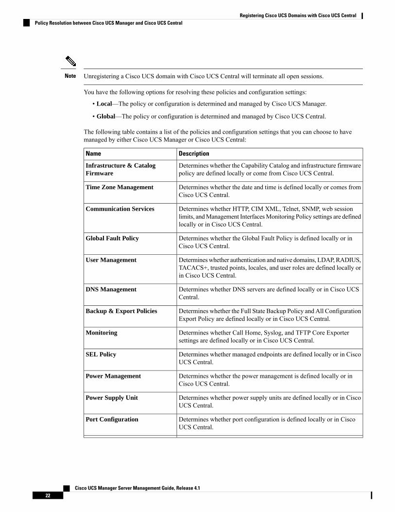
You have the following options for resolving these policies and configuration settings:
• Local—The policy or configuration is determined and managed by Cisco UCS Manager.
• Global—The policy or configuration is determined and managed by Cisco UCS Central.
The following table contains a list of the policies and configuration settings that you can choose to havemanaged by either Cisco UCS Manager or Cisco UCS Central:
DescriptionName
Determines whether the Capability Catalog and infrastructure firmwarepolicy are defined locally or come from Cisco UCS Central.
Infrastructure & CatalogFirmware
Determines whether the date and time is defined locally or comes fromCisco UCS Central.
Time Zone Management
Determines whether HTTP, CIM XML, Telnet, SNMP, web sessionlimits, andManagement InterfacesMonitoring Policy settings are definedlocally or in Cisco UCS Central.
Communication Services
Determines whether the Global Fault Policy is defined locally or inCisco UCS Central.
Global Fault Policy
Determineswhether authentication and native domains, LDAP, RADIUS,TACACS+, trusted points, locales, and user roles are defined locally orin Cisco UCS Central.
User Management
Determines whether DNS servers are defined locally or in Cisco UCSCentral.
DNS Management
Determines whether the Full State Backup Policy and All ConfigurationExport Policy are defined locally or in Cisco UCS Central.
Backup & Export Policies
Determines whether Call Home, Syslog, and TFTP Core Exportersettings are defined locally or in Cisco UCS Central.
Monitoring
Determines whether managed endpoints are defined locally or in CiscoUCS Central.
SEL Policy
Determines whether the power management is defined locally or inCisco UCS Central.
Power Management
Determines whether power supply units are defined locally or in CiscoUCS Central.
Power Supply Unit
Determines whether port configuration is defined locally or in CiscoUCS Central.
Port Configuration
Cisco UCS Manager Server Management Guide, Release 4.122
Registering Cisco UCS Domains with Cisco UCS CentralPolicy Resolution between Cisco UCS Manager and Cisco UCS Central
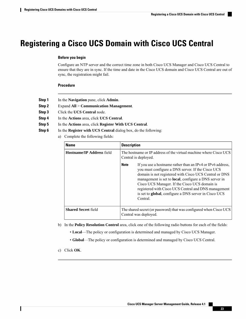
Registering a Cisco UCS Domain with Cisco UCS CentralBefore you begin
Configure an NTP server and the correct time zone in both Cisco UCS Manager and Cisco UCS Central toensure that they are in sync. If the time and date in the Cisco UCS domain and Cisco UCS Central are out ofsync, the registration might fail.
Procedure
Step 1 In the Navigation pane, click Admin.Step 2 Expand All > Communication Management.Step 3 Click the UCS Central node.Step 4 In the Actions area, click UCS Central.Step 5 In the Actions area, click Register With UCS Central.Step 6 In the Register with UCS Central dialog box, do the following:
a) Complete the following fields:
DescriptionName
The hostname or IP address of the virtual machine where Cisco UCSCentral is deployed.
If you use a hostname rather than an IPv4 or IPv6 address,you must configure a DNS server. If the Cisco UCSdomain is not registered with Cisco UCS Central or DNSmanagement is set to local, configure a DNS server inCisco UCS Manager. If the Cisco UCS domain isregistered with Cisco UCS Central and DNSmanagementis set to global, configure a DNS server in Cisco UCSCentral.
Note
Hostname/IP Address field
The shared secret (or password) that was configured when Cisco UCSCentral was deployed.
Shared Secret field
b) In the Policy Resolution Control area, click one of the following radio buttons for each of the fields:
• Local—The policy or configuration is determined and managed by Cisco UCS Manager.
• Global—The policy or configuration is determined and managed by Cisco UCS Central.
c) Click OK.
Cisco UCS Manager Server Management Guide, Release 4.123
Registering Cisco UCS Domains with Cisco UCS CentralRegistering a Cisco UCS Domain with Cisco UCS Central

Configuring Policy Resolutions between Cisco UCS Managerand Cisco UCS Central
Procedure
Step 1 In the Navigation pane, click Admin.Step 2 Expand All > Communication Management.Step 3 Click the UCS Central node.Step 4 In the Actions area, click UCS Central.Step 5 In the Policy Resolution Control area, click one of the following radio buttons for each of the fields:
• Local—The policy or configuration is determined and managed by Cisco UCS Manager.
• Global—The policy or configuration is determined and managed by Cisco UCS Central.
Step 6 Click Save Changes.
Setting Cisco UCS Central Registration Properties in Cisco UCSManager
Procedure
Step 1 In the Navigation pane, click Admin.Step 2 Expand All > Communication Management.Step 3 Click the UCS Central node.Step 4 In the Actions area, click UCS Central.Step 5 In the Status area, complete the following as appropriate:
a) Click the radio button for the Cleanup Mode that you want to use.
This can be one of the following:
• Localize Global—When a Cisco UCS domain is unregistered, all global policies in the Cisco UCSdomain will be localized to Cisco UCS Manager. The policies remain in the Cisco UCS domain,policy ownership is now local to Cisco UCS Manager, and Cisco UCS Manager admin users canmake changes.
If you reregister the Cisco UCS domain with Cisco UCS Central, there can be policyconflicts due to the policies existing both in Cisco UCSCentral and in Cisco UCSManager.Either delete the local policies, or set the local policies to global before you try to createand associate a global service profile.
Note
Cisco UCS Manager Server Management Guide, Release 4.124
Registering Cisco UCS Domains with Cisco UCS CentralConfiguring Policy Resolutions between Cisco UCS Manager and Cisco UCS Central
• Deep Remove Global—This option should only be used after careful consideration. When a CiscoUCS domain is unregistered, all global policies in the Cisco UCS domain are removed. If there areglobal service profiles, they will now refer to Cisco UCS Manager local default policies, and one ofthe following occurs:
• If there are local default policies present, the server will reboot.
• If there are no local default policies, the service profile association fails with a configurationerror.
The deep remove global cleanup mode does not remove global VSANs and VLANs whenyou unregister from Cisco UCS Central. Those must be removed manually if desired.
Note
b) Optionally check the Suspend State check box.
If checked, the Cisco UCS domain is temporarily removed fromCisco UCS Central, and all global policiesrevert to their local counterparts. All service profiles maintain their current identities. However, globalpools are no longer visible and cannot be accessible by new service profiles.
c) Optionally check the Acknowledge State check box.
If the event ID stream that represents time and consistency between Cisco UCS Manager and Cisco UCSCentral becomes skewed or inconsistent, Cisco UCS Manager places itself in a Suspended State anddisconnects itself from Cisco UCS Central.
If you check this check box, you acknowledge that inconsistencies exist between Cisco UCS Managerand Cisco UCS Central and are still willing to reconnect the Cisco UCS domain with Cisco UCS Central.
Step 6 Click Save Changes.
Unregistering a Cisco UCS Domain from Cisco UCS CentralWhen you unregister a Cisco UCS domain from Cisco UCS Central, Cisco UCS Manager no longer receivesupdates to global policies.
Procedure
Step 1 In the Navigation pane, click Admin.Step 2 Expand All > Communication Management.Step 3 Click the UCS Central node.Step 4 In the Actions area, click UCS Central.Step 5 In the Actions area, click Unregister From UCS Central.Step 6 If a confirmation dialog box displays, click Yes.Step 7 Click OK.
For more information on the impact of unregistering and registering a Cisco UCS Domain with Cisco UCSCentral, see Policy Resolution between Cisco UCS Manager and Cisco UCS Central.
Cisco UCS Manager Server Management Guide, Release 4.125
Registering Cisco UCS Domains with Cisco UCS CentralUnregistering a Cisco UCS Domain from Cisco UCS Central

Cisco UCS Manager Server Management Guide, Release 4.126
Registering Cisco UCS Domains with Cisco UCS CentralUnregistering a Cisco UCS Domain from Cisco UCS Central
C H A P T E R 5Power Capping and Power Management in CiscoUCS
• Power Capping in Cisco UCS, on page 28• Power Policy Configuration, on page 28• Power Policy for Cisco UCS Servers, on page 28• Configuring the Power Policy, on page 29• Power Supply for Redundancy Method, on page 29• Configuring Policy Driven Chassis Group Power Capping, on page 30• Policy Driven Chassis Group Power Capping, on page 30• Power Control Policy, on page 30• Power Save Mode, on page 36• Acoustic Mode Fan Profile, on page 37• Power Groups in UCS Manager, on page 39• Blade Level Power Capping, on page 44• Manual Blade Level Power Cap, on page 44• Setting the Blade-Level Power Cap for a Server, on page 44• Viewing the Blade-Level Power Cap, on page 45• Global Power Profiling Policy Configuration, on page 46• Global Power Profiling Policy, on page 46• Configuring the Global Power Profile Policy, on page 46• Global Power Allocation Policy Configuration, on page 46• Global Power Allocation Policy, on page 46• Configuring the Global Power Allocation Policy, on page 47• Power Management During Power-on Operations, on page 47• Power Sync Policy Configuration, on page 48• Power Sync Policy, on page 48• Power Synchronization Behavior, on page 48• Creating a Power Sync Policy, on page 49• Changing a Power Sync Policy, on page 51• Deleting a Power Sync Policy, on page 51• Rack Server Power Management, on page 52• UCS Mini Power Management , on page 52
Cisco UCS Manager Server Management Guide, Release 4.127
Power Capping in Cisco UCSYou can control the maximum power consumption on a server through power capping, as well as manage thepower allocation in the Cisco UCS Manager for blade servers, UCS C220 and C240 M4/M5, and C480M5/C480 M5 ML, rack servers, UCS Mini, and mixed UCS domains.
Cisco UCS Manager supports power capping on the following:
• UCS 6200 Series Fabric Interconnects
• UCS 6300 Series Fabric Interconnects
• UCS 6324 Series Fabric Interconnects (Cisco UCS Mini)
• UCS 6400 Series Fabric Interconnects
You can use Policy Driven Chassis Group Power Cap, or Manual Blade Level Power Cap methods to allocatepower that applies to all of the servers in a chassis.
Cisco UCS Manager provides the following power management policies to help you allocate power to yourservers:
DescriptionPower Management Policies
Specifies the redundancy for power supplies in allchassis in a Cisco UCS domain.
Power Policy
Specifies the priority to calculate the initial powerallocation for each blade in a chassis.
Power Control Policies
Globally manages the chassis to maximize energyefficiency or availability.
Power Save Policy
Specifies the Policy Driven Chassis Group Power Capor the Manual Blade Level Power Cap to apply to allservers in a chassis.
Global Power Allocation
Specifies how the power cap values of the servers arecalculated. If it is enabled, the servers will be profiledduring discovery through benchmarking. This policyapplies when the Global Power Allocation Policy isset to Policy Driven Chassis Group Cap.
Global Power Profiling
Power Policy Configuration
Power Policy for Cisco UCS ServersThe power policy is global and is inherited by all of the chassis' managed by the Cisco UCSManager instance.You can add the power policy to a service profile to specify the redundancy for power supplies in all chassis'in the Cisco UCS domain. This policy is also known as the PSU policy.
Cisco UCS Manager Server Management Guide, Release 4.128
Power Capping and Power Management in Cisco UCSPower Capping in Cisco UCS

For more information about power supply redundancy, see Cisco UCS 5108 Server Chassis HardwareInstallation Guide.
Configuring the Power PolicyProcedure
Step 1 In the Navigation pane, click Equipment.Step 2 Click the Equipment node.Step 3 In the Work pane, click the Policies tab.Step 4 Click the Global Policies subtab.Step 5 In the Power Policy area, click one of the following radio buttons in the Redundancy field:
• Non Redundant—Cisco UCSManager turns on the minimum number of power supplies (PSUs) neededand balances the load between them. If any additional PSUs are installed, Cisco UCSManager sets themto a "turned-off" state. If the power to any PSU is disrupted, the system may experience an interruptionin service until Cisco UCS Manager can activate a new PSU and rebalance the load.
In general, a Cisco UCS chassis requires at least two PSUs for non-redundant operation. Only smallerconfigurations (requiring less than 2500W) can be powered by a single PSU.
• N+1—The total number of PSUs to satisfy non-redundancy, plus one additional PSU for redundancy,are turned on and equally share the power load for the chassis. If any additional PSUs are installed, CiscoUCSManager sets them to a "turned-off" state. If the power to any PSU is disrupted, Cisco UCSManagercan recover without an interruption in service.
In general, a Cisco UCS chassis requires at least three PSUs for N+1 operation.
• Grid—Two power sources are turned on, or the chassis requires greater than N+1 redundancy. If onesource fails (which causes a loss of power to one or two PSUs), the surviving PSUs on the other powercircuit continue to provide power to the chassis.
For more information about power supply redundancy, see Cisco UCS 5108 Server Chassis HardwareInstallation Guide.
In addition to power supply redundancy, you can also chose to enable a Power Save Policy from the PowerSave Policy area. For more information, seePower Save Mode Policy, on page 36 .
Step 6 Click Save Changes.
Power Supply for Redundancy MethodMax Power @ 110 V (Watts)Max Power @ 220 V (Watts)PSU Redundancy
130025001+1 (N+1) OR 1 (N)
260050002+1 (N+1) OR 2 (N) or 2+2 (Grid)
Cisco UCS Manager Server Management Guide, Release 4.129
Power Capping and Power Management in Cisco UCSConfiguring the Power Policy

Max Power @ 110 V (Watts)Max Power @ 220 V (Watts)PSU Redundancy
390054723+1 (N+1) OR 3 (N)
520054724 (N)
Configuring Policy Driven Chassis Group Power Capping
Policy Driven Chassis Group Power CappingWhen you select the Policy Driven Chassis Group Power Cap in the Global Cap Policy, Cisco UCS canmaintain the over-subscription of servers without risking power failures. You can achieve over-subscriptionthrough a two-tier process. For example, at the chassis level, Cisco UCS divides the amount of power availableamongmembers of the power group, and at the blade level, the amount of power allotted to a chassis is dividedamong blades based on priority.
Each time a service profile is associated or disassociated, Cisco UCSManager recalculates the power allotmentfor each blade server within the chassis. If necessary, power from lower-priority service profiles is redistributedto higher-priority service profiles.
UCS power groups cap power in less than one second to safely protect data center circuit breakers. A blademust stay at its cap for 20 seconds before the chassis power distribution is optimized. This is intentionallycarried out over a slower timescale to prevent reacting to transient spikes in demand.
The system reserves enough power to boot a server in each slot, even if that slot is empty. This reserved powercannot be leveraged by servers requiring more power. Blades that fail to comply with the power cap arepenalized.
Note
Power Control PolicyCisco UCS uses the priority set in the power control policy along with the blade type and configuration tocalculate the initial power allocation for each blade within a chassis. During normal operation, the activeblades within a chassis can borrow power from idle blades within the same chassis. If all blades are activeand reach the power cap, service profiles with higher priority power control policies take precedence overservice profiles with lower priority power control policies.
Priority is ranked on a scale of 1-10, where 1 indicates the highest priority and 10 indicates lowest priority.The default priority is 5.
Starting with Cisco UCSManager 3.2(2), chassis dynamic power rebalance mechanism is enabled by default.The mechanism continuously monitors the power usage of the blade servers and adjusts the power allocationaccordingly. Chassis dynamic power rebalance mechanism operates within the overall chassis power budgetset by Cisco UCS Manager, which is calculated from the available PSU power and Group power.
For mission-critical application a special priority called no-cap is also available. Setting the priority to no-capdoes not guarantee that a blade server gets maximum power all the time, however, it prioritizes the bladeserver over other servers during the chassis dynamic power rebalance budget allocations.
Cisco UCS Manager Server Management Guide, Release 4.130
Power Capping and Power Management in Cisco UCSConfiguring Policy Driven Chassis Group Power Capping

If all the blade servers are set with no-cap priority and all of them run high power consuming loads, then thereis a chance that some of the blade servers get capped under high power usage, based on the power distributiondone through dynamic balance.
Note
Global Power Control Policy options are inherited by all the chassis managed by the Cisco UCS Manager.
Starting with Cisco UCS Manager 4.1(3), a global policy called Power Save Mode is available. It is disabledby default, meaning that all PSUs present remain active regardless of power redundancy policy selection.Enabling the policy restores the older behavior..
Starting with Cisco UCS Manager 4.1(2), the power control policy is also used for regulating fans in CiscoUCS C220 M5 and C240 M5 rack servers in acoustically-sensitive environments. The Acoustic setting forthese fans is only available on these servers. On C240 SDM5 rack servers, Acoustic mode is the default mode.
You must include the power control policy in a service profile and that service profile must be associated witha server for it to take effect.
Note
Creating a Power Control Policy
Procedure
Step 1 In the Navigation pane, click Servers.Step 2 Expand Servers > Policies.Step 3 Expand the node for the organization where you want to create the policy.
If the system does not include multi tenancy, expand the root node.
Step 4 Right-click Power Control Policies and choose Create Power Control Policy.Step 5 In the Create Power Control Policy dialog box, complete the following fields:
DescriptionName
The name of the policy.
This name can be between 1 and 16 alphanumericcharacters. You cannot use spaces or any specialcharacters other than - (hyphen), _ (underscore), :(colon), and . (period), and you cannot change thisname after the object is saved.
Name field
Cisco UCS Manager Server Management Guide, Release 4.131
Power Capping and Power Management in Cisco UCSCreating a Power Control Policy
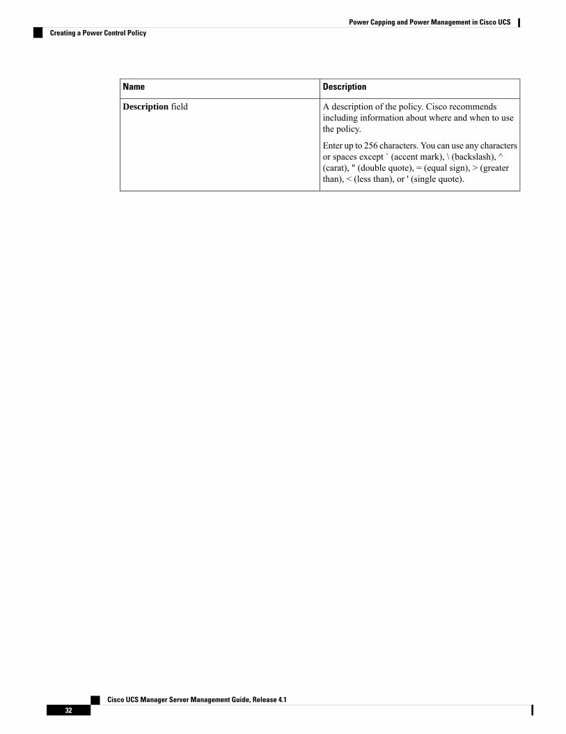
DescriptionName
A description of the policy. Cisco recommendsincluding information about where and when to usethe policy.
Enter up to 256 characters. You can use any charactersor spaces except ` (accent mark), \ (backslash), ^(carat), " (double quote), = (equal sign), > (greaterthan), < (less than), or ' (single quote).
Description field
Cisco UCS Manager Server Management Guide, Release 4.132
Power Capping and Power Management in Cisco UCSCreating a Power Control Policy

DescriptionName
Fan Speed Policy drop-down
Cisco UCS Manager Server Management Guide, Release 4.133
Power Capping and Power Management in Cisco UCSCreating a Power Control Policy
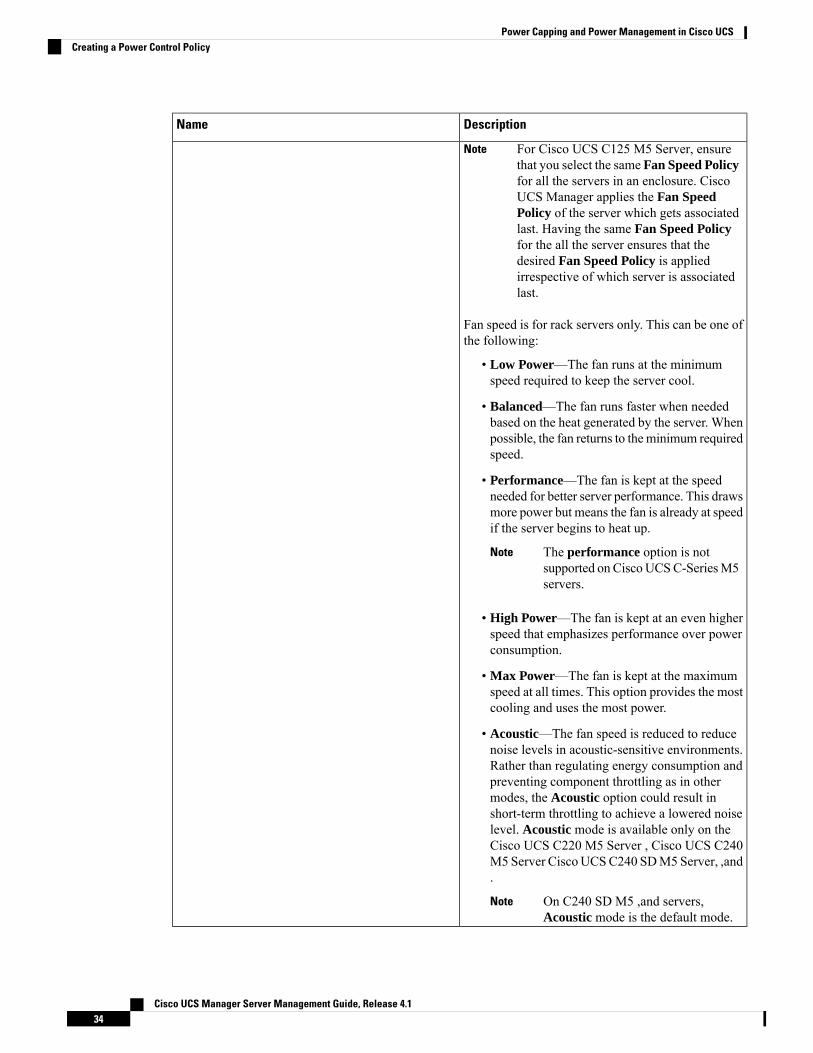
DescriptionName
For Cisco UCS C125 M5 Server, ensurethat you select the same Fan Speed Policy
Note
for all the servers in an enclosure. CiscoUCS Manager applies the Fan SpeedPolicy of the server which gets associatedlast. Having the same Fan Speed Policyfor the all the server ensures that thedesired Fan Speed Policy is appliedirrespective of which server is associatedlast.
Fan speed is for rack servers only. This can be one ofthe following:
• Low Power—The fan runs at the minimumspeed required to keep the server cool.
• Balanced—The fan runs faster when neededbased on the heat generated by the server. Whenpossible, the fan returns to the minimum requiredspeed.
• Performance—The fan is kept at the speedneeded for better server performance. This drawsmore power but means the fan is already at speedif the server begins to heat up.
The performance option is notsupported on CiscoUCSC-SeriesM5servers.
Note
• High Power—The fan is kept at an even higherspeed that emphasizes performance over powerconsumption.
• Max Power—The fan is kept at the maximumspeed at all times. This option provides the mostcooling and uses the most power.
• Acoustic—The fan speed is reduced to reducenoise levels in acoustic-sensitive environments.Rather than regulating energy consumption andpreventing component throttling as in othermodes, the Acoustic option could result inshort-term throttling to achieve a lowered noiselevel. Acoustic mode is available only on theCisco UCS C220 M5 Server , Cisco UCS C240M5 Server CiscoUCSC240 SDM5Server, ,and.
On C240 SD M5 ,and servers,Acoustic mode is the default mode.
Note
Cisco UCS Manager Server Management Guide, Release 4.134
Power Capping and Power Management in Cisco UCSCreating a Power Control Policy
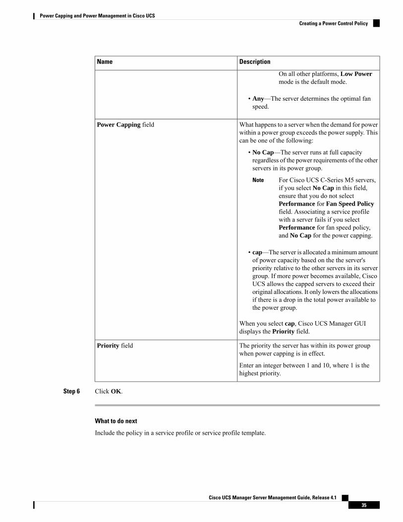
DescriptionName
On all other platforms, Low Powermode is the default mode.
• Any—The server determines the optimal fanspeed.
What happens to a server when the demand for powerwithin a power group exceeds the power supply. Thiscan be one of the following:
• No Cap—The server runs at full capacityregardless of the power requirements of the otherservers in its power group.
For Cisco UCS C-Series M5 servers,if you select No Cap in this field,ensure that you do not selectPerformance for Fan Speed Policyfield. Associating a service profilewith a server fails if you selectPerformance for fan speed policy,and No Cap for the power capping.
Note
• cap—The server is allocated aminimum amountof power capacity based on the the server'spriority relative to the other servers in its servergroup. If more power becomes available, CiscoUCS allows the capped servers to exceed theiroriginal allocations. It only lowers the allocationsif there is a drop in the total power available tothe power group.
When you select cap, Cisco UCS Manager GUIdisplays the Priority field.
Power Capping field
The priority the server has within its power groupwhen power capping is in effect.
Enter an integer between 1 and 10, where 1 is thehighest priority.
Priority field
Step 6 Click OK.
What to do next
Include the policy in a service profile or service profile template.
Cisco UCS Manager Server Management Guide, Release 4.135
Power Capping and Power Management in Cisco UCSCreating a Power Control Policy

Deleting a Power Control Policy
Procedure
Step 1 In the Navigation pane, click Servers.Step 2 Expand Servers > Policies > Organization_Name.Step 3 Expand the Power Control Policies node.Step 4 Right-click the policy you want to delete and select Delete.Step 5 If a confirmation dialog box displays, click Yes.
Power Save Mode
Power Save Mode PolicyPower Save Mode is a configurable chassis policy that allows you to non-disruptively apply bias for eitherenergy efficiency (when enabled) or availability (when disabled). By default, the Power Save Policy will bedisabled. Disabling the Power Save Mode policy allows all PSUs present to remain active, regardless of thePower Redundancy setting. Enabling the Power Save Policy sets the PSUs to active as per the power redundancypolicy.
Today, when the requested power budget is less than the available power capacity, the additional PSU capacityis placed in Power Save Mode automatically. This increases the efficiency of active PSUs and minimizesenergy wasted for conversion losses. However, there are a few use cases, where this default behavior canresult in an outage:
1. Lightly loaded chassis that only requires 2X PSU to support the requested power policy (Grid) and thecustomer did NOT follow the installation guide recommendation regarding PSU input power connections.In this scenario, the chassis has both active PSUs connected to one feed, and the other two PSUs in PowerSave mode connected to another feed. If the feed connected to the active PSUs is lost, the entire chassiswill experience a service interruption.
2. A heavily loaded chassis that requires a 3X PSUs to support the requested power policy (N+1), and thecustomer's rack provides the chassis with dual feed. In this scenario, 3X PSUs are active and 1X PSU isplaced in Power Save mode. If the feed connected to two of the active PSUs is lost (planned or unplanned),the customer could experience an outage if the load is greater than the remaining active PSU can support.
Note
A Power Save mode policy can help avoid an outage situation.
The policy is global and is inherited by all chassis managed by the Cisco UCS Manager.
Creating a Power Save PolicyUse this process to create a global Power Save policy.
Cisco UCS Manager Server Management Guide, Release 4.136
Power Capping and Power Management in Cisco UCSDeleting a Power Control Policy
Procedure
Step 1 In the Navigation pane, click Equipment.Step 2 Click the Equipment node.Step 3 In the Work pane, click the Policies tab.Step 4 Click the Global Policies subtab.Step 5 In the Power Save Policy area, check the Enable checkbox to enable the Global Power Control Policy.Step 6 Click Save Changes.
Acoustic Mode Fan Profile
Acoustic Mode Fan ProfileThe Acoustic Mode fan profile is available on Cisco UCS C220 M5 Server, C240 M5, C240 SD M5, Rackservers.
Setting up an AcousticMode fan policy lets you reduce the noise level onM5 rack servers. The higher capacityfans onM5 servers increase the cooling capacity, but also create more acoustic noise. The standard fan profilesfor M5 servers (Low Power, Balanced, High Power and Max Power) are designed to regulate the server tooptimize energy consumption. The primary goal of these fan profiles is to prevent throttling of CPU’s andperipherals.
The goal of Acoustic Mode is reducing fan speed to reduce noise levels in acoustic-sensitive environments.Power capping has no effect when Acoustic Mode is selected.
Acoustic Mode is supported from Cisco UCS Manager 4.1.1 onward. Acoustic Mode is the default mode forC240 SD M5, servers and is automatically selected in the GUI for this server. For all other M5 servers, thedefault is Low Power.
Configuring Acoustic Mode
Procedure
Step 1 In the Navigation pane, click Servers.Step 2 Expand Servers > Policies.Step 3 Expand the node for the organization where you want to create the policy.
If the system does not include multi tenancy, expand the root node.
Step 4 Right-click Power Control Policies and choose Create Power Control Policy. Although these steps use thePower Control menu, you are creating a Fan Policy, which is administered through these menus.
Step 5 In the Create Power Control Policy dialog box, complete the following fields:
Cisco UCS Manager Server Management Guide, Release 4.137
Power Capping and Power Management in Cisco UCSAcoustic Mode Fan Profile
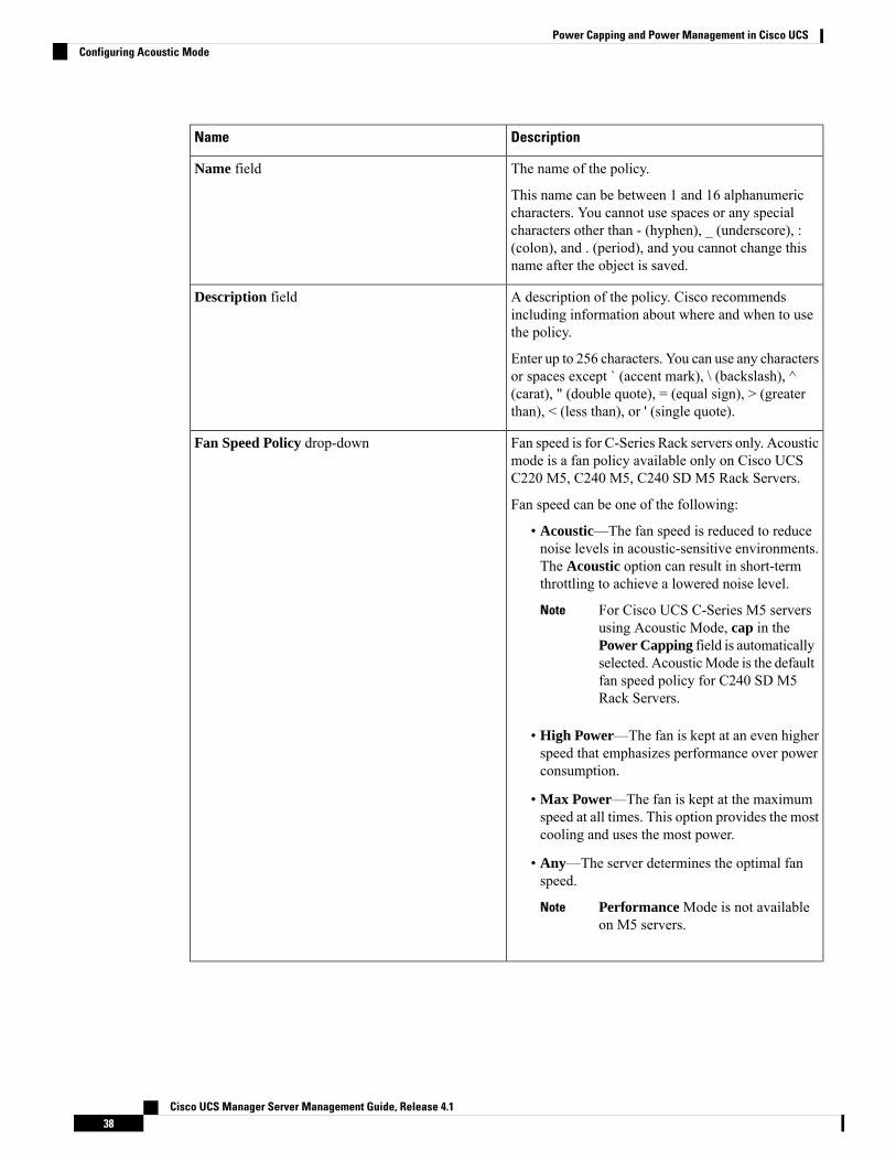
DescriptionName
The name of the policy.
This name can be between 1 and 16 alphanumericcharacters. You cannot use spaces or any specialcharacters other than - (hyphen), _ (underscore), :(colon), and . (period), and you cannot change thisname after the object is saved.
Name field
A description of the policy. Cisco recommendsincluding information about where and when to usethe policy.
Enter up to 256 characters. You can use any charactersor spaces except ` (accent mark), \ (backslash), ^(carat), " (double quote), = (equal sign), > (greaterthan), < (less than), or ' (single quote).
Description field
Fan speed is for C-Series Rack servers only. Acousticmode is a fan policy available only on Cisco UCSC220 M5, C240 M5, C240 SD M5 Rack Servers.
Fan speed can be one of the following:
• Acoustic—The fan speed is reduced to reducenoise levels in acoustic-sensitive environments.The Acoustic option can result in short-termthrottling to achieve a lowered noise level.
For Cisco UCS C-Series M5 serversusing Acoustic Mode, cap in thePower Capping field is automaticallyselected. AcousticMode is the defaultfan speed policy for C240 SD M5Rack Servers.
Note
• High Power—The fan is kept at an even higherspeed that emphasizes performance over powerconsumption.
• Max Power—The fan is kept at the maximumspeed at all times. This option provides the mostcooling and uses the most power.
• Any—The server determines the optimal fanspeed.
Performance Mode is not availableon M5 servers.
Note
Fan Speed Policy drop-down
Cisco UCS Manager Server Management Guide, Release 4.138
Power Capping and Power Management in Cisco UCSConfiguring Acoustic Mode
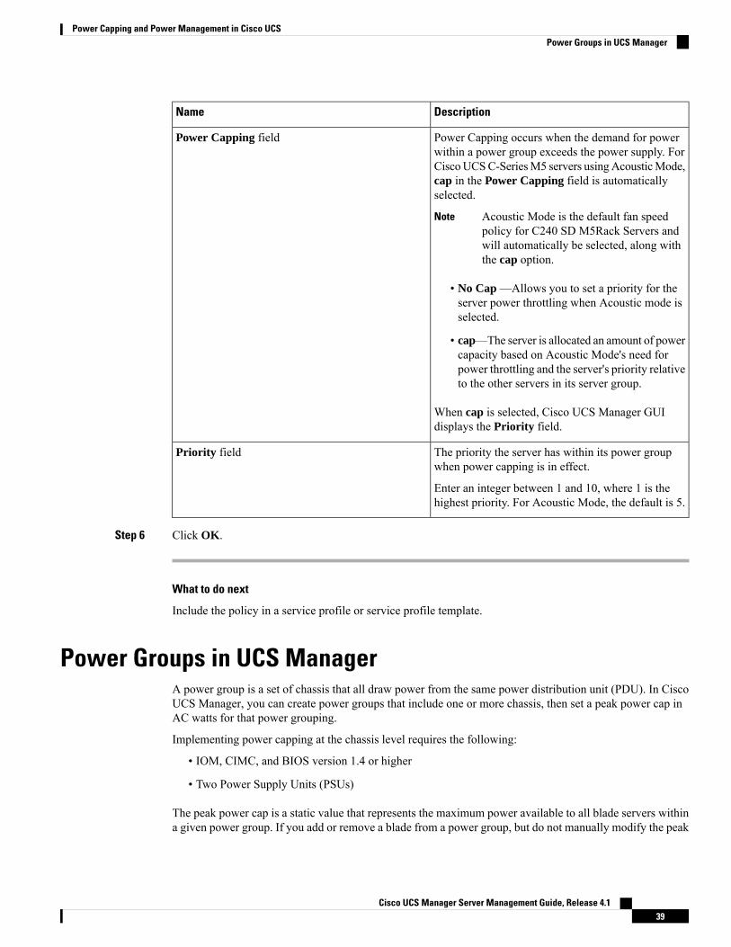
DescriptionName
Power Capping occurs when the demand for powerwithin a power group exceeds the power supply. ForCiscoUCSC-SeriesM5 servers usingAcousticMode,cap in the Power Capping field is automaticallyselected.
Acoustic Mode is the default fan speedpolicy for C240 SD M5Rack Servers andwill automatically be selected, along withthe cap option.
Note
• No Cap —Allows you to set a priority for theserver power throttling when Acoustic mode isselected.
• cap—The server is allocated an amount of powercapacity based on Acoustic Mode's need forpower throttling and the server's priority relativeto the other servers in its server group.
When cap is selected, Cisco UCS Manager GUIdisplays the Priority field.
Power Capping field
The priority the server has within its power groupwhen power capping is in effect.
Enter an integer between 1 and 10, where 1 is thehighest priority. For Acoustic Mode, the default is 5.
Priority field
Step 6 Click OK.
What to do next
Include the policy in a service profile or service profile template.
Power Groups in UCS ManagerA power group is a set of chassis that all draw power from the same power distribution unit (PDU). In CiscoUCS Manager, you can create power groups that include one or more chassis, then set a peak power cap inAC watts for that power grouping.
Implementing power capping at the chassis level requires the following:
• IOM, CIMC, and BIOS version 1.4 or higher
• Two Power Supply Units (PSUs)
The peak power cap is a static value that represents the maximum power available to all blade servers withina given power group. If you add or remove a blade from a power group, but do not manually modify the peak
Cisco UCS Manager Server Management Guide, Release 4.139
Power Capping and Power Management in Cisco UCSPower Groups in UCS Manager
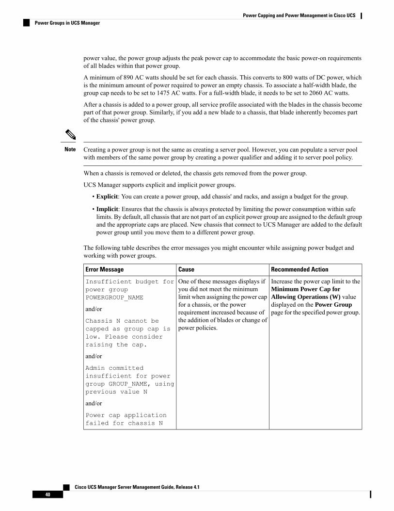
power value, the power group adjusts the peak power cap to accommodate the basic power-on requirementsof all blades within that power group.
A minimum of 890 AC watts should be set for each chassis. This converts to 800 watts of DC power, whichis the minimum amount of power required to power an empty chassis. To associate a half-width blade, thegroup cap needs to be set to 1475 AC watts. For a full-width blade, it needs to be set to 2060 AC watts.
After a chassis is added to a power group, all service profile associated with the blades in the chassis becomepart of that power group. Similarly, if you add a new blade to a chassis, that blade inherently becomes partof the chassis' power group.
Creating a power group is not the same as creating a server pool. However, you can populate a server poolwith members of the same power group by creating a power qualifier and adding it to server pool policy.
Note
When a chassis is removed or deleted, the chassis gets removed from the power group.
UCS Manager supports explicit and implicit power groups.
• Explicit: You can create a power group, add chassis' and racks, and assign a budget for the group.
• Implicit: Ensures that the chassis is always protected by limiting the power consumption within safelimits. By default, all chassis that are not part of an explicit power group are assigned to the default groupand the appropriate caps are placed. New chassis that connect to UCS Manager are added to the defaultpower group until you move them to a different power group.
The following table describes the error messages you might encounter while assigning power budget andworking with power groups.
Recommended ActionCauseError Message
Increase the power cap limit to theMinimum Power Cap forAllowing Operations (W) valuedisplayed on the Power Grouppage for the specified power group.
One of these messages displays ifyou did not meet the minimumlimit when assigning the power capfor a chassis, or the powerrequirement increased because ofthe addition of blades or change ofpower policies.
Insufficient budget forpower groupPOWERGROUP_NAME
and/or
Chassis N cannot becapped as group cap islow. Please considerraising the cap.
and/or
Admin committedinsufficient for powergroup GROUP_NAME, usingprevious value N
and/or
Power cap applicationfailed for chassis N
Cisco UCS Manager Server Management Guide, Release 4.140
Power Capping and Power Management in Cisco UCSPower Groups in UCS Manager

Recommended ActionCauseError Message
Check the PSU input power andredundancy policy to ensure thatenough power is available for thechassis.
If a PSU failed, replace the PSU.
Displays when the power budgetrequirement for the chassis is morethan the PSU power that isavailable.
Chassis N cannot becapped as the availablePSU power is not enoughfor the chassis and theblades. Please correctthe problem by checkinginput power or replacethe PSU
Do not power on un-associatedservers.
Displays when the server isconsuming more power thanallocated and cannot be capped, orthe server is powered on when nopower is allocated.
Power cap applicationfailed for server N
This is an information message.
If a server should not be capped, inthe service profile set the value ofthe power control policy PowerCapping field to no-cap.
Displays when the server is cappedto reduce the power consumptionbelow the allocated power.
P-State lowered asconsumption hit powercap for server
This is an unsupportedconfiguration. All PSUs must beconnected to similar power sources.
This fault is raised when a chassishas a mix of high-line and low-linePSU input sources connected.
Chassis N has a mix ofhigh-line and low-linePSU input power sources.
Creating a Power Group
Before you begin
Make sure that the global power allocation policy is set to Policy Driven Chassis Group Cap on the GlobalPolicies tab.
Procedure
Step 1 In the Navigation pane, click Equipment.Step 2 Click the Equipment node.Step 3 In the Work pane, click the Policies tab.Step 4 Click the Power Groups subtab.Step 5 On the icon bar to the right of the table, click +.
If the + icon is disabled, click an entry in the table to enable it.
Step 6 On the first page of the Create Power Group wizard, complete the following fields:a) Enter a unique name and description for the power group.
Cisco UCS Manager Server Management Guide, Release 4.141
Power Capping and Power Management in Cisco UCSCreating a Power Group
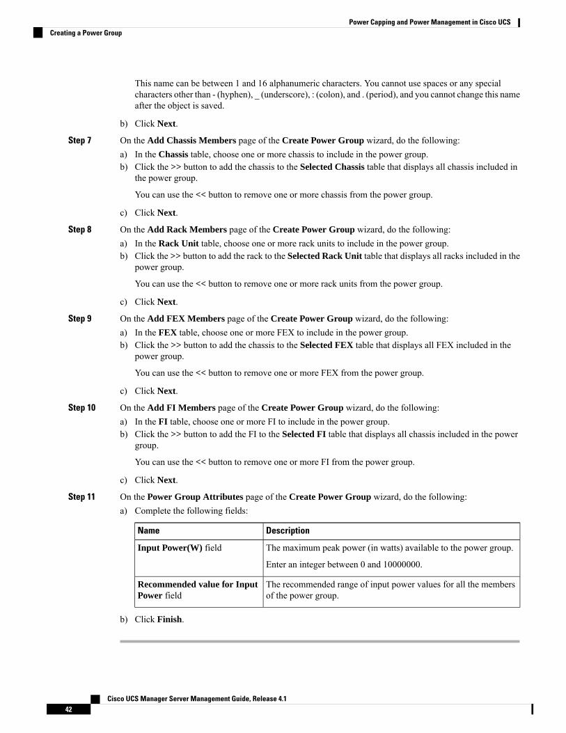
This name can be between 1 and 16 alphanumeric characters. You cannot use spaces or any specialcharacters other than - (hyphen), _ (underscore), : (colon), and . (period), and you cannot change this nameafter the object is saved.
b) Click Next.
Step 7 On the Add Chassis Members page of the Create Power Group wizard, do the following:a) In the Chassis table, choose one or more chassis to include in the power group.b) Click the >> button to add the chassis to the Selected Chassis table that displays all chassis included in
the power group.
You can use the << button to remove one or more chassis from the power group.
c) Click Next.
Step 8 On the Add Rack Members page of the Create Power Group wizard, do the following:a) In the Rack Unit table, choose one or more rack units to include in the power group.b) Click the >> button to add the rack to the Selected Rack Unit table that displays all racks included in the
power group.
You can use the << button to remove one or more rack units from the power group.
c) Click Next.
Step 9 On the Add FEX Members page of the Create Power Group wizard, do the following:a) In the FEX table, choose one or more FEX to include in the power group.b) Click the >> button to add the chassis to the Selected FEX table that displays all FEX included in the
power group.
You can use the << button to remove one or more FEX from the power group.
c) Click Next.
Step 10 On the Add FI Members page of the Create Power Group wizard, do the following:a) In the FI table, choose one or more FI to include in the power group.b) Click the >> button to add the FI to the Selected FI table that displays all chassis included in the power
group.
You can use the << button to remove one or more FI from the power group.
c) Click Next.
Step 11 On the Power Group Attributes page of the Create Power Group wizard, do the following:a) Complete the following fields:
DescriptionName
The maximum peak power (in watts) available to the power group.
Enter an integer between 0 and 10000000.
Input Power(W) field
The recommended range of input power values for all the membersof the power group.
Recommended value for InputPower field
b) Click Finish.
Cisco UCS Manager Server Management Guide, Release 4.142
Power Capping and Power Management in Cisco UCSCreating a Power Group

Adding a Chassis to a Power Group
Procedure
Step 1 In the Navigation pane, click Equipment.Step 2 Click the Equipment node.Step 3 In the Work pane, click the Power Groups tab.Step 4 Right-click the power group to which you want to add a chassis and choose Add Chassis Members.Step 5 In the Add Chassis Members dialog box, do the following:
a) In the Chassis table, choose one or more chassis to include in the power group.b) Click the >> button to add the chassis to the Selected Chassis table that displays all chassis included in
the power group.
You can use the << button to remove one or more chassis from the power group.
c) Click OK.
Removing a Chassis from a Power Group
Procedure
Step 1 In the Navigation pane, click Equipment.Step 2 Click the Equipment node.Step 3 In the Work pane, click the Power Groups tab.Step 4 Expand the power group from which you want to remove a chassis.Step 5 Right-click the chassis that you want to remove from the power group and choose Delete.Step 6 If a confirmation dialog box displays, click Yes.
Deleting a Power Group
Procedure
Step 1 In the Navigation pane, click Equipment.Step 2 Click the Equipment node.Step 3 In the Work pane, click the Power Groups tab.Step 4 Right-click the power group that you want to delete and choose Delete.Step 5 If a confirmation dialog box displays, click Yes.
Cisco UCS Manager Server Management Guide, Release 4.143
Power Capping and Power Management in Cisco UCSAdding a Chassis to a Power Group
Blade Level Power Capping
Manual Blade Level Power CapWhen manual blade-level power cap is configured in the global cap policy, you can set a power cap for eachblade server in a Cisco UCS domain.
The following configuration options are available:
• Watts—You can specify the maximum amount of power that the server can consume at one time. Thismaximum can be any amount between 0 watts and 1300 watts.
B480 M5 systems using 256GB DIMMs must have a manual bladelevel cap at 1300W.
Note
• Unbounded—No power usage limitations are imposed on the server. The server can use as much poweras it requires.
If the server encounters a spike in power usage that meets or exceeds the maximum configured for the server,Cisco UCS Manager does not disconnect or shut down the server. Instead, Cisco UCS Manager reduces thepower that is made available to the server. This reduction can slow down the server, including a reduction inCPU speed.
If you configure the manual blade-level power cap using Equipment > Policies > Global Policies > GlobalPower Allocation Policy, the priority set in the Power Control Policy is no longer relevant.
Note
Setting the Blade-Level Power Cap for a ServerBefore you begin
Make sure the global power allocation policy is set to Manual Blade Level Cap on the Global Policies tab.
Procedure
Step 1 In the Navigation pane, click Equipment.Step 2 Expand Equipment > Chassis > Chassis Number > Servers.Step 3 Choose the server for which you want to set the power budget.Step 4 In the Work pane, click the General tab.Step 5 In the Power Budget area, do the following:
a) Click the Expand icon to the right of the heading to display the fields.
Cisco UCS Manager Server Management Guide, Release 4.144
Power Capping and Power Management in Cisco UCSBlade Level Power Capping
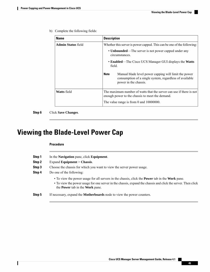
b) Complete the following fields:
DescriptionName
Whether this server is power capped. This can be one of the following:
• Unbounded—The server is not power capped under anycircumstances.
• Enabled—The Cisco UCS Manager GUI displays the Wattsfield.
Manual blade level power capping will limit the powerconsumption of a single system, regardless of availablepower in the chassis.
Note
Admin Status field
The maximum number of watts that the server can use if there is notenough power to the chassis to meet the demand.
The value range is from 0 and 10000000.
Watts field
Step 6 Click Save Changes.
Viewing the Blade-Level Power CapProcedure
Step 1 In the Navigation pane, click Equipment.Step 2 Expand Equipment > Chassis.Step 3 Choose the chassis for which you want to view the server power usage.Step 4 Do one of the following:
• To view the power usage for all servers in the chassis, click the Power tab in the Work pane.• To view the power usage for one server in the chassis, expand the chassis and click the server. Then clickthe Power tab in the Work pane.
Step 5 If necessary, expand the Motherboards node to view the power counters.
Cisco UCS Manager Server Management Guide, Release 4.145
Power Capping and Power Management in Cisco UCSViewing the Blade-Level Power Cap

Global Power Profiling Policy Configuration
Global Power Profiling PolicyThe Global Power Profiling Policy specifies how power allocation is applied to all of the servers in a chassis.The policy applies when you set the Global Power Allocation Policy to Policy Driven Chassis Group Cap.You can set the Global Power Profiling Policy to one of the following:
• Disabled—The minimum and maximum power cap values of the blades are calculated based on thestatic power consumption values of each of the components.
• Enabled—The minimum and maximum power cap values of the blades are measured as part of theserver discovery. These values are similar to the actual power consumption of the blades.
After enabling the Global Power Profiling Policy, you must re-acknowledge the blades to obtain the minimumand maximum power cap.
Note
Configuring the Global Power Profile PolicyProcedure
Step 1 In the Navigation pane, click Equipment.Step 2 Click the Equipment node.Step 3 In the Work pane, click the Policies tab.Step 4 Click the Global Policies subtab.Step 5 In the Global Power Profiling Policy area, check the Profile Power checkbox to enable the Global Power
Profiling Policy.Step 6 Click Save Changes.
Global Power Allocation Policy Configuration
Global Power Allocation PolicyThe Global Power Allocation Policy allows you to specify the Policy Driven Chassis Group Power Cap orManual Blade-level Power Cap power allocation method applied to servers in a chassis.
Cisco recommends using the default Policy Driven Chassis Group Power Cap power allocation method.
Cisco UCS Manager Server Management Guide, Release 4.146
Power Capping and Power Management in Cisco UCSGlobal Power Profiling Policy Configuration

Any change to theManual Blade level Power Cap configuration results in the loss of any groups or configurationoptions set for the Policy Driven Chassis Group Power Cap.
Important
Configuring the Global Power Allocation PolicyProcedure
Step 1 In the Navigation pane, click Equipment.Step 2 Click the Equipment node.Step 3 In the Work pane, click the Policies tab.Step 4 Click the Global Policies subtab.Step 5 In theGlobal Power Allocation Policy area, click one of the following radio buttons in theAllocation Method
field to determine the power cap management mode used in the Cisco UCS domain:
• Manual Blade Level Cap—Power allocation is configured on each individual blade server in all chassis.If you select this option, you cannot create power groups.
• Policy Driven Chassis Group Cap—Power allocation is configured at the chassis level through powercontrol policies included in the associated service profiles. If you select this option, you can also createpower groups that contain one or more chassis in the Cisco UCS domain.
By default, power allocation is done for each chassis through a power control policy.
Step 6 Click Save Changes.
Power Management During Power-on OperationsBoot Staggering during Power on
Cisco UCS Manager attempts to boot as many blades as possible based on the amount of available power. Ifthe power required to boot a blade is not available, Cisco UCS Manager staggers the boot in the Finite StateMachine (FSM) CheckPowerAvailability stage, and raises the following fault on the blade: Insufficient poweravailable to power-on server x/y.
When the required power becomes available, the FSM proceeds with blade power on. After a blade powersoff, the allocated power budget is reclaimed.
When the power budget that was allocated to the blade is reclaimed, the allocated power displays as 0 Watts.Note
Limitation
Cisco UCS Manager Server Management Guide, Release 4.147
Power Capping and Power Management in Cisco UCSConfiguring the Global Power Allocation Policy
If you power on a blade outside of the Cisco UCS Manager and if there is not enough power available forallocation, the following fault is raised:
Power cap application failed for server x/y
Power Allocation during Service Profile Association
The power allocated to a blade during service profile association depends on the Power Control Policy used,and the power that is available from the power group. After the power is allocated to a server during a successfulservice profile association, the blade is guaranteed the minimum power cap. If the Power Control Policypriority is set to no-cap, a blade is allocated a potential maximum power cap, which might exceed the measuredmaximum power cap that displays.
If the priority of an associated blade is changed to no-cap, and is not able to allocate the maximum power cap,you might see one of the following faults:
• PSU-insufficient—There is not enough available power for the PSU.
• Group-cap-insufficient—The group cap value is not sufficient for the blade.
Note
Power Sync Policy Configuration
Power Sync PolicyCisco UCS Manager includes a global (default) power sync policy to address power synchronization issuesbetween the associated service profiles and the servers. You can use the power sync policy to synchronizethe power state when the power state of the service profile differs from the actual power state of the server.The policy allows you to control when to synchronize the power state on the associated service profiles forthe servers. The power sync policy does not affect other power-related policies.
The power synchronization policy applies to all the service profiles by default. You cannot delete the defaultpower sync policy, but you can edit the default policy. You can create your own power sync policies andapply them to the service profiles. You can also create a power sync policy that is specific to a service profileand it always takes precedence over the default policy.
Cisco UCS Manager creates a fault on the associated service profile when the power sync policy referencedin the service profile does not exist. Cisco UCS Manager automatically clears the fault once you create apower sync policy for the specified service profile or change the reference to an existing policy in the serviceprofile.
Power Synchronization BehaviorCisco UCS Manager synchronizes the power state only when the actual power state of the server is OFF. Thecurrent power synchronization behavior is based on the actual power state and the preferred power state aftershallow association occurs.
For example, the following events trigger shallow association:
Cisco UCS Manager Server Management Guide, Release 4.148
Power Capping and Power Management in Cisco UCSPower Sync Policy Configuration
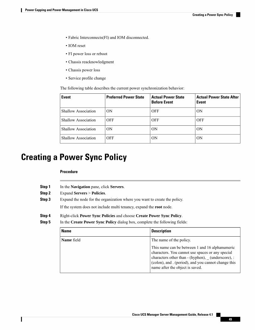
• Fabric Interconnects(FI) and IOM disconnected.
• IOM reset
• FI power loss or reboot
• Chassis reacknowledgment
• Chassis power loss
• Service profile change
The following table describes the current power synchronization behavior:
Actual Power State AfterEvent
Actual Power StateBefore Event
Preferred Power StateEvent
ONOFFONShallow Association
OFFOFFOFFShallow Association
ONONONShallow Association
ONONOFFShallow Association
Creating a Power Sync PolicyProcedure
Step 1 In the Navigation pane, click Servers.Step 2 Expand Servers > Policies.Step 3 Expand the node for the organization where you want to create the policy.
If the system does not include multi tenancy, expand the root node.
Step 4 Right-click Power Sync Policies and choose Create Power Sync Policy.Step 5 In the Create Power Sync Policy dialog box, complete the following fields:
DescriptionName
The name of the policy.
This name can be between 1 and 16 alphanumericcharacters. You cannot use spaces or any specialcharacters other than - (hyphen), _ (underscore), :(colon), and . (period), and you cannot change thisname after the object is saved.
Name field
Cisco UCS Manager Server Management Guide, Release 4.149
Power Capping and Power Management in Cisco UCSCreating a Power Sync Policy

DescriptionName
A description of the policy. Cisco recommendsincluding information about where and when to usethe policy.
Enter up to 256 characters. You can use any charactersor spaces except ` (accent mark), \ (backslash), ^(carat), " (double quote), = (equal sign), > (greaterthan), < (less than), or ' (single quote).
Description field
The options that allow you to synchronize the desiredpower state of the associated service profile to thephysical server. This can be one of the following:
• Default Sync—After the initial serverassociation, any configuration change ormanagement connectivity changes that youperform trigger a server reassociation. Thisoption synchronizes the desired power state tothe physical server if the physical server powerstate is off and the desired power state is on. Thisis the default behavior.
• Always Sync—When the initial serverassociation or the server reassociation occurs,this option synchronizes the desired power stateto the physical power state, even if the physicalserver power state is on and desired power stateis off.
• Initial Only Sync—This option onlysynchronizes the power to a server when aservice profile is associated to the server for thefirst time, or when the server is re-commissioned.When you set this option, resetting the powerstate from the physical server side does not affectthe desired power state on the service profile.
Sync-Option field
Step 6 Click OK.
What to do next
Include the policy in a service profile or service profile template.
Cisco UCS Manager Server Management Guide, Release 4.150
Power Capping and Power Management in Cisco UCSCreating a Power Sync Policy
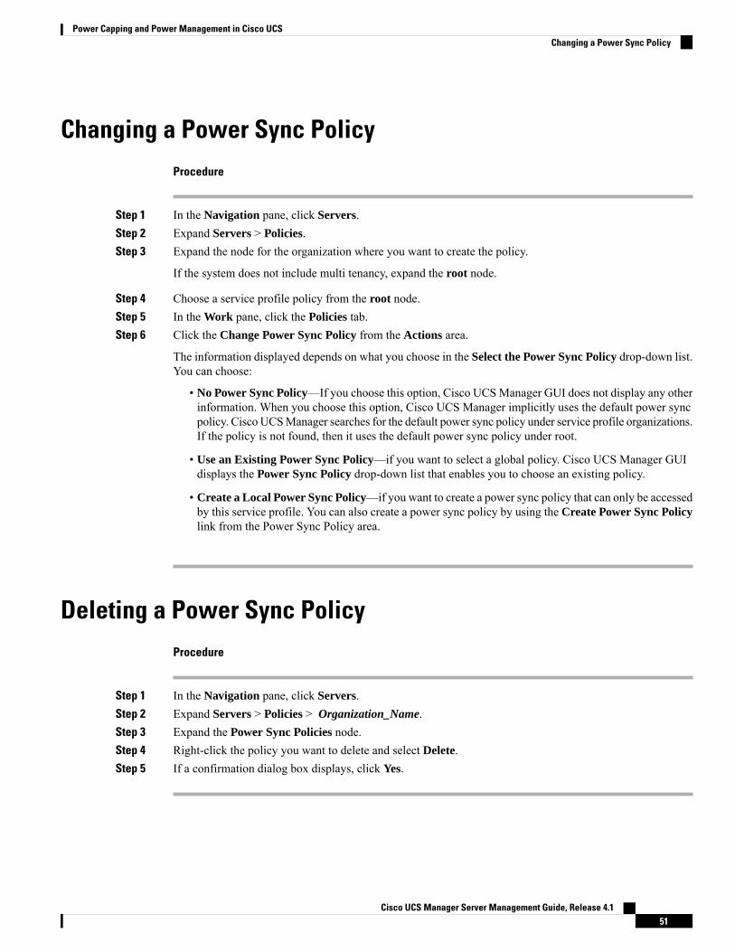
Changing a Power Sync PolicyProcedure
Step 1 In the Navigation pane, click Servers.Step 2 Expand Servers > Policies.Step 3 Expand the node for the organization where you want to create the policy.
If the system does not include multi tenancy, expand the root node.
Step 4 Choose a service profile policy from the root node.Step 5 In the Work pane, click the Policies tab.Step 6 Click the Change Power Sync Policy from the Actions area.
The information displayed depends on what you choose in the Select the Power Sync Policy drop-down list.You can choose:
• No Power Sync Policy—If you choose this option, Cisco UCSManager GUI does not display any otherinformation. When you choose this option, Cisco UCS Manager implicitly uses the default power syncpolicy. Cisco UCSManager searches for the default power sync policy under service profile organizations.If the policy is not found, then it uses the default power sync policy under root.
• Use an Existing Power Sync Policy—if you want to select a global policy. Cisco UCS Manager GUIdisplays the Power Sync Policy drop-down list that enables you to choose an existing policy.
• Create a Local Power Sync Policy—if you want to create a power sync policy that can only be accessedby this service profile. You can also create a power sync policy by using the Create Power Sync Policylink from the Power Sync Policy area.
Deleting a Power Sync PolicyProcedure
Step 1 In the Navigation pane, click Servers.Step 2 Expand Servers > Policies > Organization_Name.Step 3 Expand the Power Sync Policies node.Step 4 Right-click the policy you want to delete and select Delete.Step 5 If a confirmation dialog box displays, click Yes.
Cisco UCS Manager Server Management Guide, Release 4.151
Power Capping and Power Management in Cisco UCSChanging a Power Sync Policy
Rack Server Power ManagementPower capping is supported for following rack servers:
• Cisco UCS C220 M4 Server
• Cisco UCS C240 M4 Server
• Cisco UCS C220 M5 Server
• Cisco UCS C240 M5 Server
• Cisco UCS C240 SD M5 Server
• Cisco UCS C480 M5 Server
• Cisco UCS C480 M5 ML Server
Power capping is not supported for Cisco UCS C125 M5 Servers.
UCS Mini Power ManagementYou can manage power of the blade servers in the Cisco UCS 6324 Fabric Interconnect (FI), which is usedfor remote offices and branch sites, and for limited server deployments. UCS Manager supports Dual LinePower Supply Unit and 110V when used with the Cisco UCS 6324 Fabric Interconnect. You can manage howyou want to allocate power when using 110V power supplies, because they might not provide enough powerfor a fully loaded chassis. Dual power supplies is standard for both AC and DC-48V on the Cisco UCS Mini6324.
Cisco UCS Manager Server Management Guide, Release 4.152
Power Capping and Power Management in Cisco UCSRack Server Power Management
C H A P T E R 6Blade Server Hardware Management
• Blade Server Management, on page 53• Booting a Blade Server, on page 55• Booting a Rack-Mount Server from the Service Profile , on page 56• Determining the Boot Order of a Blade Server, on page 56• Shutting Down a Blade Server, on page 57• Shutting Down a Server from the Service Profile , on page 57• Resetting a Blade Server, on page 58• Resetting a Blade Server to Factory Default Settings, on page 58• Reacknowledging a Blade Server, on page 59• Removing a Server from a Chassis, on page 60• Deleting the Inband Configuration from a Blade Server, on page 60• Decommissioning a Blade Server, on page 61• Removing a Non-Existent Blade Server Entry, on page 61• Recommissioning a Blade Server, on page 62• Reacknowledging a Server Slot in a Chassis, on page 62• Removing a Non-Existent Blade Server from the Configuration Database, on page 63• Turning the Locator LED for a Blade Server On and Off, on page 63• Turning the Local Disk Locator LED on a Blade Server On and Off, on page 64• Resetting the CMOS for a Blade Server, on page 64• Resetting the CIMC for a Blade Server, on page 65• Clearing TPM for a Blade Server, on page 65• Viewing the POST Results for a Blade Server, on page 66• Issuing an NMI from a Blade Server, on page 66• Viewing Health Events for a Blade Server, on page 67• Health LED Alarms, on page 68• Smart SSD, on page 69
Blade Server ManagementYou can manage and monitor all blade servers in a Cisco UCS domain through Cisco UCS Manager. Youcan perform some blade server management tasks, such as changes to the power state, from the server andservice profile.
The remaining management tasks can only be performed on the server.
Cisco UCS Manager Server Management Guide, Release 4.153
The power supply units go into power save mode when a chassis has two blades or less. When a third bladeis added to the chassis and is fully discovered, the power supply units return to regular mode.
If a blade server slot in a chassis is empty, Cisco UCS Manager provides information, errors, and faults forthat slot. You can also re-acknowledge the slot to resolve server mismatch errors and to have Cisco UCSManager rediscover the blade server in the slot.
Guidelines for Removing and Decommissioning Blade ServersConsider the following guidelines when deciding whether to remove or decommission a blade server usingCisco UCS Manager:
Decommissioning a Blade Server
If you want to temporarily decommission a physically present and connected blade server, you can temporarilyremove it from the configuration. A portion of the server's information is retained by Cisco UCS Managerfor future use, in case the blade server is recommissioned.
Removing a Blade Server
Removing is performed when you physically remove a blade server from the Cisco UCS Manager bydisconnecting it from the chassis. You cannot remove a blade server fromCisco UCSManager if it is physicallypresent and connected to a chassis. After the physical removal of the blade server is completed, the configurationfor that blade server can be removed in Cisco UCS Manager.
During removal, active links to the blade server are disabled, all entries from databases are removed, and theserver is automatically removed from any server pools that it was assigned to during discovery.
Only servers added to a server pool automatically during discovery are removed automatically. Servers thatwere manually added to a server pool must be removed manually.
Note
To add a removed blade server back to the configuration, it must be reconnected, then rediscovered. When aserver is reintroduced to Cisco UCSManager, it is treated as a new server and is subject to the deep discoveryprocess. For this reason, it is possible for Cisco UCS Manager to assign the server a new ID that might bedifferent from the ID that it held before.
Recommendations for Avoiding Unexpected Server Power ChangesIf a server is not associated with a service profile, you can use any available means to change the server powerstate, including the physical Power or Reset buttons on the server.
If a server is associated with, or assigned to, a service profile, you should only use the following methods tochange the server power state:
• In Cisco UCS Manager GUI, go to the General tab for the server or the service profile associated withthe server and select Boot Server or Shutdown Server from the Actions area.
• In Cisco UCS Manager CLI, scope to the server or the service profile associated with the server and usethe power up or power down commands.
Cisco UCS Manager Server Management Guide, Release 4.154
Blade Server Hardware ManagementGuidelines for Removing and Decommissioning Blade Servers
Do not use any of the following options on an associated server that is currently powered off:
• Reset in the GUI
• cycle cycle-immediate or reset hard-reset-immediate in the CLI
• The physical Power or Reset buttons on the server
Important
If you reset, cycle, or use the physical power buttons on a server that is currently powered off, the server'sactual power state might become out of sync with the desired power state setting in the service profile. If thecommunication between the server and Cisco UCSManager is disrupted or if the service profile configurationchanges, Cisco UCS Manager might apply the desired power state from the service profile to the server,causing an unexpected power change.
Power synchronization issues can lead to an unexpected server restart, as shown below:
Server Power State AfterCommunication Is Disrupted
Current Server Power StateDesired Power State in ServiceProfile
Powered OnPowered OffUp
Powered On
Running servers are notshut down regardless ofthe desired power statein the service profile.
Note
Powered OnDown
Booting a Blade ServerIf the Boot Server link is dimmed in the Actions area, you must shut down the server first.
Procedure
Step 1 In the Navigation pane, click Equipment.Step 2 Expand Equipment > Chassis > Chassis Number > Servers.Step 3 Choose the server that you want to boot.Step 4 In the Work pane, click the General tab.Step 5 In the Actions area, click Boot Server.Step 6 If a confirmation dialog box displays, click Yes.
After the server boots, the Overall Status field on the General tab displays an OK status.
Cisco UCS Manager Server Management Guide, Release 4.155
Blade Server Hardware ManagementBooting a Blade Server
Booting a Rack-Mount Server from the Service ProfileProcedure
Step 1 In the Navigation pane, click Servers.Step 2 Expand Servers > Service Profiles.Step 3 Expand the node for the organization where you want to create the service profile.
If the system does not include multi tenancy, expand the root node.
Step 4 Choose the service profile that requires the associated server to boot.Step 5 In the Work pane, click the General tab.Step 6 In the Actions area, click Boot Server.Step 7 If a confirmation dialog box displays, click Yes.Step 8 Click OK in the Boot Server dialog box.
After the server boots, the Overall Status field on the General tab displays an ok status or an up status.
Determining the Boot Order of a Blade Server
You can also view the boot order tabs from the General tab of the service profile associated with a server.Tip
Procedure
Step 1 In the Navigation pane, click Equipment.Step 2 Expand Equipment > Chassis > Chassis Number > Servers.Step 3 Click the server for which you want to determine the boot order.Step 4 In the Work pane, click the General tab.Step 5 If the Boot Order Details area is not expanded, click the Expand icon to the right of the heading.Step 6 To view the boot order assigned to the server, click the Configured Boot Order tab.Step 7 To view what will boot from the various devices in the physical server configuration, click the Actual Boot
Order tab.
The Actual Boot Order tab always shows "Internal EFI Shell" at the bottom of the boot order list.Note
Cisco UCS Manager Server Management Guide, Release 4.156
Blade Server Hardware ManagementBooting a Rack-Mount Server from the Service Profile
Shutting Down a Blade ServerWhen you use this procedure to shut down a server with an installed operating system, Cisco UCS Managertriggers the OS into a graceful shutdown sequence.
If the Shutdown Server link is dimmed in the Actions area, the server is not running.
When a blade server that is associated with a service profile is shut down, the VIF down alerts F0283 andF0479 are automatically suppressed.
Note
Procedure
Step 1 In the Navigation pane, click Equipment.Step 2 Expand Equipment > Chassis > Chassis Number > Servers.Step 3 Choose the server that you want to shut down.Step 4 In the Work pane, click the General tab.Step 5 In the Actions area, click Shutdown Server.Step 6 If a confirmation dialog box displays, click Yes.
After the server has been successfully shut down, the Overall Status field on the General tab displays apower-off status.
Shutting Down a Server from the Service ProfileWhen you use this procedure to shut down a server with an installed operating system, Cisco UCS Managertriggers the OS into a graceful shutdown sequence.
If the Shutdown Server link is dimmed in the Actions area, the server is not running.
Procedure
Step 1 In the Navigation pane, click Servers.Step 2 Expand Servers > Service Profiles.Step 3 Expand the node for the organization where you want to create the service profile.
If the system does not include multi tenancy, expand the root node.
Step 4 Choose the service profile that requires the associated server to shut down.Step 5 In the Work pane, click the General tab.Step 6 In the Actions area, click Shutdown Server.
Cisco UCS Manager Server Management Guide, Release 4.157
Blade Server Hardware ManagementShutting Down a Blade Server
Step 7 If a confirmation dialog box displays, click Yes.
After the server successfully shuts down, the Overall Status field on the General tab displays a down statusor a power-off status.
Resetting a Blade ServerWhen you reset a server, Cisco UCS Manager sends a pulse on the reset line. You can choose to gracefullyshut down the operating system. If the operating system does not support a graceful shutdown, the server ispower cycled. The option to have Cisco UCS Manager complete all management operations before it resetsthe server does not guarantee the completion of these operations before the server is reset.
If you are trying to boot a server from a power-down state, you should not use Reset.
If you continue the power-up with this process, the desired power state of the servers become out of sync withthe actual power state and the servers might unexpectedly shut down at a later time. To safely reboot theselected servers from a power-down state, click Cancel, then select the Boot Server action.
Note
Procedure
Step 1 In the Navigation pane, click Equipment.Step 2 Expand Equipment > Chassis > Chassis Number > Servers.Step 3 Choose the server that you want to reset.Step 4 In the Work pane, click the General tab.Step 5 In the Actions area, click Reset.Step 6 In the Reset Server dialog box, do the following:
a) Click the Power Cycle option.b) (Optional) Check the check box if you want Cisco UCSManager to complete all management operations
that are pending on this server.c) Click OK.
The reset may take several minutes to complete. After the server has been reset, the Overall Status field onthe General tab displays an ok status.
Resetting a Blade Server to Factory Default SettingsYou can now reset a blade server to its factory settings. By default, the factory reset operation does not affectstorage drives and flexflash drives. This is to prevent any loss of data. However, you can choose to reset thesedevices to a known state as well.
Cisco UCS Manager Server Management Guide, Release 4.158
Blade Server Hardware ManagementResetting a Blade Server
Resetting storage devices will result in loss of data.Important
Perform the following procedure to reset the server to factory default settings.
Procedure
Step 1 In the Navigation pane, click Equipment.Step 2 Expand Equipment > Chassis > Chassis Number > Servers.Step 3 Choose the server that you want to reset to its factory default settings.Step 4 In the Work pane, click the General tab.Step 5 In the Actions area, click Server Maintenance.Step 6 In the Maintenance dialog box, do the following:
a) Click Reset to Factory Default.b) Click OK.
Step 7 From the Maintenance Server dialog box that appears, select the appropriate options:
• To delete all storage, check the Scrub Storage checkbox.
• To place all disks into their initial state after deleting all storage, check the Create Initial Volumescheckbox.
You can check this checkbox only if you check the Scrub Storage checkbox. For servers that supportJBOD, the disks will be placed in a JBOD state. For servers that do not support JBOD, each disk will beinitialized with a single R0 volume that occupies all the space in the disk.
Do not check the Create Initial Volumes box if you want to use storage profiles. Creatinginitial volumes when you are using storage profiles may result in configuration errors.
Important
• To delete all flexflash storage, check the Scrub FlexFlash checkbox.
Cisco UCS Manager resets the server to its factory default settings.
Reacknowledging a Blade ServerPerform the following procedure to rediscover the server and all endpoints in the server. For example, youcan use this procedure if a server is stuck in an unexpected state, such as the discovery state.
Procedure
Step 1 In the Navigation pane, click Equipment.Step 2 Expand Equipment > Chassis > Chassis Number > Servers.Step 3 Choose the server that you want to acknowledge.
Cisco UCS Manager Server Management Guide, Release 4.159
Blade Server Hardware ManagementReacknowledging a Blade Server
Step 4 In the Work pane, click the General tab.Step 5 In the Actions area, click Server Maintenance.Step 6 In the Maintenance dialog box, click Re-acknowledge, then click OK.
Cisco UCSManager disconnects the server and then builds the connections between the server and the fabricinterconnect or fabric interconnects in the system. The acknowledgment may take several minutes to complete.After the server has been acknowledged, the Overall Status field on the General tab displays an OK status.
Removing a Server from a ChassisProcedure
Step 1 In the Navigation pane, click Equipment.Step 2 Expand Equipment > Chassis > Chassis Number > Servers.Step 3 Choose the server that you want to remove from the chassis.Step 4 In the Work pane, click the General tab.Step 5 In the Actions area, click Server Maintenance.Step 6 In the Maintenance dialog box, click Decommission, then click OK.
The server is removed from the Cisco UCS configuration.
Step 7 Go to the physical location of the chassis and remove the server hardware from the slot.
For instructions on how to remove the server hardware, see the Cisco UCS Hardware Installation Guide foryour chassis.
What to do next
If you physically re-install the blade server, you must re-acknowledge the slot for the Cisco UCS Manager torediscover the server.
For more information, see Reacknowledging a Server Slot in a Chassis, on page 62.
Deleting the Inband Configuration from a Blade ServerThis procedure removes the inband management IP address configuration from a blade server. If this actionis greyed out, no inband configuration was completed.
Procedure
Step 1 In the Navigation pane, click Equipment.Step 2 Expand Equipment > Chassis > Chassis Number > Servers > Server Name.
Cisco UCS Manager Server Management Guide, Release 4.160
Blade Server Hardware ManagementRemoving a Server from a Chassis

Step 3 In the Work area, click the Inventory tab.Step 4 Click the CIMC subtab.Step 5 In the Actions area, click Delete Inband Configuration.Step 6 Click Yes in the Delete confirmation dialog box.
The inband configuration for the server is deleted.
If an inband service profile is configured in Cisco UCS Manager with a default VLAN and poolname, the server CIMC will automatically get an inband configuration from the inband profileapproximate one minute after deleting the inband configuration here.
Note
Decommissioning a Blade ServerProcedure
Step 1 In the Navigation pane, click Equipment.Step 2 Expand Equipment > Chassis > Chassis Number > Servers.Step 3 Choose the server that you want to decommission.Step 4 In the Work pane, click the General tab.Step 5 In the Actions area, click Server Maintenance.Step 6 In the Maintenance dialog box, do the following:
a) Click Decommission.b) Click OK.
The server is removed from the Cisco UCS configuration.
What to do next
If you physically re-install the blade server, you must re-acknowledge the slot for the Cisco UCS Manager torediscover the server.
For more information, see Reacknowledging a Server Slot in a Chassis, on page 62.
Removing a Non-Existent Blade Server EntryPerform the following procedure after decommissioning the server and physically removing the server hardware.This procedure removes the non-existing stale entry of a blade server from the Decommissioned tab.
Procedure
Step 1 In the Navigation pane, click Equipment.
Cisco UCS Manager Server Management Guide, Release 4.161
Blade Server Hardware ManagementDecommissioning a Blade Server
Step 2 In the Work pane, click the Decommissioned tab.Step 3 On the row for each blade server that you want to remove from the list, check the check box in the
Recommission column, then click Save Changes.Step 4 If a confirmation dialog box displays, click Yes.
Recommissioning a Blade ServerProcedure
Step 1 In the Navigation pane, click Equipment.Step 2 Expand Equipment node.Step 3 Click the Chassis node.Step 4 In the Work pane, click the Decommissioned tab.Step 5 On the row for each blade server that you want to recommission, check the check box in the Recommission
column, then click Save Changes.Step 6 If a confirmation dialog box displays, click Yes.Step 7 (Optional) Monitor the progress of the server recommission and discovery on the FSM tab for the server.
Reacknowledging a Server Slot in a ChassisPerform the following procedure if you decommissioned a blade server without removing the physical hardwarefrom the chassis, and you want Cisco UCS Manager to rediscover and recommission the server.
Procedure
Step 1 In the Navigation pane, click Equipment.Step 2 Expand Equipment > Chassis > Chassis Number > Servers.Step 3 Choose the server whose slot you want to reacknowledge.Step 4 If Cisco UCS Manager displays a Resolve Slot Issue dialog box, do one of the following:
DescriptionOption
Click this link and then click Yes in the confirmation dialog box. Cisco UCSManager reacknowledges the slot and discovers the server in the slot.
The here link in theSituation area
Click this button if you want to proceed to the General tab. You can use theReacknowledge Slot link in the Actions area to have Cisco UCS Managerreacknowledge the slot and discover the server in the slot.
OK
Cisco UCS Manager Server Management Guide, Release 4.162
Blade Server Hardware ManagementRecommissioning a Blade Server
Removing a Non-Existent Blade Server from the ConfigurationDatabase
Perform the following procedure if you physically removed the server hardware without first decommissioningthe server. You cannot perform this procedure if the server is physically present.
If you want to physically remove a server, see Removing a Server from a Chassis, on page 60.
Procedure
Step 1 In the Navigation pane, click Equipment.Step 2 Expand Equipment > Chassis > Chassis Number > Servers.Step 3 Choose the server that you want to remove from the configuration database.Step 4 In the Work pane, click the General tab.Step 5 In the Actions area, click Server Maintenance.Step 6 In the Maintenance dialog box, click Remove, then click OK.
Cisco UCSManager removes all data about the server from its configuration database. The server slot is nowavailable for you to insert new server hardware.
Turning the Locator LED for a Blade Server On and OffProcedure
Step 1 In the Navigation pane, click Equipment.Step 2 Expand Equipment > Chassis > Chassis Number > Servers.Step 3 Choose the server for which you want to turn the locator LED on or off.Step 4 In the Work pane, click the General tab.Step 5 In the Actions area, click one of the following:
• Turn on Locator LED—Turns on the LED for the selected server.• Turn off Locator LED—Turns off the LED for the selected server.• Turn on Master Locator LED—For the Cisco UCS B460 M4 blade server, turns on the LED for themaster node.
• Turn off Master Locator LED—For the Cisco UCS B460 M4 blade server, turns off the LED for themaster node.
• Turn on Slave Locator LED—For the Cisco UCS B460 M4 blade server, turns on the LED for theslave node.
Cisco UCS Manager Server Management Guide, Release 4.163
Blade Server Hardware ManagementRemoving a Non-Existent Blade Server from the Configuration Database
• Turn off Locator LED—For the Cisco UCS B460 M4 blade server, turns off the LED for the slavenode.
Turning the Local Disk Locator LED on a Blade Server On andOff
Before you begin
• Ensure the server, on which the disk is located, is powered on. If the server is off, you are unable to turnon or off the local disk locator LED.
Procedure
Step 1 In the Navigation pane, click Equipment.Step 2 Expand Equipment > Chassis > Chassis Number > Servers.Step 3 Choose the server for which you want to turn the local disk locator LED on or off.Step 4 In the Work pane, click the Inventory > Storage > Disks tabs.
The Storage Controller inventory appears.
Step 5 Click a disk.The disk details appear.
Step 6 In the Details area, click Toggle Locator LED.If the Locator LED state is On, it will turn Off. If the Locator LED state is Off, it will turn On.
Step 7 Click Save Changes.
Resetting the CMOS for a Blade ServerSometimes, troubleshooting a server might require you to reset the CMOS. Resetting the CMOS is not partof the normal maintenance of a server.
Procedure
Step 1 In the Navigation pane, click Equipment.Step 2 Expand Equipment > Chassis > Chassis Number > Servers.Step 3 Choose the server for which you want to reset the CMOS.Step 4 In the Work pane, click the General tab.Step 5 In the Actions area, click Recover Server.
Cisco UCS Manager Server Management Guide, Release 4.164
Blade Server Hardware ManagementTurning the Local Disk Locator LED on a Blade Server On and Off
Step 6 In the Recover Server dialog box, click Reset CMOS, then click OK.
Resetting the CIMC for a Blade ServerSometimes, with the firmware, troubleshooting a server might require you to reset the CIMC. Resetting theCIMC is not part of the normal maintenance of a server. After you reset the CIMC, the CIMC reboots themanagement controller of the blade server.
If the CIMC is reset, the power monitoring functions of Cisco UCS become briefly unavailable until the CIMCreboots. Typically, the reset only takes 20 seconds; however, it is possible that the peak power cap can exceedduring that time. To avoid exceeding the configured power cap in a low power-capped environment, considerstaggering the rebooting or activation of CIMCs.
Procedure
Step 1 In the Navigation pane, click Equipment.Step 2 Expand Equipment > Chassis > Chassis Number > Servers.Step 3 Choose the server for which you want to reset the CIMC.Step 4 In the Work pane, click the General tab.Step 5 In the Actions area, click Recover Server.Step 6 In the Recover Server dialog box, click Reset CIMC (Server Controller), then click OK.
Clearing TPM for a Blade ServerYou can clear TPM only on Cisco UCS M4 and higher blade and rack-mount servers that include support forTPM.
Clearing TPM is a potentially hazardous operation. The OS may stop booting. You may also see loss of data.Caution
Before you begin
TPM must be enabled.
Procedure
Step 1 In the Navigation pane, click Equipment.Step 2 Expand Equipment > Chassis > Chassis Number > Servers.Step 3 Choose the server for which you want to clear TPM.Step 4 In the Work pane, click the General tab.
Cisco UCS Manager Server Management Guide, Release 4.165
Blade Server Hardware ManagementResetting the CIMC for a Blade Server

Step 5 In the Actions area, click Recover Server.Step 6 In the Recover Server dialog box, click Clear TPM, then click OK.
Viewing the POST Results for a Blade ServerYou can view any errors collected during the Power On Self-Test process for a server and its adapters.
Procedure
Step 1 In the Navigation pane, click Equipment.Step 2 Expand Equipment > Chassis > Chassis Number > Servers.Step 3 Choose the server for which you want to view the POST results.Step 4 In the Work pane, click the General tab.Step 5 In the Actions area, click View POST Results.
The POST Results dialog box lists the POST results for the server and its adapters.
Step 6 (Optional) Click the link in the Affected Object column to view the properties of that adapter.Step 7 Click OK to close the POST Results dialog box.
Issuing an NMI from a Blade ServerPerform the following procedure if the system remains unresponsive and you need Cisco UCS Manager toissue a Non-Maskable Interrupt (NMI) to the BIOS or operating system from the CIMC. This action createsa core dump or stack trace, depending on the operating system installed on the server.
Procedure
Step 1 In the Navigation pane, click Equipment.Step 2 Expand Equipment > Chassis > Chassis Number > Servers.Step 3 Choose the server that you want to issue the NMI.Step 4 In the Work pane, click the General tab.Step 5 In the Actions area, click Server Maintenance.Step 6 In the Maintenance dialog box, do the following:
a) Click Diagnostic Interrupt.b) Click OK.
Cisco UCS Manager sends an NMI to the BIOS or operating system.
Cisco UCS Manager Server Management Guide, Release 4.166
Blade Server Hardware ManagementViewing the POST Results for a Blade Server
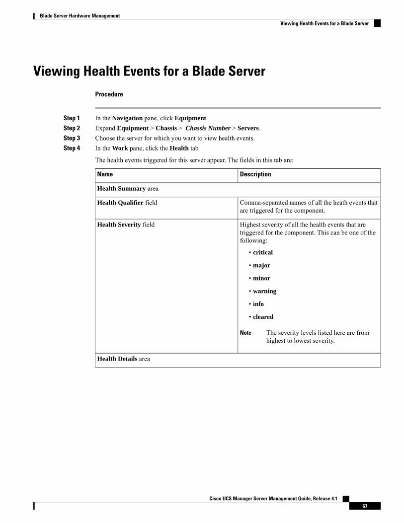
Viewing Health Events for a Blade ServerProcedure
Step 1 In the Navigation pane, click Equipment.Step 2 Expand Equipment > Chassis > Chassis Number > Servers.Step 3 Choose the server for which you want to view health events.Step 4 In the Work pane, click the Health tab
The health events triggered for this server appear. The fields in this tab are:
DescriptionName
Health Summary area
Comma-separated names of all the heath events thatare triggered for the component.
Health Qualifier field
Highest severity of all the health events that aretriggered for the component. This can be one of thefollowing:
• critical
• major
• minor
• warning
• info
• cleared
The severity levels listed here are fromhighest to lowest severity.
Note
Health Severity field
Health Details area
Cisco UCS Manager Server Management Guide, Release 4.167
Blade Server Hardware ManagementViewing Health Events for a Blade Server
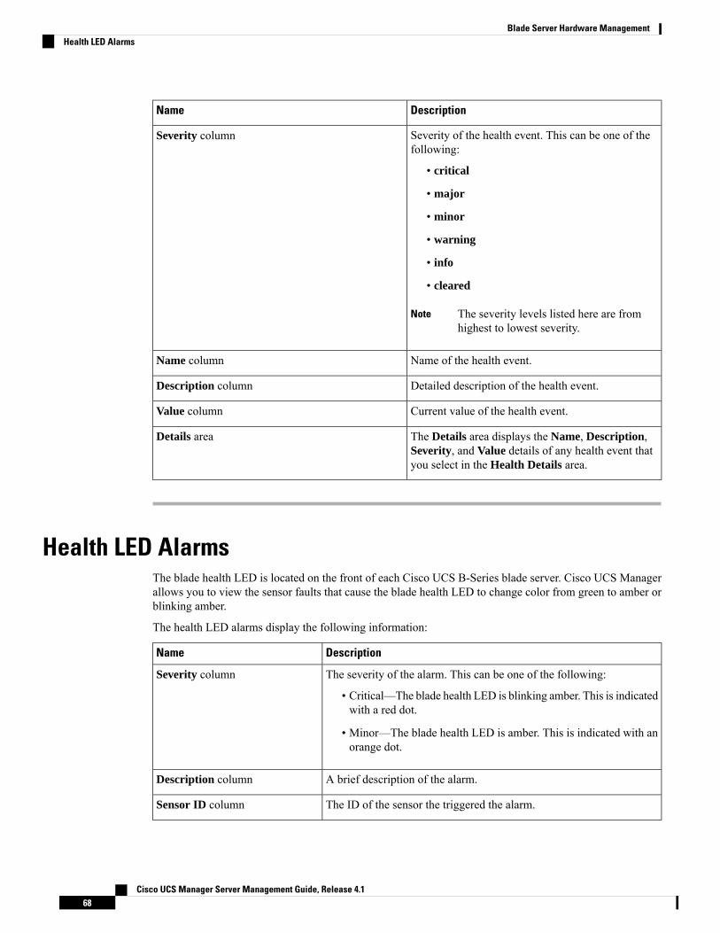
DescriptionName
Severity of the health event. This can be one of thefollowing:
• critical
• major
• minor
• warning
• info
• cleared
The severity levels listed here are fromhighest to lowest severity.
Note
Severity column
Name of the health event.Name column
Detailed description of the health event.Description column
Current value of the health event.Value column
The Details area displays the Name, Description,Severity, and Value details of any health event thatyou select in the Health Details area.
Details area
Health LED AlarmsThe blade health LED is located on the front of each Cisco UCS B-Series blade server. Cisco UCS Managerallows you to view the sensor faults that cause the blade health LED to change color from green to amber orblinking amber.
The health LED alarms display the following information:
DescriptionName
The severity of the alarm. This can be one of the following:
• Critical—The blade health LED is blinking amber. This is indicatedwith a red dot.
• Minor—The blade health LED is amber. This is indicated with anorange dot.
Severity column
A brief description of the alarm.Description column
The ID of the sensor the triggered the alarm.Sensor ID column
Cisco UCS Manager Server Management Guide, Release 4.168
Blade Server Hardware ManagementHealth LED Alarms

DescriptionName
The name of the sensor that triggered the alarm.Sensor Name column
Viewing Health LED Alarms
Procedure
Step 1 In the Navigation pane, click Equipment.Step 2 Expand Equipment > Chassis > Chassis Number > Servers.Step 3 Click the server for which you want to view health LED alarms.Step 4 In the Work pane, click the General tab.Step 5 In the Actions area, click View Health LED Alarms.
The View Health LED Alarms dialog box lists the health LED alarms for the selected server.
Step 6 Click OK to close the View Health LED Alarms dialog box.
Smart SSDBeginning with release 3.1(3), Cisco UCS Manager supports monitoring SSD health. This feature is calledSmart SSD. It provides statistical information about the properties like wear status in days, percentage liferemaining, and so on. For every property, a minimum, a maximum and an average value is recorded anddisplayed. The feature also allows you to provide threshold limit for the properties.
The Smart SSD feature is supported only for a selected range of SSDs. It is not supported for any HDDs.Note
The SATA range of supported SSDs are:
• Intel
• Samsung
• Micron
The SAS range of supported SSDs are:
• Toshiba
• Sandisk
• Samsung
• Micron
Cisco UCS Manager Server Management Guide, Release 4.169
Blade Server Hardware ManagementViewing Health LED Alarms
• Power Cycle Count is not available on SAS SSDs.
• Smart SSD feature is supported only on M4 servers and later.
Note
Monitoring SSD Health
Procedure
Step 1 Navigate to Equipment > Rack-Mounts > Servers > Server Number > Inventory > Storage.Step 2 Click the controller component for which you want to view the SSD health.Step 3 In the Work pane, click the Statistics tab.Step 4 Click the SSD for which you want to view the health properties.
You can view the values for
• PercentageLifeLeft: Displays the duration of life so action can be taken when required.
• PowerCycleCount: Displays the number of times the SSD is power cycled across the server reboot.
• PowerOnHours: Displays the duration for which the SSD is on. You can replace or turn the SSD offbased on the requirement.
If there is a change in any other property, updated PowerOnHours is displayed.Note
• WearStatusInDays: Provides guidance about the SSD wear based on the workload characteristics runat that time.
These values are updated on an hourly basis.
You can specify the threshold limit for the values and faults are raised when the value reachesor exceeds the threshold limit. Smart SSD feature tracks temperature and raises a fault as thetemperature crosses the threshold limit (90°C) andmoves the disk to the degraded state notifyingthe reason for degradation.
Note
Cisco UCS Manager Server Management Guide, Release 4.170
Blade Server Hardware ManagementMonitoring SSD Health
C H A P T E R 7Rack-Mount Server Hardware Management
• Rack-Mount Server Management, on page 71• Rack-Enclosure Server Management, on page 72• Guidelines for Removing and Decommissioning Rack-Mount Servers, on page 72• Recommendations for Avoiding Unexpected Server Power Changes, on page 73• Booting a Rack-Mount Server, on page 74• Booting a Rack-Mount Server from the Service Profile , on page 74• Determining the Boot Order of a Rack-Mount Server, on page 75• Shutting Down a Rack-Mount Server, on page 75• Shutting Down a Server from the Service Profile , on page 76• Resetting a Rack-Mount Server, on page 76• Resetting a Rack-Mount Server to Factory Default Settings, on page 77• Persistent Memory Scrub, on page 78• Reacknowledging a Rack-Mount Server, on page 79• Deleting the Inband Configuration from a Rack-Mount Server, on page 79• Decommissioning a Rack-Mount Server, on page 80• Recommissioning a Rack-Mount Server, on page 80• Renumbering a Rack-Mount Server, on page 81• Removing a Non-Existent Rack-Mount Server from the Configuration Database, on page 82• Turning the Locator LED for a Rack-Mount Server On and Off, on page 82• Turning the Local Disk Locator LED on a Rack-Mount Server On and Off, on page 83• Resetting the CMOS for a Rack-Mount Server, on page 83• Resetting the CIMC for a Rack-Mount Server, on page 84• Clearing TPM for a Rack-Mount Server, on page 84• Issuing an NMI from a Rack-Mount Server, on page 85• Viewing Health Events for a Rack-Mount Server, on page 85• Viewing the POST Results for a Rack-Mount Server, on page 87• Viewing the Power Transition Log, on page 87• Viewing Cisco UCS C125 M5 Server Slot ID, on page 88
Rack-Mount Server ManagementYou can manage and monitor all rack-mount servers that are integrated with a Cisco UCS domain throughCisco UCS Manager. All management and monitoring features are supported for rack-mount servers except
Cisco UCS Manager Server Management Guide, Release 4.171

power capping. Some rack-mount server management tasks, such as changes to the power state, can beperformed from both the server and service profile. The remaining management tasks can only be performedon the server.
Cisco UCSManager provides information, errors, and faults for each rack-mount server that it has discovered.
For information on how to integrate a supported Cisco UCS rack-mount server with Cisco UCSManager, seethe Cisco UCSC-series server integration guide or Cisco UCS S-series server integration guide for your CiscoUCS Manager release.
Tip
Rack-Enclosure Server ManagementBeginning with release 4.0(1a), Cisco UCS Manager extends support for all existing features on Cisco UCSC125 M5 Server unless specifically noted in this guide.
Cisco UCS C125 M5 Servers are housed in the Cisco UCS C4200 Series Rack Server Chassis. Each CiscoUCS C4200 Series Rack Server Chassis supports two to four Cisco UCS C125 M5 Server nodes. To managethe Cisco UCS C125 M5 Server nodes, Cisco UCS Manager supports the following:
• Enclosures:
Cisco UCS Manager GUI path - Equipment > Rack-Mounts > Enclosures
Displays a list of all the Cisco UCS C4200 Series Rack Server Chassis managed by Cisco UCSManager.
• Rack Enclosure rack_enclosure_number:
Cisco UCS Manager GUI path - Equipment > Rack-Mounts > Enclosures > Rack Enclosurerack_enclosure_number
Each Rack Enclosure is one Cisco UCS C4200 Series Rack Server Chassis, which can contain up tofour Cisco UCS C125 M5 Server nodes, four fan units, and two PSUs. See Viewing Cisco UCS C125M5 Server Slot ID, on page 88 for the slot IDs of the server.
Cisco UCS C125 M5 Servers can be managed the same way as other rack servers from Rack Enclosurerack_enclosure_number.
Cisco UCSC125M5 Servers support only Cisco UCS 6400 Series Fabric Interconnect and 6300 Series FabricInterconnect.
Note
Guidelines for Removing and Decommissioning Rack-MountServers
Consider the following guidelines when deciding whether to remove or decommission a rack-mount serverusing Cisco UCS Manager:
Cisco UCS Manager Server Management Guide, Release 4.172
Rack-Mount Server Hardware ManagementRack-Enclosure Server Management
Decommissioning a Rack-Mount server
Decommissioning is performed when a rack-mount server is physically present and connected but you wantto temporarily remove it from the configuration. Because it is expected that a decommissioned rack-mountserver will be eventually recommissioned, a portion of the server's information is retained by Cisco UCSManager for future use.
Removing a Rack-Mount server
Removing is performed when you physically remove the server from the system by disconnecting therack-mount server from the fabric extender. You cannot remove a rack-mount server fromCisco UCSManagerif it is physically present and connected to the fabric extender. Once the rack-mount server is disconnected,the configuration for that rack-mount server can be removed in Cisco UCS Manager.
During removal, management interfaces are disconnected, all entries from databases are removed, and theserver is automatically removed from any server pools that it was assigned to during discovery.
Only those servers added to a server pool automatically during discovery will be removed automatically.Servers that have been manually added to a server pool have to be removed manually.
Note
If you need to add a removed rack-mount server back to the configuration, it must be reconnected and thenrediscovered.When a server is reintroduced to Cisco UCSManager it is treated like a new server and is subjectto the deep discovery process. For this reason, it's possible that Cisco UCS Manager will assign the server anew ID that may be different from the ID that it held before.
Recommendations for Avoiding Unexpected Server PowerChanges
If a server is not associated with a service profile, you can use any available means to change the server powerstate, including the physical Power or Reset buttons on the server.
If a server is associated with, or assigned to, a service profile, you should only use the following methods tochange the server power state:
• In Cisco UCS Manager GUI, go to the General tab for the server or the service profile associated withthe server and select Boot Server or Shutdown Server from the Actions area.
• In Cisco UCS Manager CLI, scope to the server or the service profile associated with the server and usethe power up or power down commands.
Do not use any of the following options on an associated server that is currently powered off:
• Reset in the GUI
• cycle cycle-immediate or reset hard-reset-immediate in the CLI
• The physical Power or Reset buttons on the server
Important
Cisco UCS Manager Server Management Guide, Release 4.173
Rack-Mount Server Hardware ManagementRecommendations for Avoiding Unexpected Server Power Changes
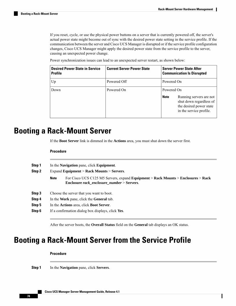
If you reset, cycle, or use the physical power buttons on a server that is currently powered off, the server'sactual power state might become out of sync with the desired power state setting in the service profile. If thecommunication between the server and Cisco UCSManager is disrupted or if the service profile configurationchanges, Cisco UCS Manager might apply the desired power state from the service profile to the server,causing an unexpected power change.
Power synchronization issues can lead to an unexpected server restart, as shown below:
Server Power State AfterCommunication Is Disrupted
Current Server Power StateDesired Power State in ServiceProfile
Powered OnPowered OffUp
Powered On
Running servers are notshut down regardless ofthe desired power statein the service profile.
Note
Powered OnDown
Booting a Rack-Mount ServerIf the Boot Server link is dimmed in the Actions area, you must shut down the server first.
Procedure
Step 1 In the Navigation pane, click Equipment.Step 2 Expand Equipment > Rack Mounts > Servers.
For Cisco UCS C125 M5 Servers, expand Equipment > Rack Mounts > Enclosures > RackEnclosure rack_enclosure_number > Servers.
Note
Step 3 Choose the server that you want to boot.Step 4 In the Work pane, click the General tab.Step 5 In the Actions area, click Boot Server.Step 6 If a confirmation dialog box displays, click Yes.
After the server boots, the Overall Status field on the General tab displays an OK status.
Booting a Rack-Mount Server from the Service ProfileProcedure
Step 1 In the Navigation pane, click Servers.
Cisco UCS Manager Server Management Guide, Release 4.174
Rack-Mount Server Hardware ManagementBooting a Rack-Mount Server

Step 2 Expand Servers > Service Profiles.Step 3 Expand the node for the organization where you want to create the service profile.
If the system does not include multi tenancy, expand the root node.
Step 4 Choose the service profile that requires the associated server to boot.Step 5 In the Work pane, click the General tab.Step 6 In the Actions area, click Boot Server.Step 7 If a confirmation dialog box displays, click Yes.Step 8 Click OK in the Boot Server dialog box.
After the server boots, the Overall Status field on the General tab displays an ok status or an up status.
Determining the Boot Order of a Rack-Mount Server
You can also view the boot order tabs from the General tab of the service profile associated with a server.Tip
Procedure
Step 1 In the Navigation pane, click Equipment.Step 2 Expand Equipment > Rack Mounts > Servers.
For Cisco UCS C125 M5 Servers, expand Equipment > Rack Mounts > Enclosures > RackEnclosure rack_enclosure_number > Servers.
Note
Step 3 Click the server for which you want to determine the boot order.Step 4 In the Work pane, click the General tab.Step 5 If the Boot Order Details area is not expanded, click the Expand icon to the right of the heading.Step 6 To view the boot order assigned to the server, click the Configured Boot Order tab.Step 7 To view what will boot from the various devices in the physical server configuration, click the Actual Boot
Order tab.
The Actual Boot Order tab always shows "Internal EFI Shell" at the bottom of the boot order list.Note
Shutting Down a Rack-Mount ServerWhen you use this procedure to shut down a server with an installed operating system, Cisco UCS Managertriggers the OS into a graceful shutdown sequence.
If the Shutdown server link is dimmed in the Actions area, the server is not running.
Cisco UCS Manager Server Management Guide, Release 4.175
Rack-Mount Server Hardware ManagementDetermining the Boot Order of a Rack-Mount Server
Procedure
Step 1 In the Navigation pane, click Equipment.Step 2 Expand Equipment > Rack Mounts > Servers.
For Cisco UCS C125 M5 Servers, expand Equipment > Rack Mounts > Enclosures > RackEnclosure rack_enclosure_number > Servers.
Note
Step 3 Choose the server that you want to shut down.Step 4 In the Work pane, click the General tab.Step 5 In the Actions area, click Shutdown Server.Step 6 If a confirmation dialog box displays, click Yes.
After the server has been successfully shut down, the Overall Status field on the General tab displays apower-off status.
Shutting Down a Server from the Service ProfileWhen you use this procedure to shut down a server with an installed operating system, Cisco UCS Managertriggers the OS into a graceful shutdown sequence.
If the Shutdown Server link is dimmed in the Actions area, the server is not running.
Procedure
Step 1 In the Navigation pane, click Servers.Step 2 Expand Servers > Service Profiles.Step 3 Expand the node for the organization where you want to create the service profile.
If the system does not include multi tenancy, expand the root node.
Step 4 Choose the service profile that requires the associated server to shut down.Step 5 In the Work pane, click the General tab.Step 6 In the Actions area, click Shutdown Server.Step 7 If a confirmation dialog box displays, click Yes.
After the server successfully shuts down, the Overall Status field on the General tab displays a down statusor a power-off status.
Resetting a Rack-Mount ServerWhen you reset a server, Cisco UCS Manager sends a pulse on the reset line. You can choose to gracefullyshut down the operating system. If the operating system does not support a graceful shutdown, the server is
Cisco UCS Manager Server Management Guide, Release 4.176
Rack-Mount Server Hardware ManagementShutting Down a Server from the Service Profile

power cycled. The option to have Cisco UCS Manager complete all management operations before it resetsthe server does not guarantee the completion of these operations before the server is reset.
If you are trying to boot a server from a power-down state, you should not use Reset.
If you continue the power-up with this process, the desired power state of the servers become out of sync withthe actual power state and the servers might unexpectedly shut down at a later time. To safely reboot theselected servers from a power-down state, click Cancel, then select the Boot Server action.
Note
Procedure
Step 1 In the Navigation pane, click Equipment.Step 2 Expand Equipment > Rack Mounts > Servers.
For Cisco UCS C125 M5 Servers, expand Equipment > Rack Mounts > Enclosures > RackEnclosure rack_enclosure_number > Servers.
Note
Step 3 Choose the server that you want to reset.Step 4 In the Work pane, click the General tab.Step 5 In the Actions area, click Reset.Step 6 In the Reset Server dialog box, do the following:
a) Click the Power Cycle option.b) (Optional) Check the check box if you want Cisco UCSManager to complete all management operations
that are pending on this server.c) Click OK.
The reset may take several minutes to complete. After the server is reset, the Overall Status field on theGeneral tab displays an ok status.
Resetting a Rack-Mount Server to Factory Default SettingsYou can now reset a rack-mount server to its factory settings. By default, the factory reset operation does notaffect storage, including storage drives and flexflash drives. This is to prevent any loss of data. However, youcan choose to reset these devices to a known state as well.
Resetting storage devices will result in loss of data.Important
Perform the following procedure to reset the server to factory default settings.
Cisco UCS Manager Server Management Guide, Release 4.177
Rack-Mount Server Hardware ManagementResetting a Rack-Mount Server to Factory Default Settings
Procedure
Step 1 In the Navigation pane, click Equipment.Step 2 Expand Equipment > Rack Mounts > Servers.
For Cisco UCS C125 M5 Servers, expand Equipment > Rack Mounts > Enclosures > RackEnclosure rack_enclosure_number > Servers.
Note
Step 3 Choose the server that you want to reset to its factory default settings.Step 4 In the Work pane, click the General tab.Step 5 In the Actions area, click Server Maintenance.Step 6 In the Maintenance dialog box, click Reset to Factory Default, then click OK.Step 7 From the Maintenance Server dialog box that appears, select the appropriate options:
• To delete all storage, check the Scrub Storage checkbox.
• To place all disks into their initial state after deleting all storage, check the Create Initial Volumescheckbox.
You can check this checkbox only if you check the Scrub Storage checkbox. For servers that supportJBOD, the disks will be placed in a JBOD state. For servers that do not support JBOD, each disk will beinitialized with a single R0 volume that occupies all the space in the disk.
Do not check theCreate Initial Volumes checkbox if you want to use storage profiles. Creatinginitial volumes when you are using storage profiles may result in configuration errors.
Important
• To delete all flexflash storage, check the Scrub FlexFlash checkbox.
• To delete all Persistent Memory storage, check the Persistent Memory Scrub checkbox.
Cisco UCS Manager resets the server to its factory default settings.
Persistent Memory ScrubPersistent memory scrub allows you to remove the persistent memory configuration and data from the persistentmemory modules on a server.
In Cisco IMC, you can scrub persistent memory by resetting the persistent memorymodules to factory defaults.
In Cisco UCS Manager, you can scrub persistent memory by using one of the following methods:
• Disassociating the service profile and the scrub policy, which has the persistent memory scrub optionset to yes
• Performing a Reset to Factory Default operation on the server with the persistent memory scrub optionset to yes
• Deleting a goal
After persistent memory scrub is complete, the following happen:
Cisco UCS Manager Server Management Guide, Release 4.178
Rack-Mount Server Hardware ManagementPersistent Memory Scrub

• All persistent memory data is erased
• Persistent memory configuration is reset to factory default settings.
For B-Series and C-Series servers, 100% Memory Mode is applied. For S-Series servers, 0% MemoryMode and App Direct Non Interleaved type are applied.
• Persistent memory module security is disabled
Reacknowledging a Rack-Mount ServerPerform the following procedure to rediscover the server and all endpoints in the server. For example, youcan use this procedure if a server is stuck in an unexpected state, such as the discovery state.
Procedure
Step 1 In the Navigation pane, click Equipment.Step 2 Expand Equipment > Rack Mounts > Servers.
For Cisco UCS C125 M5 Servers, expand Equipment > Rack Mounts > Enclosures > RackEnclosure rack_enclosure_number > Servers.
Note
Step 3 Choose the server that you want to acknowledge.Step 4 In the Work pane, click the General tab.Step 5 In the Actions area, click Server Maintenance.Step 6 In the Maintenance dialog box, do the following:
a) Click Re-acknowledge.b) Click OK.
Cisco UCS Manager disconnects the server, then builds the connections between the server and the fabricinterconnect or fabric interconnects in the system. The acknowledgment may take several minutes to complete.After the server is acknowledged, the Overall Status field on the General tab displays an OK status.
Deleting the Inband Configuration from a Rack-Mount ServerThis procedure removes the inband management IP address configuration from a rack server. If this action isgreyed out, no inband configuration was configured.
Procedure
Step 1 In the Navigation pane, click Servers.Step 2 Expand Equipment > Rack Mounts > Servers > Server Number.Step 3 In the Work area, click the Inventory tab.
Cisco UCS Manager Server Management Guide, Release 4.179
Rack-Mount Server Hardware ManagementReacknowledging a Rack-Mount Server
Step 4 Click the CIMC subtab.Step 5 In the Actions area, click Delete Inband Configuration.Step 6 Click Yes in the Delete confirmation dialog box.
The inband configuration for the server is deleted.
If an inband service profile is configured in Cisco UCS Manager with a default VLAN and poolname, the server CIMC automatically gets an inband configuration from the inband profileapproximate one minute after deleting the inband configuration here.
Note
Decommissioning a Rack-Mount ServerProcedure
Step 1 In the Navigation pane, click Equipment.Step 2 Expand Equipment > Rack Mounts > Servers.
For Cisco UCS C125 M5 Servers, expand Equipment > Rack Mounts > Enclosures > RackEnclosure rack_enclosure_number > Servers.
Note
Step 3 Choose the server that you want to decommission.Step 4 In the Work pane, click the General tab.Step 5 In the Actions area, click Server Maintenance.Step 6 In the Maintenance dialog box, click Decommission, then click OK.
The server is removed from the Cisco UCS configuration.
When you decommission the last Cisco UCS C125 M5 Server from a Rack Enclosure, Cisco UCSManager removes the completeRack Enclosure rack_enclosure_number entry from the navigationpane.
Note
Recommissioning a Rack-Mount ServerProcedure
Step 1 In the Navigation pane, click Equipment.Step 2 Under Equipment, click the Rack-Mounts node.Step 3 In the Work pane, click the Decommissioned tab.Step 4 On the row for each rack-mount server that you want to recommission, do the following:
Cisco UCS Manager Server Management Guide, Release 4.180
Rack-Mount Server Hardware ManagementDecommissioning a Rack-Mount Server
a) In the Recommission column, check the check box.b) Click Save Changes
Step 5 If a confirmation dialog box displays, click Yes.Step 6 (Optional) Monitor the progress of the server recommission and discovery on the FSM tab for the server.
Renumbering a Rack-Mount ServerBefore you begin
If you are swapping IDs between servers, you must first decommission both servers, then wait for the serverdecommission FSM to complete before proceeding with the renumbering steps.
Procedure
Step 1 In the Navigation pane, click Equipment.Step 2 Expand Equipment > Rack Mounts > Servers.
For Cisco UCS C125 M5 Servers, expand Equipment > Rack Mounts > Enclosures > RackEnclosure rack_enclosure_number > Servers.
Note
Step 3 Expand the Servers node and verify that it does not include the following:
• The rack-mount server you want to renumber
• A rack-mount server with the number you want to use
If either of these servers are listed in the Servers node, decommission those servers. You must wait until thedecommission FSM is complete and the servers are not listed in the node before continuing. This might takeseveral minutes.
Step 4 Choose the rack-mount server that you want to renumber.Step 5 On the Equipment tab, click the Rack-Mounts node.Step 6 In the Work pane, click the Decommissioned tab.Step 7 On the row for each rack-mount server that you want to renumber, do the following:
a) Double-click in the ID field, and enter the new number that you want to assign to the rack-mount server.b) In the Recommission column, check the check box.c) Click Save Changes
Step 8 If a confirmation dialog box displays, click Yes.Step 9 (Optional) Monitor the progress of the server recommission and discovery on the FSM tab for the server.
Cisco UCS Manager Server Management Guide, Release 4.181
Rack-Mount Server Hardware ManagementRenumbering a Rack-Mount Server

Removing a Non-Existent Rack-Mount Server from theConfiguration Database
Perform the following procedure if you physically removed the server hardware without first decommissioningthe server. You cannot perform this procedure if the server is physically present.
Procedure
Step 1 In the Navigation pane, click Equipment.Step 2 Expand Equipment > Rack Mounts > Servers.
For Cisco UCS C125 M5 Servers, expand Equipment > Rack Mounts > Enclosures > RackEnclosure rack_enclosure_number > Servers.
Note
Step 3 Choose the server that you want to remove from the configuration database.Step 4 In the Work pane, click the General tab.Step 5 In the Actions area, click Server Maintenance.Step 6 In the Maintenance dialog box, click Remove, then click OK.
Cisco UCSManager removes all data about the server from its configuration database. The server slot is nowavailable for you to insert new server hardware.
Turning the Locator LED for a Rack-Mount Server On and OffProcedure
Step 1 In the Navigation pane, click Equipment.Step 2 Expand Equipment > Rack Mounts > Servers.
For Cisco UCS C125 M5 Servers, expand Equipment > Rack Mounts > Enclosures > RackEnclosure rack_enclosure_number > Servers.
Note
Step 3 Choose the server for which you want to turn the locator LED on or off.Step 4 In the Work pane, click the General tab.Step 5 In the Actions area, click one of the following:
• Turn on Locator LED• Turn off Locator LED
Cisco UCS Manager Server Management Guide, Release 4.182
Rack-Mount Server Hardware ManagementRemoving a Non-Existent Rack-Mount Server from the Configuration Database
Turning the Local Disk Locator LED on a Rack-Mount Server Onand Off
Before you begin
• Ensure the server, on which the disk is located, is powered on. If the server is off, you are unable to turnon or off the local disk locator LED.
Procedure
Step 1 In the Navigation pane, click Equipment.Step 2 Expand Equipment > Rack Mounts > Servers.
For Cisco UCS C125 M5 Servers, expand Equipment > Rack Mounts > Enclosures > RackEnclosure rack_enclosure_number > Servers.
Note
Step 3 Choose the server for which you want to turn the local disk locator LED on or off.Step 4 In the Work pane, click the Inventory > Storage > Disks tabs.
The Storage Controller inventory appears.
Step 5 Click a disk.The disk details appear.
Step 6 In the Details area, click Toggle Locator LED.If the Locator LED state is On, it will turn Off. If the Locator LED state is Off, it will turn On.
Step 7 Click Save Changes.
Resetting the CMOS for a Rack-Mount ServerSometimes, troubleshooting a server might require you to reset the CMOS. Resetting the CMOS is not partof the normal maintenance of a server.
Procedure
Step 1 In the Navigation pane, click Equipment.Step 2 Expand Equipment > Rack Mounts > Servers.
For Cisco UCS C125 M5 Servers, expand Equipment > Rack Mounts > Enclosures > RackEnclosure rack_enclosure_number > Servers.
Note
Step 3 Choose the server for which you want to reset the CMOS.Step 4 In the Work pane, click the General tab.
Cisco UCS Manager Server Management Guide, Release 4.183
Rack-Mount Server Hardware ManagementTurning the Local Disk Locator LED on a Rack-Mount Server On and Off
Step 5 In the Actions area, click Recover Server.Step 6 In the Recover Server dialog box, click Reset CMOS, then click OK.
Resetting the CIMC for a Rack-Mount ServerSometimes, with the firmware, troubleshooting a server might require you to reset the CIMC. Resetting theCIMC is not part of the normal maintenance of a server. After you reset the CIMC, the CIMC reboots themanagement controller of the blade server.
Procedure
Step 1 In the Navigation pane, click Equipment.Step 2 Expand Equipment > Rack Mounts > Servers.
For Cisco UCS C125 M5 Servers, expand Equipment > Rack Mounts > Enclosures > RackEnclosure rack_enclosure_number > Servers.
Note
Step 3 Choose the server for which you want to reset the CIMC.Step 4 In the Work pane, click the General tab.Step 5 In the Actions area, click Recover Server.Step 6 In the Recover Server dialog box, click Reset CIMC (Server Controller), then click OK.
Clearing TPM for a Rack-Mount ServerYou can clear TPM only on Cisco UCS M4 and higher blade and rack-mount servers that include support forTPM.
Clearing TPM is a potentially hazardous operation. The OS may stop booting. You may also see loss of data.Caution
Before you begin
TPM must be enabled.
Procedure
Step 1 In the Navigation pane, click Equipment.Step 2 Expand Equipment > Rack Mounts > Servers.
For Cisco UCS C125 M5 Servers, expand Equipment > Rack Mounts > Enclosures > RackEnclosure rack_enclosure_number > Servers.
Note
Cisco UCS Manager Server Management Guide, Release 4.184
Rack-Mount Server Hardware ManagementResetting the CIMC for a Rack-Mount Server
Step 3 Choose the server for which you want to clear TPM.Step 4 In the Work pane, click the General tab.Step 5 In the Actions area, click Recover Server.Step 6 In the Recover Server dialog box, click Clear TPM, then click OK.
Issuing an NMI from a Rack-Mount ServerPerform the following procedure if the system remains unresponsive and you need Cisco UCS Manager toissue a Non-Maskable Interrupt (NMI) to the BIOS or operating system from the CIMC. This action createsa core dump or stack trace, depending on the operating system installed on the server.
Procedure
Step 1 In the Navigation pane, click Equipment.Step 2 Expand Equipment > Rack Mounts > Servers.
For Cisco UCS C125 M5 Servers, expand Equipment > Rack Mounts > Enclosures > RackEnclosure rack_enclosure_number > Servers.
Note
Step 3 Choose the server that you want to issue the NMI.Step 4 In the Work pane, click the General tab.Step 5 In the Actions area, click Server Maintenance.Step 6 In the Maintenance dialog box, click Diagnostic Interrupt, then click OK.
Cisco UCS Manager sends an NMI to the BIOS or operating system.
Viewing Health Events for a Rack-Mount ServerProcedure
Step 1 In the Navigation pane, click Equipment.Step 2 Expand Equipment > Rack Mounts > Servers.
For Cisco UCS C125 M5 Servers, expand Equipment > Rack Mounts > Enclosures > RackEnclosure rack_enclosure_number > Servers.
Note
Step 3 Choose the server for which you want to view health events.Step 4 In the Work pane, click the Health tab
The health events triggered for this server appear. The fields in this tab are:
Cisco UCS Manager Server Management Guide, Release 4.185
Rack-Mount Server Hardware ManagementIssuing an NMI from a Rack-Mount Server
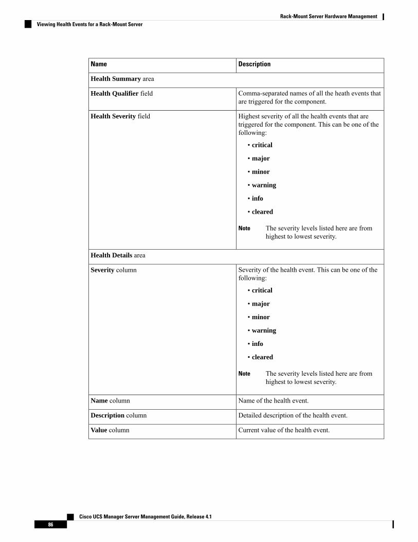
DescriptionName
Health Summary area
Comma-separated names of all the heath events thatare triggered for the component.
Health Qualifier field
Highest severity of all the health events that aretriggered for the component. This can be one of thefollowing:
• critical
• major
• minor
• warning
• info
• cleared
The severity levels listed here are fromhighest to lowest severity.
Note
Health Severity field
Health Details area
Severity of the health event. This can be one of thefollowing:
• critical
• major
• minor
• warning
• info
• cleared
The severity levels listed here are fromhighest to lowest severity.
Note
Severity column
Name of the health event.Name column
Detailed description of the health event.Description column
Current value of the health event.Value column
Cisco UCS Manager Server Management Guide, Release 4.186
Rack-Mount Server Hardware ManagementViewing Health Events for a Rack-Mount Server
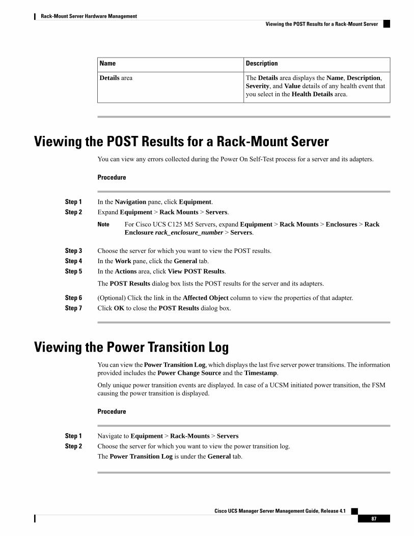
DescriptionName
The Details area displays the Name, Description,Severity, and Value details of any health event thatyou select in the Health Details area.
Details area
Viewing the POST Results for a Rack-Mount ServerYou can view any errors collected during the Power On Self-Test process for a server and its adapters.
Procedure
Step 1 In the Navigation pane, click Equipment.Step 2 Expand Equipment > Rack Mounts > Servers.
For Cisco UCS C125 M5 Servers, expand Equipment > Rack Mounts > Enclosures > RackEnclosure rack_enclosure_number > Servers.
Note
Step 3 Choose the server for which you want to view the POST results.Step 4 In the Work pane, click the General tab.Step 5 In the Actions area, click View POST Results.
The POST Results dialog box lists the POST results for the server and its adapters.
Step 6 (Optional) Click the link in the Affected Object column to view the properties of that adapter.Step 7 Click OK to close the POST Results dialog box.
Viewing the Power Transition LogYou can view the Power Transition Log, which displays the last five server power transitions. The informationprovided includes the Power Change Source and the Timestamp.
Only unique power transition events are displayed. In case of a UCSM initiated power transition, the FSMcausing the power transition is displayed.
Procedure
Step 1 Navigate to Equipment > Rack-Mounts > Servers
Step 2 Choose the server for which you want to view the power transition log.The Power Transition Log is under the General tab.
Cisco UCS Manager Server Management Guide, Release 4.187
Rack-Mount Server Hardware ManagementViewing the POST Results for a Rack-Mount Server
Viewing Cisco UCS C125 M5 Server Slot IDProcedure
Step 1 In the Navigation pane, click Equipment.Step 2 Expand Equipment > Rack Mounts > Enclosures > Rack Enclosure rack_enclosure_number.Step 3 In the Work pane, click the Slots tab.
Cisco UCS Manager Server Management Guide, Release 4.188
Rack-Mount Server Hardware ManagementViewing Cisco UCS C125 M5 Server Slot ID
C H A P T E R 8S3X60 Server Node Hardware Management
• Cisco UCS S3260 Server Node Management, on page 89• Booting a Cisco UCS S3260 Server Node, on page 90• Booting a Cisco UCS S3260 Server Node from the Service Profile , on page 90• Determining the Boot Order of a Cisco UCS S3260 Server Node, on page 90• Shutting Down a Cisco UCS S3260 Server Node, on page 91• Shutting Down a Cisco UCS S3260 Server Node from the Service Profile , on page 91• Resetting a Cisco UCS S3260 Server Node, on page 92• Resetting a Cisco UCS S3260 Server Node to Factory Default Settings, on page 93• Reacknowledging a Cisco UCS S3260 Server Node, on page 94• Removing a Cisco UCS S3260 Server Node from a Chassis, on page 94• Deleting the Inband Configuration from a Cisco UCS S3260 Server Node, on page 95• Decommissioning a Cisco UCS S3260 Server Node, on page 95• Recommissioning a Cisco UCS S3260 Server Node, on page 96• Reacknowledging a Server Slot in a S3260 Chassis, on page 96• Removing a Non-Existent Cisco UCS S3260 Server Node from the Configuration Database, on page 97• Turning the Locator LED for a Cisco UCS S3260 Server Node On and Off, on page 97• Turning the Local Disk Locator LED on a Cisco UCS S3260 Server Node On and Off, on page 98• Resetting the CIMC for a Cisco UCS S3260 Server Node, on page 98• Resetting the CMOS for a Cisco UCS S3260 Server Node, on page 99• Issuing an NMI from a Cisco UCS S3260 Server Node, on page 99• Viewing the POST Results for a Cisco UCS S3260 Server Node, on page 100• Viewing Health Events for a Cisco UCS S3260 Server Node, on page 100• Health LED Alarms, on page 102
Cisco UCS S3260 Server Node ManagementYou can manage and monitor all Cisco UCS S3260 server nodes in a Cisco UCS domain through Cisco UCSManager. You can perform some server management tasks, such as changes to the power state, from the serverand service profile.
The remaining management tasks can only be performed on the server.
If a server slot in a chassis is empty, Cisco UCSManager provides information, errors, and faults for that slot.You can also re-acknowledge the slot to resolve server mismatch errors and rediscover the server in the slot.
Cisco UCS Manager Server Management Guide, Release 4.189
Booting a Cisco UCS S3260 Server NodeIf the Boot Server link is dimmed in the Actions area, you must shut down the server first.
Procedure
Step 1 In the Navigation pane, click Equipment.Step 2 Expand Equipment > Chassis > Chassis Number > Servers.Step 3 Choose the server that you want to boot.Step 4 In the Work pane, click the General tab.Step 5 In the Actions area, click Boot Server.Step 6 If a confirmation dialog box displays, click Yes.
After the server boots, the Overall Status field on the General tab displays an OK status.
Booting a Cisco UCS S3260 Server Node from the Service ProfileProcedure
Step 1 In the Navigation pane, click Servers.Step 2 Expand Servers > Service Profiles.Step 3 Expand the node for the organization where you want to create the service profile, or where the appropriate
service profile already exists.
If the system does not include multitenancy, expand the root node.
Step 4 Choose the service profile that requires the associated server to boot.Step 5 In the Work pane, click the General tab.Step 6 In the Actions area, click Boot Server.Step 7 If a confirmation dialog box displays, click Yes.Step 8 Click OK in the Boot Server dialog box.
After the server boots, the Overall Status field on the General tab displays an ok status or an up status.
Determining the Boot Order of a Cisco UCS S3260 Server Node
You can also view the boot order tabs from the General tab of the service profile associated with a server.Tip
Cisco UCS Manager Server Management Guide, Release 4.190
S3X60 Server Node Hardware ManagementBooting a Cisco UCS S3260 Server Node
Procedure
Step 1 In the Navigation pane, click Equipment.Step 2 Expand Equipment > Chassis > Chassis Number > Servers.Step 3 Click the server for which you want to determine the boot order.Step 4 In the Work pane, click the General tab.Step 5 If the Boot Order Details area is not expanded, click the Expand icon to the right of the heading.Step 6 To view the boot order assigned to the server, click the Configured Boot Order tab.Step 7 To view what will boot from the various devices in the physical server configuration, click the Actual Boot
Order tab.
Shutting Down a Cisco UCS S3260 Server NodeWhen you use this procedure to shut down a server with an installed operating system, Cisco UCS Managertriggers the OS into a graceful shutdown sequence.
If the Shutdown Server link is dimmed in the Actions area, the server is not running.
Procedure
Step 1 In the Navigation pane, click Equipment.Step 2 Expand Equipment > Chassis > Chassis Number > Servers.Step 3 Choose the server that you want to shut down.Step 4 In the Work pane, click the General tab.Step 5 In the Actions area, click Shutdown Server.Step 6 If a confirmation dialog box displays, click Yes.
After the server has been successfully shut down, the Overall Status field on the General tab displays apower-off status.
Shutting Down a Cisco UCS S3260 Server Node from the ServiceProfile
When you use this procedure to shut down a server with an installed operating system, Cisco UCS Managertriggers the OS into a graceful shutdown sequence.
If the Shutdown Server link is dimmed in the Actions area, the server is not running.
Cisco UCS Manager Server Management Guide, Release 4.191
S3X60 Server Node Hardware ManagementShutting Down a Cisco UCS S3260 Server Node
Procedure
Step 1 In the Navigation pane, click Servers.Step 2 Expand Servers > Service Profiles.Step 3 Expand the node for the organization with the associated service profile.Step 4 Choose the service profile associated with the server to be shut down.Step 5 In the Work pane, click the General tab.Step 6 In the Actions area, click Shutdown Server.Step 7 If a confirmation dialog box displays, click Yes.
After the server successfully shuts down, the Overall Status field on the General tab displays a down statusor a power-off status.
Resetting a Cisco UCS S3260 Server NodeWhen you reset a server, Cisco UCS Manager sends a pulse on the reset line. You can choose to gracefullyshut down the operating system. If the operating system does not support a graceful shutdown, the server ispower cycled. The option to have Cisco UCS Manager complete all management operations before it resetsthe server does not guarantee the completion of these operations before the server is reset.
If you are trying to boot a server from a power-down state, you should not use Reset.
If you continue the power-up with this process, the desired power state of the servers become out of sync withthe actual power state and the servers might unexpectedly shut down at a later time. To safely reboot theselected servers from a power-down state, click Cancel, then select the Boot Server action.
Note
Procedure
Step 1 In the Navigation pane, click Equipment.Step 2 Expand Equipment > Chassis > Chassis Number > Servers.Step 3 Choose the server that you want to reset.Step 4 In the Work pane, click the General tab.Step 5 In the Actions area, click Reset.Step 6 In the Reset Server dialog box, do the following:
a) Click the Power Cycle option.b) (Optional) Check the check box if you want Cisco UCSManager to complete all management operations
that are pending on this server.c) Click OK.
Cisco UCS Manager Server Management Guide, Release 4.192
S3X60 Server Node Hardware ManagementResetting a Cisco UCS S3260 Server Node
The reset may take several minutes to complete. After the server has been reset, the Overall Status field onthe General tab displays an ok status.
Resetting a Cisco UCS S3260 Server Node to Factory DefaultSettings
You can now reset a Cisco UCS S3260 Server Node to its factory settings. By default, the factory resetoperation does not affect storage drives. This is to prevent any loss of data. However, you can choose to resetthese devices to a known state as well.
The following guidelines apply to Cisco UCS S3260 Server Nodes when using scrub policies:
• For Cisco UCS S3260 Server Nodes, you cannot delete storage by using the scrub policy.
• Cisco UCS S3260 Server Nodes do not support FlexFlash drives.
• For Cisco UCS S3260 Server Nodes, you can only reset the BIOS by using the scrub policy.
Resetting storage devices will result in loss of data.Important
Perform the following procedure to reset the server to factory default settings.
Procedure
Step 1 In the Navigation pane, click Equipment.Step 2 Expand Equipment > Chassis > Chassis Number > Servers.Step 3 Choose the server that you want to reset to its factory default settings.Step 4 In the Work pane, click the General tab.Step 5 In the Actions area, click Server Maintenance.Step 6 In the Maintenance dialog box, do the following:
a) Click Reset to Factory Default.b) Click OK.
Step 7 From the Maintenance Server dialog box that appears, select the appropriate options:
• To delete all storage, check the Scrub Storage check box.
For Cisco UCS S3260 Server Nodes, you cannot delete storage using the scrub policy.Note
• To place all disks into their initial state after deleting all storage, check theCreate Initial Volumes checkbox.
You can check this check box only if you check the Scrub Storage check box. For servers that supportJBOD, the disks will be placed in a JBOD state. For servers that do not support JBOD, each disk will beinitialized with a single R0 volume that occupies all the space in the disk.
Do not check the Create Initial Volumes box if you want to use storage profiles. Creatinginitial volumes when you are using storage profiles may result in configuration errors.
Important
Cisco UCS Manager Server Management Guide, Release 4.193
S3X60 Server Node Hardware ManagementResetting a Cisco UCS S3260 Server Node to Factory Default Settings
Cisco UCS Manager resets the server to its factory default settings.
Reacknowledging a Cisco UCS S3260 Server NodePerform the following procedure to rediscover the server and all endpoints in the server. For example, youcan use this procedure if a server is stuck in an unexpected state, such as the discovery state.
Procedure
Step 1 In the Navigation pane, click Equipment.Step 2 Expand Equipment > Chassis > Chassis Number > Servers.Step 3 Choose the server that you want to acknowledge.Step 4 In the Work pane, click the General tab.Step 5 In the Actions area, click Server Maintenance.Step 6 In the Maintenance dialog box, click Re-acknowledge, then click OK.
Cisco UCSManager disconnects the server and then builds the connections between the server and the fabricinterconnect or fabric interconnects in the system. The acknowledgment may take several minutes to complete.After the server has been acknowledged, the Overall Status field on the General tab displays an OK status.
Removing a Cisco UCS S3260 Server Node from a ChassisProcedure
Step 1 In the Navigation pane, click Equipment.Step 2 Expand Equipment > Chassis > Chassis Number > Servers.Step 3 Choose the server that you want to remove from the chassis.Step 4 In the Work pane, click the General tab.Step 5 In the Actions area, click Server Maintenance.Step 6 In the Maintenance dialog box, click Decommission, then click OK.
The server is removed from the Cisco UCS configuration.
Step 7 Go to the physical location of the chassis and remove the server hardware from the slot.
For instructions on how to remove the server hardware, see the Cisco UCS Hardware Installation Guide foryour chassis.
Cisco UCS Manager Server Management Guide, Release 4.194
S3X60 Server Node Hardware ManagementReacknowledging a Cisco UCS S3260 Server Node
What to do next
If you physically reinstall the server, you must re-acknowledge the slot for Cisco UCSManager to re-discoverthe server.
Deleting the Inband Configuration from a Cisco UCS S3260Server Node
This procedure removes the inband management IP address configuration from a blade server. If this actionis grayed out, no inband configuration was completed.
Procedure
Step 1 In the Navigation pane, click Servers.Step 2 Expand Equipment > Chassis > Chassis Number > Servers > Server Name.Step 3 In the Work area, click the Inventory tab.Step 4 Click the CIMC subtab.Step 5 In the Actions area, click Delete Inband Configuration.Step 6 Click Yes in the Delete confirmation dialog box.
The inband configuration for the server is deleted.
If an inband service profile is configured in Cisco UCS Manager with a default VLAN and poolname, the server CIMC will automatically get an inband configuration from the inband profileapproximate one minute after deleting the inband configuration here.
Note
Decommissioning a Cisco UCS S3260 Server NodeProcedure
Step 1 In the Navigation pane, click Equipment.Step 2 Expand Equipment > Chassis > Chassis Number > Servers.Step 3 Choose the server that you want to decommission.Step 4 In the Work pane, click the General tab.Step 5 In the Actions area, click Server Maintenance.Step 6 In the Maintenance dialog box, do the following:
a) Click Decommission.b) Click OK.
Cisco UCS Manager Server Management Guide, Release 4.195
S3X60 Server Node Hardware ManagementDeleting the Inband Configuration from a Cisco UCS S3260 Server Node
The server is removed from the Cisco UCS configuration.
What to do next
If you physically reinstall the server, you must re-acknowledge the slot for Cisco UCSManager to rediscoverthe server.
Recommissioning a Cisco UCS S3260 Server NodeProcedure
Step 1 In the Navigation pane, click Equipment.Step 2 Click the Chassis node.Step 3 In the Work pane, click the Decommissioned tab.Step 4 On the row for each server that you want to recommission, check the check box in theRecommission column,
then click Save Changes.Step 5 If a confirmation dialog box displays, click Yes.Step 6 (Optional) Monitor the progress of the server recommission and discovery on the FSM tab for the server.
Reacknowledging a Server Slot in a S3260 ChassisPerform the following procedure if you decommissioned a server without removing the physical hardwarefrom the chassis, and you want Cisco UCS Manager to rediscover and reacknowledge the server.
Procedure
Step 1 In the Navigation pane, click Equipment.Step 2 Expand Equipment > Chassis > Chassis Number > Servers.Step 3 Choose the server whose slot you want to reacknowledge.Step 4 If Cisco UCS Manager displays a Resolve Slot Issue dialog box, do one of the following:
DescriptionOption
Click this link and then click Yes in the confirmation dialog box. Cisco UCSManager reacknowledges the slot and discovers the server in the slot.
The here link in theSituation area
Cisco UCS Manager Server Management Guide, Release 4.196
S3X60 Server Node Hardware ManagementRecommissioning a Cisco UCS S3260 Server Node
DescriptionOption
Click this button if you want to proceed to the General tab. You can use theReacknowledge Slot link in the Actions area to have Cisco UCS Managerreacknowledge the slot and discover the server in the slot.
OK
Removing a Non-Existent Cisco UCS S3260 Server Node fromthe Configuration Database
Perform the following procedure if you physically removed the server hardware without first decommissioningthe server. You cannot perform this procedure if the server is physically present.
If you want to physically remove a server, see Removing a Cisco UCS S3260 Server Node from a Chassis,on page 94.
Procedure
Step 1 In the Navigation pane, click Equipment.Step 2 Expand Equipment > Chassis > Chassis Number > Servers.Step 3 Choose the server that you want to remove from the configuration database.Step 4 In the Work pane, click the General tab.Step 5 In the Actions area, click Server Maintenance.Step 6 In the Maintenance dialog box, click Remove, then click OK.
Cisco UCSManager removes all data about the server from its configuration database. The server slot is nowavailable for you to insert new server hardware.
Turning the Locator LED for a Cisco UCS S3260 Server Node Onand Off
Procedure
Step 1 In the Navigation pane, click Equipment.Step 2 Expand Equipment > Chassis > Chassis Number > Servers.Step 3 Choose the server for which you want to turn the locator LED on or off.Step 4 In the Work pane, click the General tab.Step 5 In the Actions area, click one of the following:
Cisco UCS Manager Server Management Guide, Release 4.197
S3X60 Server Node Hardware ManagementRemoving a Non-Existent Cisco UCS S3260 Server Node from the Configuration Database

• Turn on Locator LED—Turns on the LED for the selected server.• Turn off Locator LED—Turns off the LED for the selected server.
Turning the Local Disk Locator LED on a Cisco UCS S3260 ServerNode On and Off
Before you begin
• Ensure that the disk is zoned. Turning the locator LED on and off cannot be done on disks that are notzoned.
• Ensure the server, on which the disk is located, is powered on. If the server is off, you are unable to turnon or off the local disk locator LED.
Procedure
Step 1 In the Navigation pane, click Equipment.Step 2 Expand Equipment > Chassis > Chassis Number > Servers.Step 3 Choose the server for which you want to turn the local disk locator LED on or off.Step 4 In the Work pane, click the Inventory > Storage > Disks tabs.
The Storage Controller inventory appears.
Step 5 Click a disk.The disk details appear.
Step 6 In the Details area, click Toggle Locator LED.If the Locator LED state is On, it will turn Off. If the Locator LED state is Off, it will turn On.
Step 7 Click Save Changes.
Resetting the CIMC for a Cisco UCS S3260 Server NodeSometimes, with the firmware, troubleshooting a server might require you to reset the CIMC. Resetting theCIMC is not part of the normal maintenance of a server. After you reset the CIMC, the CIMC reboots themanagement controller of the blade server.
If the CIMC is reset, the power monitoring functions of Cisco UCS become briefly unavailable until the CIMCreboots. Typically, the reset only takes 20 seconds; however, it is possible that the peak power cap can exceedduring that time. To avoid exceeding the configured power cap in a low power-capped environment, considerstaggering the rebooting or activation of CIMCs.
Cisco UCS Manager Server Management Guide, Release 4.198
S3X60 Server Node Hardware ManagementTurning the Local Disk Locator LED on a Cisco UCS S3260 Server Node On and Off
Procedure
Step 1 In the Navigation pane, click Equipment.Step 2 Expand Equipment > Chassis > Chassis Number > Servers.Step 3 Choose the server for which you want to reset the CIMC.Step 4 In the Work pane, click the General tab.Step 5 In the Actions area, click Recover Server.Step 6 In the Recover Server dialog box, click Reset CIMC (Server Controller), then click OK.
Resetting the CMOS for a Cisco UCS S3260 Server NodeSometimes, troubleshooting a server might require you to reset the CMOS. Resetting the CMOS is not partof the normal maintenance of a server.
Procedure
Step 1 In the Navigation pane, click Equipment.Step 2 Expand Equipment > Chassis > Chassis Number > Servers.Step 3 Choose the server for which you want to reset the CMOS.Step 4 In the Work pane, click the General tab.Step 5 In the Actions area, click Recover Server.Step 6 In the Recover Server dialog box, click Reset CMOS, then click OK.
Issuing an NMI from a Cisco UCS S3260 Server NodePerform the following procedure if the system remains unresponsive and you need Cisco UCS Manager toissue a Non-Maskable Interrupt (NMI) to the BIOS or operating system from the CIMC. This action createsa core dump or stack trace, depending on the operating system installed on the server.
Procedure
Step 1 In the Navigation pane, click Equipment.Step 2 Expand Equipment > Chassis > Chassis Number > Servers.Step 3 Choose the server that you want to issue the NMI.Step 4 In the Work pane, click the General tab.Step 5 In the Actions area, click Server Maintenance.Step 6 In the Maintenance dialog box, do the following:
a) Click Diagnostic Interrupt.
Cisco UCS Manager Server Management Guide, Release 4.199
S3X60 Server Node Hardware ManagementResetting the CMOS for a Cisco UCS S3260 Server Node

b) Click OK.
Cisco UCS Manager sends an NMI to the BIOS or operating system.
Viewing the POST Results for a Cisco UCS S3260 Server NodeYou can view any errors collected during the Power On Self-Test process for a server and its adapters.
Procedure
Step 1 In the Navigation pane, click Equipment.Step 2 Expand Equipment > Chassis > Chassis Number > Servers.Step 3 Choose the server for which you want to view the POST results.Step 4 In the Work pane, click the General tab.Step 5 In the Actions area, click View POST Results.
The POST Results dialog box lists the POST results for the server and its adapters.
Step 6 (Optional) Click the link in the Affected Object column to view the properties of that adapter.Step 7 Click OK to close the POST Results dialog box.
Viewing Health Events for a Cisco UCS S3260 Server NodeProcedure
Step 1 In the Navigation pane, click Equipment.Step 2 Expand Equipment > Chassis > Chassis Number > Servers.Step 3 Choose the server for which you want to view health events.Step 4 In the Work pane, click the Health tab
The health events triggered for this server appear. The fields in this tab are:
DescriptionName
Health Summary area
Comma-separated names of all the heath events thatare triggered for the component.
Health Qualifier field
Cisco UCS Manager Server Management Guide, Release 4.1100
S3X60 Server Node Hardware ManagementViewing the POST Results for a Cisco UCS S3260 Server Node
DescriptionName
Highest severity of all the health events that aretriggered for the component. This can be one of thefollowing:
• critical
• major
• minor
• warning
• info
• cleared
The severity levels listed here are fromhighest to lowest severity.
Note
Health Severity field
Health Details area
Severity of the health event. This can be one of thefollowing:
• critical
• major
• minor
• warning
• info
• cleared
The severity levels listed here are fromhighest to lowest severity.
Note
Severity column
Name of the health event.Name column
Detailed description of the health event.Description column
Current value of the health event.Value column
The Details area displays the Name, Description,Severity, and Value details of any health event thatyou select in the Health Details area.
Details area
Cisco UCS Manager Server Management Guide, Release 4.1101
S3X60 Server Node Hardware ManagementViewing Health Events for a Cisco UCS S3260 Server Node
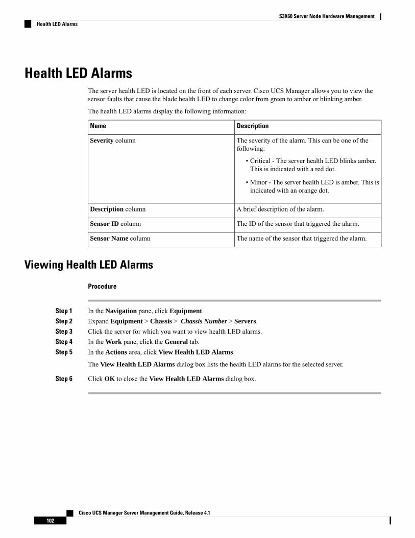
Health LED AlarmsThe server health LED is located on the front of each server. Cisco UCS Manager allows you to view thesensor faults that cause the blade health LED to change color from green to amber or blinking amber.
The health LED alarms display the following information:
DescriptionName
The severity of the alarm. This can be one of thefollowing:
• Critical - The server health LED blinks amber.This is indicated with a red dot.
• Minor - The server health LED is amber. This isindicated with an orange dot.
Severity column
A brief description of the alarm.Description column
The ID of the sensor that triggered the alarm.Sensor ID column
The name of the sensor that triggered the alarm.Sensor Name column
Viewing Health LED Alarms
Procedure
Step 1 In the Navigation pane, click Equipment.Step 2 Expand Equipment > Chassis > Chassis Number > Servers.Step 3 Click the server for which you want to view health LED alarms.Step 4 In the Work pane, click the General tab.Step 5 In the Actions area, click View Health LED Alarms.
The View Health LED Alarms dialog box lists the health LED alarms for the selected server.
Step 6 Click OK to close the View Health LED Alarms dialog box.
Cisco UCS Manager Server Management Guide, Release 4.1102
S3X60 Server Node Hardware ManagementHealth LED Alarms

C H A P T E R 9Server Pools
• Configuring Server Pools, on page 103• Configuring UUID Suffix Pools, on page 105• Configuring IP Pools, on page 107
Configuring Server Pools
Server PoolsA server pool contains a set of servers. These servers typically share the same characteristics. Thosecharacteristics can be their location in the chassis, or an attribute such as server type, amount of memory,local storage, type of CPU, or local drive configuration. You can manually assign a server to a server pool,or use server pool policies and server pool policy qualifications to automate the assignment.
If your system implements multitenancy through organizations, you can designate one or more server poolsto be used by a specific organization. For example, a pool that includes all servers with two CPUs could beassigned to theMarketing organization, while all servers with 64 GBmemory could be assigned to the Financeorganization.
A server pool can include servers from any chassis in the system. A given server can belong to multiple serverpools.
Creating a Server Pool
Procedure
Step 1 In the Navigation pane, click Servers.Step 2 Expand Servers > Pools.Step 3 Expand the node for the organization where you want to create the pool.
If the system does not include multi tenancy, expand the root node.
Step 4 Right-click the Server Pools node and select Create Server Pool.Step 5 On the Set Name and Description page of the Create Server Pool wizard, complete the following fields:
Cisco UCS Manager Server Management Guide, Release 4.1103

DescriptionName
The name of the server pool.
This name can be between 1 and 32 alphanumeric characters. You cannotuse spaces or any special characters other than - (hyphen), _ (underscore),: (colon), and . (period), and you cannot change this name after the objectis saved.
Name field
A user-defined description of the server pool.
Enter up to 256 characters. You can use any characters or spaces except` (accent mark), \ (backslash), ^ (carat), " (double quote), = (equal sign),> (greater than), < (less than), or ' (single quote).
Description field
Step 6 Click Next.Step 7 On the Add Servers page of the Create Server Pool wizard:
a) Select one or more servers from the Available Servers table.b) Click the >> button to add the servers to the server pool.c) When you have added all desired servers to the pool, click Finish.
Deleting a Server Pool
Procedure
Step 1 In the Navigation pane, click Servers.Step 2 Expand Servers > Pools > Organization_Name.Step 3 Expand the Server Pools node.Step 4 Right-click the pool you want to delete and select Delete.Step 5 If a confirmation dialog box displays, click Yes.
Adding Servers to a Server Pool
Procedure
Step 1 In the Navigation pane, click Servers.Step 2 Expand Servers > Pools > Organization_Name.Step 3 Right-click the pool to which you want to add one or more servers and select Add Servers to Server Pool.Step 4 In the Add Servers to Server Pool dialog box, do the following:
a) In the Servers table, select the servers that you want to add to the server pool.
You can use the Shift key or Ctrl key to select multiple entries.
Cisco UCS Manager Server Management Guide, Release 4.1104
Server PoolsDeleting a Server Pool

b) Click the >> button to move those servers to the Pooled Servers table and add them to the server pool.c) Click OK.
Removing Servers from a Server Pool
Procedure
Step 1 In the Navigation pane, click Servers.Step 2 Expand Servers > Pools > Organization_Name.Step 3 Right-click the pool from which you want to remove one or more servers and select Add Servers to Server
Pool.Step 4 In the Add Servers to Server Pool dialog box, do the following:
a) In the Pooled Servers table, select the servers that you want to remove from the server pool.
You can use the Shift key or Ctrl key to select multiple entries.
b) Click the << button to move those servers to the Servers table and remove them from the server pool.c) Click OK.
Configuring UUID Suffix Pools
UUID Suffix PoolsA UUID suffix pool is a collection of SMBIOS UUIDs that are available to be assigned to servers. The firstnumber of digits that constitute the prefix of the UUID are fixed. The remaining digits, the UUID suffix, arevariable. A UUID suffix pool ensures that these variable values are unique for each server associated with aservice profile which uses that particular pool to avoid conflicts.
If you use UUID suffix pools in service profiles, you do not have to manually configure the UUID of theserver associated with the service profile.
Creating a UUID Suffix Pool
Procedure
Step 1 In the Navigation pane, click Servers.Step 2 Expand Servers > Pools.Step 3 Expand the node for the organization where you want to create the pool.
If the system does not include multi tenancy, expand the root node.
Cisco UCS Manager Server Management Guide, Release 4.1105
Server PoolsRemoving Servers from a Server Pool

Step 4 Right-click UUID Suffix Pools and select Create UUID Suffix Pool.Step 5 In the Define Name and Description page of the Create UUID Suffix Pool wizard, complete the following
fields:
DescriptionName
The name of the UUID pool.
This name can be between 1 and 32 alphanumeric characters. You cannotuse spaces or any special characters other than - (hyphen), _ (underscore),: (colon), and . (period), and you cannot change this name after the objectis saved.
Name field
The user-defined description of the pool.
Enter up to 256 characters. You can use any characters or spaces except` (accent mark), \ (backslash), ^ (carat), " (double quote), = (equal sign),> (greater than), < (less than), or ' (single quote).
Description field
This can be one of the following:
• Derived—The system creates the suffix.
• other—You specify the desired suffix. If you select this option,Cisco UCSManager GUI displays a text field where you can enterthe desired suffix, in the format XXXXXXXX-XXXX-XXXX.
Prefix field
This can be one of the following:
• Default—Cisco UCS Manager selects a random identity from thepool.
• Sequential—Cisco UCS Manager selects the lowest availableidentity from the pool.
Assignment Order field
Step 6 Click Next.Step 7 In the Add UUID Blocks page of the Create UUID Suffix Pool wizard, click Add.Step 8 In the Create a Block of UUID Suffixes dialog box, complete the following fields:
DescriptionName
The first UUID in the block.From field
The number of UUIDs in the block.Size field
Step 9 Click OK.Step 10 Click Finish to complete the wizard.
What to do next
Include the UUID suffix pool in a service profile and/or template.
Cisco UCS Manager Server Management Guide, Release 4.1106
Server PoolsCreating a UUID Suffix Pool
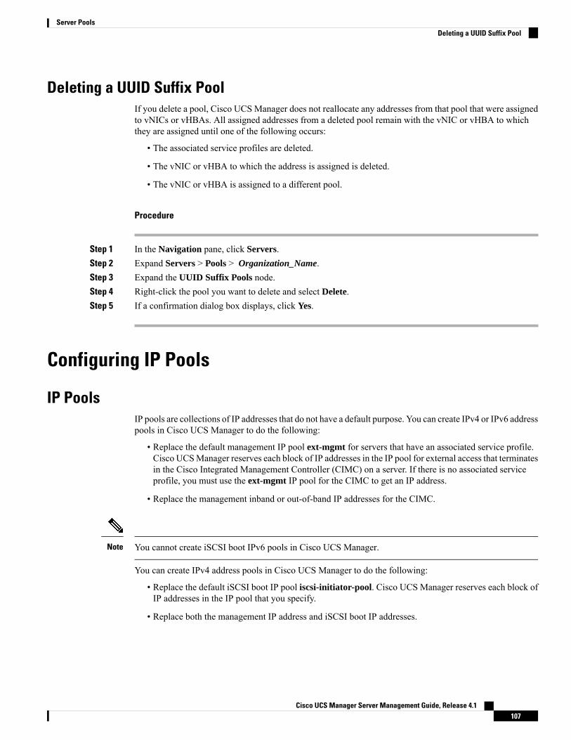
Deleting a UUID Suffix PoolIf you delete a pool, Cisco UCS Manager does not reallocate any addresses from that pool that were assignedto vNICs or vHBAs. All assigned addresses from a deleted pool remain with the vNIC or vHBA to whichthey are assigned until one of the following occurs:
• The associated service profiles are deleted.
• The vNIC or vHBA to which the address is assigned is deleted.
• The vNIC or vHBA is assigned to a different pool.
Procedure
Step 1 In the Navigation pane, click Servers.Step 2 Expand Servers > Pools > Organization_Name.Step 3 Expand the UUID Suffix Pools node.Step 4 Right-click the pool you want to delete and select Delete.Step 5 If a confirmation dialog box displays, click Yes.
Configuring IP Pools
IP PoolsIP pools are collections of IP addresses that do not have a default purpose. You can create IPv4 or IPv6 addresspools in Cisco UCS Manager to do the following:
• Replace the default management IP pool ext-mgmt for servers that have an associated service profile.Cisco UCSManager reserves each block of IP addresses in the IP pool for external access that terminatesin the Cisco Integrated Management Controller (CIMC) on a server. If there is no associated serviceprofile, you must use the ext-mgmt IP pool for the CIMC to get an IP address.
• Replace the management inband or out-of-band IP addresses for the CIMC.
You cannot create iSCSI boot IPv6 pools in Cisco UCS Manager.Note
You can create IPv4 address pools in Cisco UCS Manager to do the following:
• Replace the default iSCSI boot IP pool iscsi-initiator-pool. Cisco UCS Manager reserves each block ofIP addresses in the IP pool that you specify.
• Replace both the management IP address and iSCSI boot IP addresses.
Cisco UCS Manager Server Management Guide, Release 4.1107
Server PoolsDeleting a UUID Suffix Pool
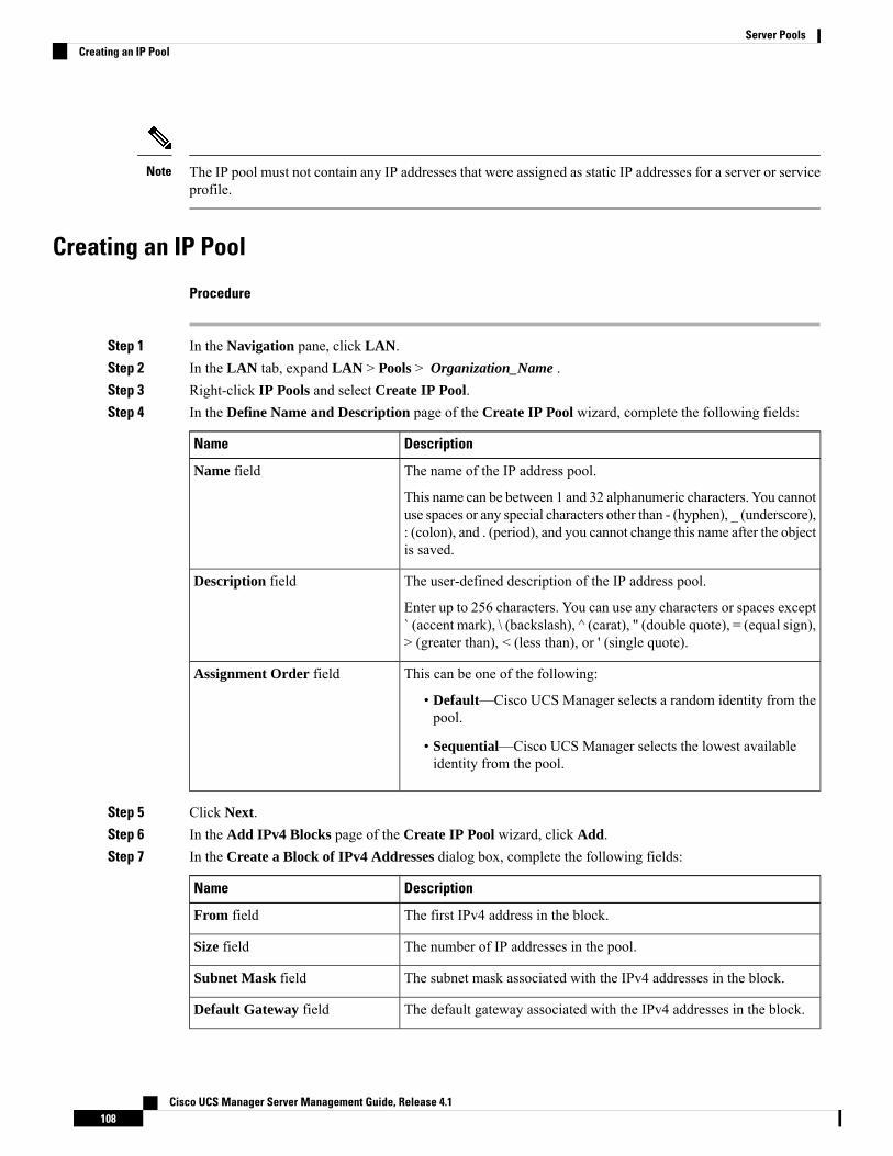
The IP pool must not contain any IP addresses that were assigned as static IP addresses for a server or serviceprofile.
Note
Creating an IP Pool
Procedure
Step 1 In the Navigation pane, click LAN.Step 2 In the LAN tab, expand LAN > Pools > Organization_Name .Step 3 Right-click IP Pools and select Create IP Pool.Step 4 In the Define Name and Description page of the Create IP Pool wizard, complete the following fields:
DescriptionName
The name of the IP address pool.
This name can be between 1 and 32 alphanumeric characters. You cannotuse spaces or any special characters other than - (hyphen), _ (underscore),: (colon), and . (period), and you cannot change this name after the objectis saved.
Name field
The user-defined description of the IP address pool.
Enter up to 256 characters. You can use any characters or spaces except` (accent mark), \ (backslash), ^ (carat), " (double quote), = (equal sign),> (greater than), < (less than), or ' (single quote).
Description field
This can be one of the following:
• Default—Cisco UCS Manager selects a random identity from thepool.
• Sequential—Cisco UCS Manager selects the lowest availableidentity from the pool.
Assignment Order field
Step 5 Click Next.Step 6 In the Add IPv4 Blocks page of the Create IP Pool wizard, click Add.Step 7 In the Create a Block of IPv4 Addresses dialog box, complete the following fields:
DescriptionName
The first IPv4 address in the block.From field
The number of IP addresses in the pool.Size field
The subnet mask associated with the IPv4 addresses in the block.Subnet Mask field
The default gateway associated with the IPv4 addresses in the block.Default Gateway field
Cisco UCS Manager Server Management Guide, Release 4.1108
Server PoolsCreating an IP Pool
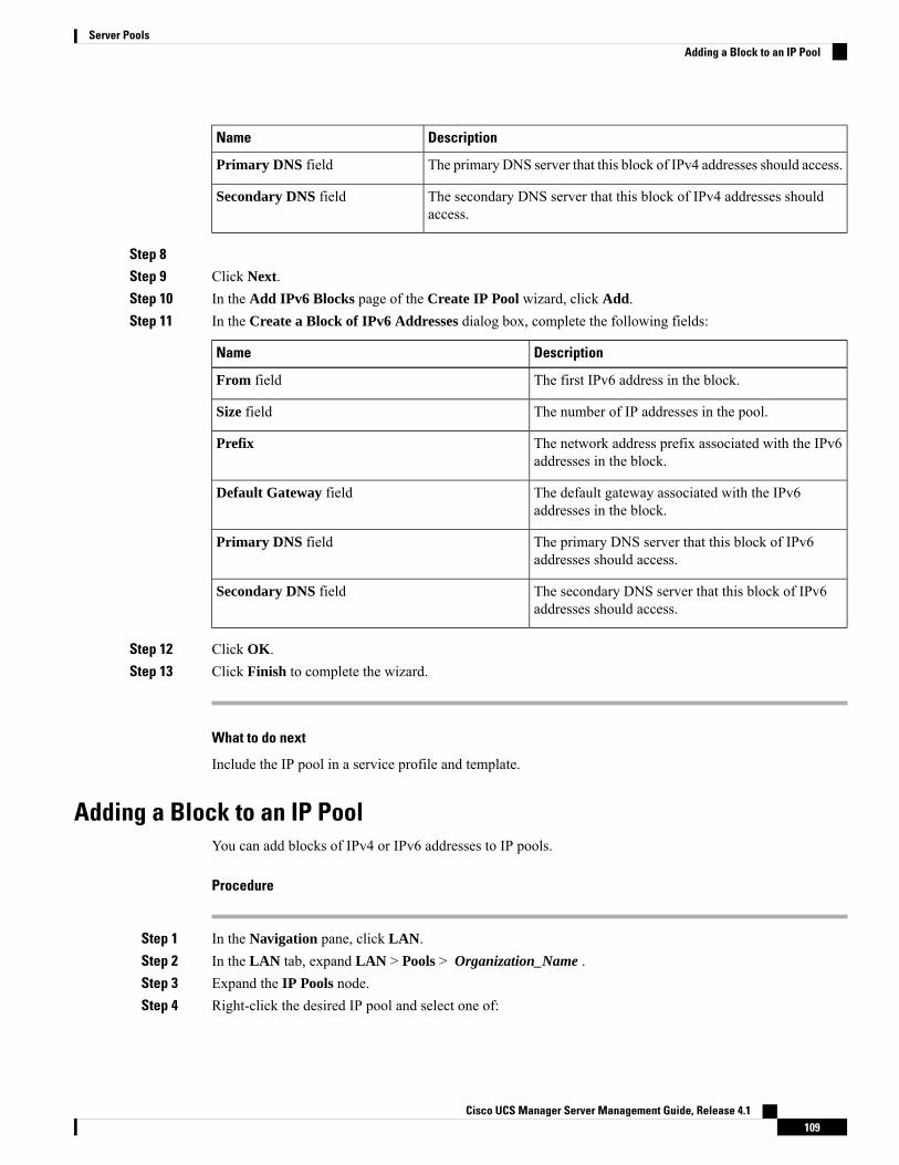
DescriptionName
The primary DNS server that this block of IPv4 addresses should access.Primary DNS field
The secondary DNS server that this block of IPv4 addresses shouldaccess.
Secondary DNS field
Step 8Step 9 Click Next.Step 10 In the Add IPv6 Blocks page of the Create IP Pool wizard, click Add.Step 11 In the Create a Block of IPv6 Addresses dialog box, complete the following fields:
DescriptionName
The first IPv6 address in the block.From field
The number of IP addresses in the pool.Size field
The network address prefix associated with the IPv6addresses in the block.
Prefix
The default gateway associated with the IPv6addresses in the block.
Default Gateway field
The primary DNS server that this block of IPv6addresses should access.
Primary DNS field
The secondary DNS server that this block of IPv6addresses should access.
Secondary DNS field
Step 12 Click OK.Step 13 Click Finish to complete the wizard.
What to do next
Include the IP pool in a service profile and template.
Adding a Block to an IP PoolYou can add blocks of IPv4 or IPv6 addresses to IP pools.
Procedure
Step 1 In the Navigation pane, click LAN.Step 2 In the LAN tab, expand LAN > Pools > Organization_Name .Step 3 Expand the IP Pools node.Step 4 Right-click the desired IP pool and select one of:
Cisco UCS Manager Server Management Guide, Release 4.1109
Server PoolsAdding a Block to an IP Pool
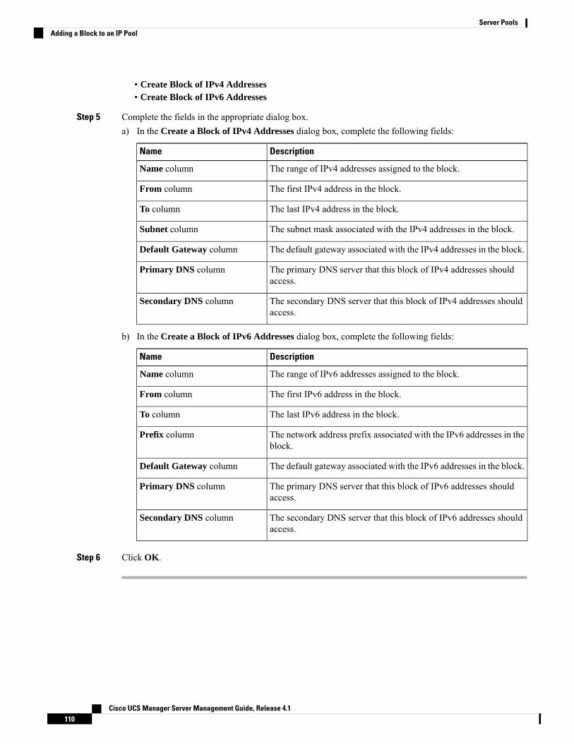
• Create Block of IPv4 Addresses• Create Block of IPv6 Addresses
Step 5 Complete the fields in the appropriate dialog box.a) In the Create a Block of IPv4 Addresses dialog box, complete the following fields:
DescriptionName
The range of IPv4 addresses assigned to the block.Name column
The first IPv4 address in the block.From column
The last IPv4 address in the block.To column
The subnet mask associated with the IPv4 addresses in the block.Subnet column
The default gateway associated with the IPv4 addresses in the block.Default Gateway column
The primary DNS server that this block of IPv4 addresses shouldaccess.
Primary DNS column
The secondary DNS server that this block of IPv4 addresses shouldaccess.
Secondary DNS column
b) In the Create a Block of IPv6 Addresses dialog box, complete the following fields:
DescriptionName
The range of IPv6 addresses assigned to the block.Name column
The first IPv6 address in the block.From column
The last IPv6 address in the block.To column
The network address prefix associated with the IPv6 addresses in theblock.
Prefix column
The default gateway associated with the IPv6 addresses in the block.Default Gateway column
The primary DNS server that this block of IPv6 addresses shouldaccess.
Primary DNS column
The secondary DNS server that this block of IPv6 addresses shouldaccess.
Secondary DNS column
Step 6 Click OK.
Cisco UCS Manager Server Management Guide, Release 4.1110
Server PoolsAdding a Block to an IP Pool
Deleting a Block from an IP Pool
Procedure
Step 1 In the Navigation pane, click LAN.Step 2 In the LAN tab, expand LAN > Pools > Root .Step 3 Expand the IP Pools node.Step 4 Expand the pool for which you want to delete a block of IP addresses.Step 5 Right-click the IP address block that you want to delete and select Delete.Step 6 If a confirmation dialog box displays, click Yes.
Deleting an IP PoolIf you delete a pool, Cisco UCS Manager does not reallocate any addresses from that pool that were assignedto vNICs or vHBAs. All assigned addresses from a deleted pool remain with the vNIC or vHBA to whichthey are assigned until one of the following occurs:
• The associated service profiles are deleted.
• The vNIC or vHBA to which the address is assigned is deleted.
• The vNIC or vHBA is assigned to a different pool.
Procedure
Step 1 In the Navigation pane, click LAN.Step 2 In the LAN tab, expand LAN > Pools > Organization_Name .Step 3 Expand the IP Pools node.Step 4 Right-click the IP pool you want to delete and select Delete.
You cannot delete the default pools ext-mgmt and iscsi-initiator-pool.Note
Step 5 If a confirmation dialog box displays, click Yes.
Cisco UCS Manager Server Management Guide, Release 4.1111
Server PoolsDeleting a Block from an IP Pool

Cisco UCS Manager Server Management Guide, Release 4.1112
Server PoolsDeleting an IP Pool

C H A P T E R 10Server Boot
• Boot Policy, on page 113• UEFI Boot Mode, on page 114• UEFI Secure Boot, on page 115• CIMC Secure Boot, on page 116• Creating a Boot Policy, on page 118• SAN Boot, on page 119• iSCSI Boot, on page 121• LAN Boot, on page 145• Local Devices Boot, on page 146• Deleting a Boot Policy, on page 152• UEFI Boot Parameters, on page 153
Boot PolicyThe Cisco UCS Manager enables you to create a boot policy for blade servers and rack servers.
The Cisco UCS Manager boot policy overrides the boot order in the BIOS setup menu and determines thefollowing:
• Selection of the boot device
• Location from which the server boots
• Order in which boot devices are invoked
For example, you can have associated servers boot from a local device, such as a local disk or CD-ROM(VMedia), or you can select a SAN boot or a LAN (PXE) boot.
You can either create a named boot policy to associate with one or more service profiles, or create a bootpolicy for a specific service profile. A boot policy must be included in a service profile, and that service profilemust be associated with a server for it to take effect. If you do not include a boot policy in a service profile,Cisco UCS Manager applies the default boot policy.
Cisco UCS Manager Server Management Guide, Release 4.1113

Changes to a boot policy might be propagated to all servers created with an updating service profile templatethat includes that boot policy. Re-association of the service profile with the server to rewrite the boot orderinformation in the BIOS is automatically triggered.
You can also specify the following for the boot policy:
• Local LUN name. The name specified is the logical name in the storage profile, not the deployed name.Specify only a primary name. Specifying a secondary name results in a configuration error.
• Specific JBOD disk number for booting from JBOD disks.
• Any LUN for backward compatibility; however, we do not recommend this. Other devices must not havebootable images to ensure a successful boot.
Note
UEFI Boot ModeUnified Extensible Firmware Interface (UEFI) is a specification that defines a software interface between anoperating system and platform firmware. Cisco UCS Manager uses UEFI to replace the BIOS firmwareinterfaces. This allows the BIOS to run in UEFI mode while still providing legacy support.
You can choose either legacy or UEFI boot mode when you create a boot policy. Legacy boot mode is supportedfor all Cisco UCS servers except Cisco UCS C125 M5 Server. UEFI boot mode is supported only on M3 andhigher servers, and allows you to enable UEFI secure boot mode. Cisco UCS C125 M5 Server supports onlyUEFI boot mode.
UEFI PXE boot is supported with all Cisco VIC adapters on Cisco UCS rack servers integrated with CiscoUCS Manager Release 2.2(4) and later releases. Beginning with Cisco UCS Manager Release 2.2(1), UEFIPXE boot is supported on all Cisco blade servers.
The following limitations apply to the UEFI boot mode:
• UEFI boot mode is not supported with the following combinations:
• Gen-3 Emulex and QLogic adapters on Cisco UCS blade and rack servers integrated with CiscoUCS Manager.
• iSCSI boot for all adapters on Cisco UCS rack servers integrated with Cisco UCS Manager.
• If you want to use UEFI boot mode with two iSCSI LUNs, you must manually specify a common iSCSIinitiator name in the service profile that is applied to both underlying iSCSI eNICs rather than allowingCisco UCS Manager to select the name from an IQN suffix pool. If you do not supply a common name,Cisco UCS Manager will not be able to detect the second iSCSI LUN.
• You cannot mix UEFI and legacy boot mode on the same server.
• The server will boot correctly in UEFI mode only if the boot devices configured in the boot policy haveUEFI-aware operating systems installed. If a compatible OS is not present, the boot device is not displayedon the Actual Boot Order tab in the Boot Order Details area.
• In some corner cases, the UEFI boot may not succeed because the UEFI boot manager entry was notsaved correctly in the BIOS NVRAM. You can use the UEFI shell to enter the UEFI boot manager entrymanually. This situation could occur in the following situations:
Cisco UCS Manager Server Management Guide, Release 4.1114
Server BootUEFI Boot Mode
• If a blade server with UEFI boot mode enabled is disassociated from the service profile, and theblade is manually powered on using the Equipment tab or the front panel.
• If a blade server with UEFI boot mode enabled is disassociated from the service profile, and a directVIC firmware upgrade is attempted.
• If a blade or rack server with UEFI boot mode enabled is booted off SAN LUN, and the serviceprofile is migrated.
You can create UEFI boot parameters in Cisco UCS Manager. UEFI Boot Parameters, on page 153provides more information.
UEFI Secure BootCisco UCS Manager supports UEFI secure boot on Cisco UCS B-Series M4 and higher Blade servers, CiscoUCS C-Series M3 and higher Rack servers, and Cisco UCS S-Series M4 Rack servers, and Cisco UCS C125M5 Servers. Linux secure boot is supported on SLES 15, SLES 13 SP4, Red Hat Linux 7.6 operating systemsstarting with Release 4.0(4a). When UEFI secure boot is enabled, all executables, such as boot loaders andadapter drivers, are authenticated by the BIOS before they can be loaded. To be authenticated, the imagesmust be signed by either the Cisco Certificate Authority (CA) or a Microsoft CA.
The following limitations apply to UEFI secure boot:
• UEFI boot mode must be enabled in the boot policy.
• UEFI boot mode is available only for drives.
• The Cisco UCS Manager software and the BIOS firmware must be at Release 2.2 or greater.
UEFI boot mode is supported on Cisco UCS C-Series and S-Seriesrack servers beginning with Release 2.2(3a).
Note
• User-generated encryption keys are not supported.
• UEFI secure boot can only be controlled by Cisco UCS Manager.
• If you want to downgrade to an earlier version of Cisco UCS Manager, and you have a server in secureboot mode, you must disassociate, then re-associate the server before downgrading. Otherwise, serverdiscovery is not successful.
• In Cisco UCSManager Release 4.0, UEFI secure boot is supported on the following Operating Systems:
• In Cisco UCS Manager Release 4.0(1), UEFI secure boot is supported only on Windows 2016 andWindows 2012 R2.
• In Cisco UCS Manager Release 4.0(2), UEFI secure boot is supported only on Windows 2016 andWindows 2019.
• In Cisco UCS Manager Release 4.0(4), UEFI secure boot is supported on the following:
Cisco UCS Manager Server Management Guide, Release 4.1115
Server BootUEFI Secure Boot
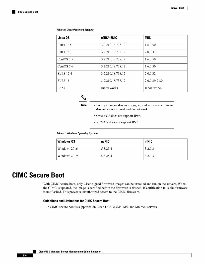
Table 10: Linux Operating Systems
fNICeNIC/nENICLinux OS
1.6.0.503.2.210.18.738.12RHEL 7.5
2.0.0.373.2.210.18.738.12RHEL 7.6
1.6.0.503.2.210.18.738.12CentOS 7.5
1.6.0.503.2.210.18.738.12CentOS 7.6
2.0.0.323.2.210.18.738.12SLES 12.4
2.0.0.39-71.03.2.210.18.738.12SLES 15
Inbox worksInbox worksESXi
• For ESXi, inbox drivers are signed and work as such. Asyncdrivers are not signed and do not work.
• Oracle OS does not support IPv6.
• XEN OS does not support IPv6.
Note
Table 11: Windows Operating Systems
nfNICneNICWindows OS
3.2.0.35.3.25.4Windows 2016
3.2.0.35.3.25.4Windows 2019
CIMC Secure BootWith CIMC secure boot, only Cisco signed firmware images can be installed and run on the servers. Whenthe CIMC is updated, the image is certified before the firmware is flashed. If certification fails, the firmwareis not flashed. This prevents unauthorized access to the CIMC firmware.
Guidelines and Limitations for CIMC Secure Boot
• CIMC secure boot is supported on Cisco UCS M3M4, M5, and M6 rack servers.
Cisco UCS Manager Server Management Guide, Release 4.1116
Server BootCIMC Secure Boot

CIMC secure boot is enabled by default on the Cisco UCS C220M4/M5, C240 M4/M5, C480 M5/C480 M5ML, rack servers, and isautomatically enabled on the Cisco UCS C460 M4 rack server afterupgrading to CIMC firmware release 2.2(3) or higher.
Note
• After CIMC secure boot is enabled, you cannot disable it.
• After CIMC secure boot is enabled on a server, you cannot downgrade to a CIMC firmware image priorto 2.1(3).
Determining the CIMC Secure Boot Status
Procedure
Step 1 In the Navigation pane, click Equipment.Step 2 Expand Equipment > Rack-Mounts > Servers > Server Name.Step 3 In the Work area, click the Inventory tab.Step 4 Click the CIMC subtab.Step 5 In the CIMC area, note the Secure Boot Operational State field.
This can be one of the following:
• Unsupported—CIMC secure boot is not supported on the server.
• Disabled—CIMC secure boot is supported, but is disabled on the server.
• Enabling—CIMC secure boot was enabled, and the operation is in process.
• Enabled—CIMC secure boot is enabled on the server.
Enabling CIMC Secure Boot on a Rack Server
Procedure
Step 1 In the Navigation pane, click Equipment.Step 2 Expand Equipment > Rack-Mounts > Servers > Server Name.Step 3 In the Work area, click the Inventory tab.Step 4 Click the CIMC subtab.Step 5 In the Actions area, click Enable Secure Boot.
CIMC secure boot is only supported on Cisco UCS M3 rack servers. If CIMC secure boot is not supportedor is already enabled, this action is greyed.
Cisco UCS Manager Server Management Guide, Release 4.1117
Server BootDetermining the CIMC Secure Boot Status
Step 6 Click Yes in the Enable Secure Boot confirmation dialog box.
After enabled, you cannot disable CIMC secure boot.Note
Creating a Boot PolicyYou can also create a local boot policy that is restricted to a service profile or service profile template. However,Cisco recommends that you create a global boot policy that can be included in multiple service profiles orservice profile templates.
Procedure
Step 1 In the Navigation pane, click Servers.Step 2 Expand Servers > Policies.Step 3 Expand the node for the organization where you want to create the policy.
If the system does not include multi tenancy, expand the root node.
Step 4 Right-click Boot Policies and select Create Boot Policy.
The Create Boot Policy wizard displays.
Step 5 Enter a unique name and description for the policy.
This name can be between 1 and 16 alphanumeric characters. You cannot use spaces or any special charactersother than - (hyphen), _ (underscore), : (colon), and . (period), and you cannot change this name after theobject is saved.
Step 6 (Optional) After you make changes to the boot order, check the Reboot on Boot Order Change check boxto reboot all servers that use this boot policy.
For boot policies applied to a server with a non-Cisco VIC adapter, even if theReboot on Boot Order Changecheck box is not checked, when SAN devices are added, deleted, or their order is changed, the server alwaysreboots when boot policy changes are saved.
Step 7 (Optional) If desired, check the Enforce vNIC/vHBA/iSCSI Name check box.
• If checked, Cisco UCS Manager displays a configuration error and reports whether one or more of thevNICs, vHBAs, or iSCSI vNICs listed in the Boot Order table match the server configuration in theservice profile.
• If not checked, Cisco UCS Manager uses the vNICs or vHBAs (as appropriate for the boot option) fromthe service profile.
Step 8 In the Boot Mode field, choose the Legacy or UEFI radio button.
Cisco UCS C125 M5 Server supports only UEFI boot mode.Note
Step 9 If you selected UEFI, check the Boot Security checkbox if you want to enable UEFI boot security.Step 10 Configure one or more of the following boot options for the boot policy and set their boot order:
Cisco UCS Manager Server Management Guide, Release 4.1118
Server BootCreating a Boot Policy
• Local Devices boot—To boot from local devices, such as local disks on the server, virtual media, orremote virtual disks, continue with Configuring a Local Disk Boot for a Boot Policy, on page 147.
• SAN boot—To boot from an operating system image on the SAN, continue with Configuring a SANBoot for a Boot Policy, on page 119.
You can specify a primary and a secondary SAN boot. If the primary boot fails, the server attempts toboot from the secondary.
• LAN boot—To boot from a centralized provisioning server, continue with Configuring a LAN Boot fora Boot Policy, on page 145.
• iSCSI boot—To boot from an iSCSI LUN, continue with Creating an iSCSI Boot Policy, on page 130.
What to do next
Include the boot policy in a service profile and template.
After a server is associated with a service profile that includes this boot policy, you can verify the boot orderin the Boot Order Details area on the General tab for the server.
SAN BootYou can configure a boot policy to boot one or more servers from an operating system image on the SAN.The boot policy can include a primary and a secondary SAN boot. If the primary boot fails, the server attemptsto boot from the secondary.
Cisco recommends using a SAN boot, because it offers the most service profile mobility within the system.If you boot from the SAN when you move a service profile from one server to another, the new server bootsfrom the same operating system image. Therefore, the new server appears as the same server to the network.
To use a SAN boot, ensure that the following is configured:
• The Cisco UCS domainmust be able to communicate with the SAN storage device that hosts the operatingsystem image.
• A boot target LUN (Logical Unit Number) on the device where the operating system image is located.
SAN boot is not supported on Gen-3 Emulex adapters on Cisco UCS blade and rack servers.Note
Configuring a SAN Boot for a Boot PolicyYou can also create a local boot policy that is restricted to a service profile or service profile template. However,Cisco recommends that you create a global boot policy that can be included in multiple service profiles orservice profile templates.
Cisco UCS Manager Server Management Guide, Release 4.1119
Server BootSAN Boot

If you configure a local disk and a SAN LUN for the boot order storage type and the operating system orlogical volume manager (LVM) is configured incorrectly, the server might boot from the local disk ratherthan the SAN LUN.
For example, on a server with Red Hat Linux installed, where the LVM is configured with default LV namesand the boot order is configured with a SAN LUN and a local disk, Linux reports that there are two LVs withthe same name and boots from the LV with the lowest SCSI ID, which could be the local disk.
Tip
This procedure continues directly from Creating a Boot Policy, on page 118.
Before you begin
If you are creating a boot policy that boots the server from a SAN LUN and you require reliable SAN bootoperations, Cisco recommends that you first remove all local disks and other SAN LUNs from the boot policyin the server service profile.
This does not apply to the UCS Mini Series.
Note
Procedure
Step 1 Click the down arrows to expand the vHBAs area.Step 2 Click the Add SAN Boot link.Step 3 In the Add San Boot dialog box, specify the vHBA and type, then click OK.
You can specify a Primary or a Secondary SAN boot. If the primary boot fails, the server attempts to bootfrom the secondary. The Any option is for unsupported adapters that connect directly to the SAN storagedevice and bypasses UCSManager. Do not use the Any option with SAN boot for a supported set of adaptorswhich are managed by UCSM. For unsupported adaptors, use the instructions from the vendor to configurethe adaptor for booting.
Step 4 If this vHBA points to a bootable SAN image, click the Add SAN Boot Target link and, in the Add SANBoot Target dialog box, specify the boot target LUN, boot target WWPN, and type, then click OK:
Step 5 Do one of the following:
• Add another boot device to the Boot Order table.• Click OK to finish.
What to do next
Include the boot policy in a service profile and template.
After a server is associated with a service profile that includes this boot policy, you can verify the actual bootorder in the Boot Order Details area on the General tab for the server.
Cisco UCS Manager Server Management Guide, Release 4.1120
Server BootConfiguring a SAN Boot for a Boot Policy

iSCSI BootiSCSI boot enables a server to boot its operating system from an iSCSI target machine located remotely overa network.
iSCSI boot is supported on the following Cisco UCS hardware:
• Cisco UCS blade servers that have the Cisco UCS M51KR-B Broadcom BCM57711 network adapterand use the default MAC address provided by Broadcom.
• Cisco UCS M81KR Virtual Interface Card
• Cisco UCS VIC-1240 Virtual Interface Card
• Cisco UCS VIC-1280 Virtual Interface Card
• Cisco UCS VIC-1340 Virtual Interface Card
• Cisco UCS VIC 1455
• Cisco UCS VIC 1457
• Cisco UCS rack servers that have the Cisco UCS M61KR-B Broadcom BCM57712 network adapter.
• Cisco UCS P81E Virtual Interface Card
• Cisco UCS VIC 1225 Virtual Interface Card on Cisco UCS rack servers
There are prerequisites that must be met before you configure iSCSI boot. For a list of these prerequisites,see iSCSI Boot Guidelines and Prerequisites, on page 122.
For a high-level procedure for implementing iSCSI boot, see Configuring iSCSI Boot, on page 125.
iSCSI Boot ProcessCisco UCS Manager uses the iSCSI vNIC and iSCSI boot information created for the service profile in theassociation process to program the adapter, located on the server. After the adapter is programmed, the serverreboots with the latest service profile values. After the power on self-test (POST), the adapter attempts toinitialize using these service profile values. If the adapter can use the values and log in to its specified target,the adapter initializes and posts an iSCSI Boot Firmware Table (iBFT) to the host memory and a valid bootableLUN to the system BIOS. The iBFT that is posted to the host memory contains the initiator and targetconfiguration that is programmed on the primary iSCSI VNIC.
Previously, the host could see only one of the boot paths configured, depending on which path completed theLUN discovery first, and would boot from that path. Now, when there are two iSCSI boot vNICs configured,the host sees both of the boot paths. So for multipath configurations, a single IQNmust be configured on boththe boot vNICs. If there are different IQNs configured on the boot vNICs on a host, the host boots with theIQN that is configured on the boot vNIC with the lower PCI order.
Note
The next step, which is the installation of the operating system (OS), requires an OS that is iBFT capable.During installation of the OS, the OS installer scans the host memory for the iBFT table and uses the informationin the iBFT to discover the boot device and create an iSCSI path to the target LUN. Some OSs requires a NIC
Cisco UCS Manager Server Management Guide, Release 4.1121
Server BootiSCSI Boot

driver to complete this path. If this step is successful, the OS installer finds the iSCSI target LUN on whichto install the OS.
The iBFT works at the OS installation software level and might not work with HBA mode (also known asTCP offload). Whether iBFT works with HBAmode depends on the OS capabilities during installation. Also,for a server that includes a Cisco UCS M51KR-B Broadcom BCM57711 adapter, the iBFT normally worksat a maximum transmission unit (MTU) size of 1500, regardless of the MTU jumbo configuration. If the OSsupports HBA mode, you might need to set HBA mode, dual-fabric support, and jumbo MTU size after theiSCSI installation process.
Note
iSCSI Boot Guidelines and PrerequisitesThese guidelines and prerequisites must be met before configuring iSCSI boot:
• After the iSCSI boot policies are created, a user with ls-compute privileges can include them in a serviceprofile or service profile template. However, a user with only ls-compute privileges cannot create iSCSIboot policies.
• To set up iSCSI boot from a Windows 2008 server where the second vNIC (failover vNIC) must bootfrom an iSCSI LUN, consult Microsoft Knowledge Base Article 976042. Microsoft has a known issuewhere Windows might fail to boot from an iSCSI drive or cause a bugcheck error if the networkinghardware is changed. To work around this issue, follow the resolution recommended by Microsoft.
• The storage array must be licensed for iSCSI boot and the array side LUN masking must be properlyconfigured.
• Two IP addresses must be determined, one for each iSCSI initiator. If possible, the IP addresses shouldbe on the same subnet as the storage array. The IP addresses are assigned statically or dynamically usingthe Dynamic Host Configuration Protocol (DHCP).
• You cannot configure boot parameters in the Global boot policy. Instead, after configuring boot parameters,include the boot policy in the appropriate service profile.
• The operating system (OS) must be iSCSI Boot Firmware Table (iBFT) compatible.
• For RHEL 7.x, the kernel parameter "rd.iscsi.ibft=1" is required before the installation. If theparameter is not entered, the iSCSI boot may fail.
• For SLES 12.x, the following guidelines must be followed:
• Hit "e" on the install disk before loading the kernel, edit the linuxefi ( if using EFI) or kernel(if using legacy), and add the kernel parameter “rd.iscsi.ibft=1 rd.iscsi.firmware=1rd.neednet=1”. If the parameter is not entered, the iSCSI boot may fail.
• On an existing system that uses iSCSI, ensure that the /etc/iscsi/iscsid.conf hasnode.startup=automatic (not manual). Add this parameter to the /etc/default/grub/ and then rungrub2-mkconfig -o /boot/grub2/grub.cfg to rebuild grub config.
• For Cisco UCS M51KR-B Broadcom BCM57711 network adapters:
• Servers that use iSCSI boot must contain the Cisco UCSM51KR-B BroadcomBCM57711 networkadapter. For information on installing or replacing an adapter card, see theCisco UCS B250 Extended
Cisco UCS Manager Server Management Guide, Release 4.1122
Server BootiSCSI Boot Guidelines and Prerequisites
Memory Blade Server Installation and Service Note. The service note is accessible from the CiscoUCS B-Series Servers Documentation Roadmap athttp://www.cisco.com/go/unifiedcomputing/b-series-doc.
• Set the MAC addresses on the iSCSI device.
• If you are using the DHCP Vendor ID (Option 43), configure the MAC address of an iSCSI devicein /etc/dhcpd.conf.
• HBA mode (also known as TCP offload) and the boot to target setting are supported. However,only Windows OS supports HBA mode during installation.
• Before installing the OS, disable the boot to target setting in the iSCSI adapter policy, then afterinstalling the OS, re-enable the boot to target setting.
Each time you change an adapter policy setting, the adapterreboots to apply the new setting.
Note
• When installing the OS on the iSCSI target, the iSCSI target must be ordered before the devicewhere the OS image resides. For example, if you are installing the OS on the iSCSI target from aCD, the boot order should be the iSCSI target and then the CD.
• After the server is iSCSI booted, do not modify the Initiator Name, Target name, LUN, iSCSI deviceIP, or Netmask/gateway using the Broadcom tool.
• Do not interrupt the POST (power on self-test) process or the Cisco UCS M51KR-B BroadcomBCM57711 network adapter will fail to initialize.
• For Cisco UCS M81KR Virtual Interface Card and Cisco UCS VIC-1240 Virtual Interface Card:
For Cisco UCS VIC-1240 Virtual Interface Card:
• Do not set MAC addresses on the iSCSI device.
• HBA mode and the boot to target setting are not supported.
• When installing the OS on the iSCSI target, the iSCSI target must be ordered after the device wherethe OS image resides. For example, if you are installing the OS on the iSCSI target from a CD, theboot order should be the CD and then the iSCSI target.
• If you are using the DHCP Vendor ID (Option 43), the MAC address of the overlay vNIC must beconfigured in /etc/dhcpd.conf.
• After the server is iSCSI booted, do not modify the IP details of the overlay vNIC.
• The VMware ESX/ESXi operating system does not support storing a core dump file to an iSCSI boottarget LUN. Dump files must be written to a local disk.
Initiator IQN ConfigurationCisco UCS uses the following rules to determine the initiator IQN for an adapter iSCSI vNIC at the time aservice profile is associated with a physical server:
Cisco UCS Manager Server Management Guide, Release 4.1123
Server BootInitiator IQN Configuration
• An initiator IQN at the service profile level and at the iSCSI vNIC level cannot be used together in aservice profile.
• If an initiator IQN is specified at the service profile level, all of the adaptor iSCSI vNICs are configuredto use the same initiator IQN, except in the case of DHCP Option 43, where the initiator IQN is set toempty on the adapter iSCSI vNIC.
• When an initiator IQN is set at the iSCSI vNIC level, the initiator IQN at the service profile level isremoved, if one is present.
• If there are two iSCSI vNIC in a service profile and only one of them has the initiator IQN set, the secondone is configured with the default IQN pool. You can change this configuration later. The only exceptionis if DHCP Option 43 is configured. In this case, the initiator IQN on the second iSCSI vNIC is removedduring service profile association.
If you change an iSCSI vNIC to use the DHCP Option 43 by settingthe vendor ID, it does not remove the initiator IQN configured at theservice profile level. The initiator IQN at the service profile level canstill be used by another iSCSI vNIC which does not use the DHCPOption 43.
Note
Enabling MPIO on WindowsYou can enable (MPIO) to optimize connectivity with storage arrays.
If you change the networking hardware,Windowsmight fail to boot from an iSCSI drive. For more information,see Microsoft support Article ID: 976042.
Note
Before you begin
The server on which you enable the Microsoft Multipath I/O (MPIO) must have a Cisco VIC driver.
If there are multiple paths configured to the boot LUN, only one path should be enabled when the LUN isinstalled.
Procedure
Step 1 In the service profile associated with the server, configure the primary iSCSI vNIC.
For more information, see Creating an iSCSI vNIC for a Service Profile, on page 131.
Step 2 Using the primary iSCSI vNIC, install the Windows operating system on the iSCSI target LUN.Step 3 After Windows installation completes, enable MPIO on the host.Step 4 In the service profile associated with the server, add the secondary iSCSI vNIC to the boot policy.
Cisco UCS Manager Server Management Guide, Release 4.1124
Server BootEnabling MPIO on Windows
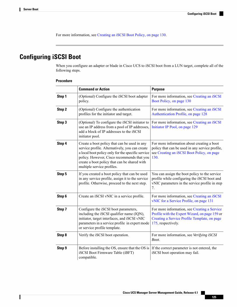
For more information, see Creating an iSCSI Boot Policy, on page 130.
Configuring iSCSI BootWhen you configure an adapter or blade in Cisco UCS to iSCSI boot from a LUN target, complete all of thefollowing steps.
Procedure
PurposeCommand or Action
For more information, see Creating an iSCSIBoot Policy, on page 130
(Optional) Configure the iSCSI boot adapterpolicy.
Step 1
For more information, see Creating an iSCSIAuthentication Profile, on page 128
(Optional) Configure the authenticationprofiles for the initiator and target.
Step 2
For more information, see Creating an iSCSIInitiator IP Pool, on page 129
(Optional) To configure the iSCSI initiator touse an IP address from a pool of IP addresses,add a block of IP addresses to the iSCSIinitiator pool.
Step 3
For more information about creating a bootpolicy that can be used in any service profile,
Create a boot policy that can be used in anyservice profile. Alternatively, you can create
Step 4
see Creating an iSCSI Boot Policy, on page130.
a local boot policy only for the specific servicepolicy. However, Cisco recommends that youcreate a boot policy that can be shared withmultiple service profiles.
You can assign the boot policy to the serviceprofile while configuring the iSCSI boot and
If you created a boot policy that can be usedin any service profile, assign it to the serviceprofile. Otherwise, proceed to the next step.
Step 5
vNIC parameters in the service profile in step7.
For more information, see Creating an iSCSIvNIC for a Service Profile, on page 131
Create an iSCSI vNIC in a service profile.Step 6
For more information, see Creating a ServiceProfile with the ExpertWizard, on page 159 or
Configure the iSCSI boot parameters,including the iSCSI qualifier name (IQN),
Step 7
Creating a Service Profile Template, on page175, respectively.
initiator, target interfaces, and iSCSI vNICparameters in a service profile in expert modeor service profile template.
For more information, see Verifying iSCSIBoot.
Verify the iSCSI boot operation.Step 8
If the correct parameter is not entered, theiSCSI boot operation may fail.
Before installing the OS, ensure that the OS isiSCSI Boot Firmware Table (iBFT)compatible.
Step 9
Cisco UCS Manager Server Management Guide, Release 4.1125
Server BootConfiguring iSCSI Boot

PurposeCommand or Action
• For RHEL 7.x, the kernel parameter"rd.iscsi.ibft=1" is required beforeinstalling the OS.
• For SLES 12.x, hit "e" on the install diskbefore loading the kernel, edit the linuxefi( if using EFI) or kernel (if using legacy),and add the kernel parameter“rd.iscsi.ibft=1 rd.iscsi.firmware=1rd.neednet=1”.
For more information, see one of the followingguides:
Install the OS on the server.Step 10
• Cisco UCS B-Series Blade ServersVMware Installation Guide
• Cisco UCS B-Series Blade Servers LinuxInstallation Guide
• Cisco UCS B-Series Blade ServersWindows Installation Guide
Boot the server.Step 11
Creating an iSCSI Adapter Policy
Procedure
Step 1 In the Navigation pane, click Servers.Step 2 Expand Servers > Policies.Step 3 Expand the node for the organization where you want to create the policy.
If the system does not include multi tenancy, expand the root node.
Step 4 Right-click Adapter Policies and choose Create iSCSI Adapter Policy.Step 5 In the Create iSCSI Adapter Policy dialog box, complete the following fields:
DescriptionName
The name of the policy.
This name can be between 1 and 16 alphanumeric characters. You cannotuse spaces or any special characters other than - (hyphen), _ (underscore),: (colon), and . (period), and you cannot change this name after the objectis saved.
Name field
Cisco UCS Manager Server Management Guide, Release 4.1126
Server BootCreating an iSCSI Adapter Policy

DescriptionName
The number of seconds to wait until Cisco UCS assumes that the initiallogin has failed and the iSCSI adapter is unavailable.
Enter an integer between 0 and 255. If you enter 0, Cisco UCS uses thevalue set in the adapter firmware (default: 15 seconds).
Connection Timeout field
The number of times to retry the connection in case of a failure duringiSCSI LUN discovery.
Enter an integer between 0 and 60. If you enter 0, Cisco UCS uses thevalue set in the adapter firmware (default: 15 seconds).
LUN Busy Retry Count field
The number of seconds to wait before the initiator assumes that theDHCP server is unavailable.
Enter an integer between 60 and 300 (default: 60 seconds).
DHCP Timeout field
Check this box if you want to use a TCP Timestamp. With this setting,transmitted packets are given a time stamp of when the packet was sentso that the packet's round-trip time can be calculated, when needed.
This option only applies to servers with the Cisco UCS NICM51KR-B adapter.
Note
Enable TCP Timestamp checkbox
Check this box to enable HBA mode (also known as TCP offload).
This option should only be enabled for servers with the CiscoUCSNICM51KR-B adapter running theWindows operatingsystem.
Important
HBA Mode check box
Check this box to boot from the iSCSI target.
This option only applies to servers with the Cisco UCS NICM51KR-B adapter. It should be disabled until you haveinstalled an operating system on the server.
Note
Boot to Target check box
This can be one of the following:
• Local—This policy is available only to service profiles and serviceprofile templates in this Cisco UCS domain.
• Pending Global—Control of this policy is being transferred toCisco UCS Central. Once the transfer is complete, this policy willbe available to all Cisco UCS domains registered with Cisco UCSCentral.
• Global—This policy is managed by Cisco UCS Central. Anychanges to this policy must be made through Cisco UCS Central.
Owner field
Step 6 Click OK.
Cisco UCS Manager Server Management Guide, Release 4.1127
Server BootCreating an iSCSI Adapter Policy
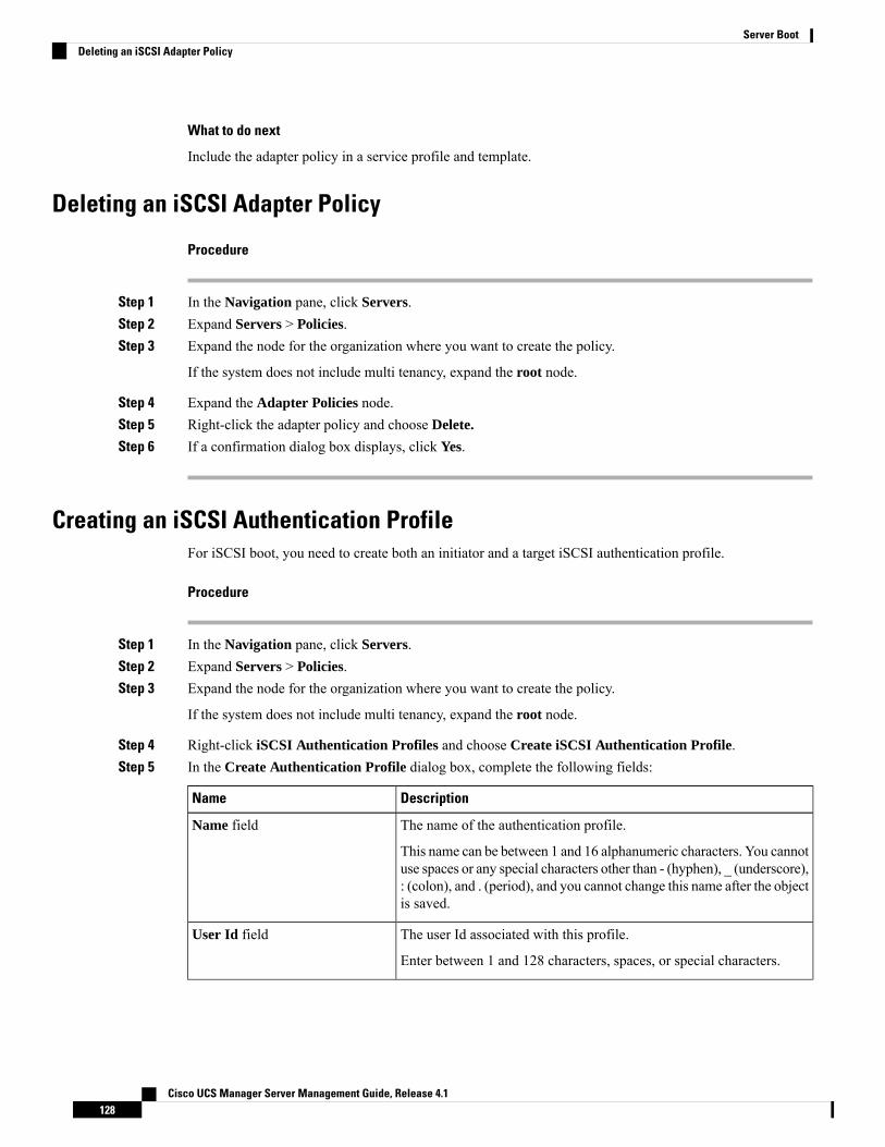
What to do next
Include the adapter policy in a service profile and template.
Deleting an iSCSI Adapter Policy
Procedure
Step 1 In the Navigation pane, click Servers.Step 2 Expand Servers > Policies.Step 3 Expand the node for the organization where you want to create the policy.
If the system does not include multi tenancy, expand the root node.
Step 4 Expand the Adapter Policies node.Step 5 Right-click the adapter policy and choose Delete.
Step 6 If a confirmation dialog box displays, click Yes.
Creating an iSCSI Authentication ProfileFor iSCSI boot, you need to create both an initiator and a target iSCSI authentication profile.
Procedure
Step 1 In the Navigation pane, click Servers.Step 2 Expand Servers > Policies.Step 3 Expand the node for the organization where you want to create the policy.
If the system does not include multi tenancy, expand the root node.
Step 4 Right-click iSCSI Authentication Profiles and choose Create iSCSI Authentication Profile.Step 5 In the Create Authentication Profile dialog box, complete the following fields:
DescriptionName
The name of the authentication profile.
This name can be between 1 and 16 alphanumeric characters. You cannotuse spaces or any special characters other than - (hyphen), _ (underscore),: (colon), and . (period), and you cannot change this name after the objectis saved.
Name field
The user Id associated with this profile.
Enter between 1 and 128 characters, spaces, or special characters.
User Id field
Cisco UCS Manager Server Management Guide, Release 4.1128
Server BootDeleting an iSCSI Adapter Policy
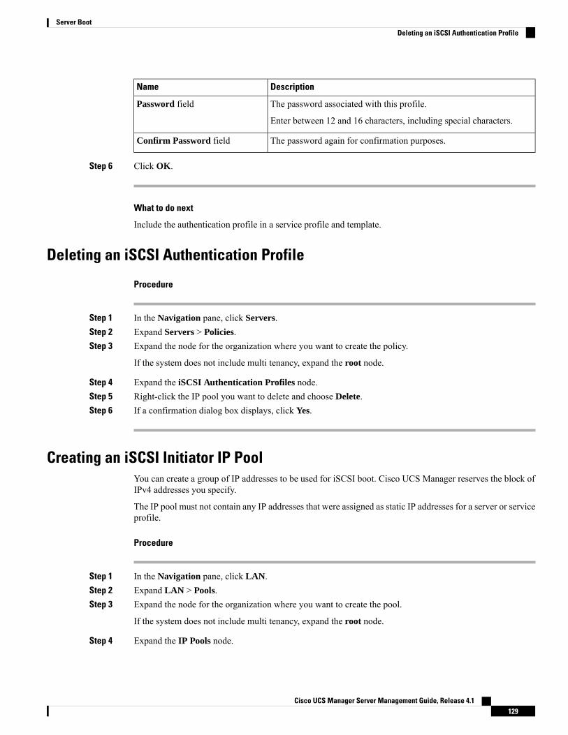
DescriptionName
The password associated with this profile.
Enter between 12 and 16 characters, including special characters.
Password field
The password again for confirmation purposes.Confirm Password field
Step 6 Click OK.
What to do next
Include the authentication profile in a service profile and template.
Deleting an iSCSI Authentication Profile
Procedure
Step 1 In the Navigation pane, click Servers.Step 2 Expand Servers > Policies.Step 3 Expand the node for the organization where you want to create the policy.
If the system does not include multi tenancy, expand the root node.
Step 4 Expand the iSCSI Authentication Profiles node.Step 5 Right-click the IP pool you want to delete and choose Delete.Step 6 If a confirmation dialog box displays, click Yes.
Creating an iSCSI Initiator IP PoolYou can create a group of IP addresses to be used for iSCSI boot. Cisco UCS Manager reserves the block ofIPv4 addresses you specify.
The IP pool must not contain any IP addresses that were assigned as static IP addresses for a server or serviceprofile.
Procedure
Step 1 In the Navigation pane, click LAN.Step 2 Expand LAN > Pools.Step 3 Expand the node for the organization where you want to create the pool.
If the system does not include multi tenancy, expand the root node.
Step 4 Expand the IP Pools node.
Cisco UCS Manager Server Management Guide, Release 4.1129
Server BootDeleting an iSCSI Authentication Profile
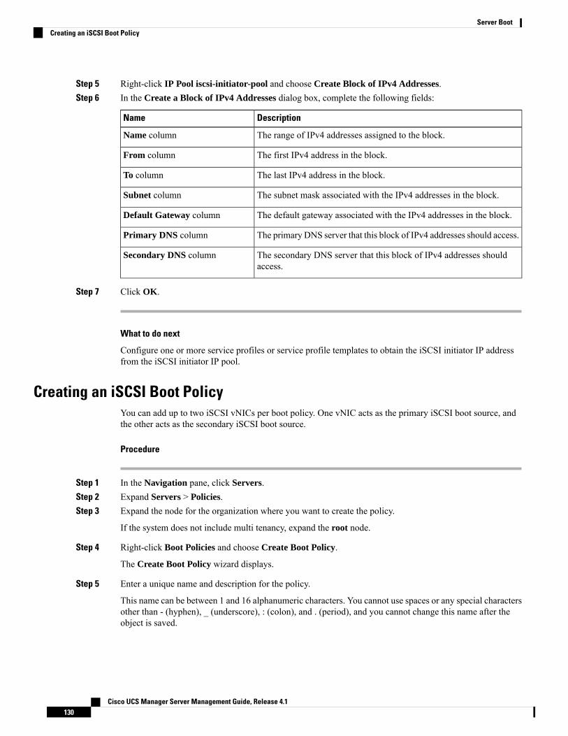
Step 5 Right-click IP Pool iscsi-initiator-pool and choose Create Block of IPv4 Addresses.Step 6 In the Create a Block of IPv4 Addresses dialog box, complete the following fields:
DescriptionName
The range of IPv4 addresses assigned to the block.Name column
The first IPv4 address in the block.From column
The last IPv4 address in the block.To column
The subnet mask associated with the IPv4 addresses in the block.Subnet column
The default gateway associated with the IPv4 addresses in the block.Default Gateway column
The primary DNS server that this block of IPv4 addresses should access.Primary DNS column
The secondary DNS server that this block of IPv4 addresses shouldaccess.
Secondary DNS column
Step 7 Click OK.
What to do next
Configure one or more service profiles or service profile templates to obtain the iSCSI initiator IP addressfrom the iSCSI initiator IP pool.
Creating an iSCSI Boot PolicyYou can add up to two iSCSI vNICs per boot policy. One vNIC acts as the primary iSCSI boot source, andthe other acts as the secondary iSCSI boot source.
Procedure
Step 1 In the Navigation pane, click Servers.Step 2 Expand Servers > Policies.Step 3 Expand the node for the organization where you want to create the policy.
If the system does not include multi tenancy, expand the root node.
Step 4 Right-click Boot Policies and choose Create Boot Policy.
The Create Boot Policy wizard displays.
Step 5 Enter a unique name and description for the policy.
This name can be between 1 and 16 alphanumeric characters. You cannot use spaces or any special charactersother than - (hyphen), _ (underscore), : (colon), and . (period), and you cannot change this name after theobject is saved.
Cisco UCS Manager Server Management Guide, Release 4.1130
Server BootCreating an iSCSI Boot Policy
Step 6 (Optional) To reboot a server that uses this boot policy after you make changes to the boot order, check theReboot on Boot Order Change check box.
In the Cisco UCS Manager GUI, if the Reboot on Boot Order Change check box is checked for a bootpolicy, and if CD-ROM or Floppy is the last device in the boot order, deleting or adding the device does notdirectly affect the boot order and the server does not reboot.
This applies only to servers using the standard boot order.Note
Step 7 (Optional) If desired, check the Enforce vNIC/vHBA/iSCSI Name check box.
• If checked, Cisco UCS Manager displays a configuration error and reports whether one or more of thevNICs, vHBAs, or iSCSI vNICs listed in the Boot Order table match the server configuration in theservice profile.
• If not checked, Cisco UCS Manager uses the vNICs or vHBAs (as appropriate for the boot option) fromthe service profile.
Step 8 To add a iSCSI boot to the boot policy, do the following:a) Click the down arrows to expand the iSCSI vNICs area.b) Click the Add iSCSI Boot link.c) In the Add iSCSI Boot dialog box, enter a name for the iSCSI vNIC, and click OK.d) Repeat steps b and c to create another iSCSI vNIC.
What to do next
Include the boot policy in a service profile and template.
After a server is associated with a service profile that includes this boot policy, you can verify the actual bootorder in the Boot Order Details area on the General tab for the server.
Creating an iSCSI vNIC for a Service Profile
Procedure
Step 1 In the Navigation pane, click Servers.Step 2 Expand Servers > Service Profiles.Step 3 Expand the node for the organization that contains the service profile for which you want to create an iSCSI
vNIC.Step 4 Expand the service profile for which you want to create a iSCSI vNIC.Step 5 Right-click the iSCSI vNICs node and choose Create vNICs.Step 6 In the Create iSCSI vNIC dialog box, complete the following fields:
Cisco UCS Manager Server Management Guide, Release 4.1131
Server BootCreating an iSCSI vNIC for a Service Profile
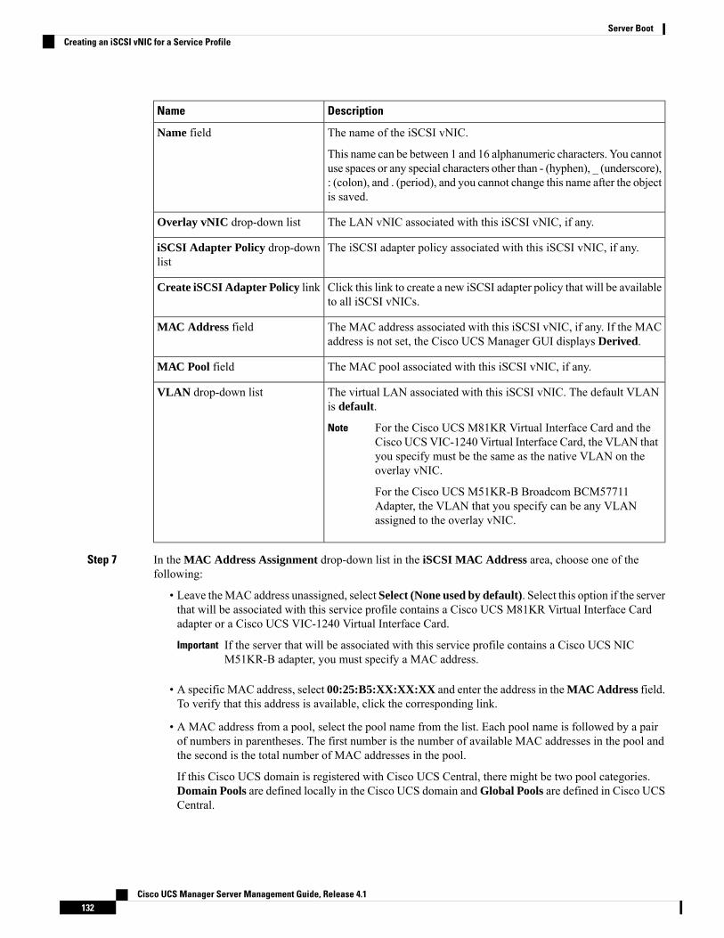
DescriptionName
The name of the iSCSI vNIC.
This name can be between 1 and 16 alphanumeric characters. You cannotuse spaces or any special characters other than - (hyphen), _ (underscore),: (colon), and . (period), and you cannot change this name after the objectis saved.
Name field
The LAN vNIC associated with this iSCSI vNIC, if any.Overlay vNIC drop-down list
The iSCSI adapter policy associated with this iSCSI vNIC, if any.iSCSI Adapter Policy drop-downlist
Click this link to create a new iSCSI adapter policy that will be availableto all iSCSI vNICs.
Create iSCSI Adapter Policy link
The MAC address associated with this iSCSI vNIC, if any. If the MACaddress is not set, the Cisco UCS Manager GUI displays Derived.
MAC Address field
The MAC pool associated with this iSCSI vNIC, if any.MAC Pool field
The virtual LAN associated with this iSCSI vNIC. The default VLANis default.
For the Cisco UCS M81KR Virtual Interface Card and theCisco UCS VIC-1240 Virtual Interface Card, the VLAN thatyou specify must be the same as the native VLAN on theoverlay vNIC.
For the Cisco UCS M51KR-B Broadcom BCM57711Adapter, the VLAN that you specify can be any VLANassigned to the overlay vNIC.
Note
VLAN drop-down list
Step 7 In the MAC Address Assignment drop-down list in the iSCSI MAC Address area, choose one of thefollowing:
• Leave theMAC address unassigned, select Select (None used by default). Select this option if the serverthat will be associated with this service profile contains a Cisco UCS M81KR Virtual Interface Cardadapter or a Cisco UCS VIC-1240 Virtual Interface Card.
If the server that will be associated with this service profile contains a Cisco UCS NICM51KR-B adapter, you must specify a MAC address.
Important
• A specific MAC address, select 00:25:B5:XX:XX:XX and enter the address in theMAC Address field.To verify that this address is available, click the corresponding link.
• A MAC address from a pool, select the pool name from the list. Each pool name is followed by a pairof numbers in parentheses. The first number is the number of available MAC addresses in the pool andthe second is the total number of MAC addresses in the pool.
If this Cisco UCS domain is registered with Cisco UCS Central, there might be two pool categories.Domain Pools are defined locally in the Cisco UCS domain and Global Pools are defined in Cisco UCSCentral.
Cisco UCS Manager Server Management Guide, Release 4.1132
Server BootCreating an iSCSI vNIC for a Service Profile
Step 8 (Optional) If you want to create a MAC pool that will be available to all service profiles, click Create MACPool and complete the fields in the Create MAC Pool wizard.
For more information, see the Creating a MAC Pool section in Cisco UCS Manager Network ManagementGuide, Release 3.2.
Step 9 Click OK.Step 10 (Optional) If you want to set or change the initiator name, from the iSCSI vNICs tab, click Reset Initiator
Name or Change Initiator Name and complete the fields in the Change Initiator Name dialog box or click. For more information, see Setting the Initiator IQN at the Service Profile Level, on page 133.
Deleting an iSCSI vNIC from a Service Profile
Procedure
Step 1 In the Navigation pane, click Servers.Step 2 Expand Servers > Service Profiles.Step 3 Expand the node for the organization that contains the service profile from which you want to delete an iSCSI
vNIC.Step 4 Expand the service profile from which you want to delete an iSCSI vNIC.Step 5 Expand the iSCSI vNICs node.Step 6 Right-click the iSCSI vNIC you want to delete and choose Delete.Step 7 If a confirmation dialog box displays, click Yes.
Setting the Initiator IQN at the Service Profile Level
Procedure
Step 1 In the Navigation pane, click Servers.Step 2 Expand Servers > Service Profiles.Step 3 Expand the desired node for the organization.Step 4 Click the service profile with the iSCSI vNIC that you want to change.Step 5 In the Work pane, click the iSCSI vNICs tab.Step 6 Click Reset Initiator Name.Step 7 If a confirmation dialog box displays, click Yes.
Cisco UCS Manager Server Management Guide, Release 4.1133
Server BootDeleting an iSCSI vNIC from a Service Profile
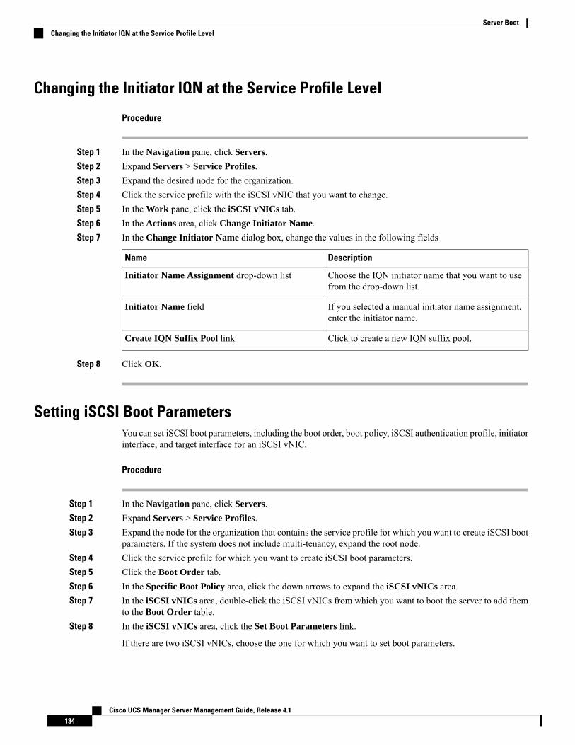
Changing the Initiator IQN at the Service Profile Level
Procedure
Step 1 In the Navigation pane, click Servers.Step 2 Expand Servers > Service Profiles.Step 3 Expand the desired node for the organization.Step 4 Click the service profile with the iSCSI vNIC that you want to change.Step 5 In the Work pane, click the iSCSI vNICs tab.Step 6 In the Actions area, click Change Initiator Name.Step 7 In the Change Initiator Name dialog box, change the values in the following fields
DescriptionName
Choose the IQN initiator name that you want to usefrom the drop-down list.
Initiator Name Assignment drop-down list
If you selected a manual initiator name assignment,enter the initiator name.
Initiator Name field
Click to create a new IQN suffix pool.Create IQN Suffix Pool link
Step 8 Click OK.
Setting iSCSI Boot ParametersYou can set iSCSI boot parameters, including the boot order, boot policy, iSCSI authentication profile, initiatorinterface, and target interface for an iSCSI vNIC.
Procedure
Step 1 In the Navigation pane, click Servers.Step 2 Expand Servers > Service Profiles.Step 3 Expand the node for the organization that contains the service profile for which you want to create iSCSI boot
parameters. If the system does not include multi-tenancy, expand the root node.Step 4 Click the service profile for which you want to create iSCSI boot parameters.Step 5 Click the Boot Order tab.Step 6 In the Specific Boot Policy area, click the down arrows to expand the iSCSI vNICs area.Step 7 In the iSCSI vNICs area, double-click the iSCSI vNICs from which you want to boot the server to add them
to the Boot Order table.Step 8 In the iSCSI vNICs area, click the Set Boot Parameters link.
If there are two iSCSI vNICs, choose the one for which you want to set boot parameters.
Cisco UCS Manager Server Management Guide, Release 4.1134
Server BootChanging the Initiator IQN at the Service Profile Level
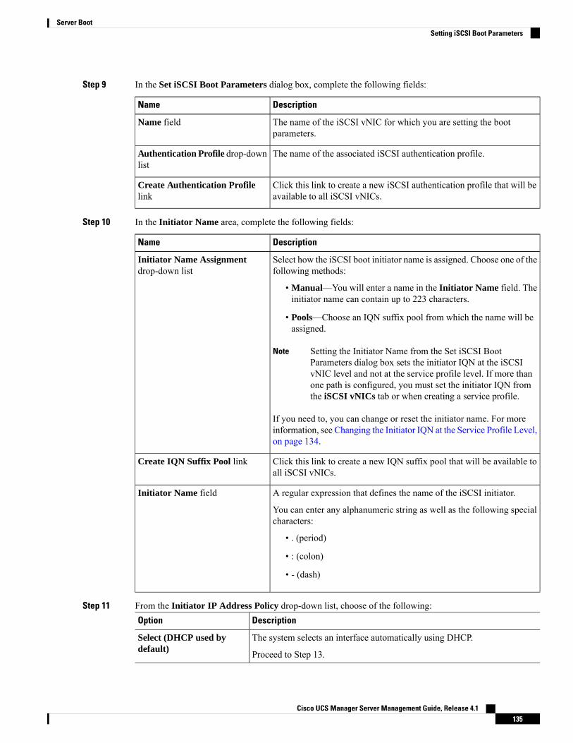
Step 9 In the Set iSCSI Boot Parameters dialog box, complete the following fields:
DescriptionName
The name of the iSCSI vNIC for which you are setting the bootparameters.
Name field
The name of the associated iSCSI authentication profile.Authentication Profile drop-downlist
Click this link to create a new iSCSI authentication profile that will beavailable to all iSCSI vNICs.
Create Authentication Profilelink
Step 10 In the Initiator Name area, complete the following fields:
DescriptionName
Select how the iSCSI boot initiator name is assigned. Choose one of thefollowing methods:
• Manual—You will enter a name in the Initiator Name field. Theinitiator name can contain up to 223 characters.
• Pools—Choose an IQN suffix pool from which the name will beassigned.
Setting the Initiator Name from the Set iSCSI BootParameters dialog box sets the initiator IQN at the iSCSIvNIC level and not at the service profile level. If more thanone path is configured, you must set the initiator IQN fromthe iSCSI vNICs tab or when creating a service profile.
Note
If you need to, you can change or reset the initiator name. For moreinformation, see Changing the Initiator IQN at the Service Profile Level,on page 134.
Initiator Name Assignmentdrop-down list
Click this link to create a new IQN suffix pool that will be available toall iSCSI vNICs.
Create IQN Suffix Pool link
A regular expression that defines the name of the iSCSI initiator.
You can enter any alphanumeric string as well as the following specialcharacters:
• . (period)
• : (colon)
• - (dash)
Initiator Name field
Step 11 From the Initiator IP Address Policy drop-down list, choose of the following:DescriptionOption
The system selects an interface automatically using DHCP.Select (DHCP used bydefault) Proceed to Step 13.
Cisco UCS Manager Server Management Guide, Release 4.1135
Server BootSetting iSCSI Boot Parameters
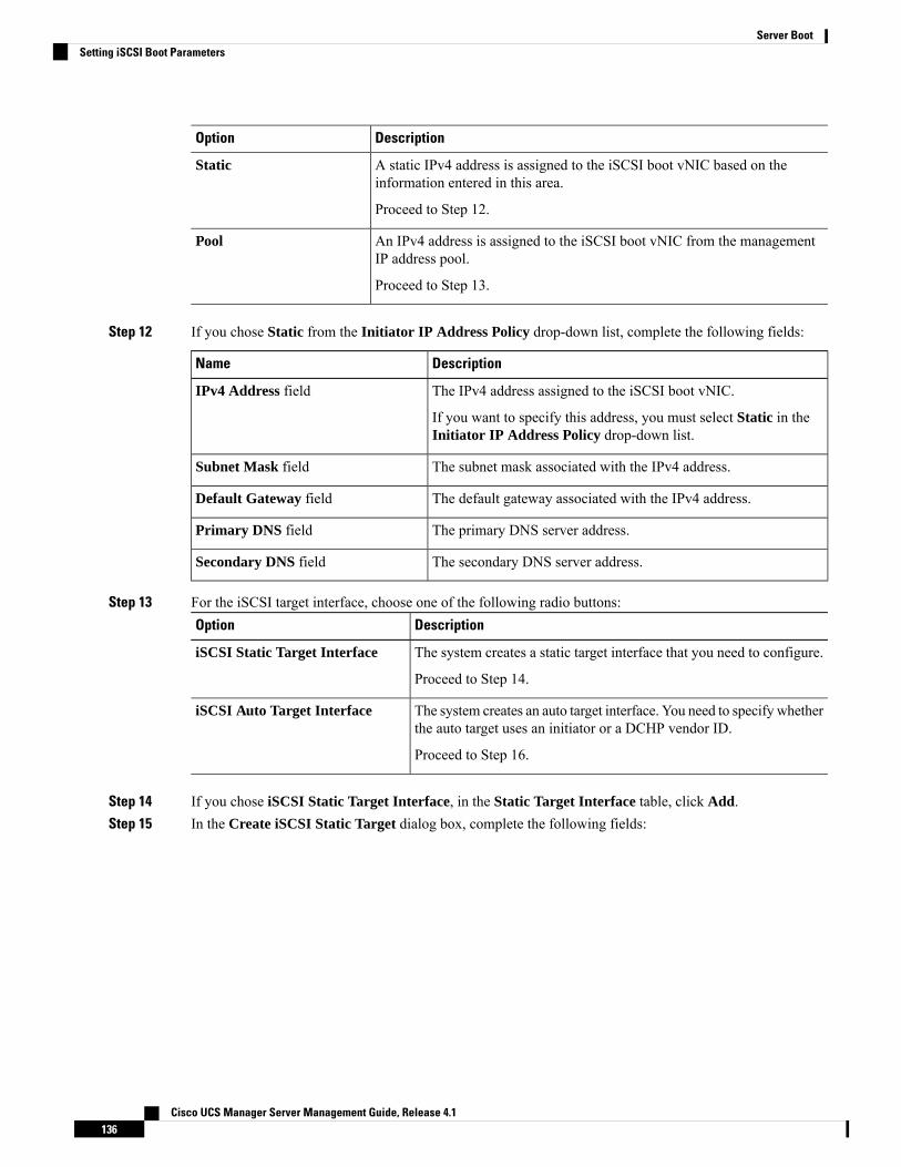
DescriptionOption
A static IPv4 address is assigned to the iSCSI boot vNIC based on theinformation entered in this area.
Static
Proceed to Step 12.
An IPv4 address is assigned to the iSCSI boot vNIC from the managementIP address pool.
Pool
Proceed to Step 13.
Step 12 If you chose Static from the Initiator IP Address Policy drop-down list, complete the following fields:
DescriptionName
The IPv4 address assigned to the iSCSI boot vNIC.
If you want to specify this address, you must select Static in theInitiator IP Address Policy drop-down list.
IPv4 Address field
The subnet mask associated with the IPv4 address.Subnet Mask field
The default gateway associated with the IPv4 address.Default Gateway field
The primary DNS server address.Primary DNS field
The secondary DNS server address.Secondary DNS field
Step 13 For the iSCSI target interface, choose one of the following radio buttons:DescriptionOption
The system creates a static target interface that you need to configure.iSCSI Static Target Interface
Proceed to Step 14.
The system creates an auto target interface. You need to specify whetherthe auto target uses an initiator or a DCHP vendor ID.
iSCSI Auto Target Interface
Proceed to Step 16.
Step 14 If you chose iSCSI Static Target Interface, in the Static Target Interface table, click Add.Step 15 In the Create iSCSI Static Target dialog box, complete the following fields:
Cisco UCS Manager Server Management Guide, Release 4.1136
Server BootSetting iSCSI Boot Parameters

DescriptionName
A regular expression that defines the iSCSI Qualified Name (IQN) orExtended Unique Identifier (EUI) name of the iSCSI target.
You can enter any alphanumeric characters as well as the followingspecial characters:
• . (period)
• : (colon)
• - (dash)
This name must be properly formatted using standard IQNor EUI guidelines.
Important
The following examples show properly formatted iSCSI target names:
• iqn.2001-04.com.example
• iqn.2001-04.com.example:storage:diskarrays-sn-a8675309
• iqn.2001-04.com.example:storage.tape1.sys1.xyz
• iqn.2001-04.com.example:storage.disk2.sys1.xyz
• eui.02004567A425678D
iSCSI Target Name field
The system-assigned priority for the iSCSI target.Priority field
The port associated with the iSCSI target.
Enter an integer between 1 and 65535. The default is 3260.
Port field
The name of the associated iSCSI authentication profile.Authentication Profile drop-downlist
Click this link to create a new iSCSI authentication profile that will beavailable to all iSCSI vNICs.
Create iSCSI AuthenticationProfile link
The IPv4 address assigned to the iSCSI target.IPv4 Address field
The LUN identifier in the iSCSI target.LUN Id field
Step 16 If you chose iSCSI Auto Target Interface, enter either the initiator name or the DHCP vendor ID in theDHCP Vendor Id field. The initiator must have already been configured. The vendor ID can be up to 32alphanumeric characters.
Step 17 Click OK.
Modifying iSCSI Boot ParametersYou can modify iSCSI boot parameters, including the boot order, boot policy, iSCSI authentication profile,initiator interface, and target interface for an iSCSI vNIC.
Cisco UCS Manager Server Management Guide, Release 4.1137
Server BootModifying iSCSI Boot Parameters
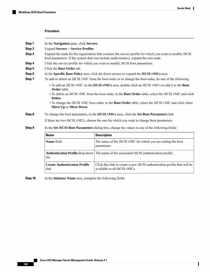
Procedure
Step 1 In the Navigation pane, click Servers.Step 2 Expand Servers > Service Profiles.Step 3 Expand the node for the organization that contains the service profile for which you want to modify iSCSI
boot parameters. If the system does not include multi-tenancy, expand the root node.Step 4 Click the service profile for which you want to modify iSCSI boot parameters.Step 5 Click the Boot Order tab.Step 6 In the Specific Boot Policy area, click the down arrows to expand the iSCSI vNICs area.Step 7 To add or delete an iSCSI vNIC from the boot order or to change the boot order, do one of the following:
• To add an iSCSI vNIC, in the iSCSI vNICs area, double-click an iSCSI vNICs to add it to the BootOrder table.
• To delete an iSCSI vNIC from the boot order, in the Boot Order table, select the iSCSI vNIC and clickDelete.
• To change the iSCSI vNIC boot order, in the Boot Order table, select the iSCSI vNIC and click eitherMove Up or Move Down.
Step 8 To change the boot parameters, in the iSCSI vNICs area, click the Set Boot Parameters link.
If there are two iSCSI vNICs, choose the one for which you want to change boot parameters.
Step 9 In the Set iSCSI Boot Parameters dialog box, change the values in any of the following fields:
DescriptionName
The name of the iSCSI vNIC for which you are setting the bootparameters.
Name field
The name of the associated iSCSI authentication profile.Authentication Profile drop-downlist
Click this link to create a new iSCSI authentication profile that will beavailable to all iSCSI vNICs.
Create Authentication Profilelink
Step 10 In the Initiator Name area, complete the following fields:
Cisco UCS Manager Server Management Guide, Release 4.1138
Server BootModifying iSCSI Boot Parameters
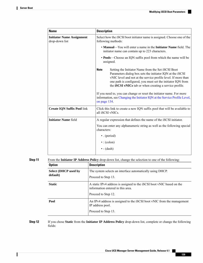
DescriptionName
Select how the iSCSI boot initiator name is assigned. Choose one of thefollowing methods:
• Manual—You will enter a name in the Initiator Name field. Theinitiator name can contain up to 223 characters.
• Pools—Choose an IQN suffix pool from which the name will beassigned.
Setting the Initiator Name from the Set iSCSI BootParameters dialog box sets the initiator IQN at the iSCSIvNIC level and not at the service profile level. If more thanone path is configured, you must set the initiator IQN fromthe iSCSI vNICs tab or when creating a service profile.
Note
If you need to, you can change or reset the initiator name. For moreinformation, see Changing the Initiator IQN at the Service Profile Level,on page 134.
Initiator Name Assignmentdrop-down list
Click this link to create a new IQN suffix pool that will be available toall iSCSI vNICs.
Create IQN Suffix Pool link
A regular expression that defines the name of the iSCSI initiator.
You can enter any alphanumeric string as well as the following specialcharacters:
• . (period)
• : (colon)
• - (dash)
Initiator Name field
Step 11 From the Initiator IP Address Policy drop-down list, change the selection to one of the following:DescriptionOption
The system selects an interface automatically using DHCP.Select (DHCP used bydefault) Proceed to Step 13.
A static IPv4 address is assigned to the iSCSI boot vNIC based on theinformation entered in this area.
Static
Proceed to Step 12.
An IPv4 address is assigned to the iSCSI boot vNIC from the managementIP address pool.
Pool
Proceed to Step 13.
Step 12 If you chose Static from the Initiator IP Address Policy drop-down list, complete or change the followingfields:
Cisco UCS Manager Server Management Guide, Release 4.1139
Server BootModifying iSCSI Boot Parameters
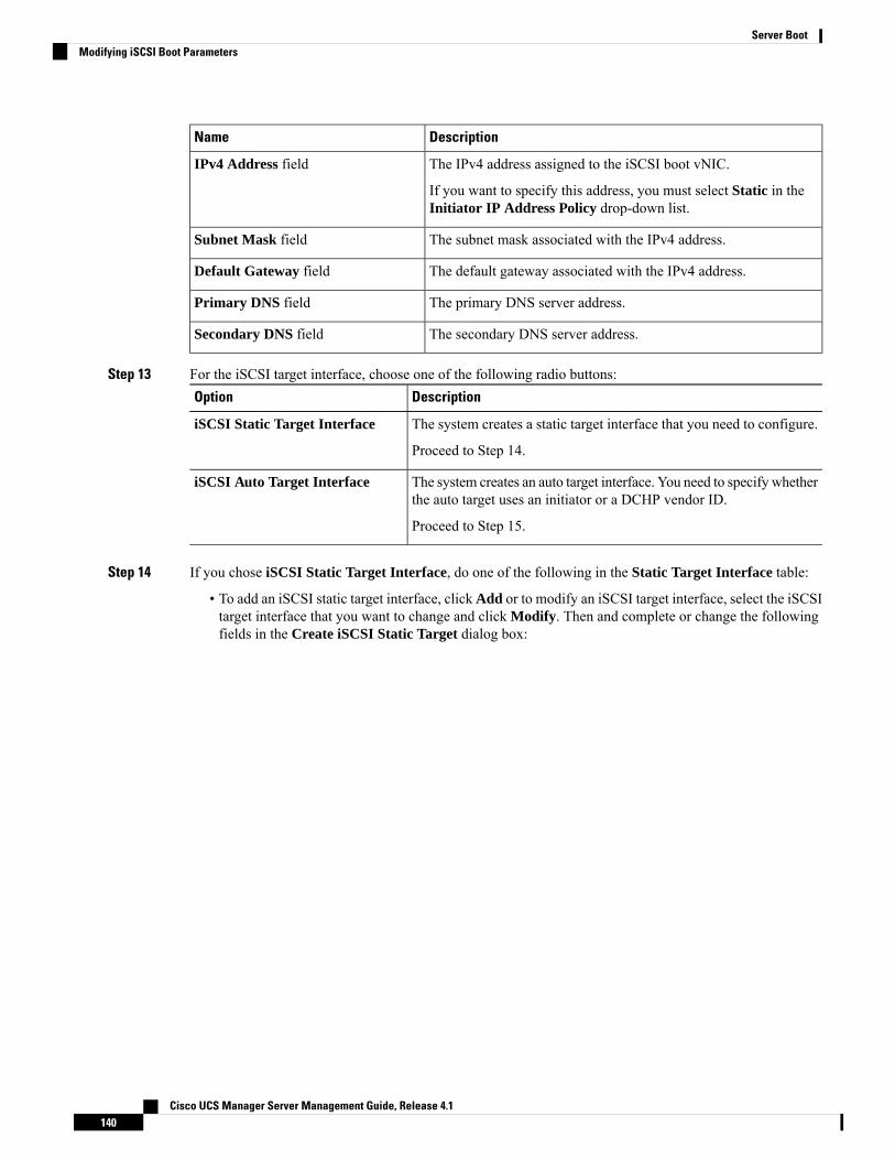
DescriptionName
The IPv4 address assigned to the iSCSI boot vNIC.
If you want to specify this address, you must select Static in theInitiator IP Address Policy drop-down list.
IPv4 Address field
The subnet mask associated with the IPv4 address.Subnet Mask field
The default gateway associated with the IPv4 address.Default Gateway field
The primary DNS server address.Primary DNS field
The secondary DNS server address.Secondary DNS field
Step 13 For the iSCSI target interface, choose one of the following radio buttons:DescriptionOption
The system creates a static target interface that you need to configure.iSCSI Static Target Interface
Proceed to Step 14.
The system creates an auto target interface. You need to specify whetherthe auto target uses an initiator or a DCHP vendor ID.
iSCSI Auto Target Interface
Proceed to Step 15.
Step 14 If you chose iSCSI Static Target Interface, do one of the following in the Static Target Interface table:
• To add an iSCSI static target interface, clickAdd or to modify an iSCSI target interface, select the iSCSItarget interface that you want to change and click Modify. Then and complete or change the followingfields in the Create iSCSI Static Target dialog box:
Cisco UCS Manager Server Management Guide, Release 4.1140
Server BootModifying iSCSI Boot Parameters
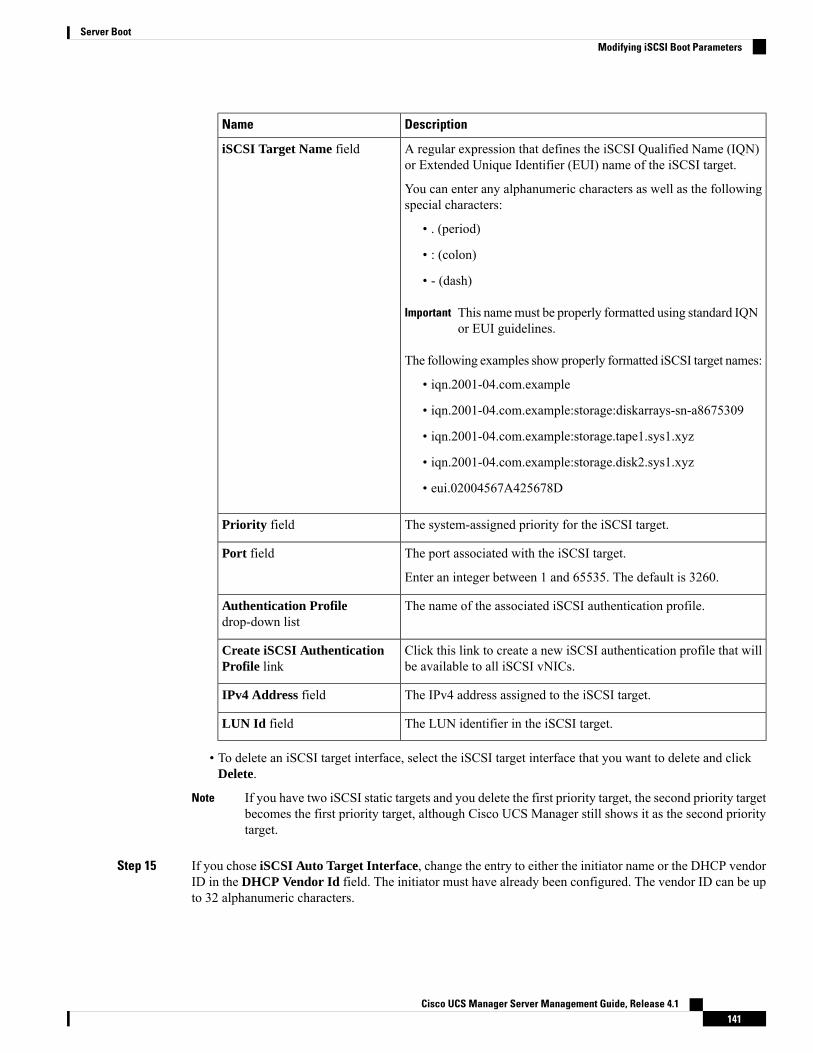
DescriptionName
A regular expression that defines the iSCSI Qualified Name (IQN)or Extended Unique Identifier (EUI) name of the iSCSI target.
You can enter any alphanumeric characters as well as the followingspecial characters:
• . (period)
• : (colon)
• - (dash)
This namemust be properly formatted using standard IQNor EUI guidelines.
Important
The following examples show properly formatted iSCSI target names:
• iqn.2001-04.com.example
• iqn.2001-04.com.example:storage:diskarrays-sn-a8675309
• iqn.2001-04.com.example:storage.tape1.sys1.xyz
• iqn.2001-04.com.example:storage.disk2.sys1.xyz
• eui.02004567A425678D
iSCSI Target Name field
The system-assigned priority for the iSCSI target.Priority field
The port associated with the iSCSI target.
Enter an integer between 1 and 65535. The default is 3260.
Port field
The name of the associated iSCSI authentication profile.Authentication Profiledrop-down list
Click this link to create a new iSCSI authentication profile that willbe available to all iSCSI vNICs.
Create iSCSI AuthenticationProfile link
The IPv4 address assigned to the iSCSI target.IPv4 Address field
The LUN identifier in the iSCSI target.LUN Id field
• To delete an iSCSI target interface, select the iSCSI target interface that you want to delete and clickDelete.
If you have two iSCSI static targets and you delete the first priority target, the second priority targetbecomes the first priority target, although Cisco UCS Manager still shows it as the second prioritytarget.
Note
Step 15 If you chose iSCSI Auto Target Interface, change the entry to either the initiator name or the DHCP vendorID in the DHCP Vendor Id field. The initiator must have already been configured. The vendor ID can be upto 32 alphanumeric characters.
Cisco UCS Manager Server Management Guide, Release 4.1141
Server BootModifying iSCSI Boot Parameters

Step 16 Click OK.
IQN PoolsAn IQN pool is a collection of iSCSI Qualified Names (IQNs) for use as initiator identifiers by iSCSI vNICsin a Cisco UCS domain.
IQN pool members are of the form prefix:suffix:number, where you can specify the prefix, suffix, and a block(range) of numbers.
An IQN pool can contain more than one IQN block, with different number ranges and different suffixes, butsharing the same prefix.
Creating an IQN Pool
In most cases, the maximum IQN size (prefix + suffix + additional characters) is 223 characters. When usingthe Cisco UCS NIC M51KR-B adapter, you must limit the IQN size to 128 characters.
Note
Procedure
Step 1 In the Navigation pane, click SAN.Step 2 Expand SAN > Pools.Step 3 Expand the node for the organization where you want to create the pool.
If the system does not include multi tenancy, expand the root node.
Step 4 Right-click IQN Pools and select Create IQN Suffix Pool.Step 5 In theDefine Name and Description page of theCreate IQN Suffix Poolwizard, fill in the following fields:
DescriptionField
The name of the iSCSI Qualified Name (IQN) pool.
This name can be between 1 and 32 alphanumeric characters. You cannotuse spaces or any special characters other than - (hyphen), _ (underscore),: (colon), and . (period), and you cannot change this name after the objectis saved.
Name
The user-defined description of the pool.
Enter up to 256 characters. You can use any characters or spaces except` (accent mark), \ (backslash), ^ (carat), " (double quote), = (equal sign),> (greater than), < (less than), or ' (single quote).
Description
Cisco UCS Manager Server Management Guide, Release 4.1142
Server BootIQN Pools
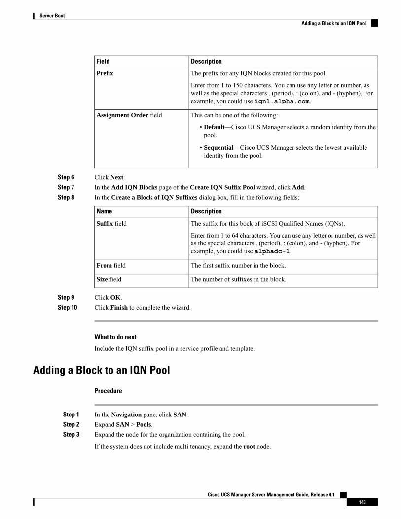
DescriptionField
The prefix for any IQN blocks created for this pool.
Enter from 1 to 150 characters. You can use any letter or number, aswell as the special characters . (period), : (colon), and - (hyphen). Forexample, you could use iqn1.alpha.com.
Prefix
This can be one of the following:
• Default—Cisco UCS Manager selects a random identity from thepool.
• Sequential—Cisco UCS Manager selects the lowest availableidentity from the pool.
Assignment Order field
Step 6 Click Next.Step 7 In the Add IQN Blocks page of the Create IQN Suffix Pool wizard, click Add.Step 8 In the Create a Block of IQN Suffixes dialog box, fill in the following fields:
DescriptionName
The suffix for this bock of iSCSI Qualified Names (IQNs).
Enter from 1 to 64 characters. You can use any letter or number, as wellas the special characters . (period), : (colon), and - (hyphen). Forexample, you could use alphadc-1.
Suffix field
The first suffix number in the block.From field
The number of suffixes in the block.Size field
Step 9 Click OK.Step 10 Click Finish to complete the wizard.
What to do next
Include the IQN suffix pool in a service profile and template.
Adding a Block to an IQN Pool
Procedure
Step 1 In the Navigation pane, click SAN.Step 2 Expand SAN > Pools.Step 3 Expand the node for the organization containing the pool.
If the system does not include multi tenancy, expand the root node.
Cisco UCS Manager Server Management Guide, Release 4.1143
Server BootAdding a Block to an IQN Pool
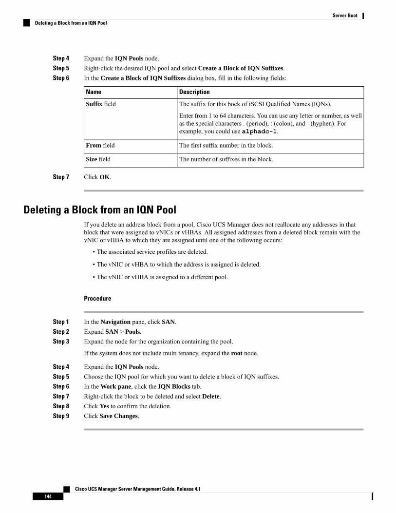
Step 4 Expand the IQN Pools node.Step 5 Right-click the desired IQN pool and select Create a Block of IQN Suffixes.Step 6 In the Create a Block of IQN Suffixes dialog box, fill in the following fields:
DescriptionName
The suffix for this bock of iSCSI Qualified Names (IQNs).
Enter from 1 to 64 characters. You can use any letter or number, as wellas the special characters . (period), : (colon), and - (hyphen). Forexample, you could use alphadc-1.
Suffix field
The first suffix number in the block.From field
The number of suffixes in the block.Size field
Step 7 Click OK.
Deleting a Block from an IQN PoolIf you delete an address block from a pool, Cisco UCS Manager does not reallocate any addresses in thatblock that were assigned to vNICs or vHBAs. All assigned addresses from a deleted block remain with thevNIC or vHBA to which they are assigned until one of the following occurs:
• The associated service profiles are deleted.
• The vNIC or vHBA to which the address is assigned is deleted.
• The vNIC or vHBA is assigned to a different pool.
Procedure
Step 1 In the Navigation pane, click SAN.Step 2 Expand SAN > Pools.Step 3 Expand the node for the organization containing the pool.
If the system does not include multi tenancy, expand the root node.
Step 4 Expand the IQN Pools node.Step 5 Choose the IQN pool for which you want to delete a block of IQN suffixes.Step 6 In the Work pane, click the IQN Blocks tab.Step 7 Right-click the block to be deleted and select Delete.Step 8 Click Yes to confirm the deletion.Step 9 Click Save Changes.
Cisco UCS Manager Server Management Guide, Release 4.1144
Server BootDeleting a Block from an IQN Pool
Deleting an IQN PoolIf you delete a pool, Cisco UCS Manager does not reallocate any addresses from that pool that were assignedto vNICs or vHBAs. All assigned addresses from a deleted pool remain with the vNIC or vHBA to whichthey are assigned until one of the following occurs:
• The associated service profiles are deleted.
• The vNIC or vHBA to which the address is assigned is deleted.
• The vNIC or vHBA is assigned to a different pool.
Procedure
Step 1 In the Navigation pane, click SAN.Step 2 Expand SAN > Pools.Step 3 Expand the node for the organization containing the pool.
If the system does not include multi tenancy, expand the root node.
Step 4 Expand the IQN Pools node.Step 5 Right-click the pool that you want to delete and select Delete.Step 6 If a confirmation dialog box displays, click Yes.
LAN BootYou can configure a boot policy to boot one or more servers from a centralized provisioning server on theLAN. A LAN (or PXE) boot is frequently used to install operating systems on a server from that LAN server.
You can add more than one type of boot device to a LAN boot policy. For example, you could add a localdisk or virtual media boot as a secondary boot device.
Configuring a LAN Boot for a Boot PolicyYou can also create a local boot policy that is restricted to a service profile or service profile template. However,Cisco recommends that you create a global boot policy that can be included in multiple service profiles orservice profile templates.
You can add more than one type of boot device to a boot policy. For example, you can add a local disk orvirtual media boot as a secondary boot device.
This procedure continues directly from Creating a Boot Policy, on page 118.
Procedure
Step 1 Click the down arrows to expand the vNICs area.Step 2 Click the Add LAN Boot link.
Cisco UCS Manager Server Management Guide, Release 4.1145
Server BootDeleting an IQN Pool
Step 3 In the Add LAN Boot dialog box, enter the name of the vNIC that you want to use for the LAN boot in thevNIC field, then click OK.
Step 4 Do one of the following:
• Add another boot device to the Boot Order table.• Click OK to finish.
What to do next
Include the boot policy in a service profile and template.
After a server is associated with a service profile that includes this boot policy, you can verify the actual bootorder in the Boot Order Details area on the General tab for the server.
Local Devices BootCisco UCS Manager allows you to boot from different local devices.
For Cisco UCSM3 and higher blade and rack servers using enhanced boot order, you can select both top-leveland second-level boot devices.
Note
When there are more than one boot options provided under same Controller, the boot options is consideredas follows instead of the boot order set in Cisco UCS Manager:
• When OS is installed or booted, for UEFI Boot, the installed OS will push its boot option to zero priority(Top Priority) irrespective of the set boot options in Cisco UCS Manager.
• The boot order will be based on the Boot Device enumeration set by BIOS and on how controller exposesthe device to host (or as provided in Cisco UCS Manager).
Note
Local Disk Boot
If a server has a local drive, you can configure a boot policy to boot the server from the top-level local diskdevice or from any of the following second-level devices:
• Local LUN—Enables boot from local disk or local LUN.
• Local JBOD—Enables boot from a bootable JBOD.
• SD card—Enables boot from SD card.
• Internal USB—Enables boot for internal USB.
• External USB—Enables boot from external USB.
• Embedded Local LUN—Enables boot from the embedded local LUN on all Cisco UCSM4, M5 servers.
Cisco UCS Manager Server Management Guide, Release 4.1146
Server BootLocal Devices Boot
• Embedded Local Disk—Enables boot from the embedded local disk on all Cisco UCS M4, M5 servers.
For Cisco UCSC125M5 Servers, if there is no separate PCIe storagecontroller, then do not use this option. Instead, use Add Local Diskoption.
Note
Second-level devices are only available for Cisco UCS M3 M3 and higher blade and rack servers usingenhanced boot order.
Note
Virtual Media Boot
You can configure a boot policy to boot one or more servers from a virtual media device that is accessiblefrom the server. A virtual media device mimics the insertion of a physical CD/DVD disk (read-only) or floppydisk (read-write) into a server. This type of server boot is typically used to manually install operating systemson a server.
Second-level devices are only available for Cisco UCSM3 and higher blade and rack servers using enhancedboot order.
Note
Remote Virtual Drive Boot
You can configure a boot policy to boot one or more servers from a remote virtual drive that is accessiblefrom the server.
NVMe Boot
Beginning with release 3.2(1) Cisco UCS Manager provides the option of adding an NVMe device to theBoot policy for M5 blade and rack servers. BIOS enumerates the NVMe devices present and boots to the firstNVMe device having UEFI capable OS installed on it.
Cisco Boot Optimized M.2 RAID Controller
Beginning with 4.0(4a), Cisco UCS Manager supports Cisco boot optimized M.2 RAID controller based offMarvell 88SE92xx PCIe to SATA 6Gb/s controller (UCS-M2-HWRAID). BIOS enumerates the M.2 SATAdrives installed on this controller followed by the front panel SATA drives to boot from the first SATA devicehaving UEFI capable OS installed on it
Configuring a Local Disk Boot for a Boot PolicyYou can also create a local boot policy that is restricted to a service profile or service profile template. However,Cisco recommends that you create a global boot policy that can be included in multiple service profiles orservice profile templates.
You can add more than one type of boot device to a boot policy. For example, you could add an SD card bootas a secondary boot device.
Cisco UCS Manager Server Management Guide, Release 4.1147
Server BootConfiguring a Local Disk Boot for a Boot Policy

This procedure continues directly from Creating a Boot Policy, on page 118.
Procedure
Step 1 Expand the Local Devices area.Step 2 Click any of the following links to add the device to the Boot Order table:
• Add Local Disk or
• Add Local LUN
• Add Local JBOD
• Add SD Card
• Add Internal USB
• Add External USB
• Add Embedded Local LUN
• Add Embedded Local Disk
In a setup with the Cisco Boot Optimized M.2 RAID Controller (UCS-M2-HWRAID),in the Add Embedded Local Disk dialog box, select Any to add the disk. Do not selectPrimary or Secondary.
Important
For Cisco UCS M3 and higher blade and rack servers using enhanced boot order, you can selectboth top-level and second-level boot devices.
Note
Step 3 Do one of the following:
• Add another boot device to the Boot Order table.• Click OK to finish.
What to do next
Include the boot policy in a service profile and template.
After a server is associated with a service profile that includes this boot policy, you can verify the actual bootorder in the Boot Order Details area on the General tab for the server.
Configuring a Virtual Media Boot for a Boot PolicyYou can also create a local boot policy that is restricted to a service profile or service profile template. However,Cisco recommends that you create a global boot policy that can be included in multiple service profiles orservice profile templates.
You can add more than one type of boot device to a boot policy. For example, you could add a local disk bootas a second boot device.
Cisco UCS Manager Server Management Guide, Release 4.1148
Server BootConfiguring a Virtual Media Boot for a Boot Policy

VirtualMedia requires the USB to be enabled. If youmodify the BIOS settings that affect the USB functionality,you also affect the Virtual Media. Therefore, Cisco recommends that you leave the following USB BIOSdefaults for best performance:
• Make Device Non Bootable—set to disabled
• USB Idle Power Optimizing Setting—set to high-performance
Note
This procedure continues directly from Creating a Boot Policy, on page 118.
Procedure
Step 1 Click the down arrows to expand the Local Devices area.Step 2 Click any of the following links to add the device to the Boot Order table:
• Add CD/DVD or
• Add Local CD/DVD
• Add Remote CD/DVD (For KVM CD/DVD in rack servers)
In a setup with M5 blade servers, if an ISO is mapped to the KVM console, use only Add RemoteCD/DVD in Boot Order.
• Add Floppy or
• Add Local Floppy
• Add Remote Floppy
• Add Remote Virtual Drive
For Cisco UCS M3 and higher blade and rack servers using enhanced boot order, you can selectboth top-level and second-level boot devices.
Note
Step 3 Do one of the following:
• Add another boot device to the Boot Order table.• Click OK to finish.
What to do next
Include the boot policy in a service profile and template.
After a server is associated with a service profile that includes this boot policy, you can verify the actual bootorder in the Boot Order Details area on the General tab for the server.
Cisco UCS Manager Server Management Guide, Release 4.1149
Server BootConfiguring a Virtual Media Boot for a Boot Policy

Configuring a NVMe Boot for a Boot PolicyYou can also create a local boot policy that is restricted to a service profile or service profile template. However,Cisco recommends that you create a global boot policy that can be included in multiple service profiles orservice profile templates.
You can add more than one type of boot device to a boot policy. For example, you could add an SD card bootas a secondary boot device.
This procedure continues directly from Creating a Boot Policy, on page 118.
Procedure
Step 1 Click the down arrows to expand the Local Devices area.Step 2 Click Add NVMe to add the device to the Boot Order table.
NVMe boot policy is available only with Uefi boot mode, with or without boot security.Note
Step 3 Do one of the following:
• Add another boot device to the Boot Order table.• Click OK to finish.
What to do next
Include the boot policy in a service profile and template.
After a server is associated with a service profile that includes this boot policy, you can verify the actual bootorder in the Boot Order Details area on the General tab for the server.
Adding a Boot Policy to a vMedia Service ProfileThis procedure describes how to set the boot policy options for vMedia on the Server Boot Order page ofthe Create Service Profile (expert) wizard.
Procedure
Step 1 In the Navigation pane, click Servers.Step 2 Expand Servers > Service Profiles.Step 3 Expand the node for the organization where you want to create the service profile.
If the system does not include multi tenancy, expand the root node.
Step 4 Right-click the organization and select Create Service Profile (expert).The Unified Computing System Manager pane displays.
Step 5 In the Name field, enter a unique name that you can use to identify the service profile.
Cisco UCS Manager Server Management Guide, Release 4.1150
Server BootConfiguring a NVMe Boot for a Boot Policy

This name can be between 2 and 32 alphanumeric characters. You cannot use spaces or any special charactersother than - (hyphen), _ (underscore), : (colon), and . (period), and this name must be unique across all serviceprofiles and service profile templates within the same organization.
This name must be unique within the organization or sub-organization in which you are creating the serviceprofile.
Step 6 From the UUID Assignment drop-down list, do one of the following:DescriptionOption
Assigns a UUID from the default UUID Suffixpool.
Select (pool default used by default)
Continue with Step 8.
Uses the UUID assigned to the server by themanufacturer.
Hardware Default
If you choose this option, the UUID remainsunassigned until the service profile isassociated with a server. At that point, theUUID is set to the UUID value assigned to theserver by the manufacturer. If the serviceprofile is later moved to a different server, theUUID is changed to match the new server.
Continue with Step 8.
Uses the UUID that you manually assign.XXXXXXXX-XXXX-XXXX-XXXX-XXXXXXXXXXXX
Continue with Step 7.
Assigns a UUID from the UUID Suffix poolthat you select from the list at the bottom ofthe drop-down list.
Pools Pool_Name
Each pool name is followed by two numbersin parentheses that show the number of UUIDsavailable in the pool and the total number ofUUIDs in the pool.
If you do not want use any of the existingpools, but want to create a pool that all serviceprofiles can access, continue with Step 4.Otherwise, continue with Step 8.
Step 7 (Optional) If you selected the XXXXXXXX-XXXX-XXXX-XXXX-XXXXXXXXXXXX option, do thefollowing:a) In the UUID field, enter the valid UUID that you want to assign to the server that uses this service profile.
Step 8 (Optional) If you want to create a new UUID Suffix pool to use in this service profile, click Create UUIDSuffix Pool and complete the fields in the Create UUID Suffix Pool wizard.
For more information, see Creating a UUID Suffix Pool, on page 105.
Step 9 (Optional) In the text box, enter a description of this service profile.
Cisco UCS Manager Server Management Guide, Release 4.1151
Server BootAdding a Boot Policy to a vMedia Service Profile
The user-defined description for this service profile.
Enter up to 256 characters. You can use any characters or spaces except ` (accent mark), \ (backslash), ^(carat), " (double quote), = (equal sign), > (greater than), < (less than), or ' (single quote).
Step 10 Click Next.Step 11 Navigate to Create Service Profile (expert) and click Server Boot Order.
The Boot Policy pane displays.Step 12 From the Boot Policy drop-down list, choose one of the following:
DescriptionOption
Assigns the default boot policy to this service profile.Select Boot Policy to use
Continue with Step 13.
Enables you to create a local boot policy that can only be accessed by thisservice profile.
Create a Specific Boot Policy
Assigns an existing boot policy to the service profile. If you choose thisoption, Cisco UCS Manager displays the details of the policy.
Boot Policies Policy_Name
If you do not want use any of the existing policies, but want to create apolicy that all service profiles can access, click Create Boot Policy.Otherwise, choose a policy from the list and continue with Step 13.
Step 13 If you created a new boot policy accessible to all service profiles and template, choose that policy from theBoot Policy drop-down list .
Step 14 Click Next.
What to do next
Associate your Service Profile with a Cisco UCS server.
Deleting a Boot PolicyProcedure
Step 1 In the Navigation pane, click Servers.Step 2 Expand Servers > Policies > Organization_Name.Step 3 Expand the Boot Policies node.Step 4 Right-click the policy you want to delete and choose Delete.Step 5 If a confirmation dialog box displays, click Yes.
Cisco UCS Manager Server Management Guide, Release 4.1152
Server BootDeleting a Boot Policy

UEFI Boot ParametersUEFI boot mode for servers is dependent on information that is stored on the platform hardware. The bootentry, which contains information about the UEFI OS boot loader, is stored in the BIOS flash of the server.In Cisco UCSManager releases earlier than Release 2.2(4), when a service profile is migrated from one serverto another server, the boot loader information is not available on the destination server. Hence, the BIOScannot load the boot loader information for the server to boot in UEFI boot mode.
Cisco UCSM Release 2.2(4) introduces UEFI boot parameters to provide the BIOS with information aboutthe location of the UEFI OS boot loader on the destination server from where the BIOS loads it. Now, theserver can use the boot loader information and boot in UEFI boot mode.
Guidelines and Limitations for UEFI Boot Parameters• You can configure UEFI boot parameters only if the boot mode is UEFI.
• When you upgrade Cisco UCS Manager to Release 2.2(4) and higher UEFI boot failure during serviceprofile migration is not handled automatically. You must explicitly create the UEFI boot parameters inthe target device to successfully boot to the UEFI-capable OS.
• UEFI boot parameters are supported on all M3 and higher servers that support second-level boot order.
• You can specify UEFI boot parameters for the following device types:
• SAN LUN
• ISCSI LUN
• Local LUN
• UEFI boot parameters are specific to each operating system. You can specify UEFI boot parameters forthe following operating systems:
• VMware ESX
• SuSE Linux
• Microsoft Windows
• Red Hat Enterprise Linux 7
Setting UEFI Boot Parameters
Before you begin
Ensure that the Boot Mode of the boot policy is Uefi.
Procedure
Step 1 In the Navigation pane, click Servers.
Cisco UCS Manager Server Management Guide, Release 4.1153
Server BootUEFI Boot Parameters
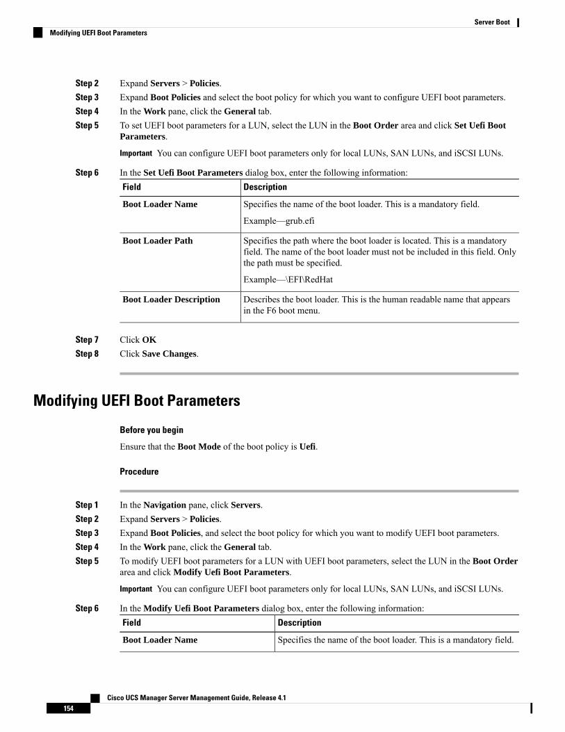
Step 2 Expand Servers > Policies.Step 3 Expand Boot Policies and select the boot policy for which you want to configure UEFI boot parameters.Step 4 In the Work pane, click the General tab.Step 5 To set UEFI boot parameters for a LUN, select the LUN in the Boot Order area and click Set Uefi Boot
Parameters.
You can configure UEFI boot parameters only for local LUNs, SAN LUNs, and iSCSI LUNs.Important
Step 6 In the Set Uefi Boot Parameters dialog box, enter the following information:DescriptionField
Specifies the name of the boot loader. This is a mandatory field.Boot Loader Name
Example—grub.efi
Specifies the path where the boot loader is located. This is a mandatoryfield. The name of the boot loader must not be included in this field. Onlythe path must be specified.
Boot Loader Path
Example—\EFI\RedHat
Describes the boot loader. This is the human readable name that appearsin the F6 boot menu.
Boot Loader Description
Step 7 Click OK
Step 8 Click Save Changes.
Modifying UEFI Boot Parameters
Before you begin
Ensure that the Boot Mode of the boot policy is Uefi.
Procedure
Step 1 In the Navigation pane, click Servers.Step 2 Expand Servers > Policies.Step 3 Expand Boot Policies, and select the boot policy for which you want to modify UEFI boot parameters.Step 4 In the Work pane, click the General tab.Step 5 To modify UEFI boot parameters for a LUN with UEFI boot parameters, select the LUN in the Boot Order
area and click Modify Uefi Boot Parameters.
You can configure UEFI boot parameters only for local LUNs, SAN LUNs, and iSCSI LUNs.Important
Step 6 In the Modify Uefi Boot Parameters dialog box, enter the following information:DescriptionField
Specifies the name of the boot loader. This is a mandatory field.Boot Loader Name
Cisco UCS Manager Server Management Guide, Release 4.1154
Server BootModifying UEFI Boot Parameters
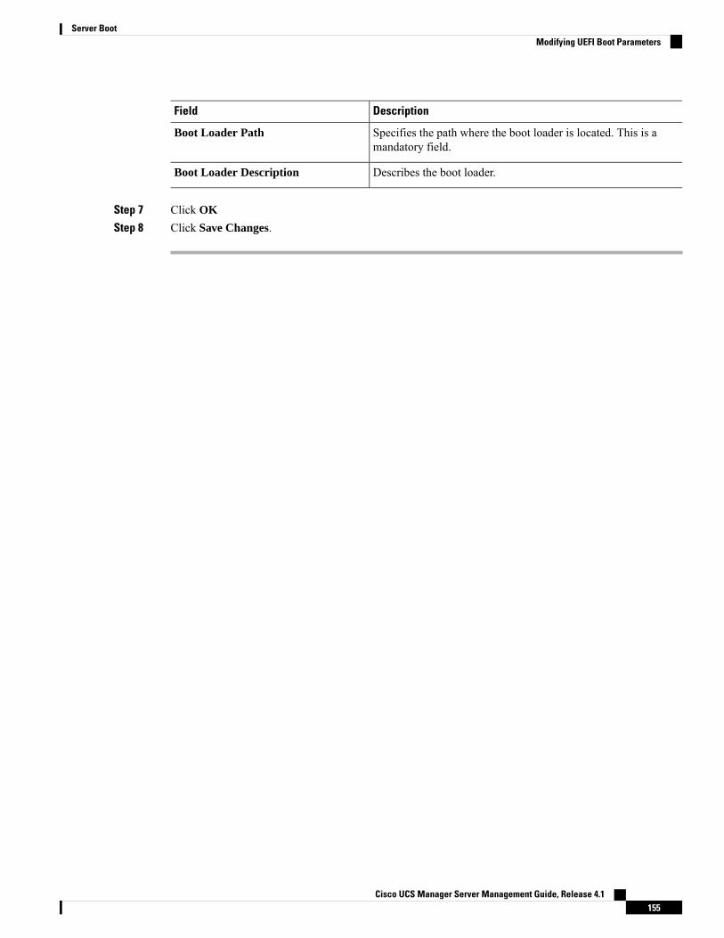
DescriptionField
Specifies the path where the boot loader is located. This is amandatory field.
Boot Loader Path
Describes the boot loader.Boot Loader Description
Step 7 Click OK
Step 8 Click Save Changes.
Cisco UCS Manager Server Management Guide, Release 4.1155
Server BootModifying UEFI Boot Parameters

Cisco UCS Manager Server Management Guide, Release 4.1156
Server BootModifying UEFI Boot Parameters

C H A P T E R 11Service Profiles
• Service Profiles in UCS Manager, on page 157• Service Profiles that Override Server Identity, on page 158• Service Profiles that Inherit Server Identity, on page 158• Guidelines and Recommendations for Service Profiles, on page 159• Methods of Creating Service Profiles, on page 159• Inband Service Profiles, on page 163• Service Profile Tasks, on page 163• Service Profile Association, on page 173• Service Profile Templates, on page 174• Service Profile Template Tasks, on page 179• Service Profile Association, on page 183
Service Profiles in UCS ManagerA service profile defines a single server and its storage and networking characteristics. You can create a serviceprofile for Cisco UCSManager and UCSMini. When a service profile is deployed to a server, UCS Managerautomatically configures the server, adapters, fabric extenders, and fabric interconnects to match theconfiguration specified in the service profile.
A service profile includes four types of information:
• Server definition: Defines the resources (e.g. a specific server or a blade inserted to a specific chassis)that are required to apply to the profile.
• Identity information: Includes the UUID, MAC address for each virtual NIC (vNIC), and WWNspecifications for each HBA.
• Firmware revision specifications: Used when a certain tested firmware revision is required to be installedor for some other reason a specific firmware is used.
• Connectivity definition: Configures network adapters, fabric extenders, and parent interconnects,however this information is abstract as it does not include the details of how each network componentis configured.
The UCS system provides two types of service profiles: Service profiles that inherit server identity and serviceprofiles that override server identity.
Cisco UCS Manager Server Management Guide, Release 4.1157
Service Profiles that Override Server IdentityThis type of service profile provides the maximum amount of flexibility and control. This profile allows youto override the identity values that are on the server at the time of association and use the resource pools andpolicies set up in Cisco UCS Manager to automate some administration tasks.
You can disassociate this service profile from one server, then associate it with another server. Thisre-association can be done either manually or through an automated server pool policy. The burned-in settings,such as UUID andMAC address on the new server are overwritten with the configuration in the service profile.As a result, the change in the server is transparent to your network. You do not need to reconfigure anycomponent or application on your network to begin using the new server.
This profile allows you to take advantage of and manage system resources through resource pools and policies,such as the following:
• Virtualized identity information, including pools of MAC addresses, WWN addresses, and UUIDs
• Ethernet and Fibre Channel adapter profile policies
• Firmware package policies
• Operating system boot order policies
Unless the service profile contains power management policies, a server pool qualification policy, or anotherpolicy that requires a specific hardware configuration, you can use the profile for any type of server in theCisco UCS domain.
You can associate these service profiles with either a rack-mount server or a blade server. The ability tomigrate the service profile depends upon whether you choose to restrict migration of the service profile.
If you choose not to restrict migration, Cisco UCS Manager does not perform any compatibility checks onthe new server before migrating the existing service profile. If the hardware of both servers are not similar,the association might fail.
Note
Service Profiles that Inherit Server IdentityThis hardware-based service profile is the simplest to use and create. This profile uses the default values inthe server and mimics the management of a rack-mounted server. It is tied to a specific server and cannot bemoved or migrated to another server.
You do not need to create pools or configuration policies to use this service profile.
This service profile inherits and applies the identity and configuration information that is present at the timeof association, such as the following:
• MAC addresses for the two NICs
• For a converged network adapter or a virtual interface card, the WWN addresses for the two HBAs
• BIOS versions
• Server UUID
Cisco UCS Manager Server Management Guide, Release 4.1158
Service ProfilesService Profiles that Override Server Identity

The server identity and configuration information inherited through this service profile might not have thevalues burned into the server hardware at the manufacturer if those values were changed before this profileis associated with the server.
Important
Guidelines and Recommendations for Service ProfilesIn addition to any guidelines or recommendations that are specific to policies and pools included in serviceprofiles and service profile templates, such as the local disk configuration policy, adhere to the followingguidelines and recommendations that impact the ability to associate a service profile with a server:
Limit to the Number of vNICs that Can Be Configured on a Rack-Mount Server
You can configure up to 56 vNICs per supported adapter, such as the Cisco UCS P81E Virtual Interface Card(N2XX-ACPCI01), on any rack-mount server that is integrated with Cisco UCS Manager.
No Power Capping Support for Rack-Mount Servers
Power capping is not supported for rack servers. If you include a power control policy in a service profile thatis associated with a rack-mount server, the policy is not implemented.
QoS Policy Guidelines for vNICs
You can only assign a QoS policy to a vNIC if the priority setting for that policy is not set to fc, whichrepresents the Fibre Channel system class. You can configure the priority for the QoS policy with any othersystem class.
QoS Policy Guidelines for vHBAs
You can only assign a QoS policy to a vHBA if the priority setting for that policy is set to fc, which representsthe Fibre Channel system class.
The Host Control setting for a QoS policy applies to vNICs only. It has no effect on a vHBA.
Methods of Creating Service Profiles
Creating a Service Profile with the Expert Wizard
Procedure
Step 1 In the Navigation pane, click Servers.Step 2 Expand Servers > Service Profiles.Step 3 Expand the node for the organization where you want to create the service profile.
If the system does not include multi tenancy, expand the root node.
Cisco UCS Manager Server Management Guide, Release 4.1159
Service ProfilesGuidelines and Recommendations for Service Profiles
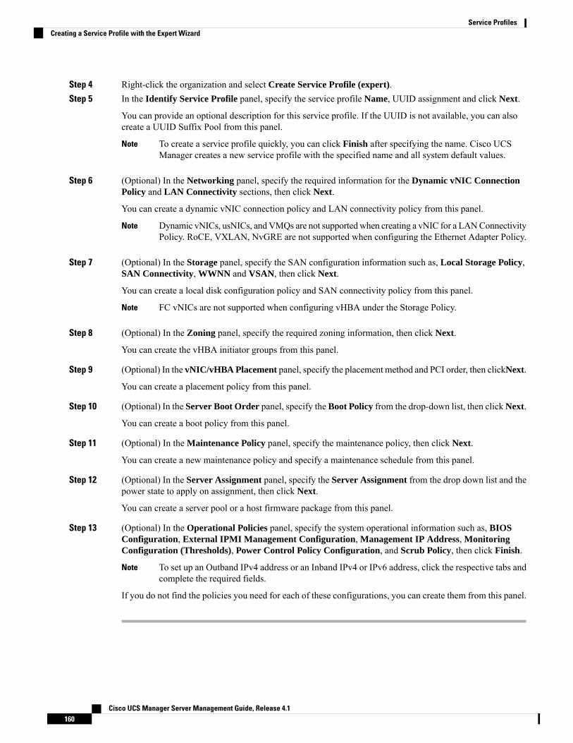
Step 4 Right-click the organization and select Create Service Profile (expert).Step 5 In the Identify Service Profile panel, specify the service profile Name, UUID assignment and click Next.
You can provide an optional description for this service profile. If the UUID is not available, you can alsocreate a UUID Suffix Pool from this panel.
To create a service profile quickly, you can click Finish after specifying the name. Cisco UCSManager creates a new service profile with the specified name and all system default values.
Note
Step 6 (Optional) In the Networking panel, specify the required information for the Dynamic vNIC ConnectionPolicy and LAN Connectivity sections, then click Next.
You can create a dynamic vNIC connection policy and LAN connectivity policy from this panel.
Dynamic vNICs, usNICs, andVMQs are not supportedwhen creating a vNIC for a LANConnectivityPolicy. RoCE, VXLAN, NvGRE are not supported when configuring the Ethernet Adapter Policy.
Note
Step 7 (Optional) In the Storage panel, specify the SAN configuration information such as, Local Storage Policy,SAN Connectivity, WWNN and VSAN, then click Next.
You can create a local disk configuration policy and SAN connectivity policy from this panel.
FC vNICs are not supported when configuring vHBA under the Storage Policy.Note
Step 8 (Optional) In the Zoning panel, specify the required zoning information, then click Next.
You can create the vHBA initiator groups from this panel.
Step 9 (Optional) In the vNIC/vHBA Placement panel, specify the placement method and PCI order, then clickNext.
You can create a placement policy from this panel.
Step 10 (Optional) In the Server Boot Order panel, specify the Boot Policy from the drop-down list, then clickNext.
You can create a boot policy from this panel.
Step 11 (Optional) In the Maintenance Policy panel, specify the maintenance policy, then click Next.
You can create a new maintenance policy and specify a maintenance schedule from this panel.
Step 12 (Optional) In the Server Assignment panel, specify the Server Assignment from the drop down list and thepower state to apply on assignment, then click Next.
You can create a server pool or a host firmware package from this panel.
Step 13 (Optional) In the Operational Policies panel, specify the system operational information such as, BIOSConfiguration, External IPMI Management Configuration, Management IP Address, MonitoringConfiguration (Thresholds), Power Control Policy Configuration, and Scrub Policy, then click Finish.
To set up an Outband IPv4 address or an Inband IPv4 or IPv6 address, click the respective tabs andcomplete the required fields.
Note
If you do not find the policies you need for each of these configurations, you can create them from this panel.
Cisco UCS Manager Server Management Guide, Release 4.1160
Service ProfilesCreating a Service Profile with the Expert Wizard
Creating a Service Profile that Inherits Server Identity
Procedure
Step 1 In the Navigation pane, click Servers.Step 2 Expand Servers > Service Profiles.Step 3 Expand the node for the organization where you want to create the service profile.
If the system does not include multi tenancy, expand the root node.
Step 4 Right-click the organization and select Create Service Profile.Step 5 In the Naming area of the Create Service Profile dialog box, complete the following fields:
a) In the Name field, enter a unique name that you can use to identify the service profile.
This name can be between 2 and 32 alphanumeric characters. You cannot use spaces or any specialcharacters other than - (hyphen), _ (underscore), : (colon), and . (period), and this name must be uniqueacross all service profiles and service profile templates within the same organization.
b) In the Description field, enter a description of this service profile.
Step 6 In the vNICs area of the Create Service Profile dialog box, choose the primary and secondary vNICs.Step 7 In the vHBAs area of the Create Service Profile dialog box, choose the primary and secondary vHBAs.Step 8 In the Boot Order area of the Create Service Profile dialog box, choose the primary and secondary boot
devices.Step 9 (Optional) In the Select column of the Server Association (optional) area, click the radio button for a server
to associate this service profile with that server.Step 10 Click OK.
Creating a Hardware Based Service Profile for a Blade ServerYou cannot move a hardware based service profile to another server.
Procedure
Step 1 In the Navigation pane, click Equipment.Step 2 Expand Equipment > Chassis > Chassis Number > Servers.Step 3 Choose the server for which you want to create a hardware based service profile.Step 4 In the Work pane, click the General tab.Step 5 In the Actions area, click Create Service Profile.Step 6 In the Create Service Profile for Server dialog box, do the following:
a) From the Create Service Profile in Organization drop-down list, select the organization in which youwant to create the service profile.
b) Click the Hardware Based Service Profile radio button.c) In the Name field, enter a unique name for the service profile.
Cisco UCS Manager Server Management Guide, Release 4.1161
Service ProfilesCreating a Service Profile that Inherits Server Identity
This name can be between 2 and 32 alphanumeric characters. You cannot use spaces or any specialcharacters other than - (hyphen), _ (underscore), : (colon), and . (period), and this name must be uniqueacross all service profiles and service profile templates within the same organization.
d) If you want Cisco UCSManager to create vNICs for the service profile, check theCreate Default vNICscheck box.
e) If you want Cisco UCSManager to create vHBAs for the service profile, check theCreate Default vHBAscheck box.
f) Click OK.
Cisco UCSManager inherits and automatically applies the identity and configuration information in the server,creates the service profile, and associates it with the server.
Creating a Hardware Based Service Profile for a Rack-Mount ServerYou cannot move a hardware based service profile to another server.
Procedure
Step 1 In the Navigation pane, click Equipment.Step 2 Expand Equipment > Rack Mounts > Servers.
For Cisco UCS C125 M5 Servers, expand Equipment > Rack Mounts > Enclosures > RackEnclosure rack_enclosure_number > Servers.
Note
Step 3 Choose the server for which you want to create a hardware based service profile.Step 4 In the Work pane, click the General tab.Step 5 In the Actions area, click Create Service Profile.Step 6 In the Create Service Profile for Server dialog box, do the following:
a) From the Create Service Profile in Organization drop-down list, select the organization in which youwant to create the service profile.
b) Click the Hardware Based Service Profile radio button.c) In the Name field, enter a unique name for the service profile.
This name can be between 2 and 32 alphanumeric characters. You cannot use spaces or any specialcharacters other than - (hyphen), _ (underscore), : (colon), and . (period), and this name must be uniqueacross all service profiles and service profile templates within the same organization.
d) If you want Cisco UCSManager to create vNICs for the service profile, check theCreate Default vNICscheck box.
e) If you want Cisco UCSManager to create vHBAs for the service profile, check theCreate Default vHBAscheck box.
f) Click OK.
Cisco UCSManager inherits and automatically applies the identity and configuration information in the server,creates the service profile, and associates it with the server.
Cisco UCS Manager Server Management Guide, Release 4.1162
Service ProfilesCreating a Hardware Based Service Profile for a Rack-Mount Server
Inband Service Profiles
Deleting the Inband Configuration from a Service ProfileThis procedure removes the inband management IP address configuration from a service profile. If this actionis greyed out, no inband configuration was configured.
Procedure
Step 1 In the Navigation pane, click Servers.Step 2 Expand Servers > Service Profiles > Service_Profile_Name.Step 3 In the Work pane, click the General tab.Step 4 In the Actions area, click Delete Inband Configuration.Step 5 Click Yes in the Delete confirmation dialog box.
The inband management IP address configuration for the service profile is deleted.
Service Profile Tasks
Renaming a Service ProfileWhen you rename a service profile, the following occurs:
• Event logs and audit logs that reference the previous name for the service profile are retained under thatname.
• A new audit record is created to log the rename operation.
• All records of faults against the service profile under its previous name are transferred to the new serviceprofile name.
You cannot rename a service profile with pending changes.Note
Procedure
Step 1 In the Navigation pane, click Servers.Step 2 Expand Servers > Service Profiles.Step 3 Expand the node for the organization that includes the service profile you want to rename.
Cisco UCS Manager Server Management Guide, Release 4.1163
Service ProfilesInband Service Profiles
If the system does not include multi tenancy, expand the root node.
Step 4 Click the service profile you want to rename.Step 5 In the Work pane, click the General tab.Step 6 In the Actions area, click Rename Service Profile.Step 7 In the Rename Service Profile dialog box, enter the new name for the service profile in the New Name field.
This name can be between 2 and 32 alphanumeric characters. You cannot use spaces or any special charactersother than - (hyphen), _ (underscore), : (colon), and . (period), and this name must be unique across all serviceprofiles and service profile templates within the same organization.
Step 8 Click OK.
Cloning a Service Profile
Procedure
Step 1 In the Navigation pane, click Servers.Step 2 Expand Servers > Service Profiles.Step 3 Expand the node for the organization where you want to create the service profile.
If the system does not include multi tenancy, expand the root node.
Step 4 Right-click the service profile you want to clone and select Create a Clone.Step 5 In the Create Clone From Service Profile dialog box:
a) Enter the name you want to use for the new profile in the Clone Name field.
This name can be between 2 and 32 alphanumeric characters. You cannot use spaces or any specialcharacters other than - (hyphen), _ (underscore), : (colon), and . (period), and this name must be uniqueacross all service profiles and service profile templates within the same organization.
This name must be unique within the organization or sub-organization in which you are creating theservice profile.
b) Click OK.
Step 6 Navigate to the service profile you just created and make sure that all options are correct.
Changing the UUID in a Service Profile
Procedure
Step 1 In the Navigation pane, click Servers.Step 2 Expand Servers > Service Profiles.Step 3 Expand the node for the organization that contains the service profile for which you want to change the UUID.
Cisco UCS Manager Server Management Guide, Release 4.1164
Service ProfilesCloning a Service Profile
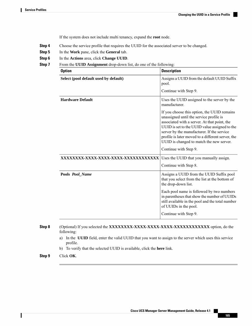
If the system does not include multi tenancy, expand the root node.
Step 4 Choose the service profile that requires the UUID for the associated server to be changed.Step 5 In the Work pane, click the General tab.Step 6 In the Actions area, click Change UUID.Step 7 From the UUID Assignment drop-down list, do one of the following:
DescriptionOption
Assigns a UUID from the default UUID Suffixpool.
Select (pool default used by default)
Continue with Step 9.
Uses the UUID assigned to the server by themanufacturer.
Hardware Default
If you choose this option, the UUID remainsunassigned until the service profile isassociated with a server. At that point, theUUID is set to the UUID value assigned to theserver by the manufacturer. If the serviceprofile is later moved to a different server, theUUID is changed to match the new server.
Continue with Step 9.
Uses the UUID that you manually assign.XXXXXXXX-XXXX-XXXX-XXXX-XXXXXXXXXXXX
Continue with Step 8.
Assigns a UUID from the UUID Suffix poolthat you select from the list at the bottom ofthe drop-down list.
Pools Pool_Name
Each pool name is followed by two numbersin parentheses that show the number of UUIDsstill available in the pool and the total numberof UUIDs in the pool.
Continue with Step 9.
Step 8 (Optional) If you selected the XXXXXXXX-XXXX-XXXX-XXXX-XXXXXXXXXXXX option, do thefollowing:a) In the UUID field, enter the valid UUID that you want to assign to the server which uses this service
profile.b) To verify that the selected UUID is available, click the here link.
Step 9 Click OK.
Cisco UCS Manager Server Management Guide, Release 4.1165
Service ProfilesChanging the UUID in a Service Profile

Modifying the Boot Order in a Service Profile
Procedure
Step 1 In the Navigation pane, click Servers.Step 2 Expand Servers > Service Profiles.Step 3 Expand the node for the organization that includes the service profile for which you want to change the boot
order.
If the system does not include multi-tenancy, expand the root node.
Step 4 Click the service profile for which you want to change the boot order.Step 5 In the Work pane, click the Boot Order tab.Step 6 Click Modify Boot Policy to change the existing boot policy.Step 7 In the Modify Boot Policy dialog box, choose one of the following from the Boot Policy drop-down list:
DescriptionOption
Assigns the default boot policy to this service profile.Select Boot Policy to use
Continue with Step 14.
Enables you to create a local boot policy that can only be accessed by thisservice profile.
Create a Specific Boot Policy
Continue with Step 8.
Assigns an existing boot policy to the service profile. If you choose thisoption, Cisco UCS Manager displays the details of the policy.
Boot Policies Policy_Name
If you do not want use any of the existing policies, but instead want to createa policy that all service profiles can access, click Create Boot Policy andcontinue with Step 2. Otherwise, continue with Step 14.
Step 8 If you chose to create a boot policy, in theCreate Boot Policy dialog box, enter a unique name and descriptionfor the policy.
This name can be between 1 and 16 alphanumeric characters. You cannot use spaces or any special charactersother than - (hyphen), _ (underscore), : (colon), and . (period), and you cannot change this name after theobject is saved.
Step 9 (Optional) To reboot all servers that use this boot policy after you make changes to the boot order, check theReboot on Boot Order Change check box.
In the Cisco UCS Manager GUI, if the Reboot on Boot Order Change check box is checked for a bootpolicy, and if CD-ROM or Floppy is the last device in the boot order, deleting or adding the device does notdirectly affect the boot order and the server does not reboot.
Step 10 (Optional) If desired, check the Enforce vNIC/vHBA/iSCSI Name check box.
• If checked, Cisco UCS Manager displays a configuration error and reports whether one or more of thevNICs, vHBAs, or iSCSI vNICs listed in the Boot Order table match the server configuration in theservice profile.
Cisco UCS Manager Server Management Guide, Release 4.1166
Service ProfilesModifying the Boot Order in a Service Profile
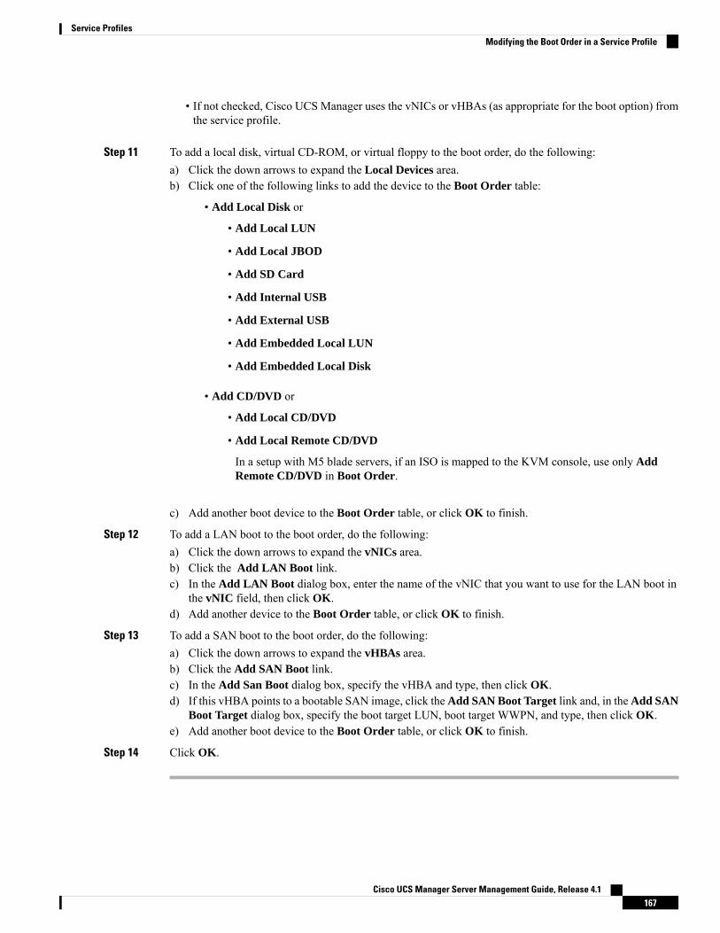
• If not checked, Cisco UCS Manager uses the vNICs or vHBAs (as appropriate for the boot option) fromthe service profile.
Step 11 To add a local disk, virtual CD-ROM, or virtual floppy to the boot order, do the following:a) Click the down arrows to expand the Local Devices area.b) Click one of the following links to add the device to the Boot Order table:
• Add Local Disk or
• Add Local LUN
• Add Local JBOD
• Add SD Card
• Add Internal USB
• Add External USB
• Add Embedded Local LUN
• Add Embedded Local Disk
• Add CD/DVD or
• Add Local CD/DVD
• Add Local Remote CD/DVD
In a setup with M5 blade servers, if an ISO is mapped to the KVM console, use only AddRemote CD/DVD in Boot Order.
c) Add another boot device to the Boot Order table, or click OK to finish.
Step 12 To add a LAN boot to the boot order, do the following:a) Click the down arrows to expand the vNICs area.b) Click the Add LAN Boot link.c) In the Add LAN Boot dialog box, enter the name of the vNIC that you want to use for the LAN boot in
the vNIC field, then click OK.d) Add another device to the Boot Order table, or click OK to finish.
Step 13 To add a SAN boot to the boot order, do the following:a) Click the down arrows to expand the vHBAs area.b) Click the Add SAN Boot link.c) In the Add San Boot dialog box, specify the vHBA and type, then click OK.d) If this vHBA points to a bootable SAN image, click theAdd SAN Boot Target link and, in theAdd SAN
Boot Target dialog box, specify the boot target LUN, boot target WWPN, and type, then click OK.e) Add another boot device to the Boot Order table, or click OK to finish.
Step 14 Click OK.
Cisco UCS Manager Server Management Guide, Release 4.1167
Service ProfilesModifying the Boot Order in a Service Profile
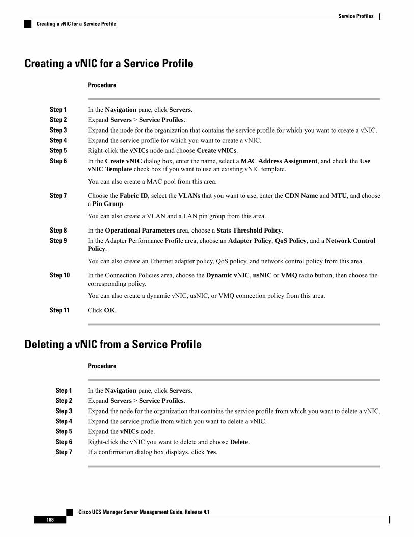
Creating a vNIC for a Service Profile
Procedure
Step 1 In the Navigation pane, click Servers.Step 2 Expand Servers > Service Profiles.Step 3 Expand the node for the organization that contains the service profile for which you want to create a vNIC.Step 4 Expand the service profile for which you want to create a vNIC.Step 5 Right-click the vNICs node and choose Create vNICs.Step 6 In the Create vNIC dialog box, enter the name, select a MAC Address Assignment, and check the Use
vNIC Template check box if you want to use an existing vNIC template.
You can also create a MAC pool from this area.
Step 7 Choose the Fabric ID, select the VLANs that you want to use, enter the CDN Name and MTU, and choosea Pin Group.
You can also create a VLAN and a LAN pin group from this area.
Step 8 In the Operational Parameters area, choose a Stats Threshold Policy.Step 9 In the Adapter Performance Profile area, choose an Adapter Policy, QoS Policy, and a Network Control
Policy.
You can also create an Ethernet adapter policy, QoS policy, and network control policy from this area.
Step 10 In the Connection Policies area, choose the Dynamic vNIC, usNIC or VMQ radio button, then choose thecorresponding policy.
You can also create a dynamic vNIC, usNIC, or VMQ connection policy from this area.
Step 11 Click OK.
Deleting a vNIC from a Service Profile
Procedure
Step 1 In the Navigation pane, click Servers.Step 2 Expand Servers > Service Profiles.Step 3 Expand the node for the organization that contains the service profile from which you want to delete a vNIC.Step 4 Expand the service profile from which you want to delete a vNIC.Step 5 Expand the vNICs node.Step 6 Right-click the vNIC you want to delete and choose Delete.Step 7 If a confirmation dialog box displays, click Yes.
Cisco UCS Manager Server Management Guide, Release 4.1168
Service ProfilesCreating a vNIC for a Service Profile

Creating a vHBA for a Service Profile
Procedure
Step 1 In the Navigation pane, click Servers.Step 2 Expand Servers > Service Profiles.Step 3 Expand the node for the organization that contains the service profile for which you want to create a vHBA.Step 4 Expand the service profile for which you want to create a vHBA.Step 5 Right-click the vHBAs node and choose Create vHBAs.Step 6 In the Create vHBAs dialog box, enter the name and optional description.Step 7 Choose the Fabric ID, Select VSAN, Pin Group, Persistent Binding, and Max Data Field Size.
You can also create a VSAN or SAN pin group from this area.
Step 8 In the Operational Parameters area, choose the Stats Threshold Policy.Step 9 In the Adapter Performance Profile area, choose the Adapter Policy and QoS Policy.
You can also create a fibre channel adapter policy or QoS policy from this area.
Step 10 Click OK.
Changing the WWPN for a vHBA
Procedure
Step 1 In the Navigation pane, click Servers.Step 2 Expand Servers > Service Profiles.Step 3 Expand the node for the organization that contains the service profile for which you want to change the
WWPN.Step 4 Expand Service_Profile_Name > vHBAs.Step 5 Click the vHBA for which you want to change the WWPN.Step 6 In the Work pane, click the General tab.Step 7 In the Actions area, click Change World Wide Name.Step 8 In the Change World Wide Port Name dialog box, complete the required fields.Step 9 Click OK.
Cisco UCS Manager Server Management Guide, Release 4.1169
Service ProfilesCreating a vHBA for a Service Profile

Clearing Persistent Binding for a vHBA
Procedure
Step 1 In the Navigation pane, click Servers.Step 2 Expand Servers > Service Profiles.Step 3 Expand the node for the organization that contains the service profile for which you want to modify the vHBA.Step 4 Expand Service_Profile_Name > vHBAs.Step 5 Click the vHBA for which you want to clear the persistent binding.Step 6 In the Work pane, click the General tab.Step 7 In the Actions area, click Clear Persistent Binding.Step 8 If a confirmation dialog box displays, click Yes.
Deleting a vHBA from a Service Profile
Procedure
Step 1 In the Navigation pane, click Servers.Step 2 Expand Servers > Service Profiles.Step 3 Expand the node for the organization that contains the service profile from which you want to delete a vHBA.Step 4 Expand the service profile from which you want to delete a vHBA.Step 5 Expand the vHBAs node.Step 6 Right-click the vHBA you want to delete and choose Delete.Step 7 If a confirmation dialog box displays, click Yes.
Adding a vHBA Initiator Group to a Service Profile
Procedure
Step 1 Expand Servers > Service Profiles.Step 2 Expand the node for the organization that contains the service profile to which you want to add a vHBA
initiator group.
If the system does not include multi tenancy, expand the root node.
Step 3 Choose the service profile to which you want to add a vHBA initiator group.Step 4 In the Work pane, click the Storage > vHBA Initiator Groups.Step 5 On the icon bar at the right of the Select vHBA Initiator Groups table, click +.
Cisco UCS Manager Server Management Guide, Release 4.1170
Service ProfilesClearing Persistent Binding for a vHBA

Step 6 In theCreate vHBA Initiator Group dialog box, complete the following fields to set the name and description:
DescriptionName
The name of the vHBA initiator group.
This name can be between 1 and 16 alphanumeric characters. Youcannot use spaces or any special characters other than - (hyphen), _(underscore), : (colon), and . (period), and you cannot change thisname after the object is saved.
Name field
A description of the group.
Enter up to 256 characters. You can use any characters or spacesexcept ` (accent mark), \ (backslash), ^ (carat), " (double quote), =(equal sign), > (greater than), < (less than), or ' (single quote).
Description field
Step 7 In the Select vHBA Initiators table, check the check box in the Select column for each vHBA you want toinclude in the vHBA initiator group.
Step 8 To add a storage connection policy to the initiator group, choose one of the following options:
• Choose an existing storage connection policy from the Storage Connection Policy drop-down list.Continue with Step 10.
• Click the Create Storage Connection Policy link if you want to create a new storage connection policythat will be available for use by other vHBA initiator groups within the Cisco UCS domain. For moreinformation, see Creating a Fibre Channel Storage Connection Policy. After you create the storageconnection policy, continue with Step 10.
• Choose the Specific Storage Connection Policy option to create a storage connection policy that is onlyavailable to this vHBA initiator group. Continue with Step 9.
Step 9 In the Specific Storage Connection Policy area, complete the following fields to create a storage connectionpolicy that is only available to this vHBA initiator group:
DescriptionName
A description of the policy. Cisco recommends including informationabout where and when to use the policy.
Enter up to 256 characters. You can use any characters or spaces except` (accent mark), \ (backslash), ^ (carat), " (double quote), = (equal sign),> (greater than), < (less than), or ' (single quote).
Description field
Cisco UCS Manager Server Management Guide, Release 4.1171
Service ProfilesAdding a vHBA Initiator Group to a Service Profile
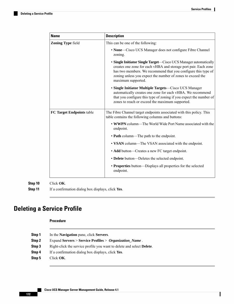
DescriptionName
This can be one of the following:
• None—Cisco UCS Manager does not configure Fibre Channelzoning.
• Single Initiator Single Target—CiscoUCSManager automaticallycreates one zone for each vHBA and storage port pair. Each zonehas two members. We recommend that you configure this type ofzoning unless you expect the number of zones to exceed themaximum supported.
• Single Initiator Multiple Targets—Cisco UCS Managerautomatically creates one zone for each vHBA. We recommendthat you configure this type of zoning if you expect the number ofzones to reach or exceed the maximum supported.
Zoning Type field
The Fibre Channel target endpoints associated with this policy. Thistable contains the following columns and buttons:
• WWPN column—TheWorldWide Port Name associated with theendpoint.
• Path column—The path to the endpoint.
• VSAN column—The VSAN associated with the endpoint.
• Add button—Creates a new FC target endpoint.
• Delete button—Deletes the selected endpoint.
• Properties button—Displays all properties for the selectedendpoint.
FC Target Endpoints table
Step 10 Click OK.Step 11 If a confirmation dialog box displays, click Yes.
Deleting a Service Profile
Procedure
Step 1 In the Navigation pane, click Servers.Step 2 Expand Servers > Service Profiles > Organization_Name .Step 3 Right-click the service profile you want to delete and select Delete.Step 4 If a confirmation dialog box displays, click Yes.Step 5 Click OK.
Cisco UCS Manager Server Management Guide, Release 4.1172
Service ProfilesDeleting a Service Profile
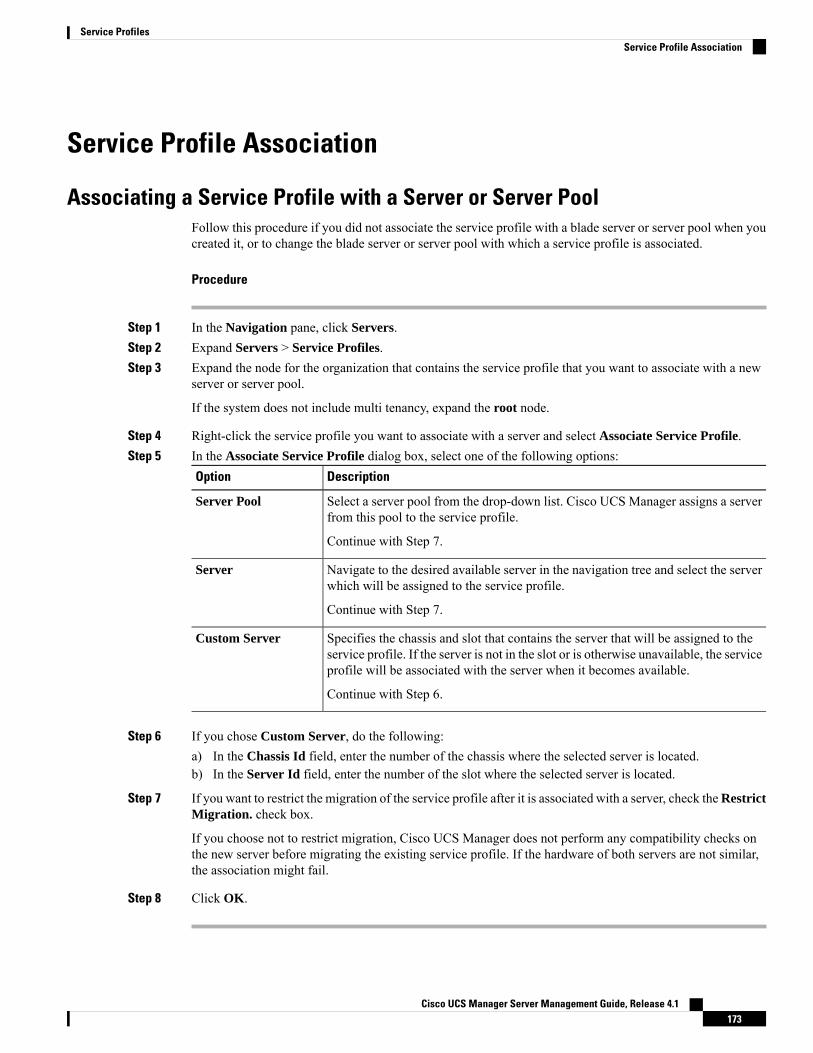
Service Profile Association
Associating a Service Profile with a Server or Server PoolFollow this procedure if you did not associate the service profile with a blade server or server pool when youcreated it, or to change the blade server or server pool with which a service profile is associated.
Procedure
Step 1 In the Navigation pane, click Servers.Step 2 Expand Servers > Service Profiles.Step 3 Expand the node for the organization that contains the service profile that you want to associate with a new
server or server pool.
If the system does not include multi tenancy, expand the root node.
Step 4 Right-click the service profile you want to associate with a server and select Associate Service Profile.Step 5 In the Associate Service Profile dialog box, select one of the following options:
DescriptionOption
Select a server pool from the drop-down list. Cisco UCS Manager assigns a serverfrom this pool to the service profile.
Server Pool
Continue with Step 7.
Navigate to the desired available server in the navigation tree and select the serverwhich will be assigned to the service profile.
Server
Continue with Step 7.
Specifies the chassis and slot that contains the server that will be assigned to theservice profile. If the server is not in the slot or is otherwise unavailable, the serviceprofile will be associated with the server when it becomes available.
Custom Server
Continue with Step 6.
Step 6 If you chose Custom Server, do the following:a) In the Chassis Id field, enter the number of the chassis where the selected server is located.b) In the Server Id field, enter the number of the slot where the selected server is located.
Step 7 If you want to restrict the migration of the service profile after it is associated with a server, check theRestrictMigration. check box.
If you choose not to restrict migration, Cisco UCS Manager does not perform any compatibility checks onthe new server before migrating the existing service profile. If the hardware of both servers are not similar,the association might fail.
Step 8 Click OK.
Cisco UCS Manager Server Management Guide, Release 4.1173
Service ProfilesService Profile Association

Disassociating a Service Profile from a Server or Server PoolWhen you disassociate a service profile, Cisco UCS Manager attempts to shutdown the operating system onthe server. If the operating system does not shutdown within a reasonable length of time, Cisco UCSManagerforces the server to shutdown.
Procedure
Step 1 In the Navigation pane, click Servers.Step 2 Expand Servers > Service Profiles.Step 3 Expand the node for the organization that contains the service profile that you want to disassociate from a
server or server pool.
If the system does not include multi tenancy, expand the root node.
Step 4 Right-click the service profile you want to disassociate from a server and selectDisassociate Service Profile.Step 5 In the Disassociate Service Profile dialog box, click Yes to confirm that you want to disassociate the service
profile.Step 6 (Optional) Monitor the status and FSM for the server to confirm that the disassociation completed.
Service Profile Templates
Initial and Existing TemplatesWith a service profile template, you can quickly create several service profiles with the same basic parameters,such as the number of vNICs and vHBAs, and with identity information drawn from the same pools.
If you need only one service profile with similar values to an existing service profile, you can clone a serviceprofile in the Cisco UCS Manager GUI.
Tip
For example, if you need several service profiles with similar values to configure servers to host databasesoftware, you can create a service profile template, either manually or from an existing service profile. Youthen use the template to create the service profiles.
Cisco UCS supports the following types of service profile templates:
Initial template
Service profiles created from an initial template inherit all the properties of the template. Service profilescreated from an initial service profile template are bound to the template. However, changes to the initialtemplate do not automatically propagate to the bound service profiles. If you want to propagate changesto bound service profiles, unbind and rebind the service profile to the initial template.
Cisco UCS Manager Server Management Guide, Release 4.1174
Service ProfilesDisassociating a Service Profile from a Server or Server Pool
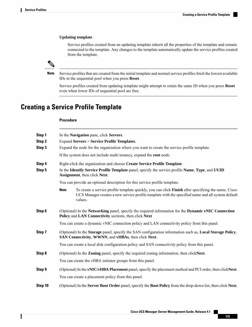
Updating template
Service profiles created from an updating template inherit all the properties of the template and remainconnected to the template. Any changes to the template automatically update the service profiles createdfrom the template.
Service profiles that are created from the initial template and normal service profiles fetch the lowest availableIDs in the sequential pool when you press Reset.
Service profiles created from updating template might attempt to retain the same ID when you press Reseteven when lower IDs of sequential pool are free.
Note
Creating a Service Profile Template
Procedure
Step 1 In the Navigation pane, click Servers.Step 2 Expand Servers > Service Profile Templates.Step 3 Expand the node for the organization where you want to create the service profile template.
If the system does not include multi tenancy, expand the root node.
Step 4 Right-click the organization and choose Create Service Profile Template.Step 5 In the Identify Service Profile Template panel, specify the service profile Name, Type, and UUID
Assignment, then click Next.
You can provide an optional description for this service profile template.
To create a service profile template quickly, you can click Finish after specifying the name. CiscoUCSManager creates a new service profile template with the specified name and all system defaultvalues.
Note
Step 6 (Optional) In the Networking panel, specify the required information for the Dynamic vNIC ConnectionPolicy and LAN Connectivity sections, then click Next
You can create a dynamic vNIC connection policy and LAN connectivity policy from this panel.
Step 7 (Optional) In the Storage panel, specify the SAN configuration information such as, Local Storage Policy,SAN Connectivity, WWNN, and vHBAs, then click Next.
You can create a local disk configuration policy and SAN connectivity policy from this panel.
Step 8 (Optional) In the Zoning panel, specify the required zoning information, then clickNext.
You can create the vHBA initiator groups from this panel.
Step 9 (Optional) In the vNIC/vHBA Placement panel, specify the placement method and PCI order, then clickNext.
You can create a placement policy from this panel.
Step 10 (Optional) In the Server Boot Order panel, specify the Boot Policy from the drop-down list, then clickNext.
Cisco UCS Manager Server Management Guide, Release 4.1175
Service ProfilesCreating a Service Profile Template

You can create a boot policy from this panel.
Step 11 (Optional) In the Maintenance Policy panel, specify the maintenance policy, then click Next.
You can create a new maintenance policy and specify a maintenance schedule from this panel.
Step 12 (Optional) In the Server Assignment panel, specify the Pool Assignment from the drop down list and thepower state to apply on assignment, then click Next.
You can create a server pool or a host firmware package from this panel.
Step 13 (Optional) In the Operational Policies panel, specify the system operational information such as, BIOSConfiguration, External IPMI Management Configuration, Management IP Address, MonitoringConfiguration (Thresholds), Power Control Policy Configuration, and Scrub Policy, then click Finish.
To set up an Outband IPv4 address or an Inband IPv4 or IPv6 address, click the respective tabs andcomplete the required fields.
Note
If you do not find the policies you need for each of these configurations, you can create them from this panel.
Creating One or More Service Profiles from a Service Profile Template
Procedure
Step 1 In the Navigation pane, click Servers.Step 2 Expand Servers > Service Profile Templates.Step 3 Expand the node for the organization that contains the service profile template that you want to use as the
basis for your service profiles.
If the system does not include multi tenancy, expand the root node.
Step 4 Right-click the service profile template from which you want to create the profiles and select Create ServiceProfiles From Template.
Step 5 In the Create Service Profiles From Template dialog box, complete the required fields.Step 6 Click OK.
Creating a Template Based Service Profile for a Blade Server
Before you begin
A qualified service profile template with the desired values must exist in Cisco UCS Manager.
Procedure
Step 1 In the Navigation pane, click Equipment.
Cisco UCS Manager Server Management Guide, Release 4.1176
Service ProfilesCreating One or More Service Profiles from a Service Profile Template
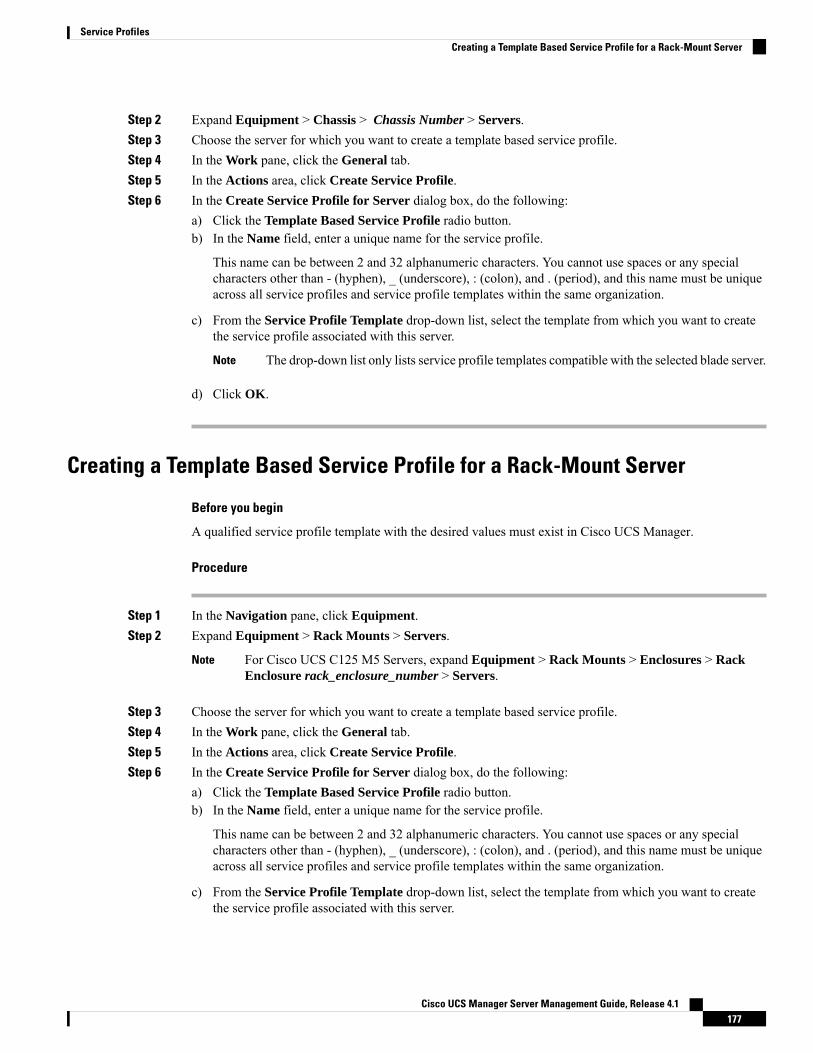
Step 2 Expand Equipment > Chassis > Chassis Number > Servers.Step 3 Choose the server for which you want to create a template based service profile.Step 4 In the Work pane, click the General tab.Step 5 In the Actions area, click Create Service Profile.Step 6 In the Create Service Profile for Server dialog box, do the following:
a) Click the Template Based Service Profile radio button.b) In the Name field, enter a unique name for the service profile.
This name can be between 2 and 32 alphanumeric characters. You cannot use spaces or any specialcharacters other than - (hyphen), _ (underscore), : (colon), and . (period), and this name must be uniqueacross all service profiles and service profile templates within the same organization.
c) From the Service Profile Template drop-down list, select the template from which you want to createthe service profile associated with this server.
The drop-down list only lists service profile templates compatible with the selected blade server.Note
d) Click OK.
Creating a Template Based Service Profile for a Rack-Mount Server
Before you begin
A qualified service profile template with the desired values must exist in Cisco UCS Manager.
Procedure
Step 1 In the Navigation pane, click Equipment.Step 2 Expand Equipment > Rack Mounts > Servers.
For Cisco UCS C125 M5 Servers, expand Equipment > Rack Mounts > Enclosures > RackEnclosure rack_enclosure_number > Servers.
Note
Step 3 Choose the server for which you want to create a template based service profile.Step 4 In the Work pane, click the General tab.Step 5 In the Actions area, click Create Service Profile.Step 6 In the Create Service Profile for Server dialog box, do the following:
a) Click the Template Based Service Profile radio button.b) In the Name field, enter a unique name for the service profile.
This name can be between 2 and 32 alphanumeric characters. You cannot use spaces or any specialcharacters other than - (hyphen), _ (underscore), : (colon), and . (period), and this name must be uniqueacross all service profiles and service profile templates within the same organization.
c) From the Service Profile Template drop-down list, select the template from which you want to createthe service profile associated with this server.
Cisco UCS Manager Server Management Guide, Release 4.1177
Service ProfilesCreating a Template Based Service Profile for a Rack-Mount Server
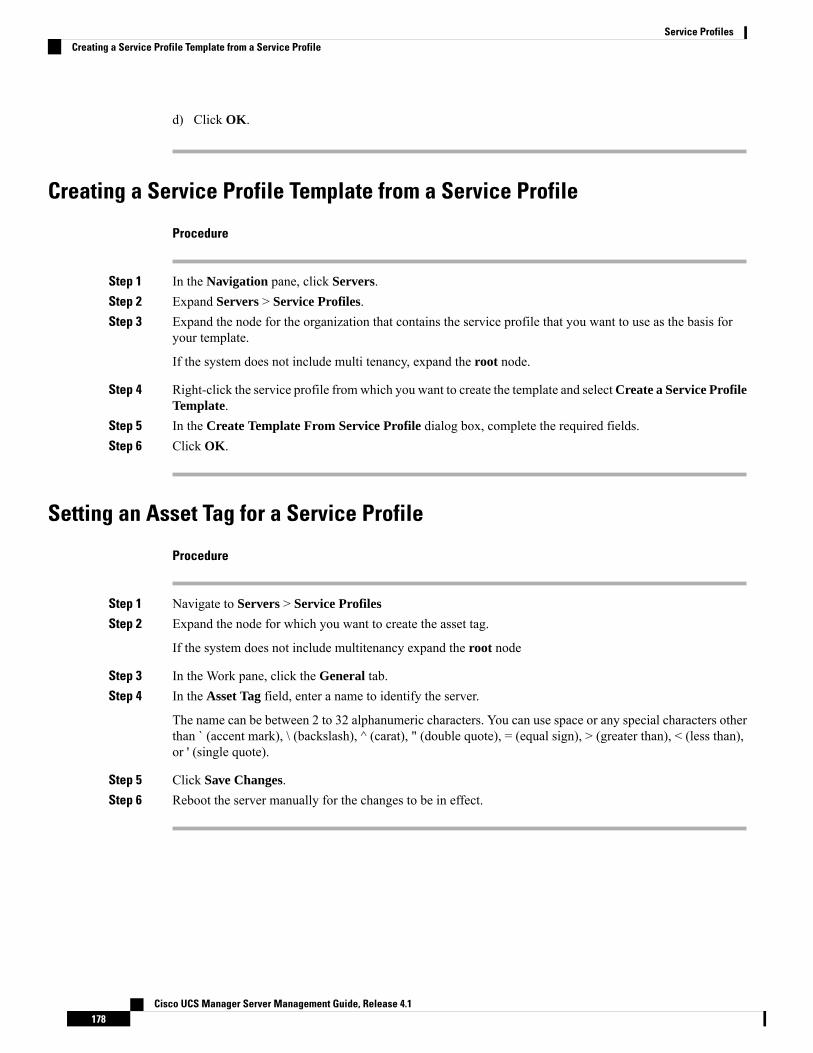
d) Click OK.
Creating a Service Profile Template from a Service Profile
Procedure
Step 1 In the Navigation pane, click Servers.Step 2 Expand Servers > Service Profiles.Step 3 Expand the node for the organization that contains the service profile that you want to use as the basis for
your template.
If the system does not include multi tenancy, expand the root node.
Step 4 Right-click the service profile fromwhich you want to create the template and selectCreate a Service ProfileTemplate.
Step 5 In the Create Template From Service Profile dialog box, complete the required fields.Step 6 Click OK.
Setting an Asset Tag for a Service Profile
Procedure
Step 1 Navigate to Servers > Service Profiles
Step 2 Expand the node for which you want to create the asset tag.
If the system does not include multitenancy expand the root node
Step 3 In the Work pane, click the General tab.Step 4 In the Asset Tag field, enter a name to identify the server.
The name can be between 2 to 32 alphanumeric characters. You can use space or any special characters otherthan ` (accent mark), \ (backslash), ^ (carat), " (double quote), = (equal sign), > (greater than), < (less than),or ' (single quote).
Step 5 Click Save Changes.Step 6 Reboot the server manually for the changes to be in effect.
Cisco UCS Manager Server Management Guide, Release 4.1178
Service ProfilesCreating a Service Profile Template from a Service Profile
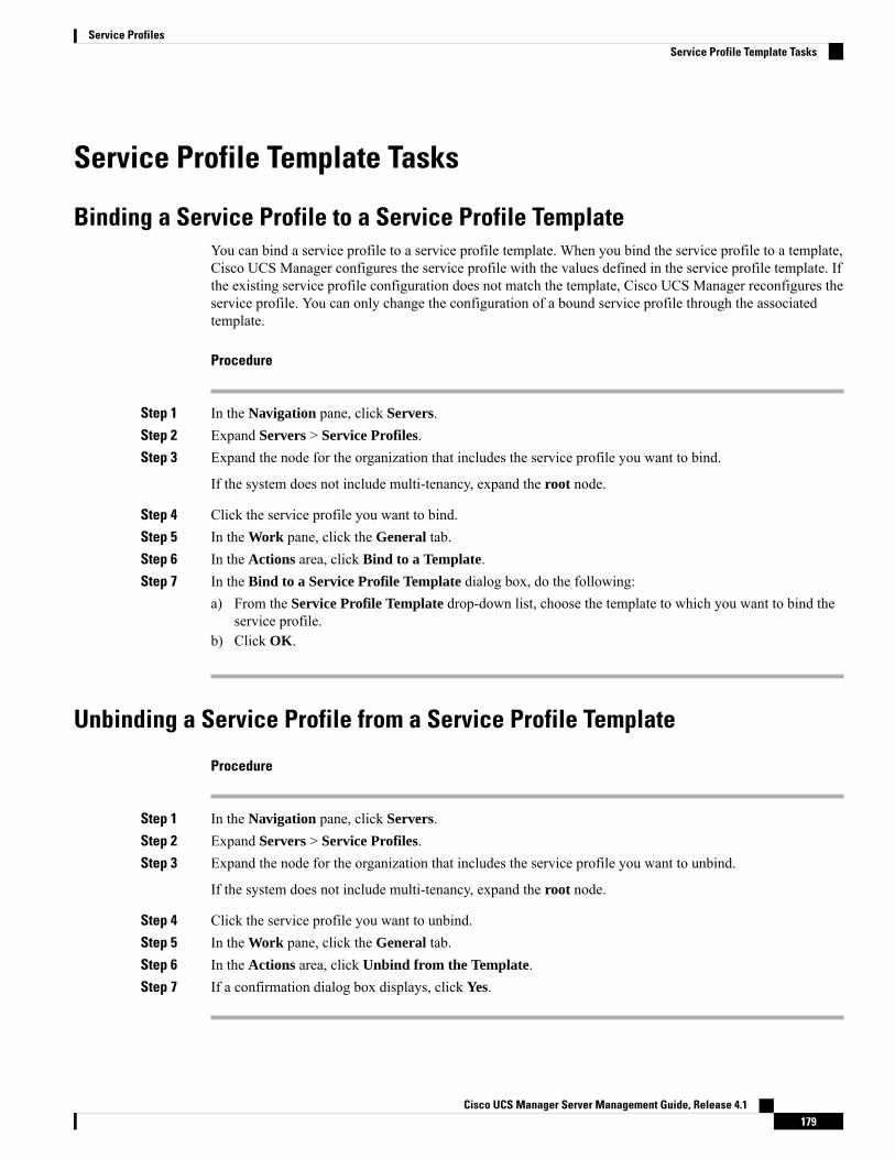
Service Profile Template Tasks
Binding a Service Profile to a Service Profile TemplateYou can bind a service profile to a service profile template. When you bind the service profile to a template,Cisco UCS Manager configures the service profile with the values defined in the service profile template. Ifthe existing service profile configuration does not match the template, Cisco UCS Manager reconfigures theservice profile. You can only change the configuration of a bound service profile through the associatedtemplate.
Procedure
Step 1 In the Navigation pane, click Servers.Step 2 Expand Servers > Service Profiles.Step 3 Expand the node for the organization that includes the service profile you want to bind.
If the system does not include multi-tenancy, expand the root node.
Step 4 Click the service profile you want to bind.Step 5 In the Work pane, click the General tab.Step 6 In the Actions area, click Bind to a Template.Step 7 In the Bind to a Service Profile Template dialog box, do the following:
a) From the Service Profile Template drop-down list, choose the template to which you want to bind theservice profile.
b) Click OK.
Unbinding a Service Profile from a Service Profile Template
Procedure
Step 1 In the Navigation pane, click Servers.Step 2 Expand Servers > Service Profiles.Step 3 Expand the node for the organization that includes the service profile you want to unbind.
If the system does not include multi-tenancy, expand the root node.
Step 4 Click the service profile you want to unbind.Step 5 In the Work pane, click the General tab.Step 6 In the Actions area, click Unbind from the Template.Step 7 If a confirmation dialog box displays, click Yes.
Cisco UCS Manager Server Management Guide, Release 4.1179
Service ProfilesService Profile Template Tasks
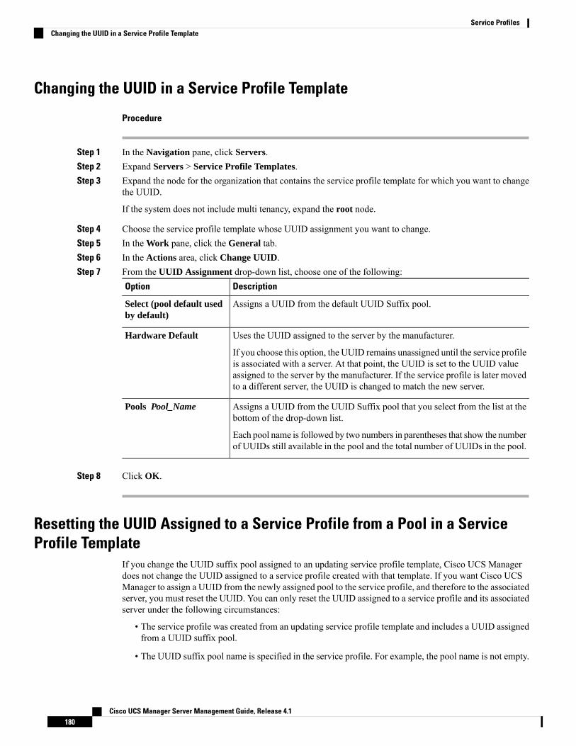
Changing the UUID in a Service Profile Template
Procedure
Step 1 In the Navigation pane, click Servers.Step 2 Expand Servers > Service Profile Templates.Step 3 Expand the node for the organization that contains the service profile template for which you want to change
the UUID.
If the system does not include multi tenancy, expand the root node.
Step 4 Choose the service profile template whose UUID assignment you want to change.Step 5 In the Work pane, click the General tab.Step 6 In the Actions area, click Change UUID.Step 7 From the UUID Assignment drop-down list, choose one of the following:
DescriptionOption
Assigns a UUID from the default UUID Suffix pool.Select (pool default usedby default)
Uses the UUID assigned to the server by the manufacturer.Hardware Default
If you choose this option, the UUID remains unassigned until the service profileis associated with a server. At that point, the UUID is set to the UUID valueassigned to the server by the manufacturer. If the service profile is later movedto a different server, the UUID is changed to match the new server.
Assigns a UUID from the UUID Suffix pool that you select from the list at thebottom of the drop-down list.
Pools Pool_Name
Each pool name is followed by two numbers in parentheses that show the numberof UUIDs still available in the pool and the total number of UUIDs in the pool.
Step 8 Click OK.
Resetting the UUID Assigned to a Service Profile from a Pool in a ServiceProfile Template
If you change the UUID suffix pool assigned to an updating service profile template, Cisco UCS Managerdoes not change the UUID assigned to a service profile created with that template. If you want Cisco UCSManager to assign a UUID from the newly assigned pool to the service profile, and therefore to the associatedserver, you must reset the UUID. You can only reset the UUID assigned to a service profile and its associatedserver under the following circumstances:
• The service profile was created from an updating service profile template and includes a UUID assignedfrom a UUID suffix pool.
• The UUID suffix pool name is specified in the service profile. For example, the pool name is not empty.
Cisco UCS Manager Server Management Guide, Release 4.1180
Service ProfilesChanging the UUID in a Service Profile Template

• The UUID value is not 0, and is therefore not derived from the server hardware.
Procedure
Step 1 In the Navigation pane, click Servers.Step 2 Expand Servers > Service Profiles.Step 3 Expand the node for the organization that contains the service profile for which you want to reset the UUID.
If the system does not include multi tenancy, expand the root node.
Step 4 Choose the service profile that requires the UUID for the associated server to be reset to a different UUIDsuffix pool.
Step 5 In the Work pane, click the General tab.Step 6 In the Actions area, click Reset UUID.
If this action is not visible, then the UUID configuration in the service profile does not meet the requirementsfor resetting a UUID.
Step 7 If a confirmation dialog box displays, click Yes.Step 8 Click OK
Resetting the MAC Address Assigned to a vNIC from a Pool in a Service ProfileTemplate
If you change the MAC pool assigned to an updating service profile template, Cisco UCS Manager does notchange the MAC address assigned to a service profile created with that template. If you want Cisco UCSManager to assign a MAC address from the newly assigned pool to the service profile, and therefore to theassociated server, you must reset the MAC address. You can only reset the MAC address assigned to a serviceprofile and its associated server under the following circumstances:
• The service profile was created from an updating service profile template and includes a MAC addressassigned from a MAC pool.
• The MAC pool name is specified in the service profile. For example, the pool name is not empty.
• The MAC address value is not 0, and is therefore not derived from the server hardware.
Procedure
Step 1 In the Navigation pane, click Servers.Step 2 Expand Servers > Service Profiles.Step 3 Expand the node for the organization that contains the service profile for which you want to reset the MAC
address.
If the system does not include multi tenancy, expand the root node.
Step 4 Expand Service_Profile_Name > vNICs.
Cisco UCS Manager Server Management Guide, Release 4.1181
Service ProfilesResetting the MAC Address Assigned to a vNIC from a Pool in a Service Profile Template
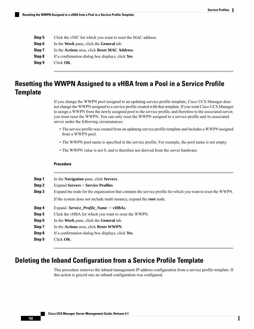
Step 5 Click the vNIC for which you want to reset the MAC address.Step 6 In the Work pane, click the General tab.Step 7 In the Actions area, click Reset MAC Address.Step 8 If a confirmation dialog box displays, click Yes.Step 9 Click OK.
Resetting the WWPN Assigned to a vHBA from a Pool in a Service ProfileTemplate
If you change the WWPN pool assigned to an updating service profile template, Cisco UCS Manager doesnot change theWWPN assigned to a service profile created with that template. If you want Cisco UCSManagerto assign a WWPN from the newly assigned pool to the service profile, and therefore to the associated server,you must reset the WWPN. You can only reset the WWPN assigned to a service profile and its associatedserver under the following circumstances:
• The service profile was created from an updating service profile template and includes aWWPN assignedfrom a WWPN pool.
• The WWPN pool name is specified in the service profile. For example, the pool name is not empty.
• The WWPN value is not 0, and is therefore not derived from the server hardware.
Procedure
Step 1 In the Navigation pane, click Servers.Step 2 Expand Servers > Service Profiles.Step 3 Expand the node for the organization that contains the service profile for which you want to reset the WWPN.
If the system does not include multi tenancy, expand the root node.
Step 4 Expand Service_Profile_Name > vHBAs.Step 5 Click the vHBA for which you want to reset the WWPN.Step 6 In the Work pane, click the General tab.Step 7 In the Actions area, click Reset WWPN.Step 8 If a confirmation dialog box displays, click Yes.Step 9 Click OK.
Deleting the Inband Configuration from a Service Profile TemplateThis procedure removes the inband management IP address configuration from a service profile template. Ifthis action is greyed out, no inband configuration was configured.
Cisco UCS Manager Server Management Guide, Release 4.1182
Service ProfilesResetting the WWPN Assigned to a vHBA from a Pool in a Service Profile Template
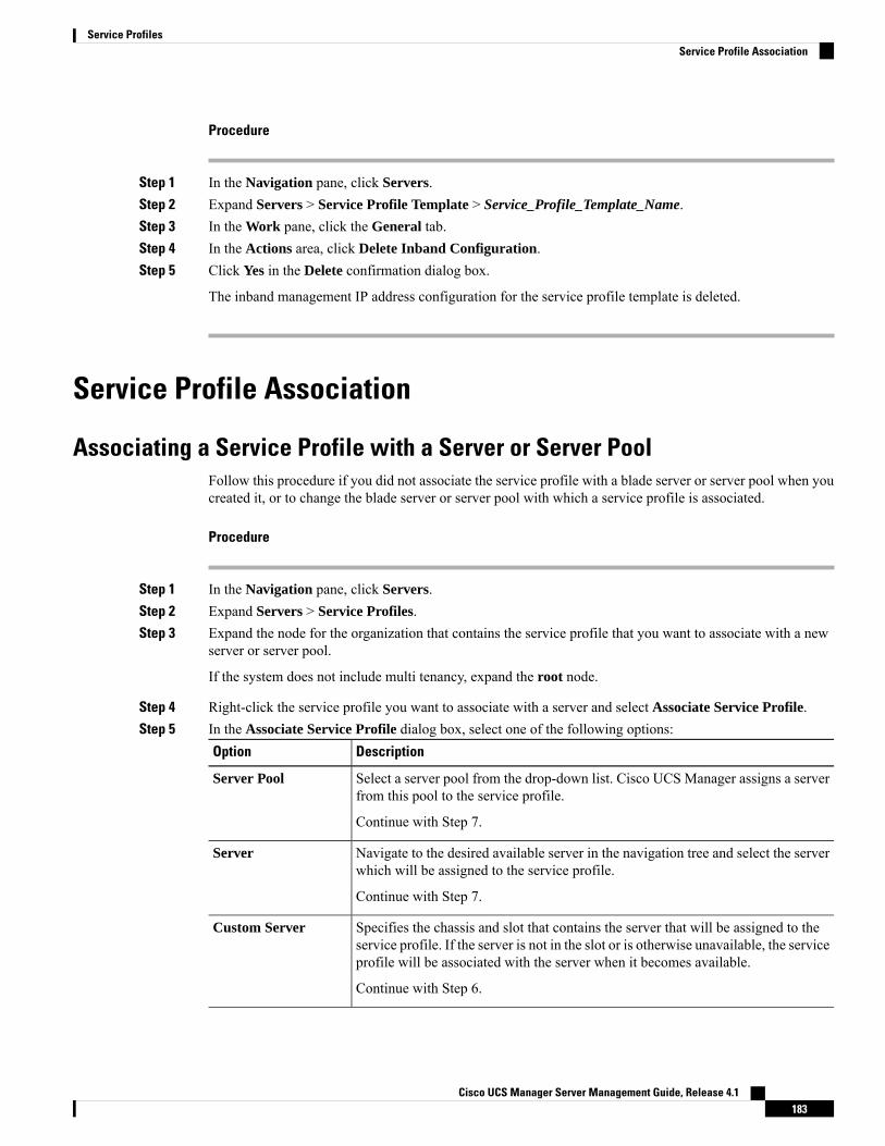
Procedure
Step 1 In the Navigation pane, click Servers.Step 2 Expand Servers > Service Profile Template > Service_Profile_Template_Name.Step 3 In the Work pane, click the General tab.Step 4 In the Actions area, click Delete Inband Configuration.Step 5 Click Yes in the Delete confirmation dialog box.
The inband management IP address configuration for the service profile template is deleted.
Service Profile Association
Associating a Service Profile with a Server or Server PoolFollow this procedure if you did not associate the service profile with a blade server or server pool when youcreated it, or to change the blade server or server pool with which a service profile is associated.
Procedure
Step 1 In the Navigation pane, click Servers.Step 2 Expand Servers > Service Profiles.Step 3 Expand the node for the organization that contains the service profile that you want to associate with a new
server or server pool.
If the system does not include multi tenancy, expand the root node.
Step 4 Right-click the service profile you want to associate with a server and select Associate Service Profile.Step 5 In the Associate Service Profile dialog box, select one of the following options:
DescriptionOption
Select a server pool from the drop-down list. Cisco UCS Manager assigns a serverfrom this pool to the service profile.
Server Pool
Continue with Step 7.
Navigate to the desired available server in the navigation tree and select the serverwhich will be assigned to the service profile.
Server
Continue with Step 7.
Specifies the chassis and slot that contains the server that will be assigned to theservice profile. If the server is not in the slot or is otherwise unavailable, the serviceprofile will be associated with the server when it becomes available.
Custom Server
Continue with Step 6.
Cisco UCS Manager Server Management Guide, Release 4.1183
Service ProfilesService Profile Association

Step 6 If you chose Custom Server, do the following:a) In the Chassis Id field, enter the number of the chassis where the selected server is located.b) In the Server Id field, enter the number of the slot where the selected server is located.
Step 7 If you want to restrict the migration of the service profile after it is associated with a server, check theRestrictMigration. check box.
If you choose not to restrict migration, Cisco UCS Manager does not perform any compatibility checks onthe new server before migrating the existing service profile. If the hardware of both servers are not similar,the association might fail.
Step 8 Click OK.
Associating a Service Profile Template with a Server PoolFollow this procedure if you did not associate the service profile template with a server pool when you createdit, or to change the server pool with which a service profile created from this template is associated.
Procedure
Step 1 In the Navigation pane, click Servers.Step 2 Expand Servers > Service Profile Templates.Step 3 Expand the node for the organization that contains the service profile that you want to associate with a server
pool.
If the system does not include multi tenancy, expand the root node.
Step 4 Right-click the service profile template you want to associate with a server pool and select Associate withServer Pool.
The Associate with Server Pool dialog box opens.
Step 5 From the Server Pool section of the Pool Assignment drop-down list, select a server pool.
If you select Assign Later, the service profile template is not associated with a server pool.
Step 6 (Optional) From the Select Qualification drop-down list, select the server pool policy qualifications you wantto apply to a server that is associated with a service profile created from this template.
Step 7 Click OK.
Disassociating a Service Profile from a Server or Server PoolWhen you disassociate a service profile, Cisco UCS Manager attempts to shutdown the operating system onthe server. If the operating system does not shutdown within a reasonable length of time, Cisco UCSManagerforces the server to shutdown.
Cisco UCS Manager Server Management Guide, Release 4.1184
Service ProfilesAssociating a Service Profile Template with a Server Pool
Procedure
Step 1 In the Navigation pane, click Servers.Step 2 Expand Servers > Service Profiles.Step 3 Expand the node for the organization that contains the service profile that you want to disassociate from a
server or server pool.
If the system does not include multi tenancy, expand the root node.
Step 4 Right-click the service profile you want to disassociate from a server and selectDisassociate Service Profile.Step 5 In the Disassociate Service Profile dialog box, click Yes to confirm that you want to disassociate the service
profile.Step 6 (Optional) Monitor the status and FSM for the server to confirm that the disassociation completed.
Disassociating a Service Profile Template from its Server Pool
Procedure
Step 1 In the Navigation pane, click Servers.Step 2 Expand Servers > Service Profile Templates.Step 3 Expand the node for the organization that contains the service profile that you want to disassociate from its
server pool.
If the system does not include multi tenancy, expand the root node.
Step 4 Right-click the service profile template you want to disassociate from its server pool and select DisassociateTemplate.
Step 5 If a confirmation dialog box displays, click Yes.
Cisco UCS Manager Server Management Guide, Release 4.1185
Service ProfilesDisassociating a Service Profile Template from its Server Pool

Cisco UCS Manager Server Management Guide, Release 4.1186
Service ProfilesDisassociating a Service Profile Template from its Server Pool

C H A P T E R 12Server-Related Policies
• BIOS Settings, on page 187• Trusted Platform Module, on page 266• Consistent Device Naming, on page 268• CIMC Security Policies, on page 272• Graphics Card Policies, on page 275• Local Disk Policies, on page 276• Persistent Memory Modules, on page 288• Scrub Policy, on page 289• DIMM Error Management, on page 293• Serial over LAN Policy Settings, on page 295• Server Autoconfiguration Policies, on page 296• Server Discovery Policy Settings, on page 298• Server Inheritance Policy Settings, on page 301• Server Pool Policy Settings, on page 302• Server Pool Policy Qualifications Settings, on page 304• vNIC/vHBA Placement Policy Settings, on page 309• CIMC Mounted vMedia, on page 322
BIOS Settings
Server BIOS Settings
Server BIOS SettingsCisco UCS provides two methods for making global modifications to the BIOS settings on servers in an CiscoUCS domain. You can create one or more BIOS policies that include a specific grouping of BIOS settingsthat match the needs of a server or set of servers, or you can use the default BIOS settings for a specific serverplatform.
Both the BIOS policy and the default BIOS settings for a server platform enable you to fine tune the BIOSsettings for a server managed by Cisco UCS Manager.
Depending upon the needs of the data center, you can configure BIOS policies for some service profiles anduse the BIOS defaults in other service profiles in the same Cisco UCS domain, or you can use only one of
Cisco UCS Manager Server Management Guide, Release 4.1187

them. You can also use Cisco UCS Manager to view the actual BIOS settings on a server and determinewhether they are meeting current needs.
Cisco UCS Manager pushes BIOS configuration changes through a BIOS policy or default BIOS settings tothe Cisco Integrated Management Controller (CIMC) buffer. These changes remain in the buffer and do nottake effect until the server is rebooted.
We recommend that you verify the support for BIOS settings in the server that you want to configure. Somesettings, such as Mirroring Mode for RAS Memory, are not supported by all Cisco UCS servers.
Note
Main BIOS Settings
The following table lists the main server BIOS settings that you can configure through a BIOS policy or thedefault BIOS settings:
DescriptionName
Properties
When the server is rebooted after you change one or more BIOSsettings.
If you enable this setting, the server is rebooted according to themaintenance policy in the server's service profile. For example,if the maintenance policy requires user acknowledgment, theserver is not rebooted and the BIOS changes are not applieduntil a user acknowledges the pending activity.
If you do not enable this setting, the BIOS changes are notapplied until the next time the server is rebooted, whether as aresult of another server configuration change or a manual reboot.
Reboot on BIOS Settings Change
BIOS Setting
What the BIOS displays during Power On Self-Test (POST).This can be one of the following:
• Disabled—The BIOS displays all messages and OptionROM information during boot.
• Enabled—The BIOS displays the logo screen, but doesnot display any messages or Option ROM informationduring boot.
• Platform Default—The BIOS uses the value for thisattribute contained in the BIOS defaults for the server typeand vendor.
Quiet Boot
Cisco UCS Manager Server Management Guide, Release 4.1188
Server-Related PoliciesMain BIOS Settings
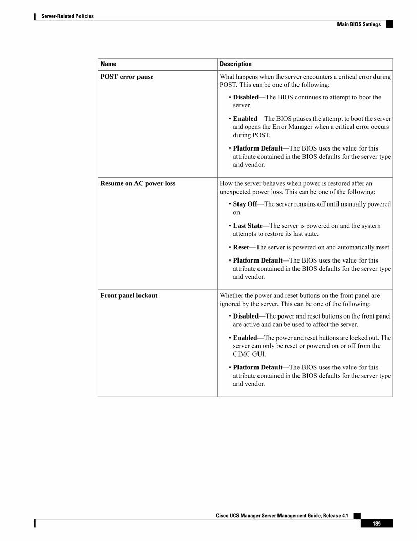
DescriptionName
What happens when the server encounters a critical error duringPOST. This can be one of the following:
• Disabled—The BIOS continues to attempt to boot theserver.
• Enabled—The BIOS pauses the attempt to boot the serverand opens the Error Manager when a critical error occursduring POST.
• Platform Default—The BIOS uses the value for thisattribute contained in the BIOS defaults for the server typeand vendor.
POST error pause
How the server behaves when power is restored after anunexpected power loss. This can be one of the following:
• Stay Off—The server remains off until manually poweredon.
• Last State—The server is powered on and the systemattempts to restore its last state.
• Reset—The server is powered on and automatically reset.
• Platform Default—The BIOS uses the value for thisattribute contained in the BIOS defaults for the server typeand vendor.
Resume on AC power loss
Whether the power and reset buttons on the front panel areignored by the server. This can be one of the following:
• Disabled—The power and reset buttons on the front panelare active and can be used to affect the server.
• Enabled—The power and reset buttons are locked out. Theserver can only be reset or powered on or off from theCIMC GUI.
• Platform Default—The BIOS uses the value for thisattribute contained in the BIOS defaults for the server typeand vendor.
Front panel lockout
Cisco UCS Manager Server Management Guide, Release 4.1189
Server-Related PoliciesMain BIOS Settings

DescriptionName
Consistent Device Naming allows Ethernet interfaces to benamed in a consistent manner. This makes Ethernet interfacenames more uniform, easy to identify, and persistent whenadapter or other configuration changes are made.
Whether consistent device naming is enabled or not. This canbe one of the following:
• Disabled—Consistent device naming is disabled for theBIOS policy.
• Enabled—Consistent device naming is enabled for theBIOS policy. This enables Ethernet interfaces to be namedconsistently.
• Platform Default—The BIOS uses the value for thisattribute contained in the BIOS defaults for the server typeand vendor.
CDN Control
Processor BIOS Settings
The following table lists the processor BIOS settings that you can configure through a BIOS policy or thedefault BIOS settings:
DescriptionName
Whether the processor uses Intel Turbo Boost Technology, whichallows the processor to automatically increase its frequency ifit is running below power, temperature, or voltage specifications.This can be one of the following:
• Disabled—The processor does not increase its frequencyautomatically.
• Enabled—The processor uses Turbo Boost Technology ifrequired.
• Platform Default —The BIOS uses the value for thisattribute contained in the BIOS defaults for the server typeand vendor.
Intel Turbo Boost Tech
Cisco UCS Manager Server Management Guide, Release 4.1190
Server-Related PoliciesProcessor BIOS Settings
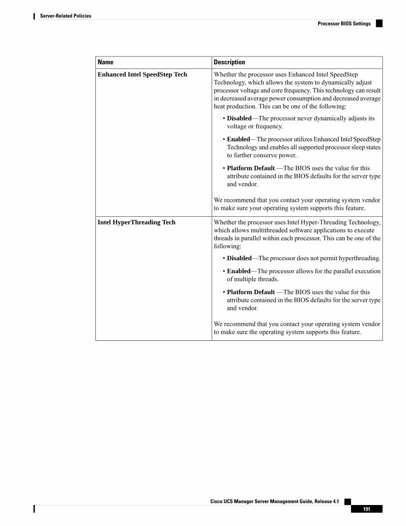
DescriptionName
Whether the processor uses Enhanced Intel SpeedStepTechnology, which allows the system to dynamically adjustprocessor voltage and core frequency. This technology can resultin decreased average power consumption and decreased averageheat production. This can be one of the following:
• Disabled—The processor never dynamically adjusts itsvoltage or frequency.
• Enabled—The processor utilizes Enhanced Intel SpeedStepTechnology and enables all supported processor sleep statesto further conserve power.
• Platform Default —The BIOS uses the value for thisattribute contained in the BIOS defaults for the server typeand vendor.
We recommend that you contact your operating system vendorto make sure your operating system supports this feature.
Enhanced Intel SpeedStep Tech
Whether the processor uses Intel Hyper-Threading Technology,which allows multithreaded software applications to executethreads in parallel within each processor. This can be one of thefollowing:
• Disabled—The processor does not permit hyperthreading.
• Enabled—The processor allows for the parallel executionof multiple threads.
• Platform Default —The BIOS uses the value for thisattribute contained in the BIOS defaults for the server typeand vendor.
We recommend that you contact your operating system vendorto make sure the operating system supports this feature.
Intel HyperThreading Tech
Cisco UCS Manager Server Management Guide, Release 4.1191
Server-Related PoliciesProcessor BIOS Settings

DescriptionName
Allows improved CPU performance by using Intel Speed Selecttechnology to tune the CPU to run at one of three operatingprofiles, based on number of logical processor cores, frequency,and TDP thread setting, to improve performance over the basicPlatform Default setting. These profiles correspond to High,Medium, and LowCore settings and can be one of the following:
• Base—The processor uses Base.
• Config 1—The processor uses Config 1.
• Config 2—The processor uses Config 2.
• Platform Default —The BIOS uses the value for thisattribute contained in the BIOS defaults for the server typeand vendor.
Low core profiles enable the CPU to run at maximum frequency.Refer to Intel Speed Select, on page 257 sample settings.
Intel Speed Select
Sets the state of logical processor cores per CPU in a package.If you disable this setting, Intel Hyper Threading technology isalso disabled. This can be one of the following:
• All—Enablesmultiprocessing on all logical processor cores.
• 1 through n—Specifies the number of logical processorcores per CPU that can run on the server. To disablemultiprocessing and have only one logical processor coreper CPU running on the server, choose 1.
• Platform Default —The BIOS uses the value for thisattribute contained in the BIOS defaults for the server typeand vendor.
We recommend that you contact your operating system vendorto make sure your operating system supports this feature.
Core Multi Processing
Cisco UCS Manager Server Management Guide, Release 4.1192
Server-Related PoliciesProcessor BIOS Settings
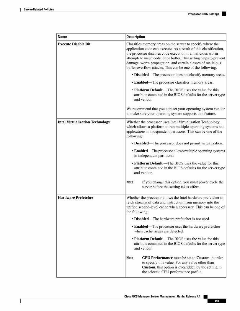
DescriptionName
Classifies memory areas on the server to specify where theapplication code can execute. As a result of this classification,the processor disables code execution if a malicious wormattempts to insert code in the buffer. This setting helps to preventdamage, worm propagation, and certain classes of maliciousbuffer overflow attacks. This can be one of the following:
• Disabled—The processor does not classify memory areas.
• Enabled—The processor classifies memory areas.
• Platform Default —The BIOS uses the value for thisattribute contained in the BIOS defaults for the server typeand vendor.
We recommend that you contact your operating system vendorto make sure your operating system supports this feature.
Execute Disable Bit
Whether the processor uses Intel Virtualization Technology,which allows a platform to run multiple operating systems andapplications in independent partitions. This can be one of thefollowing:
• Disabled—The processor does not permit virtualization.
• Enabled—The processor allowsmultiple operating systemsin independent partitions.
• Platform Default —The BIOS uses the value for thisattribute contained in the BIOS defaults for the server typeand vendor.
If you change this option, you must power cycle theserver before the setting takes effect.
Note
Intel Virtualization Technology
Whether the processor allows the Intel hardware prefetcher tofetch streams of data and instruction from memory into theunified second-level cache when necessary. This can be one ofthe following:
• Disabled—The hardware prefetcher is not used.
• Enabled—The processor uses the hardware prefetcherwhen cache issues are detected.
• Platform Default —The BIOS uses the value for thisattribute contained in the BIOS defaults for the server typeand vendor.
CPU Performance must be set to Custom in orderto specify this value. For any value other thanCustom, this option is overridden by the setting inthe selected CPU performance profile.
Note
Hardware Prefetcher
Cisco UCS Manager Server Management Guide, Release 4.1193
Server-Related PoliciesProcessor BIOS Settings
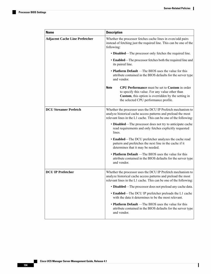
DescriptionName
Whether the processor fetches cache lines in even/odd pairsinstead of fetching just the required line. This can be one of thefollowing:
• Disabled—The processor only fetches the required line.
• Enabled—The processor fetches both the required line andits paired line.
• Platform Default —The BIOS uses the value for thisattribute contained in the BIOS defaults for the server typeand vendor.
CPU Performance must be set to Custom in orderto specify this value. For any value other thanCustom, this option is overridden by the setting inthe selected CPU performance profile.
Note
Adjacent Cache Line Prefetcher
Whether the processor uses the DCU IP Prefetch mechanism toanalyze historical cache access patterns and preload the mostrelevant lines in the L1 cache. This can be one of the following:
• Disabled—The processor does not try to anticipate cacheread requirements and only fetches explicitly requestedlines.
• Enabled—The DCU prefetcher analyzes the cache readpattern and prefetches the next line in the cache if itdetermines that it may be needed.
• Platform Default —The BIOS uses the value for thisattribute contained in the BIOS defaults for the server typeand vendor.
DCU Streamer Prefetch
Whether the processor uses the DCU IP Prefetch mechanism toanalyze historical cache access patterns and preload the mostrelevant lines in the L1 cache. This can be one of the following:
• Disabled—The processor does not preload any cache data.
• Enabled—The DCU IP prefetcher preloads the L1 cachewith the data it determines to be the most relevant.
• Platform Default —The BIOS uses the value for thisattribute contained in the BIOS defaults for the server typeand vendor.
DCU IP Prefetcher
Cisco UCS Manager Server Management Guide, Release 4.1194
Server-Related PoliciesProcessor BIOS Settings

DescriptionName
KTI prefetch is a mechanism to get the memory read startedearly on a DDR bus. This can be one of the following:
• Disabled—The processor does not preload any cache data.
• Enabled—The KTI prefetcher preloads the L1 cache withthe data it determines to be the most relevant.
• Platform Default —The BIOS uses the value for thisattribute contained in the BIOS defaults for the server typeand vendor.
KTI Prefetch
Whether the processor uses the LLC Prefetch mechanism tofetch the date into the LLC. This can be one of the following:
• Disabled—The processor does not preload any cache data.
• Enabled—The LLC prefetcher preloads the L1 cache withthe data it determines to be the most relevant.
• Platform Default —The BIOS uses the value for thisattribute contained in the BIOS defaults for the server typeand vendor.
LLC Prefetch
Whether XPT prefetch is used to enable a read request sent tothe last level cache to issue a copy of that request to the memorycontroller prefetcher. This can be one of the following:
• Disabled—TheCPU does not use the XPT Prefetch option.
• Enabled—The CPU enanbles the XPT prefetcher option.
• Auto—The CPU auto enables the XPT prefetcher option.
• Platform Default —The BIOS uses the value for thisattribute contained in the BIOS defaults for the server typeand vendor.
XPT Prefetch
Allows processors to increase I/O performance by placing datafrom I/O devices directly into the processor cache. This settinghelps to reduce cache misses. This can be one of the following:
• Auto—The CPU determines how to place data from I/Odevices into the processor cache.
• Disabled—Data from I/O devices is not placed directlyinto the processor cache.
• Enabled—Data from I/O devices is placed directly intothe processor cache.
• Platform Default —The BIOS uses the value for thisattribute contained in the BIOS defaults for the server typeand vendor.
Direct Cache Access
Cisco UCS Manager Server Management Guide, Release 4.1195
Server-Related PoliciesProcessor BIOS Settings
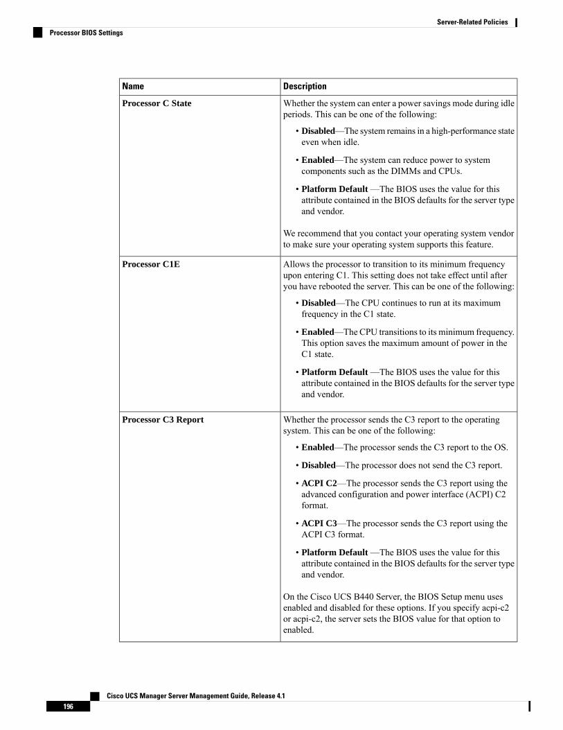
DescriptionName
Whether the system can enter a power savings mode during idleperiods. This can be one of the following:
• Disabled—The system remains in a high-performance stateeven when idle.
• Enabled—The system can reduce power to systemcomponents such as the DIMMs and CPUs.
• Platform Default —The BIOS uses the value for thisattribute contained in the BIOS defaults for the server typeand vendor.
We recommend that you contact your operating system vendorto make sure your operating system supports this feature.
Processor C State
Allows the processor to transition to its minimum frequencyupon entering C1. This setting does not take effect until afteryou have rebooted the server. This can be one of the following:
• Disabled—The CPU continues to run at its maximumfrequency in the C1 state.
• Enabled—The CPU transitions to its minimum frequency.This option saves the maximum amount of power in theC1 state.
• Platform Default —The BIOS uses the value for thisattribute contained in the BIOS defaults for the server typeand vendor.
Processor C1E
Whether the processor sends the C3 report to the operatingsystem. This can be one of the following:
• Enabled—The processor sends the C3 report to the OS.
• Disabled—The processor does not send the C3 report.
• ACPI C2—The processor sends the C3 report using theadvanced configuration and power interface (ACPI) C2format.
• ACPI C3—The processor sends the C3 report using theACPI C3 format.
• Platform Default —The BIOS uses the value for thisattribute contained in the BIOS defaults for the server typeand vendor.
On the Cisco UCS B440 Server, the BIOS Setup menu usesenabled and disabled for these options. If you specify acpi-c2or acpi-c2, the server sets the BIOS value for that option toenabled.
Processor C3 Report
Cisco UCS Manager Server Management Guide, Release 4.1196
Server-Related PoliciesProcessor BIOS Settings
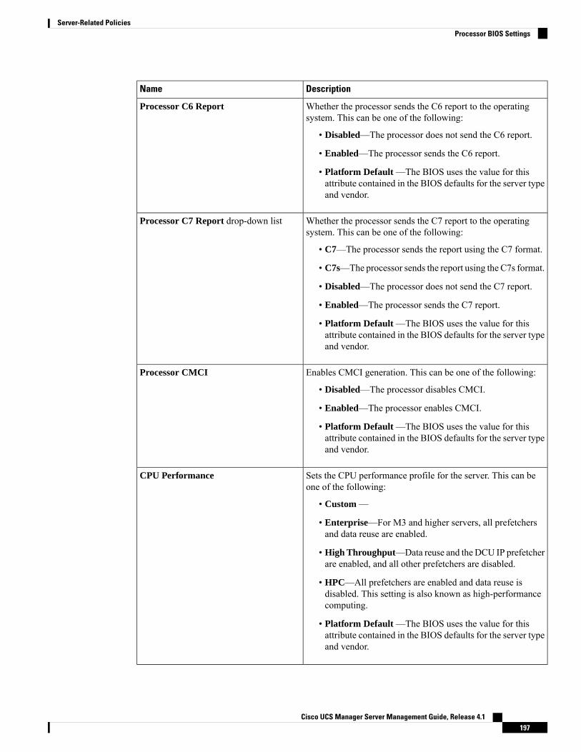
DescriptionName
Whether the processor sends the C6 report to the operatingsystem. This can be one of the following:
• Disabled—The processor does not send the C6 report.
• Enabled—The processor sends the C6 report.
• Platform Default —The BIOS uses the value for thisattribute contained in the BIOS defaults for the server typeand vendor.
Processor C6 Report
Whether the processor sends the C7 report to the operatingsystem. This can be one of the following:
• C7—The processor sends the report using the C7 format.
• C7s—The processor sends the report using the C7s format.
• Disabled—The processor does not send the C7 report.
• Enabled—The processor sends the C7 report.
• Platform Default —The BIOS uses the value for thisattribute contained in the BIOS defaults for the server typeand vendor.
Processor C7 Report drop-down list
Enables CMCI generation. This can be one of the following:
• Disabled—The processor disables CMCI.
• Enabled—The processor enables CMCI.
• Platform Default —The BIOS uses the value for thisattribute contained in the BIOS defaults for the server typeand vendor.
Processor CMCI
Sets the CPU performance profile for the server. This can beone of the following:
• Custom —
• Enterprise—For M3 and higher servers, all prefetchersand data reuse are enabled.
• High Throughput—Data reuse and the DCU IP prefetcherare enabled, and all other prefetchers are disabled.
• HPC—All prefetchers are enabled and data reuse isdisabled. This setting is also known as high-performancecomputing.
• Platform Default —The BIOS uses the value for thisattribute contained in the BIOS defaults for the server typeand vendor.
CPU Performance
Cisco UCS Manager Server Management Guide, Release 4.1197
Server-Related PoliciesProcessor BIOS Settings

DescriptionName
Allows you to select the number of mean time to repair (MTRR)variables. This can be one of the following:
• Auto Max—BIOS uses the default value for the processor.
• 8—BIOS uses the number specified for the variableMTRR.
• Platform Default —The BIOS uses the value for thisattribute contained in the BIOS defaults for the server typeand vendor.
Max Variable MTRR Setting
Allows you to set the type of Application Policy InfrastructureController (APIC) architecture. This can be one of the following:
• Disabled—Processor disables Local X2 APIC.
• Enabled—Processor enables Local X2 APIC.
• XAPIC—Uses the standard xAPIC architecture.
• X2APIC—Uses the enhanced x2APIC architecture tosupport 32 bit addressability of processors.
• AUTO—Automatically uses the xAPIC architecture thatis detected.
• Platform Default —The BIOS uses the value for thisattribute contained in the BIOS defaults for the server typeand vendor.
Local X2 APIC
Cisco UCS Manager Server Management Guide, Release 4.1198
Server-Related PoliciesProcessor BIOS Settings
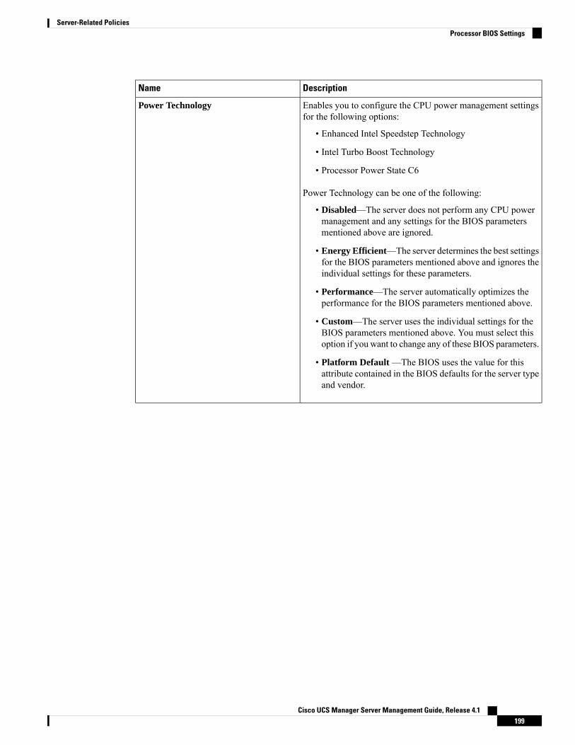
DescriptionName
Enables you to configure the CPU power management settingsfor the following options:
• Enhanced Intel Speedstep Technology
• Intel Turbo Boost Technology
• Processor Power State C6
Power Technology can be one of the following:
• Disabled—The server does not perform any CPU powermanagement and any settings for the BIOS parametersmentioned above are ignored.
• Energy Efficient—The server determines the best settingsfor the BIOS parameters mentioned above and ignores theindividual settings for these parameters.
• Performance—The server automatically optimizes theperformance for the BIOS parameters mentioned above.
• Custom—The server uses the individual settings for theBIOS parameters mentioned above. You must select thisoption if you want to change any of these BIOS parameters.
• Platform Default —The BIOS uses the value for thisattribute contained in the BIOS defaults for the server typeand vendor.
Power Technology
Cisco UCS Manager Server Management Guide, Release 4.1199
Server-Related PoliciesProcessor BIOS Settings
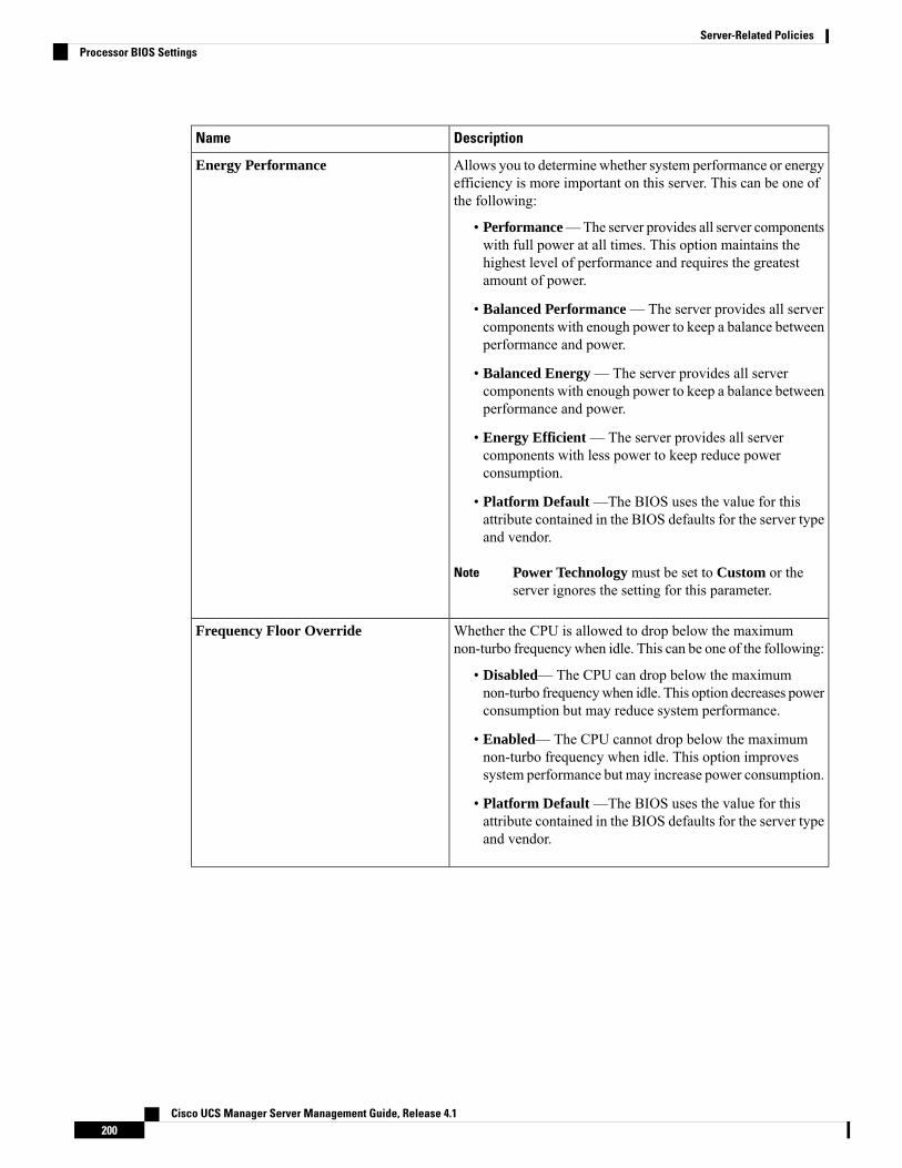
DescriptionName
Allows you to determine whether system performance or energyefficiency is more important on this server. This can be one ofthe following:
• Performance—The server provides all server componentswith full power at all times. This option maintains thehighest level of performance and requires the greatestamount of power.
• Balanced Performance — The server provides all servercomponents with enough power to keep a balance betweenperformance and power.
• Balanced Energy — The server provides all servercomponents with enough power to keep a balance betweenperformance and power.
• Energy Efficient — The server provides all servercomponents with less power to keep reduce powerconsumption.
• Platform Default —The BIOS uses the value for thisattribute contained in the BIOS defaults for the server typeand vendor.
Power Technology must be set to Custom or theserver ignores the setting for this parameter.
Note
Energy Performance
Whether the CPU is allowed to drop below the maximumnon-turbo frequency when idle. This can be one of the following:
• Disabled— The CPU can drop below the maximumnon-turbo frequencywhen idle. This option decreases powerconsumption but may reduce system performance.
• Enabled— The CPU cannot drop below the maximumnon-turbo frequency when idle. This option improvessystem performance but may increase power consumption.
• Platform Default —The BIOS uses the value for thisattribute contained in the BIOS defaults for the server typeand vendor.
Frequency Floor Override
Cisco UCS Manager Server Management Guide, Release 4.1200
Server-Related PoliciesProcessor BIOS Settings
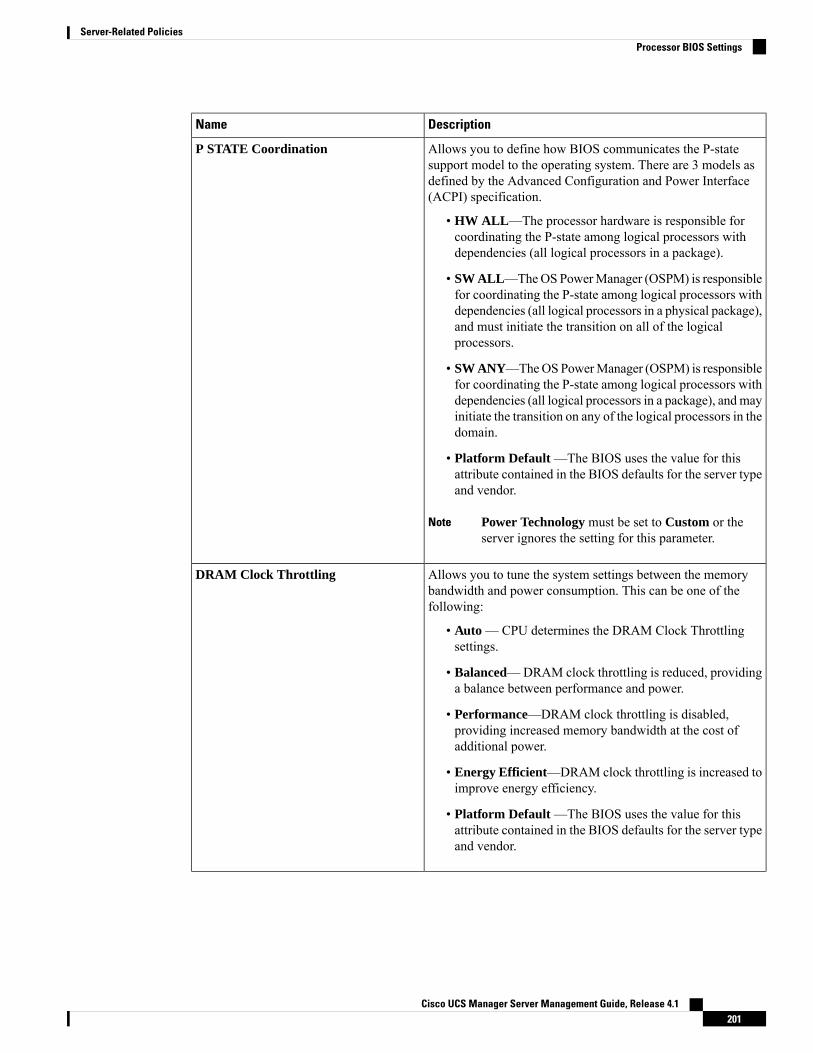
DescriptionName
Allows you to define how BIOS communicates the P-statesupport model to the operating system. There are 3 models asdefined by the Advanced Configuration and Power Interface(ACPI) specification.
• HW ALL—The processor hardware is responsible forcoordinating the P-state among logical processors withdependencies (all logical processors in a package).
• SW ALL—TheOS PowerManager (OSPM) is responsiblefor coordinating the P-state among logical processors withdependencies (all logical processors in a physical package),and must initiate the transition on all of the logicalprocessors.
• SW ANY—TheOSPowerManager (OSPM) is responsiblefor coordinating the P-state among logical processors withdependencies (all logical processors in a package), andmayinitiate the transition on any of the logical processors in thedomain.
• Platform Default —The BIOS uses the value for thisattribute contained in the BIOS defaults for the server typeand vendor.
Power Technology must be set to Custom or theserver ignores the setting for this parameter.
Note
P STATE Coordination
Allows you to tune the system settings between the memorybandwidth and power consumption. This can be one of thefollowing:
• Auto —CPU determines the DRAM Clock Throttlingsettings.
• Balanced—DRAM clock throttling is reduced, providinga balance between performance and power.
• Performance—DRAM clock throttling is disabled,providing increased memory bandwidth at the cost ofadditional power.
• Energy Efficient—DRAM clock throttling is increased toimprove energy efficiency.
• Platform Default —The BIOS uses the value for thisattribute contained in the BIOS defaults for the server typeand vendor.
DRAM Clock Throttling
Cisco UCS Manager Server Management Guide, Release 4.1201
Server-Related PoliciesProcessor BIOS Settings
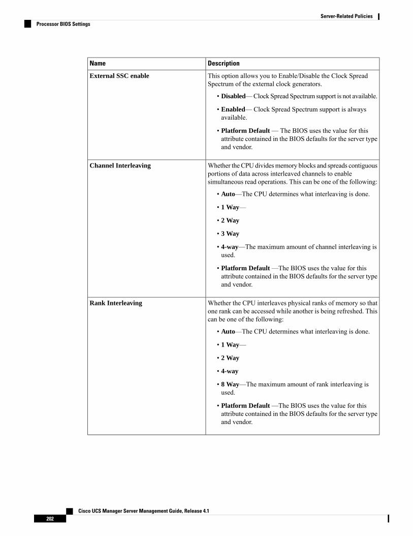
DescriptionName
This option allows you to Enable/Disable the Clock SpreadSpectrum of the external clock generators.
• Disabled—Clock Spread Spectrum support is not available.
• Enabled—Clock Spread Spectrum support is alwaysavailable.
• Platform Default — The BIOS uses the value for thisattribute contained in the BIOS defaults for the server typeand vendor.
External SSC enable
Whether the CPU dividesmemory blocks and spreads contiguousportions of data across interleaved channels to enablesimultaneous read operations. This can be one of the following:
• Auto—The CPU determines what interleaving is done.
• 1 Way—
• 2 Way
• 3 Way
• 4-way—The maximum amount of channel interleaving isused.
• Platform Default —The BIOS uses the value for thisattribute contained in the BIOS defaults for the server typeand vendor.
Channel Interleaving
Whether the CPU interleaves physical ranks of memory so thatone rank can be accessed while another is being refreshed. Thiscan be one of the following:
• Auto—The CPU determines what interleaving is done.
• 1 Way—
• 2 Way
• 4-way
• 8 Way—The maximum amount of rank interleaving isused.
• Platform Default —The BIOS uses the value for thisattribute contained in the BIOS defaults for the server typeand vendor.
Rank Interleaving
Cisco UCS Manager Server Management Guide, Release 4.1202
Server-Related PoliciesProcessor BIOS Settings
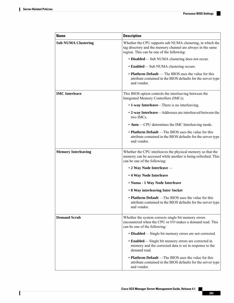
DescriptionName
Whether the CPU supports sub NUMA clustering, in which thetag directory and the memory channel are always in the sameregion. This can be one of the following:
• Disabled— Sub NUMA clustering does not occur.
• Enabled— Sub NUMA clustering occurs.
• Platform Default — The BIOS uses the value for thisattribute contained in the BIOS defaults for the server typeand vendor.
Sub NUMA Clustering
This BIOS option controls the interleaving between theIntegrated Memory Controllers (IMCs).
• 1-way Interleave—There is no interleaving.
• 2-way Interleave—Addresses are interleaved between thetwo IMCs.
• Auto —CPU determines the IMC Interleaving mode.
• Platform Default —The BIOS uses the value for thisattribute contained in the BIOS defaults for the server typeand vendor.
IMC Interleave
Whether the CPU interleaves the physical memory so that thememory can be accessed while another is being refreshed. Thiscan be one of the following:
• 2 Way Node Interleave —
• 4 Way Node Interleave
• Numa - 1 Way Node Interleave
• 8 Way interleaving Inter Socket
• Platform Default —The BIOS uses the value for thisattribute contained in the BIOS defaults for the server typeand vendor.
Memory Interleaving
Whether the system corrects single bit memory errorsencountered when the CPU or I/O makes a demand read. Thiscan be one of the following:
• Disabled— Single bit memory errors are not corrected.
• Enabled— Single bit memory errors are corrected inmemory and the corrected data is set in response to thedemand read.
• Platform Default —The BIOS uses the value for thisattribute contained in the BIOS defaults for the server typeand vendor.
Demand Scrub
Cisco UCS Manager Server Management Guide, Release 4.1203
Server-Related PoliciesProcessor BIOS Settings
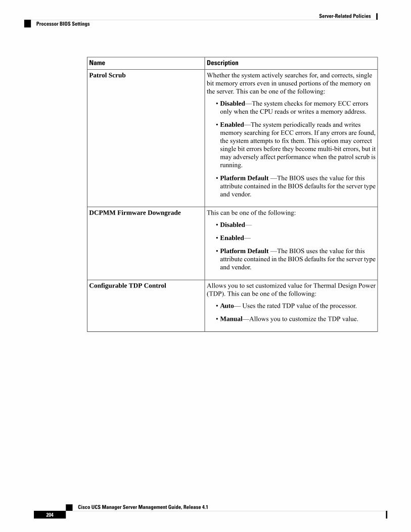
DescriptionName
Whether the system actively searches for, and corrects, singlebit memory errors even in unused portions of the memory onthe server. This can be one of the following:
• Disabled—The system checks for memory ECC errorsonly when the CPU reads or writes a memory address.
• Enabled—The system periodically reads and writesmemory searching for ECC errors. If any errors are found,the system attempts to fix them. This option may correctsingle bit errors before they become multi-bit errors, but itmay adversely affect performance when the patrol scrub isrunning.
• Platform Default —The BIOS uses the value for thisattribute contained in the BIOS defaults for the server typeand vendor.
Patrol Scrub
This can be one of the following:
• Disabled—
• Enabled—
• Platform Default —The BIOS uses the value for thisattribute contained in the BIOS defaults for the server typeand vendor.
DCPMM Firmware Downgrade
Allows you to set customized value for Thermal Design Power(TDP). This can be one of the following:
• Auto—Uses the rated TDP value of the processor.
• Manual—Allows you to customize the TDP value.
Configurable TDP Control
Cisco UCS Manager Server Management Guide, Release 4.1204
Server-Related PoliciesProcessor BIOS Settings
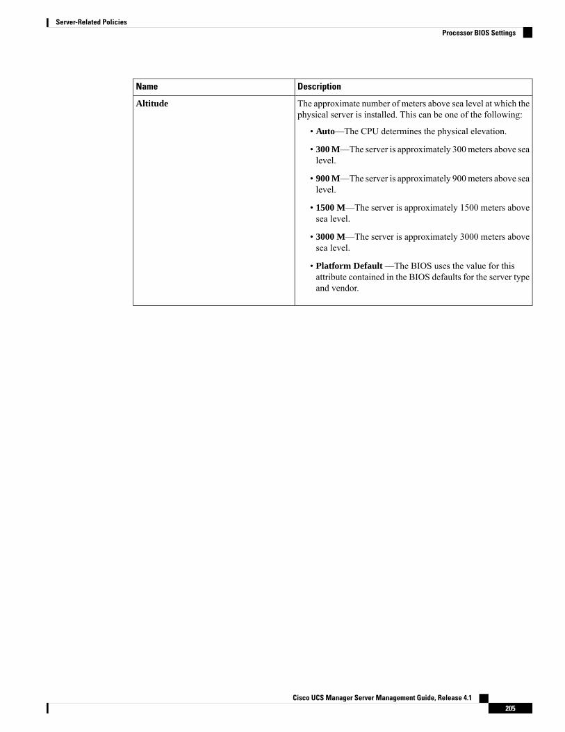
DescriptionName
The approximate number of meters above sea level at which thephysical server is installed. This can be one of the following:
• Auto—The CPU determines the physical elevation.
• 300 M—The server is approximately 300meters above sealevel.
• 900 M—The server is approximately 900meters above sealevel.
• 1500 M—The server is approximately 1500 meters abovesea level.
• 3000 M—The server is approximately 3000 meters abovesea level.
• Platform Default —The BIOS uses the value for thisattribute contained in the BIOS defaults for the server typeand vendor.
Altitude
Cisco UCS Manager Server Management Guide, Release 4.1205
Server-Related PoliciesProcessor BIOS Settings
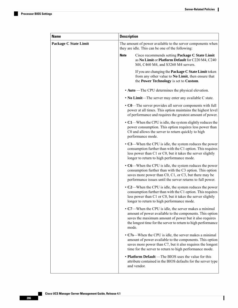
DescriptionName
The amount of power available to the server components whenthey are idle. This can be one of the following:
Cisco recommends setting Package C State LimitasNo Limit orPlatform Default for C220M4, C240M4, C460 M4, and S3260 M4 servers.
If you are changing the Package C State Limit tokenfrom any other value to No Limit, then ensure thatthe Power Technology is set to Custom.
Note
• Auto —The CPU determines the physical elevation.
• No Limit—The server may enter any available C state.
• C0—The server provides all server components with fullpower at all times. This option maintains the highest levelof performance and requires the greatest amount of power.
• C1—When the CPU is idle, the system slightly reduces thepower consumption. This option requires less power thanC0 and allows the server to return quickly to highperformance mode.
• C3—When the CPU is idle, the system reduces the powerconsumption further than with the C1 option. This requiresless power than C1 or C0, but it takes the server slightlylonger to return to high performance mode.
• C6—When the CPU is idle, the system reduces the powerconsumption further than with the C3 option. This optionsaves more power than C0, C1, or C3, but there may beperformance issues until the server returns to full power.
• C2—When the CPU is idle, the system reduces the powerconsumption further than with the C1 option. This requiresless power than C1 or C0, but it takes the server slightlylonger to return to high performance mode.
• C7—When the CPU is idle, the server makes a minimalamount of power available to the components. This optionsaves the maximum amount of power but it also requiresthe longest time for the server to return to high performancemode.
• C7s—When the CPU is idle, the server makes a minimalamount of power available to the components. This optionsaves more power than C7, but it also requires the longesttime for the server to return to high performance mode.
• Platform Default —The BIOS uses the value for thisattribute contained in the BIOS defaults for the server typeand vendor.
Package C State Limit
Cisco UCS Manager Server Management Guide, Release 4.1206
Server-Related PoliciesProcessor BIOS Settings
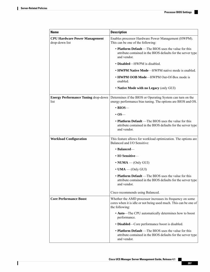
DescriptionName
Enables processor Hardware Power Management (HWPM).This can be one of the following:
• Platform Default —The BIOS uses the value for thisattribute contained in the BIOS defaults for the server typeand vendor.
• Disabled—HWPM is disabled.
• HWPM Native Mode—HWPM native mode is enabled.
• HWPM OOB Mode—HWPM Out-Of-Box mode isenabled.
• Native Mode with no Legacy (only GUI)
CPU Hardware Power Managementdrop-down list
Determines if the BIOS or Operating System can turn on theenergy performance bias tuning. The options are BIOS and OS.
• BIOS—
• OS—
• Platform Default —The BIOS uses the value for thisattribute contained in the BIOS defaults for the server typeand vendor.
Energy Performance Tuning drop-downlist
This feature allows for workload optimization. The options areBalanced and I/O Sensitive:
• Balanced—
• IO Sensitive—
• NUMA — (Only GUI)
• UMA — (Only GUI)
• Platform Default —The BIOS uses the value for thisattribute contained in the BIOS defaults for the server typeand vendor.
Cisco recommends using Balanced.
Workload Configuration
Whether the AMD processor increases its frequency on somecores when it is idle or not being used much. This can be one ofthe following:
• Auto—The CPU automatically determines how to boostperformance.
• Disabled—Core performance boost is disabled.
• Platform Default —The BIOS uses the value for thisattribute contained in the BIOS defaults for the server typeand vendor.
Core Performance Boost
Cisco UCS Manager Server Management Guide, Release 4.1207
Server-Related PoliciesProcessor BIOS Settings

DescriptionName
Allows you configure the scaling of the uncore frequency of theprocessor. This can be one of the following:
• Enabled—Uncore frequency of the processor scales up ordown based on the load. (Default.)
• Disabled—Uncore frequency of the processor remainsfixed.
• Platform Default —The BIOS uses the value for thisattribute contained in the BIOS defaults for the server typeand vendor.
Refer to the Intel Dear Customer Letter (DCL) to know the fixedhigher and lower values for Uncore Frequency Scaling.
Uncore Frequency Scaling
Allows adjustments in processor thermal design power (TDP)values. By modifying the processor behavior and theperformance levels, power consumption of a processor can beconfigured and TDP can be adjusted at the same time. Hence, aprocessor operates at higher or lower performance levels,depending on the available cooling capacities and desired powerconsumption.
This can be one of the following:
• Normal—The CPU operates at its normal performancelevel. (Default.)
• Level 1
• Level 2
Refer to the Intel Dear Customer Letter (DCL) forthe values for TDP level.
Note
Configurable TDP Level
Allows you to configure the Intel Ultra Path Interconnect (UPI)link speed between multiple sockets. This can be one of thefollowing:
• Auto—Automatically configures the optimal link speed.(Default)
• 9.6GT/s (gigatransfers per second)—Configures theoptimal link speed at 9.6GT/s
• 10.4GT/s—Configures the optimal link speed at 10.4GT/s
• 11.2GT/s—Configures the optimal link speed at 11.2GT/s
UPI Link Speed
Cisco UCS Manager Server Management Guide, Release 4.1208
Server-Related PoliciesProcessor BIOS Settings

DescriptionName
Whether the AMD processors control IO-based C-stategeneration and DF C-states. This can be one of the following:
• Auto—The CPU automatically determines how to controlIO-based C-state generation.
• Disabled—Global C-state control is disabled.
• Enabled—Global C-state control is enabled.
• Platform Default —The BIOS uses the value for thisattribute contained in the BIOS defaults for the server typeand vendor.
Global C-state Control
Whether the processor allows the AMD hardware prefetcher tospeculatively fetch streams of data and instruction frommemoryinto the L1 cache when necessary. This can be one of thefollowing:
• Auto—The CPU determines how to place data from I/Odevices into the processor cache.
• Disabled—The hardware prefetcher is not used.
• Enabled—The processor uses the hardware prefetcherwhen cache issues are detected.
• Platform Default —The BIOS uses the value for thisattribute contained in the BIOS defaults for the server typeand vendor.
L1 Stream HW Prefetcher
Whether the processor allows the AMD hardware prefetcher tospeculatively fetch streams of data and instruction frommemoryinto the L2 cache when necessary. This can be one of thefollowing:
• Auto—The CPU determines how to place data from I/Odevices into the processor cache.
• Disabled—The hardware prefetcher is not used.
• Enabled—The processor uses the hardware prefetcherwhen cache issues are detected.
• Platform Default —The BIOS uses the value for thisattribute contained in the BIOS defaults for the server typeand vendor.
L2 Stream HW Prefetcher
Cisco UCS Manager Server Management Guide, Release 4.1209
Server-Related PoliciesProcessor BIOS Settings

DescriptionName
Whether the AMDCPU interleaves the physical memory so thatthe memory can be accessed while another is being refreshed.This controls fabric level memory interleaving. Channel, dieand socket have requirements based onmemory populations andwill be ignored if the memory does not support the selectedoption.This can be one of the following:
• Auto—The CPU determines how to interleave memory.
• Channel—Interleaves the physical address space overmultiple channels, as opposed to each channel owningsingle consecutive address spaces.
• Die—Interleaves the physical address space over multipledies, as opposed to each die owning single consecutiveaddress spaces.
• None—Consecutive memory blocks are accessed from thesame physical memory.
• Socket—Interleaves the physical address space overmultiple sockets, as opposed to each socket owning singleconsecutive address spaces.
• Platform Default —The BIOS uses the value for thisattribute contained in the BIOS defaults for the server typeand vendor.
AMD Memory Interleaving
Determines the size of the memory blocks to be interleaved. Italso determines the starting address of the interleave (bit 8,9,10or 11). This can be one of the following:
• 1 KB
• 2 KB
• 256 Bytes
• 512 Bytes
• Auto—The CPU determines the size of the memory block.
• Platform Default —The BIOS uses the value for thisattribute contained in the BIOS defaults for the server typeand vendor.
AMD Memory Interleaving Size
Cisco UCS Manager Server Management Guide, Release 4.1210
Server-Related PoliciesProcessor BIOS Settings

DescriptionName
Whether memory blocks across the DRAM chip selects for node0 are interleaved. This can be one of the following:
• Auto—The CPU automatically determines how tointerleave chip selects.
• Disabled—Chip selects are not interleaved within thememory controller.
• Platform Default —The BIOS uses the value for thisattribute contained in the BIOS defaults for the server typeand vendor.
Chipselect Interleaving
Determines how physical addresses are assigned to applications.This can be one of the following:
• Auto—The CPU automatically determines how to assignphysical addresses to applications.
• Disabled—Bank group swap is not used.
• Enabled—Bank group swap is used to improve theperformance of applications.
• Platform Default —The BIOS uses the value for thisattribute contained in the BIOS defaults for the server typeand vendor.
Bank Group Swap
Allows AMD processors to determine how to operate. This canbe one of the following:
• Auto—The CPU automatically uses default powerdeterminism settings.
• Performance—Processor operates at the best performancein a consistent manner.
• Power—Processor operates at the maximum allowableperformance on a per die basis.
• Platform Default —The BIOS uses the value for thisattribute contained in the BIOS defaults for the server typeand vendor.
Determinism Slider
Cisco UCS Manager Server Management Guide, Release 4.1211
Server-Related PoliciesProcessor BIOS Settings
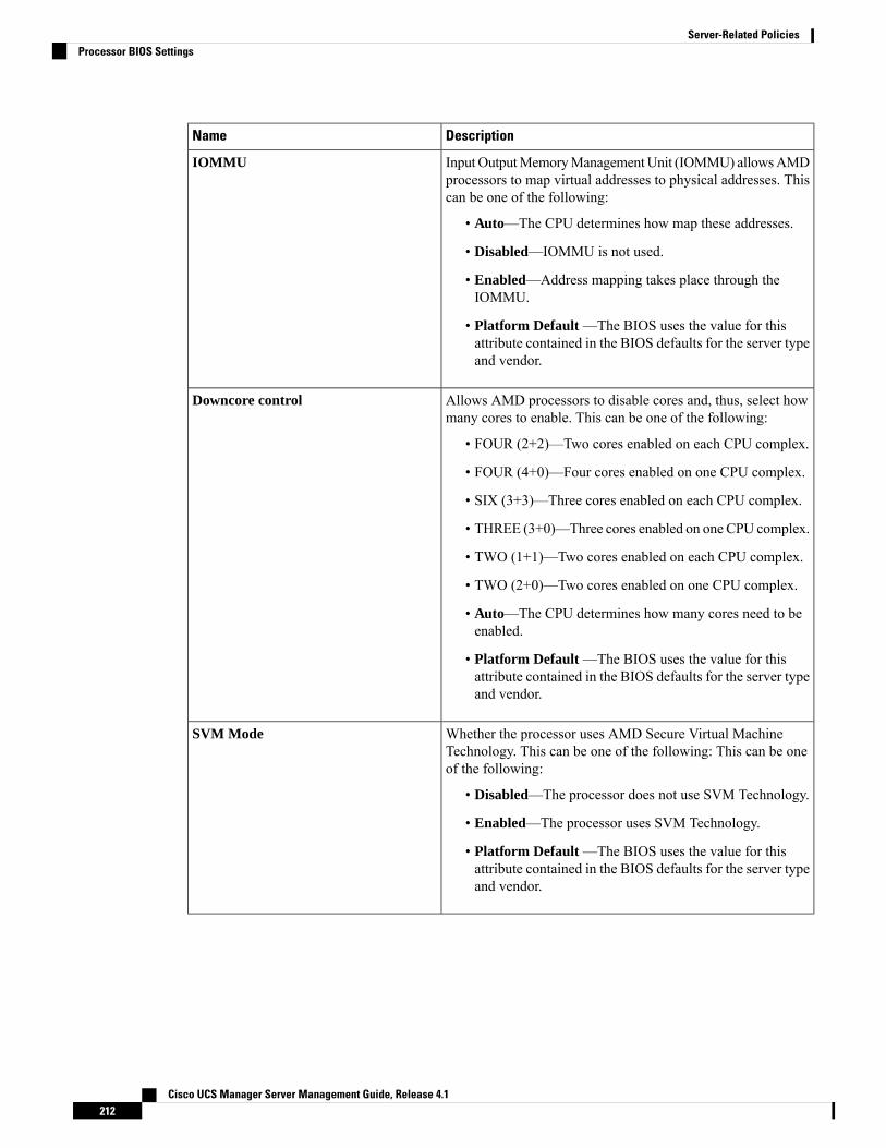
DescriptionName
InputOutputMemoryManagementUnit (IOMMU) allowsAMDprocessors to map virtual addresses to physical addresses. Thiscan be one of the following:
• Auto—The CPU determines how map these addresses.
• Disabled—IOMMU is not used.
• Enabled—Address mapping takes place through theIOMMU.
• Platform Default —The BIOS uses the value for thisattribute contained in the BIOS defaults for the server typeand vendor.
IOMMU
Allows AMD processors to disable cores and, thus, select howmany cores to enable. This can be one of the following:
• FOUR (2+2)—Two cores enabled on each CPU complex.
• FOUR (4+0)—Four cores enabled on one CPU complex.
• SIX (3+3)—Three cores enabled on each CPU complex.
• THREE (3+0)—Three cores enabled on one CPU complex.
• TWO (1+1)—Two cores enabled on each CPU complex.
• TWO (2+0)—Two cores enabled on one CPU complex.
• Auto—The CPU determines how many cores need to beenabled.
• Platform Default —The BIOS uses the value for thisattribute contained in the BIOS defaults for the server typeand vendor.
Downcore control
Whether the processor uses AMD Secure Virtual MachineTechnology. This can be one of the following: This can be oneof the following:
• Disabled—The processor does not use SVM Technology.
• Enabled—The processor uses SVM Technology.
• Platform Default —The BIOS uses the value for thisattribute contained in the BIOS defaults for the server typeand vendor.
SVM Mode
Cisco UCS Manager Server Management Guide, Release 4.1212
Server-Related PoliciesProcessor BIOS Settings
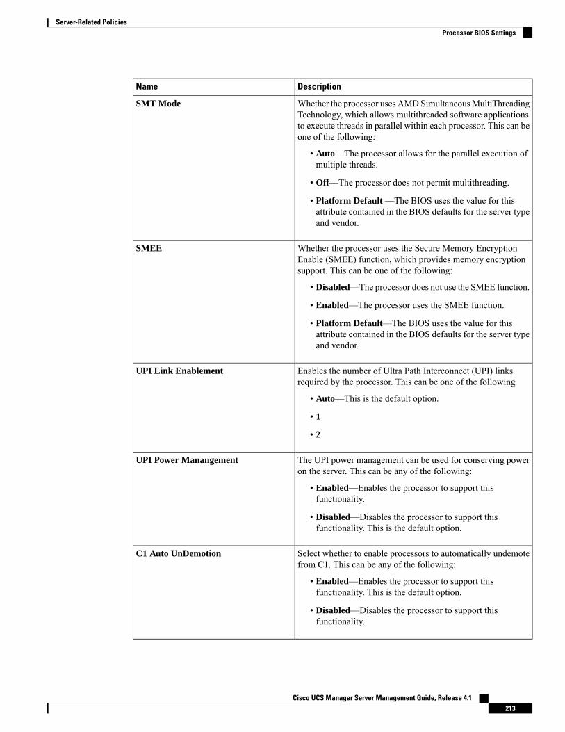
DescriptionName
Whether the processor uses AMDSimultaneousMultiThreadingTechnology, which allows multithreaded software applicationsto execute threads in parallel within each processor. This can beone of the following:
• Auto—The processor allows for the parallel execution ofmultiple threads.
• Off—The processor does not permit multithreading.
• Platform Default —The BIOS uses the value for thisattribute contained in the BIOS defaults for the server typeand vendor.
SMT Mode
Whether the processor uses the Secure Memory EncryptionEnable (SMEE) function, which provides memory encryptionsupport. This can be one of the following:
• Disabled—The processor does not use the SMEE function.
• Enabled—The processor uses the SMEE function.
• Platform Default—The BIOS uses the value for thisattribute contained in the BIOS defaults for the server typeand vendor.
SMEE
Enables the number of Ultra Path Interconnect (UPI) linksrequired by the processor. This can be one of the following
• Auto—This is the default option.
• 1
• 2
UPI Link Enablement
The UPI power management can be used for conserving poweron the server. This can be any of the following:
• Enabled—Enables the processor to support thisfunctionality.
• Disabled—Disables the processor to support thisfunctionality. This is the default option.
UPI Power Manangement
Select whether to enable processors to automatically undemotefrom C1. This can be any of the following:
• Enabled—Enables the processor to support thisfunctionality. This is the default option.
• Disabled—Disables the processor to support thisfunctionality.
C1 Auto UnDemotion
Cisco UCS Manager Server Management Guide, Release 4.1213
Server-Related PoliciesProcessor BIOS Settings
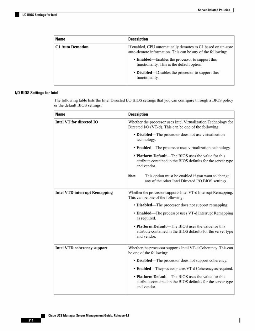
DescriptionName
If enabled, CPU automatically demotes to C1 based on un-coreauto-demote information. This can be any of the following:
• Enabled—Enables the processor to support thisfunctionality. This is the default option.
• Disabled—Disables the processor to support thisfunctionality.
C1 Auto Demotion
I/O BIOS Settings for Intel
The following table lists the Intel Directed I/O BIOS settings that you can configure through a BIOS policyor the default BIOS settings:
DescriptionName
Whether the processor uses Intel Virtualization Technology forDirected I/O (VT-d). This can be one of the following:
• Disabled—The processor does not use virtualizationtechnology.
• Enabled—The processor uses virtualization technology.
• Platform Default—The BIOS uses the value for thisattribute contained in the BIOS defaults for the server typeand vendor.
This option must be enabled if you want to changeany of the other Intel Directed I/O BIOS settings.
Note
Intel VT for directed IO
Whether the processor supports Intel VT-d Interrupt Remapping.This can be one of the following:
• Disabled—The processor does not support remapping.
• Enabled—The processor uses VT-d Interrupt Remappingas required.
• Platform Default—The BIOS uses the value for thisattribute contained in the BIOS defaults for the server typeand vendor.
Intel VTD interrupt Remapping
Whether the processor supports Intel VT-d Coherency. This canbe one of the following:
• Disabled—The processor does not support coherency.
• Enabled—The processor uses VT-dCoherency as required.
• Platform Default—The BIOS uses the value for thisattribute contained in the BIOS defaults for the server typeand vendor.
Intel VTD coherency support
Cisco UCS Manager Server Management Guide, Release 4.1214
Server-Related PoliciesI/O BIOS Settings for Intel
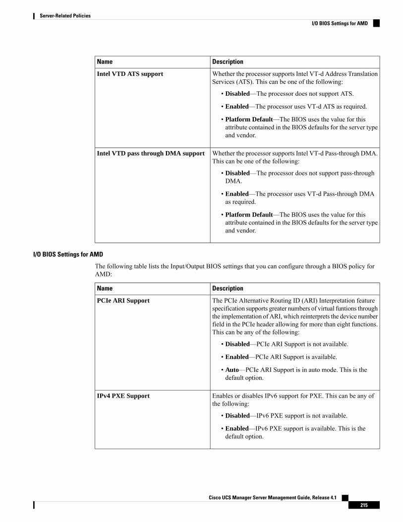
DescriptionName
Whether the processor supports Intel VT-d Address TranslationServices (ATS). This can be one of the following:
• Disabled—The processor does not support ATS.
• Enabled—The processor uses VT-d ATS as required.
• Platform Default—The BIOS uses the value for thisattribute contained in the BIOS defaults for the server typeand vendor.
Intel VTD ATS support
Whether the processor supports Intel VT-d Pass-through DMA.This can be one of the following:
• Disabled—The processor does not support pass-throughDMA.
• Enabled—The processor uses VT-d Pass-through DMAas required.
• Platform Default—The BIOS uses the value for thisattribute contained in the BIOS defaults for the server typeand vendor.
Intel VTD pass through DMA support
I/O BIOS Settings for AMD
The following table lists the Input/Output BIOS settings that you can configure through a BIOS policy forAMD:
DescriptionName
The PCIe Alternative Routing ID (ARI) Interpretation featurespecification supports greater numbers of virtual funtions throughthe implementation of ARI, which reinterprets the device numberfield in the PCIe header allowing for more than eight functions.This can be any of the following:
• Disabled—PCIe ARI Support is not available.
• Enabled—PCIe ARI Support is available.
• Auto—PCIe ARI Support is in auto mode. This is thedefault option.
PCIe ARI Support
Enables or disables IPv6 support for PXE. This can be any ofthe following:
• Disabled—IPv6 PXE support is not available.
• Enabled—IPv6 PXE support is available. This is thedefault option.
IPv4 PXE Support
Cisco UCS Manager Server Management Guide, Release 4.1215
Server-Related PoliciesI/O BIOS Settings for AMD
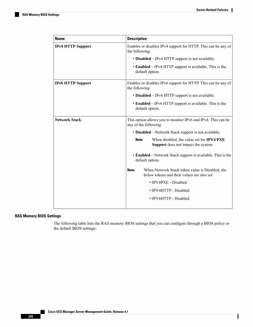
DescriptionName
Enables or disables IPv4 support for HTTP. This can be any ofthe following:
• Disabled—IPv4 HTTP support is not available.
• Enabled—IPv4 HTTP support is available. This is thedefault option.
IPv4 HTTP Support
Enables or disables IPv6 support for HTTP. This can be any ofthe following:
• Disabled—IPv6 HTTP support is not available.
• Enabled—IPv6 HTTP support is available. This is thedefault option.
IPv6 HTTP Support
This option allows you to monitor IPv6 and IPv4. This can beany of the following
• Disabled—Network Stack support is not available.
When disabled, the value set for IPV4 PXESupport does not impact the system.
Note
• Enabled—Network Stack support is available. This is thedefault option.
When Network Stack token value is Disabled, thebelow tokens and their values are also set
Note
• IPV4PXE - Disabled
• IPV4HTTP - Disabled
• IPV6HTTP - Disabled
Network Stack
RAS Memory BIOS Settings
The following table lists the RAS memory BIOS settings that you can configure through a BIOS policy orthe default BIOS settings:
Cisco UCS Manager Server Management Guide, Release 4.1216
Server-Related PoliciesRAS Memory BIOS Settings
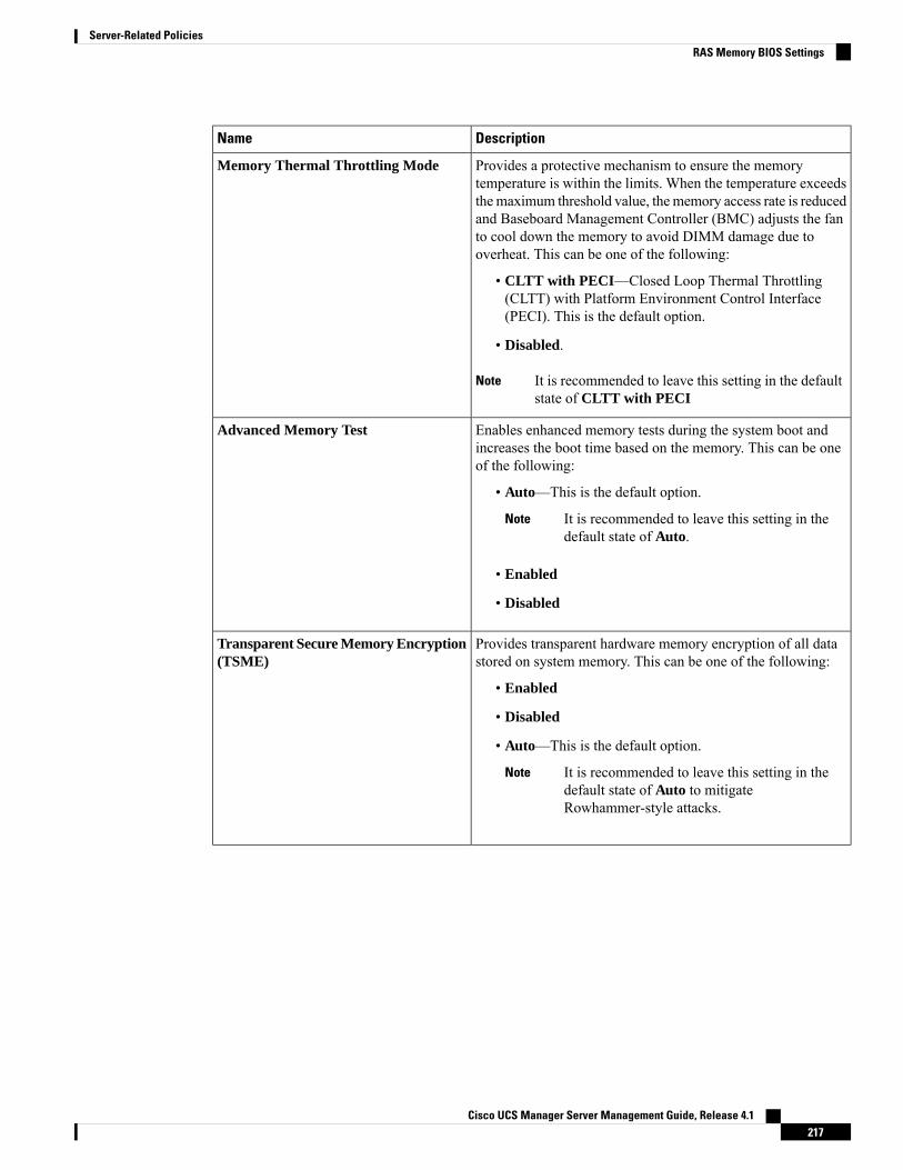
DescriptionName
Provides a protective mechanism to ensure the memorytemperature is within the limits. When the temperature exceedsthemaximum threshold value, the memory access rate is reducedand Baseboard Management Controller (BMC) adjusts the fanto cool down the memory to avoid DIMM damage due tooverheat. This can be one of the following:
• CLTT with PECI—Closed Loop Thermal Throttling(CLTT) with Platform Environment Control Interface(PECI). This is the default option.
• Disabled.
It is recommended to leave this setting in the defaultstate of CLTT with PECI
Note
Memory Thermal Throttling Mode
Enables enhanced memory tests during the system boot andincreases the boot time based on the memory. This can be oneof the following:
• Auto—This is the default option.
It is recommended to leave this setting in thedefault state of Auto.
Note
• Enabled
• Disabled
Advanced Memory Test
Provides transparent hardware memory encryption of all datastored on system memory. This can be one of the following:
• Enabled
• Disabled
• Auto—This is the default option.
It is recommended to leave this setting in thedefault state of Auto to mitigateRowhammer-style attacks.
Note
Transparent Secure Memory Encryption(TSME)
Cisco UCS Manager Server Management Guide, Release 4.1217
Server-Related PoliciesRAS Memory BIOS Settings

DescriptionName
Enables running encrypted virtual machines (VMs) in which thecode and data of the VM are isolated. This can be one of thefollowing:
• 253 ASIDs
• 509 ASIDs
• Auto—This is the default option.
It is recommended to leave this setting in thedefault state of Auto to mitigateRowhammer-style attacks.
Note
Secure Encrypted Virtualization (SEV)
Provides a protective mechanism to ensure that the softwarefunctions within the temperature limits. When the temperatureexceeds the maximum threshold value, the performance ispermitted to drop allowing to cool down to the minimumthreshold value. This can be one of the following:
• Enabled
• Disabled—This is the default option.
It is recommended to leave this setting in thedefault state of Disabled to mitigateRowhammer-style attacks.
Note
DRAM SW Thermal Throttling
Controls the refresh rate of the memory controller and mightaffect thememory performance and power depending onmemoryconfiguration and workload. This can be the following:
• 1x Refresh—This is the default option.
• 2x Refresh
Memory Refresh Rate
Controls the delayed refresh capability of the memory controller.This can be one of the following:
• High—The memory controller is allowed to postpone upto a maximum of eight refresh commands. The memorycontroller executes all the postponed refreshes within therefresh interval. For the ninth refresh command, the refreshpriority becomes Panic and the memory controller pausesthe normal memory transactions until all the postponedrefresh commands are executed.
• Low—This is the default option. The memory controlleris not allowed to postpone refresh commands.
It is recommended to leave this setting in thedefault state (Low) which will help to reducesusceptibility to Rowhammer-style attacks.
Note
Panic and High Watermark
Cisco UCS Manager Server Management Guide, Release 4.1218
Server-Related PoliciesRAS Memory BIOS Settings

DescriptionName
How the memory reliability, availability, and serviceability(RAS) is configured for the server. This can be one of thefollowing:
• Maximum Performance—Optimizes the systemperformance and disables all the advanced RAS features.
• Mirroring—System reliability is optimized by using halfthe system memory as backup. This mode is used for UCSM4 and lower blade servers.
• Lockstep—If the DIMM pairs in the server have anidentical type, size, and organization and are populatedacross the SMI channels, you can enable lockstep mode tominimize memory access latency and provide betterperformance. Lockstep is enabled by default for B440servers.
• Mirror Mode 1LM—MirrorMode 1LMwill set the entire1LM memory in the system to be mirrored, consequentlyreducing the memory capacity by half. This mode is usedfor UCS M5 blade servers.
• Partial Mirror Mode 1LM—Partial Mirror Mode 1LMwill set a part of the 1LM memory in the system to bemirrored, consequently reducing the memory capacity byhalf. This mode is used for UCS M5 blade servers.
• Sparing—System reliability is optimized by holdingmemory in reserve so that it can be used in case otherDIMMs fail. This mode provides some memoryredundancy, but does not provide as much redundancy asmirroring.
• ADDDC Sparing—System reliability is optimized byholding memory in reserve so that it can be used in caseother DIMMs fail. This mode provides some memoryredundancy, but does not provide as much redundancy asmirroring.
• Platform Default—The BIOS uses the value for thisattribute contained in the BIOS defaults for the server typeand vendor.
Memory RAS configuration
Cisco UCS Manager Server Management Guide, Release 4.1219
Server-Related PoliciesRAS Memory BIOS Settings
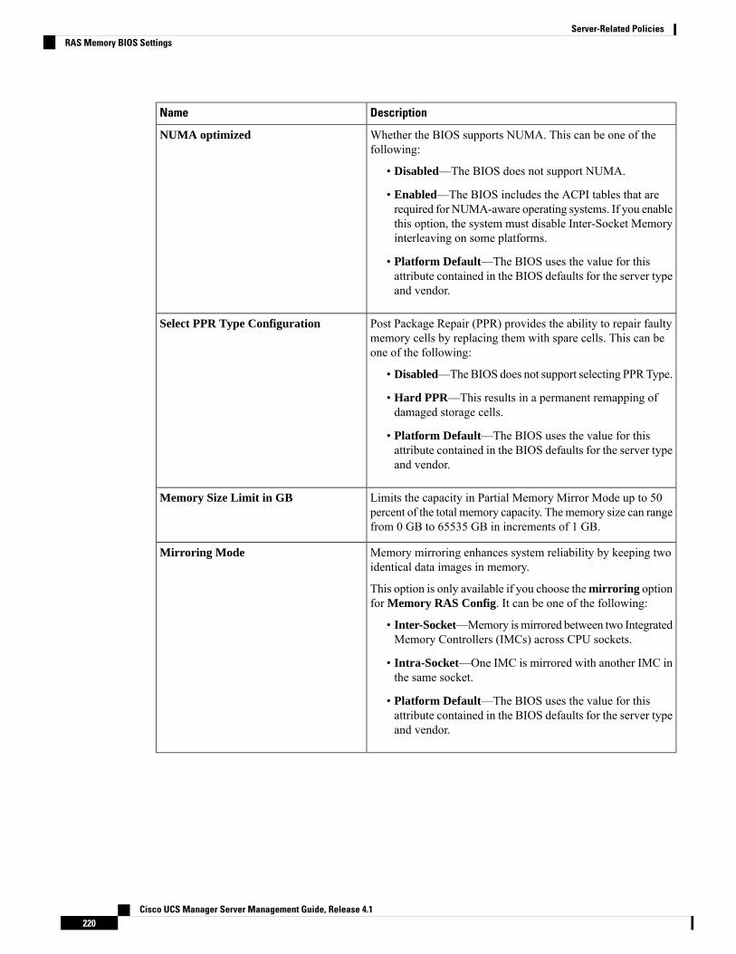
DescriptionName
Whether the BIOS supports NUMA. This can be one of thefollowing:
• Disabled—The BIOS does not support NUMA.
• Enabled—The BIOS includes the ACPI tables that arerequired for NUMA-aware operating systems. If you enablethis option, the system must disable Inter-Socket Memoryinterleaving on some platforms.
• Platform Default—The BIOS uses the value for thisattribute contained in the BIOS defaults for the server typeand vendor.
NUMA optimized
Post Package Repair (PPR) provides the ability to repair faultymemory cells by replacing them with spare cells. This can beone of the following:
• Disabled—TheBIOS does not support selecting PPRType.
• Hard PPR—This results in a permanent remapping ofdamaged storage cells.
• Platform Default—The BIOS uses the value for thisattribute contained in the BIOS defaults for the server typeand vendor.
Select PPR Type Configuration
Limits the capacity in Partial Memory Mirror Mode up to 50percent of the total memory capacity. Thememory size can rangefrom 0 GB to 65535 GB in increments of 1 GB.
Memory Size Limit in GB
Memory mirroring enhances system reliability by keeping twoidentical data images in memory.
This option is only available if you choose themirroring optionfor Memory RAS Config. It can be one of the following:
• Inter-Socket—Memory ismirrored between two IntegratedMemory Controllers (IMCs) across CPU sockets.
• Intra-Socket—One IMC is mirrored with another IMC inthe same socket.
• Platform Default—The BIOS uses the value for thisattribute contained in the BIOS defaults for the server typeand vendor.
Mirroring Mode
Cisco UCS Manager Server Management Guide, Release 4.1220
Server-Related PoliciesRAS Memory BIOS Settings
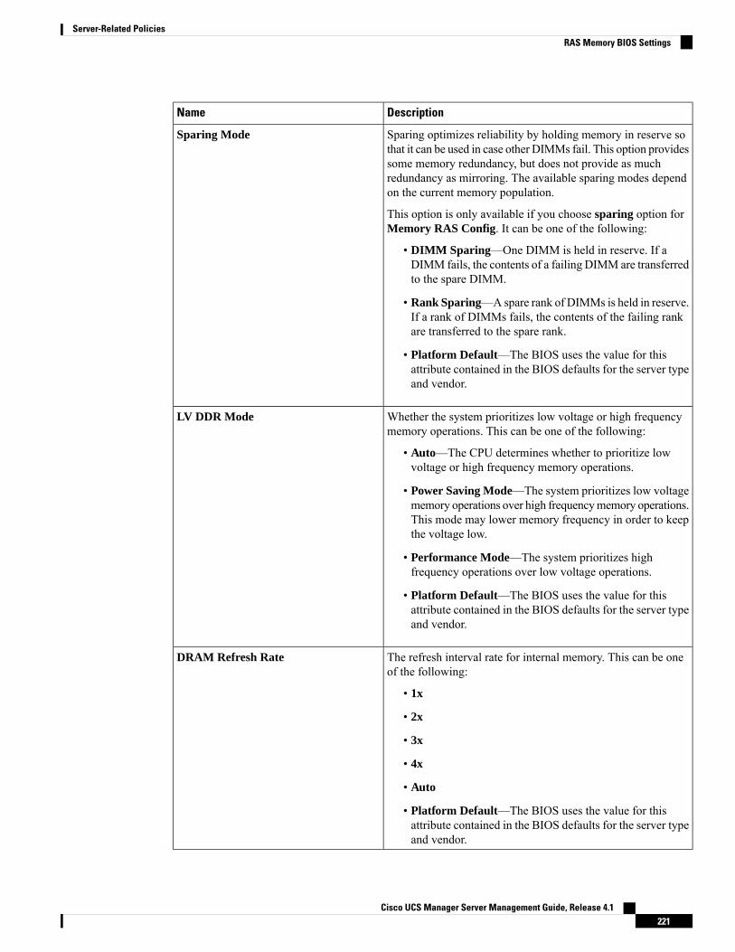
DescriptionName
Sparing optimizes reliability by holding memory in reserve sothat it can be used in case other DIMMs fail. This option providessome memory redundancy, but does not provide as muchredundancy as mirroring. The available sparing modes dependon the current memory population.
This option is only available if you choose sparing option forMemory RAS Config. It can be one of the following:
• DIMM Sparing—One DIMM is held in reserve. If aDIMM fails, the contents of a failing DIMM are transferredto the spare DIMM.
• Rank Sparing—Aspare rank of DIMMs is held in reserve.If a rank of DIMMs fails, the contents of the failing rankare transferred to the spare rank.
• Platform Default—The BIOS uses the value for thisattribute contained in the BIOS defaults for the server typeand vendor.
Sparing Mode
Whether the system prioritizes low voltage or high frequencymemory operations. This can be one of the following:
• Auto—The CPU determines whether to prioritize lowvoltage or high frequency memory operations.
• Power Saving Mode—The system prioritizes low voltagememory operations over high frequencymemory operations.This mode may lower memory frequency in order to keepthe voltage low.
• Performance Mode—The system prioritizes highfrequency operations over low voltage operations.
• Platform Default—The BIOS uses the value for thisattribute contained in the BIOS defaults for the server typeand vendor.
LV DDR Mode
The refresh interval rate for internal memory. This can be oneof the following:
• 1x
• 2x
• 3x
• 4x
• Auto
• Platform Default—The BIOS uses the value for thisattribute contained in the BIOS defaults for the server typeand vendor.
DRAM Refresh Rate
Cisco UCS Manager Server Management Guide, Release 4.1221
Server-Related PoliciesRAS Memory BIOS Settings
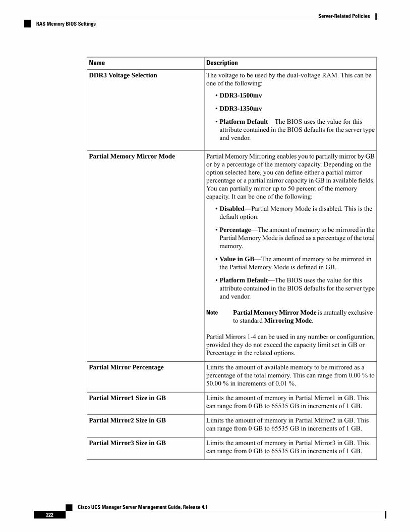
DescriptionName
The voltage to be used by the dual-voltage RAM. This can beone of the following:
• DDR3-1500mv
• DDR3-1350mv
• Platform Default—The BIOS uses the value for thisattribute contained in the BIOS defaults for the server typeand vendor.
DDR3 Voltage Selection
Partial MemoryMirroring enables you to partially mirror by GBor by a percentage of the memory capacity. Depending on theoption selected here, you can define either a partial mirrorpercentage or a partial mirror capacity in GB in available fields.You can partially mirror up to 50 percent of the memorycapacity. It can be one of the following:
• Disabled—Partial Memory Mode is disabled. This is thedefault option.
• Percentage—The amount of memory to be mirrored in thePartial MemoryMode is defined as a percentage of the totalmemory.
• Value in GB—The amount of memory to be mirrored inthe Partial Memory Mode is defined in GB.
• Platform Default—The BIOS uses the value for thisattribute contained in the BIOS defaults for the server typeand vendor.
Partial Memory Mirror Mode is mutually exclusiveto standard Mirroring Mode.
Note
Partial Mirrors 1-4 can be used in any number or configuration,provided they do not exceed the capacity limit set in GB orPercentage in the related options.
Partial Memory Mirror Mode
Limits the amount of available memory to be mirrored as apercentage of the total memory. This can range from 0.00 % to50.00 % in increments of 0.01 %.
Partial Mirror Percentage
Limits the amount of memory in Partial Mirror1 in GB. Thiscan range from 0 GB to 65535 GB in increments of 1 GB.
Partial Mirror1 Size in GB
Limits the amount of memory in Partial Mirror2 in GB. Thiscan range from 0 GB to 65535 GB in increments of 1 GB.
Partial Mirror2 Size in GB
Limits the amount of memory in Partial Mirror3 in GB. Thiscan range from 0 GB to 65535 GB in increments of 1 GB.
Partial Mirror3 Size in GB
Cisco UCS Manager Server Management Guide, Release 4.1222
Server-Related PoliciesRAS Memory BIOS Settings
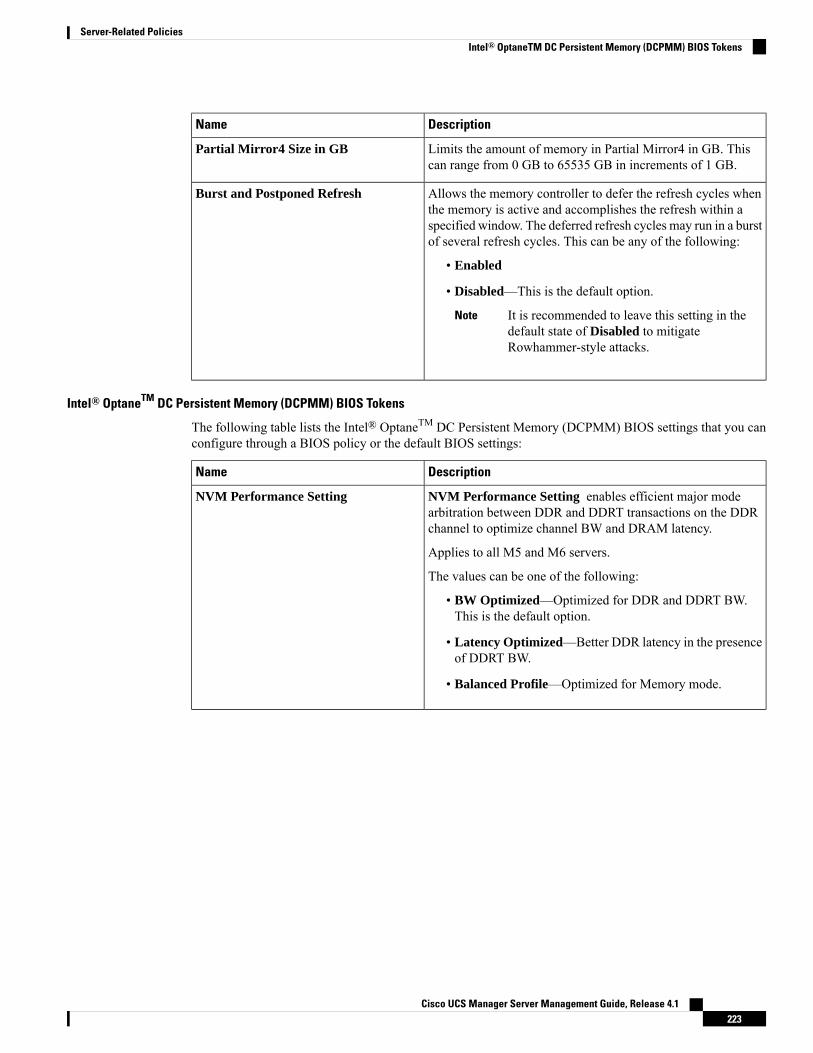
DescriptionName
Limits the amount of memory in Partial Mirror4 in GB. Thiscan range from 0 GB to 65535 GB in increments of 1 GB.
Partial Mirror4 Size in GB
Allows the memory controller to defer the refresh cycles whenthe memory is active and accomplishes the refresh within aspecified window. The deferred refresh cycles may run in a burstof several refresh cycles. This can be any of the following:
• Enabled
• Disabled—This is the default option.
It is recommended to leave this setting in thedefault state of Disabled to mitigateRowhammer-style attacks.
Note
Burst and Postponed Refresh
Intel® OptaneTM DC Persistent Memory (DCPMM) BIOS Tokens
The following table lists the Intel® OptaneTM DC Persistent Memory (DCPMM) BIOS settings that you canconfigure through a BIOS policy or the default BIOS settings:
DescriptionName
NVM Performance Setting enables efficient major modearbitration between DDR and DDRT transactions on the DDRchannel to optimize channel BW and DRAM latency.
Applies to all M5 and M6 servers.
The values can be one of the following:
• BW Optimized—Optimized for DDR and DDRT BW.This is the default option.
• Latency Optimized—Better DDR latency in the presenceof DDRT BW.
• Balanced Profile—Optimized for Memory mode.
NVM Performance Setting
Cisco UCS Manager Server Management Guide, Release 4.1223
Server-Related PoliciesIntel® OptaneTM DC Persistent Memory (DCPMM) BIOS Tokens
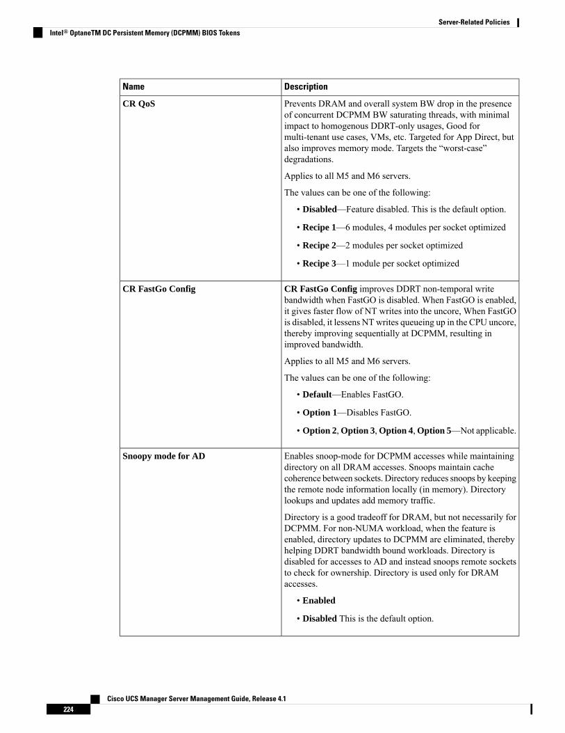
DescriptionName
Prevents DRAM and overall system BW drop in the presenceof concurrent DCPMM BW saturating threads, with minimalimpact to homogenous DDRT-only usages, Good formulti-tenant use cases, VMs, etc. Targeted for App Direct, butalso improves memory mode. Targets the “worst-case”degradations.
Applies to all M5 and M6 servers.
The values can be one of the following:
• Disabled—Feature disabled. This is the default option.
• Recipe 1—6 modules, 4 modules per socket optimized
• Recipe 2—2 modules per socket optimized
• Recipe 3—1 module per socket optimized
CR QoS
CR FastGo Config improves DDRT non-temporal writebandwidth when FastGO is disabled. When FastGO is enabled,it gives faster flow of NT writes into the uncore, When FastGOis disabled, it lessens NTwrites queueing up in the CPU uncore,thereby improving sequentially at DCPMM, resulting inimproved bandwidth.
Applies to all M5 and M6 servers.
The values can be one of the following:
• Default—Enables FastGO.
• Option 1—Disables FastGO.
• Option 2,Option 3,Option 4,Option 5—Not applicable.
CR FastGo Config
Enables snoop-mode for DCPMM accesses while maintainingdirectory on all DRAM accesses. Snoops maintain cachecoherence between sockets. Directory reduces snoops by keepingthe remote node information locally (in memory). Directorylookups and updates add memory traffic.
Directory is a good tradeoff for DRAM, but not necessarily forDCPMM. For non-NUMA workload, when the feature isenabled, directory updates to DCPMM are eliminated, therebyhelping DDRT bandwidth bound workloads. Directory isdisabled for accesses to AD and instead snoops remote socketsto check for ownership. Directory is used only for DRAMaccesses.
• Enabled
• Disabled This is the default option.
Snoopy mode for AD
Cisco UCS Manager Server Management Guide, Release 4.1224
Server-Related PoliciesIntel® OptaneTM DC Persistent Memory (DCPMM) BIOS Tokens
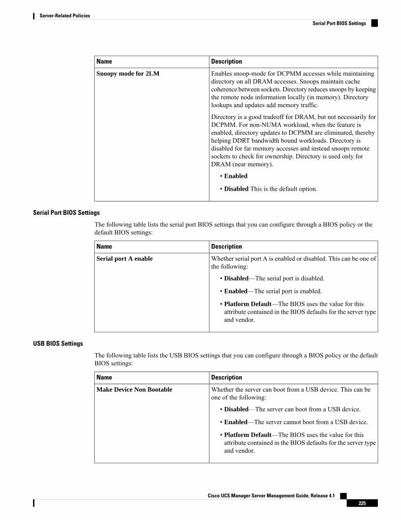
DescriptionName
Enables snoop-mode for DCPMM accesses while maintainingdirectory on all DRAM accesses. Snoops maintain cachecoherence between sockets. Directory reduces snoops by keepingthe remote node information locally (in memory). Directorylookups and updates add memory traffic.
Directory is a good tradeoff for DRAM, but not necessarily forDCPMM. For non-NUMA workload, when the feature isenabled, directory updates to DCPMM are eliminated, therebyhelping DDRT bandwidth bound workloads. Directory isdisabled for far memory accesses and instead snoops remotesockets to check for ownership. Directory is used only forDRAM (near memory).
• Enabled
• Disabled This is the default option.
Snoopy mode for 2LM
Serial Port BIOS Settings
The following table lists the serial port BIOS settings that you can configure through a BIOS policy or thedefault BIOS settings:
DescriptionName
Whether serial port A is enabled or disabled. This can be one ofthe following:
• Disabled—The serial port is disabled.
• Enabled—The serial port is enabled.
• Platform Default—The BIOS uses the value for thisattribute contained in the BIOS defaults for the server typeand vendor.
Serial port A enable
USB BIOS Settings
The following table lists the USB BIOS settings that you can configure through a BIOS policy or the defaultBIOS settings:
DescriptionName
Whether the server can boot from a USB device. This can beone of the following:
• Disabled—The server can boot from a USB device.
• Enabled—The server cannot boot from a USB device.
• Platform Default—The BIOS uses the value for thisattribute contained in the BIOS defaults for the server typeand vendor.
Make Device Non Bootable
Cisco UCS Manager Server Management Guide, Release 4.1225
Server-Related PoliciesSerial Port BIOS Settings
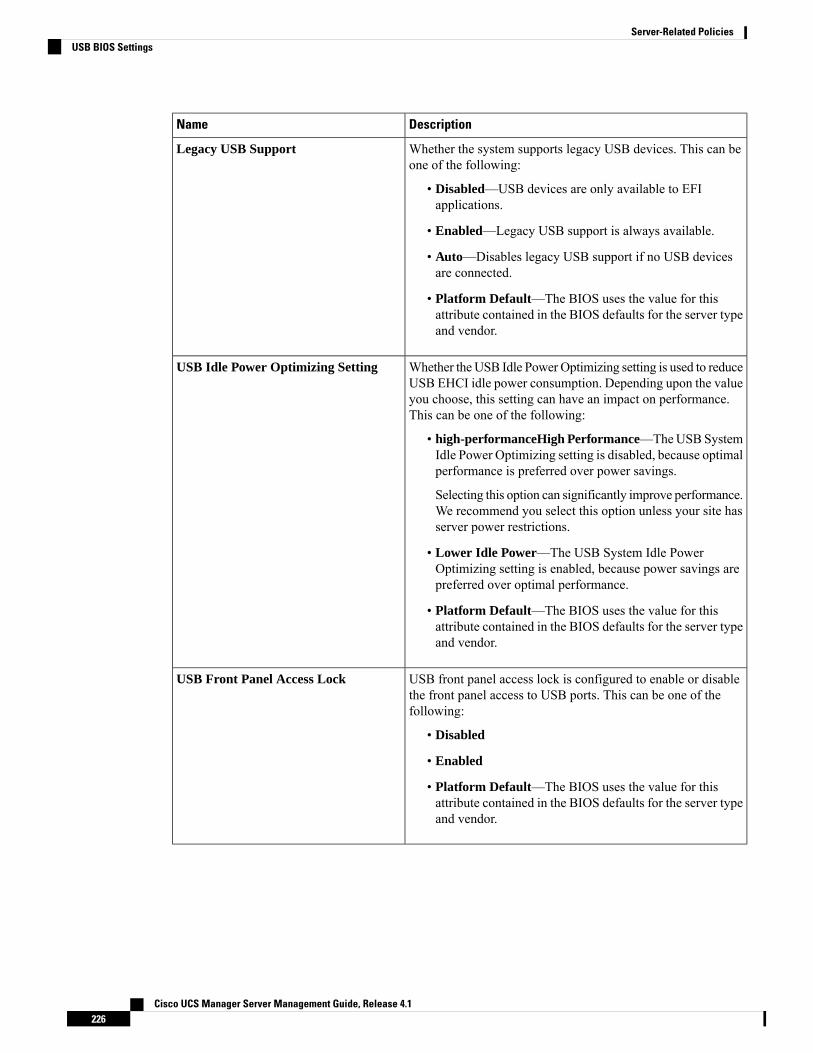
DescriptionName
Whether the system supports legacy USB devices. This can beone of the following:
• Disabled—USB devices are only available to EFIapplications.
• Enabled—Legacy USB support is always available.
• Auto—Disables legacy USB support if no USB devicesare connected.
• Platform Default—The BIOS uses the value for thisattribute contained in the BIOS defaults for the server typeand vendor.
Legacy USB Support
Whether the USB Idle Power Optimizing setting is used to reduceUSB EHCI idle power consumption. Depending upon the valueyou choose, this setting can have an impact on performance.This can be one of the following:
• high-performanceHigh Performance—TheUSBSystemIdle Power Optimizing setting is disabled, because optimalperformance is preferred over power savings.
Selecting this option can significantly improve performance.We recommend you select this option unless your site hasserver power restrictions.
• Lower Idle Power—The USB System Idle PowerOptimizing setting is enabled, because power savings arepreferred over optimal performance.
• Platform Default—The BIOS uses the value for thisattribute contained in the BIOS defaults for the server typeand vendor.
USB Idle Power Optimizing Setting
USB front panel access lock is configured to enable or disablethe front panel access to USB ports. This can be one of thefollowing:
• Disabled
• Enabled
• Platform Default—The BIOS uses the value for thisattribute contained in the BIOS defaults for the server typeand vendor.
USB Front Panel Access Lock
Cisco UCS Manager Server Management Guide, Release 4.1226
Server-Related PoliciesUSB BIOS Settings
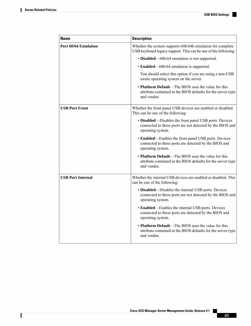
DescriptionName
Whether the system supports 60h/64h emulation for completeUSB keyboard legacy support. This can be one of the following:
• Disabled—60h/64 emulation is not supported.
• Enabled—60h/64 emulation is supported.
You should select this option if you are using a non-USBaware operating system on the server.
• Platform Default—The BIOS uses the value for thisattribute contained in the BIOS defaults for the server typeand vendor.
Port 60/64 Emulation
Whether the front panel USB devices are enabled or disabled.This can be one of the following:
• Disabled—Disables the front panel USB ports. Devicesconnected to these ports are not detected by the BIOS andoperating system.
• Enabled—Enables the front panel USB ports. Devicesconnected to these ports are detected by the BIOS andoperating system.
• Platform Default—The BIOS uses the value for thisattribute contained in the BIOS defaults for the server typeand vendor.
USB Port Front
Whether the internal USB devices are enabled or disabled. Thiscan be one of the following:
• Disabled—Disables the internal USB ports. Devicesconnected to these ports are not detected by the BIOS andoperating system.
• Enabled—Enables the internal USB ports. Devicesconnected to these ports are detected by the BIOS andoperating system.
• Platform Default—The BIOS uses the value for thisattribute contained in the BIOS defaults for the server typeand vendor.
USB Port Internal
Cisco UCS Manager Server Management Guide, Release 4.1227
Server-Related PoliciesUSB BIOS Settings

DescriptionName
Whether the vKVM ports are enabled or disabled. This can beone of the following:
• Disabled—Disables the KVM keyboard and/or mousedevices. Keyboard and/or mouse will not work in the KVMwindow.
• Enabled—Enables the KVM keyboard and/or mousedevices.
• Platform Default—The BIOS uses the value for thisattribute contained in the BIOS defaults for the server typeand vendor.
USB Port KVM
Whether the rear panel USB devices are enabled or disabled.This can be one of the following:
• Disabled—Disables the rear panel USB ports. Devicesconnected to these ports are not detected by the BIOS andoperating system.
• Enabled—Enables the rear panel USB ports. Devicesconnected to these ports are detected by the BIOS andoperating system.
• Platform Default—The BIOS uses the value for thisattribute contained in the BIOS defaults for the server typeand vendor.
USB Port Rear
Whether the SD card drives are enabled or disabled. This canbe one of the following:
• Disabled—Disables the SD card drives. The SD card drivesare not detected by the BIOS and operating system.
• Enabled—Enables the SD card drives.
• Platform Default—The BIOS uses the value for thisattribute contained in the BIOS defaults for the server typeand vendor.
USB Port SD Card
Whether the virtual media devices are enabled or disabled. Thiscan be one of the following:
• Disabled—Disables the vMedia devices.
• Enabled—Enables the vMedia devices.
• Platform Default—The BIOS uses the value for thisattribute contained in the BIOS defaults for the server typeand vendor.
USB Port VMedia
Cisco UCS Manager Server Management Guide, Release 4.1228
Server-Related PoliciesUSB BIOS Settings
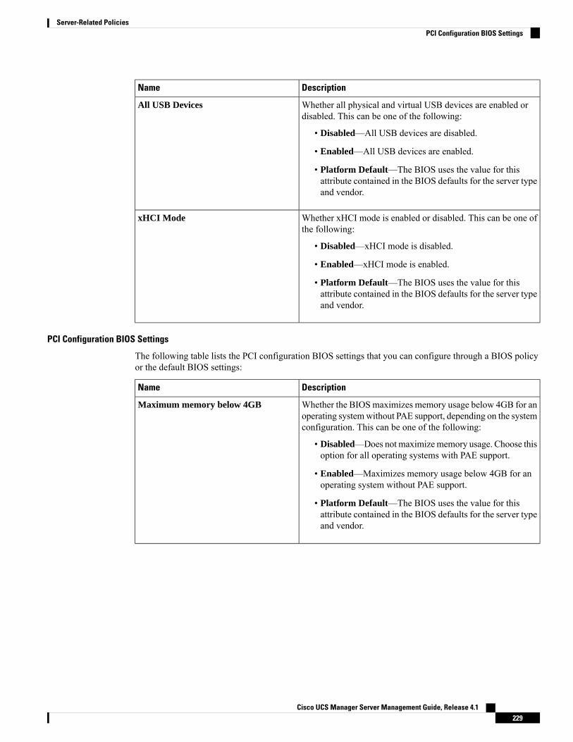
DescriptionName
Whether all physical and virtual USB devices are enabled ordisabled. This can be one of the following:
• Disabled—All USB devices are disabled.
• Enabled—All USB devices are enabled.
• Platform Default—The BIOS uses the value for thisattribute contained in the BIOS defaults for the server typeand vendor.
All USB Devices
Whether xHCI mode is enabled or disabled. This can be one ofthe following:
• Disabled—xHCI mode is disabled.
• Enabled—xHCI mode is enabled.
• Platform Default—The BIOS uses the value for thisattribute contained in the BIOS defaults for the server typeand vendor.
xHCI Mode
PCI Configuration BIOS Settings
The following table lists the PCI configuration BIOS settings that you can configure through a BIOS policyor the default BIOS settings:
DescriptionName
Whether the BIOSmaximizes memory usage below 4GB for anoperating systemwithout PAE support, depending on the systemconfiguration. This can be one of the following:
• Disabled—Does not maximizememory usage. Choose thisoption for all operating systems with PAE support.
• Enabled—Maximizes memory usage below 4GB for anoperating system without PAE support.
• Platform Default—The BIOS uses the value for thisattribute contained in the BIOS defaults for the server typeand vendor.
Maximum memory below 4GB
Cisco UCS Manager Server Management Guide, Release 4.1229
Server-Related PoliciesPCI Configuration BIOS Settings
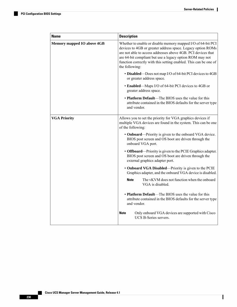
DescriptionName
Whether to enable or disable memory mapped I/O of 64-bit PCIdevices to 4GB or greater address space. Legacy option ROMsare not able to access addresses above 4GB. PCI devices thatare 64-bit compliant but use a legacy option ROM may notfunction correctly with this setting enabled. This can be one ofthe following:
• Disabled—Does not map I/O of 64-bit PCI devices to 4GBor greater address space.
• Enabled—Maps I/O of 64-bit PCI devices to 4GB orgreater address space.
• Platform Default—The BIOS uses the value for thisattribute contained in the BIOS defaults for the server typeand vendor.
Memory mapped IO above 4GB
Allows you to set the priority for VGA graphics devices ifmultiple VGA devices are found in the system. This can be oneof the following:
• Onboard—Priority is given to the onboard VGA device.BIOS post screen and OS boot are driven through theonboard VGA port.
• Offboard—Priority is given to the PCIEGraphics adapter.BIOS post screen and OS boot are driven through theexternal graphics adapter port.
• Onboard VGA Disabled—Priority is given to the PCIEGraphics adapter, and the onboard VGA device is disabled.
The vKVMdoes not function when the onboardVGA is disabled.
Note
• Platform Default—The BIOS uses the value for thisattribute contained in the BIOS defaults for the server typeand vendor.
Only onboard VGA devices are supported with CiscoUCS B-Series servers.
Note
VGA Priority
Cisco UCS Manager Server Management Guide, Release 4.1230
Server-Related PoliciesPCI Configuration BIOS Settings

DescriptionName
Allows you to set the level of ASPM (Active Power StateManagement) support in the BIOS. This can be one of thefollowing:
• Disabled—ASPM support is disabled in the BIOS.
• Auto—The CPU determines the power state.
• ForceL0—Force all links to L0 standby (L0s) state.
• Platform Default—The BIOS uses the value for thisattribute contained in the BIOS defaults for the server typeand vendor.
ASPM Support
Allows you to disable the PCI BME bit to mitigate the threatfrom an unauthorized external DMA. This can be one of thefollowing:
• Disabled—PCI BME bit is disabled in the BIOS.
• Enabled—PCI BME bit is enabled in the BIOS.
• Platform Default—The BIOS uses the value for thisattribute contained in the BIOS defaults for the server typeand vendor.
BME DMA Mitigation Support
QPI BIOS Settings
The following table lists the QPI BIOS settings that you can configure through a BIOS policy or the defaultBIOS settings:
DescriptionName
The Intel QuickPath Interconnect (QPI) link frequency, in megatransfersper second (MT/s). This can be one of the following:
• 6.4 GT/s
• 7.2 GT/s
• 8.0 GT/s
• 9.6 GT/s
• Auto—The CPU determines the QPI link frequency.
• Platform Default—The BIOS uses the value for this attributecontained in the BIOS defaults for the server type and vendor.
QPI Link Frequency Select
Cisco UCS Manager Server Management Guide, Release 4.1231
Server-Related PoliciesQPI BIOS Settings
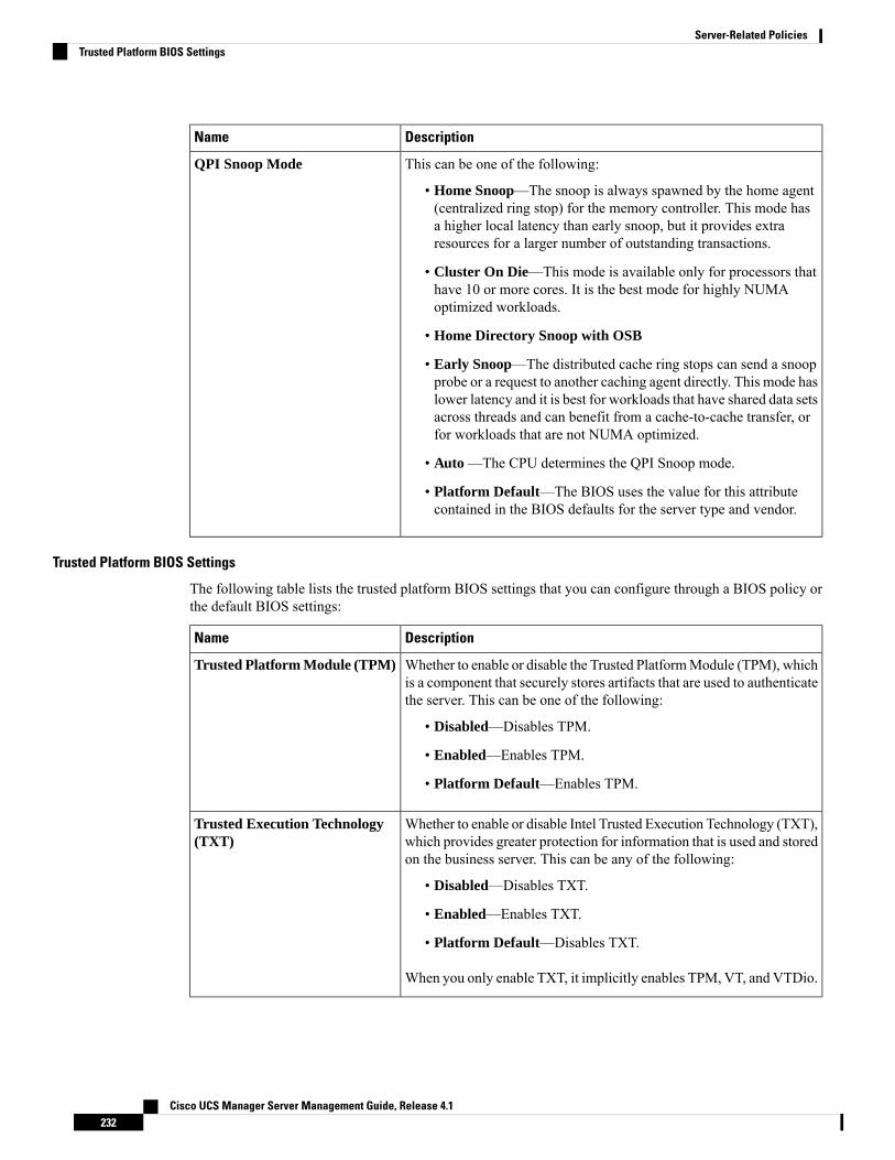
DescriptionName
This can be one of the following:
• Home Snoop—The snoop is always spawned by the home agent(centralized ring stop) for the memory controller. This mode hasa higher local latency than early snoop, but it provides extraresources for a larger number of outstanding transactions.
• Cluster On Die—This mode is available only for processors thathave 10 or more cores. It is the best mode for highly NUMAoptimized workloads.
• Home Directory Snoop with OSB
• Early Snoop—The distributed cache ring stops can send a snoopprobe or a request to another caching agent directly. This mode haslower latency and it is best for workloads that have shared data setsacross threads and can benefit from a cache-to-cache transfer, orfor workloads that are not NUMA optimized.
• Auto —The CPU determines the QPI Snoop mode.
• Platform Default—The BIOS uses the value for this attributecontained in the BIOS defaults for the server type and vendor.
QPI Snoop Mode
Trusted Platform BIOS Settings
The following table lists the trusted platform BIOS settings that you can configure through a BIOS policy orthe default BIOS settings:
DescriptionName
Whether to enable or disable the Trusted PlatformModule (TPM), whichis a component that securely stores artifacts that are used to authenticatethe server. This can be one of the following:
• Disabled—Disables TPM.
• Enabled—Enables TPM.
• Platform Default—Enables TPM.
Trusted Platform Module (TPM)
Whether to enable or disable Intel Trusted Execution Technology (TXT),which provides greater protection for information that is used and storedon the business server. This can be any of the following:
• Disabled—Disables TXT.
• Enabled—Enables TXT.
• Platform Default—Disables TXT.
When you only enable TXT, it implicitly enables TPM, VT, and VTDio.
Trusted Execution Technology(TXT)
Cisco UCS Manager Server Management Guide, Release 4.1232
Server-Related PoliciesTrusted Platform BIOS Settings
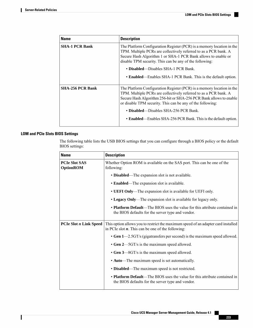
DescriptionName
The Platform Configuration Register (PCR) is a memory location in theTPM. Multiple PCRs are collectively referred to as a PCR bank. ASecure Hash Algorithm 1 or SHA-1 PCR Bank allows to enable ordisable TPM security. This can be any of the following:
• Disabled—Disables SHA-1 PCR Bank.
• Enabled—Enables SHA-1 PCR Bank. This is the default option.
SHA-1 PCR Bank
The Platform Configuration Register (PCR) is a memory location in theTPM. Multiple PCRs are collectively referred to as a PCR bank. ASecure Hash Algorithm 256-bit or SHA-256 PCRBank allows to enableor disable TPM security. This can be any of the following:
• Disabled—Disables SHA-256 PCR Bank.
• Enabled—Enables SHA-256 PCRBank. This is the default option.
SHA-256 PCR Bank
LOM and PCIe Slots BIOS Settings
The following table lists the USB BIOS settings that you can configure through a BIOS policy or the defaultBIOS settings:
DescriptionName
Whether Option ROM is available on the SAS port. This can be one of thefollowing:
• Disabled—The expansion slot is not available.
• Enabled—The expansion slot is available.
• UEFI Only—The expansion slot is available for UEFI only.
• Legacy Only—The expansion slot is available for legacy only.
• Platform Default—The BIOS uses the value for this attribute contained inthe BIOS defaults for the server type and vendor.
PCIe Slot SASOptionROM
This option allows you to restrict the maximum speed of an adapter card installedin PCIe slot n. This can be one of the following:
• Gen 1—2.5GT/s (gigatransfers per second) is the maximum speed allowed.
• Gen 2—5GT/s is the maximum speed allowed.
• Gen 3—8GT/s is the maximum speed allowed.
• Auto—The maximum speed is set automatically.
• Disabled—The maximum speed is not restricted.
• Platform Default—The BIOS uses the value for this attribute contained inthe BIOS defaults for the server type and vendor.
PCIe Slot n Link Speed
Cisco UCS Manager Server Management Guide, Release 4.1233
Server-Related PoliciesLOM and PCIe Slots BIOS Settings
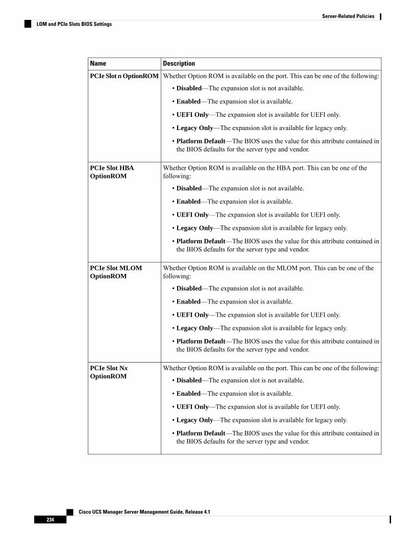
DescriptionName
Whether Option ROM is available on the port. This can be one of the following:
• Disabled—The expansion slot is not available.
• Enabled—The expansion slot is available.
• UEFI Only—The expansion slot is available for UEFI only.
• Legacy Only—The expansion slot is available for legacy only.
• Platform Default—The BIOS uses the value for this attribute contained inthe BIOS defaults for the server type and vendor.
PCIe Slot n OptionROM
Whether Option ROM is available on the HBA port. This can be one of thefollowing:
• Disabled—The expansion slot is not available.
• Enabled—The expansion slot is available.
• UEFI Only—The expansion slot is available for UEFI only.
• Legacy Only—The expansion slot is available for legacy only.
• Platform Default—The BIOS uses the value for this attribute contained inthe BIOS defaults for the server type and vendor.
PCIe Slot HBAOptionROM
Whether Option ROM is available on the MLOM port. This can be one of thefollowing:
• Disabled—The expansion slot is not available.
• Enabled—The expansion slot is available.
• UEFI Only—The expansion slot is available for UEFI only.
• Legacy Only—The expansion slot is available for legacy only.
• Platform Default—The BIOS uses the value for this attribute contained inthe BIOS defaults for the server type and vendor.
PCIe Slot MLOMOptionROM
Whether Option ROM is available on the port. This can be one of the following:
• Disabled—The expansion slot is not available.
• Enabled—The expansion slot is available.
• UEFI Only—The expansion slot is available for UEFI only.
• Legacy Only—The expansion slot is available for legacy only.
• Platform Default—The BIOS uses the value for this attribute contained inthe BIOS defaults for the server type and vendor.
PCIe Slot NxOptionROM
Cisco UCS Manager Server Management Guide, Release 4.1234
Server-Related PoliciesLOM and PCIe Slots BIOS Settings

DescriptionName
Whether Option ROM is available on the 10G LOM port. This can be one of thefollowing:
• Disabled—The expansion slot is not available.
• Enabled—The expansion slot is available.
• Platform Default—The BIOS uses the value for this attribute contained inthe BIOS defaults for the server type and vendor.
PCIe 10G LOM 2 Link
PCI ROM Command Line Protocol (CLP) controls the execution of differentOption ROMs such as PxE and iSCSI that are present in the card. By default, itis disabled.
• Disabled—The expansion slot is not available.
• Enabled—The expansion slot is available.
• Platform Default—The BIOS uses the value for this attribute contained inthe BIOS defaults for the server type and vendor.
PCI ROM CLP
Whether the server can use Option ROM present in System IO Controller 1(SIOC1). This can be one of the following:
• Disabled—The expansion slot is not available.
• Enabled—The expansion slot is available.
• UEFI Only—The expansion slot is available for UEFI only.
• Legacy Only—The expansion slot is available for legacy only.
• Platform Default—The BIOS uses the value for this attribute contained inthe BIOS defaults for the server type and vendor.
SIOC1 Option ROM
Whether the server can use Option ROM present in System IO Controller 2(SIOC2). This can be one of the following:
• Disabled—The expansion slot is not available.
• Enabled—The expansion slot is available.
• UEFI Only—The expansion slot is available for UEFI only.
• Legacy Only—The expansion slot is available for legacy only.
• Platform Default—The BIOS uses the value for this attribute contained inthe BIOS defaults for the server type and vendor.
SIOC2 Option ROM
Cisco UCS Manager Server Management Guide, Release 4.1235
Server-Related PoliciesLOM and PCIe Slots BIOS Settings
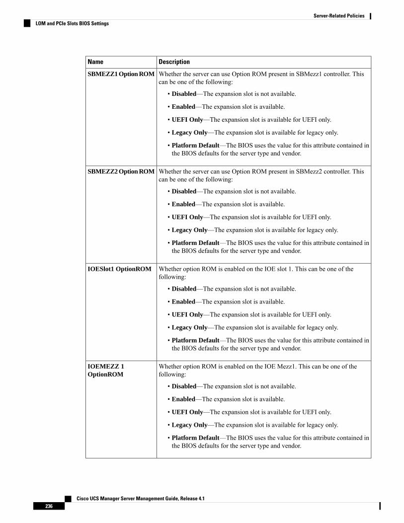
DescriptionName
Whether the server can use Option ROM present in SBMezz1 controller. Thiscan be one of the following:
• Disabled—The expansion slot is not available.
• Enabled—The expansion slot is available.
• UEFI Only—The expansion slot is available for UEFI only.
• Legacy Only—The expansion slot is available for legacy only.
• Platform Default—The BIOS uses the value for this attribute contained inthe BIOS defaults for the server type and vendor.
SBMEZZ1 Option ROM
Whether the server can use Option ROM present in SBMezz2 controller. Thiscan be one of the following:
• Disabled—The expansion slot is not available.
• Enabled—The expansion slot is available.
• UEFI Only—The expansion slot is available for UEFI only.
• Legacy Only—The expansion slot is available for legacy only.
• Platform Default—The BIOS uses the value for this attribute contained inthe BIOS defaults for the server type and vendor.
SBMEZZ2 Option ROM
Whether option ROM is enabled on the IOE slot 1. This can be one of thefollowing:
• Disabled—The expansion slot is not available.
• Enabled—The expansion slot is available.
• UEFI Only—The expansion slot is available for UEFI only.
• Legacy Only—The expansion slot is available for legacy only.
• Platform Default—The BIOS uses the value for this attribute contained inthe BIOS defaults for the server type and vendor.
IOESlot1 OptionROM
Whether option ROM is enabled on the IOE Mezz1. This can be one of thefollowing:
• Disabled—The expansion slot is not available.
• Enabled—The expansion slot is available.
• UEFI Only—The expansion slot is available for UEFI only.
• Legacy Only—The expansion slot is available for legacy only.
• Platform Default—The BIOS uses the value for this attribute contained inthe BIOS defaults for the server type and vendor.
IOEMEZZ 1OptionROM
Cisco UCS Manager Server Management Guide, Release 4.1236
Server-Related PoliciesLOM and PCIe Slots BIOS Settings
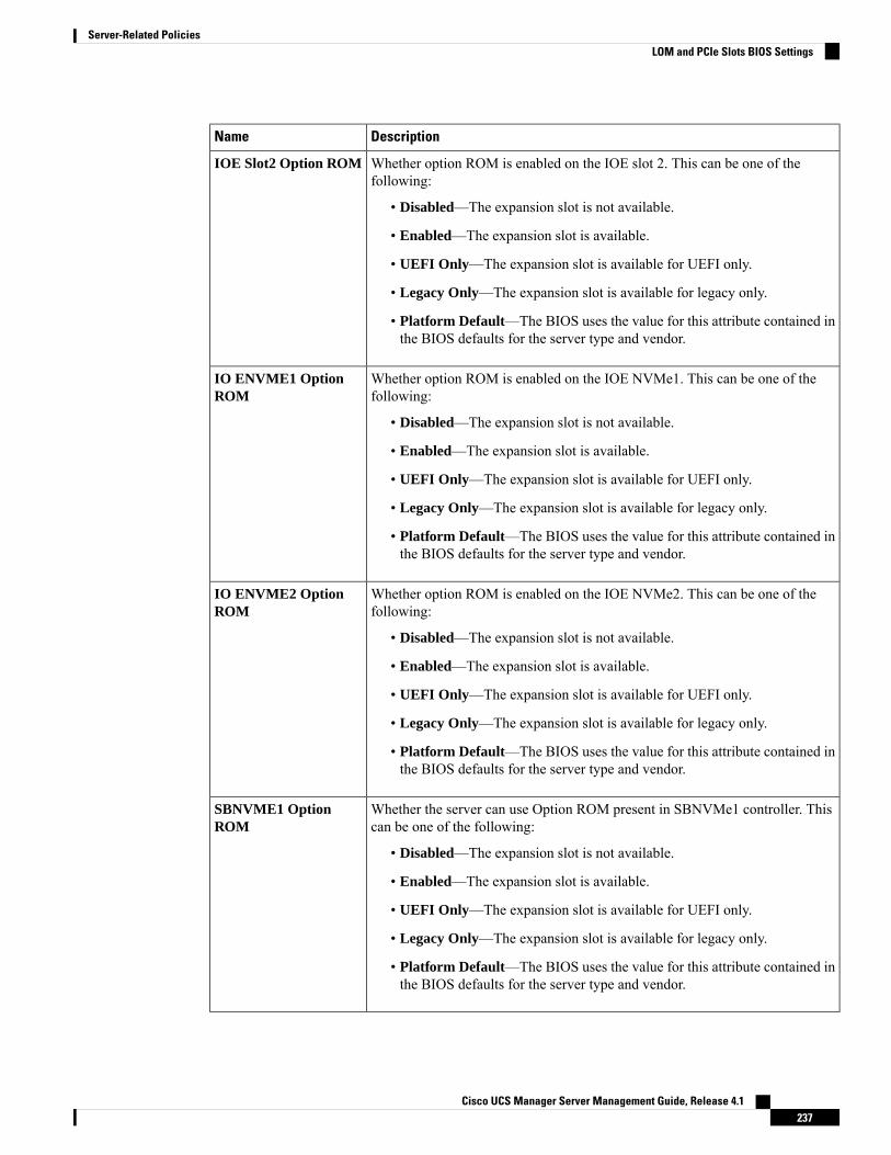
DescriptionName
Whether option ROM is enabled on the IOE slot 2. This can be one of thefollowing:
• Disabled—The expansion slot is not available.
• Enabled—The expansion slot is available.
• UEFI Only—The expansion slot is available for UEFI only.
• Legacy Only—The expansion slot is available for legacy only.
• Platform Default—The BIOS uses the value for this attribute contained inthe BIOS defaults for the server type and vendor.
IOE Slot2 Option ROM
Whether option ROM is enabled on the IOE NVMe1. This can be one of thefollowing:
• Disabled—The expansion slot is not available.
• Enabled—The expansion slot is available.
• UEFI Only—The expansion slot is available for UEFI only.
• Legacy Only—The expansion slot is available for legacy only.
• Platform Default—The BIOS uses the value for this attribute contained inthe BIOS defaults for the server type and vendor.
IO ENVME1 OptionROM
Whether option ROM is enabled on the IOE NVMe2. This can be one of thefollowing:
• Disabled—The expansion slot is not available.
• Enabled—The expansion slot is available.
• UEFI Only—The expansion slot is available for UEFI only.
• Legacy Only—The expansion slot is available for legacy only.
• Platform Default—The BIOS uses the value for this attribute contained inthe BIOS defaults for the server type and vendor.
IO ENVME2 OptionROM
Whether the server can use Option ROM present in SBNVMe1 controller. Thiscan be one of the following:
• Disabled—The expansion slot is not available.
• Enabled—The expansion slot is available.
• UEFI Only—The expansion slot is available for UEFI only.
• Legacy Only—The expansion slot is available for legacy only.
• Platform Default—The BIOS uses the value for this attribute contained inthe BIOS defaults for the server type and vendor.
SBNVME1 OptionROM
Cisco UCS Manager Server Management Guide, Release 4.1237
Server-Related PoliciesLOM and PCIe Slots BIOS Settings
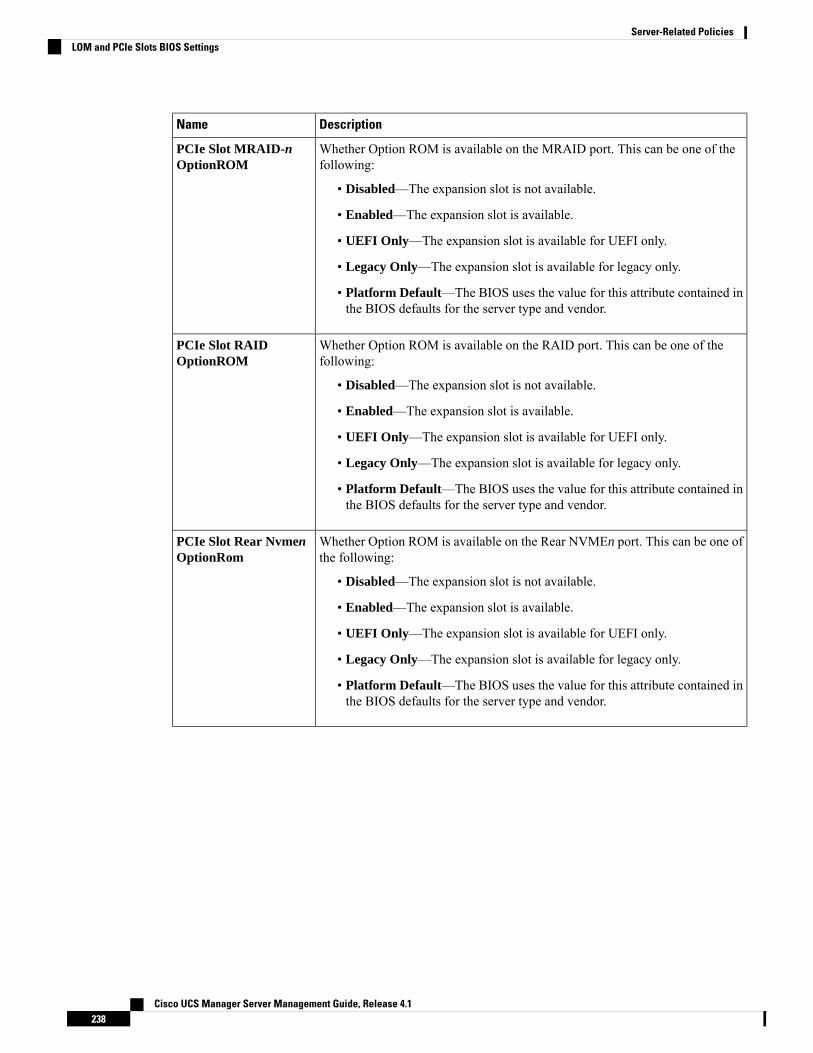
DescriptionName
Whether Option ROM is available on the MRAID port. This can be one of thefollowing:
• Disabled—The expansion slot is not available.
• Enabled—The expansion slot is available.
• UEFI Only—The expansion slot is available for UEFI only.
• Legacy Only—The expansion slot is available for legacy only.
• Platform Default—The BIOS uses the value for this attribute contained inthe BIOS defaults for the server type and vendor.
PCIe Slot MRAID-nOptionROM
Whether Option ROM is available on the RAID port. This can be one of thefollowing:
• Disabled—The expansion slot is not available.
• Enabled—The expansion slot is available.
• UEFI Only—The expansion slot is available for UEFI only.
• Legacy Only—The expansion slot is available for legacy only.
• Platform Default—The BIOS uses the value for this attribute contained inthe BIOS defaults for the server type and vendor.
PCIe Slot RAIDOptionROM
Whether Option ROM is available on the Rear NVMEn port. This can be one ofthe following:
• Disabled—The expansion slot is not available.
• Enabled—The expansion slot is available.
• UEFI Only—The expansion slot is available for UEFI only.
• Legacy Only—The expansion slot is available for legacy only.
• Platform Default—The BIOS uses the value for this attribute contained inthe BIOS defaults for the server type and vendor.
PCIe Slot Rear NvmenOptionRom
Cisco UCS Manager Server Management Guide, Release 4.1238
Server-Related PoliciesLOM and PCIe Slots BIOS Settings
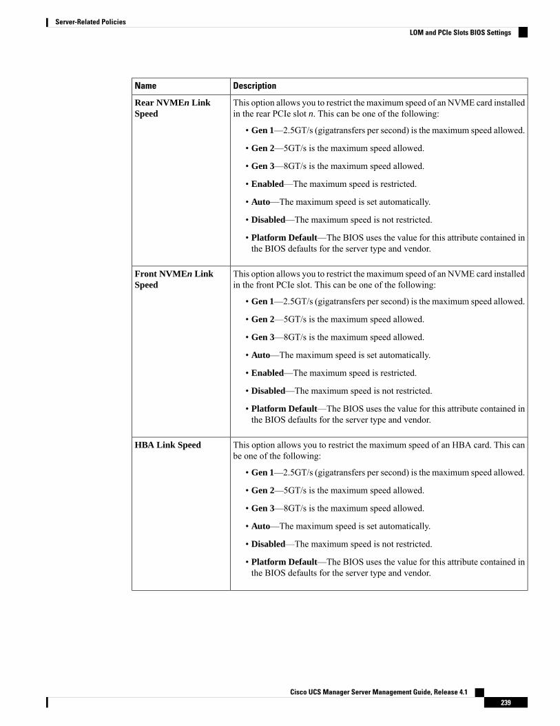
DescriptionName
This option allows you to restrict the maximum speed of an NVME card installedin the rear PCIe slot n. This can be one of the following:
• Gen 1—2.5GT/s (gigatransfers per second) is the maximum speed allowed.
• Gen 2—5GT/s is the maximum speed allowed.
• Gen 3—8GT/s is the maximum speed allowed.
• Enabled—The maximum speed is restricted.
• Auto—The maximum speed is set automatically.
• Disabled—The maximum speed is not restricted.
• Platform Default—The BIOS uses the value for this attribute contained inthe BIOS defaults for the server type and vendor.
Rear NVMEn LinkSpeed
This option allows you to restrict the maximum speed of an NVME card installedin the front PCIe slot. This can be one of the following:
• Gen 1—2.5GT/s (gigatransfers per second) is the maximum speed allowed.
• Gen 2—5GT/s is the maximum speed allowed.
• Gen 3—8GT/s is the maximum speed allowed.
• Auto—The maximum speed is set automatically.
• Enabled—The maximum speed is restricted.
• Disabled—The maximum speed is not restricted.
• Platform Default—The BIOS uses the value for this attribute contained inthe BIOS defaults for the server type and vendor.
Front NVMEn LinkSpeed
This option allows you to restrict the maximum speed of an HBA card. This canbe one of the following:
• Gen 1—2.5GT/s (gigatransfers per second) is the maximum speed allowed.
• Gen 2—5GT/s is the maximum speed allowed.
• Gen 3—8GT/s is the maximum speed allowed.
• Auto—The maximum speed is set automatically.
• Disabled—The maximum speed is not restricted.
• Platform Default—The BIOS uses the value for this attribute contained inthe BIOS defaults for the server type and vendor.
HBA Link Speed
Cisco UCS Manager Server Management Guide, Release 4.1239
Server-Related PoliciesLOM and PCIe Slots BIOS Settings
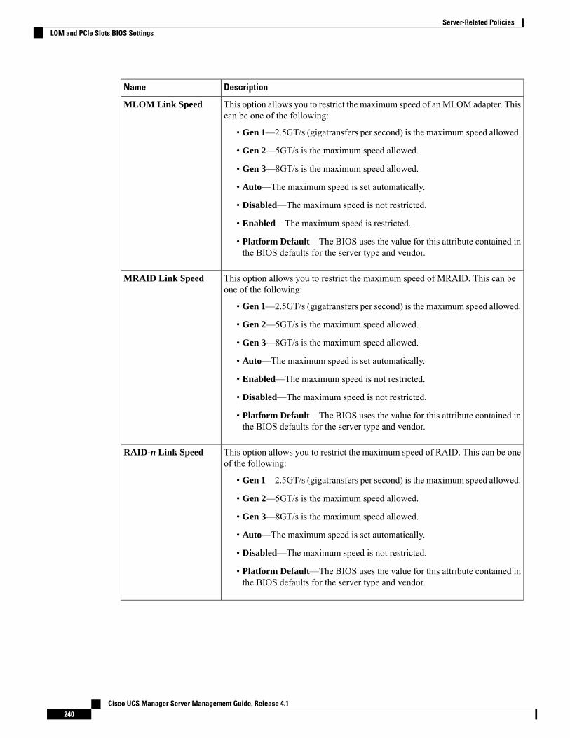
DescriptionName
This option allows you to restrict the maximum speed of anMLOM adapter. Thiscan be one of the following:
• Gen 1—2.5GT/s (gigatransfers per second) is the maximum speed allowed.
• Gen 2—5GT/s is the maximum speed allowed.
• Gen 3—8GT/s is the maximum speed allowed.
• Auto—The maximum speed is set automatically.
• Disabled—The maximum speed is not restricted.
• Enabled—The maximum speed is restricted.
• Platform Default—The BIOS uses the value for this attribute contained inthe BIOS defaults for the server type and vendor.
MLOM Link Speed
This option allows you to restrict the maximum speed of MRAID. This can beone of the following:
• Gen 1—2.5GT/s (gigatransfers per second) is the maximum speed allowed.
• Gen 2—5GT/s is the maximum speed allowed.
• Gen 3—8GT/s is the maximum speed allowed.
• Auto—The maximum speed is set automatically.
• Enabled—The maximum speed is not restricted.
• Disabled—The maximum speed is not restricted.
• Platform Default—The BIOS uses the value for this attribute contained inthe BIOS defaults for the server type and vendor.
MRAID Link Speed
This option allows you to restrict the maximum speed of RAID. This can be oneof the following:
• Gen 1—2.5GT/s (gigatransfers per second) is the maximum speed allowed.
• Gen 2—5GT/s is the maximum speed allowed.
• Gen 3—8GT/s is the maximum speed allowed.
• Auto—The maximum speed is set automatically.
• Disabled—The maximum speed is not restricted.
• Platform Default—The BIOS uses the value for this attribute contained inthe BIOS defaults for the server type and vendor.
RAID-n Link Speed
Cisco UCS Manager Server Management Guide, Release 4.1240
Server-Related PoliciesLOM and PCIe Slots BIOS Settings

DescriptionName
Whether all onboard LOM ports are enabled or disabled. This can be one of thefollowing:
• Enabled—All onboard LOM are enabled.
• Disabled—All onboard LOM are disabled.
• Platform Default—The BIOS uses the value for this attribute contained inthe BIOS defaults for the server type and vendor.
All Onboard LOM
Whether Option ROM is available on the LOM port 1. This can be one of thefollowing:
• Disabled—The expansion slot is not available.
• Enabled—The expansion slot is available.
• UEFI Only—The expansion slot is available for UEFI only.
• Legacy Only—The expansion slot is available for legacy only.
• Platform Default—The BIOS uses the value for this attribute contained inthe BIOS defaults for the server type and vendor.
LOM Port 1 OptionRom
Whether Option ROM is available on the LOM port 2. This can be one of thefollowing:
• Disabled—The expansion slot is not available.
• Enabled—The expansion slot is available.
• UEFI Only—The expansion slot is available for UEFI only.
• Legacy Only—The expansion slot is available for legacy only.
• Platform Default—The BIOS uses the value for this attribute contained inthe BIOS defaults for the server type and vendor.
LOM Port 2 OptionRom
The state of the adapter card installed in PCIe slot n. This can be one of thefollowing:
• Disabled—The expansion slot is not available.
• Enabled—The expansion slot is available.
• UEFI Only—The expansion slot is available for UEFI only.
• Legacy Only—The expansion slot is available for legacy only.
• Platform Default—The BIOS uses the value for this attribute contained inthe BIOS defaults for the server type and vendor.
Slot n State
Cisco UCS Manager Server Management Guide, Release 4.1241
Server-Related PoliciesLOM and PCIe Slots BIOS Settings

DescriptionName
Whether the server can use Option ROM present in SBNVMe1 controller. Thiscan be one of the following:
• Disabled—The expansion slot is not available.
• Enabled—The expansion slot is available.
• UEFI Only—The expansion slot is available for UEFI only.
• Legacy Only—The expansion slot is available for legacy only.
• Platform Default—The BIOS uses the value for this attribute contained inthe BIOS defaults for the server type and vendor.
SBNVMe1 OptionROM
Whether the server can use Option ROM present in SBNVMe2 controller. Thiscan be one of the following:
• Disabled—The expansion slot is not available.
• Enabled—The expansion slot is available.
• UEFI Only—The expansion slot is available for UEFI only.
• Legacy Only—The expansion slot is available for legacy only.
• Platform Default—The BIOS uses the value for this attribute contained inthe BIOS defaults for the server type and vendor.
SBNVMe2 OptionROM
Whether the server can use Option ROM present in SIOCNVMe1 controller.This can be one of the following:
• Disabled—The expansion slot is not available.
• Enabled—The expansion slot is available.
• UEFI Only—The expansion slot is available for UEFI only.
• Legacy Only—The expansion slot is available for legacy only.
• Platform Default—The BIOS uses the value for this attribute contained inthe BIOS defaults for the server type and vendor.
SIOCNVMe1OptionROM
Whether the server can use Option ROM present in SIOCNVMe2 controller.This can be one of the following:
• Disabled—The expansion slot is not available.
• Enabled—The expansion slot is available.
• UEFI Only—The expansion slot is available for UEFI only.
• Legacy Only—The expansion slot is available for legacy only.
• Platform Default—The BIOS uses the value for this attribute contained inthe BIOS defaults for the server type and vendor.
SIOCNVMe2OptionROM
Cisco UCS Manager Server Management Guide, Release 4.1242
Server-Related PoliciesLOM and PCIe Slots BIOS Settings
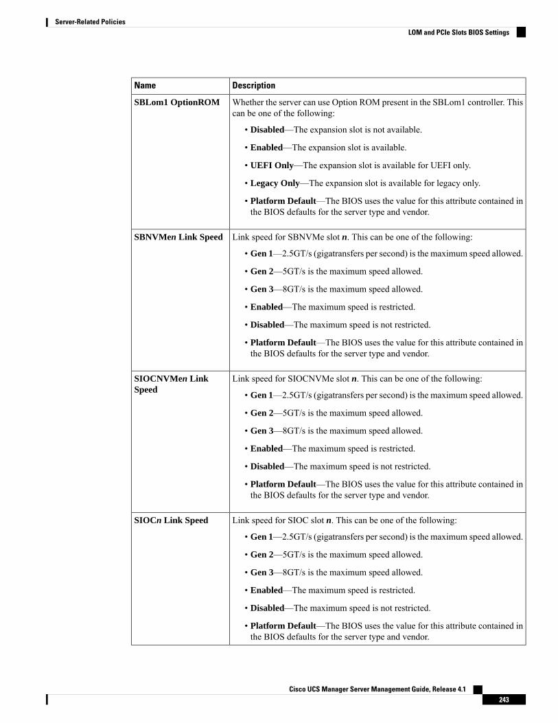
DescriptionName
Whether the server can use Option ROM present in the SBLom1 controller. Thiscan be one of the following:
• Disabled—The expansion slot is not available.
• Enabled—The expansion slot is available.
• UEFI Only—The expansion slot is available for UEFI only.
• Legacy Only—The expansion slot is available for legacy only.
• Platform Default—The BIOS uses the value for this attribute contained inthe BIOS defaults for the server type and vendor.
SBLom1 OptionROM
Link speed for SBNVMe slot n. This can be one of the following:
• Gen 1—2.5GT/s (gigatransfers per second) is the maximum speed allowed.
• Gen 2—5GT/s is the maximum speed allowed.
• Gen 3—8GT/s is the maximum speed allowed.
• Enabled—The maximum speed is restricted.
• Disabled—The maximum speed is not restricted.
• Platform Default—The BIOS uses the value for this attribute contained inthe BIOS defaults for the server type and vendor.
SBNVMen Link Speed
Link speed for SIOCNVMe slot n. This can be one of the following:
• Gen 1—2.5GT/s (gigatransfers per second) is the maximum speed allowed.
• Gen 2—5GT/s is the maximum speed allowed.
• Gen 3—8GT/s is the maximum speed allowed.
• Enabled—The maximum speed is restricted.
• Disabled—The maximum speed is not restricted.
• Platform Default—The BIOS uses the value for this attribute contained inthe BIOS defaults for the server type and vendor.
SIOCNVMen LinkSpeed
Link speed for SIOC slot n. This can be one of the following:
• Gen 1—2.5GT/s (gigatransfers per second) is the maximum speed allowed.
• Gen 2—5GT/s is the maximum speed allowed.
• Gen 3—8GT/s is the maximum speed allowed.
• Enabled—The maximum speed is restricted.
• Disabled—The maximum speed is not restricted.
• Platform Default—The BIOS uses the value for this attribute contained inthe BIOS defaults for the server type and vendor.
SIOCn Link Speed
Cisco UCS Manager Server Management Guide, Release 4.1243
Server-Related PoliciesLOM and PCIe Slots BIOS Settings
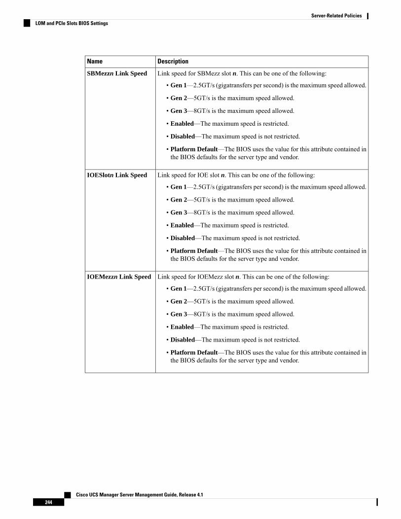
DescriptionName
Link speed for SBMezz slot n. This can be one of the following:
• Gen 1—2.5GT/s (gigatransfers per second) is the maximum speed allowed.
• Gen 2—5GT/s is the maximum speed allowed.
• Gen 3—8GT/s is the maximum speed allowed.
• Enabled—The maximum speed is restricted.
• Disabled—The maximum speed is not restricted.
• Platform Default—The BIOS uses the value for this attribute contained inthe BIOS defaults for the server type and vendor.
SBMezzn Link Speed
Link speed for IOE slot n. This can be one of the following:
• Gen 1—2.5GT/s (gigatransfers per second) is the maximum speed allowed.
• Gen 2—5GT/s is the maximum speed allowed.
• Gen 3—8GT/s is the maximum speed allowed.
• Enabled—The maximum speed is restricted.
• Disabled—The maximum speed is not restricted.
• Platform Default—The BIOS uses the value for this attribute contained inthe BIOS defaults for the server type and vendor.
IOESlotn Link Speed
Link speed for IOEMezz slot n. This can be one of the following:
• Gen 1—2.5GT/s (gigatransfers per second) is the maximum speed allowed.
• Gen 2—5GT/s is the maximum speed allowed.
• Gen 3—8GT/s is the maximum speed allowed.
• Enabled—The maximum speed is restricted.
• Disabled—The maximum speed is not restricted.
• Platform Default—The BIOS uses the value for this attribute contained inthe BIOS defaults for the server type and vendor.
IOEMezzn Link Speed
Cisco UCS Manager Server Management Guide, Release 4.1244
Server-Related PoliciesLOM and PCIe Slots BIOS Settings
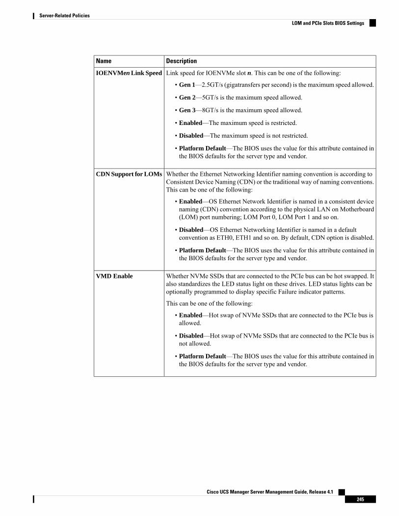
DescriptionName
Link speed for IOENVMe slot n. This can be one of the following:
• Gen 1—2.5GT/s (gigatransfers per second) is the maximum speed allowed.
• Gen 2—5GT/s is the maximum speed allowed.
• Gen 3—8GT/s is the maximum speed allowed.
• Enabled—The maximum speed is restricted.
• Disabled—The maximum speed is not restricted.
• Platform Default—The BIOS uses the value for this attribute contained inthe BIOS defaults for the server type and vendor.
IOENVMen Link Speed
Whether the Ethernet Networking Identifier naming convention is according toConsistent Device Naming (CDN) or the traditional way of naming conventions.This can be one of the following:
• Enabled—OS Ethernet Network Identifier is named in a consistent devicenaming (CDN) convention according to the physical LAN on Motherboard(LOM) port numbering; LOM Port 0, LOM Port 1 and so on.
• Disabled—OS Ethernet Networking Identifier is named in a defaultconvention as ETH0, ETH1 and so on. By default, CDN option is disabled.
• Platform Default—The BIOS uses the value for this attribute contained inthe BIOS defaults for the server type and vendor.
CDN Support for LOMs
Whether NVMe SSDs that are connected to the PCIe bus can be hot swapped. Italso standardizes the LED status light on these drives. LED status lights can beoptionally programmed to display specific Failure indicator patterns.
This can be one of the following:
• Enabled—Hot swap of NVMe SSDs that are connected to the PCIe bus isallowed.
• Disabled—Hot swap of NVMe SSDs that are connected to the PCIe bus isnot allowed.
• Platform Default—The BIOS uses the value for this attribute contained inthe BIOS defaults for the server type and vendor.
VMD Enable
Cisco UCS Manager Server Management Guide, Release 4.1245
Server-Related PoliciesLOM and PCIe Slots BIOS Settings

DescriptionName
Access Control Services (ACS) allow the processor to enable or disablepeer-to-peer communication between multiple devices for Control Slot n. Thiscan be one of the following:
• Enabled—Enables peer-to-peer communication between multiple devicesfor Control Slot n.
• Disabled—Disables peer-to-peer communication betweenmultiple devicesfor Control Slot n.
• Platform Default—The BIOS uses the value for this attribute contained inthe BIOS defaults for the server type and vendor.
ACS Control SLOT-n
n = 11 to 14
Whether the Option ROM is enabled on GPU slot n. n is the slot number, whichcan be numbered 1 through 8. This can be one of the following:
• Disabled—The expansion slot is not available.
• Enabled—The expansion slot is available.
• Platform Default—The BIOS uses the value for this attribute contained inthe BIOS defaults for the server type and vendor.
PCIe Slot GPUnOptionROM
Only for CiscoUCSC480M5 ML Server
Access Control Services (ACS) allow the processor to enable or disablepeer-to-peer communication between multiple devices for GPUs. This can beone of the following:
• Disabled—Enables peer-to-peer communication between multiple devicesfor GPUs.
• Enabled—Disables peer-to-peer communication betweenmultiple devicesfor GPUs.
• Platform Default—The BIOS uses the value for this attribute contained inthe BIOS defaults for the server type and vendor.
ACS Control GPU-n
n = 1 to 8
Reduces EMI interference by down-spreading the clock by 0.5%.
Disable this feature to centralize the clock without spreading.
For all Cisco UCS M5 servers, this option is Disabled by default.
• Disabled—Clock is centralized without spreading.
• Auto— EMI interference is auto adjusted.
• ZeroPointFive—EMI interference us reduced by down-spreading the clockby 0.5%.
• Platform Default — The BIOS uses the value for this attribute containedin the BIOS defaults for the server type and vendor.
PCIe PLL SSC
Cisco UCS Manager Server Management Guide, Release 4.1246
Server-Related PoliciesLOM and PCIe Slots BIOS Settings
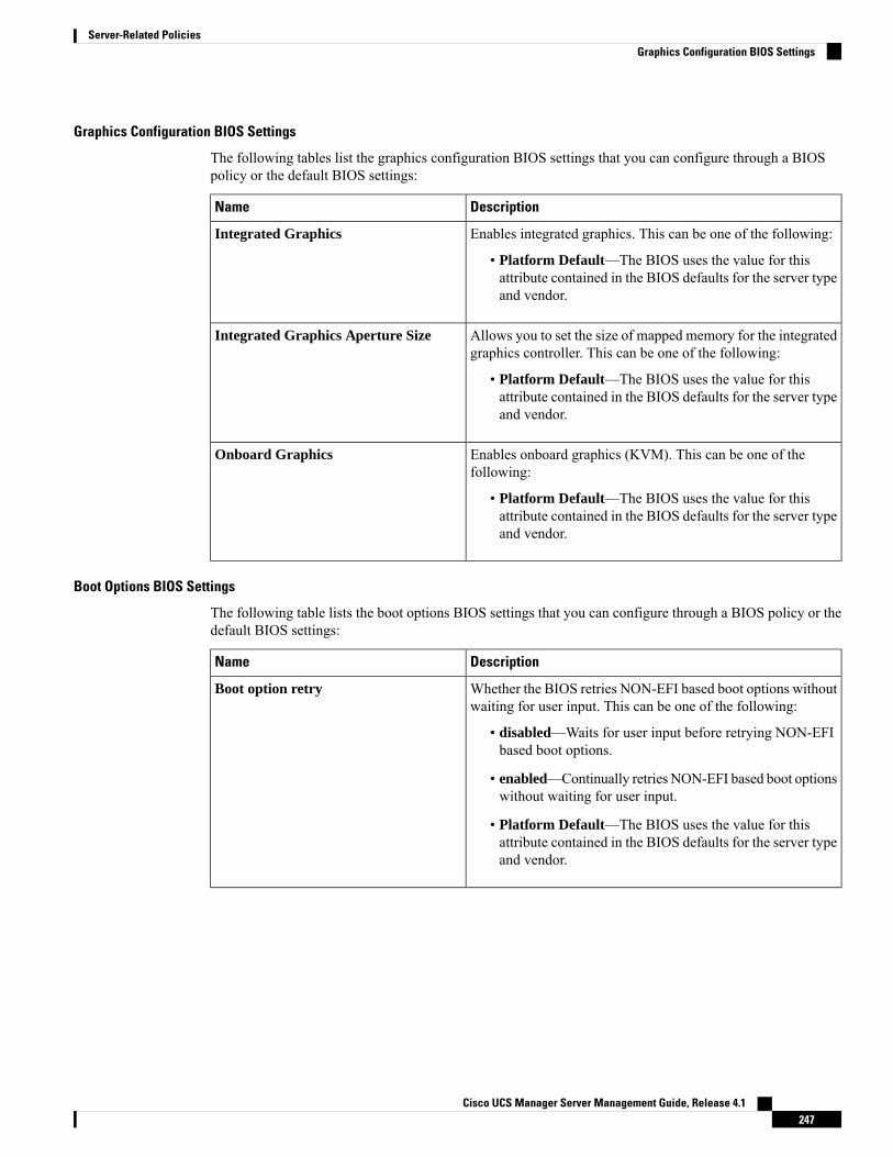
Graphics Configuration BIOS Settings
The following tables list the graphics configuration BIOS settings that you can configure through a BIOSpolicy or the default BIOS settings:
DescriptionName
Enables integrated graphics. This can be one of the following:
• Platform Default—The BIOS uses the value for thisattribute contained in the BIOS defaults for the server typeand vendor.
Integrated Graphics
Allows you to set the size of mapped memory for the integratedgraphics controller. This can be one of the following:
• Platform Default—The BIOS uses the value for thisattribute contained in the BIOS defaults for the server typeand vendor.
Integrated Graphics Aperture Size
Enables onboard graphics (KVM). This can be one of thefollowing:
• Platform Default—The BIOS uses the value for thisattribute contained in the BIOS defaults for the server typeand vendor.
Onboard Graphics
Boot Options BIOS Settings
The following table lists the boot options BIOS settings that you can configure through a BIOS policy or thedefault BIOS settings:
DescriptionName
Whether the BIOS retries NON-EFI based boot options withoutwaiting for user input. This can be one of the following:
• disabled—Waits for user input before retrying NON-EFIbased boot options.
• enabled—Continually retries NON-EFI based boot optionswithout waiting for user input.
• Platform Default—The BIOS uses the value for thisattribute contained in the BIOS defaults for the server typeand vendor.
Boot option retry
Cisco UCS Manager Server Management Guide, Release 4.1247
Server-Related PoliciesGraphics Configuration BIOS Settings
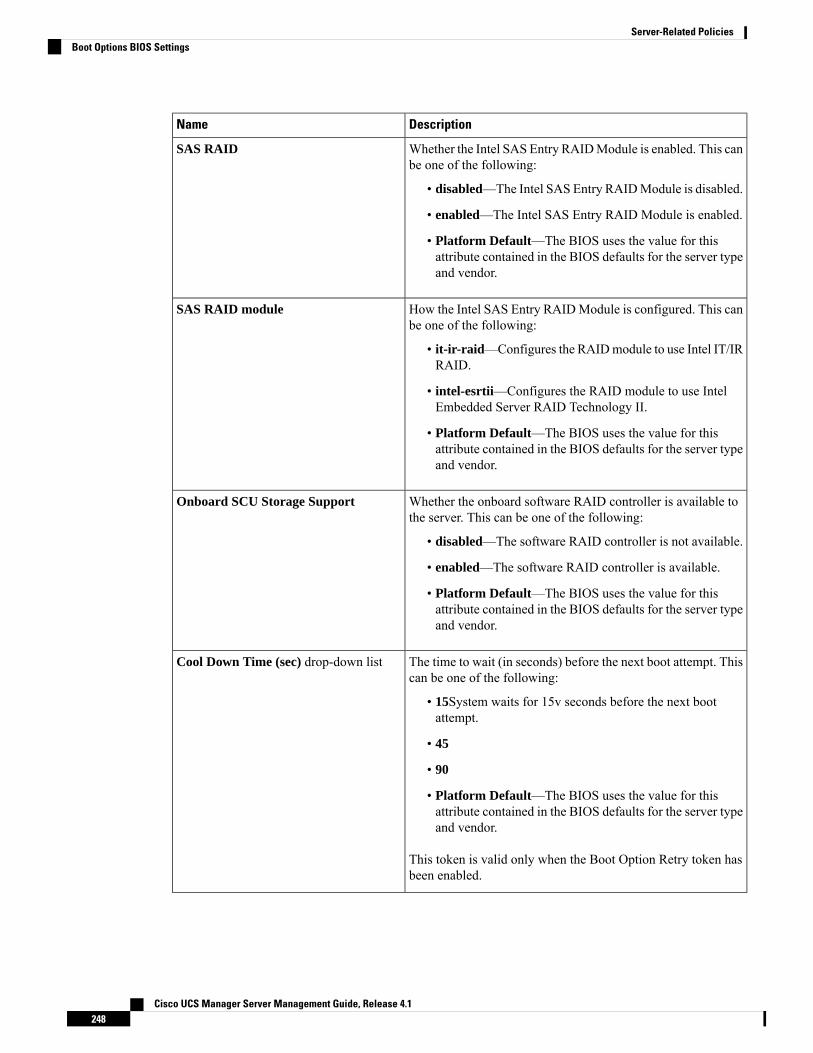
DescriptionName
Whether the Intel SAS Entry RAIDModule is enabled. This canbe one of the following:
• disabled—The Intel SAS Entry RAIDModule is disabled.
• enabled—The Intel SAS Entry RAID Module is enabled.
• Platform Default—The BIOS uses the value for thisattribute contained in the BIOS defaults for the server typeand vendor.
SAS RAID
How the Intel SAS Entry RAIDModule is configured. This canbe one of the following:
• it-ir-raid—Configures the RAIDmodule to use Intel IT/IRRAID.
• intel-esrtii—Configures the RAID module to use IntelEmbedded Server RAID Technology II.
• Platform Default—The BIOS uses the value for thisattribute contained in the BIOS defaults for the server typeand vendor.
SAS RAID module
Whether the onboard software RAID controller is available tothe server. This can be one of the following:
• disabled—The software RAID controller is not available.
• enabled—The software RAID controller is available.
• Platform Default—The BIOS uses the value for thisattribute contained in the BIOS defaults for the server typeand vendor.
Onboard SCU Storage Support
The time to wait (in seconds) before the next boot attempt. Thiscan be one of the following:
• 15System waits for 15v seconds before the next bootattempt.
• 45
• 90
• Platform Default—The BIOS uses the value for thisattribute contained in the BIOS defaults for the server typeand vendor.
This token is valid only when the Boot Option Retry token hasbeen enabled.
Cool Down Time (sec) drop-down list
Cisco UCS Manager Server Management Guide, Release 4.1248
Server-Related PoliciesBoot Options BIOS Settings
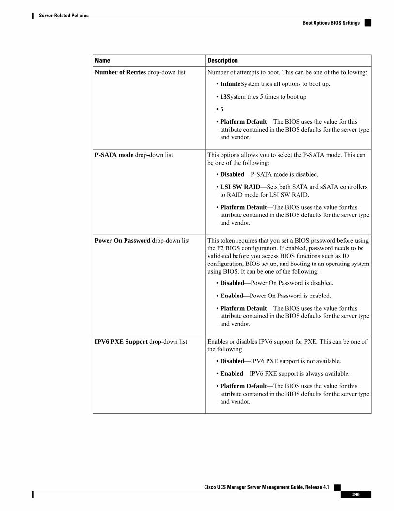
DescriptionName
Number of attempts to boot. This can be one of the following:
• InfiniteSystem tries all options to boot up.
• 13System tries 5 times to boot up
• 5
• Platform Default—The BIOS uses the value for thisattribute contained in the BIOS defaults for the server typeand vendor.
Number of Retries drop-down list
This options allows you to select the P-SATA mode. This canbe one of the following:
• Disabled—P-SATA mode is disabled.
• LSI SW RAID—Sets both SATA and sSATA controllersto RAID mode for LSI SW RAID.
• Platform Default—The BIOS uses the value for thisattribute contained in the BIOS defaults for the server typeand vendor.
P-SATA mode drop-down list
This token requires that you set a BIOS password before usingthe F2 BIOS configuration. If enabled, password needs to bevalidated before you access BIOS functions such as IOconfiguration, BIOS set up, and booting to an operating systemusing BIOS. It can be one of the following:
• Disabled—Power On Password is disabled.
• Enabled—Power On Password is enabled.
• Platform Default—The BIOS uses the value for thisattribute contained in the BIOS defaults for the server typeand vendor.
Power On Password drop-down list
Enables or disables IPV6 support for PXE. This can be one ofthe following
• Disabled—IPV6 PXE support is not available.
• Enabled—IPV6 PXE support is always available.
• Platform Default—The BIOS uses the value for thisattribute contained in the BIOS defaults for the server typeand vendor.
IPV6 PXE Support drop-down list
Cisco UCS Manager Server Management Guide, Release 4.1249
Server-Related PoliciesBoot Options BIOS Settings
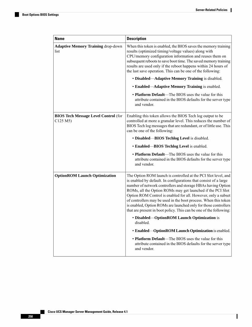
DescriptionName
When this token is enabled, the BIOS saves the memory trainingresults (optimized timing/voltage values) along withCPU/memory configuration information and reuses them onsubsequent reboots to save boot time. The savedmemory trainingresults are used only if the reboot happens within 24 hours ofthe last save operation. This can be one of the following:
• Disabled—Adaptive Memory Training is disabled.
• Enabled—Adaptive Memory Training is enabled.
• Platform Default—The BIOS uses the value for thisattribute contained in the BIOS defaults for the server typeand vendor.
Adaptive Memory Training drop-downlist
Enabling this token allows the BIOS Tech log output to becontrolled at more a granular level. This reduces the number ofBIOS Tech logmessages that are redundant, or of little use. Thiscan be one of the following:
• Disabled—BIOS Techlog Level is disabled.
• Enabled—BIOS Techlog Level is enabled.
• Platform Default—The BIOS uses the value for thisattribute contained in the BIOS defaults for the server typeand vendor.
BIOS Tech Message Level Control (forC125 M5)
The Option ROM launch is controlled at the PCI Slot level, andis enabled by default. In configurations that consist of a largenumber of network controllers and storage HBAs having OptionROMs, all the Option ROMs may get launched if the PCI SlotOption ROM Control is enabled for all. However, only a subsetof controllers may be used in the boot process. When this tokenis enabled, Option ROMs are launched only for those controllersthat are present in boot policy. This can be one of the following:
• Disabled—OptionROM Launch Optimization isdisabled.
• Enabled—OptionROM Launch Optimization is enabled.
• Platform Default—The BIOS uses the value for thisattribute contained in the BIOS defaults for the server typeand vendor.
OptionROM Launch Optimization
Cisco UCS Manager Server Management Guide, Release 4.1250
Server-Related PoliciesBoot Options BIOS Settings
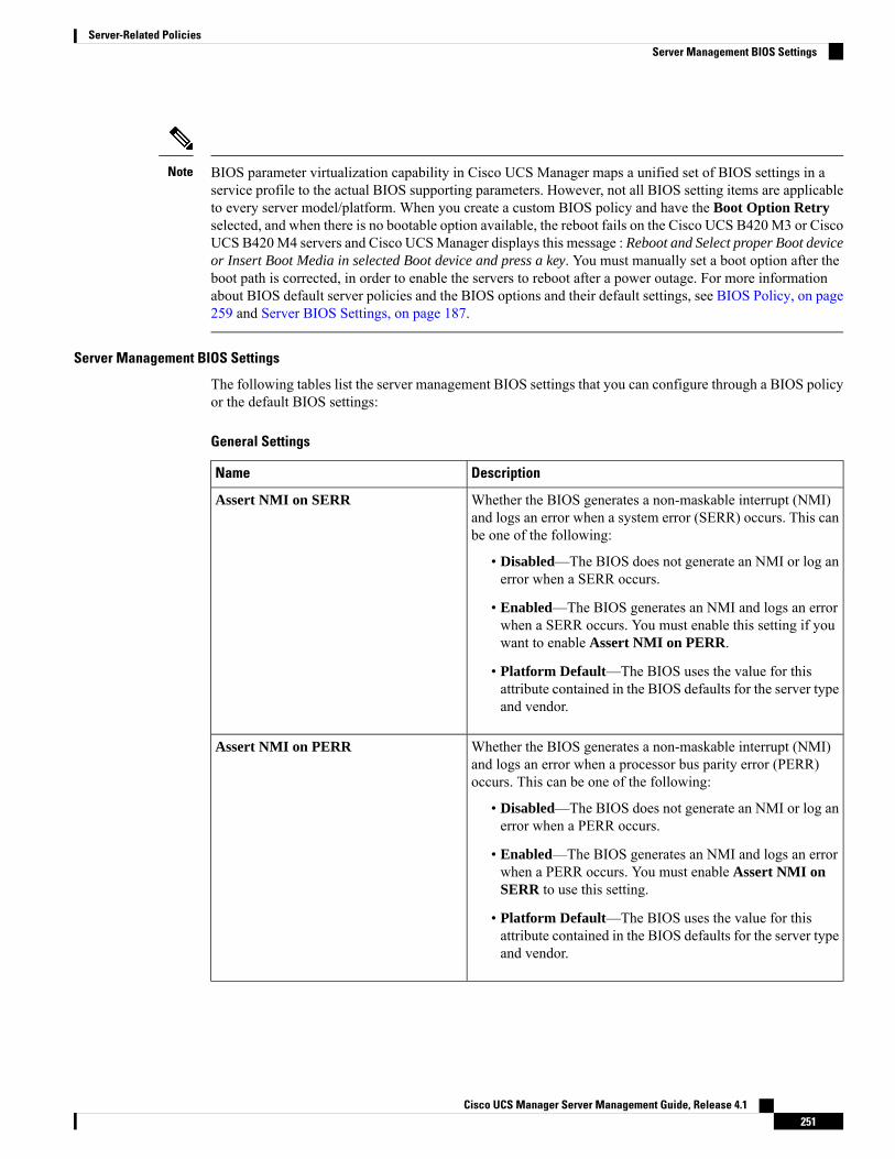
BIOS parameter virtualization capability in Cisco UCS Manager maps a unified set of BIOS settings in aservice profile to the actual BIOS supporting parameters. However, not all BIOS setting items are applicableto every server model/platform. When you create a custom BIOS policy and have the Boot Option Retryselected, and when there is no bootable option available, the reboot fails on the Cisco UCS B420M3 or CiscoUCS B420M4 servers and Cisco UCSManager displays this message : Reboot and Select proper Boot deviceor Insert Boot Media in selected Boot device and press a key. You must manually set a boot option after theboot path is corrected, in order to enable the servers to reboot after a power outage. For more informationabout BIOS default server policies and the BIOS options and their default settings, see BIOS Policy, on page259 and Server BIOS Settings, on page 187.
Note
Server Management BIOS Settings
The following tables list the server management BIOS settings that you can configure through a BIOS policyor the default BIOS settings:
General Settings
DescriptionName
Whether the BIOS generates a non-maskable interrupt (NMI)and logs an error when a system error (SERR) occurs. This canbe one of the following:
• Disabled—The BIOS does not generate an NMI or log anerror when a SERR occurs.
• Enabled—The BIOS generates an NMI and logs an errorwhen a SERR occurs. You must enable this setting if youwant to enable Assert NMI on PERR.
• Platform Default—The BIOS uses the value for thisattribute contained in the BIOS defaults for the server typeand vendor.
Assert NMI on SERR
Whether the BIOS generates a non-maskable interrupt (NMI)and logs an error when a processor bus parity error (PERR)occurs. This can be one of the following:
• Disabled—The BIOS does not generate an NMI or log anerror when a PERR occurs.
• Enabled—The BIOS generates an NMI and logs an errorwhen a PERR occurs. You must enable Assert NMI onSERR to use this setting.
• Platform Default—The BIOS uses the value for thisattribute contained in the BIOS defaults for the server typeand vendor.
Assert NMI on PERR
Cisco UCS Manager Server Management Guide, Release 4.1251
Server-Related PoliciesServer Management BIOS Settings
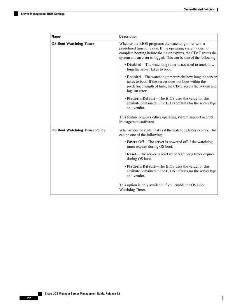
DescriptionName
Whether the BIOS programs the watchdog timer with apredefined timeout value. If the operating system does notcomplete booting before the timer expires, the CIMC resets thesystem and an error is logged. This can be one of the following:
• Disabled—The watchdog timer is not used to track howlong the server takes to boot.
• Enabled—The watchdog timer tracks how long the servertakes to boot. If the server does not boot within thepredefined length of time, the CIMC resets the system andlogs an error.
• Platform Default—The BIOS uses the value for thisattribute contained in the BIOS defaults for the server typeand vendor.
This feature requires either operating system support or IntelManagement software.
OS Boot Watchdog Timer
What action the system takes if the watchdog timer expires. Thiscan be one of the following:
• Power Off—The server is powered off if the watchdogtimer expires during OS boot.
• Reset—The server is reset if the watchdog timer expiresduring OS boot.
• Platform Default—The BIOS uses the value for thisattribute contained in the BIOS defaults for the server typeand vendor.
This option is only available if you enable the OS BootWatchdog Timer.
OS Boot Watchdog Timer Policy
Cisco UCS Manager Server Management Guide, Release 4.1252
Server-Related PoliciesServer Management BIOS Settings
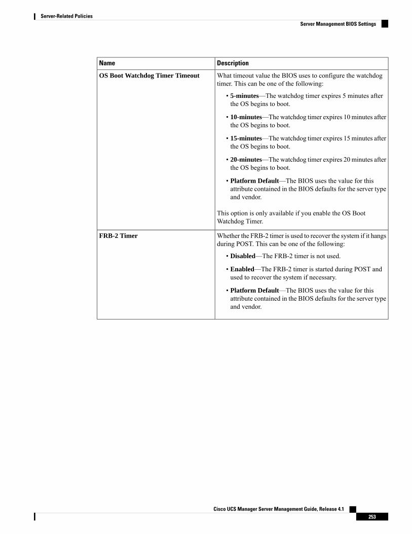
DescriptionName
What timeout value the BIOS uses to configure the watchdogtimer. This can be one of the following:
• 5-minutes—The watchdog timer expires 5 minutes afterthe OS begins to boot.
• 10-minutes—Thewatchdog timer expires 10 minutes afterthe OS begins to boot.
• 15-minutes—Thewatchdog timer expires 15 minutes afterthe OS begins to boot.
• 20-minutes—Thewatchdog timer expires 20 minutes afterthe OS begins to boot.
• Platform Default—The BIOS uses the value for thisattribute contained in the BIOS defaults for the server typeand vendor.
This option is only available if you enable the OS BootWatchdog Timer.
OS Boot Watchdog Timer Timeout
Whether the FRB-2 timer is used to recover the system if it hangsduring POST. This can be one of the following:
• Disabled—The FRB-2 timer is not used.
• Enabled—The FRB-2 timer is started during POST andused to recover the system if necessary.
• Platform Default—The BIOS uses the value for thisattribute contained in the BIOS defaults for the server typeand vendor.
FRB-2 Timer
Cisco UCS Manager Server Management Guide, Release 4.1253
Server-Related PoliciesServer Management BIOS Settings

Console Redirection Settings
DescriptionName
Allows a serial port to be used for console redirection duringPOST and BIOS booting. After the BIOS has booted and theoperating system is responsible for the server, console redirectionis irrelevant and has no effect. This can be one of the following:
• Disabled—No console redirection occurs during POST.
• serial-port-a or COM 0 or Enabled—Enables serial portA for console redirection during POST. This option is validfor blade servers and rack-mount servers.
• serial-port-b orCOM 1—Enables serial port B for consoleredirection and allows it to perform server managementtasks. This option is only valid for rack-mount servers.
• Platform Default—The BIOS uses the value for thisattribute contained in the BIOS defaults for the server typeand vendor.
If you enable this option, you also disable the displayof the Quiet Boot logo screen during POST.
Note
Console redirection
Whether a handshake protocol is used for flow control. Requestto Send / Clear to Send (RTS/CTS) helps to reduce framecollisions that can be introduced by a hidden terminal problem.This can be one of the following:
• None—No flow control is used.
• RTS-CTS—RTS/CTS is used for flow control.
• Platform Default—The BIOS uses the value for thisattribute contained in the BIOS defaults for the server typeand vendor.
This setting must match the setting on the remoteterminal application.
Note
Flow Control
Cisco UCS Manager Server Management Guide, Release 4.1254
Server-Related PoliciesServer Management BIOS Settings
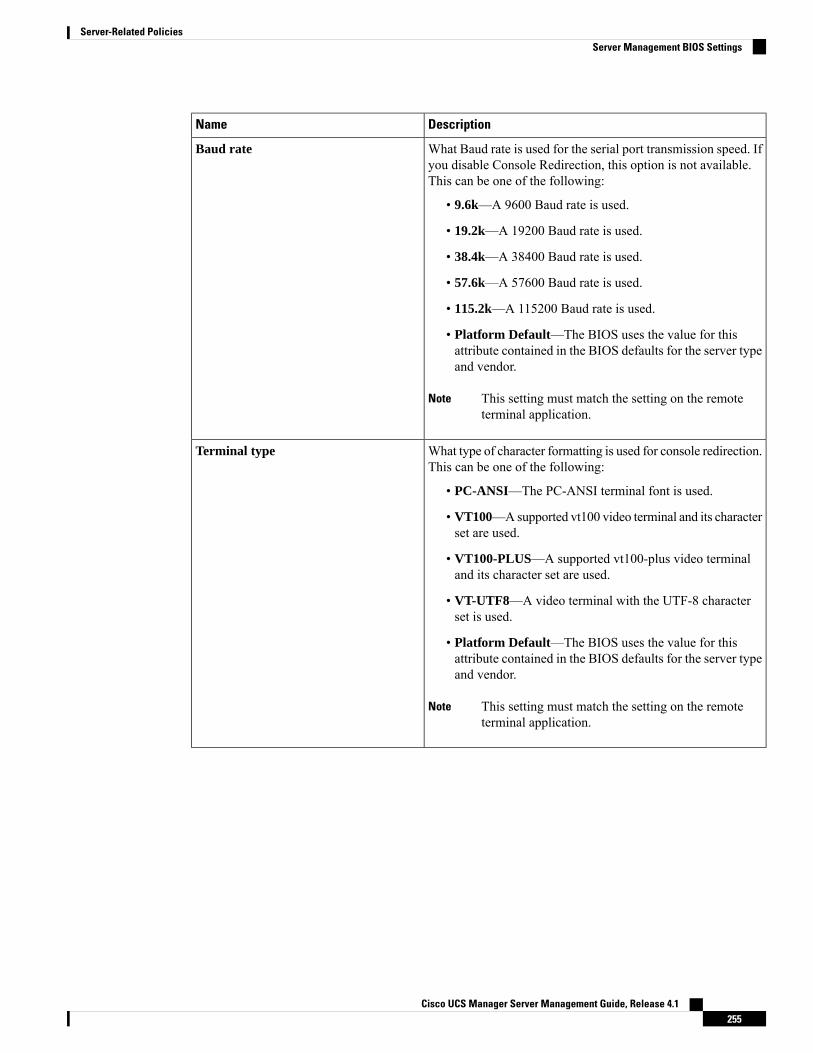
DescriptionName
What Baud rate is used for the serial port transmission speed. Ifyou disable Console Redirection, this option is not available.This can be one of the following:
• 9.6k—A 9600 Baud rate is used.
• 19.2k—A 19200 Baud rate is used.
• 38.4k—A 38400 Baud rate is used.
• 57.6k—A 57600 Baud rate is used.
• 115.2k—A 115200 Baud rate is used.
• Platform Default—The BIOS uses the value for thisattribute contained in the BIOS defaults for the server typeand vendor.
This setting must match the setting on the remoteterminal application.
Note
Baud rate
What type of character formatting is used for console redirection.This can be one of the following:
• PC-ANSI—The PC-ANSI terminal font is used.
• VT100—Asupported vt100 video terminal and its characterset are used.
• VT100-PLUS—A supported vt100-plus video terminaland its character set are used.
• VT-UTF8—A video terminal with the UTF-8 characterset is used.
• Platform Default—The BIOS uses the value for thisattribute contained in the BIOS defaults for the server typeand vendor.
This setting must match the setting on the remoteterminal application.
Note
Terminal type
Cisco UCS Manager Server Management Guide, Release 4.1255
Server-Related PoliciesServer Management BIOS Settings
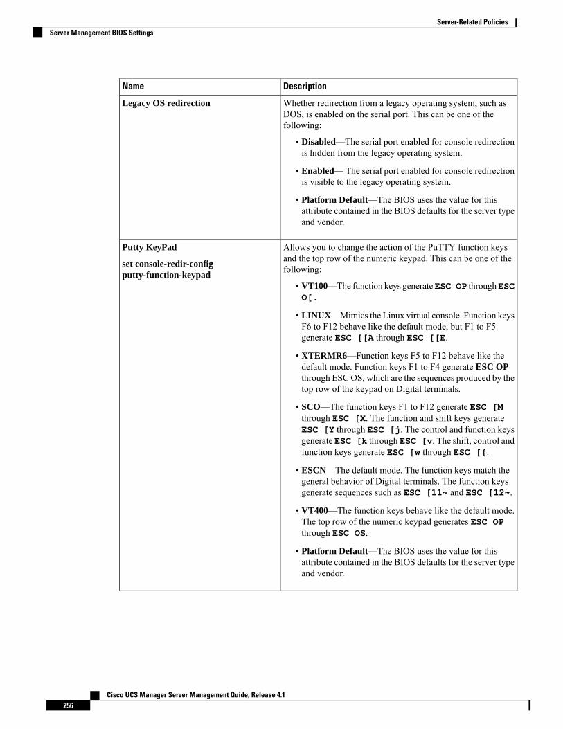
DescriptionName
Whether redirection from a legacy operating system, such asDOS, is enabled on the serial port. This can be one of thefollowing:
• Disabled—The serial port enabled for console redirectionis hidden from the legacy operating system.
• Enabled—The serial port enabled for console redirectionis visible to the legacy operating system.
• Platform Default—The BIOS uses the value for thisattribute contained in the BIOS defaults for the server typeand vendor.
Legacy OS redirection
Allows you to change the action of the PuTTY function keysand the top row of the numeric keypad. This can be one of thefollowing:
• VT100—The function keys generateESC OP throughESCO[.
• LINUX—Mimics the Linux virtual console. Function keysF6 to F12 behave like the default mode, but F1 to F5generate ESC [[A through ESC [[E.
• XTERMR6—Function keys F5 to F12 behave like thedefault mode. Function keys F1 to F4 generate ESC OPthrough ESCOS, which are the sequences produced by thetop row of the keypad on Digital terminals.
• SCO—The function keys F1 to F12 generate ESC [Mthrough ESC [X. The function and shift keys generateESC [Y through ESC [j. The control and function keysgenerate ESC [k through ESC [v. The shift, control andfunction keys generate ESC [w through ESC [{.
• ESCN—The default mode. The function keys match thegeneral behavior of Digital terminals. The function keysgenerate sequences such as ESC [11~ and ESC [12~.
• VT400—The function keys behave like the default mode.The top row of the numeric keypad generates ESC OPthrough ESC OS.
• Platform Default—The BIOS uses the value for thisattribute contained in the BIOS defaults for the server typeand vendor.
Putty KeyPad
set console-redir-configputty-function-keypad
Cisco UCS Manager Server Management Guide, Release 4.1256
Server-Related PoliciesServer Management BIOS Settings
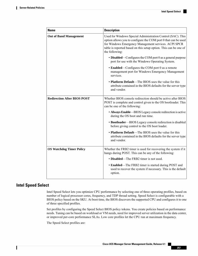
DescriptionName
Used for Windows Special Administration Control (SAC). Thisoption allows you to configure the COM port 0 that can be usedfor Windows Emergency Management services. ACPI SPCRtable is reported based on this setup option. This can be one ofthe following:
• Disabled—Configures the COMport 0 as a general purposeport for use with the Windows Operating System.
• Enabled—Configures the COM port 0 as a remotemanagement port for Windows Emergency Managementservices.
• Platform Default—The BIOS uses the value for thisattribute contained in the BIOS defaults for the server typeand vendor.
Out of Band Management
Whether BIOS console redirection should be active after BIOSPOST is complete and control given to the OS bootloader. Thiscan be one of the following:
• Always Enable—BIOSLegacy console redirection is activeduring the OS boot and run time.
• Bootloader—BIOS Legacy console redirection is disabledbefore giving control to the OS boot loader.
• Platform Default—The BIOS uses the value for thisattribute contained in the BIOS defaults for the server typeand vendor.
Redirection After BIOS POST
Whether the FRB2 timer is used for recovering the system if ithangs during POST. This can be any of the following:
• Disabled—The FRB2 timer is not used.
• Enabled—The FRB2 timer is started during POST andused to recover the system if necessary. This is the defaultoption.
OS Watchdog Timer Policy
Intel Speed SelectIntel Speed Select lets you optimize CPU performance by selecting one of three operating profiles, based onnumber of logical processor cores, frequency, and TDP thread setting. Speed Select is configurable with aBIOS policy based on the SKU. At boot time, the BIOS discovers the supported CPU and configures it to oneof three specified profiles.
Set profiles by configuring the Speed Select BIOS policy tokens. You create policies based on performanceneeds. Tuning can be based on workload or VM needs, need for improved server utilization in the data center,or improved per-core performance SLAs. Low core profiles let the CPU run at maximum frequency.
The Speed Select profiles are:
Cisco UCS Manager Server Management Guide, Release 4.1257
Server-Related PoliciesIntel Speed Select

• Base—High Core Configuration. Suggested for general purpose VM instances.
• Config 1—MediumCore Configuration. Suggested for high performance VM instances or Storage SKUs.
• Config 2—Low Core Configuration. Suggested for very high frequency Bare Metal servers or VMinstances.
The following tables show sample profile values based on the Intel® Xeon® Gold CPU 6240Y. Base is thedefault profile.
Table 12: Base Config
LLC/Core (Mb)All Core TurboBase Frequency(GHz)
CoresSKU
1.493.12.4248260Y
1.3753.32.6186240Y
1.3752.72.2124214Y
Tj Max (ºC)TDP (W)SKU
1041608260Y
881506240Y
88854214Y
Table 13: Config 1
LLC/Core (Mb)All Core TurboBase Frequency(GHz)
CoresSKU
1.793.32.5208260Y
1.773.42.8146240Y
1.652.72.3104214Y
Tj Max (ºC)TDP (W)SKU
TControl Spec1558260Y
TControl Spec1506240Y
TControl Spec854214Y
Table 14: Config 2
LLC/Core (Mb)All Core TurboBase Frequency(GHz)
CoresSKU
2.233.62.7168260Y
Cisco UCS Manager Server Management Guide, Release 4.1258
Server-Related PoliciesIntel Speed Select

LLC/Core (Mb)All Core TurboBase Frequency(GHz)
CoresSKU
3.093.63.186240Y
2.062.92.484214Y
Tj Max (ºC)TDP (W)SKU
TControl Spec1508260Y
TControl Spec1506240Y
TControl Spec854214Y
While changing the profiles can make the CPU run at a different frequency, the CIMC processor inventorypage will show information for the processor Base frequency, core, and threads. It will not display runningfrequencies.
Note
BIOS PolicyThe BIOS policy is a policy that automates the configuration of BIOS settings for a server or group of servers.You can create global BIOS policies available to all servers in the root organization, or you can create BIOSpolicies in sub-organizations that are only available to that hierarchy.
To use a BIOS policy, do the following:
1. Create the BIOS policy in Cisco UCS Manager.
2. Assign the BIOS policy to one or more service profiles.
3. Associate the service profile with a server.
During service profile association, Cisco UCS Manager modifies the BIOS settings on the server to matchthe configuration in the BIOS policy. If you do not create and assign a BIOS policy to a service profile, theserver uses the default BIOS settings for that server platform.
Default BIOS SettingsCisco UCS Manager includes a set of default BIOS settings for each type of server supported by Cisco UCS.The default BIOS settings are available only in the root organization and are global. Only one set of defaultBIOS settings can exist for each server platform supported by Cisco UCS. You can modify the default BIOSsettings, but you cannot create an additional set of default BIOS settings.
Each set of default BIOS settings are designed for a particular type of supported server and are applied to allservers of that specific type which do not have a BIOS policy included in their service profiles.
Unless a Cisco UCS implementation has specific needs that are not met by the server-specific settings, werecommend that you use the default BIOS settings that are designed for each type of server in the Cisco UCSdomain.
Cisco UCS Manager applies these server platform-specific BIOS settings as follows:
Cisco UCS Manager Server Management Guide, Release 4.1259
Server-Related PoliciesBIOS Policy
• The service profile associated with a server does not include a BIOS policy.
• The BIOS policy is configured with the platform-default option for a specific setting.
You can modify the default BIOS settings provided by Cisco UCS Manager. However, any changes to thedefault BIOS settings apply to all servers of that particular type or platform. If you want to modify the BIOSsettings for only certain servers, we recommend that you use a BIOS policy.
The BIOS tokens for M5 servers and later are read-only and cannot be modified. For a complete and up todate list of BIOS tokens, defaults, and values, refer Cisco UCS M5 Server BIOS Tokens .
Creating a BIOS Policy
Cisco UCS Manager pushes BIOS configuration changes through a BIOS policy or default BIOS settings tothe Cisco Integrated Management Controller (CIMC) buffer. These changes remain in the buffer and do nottake effect until the server is rebooted.
We recommend that you verify the support for BIOS settings in the server that you want to configure. Somesettings, such as Mirroring Mode for RAS Memory, are not supported by all Cisco UCS servers.
Note
Procedure
Step 1 In the Navigation pane, click Servers.Step 2 Expand Servers > Policies.Step 3 Expand the node for the organization where you want to create the policy.
If the system does not include multi tenancy, expand the root node.
Step 4 Right-click BIOS Policies and select Create BIOS Policy.Step 5 On the Main page of the Create BIOS Policy wizard, enter a name for the BIOS policy in the Name field.
This name can be between 1 and 16 alphanumeric characters. You cannot use spaces or any special charactersother than - (hyphen), _ (underscore), : (colon), and . (period), and you cannot change this name after theobject is saved.
Step 6 In the Create BIOS Policy wizard, do the following to configure the BIOS settings:a) If you want to change a BIOS setting, click the desired radio button or make the appropriate choice from
the drop-down list.
For descriptions and information about the options for each BIOS setting, see the following topics:
• Main page: Main BIOS Settings, on page 188
• Advanced page: Main BIOS Settings, on page 188
• Processor page: Processor BIOS Settings, on page 190
• IO BIOS for Intel page: I/O BIOS Settings for Intel, on page 214
• IO BIOS for AMD page: I/O BIOS Settings for AMD, on page 215
Cisco UCS Manager Server Management Guide, Release 4.1260
Server-Related PoliciesCreating a BIOS Policy

• RAS Memory page: RAS Memory BIOS Settings, on page 216
• Serial Port page: Serial Port BIOS Settings, on page 225
• USB page: USB BIOS Settings, on page 225
• PCI Configuration page: PCI Configuration BIOS Settings, on page 229
• QPI page: QPI BIOS Settings, on page 231
• LOM and PCIe Slots subtab: LOM and PCIe Slots BIOS Settings, on page 233
• Trusted Platform subtab: Trusted Platform BIOS Settings, on page 232
• Graphics Configuration subtab: Graphics Configuration BIOS Settings, on page 247
• Boot Options page: Boot Options BIOS Settings, on page 247
• Server Management page: Server Management BIOS Settings, on page 251
b) Click Next after each page.
Step 7 After you configure all of the BIOS settings for the policy, click Finish.
Modifying the BIOS DefaultsWe recommend that you verify the support for BIOS settings in the server that you want to configure. Somesettings, such as Mirroring Mode for RAS Memory, are not supported by all Cisco UCS servers.
Unless a Cisco UCS implementation has specific needs that are not met by the server-specific settings, werecommend that you use the default BIOS settings that are designed for each type of server in the Cisco UCSdomain.
Procedure
Step 1 In the Navigation pane, click Servers.Step 2 Expand Servers > Policies.Step 3 Expand the node for the organization where you want to create the policy.
If the system does not include multi tenancy, expand the root node.
Step 4 Expand BIOS Defaults and select the server model number or desired policy for which you want to modifythe default BIOS settings.
Step 5 In the Work pane, click the appropriate tab and then click the desired radio button or make a choice from thedrop-down list to modify the default BIOS settings:
For descriptions and information about the options for each BIOS setting, see the following topics. Not allBIOS settings are available for each type of server.
• Main tab: Main BIOS Settings, on page 188
• Advanced tab:
• Processor subtab: Processor BIOS Settings, on page 190
Cisco UCS Manager Server Management Guide, Release 4.1261
Server-Related PoliciesModifying the BIOS Defaults
• IO BIOS for Intel subtab: I/O BIOS Settings for Intel, on page 214
• IO BIOS for AMD page: I/O BIOS Settings for AMD, on page 215
• RAS Memory subtab: RAS Memory BIOS Settings, on page 216
• Serial Port subtab: Serial Port BIOS Settings, on page 225
• USB subtab: USB BIOS Settings, on page 225
• PCI Configuration subtab: PCI Configuration BIOS Settings, on page 229
• QPI subtab: QPI BIOS Settings, on page 231
• LOM and PCIe Slots subtab: LOM and PCIe Slots BIOS Settings, on page 233
• Trusted Platform subtab: Trusted Platform BIOS Settings, on page 232
• Graphics Configuration subtab: Graphics Configuration BIOS Settings, on page 247
• Boot Options tab: Boot Options BIOS Settings, on page 247Boot Options BIOS Settings, on page 247
• Server Management tab: Server Management BIOS Settings, on page 251 Server Management BIOSSettings, on page 251
Step 6 Click Save Changes.
Viewing the Actual BIOS Settings for a ServerFollow this procedure to see the actual BIOS settings on a server.
Procedure
Step 1 In the Navigation pane, click Equipment.Step 2 Expand Equipment > Chassis > Chassis Number > Servers.Step 3 Choose the server for which you want to view the actual BIOS settings.Step 4 On the Work pane, click the Inventory tab.Step 5 Click the Motherboard subtab.Step 6 In the BIOS Settings area, click the Expand icon to the right of the heading to open that area.
Each tab in the BIOS Settings area displays the settings for that server platform. Some of the tabs containsubtabs with additional information.
Memory RAS FeaturesThe Intel® Xeon® processor supports additional RAS memory features via the BIOS. These features expandon the capabilities of the processor to increase the performance and reliability of memory DIMMs.
Cisco UCS Manager Server Management Guide, Release 4.1262
Server-Related PoliciesViewing the Actual BIOS Settings for a Server
Post-Package Repair (PPR)Post Package Repair (PPR) allows you to use spare rows in the DRAM bank within the DDR4 DRAM toreplace faulty rows detected during system boot time. Cisco UCSM5 platforms apply hard PPR. In hard PPR,the repair is permanent. The remapping of a faulty row to a spare row cannot be reverted. The remappingpersists even after removal of power. If a PPR event occurs, the platform firmware generates a customervisible fault to schedule for system reboot for the repair to take effect.
The number of spare rows in the DRAM bank varies based on DIMM manufactures and models. The sparerows that are available after executing the PPR event are not visible to the platform firmware. Thereby, whenall the spare rows that are available in the platform firmware visibility are utilized, the repair will not takeeffect and the memory errors may reoccur on the same DIMM.
Enabling Post Package RepairWhen enabled, the repair process is irrevocable.
Procedure
Step 1 In the Navigation pane, click Servers.Step 2 Expand Servers > Policies.Step 3 Expand the node for the organization where you want to create the policy.
If the system does not include multi tenancy, expand the root node.
Step 4 In the Policies section, right-click the BIOS Policy section and select Create BIOS Policy from the popup.In the BIOS Policy form, enter a name and optional description. Click OK to create the policy.
Step 5 Go to Policies > Root > BIOS Policies and select the new policy.Step 6 In the main work pane, select the Advanced tab, then select the RAS Memory tab.Step 7 To enable automatic repair of faulty cell areas detected during system boot, in Select PPR Type Configuration
select Hard PPR.Step 8 Click Save Changes.
Limiting Presented MemoryThe amount of memory presented to the user can be limited in the BIOS. When the system is fully populatedwith high capacity DIMM modules, it may be desirable to reduce the amount of memory actually presentedfor use.
The memory limit will be applied evenly across all installed and available DIMMs to the extent possible. Theminimum amount of presented memory you can specify is 1 GB. The following parameters apply:
0 = No limit. Full amount of installed memory is presented.
1 to 231 – 1 = Size of presented memory in gigabytes (GB )
Actual presented memory size will always be equal or less than specified memory size.
Cisco UCS Manager Server Management Guide, Release 4.1263
Server-Related PoliciesPost-Package Repair (PPR)

Limiting Memory SizeActual presented memory size will always be equal or less than specified memory size.
Procedure
Step 1 In the Navigation pane, click Servers.Step 2 Expand Servers > Policies.Step 3 Expand the node for the organization where you want to create the policy.
If the system does not include multi tenancy, expand the root node.
Step 4 In the Policies section, right-click the BIOS Policy section and select Create BIOS Policy from the popup.In the BIOS Policy form, enter a name and optional description. Click OK to create the policy.
Step 5 Go to Policies > Root > BIOS Policies and select the new policy.Step 6 In the main work pane, select the Advanced tab, then select the RAS Memory tab.Step 7 To limit the amount of presented memory to be mirrored, go to Memory Size Limit in GB and enter a value
(in GB) for the desired amount of memory to be presented to the user.Step 8 Click Save Changes.
Partial Memory MirroringPartialMemoryMirroring if DIMMs is an advanced RAS feature. Only Gold and Platinum SKUCPUs supportthis feature
Partial DIMM Mirroring creates a mirrored copy of a specific region of memory cells, rather than keepingthe complete mirror copy. Partial Memory Mirroring can be performed from either BIOS policy setup menuor from the Linux Operating System. Partial Mirroring creates a mirrored region in memory map with theattributes of a partial mirror copy. Up to 50% of the total memory capacity can be mirrored, using up to 4partial mirrors
For mirroring, at least two DDR channels must be populated in each IMC. Partial mirroring supports oneDDR4 mirror region per IMC, with a maximum of four mirror regions.
In a two-way channel interleave, two channels are populated in each IMC. In a three-way channel interleave,three channels are populated in each IMC.
Partial mirroring is incompatible with rank sparing and ADDDC.
The following rules apply to partial mirroring:
• The DIMM population must be identical for the mirrored channels.
• The mirror pair must be in the same M2M, within an IMC DDR channel.
• DDR4 partial mirror regions within one iMC must be either two-way channel interleaves or three-waychannel interleave. Two and three-way channel interleaves cannot be mixed. When the mirror regionspans across iMCs, the channel interleaves must be the same.
Cisco UCS Manager Server Management Guide, Release 4.1264
Server-Related PoliciesLimiting Memory Size
Enabling Partial Memory MirroringThe amount of partial DIMMmemory mirroring can be configured either in percentage of available memoryresources or in gigabytes..
Before you begin
Partial Memory Mirror Mode is mutually exclusive to standard Mirror Mode.Note
Partial Mirroring is incompatible with rank sparing and ADDDC. Verify that these are not selected.
Procedure
Step 1 In the Navigation pane, click Servers.Step 2 Expand Servers > Policies.Step 3 Expand the node for the organization where you want to create the policy.
If the system does not include multi tenancy, expand the root node.
Step 4 In the Policies section, right-click the BIOS Policy section and select Create BIOS Policy from the popup.In the BIOS Policy form, enter a name and optional description. Click OK to create the policy.
Step 5 Go to Policies > Root > BIOS Policies and select the new policy.Step 6 In the main work pane, select the Advanced tab, then select the RAS Memory tab.Step 7 Go to Memory RAS Configuration and select Partial Mirror Mode 1LM from the dropdown list.Step 8 To configure the partial mirror in percentage, go to Partial Memory Mirror Mode and select Percentage
from the dropdown.Step 9 Go to Partial Mirror percentage and type a value between 0.01 and 50.00, representing the desired percentage
of memory to be mirrored.Step 10 To configure the partial mirror in gigabytes, go to Partial Memory Mirror Mode and select Value in GB
from the dropdown.Step 11 Enter a value between 1 and GB of memory displayed in the limits field for Partial Mirror 1.Step 12 If desired, enter additional values into Partial Mirror 2, Partial Mirror 3, and Partial Mirror 4. The total
of values entered into these mirrors cannot exceed the total memory available.Step 13 Click Save Changes.
What to do next
Reboot the system.
Cisco UCS Manager Server Management Guide, Release 4.1265
Server-Related PoliciesEnabling Partial Memory Mirroring
Trusted Platform Module
Trusted Platform ModuleThe Trusted PlatformModule (TPM) is a component that can securely store artifacts that are used to authenticatethe server. These artifacts can include passwords, certificates, or encryption keys. A TPM can also be usedto store platformmeasurements that help ensure that the platform remains trustworthy. Authentication (ensuringthat the platform can prove that it is what it claims to be) and attestation (a process helping to prove that aplatform is trustworthy and has not been breached) are necessary steps to ensure safer computing in allenvironments. It is a requirement for the Intel Trusted Execution Technology (TXT) security feature, whichmust be enabled in the BIOS settings for a server equipped with a TPM. Cisco UCSM4 and higher blade andrack-mount servers include support for TPM. TPM is enabled by default on these servers.
• If you upgrade Cisco UCS Manager to Release 2.2(4) and higher, TPM is enabled.
• When TPM is enabled and you downgrade Cisco UCS Manager from Release 2.2(4), TPM is disabled.
Important
Intel Trusted Execution TechnologyIntel Trusted Execution Technology (TXT) provides greater protection for information that is used and storedon the business server. A key aspect of that protection is the provision of an isolated execution environmentand associated sections of memory where operations can be conducted on sensitive data, invisible to the restof the system. Intel TXT provides for a sealed portion of storage where sensitive data such as encryption keyscan be kept, helping to shield them from being compromised during an attack by malicious code. Cisco UCSM4 and higher blade and rack-mount servers include support for TXT. TXT is disabled by default on theseservers.
TXT can be enabled only after TPM, Intel Virtualization technology (VT) and Intel Virtualization Technologyfor Directed I/O (VT-d) are enabled. When you only enable TXT, it also implicitly enables TPM, VT, andVT-d.
Configuring Trusted Platform
Procedure
Step 1 In the Navigation pane, click Servers.Step 2 Expand Servers > Policies.Step 3 Expand the node for the organization where you want to configure TPM.Step 4 Expand BIOS Policies and select the BIOS policy for which you want to configure TPM.Step 5 In the Work pane, click the Advanced tab.Step 6 Click the Trusted Platform subtab.Step 7 To configure TPM, click one of the following:
Cisco UCS Manager Server Management Guide, Release 4.1266
Server-Related PoliciesTrusted Platform Module
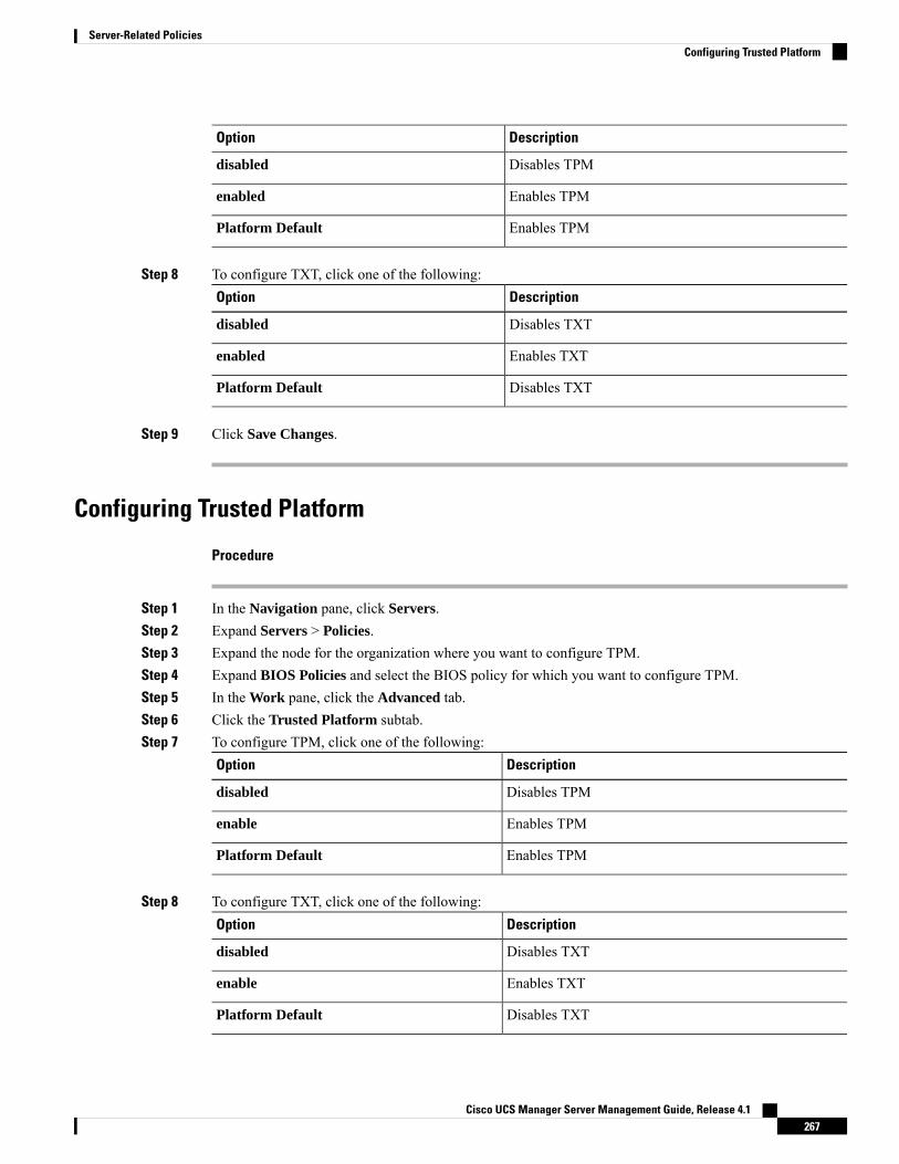
DescriptionOption
Disables TPMdisabled
Enables TPMenabled
Enables TPMPlatform Default
Step 8 To configure TXT, click one of the following:DescriptionOption
Disables TXTdisabled
Enables TXTenabled
Disables TXTPlatform Default
Step 9 Click Save Changes.
Configuring Trusted Platform
Procedure
Step 1 In the Navigation pane, click Servers.Step 2 Expand Servers > Policies.Step 3 Expand the node for the organization where you want to configure TPM.Step 4 Expand BIOS Policies and select the BIOS policy for which you want to configure TPM.Step 5 In the Work pane, click the Advanced tab.Step 6 Click the Trusted Platform subtab.Step 7 To configure TPM, click one of the following:
DescriptionOption
Disables TPMdisabled
Enables TPMenable
Enables TPMPlatform Default
Step 8 To configure TXT, click one of the following:DescriptionOption
Disables TXTdisabled
Enables TXTenable
Disables TXTPlatform Default
Cisco UCS Manager Server Management Guide, Release 4.1267
Server-Related PoliciesConfiguring Trusted Platform
Step 9 Click Save Changes.
Viewing TPM Properties
Procedure
Step 1 In the Navigation pane, click Equipment.Step 2 Expand Equipment > Chassis > Chassis Number > Cartridges > Cartridge Number > Servers
Step 3 Choose the server for which you want to view the TPM settings.Step 4 On the Work pane, click the Inventory tab.Step 5 Click the Motherboard subtab.
Consistent Device NamingWhen there is no mechanism for the Operating System to label Ethernet interfaces in a consistent manner, itbecomes difficult to manage network connections with server configuration changes. Consistent DeviceNaming (CDN), introduced in Cisco UCS Manager Release 2.2(4), allows Ethernet interfaces to be namedin a consistent manner. This makes Ethernet interface namesmore persistent when adapter or other configurationchanges are made.
To configure CDN for a vNIC, do the following:
• Enable consistent device naming in the BIOS policy.
• Associate the BIOS policy with a service profile.
• Configure consistent naming for a vNIC.
Guidelines and Limitations for Consistent Device Naming• CDN is supported on the following Operating Systems:
• Windows 2012 R2
• Windows 2016
• Windows Server 2019
• Red Hat Enterprise Linux (RHEL) 6.x and 7.x
• SLES 12 SP3, SLES 12 SP4, and SLES 15 (for 4.0(4a) and later)
• ESXi 6.7
• Consistent device naming (CDN) is supported on all M3 and higher blade and rack-mount servers.
• BIOS and adapter firmware must be part of the Release 2.2(4) or higher bundle to support CDN.
Cisco UCS Manager Server Management Guide, Release 4.1268
Server-Related PoliciesViewing TPM Properties

• In Cisco UCS Manager Release 3.1 and later releases, CDN is supported on the following adapters:
• Cisco UCS VIC 1455 (UCSC-PCIE-C25Q-04)
• Cisco UCS VIC 1457 (UCSC-MLOM-C25Q-04)
• Cisco UCS VIC 1385 (UCSC-PCIE-C40Q-03)
• Cisco UCS VIC 1387 (UCSC-MLOM-C40Q-03)
• If the RHEL Operating System is installed on the server, CDN will appear when running the command"biosdevname -d" as "sysfs label". CDN will not change the kernel name.
• In Cisco UCS Manager Release 2.2(4), CDN is supported only on the following adapters:
• Cisco UCS VIC 1225 (UCSC-PCIE-CSC-02)
• Cisco UCS MLOM 1227 (UCSC-MLOM-CSC-02)
• Cisco UCS VIC 1225T (UCSC-PCIE-C10T-02)
• Cisco UCS MLOM 1227T (UCSC-MLOM-C10T-02)
• Cisco UCS VIC 1240 (UCSB-MLOM-40G-01)
• Cisco UCS VIC 1280 (UCS-VIC-M82-8P)
• Cisco UCS VIC 1340 (UCSB-MLOM-40G-03)
• Cisco UCS VIC 1380 (UCSB-VIC-M83-8P)
• CDN is supported for vNIC template and dynamic vNIC.
• Multiple vNICs within the same service profile cannot have the same CDN name.
• When a CDN name is not specified for a vNIC, the vNIC name is used as the CDN name.
• The CDN name that you configure for a vNIC appears as Admin CDN Name. The CDN name that isfinally applied to the vNIC appears as Oper CDN Name. For example, if the Admin CDN Name for avNIC called "vnic0" is cdn0, then the Oper CDN Name for this vNIC will be cdn0, but if the AdminCDN Name for the same vNIC is not specified, the Oper CDN Name will be vnic0.
• In Cisco UCS Manager Release 3.1 and later releases, downgrade of the adapter firmware is preventedif a CDN-enabled BIOS policy is assigned to a server.
• In Cisco UCSManager Release 2.2(4), downgrade of Cisco UCSManager is prevented if CDN is enabledin a BIOS policy that is assigned to an associated server.
• In Cisco UCSManager Release 2.2(4), downgrade of the BIOS firmware is prevented if a CDN-enabledBIOS policy is assigned to a server.
• In Cisco UCSManager Release 2.2(4), downgrade of the adapter firmware is prevented if a CDN-enabledBIOS policy is assigned to a server.
• When the applied BIOS policy is changed from CDN-disabled to CDN-enabled or from CDN-enabledto CDN-disabled, the host reboots with a warning, irrespective of whether reboot on BIOS update isenabled or not.
• It is recommended that you enable CDN in the BIOS policy and add CDN names to the vNICS beforethe Windows Operating System is installed.
Cisco UCS Manager Server Management Guide, Release 4.1269
Server-Related PoliciesGuidelines and Limitations for Consistent Device Naming
• If theWindows Operating System is already installed on the server and CDN is then enabled in the BIOSpolicy, do the following:
1. Uninstall the network drivers.
2. Scan the system for hidden devices and uninstall them.
3. Rescan the system for new hardware and install the network drivers again.
If this is not done, the vNICs will not come up with the configured CDN names.
• When the applied BIOS policy is changed from CDN-disabled to CDN-enabled or from CDN-enabledto CDN-disabled on a service profile, do the following:
1. Uninstall the network drivers.
2. Scan the system for hidden devices and delete them.
3. Re-scan the system for new hardware and install the network drivers again.
When the BIOS policy is changed from CDN-enabled toCDN-disabled, ensure that the CDN names are removed from all thevNICs on the system.
Note
• If any change is made to the vNICs, the BDF of all the devices on the system also changes. Followingare some of the scenarios that trigger a change in the BDF of all the vNICs present on the system:
• When a vNIC is added or deleted
• When a vNIC is moved from one adapter on the system to another adapter on the system
When these changes are made to the system, do the following:
1. Uninstall the network driver from all the present network interfaces.
2. Scan the system for hidden devices and uninstall them.
3. Re-scan the system for new hardware and install the network driver on the network controllers again.
If the hidden devices are not deleted, the CDN names of the network adapters will not appear as configuredon Cisco UCS Manager.
CDN with a Mixed Set of Adapters
When a CDN name is configured for a vNIC in a system with a mixed set of CDN-supported adapters andCDN-unsupported adapters, then system placement may not place CDN-configured vNICs on adapters thatsupport CDN.
If CDN is enabled in the BIOS policy, and system placement places a CDN-configured vNIC (Admin CDNconfigured) on an adapter that does not support CDN, an info fault will be raised, but the configuration issuefor the service profile will be ignored.
If CDN is enabled in the BIOS policy, and system placement places a vNIC (Admin CDN not configured)on an adapter that does not support CDN, an info fault will be raised, but the configuration issue for the service
Cisco UCS Manager Server Management Guide, Release 4.1270
Server-Related PoliciesGuidelines and Limitations for Consistent Device Naming

profile will be ignored. The Oper CDN Name in this case will be empty and will not be derived from thevNIC name.
If you want to deploy the CDN name as the host network interface name for a server, you must manuallyplace a vNIC on a supported adapter.
Configuring Consistent Device Naming in a BIOS Policy
Procedure
Step 1 In the Navigation pane, click Servers.Step 2 Expand Servers > Policies.Step 3 Expand root.Step 4 Expand BIOS Policies .Step 5 Select the BIOS policy for which you want to configure CDN.Step 6 Under the Main tab, click one of the following in the Consistent Device Naming field to configure CDN:
DescriptionOption
Disables CDN in the BIOS policydisabled
Enables CDN in the BIOS policyenabled
The BIOS uses the value for this attribute contained in the BIOS defaultsfor the server type and vendor.
Platform Default
Step 7 Click Save Changes.
Configuring a CDN Name for a vNICWhen a CDN name is not specified for a vNIC, the vNIC name is used as the CDN name.
Procedure
Step 1 In the Navigation pane, click Servers.Step 2 Expand Servers > Service Profiles.Step 3 Expand the node for the organization that contains the vNIC for which you want to configure a CDN name.Step 4 Expand the service profile and vNICs node that contain the vNIC for which you want to configure a CDN
name.Step 5 Select the vNIC.Step 6 Click on the General tab.Step 7 In the Properties area, choose User Defined as the CDN Source.Step 8 Enter the CDN name for the vNIC in the CDN Name field.
Cisco UCS Manager Server Management Guide, Release 4.1271
Server-Related PoliciesConfiguring Consistent Device Naming in a BIOS Policy
The CDN name that you configure for a vNIC appears asCDN Name. The CDN name that is finallyapplied to the vNIC appears as Oper CDN Name. For example, if the CDN Name for a vNICcalled "vnic0" is cdn0, then theOper CDN Name for this vNIC will be cdn0, but if theCDN Namefor the same vNIC is not specified, the Oper CDN Name will be vnic0.
Note
Step 9 Click Save Changes.
CIMC Security PoliciesCisco UCS Manager provides the following policies to increase security:
• KVM Management Policy
• IPMI Access Profile
IPMI Access ProfileThis policy allows you to determine whether IPMI commands can be sent directly to the server, using the IPaddress. For example, you can send commands to retrieve sensor data from the CIMC. This policy definesthe IPMI access, including a username and password that can be authenticated locally on the server, andwhether the access is read-only or read-write.
You can also restrict remote connectivity by disabling or enabling IPMI over LAN in the IPMI access profile.IPMI over LAN is disabled by default on all unassociated servers, and on all servers without an IPMI accesspolicy. When an IPMI access policy is created, the IPMI over LAN is set to enabled by default. If you do notchange the value to disabled, IPMI over LAN will be enabled on all associated servers.
You must include this policy in a service profile and that service profile must be associated with a server forit to take effect.
Creating an IPMI Access Profile
Before you begin
An IPMI profile requires that one or more of the following resources already exist in the system:
• Username with appropriate permissions that can be authenticated by the operating system of the server
• Password for the username
• Permissions associated with the username
Procedure
Step 1 In the Navigation pane, click Servers.Step 2 Expand Servers > Policies.Step 3 Expand the node for the organization where you want to create the policy.
Cisco UCS Manager Server Management Guide, Release 4.1272
Server-Related PoliciesCIMC Security Policies
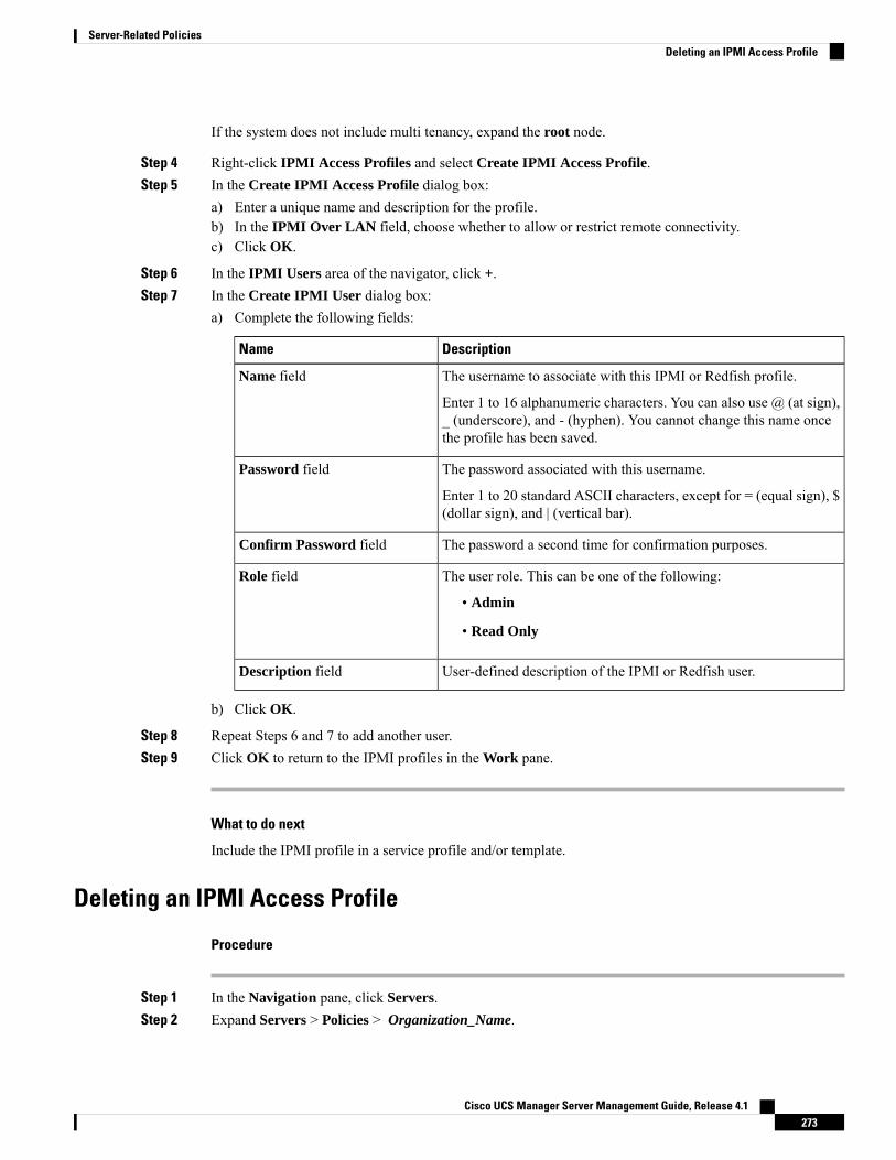
If the system does not include multi tenancy, expand the root node.
Step 4 Right-click IPMI Access Profiles and select Create IPMI Access Profile.Step 5 In the Create IPMI Access Profile dialog box:
a) Enter a unique name and description for the profile.b) In the IPMI Over LAN field, choose whether to allow or restrict remote connectivity.c) Click OK.
Step 6 In the IPMI Users area of the navigator, click +.Step 7 In the Create IPMI User dialog box:
a) Complete the following fields:
DescriptionName
The username to associate with this IPMI or Redfish profile.
Enter 1 to 16 alphanumeric characters. You can also use @ (at sign),_ (underscore), and - (hyphen). You cannot change this name oncethe profile has been saved.
Name field
The password associated with this username.
Enter 1 to 20 standard ASCII characters, except for = (equal sign), $(dollar sign), and | (vertical bar).
Password field
The password a second time for confirmation purposes.Confirm Password field
The user role. This can be one of the following:
• Admin
• Read Only
Role field
User-defined description of the IPMI or Redfish user.Description field
b) Click OK.
Step 8 Repeat Steps 6 and 7 to add another user.Step 9 Click OK to return to the IPMI profiles in the Work pane.
What to do next
Include the IPMI profile in a service profile and/or template.
Deleting an IPMI Access Profile
Procedure
Step 1 In the Navigation pane, click Servers.Step 2 Expand Servers > Policies > Organization_Name.
Cisco UCS Manager Server Management Guide, Release 4.1273
Server-Related PoliciesDeleting an IPMI Access Profile
Step 3 Expand the IPMI Profiles node.Step 4 Right-click the profile you want to delete and select Delete.Step 5 If a confirmation dialog box displays, click Yes.
KVM Management PolicyThe KVMManagement policy allows you to determine whether vMedia encryption is enabled when youaccess a server via KVM.
You must include this policy in a service profile and that service profile must be associated with a server forit to take effect.
After a KVM vMedia session is mapped, if you change the KVM management policy, it will result in a lossof the vMedia session. You must re-map the KVM vMedia session again.
Note
Before Cisco UCSManager Release 4.0(4), port 2068 was the only KVM port. Beginning with Release 4.0(4),you can configure a port number between 1024 and 49151 as the KVM port. Port 2068 continues to be thedefault KVM port number.
Creating a KVM Management Policy
Procedure
Step 1 In the Navigation pane, click Servers.Step 2 Expand Servers > Policies.Step 3 Expand the node for the organization where you want to create the policy.
If the system does not include multi tenancy, expand the root node.
Step 4 Right-click KVM Management Policies and select Create KVM Management Policy.Step 5 In the Create KVM Management Policy dialog box:
a) Enter a unique name and description for the policy.b) In the vMedia Encryption field, choose whether to enable vMedia encryption.
Starting with UCS Manager 4.2, vMedia Encryption is always enabled for security purposes.It cannot be modified by the user.
Note
c) In the KVM Port field, enter a port number between 1024 and 49151 for KVM.
The default KVM port number is 2068.
d) Click OK.
Cisco UCS Manager Server Management Guide, Release 4.1274
Server-Related PoliciesKVM Management Policy
After a KVM vMedia session is mapped, if you change the KVMmanagement policy, it will resultin a loss of the vMedia session. You must re-map the KVM vMedia session again.
Note
Graphics Card PoliciesCisco UCSManager Release 3.1(3) extends graphics card support to include the ability to change the graphicscard mode. You can now configure graphics card modes by using a graphics card policy. The graphics cardmodes are:
• Compute
• Graphics
• Any Configuration
Creating a Graphics Card Policy
Cisco UCS Manager pushes the configuration changes to the GPU through the Graphics Card policy to theProcessor Node Utility Operating System (PNuOS). These changes do not take effect until the server isrebooted.
Note
Procedure
Step 1 In the Navigation pane, click Servers.Step 2 Expand Servers > Policies.Step 3 Expand the node for the organization where you want to create the policy.
If the system does not include multi tenancy, expand the root node.
Step 4 Right-click Graphics Card Policies and select Create Graphics Card Policy.Step 5 On the Main page of the Create Graphics Card Policy dialog box:
a) Enter a unique name for the policy.b) (Optional) Enter a description for the policy.c) In the Graphics Card Mode field, choose one of the options:
• Compute
• Graphics
• Any Configuration
d) Click OK.
Cisco UCS Manager Server Management Guide, Release 4.1275
Server-Related PoliciesGraphics Card Policies
Local Disk Policies
Local Disk Configuration PolicyThis policy configures any optional SAS local drives that have been installed on a server through the onboardRAID controller of the local drive. This policy enables you to set a local disk mode for all servers that areassociated with a service profile that includes the local disk configuration policy.
The local disk modes include the following:
• No Local Storage—For a diskless server or a SAN only configuration. If you select this option, youcannot associate any service profile which uses this policy with a server that has a local disk.
• RAID 0 Striped—Data is striped across all disks in the array, providing fast throughput. There is nodata redundancy, and all data is lost if any disk fails.
• RAID 1 Mirrored—Data is written to two disks, providing complete data redundancy if one disk fails.The maximum array size is equal to the available space on the smaller of the two drives.
• Any Configuration—For a server configuration that carries forward the local disk configuration withoutany changes.
• No RAID—For a server configuration that removes the RAID and leaves the disk MBR and payloadunaltered.
If you choose No RAID and you apply this policy to a server that already has an operating system withRAID storage configured, the system does not remove the disk contents. Therefore, there may be novisible differences on the server after you apply theNo RAIDmode. This can lead to a mismatch betweenthe RAID configuration in the policy and the actual disk configuration shown in the Inventory > Storagetab for the server.
To make sure that any previous RAID configuration information is removed from a disk, apply a scrubpolicy that removes all disk information after you apply the No RAID configuration mode.
• RAID 5 Striped Parity—Data is striped across all disks in the array. Part of the capacity of each diskstores parity information that can be used to reconstruct data if a disk fails. RAID 5 provides good datathroughput for applications with high read request rates.
• RAID 6 Striped Dual Parity—Data is striped across all disks in the array and two parity disks are usedto provide protection against the failure of up to two physical disks. In each row of data blocks, two setsof parity data are stored.
• RAID 10 Mirrored and Striped—RAID 10 uses mirrored pairs of disks to provide complete dataredundancy and high throughput rates.
• RAID 50 Striped Parity and Striped—Data is striped across multiple striped parity disk sets to providehigh throughput and multiple disk failure tolerance.
• RAID 60 Striped Dual Parity and Striped —Data is striped across multiple striped dual parity disksets to provide high throughput and greater disk failure tolerance.
You must include this policy in a service profile and that service profile must be associated with a server forthe policy to take effect.
Cisco UCS Manager Server Management Guide, Release 4.1276
Server-Related PoliciesLocal Disk Policies

For a Cisco UCS C-Series server integrated with Cisco UCS Manager, with an embedded on-board RAIDcontroller, the local disk mode should always be Any Configuration, and the RAID must be configureddirectly on the controller.
Note
Guidelines for all Local Disk Configuration PoliciesBefore you create a local disk configuration policy, consider the following guidelines:
No Mixed HDDs and SSDs
Do not include HDDs and SSDs in a single server or RAID configuration.
JBOD Mode Support
The B200 M3 server supports JBOD mode for local disks.
Only B200 M3 and B22 M3 blade servers support the JBOD mode for local disks.Note
Guidelines for Local Disk Configuration Policies Configured for RAID
Configure RAID Settings in Local Disk Configuration Policy for Servers with MegaRAID Storage Controllers
If a blade server or integrated rack-mount server has a MegaRAID controller, you must configure RAIDsettings for the drives in the Local Disk Configuration policy included in the service profile for that server.You can do this either by configuring the local disk configuration policy in the service profile using one ofthe defined RAID modes for that server, or you can use the Any Configuration mode with the LSI Utilitiestoolset to create the RAID volumes.
If you do not configure your RAID LUNs before installing the OS, disk discovery failures might occur duringthe installation and you might see error messages such as “No Device Found.”
Server May Not Boot After RAID1 Cluster Migration if Any Configuration Mode Specified in Service Profile
After RAID1 clusters are migrated, you need to associate a service profile with the server. If the local diskconfiguration policy in the service profile is configured with Any Configuration mode rather than RAID1,the RAID LUN remains in "inactive" state during and after association. As a result, the server cannot boot.
To avoid this issue, ensure that the service profile you associate with the server contains the identical localdisk configuration policy as the original service profile before the migration and does not include the AnyConfiguration mode.
Do Not Use JBOD Mode on Servers with MegaRAID Storage Controllers
Do not configure or use JBODmode or JBOD operations on any blade server or integrated rack-mount serverwith a MegaRAID storage controllers. JBOD mode and operations are not intended for nor are they fullyfunctional on these servers.
Cisco UCS Manager Server Management Guide, Release 4.1277
Server-Related PoliciesGuidelines for all Local Disk Configuration Policies
Maximum of One RAID Volume and One RAID Controller in Integrated Rack-Mount Servers
A rack-mount server that has been integrated with Cisco UCS Manager can have a maximum of one RAIDvolume irrespective of how many hard drives are present on the server.
All the local hard drives in an integrated rack-mount server must be connected to only one RAID Controller.Integration with Cisco UCS Manager does not support the connection of local hard drives to multiple RAIDControllers in a single rack-mount server. We therefore recommend that you request a single RAID Controllerconfiguration when you order rack-mount servers to be integrated with Cisco UCS Manager.
In addition, do not use third party tools to create multiple RAID LUNs on rack-mount servers. Cisco UCSManager does not support that configuration.
Maximum of One RAID Volume and One RAID Controller in Blade Servers
A blade server can have a maximum of one RAID volume irrespective of how many drives are present in theserver. All the local hard drives must be connected to only one RAID controller. For example, a B200 M3server has an LSI controller and an Intel Patsburg controller, but only the LSI controller can be used as aRAID controller.
In addition, do not use third party tools to create multiple RAID LUNs on blade servers. Cisco UCSManagerdoes not support that configuration.
License Required for Certain RAID Configuration Options on Some Servers
Some Cisco UCS servers require a license for certain RAID configuration options.When Cisco UCSManagerassociates a service profile containing this local disk policy with a server, Cisco UCS Manager verifies thatthe selected RAID option is properly licensed. If there are issues, Cisco UCSManager displays a configurationerror during the service profile association.
For RAID license information for a specific Cisco UCS server, see the Hardware Installation Guide for thatserver.
B420 M3 Server Does Not Support All Configuration Modes
The B420 M3 server does not support the following configuration modes in a local disk configuration policy:
• No RAID
• RAID 6 Striped Dual Parity
In addition, the B420 M3 does not support JBOD modes or operations.
Creating a Local Disk Configuration Policy
Procedure
Step 1 In the Navigation pane, click Servers.Step 2 Expand Servers > Policies.Step 3 Expand the node for the organization where you want to create the policy.
If the system does not include multi tenancy, expand the root node.
Cisco UCS Manager Server Management Guide, Release 4.1278
Server-Related PoliciesCreating a Local Disk Configuration Policy
Step 4 Right-click Local Disk Config Policies and choose Create Local Disk Configuration Policy.Step 5 In the Create Local Disk Configuration Policy dialog box, complete the following fields:
DescriptionName
The name of the policy.
This name can be between 1 and 16 alphanumeric characters. You cannotuse spaces or any special characters other than - (hyphen), _ (underscore),: (colon), and . (period), and you cannot change this name after the objectis saved.
Name field
A description of the policy. Cisco recommends including informationabout where and when to use the policy.
Enter up to 256 characters. You can use any characters or spaces except` (accent mark), \ (backslash), ^ (carat), " (double quote), = (equal sign),> (greater than), < (less than), or ' (single quote).
Description field
Cisco UCS Manager Server Management Guide, Release 4.1279
Server-Related PoliciesCreating a Local Disk Configuration Policy

DescriptionName
This can be one of the following local disk policy modes:
• No Local Storage
• RAID 0 Striped
• RAID 1 Mirrored
• Any Configuration
• No RAID
If you choose No RAID and you apply this policy to a server thatalready has an operating system with RAID storage configured,the system does not remove the disk contents. Therefore, there maybe no visible differences on the server after you apply theNo RAIDmode. This can lead to amismatch between the RAID configurationin the policy and the actual disk configuration shown in theInventory > Storage tab for the server.
To make sure that any previous RAID configuration informationis removed from a disk, apply a scrub policy that removes all diskinformation after you apply the No RAID configuration mode.
• RAID 5 Striped Parity
• RAID 6 Striped Dual Parity
• RAID 10 Mirrored and Striped
• RAID 50 Striped Parity and Striped
• RAID 60 Striped Dual Parity and Striped
Some Cisco UCS servers require a license for certain RAIDconfiguration options. When Cisco UCSManager associatesa service profile containing this local disk policy with aserver, Cisco UCS Manager verifies that the selected RAIDoption is properly licensed. If there are issues, Cisco UCSManager displays a configuration error during the serviceprofile association.
For RAID license information for a specific Cisco UCSserver, see the Hardware Installation Guide for that server.
Note
Mode drop-down list
Cisco UCS Manager Server Management Guide, Release 4.1280
Server-Related PoliciesCreating a Local Disk Configuration Policy
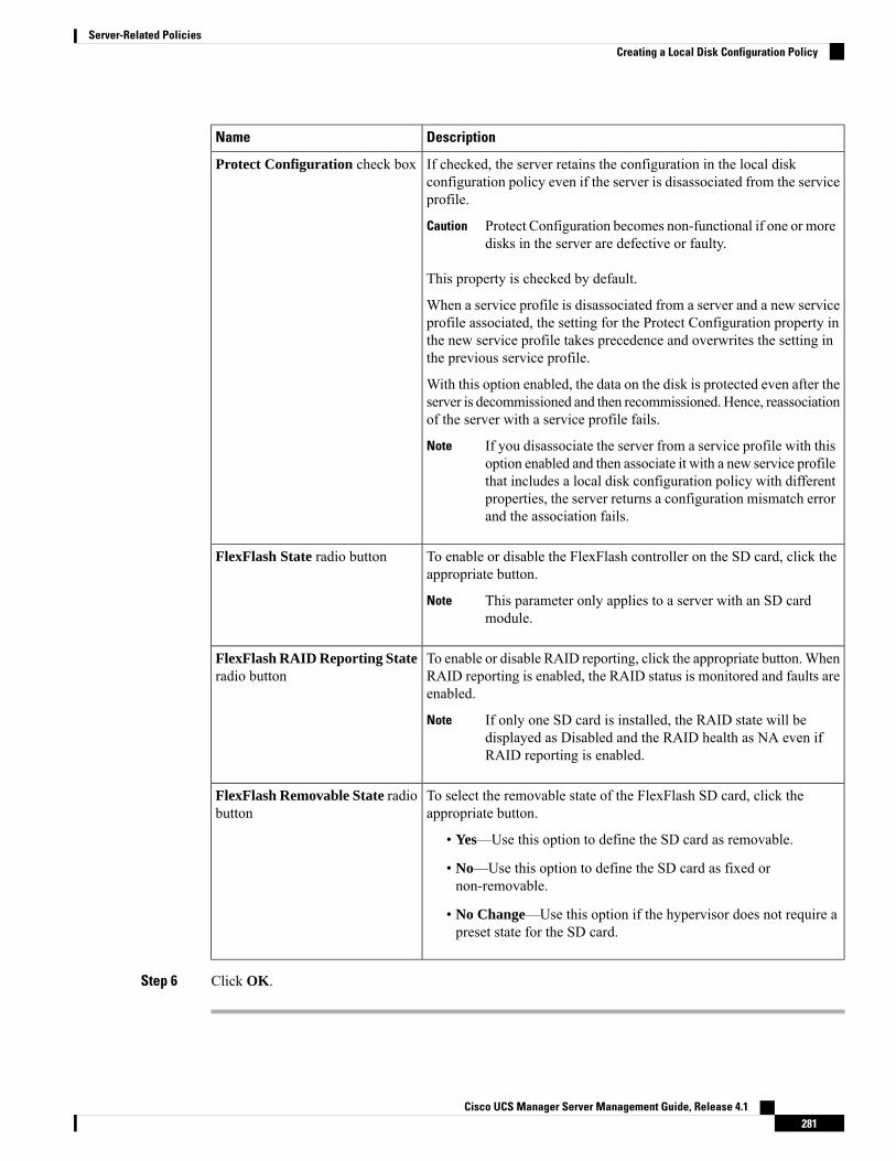
DescriptionName
If checked, the server retains the configuration in the local diskconfiguration policy even if the server is disassociated from the serviceprofile.
Protect Configuration becomes non-functional if one or moredisks in the server are defective or faulty.
Caution
This property is checked by default.
When a service profile is disassociated from a server and a new serviceprofile associated, the setting for the Protect Configuration property inthe new service profile takes precedence and overwrites the setting inthe previous service profile.
With this option enabled, the data on the disk is protected even after theserver is decommissioned and then recommissioned. Hence, reassociationof the server with a service profile fails.
If you disassociate the server from a service profile with thisoption enabled and then associate it with a new service profilethat includes a local disk configuration policy with differentproperties, the server returns a configuration mismatch errorand the association fails.
Note
Protect Configuration check box
To enable or disable the FlexFlash controller on the SD card, click theappropriate button.
This parameter only applies to a server with an SD cardmodule.
Note
FlexFlash State radio button
To enable or disable RAID reporting, click the appropriate button.WhenRAID reporting is enabled, the RAID status is monitored and faults areenabled.
If only one SD card is installed, the RAID state will bedisplayed as Disabled and the RAID health as NA even ifRAID reporting is enabled.
Note
FlexFlash RAID Reporting Stateradio button
To select the removable state of the FlexFlash SD card, click theappropriate button.
• Yes—Use this option to define the SD card as removable.
• No—Use this option to define the SD card as fixed ornon-removable.
• No Change—Use this option if the hypervisor does not require apreset state for the SD card.
FlexFlash Removable State radiobutton
Step 6 Click OK.
Cisco UCS Manager Server Management Guide, Release 4.1281
Server-Related PoliciesCreating a Local Disk Configuration Policy
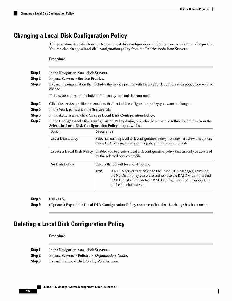
Changing a Local Disk Configuration PolicyThis procedure describes how to change a local disk configuration policy from an associated service profile.You can also change a local disk configuration policy from the Policies node from Servers.
Procedure
Step 1 In the Navigation pane, click Servers.Step 2 Expand Servers > Service Profiles.Step 3 Expand the organization that includes the service profile with the local disk configuration policy you want to
change.
If the system does not include multi tenancy, expand the root node.
Step 4 Click the service profile that contains the local disk configuration policy you want to change.Step 5 In the Work pane, click the Storage tab.Step 6 In the Actions area, click Change Local Disk Configuration Policy.Step 7 In the Change Local Disk Configuration Policy dialog box, choose one of the following options from the
Select the Local Disk Configuration Policy drop-down list.DescriptionOption
Select an existing local disk configuration policy from the list below this option.Cisco UCS Manager assigns this policy to the service profile.
Use a Disk Policy
Enables you to create a local disk configuration policy that can only be accessedby the selected service profile.
Create a Local Disk Policy
Selects the default local disk policy.No Disk Policy
If a UCS server is attached to the Cisco UCS Manager, selectingthe No Disk Policy can erase and replace the RAID with individualRAID 0 disks if the default RAID configuration is not supportedon the attached server.
Note
Step 8 Click OK.Step 9 (Optional) Expand the Local Disk Configuration Policy area to confirm that the change has been made.
Deleting a Local Disk Configuration Policy
Procedure
Step 1 In the Navigation pane, click Servers.Step 2 Expand Servers > Policies > Organization_Name.Step 3 Expand the Local Disk Config Policies node.
Cisco UCS Manager Server Management Guide, Release 4.1282
Server-Related PoliciesChanging a Local Disk Configuration Policy
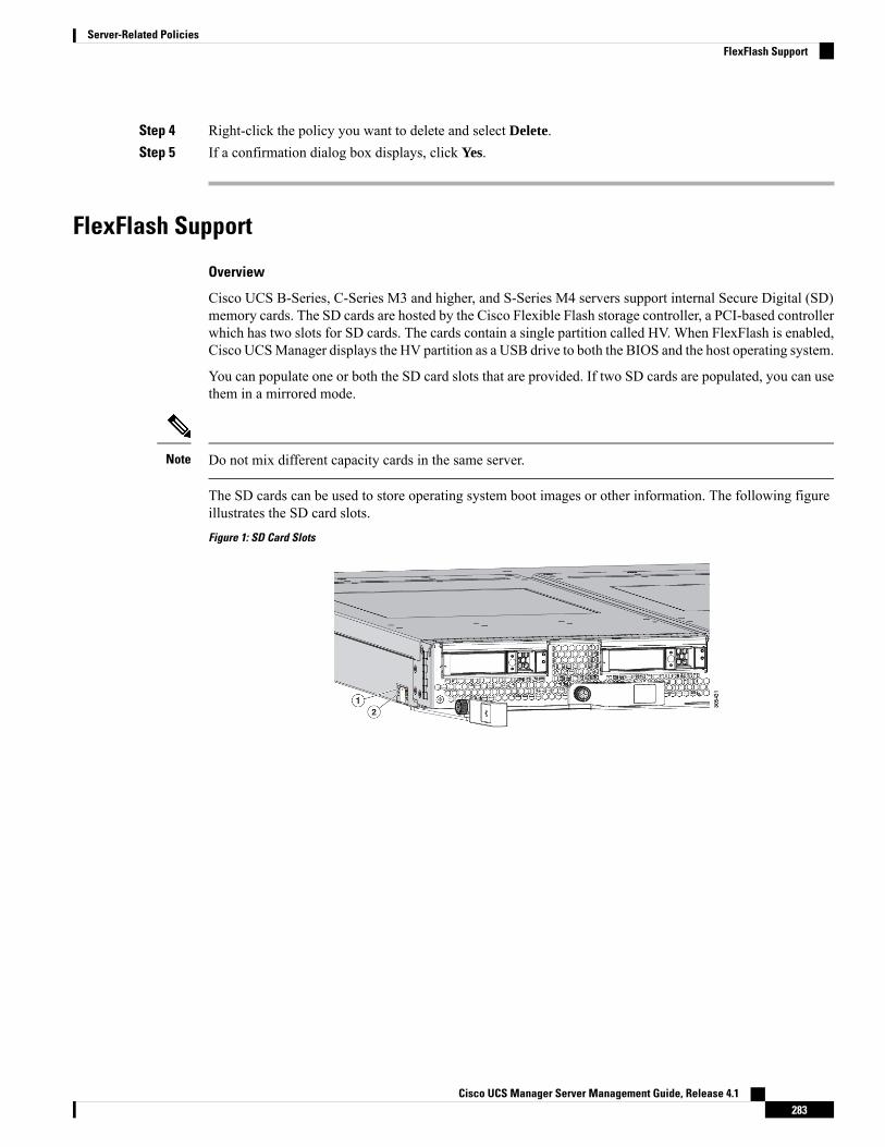
Step 4 Right-click the policy you want to delete and select Delete.Step 5 If a confirmation dialog box displays, click Yes.
FlexFlash Support
Overview
Cisco UCS B-Series, C-Series M3 and higher, and S-Series M4 servers support internal Secure Digital (SD)memory cards. The SD cards are hosted by the Cisco Flexible Flash storage controller, a PCI-based controllerwhich has two slots for SD cards. The cards contain a single partition called HV. When FlexFlash is enabled,Cisco UCSManager displays the HV partition as a USB drive to both the BIOS and the host operating system.
You can populate one or both the SD card slots that are provided. If two SD cards are populated, you can usethem in a mirrored mode.
Do not mix different capacity cards in the same server.Note
The SD cards can be used to store operating system boot images or other information. The following figureillustrates the SD card slots.
Figure 1: SD Card Slots
Cisco UCS Manager Server Management Guide, Release 4.1283
Server-Related PoliciesFlexFlash Support

FlexFlash is disabled by default. You can enable FlexFlash in a local disk policy used in a service profile.When FlexFlash is enabled in a local disk policy, and the server is capable of supporting SD cards, the FlexFlashcontroller is enabled during service profile association. If a server is not capable of supporting SD cards orhas an older CIMC version, a config failure message is displayed.
If you disable FlexFlash in a supported server, the Hypervisor or HV partition is immediately disconnectedfrom the host. The FlexFlash controller will also be disabled as part of a related service profile disassociation.
The FlexFlash controller supports RAID-1 for dual SD cards. The FlexFlash scrub policy erases the HVpartition in both cards, and brings the cards to a healthy RAID state.
You can configure new SD cards in a RAID pair and format them using one of the following methods:
• Format the SD cards. Formatting the SD Cards, on page 288 provides detailed information.
• Disassociate the service profile from the server. Re-acknowledge the server after modifying the defaultscrub policy and then associate the server profile back to the server.
The Scrub Policy Settings section in the Cisco UCS Manager Server Management Guide provides moredetails about the usage of the scrub policy.
Disable the scrub policy as soon as the pairing is complete.Note
To boot from the HV partition, the SD card must be present in the boot policy used in the service profile.
FlexFlash Firmware Management
The FlexFlash controller firmware is bundled as part of the CIMC image. When you upgrade the CIMC, if anewer firmware version is available for the FlexFlash controller, the controller can no longer be managed,and the FlexFlash inventory displays the Controller State as Waiting For User Action and the ControllerHealth as Old Firmware Running. To upgrade the FlexFlash controller firmware, you need to perform aboard controller update. For more information, see the appropriateCisco UCS B-Series Firmware ManagementGuide, available at the following URL:http://www.cisco.com/en/US/products/ps10281/products_installation_and_configuration_guides_list.html.
Cisco UCS Manager Server Management Guide, Release 4.1284
Server-Related PoliciesFlexFlash Support
Limitations for the Cisco Flexible Flash Storage Controller:
• The Cisco Flexible Flash storage controller only supports 16 GB, 32 GB, and 64 GB SD cards.
The 16 GB and 32 GB cards are supported only on the M3 bladeservers, and the 64 GB SD cards are supported only on the M4 andM5 blade servers.
Note
• We do not recommend using an SD card from a rack server in a blade server, or using an SD card froma blade server in a rack server. Switching SD cards between server types might result in data loss fromthe SD card.
• Some Cisco UCS C-Series rack-mount servers have SD cards with four partitions: HV, HUU, SCU, andDrivers. Only the HV partition is visible in Cisco UCS Manager. You can migrate a four-partition SDcard to a single HV partition card with a FlexFlash scrub policy but there may be data loss.
• The FlexFlash controller does not support RAID-1 sync (mirror rebuild). If the SD cards are in a degradedRAID state, or if any metadata errors are reported by the controller, you must run the FlexFlash scrubpolicy to pair the cards for RAID. For more information about the FlexFlash scrub policy, seeServer-Related Policies. The following conditions might result in degraded RAID or metadata errors:
• Inserting a new or used SD card in one slot, when the server already has an SD card populated inthe second slot.
• Inserting two SD cards from different servers.
• The server firmware version must be at 2.2(1a) or higher.
FlexFlash FX3S SupportBeginning with Release 2.2(3), Cisco UCS Manager allows additional FlexFlash support with the FX3Scontroller. The FX3S controller is present on the following servers:
• Cisco UCS B200 M4 and M5 blade server
• Cisco UCS C220 M4 and M5 rack server
• Cisco UCS C240 M4 and M5 rack server
• C480 M5 rack server
• C480 M5 ML blade server
• B480 M5 blade server
• Cisco UCS C125 M5 Server
FlexFlash operations with the FX3S control are similar to those with the Cisco Flexible Flash storage controller.FlexFlash is disabled by default, and is enabled using a local disk policy. You can also reset the controller,format the SD cards, and enable automatic synchronization of your paired SD cards.
The SD cards for the FX3S controller contain a single partition called Hypervisor.
Cisco UCS Manager Server Management Guide, Release 4.1285
Server-Related PoliciesFlexFlash FX3S Support
Limitations for the Cisco FX3S Controller:
• The FX3S controller supports only 32 GB and 64 GB SD cards. 16 GB cards are not supported.
• The FX3S controller supports 128 GB cards on M5 blades and above.
• We do not recommend using an SD card from a rack server in a blade server, or using an SD card froma blade server in a rack server. Switching SD cards between server types might result in data loss fromthe SD card.
• The server firmware version must be at 2.2(3a) or higher.
Starting Up Blade Servers with FlexFlash SD CardsUse this procedure to start up blade servers using FlexFlash cards 16 GB and larger. This procedure requiresthat you know how to setup the blade server, software, and the associated infrastructure, and ensure that theyare working. This Cisco UCS Manager controlled procedure is applicable to all blade servers, running anyversion of firmware. This procedure does not apply to rack servers. Follow this procedure before you enableFlexFlash cards in a working environment.
If you use the following procedure with FlexFlash cards already in use, you will lose all data from the cards.Caution
This procedure does not cover FlexFlash card usage or other functions of the FlexFlash system.Note
Procedure
Step 1 Expand Equipment > Chassis > Chassis Number > Servers.Step 2 In the Work pane, check the details of the FlexFlash cards in the FlexFlash Controller window.Step 3 Expand Servers > Service Profiles.Step 4 Expand the node for the organization containing the pool.
If the system does not include multi tenancy, expand the root node.
Step 5 Expand the node for the organization containing the service profile and click Storage.Step 6 In the Work pane, click Change Local Disk Configuration Policy in the Actions area and expand Create
Local Disk Configuration Policy link. Follow the procedure in Creating a Local Disk Configuration Policy,on page 278 to create a Local Disk Configuration Policy.
The FlexFlash policy name must not contain empty spaces or special characters.
Step 7 Expand Change Disk Local Configuration Policy, and select the policy you just created and click OK.
Step 8 Expand Servers > Policies.Step 9 Follow the procedure in Creating a Scrub Policy, on page 291 and create a policy with a name such as
Scrub-FF-name and click OK.
The Scrub policy name must not contain empty spaces or special characters.
Cisco UCS Manager Server Management Guide, Release 4.1286
Server-Related PoliciesStarting Up Blade Servers with FlexFlash SD Cards
Step 10 Select the policy you created from the drop-down box.Step 11 Expand Equipment > Chassis > Chassis Number > Servers.Step 12 In the Work pane, click the General tab and select Server Maintenance from the Actions area.Step 13 In the Maintenance Server dialogue box, click on the Re-acknowledge radio button, and then click OK.Step 14 Click Server Maintenance in the Action area and click on the Re-acknowledge radio button again.Step 15 From the Inventory tab, select the Storage sub-tab.
You can verify details of the enabled FlexFlash cards from the FlexFlash Controller window in the Workarea.
Step 16 Launch KVMManager and log on to the operating system. Verify details of the Hypervisor partition fromthe Devices and drives folder. Depending on the card size, the HV partition displays details of 32GB, 64GB,or 128 GB.The FlexFlash cards are now synced and ready to use.
Enabling FlexFlash SD Card Support
Procedure
Step 1 In the Navigation pane, click Servers.Step 2 Expand Servers > Policies.Step 3 Expand the node for the organization where you want to create the policy.
If the system does not include multi tenancy, expand the root node.
Step 4 Expand Local Disk Config Policies and choose the local disk config policy for which you want to enableFlexFlash support.
Step 5 In the Work pane, click the General tab.Step 6 In the FlexFlash State field, click the Enable radio button.Step 7 In the FlexFlash RAID Reporting State field, click the Enable radio button.Step 8 Click Save Changes.
Enabling Auto-Sync
Procedure
Step 1 In the Navigation pane, click Equipment.Step 2 Expand Equipment > Chassis > Chassis Number > Servers.Step 3 Click the server for which you want to enable auto-sync.Step 4 In the Work pane, click the Inventory tab.Step 5 Click the Storage subtab.Step 6 In the Actions area, click Enable Auto-sync.
Cisco UCS Manager Server Management Guide, Release 4.1287
Server-Related PoliciesEnabling FlexFlash SD Card Support
Step 7 In the Enable Auto-sync dialog box, choose the Admin Slot Number for the SD card that you want to useas the primary.
Step 8 Click OK.
Formatting the SD Cards
Procedure
Step 1 In the Navigation pane, click Equipment.Step 2 Expand Equipment > Chassis > Chassis Number > Servers.Step 3 Click the server for which you want to format the SD cards.Step 4 In the Work pane, click the Inventory tab.Step 5 Click the Storage subtab.Step 6 In the Actions area, click Format SD Cards.Step 7 Click Yes to format the SD cards.
Resetting the FlexFlash Controller
Procedure
Step 1 In the Navigation pane, click Equipment.Step 2 Expand Equipment > Chassis > Chassis Number > Servers.Step 3 Click the server for which you want to reset the FlexFlash controller.Step 4 In the Work pane, click the Inventory tab.Step 5 Click the Storage subtab.Step 6 In the Actions area, click Reset FlexFlash Controller.Step 7 Click Yes to reset the FlexFlash controller.
Persistent Memory ModulesCisco UCSManager Release 4.0(4) introduces support for the Intel®Optane™Data Center persistent memorymodules on the UCS M5 servers that are based on the Second Generation Intel® Xeon® Scalable processors.. These persistent memory modules can be used only with the Second Generation Intel® Xeon® Scalableprocessors.
Persistent memory modules are non-volatile memory modules that bring together the low latency of memoryand the persistence of storage. Data stored in persistent memory modules can be accessed quickly comparedto other storage devices, and is retained across power cycles.
Cisco UCS Manager Server Management Guide, Release 4.1288
Server-Related PoliciesFormatting the SD Cards

For detailed information about configuring persistent memory modules, see the Cisco UCS: Configuring andManaging Intel® Optane™ Data Center Persistent Memory Modules Guide.
Scrub Policy
Scrub Policy SettingsThis policy determines what happens to local data and to the BIOS settings on a server during the discoveryprocess, when the server is re-acknowledged, or when the server is disassociated from a service profile.
Local disk scrub policies only apply to hard drives that are managed by Cisco UCSManager and do not applyto other devices such as USB drives.
Note
Depending upon how you configure a scrub policy, the following can occur at those times:
Disk scrub
One of the following occurs to the data on any local drives on disassociation:
• If enabled, deletes initial 200MB of data from master boot record or the boot sectors. Thus, preventingthe system to boot from an already installed OS if any. For secure deletion of data on drives, refer UCSSecure Data Deletion For Commission Regulation (EU) 2019 /424 Users Guide.
Though the disk scrub policy is not intended to delete the user datathat exceeds 200MB, Cisco UCS Manager cannot guarantee againstdata loss.
Note
• If disabled (default), preserves all data on any local drives, including local storage configuration.
For a server associated with a service profile, disk scrub occurs during disassociation, based on the scrubpolicy used in the service profile. For an un-associated server, disk scrub occurs during the server discoveryprocess, based on the default scrub policy.
Scrub policies are supported on all B-Series platforms and only on the following C-Series platforms:
• Cisco UCS C220 M4 Server
• Cisco UCS C240 M4 Server
• Cisco UCS C460 M4 Storage Server
• Cisco UCS C220 M5 Server
• Cisco UCS C240 M5 Server
• Cisco UCS C480 M5 Server
• Cisco UCS C480 M5 ML Server
Cisco UCS Manager Server Management Guide, Release 4.1289
Server-Related PoliciesScrub Policy
• Cisco UCS S3260 M4 Storage Server—You can scrub only the boot drives and VDs created using thesame drives.
• Cisco UCS S3260 M5 Storage Server—You can scrub only the boot drives and VDs created using thesame drives.
You must re-acknowledge the server to see the changes related to LUN deletion if:
• you are scrubbing boot drives which have LUNs under the SAS controller in a set up with Cisco UCSS3260 M4 or Cisco UCS S3260 M5 Storage Server.
• you are scrubbing the LUNs on Cisco boot optimized M.2 RAID controller.
Note
BIOS Settings Scrub
One of the following occurs to the BIOS settings when a service profile containing the scrub policy isdisassociated from a server:
• If enabled, erases all BIOS settings for the server and resets them to the BIOS defaults for that servertype and vendor.
• If disabled (default), preserves the existing BIOS settings on the server.
FlexFlash Scrub
FlexFlash Scrub enables you to pair new or degraded SD cards, resolve FlexFlash metadata configurationfailures, and migrate older SD cards with 4 partitions to single partition SD cards. One of the following occursto the SD card when a service profile containing the scrub policy is disassociated from a server, or when theserver is reacknowledged:
• If enabled, the HV partition on the SD card is formatted using the PNUOS formatting utility. If two SDcards are present, the cards are RAID-1 paired, and the HV partitions in both cards are marked as valid.The card in slot 1 is marked as primary, and the card in slot 2 is marked as secondary.
• If disabled (default), preserves the existing SD card settings.
• For a server associated with a service profile, FlexFlash scrub occurs during disassociation, based on thescrub policy used in the service profile. For an un-associated server, FlexFlash scrub occurs during theserver discovery process, based on the default scrub policy.
• Because the FlexFlash scrub erases the HV partition on the SD cards, we recommend that you take a fullbackup of the SD card(s) using your preferred host operating system utilities before performing theFlexFlash scrub.
• To resolve metadata config failures in a service profile, you need to disable FlexFlash in the local diskconfig policy before you run the FlexFlash scrub, then enable FlexFlash after the server is reacknowledged.
• Disable the scrub policy as soon as the pairing is complete or the metadata failures are resolved.
• FlexFlash scrub is not supported for Cisco UCS S3260 Storage Server.
Note
Cisco UCS Manager Server Management Guide, Release 4.1290
Server-Related PoliciesScrub Policy Settings

Persistent Memory Scrub
Persistent memory scrub enables you to preserve or remove the persistent memory configuration and data ona server.
• If enabled:
• erases all the persistent memory data
• resets the configuration to factory default
• disables DIMM security
• If disabled (default), preserves the existing persistent memory configuration and data on the server. Itdoes not change the DIMM lock state.
Creating a Scrub Policy
Procedure
Step 1 In the Navigation pane, click Servers.Step 2 Expand Servers > Policies.Step 3 Expand the node for the organization where you want to create the policy.
If the system does not include multi tenancy, expand the root node.
Step 4 Right-click Scrub Policies and select Create Scrub Policy.
Cisco UCS Manager does not support NVME local disk scrub.Note
Step 5 In the Create Scrub Policy wizard, complete the following fields:
DescriptionName
The name of the policy.
This name can be between 1 and 16 alphanumeric characters. You cannotuse spaces or any special characters other than - (hyphen), _ (underscore),: (colon), and . (period), and you cannot change this name after the objectis saved.
Name field
A description of the policy. Cisco recommends including informationabout where and when to use the policy.
Enter up to 256 characters. You can use any characters or spaces except` (accent mark), \ (backslash), ^ (carat), " (double quote), = (equal sign),> (greater than), < (less than), or ' (single quote).
Description field
Cisco UCS Manager Server Management Guide, Release 4.1291
Server-Related PoliciesCreating a Scrub Policy

DescriptionName
If this field is set to Yes, when a service profile containing this scrubpolicy is disassociated from a server, the initial 200MB of data is deletedfrommaster boot record or the boot sectors. Thus, preventing the systemto boot from an already installed OS if any. For secure deletion of dataon drives, refer UCS Secure Data Deletion For Commission Regulation(EU) 2019 /424 Users Guide. If this field is set to No, the data on thelocal drives is preserved, including all local storage configuration.
Though the disk scrub policy is not intended to delete theuser data that exceeds 200MB, Cisco UCS Manager cannotguarantee against data loss.
Note
Disk Scrub field
If the field is set to Yes, when a service profile containing this scrubpolicy is disassociated from a server, the BIOS settings for that serverare erased and reset to the defaults for that server type and vendor. Ifthis field is set to No, the BIOS settings are preserved.
BIOS Settings Scrub field
If the field is set to Yes, the HV partition on the SD card is formattedusing the PNUOS formatting utility when the server is reacknowledged.If this field is set to No, the SD card is preserved.
FlexFlash Scrub field
If the field is set to Yes, when a service profile containing this scrubpolicy is disassociated from a server, all persistent memory modules forthat server are erased and reset to the defaults for that server type andvendor. If this field is set to No, the persistent memory modules arepreserved.
Persistent Memory Scrub field
Step 6 Click OK.
Disk Scrub option will scrub only boot-lun/boot-disk for Cisco UCS S3260 Storage Server and itwill not scrub data-lun’s/data-disks. The FlexFlash Scrub option is not supported for Cisco UCSS3260 Storage Server.
Note
Deleting a Scrub Policy
Procedure
Step 1 In the Navigation pane, click Servers.Step 2 Expand Servers > Policies > Organization_Name.Step 3 Expand the Scrub Policies node.Step 4 Right-click the policy you want to delete and select Delete.Step 5 If a confirmation dialog box displays, click Yes.
Cisco UCS Manager Server Management Guide, Release 4.1292
Server-Related PoliciesDeleting a Scrub Policy
DIMM Error Management
DIMM Correctable Error HandlingIn Cisco UCSManager, when a DIMMencounters a significant correctable error in a given predefined window,it is stated as degraded and considered as a non-functional device.
The DIMMcorrectable error handling feature enables you to reset all the correctable and uncorrectable memoryerrors on all the DIMMs in a server. When you reset the error configuration, the error count of a given DIMMis cleared, the status changes to operable, and it resets the sensor state of the given DIMM.
Resetting Memory ErrorsUse this procedure to reset all correctable and uncorrectable memory errors encountered by Cisco UCSManager and the baseboard management controller (BMC).
Procedure
Step 1 In the Navigation pane, click Equipment.Step 2 Expand Equipment > Chassis > Chassis Number > Servers.Step 3 Right-click on the server for which you want to reset the error configuration, and select Reset All Memory
Errors. You can also select Reset All Memory Errors from the Actions area.Step 4 If the Cisco UCS Manager GUI displays a confirmation dialog box, click Yes.
DIMM BlacklistingIn Cisco UCSManager, the state of the Dual In-lineMemoryModule (DIMM) is based on SEL event records.When the BIOS encounters a noncorrectable memory error during memory test execution, the DIMM ismarked as faulty. A faulty DIMM is a considered a nonfunctional device.
If you enable DIMM blacklisting, Cisco UCS Manager monitors the memory test execution messages andblacklists any DIMMs that encounter memory errors in the DIMM SPD data. To allow the host to map outany DIMMs that encounter uncorrectable ECC errors.
Enabling DIMM BlacklistingThe memory policy is a global policy that you can apply to existing servers on a Cisco UCS domain and alsoto the servers that are added after you set the memory policy.
Cisco UCS Manager Server Management Guide, Release 4.1293
Server-Related PoliciesDIMM Error Management

• This feature is supported both on the Cisco UCS B-Series blade servers and UCS C-Series rack servers.
Cisco UCS C-Series 420M3 rack servers do not support this feature.Note
• This global policy cannot be added to a service profile.
Note
Before you begin
• For Cisco B-Series blade server, the server firmware must be at Release 2.2(1) or a later release.
• For Cisco C-Series and S-Series rack server, the server firmware must be at Release 2.2(3).
• You must be logged in with one of the following privileges:
• Admin
• Server policy
• Server profile server policy
Procedure
Step 1 In the Navigation pane, click Servers.Step 2 Expand Servers > Policies.Step 3 Expand the node for the organization where you want to enable the blacklisting.
If the system does not include multitenancy, expand the root node.
Step 4 Expand Memory Policy and choose default.Step 5 In the Blacklisting area, click the Enabled radio button.
The DIMM blacklisting is enabled for the domain level policy and these changes apply to all the servers onthat particular domain.
If the Cisco IMC of a server does not support DIMM blacklisting, an information level fault is generated.Note
Cisco UCS Manager Server Management Guide, Release 4.1294
Server-Related PoliciesEnabling DIMM Blacklisting
Serial over LAN Policy Settings
Serial over LAN Policy OverviewThis policy sets the configuration for the serial over LAN connection for all servers associated with serviceprofiles that use the policy. By default, the serial over LAN connection is disabled.
If you implement a serial over LAN policy, we recommend that you also create an IPMI profile.
You must include this policy in a service profile and that service profile must be associated with a server forit to take effect.
Creating a Serial over LAN Policy
Procedure
Step 1 In the Navigation pane, click Servers.Step 2 Expand Servers > Policies.Step 3 Expand the node for the organization where you want to create the policy.
If the system does not include multi tenancy, expand the root node.
Step 4 Right-click Serial over LAN Policies and select Create Serial over LAN Policy.Step 5 In the Create Serial over LAN Policy wizard, complete the following fields:
DescriptionName
The name of the policy.
This name can be between 1 and 16 alphanumericcharacters. You cannot use spaces or any specialcharacters other than - (hyphen), _ (underscore), :(colon), and . (period), and you cannot change thisname after the object is saved.
Name field
A description of the policy. Cisco recommendsincluding information about where and when to usethe policy.
Enter up to 256 characters. You can use any charactersor spaces except ` (accent mark), \ (backslash), ^(carat), " (double quote), = (equal sign), > (greaterthan), < (less than), or ' (single quote).
Description field
This can be one of the following:
• Disable—Serial over LAN access is blocked.
• Enable—Serial over LAN access is permitted.
Serial over LAN State field
Cisco UCS Manager Server Management Guide, Release 4.1295
Server-Related PoliciesSerial over LAN Policy Settings

DescriptionName
This can be one of the following:
• 9600
• 19200
• 38400
• 57600
• 115200
Speed drop-down list
Step 6 Click OK.
Deleting a Serial over LAN Policy
Procedure
Step 1 In the Navigation pane, click Servers.Step 2 Expand Servers > Policies > Organization_Name.Step 3 Expand the Serial over LAN Policies node.Step 4 Right-click the policy you want to delete and select Delete.Step 5 If a confirmation dialog box displays, click Yes.
Server Autoconfiguration Policies
Server Autoconfiguration Policy OverviewCisco UCS Manager uses this policy to determine how to configure a new server. If you create a serverautoconfiguration policy, the following occurs when a new server starts:
1. The qualification in the server autoconfiguration policy is executed against the server.
2. If the server meets the required qualifications, the server is associated with a service profile created fromthe service profile template configured in the server autoconfiguration policy. The name of that serviceprofile is based on the name given to the server by Cisco UCS Manager.
3. The service profile is assigned to the organization configured in the server autoconfiguration policy.
Cisco UCS Manager Server Management Guide, Release 4.1296
Server-Related PoliciesDeleting a Serial over LAN Policy
Creating an Autoconfiguration Policy
Before you begin
This policy requires that one or more of the following resources already exist in the system:
• Server pool policy qualifications
• Service profile template
• Organizations, if a system implements multitenancy
Procedure
Step 1 In the Navigation pane, click Equipment.Step 2 Click the Equipment node.Step 3 In the Work pane, click the Policies tab.Step 4 Click the Autoconfig Policies subtab.Step 5 On the icon bar to the right of the table, click +.
If the + icon is disabled, click an entry in the table to enable it.
Step 6 In the Create Autoconfiguration Policy dialog box, complete the following fields:
DescriptionName
The name of the policy.
This name can be between 1 and 16 alphanumeric characters. You cannotuse spaces or any special characters other than - (hyphen), _ (underscore),: (colon), and . (period), and you cannot change this name after the objectis saved.
Name field
A description of the policy. Cisco recommends including informationabout where and when to use the policy.
Enter up to 256 characters. You can use any characters or spaces except` (accent mark), \ (backslash), ^ (carat), " (double quote), = (equal sign),> (greater than), < (less than), or ' (single quote).
Description field
The server pool policy qualification associated with thisauto-configuration policy.
If a new server is discovered that matches the criteria specified in theserver pool policy qualification, Cisco UCS automatically creates aservice profile based on the service profile template selected in theService Profile Template Name drop-down list and associates thenewly created service profile with the server.
Qualification drop-down list
Cisco UCS Manager Server Management Guide, Release 4.1297
Server-Related PoliciesCreating an Autoconfiguration Policy
DescriptionName
The organization associated with this autoconfiguration policy.
If Cisco UCS automatically creates a service profile to associate with aserver, it places the service profile under the organization selected inthis field.
Org drop-down list
The service profile template associated with this policy.Service Profile Template Namedrop-down list
Step 7 Click OK.
Deleting an Autoconfiguration Policy
Procedure
Step 1 In the Navigation pane, click Equipment.Step 2 Click the Equipment node.Step 3 In the Work pane, click the Policies tab.Step 4 Click the Autoconfig Policies subtab.Step 5 Right-click the autoconfiguration policy that you want to delete and choose Delete.Step 6 If a confirmation dialog box displays, click Yes.
Server Discovery Policy Settings
Server Discovery Policy OverviewThe server discovery policy determines how the UCSManager reacts when you add a new UCS Blade Serverand UCS Mini. If you create a server discovery policy, you can control whether the system conducts a deepdiscovery when a server is added to a chassis, or whether a user must first acknowledge the new server. Bydefault, the system conducts a full discovery.
If you create a server discovery policy, the following occurs when a new server starts:
1. The server discovery policy qualification is executed against the server.
2. If the server meets the required qualifications, Cisco UCS Manager applies the following to the server:
• Depending on the option that you select for the action, UCS Manager discovers the new serverimmediately, or waits for a user acknowledgment of the new server
• Applies the scrub policy to the server
Cisco UCS Manager Server Management Guide, Release 4.1298
Server-Related PoliciesDeleting an Autoconfiguration Policy
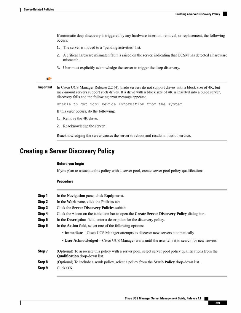
If automatic deep discovery is triggered by any hardware insertion, removal, or replacement, the followingoccurs:
1. The server is moved to a “pending activities” list.
2. A critical hardware mismatch fault is raised on the server, indicating that UCSM has detected a hardwaremismatch.
3. User must explicitly acknowledge the server to trigger the deep discovery.
In Cisco UCS Manager Release 2.2 (4), blade servers do not support drives with a block size of 4K, butrack-mount servers support such drives. If a drive with a block size of 4K is inserted into a blade server,discovery fails and the following error message appears:
Unable to get Scsi Device Information from the system
If this error occurs, do the following:
1. Remove the 4K drive.
2. Reacknowledge the server.
Reacknowledging the server causes the server to reboot and results in loss of service.
Important
Creating a Server Discovery Policy
Before you begin
If you plan to associate this policy with a server pool, create server pool policy qualifications.
Procedure
Step 1 In the Navigation pane, click Equipment.Step 2 In the Work pane, click the Policies tab.Step 3 Click the Server Discovery Policies subtab.Step 4 Click the + icon on the table icon bar to open the Create Server Discovery Policy dialog box.Step 5 In the Description field, enter a description for the discovery policy.Step 6 In the Action field, select one of the following options:
• Immediate—Cisco UCS Manager attempts to discover new servers automatically
• User Acknowledged—Cisco UCS Manager waits until the user tells it to search for new servers
Step 7 (Optional) To associate this policy with a server pool, select server pool policy qualifications from theQualification drop-down list.
Step 8 (Optional) To include a scrub policy, select a policy from the Scrub Policy drop-down list.Step 9 Click OK.
Cisco UCS Manager Server Management Guide, Release 4.1299
Server-Related PoliciesCreating a Server Discovery Policy

What to do next
Include the server discovery policy in a service profile and/or template.
Deleting a Server Discovery Policy
Procedure
Step 1 In the Navigation pane, click Equipment.Step 2 In the Work pane, click the Policies tab.Step 3 Click the Server Discovery Policies subtab.Step 4 Right-click the server discover policy that you want to delete and choose Delete.Step 5 If a confirmation dialog box displays, click Yes.
Hardware Change Discovery PolicyThe Hardware Change Discovery is a global policy used to set the how Cisco UCS Manager behaves whenthere is a hardware component change. The policy has two values:
• User Acknowledged: You must acknowledge the server to clear all the hardware inventory mismatchfaults.
• Auto Acknowledged: Triggers automatic deep discovery when a hardware component change is detected.
When UCSM detects any change in the server hardware component, a critical hardware inventory mismatchfault is raised on the server. You must manually acknowledge the server to clear the fault and complete thehardware inventory. Once you have acknowledged the server, deep discovery and deep association is triggered.
For rack servers, youmust decommision and recomission the server to clear the fault and complete the hardwareinventory.
You cannot make changes to the policy if there is a hardware inventory mismatch fault.
Configuring Hardware Change Discovery Policy
Procedure
Step 1 Navigate to Equipment > Policies > Global Policies
Step 2 Under Hardware Change Discovery Policy, choose one of the following:
• User Acknowledged: You must acknowledge the server to clear all the hardware inventory mismatchfaults.
• Auto Acknowledged: Triggers automatic deep discovery when a hardware component change is detected.
Cisco UCS Manager Server Management Guide, Release 4.1300
Server-Related PoliciesDeleting a Server Discovery Policy

Step 3 Click Save Changes.
Server Inheritance Policy Settings
Server Inheritance Policy OverviewThis policy is invoked during the server discovery process to create a service profile for the server. All serviceprofiles created from this policy use the values burned into the blade at manufacture. The policy performs thefollowing:
• Analyzes the inventory of the server
• If configured, assigns the server to the selected organization
• Creates a service profile for the server with the identity burned into the server at manufacture
You cannot migrate a service profile created with this policy to another server.
Creating a Server Inheritance PolicyA blade server or rack-mount server with a VIC adapter, such as the Cisco UCS M81KR Virtual InterfaceCard, does not have server identity values burned into the server hardware at manufacture. As a result, theidentity of the adapter must be derived from default pools. If the default pools do not include sufficient entriesfor one to be assigned to the server, service profile association fails with a configuration error.
Procedure
Step 1 In the Navigation pane, click Equipment.Step 2 In the Work pane, click the Policies tab.Step 3 Click the Server Inheritance Policies subtab.Step 4 On the icon bar at the bottom of the table, click + Add.
If + Add is disabled, click an entry in the table to enable it.
Step 5 In the Create Server Inheritance Policy dialog box, complete the following fields:
DescriptionName
The name of the policy.
This name can be between 1 and 16 alphanumeric characters. You cannotuse spaces or any special characters other than - (hyphen), _ (underscore),: (colon), and . (period), and you cannot change this name after the objectis saved.
Name field
Cisco UCS Manager Server Management Guide, Release 4.1301
Server-Related PoliciesServer Inheritance Policy Settings
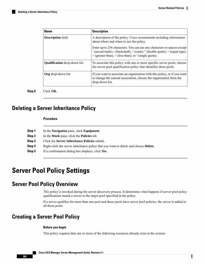
DescriptionName
A description of the policy. Cisco recommends including informationabout where and when to use the policy.
Enter up to 256 characters. You can use any characters or spaces except` (accent mark), \ (backslash), ^ (carat), " (double quote), = (equal sign),> (greater than), < (less than), or ' (single quote).
Description field
To associate this policy with one or more specific server pools, choosethe server pool qualification policy that identifies these pools.
Qualification drop-down list
If you want to associate an organization with this policy, or if you wantto change the current association, choose the organization from thedrop-down list.
Org drop-down list
Step 6 Click OK.
Deleting a Server Inheritance Policy
Procedure
Step 1 In the Navigation pane, click Equipment.Step 2 In the Work pane, click the Policies tab.Step 3 Click the Server Inheritance Policies subtab.Step 4 Right-click the server inheritance policy that you want to delete and choose Delete.Step 5 If a confirmation dialog box displays, click Yes.
Server Pool Policy Settings
Server Pool Policy OverviewThis policy is invoked during the server discovery process. It determines what happens if server pool policyqualifications match a server to the target pool specified in the policy.
If a server qualifies for more than one pool and those pools have server pool policies, the server is added toall those pools.
Creating a Server Pool Policy
Before you begin
This policy requires that one or more of the following resources already exist in the system:
Cisco UCS Manager Server Management Guide, Release 4.1302
Server-Related PoliciesDeleting a Server Inheritance Policy

• A minimum of one server pool
• Server pool policy qualifications, if you choose to have servers automatically added to pools
Procedure
Step 1 In the Navigation pane, click Servers.Step 2 Expand Servers > Policies.Step 3 Expand the node for the organization where you want to create the policy.
If the system does not include multi tenancy, expand the root node.
Step 4 Right-click Server Pool Policies and select Create Server Pool Policy.Step 5 In the Create Server Pool Policy dialog box, complete the following fields:
DescriptionName
The name of the policy.
This name can be between 1 and 16 alphanumeric characters. You cannotuse spaces or any special characters other than - (hyphen), _ (underscore),: (colon), and . (period), and you cannot change this name after the objectis saved.
Name field
A description of the policy. Cisco recommends including informationabout where and when to use the policy.
Enter up to 256 characters. You can use any characters or spaces except` (accent mark), \ (backslash), ^ (carat), " (double quote), = (equal sign),> (greater than), < (less than), or ' (single quote).
Description field
If you want to associate this policy with a server pool, select that poolfrom the drop-down list.
Target Pool drop-down list
To associate this policy with one or more specific server pools, choosethe server pool qualification policy that identifies these pools.
Qualification drop-down list
Step 6 Click OK.
Deleting a Server Pool Policy
Procedure
Step 1 In the Navigation pane, click Servers.Step 2 Expand Servers > Policies > Organization_Name.Step 3 Expand the Server Pool Policies node.Step 4 Right-click the policy you want to delete and select Delete.
Cisco UCS Manager Server Management Guide, Release 4.1303
Server-Related PoliciesDeleting a Server Pool Policy
Step 5 If a confirmation dialog box displays, click Yes.
Server Pool Policy Qualifications Settings
Server Pool Policy Qualification OverviewThis policy qualifies servers based on the inventory of a server conducted during the discovery process. Thequalifications are individual rules that you configure in the policy to determine whether a server meets theselection criteria. For example, you can create a rule that specifies the minimum memory capacity for serversin a data center pool.
Qualifications are used in other policies to place servers, not just by the server pool policies. For example, ifa server meets the criteria in a qualification policy, it can be added to one or more server pools or have aservice profile automatically associated with it.
You can use the server pool policy qualifications to qualify servers according to the following criteria:
• Adapter type
• Chassis location
• Memory type and configuration
• Power group
• CPU cores, type, and configuration
• Storage configuration and capacity
• Server model
Depending upon the implementation, you might need to configure several policies with server pool policyqualifications including the following:
• Autoconfiguration policy
• Chassis discovery policy
• Server discovery policy
• Server inheritance policy
• Server pool policy
Creating Server Pool Policy Qualifications
Procedure
Step 1 In the Navigation pane, click Servers.Step 2 Expand Servers > Policies.
Cisco UCS Manager Server Management Guide, Release 4.1304
Server-Related PoliciesServer Pool Policy Qualifications Settings

Step 3 Expand the node for the organization where you want to create the policy.
If the system does not include multi tenancy, expand the root node.
Step 4 Right-click the Server Pool Policy Qualifications node and selectCreate Server Pool Policy Qualification.Step 5 In the Create Server Pool Policy Qualification dialog box, enter a unique name and description for the
policy.Step 6 (Optional) To use this policy to qualify servers according to their adapter configuration, do the following:
a) Click Create Adapter Qualifications.b) In the Create Adapter Qualifications dialog box, complete the following fields:
DescriptionName
The adapter type.
Once you save the adapter qualification, this type cannot be changed.
Type drop-down list
A regular expression that the adapter PID must match.PID field
The maximum capacity for the selected type.
To specify a capacity, choose select and enter the desired maximumcapacity. You can enter an integer between 1 and 65535.
Maximum Capacity field
c) Click OK.
Step 7 (Optional) To use this policy to qualify servers according to the chassis in which they physically reside, dothe following:a) Click Create Chassis/Server Qualifications.b) In theChassis Qualifications area of theCreate Chassis and Server Qualifications dialog box, complete
the following fields to specify the range of chassis you want to use:
• First Chassis ID field—The first chassis ID from which server pools associated with this policy candraw.
• Number of Chassis field—The total number of chassis to include in the pool, starting with thechassis identified in the First Chassis ID field.
Example:
For example, if you want to use chassis 5, 6, 7, and 8, enter 5 in the First Chassis ID field and 4 in theNumber of Chassis field. If you want to use only chassis 3, enter 3 in the First Chassis ID field and 1in the Number of Chassis field.
If you want to use chassis 5, 6, and 9, create a chassis/server qualification for the range 5-6 andanother qualification for chassis 9. You can add as many chassis/server qualifications as needed.
Tip
c) Click Finish.
Step 8 (Optional) To use this policy to qualify servers according to both the chassis and slot in which they physicallyreside, do the following:a) Click Create Chassis/Server Qualifications.b) In theChassis Qualifications area of theCreate Chassis and Server Qualifications dialog box, complete
the following fields to specify the range of chassis you want to use:
Cisco UCS Manager Server Management Guide, Release 4.1305
Server-Related PoliciesCreating Server Pool Policy Qualifications
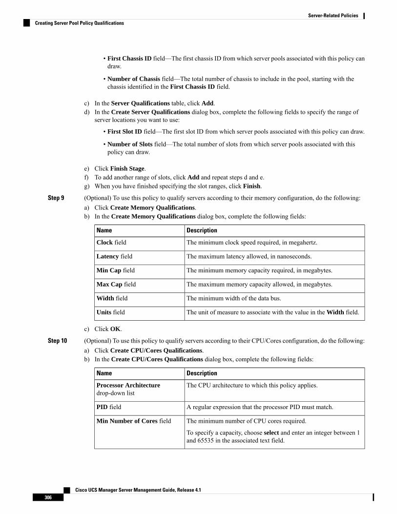
• First Chassis ID field—The first chassis ID from which server pools associated with this policy candraw.
• Number of Chassis field—The total number of chassis to include in the pool, starting with thechassis identified in the First Chassis ID field.
c) In the Server Qualifications table, click Add.d) In the Create Server Qualifications dialog box, complete the following fields to specify the range of
server locations you want to use:
• First Slot ID field—The first slot ID from which server pools associated with this policy can draw.
• Number of Slots field—The total number of slots from which server pools associated with thispolicy can draw.
e) Click Finish Stage.f) To add another range of slots, click Add and repeat steps d and e.g) When you have finished specifying the slot ranges, click Finish.
Step 9 (Optional) To use this policy to qualify servers according to their memory configuration, do the following:a) Click Create Memory Qualifications.b) In the Create Memory Qualifications dialog box, complete the following fields:
DescriptionName
The minimum clock speed required, in megahertz.Clock field
The maximum latency allowed, in nanoseconds.Latency field
The minimum memory capacity required, in megabytes.Min Cap field
The maximum memory capacity allowed, in megabytes.Max Cap field
The minimum width of the data bus.Width field
The unit of measure to associate with the value in the Width field.Units field
c) Click OK.
Step 10 (Optional) To use this policy to qualify servers according to their CPU/Cores configuration, do the following:a) Click Create CPU/Cores Qualifications.b) In the Create CPU/Cores Qualifications dialog box, complete the following fields:
DescriptionName
The CPU architecture to which this policy applies.Processor Architecturedrop-down list
A regular expression that the processor PID must match.PID field
The minimum number of CPU cores required.
To specify a capacity, choose select and enter an integer between 1and 65535 in the associated text field.
Min Number of Cores field
Cisco UCS Manager Server Management Guide, Release 4.1306
Server-Related PoliciesCreating Server Pool Policy Qualifications
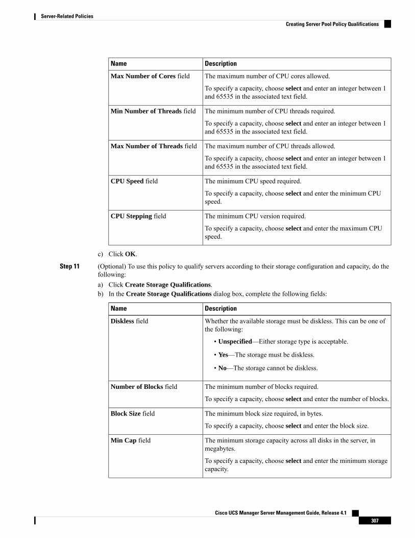
DescriptionName
The maximum number of CPU cores allowed.
To specify a capacity, choose select and enter an integer between 1and 65535 in the associated text field.
Max Number of Cores field
The minimum number of CPU threads required.
To specify a capacity, choose select and enter an integer between 1and 65535 in the associated text field.
Min Number of Threads field
The maximum number of CPU threads allowed.
To specify a capacity, choose select and enter an integer between 1and 65535 in the associated text field.
Max Number of Threads field
The minimum CPU speed required.
To specify a capacity, choose select and enter the minimum CPUspeed.
CPU Speed field
The minimum CPU version required.
To specify a capacity, choose select and enter the maximum CPUspeed.
CPU Stepping field
c) Click OK.
Step 11 (Optional) To use this policy to qualify servers according to their storage configuration and capacity, do thefollowing:a) Click Create Storage Qualifications.b) In the Create Storage Qualifications dialog box, complete the following fields:
DescriptionName
Whether the available storage must be diskless. This can be one ofthe following:
• Unspecified—Either storage type is acceptable.
• Yes—The storage must be diskless.
• No—The storage cannot be diskless.
Diskless field
The minimum number of blocks required.
To specify a capacity, choose select and enter the number of blocks.
Number of Blocks field
The minimum block size required, in bytes.
To specify a capacity, choose select and enter the block size.
Block Size field
The minimum storage capacity across all disks in the server, inmegabytes.
To specify a capacity, choose select and enter the minimum storagecapacity.
Min Cap field
Cisco UCS Manager Server Management Guide, Release 4.1307
Server-Related PoliciesCreating Server Pool Policy Qualifications
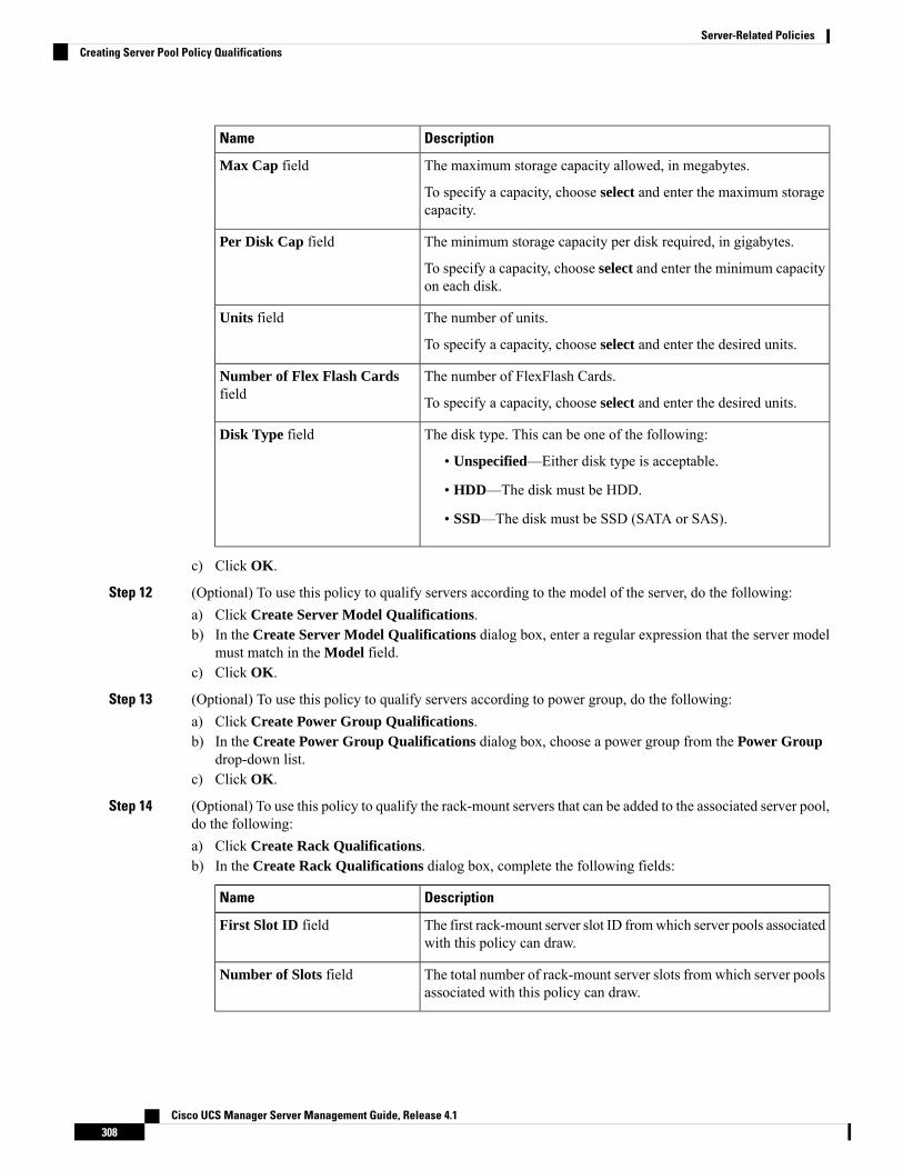
DescriptionName
The maximum storage capacity allowed, in megabytes.
To specify a capacity, choose select and enter the maximum storagecapacity.
Max Cap field
The minimum storage capacity per disk required, in gigabytes.
To specify a capacity, choose select and enter the minimum capacityon each disk.
Per Disk Cap field
The number of units.
To specify a capacity, choose select and enter the desired units.
Units field
The number of FlexFlash Cards.
To specify a capacity, choose select and enter the desired units.
Number of Flex Flash Cardsfield
The disk type. This can be one of the following:
• Unspecified—Either disk type is acceptable.
• HDD—The disk must be HDD.
• SSD—The disk must be SSD (SATA or SAS).
Disk Type field
c) Click OK.
Step 12 (Optional) To use this policy to qualify servers according to the model of the server, do the following:a) Click Create Server Model Qualifications.b) In the Create Server Model Qualifications dialog box, enter a regular expression that the server model
must match in the Model field.c) Click OK.
Step 13 (Optional) To use this policy to qualify servers according to power group, do the following:a) Click Create Power Group Qualifications.b) In the Create Power Group Qualifications dialog box, choose a power group from the Power Group
drop-down list.c) Click OK.
Step 14 (Optional) To use this policy to qualify the rack-mount servers that can be added to the associated server pool,do the following:a) Click Create Rack Qualifications.b) In the Create Rack Qualifications dialog box, complete the following fields:
DescriptionName
The first rack-mount server slot ID fromwhich server pools associatedwith this policy can draw.
First Slot ID field
The total number of rack-mount server slots from which server poolsassociated with this policy can draw.
Number of Slots field
Cisco UCS Manager Server Management Guide, Release 4.1308
Server-Related PoliciesCreating Server Pool Policy Qualifications

Step 15 Verify the qualifications in the table and correct if necessary.Step 16 Click OK.
Deleting Server Pool Policy Qualifications
Procedure
Step 1 In the Navigation pane, click Servers.Step 2 Expand Servers > Policies > Organization_Name.Step 3 Expand the Server Pool Policy Qualifications node.Step 4 Right-click the policy qualifications you want to delete and select Delete.Step 5 If a confirmation dialog box displays, click Yes.
Deleting Qualifications from Server Pool Policy QualificationsUse this procedure to modify Server Pool Policy Qualifications by deleting one or more sets of qualifications.
Procedure
Step 1 In the Navigation pane, click Servers.Step 2 Expand Servers > Policies > Organization_Name.Step 3 Expand the Server Pool Policy Qualifications node.Step 4 Choose the policy you want to modify.Step 5 In the Work pane, choose the Qualifications tab.Step 6 To delete a set of qualifications:
a) In the table, choose the row that represents the set of qualifications.b) Right-click the row and select Delete.
Step 7 Click Save Changes.
vNIC/vHBA Placement Policy Settings
vNIC/vHBA Placement PoliciesvNIC/vHBA placement policies are used to determine the following:
• How the virtual network interface connections (vCons) are mapped to the physical adapters on a server.
Cisco UCS Manager Server Management Guide, Release 4.1309
Server-Related PoliciesDeleting Server Pool Policy Qualifications
• What types of vNICs or vHBAs can be assigned to each vCon.
Each vNIC/vHBA placement policy contains four vCons that are virtual representations of the physicaladapters. When a vNIC/vHBA placement policy is assigned to a service profile, and the service profile isassociated with a server, the vCons in the vNIC/vHBA placement policy are assigned to the physical adaptersand the vNICs and vHBAs are assigned to those vCons.
For blade or rack servers that contain one adapter, Cisco UCS assigns all vCons to that adapter. For serversthat contain four adapters, Cisco UCS assigns vCon1 to Adapter1, vCon2 to Adapter2, vCon3 to Adapter3,and vCon4 to Adapter4.
For blade or rack servers that contain two or three adapters, Cisco UCS assigns the vCons based on the typeof server and the selected virtual slot mapping scheme, which can be Round Robin or Linear Ordered. Fordetails about the available mapping schemes, see vCon to Adapter Placement, on page 310.
After Cisco UCS assigns the vCons, it assigns the vNICs and vHBAs based on the Selection Preference foreach vCon. This can be one of the following:
You can specify the PCI order for the vHBA; however, the desired order works within a class of devices, suchas vNICs or vHBAs and not across them. Within an adapter, vNICs are always placed ahead of the vHBAs.
Note
• All—All configured vNICs and vHBAs can be assigned to the vCon, whether they are explicitly assignedto it, unassigned, or dynamic. This is the default.
• Assigned Only—vNICs and vHBAs must be explicitly assigned to the vCon. You can assign themexplicitly through the service profile or the properties of the vNIC or vHBA.
• Exclude Dynamic—Dynamic vNICs and vHBAs cannot be assigned to the vCon. The vCon can be usedfor all static vNICs and vHBAs, whether they are unassigned or explicitly assigned to it.
• Exclude Unassigned—Unassigned vNICs and vHBAs cannot be assigned to the vCon. The vCon canbe used for dynamic vNICs and vHBAs and for static vNICs and vHBAs that are explicitly assigned toit.
• Exclude usNIC—Cisco usNICs cannot be assigned to the vCon. The vCon can be used for all otherconfigured vNICs and vHBAs, whether they are explicitly assigned to it, unassigned, or dynamic.
An SRIOV usNIC that is explicitly assigned to a vCon set toExcludeusNIC will remain assigned to that vCon.
Note
If you do not include a vNIC/vHBA placement policy in the service profile, Cisco UCS Manager defaults totheRound Robin vConmapping scheme and theAll vNIC/vHBA selection preference, distributing the vNICsand vHBAs between the adapters based on the capabilities and relative capacities of each adapter.
vCon to Adapter PlacementCisco UCSmaps every vCon in a service profile to a physical adapter on the server. How that mapping occursand how the vCons are assigned to a specific adapter in a server depends on the following:
Cisco UCS Manager Server Management Guide, Release 4.1310
Server-Related PoliciesvCon to Adapter Placement
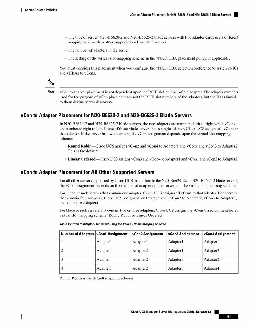
• The type of server. N20-B6620-2 and N20-B6625-2 blade servers with two adapter cards use a differentmapping scheme than other supported rack or blade servers.
• The number of adapters in the server.
• The setting of the virtual slot mapping scheme in the vNIC/vHBA placement policy, if applicable.
You must consider this placement when you configure the vNIC/vHBA selection preference to assign vNICsand vHBAs to vCons.
vCon to adapter placement is not dependent upon the PCIE slot number of the adapter. The adapter numbersused for the purpose of vCon placement are not the PCIE slot numbers of the adapters, but the ID assignedto them during server discovery.
Note
vCon to Adapter Placement for N20-B6620-2 and N20-B6625-2 Blade ServersIn N20-B6620-2 and N20-B6625-2 blade servers, the two adapters are numbered left to right while vConsare numbered right to left. If one of these blade servers has a single adapter, Cisco UCS assigns all vCons tothat adapter. If the server has two adapters, the vCon assignment depends upon the virtual slot mappingscheme:
• Round Robin—Cisco UCS assigns vCon2 and vCon4 to Adapter1 and vCon1 and vCon3 to Adapter2.This is the default.
• Linear Ordered—Cisco UCS assigns vCon3 and vCon4 to Adapter1 and vCon1 and vCon2 to Adapter2.
vCon to Adapter Placement for All Other Supported ServersFor all other servers supported by Cisco UCS in addition to the N20-B6620-2 and N20-B6625-2 blade servers,the vCon assignment depends on the number of adapters in the server and the virtual slot mapping scheme.
For blade or rack servers that contain one adapter, Cisco UCS assigns all vCons to that adapter. For serversthat contain four adapters, Cisco UCS assigns vCon1 to Adapter1, vCon2 to Adapter2, vCon3 to Adapter3,and vCon4 to Adapter4.
For blade or rack servers that contain two or three adapters, Cisco UCS assigns the vCons based on the selectedvirtual slot mapping scheme: Round Robin or Linear Ordered.
Table 15: vCon to Adapter Placement Using the Round - Robin Mapping Scheme
vCon4 AssignmentvCon3 AssignmentvCon2 AssignmentvCon1 AssignmentNumber of Adapters
Adapter1Adapter1Adapter1Adapter11
Adapter2Adapter1Adapter2Adapter12
Adapter2Adapter3Adapter2Adapter13
Adapter4Adapter3Adapter2Adapter14
Round Robin is the default mapping scheme.
Cisco UCS Manager Server Management Guide, Release 4.1311
Server-Related PoliciesvCon to Adapter Placement for N20-B6620-2 and N20-B6625-2 Blade Servers

Table 16: vCon to Adapter Placement Using the Linear Ordered Mapping Scheme
vCon4 AssignmentvCon3 AssignmentvCon2 AssignmentvCon1 AssignmentNumber of Adapters
Adapter1Adapter1Adapter1Adapter11
Adapter2Adapter2Adapter1Adapter12
Adapter3Adapter3Adapter2Adapter13
Adapter4Adapter3Adapter2Adapter14
vNIC/vHBA to vCon AssignmentCisco UCSManager provides two options for assigning vNICs and vHBAs to vCons through the vNIC/vHBAplacement policy: explicit assignment and implicit assignment.
Explicit Assignment of vNICs and vHBAs
With explicit assignment, you specify the vCon and, therefore, the adapter to which a vNIC or vHBA isassigned. Use this assignment option when you need to determine how the vNICs and vHBAs are distributedbetween the adapters on a server.
To configure a vCon and the associated vNICs and vHBAs for explicit assignment, do the following:
• Set the vCon configuration to any of the available options. You can configure the vCons through avNIC/vHBA placement policy or in the service profile associated with the server. If a vCon is configuredfor All, you can still explicitly assign a vNIC or vHBA to that vCon.
• Assign the vNICs and vHBAs to a vCon. You can make this assignment through the virtual host interfaceplacement properties of the vNIC or vHBA or in the service profile associated with the server.
If you attempt to assign a vNIC or vHBA to a vCon that is not configured for that type of vNIC or vHBA,Cisco UCS Manager displays a message advising you of the configuration error.
During service profile association, Cisco UCSManager validates the configured placement of the vNICs andvHBAs against the number and capabilities of the physical adapters in the server before assigning the vNICsand vHBAs according to the configuration in the policy. Load distribution is based upon the explicit assignmentsto the vCons and adapters configured in this policy.
If the adapters do not support the assignment of one or more vNICs or vHBAs, Cisco UCS Manager raises afault against the service profile.
You can specify the PCI order for the vHBA; however, the desired order works within a class of devices, suchas vNICs or vHBAs and not across them. Within an adapter, vNICs are always placed ahead of the vHBAs.
Note
Implicit Assignment of vNICs and vHBAs
With implicit assignment, Cisco UCS Manager determines the vCon and, therefore, the adapter to which avNIC or vHBA is assigned according to the capability of the adapters and their relative capacity. Use thisassignment option if the adapter to which a vNIC or vHBA is assigned is not important to your systemconfiguration.
Cisco UCS Manager Server Management Guide, Release 4.1312
Server-Related PoliciesvNIC/vHBA to vCon Assignment

To configure a vCon for implicit assignment, do the following:
• Set the vCon configuration to All, Exclude Dynamic, or Exclude Unassigned. You can configure thevCons through a vNIC/vHBA placement policy or in the service profile associated with the server.
• Do not set the vCon configuration to Assigned Only. Implicit assignment cannot be performed with thissetting.
• Do not assign any vNICs or vHBAs to a vCon.
During service profile association, Cisco UCS Manager verifies the number and capabilities of the physicaladapters in the server and assigns the vNICs and vHBAs accordingly. Load distribution is based upon thecapabilities of the adapters, and placement of the vNICs and vHBAs is performed according to the actualorder determined by the system. For example, if one adapter can accommodate more vNICs than another, thatadapter is assigned more vNICs.
If the adapters cannot support the number of vNICs and vHBAs configured for that server, Cisco UCSManagerraises a fault against the service profile.
Implicit Assignment of vNICs in a Dual Adapter Environment
When you use implicit vNIC assignment for a dual slot server with an adapter card in each slot, Cisco UCSManager typically assigns the vNICs/vHBAs as follows:
• If the server has the same adapter in both slots, Cisco UCS Manager assigns half the vNICs and half thevHBAs to each adapter.
• If the server has one non-VIC adapter and one VIC adapter, Cisco UCSManager assigns two vNICs andtwo vHBAs to the non-VIC adapter and the remaining vNICs and vHBAs to the VIC adapter.
• If the server has two different VIC adapters, Cisco UCS Manager assigns the vNICs and vHBAsproportionally, based on the relative capabilities of the two adapters.
The following examples show how Cisco UCS Manager would typically assign the vNICs and vHBAs withdifferent combinations of supported adapter cards:
• If you want to configure four vNICs and the server contains two Cisco UCS M51KR-B BroadcomBCM57711 adapters (with two vNICs each), Cisco UCS Manager assigns two vNICs to each adapter.
• If you want to configure 50 vNICs and the server contains a Cisco UCS CNA M72KR-E adapter (2vNICs) and a Cisco UCS M81KR Virtual Interface Card adapter (128 vNICs), Cisco UCS Managerassigns two vNICs to the Cisco UCS CNA M72KR-E adapter and 48 vNICs to the Cisco UCS M81KRVirtual Interface Card adapter.
• If you want to configure 150 vNICs and the server contains a Cisco UCSM81KR Virtual Interface Cardadapter (128 vNICs) and a Cisco UCSVIC-1240 Virtual Interface Card adapter (256 vNICs), Cisco UCSManager assigns 50 vNICs to the Cisco UCS M81KR Virtual Interface Card adapter and 100 vNICs tothe Cisco UCS VIC-1240 Virtual Interface Card adapter.
Exceptions to this implicit assignment occur if you configure the vNICs for fabric failover and if you configuredynamic vNICs for the server.
Note
Cisco UCS Manager Server Management Guide, Release 4.1313
Server-Related PoliciesvNIC/vHBA to vCon Assignment
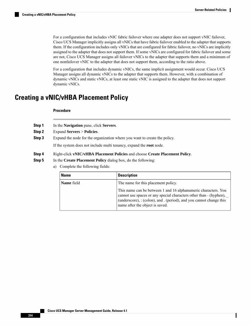
For a configuration that includes vNIC fabric failover where one adapter does not support vNIC failover,Cisco UCSManager implicitly assigns all vNICs that have fabric failover enabled to the adapter that supportsthem. If the configuration includes only vNICs that are configured for fabric failover, no vNICs are implicitlyassigned to the adapter that does not support them. If some vNICs are configured for fabric failover and someare not, Cisco UCS Manager assigns all failover vNICs to the adapter that supports them and a minimum ofone nonfailover vNIC to the adapter that does not support them, according to the ratio above.
For a configuration that includes dynamic vNICs, the same implicit assignment would occur. Cisco UCSManager assigns all dynamic vNICs to the adapter that supports them. However, with a combination ofdynamic vNICs and static vNICs, at least one static vNIC is assigned to the adapter that does not supportdynamic vNICs.
Creating a vNIC/vHBA Placement Policy
Procedure
Step 1 In the Navigation pane, click Servers.Step 2 Expand Servers > Policies.Step 3 Expand the node for the organization where you want to create the policy.
If the system does not include multi tenancy, expand the root node.
Step 4 Right-click vNIC/vHBA Placement Policies and choose Create Placement Policy.Step 5 In the Create Placement Policy dialog box, do the following:
a) Complete the following fields:
DescriptionName
The name for this placement policy.
This name can be between 1 and 16 alphanumeric characters. Youcannot use spaces or any special characters other than - (hyphen), _(underscore), : (colon), and . (period), and you cannot change thisname after the object is saved.
Name field
Cisco UCS Manager Server Management Guide, Release 4.1314
Server-Related PoliciesCreating a vNIC/vHBA Placement Policy
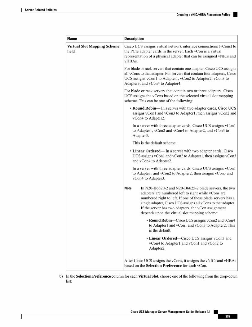
DescriptionName
Cisco UCS assigns virtual network interface connections (vCons) tothe PCIe adapter cards in the server. Each vCon is a virtualrepresentation of a physical adapter that can be assigned vNICs andvHBAs.
For blade or rack servers that contain one adapter, Cisco UCS assignsall vCons to that adapter. For servers that contain four adapters, CiscoUCS assigns vCon1 to Adapter1, vCon2 to Adapter2, vCon3 toAdapter3, and vCon4 to Adapter4.
For blade or rack servers that contain two or three adapters, CiscoUCS assigns the vCons based on the selected virtual slot mappingscheme. This can be one of the following:
• Round Robin— In a server with two adapter cards, Cisco UCSassigns vCon1 and vCon3 to Adapter1, then assigns vCon2 andvCon4 to Adapter2.
In a server with three adapter cards, Cisco UCS assigns vCon1to Adapter1, vCon2 and vCon4 to Adapter2, and vCon3 toAdapter3.
This is the default scheme.
• Linear Ordered— In a server with two adapter cards, CiscoUCS assigns vCon1 and vCon2 to Adapter1, then assigns vCon3and vCon4 to Adapter2.
In a server with three adapter cards, Cisco UCS assigns vCon1to Adapter1 and vCon2 to Adapter2, then assigns vCon3 andvCon4 to Adapter3.
In N20-B6620-2 and N20-B6625-2 blade servers, the twoadapters are numbered left to right while vCons arenumbered right to left. If one of these blade servers has asingle adapter, Cisco UCS assigns all vCons to that adapter.If the server has two adapters, the vCon assignmentdepends upon the virtual slot mapping scheme:
Note
• Round Robin—CiscoUCS assigns vCon2 and vCon4to Adapter1 and vCon1 and vCon3 to Adapter2. Thisis the default.
• Linear Ordered—Cisco UCS assigns vCon3 andvCon4 to Adapter1 and vCon1 and vCon2 toAdapter2.
After Cisco UCS assigns the vCons, it assigns the vNICs and vHBAsbased on the Selection Preference for each vCon.
Virtual Slot Mapping Schemefield
b) In the Selection Preference column for eachVirtual Slot, choose one of the following from the drop-downlist:
Cisco UCS Manager Server Management Guide, Release 4.1315
Server-Related PoliciesCreating a vNIC/vHBA Placement Policy

• All—All configured vNICs and vHBAs can be assigned to the vCon, whether they are explicitlyassigned to it, unassigned, or dynamic. This is the default.
• Assigned Only—vNICs and vHBAs must be explicitly assigned to the vCon. You can assign themexplicitly through the service profile or the properties of the vNIC or vHBA.
• Exclude Dynamic—Dynamic vNICs and vHBAs cannot be assigned to the vCon. The vCon can beused for all static vNICs and vHBAs, whether they are unassigned or explicitly assigned to it.
• Exclude Unassigned—Unassigned vNICs and vHBAs cannot be assigned to the vCon. The vConcan be used for dynamic vNICs and vHBAs and for static vNICs and vHBAs that are explicitlyassigned to it.
• Exclude usNIC—Cisco usNICs cannot be assigned to the vCon. The vCon can be used for all otherconfigured vNICs and vHBAs, whether they are explicitly assigned to it, unassigned, or dynamic.
An SRIOV usNIC that is explicitly assigned to a vCon set to Exclude usNIC will remainassigned to that vCon.
Note
c) Click OK.
Deleting a vNIC/vHBA Placement Policy
Procedure
Step 1 In the Navigation pane, click Servers.Step 2 Expand Servers > Policies > Organization_Name.Step 3 Expand the vNIC/vHBA Placement Policies node.Step 4 Right-click the policy you want to delete and choose Delete.Step 5 If a confirmation dialog box displays, click Yes.
Explicitly Assigning a vNIC to a vCon
Before you begin
Configure the vCons through a vNIC/vHBA placement policy or in the service profile with one of the followingvalues:
• Assigned Only
• Exclude Dynamic
• Exclude Unassigned
If a vCon is configured for All, you can explicitly assign a vNIC or vHBA to that vCon. However, there isless control with this configuration.
Cisco UCS Manager Server Management Guide, Release 4.1316
Server-Related PoliciesDeleting a vNIC/vHBA Placement Policy
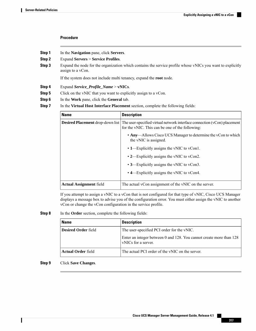
Procedure
Step 1 In the Navigation pane, click Servers.Step 2 Expand Servers > Service Profiles.Step 3 Expand the node for the organization which contains the service profile whose vNICs you want to explicitly
assign to a vCon.
If the system does not include multi tenancy, expand the root node.
Step 4 Expand Service_Profile_Name > vNICs.Step 5 Click on the vNIC that you want to explicitly assign to a vCon.Step 6 In the Work pane, click the General tab.Step 7 In the Virtual Host Interface Placement section, complete the following fields:
DescriptionName
The user-specified virtual network interface connection (vCon) placementfor the vNIC. This can be one of the following:
• Any—Allows Cisco UCSManager to determine the vCon to whichthe vNIC is assigned.
• 1—Explicitly assigns the vNIC to vCon1.
• 2—Explicitly assigns the vNIC to vCon2.
• 3—Explicitly assigns the vNIC to vCon3.
• 4—Explicitly assigns the vNIC to vCon4.
Desired Placement drop-down list
The actual vCon assignment of the vNIC on the server.Actual Assignment field
If you attempt to assign a vNIC to a vCon that is not configured for that type of vNIC, Cisco UCS Managerdisplays a message box to advise you of the configuration error. You must either assign the vNIC to anothervCon or change the vCon configuration in the service profile.
Step 8 In the Order section, complete the following fields:
DescriptionName
The user-specified PCI order for the vNIC.
Enter an integer between 0 and 128. You cannot create more than 128vNICs for a server.
Desired Order field
The actual PCI order of the vNIC on the server.Actual Order field
Step 9 Click Save Changes.
Cisco UCS Manager Server Management Guide, Release 4.1317
Server-Related PoliciesExplicitly Assigning a vNIC to a vCon
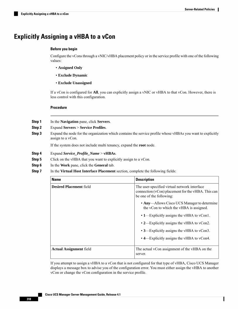
Explicitly Assigning a vHBA to a vCon
Before you begin
Configure the vCons through a vNIC/vHBA placement policy or in the service profile with one of the followingvalues:
• Assigned Only
• Exclude Dynamic
• Exclude Unassigned
If a vCon is configured for All, you can explicitly assign a vNIC or vHBA to that vCon. However, there isless control with this configuration.
Procedure
Step 1 In the Navigation pane, click Servers.Step 2 Expand Servers > Service Profiles.Step 3 Expand the node for the organization which contains the service profile whose vHBAs you want to explicitly
assign to a vCon.
If the system does not include multi tenancy, expand the root node.
Step 4 Expand Service_Profile_Name > vHBAs.Step 5 Click on the vHBA that you want to explicitly assign to a vCon.Step 6 In the Work pane, click the General tab.Step 7 In the Virtual Host Interface Placement section, complete the following fields:
DescriptionName
The user-specified virtual network interfaceconnection (vCon) placement for the vHBA. This canbe one of the following:
• Any—Allows Cisco UCSManager to determinethe vCon to which the vHBA is assigned.
• 1—Explicitly assigns the vHBA to vCon1.
• 2—Explicitly assigns the vHBA to vCon2.
• 3—Explicitly assigns the vHBA to vCon3.
• 4—Explicitly assigns the vHBA to vCon4.
Desired Placement field
The actual vCon assignment of the vHBA on theserver.
Actual Assignment field
If you attempt to assign a vHBA to a vCon that is not configured for that type of vHBA, Cisco UCS Managerdisplays a message box to advise you of the configuration error. You must either assign the vHBA to anothervCon or change the vCon configuration in the service profile.
Cisco UCS Manager Server Management Guide, Release 4.1318
Server-Related PoliciesExplicitly Assigning a vHBA to a vCon
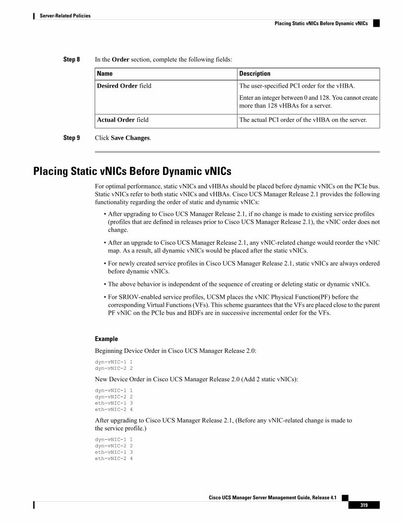
Step 8 In the Order section, complete the following fields:
DescriptionName
The user-specified PCI order for the vHBA.
Enter an integer between 0 and 128. You cannot createmore than 128 vHBAs for a server.
Desired Order field
The actual PCI order of the vHBA on the server.Actual Order field
Step 9 Click Save Changes.
Placing Static vNICs Before Dynamic vNICsFor optimal performance, static vNICs and vHBAs should be placed before dynamic vNICs on the PCIe bus.Static vNICs refer to both static vNICs and vHBAs. Cisco UCS Manager Release 2.1 provides the followingfunctionality regarding the order of static and dynamic vNICs:
• After upgrading to Cisco UCS Manager Release 2.1, if no change is made to existing service profiles(profiles that are defined in releases prior to Cisco UCS Manager Release 2.1), the vNIC order does notchange.
• After an upgrade to Cisco UCS Manager Release 2.1, any vNIC-related change would reorder the vNICmap. As a result, all dynamic vNICs would be placed after the static vNICs.
• For newly created service profiles in Cisco UCS Manager Release 2.1, static vNICs are always orderedbefore dynamic vNICs.
• The above behavior is independent of the sequence of creating or deleting static or dynamic vNICs.
• For SRIOV-enabled service profiles, UCSM places the vNIC Physical Function(PF) before thecorresponding Virtual Functions (VFs). This scheme guarantees that the VFs are placed close to the parentPF vNIC on the PCIe bus and BDFs are in successive incremental order for the VFs.
Example
Beginning Device Order in Cisco UCS Manager Release 2.0:dyn-vNIC-1 1dyn-vNIC-2 2
New Device Order in Cisco UCS Manager Release 2.0 (Add 2 static vNICs):dyn-vNIC-1 1dyn-vNIC-2 2eth-vNIC-1 3eth-vNIC-2 4
After upgrading to Cisco UCS Manager Release 2.1, (Before any vNIC-related change is made tothe service profile.)dyn-vNIC-1 1dyn-vNIC-2 2eth-vNIC-1 3eth-vNIC-2 4
Cisco UCS Manager Server Management Guide, Release 4.1319
Server-Related PoliciesPlacing Static vNICs Before Dynamic vNICs
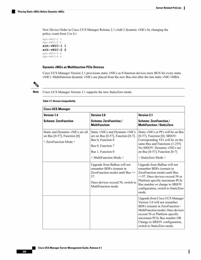
New Device Order in Cisco UCS Manager Release 2.1 (Add 2 dynamic vNICs by changing thepolicy count from 2 to 4.)dyn-vNIC-1 3dyn-vNIC-2 4eth-vNIC-1 1eth-vNIC-2 2dyn-vNIC-3 5dyn-vNIC-4 6
Dynamic vNICs as Multifunction PCIe Devices
Cisco UCS Manager Version 2.1 provisions static vNICs as 0-function devices (new BUS for every staticvNIC). Multifunction dynamic vNICs are placed from the new Bus-slot after the last static vNIC/vHBA.
Cisco UCS Manager Version 2.1 supports the new StaticZero mode.Note
Table 17: Version Compatibility
Cisco UCS Manager
Version 2.1
Scheme: ZeroFunction /MultiFunction / StaticZero
Version 2.0
Scheme: ZeroFunction /MultiFunction
Version 1.4
Scheme: ZeroFunction
Static vNICs or PFs will be on Bus[0-57], Function [0]. SRIOV:Corresponding VFs will be on thesame Bus and Functions [1-255]No-SRIOV: Dynamic vNICs areon Bus [0-57], Function [0-7]
< StaticZero Mode >
Static vNICs and Dynamic vNICsare on Bus [0-57], Function [0-7].Bus 0, Function 0
Bus 0, Function 7
Bus 1, Function 0
< MultiFunction Mode >
Static and Dynamic vNICs are allon Bus [0-57], Function [0]
< ZeroFunction Mode >
Upgrade from Balboa will notrenumber BDFs (remain inZeroFunction mode) until Bus<=57. Once devices exceed 58 orPlatform specific maximum PCIeBus number or change to SRIOVconfiguration, switch to StaticZeromode.
Upgrade from Balboa will notrenumber BDFs (remain inZeroFunction mode) until Bus <=57.
Once devices exceed 58, switch toMultiFunction mode.
Upgrade fromCisco UCSManagerVersion 2.0 will not renumberBDFs (remain in ZeroFunction /MultiFunctionmode). Once devicesexceed 58 or Platform specificmaximum PCIe Bus number ORChange to SRIOV configuration,switch to StaticZero mode.
Cisco UCS Manager Server Management Guide, Release 4.1320
Server-Related PoliciesPlacing Static vNICs Before Dynamic vNICs
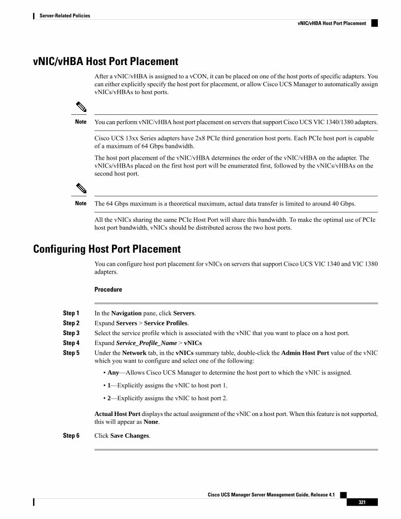
vNIC/vHBA Host Port PlacementAfter a vNIC/vHBA is assigned to a vCON, it can be placed on one of the host ports of specific adapters. Youcan either explicitly specify the host port for placement, or allow Cisco UCSManager to automatically assignvNICs/vHBAs to host ports.
You can perform vNIC/vHBA host port placement on servers that support Cisco UCSVIC 1340/1380 adapters.Note
Cisco UCS 13xx Series adapters have 2x8 PCIe third generation host ports. Each PCIe host port is capableof a maximum of 64 Gbps bandwidth.
The host port placement of the vNIC/vHBA determines the order of the vNIC/vHBA on the adapter. ThevNICs/vHBAs placed on the first host port will be enumerated first, followed by the vNICs/vHBAs on thesecond host port.
The 64 Gbps maximum is a theoretical maximum, actual data transfer is limited to around 40 Gbps.Note
All the vNICs sharing the same PCIe Host Port will share this bandwidth. To make the optimal use of PCIehost port bandwidth, vNICs should be distributed across the two host ports.
Configuring Host Port PlacementYou can configure host port placement for vNICs on servers that support Cisco UCS VIC 1340 and VIC 1380adapters.
Procedure
Step 1 In the Navigation pane, click Servers.Step 2 Expand Servers > Service Profiles.Step 3 Select the service profile which is associated with the vNIC that you want to place on a host port.Step 4 Expand Service_Profile_Name > vNICs
Step 5 Under the Network tab, in the vNICs summary table, double-click the Admin Host Port value of the vNICwhich you want to configure and select one of the following:
• Any—Allows Cisco UCS Manager to determine the host port to which the vNIC is assigned.
• 1—Explicitly assigns the vNIC to host port 1.
• 2—Explicitly assigns the vNIC to host port 2.
Actual Host Port displays the actual assignment of the vNIC on a host port. When this feature is not supported,this will appear as None.
Step 6 Click Save Changes.
Cisco UCS Manager Server Management Guide, Release 4.1321
Server-Related PoliciesvNIC/vHBA Host Port Placement
CIMC Mounted vMediaUsing Scriptable vMedia
Cisco UCS Manager allows provisioning of vMedia devices iso images for remote UCS servers. UsingScriptable vMedia, you can programmatically mount an IMG or an ISO image on a remote server. CIMCmounted vMedia provide communications between other mounted media inside your datacenter with noadditional requirements media connection. Scriptable vMedia allows you to control virtual media deviceswithout using a browser to manually map each UCS server individually.
Scriptable vMedia supports multiple share types including NFS, CIFS, HTTP, and HTTPS shares. ScriptablevMedia is enabled through BIOS configuration and configured through a Web GUI and CLI interface.
Cisco UCS Manager Scriptable vMedia supports the following functionality:
• Booting from a specific vMedia device
• Copying files from a mounted share to a local disk
• Installation and updating OS drivers
Cisco UCS Manager support for Scriptable vMedia is applicable for CIMC mapped devices only. ExistingKVM based vMedia devices are not supported.
Note
vMedia mount fails when the following conditions are met:
1. The remote vMedia image filename in the vMedia policy is set to Service-Profile-Name.
2. The service profile is renamed.
This is because the change in the name of the service profile does not change the remote vMedia imagefilename in the vMedia policy. The image filename still points to the older image on the remote device, whichcannot be found.
Creating a vMedia PolicyA vMedia policy is used to configure the mapping information for remote vMedia devices. Two vMediadevices and mappings for CD and HDD are allowed in a vMedia policy. You can configure one ISO and oneIMG at a time. ISO configurations maps to a CD drive and IMG configurations maps to a HDD device.
If you want to map a device to a remote folder, you must create an IMG and map it as a HDD device.Note
Before you begin
Make sure that you have access to the following:
• Remote vMedia Server
Cisco UCS Manager Server Management Guide, Release 4.1322
Server-Related PoliciesCIMC Mounted vMedia
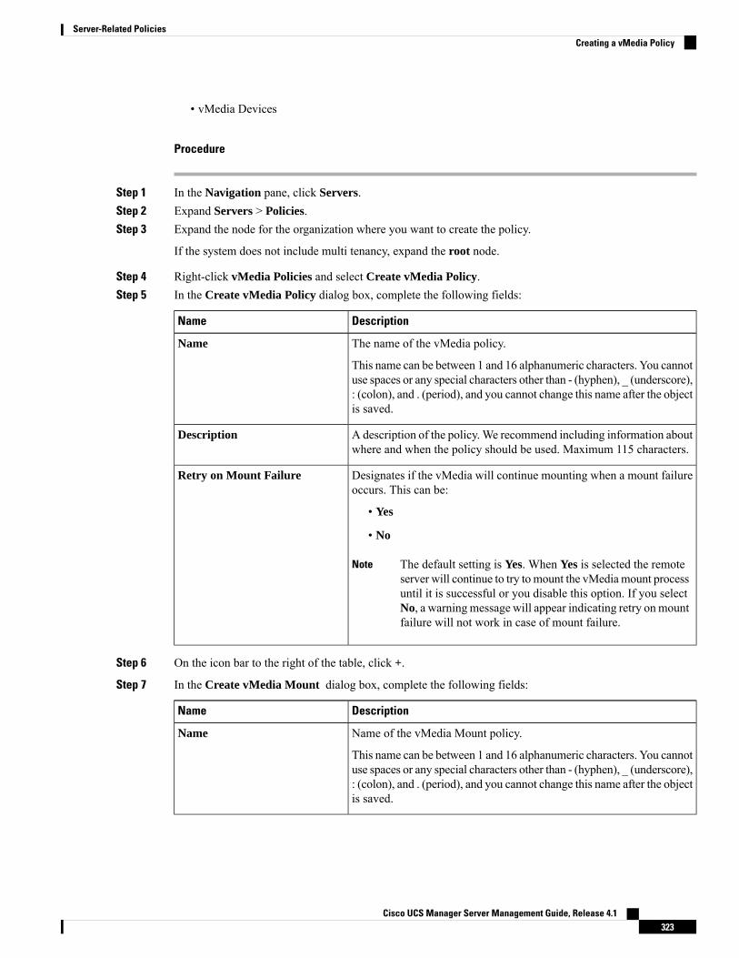
• vMedia Devices
Procedure
Step 1 In the Navigation pane, click Servers.Step 2 Expand Servers > Policies.Step 3 Expand the node for the organization where you want to create the policy.
If the system does not include multi tenancy, expand the root node.
Step 4 Right-click vMedia Policies and select Create vMedia Policy.Step 5 In the Create vMedia Policy dialog box, complete the following fields:
DescriptionName
The name of the vMedia policy.
This name can be between 1 and 16 alphanumeric characters. You cannotuse spaces or any special characters other than - (hyphen), _ (underscore),: (colon), and . (period), and you cannot change this name after the objectis saved.
Name
A description of the policy.We recommend including information aboutwhere and when the policy should be used. Maximum 115 characters.
Description
Designates if the vMedia will continue mounting when a mount failureoccurs. This can be:
• Yes
• No
The default setting is Yes. When Yes is selected the remoteserver will continue to try tomount the vMediamount processuntil it is successful or you disable this option. If you selectNo, a warningmessage will appear indicating retry onmountfailure will not work in case of mount failure.
Note
Retry on Mount Failure
Step 6 On the icon bar to the right of the table, click +.
Step 7 In the Create vMedia Mount dialog box, complete the following fields:
DescriptionName
Name of the vMedia Mount policy.
This name can be between 1 and 16 alphanumeric characters. You cannotuse spaces or any special characters other than - (hyphen), _ (underscore),: (colon), and . (period), and you cannot change this name after the objectis saved.
Name
Cisco UCS Manager Server Management Guide, Release 4.1323
Server-Related PoliciesCreating a vMedia Policy

DescriptionName
The type of remote vMedia you plan to mount. This can be:
• CDD—Scriptable vMedia CD.
• HDD—Scriptable vMedia HDD.
Device Type
The protocol to use when communicating with the remote server. Clickone of the following radio buttons to indicate the protocol you want touse to communicate with the mounted remote server. This can be:
• NFS - Network Files System.
• CIFS - Common Internet File System.
• HTTP - Hypertext Transfer Protocol.
• HTTPS - Hypertext Transfer Protocol over Secure.
Protocol
The protocol to use for authentication when you use CIFS as the protocolfor communicating with the remote server. When you use any protocolother than CIFS, this field is not available. Select one of the followingfrom the drop-down list to specify the authentication protocol.
• Default—NT LAN Manager Security Support Provider(NTLMSSP) protocol. Use this option only with Windows 2008R2 and Windows 2012 R2.
• None—No authentication is used
• Ntlm—NT LAN Manager (NTLM) security protocol. Use thisoption only with Windows 2008 R2 and Windows 2012 R2.
• Ntlmi—NTLMi security protocol. Use this option only when youenable Digital Signing in the CIFS Windows server.
• Ntlmssp—NT LAN Manager Security Support Provider(NTLMSSP) protocol. Use this option only with Windows 2008R2 and Windows 2012 R2.
• Ntlmsspi—NTLMSSPi protocol. Use this option only when youenable Digital Signing in the CIFS Windows server.
• Ntlmv2—NTLMv2 security protocol. Use this option only withSamba Linux.
• Ntlmv2i—NTLMv2i security protocol. Use this option only withSamba Linux.
The authentication protocol options are available only whenyou select CIFS as the protocol. For all other protocols, theAuthentication Protocol field is disabled.
Note
Authentication Protocol
Cisco UCS Manager Server Management Guide, Release 4.1324
Server-Related PoliciesCreating a vMedia Policy
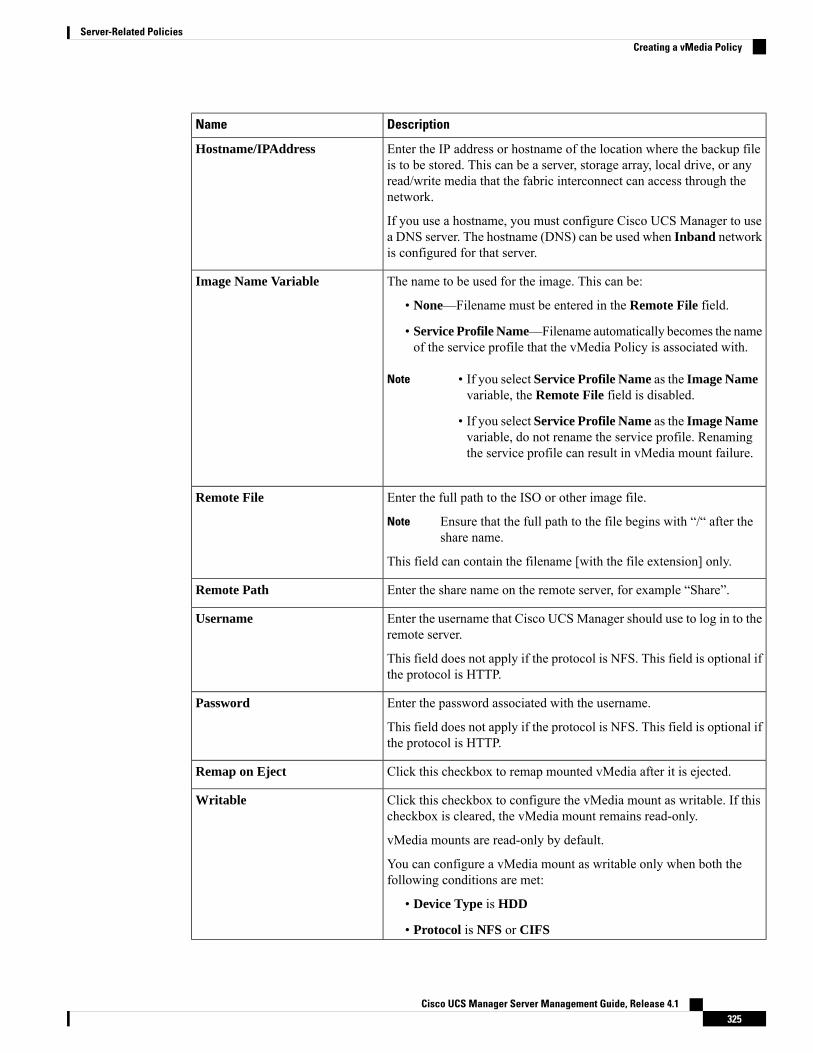
DescriptionName
Enter the IP address or hostname of the location where the backup fileis to be stored. This can be a server, storage array, local drive, or anyread/write media that the fabric interconnect can access through thenetwork.
If you use a hostname, you must configure Cisco UCS Manager to usea DNS server. The hostname (DNS) can be used when Inband networkis configured for that server.
Hostname/IPAddress
The name to be used for the image. This can be:
• None—Filename must be entered in the Remote File field.
• Service Profile Name—Filename automatically becomes the nameof the service profile that the vMedia Policy is associated with.
Note • If you select Service Profile Name as the Image Namevariable, the Remote File field is disabled.
• If you select Service Profile Name as the Image Namevariable, do not rename the service profile. Renamingthe service profile can result in vMedia mount failure.
Image Name Variable
Enter the full path to the ISO or other image file.
Ensure that the full path to the file begins with “/“ after theshare name.
Note
This field can contain the filename [with the file extension] only.
Remote File
Enter the share name on the remote server, for example “Share”.Remote Path
Enter the username that Cisco UCSManager should use to log in to theremote server.
This field does not apply if the protocol is NFS. This field is optional ifthe protocol is HTTP.
Username
Enter the password associated with the username.
This field does not apply if the protocol is NFS. This field is optional ifthe protocol is HTTP.
Password
Click this checkbox to remap mounted vMedia after it is ejected.Remap on Eject
Click this checkbox to configure the vMedia mount as writable. If thischeckbox is cleared, the vMedia mount remains read-only.
vMedia mounts are read-only by default.
You can configure a vMedia mount as writable only when both thefollowing conditions are met:
• Device Type is HDD
• Protocol is NFS or CIFS
Writable
Cisco UCS Manager Server Management Guide, Release 4.1325
Server-Related PoliciesCreating a vMedia Policy
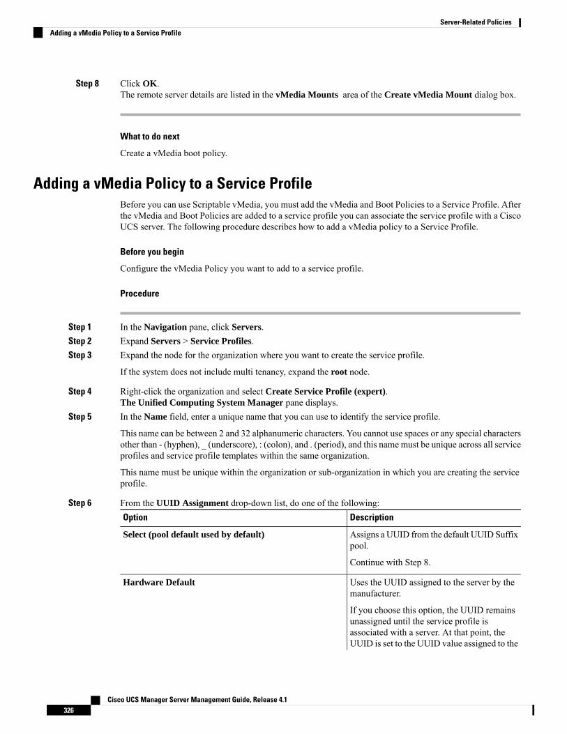
Step 8 Click OK.The remote server details are listed in the vMedia Mounts area of the Create vMedia Mount dialog box.
What to do next
Create a vMedia boot policy.
Adding a vMedia Policy to a Service ProfileBefore you can use Scriptable vMedia, you must add the vMedia and Boot Policies to a Service Profile. Afterthe vMedia and Boot Policies are added to a service profile you can associate the service profile with a CiscoUCS server. The following procedure describes how to add a vMedia policy to a Service Profile.
Before you begin
Configure the vMedia Policy you want to add to a service profile.
Procedure
Step 1 In the Navigation pane, click Servers.Step 2 Expand Servers > Service Profiles.Step 3 Expand the node for the organization where you want to create the service profile.
If the system does not include multi tenancy, expand the root node.
Step 4 Right-click the organization and select Create Service Profile (expert).The Unified Computing System Manager pane displays.
Step 5 In the Name field, enter a unique name that you can use to identify the service profile.
This name can be between 2 and 32 alphanumeric characters. You cannot use spaces or any special charactersother than - (hyphen), _ (underscore), : (colon), and . (period), and this name must be unique across all serviceprofiles and service profile templates within the same organization.
This name must be unique within the organization or sub-organization in which you are creating the serviceprofile.
Step 6 From the UUID Assignment drop-down list, do one of the following:DescriptionOption
Assigns a UUID from the default UUID Suffixpool.
Select (pool default used by default)
Continue with Step 8.
Uses the UUID assigned to the server by themanufacturer.
Hardware Default
If you choose this option, the UUID remainsunassigned until the service profile isassociated with a server. At that point, theUUID is set to the UUID value assigned to the
Cisco UCS Manager Server Management Guide, Release 4.1326
Server-Related PoliciesAdding a vMedia Policy to a Service Profile

DescriptionOption
server by the manufacturer. If the serviceprofile is later moved to a different server, theUUID is changed to match the new server.
Continue with Step 8.
Uses the UUID that you manually assign.XXXXXXXX-XXXX-XXXX-XXXX-XXXXXXXXXXXX
Continue with Step 7.
Assigns a UUID from the UUID Suffix poolthat you select from the list at the bottom ofthe drop-down list.
Pools Pool_Name
Each pool name is followed by two numbersin parentheses that show the number of UUIDsstill available in the pool and the total numberof UUIDs in the pool.
If you do not want use any of the existingpools, but instead want to create a pool that allservice profiles can access, continue with Step4. Otherwise, continue with Step 8.
Step 7 (Optional) If you selected the XXXXXXXX-XXXX-XXXX-XXXX-XXXXXXXXXXXX option, do thefollowing:a) In the UUID field, enter the valid UUID that you want to assign to the server which uses this service
profile.b) To verify that the selected UUID is available, click the here link.
Step 8 (Optional) If you want to create a new UUID Suffix pool to use to use in this service profile, click CreateUUID Suffix Pool and complete the fields in the Create UUID Suffix Pool wizard.
Step 9 (Optional) In the text box, enter a description of this service profile.
The user-defined description for this service profile.
Enter up to 256 characters. You can use any characters or spaces except ` (accent mark), \ (backslash), ^(carat), " (double quote), = (equal sign), > (greater than), < (less than), or ' (single quote).
Step 10 Click Next.Step 11 From the vMedia drop down list, choose one of the following:
DescriptionOption
Enables you to assign a vMedia policy to this service profile.Select vMedia Policy to use
Continue with Step 12.
Enables you to create a local vMedia policy that can only be accessed bythis service profile.
Create a Specific vMediaPolicy
Assigns an existing vMedia policy to the service profile. If you choose thisoption, Cisco UCS Manager displays the details of the policy.
vMedia Policies Policy_Name
Cisco UCS Manager Server Management Guide, Release 4.1327
Server-Related PoliciesAdding a vMedia Policy to a Service Profile

DescriptionOption
If you do not want use any of the existing policies but instead want to createa policy that all service profiles can access, click Create vMedia Policy .Otherwise, choose a policy from the list and continue with Step 13.
Step 12 If you created a new vmedia policy accessible to all service profiles and template, choose that policy fromthe vMedia drop down list .
Step 13 Click Next.
Viewing CIMC vMedia Policy
Before you begin
vMedia Policies are configured.
Procedure
Step 1 In the Navigation pane, click Servers.Step 2 Expand Policies > vMedia Policies.Step 3 Expand the vMedia Policies node to view the list of vMedia Policies.Step 4 Double-click the name of a vMedia policy to view the properties for the selected vMedia Mount.
On the Properties page, you can modify the properties used for the vMedia Mounts.
Cisco UCS Manager Server Management Guide, Release 4.1328
Server-Related PoliciesViewing CIMC vMedia Policy
C H A P T E R 13Firmware Upgrades
• Firmware Upgrades, on page 329• Verifying Firmware Versions on Components, on page 329
Firmware UpgradesBeginning with Cisco UCS Manager Release 4.1(1), Cisco is releasing unified Cisco UCS Manager softwareand firmware upgrades for the following platforms with every release of Cisco UCS Manager:
• Cisco UCS 6400 Series Fabric Interconnect with Cisco UCS B-Series, C-Series, and S-Series Servers
• Cisco UCS 6300 Series Fabric Interconnect with Cisco UCS B-Series, C-Series, and S-Series Servers
• Cisco UCS 6200 Series Fabric Interconnect with Cisco UCS B-Series, C-Series, and S-Series
• Cisco UCS 6324 Fabric Interconnect with Cisco UCS B-Series Servers and C-Series Servers, which isalso known as UCS Mini
You can upgrade the firmware through Auto Install, packages in service profiles, using the firmware automaticsynchronization server policy, and directly at endpoints. For more information on guidelines and installingfirmware, see the Cisco UCS Firmware Management Guide.
Verifying Firmware Versions on ComponentsProcedure
Step 1 In the Navigation pane, click Equipment.Step 2 In the Work pane, click the Firmware Management tab.Step 3 On the Installed Firmware tab, review the firmware versions listed for each component.
For more information on guidelines and installing firmware, see theCisco UCS Firmware Management Guide.
Cisco UCS Manager Server Management Guide, Release 4.1329

Cisco UCS Manager Server Management Guide, Release 4.1330
Firmware UpgradesVerifying Firmware Versions on Components
C H A P T E R 14Diagnostics Configuration
• Overview of Cisco UCS Manager Diagnostics, on page 331• Creating a Diagnostics Policy, on page 331• Diagnostics Test on a Blade Server, on page 332• Diagnostics Test on a Rack Server, on page 333• Starting a Diagnostics Tests on All Servers, on page 334• Stopping a Diagnostics Tests on All Servers, on page 335• Viewing the Server Diagnostics Status/Result, on page 335• Diagnostics Troubleshooting, on page 336
Overview of Cisco UCS Manager DiagnosticsThe Cisco UCS Manager diagnostics tool enables you to verify the health of the hardware components onyour servers. The diagnostics tool provides a variety of tests to exercise and stress the various hardwaresubsystems on the servers, such as memory and CPU. You can use the tool to run a sanity check on the stateof your servers after you fix or replace a hardware component. You can also use this tool to run comprehensiveburn-in tests before you deploy a new server in your production environment.
When a system is new, a default diagnostics policy is created in org scope. This default policy is named defaultand it cannot be deleted. The user will receive an error message if they try to delete it. The default diagnosticpolicy is the preferred way to execute the same set of tests across all servers. Any diagnostic policy, includingthe default can be customized.
The default policy only has one memory test. The default parameters of the memory test can be modified. Inaddition, the memory test within the default diagnostics policy can be deleted. If it does not have a memorytest, the diagnostic policy will not run.
Creating a Diagnostics PolicyBefore you begin
You must have admin privileges to perform this task.
Cisco UCS Manager Server Management Guide, Release 4.1331
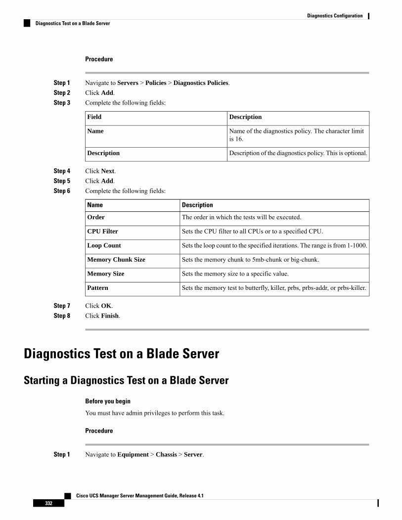
Procedure
Step 1 Navigate to Servers > Policies > Diagnostics Policies.Step 2 Click Add.Step 3 Complete the following fields:
DescriptionField
Name of the diagnostics policy. The character limitis 16.
Name
Description of the diagnostics policy. This is optional.Description
Step 4 Click Next.Step 5 Click Add.Step 6 Complete the following fields:
DescriptionName
The order in which the tests will be executed.Order
Sets the CPU filter to all CPUs or to a specified CPU.CPU Filter
Sets the loop count to the specified iterations. The range is from 1-1000.Loop Count
Sets the memory chunk to 5mb-chunk or big-chunk.Memory Chunk Size
Sets the memory size to a specific value.Memory Size
Sets the memory test to butterfly, killer, prbs, prbs-addr, or prbs-killer.Pattern
Step 7 Click OK.Step 8 Click Finish.
Diagnostics Test on a Blade Server
Starting a Diagnostics Test on a Blade Server
Before you begin
You must have admin privileges to perform this task.
Procedure
Step 1 Navigate to Equipment > Chassis > Server.
Cisco UCS Manager Server Management Guide, Release 4.1332
Diagnostics ConfigurationDiagnostics Test on a Blade Server
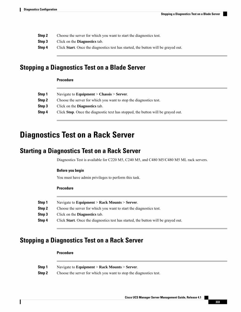
Step 2 Choose the server for which you want to start the diagnostics test.Step 3 Click on the Diagnostics tab.Step 4 Click Start. Once the diagnostics test has started, the button will be grayed out.
Stopping a Diagnostics Test on a Blade Server
Procedure
Step 1 Navigate to Equipment > Chassis > Server.Step 2 Choose the server for which you want to stop the diagnostics test.Step 3 Click on the Diagnostics tab.Step 4 Click Stop. Once the diagnostic text has stopped, the button will be grayed out.
Diagnostics Test on a Rack Server
Starting a Diagnostics Test on a Rack ServerDiagnostics Test is available for C220 M5, C240 M5, and C480 M5/C480 M5 ML rack servers.
Before you begin
You must have admin privileges to perform this task.
Procedure
Step 1 Navigate to Equipment > Rack Mounts > Server.Step 2 Choose the server for which you want to start the diagnostics test.Step 3 Click on the Diagnostics tab.Step 4 Click Start. Once the diagnostics test has started, the button will be grayed out.
Stopping a Diagnostics Test on a Rack Server
Procedure
Step 1 Navigate to Equipment > Rack Mounts > Server.Step 2 Choose the server for which you want to stop the diagnostics test.
Cisco UCS Manager Server Management Guide, Release 4.1333
Diagnostics ConfigurationStopping a Diagnostics Test on a Blade Server
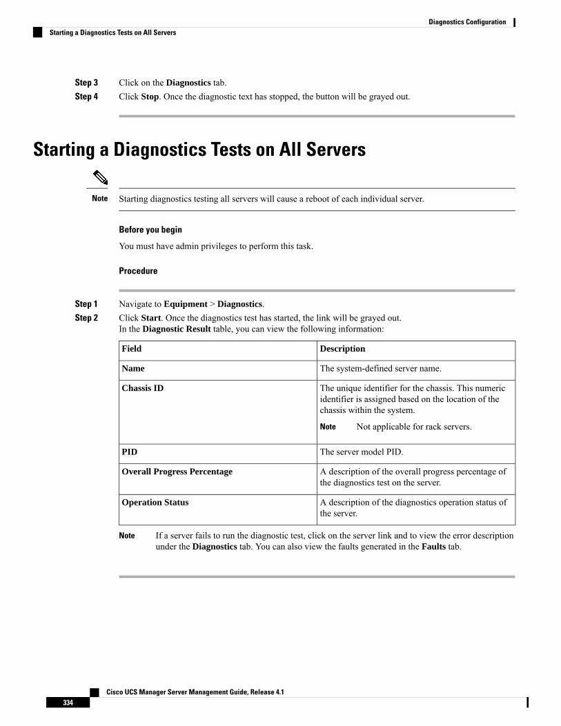
Step 3 Click on the Diagnostics tab.Step 4 Click Stop. Once the diagnostic text has stopped, the button will be grayed out.
Starting a Diagnostics Tests on All Servers
Starting diagnostics testing all servers will cause a reboot of each individual server.Note
Before you begin
You must have admin privileges to perform this task.
Procedure
Step 1 Navigate to Equipment > Diagnostics.Step 2 Click Start. Once the diagnostics test has started, the link will be grayed out.
In the Diagnostic Result table, you can view the following information:
DescriptionField
The system-defined server name.Name
The unique identifier for the chassis. This numericidentifier is assigned based on the location of thechassis within the system.
Not applicable for rack servers.Note
Chassis ID
The server model PID.PID
A description of the overall progress percentage ofthe diagnostics test on the server.
Overall Progress Percentage
A description of the diagnostics operation status ofthe server.
Operation Status
If a server fails to run the diagnostic test, click on the server link and to view the error descriptionunder the Diagnostics tab. You can also view the faults generated in the Faults tab.
Note
Cisco UCS Manager Server Management Guide, Release 4.1334
Diagnostics ConfigurationStarting a Diagnostics Tests on All Servers
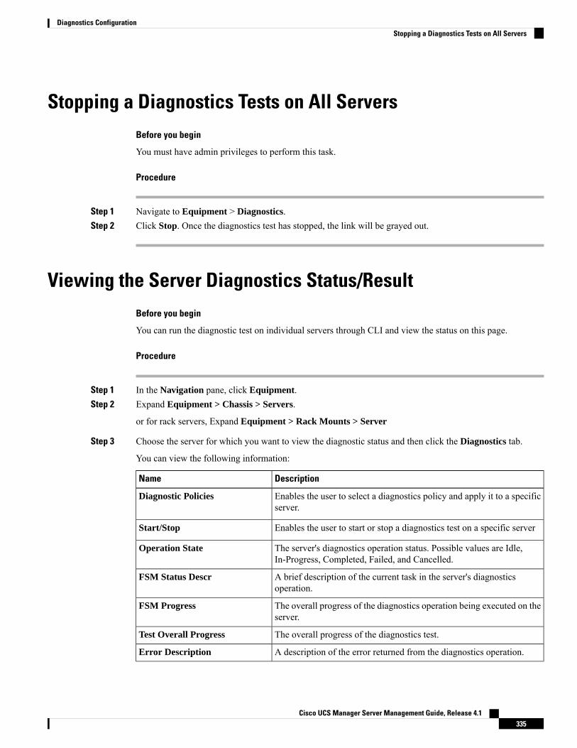
Stopping a Diagnostics Tests on All ServersBefore you begin
You must have admin privileges to perform this task.
Procedure
Step 1 Navigate to Equipment > Diagnostics.Step 2 Click Stop. Once the diagnostics test has stopped, the link will be grayed out.
Viewing the Server Diagnostics Status/ResultBefore you begin
You can run the diagnostic test on individual servers through CLI and view the status on this page.
Procedure
Step 1 In the Navigation pane, click Equipment.Step 2 Expand Equipment > Chassis > Servers.
or for rack servers, Expand Equipment > Rack Mounts > Server
Step 3 Choose the server for which you want to view the diagnostic status and then click the Diagnostics tab.
You can view the following information:
DescriptionName
Enables the user to select a diagnostics policy and apply it to a specificserver.
Diagnostic Policies
Enables the user to start or stop a diagnostics test on a specific serverStart/Stop
The server's diagnostics operation status. Possible values are Idle,In-Progress, Completed, Failed, and Cancelled.
Operation State
A brief description of the current task in the server's diagnosticsoperation.
FSM Status Descr
The overall progress of the diagnostics operation being executed on theserver.
FSM Progress
The overall progress of the diagnostics test.Test Overall Progress
A description of the error returned from the diagnostics operation.Error Description
Cisco UCS Manager Server Management Guide, Release 4.1335
Diagnostics ConfigurationStopping a Diagnostics Tests on All Servers

Table 18: Diagnostic Result
DescriptionName
The unique identifier associated with the test.ID
The type of diagnostics test.Test Type
The status of the test execution. Values are: Idle, In Progress, Completed,or Failed.
Status
The description of the diagnostics test run. Once the test is complete, itprovides detailed descriptions of the result.
Description
The result of the diagnostics test. Values are Pass, Fail, or NA.Result
The progress percentage of the diagnostics test.Progress Percentage
Diagnostics TroubleshootingSteps to DebugIssue
Refer to memory-related faults in addition to the diagnostics operation results.If the BIOSdetects a badDIMM, theDIMM isdisabled andis not visibleto theDiagnosticsoperation.
Refer to memory-related faults in addition to the diagnostics operation results.If theDIMMblacklistingfeature isenabled anda DIMM isblacklisted,it is notvisible to theDiagnosticsoperation.
Cisco UCS Manager Server Management Guide, Release 4.1336
Diagnostics ConfigurationDiagnostics Troubleshooting
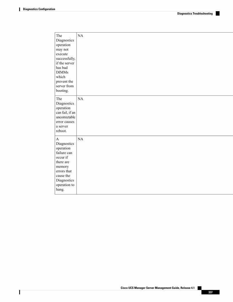
NATheDiagnosticsoperationmay notexecutesuccessfully,if the serverhas badDIMMswhichprevent theserver frombooting.
NATheDiagnosticsoperationcan fail, if anuncorrectableerror causesa serverreboot.
NAADiagnosticsoperationfailure canoccur ifthere arememoryerrors thatcause theDiagnosticsoperation tohang.
Cisco UCS Manager Server Management Guide, Release 4.1337
Diagnostics ConfigurationDiagnostics Troubleshooting
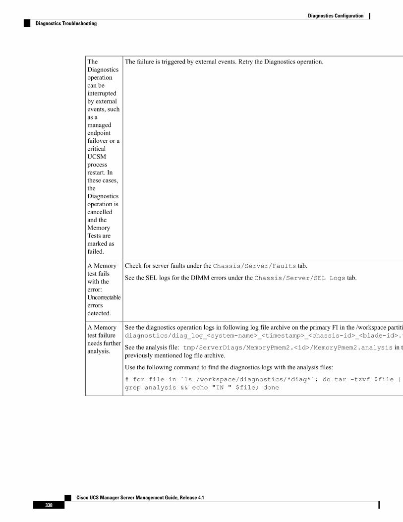
The failure is triggered by external events. Retry the Diagnostics operation.TheDiagnosticsoperationcan beinterruptedby externalevents, suchas amanagedendpointfailover or acriticalUCSMprocessrestart. Inthese cases,theDiagnosticsoperation iscancelledand theMemoryTests aremarked asfailed.
Check for server faults under the Chassis/Server/Faults tab.
See the SEL logs for the DIMM errors under the Chassis/Server/SEL Logs tab.
A Memorytest failswith theerror:Uncorrectableerrorsdetected.
See the diagnostics operation logs in following log file archive on the primary FI in the /workspace partition:diagnostics/diag_log_<system-name>_<timestamp>_<chassis-id>_<blade-id>.tgz
See the analysis file: tmp/ServerDiags/MemoryPmem2.<id>/MemoryPmem2.analysis in thepreviously mentioned log file archive.
Use the following command to find the diagnostics logs with the analysis files:
# for file in `ls /workspace/diagnostics/*diag*`; do tar -tzvf $file |grep analysis && echo "IN " $file; done
A Memorytest failureneeds furtheranalysis.
Cisco UCS Manager Server Management Guide, Release 4.1338
Diagnostics ConfigurationDiagnostics Troubleshooting


![Mission Manager[1]](https://static.fdokumen.com/doc/165x107/6313fe215cba183dbf075a68/mission-manager1.jpg)