Cisco UCS Director Administration Guide, Release 6.7
432
Cisco UCS Director Administration Guide, Release 6.7 First Published: 2019-01-09 Last Modified: 2020-11-13 Americas Headquarters Cisco Systems, Inc. 170 West Tasman Drive San Jose, CA 95134-1706 USA http://www.cisco.com Tel: 408 526-4000 800 553-NETS (6387) Fax: 408 527-0883
-
Upload
khangminh22 -
Category
Documents
-
view
0 -
download
0
Transcript of Cisco UCS Director Administration Guide, Release 6.7

Cisco UCS Director Administration Guide, Release 6.7First Published: 2019-01-09
Last Modified: 2020-11-13
Americas HeadquartersCisco Systems, Inc.170 West Tasman DriveSan Jose, CA 95134-1706USAhttp://www.cisco.comTel: 408 526-4000
800 553-NETS (6387)Fax: 408 527-0883

THE SPECIFICATIONS AND INFORMATION REGARDING THE PRODUCTS IN THIS MANUAL ARE SUBJECT TO CHANGE WITHOUT NOTICE. ALL STATEMENTS,INFORMATION, AND RECOMMENDATIONS IN THIS MANUAL ARE BELIEVED TO BE ACCURATE BUT ARE PRESENTED WITHOUT WARRANTY OF ANY KIND,EXPRESS OR IMPLIED. USERS MUST TAKE FULL RESPONSIBILITY FOR THEIR APPLICATION OF ANY PRODUCTS.
THE SOFTWARE LICENSE AND LIMITED WARRANTY FOR THE ACCOMPANYING PRODUCT ARE SET FORTH IN THE INFORMATION PACKET THAT SHIPPED WITHTHE PRODUCT AND ARE INCORPORATED HEREIN BY THIS REFERENCE. IF YOU ARE UNABLE TO LOCATE THE SOFTWARE LICENSE OR LIMITED WARRANTY,CONTACT YOUR CISCO REPRESENTATIVE FOR A COPY.
The Cisco implementation of TCP header compression is an adaptation of a program developed by the University of California, Berkeley (UCB) as part of UCB's public domain version ofthe UNIX operating system. All rights reserved. Copyright © 1981, Regents of the University of California.
NOTWITHSTANDING ANY OTHERWARRANTY HEREIN, ALL DOCUMENT FILES AND SOFTWARE OF THESE SUPPLIERS ARE PROVIDED “AS IS" WITH ALL FAULTS.CISCO AND THE ABOVE-NAMED SUPPLIERS DISCLAIM ALL WARRANTIES, EXPRESSED OR IMPLIED, INCLUDING, WITHOUT LIMITATION, THOSE OFMERCHANTABILITY, FITNESS FOR A PARTICULAR PURPOSE AND NONINFRINGEMENT OR ARISING FROM A COURSE OF DEALING, USAGE, OR TRADE PRACTICE.
IN NO EVENT SHALL CISCO OR ITS SUPPLIERS BE LIABLE FOR ANY INDIRECT, SPECIAL, CONSEQUENTIAL, OR INCIDENTAL DAMAGES, INCLUDING, WITHOUTLIMITATION, LOST PROFITS OR LOSS OR DAMAGE TO DATA ARISING OUT OF THE USE OR INABILITY TO USE THIS MANUAL, EVEN IF CISCO OR ITS SUPPLIERSHAVE BEEN ADVISED OF THE POSSIBILITY OF SUCH DAMAGES.
Any Internet Protocol (IP) addresses and phone numbers used in this document are not intended to be actual addresses and phone numbers. Any examples, command display output, networktopology diagrams, and other figures included in the document are shown for illustrative purposes only. Any use of actual IP addresses or phone numbers in illustrative content is unintentionaland coincidental.
All printed copies and duplicate soft copies of this document are considered uncontrolled. See the current online version for the latest version.
Cisco has more than 200 offices worldwide. Addresses and phone numbers are listed on the Cisco website at www.cisco.com/go/offices.
Cisco and the Cisco logo are trademarks or registered trademarks of Cisco and/or its affiliates in the U.S. and other countries. To view a list of Cisco trademarks, go to this URL:https://www.cisco.com/c/en/us/about/legal/trademarks.html. Third-party trademarks mentioned are the property of their respective owners. The use of the word partner does not imply apartnership relationship between Cisco and any other company. (1721R)
© 2019–2020 Cisco Systems, Inc. All rights reserved.

C O N T E N T S
Full Cisco Trademarks with Software License ?
Preface xixP R E F A C E
Audience xix
Conventions xix
Documentation Feedback xxi
Obtaining Documentation and Submitting a Service Request xxi
New and Changed Information for this Release 1C H A P T E R 1
New and Changed Information for this Release 1
Overview 5C H A P T E R 2
Cisco UCS Director 5
Features and Benefits 6
Physical and Virtual Management Features 7
Model-Based Orchestration 8
User Interface of Cisco UCS Director 9
Landing Page 10
Common Icons 12
Converged View 14
Generating Additional Reports for a Cloud Account 14
Guided Setup Wizards in Cisco UCS Director 14
Creating a Wizard from a Workflow 15
Setting up Non-Secure Connection to the Cisco UCS Director User Interface 16
Initial Login 17
Generating a Self-Signed Certificate 17
Cisco UCS Director Administration Guide, Release 6.7iii

Recommended Order of System Setup 18
Configuring the Host Name for Cisco UCS Director 20
Working with Ciphers 21
Editing Cipher Usage 21
Installing the Latest Java Cryptograpy Extension (JCE) Policy Files 22
Managing Users and Groups 23C H A P T E R 3
User Roles 23
Adding a User Role 25
Adding Users 26
Managing User Types 28
Default User Permissions 28
User Roles and Permissions 28
Permissions for Server Management 31
All Policy Admin 32
Billing Admin 34
Computing Admin 35
Group Admin 37
IS Admin 39
Network Admin 40
Operator 42
Service End User 44
Storage Admin 45
Viewing User Role Information for Users 47
Reviewing Recent Login History of Users 48
Configuring Session Limits for Users 48
Managing User Account Status 49
Unassigning Resources From a User 49
Disabling a User Account in Cisco UCS Director 50
Disabling User Accounts within a Group 50
MSP Administrator Role 51
Managing Groups 52
Creating a User Group 52
Using the Global Dashlet Setup Option 53
Cisco UCS Director Administration Guide, Release 6.7iv
Contents

Creating an MSP Organization 54
Creating a Customer Organization 55
Password Policy 56
Creating a Password Policy 56
Group Budget Policy 57
Viewing and Editing a Group Budget Policy 58
Resource Limits 58
Viewing Resource Limits 59
Editing Resource Limits 59
Configuring the Administration Profile 62
Creating the Admin Profile 62
Editing Your Administrative Profile 63
Sending a Broadcast Message 64
Changing the Admin Password 65
Viewing Current Online Users 65
Viewing Workflow Task Details 65
Managing User Access Profiles 66
Multi-Role Access Profiles 66
Creating a User Access Profile 66
Logging in to a Profile 67
Default Profile 67
Changing a Default Profile 68
Authentication and LDAP Integration 68
Configuring Authentication Preferences 68
LDAP Integration 69
Single Sign On with OneLogin 82
Authentication and Cisco Identity Services Engine (Cisco ISE) 88
Cisco Identity Services Engine (Cisco ISE) Integration 88
Configuring Cisco Identity Services Engine (Cisco ISE) Server Integration 88
Branding for Customer Organizations 91
Branding User Groups 92
Branding Customer Organizations 93
Login Page Branding 94
Configuring a Custom Domain Logo 95
Cisco UCS Director Administration Guide, Release 6.7v
Contents

Setting Up the End User Portal 97C H A P T E R 4
End User Portal 97
Summary of Tasks to Set Up the End User Portal 97
Setting Up User Accounts for the End User Portal 98
Creating a User Group 98
Adding Users 99
Setting Permissions for the End User Portal 101
Permissions Required for Approvals 101
Permissions Required for Catalogs 102
Permissions Required for Budget Entries 102
Physical Resources 103
Permissions Required for CloudSense Reports 103
Permissions Required for Rack Servers 103
Permissions Required for Servers 103
Permissions Required for Service Profiles 103
Permissions Required for SnapMirrors 104
Permissions Required for Storage Virtual Machines 104
Permissions Required for vFilers 104
Permissions Required for SVM Initiator Groups 104
Permissions Required for SVM LUNs 105
Permissions Required for SVM CIFS Shares 105
Permissions Required for SVM Export Policies 105
Permissions Required for SVM Export Rules 105
Permissions Required for SVM Initiators 106
Permissions Required for SVM Port Sets 106
Permissions Required for SVM SIS Policies 106
Permissions Required for SVM Snapshot Policies 106
Permissions Required for SVMWWPN Aliases 106
Permissions Required for SVM Volume Snapshots 107
Permissions Required for SVM Volumes 107
Permissions Required for vFiler Volumes 108
Services 108
Permissions Required for Payment Information 108
Cisco UCS Director Administration Guide, Release 6.7vi
Contents

Permissions Required for Service Requests 108
Permissions Required for User OVF Management 109
Virtual Resources 109
Permissions Required for Application Containers 109
Permissions Required for VMs 110
Permissions Required for Images 111
Setting Up the User Interface of the End User Portal 111
Configuring Dashlets 111
Changing Colors of Dashlet Reports 112
Selecting Catalogs for End User Portal 113
Managing System Administration Settings 115C H A P T E R 5
Setting up the Outgoing Mail Server 115
Working with Email Templates 116
Adding an Email Template 117
Previewing an Email Template 117
Setting a Default Email Template 118
Configuring System Parameters (Optional) 118
Configuring System Parameters 118
Configuring Infrastructure System Parameters (Optional) 120
Configuring Proxy Settings 120
Running an Object Search 121
Viewing Workflow Tasks in the Workflow Designer 121
Working with Licenses in Cisco UCS Director 122
Applying Upgrade License 124
Migrating a License 125
Replacing a License 125
Updating the License 125
Verifying License Utilization 126
Viewing License Utilization History 126
Viewing Deactivated License Information 127
Viewing License Key Information 127
Viewing License Status 127
Viewing Resource Usage Data 128
Cisco UCS Director Administration Guide, Release 6.7vii
Contents

Application Categories 128
Adding Application Categories 129
Customizing the Portal 130
Customizing the Login Page and Background Images 130
Customizing the Application Logo 131
Customizing Favicons 132
Customizing Application Header 133
Customizing Date Display 133
Customizing the Color Theme 134
Customizing Logout Redirect 134
Customizing Reports 134
Enabling Advanced Controls 135
Enabling the Service Provider Feature 136
User Menus 137
Setting User Menus 137
Setting User Permissions 137
System Tasks 138
Creating a Node Pool 139
Creating a System Task Policy 139
Assigning a Node Pool to a System Task Policy 139
Creating a Service Node 140
Assigning a System Policy to a System Task 141
Executing System Tasks 141
Disabling or Enabling a System Task 142
Scheduling a System Task 142
System Tasks with Fixed Rate Option 144
Managing Icons in the Cisco UCS Director User Interface 144
Modifying an Icon in the Cisco UCS Director User Interface 145
Editing an Icon 146
Deleting an Icon 147
Previewing an Icon 147
Tag Library 147
Creating a Tag 148
Support Information 149
Cisco UCS Director Administration Guide, Release 6.7viii
Contents

Viewing System Information 150
Showing Logs 151
Downloading Logs 151
Starting the Debug Log 152
Generating API Logs 152
Database Audit Logging 153
Enabling Audit Logging 153
Device Connector 153
Configuring Device Connector 154
Launching Cisco UCS Director from Cisco Intersight 155
Connector Pack Management 156
Upgrading Connector Packs 158
Viewing Connector Pack Upgrade Information 159
Base Platform Pack and System Update Manager 160
Upgrading Base Platform Pack 160
Upgrading the System Update Manager 161
Upgrade Process Validation and Failure Scenarios 162
Managing Integration Settings 165C H A P T E R 6
About Integration Settings 165
Configuration Management Database Integration 165
Setting Up CMBD Integration 166
Metering Data Export 166
Setting Up Metering Data Export 167
Change Records 167
Viewing Change Records 167
System Logs 167
Setting up System Logs 167
Storage and OVF Upload 168
Multiple Language Support 168
Choosing a Language for Cisco UCS Director 169
Setting a Locale for the User Interface 169
Adding a Repository 170
Cisco UCS Director Administration Guide, Release 6.7ix
Contents

Managing a Physical Infrastructure 171C H A P T E R 7
About Managing a Physical Infrastructure 171
Using the Converged View 171
Adding a Site 172
Adding a Pod 172
Adding a Physical Account 174
Adding a Multi-Domain Manager Account 176
Adding a Network Element 177
Enabling DHCP Logging 178
Testing Connectivity 179
Testing Connectivity of Managed Network Elements 179
Testing the Connection to a Physical Account 179
Enabling Device Discovery 179
Managing a Virtual Infrastructure 181C H A P T E R 8
About Managing VMware Clouds 181
Creating a VMware Cloud 182
Downloading the PowerShell Agent Installer 185
Creating a PowerShell Agent 185
Verifying Cloud Discovery and Connectivity 186
Testing the Connection 186
Viewing vCenter Plug-ins 186
Provisioning Virtual Machines in Cisco UCS Director 187
Managing Policies 191C H A P T E R 9
Policies 191
Computing Policies 192
Creating a Computing Policy 192
Configuring a Bare Metal Server Provisioning Policy 194
Validating a Bare Metal Server Provisioning Policy 199
Data Collection Policy 199
Configuring a Data Collection Policy for a Virtual Account 200
Associating the Data Collection Policy for a Virtual Account 201
Cisco UCS Director Administration Guide, Release 6.7x
Contents

About Group Share Policy 202
Creating a Group Share Policy 202
Storage Policies 203
Storage Policies for Multiple VM Disks 203
Adding and Configuring a Storage Policy 203
Virtual Storage Catalogs 209
Configuring a Virtual Storage Catalog 209
Credential Policies 210
Configuring a Credential Policy 211
Network Policies 211
Adding a Static IP Pool Policy 211
Configuring a IP Subnet Pool Policy 213
Adding a Network Policy 214
Networking Provisioning Policies 217
Configuring a Network Provisioning Policy 217
VLAN Pool Policies 219
Configuring a VLAN Pool Policy 219
System Policies 219
Configuring a System Policy 219
OS Licenses 225
Adding an OS License 225
End User Self-Service Policy 226
Creating an End User Policy 227
Configuring a VM Management Policy 227
Managing Virtual Data Centers 231C H A P T E R 1 0
Virtual Data Centers 231
VDC Actions 232
Adding a Virtual Data Center 232
Viewing a Virtual Data Center 235
Managing Application Categories in a Virtual Data Centers 236
Assigning an Application Category to Multiple VDCs 236
Virtual Data Center Service Profiles 237
Adding a Virtual Data Center Service Profile 237
Cisco UCS Director Administration Guide, Release 6.7xi
Contents

Managing Resource Groups 241C H A P T E R 1 1
Resource Groups 241
Environment Variables 241
Adding a Custom Environment Variable 250
Adding a Resource Group 252
Editing a Resource Group 260
Adding a Pod to a Resource Group 261
Managing Tags of a Resource Group 262
Deleting a Resource Group 263
Tenant 263
Service Offerings 264
Adding a Service Offering 265
Cloning a Service Offering 269
Editing a Service Offering 273
Deleting a Service Offering 277
Tenant Profiles 277
Adding a Tenant Profile 277
Troubleshooting a Service Offering List 279
Cloning a Tenant Profile 280
Editing a Tenant Profile 281
Deleting a Tenant Profile 282
Managing Catalogs 283C H A P T E R 1 2
About Managing Catalogs 283
Publishing a Catalog 284
About Publishing Advanced Catalogs 291
Publishing Advanced Catalogs 291
Creating a Bare Metal Server Catalog 293
Reordering Catalogs Within a Folder 295
Accessing Hosts for Deployment 295
Reordering Catalog Folders 296
Using Self-Service Provisioning 297C H A P T E R 1 3
Cisco UCS Director Administration Guide, Release 6.7xii
Contents

Self-Service Provisioning 297
Service Requests 297
Creating a Service Request with Catalog Type—Standard 298
Creating a Service Request with Catalog Type—Advanced 305
Creating a Service Request with Catalog Type—Bare Metal 306
Service Request Workflow and Details 309
Service Request Workflow 309
Service Request Details 311
Viewing the Workflow Status of a Service Request 312
Viewing Log Details for a Service Request 312
About Scheduling a Service Request 313
Scheduling Service Requests 313
About Resubmitting a Service Request 313
Resubmitting a Service Request 314
Other Service Request Functions 314
Canceling a Service Request 314
Rolling Back a Service Request 314
Archiving a Service Request 315
Bulk Archiving Service Requests 315
Deleting Service Requests 316
Viewing Service Requests for a Particular Group 317
Searching the Records of Service Requests for a Group 318
Exporting a Report of Service Requests for a Group 318
Reinstating an Archived Service Request 319
Launching the Service Request Quick View 319
Service Request Approval Process 320
Approving a Service Request 320
Rejecting a Service Request 320
Viewing Approval Information on Service Requests 321
Searching the Records of Service Request Approvals 321
Exporting a Report of Service Request Approvals 321
Service Request Budgeting 322
Viewing the Current Month Budget Availability 322
Viewing Budget Entries 322
Cisco UCS Director Administration Guide, Release 6.7xiii
Contents

Adding a Budget Entry 322
Multiple Disk VM Provisioning 325C H A P T E R 1 4
About Multiple Disk VM Provisioning 325
Overview of the Procedure for Multiple Disk VM Provisioning 326
About Templates with Multiple Disks 326
Assigning Disk Categories 326
Defining Storage Policies 327
Creating a Storage Policy 327
Creating a Catalog 333
Adding a Catalog 333
Creating a VM Disk 341
Using the Chargeback Module 343C H A P T E R 1 5
About Chargeback Features 343
Budget Policies 344
Configuring a Budget Policy 344
Creating a Tag-Based Cost Model 344
Cost Models 345
Creating a Cost Model 346
Creating a Bare Metal Cost Model 349
Modifying a VDC to Include a Cost Model 349
Adding a Cost Model to a VDC 350
Editing a VDC to Include a Cost Model 352
Package-Based Cost Models 352
Creating a Package-Based Cost Model 353
Storage Tier Cost Models 354
Assigning a Cost to a Tier 354
About Assigning a Datastore to Tiers 355
Assigning a Datastore to a Tier 355
Chargeback Reports 355
Viewing the Current Month Summary 356
Viewing the Previous Month’s Summary 357
Viewing Monthly Resource Accounting Information 357
Cisco UCS Director Administration Guide, Release 6.7xiv
Contents

Viewing the VM Level Resource Accounting Details 357
Viewing the VM Level Chargeback Details 358
Exporting the Monthly Resource Accounting Details 358
Exporting VM Level Resource Accounting Details 358
Exporting VM Level Chargeback Details 359
About Change Records 360
Accessing Change Records 360
Chargeback Calculations 360
System Monitoring and Reporting 363C H A P T E R 1 6
Dashboard 363
Enabling the Dashboard 363
Creating Additional Dashboards 364
Deleting a Dashboard 364
Adding Report Widgets 364
Refreshing Widget Data 365
Summary 365
Viewing Virtual Machine, Cloud, and System Summary Information 365
Customizing Summary Report Widgets 365
Inventory Management 366
Accessing System Inventory Details 366
Resource Pools 366
Accessing Resource Details 367
Clusters 367
Accessing Clusters 367
Images 367
Accessing Images 368
Assigning VM Images to Users or Groups 368
Host Nodes 368
Accessing Host Nodes 369
Virtual Machines (VMs) 369
Accessing VMs 369
Accessing Group Level VMs 369
Topology 370
Cisco UCS Director Administration Guide, Release 6.7xv
Contents

Accessing Topology Types 370
Assessment 370
Accessing Assessments 370
Reports 371
Accessing Reports 371
Managing Lifecycles 373C H A P T E R 1 7
Managing VM Power Settings 373
Managing VM Snapshots 374
Creating VM Snapshots 375
Reverting to a Snapshot 375
Marking a Golden Snapshot 376
Deleting a Snapshot 376
Deleting All Snapshots 377
Configuring the Lease Time for a Virtual Machine 377
Managing VM Actions 378
Viewing VM Details 379
Resizing VMs 379
Using the Stack View Option 380
Creating a VM Disk 380
Resizing a VM Disk 382
Locking VMs in Cisco UCS Director 383
Adding vNICs 384
Replacing a vNIC 385
Launching the VM Client 386
Enabling the VNC Console on a VM 387
Automatically Unconfiguring the VNC Console on a VM 388
Accessing VM Console Using VNC Client 388
Configuring ESX/ESXi Server for VNC Access to VM Console 389
Accessing VMRC Console 390
Assigning a VM 391
VM Credentials 392
Viewing VM Credentials 393
Initiating Inventory Collection for a VM 393
Cisco UCS Director Administration Guide, Release 6.7xvi
Contents

Testing VNC Connectivity 393
Cloning a VM 394
Moving a VM to VDC 399
Resynchronizing a VM 399
Applying a Tag to a VM 400
Mounting an ISO Image as a CD/DVD Drive 400
Unmounting an ISO Image as a CD/DVD Drive 401
Managing CloudSense Analytics 403C H A P T E R 1 8
CloudSense Analytics 403
Generating a Report 404
Generating an Assessment 406
Report Builder for Custom Report Templates 406
Creating a Report Builder Template 407
Generating a Report from a Template 408
Viewing Reports Generated From a Template 409
Emailing Reports Generated From a Template 410
Cisco UCS Director Administration Guide, Release 6.7xvii
Contents

Cisco UCS Director Administration Guide, Release 6.7xviii
Contents

Preface
This preface contains the following sections:
• Audience, on page xix• Conventions, on page xix• Documentation Feedback, on page xxi• Obtaining Documentation and Submitting a Service Request, on page xxi
AudienceThis guide is intended primarily for data center administrators who use Cisco UCS Director and who haveresponsibilities and expertise in one or more of the following:
• Server administration
• Storage administration
• Network administration
• Network security
• Virtualization and virtual machines
ConventionsIndicationText Type
GUI elements such as tab titles, area names, and field labels appear in this font.
Main titles such as window, dialog box, and wizard titles appear in this font.
GUI elements
Document titles appear in this font.Document titles
In a Text-based User Interface, text the system displays appears in this font.TUI elements
Terminal sessions and information that the system displays appear in thisfont.
System output
Cisco UCS Director Administration Guide, Release 6.7xix

IndicationText Type
CLI command keywords appear in this font.
Variables in a CLI command appear in this font.
CLI commands
Elements in square brackets are optional.[ ]
Required alternative keywords are grouped in braces and separated by verticalbars.
{x | y | z}
Optional alternative keywords are grouped in brackets and separated by verticalbars.
[x | y | z]
A nonquoted set of characters. Do not use quotation marks around the string orthe string will include the quotation marks.
string
Nonprinting characters such as passwords are in angle brackets.< >
Default responses to system prompts are in square brackets.[ ]
An exclamation point (!) or a pound sign (#) at the beginning of a line of codeindicates a comment line.
!, #
Means reader take note. Notes contain helpful suggestions or references to material not covered in thedocument.
Note
Means reader be careful. In this situation, you might perform an action that could result in equipment damageor loss of data.
Caution
Means the following information will help you solve a problem. The tips information might not betroubleshooting or even an action, but could be useful information, similar to a Timesaver.
Tip
Means the described action saves time. You can save time by performing the action described in the paragraph.Timesaver
IMPORTANT SAFETY INSTRUCTIONS
This warning symbol means danger. You are in a situation that could cause bodily injury. Before you workon any equipment, be aware of the hazards involved with electrical circuitry and be familiar with standardpractices for preventing accidents. Use the statement number provided at the end of each warning to locateits translation in the translated safety warnings that accompanied this device.
SAVE THESE INSTRUCTIONS
Warning
Cisco UCS Director Administration Guide, Release 6.7xx
PrefacePreface

Documentation FeedbackTo provide technical feedback on this document, or to report an error or omission, please send your commentsto [email protected]. We appreciate your feedback.
Obtaining Documentation and Submitting a Service RequestFor information on obtaining documentation, submitting a service request, and gathering additional information,see the monthly What's New in Cisco Product Documentation, which also lists all new and revised Ciscotechnical documentation.
Subscribe to the What's New in Cisco Product Documentation as a Really Simple Syndication (RSS) feedand set content to be delivered directly to your desktop using a reader application. The RSS feeds are a freeservice and Cisco currently supports RSS version 2.0.
Cisco UCS Director Administration Guide, Release 6.7xxi
PrefaceDocumentation Feedback

Cisco UCS Director Administration Guide, Release 6.7xxii
PrefaceObtaining Documentation and Submitting a Service Request

C H A P T E R 1New and Changed Information for this Release
This chapter contains the following section:
• New and Changed Information for this Release, on page 1
New and Changed Information for this ReleaseThe following tables provides an overview of the significant changes to this guide for this current release.The table does not provide an exhaustive list of all changes made to this guide or of all new features in thisrelease.
Table 1: Changes introduced in Release 6.7(4.0)
Where DocumentedDescriptionFeature
Initial Login, on page 17After upgrading to this release,when you login to the administratorportal for the first time, you areprompted to change your defaultpassword.
To reset your admin password atinitial login, you should have resetthe SSH root and shelladminpasswords.
At initial login, you are promptedto change your password.
Cisco Identity Services Engine(Cisco ISE) Integration, on page88
Configuring Cisco Identity ServicesEngine (Cisco ISE) ServerIntegration, on page 88
Starting with this release, you cansychronize and retrieve useraccounts created in Cisco IdentityServices Engine (Cisco ISE) byintegrating a Cisco ISE server withCisco UCS Director.
This feature is available only withCisco UCSDirector Base Platformpack release 6.7.3.1.
Support for synchronizing usersconfigured in Cisco IdentityServices Engine (Cisco ISE).
Cisco UCS Director Administration Guide, Release 6.71

Table 2: Changes Introduced in Release 6.7(2.0)
Where DocumentedDescriptionFeature
Configuring Device Connector, onpage 154
Starting with this release, theheader pane of the user interfaceincludes an icon to indicate if thedevice is claimed or not in CiscoIntersight. This icon is visible onlyto administrator users.
This icon is notavailable in Cisco UCSDirector instances thathave beencross-launched fromCisco Intersight.
Note
Icon to represent device claimstatus
Table 3: Changes Introduced in Release 6.7
Where DocumentedDescriptionFeature
Upgrading Connector Packs, onpage 158
When you log in to Cisco UCSDirector, a notification messageindicating that connector packs areavailable for upgrade is displayed.
Connector Pack Upgradenotification
Launching the Service RequestQuick View, on page 319
The header pane of the userinterface has a new icon thatlaunches the Service RequestQuick View panel. It displays the25most recent service requests thatare in the following states:
• In-Progress.
• Completed Successfully
• Failed
This feature is notavailable in Cisco UCSDirector instances thathave beencross-launched fromCisco Intersight.
Note
Introduction of the ServiceRequest Quick View panel
Cisco UCS Director Administration Guide, Release 6.72
New and Changed Information for this ReleaseNew and Changed Information for this Release

Where DocumentedDescriptionFeature
Viewing Workflow Task Details,on page 65
Viewing Workflow Tasks in theWorkflow Designer, on page 121
As an administrator with read-onlyprivileges in the system, (users suchas network administrators orstorage administrators), you haveread-only privileges to accessworkflow information in the userinterface. TheOrchestration pagein the user interface includes newoptions, View and WorkflowDesigner, that you can use to viewworkflow task information eitherin a textual summary format or ina graphical representation.
All workflow task information thatis displayed is read-only.
Introduction of read-only access fororchestration workflowinformation.
Generating a Self-SignedCertificate, on page 17
Cisco UCS Director now requiresa self-signed SSL certificate. As anadministrator, you can generate aself-signed certificate from the userinterface.
Do not use this self-signedcertificate for the DeviceConnector.
Enhancements to SSL certificates
Base Platform Pack and SystemUpdate Manager, on page 160
Upgrading Base Platform Pack, onpage 160
Upgrading the System UpdateManager, on page 161
This release introduces thecapability to update the followingcomponents of the Cisco UCSDirector software:
• Base PlatformPack—Includesbasic infrastructurecomponents such as the userinterface, Shell admin consolechanges, and critical defectfixes.
• System UpdateManager—Includes theframework that helps youupgrade all connector packsand the base platform pack.
Ability to upgrade the BasePlatform Pack and the SystemUpdate Manager
Cisco UCS Director Administration Guide, Release 6.73
New and Changed Information for this ReleaseNew and Changed Information for this Release

Cisco UCS Director Administration Guide, Release 6.74
New and Changed Information for this ReleaseNew and Changed Information for this Release

C H A P T E R 2Overview
This chapter contains the following sections:
• Cisco UCS Director, on page 5• Setting up Non-Secure Connection to the Cisco UCS Director User Interface, on page 16• Initial Login, on page 17• Recommended Order of System Setup, on page 18• Configuring the Host Name for Cisco UCS Director, on page 20• Working with Ciphers, on page 21
Cisco UCS DirectorCisco UCS Director is a complete, highly secure, end-to-end management, orchestration, and automationsolution for a wide array of Cisco and non-Cisco data infrastructure components, and for the industry's leadingconverged infrastructure solutions based on the Cisco UCS and Cisco Nexus platforms. For a complete listof supported infrastructure components and solutions, see the Cisco UCS Director Compatibility Matrix.
Cisco UCS Director is a 64-bit appliance that uses the following standard templates:
• Open Virtualization Format (OVF) for VMware vSphere
• Virtual Hard Disk (VHD) for Microsoft Hyper-V
Management through Cisco UCS Director
Cisco UCSDirector extends the unification of computing and networking layers through Cisco UCS to provideyou with comprehensive visibility and management of your data center infrastructure components. You canuse Cisco UCS Director to configure, administer, and monitor supported Cisco and non-Cisco components.The tasks you can perform include the following:
• Create, clone, and deploy service profiles and templates for all Cisco UCS servers and computeapplications.
• Monitor organizational usage, trends, and capacity across a converged infrastructure on a continuousbasis. For example, you can view heat maps that show virtual machine (VM) utilization across all yourdata centers.
• Deploy and add capacity to converged infrastructures in a consistent, repeatable manner.
Cisco UCS Director Administration Guide, Release 6.75

• Manage, monitor, and report on data center components, such as Cisco UCS domains or Cisco Nexusnetwork devices.
• Extend virtual service catalogs to include services for your physical infrastructure.
• Manage secure multi-tenant environments to accommodate virtualized workloads that run withnon-virtualized workloads.
Automation and Orchestration with Cisco UCS Director
Cisco UCS Director enables you to build workflows that provide automation services, and to publish theworkflows and extend their services to your users on demand. You can collaborate with other experts in yourcompany to quickly and easily create policies. You can build Cisco UCS Director workflows to automatesimple or complex provisioning and configuration processes.
Once built and validated, these workflows perform the sameway every time, nomatter who runs the workflows.An experienced data center administrator can run them, or you can implement role-based access control toenable your users and customers to run the workflows on a self-service basis, as needed.
With Cisco UCS Director, you can automate a wide array of tasks and use cases across a wide variety ofsupported Cisco and non-Cisco hardware and software data center components. A few examples of the usecases that you can automate include, but are not limited to:
• VM provisioning and lifecycle management
• Network resource configuration and lifecycle management
• Storage resource configuration and lifecycle management
• Tenant onboarding and infrastructure configuration
• Application infrastructure provisioning
• Self-service catalogs and VM provisioning
• Bare metal server provisioning, including installation of an operating system
Features and BenefitsThe features and benefits of Cisco UCS Director are as follows:
BenefitFeature
• Provides a single interface for administrators to provision, monitor, andmanage the system across physical, virtual, and bare metal environments
• Provides unified dashboards, reports, and heat maps, which reducetroubleshooting and performance bottlenecks
Central management
• Allows end users to order and deploy new infrastructure instancesconforming to IT-prescribed policies and governance
Self-service catalog
• Provides a real-time available capability, internal policies, and applicationworkload requirements to optimize the availability of your resources
Adaptive provisioning
Cisco UCS Director Administration Guide, Release 6.76
OverviewFeatures and Benefits
BenefitFeature
• Provides continuous monitoring of infrastructure resources to improvecapacity planning, utilization, and management
• Identifies underutilized and overutilized resources
Dynamic capacitymanagement
• Supports VMware ESX, ESXi, Microsoft Hyper-V, and Red Hathypervisors
Multiple hypervisor support
• Provisions, monitors, and manages physical, virtual, and bare metalservers, as well as blades
• Allows end users to implement virtual machine life-cycle managementand business continuance through snapshots
• Allows administrators to access server utilization trend analysis
Computing management
• Provides policy-based provisioning of physical and virtual switches anddynamic network topologies
• Allows administrators to configure VLANs, virtual network interfacecards (vNICs), port groups and port profiles, IP and Dynamic Host ControlProtocol (DHCP) allocation, and access control lists (ACLs) acrossnetwork devices
Network management
• Provides policy-based provisioning and management of filers, virtualfilers (vFilers), logical unit numbers (LUNs), and volumes
• Provides unified dashboards that allow administrators comprehensivevisibility into organizational usage, trends, and capacity analysis details.
Storage management
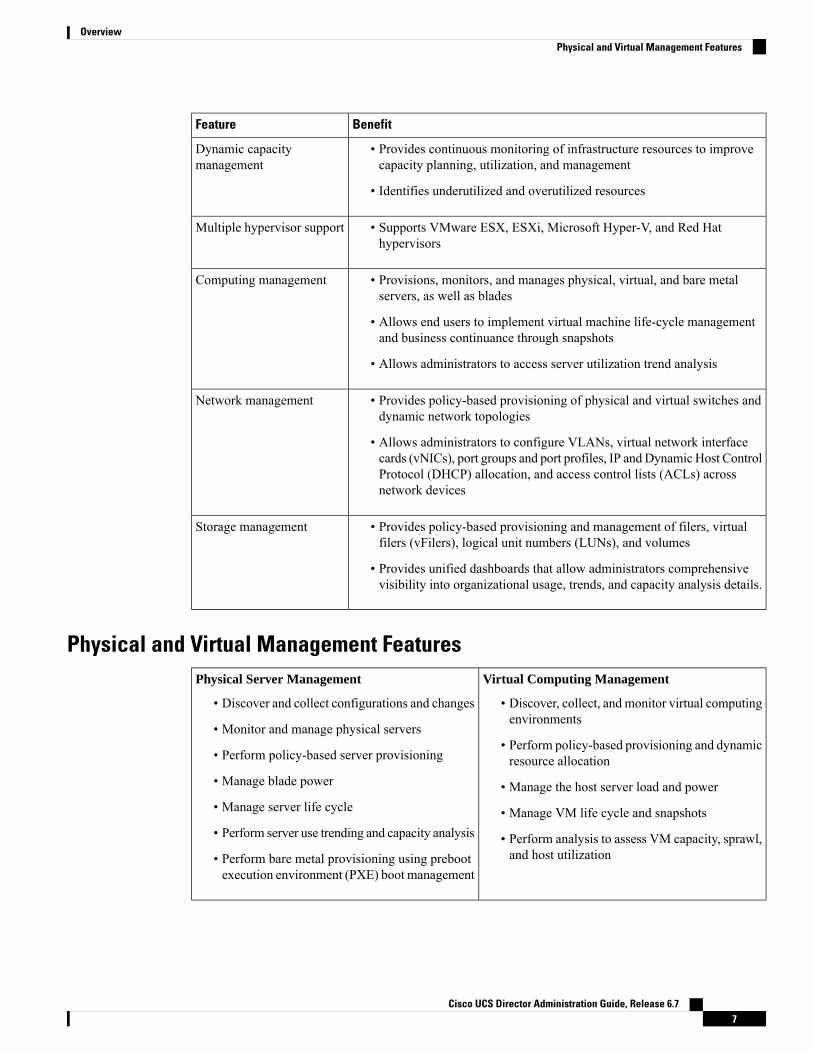
Physical and Virtual Management FeaturesVirtual Computing Management
• Discover, collect, and monitor virtual computingenvironments
• Perform policy-based provisioning and dynamicresource allocation
• Manage the host server load and power
• Manage VM life cycle and snapshots
• Perform analysis to assess VM capacity, sprawl,and host utilization
Physical Server Management
• Discover and collect configurations and changes
• Monitor and manage physical servers
• Perform policy-based server provisioning
• Manage blade power
• Manage server life cycle
• Perform server use trending and capacity analysis
• Perform bare metal provisioning using prebootexecution environment (PXE) boot management
Cisco UCS Director Administration Guide, Release 6.77
OverviewPhysical and Virtual Management Features

Virtual Storage Management
• Discover, collect, and monitor storage of vFilersand storage pools
• Perform policy-based storage provisioning forthick and thin clients
• Create new datastores and map them to virtualdevice contexts (VDCs)
• Add and resize disks to VMs
• Monitor and manage organizational storage use
• Perform virtual storage trend and capacityanalysis
Physical Storage Management
• Discover, collect, and monitor storage filers
• Perform policy-based provisioning of vFilers
• Provision and map volumes
• Create and map Logical Unit Number (LUN)and iGroup instances
• Perform SAN zone management
• Monitor and manage network-attached storage(NAS) and SAN-based storage
• Implement storage best practices andrecommendation
Virtual Network Management
• Add networks to VMs
• Perform policy-based provisioning with IP andDHCP allocation
• Configure and connect Virtual Network InterfaceCards ( vNICs) to VLANs and private VLANs
• Create port groups and port profiles for VMs
• Monitor organizational use of virtual networks
Physical Network Management
• Discover, collect, and monitor physical networkelements
• Provision VLANs across multiple switches
• Configure Access Control Lists (ACLs) onnetwork devices
• Configure storage network s
• Implement dynamic network topologies
Model-Based OrchestrationCisco UCS Director includes a task library containing over 1000 tasks and out-of-the-box workflows.Model-based orchestration and a workflow designer enable you to customize and automate the infrastructureadministrative and operational tasks. You can extend and customize the system to meet individual needs.
The following table shows the maintenance and update activities of the task library from day1 through day3:
Day-3Day-2Day-1
• Add/upgrade hardware
• Repurpose
• Monitor performance
• Start meeting and billing
• Manage tenant change
• Self-service Infrastructure asa Service (IaaS)
• Add tenants
• Migrate or add applicants
• Integrate with enterprisesystems
• Use End User Portal
Cisco UCS Director Administration Guide, Release 6.78
OverviewModel-Based Orchestration

User Interface of Cisco UCS DirectorCisco UCS Director introduces a new user interface for the administrative portal. This section introduces youto some of the key features of this new user interface.
Change in Navigation
In earlier releases, you could access screens using the main menu bar. Starting with this release, all navigationoptions are now available from a side bar, and not from the horizontal main menu bar. As a result, the mainmenu bar is no longer visible in the user interface. You can use your mouse or the cursor to hover over anoption on the side navigation bar, and then click on any of the menu options.
Absence of User Interface Labels
The user interface no longer includes labels for actions such as Add, Edit, Delete, Export, and Filter. Theseactions are represented only with icons. If you use your mouse or cursor to hover over the icon, the label willdisplay the action you can perform using that icon. You can also modify the icons in the user interface for allactions and status messages. For more information, see Modifying an Icon in the Cisco UCS Director UserInterface, on page 145.
Using Dashboard to Access Detailed Reports
If you have enabled the Dashboard, then it is the first screen that you will see when you login to Cisco UCSDirector. Typically, you can use this dashboard to add important or frequently accessed report widgets. Now,you can click on any of the reports that are displayed on the Dashboard, and immediately access the screenin the user interface where more detailed information is displayed.
For more information, see Enabling the Dashboard, on page 363
In addition, you can create multiple dashboards and delete them when you no longer need them. For moreinformation, see Creating Additional Dashboards, on page 364 and Deleting a Dashboard, on page 364.
Enhanced Capabilities with Tabular Reports
Following are some of the enhanced capabilities with tabular reports available in the user interface:
• Right-click to view additional options
After you select a row, if you right-click on your mouse, a list of options relevant to the row you selectedare displayed.
• Filter and Search
You can use a Filter option or a Search option with tabular reports in the Cisco UCS Director interface.On any page with a tabular report, you can use the Filter option that allows you to narrow down thetabular report results with a specific criteria. You can use this Filter option on tabular reports that do notspan across pages. For tabular reports that do span across multiple pages, you can use the Search optionto narrow down your search result.
• Adding tabular reports to the Favorites menu
You can add any tabular report displayed in the user interface as a Favorite. By adding a report as afavorite, you can access this report from the Favorites menu.
• Resizing of columns
Cisco UCS Director Administration Guide, Release 6.79
OverviewUser Interface of Cisco UCS Director

You can resize all the columns that are displayed in the tabular report, including the last column. Afteryou expand the columns, you can use the horizontal scroll bar to view the complete screen.
• Informational message displayed in the absence of data
If there is no information to be displayed in a report, the following message is displayed.
No Data
Removing and Restoring Tabs
On any screen that has multiple tabs available, you can choose the number of tabs that you would like to seeon that screen. If you close a tab on a screen, it will no longer be displayed in the row of tabs displayed in theuser interface. If you would like to bring it back on the screen, then click the arrow facing downwards that isvisible on the far right of the screen. It displays a drop-down list of tabs that are available but hidden fromview. Choose the tab you would like to restore.
You can remove and restore tabs on a screen only when there are a minimum of two tabs. This functionalityis not available when there is only one tab displayed on a screen in the interface.
Note
Enhancements to Reporting Capabilities
Following are some of the enhanced reporting capabilities available in the user interface:
• Introduction of pie charts and bar graphs
Each individual pie chart or bar graph can be exported out of the system in PDF, CSV or XLS format,or can be added to the Dashboard.
• Availability of More Reports option
Using the More Reports option, you can now generate reports on specific data for the resources in thecloud accounts. For more information, see Generating Additional Reports for a Cloud Account, on page14.
Landing PageThe landing page opens when you log in to the Cisco UCS Director administrator portal. The elements thatyou see on the landing page depend upon how you have configured the display. By default, the ConvergedView is displayed when you login to the portal.
The following are the available elements for your landing page:
• Header—Displays across the top of the screen.
• Navigation menu—The main navigation bar is no longer on the top of the screen. It is now available asa vertical menu on the left-side of the screen.
The menu does not have a scroll bar. The menu only displays the number of options that fit in the spaceavailable. Some options may not appear if you minimize your screen or zoom in. You can click Site Map toview all available options.
Note
Cisco UCS Director Administration Guide, Release 6.710
OverviewLanding Page

DescriptionNameNumber
Contains frequently accessed elements,including the menu. The header is alwaysvisible.
Header1
Provides a link to the Cisco website fromwhere you can access information on usingthe software.
Link2
Allows you to search for and navigate directlyto a specific report in the portal.
Search icon3
Displays the number of diagnostic systemmessages that have been logged. Clicking onthis link takes you to the Diagnostic SystemMessages screen from where you can viewdetailed information.
Diagnostic System Messages icon4
Displays the claim status of the device in CiscoIntersight.
Claim Status icon5
Launches the Service Request Quick Viewpanel that displays the recent in-progress,completed and failed service requests.
This feature is not available in Cisco UCSDirector instances that have beencross-launched from Cisco Intersight.
Service Request Quick View Panel6
Displays the list of connector packs availablefor upgrade. Clicking on this link takes you tothe Available System Upgrades screen fromwhere you can view detailed information.
New Upgrade Notification7
Cisco UCS Director Administration Guide, Release 6.711
OverviewLanding Page

DescriptionNameNumber
Links to the online help system for theadministrator portal.
Help icon8
Displays information about the software, andthe version that is currently installed.
About icon9
Returns you to the landing page from anylocation in the user interface.
Home icon10
Allows you to edit your profile, enable ordisable the dashboard, and log out.
User icon11
The vertical navigationmenu using which youcan access different screens in the interface.
Navigation menu12
Common IconsThe following table provides information about the common icons used in the user interface. You can see thename of an icon when you hover over it with your mouse. Some icons may have a different name, dependingupon the context in which they're used.
DescriptionNameIcon
Search is available on the header and on individual screens. Click Search onthe header to find a report in the user interface. Click Search on an individualscreen to find one or more items in the report.
Search
Alert is available on the header. Click Alert to view your diagnostic systemmessages.
Alert
User is available on the header. Click User to access your profile, or to logout of the user interface.
User
Export is available on individual screens. Click Export to export the contentof the report that is visible on the screen.
Export
Import is available on individual screens. Click Import to import a file.Import
Refresh is available on individual screens. Click Refresh to refresh the datathat is visible on the screen.
Refresh
View Details is available on individual screens. Click View Details to seedetails about the selected row in the table.
View Details
Table view is available for your application containers and catalogs. ClickTable View to view your application containers or catalogs in a table withdetails about each application container or catalog displayed.
Table View
Cisco UCS Director Administration Guide, Release 6.712
OverviewCommon Icons
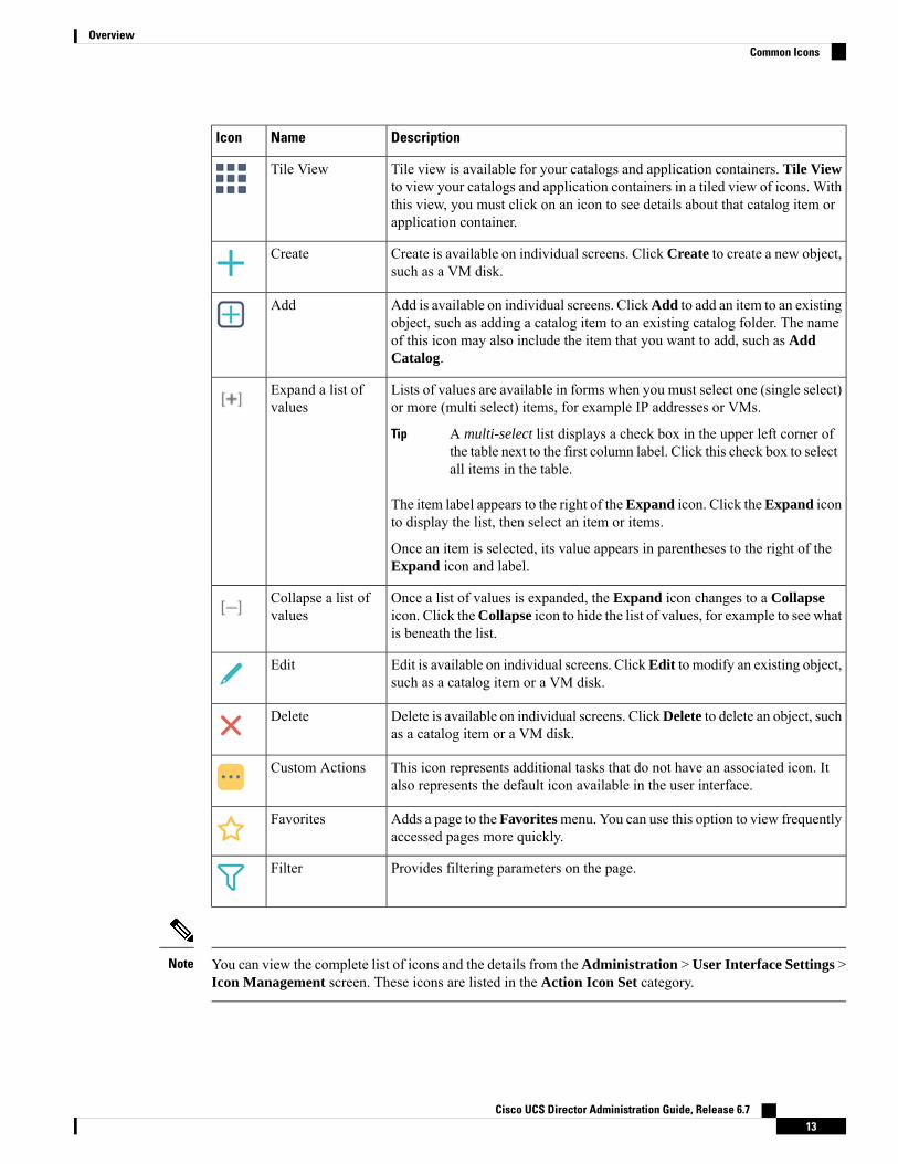
DescriptionNameIcon
Tile view is available for your catalogs and application containers. Tile Viewto view your catalogs and application containers in a tiled view of icons. Withthis view, you must click on an icon to see details about that catalog item orapplication container.
Tile View
Create is available on individual screens. Click Create to create a new object,such as a VM disk.
Create
Add is available on individual screens. ClickAdd to add an item to an existingobject, such as adding a catalog item to an existing catalog folder. The nameof this icon may also include the item that you want to add, such as AddCatalog.
Add
Lists of values are available in forms when you must select one (single select)or more (multi select) items, for example IP addresses or VMs.
A multi-select list displays a check box in the upper left corner ofthe table next to the first column label. Click this check box to selectall items in the table.
Tip
The item label appears to the right of theExpand icon. Click theExpand iconto display the list, then select an item or items.
Once an item is selected, its value appears in parentheses to the right of theExpand icon and label.
Expand a list ofvalues
Once a list of values is expanded, the Expand icon changes to a Collapseicon. Click theCollapse icon to hide the list of values, for example to see whatis beneath the list.
Collapse a list ofvalues
Edit is available on individual screens. ClickEdit to modify an existing object,such as a catalog item or a VM disk.
Edit
Delete is available on individual screens. ClickDelete to delete an object, suchas a catalog item or a VM disk.
Delete
This icon represents additional tasks that do not have an associated icon. Italso represents the default icon available in the user interface.
Custom Actions
Adds a page to the Favoritesmenu. You can use this option to view frequentlyaccessed pages more quickly.
Favorites
Provides filtering parameters on the page.Filter
You can view the complete list of icons and the details from the Administration > User Interface Settings >Icon Management screen. These icons are listed in the Action Icon Set category.
Note
Cisco UCS Director Administration Guide, Release 6.713
OverviewCommon Icons

Converged ViewWhen you login to the administrator portal for the first time, by default, the Converged screen is displayed.This screen displays the currently configured pods in your environment. From this screen, you can addadditional pods, or you can select a pod and view additional details on the resources within the pod. Typically,the additional details displayed include the following:
• Virtual resources
• Compute resources
• Network resources
• Storage resources
You can click on any of these resources, and the screen loads additional information.
Cisco UCS Director allows you to configure the Dashboard as the first screen to be displayed when you loginto the user interface. For more information, see Enabling the Dashboard, on page 363.
Generating Additional Reports for a Cloud AccountYou can use the More Reports option to generate specific reports for either a virtual cloud account or for aphysical pod account. The type of reports that are generated using this More Reports option varies based onthe type of account.
If there is no information available to generate this report, then a message stating that there is no data isdisplayed.
Procedure
Step 1 Navigate to the cloud account that you want to generate additional reports for.Step 2 From the More Actions drop-down menu, click More Reports.Step 3 From theType drop-down list, andReport drop-down list, choose the type of report that you want to generate.
The report is generated and displayed in the user interface.
Step 4 (Optional) Click Settings > Export Report to choose the format in which you want the report to be exportedin.
Guided Setup Wizards in Cisco UCS DirectorCisco UCS Director includes a set of wizards that guide you through configuring important features. Thefollowing are the available guided setup wizards:
• Device Discovery—This wizard enables you to discover devices and assign them to a pod.
• Initial System Configuration—This wizard helps you complete initial tasks to set up Cisco UCSDirector,such as uploading licenses, and setting up SMTP, NTP, and DNS servers.
• vDC Creation—This wizard enables you to configure the policies required to provision VMs in privateclouds.
Cisco UCS Director Administration Guide, Release 6.714
OverviewConverged View

• FlexPod Configuration—This wizard helps you set up a FlexPod account.
• Vblock Pod Configuration—This wizard enables you to discover and assign accounts to Vblock pods.
• VSPEX Pod Configuration—This wizard enables you to discover and assign accounts to VSPEX pods.
• Virtual SAN Pod Configuration—This wizard enables you to set up a Virtual SAN Pod and add devices.
When you first log into Cisco UCS Director, a Wizard Explorer window is displayed. From this window,you can view the details of the available guided setup wizards and choose to launch any of them. If you donot want this Wizard Explorer to appear every time you log in, you can check the Do not show this pageagain checkbox. To launch these wizards later on, click Administration > Guided Setup.
In addition to these system-providedwizards, you can create a wizard from aworkflow that you have previouslyconfigured. For more information, see Creating a Wizard from a Workflow, on page 15.
Creating a Wizard from a WorkflowYou can convert valid workflows into wizards, and save them in Cisco UCS Director.
Before you begin
You must have created valid workflows in Cisco UCS Director.
Procedure
Step 1 Choose Administration > Guided Setup.Step 2 On the Guided Setup page, click Setup.Step 3 From the More Actions drop-down menu, click Create from Workflow.Step 4 In the Create Wizard from Workflow screen, complete the required fields, including the following:
DescriptionName
Click Select to view a list of available workflows inthe Select Workflow screen.
Check the check boxes of the workflows that youwantto convert to a wizard and click Select.
Select Workflow field
Check this check box if you want the static valuesfrom the selected workflow tasks to be carried overinto the wizard pages.
Carry over static field values check box
The name of the wizard. This is the primary name ofthe wizard.
Label field
A secondary name of the wizard.Second Label field
A description of the wizard.Description field
Cisco UCS Director Administration Guide, Release 6.715
OverviewCreating a Wizard from a Workflow

DescriptionName
Click Select to view a list of available icons in theIcon Image screen.
Check the check box of the icon that you want toassociate with this workflow and click Select.
Icon Image field
Step 5 Click Submit.
What to do next
You can perform the following tasks:
• Launch the wizard.
• Edit the wizard.
• View details of the wizard.
• Re-order the wizard in the interface.
• Delete the wizard.
Setting up Non-Secure Connection to the Cisco UCS DirectorUser Interface
By default, the Cisco UCS Director user interface launches in the secure mode. If you want to bypass thesecure mode, and launch the user interface in a non-secure mode (HTTP), you must follow this procedure.
Procedure
Step 1 Log in as root.Step 2 Make the following changes in the
/opt/infra/web_cloudmgr/apache-tomcat/conf/server.xml file:a) Comment out the existing port 8080 Connector tag
<!--<Connector port="8080" protocol="HTTP/1.1"redirectPort="443" maxHttpHeaderSize="65536"URIEncoding = "UTF-8"/>-->
b) Add the following as a new port 8080 Connector tag:
<Connector port="8080" protocol="HTTP/1.1"maxThreads="150" minSpareThreads="4"connectionTimeout="20000"
Cisco UCS Director Administration Guide, Release 6.716
OverviewSetting up Non-Secure Connection to the Cisco UCS Director User Interface

URIEncoding = "UTF-8" />
Step 3 Comment the <security-constraint> tag in the/opt/infra/web_cloudmgr/apache-tomcat/webapps/app/WEB-INF/web.xml file.
<!--<security-constraint><web-resource-collection><web-resource-name>HTTPSOnly</web-resource-name><url-pattern>/*</url-pattern></web-resource-collection><user-data-constraint><transport-guarantee>CONFIDENTIAL</transport-guarantee></user-data-constraint></security-constraint>-->
Step 4 Restart the services.Step 5 Launch the user interface and log in to the system.
You can now log into the system in the non-secure mode using the following URL format:
http://<IP-Address>:8080 or http://<IP-Address>
You can launch the user interface in both, secure and non-secure modes.
Initial LoginLog into Cisco UCS Director using the hostname or IP address with the default credentials that have beenprovided. After logging in to the administrator portal, you are prompted to change your password. Enter thecurrent password and the new password information. You cannot save the new password information unlessyou have also reset the default SSH password for root and shelladmin users. To reset these passwords, connectto Cisco UCS Director using SSH, and reset the passwords. After you reset the SSH root and shelladminpasswords, the Save button on this screen is enabled.
We recommend that you delete the startup admin account after you create the first admin account. To accessthe End User Portal, you must have a valid email address.
Note
Generating a Self-Signed CertificatePrior versions of Cisco UCS Director required a Cisco-signed SSL certificate. Cisco UCS Director nowrequires a user-signed certificate instead of a Cisco-signed certificate. After installing or upgrading CiscoUCS Director, if the SSL certificate in the system is identified as a Cisco-signed certificate, you will beprompted post login to generate a self-signed certificate. After you generate the self-signed certificate, theTomcat service is restarted to associate with the new certificate. After the Tomcat service is restarted, you areprompted to re-login to the user interface.
Cisco UCS Director Administration Guide, Release 6.717
OverviewInitial Login

Do not use this self-signed certificate for the Device Connector.Note
To generate the self-signed certificate, do the following:
Procedure
Step 1 Log into the Cisco UCS Director user interface.Step 2 In the Generate Self-Signed Certificate screen, complete the required fields, including the following:
DescriptionField
Enter the domain name. For example, cisco.com.Local Domain field
Enter the number of days that you want the self-signedcertificate to be valid. For example, 1825.
We recommend that you enter a number between 1825days (5 years) and 5475 days (15 years).
Certificate Validity (in days) field
Enter the Java KeyStore (JKS) password to generatethe self-signed certificate.
The Java KeyStore (JKS) file is a repository forcertificates used by the Tomcat service, and ispassword protected. Enter this password for this field.
Keystore Password field
Confirm the Java KeyStore (JKS) password togenerate the self-signed certificate.
Confirm Keystore Password field
Step 3 Click Save.
Recommended Order of System SetupThe following figure illustrates the workflow to set up your environment using Cisco UCS Director:
Cisco UCS Director Administration Guide, Release 6.718
OverviewRecommended Order of System Setup

Figure 1: Sample Workflow to Set up Your Environment
The following table describes the chapters available in this book using which you can complete setting upyour environment.
DescriptionChapterName
Describes how to apply a license, set up the Admin profile, create groups,and create users. You will learn how to access language support, applyportal customization, and system settings
2, 3, 4and 5
Initial set up
Describes how to optionally add a pod and physical account, add networkelements, test the connections, and verify account discovery.
6Physical Infrastructure
You can create the virtual infrastructure before the physicalinfrastructure if you want.
Note
Cisco UCS Director Administration Guide, Release 6.719
OverviewRecommended Order of System Setup

DescriptionChapterName
Describes how to create a cloud, verify cloud discovery and connectivity,test the connections, and view vCenter plug ins.
7Virtual Infrastructure
Describes how to create and manage computing policies, storage policies,network policies, and system policies. You will learn how to add OSlicenses for Microsoft Windows catalogs.
8Policies
Describes how to set up VDCs to manage specific environments forgroups. policies, and cost models, and how resource limits are configuredand managed at the VDC level.
9Virtual Data Centers
Describes how to set up catalog items, attach groups with access to acatalog, and publish catalog items.
10Catalogs
Describes how you can create and manage provisioning service requests.11Self-ServiceProvisioning
Describes how to configure VM disk provisioning on a preferred singledatastore or multiple datastores. It also provides instructions on how toconfigure individual disk policies for each additional disk in a template.
12Multi-DiskProvisioning
Describes how to create chargeback summary reports, detailed reports,and resource accounting reports. It shows how cost models are definedand assigned to policies within departments and organizations.
13Chargeback
Describes how you can get complete cloud visibility, monitor resourceusage, and manage the cloud stack—clouds, clusters, host servers, andvirtual machines.
14Cloud Management
Describes how to perform post provisioning life cyclemanagement actionson VMs, such as VM power management, VM resizing, VM snapshotmanagement, and other VM actions.
15Life Cycles
Describes the analytical reports about the underlying physical and virtualinfrastructure that Cisco UCS Director can generate.
16CloudSense
Configuring the Host Name for Cisco UCS DirectorIf you changed the default host name of the appliance of Cisco UCS Director using the command prompt,then you must follow this procedure to ensure that the name is updated in the /etc/hosts file.
Procedure
Step 1 SSH to the appliance using the root account.Step 2 Edit the /etc/hosts to update the new host name.
In a single node environment, you must update the file in the following format:vi /etc/hosts198.51.100.1 new_hostname
Cisco UCS Director Administration Guide, Release 6.720
OverviewConfiguring the Host Name for Cisco UCS Director

In a multi-node environment, if the host names of other nodes are changed, then you must update the IPaddress and the new host name on the primary node, service nodes and database nodes. For example:vi /etc/hosts198.51.100.1 new_hostnameEx:198.51.100.2 UCSD_Primary198.51.100.3 UCSD_Service198.51.100.4 UCSD_Inv_DB198.51.100.5 UCSD_Mon_DB
Step 3 Restart the appliance services.
Working with CiphersAs an administrator in Cisco UCS Director, you have the capability to enable or disable ciphers from theproperty file. In the event that you enable a cipher with a potential security risk, a warning message is loggedin the Cisco UCS Director log file. By default, all ciphers that pose a risk are disabled. You can configurespecific ciphers from the defaultEnabledCipherSuites.properties file, located in the/opt/infra/inframgr folder. For more information, see Editing Cipher Usage, on page 21.
In addition, you can change the preference order of the standard set of ciphers, based on your systemrequirements. By default, the standard ciphers are listed according to the preference order.
Cisco UCS Director currently supports the use of "limited" and "strong" Java Cryptograpy Extension (JCE)Policy files for Java SE Runtime Environment. If you want to change these policies to "unlimited" and "strong"JCE policies, then you must download and install the latest JCE policy files from the Oracle website. Formore information, see Installing the Latest Java Cryptograpy Extension (JCE) Policy Files , on page 22.
Editing Cipher UsageCipherSuites are maintained in the defaultEnabledCipherSuites.properties file. You can editthe list of ciphers in this file, based on the application requirements for your network.
We recommend that you always use the standard ciphers and not enable any broken or risky ciphers for yourapplication.
Procedure
Step 1 Open the defaultEnabledCipherSuites.properties file.
It is available in the opt/infra/inframgr/ directory.
Step 2 To use a broken cipher, locate the cipher in the file, and uncomment it.Step 3 Save the file.Step 4 Restart the service.
Cisco UCS Director Administration Guide, Release 6.721
OverviewWorking with Ciphers

Installing the Latest Java Cryptograpy Extension (JCE) Policy FilesComplete the following procedure to download and install the latest JCE policy files:
Procedure
Step 1 Take a backup of the following files in the $JAVA_HOME/jre/lib/security folder:
• local_policy.jar
• US_export_policy.jar
Step 2 Access the oracle Java SE download page at http://www.oacle.com/technetwork/java/javase/downloads.index.html.
Step 3 Scroll to the Additional Resources section to locate the Java Cryptography Extension (JCE) UnlimitedStrength Jurisdiction Policy File.
Step 4 Download theJava Cryptography Extension (JCE) Unlimited Strength JurisdictionPolicy Files for JDK/JRE 8 zipped file.
Step 5 Extract the contents of the zipped file.Step 6 Replace the local_policy.jar and US_export_policy.jar in the
$JAVA_HOME/jre/lib/security folder.Step 7 Restart the application.
Cisco UCS Director Administration Guide, Release 6.722
OverviewInstalling the Latest Java Cryptograpy Extension (JCE) Policy Files

C H A P T E R 3Managing Users and Groups
This chapter contains the following sections:
• User Roles, on page 23• Adding a User Role, on page 25• Adding Users, on page 26• Managing User Types, on page 28• Default User Permissions, on page 28• Managing User Account Status, on page 49• MSP Administrator Role, on page 51• Managing Groups, on page 52• Configuring the Administration Profile, on page 62• Managing User Access Profiles, on page 66• Authentication and Cisco Identity Services Engine (Cisco ISE), on page 88• Branding for Customer Organizations, on page 91• Branding User Groups, on page 92• Branding Customer Organizations, on page 93• Login Page Branding, on page 94
User RolesCisco UCS Director supports the following user roles:
• All Policy Admin
• Billing Admin
• Computing Admin
• Group Admin—An end user with the privilege of adding users. This user can use the End User Portal.
• IS Admin
• MSP Admin
• Network Admin
• Operator
Cisco UCS Director Administration Guide, Release 6.723

• Service End User—This user can only view and use the End User Portal.
• Storage Admin
• System Admin
These user roles are system-defined and available in Cisco UCS Director by default. You can determine if arole is available in the system by default, if the Default Role column in the Users page is marked with Yes.
As an administrator in Cisco UCS Director, you can assign users to system-provided user roles or tocustom-defined user roles. In addition, at a later point in time, you can view information on the role that auser is assigned to. For more information, see Viewing User Role Information for Users.
Note
As an administrator in the system, you can perform the following tasks with user roles:
• Create a custom user role in the system, and create user accounts with this role or assign the role toexisting users.
When you create a new user role, you can specify if the role is that of an administrator or an end user.For more information on creating a user role, see Adding a User Role, on page 25. For information oncreating user accounts for a role, see Adding Users, on page 26.
• Modify existing user roles, including default roles, to change menu settings and read/write permissionsfor users associated with that role.
The procedure to modify menu settings and permissions for a role is the same as the procedure to add auser role.
Defining Permissions to Perform VM Management Tasks to Users
Previously, user permissions for VMmanagement tasks could only be created by defining them in an end-userself-service policy. As an administrator in the system, you can now map permissions to perform VMmanagement tasks to any user role. Users that are mapped to the given role can complete the selected VMmanagement related tasks. However, to assign VM management tasks to end users using the end-user selfservice policy, you must first disable all VM management actions for this user role, and then enable all othermanagement tasks.
For any user in the system, the capability to perform VM management tasks is determined by the following:
• The permissions assigned to the user role that the user is mapped to
• The end user self-service policy that is mapped to the VDC.
If you have upgraded to the current release, then the permissions to performVMmanagement tasks is retainedin the end user self service policy that was created with the previous release version. However, the permissionsthat you defined or set for the user role after upgrading to the current release, takes precedence.
You can provide permissions to perform VMmanagement tasks to other administrators, such as MSP Adminor Group Admin, by defining them in the user role only.
Note
Cisco UCS Director Administration Guide, Release 6.724
Managing Users and GroupsUser Roles

Adding a User RoleYou can create any number of user roles in Cisco UCS Director and define the menu settings for the userscreated with these roles.
Procedure
Step 1 Choose Administration > System.Step 2 On the System page, click User Roles.Step 3 Click Add.Step 4 In the Add User Role screen, complete the required fields, including the following:
DescriptionName
Name of the user role.User Role field
Choose the type of role that you are adding. It can beone of the following:
• Admin
• End user
Role Type drop-down list
The description of the role being added.Description field
Click Select to view a list of user roles in the DenyRole List screen.
Check the roles that you want to deny for users createdwith this role and click Select.
For example, as an administrator, you are creating anew group admin role in the system using the clonefeature, and this group admin role must include thecapability to create users with privileges higher thanthe group admin role. However, by default, the GroupAdmin role does not allow creating users withprivilege higher than the group admin. So in thissituation, as the administrator, you will need to selectthe default group admin role in the deny list.
Deny Role List
Step 5 Click Next.Step 6 In the Menu Settings pane, check the menu options that will be visible to users who are defined in this role.Step 7 Click Next.Step 8 In the User Permissions pane, choose the read or write permissions associated with various available user
tasks.Step 9 Click Submit.
Cisco UCS Director Administration Guide, Release 6.725
Managing Users and GroupsAdding a User Role

What to do next
Create a user account with this role type.
Adding UsersBefore you begin
Ensure that you have created a group before you add a user to it.
Procedure
Step 1 Choose Administration > Users and Groups.Step 2 On the Users and Groups page, click Users.
The Users page displays the following information for all user accounts currently available in the system:
• Status
• Login name and access level
• Email address
• Date when the user account will be disabled
• Current status of the password, and the date on which the password will expire
Step 3 Click Add.Step 4 On the Add User screen, complete the required fields, including the following:
DescriptionField Name
Choose the role type for the user.
This drop-down list displays all theavailable user roles in Cisco UCSDirector.In addition to the user roles available bydefault, you can create additional userroles. For more information on creatinguser roles, see Adding a User Role, on page25.
Note
User Role drop-down list
Select the group that the user will have access to. Youcan either select a group already available, or you canadd a new group.
This field is visible only when you selectService End-User or Group Admin as theuser role.
Note
User Group drop-down list
Cisco UCS Director Administration Guide, Release 6.726
Managing Users and GroupsAdding Users

DescriptionField Name
Select theMSP organization that the user will manage.
You can either select an organization that is currentlyavailable, or you can add a new organization.
This field is visible only when you selectMSP Admin as the user role.
Note
MSP Organization drop-down list
The login name.
You can include special characters such as ( ). & - _`~ $% ^ {}! ' @
Login Name field
The password.
If Lightweight Directory Access Protocol(LDAP) authentication is configured forthe user, the password is validated only atthe LDAP server, and not at the localserver.
Note
Password field
The password is entered again for confirmation.Confirm Password field
The email address.
The email address is required to notify thegroup owner about the service requeststatus and to request approval.
Note
User Contact Email field
The first name.First Name field
The last name.Last Name field
The phone number of the user.Phone field
The office address of the user.Address field
Check to set the date and time when the user accountmust be disabled in the system. Disabling a useraccount means that the user can no longer log in intothe system.
A week prior to this date, an email message statingthat the account will be disabled is sent to the user.This automatic email message is generated and sentby thePeriodicNotificationToUserTask system task.
On the specified date and time, the user account isdisabled automatically. If the user is logged in to thesystem on the date specified, then the login session isterminated automatically.
Set user disable date check box
Cisco UCS Director Administration Guide, Release 6.727
Managing Users and GroupsAdding Users

DescriptionField Name
Choose a language for the system specifically for thisuser. By default, the language is set to English.
When this user logs in, the user interface is displayedin the language you selected. This locale selectionapplies only to this user.
Locale drop-down list
Step 5 Click Add.
What to do next
Click a row with a user and click Manage Profiles, to optionally assign multiple roles for that user.
Managing User TypesAs the system administrator, you have full privileges to manage Cisco UCS Director, including adding users,viewing users and user permissions, and modifying individual user read/write permissions for different systemcomponents.
Most users access the Administrative portal when they log in.
Default User PermissionsEach admin user has a set of permissions to access Cisco UCS Director. The types of user permissions are asfollows:
• Read—An admin user with Read permission has the ability to only read a file.
• Write—An admin user with Write permission has the ability to read, write, and modify a file. Thispermission includes the ability to delete or rename files.
• Read/Write—An admin user with Read/Write permission has the ability to read and write a file.
User Roles and PermissionsThe following table shows a list of the permissions that are mapped to each user role:
StorageAdmin
ServiceEndUser
OperatorNetworkAdmin
MSPAdmin
ISAdmin
GroupAdmin
ComputingAdmin
BillingAdmin
AllPolicyAdmin
Permission
ReadRead/Write
ReadReadWriteReadRead /Write
ReadReadVirtualComputing
WriteWriteWriteWriteWriteWriteWriteWriteWriteVM Label
Cisco UCS Director Administration Guide, Release 6.728
Managing Users and GroupsManaging User Types

StorageAdmin
ServiceEndUser
OperatorNetworkAdmin
MSPAdmin
ISAdmin
GroupAdmin
ComputingAdmin
BillingAdmin
AllPolicyAdmin
Permission
WriteWriteWriteAssignVM tovDC
ReadReadReadReadReadReadVirtualStorage
ReadReadReadReadReadReadVirtualNetwork
ReadReadReadReadReadRead /Write
Read /Write
PhysicalComputing
Read /Write
ReadReadReadReadRead /Write
ReadRead /Write
PhysicalStorage
ReadRead /Write
Read /Write
ReadReadRead /Write
PhysicalNetwork
ReadRead/Write
Read /Write
ReadRead /Write
ReadRead /Write
ReadReadRead /Write
GroupServiceRequest
WriteWriteWriteWriteWriteCreateServiceRequest
Read /Write
Read/Write
ReadRead /Write
Read /Write
Read /Write
Read/Write
Read /Write
Read /Write
ApproverServiceRequest
ReadReadReadRead /Write
ReadReadRead /Write
ReadBudgeting
ReadReadReadReadReadReadReadReadReadReadResourceAccouting
ReadReadReadReadReadReadReadReadReadReadChargeback
ReadReadReadReadReadReadSystemAdmin
ReadReadReadReadReadReadUsers andGroups
ReadReadReadReadReadReadVirtualAccounts
ReadReadReadReadReadReadReadReadReadCatalogs
Cisco UCS Director Administration Guide, Release 6.729
Managing Users and GroupsUser Roles and Permissions

StorageAdmin
ServiceEndUser
OperatorNetworkAdmin
MSPAdmin
ISAdmin
GroupAdmin
ComputingAdmin
BillingAdmin
AllPolicyAdmin
Permission
ReadReadReadReadReadRead /Write
ReadReadReadvDC
ReadReadReadReadRead /Write
Read /Write
ComputingPolicy
Read /Write
ReadReadReadReadRead /Write
StoragePolicy
ReadReadRead /Write
ReadReadRead /Write
NetworkPolicy
ReadReadReadRead /Write
ReadWriteDeploymentPolicy
ReadReadReadRead /Write
ReadRead /Write
ServiceDelivery
ReadReadReadReadReadReadReadReadReadReadResourceLimitReport
ReadReadReadRead /Write
ReadRead /Write
ReadReadGroupUsers
ReadReadReadReadReadRead /Write
ReadRead /Write
ReadCloudsenseReports
ReadReadReadRead /Write
ReadCloudsenseAssessmentReports
Read /Write
Read /Write
Read /Write
Read /Write
Read /Write
Orchestration
Read /Write
Read /Write
WriteReadReadReadDiscovery
OpenAutomationModules
ReadReadRead /Write
CS SharedReports
Read /Write
CS SharedAssessments
Cisco UCS Director Administration Guide, Release 6.730
Managing Users and GroupsUser Roles and Permissions

StorageAdmin
ServiceEndUser
OperatorNetworkAdmin
MSPAdmin
ISAdmin
GroupAdmin
ComputingAdmin
BillingAdmin
AllPolicyAdmin
Permission
RemoteVMAccess
MobileAccessSettings
ReadReadReadEnd UserChargeback
UCSDCluster
Read /Write
Read /Write
Read /Write
Read /Write
ResourceGroups
Read /Write
Read /Write
Read /Write
Read /Write
TagLibrary
TrueTrueTrueTrueTrueTrueTrueTrueTrueTrueAllowDeployabilityAssessment
Read /Write
Read/Write
Read /Write
Read /Write
Read /Write
Read /Write
Read /Write
Read /Write
Read /Write
Read /Write
WriteCloupiaScript
Read /Write
Read/Write
Read /Write
Read /Write
Read /Write
Read /Write
Read /Write
Read /Write
Read /Write
Read /Write
ExecuteCloupiaScript
Permissions for Server ManagementIn prior releases, to manage physical servers, Cisco UCS Director only provided the following options:
• Read Physical Computing
• Write Physical Computing
As an administrator, if you enabled the write permission, then users had the capability to manage all CiscoUCS physical servers in the environment.With this release, within theWrite Physical Computing permission,the following new categories of permissions have been introduced:
• Physical Server Management
• Other Physical Compute Management
Enabling Physical Server Management implies enabling management of Cisco UCS Servers only. Thiscategory includes the following actions:
Cisco UCS Director Administration Guide, Release 6.731
Managing Users and GroupsPermissions for Server Management

• Power Management (Power On and Power Off)
• Group Management (Assign Group and Unassign Group)
• Inventory Management
• Server Management
• Server Access
If you enable these tasks for users, then those users can view these actions or tasks in the portal. However,for end users, even if you enable these tasks, they can only perform the following tasks on Cisco UCS servers:
• Power on and off servers
• Associate and disassociate groups
• KVM console
EnablingOther Physical Compute Management implies enabling management tasks for other UCS serversin the environment. Uses from whom this permission is enabled can perform tasks such as working withservice profiles or VLANs.
All Policy AdminThe following table shows a list of operations that an All Policy admin can perform:
PermissionsOperations
WriteRead
YesVirtual Computing
YesVM Label
YesAssign VM to vDC
YesVirtual Storage
YesVirtual Network
YesYesPhysical Computing
YesYesPhysical Storage
YesYesPhysical Network
YesYesGroup Service Request
YesCreate Service Request
YesYesApprover Service Request
YesBudgeting
YesResource Accounting
Cisco UCS Director Administration Guide, Release 6.732
Managing Users and GroupsAll Policy Admin

PermissionsOperations
YesChargeback
YesSystem Admin
YesUsers and Groups
YesVirtual Accounts
YesCatalogs
YesvDC
YesYesComputing Policy
YesYesStorage Policy
YesDeployment Policy
YesYesNetwork Policy
YesYesService Delivery
YesResource Limit Report
YesGroup Users
YesCloudsense Reports
YesCloudsense AssessmentReports
YesYesOrchestration
YesDiscovery
Open Automation Modules
CS Shared Reports
CS Shared Assessments
Remote VM Access
Mobile Access Settings
End User Chargeback
Write Resource Accounting
UCSD Cluster
Resource Groups
Tag Library
Cisco UCS Director Administration Guide, Release 6.733
Managing Users and GroupsAll Policy Admin

PermissionsOperations
TrueAllow DeployabilityAssessment
Billing AdminThe following table show a list of operations that a Billing admin can perform:
PermissionOperation
WriteRead
Virtual Computing
VM Label
Assign VM to vDC
Virtual Storage
Virtual Network
Physical Computing
Physical Storage
Physical Network
YesGroup Service Request
Approver Service Request
YesYesBudgeting
YesResource Accounting
YesChargeback
System Admin
Users and Groups
Virtual Accounts
Catalogs
vDC
Computing Policy
Storage Policy
Deployment Policy
Cisco UCS Director Administration Guide, Release 6.734
Managing Users and GroupsBilling Admin

PermissionOperation
Network Policy
Service Delivery
YesResource Limit Report
Group Users
YesYesCloudsense Reports
YesYesCloudsense AssessmentReports
Orchestration
YesDiscovery
Open Automation Modules
CS Shared Reports
CS Shared Assessments
Remote VM Access
Mobile Access Settings
End User Chargeback
YesWrite Resource Accounting
UCSD Cluster
Resource Groups
Tag Library
TrueAllow DeployabilityAssessment
Computing AdminThe following table shows a list of operations that a Computing admin can perform:
PermissionOperation
WriteRead
YesVirtual Computing
YesVM Label
Assign VM to vDC
Cisco UCS Director Administration Guide, Release 6.735
Managing Users and GroupsComputing Admin

PermissionOperation
YesVirtual Storage
YesVirtual Network
YesYesPhysical Computing
YesPhysical Storage
YesPhysical Network
YesGroup ServiceRequest
YesYesApprover ServiceRequest
YesBudgeting
YesResource Accounting
YesChargeback
YesSystem Admin
YesUsers and Groups
YesVirtual Accounts
YesCatalogs
YesvDC
YesYesComputing Policy
YesStorage Policy
YesDeployment Policy
YesNetwork Policy
YesService Delivery
YesResource Limit Report
YesGroup Users
YesCloudsense Reports
YesCloudsenseAssessment Reports
YesYesOrchestration
YesDiscovery
Cisco UCS Director Administration Guide, Release 6.736
Managing Users and GroupsComputing Admin

PermissionOperation
Open AutomationModules
CS Shared Reports
CS SharedAssessments
Remote VM Access
Mobile AccessSettings
End User Chargeback
Write ResourceAccounting
UCSD Cluster
YesYesResource Groups
YesYesTag Library
TrueAllow DeployabilityAssessment
Group AdminThe following table shows a list of operations that a Group admin can perform:
PermissionTask
WriteRead
YesYesVirtual Computing
YesVM Label
Assign VM to vDC
Virtual Storage
Virtual Network
Physical Computing
YesYesPhysical Storage
Physical Network
YesYesGroup Service Request
Cisco UCS Director Administration Guide, Release 6.737
Managing Users and GroupsGroup Admin

PermissionTask
YesCreate Service Request
YesYesApprover Service Request
Budgeting
YesResource Accounting
YesChargeback
System Admin
Users and Groups
Virtual Accounts
YesCatalogs
YesvDC
Computing Policy
Storage Policy
Deployment Policy
Network Policy
Service Delivery
YesResource Limit Report
YesYesGroup Users
YesYesCloudsense Reports
Cloudsense AssessmentReports
Orchestration
Discovery
Open Automation Modules
YesYesCS Shared Reports
CS Shared Assessments
Remote VM Access
Mobile Access Settings
YesEnd User Chargeback
Cisco UCS Director Administration Guide, Release 6.738
Managing Users and GroupsGroup Admin

PermissionTask
Write Resource Accounting
UCSD Cluster
Resource Groups
Tag Library
TrueAllow DeployabilityAssessment
IS AdminThe following table shows a list of operations that an IS admin can perform:
PermissionTask
WriteRead
YesVirtual Computing
YesVM Label
YesAssign VM to vDC
YesVirtual Storage
YesVirtual Network
YesPhysical Computing
YesPhysical Storage
YesPhysical Network
YesGroup Service Request
YesYesApprover Service Request
YesBudgeting
YesResource Accounting
YesChargeback
YesSystem Admin
YesUsers and Groups
YesVirtual Accounts
YesCatalogs
YesYesvDC
Cisco UCS Director Administration Guide, Release 6.739
Managing Users and GroupsIS Admin

PermissionTask
YesComputing Policy
YesStorage Policy
YesYesDeployment Policy
YesNetwork Policy
YesYesService Delivery
YesResource Limit Report
YesGroup Users
YesCloudsense Reports
YesCloudsense AssessmentReports
YesYesOrchestration
YesDiscovery
Open Automation Modules
CS Shared Reports
CS Shared Assessments
Remote VM Access
Mobile Access Settings
End User Chargeback
Write Resource Accounting
UCSD Cluster
YesYesResource Groups
YesYesTag Library
TrueAllow DeployabilityAssessment
Network AdminThe following table shows a list of operations that a Network admin can perform:
PermissionTask
WriteRead
Cisco UCS Director Administration Guide, Release 6.740
Managing Users and GroupsNetwork Admin

PermissionTask
YesVirtual Computing
YesVM Label
Assign VM to vDC
YesVirtual Storage
YesVirtual Network
YesPhysical Computing
YesPhysical Storage
YesYesPhysical Network
YesGroup Service Request
YesYesApprover Service Request
YesBudgeting
YesResource Accounting
YesChargeback
YesSystem Admin
YesUsers and Groups
YesVirtual Accounts
YesCatalogs
YesvDC
YesComputing Policy
YesStorage Policy
YesDeployment Policy
YesYesNetwork Policy
YesService Delivery
YesResource Limit Report
YesGroup Users
YesCloudsense Reports
YesCloudsense AssessmentReports
Cisco UCS Director Administration Guide, Release 6.741
Managing Users and GroupsNetwork Admin

PermissionTask
YesYesOrchestration
YesYesDiscovery
Open Automation Modules
CS Shared Reports
CS Shared Assessments
Remote VM Access
Mobile Access Settings
End User Chargeback
Write Resource Accounting
UCSD Cluster
YesYesResource Groups
YesYesTag Library
TrueAllow DeployabilityAssessment
OperatorThe following table shows a list of operations that an Operator can perform:
PermissionTask
WriteRead
YesVirtual Computing
YesVM Label
YesAssign VM to vDC
YesVirtual Storage
YesVirtual Network
YesPhysical Computing
YesPhysical Storage
YesPhysical Network
YesYesGroup Service Request
YesCreate Service Request
Cisco UCS Director Administration Guide, Release 6.742
Managing Users and GroupsOperator

PermissionTask
YesYesApprover Service Request
YesBudgeting
YesResource Accounting
YesChargeback
YesSystem Admin
YesUsers and Groups
YesVirtual Accounts
YesCatalogs
YesvDC
YesComputing Policy
YesStorage Policy
YesDeployment Policy
YesNetwork Policy
YesService Delivery
YesResource Limit Report
YesGroup Users
YesCloudsense Reports
YesCloudsense AssessmentReports
Orchestration
Discovery
Open Automation Modules
CS Shared Reports
CS Shared Assessments
Remote VM Access
Mobile Access Settings
End User Chargeback
Write Resource Accounting
Cisco UCS Director Administration Guide, Release 6.743
Managing Users and GroupsOperator

PermissionTask
UCSD Cluster
Resource Groups
Tag Library
TrueAllow DeployabilityAssessment
Service End UserThe following table shows a list of operations that a Service End User can perform:
PermissionTask
WriteRead
YesYesVirtual Computing
YesVM Label
Assign VM to vDC
Virtual Storage
Virtual Network
YesPhysical Computing
YesPhysical Storage
Physical Network
YesYesGroup Service Request
YesCreate Service Request
YesYesApprover Service Request
Budgeting
YesResource Accounting
YesChargeback
System Admin
Users and Groups
Virtual Accounts
YesCatalogs
YesvDC
Cisco UCS Director Administration Guide, Release 6.744
Managing Users and GroupsService End User

PermissionTask
Computing Policy
Storage Policy
Deployment Policy
Network Policy
Service Delivery
YesResource Limit Report
Group Users
YesCloudsense Reports
Cloudsense AssessmentReports
Orchestration
Discovery
Open Automation Modules
YesCS Shared Reports
CS Shared Assessments
Remote VM Access
Mobile Access Settings
YesEnd User Chargeback
Write Resource Accounting
UCSD Cluster
Resource Groups
Tag Library
TrueAllow DeployabilityAssessment
Storage AdminThe following table shows a list of operations that a Storage admin can perform:
PermissionTask
WriteRead
Cisco UCS Director Administration Guide, Release 6.745
Managing Users and GroupsStorage Admin

PermissionTask
YesVirtual Computing
YesVM Label
Assign VM to vDC
YesVirtual Storage
YesVirtual Network
YesPhysical Computing
YesYesPhysical Storage
YesPhysical Network
YesGroup Service Request
YesYesApprover Service Request
YesBudgeting
YesResource Accounting
YesChargeback
YesSystem Admin
YesUsers and Groups
YesVirtual Accounts
YesCatalogs
YesvDC
YesComputing Policy
YesYesStorage Policy
YesDeployment Policy
YesNetwork Policy
YesService Delivery
YesResource Limit Report
YesGroup Users
YesCloudsense Reports
YesCloudsense AssessmentReports
Cisco UCS Director Administration Guide, Release 6.746
Managing Users and GroupsStorage Admin

PermissionTask
YesYesOrchestration
YesYesDiscovery
Open Automation Modules
CS Shared Reports
CS Shared Assessments
Remote VM Access
Mobile Access Settings
End User Chargeback
Write Resource Accounting
UCSD Cluster
YesYesResource Groups
YesYesTag Library
TrueAllow DeployabilityAssessment
Viewing User Role Information for UsersAs an administrator in the system, you can assign users to system-provided user roles or to custom-defineduser roles. You can view this information at a later point in time for all users in a group.
Procedure
Step 1 Choose Organizations > Summary.Step 2 On the Summary page, choose the user group.Step 3 Click Users.
From this page, you can view detailed information on the users that belong to the selected group. The AccessLevel column displays the roles, system-defined or custom-defined roles, that the users are assigned to.Optionally, you can choose Administration > User and Groups > Users to view all user information. If youare a group administrator, then to view this information, choose Organizations > Users.
If you are a group administrator, then this page displays the password expiry date and time for each user. Thisinformation is derived from the Password policy that is configured in the system. This page also graphicallyrepresents the password expiry status for each user. The column titled Password Expiry Status displays agreen icon for passwords that have not yet expired, and a red icon for passwords that have expired.
Cisco UCS Director Administration Guide, Release 6.747
Managing Users and GroupsViewing User Role Information for Users

Reviewing Recent Login History of UsersAs an administrator in the system, you can review the login history for all users. The system records thefollowing details for every login attempt:
• Login Name—The user name of the logged in user.
• Remote Address—The IP address of the system or the server that the user has logged in from.
• Client Detail—The browser information.
• Client Type—Information on whether the user logged in to the brower or the REST API.
• Authentication Status—Information on whether the login action resulted in success or failure.
• Comments—The cause for authentication failure.
• Accessed On—The date and time of the login activity for the user.
Procedure
Step 1 Choose Administration > Users and Groups.Step 2 On the Users and Groups page, click All Users Login History.Step 3 Review the information displayed on the screen.
Configuring Session Limits for UsersYou can configure the number of user interface sessions and REST API requests that users can initiate on thesystem.
Procedure
Step 1 Choose Administration > Users and Groups.Step 2 On the Users and Groups page, click Session Management.Step 3 In the Session Management screen, complete the required fields, including the following:
DescriptionName
The maximum number of concurrent GUI sessionsthat are supported for each user. Enter a numberbetween 1 and 128.
The default value is 16.
Maximum Concurrent Sessions Per User field
The maximum number of concurrent REST APIrequests that are supported for each user. Enter anumber between 1 and 256.
The default value is 128.
Maximum Concurrent REST API Requests PerUser field
Cisco UCS Director Administration Guide, Release 6.748
Managing Users and GroupsReviewing Recent Login History of Users

Step 4 Click Submit.
What to do next
When users initiate a GUI session or a REST API request to exceed the limit specified on this screen, an errormessage is displayed in the System Messages screen. In this scenario, either users should clear their sessionsand API requests, or as an administrator, you can use the Shell utility and clear the sessions and requests fora user. For more information, see Cisco UCS Director Shell Guide, Release 6.5.
Managing User Account StatusCisco UCS Director provides you with the capability to enable and disable users in the system. When youdisable a user record, the user cannot log in to the system, and cannot use the APIs. In addition, the disableduser record is no longer present in any of the User fields that are displayed while performing administrativeactions, such as assigning VMs or port groups. However, the records of all system users, whether enabled ordisabled, are listed in the Users tab. In this tab, view the Status column to see if a user account status isDisabled or Enabled.
You can disable a user in one of the following ways:
• At account creation, you can set a date for disabling the user. For more information, see Adding Users,on page 26.
• Disable a user from the Users page. For more information, see Disabling a User Account in Cisco UCSDirector, on page 50.
• Disable all users in anMSPOrganization or a Customer Organization. For more information, see DisablingUser Accounts within a Group, on page 50.
After you disable a user account, you can re-enable the account at a later point.Note
Unassigning Resources From a UserCisco UCS Director allows you to unassign resources from a user.
You can unassign resources from a user prior to disabling the user account in the system.Note
Procedure
Step 1 Choose Administration > Users and Groups.Step 2 On the Users and Groups page, click Users.Step 3 Choose a user from the report, and click View.
Cisco UCS Director Administration Guide, Release 6.749
Managing Users and GroupsManaging User Account Status

Step 4 From the User Details screen, choose the resources you want to unassign from the user.
You can select multiple resources.
Step 5 Click Unassign.Step 6 In the Unassign Resource screen, click Unassign.Step 7 Click OK.
What to do next
You can assign this resource to another user in the system.
Disabling a User Account in Cisco UCS DirectorPerform this procedure to disable a specific user account in Cisco UCS Director.
Procedure
Step 1 On the menu bar, choose Administration > Users and Groups.Step 2 Click the Users tab.Step 3 Choose the user account from the table.
You can choose multiple users.
Step 4 On the toolbar, choose Disable.Step 5 In the Disable User dialog box, click Disable.Step 6 Click OK.
If the user whose account that you disabled is currently logged in to the system through the graphical userinterface or the API, then that user session is terminated immediately. The disabled user cannot log in to theapplication.
What to do next
You can choose to enable the user's account at a later point in time. To do so, return to the Users page, selectthe user and click Enable.
Disabling User Accounts within a GroupPerform this procedure to disable user accounts within an MSP organization or a customer organization.
Procedure
Step 1 On the menu bar, choose Administration > Users and Groups.Step 2 Click the MSP Organizations tab or the Customer Organizations tab.
Cisco UCS Director Administration Guide, Release 6.750
Managing Users and GroupsDisabling a User Account in Cisco UCS Director

These tab names are only indicative. If you have enabled the Service Provider Feature, you have to specifythe names of the organization at the first and second level. The names that you specify are displayed as tabsin the interface.
Step 3 Select a group from the table.
You can select multiple groups.
Step 4 Click Disable Users.Step 5 In the Disable Users dialog box, click Disable Users.Step 6 Click OK.
What to do next
You can enable all the user accounts in this group by returning to MSP Organizations tab or the CustomerOrganizations tab, selecting the group, and clicking Enable Users.
MSP Administrator RoleA Managed Service Provider (MSP) organization is a type of customer group in Cisco UCS Director. It canbe considered as a parent organization in the system. Within this MSP organization, multiple sub-categoriesor child organizations can be grouped. For example, a company name such as 'Cisco Systems' would representan MSP organization. Within this MSP organization, you can create multiple customer groups, such as HR,Finance, and Operations. These groups would be considered as customer groups within an MSP organization.
An administrator is required for each MSP in Cisco UCS Director. This administrator is referred to as theMSP Admin. This administrator manages the MSP organization and all the customer organizations withinthe MSP organization.
If you are a global administrator in Cisco UCS Director, following is the recommended sequence of steps tocreate an MSP organization and an MSP administrator:
1. Enable the Service Provider Feature in Cisco UCS Director. For more information, see Enabling theService Provider Feature, on page 136.
2. Create the MSP organization. For more information, see Creating an MSP Organization, on page 54.
3. Create the customer groups within the MSP organization. For more information, see Creating a CustomerOrganization, on page 55.
4. Create a user account with MSP administrator role privileges in Cisco UCS Director. While creating thisuser account, you can also select the MSP organizations that this user can manage and you can create anewMSP organization. For information on creating a user account with a specific role, see Adding Users,on page 26.
The role defines the menus and tabs that this user can view in Cisco UCS Director. Typically, an MSPadministrator will require the following menus:
• Organization
• Policies
• CloudSense
Cisco UCS Director Administration Guide, Release 6.751
Managing Users and GroupsMSP Administrator Role

In addition to creatingMSP organizations andMSP administrator roles, you can also brand these organizationswith customized logos and application labels. For more information, see Branding Customer Organizations,on page 93.
Cisco UCS Director supports branding at the global level, MSP organization level, and customer organizationlevel. However, the branding details visible to a user are limited by certain guidelines. For more information,see Branding for Customer Organizations, on page 91.
Note
If you are an MSP administrator, then the following table lists the tasks that you can perform in Cisco UCSDirector. It also lists sections in this guide where you can find procedural information.
Link to the information in the guideTask
Creating a Customer Organization, on page 55Create customer organizations to manage
Branding Customer Organizations, on page 93Apply specific branding to customer organizations.
Managing Policies, on page 191Create and manage policies to provision VMs
Managing CloudSense Analytics, on page 403Use CloudSense Analytics to generate reports
Managing Groups
Creating a User Group
Procedure
Step 1 Choose Administration > Users and Groups.Step 2 On the Users and Groups page, click User Groups.Step 3 Click Add.Step 4 On the Add Group screen, complete the following fields:
DescriptionField Name
The name of the group or the customer organization.
You can include special characters such as ( ). & - _ `~ $% ^ {}! '@
Name field
The description of the group or the customer organization, if required.Description field
A shorter name or code name for the group. This name is used in VM andhostname templates.
Code field
Cisco UCS Director Administration Guide, Release 6.752
Managing Users and GroupsManaging Groups

DescriptionField Name
(Optional) The cost center name or number if required. This name or numberrepresents a cost center that a group is associated with. This name can beused in a VMware System policy for the VM naming convention.
For more information about using a cost center for naming conventions, seeManaging Policies, on page 191.
Cost Center field
The email used to notify the group owner about the status of service requestsand request approvals if necessary.
Contact Email field
The contact’s first name.First Name field
The contact’s last name.Last Name field
The contact’s phone number.Phone field
The contact’s address.Address field
Choose the group share policy for the users in this group.
This drop-down list is populated only when you have created group sharepolicies.
For more information on creating this policy, see Creating a Group SharePolicy, on page 202.
Group Share Policydrop-down list
If checked, the users of this group can have resources assigned to them andcan own these resources. Also, these users can view resources belonging tothe group. However, the resources among these users cannot be shared.
Allow Resource AssignmentTo Users check box
Step 5 Click Add.
What to do next
Repeat this procedure if you want to add more groups. For each group that you add, you can edit resourcelimits, manage tags, and customize the logo and application labels.
Using the Global Dashlet Setup OptionThis procedure describes how you can customize the number of dashlets that all end users in all groups canview in the End User Portal. In addition, you can customize the number of dashlets that end users in a specificgroup can view. For more information on customizing the dashlets for a specific group, see ConfiguringDashlets, on page 111.
Procedure
Step 1 Choose Administration > Users and Groups.Step 2 On the Users and Groups page, click Global Dashlet Setup.Step 3 In the Dashlets Report screen, click Select.
Cisco UCS Director Administration Guide, Release 6.753
Managing Users and GroupsUsing the Global Dashlet Setup Option

Step 4 In the Dashlet Name screen, uncheck the check boxes of the dashlets that should not be displayed for all endusers of all groups in the system.
Step 5 Click Select.Step 6 In the Dashlets Report screen, click Submit.
Creating an MSP Organization
Procedure
Step 1 Choose Administration > Users and Groups.Step 2 Click MSP Organizations.
These tab names are only indicative. If you have enabled the Service Provider Feature, you must specifythe names of the organization at the first and second level. The names that you specify are displayed as tabsin the interface.
Step 3 Click Add.Step 4 In the Add MSP Organizations screen, complete the required fields, including the following:
DescriptionField Name
The name of the MSP organization.
You can include special characters such as ( ). & - _ `~ $% ^ {}! '
Name field
The description of the MSP organization, if necessary.Description field
A shorter name or code name for the group. This name is used in VM andhostname templates.
Code field
The cost center name or number if required. This name or number representsa cost center that a group is associated with. This name can be used in aVMware System policy for the VM naming convention.
For more information about using a cost center for naming conventions, seeManaging Policies, on page 191.
Cost Center field
The email used to notify the MSP administrator about the status of servicerequests and request approvals, if necessary.
Contact Email field
The contact’s first name.First Name field
The contact’s last name.Last Name field
The contact’s phone number.Phone field
The contact’s address.Address field
Step 5 Click Add.
Cisco UCS Director Administration Guide, Release 6.754
Managing Users and GroupsCreating an MSP Organization

What to do next
For each MSP organization that you create, you can edit resource limits, manage tags, and customize the logoand application labels. You can also create customer organizations within each MSP organization.
Creating a Customer OrganizationYou can follow this procedure to create a customer organization within an MSP organization.
Procedure
Step 1 Choose Administration > Users and Groups.Step 2 Click Customer Organizations.
This tab name is only indicative. If you have enabled the Service Provider Feature, you must specify thenames of the organization at the first and second level. Those names are displayed as tabs in the interface. Ifyou have disabled the Service Provider Feature, then only the Customer Organizations tab is displayed.
Step 3 Click Add.Step 4 In the Add Group screen, complete the required fields, including the following:
DescriptionField Name
The name of the group or the customer organization.
You can include special characters such as ( ). & - _ `~ $% ^ {}! '
Name field
The description of the group or the customer organization, if necessary.Description field
Select the MSP organization name from the drop-down list.
This list includes all the groups that you can currently manage. For example,if you are a global administrator of the system, then this list displays all theorganizations that you manage. But, if you are an MSP administrator, thenthis list displays only the organization that you have administrative privilegesfor.
MSP Group Name field
A shorter name or code name for the group. This name is used in VM andhostname templates.
Code field
(Optional) The cost center name or number if required. This name or numberrepresents a cost center that a group is associated with. This name can beused in a VMware System policy for the VM naming convention.
For more information about using a cost center for naming conventions, seeManaging Policies, on page 191.
Cost Center field
The email used to notify the group owner about the status of service requestsand request approvals, if necessary.
Contact Email field
The contact’s first name.First Name field
The contact’s last name.Last Name field
Cisco UCS Director Administration Guide, Release 6.755
Managing Users and GroupsCreating a Customer Organization

DescriptionField Name
The contact’s phone number.Phone field
The contact’s address.Address field
Choose the group share policy for the users in this group.
This drop-down list is populated only when you have created group sharepolicies. For more information on creating this policy, see Creating a GroupShare Policy, on page 202.
Group Share Policydrop-down list
If checked, the users of this group can have resources assigned to them andcan own these resources. Also, these users can view resources belonging tothe group. However, the resources among these users cannot be shared.
Allow Resource AssignmentTo Users check box
Step 5 Click Add.
What to do next
Repeat this procedure to add more customer organizations. For each customer organization that you add, youcan edit resource limits, manage tags, and customize the logo and application labels.
Password PolicyThe password policy applies to all users and is enforced when you add a user or change the password for alluser types. This policy enables the following password constraints:
• Password length
• Whether the password can be the same as the username
• Whether a user can set the current password as a new password
• Whether certain regular expressions are disallowed in a password
Creating a Password Policy
Procedure
Step 1 Choose Administration > Users and Groups.Step 2 On the Users and Groups page, click Password Policy.Step 3 In the Password Policy screen, complete the required fields, including the following:
DescriptionName
Choose the minimum number of characters for thepassword.
The minimum length of a password cannotbe lesser than 4 characters.
Note
Minimum Password Length drop-down list
Cisco UCS Director Administration Guide, Release 6.756
Managing Users and GroupsPassword Policy

DescriptionName
Choose the maximum number of characters for thepassword.
The maximum length of a password canbe up to 127 characters.
Note
Maximum Password Length drop-down list
Choose the minimum number of character classes,such as uppercase, lowercase, numbers, and specialcharacters.
Minimum Character Classes drop-down list
Check the check box to disallow passwords that arethe same as the login ID.
Disallow Login in Password check box
Check the check box to disallow the previouspassword from being used as the new password.
Disallow Previous Password check box
Choose the number of previous passwords that mustbe stored in the system.
Previous Passwords Counts drop-down list
The regular expressions (one per line) that are notallowed for passwords. For example,.*abc.* specifiesthat a given password cannot contain the string “abc”.
Disallow Passwords that match Regular Expressionfield
Specify the number of days for which the passwordwill remain active. By default, the value for this fieldis set to 180.
Password expiry (in days) field
Specify the number of days prior to the passwordexpiration that a warning message is sent to the user.
Warn Password expiry (in Days) drop-down list
Specify the number of days, after password expiration,that a user can use the password to log in to thesystem.
Grace Period for Password (in Days) drop-downlist
Step 4 Click Submit.
Group Budget PolicyResources are accounted for by using the Chargeback feature. For resource usage by a group or customerorganization, you associate the entity with a budget policy.
You can configure a group or customer organization with a budget watch, and configure a group or customerorganization to stay within or exceed the provisioned budget.
Cisco UCS Director Administration Guide, Release 6.757
Managing Users and GroupsGroup Budget Policy

Viewing and Editing a Group Budget Policy
Procedure
Step 1 Choose Administration > Users and Groups.Step 2 On the Users and Groups page, click User Groups.Step 3 Choose a group from the list.Step 4 From the More Actions drop-down menu, click Budget Policy.Step 5 In the Budget Policy screen, complete the required fields, including the following:
DescriptionName
Check the check box to monitor the budget usage forthe group. Uncheck the box to ignore all budget entriesfor this group.
Enable Budget Watch check box
Check the check box to allow group members toexceed the provisioned budget. Uncheck the box toreject requests, once the budget is exhausted, until anew budget is added.
Allow Over Budget check box
Step 6 Click Save.
Resource LimitsYou can configure resource limits for a group, a customer organization, or a tenant, to manage resourceutilization. You can specify limits for the following:
• Virtual resources
• Operating system resources
• Physical resources
Configuration of operating system resource and physical resource limits are not supported for public clouds.Note
Guidelines for Resource Limits with Service Provider Enabled
If you have enabled the Service Provider feature in Cisco UCS Director, keep in mind the followingconsiderations while configuring resource limits:
• The limit set for the parent organization determines the limits that you can set for customer groups andcontainers within the parent organization.
• If you have not added resource limits to a specific customer group but have specified limits for containerswithin that group, you must consider the total resource limits before setting a limit for another customergroup within the parent organization.
Cisco UCS Director Administration Guide, Release 6.758
Managing Users and GroupsViewing and Editing a Group Budget Policy

• The total number of resource limits configured for all customer groups and containers within those groupscannot exceed the resource limit set for the parent organization.
• If you do not add resource limits to a specific customer group but do specify resource limits for containerswithin that group, you must consider the total of all container resource limits before you set a limit forthe parent organization.
For example, the parent organization, Tenant 1, includes three customer groups: Group A, Group B, andGroup C. If you configure a resource limit of ten for Tenant 1, the cumulative resource limits specified forall customer groups within Tenant 1 must not exceed ten. The cumulative resource limits include resourcelimits applied to customer groups and containers.
Group A includes containers C1 and C2, and has a resource limit of 4 assigned to the customer group. GroupB includes containers C3 and C4, and each of these containers has a resource limit of two. This configurationmeans that two is the maximum available resource limit you can configure for Group C and all its containers(the resource limit for Tenant 1, minus the total resource limits for Group A, Group, B, and containers C1,C2, C3, and C4).
Guidelines for Resource Limits with Service Provider Disabled
If you have disabled the Service Provider feature, there is only one parent organization. Therefore, if you seta resource limit for the parent organization, the total of the limits specified for all customer groups must notexceed the parent resource limit.
For example, the parent organization includes two customer groups: Group A and Group B. If you set a limitof ten for the parent organization and five for Group A. The resource limit that you set for Group B, must notexceed five (the resource limit for the parent organization minus the resource limit for Group A).
Viewing Resource Limits
Procedure
Step 1 Choose Organizations > Summary.Step 2 On the Summary page, choose the user group.Step 3 Click Resource Limits to view the current limit, usage, pending SR usage, and status of the resources for the
selected group.
Editing Resource Limits
Procedure
Step 1 Choose Administration > Users and Groups.Step 2 If you are editing a resource limit for an organization or a customer group, choose Customer Organization,
or MSP Organization.
These tab names are only indicative. If you have enabled the Service Provider Feature, you haveto specify the names of the organization at the first and second level. The names that you specifyare displayed as tabs in the interface.
Important
Cisco UCS Director Administration Guide, Release 6.759
Managing Users and GroupsViewing Resource Limits

Step 3 To edit the resource limit for a user group, choose User Groups.Step 4 Choose a group from the table, and click Edit Resources Limits. The Resource Limit screen appears.Step 5 In the Resource Limit screen, check Enable Resource Limits and complete the required fields, including
the following:
DescriptionField Name
The group name that you selected.Group field
Check the check box to enable the resource limits oruncheck the check box to disable the resource limits.
If checked, the user is provided with the option to setresource limits for a group and all nonzero resourcelimits are applied.
Enable Resource Limits check box
The maximum number of active VMs.Maximum Active VM Count field
The total number of VMs.Maximum Total VM Count field
The total number of VDCs.
While provisioning a VM, if the number of VDCsyou specify exceeds the number you specify in thisfield, then an error message is displayed.
Maximum Total VDC Count field
The maximum number of provisioned vCPUs.Provisioned vCPUs Limit field
The provisioned memory limit, in gigabytes.Provisioned Memory (GB) Limit field
The provisioned limit for disks, in gigabytes.Provisioned Disk (GB) Limit field
The reserved limit of CPUs, in gigahertz.Reserved CPU (GHz) Limit field
The reserved memory limit, in gigabytesReserved Memory (GB) Limit field
The maximum limit for snapshots, in gigabytes.Maximum Snapshot (GB) Limit field
Check the box to include the group's inactive VMCPU or memory data in the computation of resourcelimits. Uncheck the box to exclude inactive VMCPUor memory data from the computation of resourcelimits.
Count CPU and Memory for Inactive VMs checkbox
OS Resource Limits
The configuration of OS resource limits and physical resource limits is not supported for publicclouds.
Note
The maximum number of CentOS (CommunityEnterprise Operating System) servers.
CentOS field
The maximum number of Windows 2003 servers.Windows Server 2003 field
The maximum number of Windows 2008 servers.Windows Server 2008 field
Cisco UCS Director Administration Guide, Release 6.760
Managing Users and GroupsEditing Resource Limits

DescriptionField Name
The maximum number of Windows 2012 servers.Windows Server 2012 field
The maximum number of Windows 2016 servers.Windows Server 2016 field
The maximum number of Windows 7 machines.Windows 7 field
The maximum number of Windows XP machines.Windows XP field
The maximum number of Red Hat machines.Red Hat field
The maximum number of Ubuntu machines.Ubuntu field
The maximum number of FreeBSD machines.FreeBSD field
The maximum number of other Linux OS.Other Linux field
The maximum number of other OS.Other field
Physical Resource Limits
The maximum number of servers.Maximum Physical Server Count field
The maximum number of full length physical servers.
The number of servers specified in this field, whenadded with the number of servers specified for theMaximum Half Width Physical Server Count fieldmust be less than or equal to the number of serversspecified in the Maximum Physical Server Countfield.
This field is applicable only for Cisco UCSblade servers.
Important
Maximum Full Width Physical Server Count field
Themaximum number of half length physical servers.
The number of servers specified in this field, whenadded with the number of servers specified for theMaximum Full Width Physical Server Count fieldmust be less than or equal to the number of serversspecified in the Maximum Physical Server Countfield.
This field is applicable only for Cisco UCSblade servers.
Important
Maximum Half Width Physical Server Count field
The maximum amount of server memory.Maximum Physical Server Memory (GB) field
The maximum number of server CPUs.Maximum Physical Server CPU Count field
The maximum number of vFilers.Maximum vFiler Count field
The maximum amount of storage space.Maximum Physical Storage Space (GB) field
Cisco UCS Director Administration Guide, Release 6.761
Managing Users and GroupsEditing Resource Limits

Step 6 Click Save.
Configuring the Administration Profile
Creating the Admin Profile
Procedure
Step 1 Choose Administration > Users and Groups.Step 2 On the Users and Groups page, click Users.Step 3 Click Add.Step 4 In the Add User screen, complete the required fields, including the following:
DescriptionField Name
Choose the user type option as System Admin. Thesystem administrator has full privileges.
User Type drop-down list
The login name. The default is admin.Login Name field
The admin password.Password field
The admin password that is entered again forconfirmation.
Confirm Password field
The administrator’s email address.User Contact Email field
The administrator’s first name.First Name field
The administrator’s last name.Last Name field
The administrator’s phone number.Phone field
The administrator’s address.Address field
Cisco UCS Director Administration Guide, Release 6.762
Managing Users and GroupsConfiguring the Administration Profile

DescriptionField Name
Check to set the date and time when the user accountmust be disabled in the system. Disabling a useraccount means that the user can no longer log in intothe system.
A week prior to this date, an email message statingthat the account will be disabled is sent to the user.This automatic email message is generated and sentby thePeriodicNotificationToUserTask system task.
On the specified date and time, the user account isdisabled automatically. If the user is logged in to thesystem on the date specified, then the login session isterminated automatically.
Set user disable date check box
Choose a language for the system specifically for thisuser. By default, the language is set to English.
When this user logs in, the user interface is displayedin the language you selected. This locale selectionapplies only to this user.
Locale drop-down list
Step 5 Click Add.
Editing Your Administrative ProfileAs an administrator in the system, you can edit your own profile in the system.
Procedure
Step 1 Mouse-over your login name on the top right corner of the screen.Step 2 Choose Edit My Profile.
All information that was specified while creating the account is displayed.
Step 3 In the Edit My Profile screen, complete the required fields, including the following:
DescriptionName
Choose a new language for the user interfaceLanguage drop-down list
Enter your current password.Old Password field
Enter your new password.New Password field
Re-enter your new password.Confirm Password field
Choose a new profile as the default profile.Access Profiles
Cisco UCS Director Administration Guide, Release 6.763
Managing Users and GroupsEditing Your Administrative Profile

DescriptionName
Check this check box to view the Dashboard screensoon after logging into the system.
Enable Dashboard check box
Step 4 Click Show Advanced Settings and complete the required fields, including the following:
DescriptionName
Choose either Copy Key Value or Regenerate Keyoption.
REST API Access Key field
Check this check box to enable the Developer menuon the system.
You must restart the system for this change to takeeffect.
Enable Developer Menu check box
Enter a message that must be broadcast on the system.System Broadcast Message field
Step 5 Click Save.Step 6 Restart the system.
All changes that require a system restart are available in the interface.
Sending a Broadcast MessageAs an administrator on the system, you can send a broadcast message to all the users that are currently loggedinto Cisco UCS Director. While configuring this message, you can either choose to have this message setwith or without a timer.
Procedure
Step 1 Move the cursor over your login name on the top right corner of the screen.Step 2 Choose Edit My Profile.Step 3 Choose Show Advanced Settings and complete the required fields, including the following:
DescriptionName
Enter the message that you want to send as a broadcastto all users.
System Broadcast Message field
Check this check box to dismiss the messageautomatically after a specific period of time. If youdo not check this check box, the user will necessarilyhave to close the message.
Dismiss Message Automatically check box
Choose the number of minutes that the message mustbe visible to users, after which it automatically closes.
Number of Minutes to Display drop-down list
Cisco UCS Director Administration Guide, Release 6.764
Managing Users and GroupsSending a Broadcast Message

Step 4 Click Send.
Changing the Admin Password
Procedure
Step 1 Choose Administration > Users and Groups.Step 2 On the Users and Groups page, click Users.Step 3 Choose the administrator user account from the list of accounts.Step 4 From the More Actions drop-down menu, click Change Password.
Step 5 In the Change Password screen, enter a new password for the admin user and confirm it.Step 6 Click Save.
Viewing Current Online Users
Procedure
Step 1 Choose Administration > Users and Groups.Step 2 ChooseCurrent Online Users to view a list of online users. The list displays each user's username, IP address,
session start time, last data access, and client.
Viewing Workflow Task Details
Before you begin
Youmust have read-only privileges for Orchestration assigned to your administrator user role. For informationon creating or or modifying user roles, see Adding a User Role, on page 25.
Procedure
Step 1 Choose Orchestration.Step 2 On the Orchestration page, click Workflows.Step 3 Choose a workflow task from the list.Step 4 Choose View.
The subsequent screen displays a textual summary of the entire workflow task and the inputs provided.
Cisco UCS Director Administration Guide, Release 6.765
Managing Users and GroupsChanging the Admin Password

Step 5 Review the information and click Close.
Managing User Access Profiles
Multi-Role Access ProfilesA user can be assigned to more than one role, which is reflected in the system as a user access profile. Forexample, a user might log into Cisco UCSDirector as a group administrator and as an all-policy administrator,if both types of access are appropriate.
Access profiles also define the resources that can be viewed by a user. With Cisco UCS Director Release 5.4,support for multiple profiles for a single user was introduced. So when you install version 5.4, and if a useraccount is associated with multiple groups, the system creates multiple profiles for the user account. But ifyou upgrade the system from a prior version to version 5.4, and if the LDAPSyncTask system task is not yetrun, then, by default, only one profile is listed for a user account in the system.
When LDAP users are integrated with Cisco UCS Director, if a user belongs to more than one group, thenthe system creates a profile for each group. But by default, the domain users profile is added for LDAP users.
The Manage Profiles feature enables you to add, log into, edit, or delete a user access profile.Note
The Authentication Type column in the Manage Profiles screen indicates the authentication mechanismspecified for the user accounts. It can be Local, LDAP or TACACS.
Creating a User Access Profile
Procedure
Step 1 Choose Administration > Users and Groups.Step 2 On the Users and Groups page, click Users.Step 3 Choose a user from the list.Step 4 From the More Actions drop-down menu, click Manage Profiles.Step 5 In the Manage Profile screen, click Add.Step 6 In the Add Entry to Access Profiles screen, complete the required fields, including the following:
DescriptionField Name
The profile name.Name field
The description of the profile.Description field
Choose the user role type.Type drop-down list
Cisco UCS Director Administration Guide, Release 6.766
Managing Users and GroupsManaging User Access Profiles

DescriptionField Name
Choose the organization to which this user profileapplies.
Customer Organizations drop-down list
Select this checkbox to specify that the user can viewresources from all other groups that they have accessto or are a part of.
Show Resources From All Other Groups the UserHas Access check box
Click Select to choose the groups to which the userprofile applies.
The user will be able to access all the resourcesassociated with the selected groups.
Shared Groups field
Check the check box if this is the default user accessprofile. Uncheck the check box if it is not the default.
Default Profile check box
Step 7 Click Submit.
What to do next
Create additional user access profiles as needed.
Logging in to a ProfileAs a user in the system, if you have multiple profiles for your account, then you can log in to the system witha specific profile.
Procedure
Step 1 In the Cisco UCS Director login dialog box, enter your username in the Username field, in the formatUsername: Access Profile Name.
For example, Alex: GrpAdmin
Step 2 In the Password field, enter your password.Step 3 Click Login.
Default ProfileThe default profile is the first profile that you created in the system. You can change the default to anotherprofile. Using the new default profile, you log in by entering the username and password.
Cisco UCS Director Administration Guide, Release 6.767
Managing Users and GroupsLogging in to a Profile

Changing a Default Profile
Procedure
Step 1 In the user interface, click the username displayed on the top right corner.Step 2 In the drop-down menu, click Edit My Profile.Step 3 In the Edit My Profile screen, select the profile that you want to set as a default profile.
A profile can also be set as default while it is being added, or being edited.Note
Authentication and LDAP IntegrationAs an administrator, you can specify an authentication mechanism for the user accounts in the system. Youcan configure an authentication preference with a fallback choice for LDAP. You can also configure a preferencewith no fallback for Verisign Identity Protection (VIP) authentication.
Starting with Release 6.6, configuring an LDAP authentication preference using the Verisign Identity Protectionauthentication service is no longer supported. This option is currently displayed in the user interface of theadministrative portal, and will be removed from a subsequent release.
Important
DescriptionName
Authentication is done first at the local server (CiscoUCS Director). If the user record is not found in thelocal server, then the authentication process shifts tothe LDAP server.
Local First, fallback to LDAP
VIPAuthentication Service (two-factor authentication)is enabled.
Verisign Identity Protection
Configuring Authentication Preferences
Procedure
Step 1 Choose Administration > Users and Groups.Step 2 On the Users and Groups page, click Authentication Preferences.Step 3 In the Authentication Preferences screen, complete the required field:
Cisco UCS Director Administration Guide, Release 6.768
Managing Users and GroupsChanging a Default Profile

DescriptionName
Choose the authentication preference.
• Local First, fallback to LDAP
If you select this option, then you must configurethe LDAP servers. For more information, seeConfiguring LDAP Servers, on page 73.
• Verisign Identity Protection
If you select this option, continue to Step 4.
Starting with Release 6.6, configuring anLDAP authentication preference using theVerisign Identity Protection authenticationservice is no longer supported. This optionis currently displayed in the user interface ofthe administrative portal, and will beremoved from a subsequent release.
Important
Authentication Preferences drop-down list
Step 4 If you selected Verisign Identity Protection, complete the following steps:a) Click Browse to upload a VIP certificate. Locate and select the certificate, and click Upload.b) Enter the Password.
Step 5 Click Save.
LDAP IntegrationYou can use LDAP integration to synchronize the LDAP server’s groups and users with Cisco UCS Director.LDAP authentication enables synchronized users to authenticate with the LDAP server. You can synchronizeLDAP users and groups automatically or manually. While adding an LDAP account, you can specify afrequency at which the LDAP account is synchronized automatically with Cisco UCS Director. Optionally,you can manually trigger the LDAP synchronization by using the LDAPSyncTask system task.
After you configure an LDAP account and after the synchronization process is run, either manually orautomatically, the recently added LDAP information is displayed in Cisco UCS Director. This informationis displayed in a tree view that depicts the hierarchical structure of all organizational units (OUs), groups, andusers that have been added to the system. You can view this information by choosing Administration >LDAP Integration. You can select and expand an OU in the left pane to view all the groups within it. If youselect a group in this left pane, you can view a list of users that are associated with that group. If an OU hasseveral sub OUs within it, then you can click the Organization tab in the right pane to view detailedinformation. In addition, the Groups and Users tabs in the right pane display groups and users respectivelythat are synchronized within the selected OU.
In addition to running a system task, Cisco UCS Director also provides an additional option for you tosynchronize the LDAP directory with the system:
• Cleanup LDAP Users system task—This system task determines if the synchronized users in the systemare deleted from the LDAP directories or not. If there are user records that have been deleted from theLDAP directories, then after this system task is run, these user accounts are marked as disabled in thesystem. As an administrator, you can unassign resources of these disabled user accounts. By default, this
Cisco UCS Director Administration Guide, Release 6.769
Managing Users and GroupsLDAP Integration

task is in the enabled state. After the second system restart, this system task is changed to the disabledstate. This applies to both, a standalone and multi-node setup.
In a multi-node setup, this system task runs only on the primary node, even if there is a service nodeconfigured.
Users that do not belong to a group or to a domain user’s group display in LDAP as Users with No Group.These users are added under the domain user’s group in Cisco UCS Director.
You can add LDAP users with the same name in different LDAP server accounts. The domain name isappended to the login user name to differentiate multiple user records. For example: [email protected] rule is applicable to user groups as well.
Appending the domain name to the user name to login to the system is only applicable to LDAP users. It doesnot apply to local users. All local users can login to the system with the user names.
When a single LDAP account is added, and a user logs in by specifying only the user name, Cisco UCSDirector first determines if the user is a local user or is an LDAP user. If the user is identified as a local userand as an external LDAP user, then at the login stage, if the user name matches the local user name, then thelocal user is authenticated into Cisco UCSDirector. Alternatively, if the user namematches that of the externaluser, then the LDAP user is authenticated into Cisco UCS Director.
Important
LDAP Integration Rules and Limitations
Group Synchronization Rules
• If a chosen LDAP group already exists in Cisco UCS Director and the source is type Local, the groupis ignored during synchronization.
• If a chosen LDAP group already exists in Cisco UCS Director and the group source is type External,the group’s description and email attributes are updated in Cisco UCS Director.
• While adding an LDAP server, you can now specify user filters and group filters. When you specify agroup filter, all users that belong to the specified group are added to the system. In addition, the followingactions are also performed:
• If the specified group includes sub-groups, then the group, the sub-groups and the users in thosesub-groups are added to the system (only applicable when you manually synchronize the LDAPdirectory).
• If the user is part of multiple groups, and the other groups do not match the group specified as thegroup filter, then those additional groups are not added to the system.
• A user can be part of multiple user groups. However, the group that is mentioned first in the list of groupsthat the user is part of is set as the default primary group for the user. If the user is not part of any group,then the default primary group is set as Domain Users.
You can view information on all the groups that a user is part of only after theLDAPSyncTask system task is run.
Note
Cisco UCS Director Administration Guide, Release 6.770
Managing Users and GroupsLDAP Integration Rules and Limitations

• When an LDAP group is synchronized, all users that are in the group are first added to the system. Also,if users in the specified LDAP group are associated with other groups that are in the same OU or in adifferent OU, then those groups are also retrieved and added to the system.
• The LDAP synchronization process will retrieve the specified LDAP groups for the system, along withnested groups, if any.
• Prior to this release, a user was part of only one group. After an upgrade to the current release, and onlyafter the LDAPSyncTask system task is run, the Manage Profiles dialog box displays the other groupsthat the user is part of. This is applicable only when the other groups match the group filters that youspecified while configuring the LDAP server.
User Synchronization Rules
• LDAP users that have special characters in their names are now added to Cisco UCS Director.
• While adding an LDAP server, you can now specify user filters and group filters. When you specify auser filter, all the users that match the filter you specified, and the groups that they belong to, are retrievedfor the system.
• An LDAP user can have multiple group memberships. When the LDAP user is synchronized with thesystem, this multiple group membership information is retained. Cisco UCS Director provides you withan option to view this information for every user. For more information, see Viewing GroupMembershipInformation, on page 81. In addition, multiple access profiles are also automatically created for the user.
You can view this information only when the groups match the filter you specifiedwhile configuring the LDAP server, and when the groups have been assimilatedinto the system.
Note
• Cisco UCS Director now displays the User Principal Name (UPN) for each user that is added into thesystem. This is applicable for users that have been added into the system in prior releases. Users can login to the system using their login name or their user principal name. Logging in using the user principalname along with the profile name is not supported.
• If a chosen LDAP user already exists in Cisco UCS Director and the source type is External, then thatuser is ignored at synchronization. The user’s name, description, email, and other attributes are notupdated again.
• If a user account is created in two different LDAP directories, then the user details of the LDAP directorythat was synchronized first are displayed. The user details from the other LDAP directory are not displayed.
• After multiple LDAP directories are synchronized, the LDAP external users must log in to Cisco UCSDirector by specifying the complete domain name along with their user name. For example:vxedomain.com\username. However, this rule does not apply if there is only one LDAP server directoryadded to Cisco UCS Director.
After an LDAP synchronization process, verify that the user is assigned to the correct group.Note
Cisco UCS Director Administration Guide, Release 6.771
Managing Users and GroupsLDAP Integration Rules and Limitations

Managing LDAP Integration
Procedure
Step 1 Choose Administration > LDAP Integration.Step 2 Required: Choose an LDAP server and click the following buttons, as needed, to manage LDAP integration:
DescriptionName
Enables you to choose a distinguished domain nameto search. All users and groups from the chosenorganization units are fetched into CiscoUCSDirectorwhen the LDAP synchronization process is completed.This action is also considered to be an automaticsynchronization process.
You can initiate LDAP serversynchronization as a system task. For moreinformation, see Executing the LDAPSynchronization System Task, on page 78.
Note
Search BaseDN button
Displays a dialog box that enables you to specifyeither basic or advanced search criteria to fetch LDAPusers and groups.
Request Manual LDAP Sync
Step 3 (Optional) If you chose Request Manual LDAP Sync, complete the following fields:
DescriptionName
Enables search on the manually added organizationunits.
When you check this check box, the manually addedOUs are displayed.
Manual Search Base check box
Enables basic search by organization unit.Basic Search check box
Enables advanced search.Advanced Search check box
When you use either of the search options, if users and groups that match the search criteria alreadyexist in Cisco UCS Director, then they are not displayed as part of the search results.
Important
Step 4 For basic search, click Select to specify the search base.Step 5 Choose the search base DN, click Select, and continue to Step 9.Step 6 For advanced search, in the Advanced Filtering Options pane add or edit attribute names for User Filters
and Group Filters.Step 7 Click Next.Step 8 In the Select Users and Groups pane, complete the following fields:
Cisco UCS Director Administration Guide, Release 6.772
Managing Users and GroupsManaging LDAP Integration

DescriptionName
The LDAP groups from which the users must besynchronized.
LDAP Groups field
The LDAP users that must be synchronized.LDAP Users field
Step 9 Click Submit to synchronize the LDAP server.
Configuring LDAP Servers
You can configure multiple LDAP servers and accounts in Cisco UCSDirector. While adding LDAP accounts,you can specify the following:
• An organization unit (OU) that is part of the search base DN.
• A frequency at which the LDAP account is automatically synchronized with the system.
• A group or user filter to narrow down the results, and specify an LDAP role filter on the groups and users
Soon after an LDAP server account is added, a system task for this account is created automatically, and itimmediately begins to synchronize the data. All the users and groups in the LDAP server account are addedto the system. By default, all the users from the LDAP account are automatically assigned to the serviceend-user profile.
Before you begin
You should have set the authentication preferences to the following:
• Local First, fallback to LDAP
Procedure
Step 1 Choose Administration > LDAP Integration.Step 2 Click Add.Step 3 In the LDAP Server Configuration screen, complete the required fields, including the following:
DescriptionName
The name of the account.
This name must be unique.
Account Name field
The type of LDAP server. It can be one of thefollowing:
• OpenLDAP
• MSAD - Microsoft Active Directory
Server Type field
The IP address or the host name of the LDAP server.Server field
Cisco UCS Director Administration Guide, Release 6.773
Managing Users and GroupsConfiguring LDAP Servers

DescriptionName
Enables a secure connection to the LDAP server.Enable SSL check box
The port number.
It is automatically set to 636 for SSL, and 389 fornon-secure mode.
Port field
The domain name.
If you selected OpenLDAP as the LDAP DirectoryType, then this domain name must match the domainspecified with the user name.
You must specify the complete domainname. For example: vxedomain.com.
Important
Domain Name field
The user name.
You can specify the user name in one of the followingformats:
• <username>@domain.com
• Distinguished Name of the user in the followingformat:
CN=PowerUser,CN=Users,DC=domain,DC=com
If you selected OpenLDAP as the LDAP DirectoryType, then specify the user names in the followingformat:
uid=users,ou=People,dc=ucsd,dc=com
where ou specified is the one all the other users areplaced in the directory hierarchy.
User Name field
The user password.Password field
Select the frequency (hours) at which the LDAP servermust be synchronized. It can be one of the following:
• 1
• 4
• 12
• 24
Synchronization Frequency drop-down list
Check this check box to manually enter the searchbase organization units (OU).
If you do not check this check box, then the searchbase organization units (OU) are retrieved from theLDAP server automatically.
Enable Manual Search Base check box
Cisco UCS Director Administration Guide, Release 6.774
Managing Users and GroupsConfiguring LDAP Servers

DescriptionName
Check this check box to enable TACACSauthentication for user accounts in Cisco IdentityServices Engine (Cisco ISE).
This option is not displayed if you have not added aCisco ISE server in Cisco UCS Director.
Enable TACACS Authentication check box
Choose the Cisco ISE server from the list.ISE Server drop-down list
Step 4 Click Next.Step 5 If you checked theEnable Manual Search Base check box, theAdd Entry to Search Base screen is displayed.
In this screen, enter the organization units (OU) and click Submit.
You can enter multiple organization units (OU) from this screen.
a) After the OU is added to the system, click Next to configure user and group filters.
Step 6 If you did not check the Enable Manual Search Base check box, the LDAP Search Base pane is displayed.In this pane, click Select to specify LDAP search base entries and click Select.
All organization units (OU) that are available in Cisco UCS Director are displayed in this list.
Step 7 Click Next.Step 8 In the Configure User and Group Filters pane, complete the following fields:
DescriptionName
Click the + sign to select specific users that must besynchronized with the system.
All groups that the selected users are part of areretrieved and added into the system.
User Filters
Click the + sign to select groups that must besynchronized with the system.
All users that are part of the selected group filters areretrieved and added into the system. However, if theusers in the selected group are also part of othergroups, then those groups are not retrieved and addedto the system unless you select them.
Group Filters
Add Entry to Group Filters dialog box
Choose either Group Name or User Name.Attribute Name drop-down list
Choose the filter to retrieve groups and users. It canbe one of the following:
• Equals to
• Starts with
Operator drop-down list
Cisco UCS Director Administration Guide, Release 6.775
Managing Users and GroupsConfiguring LDAP Servers

DescriptionName
Specify a keyword or a value that must be includedin the search.
Attribute Value field
Based on the filters, the groups or users are retrieved.
Step 9 Click Next.Step 10 In the LDAP User Role Filter pane, click the (+) sign to add a user role filter.Step 11 In the Add Entry to User Role Filters dialog box, complete the following fields:
DescriptionName
The name of the attribute. It can be Group Name.Attribute Name field
It can be one of the following:
• Equal to
• Starts with
Operator drop-down list
Specify a value in this field.
All users that match the values of the Operator fieldand theAttribute Value field are assigned to the userrole you select in theMap User Role drop-down list.
Attribute Value field
Select a user role that you want the users mapped to.You can choose a role that was available by default,or you can choose a role that you created in thesystem.
Following are the roles that are available by defaultin Cisco UCS Director:
• All Policy Admin
• Billing Admin
• Computing Admin
• Service End-User
• Group Admin
• IS Admin
• Network Admin
• Operator Admin
• Storage Admin
• System Admin
Map User Role drop-down list
Check this check box to enable TACACS-basedauthentication for users configured in Cisco ISE.
Enable TACACS Authentication check box
Cisco UCS Director Administration Guide, Release 6.776
Managing Users and GroupsConfiguring LDAP Servers

Step 12 Click Submit.Step 13 Click OK.
The user role filters are added to the User Role Filters table.
If you have multiple user role filters specified, then the filter specified in the first row is processed.
If you manually update a user role for a user from the Login Users tab, then the user role that youmapped the group to is no longer applied to the user.
Note
What to do next
If you have not set the authentication preference to LDAP, then you are prompted to modify the authenticationpreference. For more information on changing the authentication preference, see Configuring AuthenticationPreferences, on page 68.
Testing LDAP Server Connectivity
Procedure
Step 1 Choose Administration > LDAP Integration.Step 2 In the LDAP Integration tab, choose an LDAP account name from the table.Step 3 Click Test Connection.Step 4 In the Test LDAP Connectivity screen, click Close.
Viewing LDAP Server Summary Information
Procedure
Step 1 Choose Administration > LDAP Integration.Step 2 In the LDAP Integration tab, choose an LDAP account name from the table.Step 3 Click View.
The View LDAP Account Information screen displays summary information of the LDAP account.
Step 4 Click Close.
Adding LDAP Search BaseDN Entries
Procedure
Step 1 Choose Administration > LDAP Integration.Step 2 In the LDAP Integration tab, choose an LDAP account name from the table.
Cisco UCS Director Administration Guide, Release 6.777
Managing Users and GroupsTesting LDAP Server Connectivity

Step 3 Click Search BaseDN.Step 4 If you have not checked Enable Manual Search Basewhile configuring the LDAP server, then in the LDAP
Search Base screen, click Select to view the list of search base entries that are currently added.a) Check the check boxes of the search base entries you want to include.b) Click Select.c) Click Submit.
Step 5 If you have checked Enable Manual Search Base while configuring the LDAP server, then in the LDAPSearch Base screen, click + to add a new entry to the search base table.
For search base entries that are already added in the system, you can either edit, delete or re-order them usingthe options displayed on the screen.
Step 6 Click Submit.
Executing the LDAP Synchronization System Task
Procedure
Step 1 Choose Administration > System.Step 2 On the System page, click System Tasks.Step 3 Enter LDAP in the Filter field.Step 4 Select LDAPSyncTask from the System Tasks table.Step 5 Click Run Now.Step 6 (Optional) Click Manage Task to enable or disable the synchronization process.
What to do next
The results of the synchronization process are displayed in Cisco UCS Director. Select an LDAP account onthe LDAP Integration pane, and click Results to view the summary of the synchronization process.
Modifying LDAP Server Details
You can only modify the following details for a configured LDAP server:
• Port numbers and SSL configuration
• User name and password
• Synchronization frequency
• Search BaseDN selections
• User roles and groups that are mapped
Cisco UCS Director Administration Guide, Release 6.778
Managing Users and GroupsExecuting the LDAP Synchronization System Task

Procedure
Step 1 Choose Administration > LDAP Integration.Step 2 In the LDAP Integration tab, choose an LDAP account name from the table.Step 3 Click Modify.Step 4 In the Modify LDAP Server Configuration screen, edit the required fields, including the following:
DescriptionName
Enables a secure connection to the LDAP server.Enable SSL check box
The port number.
It is automatically set to 636 for SSL, and 389 fornon-secure mode.
Port field
The user name.
If you selected OpenLDAP as the LDAP DirectoryType, then specify the user names in the followingformat:
uid=users,ou=People,dc=ucsd,dc=com
where ou specified is the one all the other users areplaced in the directory hierarchy.
User Name field
The user password.Password field
Choose the frequency (in hours) at which the LDAPserver is synchronized with the system database. Itcan be one of the following:
• 1
• 4
• 12
• 24
Synchronization Frequency drop-down list
Step 5 Click Next.Step 6 In the LDAP Search Base pane, click Select to specify LDAP search base entries and click Select.Step 7 Click Next.Step 8 In the Configure User and Group Filters pane, complete the following fields:
DescriptionName
Click the + sign to select specific users that must besynchronized with the system.
User Filters
Click the + sign to select groups that must besynchronized with the system.
Group Filters
Cisco UCS Director Administration Guide, Release 6.779
Managing Users and GroupsModifying LDAP Server Details

Step 9 Click Next.Step 10 In the LDAP User Role Filter pane, click the (+) sign to add a user role filter.Step 11 In the Add Entry to User Role Filters dialog box, complete the following fields:
DescriptionName
The name of the attribute. It can be Group Name.Attribute Name field
It can be one of the following:
• Equal to
• Starts with
Operator drop-down list
Specify a value in this field.
All users that match the values of the Operator fieldand theAttribute Value field are assigned to the userrole you select in theMap User Role drop-down list.
Attribute Value field
Select a user role that you want the users mapped to.You can choose a role that was available by default,or you can choose a role that you created in thesystem.
Following are the roles that are available by defaultin Cisco UCS Director:
• All Policy Admin
• Billing Admin
• Computing Admin
• Service End-User
• Group Admin
• IS Admin
• Network Admin
• Operator Admin
• Storage Admin
• System Admin
Map User Role drop-down list
Step 12 Click Submit.Step 13 Click OK.
The user role filters are added to the User Role Filters table.
If you have multiple user role filters specified, then the filter specified in the first row is processed.Note
Cisco UCS Director Administration Guide, Release 6.780
Managing Users and GroupsModifying LDAP Server Details

Viewing Group Membership Information
Any user in the system can be part of multiple user groups. When a user is added to the system, all groupsthat the user is part of are also added to the system. However, the group that the user was most recently addedto is set as the default primary group for the user. If the user is not part of any group, then the default primarygroup is set as Domain Users. While you can use the Manage Profiles option to view and modify groupmembership for users, Cisco UCS Director also provides you with an additional option to view a list of allgroups that a specific user is part of.
Procedure
Step 1 Choose Administration > Users and Groups.Step 2 On the Users and Groups page, click Users.Step 3 Select a user from the table.Step 4 From the More Actions drop-down menu, click Group Membership.
The MemberOf screen displays all the groups that the user is part of.
Step 5 Click Close.
Deleting LDAP Server Information
When you delete an LDAP server account, the following actions are initiated:
• Resources that have been assigned to LDAP users are un-assigned.
• VMs that have been assigned to the LDAP users are un-assigned.
• Resources that have been assigned to LDAP groups are un-assigned.
• VMs that have been assigned to the LDAP groups are un-assigned.
• VM share policies that have been assigned to LDAP users are un-assigned.
• Tags that have been applied to the LDAP users and groups are cleared
• Users and groups are immediately deleted from the database.
• The LDAP server details are removed from the tree view.
Procedure
Step 1 Choose Administration > LDAP Integration.Step 2 In the LDAP Integration tab, choose an LDAP account name from the table.Step 3 Click Delete.Step 4 In the Delete LDAP Account screen, click Delete.Step 5 Click OK.
This initiates the deletion of the LDAP account in Cisco UCS Director. Based on the number of users andgroups in the LDAP account, this deletion process could take a few minutes to complete. During such time,
Cisco UCS Director Administration Guide, Release 6.781
Managing Users and GroupsViewing Group Membership Information

the LDAP account may still be visible in Cisco UCS Director. Click Refresh to ensure that the account hasbeen deleted.
Single Sign On with OneLoginCisco UCS Director provides a Single Sign-On (SSO) service based on SAML 2.0. To enable SSO, CiscoUCS Director must be registered as a Service Provider (SP) with the OneLogin Identity Provider (IDP). SSOenables users to access multiple systems seamlessly without having to log in to individual systems. With SSOconfigured and enabled between the SP and IDP, a user can log in to the OneLogin portal and then accessCisco UCS Director without having to log in again.
To enable Single Sign-On with OneLogin, you must complete the following:
1. Create a user account at the OneLogin site.
2. Map the Cisco UCS Director appliance details in the OneLogin site.
For more information, see Mapping the Cisco UCS Director Appliance at the OneLogin Site, on page 82
3. Generate a Single Sign-On certificate at the OneLogin site.
For more information, see Generating a OneLogin Certificate, on page 83.
4. Create a user account in Cisco UCS Director with the same credentials as the account created at theOneLogin site. The user account must be created on the same appliance that was mapped in the OneLoginsite.
For information on adding a user, see Adding Users, on page 26.
5. Enable Single Sign-on by uploading the certificate on the appliance that you referenced in the OneLoginsite.
For more information, see Enabling Single Sign-On, on page 84.
After you complete this procedure, when you return to the OneLogin site and click on Cisco UCS Director,the user will no longer be prompted to enter their user name and password information.
Mapping the Cisco UCS Director Appliance at the OneLogin Site
To enable Single Sign-On, you must first map the system that is running Cisco UCS Director.
Before you begin
You must have a OneLogin account.
Procedure
Step 1 Access the OneLogin site from the following link: https://www.onelogin.com.Step 2 Log in to the site using your account details.Step 3 From the menu bar, choose Apps > Add Apps.Step 4 In the Find Applications field, enter SAML.Step 5 In the search results that are displayed, select and double-click OneLogin SAML Test (IdP) SAML 2.0.
Cisco UCS Director Administration Guide, Release 6.782
Managing Users and GroupsSingle Sign On with OneLogin

The Info pane is displayed.
Step 6 In the Info pane, enter the following information:
DescriptionField
Enter a unique name for the system that is runningCisco UCS Director.
This name is displayed on the home page of theOneLogin portal. You can register multiple CiscoUCS Director appliances at this portal. Be sure toenter a name that helps you identify the systemaccurately.
Display Name field
Step 7 Click Save.Step 8 Choose Configuration from the menu bar, and enter the following information:
DescriptionField
Enter the URL of the system that is running CiscoUCS Director.
Enter the URL that is displayed after a user logsinto the Cisco UCS Director user interface. Itshould look similar to the following:https://<ip_address>/app/cloudmgr/cloudmgr.jsp.For example:https://10.10.10.10/app/cloudmgr/cloudmgr.jsp.
For releases 6.0 and later, the URL should looksimilar to the following:https://<ip_address>/app/ux/index.html. Forexample: https://10.10.10.10/app/ux/index.html.
Important
SAML Consumer URL field
Step 9 Click Save.
On the home page of this site, an icon is created for the server details that you specified. For every appliancethat you register at the OneLogin site, an icon is displayed on the home page. If you click this icon, you areautomatically directed to the Cisco UCS Director user interface.
What to do next
Generate a OneLogin certificate and enable SSO on the Cisco UCS Director appliance.
Generating a OneLogin Certificate
Before you begin
• You must have a OneLogin account
• The Cisco UCS Director application must be registered with the OneLogin website.
Cisco UCS Director Administration Guide, Release 6.783
Managing Users and GroupsGenerating a OneLogin Certificate

Procedure
Step 1 Access the OneLogin site from the following link: https://www.onelogin.com.Step 2 Log in to the site using your account details.Step 3 From the menu bar, choose Settings > SAML.Step 4 Select Standard Strength Certificate (2048-bit).Step 5 Click Download.Step 6 Click OK.
A file with the name onelogin.pem is downloaded to your system.
What to do next
You must upload this certificate on the Cisco UCS Director appliance.
Enabling Single Sign-On
Procedure
Step 1 Choose Administration > Users and Groups.Step 2 On the Users and Groups page, click Single Sign-On.Step 3 Check Enable Single Sign-On.Step 4 In the File field, either drag and drop a file, or click Select a File to browse and select the OneLogin certificate
file on your system.
The OneLogin certificate file is saved on your system with the name onelogin.pem.
Step 5 Click Upload.Step 6 When the upload is complete, click Submit.
When you launch Cisco UCS Director from the OneLogin site, you are not prompted to log in to the system.
Single Sign-on with Ping Federate
You can enable Single Sign-on (SSO) for Cisco UCSDirector with Ping Federate. SSO enables users to accessmultiple systems seamlessly without having to log in to individual systems.
To enable Single Sign-On with Ping Federate, you must complete the following:
1. Create an adaptor.
See Creating an Adapter in Ping Federate, on page 86
2. Create Service Provider (SP) connectors.
See Creating Service Provider Connections, on page 86
3. Upload the certificate on the Cisco UCS Director appliance.
Cisco UCS Director Administration Guide, Release 6.784
Managing Users and GroupsEnabling Single Sign-On

4. Navigate to the URL specified while creating the SP connection, and login using the credentials you hadspecified.
Creating a User in Ping Federate
Procedure
Step 1 Launch the Ping Federate user interface.Step 2 Click Server Configuration.Step 3 Click Password Credential Validators displayed under Authentication.Step 4 Click Create New Instance and complete the following:
a) In the Type tab, enter unique values for INSTANCE NAME and INSTANCE ID fields.b) In the TYPE drop-down list, choose Simple Username Password Credential Validator.c) In the PARENT INSTANCE drop-down list, choose None.d) In the Instance Configuration tab, click Add a new row to Users.
Step 5 Add a new user and click Update.Step 6 Click Next.Step 7 Review the summary.Step 8 Click Done.
Creating LDAP Users
Procedure
Step 1 Launch the Ping Federate user interface.Step 2 Click Server Configuration.Step 3 Click Password Credential Validators link displayed below Authentication.Step 4 Click Create New Instance and complete the following fields:
a) In the Type tab, enter unique values for INSTANCE NAME and INSTANCE ID fields and click Next.b) In the TYPE drop-down list, choose LDAP Username Password Credential Validator.c) In the Parent Instance drop-down list, choose None.d) In the Instance Configuration tab, click Manage Data Stores displayed at the botton of the page.e) Choose Add New Data Store.f) In the Data Store Type drop-down list, choose LDAP.g) Add appropriate values for the LDAP configuration fields.h) Click Done.
Cisco UCS Director Administration Guide, Release 6.785
Managing Users and GroupsCreating a User in Ping Federate

Creating an Adapter in Ping Federate
Before you begin
You must create a user in Ping Federate with the same credentials of the user created in Cisco UCS Director.You can create a user in multiple ways in Ping Federate. Following are the commonly used procedures tocreate a user:
• Create a single user.
See Creating a User in Ping Federate, on page 85
• Configure LDAP users.
See Creating LDAP Users, on page 85
Procedure
Step 1 Launch the Ping Federate user interface.Step 2 Choose Adapter > Type.Step 3 Complete the following fields on the Type screen:
a) Enter unique values for the INSTANCE NAME and INSTANCE ID fields.b) Choose HTML Form IDP Adapter or LDAP from the Type drop-down list.c) Choose None from the Parent Instance drop-down list.d) Click Next.
Step 4 Complete the following fields on the IDP Adapter screen:a) Click Add a new row to Credential Validators and select the form that you created earlier.b) Click Update.c) Click Next.
Step 5 In the Extended Contract screen, click Next.Step 6 In the Adapter Attributes screen, choose the user name as the pseudonym.Step 7 Click Next.Step 8 In the Adapter Contract Mapping screen, click Next.Step 9 Review the information displayed in the Summary screen, and click Done.Step 10 Click Save.
What to do next
Configure Service Provider (SP) connections.
Creating Service Provider Connections
Procedure
Step 1 Launch the Ping Federate user interface.
Cisco UCS Director Administration Guide, Release 6.786
Managing Users and GroupsCreating an Adapter in Ping Federate

Step 2 Click SP Connections.Step 3 Click Create New.Step 4 In the Connection Type tab, check the Browser SSO Profiles check box and click Next.Step 5 In the Connection Options tab, check the Browser SSO check box and click Next.Step 6 In the Import Metadata tab, click the None radio button for the METADATA field.Step 7 In the General Info tab, enter the values for the following fields:
• Connection ID
• Connection Name
• BASE URL—Enter the URL of Cisco UCS Director.
Step 8 Click Next.Step 9 In the Browser SSO tab, choose Configure Browser SSO and complete the following:
a) In the SAML Profiles tab, check the IDP-INITIATED SSO checkbox and click Next.b) In the Assertion Lifetime tab, retain the default values and settings, and click Next.c) In the Assertion Creation tab, choose Configure Assertion Creation and complete the following:
1. In the Identity Mapping tab, choose the Standard option and click Next.
2. In the Attribute Contract tab, retain the default values and click Next.
3. In the Authentication Source Mapping tab, choose Map New Instance tab.
You must select the adapter instance you previously created, and and click Next.
4. In the Mapping Method tab, retain the default values and click Next.
5. In the Attributes Contract Fulfillment tab, choose Adapter in the Source column and usernamein the Value column. Retain the default values for other columns, and and click Next.
Step 10 In the Protocol Setting tab, choose New Protocol, and complete the following:a) In the Assertion Consumer Service URL screen, choose POST in the Binding column and enter the
Cisco UCS Director URL in the Endpoint URL column and click Next.b) Choose the default values in the subsequent screen and click Done.
Step 11 In the Credentials tab, create a certificate and download it. Click Next.Step 12 In the Activation and Summary screen, choose Active as the Connection Status and click Done.Step 13 Upload the certificate in Cisco UCS Director.
The user name you specify must be the same as the user name specified in Ping Federate.
Step 14 Navigate to the URL you specificed as the SSO Application Endpoint and login to complete enabling singlesign-on.
Cisco UCS Director Administration Guide, Release 6.787
Managing Users and GroupsCreating Service Provider Connections

Authentication and Cisco Identity Services Engine (Cisco ISE)
Cisco Identity Services Engine (Cisco ISE) IntegrationYou can integrate a Cisco Identity Services Engine (Cisco ISE) server into Cisco UCSDirector using TACACSto synchronize Cisco ISE users and user groups. With this integration, users configured in Cisco ISE areretrieved and integrated in Cisco UCS Director. Following are the prerequisites to configuring the Cisco ISEserver in Cisco UCS Director:
• Add Cisco UCS Director as a network device in Cisco ISE and enable TACACS authentication.
The shared secret key that you enter in Cisco ISE to enable TACACS authentication must be entered inCisco UCS Director when you add the Cisco ISE server.
• Specify an authentication protocol in Cisco ISE. It can either be PAP/ASCII or CHAP.
The authentication protocol that you select in Cisco ISE must be selected in Cisco UCS Director as well.
• Enable the External RESTful Services (ERS) APIs in Cisco ISE.
In a cluster-setup, you must enable ERS for the primary administration node and for all the other nodes.
You can integrate a Cisco ISE server that is running release version 2.6.0.156 or later.Note
For information on completing these prerequisites, see the Cisco Identity Services Engine AdministratorGuide.
After addng the Cisco ISE server in Cisco UCS Director, you can synchronize the users and groupsautomatically or manually. While adding the Cisco ISE account, you can specify a frequency at which theaccount is synchronized automatically with Cisco UCS Director. Optionally, you can manually trigger thesynchronization by using the ISE Sync Task system task. After the system task runs, all user accounts areretrieved and displayed on the Users page, and User Groups page. By default, a user group called TACACSUsers Group is available on the User Groups page. Cisco ISE users that do not belong to any user group areautomatically added to this user group when their accounts are retrieved in Cisco UCS Director.
Cisco UCS Director also includes the Cleanup ISE Users system task to disable accounts of users that havebeen removed from Cisco ISE. By default, this system task is disabled. If you enable this system task, it runsautomatically every day.
Configuring Cisco Identity Services Engine (Cisco ISE) Server Integration
Before you begin
• Add Cisco UCS Director as a network device in Cisco ISE and enable TACACS authentication.
The shared secret key that you enter in Cisco ISE to enable TACACS authentication will have to beentered in Cisco UCS Director when you add the Cisco ISE server.
• Specify an authentication protocol in Cisco ISE.
Cisco UCS Director Administration Guide, Release 6.788
Managing Users and GroupsAuthentication and Cisco Identity Services Engine (Cisco ISE)

It can either be Password Authentication Protocol (PAP) or Challenge Handshake Authentication Protocol(CHAP). The authentication protocol that you select in Cisco ISEmust be selected in Cisco UCSDirectorwhen you add the Cisco ISE server.
• Enable the External RESTful Services (ERS) APIs in Cisco ISE.
In a cluster-setup, you must enable ERS for the primary administration node and for all the other nodes.
For information on completing these prerequisites, see the Cisco Identity Services Engine AdministratorGuide.
Procedure
Step 1 Choose Administration > Users and Groups.Step 2 On the Users and Groups page, click ISE Server Integration.Step 3 Click Add.Step 4 In the ISE Configuration screen, complete the required fields, including the following:
DescriptionName
The name of the account. This name must be unique.Account Name field
The IP address or the host name of the Cisco ISEserver.
Server field
The port number.
By default this port number is set to 49.
Port field
The user name of the user who has access to the RESTAPIs of the Cisco Identity Services Engine (ISE).
Username field
The password of the user who has access to the RESTAPIs of the Cisco Identity Services Engine (CiscoISE).
Password field
The authentication type to be used. It can be one ofthe following:
• Password Authentication Protocol (PAP) or
• Challenge Handshake Authentication Protocol(CHAP)—not supported for LDAP users.
Authentication Type
The shared secret key you configured in Cisco ISE.Secret Key
The time (in seconds) that the system waits afterwhich the connection is timed out.
Connection Timeout
Cisco UCS Director Administration Guide, Release 6.789
Managing Users and GroupsConfiguring Cisco Identity Services Engine (Cisco ISE) Server Integration

DescriptionName
Select the frequency (hours) at which the ISE servermust be synchronized. It can be one of the following:
• 4
• 12
• 24
Synchronization Interval field
Step 5 Click Next.Step 6 In the Configure User and Group Filters pane, complete the following fields:
DescriptionName
Click the + sign to select specific users that must besynchronized with the system.
All groups that the selected users are part of areretrieved and added into the system.
User Filters
Click the + sign to select groups that must besynchronized with the system.
All users that are part of the selected group filters areretrieved and added into the system. However, if theusers in the selected group are also part of othergroups, then those groups are not retrieved and addedto the system unless you select them.
Group Filters
Add Entry to Group Filters dialog box
Choose either Group Name or User Name.Attribute Name drop-down list
Choose the filter to retrieve groups and users. It canbe one of the following:
• Equal to
• Starts with
Operator drop-down list
Specify a keyword or a value that must be includedin the search and click Submit.
Attribute Value field
Based on the filters, the groups or users are retrieved.
Step 7 Click Next.Step 8 In the Configure User Role Filters pane, click the (+) sign to add a user role filter.Step 9 In the Add Entry to User Role Filters dialog box, complete the following fields:
DescriptionName
The name of the attribute. It can be Group Name.Attribute Name field
Cisco UCS Director Administration Guide, Release 6.790
Managing Users and GroupsConfiguring Cisco Identity Services Engine (Cisco ISE) Server Integration

DescriptionName
It can be one of the following:
• Equal to
• Starts with
Operator drop-down list
Specify a value in this field.
All users that match the values of the Operator fieldand theAttribute Value field are assigned to the userrole you select in theMap User Role drop-down list.
Attribute Value field
Select a user role that you want the users mapped to.You can choose a role that was available by default,or you can choose a role that you created in thesystem.
Following are the roles that are available by defaultin Cisco UCS Director:
• All Policy Admin
• Billing Admin
• Computing Admin
• Service End-User
• Group Admin
• IS Admin
• Network Admin
• Operator Admin
• Storage Admin
• System Admin
Map User Role drop-down list
Step 10 Click Submit.Step 11 Click Submit in the Configure User Role Filters page.
Branding for Customer OrganizationsCisco UCS Director supports branding and customizing the portal at the following levels:
• Global level—This system-level branding can be modified by the global administrator.
• MSP Organization level or the tenant level—The branding at this level can be modified by theadministrator or the MSP administrator.
Cisco UCS Director Administration Guide, Release 6.791
Managing Users and GroupsBranding for Customer Organizations

• Customer organization level—Customer organizations are usually grouped with an MSP organization.An MSP administrator or a global administrator can modify the branding details.
With the introduction of branding support at the MSP organization level, certain rules apply to what brandingchanges users may view. The settings that are applied depend on the following:
• User role—Is the user an end user, a group administrator, or an MSP administrator?
• User's customer organization and the branding set for it.
• MSP Organization branding settings.
The following table elaborates the branding behavior in Cisco UCS Director.
Table 4: Branding Behavior in Cisco Cisco UCS Director
End UserGroup AdministratorMSP AdministratorBranding set atCustomerOrganization Level
Branding set at MSPOrganization Level
Branding details setat the customerorganization level towhich this userbelongs to isdisplayed.
Branding details setat the customerorganization level isdisplayed.
Branding details setat the MSPorganization levelare displayed.
YesYes
Branding details setat the customerorganization level towhich this userbelongs to isdisplayed.
Branding details setat the customerorganization level isdisplayed.
Global brandingdetails are displayed.
YesNo
Branding details setat the MSPorganization level towhich the customerorganization belongsto is displayed.
Branding details setat the MSPorganization level towhich this customerorganization belongsto is displayed.
Branding details setat the MSPorganization levelare displayed.
NoYes
Global brandingdetails are displayed.
Global brandingdetails are displayed.
Global brandingdetails are displayed.
NoNo
Branding User GroupsProcedure
Step 1 Choose Administration > Users and Groups.Step 2 On the Users and Groups page, click User Groups.
Cisco UCS Director Administration Guide, Release 6.792
Managing Users and GroupsBranding User Groups

Step 3 Choose the group to brand.Step 4 From the More Actions drop-down menu, click Branding.
The Group Branding screen displays the options that you can customize.
Step 5 Check Logo image to customize the image that is displayed on the top left corner of the user interface.a) Click Upload to browse to a logo image file and choose it.
Make sure that the logo image is in PNG, JPG, or GIF format. The optimal image size is 200pixels in width and 100 pixels in height. We recommend that you use a small file size to enablefaster download.
Note
b) Click Submit.
Step 6 Check Application Labels to specify a label that is displayed on the top header of the user interface.a) Enter at least one application label in the Label 1 and Label 2 fields.
Step 7 CheckURL Forwarding on Logout to re-direct users to a specific URL after logging out of the user interface.a) In the URL field, enter the URL.
Step 8 Required: Check Custom Links to specify the links that appear on the top right corner of the user interface.a) Complete at least the first two fields.
DescriptionName
The label for custom link 1.Custom Link 1 Label field
The URL for custom link 1.Custom Link 1 URL field
The label for custom link 2.Custom Link 2 Label field
The URL for custom link 2.Custom Link 2 URL field
Step 9 Click Submit.
Branding Customer OrganizationsYou can customize the logo and application labels for customer organizations in Cisco UCS Director.
Procedure
Step 1 Choose Administration > Users and Groups.Step 2 Choose the Customer Organizations tab or the MSP Organizations tab.
These tab names are only indicative. If you have enabled the Service Provider Feature, you have to specifythe names of the organization at the first and second level. The names that you specify are displayed as tabsin the interface. If you have disabled the Service Provider Feature, then only the Customer Organizationstab is displayed.
Step 3 Choose the customer organization to brand.
Cisco UCS Director Administration Guide, Release 6.793
Managing Users and GroupsBranding Customer Organizations

Step 4 From the More Actions drop-down menu, click Branding.
The Group Branding screen displays the options that you customize.
Step 5 Check Logo image to customize the image that is displayed on the top left corner of the user interface.a) Click Upload to browse to a logo image file and choose it.
Make sure that the logo image is in PNG, JPG, or GIF format. The optimal image size is 200pixels in width and 100 pixels in height. We recommend that you use a small file size to enablefaster download.
Note
b) Click Submit.
Step 6 Check Application Labels to specify a label that is displayed on the top header of the user interface.a) Enter at least one application label in the Label 1 and Label 2 fields.
Step 7 CheckURL Forwarding on Logout to re-direct users to a specific URL after logging out of the user interface.a) In the URL field, enter the URL.
Step 8 Required: Check Custom Links to specify the links that appear on the top right corner of the user interface.a) Complete at least the first two fields.
DescriptionName
The label for custom link 1.Custom Link 1 Label field
The URL for custom link 1.Custom Link 1 URL field
The label for custom link 2.Custom Link 2 Label field
The URL for custom link 2.Custom Link 2 URL field
Step 9 Click Submit.
Login Page BrandingA login page can be configured to display a logo that is associated with a domain name. When the end userlogs in from that domain, the user sees the custom logo on the login page. The optimal image size for a logois 890 pixels wide and 470 pixels high, with 255 pixels allowed for white space. Cisco recommends that youkeep the image size small to enable faster downloads.
The group or customer organization login page must first be configured (enabled) for branding.Note
Cisco UCS Director Administration Guide, Release 6.794
Managing Users and GroupsLogin Page Branding

Configuring a Custom Domain Logo
Procedure
Step 1 Choose Administration > Users and Groups.Step 2 On the Users and Groups page, click Login Page Branding.Step 3 Click Add.Step 4 In the Domain Branding screen, complete the required fields, including the following:
DescriptionName
The domain name to brand.Domain Name field
Check the check box to enable login page brandingfrom a specified domain name.
Custom Domain Logo check box
The logo file to upload. You can either drag and dropa file in this field, or you can click Select a File tobrowse and select the file to upload.
The optimal image size for a logo is 890pixels wide by 470 pixels high, with 255pixels for white space.We recommend thatyou keep the image size small to enablefaster downloads.
Note
File field
Step 5 Click Submit.
Cisco UCS Director Administration Guide, Release 6.795
Managing Users and GroupsConfiguring a Custom Domain Logo

Cisco UCS Director Administration Guide, Release 6.796
Managing Users and GroupsConfiguring a Custom Domain Logo

C H A P T E R 4Setting Up the End User Portal
• End User Portal, on page 97• Summary of Tasks to Set Up the End User Portal, on page 97• Setting Up User Accounts for the End User Portal, on page 98• Setting Permissions for the End User Portal, on page 101• Setting Up the User Interface of the End User Portal, on page 111
End User PortalThe End User Portal is a self-service portal that includes a catalog of services that you provide to the user.After an end user requests one of the services available, the End User Portal completes the service requestworkflow that you have configured for the user. This workflow may include approvals of the self-serviceprovisioning request, assignment of the necessary compute, storage and network resources, and configurationof security and performance settings. After the service is provisioned, the end user can track the status of theservices using the summary dashlets and summary reports on the landing page and through the reports availablewithin the End User Portal.
Following are tasks that an end user can perform in the End User Portal:
• Provision virtual machines (VMs), application specific infrastructure, and bare metal servers
• Review and manage your service requests
• Upload and deploy OVFs and other images
• Monitor and create reports for your provisioned virtual and physical resources
• Approve service requests to provision infrastructure
Summary of Tasks to Set Up the End User PortalAs an administrator, following are the tasks you must complete to set up the End User Portal:
• Add user groups
• Add user accounts
• Set up end user permissions for specific tasks
Cisco UCS Director Administration Guide, Release 6.797

• Set up the user interface of the portal
Setting Up User Accounts for the End User Portal
Creating a User Group
Procedure
Step 1 Choose Administration > Users and Groups.Step 2 On the Users and Groups page, click User Groups.Step 3 Click Add.Step 4 On the Add Group screen, complete the following fields:
DescriptionField Name
The name of the group or the customer organization.
You can include special characters such as ( ). & - _ `~ $% ^ {}! '@
Name field
The description of the group or the customer organization, if required.Description field
A shorter name or code name for the group. This name is used in VM andhostname templates.
Code field
(Optional) The cost center name or number if required. This name or numberrepresents a cost center that a group is associated with. This name can beused in a VMware System policy for the VM naming convention.
For more information about using a cost center for naming conventions, seeManaging Policies, on page 191.
Cost Center field
The email used to notify the group owner about the status of service requestsand request approvals if necessary.
Contact Email field
The contact’s first name.First Name field
The contact’s last name.Last Name field
The contact’s phone number.Phone field
The contact’s address.Address field
Choose the group share policy for the users in this group.
This drop-down list is populated only when you have created group sharepolicies.
For more information on creating this policy, see Creating a Group SharePolicy, on page 202.
Group Share Policydrop-down list
Cisco UCS Director Administration Guide, Release 6.798
Setting Up the End User PortalSetting Up User Accounts for the End User Portal

DescriptionField Name
If checked, the users of this group can have resources assigned to them andcan own these resources. Also, these users can view resources belonging tothe group. However, the resources among these users cannot be shared.
Allow Resource AssignmentTo Users check box
Step 5 Click Add.
What to do next
Repeat this procedure if you want to add more groups. For each group that you add, you can edit resourcelimits, manage tags, and customize the logo and application labels.
Adding Users
Before you begin
Ensure that you have created a group before you add a user to it.
Procedure
Step 1 Choose Administration > Users and Groups.Step 2 On the Users and Groups page, click Users.
The Users page displays the following information for all user accounts currently available in the system:
• Status
• Login name and access level
• Email address
• Date when the user account will be disabled
• Current status of the password, and the date on which the password will expire
Step 3 Click Add.Step 4 On the Add User screen, complete the required fields, including the following:
DescriptionField Name
Choose the role type for the user.
This drop-down list displays all theavailable user roles in Cisco UCSDirector.In addition to the user roles available bydefault, you can create additional userroles. For more information on creatinguser roles, see Adding a User Role, on page25.
Note
User Role drop-down list
Cisco UCS Director Administration Guide, Release 6.799
Setting Up the End User PortalAdding Users

DescriptionField Name
Select the group that the user will have access to. Youcan either select a group already available, or you canadd a new group.
This field is visible only when you selectService End-User or Group Admin as theuser role.
Note
User Group drop-down list
Select theMSP organization that the user will manage.
You can either select an organization that is currentlyavailable, or you can add a new organization.
This field is visible only when you selectMSP Admin as the user role.
Note
MSP Organization drop-down list
The login name.
You can include special characters such as ( ). & - _`~ $% ^ {}! ' @
Login Name field
The password.
If Lightweight Directory Access Protocol(LDAP) authentication is configured forthe user, the password is validated only atthe LDAP server, and not at the localserver.
Note
Password field
The password is entered again for confirmation.Confirm Password field
The email address.
The email address is required to notify thegroup owner about the service requeststatus and to request approval.
Note
User Contact Email field
The first name.First Name field
The last name.Last Name field
The phone number of the user.Phone field
The office address of the user.Address field
Cisco UCS Director Administration Guide, Release 6.7100
Setting Up the End User PortalAdding Users

DescriptionField Name
Check to set the date and time when the user accountmust be disabled in the system. Disabling a useraccount means that the user can no longer log in intothe system.
A week prior to this date, an email message statingthat the account will be disabled is sent to the user.This automatic email message is generated and sentby thePeriodicNotificationToUserTask system task.
On the specified date and time, the user account isdisabled automatically. If the user is logged in to thesystem on the date specified, then the login session isterminated automatically.
Set user disable date check box
Choose a language for the system specifically for thisuser. By default, the language is set to English.
When this user logs in, the user interface is displayedin the language you selected. This locale selectionapplies only to this user.
Locale drop-down list
Step 5 Click Add.
What to do next
Click a row with a user and click Manage Profiles, to optionally assign multiple roles for that user.
Setting Permissions for the End User PortalAfter you create user accounts for the End User Portal, you must provide these accounts with permissions toperform specific tasks. The subsequent sections list out the permissions that you need to able for end users toperform tasks such as managing catalogs or managing VMs.
Permissions Required for ApprovalsThe following table shows a list of the available approval actions and permissions required:
End User PermissionsTask
DefaultViewing Service Request Details
DefaultApproving a Service Request
DefaultRejecting a Service Request
DefaultCanceling a Service Request
DefaultResubmitting a Service Request
Cisco UCS Director Administration Guide, Release 6.7101
Setting Up the End User PortalSetting Permissions for the End User Portal

End User PermissionsTask
DefaultArchiving a Service Request
DefaultAdding Notes to a Service Request
DefaultRolling Back a Service Request
Permissions Required for CatalogsThe following table shows a list of the available catalog actions and permissions required:
End User PermissionsTask
DefaultViewing Catalog Details
DefaultCreating a Service Request for a Standard Catalog
DefaultCreating a Service Request for an Advanced Catalog
DefaultCreating a Service Request for a Service ContainerCatalog
DefaultCreating a Service Request for a Bare Metal Catalog
DefaultRunning a Deployability Assessment
Additional permissions requiredAdding a Standard Catalog Item
Additional permissions requiredAdding an Advanced Catalog Item
Additional permissions requiredAdding a Service Container Catalog Item
Additional permissions requiredAdding a Bare Metal Catalog Item
Additional permissions requiredCloning a Catalog Item
Additional permissions requiredEditing a Catalog
Additional permissions requiredDeleting a Catalog
Permissions Required for Budget EntriesYou can perform actions on the budget entries. For some actions, additional permissions are required. Thefollowing table shows a list of the available budget entry management actions and permissions required:
End User PermissionsTask
Additional permissions requiredAdding a Budget Entry
Additional permissions requiredViewing a Budget Entry
Cisco UCS Director Administration Guide, Release 6.7102
Setting Up the End User PortalPermissions Required for Catalogs

Physical Resources
Permissions Required for CloudSense ReportsThe following table shows a list of the available CloudSense management actions and permissions required:
End User PermissionsTask
DefaultGenerating a CloudSense Report
Additional permissions requiredOpening a CloudSense Report
Additional permissions requiredEmailing a CloudSense Report
Additional permissions requiredDeleting a CloudSense Report
Permissions Required for Rack ServersThe following table shows a list of the available rack server management actions and permissions required:
End User PermissionsTask
Additional permissions requiredPowering a Rack Server On or Off
Additional permissions requiredShutting Down a Rack Server
Additional permissions requiredPerforming a Hard Reset on a Rack Server
Additional permissions requiredPower Cycling a Rack Server
Additional permissions requiredLaunching the KVM Console for a Rack Server
Permissions Required for ServersThe following table shows a list of the available server management actions and permissions required:
End User PermissionsTask
Additional permissions requiredPowering a Server On or Off
Additional permissions requiredAssociating a Server with a Service Profile
Additional permissions requiredDisassociating a Server
Additional permissions requiredLaunching the KVM Console for a Server
Permissions Required for Service ProfilesThe following table shows a list of the available service profile management actions and permissions required:
End User PermissionsTask
DefaultViewing Service Profile Details
Cisco UCS Director Administration Guide, Release 6.7103
Setting Up the End User PortalPhysical Resources

End User PermissionsTask
Additional permissions requiredDisassociating a Service Profile from a Server
Additional permissions requiredRequesting an Inventory Collection
Permissions Required for SnapMirrorsThe following table shows a list of the available SnapMirror actions and permissions required:
End User PermissionsTask
DefaultViewing SnapMirror Details
Permissions Required for Storage Virtual MachinesThe following table shows a list of the available SVM management actions and permissions required:
End User PermissionsTask
DefaultViewing SVM Details
Permissions Required for vFilersThe following table shows a list of the available NetApp vFiler actions and permissions required:
End User PermissionsTask
DefaultViewing vFiler Details
Additional permissions requiredSetting up a vFiler
Additional permissions requiredSetting up CIFS on a vFiler
Permissions Required for SVM Initiator GroupsThe following table shows a list of the available SVM initiator group actions and permissions required:
End User PermissionsTask
Additional permissions requiredCreating an SVM Initiator Group
Additional permissions requiredRenaming an SVM Initiator Group
Additional permissions requiredBinding a Port Set to an SVM Initiator Group
Additional permissions requiredUnbinding a Port Set from an SVM Initiator Group
Cisco UCS Director Administration Guide, Release 6.7104
Setting Up the End User PortalPermissions Required for SnapMirrors

Permissions Required for SVM LUNsThe following table shows a list of the available SVM LUN actions and permissions required:
End User PermissionsTask
DefaultViewing SVM LUN details
Additional permissions requiredCreating an SVM LUN
Additional permissions requiredResizing an SVM LUN
Additional permissions requiredCloning an SVM LUN
Additional permissions requiredTaking an SVM LUN Offline or Online
Additional permissions requiredMapping an SVM LUN to an Initiator Group
Additional permissions requiredUnmapping an SVM LUN from an Initiator Group
Additional permissions requiredToggling the Space Reservation on an SVM LUN
Permissions Required for SVM CIFS SharesThe following table shows a list of the available CIFS share actions and permissions required:
End User PermissionsTask
Additional permissions requiredCreating a CIFS Share on an SVM
Additional permissions requiredSetting CIFS Share Access on an SVM
Permissions Required for SVM Export PoliciesThe following table shows a list of the available SVM export policy actions and permissions required:
End User PermissionsTask
Additional permissions requiredCreating an Export Policy for an SVM
Permissions Required for SVM Export RulesThe following table shows a list of the available SVM export rule actions and permissions required:
End User PermissionsTask
Additional permissions requiredCreating an SVM Export Rule
Cisco UCS Director Administration Guide, Release 6.7105
Setting Up the End User PortalPermissions Required for SVM LUNs

Permissions Required for SVM InitiatorsThe following table shows a list of the available SVM initiator actions and permissions required:
End User PermissionsTask
Additional permissions requiredCreating an SVM Initiator
Permissions Required for SVM Port SetsThe following table shows a list of the available SVM port set actions and permissions required:
End User PermissionsTask
Additional permissions requiredCreating an SVM Port Set
Additional permissions requiredDestroying an SVM Port Set
Additional permissions requiredAdding a Port to an SVM Port Set
Additional permissions requiredRemoving a Port from an SVM Port Set
Permissions Required for SVM SIS PoliciesThe following table shows a list of the available SVM SIS policy actions and permissions required:
End User PermissionsTask
Additional permissions requiredCreating an SIS Policy for an SVM
Permissions Required for SVM Snapshot PoliciesThe following table shows a list of the available SVM snapshot policy actions and permissions required:
End User PermissionsTask
DefaultViewing SVM Snapshot Policy Details
Additional permissions requiredCreating a Snapshot Policy on an SVM
Additional permissions requiredEnabling and Disabling a Snapshot Policy on an SVM
Additional permissions requiredCreating a Snapshot Policy Schedule for an SVMSnapshot Policy
Permissions Required for SVM WWPN AliasesThe following table shows a list of the available SVMWWPN alias actions and permissions required:
End User PermissionsTask
Additional permissions requiredCreating a WWPN Alias on an SVM
Cisco UCS Director Administration Guide, Release 6.7106
Setting Up the End User PortalPermissions Required for SVM Initiators

Permissions Required for SVM Volume SnapshotsThe following table shows a list of the available SVM volume snapshot actions and permissions required:
End User PermissionsTask
Additional permissions requiredCreating a Snapshot for an SVM Volume
Additional permissions requiredRestoring an SVM Volume from a Snapshot
Additional permissions requiredUsing a Snapshot to Restore a File on an SVMVolume
Additional permissions requiredUsing a Snapshot to Partially Restore a File on anSVM Volume
Permissions Required for SVM VolumesThe following table shows a list of the available SVM volume actions and permissions required:
End User PermissionsTask
DefaultViewing SVM Volume Details
Additional permissions requiredCreating an SVM Volume
Additional permissions requiredTaking an SVM Volume Offline or Online
Additional permissions requiredResizing an SVM Volume
Additional permissions requiredCloning an SVM Volume
Additional permissions requiredCreating a Multi-Volume Snapshot
Additional permissions requiredMoving an SVM Volume
Additional permissions requiredMounting and Unmounting an SVM Volume
Additional permissions requiredEnabling and Disabling Deduplication on an SVMVolume
Additional permissions requiredStarting Deduplication on an SVM Volume
Additional permissions requiredStopping Deduplication on an SVM Volume
Additional permissions requiredCreating a Qtree on an SVM Volume
Additional permissions requiredRunning Inventory Collection on an SVM Volume
Additional permissions requiredSetting the Snapshot Reserve for an SVM Volume
Additional permissions requiredAssigning an SVM Volume to a Group
Additional permissions requiredUnassigning an SVM Volume from a Group
Cisco UCS Director Administration Guide, Release 6.7107
Setting Up the End User PortalPermissions Required for SVM Volume Snapshots

Permissions Required for vFiler VolumesThe following table shows a list of the available vFiler volume actions and permissions required:
End User PermissionsTask
DefaultViewing vFiler Volume Details
Additional permissions requiredCreating a vFiler Volume
Additional permissions requiredResizing a vFiler Volume
Additional permissions requiredTaking a vFiler Volume Offline or ONline
Additional permissions requiredEnabling and Disabling Deduplication on a vFilerVolume
Additional permissions requiredExporting a vFiler Volume using NFS
Additional permissions requiredCreating a vFiler Volume Snapshot
Additional permissions requiredResizing the Snapshot Reserve for a vFiler Volume
Additional permissions requiredCreating a CIFS Share on a vFiler Volume
Additional permissions requiredSetting CIFS Share Access on a vFiler Volume
Additional permissions requiredCreating a Qtree on a vFiler Volume
Services
Permissions Required for Payment InformationThe following table shows a list of the available payment actions and permissions required:
End User PermissionsTask
Additional permissions requiredViewing Payment Information Details
Additional permissions requiredMaking a Payment
Additional permissions requiredUpdating Payment Details
Additional permissions requiredChecking Funds
Permissions Required for Service RequestsThe following table shows a list of the available service request actions and permissions required:
End User PermissionsTask
DefaultViewing Service Request Details
DefaultCreating a Service Request for a Standard Catalog
Cisco UCS Director Administration Guide, Release 6.7108
Setting Up the End User PortalPermissions Required for vFiler Volumes

End User PermissionsTask
DefaultCreating a Service Request for an Advanced Catalog
DefaultCreating a Service Request for a Service Container
DefaultCreating a Service Request for a Bare Metal Catalog
DefaultCanceling a Service Request
DefaultResubmitting a Service Request
DefaultArchiving a Service Request
DefaultAdding Notes to a Service Request
DefaultRolling Back a Service Request
Permissions Required for User OVF ManagementThe following table shows a list of the available OVF management actions and permissions required:
End User PermissionsTask
DefaultUploading an OVF File
DefaultDeploying an OVF File
Virtual Resources
Permissions Required for Application ContainersThe following table shows a list of the available application container actions and permissions required:
End User PermissionsTask
DefaultViewing Application Container Details
DefaultViewing Application Container Reports
DefaultManaging an Application Container's Power
DefaultDecommissioning an Application Container
DefaultCloning an Application Container
DefaultAdding a VM to an Application Container
DefaultAdding a Bare Metal Server to a Deployed APICApplication Container
DefaultDeleting an Application Container
DefaultAccessing a VM Console
Cisco UCS Director Administration Guide, Release 6.7109
Setting Up the End User PortalPermissions Required for User OVF Management

End User PermissionsTask
DefaultEditing Resource Limits
DefaultEditing a Cost Model
DefaultAdding an Application Container Contract
Permissions Required for VMsThe following table shows a list of the available VM lifecycle management actions and permissions required:
End User PermissionsTask
DefaultViewing VM Details
DefaultRequesting Inventory Collection on a VM
Additional permissions requiredLaunching the VM Client
Additional permissions requiredLaunching the VNC Console
Additional permissions requiredLaunching the VMRC HTML5 Console
Additional permissions requiredConfiguring the Lease Time for a VM
Additional permissions requiredManaging a VM's Power
Additional permissions requiredCreating a Snapshot
Additional permissions requiredReverting a Snapshot
Additional permissions requiredMarking a Snapshot as Golden
Additional permissions requiredCloning a VM
Additional permissions requiredResizing a VM
Additional permissions requiredResynchronizing a VM
Additional permissions requiredCreating a VM Disk
Additional permissions requiredAdding a vNIC to a VM
Additional permissions requiredAssigning a VM to a VDC
Additional permissions requiredMoving a VM to a VDC
Additional permissions requiredCloning a VM as an Image
Additional permissions requiredConverting a VM as an Image
Additional permissions requiredEnabling and Disabling the VMRCConsole on a VM
Additional permissions requiredMounting an ISO Image as a CD/DVD Drive
Cisco UCS Director Administration Guide, Release 6.7110
Setting Up the End User PortalPermissions Required for VMs

End User PermissionsTask
Additional permissions requiredUnmounting an ISO Image as a CD/DVD Drive
Permissions Required for ImagesThe following table shows a list of the available image actions and permissions required:
End User PermissionsTask
Additional Permissions RequiredConverting an Image to a VM
Additional Permissions RequiredDeploying a VM from a Template
Setting Up the User Interface of the End User PortalIn addition to enabling permissions for end users, you can also enable certain elements in the End User Portal.These include:
• Configuring dashlets
• Configuring colors of dashlet reports
• Selecting catalogs
Configuring DashletsA dashlet is a report that you can display on the dashboard of End User Portal.
The available dashlets include:
• VMs
• UCS Servers
• Orders
• Catalogs
• Approvals
As an administrator, you can choose to display some or all of dashlets on the End User Portal to all users inall groups in the system, or to all users in specific user groups in the system. This procedure describes howto configure the dashlets for users within a specific group. To configure dashlets for all user groups, see Usingthe Global Dashlet Setup Option, on page 53.
All available dashlets are added to a user group only when the user group contains a user. When a user groupdoes not have even one user, dashlets do not appear for the user group.
Note
To configure dashlets for a specific user group, do the following:
Cisco UCS Director Administration Guide, Release 6.7111
Setting Up the End User PortalPermissions Required for Images

Procedure
Step 1 Choose Administration > Users and Groups.Step 2 On the Users and Groups page, click User Groups.Step 3 Click the row with the user group for which you want to configure the dashlets.Step 4 From the More Actions drop-down list, choose Dashlet Setup.
The Dashlets Report screen appears with all the available dashlets.
When the user group does not have any users, dashlets do not appear in theDashlets Report screen.Add a user to the user group to configure the dashlets.
Note
Step 5 On the Dashlets Report screen, select the dashlet you do not want for the user group and click the X (Delete)icon.
Step 6 To add a dashlet to the user group, click the + (Add) icon. On the Add Entry screen, do the following:a) From the Dashlet Name list, select the dashlet type.b) In the Dashlet Data Report section, click the + (Add) icon.c) In the Add Entry to Dashlet Data Report, select the entry (status, type, or state depending on the dashlet
type you chose), assign a color to the entry, and click Submit.d) Assign colors to the rest of the entries.e) After assigning colors to the entries for the dashlet, click Submit.
Step 7 On the Dashlets Report screen, make sure the Publish to end users box is checked.
This option enables the dashlets to appear on the End User Portal for users of this group.
Step 8 Click Submit.
Changing Colors of Dashlet ReportsAs an administrator, you can choose to change the color for each entry in the dashlet reports that appear onthe End User Portal. An entry might be a status (In Progress or Completed), a category type (Standard orAdvanced), or a power state (on or off) depending on the dashlet. For example, for the VMs dashlet, you canassign red for the ON state and gray for the Off state.
To change colors for entries in a dashlet report, do the following:
Procedure
Step 1 Choose Administration > Users and Groups.Step 2 On the Users and Groups page, click User Groups.Step 3 Click the row with the user group for which you want to configure the dashlet.Step 4 From the More Actions drop-down list, choose Dashlet Setup.
The Dashlets Report screen appears with all the available dashlets.Step 5 On the Dashlets Report screen, select the dashlet and click Edit.
The Add Entry screen appears.Step 6 On the Add Entry screen, do the following:
Cisco UCS Director Administration Guide, Release 6.7112
Setting Up the End User PortalChanging Colors of Dashlet Reports

a) In the Add Entry to Dashlet Data Report area, select the entry, assign a color to the entry, and click Submit.b) Assign colors for the rest of the entries.c) After assigning colors to the entries for the dashlet, click Submit.
Step 7 Make sure the Publish to end users box is checked.
This option enables the changes in the dashlet to appear on the End User Portal for users of this group.
Step 8 Click Submit.
Selecting Catalogs for End User PortalAs an administrator, you can enable folders and catalogs within these folders to appear on the dashboard ofthe end user portal. You can enable a maximum of 25 catalog folders and a maximum of 25 catalogs withina folder to appear on the dashboard of the end user portal.
To configure catalogs to appear on the dashboard of the end user portal, do the following:
Procedure
Step 1 Choose Administration > Users and Groups.Step 2 On the Users and Groups page, click User Groups.Step 3 If you have MSP-mode enabled, then choose the Customer Organizations tab.Step 4 Click the row with the user group for which you want to configure the catalogs.Step 5 From the More Actions drop-down list, choose Catalog Setup.
The Configure Catalog screen appears with the list of catalogs available for the user group.
If catalogs have not been assigned to the user group, the Configure Catalog screen is empty.Note
Step 6 On the Configure Catalog screen, check the catalogs that must appear on the End User Portal dashboard.Step 7 Click Submit.
When users that belong to the group login to the end user portal, the dashboard is populated with the selectedcatalogs and catalog folders.
Cisco UCS Director Administration Guide, Release 6.7113
Setting Up the End User PortalSelecting Catalogs for End User Portal

Cisco UCS Director Administration Guide, Release 6.7114
Setting Up the End User PortalSelecting Catalogs for End User Portal

C H A P T E R 5Managing System Administration Settings
This chapter contains the following sections:
• Setting up the Outgoing Mail Server, on page 115• Working with Email Templates, on page 116• Configuring System Parameters (Optional), on page 118• Running an Object Search, on page 121• Viewing Workflow Tasks in the Workflow Designer, on page 121• Working with Licenses in Cisco UCS Director, on page 122• Application Categories, on page 128• Customizing the Portal, on page 130• Customizing Reports, on page 134• Enabling Advanced Controls, on page 135• Enabling the Service Provider Feature, on page 136• User Menus, on page 137• Setting User Permissions, on page 137• System Tasks, on page 138• Managing Icons in the Cisco UCS Director User Interface, on page 144• Tag Library , on page 147• Support Information, on page 149• Database Audit Logging, on page 153• Device Connector, on page 153• Launching Cisco UCS Director from Cisco Intersight, on page 155• Connector Pack Management, on page 156
Setting up the Outgoing Mail ServerAll outgoing emails from Cisco UCS Director require an SMTP server.
Procedure
Step 1 Choose Administration > System.Step 2 On the System page, click Mail Setup.
Cisco UCS Director Administration Guide, Release 6.7115

Step 3 On the Mail Setup screen, complete the following fields:
DescriptionName
The outgoing SMTP server address.Outgoing Email Server (SMTP) field
The outgoing SMTP server port number.Outgoing SMTP Port field
The user ID.Outgoing SMTP User field
The user password.Outgoing SMTP Password field
The sender’s email addressOutgoing Email Sender Email Address field
The IP address or DNS name of the Cisco UCSDirector virtual appliance. This field is used to createproper links in emails for user workflow actions.
Server IP address field
Check this check box to test the current email settings.Send Test Email check box
Step 4 Click Save.
Working with Email TemplatesCisco UCS Director has a notification mechanism that enables you to configure emails to be sent to anadministrator when specific events occur, such as when a VM is provisioned. In addition, if approvals arerequired for any task, an email notification can be sent to an administrator or to the group administrator.
You can specify multiple recipients for an email notification. Use a comma as a separator for multiple emailaddresses.
Note
Cisco UCS Director provides a set of email templates in the HTML format that cover different scenarios. Thefollowing are some of the tasks that you can perform with email templates library:
• Add a new email template
• Edit an existing email template—You can edit the subject and message details, or the formatting andpresentation fields of an email template. Do not modify any Java-related information in the template.
• Preview an email template—You can preview the email content and determine if the email templateneeds modification.
• Set an email template as default—You can set email notifications to be sent based on the default emailtemplate.
• Delete an email template—You can delete the templates that you have added. However, you cannotdelete a template if it meets one of the following criteria:
• You added a template and set it as a default template.
• It is a system-provided template.
Cisco UCS Director Administration Guide, Release 6.7116
Managing System Administration SettingsWorking with Email Templates

Adding an Email Template
Procedure
Step 1 Choose Administration > System.Step 2 On the System page, click Email Templates.Step 3 Click Add.Step 4 On the Add Template screen, complete the following fields:
DescriptionName
The name of the email template.Email Template Name field
The description of the email template.Template Description field
Select the type of email template that you are adding.This drop-down list is populated with thesystem-provided templates.
Template Type drop-down list
The subject line for the email template.Subject field
If you check this check box, the subject line youentered is cleared, and the system-provided subjectline is populated in the Subject field.
Reset to Default Subject check box
The HTML code that defines the email template, suchas the email content, font size and color, thenotification triggers, and so on.
Body field
If you check this box, the HTML code used in thesystem-provided email template is populated in theScript field.
After the HTML code is populated, to retain thechanges you made to the code, you must uncheck thisbox.
Reset to Default Body check box
Step 5 Click Submit.
What to do next
Preview the email template to determine if you need to make more changes.
Previewing an Email TemplateAfter you create a new email template in Cisco UCS Director, you can preview the email content to determineif you need to make any additional changes.
Cisco UCS Director Administration Guide, Release 6.7117
Managing System Administration SettingsAdding an Email Template

Procedure
Step 1 Choose Administration > System.Step 2 On the System page, click Email Templates.Step 3 Expand the folder with the email template type, and click the row with the email template that you want to
preview.Step 4 Click Preview Template.Step 5 On the Launch Report screen, click Submit.
The previewmode of an email template displays only static information. Dynamic information suchas the customer name, or resources, is not displayed.
Note
What to do next
If necessary, you can return to the email template to make additional changes.
Setting a Default Email TemplateUsually, a system template is set as the default email template. If you have added multiple templates for aspecific scenario, you can choose to select one of these templates as a default template. Setting a template asdefault means that the selected template is used for notification.
Procedure
Step 1 Choose Administration > System.Step 2 On the System page, click Email Templates.Step 3 Expand the folder with the email template type, and click the row with the email template that you want to
set as the default.Step 4 Click Set As Default Email Template.
Configuring System Parameters (Optional)
Configuring System ParametersYou should edit the system parameters only if you need to change the default values.
Procedure
Step 1 Choose Administration > System.
Cisco UCS Director Administration Guide, Release 6.7118
Managing System Administration SettingsSetting a Default Email Template

Step 2 On the System page, click System Parameters.Step 3 On the System sreen, complete the following fields:
DescriptionName
The user-defined number of days that the systemretains VM data.
Number of Days to Keep Deleted VMs Data field
The user-defined number of days that the systemretains all events.
Events older than the specified time periodare deleted.
Note
Number of Days to Keep Events field
The user-defined number of days that the systemretains trend data or historical data of the inventory(such as CPU, storage, and memory usage).
This data is used for reporting.Note
Number of Days to Keep Trend Data field
Choose the number of days that the system retainsVM metering records.
This data is specific to VMs and theirresources.
Note
Number of Days to Keep Metering Data drop-downlist
The URL of the VM locking controls file that is hostedon a server that is accessible from the system that isrunning Cisco UCS Director.
This file must be in XML format. For moreinformation on creating this VM lockingcontrols file, see Locking VMs in CiscoUCS Director, on page 383.
Note
Download VM Locking Controls from URL field
Choose the type of currency to use.
Available currencies are US, EURO, GBP, KRW,CAD, CHF, CLP, NR, JPY, AUD, NZD, SGD, HKD,MYR, MXN, BRL, AED, DKK, SEK, KWD, CYN,RUB, ZAR, and Other.
Currency drop-down list
Enter the currency name (one only).
This field appears when Other is chosenas the currency.
Note
Currency field
Choose the currency precision in decimal points.Available precision is from 0 to 5 decimal points.
Currency Precision drop-down list
Choose a time interval to check the availability offunds.
Funds Availability Check Interval (mins)drop-down list
Cisco UCS Director Administration Guide, Release 6.7119
Managing System Administration SettingsConfiguring System Parameters

Step 4 Click Save.
Configuring Infrastructure System Parameters (Optional)You can set parameters for polling the virtual and physical system infrastructure resources.
Procedure
Step 1 Choose Administration > System.Step 2 On the System page, click Infrastructure System Parameters.Step 3 On the Infrastructure System Parameters screen, enter the number of days to keep trend data for the system
infrastructure. The default is 30 days.Step 4 Click Save.
Configuring Proxy SettingsPerform this procedure when you want to configure proxy settings.
Procedure
Step 1 Choose Administration > System.Step 2 On the System page, click Proxy Configuration.Step 3 Complete the required fields, including the following, to configure proxy on the system:
DescriptionField
(Optional) Check this check box to enable proxy and complete thefollowing:
• Host Name field - Enter a host name for the proxy configuration.
• Port field - Enter the port for the proxy configuration.
Enable Proxy Configuration checkbox
(Optional) Check this check box to enable proxy authentication andcomplete the following:
• Proxy User Name field - Enter a proxy user name for the proxyauthentication.
• Proxy Password field - Enter the password for the proxy username.
Enable Proxy Authenticationcheck box
Step 4 Click Save.
Cisco UCS Director Administration Guide, Release 6.7120
Managing System Administration SettingsConfiguring Infrastructure System Parameters (Optional)

Running an Object SearchUse the object search feature to locate a specific report from the following screens in the user interface:
• Physical
• Virtual
• Workflows
• Custom Tasks
Procedure
Step 1 Choose Sitemap.Step 2 On the Sitemap screen, click Object Search.Step 3 To determine the tabs that the search should run on, choose Advanced Search.
Any report that contains the searchable objects in the Physical and Virtual screens are displayed, along withthe options to choose Workflows and Custom Tasks.
By default, all these options are selected.
Step 4 Clear the check boxes of the tabs that you do not want the search to include.Step 5 In the Search field, we recommend that you enter 3 characters of the object you want to locate.
The search field is case sensitive.
Step 6 Click the Search icon or press Enter on your keyboard.All reports that match the search criteria are displayed.
Viewing Workflow Tasks in the Workflow DesignerBefore you begin
Youmust have read-only privileges for Orchestration assigned to your administrator user role. For informationon creating or or modifying user roles, see Adding a User Role, on page 25.
Procedure
Step 1 Choose Orchestration.Step 2 On the Orchestration page, click Workflows.Step 3 Choose a workflow task from the list.Step 4 Choose Workflow Designer.
Cisco UCS Director Administration Guide, Release 6.7121
Managing System Administration SettingsRunning an Object Search

The subsequent screen displays the details of the workflow. All information on this screen is read-only. Youcannot edit the workflow tasks.
Step 5 Double-click on a workflow task in the Workflow Designer to review the detailed information.Step 6 Review the information on the screen, and click Close.
Working with Licenses in Cisco UCS DirectorLicenses enable you to add or manage resources in your environment. Cisco UCS Director supports thefollowing licenses:
• Evaluation license—Free trial license with an expiry date. This license is also referred to as the defaultlicense. It is valid for 90 days.
• Production License—With this license, you can add server, storage and network licenses in yourenvironment.
• ELA license—With this license, you can provided unlimited count of resources. For example, if you adda server license to an ELA license, then you can manage an unlimited number of servers in yourenvironment.
These licenses are also referred as the base license, using which users can access resources such Users, Groups,VDCs, and Catalogs in Cisco UCS Director. In addition to the base licenses, Cisco UCS Director supportsthe use of subscription licenses. These subscription licenses may or may not include a base license.
The administrator user interface of Cisco UCS Director provides you with a number of options and reports,using which, you can perform several administrative tasks with licenses.
Following are the options that you can use to perform specific tasks:
Additional Information Availablein
DescriptionOption Name
Updating the License, on page 125Use this option to add a new licenseto your system.
Update License
ApplyingUpgrade License, on page124
Use this option to upgrade aspecific license to get server,storage, network, and VM counts.
Apply Upgrade License
Replacing a License, on page 125Use this option to deactivate anddelete all existing licenses,including the base license, andreplace it with a new license.However, the new license mustinclude a base license.
For example: Use the ReplaceOption if you have a base licensecurrently installed, and have toinstall a subscription license thatincludes a base license within it.
Replace License
Cisco UCS Director Administration Guide, Release 6.7122
Managing System Administration SettingsWorking with Licenses in Cisco UCS Director

Additional Information Availablein
DescriptionOption Name
Migrating a License, on page 125Use this option to delete all existingsystem licenses, except the baselicense, and add a new license. Thenew license that you want tomigrate to must be of the samelicense type.
For example, you canmigrate fromone production license to anotherproduction license. But you cannotmigrate from a production licenseto an Evaluation license.
You can also use this option if youhave a base license currentlyinstalled, and have to install asubscription license that does notinclude a base license.
Migrate License
Following are some of the reports that you can view to understand license utilization and usage in Cisco UCSDirector:
Additional Information inDisplays Information OnReport Name
Viewing License Key Information,on page 127
Lists all available license keys inthe system. It also lists the licensefeatures, the license count and theexpiry date.
License Keys
Verifying License Utilization, onpage 126
Lists all the licenses that are in use,available licenses, and the actuallicense limit of all resources.
This screen is populated withresults from the License Audittask. This task collects licenseusage and license limit of allresources and displays it on theLicense Utilization screen. TheLicense Audit task runs every 4hours, by default.
License Utilization
Viewing License Status, on page127
Displays information on licenseviolations, if any.
For example, violations such asexceeding license limit for aresource, or the absence of apermanent license in the system aredisplayed on this screen.
License Status
Cisco UCS Director Administration Guide, Release 6.7123
Managing System Administration SettingsWorking with Licenses in Cisco UCS Director

Additional Information inDisplays Information OnReport Name
Viewing License UtilizationHistory, on page 126
Displays periodic license utilizationfor Network controllers, storagecontrollers, servers, server VMs,desktop VMs, small pods andmedium pod resources.
This screen is populated withresults from the System resourceUtil Snapshot scheduler task thatruns every 24 hours.
License Utilization History
Viewing Resource Usage Data, onpage 128
Displays the resource usage ofdifferent resources in the system,such as users, VDCs, servicerequests, public and private clouds,and physical servers.
Every time you add or delete aresource from the system, thisreport is updated.
Resource Usage Data
Viewing Deactivated LicenseInformation, on page 127
Displays all the licenses that weredeleted when you used the ReplaceLicenses option.
This screen also displays the userwho replaced the license, and thetime when the license wasdeactivated.
Deactivated Licenses
Applying Upgrade LicenseUse this option to upgrade a specific license to get server, storage, network, and VM counts. You can convertsmall pod or medium pod licenses to server, storage, network or VM counts. 1 pod license provides 8 physicalservers, 8 storage resources, 8 network resources, 400 VMs and 8 other resources.
Procedure
Step 1 Choose Administration > License.Step 2 On the License page, click License Keys.Step 3 Choose Apply Upgrade License.Step 4 Choose an option from the Select Upgrade Type drop-down list.Step 5 Specify the number of pods to upgrade.Step 6 Click Apply.
Cisco UCS Director Administration Guide, Release 6.7124
Managing System Administration SettingsApplying Upgrade License

Migrating a LicenseUse this procedure to delete all exiting licenses, except the base license, and add a new license to the system.
Procedure
Step 1 Choose Administration > License.Step 2 On the License page, click License Keys.Step 3 Choose Migrate License.Step 4 In the File field, you can either drag and drop a PAK file or click Select a File to browse and select a file.Step 5 (Optional) Check Enter License Text to copy and paste the license text.Step 6 Click Submit.
Replacing a LicenseYou can use this procedure to replace a license in the system. This action will deactivate all other existinglicenses on the systems.
Procedure
Step 1 Choose Administration > License.Step 2 On the License page, click License Keys.Step 3 Choose Replace License.Step 4 In the File field, you can either drag and drop a PAK file or click Select a File to browse and select a file.Step 5 (Optional) Check Enter License Text to copy and paste the license text.Step 6 Click Submit.
All existing licenses are replaced with the new license.
Updating the LicenseYou can update the license using the Product Authorization Key (PAK). However, you cannot mix licensetypes in your environment. For example, you cannot use this option to update a permanent license with asubscription license.
Procedure
Step 1 Choose Administration > License.Step 2 On the License page, click License Keys.Step 3 Click Update License.
Cisco UCS Director Administration Guide, Release 6.7125
Managing System Administration SettingsMigrating a License

The Update License screen is displayed.Step 4 Click Select a File to navigate and to choose the PAK license file.Step 5 Click Upload to upload the PAK license file.
If the license file does not upload, check the check box and copy and paste the license text into thelicense text field.
Note
Step 6 Click Submit.The license is updated.
Verifying License UtilizationThe License Utilization page shows the licenses in use and details about each license, including license limit,available quantity, status, and remarks. License audits can also be run from this page.
Procedure
Step 1 Choose Administration > License.Step 2 On the License page, click License Utilization.Step 3 Click the row with the license that you want to verify.Step 4 (Optional) To run a license audit, click Run License Audit.Step 5 On the Run License Audit screen, click Submit.
This process takes several minutes to run.
Viewing License Utilization HistoryThe number of licensed network and storage controllers, servers, server and desktop VMs, and small andmedium pods can be tracked over time to see how network resources are being utilized.
Procedure
Step 1 Choose Administration > License.Step 2 On the License page, click License Utilization History.
The license utilization history is displayed for the following resource categories, with timestamp:
• Network Controllers
• Storage Controllers
• Servers
• Server VMs
Cisco UCS Director Administration Guide, Release 6.7126
Managing System Administration SettingsVerifying License Utilization

• Desktop VMs
• Small pods
• Medium pods
Viewing Deactivated License InformationYou can view the list of deactivated licenses from the user interface. You can view the following informationon deactivated licenses:
• PAK file name
• File ID
• License Entry
• Licence Value
• Expiry Date
• Deactivated Time
• Name of user who deactivated the license
Procedure
Step 1 Choose Administration > License.Step 2 On the License page, click Deactivated Licenses.Step 3 Review the information displayed for all the deactivated licenses.
Viewing License Key InformationThe License Keys screen lists all available license keys in the system. It also lists the license features, thelicense count and the expiry date.
Procedure
Step 1 Choose Administration > License.Step 2 On the License page, click License Keys.Step 3 Review the information displayed on the screen.
Viewing License StatusThe License Status page displays information on license violations, if any.
Cisco UCS Director Administration Guide, Release 6.7127
Managing System Administration SettingsViewing Deactivated License Information

Procedure
Step 1 Choose Administration > License.Step 2 On the License page, click License Status.Step 3 Review the information displayed in the screen.
Viewing Resource Usage DataYou can view how resources are being utilized in your environment.
Procedure
Step 1 Choose Administration > License.Step 2 On the License page, click Resource Usage Data.
Following are the available report categories:
• Resource Name—Name of the available resources associated with Cisco UCS Director.
• Resource Count—Quantity of each available resource.
Application CategoriesApplication categories are an optional configuration that enable you to define the type of workload for a VM.If you do not use application categories, Cisco UCS Director assumes that all VMs provisioned for your usersare generic VMs and configures them to handle CPU-intensive workloads. Whether you choose to use thedefault application categories or to create your own, you can provide your users with a pre-defined set ofworkloads that match their application needs.
The workload options for application categories include the following:
• CPU intensive
• Network I/O intensive
• Disk I/O intensive
• Memory intensive
• Any combination of the above
After you create your application categories, you can go to the desired cloud account and assign the vDCpolicies to the application categories. This assignment determines the boundaries of the infrastructure wherethe application can be provisioned. You can also use application categories to allocate clusters based on thetype of application. For example, Cluster 1 is allocated for Web applications and Cluster 2 is allocated fordatabase applications.
Cisco UCS Director Administration Guide, Release 6.7128
Managing System Administration SettingsViewing Resource Usage Data

When an application category is chosen by a user, Cisco UCS Director uses the vDC assignment to determinewhich location, within the boundary of the vDC, best meets the application's workload needs. For example,if the user chooses a CPU-intensive application category, Cisco UCS Director provisions the application inthe available infrastructure with the least CPU utilization.
Adding Application CategoriesBy default, Cisco UCS Director provides the following application categories for you to use or edit:
• Discovered VM
• Generic VM
• Web Server
• Application Server
• Database
• App—CPU Intensive
• App—Memory Intensive
• App—Disk Intensive
• App—Network Intensive
• Other App 1
• Other App 2
• Other App 3
Cisco UCS Director allows you to create application categories for multiple virtual data centers at a systemlevel. This capability eliminates the repetitive task of selecting individual virtual data centers and assigningpolicies for categories.
Procedure
Step 1 Choose Administration > System.Step 2 On the System page, click Application Categories.Step 3 Click Add.Step 4 On the Add Category screen, complete the following fields:
DescriptionName
A unique name for the category.Category Label field
Specify a code for the category. You can use this codein the VM or host name templates.
Category Code field
A description of the category.Category Description field
Cisco UCS Director Administration Guide, Release 6.7129
Managing System Administration SettingsAdding Application Categories

DescriptionName
Check this check box to enable the category. Enablinga category implies that you can select this categoryduring VDC assignment.
If you do not check this check box, then this categorycannot be used in the system.
Category Enabled check box
Choose a default algorithm that must be applied duringVM provisioning.
Default Smart Allocation Algorithm drop-down list
Step 5 Click Submit.
The application category is displayed when you click theManage Categories option for a virtual data center.
What to do next
After you have created an application category, you can perform the following tasks:
• Edit or clone the application category
• Assign the application category to multiple virtual data centers. For more information, see ManagingApplication Categories in a Virtual Data Centers, on page 236.
Customizing the PortalOrganizations can customize the EndUser Portal. The logo, login page, home page, and so on can be customizedfor branding and user interface-related changes.
Customizing the Login Page and Background ImagesYou can change the login page and background images by uploading custom images.
Procedure
Step 1 Choose Administration > User Interface Settings.Step 2 On the User Interface Settings page, click Login Page.Step 3 Check Use customizable Login page.Step 4 In the Logo Images section, click Add and complete the following fields:
DescriptionField
A name for the image.Image Label field
A description for the image that you upload.Description field
Cisco UCS Director Administration Guide, Release 6.7130
Managing System Administration SettingsCustomizing the Portal

DescriptionField
Click Browse to search and select an image file.
An optimal image is 200 pixels in widthand 100 pixels in height and is in the PNGformat.
Important
Select a file for upload field
Click this option to upload the image.
This option is enabled only after you have browsedand selected an image.
Upload option
Click Submit after the image is uploaded.Submit option
Step 5 In the Background Images section, choose an item or click Add and complete the following fields:
DescriptionField
A name for the image.Image Label field
A description for the image that you upload.Description field
Click Browse to search and select an image file.
An optimal image is 890 pixels in width,470 pixels in height, and has 255 pixels ofwhite space. In addition, the image mustbe in the PNG format.
Important
Select a file for Upload field
Click this option to upload the image.
This option is enabled only after you have browsedand selected an image.
Upload option
Step 6 Click Submit.
Customizing the Application LogoYou can customize the application logo on the home page by uploading a custom image.
Procedure
Step 1 Choose Administration > User Interface Settings.Step 2 On the User Interface Settings page, click Application Logo.Step 3 In the Images section, click Add to add a new image that is not listed, and complete the following fields:
DescriptionField
A name for the image.Image Label field
Cisco UCS Director Administration Guide, Release 6.7131
Managing System Administration SettingsCustomizing the Application Logo

DescriptionField
A description for the image that you upload.Description field
Click Browse to search and select an image file.
Supported image formats are PNG, JPG,and GIF. An optimal image size is 100pixels in width and 50 pixels in height.
Important
Select a file for upload field
Click this option to upload the image.
This option is enabled only after you have browsedand selected an image.
Upload option
Step 4 Click Submit.
Customizing FaviconsYou can customize a favorites icon (Favicon) that is displayed in the browser’s address bar or next to the pagename, if it is bookmarked.
Procedure
Step 1 Choose Administration > User Interface Settings.Step 2 On the User Interface Settings page, click Favicon.Step 3 In the Images section, click Add to add a new image not listed and complete the following fields:
DescriptionField
A name for the image.Image Label field
A description for the image that you upload.Description field
Click Browse to search and select an image file.
Supported image format is PNG. Anoptimal image size is 16x16 pixels.
Important
Select a file for upload field
Click this option to upload the image.
This option is enabled only after you have browsedand selected an image.
Upload option
Step 4 Click Submit.
Cisco UCS Director Administration Guide, Release 6.7132
Managing System Administration SettingsCustomizing Favicons

Customizing Application HeaderYou can customize the End User Portal labels, next to the customer logo, by modifying existing labels.
Procedure
Step 1 Choose Administration > User Interface Settings.Step 2 On the User Interface Settings page, click Application Header.Step 3 Complete the following fields:
DescriptionName
Check to hide the header section. If checked, theheader that contains the logo image, application name,and links, such as Logout, are hidden.
Hide Entire Header check box
The product name that must be displayed in theheader.
Product Name field
The second title of the product.Product Name 2nd Line field
Check to enable the About link in the header.Uncheck to disable the About link in the header.
Enable About Dialog check box
Administrator Portal
The custom link label 1 for the administrator portal.Custom Link 1 Label field
The custom link URL 1 for the administrator portal.Custom Link 1 URL field
The custom link label 2 for the administrator portal.Custom Link 2 Label field
The custom link URL 2 for the administrator portal.Custom Link 2 URL field
End User Portal
The custom link label 1 for the End User Portal.Custom Link 1 Label field
The custom link URL 1 for the End User PortalCustom Link 1 URL field
The custom link label 2 for the End User Portal.Custom Link 2 Label field
The custom link URL 2 for the End User Portal.Custom Link 2 URL field
Step 4 Click Save.
Customizing Date DisplayNumerous data display formats are supported.
Cisco UCS Director Administration Guide, Release 6.7133
Managing System Administration SettingsCustomizing Application Header

Procedure
Step 1 Choose Administration > User Interface Settings.Step 2 On the User Interface Settings page, click Date Display.Step 3 Edit the date format.Step 4 If required, check Hide Timezone to hide the time zone display from the user interface.Step 5 Click Save.
Customizing the Color Theme
Procedure
Step 1 Choose Administration > User Interface Settings.Step 2 On the User Interface Settings page, click Color Theme.Step 3 From the drop-down list, choose from the available theme styles.Step 4 Click Save.
Customizing Logout Redirect
Procedure
Step 1 Choose Administration > User Interface Settings.Step 2 On the User Interface Settings page, click Logout Redirect.Step 3 In the Logout Redirect field, enter the URL.Step 4 Click Save.
Customizing ReportsReport customization enables you to make a custom label or hide the available reports.
You cannot customize or hide reports for users and groups. You can customize the report table on all otherpages. You can customize only those reports that are identified as Tabular with actions.
Note
Cisco UCS Director Administration Guide, Release 6.7134
Managing System Administration SettingsCustomizing the Color Theme

Procedure
Step 1 Choose Administration > User Interface Settings.Step 2 On the User Interface Settings page, click Reports Customization.Step 3 Click the row with the report that you want to customize.Step 4 Click Edit.Step 5 On the Customize Report screen, complete the following fields:
DescriptionName
Check to hide the report. Uncheck to show the report.Hide Report check box
A new label for the report, if required.New Label field
Step 6 Click Save.
Enabling Advanced ControlsProcedure
Step 1 Choose Administration > System.Step 2 On the System page, click Advanced Controls.Step 3 Check the required fields:
DescriptionName
Check to enable virtual infrastructure monitoring,physical infrastructure monitoring, and external cloudmonitoring.
Check all additional check boxes under this category,as needed.
Performance Monitoring check box
Check to enable monitoring of VM meteringfunctions.
If the VM metering function is disabled,chargeback does not work.
Note
Resource Metering check box
Check to enable virtual and physical infrastructureevents.
Event Monitoring check box
Check to enable automatic support.Auto Support check box
Check to enable generation of heat map reports forthe virtual infrastructure.
Heat Map Report Computing check box
Cisco UCS Director Administration Guide, Release 6.7135
Managing System Administration SettingsEnabling Advanced Controls

DescriptionName
Check to generate reports on virtual assessment.Automatic Assessment check box
Check to enable and compute the load indices forhosts for various host parameters every 4 hours.
These indices are used in adaptive provisioning of thecatalogs. A lower index indicates a better chance forthe host being chosen for provisioning. This processworks according to the computing policy of a specificVDC.
Adaptive Provisioning Indexing check box
Check to enable and delete the inactive (powered off)VMs under a VDC after a time that is specified bythe administrator. The deletion of these inactive VMsis also based on the VM management policy definedby the administrator. Before an inactive VM is isdeleted, an email notification is sent to the user.
This property is associated with the Delete afterinactive VM days field in the VM managementpolicy. See Configuring a VM Management Policy,on page 227.
By default, the property box is not checked.Note
Delete Inactive VMs Based on VDC Policy checkbox
Check to administratively enable the remoteexecution.
System Task Remoting check box
Step 4 Click Submit.
Enabling the Service Provider FeatureProcedure
Step 1 Choose Administration > System.Step 2 On the System page, click Service Provider Feature.Step 3 Complete the following fields:
DescriptionName
Check to enable service providers in Cisco UCSDirector.
Enable Service Provider Feature (Requires SystemRestart) check box
The name of the parent organization for which thisfeature should be enabled.
Organization Name (First Level) field
Cisco UCS Director Administration Guide, Release 6.7136
Managing System Administration SettingsEnabling the Service Provider Feature

DescriptionName
The name of the child organization for which thisfeature should be enabled.
Organization Name (Second Level) field
Step 4 Click Submit.
User MenusYou can enable customized menu operations for individual user roles. The menu settings that users can viewand access in the application is dependent on the user roles that they have been assigned, and the menuoperations that you set for the roles.
Setting User Menus
Procedure
Step 1 Choose Administration > System.Step 2 On the System page, click User Roles.Step 3 Click the row with the user role for which you want to edit the user menus.Step 4 Click Edit.Step 5 On the Edit User Role screen, click Next.Step 6 On the Menu Settings screen, you can view the menu settings for the chosen user role.Step 7 Check or uncheck the menu check boxes to allow menus for that role, or check Reset to Defaults.Step 8 Click Submit.
Setting User PermissionsProcedure
Step 1 Choose Administration > System.Step 2 On the System page, click User Roles.Step 3 Click the row with the user role for which you want to edit the user permissions.Step 4 Click Edit.Step 5 On the Edit User Role screen, click Next.Step 6 On the User Permissions screen, you can view the read and write operations for the chosen user role.Step 7 Check or uncheck the check boxes to allow read and write operations for an individual role, or check Reset
to Defaults.
Cisco UCS Director Administration Guide, Release 6.7137
Managing System Administration SettingsUser Menus

Step 8 Click Submit.
System TasksThe System Tasks screen displays all the system tasks that are currently available in Cisco UCS Director.However, this list of system tasks is linked to the type of accounts that you have created in Cisco UCSDirector.For example, if you have logged in for the first time, then only a set of general system-related tasks or VMwarerelated tasks are visible on this page. When you add accounts, such as rack accounts or Cisco UCS Manageraccounts, system tasks related to these accounts are populated on this page.
Following are the tasks that you can complete from the System Tasks screen:
• View the available systems tasks—You can use the Expand and Collapse options to view all the systemtasks that are available on this page. The tasks are categorized according to the accounts available inCisco UCS Director. For example: Cisco UCS Tasks or NetApp Tasks.
• Manage system tasks—You can select a system task on the System Tasks screen, and click ManageTask. From this Manage Task screen, you can perform the following tasks:
• Disable and enable system tasks—In circumstances when there are multiple processes or tasksrunning on the appliance, you can choose to disable a system task. If you do so, then until such timethat you manually enable it, the system task will not run. This will affect the data populated in otherreports. For example, if you disable an inventory collection system task, then reports that requirethis data may not display accurate data. In this case, you will have to manually run an inventorycollection process, or enable the system task.
For more information, see Disabling or Enabling a System Task, on page 142.
• Modify the schedule for the system task—You can modify the schedule type for a system task, oryou can configure a custom frequency for the task. For more information, see Scheduling a SystemTask, on page 142
In a single-node setup, where there is only one server, all system tasks run on this server. In a multi-nodesetup, where there are multiple servers configured, all system tasks run on the primary server by default.However, you can specify system tasks to run on the secondary servers. Following are the recommended stepsto perform this task:
1. Ensure that the secondary servers are available in Cisco UCS Director as nodes. If the servers are notavailable, then you must add the servers as nodes. See Creating a Service Node, on page 140.
2. Create a node pool from the available servers. See Creating a Node Pool, on page 139.
3. Create a system task policy, and associate it with a node policy. See Creating a System Task Policy, onpage 139.
4. Associate a node pool with the system task policy. See Assigning a Node Pool to a System Task Policy,on page 139.
5. Select a system task, and associate it with a system-task policy. See Assigning a System Policy to a SystemTask, on page 141.
Cisco UCS Director Administration Guide, Release 6.7138
Managing System Administration SettingsSystem Tasks

Creating a Node Pool
Procedure
Step 1 Choose Administration > System.Step 2 On the System page, click Service Nodes.Step 3 Click Service Node Pools.Step 4 On the Service Node Pool screen, click Add.Step 5 On the Add Entry to Service Node Pools screen enter the node pool name in the Name field.Step 6 (Optional) In the Description field, enter a description of the node pool name.Step 7 Click Submit. The node pool is created.
Creating a System Task PolicyAs an administrator, you can choose to combine a few policies and create a system task policy, in addition tothe default system task policy. You can group system tasks into a system task policy to later determine whichsystem tasks are running on which node.
Procedure
Step 1 Choose Administration > System.Step 2 On the System page, click System Task Policy.Step 3 Click Add.Step 4 On the Add screen, enter the name that you gave the system task policy in the Name field.Step 5 (Optional) In the Description field, enter a description of the system task policy.Step 6 From the Node Pool drop-down list, choose the node pool to which this system task policy belongs.Step 7 Click Submit.
The selected node pool now belongs to the newly created system task policy.
Assigning a Node Pool to a System Task Policy
Procedure
Step 1 Choose Administration > System.Step 2 On the System page, click System Task Policy.Step 3 Click the row with the system task policy to which you want to assign a node pool.Step 4 Click Edit.
Cisco UCS Director Administration Guide, Release 6.7139
Managing System Administration SettingsCreating a Node Pool

If the default system task policy is used, you can assign service nodes to this policy. See Creatinga System Task Policy, on page 139, if you want to configure a policy that is different from the default.
Note
Step 5 From the Node Pool drop-down list, choose a node pool that you want to assign to the system task policy.Step 6 Click Submit.
The selected node pool now belongs to the system task policy.
Creating a Service Node
Procedure
Step 1 Choose Administration > System.Step 2 On the System page, click Service Nodes.Step 3 Click Add.Step 4 On the Service Node screen, complete the following fields:
DescriptionName
The name of the service node.Node Name field
You cannot edit this field. By default, this fielddisplays Service as the role of this node.
Role field
By default, the default-service-node-pool isdisplayed.
Service Node Pool drop-down list
Enter either the DNS name or IP address of the servicenode.
This field cannot use the Primary Node’sIP address. Ensure that a valid ServiceNode DNS name or IP address is entered.
Note
DNS Name field
The description of the of the service node.Description field
Choose either http (default) or https.Protocol drop-down list
The default TCP port for the Hypertext TransferProtocol (HTTP) 80 is entered by default. Enter adifferent TCP port if necessary.
Port field
Cisco UCS Director Administration Guide, Release 6.7140
Managing System Administration SettingsCreating a Service Node

DescriptionName
The infraUser user name is entered by default.
The infraUser is a user account created by default. Tofind this user account on the menu bar, chooseAdministration > Users and Groups.
ClickLogin Users to find the infraUser user accountin the Login Name column.
The InfraUser user name is not the defaultadministrator user to login to the system.
Note
Another user name can be added to this field. Thisuser’s API key is used to authenticate with the ServiceNode.
UserName field
Step 5 Click Submit.
Assigning a System Policy to a System Task
Procedure
Step 1 Choose Administration > System.Step 2 On the System page, click System Tasks.Step 3 Choose a folder that contains system tasks. Click the folder arrow to expand its tasks.
128 system tasks are available.Note
Step 4 Choose the task and click Manage Task.
The Manage Task screen appears.
Step 5 From the Task Execution drop-down list, choose Enable.Step 6 From the System Task Policy drop-down list, choose a system policy.Step 7 Click Submit.
The system task is assigned to the selected system policy.
Executing System TasksCisco UCS Director includes a few system tasks that cannot be run remotely on a service node. Also, you canassign a system policy remotely from the local host or the primary node.
In addition, you can search and select a specific system task, and run it immediately in the system.
Cisco UCS Director Administration Guide, Release 6.7141
Managing System Administration SettingsAssigning a System Policy to a System Task

Procedure
Step 1 Choose Administration > System.Step 2 On the System page, click System Tasks.Step 3 Choose a task from the list.Step 4 Click Run Now.
The result of the executed system task is updated in the user interface.
Disabling or Enabling a System Task
Procedure
Step 1 Choose Administration > System.Step 2 On the System page, click System Tasks.Step 3 Choose a folder that contains one or more system tasks. Click the folder arrow to expand its tasks.
128 system tasks are available.Note
Step 4 Choose the task and click Manage Task.
The Manage Task screen appears.
Step 5 To disable a system task, from the Task Execution drop-down list, choose Disable.Step 6 To enable a system task, from the Task Execution drop-down list, choose Enable.Step 7 Click Submit.
Scheduling a System Task
Procedure
Step 1 Choose Administration > System.Step 2 On the System page, click System Tasks.Step 3 Choose a system task and click Manage Task.Step 4 In the Manage Task screen, complete the following fields to schedule the system task:
Cisco UCS Director Administration Guide, Release 6.7142
Managing System Administration SettingsDisabling or Enabling a System Task

DescriptionName
Specify the schedule type for the system task. It canbe one of the following options:
• Fixed Delay—Implies the time period betweenthe completion of one task execution and theinitiation of the next task execution.
• Fixed Rate—Implies the time period betweensuccessive tasks executions. If there is a delayin the execution of one task or if one task takeslonger to execute than its scheduled time, itresults in delays in subsequent task executions.Systems tasks that are configured with thissetting will not run concurrently. These taskswill not run concurrently.
Schedule Type drop-down list
Choose a number from the dropdown list.
If you chose Fixed Delay as the schedule type, thenthis number indicates the time gap, in hours, betweenthe completion of one task exection and the initiationof the next task execution.
IF you chose Fixed Rate, then this number indicatestime period, in hours, between successive taskexecutions.
Hours
Check this check box to enable a custom frequencyfor the system task.
Enable Custom Frequency check box
Specify the recurrence schedule for the system task.Itcan be one of the following:
• No End
• Only Once
Recurrence Type drop-down list
Specify the date and time for the recurrence schedule.Start Time field
Choose a frequency for the system task. It can be oneof the following:
• Hourly
• Daily
• Weekly
• Monthly
This field is displayed only when youselect No End in the Recurrence Typedrop-down list.
Note
Frequency drop-down list
Cisco UCS Director Administration Guide, Release 6.7143
Managing System Administration SettingsScheduling a System Task

DescriptionName
Choose a frequency interval from the drop-down list.The values in this list vary depending on the frequencyyou have specified.
Frequency Interval drop-down list
Step 5 Click Submit.
System Tasks with Fixed Rate OptionThe following table lists the system tasks that run only with the Fixed Rate option.
System Task LabelCategory
Deleted UCSCentralAccount CleanUp TaskCompute
UCS Daily Historical DataPurge Task
Deleted UCSAccount CleanUp Task
UCS Historical Data Aggregator Task
UCS Monthly Historical DataPurge Task
UCS Event Record Purge Task
UCS Event Subscription Task
UCS Fault Record Purge Task
UCS Server Transition State Manager
Virtual SAN Ready Node Qualification Task
VM Metering Data Aggregator TaskAdmin
VM Metering Task
VM LifeCycle Manager
UsageData AggregatorVirtualization
Performance Data Collector
Managing Icons in the Cisco UCS Director User InterfaceCisco UCS Director supports customization and management of catalog icons, action-related icons, andstatus-related icons. Each icon set in the system contains several images that are available by default. Youcan change the icons that are displayed for either the catalogs, actions or status. You can either upload a newimage and set it as the icon, or you can choose a different icon from the set of system-provided icons
Cisco UCS Director Administration Guide, Release 6.7144
Managing System Administration SettingsSystem Tasks with Fixed Rate Option

• While uploading an icon, ensure that the icon is in either the .SVG format or in the .PNG format. If youare uploading a .SVG image, ensure that the pixel compression is as follows:
• For action icons— 24px x 24px
• For table icons—16px x 16px
• For status icons—16px x 16px
• For header icons— 20px x 20px (except for the alert icon)
• After you select an icon, you must log out and log in again to the system for the new icon to be visiblein the user interface.
Important
Following are the pre-populated icon sets in Cisco UCS Director:
• Standard Catalog Icon Set
• Status Icon Set
• Bare Metal Catalog Icon Set
• Advanced Catalog Icon Set
• Container Catalog Icon Set
• Catalog Folder Icon Set
• Action Icon Set
In addition to modifying an icon in the user interface, you can also revert to the default icon.
Modifying an Icon in the Cisco UCS Director User Interface
Procedure
Step 1 Choose Administration > User Interface Settings.Step 2 On the User Interface Settings page, click Icon Management.Step 3 Select an icon set category.
It can be one of the following:
• Standard Catalog Icon Set
• Status Icon Set
• Bare Metal Catalog Icon Set
• Advanced Catalog Icon Set
• Container Catalog Icon Set
• Catalog Folder Icon Set
Cisco UCS Director Administration Guide, Release 6.7145
Managing System Administration SettingsModifying an Icon in the Cisco UCS Director User Interface

• Action Icon Set
Step 4 Click Icon Images.Step 5 Expand Icon Images.Step 6 Select an icon image from the list of icons.Step 7 Click edit.Step 8 In the Edit Icon Images Entry page, complete one of the following steps:
a) Choose an image that currently exists in the system using the Use Existing icon drop-down list.b) Upload a new image to the system by either dragging the image into the File field or by browsing and
selecting an image using the Select a File option.
While uploading an icon, ensure that the icon is in either the .SVG format or in the .PNG format.If you are uploading a .SVG image, ensure that the pixel compression is as follows:
• For action icons— 24px x 24px
• For table icons—16px x 16px
• For status icons—16px x 16px
• For header icons— 20px x 20px (except for the alert icon)
Important
Step 9 Click Submit.
What to do next
You must log out and log in again to the system for the new icon to be visible in the user interface.
Editing an Icon
Procedure
Step 1 Choose Administration > User Interface Settings.Step 2 On the User Interface Settings page, click Icon Management.Step 3 Choose the row with the icon category that contains the icon that you want to edit.Step 4 Click Icon Images.Step 5 On the Manage Icon Images screen, choose an icon image to edit.Step 6 Click Edit.Step 7 On the Edit Icon Images Entry screen, edit the Description.Step 8 Choose a replacement file to upload by clicking Browse and browsing to an image.Step 9 Click Upload.Step 10 Once the upload is finished, click Submit.
Cisco UCS Director Administration Guide, Release 6.7146
Managing System Administration SettingsEditing an Icon

Deleting an Icon
Procedure
Step 1 Choose Administration > User Interface Settings.Step 2 On the User Interface Settings page, click Icon Management.Step 3 Choose the row with the icon category that contains the icon that you want to delete.Step 4 Click Icon Images.Step 5 On the Manage Icon Images screen, choose an icon image and click Delete.Step 6 Click Submit.
Previewing an Icon
Procedure
Step 1 Choose Administration > User Interface Settings.Step 2 On the User Interface Settings page, click Icon Management.Step 3 Choose the row with the icon category that you want to preview.Step 4 Click Icon Images.Step 5 On the Manage Icon Images screen, choose an icon image to preview.Step 6 Click the Information icon to preview the image.
Tag LibraryTagging is when you assign a label to an object. As an administrator, you can decide to tag objects such asresource groups and user groups, in Cisco UCS Director. You can assign tags to a category such as Compute,Storage, Network, and Virtual. You can also apply a tag to a specific type of account in the selected category.For information on how to apply and remove tags on resource groups, see the Managing Tags of a ResourceGroup section in the Cisco UCS Director APIC Management Guide.
Once the tag is created, based on the defined applicability rules, the tags are filtered and displayed in an objectreport. You can associate the tag to an object such as resource group. To view the resource entities that areassociated with a tag, choose the tag and click View Details. Alternatively, you can double click the tag.
If resource entity is not associated with the tag, the table is empty.Note
Cisco UCS Director Administration Guide, Release 6.7147
Managing System Administration SettingsDeleting an Icon

Creating a TagYou can use the Create action on the Tag Library screen to create a tag that can be assigned to one or moreobjects in report page.
Procedure
Step 1 Choose Policies > Tag Library.Step 2 Click Create.Step 3 On the Create Tag screen, complete the following fields:
DescriptionName
The name for the tag.Name field
The description of the tag.Description field
Choose INTEGER or STRING as the type of thetag.
Type drop-down list
The possible values for the tag.Possible Tag Values field
Step 4 Click Next.Step 5 On the Applicability Rules screen, complete the following fields:
DescriptionName
Checko make the tag visible to end user.Visible to End User field
Cisco UCS Director Administration Guide, Release 6.7148
Managing System Administration SettingsCreating a Tag

DescriptionName
Choose the entities on which the tag need to beapplied.
To add an entity, do the following:
a. Click the + icon.
b. From the Category drop-down list, choose thecategory. It can be one of the following:
• Virtual_Compute
• Virtual_Storage
• Virtual_Network
• Physical_Compute
• Physical_Storage
• Physical_Network
• Administration
c. Choose the taggable entities.
d. Click Submit.
The tags are displayed under the respectivecategory according to the set taggableentities.
Note
Taggable Entities field
Step 6 Click Submit.
What to do next
After creating a tag, you can edit, clone and delete it by selecting the respective option in the user interface.
Support InformationCisco UCS Director support provides basic and advanced system information, including the license status,database tables, version, resource usage, logs, and debugging processes for troubleshooting.
The Support Information page lets you perform the following actions:
• View system information (Basic)
• View system information (Advanced)
• Show logs
• Download all logs
Cisco UCS Director Administration Guide, Release 6.7149
Managing System Administration SettingsSupport Information

• Start and stop debug logging
• Start and stop API logging
Viewing System InformationCisco UCS Director allows you to access system information from the user interface. You can access thefollowing types of system information:
• Basic system information
• Advanced system information
Basic system information includes the following:
• Software version
• Uptime
• Service status
• System license status
• System usage
• Compute accounts status
• Compute server status
• Storage account status
• System catalogs
• Network device status and
• Cloud status
The advanced system information includes the following:
• Basic system information
• Database tables summary
• Product configuration
• Top process information
• Information on processors, memory, disks, log files, network, and login
• System task status
• Cloud inventory
• Monitoring status
Cisco UCS Director Administration Guide, Release 6.7150
Managing System Administration SettingsViewing System Information

Procedure
Step 1 Choose Administration > Support Information.Step 2 From the System Information drop-down list, choose the type of system information you want to view.Step 3 Click Submit.
The System Information page opens in a new tab and displays information about the Cisco UCS Directorappliance.
Showing LogsCisco UCS Director collates the following logs in the system:
• Infra Manager
• Web Context Cloud Manger
• Tomcat Log
• Authenticator Log
• Mail Delivery Log
• Patch Log
Procedure
Step 1 Choose Administration > Support Information.Step 2 From the System Information drop-down list, choose Show Log.Step 3 From the Show Log drop-down list, choose the log file that you want to view.Step 4 Click Show Logs.
The log file opens in a new tab or browser window and displays any available information, warning, and errorlogs.
Downloading LogsYou can download all the log files as a zipped file.
Procedure
Step 1 Choose Administration > Support Information.Step 2 From the System Information drop-down list, choose Download All Logs.
Cisco UCS Director Administration Guide, Release 6.7151
Managing System Administration SettingsShowing Logs

Step 3 Click Download.
Starting the Debug LogDebug logging enables you to record a maximum of 30 minutes debug logging to a log file.
Procedure
Step 1 Choose Administration > Support Information.Step 2 From the System Information drop-down list, choose Debug Logging.Step 3 Click Start Debug Logging.Step 4 Click Stop Debug Logging to stop the recording.
The recording will automatically stop once it reaches the 30 minute limit.
Step 5 Click Download Debug Logs from HH.MM.SS (time) to download the zipped log file.
To view the log details and SQL information in debug mode for reports, log into the Cisco UCSDirector using shelladmin or root credentials and do one of the following:
• As a shelladmin user, choose Tail Inframgr Logs option and press Enter
• As a root user, execute tail -f /opt/infra/inframgr/logfile.txt.
Note
Generating API Logs
Procedure
Step 1 Choose Administration > Support Information.Step 2 From the System Information drop-down list, choose API Logging.Step 3 Click Start API Logging.Step 4 Perform any tests that you want to run.Step 5 Click Stop API Logging to stop the recording.Step 6 Click Download API Debug Logs from HH.MM.SS (time) to download the zipped file.
A compressed (zip) file is generated and downloaded on to your desktop. This zipped file contains a text filethat lists all the REST APIs that invoked on the appliance, along with the timestamp.
Cisco UCS Director Administration Guide, Release 6.7152
Managing System Administration SettingsStarting the Debug Log

Database Audit LoggingDatabase audit logging lets the system record information on login events and query events. These events arelogged in the /var/lib/mysql/data/audit.log file. By default, database audit logging is disabled.To enable database audit logging, use the dbAuditLog.sh command. For more information, see EnablingAudit Logging, on page 153.
You can disable database audit logging if the system encounters performance issues due to a heavy audit logoutput.
Note
Enabling Audit Logging
Procedure
Step 1 Login as root on the Cisco UCS Director appliance directly or by using an SSH client.Step 2 Run the following commands to stop all services running on the system.
[root@localhost infra]# pwd/opt/infra[root@localhost infra]# ./stopInfraAll.sh[root@localhost infra]# ./statusInfra.sh
Step 3 Run the following command to enable audit logging.[root@localhost infra]# cd bin[root@localhost bin]# pwd/opt/infra/bin[root@localhost bin]# ./dbAuditLog.sh ON
Step 4 Run the following commands to restart the services:[root@localhost infra]# pwd/opt/infra/bin[root@localhost infra]#./startInfraAll.sh
Step 5 Run the following command to check the status of audit logging.[root@localhost bin]# ./dbAuditLog.sh STATUSaudit-log= ON
If you see a message that states that there is an issue with the database startup, you must remove or renamethe audit.log file and restart the Cisco UCS Director database server.
Device ConnectorThe device connector connects Cisco UCS Director to Cisco Intersight, the cloud-hosted server managementsystem. It enables Cisco UCS Director to be managed and monitored through Cisco Intersight.
Cisco UCS Director Administration Guide, Release 6.7153
Managing System Administration SettingsDatabase Audit Logging

To register a device with Cisco Intersight in the cloud, you must do the following:
1. Configure the device connector proxy settings to connect Cisco UCS Director with Cisco Intersight.
This is required only if you have proxy configuration enabled.
2. Validate your access to the device from Cisco Intersight using the device serial number and the securitycode and claim the device.
After a system running Cisco UCS Director is claimed in Cisco Intersight, you must refresh the informationdisplayed on theDevice Connector screen. ChooseAdministration >Device Connector to view the updatedinformation.
Note
Configuring Device Connector
Procedure
Step 1 Choose Administration > Device Connector.Step 2 Click Settings.Step 3 In the Settings dialog box, choose Proxy Configuration.Step 4 For the HTTPS Proxy field, move the slider to Enabled.Step 5 Enter the proxy hostname or IP address in the Proxy Hostname/IP field.Step 6 Enter the proxy port number in the Proxy Port field.Step 7 To authenticate access to the proxy server, turn the Authentication mode on and enter the Username and
Password.Step 8 Click Ok.
Based on the connectivity to Cisco Intersight, the Status field displays one of the following messages:
• When the connection to Cisco Intersight is successful, the status messages could be one of the following:
• Unclaimed—Implies that the connection is successful but the device is not claimed. You can claiman unclaimed connection through Cisco Intersight.
For information on claming a device, see the integrated guided walkthrough titled Learn How toClaim a Device available within the Online Help menu in the Cisco Intersight user interface.
• Claimed—Implies that the connection to Cisco Intersight is successful and you have claimed thedevice.
Cisco UCS Director Administration Guide, Release 6.7154
Managing System Administration SettingsConfiguring Device Connector

The header pane of the user interface now includes an icon to indicate the status of the devicein Cisco Intersight. This icon is visible only to administrator users and the status change isreflected only when the browser is refreshed or when a new login session is initiated.
DescriptionIcon
Indicates that the device is not claimed inCisco Intersight.
Indicates that the device is claimed in CiscoIntersight.
Note
• When the connection to Cisco Intersight is unsuccessful, the status messages could be one of the following:
• Administratively disabled—Implies that the administrator has disabled managing the device fromCisco Intersight.
• Certification Validation Error—Implies that an invalid certificate exists on the system.
• Not Claimed—Indicates that the device is registered, but not claimed in Cisco Intersight.
• DNS is not configured or DNS is mis-configured.
• Unable to resolve DNS name of the service—Indicates that although DNS is configured, the DNSname of the Cisco Intersight platform cannot be resolved.
• NTP is not configured
• Unable to establish a network connection—Indicates that Cisco UCS Director cannot connect toCisco Intersight.
If you have enabled HTTP using option 28 from the Shell Admin console, then the status messages displayedon this screen may not be accurate.
Launching Cisco UCS Director from Cisco IntersightAfter the device connector is configured and the device is claimed, you can launch the Cisco UCS Directoruser interface from Cisco Intersight.
If any of the Cisco UCS Director services are down, you cannot launch Cisco UCS Director from CiscoIntersight.
A message stating that there is no service is displayed.
Important
Although you can launch Cisco UCS Director from Cisco Intersight, following are some of the restrictionsthat you need to be aware of:
• You cannot edit a user profile.
• You cannot perform any import and export actions.
Cisco UCS Director Administration Guide, Release 6.7155
Managing System Administration SettingsLaunching Cisco UCS Director from Cisco Intersight

• The main menu and the Dashboard are disabled.
• The Device Connector tab is not visible.
• You cannot perform any launch actions.
• You cannot upgrade connector packs.
• You cannot generate any summary reports.
• The user name is displayed as Cisco Intersight user when you launch Cisco UCS Director.
• All service requests and audit log details are logged as Admin user.
Procedure
Step 1 Log into the Cisco Intersight user interface.Step 2 Choose Devices.
The Devices screen appears that displays a list of available Cisco UCS Director systems.Step 3 Select a Cisco UCS Director device from the list, and click .....
You must scroll to the far right of the list of devices to see the .... option.
The IP address displayed for the Cisco UCS Director device in Cisco Intersight is determined bythe IP address you entered for the Server IP address field while configuring the outgoing mailserver for Cisco UCS Director.
If you modify the server IP address after the Device Connector process is up, you must restart theDevice Connector process. To do so, login to the Cisco UCS Director device, and run the followingcommands:/opt/infra/bin/stopdc.sh/opt/infra/bin/startdc.sh
Refresh the Devices screen in Cisco Intersight to view the updated server IP address.
Note
Step 4 Choose Launch UCSD.
Cisco Intersight is connected to the Cisco UCS Director system and the Cisco UCS Director user interfaceopens in a new tab.
Users with read-only permissions created in Cisco Intersight cannot perform any actions. Theseusers can only view reports.
Note
Connector Pack ManagementConnector packs help you perform connector level upgrade in Cisco UCS Director without impacting otherconnectors. After a system running Cisco UCSDirector is claimed in Cisco Intersight, as a system administrator,you can view information on new versions of connector packs that are available for upgrade. The top headerpane of the user interface displays a notification indicating that new connector pack versions are available.
Cisco UCS Director Administration Guide, Release 6.7156
Managing System Administration SettingsConnector Pack Management

You can select and upgrade the connector packs on the system. For more information, see Upgrading ConnectorPacks, on page 158.
Connector packs help you perform connector level upgrade in Cisco UCS Director without impacting otherconnectors. As a system administrator, you can view information on new versions of connector packs that areavailable for upgrade.
Following are the connectors that are available in this release:
• Cisco UCS which includes Cisco UCS Central and Cisco UCS Manager
• ACI APIC
• ACI Multi-Site Controller
• F5 Load Balancer
• Network Devices
• EMC Isilon
• EMC RecoverPoint
• EMC VMAX
• EMC VNX
• EMC VNXe
• EMC VPLEX
• EMC Unity
• EMC XtremIO
• IBM
• NetApp ONTAP
• VCE VisionIO
• Microsoft Hyper-V
• RedHat KVM
• Vmware
• Bare Metal Agent
• Cisco IMC
• Cisco BigData Express
• Cisco HyperFlex
As a system administrator, you can upgrade connector packs from:
• Cisco UCS Director. For more information on upgrading the connector packs using Cisco UCS Directoruser interface, see Upgrading Connector Packs, on page 158.
• Cisco Intersight user interface in which CiscoUCSDirector is claimed. For more information on upgradingthe connector packs fromCisco Intersight UI, see Upgrading Connector Packs on UCSDirector Instances.
Cisco UCS Director Administration Guide, Release 6.7157
Managing System Administration SettingsConnector Pack Management

The top header pane of the user interface displays a notification indicating that new connector pack versionsare available.
Latest versions of these connectors are made available to Cisco UCS Director only through Cisco Intersight.So Cisco UCS Director must be claimed in Cisco Intersight.
Important
Upgrading Connector PacksAs a system administrator, you can upgrade connector packs using the Cisco UCS Director graphical userinterface. When new connector pack versions are available, the system notifies you in the following ways:
• Pop-up message when you log in to Cisco UCS Director user interface.
When you log in to the user interface of Cisco UCSDirector, and if there are new connector pack versionsavailable for upgrade, a pop-up message prompting you to upgrade these versions is displayed. ClickYes to upgrade these connector pack versions immediately or click No to upgrade at a later time.
This pop-up notificationmessage is displayed once every 3 days. It is not displayedevery time you log in to the user interface.
Note
• An alert with a downward facing arrow image and a number in the header pane of the user interface.
This number indicates the number of connector packs that are available for upgrade.
The pop-up message and the alert on the header pane are displayed only when Cisco UCS Director has beenclaimed in Cisco Intersight. For information on establishing a connection with Cisco Intersight, see ConfiguringDevice Connector, on page 154.
You can upgrade system packs (System Update Manager, Base Platform Pack and Connector Pack versions)in a standalone setup and in a multi-node setup. In a multi-node setup, you must upgrade the versions onlyon the primary node.
Note
Before you begin
• You must have system administrator privileges in Cisco UCS Director.
• Cisco UCS Director has been claimed in Cisco Intersight.
• Cisco UCS Director is successfully connected to Cisco Intersight.
• The latest version of the Base Platform connector pack is installed.
Procedure
Step 1 On the header, click New Upgrades Available.
Cisco UCS Director Administration Guide, Release 6.7158
Managing System Administration SettingsUpgrading Connector Packs

The Available System Upgrades screen appears and will display all available connector packs for upgradealong with version information. Upon login, if you clicked Yes to the pop-up message, then the very sameupgrade screen appears.
The New Upgrades Available icon is visible on the header only when new versions of the currentrunning connector packs are available for upgrade.
Note
Step 2 Check the check box of a connector pack from the list.
You can check the check boxes of multiple connector packs.
Step 3 Click Upgrade.Step 4 In the Confirm Upgrade dialog box, click Yes.
After you confirm that the connector version must be upgraded, the validation process is initiated. If thevalidation process completes successfully, the upgrade process is initiated and the System Upgrade Statusscreen displays the upgrade status. After the upgrade process is successful, the Logout option is enabled.
For more information on possible outcomes of the validation and upgrade process, see Upgrade ProcessValidation and Failure Scenarios, on page 162.
Step 5 Click Logout.
While upgrading a base platform pack that includes changes to all infrastructure components, all Cisco UCSDirector services are restarted. As a result, after clicking Logout, the screen could appear to be unresponsivefor a few minutes. After all the services are restarted, and the upgrade process is complete, you can login toCisco UCS Director .
What to do next
You can view the upgrade reports by choosing Administration > System > System Updates. From thisscreen, you can double-click on a report, and view additional details on the upgrade process. For moreinformation, see Viewing Connector Pack Upgrade Information, on page 159.
Viewing Connector Pack Upgrade Information
Procedure
Step 1 Choose Administration > System.Step 2 On the System page, click Connector Pack Upgrades.
Information such as upgrade request ID, user that initiated the upgrade, upgrade start time and end time, andthe upgrade status are displayed.
Step 3 Select a connector pack and choose View Details to view details such as connector pack name, upgradedversion, and prior version.
Step 4 Click State History to view the various states of the connector pack upgrade process. For example, upgraderequest received, upgrade process initiated or upgrade process completed.
Step 5 Click Stages to view the entire lifecycle of the connector pack upgrade request.
Cisco UCS Director Administration Guide, Release 6.7159
Managing System Administration SettingsViewing Connector Pack Upgrade Information

Base Platform Pack and System Update ManagerCisco UCS Director includes the capability to update the following components of the software:
• Base Platform Pack—Includes basic infrastructure components such as the user interface, Shell adminconsole changes, and critical defect fixes.
• System Update Manager—Includes the framework that helps you upgrade all connector packs and thebase platform pack.
• Connector Packs—Includes connector-specific updates and critical defect fixes, which you can upgradein your environment without affecting other connectors. See Connector Pack Management, on page 156.
Prior to upgrading any of these packs, ensure that the following prerequisites are met:
• You must have system administrator privileges in Cisco UCS Director.
• Cisco UCS Director has been claimed in Cisco Intersight.
• Cisco UCS Director is successfully connected to Cisco Intersight.
• The latest version of the Base Platform connector pack is installed.
When you login to the user interface, the header pane will indicate the number of updates that are availablefor your system. Clicking that number will display the Available System Upgrades screen. This screendisplays information on base packs and the connector packs that are available for upgrade. From this screen,you can perform the following actions:
• Upgrade connector packs that you need for your environment.
See Upgrading Connector Packs, on page 158.
• Upgrade the Base Platform pack—Selecting this base pack will also automatically select the SystemUpdate Manager Pack, and the connector packs that are available for upgrade.
• Upgrade only the System Update Manager
See Upgrading the System Update Manager, on page 161.
• Upgrade the connector packs, Base Platform pack and System Update Manager together
If you select all three options, the System Update Manager is upgraded first, followed by the connectorpacks, and then finally the Base Platform pack. After the System Update Manager upgrade is complete,the System Update Manager service is restarted, following which the upgrade process for the connectorpacks and the Base Platform pack is initiated. If the upgrade process for the connector packs fail, thenthe versions on the system are reverted to the previously installed versions, and the upgrade of the BasePlatform pack is also terminated.
Upgrading Base Platform Pack
Before you begin
• You must have system administrator privileges in Cisco UCS Director.
• Cisco UCS Director has been claimed in Cisco Intersight.
• Cisco UCS Director is successfully connected to Cisco Intersight.
Cisco UCS Director Administration Guide, Release 6.7160
Managing System Administration SettingsBase Platform Pack and System Update Manager

• The latest version of the Base Platform connector pack is installed.
Procedure
Step 1 On the header, click New Upgrades Available.
The Available System Upgrades screen appears that displays a list of available connector packs for upgradealong with the version information.
The New Upgrades Available icon is visible on the header only when new versions of the currentrunning connector packs are available for upgrade.
Note
Step 2 Check the Base Platform check box.
Checking this check box will also automatically select the System Update Manager and connector packs, ifavailable.
Step 3 Click Upgrade.
To complete the upgrade, the required Cisco UCS Director services will restart.
Step 4 In the Confirm Upgrade dialog box, click Yes to proceed with the upgrade.
After you click Yes, the validation process is initiated. If the validation process completes successfully, theupgrade process is initiated and the System Upgrade Status screen displays the upgrade status.
For more information on possible outcomes of the validation and upgrade process, see Upgrade ProcessValidation and Failure Scenarios, on page 162.
Step 5 Review the status messages on the System Upgrade Status screen.Step 6 After the upgrade process completes successfully, click Logout.
While upgrading a base platform pack that includes changes to all infrastructure components, all Cisco UCSDirector services are restarted. As a result, after clicking Logout, the screen could appear to be unresponsivefor a few minutes. After all the services are restarted, and the upgrade process is complete, you can login toCisco UCS Director.
Step 7 Login to the user interface.
Upgrading the System Update Manager
Before you begin
• You must have system administrator privileges in Cisco UCS Director.
• Cisco UCS Director has been claimed in Cisco Intersight.
• Cisco UCS Director is successfully connected to Cisco Intersight.
• The latest version of the Base Platform connector pack is installed.
Cisco UCS Director Administration Guide, Release 6.7161
Managing System Administration SettingsUpgrading the System Update Manager

Procedure
Step 1 On the header, click New Upgrades Available.
The Available System Upgrades screen appears that displays a list of available connector packs for upgradealong with the version information.
The New Upgrades Available icon is visible on the header only when new versions of the currentrunning connector packs are available for upgrade.
Note
Step 2 Check the System Update Manager check box.Step 3 Click Upgrade.
To complete the upgrade, the required Cisco UCS Director services will restart.
Step 4 In the Confirm Upgrade dialog box, click Yes to proceed with the upgrade.
After you click Yes, the validation process is initiated. If the validation process completes successfully, theupgrade process is initiated and the System Upgrade Status screen displays the upgrade status.
For more information on possible outcomes of the validation and upgrade process, see Upgrade ProcessValidation and Failure Scenarios, on page 162.
Step 5 Review the status messages on the System Upgrade Status screen.Step 6 After the System Update Manager upgrade process completes successfully, click Logout.
After the upgrade process is complete, the System Update Manager service is restarted.
Step 7 Login to the user interface.
Upgrade Process Validation and Failure ScenariosAfter you initiate a system pack upgrade, a validation process is initiated in the system. The following tabledescribes the possible outcomes of the validation for system packs:
Recommended ActionInformation in the UserInterface
Validation ProcessOutcome
Scenario
None.
The upgrade process isinitiated.
The System UpgradeValidation screen displays thestatus
SucceedsNo problems with anysystem pack versions
No workflows inprogress
No users logged intothe system
Review the information andperform the corrective actionsuggested.
The System UpgradeValidation screen displays anerror message and correctiveaction.
FailsProblems with one ormore system packs
Cisco UCS Director Administration Guide, Release 6.7162
Managing System Administration SettingsUpgrade Process Validation and Failure Scenarios

Recommended ActionInformation in the UserInterface
Validation ProcessOutcome
Scenario
Review the corrective action,and click Force Upgrade toproceed with the upgrade.
The ForceUpgrade option isavailable only forBase Platform packand connectorpacks. It is notdisplayed for theSystem UpdateManager.
Note
The System Upgrade Statusscreen is displayed withcurrent status for the upgraderequest.
Users are automaticallylogged out of the system witha system broadcast messageabout the upgrade.
The System UpgradeValidation screen displays anerror message and correctiveaction.
FailsOther users are loggedinto the system
or
Workflows are inprogress
After validation process completes successfully, the upgrade process is initiated and the System UpgradeStatus screen displays the status. On successful completion of the upgrade process, the Logout option isenabled on the user interface. The following table describes the possible issues that you could encounter duringan upgrade process:
Impact to Upgrade ProcessInformation in the User InterfaceScenario
The upgrade process completessuccessfully.
The System Upgrade Statusscreen is displayed to the user withcurrent status for the upgraderequest.
System pack upgrade is in progressand other users with administratorprivileges logs in to the userinterface.
The upgrade process completessuccessfully.
The system startup page isdisplayed to the user.
System pack upgrade is in progressand an end user logs in to the userinterface.
When the upgrade process for anysystem pack fails, then the versionof that system pack is reverted tothe previously installed version.
The System Upgrade Statusscreen displays the status of theupgrade.
The overall upgrade status isindicated as partially completed.The status for each system packwill help you determine the systempack that was not upgraded.
You selected multiple packs forupgrade, and the upgrade for onesystem pack fails.
Cisco UCS Director Administration Guide, Release 6.7163
Managing System Administration SettingsUpgrade Process Validation and Failure Scenarios

Impact to Upgrade ProcessInformation in the User InterfaceScenario
Although the System UpgradeStatus screen does not display thecomplete workflow, the upgradeprocess completes successfully.
If the base platform pack that youselected for upgrade includes anupdate to the Tomcat service, thenthe System Upgrade Status screendoes not display the completeworkflow of the upgrade process.This is because the Tomcat servicerestarts in the system which resultsin terminating your session in theuser interface. Also, you areautomatically directed to the systemstart-up screen. You can login tothe user interface only after allCisco UCS Director services arerestarted.
You selected the base platformpack for upgrade and you arelogged out of the user interfacebefore the System Upgrade Statusscreen displays the completeworkflow of the upgrade process.
Cisco UCS Director Administration Guide, Release 6.7164
Managing System Administration SettingsUpgrade Process Validation and Failure Scenarios

C H A P T E R 6Managing Integration Settings
This chapter contains the following sections:
• About Integration Settings, on page 165• Configuration Management Database Integration, on page 165• Metering Data Export, on page 166• Change Records, on page 167• System Logs, on page 167• Storage and OVF Upload, on page 168• Multiple Language Support, on page 168• Adding a Repository, on page 170
About Integration SettingsUsing this menu, you can perform the following actions in Cisco UCS Director:
• Monitor application storage information
• Set up the CMDB integration
• Manage the OVF
• Export metering reports
• View System Logs
Configuration Management Database IntegrationThe ConfigurationManagement Database (CMDB) is used to track andmanage changes in the system. CMDBtypically displays ADD, DELETE, or MODIFY event types on resources such as virtual machines (VMs),service requests, groups, and so on.
Cisco UCS Director Administration Guide, Release 6.7165

Setting Up CMBD Integration
Procedure
Step 1 Choose Administration > Integration.Step 2 On the Integration page, click CMDB Integration Setup.Step 3 In the CMDB Integration Setup screen, complete the required fields, including the following:
DescriptionName
Check the check box to export change records to anFTP server.
Export to FTP Server check box
Choose the type of export format: CSV or XML.Export Format drop-down list
The FTP server address.FTP Server field
The FTP server port number.FTP Port field
The FTP user ID.FTP User field
The FTP user password.FTP Password field
Choose how often the change records are exported tothe FTP server.
FTP Export Frequency drop-down list
The filename for the exported change records. Thefollowing variables can be used to create newfilenames each time that a file is exported to the targetFTP server:
MONTH, WEEK, DAY, YEAR, HOUR, MIN, SEC,MLLIS.
Example: XYZ-$DAY-$HOUR-$MIN-$SEC
FTP File Name field
Check the check box to test FTP settings.Test FTP check box
Step 4 Click Save.
Metering Data ExportYou can export trend data, such as VM resource usage and resource accounting details, by setting up a meteringdata export to a target server.
Cisco UCS Director Administration Guide, Release 6.7166
Managing Integration SettingsSetting Up CMBD Integration

Setting Up Metering Data Export
Procedure
Step 1 Choose Administration > Integration.Step 2 On the Integration page, click Metering Data Export Setup.Step 3 Complete the fields that are used in setting up the Configuration Management Database (CMDB).
For more information, see Setting Up CMBD Integration, on page 166.
Step 4 Click Save.
Change Records
Viewing Change RecordsYou can view a maximum of 1000 records. The reports are listed in descending order, wherein the recentreports are displayed in the top row.
Procedure
Step 1 Choose Administration > Integration.Step 2 On the Integration page, click Change Records.
System LogsYou can forward system log (syslog) information to configured servers. Each system message is associatedwith a severity level. You can determine the severity level of the system logs that you want forwarded to thetarget server.
Setting up System Logs
Procedure
Step 1 Choose Administration > Integration.Step 2 On the Integration page, click Syslogs.Step 3 Check the Enable Syslog Forward check box and complete the required fields, including the following:
Cisco UCS Director Administration Guide, Release 6.7167
Managing Integration SettingsSetting Up Metering Data Export

DescriptionField
Choose a threshold below which any severitymessages are not forwarded to the syslog server.
Minimum Severity drop-down list
Primary Syslog Server
The primary server address.Server Address field
Choose the protocol: UDP or TCP.Protocol drop-down list
The port number.Port field
Choose the message format: XML or plain text.Syslog Message Format drop-down list
Secondary Syslog Server
The secondary server address.Server Address field
Choose the protocol: UDP or TCP.Protocol drop-down list
The port number.Port field
Choose the message format: XML or plain text.Syslog Message Format drop-down list
Step 4 Click Save.
Storage and OVF UploadYou can configure the storage location for files that are uploaded by the administrator, group administrator,or the end user. The uploaded files can either be stored locally or configured to go to an external NFS sharemount point. As an administrator in the system, you can configure the Network File System (NFS) location.
The Upload files feature provides an option for administrators, group administrators, or the end-user (serviceend-user portal) to upload Open Virtualization Format (OVF) files to the local storage or to an external NFSshare mount point. For more details, see the Cisco UCS Director OVF File Upload Guide.
Multiple Language SupportCisco UCS Director supports the following languages for concurrent display and input:
• English (United States)
• Japanese (Japan)
• Spanish (Latin America)
• French (France)
• Korean (Korea)
• Chinese (China)
Cisco UCS Director Administration Guide, Release 6.7168
Managing Integration SettingsStorage and OVF Upload

• Russian (Russia)
All input fields support entering text in the user’s language of choice.
As an administrator, you can set a language preference for specific users while you are adding them to thesystem. For more information, see Adding Users, on page 26. In addition, each user in the system can selecta language for the user interface. For more information, see Setting a Locale for the User Interface, on page169
Choosing a Language for Cisco UCS DirectorYou can choose a language for the Cisco UCS Director user interface.
Procedure
Step 1 Choose Administration > User Interface Settings.Step 2 On the User Interface Settings page, click Language.Step 3 From the Language drop-down list, choose a language.Step 4 Click Save.
You must restart the system for the language change to take effect.Important
Setting a Locale for the User InterfaceAs a user in the system, you can select a specific language for the user interface. This language preference isset only for your login session, and does not impact the language selected for other users.
Procedure
Step 1 Click your user name that is displayed on the top right corner of the screen, and choose Edit My Profile.Step 2 In the Edit My Profile screen, choose a language from the Language drop-down list.Step 3 Click Save.
The language in the user interface is changed immediately.
If the Language drop-down list and Save option is not visible, then you must clear browser cacheand launch Cisco UCS Director again.
Note
Cisco UCS Director Administration Guide, Release 6.7169
Managing Integration SettingsChoosing a Language for Cisco UCS Director

Adding a RepositoryProcedure
Step 1 Choose Administration > Integration.Step 2 On the Integration page, click Manage Repositories.Step 3 Click Add.Step 4 In the Add Repository page, complete the required fields, including the following:
DescriptionName
A nickname to identify the repository. It must be aunique value.
Repository Nickname
The URL to access the repository.Repository URL
The name of the repository to identify it within CiscoUCS Director.
Repository Name
The branch that contains the files. By default, it is setto master.
Branch Name
The user name of the GitHub account.Repository User
The password of your GitHub account.Repository Password
Check this check box to use this repository for allscript files.
Make this my default repository
Step 5 Click Test Connectivity to check connectivity to the repository.Step 6 Click Submit.
Cisco UCS Director Administration Guide, Release 6.7170
Managing Integration SettingsAdding a Repository

C H A P T E R 7Managing a Physical Infrastructure
This chapter contains the following sections:
• About Managing a Physical Infrastructure, on page 171• Testing Connectivity, on page 179• Enabling Device Discovery, on page 179
About Managing a Physical InfrastructureCisco UCS Director enables you to manage both physical and virtual infrastructures. While managing aphysical account, you would need to first create a site, and add a pod to the site. After you create this account,Cisco UCS Director discovers all components within the newly created physical account. Typically, thediscovery process takes about 5 minutes. In the system, you can either add a new pod or you can use thedefault pod that is available. A physical account can be associated with the default pod or with one that youadd.
As an administrator, you can create either a physical account or a virtual account first in the system. A physicalaccount in Cisco UCS Director has no dependency on a virtual (cloud) account.
Note
Using the Converged ViewThe Converged view provides you with a graphical representation of the sites, and pods that you haveconfigured in Cisco UCS Director. To access this view, choose Converged from the side navigation bar. Ifyou have configured a site or multiple sites in the system, then thisConverged view page displays a drop-downlist from where you can select a site and view the pods that are associated with the site. However, you cannotadd a site from this page. For information on adding a site, see Adding a Site, on page 172. After you haveadded a site in the system, you can either add a pod from the Converged page, or you can add a pod from theAdministration > Physical Accounts > Pods screen.
The Converged page, in addition to letting you view the pods associated with each site, also provides thefollowing options:
• Search—If your site has several pods, then you can use the search feature to locate a specific pod usingthe name as the search criteria.
• Add, Edit and Delete—Use these options to add, modify or delete pods.
Cisco UCS Director Administration Guide, Release 6.7171

• Collapse and expand the row of pods displayed for a site.
• View specific account information of each pod:
• If you select a pod, and mouse over an account, then all account details are displayed. Alternatively,you can click an account to view the detailed information.
• Power status of the account - the power icon on the account indicates if the account is powered onor powered off. Green color indicates that it is powered on, and red color indicates that it is poweredoff.
Adding a Site
Procedure
Step 1 Choose Administration > Physical Accounts.Step 2 On the Physical Accounts page, click Site Management.Step 3 Click Add.Step 4 On the Add Site screen, complete the following fields:
DescriptionName
A descriptive name for the site.Site Name field
The description of the site, such as the location,significance, and so on.
Description field
The name of the person responsible for this site.Contact Name field
Step 5 Click Submit.
Adding a Pod
Procedure
Step 1 Choose Administration > Physical Accounts.Step 2 On the Physical Accounts page, click Pods.Step 3 Click Add.Step 4 On the Add Pod screen, complete the following fields:
DescriptionName
A descriptive name for the pod.Name field
Cisco UCS Director Administration Guide, Release 6.7172
Managing a Physical InfrastructureAdding a Site

DescriptionName
Choose the type of pod that you want to add. This can be one of thefollowing:
• Flexpod
• VersaStack
• Generic
• ExpressPod Medium
• VSPEX
• ExpressPod Small
• Vblock
• HyperFlex
• Virtual SAN Pod
The nongeneric pod types accommodate only specific physical andvirtual components. A generic pod does not require a specific podlicense. You can add any type of physical or virtual component to ageneric pod. For more information about bundled pod licenses(FlexPod, Vblock, and VSPEX), which include the necessaryindividual device licenses to run a pod, see the Cisco UCS DirectorInstallation and Upgrade Guides.
Only VersaStack and Generic pods are supported in theIBM accounts in Cisco UCS Director.
Note
Type drop-down list
Choose the site where you want to add the pod. If your environmentdoes not include sites, you can omit this step.
Site drop-down list
(Optional) A description of the pod.Description field
The physical location of the pod. For example, this field could includethe city or other internal identification used for the pod.
Address field
Check to hide the pod if you do not want it to show in the ConvergedCheck View. You can continue to add or delete accounts from thepod.
For example, you can use this check box to ensure that a pod thatdoes not have any physical or virtual elements is not displayed inthe Converged View.
Hide Pod check box
Step 5 Click Add.
What to do next
Add one or more accounts to the pod.
Cisco UCS Director Administration Guide, Release 6.7173
Managing a Physical InfrastructureAdding a Pod

Adding a Physical Account
Procedure
Step 1 Choose Administration > Physical Accounts.Step 2 On the Physical Accounts page, click Physical Accounts.Step 3 Click Add.Step 4 On the Add Account screen, complete the following fields:
DescriptionName
Choose the pod to which this physical accountbelongs.
Pod drop-down list
Choose the category type (Computing or Storage). Ifyou chose Storage, continue to Step 6.
Category drop-down list
Choose from the following account types for thisphysical account:
• UCSM
• HP ILO
• Cisco Rack Server (CIMC)
• IPMI
Account Type drop-down list
Step 5 Click Submit.Step 6 On the Add Account screen, complete the following fields:
DescriptionName
Choose from the following authentication types to beused for this account:
• Locally Authenticated—A locally authenticateduser account is authenticated directly throughthe fabric interconnect and can be enabled ordisabled by anyone with admin or AAAprivileges.
• Remotely Authenticated—A remotelyauthenticated user account is any user accountthat is authenticated through LDAP, RADIUS,or TACACS+.
Authentication Type drop-down list
Cisco UCS Director Administration Guide, Release 6.7174
Managing a Physical InfrastructureAdding a Physical Account

DescriptionName
Choose how servers are managed by this account byselecting one of the following options:
• All Servers
• Selected Servers
Server Management drop-down list
A unique name for the physical account that you wantto add.
Account Name field
The IP address of the server.Server Address field
Check this check box if you want to use a credentialpolicy for this account rather than enter theinformation manually.
Use Credential Policy check box
If you checked Use Credential Policy, choose thecredential policy that you want to use from thisdrop-down list.
This field is only displayed if you choose to use acredential policy.
Credential Policy drop-down list
The username for accessing this account.
This field is not displayed if you choose to use acredential policy.
User ID field
The password associated with the username.
This field is not displayed if you choose to use acredential policy.
Password field
Choose the transport type that you want to use for theaccount.
This can be one of the following:
• HTTP
• HTTPS
This field is not displayed if you choose to use acredential policy.
Transport Type drop-down list
The server port number.
This field is not displayed if you choose to use acredential policy.
Port field
The description of the account.Description field
The contact email address for the account.Contact Email field
The location.Location field
Cisco UCS Director Administration Guide, Release 6.7175
Managing a Physical InfrastructureAdding a Physical Account

DescriptionName
The service provider’s name, if any.Service Provider field
Step 7 If this account is Storage, choose the appropriate account type: NetApp ONTAP, NetApp OnCommand,EMC VNX, EMC VMAX Solutions Enabler or WHIPTAIL.
Step 8 Click Add.
Adding a Multi-Domain Manager AccountYou can add the following types of multi-domain manager accounts:
• PNSC—Cisco Prime Network Services Controller account
• DCNM—Cisco Prime Data Center Network Manager account
• UCS Central—Cisco UCS Central account
• APIC—Cisco Application Policy Infrastructure Controller account
• EMC RecoverPoint account
• EMC VPLEX account
Before you begin
You must be logged in to the appliance to complete this task.
Procedure
Step 1 Choose Administration > Physical Accounts.Step 2 On the Physical Accounts page, click Multi-Domain Managers.Step 3 Click Add.Step 4 On the Add Account screen, choose the account type from the drop-down list.Step 5 Click Submit.Step 6 On the Multi-Domain Manager Account screen, complete the following fields:
DescriptionName
Choose the account name to which this multi-domainmanager account belongs.
Account Name field
(Optional) The description of the account.Description field
Enter the IP address of the server managing themulti-domain manager account.
Server Address field
A unique name for the physical account that you wantto add.
Account Name field
Cisco UCS Director Administration Guide, Release 6.7176
Managing a Physical InfrastructureAdding a Multi-Domain Manager Account

DescriptionName
The IP address of the server.Server Address field
The username for accessing this account.User ID field
The password associated with the username.Password field
Choose the transport type that you want to use for theaccount. This can be one of the following:
• http
• https
Transport Type drop-down list
The server port number. The default port is 443.Port field
(Optional) The contact email address for the account.Contact Email field
(Optional) The location.Location field
Step 7 Click Submit.
Adding a Network ElementIn order to create a virtual server that supports load balancing, first add a network element in Cisco UCSDirector. After a Load Balancer is added as a network element in Cisco UCS Director, it appears on theManaged Network Element screen.
Before you begin
You must be logged in to the appliance to complete this task.
Procedure
Step 1 Choose Administration > Physical Accounts.Step 2 On the Physical Accounts page, click Managed Network Elements.Step 3 Click Add Network Element.Step 4 On the Add Network Element screen, complete the following fields:
DescriptionName
Choose the pod to which the network element belongs.Pod drop-down list
Choose the device category for this network element.For example: F5 Load Balancer.
Device Category drop-down list
The IP address for this device.Device IP field
Cisco UCS Director Administration Guide, Release 6.7177
Managing a Physical InfrastructureAdding a Network Element

DescriptionName
Choose the protocol to be used. The list may includethe following:
• Telnet
• SSH
• HTTP
• HTTPS
When working with an F5 load balancerdevice, HTTP and HTTPS are the onlyvalid selections.
Note
Protocol drop-down list
The port to use.Port field
The login name.Login field
The password associated with the login name.Password field
Step 5 Click Submit.
Adding the F5 Load Balancer triggers the system task inventory collection. The polling interval configuredon the System Tasks screen specifies the frequency of inventory collection.
What to do next
To modify or edit a virtual server, choose the server, and then click Modify. To remove a virtual server,choose the server, and then click Delete.
Enabling DHCP Logging
Before you begin
You must be logged in to the appliance to complete this task.
Procedure
Step 1 Choose Administration > Physical Accounts.Step 2 On the Physical Accounts page, choose the Network Service Agents.Step 3 Click Embedded Network Services.Step 4 On the Embedded Network Services screen, check the Enable DHCP Logging.
Cisco UCS Director Administration Guide, Release 6.7178
Managing a Physical InfrastructureEnabling DHCP Logging

Testing ConnectivityYou can test connectivity for managed network elements, virtual accounts, and physical accounts.
Testing Connectivity of Managed Network Elements
Procedure
Step 1 Choose Administration > Physical Accounts.Step 2 On the Physical Accounts page, click Managed Network Elements.Step 3 Click the row with the pod for which you want to test connectivity.Step 4 Click Test Connection.
Testing the Connection to a Physical AccountYou can test the connection at any time after you add an account to a pod.
Procedure
Step 1 Choose Administration > Physical Accounts.Step 2 On the Physical Accounts page, click Multi-Domain Managers.Step 3 On theMulti-Domain Managers screen, click the row of the account for which youwant to test the connection.Step 4 Click Test Connection.Step 5 When the connection test has completed, click Close.
What to do next
If the connection fails, verify the configuration of the account, including the username and password. If theusername and password are correct, determine whether there is a network connectivity problem.
Enabling Device DiscoveryProcedure
Step 1 Choose Administration > Physical Accounts.Step 2 On the Physical Accounts page, click Discovered Devices.Step 3 Click Setup Discovery.
Cisco UCS Director Administration Guide, Release 6.7179
Managing a Physical InfrastructureTesting Connectivity

Step 4 On the Setup Discovery screen, check Enable Discovery.Step 5 On the Setup Discovery screen, complete the IP address range field and determine if the default values for
the following fields are adequate for your environment:
DescriptionName
The check box is checked by default to enable devicediscovery for this account.
Enable Discovery check box
The IP address range for device discovery. (Forexample, 10.1.1.1-10.1.1.12 )
IP Range field
The TCP timeout (ms) (default value is 2000 ms).TCP Timeout (ms) field
The SNMP timeout (ms) (default is 1500 ms).SNMP Timeout (ms) field
The SNMP community string (default is public).SNMP Community Strings field
Step 6 Click Submit.
Cisco UCS Director Administration Guide, Release 6.7180
Managing a Physical InfrastructureEnabling Device Discovery

C H A P T E R 8Managing a Virtual Infrastructure
This chapter contains the following sections:
• About Managing VMware Clouds, on page 181• Verifying Cloud Discovery and Connectivity, on page 186• Viewing vCenter Plug-ins, on page 186• Provisioning Virtual Machines in Cisco UCS Director, on page 187
About Managing VMware CloudsCisco UCS Director supports VMware through vCenter (ESX 3.5, ESX/ESXi 4.x, 5.x, 6.0 and 6.5). CiscoUCS Director automatically discovers all existing virtual machines (VMs) and images in the newly addedcloud account. Typically, the discovery process takes about 5 minutes. You can also add VMware clouds
The term “cloud” refers to one vCenter installation.Note
Cisco UCSDirector supports inventory collection and VMprovisioning usingmultiple datacenters and clusters.When creating a VMware cloud, you can choose the option to discover and select multiple datacenters andclusters. Once you add a discovered datacenter and cluster to a cloud, you cannot de-select them from thecloud by editing it. However, you can edit the cloud to add extra datacenters and clusters.
Cisco UCS Director does not support the creation of clouds that use the same vCenter account. If there areduplicate accounts, you cannot create a VMware Cloud. In addition, if there are duplicate accounts, VMprovisioning fails and an error appears in the status for the virtual account. The Test Connectivity functionalso fails with the error message. This error also occurs if the same server with the same combination ofclusters is used in different clouds.
To disable this functionality, you can manually modify the vmware.properties file in the cd/opt/infra/inframgr directory to allow duplicate account IDs by setting the allowDuplicateCloudsfield to true. By default the field is set to false.
Note
When upgrading from a previous release, all duplicate accounts display a failed connection status. Thoughan error message displays, all the actions can still be executed on the VMs.
Cisco UCS Director Administration Guide, Release 6.7181

Creating a VMware CloudWhen creating a VMware cloud, you can specify a datacenter and clusters in one of the following ways:
• Within the credential policy
• In the VMware Datacenter and VMware Cluster fields
• From the Discover Datacenters / Clusters check box
Either a datacenter within the credential policy or the VMware datacenter and VMware cluster can be selected.Specifying the datacenter in the Add Cloud screen and in the credential policy form results in an error.
Note
Procedure
Step 1 Choose Administration > Virtual Accounts.Step 2 On the Virtual Accounts page, click Virtual Accounts.Step 3 Click Add.Step 4 On the Add Cloud screen, complete the required fields, including the following:
DescriptionName
Displays the available cloud types. Choose VMware.
The following fields are displayed whenVMware is chosen. Other cloud typesdisplay fields that are specific to that cloudtype.
Note
Cloud Type drop-down list
The cloud name. The name cannot include singlequotes.
Each cloud requires a unique name inCisco UCS Director. Once a cloud hasbeen added, all reports refer to the cloudusing the Cloud Name.
Note
Cloud Name field
The vCenter server addressServer Address field
Check this check box if you want to use a credentialpolicy for this account rather than enter theinformation manually.
Use Credential Policy check box
If you checked Use Credential Policy, choose thecrednetial policy that you want to use from thisdrop-down list.
This field is only displayed if you choose to use acredential policy.
Use Credential Policy drop-down list
Cisco UCS Director Administration Guide, Release 6.7182
Managing a Virtual InfrastructureCreating a VMware Cloud

DescriptionName
The vCenter server username.Server User ID field
The vCenter server password.Server Password field
The server port number.Server Access Port field
The server access URL.Server Access URL field
The data center name on the vCenter account.VMware Datacenter field
Check this check box to discover and use anyVMwaredatacenters and associated VMware clusters.
Discover Datacenters / Clusters check box
The name of the VMware cluster in the vCenteraccount.
This name allows you to discover, monitor, andmanage the specified pod's resources. Leave the fieldblank if the entire vCenter account is managed byCisco UCS Director.
VMware Cluster field
Check the associated datacenters and clusters youwant to use.
This field is visible only when you checktheDiscover Datacenters / Clusters checkbox.
Note
Select Datacenters / Clusters field
Check this check box to enable Site RecoveryManager (SRM) for the account.
Enable SRM check box
The IP address of the primary SRM server.
This field is visible only when you checkthe Enable SRM check box.
Note
Primary SRM Server Address field
The user ID for the primary SRM server.
This field is visible only when you checkthe Enable SRM check box.
Note
Primary SRM Server User ID field
The password of the user for the primary SRM server.
This field is visible only when you checkthe Enable SRM check box.
Note
Primary SRM Server Password field
The port number for the primary SRM server. ForSRM version 6.0, enter 9086 as the port number.
This field is visible only when you checkthe Enable SRM check box.
Note
Primary SRM Server Access Port field
Cisco UCS Director Administration Guide, Release 6.7183
Managing a Virtual InfrastructureCreating a VMware Cloud

DescriptionName
The user ID for the remote SRM server.
This field is visible only when you checkthe Enable SRM check box.
Note
Remote SRM Server User ID field
The password of the user ID for the remote SRMserver.
This field is visible only when you checkthe Enable SRM check box.
Note
Remote SRM Server Password field
Check this check box to use Single Sign-On (SSO)for authentication.
The SSO option is only available for Virtual SAN(VSAN). SSO credentials are required for VMprovisioning using storage profiles on the Virtual SANcluster.
Use SSO check box
The IP address of the Single-Sign On server.
This field is visible only when you checkthe Use SSO check box.
Note
SSO Server Address field
The user ID for the SSO server.
This field is visible only when you checkthe Use SSO check box.
Note
SSO Server User ID field
The password of the user ID for the SSO server.
This field is visible only when you checkthe Use SSO check box.
Note
SSO Server Password field
The URL for SSO server access.
This field is visible only when you checkthe Use SSO check box.
Note
SSO Server Access URL field
The port number. For vCenter version 5.x, enter 7444as the port number.
This field is visible only when you checkthe Use SSO check box.
Note
SSO Server Access Port field
The URL for server access.Server Access URL field
The description of the cloud.Description field
The contact email address for the cloud.Contact Email field
The location.Location field
Cisco UCS Director Administration Guide, Release 6.7184
Managing a Virtual InfrastructureCreating a VMware Cloud

DescriptionName
Choose the converged infrastructure pod.
When you choose a pod name, the VMware cloudaccount is made available in the convergedinfrastructure stack.
You cannot add more than one virtualaccount to a virtual SAN pod.
Note
Pod drop-down list
The service provider’s name.Service Provider field
Step 5 Click Add.
Downloading the PowerShell Agent InstallerThe PowerShell Agent is installed on Windows Server 2008 R2 or Windows Server 2012 64-bit virtualmachines.
Procedure
Step 1 Choose Administration > Virtual Accounts.Step 2 On the Virtual Accounts page, click PowerShell Agents.Step 3 Click Download Installer.Step 4 In the Download Agent Installer screen, check if your system meets the listed installation requirements.Step 5 If the requirements are met, click Submit.
The Opening PSASetup. exe dialog box prompts you to save the executable file.
Step 6 Click Save File.
The file is saved to your system’s download location.
Step 7 Install the PSASetup. exe file on your Windows Server 2008 R2 or Windows Server 2012 64-bit virtualmachine (VM).
Creating a PowerShell Agent
Procedure
Step 1 Choose Administration > Virtual Accounts.Step 2 On the Virtual Accounts page, click PowerShell Agents.Step 3 Click Add.
Cisco UCS Director Administration Guide, Release 6.7185
Managing a Virtual InfrastructureDownloading the PowerShell Agent Installer

Step 4 In the Add Agent screen, complete the required fields, including the following:
DescriptionName
The agent name.Agent Name field
The agent address.Agent Address field
The agent access port number.Agent Access Port field
The access key.Access Key field
The description of the agent.Description field
Step 5 Click Submit.
Verifying Cloud Discovery and Connectivity
Testing the Connection
Procedure
Step 1 Choose Administration > Virtual Accounts.Step 2 On the Virtual Accounts page, click Virtual Accounts.Step 3 Choose the VMware account that you want to test.Step 4 Click Test Connectivity.
There is no progress bar that displays the results of the connectivity test. Use the Summary tab to verify thatthe cloud account is added and its data is collected.
Step 5 Choose Virtual > Compute.Step 6 Click Summary.
It can take a few minutes to complete autodiscovery and populate the data.
Step 7 Choose the cloud name to view its status details.
Viewing vCenter Plug-insProcedure
Step 1 Choose Administration > Virtual Accounts.
Cisco UCS Director Administration Guide, Release 6.7186
Managing a Virtual InfrastructureVerifying Cloud Discovery and Connectivity

Step 2 On the Virtual Accounts page, click Plugins.
Provisioning Virtual Machines in Cisco UCS DirectorProvisioning virtual machines in Cisco UCSDirector is a multi-step process. It involves steps such as creatinga virtual account, creating policies, and creating catalogs and service requests. Prior to starting this task, asan administrator, determine the following:
• The cluster in which the VM must be deployed
• The datastores within the cluster that are available for VM provisioning
• The available network within the cluster in which the VM must be deployed
In the absence of this information, if you select invalid datastores or an incorrect network for a cluster, VMprovisioning in Cisco UCS Director fails.
Attention
The process of provisioning a VM in Cisco UCS Director can be summarized as:
1. Create a user group.
For more information, see Creating a User Group, on page 52.
2. Create a virtual account.
A VM is provisioned within a virtual account in Cisco UCS Director. For more information, see Creatinga VMware Cloud, on page 182.
3. Create a VMware system policy.
This policy defines the system-specific information for the VM. Youmust specify the VM naming templateto use, the OS to be configured, and the domain in which the VM must be provisioned. For moreinformation, see Configuring a System Policy, on page 219.
4. Create a VMware computing policy.
Computing policies determine the compute resources that can be used during provisioning to satisfy groupor workload requirements. The cluster that you specify in this policy determines the choices you make insubsequent policies. For more information, see Creating a Computing Policy, on page 192.
5. Create a storage policy.
A storage policy defines resources such as the datastore scope, type of storage to use, minimum conditionsfor capacity, latency, and so on. For more information, see Adding and Configuring a Storage Policy, onpage 203.
6. Create a network policy.
The network policy defines resources such as network settings, DHCP or static IP, and the option to addmultiple vNICs for provisioning VMs. For more information, see Configuring a Network ProvisioningPolicy, on page 217.
7. Create a virtual data center.
Cisco UCS Director Administration Guide, Release 6.7187
Managing a Virtual InfrastructureProvisioning Virtual Machines in Cisco UCS Director

AVirtual Data Center (VDC) is an environment that combines virtual resources, operational details, rules,and policies.While creating a VDC, select the user group that you created for VM provisioning, and selectthe cloud that you specified while creating the policies. Based on the cloud account that you select, allthe subsequent policy-related fields are populated. For more information, see Adding a Virtual DataCenter, on page 232.
8. Create a catalog to select a template.
You can self-provision virtual machines (VMs) using predefined catalog items. A catalog defines parameterssuch as the cloud name and the group name to which the VM is bound. For more information, see Publishinga Catalog, on page 284.
9. Create and submit a service request.
You can use the self-service provisioning feature to create a service request to provision virtual machines(VMs), services, or applications. The service request process produces a provisioning workflow for VMcreation. For more information, see Creating a Service Request with Catalog Type—Standard, on page298.
After you submit a service request, a workflow is triggered, and the VM is provisioned.
The following image illustrates the workflow to provision a VM in Cisco UCS Director.
Cisco UCS Director Administration Guide, Release 6.7188
Managing a Virtual InfrastructureProvisioning Virtual Machines in Cisco UCS Director

Figure 2: Workflow for Provisioning a Virtual Machine in Cisco UCS Director
Cisco UCS Director Administration Guide, Release 6.7189
Managing a Virtual InfrastructureProvisioning Virtual Machines in Cisco UCS Director

Cisco UCS Director Administration Guide, Release 6.7190
Managing a Virtual InfrastructureProvisioning Virtual Machines in Cisco UCS Director

C H A P T E R 9Managing Policies
This chapter contains the following sections:
• Policies, on page 191• Computing Policies, on page 192• Configuring a Bare Metal Server Provisioning Policy, on page 194• Data Collection Policy, on page 199• About Group Share Policy, on page 202• Storage Policies, on page 203• Credential Policies, on page 210• Network Policies, on page 211• System Policies, on page 219• End User Self-Service Policy, on page 226• Configuring a VM Management Policy, on page 227
PoliciesCisco UCS Director provides an End User Portal in which resources, such as virtual machines (VMs) or baremetal servers, are provisioned from a pool of assigned resources using predefined policies set by administrators.
A policy is a group of rules that determine where and how a new resource, be it a virtual machine or a baremetal server, is provisioned within the infrastructure, based on available system resources.
Cisco UCS Director requires that you set up the following policies to provision resources:
• Computing
• Storage
• Network
• System
• Bare Metal
Create a cloud account prior to setting up policies to provision VMs.Important
Cisco UCS Director Administration Guide, Release 6.7191

Computing PoliciesComputing policies determine the compute resources that can be used during provisioning to satisfy groupor workload requirements.
As an administrator, you can define advanced policies by mixing and matching various conditions in thecomputing policy.
We recommend that you thoroughly understand all the fields in the computing policy. Some combinations ofconditions can result in no host machines being available during self-service provisioning.
Note
Creating a Computing Policy
Procedure
Step 1 Choose Policies > Virtual/Hypervisor Policies > Computing.Step 2 On the Computing page, click VMware Computing Policy.Step 3 Click Add.Step 4 On the Add Computing Policy screen, complete the following fields:
DescriptionName
The name of the policy.
This name is used during catalogdefinition.
Note
Policy Name field
The description of the policy.Policy Description field
Choose the cloud where resource allocation occurs.Cloud Name drop-down list
Choose the scope of deployment.
You can narrow the scope of deploymentby specifying whether to use all, includechosen, or exclude chosen options.Depending on the choices, a new fieldappears where the required hosts or clusterscan be chosen.
Note
Host Node/Cluster Scope drop-down list
Choose the resource pool.Resource Pool drop-down list
Choose the ESX installation type: ESX, ESXi, orboth.
ESX Type drop-down list
Choose the version of ESX.ESX Version drop-down list
Cisco UCS Director Administration Guide, Release 6.7192
Managing PoliciesComputing Policies

DescriptionName
Check one or more conditions that should match. Anyhosts that do not meet these criteria are excluded fromconsideration. If more than one condition is chosen,all of the chosen conditions must match.
Filter Conditions check boxes
Deployment Options
Check to override the template properties. You areprovided with options to enter custom settings forCPU and memory.
Override Template check box
A custom number of vCPUs. The specified numberof vCPUs for a VM should not exceed the total coresfor the chosen scope of host nodes or clusters.
This option appears if you checkedOverride Template.
Note
Number of vCPUs field
The CPU reservation for the VM. The reservationdepends upon the number of vCPUs specified.
This option appears if you checkedOverride Template.
Note
CPU Reservation (MHz) field
The CPU limit for the VM. The CPU limit is basedon the chosen scope of host nodes or clusters.
CPU Limit (MHz) field
Choose the CPU shares: low, normal, or high. TheCPU shares determine which VM gets CPU resourceswhen there is competition among VMs.
This option appears if you checkedOverride Template.
Note
CPU Shares drop-down list
The custom memory for the VM.
This option appears if you checkedOverride Template.
Note
Memory field
The memory reservation for the VM. The reservationdepends upon the memory specified.
This option appears if you checkedOverride Template.
Note
Memory Reservation (MB) field
The memory limit for the VM. The memory limit isbased on the chosen scope of host nodes or clusters.
This option appears if you checkedOverride Template.
Note
Memory Limit (MB) field
Cisco UCS Director Administration Guide, Release 6.7193
Managing PoliciesCreating a Computing Policy

DescriptionName
Choose the memory shares: low, normal, or high.1Memory shares determine which VM gets memoryresources when there is competition among VMs.
This option appears if you checkedOverride Template.
Note
Memory Shares drop-down list
Resizing Options
Check to allow VM resizing before provisioning orto resize an existing VM.
Allow Resizing of VM check box
The range of vCPUs to use while provisioning a VMor resizing an existing VM. A range of more than 8is visible during VM provisioning or resizing only ifthe chosen cloud (vCenter) is 5 or above and has VMversion 8. Only the values specified in the box arevisible.
This option appears if you checked AllowResizing of VM.
Note
Permitted Values for vCPUs field
The number of permitted cores per socket. Thenumber of cores per socket can be configured whencreating a service request, deploying a VM, cloninga VM, or provisioning a VM using an orchestrationworkflow. If this field is empty, you will not have theoption to specify the cores per socket whileprovisioning a VM and other actions.
Permitted Values for cores per socket
The range of memory to use while provisioning a VMor resizing an existing VM. For example: 512, 768,1024, 1536, 2048, 3072, 4096, and so on. Only thevalues specified in the box are visible.
This option appears if you checked AllowResizing of VM.
Note
Permitted Values for Memory in MB field
Step 5 Click Submit.
Configuring a Bare Metal Server Provisioning PolicyBefore you begin
• A Bare Metal Agent (BMA) account must be added and configured with Bare Metal OS images.
• A Cisco UCS Manager account must be added.
Cisco UCS Director Administration Guide, Release 6.7194
Managing PoliciesConfiguring a Bare Metal Server Provisioning Policy

• A Cisco UCS Central account must be added.
• If you need a specific cost associated with the bare metal server, then you must create a bare metal servercost model prior to creating this policy.
Procedure
Step 1 Choose Policies > Physical Infrastructure Policies > Bare Metal Servers.Step 2 On the Bare Metal Servers page, click Bare Metal Server Provisioning Policy.Step 3 Click Add.Step 4 On the Add Bare Metal Server Provisioning Policy screen, complete the required fields, including the
following:
DescriptionName
Enter a unique name for the policy.Policy Name field
Enter a description for the policy.Policy Description field
Choose an account type from the drop-down list. Itcan be one of the following:
• UCS Central
• UCS Manager
Account Type drop-down list
Choose a Cisco UCS Central account name.
This field is displayed only if you selectedUCS Central in the Account Typedrop-down list.
Note
UCS Central Account Name drop-down list
Choose an account name from the drop-down list.Account Name drop-down list
Choose the scope for the policy. It can be one of thefollowing:
• Include Servers
• Include Server Pools
Server Selection Scope drop-down list
Expand the list to check the UCS domain groups tobe included in this policy. After checking the domaingroups, click Validate.
This field is displayed only if you selectedUCS Central in the Account Typedrop-down list.
Note
Domain Group(s) list
Cisco UCS Director Administration Guide, Release 6.7195
Managing PoliciesConfiguring a Bare Metal Server Provisioning Policy

DescriptionName
Check this check box to populate the DomainName(s) list with ungrouped domains along with thedomain names included in the selected domain groups.
This field is displayed only if you selectedUCS Central in the Account Typedrop-down list and if you have selected adomain group from theDomain Group(s)list.
Note
Include Ungrouped Domains check box
Expand the list to check the UCS domain names tobe included in this policy. After checking the domainname, click Validate.
This field is displayed only if you selectedUCS Central in the Account Typedrop-down list.
Note
Domain Name(s) list
Check the servers for this policy.
This field is visible only if you selected IncludeServers in the Server Selection Scope drop-downlist.
Servers field
Check the server pools for this policy.
This field is visible only if you selected IncludeServer Pools in the Server Selection Scopedrop-down list.
Server Pools field
Choose a service profile template.Service Profile Template drop-down list
Check to include servers that contain at least oneFCoE capable interface card.
Use for SAN Boot check box
Specify theminimum number of CPUs that the servermust contain.
Minimum Number of CPUs field
Specify the minimum amount of memory that mustbe available on the server.
Minimum Amount of Memory (MB) field
Specify the number of cores that must be enabled onthe server.
Minimum Number of Cores Enabled field
Check to allow users to select servers while using thispolicy to provision bare metal servers. If you do notcheck this check box, a bare metal server isprovisioned based on the parameters you specify inthis policy.
Allow User to Choose Servers check box
Cisco UCS Director Administration Guide, Release 6.7196
Managing PoliciesConfiguring a Bare Metal Server Provisioning Policy

DescriptionName
Check to have the system resources displayed whenprovisioning bare metal servers. You can choose anyof the following resources:
• CPU
• Memory
• Storage
Show Server Resources to User check box
Select a bare metal agent for the PXE setup.Target BMA drop-down list
Check this check box to view a list of Windowsimages that you can select.
Use Windows Images check box
Check the check boxes of the OS images. If youchecked Use Windows Images, then a list ofWindows images are displayed. If you did not checkUse Windows Images, then a list of Windows andCentOS images are displayed.
While creating a service request for provisioning baremetal servers, you are prompted to select a Windowsimage.
OS Image Selection
Choose a boot manager from the drop-down list. Itcan be one of the following:
• PXE
• iPXE-BIOS
• iPXE-EUFI
Network Boot Manager drop-down list
Choose the type of IP configuration from thedrop-down list. It can be one of the following:
• DHCP
• Static
IP Configuration Type drop-down list
Cisco UCS Director Administration Guide, Release 6.7197
Managing PoliciesConfiguring a Bare Metal Server Provisioning Policy

DescriptionName
Expand this list to map a domain to a specific BMA,or OS image.
Click + to add a domain mapping. You will need tospecify information for the following fields:
• DomainName—check the names of the domainsthat you want to map.
• Target BMA—Choose a target BMA from thedrop-down list.
• OS Image—Check an OS image.
This field is displayed only if you selectedUCS Central in the Account Typedrop-down list.
Note
Domain Mapping list
Network Management
Check to select a static IP pool policy for provisioninga bare metal server.
If you check this check box, an IP address isautomatically assigned to the bare metal server fromthe IP range provided in the static IP pool policy.
Use Static IP Pool Policy check box
Specify an IP address range.Server IP Address field
Specify the server netmask.Server Netmask field
Specify the server gateway IP addressServer Gateway field
Specify the name server IP addressName Server field
Specify the management VLAN. By default, it is setto 0.
Management VLAN field
System Parameters
Specify the server host name.Server Host Name field
Choose a policy from the drop-down list.
The server host name is validated against the policythat you select in this field before it is applied on thebare metal server.
Host Name Validation Policy drop-down list
Specify the password for the server host name.Password field
Confirm the password for the server host name.Confirm Password field
Set the time zone for the servers.Timezone drop-down list
Cisco UCS Director Administration Guide, Release 6.7198
Managing PoliciesConfiguring a Bare Metal Server Provisioning Policy

DescriptionName
Choose a cost model for the servers.Cost Model drop-down list
Step 5 Click Submit.
What to do next
You can validate the policy.
Validating a Bare Metal Server Provisioning PolicyTo ensure that the parameters specified in the bare metal server provisioning policy are accurate, you can runthis validation process on the policy.
Before you begin
You should have created a bare metal server provisioning policy.
Procedure
Step 1 Choose Policies > Physical Infrastructure Policies > Bare Metal Servers.Step 2 On the Bare Metal Servers page, click Bare Metal Server Provisioning Policy.Step 3 Choose a policy from the list of policies.Step 4 From the More Actions drop-down list, choose Validate.
The validation process is initiated, and the results are displayed in the Status column on the Bare MetalServer Provisioning Policy screen.
Data Collection PolicyA data collection policy can be created to control the parameters that can be retrieved from the vCenter serverfor each VMware account. Each of the parameters mentioned in a data collection policy is collected and usedin specific trend reports in Cisco UCS Director.
VMware is the only supported virtual account type. When a VMware account is added, it is automaticallyassociated with the default-data-collection-policy.
Note
Cisco UCS Director Administration Guide, Release 6.7199
Managing PoliciesValidating a Bare Metal Server Provisioning Policy

Configuring a Data Collection Policy for a Virtual Account
Procedure
Step 1 Choose Policies > Virtual/Hypervisor Policies > Service Delivery.Step 2 On the Service Delivery page, click Data Collection Policy.Step 3 Click Add.Step 4 On the Add screen, complete the following fields:
DescriptionName
The name of the data collection policy.
This name is used during catalogdefinition.
Note
Name field
The description of the policy.Description field
The VMware virtual account is selected.Account Type drop-down list
Cisco UCS Director Administration Guide, Release 6.7200
Managing PoliciesConfiguring a Data Collection Policy for a Virtual Account

DescriptionName
Choose a data collection group containing vCenterparameters. For example: CPU.
Click the pencil icon to edit the data collection group.On the Edit Resource Entry screen, you can enableor disable data collection by checking or uncheckingEnable Collection.
To view the datastore-specific performance data inthe Cisco UCS Director GUI, select the followingresources:
• Datastore throughput in kilobytes per second
• Datastore number of read average
• Datastore number of write average
• Disk total latency in milliseconds
For a Disk Latency report, in addition to selecting theresources listed above, set the vCenter Serverperformance data statistics collection level to 3.
For a Throughput report, in addition to selecting theresources listed above, set the vCenter Serverperformance data statistics collection level to 4.
Increasing the statistics collection to level 2and above in the vCenter server could havean impact on the performance of the vCenterserver and of Cisco UCS Director.
For more information, seehttps://kb.vmware.com/selfservice/microsites/search.do?language=en_US&cmd=displayKC&externalId=2003885.
Important
Resource window
Step 5 Click Submit.
Associating the Data Collection Policy for a Virtual Account
Procedure
Step 1 Choose Policies > Virtual/Hypervisor Policies > Service Delivery.Step 2 On the Service Delivery page, click Data Collection Policy Association.Step 3 Choose the Data Collection Policy Association tab.
Cisco UCS Director Administration Guide, Release 6.7201
Managing PoliciesAssociating the Data Collection Policy for a Virtual Account

Step 4 Click the row with the virtual (VMware) account for which you want to associate the data collection policy,and click Edit.
Step 5 In the Edit dialog box, choose the data collection policy from the Policy drop-down list that you configured.Step 6 Click Submit.
The VMware account is now associated with the data collection policy.
About Group Share PolicyA group share policy provides more control to the users on resources and on what they can share with otherusers.With this policy, users can view resources that are currently assigned only to them or can view resourcesthat are assigned to all groups that the users are part of.
While you are creating a group, you can define a group share policy and determinewhich groups have read/writepermissions. Later, when users are added to this group, their access to resources is defined by the group sharepolicy.
Creating a Group Share Policy
Procedure
Step 1 Choose Administration > Users and Groups.Step 2 On the Users and Groups page, click Group Share Policy.Step 3 Click Add.Step 4 On the Add Group Share Policy screen, complete the following fields:
DescriptionName
The name of the group share policy.Policy Name field
The description of the policy.Policy Description field
Check to apply this policy to one or more MSPorganizations.
MSP Group Share Policy check box
Click Select to choose the MSP organizations thathave read/write permissions for the resources definedwith this policy.
This file is only available if you check MSP GroupShare Policy.
MSP Organizations field
Click Select to choose the organizations that haveread/write permissions for the resources defined withthis policy.
Customer Organizations field
Cisco UCS Director Administration Guide, Release 6.7202
Managing PoliciesAbout Group Share Policy

Step 5 Click Submit.
What to do next
You can associate this group share policy with user groups in the system. Based on the permissions, userswithin those groups inherit read/write permissions to resources.
Storage PoliciesA storage policy defines resources such as the datastore scope, type of storage to use, minimum conditionsfor capacity, latency, and so on.
The storage policy also provides options to configure additional disk policies for multiple disks, and to providedatastore choices for use during a service request creation.
Cisco UCS Director supports datastore choice during a service request creation for VM provisioning. Youcan enable or disable datastore choices for the end user during service request creation. The datastores listeddepend upon the scope conditions specified in the storage policy that is associated with the VDC during theservice request creation.
To use the datastore selection feature while creating a service request, the template for VM provisioning musthave the disk type assigned as System. This is applicable for templates with single or multiple disks.
Note
Storage Policies for Multiple VM DisksCisco UCS Director supports VM provisioning with multiple disks on multiple datastores.
Disks are classified into five types: system, data, database, swap, and log. The system disk policy is configuredfirst, and the other disks can be configured depending on requirements. You can configure the disk policyindividually for each disk type or choose the default system disk policy for each disk.
For information on creating a storage policy for a template with multiple disks, see Multiple Disk VMProvisioning, on page 325.
Note
Adding and Configuring a Storage Policy
Procedure
Step 1 Choose Policies > Virtual/Hypervisor Policies > Storage.Step 2 On the Storage page, click VMware Storage Policy.Step 3 Click Add.Step 4 On the Add Storage Resource Allocation Policy screen, complete the following fields:
Cisco UCS Director Administration Guide, Release 6.7203
Managing PoliciesStorage Policies

DescriptionName
Storage Policy - System Disk Policy
Enter the cloud in which resource allocation occurs.Policy Name field
Enter the description of the policy.
If youwant to narrow the scope of deployment, choosewhether to use all data stores, include selected datastores, or exclude selected data stores.
Policy Description field
Choose the cloud account for this resource allocation.
If you choose an SRMaccount, theEnable Protectioncheck box is displayed. For more information abouthow to enable protection groups for Site RecoveryManager, see the Cisco UCS Director VMwareManagement Guide.
Cloud Name drop-down list
Check to ensure that VMs are deployed usingReadyClones.
This option is available only if the cloud account youchose is an HyperFlex (HX) cloud.
Use ReadyClone check box
Check if you want to protect the VMs usingHyperFlex cloud.
This field is displayed only when the VM is enabledwith Hyperflex Dataprotection.
Enable HX Protection check box
Choose the protection group to protect the VM. ClickSelect to choose the protection group.
This field is displayed only when you check theEnable HX Protection check box.
Select Protection Group field
System Disk Scope
Check if you want to use a linked clone.
If you do not check this box, the configuration usesa full clone.
Use Linked Clone check box
Choose a storage profile if you want to provision oneor more VMs with the associated storage profile.
Storage Profile drop-down list
Cisco UCS Director Administration Guide, Release 6.7204
Managing PoliciesAdding and Configuring a Storage Policy

DescriptionName
To define the scope of deployment, choose one of thefollowing options:
• All
• Include Selected Datastores
• Exclude Selected Datastores
• Include Selected Datastore Clusters
• Exclude Selected Datastore Clusters
Depending on which option you choose, additionalfields may display.
The option that you choose determineswhich datastores or datastore clusters areavailable when you create a VM disk.
Note
Data Stores/Datastore Clusters Scope drop-downlist
If you chose Include Selected Datastores orExcludeSelected Datastores, expand Selected Data Storesto choose the appropriate datastores.
Selected Data Stores field
Check to use only shared datastores.
This option is available only if you chose to includeor exclude selected datastores.
Use Shared Data Store only check box
If you chose Include Selected Datastore Clustersor Exclude Selected Datastore Clusters, expandSelected Datastore Clusters to choose the appropriatedatastore clusters.
Selected Datastore Clusters field
If you chose to include or exclude selected datastoreclusters, choose one of the following SDRS rule types:
• Keep VMDKs Together—You need to selectan existing rule on the filtered clusters. Thenewly provisioned VM is added to the VManti-affinity rule.
• Separate VMDKs—If the newly provisionedVM contains more than one disk, a new VMaffinity rule is created on the datastore cluster.
Select SDRS Rule Type drop-down list
If you chose Keep VMDKs Together, you mustchoose the VMs to which you want to apply the rule.
Select SDRS Rule field
Storage Options
By default, the option is checked. Uncheck if you donot want to use local storage.
Use Local Storage check box
Cisco UCS Director Administration Guide, Release 6.7205
Managing PoliciesAdding and Configuring a Storage Policy

DescriptionName
By default, the option is checked. Uncheck if you donot want to use NFS storage.
Use NFS check box
By default, the option is checked. Uncheck if you donot want to use SAN storage.
Use SAN check box
To add one more conditions to filter the datastores,do the following for each desired condition:
• Check the appropriate box.
• Choose the desired option from the drop-downlist.
• Enter the criteria by which you want to filter thedatastores.
Any datastores that do not meet these criteria areexcluded from consideration. If more than onecondition is chosen, all conditions must match.
Filter Conditions check boxes
Check to override the template properties. You areprovided with options to enter custom settings, suchas using thin provisioning or setting a custom disksize.
Override Template check box
Check to use thin provisioning during VM storageprovisioning.
Thin provisioning enables dynamic allocation ofphysical storage capacity to increase VM storageutilization.
This option is available only if you choose OverrideTemplate.
Use Thin Provisioning check box
Check to use a custom disk size that overrides the disksize of the template used for VM provisioning.
This option is available only if you choose OverrideTemplate.
Manual Disk Size check box
Resizing Options for VM Lifecycle
Check to provide the end user with an option to choosethe VM disk size before provisioning.
Allow Resizing of Disk check box
Cisco UCS Director Administration Guide, Release 6.7206
Managing PoliciesAdding and Configuring a Storage Policy

DescriptionName
Specify the disk size values that can be chosen whileprovisioning a VM.
You can specify these values in one of the followingformats:
• Range such as 10-1000
• Comma separated values such as 1, 5, 10, 50,100, 500, 1024, 5120, 10240.
• Combination of range and comma separatedvalues such as 1,5,10, 10-1000.
This option is available only if you choose AllowResizing of Disk.
Permitted Values for Disk in GB field
Check to provide the end user with an option to choosethe datastore during the service request creation.
Allow user to select datastores from scope checkbox
If you use this storage policy for OVF deployment, then the deployed OVF VM is created withoutthin provisioning.
Note
Step 5 Click Next.Step 6 On the Additional Disk Policies screen, do one of the following:
• Expand Disk Policies to choose a disk type to configure if you do not want to use the same disk policyfor that disk type as you configured in the System Disk Policy.
• Click Next if you want to use the System Disk Policy options for all disk types.
By default, the disk policy for the disk is the same as in the System Disk Policy that you configuredon the Add Storage Resource Allocation Policy screen.
Note
Step 7 If you chose to configure a custom system disk policy for a specific disk type, do the following:a) Click Edit to edit the disk type.b) On the Edit Disk Policies Entry screen, uncheck Same As System Disk Policy.c) On theEdit Entry screen, complete the fields.
All the fields displayed here are the same as the fields displayed on theAdd Storage Resource AllocationPolicy screen.
This configuration determines which datastores are available for the disk type when you createa VM disk.
Note
d) Click Submit.e) Repeat these steps to configure the other disk types, if desired.
To use the storage policy created with additional disk policies, you must associate the policy withthe VDC that is used for the VM provisioning
Note
Step 8 Click Next.
Cisco UCS Director Administration Guide, Release 6.7207
Managing PoliciesAdding and Configuring a Storage Policy

Step 9 On the Hard Disk Policy screen, specify the number of physical disks that you want to create during VMprovisioning.a) Expand Disks to add a disk by completing the following fields:
DescriptionField
Enter a descriptive label for the disk you are adding.Disk Label field
Enter the size of the disk.Disk Size (GB) field
Choose the disk type.
The options that you see in this drop-down listdepends on whether you checked Same as SystemPolicy earlier in this procedure.
Disk Type drop-down list
Controller Options
Choose a controller type from the drop-down list.
Based on the availability of ports, a controller ismapped to the VM disks.
Controller Type drop-down list
Check this box to create a new controller.
The type of controller that is created is based on theselection you made in the Controller Typedrop-down list.
Create Disk on new Controller check box
Disk Provisioning Options
Click the radio button of the type of provisioningyou want to specify. You can specify one of thefollowing:
• Thin Provision
• Thick Provision lazy zeroed
• Thick Provision eager zeroed
Disk Provisioning Options radio buttons
Resizing Options for VM Lifecycle
Check to enable editing of the VM disk size beforeprovisioning.
Allow Resizing of Disk check box
Cisco UCS Director Administration Guide, Release 6.7208
Managing PoliciesAdding and Configuring a Storage Policy

DescriptionField
Specify the disk size values that can be chosen whileprovisioning a VM.
You can specify these values in one of the followingformats:
• Range such as 10-1000
• Comma separated values such as 1, 5, 10, 50,100, 500, 1024, 5120, 10240.
• Combination of range and comma separatedvalues such as 1,5,10, 10-1000.
This option appears if Allow Resizing of Disk ischecked.
Permitted Values for Disk in GB field
Check to provide the user with an option to choosethe datastore during the service request creation.
Allow user to select datastores from scope checkbox
Step 10 Click Submit.
• If you use a storage policy for OVF deployment, then the deployed OVFVM is created withoutthin provisioning.
• To use the storage policy created with additional disk policies, you need to associate the policywith the VDC that is used for the VM provisioning.
• When using the Additional Disks Policies configured in a policy, make sure to uncheckProvision all disks in a single database during catalog creation for the multiple disk template.For more information about catalog creation, see Managing Catalogs, on page 283.
Note
Virtual Storage CatalogsYou can use a virtual storage catalog to customize storage policies. Using the virtual storage catalog, you canchoose more than one storage policy and give it a custom storage entry name.
Youmap a storage catalog to a catalog by enabling it during catalog creation.When you raise a service requestusing the catalog, you are provided with the Storage Tier choice.
Configuring a Virtual Storage Catalog
Procedure
Step 1 Choose Policies > Virtual/Hypervisor Policies > Storage.Step 2 On the Storage page, click Virtual Storage Catalog.Step 3 Click Add.
Cisco UCS Director Administration Guide, Release 6.7209
Managing PoliciesVirtual Storage Catalogs

Step 4 On the Add Catalog screen, complete the following fields:
DescriptionName
The name of the catalog.
This name is used during catalog custom actionsdefinition.
Catalog Name field
The description of the catalog.Catalog Description field
Select the cloud account.Cloud Name drop-down list
Choose the number of entries. The range is from 1 to10. Depending on the choice, storage entry optionsare provided in the subsequent dialog box.
Choose No of Entries drop-down list
Step 5 Click Next.Step 6 On the Add Entries screen, complete the following fields:
DescriptionName
Storage Entry #1
The name of the storage entry.Storage Entry Name field
Choose the storage policy.Storage Policy drop-down list
Storage Entry # 2
The storage entry name of the second policy.Storage Entry Name field
Choose the storage policy.Storage Policy drop-down list
Step 7 Click Submit.
What to do next
• You can map the virtual storage catalog during catalog creation.
See Managing Catalogs.
• You can view the storage tier options during the Service request creation.
See Using Self-Service Provisioning.
Credential PoliciesA policy comprises a set of rules that controls access to a system or network resource. A credential policydefines password requirements and account lockouts for user accounts. Credential policies that are assignedto user accounts control the authentication process in Cisco UCS Director. After you add a credential policy,you can assign the new policy as the default policy for a credential type or to an individual application.
Cisco UCS Director Administration Guide, Release 6.7210
Managing PoliciesCredential Policies

Configuring a Credential Policy
Procedure
Step 1 Choose Policies > Physical Infrastructure Policies > Credential Policies.Step 2 On the Credential Policies page, click Credential Policies.Step 3 Click Add.Step 4 On the Add Credential Policy screen, check the check the account type.Step 5 Click Select.Step 6 On the Add Credential Policy screen, complete the required fields, including the following:
DescriptionName
A unique name for the policy.Policy Name field
A description for the policy.Description field
The user name for the account.Username field
The password for the user account.Password field
Select the protocol.Protocol drop-down list
The port number.Port field
The fields displayed in this screen vary depending on the type of account that you are creating the policy for.
Step 7 Click Submit.
At a later point in time, if you modify the credentials in this policy, the changes are automatically applied toaccounts configured with the policy. These changes are applied when Cisco UCSDirector attempts to connectwith these accounts.
Network PoliciesThe network policy includes resources such as network settings, DHCP or static IP, and the option to addmultiple vNICs for VMs provisioned using this policy.
Adding a Static IP Pool PolicyYou can optionally configure a static IP pool policy that can be used with a network policy.
Procedure
Step 1 Choose Policies > Virtual/Hypervisor Policies > Network.
Cisco UCS Director Administration Guide, Release 6.7211
Managing PoliciesConfiguring a Credential Policy

Step 2 On the Network page, click Static IP Pool Policy.Step 3 Click Add.Step 4 On the Static IP Pool Policy Information screen, complete the following fields:
DescriptionName
Name of the IP pool policy.Policy Name field
Description of the IP pool policy.Policy Description field
Indicate whether IP overlap is allowed or not. Bydefault, overlapping IP is not enabled.
Enabling overlapping of IP implies the following:
• You can create an IP pool and have IP addressesoverlap within that pool.
• You can create two static IP pools and have theIP addresses overlap between the pools.
Allow IP Overlap drop-down list
The scope of the IP pool overlap.
The options are:
• MSP Organization
This option is visible only if you have enabledMSP.
• Group/Customer Organization
• Container
This option is visible only if you select Yesin the Allow IP Overlap drop-down list.
Note
Scope drop-down list
Choose Select to check the user group for the policy.All the user groups created in the system aredisplayed.
User Group ID field
Choose Select to check the container.Container ID field
Step 5 Expand the Static IP Pools section section and click (+) to add and configure multiple static IP pools.Step 6 On the Add Entry to Static IP Pools screen, complete the following fields:
DescriptionName
The static IP pool.
For example: 10.5.0.1 - 10.5.0.50, 10.5.0.100,10.5.1.20 -10.5.1.70.
Static IP Pool field
The subnetwork mask for the pool. For example:255.255.255.0.
Subnet Mask field
Cisco UCS Director Administration Guide, Release 6.7212
Managing PoliciesAdding a Static IP Pool Policy

DescriptionName
The IP address of the default gateway for this network.Gateway IP Address field
The VLAN ID to be used for the network. Enter avalid VLAN ID range.
VLAN ID field
Step 7 Click Submit.Step 8 Click Submit on the Static IP Pool Policy Informationscreen.
Configuring a IP Subnet Pool Policy
Procedure
Step 1 Choose Policies > Virtual/Hypervisor Policies > Network.Step 2 On the Network page, click IP Subnet Pool Policy.Step 3 Click Add.Step 4 On the IP Subnet Pool Policy Information screen, complete the following fields:
DescriptionField
The name of the policy.Policy Name field
The description of the policy.Policy Description field
The network supernet address.Network Supernet Address field
The network supernet mask.Network Supernet Mask field
Choose the number of subnets required for yourconfiguration.
Number of Subnets Required drop-down list
Choose a gateway address index:Gateway Address drop-down list
Indicate whether IP overlap is allowed or not. Bydefault, overlapping IP is not enabled.
Enabling overlapping of IP implies the following:
• You can create an IP pool and have IP addressesoverlap within that pool.
• You can create two IP subnet pools and have theIP addresses overlap between the pools.
Allow IP Overlap drop-down list
Cisco UCS Director Administration Guide, Release 6.7213
Managing PoliciesConfiguring a IP Subnet Pool Policy

DescriptionField
The scope of the IP subnet pool overlap. The optionsare:
• MSP Organization
This option is visible only if you have enabledMSP.
• Group/Customer Organization
• Container
This option is visible only if you select Yesin the Allow IP Overlap drop-down list.
Note
Scope drop-down list
While creating a policy with overlapping IP enabled, you must first determine if there are any otherIP subnet pool policies created with the same IP range. If those other policies also have overlappingIP enabled, then you can create an additional policy with no errors. However, if a previously createdIP subnet pool policy, which uses the same IP range that you want to specify for the policy you arecreating, does not have overlapping IP enabled, then you cannot proceed. The same behavior holdstrue in the case of creating a policy without enabling overlapping IP.
While creating this policy without enabling overlapping IP, you must first determine if there areany other policies that are created with the same IP range. If previously created pool policies haveoverlapping IP enabled, then you cannot specify the same IP range to create another policy withoverlapping IP disabled.
Important
Step 5 Click Submit.
Adding a Network Policy
Procedure
Step 1 Choose Policies > Virtual/Hypervisor Policies > Network.Step 2 On the Network page, click VMware Network Policy.Step 3 Click Add.Step 4 On the Network Policy Information screen, complete the following fields:
DescriptionName
The name of the network policy.Policy Name field
The description of the network policy.Policy Description field
Choose the cloud account to which the policy applies.Cloud Name drop-down list
Cisco UCS Director Administration Guide, Release 6.7214
Managing PoliciesAdding a Network Policy

DescriptionName
Check if you want to provide vNICs selection duringthe creation of a service request-deploymentconfiguration.
Allow end user to select optional NICs check box
Expand the VM Networks table to add a new entryto the VM network.
VM Networks field
Step 5 Click Add in the VM Networks section to add and configure multiple vNICs. These vNICs are applicable tothe VM that is provisioned using this policy.
To add or replace vNICs for provisioned or discovered VMs using VM actions, you must configurethe vNICs.
Note
Step 6 On the Add Entry to VM Networks screen, complete the following fields:
DescriptionName
The name for the new NICNIC Alias field
IfAllow end user to select optional NICs is checkedon the Network Policy Information screen, this boxis pre-selected. If the Allow end user to selectoptional NICs box was not checked, and this checkbox is not selected, then the NIC Alias field isoptional.
At least one of the NICs should have theMandatory option selected. The NICs thathave the Mandatory option selected areused in VM provisioning and there will beno option for the user during VM servicerequest creation.
Note
Mandatory check box
Check to allow the end user to choose port groupsduring provisioning.
Allow end user to choose portgroups check box
Checking this check box along with the Allow enduser to choose portgroups check box lists all theselected portgroups of NICs in the policy.
Show policy level portgroups check box
Check if you do not need custom settings. Clear thischeck box for custom settings.
TheAdapter Type drop-down list is not visible whenyou check this check box.
Copy Adapter from Template check box
Check to allow users to override the IP address.Allow the end user to override IP Address checkbox
Cisco UCS Director Administration Guide, Release 6.7215
Managing PoliciesAdding a Network Policy

DescriptionName
Choose the adapter type. Select this option if the userwants to have the same Adapter Type that is availablein the template.
This option is not visible if the CopyAdapter from Template option is chosen.
Note
Adapter Type drop-down list
Step 7 Click Add (+) in the Port Groups section. The Add Entry to Port Groups screen appears.Step 8 Click Select to choose the port group name.Step 9 From the Select IP Address Type drop-down field, choose DHCP (default) or Static.
a) If you choose Static, you must choose IP Pool Policy (default) or Inline IP Pool.
If you choose IP Pool Policy, click Select to choose a static IP pool. On the Select screen, choose fromthe list of preconfigured static IP pool(s). If no preconfigured static IP pools exist, see Adding a Static IPPolicy for more information.
b) If you choose Inline IP Pool, complete the following fields:
DescriptionName
The static IP pool. For example: 10.5.0.1 - 10.5.0.50,10.5.0.100, 10.5.1.20-10.5.1.70
Static IP Pool field
The subnetwork mask for the pool. For example:255.255.255.0
Subnet Mask field
The IP address of the default gateway for thisnetwork.
Gateway IP Address field
Indicate whether IP overlap is allowed or not. Bydefault, overlapping IP is not enabled.
Enabling overlapping of IP implies the following:
• You can create an IP pool and have IPaddresses overlap within that pool.
• You can create two static IP pools and havethe IP addresses overlap between the pools
Allow IP Overlap drop-down list
Cisco UCS Director Administration Guide, Release 6.7216
Managing PoliciesAdding a Network Policy

DescriptionName
The scope of the IP pool overlap. The options are:
• MSP Organization
This option is visible only if you have enabledMSP.
• Group/Customer Organization
• Container
This option is visible only if you selectYes in theAllow IP Overlap drop-downlist.
Note
Scope drop-down list
Choose Select to check the user group. All the usergroups created in the system are displayed.
User Group ID field
Choose Select to check the container.Container ID field
Step 10 Check IPv6 to configure IPv6.
You must configure the identical fields that you specified for IPv4 configuration.
Step 11 Click Submit.Step 12 Click Submit on the Add Entry to VM Networks screen.Step 13 Click Submit on the Network Policy Information screen.
Networking Provisioning PoliciesA network provisioning policy is used during orchestration workflow tasks. This policy defines Layer 2network configuration and access control lists (ACLs) for switches in the network.
Configuring a Network Provisioning Policy
Procedure
Step 1 Choose Policies > Virtual/Hypervisor Policies > Network.Step 2 On the Network page, click Network Provisioning Policy.Step 3 Click Add.Step 4 On the Add Policy screen, complete the following fields:
DescriptionName
General Information
The name of the policy.Policy Name field
Cisco UCS Director Administration Guide, Release 6.7217
Managing PoliciesNetworking Provisioning Policies

DescriptionName
The description of the policy.Policy Description field
L2 Network Configuration VLAN
If checked, the following fields are automaticallypopulated:
• Private VLAN Type: community
• Primary VLAN ID: 0
• Secondary VLAN Range—Starting ID 500
• Secondary VLAN Range—Ending ID 1000
Use Private VLAN check box
A starting ID for the VLAN range. 500 is the defaultID start range.
VLAN Range - Starting ID field
An ending ID for the VLAN range. 1000 is the defaultID end range.
VLAN Range - Ending ID field
The VLAN base profile name. This is the profile thatcontains one or more nested profile assignments.
Base Profile Name field
Access Control List
By default, it is set to Simple. This is the only optionavailable currently.
ACL Type drop-down list
Check to allow ICMP on the VLAN.Allow ICMP check box
The following options are available:
• FTP
• SSH
• Telnet
• SMTP
• POP3
• HTTP
• HTTPS
• MySQL
Permit Incoming Traffic to TCP Ports field
The following options are available:
• SNMP
• Syslog
Permit Incoming Traffic to UDP Ports field
Cisco UCS Director Administration Guide, Release 6.7218
Managing PoliciesConfiguring a Network Provisioning Policy

Step 5 Click Submit.
VLAN Pool PoliciesA VLAN pool policy defines the VLAN range for a pod. This policy is used in the orchestration workflowfor generating a free VLAN ID from the defined range specified in the policy.
Configuring a VLAN Pool Policy
Procedure
Step 1 Choose Policies > Virtual/Hypervisor Policies > Network.Step 2 On the Network page, click VLAN Pool Policy.Step 3 Click Add.Step 4 On the Add Policy screen, complete the following fields:
DescriptionName
Allows you to choose the pod.Pod drop-down list
The policy name. This policy name is used inorchestration workflows.
Policy Name field
The description of the policy.Policy Description field
The VLAN range. For example: 1,3, 5—15.VLAN Range field
Step 5 Click Submit.
System PoliciesA system policy defines system-specific information, such as the template to use, time zone, OS-specificinformation, and so on.
Configuring a System Policy
When you use the system policy to provision virtual machines by deploying an OVF, enter only the VMName Template and the Host Name Template fields. The remaining fields in the system policy are notapplicable.
Note
Cisco UCS Director Administration Guide, Release 6.7219
Managing PoliciesVLAN Pool Policies

Procedure
Step 1 Choose Policies > Virtual/Hypervisor Policies > Service Delivery.Step 2 On the Service Delivery page, click VMware System Policy.Step 3 Click Add.Step 4 On the System Policy Information screen, complete the following fields:
DescriptionName
The name of the policy. This name is used duringcatalog definition.
Policy Name field
The description of the policy.Policy Description field
The VM name template to use.
Cisco UCSDirector allows automatic creation of VMnames. VM names can be automatically created usinga set of variable names. Each variable must beenclosed in ${VARIABLE_NAME}. For example:vm-${GROUP_NAME}-SR${SR_ID}.
VM Name Template field
Check to disable the VM name uniqueness checkwhen the VM is provisioned.
Disabling the VMname uniqueness check allows youto disable the VM name validation across Cisco UCSDirector and use the same VM name in a multi-tenantand multi-domain environment.
If this field is unchecked, the VM name uniquenesscheck runs and only allows the same VM name if itis provisioned in a different folder or datacenter.
Disable VM Name Uniqueness Check check box
Allows you to choose a VM name validation policy.This list is populated with the policies that you createdpreviously.
VM Name Validation Policy drop-down list
Step 5 Choose from the following optional VM Name Template features:
DescriptionName
Check to allow the user to add a VM name or VMprefix during a service request creation for VMprovisioning.
End User VM Name or VM Prefix check box
Check to automatically power on all VMs deployedusing this policy.
Power On after deploy check box
The VM hostnames that can be automatically createdusing set of variable names. Each variable must beenclosed in ${VARIABLE}.
Host Name Template field
Cisco UCS Director Administration Guide, Release 6.7220
Managing PoliciesConfiguring a System Policy

DescriptionName
Check to disable the host name uniqueness checkwhen the VM is provisioned with guest OScustomizations.
Disabling the host name uniqueness check allows youto disable the host name validation across Cisco UCSDirector and use the same host name in a multi-tenantand multi-domain environment.
If this field is unchecked, the host name uniquenesscheck runs and only allows the same host name if theVM is going to be provisioned in a different tenant,domain, or workgroup.
Disable Host Name Uniqueness Check check box
Choose a host name validation policy. This list ispopulated with the policies that you created earlieron.
Host Name Validation Policy drop-down list
Step 6 Complete the following fields:
DescriptionName
Choose the time zone.Linux Time Zone drop-down list
Choose the maximum waiting period for the LinuxVM to boot.
Linux VM Max Boot Wait Time drop-down list
The IP domain to use for the VM.DNS Domain field
The DNS suffixes to configure for the DNS lookup.Use commas to separate multiple entries.
DNS Suffix List field
The list of DNS server IP addresses. Use commas toseparate multiple entries.
DNS Server List field
Choose the OS of the image that is installed on theVM. You can choose between:
• Windows and Linux
• Linux Only
VM Image Type drop-down list
Windows
TheWindows product ID or license key. The productID or license key can be provided here or at the OSlicense pool. The key entered in the OS license pooloverrides the key provided here.
Product ID field
The Windows license owner name.License Owner Name field
The organization name to configure in the VM.Organization field
Choose per-seat or per-server.License Mode drop-down list
Cisco UCS Director Administration Guide, Release 6.7221
Managing PoliciesConfiguring a System Policy

DescriptionName
The number of license users or connections.Number of License Users
The WINS server IP addresses. Use commas toseparate multiple entries.
WINS Server List field
Choose themaximumwaiting period for theWindowsVM to boot.
Windows VM Max Boot Wait Time drop-down list
Check to create a unique SID for the system.Create a unique SID check box
Check to enable auto logon.Auto Logon check box
The number of times to perform auto logon.Auto Logon Count field
The password for the administrator's account.Administrator Password field
Choose the time zone that must be set for theWindows VM.
Windows Time Zone drop-down list
Choose either Domain or Workgroup.Domain/Workgroup drop-down list
The name for the workgroup.
This option appears if Workgroup is chosen as thevalue in the Domain/Workgroup drop-down list.
Workgroup field
The name of the Windows domain.
This option appears if Domain is chosenas the value in the Domain/Workgroupdrop-down list.
Note
Domain field
The Windows domain administrator’s username.
This option appears if Domain is chosenas the value in the Domain/Workgroupdrop-down list.
Note
Domain Username field
The Windows domain administrator’s password.
This option appears if Domain is chosenas the value in the Domain/Workgroupdrop-down list.
Note
Domain Password field
Cisco UCS Director Administration Guide, Release 6.7222
Managing PoliciesConfiguring a System Policy

DescriptionName
Define VM Annotation check box
Cisco UCS Director Administration Guide, Release 6.7223
Managing PoliciesConfiguring a System Policy

DescriptionName
Check to specify annotations to the VM.
You can specify a note and custom attributes as partof the annotation. After you select this check box,complete the following fields:
• VM Annotation field
Enter a description for the VM.
• Custom Attributes
Click Add (+) to specify the Name, Type, andValue.
Following are some of the Custom Attributes thatyou can add:
• ${VM_HOSTNAME}
• ${VM_HOSTNAME_SHORT}
• ${VM_HOSTNAME_DOMAIN}
• ${VM_IPADDRESS}
• ${VM_ID}
• ${VM_NAME}
• ${VM_STATE}
• ${VM_STATE_DETAILS}
• ${VM_PARENT}
• ${VM_CLOUD}
• ${VM_GROUP_NAME}
• ${VM_GROUP_ID}
• ${VM_VDC_NAME}
• ${VM_VDC_ID}
• ${VM_SR_ID}
• ${VM_SCHED_TERM}
• ${VM_TYPE}
• ${VM_COMMENTS}
• ${VM_CATALOG_ID}
• ${ INITIATING_USER}
• ${SUBMITTER_EMAIL}
Cisco UCS Director Administration Guide, Release 6.7224
Managing PoliciesConfiguring a System Policy

DescriptionName
• ${SUBMITTER_FIRSTNAME}
• ${SUBMITTER_LASTNAME}
• ${SUBMITTER_GROUPNAME}
• Variables for VM creation:
• ${SR_ID}
• ${GROUP_NAME}
• ${USER}
• ${APPCODE}
• ${COST_CENTER}
• ${UNIQUE_ID}
• ${LOCATION}
• ${PROFILE_NAME}
• ${COMMENTS}
• ${CATALOG_NAME}
• ${CLOUD_NAME}
The information that you add as part of theVM Annotation is displayed for the VMin the VM Details page.
Note
Step 7 Click Submit.
OS LicensesCisco UCS Director provides an option for users to add Windows OS licenses. These licenses are mapped toWindows images during the creation of a catalog. You have an option to provide the Windows OS licensefor a Windows image in VMware System Policy or choose the key from the OS version field during catalogcreation.
Adding an OS License
Procedure
Step 1 Choose Policies > Virtual/Hypervisor Policies > Service Delivery.Step 2 On the Service Delivery page, click OS License.Step 3 Click Add.
Cisco UCS Director Administration Guide, Release 6.7225
Managing PoliciesOS Licenses

Step 4 On the Add License Details screen, complete the following fields:
DescriptionName
The Windows version name.Windows Version Name field
The Windows product ID or license key. This fieldaccepts KMS client set-up keys.
License field
The Windows license owner name.License Owner Name field
The organization name to configure in the VM.Organization field
Allows you to choose per-seat or per-server.License Mode drop-down list
The number of license users or connections.Number of Licensed Users field
Step 5 Click Submit.
End User Self-Service PolicyAn End User Self-Service Policy controls the actions or tasks that a user can perform on a VDC. The startingpoint for creating this policy is to specify an account type (for example, VMware). After you specify anaccount type, you can continue with creating the policy. After you create the policy, you must assign thepolicy to a vDC that is created with the same account type. For example, if you have created an end userpolicy for VMware, then you can specify this policy when you create a VMware vDC. You cannot view orassign policies that have been created for other account types.
In addition to creating an end user self-service policy, Cisco UCSDirector allows you to perform the followingtasks:
• View—Displays a summary of the policy.
• Edit—Opens the End User Policy screen from which you can modify the description or the end userself-service options.
• Clone—Opens the End User Policy screen through which you can create an additional policy using theparameters defined in an existing end user self-service policy.
• Delete—Deletes the policy from the system. You cannot delete a policy that has a VDC assigned to it.
The tasks that a user can perform on a VDC are defined by the role that the user is mapped to and by the enduser self-service policy assigned to the VDC. If you have upgraded to the current release, then the permissionsto perform VM management tasks are retained in any pre-existing end user self-service policy. However, thepermissions defined in the user role to which the user belongs takes precedence.
Important
Cisco UCS Director Administration Guide, Release 6.7226
Managing PoliciesEnd User Self-Service Policy

Creating an End User Policy
Procedure
Step 1 Choose Policies > Virtual/Hypervisor Policies > Service Delivery.Step 2 On the Service Delivery page, click End User Self-Service Policy.Step 3 Click Add.Step 4 On the Add End User Policy screen, select an account type from the drop-down list.Step 5 Click Submit.Step 6 On the End User Policy screen, complete the following fields:
DescriptionName
The name of the policy.Policy Name field
The description for the policy.Policy Description field
A list of tasks that a user can perform on a VDC thatis assigned with this policy.
The list of tasks varies according to the AccountType.
End User Self-Service Options field
Step 7 Click Submit.
What to do next
Assign this end-user policy to a VDC. For more information, see Adding a Virtual Data Center, on page 232.
Configuring a VM Management PolicyThis policy defines how VMs are managed in the VDC.
Procedure
Step 1 Choose Policies > Virtual/Hypervisor Policies > Service Delivery.Step 2 On the Service Delivery page, click VM Management Policy.Step 3 Click Add.Step 4 On the Add VM Management Policy screen, complete the following fields:
DescriptionField
A unique name for the policy.Policy Name field
A description for the policy.Policy Description field
Cisco UCS Director Administration Guide, Release 6.7227
Managing PoliciesCreating an End User Policy

DescriptionField
VM Lease Expiry Notification Settings
Check to set notification parameters for VMsconfigured with lease time.
Configure VM Lease Notification check box
Enter a number.
This number indicates the number of days prior toVM lease expiry that an email notification is sent tothe VM owner.
How many days before VM Lease expiry shouldnotifications be sent field
Enter a number.
This number indicates the number of emailnotifications that will be sent informing the user ofthe VM lease expiration.
How many notifications should be sent field
Choose a number from the drop-down list.
This number defines the time gap or interval betweenthe notification emails that are sent.
Interval between notifications drop-down list
Inactive VM Management Settings
Enter a number.
This number indicates the number of days after whichan inactive VM is deleted from the system.
Inactive VMs are deleted only if theDeleteInactive VMs Based on vDC Policyoption is selected in the Properties pane.This option is displayed when you selectAdministration > System > AdvancedControls. See Enabling AdvancedControls, on page 135
Note
Delete after inactive VM days field
Enter a number.
This number indicates the number of days that thesystemwaits before deleting an inactive VM from thesystem.
When the time period specified in theDelete after inactive VM days andAdditional grace period for deletingexpired VMs fields elapse, VMsdiscovered through Cisco UCS Directorare deleted, and service requests for VMsprovisioned through Cisco UCS Directorare rolled back. A new email template forrolled back Service Requests (SR) for thesesystem—provisioned VMs has beenintroduced.
Note
Additional grace period for deleting expired VMsfield
Cisco UCS Director Administration Guide, Release 6.7228
Managing PoliciesConfiguring a VM Management Policy

DescriptionField
Select an action to be taken when a service request(SR) roll back task fails for VMs provisioned throughCisco UCS Director. You can choose one of thefollowing options:
• Send notification and delete the VM
• Send notification and do not delete the VM
In the VM Automatic Deletion emailtemplate, a new field titled Rollback SRID has been introduced. This field ispopulated for VMs provisioned throughCisco UCS Director and is blank for VMsdiscovered through Cisco UCS Director.
Note
Action to be taken when a service request (SR) rollback task fails for VMs provisioned through CiscoUCS Director drop-down list
Check to set notification parameters for VMs that areto be deleted.
Configure VM Delete Notification check box
Enter a number.
This number indicates the number of days prior toVM deletion that an email notification is sent to theuser.
How many days before VM deletion shouldnotifications be sent field
Enter a number.
This number indicates the number of notificationemails that are sent to the user.
How many notifications should be sent field
Choose a number from the drop-down list.
This number defines the time gap or interval betweenthe notification emails that are sent.
Interval between notifications drop-down list
Step 5 Click Submit.
What to do next
You can map this policy to a virtual data center.
Cisco UCS Director Administration Guide, Release 6.7229
Managing PoliciesConfiguring a VM Management Policy

Cisco UCS Director Administration Guide, Release 6.7230
Managing PoliciesConfiguring a VM Management Policy

C H A P T E R 10Managing Virtual Data Centers
This chapter contains the following sections:
• Virtual Data Centers, on page 231• VDC Actions, on page 232• Virtual Data Center Service Profiles, on page 237
Virtual Data CentersA Virtual Data Center (VDC) is a logical grouping that combines virtual resources, operational details, rules,and policies to manage specific group requirements.
A group or organization can manage multiple VDCs, images, templates, and policies. Organizations canallocate quotas and assign resource limits for individual groups at the VDC level.
You can also define approvers specific to a VDC. The approvers assigned to a particular VDC must approveall service requests from users for VM provisioning.
There is a default VDC in Cisco UCSDirector, and all discovered VMs are part of this default VDC. DiscoveredVMs are VMs that are created outside of Cisco UCS Director or were already created on VMware vCenterbefore Cisco UCS Director was installed. Cisco UCS Director automatically discovers such VMs and addsthem to the default VDC.
Note
A VM that is provisioned using a service request can be associated with a specific VDC. When you create aservice request, you can choose the VDC on which this VM is provisioned. You can view a list of the VDCsthat are available for a particular group and choose the required VDC when provisioning VMs.
Cisco UCS Director Administration Guide, Release 6.7231

VDC Actions
Adding a Virtual Data Center
Procedure
Step 1 Choose Policies > Virtual/Hypervisor Policies > Virtual Data Centers.Step 2 On the Virtual Data Centers page, click vDC.Step 3 Click Add.Step 4 On the VDC Add screen, select an account type from the drop-down list.
The account type that you select determines the list of cloud names that are displayed on theAdd VDC screen.
Step 5 Click Submit.Step 6 On the Add VDC screen, complete the following fields:
DescriptionName
The name of the VDC.
You can include special characters such as ( ). & - _`~ $% ^ {}! ' @
A name cannot be edited after it is entered.Note
VDC Name field
Check the check box to deny the use of the VDC forany further deployments. Uncheck the check box toallow the use of the VDC for further deployments.
VDC Locked check box
The VDC-specific description.VDC Description field
Click Select to check the check box of the group forwhich the VDC is being set up.
Group drop-down list
Choose the cloud on which the VDC is being set up.
The options available in this drop-down list aredetermined by the account type you specified.
Cloud Name drop-down list
Approvers and Contacts
First Level Approver(s)
Check this check box to select the groups of users thatneed to approve the service request at the first level.
Approval required from Groups check box
Cisco UCS Director Administration Guide, Release 6.7232
Managing Virtual Data CentersVDC Actions

DescriptionName
Click Select to check the check boxes of the usergroups. You can select multiple groups.
This field is displayed only when you havechecked the Approval required fromGroups check box.
Note
User Group
The users who must approve the service request atthe first level.
Click Select and check the check boxes of the users.You can select multiple users.
This field is displayed when you have notchecked the Approval required fromGroups check box.
Note
User field
Second Level Approver(s) field
Check this check box to select the groups of users thatneed to approve the service request at the second level.
Approval Required from Groups
Click Select to check the check boxes of the usergroups. You can select multiple groups.
This field is displayed only when you havechecked the Approval required fromGroups check box.
Note
User Group
The users who must approve the service request atthe second level.
Click Select and check the check boxes of the users.You can select multiple users.
This field is displayed when you have notchecked the Approval required fromGroups check box.
Note
User field
Check this check box to indicate that approval isrequired from all users who have been selected asfirst-level and second-level approvers.
Approval Required from all users check box
The number of times the reminder email to approvethe service request is sent to the approvers.
By default, the system sends a reminder email oncein every 24 hours until the service request is approvedor rejected.
Number of Approval Requests Reminders field
Cisco UCS Director Administration Guide, Release 6.7233
Managing Virtual Data CentersAdding a Virtual Data Center

DescriptionName
The time interval between the reminder emails thatare sent to the approvers.
By default, the system sends a reminder email every24 hours.
Reminder Interval (Hours) field
The contact or user’s email address. The person whois notified about VM provisioning using this VDC.
Provider Support Email Address field
The second contact’s email address for copyingnotifications about this VDC.
Copy Notifications to Email Address field
Policies
Choose the system policy applicable to the VDC.System Policy drop-down list
Choose the computing policy applicable to the VDC.Computing Policy drop-down list
Choose the network policy applicable to the VDC.Network Policy drop-down list
Choose the storage policy applicable to the VDC.Storage Policy drop-down list
Choose the ISO image mapping policy applicable tothe VDC.
ISO Image Mapping Policy drop-down list
Choose the cost model applicable to the VDC.Cost Model drop-down list
Check the check box to disable displaying cost detailsin the following pages for this VDC:
• Create Service Request wizard
The cost information is not displayed in theDeployment Configuration pane, CustomSpecification pane and the Summary pane.
• Specific VM action pages - VM resize, ResizeVM disk, and Create VM disk.
• Email notifications
Disable displaying cost details check box
Choose the policy that is used for execution oforchestration workflow post provisioning of the VMs.The chosen workflow appears as an action button forVMs within the VDC.
User Action Policy drop-down list
Choose the VM management policy for the VDC.
This policy defines how VMs are managed in theVDC.
VM Management Policy drop-down list
Check the check box to clone the VM using RCU.
This option is only available for some VDC types.
Enable Storage Efficiency check box
Cisco UCS Director Administration Guide, Release 6.7234
Managing Virtual Data CentersAdding a Virtual Data Center

DescriptionName
Select a self-service policy for the VDC. The policydefines the tasks or actions that can be performed onthe VDC.
This drop-down list is populated withpolicies that are relevant to the accounttype that you are creating the VDC for.
The tasks that a user can perform on aVDC are defined by the role that the useris mapped to and by the end userself-service policy assigned to the VDC.If you have upgraded to the current release,then the permissions to perform VMmanagement tasks are retained in anypre-existing end user self-service policy.However, the permissions defined in theuser role to which the user belongs takesprecedence.
Note
End User Self-Service Policy
Step 7 Click Add.
The following tasks can no longer be performed by users on a VM:
• Migrate a VM
• Use Stack View
• Assign a VM
Note
What to do next
After adding a VDC, you can edit, clone, or delete it by selecting the respective option in the user interface.
Viewing a Virtual Data Center
Procedure
Step 1 Choose Policies > Virtual/Hypervisor Policies > Virtual Data Centers.Step 2 On the Virtual Data Centers page, choose the VDC group.Step 3 On the Virtual Data Centers page, click vDC.Step 4 Click the row with the VDC that you want to view.Step 5 Click View to open the VDC Details screen.
Cisco UCS Director Administration Guide, Release 6.7235
Managing Virtual Data CentersViewing a Virtual Data Center

Managing Application Categories in a Virtual Data Centers
Procedure
Step 1 Choose Policies > Virtual/Hypervisor Policies > Virtual Data Centers.Step 2 On the Virtual Data Centers page, choose the VDC group.Step 3 On the Virtual Data Centers page, click vDC.Step 4 Click the row with the VDC that you want to edit.Step 5 Click Manage Categories.Step 6 On theEdit App Category screen, edit the appropriate fields that apply to modify the system policy, computing
policy, network policy, or storage policy. You can also change the cost model and the smart allocation policy.Step 7 Click Save.
Assigning an Application Category to Multiple VDCsYou can assign application categories to multiple VDCs.
Procedure
Step 1 Choose Virtual > Compute.Step 2 On the Compute page, choose the cloud.Step 3 On the Compute page, click Application Categories.Step 4 Click the row with the application category that you want to assign to one or more VDCs.Step 5 Click Assign App Category.Step 6 On the Assign Application Category screen, click + to map policies to multiple VDCs.
TheAssign Application Category screen lists all the application categories that have been previously assignedto VDCs. You can select an assigned application category, and either edit it or delete it from the VDC.
Step 7 On the Add Entry to Map Policies to Multiple VDCs screen, complete the following fields:
DescriptionName
Policies
Choose a system policy from the drop-down list.System Policy drop-down list
Choose a computing policy from the drop-down list.Computing Policy drop-down list
Choose a storage policy from the drop-down list.Storage Policy drop-down list
Choose a smart allocation policy from the drop-downlist.
Smart Allocation Policy drop-down list
Choose a network policy from the drop-down list.Network Policy drop-down list
Cisco UCS Director Administration Guide, Release 6.7236
Managing Virtual Data CentersManaging Application Categories in a Virtual Data Centers

DescriptionName
Choose a cost model from the drop-down list.
All cost models for the cloud are displayed in thisdrop-down list.
Cost Model drop-down list
VDC
Click Select to check the check boxes of the VDCsthat you want to map the policies to.
The system displays VDCs that are part ofthe cloud you selected.
If the VDC you selected has policiesmapped to it previously, a warningmessage is displayed.
Note
Select VDCs field
Check this check box to overwrite policies that havebeen previously mapped to the VDC you selected.
Overwrite policies for mapped VDCs check box
Step 8 Click Submit.Step 9 On the Assign Application Category screen, click Submit.
Virtual Data Center Service ProfilesA Virtual Data Center Service Profile is similar to a VDC. However, you only need to create a VDC serviceprofile if you plan to create VDCs from workflow tasks, such as Gold, Silver, and Bronze VDCs.
Adding a Virtual Data Center Service Profile
Procedure
Step 1 Choose Policies > Virtual/Hypervisor Policies > Virtual Data Centers.Step 2 On the Virtual Data Centers page, click vDC Service Profiles.Step 3 Click Add.Step 4 On the Add VDC Service Profile screen, complete the following fields:
DescriptionName
The name of the VDC profile.
A name cannot be edited after it is entered.
VDC Profile Name field
Cisco UCS Director Administration Guide, Release 6.7237
Managing Virtual Data CentersVirtual Data Center Service Profiles

DescriptionName
Check the check box to deny the use of the VDC forany further deployments. Actions on existing VMs,within this VDC, are disabled. Uncheck the checkbox to allow the use of the VDC for furtherdeployments.
VDC Locked check box
The VDC-specific description.VDC Description field
Choose the group for which the VDC is being set up.Group drop-down list
Choose the cloud on which the VDC is being set up.Cloud Name drop-down list
Approvers and Contacts
The users who must approve the service request atthe first level.
Click Select and check the check boxes of the users.You can select multiple users.
First Approver User Name field
The users who must approve the service request atthe second level.
Click Select and check the check boxes of the users.You can select multiple users.
Second Approver User Name field
Check this check box to indicate that approval isrequired from all users who have been selected asfirst-level and second-level approvers.
Approval Required from all users check box
The number of times the reminder email to approvethe service request is sent to the approvers.
By default, the system sends a reminder email oncein every 24 hours until the service request is approvedor rejected.
Number of Approval Requests Reminders field
The time interval between the reminder emails that issent to the approvers.
By default, the system sends a reminder email every24 hours.
Reminder Interval (Hours) field
The contact or user’s email address. The person whois notified about VM provisioning using this VDC.
Provider Support Email Address field
The second contact’s email for copying notificationsabout this VDC.
Copy Notifications to Email Address field
Policies
Choose the system policy applicable to the VDCservice profile.
System Policy drop-down list
Cisco UCS Director Administration Guide, Release 6.7238
Managing Virtual Data CentersAdding a Virtual Data Center Service Profile

DescriptionName
Choose the computing policy applicable to the VDCservice profile.
Computing Policy drop-down list
Choose the network policy applicable to the VDCservice profile.
Network Policy drop-down list
Choose the storage policy applicable to the VDCservice profile.
Storage Policy drop-down list
Choose the cost model applicable to the VDC serviceprofile.
Cost Model drop-down list
Check the check box to disable displaying cost in theSR summary and email page for this VDC serviceprofile.
Disable displaying cost in the SR summary andemail page check box
Choose the policy that is used for execution oforchestrationworkflow after provisioning of the VMs.The chosen workflow appears as an action button forVMs within the VDC.
User Action Policy drop-down list
End User Self-Service Options
Check the check box to enable all VM powermanagement actions for VMs that belong to this VDC.
VM Power Management check box
Check the check box to enable the VM resize actionfor VMs that belong to this VDC.
VM Resize check box
Check the check box to enable all storage snapshotactions for VMs in this VDC.
VM Snapshot Management check box
Check the check box to enable the VM delete actionfor VMs in this VDC.
VM Deletion check box
Check the check box to enable the VM diskmanagement for VMs in this VDC.
VM Disk Management check box
Check the check box to enable network managementfor the VM that belongs to this VDC.
VM Network Management check box
Choose the number of days to wait before deleting aninactive VM. The VM in the inactive state is when itis not in the power-on state.
Delete after Inactive VM days drop-down list
Step 5 Click Add.
Cisco UCS Director Administration Guide, Release 6.7239
Managing Virtual Data CentersAdding a Virtual Data Center Service Profile

Cisco UCS Director Administration Guide, Release 6.7240
Managing Virtual Data CentersAdding a Virtual Data Center Service Profile

C H A P T E R 11Managing Resource Groups
This chapter contains the following sections:
• Resource Groups, on page 241• Tenant, on page 263• Service Offerings, on page 264• Tenant Profiles, on page 277
Resource GroupsYou can use a resource group to select the appropriate resources for a tenant based on the requirements of anapplication. Additional concepts, such as a service offering, tenant profile, application profile, and resourcegroup, are all required. Using these resource group concepts, you can onboard tenants and deploy applicationsbased on a dynamic selection of resources. You can share resources in a resource group across tenants or youcan dedicate them to a specific tenant.
A resource group is a pool of resources. Each group can contain physical infrastructure resources, virtualinfrastructure resources, or a combination of physical and virtual infrastructure resources. Resource groupsenable you to onboard tenants into Cisco UCS Director with minimum intervention.
As an infrastructure administrator or system administrator, you can add physical or virtual accounts to aresource group one at a time. Also, you can assign a pod to a resource group where all the accounts in the podare added to the resource group. For more information about assigning a pod to a resource group, see Addinga Pod to a Resource Group, on page 261.
When an account is added to a resource group, the resource group by default announces all the capabilitiesand capacities for objects for that account as resource group entity capacities and capabilities. With CiscoUCS Director, you can selectively disable certain capacities or capabilities from the resource group.
Environment VariablesYou can configure the environment variable for each resource. These environment variables are used duringprovisioning of the tenant onboarding and application deployment.
You can set the following default environment variables for both virtual and physical accounts. Also, you canadd an environment variable in Cisco UCS Director and use the environment variable in the resource group.For more information on how to add an environment variable, see Adding a Custom Environment Variable,on page 250.
Cisco UCS Director Administration Guide, Release 6.7241

The listed environment variables are not required for every workflow. The subset of required environmentvariables depends on the use case and the specific workflow(s) being executed.
Note
Virtual Compute Environment Variables
Sample ValueDescriptionEnvironment Variable
APICThe folder to which you want to add thenewly created container.
Container Parent Folder
IP-PoolTheAPIC container uses an IP subnet poolpolicy that is defined in Cisco UCSDirector. Each tier inside the container getsa unique subnet address from the IP subnetpool policy. This environment variable isused for container provisioning.
IP Subnet Pool Policy
Virtual Storage Environment Variables
No environment variables are required for virtual storage.
Virtual Network Environment Variables
Sample ValueDescriptionEnvironment Variable
ACI-Bldg4-1-vCenterVMware vCenter is configuredACI-vCenter with the VirtualMachineManager (VMM) domain.When VMware vCenter isassociated with Cisco APIC, adistributed virtual switch (DVS)with the same name is created inVMware vCenter. Thisenvironment variable is used fortenant onboarding.
Choose VMM domain with CiscoAV switch to support AVS inVXLAN mode.
Cisco UCS Director offers AVSsupport in both VLAN andVXLAN mode. The VM gets theVLAN ID or VXLAN ID from thepool assigned to the VMMdomain.
VMM Domain for VMware
Cisco UCS Director Administration Guide, Release 6.7242
Managing Resource GroupsEnvironment Variables

Sample ValueDescriptionEnvironment Variable
virt_switchChoose either DV switch or CiscoAV switch according to therequirement.
The DV switch is available on thevCenter account and is used toconnect the selected host duringonboarding.
The Cisco AV switch is used tosupport AVS in VXLAN mode.
This environment variable is usedfor tenant onboarding.
DV Switch
Physical Compute Environment Variables
Sample ValueDescriptionEnvironment Variable
PhysThe physical domain for CiscoUCS. This environment variable isused for bare metal provisioning.
Physical Domain for UCS
ACI3-Eng-VLAN-PoolThe VLAN pool from which youwant to assign a VLAN ID for theaccount.
VLAN Pool
DR_UCSM;org-root;org-root/ls-ACI-DR-Hosts
The template used for creating thehost service profile on which youwant to provision bare metal. Thisenvironment variable is used forbare metal provisioning on aNetApp storage system.
iSCSI PXE Boot Service ProfileTemplate
VNX_UCSM;org-root/ls-PSC-FullBlade-Template
The service profile template is usedto create a service profile. When aservice profile is created, thesoftware identifies and selects freeservers from the server pool that isassociated with the service profiletemplate. This environmentvariable is used for the VNX tenantonboarding.
Service Profile Template for FullWidth Blade
Cisco UCS Director Administration Guide, Release 6.7243
Managing Resource GroupsEnvironment Variables

Sample ValueDescriptionEnvironment Variable
VNX_UCSM;org-root/ls-PSC-HalfBlade-Template
The service profile template is usedto create a service profile. When aservice profile is created, thesoftware identifies and selects freeservers from the server pool that isassociated with the service profiletemplate. This environmentvariable is used for the VNX tenantonboarding.
Service Profile Template for HalfWidth Blade
IQN_PoolThe IQN pool that contains theiSCSI Qualified Names (IQNs)used as initiator identifiers byiSCSI vNICs in a Cisco UCSdomain. The IQN pool is used tocreate a service profile iSCSI bootpolicy. This environment variableis used for bare metal provisioningon a NetApp storage system.
IQN Pool
VNX_UCSM;org-root;org-root//boot-policy-SAN_NEW
Boot policy for the physicalcompute account. This environmentvariable is used for a VNX-typeaccount.
Boot Policy
VNX_UCSM;fabric/lan/net-MGT-ACI-POOL
VLAN for the physical computeaccount. This environment variableis used for a VNX-type account.
VLAN
Physical Storage Environment Variables
Sample ValueDescriptionEnvironment Variable
topology/pod-1/paths-201/pathep-[eth1/36]
• Pod-1—The pod ID of theAPIC account.
• Paths-201—The node ID ofthe leaf to which the NetAppcontroller is connected.
• Pathep-[eth1/36]—The porton which the NetAppcontroller is connected.
The physical domain that is used toconnect the NetApp account to theAPIC. This environment variableis used for tenant onboarding.
Physical Domain for NetApp
Cisco UCS Director Administration Guide, Release 6.7244
Managing Resource GroupsEnvironment Variables

Sample ValueDescriptionEnvironment Variable
topology/pod-1/node-302/sys/cdp/inst/if-[eth1/47]adj-1
The static path defines the port onthe APICwhere the NetApp clusternode is connected. Thisenvironment variable is used to addthe static path to the endpoint group(EPG) during tenant onboarding.
NetApp Static Path
Vlan_poolThe VLAN pool that is used tocreate the cluster vServer. Thisenvironment variable is used fortenant onboarding.
Vlan pool
VNX-POD;VNX_BLOCK;A-0;50:06:01:60:88:60:1B:6A:50:06:01:60:08:60:1B:6A,VNX-POD;VNX_BLOCK;A-1;50:06:01:60:88:60:1B:6A:50:06:01:61:08:60:1B:6A
The storage processor (SP) port forthe physical storage account. Thisenvironment variable is used forVNX type account.
SP Port
The replication storage group forthe physical storage account. Thisenvironment variable is used forVNX type account.
Replication Storage Group
NetApp-vlan-poolThis environment variable is usedto define a VLAN pool. IndividualVLANs are then assigned to aphysical storage accountdynamically from the pool.
NFS Vlan Pool
NetApp-vlan-poolThe VLAN pool for managementof Storage VirtualMachine (SVM).
SVM mgmt Vlan Pool
NetApp-vlan-poolThe VLAN pool from which aVLAN is chosen as iSCSI_AVLAN.
iSCSI_A VLAN Pool
NetApp-vlan-poolThe VLAN pool from which aVLAN is chosen as iSCSI_BVLAN.
iSCSI_B VLAN Pool
topology/pod-1/path-101/pathep-[PGr-FAS-A]
The static path of virtual portchannel (vPC) for node 1.
APIC vPC Static Path for Node 1
topology/pod-1/path-101/pathep-[PGr-FAS-B]
The static path of virtual portchannel (vPC) for node 2.
APIC vPC Static Path for Node 2
ip_nfs_subnet_poolThe subnet IP pool policy for NFS.NFS IP Subnet Pool Policy
NetApp_ISCSI_A_Subnet_poolThe IP subnet pool policy to beused for the first iSCSI VLAN.
iSCSI_A IP Subnet Pool Policy
Cisco UCS Director Administration Guide, Release 6.7245
Managing Resource GroupsEnvironment Variables

Sample ValueDescriptionEnvironment Variable
NetApp_ISCSI_B_Subnet_poolThe IP subnet pool policy to beused for the second iSCSI VLAN.
iSCSI_B IP Subnet Pool Policy
netapp_svm_subnet_poolThe subnet IP pool policy for SVMmanagement.
SVM mgmt IP Subnet Pool Policy
VMNet_IP_Subnet_pool_policyThe subnet IP pool policy for VMnetwork.
VMNet IP Subnet Pool Policy
NetApp-PoolThe APIC VLAN pool from whichthe VLAN ID needs to be assignedfor node 1.
APIC Vlan Pool for Node 1
NetApp-PoolThe APIC VLAN pool from whichthe VLAN ID needs to be assignedfor node 2.
APIC Vlan Pool for Node 2
ACI2-CMODE-01The identity of the first NetappC-mode account node.
Cluster Node 1 Identity
ACI2-CMODE-02The identity of the second NetappC-mode account node.
Cluster Node 2 Identity
RPThe recovery point attached to theVNX account.
Default Recovery Point
RP@1649417791The identity of the recovery pointattached to the VNX account.
Recovery Point Cluster Identity
Physical Network Environment Variables
Sample ValueDescriptionEnvironment Variable
IP_poolThe IP pool that is used to assignthe IP addresses between theNetApp datastore and hostvmkernel. This environmentvariable is used for tenantonboarding.
IP Pool
pxe_ip_new11The IP pool of the PrebooteXecution Environment (PXE)server. This environment variableis used for bare metal provisioning.
PXE Server IP Pool
VNX_APIC185@common@BMA-AP@PSC_BMA
The Cisco UCS Director BareMetal Agent endpoint group (EPG)entity. This environment variableis used for bare metal provisioning.
BMA EPG Entity
Cisco UCS Director Administration Guide, Release 6.7246
Managing Resource GroupsEnvironment Variables

Sample ValueDescriptionEnvironment Variable
YesWhen configuring the physicalsetup for FlexPod, VSAN is createdfor the Fabric Interconnect (FI) A- NXOS switch 1 connection andFI B - NXOS switch 2 connection.In BMA provisioning, zoning isconfigured for FI A - NXOScontroller. Choose this environmentvariable to specify whether a CiscoNexus switch is connected to CiscoUCS FI A. This environmentvariable appears for the MDSswitch.
Connected to FI A
Phy_LB_DomainThe physical domain that you needto use for the load balancer service.
Physical domain for LB
topology/pod-1/node-101/sys/cdp/inst/if-[eth1/12]/adj-1
The physical path of the loadbalancer service.
Physical LB Path
topology/pod-1/paths-302/pathep-[PC_Policy_1Gb]
The static path of the first DirectPort Channel (DPC).
DPC Static path 1
topology/pod-1/paths-303/pathep-[PC_Policy_1Gb]
The static path of the second DPC.DPC Static path 2
topology/pod-1/protpaths-103-104/pathep-[ifs-n3k-b_PolGrp]
The first transit path from the ACIleaf to an external router.
Path 1 to L3Out
topology/pod-1/protpaths-103-104/pathep-[ifs-n3k-a_PolGrp]
The second transit path from theACI leaf to an external router.
Path 2 to L3Out
L2-2960The physical domain for Layer 2.This environment variable is usedfor configuring EPG transit.
L2 Physical Domain
IpsubnetpoolpolicyThe pool policy to be used to getthe IP addresses for sub-interfaces.
IP Subnet Pool Policy
L3out_PoolThe pool to be used to get theVLAN ID that is used tocommunicate between the externalrouter and ACI fabric. Thisenvironment variable is used toconfigure the external routednetwork.
L3 Vlan Pool
L2out_PoolThe pool to be used to get theVLAN ID for the transit EPG. Thisenvironment variable is used forcreating a transit EPG.
L2 Transit Vlan Pool
Cisco UCS Director Administration Guide, Release 6.7247
Managing Resource GroupsEnvironment Variables

Sample ValueDescriptionEnvironment Variable
topology/pod-1/node-302The leaf nodes of the APICaccount. This environment variableis used for creating a transit EPG.
Node
topology/pod-1/paths-303/pathep-[eth1/47],topology/pod-1/paths-303/pathep-[eth1/48],topology/pod-1/paths-302/pathep-[eth1/47]topology/pod-1/paths-302/pathep-[eth1/48]
The sub-interface routed path basedon the leaf node selection.
Routed Sub-Interface Path
192.0.232.166, 192.0.232.167The Nexus switches for the APICaccount.
Nexus Switches
loop_back_ip_pool_policyThe pool policy to be used to getthe IP address for Loop Back.
Loop Back IP Subnet Pool Policy
Phy_L3out_domainThe Layer 3 domain of the APICaccount. This environment variableis used to configure the externalrouted network.
L3 Domain
IP_poolThe IP pool to configure router IDfor routers on an external Layer 3network. This environment variableis used to configure the externalrouted network.
Router IP Pool
IP_poolThe IP pool to provide the clustermanagement IP address for the loadbalancer device cluster.
LB Cluster IP Pool
topology/pod-1/protpaths-101-102/pathep-[vpcPG_ec1acifwi001-2_DATA
The interface connecting APIC toa router on an external Layer 3network. This environment variableis used to configure the externalrouted network.
SVI Path
IP_poolThe subnet for configuring a switchvirtual interface (SVI) on APICleaves. This environment variableis used to configure the externalrouted network.
SVI IP Pool
Cisco UCS Director Administration Guide, Release 6.7248
Managing Resource GroupsEnvironment Variables

The following environment variable are not supported in Cisco UCS Director Release 5.4: IP Subnet PoolPolicy, iSCSI PXE Boot Service Profile Template, IQN Pool, Replication Storage Group, PXE Server IPPool, BMA EPG Entity, Physical domain for LB, and Physical LB Path.
Note
The environment variable that need to be defined for VNX tenant onboarding are:
• Physical Compute—Cisco UCS Manager
• Service Profile Template for Full Width Blade
• Service Profile Template for Half Width Blade
• EMC VNX Unified
• SP Port
• VMware Account
• DV Switch-Virtual Network
• VMM Domain for VMware-Virtual Network
• APIC (Physical Network)
• DPC Static Path 1 (for L2 configuration)
• DPC Static Path 2 (for L2 configuration)
• L2 Physical Domain (for L2 configuration)
• IP Subnet Pool Policy (for L3 configuration)
• L3 VLAN Pool (for L3 configuration)
• Routed Sub-Interface Path (for L3 configuration)
• Node (for L3 configuration)
• Nexus Switches (for L3 configuration)
• Loop Back IP Subnet Pool Policy (for L3 configuration)
The environment variable that need to be defined for FlexPod tenant onboarding as per the Cisco UCSDirectorand FlexPod Cisco validated design (CVD) are:
• APIC Account
• IP Pool
• NetApp
• Vlan Pool
• Physical Domain for NetApp
• NFS Vlan Pool
Cisco UCS Director Administration Guide, Release 6.7249
Managing Resource GroupsEnvironment Variables

• SVM mgmt Vlan Pool
• APIC vPC Static Path for Node 1
• APIC vPC Static Path for Node 2
• NFS IP Subnet Pool Policy
• SVM mgmt IP Subnet Pool Policy
• VMNet IP Subnet Pool Policy
• APIC Vlan Pool for Node 1
• APIC Vlan Pool for Node 2
• Cluster Node 1 Identity
• Cluster Node 2 Identity
• iSCSI_A VLAN Pool
• iSCSI_B VLAN Pool
• iSCSI_A IP Subnet Pool Policy
• iSCSI_B IP Subnet Pool Policy
• VMware Account
• DV Switch
• VMM Domain for VMware-Virtual Network
The environment variable that need to be defined for NetApp tenant onboarding (obsolete) are:
• APIC Account
• IP Pool
• NetApp
• Vlan Pool
• NetApp Static Path
• Physical Domain for NetApp
• Virtual Network
• DV Switch
• VMM Domain for VMware
Adding a Custom Environment VariableYou can define an environment variable that you want to use in the resource group and workflow. The typeof the user-defined environment variable is custom.
Cisco UCS Director Administration Guide, Release 6.7250
Managing Resource GroupsAdding a Custom Environment Variable

Procedure
Step 1 Choose Policies > Resource Groups.Step 2 On the Resource Groups page, click Environment Variables.Step 3 Click the row with anenvironment variable and click View to view the name, variable type, and identity type
of the environment variable.Step 4 Click the row with the environmental variable and click Delete to delete the environment variable.
You can delete only the user-defined environment variable that is categorized as custom.
Step 5 Click Add.Step 6 On the Resource Group Environment Variable screen, complete the following fields:
DescriptionName
The name of the environment variable.Custom Environment Name field
The description of the environment variable.Description field
Choose one of the following as the resource type forthe environment variable:
• VIRTUAL_COMPUTE
• VIRTUAL_NETWORK
• VIRTUAL_STORAGE
• PHYSICAL_COMPUTE
• PHYSICAL_STORAGE
• PHYSICAL_NETWORK
The environment variable is categorized under thechosen resource type.
Resource Type drop-down list
Expand Input Type and check the variable type thatyou want to use for the environment variable. Thevariable type can be text, list of variable (LoV),multiple selection, table, and popup table.
Input Type field
Step 7 Click Submit.The added custom environment variable is listed on the Environment Variables page. You can add thiscustom environment variable in the Resource Group.
Cisco UCS Director Administration Guide, Release 6.7251
Managing Resource GroupsAdding a Custom Environment Variable

Adding a Resource Group
Before you begin
Ensure that the IP subnet pool policy and VLAN pool policy are defined to use the policy in the environment.Also, you can add a policy on the Add Entry to Environment Variables screen when adding a resourcegroup.
Procedure
Step 1 Choose Policies > Resource Groups.Step 2 On the Resource Groups page, click Resource Groups.Step 3 Click the row with a resource group and click View to view the name and description of the resource group.Step 4 Click the row with a resource group and click View Details to view the resources that are associated with a
resource group.
The ID, pod, account name, category, account type, resource type, and resource name of the resources in theresource group are displayed.
Step 5 Click the row with a resource and click View Details to view the capacities and capabilities of a resource.Step 6 Click Add.Step 7 On the Create Resource Group screen, complete the following fields:
DescriptionName
The name of the resource group.Name field
The description of the resource group.Description field
Check to enable the disaster recovery service supportfor the resource group.
The disaster recovery service support isenabled based on the use case and theworkflow being executed.
Note
Enable DR check box
This field appears only when Enable DR is checked.By default, Primary is selected to set the resourcegroup as primary. If you want to set the resource groupas secondary, choose Secondary.
Accounts Priority drop-down list
Choose a resource group as a disaster recovery serviceresource group for handling failover and recoveringdata during disaster.
DRS Resource Group drop-down list
The primary and secondary resource groups must each have an equal number of accounts in orderto support the disaster recovery service.
Note
Step 8 Click Next.
Cisco UCS Director Administration Guide, Release 6.7252
Managing Resource GroupsAdding a Resource Group

Step 9 (Optional) On theVirtual Compute screen, choose the virtual compute account and the interested capabilitiesand capacities:a) Expand Virtual Accounts and click the + icon to add a virtual account.b) On the Add Entry to Virtual Accounts screen, expand Accounts, check the virtual account that you
want to use, and then click Validate.
You can choose either a VMware account or a Hyper-V account from the account list. Accordingto the chosen virtual account, you need to choose environment variable, capabilities, andcapacities. If the required environment variable is not available in the drop-down list, you cancreate a new environment variable. For more information on how to create an environmentvariable, see Adding a Custom Environment Variable, on page 250.
Note
c) Expand Environment Variables and click the + icon.
1. On the Add Entry to Environment Variables screen, choose an environment variable from theName drop-down list.
2. In the Required Value field, choose the value according to the selected environment variable. Whenyou choose IP Subnet Pool Policy from the Name drop-down list, expand Required Value andcheck the policy that you want to use. You can also add a policy by clicking the + icon.
3. Click Submit.
d) In the Selected Capabilities field, the capabilities of the chosen virtual account appear by default.
You can opt to disable the capabilities by unchecking the capability in the edit window that appears onclicking the Edit icon. You can remove the capability from the list by clicking the Delete icon.
e) In the Selected Capacities field, the capacities of the chosen virtual account appear by default.
You can opt to disable the capacities by unchecking the capacity in the edit window that appears onclicking the Edit icon. You can remove the capacity from the list by clicking the Delete icon.
f) Click Submit on the Add Entry to Virtual Accounts screen.
An account that is added to a resource group cannot be added to another resource group andcannot be deleted from Cisco UCS Director.
Note
Step 10 Click Next.Step 11 On the Virtual Storage screen, expand Virtual Accounts click the row with the virtual compute account and
the interested capabilities and capacities.a) Click the + icon to add a virtual account.b) On the Add Entry to Virtual Accounts screen, expand Accounts, check the virtual account you want
to use, and click Validate.
You can choose either a VMware account or a Hyper-V account from the account list. Accordingto the chosen virtual account, you need to choose environment variable, capabilities, andcapacities. If the required environment variable is not available in the drop-down list, you cancreate a new environment variable. For more information on how to create an environmentvariable, see Adding a Custom Environment Variable, on page 250.
Note
c) Expand Environment Variables and click the + icon.
1. On theAdd Entry to Environment Variables screen, choose an environment variablefrom theNamedrop-down list.
Cisco UCS Director Administration Guide, Release 6.7253
Managing Resource GroupsAdding a Resource Group
2. In the Required Value field, choose the value according to the selected environment variable.
3. Click Submit.
d) In the Selected Capabilities field, the capabilities of the chosen virtual account appear by default.
You can opt to disable the capabilities by unchecking the capability in the edit window that appears onclicking the Edit icon. You can remove the capability from the list by clicking the Delete icon.
e) In the Selected Capacities field, the capacities of the chosen virtual account appear by default.
You can opt to disable the capacities by unchecking the capacity in the edit window that appears onclicking the Edit icon. You can remove the capacity from the list by clicking the Delete icon.
f) Click Submit on the Add Entry to Virtual Accounts screen.
An account that is added to a resource group cannot be added to another resource group andcannot be deleted from Cisco UCS Director.
Note
Step 12 Click Next.Step 13 On theVirtual Network screen, expandVirtual Accounts and click the rowwith the virtual network account
and the interested capabilities and capacities:a) Click the + icon to add a virtual account.b) On the Add Entry to Virtual Accounts screen, expand Accounts, check the virtual account that you
want to use, and click Validate.
You can choose either a VMware account or a Hyper-V account from the account list. Accordingto the chosen virtual account, you need to choose environment variable, capabilities, andcapacities. If the required environment variable is not available in the drop-down list, you cancreate a new environment variable. For more information on how to create an environmentvariable, see Adding a Custom Environment Variable, on page 250.
Note
c) Expand Environment Variables and click the + icon.
1. On the Add Entry to Environment Variables screen, choose an environment variable from theName drop-down list.
2. Expand Required Value field and check the value according to the selected environment variablethat you want to use in the environment.
3. Click Submit.
d) In the Selected Capabilities field, the capabilities of the chosen virtual account appear by default.
You can opt to disable the capabilities by unchecking the capability in the edit window that appears onclicking the Edit icon. You can remove the capability from the list by clicking the Delete icon.
e) In the Selected Capacities field, the capacities of the chosen virtual account appear by default.
You can opt to disable the capacities by unchecking the capacity in the edit window that appears onclicking the Edit icon. You can remove the capacity from the list by clicking the Delete icon.
f) Click Submit on the Add Entry to Virtual Accounts screen.
An account that is added to a resource group cannot be added to another resource group andcannot be deleted from Cisco UCS Director.
Note
Cisco UCS Director Administration Guide, Release 6.7254
Managing Resource GroupsAdding a Resource Group

Step 14 Click Next.Step 15 (Optional) On the Physical Compute screen, expandCompute Accounts and click the row with the physical
compute account and the interested capabilities and capacities:a) Click the + icon to add a compute account.b) On the Add Entry to Compute Accounts screen, check the compute account that you want to use, and
click Validate.c) Expand Environment Variables and click the + icon.
1. On the Add Entry to Environment Variables screen, choose an environment variable from theName drop-down list.
2. Expand Required Value field, and check the value according to the selected environment variable.When you choose Vlan pool from the Name drop-down list, expand Required Value and check thepolicy that you want to use. You can also add a policy by clicking the + icon.
3. Click Submit.
d) Expand Selected Capabilities and click on the row with the resource and resource capability that youwant to use.
e) Expand Selected Capacities and click on the row with the resource and resource capacities that you wantto use.
f) Click Submit on the Add Entry to Compute Accounts screen.
An account that is added to a resource group cannot be added to another resource group andcannot be deleted from Cisco UCS Director.
Note
Step 16 Click Next.Step 17 (Optional) On the Physical Storage screen, expand Storage Accounts and click the row with the physical
storage account and the interested capabilities and capacities:a) Click the + icon to add a storage account.b) On theAdd Entry to Storage Accounts screen, check the storage account that you want to use, and click
Validate.c) Expand Environment Variables and click the + icon.
1. In the Add Entry to Environment Variables dialog box, choose an environment variable from theName drop-down list.
2. Expand Required Value and check the value according to the selected environment variable. Whenyou choose Vlan pool from the Name drop-down list, expand Required Value and check the policythat you want to use. You can also add a policy by clicking the + icon.
3. Click Submit.
The IP address and subnet mask of the storage device must be within the IP address range specifiedbased on the policy.
d) Expand Selected Capabilities and click on the row with the resource and resource capability that youwant to use.
e) Expand Selected Capacities and click on the row with the resource and resource capacities that you wantto use.
f) Click Submit on the Add Entry to Storage Accounts screen.
Cisco UCS Director Administration Guide, Release 6.7255
Managing Resource GroupsAdding a Resource Group

An account that is added to a resource group cannot be added to another resource group andcannot be deleted from Cisco UCS Director.
Note
Step 18 Click Next.Step 19 (Optional) On the Physical Network screen, expand Network Accounts and click the row with the physical
network account and the interested capabilities and capacities:a) Click the + icon to add a network account.b) On the Add Entry to Network Accounts screen, choose the storage account.c) Expand Environment Variables and click the + icon.
1. On the Add Entry to Environment Variables screen, choose an environment variable from theName drop-down list.
2. Expand Required Value and check the value according to the selected environment variable. Whenyou choose IP Pool from the Name drop-down list, expand Required Value and check the policythat you want to use.
3. Click Submit.
d) Expand Selected Capabilities and click the + icon.
1. On theAdd Entry to Selected Capabilities screen, choose FC Capability on MDS orZone Supportfrom the Select Resource drop-down list.
2. In the Resource Capability field, choose a value from the list of values that are displayed accordingto the selected resource.
3. Click Submit.
e) Expand Selected Capacities and click on the row with the resource and resource capacities that you wantto use.
f) Click Submit on the Add Entry to Network Accounts screen.
An account that is added to a resource group cannot be added to another resource group andcannot be deleted from Cisco UCS Director.
Note
Step 20 Click Next.Step 21 On the L4L7 Devices screen, choose the firewall specification and load balancer specification:
a) Expand Firewall Specification and click the + icon.On the Add Entry to Firewall Specification screen, complete the following fields:
DescriptionName
Choose VIRTUAL or PHYSICAL as the firewalltype.
Firewall Type drop-down list
The following fields appear when you choose VIRTUAL as the firewall type:
Expand Virtual Accounts and check the virtualaccount you want to use.
Virtual Accounts field
Cisco UCS Director Administration Guide, Release 6.7256
Managing Resource GroupsAdding a Resource Group

DescriptionName
Choose a VM deployment policy. Click the + iconto add a VM deployment policy. For moreinformation about how to add a VM deploymentpolicy, see the Adding an ASAv VM DeploymentPolicy section in the Cisco UCS DirectorApplication Container Guide.
VM Deployment Policy drop-down list
Expand Firewall Management Port Group andcheck the port group of vCenter that you want touse. The management interface will be placed inthe chosen port group during ASAv deployment.
Firewall Management Port Group field
Expand Management IP Pool and check the IPpool that you want to use for assigningmanagementIP address.
Management IP Pool field
ExpandRegular HA IP Pool and check the IP pool(private IP range) to allocate IP address from thepool. This pool is used as failover link betweenprimary and secondary ASA devices. This pool isused when the firewall HA is enabled in the Layer4 through Layer 7 service policy.
Regular HA IP Pool field
Expand Stateful HA IP Pool and check the IP pool(private IP range) to allocate IP address from thepool. This pool is used as state link between primaryand secondary CiscoASA devices. This pool is usedwhen the stateful failover is enabled in the Layer 4through Layer 7 service policy. The stateful HA IPpool and regular HA IP pool must be in differentsubnets to avoid network IP conflict.
Stateful HA IP Pool field
The following fields appear when you choose PHYSICAL as the firewall type.
Expand APIC Accounts and check the APICaccount that you want to use.
APIC Accounts field
Check Multi Context Enabled if the multiplecontext configuration is enabled on the Cisco ASAdevice.
Multi Context Enabled check box
This field appears only when Multi ContextEnabled is checked. The IP address of the physicalCisco ASA device. This IP address is configuredas the Admin Context IP address.
Firewall Cluster IP field
This field appears only when Multi ContextEnabled is checked. The username of the clusterthat is used by APIC to access ASA.
Cluster Username field
Cisco UCS Director Administration Guide, Release 6.7257
Managing Resource GroupsAdding a Resource Group

DescriptionName
This field appears only when Multi ContextEnabled is checked. The password of the clusterthat is used by APIC to access ASA.
Cluster Password field
The IP address that is used to reach the firewalldevice. If Multi Context Enabled is checked, thisfield collects the User Context IP address of thevirtual ASA device that is configured on Day 0.
Firewall/Context IP field
The port number of the firewall device.Port field
The username that is used to access the firewalldevice. If Multi Context Enabled is checked, thisfield collects the username of the user context.
Username field
The password that is used to access the firewalldevice. If Multi Context Enabled is checked, thisfield collects the password of the user context.
Password field
Expand Physical Domain and check the physicaldomain that you want to use. Click the + icon toadd a physical domain.
Physical Domain field
Expand Static Path and check the static path thatyou want to use. Cisco UCS Director displays thepath types, such as VPC and leaf, in the table.
Static Path field
The port channel interface of the Cisco ASA devicewhich is connected to leaf (for example, Po1,Port-channel1).
Port Channel Name field
The unique ID of the channel group. This fieldappears only when Multi Context Enabled isunchecked.
Channel Group Id field
The interface name(s) of the port channel member.This field appears only when Multi ContextEnabled is unchecked.
Enter the interface name without space.If there are more than one interfaces,enter the interface names separated bycomma.
Note
Port Channel Member Interfaces field
b) Click Submit.
If the multiple context is enabled on the Cisco ASA device, repeat the firewall specification toadd the details for each context.
Note
c) Expand Load Balancer Specification, click the + icon.On the Add Entry to Load Balancer Specification screen, complete the following fields:
Cisco UCS Director Administration Guide, Release 6.7258
Managing Resource GroupsAdding a Resource Group

DescriptionName
Choose Virtual or Physical as the load balancertype.
Load Balancer Type drop-down list
This field appears when you choose the loadbalancer type asVirtual. ExpandVirtual Accountsand check the virtual account that you want to use.
Virtual Accounts field
This field appears when you choose the loadbalancer type as Physical. ExpandAPIC Accountsand check the APIC account that you want to use.
APIC Accounts field
The IP address that is used to reach the NetScalardevice.
Load Balancer IP field
The port number of the NetScalar device.Port field
The gateway IP address of the NetScalar device.Load Balancer Gateway field
The username that is used to access the NetScalardevice.
Username field
The password that is used to access the NetScalardevice.
Password field
Optional. Expand Function Profile and check thefunction profile that you want to use.
Function Profile field
This field appears when you choose the loadbalancer type as Virtual. Expand VMs and checkthe VM that you want to use.
VMs field
This field appears when you choose the loadbalancer type as Physical. Expand PhysicalDomain and check the physical domain that youwant to use. Click the + icon to add a physicaldomain.
Physical Domain field
This field appears when you choose the loadbalancer type as Physical. The interface that is usedfor the device cluster configuration (for example,LA_1).
Interface field
This field appears when you choose the loadbalancer type as Physical. Expand Static Path andcheck the static path that you want to use.
Static Path field
d) Click Submit.
Step 22 Click Submit.
Cisco UCS Director Administration Guide, Release 6.7259
Managing Resource GroupsAdding a Resource Group

Editing a Resource GroupWhen editing a resource group, you can add accounts to the resource group, edit the accounts that are addedto the resource group, and delete accounts from the resource group.
You can delete an account from a resource group only when the account is not associated with other resourcegroup objects, such as a tenant profile.
Procedure
Step 1 Choose Policies > Resource Groups.Step 2 On the Resource Groups page, click Resource Groups.Step 3 Click the row with the resource group that you want to edit.Step 4 Click Edit.Step 5 On the Edit Resource Group screen, complete the following fields for the resource group:
DescriptionName
The name of the resource group.Name field
The description of the resource group.Description field
Check to enable the disaster recovery service supportfor the resource group.
The disaster recovery service support isenabled based on the use case and theworkflow being executed.
Note
Enable DR check box
This field appears only when Enable DR is checked.By default, Primary is selected to set the resourcegroup as primary. If you want to set the resource groupas secondary, choose Secondary.
Accounts Priority drop-down list
Choose a resource group as a disaster recovery serviceresource group for handling failover and recoveringdata during disaster.
DRS Resource Group drop-down list
Step 6 Click Next.Step 7 (Optional) The Virtual Compute screen displays the virtual compute accounts added to the resource group.
ExpandVirtual Accounts, click the row of an account, and click the edit icon to edit the environment variable,capabilities, and capacities of the account. You can also add an account using the add icon and delete theaccount using the delete icon.
Step 8 Click Next.Step 9 TheVirtual Storage screen displays the virtual storage accounts added to the resource group. ExpandVirtual
Accounts, click the row of an account, and click the edit icon to edit the environment variable, capabilities,and capacities of the account. You can also add an account using the add icon and delete the account usingthe delete icon.
Step 10 Click Next.
Cisco UCS Director Administration Guide, Release 6.7260
Managing Resource GroupsEditing a Resource Group

Step 11 The Virtual Network screen displays the virtual network accounts added to the resource group. ExpandVirtual Accounts, click the row of an account, and click the edit icon to edit the environment variable,capabilities, and capacities of the account. You can also add an account using the add icon and delete theaccount using the delete icon.
Step 12 Click Next.Step 13 The Physical Compute screen displays the physical compute accounts added to the resource group. Expand
Compute Accounts, click the row of an account, and click the edit icon to edit the environment variable,capabilities, and capacities of the account. You can also add an account using the add icon and delete theaccount using the delete icon.
Step 14 Click Next.Step 15 The Physical Storage screen displays the physical storage accounts added to the resource group. Expand
Storage Accounts, click the row of an account, and click the edit icon to edit the environment variable,capabilities, and capacities of the account. You can also add an account using the add icon and delete theaccount using the delete icon.
Step 16 Click Next.Step 17 The Physical Network screen displays the physical network accounts added to the resource group. Expand
Network Accounts, click the row of an account, and click the edit icon to edit the environment variable,capabilities, and capacities of the account. You can also add an account using the add icon and delete theaccount using the delete icon.
Step 18 Click Next.Step 19 On the L4L7 Devices screen, edit the firewall specification and load balancer specification as required.Step 20 Click Submit.
Adding a Pod to a Resource GroupTo add all accounts in a pod to a resource group, add the pod itself to the resource group.
You can also add amulti-domainmanager account to a resource group using theAdd Pod to Resource Groupoption, provided that the multi-domain manager account is associated with a pod.
Note
Procedure
Step 1 Choose Policies > Resource Groups.Step 2 On the Resource Groups page, click Resource Groups.Step 3 Click Add Pod to Resource Group.Step 4 On the Resource Group screen, complete the following fields:
Cisco UCS Director Administration Guide, Release 6.7261
Managing Resource GroupsAdding a Pod to a Resource Group

DescriptionName
Choose one of the following:
• Existing Resource Group—To add a pod to theexisting resource group.
• Name drop-down list—Choose the resourcegroup.
• Add New Resource Group—To create a newresource group and add a pod to the newly addedresource group.
• Name field—The name of the resourcegroup.
• Description field—The description of theresource group.
Select drop-down list
Expand Pod and check the pod that you want to addto the resource group.
Pod field
Step 5 Click Submit.
Managing Tags of a Resource GroupYou can add a tag to a resource group, edit the assigned tag, and delete the tag from the resource group.
TheManage Tag dialog box displays tags according to the Taggable Entities that are assigned during creation.For more information on how to create a tag, see the Cisco UCS Director Administration Guide.
Note
The resources need to be grouped based on the resource capabilities. Use a tag to group the resources. Youcan create the tag library based on the resource type, capacity, quality, and capability of each resource, so asto group the resources in a proper pattern.
Procedure
Step 1 Choose Policies > Resource Groups.Step 2 On the Resource Groups page, click Resource Groups.Step 3 Click the row with the resource group for which you want to manage the associated tags.Step 4 From the More Actions drop-down list, choose Manage Tags.Step 5 On the Manage Tags screen, expand Tag and click the + icon to add a tag.
Alternatively, you can click Add Tags on the Resource Groups page.
a) On the Add Entry to Tag screen, complete the following fields:
Cisco UCS Director Administration Guide, Release 6.7262
Managing Resource GroupsManaging Tags of a Resource Group

DescriptionName
Choose the name of the tag.Tag Name drop-down list
Choose the value of the tag.Tag Value drop-down list
b) Click Submit.
Step 6 On the Manage Tags screen, click the row with the tag you want to edit and click the pencil icon.a) On the Edit Tag Entry screen, complete the following fields:
DescriptionName
Choose the name of the tag.Tag Name drop-down list
Choose the value of the tag.Tag Value drop-down list
b) Click Submit.
Step 7 On the Manage Tags screen, click the row with the tag you want to delete and click the delete icon.
Alternatively, you can click Delete Tags on the Resource Groups page.
a) On the Delete Tag Entry screen, expand Tag Name, check the tag you want to delete, and click Submit.
Step 8 Click Submit.
Deleting a Resource Group
You cannot delete a resource group that is in use.Note
Procedure
Step 1 Choose Policies > Resource Groups.Step 2 On the Resource Groups page, click Resource Groups.Step 3 Click the row with the resource group that you want to delete.Step 4 Click Delete.
The Delete Resource Group screen appears.
Step 5 Click Submit.
TenantA tenant is a customer who uses resources in Cisco UCS Director to deploy and manage their application.
Cisco UCS Director Administration Guide, Release 6.7263
Managing Resource GroupsDeleting a Resource Group

When a customer wants to deploy an application in Cisco UCSDirector, the customer is onboarded as a tenantand the infrastructure is provided to deploy the application, using the APIC use case workflows.
To view the list of tenants that are onboarded in Cisco UCS Director choose Policies > Resource Groups.Click the row with a tenant and click View Details to view the service offerings of the tenant. Click the rowwith a service offering and click View Details to view the resource groups of a tenant.
If the disaster recovery support is enabled for the tenant, the resource groups of the primary site and the disasterrecovery site are displayed.
Note
To view the resource entity, reserved resources, and resources available for use in tenant and container, clickthe row with the resource group and click View Details. The following information appears:
• Resource Entity—Displays the details of the entity in the resource group. The details include name,type, component, resource group, tenant resource allocation type, application resource allocation type,container, and state of the resource entity.
• Tenant Resource Limits—Displays availability of both virtual and physical resources in a tenant. Theresources reserved during tenant onboarding are displayed along with the used and available resourcevalues. The VDCs Limit column specifies the maximum number of containers that are reserved for thetenant. The Available Number of VDCs column represents the number of containers that are availablefor provisioning. The physical resource limits display the blades that are reserved as part of tenantonboarding, along with the number of blades used for bare metal provisioning.
• Container Resource Limits—Displays availability of both virtual and physical resources in a container.The resource limits that are set during container creation are displayed along with the used and availableresources.
If a container is created without a resource limit, the value of the virtual resourcesis displayed as Not Set.
Note
• Private Network—Displays the private networks created for the tenant. Click the row of a privatenetwork and click View Details to view the supernet and subnet pools of the private network. TheSupernets screen lists the supernets available for the tiers. The Subnets screen displays the sub-networkpool that is used for load balancer configuration during the container deployment.
The tenant-specific and container-specific resource limits assist in provisioning VMs and BMs.
Service OfferingsA service offering defines the resources required to provision an application. Each service offering mustinclude one or more service classes that represents the capacity and capability needed for the following resourcelayers:
• Virtual Compute
• Virtual Storage
• Virtual Network
Cisco UCS Director Administration Guide, Release 6.7264
Managing Resource GroupsService Offerings

• Physical Compute
• Physical Storage
• Physical Network
• Layer 4 to Layer 7 Services
When you define a service offering, you can specify the usage of resource groups as one of the following:
• Shared—The resources are shared among the applications or tenants.
• Dedicated —The resources are dedicated to a single application or tenant.
Based on the capacity, capability, and resource tags defined in the service offering, the resource groups arefiltered and the matching resource groups are selected for further processing in the tenant onboarding andapplication deployment.
Adding a Service Offering
Before you begin
If tag-based resource selection is required for any of the resources, ensure that the tags are created in the taglibrary and are associated with the respective object. So that, the tags are listed when you define resource tagfor service class. For more information on how to create a tag, see the Cisco UCS Director AdministrationGuide.
Procedure
Step 1 Choose Policies > Resource Groups.Step 2 On the Resource Groups page, click Service Offering.Step 3 Click the row of a service offering and click View to view the name, description, and service classes of the
service offering.Step 4 Click the row of a service offering and click View Details to view the service classes of the service offering.Step 5 Click the row of a service class and click View Details to view the capabilities, capacity, and resource-group
tag of the service class.Step 6 Click Add.Step 7 On the Add Service Offering screen, complete the following fields:
DescriptionName
The name of the service offering.Name field
The description of the service offering.Description field
Cisco UCS Director Administration Guide, Release 6.7265
Managing Resource GroupsAdding a Service Offering

DescriptionName
If checked, the user can define any number of resourcetypes (minimum of one resource type to maximum ofsix resource types) for the service class according tothe topology.
If unchecked, the user has to define all the six resourcetypes (physical compute, physical storage, physicalnetwork, virtual compute, virtual storage, and virtualnetwork) for the service class. Even if the user doesnot define all the virtual and physical infrastructureresource types, Cisco UCS Director looks forresources for the missing resource types along withthe defined resource types.
To create a service offering that is used foronboarding a tenant using APIC accountand VMware account, check this checkbox and create a service offering withservice class for four resource types(physical network, virtual compute, virtualstorage, and virtual network). This serviceoffering needs to be chosen during creationof a tenant profile. The tenant profile willbe used for onboarding a tenant usingAPIC account and VMware account (forexample, tenant onboarding with privatenetworks).
Note
Override Mandatory Service Class Requirementcheck box
Step 8 Click Next.Step 9 On the Service Class screen, expand Service Class and click the + icon to define the service class that the
service offering has to provide.Step 10 On the Add Entry to Service Class screen, complete the following fields:
DescriptionName
The name of the service class.Name field
The description of the service class.Description field
Choose the type of resource allocation for the tenant.
It can be one of the following:
• Dedicated—To dedicate the resources for atenant.
• Shared—To share the resources among thetenants.
Resource Allocation type for Tenant drop-downlist
Cisco UCS Director Administration Guide, Release 6.7266
Managing Resource GroupsAdding a Service Offering

DescriptionName
Choose the type of resource allocation for theapplication.
It can be one of the following:
• Dedicated—To dedicate the resources for anapplication.
• Shared—To share the resources among theapplications.
Resource Allocation type for Applicationdrop-down list
Choose the type of resource that you are adding to theservice class. It can be one of the following:
• Virtual_Compute
• Virtual_Storage
• Virtual_Network
• Physical_Compute
• Physical_Storage
• Physical_Network
The user can define a minimum of two resource types(physical or virtual compute, and physical or virtualnetwork) and amaximumof six resource types (virtualcompute, virtual storage, virtual network, physicalcompute, physical storage, and physical network)during the addition of the service class, only whenOverride Mandatory Service Class Requirementis unchecked.
Resource Type drop-down list
Cisco UCS Director Administration Guide, Release 6.7267
Managing Resource GroupsAdding a Service Offering

DescriptionName
Expand Resource Tag and click the row with theresource tag that you want to use. For moreinformation about the tag library, see the Cisco UCSDirector Administration Guide.
You can add the data store tags withmultiple tag values (for example, gold,silver, bronze) in the virtual storage serviceclass level.
Note
You can add the ESXi cluster tag withmultiple tag values in the virtual computeservice class level.
Note
You can modify only the required valuesof the tags defined in this table. You cannotadd new tags to this table. For informationon how to create a tag, see the Tag Librarysection in the Cisco UCS DirectorAdministration Guide.
Important
Resource Tag field
By default, the capabilities that are applicable for theVMware and Hyper-V account are displayedaccording to the chosen resource type. You can editthe value of the resource capability using the Editicon. You can remove a resource capability from theservice offering using the Delete icon.
All the resource capabilities related to theresource type are prepopulated with thedefault value as false. You can modify thecapability value.
Important
Resource Capability field
The available resource capacity for the serviceoffering.
To add a resource capacity, expand ResourceCapacity and click the Add icon and choose thecapacity type from the list of capacities that areapplicable for the VMware and Hyper-V account. Thecapacities are displayed based on the chosen resourcetype. Choose the capacity matching criteria and setthe required capacity value.
To remove the resource capacity, click the Deleteicon. To modify the values of the capacity, click theEdit icon.
Resource Capacity field
The tag is used along with resource capability and capacity for filtering the resources in the resourcegroup.
Note
Cisco UCS Director Administration Guide, Release 6.7268
Managing Resource GroupsAdding a Service Offering

Step 11 Click Submit.The service class information is added to the table. You can define multiple service classes for the serviceoffering.
Step 12 Click Submit.
Cloning a Service Offering
Before you begin
Ensure that the tags are created in the tag library and the tags are associated with the respective object. Sothat, the tags are listed when you define resource tag for service class. For more information on how to createa tag, see the Cisco UCS Director Administration Guide.
Procedure
Step 1 Choose Policies > Resource Groups.Step 2 On the Resource Groups page, click Service Offering.Step 3 Click the row with the service offering that you want to clone.Step 4 Click Clone Service Offering.Step 5 On the Clone Service Offering screen, complete the following fields:
DescriptionName
The name of the service offering.Name field
The description of the service offering.Description field
Cisco UCS Director Administration Guide, Release 6.7269
Managing Resource GroupsCloning a Service Offering

DescriptionName
If checked, the user can define any number of resourcetypes (minimum of one resource type to maximum ofsix resource types) for the service class according tothe topology.
If unchecked, the user has to define all the six resourcetypes (physical compute, physical storage, physicalnetwork, virtual compute, virtual storage, and virtualnetwork) for the service class. Even if the user doesnot define all the virtual and physical infrastructureresource types, Cisco UCS Director looks forresources for the missing resource types along withthe defined resource types.
To create a service offering that is used foronboarding a tenant using APIC accountand VMware account, check this checkbox and create a service offering withservice class for four resource types(physical network, virtual compute, virtualstorage, and virtual network). This serviceoffering needs to be chosen during creationof a tenant profile. The tenant profile willbe used for onboarding a tenant usingAPIC account and VMware account (forexample, tenant onboarding with privatenetworks).
Note
Override Mandatory Service Class Requirementcheck box
Step 6 Click Next.Step 7 On the Service Class screen, expand Service Class and click the + icon to define the service class that the
service offering has to provide.Step 8 On the Add Entry to Service Class screen, complete the following fields:
DescriptionName
The name of the service class.Name field
The description of the service class.Description field
Choose the type of resource allocation for the tenant.
It can be one of the following:
• Dedicated—To dedicate the resources for atenant.
• Shared—To share the resources among thetenants.
Resource Allocation type for Tenant drop-downlist
Cisco UCS Director Administration Guide, Release 6.7270
Managing Resource GroupsCloning a Service Offering

DescriptionName
Choose the type of resource allocation for theapplication.
It can be one of the following:
• Dedicated—To dedicate the resources for anapplication.
• Shared—To share the resources among theapplications.
Resource Allocation type for Applicationdrop-down list
Choose the type of resource that you are adding to theservice class. It can be one of the following:
• Virtual_Compute
• Virtual_Storage
• Virtual_Network
• Physical_Compute
• Physical_Storage
• Physical_Network
The user can define a minimum of two resource types(physical or virtual compute, and physical or virtualnetwork) and amaximumof six resource types (virtualcompute, virtual storage, virtual network, physicalcompute, physical storage, and physical network)during the addition of the service class, only whenOverride Mandatory Service Class Requirementis unchecked.
Resource Type drop-down list
Cisco UCS Director Administration Guide, Release 6.7271
Managing Resource GroupsCloning a Service Offering

DescriptionName
Expand Resource Tag and click the row with theresource tag that you want to use. For moreinformation about the tag library, see the Cisco UCSDirector Administration Guide.
You can add the data store tags withmultiple tag values (for example, gold,silver, bronze) in the virtual storage serviceclass level.
Note
You can add the ESXi cluster tag withmultiple tag values in the virtual computeservice class level.
Note
You can modify only the required valuesof the tags defined in this table. You cannotadd new tags to this table. For informationon how to create a tag, see the Tag Librarysection in the Cisco UCS DirectorAdministration Guide.
Important
Resource Tag field
By default, the capabilities that are applicable for theVMware and Hyper-V account are displayedaccording to the chosen resource type. You can editthe value of the resource capability using the Editicon. You can remove a resource capability from theservice offering using the Delete icon.
All the resource capabilities related to theresource type are prepopulated with thedefault value as false. You can modify thecapability value.
Important
Resource Capability field
The available resource capacity for the serviceoffering.
To add a resource capacity, expand ResourceCapacity and click the Add icon and choose thecapacity type from the list of capacities that areapplicable for the VMware and Hyper-V account. Thecapacities are displayed based on the chosen resourcetype. Choose the capacity matching criteria and setthe required capacity value.
To remove the resource capacity, click the Deleteicon. To modify the values of the capacity, click theEdit icon.
Resource Capacity field
Step 9 (Optional) Click the pencil icon to edit the values of an already configured service class.Step 10 (Optional) Click the trash icon to delete an already configured service class from the service offering.
Cisco UCS Director Administration Guide, Release 6.7272
Managing Resource GroupsCloning a Service Offering

Step 11 Click Submit.
Editing a Service Offering
Do not edit the service offering that is mapped to a resource group and tenant profile. If you edit the serviceoffering that is mapped to a resource group and tenant profile, the tenant that is onboarded using the serviceoffering will be affected.
Note
Before you begin
Ensure that the tags are created in the tag library and the tags are associated with the respective object. Sothat, the tags are listed when you define resource tag for service class. For more information on how to createa tag, see the Cisco UCS Director Administration Guide.
Procedure
Step 1 Choose Policies > Resource Groups.Step 2 On the Resource Groups page, click Service Offering.Step 3 Click the row with the service offering that you want to edit.Step 4 Click Edit.Step 5 On the Modify Service Offering screen, complete the following fields:
DescriptionName
The name of the service offering.Name field
The description of the service offering.Description field
Cisco UCS Director Administration Guide, Release 6.7273
Managing Resource GroupsEditing a Service Offering

DescriptionName
If checked, the user can define any number of resourcetypes (minimum of one resource type to maximum ofsix resource types) for the service class according tothe topology.
If unchecked, the user has to define all the six resourcetypes (physical compute, physical storage, physicalnetwork, virtual compute, virtual storage, and virtualnetwork) for the service class. Even if the user doesnot define all the virtual and physical infrastructureresource types, Cisco UCS Director looks forresources for the missing resource types along withthe defined resource types.
To create a service offering that is used foronboarding a tenant using APIC accountand VMware account, check this checkbox and create a service offering withservice class for four resource types(physical network, virtual compute, virtualstorage, and virtual network). This serviceoffering needs to be chosen during creationof a tenant profile. The tenant profile willbe used for onboarding a tenant usingAPIC account and VMware account (forexample, tenant onboarding with privatenetworks).
Note
Override Mandatory Service Class Requirementcheck box
Step 6 Click Next.Step 7 On the Service Class screen, expand Service Class and click the + icon to define the service class that the
service offering has to provide.Step 8 On the Add Entry to Service Class screen, complete the following fields:
DescriptionName
The name of the service class.Name field
The description of the service class.Description field
Choose the type of resource allocation for the tenant.
It can be one of the following:
• Dedicated—To dedicate the resources for atenant.
• Shared—To share the resources among thetenants.
Resource Allocation type for Tenant drop-downlist
Cisco UCS Director Administration Guide, Release 6.7274
Managing Resource GroupsEditing a Service Offering

DescriptionName
Choose the type of resource allocation for theapplication.
It can be one of the following:
• Dedicated—To dedicate the resources for anapplication.
• Shared—To share the resources among theapplications.
Resource Allocation type for Applicationdrop-down list
Choose the type of resource that you are adding to theservice class. It can be one of the following:
• Virtual_Compute
• Virtual_Storage
• Virtual_Network
• Physical_Compute
• Physical_Storage
• Physical_Network
The user can define a minimum of two resource types(physical or virtual compute, and physical or virtualnetwork) and amaximumof six resource types (virtualcompute, virtual storage, virtual network, physicalcompute, physical storage, and physical network)during the addition of the service class, only whenOverride Mandatory Service Class Requirementis unchecked.
Resource Type drop-down list
Cisco UCS Director Administration Guide, Release 6.7275
Managing Resource GroupsEditing a Service Offering

DescriptionName
Expand Resource Tag and click the row with theresource tag that you want to use. For moreinformation about the tag library, see the Cisco UCSDirector Administration Guide.
You can add the data store tags withmultiple tag values (for example, gold,silver, bronze) in the virtual storage serviceclass level.
Note
You can add the ESXi cluster tag withmultiple tag values in the virtual computeservice class level.
Note
You can modify only the required valuesof the tags defined in this table. You cannotadd new tags to this table. For informationon how to create a tag, see the Tag Librarysection in the Cisco UCS DirectorAdministration Guide.
Important
Resource Tag field
By default, the capabilities that are applicable for theVMware and Hyper-V account are displayedaccording to the chosen resource type. You can editthe value of the resource capability using the Editicon. You can remove a resource capability from theservice offering using the Delete icon.
All the resource capabilities related to theresource type are prepopulated with thedefault value as false. You can modify thecapability value.
Important
Resource Capability field
The available resource capacity for the serviceoffering.
To add a resource capacity, expand ResourceCapacity and click the Add icon and choose thecapacity type from the list of capacities that areapplicable for the VMware and Hyper-V account. Thecapacities are displayed based on the chosen resourcetype. Choose the capacity matching criteria and setthe required capacity value.
To remove the resource capacity, click the Deleteicon. To modify the values of the capacity, click theEdit icon.
Resource Capacity field
Step 9 Click Submit.
Cisco UCS Director Administration Guide, Release 6.7276
Managing Resource GroupsEditing a Service Offering

Deleting a Service Offering
You cannot delete a service offering that is in use.Note
Procedure
Step 1 Choose Policies > Resource Groups.Step 2 On the Resource Groups page, click Service Offering.Step 3 Click the row with the service offering that you want to delete.Step 4 Click Delete.Step 5 On the Service Offering screen, click Delete.
Tenant ProfilesTenant profiles represent the pairing of one or more service offerings with one or more resource groups. Eachtenant profile defines the characteristic of infrastructure requirements and application requirements.
You can create a tenant profile to meet each possible combination of customer and application. You canassociate a tenant profile with multiple service offerings and choose a resource group for each service offering.A tenant profile can be shared by more than one tenant.
Adding a Tenant Profile
Before you begin
If the DR service support is enabled for the tenant profile, the resources that satisfy the following are displayedfor choosing a resource group for a specific service offering:
• The DR service is enabled.
• The resource group is configured as primary.
• The primary resource group is mapped with the secondary resource group.
• The primary and secondary resource groups have same number of accounts.
• The resources required for the tenant are available in both the primary and secondary resource groups.
For more information on how to enable DR service and set the resource group as primary or secondary, seeAdding a Resource Group, on page 252.
Cisco UCS Director Administration Guide, Release 6.7277
Managing Resource GroupsDeleting a Service Offering

Procedure
Step 1 Choose Policies > Resource Groups.Step 2 On the Resource Groups page, click Tenant Profile.Step 3 Click the row with a tenant profile and click View to view the name, description, and service offering of the
tenant profile with the resource limit added to the tag.Step 4 Click the row with a tenant profile and clickView Details to view the tenants that are associated with a tenant
profile.
The name, resource group, service offering, APIC account, service request ID, and customer assigned for thetenants in the tenant profile are displayed.
Step 5 Click the row with a tenant and click View Details to view the service offering.Step 6 Click the row with a service offering and click View Details to view the resource entity of a tenant.Step 7 Click Add.Step 8 On the Add Tenant Profile screen, complete the following fields:
DescriptionName
The name of the tenant profile.
Once specified, you cannot edit the name of theprofile.
Name field
The description of the tenant profile.Description field
Check to enable the disaster recovery service supportfor the tenant profile. If checked, the tenant isallocated with resources from both the primaryresource group and the secondary resource group.
Enable DR check box
The service offerings to be associated with the tenantprofile.
Expand Service Offering , check the service offeringthat you want to use, and then click Validate. Theservice offerings are displayed based on the matchingresource group availability. To create a new serviceoffering, click the + icon. For more information abouthow to create a service offering, see Adding a ServiceOffering, on page 265.
If you receive an error message instead ofthe service offerings list, take actionaccording to the error message. For moredetails, see Troubleshooting a ServiceOffering List, on page 279.
Note
Service Offering field
Cisco UCS Director Administration Guide, Release 6.7278
Managing Resource GroupsAdding a Tenant Profile

DescriptionName
Choose how the resource group selectionwill bemadefor the tenant profile:
• Admin Selection—The resource group isselected by the administrator.
• Resource Group Tag based selection—Theresource group is selected based on the tag.
Resource Group Selection drop-down list
Step 9 Click Next.Step 10 ExpandResrouce Group and click theAdd (+) icon to choose a resource group for a specific service offering.
For each service offering selected for the tenant profile, you can select the resource group.
The resource groups that match the specified requirement of the tenant profile are displayed.
If there is no matching resource group for the resource requirements defined in a service offering,Cisco UCS Director will not list any resource group.
Note
Step 11 Click Submit.
Troubleshooting a Service Offering ListWhile creating a tenant profile, you associate a tenant profile with multiple service offerings. The serviceofferings list is displayed based on the matching resource group availability. If you receive an error messageinstead of the service offerings list, take action according to the error message.
For example, on receiving the error message: Host is not mounted on UCS servers, check for the following:
Procedure
PurposeCommand or Action
Verify that the Cisco UCS server is managedby Cisco UCS Director. To check the status of
Step 1
the Cisco UCS servers, choose Physical >Compute, choose the Cisco UCS Manageraccount, and click the UCS DiscoveredServers.
Verify that the vCenter account and Cisco UCSManager account are in the same resource
Step 2
group, and host in the vCenter account ismounted on the Cisco UCS Manager account.
Verify that the Cisco UCS Manager accountsthat are available in Cisco UCS Director each
Step 3
have a unique IP address. If more than oneaccount exists with the same IP address, removeone of the accounts that is not part of theresource group.
Cisco UCS Director Administration Guide, Release 6.7279
Managing Resource GroupsTroubleshooting a Service Offering List

Cloning a Tenant Profile
Procedure
Step 1 Choose Policies > Resource Groups.Step 2 On the Resource Groups page, click Tenant Profile.Step 3 Click the row with the tenant profile that you want to clone.Step 4 Click Clone.Step 5 On the Clone Tenant Profile screen, complete the following fields:
DescriptionName
The name of the tenant profile.Name field
The description of the tenant profile.Description field
The service offerings to be associated with the tenantprofile.
Expand Service Offering, check the service offeringyou want to use, and then click Validate. The serviceofferings are displayed based on thematching resourcegroup availability. To create a new service offering,click the + icon. For more information about how tocreate a service offering, see Adding a ServiceOffering, on page 265.
If you receive an error message instead ofthe service offerings list, take actionaccording to the error message. For moredetails, see Troubleshooting a ServiceOffering List, on page 279.
Note
Service Offering field
Choose how the resource group selectionwill bemadefor the tenant profile:
• Admin Selection—The resource group isselected by the administrator.
• Resource Group Tag based selection—Theresource group is selected based on the tag.
Resource Group Selection drop-down list
Step 6 Click Next.Step 7 ExpandResource Group and click theAdd (+) icon to choose a resource group for a specific service offering.
For each service offering selected for the tenant profile, you can select the resource group.
The resource groups that match the specified requirement of the tenant profile are displayed.
If there is no matching resource group for the resource requirements defined in the service offering,Cisco UCS Director will not list any resource group.
Note
Cisco UCS Director Administration Guide, Release 6.7280
Managing Resource GroupsCloning a Tenant Profile

Step 8 Click Submit.
Editing a Tenant Profile
Procedure
Step 1 Choose Policies > Resource Groups.Step 2 On the Resource Groups page, click Tenant Profile.Step 3 Click the row with the tenant profile that you want to edit.Step 4 Click Edit.Step 5 On the Modify Tenant Profile screen, complete the following fields:
DescriptionName
The name of the tenant profile.
Once specified, you cannot edit the name of theprofile.
Name field
The description of the tenant profile.Description field
The service offerings to be associated with the tenantprofile.
Expand Service Offering, check the service offeringyou want to use, and then click Validate. The serviceofferings are displayed based on thematching resourcegroup availability. To create a new service offering,click the + icon. For more information about how tocreate a service offering, see Adding a ServiceOffering, on page 265.
If you receive an error message instead ofthe service offerings list, take actionaccording to the error message. For moredetails, see Troubleshooting a ServiceOffering List, on page 279.
Note
Service Offering field
Choose how the resource group selectionwill bemadefor the tenant profile:
• Admin Selection—The resource group isselected by the administrator.
• Resource Group Tag based selection—Theresource group is selected based on the tag.
Resource Group Selection drop-down list
Step 6 Click Next.
Cisco UCS Director Administration Guide, Release 6.7281
Managing Resource GroupsEditing a Tenant Profile

Step 7 Expand Resource Group click the Add (+) icon to choose a resource group for a specific service offering.For each service offering selected for the tenant profile, you can select the resource group.
The resource groups that match the specified requirement of the tenant profile are displayed.
If there is no matching resource group for the resource requirements defined in the service offering,Cisco UCS Director will not list any resource group.
Note
Step 8 Click Submit.
Deleting a Tenant Profile
You cannot delete a tenant profile that is in use.Note
Procedure
Step 1 Choose Policies > Resource Groups.Step 2 On the Resource Groups page, click Tenant Profile.Step 3 Click the row with the tenant profile that you want to delete.Step 4 Click Delete.
The tenant profile is deleted after confirmation.
Cisco UCS Director Administration Guide, Release 6.7282
Managing Resource GroupsDeleting a Tenant Profile

C H A P T E R 12Managing Catalogs
This chapter contains the following sections:
• About Managing Catalogs, on page 283• Publishing a Catalog, on page 284• About Publishing Advanced Catalogs, on page 291• Publishing Advanced Catalogs, on page 291• Creating a Bare Metal Server Catalog, on page 293• Reordering Catalogs Within a Folder, on page 295• Accessing Hosts for Deployment, on page 295• Reordering Catalog Folders, on page 296
About Managing CatalogsYou can self-provision virtual machines (VMs) and bare metal (BM) servers using predefined catalog items.Only a system administrator can create a catalog. A catalog defines parameters, such as the cloud name andthe group name to which the VM is bound.
The following folders are available by default. You cannot edit or delete them.
• Standard
• Advanced
• Service Container
• Bare Metal
To aid in managing catalogs, Cisco UCS Director allows you to group similar catalogs within a folder. Whilecreating a catalog, you can choose to add it in a previously created folder, or create a new folder. A folder isvisible in the system only when it contains a catalog.
The Manage Folder option on the Catalog page allows you to perform the following tasks:
• Edit a folder—Modify the name of a user-created folder or the folder icon for all folders. You cannotmodify the name of a default folder.
• Delete a folder—Delete a folder from Cisco UCS Director. If this folder contains catalogs, then thesecatalogs are automatically moved into the folders that are available by default, based on the catalog type.
Default folders cannot be deleted.
Cisco UCS Director Administration Guide, Release 6.7283

• Re-order the list of folder—Change the order in which the folders are listed in the Catalog page. Bydefault, folders are listed alphabetically.
If you have upgraded Cisco UCS Director to the latest version, then all catalogs created in prior versions aregrouped into folders available by default, based on their catalog types.
By default, catalogs are displayed in a tile view format. You can choose to have the catalogs displayed in atable view format as well. Use the options on the far right of the screen to switch between the table view andthe tile view format. In the table view format, you can use the options to expand or collapse all folders.
From the Catalog page, you can create a Service Request. Click Create Service Request, and complete theprocedure documented in Creating a Service Request with Catalog Type—Standard, on page 298.
Important
Publishing a CatalogProcedure
Step 1 Choose Policies > Catalogs.Step 2 On the Catalogs page, click Add.Step 3 On the Add Catalog screen, choose the Catalog Type that you want to add.
It can be one of the following:
• Standard—Used to create catalogs for VM provisioning, using images from a list of clouds.
• Advanced—Used to publish orchestration workflows, such as catalog items.
• Service Container—Used to publish application containers as catalog items.
• Bare Metal—Used to create catalogs for bare metal server provisioning.
For information on how to create a bare metal catalog, see Creating a Bare Metal Server Catalog, onpage 293.
Step 4 Click Submit.Step 5 On the Add Catalog: Basic Information screen, complete the required fields, including the following:
DescriptionName
Enter a name for the catalog.
After created, a catalog name cannot bemodified.
Note
Catalog Name field
Enter a description of the catalog.Catalog Description field
Displays the type of catalog you previously chose. Tochange the catalog type, you need to cancel and restartthis procedure.
Catalog Type drop-down list
Cisco UCS Director Administration Guide, Release 6.7284
Managing CatalogsPublishing a Catalog

DescriptionName
Choose from a list of icons to associate this catalogwith an image. This icon is seen when you are creatinga service request using this catalog.
Catalog Icon drop-down list
Check the box to enable all groups to use this catalog.Leave it unchecked to deny its use to other groups.
Applied to all groups check box
Enter the email address of the support contact who isnotified when a service request is created using thiscatalog item.
Support Contact Email Address field
Click Select to the check the checkboxes of specificuser groups. The checked groups use this catalog toprovision new VMs. After checking the checkboxesof user groups, click Select to return to the AddCatalog screen.
Selected Groups list
By default, this box is checked. Uncheck this box ifyou do not want this catalog to be visible to users. Ifyou do not uncheck this box, then this catalog isvisible to the users of the system.
Publish to end users check box
Choose the cloudwith the image for VMprovisioning.Cloud Name drop-down list
Check this box to clone a new VM from a selectedimage. If you do not check this check box, a blankVM is created.
Provision new VM for ISO mounting check box
Click Select to the check the checkboxes of the typeof image (any existing templates such as Windows,Linux, and other files that make up the image) to usewhen VMs are provisioned using this catalog. Afterchecking the checkboxes of the required images, clickSelect to return to the Add Catalog screen.
If you are a group administrator, or a user in a groupwith permissions to create catalogs, this field displaysimages that are assigned to the group to which youbelong.
If you are an MSP administrator, then this fielddisplays images that are assigned to your MSPorganization, and to the groups within the MSPorganization.
Image list
Check this box to ensure that the new VM isprovisioned using the Content Library VMTemplate.
If you choose this option, the Image list is hidden.
Provision new VM using Content Library VMTemplate check box
Choose the content library VM template.Content Library VM Template list
Cisco UCS Director Administration Guide, Release 6.7285
Managing CatalogsPublishing a Catalog

DescriptionName
Enter the Windows License.
This field appears only when a Windowsimage is chosen. This option is notsupported in the RHEV KVM Connector.
Note
Windows License Pool field
Check the box to ensure that VMs are deployed usingReadyClones.
When this box is checked, theUse Linked Clone andProvision all disks in single datastore check boxesare not available for editing.
This checkbox is not visible if:
1. The selected image is not on the HXdatastore.
2. The VM has multiple disks.
Note
Use ReadyClone check box
Check the box if you want to use a linked clone.
Linked Clone or Full Clone depends on the LinkedClone selection in the Storage Policy.
This field appears only when a Snapshotimage is chosen.
Note
Use Linked Clone check box
Check the box to provision all disks in a singledatastore. You can also choose to use the datastoresconfigured for each disk in the storage policy.
For more information on multiple disk storage policycreation, see Managing Policies, on page 191.
This field appears only if the chosentemplate has multiple disks. This option isnot supported in the RHEV KVMConnector.
Note
Provision all disks in single datastore check box
Choose the template from the list.
This field appears only when the chosenCatalog Type is Service Container.
Note
Service Container Template Name drop-down list
Cisco UCS Director Administration Guide, Release 6.7286
Managing CatalogsPublishing a Catalog

DescriptionName
Choose the folder within which this catalog must becreated.
The drop-down list includes names offolders that are available by default. Youcan either choose a folder that is available,or click Create New Folder.
On the Add New Folder screen, enter aFolder Name, choose a Folder Icon, andclick Add.
Note
Select Folder drop-down list
This field appears only when the chosenCatalog Type is Bare Metal.
NoteBare Metal Server Provisioning Policy drop-downlist
Check this box to enable the user to set the supportemail for sending service request status.
Configure Service Request Support Email checkbox
Step 6 Click Next.Step 7 On the Add Catalog: Application Details screen, complete the required fields, including the following:
DescriptionName
Expand the list to choose a VDC category and clickSelect.
Category list
Check the box to enable the user to override theselected category while provisioning a VM using aservice request.
Override check box
Enter the email address of the contact who is notifiedwhen a service request is created using this catalogitem.
Support Contact Email Address field
Choose the type of OS installed on the VM when itis provisioned.
This option is not supported in the RHEVKVM Connector.
Note
Specify OS drop-down list
Enter an OS that is not available in the Specify OSdrop-down list.
This option is not supported in the RHEVKVM Connector.
Note
Specify Other OS field
Check the appropriate boxes to specify applicationsthat are installed on the VM during provisioning.
This option is not supported in the RHEVKVM Connector.
Note
Specify Applications check boxes
Cisco UCS Director Administration Guide, Release 6.7287
Managing CatalogsPublishing a Catalog

DescriptionName
Enter other applications that are not available fromthe Specify Applications check boxes.
This option is not supported in the RHEVKVM Connector.
Note
Specify Other Applications field
Enter an application code that is used in the VMname.
The application code can be between 1 to 4 characters(for example:W2K3, DB,WS). The application codecan be used in a system policy for the VM name byusing the variable ${APPCODE}.
For example, if the VM Name Template isvm-${GROUP_NAME}-${APPCODE}, the VMprovisioned with the system policy has the namevm-groupname-W2K3.
This option is not supported in the RHEVKVM Connector.
Note
Application Code field
Step 8 Click Next.Step 9 On the Add Catalog: User credentials screen, complete the required fields, including the following:
These options are not supported in the RHEV KVM Connector.Note
DescriptionName
Choose to allow or disallow users to retrieve VMaccess credentials (shared). The following options areavailable:
• Do not share
• Share after password reset
• Share template credentials
TheDo not share option is chosen if the administratorwants to send the credentials privately to another useroutside Cisco UCS Director.
Credential Options drop-down list
Enter the user ID.
This field is available only if a choice ismade to share under Credential Options.
Note
User ID field
Enter the password.
This field is available only if a choice ismade to share under Credential Options.
Note
Password field
Cisco UCS Director Administration Guide, Release 6.7288
Managing CatalogsPublishing a Catalog

Step 10 Click Next.Step 11 On the Add Catalog: Customization screen, complete the required fields, including the following:
DescriptionName
Check the box to enable automatic guestcustomization.
If you do not check this check box, then Cisco UCSDirector does not configure the DNS, Network, andGuest OS properties.
Automatic Guest Customization Enable check box
Check the Enable check box to enable execution ofan orchestration workflow before VM provisioning.
Pre Provisioning Custom Actions Enable
Click Select to check the compound workflow thatshould be used in the orchestration workflow beforeVM provisioning.
Check the check boxes of the required workflows,and click Select to return to the Add Catalog screen.
This field appears when Pre ProvisioningCustom Actions Enable is checked.
Note
Workflow field
Check the box to enable execution of an orchestrationworkflow after VM provisioning.
Post Provisioning Custom Actions Enable checkbox
Click Select to check the check boxes of theworkflows that need to be used in the orchestrationworkflow after VM provisioning.
Check the check boxes of the required workflows,and click Select to return to the Add Catalog screen.
This field appears when Post ProvisioningCustom Actions Enable is checked.
Note
Workflow drop-down list
Check the box to choose storage entries from theVirtual Storage catalog.
Virtual Storage Catalog Enable check box
Chose a storage entry from the catalog.
This field appears when Virtual StorageCatalog Enable is checked.
Note
Virtual Storage Catalog drop-down list
Cost Computation
Choose Hourly or Monthly.Charge Duration drop-down list
Enter the cost for the application that is included inthe template.
This option is not supported in the RHEVKVM Connector.
Note
Active VM Application Cost USD field
Cisco UCS Director Administration Guide, Release 6.7289
Managing CatalogsPublishing a Catalog

DescriptionName
Enter the cost to this catalog of a VM in inactive state,per hour or month.
This option is not supported in the RHEVKVM Connector.
Note
Inactive VM Application Cost USD field
VM Life Cycle Configuration
Check the box to define a lease time (in days andhours).
Lease Time check box
Enter the number of days.
This field appears when Lease Time ischecked.
Note
Days field
Enter the number of hours.
This field appears when Lease Time ischecked.
Note
Hours field
Check the box to prevent service users fromconfiguring a lease time for VMs.
Hide end user lease configuration check box
Check the box to prevent service users fromprovisioning VMs at a later time.
Hide end user VM provision later check box
Step 12 Click Next.Step 13 On the Add Catalog: VM Access screen, complete the required fields, including the following:
DescriptionName
Check the box to enable web access to the VM. Bydefault, this check box is unchecked whichmeans thatweb access to the VM is disabled.
Web Access Configuration Enable check box
Enter the URL of the VM.
This field appears when Web AccessConfiguration Enable is checked.
Note
URL field
Enter the label that is defined for this URL.
This field appears when Web AccessConfiguration Enable is checked.
Note
Label field
Check the box to enable remote desktop access to theVM. By default, this check box is unchecked, whichmeans that remote desktop access to the VM isdisabled.
Remote Desktop Access Configuration Enablecheck box
Cisco UCS Director Administration Guide, Release 6.7290
Managing CatalogsPublishing a Catalog

DescriptionName
Enter the IP address of the server for remote access.
This field appears when Remote DesktopAccess Configuration Enable is checked.
Note
Server field
Enter the port number on the server for remote access.
This field appears when Remote DesktopAccess Configuration Enable is checked.
Note
Port field
Enter the label that is defined for this remote access.
This field appears when Remote DesktopAccess Configuration Enable is checked.
Note
Label field
Check the box to enable VMRC console access to theVM. By default, this check box is unchecked, whichmeans that the VMRC console access to the VM isdisabled.
VMRC Console Configuration Enable check box
Step 14 Click Next.Step 15 Review the catalog information on the Add Catalog: Summary screen.Step 16 Click Submit.
About Publishing Advanced CatalogsWhen you choose the Advanced catalog type, you can provision workflow catalogs. End users can executeworkflows with these catalogs during a Service Request. You create an Advanced Catalog Item by definingparameters such as Group Name and Workflow.
Publishing Advanced CatalogsProcedure
Step 1 Choose Policies > Catalogs.Step 2 On the Catalog page, click Add.Step 3 In the Catalog Add screen, from the Catalog Type drop-down list, select Advanced.Step 4 Click Submit.Step 5 In the Add Catalog screen, complete the required fields, including the following:
Cisco UCS Director Administration Guide, Release 6.7291
Managing CatalogsAbout Publishing Advanced Catalogs

DescriptionName
Basic Information Pane
The name of the catalog.Catalog Name field
The description of the catalog.Catalog Description field
Choose Advanced.Catalog Type
Choose the icon to associate this catalog with animage. The icon is seen when creating a servicerequest using this catalog.
Catalog Icon drop-down list
Check the check box to enable all groups to use thiscatalog. By default, this check box is not checked,which means that all groups cannot use this catalog.
Applied to all groups check box
The email address of the support contact person.Support Contact Email Address field
Click Select and complete the following:
a. (Optional) Click Check All to choose all of thecategories or click Check None to deselect allcategories.
b. From the Select Items dialog box, check theappropriate groups to include. The checked groupscan use this catalog to provision new VMs.
c. Click Select to finish your selection of categories.
Selected Groups
By default, this check box is checked, which meansthat the catalog is available to end users. Uncheck thischeck box if you do not want this catalog to be visibleto end users.
Publish to end users check box
Choose the folder within which this catalog must becreated in.
The drop-down list includes names offolders that are already available. You caneither select a folder that is available, orclick the + icon to create a new folder.
To create a new folder in the Add NewFolder dialog box, specify a folder name,and select an icon for the folder.
Note
Select Folder drop-down list
Check this check box to specify the email address towhich the service request status email must be sentto.
Configure Service Request Support Email field
Step 6 Click Next.
Cisco UCS Director Administration Guide, Release 6.7292
Managing CatalogsPublishing Advanced Catalogs

Step 7 In the vApp Workflow pane, click Workflow Select.Step 8 In the Select pane, check the check box next to the appropriate workflow.Step 9 Click Select.Step 10 Review the catalog information on the Summary page.Step 11 Click Submit.
Creating a Bare Metal Server CatalogBefore you begin
You should have created a bare metal provisioning policy.
Procedure
Step 1 Choose Policies > Catalogs.Step 2 On the Catalog page, click Add.Step 3 In the Add Catalog screen, choose Bare Metal as the Catalog Type.Step 4 Click Submit.Step 5 In the Add Catalog screen, complete the required fields, including the following:
DescriptionName
Basic Information pane
Enter a name of the catalog.
Once created, a catalog name cannot bemodified.
Note
Catalog Name field
Enter a description of the catalog.Catalog Description field
This field cannot be edited. It displays Bare Metal.Catalog Type drop-down list
Choose from a list of icons to associate this catalogwith an image. This icon is seen when you are creatinga service request using this catalog.
Catalog Icon drop-down list
Check the check box to enable all groups to use thiscatalog. Leave it unchecked to deny its use to othergroups.
Applied to all groups check box
Cisco UCS Director Administration Guide, Release 6.7293
Managing CatalogsCreating a Bare Metal Server Catalog

DescriptionName
Specify the email address of the support contacts.
These users will receive email notifications on thestatus of the bare metal server provisioning using thecatalog.
This notification email is also sent to theuser who initiates the bare metal serverprovisioning.
Note
Support Contact Email Addresses field
Check the check boxes for included groups that arefrom the Select Items dialog box. The checked groupsuse this catalog to provision new bare metal servers.
Selected Groups check box list
By default, this check box is checked. Uncheck thischeck box if you do not want this catalog to be visibleto end users. If you do not uncheck this check box,then this catalog is visible to the end users of thesystem.
Publish to end users check box
Choose the folder within which this catalog must becreated.
The drop-down list includes names offolders that are available by default. Youcan either select a folder that is available,or click the + icon to create a new folder.
To create a new folder in the Add NewFolder dialog box, specify a folder name,and select an icon for the folder.
Note
Select Folder drop-down list
Choose a bare metal provisioning policy.Bare Metal Server Provisioning Policy drop-downlist
By default, this check box is unchecked. Check thischeck box to specify an email address to which thestatus of the service request must be emailed to.
Configure Service Request Support Email checkbox
Step 6 Click Next.Step 7 In the Bare Metal Workflow pane, click Select to choose a bare metal server provisioning workflow.
To create a bare metal workflow, you will need to include the following set of tasks at a minimum:
• The Bare Metal Provisioning wrapper
• Select UCS Server
• Create UCS Service Profile from Template
• Associate UCS Service Profile
• Setup PXE Boot With BMA Selection
Cisco UCS Director Administration Guide, Release 6.7294
Managing CatalogsCreating a Bare Metal Server Catalog

• Power On UCS Server
• Monitor PXE Boot
• Modify UCS Service Profile Boot Policy
• Power On UCS Server
• Assign UCS Server to Group
Step 8 Click Next.Step 9 Review the catalog information in the Summary pane.Step 10 Click Submit.
What to do next
Using this catalog, you can create a service request for bare metal servers.
Reordering Catalogs Within a FolderBy default the catalogs within a folder are listed alphabetically, but you can customize the order.
Procedure
Step 1 Choose Policies > Catalogs.Step 2 On the Catalog page, expand a folder to view the catalogs within it.Step 3 Select a catalog from the list.Step 4 Click the Move Up or Move Down options to reorder the catalogs.
Accessing Hosts for DeploymentYou can choose a catalog item to assess deployable hosts and provide a reason for hosts that are excluded.You can determine if you want to run this assessment on all configured VDCs, or on certain specific VDCs.
Procedure
Step 1 Choose Policies > Catalogs.Step 2 On the Catalog page, choose a Catalog Entry to assess.Step 3 Click Deployability Assessment.Step 4 In the Select vDC screen, complete the required fields, including the following:
Cisco UCS Director Administration Guide, Release 6.7295
Managing CatalogsReordering Catalogs Within a Folder

DescriptionField
By default, this check box is checked, which indicatesthat this catalog item will be assessed with all VDCs.Uncheck this check box to select specific VDCs.
Run Assessment Across all VDCs check box
Click Select to check the check boxes of the VDCsagainst which you want the catalog item assessed.
The list displays all the vDCs associated with the usergroup for the selected catalog.
Select VDC field
Step 5 Click Submit.Step 6 View the Deployability Assessment report and the click Close.
Reordering Catalog FoldersBy default the catalog folders are listed alphabetically, but you can customize the order.
Procedure
Step 1 Choose Policies > Catalogs.Step 2 Click Manage Folder.Step 3 In the Manager Folder screen, select a catalog folder and use the arrows to reorder the folders.Step 4 Click Submit.
Cisco UCS Director Administration Guide, Release 6.7296
Managing CatalogsReordering Catalog Folders

C H A P T E R 13Using Self-Service Provisioning
This chapter contains the following sections:
• Self-Service Provisioning, on page 297• Service Requests, on page 297• Service Request Workflow and Details, on page 309• About Scheduling a Service Request, on page 313• About Resubmitting a Service Request, on page 313• Other Service Request Functions, on page 314• Service Request Approval Process, on page 320• Service Request Budgeting, on page 322
Self-Service ProvisioningYou can provision virtual machines (VMs) or applications through self-service provisioning. To provision aVM or an application using self-service provisioning, you must first create a service request. This actioninitiates a VM-creation workflow that includes the following:
• Budget validation
• Dynamic resource allocation
• Approval
• Provisioning
• Lifecycle setup
• Notification about the status of service requests
Service RequestsYou can use the self-service provisioning feature to create a service request to provision virtual machines(VMs), services, or applications. The service request process produces a provisioning workflow for VMcreation that includes the following actions:
• Budget validation
Cisco UCS Director Administration Guide, Release 6.7297

• Dynamic resource allocation
• Approvals
• Provisioning
• Lifecycle setup and notification
If you change the number of CPU Cores or memory allocation while in the Deployment Configurationscreen, the total cost is automatically updated and displayed.
Note
To provision a VM or execute an orchestration workflow, you must first create a service request. If desired,you can require approval from one or two administrators or designated users before the VM is provisionedor the workflow executed. VMs can be immediately approved or scheduled to be approved within a maximumof 90 days from the original request.
Creating a Service Request with Catalog Type—Standard
Procedure
Step 1 Choose Organizations > Service Requests.Step 2 On the Service Requests page, click Service Requests.Step 3 Click Create Request.Step 4 On the Create Request screen, choose Standard as the catalog type.Step 5 Click Submit.Step 6 On the Create Service Request screen, complete the following fields:
DescriptionName
Catalog Selection Request Screen
VM Ownership
Select this radio button to choose the customerorganization for which a VM is provisioned.
Customer Organization radio button
Cisco UCS Director Administration Guide, Release 6.7298
Using Self-Service ProvisioningCreating a Service Request with Catalog Type—Standard

DescriptionName
Click Select to choose the customer organizations forwhich you want to provision the VM.
Customer organizations that have valid vDCs aredisplayed.
This field is visible only when you selecttheCustomer Organizations radio button.
Note
If you chose Create Service Request from theCatalog screen, then the group list that is displayedis dependent on the user groups you select in the leftpane
Customer Organizations field
Select this radio button to choose the users to whomyou want a VM is provisioned.
User radio button
Click Select to choose the users to whom you wantto provision the VM. This list is populated with usersfrom groupswhich allow resource assignment to users.
Currently, only VMs that are in a VMwarecloud can be assigned to a specific enduser.
Note
If you chose Create Service Request from theCatalog screen, then the user list that is displayed isdependent on the user groups you select in the leftpane.
User field
VM Access Sharing
Click Select to choose users who can only access VMinformation.
The selected users can only access the VM. Theycannot perform any administrative tasks.
Users with Access Privilege field
Click Select to choose users who can only managethe VM.
The selected users can perform administrative taskson the VM.
Users with Manage Privilege field
Cisco UCS Director Administration Guide, Release 6.7299
Using Self-Service ProvisioningCreating a Service Request with Catalog Type—Standard

DescriptionName
Displays the catalog type. It can be one of thefollowing:
• Standard
• Advanced
• Service Container
• VDI
Advanced is used for OrchestrationWorkflow.
Note
Catalog Type drop-down list
Choose the catalog that is used for VM provisioning.
If you chose Create Service Request from theCatalog screen, then you cannot select a catalog.
Select Catalog drop-down list
Check this check box to perform an assessment of thebudget allocation, resource limits and resourceavailability prior to submitting a service request. Afteryou check this check box, the summary of theassessment is displayed in the DeploymentAssessment pane.
This option is visible only for VMwarecatalogs, and for catalogs that are notISO-based.
Important
Perform deployment assessment check box
Step 7 Click Next.Step 8 On the Provisioning Configuration screen, complete the following fields:
DescriptionName
Choose a vDC for the service request.Select vDC drop-down list
Specify a name for the VM.
If you do not specify a name, the system willautomatically generate a VM name.
VM Name field
Click Select to choose a Guest OS for the servicerequest.
Guest OS field
Choose the number of vCPUs from the drop-downlist.
This field is populated and editable only if youchecked Allow Resizing of VM while creating theVMware computing policy.
Number of vCPUs drop-down list
Cisco UCS Director Administration Guide, Release 6.7300
Using Self-Service ProvisioningCreating a Service Request with Catalog Type—Standard

DescriptionName
Choose the memory capacity from the drop-down list.
This field is populated and editable only if youchecked Allow Resizing of VM while creating theVMware computing policy.
Memory drop-down list
Click Select to choose an application category that isdifferent from the one specified while creating thecatalog.
Category field
Step 9 Click Next.Step 10 On the Deployment Configuration screen, complete the following fields:
DescriptionName
The VDC on which the VM is provisioned.
VDCs are defined by the administrator.
Select VDC drop-down list
The VM name or prefix.VM Name or VM Prefix field
Any comments relating to the deploymentconfiguration.
Comment field
Choose either Now or Later.
Choose Now to set provisioning for any time withinthe next 90 days. When you choose Later, a calendarfor the Day, drop-down lists for the Hour andMinute,and radio buttons for AM or PM appear.
Provision drop-down list
The number of days after which the VM is terminated.
This option appears when Power OFF theVM After is checked.
Note
Days calendar
Choose the number of hours after which the VM isterminated.
This option appears when Power OFF theVM After is checked.
Note
Hours drop-down list
Choose the number of minutes after which the VM isterminated.
This option appears when Power OFF theVM After is checked.
Note
Minutes drop-down list
Check to indicate that a lease time is configured forthe VM.
Lease Time check box
Cisco UCS Director Administration Guide, Release 6.7301
Using Self-Service ProvisioningCreating a Service Request with Catalog Type—Standard

DescriptionName
Default Cost Computation Period Settings
If you checked theDisable displaying costdetails check box while adding ormodifying the VDC, then this informationis not displayed.
Important
Choose a duration for which the cost is calculated.By default, this duration is set to Monthly.
Charge Duration drop-down list
Specify the number of months to be included in thecost computation
This field is displayed only when youselect Monthly in the Charge Durationdrop-down list.
Note
Month field
Specify the number of days to be included in the costcomputation
This field is displayed only when youselect Daily in the Charge Durationdrop-down list.
Note
Day field
Specify the number of hours to be included in the costcomputation
This field is displayed only when youselect Hourly in the Charge Durationdrop-down list.
Note
Hours field
Step 11 Click Next.Step 12 On the Custom Specification screen, complete the following fields:
DescriptionName
Choose the CPU cores for the VM being provisioned.
This list opens if the resizing option ischosen on the Computing Policy screen.
Note
CPU Cores drop-down list
Cisco UCS Director Administration Guide, Release 6.7302
Using Self-Service ProvisioningCreating a Service Request with Catalog Type—Standard

DescriptionName
Choose the cores per socket for the VM beingprovisioned. The number of cores per socket availableis specified in the VM computing policy.
The values displayed are based on the VM computingpolicy and the CPU count selected. The values in theCores Per Socket drop-down list are divisors of theCPU count. For example, if the CPU count is 4, andthe allowed sockets per core specified in the VMcomputing policy are 1, 2, 3, and 4, the Cores PerSocket drop-down list displays 1, 2, and 4 as availableoptions.
Cores Per Socket drop-down list
Choose the amount of memory for the VM beingprovisioned.
This list opens if the resizing option ischosen on the Computing Policy sreen.
Note
Memory drop-down list
Displays an approximate SR cost based on the valuesyou provided in the Default Cost ComputationPeriod Settings fields.
If you checked Disable displaying costdetails while adding or modifying theVDC, then this information is notdisplayed.
Important
Approximate SR Cost Estimate field
Choose an option to customize storage entries for theVM being provisioned.
This custom list opens if the VirtualStorage Catalog was enabled when thechosen catalog was created.
See more information about the creationof a virtual storage catalog in Policies, onpage 191. See more information aboutenabling this option during catalog creationin AboutManaging Catalogs, on page 283.
Note
Storage Tier drop-down list
Cisco UCS Director Administration Guide, Release 6.7303
Using Self-Service ProvisioningCreating a Service Request with Catalog Type—Standard

DescriptionName
Choose the preferred hard disk size for VMprovisioning. The list of available datastores dependsupon the scope conditions specified in the storagepolicy. You can enable or disable this option in thestorage policy.
Choose a disk from the table, and click the pencil iconto select a datastore.
You can edit the size of the disk if youhave enabled the Allow Resizing of Diskoption in the storage policy.
Note
Disk Datastores table
Step 13 To choose a datastore for a disk, choose a disk from the list and click the Pencil icon.Step 14 Click Select to view available datastores.Step 15 Choose a datastore from the list and click Select.Step 16 Click Submit.Step 17 (Optional) For templates with multiple disks, you must choose a datastore for each disk.Step 18 On the Custom Specification screen, click Select to view available VM Networks.
This option is available only if Allow end user to select optional NICs or Allow end user tochoose portgroups are checked in the network policy associated with the VDC selected for thisVM provisioning service request. For more information, see Adding a Network Policy, on page 214.
Note
Step 19 Choose a VM Network from the list and click Select.Step 20 Click Next.Step 21 Complete the details on the Custom Workflow screen.
Custom workflow inputs apply if the catalog chosen for VM provisioning has Post ProvisioningCustom Actions enabled. In this procedure, the post-provisioning workflow allows users to specifycustom inputs.
Note
Step 22 Click Next.
The list of available datastores depends upon the scope conditions specified in the storage policy.You can choose only one datastore for each disk category (System, Data, Database, Swap, and Log).
Note
Step 23 Required: If you checkedPerform deployment assessment, then review the report of the assessment displayedon the Deployment Assessment screen.
If this assessment report identifies errors, then you must return to the previous panes and rectify the errorsbefore submitting the request. If the assessment report shows no errors, then click Next.
Step 24 Review the summary for the service request.Step 25 Click Submit.
Cisco UCS Director Administration Guide, Release 6.7304
Using Self-Service ProvisioningCreating a Service Request with Catalog Type—Standard

Creating a Service Request with Catalog Type—AdvancedBy choosing the advanced catalog type during the creation of a service request, you can execute orchestrationworkflows. The steps for creating an advanced catalog are much the same as those for creating a standardcatalog.
Procedure
Step 1 Choose Organizations > Service Requests.Step 2 On the Service Requests page, click Service Requests.Step 3 Click Create Request.Step 4 In the Create Request screen, choose Advanced as the catalog type.Step 5 Click Submit.Step 6 On theCatalog Selection screen, choose theGroup,Catalog Type (Advanced), and theCatalog (workflow).Step 7 Click Next.Step 8 On the Custom Workflow screen, provide the custom workflow input values.
If you want to provision a VM using this service request, then youmust select a standard catalog in this screen.If you select an advanced catalog, then VM provisioning will fail.
Step 9 Click Next.Step 10 Review the summary of the service request.
All information that you entered in the previous screens is displayed in this summary screen.
While provisioning a VMwith a service request using an advanced catalog, be sure to have includedthe following information while creating the service request:
• Include the following workflow tasks in the VM provisioning workflow:
• VMware VM Provision Inputs
• Resource Allocation Configuration
• VM Provision Engine
• Include the following custom workflow inputs of respective input types:
• vDC
• Catalog or image
• The Disable displaying cost details check box is not checked.
If all of these conditions are met, the summary screen of the service request will display theapproximate service request cost.
Note
Step 11 Click Submit.
Cisco UCS Director Administration Guide, Release 6.7305
Using Self-Service ProvisioningCreating a Service Request with Catalog Type—Advanced

Creating a Service Request with Catalog Type—Bare Metal
Before you begin
You should have created a bare metal catalog, and a provisioning policy.
Procedure
Step 1 Choose Organizations > Service Requests.Step 2 On the Service Requests page, click Service Requests.Step 3 Click Create Request.Step 4 On the Create Request screen, choose Bare Metal as the catalog type.Step 5 Click Submit.Step 6 On the Create Service Request screen, complete the required fields, including the following:
DescriptionName
Catalog Selection pane
Select a user group from the list of groups that alreadyexist in the system.
Select Group drop-down list
You cannot edit this field. It displays Bare Metal.Catalog Type drop-down list
Select a catalog from the drop-down list. It displaysthe list of bare metal catalogs you created.
Select Catalog drop-down list
Check to run a deployment assessment with thespecified information.
Perform Deployment Assessment check box
Step 7 Click Next.Step 8 On theBare Metal Deployment Configuration screen, complete the required fields, including the following:
The following table lists the fields displayed for Cisco UCS Manager accounts.
Cisco UCS Director Administration Guide, Release 6.7306
Using Self-Service ProvisioningCreating a Service Request with Catalog Type—Bare Metal

DescriptionName
While creating the bare metal provisioning policy, ifyou checkedAllow Users to Select Servers, then youcan use this drop-down list to choose the servers onwhich you want the server provisioned.
After you select a server, resource information suchas CPU, memory and Storage details displayed. Thisinformation is displayed only if you checked ShowServer Resources to User while creating the baremetal server provisioning policy.
If you did not checkAllow Users to SelectServers, then this field is not editable. Itis populated with the server name thatmatches the criteria specified in theprovisioning policy.
Note
Server drop-down list
Choose a duration for which the cost is calculated.By default, this duration is set to Monthly.
Charge Duration drop-down list
Specify the number of months to be included in thecost computation.
This field is displayed only when youselect Monthly in the Charge Durationdrop-down list.
Note
Month field
Specify the number of days to be included in the costcomputation.
This field is displayed only when youselect Daily in the Charge Durationdrop-down list.
Note
Day field
Specify the number of hours to be included in the costcomputation.
This field is displayed only when youselect Hourly in the Charge Durationdrop-down list.
Note
Hours field
Click theCompute SR Cost Estimate option to viewthe cost estimate. This cost estimate calculated basedon the information that you have entered on thisscreen.
Approximate SR Cost Estimate field
If a cost model is not associated with the provisioning policy, then all cost-related fields such asCharge Duration, and theApproximate SR Cost Estimate fields are not displayed. If a cost modelis associated with the policy, then these fields are displayed.
Attention
Cisco UCS Director Administration Guide, Release 6.7307
Using Self-Service ProvisioningCreating a Service Request with Catalog Type—Bare Metal

If you are creating a service request for Cisco UCS Central accounts, complete the required fields, includingthe following:
DescriptionName
You can choose a domain group. The available groupsare determined by the domain groups selected in thebare metal server provisioning policy.
Domain Group drop-down list
This list displays the domain names that were selectedin the bare metal server provisioning policy.
Domain Name drop-down list
This list displays the servers that are available in thechosen domain name.
Server drop-down list
Displays the CPU details.CPU field
Displays memory information.Memory field
Displays storage-related information.
This field is not editable.
Storage field
Choose an OS image from the drop-down list.
This field is populated based on the domain mappingparameters specified in the bare metal serverprovisioning policy. By default, Target BMA and OSImage selected in the policy are used for provisioning.However, if you have specified any domain mappingparameters in the policy, then the OS image selectedin the mapped domains takes preference over thedefault images.
OS image drop-down list
Step 9 On the Custom Workflow screen, specify a Service Profile name.Step 10 Click Next.Step 11 Review the deployment assessment summary for the service request.
This information is displayed only if you checked Perform deployment assessment on theCatalog Selectionscreen.
Step 12 Review the summary for the service request.Step 13 Click Submit.
What to do next
After you click Submit, the workflow is triggered, and the bare metal servers are provisioned. After theworkflow is completed, the bare metal server is displayed in the selected group. In addition, the chargebackcycles are initiated for the servers.
If you want to change the cost model for the server, then you must edit the cost model selection in the baremetal provisioning policy.
Cisco UCS Director Administration Guide, Release 6.7308
Using Self-Service ProvisioningCreating a Service Request with Catalog Type—Bare Metal

Service Request Workflow and DetailsAfter you create a service request, you can check its status and workflow, cancel the request, resubmit therequest, and so on. These actions are controlled by the toolbar buttons at the top of the service request lists.
Service Request WorkflowTheWorkflow Status box displays details about the service request and the workflow steps. A typical servicerequest workflow to provision a VM includes the following steps:
1. Initiation—Service request is initiated by the user.
2. Resource Allocation—Required resources, such as virtual compute, are allocated to the VM.
3. Approval—VM provisioning is approved, if required. During this step, an email is sent to the approversdefined in the catalog chosen for VM provisioning. If you selected user groups for approval, then an emailis sent to all users in the selected groups.
4. Provision—VM is created and provisioned.
5. Set Up Lifecycle Schedule—Lifecycle scheduling is configured with the setup, scheduled times, andtermination times.
6. Notify—User is notified by email that the VM has been created and provisioned.
Following is a graphical representation of the workflow.
Cisco UCS Director Administration Guide, Release 6.7309
Using Self-Service ProvisioningService Request Workflow and Details

Figure 3: Catalog Service Request Workflow
Optional service request workflow steps include Budget Watch and Check Resource Limits:
• BudgetWatch—An administrator has to enable budgeting for a group. This step determines if a sufficientbudget is available for provisioning a new VM in that group.
• Check Resource Limits—Resource limits for a group must be enabled by an administrator. This stepdetermines if sufficient resources are available for provisioning a new VM in that group.
Any user who has been assigned the Read-Group Service Request permission can view the progress of aservice request.
Cisco UCS Director Administration Guide, Release 6.7310
Using Self-Service ProvisioningService Request Workflow

Service Request DetailsService Request details include items under Overview, Ownership, Catalog Information, and the CurrentStatus of the service request, as follows:
DescriptionName
Overview
The service request ID number.Request ID
The type of request (in this case, creating a VM).Request Type
The VDC where the VM is provisioned.VDC
The image from which the VM is provisioned.Image
The time of the service request creation.Request Time
The status of the service request as Complete,Canceled, Failed, and so on.
Request Status
Any comments.Comments
Ownership
The group to which the service request initiating userbelongs.
Group
The user who has initiated the service request.Initiating User
The amount of time that the VM is active. If this timeis defined, the VM is deleted after the specified time.
Duration Hours
The time at which the VM is provisioned. If defined,the VM is provisioned at 6 a.m. on the scheduled date.If not defined, the VM is provisioned when theworkflow steps for the service request are complete.
Scheduled Time
Catalog Information
The email ID provided by the administrator whencreating a VDC.
VDC Owner Email
The user (if defined) who must approve the servicerequest for VM provisioning.
Approving Users
The catalog item name from which the VM isprovisioned.
Catalog Name
The catalog item description.Catalog Description
The cost (projected) of provisioning the VM. Thiscost is determined based on the Cost Model that isdefined for the catalog item.
Service Request Cost
Cisco UCS Director Administration Guide, Release 6.7311
Using Self-Service ProvisioningService Request Details

You can view the status of each workflow step. Details such as warning or error messages and the time of therequest are also displayed. The workflow steps are color-coded to indicate their status:
DescriptionColor Code
The step is incomplete.Gray
The step completed successfully.Green
The step failed. The reason for failure is alsodescribed.
Red
More input is required for the step to complete. Forexample, an approver was defined for a servicerequest, and until the request is approved, this step isincomplete.
Blue
Approvers may look under the Approvals tab to see their assigned service requests.Note
Viewing the Workflow Status of a Service Request
Procedure
Step 1 Choose Organizations > Service Requests.Step 2 Choose a user group.
The default is All User Groups, which lists all service requests.
Step 3 On the Service Requests page, click Service Requests.Step 4 Click the row with the service request for which you want to view the workflow status.Step 5 Click View Details and click Workflow Status to see the details and status of the service request.
Viewing Log Details for a Service Request
Procedure
Step 1 Choose Organizations > Service Requests.Step 2 Choose a user group.
The default is All User Groups, which lists all service requests.
Step 3 On the Service Requests page, click Service Requests.Step 4 Click the row with the service request for which you want to view the service request log.
Cisco UCS Director Administration Guide, Release 6.7312
Using Self-Service ProvisioningViewing the Workflow Status of a Service Request

Step 5 Click View Details, and click Log.
About Scheduling a Service RequestYou can schedule VM provisioning for a later date using Deferred Provisioning. The default provisioning isat 8.30 a.m. on the date of scheduling. Once a new date is set, the VM provisioning status in the workflowdisplays the change.
Scheduling Service Requests
Procedure
Step 1 Choose Organizations > Service Requests.Step 2 On the Service Requests page, click Service Requests.Step 3 Click Create Request.Step 4 Choose the group, catalog type, and catalog. See Creating a Service Request with Catalog Type—Standard,
on page 298.Step 5 Click Next.Step 6 Choose the Later option for the Provision field, and the provisioning date on the Service Request screen.Step 7 Click Next until the Summary screen appears.Step 8 Click Submit.
About Resubmitting a Service RequestYou can resubmit a failed service request. A service request could fail for the following reasons:
• Budget limit (if defined by administrator) is exceeded for the group under which the VM is beingprovisioned.
• Resource limits (if defined by administrator) are exceeded for the group under which the VM is beingprovisioned.
• Provisioning could fail if a service request lacks relevant information.
When a service request is resubmitted, the process starts again from the workflow step that failed in the earliersubmissions. For example, if a service request fails in the Resource Allocation workflow (Step 2), when thisservice request is resubmitted, the process is re-initiated from that step.
Cisco UCS Director Administration Guide, Release 6.7313
Using Self-Service ProvisioningAbout Scheduling a Service Request

Resubmitting a Service Request
Procedure
Step 1 Choose Organizations > Service Requests.Step 2 Choose a user group.
The default is All User Groups, which lists all service requests.
Step 3 On the Service Requests page, click Service Requests.Step 4 Click the row with the service request to that you want to resubmit.Step 5 Click Resubmit Request.
Other Service Request Functions
Canceling a Service RequestAs an administrator in the system, you can cancel any service request that has been created. If you are anMSPadmin, or a group admin, you can cancel service requests that you have created, and those created by usersin member groups that you manage.
Procedure
Step 1 Choose Organizations > Service Requests.Step 2 Choose a user group.
The default is All User Groups, which lists all service requests.
Step 3 On the Service Requests page, click Service Requests.Step 4 Click the row with the service request that you want to cancel.Step 5 Click Cancel Request.Step 6 Click Submit to cancel the service request.
Rolling Back a Service RequestYou can roll back a service request when a service request is created using orchestration workflow or fencedcontainer deployment.
Cisco UCS Director Administration Guide, Release 6.7314
Using Self-Service ProvisioningResubmitting a Service Request

Procedure
Step 1 Choose Organizations > Service Requests.Step 2 Choose a user group.
The default is All User Groups, which lists all service requests.
Step 3 On the Service Requests page, click Service Requests.Step 4 Click the row with the service request that you want to roll back.Step 5 From the More Actions drop-down list, choose Rollback Request.Step 6 On the Rollback Service Request screen, select the tasks in the service requests that must be rolled back.
By default, all of the tasks in the service request are checked.
Step 7 (Optional) Check Abort rollback, if any rollback task fails.Step 8 Click Submit.
Archiving a Service Request
Procedure
Step 1 Choose Organizations > Service Requests.Step 2 Choose a user group.
The default is All User Groups, which lists all service requests.
Step 3 On the Service Requests page, click Service Requests.Step 4 Click the row with the service request that you want to archive.Step 5 Click Archive.Step 6 On the Archive Request screen, click Archive.
On the Service Requests page, you can click Archived Service Requests to view all the archived requests.
What to do next
If you need to use this archived service request at a later time, you can re-instate it. For more information, seeReinstating an Archived Service Request, on page 319.
Bulk Archiving Service Requests
Procedure
Step 1 Choose Organizations > Service Requests.
Cisco UCS Director Administration Guide, Release 6.7315
Using Self-Service ProvisioningArchiving a Service Request

Step 2 Choose a user group.
The default is All User Groups, which lists all service requests.
Step 3 On the Service Requests page, click Service Requests.Step 4 Click Bulk Archive.Step 5 On the Bulk Archive page, select the required option from the Bulk Archive drop-down list. The options
include:
• Service Request Range: Specify the service request IDs separated by a comma, in one of the following
• Individual SR IDs, for example, 8, 9, 15, 77
• Range of SR IDs, for example, 44-68, 108-332
• Combination of a range and individual SR IDs, for example, 23-44, 55-90, 66, 8
• Date: All the services requests which have been triggered before the selected date are archived.
• Status: Service requests are archived based on the status selected. You can select any of the followingstatus:
• Completed Service Requests
• Failed Service Requests
• Canceled Service Requests
Based on the option selected, the input field is displayed.
Step 6 Specify the field.
A message screen, that shows the total number of service requests to be archived, appears.
Step 7 Click Archive.
A confirmation message that the service requests archived successfully appears on top of the screen.
What to do next
You can view archived service requests in the Archived Service Request page. You can use the Unarchiveoption if you want to reinstate a service request back to the Service Request screen.
Deleting Service RequestsYou can delete archived service requests from Cisco UCS Director. The deleted service requests are removedpermanently from Cisco UCS Director.
You can enter archived service requests to delete in one of two ways:
• By selecting the service requests on theArchived Service Requests screen and clickingDelete Requests.
• By clicking Purge Requests and entering the IDs of the archived service requests.
Cisco UCS Director Administration Guide, Release 6.7316
Using Self-Service ProvisioningDeleting Service Requests

Both methods result in the permanent removal of the specified service requests. The only difference is themethod of data entry.
You can delete only archived service requests. For information about archiving service requests, see the currentrelease of the Cisco UCS Director Administration Guide. Because active service requests cannot be archived,you cannot delete service requests that are in progress, or that contain child service requests that are in progress.
You also cannot delete a service request that has a rollback that is in progress or that has failed. For example,say that you submit a rollback for service request (SR) 100 that generates a rollback service request SR 101.You cannot delete SR 100 while SR 101 is in progress. Furthermore, you cannot delete SR 100 if SR 101fails.
To delete service requests, do the following:
Procedure
Step 1 Choose Organizations > Service Requests.Step 2 On the Service Requests page, click Archived Service Requests.Step 3 You can either enter service request IDs using the keyboard or choose service requests from the Archived
Service Requests report.
To enter service request IDs, skip to the next step. To choose service requests instead, do the following:
a) Choose all the service requests that you want to delete.
Select multiple items as you would in any other application on your system. For example, inWindows, hold down the Ctrl key to choose more items or Shift to choose a range of items.
Note
When you choose one or more service requests, the Delete Request icon appears.
b) Click Delete Request.c) On the Delete Request screen, click Delete.
Step 4 To enter service requests, do the following:a) Click Purge Requests.b) In SR IDs on the Delete Request screen, enter the IDs of the service requests that you want to delete .
Use hyphens to indicate ranges of IDs and commas to separate ranges or individual IDs; for example:101-111, 113, 116-118.
c) Click Delete.
Viewing Service Requests for a Particular Group
Procedure
Step 1 Choose Organizations > Service Requests.Step 2 Choose a user group.
The default is All User Groups, which lists all service requests.
Cisco UCS Director Administration Guide, Release 6.7317
Using Self-Service ProvisioningViewing Service Requests for a Particular Group

Step 3 On the Service Requests page, click Service Requests.
All of the service requests for the selected user group are displayed.
Searching the Records of Service Requests for a Group
Procedure
Step 1 Choose Organizations > Service Requests.Step 2 On the Service Requests page, click Service Requests.Step 3 Click Search and Replace.Step 4 On the Search and Replace screen, enter the search terms in the search fields. You must enter the following
information:
• Asset Identity
• Asset Type
• New Asset Identity
• Selected SRs
Step 5 Click Submit.
Exporting a Report of Service Requests for a Group
Procedure
Step 1 Choose Organizations > Service Requests.Step 2 On the Service Requests page, choose the user group.Step 3 On the Service Requests page, click Service Requests.Step 4 Click Export Report.Step 5 On the Export Report screen, choose the report format.
The report format can be PDF, CSV, or XLS.
Step 6 Click Generate Report.
After the report is generated, the Download option appears.
Step 7 Click Download to open the report and to save it on your system.
Cisco UCS Director Administration Guide, Release 6.7318
Using Self-Service ProvisioningSearching the Records of Service Requests for a Group

Reinstating an Archived Service Request
Procedure
Step 1 Choose Organizations > Service Requests.Step 2 On the Service Requests page, click Archived Service Requests.Step 3 Click the row with the service request that you want to reinstate.Step 4 Click Unarchive.
Launching the Service Request Quick ViewThe header pane of the Cisco UCS Director graphical user interface displays an icon that launches the QuickView panel for service requests. This Service Request Quick View panel includes sections which display25 of the most recent service requests that are in the following states:
• In-Progress
• Completed Successfully
• Failed
If there are no service requests for a particular status in the system, then that section is not displayed in theService Request Quick View panel. For example, if there are no failed service requests in the system, thenthe Service Request Quick View panel does not display the Failed Service Requests section. Also, if thereare no service requests that are either in the running, completed, or failed state, then the icon to launch theService Request Quick View panel is not displayed on the header pane.
This feature is not available in Cisco UCS Director instances that have been cross-launched from CiscoIntersight.
Note
Procedure
Step 1 On the header pane, click the icon to launch the Service Request Quick View panel.
The Service Request Quick View panel is displayed on the far right of the screen.
Step 2 Click on any of the following panels to view details of the service requests:
• Recent In-Progress Service Requests
• Recent Completed Service Requests
• Recent Failed Service Requests
Step 3 (Optional) Click on any service request within a panel to view additional details.
Cisco UCS Director Administration Guide, Release 6.7319
Using Self-Service ProvisioningReinstating an Archived Service Request

Step 4 Click the icon again or on any other area of the screen to close the Service Request Quick View panel.
Service Request Approval ProcessBefore the VM is provisioned, a service request must be approved by a specified approver or approvers namedin the VDC. You have an option to define one or two approvers for a group.
• Once created, the service request workflow has a step requiring VM approval that displays the name ofthe approver.
• A service request notification email is sent to the approvers. Approvers may view all pending requestsunder the Approvals tab.
• Once approved is granted, VM provisioning is initiated.
For more information about defining approvers, see Virtual Data Centers, on page 231.Note
Approving a Service Request
Procedure
Step 1 Choose Organizations > My Approvals.Step 2 Click the row with the service request that you want to approve.Step 3 (Optional) To verify the details, click View Details.
You can view the Workflow and Input/Output information and click Close.
Step 4 Click Approve.Step 5 Add comments on the Service Request screen if necessary.Step 6 Click Approve.
Rejecting a Service Request
Procedure
Step 1 Choose Organizations > My Approvals.Step 2 Click the row with the service request that you want to reject.Step 3 (Optional) Verify the details by clicking View Details and then click Close.Step 4 Click Reject.
Cisco UCS Director Administration Guide, Release 6.7320
Using Self-Service ProvisioningService Request Approval Process

Step 5 Add comments on the Service Request screen if necessary.Step 6 Click Reject.
Viewing Approval Information on Service Requests
Procedure
Step 1 Choose Organizations > My Approvals.Step 2 Click My Approvals.
All approvals that are either already approved or pending approval are listed.
Searching the Records of Service Request Approvals
Procedure
Step 1 Choose Organizations > My Approvals.Step 2 Click My Approvals.
All approvals that are either already approved or pending approval are listed.
Step 3 In the Search field, enter your search term.
The service requests that match the search criteria are displayed.
Exporting a Report of Service Request Approvals
Procedure
Step 1 Choose Organizations > My Approvals.Step 2 Click the row with the service request for which you want to export a report..Step 3 Click Export Report.Step 4 On the Export Report screen, choose the report format.
The report format can be PDF, CSV, or XLS.
Step 5 Click Generate Report.
After the report is generated, the Download option appears.
Cisco UCS Director Administration Guide, Release 6.7321
Using Self-Service ProvisioningViewing Approval Information on Service Requests

Step 6 Click Download to open the report and to save it on your system.
Service Request Budgeting
Viewing the Current Month Budget Availability
Procedure
Step 1 Choose Organizations > Service Requests.Step 2 On the Service Requests page, choose the user group.Step 3 On the Service Requests page, click Current Month Budget Availability.
Viewing Budget Entries
Procedure
Step 1 Choose Organizations > Summary.Step 2 On the Summary page, choose the user group.Step 3 On the Summary page, click Budget Entries.
Adding a Budget Entry
Procedure
Step 1 Choose Organizations > Summary.Step 2 On the Summary page, choose the user group.Step 3 On the Summary page, click Budget Entries.Step 4 Click Add.Step 5 On the Add Budget Entry screen, complete the following fields:
DescriptionName
The name of the budget entry.Entry Name field
The amount of the budget per month.Budget Amount field
Choose the year.Year drop-down list
Cisco UCS Director Administration Guide, Release 6.7322
Using Self-Service ProvisioningService Request Budgeting

DescriptionName
Choose the month.Month drop-down list
Choose the number of months for the same amountof budget to repeat.
Repeat Entries drop-down list
Step 6 Click Add.
Cisco UCS Director Administration Guide, Release 6.7323
Using Self-Service ProvisioningAdding a Budget Entry

Cisco UCS Director Administration Guide, Release 6.7324
Using Self-Service ProvisioningAdding a Budget Entry

C H A P T E R 14Multiple Disk VM Provisioning
This chapter contains the following sections:
• About Multiple Disk VM Provisioning, on page 325• Overview of the Procedure for Multiple Disk VM Provisioning, on page 326• About Templates with Multiple Disks, on page 326• Assigning Disk Categories, on page 326• Defining Storage Policies, on page 327• Creating a Catalog, on page 333• Creating a VM Disk, on page 341
About Multiple Disk VM ProvisioningCisco UCS Director supports virtual machine (VM) provisioning of multiple disks from a template. You canconfigure VM disk provisioning on a preferred single datastore or on multiple datastores. You can alsoconfigure individual disk policies for each additional disk in a template.
Cisco UCS Director classifies the disks into the following categories:
• System
• Data
• Database
• Swap
• Log
The disk categories that are defined by Cisco UCS Director are for disk labeling only.Note
Cisco UCS Director Administration Guide, Release 6.7325

Overview of the Procedure for Multiple Disk VM ProvisioningProcedure
Step 1 Check for the availability of a template with multiple disks.Step 2 Assign disk categories.Step 3 Define the storage policy.Step 4 Create the template catalog.
About Templates with Multiple DisksTo provision a multiple disk virtual machine (VM), a template (image) with multiple disks, must be available.Before using a template with multiple disks for VM provisioning, you must assign the disk categories forindividual disks.
Assigning Disk CategoriesProcedure
Step 1 Choose Virtual > Compute.Step 2 On the Compute page, choose the cloud.Step 3 On the Compute page, click Images.Step 4 Click the row with a template with multiple disks and click View Details.Step 5 Click Disks.Step 6 Choose a disk.Step 7 Click the row with the disk for which you want to assign a disk type and click Assign Disk Type.Step 8 On the Assign Disk Type screen, choose the disk type from the drop-down list.
It can be one of the following:
• System
• Data
• Database
• Swap
• Log
Cisco UCS Director Administration Guide, Release 6.7326
Multiple Disk VM ProvisioningOverview of the Procedure for Multiple Disk VM Provisioning

Step 9 Click Submit.
Defining Storage PoliciesA storage policy defines resources such as datastore scope, type of storage to use, minimum conditions forcapacity, and latency. This policy also provides an option to configure additional disk policies for multipledisks, and an option to provide datastore choices for end users during a service request creation.
Cisco UCS Director supports VM provisioning with multiple disks on multiple datastores. There are fivetypes of disks: System, Data, Database, Swap, and Log. The System disk policy is configured first, and theother disks are configured later depending on the requirements. You can configure the disk policy individuallyfor each disk type, or choose the default system disk policy.
When using additional disk policies, be sure to uncheck the Provision all disks in a single datastore optionduring catalog creation for the multiple disk template. For more information about catalog creation, see Addinga Catalog, on page 333.
In addition, Cisco UCS Director supports datastore selection during the creation of a service request for VMprovisioning. It gives you an option to enable or disable datastore selection for the end user. When a VDC isspecified at creation of a service request, the scope conditions defined in its storage policy determine whichdatastores appear for selection here.
VMware VM provisioning fails when the datastore capacity specified in a storage policy uses the equalscondition for decimal values with two values after the decimal (hundreths place). If specifying a capacity thatincludes decimal values, round the value up to one value after the decimal (tenths place).
See the Cisco UCS Director Troubleshooting Guide.
Note
Creating a Storage Policy
Procedure
Step 1 Choose Policies > Virtual/Hypervisor Policies > Storage.Step 2 On the Storage page, click VMware Storage Policy.Step 3 Click Add.Step 4 On the Add Storage Resource Allocation Policy- System Disk Policy screen, complete the following fields
DescriptionName
Choose the cloud in which resource allocation occurs.Policy Name field
The description of the policy.
If youwant to narrow the scope of deployment, choosewhether to use all, include selected data stores, orexclude selected data stores.
Policy Description field
Cisco UCS Director Administration Guide, Release 6.7327
Multiple Disk VM ProvisioningDefining Storage Policies

DescriptionName
Choose the cloud account for this resource allocation.
If you choose an SRMaccount, theEnable Protectioncheck box is displayed. For more information abouthow to enable protection groups for Site RecoveryManager, see the Cisco UCS Director VMwareManagement Guide.
Cloud Name drop-down list
System Disk Scope
If you want to use a linked clone, click the check box.
If you do not click this check box, the configurationuses a full clone.
Use Linked Clone check box
Choose a storage profile if you want to provision oneor more VMs with the associated storage profile.
Storage Profile drop-down list
To define the scope of deployment, choose one of thefollowing options:
• All
• Include Selected Datastores
• Exclude Selected Datastores
• Include Selected Datastore Clusters
• Exclude Selected Datastore Clusters
Depending upon which option you choose, additionalfields may display.
The option that you choose determineswhich datastores or datastore clusters areavailable when you create a VM disk.
Note
Data Stores/Data Store Clusters Scope drop-downlist
If you chose Include Selected Datastores orExcludeSelected Datastores, click Select to choose theappropriate datastores.
Selected Data Stores field
Click the check box to use shared datastores only.
This option is only available if you chose to includeor exclude selected datastores.
Use Shared Data Store Only check box
If you chose Include Selected Datastore ClustersorExclude Selected Datastore Clusters, click Selectto choose the appropriate datastore clusters.
Selected Datastore Clusters field
Cisco UCS Director Administration Guide, Release 6.7328
Multiple Disk VM ProvisioningCreating a Storage Policy

DescriptionName
If you chose to include or exclude selected datastoreclusters, choose one of the following SDRS rule types:
• Keep VMDKs Together—You need to selectan existing rule on the filtered clusters. Thenewly provisioned VM is added to the VManti-affinity rule.
• Separate VMDKs—If the newly provisionedVM contains more than one disk, a new VMaffinity rule is created on the datastore cluster.
Select SDRS Rule Type drop-down list
If you chose Keep VMDKs Together, you mustchoose the VMs that you want to apply the rule to.
Select SDRS Rule field
Storage Options
By default, the field is checked. Uncheck the checkbox if you do not want to use local storage.
Use Local Storage check box
By default, the field is checked. Uncheck the checkbox if you do not want to use NFS storage.
Use NFS check box
By default, the field is checked. Uncheck the checkbox if you do not want to use VMFS storage.
Use VMFS check box
By default, the field is checked. Uncheck the checkbox if you do not want to use SAN storage.
Use SAN check box
Cisco UCS Director Administration Guide, Release 6.7329
Multiple Disk VM ProvisioningCreating a Storage Policy

DescriptionName
To add one more conditions to filter the datastores,do the following for each desired condition:
• Click the appropriate check box.
• Choose the desired option from the drop-downlist.
• Enter the criteria by which you want to filter thedatastores.
Any datastores that do not meet these criteria areexcluded from consideration. If more than onecondition is chosen, all conditions must match.
VMware VM provisioning fails when thedatastore capacity specified in a storagepolicy uses the equals condition fordecimal values with two values after thedecimal (hundreths place). If specifying acapacity that includes decimal values,round the value up to one value after thedecimal (tenths place).
For example if the value is 10.25 GB, itdisplays as 10.3 GB in the datastore report.For all options, you must specify any valueless than 10.3 but rounded to one valueafter the decimal, such as 10.2 GB, 10.1GB, or 10 GB.
Note
Filter Conditions check boxes
Check the check box to override the templateproperties. You are provided with options to entercustom settings, such as using thin provisioning orsetting a custom disk size.
Override Template check box
Check the check box to use thin provisioning duringVM storage provisioning.
Thin provisioning enables dynamic allocation ofphysical storage capacity to increase VM storageutilization.
This option is only available if you choose OverrideTemplate.
Use Thin Provisioning check box
A custom disk size that overrides the disk size of thetemplate used for VM provisioning.
This option is only available if you choose OverrideTemplate.
Manual Disk Size
Resizing Options for VM Lifecycle
Cisco UCS Director Administration Guide, Release 6.7330
Multiple Disk VM ProvisioningCreating a Storage Policy

DescriptionName
Check the check box to provide the end user with anoption to choose the VMdisk size before provisioning.
Allow Resizing of Disk check box
Specify the disk size values that can be chosen whileprovisioning a VM. You can specify these values inone of the following formats:
• Range such as 10-1000
• Comma separated values such as 1, 5, 10, 50,100, 500, 1024, 5120, 10240.
• Combination of range and comma separatedvalues such as 1,5,10, 10-1000.
This option is only available if you choose AllowResizing of Disk.
Permitted Values for Disk in GB field
Check the check box to provide the end user with anoption to choose the datastore during the servicerequest creation.
Allow user to select datastores from scope checkbox
Step 5 Click Next.Step 6 On the Additional Disk Policies screen, do one of the following:
• Choose a disk type to configure if you do not want to use the same disk policy for that disk type as youconfigured in the System Disk Policy.
• Click Next if you want to use the System Disk Policy options for all disk types.
By default, the disk policy for the disk is the same as in the System Disk Policy that you configuredon the Add Storage Resource Allocation Policy screen.
Note
Step 7 If you chose to configure a custom system disk policy for a specific disk type, do the following:a) Click the row with the policy you want to edit, and click Edit to edit the disk type.b) On the Edit Policies Entry screen, uncheck Same as System Disk Policy.c) On the Edit Entry screen, complete the fields.
All the fields displayed here are the same as the fields displayed in theAdd Storage Resource AllocationPolicy screen.
This configuration determines which datastores are available for the disk type when you createa VM disk.
Note
d) Click Submit.e) Repeat these steps to configure the other disk types, if desired.
To use the storage policy created with additional disk policies, you must associate the policy withthe VDC that is used for the VM provisioning
Note
Step 8 Click Next.
Cisco UCS Director Administration Guide, Release 6.7331
Multiple Disk VM ProvisioningCreating a Storage Policy

Step 9 On the Hard Disk Policy screen, you can specify the number of physical disks that you want to create duringVM provisioning.a) Click Add to add a disk and complete the following fields:
DescriptionField
A descriptive label for the disk you are adding.Disk Label field
The size of the disk.Disk Size (GB) field
Choose the disk type.
The options that you see in this drop-down listdepends on whether you selected the Same asSystem Policy check box earlier in this procedure.
Disk Type drop-down list
Controller Options
Choose a controller type from the drop-down list.
Based on the availability of ports, a controller ismapped to the VM disks.
Controller Type drop-down list
Check this check box to create a new controller.
The type of controller that is created is based on theselection you made in the Controller Typedrop-down list.
Create Disk on new Controller check box
Disk Provisioning Options
Check the radio button of the type of provisioningyou want to specify. You can specify one of thefollowing:
• Thin Provision
• Thick Provision lazy zeroed
• Thick Provision eager zeroed
Disk Provisioning Options radio buttons
Resizing Options for VM Life cycle
Check the check box to enable editing of the VMdisk size before provisioning.
Allow Resizing of Disk check box
Cisco UCS Director Administration Guide, Release 6.7332
Multiple Disk VM ProvisioningCreating a Storage Policy

DescriptionField
This option appears if Allow Resizing of Disk ischecked.
Specify the custom range of disk size values thatare chosen while provisioning a VM.
You can specify these values in one of the followingformats:
• Range such as 10-1000
• Comma separated values such as 1, 5, 10, 50,100, 500, 1024, 5120, 10240.
• Combination of range and comma separatedvalues such as 1,5,10, 10-1000.
Permitted Values for Disk in GB field
Check the check box to provide the user with anoption to choose the datastore during the servicerequest creation.
Allow user to select datastore from scope checkbox
Step 10 Click Submit.
To use the storage policy created with additional disk policies, you need to associate the policy withthe VDC that is used for the VM provisioning.
When using the Additional disks policies configured in a policy, make sure to uncheck Provisionall disks in a single database during catalog creation for the multiple disk template. For moreinformation about catalog creation, see Managing Catalogs, on page 283.
Note
Creating a Catalog
Adding a Catalog
Procedure
Step 1 Choose Policies > Catalogs.Step 2 On the Catalogs page, click Add.Step 3 On the Add Catalog screen, choose the Catalog Type that you want to add.
It can be one of the following:
• Standard—Used to create catalogs for VM provisioning, using images from a list of clouds.
• Advanced—Used to publish orchestration workflows, such as catalog items.
Cisco UCS Director Administration Guide, Release 6.7333
Multiple Disk VM ProvisioningCreating a Catalog

• Service Container—Used to publish application containers as catalog items.
• Bare Metal—Used to create catalogs for bare metal server provisioning.
For information on how to create a bare metal catalog, see Creating a Bare Metal Server Catalog, onpage 293.
Step 4 Click Submit.Step 5 On the Add Catalog: Basic Information screen, complete the required fields, including the following:
DescriptionName
Enter a name for the catalog.
After created, a catalog name cannot bemodified.
Note
Catalog Name field
Enter a description of the catalog.Catalog Description field
Displays the type of catalog you previously chose. Tochange the catalog type, you need to cancel and restartthis procedure.
Catalog Type drop-down list
Choose from a list of icons to associate this catalogwith an image. This icon is seen when you are creatinga service request using this catalog.
Catalog Icon drop-down list
Check the box to enable all groups to use this catalog.Leave it unchecked to deny its use to other groups.
Applied to all groups check box
Enter the email address of the support contact who isnotified when a service request is created using thiscatalog item.
Support Contact Email Address field
Click Select to the check the checkboxes of specificuser groups. The checked groups use this catalog toprovision new VMs. After checking the checkboxesof user groups, click Select to return to the AddCatalog screen.
Selected Groups list
By default, this box is checked. Uncheck this box ifyou do not want this catalog to be visible to users. Ifyou do not uncheck this box, then this catalog isvisible to the users of the system.
Publish to end users check box
Choose the cloudwith the image for VMprovisioning.Cloud Name drop-down list
Check this box to clone a new VM from a selectedimage. If you do not check this check box, a blankVM is created.
Provision new VM for ISO mounting check box
Cisco UCS Director Administration Guide, Release 6.7334
Multiple Disk VM ProvisioningAdding a Catalog

DescriptionName
Click Select to the check the checkboxes of the typeof image (any existing templates such as Windows,Linux, and other files that make up the image) to usewhen VMs are provisioned using this catalog. Afterchecking the checkboxes of the required images, clickSelect to return to the Add Catalog screen.
If you are a group administrator, or a user in a groupwith permissions to create catalogs, this field displaysimages that are assigned to the group to which youbelong.
If you are an MSP administrator, then this fielddisplays images that are assigned to your MSPorganization, and to the groups within the MSPorganization.
Image list
Check this box to ensure that the new VM isprovisioned using the Content Library VMTemplate.
If you choose this option, the Image list is hidden.
Provision new VM using Content Library VMTemplate check box
Choose the content library VM template.Content Library VM Template list
Enter the Windows License.
This field appears only when a Windowsimage is chosen. This option is notsupported in the RHEV KVM Connector.
Note
Windows License Pool field
Check the box to ensure that VMs are deployed usingReadyClones.
When this box is checked, theUse Linked Clone andProvision all disks in single datastore check boxesare not available for editing.
This checkbox is not visible if:
1. The selected image is not on the HXdatastore.
2. The VM has multiple disks.
Note
Use ReadyClone check box
Check the box if you want to use a linked clone.
Linked Clone or Full Clone depends on the LinkedClone selection in the Storage Policy.
This field appears only when a Snapshotimage is chosen.
Note
Use Linked Clone check box
Cisco UCS Director Administration Guide, Release 6.7335
Multiple Disk VM ProvisioningAdding a Catalog

DescriptionName
Check the box to provision all disks in a singledatastore. You can also choose to use the datastoresconfigured for each disk in the storage policy.
For more information on multiple disk storage policycreation, see Managing Policies, on page 191.
This field appears only if the chosentemplate has multiple disks. This option isnot supported in the RHEV KVMConnector.
Note
Provision all disks in single datastore check box
Choose the template from the list.
This field appears only when the chosenCatalog Type is Service Container.
Note
Service Container Template Name drop-down list
Choose the folder within which this catalog must becreated.
The drop-down list includes names offolders that are available by default. Youcan either choose a folder that is available,or click Create New Folder.
On the Add New Folder screen, enter aFolder Name, choose a Folder Icon, andclick Add.
Note
Select Folder drop-down list
This field appears only when the chosenCatalog Type is Bare Metal.
NoteBare Metal Server Provisioning Policy drop-downlist
Check this box to enable the user to set the supportemail for sending service request status.
Configure Service Request Support Email checkbox
Step 6 Click Next.Step 7 On the Add Catalog: Application Details screen, complete the required fields, including the following:
DescriptionName
Expand the list to choose a VDC category and clickSelect.
Category list
Check the box to enable the user to override theselected category while provisioning a VM using aservice request.
Override check box
Enter the email address of the contact who is notifiedwhen a service request is created using this catalogitem.
Support Contact Email Address field
Cisco UCS Director Administration Guide, Release 6.7336
Multiple Disk VM ProvisioningAdding a Catalog

DescriptionName
Choose the type of OS installed on the VM when itis provisioned.
This option is not supported in the RHEVKVM Connector.
Note
Specify OS drop-down list
Enter an OS that is not available in the Specify OSdrop-down list.
This option is not supported in the RHEVKVM Connector.
Note
Specify Other OS field
Check the appropriate boxes to specify applicationsthat are installed on the VM during provisioning.
This option is not supported in the RHEVKVM Connector.
Note
Specify Applications check boxes
Enter other applications that are not available fromthe Specify Applications check boxes.
This option is not supported in the RHEVKVM Connector.
Note
Specify Other Applications field
Enter an application code that is used in the VMname.
The application code can be between 1 to 4 characters(for example:W2K3, DB,WS). The application codecan be used in a system policy for the VM name byusing the variable ${APPCODE}.
For example, if the VM Name Template isvm-${GROUP_NAME}-${APPCODE}, the VMprovisioned with the system policy has the namevm-groupname-W2K3.
This option is not supported in the RHEVKVM Connector.
Note
Application Code field
Step 8 Click Next.Step 9 On the Add Catalog: User credentials screen, complete the required fields, including the following:
These options are not supported in the RHEV KVM Connector.Note
Cisco UCS Director Administration Guide, Release 6.7337
Multiple Disk VM ProvisioningAdding a Catalog

DescriptionName
Choose to allow or disallow users to retrieve VMaccess credentials (shared). The following options areavailable:
• Do not share
• Share after password reset
• Share template credentials
TheDo not share option is chosen if the administratorwants to send the credentials privately to another useroutside Cisco UCS Director.
Credential Options drop-down list
Enter the user ID.
This field is available only if a choice ismade to share under Credential Options.
Note
User ID field
Enter the password.
This field is available only if a choice ismade to share under Credential Options.
Note
Password field
Step 10 Click Next.Step 11 On the Add Catalog: Customization screen, complete the required fields, including the following:
DescriptionName
Check the box to enable automatic guestcustomization.
If you do not check this check box, then Cisco UCSDirector does not configure the DNS, Network, andGuest OS properties.
Automatic Guest Customization Enable check box
Check the Enable check box to enable execution ofan orchestration workflow before VM provisioning.
Pre Provisioning Custom Actions Enable
Click Select to check the compound workflow thatshould be used in the orchestration workflow beforeVM provisioning.
Check the check boxes of the required workflows,and click Select to return to the Add Catalog screen.
This field appears when Pre ProvisioningCustom Actions Enable is checked.
Note
Workflow field
Check the box to enable execution of an orchestrationworkflow after VM provisioning.
Post Provisioning Custom Actions Enable checkbox
Cisco UCS Director Administration Guide, Release 6.7338
Multiple Disk VM ProvisioningAdding a Catalog

DescriptionName
Click Select to check the check boxes of theworkflows that need to be used in the orchestrationworkflow after VM provisioning.
Check the check boxes of the required workflows,and click Select to return to the Add Catalog screen.
This field appears when Post ProvisioningCustom Actions Enable is checked.
Note
Workflow drop-down list
Check the box to choose storage entries from theVirtual Storage catalog.
Virtual Storage Catalog Enable check box
Chose a storage entry from the catalog.
This field appears when Virtual StorageCatalog Enable is checked.
Note
Virtual Storage Catalog drop-down list
Cost Computation
Choose Hourly or Monthly.Charge Duration drop-down list
Enter the cost for the application that is included inthe template.
This option is not supported in the RHEVKVM Connector.
Note
Active VM Application Cost USD field
Enter the cost to this catalog of a VM in inactive state,per hour or month.
This option is not supported in the RHEVKVM Connector.
Note
Inactive VM Application Cost USD field
VM Life Cycle Configuration
Check the box to define a lease time (in days andhours).
Lease Time check box
Enter the number of days.
This field appears when Lease Time ischecked.
Note
Days field
Enter the number of hours.
This field appears when Lease Time ischecked.
Note
Hours field
Check the box to prevent service users fromconfiguring a lease time for VMs.
Hide end user lease configuration check box
Cisco UCS Director Administration Guide, Release 6.7339
Multiple Disk VM ProvisioningAdding a Catalog

DescriptionName
Check the box to prevent service users fromprovisioning VMs at a later time.
Hide end user VM provision later check box
Step 12 Click Next.Step 13 On the Add Catalog: VM Access screen, complete the required fields, including the following:
DescriptionName
Check the box to enable web access to the VM. Bydefault, this check box is unchecked whichmeans thatweb access to the VM is disabled.
Web Access Configuration Enable check box
Enter the URL of the VM.
This field appears when Web AccessConfiguration Enable is checked.
Note
URL field
Enter the label that is defined for this URL.
This field appears when Web AccessConfiguration Enable is checked.
Note
Label field
Check the box to enable remote desktop access to theVM. By default, this check box is unchecked, whichmeans that remote desktop access to the VM isdisabled.
Remote Desktop Access Configuration Enablecheck box
Enter the IP address of the server for remote access.
This field appears when Remote DesktopAccess Configuration Enable is checked.
Note
Server field
Enter the port number on the server for remote access.
This field appears when Remote DesktopAccess Configuration Enable is checked.
Note
Port field
Enter the label that is defined for this remote access.
This field appears when Remote DesktopAccess Configuration Enable is checked.
Note
Label field
Check the box to enable VMRC console access to theVM. By default, this check box is unchecked, whichmeans that the VMRC console access to the VM isdisabled.
VMRC Console Configuration Enable check box
Step 14 Click Next.Step 15 Review the catalog information on the Add Catalog: Summary screen.
Cisco UCS Director Administration Guide, Release 6.7340
Multiple Disk VM ProvisioningAdding a Catalog

Step 16 Click Submit.
Creating a VM DiskYou can add an additional disk with a custom size to provisioned or discovered VMs using the Create VMdisk option.
Procedure
Step 1 Choose Virtual > Compute.Step 2 On the Compute page, choose the cloud.Step 3 On the Compute page, click VMs.Step 4 Click the row with the VM for which you want to create a VM disk.Step 5 From the More Actions drop-down list, choose Create VM Disk.Step 6 On the Create VM Disk screen, complete the following fields:
DescriptionName
The name of the VM.
Once entered, the VM name cannot be edited.
VM Name field
The disk size for the VM, in GB. Enter an integer inthis field. This integer should be within the range oramong the comma separated values specified in thestorage policy associated with this VM.
New Disk Size (GB) field
Choose the disk type. It can be one of the following:
• System
• Swap
• Data
• Database
• Log
Select Disk Type drop-down list
Specify if the VM disk should be created from adatastore or a datastore cluster.
Select Datastore/Datastore Cluster drop-down list
Cisco UCS Director Administration Guide, Release 6.7341
Multiple Disk VM ProvisioningCreating a VM Disk

DescriptionName
Click Select and choose which datastore you want touse to create the VM disk.
The available datastores depend upon thestorage policy associated with the VDC.Only datastores that meet the criteriaspecified in the storage policy are availablefor the VM disk.
Note
This field is only available if you specify that the VMdisk should be created from a datastore.
Select Datastore field
Click Select and choose which datastore cluster youwant to use to create the VM disk.
The available datastore clusters dependupon the storage policy associated with theVDC. Only datastore clusters that meet thecriteria specified in the storage policy areavailable for the VM disk.
Note
This field is only available if you specify that the VMdisk should be created from a datastore cluster.
Select Datastore Cluster field
Check the check box to add a thin provisioned diskto the VM.
Thin provisioning enables dynamicallocation of physical storage capacity toincrease VM storage utilization.
Note
Thin Provision check box
This option calculates the cost of the new disk basedon the input you specified, and displays it in the dialogbox.
Compute New Disk Cost option
Step 7 Click Create.
Cisco UCS Director Administration Guide, Release 6.7342
Multiple Disk VM ProvisioningCreating a VM Disk

C H A P T E R 15Using the Chargeback Module
This chapter contains the following sections:
• About Chargeback Features, on page 343• Budget Policies, on page 344• Cost Models, on page 345• Modifying a VDC to Include a Cost Model, on page 349• Package-Based Cost Models, on page 352• Storage Tier Cost Models, on page 354• About Assigning a Datastore to Tiers, on page 355• Chargeback Reports, on page 355• About Change Records, on page 360• Chargeback Calculations, on page 360
About Chargeback FeaturesThe chargeback module in Cisco UCS Director offers in-depth visibility into the costs of the virtualinfrastructure. It allows the definition of cost models and their assignment to policies within departments andorganizations. Virtual machine (VM) metering data is collected at frequent intervals to ensure accuratecalculation of resource costs.
The chargeback module is supported only for physical servers that are within an application container.Attention
Following are the features of the chargeback module:
• Flexibility—Provides fixed costs, one-time costs, allocation costs, usage costs, and a combination ofthese costs, based on the organizational requirements.
• Reusable Cost Models—Assigns cost models to VMs using standardized cost models or templates. Thesetemplates apply cost models to new environments quickly.
• Reporting—Generates various summary and comparison reports of costs and resource usage for thevirtual infrastructure. These reports are exported to PDF, CSV, and XLS formats and allow you to viewthem with a web browser.
• Top Five Reports—Monitors the top five reports for organizations or groups with the highest VM cost,CPU, memory, storage, and network costs.
Cisco UCS Director Administration Guide, Release 6.7343

• Dashboard—Monitors and analyzes VM metering information and chargeback in real time with thebuilt-in dashboard and an extensive set of graphical widgets.
Budget PoliciesOverall resources are accounted for by the chargeback module. In addition to chargeback, individual groupsor organizations must be associated with a budget policy where you can enable or disable the budget watchand over budget.
Configuring a Budget Policy
Procedure
Step 1 Choose Administration > Users and Groups.Step 2 On the Users and Groups page, click User Groups.Step 3 Choose a group and click Budget Policy.Step 4 In the Budget Policy screen, complete the required fields, including the following:
DescriptionName
If checked, the group’s budget usage is monitored. Ifunchecked, all budget entries for this group areignored.
Enable Budget Watch check box
If checked, the groupmembers are allowed to go overthe provisioned budget. If unchecked, once the budgetis exhausted, all requests are rejected until a newbudget is added.
Allow Over Budget check box
Step 5 Click Save.
Creating a Tag-Based Cost ModelThe tag-based cost model capability is supported on all VMs that have been provisioned through a container.
Procedure
Step 1 Choose Policies > Virtual/Hypervisor Policies > Service Delivery.Step 2 On the Service Delivery page, click Tag Based Cost Model.Step 3 Click Add to create a new cost model.Step 4 In the Add Tag Based Cost Model screen, complete the required fields, including the following:
Cisco UCS Director Administration Guide, Release 6.7344
Using the Chargeback ModuleBudget Policies

DescriptionField
The name of the cost model.Cost Model Name field
The description of the cost model.Cost Model Description
Select a VM tag from the drop-down list.
The tag costs that you specify are restricted to the VMtag that you select in this drop-down list. Thetag-based cost model is restricted to the VM tag thatyou selected.
Tag Name drop-down list
Step 5 Click + sign to add tag costs to the cost model.Step 6 In the Add Entry to Tag Costs screen, complete the required fields, including the following:
DescriptionField
Choose a tag value from the drop-down list.
This drop-down list displays the possible values forthe tag name that you selected.
VM Tag drop-down list
The per-hour fixed cost for the tag.Fixed Cost field
The fixed one-time cost for the tag.One Time Cost field
Check the check box to include the tag-based costmodel along with the regular cost model for the VM.
Include VM in Regular Chargeback check box
Step 7 Click Submit.Step 8 In the Add Tag Based Cost Model screen, click Submit.Step 9 Click OK.
Cost ModelsA cost model is used to define the unit-level costs of virtual resources, and physical resources. These costsare used for chargeback calculations of VMs within the virtual infrastructure as well as physical resources.Cost models offer a definition of costs in a linear model.
The cost of a particular resource is calculated on how many units are assigned to that resource in the VM orphysical resource. For example, the cost of 1 GB of RAM is defined within the cost model. This unit cost isused to determine the cost of RAM for a particular VM.
You can define one-time provisioning costs, active or inactive VM costs, and provisioned, reserved, or usedcosts for resources, such as CPU, and memory. These values are used to calculate VM costs based on usage.
In addition, you can also create a cost model for bare metal servers within the physical infrastructure.
Cisco UCS Director Administration Guide, Release 6.7345
Using the Chargeback ModuleCost Models

You can map a cost model to a VDC or to an application container. For more information on mapping a costmodel to an application container, see the Cisco UCS Director Application Container Guide available at thefollowing link:
http://www.cisco.com/c/en/us/support/servers-unified-computing/ucs-director/products-installation-and-configuration-guides-list.html
Note
Creating a Cost Model
Procedure
Step 1 Choose Policies > Virtual/Hypervisor Policies > Service Delivery.Step 2 On the Service Delivery page, click Cost Model.Step 3 Click Add.Step 4 In the Add Cost Model screen, complete the required fields, including the following:
DescriptionName
The name of the cost model.Cost Model Name field
The description of the cost model.Cost Model Description field
Choose the type of cost model.
Standard indicates a linear cost model. Advancedindicates a package or script-based cost model. Seethe Package-Based Cost Models for the Advancedcost model description and usage. You can also chooseHyperV, if appropriate.
Cost Model Type drop-down list
Choose the interval at which costs for the VM'sresources are defined. It can be one of the followingoptions:
• Hourly—If you want to quantify the costs ofresources on an hourly basis.
• Daily—If you want to quantify the costs ofresources on a daily basis.
• Weekly—If you want to quantify the costs ofresources on a weekly basis.
• Monthly—If you want to quantify the costs ofresources on a monthly basis.
• Yearly—If you want to quantify the costs ofresources on a yearly basis.
Charge Duration drop-down list
Cisco UCS Director Administration Guide, Release 6.7346
Using the Chargeback ModuleCreating a Cost Model

DescriptionName
Virtual Machine Cost Parameters
Fixed Costs (Currency: USD)
The fixed one-time cost for provisioning the VM.One Time Cost field
VM Costs (Currency: USD)
The per-hour cost of a VM in the active state.Active VM Cost field
The per-hour cost of a VM in the inactive state.Inactive VM Cost field
Choose the charge unit for CPU: GHz or cores.CPU Charge Unit drop-down list
The provisioned CPU cost per CPU charge unitper-hour. The system calculates the percentage ofCPU that was provisioned for the VM.
The cost of the CPU charge unit is GHz.
If you enter a value for theUsed CPU Costfield, you must leave this field blank.
Note
Provisioned CPU Cost field
The reserved CPU cost per GHz per hour.
The amount of CPU that has been actually reservedto the VM is taken into consideration, including theprovisioned CPU cost calculation. Any extra cost forthe reserved CPU (apart from the provisioning cost)is entered here. For example, if the provisioning costis $1 and the reserved cost is $1.4, the extra amountto reserve must be mentioned. In this example, it is$1.4 – $1 = $0.4.
The cost if the CPU charge unit is GHz.
If you enter a value for theUsed CPU Costfield, you must leave this field blank.
Note
Reserved CPU Cost field
The used CPU cost per GHz per hour. The cost isbased on the actual CPU usage.
This cost does not take into consideration theprovisioned and reserved costs. If you enter a valuefor the Used CPU Cost field, the provisioned costand reserved cost fields must be left blank.
The cost if the CPU charge unit is GHz.Note
Used CPU Cost field
The provisioned memory cost per GB per hour.Provisioned Memory Cost field
The reserved memory cost per GB per hour.Reserved Memory Cost field
The used memory cost per GB per hour.Used Memory Cost field
Cisco UCS Director Administration Guide, Release 6.7347
Using the Chargeback ModuleCreating a Cost Model

DescriptionName
The received data cost per GB per hour.Received Network Data Cost field
The transmitted data cost per GB per hour.Transmitted Network Data Cost field
The committed storage cost per GB per hour.Committed Storage Cost field
The uncommitted storage cost per GB per hour. Theunused but provisioned storage is defined asuncommitted storage.
Uncommitted Storage Cost field
Select a tag-based cost model.
This list displays all the tag-based cost models thatyou have created.
Tag Based Cost Model drop-down list
Physical Server Cost Parameters
Fixed Costs (Currency: USD)
The fixed one-time cost for provisioning the server.One Time Cost field
Choose the charge unit for CPU: GHz or cores.CPU Charge Unit drop-down list
The provisioned CPU cost per CPU charge unit perhour. The CPU percentage that was provisioned tothe server is taken into consideration.
The cost if the CPU charge unit is GHz.
If you enter a value for theUsed CPU Costfield, you must leave this field blank.
Note
Provisioned CPU Cost field
The provisioned memory cost per GB, per-hour.Provisioned Memory Cost field
The used memory cost per GB, per-hour.Used Memory Cost field
The committed storage cost per GB, per-hour.Committed Storage Cost field
The cost of full-length blade servers, per-hour.
This field does not appear when HyperVis selected as the cost model type.
Note
Full Length Blade Cost field
The cost of half-length blade servers, per-hour.
This field does not appear when HyperVis selected as the cost model type.
Note
Half Length Blade Cost field
Step 5 Click Add.
Cisco UCS Director Administration Guide, Release 6.7348
Using the Chargeback ModuleCreating a Cost Model

Creating a Bare Metal Cost Model
Procedure
Step 1 Choose Policies > Physical Infrastructure Policies > Bare Metal Servers.Step 2 On the Bare Metal Servers page, click Bare Metal Cost Model.Step 3 Click Add.Step 4 In the Add Bare Metal Cost Model screen, complete the required fields, including the following:
DescriptionName
The name of the cost model.Cost Model Name field
The description of the cost model.Cost Model Description field
Choose the charge duration from the drop-down list.It can be Hourly, Daily, Weekly, Monthly, and Yearly.
Charge Duration drop-down list
The fixed one-time cost for provisioning a bare metalserver.
One Time Cost field
Choose the charge unit for the CPU. It can be GHzor Cores.
CPU Charge Unit drop-down list
The CPU cost per CPU charge unit per hour.CPU Cost field
The memory cost per GB per hour.Memory Cost field
The used memory cost per GB per hour.Used Memory Cost field
The storage cost per GB per hour.Storage Cost field
The cost of the full width blade servers per hour.Full Width Blade Cost field
The cost of the half width blade servers per hour.Half Width Blade Cost field
Step 5 Click Submit.
What to do next
You can choose this cost model when you create a Bare Metal Server provisioning policy.
Modifying a VDC to Include a Cost ModelYou can add or edit an existing VDC to assign a newly created cost model. You can edit an existing VDC,or create a new VDC and assign a cost model to it.
Cisco UCS Director Administration Guide, Release 6.7349
Using the Chargeback ModuleCreating a Bare Metal Cost Model

After the cost model is assigned to a VDC, all VMs within the VDC are charged based on the advanced costmodel. Any VMs within VDCs that have the standard type of cost model are still charged according to thestandard cost model.
Adding a Cost Model to a VDC
Procedure
Step 1 Choose Policies > Virtual/Hypervisor Policies > Virtual Data Centers.Step 2 On the Virtual Data Centers page, click vDC.Step 3 Choose the VDC to which you want to add the cost model.Step 4 Click Add.Step 5 In the Add vDC screen, select the account type, and click Submit.Step 6 In the Add VDC screen, complete the required fields, including the following:
DescriptionName
The name of the VDC.VDC Name field
By default, this check box is not checked, whichmeans that the VDC is available for furtherdeployments.
Check the check box to deny the use of the VDC forany further deployments. Actions on existing VMs,within this VDC, are disabled. Uncheck the checkbox to allow the use of the VDC for furtherdeployments.
VDC Locked check box
The VDC-specific description.VDC Description field
Choose the group for which the VDC is being set up.Group drop-down list
Choose the cloud on which the VDC is being set up.Cloud Name drop-down list
Check the check box to enable SRM.Enable Protection check box
Approvers and Contacts
The users who must approve the service request atthe first-level.
Expand the list to check the check boxes of the users.You can select multiple users.
First Level Approvers list
The users who must approve the service request atthe second-level.
Expand the list to check the check boxes of the users.You can select multiple users.
Second Level Approvers list
Cisco UCS Director Administration Guide, Release 6.7350
Using the Chargeback ModuleAdding a Cost Model to a VDC

DescriptionName
Check this check box to indicate that approval isrequired from all users who have been selected asfirst-level and second-level approvers.
Approval Required from all users check box
The number of times the reminder email to approvethe service request is sent to the approvers.
By default, the system sends a reminder email onceevery 24 hours until the service request is approvedor rejected.
Number of Approval Requests Reminders field
The time interval between the reminder emails thatare sent to the approvers.
By default, the system sends a reminder email every24 hours.
Reminder Interval (Hours) field
The contact or user’s email address. The person whois notified about VM provisioning using this VDC.
Provider Support Email Address field
The second contact’s email for receiving copies ofnotifications about this VDC.
Copy Notifications to Email Address field
Policies
Choose the system policy applicable to the VDC.System Policy drop-down list
Choose the computing policy applicable to the VDC.Computing Policy drop-down list
Choose the network policy applicable to the VDC.Network Policy drop-down list
Choose the storage policy applicable to the VDC.Storage Policy drop-down list
Choose the cost model applicable to the VDC.Cost Model drop-down list
Check the check box to disable displaying cost in theSR summary and email page for this VDC.
Disable displaying cost in the SR summary andemail page check box
Choose the policy that is used for execution oforchestration workflows after provisioning of theVMs. The chosen workflow appears as an actionbutton for VMs within the VDC.
User Action Policy drop-down list
End User Self-Service Policies
Check the box to enable all VM power managementactions for VMs that belong to this VDC.
VM Power Management check box
End user self-service policies also include VM Resizing, VM Snapshot Mangement, VM deletion,VMDiskManagement, andVMNetworkManagement. For more information, see Adding a VirtualData Center, on page 232.
Note
Cisco UCS Director Administration Guide, Release 6.7351
Using the Chargeback ModuleAdding a Cost Model to a VDC

Step 7 Click Add.
Editing a VDC to Include a Cost Model
Procedure
Step 1 Choose Policies > Virtual/Hypervisor Policies > Virtual Data Centers.Step 2 On the Virtual Data Centers page, click vDC.Step 3 Choose the VDC to add to the cost model.Step 4 Click Manage Categories.Step 5 Choose the category to edit.Step 6 Click Edit.Step 7 In the Edit App Category screen, in the drop-down list, choose a Cost Model and a Deploy Policy.Step 8 Click Save.
Package-Based Cost ModelsA package-based cost model enables you to define the costs for the system resources as packages instead ofas individual definitions. There are different packages to choose from based on your requirements. This typeof cost model is suitable for nonlinear models.
Cisco UCS Director supports definitions of CPU memory (server) packages.Note
In this type of cost model, the definition is based on the available resource packages. The model is in thefollowing format:
C – M:X.
C is the number of CPU cores.
M is the memory in GB.
X is the combined monthly cost of C and M.
For example, a package with an entry of 2-4:200 implies CPU cores = 2, memory = 4 GB, and the cost of thispackage is $200 per month.
You can define multiple packages using the following format: C1-M1:X1,C2-M2:X2,......,CN-MN:XN.
For example, 1-1:50,1-2:70,1-4:90,2-4:150,2-6:170,2-8:190,4-8:350,4-12:380,4-16:400. The first entry 1-1:50is a package of 1 core CPU and 1 GB memory that costs $50 per month.
Cisco UCS Director Administration Guide, Release 6.7352
Using the Chargeback ModuleEditing a VDC to Include a Cost Model
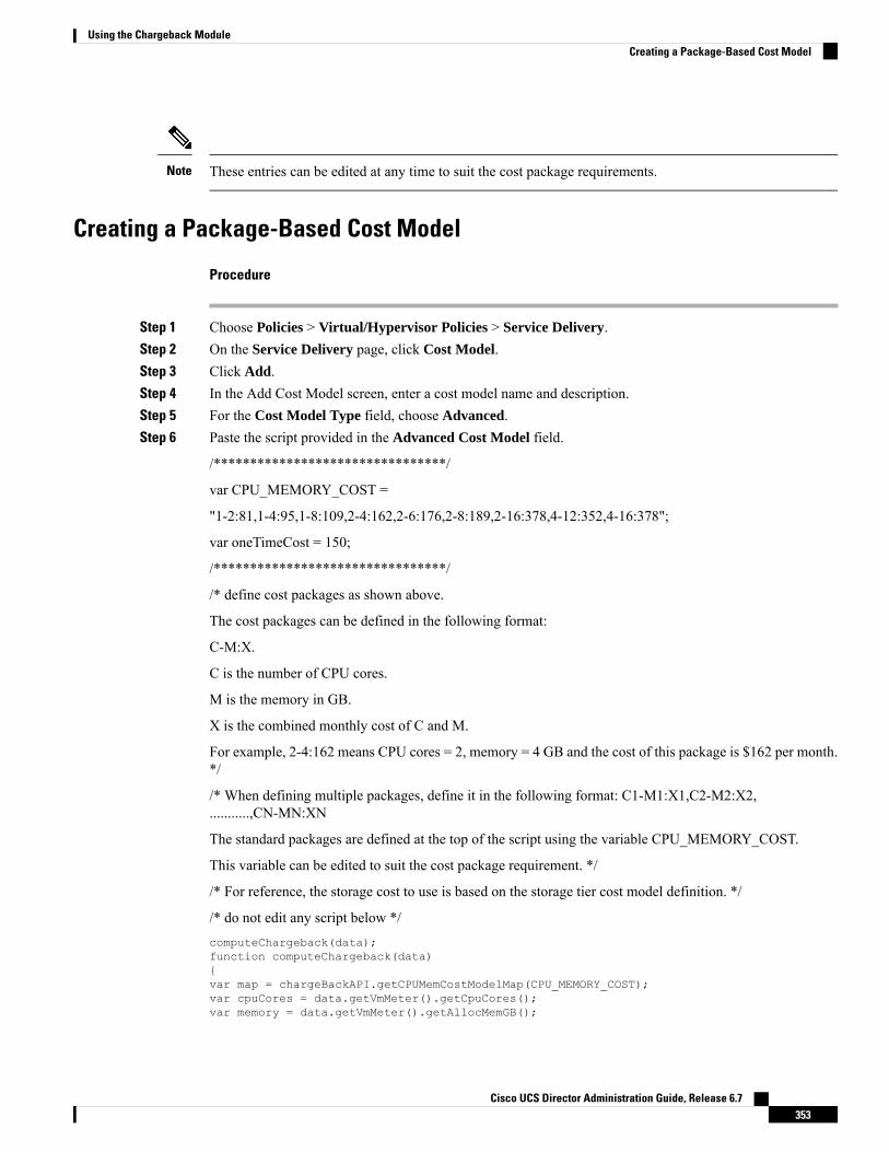
These entries can be edited at any time to suit the cost package requirements.Note
Creating a Package-Based Cost Model
Procedure
Step 1 Choose Policies > Virtual/Hypervisor Policies > Service Delivery.Step 2 On the Service Delivery page, click Cost Model.Step 3 Click Add.Step 4 In the Add Cost Model screen, enter a cost model name and description.Step 5 For the Cost Model Type field, choose Advanced.Step 6 Paste the script provided in the Advanced Cost Model field.
/********************************/
var CPU_MEMORY_COST =
"1-2:81,1-4:95,1-8:109,2-4:162,2-6:176,2-8:189,2-16:378,4-12:352,4-16:378";
var oneTimeCost = 150;
/********************************/
/* define cost packages as shown above.
The cost packages can be defined in the following format:
C-M:X.
C is the number of CPU cores.
M is the memory in GB.
X is the combined monthly cost of C and M.
For example, 2-4:162 means CPU cores = 2, memory = 4 GB and the cost of this package is $162 per month.*/
/* When defining multiple packages, define it in the following format: C1-M1:X1,C2-M2:X2,...........,CN-MN:XN
The standard packages are defined at the top of the script using the variable CPU_MEMORY_COST.
This variable can be edited to suit the cost package requirement. */
/* For reference, the storage cost to use is based on the storage tier cost model definition. */
/* do not edit any script below */computeChargeback(data);function computeChargeback(data){var map = chargeBackAPI.getCPUMemCostModelMap(CPU_MEMORY_COST);var cpuCores = data.getVmMeter().getCpuCores();var memory = data.getVmMeter().getAllocMemGB();
Cisco UCS Director Administration Guide, Release 6.7353
Using the Chargeback ModuleCreating a Package-Based Cost Model

var serverCost = chargeBackAPI.getCostForItem(map,cpuCores, memory);serverCost = serverCost / (24 * 30);var storageTierCost = chargeBackAPI.getStorageCostForItem(data.getVmMeter().getVmId());var storageGB = (data.getVmMeter().getCommittedDiskGB()) +(data.getVmMeter().getUncommittedDiskGB());var committedDiskGBCost = (data.getVmMeter().getCommittedDiskGB()) * storageTierCost;var unCommittedDiskGBCost = (data.getVmMeter().getUncommittedDiskGB()) * storageTierCost;var storageCost = (storageGB * storageTierCost) / (24 * 30);var totalVMCost = serverCost + storageCost;var cb = data.getCbSummary();cb.setCpuCores(cpuCores);cb.setMemory(memory);cb.setServerCost(serverCost);cb.setCommittedDiskGB(data.getVmMeter().getCommittedDiskGB());cb.setCommittedDiskGBCost(committedDiskGBCost);cb.setUncommittedDiskGB(data.getVmMeter().getUncommittedDiskGB());cb.setUncommittedDiskGBCost(unCommittedDiskGBCost);cb.setTotalCost(totalVMCost);}
/********************************/
Step 7 Click Add.
Once the cost model has been defined, assign it to a VDC in order to start the chargeback of VMsbased on this cost model.
Note
Storage Tier Cost ModelsYou can use a storage tier cost model to define multiple costs for storage using the tier format. Current storagetypes include but not limited to local storage, NFS, SAN, and NAS. Each storage cost could vary. You canincorporate this variation while calculating costs for storage usage.
You can use this model to define different costs for different tiers and then assign existing datastores to thesetiers. You can group similar datastore types by cost wise using the tier cost model.
Each tier must be assigned a cost, at a per-GB, per-month value. For example, when assigning $0.50 to a tier,all datastores within this tier are charged at $0.50 per GB per month. By default, four tiers are already created,so you must assign the costs to them.
Assigning a Cost to a Tier
Procedure
Step 1 Choose Policies > Virtual/Hypervisor Policies > Service Delivery.Step 2 On the Service Delivery page, click Storage Tier Cost Model.Step 3 Choose the tier to edit.Step 4 Click Edit.Step 5 Edit the Disk Cost (GB)/Month field.
Cisco UCS Director Administration Guide, Release 6.7354
Using the Chargeback ModuleStorage Tier Cost Models
Step 6 Click Submit.
About Assigning a Datastore to TiersYou can assign a datastore to a tier so that the cost defined in the tier is used to calculate the cost of storagewithin that particular datastore.
When calculating the chargeback for VMs within a datastore, the cost is determined by which tier the datastorewas assigned to. If no tier is assigned to a datastore, the storage cost for that datastore is not considered whenusing the advanced (script-based) cost model.
With a regular cost model, you define resource costs in a form. Storage tier costs are taken into considerationif tier costs are assigned and datastores are assigned to those tiers. However, if no tier is assigned to a datastore,the storage cost for VMs under that datastore is removed from the storage cost entry of the cost model form.
Assigning a datastore to a tier applies only to the regular cost model.Note
Assigning a Datastore to a Tier
Procedure
Step 1 Choose Virtual > Storage.Step 2 On the Storage page, choose the cloud.Step 3 On the Storage page, click Datastore Capacity Report.Step 4 Choose the datastore to assign to a tier.Step 5 Click Assign Tier and the Storage Tier screen appears.
Currently, the tier-based cost is supported only on VMware cloud accounts.
Step 6 From the drop-down list, choose a tier.Step 7 Click Submit.
Chargeback ReportsChargeback provides information about how much your organization may be paying for resources, evenunused resources. This feature allows you to optimize resource consumption and costs. System resourcesaccounting can be based on monthly usage. Resources, such as CPU and memory usage, are monitored andmeasured.
Chargeback reports are based on the cost model type. Chargeback is calculated and shown in the user interfacein the form of tabular reports, summaries, graphical reports, and widgets.
Cisco UCS Director Administration Guide, Release 6.7355
Using the Chargeback ModuleAbout Assigning a Datastore to Tiers

Chargeback summary data is stored only at a daily and monthly interval. So, you cannot generate daily andhourly trend cost reports using the Chargeback menu option. You can generate trend reports only for weeklyand monthly duration. You can generate these trend reports, in addition to several other trend reports, usingthe Report Builder menu available under CloudSense. For more information on using the Report Builderoption, see Report Builder for Custom Report Templates, on page 406.
While generating trend reports for a month, the data is caculated from the first day of the month till the currentdate. For example, if you are generating a trend report on 5th March, this report includes data from March1st, to March 5th.
Important
For VMs that are provisioned through a container, you can associate a tag-based cost model and include thosecosts in the regular chargeback calculations and subsequent reports.
Note
Following are the report types that are available:
• Viewing
• Current month summary—The current month summary cost report (VM, CPU, storage costs, andso on).
• Previous month summary—The previous month summary cost report (VM, CPU, storage costs,and so on).
• Monthly resource accounting details—The resource accounting details (CPU and memory usagestatistics) on a monthly basis.
• VM level resource accounting details—The resource accounting details at the VM level.
• VM level chargeback details—The charges that are applicable for VM usage calculated with thechargeback feature.
• Export
• Export monthly resource accounting details—These reports can be exported as tables.
• Export VM level resource Accounting details—These reports can be exported as tables.
• Export VM level chargeback details—Chargeback reports can be exported as tables.
You can generate these reports for a group, or for a specific virtual data center (VDC). These reports includeinformation on virtual resources as well as on physical servers.
Important
Viewing the Current Month SummaryUsing the Current Month Summary tab, you can view the month’s chargeback details for all VMs andphysical servers that belong to the group.
Cisco UCS Director Administration Guide, Release 6.7356
Using the Chargeback ModuleViewing the Current Month Summary

Procedure
Step 1 Choose Organizations > Chargeback.Step 2 On the Chargeback page, choose the user group.Step 3 On the Chargeback page, click Current Month Summary.
Viewing the Previous Month’s SummaryUsing the Previous Month Summary tab, you can view the previous month’s chargeback details for all VMsand physical servers that belong to the group.
Procedure
Step 1 Choose Organizations > Chargeback.Step 2 On the Chargeback page, choose the user group.Step 3 On the Chargeback page, click Previous Month Summary.
Viewing Monthly Resource Accounting Information
Procedure
Step 1 Choose Organizations > Chargeback.Step 2 Choose a group or a virtual data center (VDC).Step 3 On the Chargeback page, click Resource Accounting.
Viewing the VM Level Resource Accounting DetailsUsing the Resource Accounting Details tab, you can view the individual VM's resource usage details.
Procedure
Step 1 Choose Organizations > Chargeback.Step 2 Choose a group or a virtual data center (VDC).Step 3 On the Chargeback page, click Resource Accounting Details.
Cisco UCS Director Administration Guide, Release 6.7357
Using the Chargeback ModuleViewing the Previous Month’s Summary

Viewing the VM Level Chargeback DetailsUsing the Chargeback tab, you can view the chargeback report for the selected group or VDC.
If you indicated that the tag-based cost model must be included in the regular VM chargeback calculations,then you will see the Fixed Costs column in the report. This column retrieves the cost that you indicated inthe tag-based cost model.
Procedure
Step 1 Choose Organizations > Chargeback.Step 2 Choose a group or a virtual data center (VDC).Step 3 On the Chargeback page, click Chargeback.
Exporting the Monthly Resource Accounting Details
Procedure
Step 1 Choose Organizations > Chargeback.Step 2 On the Chargeback page, click Resource Accounting.Step 3 Click the Export Report icon.Step 4 In the Export Report screen, choose a format.
It can be one of the following options:
• CSV
• XLS
Step 5 Click Generate Report.
After the report is generated, the Download option appears.
Step 6 Click Download to open the report in another browser.
After the report opens in another browser, you can save it on your system.
Exporting VM Level Resource Accounting Details
Procedure
Step 1 Choose Organizations > Chargeback.
Cisco UCS Director Administration Guide, Release 6.7358
Using the Chargeback ModuleViewing the VM Level Chargeback Details

Step 2 On the Chargeback page, click Resource Accounting Details.Step 3 Click the Export Report icon.Step 4 In the Export Report screen, choose a format.
It can be one of the following options:
• CSV
• XLS
Step 5 Click Generate Report.
After the report is generated, the Download option appears.
Step 6 Click Download to open the report in another browser.
After the report opens in another browser, you can save it on your system.
Exporting VM Level Chargeback Details
Procedure
Step 1 Choose Organizations > Chargeback.Step 2 On the Chargeback page, click Chargeback.Step 3 On the right side of the toolbar, click the Export Report icon.Step 4 In the Export Report screen, choose a format.
It can be one of the following options:
• CSV
• XLS
Step 5 Click Generate Report.
After the report is generated, the Download option appears.
Step 6 Click Download to open the report in another browser.
After the report opens in another browser, you can save it on your system.
Cisco UCS Director Administration Guide, Release 6.7359
Using the Chargeback ModuleExporting VM Level Chargeback Details

About Change RecordsYou can use change records within the Change Management Database (CMDB) to track and manage changesin the system. These records typically display ADD, DELETE, andMODIFY types of events on any resource,such as a VM, service request, or group.
Change records display information about the resource type (VM), including the resource name, change type,change time, and description. When a VM is resized, the change records display information on the resourcesthat were resized. This includes information on the original resource size and the resized values. You canview this information from the Change Records tab.
Accessing Change Records
Procedure
Step 1 Choose Administration > Integration.Step 2 On the Integration page, click Change Records.
Chargeback CalculationsThe total cost calculated for a VM includes the following:
Total cost = active VM cost or inactive VM cost + one-time cost + CPU cost + memory cost + disk cost +CPU reserved cost + memory reserved cost + CPU used cost + CPU core cost + memory used cost + networkreceived used cost + network transmitted used cost + application cost.
If a VM is associated with a tag, and has a cost model and a tag-based cost model associated with the vDCs,then the chargeback calculation is derived as follows:
• When the Include VM in Regular Chargeback check box is not checked, only the tag-based cost iscalculated.
Total Cost - Fixed Cost + One-Time Cost
• When the Include VM in Regular Chargeback check box is checked, the total cost is calculated includingthe tag-based cost and the regular chargeback computation.
Total Cost = active VM cost or inactive VM cost + one-time cost + CPU cost + memory cost + disk cost+ CPU reserved cost + memory reserved cost + CPU used cost + CPU core cost + memory used cost +network received used cost + network transmitted used cost + application cost + Fixed Cost
The one-time cost for the VM is determined from the cost specified in the tag-based cost model. If you havenot specified a one time cost in the tag-based cost model, then this cost is derived from the regular cost model.
Note
The total cost calculated for a physical server includes the following:
Cisco UCS Director Administration Guide, Release 6.7360
Using the Chargeback ModuleAbout Change Records

Total cost = one time cost + CPU cost + memory cost + memory used cost + committed disk cost + CPU corecost + full blade cost + half blade cost.
The VM cost calculation is done only on an hourly basis. There is no other option available to calculate theVM cost. The cost for each resource is calculated based on the values that are defined in the cost model. Thecost calculations are based as follows:
Cost DescriptionCost
The value defined in the cost model for the active VMcost.
Active VM Cost
The value defined in the cost model for the inactiveVM cost.
Inactive VM Cost
The value defined in the cost model for the one-timecost.
One Time Cost
CPU usage (provisioned) × cost that is defined in thecost model for the provisioned CPU cost. The CPUcharge unit is GHz.
CPU Cost
Memory usage (provisioned) × cost that is defined inthe cost model for the provisioned memory cost. Thememory charge unit is GB.
Memory Cost
The committed storage × committed storage cost thatis defined in the cost model + uncommitted storage× uncommitted storage cost that is defined in the costmodel. The storage charge unit is GB.
Disk Cost
The reserved CPU × cost that is defined in the costmodel for the reserved CPU cost.1.
CPU Reserved Cost
The reserved memory × cost that is defined in the costmodel for the reserved memory cost.2.
Memory Reserved Cost
The used CPU × cost that is defined in the cost modelfor the used CPU cost.1.
CPU Used Cost
The used CPU core × cost that is defined in the costmodel for the CPU core cost. The CPU charge unit isper core.
CPU Core Cost
The used memory × cost that is defined in the costmodel for the used memory cost.2.
Memory Used Cost
The network received usage in KB / (1024.0 × 1024.0)× cost that is defined in the cost model for the receivednetwork data cost. The network charge unit is GB.
Network Received Used Cost
The network transmitted usage in KB / (1024.0 ×1024.0) × cost that is defined in the cost model forthe transmitted network data cost.5.
Network Transferred Used Cost
Cisco UCS Director Administration Guide, Release 6.7361
Using the Chargeback ModuleChargeback Calculations

Cost DescriptionCost
The active VM hours × cost that is defined in a catalogfor active VM application cost + inactive VM hours× cost that is defined in a catalog for the inactive VMapplication cost.
Application Cost
The cost of full-length blade servers per-hour. Thiscost is applicable only for physical servers.
This is applicable only for physical servers that arepart of an application container.
Full-length Blade Cost
The cost of half-length blade servers per-hour. Thiscost is applicable only for physical servers.
This is applicable only for physical servers that arepart of an application container.
Half-Length Blade Cost
The fixed cost, per-hour, determined for the VM.
This is applicable only if you have indicated that thetag-based cost model should be included with theregular cost model for the VM.
Fixed Cost USD
Cisco UCS Director Administration Guide, Release 6.7362
Using the Chargeback ModuleChargeback Calculations

C H A P T E R 16System Monitoring and Reporting
This chapter contains the following sections:
• Dashboard, on page 363• Summary, on page 365• Inventory Management, on page 366• Resource Pools, on page 366• Clusters, on page 367• Images, on page 367• Host Nodes, on page 368• Virtual Machines (VMs), on page 369• Topology, on page 370• Assessment, on page 370• Reports, on page 371
DashboardIn Cisco UCSDirector, you can enable theDashboard option in the user interface. On theDashboard screen,you can add important, or frequently accessed report widgets. If you have enabled the Dashboard option,then this is the first window that you see when you log in to the user interface. After enabling theDashboard,you can create additional dashboards, and delete them when you no longer need them. For more information,see Creating Additional Dashboards, on page 364 and Deleting a Dashboard, on page 364.
Enabling the Dashboard
Procedure
Step 1 On the header, click the user icon, and choose Edit My Profile.Step 2 On the Edit My Profile screen, scroll down to the Dashboard section.Step 3 Check Enable Dashboard.Step 4 Click Save.
When you log out and log in, the first screen that you see is the Dashboard.
Cisco UCS Director Administration Guide, Release 6.7363

Step 5 Click Close to view the Dashboard immediately.
What to do next
If there are no widgets on the Dashboard, you can access any summary report in the user interface, and selectAdd to Dashboard.
Creating Additional Dashboards
Before you begin
You should have enabled the Dashboard in the user interface.
Procedure
Step 1 Log into Cisco UCS Director user interface.
The default Dashboard screen is displayed.
Step 2 Click the down arrow displayed next to the default dashboard name and choose Create Dashboard.Step 3 Enter the name of the dashboard.Step 4 Click Submit.
Deleting a DashboardYou cannot delete the default dashboard.
Procedure
Step 1 Log into Cisco UCS Director user interface.
The default Dashboard screen is displayed.
Step 2 Click the drop-down list to view the list of dashboards that you have created.Step 3 Click the X mark displayed next to the dashboard name.Step 4 Confirm that you want to delete the dashboard.
Adding Report Widgets
Before you begin
You must be logged in to the appliance to complete this task.
Cisco UCS Director Administration Guide, Release 6.7364
System Monitoring and ReportingCreating Additional Dashboards

Procedure
Step 1 Choose the desired option and navigate to the summary report you want to add to your dashboard.
For example, if you want to add a VM-related summary report, choose Virtual > Compute and then clickSummary.
Step 2 On the Summary screen, scroll down to the report that you want to add to your dashboard.Step 3 In the upper right corner of the report, click Settings and then choose Add to Dashboard.
Refreshing Widget DataAfter enabling the Dashboard option, you can set a refresh interval to the widgets on this page. Automaticrefresh can occur at intervals from a minimum of 5 minutes to a maximum of 60 minutes.
The Automatic Refresh button on the dashboard should be set to ON to configure the interval.
SummaryThe Summary screen allows you to manage system inventory. It gives you access to a wide array of tabular,graphical, and map reports, and also helps in managing inventory lifecycle actions.
Each report is displayed as a widget. Reports can be hidden through customization.
Viewing Virtual Machine, Cloud, and System Summary Information
Procedure
Step 1 Choose Virtual > Compute.Step 2 On the Compute page, click Summary.
All information is displayed in the form of tables, graphs, and charts.
Customizing Summary Report Widgets
Procedure
Step 1 Choose Virtual > Compute.Step 2 On the Compute page, click Summary.Step 3 Click the reports drop-down icon to display the available reports.Step 4 Click and drag a widget onto the Dashboard.
Cisco UCS Director Administration Guide, Release 6.7365
System Monitoring and ReportingRefreshing Widget Data

Step 5 From the Show more reports drop-down list, check the name of the report that you want to add.
Inventory ManagementYou can monitor the system inventory using theDashboard. TheDashboard displays the entire system levelinfrastructure information for administrative management.
Accessing System Inventory Details
Procedure
Step 1 Choose Virtual > Compute.Step 2 On the Compute page, choose the cloud.Step 3 Choose any of the options to view detailed information.
Following is a list of some of the report options visible for each cloud:
• Summary
• Polling
• VDCs
• Clusters
• Host Nodes
• Resource Pools
• VMs
• VM Action Requests
• Events
• Assessment
• Application Categories
• Data Centers
• SRM Sites
Resource PoolsThe Resource Pools screen shows resource details at the host node level. These details include the CPUconfigured reservation, CPU limit, CPU used, and memory used.
Cisco UCS Director Administration Guide, Release 6.7366
System Monitoring and ReportingInventory Management

Accessing Resource Details
Procedure
Step 1 Choose Virtual > Compute.Step 2 On the Compute page, choose the cloud.Step 3 On the Compute page, click Resource Pools.
All the resource pools for the selected cloud are displayed. You can select a resource pool and click ViewDetails to view detailed information of each resource pool.
ClustersIf a pod includes clusters, then the Clusters screen displays all the cluster-related information.
Accessing Clusters
Procedure
Step 1 Choose Virtual > Compute.Step 2 On the Compute page, choose the cloud.Step 3 On the Compute page, click Clusters.
All clusters available in the selected cloud accounts are displayed. You can select a specific cluster, and clickView Details.
ImagesThe Images screen displays all available image IDs and their details. These images include guest OS, CPU,memory, and storage provisioned. You can use these image IDs to provision new virtual machines (VMs). Ifyou are a group administrator, or an MSP administrator, then the Images screen displays images that havebeen assigned to your group.
If you select a specific VMware cloud account, and click Images, you can assign images to groups or toindividual users. Images assigned to a particular group or user are displayed when administrators of the relevantgroup log in to the system.
Cisco UCS Director Administration Guide, Release 6.7367
System Monitoring and ReportingAccessing Resource Details

Accessing Images
Procedure
Step 1 Choose Virtual > Compute.Step 2 On the Compute page, choose the cloud.Step 3 On the Compute page, click Images.
A list of images associated with the selected clouds is displayed. You can select a specific image and clickView Details.
Assigning VM Images to Users or GroupsAs an administrator, you can assign specific VM images to users or groups. The assignments filter the imagesthat are displayed when you perform VM provisioning tasks, such as creating catalogs.
Procedure
Step 1 Choose Virtual > Compute.Step 2 On the Compute page, choose the cloud.Step 3 On the Compute page, click Images.Step 4 Click the row with the image that you want to assign to a group.Step 5 Click Assign Image to Group.Step 6 On the Assign Image to Group screen, expand the Group ID field, and check the names of the groups to
which you want to assign the image.Step 7 To assign an image to individual users, complete the following fields:
DescriptionName
Check to assign the image to specific users.Assign to Users check box
Expand this field to check the names of users to whomyou want to assign the image.
User field
Step 8 Click Submit.
Host NodesThe Host Nodes screen displays all physical host nodes that are available in the infrastructure. The screenlists details such as the ESX/ESXi version installed, active VMs, and power status.
Cisco UCS Director Administration Guide, Release 6.7368
System Monitoring and ReportingAccessing Images

Accessing Host Nodes
Before you begin
You must be logged in to the appliance to complete this task.
Procedure
Step 1 Choose Virtual > Compute.Step 2 On the Compute page, click Host Nodes.Step 3 Click the row with the host node that you want view, and click View Details.
Virtual Machines (VMs)The VMs screen displays all the VMs and VM-specific details for the chosen cloud.
Accessing VMs
Procedure
Step 1 On the menu bar, choose Virtual > Compute.Step 2 On the Compute page, click VMs.
All virtual machines for all cloud accounts are displayed. You can perform additional tasks on these VMssuch as launching VM client or powering off VMs. For more information, see Managing VM Actions, onpage 378.
Accessing Group Level VMs
Procedure
Step 1 Choose Organizations > Virtual Resources.Step 2 On the Virtual Resources page, choose the user group.Step 3 On the Virtual Resources page, click VMs.
All virtual machines for the selected group are displayed. You can perform additional tasks on these VMssuch as launching VM client or powering off VMs. For more information, see Managing VM Actions, onpage 378.
Cisco UCS Director Administration Guide, Release 6.7369
System Monitoring and ReportingAccessing Host Nodes

TopologyThe Topology screen displays VMware cloud topology. There are four view mode types: Hierarchical,Concentric, Circular, and Force Directed. Depending on the mode, you can adjust the item spacing, distance,radius, rigidity, and force distance.
Accessing Topology Types
Before you begin
You must be logged in to the appliance to complete this task.
Procedure
Step 1 Choose Virtual > Compute.Step 2 On the Compute page, choose the cloud.Step 3 On the Compute page, click Topology.Step 4 Choose Hostnode-Datastore Topology or Hostnode-VM Topology.Step 5 Click View Connectivity.
The topology appears in a new window.
Not all of the topology types are displayed.Note
AssessmentThe Assessment screen displays assessment reports such as cloud readiness, and virtualization best practicesfor a cloud account.
Accessing Assessments
Before you begin
You must be logged in to the appliance to complete this task.
Procedure
Step 1 Choose Virtual > Compute.Step 2 On the Compute page, choose the cloud.Step 3 On the Compute page, click Assessment.
Cisco UCS Director Administration Guide, Release 6.7370
System Monitoring and ReportingTopology

Step 4 From the drop-down list, choose a report type to filter the report.
ReportsCisco UCS Director can help you monitor virtual infrastructure and system resources. It displays a widevariety of reports that provide insight into how the system is performing
Following are the types of reports:
• Tabular reports for system information, including overview, host nodes, new VMs, and deleted VMs.
• Bar and pie graph comparisons, including VMs active versus inactive, and CPU provisioned versuscapacity.
• Trend graphs about system resources, including CPU trends, memory trends, and VM additions anddeletions.
• Other reports include Top 5 reports at the group, VDC, host node, and VM levels. The Top 5 reportsfocus on groups with the highest number of VMs, groups with the greatest CPU usage, VDCs with thehighest number of VMs, and host nodes with the greatest CPU usage.
• Map reports, displaying the system resource information in the form of heat maps or color-coded maps.
Additional trend reports are available for certain accounts (for example: KVM accounts). Trend reports displaydata over a selected time frame.
Accessing Reports
Procedure
Step 1 Choose Virtual > Compute.Step 2 On the Compute page, choose the cloud.Step 3 Click the name of the report that you want to view (Map, Top 5, or More Reports).
Cisco UCS Director Administration Guide, Release 6.7371
System Monitoring and ReportingReports

Cisco UCS Director Administration Guide, Release 6.7372
System Monitoring and ReportingAccessing Reports

C H A P T E R 17Managing Lifecycles
This chapter contains the following sections:
• Managing VM Power Settings, on page 373• Managing VM Snapshots, on page 374• Configuring the Lease Time for a Virtual Machine, on page 377• Managing VM Actions, on page 378• Applying a Tag to a VM, on page 400• Mounting an ISO Image as a CD/DVD Drive, on page 400• Unmounting an ISO Image as a CD/DVD Drive, on page 401
Managing VM Power SettingsBefore you begin
You must be logged in to the appliance to complete this task.
Procedure
Step 1 Choose Virtual > Compute.Step 2 On the Compute page, choose the cloud.Step 3 On the Compute page, click VMs.Step 4 Click the row with the VM on which you want to perform an action.Step 5 Choose an action and the VM Task screen appears.
DescriptionName
The name of the VM that is the subject of the action.VM Name display-only field
The task to power off the VM.Power Off display-only field
The task to power on the VM.Power On display-only field
The task to put the VM in a suspended state.Suspend display-only field
The task to shut down the guest OS on the VM.Shutdown Guest display-only field
Cisco UCS Director Administration Guide, Release 6.7373

DescriptionName
The task to move the VM into a standby state.
Not supported in the RHEV KVMConnector.
Note
Standby display-only field
The task to perform a hard reset of the VM.
Not supported in the RHEV KVMConnector.
Note
Reset display-only field
The task to perform a soft reboot of the VM.
Not supported in the RHEV KVMConnector.
Note
Reboot display-only field
Enter any comments that help identify the VM.Comments field
The task to power on a VM now or later at a specificdate and time.
Schedule Action radio button
Step 6 Click Proceed.
Managing VM SnapshotsThis process includes the following tasks:
• Create Snapshot—You can create a snapshot of all the VM’s resources in their current state.
• Revert Snapshot—If the VM crashes or malfunctions (For example, if the OS becomes corrupt), you canrevert to the most recent snapshot of the VM. Where there are multiple snapshots for a VM, you canrevert to a specific snapshot.
• Mark Golden Snapshot—You can mark a specific snapshot for a VM as a Golden Snapshot. This featureprotects the snapshot from accidental deletion.
• Delete a Snapshot—You can delete a snapshot, if necessary. A Golden Snapshot must be first unmarkedbefore it can be deleted.
• Delete All Snapshots—You can delete all snapshots for a VM. However, you cannot delete all snapshotsif they include Golden Snapshots. You must first unmark any Golden Snapshot and then delete allsnapshots.
Cisco UCS Director Administration Guide, Release 6.7374
Managing LifecyclesManaging VM Snapshots

Creating VM Snapshots
Procedure
Step 1 Choose Virtual > Compute.Step 2 On the Compute page, choose the cloud.Step 3 On the Compute page, click VMs.Step 4 Click the row with the VM for which you want to create a snapshot.Step 5 From the More Actions drop-down list, choose Create Snapshot.Step 6 On the Create Virtual Machine Snapshot screen, complete the following fields:
DescriptionName
The snapshot name.Snapshot Name field
The snapshot description.Snapshot Description field
Check the check box to include the VM memory inthe snapshot.
Snapshot Memory check box
Check the check box to take the snapshot in quiescemode.
Quiescing a file system brings the on-diskdata of a physical or virtual computer intoa state that is suitable for backups. Thisprocess might include operations such asflushing buffers from the operating systemsin-memory cache to disk, or otherhigher-level application-specific tasks. Touse this option, VMware Tools must beinstalled on the VM.
Note
Quiesce Guest File System check box
Step 7 Click Proceed.
Reverting to a Snapshot
Before you begin
You must be logged in to the appliance to complete this task.
Procedure
Step 1 Choose Virtual > Compute.Step 2 On the Compute page, choose the cloud.
Cisco UCS Director Administration Guide, Release 6.7375
Managing LifecyclesCreating VM Snapshots

Step 3 On the Compute page, click VMs.Step 4 Click the row with the VM that you want to revert to a snapshot.Step 5 From the More Actions drop-down list, choose Revert Snapshot.Step 6 On the Revert Snapshot Task screen, check the name of the desired snapshot.Step 7 Click Proceed.
Marking a Golden Snapshot
Procedure
Step 1 Choose Virtual > Compute.Step 2 On the Compute page, choose the cloud.Step 3 On the Compute page, click VMs.Step 4 Click the row with the VM for which you want to mark a snapshot as golden.Step 5 From the More Actions drop-down list, choose Mark Golden Snapshot.Step 6 On the Mark Golden Snapshot Task screen, check the name of the desired snapshot.Step 7 Check Mark as Golden Snapshot.Step 8 Click Proceed.
Deleting a Snapshot
Procedure
Step 1 Choose Virtual > Compute.Step 2 On the Compute page, choose the cloud.Step 3 On the Compute page, click VMs.Step 4 Click the row with the VM for which you want to delete a snapshot.Step 5 From the More Actions drop-down list, choose Delete Snapshot.Step 6 On the Delete Snapshot Task screen, check the name of the desired snapshot.Step 7 Check Delete Children to delete child snapshots of the selected snapshot.Step 8 Click Proceed.
Cisco UCS Director Administration Guide, Release 6.7376
Managing LifecyclesMarking a Golden Snapshot

Deleting All Snapshots
Procedure
Step 1 Choose Virtual > Compute.Step 2 On the Compute page, choose the cloud.Step 3 On the Compute page, click VMs.Step 4 Click the row with the VM for which you want to delete all snapshots.Step 5 From the More Actions drop-down list, choose Delete All Snapshots.Step 6 On the VM Snapshot Task screen, enter an optional comment.Step 7 Click Proceed.
Configuring the Lease Time for a Virtual MachineA user can configure a lease expiration time for a selected virtual machine (VM). Once the lease time expires,the VM is powered down. The lease time end is a calendar selection.
Procedure
Step 1 Choose Virtual > Compute.Step 2 On the Compute page, choose the cloud.Step 3 On the Compute page, click VMs.Step 4 Click the row with the VM for which you want to configure the lease time.Step 5 From the More Actions drop-down list, choose Configure Lease Time.Step 6 On the Configure Lease Time screen, check Set Lease Time. Complete the following fields:
DescriptionName
The name specified while creating the VM.
Once entered, you cannot edit the name of the VM.
VM Name field
The lease date and time for the VM. There arecalendars for the Date, drop-down lists for the Time(hour and minute), and radio buttons for AM or PM.
Lease Date/Time calendar, drop-down lists, radiobuttons
Step 7 Click Submit.
Cisco UCS Director Administration Guide, Release 6.7377
Managing LifecyclesDeleting All Snapshots

Managing VM ActionsAfter creating a VM, you can perform additional tasks on it, by using menus available in the user interface.You can access these menus in one of the following ways:
• Right clicking on a VM to view a list of limited options,
• Choosing a VM and clicking the down arrow option on the toolbar for a complete list of options.
Following are the other VM actions:
• View VM Details—You can access individual VMs to view details, such as summary reports, vNICs,disks, and snapshots.
• Stack View—You can view stacks of information about a particular VM including, OS, hypervisor, andinfrastructure information.
• Delete a VM—You can delete a VM from the list. Only a powered-off VM can be deleted.
• Create a VM Disk—You can add an additional disk with a custom size to a VM.
• Delete a VM Disk—You can delete a disk.
• Add vNICs—You can add multiple vNICs to a VM. You also have the option to add or replace a vNICin a VM. The options for vNICs depend on the network policy mapped to the VDC associated with theVM.
• Launch VM Client—You can set up and access either web access, remote desktop, or VMRC Consoleaccess for a VM.
• VMRC Console (HTML5)—You can launch a VMRC HTML5 console that is web browser and plug-inindependent.
• Assign VM—You can assign a VM to a group or VDC and modify the category of the VM. You can setthe provisioning time, termination time, and label for a VM.
• Access VM Credentials—You can access a VM’s login credentials when it is set up for web or remotedesktop access, but only if the administrator provides the privileges in the catalog from which the VMis provisioned.
• Inventory Collection Request for VM—You can choose aVMand request on-demand inventory collection.
• Test VNC—You can test VNC connectivity, for troubleshooting purposes.
• Clone—You can clone or make a copy of an existing VM to make a new VM with the same or similarqualities.
• Move a VM to VDC—You can move a VM to a VDC so that the rules of the VDC system policy arefollowed in the VM.
• VM Resync—You can choose to set the number of minutes to have a VM resynchronize its timeperiodically with Cisco UCS Director.
• Mount ISO Image as CD/DVD Drive—You can mount ISO images on the VM without using a physicaldrive. Once mounted in your virtual machine, you can open, extract, and use the files from a virtualCD/DVD drive without a physical disk.
Cisco UCS Director Administration Guide, Release 6.7378
Managing LifecyclesManaging VM Actions

• Unmount ISO Image as CD/DVDDrive—You can unmount an ISO image already attached to CD/DVDdrive on the virtual machine.
Viewing VM Details
Procedure
Step 1 Choose Virtual > Compute.Step 2 On the Compute page, choose the cloud.Step 3 On the Compute page, click VMs.Step 4 Click the row with the VM for which you want to view the details.Step 5 Click View Details.
Resizing VMs
Procedure
Step 1 Choose Virtual > Compute.Step 2 On the Compute page, choose the cloud.Step 3 On the Compute page, click VMs.Step 4 Click the row with the VM that you want to resize.Step 5 From the More Actions drop-down list, choose Resize VM.Step 6 On the Resize VM screen, complete the following fields:
DescriptionName
The name of the selected VM.VM Name field
The number of allocated CPUs being used by the VM.Current Allocated CPU field
The amount of memory allocated to the VM.Current Allocated Memory(GB) field
Choose the CPU required.New CPU Count drop-down list
Choose the cores per socket.New Cores Per Socketdrop-down list
Choose the amount of memory.New Memory drop-down list
Displays the current CPU cost per-hour.
This value is calculated based on the currently allocated CPU for the VM.
Current CPU Cost (Currency:USD) field
Cisco UCS Director Administration Guide, Release 6.7379
Managing LifecyclesViewing VM Details

DescriptionName
Displays the current memory cost per-hour.
This value is calculated based on the currently allocated memory for theVM.
Current Memory Cost(Currency: USD) field
Displays the CPU cost per-hour based on the CPU count specified for theVM.
New CPU Cost (Currency:USD) field
Displays the memory cost per-hour based on the memory specified forthe VM.
New Memory Cost (Currency:USD)
If you checked the Disable displaying cost details check box while adding or modifying the VDC,then information on the current and new CPU cost and memory cost is not displayed.
Important
Step 7 Click Resize.
Using the Stack View Option
Procedure
Step 1 Choose Virtual > Compute.Step 2 On the Compute page, choose the cloud.Step 3 On the Compute page, click VMs.Step 4 Click the row with the VM for which you want to view the stack view.Step 5 Click Stack View.
The Stack View screen displays information on the selected VM.
• If there are multiple components in the report, such as hard drives or network adapters, youcan click the arrow displayed on each component and select a different component.
• You can view additional information on each component by clicking the eye icon.
Note
Creating a VM DiskYou can create a VM disk only if you checked Allow Resizing of Disk while configuring the storage policythat is mapped to the vDC.
Before you begin
The VM should be in the powered off state.
Cisco UCS Director Administration Guide, Release 6.7380
Managing LifecyclesUsing the Stack View Option

Procedure
Step 1 Choose Virtual > Compute.Step 2 On the Compute page, choose the cloud.Step 3 On the Compute page, click VMs.Step 4 Click the row with the VM on which you want to create a VM disk.Step 5 From the More Actions drop-down list, choose Create VM Disk.Step 6 On the Create VM Disk screen, complete the following fields:
DescriptionName
The name of the VM.
Once entered, the VM name cannot be edited.
VM Name field
The disk size for the VM, in GB.
Youmust enter an integer in this field, and this integershould be within the range specified in the storagepolicy associated with this VM.
New Disk Size (GB) field
Choose the disk type. It can be one of the following:
• System
• Swap
• Data
• Database
• Log
Select Disk Type drop-down list
Specify if the VM disk should be created from adatastore or a datastore cluster.
Select Datastore/Datastore Cluster drop-down list
Click Select and choose which datastore you want touse to create the VM disk.
The available datastores depend upon thestorage policy associated with the VDC.Only datastores that meet the criteriaspecified in the storage policy are availablefor the VM disk.
Note
This field is only available if you specify that the VMdisk should be created from a datastore.
Select Datastore field
Cisco UCS Director Administration Guide, Release 6.7381
Managing LifecyclesCreating a VM Disk

DescriptionName
Click Select and choose which datastore cluster youwant to use to create the VM disk.
The available datastore clusters dependupon the storage policy associated with theVDC. Only datastore clusters that meet thecriteria specified in the storage policy areavailable for the VM disk.
Note
This field is only available if you specify that the VMdisk should be created from a datastore cluster.
Select Datastore Cluster field
Check the check box to add a thin provisioned diskto the VM.
Thin provisioning enables dynamicallocation of the physical storage capacityto increase VM storage utilization.
Note
Thin Provision check box
This option calculates and displays the disk cost, perhour, based on the new disk size and the datastore youhave specified for the VM disk.
If you checked theDisable displaying costdetails check box while adding ormodifying the VDC, then the ComputeNew Disk Cost field is not displayed.
Important
Compute New Disk Cost field
Step 7 Click Create.
Resizing a VM Disk
Procedure
Step 1 Choose Virtual > Compute.Step 2 On the Compute page, choose the cloud.Step 3 On the Compute page, click VMs.Step 4 Click the row with the VM for which you want to resize the VM disk.Step 5 From the More Actions drop-down list, choose Resize VM Disk.Step 6 On the Resize VM Disk screen, complete the following fields:
DescriptionName
The name of the VM.
This name cannot be edited.
VM Name field
Cisco UCS Director Administration Guide, Release 6.7382
Managing LifecyclesResizing a VM Disk

DescriptionName
Select the VM disk from the drop-down list.Select Disk drop-down list
Displays the total provisioned space on the VM.Total Provisioned (GB) field
The new size for the VM.
Enter an integer in this field. This integer should bewithin the range or among the comma separated valuesspecified in the storage policy associated with thisVM and should be greater than the total provisionedsize.
New Size (GB) field
Displays the current disk cost per hour.Current Disk Cost (Currency: USD) field
This option calculates the disk cost, per hour, basedon the new disk size you specified.
Compute New Disk Cost field
Displays the disk cost per hour for the new disk sizespecified for the VM.
New Disk Cost (Currency: USD) field
If you checked the Disable displaying cost details check box while adding or modifying the VDC,then information on the current and new disk cost is not displayed.
Important
Step 7 Click Resize.
Locking VMs in Cisco UCS DirectorAs an administrator in Cisco UCS Director, you can create a list of VMs that you would like locked. LockingVMs implies preventing actions from running on the specified VMs. These actions could be shutting down,resetting, or powering off VMs.
Procedure
Step 1 Create an XML file titled VMControls.xml which is similar to the following:<VMControlList>--<VMControl>
<ControlType>lock</ControlType><MatchType>VM-IPAddress</MatchType><MatchValue>19.19.19.19</MatchValue><IsRegex>false</IsRegex><ContactEmail>[email protected]</ContactEmail>--<Label>
Do not shutdown or delete my machine.--</Label>
--</VMControl>--<VMControl>
<ControlType>lock</ControlType><MatchType>VM-IPAddress</MatchType><MatchValue>19.29.29.29*</MatchValue><IsRegex>true</IsRegex>
Cisco UCS Director Administration Guide, Release 6.7383
Managing LifecyclesLocking VMs in Cisco UCS Director

<ContactEmail>[email protected]</ContactEmail>--<Label>
Do not shutdown or delete this machine.--</Label>
--</VMControl></VMControlList>
Step 2 Host this file on a server that is accessible from the system that is running Cisco UCS Director.Step 3 Choose Administration > System.Step 4 On the System page, click System Parameters.Step 5 In the Download VM Locking Controls From URL field, enter the URL of the XML file.
The URL will look similar to this: <ip_address>:8000/VMControls.xml.
Step 6 Click Save.Step 7 On the System page, click System Tasks.Step 8 Search for and select the VM Control List Poller Task.Step 9 Click Run Now.
This system task downloads the VMControls.xml file and saves it in the inventory database. After thissystem task is run, actions such as powering off, or shutting down are prevented from running on VMs thatmatch the IP addresses specified in the XML file.
Adding vNICs
When you add a vNIC VM, the values of the Port Group Name andAdapter Type parameters are modified.The IP address of the VM is changed only if DHCP is enabled on the selected port group. However, the IPaddress is not modified if it is sourced from a static pool policy.
Note
Procedure
Step 1 Choose Virtual > Compute.Step 2 On the Compute page, choose the cloud.Step 3 On the Compute page, click VMs.Step 4 Click the rwo with the VM to which you want to add a vNIC.Step 5 From the More Actions drop-down list, choose Add vNICs.Step 6 On the Add VM vNICs screen, choose Add from the Operation drop-down list.
This addition is not allowed if the vNIC limit configured in the network policy will be exceeded.
Step 7 Expand the VM NETWORKS list.Step 8 Click Add (+).Step 9 On the Add Entry to VM Networks screen, complete the following fields:
Cisco UCS Director Administration Guide, Release 6.7384
Managing LifecyclesAdding vNICs

DescriptionName
Choose a NIC alias from the list.NIC Alias drop-down list
Choose a port group from the list.Port Group Type display-only drop-down list
Choose a port group name from the list.Port Group Name drop-down list
Choose the adapter type.
The choice is available only if the NIC alias does nothave Copy Adapter Type from Template chosen inthe network policy.
Adapter Type display-only drop-down list
If this field is checked, then the IP is assigned usingDHCP.
DHCP check box
The static IP address pool.Static IP Pool field
The network mask.Network Mask field
The gateway IP address.Gateway IP Address field
The NIC Alias, Port Group Name, Adapter Type, DHCP, and Static IP Pool choices dependon the settings in the network policies associated with the VM (VM’s VDC). For more informationabout multiple NIC network policies, see Managing Policies, on page 191.
The VM is powered down to perform this action. The VMwill power up once the action is completed.
Note
Step 10 Click Submit.
Replacing a vNIC
When you replace a vNIC VM, the values for the Port Group Name and Adapter Type parameters aremodified. The IP address of the VM is changed only if DHCP is enabled on the selected port group. However,the IP address is not modified if it is sourced from a static pool policy.
Note
Procedure
Step 1 Choose Virtual > Compute.Step 2 On the Compute page, choose the cloud.Step 3 On the Compute page, click VMs.Step 4 Click the row with the VM for which you want to replace a vNIC.Step 5 From the More Actions drop-down list, choose Add vNICs.Step 6 On the Add VM vNICs screen, choose Replace from the Operation drop-down list.
This replacement is not allowed if the additional vNIC limit configured in the network policy will be exceeded.
Cisco UCS Director Administration Guide, Release 6.7385
Managing LifecyclesReplacing a vNIC

Step 7 Choose a vNIC.Step 8 On the Add vNIC screen, complete the following fields:
DescriptionName
Choose a NIC alias.
Only the vNICs configured in the network policy arevisible here.
NIC Alias drop-down list
Choose a port group name from the list.Port Group Name drop-down list
Choose the adapter type.
The choice is available only if the choice of the NICalias does not have Copy Adapter Type fromTemplate chosen in the network policy.
Adapter Type display-only drop-down list
Check the check box if you want the IP assigned usingDHCP.
DHCP check box
The static IP address pool.Static IP Pool field
The network mask.Network Mask field
The gateway IP address.Gateway IP Address field
Step 9 Click Submit.
The VM is powered down to perform this action. The VM is powered up once the action is completed.The Replace task removes all existing vNICs from the VM and replaces them with the vNICs thatwere added.
The NIC Alias, Port Group Name, Adapter Type, DHCP, and Static IP Pool choices dependon the settings in the network policy associated with the VM (VM’s VDC). For more informationabout multiple NIC network policies, see Managing Policies, on page 191.
Note
Launching the VM Client
Procedure
Step 1 Choose Virtual > Compute.Step 2 On the Compute page, choose the cloud.Step 3 On the Compute page, click VMs.Step 4 Click the row with the VM for which you want to launch the VM client.Step 5 Click Launch VM Client.Step 6 On the Launch Client screen choose an access scheme for the VM Client.
Cisco UCS Director Administration Guide, Release 6.7386
Managing LifecyclesLaunching the VM Client

If a VM is provisioned through Cisco UCS Director, the access schemes displayed in this dialog box aredefined by the options enabled in the catalog used to provision the VM.
For a VM that is discovered, the options,Remote Desktop,Web Access,VMRC Console (Browser Plug-in),and VMRC Console (Standalone Plug-in) are displayed.
Step 7 Click Proceed.
Enabling the VNC Console on a VM
Procedure
Step 1 Choose Virtual > Compute.Step 2 On the Compute page, choose the cloud.Step 3 On the Compute page, click VMs.Step 4 Click the row with the VM for which you want to configure VNC.Step 5 From the More Actions drop-down list, choose Configure VNC.Step 6 On the Configure VNC screen, choose a keyboard mapping language from the drop-down list.
• French (Switzerland)
• Japanese
• US English
• Italian
• Icelandic
• UK English
• French (Belgium)
• German (Switzerland)
• German
• Spanish
• Norwegian
• Finnish
• Polish
Step 7 Click Submit.Step 8 Click OK.
The system automatically configures VNC console access to a VM when a request is submitted.
Cisco UCS Director Administration Guide, Release 6.7387
Managing LifecyclesEnabling the VNC Console on a VM

Automatically Unconfiguring the VNC Console on a VMYou can enable the VMware Monitor VNC Port Task to enable automatic unconfiguration of VNC consoles.This task runs every 30 minutes and unconfigures VNC ports that are open for more than a default of 60minutes. VNC is unconfigured on the ports, and the ports are released for future allocation.
You can modify the frequency in which the task is run by clicking Manage System Task and selecting theduration from the drop-down list.
You can modify the port wait time by editing the unConfigureVNCPortWaitTime parameter in the/opt/infra/inframgr/vmware.properties file.
Procedure
Step 1 Choose Administration > System.Step 2 On the System page, click System Tasks.Step 3 Click the VMware Standard Tasks arrow to expand its tasks.Step 4 Click the row with the VMware Monitor VNC Port Task system task.Step 5 Click Manage Task.Step 6 From the Task Execution drop-down list, choose Enable.Step 7 Click Submit.
Accessing VM Console Using VNC ClientThe VNC client is an Ajax-based application that provides access to a VM console. The console window canbe launched by using any standalone web browser. It does not require a dedicated browser plug-in and itprovides full VM control capabilities. However, you must disable popup blockers in the browser for the VNCconsole to launch.
Before you begin
• You must configure ESX/ESXi server for VNC access to VM console. For more information, seeConfiguring ESX/ESXi Server for VNC Access to VM Console, on page 389.
• Cisco UCS Director provides automatic configuration of the VM console access using VNC client. Toconfigure, you must open ports 5901-5964 in the ESX/ESXi server to the Cisco UCS Director appliance.
• Import a self-signed certificate or a CA certificate using Cisco UCS Director admin shell. Importing acertificate enables secured access to the VM console using the VNC client. For more information onimporting certificates, see the Cisco UCS Director Shell Guide
• Disable popup blockers in your browser.
VMware with ESX 4.x, ESXi 5.x, ESXi 6.0, 6.5 and 6.7 versions is supported for configuring VM consoleaccess using the VNC client.
Note
Cisco UCS Director Administration Guide, Release 6.7388
Managing LifecyclesAutomatically Unconfiguring the VNC Console on a VM

Procedure
Step 1 Choose Virtual > Compute.Step 2 On the Compute page, choose the cloud.Step 3 On the Compute page, click VMs.Step 4 Click the row with the VM for which you want to launch the VNC console.Step 5 Click Launch VNC Console.Step 6 On the Launch VNC Console screen, choose the keyboard mapping layout, and click Submit.
If the screen is blank, click in the black area and press Enter.Tip
Configuring ESX/ESXi Server for VNC Access to VM ConsoleVMware with ESX 4.x and ESXi 5.x versions is supported to configure VNC access to the VM console.
Procedure
Step 1 Log in to ESXi5.x host.Step 2 Using the shell, disable the firewall configuration.Step 3 Copy and paste the following XML configuration to the vnc.xml file.
# cat /etc/vmware/firewall/vnc.xml<!-- Firewall configuration information for VNC --><ConfigRoot><service><id>VNC</id><rule id='0000'><direction>inbound</direction><protocol>tcp</protocol><porttype>dst</porttype><port><begin>5901</begin><end>5964</end></port></rule><rule id='0001'><direction>outbound</direction><protocol>tcp</protocol><porttype>dst</porttype><port><begin>0</begin><end>65535</end></port></rule><enabled>true</enabled><required>false</required>
</service></ConfigRoot>
Cisco UCS Director Administration Guide, Release 6.7389
Managing LifecyclesConfiguring ESX/ESXi Server for VNC Access to VM Console

This vnc.xml file is available when VNC is enabled for the host. If this file is not available, thencreate a vnc.xml file, add the configuration lines mentioned in this procedure, and save the file.
Note
Step 4 Refresh the firewall rules and verify that the new configuration is accurately loaded.~ # esxcli network firewall refresh~ # esxcli network firewall ruleset list | grep VNCVNC true #****************************************
Step 5 Repeat these steps on all ESXi hosts in an ESXi cluster.
Accessing VMRC Console
Before you begin
• Make sure to import a self-signed certificate or a CA certificate using Cisco UCS Director admin shell.Importing a certificate enables secured access to the VMRC console. For more information on importingcertificates, see the Cisco UCS Director Shell Guide.
• Make sure to start the VMRC tunneling service using Cisco UCS Director admin shell. For moreinformation on starting the VMRC tunneling service, see the Cisco UCS Director Shell Guide.
• Disable popup blockers in your browser.
• Access https://<IP-Address>:VMRC_PORT and accept the certificate. For example,https://<IP-Address>:9002
VMRC_PORT is a configurable parameter that is available in the/opt/infra/inframgr/tesseract.properties file. To view thedebug logs, you can add the traceEnabled field in the/opt/infra/inframgr/tesseract.properties file and set the valueto true or yes.
Note
• Make sure to open the VMRC_PORT (for example, port 9002) in the proxy server while accessing theCisco UCS Director appliance through the proxy server.
• Make sure that the HTTPs traffic is enabled between the Cisco UCS Director and the ESXi host.
• Make sure that VNC is disabled. If VNC is enabled on a VM, disable the VNC and reboot the VM.
Procedure
Step 1 Choose Virtual > Compute.Step 2 On the Compute page, choose the cloud.Step 3 On the Compute page, click VMs.Step 4 Click the row with the VM for which you want to launch the VMRC console.
Cisco UCS Director Administration Guide, Release 6.7390
Managing LifecyclesAccessing VMRC Console

Step 5 Click VMRC Console (HTLM5). The VMRC console opens in a new tab.
Assigning a VMYou can assign a resource or a VM to a user group. If the resource or VM is in a VMWare cloud, then youcan also assign it to a specific end user in Cisco UCS Director.
Procedure
Step 1 Choose Virtual > Compute.Step 2 On the Compute page, choose the cloud.Step 3 On the Compute page, click VMs.Step 4 Click on the row with the VM that you want to assign.Step 5 From the More Actions drop-down list, choose Assign VM.Step 6 On the Assign VM screen, complete the following fields:
DescriptionName
The name of the VM.VM Name field
VM Ownership Section
Select this radio button to assign the VM to a specificgroup.
Customer Organizations radio button
Click Select to choose the specific user group to whichyou want to assign the VM.
This field is visible only when you select theCustomer Organizations radio button.
Only groups that have valid vDCs aredisplayed.
Note
Cutomer Organizations field
Select this radio button to assign the VM to a specificuser.
User radio button
Click Select to choose the user to whom you want toassign the VM. This list is populated with users fromgroups that allow resource assignment to users.
User field
VM Access Sharing Section
Cisco UCS Director Administration Guide, Release 6.7391
Managing LifecyclesAssigning a VM

DescriptionName
Click Select to choose users who can only access VMinformation.
The selected users can only access the VM. Theycannot perform any administrative actions
This option is only available if the User radio buttonis selected and you have selected a specific user forthis VM.
Users with Access Privilege field
Click Select to choose users who can only managethe VM.
The selected users can perform administrative taskson the VM.
This option is only available if the User radio buttonis selected and you have selected a specific user forthis VM.
Users with Manage Privilege field
General Assignment Information Section
Choose the VDC.VDC drop-down list
Choose the category for the VM.Category drop-down list
The VM label if required.VM User Label field
Check the check box to set a specific provisioningtime for the VM.
Set Provision Time check box
The VM’s provisioning date and time. There arecalendars for the Date, drop-down lists for the Time(hour and minute), and radio buttons for AM or PM.
This option appears when Set Provision Time ischecked.
Provision Date/Time calendar, drop-down lists, radiobuttons
Add any comments about the task, if necessary.Comments field
Step 7 Click Assign.
VM CredentialsThe web or remote access login credentials for a VM can only be viewed if the administrator provides thenecessary privileges in the Catalog from which the VM is provisioned.
Cisco UCS Director Administration Guide, Release 6.7392
Managing LifecyclesVM Credentials

Viewing VM Credentials
Before you begin
You must be logged in to the appliance to complete this task.
Procedure
Step 1 Choose Virtual > Compute.Step 2 On the Compute page, choose the cloud.Step 3 On the Compute page, click VMs.Step 4 Click the row with the VM for which you want to view the credentials.Step 5 From the More Actions drop-down list, choose Access VM Credentials.
Initiating Inventory Collection for a VM
Procedure
Step 1 Choose Virtual > Compute.Step 2 On the Compute page, choose the cloud.Step 3 On the Compute page, click VMs.Step 4 Click the row with the VM for which you want to request an inventory collection.Step 5 From the More Actions drop-down list, choose Inventory Collection Request for VM.Step 6 Click Submit.
Testing VNC ConnectivityTesting VNC connectivity is used for troubleshooting purposes. A successful test for VNC connectivitydisplays the host node IP address and VNC port number. For example: VNC connectivity intactat 172.16.0.1:5921.
However if connectivity fails, a failure message displays. For example: VM is not configured forVNC yet.
Procedure
Step 1 Choose Virtual > Compute.Step 2 On the Compute page, choose the cloud.Step 3 On the Compute page, click VMs.Step 4 Click the row with the VM on which you want to test VNC connectivity.
Cisco UCS Director Administration Guide, Release 6.7393
Managing LifecyclesViewing VM Credentials

Step 5 From the More Actions drop-down list, choose Test VNC.Step 6 On the Test VNC Connectivity screen, click Submit.Step 7 Use the result to troubleshoot VNC connectivity.
If connectivity fails, then there is no VNC port assigned to the VM IP address. For more information,see Enabling the VNC Console on a VM, on page 387.
Note
Cloning a VMCloning a VM allows you to create a new VM in the system by using some of the parameters defined in anexisting VM. The cloning option helps you create a VM faster, especially if you want to modify only a fewparameters of an existing VM. The name that you specify for the cloned VM is defined by the system policy.
Procedure
Step 1 Choose Virtual > Compute.Step 2 On the Compute page, choose the cloud.Step 3 On the Compute page, click VMs.Step 4 Click the row with the VM that you want to clone.Step 5 From the More Actions drop-down list, choose Clone.Step 6 On the Clone VM: Select Group screen, complete the following fields:
DescriptionName
Expand the list to choose a predefined group to cloneand click Select. The Default Group is chosen bydefault.
Select Group list
Check the box to assign the VM to a specific user.
This option is visible only if resource assignment tousers is enabled for the group share policy that isapplied to the selected user group. For moreinformation on creating a group share policy, seeCreating a Group Share Policy, on page 202.
Assign To User check box
Choose the user to whom this VM is assigned.
Currently, only VMs that are in a VMwarecloud can be assigned to a specific user.
Note
User drop-down list
Cisco UCS Director Administration Guide, Release 6.7394
Managing LifecyclesCloning a VM

DescriptionName
Check the box to clone a VM from a linked clone.
A linked clone is a copy of a virtualmachine that shares virtual disks with theparent VM. A linked clone is made froma snapshot of the parent VM. A linkedclone must have access to the parent VM.Without access to the parent VM, a linkedclone is disabled.
Note
Linked Clone or Full Clone depends on the LinkedClone selection in the Storage Policy.
Use Linked Clone check box
Choose the type of snapshot that is associated withthe linked clone.
You can choose one of the following:
• Existing Snapshot
• New Snapshot
Select Snapshot Type drop-down list
Expand the list to choose an existing snapshot andclick Select.
This field appears only when you selectExisting Snapshot.
Note
Select Existing Snapshot list
Enter a name for the new snapshot.
This field appears only when you selectNew Snapshot.
Note
Snapshot Name field
Check the box to ensure that VMs are deployed usingReadyClones.
When this box is checked, the Use Linked Clonecheck box is hidden.
Use ReadyClone check box
Step 7 Click Next.Step 8 On the Clone VM: Customization Options screen, complete the following fields:
DescriptionName
Expand the list to choose the required VM categoryand click Select.
Category list
Cisco UCS Director Administration Guide, Release 6.7395
Managing LifecyclesCloning a VM

DescriptionName
Choose to allow or disallow users to retrieve VMaccess credentials (shared). The following options areavailable:
• Do not share
• Share after password reset
• Share template credentials
TheDo not share option is chosen if the administratorwants to send the credentials privately to another useroutside Cisco UCS Director.
Credential Options drop-down list
Enter the user ID.
This field is available only if a choice is made to shareunder Credential Options.
User ID field
Enter the user password.
This field is available only if a choice is made to shareunder Credential Options.
Password field
Check the box to provision all VM disks in thepreviously configured single datastore.
Provision all disks in a single datastore check box
Check the box to assess the budget allocation, resourcelimits, and resource availability prior to cloning a VM.After you check this box, the summary of theassessment is displayed on the DeploymentAssessment screen.
This option is visible only for VMwareclouds.
Note
Perform deployment assessment check box
This box is checked.Automatic Guest Customization Enable check box
Check the box to enable execution of an orchestrationworkflow after VM provisioning.
The chosen workflow initiates when provisioningstarts.
Post Provisioning Custom Actions Enable checkbox
Choose a defined workflow for provisioning.
This field appears when Post ProvisioningCustom Actions Enable is checked.
Note
Any workflow input values are entered on the CloneVM: Custom Workflow screen.
Workflow drop-down list
Choose Hourly or Monthly.VM App Charge Frequency drop-down list
Cisco UCS Director Administration Guide, Release 6.7396
Managing LifecyclesCloning a VM

DescriptionName
Enter the cost for the application that is included inthe template.
Active VM Application Cost field
Enter the cost to this catalog of a VM in inactive state,per hour or month.
Inactive VM Application Cost field
Step 9 Click Next.Step 10 On the Clone VM: Deployment Configuration screen, complete the following fields:
DescriptionName
Choose a VDC containing the policies you want forthe VM.
Select VDC drop-down list
Optionally, enter a description of the VDC.Comment field
Choose Now to provision the VDC now or chooseLater to provision the VDC later.
If you choose Later, then fields to specify the dateand time appear.
Provision drop-down list
Check the box to configure a lease expiration time.Lease Time check box
Enter the number of days for the lease time.
This field appears only when Lease Timeis checked.
Note
Days field
Enter the number of hours for the lease time.
This field appears only when Lease Timeis checked.
Note
Hours field
Step 11 Click Next.Step 12 On the Clone VM: Custom Specification screen, complete the following fields:
DescriptionName
Choose the CPU cores for the VM being provisioned.CPU Cores drop-down list
Choose the cores per socket for the VM beingprovisioned. The number of cores per socket availableis specified in the VM computing policy.
Cores Per Socket drop-down list
Choose the amount of memory for the VM beingprovisioned.
Memory drop-down list
Step 13 Click Next.Step 14 On the Clone VM: Custom Workflow screen, enter any workflow input values, if applicable.Step 15 Click Next.
Cisco UCS Director Administration Guide, Release 6.7397
Managing LifecyclesCloning a VM

Step 16 On the Clone VM: Select Datastores screen, expand VM Disks to assign any applicable datastores to theapplicable disk.
Step 17 Click the row of the disk to which you want to assign a datastore.Step 18 Click Edit selected entry in the table below.Step 19 On the Edit VM Disks Entry screen, complete the following fields:
DescriptionName
The name of the VM disk to which datastores areassigned.
Disk Name
Choose the VM disk type. For example, System.Disk Type
Choose the datastores that you want for this VM disk.The available datastore choices are from the datastorage policy associated with the VDC.
Selected Datastores
Check this box if you do not want the disks resizedbefore cloning the VM.
If you check this box, then the Size drop-down list ishidden.
Do not resize check box
Choose the new size of the disk while cloning theVM.
You can edit the size of the disk only ifyou enabledAllow Resizing of Disk in thestorage policy.
Note
Size drop-down list
Step 20 Click Submit.Step 21 Click Next.Step 22 On the Clone VM: Select VM Networks screen, click the VM Networks pencil icon to edit a VM network.
The Clone VM: Select VM Networks screen is empty unless Allow end user to select optionalNICs is chosen in the network policy.
Note
Step 23 On the Select screen, choose the clouds that you want associated with the VM.Step 24 Click Submit.Step 25 Click Next.Step 26 Required: If you checked Perform deployment assessment on the Clone VM: Customization Options
screen, then review the report of the assessment displayed on the Deployment Assessment screen.
If this assessment report identifies errors, return to the previous screens and rectify the errors before submittingthe request. If the assessment report shows no errors, then you can continue.
Step 27 Click Next.Step 28 Review the cloned VM information on the Clone VM: Summary screen.Step 29 Click Submit.
Cisco UCS Director Administration Guide, Release 6.7398
Managing LifecyclesCloning a VM

The cloned VM gets its new name from the VDC policy.
Moving a VM to VDCA VM is moved to a VDC so that the rules of the VDC system policy are followed in the VM. The existingVM is replaced by the one that is moved to the VDC.
The old VM is deleted. The new VM name is given according to the system policy.Note
Before you begin
You must be logged in to the appliance to complete this task.
Procedure
Step 1 On the menu bar, choose Virtual > Compute.Step 2 On the Compute page, choose the cloud.Step 3 On the Compute page, click VMs.Step 4 Click the row with the VM that you want to move to a VDC.Step 5 From the More Actions drop-down list, choose Move VM to VDC.Step 6 On the Move VM to VDC screen, you can make modifications to the VM that you are moving in the same
way you did when cloning a VDC.See Cloning a VM, on page 394.
Resynchronizing a VM
Before you begin
You must be logged in to the appliance to complete this task.
Procedure
Step 1 Choose Virtual > Compute.Step 2 On the Compute page, click Clouds.Step 3 On the Compute page, click VMs.Step 4 Click the row with the VM that you want to resynchronize.Step 5 From the More Actions drop-down list, choose Resync VM.Step 6 On the Resync VM screen, choose the number of minutes from 0 to 30 from the Max Wait Time drop-down
list.
Cisco UCS Director Administration Guide, Release 6.7399
Managing LifecyclesMoving a VM to VDC

Step 7 Click Submit.
Applying a Tag to a VMWith the introduction of tagging support for a VM, you can manage tags in Cisco UCS Director to categorizeand identify specific VMs as firewall VMs or as load balancer VMs.
Procedure
Step 1 Choose Virtual > Compute.Step 2 On the Compute page, choose the cloud.Step 3 On the Compute page, click VMs.Step 4 Click the row with the VM to which you want to add tags.Step 5 From the More Actions drop-down list, choose Add Tags.Step 6 On the Add Tags screen, complete the following fields:
DescriptionField
Choose the tag that you want to apply to the VM.
This drop-down list displays all the tags that you havepreviously created. You can choose a tag from thislist, or create a new tag. For information on creatinga tag, see Creating a Tag, on page 148.
Tag Name drop-down list
Choose a value for the tag.Tag Value drop-down list
Step 7 Click Submit.
What to do next
You can create a tag-based cost model for the VMs. For more information, see Creating a Tag-Based CostModel, on page 344.
Mounting an ISO Image as a CD/DVD DriveAn ISO is a disk image. You can mount ISO images on the VMwithout using a physical drive. Once mountedin your virtual machine, you can open, extract, and use the files from a virtual CD/DVD drive without aphysical disk.
Procedure
Step 1 Choose Virtual > Compute.
Cisco UCS Director Administration Guide, Release 6.7400
Managing LifecyclesApplying a Tag to a VM

Step 2 On the Compute page, click VMs.Step 3 Click the row with the VM on which you want to mount an ISO image.Step 4 From the More Actions drop-down list, choose Mount ISO Image As CD/DVD Drive.Step 5 On the CD/DVD Drive Mount ISO screen, choose the ISO image from the list of available images.Step 6 Choose one of the following options:
• Create New CD/DVD Drive and check Power OFF VM.• Use Existing CD/DVD Drive and choose the drive from the Select DVD/DVD Drive drop-down list.
Step 7 Click Submit.The new or existing CD/DVD drive is mapped to your VM. You can log into the VM to view the mappeddrive.
Unmounting an ISO Image as a CD/DVD DriveYou can unmount an ISO image already attached to CD/DVD drive on the virtual machine.
Procedure
Step 1 Choose Virtual > Compute.Step 2 On the Compute page, click VMs.Step 3 Click the row with the VM on which you want to unmount an ISO image.Step 4 From the More Actions drop-down list, choose UnMount ISO Image As CD/DVD Drive.Step 5 On the CD/DVD Drive UnMount ISO screen, choose the CD/DVD drive to unmount from the Select
CD/DVD Drive drop-down list.Step 6 Click Submit.
Cisco UCS Director Administration Guide, Release 6.7401
Managing LifecyclesUnmounting an ISO Image as a CD/DVD Drive

Cisco UCS Director Administration Guide, Release 6.7402
Managing LifecyclesUnmounting an ISO Image as a CD/DVD Drive

C H A P T E R 18Managing CloudSense Analytics
This chapter contains the following sections:
• CloudSense Analytics, on page 403• Generating a Report, on page 404• Generating an Assessment, on page 406• Report Builder for Custom Report Templates, on page 406• Creating a Report Builder Template, on page 407• Generating a Report from a Template, on page 408• Viewing Reports Generated From a Template, on page 409• Emailing Reports Generated From a Template, on page 410
CloudSense AnalyticsCloudSense Analytics in Cisco UCS Director provide visibility into the infrastructure resources utilization,critical performance metrics across the IT infrastructure stack, and capacity in real time. CloudSensesignificantly improves capacity trending, forecasting, reporting, and planning of virtual and cloud infrastructures.
You can generate the following reports with CloudSense:
• Billing Report for a Customer
• EMC Storage Inventory Report
• NetApp Storage Inventory Report
• NetApp Storage Savings Per Group
• NetApp Storage Savings Report
• Network Impact Assessment Report
• Organizational Usage of Virtual Computing Infrastructure
• PNSC Account Summary Report
• Physical Infrastructure Inventory Report for a Group
• Storage Dedupe Status Report
• Storage Inventory Report For A Group
Cisco UCS Director Administration Guide, Release 6.7403

• Thin Provisioned Space Report
• UCS Data Center Inventory Report
• VM Activity Report by Group
• VMware Host Performance Summary
• Virtual Infrastructure and Assets Report
This is a complete list of reports available in the system. However, the number of reports available in thesystem for a user depends on the user role. By default, the CloudSense option is not visible to MSPadministrators. The system administrator needs to enable this option for MSP administrators. Once this isdone, then when an MSP administrator logs in, only reports relevant to customer organizations are displayed.
Note
Generating a ReportBefore you begin
You must be signed into the appliance before completing this task.
Procedure
Step 1 Choose CloudSense > Reports.Step 2 Click a tab based on the type of report you want to generate. It can be one of the following:
• Application Container Report
• Billing Report for a Customer
• Cisco C880M4 Inventory Report
• EMC Storage Inventory Report
• Group Infrastructure Inventory Report
• Hyper V Cloud Utilization Summary Report
• IBM Storwize Inventory Report
• NetApp Storage Inventory Report
• NetApp Storage Savings Per Group Report
• NetApp Storage Savings Report
• Network Impact Assessment Report
• Organizational Usage of Virtual Computing Infrastructure Report
• PNSC Account Summary Report
Cisco UCS Director Administration Guide, Release 6.7404
Managing CloudSense AnalyticsGenerating a Report

• Physical Infrastructure Inventory Report for a Group
• Service Request Statistics
• Service Request Statistics Per Group
• Storage Dedupe Status Report
• Storage Inventory Report for a Group
• Thin Provisioned Space Report
• UCS Data Center Inventory Report
• VM Activity Report By Group
• VM Performance Summary Report
• VMware Cloud Utilization Summary Report
• VMware Host Performance Summary Report
• Virtual Infrastructure and Assets Report
Step 3 Click Generate Report.Step 4 In the Generate Report screen, complete the required fields, including the following:
DescriptionName
Select the group that you want to generate the reportfor.
If you are an administrator, then thisdrop-down list displays all the groups forwhich you have administrative privileges.For example, if you are an MSPadministrator, then this drop-down listdisplays all the customer groups that youmanage. This list does not display anyother groups.
Note
Context drop-down list
You can provide a label for the report to distinguishit from the other reports that you generate.
Report Label field
Step 5 Click Submit.
The report is generated in the system. This generated report is accessible only to you and to users in the groupsthat you manage. For example, if you are an MSP administrator, then this generated report is not visible toother MSP administrators or groups.
Cisco UCS Director Administration Guide, Release 6.7405
Managing CloudSense AnalyticsGenerating a Report

Generating an AssessmentProcedure
Step 1 Choose CloudSense > Assessments.Step 2 Click Generate Report.Step 3 In the Generate Report screen, complete the required fields, including the following:
DescriptionName
Select the group that you want to generate the reportfor.
If you are an administrator, then thisdrop-down list displays all the groups forwhich you have administrative privileges.For example, if you are an MSPadministrator, then this drop-down listdisplays all the customer groups that youmanage. This list does not display anyother groups.
Note
Context drop-down list
You can provide a label for the report to distinguishit from the other reports that you generate.
Report Label field
Step 4 Click Submit.
Report Builder for Custom Report TemplatesUsing theReport Builder option in Cisco UCSDirector, you can create custom report templates to run reportson specific parameters. You can specify the context, the type of report to run, and the duration of the datasamples for the report. You can also create multiple templates.
After you have created a report template, you can use it to generate a report in either PDF or HTML formats.You can view custom reports in Cisco UCS Director or you can email reports, either to yourself and to otherusers in your organization. You can review and archive these reports outside Cisco UCS Director.
In addition to creating a template, you can edit, clone, and delete custom report templates.
You cannot generate daily and hourly trend cost reports using the report builder. You can generate trendreports only for weekly and monthly duration.While generating trend reports for a month, the data is caculatedfrom the first day of the month till the current date. For example, if you are generating a trend report on 5thMarch, this report includes data from March 1st, to March 5th.
Note
Cisco UCS Director Administration Guide, Release 6.7406
Managing CloudSense AnalyticsGenerating an Assessment

Creating a Report Builder TemplateProcedure
Step 1 Choose CloudSense > Report Builder.Step 2 Click Add Template.Step 3 In the Add Template screen, complete the required fields, including the following:
DescriptionName
The name of the report template.Name field
A description of the template.Description field
Click + to add entries to the reports.Reports field
Step 4 In the Add Entry to Reports screen, complete the required fields, including the following:
DescriptionName
Choose one of the following options:
• VDC
• Cloud
• Physical Account
• Multi Domain Manager
• Global
• Global Admin
Report Context drop-down list
Choose a VDC.
This field is displayed only when the report contextis set to VDC.
VDC drop-down list
Choose a cloud from the drop-down list. This listdisplays all the clouds that have been previouslyconfigured in the system.
This field is displayed only when the report contextis set to Cloud.
Clouds drop-down list
Choose a physical account from the drop-down list.This list displays all the accounts that have beenpreviously configured in the system.
This field is displayed only when the report contextis set to Physical Accounts.
Physical Accounts drop-down list
Cisco UCS Director Administration Guide, Release 6.7407
Managing CloudSense AnalyticsCreating a Report Builder Template

DescriptionName
Choose a multi-domainmanager from the drop-downlist. This list displays all the accounts that have beenpreviously configured in the system.
This field is displayed only when the report contextis set to Multi Domain Manager.
Multi Domain Manager
Click Select to choose the reports that you wantincluded in the template.
This list is filtered depending on the report contextthat you have selected.
Reports drop-down list
If you specified VDC as the report context, thenchoose one of the following durations for the template:
• Hourly
• Daily
• Weekly
• Monthly
If you specified Cloud as the report context, thenchoose one of the following durations for the template:
• Daily
• Weekly
• Monthly
Duration for Trend Reports drop-down list
Step 5 Click Submit.Step 6 In the Add Template screen, click Submit.
What to do next
After you have created a template, you can generate a report based on the template. For more information,see Generating a Report from a Template, on page 408.
Generating a Report from a TemplateBefore you begin
You should have created a report template in the system. For information, see Creating a Report BuilderTemplate, on page 407.
Cisco UCS Director Administration Guide, Release 6.7408
Managing CloudSense AnalyticsGenerating a Report from a Template

Procedure
Step 1 Choose CloudSense > Report Builder.Step 2 Select a template from the table.Step 3 From the More Actions drop-down menu, choose Generate Report.Step 4 In the Confirm Report Generation screen, complete the required fields, including the following:
DescriptionName
A title for the report.Report Title field
A description of the report.Description field
Step 5 Click Generate.
The report is generated and saved in the system.
What to do next
You can view the report that has been generated, and if necessary, email the report.
Viewing Reports Generated From a TemplateBefore you begin
You should have created a template, and generated a report using the template.
Procedure
Step 1 Choose CloudSense > Report Builder.Step 2 Select a template from the table.Step 3 From the More Actions drop-down menu, choose View Reports.
The Custom Reports screen displays the reports that have been generated using the template.
Step 4 Select a report from the table.Step 5 Click View Report.Step 6 In the View Report screen, choose the format in which you would like to view the report.
You can choose either HTML or PDF.
Step 7 Click Submit.
The report opens in a new browser tab.
Cisco UCS Director Administration Guide, Release 6.7409
Managing CloudSense AnalyticsViewing Reports Generated From a Template

What to do next
You can email the reports to other users in the organization.
Emailing Reports Generated From a TemplateYou can email a report that is generated from a template to yourself or to other users within the organization.
Before you begin
• You should have created a template, and generated a report using the template.
• You should have configured your email address during the initial system set-up. Your name and emailaddress identifies you as the sender with the report.
Procedure
Step 1 Choose CloudSense > Report Builder.Step 2 Select a template from the table.Step 3 Click View Reports.
The Custom Reports screen displays the reports that have been generated using the template.
Step 4 Select a report from the table.Step 5 Click Email Report.Step 6 In the Email Report screen, complete the required fields, including the following:
DescriptionName
The email address of the recipient.
You can enter multiple email addresses separated bycommas.
To field
The subject of the email message.Subject field
Choose the format of the report that will be attachedto the email message. You can choose one of thefollowing:
• HTML
Format drop-down list
Step 7 Click Submit.
What to do next
If you no longer need the report, you can select it, and click Delete to erase the report from the system.
Cisco UCS Director Administration Guide, Release 6.7410
Managing CloudSense AnalyticsEmailing Reports Generated From a Template