DDA Version 4.1
110
DDA Version 4.1 Software manual
-
Upload
independent -
Category
Documents
-
view
1 -
download
0
Transcript of DDA Version 4.1
DDA Version 4.1
Software manual
DDA Version 4.1Software manual
by ES
This manual contains a practical guide how to use the DDA(Digital Directivity Analysis) software. DDA is a powerful yetintuitive application for accurately predicting theelectro-acoustic performance of sound systems in (semi)open or closed spaces. It includes 3D room acousticmodeling, direct sound simulation, statistical acousticprediction and loudspeaker directivity control using the AXYSbeam steering (DDC) and beam shaping (DDS) arraytechnology
Koxkampseweg 10 5301 KK ZaltbommelThe Netherlands
Phone:Fax:Web:E-mail:
+ 31(0)418-515583 + 31(0)418-518077http://[email protected]
No part of this document including the software described in it may be reproduced, transmitted, transcribed,stored in a database system or translated without the express written permission of Duran Audio BV.Documentation kept by the end-user for back-up purposes is excluded from the above mentioned.
All products and corporate names mentioned in this manual might be registered trademarks or copyrightsof their respective companies. They are used here for indicative purposes only.
The information contained in this document has been carefully checked for accuracy, however no guaranteeis given with respect to the correctness. Duran Audio BV accepts no responsibility or liability for any errors orinaccuracies that may appear in this document or the products and/or software described in it.
Specifications and information contained in this document are subject to change at any time without notice.
© 2000...2013 Duran Audio BV. All rights reserved.
DDA Version 4.1
User's notice:
Please report any bugs or suggestions to:
Duran Audio BVKoxkampseweg 105301 KK ZaltbommelThe Netherlands
Phone:Fax:Web:E-mail:
+ 31(0)418-515583 + 31(0)418-518077http://[email protected]
Printed 18-9-2013, 12:02
DDA Version 4.1I
© 2000...2013 Duran Audio BV
Table of Contents
Foreword I
Part I Introduction 2
................................................................................................................................... 21 Overview
................................................................................................................................... 42 Getting started
......................................................................................................................................................... 5License procedure
......................................................................................................................................................... 7License removal
......................................................................................................................................................... 8License extension
......................................................................................................................................................... 8DDA updates
Part II Array theory 10
................................................................................................................................... 101 Introduction
................................................................................................................................... 102 Basics
................................................................................................................................... 103 Array directivity
................................................................................................................................... 124 Size and spacing
................................................................................................................................... 155 Acoustic Boundary Conditions (ABC)
Part III Duran Audio directivity concepts 17
................................................................................................................................... 171 Analogue Directivity Control
......................................................................................................................................................... 17What is ADC?
................................................................................................................................... 172 Digital Directivity Control
......................................................................................................................................................... 17What is DDC?
......................................................................................................................................................... 17DDC basics
......................................................................................................................................................... 19Beam parameters DDC
......................................................................................................................................................... 21DDC implementation
................................................................................................................................... 223 Digital Directivity Synthesis
......................................................................................................................................................... 22What is DDS?
......................................................................................................................................................... 22DDS basics
Part IV DDA program 28
................................................................................................................................... 281 Main window
......................................................................................................................................................... 29Menu commands
.................................................................................................................................................. 29File
.................................................................................................................................................. 31Edit
........................................................................................................................................... 31Project settings
...................................................................................................................................... 36SR ("Blue line") settings
...................................................................................................................................... 38ADC settings
...................................................................................................................................... 39DDC settings
...................................................................................................................................... 42DDS settings
...................................................................................................................................... 42DDS settings (Geo method)
...................................................................................................................................... 44DDS settings (Balloon method)
...................................................................................................................................... 46Point source settings
...................................................................................................................................... 47Set EQ
........................................................................................................................................... 48GCF edit tool
.................................................................................................................................................. 49Command
IIContents
© 2000...2013 Duran Audio BV
.................................................................................................................................................. 52View
.................................................................................................................................................. 53Plot
.................................................................................................................................................. 53Options
........................................................................................................................................... 54Calculation Options
........................................................................................................................................... 55Mapping Options
........................................................................................................................................... 57Acoustic Environment Options
........................................................................................................................................... 60Folder Options
.................................................................................................................................................. 61Tools
........................................................................................................................................... 62Array Builder
........................................................................................................................................... 632D Geometry Builder
.................................................................................................................................................. 65Help
......................................................................................................................................................... 65Tool bar commands
......................................................................................................................................................... 66Keyboard and mouse commands
......................................................................................................................................................... 67Info w indow
................................................................................................................................... 682 DDA configuration files
......................................................................................................................................................... 68General syntax rules
......................................................................................................................................................... 69Geometry configuration file (GCF)
......................................................................................................................................................... 73Receiver configuration file (RCF)
......................................................................................................................................................... 73Unit configuration file (UCF)
.................................................................................................................................................. 77Supported units
.................................................................................................................................................. 79ABC descriptors
................................................................................................................................... 803 DDA directivity export files
......................................................................................................................................................... 80CATT Acoustic DDI
................................................................................................................................... 814 Using DDA
......................................................................................................................................................... 81Groups and loudspeakers
......................................................................................................................................................... 82Building GCF files
......................................................................................................................................................... 84Applying DDC
.................................................................................................................................................. 84Choosing the Intellivox model
.................................................................................................................................................. 85Choosing the mounting height
.................................................................................................................................................. 85Choosing the beam parameters
......................................................................................................................................................... 86Applying DDS
.................................................................................................................................................. 86Geo or Balloon method?
.................................................................................................................................................. 87Building UCF files
.................................................................................................................................................. 88Choosing the plane properties
......................................................................................................................................................... 89Acoustic parameters
......................................................................................................................................................... 90Examples
................................................................................................................................... 905 Copyright notices
......................................................................................................................................................... 90DDA
......................................................................................................................................................... 91SciTE
......................................................................................................................................................... 91Other
.................................................................................................................................................. 92Findobj
.................................................................................................................................................. 93Arrow
.................................................................................................................................................. 94Inif ile
.................................................................................................................................................. 95InteractiveLegend
.................................................................................................................................................. 96xml_w rite
.................................................................................................................................................. 97xticklabel_rotate
................................................................................................................................... 986 Known software problems
Index 99

Foreword
Empty
© 2000...2013 Duran Audio BV
DDAI
Part
I
2 DDA Version 4.1
© 2000...2013 Duran Audio BV
1 Introduction
1.1 Overview
This manual contains a functional description of the Digital Directivity Analysis (DDA) software. The
document is also intended as a theoretical and practical introduction to the AXYS DDC Intellivoxand DDS array control concepts. It is written primarily for electro acoustic consultants and sound
engineers who want to specify or use AXYS loudspeaker products in their sound design.Knowledge of secondary physics and mathematics is helpful, but is not essential.
Organisation of the document
Chapter Description
Chapter 1: Introduction Introduction and overview
Chapter 2: Array theory Covers the basic physics ofloudspeaker arrays
Chapter 3: Duran Audio array concepts Describes the basics, features, and
implementation of the AXYS ADC, DDC and DDS arrayconcepts
Chapter 4: DDA program Gives a functional description of theDDA software; a tool to simulate/optimise AXYS Blue Line, ADC,DDC and DDS loudspeakers. Italso supports brand-independentpoint source loudspeakers usingthe CLF (Common LoudspeakerFormat)
What is DDA? DDA (Digital Directivity Analysis) is a powerful yet intuitive Windows application for accuratelypredicting the electro-acoustic performance of loudspeaker systems in (semi) open or closedspaces. It includes 3D room acoustic modeling, direct sound simulation as well as statisticalprediction of various acoustic parameters. Using the advanced AXYS beam steering (DDC) andbeam shaping (DDS) technologies, the radiation pattern of loudspeaker arrays can be controlledprecisely and tailored to the shape and the acoustics of the space. In addition, DDA offers variousdesign tools which reduce design time and help the sound designer to optimise the systemperformance. For installation and commissioning purposes DDA (User Edition) also generates FIR output filters which can be uploaded to supported DDS-controlled loudspeaker arrays using theAXYS WinControl software.
Overview of the functionality:
Building of 3D geometric models. The geometry is defined in a proprietary text format and canbe edited using a third-party freeware text editor. Alternatively, the built-in interactive 2DGeometry Builder can be used or the SU2DDA and SU4AC plugins which are available for
3Introduction
© 2000...2013 Duran Audio BV
Google SketchUp to convert from 3D models from SkecthUp to DDA.
Importing geometry files from Catt Acoustic, Odeon or EASE.
Editing of acoustic absorption properties of room boundaries using the built-in material library oruser-defined values.
Support for all AXYS Sound Reinforcement (SR), and Intellivox ADC, DDC and DDSloudspeakers:
SR ("Blue Line")This type applies to the Source, Scope and Flex G2 loudspeaker systems.
ADC (Analogue Directivity Control)This technology is used in the Intellivox-V90 and H90 passive 100V loudspeakercolumns.
DDC (Digital Directivity Control)This is our well-known parametric "Beam steering" technology used in the Intellivox-DCrange.
DDS (Digital Directivity Synthesis)This is the advanced and unique "Beam shaping" technology used in the Intellivox-DS
and Target range.
Support for point source loudspeakers of any brand.All loudspeakers described by a CLF (Common Loudspeaker Format) file are supported.For more information about CLF please visit: www.clfgroup.org
Currently, optional embedded DXF data in the CLF-file for the cabinet description is not usedin DDA. Instead a default rectangular box is used for rendering the cabinet. Standardrectangular or trapezoidal box info in the CLF is properly visualised though.
3D simulation and visualisation of loudspeaker (array) response.
Design tools such as:Array builder (with auto-curvature option).2D Geometry Builder.Delay optimiser.
Statistical room acoustic modeling including direct SPL, Total SPL, D/R, STI, Delay Spreadetc.
Export of directivity data usage in Catt Acoustic, Odeon or EASE.
Export/copy graphics to various formats.
System requirementsSystem hardware and software requirements:
500 MB free disk space.Windows XP(Service Pack 3), Windows Vista (Service Pack 2), Windows Server 2003 R2(Service Pack 2), Windows Server 2008 (Service Pack 2 or R2), Windows 7 (SP1) or Windows8.2 GB RAM, 4GB RAM recommended.Adobe Acrobat Reader 4.0 or higher to view and print the DDA documentation in PDF format.
4 DDA Version 4.1
© 2000...2013 Duran Audio BV
The AXYS array concept
The directional behavior of the AXYS powered loudspeaker columns (Intellivox series) and modulararrays (Target) are controlled digitally. The on-board DSP hardware takes care of the required signalprocessing. Apart from the DSP, each unit is equipped with a micro controller that takes care of allthe surveillance routines, DSP management, storage and logging and RS-485 network functionality.
All directivity and surveillance settings can be configured using the AXYS WinControl software.
Note:
This document is compiled for the AXYS User edition of DDA.
1.2 Getting started
To get started with DDA, follow the next instructions:
LaunchInstall the software and run it. DDA will show a splash screen and, after a while, a licensedialog.The splash window can be closed any time by clicking it.If you run DDA for the first time, the application will be 'LOCKED'. To successfully enter DDAyou must license the software. Next time you start DDA, the license window won't appear unless Scroll Lock is enabled. Notethat the license is valid for a limited number of days (see License in status bar).
Example projectsTo easily explore the capabilities of DDA without to start modeling from scratch, a couple of exampleprojects are available.
Open project
Press Open Project in the File menu or press the Open file icon in the toolbar. A file selectdialog box will appear.Open the 'Demo_Church' folder (located in the '<My Documents>\Duran AudioBV\DDA\Projects\Examples' folder) and open the 'DemoChurch.mat' project file. The projectsettings window will appear. Note that this is a DDC-project. Press the OK button.
Edit & CheckUse the Build All command in the Command menu or in the toolbar. A dialog will appear thatshows the progress of the building process. Wait till the Geometry plot object appears in theplot section of the DDA window.You can rotate the scene by dragging the mouse in the plot area (holding the left mousebutton). In this way you can check the geometry.Right-click on the plot and discover the various context menu commands.
Press the Next plot button in the toolbar or the right-arrow key. The Plane properties objectwill appear. By pressing the up/down arrow keys or using the slider bar at the lower right cornerof the plot area, you can select different planes. Alternatively, a plane can also be selected byclicking on it. Underlying planes can be selected by clicking multiple times on the same spot.
5Introduction
© 2000...2013 Duran Audio BV
Verify (by rotating the model) that the inner side of the planes are colored red, while the outerside are colored blue. In the Info window below you can check the plane parameters.Go to the next plot object. The Unit configuration object will appear. Now you can check the unitconfiguration and its dimensions. In case one or more mirror-symmetric copies of the primary loudspeaker are used (only possible for DDS groups), a dropdown box is enabled to choosebetween "Original" or "Mirror-symmetric copy".
CalculationPress the Trial run command in the Command menu or in the toolbar. A dialog will appear thatshows the progress of the calculation process. Wait till the predicted direct SPL distribution willbe shown. Inspect the SPL distribution by rotating the scene.
Press the XY-projection button in the toolbar. Now, a top view of the scene is shown. Whenmoving the mouse over the plot area, position information is shown in the bottom info window.Click the left mouse button somewhere in the color plot. A label will be shown, indicating the
SPL at that position. Note that after pressing the 3D-view button in the toolbar, the label isstill shown. Go to the next plot object. The Total (direct+reverberant) SPL distribution will be shown.Go to the next plot object. The D/R ratio mapping will be shown.Go to the next plot object. The MTI mapping will be shown.Go to the next plot object. The Delay spread mapping will be shown.Go to the next plot object. The horizontal and vertical directivity polar patterns will be shown(see also directivity balloon settings in the project settings window).Go to the next plot object. The 3D directivity balloon will be shown. Go to the next plot object. The Direct SPL statistics will be shown.Go to the next plot object. The Total SPL statistics will be shown.Go to the next plot object. The D/R ratio statistics will be shown.Go to the next plot object. The MTI statistics will be shown.Go to the next plot object. The Delay spread statistics will be shown. By pressing the previous button in the toolbar or the left-arrow key you can go back to one of the previous plot objects.
1.2.1 License procedure
DDA is a licensed product. Each individual user, company, agency or institution that uses thisprogram has to obtain a license, one for each computer on which the program is used.
Licensing procedure:
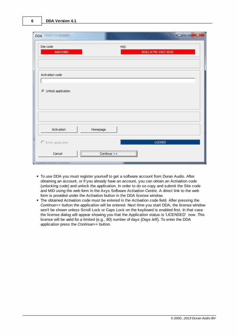
Program should be initially installed and unlocked by user with Administrator rights.Install the software and run it. After a while, DDA will show a license dialog.If you run DDA for the first time the application will be 'LOCKED' as shown in the applicationstatus field.
6 DDA Version 4.1
© 2000...2013 Duran Audio BV
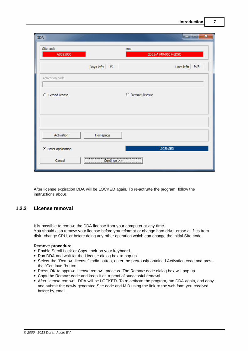
To use DDA you must register yourself to get a software account from Duran Audio. Afterobtaining an account, or if you already have an account, you can obtain an Activation code(unlocking code) and unlock the application. In order to do so copy and submit the Site codeand MID using the web form in the Axys Software Activation Centre. A direct link to the webform is provided under the Activation button in the DDA license window. The obtained Activation code must be entered in the Activation code field. After pressing the Continue>> button the application will be entered. Next time you start DDA, the license windowwon't be shown unless Scroll Lock or Caps Lock on the keyboard is enabled first. In that casethe license dialog will appear showing you that the Application status is 'LICENSED' now. Thislicense will be valid for a limited (e.g., 90) number of days (Days left). To enter the DDAapplication press the Continue>> button.
7Introduction
© 2000...2013 Duran Audio BV
After license expiration DDA will be LOCKED again. To re-activate the program, follow theinstructions above.
1.2.2 License removal
It is possible to remove the DDA license from your computer at any time.You should also remove your license before you reformat or change hard drive, erase all files fromdisk, change CPU, or before doing any other operation which can change the initial Site code.
Remove procedureEnable Scroll Lock or Caps Lock on your keyboard.Run DDA and wait for the License dialog box to pop-up. Select the "Remove license" radio button, enter the previously obtained Activation code and pressthe "Continue "button. Press OK to approve license removal process. The Remove code dialog box will pop-up.Copy the Remove code and keep it as a proof of successful removal.After license removal, DDA will be LOCKED. To re-activate the program, run DDA again, and copyand submit the newly generated Site code and MID using the link to the web form you receivedbefore by email.
8 DDA Version 4.1
© 2000...2013 Duran Audio BV
1.2.3 License extension
It is possible to extend the DDA license on your computer at any time. This feature is useful in caseyou want to extend the license period before expiration.
Extension procedureEnable Scroll Lock or Caps Lock on your keyboard.Run DDA and wait for the License dialog box to pop-up. Select the "Extend license" radio button. The new Site code and MID are shown in the upper redfields. Copy and submit the newly generated Site code and MID using the link to the web form youreceived before by email.In the period before you obtain the new Activation code (allow for two processing days), you cancontinue using DDA (i.e., until the old expiration date) by pressing the "Enter application" radiobutton and followed by pressing the Continue>> button.The obtained code must be entered in the Activation code field. After pressing the Continue>>button the application will entered.
1.2.4 DDA updates
New DDA releases can be installed over your current install (i.e., without uninstalling). During thelicense period, you don't need to obtain a new Activation code after updating DDA. The license willstay valid for the remaining period. In case you upgrade DDA to another edition, a new Activation code should be obtained.

Part
II
10 DDA Version 4.1
© 2000...2013 Duran Audio BV
2 Array theory
2.1 Introduction
Loudspeaker arrays are not new. The first designs can be found dating back to the 1930s. Due tothe limited frequency range, the frequency-dependent directional behavior and the resulting irregularoff-axis response, loudspeaker columns were mainly used for speech reinforcement. With thedevelopment of high-quality horns in the 1970s, loudspeaker columns lost even more ground.The (ongoing) rapid development of micro-electronics in the last decades, in particular thedevelopment of digital signal processors (DSP's), offered a whole new range of possibilities for thecontrol of loudspeaker arrays. In the early 1990s, Duran Audio introduced the first commercially
available powered, DSP-controlled loudspeaker line array (AXYS® Octavox and Intellivox series).Probably, the success of these arrays in a wide field of applications (airports, train stations,churches, sport stadiums, musical and opera shows etc.) has contributed to today's increasinginterest of manufacturers in loudspeaker arrays for the concert touring market.
2.2 Basics
Sound is a wave phenomenon. In an acoustic wave, energy (i.e. a sound signal) is transported fromone region in space to another. This means that a sound wave has both temporal properties (i.e. thecontents of the signal) and spatial properties (i.e. the directional behavior). The most fundamental acoustic source is the monopole. A monopole is a point source, which maybe considered as an infinitely small radially pulsating sphere. The acoustic wave pattern of amonopole is spherically symmetrical, which means that the energy is radiated equally in alldirections (i.e. omni-directional). A real loudspeaker can be modelled as a directional point source.An array can be simply defined as a spatial distribution of loudspeakers along a line (i.e., a linearray) or at a surface (i.e., a planar array). By driving the array elements independently, both the temporal and the spatial response of an array can be controlled electronically.
2.3 Array directivity
Point Source Model (PSM)Probably, one of the most widely applied models in acoustic simulation software for the calculationof the direct sound is the Point Source Model (PSM). In the PSM each loudspeaker in the array ismodelled as a directional point source, positioned in free space (i.e., no reflecting boundaries). Themodel assumes that the sound field (magnitude and phase of the acoustic pressure in all directions)of a loudspeaker is unaffected by the presence of other cabinets in the array.
The directional properties of a loudspeaker are usually measured in an anechoic room (i.e., areflection-free environment). As the transducers are mounted in the actual loudspeaker enclosure,cabinet diffraction (i.e., bending of sound waves around the cabinet) is taken into account in thecomplex directivity data.In the free-field PSM, the total sound field (magnitude and phase of the acoustic pressure in alldirections) of a loudspeaker (array) can be calculated by the complex addition of the individualtransducer contributions (i.e., applying the principle of superposition). It is assumed that eachtransducer contribution is independent and unaffected by the presence and the relative positions of
11Array theory
© 2000...2013 Duran Audio BV
any other loudspeaker cabinets.
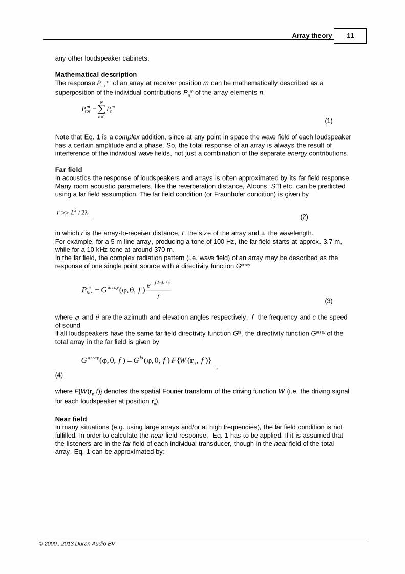
Mathematical descriptionThe response Ptot
m of an array at receiver position m can be mathematically described as a
superposition of the individual contributions Pnm of the array elements n.
N
n
mn
mtot PP
1(1)
Note that Eq. 1 is a complex addition, since at any point in space the wave field of each loudspeakerhas a certain amplitude and a phase. So, the total response of an array is always the result ofinterference of the individual wave fields, not just a combination of the separate energy contributions.
Far fieldIn acoustics the response of loudspeakers and arrays is often approximated by its far field response.Many room acoustic parameters, like the reverberation distance, Alcons, STI etc. can be predictedusing a far field assumption. The far field condition (or Fraunhofer condition) is given by
2/2Lr, (2)
in which r is the array-to-receiver distance, L the size of the array and the wavelength.For example, for a 5 m line array, producing a tone of 100 Hz, the far field starts at approx. 3.7 m,while for a 10 kHz tone at around 370 m.In the far field, the complex radiation pattern (i.e. wave field) of an array may be described as theresponse of one single point source with a directivity function Garray
r
efGP
cfrjarraym
far
/2
),,(
(3)
where and are the azimuth and elevation angles respectively, f the frequency and c the speedof sound.If all loudspeakers have the same far field directivity function Gls, the directivity function Garray of thetotal array in the far field is given by
)},({),,(),,( fWFfGfG nlsarray r
,(4)
where F{W(rn,f)} denotes the spatial Fourier transform of the driving function W (i.e. the driving signal
for each loudspeaker at position rn).
Near fieldIn many situations (e.g. using large arrays and/or at high frequencies), the far field condition is notfulfilled. In order to calculate the near field response, Eq. 1 has to be applied. If it is assumed thatthe listeners are in the far field of each individual transducer, though in the near field of the totalarray, Eq. 1 can be approximated by:
12 DDA Version 4.1
© 2000...2013 Duran Audio BV
nm
cfrjN
nnn
mtot
r
efGfWP
nm
,
/2
1
,
),,()(
(5)
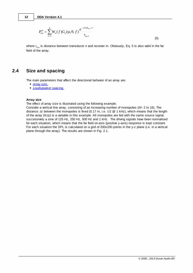
where rm,n is distance between transducer n and receiver m. Obviously, Eq. 5 is also valid in the far
field of the array.
2.4 Size and spacing
The main parameters that affect the directional behavior of an array are:Array size.Loudspeaker spacing.
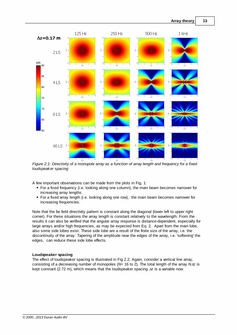
Array sizeThe effect of array size is illustrated using the following example. Consider a vertical line array, consisting of an increasing number of monopoles (N= 2 to 16). Thedistance z between the monopoles is fixed (0.17 m, i.e. /2 @ 1 kHz), which means that the lengthof the array (N z) is a variable in this example. All monopoles are fed with the same source signal,successively a sine of 125 Hz, 250 Hz, 500 Hz and 1 kHz. The driving signals have been normalisedfor each situation, which means that the far field on-axis (positive y-axis) response is kept constant.For each situation the SPL is calculated on a grid of 200x200 points in the y-z plane (i.e. in a verticalplane through the array). The results are shown in Fig. 2.1.
13Array theory
© 2000...2013 Duran Audio BV
Figure 2.1: Directivity of a monopole array as a function of array length and frequency for a fixedloudspeaker spacing
A few important observations can be made from the plots in Fig. 1:For a fixed frequency (i.e. looking along one column), the main beam becomes narrower forincreasing array lengthsFor a fixed array length (i.e. looking along one row), the main beam becomes narrower forincreasing frequencies.
Note that the far field directivity pattern is constant along the diagonal (lower left to upper rightcorner). For these situations the array length is constant relatively to the wavelength. From theresults it can also be verified that the angular array response is distance-dependent, especially forlarge arrays and/or high frequencies, as may be expected from Eq. 2. Apart from the main lobe,also some side lobes exist. These side lobe are a result of the finite size of the array, i.e. thediscontinuity of the array. Tapering of the amplitude near the edges of the array, i.e. 'softening' theedges, can reduce these side lobe effects.
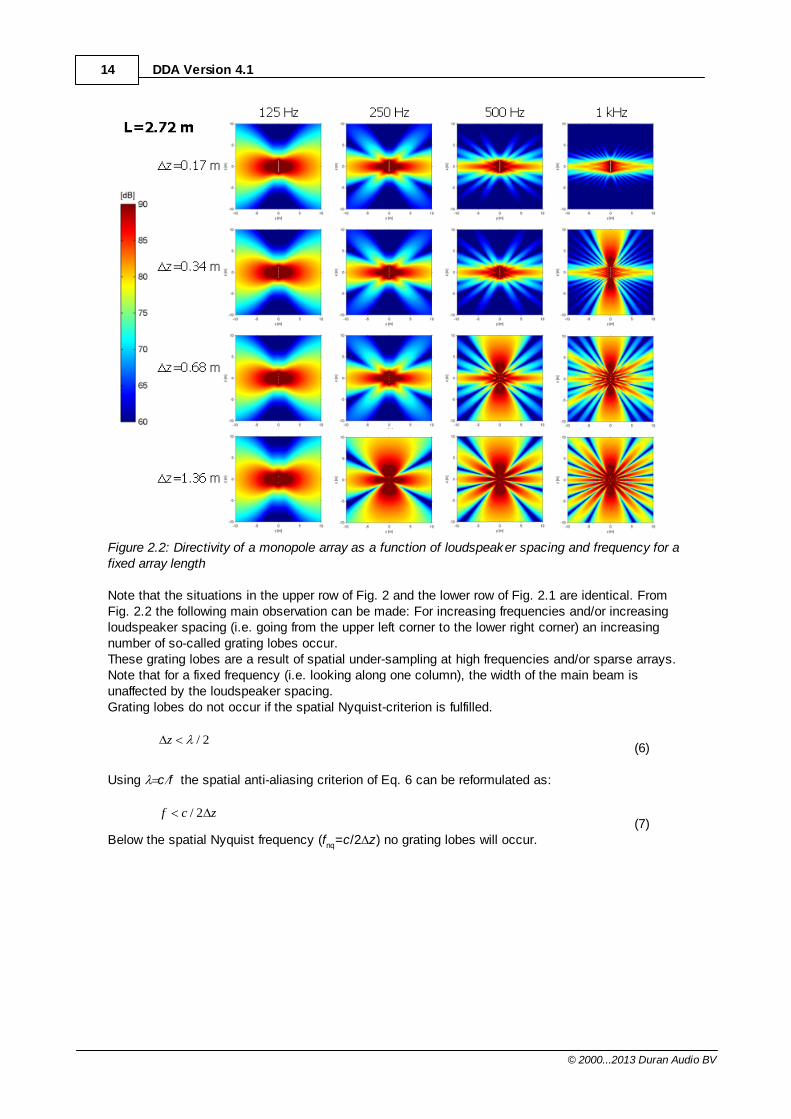
Loudspeaker spacingThe effect of loudspeaker spacing is illustrated in Fig 2.2. Again, consider a vertical line array,consisting of a decreasing number of monopoles (N= 16 to 2). The total length of the array N z iskept constant (2.72 m), which means that the loudspeaker spacing z is a variable now.
14 DDA Version 4.1
© 2000...2013 Duran Audio BV
Figure 2.2: Directivity of a monopole array as a function of loudspeaker spacing and frequency for afixed array length
Note that the situations in the upper row of Fig. 2 and the lower row of Fig. 2.1 are identical. FromFig. 2.2 the following main observation can be made: For increasing frequencies and/or increasingloudspeaker spacing (i.e. going from the upper left corner to the lower right corner) an increasingnumber of so-called grating lobes occur.These grating lobes are a result of spatial under-sampling at high frequencies and/or sparse arrays.Note that for a fixed frequency (i.e. looking along one column), the width of the main beam isunaffected by the loudspeaker spacing.Grating lobes do not occur if the spatial Nyquist-criterion is fulfilled.
2/z(6)
Using c f the spatial anti-aliasing criterion of Eq. 6 can be reformulated as:
zcf 2/(7)
Below the spatial Nyquist frequency (fnq=c/2 z) no grating lobes will occur.
15Array theory
© 2000...2013 Duran Audio BV
2.5 Acoustic Boundary Conditions (ABC)
Limitations of the PSMIn general, the Point Source Model (PSM ) gives accurate predictions of the array response at midand high frequencies. However, at low frequencies the sound field of a subwoofer (array) is stronglyaffected by the radiation impedance (i.e., the acoustic load) and the cabinet diffraction. Both theacoustic load and the diffraction are depending on the size and shape of the array and the position ofthe loudspeaker in the array.In addition, subwoofer arrays are often stacked on the floor or stage in practice, forming a half-spaceradiation condition. Assuming the ground plane is acoustically hard and large compared to theacoustic wave length, it can be modelled as a infinite baffle. At first sight it might be expected thatthe radiation pattern of the individual array elements doesn't change and that the effect of the groundplane can be simply modelled by adding a mirror-image of the source. However, due to the contactinterface between the array and the ground plane, the sound diffraction around the array is affectedtoo, because the 'path' under the array is now blocked.
Differential subwoofer arraysIn many situations the shortcomings of the PSM model are acceptable because the actual LF outputof a subwoofer array usually exceeds the predicted value. However, unacceptable deviations occurwith 'differential' bass arrays, which consist of two or more axially spaced subwoofers. A well-knownexample of a differential bass array is the (hyper)cardioid subwoofer, which is useful in live concertapplications due to its strong backward LF sound rejection. Here, small modelling errors could leadto major deviations in the actual rearward sound rejection compared to the predicted one.
The PSM-BEM modelFrom the above it's evident that the directional response of a subwoofer is affected by the arraygeometry as well as the radiation condition (full or half-space). So, in order to accurately model andoptimise a (differential) subwoofer array, the actual Acoustic Boundary Conditions (ABC) should betaken into account. A possible aproach would be to measure the spectral and directional characteristics of eachtransducer for various boundary conditions (i.e., the array configuration and/or the presence of aground plane). This is not feasible in practice. Therefore a different approach is used.Using the acoustic Boundary Element Method (BEM), it is possible to accurately calculate thesound radiation from large vibrating objects at low and mid frequencies. A direct implementation ofBEM modelling into DDA would lead to dramatically increased computation times. Therefore, acomputationally efficient, hybrid PSM-BEM approach is used. By combining measured free field dataof a single subwoofer and measured particle velocity data near the loudspeaker cone (and bassreflexports), accurate sensitivity and directivity data have been pre-calculated for each Axys subwoofermodel in various array setups using a full or half-space radiation condition. These data sets can beused in DDA by defining the appropriate ABC-descriptor. Please check the section UnitConfiguration File (UCF) for more details.
More information and technical papers can be found in the Downloads section of the Duran Audioweb site.
Part
III
17Duran Audio directivity concepts
© 2000...2013 Duran Audio BV
3 Duran Audio directivity concepts
3.1 Analogue Directivity Control
3.1.1 What is ADC?
Analogue Directivity Control is a passive, electronic beam control concept. ADC-driven Intellivox-typeloudspeaker arrays have a fixed directional behaviour. A passive filter network provides timealignment for the individual drivers, equalisation of the complete array and creates a constantwavelength array over a large frequency range.The AXYS Intellivox ADC range is intended for use in 70V/100V Public Address and Voice Alarm(PA/VA) systems. The ADC range has been designed to work with the AXYS Industry Amp series of100V line amplifiers. However, it can also be used with 3rd party amplifiers.
3.2 Digital Directivity Control
3.2.1 What is DDC?
Digital Directivity Control is a parametric, electronic beam control concept. DDC-driven Intellivox-typeloudspeaker arrays show a strong, almost frequency independent, directional behavior. This resultsin a uniform audience coverage, even over very long distances (up to 80 m). The far field directivitypattern can be controlled by a number of beam parameters: 'opening angle', 'elevation angle' and'focus distance'. So, the 'throw' and the aiming of the beam can be changed electronically, i.e.,without any mechanical adjustment of the array.
The on-board DSP hardware takes care of the required signal processing. Apart from the DSP, eachunit is equipped with a micro controller that takes care of all the surveillance routines, DSPmanagement, storage and logging and RS-485 network functionality. All beam and surveillancesettings can be configured using the WinControl software.
3.2.2 DDC basics
In order to realise a frequency independent main lobe and also to avoid grating lobes, the followingcriteria should be met:
The effective length of the array must be proportional to the wave length, in formula:
constLeff
The distance z between adjacent loudspeakers must be smaller than half the wave length (i.e.spatial Nyquist-criterion):
2/z
It can be shown mathematically that combining both requirement results in a special non-uniform('logarithmic') positioning scheme of the transducers. Note that the minimum distance between theloudspeakers in a line array is limited by the diameter of the loudspeakers, which means that thesecond condition cannot always be fulfilled for high frequencies in practice. Applying this patentedpositioning scheme (in the larger models of the Intellivox series), reduces the total number ofloudspeakers channels that is needed for a given frequency range.
Since the main lobe can be steered electronically, i.e. without the need of physical aiming, the array
18 DDA Version 4.1
© 2000...2013 Duran Audio BV
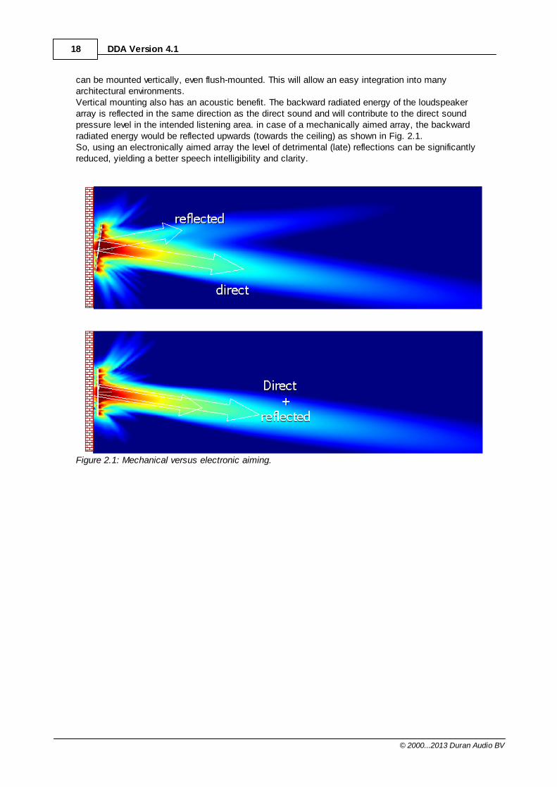
can be mounted vertically, even flush-mounted. This will allow an easy integration into manyarchitectural environments. Vertical mounting also has an acoustic benefit. The backward radiated energy of the loudspeakerarray is reflected in the same direction as the direct sound and will contribute to the direct soundpressure level in the intended listening area. in case of a mechanically aimed array, the backwardradiated energy would be reflected upwards (towards the ceiling) as shown in Fig. 2.1.So, using an electronically aimed array the level of detrimental (late) reflections can be significantlyreduced, yielding a better speech intelligibility and clarity.
Figure 2.1: Mechanical versus electronic aiming.
19Duran Audio directivity concepts
© 2000...2013 Duran Audio BV
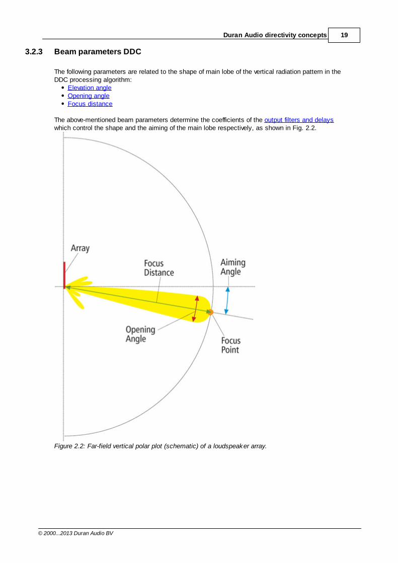
3.2.3 Beam parameters DDC
The following parameters are related to the shape of main lobe of the vertical radiation pattern in theDDC processing algorithm:
Elevation angleOpening angleFocus distance
The above-mentioned beam parameters determine the coefficients of the output filters and delayswhich control the shape and the aiming of the main lobe respectively, as shown in Fig. 2.2.
Figure 2.2: Far-field vertical polar plot (schematic) of a loudspeaker array.
20 DDA Version 4.1
© 2000...2013 Duran Audio BV
Main lobe
Elevation angleVertical far-field aiming angle of the main lobe in degrees. Negative values mean that the beam issteered downwards with respect to the perpendicular of the Intellivox unit. The setting of the elevationangle should be chosen in relation to the height of the acoustic center of the array with respect tothe height and length of the listening plane, as explained Choosing DDC beam parameters. Therange of the Elevation angle as well as the other beam related parameters is depending on the unittype.
Opening angleVertical far-field opening angle (- 6 dB) of the main lobe in degrees. By increasing or decreasing thisvalue, the 'throw' of the array can be enlarged or reduced respectively. The minimum opening angle islimited by the (acoustic) length of the array.
Focus distanceDistance of the acoustical reference point ("acoustical center") to the focal point in meters. The focalpoint is the position in space where all loudspeaker contributions arrive in phase. The acousticalreference point is taken as:
The acoustical center of the lowest transducer in case of an asymmetric array.orThe acoustical center of the transducer located in the middle of a symmetrical array (or theaverage of the two transducers closest to the middle in case the array consists of an even numberof transducers).
The Focus distance and the Elevation angle define the optimisation point that is used to calculatethe output channel delays for the main lobe. In Choosing DDC beam parameters guidelines aregiven to choose the optimum values for the beam parameters.
21Duran Audio directivity concepts
© 2000...2013 Duran Audio BV
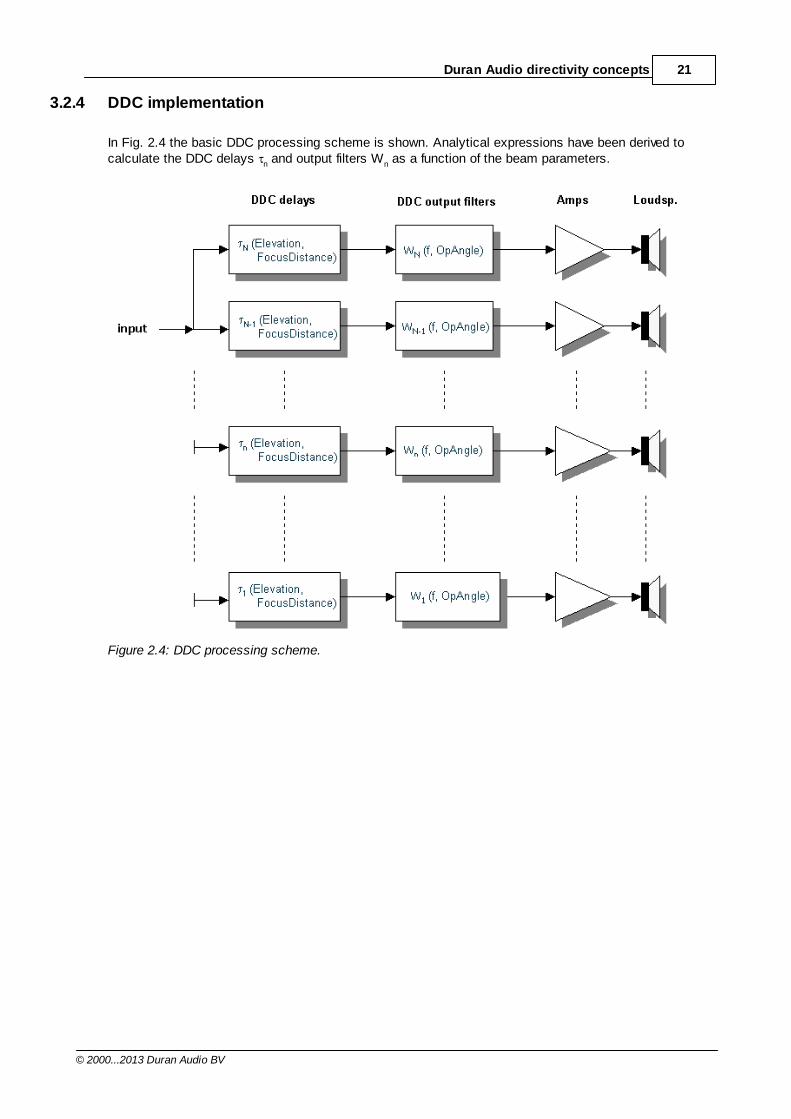
3.2.4 DDC implementation
In Fig. 2.4 the basic DDC processing scheme is shown. Analytical expressions have been derived tocalculate the DDC delays n and output filters Wn as a function of the beam parameters.
Figure 2.4: DDC processing scheme.
22 DDA Version 4.1
© 2000...2013 Duran Audio BV
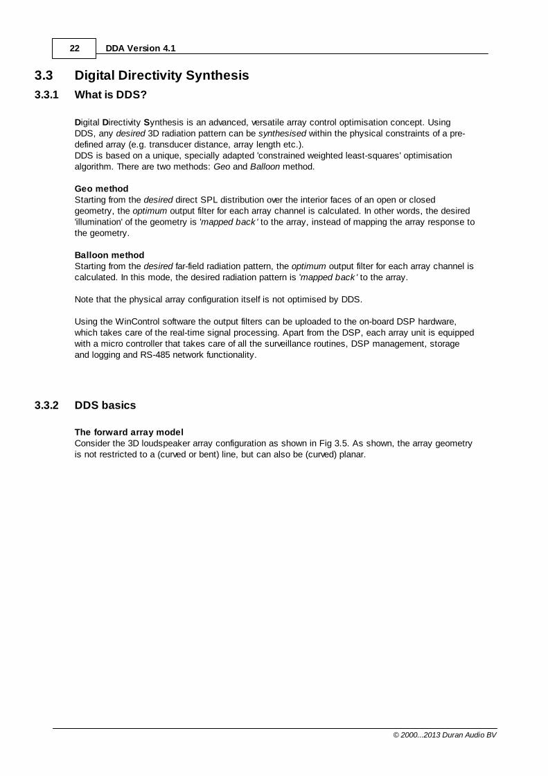
3.3 Digital Directivity Synthesis
3.3.1 What is DDS?
Digital Directivity Synthesis is an advanced, versatile array control optimisation concept. UsingDDS, any desired 3D radiation pattern can be synthesised within the physical constraints of a pre-defined array (e.g. transducer distance, array length etc.).DDS is based on a unique, specially adapted 'constrained weighted least-squares' optimisationalgorithm. There are two methods: Geo and Balloon method.
Geo methodStarting from the desired direct SPL distribution over the interior faces of an open or closedgeometry, the optimum output filter for each array channel is calculated. In other words, the desired'illumination' of the geometry is 'mapped back ' to the array, instead of mapping the array response tothe geometry.
Balloon methodStarting from the desired far-field radiation pattern, the optimum output filter for each array channel iscalculated. In this mode, the desired radiation pattern is 'mapped back ' to the array.
Note that the physical array configuration itself is not optimised by DDS.
Using the WinControl software the output filters can be uploaded to the on-board DSP hardware,which takes care of the real-time signal processing. Apart from the DSP, each array unit is equippedwith a micro controller that takes care of all the surveillance routines, DSP management, storageand logging and RS-485 network functionality.
3.3.2 DDS basics
The forward array modelConsider the 3D loudspeaker array configuration as shown in Fig 3.5. As shown, the array geometryis not restricted to a (curved or bent) line, but can also be (curved) planar.
23Duran Audio directivity concepts
© 2000...2013 Duran Audio BV
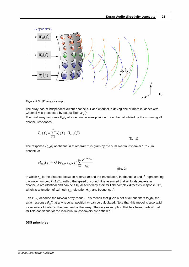
Figure 3.5: 3D array set-up.
The array has N independent output channels. Each channel is driving one or more loudspeakers.Channel n is processed by output filter Wn(f).
The total array response Pm(f) at a certain receiver position m can be calculated by the summing all
channel responses:
N
nnmnm fHfWfP
1, )()()(
(Eq. 1)
The response Hm,n(f) of channel n at receiver m is given by the sum over loudspeaker 1 to Ln in
channel n:
n lmL
l lm
rkj
lmlmlnmr
efGfH
1 ,
,,,
,
),,()(
(Eq. 2)
in which rm,l is the distance between receiver m and the transducer l in channel n and k representing
the wave number, k= f/c, with c the speed of sound. It is assumed that all loudspeakers inchannel n are identical and can be fully described by their far field complex directivity response Gl
ls,
which is a function of azimuth m,l, elevation m,l, and frequency f.
Eqs.(1-2) describe the forward array model. This means that given a set of output filters Wn(f), the
array response Pm(f) at any receiver position m can be calculated. Note that this model is also valid
for receivers located in the near field of the array. The only assumption that has been made is thatfar field conditions for the individual loudspeakers are satisfied.
DDS principles
24 DDA Version 4.1
© 2000...2013 Duran Audio BV
In general, the output filters Wn(f) are unknown. Let Dm(f) represent the user-defined desired response
of the array at frequency f for a set of M receivers (m =1..M). By replacing Pm(f) by the desired response Dm(f), Eq (1) can be re-written as a system of
M equations with N unknowns. An exact and unique solution does not exist since in general thereare more equations then unknowns (M>N). However, it is still possible to find a 'best fit' for Wn(f) by
applying a 'weighted least-squares' error criterion. This implies minimizing the difference between thedesired response Dm(f) and the realised response Pm(f). In addition error weights are used which
indicate the 'importance' or 'priority' of different receiver positions. Receiver positions that have arelatively high weighting factor, are favored above others.
DDS utilises a unique, specially adapted variant of the weighted least squares algorithm. Besides anoptimum match between desired and realised array response, the DDS design goals were:
Minimum array sound power.Optimum array sensitivity. Insensitivity to small deviations in position, directivity, and sensitivity of the individualloudspeakers. Stable and robust output filters with accurate amplitude and phase response. Therefore, theoutput filters are implemented as Finite Impulse Response (FIR) filters.
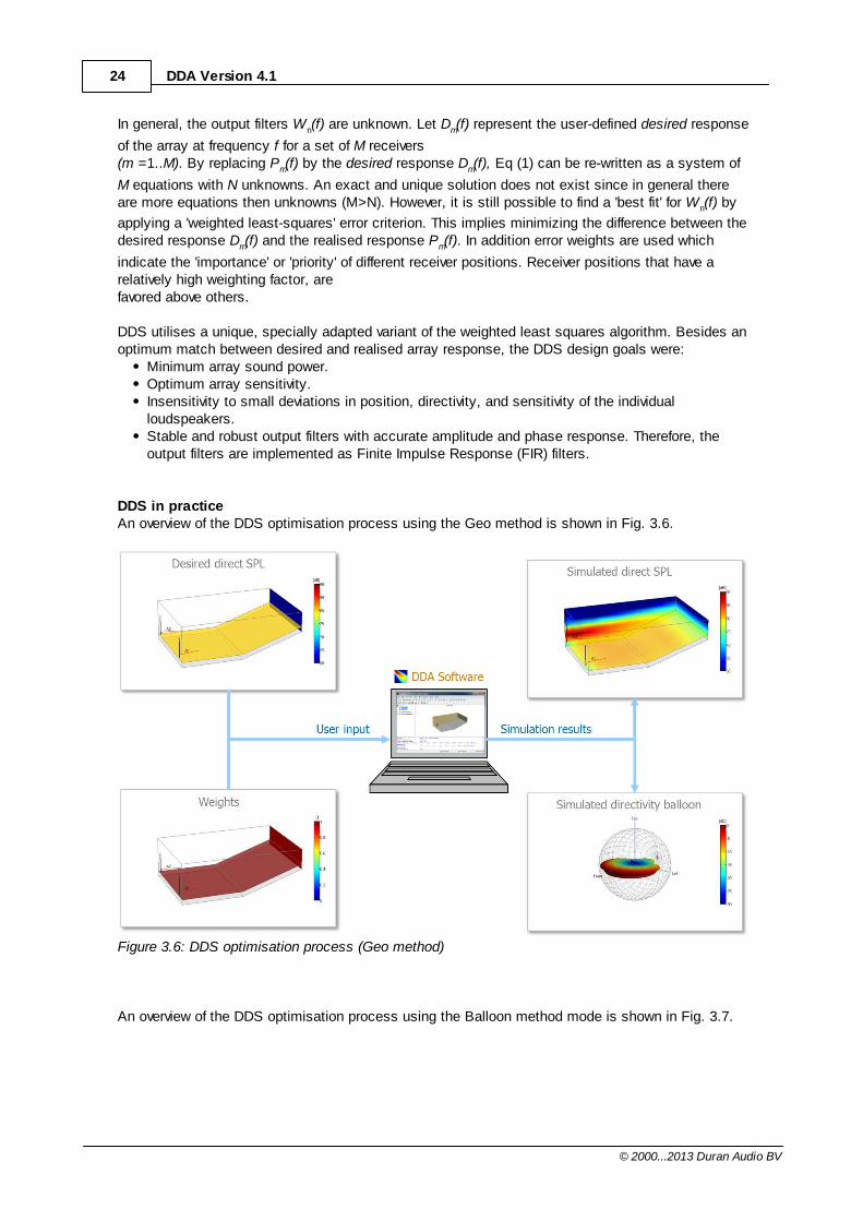
DDS in practiceAn overview of the DDS optimisation process using the Geo method is shown in Fig. 3.6.
Figure 3.6: DDS optimisation process (Geo method)
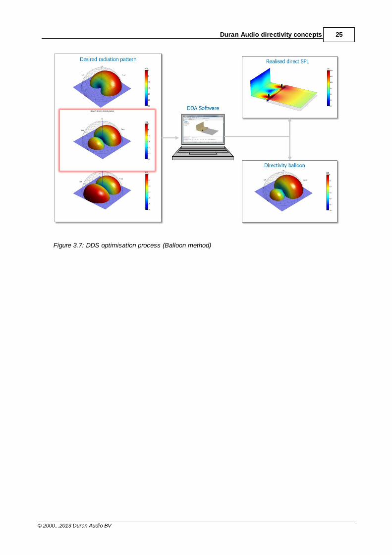
An overview of the DDS optimisation process using the Balloon method mode is shown in Fig. 3.7.
25Duran Audio directivity concepts
© 2000...2013 Duran Audio BV
Figure 3.7: DDS optimisation process (Balloon method)

26 DDA Version 4.1
© 2000...2013 Duran Audio BV
Part
IV
28 DDA Version 4.1
© 2000...2013 Duran Audio BV
4 DDA program
4.1 Main window
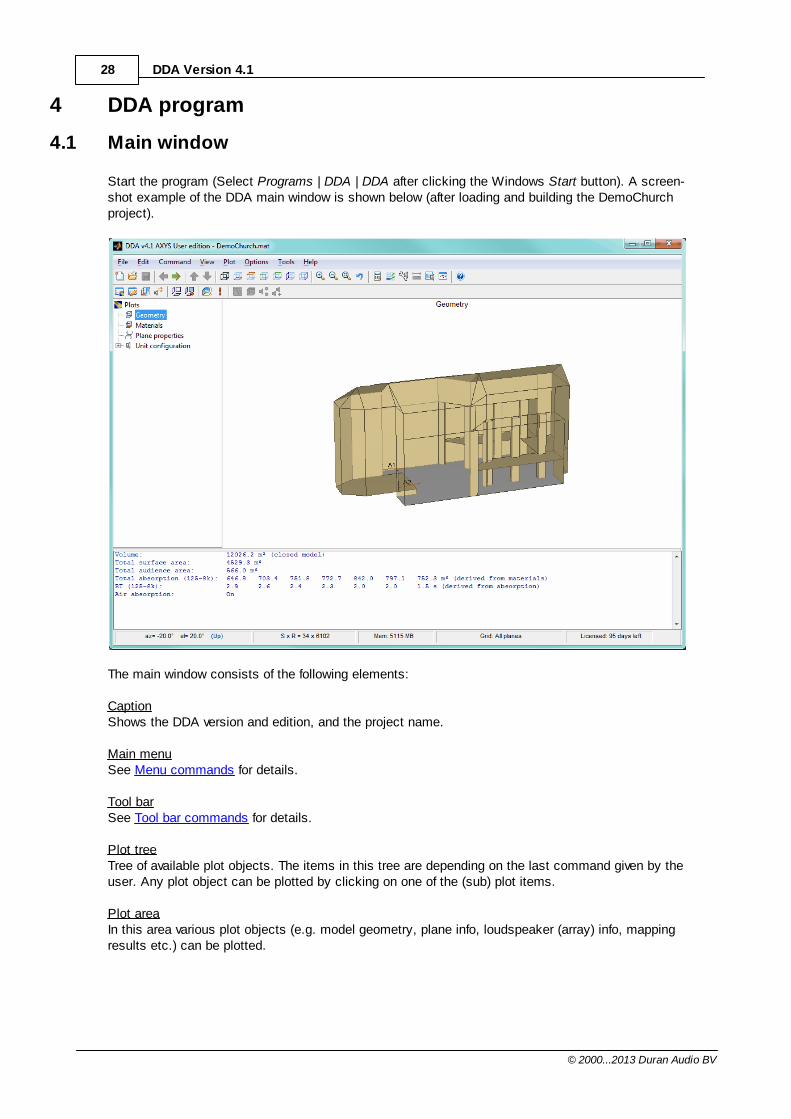
Start the program (Select Programs | DDA | DDA after clicking the Windows Start button). A screen-shot example of the DDA main window is shown below (after loading and building the DemoChurchproject).
The main window consists of the following elements:
CaptionShows the DDA version and edition, and the project name.
Main menuSee Menu commands for details.
Tool barSee Tool bar commands for details.
Plot treeTree of available plot objects. The items in this tree are depending on the last command given by theuser. Any plot object can be plotted by clicking on one of the (sub) plot items.
Plot areaIn this area various plot objects (e.g. model geometry, plane info, loudspeaker (array) info, mappingresults etc.) can be plotted.
29DDA program
© 2000...2013 Duran Audio BV
Info windowThe Info window shows information about the current project, plot object, or calculation results. See Info window for details.
Status barThe status bar shows information about plot coordinates (only in projection view), total number ofdrivers in all arrays by the number of grid point in the model (SxR), available physical memory andlicense duration..
4.1.1 Menu commands
4.1.1.1 File
File related commands.
New Project...Opens the Save New DDA Project dialog to create and save new project on disk.
Open Project...Opens the Open DDA Project dialog to load project settings from disk.
Save ProjectSaves current project settings to disk.
Save Project As...Opens the Save As Project dialog to save project settings to disk. The entire project, including thelinked configuration files (GCF, UCF and RCF), can be saved, or, only the project file ([ProjectName].mat).
Pack Project...Opens the Pack DDA Project dialog to zip all project files to file. All referenced project files and thefiles in the [ProjectName]_WinControl, and [ProjectName]_DosControl directories (if available) arezipped into one zip-file. The file paths are included.
Unpack Project...Opens the Unpack DDA Project dialog to unzip the selected file into the selected destination. It isadvised to create a new, empty destination folder, otherwise existing files might be overwritten. Theextracted files always have read and write file permission.
Import Model From...Opens the Import Model dialog to load import file from disk.DDA can import geometry files from CATT Acoustic, Odeon or EASE.The procedure will be described below:
CATT or Odeon models can be imported by loading a CAD-file which can be exported fromCATT or Odeon. In CATT the model can be exported by using the "Export Geometry ToAutoCAD Interface" function.EASE models can be imported by loading a xfc-file which can be exported from EASE usingthe Import/Export function in the Main window.
30 DDA Version 4.1
© 2000...2013 Duran Audio BV
Export Directivity Data To...Opens the Export Directivity Data dialog to save file(s) to disk. In order to use this feature, a Full run calculation must be finished.
CATT Acoustic v8 or higher:Generation of generic CATT Acoustic v8 SD2-directivity files. For more information about theGeneric DDI interface, see the CATT DDI Interface. EASE 4.0 balloon:A 5-degree resolution, 1/3-octave directivity balloons is exported from DDA to EASE 4.0 format.In the project directory a [ProjectName]_EASE directory is created in which a xhn-file is savedthat can be imported in EASE using the Import ASCII function in the speaker base module. In the Project Settings window of DDA the Resolution in the Directivity Balloon Settings must beset to 5 degrees, otherwise a warning is issued and the export is canceled. Since in the nearfield of an array the directivity balloons are distance-dependent, the user should set the Radiusin the Directivity Balloon Settings to a representative (average) distance. Note that, especiallyfor large arrays and/or high frequencies (i.e., small opening angles), the 5-degree resolutionballoons give a poor representation of the directional behavior of the array. EASE GLL Configuration (XGLC):Generation of XGLC files to configure the appropriate GLL in EASE 4.3 or higher. After exportcompletion, the created export folder can be opened in the Windows explorer. The export folderis named [ProjectName]_EASE_XGLC, where [ProjectName] is the name of the current DDAproject. For each loudspeaker (array) in the DDA project a separate XGLC file is generated (i.e.,A1_Axys_Intellivox.xglc). The first part of the file name corresponds to the loudspeaker name inDDA (i.e., A1). The second part (i.e., Axys_Intellivox) refers to the name of the GLL that mustbe used in EASE. Only the corresponding GLL can be configured in EASE with a XGLC file. ForEASE three GLL files are available (for the Axys Intellivox range, the Target range and theSource-Scope range). Although DDA allows mixing of array units from different product ranges,the EASE GLLs only accept XGLC data for arrays with units from one product range only. For more information about the use of GLL files in EASE, the user is referred to the EASEmanual.Odeon XML:Generation of XML files to use in Odeon v10.1 or higher. After export completion, the createdexport folder can be opened in the Windows explorer. The export folder is named [ProjectName]_Odeon, where [ProjectName] is the name of the current DDA project. For each loudspeaker (array) in the DDA project a separate XML file is generated (i.e., A1.xml). The XML files arereferring to one or more CLF files (Common loudspeaker Format) for the individual transducersin the loudspeaker (array). These CLF-files describe the directivity of the individual loudspeakersin a loudspeaker. Therefore, before the exported data can be used in Odeon, the entireDuranAudio folder in the [DDA Install Folder]\Odeon folder, should be copied into the [OdeonInstall Folder]\DirFiles folder.
For more information about the use of array sources with XML files in Odeon, the user isreferred to the Odeon manual.
Export Plot File To...Opens the Save Plot File As dialog to save the contents of plot region in specific file-format.Plots can be exported to:
JPEG (screen resolution), Joint Photographic Experts Group formatJPEG (print quality 300 dpi), Joint Photographic Experts Group formatEMF (wire frame only), Windows Enhanced Meta FileThis export option is only available when showing the Geometry plot
31DDA program
© 2000...2013 Duran Audio BV
Print...Print the contents of plot region.
1...4Recently opened Project files.
QuitQuits program execution.
4.1.1.2 Edit
Edit related commands.
Project settings...Opens the Project Settings dialog to set various project options.
Edit configuration files...Opens the Config-editor. All configuration files, which are referenced in the Project settings dialog,are opened.
Edit plane properties...Activates the Plane properties plot object and opens the GCF edit tool. Any open configuration files,are closed first. This command is only available after building the project.
Edit loudspeaker positions...Activates the Geometry plot object and opens the Project Settings dialog. This command is onlyavailable after building the project.
Select loudspeakers for summationActivates the Summed frequency response plot object and opens the loudspeaker selection dialog.In this way the summed frequency response of any combination of loudspeakers at the receiverpositions defined in the RCF-file can be calculated. Depending on the Multiple loudspeaker sumsetting in the Calculation Options dialog, energy or interference summing is used.
Copy as bitmapCopies the plot area of the application window to the clipboard in bitmap format.
4.1.1.2.1 Project settings
Option window to set project settings.
DescriptionEdit box for project description.
Geo-file
32 DDA Version 4.1
© 2000...2013 Duran Audio BV
Name of Geo Configuration File (GCF)-file. This file contains the geometric description of the 3D
model. Enter the name in the edit field or click the button to browse.
Rec-fileName of the Receiver Configuration File (RCF)-file. The file contains the positions of one or more
discrete receivers. Enter the name in the edit field or click the button to browse.
GroupsGroup listboxListbox for selecting a Group.
Add Group button
The button can be used for appending a new Group to the list.
Duplicate Group button
The button can be used for duplicating the selected Group and appending it to the list.
Import Group button
The button can be used for importing the Group(s) from another project to the list.
Delete Group button
The button can be used for deleting the selected Group from the list.
Source typeRadio buttons to select SR ("Blue line"), ADC, DDC, DDS or Point source for the selected
group. The button next to the DDS radio button opens a pop-up menu to choose either Geo
or Balloon method.
Radiation conditionDropdown box for selecting the appropriate acoustic radiation condition (Full or Half space) forthe selected group.
Note: In most situations the "Full space" option should be used. Only change to "Half space" inspecific situations such as ground-stacked differential subwoofer arrays.
In case of half space radiation, the position of the boundary plane must be chosen. The twooptions are: "Below" and "Behind". In the first case an infinitely large, acoustically hardhorizontal boundary plane is modelled directly below the loudspeaker (array) at z=z
bottom. In the
second case the boundary plane is positioned vertically behind the loudspeaker (array) at x=x
back. Note that the boundary plane is 'connected' to the loudspeaker (array), which means that if
the array is moved from one location to the other, the boundary plane is shifted too. Moreinformation about radiation conditions can be found in the Acoustic Boundary Conditionssection.
LoudspeakersNew loudspeaker button
33DDA program
© 2000...2013 Duran Audio BV
The button can be used for inserting a loudspeaker in the table (a copy of the selectedloudspeaker(s) is inserted after the last selected one).The first loudspeaker in a group is called the primary loudspeaker (see also Choosing planeproperties).
Remove loudspeaker button
The button can be used for deleting the selected loudspeaker(s) from the table.
Input loudspeaker position by mouse clicking
The button can be used to edit the loudspeaker coordinates by picking a position withthe mouse. This works easiest when the geometry is shown in 2D projection (e.g., planview). The third coordinate (i.e., the one perpendicular to the view) remains unaltered. Thisfunctionality is only available after building the project, i.e., when the geometry is plotted.
Delay zone:Dropdown box for selecting the delay zone.
Loudsp. (default)The delay and lock settings can be set for each loudspeaker separately.
Group The delay and lock settings can only be set for the entire group. This means thatall loudspeakers in the group are 'synchronised'.
The zone setting is very useful for automatic predelay optimisation. In case the zone is setto Group, the entire group is regarded as one delay zone.
Set EQOpens the EQ window to set EQ
Loudspeaker tableTable for selecting and editing the loudspeakers within the selected Group. Parameters:X, Y, Z, H, V and RollIn these fields the x, y, and z-coordinates (in metres) of the reference point as well as thethe horizontal, vertical, and roll angle (in degrees) can be entered. With the +/- buttons thevalue can be incremented or decremented by 5m or 5 degrees respectively.
MirrorThis option is only used with DDS loudspeakers.Check box to use a mirror-symmetric copy of the loudspeaker (array). Normally, eachloudspeaker in the list is a translated and rotated copy of the primary loudspeaker (i.e., theloudspeaker configuration defined in the UCF-file). However, if this option is checked, theselected loudspeaker is a mirror-symmetric copy of the stack (i.e., the stack is mirrored inthe xz-plane of the local stack coordinate system). This feature is useful when using a left/right set-up, with asymmetrical units like the T-2820(Target top), or, when horizontal or planar modular arrays are used. In these situations onlythe right hand side stack (as seen from the audience) has to be defined in a UCF-file.
Note: Check box must be double-clicked in order to change.
34 DDA Version 4.1
© 2000...2013 Duran Audio BV
DelayField to define the delay (in milliseconds) for the selected loudspeaker or group (dependingon the zone setting). In this way a distributed set of loudspeakers can be time-aligned.
Lock delayIf this checkbox is checked, the delay for the selected loudspeaker or group (depending onthe zone setting) is locked (i.e., fixed) during delay optimisation. Note: Check box must be double-clicked in order to change.
GainField to set gain (dB) for selected loudspeaker.
Notes: For AXYS SR, ADC, DDC loudspeaker types, the Gain represents the output gain (i.e.,volume) of the built-in amplifier. The maximum SPL is obtained at 0dB Gain. A high Gainmight result in a negative Headroom depending on the input gain in the Group settings. For AXYS DDS loudspeakers, the SPL is determined by the Desired SPL. The Gain ismerely a correction for each loudspeaker in the Group.For Point sources (CLF) the definition of Gain depends on the loudspeaker type (Passive,Active or Powered).
For Passive and Active loudspeakers the Gain represents the required gain of anexternal power amplifier. If the Gain is set to 0dB, the loudspeaker is operated at 1W,in which case the SPL @1m equals the Sensitivity (Please check data with CLFViewer). For Powered loudspeakers the Gain represents the output gain (i.e., volume) of thebuilt-in amplifier. With a Gain of 0 dB the SPL @1m equals the Axial Spectrum valuesnormalised to 1V
RMS (i.e. 0 dBV) input (if actual Input Voltage is given in CLF). In
case the Input voltage is not given in the CLF, it is assumed that the given AxialSpectrum in the CLF was measured at an input voltage of 0.1V
RMS (-20 dBV).
In case neither the Axial Spectrum nor the Input Voltage is given in the CLF, the AxialSpectrum is assumed to be 100dB @0dBV input (flat over all frequencies). Pleasealways check manufacturer's data sheet for the given max. SPL figures as thedefinition of Axial Spectrum in the CLF is not well-defined.
EQ (32-16k)Fields to set octave-band EQ (dB) for selected loudspeakers.
Note: Gain and EQ have no effect on the channel output filters, i.e., they are not included inthe output filters.
LabelField to enter an optional label for the selected loudspeaker. This Label will be shown in the loudspeaker table.
35DDA program
© 2000...2013 Duran Audio BV
CalculationSurface gridWith this dropdown box the gridding options can be set. The two options are:
All planesA receiver grid will be created for all surfaces in the model.
Audience (+Virtual+Weighted)A receiver grid will be created only for the audience plane(s) and for any virtual or DDS-weighted planes (if applicable). Note that the acoustic parameters are calculated only for the'gridded' planes. For larger models this option saves a lot of memory.
Grid stepWith this edit box the step size of the receiver grid can be defined. For mapping purposes, eachplane (polygon surface) in the geometric model is divided into a triangular grid. The grid stepdefines the size of the right-angled triangles inside the polygon.
Map height audienceWith this edit box the listening height (ear level) for the audience can be defined. The map heightis only applied to audience planes (see also AUDIENCE parameter in GCF-file).
Line-of-sight checkWith this dropdown box line-of-sight calculation options can be set. To display possible shadowzones in the model, DDA utilises a geometric line-of-sight algorithm. Acoustic diffraction is nottaken into account. For complex models, line-of-sight calculations can put a severe claim onprocessing power. Therefore, different calculation schemes are implemented (in order ofincreasing computation time):
NoneNo checking is done.
Loudsp. ref. --> AudienceLine-of-sight checking is done from the reference point of the loudspeaker (array) to theaudience plane(s). Possible shadow zones at other planes are not shown. Warning: If only a part of the loudspeaker (e.g. some drivers) is blocked, but the referencepoint is still visible from the receiver's point-of-view, no shadowing occurs. In these situationsthe "Each driver --> Audience" option is recommended.
Each driver --> AudienceLine-of-sight checking is done from each driver in the loudspeaker (array) to the audienceplane(s). Possible shadow zones at other planes are not shown.
Loudsp. ref. --> All planesLine-of-sight is calculated from the reference point of the loudspeaker (array) to all planes. Warning: If only a part of the loudspeaker (e.g. some drivers) is blocked, but the referencepoint is still visible from the receiver's point-of-view, no shadowing occurs. In these situationsthe "Each driver --> All planes" option is recommended.
Each driver --> All planesLine-of-sight checking is done from for each driver in the loudspeaker (array) to all planes.
Note: Virtual planes are acoustically transparent, which means that they cannot cast anyshadows.
Directivity balloonResolutionWith this edit box the angular resolution for the calculation of the directivity balloons can be set.
Radius
36 DDA Version 4.1
© 2000...2013 Duran Audio BV
With this edit box the radius of the sphere for the calculation of the directivity balloons can beset. The center of the sphere is always taken at the reference point of the loudspeaker (array). To evaluate the far field directivity pattern of the loudspeaker (array), a relatively large radiusmust be chosen (for more details see: Array directivity). At short distances (i.e., in the near fieldof the array), the directivity pattern is strongly distance-dependent.
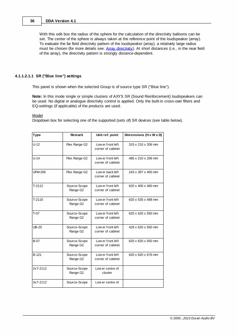
4.1.1.2.1.1 SR ("Blue line") settings
This panel is shown when the selected Group is of source type SR ("Blue line").
Note: In this mode single or simple clusters of AXYS SR (Sound Reinforcement) loudspeakers canbe used. No digital or analogue directivity control is applied. Only the built-in cross-over filters andEQ-settings (if applicable) of the products are used.
ModelDropdown box for selecting one of the supported (sets of) SR devices (see table below).
Type Remark Unit ref. point Dimensions (H x W x D)
U-12 Flex Range G2 Low er front left
corner of cabinet
315 x 210 x 206 mm
U-14 Flex Range G2 Low er front left
corner of cabinet
485 x 210 x 206 mm
UFM-265 Flex Range G2 Low er back left
corner of cabinet
243 x 397 x 400 mm
T-2112 Source-Scope
Range G2
Low er front left
corner of cabinet
620 x 400 x 460 mm
T-2115 Source-Scope
Range G2
Low er front left
corner of cabinet
620 x 535 x 498 mm
T-07 Source-Scope
Range G2
Low er front left
corner of cabinet
620 x 620 x 550 mm
UB-25 Source-Scope
Range G2
Low er front left
corner of cabinet
429 x 620 x 550 mm
B-07 Source-Scope
Range G2
Low er front left
corner of cabinet
620 x 620 x 550 mm
B-121 Source-Scope
Range G2
Low er front left
corner of cabinet
620 x 620 x 676 mm
2xT-2112 Source-Scope
Range G2
Low er centre of
cluster
3xT-2112 Source-Scope Low er centre of
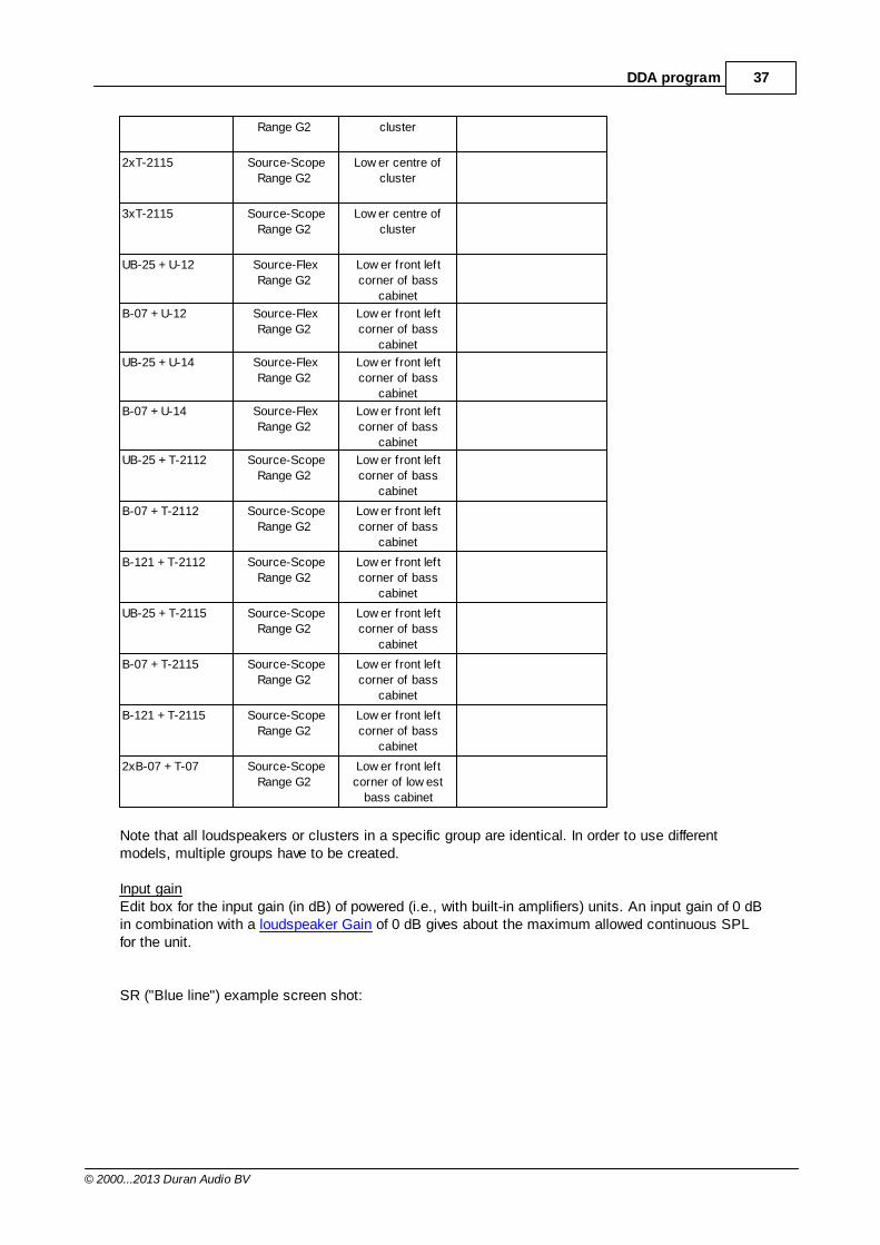
37DDA program
© 2000...2013 Duran Audio BV
Range G2 cluster
2xT-2115 Source-Scope
Range G2
Low er centre of
cluster
3xT-2115 Source-Scope
Range G2
Low er centre of
cluster
UB-25 + U-12 Source-Flex
Range G2
Low er front left
corner of bass
cabinet
B-07 + U-12 Source-Flex
Range G2
Low er front left
corner of bass
cabinet
UB-25 + U-14 Source-Flex
Range G2
Low er front left
corner of bass
cabinet
B-07 + U-14 Source-Flex
Range G2
Low er front left
corner of bass
cabinet
UB-25 + T-2112 Source-Scope
Range G2
Low er front left
corner of bass
cabinet
B-07 + T-2112 Source-Scope
Range G2
Low er front left
corner of bass
cabinet
B-121 + T-2112 Source-Scope
Range G2
Low er front left
corner of bass
cabinet
UB-25 + T-2115 Source-Scope
Range G2
Low er front left
corner of bass
cabinet
B-07 + T-2115 Source-Scope
Range G2
Low er front left
corner of bass
cabinet
B-121 + T-2115 Source-Scope
Range G2
Low er front left
corner of bass
cabinet
2xB-07 + T-07 Source-Scope
Range G2
Low er front left
corner of low est
bass cabinet
Note that all loudspeakers or clusters in a specific group are identical. In order to use differentmodels, multiple groups have to be created.
Input gainEdit box for the input gain (in dB) of powered (i.e., with built-in amplifiers) units. An input gain of 0 dBin combination with a loudspeaker Gain of 0 dB gives about the maximum allowed continuous SPLfor the unit.
SR ("Blue line") example screen shot:
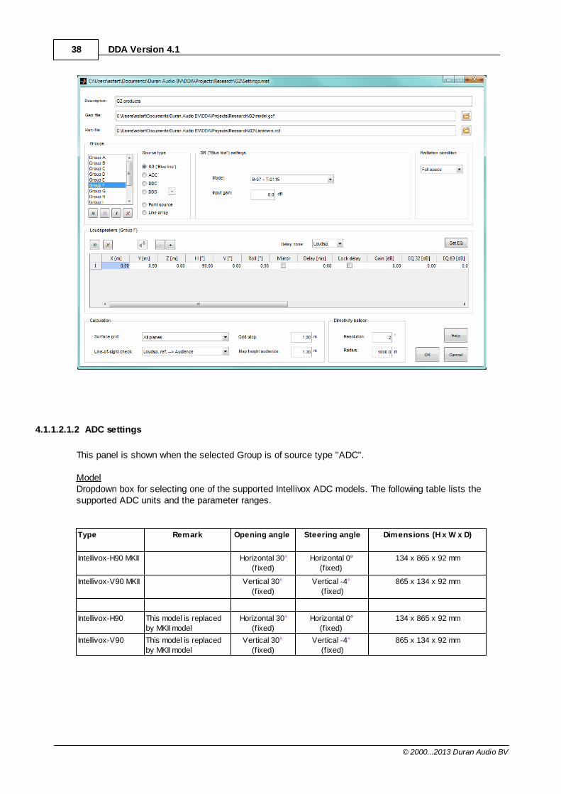
38 DDA Version 4.1
© 2000...2013 Duran Audio BV
4.1.1.2.1.2 ADC settings
This panel is shown when the selected Group is of source type "ADC".
ModelDropdown box for selecting one of the supported Intellivox ADC models. The following table lists thesupported ADC units and the parameter ranges.
Type Remark Opening angle Steering angle Dimensions (H x W x D)
Intellivox-H90 MKII Horizontal 30°
(f ixed)
Horizontal 0°
(f ixed)
134 x 865 x 92 mm
Intellivox-V90 MKII Vertical 30°
(f ixed)
Vertical -4°
(f ixed)
865 x 134 x 92 mm
Intellivox-H90 This model is replaced
by MKII model
Horizontal 30°
(f ixed)
Horizontal 0°
(f ixed)
134 x 865 x 92 mm
Intellivox-V90 This model is replaced
by MKII model
Vertical 30°
(f ixed)
Vertical -4°
(f ixed)
865 x 134 x 92 mm
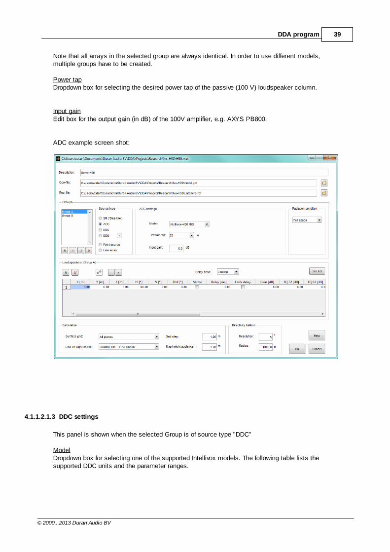
39DDA program
© 2000...2013 Duran Audio BV
Note that all arrays in the selected group are always identical. In order to use different models,multiple groups have to be created.
Power tapDropdown box for selecting the desired power tap of the passive (100 V) loudspeaker column.
Input gainEdit box for the output gain (in dB) of the 100V amplifier, e.g. AXYS PB800.
ADC example screen shot:
4.1.1.2.1.3 DDC settings
This panel is shown when the selected Group is of source type "DDC"
ModelDropdown box for selecting one of the supported Intellivox models. The following table lists thesupported DDC units and the parameter ranges.
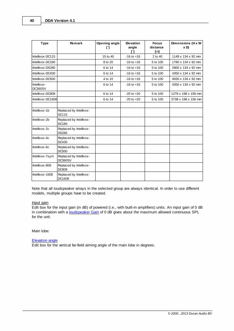
40 DDA Version 4.1
© 2000...2013 Duran Audio BV
Type Remark Opening angle
[°]
Elevation
angle
[°]
Focus
distance
[m]
Dimensions (H x W
x D)
Intellivox-DC115 15 to 40 -16 to +16 2 to 40 1149 x 134 x 92 mm
Intellivox-DC180 8 to 20 -16 to +16 5 to 100 1780 x 134 x 92 mm
Intellivox-DS280 6 to 14 -16 to +16 5 to 100 2800 x 134 x 92 mm
Intellivox-DC430 6 to 14 -16 to +16 5 to 100 4350 x 134 x 92 mm
Intellivox-DC500 4 to 10 -16 to +16 5 to 100 4930 x 134 x 92 mm
Intellivox-
DC360SV
6 to 14 -16 to +16 5 to 100 4350 x 134 x 92 mm
Intellivox-DC808 6 to 14 -20 to +20 5 to 100 1278 x 198 x 156 mm
Intellivox-DC1608 6 to 14 -20 to +20 5 to 100 3738 x 198 x 156 mm
Intellivox-1b Replaced by Intellivox-
DC115
Intellivox-2b Replaced by Intellivox-
DC180
Intellivox-2c Replaced by Intellivox-
DS280
Intellivox-4c Replaced by Intellivox-
DC430
Intellivox-6c Replaced by Intellivox-
DC500
Intellivox-7sym Replaced by Intellivox-
DC360SV
Intellivox-808 Replaced by Intellivox-
DC808
Intellivox-1608 Replaced by Intellivox-
DC1608
Note that all loudspeaker arrays in the selected group are always identical. In order to use differentmodels, multiple groups have to be created.
Input gainEdit box for the input gain (in dB) of powered (i.e., with built-in amplifiers) units. An input gain of 0 dBin combination with a loudspeaker Gain of 0 dB gives about the maximum allowed continuous SPLfor the unit.
Main lobe:
Elevation angleEdit box for the vertical far-field aiming angle of the main lobe in degrees.
41DDA program
© 2000...2013 Duran Audio BV
Opening angleEdit box for the vertical far-field opening angle (- 6 dB) of the main lobe in degrees.
Focus distanceEdit box for the distance of the acoustical reference point ("acoustic center") to the focus point of themain lobe in meters.
Relative gainEdit box for the gain of the main lobe which can be changed from -20 to +10 dB.
Second lobe:Check box for (un)selecting dual lobe processing. Note: In WinControl these parameters can only be changed for units that have the "dual lobe" DSPsoftware installed.
Elevation angleEdit box for the vertical far-field aiming angle of the second lobe in degrees.
Focus distanceEdit box for the distance of the acoustical reference point ("acoustic center") to the focus point of thesecond lobe in meters.
Relative gainEdit box for the relative gain of the second lobe which can be changed from -20 to +10 dB.
Note: The range of the beam related parameters is depending on the unit type (see table above).
DDC example screen shot:
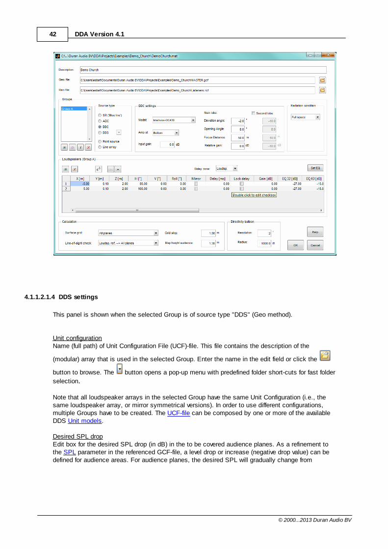
42 DDA Version 4.1
© 2000...2013 Duran Audio BV
4.1.1.2.1.4 DDS settings
This panel is shown when the selected Group is of source type "DDS" (Geo method).
Unit configurationName (full path) of Unit Configuration File (UCF)-file. This file contains the description of the
(modular) array that is used in the selected Group. Enter the name in the edit field or click the
button to browse. The button opens a pop-up menu with predefined folder short-cuts for fast folder
selection.
Note that all loudspeaker arrays in the selected Group have the same Unit Configuration (i.e., thesame loudspeaker array, or mirror symmetrical versions). In order to use different configurations,multiple Groups have to be created. The UCF-file can be composed by one or more of the availableDDS Unit models.
Desired SPL dropEdit box for the desired SPL drop (in dB) in the to be covered audience planes. As a refinement tothe SPL parameter in the referenced GCF-file, a level drop or increase (negative drop value) can bedefined for audience areas. For audience planes, the desired SPL will gradually change from
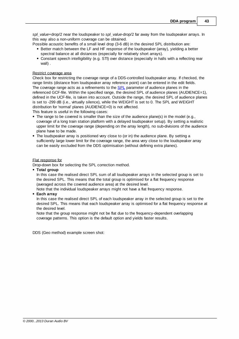
43DDA program
© 2000...2013 Duran Audio BV
spl_value+drop/2 near the loudspeaker to spl_value-drop/2 far away from the loudspeaker arrays. Inthis way also a non-uniform coverage can be obtained. Possible acoustic benefits of a small level drop (3-6 dB) in the desired SPL distribution are:
Better match between the LF and HF response of the loudspeaker (array), yielding a betterspectral balance at all distances (especially for relatively short arrays). Constant speech intelligibility (e.g. STI) over distance (especially in halls with a reflecting rearwall) .
Restrict coverage areaCheck box for restricting the coverage range of a DDS-controlled loudspeaker array. If checked, therange limits (distance from loudspeaker array reference point) can be entered in the edit fields.The coverage range acts as a refinements to the SPL parameter of audience planes in thereferenced GCF-file. Within the specified range, the desired SPL of audience planes (AUDIENCE=1),defined in the UCF-file, is taken into account. Outside the range, the desired SPL of audience planesis set to -299 dB (i.e., virtually silence), while the WEIGHT is set to 0. The SPL and WEIGHTdistribution for 'normal' planes (AUDIENCE=0) is not affected.This feature is useful in the following cases:
The range to be covered is smaller than the size of the audience plane(s) in the model (e.g.,coverage of a long train station platform with a delayed loudspeaker setup). By setting a realisticupper limit for the coverage range (depending on the array length), no sub-divisions of the audienceplane have to be made.The loudspeaker array is positioned very close to (or in) the audience plane. By setting asufficiently large lower limit for the coverage range, the area very close to the loudspeaker arraycan be easily excluded from the DDS optimisation (without defining extra planes).
Flat response forDrop-down box for selecting the SPL correction method.
Total groupIn this case the realised direct SPL sum of all loudspeaker arrays in the selected group is set tothe desired SPL. This means that the total group is optimised for a flat frequency response(averaged across the covered audience area) at the desired level. Note that the individual loudspeaker arrays might not have a flat frequency response.Each arrayIn this case the realised direct SPL of each loudspeaker array in the selected group is set to thedesired SPL. This means that each loudspeaker array is optimised for a flat frequency response atthe desired level. Note that the group response might not be flat due to the frequency-dependent overlappingcoverage patterns. This option is the default option and yields faster results.
DDS (Geo method) example screen shot:
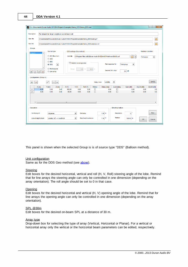
44 DDA Version 4.1
© 2000...2013 Duran Audio BV
This panel is shown when the selected Group is is of source type "DDS" (Balloon method).
Unit configurationSame as for the DDS Geo method (see above).
SteeringEdit boxes for the desired horizontal, vertical and roll (H, V, Roll) steering angle of the lobe. Remindthat for line arrays the steering angle can only be controlled in one dimension (depending on thearray orientation). The roll angle should be set to 0 in that case.
OpeningEdit boxes for the desired horizontal and vertical (H, V) opening angle of the lobe. Remind that forline arrays the opening angle can only be controlled in one dimension (depending on the arrayorientation).
SPL @30mEdit boxes for the desired on-beam SPL at a distance of 30 m.
Array typeDrop-down box for selecting the type of array (Vertical, Horizontal or Planar). For a vertical orhorizontal array only the vertical or the horizontal beam parameters can be edited, respectively.
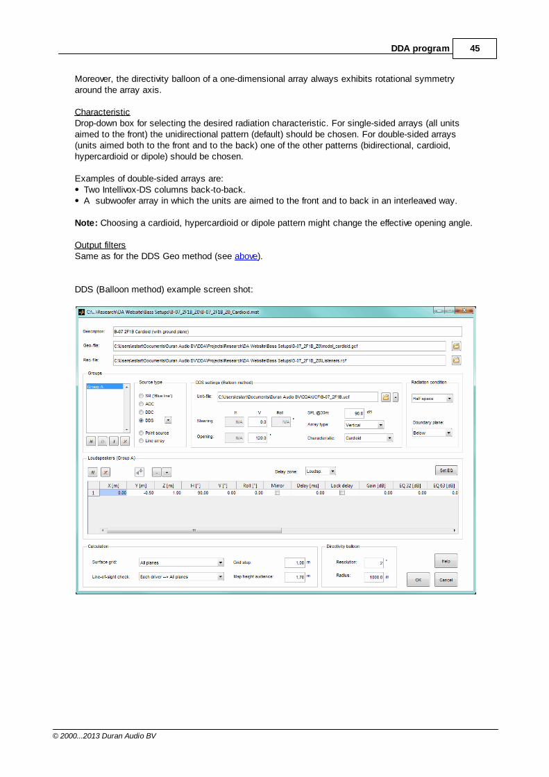
45DDA program
© 2000...2013 Duran Audio BV
Moreover, the directivity balloon of a one-dimensional array always exhibits rotational symmetryaround the array axis.
CharacteristicDrop-down box for selecting the desired radiation characteristic. For single-sided arrays (all unitsaimed to the front) the unidirectional pattern (default) should be chosen. For double-sided arrays(units aimed both to the front and to the back) one of the other patterns (bidirectional, cardioid,hypercardioid or dipole) should be chosen.
Examples of double-sided arrays are:Two Intellivox-DS columns back-to-back.A subwoofer array in which the units are aimed to the front and to back in an interleaved way.
Note: Choosing a cardioid, hypercardioid or dipole pattern might change the effective opening angle.
Output filtersSame as for the DDS Geo method (see above).
DDS (Balloon method) example screen shot:
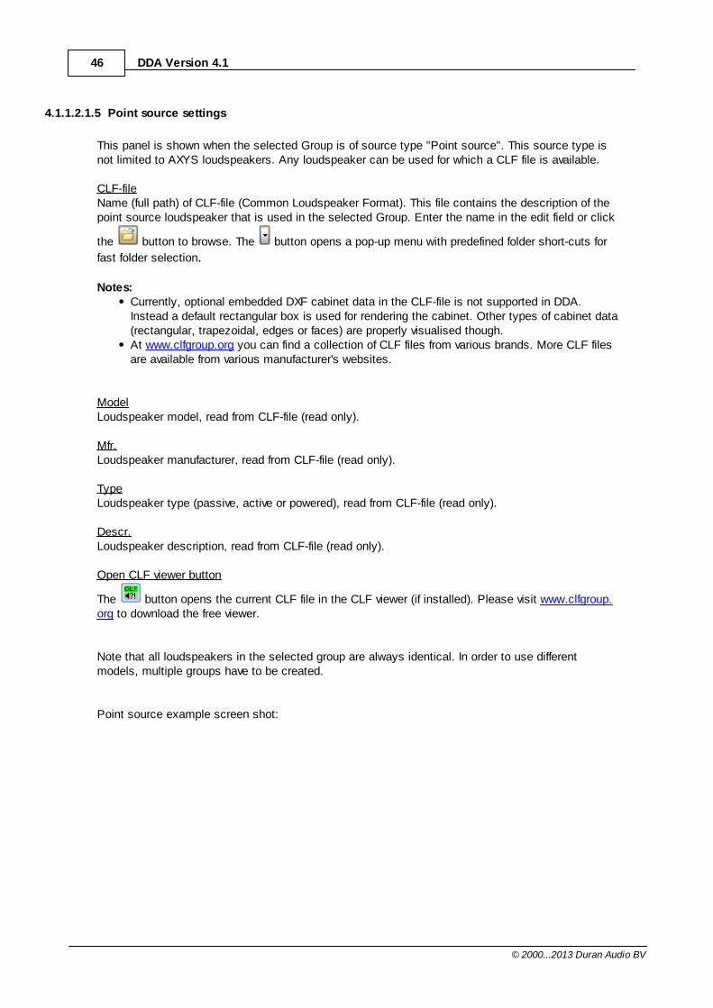
46 DDA Version 4.1
© 2000...2013 Duran Audio BV
4.1.1.2.1.5 Point source settings
This panel is shown when the selected Group is of source type "Point source". This source type isnot limited to AXYS loudspeakers. Any loudspeaker can be used for which a CLF file is available.
CLF-fileName (full path) of CLF-file (Common Loudspeaker Format). This file contains the description of thepoint source loudspeaker that is used in the selected Group. Enter the name in the edit field or click
the button to browse. The button opens a pop-up menu with predefined folder short-cuts for
fast folder selection.
Notes: Currently, optional embedded DXF cabinet data in the CLF-file is not supported in DDA.Instead a default rectangular box is used for rendering the cabinet. Other types of cabinet data(rectangular, trapezoidal, edges or faces) are properly visualised though.At www.clfgroup.org you can find a collection of CLF files from various brands. More CLF filesare available from various manufacturer's websites.
ModelLoudspeaker model, read from CLF-file (read only).
Mfr.Loudspeaker manufacturer, read from CLF-file (read only).
TypeLoudspeaker type (passive, active or powered), read from CLF-file (read only).
Descr.Loudspeaker description, read from CLF-file (read only).
Open CLF viewer button
The button opens the current CLF file in the CLF viewer (if installed). Please visit www.clfgroup.org to download the free viewer.
Note that all loudspeakers in the selected group are always identical. In order to use differentmodels, multiple groups have to be created.
Point source example screen shot:
47DDA program
© 2000...2013 Duran Audio BV
4.1.1.2.1.6 Set EQ
In this panel the EQ (in octave bands) for the selected loudspeaker can be changed either bydragging the sliders or by entering directly octave values.The interpolated frequency response of the EQ is shown in the upper graph.
SelectWith this drop down box a loudspeaker (within the selected Group) can be selected.
Auto EQApply auto correction of the on-axis frequency response of the selected loudspeaker. Positive corrections are limited to +12 dB.
Note: This functionality is only available for Point source loudspeakers
Flat EQSets a flat EQ for selected loudspeaker
Apply to allApplies the EQ of selected loudspeaker to all loudspeakers in the Group.
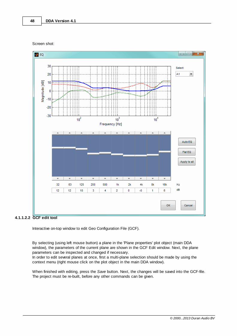
48 DDA Version 4.1
© 2000...2013 Duran Audio BV
Screen shot:
4.1.1.2.2 GCF edit tool
Interactive on-top window to edit Geo Configuration File (GCF).
By selecting (using left mouse button) a plane in the 'Plane properties' plot object (main DDAwindow), the parameters of the current plane are shown in the GCF Edit window. Next, the planeparameters can be inspected and changed if necessary.In order to edit several planes at once, first a multi-plane selection should be made by using thecontext menu (right mouse click on the plot object in the main DDA window).
When finished with editing, press the Save button. Next, the changes will be saved into the GCF-file.The project must be re-built, before any other commands can be given.
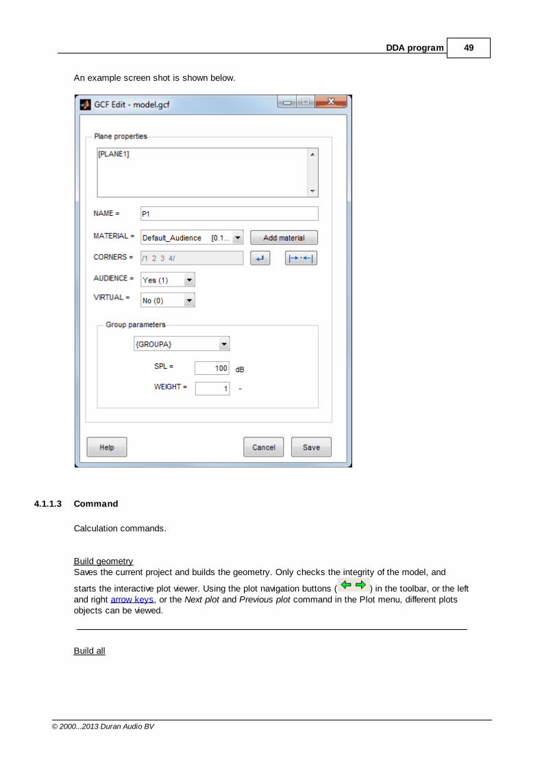
49DDA program
© 2000...2013 Duran Audio BV
An example screen shot is shown below.
4.1.1.3 Command
Calculation commands.
Build geometrySaves the current project and builds the geometry. Only checks the integrity of the model, and
starts the interactive plot viewer. Using the plot navigation buttons ( ) in the toolbar, or the leftand right arrow keys, or the Next plot and Previous plot command in the Plot menu, different plotsobjects can be viewed.
Build all
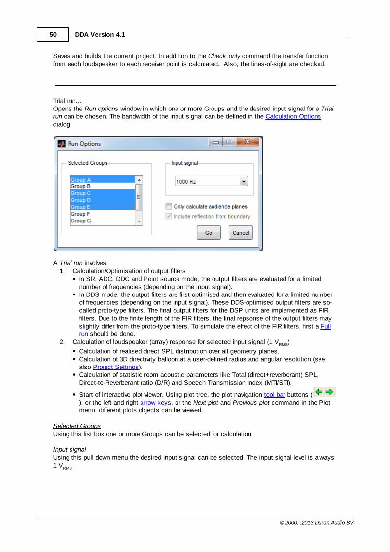
50 DDA Version 4.1
© 2000...2013 Duran Audio BV
Saves and builds the current project. In addition to the Check only command the transfer functionfrom each loudspeaker to each receiver point is calculated. Also, the lines-of-sight are checked.
Trial run...Opens the Run options window in which one or more Groups and the desired input signal for a Trialrun can be chosen. The bandwidth of the input signal can be defined in the Calculation Optionsdialog.
A Trial run involves:1. Calculation/Optimisation of output filters
In SR, ADC, DDC and Point source mode, the output filters are evaluated for a limitednumber of frequencies (depending on the input signal). In DDS mode, the output filters are first optimised and then evaluated for a limited numberof frequencies (depending on the input signal). These DDS-optimised output filters are so-called proto-type filters. The final output filters for the DSP units are implemented as FIRfilters. Due to the finite length of the FIR filters, the final repsonse of the output filters mayslightly differ from the proto-type filters. To simulate the effect of the FIR filters, first a Fullrun should be done.
2. Calculation of loudspeaker (array) response for selected input signal (1 VRMS)
Calculation of realised direct SPL distribution over all geometry planes. Calculation of 3D directivity balloon at a user-defined radius and angular resolution (seealso Project Settings).Calculation of statistic room acoustic parameters like Total (direct+reverberant) SPL,Direct-to-Reverberant ratio (D/R) and Speech Transmission Index (MTI/STI).
Start of interactive plot viewer. Using plot tree, the plot navigation tool bar buttons (), or the left and right arrow keys, or the Next plot and Previous plot command in the Plotmenu, different plots objects can be viewed.
Selected GroupsUsing this list box one or more Groups can be selected for calculation
Input signalUsing this pull down menu the desired input signal can be selected. The input signal level is always1 VRMS
51DDA program
© 2000...2013 Duran Audio BV
Only calculate audience planesBy checking this checkbox the loudspeaker (array) response is only evaluated at the audienceplanes. Note that in DDS mode still all SPL and WEIGHT parameters (i.e., also non-audienceplanes) are taken into account for the optimisation.
Include reflection form boundaryThis check box is only available if one or more selected Groups are using a boundary Plane (see Radiation Condition in Project Settings). By checking this checkbox the effect of the boundary planeis taken into account in the calculations.
Full runStarts a Full run over entire frequency range (0-24 kHz). This action involves:
Calculation/Optimisation of the entire frequency response of the (proto-type) output filters.Design of FIR output filters which closely approximate frequency response of the proto-typeoutput filters (only in DDS mode). Generation of DSP upload file with FIR coefficients (only in DDS mode). In the project directorya [ProjectName]_WinControl directory is created which contains the [ProjectName].dda and[ProjectName].stk exchange files to be used in WinControl (Only in DDA User Edition).Storage of output filters in DDA project file for later use.Shows the response of the output filters, calculated in this Full run.
The following commands are only available after a Full run:
Output filtersShows the response of output filters, calculated in the last Full run. Using the plot navigation tool bar
buttons ( ), or the left and right arrow keys, or the Next plot and Previous plot in the Plotmenu, different plots objects can be viewed.
Map responseOpens the Run options (see also Trial run) window in which one or more Groups and the desiredinput signal for a calculation can be chosen. Map response involves:
1. Reading saved output filtersAfter the Full run command, the output filters were stored in the DDA project. This means thatthe frequency responses of the output filters are readily available and don't have to becalculated first (like in a Trial run).
In Point Source, ADC and DDC mode, the frequency response of the saved output filters isexactly the same as the ones calculated in a Trial run. In DDS mode, the frequency response of the previously saved FIR (+IIR) output filters isevaluated at the requested frequency points (depending on the input signal). Note: The transfer functions of the FIR output filters may slightly differ from the proto-typefilter responses that are used for the Trial run mappings.
2. Calculation of loudspeaker (array) response for selected input signal (1 VRMS)
See Trial run.
52 DDA Version 4.1
© 2000...2013 Duran Audio BV
Rec. responseCalculates and displays the frequency response of the loudspeaker(s) at the receiver positions
defined in the RCF-file. Using the plot navigation tool bar buttons ( ), or the left and rightarrow keys, or the Next plot and Previous plot in the Plot menu, different plots objects can beviewed.Note: For DDS loudspeaker arrays the final FIR output filters are used.
4.1.1.4 View
Plot view related commands.
3D viewDisplays 3D view of current plot .
XY projection (-Z)Displays XY-projection of current plot (looking along the -Z-axis).
XY projection (+Z)Displays XY-projection of current plot (looking along the +Z-axis).
YZ projection (-X)Displays YZ-projection of current plot (looking along the -X-axis).
YZ projection (-X)Displays YZ-projection of current plot (looking along the +X-axis).
XZ projection (-Y)Displays XZ-projection of current plot (looking along the -Y-axis).
XZ projection (-Y)Displays XZ-projection of current plot (looking along the +Y-axis).
Zoom inZooms in on current plot.
Zoom outZooms out on current plot.
Zoom windowZoom selection window
Zoom/pan resetResets the zoom and pan state of the current plot.
53DDA program
© 2000...2013 Duran Audio BV
4.1.1.5 Plot
Plot related commands.
Previous plotDisplays previous plot object.
Next plotDisplays next plot object.
Previous subplotDisplays previous subplot object.
Next subplotDisplays next subplot object.
Various plot objectsList of available plot objects. The items in this list are depending on last command given by the user.
4.1.1.6 Options
Option related commands.
Calculation...Opens the Calculation Options dialog to set various calculation options.
Mapping...Opens the Mapping Options dialog to set various mapping options.
Environment...Opens the Environment Options dialog to set various acoustic environment options.
Folders...Opens the Folders Options dialog to set the default folders.
Hardware OpenGL This feature should be enabled on most platforms.Toggles the state of OpenGL hardware acceleration on the graphics card. Note: Some graphics cards are not fully compatible with the OpenGL standard and may causerendering problems in DDA. In those situations it is advised to unselect hardware OpenGL, activatingsoftware rendering. In case the rendering problems get worse, go back to hardware OpenGL ordisable OpenGL.
54 DDA Version 4.1
© 2000...2013 Duran Audio BV
Disable OpenGLCompletely disables OpenGL rendering. In case hardware as well as software OpenGL is causingrendering problems or program crashes, it is advised to disable OpenGL. Note that without OpenGL rendering:
rotating the model is slower.(semi-) transparency is not supported. Audience and virtual plane mappings will be coloredsolidly.
4.1.1.6.1 Calculation Options
Option window to set calculation bandwidth.
Bandwidth
Calculation / Trial runWith this dropdown box the bandwidth of the input signal for the Trial run command in the Projectmenu can be selected.
Evaluation / Map SPLWith this dropdown box the bandwidth of the input signal for the Map response command in theProject menu can be selected.
Direct sound
Loudspeaker summingWith this dropdown box calculation options for direct sound addition of multiple loudspeakers can beset.
Energy:The combined response of the loudspeakers is given by the energy sum of the individualresponses. Usually, this setting gives the most useful information about the total direct soundcoverage for a wide frequency range. Complex:The total direct SPL of the loudspeakers is calculated by the complex addition (i.e., usingamplitude and phase) of the individual responses. Usually, this setting is only used for low frequencies and/or relatively small inter-loudspeakerdistances. For higher frequencies and/or large inter-loudspeaker distances, the total direct SPLvaries strongly for neighbouring receiver positions.
Reverberant sound
Acoustical modelWith this dropdown box the theoretical acoustical model for the calculation of the strength of thereverberant field can be set.
Classical:The reverberant field is calculated using the "classical" theory. The reverberant sound isassumed to be diffuse, i.e., independent of the position in space, as described in manytextbooks (e.g., LL. Beranek, Acoustics (McGraw-Hill, New York, 1954)). Revised:The reverberant field is calculated using the "revised" theory, according to Barron and Lee (M.
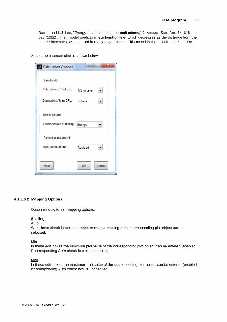
55DDA program
© 2000...2013 Duran Audio BV
Barron and L.J. Lee, ''Energy relations in concert auditoriums,'' J. Acoust. Soc. Am. 84, 618–628 (1988)). Their model predicts a reverberation level which decreases as the distance from thesource increases, as observed in many large spaces. This model is the default model in DDA.
An example screen shot is shown below.
4.1.1.6.2 Mapping Options
Option window to set mapping options.
ScalingAutoWith these check boxes automatic or manual scaling of the corresponding plot object can beselected.
MinIn these edit boxes the minimum plot value of the corresponding plot object can be entered (enabledif corresponding Auto check box is unchecked).
MaxIn these edit boxes the maximum plot value of the corresponding plot object can be entered (enabledif corresponding Auto check box is unchecked).
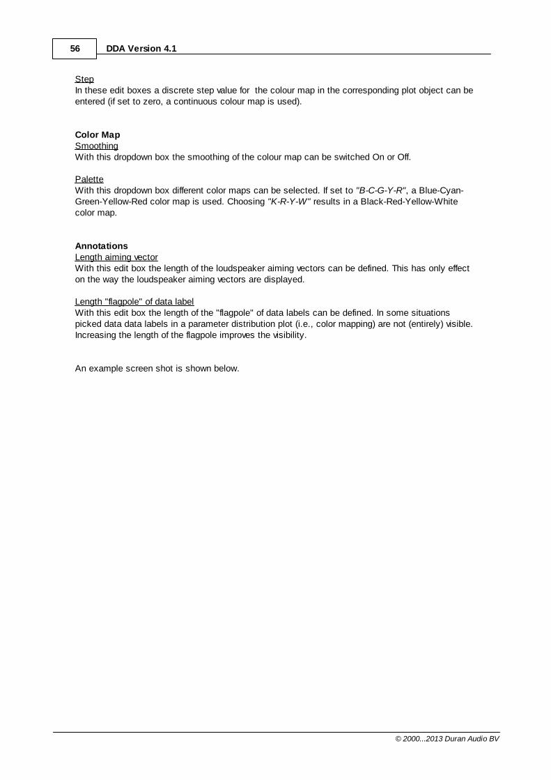
56 DDA Version 4.1
© 2000...2013 Duran Audio BV
StepIn these edit boxes a discrete step value for the colour map in the corresponding plot object can beentered (if set to zero, a continuous colour map is used).
Color MapSmoothingWith this dropdown box the smoothing of the colour map can be switched On or Off.
PaletteWith this dropdown box different color maps can be selected. If set to "B-C-G-Y-R", a Blue-Cyan-Green-Yellow-Red color map is used. Choosing "K-R-Y-W" results in a Black-Red-Yellow-Whitecolor map.
AnnotationsLength aiming vectorWith this edit box the length of the loudspeaker aiming vectors can be defined. This has only effecton the way the loudspeaker aiming vectors are displayed.
Length "flagpole" of data labelWith this edit box the length of the "flagpole" of data labels can be defined. In some situationspicked data data labels in a parameter distribution plot (i.e., color mapping) are not (entirely) visible.Increasing the length of the flagpole improves the visibility.
An example screen shot is shown below.
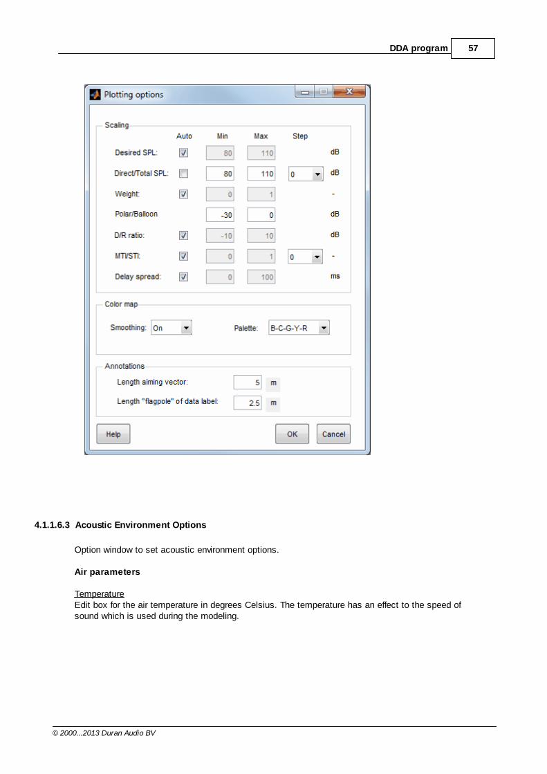
57DDA program
© 2000...2013 Duran Audio BV
4.1.1.6.3 Acoustic Environment Options
Option window to set acoustic environment options.
Air parameters
TemperatureEdit box for the air temperature in degrees Celsius. The temperature has an effect to the speed ofsound which is used during the modeling.
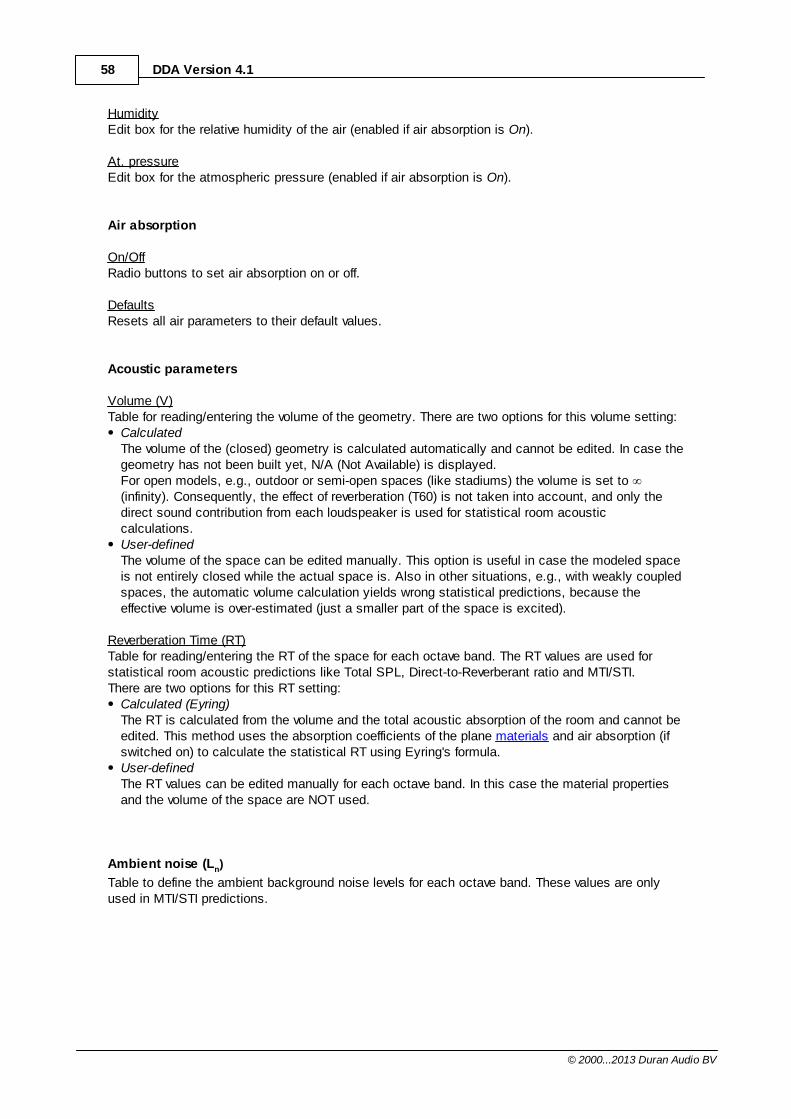
58 DDA Version 4.1
© 2000...2013 Duran Audio BV
HumidityEdit box for the relative humidity of the air (enabled if air absorption is On).
At. pressureEdit box for the atmospheric pressure (enabled if air absorption is On).
Air absorption
On/OffRadio buttons to set air absorption on or off.
DefaultsResets all air parameters to their default values.
Acoustic parameters
Volume (V)Table for reading/entering the volume of the geometry. There are two options for this volume setting:
CalculatedThe volume of the (closed) geometry is calculated automatically and cannot be edited. In case thegeometry has not been built yet, N/A (Not Available) is displayed. For open models, e.g., outdoor or semi-open spaces (like stadiums) the volume is set to (infinity). Consequently, the effect of reverberation (T60) is not taken into account, and only thedirect sound contribution from each loudspeaker is used for statistical room acousticcalculations. User-definedThe volume of the space can be edited manually. This option is useful in case the modeled spaceis not entirely closed while the actual space is. Also in other situations, e.g., with weakly coupledspaces, the automatic volume calculation yields wrong statistical predictions, because theeffective volume is over-estimated (just a smaller part of the space is excited).
Reverberation Time (RT)Table for reading/entering the RT of the space for each octave band. The RT values are used forstatistical room acoustic predictions like Total SPL, Direct-to-Reverberant ratio and MTI/STI.There are two options for this RT setting:
Calculated (Eyring)The RT is calculated from the volume and the total acoustic absorption of the room and cannot beedited. This method uses the absorption coefficients of the plane materials and air absorption (ifswitched on) to calculate the statistical RT using Eyring's formula. User-definedThe RT values can be edited manually for each octave band. In this case the material propertiesand the volume of the space are NOT used.
Ambient noise (Ln)
Table to define the ambient background noise levels for each octave band. These values are onlyused in MTI/STI predictions.
59DDA program
© 2000...2013 Duran Audio BV
An example screen shot is shown below.
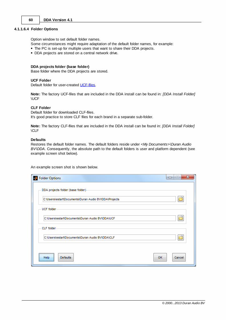
60 DDA Version 4.1
© 2000...2013 Duran Audio BV
4.1.1.6.4 Folder Options
Option window to set default folder names. Some circumstances might require adaptation of the default folder names, for example:
The PC is set-up for multiple users that want to share their DDA projects.DDA projects are stored on a central network drive.
DDA projects folder (base folder)Base folder where the DDA projects are stored.
UCF FolderDefault folder for user-created UCF-files.
Note: The factory UCF-files that are included in the DDA install can be found in: [DDA Install Folder]\UCF
CLF FolderDefault folder for downloaded CLF-files.It's good practice to store CLF files for each brand in a separate sub-folder.
Note: The factory CLF-files that are included in the DDA install can be found in: [DDA Install Folder]\CLF
DefaultsRestores the default folder names. The default folders reside under <My Documents>\Duran AudioBV\DDA. Consequently, the absolute path to the default folders is user and platform dependent (seeexample screen shot below).
An example screen shot is shown below.
61DDA program
© 2000...2013 Duran Audio BV
4.1.1.7 Tools
Calculator..Opens the Windows calculator.
2D Geometry Builder...Opens the interactive 2D Geometry Builder.
Array Builder...Opens the Array Builder.
Measure distance..Activates the measuring tool. The distance between two point is measured by clicking on a startingpoint, move the mouse to the end-point, and click the mouse button again. To stop the measuring tool, deselect this menu item or deselect the distance tool in the toolbar.Note: This tool is only available in a 2D view.
Loudspeaker table..Displays the loudspeaker table control showing information about all loudspeakers in the currentproject.
Delay optimiser ..Starts the Delay optimiser. In the Run options window one or more Groups can be chosen. Afterpressing "Go", the delay optimisation is started.
This tool can be used to automatically align the direct sound contributions of multiple loudspeakers(or zones). The algorithm searches the predelays that minimise the delay spread (averaged over theentire audience plane). By minimising the delay spread, the audibility of secondary loudspeaker contributions ('echoes') isreduced. In general, this will lead to a better and more uniform speech intelligibility. This can beverified by comparing various STI (Speech Transmission Index) predictions using different predelaysettings.The predelay optimisation is an iterative process which may take a long time (depending on thenumber of delay zones and the number of grid point in the audience area(s)). To follow the progressof the calculations, intermediate delay spread and predelay values are plotted. At the end of theoptimisation process, the optimum predelays can be saved (optionally) in the Project Settings.
Notes: A delay zone can be an entire Group or a single loudspeaker (depending on the Zone option in theLoudspeakers section in the Project Settings). The delay of one or more delay zones can be locked by the user (see Lock option in theLoudspeakers section in the Project Settings). Locked delays are kept constant during delayoptimisation. This might prevent the optimiser from finding the global minimum for the delayspread, but will find the minimum delay spread, given the boundary conditions.In case none of the delay zones is locked, the minimum delay is always set to zero.If line-of-sight checking is enabled in the Project Settings, potential direct sound blocking byobstacles in the model is taken into account. The delay spread is only minimised for 'illuminated' audience planes.Groups containing only subwoofers should not be selected for delay optimisation. The
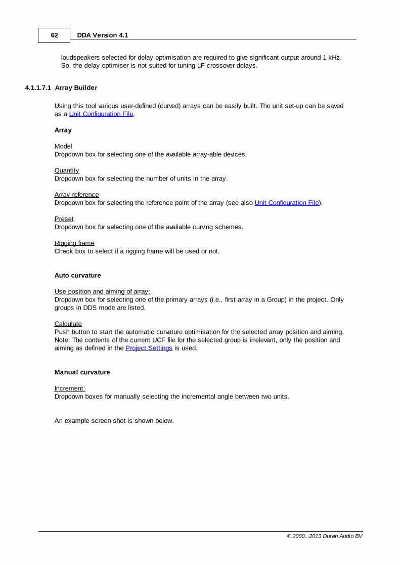
62 DDA Version 4.1
© 2000...2013 Duran Audio BV
loudspeakers selected for delay optimisation are required to give significant output around 1 kHz.So, the delay optimiser is not suited for tuning LF crossover delays.
4.1.1.7.1 Array Builder
Using this tool various user-defined (curved) arrays can be easily built. The unit set-up can be savedas a Unit Configuration File.
Array
ModelDropdown box for selecting one of the available array-able devices.
QuantityDropdown box for selecting the number of units in the array.
Array referenceDropdown box for selecting the reference point of the array (see also Unit Configuration File).
PresetDropdown box for selecting one of the available curving schemes.
Rigging frameCheck box to select if a rigging frame will be used or not.
Auto curvature
Use position and aiming of array:Dropdown box for selecting one of the primary arrays (i.e., first array in a Group) in the project. Onlygroups in DDS mode are listed.
CalculatePush button to start the automatic curvature optimisation for the selected array position and aiming.Note: The contents of the current UCF file for the selected group is irrelevant, only the position andaiming as defined in the Project Settings is used.
Manual curvature
Increment:Dropdown boxes for manually selecting the incremental angle between two units.
An example screen shot is shown below.
63DDA program
© 2000...2013 Duran Audio BV
4.1.1.7.2 2D Geometry Builder
Using this tool 2D models can be easily built by creating line plot (i.e., cross section of a 3D model).When the 2D line model is exported to a 3D GCF, the lines are extruded along the width (Y-direction) of the model.
The following functionality is available:The length and slope of a line can be modified by clicking and dragging one of the end points or byediting its coordinates. A line can be shifted integrally by clicking and dragging the line itself (i.e., not the one of the endpoints).By checking "Snap to grid" the end points of a line can be precisely dragged to any grid point. Thegrid step can be set to any value between 0.001 m (1 mm) and 10 m.
The orientation of a line (and the resulting plane in 3D) can be easily reversed by clicking the
button. The plane label (e.g., P3) is always placed at the front side of the plane. The orientation ofthe planes is important for a proper rendering of the 3D model. Audience planes can be set and are marked with an asterisk (*).The desired SPL and WEIGHT can be set for each plane. Note that these parameters are onlyrelevant for Groups that have Directivity type set to DDS (Geo method).
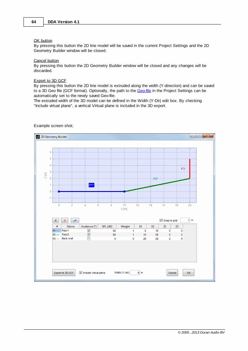
64 DDA Version 4.1
© 2000...2013 Duran Audio BV
OK buttonBy pressing this button the 2D line model will be saved in the current Project Settings and the 2DGeometry Builder window will be closed.
Cancel buttonBy pressing this button the 2D Geometry Builder window will be closed and any changes will bediscarded.
Export to 3D GCFBy pressing this button the 2D line model is extruded along the width (Y-direction) and can be savedto a 3D Geo file (GCF format). Optionally, the path to the Geo-file in the Project Settings can beautomatically set to the newly saved Geo-file.The extruded width of the 3D model can be defined in the Width (Y-Dir) edit box. By checking "Include virtual plane", a vertical Virtual plane is included in the 3D export.
Example screen shot;
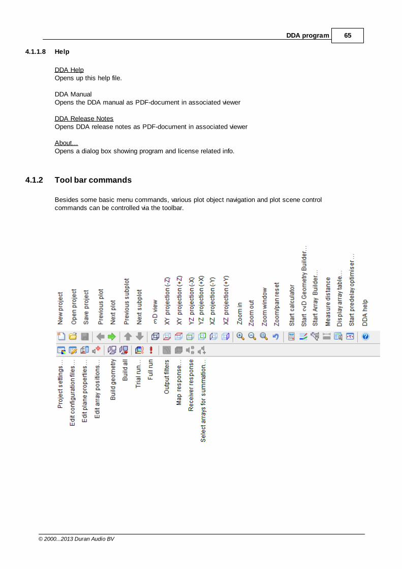
65DDA program
© 2000...2013 Duran Audio BV
4.1.1.8 Help
DDA HelpOpens up this help file.
DDA ManualOpens the DDA manual as PDF-document in associated viewer
DDA Release NotesOpens DDA release notes as PDF-document in associated viewer
About...Opens a dialog box showing program and license related info.
4.1.2 Tool bar commands
Besides some basic menu commands, various plot object navigation and plot scene controlcommands can be controlled via the toolbar.
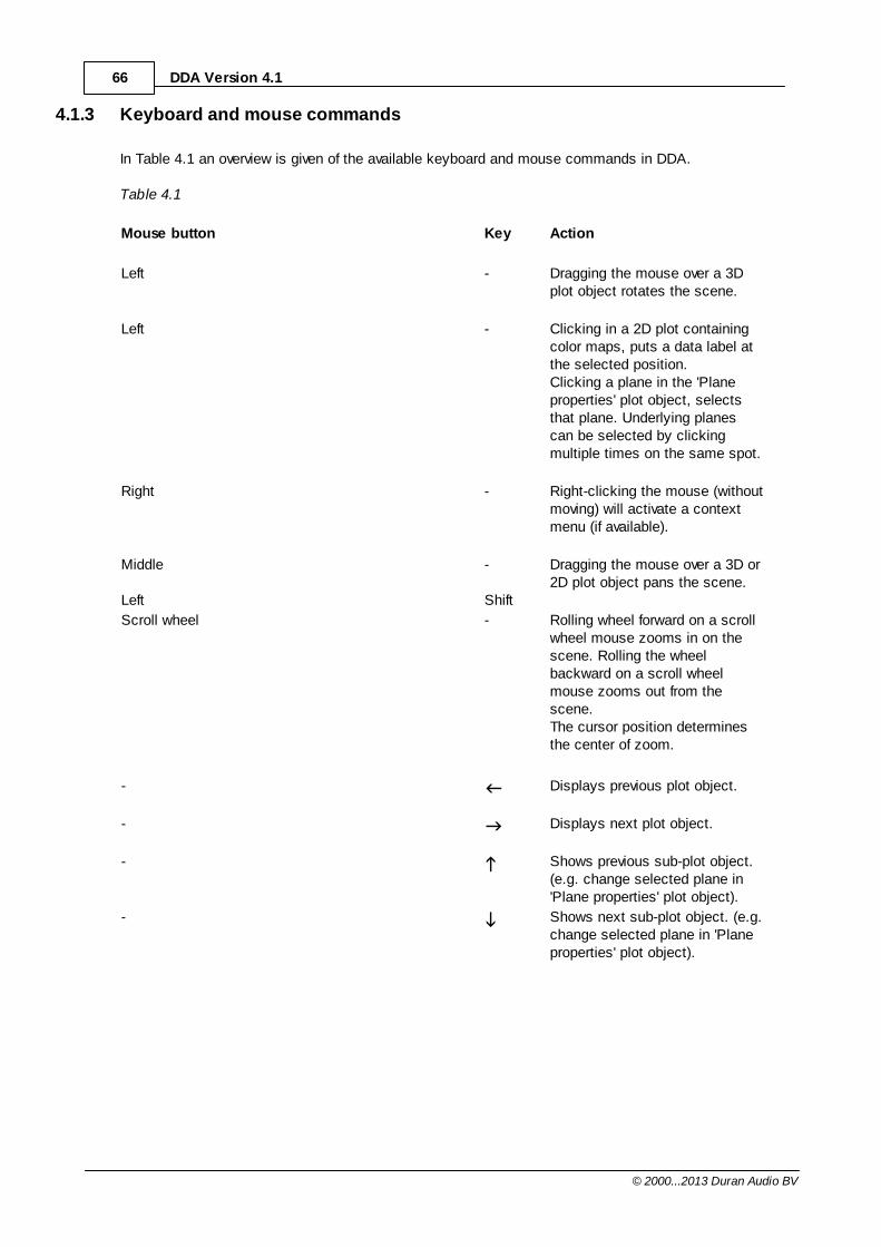
66 DDA Version 4.1
© 2000...2013 Duran Audio BV
4.1.3 Keyboard and mouse commands
In Table 4.1 an overview is given of the available keyboard and mouse commands in DDA.
Table 4.1
Mouse button Key Action
Left - Dragging the mouse over a 3Dplot object rotates the scene.
Left - Clicking in a 2D plot containingcolor maps, puts a data label atthe selected position.Clicking a plane in the 'Planeproperties' plot object, selectsthat plane. Underlying planescan be selected by clickingmultiple times on the same spot.
Right - Right-clicking the mouse (withoutmoving) will activate a contextmenu (if available).
Middle
Left
-
Shift
Dragging the mouse over a 3D or2D plot object pans the scene.
Scroll wheel - Rolling wheel forward on a scrollwheel mouse zooms in on thescene. Rolling the wheelbackward on a scroll wheelmouse zooms out from thescene.The cursor position determinesthe center of zoom.
- Displays previous plot object.
- Displays next plot object.
- Shows previous sub-plot object.(e.g. change selected plane in'Plane properties' plot object).
- Shows next sub-plot object. (e.g.change selected plane in 'Planeproperties' plot object).
67DDA program
© 2000...2013 Duran Audio BV
4.1.4 Info window
Depending on the plot object that is being viewed, this window shows the following plot-relatedparameters.
Geometry plot:Directivity method (DDC/DDS).Project path and file name.Geometrical info (volume, area etc.)
Plane infoPlane properties as set in Geometry Configuration File.
Unit configurationBeam parameters or Project name (in DDS mode).
Desired SPL, WeightsProject name.
Direct SPL, Directivity balloonBeam parameters or Project name (in DDS mode).Directivity index (DI).Sound power level (Lw) for one loudspeaker (array).
On-axis SPL of loudspeaker (array) @ 1m. The on-axis level is always calculated 1 m in front ofthe reference point of the loudspeaker array (i.e. at XYZ=1,0,0 in local loudspeaker coordinates).See also aiming conventions in the unit configuration section.Air absorption On/Off.Total headroom of each loudspeaker (array). A positive value indicates that the calculated SPLdistribution in the plot object is feasible. A negative values means that the set SPL is too high.For SR, DDC or ADC loudspeakers the headroom is dependent on the Input gain as well as theloudspeaker Gain which can be set in the Group and Loudspeaker section of the Project Setting,respectively. For DDS loudspeakers the headroom is dependent on the user-defined desired directSPL, the loudspeaker Gain, size of the audience area, mounting position and aiming of the loudspeaker (array) etc. The maximum, continuous direct SPL for the given loudspeaker set-upand given input signal can be calculated by adding the headroom value to the realised SPL in theplot object. A minimum crest factor of 3 dB is always accounted for. In practice a larger headroomis often required. This means that the design must deliver sufficient headroom.
Total SPL, D/R ratio, MTI/STIGeometrical info.Room acoustic parameters as defined in the Acoustic environment options.
MTI/STI statisticsDistribution and inverse cumulative distribution values
68 DDA Version 4.1
© 2000...2013 Duran Audio BV
4.2 DDA configuration files
4.2.1 General syntax rules
In DDA the following configuration files are used:1. Geometry Configuration File (*.GCF).2. Receiver Configuration File (*.RCF).3. Unit Configuration File (*.UCF).
The file format is based on the Windows ".INI File Format". The configuration files are encoded as standard ASCII text files.
General format descriptionThe configuration file is divided into sections and sub-sections, each containing one or more keys (i.e., properties). Each key contains one or more values, or a string.
Example:
[SectionName] keyname=value ;optional comment keyname=value1 value2 value3 ;optional comment keyname=string {SubsectionName} keyname=value
Section names are enclosed in square brackets,[ ], and must begin at the beginning of a line. Sub-section names are enclosed in curly braces, { }. Section, sub-section, and key names are case-insensitive, and cannot contain spacing characters. The key name is followed by an equal sign ("=",decimal code 61), optionally surrounded by spacing characters, which are ignored.If the same section appears more than once in the same file, or if the same key appears more thanonce in the same section, an error message is issued.Multiple values for a key are separated by at least one spacing character.When the parser encounters an unrecognised section name, the entire section (with all its keys) willbe skipped. Within a known section, unrecognised keys are skipped.The parser is not case sensitive (capitals are sometimes used to make variable names morereadable). In case of boolean variables valid settings are: 0 or 1.
Spacing and CommentsBoth Space (decimal code 32) and Horizontal Tab (HT, decimal code 9) are acceptable spacingcharacters. Lines are terminated by a CR (decimal code 13) and/or LF (decimal code 10) character. Comments are introduced by a semicolon character (";", decimal code 59). Comments must beginat the beginning of a line or after a spacing character. the part after the semicolon is not interpreted.Empty lines, and spaces at the beginning of a line should are ignored. The parser is tolerant towards spacing variations, such as in:
[section name] keyname=value ; comment keyname = value1 value2 value3 ;comment
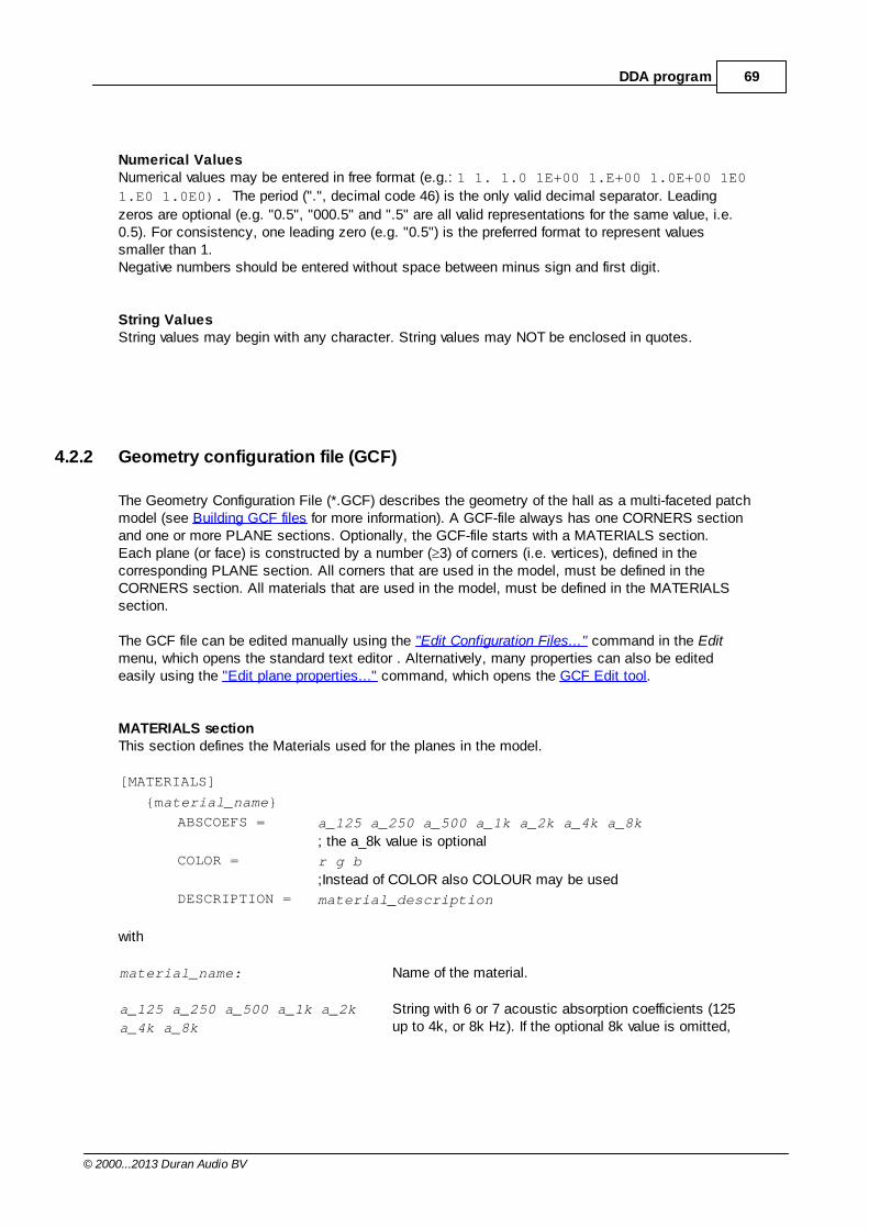
69DDA program
© 2000...2013 Duran Audio BV
Numerical ValuesNumerical values may be entered in free format (e.g.: 1 1. 1.0 1E+00 1.E+00 1.0E+00 1E0
1.E0 1.0E0). The period (".", decimal code 46) is the only valid decimal separator. Leading
zeros are optional (e.g. "0.5", "000.5" and ".5" are all valid representations for the same value, i.e.0.5). For consistency, one leading zero (e.g. "0.5") is the preferred format to represent valuessmaller than 1.Negative numbers should be entered without space between minus sign and first digit.
String ValuesString values may begin with any character. String values may NOT be enclosed in quotes.
4.2.2 Geometry configuration file (GCF)
The Geometry Configuration File (*.GCF) describes the geometry of the hall as a multi-faceted patchmodel (see Building GCF files for more information). A GCF-file always has one CORNERS sectionand one or more PLANE sections. Optionally, the GCF-file starts with a MATERIALS section.Each plane (or face) is constructed by a number ( 3) of corners (i.e. vertices), defined in thecorresponding PLANE section. All corners that are used in the model, must be defined in theCORNERS section. All materials that are used in the model, must be defined in the MATERIALSsection.
The GCF file can be edited manually using the "Edit Configuration Files..." command in the Editmenu, which opens the standard text editor . Alternatively, many properties can also be editedeasily using the "Edit plane properties..." command, which opens the GCF Edit tool.
MATERIALS sectionThis section defines the Materials used for the planes in the model.
[MATERIALS]
{material_name}
ABSCOEFS = a_125 a_250 a_500 a_1k a_2k a_4k a_8k
; the a_8k value is optional
COLOR = r g b
;Instead of COLOR also COLOUR may be used
DESCRIPTION = material_description
with
material_name: Name of the material.
a_125 a_250 a_500 a_1k a_2k
a_4k a_8k
String with 6 or 7 acoustic absorption coefficients (125up to 4k, or 8k Hz). If the optional 8k value is omitted,
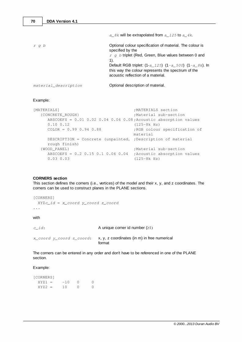
70 DDA Version 4.1
© 2000...2013 Duran Audio BV
a_8k will be extrapolated from a_125 to a_4k.
r g b Optional colour specification of material. The colour isspecified by the r g b triplet (Red, Green, Blue values between 0 and
1). Default RGB triplet: (1-a_125) (1-a_500) (1-a_8k). In
this way the colour represents the spectrum of theacoustic reflection of a material.
material_description Optional description of material.
Example:
[MATERIALS] ;MATERIALS section{CONCRETE_ROUGH} ;Material sub-section
ABSCOEFS = 0.01 0.02 0.04 0.06 0.080.10 0.12
;Acoustic absorption values(125-8k Hz)
COLOR = 0.99 0.94 0.88 ;RGB colour specification ofmaterial
DESCRIPTION = Concrete (unpainted,rough finish)
;Description of material
{WOOD_PANEL} ;Material sub-sectionABSCOEFS = 0.2 0.15 0.1 0.06 0.040.03 0.03
;Acoustic absorption values(125-8k Hz)
CORNERS sectionThis section defines the corners (i.e., vertices) of the model and their x, y, and z coordinates. Thecorners can be used to construct planes in the PLANE sections.
[CORNERS]
XYZc_id = x_coord y_coord z_coord...
with
c_id: A unique corner id number (
x_coord y_coord z_coord: x, y, z coordinates (in m) in free numericalformat
The corners can be entered in any order and don't have to be referenced in one of the PLANEsection.
Example:
[CORNERS] XYZ1 = -10 0 0 XYZ2 = 10 0 0
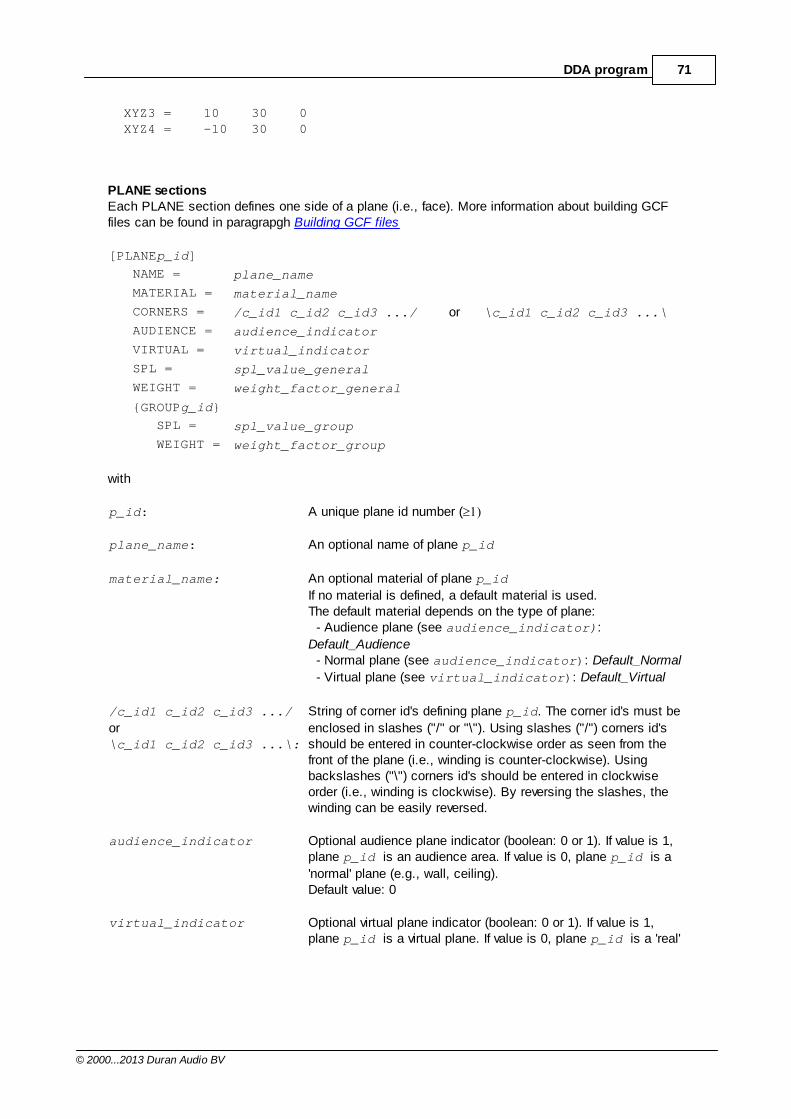
71DDA program
© 2000...2013 Duran Audio BV
XYZ3 = 10 30 0 XYZ4 = -10 30 0
PLANE sectionsEach PLANE section defines one side of a plane (i.e., face). More information about building GCFfiles can be found in paragrapgh Building GCF files
[PLANEp_id]
NAME = plane_name
MATERIAL = material_name
CORNERS = /c_id1 c_id2 c_id3 .../ or \c_id1 c_id2 c_id3 ...\
AUDIENCE = audience_indicator
VIRTUAL = virtual_indicator
SPL = spl_value_general
WEIGHT = weight_factor_general
{GROUPg_id}
SPL = spl_value_group
WEIGHT = weight_factor_group
with
p_id: A unique plane id number (
plane_name: An optional name of plane p_id
material_name: An optional material of plane p_id
If no material is defined, a default material is used.The default material depends on the type of plane: - Audience plane (see audience_indicator):
Default_Audience - Normal plane (see audience_indicator): Default_Normal
- Virtual plane (see virtual_indicator): Default_Virtual
/c_id1 c_id2 c_id3 .../
or\c_id1 c_id2 c_id3 ...\:
String of corner id's defining plane p_id. The corner id's must be
enclosed in slashes ("/" or "\"). Using slashes ("/") corners id'sshould be entered in counter-clockwise order as seen from thefront of the plane (i.e., winding is counter-clockwise). Usingbackslashes ("\") corners id's should be entered in clockwiseorder (i.e., winding is clockwise). By reversing the slashes, thewinding can be easily reversed.
audience_indicator Optional audience plane indicator (boolean: 0 or 1). If value is 1, plane p_id is an audience area. If value is 0, plane p_id is a
'normal' plane (e.g., wall, ceiling).Default value: 0
virtual_indicator Optional virtual plane indicator (boolean: 0 or 1). If value is 1,plane p_id is a virtual plane. If value is 0, plane p_id is a 'real'
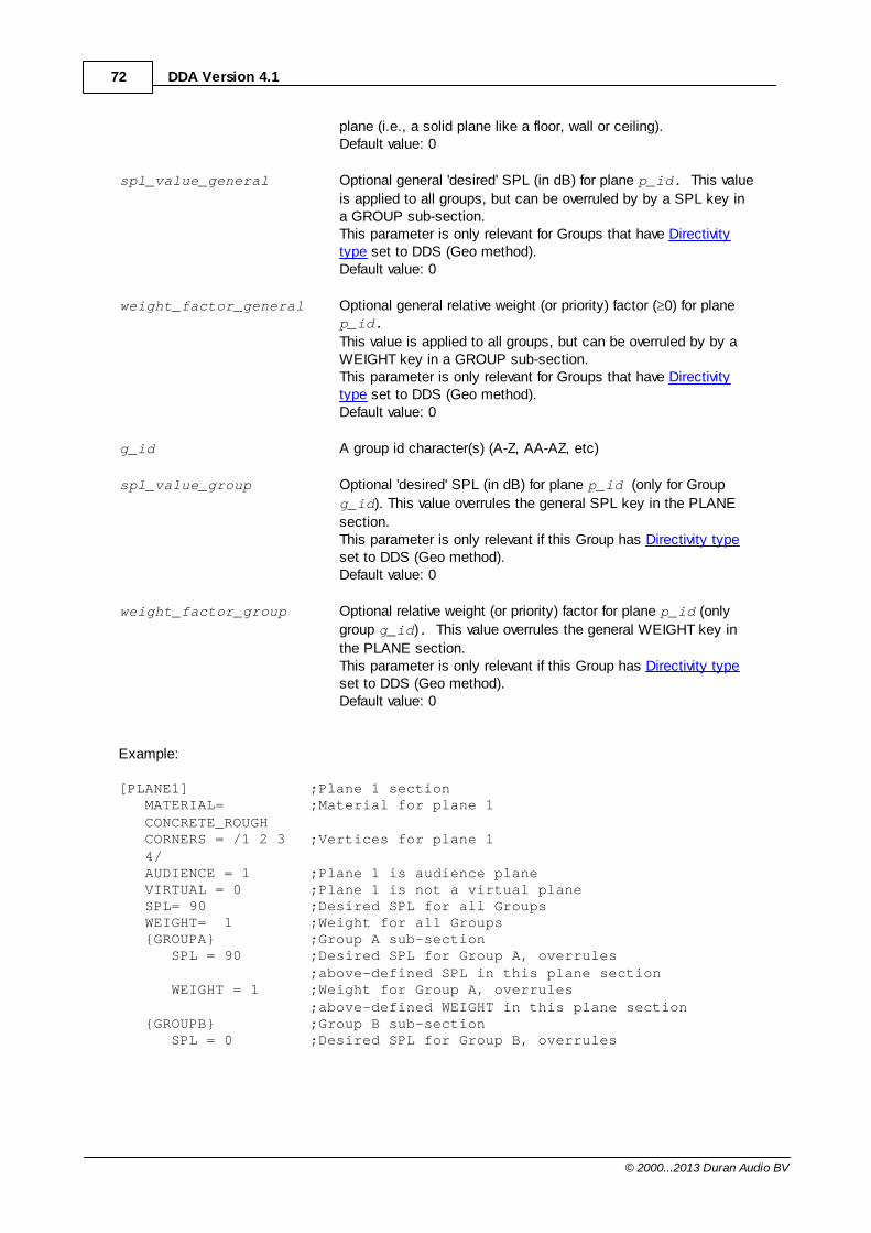
72 DDA Version 4.1
© 2000...2013 Duran Audio BV
plane (i.e., a solid plane like a floor, wall or ceiling). Default value: 0
spl_value_general Optional general 'desired' SPL (in dB) for plane p_id. This value
is applied to all groups, but can be overruled by by a SPL key ina GROUP sub-section.This parameter is only relevant for Groups that have Directivitytype set to DDS (Geo method).Default value: 0
weight_factor_general Optional general relative weight (or priority) factor ( 0) for planep_id.
This value is applied to all groups, but can be overruled by by aWEIGHT key in a GROUP sub-section.This parameter is only relevant for Groups that have Directivitytype set to DDS (Geo method).Default value: 0
g_id A group id character(s) (A-Z, AA-AZ, etc)
spl_value_group Optional 'desired' SPL (in dB) for plane p_id (only for Group
g_id). This value overrules the general SPL key in the PLANE
section.This parameter is only relevant if this Group has Directivity typeset to DDS (Geo method).Default value: 0
weight_factor_group Optional relative weight (or priority) factor for plane p_id (only
group g_id). This value overrules the general WEIGHT key in
the PLANE section.This parameter is only relevant if this Group has Directivity typeset to DDS (Geo method).Default value: 0
Example:
[PLANE1] ;Plane 1 sectionMATERIAL=CONCRETE_ROUGH
;Material for plane 1
CORNERS = /1 2 34/
;Vertices for plane 1
AUDIENCE = 1 ;Plane 1 is audience planeVIRTUAL = 0 ;Plane 1 is not a virtual plane SPL= 90 ;Desired SPL for all GroupsWEIGHT= 1 ;Weight for all Groups{GROUPA} ;Group A sub-section
SPL = 90 ;Desired SPL for Group A, overrules ;above-defined SPL in this plane section
WEIGHT = 1 ;Weight for Group A, overrules ;above-defined WEIGHT in this plane section
{GROUPB} ;Group B sub-sectionSPL = 0 ;Desired SPL for Group B, overrules
73DDA program
© 2000...2013 Duran Audio BV
;above-defined SPL in this plane sectionWEIGHT = 1 ;Weight for Group B, overrules
;above-defined Weight in this plane section
Note: GROUP subsections were newly introduced in DDA v.2. The new syntax is backwardscompatible, therefore DDA v.1 GCF-files can still be interpreted by DDA v.3. The SPL and WEIGHTkey are interpreted as general keys, i.e., apply to all groups (unless they are overruled by key in thegroup sub-sections).
4.2.3 Receiver configuration file (RCF)
The Receiver Configuration File (*.RCF) can be used to define discrete receiver positions in themodel. After a Full run calculation a detailed frequency response can be calculated at thesepositions.
RECEIVERS sectionThe position of the each receiver in the model is defined in the RECEIVERS section. A rcf-file mustcontain at least one receiver point.
[RECEIVERS]
XYZr_id = x_coord y_coord z_coord
with
r_id: A unique receiver id number (
x_coord y_coord z_coord: x, y, z coordinates (in m) of the receiver point in the model
Example:
[RECEIVERS] XYZ1 = 0 10 1.7 XYZ2 = 0 20 1.7 ...
4.2.4 Unit configuration file (UCF)
The Unit Configuration File (*.UCF) describes the array set-up. In DDA any array can be assembledfrom a set of pre-defined components, called units. Each unit represents one physical entity, like anIntellivox or Target box. A unit has one or more independent output channels (i.e., processingchannels). Each channel drives one or more loudspeakers. There are no restrictions in the selection, positioning, and aiming of the units. Consequently, theuser is responsible for defining a coherent and feasible array (e.g., DDA is not developed to optimisedistributed systems).
Note: The array is checked for coinciding transducers, however, (partly) overlapping units are NOT
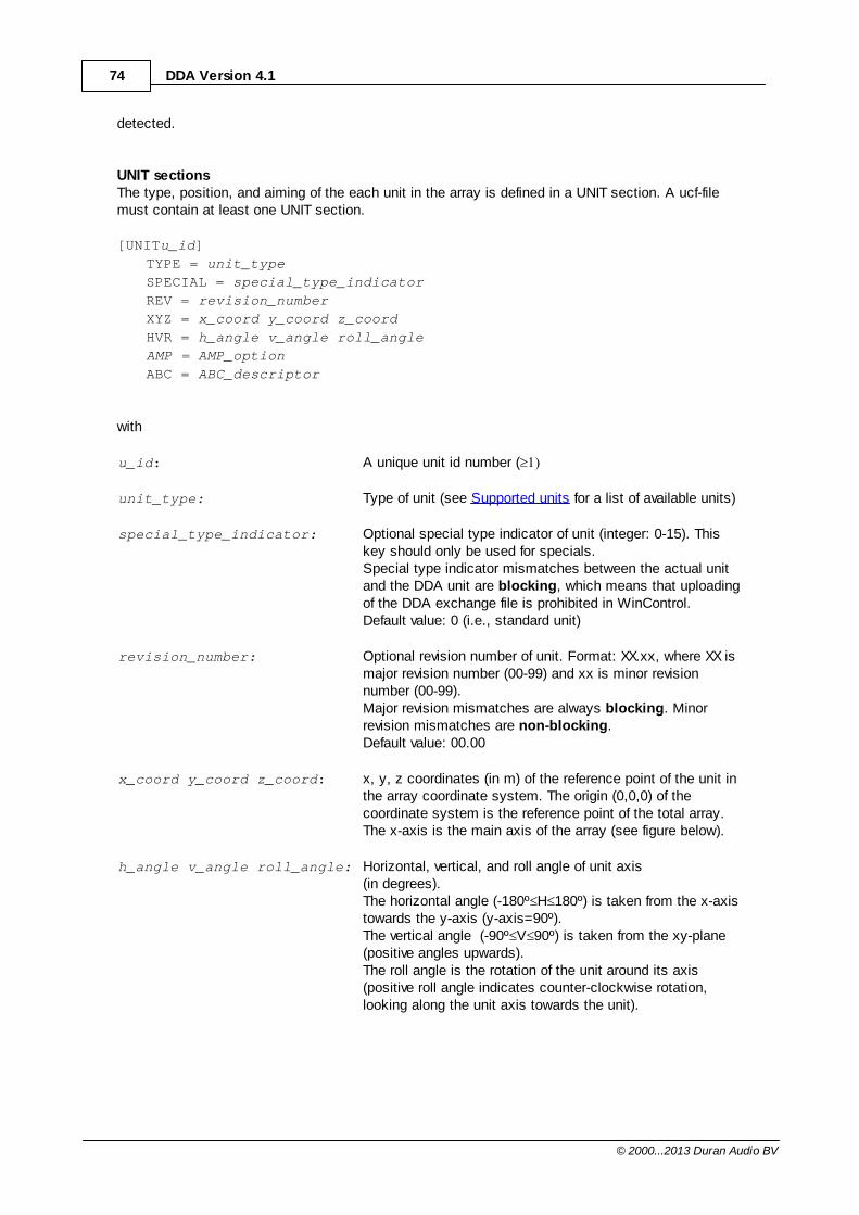
74 DDA Version 4.1
© 2000...2013 Duran Audio BV
detected.
UNIT sectionsThe type, position, and aiming of the each unit in the array is defined in a UNIT section. A ucf-filemust contain at least one UNIT section.
[UNITu_id]
TYPE = unit_type
SPECIAL = special_type_indicator
REV = revision_number
XYZ = x_coord y_coord z_coord
HVR = h_angle v_angle roll_angle
AMP = AMP_option
ABC = ABC_descriptor
with
u_id: A unique unit id number (
unit_type: Type of unit (see Supported units for a list of available units)
special_type_indicator: Optional special type indicator of unit (integer: 0-15). Thiskey should only be used for specials. Special type indicator mismatches between the actual unitand the DDA unit are blocking, which means that uploadingof the DDA exchange file is prohibited in WinControl.Default value: 0 (i.e., standard unit)
revision_number: Optional revision number of unit. Format: XX.xx, where XX ismajor revision number (00-99) and xx is minor revisionnumber (00-99). Major revision mismatches are always blocking. Minorrevision mismatches are non-blocking.Default value: 00.00
x_coord y_coord z_coord: x, y, z coordinates (in m) of the reference point of the unit inthe array coordinate system. The origin (0,0,0) of thecoordinate system is the reference point of the total array.The x-axis is the main axis of the array (see figure below).
h_angle v_angle roll_angle: Horizontal, vertical, and roll angle of unit axis(in degrees). The horizontal angle (-180º H 180º) is taken from the x-axistowards the y-axis (y-axis=90º). The vertical angle (-90º V 90º) is taken from the xy-plane(positive angles upwards).The roll angle is the rotation of the unit around its axis(positive roll angle indicates counter-clockwise rotation,looking along the unit axis towards the unit).
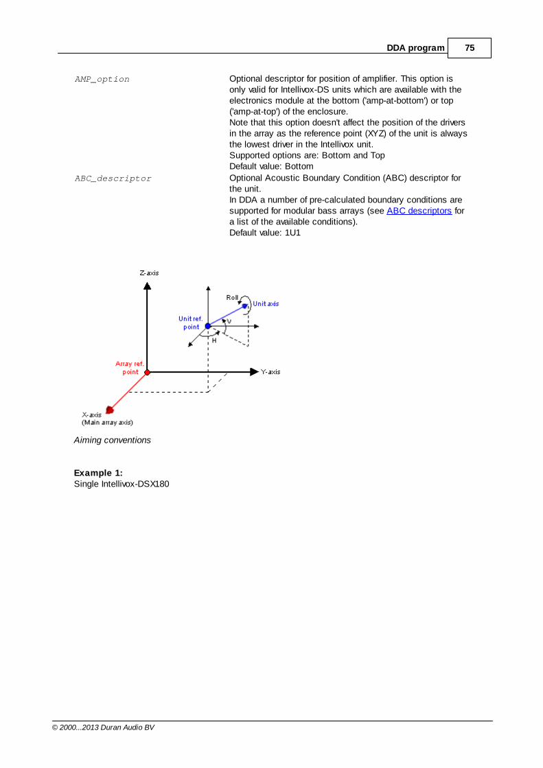
75DDA program
© 2000...2013 Duran Audio BV
AMP_option Optional descriptor for position of amplifier. This option isonly valid for Intellivox-DS units which are available with theelectronics module at the bottom ('amp-at-bottom') or top('amp-at-top') of the enclosure.Note that this option doesn't affect the position of the driversin the array as the reference point (XYZ) of the unit is alwaysthe lowest driver in the Intellivox unit.Supported options are: Bottom and TopDefault value: Bottom
ABC_descriptor Optional Acoustic Boundary Condition (ABC) descriptor forthe unit. In DDA a number of pre-calculated boundary conditions aresupported for modular bass arrays (see ABC descriptors fora list of the available conditions).Default value: 1U1
Aiming conventions
Example 1:Single Intellivox-DSX180
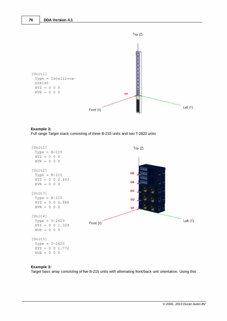
76 DDA Version 4.1
© 2000...2013 Duran Audio BV
[Unit1]Type = Intellivox-DSX180XYZ = 0 0 0HVR = 0 0 0
Example 2:Full range Target stack consisting of three B-215 units and two T-2820 units
[Unit1]Type = B-215XYZ = 0 0 0HVR = 0 0 0
[Unit2]Type = B-215XYZ = 0 0 0.443HVR = 0 0 0
[Unit3]Type = B-215XYZ = 0 0 0.886HVR = 0 0 0
[Unit4]Type = T-2820XYZ = 0 0 1.329HVR = 0 0 0
[Unit5]Type = T-2820XYZ = 0 0 1.772HVR = 0 0 0
Example 3:Target bass array consisting of five B-215 units with alternating front/back unit orientation. Using this
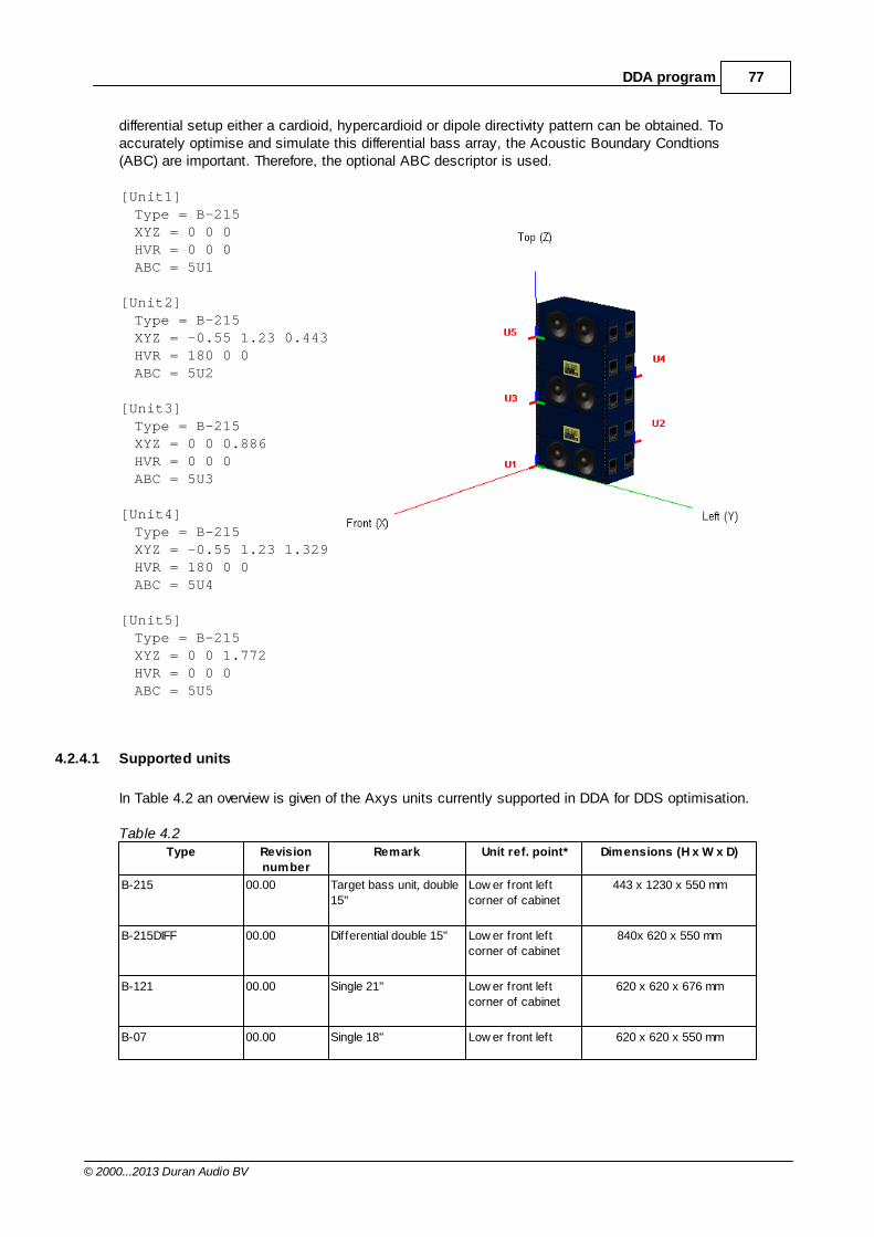
77DDA program
© 2000...2013 Duran Audio BV
differential setup either a cardioid, hypercardioid or dipole directivity pattern can be obtained. Toaccurately optimise and simulate this differential bass array, the Acoustic Boundary Condtions(ABC) are important. Therefore, the optional ABC descriptor is used.
[Unit1]Type = B-215XYZ = 0 0 0HVR = 0 0 0ABC = 5U1
[Unit2]Type = B-215XYZ = -0.55 1.23 0.443HVR = 180 0 0ABC = 5U2
[Unit3]Type = B-215XYZ = 0 0 0.886HVR = 0 0 0ABC = 5U3
[Unit4]Type = B-215XYZ = -0.55 1.23 1.329HVR = 180 0 0ABC = 5U4
[Unit5]Type = B-215XYZ = 0 0 1.772HVR = 0 0 0ABC = 5U5
4.2.4.1 Supported units
In Table 4.2 an overview is given of the Axys units currently supported in DDA for DDS optimisation.
Table 4.2Type Revision
number
Remark Unit ref. point* Dimensions (H x W x D)
B-215 00.00 Target bass unit, double
15''
Low er front left
corner of cabinet
443 x 1230 x 550 mm
B-215DIFF 00.00 Differential double 15'' Low er front left
corner of cabinet
840x 620 x 550 mm
B-121 00.00 Single 21'' Low er front left
corner of cabinet
620 x 620 x 676 mm
B-07 00.00 Single 18'' Low er front left 620 x 620 x 550 mm
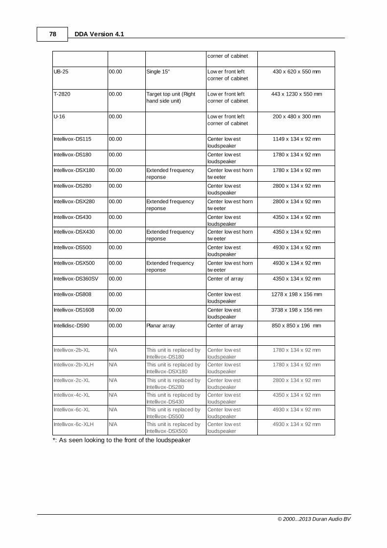
78 DDA Version 4.1
© 2000...2013 Duran Audio BV
corner of cabinet
UB-25 00.00 Single 15'' Low er front left
corner of cabinet
430 x 620 x 550 mm
T-2820 00.00 Target top unit (Right
hand side unit)
Low er front left
corner of cabinet
443 x 1230 x 550 mm
U-16 00.00 Low er front left
corner of cabinet
200 x 480 x 300 mm
Intellivox-DS115 00.00 Center low est
loudspeaker
1149 x 134 x 92 mm
Intellivox-DS180 00.00 Center low est
loudspeaker
1780 x 134 x 92 mm
Intellivox-DSX180 00.00 Extended frequency
reponse
Center low est horn
tw eeter
1780 x 134 x 92 mm
Intellivox-DS280 00.00 Center low est
loudspeaker
2800 x 134 x 92 mm
Intellivox-DSX280 00.00 Extended frequency
reponse
Center low est horn
tw eeter
2800 x 134 x 92 mm
Intellivox-DS430 00.00 Center low est
loudspeaker
4350 x 134 x 92 mm
Intellivox-DSX430 00.00 Extended frequency
reponse
Center low est horn
tw eeter
4350 x 134 x 92 mm
Intellivox-DS500 00.00 Center low est
loudspeaker
4930 x 134 x 92 mm
Intellivox-DSX500 00.00 Extended frequency
reponse
Center low est horn
tw eeter
4930 x 134 x 92 mm
Intellivox-DS360SV 00.00 Center of array 4350 x 134 x 92 mm
Intellivox-DS808 00.00 Center low est
loudspeaker
1278 x 198 x 156 mm
Intellivox-DS1608 00.00 Center low est
loudspeaker
3738 x 198 x 156 mm
Intellidisc-DS90 00.00 Planar array Center of array 850 x 850 x 196 mm
Intellivox-2b-XL N/A This unit is replaced by
Intellivox-DS180
Center low est
loudspeaker
1780 x 134 x 92 mm
Intellivox-2b-XLH N/A This unit is replaced by
Intellivox-DSX180
Center low est
loudspeaker
1780 x 134 x 92 mm
Intellivox-2c-XL N/A This unit is replaced by
Intellivox-DS280
Center low est
loudspeaker
2800 x 134 x 92 mm
Intellivox-4c-XL N/A This unit is replaced by
Intellivox-DS430
Center low est
loudspeaker
4350 x 134 x 92 mm
Intellivox-6c-XL N/A This unit is replaced by
Intellivox-DS500
Center low est
loudspeaker
4930 x 134 x 92 mm
Intellivox-6c-XLH N/A This unit is replaced by
Intellivox-DSX500
Center low est
loudspeaker
4930 x 134 x 92 mm
*: As seen looking to the front of the loudspeaker
79DDA program
© 2000...2013 Duran Audio BV
4.2.4.2 ABC descriptors
Using the PSM-BEM approach a library of directivity data has been pre-calculated for bass unitsusing different boundary conditions. To correctly simulate a bass unit as part of a specific (differential) bass array, the appropriate ABC-descriptor should be used in the Unit Configuration File (UCF).The appropriate radiation condition (full or half space) for the loudspeaker array must be set in theProject settings.
In Tables 4.3 an overview is given of the available ABC-descriptors for all DDS-driven bass units.
Table 4.3
Type ABC Description1 Example Unit Configuration File (UCF)2
All Units 1U1 Default ABC descriptor for all units B-215_1F.ucf (single unit, frontally aimed)
B-07_1F.ucf (single unit, frontally aimed)
B-121_1F.ucf (single unit, frontally aimed)
B-215 2Ux ABC descriptor for unit x in vertical array
of 2units (for x= 1 to 2).
B-215_2F.ucf (all units frontally aimed)
B-215_1F1B.ucf (differential array, i.e., units
have alternating front/back aiming)
B-215 3Ux ABC descriptor for unit x in vertical array
of 3 units (for x= 1 to 3).
B-215_3F.ucf (all units frontally aimed)
B-215_2F1B.ucf (differential array, i.e., units
have alternating front/back aiming)
B-215 5Ux ABC descriptor for unit x in vertical array
of 5 units (for x= 1 to 5).
B-215_5F.ucf (all units frontally aimed)
B-215_3F2B.ucf (differential array, i.e., units
have alternating front/back aiming)
B-215 7Ux ABC descriptor for unit x in vertical array
of 7 units (for x= 1 to 7).
B-215_7F.ucf (all units frontally aimed)
B-215_4F3B.ucf (differential array, i.e., units
have alternating front/back aiming)
B-215DIFF 2Ux ABC descriptor for unit x in vertical array
of 2 units (for x= 1 to 2).
B-215DIFF_2F.ucf (both units frontally
aimed)
B-121 2Ux ABC descriptor for unit x in vertical array
of 2 units (for x= 1 to 2).
B-121_2F.ucf (both units frontally aimed)
B-121_1F1B.ucf (differential array, i.e., units
have alternating front/back aiming)
B-121 3Ux ABC descriptor for unit x in vertical array
of 3 units (for x= 1 to 3).
B-121_3F.ucf (all units frontally aimed)
B-121_2F1B.ucf (differential array, i.e., units
have alternating front/back aiming)
B-07 2Ux ABC descriptor for unit x in vertical array
of 2 units (for x= 1 to 2).
B-07_2F.ucf (both units frontally aimed)
B-07_1F1B.ucf (differential array, i.e., units
have alternating front/back aiming)
B-07 3Ux ABC descriptor for unit x in vertical array
of 3 units (for x= 1 to 3).
B-07_3F.ucf (all units frontally aimed)
B-07_2F1B.ucf (differential array, i.e., units
have alternating front/back aiming)
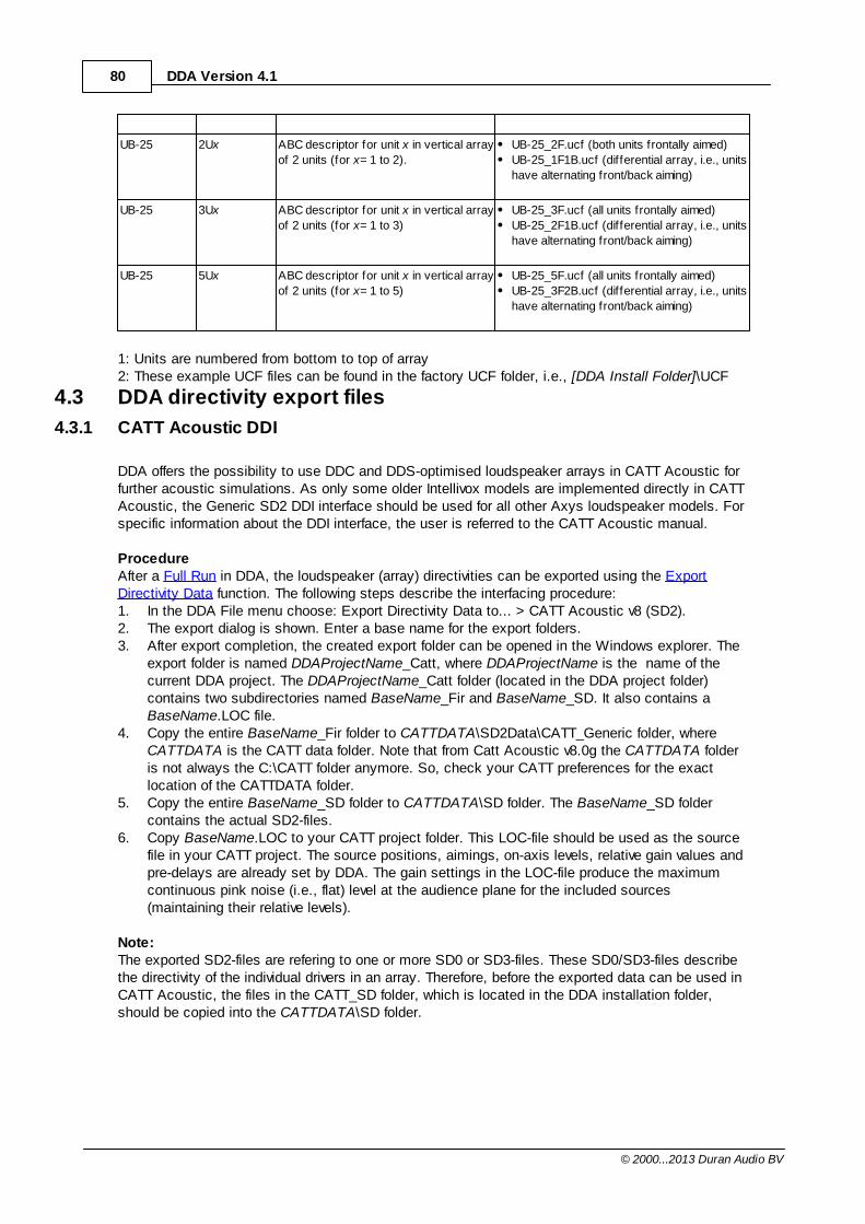
80 DDA Version 4.1
© 2000...2013 Duran Audio BV
UB-25 2Ux ABC descriptor for unit x in vertical array
of 2 units (for x= 1 to 2).
UB-25_2F.ucf (both units frontally aimed)
UB-25_1F1B.ucf (differential array, i.e., units
have alternating front/back aiming)
UB-25 3Ux ABC descriptor for unit x in vertical array
of 2 units (for x= 1 to 3)
UB-25_3F.ucf (all units frontally aimed)
UB-25_2F1B.ucf (differential array, i.e., units
have alternating front/back aiming)
UB-25 5Ux ABC descriptor for unit x in vertical array
of 2 units (for x= 1 to 5)
UB-25_5F.ucf (all units frontally aimed)
UB-25_3F2B.ucf (differential array, i.e., units
have alternating front/back aiming)
1: Units are numbered from bottom to top of array2: These example UCF files can be found in the factory UCF folder, i.e., [DDA Install Folder]\UCF
4.3 DDA directivity export files
4.3.1 CATT Acoustic DDI
DDA offers the possibility to use DDC and DDS-optimised loudspeaker arrays in CATT Acoustic forfurther acoustic simulations. As only some older Intellivox models are implemented directly in CATTAcoustic, the Generic SD2 DDI interface should be used for all other Axys loudspeaker models. Forspecific information about the DDI interface, the user is referred to the CATT Acoustic manual.
ProcedureAfter a Full Run in DDA, the loudspeaker (array) directivities can be exported using the ExportDirectivity Data function. The following steps describe the interfacing procedure:1. In the DDA File menu choose: Export Directivity Data to... > CATT Acoustic v8 (SD2).2. The export dialog is shown. Enter a base name for the export folders.3. After export completion, the created export folder can be opened in the Windows explorer. The
export folder is named DDAProjectName_Catt, where DDAProjectName is the name of thecurrent DDA project. The DDAProjectName_Catt folder (located in the DDA project folder)contains two subdirectories named BaseName_Fir and BaseName_SD. It also contains aBaseName.LOC file.
4. Copy the entire BaseName_Fir folder to CATTDATA\SD2Data\CATT_Generic folder, whereCATTDATA is the CATT data folder. Note that from Catt Acoustic v8.0g the CATTDATA folderis not always the C:\CATT folder anymore. So, check your CATT preferences for the exactlocation of the CATTDATA folder.
5. Copy the entire BaseName_SD folder to CATTDATA\SD folder. The BaseName_SD foldercontains the actual SD2-files.
6. Copy BaseName.LOC to your CATT project folder. This LOC-file should be used as the sourcefile in your CATT project. The source positions, aimings, on-axis levels, relative gain values andpre-delays are already set by DDA. The gain settings in the LOC-file produce the maximumcontinuous pink noise (i.e., flat) level at the audience plane for the included sources(maintaining their relative levels).
Note:The exported SD2-files are refering to one or more SD0 or SD3-files. These SD0/SD3-files describethe directivity of the individual drivers in an array. Therefore, before the exported data can be used inCATT Acoustic, the files in the CATT_SD folder, which is located in the DDA installation folder,should be copied into the CATTDATA\SD folder.
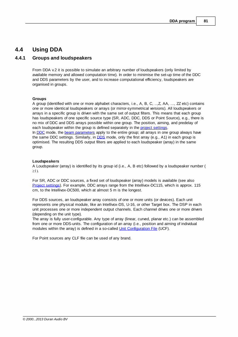
81DDA program
© 2000...2013 Duran Audio BV
4.4 Using DDA
4.4.1 Groups and loudspeakers
From DDA v.2 it is possible to simulate an arbitrary number of loudspeakers (only limited byavailable memory and allowed computation time). In order to minimise the set-up time of the DDCand DDS parameters by the user, and to increase computational efficiency, loudspeakers areorganised in groups.
GroupsA group (identified with one or more alphabet characters, i.e., A, B, C, ..,Z, AA, ..., ZZ etc) containsone or more identical loudspeakers or arrays (or mirror-symmetrical versions). All loudspeakers orarrays in a specific group is driven with the same set of output filters. This means that each grouphas loudspeakers of one specific source type (SR, ADC, DDC, DDS or Point Source), e.g., there isno mix of DDC and DDS arrays possible within one group. The position, aiming, and predelay ofeach loudspeaker within the group is defined separately in the project settings.In DDC mode, the beam parameters apply to the entire group; all arrays in one group always havethe same DDC settings. Similarly, in DDS mode, only the first array (e.g., A1) in each group isoptimised. The resulting DDS output filters are applied to each loudspeaker (array) in the samegroup.
LoudspeakersA Loudspeaker (array) is identified by its group id (i.e., A, B etc) followed by a loudspeaker number (
For SR, ADC or DDC sources, a fixed set of loudspeaker (array) models is available (see also Project settings). For example, DDC arrays range from the Intellivox-DC115, which is approx. 115cm, to the Intellivox-DC500, which at almost 5 m is the longest.
For DDS sources, an loudspeaker array consists of one or more units (or devices). Each unitrepresents one physical module, like an Intellivox-DS, U-16, or other Target box. The DSP in eachunit processes one or more independent output channels. Each channel drives one or more drivers(depending on the unit type).The array is fully user-configurable. Any type of array (linear, curved, planar etc.) can be assembledfrom one or more DDS-units. The configuration of an array (i.e., position and aiming of individualmodules within the array) is defined in a so-called Unit Configuration File (UCF).
For Point sources any CLF file can be used of any brand.
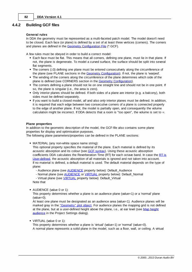
82 DDA Version 4.1
© 2000...2013 Duran Audio BV
4.4.2 Building GCF files
General rulesIn DDA the geometry must be represented as a multi-faceted patch model. The model doesn't needto be closed. Each face (or plane) is defined by a set of at least three vertices (corners). The cornersand planes are defined in the Geometry Configuration File (*.GCF).
A few rules must be obeyed in order to build a correct model:Each face must be flat. This means that all corners, defining one plane, must lie in that plane. Ifnot, the plane is degenerate. To model a curved surface, the surface should be split into severalflat segments.The corners ( 3) defining one plane must be entered consecutively along the circumference ofthe plane (see PLANE sections in the Geometry Configuration). If not, the plane is 'warped'.The winding of the corners along the circumference of the plane determines which side of theplane is defined (see CORNERS section in the Geometry Configuration).The corners defining a plane should not lie on one straight line and should not be in one point. Ifso, the plane is singular (i.e., the area is zero).Only interior planes should be defined. If both sides of a plane are interior (e.g. a balcony), bothsides must be defined separately.If you want to build a closed model, all and also only interior planes must be defined. In addition,it is required that each edge between two consecutive corners of a plane is connected properlyto the edge of another plane. If not, the model is partially open, and consequently the volumecalculation might be incorrect. If DDA detects that a room is "too open", the volume is set to
Plane propertiesIn addition to the geometric description of the model, the GCF-file also contains some planeproperties for display and optimisation purposes.The following plane parameters/properties can be defined in the PLANE sections:
MATERIAL (any non-white space name string): This optional property specifies the material of the plane. Each material is defined by itsacoustic absorption and its colour (see GCF syntax). Using these acoustic absorptioncoefficients DDA calculates the Reverberation Time (RT) for each octave band. In case the RT isUser-defined, the acoustic absorption of all materials is ignored and not taken into account.If no material is defined, a default material is used. The default material depends on the type ofplane:
- Audience plane (see AUDIENCE property below): Default_Audience- Normal plane (see AUDIENCE or VIRTUAL property below): Default_Normal- Virtual plane (see VIRTUAL property below): Default_Virtual
Note that
AUDIENCE (value 0 or 1): This property determines whether a plane is an audience plane (value=1) or a 'normal' plane(value=0).At least one plane must be designated as an audience area (value=1). Audience planes will bemarked gray in the "Geometry" plot object. For audience planes the mapping grid is not definedat the plane, but at a user-defined height above the plane, i.e., at ear level (see Map heightaudience in the Project Settings dialog).
VIRTUAL (value 0 or 1): This property determines whether a plane is 'virtual' (value=1) or 'normal' (value=0). A normal plane represents a solid plane in the model, such as a floor, wall, or ceiling. A virtual
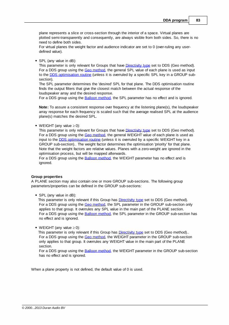
83DDA program
© 2000...2013 Duran Audio BV
plane represents a slice or cross-section through the interior of a space. Virtual planes areplotted semi-transparently and consequently, are always visible from both sides. So, there is noneed to define both sides.For virtual planes the weight factor and audience indicator are set to 0 (over-ruling any user-defined value).
SPL (any value in dB):This parameter is only relevant for Groups that have Directivity type set to DDS (Geo method).For a DDS group using the Geo method, the general SPL value of each plane is used as inputto the DDS optimisation routine (unless it is overruled by a specific SPL key in a GROUP sub-section). The SPL parameter determines the 'desired' SPL for that plane. The DDS optimisation routinefinds the output filters that give the closest match between the actual response of the loudspeaker array and the desired response. For a DDS group using the Balloon method, the SPL parameter has no effect and is ignored.
Note: To assure a consistent response over frequency at the listening plane(s), the loudspeakerarray response for each frequency is scaled such that the average realised SPL at the audienceplane(s) matches the desired SPL.
WEIGHT (any value 0):This parameter is only relevant for Groups that have Directivity type set to DDS (Geo method).For a DDS group using the Geo method, the general WEIGHT value of each plane is used asinput to the DDS optimisation routine (unless it is overruled by a specific WEIGHT key in aGROUP sub-section).. The weight factor determines the optimisation 'priority' for that plane.Note that the weight factors are relative values. Planes with a zero-weight are ignored in theoptimisation process, but will be mapped afterwards. For a DDS group using the Balloon method, the WEIGHT parameter has no effect and isignored.
Group propertiesA PLANE section may also contain one or more GROUP sub-sections. The following groupparameters/properties can be defined in the GROUP sub-sections:
SPL (any value in dB):This parameter is only relevant if this Group has Directivity type set to DDS (Geo method).For a DDS group using the Geo method, the SPL parameter in the GROUP sub-section onlyapplies to that group. It overrules any SPL value in the main part of the PLANE section. For a DDS group using the Balloon method, the SPL parameter in the GROUP sub-section hasno effect and is ignored.
WEIGHT (any value 0):This parameter is only relevant if this Group has Directivity type set to DDS (Geo method)..For a DDS group using the Geo method, the WEIGHT parameter in the GROUP sub-sectiononly applies to that group. It overrules any WEIGHT value in the main part of the PLANEsection. For a DDS group using the Balloon method, the WEIGHT parameter in the GROUP sub-sectionhas no effect and is ignored.
When a plane property is not defined, the default value of 0 is used.
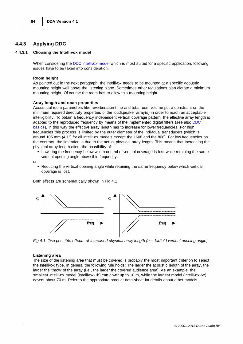
84 DDA Version 4.1
© 2000...2013 Duran Audio BV
4.4.3 Applying DDC
4.4.3.1 Choosing the Intellivox model
When considering the DDC Intellivox model which is most suited for a specific application, followingissues have to be taken into consideration:
Room heightAs pointed out in the next paragraph, the Intellivox needs to be mounted at a specific acousticmounting height well above the listening plane. Sometimes other regulations also dictate a minimummounting height. Of course the room has to allow this mounting height.
Array length and room propertiesAcoustical room parameters like reverberation time and total room volume put a constraint on theminimum required directivity properties of the loudspeaker array(s) in order to reach an acceptableintelligibility. To obtain a frequency independent vertical coverage pattern, the effective array length isadapted to the reproduced frequency by means of the implemented digital filters (see also DDCbasics). In this way the effective array length has to increase for lower frequencies. For highfrequencies this process is limited by the outer diameter of the individual transducers (which isaround 105 mm (4.1") for all Intellivox models except the 1608 and the 808). For low frequencies onthe contrary, the limitation is due to the actual physical array length. This means that increasing thephysical array length offers the possibility of:
Lowering the frequency below which control of vertical coverage is lost while retaining the samevertical opening angle above this frequency.
orReducing the vertical opening angle while retaining the same frequency below which verticalcoverage is lost.
Both effects are schematically shown in Fig 4.1
freq freqfreq freq
Fig 4.1 Two possible effects of increased physical array length ( = farfield vertical opening angle).
Listening areaThe size of the listening area that must be covered is probably the most important criterion to selectthe Intellivox type. In general the following rule holds: The larger the acoustic length of the array, thelarger the 'throw' of the array (i.e., the larger the covered audience area). As an example, thesmallest Intellivox model (Intellivox-1b) can cover up to 10 m, while the largest model (Intellivox-6c)covers about 70 m. Refer to the appropriate product data sheet for details about other models.
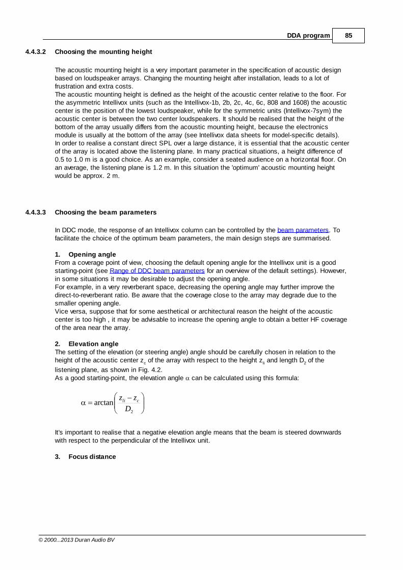
85DDA program
© 2000...2013 Duran Audio BV
4.4.3.2 Choosing the mounting height
The acoustic mounting height is a very important parameter in the specification of acoustic designbased on loudspeaker arrays. Changing the mounting height after installation, leads to a lot offrustration and extra costs. The acoustic mounting height is defined as the height of the acoustic center relative to the floor. Forthe asymmetric Intellivox units (such as the Intellivox-1b, 2b, 2c, 4c, 6c, 808 and 1608) the acousticcenter is the position of the lowest loudspeaker, while for the symmetric units (Intellivox-7sym) theacoustic center is between the two center loudspeakers. It should be realised that the height of thebottom of the array usually differs from the acoustic mounting height, because the electronicsmodule is usually at the bottom of the array (see Intellivox data sheets for model-specific details). In order to realise a constant direct SPL over a large distance, it is essential that the acoustic centerof the array is located above the listening plane. In many practical situations, a height difference of0.5 to 1.0 m is a good choice. As an example, consider a seated audience on a horizontal floor. Onan average, the listening plane is 1.2 m. In this situation the 'optimum' acoustic mounting heightwould be approx. 2 m.
4.4.3.3 Choosing the beam parameters
In DDC mode, the response of an Intellivox column can be controlled by the beam parameters. Tofacilitate the choice of the optimum beam parameters, the main design steps are summarised.
1. Opening angleFrom a coverage point of view, choosing the default opening angle for the Intellivox unit is a goodstarting-point (see Range of DDC beam parameters for an overview of the default settings). However,in some situations it may be desirable to adjust the opening angle. For example, in a very reverberant space, decreasing the opening angle may further improve thedirect-to-reverberant ratio. Be aware that the coverage close to the array may degrade due to thesmaller opening angle.Vice versa, suppose that for some aesthetical or architectural reason the height of the acousticcenter is too high , it may be advisable to increase the opening angle to obtain a better HF coverageof the area near the array.
2. Elevation angleThe setting of the elevation (or steering angle) angle should be carefully chosen in relation to theheight of the acoustic center zc of the array with respect to the height zli and length D2 of the
listening plane, as shown in Fig. 4.2. As a good starting-point, the elevation angle can be calculated using this formula:
2
arctanD
zz cli
It's important to realise that a negative elevation angle means that the beam is steered downwardswith respect to the perpendicular of the Intellivox unit.
3. Focus distance
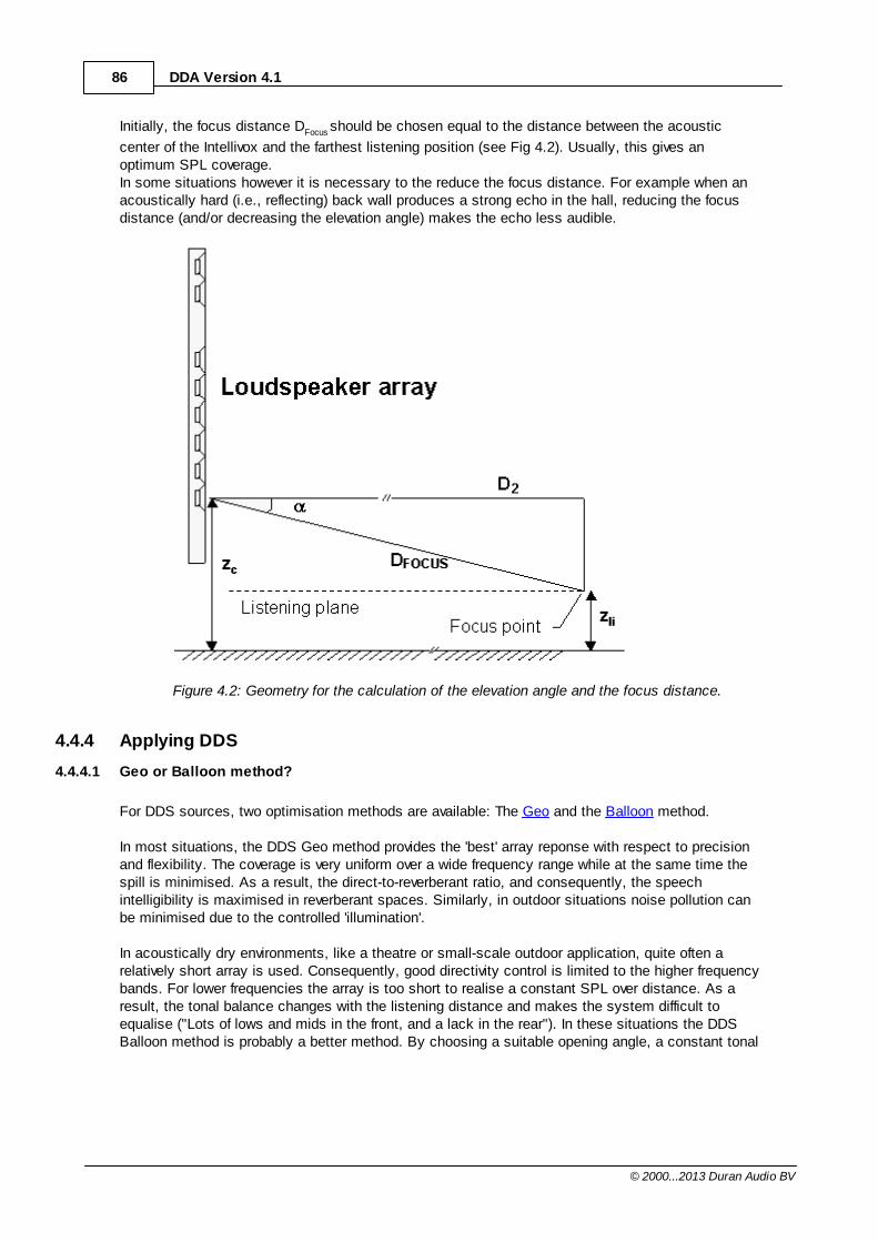
86 DDA Version 4.1
© 2000...2013 Duran Audio BV
Initially, the focus distance DFocus should be chosen equal to the distance between the acoustic
center of the Intellivox and the farthest listening position (see Fig 4.2). Usually, this gives anoptimum SPL coverage. In some situations however it is necessary to the reduce the focus distance. For example when anacoustically hard (i.e., reflecting) back wall produces a strong echo in the hall, reducing the focusdistance (and/or decreasing the elevation angle) makes the echo less audible.
Figure 4.2: Geometry for the calculation of the elevation angle and the focus distance.
4.4.4 Applying DDS
4.4.4.1 Geo or Balloon method?
For DDS sources, two optimisation methods are available: The Geo and the Balloon method.
In most situations, the DDS Geo method provides the 'best' array reponse with respect to precisionand flexibility. The coverage is very uniform over a wide frequency range while at the same time thespill is minimised. As a result, the direct-to-reverberant ratio, and consequently, the speechintelligibility is maximised in reverberant spaces. Similarly, in outdoor situations noise pollution canbe minimised due to the controlled 'illumination'.
In acoustically dry environments, like a theatre or small-scale outdoor application, quite often arelatively short array is used. Consequently, good directivity control is limited to the higher frequencybands. For lower frequencies the array is too short to realise a constant SPL over distance. As aresult, the tonal balance changes with the listening distance and makes the system difficult toequalise ("Lots of lows and mids in the front, and a lack in the rear"). In these situations the DDSBalloon method is probably a better method. By choosing a suitable opening angle, a constant tonal
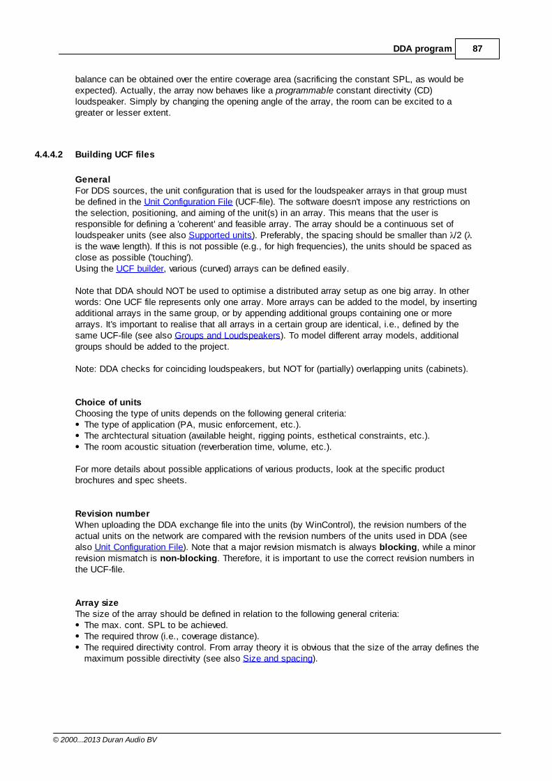
87DDA program
© 2000...2013 Duran Audio BV
balance can be obtained over the entire coverage area (sacrificing the constant SPL, as would beexpected). Actually, the array now behaves like a programmable constant directivity (CD)loudspeaker. Simply by changing the opening angle of the array, the room can be excited to agreater or lesser extent.
4.4.4.2 Building UCF files
GeneralFor DDS sources, the unit configuration that is used for the loudspeaker arrays in that group mustbe defined in the Unit Configuration File (UCF-file). The software doesn't impose any restrictions onthe selection, positioning, and aiming of the unit(s) in an array. This means that the user isresponsible for defining a 'coherent' and feasible array. The array should be a continuous set ofloudspeaker units (see also Supported units). Preferably, the spacing should be smaller than /2 (is the wave length). If this is not possible (e.g., for high frequencies), the units should be spaced asclose as possible ('touching'). Using the UCF builder, various (curved) arrays can be defined easily.
Note that DDA should NOT be used to optimise a distributed array setup as one big array. In otherwords: One UCF file represents only one array. More arrays can be added to the model, by insertingadditional arrays in the same group, or by appending additional groups containing one or morearrays. It's important to realise that all arrays in a certain group are identical, i.e., defined by thesame UCF-file (see also Groups and Loudspeakers). To model different array models, additionalgroups should be added to the project.
Note: DDA checks for coinciding loudspeakers, but NOT for (partially) overlapping units (cabinets).
Choice of unitsChoosing the type of units depends on the following general criteria:
The type of application (PA, music enforcement, etc.).The archtectural situation (available height, rigging points, esthetical constraints, etc.).The room acoustic situation (reverberation time, volume, etc.).
For more details about possible applications of various products, look at the specific productbrochures and spec sheets.
Revision numberWhen uploading the DDA exchange file into the units (by WinControl), the revision numbers of theactual units on the network are compared with the revision numbers of the units used in DDA (seealso Unit Configuration File). Note that a major revision mismatch is always blocking, while a minorrevision mismatch is non-blocking. Therefore, it is important to use the correct revision numbers inthe UCF-file.
Array sizeThe size of the array should be defined in relation to the following general criteria:
The max. cont. SPL to be achieved.The required throw (i.e., coverage distance).The required directivity control. From array theory it is obvious that the size of the array defines themaximum possible directivity (see also Size and spacing).
88 DDA Version 4.1
© 2000...2013 Duran Audio BV
The mounting height of the array relative to the audience height. The larger the mounting height,the larger the required opening angle becomes, and consequently the smaller the required arraysize.
4.4.4.3 Choosing the plane properties
After building a new model, or after importing one, the plane properties (or keys) in the GCF-fileshould be set (see also Building GCF-files).
AUDIENCEIn DDA audience areas are NOT defined separately as floating planes. Any plane that is occupied byaudience has to be defined as an audience plane by setting the key AUDIENCE=1 in the GCF-file.The walls, ceiling and other 'normal' planes should be defined as AUDIENCE=0 (this is the defaultsetting).
VIRTUALUsually, all planes in the model are solid planes, like a floors, walls, or ceilings (default key valueVIRTUAL=0). If you wish to simulate the SPL distribution at a certain 'slice' or cross-section throughthe space, a virtual plane should be defined. In order to define a plane as a virtual plane, the keyVIRTUAL=1 should be set.
Note: The next plane parameters (SPL and WEIGHT) only apply to DDS groups using the Geomethod.
SPLIn order to optimise for the desired acoustic 'illumination' of space, the SPL property of the planesthat need to be covered should be set to the desired sound pressure level (e.g., 90 dB). Planes thatmust be avoided (i.e., no illumination) should have a relatively low SPL value (e.g., 0 dB, which is thedefault value). 'Silence areas' with a non-zero weight must be defined as AUDIENCE=0 (see note). Remind that the SPL key in main part of the PLANE section applies to all groups, while the SPL keyin a GROUP sub-section only applies to that group.After doing a Trial run or Full run the Info window shows headroom that is left.
Note: Only the primary loudspeaker (i.e., A1, B1 etc) in each group will be optimised. Thecalculated output filters are copied to the other arrays in the same group. This means that thedesired SPL values for each group only apply to the primary loudspeaker.
WEIGHTThe weight factor determines the priority of each plane in the optimisation process. At least oneaudience plane should have a non-zero weight. Remind that the WEIGHT key in main part of thePLANE section applies to all groups, while the WEIGHT key in a GROUP sub-section only appliesto that group.As starting point, it is advised to set WEIGHT=1 for all audience planes to be illuminated. All otherplanes can be defined as a 'don't care area' by setting WEIGHT=0 (default value). By performing a Trial run the total illumination of the space is simulated. Depending on their acousticabsorptive properties, you may wish to reduce the SPL at some planes in the model. This can beachieved by increasing the WEIGHT value for those planes. Try to avoid unnecessary large WEIGHTvalues for the 'silence areas', because it will compromise the coverage of the audience areas. Bear in mind that line arrays can only control the dispersion of the lobe in one dimension. Putting
89DDA program
© 2000...2013 Duran Audio BV
constraints (i.e., applying positive weights) in the other dimension doesn't have any effect.
Note: Only the primary loudspeaker (i.e., A1, B1 etc) in each group will be optimised. Thecalculated output filters are copied to the other arrays in the same group. This means that theweights for each group only apply to the primary loudspeaker.
4.4.5 Acoustic parameters
The following section describes how the various acoustic parameters (measures) are calculated.
Direct SPLThis is the SPL of the direct sound, which travels directly from the source (array) to the point ofobservation. There is no reflection of sound is involved. The contributions of multiple sources areadded irrespectively of the time of arrival at the observation point. Depending on the calulationsettings, the combined direct sound of multiple sources is calculated by complex addition(interference sum) or by energy addition (energy sum).The direct sound might be blocked any obstacle in the room. To calculate and visualise possibleshadow areas, DDA applies a geometric line-of-sight algorithm.
Total SPLThis is the SPL of the direct sound plus the contribution of the reverberant field (only in closedgeometries). The strength of the reverberant field is calculated on the basis of a statistical roomacoustic prediction model. It is assumed that the reverberation is uniformly distributed in space. The acoustic environment in a statistical model in mainly determined by the volume of the room, thesound power of the sources and the reverberation time (T60) of the room.
D/R ratioThe direct-to-reverberant ratio is the ratio (expressed in decibels) between the direct sound and thereverberant sound. A D/R ratio of 0 dB means that the level of the direct sound is equal to thereverberant level. Positive D/R values indicate a stronger direct than reverberant field.
STIThe Speech Transmission Index (STI) is a frequently used objective measure of speech intelligibility.Using a statistical model, the STI is determined by the T60, the D/R ratio and the signal-to-noiseratio (SNR), as defined in the Acoustic Environment Options. For broadband input signals DDA calculates the full STI. In case of a band-limited input sigal onlythe MTI (Modulation Transfer Index) is calculated. The MTI for each octave band forms the basis ofthe STI calculation.If Pink noise (A) or Pink noise (L) is used as input, the "original" STI is calculated, according toSteeneken, H. J. M. and Houtgast, T. "A Physical Method for Measuring Speech TransmissionQuality," JASA vol. 67, no. 1 (1980).If Male or Female speech is used as input, the revised STI (according to IEC 60268-16:2011) iscalculated. This STI method includes gender specific input spectra, level-dependent auditorymasking and redundancy correction (beta) factors.
Delay spreadThe delay spread is a measure of the effective width (time extent) of the energy-time distribution ofthe direct sound. The delay spread is based on the mean energy-weighted absolute delay deviationfrom the mean delay (i.e., centre time). In the special case of two equally strong but mutuallydelayed signals, the delay spread exactly equals the time of arrival difference.
90 DDA Version 4.1
© 2000...2013 Duran Audio BV
This parameter can be useful during the the design of distributed source solutons. The disturbanceby secondary arrivals (or echoes) is dependent on the level and the time delay (relative to theprimary arrival). Echoes become more disturbing at higher levels and/or longer delays. In distributed source set-ups 'delay spreading' due to multiple direct sound arrivals can never beavoided at all listening positions simultaneously. However, by choosing a suitable source layout andby applying 'appropriate' predelays, the 'delay spreading' can be minimised. Finding the 'appropriate'predelays can be very complex and time-consuming. Therefore DDA has a special delay optimisatontool, which automates this process.
4.4.6 Examples
The first time you start DDA (after a new install or update), DDA automatically copies some exampleprojects to your default project folder.These examples can be found in the folder: <My Documents>\Duran AudioBV\DDA\Projects\Examples.
4.5 Copyright notices
4.5.1 DDA
Digital Directivity AnalysisCopyright© 2000-2013 Duran Audio BV
License Agreement
1. Grant of License: Duran Audio BV, Zaltbommel, The Netherlands grants the original purchaser ofthis product the nonexclusive right to use this software at one computer location serving oneindividual user. Use on a network is strictly prohibited. This license does not represent a sale ofsoftware or permission to lease or rent the software to other parties. The material in this productmay not be reproduced without accompanying copyright notices. The material in this product maynot be transmitted or exported to another user. The original purchaser may use this product onanother computer only if the files installed by the SETUP program are deleted from the originalcomputer.
2. Updates: If this software is an upgrade/update from a prior version, the same license provisions asdescribed in 1 (above) shall apply.
3. Copyright: This product, including all of its contents, is owned by Duran Audio BV, and isprotected by copyright laws. None of the printed materials accompanying this product may becopied.
4. Limited Warranty: Duran Audio BV warrants to the original purchaser that this software disc isfree of defects in materials and of faulty workmanship under normal use for a period of 90 days fromthe date of purchase. Duran Audio BV reserves the right to determine whether the disc is actuallydefective if returned to Duran Audio BV by the original purchaser, along with proof of purchase.
Otherwise, Duran Audio BV disclaim all other warranties, express or implied, including but notlimited to any implied warranties of merchantability and fitness for a particular purpose or liability onbehalf of Duran Audio BV with respect to the software and the accompanying written materials.
91DDA program
© 2000...2013 Duran Audio BV
Duran Audio BV specifically disclaim any warrant, guarantee or representation as to the correctnessor accuracy of reliability of the material in this disc and its use. You as the user assume the entirerisk of using the product and information contained in the product.
5. Remedies: Duran Audio BV's entire liability and the customer's exclusive remedy shall be thereplacement of a defective disc, deemed defective at the sole discretion of Duran Audio BV. If anylegally constituted and competent jurisdiction determines the above warranty is invalid in any way,damages and other compensation will not exceed the original purchase price of this product andproof of this price must be furnished by the user.
6. Consequential Damages: In no event shall Duran Audio BV be liable for any damages whatsoever(including, without limitations, damages for loss of business profits, loss of business information,business interruption, or other loss).
4.5.2 SciTE
License for Scintilla and SciTE
Copyright 1998-2003 by Neil Hodgson <[email protected]>
All Rights Reserved
Permission to use, copy, modify, and distribute this softwareand its documentation for any purpose and without fee is herebygranted, provided that the above copyright notice appear in all copiesand that both that copyright notice and this permission notice appear in supporting documentation.
NEIL HODGSON DISCLAIMS ALL WARRANTIES WITH REGARD TO THIS SOFTWARE, INCLUDING ALL IMPLIED WARRANTIES OF MERCHANTABILITY AND FITNESS, IN NO EVENT SHALL NEIL HODGSON BE LIABLE FOR ANY SPECIAL, INDIRECT OR CONSEQUENTIAL DAMAGES OR ANY DAMAGES WHATSOEVER RESULTING FROM LOSS OF USE, DATA OR PROFITS, WHETHER IN AN ACTION OF CONTRACT, NEGLIGENCE OR OTHER TORTIOUS ACTION, ARISING OUT OF OR IN CONNECTION WITH THE USE OR PERFORMANCE OF THIS SOFTWARE.
4.5.3 Other
DDA makes gratefully use of the following functions obtainedfrom the Matlab File Exchange:
findobj.m by Yair Altman
arrow3&4.m by Tom Davis
inifile.m by Primoz Cermelj
92 DDA Version 4.1
© 2000...2013 Duran Audio BV
InteractiveLegend by Francois Bouffard
xml_write by Jaroslaw Tuszynski
xticklabel_rotate by Brian Katz
4.5.3.1 Findobj
Copyright (c) 2009, Yair AltmanAll rights reserved.
Redistribution and use in source and binary forms, with orwithoutmodification, are permitted provided that the followingconditions aremet:
* Redistributions of source code must retain the abovecopyright notice, this list of conditions and the followingdisclaimer. * Redistributions in binary form must reproduce the abovecopyright notice, this list of conditions and the followingdisclaimer in the documentation and/or other materials provided with thedistribution
THIS SOFTWARE IS PROVIDED BY THE COPYRIGHT HOLDERS ANDCONTRIBUTORS "AS IS"AND ANY EXPRESS OR IMPLIED WARRANTIES, INCLUDING, BUT NOTLIMITED TO, THEIMPLIED WARRANTIES OF MERCHANTABILITY AND FITNESS FOR APARTICULAR PURPOSEARE DISCLAIMED. IN NO EVENT SHALL THE COPYRIGHT OWNER ORCONTRIBUTORS BELIABLE FOR ANY DIRECT, INDIRECT, INCIDENTAL, SPECIAL, EXEMPLARY,ORCONSEQUENTIAL DAMAGES (INCLUDING, BUT NOT LIMITED TO,PROCUREMENT OFSUBSTITUTE GOODS OR SERVICES; LOSS OF USE, DATA, OR PROFITS; ORBUSINESSINTERRUPTION) HOWEVER CAUSED AND ON ANY THEORY OF LIABILITY,WHETHER INCONTRACT, STRICT LIABILITY, OR TORT (INCLUDING NEGLIGENCE OROTHERWISE)ARISING IN ANY WAY OUT OF THE USE OF THIS SOFTWARE, EVEN IFADVISED OF THEPOSSIBILITY OF SUCH DAMAGE.
93DDA program
© 2000...2013 Duran Audio BV
4.5.3.2 Arrow
Copyright (c) 2002, Tom DavisAll rights reserved.
Redistribution and use in source and binary forms, with orwithout modification, are permitted provided that the followingconditions are met:
* Redistributions of source code must retain the abovecopyright notice, this list of conditions and the followingdisclaimer. * Redistributions in binary form must reproduce the abovecopyright notice, this list of conditions and the followingdisclaimer in the documentation and/or other materials provided with thedistribution THIS SOFTWARE IS PROVIDED BY THE COPYRIGHT HOLDERS ANDCONTRIBUTORS "AS IS" AND ANY EXPRESS OR IMPLIED WARRANTIES, INCLUDING, BUT NOTLIMITED TO, THE IMPLIED WARRANTIES OF MERCHANTABILITY AND FITNESS FOR APARTICULAR PURPOSE ARE DISCLAIMED. IN NO EVENT SHALL THE COPYRIGHT OWNER ORCONTRIBUTORS BE LIABLE FOR ANY DIRECT, INDIRECT, INCIDENTAL, SPECIAL, EXEMPLARY,OR CONSEQUENTIAL DAMAGES (INCLUDING, BUT NOT LIMITED TO,PROCUREMENT OF SUBSTITUTE GOODS OR SERVICES; LOSS OF USE, DATA, OR PROFITS; ORBUSINESS INTERRUPTION) HOWEVER CAUSED AND ON ANY THEORY OF LIABILITY,WHETHER IN CONTRACT, STRICT LIABILITY, OR TORT (INCLUDING NEGLIGENCE OROTHERWISE) ARISING IN ANY WAY OUT OF THE USE OF THIS SOFTWARE, EVEN IFADVISED OF THE POSSIBILITY OF SUCH DAMAGE.
94 DDA Version 4.1
© 2000...2013 Duran Audio BV
4.5.3.3 Inifile
Copyright (c) 2003, Primoz CermeljAll rights reserved.
Redistribution and use in source and binary forms, with orwithout modification, are permitted provided that the followingconditions are met:
* Redistributions of source code must retain the abovecopyright notice, this list of conditions and the followingdisclaimer. * Redistributions in binary form must reproduce the abovecopyright notice, this list of conditions and the followingdisclaimer in the documentation and/or other materials provided with thedistribution THIS SOFTWARE IS PROVIDED BY THE COPYRIGHT HOLDERS ANDCONTRIBUTORS "AS IS" AND ANY EXPRESS OR IMPLIED WARRANTIES, INCLUDING, BUT NOTLIMITED TO, THE IMPLIED WARRANTIES OF MERCHANTABILITY AND FITNESS FOR APARTICULAR PURPOSE ARE DISCLAIMED. IN NO EVENT SHALL THE COPYRIGHT OWNER ORCONTRIBUTORS BE LIABLE FOR ANY DIRECT, INDIRECT, INCIDENTAL, SPECIAL, EXEMPLARY,OR CONSEQUENTIAL DAMAGES (INCLUDING, BUT NOT LIMITED TO,PROCUREMENT OF SUBSTITUTE GOODS OR SERVICES; LOSS OF USE, DATA, OR PROFITS; ORBUSINESS INTERRUPTION) HOWEVER CAUSED AND ON ANY THEORY OF LIABILITY,WHETHER IN CONTRACT, STRICT LIABILITY, OR TORT (INCLUDING NEGLIGENCE OROTHERWISE) ARISING IN ANY WAY OUT OF THE USE OF THIS SOFTWARE, EVEN IFADVISED OF THE POSSIBILITY OF SUCH DAMAGE.
95DDA program
© 2000...2013 Duran Audio BV
4.5.3.4 InteractiveLegend
Copyright (c) 2012, Francois BouffardAll rights reserved.
Redistribution and use in source and binary forms, with orwithout modification, are permitted provided that the followingconditions are met:
* Redistributions of source code must retain the abovecopyright notice, this list of conditions and the followingdisclaimer. * Redistributions in binary form must reproduce the abovecopyright notice, this list of conditions and the followingdisclaimer in the documentation and/or other materials provided with thedistribution THIS SOFTWARE IS PROVIDED BY THE COPYRIGHT HOLDERS ANDCONTRIBUTORS "AS IS" AND ANY EXPRESS OR IMPLIED WARRANTIES, INCLUDING, BUT NOTLIMITED TO, THE IMPLIED WARRANTIES OF MERCHANTABILITY AND FITNESS FOR APARTICULAR PURPOSE ARE DISCLAIMED. IN NO EVENT SHALL THE COPYRIGHT OWNER ORCONTRIBUTORS BE LIABLE FOR ANY DIRECT, INDIRECT, INCIDENTAL, SPECIAL, EXEMPLARY,OR CONSEQUENTIAL DAMAGES (INCLUDING, BUT NOT LIMITED TO,PROCUREMENT OF SUBSTITUTE GOODS OR SERVICES; LOSS OF USE, DATA, OR PROFITS; ORBUSINESS INTERRUPTION) HOWEVER CAUSED AND ON ANY THEORY OF LIABILITY,WHETHER IN CONTRACT, STRICT LIABILITY, OR TORT (INCLUDING NEGLIGENCE OROTHERWISE) ARISING IN ANY WAY OUT OF THE USE OF THIS SOFTWARE, EVEN IFADVISED OF THE POSSIBILITY OF SUCH DAMAGE.
96 DDA Version 4.1
© 2000...2013 Duran Audio BV
4.5.3.5 xml_write
Copyright (c) 2007, Jaroslaw TuszynskiAll rights reserved.
Redistribution and use in source and binary forms, with orwithout modification, are permitted provided that the followingconditions are met:
* Redistributions of source code must retain the abovecopyright notice, this list of conditions and the followingdisclaimer. * Redistributions in binary form must reproduce the abovecopyright notice, this list of conditions and the followingdisclaimer in the documentation and/or other materials provided with thedistribution THIS SOFTWARE IS PROVIDED BY THE COPYRIGHT HOLDERS ANDCONTRIBUTORS "AS IS" AND ANY EXPRESS OR IMPLIED WARRANTIES, INCLUDING, BUT NOTLIMITED TO, THE IMPLIED WARRANTIES OF MERCHANTABILITY AND FITNESS FOR APARTICULAR PURPOSE ARE DISCLAIMED. IN NO EVENT SHALL THE COPYRIGHT OWNER ORCONTRIBUTORS BE LIABLE FOR ANY DIRECT, INDIRECT, INCIDENTAL, SPECIAL, EXEMPLARY,OR CONSEQUENTIAL DAMAGES (INCLUDING, BUT NOT LIMITED TO,PROCUREMENT OF SUBSTITUTE GOODS OR SERVICES; LOSS OF USE, DATA, OR PROFITS; ORBUSINESS INTERRUPTION) HOWEVER CAUSED AND ON ANY THEORY OF LIABILITY,WHETHER IN CONTRACT, STRICT LIABILITY, OR TORT (INCLUDING NEGLIGENCE OROTHERWISE) ARISING IN ANY WAY OUT OF THE USE OF THIS SOFTWARE, EVEN IFADVISED OF THE POSSIBILITY OF SUCH DAMAGE.
97DDA program
© 2000...2013 Duran Audio BV
4.5.3.6 xticklabel_rotate
Copyright (c) 2003, Brian KatzCopyright (c) 2009, The MathWorks, Inc.All rights reserved.
Redistribution and use in source and binary forms, with orwithout modification, are permitted provided that the followingconditions are met:
* Redistributions of source code must retain the abovecopyright notice, this list of conditions and the followingdisclaimer. * Redistributions in binary form must reproduce the abovecopyright notice, this list of conditions and the followingdisclaimer in the documentation and/or other materials provided with thedistribution * Neither the name of the The MathWorks, Inc. nor the names of its contributors may be used to endorse or promoteproducts derived from this software without specific prior writtenpermission. THIS SOFTWARE IS PROVIDED BY THE COPYRIGHT HOLDERS ANDCONTRIBUTORS "AS IS" AND ANY EXPRESS OR IMPLIED WARRANTIES, INCLUDING, BUT NOTLIMITED TO, THE IMPLIED WARRANTIES OF MERCHANTABILITY AND FITNESS FOR APARTICULAR PURPOSE ARE DISCLAIMED. IN NO EVENT SHALL THE COPYRIGHT OWNER ORCONTRIBUTORS BE LIABLE FOR ANY DIRECT, INDIRECT, INCIDENTAL, SPECIAL, EXEMPLARY,OR CONSEQUENTIAL DAMAGES (INCLUDING, BUT NOT LIMITED TO,PROCUREMENT OF SUBSTITUTE GOODS OR SERVICES; LOSS OF USE, DATA, OR PROFITS; ORBUSINESS INTERRUPTION) HOWEVER CAUSED AND ON ANY THEORY OF LIABILITY,WHETHER IN CONTRACT, STRICT LIABILITY, OR TORT (INCLUDING NEGLIGENCE OROTHERWISE) ARISING IN ANY WAY OUT OF THE USE OF THIS SOFTWARE, EVEN IFADVISED OF THE POSSIBILITY OF SUCH DAMAGE.
98 DDA Version 4.1
© 2000...2013 Duran Audio BV
4.6 Known software problems
OpenGL issues
On some platforms OpenGL rendering is causing severe problems. OpenGL problems are usuallycaused by incompatible hardware, bugs in the hardware driver, or incorrect system configuration.Problems related to OpenGL can cause the following types of unexpected behaviour:
Graphics render poorly or not at all Erratic display of a graphics figure or GUI window Poorly rendered data labels.
On some platforms switching to software OpenGL rendering may improve things. On some platformshowever, disabling OpenGL is the last resort.
Index 99
© 2000...2013 Duran Audio BV
Index
- 2 -2D Geometry Builder 61
- A -ABC 15, 73, 79
ABC descriptors 79
Account 5
Acoustic Boundary Condition (ABC) 79
Acoustic Boundary Conditions (ABC) 15
Acoustical model 54
Activation 5
ADC 17, 31
ADC settings 38
Aiming 17, 31
Ambient noise 57
Array 10, 87
Array Builder 61
Array table 61
Array type 44
AUDIENCE 69, 88
Auto EQ 47
- B -Background noise 57
Balloon method 86
Beam DDC beam parameters 19
Elevation angle 19
Focus distance 19
Opening angle 19
beam parameters 85
BEM 15
Boundary Element Method (BEM) 15
bugs 98
- C -Calculation 31
Calculator 61
Caption 28
Cardioid 15
CATT 29, 80
Characteristic 44
Classical 54
CLF 2, 31, 46, 60
CLF viewer 31, 46
coherent 87
column 10
command 66
Complex 54
Control 17
corner 69, 82
Curvature 62auto 62
manual 62
- D -D/R ratio 89
DDA 2, 28
DDC 2, 17, 31processing 21
DDC beam parameters 19
DDC settings 39
DDI 80
DDS 2, 22, 31Balloon method 22
Geo method 22
DDS settings (Balloon method) 44
DDS settings (Geo method) 42
degenerate 82
Delay 31
Delay optimiser 61
Delay spread 61, 89
Delay zone 31
Description 31
Desired SPL drop 42
DI 67
differential 73
Differential array 79
Differential subwoofer array 15
Digital 17, 22
Digital Directivity 17
Direct sound 54
DDA100
© 2000...2013 Duran Audio BV
Direct SPL 89
Directivity 10, 17, 22
Directivity Index 67
Direct-to-reverberant ratio 57
Distance 61
- E -EASE 29
Edit 31Copy 31
elevation angle 19, 39, 85
EMF 29
Energy 54
EQ 31, 47
Examples 4, 90
Extend 8
- F -Far field 10
File 29Export 29
Import 29
New 29
Open 29
Pack 29
Print 29
Quit 29
Save 29
Unpack 29
Flat EQ 47
Flat FR for Total group 42
Flat FR for Each array 42
focus distance 19, 39, 85
Full run 49
- G -Gain 31
GCF 69, 82CORNERS 69
GROUP 69
MATERIALS 69
PLANE 69
Geo method 86
Geo-file 31
Getting started 4
GLL 29
Grid step 31
Group 81
Groups 31
- H -headroom 67
HVR 73
- I -Info 67
Info window 28
Input gain 36, 38, 39
installation 98
Intellivox 77
Interface 28
- J -JPEG 29
- K -Key name 68
Keyboard 66
- L -Label 31
License 4, 5, 7, 8
Licensed 5
Licensing 5
Line-of-sight check 31
Lock 31
Locked 5
Loudspeaker 81
Loudspeakers 31
Lw 67
- M -Main 28
Index 101
© 2000...2013 Duran Audio BV
Main lobe 19, 39
Map height audience 31
material 69, 82
Menu 31Edit 31
File 29
Help 65
Options 53
method Balloon 22
Geo 22
MID 5
Mirror 31
Mirror-symmetric copy 31
model 36, 38, 39, 82
mounting height 85
Mouse 66
MTI 49
- N -Near field 10
noise 57
- O -Odeon 29
On-axis level 67
OpenGL 98
Opening 44
opening angle 19, 39, 85
Options Acoustic Environment 57
Calculation 54
Folders 60
Mapping 55
OpenGL 53
Output filters 42, 44Enhanced (FIR+IIR) 42
Standard (FIR) 42
- P -Plane 69
plane face 82
Plot area 28
Plot tree 28
Point source 31
Point Source Model 10
Point source settings 46
Position 31
Power tap 38
prediction 2
primary array 88
Project settings 31
PSM 10
PSM-BEM 15
- R -Radiation condition 15
Radius 31
RCF 73RECEIVERS 73
XYZ 73
Receiver 73
Rec-file 31
Relative gain 39
Release notes 65
Remove 7
Resolution 31
Restrict coverage area 42
REV 73
Reverberant sound 54
Reverberation Time 57
Revised 54
revision number 73
RMS delay spread 61
- S -SD0 80
SD2 80
Second lobe 19, 39
section 68, 69
simulation 2
Site code 5
Size 12
Sound 10
Sound power 67
Sound power Level 67
Source type 31
DDA102
© 2000...2013 Duran Audio BV
Spacing 12
Spatial 10
SPECIAL 73
special type indicator 73
SPL 69, 88
SPL @30m 44
SR ("Blue line") 31
SR (Blue line) settings 36
Steering 44
STI 49, 57, 89
sub-section 69
Surface grid 31
Syntax 68
Synthesis 22
- T -Throw 87
Tool bar 28, 65
Total SPL 89
Trial run... 49
TYPE 73
- U -UCF 73, 87
ABC 73
HVR 73
REV 73
SPECIAL 73
TYPE 73
UNIT 73
XYZ 73
UCF examples 79
Unit supported 77
Unit configuration 42, 44
updates 98
- V -vertex 82
VIRTUAL 69, 88
Volume 57
- W -warped 82
Wave 10
WEIGHT 69, 88
WinControl 2
Window 28
- X -XML 29
XYZ 69, 73
- Z -Zoom 52
Endnotes 2... (after index)
103
© 2000...2013 Duran Audio BV

Back Cover