Characterization of Vehicle Occupant Fracture Injury Pattern ...
62
USAARL Report No. 2020-09 Characterization of Vehicle Occupant Fracture Injury Pattern during Operation Iraqi Freedom (OIF) and Operation Enduring Freedom (OEF): 2007 – 2010 By Kimberly B. Vasquez 1 , Allison Robinette 1,2 , Scott M. Harrington 1 , Frederick T. Brozoski 1 , Tyler F. Rooks 1 , Danielle Rhodes 1,3 , Edward Mazuchowski II 4 , Grace M. Lidl 1 , B. Joseph McEntire 1 , & Valeta Carol Chancey 1 1 U.S. Army Aeromedical Research Laboratory 2 Oak Ridge Institute for Science and Education 3 Katmai Health Services 4 Armed Forces Medical Examiner System/Joint Trauma System United States Army Aeromedical Research Laboratory Injury Biomechanics and Protection Group March 2020 DISTRIBUTION STATEMENT A. Approved for public release; Distribution unlimited.
-
Upload
khangminh22 -
Category
Documents
-
view
1 -
download
0
Transcript of Characterization of Vehicle Occupant Fracture Injury Pattern ...
USAARL Report No. 2020-09
Characterization of Vehicle Occupant Fracture Injury Pattern during Operation Iraqi Freedom (OIF) and Operation Enduring Freedom (OEF): 2007 – 2010
By Kimberly B. Vasquez1, Allison Robinette1,2, Scott M. Harrington1, Frederick T. Brozoski1, Tyler F. Rooks1, Danielle Rhodes1,3, Edward Mazuchowski II4, Grace M. Lidl1, B. Joseph McEntire1, & Valeta Carol Chancey1
1U.S. Army Aeromedical Research Laboratory 2Oak Ridge Institute for Science and Education 3Katmai Health Services 4Armed Forces Medical Examiner System/Joint Trauma System
United States Army Aeromedical Research Laboratory
Injury Biomechanics and Protection Group
March 2020
DISTRIBUTION STATEMENT A. Approved for public release; Distribution unlimited.
Notice
Qualified Requesters Qualified requesters may obtain copies from the Defense Technical Information Center (DTIC), Fort Belvoir, Virginia 22060. Orders will be expedited if placed through the librarian or other person designated to request documents from DTIC. Change of Address Organizations receiving reports from the U.S. Army Aeromedical Research Laboratory on automatic mailing lists should confirm correct address when corresponding about laboratory reports. Disposition Destroy this document when it is no longer needed. Do not return it to the originator. Disclaimer The views, opinions, and/or findings contained in this report are those of the author(s) and should not be construed as an official Department of the Army position, policy, or decision, unless so designated by other official documentation. Citation of trade names in this report does not constitute an official Department of the Army endorsement or approval of the use of such commercial items. Human Subject Data Use The U.S. Army Aeromedical Research Laboratory Determination Official determined that this activity does not constitute research as defined under the human subjects protection regulations, as it is not “a systematic investigation, including research development, testing and evaluation, designed to develop or contribute to generalizable knowledge.” [32 CFR 219.102(d)].

Standard Form 298 (Rev. 8/98)
REPORT DOCUMENTATION PAGE
Prescribed by ANSI Std. Z39.18
Form Approved OMB No. 0704-0188
The public reporting burden for this collection of information is estimated to average 1 hour per response, including the time for reviewing instructions, searching existing data sources, gathering and maintaining the data needed, and completing and reviewing the collection of information. Send comments regarding this burden estimate or any other aspect of this collection of information, including suggestions for reducing the burden, to Department of Defense, Washington Headquarters Services, Directorate for Information Operations and Reports (0704-0188), 1215 Jefferson Davis Highway, Suite 1204, Arlington, VA 22202-4302. Respondents should be aware that notwithstanding any other provision of law, no person shall be subject to any penalty for failing to comply with a collection of information if it does not display a currently valid OMB control number. PLEASE DO NOT RETURN YOUR FORM TO THE ABOVE ADDRESS. 1. REPORT DATE (DD-MM-YYYY) 2. REPORT TYPE 3. DATES COVERED (From - To)
4. TITLE AND SUBTITLE 5a. CONTRACT NUMBER
5b. GRANT NUMBER
5c. PROGRAM ELEMENT NUMBER
5d. PROJECT NUMBER
5e. TASK NUMBER
5f. WORK UNIT NUMBER
6. AUTHOR(S)
7. PERFORMING ORGANIZATION NAME(S) AND ADDRESS(ES) 8. PERFORMING ORGANIZATIONREPORT NUMBER
9. SPONSORING/MONITORING AGENCY NAME(S) AND ADDRESS(ES) 10. SPONSOR/MONITOR'S ACRONYM(S)
11. SPONSOR/MONITOR'S REPORTNUMBER(S)
12. DISTRIBUTION/AVAILABILITY STATEMENT
13. SUPPLEMENTARY NOTES
14. ABSTRACT
15. SUBJECT TERMS
16. SECURITY CLASSIFICATION OF:a. REPORT b. ABSTRACT c. THIS PAGE
17. LIMITATION OFABSTRACT
18. NUMBEROFPAGES
19a. NAME OF RESPONSIBLE PERSON
19b. TELEPHONE NUMBER (Include area code)
25-03-2020 Final Technical Report 10-01-2016 -- 09-30-2019
Characterization of Vehicle Occupant Fracture Injury Pattern duringOperation Iraqi Freedom (OIF) and Operation Enduring Freedom (OEF):2007-2010
MOMRP 19020Vasquez, Kimberly B.; Robinette, Allison; Harrington, Scott M.; Brozoski,Frederick T.; Rooks, Tyler F.; Rhodes, Danielle; Mazuchowski, Edward II;Lidl, Grace M.; McEntire, B. Joseph; Chancey, Valeta Carol
U.S. Army Aeromedical Research LaboratoryP.O. Box 620577Fort Rucker, AL 36362
USAARL TR 2020-09
Military Operational Medicine Research ProgramU.S. Army Medical Research and Development Command504 Scott StreetFort Detrick, MD 21702-5012
USAMRDC
DISTRIBUTION STATEMENT A. Approved for public release; Distribution Unlimited.
Oak Ridge Institute for Science and Education; Katmai Health Services; Armed Forces Medical Examiner System/Joint TraumaSystem
Historically, occupant injury protection and prevention research has focused heavily on frontal, lateral, and oblique automobile and aviation impactevents. Due to the increase in Underbody blast (UBB) events occurring during Operation Iraqi Freedom and Operation Enduring Freedom(OIF/OEF), a need for research in cataloging high-velocity vertical impact injuries arose. The purpose of this study was to create a medical imagecatalog of operationally relevant injuries for researchers to recreate and validate lab-controlled experiments. Medical images, x-rays and/orcomputed tomography (CT) scans, from Wounded in Action (WIA) and Killed in Action (KIA) individuals were reviewed and cataloged. Foridentified injuries, 2D images were captured and 3D reconstructions were created and placed into the 2007-2010 OIF/OEF UBB Medical ImageCatalog. This medical image catalog will inform researchers of the complexity and severity of injuries due to UBB, the possible loading dynamics,and potential mechanism of tissue failure for the development of effective personal protective equipment (PPE), vehicle design, and other blastmitigating technologies.
UNCLAS UNCLAS UNCLAS SAR 62
Loraine St. Onge, PhD
334-255-6906

ii
This page is intentionally blank.

iii
Acknowledgements
This work was supported by the U.S. Army Medical Research and Development Command (USAMRDC) (formerly the U.S. Army Medical Research and Materiel Command) through the Military Operational Medicine Research Program (MOMRP).
This research was supported in part by an appointment to the Postgraduate Research Participation Program at the U.S. Army Aeromedical Research Laboratory administered by the Oak Ridge Institute for Science and Education (ORISE) through an interagency agreement between the U.S. Department of Energy and the USAMRDC.

iv
This page is intentionally blank

v
Table of Contents Page
Introduction ..................................................................................................................................... 1 Methods........................................................................................................................................... 2 Results ............................................................................................................................................. 5 Discussion ....................................................................................................................................... 7
Medical Image Collection and Quality ............................................................................... 7 Injury Identification and 3D Reconstructions ..................................................................... 7 Wounded in Action Medical Image Catalog versus the Injury Dataset .............................. 7
Conclusions ..................................................................................................................................... 8 References ....................................................................................................................................... 9 Appendix A. Exemplar Injuries to the Head and Face Region ..................................................... 11 Appendix B. Exemplar Injuries to the Neck Region .................................................................... 15 Appendix C. Exemplar Injuries to the Torso Region ................................................................... 19 Appendix D. Exemplar Injuries to the Upper Extremities ............................................................ 23 Appendix E. Exemplar Injuries to the Lumbar Spine ................................................................... 27 Appendix F. Exemplar Injuries to the Pelvis Region ................................................................... 31 Appendix G. Exemplar Injuries to the Thigh ................................................................................ 35 Appendix H. Exemplar Injuries to the Lower Leg ....................................................................... 39 Appendix I. Exemplar Injuries to the Foot and Ankle Region ..................................................... 43 Appendix J. Exemplar Images of One Killed in Action Individual .............................................. 49 List of Figures 1. Down selection flowchart of injury dataset to available medical images in the 2007-2010 OIF/OEF UBB Medical Image Catalog .......................................................................................... 4 2. Distribution of injuries per body region in the 2007-2010 OIF/OEF UBB injury dataset ......... 5 3. Percentage of individuals with images by body region in the 2007-2010 OIF/OEF UBB Medical Image Catalog ................................................................................................................... 6

vi
This page is intentionally blank.
1
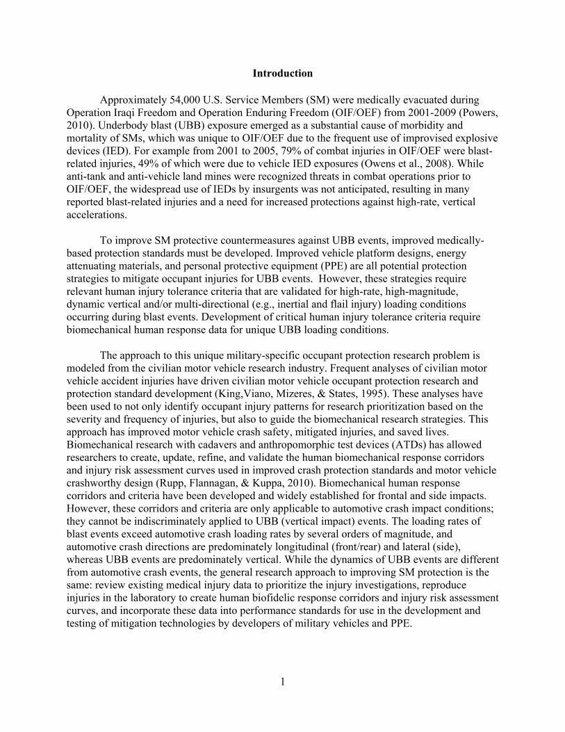
Introduction
Approximately 54,000 U.S. Service Members (SM) were medically evacuated during Operation Iraqi Freedom and Operation Enduring Freedom (OIF/OEF) from 2001-2009 (Powers, 2010). Underbody blast (UBB) exposure emerged as a substantial cause of morbidity and mortality of SMs, which was unique to OIF/OEF due to the frequent use of improvised explosive devices (IED). For example from 2001 to 2005, 79% of combat injuries in OIF/OEF were blast-related injuries, 49% of which were due to vehicle IED exposures (Owens et al., 2008). While anti-tank and anti-vehicle land mines were recognized threats in combat operations prior to OIF/OEF, the widespread use of IEDs by insurgents was not anticipated, resulting in many reported blast-related injuries and a need for increased protections against high-rate, vertical accelerations.
To improve SM protective countermeasures against UBB events, improved medically- based protection standards must be developed. Improved vehicle platform designs, energy attenuating materials, and personal protective equipment (PPE) are all potential protection strategies to mitigate occupant injuries for UBB events. However, these strategies require relevant human injury tolerance criteria that are validated for high-rate, high-magnitude, dynamic vertical and/or multi-directional (e.g., inertial and flail injury) loading conditions occurring during blast events. Development of critical human injury tolerance criteria require biomechanical human response data for unique UBB loading conditions.
The approach to this unique military-specific occupant protection research problem is modeled from the civilian motor vehicle research industry. Frequent analyses of civilian motor vehicle accident injuries have driven civilian motor vehicle occupant protection research and protection standard development (King,Viano, Mizeres, & States, 1995). These analyses have been used to not only identify occupant injury patterns for research prioritization based on the severity and frequency of injuries, but also to guide the biomechanical research strategies. This approach has improved motor vehicle crash safety, mitigated injuries, and saved lives. Biomechanical research with cadavers and anthropomorphic test devices (ATDs) has allowed researchers to create, update, refine, and validate the human biomechanical response corridors and injury risk assessment curves used in improved crash protection standards and motor vehicle crashworthy design (Rupp, Flannagan, & Kuppa, 2010). Biomechanical human response corridors and criteria have been developed and widely established for frontal and side impacts. However, these corridors and criteria are only applicable to automotive crash impact conditions; they cannot be indiscriminately applied to UBB (vertical impact) events. The loading rates of blast events exceed automotive crash loading rates by several orders of magnitude, and automotive crash directions are predominately longitudinal (front/rear) and lateral (side), whereas UBB events are predominately vertical. While the dynamics of UBB events are different from automotive crash events, the general research approach to improving SM protection is the same: review existing medical injury data to prioritize the injury investigations, reproduce injuries in the laboratory to create human biofidelic response corridors and injury risk assessment curves, and incorporate these data into performance standards for use in the development and testing of mitigation technologies by developers of military vehicles and PPE.
2
As a vital first step in the process to establish injury patterns in the UBB environment, an initial injury analysis has been performed on a dataset provided by the Joint Trauma Analysis for the Prevention of Injury in Combat (JTAPIC) Program. This dataset includes all medical injuries sustained during UBB events occurring between 2007 and 2010. The initial analysis describes distribution patterns of injuries by: body region, body region and injury type, and body region and severity (Vasquez, Brozoski, Logsdon, & Chancey, 2018). The analysis of injury patterns provides researchers with the ability to develop laboratory-controlled studies to replicate the high-rate, vertical loading UBB events. However, to augment the injury pattern analysis, medical images of injuries sustained during UBB events are required to provide additional insight into the injury complexity as well as validate that laboratory-controlled studies produce relevant injuries to the UBB environment.
This report describes an overview of the methods used to create the 2007-2010 OIF/OEF UBB Medical Image Catalog. Sample images from the catalog are provided in Appendices A through J. Radiological images of Wounded in Action (WIA) and Killed in Action (KIA) individuals injured during UBB exposures during OIF/OEF from 2007 to 2010 were collected to create a catalog of UBB injuries. This Medical Image Catalog will inform researchers of the complexity and severity of injuries due to UBB, the possible loading dynamics, and potential mechanisms of tissue failure. Using the insight gained from the images, researchers will be able to refine tests to duplicate these injuries in the laboratory and validate injuries produced in the laboratory as operationally relevant.
Methods
In 2011, all medical injury data from mounted UBB events in theater during OIF/OEF from 2007 through 2010 available to the JTAPIC Program was provided to the U.S. Army Aeromedical Research Laboratory (USAARL). The research team specifically requested data from JTAPIC for SMs injured during an UBB event with the assumption that all injured SMs were mounted in the vehicle at the time of the event (Vasquez et al., 2018). The dataset contained the following information for each injured individual: initial disposition (WIA or KIA), injury description(s), and respective Abbreviated Injury Scale (AIS) code(s). Disposition of SM (KIA or WIA) was provided and determined by the on-site status of the injured individual. KIA was assigned to individuals that were deceased on-site; all other injured individuals were assigned as WIA, including those that may have later died from wounds. The AIS is an anatomically-based scoring system that classifies each injury by body region and severity (Association for the Advancement of Automotive Medicine, 2008). After the dataset was reviewed for completeness, each injury was coded by body region, injury type, and severity derived from the injury descriptions and AIS codes provided.
A down selection process from the 2007-2010 OIF/OEF UBB injury dataset was completed to determine which individuals’ medical images were to be obtained. Medical images were only necessary for injuries of interest, for injuries that require protection, and for which injury mitigating strategies could be developed. Therefore, medical images of individuals only sustaining minor injuries (e.g., superficial abrasions, contusions, etc.) as well as catastrophic injuries (e.g., torso transection, decapitation, thermal burns, etc.) were excluded from being requested. More details of injury types included and excluded are described in Vasquez et al.
3
(2018). The medical images for the WIA individuals were obtained from Lundstuhl Regional Medical Center (LRMC) in 2012. LRMC staff provided all available medical images from the list of individuals to USAARL. For the KIAs, most individuals sustained whole body trauma, for which developing injury mitigating strategies is difficult; however, the KIAs are still important to consider. A list of events from the injury dataset was compared to a JTAPIC list of events that contained additional environmental and exposure information. Matching events were the first down selection criteria. Additional down selection criteria to choose KIA medical images were events in which resulted in WIAs and KIAs in the same event. The images for the KIA individuals were obtained from the Armed Forces Medical Examiner’s Office (AFME) in 2012. The medical images collected from LRMC and AFME established the 2007-2010 OIF/OEF UBB Medical Image Catalog, a subset from the injury dataset (Vasquez et al., 2018). A flowchart of the down selection process from the injury dataset to the medical images requested is shown in Figure 1.
The medical images, mainly DICOM files, for every individual (WIA and KIA) were reviewed and assigned a body region. Nine body regions were assigned to investigate the unique aspects of the vertical loading from UBB and identify trends of injury by region: (1) Head and Face; (2) Neck with an emphasis on cervical spine; (3) Torso including the shoulder complex; (4) Upper Extremity; (5) Lumbar Spine; (6) Pelvis including the hip complex; (7) Thigh; (8) Lower Leg including the knee; and (9) Foot and Ankle. If an image included more than one body region (e.g., head and neck), the image was assigned to each viewable body region. If an image had more than one body region without substantial portions (at least two-thirds) in the view, the DICOM metadata (assigned when the image was taken) was used to determine the focus of the medical image and the image was assigned to that body region.
Research physicians reviewed a subset of the medical images to find exemplar UBB injuries for this summary report. For each image reviewed, the image was assigned a (1) body region and specific skeletal location, (2) injury type, and, if able, (3) severity. Although several injury types were available within the injury dataset (fracture/dislocation, amputation, internal organ injuries, thermal, neuro/vascular, penetrating/perforating, minor injuries), the images down-selected for the Medical Image Catalog were x-ray and/or computed tomography (CT), therefore, the majority of the injury types identified from the images were musculoskeletal related (e.g., fractures). Severity was determined and documented by the research physicians as best as the image(s) allowed. The severity was determined based on the guidance within the Abbreviated Injury Scale (AIS) 2005: 2008 Update.
For each injury identified by the research physicians, 2D images were captured in the axis of interest. The 2D image was captured from either an x-ray or the slice view of a CT. If a CT scan was available and of reasonable quality, a 3D reconstruction of the injury was rendered using the 3D reconstruction software Materialise Mimics® (version 21.0, Belgium). Adjacent body regions were removed from the reconstructions to highlight the injury, e.g., the ribs were removed to better view an anterior thoracic vertebral body fracture. The 2007-2010 OIF/OEF UBB Medical Image Catalog includes original medical image files organized by individual and body region, the injuries determined by the research physicians for a subset of all images, and the 2D images and 3D reconstructions.
4
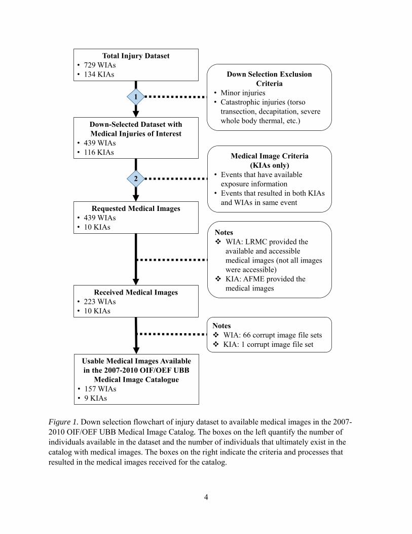
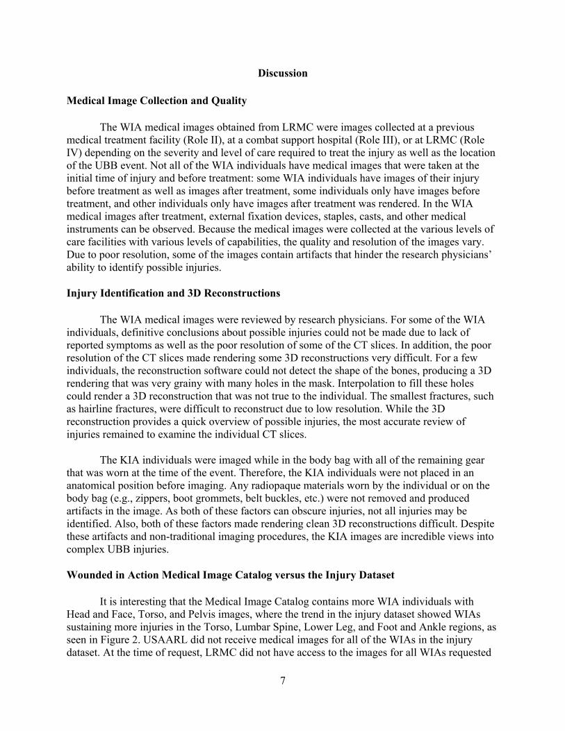
Figure 1. Down selection flowchart of injury dataset to available medical images in the 2007-2010 OIF/OEF UBB Medical Image Catalog. The boxes on the left quantify the number of individuals available in the dataset and the number of individuals that ultimately exist in the catalog with medical images. The boxes on the right indicate the criteria and processes that resulted in the medical images received for the catalog.
Total Injury Dataset• 729 WIAs• 134 KIAs
Notes WIA: 66 corrupt image file sets KIA: 1 corrupt image file set
Requested Medical Images• 439 WIAs• 10 KIAs
Down-Selected Dataset with Medical Injuries of Interest
• 439 WIAs• 116 KIAs
Received Medical Images• 223 WIAs• 10 KIAs
Usable Medical Images Available in the 2007-2010 OIF/OEF UBB
Medical Image Catalogue• 157 WIAs• 9 KIAs
Notes WIA: LRMC provided the
available and accessible medical images (not all images were accessible)
KIA: AFME provided the medical images
Medical Image Criteria (KIAs only)
• Events that have available exposure information
• Events that resulted in both KIAs and WIAs in same event
Down Selection Exclusion Criteria
• Minor injuries• Catastrophic injuries (torso
transection, decapitation, severe whole body thermal, etc.)
1
2

5
Results
For medical injuries of interest, the down-selected injury dataset (Figure 1) contains 296 events, 555 unique individuals, and 3,844 injuries. Every injury for each individual was coded for body region, injury type, and severity. The body region distribution of all injury types by disposition is shown in Figure 2. Each injury was assigned a body region; the total number of injuries were then counted per body region, where n represents the total number of injuries. An individual was assigned to every body region in which they received at least one injury; the total number of injured individuals were then counted per body region, where m represents the total number of individuals. This implies that the same individual may be counted in more than one body region (Vasquez et al., 2018).
Figure 2. Distribution of injuries per body region in the 2007-2010 OIF/OEF UBB injury dataset. The distribution of the injuries per body region includes all injury types available.
From the 555 individuals in the 2007-2010 OIF/OEF UBB injury dataset, medical images were only provided for 223 WIA and 10 KIA individuals. Some medical image files were corrupt and were unusable (66 WIA and 1 KIA individuals). Medical images (x-rays and/or CTs) from 157 WIA and 9 KIA individuals are available for use in the 2007-2010 OIF/OEF UBB Medical Image Catalog. The process of obtaining the available medical images is detailed in Figure 1.
As USAARL research physicians systematically reviewed the medical images of 157
WIA individuals, musculoskeletal-related injury types, as expected, were identified: fractures, ligament injury, and soft tissue damage due to complex fractures. However, a few other injury types were identified in the x-rays and CTs, such as neuro/vascular (e.g., hemorrhaging) and

6
internal organ injury (e.g., pneumothorax). It is possible that more injuries exist than what was identified in the images.
The number of WIA and KIA individuals that have imaging per body region is shown in Figure 3. Individuals were counted once per body region if they had at least one medical image in that body region. Fifty percent or more of the WIA individuals in the 2007-2010 OIF/OEF UBB Medical Image Catalog have at least one image in the Head and Face, Torso, and Pelvis regions.
Figure 3. Percentage of individuals with images by body region in the 2007-2010 OIF/OEF UBB Medical Image Catalog. The number of individuals include all WIA and KIA individuals that have at least one image in each body region. The data labels over the bars represent the count of individuals in that body region.
The WIA medical images for three exemplar individuals in each body region are provided in Appendices A through I. The primary injury type identified in the CT and x-ray images were fractures. A range of fracture complexity/severity is provided for each body region. External fixation devices, in addition to other medical equipment, can be seen in some of the images. The 2007-2010 OIF/OEF UBB Medical Image Catalog only had two WIA individuals with fractures in the Head and Face region. Both individuals only sustained fractures to the face. In addition to skeletal fractures, Appendix C contains an image of a pneumothorax. The images for nine KIA individuals are available. The medical images for one KIA have been reviewed for injury identification by the research physicians, and the anterior-posterior view of one image of that KIA individual is provided in Appendix J.
7
Discussion Medical Image Collection and Quality
The WIA medical images obtained from LRMC were images collected at a previous medical treatment facility (Role II), at a combat support hospital (Role III), or at LRMC (Role IV) depending on the severity and level of care required to treat the injury as well as the location of the UBB event. Not all of the WIA individuals have medical images that were taken at the initial time of injury and before treatment: some WIA individuals have images of their injury before treatment as well as images after treatment, some individuals only have images before treatment, and other individuals only have images after treatment was rendered. In the WIA medical images after treatment, external fixation devices, staples, casts, and other medical instruments can be observed. Because the medical images were collected at the various levels of care facilities with various levels of capabilities, the quality and resolution of the images vary. Due to poor resolution, some of the images contain artifacts that hinder the research physicians’ ability to identify possible injuries.
Injury Identification and 3D Reconstructions
The WIA medical images were reviewed by research physicians. For some of the WIA individuals, definitive conclusions about possible injuries could not be made due to lack of reported symptoms as well as the poor resolution of some of the CT slices. In addition, the poor resolution of the CT slices made rendering some 3D reconstructions very difficult. For a few individuals, the reconstruction software could not detect the shape of the bones, producing a 3D rendering that was very grainy with many holes in the mask. Interpolation to fill these holes could render a 3D reconstruction that was not true to the individual. The smallest fractures, such as hairline fractures, were difficult to reconstruct due to low resolution. While the 3D reconstruction provides a quick overview of possible injuries, the most accurate review of injuries remained to examine the individual CT slices.
The KIA individuals were imaged while in the body bag with all of the remaining gear that was worn at the time of the event. Therefore, the KIA individuals were not placed in an anatomical position before imaging. Any radiopaque materials worn by the individual or on the body bag (e.g., zippers, boot grommets, belt buckles, etc.) were not removed and produced artifacts in the image. As both of these factors can obscure injuries, not all injuries may be identified. Also, both of these factors made rendering clean 3D reconstructions difficult. Despite these artifacts and non-traditional imaging procedures, the KIA images are incredible views into complex UBB injuries.
Wounded in Action Medical Image Catalog versus the Injury Dataset
It is interesting that the Medical Image Catalog contains more WIA individuals with Head and Face, Torso, and Pelvis images, where the trend in the injury dataset showed WIAs sustaining more injuries in the Torso, Lumbar Spine, Lower Leg, and Foot and Ankle regions, as seen in Figure 2. USAARL did not receive medical images for all of the WIAs in the injury dataset. At the time of request, LRMC did not have access to the images for all WIAs requested
8
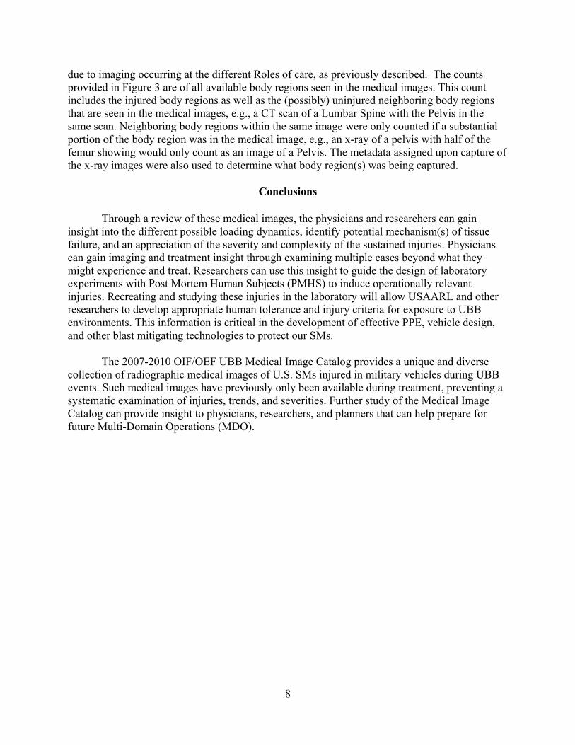
due to imaging occurring at the different Roles of care, as previously described. The counts provided in Figure 3 are of all available body regions seen in the medical images. This count includes the injured body regions as well as the (possibly) uninjured neighboring body regions that are seen in the medical images, e.g., a CT scan of a Lumbar Spine with the Pelvis in the same scan. Neighboring body regions within the same image were only counted if a substantial portion of the body region was in the medical image, e.g., an x-ray of a pelvis with half of the femur showing would only count as an image of a Pelvis. The metadata assigned upon capture of the x-ray images were also used to determine what body region(s) was being captured.
Conclusions
Through a review of these medical images, the physicians and researchers can gain insight into the different possible loading dynamics, identify potential mechanism(s) of tissue failure, and an appreciation of the severity and complexity of the sustained injuries. Physicians can gain imaging and treatment insight through examining multiple cases beyond what they might experience and treat. Researchers can use this insight to guide the design of laboratory experiments with Post Mortem Human Subjects (PMHS) to induce operationally relevant injuries. Recreating and studying these injuries in the laboratory will allow USAARL and other researchers to develop appropriate human tolerance and injury criteria for exposure to UBB environments. This information is critical in the development of effective PPE, vehicle design, and other blast mitigating technologies to protect our SMs.
The 2007-2010 OIF/OEF UBB Medical Image Catalog provides a unique and diverse collection of radiographic medical images of U.S. SMs injured in military vehicles during UBB events. Such medical images have previously only been available during treatment, preventing a systematic examination of injuries, trends, and severities. Further study of the Medical Image Catalog can provide insight to physicians, researchers, and planners that can help prepare for future Multi-Domain Operations (MDO).

9
References Association for the Advancement of Automotive Medicine. (2008). Abbreviated injury scale—
2005 update 2008. Chicago, IL: Edited by Gennarelli, T. A. & Wodzin, E.
King, A. I., Viano, D.C., Mizeres, N., & States, J.D. (1995). Humanitarian benefits of cadaver research on injury prevention. The Journal of Trauma and Acute Care Surgery, 38(4), 564-569.
Owens B. D., Kragh Jr., J.F., Wenke J.C., Macaitis J., Wade C.E., & Holcomb J.B. (2008). Combat wounds in Operation Iraqi Freedom and Operation Enduring Freedom. Journal of Trauma and Acute Care Surgery, 64(2):295-299.
Powers, T. E. Medical evacuations from Operation Iraqi Freedom (OIF) and Operation Enduring Freedom (OEF), active and reserve components, U.S. Armed Forces, October 2001-September 2009. MSMR. 2010;17(2):2-7.
Rupp, J. D., Flannagan, C. A. C., & Kuppa, S. M. (2010). An injury risk curve for the hip for use in frontal impact crash testing. Journal of Biomechanics, 43(3), 527-531.
Vasquez, K. B., Brozoski, F. T., Logsdon, K. P., & Chancey, V. C. (2018). Retrospective analysis of injuries in underbody blast events: 2007–2010. Military Medicine, 183(suppl_1), 347-352.

10
This page is intentionally blank.

11
Appendix A. Exemplar Injuries to the Head and Face Region
12
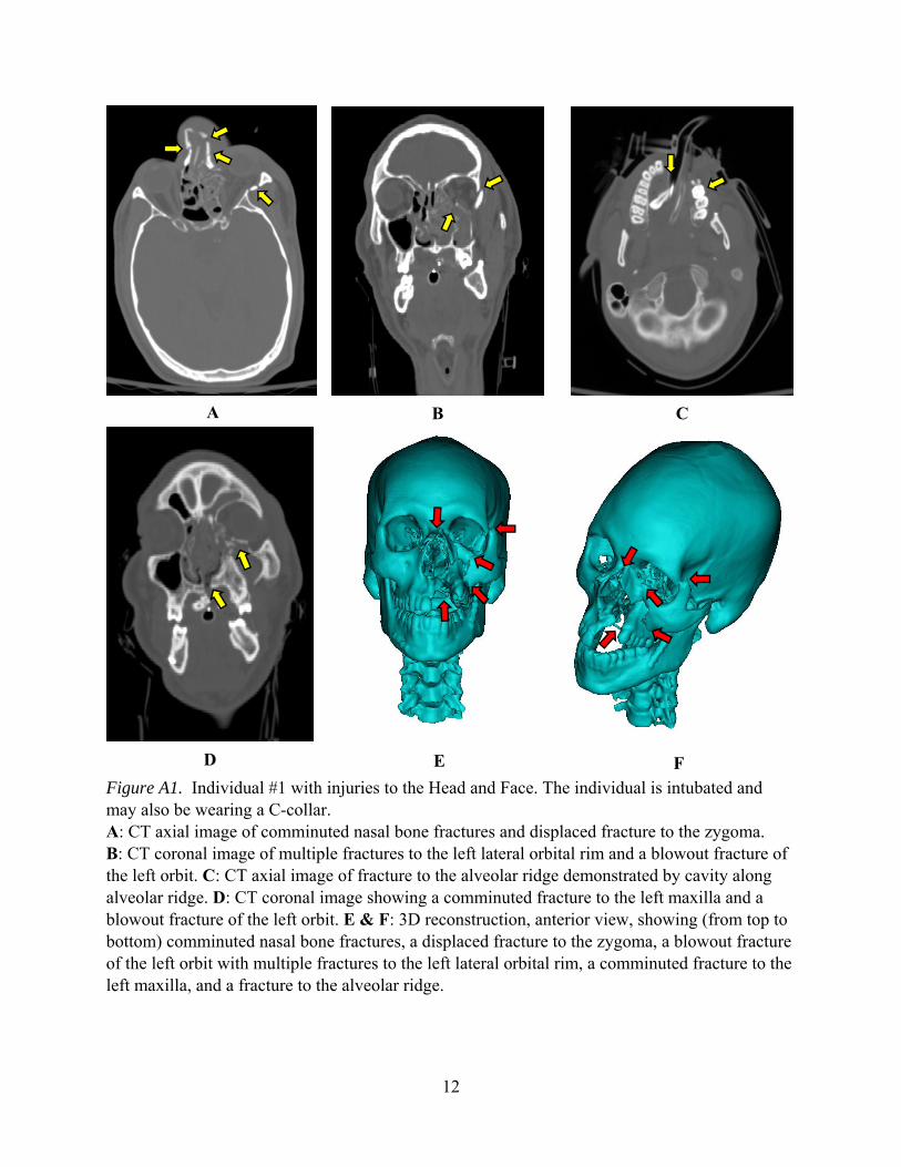
Figure A1. Individual #1 with injuries to the Head and Face. The individual is intubated and may also be wearing a C-collar. A: CT axial image of comminuted nasal bone fractures and displaced fracture to the zygoma. B: CT coronal image of multiple fractures to the left lateral orbital rim and a blowout fracture of the left orbit. C: CT axial image of fracture to the alveolar ridge demonstrated by cavity along alveolar ridge. D: CT coronal image showing a comminuted fracture to the left maxilla and a blowout fracture of the left orbit. E & F: 3D reconstruction, anterior view, showing (from top to bottom) comminuted nasal bone fractures, a displaced fracture to the zygoma, a blowout fracture of the left orbit with multiple fractures to the left lateral orbital rim, a comminuted fracture to the left maxilla, and a fracture to the alveolar ridge.
A B C
D
E
F
13
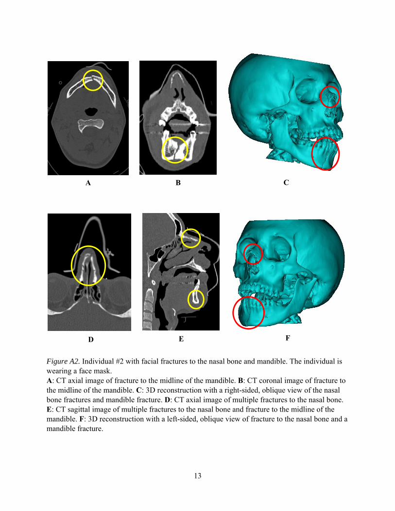
Figure A2. Individual #2 with facial fractures to the nasal bone and mandible. The individual is wearing a face mask. A: CT axial image of fracture to the midline of the mandible. B: CT coronal image of fracture to the midline of the mandible. C: 3D reconstruction with a right-sided, oblique view of the nasal bone fractures and mandible fracture. D: CT axial image of multiple fractures to the nasal bone. E: CT sagittal image of multiple fractures to the nasal bone and fracture to the midline of the mandible. F: 3D reconstruction with a left-sided, oblique view of fracture to the nasal bone and a mandible fracture.
A B
D E
C
F

14
This page is intentionally blank.

15
Appendix B. Exemplar Injuries to the Neck Region

16
Figure B1. Individual #1 with a fracture to the C5 vertebra. A: CT image showing a sagittal view of the anterior vertebral body fracture on the C5 vertebra. B: 3D reconstruction of anterior vertebral body fracture on the C5 vertebra.
A B

17
Figure B2. Individual #2 with a fracture to the C2 vertebra. A: X-ray image of vertebral fracture on the pedicle/facet of the C2 vertebra. B: CT coronal view of bilateral fractures on the pedicle/facet of the C2 Vertebra. C: CT sagittal view of fracture on the pedicle/facet of the C2 vertebra. D: CT axial view of bilateral fractures on the pedicle/facet of the C2 vertebra. E: 3D reconstruction of the C2 vertebra with bilateral fractures to the pedicle/facet.
A B C
D E

18
Figure B3. Individual #3 with fractures to the C7 vertebra. The individual is intubated and may also be wearing a C-collar. A: CT axial view of bilateral pedicle and lamina fractures on the C7 vertebra. B: CT coronal view of bilateral pedicle and lamina fractures on the C7 vertebra. C: 3D reconstruction of the posterior cervical spine showing bilateral pedicle and lamina fractures on the C7 vertebra.
A B C

19
Appendix C. Exemplar Injuries to the Torso Region

20
Figure C1. Individual #1 with a displaced fracture to the 6th rib on the left side. Ribs 4, 5, 7, and 11 may also be fractured on the left side; however, the CT is too pixelated to confirm. A: Axial CT image of displaced 6th rib fracture on the left side. B: 3D reconstruction of displaced fracture to the 6th rib on the left side. The reconstruction show T6-T12 with only the left side ribs constructed.
A
B
21
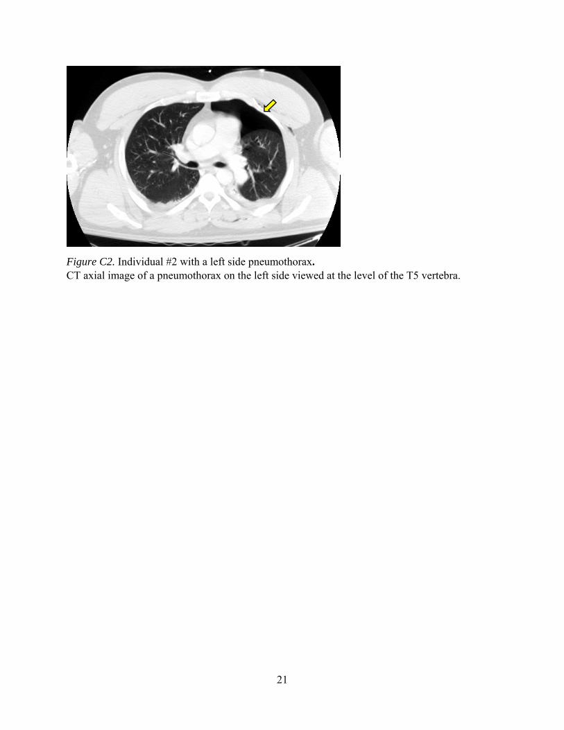
Figure C2. Individual #2 with a left side pneumothorax. CT axial image of a pneumothorax on the left side viewed at the level of the T5 vertebra.

22
Figure C3. Individual #3 with multiple fractures to the T5 vertebra and transverse process fractures on the left side of L1, L2, and L3 vertebrae. The T5 vertebral body has anterior wedging greater than 20%. A: CT sagittal view of burst fracture on the vertebral body of the T5 vertebra. T5 also has a bilateral transverse process fracture and a spinous process fracture. B: CT frontal view of a burst fracture on the vertebral body of the T5 vertebra. C: 3D reconstruction of a posterior view of the spinal column (from T2 to sacrum) showing a bilateral fracture to the transverse process and a fracture to spinous process on the T5 vertebra. D: 3D reconstruction of an anterior view of the spinal column (from T2 to sacrum) with a close-up of a burst fracture on the vertebral body of the T5 vertebra.
A
B C D

23
Appendix D. Exemplar Injuries to the Upper Extremities
24
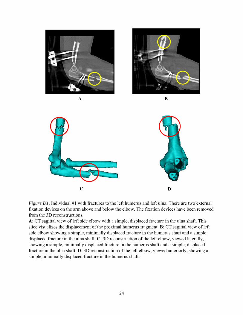
Figure D1. Individual #1 with fractures to the left humerus and left ulna. There are two external fixation devices on the arm above and below the elbow. The fixation devices have been removed from the 3D reconstructions. A: CT sagittal view of left side elbow with a simple, displaced fracture in the ulna shaft. This slice visualizes the displacement of the proximal humerus fragment. B: CT sagittal view of left side elbow showing a simple, minimally displaced fracture in the humerus shaft and a simple, displaced fracture in the ulna shaft. C: 3D reconstruction of the left elbow, viewed laterally, showing a simple, minimally displaced fracture in the humerus shaft and a simple, displaced fracture in the ulna shaft. D: 3D reconstruction of the left elbow, viewed anteriorly, showing a simple, minimally displaced fracture in the humerus shaft.
A B
C D
25
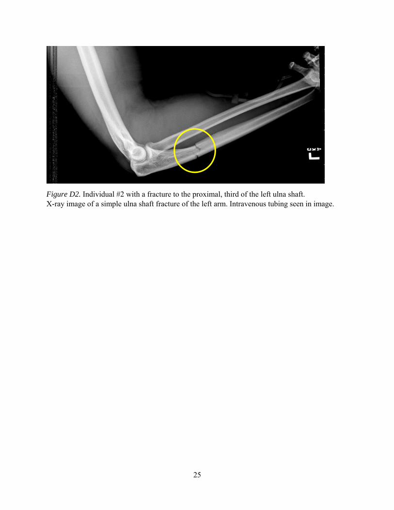
Figure D2. Individual #2 with a fracture to the proximal, third of the left ulna shaft. X-ray image of a simple ulna shaft fracture of the left arm. Intravenous tubing seen in image.
26
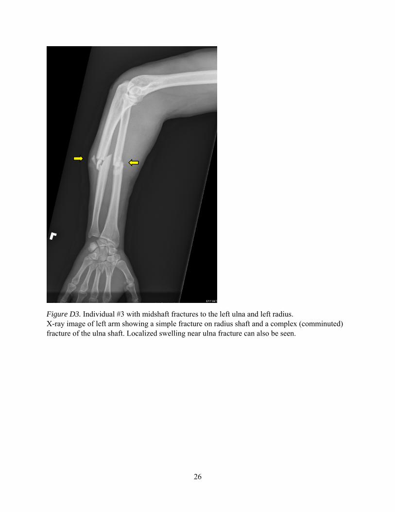
Figure D3. Individual #3 with midshaft fractures to the left ulna and left radius. X-ray image of left arm showing a simple fracture on radius shaft and a complex (comminuted) fracture of the ulna shaft. Localized swelling near ulna fracture can also be seen.

27
Appendix E. Exemplar Injuries to the Lumbar Spine
28
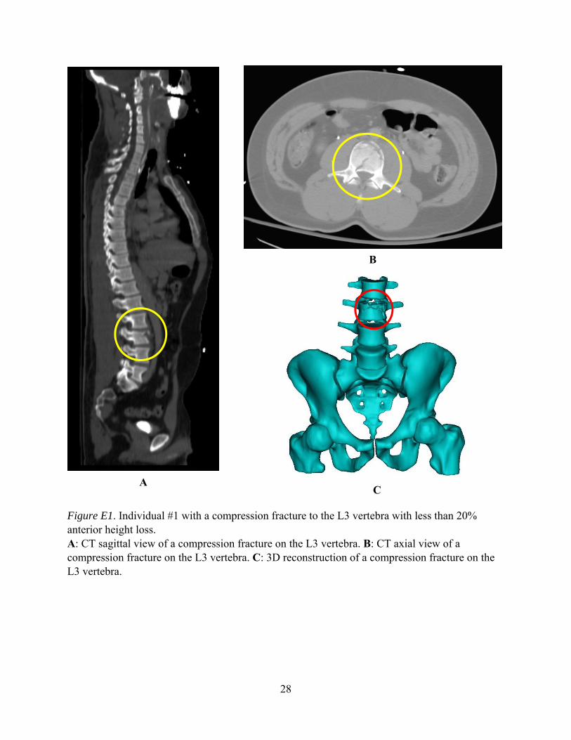
Figure E1. Individual #1 with a compression fracture to the L3 vertebra with less than 20% anterior height loss. A: CT sagittal view of a compression fracture on the L3 vertebra. B: CT axial view of a compression fracture on the L3 vertebra. C: 3D reconstruction of a compression fracture on the L3 vertebra.
A
B
C
29
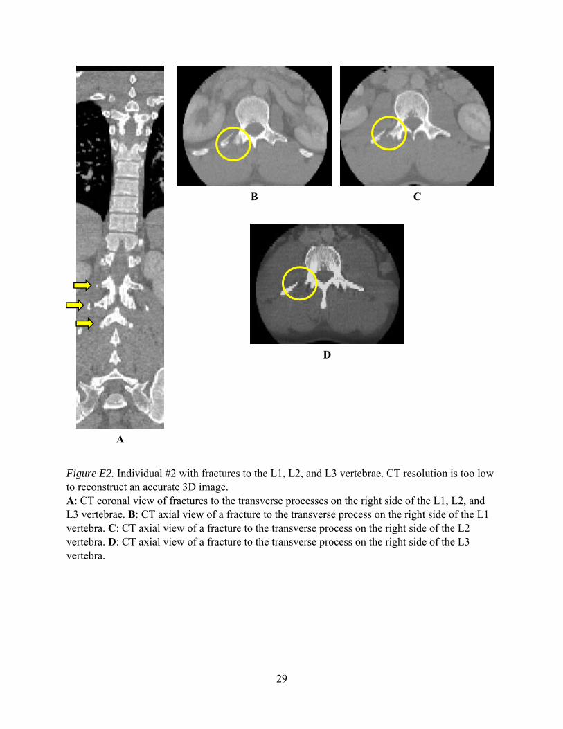
Figure E2. Individual #2 with fractures to the L1, L2, and L3 vertebrae. CT resolution is too low to reconstruct an accurate 3D image. A: CT coronal view of fractures to the transverse processes on the right side of the L1, L2, and L3 vertebrae. B: CT axial view of a fracture to the transverse process on the right side of the L1 vertebra. C: CT axial view of a fracture to the transverse process on the right side of the L2 vertebra. D: CT axial view of a fracture to the transverse process on the right side of the L3 vertebra.
A
B C
D

30
Figure E3. Individual #3 with burst fractures to the L1 and L4 vertebrae, a bilateral fracture to the transverse process on L1, and a fracture to the right side transverse process on L4. There may also be other transverse process fractures in the Lumbar Spine region, but definitive conclusions cannot be made for other fractures due to the poor resolution of the sagittal and coronal views of the CT. A: CT axial view of L1 vertebra with a burst fracture to the body and bilateral fractures to the transverse processes. B: CT axial view L4 vertebra with a burst fracture to the body and fracture to the right side transverse process. There is evidence of laparotomy in the CT, and material consistent with wound packing is seen in the image. C: 3D reconstruction of an anterior view of the lumbar column. L1 has a burst fracture and bilateral fractures to the transverse processes. L4 has a burst fracture and a fracture to the right side of the transverse process. D: 3D reconstruction showing the right side of the lumbar column. L1 and L4 have burst fractures. L1 and L4 also have fractures to the transverse processes.
A B
C D

31
Appendix F. Exemplar Injuries to the Pelvis Region

32
Figure F1. Individual #1 with multiple fractures to the left side of the pelvis. It is possible that other fractures are present; however, definitive conclusions cannot be made for other fractures due to the poor resolution of the sagittal and coronal views of the CT. A: CT axial view of a fracture of the superior pubic ramus on the left side of the pelvis. B: CT axial view of a fracture to the tuberosity on the left side of the pelvis. C: CT axial view of a fracture to the sacrum on the left side of the pelvis with separation to the left sacroiliac joint. D: 3D reconstruction of an anterior view of the pelvis with fractures to the sacrum, superior pubic ramus, and tuberosity on the left side. E: X-ray image showing an anterior-posterior view of unilateral fractures to the sacrum and pelvic ring. The pelvic ring is fractured at the superior pubic ramus and the tuberosity. External fixators can be seen in the image in addition to radiopaque materials.
A
B
C
D
E
33
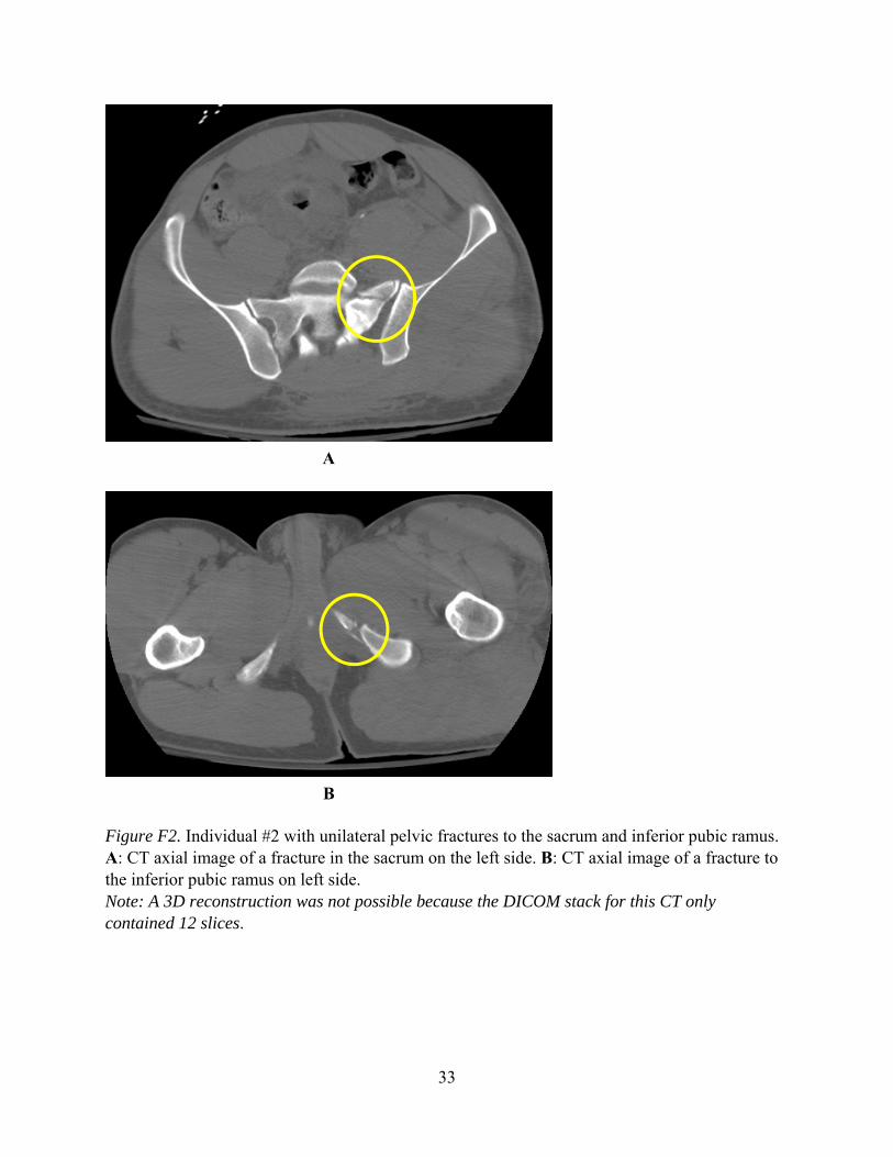
Figure F2. Individual #2 with unilateral pelvic fractures to the sacrum and inferior pubic ramus. A: CT axial image of a fracture in the sacrum on the left side. B: CT axial image of a fracture to the inferior pubic ramus on left side. Note: A 3D reconstruction was not possible because the DICOM stack for this CT only contained 12 slices.
A
B
34
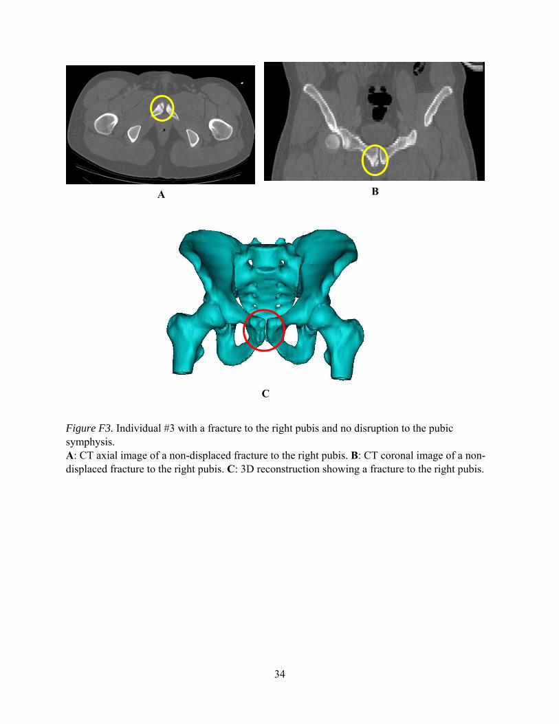
Figure F3. Individual #3 with a fracture to the right pubis and no disruption to the pubic symphysis. A: CT axial image of a non-displaced fracture to the right pubis. B: CT coronal image of a non-displaced fracture to the right pubis. C: 3D reconstruction showing a fracture to the right pubis.
A B
C

35
Appendix G. Exemplar Injuries to the Thigh
36
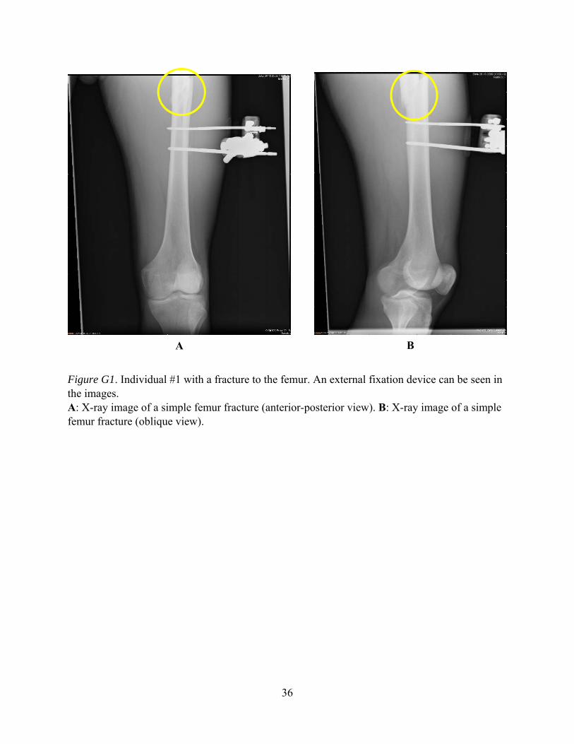
Figure G1. Individual #1 with a fracture to the femur. An external fixation device can be seen in the images. A: X-ray image of a simple femur fracture (anterior-posterior view). B: X-ray image of a simple femur fracture (oblique view).
A B

37
Figure G2. Individual #2 with fractures to the femur shaft and femoral neck on the right thigh. External fixation devices, bone screws, and surgical staples are seen in the images. A: X-ray image of femur fractures to the right thigh. When described from the proximal to distal aspect, there is a fracture to the femoral neck with bone screws in place and a simple fracture to the femur shaft. B: X-ray image of a simple fracture to the right femur shaft with external fixation devices available.
A B
38
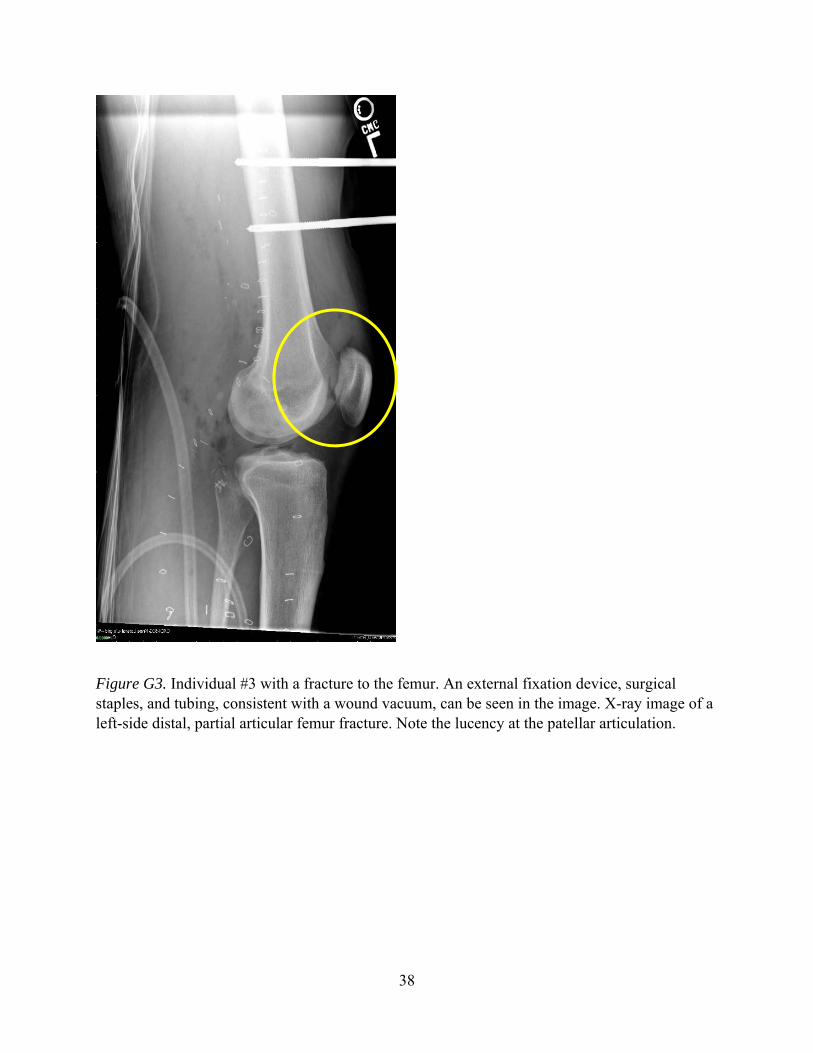
Figure G3. Individual #3 with a fracture to the femur. An external fixation device, surgical staples, and tubing, consistent with a wound vacuum, can be seen in the image. X-ray image of a left-side distal, partial articular femur fracture. Note the lucency at the patellar articulation.

39
Appendix H. Exemplar Injuries to the Lower Leg
40
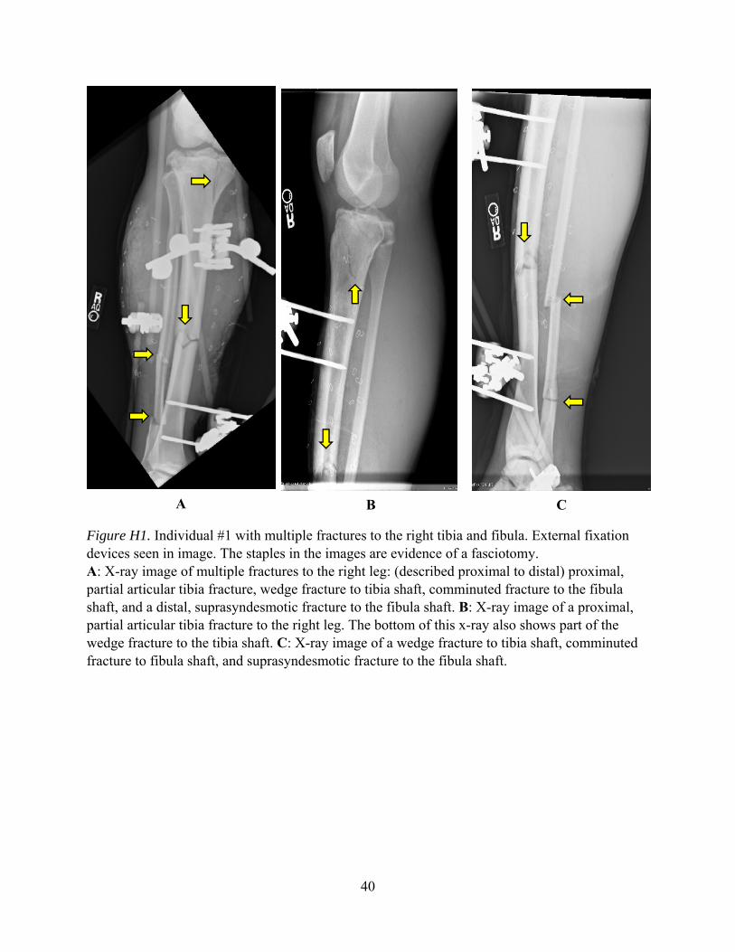
Figure H1. Individual #1 with multiple fractures to the right tibia and fibula. External fixation devices seen in image. The staples in the images are evidence of a fasciotomy. A: X-ray image of multiple fractures to the right leg: (described proximal to distal) proximal, partial articular tibia fracture, wedge fracture to tibia shaft, comminuted fracture to the fibula shaft, and a distal, suprasyndesmotic fracture to the fibula shaft. B: X-ray image of a proximal, partial articular tibia fracture to the right leg. The bottom of this x-ray also shows part of the wedge fracture to the tibia shaft. C: X-ray image of a wedge fracture to tibia shaft, comminuted fracture to fibula shaft, and suprasyndesmotic fracture to the fibula shaft.
A B C

41
Figure H2. Individual #2 with a fracture to the tibia on the right side. A: X-ray image of the right leg with a minimally displaced, comminuted fracture from mid to distal tibia. B: Lateral view of an x-ray image with a minimally displaced, comminuted fracture from the mid to distal tibia on the right leg.
A B
42
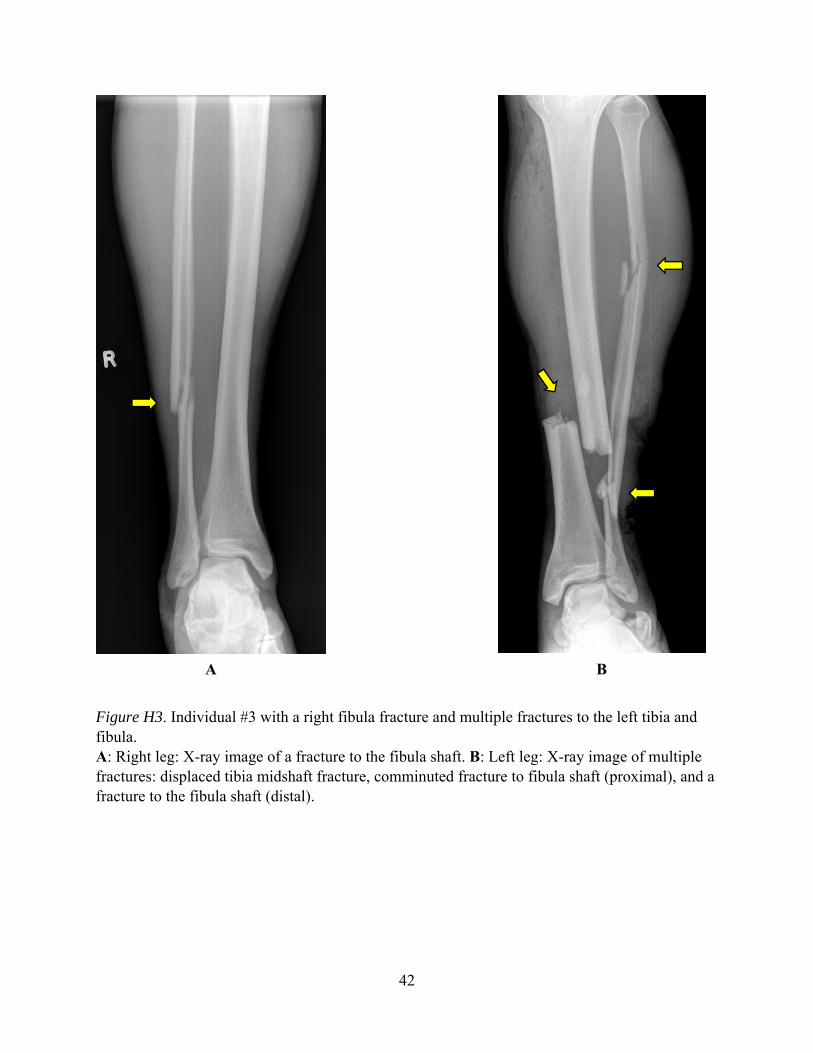
Figure H3. Individual #3 with a right fibula fracture and multiple fractures to the left tibia and fibula. A: Right leg: X-ray image of a fracture to the fibula shaft. B: Left leg: X-ray image of multiple fractures: displaced tibia midshaft fracture, comminuted fracture to fibula shaft (proximal), and a fracture to the fibula shaft (distal).
A B

43
Appendix I. Exemplar Injuries to the Foot and Ankle Region

44
Figure I1. Individual #1 with fractures to the calcaneus and tibia of the left foot and ankle. A: CT sagittal view of a left-side distal, comminuted tibia fracture (complete articular). B: 3D reconstruction (right lateral view) of a left distal, comminuted tibia fracture (complete articular). C: CT axial view of a left distal, comminuted tibia fracture (complete articular). D: CT sagittal view of a left-side, non-displaced calcaneus fracture. E: 3D reconstruction (left view) of a left-side fracture on the calcaneus. F: X-ray image of a left-side calcaneus fracture, and a left midshaft simple fibular fracture. External fixators seen in the image.
F
B
E
C
A
D

45
Figure I2. Individual #2 with fractures to the right calcaneus and talus. X-ray image of a right foot lateral view showing posterior process fracture of the talus (with one joint surface affected) and a displaced, comminuted fracture of the distal plantar aspect of the calcaneus.

46
Figure I3. Individual #3 with multiple fractures to the left and right feet and ankles. The CT of these injuries contains both feet. A cast on each foot can be seen in the CT images. A: CT sagittal view of the individual’s left foot with a calcaneus fracture. B: A CT sagittal view of the individual’s right foot with a calcaneus fracture, a talus fracture, and a navicular fracture. C: CT sagittal view of the individual’s right foot with a fracture to the 4th metatarsal. D: CT axial view of the left and right feet with bilateral calcaneus fractures. E: CT axial view of the individual’s left foot with a small fracture to the navicular.
A
D
B C
E

47
Figure I4. 3D reconstructions of the feet of individual #3, which contain multiple fractures. A: Right foot arrows (from left to right) show a calcaneus fracture, a talus fracture, and fractures to the 2nd and 3rd metatarsals. Left foot arrows (from left to right) show a calcaneus fracture and a fracture to 1st metatarsal. B: Right foot arrows (from left to right) show a fracture to the 2nd metatarsal, a talus fracture, a navicular fracture, and a calcaneus fracture. C: Right foot arrows (from top to bottom) show a talus fracture, a calcaneus fracture, a navicular fracture, and fractures to the 2nd and 3rd metatarsals. Left foot arrows (from top to bottom) show a calcaneus fracture and a fracture to the 1st metatarsal. D: Right foot arrows (from top to bottom) show a calcaneus fracture, a navicular fracture, a fracture to the intermediate cuneiform, and fractures to the 2nd and 3rd metatarsals. The left foot arrow shows a calcaneus fracture.
A B
D C

48
This page is intentionally blank.

49
Appendix J. Exemplar Images of One Killed in Action Individual
50
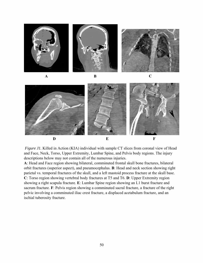
Figure J1. Killed in Action (KIA) individual with sample CT slices from coronal view of Head and Face, Neck, Torso, Upper Extremity, Lumbar Spine, and Pelvis body regions. The injury descriptions below may not contain all of the numerous injuries. A: Head and Face region showing bilateral, comminuted frontal skull bone fractures, bilateral orbit fractures (superior aspect), and pneumocephalus. B: Head and neck section showing right parietal vs. temporal fractures of the skull, and a left mastoid process fracture at the skull base. C: Torso region showing vertebral body fractures at T5 and T6. D: Upper Extremity region showing a right scapula fracture. E: Lumbar Spine region showing an L1 burst fracture and sacrum fracture. F: Pelvis region showing a comminuted sacral fracture, a fracture of the right pelvic involving a comminuted iliac crest fracture, a displaced acetabulum fracture, and an ischial tuberosity fracture.
A B C
D E F
51
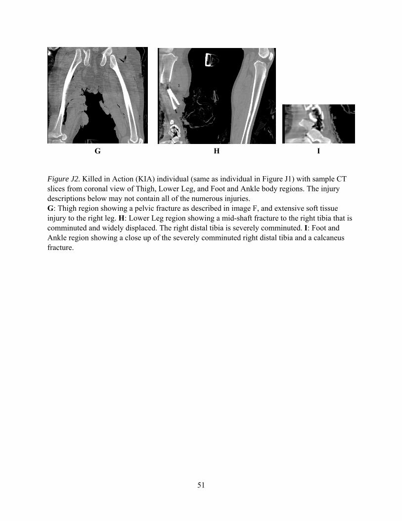
Figure J2. Killed in Action (KIA) individual (same as individual in Figure J1) with sample CT slices from coronal view of Thigh, Lower Leg, and Foot and Ankle body regions. The injury descriptions below may not contain all of the numerous injuries. G: Thigh region showing a pelvic fracture as described in image F, and extensive soft tissue injury to the right leg. H: Lower Leg region showing a mid-shaft fracture to the right tibia that is comminuted and widely displaced. The right distal tibia is severely comminuted. I: Foot and Ankle region showing a close up of the severely comminuted right distal tibia and a calcaneus fracture.
G H I


www.usaarl.army.mil
U.S. Army Medical Research and Materiel Command
Department of the ArmyU.S. Army Aeromedical Research Laboratory
Fort Rucker, Alabama 36362-0577