Characterization of friction properties at the workmaterial/cutting tool interface during the...
9
Characterization of friction properties at the work material/cutting tool interface during the machining of randomly structured carbon fibers reinforced polymer with Poly Crystalline Diamond tool under dry conditions Grégory Chardon a,n , Olga Klinkova b , Joël Rech a , Sylvain Drapier c , Jean-Michel Bergheau a a University of Lyon, Ecole Nationale d'Ingénieurs de Saint-Etienne, Laboratoire de Tribologie et Dynamique des Systèmes, CNRS UMR 5513, 58 rue Jean Parot, Saint-Etienne 42000, France b Ecole Nationale Supérieure des Mines de Saint-Etienne, Laboratoire de Tribologie et Dynamique des Systèmes, CNRS UMR 5513,158, cours Fauriel, Saint-Etienne 42023, France c Ecole Nationale Supérieure des Mines de Saint-Etienne, Laboratoire Georges Friedel, CNRS UMR 5307, 158, cours Fauriel, Saint-Etienne 42023, France article info Article history: Received 13 February 2014 Received in revised form 27 August 2014 Accepted 4 September 2014 Available online 22 September 2014 Keywords: Friction Composite materials Cutting abstract Carbon fiber reinforced polymers (CFRP) are increasingly employed within the aerospace industry. Therefore, a lot of Finite Element models have been developed in order to understand their material removal mechanisms. Among the scientific issues faced by these works, the identification of friction coefficients remains a strategic field of research. This paper aims at characterizing the friction properties between composite and cutting tool materials. The specific tribological conditions during machining of such heterogeneous materials are discussed in the paper, especially the configuration of the tribosystem. This paper presents the development of an original tribometer designed to simulate conditions corresponding to machining of randomly structured CFRP materials. It provides quantitative values of friction coefficient and heat partition coefficient depending on sliding velocities. & 2014 Elsevier Ltd. All rights reserved. 1. Introduction Composite materials such as carbon fiber reinforced polymer (CFRP) are increasingly used in industrial fields, such as aeros- pace, aircraft, automotive and sports, owing to their advantages in mechanical properties (higher specific strength and stiffness) com- pared with their low density. Most of composite products are made to near-net-shape. However, machining processes such as milling or drilling are frequently used to achieve dimensional tolerance and assembly requirements. Previous works have shown that machining composite materials differs significantly from machining conven- tional metals (matrix cracking, fiber fracture, interlaminar delamina- tion, etc.) due to the material properties of the fibers and to their heterogeneous structure [1–3]. The important material abrasiveness leads manufacturers to make use of hard substrates to limit rapid tool wear. Productivity improvement of machining operations requires the optimization of tool geometry and cutting conditions. In parallel, a lot of attention has to be paid on the surface integrity of machined parts, since cutting may induce functional problems [1]. Numerical modeling of cutting is a way to enable this optimization and to ensure the quality of machined surfaces. Among the key input data necessary to perform numerical models, a friction model between composite material and cutting tool material is required. However, obtaining realistic friction data in CFRP cutting remains an issue for several reasons. On one hand, due to the kinematic of a cutting operation, the workmaterial is separated in two parts (Fig. 1): the chip and the machined surface. From the chip point of view, the shearing zone is called the secondary shear zone. From the machined surface point of view, the shearing zone is called the rubbing zone or the third shear zone. In both cases, the surface of the workmaterial will be in contact with the cutting tool material during a very short period (typically some milliseconds) under very high pressure and velocity. Moreover, this surface will no longer be in contact with the cutting tool material. From the cutting tool point of view, there is a continuous flow of new workmaterial in these zones. This tribological situation corresponds to a so-called: ‘opened tribo- system’, which will be described later in the paper. The wide majority of tribometers are ‘closed tribosystem’, such as pin on disc systems, where a pin always rubs on the same part of a material. This situation is not suitable to provide relevant data for cutting applications. Indeed, there are very few tribometers able to simulate such ‘opened tribosystem’ [4]. On other hand, a CFRP is a heterogeneous material made of several orientated layers in the case laminated structure, or of several short fiber bundles in the case of randomly structured Contents lists available at ScienceDirect journal homepage: www.elsevier.com/locate/triboint Tribology International http://dx.doi.org/10.1016/j.triboint.2014.09.002 0301-679X/& 2014 Elsevier Ltd. All rights reserved. n Corresponding author. Tel.: þ33477437580. E-mail address: [email protected] (G. Chardon). Tribology International 81 (2015) 300–308
Transcript of Characterization of friction properties at the workmaterial/cutting tool interface during the...
Characterization of friction properties at the work material/cutting toolinterface during the machining of randomly structured carbon fibersreinforced polymer with Poly Crystalline Diamond tool underdry conditions
Grégory Chardon a,n, Olga Klinkova b, Joël Rech a, Sylvain Drapier c, Jean-Michel Bergheau a
a University of Lyon, Ecole Nationale d'Ingénieurs de Saint-Etienne, Laboratoire de Tribologie et Dynamique des Systèmes, CNRS UMR 5513, 58 rue Jean Parot,Saint-Etienne 42000, Franceb Ecole Nationale Supérieure des Mines de Saint-Etienne, Laboratoire de Tribologie et Dynamique des Systèmes, CNRS UMR 5513, 158, cours Fauriel,Saint-Etienne 42023, Francec Ecole Nationale Supérieure des Mines de Saint-Etienne, Laboratoire Georges Friedel, CNRS UMR 5307, 158, cours Fauriel, Saint-Etienne 42023, France
a r t i c l e i n f o
Article history:Received 13 February 2014Received in revised form27 August 2014Accepted 4 September 2014Available online 22 September 2014
Keywords:FrictionComposite materialsCutting
a b s t r a c t
Carbon fiber reinforced polymers (CFRP) are increasingly employed within the aerospace industry.Therefore, a lot of Finite Element models have been developed in order to understand their materialremoval mechanisms. Among the scientific issues faced by these works, the identification of frictioncoefficients remains a strategic field of research. This paper aims at characterizing the friction propertiesbetween composite and cutting tool materials. The specific tribological conditions during machining ofsuch heterogeneous materials are discussed in the paper, especially the configuration of the tribosystem.This paper presents the development of an original tribometer designed to simulate conditionscorresponding to machining of randomly structured CFRP materials. It provides quantitative values offriction coefficient and heat partition coefficient depending on sliding velocities.
& 2014 Elsevier Ltd. All rights reserved.
1. Introduction
Composite materials such as carbon fiber reinforced polymer(CFRP) are increasingly used in industrial fields, such as aeros-pace, aircraft, automotive and sports, owing to their advantages inmechanical properties (higher specific strength and stiffness) com-pared with their low density. Most of composite products are madeto near-net-shape. However, machining processes such as milling ordrilling are frequently used to achieve dimensional tolerance andassembly requirements. Previous works have shown that machiningcomposite materials differs significantly from machining conven-tional metals (matrix cracking, fiber fracture, interlaminar delamina-tion, etc.) due to the material properties of the fibers and to theirheterogeneous structure [1–3]. The important material abrasivenessleads manufacturers to make use of hard substrates to limit rapidtool wear. Productivity improvement of machining operationsrequires the optimization of tool geometry and cutting conditions.In parallel, a lot of attention has to be paid on the surface integrity ofmachined parts, since cutting may induce functional problems [1].Numerical modeling of cutting is a way to enable this optimization
and to ensure the quality of machined surfaces. Among the keyinput data necessary to perform numerical models, a friction modelbetween composite material and cutting tool material is required.However, obtaining realistic friction data in CFRP cutting remains anissue for several reasons. On one hand, due to the kinematic of acutting operation, the workmaterial is separated in two parts (Fig. 1):the chip and the machined surface. From the chip point of view,the shearing zone is called the secondary shear zone. From themachined surface point of view, the shearing zone is called therubbing zone or the third shear zone. In both cases, the surface of theworkmaterial will be in contact with the cutting tool material duringa very short period (typically some milliseconds) under very highpressure and velocity. Moreover, this surface will no longer be incontact with the cutting tool material. From the cutting tool point ofview, there is a continuous flow of new workmaterial in these zones.This tribological situation corresponds to a so-called: ‘opened tribo-system’, which will be described later in the paper. The wide majorityof tribometers are ‘closed tribosystem’, such as pin on disc systems,where a pin always rubs on the same part of a material. This situationis not suitable to provide relevant data for cutting applications.Indeed, there are very few tribometers able to simulate such ‘openedtribosystem’ [4]. On other hand, a CFRP is a heterogeneous materialmade of several orientated layers in the case laminated structure, orof several short fiber bundles in the case of randomly structured
Contents lists available at ScienceDirect
journal homepage: www.elsevier.com/locate/triboint
Tribology International
http://dx.doi.org/10.1016/j.triboint.2014.09.0020301-679X/& 2014 Elsevier Ltd. All rights reserved.
n Corresponding author. Tel.: þ33477437580.E-mail address: [email protected] (G. Chardon).
Tribology International 81 (2015) 300–308

structure. For each layer or short fiber bundles, fibers are oriented ina defined direction. Therefore, a cutting edge has to cut fibers havingvarious orientations. It is shown by [5] that the layer orientation mayinfluence friction at the tool/CFRP interface.
In the scientific literature, a lot of efforts has been made recently toinitiate the Finite Element Modeling of composite materials in order tounderstand the local material removal mechanisms. The wide majorityof these works considers the Coulomb model with a constantcoefficient [6–10] or does not consider any friction at all [11–14]. Thevalues of the friction coefficient reported vary between 0.1 [5], 0.15[8,15], 0.3 [6,10,16] and 0.5 [8,17] depending on the couple of materialsinvolved (tool material/nature of composite material). Other authorsconsider a coefficient of friction with respect to fibers orientation[10,18] from 0.09 to 0.9. Finally [5] has shown that the presence of acutting fluid can reduce the friction coefficient from 0.1 to 0.06 duringmachining of laminated CFRP with diamond cutting tools.
The identification conditions of friction coefficients are rarelyexplained in details, this makes it difficult to apply for other inves-tigations. In the field of tribology, several works consider the
friction of composites against metals or sapphire, which are notrelevant substrates for cutting tools [19,20]. Consequently, suchvalues are not usable to model cutting processes with PCD tools asconsidered in the present work.
Some works such as [9,10] have performed pin on disc testswith High Speed Steel pins (HSS) and a Glass FRP disc, which isnot a relevant tribological test as mentioned previously. Addi-tionally, the testing conditions (sliding velocity E0.008 m/s) donot make sense for CFRP machining. For example, [21] reports thatcutting speeds usually applied during machining of CFRP with HSStools are in the range from 10 to 40 m/min (0.16 to 0.66 m/s).Other works such as [5] have characterized the friction coeffi-cients between a laminated CFRP and a diamond tool under slidingvelocities up to 20 m/min (0.33 m/s).
Unfortunately most of the papers use friction coefficients whichhave not been identified by any friction test [6,7,8,16,17]. Only fewpapers have applied relevant friction conditions (i.e. measuredwith an opened tribosystem). It is only possible to mention thework done by Mondelin et al. [5] who have developed an opened
Fig. 1. Basic modeling of metal cutting.
Fig. 2. Manufacture of a part made of the HexTOOL™ composite material [26].
G. Chardon et al. / Tribology International 81 (2015) 300–308 301
tribometer specifically designed for laminated CFRP. However thissystem is limited to perform tests under sliding velocities up to20 m/min (0.33 m/s), which is quite low compared with industriallyexpected cutting speeds up to 800 m/min (13.33 m/s) for PCD toolsin a milling process.
As a summary, it can be stated, that there is no data alreadypublished in a scientific journal presenting friction coefficientsfor a randomly structured CFRP and a PCD tool, that have beenperformed on an opened tribometer under high sliding velocities upto 800 m/min (13.33 m/s). Such tribometers have already beendeveloped to characterize friction coefficients in metal cutting[4,22,23]. Indeed, standard substrates such as high speed steel orcarbide are more and more replaced by PCD because of its highhardness and resistance to wear [1–3]. In fact, carbide allows tomake inexpensive tools but his low resistance to wear is not suitablefor long machining or mass production [24–25]. PCD seems to be thebest industrial solution in machining CFRP. We can notice that singlecrystalline diamond is not suitable for cutting tools with large depthof cut because insert sizes are very limited.
In fact, a previous work by the same authors [15] enablescharacterizing friction coefficients between randomly structuredCFRP and carbide tools with sliding velocities up to 120 m/min(2 m/s). This paper follows and is a complement of this previouswork [15]. Consequently, the objective of this work is to adapt theprinciple of this tribometer to characterize friction coefficientsbetween randomly structured CFRP and PCD tools for a large rangeof sliding velocities (up to 800 m/min (13.33 m/s)).
2. Description of the experimental work
2.1. Description of CFRP structure
The HexTOOL™ material is a new composite solution for man-ufacturing molds to produce aerospace components. HexTOOL™uses Hexcel's established HexMCs technology. This product consistsof high strength carbon fiber, with a nominal fiber volume of 60%,and HexPly M61 BMI (bismaleimide) resin, at 40% resin volumecontent, cured at 190 1C in autoclave under 7 bar pressure. This is an
alternative to conventional tooling materials, including metal.Specifically developed for tooling, the M61 resin is toughened andmodified to reduce resin flow so that the pre-impregnated sectionsstay in place during tool cure to maintain their quasi-isotropic fiberdistribution. Compared with epoxy resins, this provides superiormachinability without distortion, permitting the manufacture ofmould with complex shapes and tight tolerances. The HexTOOL™
structure is presented in Fig. 2, where one can see the unidirectionalcarbon fiber pre-impregnated bundles of 50 mm length and 8 mmwidth presented in a quasi-isotropic orientation. The manufacturingprocess of composite components generally involves the lay-up ofpre-impregnated bundles onto a tool surface, vacuum baggingfollowed by autoclave cure. The lay-up process aims at obtainingthe desired composite mold thickness; it is done by stacking severalplies. The autoclave curing induces resin reticulation by applyingthe temperature cycle.
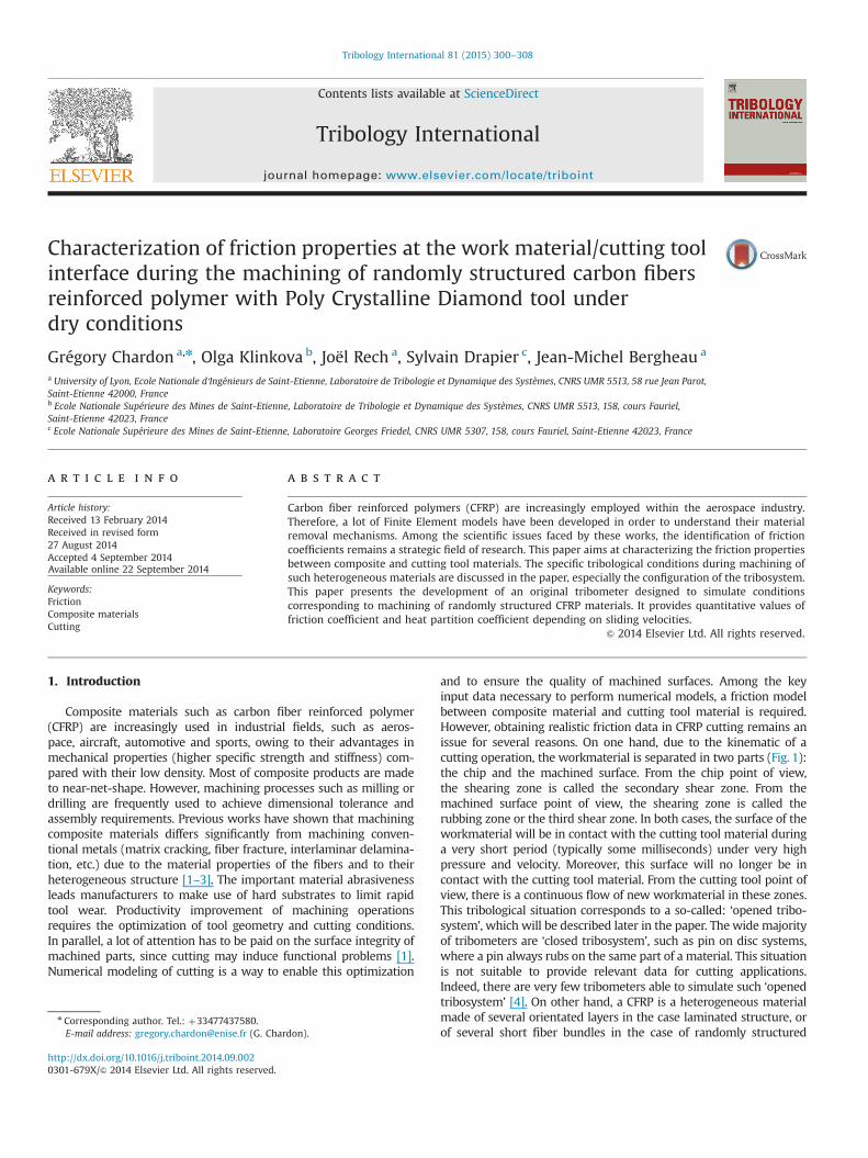
Once the composite mold is cured, the HexTOOL™ mold has arough surface. A machining operation is necessary so as to obtain asmooth and accurate surface. Fig. 3 shows an image of a section ata mesoscopic scale (view B) and at a microscopic scale (view C).The wavy structure is induced by the stacking of the rand-omly distributed fiber bundles during the lay-up process. After amachining operation, the structure appears as marbled with-out any specific orientation of fibers (view A). Hence machinedsurfaces can be considered as randomly structured.
2.2. Experimental set-up
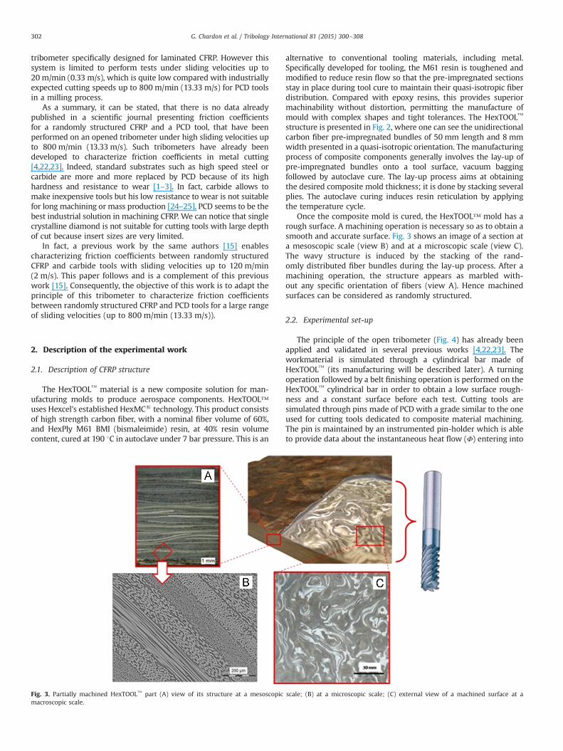
The principle of the open tribometer (Fig. 4) has already beenapplied and validated in several previous works [4,22,23]. Theworkmaterial is simulated through a cylindrical bar made ofHexTOOL™ (its manufacturing will be described later). A turningoperation followed by a belt finishing operation is performed on theHexTOOL™ cylindrical bar in order to obtain a low surface rough-ness and a constant surface before each test. Cutting tools aresimulated through pins made of PCD with a grade similar to the oneused for cutting tools dedicated to composite material machining.The pin is maintained by an instrumented pin-holder which is ableto provide data about the instantaneous heat flow (Φ) entering into
Fig. 3. Partially machined HexTOOL™ part (A) view of its structure at a mesoscopic scale; (B) at a microscopic scale; (C) external view of a machined surface at amacroscopic scale.
G. Chardon et al. / Tribology International 81 (2015) 300–308302
the pin. The detailed information about heat flowmeasuring systemcan be found in [23]. The pin-holder is fixed onto a dynamometer inorder to measure the normal force Fn and the tangential force Ft(macroscopic forces). The apparent friction coefficient mapp isprovided by the ratio between the tangential and the normal forces(Fig. 6), taken as an average value in the stable zone.
m app ¼ FtFn
ð1Þ
The term ‘apparent friction coefficient’ is used since it differssignificantly from the ‘interfacial friction coefficient’ induced byadhesion at the pin/workmaterial interface. Indeed the macroscopicforces measured by the tribometer include friction phenomena(adhesion–4madh), elastic deformation and plastic deformation ofthe workmaterial, which cannot be neglected under such severecontact conditions (FnE600 N). The identification of the evolutionof madh with the present data will be presented later in the paper.
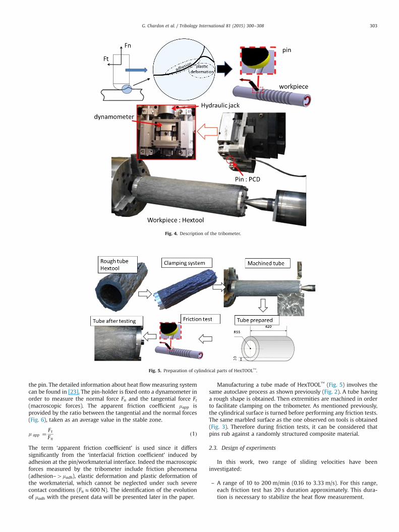
Manufacturing a tube made of HexTOOL™ (Fig. 5) involves thesame autoclave process as shown previously (Fig. 2). A tube havinga rough shape is obtained. Then extremities are machined in orderto facilitate clamping on the tribometer. As mentioned previously,the cylindrical surface is turned before performing any friction tests.The same marbled surface as the one observed on tools is obtained(Fig. 3). Therefore during friction tests, it can be considered thatpins rub against a randomly structured composite material.
2.3. Design of experiments
In this work, two range of sliding velocities have beeninvestigated:
– A range of 10 to 200 m/min (0.16 to 3.33 m/s). For this range,each friction test has 20 s duration approximately. This dura-tion is necessary to stabilize the heat flow measurement.
Fig. 4. Description of the tribometer.
Fig. 5. Preparation of cylindrical parts of HexTOOL™.
G. Chardon et al. / Tribology International 81 (2015) 300–308 303

– A range of 200 to 800 m/min (3.33 to 13.33 m/s) in accordancewith industrial cutting speed. For this range, the experimentalset-up does not provide a sufficient duration of friction tomeasure the heat flow. Indeed, from 200 m/min (3.33 m/s),duration of friction is below 10 s, so for this range, only thefriction coefficient is discussed.
Each velocity has been replicated at least three times so as toevaluate the deviations.
2.4. Estimation of interfacial friction coefficient
The apparent friction coefficient previously introduced in Eq. (1)can be decomposed into two components [27]
m app ¼ FtFn
¼ m adhþm def ð2Þ
where madh is the adhesive contribution and mdef is the deformationcontribution made up of elastic and plastic partitions. To extract thepart of adhesion and deformation from the apparent friction coeffi-cient, it is possible to rely on an analytical solution developed byLafaye et al. [28,29] (Fig. 6). This model depends on real contact mat-erial properties taking into account the elastic recovery. In this app-roach, the pin is considered as infinitely rigid and the workmaterial issupposed to be elasto-plastic. For each point of the contact surface,an elementary mechanical action is considered, which can be decom-posed into two parts, an elementary contact pressure:
P!
dS¼ PdS n! ð3Þ
and an elementary tangential force
τ!dS¼ τdS t! ð4Þ
which combine to yeld the elementary resulting force
dF�!¼ PdS n!þ τdS t
! ð5Þand eventually the resulting force acting on surface Sc
F!¼
ZScdF�! ð6Þ
where n! and t!
are, respectively, the normal and the tangential unitvector of the considered elementary surface, Sc is the effectivecontact surface area, which can be St or Sn standing for the contactsurface projection respectively in planes xy and yz. The interfacialfriction coefficient (adhesive friction coefficient) madh is defined by
m adh ¼τ
Pð7Þ
Thus, macroscopic normal and tangential forces, which aremeasured during friction tests, are the sum of elementarymechanical actions:
F!
n ¼ F!
: Z!� �
: Z!¼
ZScðPdS n!: Z
!þτdS t!
: Z!Þ: Z! ð8Þ
F!
t ¼ F!
:X!� �
:X!¼
ZScðPdS n!:X
!þτdS t!
:X!Þ:X! ð9Þ
These forces can be also written as
F!
n ¼ BP�Dτð Þ: Z! ð10Þ
F!
t ¼ APþCτð Þ:X! ð11Þ
Fig. 6. (a) Illustration of analytical parameters; (b) contact surfaces; (c) normally projected contact surface; (d) tangentially projected contact surface.
G. Chardon et al. / Tribology International 81 (2015) 300–308304
with
A¼D¼ZScðdS n!:X
!����
����¼ZScðdS t
!: Z!Þ
�������� ð12Þ
measure of the projection of the contact surface Sc along X-,
B¼ C ¼ZScðdS n!: Z
!����
����¼ZScðdS t
!:X!Þ
�������� ð13Þ
measure of the projection of the contact surface Sc along Z-.The contact area Sc is the sum of the front area (half of the disc
with radius R) and the rear area (part of the rear half disc). Theseprojected areas (Fig. 6c and d) are calculated using the analyticalsolution presented in [28] for spherical tip with elastic recovery.
Sn ¼ πþ2ωþsin2ωð Þa2=2 ð14Þ
Where ω is the rear contact angle, a is the contact radius
St ¼ R2�a2sin2ω� �
sin�1 acosω=r� ��acosω
ffiffiffiffiffiffiffiffiffiffiffiffiffiffiffiR2�a2
pð15Þ
where r¼ffiffiffiffiffiffiffiffiffiffiffiffiffiffiffiffiffiffiffiffiffiffiffiffiffiffiR2�a2sin2ω
pis the radius of projected area, R the
radius of the spherical tip.Therefore, the apparent friction coefficient may be written as a
function of the adhesive friction coefficient:
m app ¼: F!
t:
: F!
n:¼ APþCτBP�Dτ
¼ AþCm adh
B�Dm adhð16Þ
Finally, the adhesive friction coefficient can be calculated, basedon the effective contact area estimated from experimental mea-surements, as follows:
m app ¼Bm app�ACþDm app
ð17Þ
3. Results and discussion
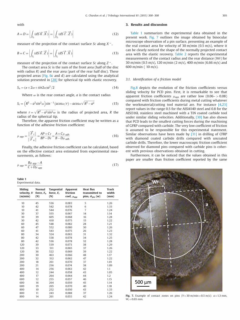
Table 1 summarizes the experimental data obtained in thepresent work. Fig. 7 outlines the image obtained by binocularmicroscope observation of a pin surface, presenting an example ofthe real contact area for velocity of 30 m/min (0.5 m/s), where itcan be clearly noticed the shape of the normally projected contactarea with the elastic recovery. Table 2 reports the experimentalmeasurements of the contact radius and the rear distance (Wr) for30 m/min (0.5 m/s), 120 m/min (2 m/s), 400 m/min (6.66 m/s) and600 m/min ( 10 m/s).
3.1. Identification of a friction model
Fig.8 depicts the evolution of the friction coefficients versussliding velocity for PCD pins. First, it is remarkable to see thatapparent friction coefficients mapp are rather low (0.06–40.08)compared with friction coefficients during metal cutting whateverthe workmaterial/cutting tool material are. For instance [4,23]report values in the range 0.5 for the AISI4140 steel and 0.8 for theAISI316L stainless steel machined with a TiN coated carbide toolunder similar sliding velocities. Additionally, [30] has also shownthat PCD leads to the smallest cutting forces during the machiningof GFRP compared with carbide. The very low coefficient of frictionis assumed to be responsible for this experimental statement.Similar observations have been made by [31] in drilling of CFRPwith diamond coated carbide drills compared with uncoatedcarbide drills. Therefore, the lower macroscopic friction coefficientobserved for diamond pins compared with carbide pins is coher-ent with previous observations obtained in cutting.
Furthermore, it can be noticed that the values obtained in thispaper are smaller than friction coefficient reported by the same
Table 1Experimental data.
Slidingvelocity, V(m/min)
Normalforce, Fn(N)
Tangentialforce, Ft(N)
Apparentfrictioncoef, lapp
Heat fluxtransmitted topins, Φpin (w)
Trackwidth(mm)
10 45 536 0.083 5 1.2610 42 542 0.078 6 1.3310 41 544 0.076 7 1.2430 37 555 0.067 14 1.1430 39 605 0.068 16 1.2830 42 610 0.075 15 1.2260 45 548 0.082 28 1.2160 47 552 0.080 30 1.2660 41 543 0.075 26 1.2380 34 524 0.063 31 1.3280 42 538 0.078 34 1.2580 42 536 0.078 32 1.28
120 39 539 0.073 38 1.29120 33 511 0.065 37 1.26120 36 522 0.069 39 1.22200 30 463 0.066 48 1.17200 32 512 0.062 47 1.22200 18 261 0.070 37 1.01200 21 256 0.074 38 1.09400 14 256 0.063 42 1.1400 12 244 0.058 43 1.05400 17 264 0.064 44 1.2600 12 255 0.057 46 1.15600 16 264 0.059 45 1.14600 19 265 0.070 40 1.18800 10 252 0.050 43 1.33800 11 243 0.088 37 1.26800 14 261 0.055 42 1.24 Fig. 7. Example of contact zones on pins (V¼30 m/min¼0.5 m/s): a¼1.3 mm,
Wr¼0.65 mm.
G. Chardon et al. / Tribology International 81 (2015) 300–308 305
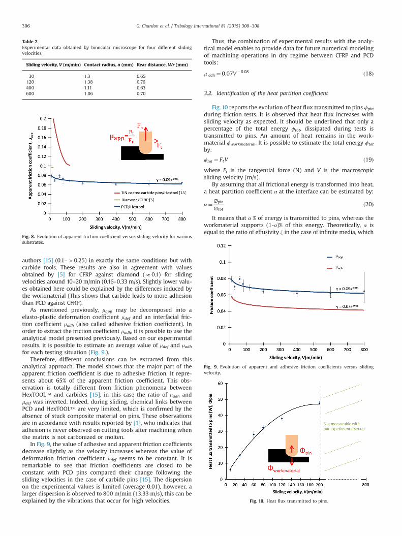
authors [15] (0.1–40.25) in exactly the same conditions but withcarbide tools. These results are also in agreement with valuesobtained by [5] for CFRP against diamond (E0.1) for slidingvelocities around 10–20 m/min (0.16–0.33 m/s). Slightly lower valu-es obtained here could be explained by the differences induced bythe workmaterial (This shows that carbide leads to more adhesionthan PCD against CFRP).
As mentioned previously, mapp may be decomposed into aelasto-plastic deformation coefficient mdef and an interfacial fric-tion coefficient madh (also called adhesive friction coefficient). Inorder to extract the friction coefficient madh, it is possible to use theanalytical model presented previously. Based on our experimentalresults, it is possible to estimate an average value of mdef and madhfor each testing situation (Fig. 9.).
Therefore, different conclusions can be extracted from thisanalytical approach. The model shows that the major part of theapparent friction coefficient is due to adhesive friction. It repre-sents about 65% of the apparent friction coefficient. This obs-ervation is totally different from friction phenomena betweenHexTOOL™ and carbides [15], in this case the ratio of madh andmdef was inverted. Indeed, during sliding, chemical links betweenPCD and HexTOOL™ are very limited, which is confirmed by theabsence of stuck composite material on pins. These observationsare in accordance with results reported by [1], who indicates thatadhesion is never observed on cutting tools after machining whenthe matrix is not carbonized or molten.
In Fig. 9, the value of adhesive and apparent friction coefficientsdecrease slightly as the velocity increases whereas the value ofdeformation friction coefficient mdef seems to be constant. It isremarkable to see that friction coefficients are closed to beconstant with PCD pins compared their change following thesliding velocities in the case of carbide pins [15]. The dispersionon the experimental values is limited (average 0.01), however, alarger dispersion is observed to 800 m/min (13.33 m/s), this can beexplained by the vibrations that occur for high velocities.
Thus, the combination of experimental results with the analy-tical model enables to provide data for future numerical modelingof machining operations in dry regime between CFRP and PCDtools:
m adh ¼ 0:07V �0:08 ð18Þ
3.2. Identification of the heat partition coefficient
Fig. 10 reports the evolution of heat flux transmitted to pins ϕpin
during friction tests. It is observed that heat flux increases withsliding velocity as expected. It should be underlined that only apercentage of the total energy ϕtot, dissipated during tests istransmitted to pins. An amount of heat remains in the work-material ϕworkmaterial. It is possible to estimate the total energy ϕtot
by:
ϕtot ¼ FtV ð19Þwhere Ft is the tangential force (N) and V is the macroscopicsliding velocity (m/s).
By assuming that all frictional energy is transformed into heat,a heat partition coefficient α at the interface can be estimated by:
α¼∅pin
∅totð20Þ
It means that α % of energy is transmitted to pins, whereas theworkmaterial supports (1-α)% of this energy. Theoretically, α isequal to the ratio of effusivity ξ in the case of infinite media, which
Table 2Experimental data obtained by binocular microscope for four different slidingvelocities.
Sliding velocity, V (m/min) Contact radius, a (mm) Rear distance, Wr (mm)
30 1.3 0.65120 1.38 0.76400 1.11 0.63600 1.06 0.70
Fig. 8. Evolution of apparent friction coefficient versus sliding velocity for varioussubstrates.
Fig. 9. Evolution of apparent and adhesive friction coefficients versus slidingvelocity.
Fig. 10. Heat flux transmitted to pins.
G. Chardon et al. / Tribology International 81 (2015) 300–308306
is defined in Eq. (20). ξ depends on the effusivity of the twomaterials when sliding at a very low velocity (some mm/s).
ξ¼ epinepinþeworkmaterial
� 0:96 at 201C ð21Þ
with pin's effusivity:
epin ¼ffiffiffiffiffiffiffiffiffiffiffiffiffiffiffiffiffiffiffiffiffiffiffiλpinρpinCpin
q� 50000 ðN m�1 1C�1 s�1=2Þ at 201C ð22Þ
where λ is the thermal conductivity (W m�1 1C�1), ρ is the density(kg m�3), C is the specific heat (J.kg�1 1C�1) and the workmaterialeffusivity:
eworkmaterial ¼ffiffiffiffiffiffiffiffiffiffiffiffiffiffiffiffiffiffiffiffiffiffiffiffiffiffiffiffiffiffiffiffiffiffiffiffiffiffiffiffiffiffiffiffiffiffiffiffiffiffiffiffiffiffiffiffiffiffiffiffiffiffiffiffiffiffiffiffiffiffiλworkmaterialρworkmaterialCworkmaterial
p� 2333ðN m�1 1C�1:s�1=2Þ at 201C ð23ÞUnfortunately, for dynamic sliding interfaces, the standard
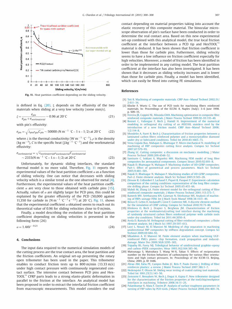
thermal model is no more valid. Therefore, Fig. 11 reports theexperimental values of the heat partition coefficient α as a functionof sliding velocity. One can notice that decreases with slidingvelocity which is a similar trend as the one observed for metal [4].Furthermore, the experimental values of the heat partition coeffi-cient α are very close to those obtained with carbide pins [15].Actually, values of α are slightly larger for PCD pins, this could beexplained by the greater effusivity of the PCD (50,000 against11,350 for carbide in (N m�1 1C�1 s�1/2) at 20 1C). Fig. 11. showsthat the experimental coefficient α obtained seems to reach out itstheoretical value of 0.96 for sliding velocities close to 0 m/min.
Finally, a model describing the evolution of the heat partitioncoefficient depending on sliding velocities is presented in thefollowing form (24):
α¼ 1:44V �0:21 ð24Þ
4. Conclusions
The input data required to the numerical simulation models ofthe cutting process are the true contact area, the heat partition andthe friction coefficients. An original set-up presenting the rotaryopen tribometer has been used in the paper. This tribometerenables to conduct friction tests up to 800 m/min (13.33 m/s)under high contact pressure with continuously regenerated con-tact surface. The intensive contact between PCD pins and Hex-TOOL™ CFRP parts leads to a strong elasto-plastic deformation inparallel to the friction at the interface. An analytical model hasbeen proposed in order to extract the interfacial friction coefficientfrom macroscopic measurements. This model considers the real
contact depending on material properties taking into account theelastic recovery of this composite material. The binocular micro-scope observation of pin's surface have been conducted in order todetermine the real contact area. Based on this new experimentalset-up combined with this analytical model, the true local frictioncoefficient at the interface between a PCD tip and HexTOOL™
material is deduced. It has been shown that friction coefficient islower than those for carbide pins. Futhermore, sliding velocityseems to have a low influence on friction coefficient especially forhigh velocities. Moreover, a model of friction has been identified inorder to be implemented in any cutting model. The heat partitioncoefficient at the interface has also been investigated. It has beenshown that it decreases as sliding velocity increases and is lowerthan those for carbide pins. Finally, a model has been identified,which can easily be fitted into cutting FE simulations.
References
[1] Teti R. Machining of composite materials. CIRP Ann—Manuf Technol 2002;51/2:611–34.
[2] Klocke F, Wurtz C. The use of PCD tools for machining fibers reinforcedmaterials. In: Proceedings of the ECCM. 8, Naples (Italy); 3–6 June 1998.p. 509–15.
[3] Ferreira JR, Coppini NL, Miranda GWA. Machining optimization in composite fibrereinforced composite materials. J Mater Process Technol 1999;92–93:135–40.
[4] Bonnet C, Valiorgue F, Rech J, Hamdi H. Improvement of the numericalmodeling in orthogonal dry cutting of an AISI316L stainless steel by theintroduction of a new friction model. CIRP Ann—Manuf Technol 2008;1/2:114–8.
[5] Mondelin A, Furet B, Rech J. Characterisation of friction properties between alaminated carbon fibers reinforced polymer and a monocrystalline diamondunder dry or lubricated conditions. Tribol Int 2010;43:1665–73.
[6] Venu Gopala Rao, Mahajan G, Bhatnagar P, Micro-mechanical N. modelling ofmachining of FRP composites cutting force analysis. Compos Sci Technol2007;67:579–93.
[7] Zhang LC. Cutting composite: a discussion on mechanics modelling. J MaterProcess Technol 2009;209:4548–52.
[8] Santiuste C, Soldani X, Miguelez MH. Machining FEM model of long fibrecomposites for aeronautical components. Compos Struct 2010;92:691–8.
[9] Nayak D, Bhatnagar N, Mahajan P. Machining studies of UD-GFRP composites.Part-1. Effect of geometrical and process parameters. Mach Sci Technol2005;9:481–501.
[10] Nayak D, Bhatnagar N, Mahajan P. Machining studies of UD-GFRP composites.Part-2. Finite element analysis. Mach Sci Technol 2005;9:503–28.
[11] Zitoune R, Collombet F, Lachaud F, Piquet R, Pasquet P. Experiment-calculationcomparison of the cutting conditions representative of the long fibre compo-site drilling phase. Compos Sci Technol 2005;65:455–66.
[12] Mahdi M, Zhang LA. Finite element model for the orthogonal cutting of fibrereinforced composite materials. J Mater Process Technol 2001;113:373–7.
[13] Ramesh MV, Seetharamu KN, Ganesan N, Shivkumar MS. Analysis of machin-ing of FRPs usinage FEM. Int J Mach Tools Manuf 1998;38:1531–49.
[14] Iliescu D, Gehin D, Iordanoff I, Girot F, Gutteriez ME. A discrete element methodfor the simulation of CFRP cutting. Compos Sci Technol 2010;70:73–80.
[15] Klinkova O, Rech J, Drapier S, Bergheau JM. Characterization of frictionproperties at the workmaterial/cutting tool interface during the machiningof randomly structured carbon fibers reinforced polymer with carbide toolsunder dry conditions. Tribol Int 2011;44:2050–8.
[16] Arola D, Ramulu M. Orthogonal cutting of fiber-reinforced composites: a finiteelement analysis. Int J Mech Sci 1997;39:597–613.
[17] Lasri L, Nouari M, El Mansori M. Modeling of chip separation in machiningunidirectional FRP composites by stiffness degradation concept. Compos SciTechnol 2009;69:684–92.
[18] Mkaddem A, El Mansori M. Finite element analysis when machining UGF-reinforced PMCs plates: chip formation, crack propagation and induced-damage. Mater Des 2009;30/8:3295–302.
[19] Tripathy BS, Furey MJ. Triboligical behavior of unidirectional graphite–epoxyand carbon–PEEK composites. Wear 1993;162/164:385–96.
[20] Matsunaga S, Matsubara T, Wang W-X, Takao Y. Effects of reciprocationnumber on the friction behaviors of carbon/epoxy for various fiber orienta-tions and high contact pressures. In: Proceedings of the ICCM-13. Beijing,China; 2001, p. ID 1446.
[21] Abrao AM, Faria PE, Campos Rubio JC, Reis P, Paulo Davim J. Drilling of fibrereinforces plastics: a review. J Mater Process Technol 2007;186:1–7.
[22] Hedenqvist P, Olsson M. Sliding wear testing of coated cutting tool materials.Tribol Int 1991;23(3):143–50.
[23] Zemzemi F, Bensalem W, Rech J, Dogui A, Kapsa P. New tribometer designedfor the characterization of the friction properties at the tool/chip/workpieceinterfaces in machining. Tribotest 2008;14:11–25.
[24] Palanikumar K, Mata F, Davim JP. Analysis of surface roughness parameters inturning of FRP tubes by PCD tools. J Mater Process Technol 2008;204:469–74.
Fig. 11. Heat partition coefficient depending on the sliding velocity.
G. Chardon et al. / Tribology International 81 (2015) 300–308 307

[25] Petropoulos G, Mata F, Davim JP. Statistical study of surface roughness inturning of peek composites. Mater Des 2008;29:218–23.
[26] Hexcel Composites. HexTOOL™ User Guide, 2008.[27] Bowden FP, Tabor D. Friction and lubrication of solids. Oxford University Press;
1951.[28] Lafaye S, Gauthier C, Schirrer R. The ploughing friction: analytical model with
elastic recovery for a conical tip with a blunted spherical extremity. Tribol Lett2006;21/2:95–9.
[29] Lafaye S, Gauthier C, Schirrer R. A surface flow line model of a scratching tip:apparent and true local friction coefficients. Tribol Int 2005;38:113–27.
[30] Sang-Ook A, Lee ES, Noh SL. A study on the cutting characteristics of GFRPwith respect to tool materials and geometries. J Mater Process Technol1997;68:60–7.
[31] Iliescu D, Gehin D, Gutierrez ME, Girot F. Modeling and tool wear in drilling ofCFRP. Int J Mach Tool Manuf 2010;50:204–13.
G. Chardon et al. / Tribology International 81 (2015) 300–308308