Chapter 52 – Diving Systems January 2020 - Türk Loydu
163
Chapter 52 – Diving Systems January 2020 This latest edition incorporates all rule changes. The latest revisions are shown with a vertical line. The section title is framed if the section is revised completely. Changes after the publication of the rule are written in red colour. Unless otherwise specified, these Rules apply to ships for which the date of contract for construction as defined in TL- PR 29 is on or after 1 st of January 2020. New rules or amendments entering into force after the date of contract for construction are to be applied if required by those rules. See Rule Change Notices on TL website for details. "General Terms and Conditions" of the respective latest edition will be applicable (see Rules for Classification and Surveys). If there is a difference between the rules in English and in Turkish, the rule in English is to be considered as valid. This publication is available in print and electronic pdf version. Once downloaded, this document will become UNCONTROLLED. Please check the website below for the valid version. http:/www.turkloydu.org All rights are reserved by Türk Loydu, and content may not be reproduced, disseminated, published, or transferred in any form or by any means, except with the prior written permission of TL.
-
Upload
khangminh22 -
Category
Documents
-
view
3 -
download
0
Transcript of Chapter 52 – Diving Systems January 2020 - Türk Loydu

Chapter 52 – Diving Systems
January 2020
This latest edition incorporates all rule changes. The latest revisions are shown with a vertical line. The section title is framed if the section is revised completely. Changes after the publication of the rule are written in red colour. Unless otherwise specified, these Rules apply to ships for which the date of contract for construction as defined in TL- PR 29 is on or after 1st of January 2020. New rules or amendments entering into force after the date of contract for construction are to be applied if required by those rules. See Rule Change Notices on TL website for details. "General Terms and Conditions" of the respective latest edition will be applicable (see Rules for Classification and Surveys). If there is a difference between the rules in English and in Turkish, the rule in English is to be considered as valid. This publication is available in print and electronic pdf version. Once downloaded, this document will become UNCONTROLLED. Please check the website below for the valid version.
http:/www.turkloydu.org
All rights are reserved by Türk Loydu, and content may not be reproduced, disseminated, published, or transferred in any form or by any means, except with the prior written permission of TL.
TÜRK LOYDU
Head Office Postane Mah. Tersaneler Cad. No:26 Tuzla 34944 İSTANBUL / TÜRKİYE
Tel : (90-216) 581 37 00
Fax : (90-216) 581 38 00
E-mail : [email protected]
http://www.turkloydu.org
Regional Offices
Ankara Eskişehir Yolu Mustafa Kemal Mah. 2159. Sokak No : 6/4 Çankaya - ANKARA / TÜRKİYE
Tel : (90-312) 219 56 34 - 219 68 25
Fax : (90-312) 219 69 72
E-mail : [email protected]
İzmir Atatürk Cad. No :378 K.4 D.402 Kavalalılar Apt. 35220 Alsancak - İZMİR / TÜRKİYE
Tel : (90-232) 464 29 88
Fax : (90-232) 464 87 51
E-mail : [email protected]
Adana Çınarlı Mah. Atatürk Cad. Aziz Naci İş Merkezi No:5 K.1 D.2 Seyhan - ADANA / TÜRKİYE
Tel : (90- 322) 363 30 12
Fax : (90- 322) 363 30 19
E-mail : [email protected]
Contents
Diving Systems
Page Section 1 - Classification And Certification of Diving Systems and Diving Simulators
A. Scope of Application .......................................................................................................................................... 1- 2
B. Classification And Character of Classification .................................................................................................... 1- 2
C. Classıfıcatıon of Diving Systems Buılt or Converted Under The Survey of And
in Accordance Wıth The Rules of TL ................................................................................................................. 1- 3
D. Classıfıcatıon Of Dıvıng Systems Not Buıld Under The Survey of TL ............................................................... 1- 4
E. Surveys For Maıntenance Of Class ................................................................................................................... 1- 5
F. Surveys Other Than For Classıfıcatıon. ............................................................................................................ 1- 8
G. Certıfıcatıon ....................................................................................................................................................... 1- 8
H. Workmanship ..................................................................................................................................................... 1- 9
Section 2 - Rules for Construction of Diving Systems
A. General Principles ............................................................................................................................................. 2- 4
B. Rules And Regulations to be Considered .......................................................................................................... 2- 4
C. Definitions .......................................................................................................................................................... 2- 4
D. Environmental Conditions .................................................................................................................................. 2- 7
E. Documents For Approval ................................................................................................................................... 2- 8
F. Failure Modes And Effects Analysis (FMEA) ..................................................................................................... 2-12
G. Tests And Trials ................................................................................................................................................. 2-14
H. Marking .............................................................................................................................................................. 2-18
I. Principles For The Design And Construction Of Diving Systems ....................................................................... 2-20
J. Vessels And Apparatus Under Pressure ............................................................................................................ 2-21
K. Pipes, Valves, Fittings, Hoses, Umbilicals ......................................................................................................... 2-29
L. Compressors ..................................................................................................................................................... 2-32
M. Life Support Systems ......................................................................................................................................... 2-33
N. Electrical Equipment .......................................................................................................................................... 2-38
O. Automation, Communication And Locating Equipment ...................................................................................... 2-48
P. Fire Protection ................................................................................................................................................... 2-54
Q. Launch, Recovery, Transfer And Mating Systems ............................................................................................. 2-56
R. Hyperbaric Evacuation System .......................................................................................................................... 2-60
S. Wet Bells ............................................................................................................................................................ 2-63
Section 3 - Rules for Construction of Diving Simulators
A. General Rules And Instructions ......................................................................................................................... 3- 2
B. Principles Of Design And Construction Of Diving Simulators ............................................................................ 3- 8
C. Vessels And Apparatus Under Pressure ............................................................................................................ 3- 10
D. Pipes, Valves, Fittings, Hoses, Umbilicals ........................................................................................................ 3- 12
E. Compressors ..................................................................................................................................................... 3- 12
F. Life Support Systems ......................................................................................................................................... 3- 12
G. Electrical Installations ....................................................................................................................................... 3-17
H. Automation Equipment And Communication Equipment .................................................................................. 3-17
I. Fire Protection ................................................................................................................................................... 3-17
J. Hyperbaric Evacuation System ........................................................................................................................ 3-17

Contents
Section 4 - Rules for Construction of Diver Pressure Chambers
A. General Rules and Instructions .......................................................................................................................... 4- 2
B. Principles of Design And Construction ............................................................................................................... 4- 4
Annex A Calculation of The Pressure Hull
A. General ............................................................................................................................................................... A-2
B. Fatigue Strength ................................................................................................................................................ A-3
C. Stresses at Nominal Diving Pressure ................................................................................................................ A-3
D. Stresses at Test Diving Pressure ....................................................................................................................... A-3
E. Proof of Ultimate Strength at Collapse Diving Pressure ..................................................................................... A-3
F. Calculation .......................................................................................................................................................... A-4
G. Literature .......................................................................................................................................................... A-22
Annex B Manufacturing Tolerances for the Pressure Hull
A. General .............................................................................................................................................................. B- 2
B. Dimensions of the Pressure Hull ....................................................................................................................... B- 2
C. Pressure Hull Frames ........................................................................................................................................ B- 4
D. Out-Of-Roundness of the Cylindrical Resp. Conical Pressure Hull .................................................................. B- 5
E. Spherical Shells and Dished Ends ..................................................................................................................... B- 9
F. Literature ........................................................................................................................................................ B- 11
Annex C Acrylic Windows
A. General ............................................................................................................................................................... C-2
B. Materials ............................................................................................................................................................. C-2
C. Manufacture of Windows .................................................................................................................................... C-3
D. Window Shapes And Sizes ................................................................................................................................ C-3
E. Installation of Windows .................................................................................................................................... C- 4
Annex D Manufacture And Treatment Of Fibre Reinforced Plastics (Frp)
A. General .............................................................................................................................................................. D- 2
B. Requirements For The Materials And Their Processing .................................................................................... D- 2
C. Requirements For The Design ............................................................................................................................ D- 3
Annex E Basic Requirements For Umbilicals
A. General ............................................................................................................................................................... E- 2
B. Principles For Layout And Design ...................................................................................................................... E- 2
C. Documents For Approval .................................................................................................................................... E- 7
D. Tests And Trials .................................................................................................................................................. E- 7
E. Marking ............................................................................................................................................................... E- 9

Section 1- Classification and Certification of Diving Systems and Diving Simulators 1-1
TÜRK LOYDU – DIVING SYSTEMS – JANUARY 2020
SECTION 1
CLASSIFICATION and CERTIFICATION of DIVING SYSTEMS and DIVING SIMULATORS
Page
A. SCOPE of APPLICATION..................................................................................................................................1- 2
1. General
2. Diving Systems
3. Diving Simulators
4. Diver Pressure Chambers
B. CLASSIFICATION and CHARACTERS of CLASSIFICATION ........................................................................ 1- 2
1. Classification
2. Characters of Classification
3. Duration of Class
C. CLASSIFICATION of DIVING SYSTEMS BUILT or CONVERTED UNDER the SURVEY
of and in ACCORDANCE WITH THE RULES OF TL........................................................................................1- 3
1. General
2. Supervision During Construction
D. CLASSIFICATION of DIVING SYSTEMS not BUILD UNDER the SURVEY of TL ......................................... 1- 4
1. General
2. Procedure of Admission to Class
E. SURVEYS for MAINTENANCE of CLASS ....................................................................................................... 1- 5
1. Kinds of Surveys
2. Explanatory Notes on Surveys
3. Performance of Surveys
F. SURVEYS OTHER THAN for CLASSIFICATION..............................................................................................1- 8
1. Surveys by Special Agreement
2. Surveys Relating to the Safety of Equipment
G. CERTIFICATION..................................................................................................................................................1- 8
1. General
2. Certification According to TL Rules
3. Certification According to Other Rules
H. WORKMANSHIP..................................................................................................................................................1- 9
1. General
2. Details in Manufacturing Documents

1-2 Section 1- Classification and Certification of Diving Systems and Diving Simulators A,B
TÜRK LOYDU – DIVING SYSTEMS – JANUARY 2020
A. Scope of Application
1. General
These Rules are valid for the construction of diving
systems, diving simulators, diver pressure chambers
and the systems necessary for operation, which shall be
classified (see B. - F.) or Certified (see G.) by TL.
These Rules can be used in analogous way for manned
pressure chambers for other applications, like e.g.
compressed air and caisson works.
2. Diving systems
For the purpose of these Rules, systems for supporting
diver operations which are permanently installed on a
diver support ship, a similar floating structure or an
offshore plant respectively which are assembled for the
actual duty of a mission and are installed for a limited
period, are diving systems.
Diver launching systems are also belonging to these
systems.
3. Diving simulators
As diving simulators a pressure chamber system is
understood, in which training of divers or Manned and
unmanned tests can be performed in dry or wet
environment, at conditions which are adequate to an
underwater mission. Normally diving simulators are
installed in buildings or similar objects.
4. Diver pressure chambers
For the purpose of these Rules, pressure chambers or
pressure chamber systems, in which divers are treated
and transported under pressure, are diver pressure
chambers.
B. Classification and Characters of
Classification
1. Classification
1.1 Opportunity for Classification
1.1.1 Diving systems may be classified and have
then to be subjected to periodic surveys by TL
according to the duration of Class.
1.1.2 Diving simulators, diver pressure chambers,
diver launching systems and single elements of diving
systems are in general not subject to Classification, but
will be certified by TL. The requirements for their
Certification are defined in G.
If a diving simulator shall be classified on request of a
manufacturer or operator, the Rules for Classification of
diving systems shall be applied in analogous way.
1.1.3 Diving systems, which shall not be classified
by TL, but which shall be constructed and tested
according to the Rules and under survey of TL, may
receive an adequate System Certificate from TL, see G.
1.2 Basis for classification
The following Rules for Classification and Construction
constitute the basis for the Classification of diving
systems.
For requirements not defined in these Rules, the other
Rules for Construction of TL have to be applied.
The term "Rules for Construction" includes Rules for
Materials and Welding as well as other Rules for
Construction issued by TL.
1.3 Scope of classification
Classification covers the structure, machinery and
electrical equipment of diving systems.
1.4 Class certificate
The Certificate of Classification for diving systems is
issued by the TL Head Office. It is to be kept at the
diving system.

B,C Section 1- Classification and Certification of Diving Systems and Diving Simulators 1-3
TÜRK LOYDU – DIVING SYSTEMS – JANUARY 2020
1.5 Class register
Diving systems classified by TL are entered in the
Register Book with a note of the relevant Character of
Classification and are, as far as applicable, included in
the list of ships with diving System Certificates.
1.6 Operational records
For diving systems operational records are to be kept in
which details of operations (diving operations,
maintenance, damages, repairs, etc.) are to be entered.
The record is to be submitted to the TL Surveyor on
request.
2. Characters of Classification
2.1 The Character of Classification for diving
systems is:
TAZ
2.2 Diving systems built under the survey and in
accordance with the Rules of TL using materials and
components tested by TL in conformity with its Rules
receive the notation + in front of the Character of
Classification.
2.3 Diving systems built under the survey and in
accordance with the rules of another recognized
classification society receive, on being awarded TL
classification, the notation [+] in front of the Character of
Classification.
2.4 For diving systems of non-standard design, TL
reserve the right to subject the systems to additional
tests, to order a special survey schedule and to make
special entries in the Class Certificate and the Register
Book.
3. Duration of Class
3.1 The period of Class of permanently installed
diving systems is always identical to that of the
machinery plant of the diver support ship, floating
structure or the offshore plant. The Class will be
maintained as long as the diving system is subjected to
all prescribed surveys, and any modifications and
repairs found to be necessary are carried out to the
satisfaction of TL.
3.2 If the diving system is not subjected to the
prescribed surveys at their due dates, the Class will be
suspended.
3.3 If the diving system has suffered damage
affecting its Class or if such damage may be assumed,
a survey is to be performed before diving operations
begin. TL is to be notified of such damage.
3.4 Where it is found that the diving system no
longer complies with the requirements of the Rules on
the basis of which the Class was assigned, or if the
operator fails to carry out repairs or alterations
considered necessary by TL within a specified period to
be agreed upon, the Class of the diving system will
expire.
3.5 If the repairs or modifications required by TL
have been carried out and the system is subjected to a
Reclassification Survey, the original Character of
Classification may be reinstated. This survey is to be
carried out in accordance with the requirements for a
Class Renewal Survey.
3.6 For diving systems which are out of operation
for some time or their diver support ship, floating
structure or offshore plant is laid up, the period of Class
remains unchanged. On request, surveys which fall due
may be postponed until the diving system is replaced
into service. The total scope of the surveys required
thereafter shall be determined by TL for each case
individually.
3.7 If for some reason the Class has expired or
has been withdrawn by TL, this will be indicated in the
Register Book. The Certificates of Classification shall be
returned to TL
C. Classification of Diving Systems Built or
Converted under the Survey of and in Accordance
with the Rules of TL
1. General
1.1 Application for the classification of a diving
system is to be submitted to TL in writing by the
manufacturer or operator.
1-4 Section 1- Classification and Certification of Diving Systems and Diving Simulators C,D
TÜRK LOYDU – DIVING SYSTEMS – JANUARY 2020
1.2 In general, particulars of the diving system are
to be submitted to TL in triplicate. in case of electronic
transmission as single issue for examination.
1.3 Any deviation from the approved drawings and
documents are subject to the approval of TL before
work is commenced.
1.4 The surveyor is to be advised in sufficiently
early time for tests to be performed under the
supervision of TL.
1.5 On the completion and successful testing of
the diving system, TL will issue the Classification
Certificate.
2. Supervision during construction
2.1 Materials for new constructions, replacements
and repaired parts have to be tested as defined in the
TL Rules for Materials.
2.2 Parts of the diving system requiring approval
will be checked during manufacture for conformity with
the approved documents.
2.3 The separate components of the diving system
are to be tested at the manufacturer test bed for
mechanical strength and, where appropriate, for
functional efficiency. Where components are novel in
design or have not yet sufficiently proved their efficiency
on board ship or in diving systems, TL may demand
more extensive tests.
2.4 The Surveyors of TL will supervise the
installation or the assembly of the diving system on the
ship, floating structure or the offshore plant, will
examine the workmanship and will carry out the
required tightness and functional tests.
2.5 Upon completion, the entire diving system will
be subjected to a test under working conditions in
accordance with Section 2, G.
2.6 To enable the Surveyor to fulfil his duties, he is
to be given free access to the ship, the floating structure
or the offshore plant and the workshops where parts
requiring approval are manufactured, assembled or
tested. Assistance by providing the necessary staff and
equipment has to be granted by the shipyard or
manufacturer. The compliance with the requirements for
workmanship according to H. is to be checked by the
Surveyor.
D. Classification of Diving Systems not Built
under the Survey of TL
1. General
1.1 Applications for the Classification of diving
systems not built under the survey of TL are to be
submitted to TL in writing.
1.2 With the application for classification
documents relating to the diving system are to be
submitted for examination the scope of which shall be
as stated in the Rules for Construction. The
documentation relating to functional tests is to be
submitted and, where necessary, individual tests are to
be repeated.
1.3 Existing Class and period of Class, as well as
any requirements which have been made conditional
upon the existing Class are to be reported to TL.
1.4 Where the diving system has existing Class
awarded by a recognized classification society, it may in
exceptional cases be sufficient to forward one set of the
necessary documents.
2. Procedure of admission to Class
2.1 For admission to Class the diving system is to
be surveyed in accordance with the provisions for a
Class Renewal Survey.
2.2 If the diving system holds the Class of another
recognized Classification Society, the survey of
individual parts may be deferred pending the next due
date a survey of these parts within the scope of an
Annual Survey may be declared as sufficient.
2.3 A Classification Certificate will be issued on the
basis of satisfactory Surveyor's Reports on the
admission to Class. Once a diving system has been
classed with TL, the same regulations will apply as for
diving systems built under survey of TL.
E Section 1- Classification and Certification of Diving Systems and Diving Simulators 1-5
TÜRK LOYDU – DIVING SYSTEMS – JANUARY 2020
E. Surveys for Maintenance of Class
1. Kinds of surveys
Diving systems classed with TL are to be subjected to
the following surveys, if their Class is to be maintained:
1.1 Annual survey, see 3.1.
1.2 Intermediate survey, see 3.2.
The intermediate survey falls due nominally 2,5 years
after commissioning and each class renewal and may
be carried out on the occasion of the second or third
Annual Survey.
1.3 Class Renewal Survey after five years, see
3.3.
1.4 Damage survey, where the diving system has
been damaged or where the hull or parts of the
machinery plant have suffered damage liable to affect
the diving system, see 3.4.
1.5 Extraordinary Survey, before the start of diving
operations with a modified diving system or after new
assembly or change of location of a diving system, see
3.5.
1.6 TL reserve the right to demand for
extraordinary surveys in justified cases. Such surveys
may be taken into account for the prescribed regular
surveys.
1.7 Apparatus and components are to be arranged
accessible for surveys. If it is either impracticable or
excessively costly to prepare units and components for
internal survey on the installation location, surveys may
also, on application by the operator, be performed in the
manufacturer's works or other authorized workshop.
2. Explanatory notes on surveys
2.1 The locally responsible Surveyor of TL is to be
given timely notice when regular surveys become due
or when it is intended to carry out repairs or alterations,
so that the work can be supervised.
2.2 The records of each survey, as well as special
requirements upon which the maintenance of Class has
been made conditional, will be entered in the
Classification Certificate. In addition to the Character of
Classification and the month and year of Classification,
the Register Book shall also state the month and year of
the last Annual Survey or the last Class Renewal
Survey.
2.3 The reports prepared by the Surveyors are
checked by TL. The results of surveys carried out are
published in the Register Book, upon acceptance.
2.4 Where defects are repaired provisionally only,
or where the Surveyor does not consider immediate
repairs or replacements necessary, the class of the
diving system may be confirmed for a certain limited
period by making an entry in the Certificate of
Classification. The withdrawal of such restrictions will be
entered in the Certificate of Classification.
2.5 Where parts are damaged or worn to such an
extent that they no longer comply with the requirements
of TL, they are to be repaired or replaced.
2.6 If a diving system has to be surveyed in a
location where, or near which, there is no Agent or
Surveyor of TL, the locally responsible Consul, a
competent Office or Authority, or the Average
Commissioner of the relevant Insurance Company
concerned is to be requested to cause a survey by an
expert. The commission of the expert is to be confirmed
by the Consul, the Office of Authority, or the Average
Commissioner.
The called-in expert shall be requested to forward to TL
forthwith a report on the condition and on the repairs as
well as on the decision arrived at. A copy of the report is
to be retained at the diving system. The decision of the
expert is subject to the approval of TL, who will decide
on whether the diving system has to be surveyed again.
3. Performance of surveys
The surveys are to be performed according to the
following criteria. If the operational systems of the diving
system should be different from the standard case, the
scope of the surveys may be adjusted accordingly in

1-6 Section 1- Classification and Certification of Diving Systems and Diving Simulators E
TÜRK LOYDU – DIVING SYSTEMS – JANUARY 2020
coordination with TL.
3.1 Annual survey
The Annual Survey of the diving system shall include at
least the following tests and checks:
3.1.1 Examination of the documents relating to the
diving system and scrutiny of the operational records.
3.1.2 The entire compression chamber system
including all fixtures, penetrations, window frames,
doors and covers, seals, locking systems etc. is to be
inspected for visible damages, cracks, deformation,
corrosion and fouling etc.
3.1.3 Check of measures for corrosion protection
(e.g. anodes).
3.1.4 All other pressure vessels and apparatus
under external and internal overpressure, valves, fittings
and safety equipment are to be subjected to external
inspection.
3.1.5 The entire machinery plant including electrical
installations and gas supply system for the pressure
chamber system and all redundant systems are to be
subjected to external inspection.
3.1.6 Check that insulation measurements have
been performed on the electrical equipment.
3.1.7 Review of safety systems including response
pressure of the safety valves and the set points of the
safety and warning devices.
3.1.8 Functional test of all alarm systems.
3.1.9 Switching from the main to the emergency
electricity supply is to be tested.
3.1.10 The accuracy of all essential instrument
readings is to be checked (e.g. depth gauge, gas
analyzer, etc.).
3.1.11 All emergency systems are to undergo a
functional test (e.g. the autonomous gas supply of the
diving chamber)
3.1.12 Functional test of the life support systems.
3.1.13 Tightness tests of the life support systems.
3.1.14 Review of the function of the fire surveillance
and extinguishing systems.
3.1.15 All hose lines for the gas supply and gas filling
as well as the hoses of the diver’s heating and the
umbilicals are to be checked for visible damages and
tightness.
3.1.16 Acryl glass panes are to be subjected to a
visual check for cracks, scratches, changes of structure
(crazing). As far as possible at installed condition, the
contact area and window sealing are to be checked.
3.1.17 Umbilical and lifting cable are to be checked
for visible damages, cracks, deformations and
corrosion.
3.1.18 Function of the main and emergency
communication systems are to be checked.
3.1.19 If compressors for breezing air are used the
quality of the compressed air is to be proven, e.g.
according to EN 12021.
3.1.20 The mating arrangement will be checked for
visible damages, cracks, deformations and corrosion
attacks and, as far as possible, subjected to a functional
test.
3.1.21 The launch and recovery system including all
load transmitting devices is to be checked for visible
damages, cracks, deformations and corrosion and shall
undergo a functional test including a brake test (power
failure).
3.1.22 The systems for safe stowage and safe deck
transport aboard the diver support ship are to be
reviewed.
3.1.23 The supply systems which are necessary for
the safe operation of the diving system and their control
aboard the diver support ship are to be checked.
E Section 1- Classification and Certification of Diving Systems and Diving Simulators 1-7
TÜRK LOYDU – DIVING SYSTEMS – JANUARY 2020
3.1.24 The functional efficiency of the total system is
to be checked by means of a trial dive.
3.2 Intermediate Survey
An Intermediate Survey is an Annual Survey according
to 3.1 extended by the following scope:
3.2.1 Performance of a tightness test on the
compression chamber system at maximum permissible
working pressure using air.
3.2.2 For diving chambers, compression chamber
penetrations and closings are to be checked by an
under pressure test with at least 0,2 bar below
atmospheric pressure.
3.2.3 Verification of the set pressures and reset
pressures of compression chamber relief valves and of
safety and warning systems.
3.2.4 Functional tests on mechanical and electrical
equipment.
3.2.5 Functional test and purity check on all
breathing gas compressors.
3.2.6 Functional test on mating and de-mating of the
hyperbaric rescue system.
3.3 Class Renewal Survey
In addition to the surveys defined in 3.2 the following
tests and examinations are to be carried out for Class
Renewal Surveys:
3.3.1 Visual check of all fastenings, bearing and
coupling elements of all machinery and devices.
3.3.2 Check of the shell cladding and buoyancy aids
(pressure resistant foam). If necessary the cladding has
to be removed.
3.3.3 Pressure chambers and locks are to be
subjected to functional tests and a tightness test with
maximum allowable working pressure and the actual
operating medium.
3.3.4 Check of the structural areas which are not
easily accessible with the aid of a non-destructive test
procedure.
3.3.5 Dimensional checks and non-destructive wall
thickness tests are to be performed on the pressure
chambers and especially the diving chamber. Where
necessary, buoyancy aids, cladding and layers of
thermal insulation are to be removed for this purpose.
3.3.6 With the diving chamber the jettisoning of
emergency ballast and floating tests are to be
performed.
3.3.7 Internal visual check of vessels and apparatus
under pressure. If these cannot be satisfactorily
inspected internally or their satisfactory condition cannot
be fully verified by internal inspection, another non-
destructive test method is to be used and/or a hydraulic
pressure test is to be performed. Where necessary,
buoyancy aids, claddings and layers of thermal
insulation are to be removed for this purpose.
3.3.8 The examinations according to 3.1.16 are to be
performed for dismantled acrylic glass panes. (Duration
of employment normally 10 years)
3.3.9 Check that accessories, especially hose
assemblies and compensators are changed according
to the maintenance plan.
3.3.10 After 10 years all pressure chambers are to be
subjected to a hydrostatic internal pressure test and
eventually also to an external pressure check.
3.3.11 For the launch and recovery system including
all load transmitting devices a dynamic test with 1,25
times SWL including a brake test (power failure) is to be
performed.
3.3.12 Where surveys are performed on a diving
system or parts thereof during the period of Class the
scope of which corresponds to a Class Renewal
Survey, then the regular Class Renewal Survey for the
parts concerned may at the operator’s request be
postponed accordingly.
1-8 Section 1- Classification and Certification of Diving Systems and Diving Simulators E,F,G
TÜRK LOYDU – DIVING SYSTEMS – JANUARY 2020
3.4 Damage Survey
3.4.1 If a diving system has suffered damage
affecting its Class or if such damage may be assumed,
or if the diver support ship has received damage
affecting the diving system, a Damage Survey is to be
carried out.
3.4.2 Following damage, the diving system is to be
presented for survey in such a way that a satisfactory
inspection can be carried out. The extent of the Damage
Survey will be determined by TL in each individual case.
3.5 Extraordinary Survey
3.5.1 When any modification is made in respect of
design, mode of operation or equipment, and after
major maintenance works especially repairs of pressure
vessels, the diving system is to be subjected to an
Extraordinary Survey.
3.5.2 In addition, mobile diving systems are to
undergo an Extraordinary Survey equivalent in scope to
an Annual Survey after each re-assembly and whenever
there is a change of location.
A further check shall be made to ensure that the diving
system is properly assembled, secured and supported
at the location of installation.
3.5.3 For diving systems which are designed for
change of location and if their assembly guarantees an
easy installation, an Extraordinary Survey can be
waived.
F. Surveys other than for Classification
1. Survey by special agreement
Where surveys are required by official ordinances,
international agreements or other provisions, TL will
undertake them on application, or by official order in
accordance with the relevant provisions.
2. Surveys relating to the safety of equipment
2.1 For all components with an important safety
aspect (e.g. pressure vessels and apparatus etc.), TL
will, on application, examine the drawings, carry out all
the necessary surveys, acceptance tests and pressure
tests and issue the relevant Certificates.
2.2 On application, TL will also perform the
periodic surveys required for pressure vessels and
apparatus.
2.3 When any modification is made in respect of
design, mode of operation, equipment or location of
installation TL will perform a survey of the safety
measures of the total diving system. A relevant
Certificate for the tests will be issued (compare G.).
G. Certification
1. General
1.1 The application for Certification of a diving
system, a diving simulator, a diver compression
chamber, a diver launching system or parts thereof is to
be required from TL by the manufacturer or operator in
written form.
1.2 After the contract has been signed by parties,
documents for these systems are to be submitted to TL
generally in triplicate respectively in case of electronic
transmission as single issue for approval. The scope of
the documents to be submitted depends on the type
and equipment of the system and follows from Section
2, E., Section 3, A.6. or Section 4, A.3.
1.3 Surveys which have to be performed by TL are
to be noticed to TL in due time.
2. Certification according to TL Rules
2.1 Opportunity for Certification
Diving systems, diving simulators, diver pressure
chambers, diver launching systems or parts thereof,
which are constructed and tested according to the Rules
and surveys of TL may receive a System Certificate.
2.2 Scope of Certification
The Certification comprises the complete plant including
its machinery and electrical equipment as well as the
installation at the location.

G,H Section 1- Classification and Certification of Diving Systems and Diving Simulators 1-9
TÜRK LOYDU – DIVING SYSTEMS – JANUARY 2020
2.3 System Certificate
2.3.1 After completion and successful testing of the
plant a System Certificate will be issued by TL
2.3.2 TL certifies with the Certificate the technical
condition of the plant at the time of the tests and
approvals. In addition it will be confirmed that no safety
reservations are opposing the operation of the plant.
2.3.3 The validity of the System Certificate is 5 years
at the utmost and can be prolonged after a renewed
test. For maintaining the Certificate the system is in
general to be subjected to an Annual Survey. The scope
has to be agreed with TL in each single case.
The System Certificate expires if substantial changes
are performed at the system respectively if the system
has been severely damaged and the change or the
repair has not been agreed and approved by TL.
3. Certification according to other rules
3.1 For diving systems, diver pressure chambers,
wet bells and parts thereof, which are not built
according to the Rules of TL, the applied rules have to
be defined in a binding way in the application for
Certification.
3.2 Systems which have been constructed and
tested under survey of TL according to other recognized
rules may receive a Certificate by TL
H. Workmanship
1. General
1.1 Requirements to be complied with by the
manufacturer and supplier
1.1.1 Each workshop of a manufacturer/supplier has
to be provided with suitable equipment and facilities to
enable proper handling of the respective materials,
manufacturing processes, structural components, etc.
TL reserve the right to inspect the plant accordingly and
ask for related requirements or to restrict the scope of
manufacture to the potential available at the plant.
For safety relevant components and elements it is to be
defined by TL if the manufacturer/supplier needs an
approval by TL Components and elements are regarded
as safety relevant, if a direct danger for persons or the
environment may be caused by them.
1.1.2 The manufacturing plants are to have at their
disposal sufficiently qualified personnel. The
supervisory and control personnel is to be named to TL
the areas of responsibility are to be defined. TL reserve
the right to require proof of qualification.
1.2 Quality control
1.2.1 The manufacturer/supplier has to apply a
quality management system, like e.g. ISO 9001 or
equivalent.
1.2.2 As far as required and expedient, all
components both during manufacture and on
completion are to be checked for completeness, correct
dimensions and faultless workmanship according to the
Standard of good engineering practice.
1.2.3 Upon inspection and eventual corrections by
the manufacturing plant, the structural components are
to be presented to the TL Surveyor for inspection, in
suitable sections, normally in uncoated condition and
enabling proper access for inspection.
1.2.4 The TL Surveyor may reject components that
have not been adequately pre-checked and may
demand their resubmission upon successful checks by
the manufacturer and, if necessary, corrective actions.
2. Details in manufacturing documents
2.1 All significant details concerning quality and
functional ability of the component concerned shall be
entered in the manufacturing documents (workshop
drawings, etc.). This includes besides scantlings -
where relevant - such items as surface conditions (e.g.
finishing of flame cut edges and weld seams), special
methods of manufacture involved as well as inspection
and acceptance requirements and where relevant
permissible tolerances.
As far as a standard (works or national standard, etc.)
shall be used it has to be harmonized with TL

1-10 Section 1- Classification and Certification of Diving Systems and Diving Simulators H
TÜRK LOYDU – DIVING SYSTEMS – JANUARY 2020
2.2 If, due to missing or insufficient details in the
manufacturing documents, the quality or functional
ability of the component cannot be guaranteed or is
doubtful, TL may require appropriate improvements.
This is valid analogously for supplementary or additional
parts (e.g. reinforcements), even if these were not
required at the time of plan approval or if - as a result of
insufficient detailing - could not be required.
Section 2- Rules for Construction of Diving Systems 2-1
TÜRK LOYDU – DIVING SYSTEMS – JANUARY 2020
SECTION 2
RULES for CONSTRUCTION of DIVING SYSTEMS
Page A. GENERAL PRINCIPLES ................................................................................................................................... 2- 4
B. RULES and REGULATIONS to be CONSIDERED ......................................................................................... 2- 4
1. TL Rules
2. National Regulations
3. International Conventions and Codes
C. DEFINITIONS ................................................................................................................................................... 2- 4
1. General
2. Main Dimensions and Main Parameters
3. Components of Diving Systems
D. ENVIRONMENTAL CONDITIONS .................................................................................................................. 2-7
1. General
2. Inclined Positions
3. Water
4. Seaways
5. Tide and Currents
6. Climate
7. Vibrations and Shaking
8. Explosion Endangered Zones
9. Further Environmental Conditions
E. DOCUMENTS for APPROVAL ......................................................................................................................... 2-8
1. General
2. Total System
3. Vessels and Apparatus Under Pressure
4. Gas Supply
5. Life Support Systems
6. Electrical Equipment
7. Automation, Communications and Locating Equipment
8. Fire Protection
9. Launching and Recovery Systems
10. Hyperbaric Evacuation System
F. FAILURE MODES and EFFECT ANALYSIS (FMEA) ...................................................................................... 2-12
1. General
2. Description of the Subsystems Relevant for the Analysis
3. Block Diagrams of the Relevant Subsystems
4. Analysis of the Different Relevant Subsystems
5. Tabular worksheet
6. Assumptions and Defined Limits for the Analysis
7. Treatment of Changes
8. Conclusions
9. FMEA Test Program
G. TESTS AND TRIALS ....................................................................................................................................... 2-14
1. General
2. Vessels and Apparatus Under Pressure
3. Diving Bell and Decompression Chamber Windows
4. Compressors
5. Piping System
6. Hoses, Hose Assemblies, Umbilicals
7. Electrical Equipment
8. Automation, Communications and Locating Equipment
9. Life Support Systems

2-2 Section 2- Rules for Construction of Diving Systems
TÜRK LOYDU – DIVING SYSTEMS – JANUARY 2020
10. Fire Protection
11. Launch, Recovery, Tranfer and Mating Systems
12. Hyperbaric Evacuation System
13. Diving Bells
14. Wet Bells
H. MARKING ......................................................................................................................................................... 2-18
1. Pressure Chambers
2. Wet Bells
3. Valves, Fittings, Indicating and Warning Devices
4. Pressure Vessels and Gas Cylinders
5. Launch and Recovery Systems
6. Compressors
7. Hyperbaric Evacuation System
I. PRINCIPLES for the DESIGN and CONSTRUCTION of DIVING SYSTEMS .................................................. 2-20
1. General Principles
2. Conditions in Chambers
3. Arrangement
4. Chamber Equipment and Fittings
5. Corrosion Protection
J. VESSELS and APPARATUS UNDER PRESSURE .......................................................................................... 2-21
1. Decompression Chambers and Diving Bells
2. Pressure Vessels, Gas Cylinders and Apparatus Under Pressure
K. PIPES, VALVES, FITTINGS, HOSES, UMBILICALS ...................................................................................... 2-29
1. General
2. Design Principles
3. Materials, Manufacturing and Calculation
4. Operational Media
L. COMPRESSORS ............................................................................................................................................... 2-32
1. General
2. Design Principles
3. Materials
4. Equipment
5. Marking
M. LIFE SUPPORT SYSTEMS………………………………………………………………………………………………2-33
1. General
2. Gas Supply
3. Control and Instrumentation
N. ELECTRICAL EQUIPMENT………………………………………………………………………………………………2-38
1. General
2. Design Principles
3. Power Supply
4. Power Distribution
5. Electrical Equipment
O. AUTOMATION, COMMUNICATION and LOCATING EQUIPMENT…………………………………………….…2-48
1. General
2. Automation Equipment
3. Communication Equipment
4. Emergency Location and Communication
P. FIRE PROTECTION……………………………………………………………………………………………..……….2-54
1. General
2. Structural Fire Protection
3. Fire Surveillance
4. Fire Extinguishing Systems
5. Other Fire Protection Equipment
Section 2- Rules for Construction of Diving Systems 2-3
TÜRK LOYDU – DIVING SYSTEMS – JANUARY 2020
Q. LAUNCH, RECOVERY, TRANSFER and MATING SYSTEMS…………………………………………………..2-56
1. General
2. Principles for Design
3. Calculation
4. Equipment
5. Coil-up/Coil-off Mechanism for Umbilicals
6. Transfer and Mating Systems
R. HYPERBARIC EVACUATION SYSTEM……………………………………………………………………………..2-60
1. General
2. Design Principles
S. WET BELLS……………………………………………………………………………………………………………..2-63
1. General
2. Design Principles
3. Launching and Recovery Systems
4. Equipment for Breathing Gas Supply
5. Central Control Position
6. Diver Basket

2-4 Section 2- Rules for Construction of Diving Systems A,B,C
TÜRK LOYDU – DIVING SYSTEMS – JANUARY 2020
A. General Principles
1. Diving systems and their components are to be
designed for the conditions under which they shall be
operated according to the specification.
2. Diving systems are to be designed to enable a
safe transfer of persons under pressure from the
decompression chamber to the underwater working
place (and vice versa) as well as an entrance and exit of
divers under pressure without risk.
3. Diving systems are to be so designed and
constructed that a safe operation, a sufficient
maintenance
B. Rules and Regulations to be Considered
1. TL Rules
1.1 The following Rules are valid as additional
requirements for Classification and construction of
diving systems in addition to the Rules for Classification
and Construction of TL:
- Classification and Surveys
- Chapters 1, 4, 4-1 and 5
- Chapter 2 and 3.
1.2 Designs differing from the Rules of
Construction may be permitted provided that they have
been checked by TL for their suitability and are
recognized as equivalent.
1.3 Diving systems or parts thereof whose
development is based on new principles and which
have not yet been sufficiently tested in practical
operation require special approval by TL.
1.4 In the cases mentioned in 1.2 and 1.3, TL is
entitled to require the submission of additional
documentation and the performance of special tests.
1.5 TL reserve the right to impose demands
additional to those contained in the Rules in respect of
all types of systems when such action is necessitated
by new knowledge or practical experience, or to
sanction deviations from the Rules in specially justified
cases.
2. National regulations
National regulations existing alongside TL's Rules are
naffected.
3. International Conventions and Codes
Diving systems conforming to these Rules also comply
with the requirements according to:
- IMO Resolution A.536(13): “Code of Safety for
Diving Systems”, 1983
- IMO Resolution A.583(14): “Amendments to
the Code of Safety for Diving Systems, 1985
- IMO Resolution A.831(19): “Code of Safety for
Diving Systems”, 1995
- IMO Draft Resolution MSC.185(79): “Adoption
of Amendments to the Code of Safety for
Diving Systems”, 2004
- IMO Resolution A.692(17): “Guidelines and
Specifications for Hyperbaric Evacuation
Systems 1991.
C. Definitions
1. General
For the purpose of these Rules the terms used have the
meanings defined in the following unless expressly
provided otherwise:
1.1 Mating Device
Necessary equipment for the connection of a diving bell
to a decompression chamber.
1.2 Breathing gas/breathing gas mixture
All gases/mixtures which are used for breathing during
diving operations.
C Section 2- Rules for Construction of Diving Systems 2-5
TÜRK LOYDU – DIVING SYSTEMS – JANUARY 2020
1.3 Launch, recovery and transfer system
The plant and equipment necessary for launching,
recovering and transfer of the diving bell between the
work location and the decompression chamber.
Launch, recovery and transfer systems may be applied
also for hyperbaric evacuation systems, compare R.
and for wet bells, compare S.
1.4 Decompression chamber
A pressure vessel for occupancy of divers before or
after missions aboard of a support ship with means of
controlling and monitoring the internal pressure within
the chamber.
Decompression chambers are also known as deck
decompression chambers (DDC) or surface
compression chambers
1.5 Pressure vessel
A container which is exposed to internal or external over
pressure.
1.6 Gas cylinders
Bottles for storage and transport of gases under
pressure.
1.7 Pressure chamber
Pressure vessel for human occupancy (PVHO) at higher
than atmospheric pressure, normally equipped with
means of controlling and monitoring.
1.8 Gas storage
In the open or in spaces fixed installed containers with
pressurized gas, where the breathing and working
gases for the operation are stored.
1.9 Hyperbaric evacuation system
An emergency system whereby divers under pressure
can be safely evacuated from the support ship to a
location where decompression can be carried out.
1.10 Life support system
Systems for gas supply, purification, exchanging and
conditioning of the atmosphere in the pressure chamber
as well as for the supply of water and food and for the
removal of waste. It comprises in addition the
surveillance system and equipment required to provide
a safe environment for the diving crew in the diving bell
and the pressure chamber system under all possible
pressures and conditions to which they may be exposed
during diving operations.
1.11 Diving system
System for the support of diving operations especially in
greater depths with following main components:
decompression chamber, diving bell, hyperbaric
evacuation system, Launch, recovery and transfer
system and installations for storage and filling of gases.
A further type of diving system is a diver launch system,
which consists of a wet bell or diver basket and the
belonging launch and recovery system.
1.12 Diving pressure
The respective overpressure, corresponding to the
relevant diving depth, to which a diving bell or a diver is
exposed during underwater operations [bar].
1.13 Support ship
Surface vessel (Diving Support Vessel - DSV) or
floating structure for support and supply of diving
operations. Within these Rules the diver support ship
may also be a stationary supply station (e.g. on the
coast or on a stationary offshore plant).
1.14 Diving bell
A submersible pressure chamber, including its ancillary
equipment, for transfer of divers under pressure
between the work location and the decompression
chamber.
1.15 Diver basket
A simple basket for the transport of divers to the
underwater working location.
2-6 Section 2- Rules for Construction of Diving Systems C
TÜRK LOYDU – DIVING SYSTEMS – JANUARY 2020
1.16 Lifting cable
Cable for lifting and lowering a diving bell/wet bell.
1.17 Transportable diving system
Diving system which is designed, to be assembled and
operated for a limited time period at different installation
locations.
1.18 Umbilical
Connection between support ship and diving bell
respectively between diver and the adjacent supply
arrangement, which might contain monitoring,
communication and power supply cables, breathing gas
and hot water hoses. The lifting cable for lifting and
lowering the diving bell/wet bell may be part of the
umbilical.
1.19 Wet bell
Open submersible device, including accessories, for the
carriage of divers at the ambient pressure prevailing
between support ship and the underwater site.
1.20 Living compartment
Part of the decompression chambers which is used as
habitation of the divers before and after the diving
missions and which is adequately equipped.
2. Main dimensions and main parameters
2.1 Length over all L
The length over all L is the external length between the
most forward and most aft point of a chamber including
all fixed installed components of equipment, measured
in longitudinal direction [m].
2.2 Breadth over all B
The breadth over all B is the maximum breadth of a
chamber including all fixed installed components of
equipment, measured vertical to the length L in
horizontal direction [m].
2.3 Total height H
The total height H is the total height from the baseline to
the upper edge of the chamber including all fixed
installed components of equipment, measured in
vertical direction [m].
2.4 Diameter D of a chamber
The diameter D of a chamber is the diameter of the
cylinder or the sphere related to the inner side of the
wall [m].
2.5 Volumes of the pressure chambers
2.5.1 Total volume V
The total volume of the diving system V is the sum of
the volumes of all single chambers including the
volumes of all access passages [ℓ].
2.5.2 Single volume Vi
The single volume Vi is the volume of a chamber [ℓ].
2.5.3 Displacement volume of the diving bell Δ↓The
displacement volume of the completely submersed
diving bell is Δ↓ [m3].
2.6 Payload NL of the diving bell
The maximum additional load of the diving bell
consisting of divers, devices, equipment, materials is
the payload NL [kg]. Normally for equipped divers at
least a weight of 150 kg is to be considered.
2.7 Total weight G
The total weight of the diving system ready for operation
is G [t].
2.8 Diving depths and diving pressures
2.8.1 Nominal diving pressure
The nominal diving pressure NDP [bar] is the pressure
which corresponds to the nominal diving depth NDD [m]
for unrestricted diving operation of the diving system.
C,D Section 2- Rules for Construction of Diving Systems 2-7
TÜRK LOYDU – DIVING SYSTEMS – JANUARY 2020
2.8.2 Test diving pressure
The test diving pressure TDP [bar] is the pressure for
testing the components of the diving system subjected
to external pressure for strength, tightness and ability to
function. It corresponds to a test diving depth TDD [m].
2.8.3 Collapse diving pressure
The collapse diving pressure CDP [bar] is the pressure
for the components of the diving system subjected to
external pressure for which the component will be
destroyed without consideration of the creeping
behaviour and the creep rupture strength of the
material.
It corresponds to a collapse diving depth CDD [m].
3. Components of diving systems
As far as present, the following components form part of
the diving system and are to be designed, constructed
and tested in accordance with these Rules:
- Decompression chambers
- Diving bells
- Wet bells
- Diver baskets
- Permanently installed gas containers
- Pressure vessels
- Pipes, valves, fittings and hoses
- Umbilicals
- Breathing gas systems
- Life support systems
- Diver heating systems
- Sanitary systems
- Communication systems
- Electrical systems and equipment
- Automation, communication and locating
equipment
- Gas analyzing systems
- Fire prevention, fire detection and
extinguishing equipment
- Compressors
- Gas mixers
- Helium reclaim system
- Launching, recovery, transfer and mating
- Hyperbaric evacuation system.
D. Environmental Conditions
1. General
As a minimum requirement, the design, selection and
arrangement of all machinery, instruments and
equipment of diving systems are required to conform to
the environmental conditions stated below. For diving
systems which are operating in defined areas only,
deviating environmental conditions may be approved.
2. Inclined positions
If not specified otherwise, a functioning without
disturbances has to be guaranteed for the inclinations
defined in Table 2.1. For hyperbaric evacuation systems
deviating values may be approved.
3. Water
For the design of diving systems and their components
the temperature range of the water as well as the range
of salt content and therefore of the density is to be
defined. If not agreed otherwise, the values of Table 2.2
are to be used. A value of 0,101 bar/m is valid when
converting diving depth to pressure.
2-8 Section 2- Rules for Construction of Diving Systems D,E
TÜRK LOYDU – DIVING SYSTEMS – JANUARY 2020
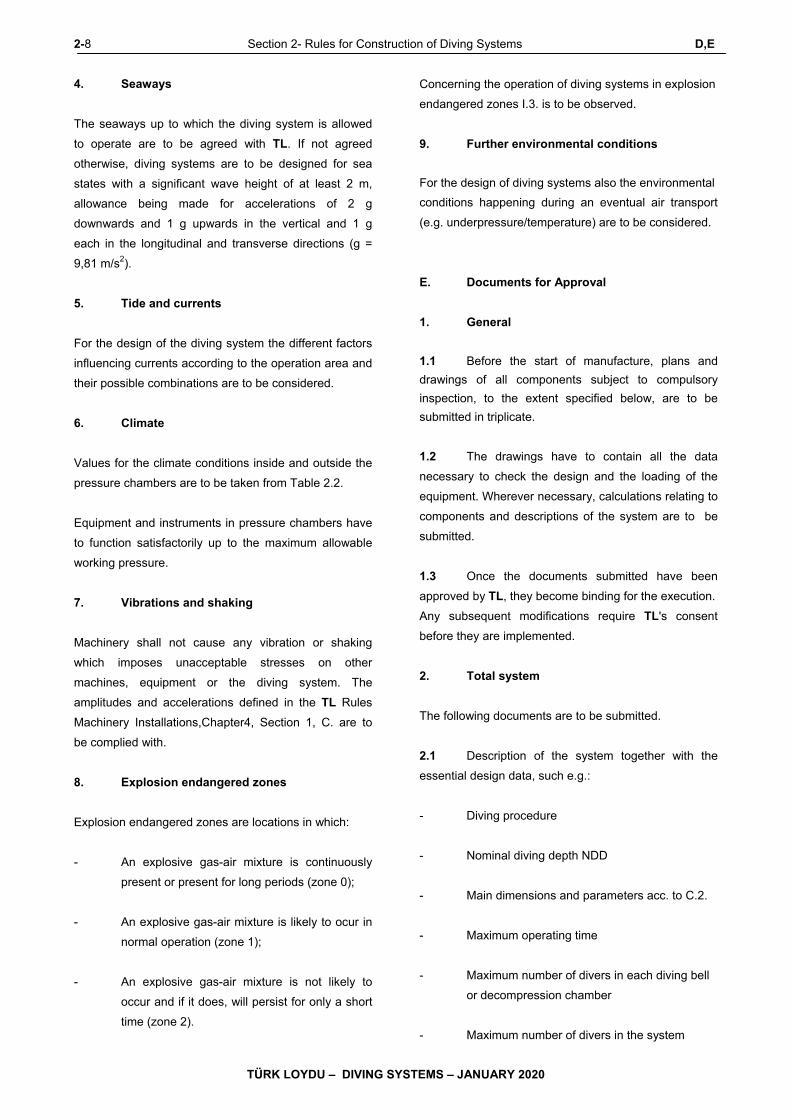
4. Seaways
The seaways up to which the diving system is allowed
to operate are to be agreed with TL. If not agreed
otherwise, diving systems are to be designed for sea
states with a significant wave height of at least 2 m,
allowance being made for accelerations of 2 g
downwards and 1 g upwards in the vertical and 1 g
each in the longitudinal and transverse directions (g =
9,81 m/s2).
5. Tide and currents
For the design of the diving system the different factors
influencing currents according to the operation area and
their possible combinations are to be considered.
6. Climate
Values for the climate conditions inside and outside the
pressure chambers are to be taken from Table 2.2.
Equipment and instruments in pressure chambers have
to function satisfactorily up to the maximum allowable
working pressure.
7. Vibrations and shaking
Machinery shall not cause any vibration or shaking
which imposes unacceptable stresses on other
machines, equipment or the diving system. The
amplitudes and accelerations defined in the TL Rules
Machinery Installations,Chapter4, Section 1, C. are to
be complied with.
8. Explosion endangered zones
Explosion endangered zones are locations in which:
- An explosive gas-air mixture is continuously
present or present for long periods (zone 0);
- An explosive gas-air mixture is likely to ocur in
normal operation (zone 1);
- An explosive gas-air mixture is not likely to
occur and if it does, will persist for only a short
time (zone 2).
Concerning the operation of diving systems in explosion
endangered zones I.3. is to be observed.
9. Further environmental conditions
For the design of diving systems also the environmental
conditions happening during an eventual air transport
(e.g. underpressure/temperature) are to be considered.
E. Documents for Approval
1. General
1.1 Before the start of manufacture, plans and
drawings of all components subject to compulsory
inspection, to the extent specified below, are to be
submitted in triplicate.
1.2 The drawings have to contain all the data
necessary to check the design and the loading of the
equipment. Wherever necessary, calculations relating to
components and descriptions of the system are to be
submitted.
1.3 Once the documents submitted have been
approved by TL, they become binding for the execution.
Any subsequent modifications require TL's consent
before they are implemented.
2. Total system
The following documents are to be submitted.
2.1 Description of the system together with the
essential design data, such e.g.:
- Diving procedure
- Nominal diving depth NDD
- Main dimensions and parameters acc. to C.2.
- Maximum operating time
- Maximum number of divers in each diving bell
or decompression chamber
- Maximum number of divers in the system
E Section 2- Rules for Construction of Diving Systems 2-9
TÜRK LOYDU – DIVING SYSTEMS – JANUARY 2020
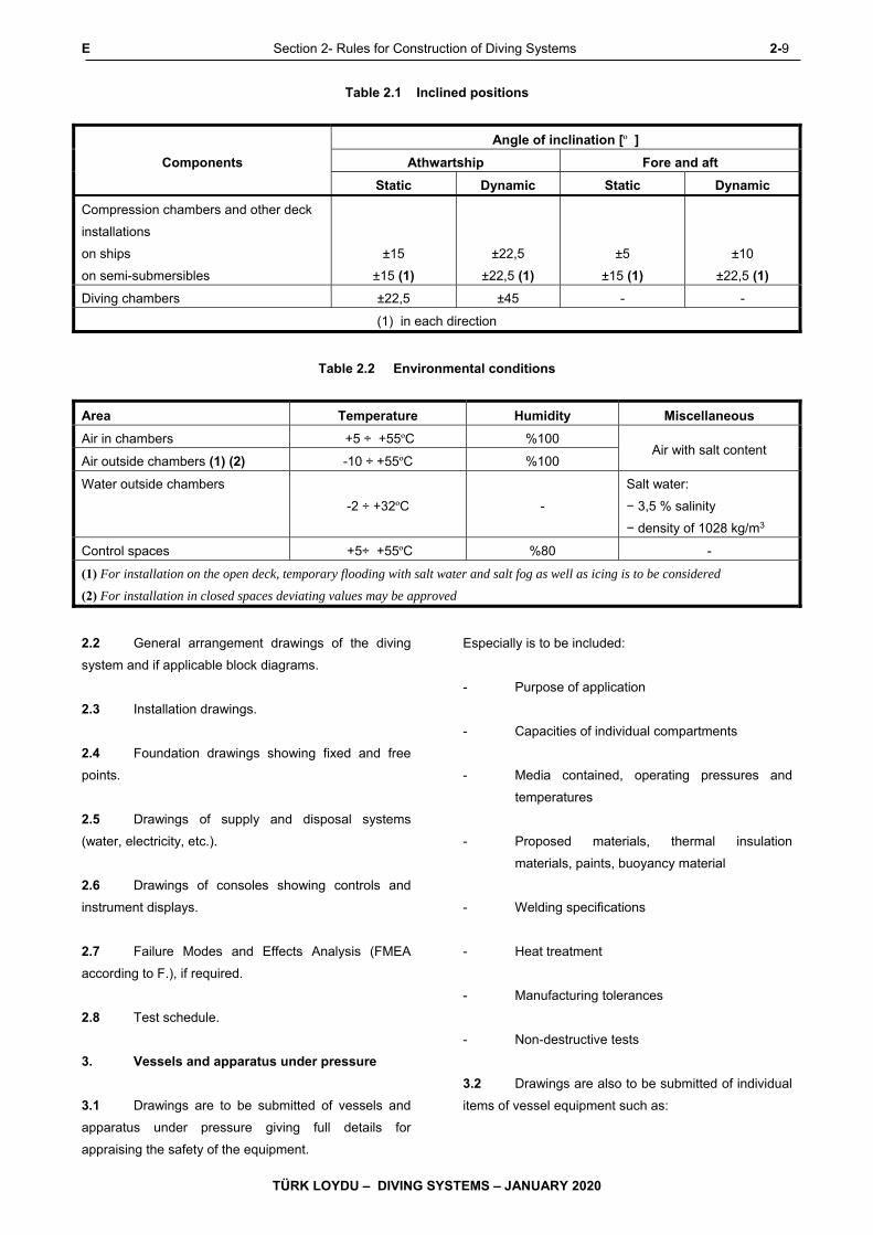
Table 2.1 Inclined positions
Components
Angle of inclination [º ]
Athwartship Fore and aft
Static Dynamic Static Dynamic
Compression chambers and other deck
installations
on ships
on semi-submersibles
±15
±15 (1)
±22,5
±22,5 (1)
±5
±15 (1)
±10
±22,5 (1)
Diving chambers ±22,5 ±45 - -
(1) in each direction
Table 2.2 Environmental conditions
Area Temperature Humidity Miscellaneous
Air in chambers +5 ÷ +55ºC %100 Air with salt content
Air outside chambers (1) (2) -10 ÷ +55ºC %100
Water outside chambers
-2 ÷ +32ºC -
Salt water:
− 3,5 % salinity
− density of 1028 kg/m3
Control spaces +5÷ +55ºC %80 -
(1) For installation on the open deck, temporary flooding with salt water and salt fog as well as icing is to be considered
(2) For installation in closed spaces deviating values may be approved
2.2 General arrangement drawings of the diving
system and if applicable block diagrams.
2.3 Installation drawings.
2.4 Foundation drawings showing fixed and free
points.
2.5 Drawings of supply and disposal systems
(water, electricity, etc.).
2.6 Drawings of consoles showing controls and
instrument displays.
2.7 Failure Modes and Effects Analysis (FMEA
according to F.), if required.
2.8 Test schedule.
3. Vessels and apparatus under pressure
3.1 Drawings are to be submitted of vessels and
apparatus under pressure giving full details for
appraising the safety of the equipment.
Especially is to be included:
- Purpose of application
- Capacities of individual compartments
- Media contained, operating pressures and
temperatures
- Proposed materials, thermal insulation
materials, paints, buoyancy material
- Welding specifications
- Heat treatment
- Manufacturing tolerances
- Non-destructive tests
3.2 Drawings are also to be submitted of individual
items of vessel equipment such as:
2-10 Section 2- Rules for Construction of Diving Systems E
TÜRK LOYDU – DIVING SYSTEMS – JANUARY 2020
- Windows, window flanges, retaining rings
- Door leaves and frames
- Bayonet locks
- Coupling clamps
- Integral opening reinforcements
- Supply locks
- Internal facilities
4. Gas supply
4.1 Piping diagrams, block diagrams and
descriptions are to be furnished for the entire gas supply
system, including a list of valves and fittings.
4.2 Details of the umbilical structure for the supply
of the diving bell, wet bell and divers.
4.3 Description of proposed cleaning procedure for
breathing gas system.
4.4 Details of the gas analysis, including an
equipment list.
4.5 Description of compressors and their drives
with definition of essential design and operating data.
5. Life support systems
It is to be submitted:
5.1 Piping diagrams, block diagrams and
descriptions of systems and equipment.
5.2 Calculations of the cooling and heating
requirements.
5.3 Description and drawings of the water supply
and disposal system.
5.4 Description and design details of the diver
heating system.
6. Electrical equipment
It is to be submitted:
6.1 A general arrangement drawing of the
electrical equipment containing at least the following
information:
- Voltage rating of systems
- Power or current ratings of electrical
consumers
- Switchgear, indicating settings for short-circuit
and overload protection; fuses with details of
current ratings
- Cable types and cross-sections.
6.2 The power balance of the main and emergency
power supply systems for diving systems with their own
power generating plant.
6.3 Drawings of switchgear and distribution
equipment.
6.4 Complete documentation for electric motor
drives with details of control, measuring and monitoring
systems.
6.5 Battery installation drawing with details of
battery types, chargers and battery room ventilation.
6.6 Details of electrical penetrations through
pressure chamber walls.
6.7 Drawings and descriptions of all electrical
components installed in pressure chambers.
7. Automation, communications and locating
equipment
It is to be submitted:
7.1 General arrangement drawings/block diagrams
of control equipment, including lists of measuring points.
7.2 Equipment list covering sensors, indicating
instruments, etc.

E Section 2- Rules for Construction of Diving Systems 2-11
TÜRK LOYDU – DIVING SYSTEMS – JANUARY 2020
7.3 Drawings and descriptions of electronic
components such as instrument amplifiers, computers
and peripheral units.
7.4 General arrangement drawings and equipment
lists for communications systems and signalling
equipment.
7.5 Arrangement drawing and description of the
video system.
7.6 Description of the central control position.
8. Fire protection
It is to be submitted:
8.1 A description of the preventive fire protection
measures.
8.2 Details of the fire loads in the system.
8.3 Drawings and descriptions of:
- Fire detection system
- Fire alarm equipment.
- Fire extinguishing system(s)
9. Launching, recovery, transfer and mating
systems
9.1 Launch and recovery systems
It is to be submitted:
- Description of the system with details of
operating conditions and technical data
including lifting and lowering speed
- Data about installation and connection
conditions including control stand
- Design drawings of:
- launch and recovery systems
- coil-up/coil-off mechanism for umbilical
- substructures of handling gear and winches
- detailed drawings of exchangeable single
parts and fittings or definition of the
standards where they are based on
- machinery equipment such as winches,
drives etc.
- piping and instrumentation diagrams of
the hydraulic or pneumatic systems
- control scheme and description of safety
systems
- information about nominal data and type
of protection of electrical installations
- data for lifting and guide cables/
umbilicals
9.2 Installations for stowage and deck
transport
It is to be submitted:
- Plans with description of the transport, the
stowage and the lashing measures including
parts lists with the lashing material used
- Description of the electrical measures
- Description of the fire protection measures
- Description of the explosion protection
9.3 Mating equipment
It is to be submitted:
- Description of system with data about
operating conditions
- Data concerning installation and connecting
conditions including control station
- Design drawings of the mating equipment

2-12 Section 2- Rules for Construction of Diving Systems E,F
TÜRK LOYDU – DIVING SYSTEMS – JANUARY 2020
- Control scheme and description of the safety
equipment
10. Hyperbaric evacuation system
It is to be submitted:
10.1 Description of system and operating instruction
10.2 Arrangement drawing
10.3 Construction drawing of evacuation system
10.4 Drawing of the launch and recovery system,
including description of the power supply
10.5 Emergency plan with definition of the
procedures for all possible emergency cases
11. Wet bells
It is to be submitted:
11.1 System description
11.2 Arrangement plan
11.3 Construction drawings for e.g. wet bell, diver
basket, launch and recovery systems, control platform,
gas supply, umbilical, electrical equipment.
F. Failure Modes and Effects Analysis (FMEA)
1. General
1.1 The Failure Modes and Effects Analysis
(FMEA) has the purpose to identify possible failures in
subsystems and in components, which are part of a
diving system and to describe the effects on the total
system and its subsystems or components.
1.2 For diving systems an analysis concerning the
function and availability of the diving system after
occurrence of a single failure has to be submitted if
requested by TL.
1.3 The FMEA shall be executed in an early
stadium accompanying the design to be able to realize
system modification at due time. A tabular form, e.g.
according to IEC 60812 or IMCA D 039 is to be used.
2. Description of the subsystems relevant for
the analysis
2.1 The FMEA shall represent an independent
document and be understandable without consulting
further documentation. This means that all relevant
subsystems are to be described concerning the
structure of their basic functions, the installed
redundancies and especially the interfaces of the
subsystems to each other.
2.2 The description shall provide the operating
personnel with a good overview of the system structure
and the functionalities of the relevant subsystems. For
all subsystems typical failure modes and their effects on
the overall function of the system shall be indicated.
Further on the corrective actions to manage these
failures and their effects are to be provided.
2.3 For diving systems the following subsystems
are relevant for maintaining the overall function:
- Equipment and interior arrangement of the
decompression chambers and diving bells
- Equipment of the wet bell, as far as existing
- Piping systems including pumps, fittings and
hoses
- Umbilicals
- Compressor plant
- Life support systems for maintaining of the
chamber atmosphere
- Generation and distribution of electrical power
- Emergency power supply
- Electrical protective systems
- Automation, communication, navigation and
locating equipment including central control
position
F Section 2- Rules for Construction of Diving Systems 2-13
TÜRK LOYDU – DIVING SYSTEMS – JANUARY 2020
- Fire protection
- Launch and recovery system
- Coil-up/coil-off mechanism for umbilicals
- Transfer and mating equipment
- Hyperbaric evacuation system
The system descriptions are to be completed by block
diagrams according to 3.
3. Block diagrams of the relevant subsystems
For each relevant subsystem a block diagram is to be
established. This block diagram shall contain the
essential information of the system required for the
failure analysis, which is normally:
- Definition of the subsystems
- All essential components of the subsystems
- Interfaces between the components of the
subsystems
- Interfaces to or from other subsystems (typical
for heat exchangers, hydraulic and
compressed air drives and controls, etc.)
- Arrangements for control of the total system
- Supplies from outside the total system
- Further aspects depending on the actual
design of the total system
At interfaces the different types of power, media and
data may be transferred.
4. Analysis of the different relevant
subsystems
Each relevant subsystem is to be analyzed with regard
to the following essential aspects, in course of which
further aspects may occur during the execution of the
analysis, compare worksheet in 5.:
- Malfunctions of components
- Failure of components in a subsystem
- Interface failures between the subsystems, a
subsystem and its components as well as
between components themselves. The
interface analysis is very important, as
according to experience many failures are
created due to lack of knowledge of which
data, medium and power are transferred or
how failures are spread via the interfaces to
other subsystems/ components.
- Malfunctions of subsystems
- Failure of subsystems
- Faulty operation of subsystems or
components, only with certain probability
- Failures because of external influences which
may lead to simultaneous failure of redundant
subsystems, e.g. changed environmental
conditions and their control, voltage and
amperage fluctuations in power supply,
contamination of supply media, etc.
- Hidden failures
Check for hidden failures and the practicality of
Alarms arrangement of periodic testing, where
alarms are not practical
5. Tabular worksheet
The analysis shall be carried out in tabular form with a
worksheet according to the following example or e.g.
according to IEC 60812 or IMCA D 039.
The analysis has to consider all operational modes.
6. Assumptions and defined limits for the
analysis
During the analysis the assumptions are to be defined
which influence the result of the analysis. Typical
assumptions are e.g.:
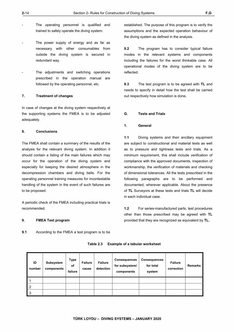
2-14 Section 2- Rules for Construction of Diving Systems F,G
TÜRK LOYDU – DIVING SYSTEMS – JANUARY 2020
- The operating personnel is qualified and
trained to safely operate the diving system.
- The power supply of energy and as far as
necessary with other consumables from
outside the diving system is secured in
redundant way.
- The adjustments and switching operations
prescribed in the operation manual are
followed by the operating personnel, etc.
7. Treatment of changes
In case of changes at the diving system respectively at
the supporting systems the FMEA is to be adjusted
adequately.
8. Conclusions
The FMEA shall contain a summary of the results of the
analysis for the relevant diving system. In addition it
should contain a listing of the main failures which may
occur for the operation of the diving system and
especially for keeping the desired atmosphere in the
decompression chambers and diving bells. For the
operating personnel training measures for incontestable
handling of the system in the event of such failures are
to be proposed.
A periodic check of the FMEA including practical trials is
recommended.
9. FMEA Test program
9.1 According to the FMEA a test program is to be
established. The purpose of this program is to verify the
assumptions and the expected operation behaviour of
the diving system as defined in the analysis.
9.2 The program has to consider typical failure
modes in the relevant systems and components
including the failures for the worst thinkable case. All
operational modes of the diving system are to be
reflected.
9.3 The test program is to be agreed with TL and
needs to specify in detail how the test shall be carried
out respectively how simulation is done.
G. Tests and Trials
1. General
1.1 Diving systems and their ancillary equipment
are subject to constructional and material tests as well
as to pressure and tightness tests and trials. As a
minimum requirement, this shall include verification of
compliance with the approved documents, inspection of
workmanship, the verification of materials and checking
of dimensional tolerances. All the tests prescribed in the
following paragraphs are to be performed and
documented, wherever applicable. About the presence
of TL Surveyors at these tests and trials TL will decide
in each individual case.
1.2 For series-manufactured parts, test procedures
other than those prescribed may be agreed with TL
provided that they are recognized as equivalent by TL.
Table 2.3 Example of a tabular worksheet
ID
number
Subsystem
components
Type
of
failure
Failure
cause
Failure
detection
Consequences
for subsystem/
components
Consequences
for total
system
Failure
correction Remarks
1
2
3
G Section 2- Rules for Construction of Diving Systems 2-15
TÜRK LOYDU – DIVING SYSTEMS – JANUARY 2020
1.3 TL reserve the right to extend the scope of the
tests where necessary and also to subject to test those
parts for which testing is not expressly prescribed in the
Rules.
1.4 The material test Certificates for the applied
materials, reports on non-destructive testing of welds
and, if applicable, the results of inspections of
workmanship and evidence of heat treatments
performed are to be presented.
1.5 Gas storage, pressure chambers and life
support systems including piping system are to be
subjected to a tightness test with the adequate
breathing gas or a gas mixture with similar properties at
maximum allowable working pressure. As maximum
permissible leakage rate 1 % pressure drop within 24
hours for the whole pressure chamber system is valid.
1.6 After the pressure chambers and ancillary
equipment have been installed on board, the diving
system together with its ancillary plant is to be subjected
to functional test. All items of safety equipment are to be
tested except where a sufficient trial has already been
performed on the manufacturer's premises in the
presence of TL.
1.7 During sea trials the launch, recovery, transfer
and mating systems are to be subjected to a test in
which the diving bell loaded to its maximum weight is
lowered to the nominal diving depth NDD. Thereafter,
the diving bell is to be inspected for leaks and the
electrical installation including the communication
system is to be tested.
1.8 Parts subject to replacement are to be
replaced with tested parts. The same also applies to
spare parts.
2. Vessels and apparatus under pressure
2.1 On completion, pressure vessels and
apparatus are to be subjected to a constructional test.
The constructional test includes verification that the
vessel conforms to the approved drawings and that the
workmanship is satisfactory. All components have to be
accessible to allow adequate inspection.
2.2 A hydraulic pressure test is to be performed
prior to insulation and preservation treatment of the
vessels. Each pressure chamber compartment is to be
tested individually. The walls may exhibit no permanent
deformation or leakage.
2.3 For vessel and apparatus, the test pressure
shall normally be equivalent to 1,5 times the internal
maximum allowable working pressure.
2.4 Vessels and apparatus at the diving bell which
are exposed to an external pressure are also required to
undergo an external pressure test. The test pressure
has to be at least adequate to the test diving pressure
TDP of the diving bell.
2.5 Vessels and pressure-proof housings, which
are applied internally in pressure chambers and may be
subjected to external overpressure, are to be tested at
least with 1,5 times the maximum allowable working
pressure of the chamber (see Table 2.8a).
2.6 Where the compression strength of vessels
and apparatus under pressure cannot be proven
sufficiently by calculation, an alternative check is to be
agreed with TL.
3. Diving bell and decompression chamber
windows
3.1 Each pressure chamber window has to
undergo a hydraulic pressure test which may be
performed after installation together with the pressure
chamber or in a testing device. The test pressure shall
normally be equivalent to 1,5 times the internal
maximum allowable working pressure or the test diving
pressure TDP. For the pressure test it has to be
observed that the test pressure is not higher than 1,5
times the design pressure of the window.
3.2 After the pressure test windows may exhibit no
scratches, cracks or permanent deformations.
4. Compressors
4.1 Compressor components subjected to
pressure are to undergo a hydraulic pressure test at a
test pressure equal to 1,5 times the delivery pressure of
the compressor stage concerned.

2-16 Section 2- Rules for Construction of Diving Systems G
TÜRK LOYDU – DIVING SYSTEMS – JANUARY 2020
4.2 On completion, compressors are to be
subjected to a tightness test at their maximum allowable
working pressure. In addition, a function and
performance test is to be carried out in which the final
moisture content and any possible contamination of the
compressed gas are to be determined. The control,
monitoring and safety devices are to be checked.
5. Piping systems
5.1 On completion of manufacture but before
insulation or painting, all piping systems under internal
pressure are to undergo a hydraulic pressure test at 1,5
times the design pressure. Piping systems under
external diving pressure are to be tested in addition with
nominal diving pressure NDP (depending on the load
case from outside or inside).
5.2 Wherever possible, all butt welds in piping
systems for life support systems are to be subjected to
100 % X-ray test.
5.3 Piping systems for breathing gas and oxygen
are to be subjected to a purity test.
6. Hoses, hoses assemblies umbilicals
6.1 All aspects for tests and trials of umbilicals are
defined in Annex E, D.
6.2 As far as the requirements for umbilicals are
applicable for hoses, these have to be applied.
7. Electrical equipment
7.1 Electrical machines, components, cables and
lines are to be tested in the manufacturer's works in
accordance with the TL Electric Rules.
7.2 All electrical systems and equipment are to be
inspected and tested before the diving system is put into
service.
7.3 Electrical protective devices are to be checked;
in addition, an insulation test is to be performed on the
electrical equipment in the pressure chambers.
7.4 All electrical equipment which is exposed to
diving pressure shall be checked additionally for
insulation after the first diving.
8. Automation, communications and locating
equipment
8.1 Indicating and monitoring instruments are to be
tested for the accuracy of their readings and their limit
value settings.
8.2 Automatic control systems are to be checked
for satisfactory performance under service conditions.
8.3 Normal and emergency communications
equipment is to be subjected to a functional test. The
effectiveness of the helium speech unscrambler is to be
demonstrated down to nominal diving depth NDD.
8.4 Proof is required of the autonomy of the safety
systems.
9. Life support systems
9.1 Within a functional test the satisfactory
functioning of the life support systems under normal and
emergency conditions is to be proven.
9.2 The arrangement of the analyzing devices is to
be inspected, and the accuracy of their readings and
their limit value settings is to be checked.
10. Fire protection
10.1 The fire behaviour of the chamber equipment is
to be checked by reference to the relevant test
Certificates and symbols.
10.2 A check is to be made as to whether the
electrical heating systems and heaters are fitted with
protection against overheating.
10.3 Fire alarm, detection and extinguishing
appliances are to be subjected to a functional test.
G Section 2- Rules for Construction of Diving Systems 2-17
TÜRK LOYDU – DIVING SYSTEMS – JANUARY 2020
11. Launch, recovery, transfer and mating
systems
11.1 Launch and recovery systems
Before putting into operation of the launch and recovery
system as well as the coil-up/coil-off mechanism for
umbilicals an acceptance test with the following single
tests is to be performed:
- Check that for all single parts the required
proofs are existing
- The breaking strength of the used ropes is to
be proven by a total rupture test and to be
certified.
- Static test of the system at the manufacturer
with a test load equal to 2,2 times the safe
working load SWL
- Dynamic test (brake test) aboard with 1,25
times the safe working load SWL
- For an A-frame operated by two hydraulic
cylinders an additional test with SWL and use
of only one cylinder is to be performed.
- Check of minimum lifting speed
- Test that the procedure of transfer and launch
or recovery of the diving bell/wet bell is
performed in normal and emergency operation
safely and without jerk. The test in normal
operation is to be performed down to nominal
diving depth NDD.
- Check of devices for jettisoning the lifting
cable/ umbilicals
- Test of function including safety and alarm
systems
11.2 Stowage and deck transport systems
Before use of the stowage and transport systems an
acceptance test with the following single test is to be
performed:
- Check that proofs are available for all
exchangeable single parts
- Check, that proofs are available for the rupture
strength of the used ropes
- Check that the transport of the diving bell or
the wet bell in normal and emergency
operation is safe and without jerk
- functional test including check of the safety
devices
11.3 Mating system
- The mating procedure is to be tested. For
power drives the main drive as well as the
auxiliary drive are to be checked for correct
function.
- It is to be checked that release of the mating
system and transfer of the diving bell can only
take place when the connecting trunk is not
under pressure.
12. Hyperbaric evacuation system
By a functional test it is to be demonstrated that the
hyperbaric rescue system is able to convey divers under
pressure from aboard to a safe position and that they
can be monitored and supplied during this mission.
13. Diving bells
13.1 Static test of the lifting points for the lifting
cable with 2,2 times the permissible total weight (dead
weight + payload) of the diving bell.
13.2 The fixing point of the umbilical at the diving
bell is to be tested statically with 2,2 times the maximum
permissible tension load of the umbilical.
2-18 Section 2- Rules for Construction of Diving Systems G,H
TÜRK LOYDU – DIVING SYSTEMS – JANUARY 2020
13.3 For the following systems additional functional
tests are to be performed:
- Main and emergency power supply
- Control and monitoring systems
- Arrangements for recovery of a diver who had
an accident
13.4 The weight and buoyancy of diving bells are to
be measured and their stability in normal and
emergency operation is to be checked. The release of
ballast weights and the operation of the device for the
emergency release of the lifting cable and the umbilical
are to be demonstrated in shallow water.
14. Wet bells
14.1 Static test of the lifting points for the lifting
cable with a test load equal to 2,2 times the permissible
total weight (dead weight + payload) of the wet bell.
14.2 The fixing point of the umbilical at the wet bell
is to be tested statically with 2,2 times the maximum
permissible tension load of the umbilical.
14.3 For the following systems additional functional
tests are to be performed:
- Main and emergency power supply
- Control and monitoring systems
- Arrangements for recovery of a diver who had
an accident
- Communication equipment
14.4 Lowering of the wet bell down to nominal
diving depth NDD.
H. Marking 1. Pressure chambers
All pressure chambers, like e.g. diving bells and
decompression chambers are to be fitted in a prominent
position with a permanently mounted name plate
containing at least the following data:
- name or company designation of manufacturer
- year of construction and serial number
- maximum allowable working pressure or
nominal diving pressure [bar]
- test pressure [bar]
- capacity [ℓ] (indication for each chamber
compartment)
- dead weight of diving bell [kg]
- payload NL of diving bell [kg]
- maximum permissible number of divers
- date of test
- test stamp
2. Wet bells
All wet bells and diver baskets are to be fitted in a
prominent position with a permanently mounted name
plate containing at least the following data:
- Name or company designation of manufacturer
- Year of construction and serial number
- Nominal diving depth NDD
- Dead weight of wet bell [kg]
- Payload NL [kg]
- Maximum permissible number of divers

H Section 2- Rules for Construction of Diving Systems 2-19
TÜRK LOYDU – DIVING SYSTEMS – JANUARY 2020
- Date of test
- Test stamp
3. Valves, fittings, indicating and warning
devices
All essential valves, fittings, operating elements,
indicators and warning devices are to be provided with a
permanent and seawater resistant identification. The
identifying marks are to be clear and unmistakable.
In pressure chambers at least flame resistant materials
are to be used for the marks.
4. Pressure vessels and gas cylinders
4.1 All other pressure vessels and gas cylinders
are to be prominently and permanently marked with the
following details:
- Name or company designation of manufacturer
- Year of construction and serial number
(pressure vessels)
- Serial number (gas cylinders)
- Type of gas
- Maximum allowable working pressure [bar]
- Test pressure [bar]
- Maximum allowable working temperature (for
> 50 °C and < -10 °C)
- Capacity [ℓ]
- Empty weight (of gas cylinders) [kg]
- Date of test
- Test stamp
4.2 Permanently installed pressure vessels, gas
cylinders and gas piping systems are, in addition, to be
marked with a permanent colour code in accordance
with Table 2.4 and with the chemical symbol
designating the type of gas concerned. The marking of
pressure vessels and gas cylinders has to be visible
from the valve side.
Systems for other media are also to be marked in
suitable way.
The distances of the markings are to be chosen for pipe
systems according to function and safety.
5. Launch and recovery systems
The launch and recovery systems as well as the coilup/
coil-off mechanism for the umbilicals are to be marked
with a fixed type plate at a good visible position which
contains at least the following data:
- Manufacturer
- Serial number and year of construction
- Safe working load SWL [t]
- Load radius [m]
- Date of test and test stamp, for cranes at the
bottom end of the right-hand jib member and
next to the point where the member joins to the
crane housing
Table 2.4 Marking of gas systems
Type of gas Chemical
symbol Colour code
Oxygen O2 White
Nitrogen N2 Black
Air - White and black
Helium He Brown
Oxygen/Helium
mixed gas
Heliox White and brown
Oxygen/Nitrogen
mixed gas (Nitrox)
Nitrox White and brown
Oxygen/Helium/Ni
trogen mixed gas
Trimix White and brown
The designation of gases for special purposes is to be agreed with TL.

2-20 Section 2- Rules for Construction of Diving Systems H,I
TÜRK LOYDU – DIVING SYSTEMS – JANUARY 2020
6. Compressors
Concerning the marking of compressors see L.5.
7. Hyperbaric evacuation system
Concerning the marking of hyperbaric evacuation
systems see R.2.5.
I. Principles for the Design and Construction
of Diving Systems
1. General principles
1.1 Wherever expedient and feasible, diving
systems are to be designed and constructed in such a
way that failure of any single component cannot give
rise to a dangerous situation.
1.2 Diving systems and their components are to be
designed and constructed that during missions and
operation of the pressure chamber sufficient possibilities
for monitoring are given. This can be achieved e.g. by
video systems or acoustic devices.
1.3 All parts of a diving system are to be designed,
constructed and mounted in such a way as to facilitate
cleaning and disinfection.
2. Conditions in chambers
2.1 Diving systems are to be so equipped that a
breathable atmosphere can be maintained in
decompression chambers and diving bells throughout
the entire operating period of the divers.
2.2 The partial pressure of the CO2 in the chamber
atmosphere has to be kept permanently below 0,005
bar assuming a CO2 production rate of 0,05 Nm3/h per
diver. In diving bells it has to be possible to keep the
partial pressure of CO2 below 0,015 bar as a minimum
requirement. Under emergency conditions the partial
pressure of CO2 has to be kept below 0,02 bar for at
least 24 h.
2.3 Diving systems using mixed gas and designed
for operating periods of more than 12 hours are to be
capable, under steady conditions, of keeping the
temperature in the decompression chamber constant to
± 1 °C in the 27 - 36 °C temperature range while
maintaining a relative humidity of at least 50 %.
2.4 Decompression chambers are to be designed
and equipped in such a way that a homogeneous
atmosphere (CO2 and O2 concentrations, temperature
and humidity) can be maintained in the chamber.
2.5 In the steady state, a permanent noise level
(over 8 hours) in the pressure chambers exceeding 65
dB(A) is not permitted
3. Arrangement
3.1 Diving systems on support ships may only be
located and operated in areas not subject to an
explosion hazard. In exceptional cases, installation
subject to special conditions may be permitted in the
lowest explosion protection zone.
3.2 As far as possible, the area in which the diving
system is installed is to be kept free of fire loads. In
addition, only those electrical cables needed to operate
the diving system should be routed through this area.
3.3 It is not permitted to locate diving systems and
breathing gas storage facilities may not be located in
engine rooms unless the engine plant is connected to
the diving system.
3.4 Diving systems and breathing gas storage
facilities are to be located in spaces which can be
adequately ventilated and provided with suitable electric
lighting.
3.5 Where parts of the diving system are located
on the open deck, these are to be protected against
damage due to other shipboard activities.
4. Chamber equipment and fittings
4.1 The equipment and fittings of decompression
chambers and diving bells are to be suitable for
operation in hyperbaric atmospheres. Under these
conditions they shall not give off any toxic or strongly
irritant gases. The same also applies to protective
coatings and paints used inside the chambers.
I,J Section 2- Rules for Construction of Diving Systems 2-21
TÜRK LOYDU – DIVING SYSTEMS – JANUARY 2020
4.2 Only incombustible or at least flame retardant
materials should be used in the chambers.
4.3 Diving bells where the emergency surfacing is
initiated by jettisoning of ballast, are to be equipped with
devices to jettison the lifting cable/ umbilicals and the
ballast weights. The devices for jettisoning of ballast are
to be so designed that two mutually independent actions
in the interior of the chamber are required to initiate the
release.
4.4 After jettisoning of the ballast weights the
diving bell with full payload NL and flooded trunk has to
have a positive buoyancy of 3 % of the displacement at
nominal diving depth NDD. Hereby the bell shall have
sufficient stability to stay in upright floating condition. As
far as applicable the definitions for buoyancy and
stability according the TL Rules for Submersibles,
Section 3 are to be observed
5. Corrosion protection
5.1 Diving systems and all their accessories are to
be effectively protected against corrosion.
5.2 Anti-corrosion coatings exposed to the
conditions within the chambers have to conform to the
requirements stated in 4. In addition, they shall not tend
to blister or flake under hyperbaric conditions
J. Vessels and Apparatus under Pressure
1. Decompression chambers and diving bells
1.1 General
1.1.1 The following Rules are applicable to
decompression chambers and diving bells which are
used in diving systems and in which persons stay in
breathable atmosphere at pressures higher than
atmosphericpressure.
1.1.2 The documents to be submitted to TL for
approval are listed in E.3.
1.1.3 The necessary tests and markings are stated
in G.2. and H.1.
1.2 Design principles
1.2.1 Pressure chambers
1.2.1.1 Each pressure chamber or compartment is to
be so equipped that it is fully protected against
inadmissible working overpressure and inadmissible
pressure drops.
1.2.1.2 Pressure chambers are to be so designed that
at least two persons can simultaneously pass in or out
through the locks without exposing the other divers in
the system to a pressure change.
1.2.1.3 In diving systems where divers are required to
remain under pressure for a continuous period of more
than 12 hours, the living compartment of the
decompression chamber is to be so designed and
equipped that persons are able to stand upright in it and
each diver is provided with a bunk on which he is able
to stretch out comfortably. A toilet and shower are also
to be provided. The toilet and shower are to be
accommodated in a separate compartment. Toilet
facilities capable of discharging the waste to outside
and further waste water systems are to be equipped
with suitable interlocks to prevent pressure losses in the
chamber system.
1.2.1.4 The living area of decompression chambers
and other compartments envisaged for decompression
are to be provided with a lock through which provisions,
medicines and equipment items can be passed in and
out without exposing the occupants of the chamber to a
pressure change.
1.2.1.5 Locks are to be designed to prevent accidental
opening under pressure; if necessary, suitable
interlocks are to be fitted.
1.2.1.6 Each pressure chamber compartment is to be
provided with view ports enabling all occupants to be
observed from outside.
1.2.1.7 Wherever necessary, pressure chamber
Windows are to be protected against mechanical
damage from inside and outside.
2-22 Section 2- Rules for Construction of Diving Systems J
TÜRK LOYDU – DIVING SYSTEMS – JANUARY 2020
1.2.2 Diving bells
1.2.2.1 Each diving bell is to be so equipped that it is
fully protected against inadmissible internal working
overpressure and inadmissible pressure drops.
1.2.2.2 Each diving bell is to be provided with an extra
lifting point designed to take the entire weight of the bell
including ballast and equipment as well as the payload
NL.
1.2.2.3 Close to the lifting point, the diving bell is to be
provided with spare connections for hot water (¾" NPT
female thread) and breathing gas (½" NPT female
thread). The manifold is to be clearly marked and
effectively protected.
1.2.2.4 Diving bells are to be designed to allow entry
and exit even in an emergency.
1.2.2.5 Diving bells are to be equipped with a device
for the recovery of an unconscious diver out from the
diving bell.
1.2.2.6 The dimensional design of diving bell shall be
such as to provide adequate space for the proposed
number of divers and their equipment.
1.2.2.7 Seating is to be provided for each diver in the
diving bell.
1.2.2.8 Diving bells are to be provided with view ports
so that divers working outside the chamber can be
observed from within the chamber. The Windows are to
be protected against mechanical damage from inside
and outside.
1.2.2.9 Each diving bell is to be adequately
illuminated.
1.2.3 Doors, accesses and penetrations
1.2.3.1 Two measures are to be provided, that the
doors and hatches are closed and secured before
diving, one measure has to be visually apparent.
1.2.3.2 Doors and mating devices for diving bells,
which are not tightening by pressure, are to be so
equipped with a closing mechanism that opening under
pressure is excluded. The closing mechanism is to be
designed that the correct closing position can be clearly
apparent before pressure is applied.
1.2.3.3 Means are to be fitted to enable doors to be
opened from both sides. A banging of doors and access
hatches is to be avoided safely by mechanical
measures.
Door trunks are to be fitted with pressure compensating
valves.
1.2.3.4 Doors and hatches for persons are required to
have a clear opening, at least 500 mm in diameter. For
diving bell lockin/lockout hatches the clear diameter
shall be at least 600 mm.
1.2.3.5 The length of the hatch trunk should not
exceed the hatch diameter.
1.2.3.6 Penetrations through chamber walls for
umbilicals/supply lines and other pipelines, hoses and
cables are to be protected, as far as possible, by
chamber extensions and coverings against mechanical
damage.
1.2.3.7 Doors and access openings are to be laid out
for at least collapse diving pressure CDP.
1.2.4 Pressure proof bulkheads
Pressure proof bulkheads for subdivision of the internal
space of decompression chambers are to be designed
for maximum allowable working pressure.
1.3 Materials
1.3.1 General
1.3.1.1 Materials are to be suitable for the purpose
intended and for the processes applied, e.g. welding.
Principally the requirements of the TL Rules for
Materials are valid.
1.3.1.2 Furthermore the materials have to meet the
special requirements defined in 1.3.3.
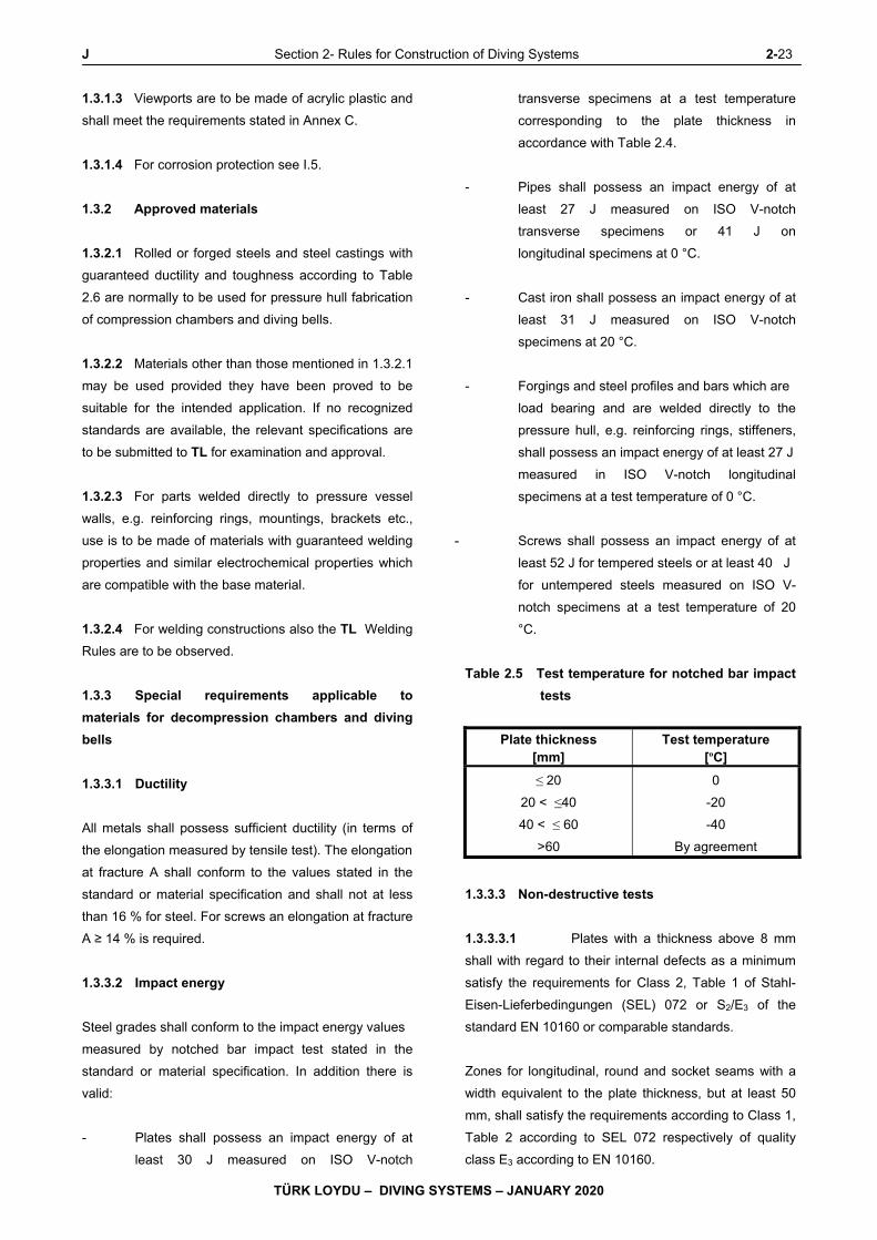
J Section 2- Rules for Construction of Diving Systems 2-23
TÜRK LOYDU – DIVING SYSTEMS – JANUARY 2020
1.3.1.3 Viewports are to be made of acrylic plastic and
shall meet the requirements stated in Annex C.
1.3.1.4 For corrosion protection see I.5.
1.3.2 Approved materials
1.3.2.1 Rolled or forged steels and steel castings with
guaranteed ductility and toughness according to Table
2.6 are normally to be used for pressure hull fabrication
of compression chambers and diving bells.
1.3.2.2 Materials other than those mentioned in 1.3.2.1
may be used provided they have been proved to be
suitable for the intended application. If no recognized
standards are available, the relevant specifications are
to be submitted to TL for examination and approval.
1.3.2.3 For parts welded directly to pressure vessel
walls, e.g. reinforcing rings, mountings, brackets etc.,
use is to be made of materials with guaranteed welding
properties and similar electrochemical properties which
are compatible with the base material.
1.3.2.4 For welding constructions also the TL Welding
Rules are to be observed.
1.3.3 Special requirements applicable to
materials for decompression chambers and diving
bells
1.3.3.1 Ductility
All metals shall possess sufficient ductility (in terms of
the elongation measured by tensile test). The elongation
at fracture A shall conform to the values stated in the
standard or material specification and shall not at less
than 16 % for steel. For screws an elongation at fracture
A ≥ 14 % is required.
1.3.3.2 Impact energy
Steel grades shall conform to the impact energy values
measured by notched bar impact test stated in the
standard or material specification. In addition there is
valid:
- Plates shall possess an impact energy of at
least 30 J measured on ISO V-notch
transverse specimens at a test temperature
corresponding to the plate thickness in
accordance with Table 2.4.
- Pipes shall possess an impact energy of at
least 27 J measured on ISO V-notch
transverse specimens or 41 J on
longitudinal specimens at 0 °C.
- Cast iron shall possess an impact energy of at
least 31 J measured on ISO V-notch
specimens at 20 °C.
- Forgings and steel profiles and bars which are
load bearing and are welded directly to the
pressure hull, e.g. reinforcing rings, stiffeners,
shall possess an impact energy of at least 27 J
measured in ISO V-notch longitudinal
specimens at a test temperature of 0 °C.
- Screws shall possess an impact energy of at
least 52 J for tempered steels or at least 40 J
for untempered steels measured on ISO V-
notch specimens at a test temperature of 20
°C.
Table 2.5 Test temperature for notched bar impact
tests
Plate thickness [mm]
Test temperature [ºC]
≤ 20
20 < ≤40
40 < ≤ 60
>60
0
-20
-40
By agreement
1.3.3.3 Non-destructive tests
1.3.3.3.1 Plates with a thickness above 8 mm
shall with regard to their internal defects as a minimum
satisfy the requirements for Class 2, Table 1 of Stahl-
Eisen-Lieferbedingungen (SEL) 072 or S2/E3 of the
standard EN 10160 or comparable standards.
Zones for longitudinal, round and socket seams with a
width equivalent to the plate thickness, but at least 50
mm, shall satisfy the requirements according to Class 1,
Table 2 according to SEL 072 respectively of quality
class E3 according to EN 10160.
2-24 Section 2- Rules for Construction of Diving Systems J
TÜRK LOYDU – DIVING SYSTEMS – JANUARY 2020
Areas for the connection of lifting eyes, elements of the
exostructure and other plates, which may also be
stressed in thickness direction, shall satisfy the
requirements according to Class 0, Table 1 according to
SEL 072 respectively of quality class S3 according to
EN 10160.
1.3.3.3.2 For forgings greater than DN 250 the material
quality is to be checked by the producer using suitable
test procedures according to the TL Material Rules,
Section 3, G. The tolerance boundaries are to be
agreed with TL depending on the type of the
component.
1.3.3.3.3 The producer has to submit to TL the proof for
the non-destructive tests.
1.3.4 Proof of quality characteristics
1.3.4.1 Proof of the quality characteristics of materials
used for pressure chambers is to be supplied in the
form of material test Certificates according to the TL
Rules Principles and Test Procedures. The type of
Certificate required for the product concerned is
indicated in Table 2.7. Unless otherwise specified, the
testing authority for issuance of a TL Material Certificate
is TL.
1.3.4.2 The evidence to be supplied in respect of the
characteristics of products made of steel not included in
Table 2.7 shall be agreed with TL.
1.3.4.3 For small parts, like e.g. supports for consoles,
welding lugs or other, not load-bearing and not pressure
loaded elements, approval Certificates of the
manufacturer are to submitted.
1.4 Principles of manufacture and construction
1.4.1 Treatment
1.4.1.1 Treatments applied to materials are to be
professionally carried out. Materials whose
characteristics have been impaired by hot or cold
forming shall be suitably heat-treated, compare TL
Material Rules.
Concerning the criteria for adequate workmanship see
also Section 1, H.
1.4.1.2 Materials and components are to be so marked
as to enable them to be identified and correlated with
their respective test Certificates even during and after
the fabrication of the pressure chamber.
1.4.1.3 The requirements of Annex C are to be
complied with in the manufacture and machining of
acrylic windows.
1.4.2 Welding
1.4.2.1 Approval
Companies wishing to fabricate the pressure hulls for
pressure chambers have to be approved by TL with
regard to their facilities, welding personnel and
Professional supervision.
1.4.2.2 Procedure tests
Before welding work is commenced, the properties of
the joints to be welded are to be proven to TL by
welding procedure tests at the manufacturer's works.
1.4.2.3 Butt welds
All butt welds of the pressure chamber are to be
performed as full-penetration, multi-pass welds
executed from both sides. In addition, the work is to be
performed in such a way that it can be assigned a weld
factor v = 1,0 in accordance with the TL Welding Rules,
General Requirements, Proof of Qualifications,
Approvals.
1.4.2.4 Fillet welds
The proof of the fillet welds is to be performed according
to the TL Rules Hull Structures, Section 20. If no
detailed proof by computation is required, the
dimensioning shall follow TL Rules, Chapter 53,
Submersibles, Section 5, Table 5.4.
Depending on accessibility a suitable test procedure is
to be applied and to be agreed with TL.
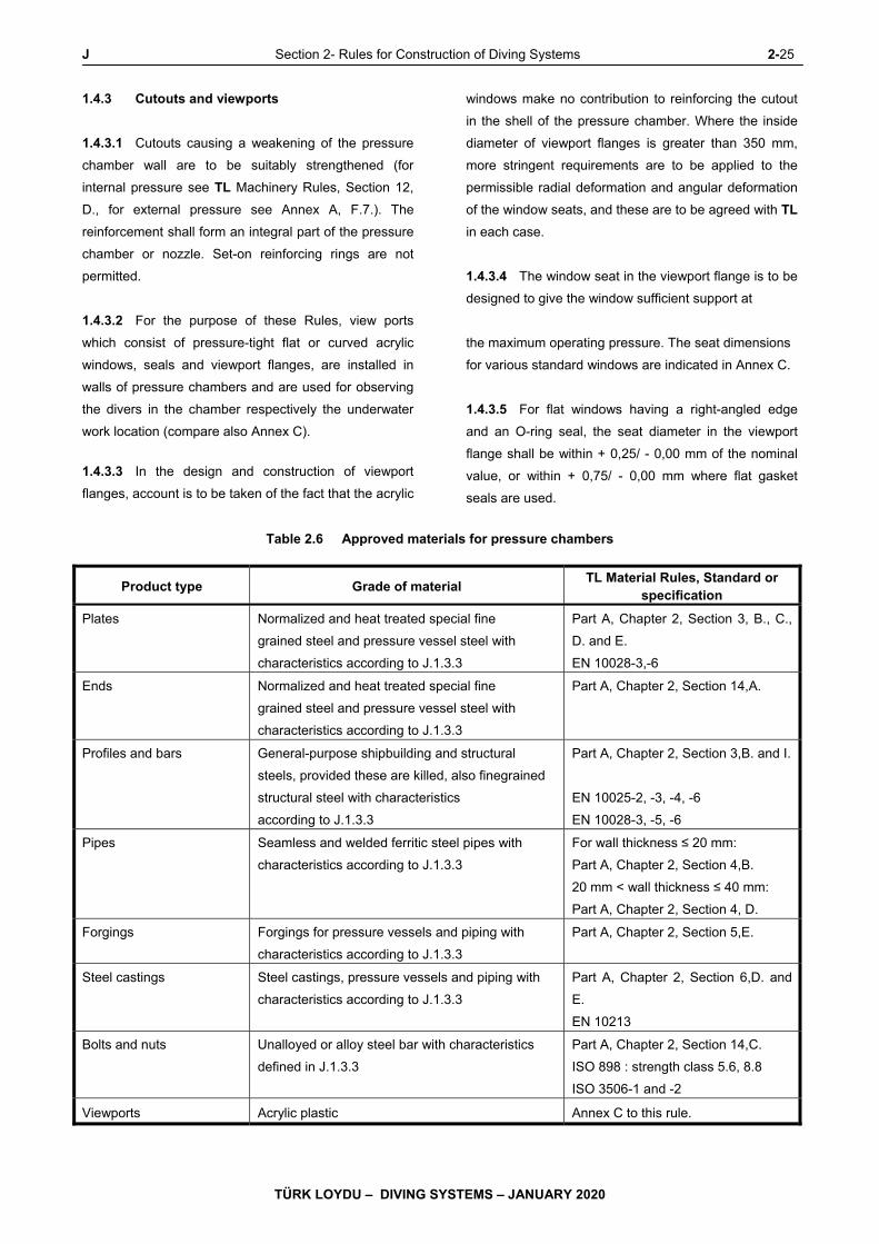
J Section 2- Rules for Construction of Diving Systems 2-25
TÜRK LOYDU – DIVING SYSTEMS – JANUARY 2020
1.4.3 Cutouts and viewports
1.4.3.1 Cutouts causing a weakening of the pressure
chamber wall are to be suitably strengthened (for
internal pressure see TL Machinery Rules, Section 12,
D., for external pressure see Annex A, F.7.). The
reinforcement shall form an integral part of the pressure
chamber or nozzle. Set-on reinforcing rings are not
permitted.
1.4.3.2 For the purpose of these Rules, view ports
which consist of pressure-tight flat or curved acrylic
windows, seals and viewport flanges, are installed in
walls of pressure chambers and are used for observing
the divers in the chamber respectively the underwater
work location (compare also Annex C).
1.4.3.3 In the design and construction of viewport
flanges, account is to be taken of the fact that the acrylic
windows make no contribution to reinforcing the cutout
in the shell of the pressure chamber. Where the inside
diameter of viewport flanges is greater than 350 mm,
more stringent requirements are to be applied to the
permissible radial deformation and angular deformation
of the window seats, and these are to be agreed with TL
in each case.
1.4.3.4 The window seat in the viewport flange is to be
designed to give the window sufficient support at
the maximum operating pressure. The seat dimensions
for various standard windows are indicated in Annex C.
1.4.3.5 For flat windows having a right-angled edge
and an O-ring seal, the seat diameter in the viewport
flange shall be within + 0,25/ - 0,00 mm of the nominal
value, or within + 0,75/ - 0,00 mm where flat gasket
seals are used.
Table 2.6 Approved materials for pressure chambers
Product type Grade of material TL Material Rules, Standard or
specification
Plates Normalized and heat treated special fine
grained steel and pressure vessel steel with
characteristics according to J.1.3.3
Part A, Chapter 2, Section 3, B., C.,
D. and E.
EN 10028-3,-6
Ends Normalized and heat treated special fine
grained steel and pressure vessel steel with
characteristics according to J.1.3.3
Part A, Chapter 2, Section 14,A.
Profiles and bars General-purpose shipbuilding and structural
steels, provided these are killed, also finegrained
structural steel with characteristics
according to J.1.3.3
Part A, Chapter 2, Section 3,B. and I.
EN 10025-2, -3, -4, -6
EN 10028-3, -5, -6
Pipes Seamless and welded ferritic steel pipes with
characteristics according to J.1.3.3
For wall thickness ≤ 20 mm:
Part A, Chapter 2, Section 4,B.
20 mm < wall thickness ≤ 40 mm:
Part A, Chapter 2, Section 4, D.
Forgings Forgings for pressure vessels and piping with
characteristics according to J.1.3.3
Part A, Chapter 2, Section 5,E.
Steel castings Steel castings, pressure vessels and piping with
characteristics according to J.1.3.3
Part A, Chapter 2, Section 6,D. and
E.
EN 10213
Bolts and nuts Unalloyed or alloy steel bar with characteristics
defined in J.1.3.3
Part A, Chapter 2, Section 14,C.
ISO 898 : strength class 5.6, 8.8
ISO 3506-1 and -2
Viewports Acrylic plastic Annex C to this rule.

2-26 Section 2- Rules for Construction of Diving Systems J
TÜRK LOYDU – DIVING SYSTEMS – JANUARY 2020
Table 2.7 Proof of quality characteristics
Product type Type of certificate (1)
A B C
Plates for the pressure hull X -
Not applicable for materials for pressure hull
Steel profiles and bars (load-bearing elements) X -
Pipes and sockets
> DN 50
≤ DN 50
X
-
-
X
Forgings
> DN 250
≤ DN 250
X
-
-
X
Steel castings X -
Bolts
≥ M 30
≥ M 16 alloyed and tempered steel
Other not here defined bolts
X
X
-
-
-
X
Nuts
≥ M 30
Other
X
-
-
X
Acrylic plastic X (2) -
(1) Test Certificates are to be issued in accordance with TL Material Rules, Section 1,F. with the following abbreviations:
A: TL Material Certificate, B: Manufacturer Inspection Certificate, C: Manufacturer Test Report
(2) Proof by independent institution may be recognized
1.4.3.6 For spherical windows with a conical bearing
surface, the major diameter of the conical seat in the
viewport flange shall be within + 0,002 Do/- 0,000 mm of
the nominal value.
The included conical angle of the window seat in the
viewport flange shall be within + 0,000/ - 0,25 degrees
of the nominal value.
1.4.3.7 The surface roughness of the window seat
shall not exceed 1,5 μm.
1.4.3.8 The window seat is to be permanently
protected against corrosion (e.g. by overlay welding
using corrosion-resistant filler metals).
1.4.3.9 A soft gasket material can be used for the
primary seal of standard windows in accordance with
Annex C, Tables C.2 to C.4. This seal shall be
sufficiently thick to enable it to absorb a reasonable
degree of deformation without experiencing permanent
setting.
1.4.3.10 In the case of flat windows with a rightangled
edge, a secondary seal is required which is normally
bonded to the flange seat with contact cement. This
seal also acts as a supporting gasket for the window
and shall not be more than 3 mm thick.
1.4.3.11 Sealing ring grooves are not allowed in the
window bearing surface or the metal flange seat.
1.4.3.12 Retaining rings shall be able to provide the
necessary initial deformation of the window seals.
1.4.3.13 When fitting acrylic windows, care is to be
taken to ensure that all bearing surfaces are thoroughly
cleaned. Where cleaning agents, window seat greases
or adhesives for the window seals are used, these are
to be tested for compatibility with acrylic plastic prior to
use.
J Section 2- Rules for Construction of Diving Systems 2-27
TÜRK LOYDU – DIVING SYSTEMS – JANUARY 2020
1.4.4 Ends
1.4.4.1 Knuckles of dished ends shall not be
inadmissibly restricted in their movement by mechanical
restraints of any kind, e.g. retaining plates, stiffeners,
etc. Supporting legs may only be fixed to ends which
have been adequately dimensioned for this purpose.
1.4.4.2 Where covers or ends are secured by swing
bolts, measures are to be taken to prevent these
slipping off.
1.4.5 Pipe nozzles and flanges
1.4.5.1 The wall thickness of pipe nozzles is to be so
dimensioned that they are fully able to withstand
additional external loads. The wall thickness of socket-
welded nozzles shall be compatible with the wall
thickness of the part into which they are welded.
Pipe nozzles and flanges are to be welded fully bearing.
1.4.5.2 Pipe connections in accordance with the TL
Machinery Rules, Section 16 are to be provided for the
connection of pipes.
1.4.6 Screws and bolts
1.4.6.1 Stud bolts screwed directly into the wall of the
pressure chamber shall have within the wall of the
pressure chamber a load-bearing length at least equal
to the bolt diameter. Bolt holes are mainly to be
provided in reinforced areas and shall in no case
perforate the wall of the pressure vessel. A
mathematical verification is to be submitted to TL.
For the testing of screws and bolts, see Table 2.7.
1.5 Calculation
1.5.1 Principles of calculation
1.5.1.1 Pressure chambers, hatches, locks, windows,
suspensions etc. under internal pressure are to be
calculated in accordance with the Rules of TL (see 2.)
or other recognized engineering codes. Only the values
stated in 1.5.3 are to be regarded as permissible
stresses.
Diving bells for external pressure are to be calculated
according to Annex A.
1.5.1.2 The calculations underlying the dimensional
design are to be submitted to TL. Where the
calculations are to be performed by computer, proof of
the suitability of the programs is to be furnished to TL.
1.5.1.3 Load factors for dynamic loads are to be
agreed with TL.
1.5.1.4 The fatigue strength for at least 5000 operation
cycles (recommendation: 10000) at rectangular
spectrum has to be proven in dependence on the TL
Hull Rules, Section 3.
1.5.1.5 For the efficiency of welds, see 1.4.2.
1.5.1.6 The allowance for corrosion and wear is
normally c = 1 mm. This allowance may be dispensed
with in the case of plate with a thickness of 30 mm and
over and with stainless steels and other corrosion
resistant materials.
1.5.1.7 The wall thickness of the casings and ends of
seamless and welded vessels shall normally not be less
than 6 mm. A smaller minimum wall thickness may be
agreed for tubular and corrosion-resistant vessel
casings.
1.5.2 Calculation data
1.5.2.1 For stresses from internal pressure, the design
pressure is to be determined by reference to the
specification of the diving system. Where applicable,
allowance is to be made for additional forces. The
design pressure is normally the maximum allowable
working pressure.
1.5.2.2 For stresses from external pressure the
nominal diving pressure NDP, the test diving pressure
TDP as well as the collapse diving pressure CDP
according to the definitions in C.2.8 are to be
considered. The test diving pressure TDP and the
collapse diving pressure CDP depending on the nominal
diving pressure NDP are to be taken from Table 2.8a.
1.5.2.3 For design temperatures, see Table 2.2.
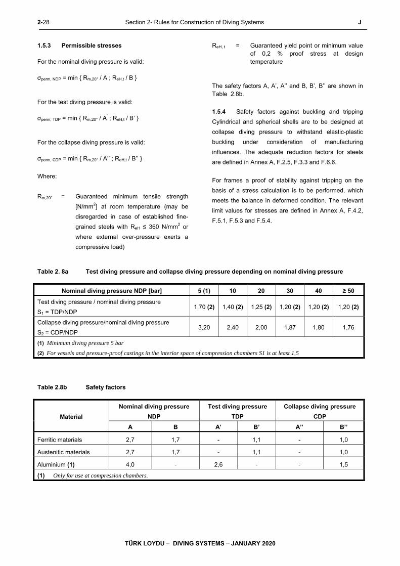
2-28 Section 2- Rules for Construction of Diving Systems J
TÜRK LOYDU – DIVING SYSTEMS – JANUARY 2020
1.5.3 Permissible stresses For the nominal diving pressure is valid: σperm, NDP = min { Rm,20° / A ; ReH,t / B } For the test diving pressure is valid: σperm, TDP = min { Rm,20° / A
’ ; ReH,t / B’ } For the collapse diving pressure is valid: σperm, CDP = min { Rm,20° / A’’ ; ReH,t / B’’ }
Where:
Rm,20° = Guaranteed minimum tensile strength
[N/mm2] at room temperature (may be
disregarded in case of established fine-
grained steels with ReH ≤ 360 N/mm2 or
where external over-pressure exerts a
compressive load)
ReH, t = Guaranteed yield point or minimum value of 0,2 % proof stress at design temperature
The safety factors A, A’, A’’ and B, B’, B’’ are shown in Table 2.8b.
1.5.4 Safety factors against buckling and tripping
Cylindrical and spherical shells are to be designed at
collapse diving pressure to withstand elastic-plastic
buckling under consideration of manufacturing
influences. The adequate reduction factors for steels
are defined in Annex A, F.2.5, F.3.3 and F.6.6.
For frames a proof of stability against tripping on the
basis of a stress calculation is to be performed, which
meets the balance in deformed condition. The relevant
limit values for stresses are defined in Annex A, F.4.2,
F.5.1, F.5.3 and F.5.4.
Table 2. 8a Test diving pressure and collapse diving pressure depending on nominal diving pressure
Nominal diving pressure NDP [bar] 5 (1) 10 20 30 40 ≥ 50
Test diving pressure / nominal diving pressure
S1 = TDP/NDP 1,70 (2) 1,40 (2) 1,25 (2) 1,20 (2) 1,20 (2) 1,20 (2)
Collapse diving pressure/nominal diving pressure
S2 = CDP/NDP 3,20 2,40 2,00 1,87 1,80 1,76
(1) Minimum diving pressure 5 bar
(2) For vessels and pressure-proof castings in the interior space of compression chambers S1 is at least 1,5
Table 2.8b Safety factors
Material
Nominal diving pressure
NDP
Test diving pressure
TDP
Collapse diving pressure
CDP
A B A’ B’ A’’ B’’
Ferritic materials 2,7 1,7 - 1,1 - 1,0
Austenitic materials 2,7 1,7 - 1,1 - 1,0
Aluminium (1) 4,0 - 2,6 - - 1,5
(1) Only for use at compression chambers.
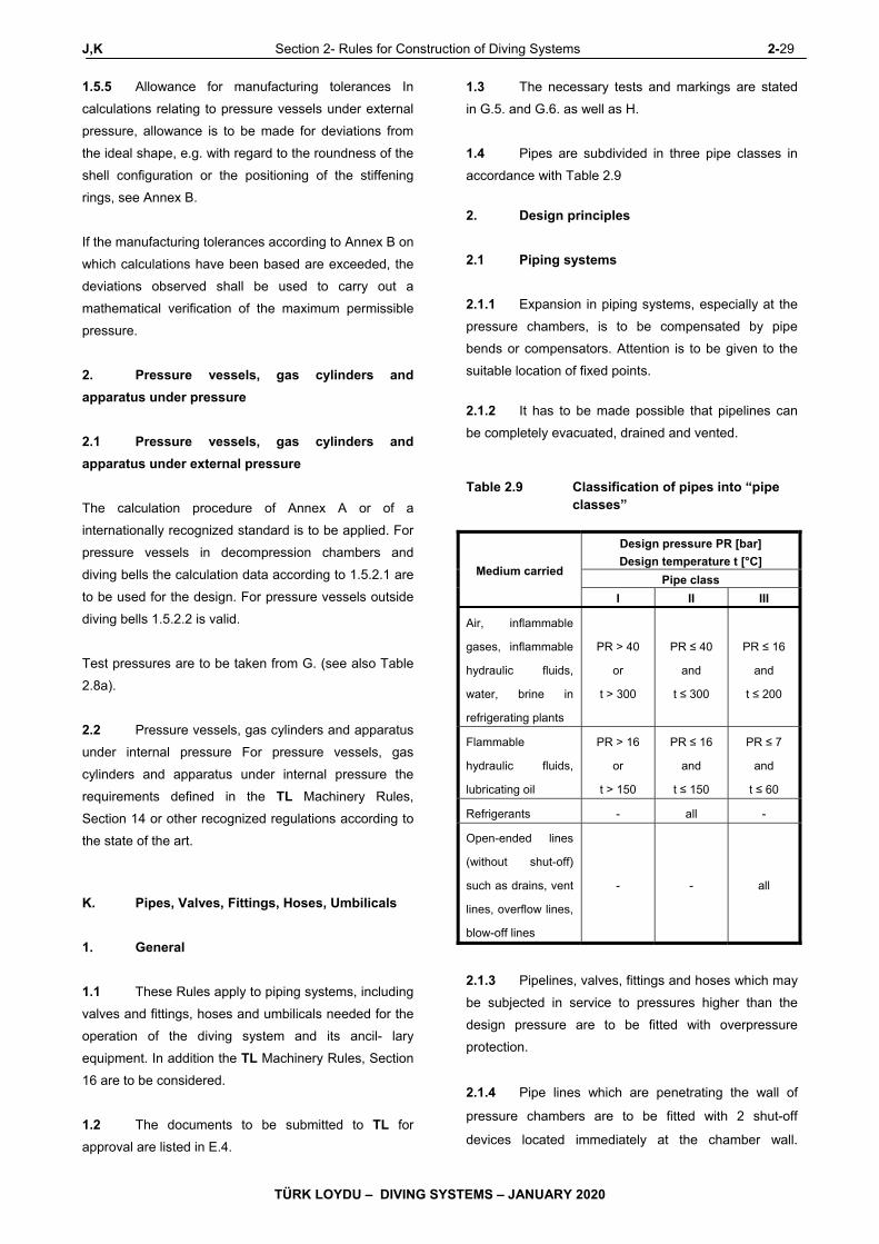
J,K Section 2- Rules for Construction of Diving Systems 2-29
TÜRK LOYDU – DIVING SYSTEMS – JANUARY 2020
1.5.5 Allowance for manufacturing tolerances In
calculations relating to pressure vessels under external
pressure, allowance is to be made for deviations from
the ideal shape, e.g. with regard to the roundness of the
shell configuration or the positioning of the stiffening
rings, see Annex B.
If the manufacturing tolerances according to Annex B on
which calculations have been based are exceeded, the
deviations observed shall be used to carry out a
mathematical verification of the maximum permissible
pressure.
2. Pressure vessels, gas cylinders and
apparatus under pressure
2.1 Pressure vessels, gas cylinders and
apparatus under external pressure
The calculation procedure of Annex A or of a
internationally recognized standard is to be applied. For
pressure vessels in decompression chambers and
diving bells the calculation data according to 1.5.2.1 are
to be used for the design. For pressure vessels outside
diving bells 1.5.2.2 is valid.
Test pressures are to be taken from G. (see also Table
2.8a).
2.2 Pressure vessels, gas cylinders and apparatus
under internal pressure For pressure vessels, gas
cylinders and apparatus under internal pressure the
requirements defined in the TL Machinery Rules,
Section 14 or other recognized regulations according to
the state of the art.
K. Pipes, Valves, Fittings, Hoses, Umbilicals
1. General
1.1 These Rules apply to piping systems, including
valves and fittings, hoses and umbilicals needed for the
operation of the diving system and its ancil- lary
equipment. In addition the TL Machinery Rules, Section
16 are to be considered.
1.2 The documents to be submitted to TL for
approval are listed in E.4.
1.3 The necessary tests and markings are stated
in G.5. and G.6. as well as H.
1.4 Pipes are subdivided in three pipe classes in
accordance with Table 2.9
2. Design principles
2.1 Piping systems
2.1.1 Expansion in piping systems, especially at the
pressure chambers, is to be compensated by pipe
bends or compensators. Attention is to be given to the
suitable location of fixed points.
2.1.2 It has to be made possible that pipelines can
be completely evacuated, drained and vented.
Table 2.9 Classification of pipes into “pipe classes”
Medium carried
Design pressure PR [bar]
Design temperature t [°C]
Pipe class
I II III
Air, inflammable
gases, inflammable
hydraulic fluids,
water, brine in
refrigerating plants
PR > 40
or
t > 300
PR ≤ 40
and
t ≤ 300
PR ≤ 16
and
t ≤ 200
Flammable
hydraulic fluids,
lubricating oil
PR > 16
or
t > 150
PR ≤ 16
and
t ≤ 150
PR ≤ 7
and
t ≤ 60
Refrigerants - all -
Open-ended lines
(without shut-off)
such as drains, vent
lines, overflow lines,
blow-off lines
- - all
2.1.3 Pipelines, valves, fittings and hoses which may
be subjected in service to pressures higher than the
design pressure are to be fitted with overpressure
protection.
2.1.4 Pipe lines which are penetrating the wall of
pressure chambers are to be fitted with 2 shut-off
devices located immediately at the chamber wall.
2-30 Section 2- Rules for Construction of Diving Systems K
TÜRK LOYDU – DIVING SYSTEMS – JANUARY 2020
Wherever possible, one of these devices is to be a non-
return valve.
2.1.5 Suction ends in pressure chambers are to be
protected against inadvertent covering and suction of
foreign bodies.
2.1.6 Pipelines carrying gas under high pressure
shall not be routed through accommodation spaces,
engine rooms or similar compartments.
2.1.7 Gas lines and electrical cables are to be routed
separately.
2.1.8 Materials for breathing gas systems shall not
develop poisonous or flammable products.
2.2 Pipe connections
2.2.1 Wherever possible, pipes shall preferably be
joined by full-penetration butt welds.
2.2.2 Screwed pipe connections approved by TL
may only be used.
2.2.3 Flanged connections may be used provided
that the flanges and flange bolts conform to a
recognized standard.
2.3 Valves and fittings
2.3.1 Shut-off-devices shall conform to a recognized
standard. Valves with screw-down bonnets or spindles
are to be protected against unintentional unscrewing of
the bonnet.
2.3.2 Manually operated shut-off devices are to be
closed by turning in the clockwise direction.
2.3.3 The closed and open positions of functionally
important shut-off valves shall be clearly indicated.
2.4 Hoses
2.4.1 Except for umbilicals, non-metal and metal
hoses are to be reduced to a minimum and are only to
be installed in short lengths.
2.4.2 Hose lines, including their connectors, must be
of proven suitability for the media, pressures and
temperatures concerned. When selecting the material,
special attention is to be paid to toxicity, inflammability,
gas permeability and, where applicable, to compatibility
with oxygen. Only types approved by TL may be used.
2.4.3 Hose lines are to be designed for a bursting
pressure, which shall be at least for liquids equivalent to
4 times and for gases 5 times the maximum allowable
working pressure.
2.4.4 Systems with hose lines are to be fitted with a
device for relieving the pressure before the hoses are
disconnected.
2.4.5 Hoses are to be connected with a suitable
connection to the fittings. Hose fittings are to be made
of corrosion resistant material and are to be so
designed that they cannot be disconnected accidetally.
2.5 Umbilicals
2.5.1 Umbilicals as the connection element between
support ship and diving bells / wet bell may contain
control and communication cables, hydraulic and
breathing gas lines as well as energy supply lines and a
lifting cable in a joint cover.
Umbilicals may also be used as connection element to
the diver and may include a supply line for diver
heating.
2.5.2 All aspects for the design of umbilicals are
defined in Annex E.
2.6 Oxygen systems
For oxygen systems the following special requirements
are to be considered:
2.6.1 Pipelines for mixed gases containing more
than 25 % oxygen are to be treated as pure oxygen
lines.

K Section 2- Rules for Construction of Diving Systems 2-31
TÜRK LOYDU – DIVING SYSTEMS – JANUARY 2020
2.6.2 All components and materials included in the
system are to be suitable for oxygen in relation to their
type and application and are to be carefully cleaned and
degreased before putting into operation.
2.6.3 Manometers for oxygen and/or Nitrox are to be
marked as free of oil and grease.
2.6.4 In piping systems containing oxygen only
spindle valves are permissible. As emergency shutoff
quick-closing valves, like e.g. ball valves, may be
provided at a suitable location, if these are adequately
marked and secured against unintentional activation.
2.6.5 Wherever possible, the pressure in oxygen
lines is to be reduced at the gas storage facility to a
pressure which is still compatible with an adequate gas
supply to the diving system.
2.6.6 Oxygen pipes are to be routed separately from
to oil pipes. Pipelines carrying oxygen under high
pressure shall not be routed through accommodation
spaces, engine rooms or similar compartments.
2.6.7 For oxygen lines with operating pressures
above 40 bar high-alloyed Cr-Ni-steels with a content of
Cr and Ni of together at least 22 % or Cr-Si-steels with a
Cr content of at least 22 % are to be used.
2.6.8 Connection pieces for oxygen are to be
designed to avoid burnout or are to be so arranged or to
be protected that the personnel cannot be injured in
case of burnout.
2.6.9 Spindle valves for oxygen are to be so
designed for nominal diameters above 15 mm and
operating pressures of more than 40 bar, that the
spindle gear is outside the gas space.
2.6.10 Sealing materials which contain flammable
elements and which come into contact with gases under
pressure and oxygen influence, may only be approved
for connection parts if their suitability for pressures,
temperature and type of mounting is proven.
2.6.11 For valves, fittings and connections for oxygen
only lubricants are permissible, which are approved for
the operating conditions.
2.6.12 Hoses are to be suitable for oxygen.
3. Materials, manufacturing and calculation
3.1 Piping systems, valves, fittings and pumps
3.1.1 Concerning the materials, manufacturing and
calculation of piping systems, valves, fittings and pumps
the TL Machinery Rules, Section 16 are valid.
3.1.2 All pipelines penetrating the wall of the
pressure chamber are to be pipe class I.
3.1.3 The permissible stresses for steel pipes and
pipes of metallic materials without fully developed yield
strength are to be chosen according to the TL
Machinery Rules, Section 16.
3.1.4 For welding connections of piping systems the
TL Welding Rules, Chapter 6 are valid.
3.2 Hydraulic systems
For hydraulic systems additionally the TL Machinery
Rules, Section 10 are valid.
4. Operational media
4.1 Media such as hydraulic fluids, lubricants, etc.
are to be selected in accordance with the proposed
environmental conditions. They shall not tend to
congeal or evaporate over the whole temperature
range.
4.2 Solid lubricants are to be so selected that
water penetration or contact with seawater does not
seriously impair the serviceability of the diving system.
4.3 Operational media shall not contain toxic
ingredients which are liable to be hazardous to health
through skin contact or when given off in fumes.
4.4 Operational media should not be corrosive or
attack other operating equipment (e.g. seals, hose lines,
etc.).

2-32 Section 2- Rules for Construction of Diving Systems L
TÜRK LOYDU – DIVING SYSTEMS – JANUARY 2020
L. Compressors
1. General
1.1 These Rules apply to compressors, including
valves, used in diving systems for compressing
breathing gases.
Where the compressors are electrically driven, the
motors and other electrical equipment have to comply
with the TL Electric Rules.
For the mechanical part of reciprocating compressors
see also TL Machinery Rules.
1.2 The documents to be submitted to TL for
approval are listed in E.4.
1.3 The necessary tests are stated in G.4.
2. Design principles
2.1 Compressors are to be suitable for the
operation on board of support ships under the effective
operation and environmental conditions.
2.2 Compressors are to be designed for the
required delivery rates, types of gas and delivery
pressures.
2.3 Compressors are to be so designed that no
lubricating oil can penetrate the gas circuit.
2.4 Compressors are to be so installed that no
harmful gases can be sucked in.
2.5 Where a compressor is used for the divers' air
supply, a receiver is to be interposed for the
compensation of pressure variations.
2.6 Oxygen compressors are to be installed in
separate spaces which have adequate ventilation.
2.7 The breathing air produced by compressors
has to meet the requirements of EN 12021. National
requirements remain unaffected hereby.
3. Materials
3.1 The materials of compressor parts are to be
suitable for the application concerned. They are to be
specified with due attention to the operating conditions
and the nature of the delivered medium. The TL
Material Rules are to be complied with. For O2
compressors the regulations for operation of oxygen
systems are to be observed additionally.
3.2 Proof is to be furnished of the quality of the
materials used for all components under pressure.
4. Equipment
4.1 Compressors are to be equipped with
adequately designed suction filters, coolers and water
separators.
4.2 Each compressor stage is to be equipped with
a pressure relief valve or rupture disc, neither of which
can be disabled. This safety device is to be designed
and set in such a way that the specified pressure in the
compressor stage concerned cannot be exceeded by
more than 10 %. The setting is to be safeguarded
against unauthorized alteration. If rupture discs are
used it is to be secured that no gas escapes
uncontrolled from the gas stock.
4.3 Each compressor stage is to be provided with
a suitable pressure gauge indicating clearly the final
pressure of that stage.
4.4 Where a compressor stage comprises more
than one cylinder and each cylinder can be closed off
individually, a pressure relief valve and a pressure
gauge is to be provided for each cylinder.
4.5 Cooling liquid systems with a shutoff device
are to be so designed that the specified coolant
pressure cannot be exceeded.
4.6 Dry-running reciprocating compressors are to
be equipped at each stage with a device which activates
a warning signal and shuts down the drive motor if the
final compression temperature stated in the operating
instructions is exceeded.

L,M Section 2- Rules for Construction of Diving Systems 2-33
TÜRK LOYDU – DIVING SYSTEMS – JANUARY 2020
4.7 Diaphragm-type compressors are to be
equipped at each stage with a diaphragm rupture
indicator which shuts down the compressor as soon as
damage occurs to the drive or compressor diaphragm.
5. Marking
A manufacturer's data plate containing the following
details is to be permanently fixed to each compressor:
- Manufacturer
- Type designation
- Serial number
- Year of construction
– Nominal capacity [m3/h]
- Compression end pressure [bar]
- Number of revolutions [min-1]
- Power demand [kW]
M. Life Support Systems
1. General
1.1 These Rules apply to all those plant
components and parts which are needed to ensure life
support and a safe environment for the occupants of a
diving system.
1.2 The documents to be submitted to TL for
approval are listed in E.5.
1.3 The necessary tests and markings are stated
in G.9. and H.
1.4 Breathing gases, breathing gas mixtures
Breathing gases and breathing gas mixtures are all gas
mixtures, which are used during diving missions or
during the application of breathing masks.
1.5 Nitrox
Nitrox is a breathing gas consisting of air and oxygen
with an oxygen content above 21 Vol%.
1.6 Heliox
Heliox is a breathing gas consisting of helium and
oxygen.
1.7 Trimix
Trimix is a breathing gas consisting of helium, nitrogen
and oxygen with an oxygen content below 21 Vol.%.
2. Gas supply
2.1 Filling stations
2.1.1 Filling stations serve to fill the gas storage with
breathing gas. The station has to include the complete
equipment to fill the containers. The boundary of the
gas production and filling station is located immediately
behind the shut-off valve at the gas line for filling or at
the suction side of the delivery system.
2.1.2 Filling stations are to be constructed and
operated, that operating, surveillance and maintenance
personnel or other persons nearby are not endangered.
2.1.3 Filling stations for breathing gases are not to
be installed in areas where internal combustion engines
or boilers are in operation.
2.1.4 Filling stations for breathing gases are to be
arranged with sufficient place for operation,
maintenance and cleaning, escape and rescue corridors
as well as for fire extinguishing.
2.1.5 Pipe connections between filling stations for
compressed air for production of breathing gases and
other compressed air systems on board are only be
established with special approval of TL and under
consideration of additional protection measures.
2.1.6 Filling pipes/hoses and connection or coupling
fittings/hoses are to be suitable for rendering pressure-
less without danger.
2-34 Section 2- Rules for Construction of Diving Systems M
TÜRK LOYDU – DIVING SYSTEMS – JANUARY 2020
Gas under pressure, which is discharged by the safety
devices, is to be drawn off in a suitable way.
2.1.7 Filling connections are to be designed and
marked in a way, where confusion of gases to be filled
is safely avoided and a correct connection is enabled.
2.1.8 At the position of the gas delivery, the filling
station is to be equipped with a manometer showing the
delivery pressure.
2.1.9 Filling stations for breathing gases are to be
operated manually and to be monitored.
2.2 Gas storage facilities
2.2.1 Each diving system is to be provided with a
permanently installed gas storage facility or with a
suitable location for the storage of portable gas
cylinders.
2.2.2 The capacity of the gas storage facility shall be
such that, for all the planned diving operations, a
sufficient number and quantity of gas mixtures are
available to supply all the decompression chambers,
diving bells and divers with the correct gases at all
operating depths and under normal and emergency
conditions.
2.2.3 The stock of emergency breathing gas supply
is to be stored separately in gas cylinders which shall
not be opened for normal operation.
2.2.4 The diving bell is to be provided with its own
gas cylinders so that the maximum number of
occupants in the bell can in an emergency be supplied
with a sufficient quantity of breathing gas mixture for at
least 24 hours. In addition an oxygen bottle for
supplementing the oxygen supply is to be carried on the
diving bell.
2.2.5 Oxygen bottles are to be placed in well
ventilated positions and may not be stored close to
combustible materials.
2.2.6 Spaces in which oxygen is stored are to be
separated from the adjoining spaces by bulkheads and
decks of Type "A-60" and are to be arranged to facilitate
speedy exit in case of danger.
Spaces in which oxygen can penetrate are to be
equipped with oxygen indicating and alarm devices. The
oxygen sensor is to be installed near the floor. A
monitored suction of space air near the floor may be
provided as an alternative.
2.3 Gas distribution
2.3.1 General
2.3.1.1 The gas supply system shall be so designed
that the pressure in the living compartment of the
decompression chamber can be raised at a rate of at
least 2 bar/min up to 2 bar and thereafter at a rate of 1
bar/min.
2.3.1.2 The gas venting system shall be so designed
that the pressure in a decompression chamber or diving
bell can be lowered to 1 bar at a rate of at least 1
bar/min.
2.3.1.3 Sets of breathing masks controlled by
respiration which supply breathing gas to persons under
pressure and also remove the exhaust gas
independently of the chamber atmosphere are to be
designed for a gas flow equivalent to 3 times the
required breathing rate per minute (AMV).
The required breathing rate per minute depends on the
activity to be performed and the environmental
conditions.
When designing the breathing mask gas supply and
exhaust gas disposal system, the number or persons
simultaneously connected to the system is to be allowed
for as defined in Table 2.10:
2.3.1.4 The gas circulating systems are to be so
designed that the chamber conditions stated in I.2. are
maintained.
2.3.1.5 Each decompression chamber compartment
and each diving bell is to be equipped with at least the
following gas systems:

M Section 2- Rules for Construction of Diving Systems 2-35
TÜRK LOYDU – DIVING SYSTEMS – JANUARY 2020
- 2 independent gas supply systems for
compression which may deliver into a single
inlet pipe
immediately at the chamber
- 1 chamber exhaust gas system
- 1 independent mask supply system (BIBS)
- 1 mask exhaust gas system
- 1 gas circulating system for maintaining a
breathable chamber atmosphere
Where pure oxygen or gas containing more than 25 %
O2 by volume is supplied to the chamber, a separate
piping system is to be provided for this purpose.
Table 2.10 Quantity of breathing gas for simultaneously connected breathing masks
Number of persons
Quantity of breathing gas [litres/min]
1
2
3
4
5
6
7
8
z>8
1 x AMV x 3
2 x AMV x 1,8
3 x AMV X 1,6
4 x AMV x 1,4
5 x AMV x 1,3
6 x AMV X 1,2
7 x AMV x 1,1
8 x AMV X 1,1
z x AMV X 1,0
2.3.1.6 Valves in gas systems are to be arranged so
that a leaking valve cannot cause any unintended
mixing of gases respectively no oxygen or oxygenlike
gas can penetrate into lines intended for other gases.
Intersections between oxygen and non-oxygen systems
are to be isolated by twin shut-off valves with a vent
valve placed between them.
2.3.1.7 Filters and pressure reducers are to be fitted in
such a way that they can be dismounted without having
to interrupt major gas supply lines.
2.3.1.8 If for diving depths above 50 m the
composition of the gas of the chamber atmosphere
does not correspond to the required breathing gas of
the breathing masks (e.g. Heliox, Trimix), special
measures (e.g. redundant masks and pressure
reducers) are to be performed and to be agreed with
TL.
2.3.2 Pressure chambers
2.3.2.1 At least one breathing mask is to be provided
for each occupant of each separately pressurized
chamber compartment.
2.3.2.2 The masks are to be joined either permanently
or by plug connectors to the mask gas supply and
exhaust system.
2.3.2.3 The exhaust gas (exhalation line) side of the
masks is to be protected against any inadmissible
pressure drop or inadmissible pressure difference.
2.3.2.4 The supply of gas to the chamber is to be
arranged so as to ensure that a homogeneous gas
distribution inside the chamber is achieved as quickly as
possible.
2.3.3 Diving bells
2.3.3.1 Besides their normal breathing gas supply
diving bells and divers in the water have also to carry an
independent reserve gas supply.
2.3.3.2 The supply of breathing gas to the diving bell is
to be designed in such a way that, should the diving bell
umbilical fail, the carried bell reserve supply can be
switched manually or automatically to the diver bell
supply without flowing back into the bell umbilical.
2.3.3.3 The divers' umbilical system is to be so
designed that each diver has his own independent
supply.
2.3.3.4 In the diving bell at least one breathing mask is
to be provided for each diver, and this is to be
connected to both the normal and the reserve gas
supply. Divers' masks and helmets with a gas supply
may be recognized as breathing masks.
2.3.3.5 Automatic pressure reducers are to be
provided for the breathing masks.
2-36 Section 2- Rules for Construction of Diving Systems M
TÜRK LOYDU – DIVING SYSTEMS – JANUARY 2020
2.3.3.6 The emergency oxygen supply is to be fitted
with a dosage system to enable the oxygen in the diving
bell to be maintained at the correct partial pressure.
2.4 Conditioning of chamber atmosphere
2.4.1 Each pressure chamber is to be equipped with
an oxygen dosing device and a chamber gas circulating
unit in which the CO2 can be absorbed and the air
temperature and humidity can be regulated. The rate of
circulation shall be such as to satisfy the conditions
stated in I.2.
2.4.2 Each diving system is to be equipped with at
least 2 chamber gas treatment units which are to be so
arranged that they can be switched to adjoining
chambers.
2.4.3 Diving bells are to be equipped with a chamber
gas treatment unit and also with an autonomous reserve
CO2 absorption unit for emergency use.
2.4.4 Diving bells are to be equipped with a heating
system provided with redundant supplies and so
designed that the divers in the diving bell and in the
water are maintained in a thermal balance. For diving
operations at depths greater than 100 m breathing gas
preheaters are to be provided additionally for the divers
in the water.
2.4.5 Measures are to be taken to enable the divers
within the diving bell to be maintained in a safe thermal
balance for at least 24 hours in an emergency.
2.5 Treatment and mixing of breathing gases
The use of closed breathing circuits, gas mixing
systems for direct breathing gas supply and helium
reclaim systems is subject to approval by TL.
3. Control and instrumentation
3.1 Central control position
The surveillance and control of the life support systems
has to be performed with the assistance of the central
control position of the diving system on the support ship,
where all essential chamber data are indicated as well
as the chamber pressures are controlled and the gases
are distributed to the different chambers, if more than
one chamber is existing. In addition the operating
conditions of the ancillary systems are to be indicated
there (see O.1.4 and O.1.5).
3.2 Instrumentation
3.2.1 Indicating instruments
3.2.1.1 The central control position is to be equipped
with suitable instruments for the surveillance of each
manned decompression chamber compartment or. each
diving bell (see Table 2.11).
3.2.1.2 The instrument indicating the pressures in
decompression chambers and diving bells are to be
accurate to ± 0,25 % of the whole scale with a
maximum deviation of 30 cm water column. All other
pressure readings shall be accurate to ± 1 % of the
whole scale.
3.2.1.3 The central control position is also to be
equipped with indicating instruments for the following
parameters:
- Pressure of connected breathing gas
receivers/bottles
- Pressure downstream of pressure reducers
- Oxygen content in supply lines to:
- umbilical
- chamber compartments
- Breathing masks in chambers
3.2.1.4 Inadmissible deviations from the reference
values of the vital parameters mentioned in M. shall
actuate a visual and audible alarm at the central control
position; the same for automatically actuated switching
operations in the gas supply system and similar
functions.
3.2.1.5 The compartments of decompression
chambers are to be fitted with pressure and temperature
gauges which can be read from inside. Diving bells are
to be equipped with instruments indicating the internal
M Section 2- Rules for Construction of Diving Systems 2-37
TÜRK LOYDU – DIVING SYSTEMS – JANUARY 2020
and external pressure and the pressure of the
independent gas supply.
3.2.1.6 Pressure indicators connected directly to the
pressure chamber system are to be fitted with a shutoff
valve
3.2.2 Analyzer systems
3.2.2.1 Each diving simulator is to be equipped with at
least one oxygen and one CO2 analyzing system.
3.2.2.2 Throughout the entire period of operation, the
oxygen analyzer has to give a reading accuracy to at
least ± 0,015 bar partial oxygen pressure.
3.2.2.3 Throughout the entire period of operation, the
CO2 analyzer has to give a reading accuracy to at least
± 0,001 bar partial CO2 pressure.
3.2.2.4 In diving bells and living compartments of
decompression chambers in addition independent
instruments for monitoring the oxygen and CO2 levels
are to be provided.
3.2.2.5 Where gases other than air or helium-oxygen
or He/N2/O2 mixtures are used in diving operation, the
necessary instrumentation is in each case to be defined
together with TL.
3.2.2.6 If impurities of the chamber atmosphere, such
as CO, NO, NOx or hydrocarbons might occur, an
adequate analyze system is to be provided. Test tubes
may be recognized for this purpose.
The accuracy of the analyzer readings shall be such
that the discrepancy between the partial pressure in the
gas and the partial pressure readings on the instrument
does not exceed 10 %.
3.3 Control equipment
3.3.1 The central control position is to be equipped
with controls for at least the following functions:
- Pressurization and pressure control of each
independently operated decompression
chamber compartment and each diving bell
- Decompression of each independently
operated decompression chamber
compartment and each diving bell
- Pressure equalization between chamber
compartments
- Oxygen addition to the chamber compartments
- Control of gas supply to breathing masks
- Control of temperature and humidity in the
pressure chambers
3.3.2 At the control position for the gas distribution a
system mimic diagram is to be provided showing the
functions of the various valves and the different gas
lines marked in colour.
Table 2.11 Operation conditions to be monitored
Parameter Decompression chamber compartments
Diving bell
Pressure or depth (1) X X (2)
Temperature (1) X -
Humidity X -
O2 partial pressure (1) X X
CO2 partial pressure X X
(1) These parameters are to be displayed continuously.
(2) The pressure or the depth inside and outside the diving bell is to be indicated.

2-38 Section 2- Rules for Construction of Diving Systems N
TÜRK LOYDU – DIVING SYSTEMS – JANUARY 2020
N. Electrical Equipment
1. General
1.1 The following Rules supplement the TL Electric
Rules and are to be applied to diving systems.
1.2 The documents to be submitted to TL are listed
in E.6.
1.3 The necessary tests are stated in G.7.
2. Design principles
2.1 General principles
2.1.1 All electrical systems and equipment are to be
constructed and installed in such a way that they are
serviceable and perform satisfactorily under the design
conditions specified for the diving system to minimize
the risks for divers through fire, explosion, electric shock
and emission of toxic gases.
2.1.2 Provision is to be made for maintaining the
diving system in a normal operating condition without
recourse to the emergency power supply.
2.1.3 Even under emergency conditions, the
operation of equipment necessary to the divers' safety is
to be guaranteed.
2.1.4 Suitable Protective measures are to be taken
to exclude any electrical hazards to divers and to the
operating personnel of the diving system.
2.2 Materials and insulation
2.2.1 The materials used in the construction of
electrical machines, cables and apparatus are to be
resistant to moist and salty sea air, seawater and oil
vapours. They shall not be hygroscopic and are to be
flame-retardant and self-extinguishing. In addition,
materials installed inside decompression chambers and
diving bells are to be approved for operation in
hyperbaric atmospheres and shall not liberate toxic
gases or fumes under these conditions.
2.2.2 Materials with high tracking resistance are to
be used for the supports of live parts. The air and
leakage distances are to be dimensioned
devicespecifically according to IEC. Switchgears,
penetrations through pressure vessel walls, underwater
plug connectors and appliances directly connected to
the busbars are to be designed for the next higher
nominal insulation rating.
2.2.3 Materials and insulations for electrical
equipment used in water are to be agreed with TL.
2.3 Supply systems
2.3.1 Approved supply systems are:
- Direct current and single-phase alternating
current:
2 conductors insulated from ship's hull
– Alternating current (three-phase alternating
current):
3 conductors insulated from ship's hull
2.3.2 The use of the diving system, the ship's hull or
parts thereof for the return of electrical current is not
permitted.
2.3.3 Systems earthing is not permitted.
Exceptions may be allowed in the case of subsystems
using isolating transformers and high-resistance
systems earthing.
2.4 Maximum permissible operating voltages
2.4.1 The following maximum voltages are permitted
for electrical equipment inside decompression
chambers (only in dry chamber compartments):
- for permanently installed electrical drives and
heating systems: 250 V
- for lighting networks and socket circuits,
communications and display equipment and all
consumers supplied via cables not
permanently installed: 50 V
2.4.2 30 V is the maximum permissible voltage for all
electrical equipment in diving bells and wet bells.

N Section 2- Rules for Construction of Diving Systems 2-39
TÜRK LOYDU – DIVING SYSTEMS – JANUARY 2020
2.4.3 Voltages higher than those stated in 2.4.1 and
2.4.2 may be approved where additional safety
measures are taken which achieve an equivalent level
of safety.
2.4.4 The permissible voltages for electrical
equipment used in water are to be agreed with TL in
each case.
2.5 Protective measures
2.5.1 All electrical equipment is to be protected in
accordance with the TL Electric Rules, Section 1 unless
otherwise stated in the following.
2.5.2 To protect divers against excessive contact
voltages and electric shock, additional safety measures
are to be taken to avoid or restrict dangerous fault
currents. These measures are to be agreed with TL in
each single case.
2.5.3 For diving systems the minimum degrees of
protection according to Table 2.12 are valid. The degree
of protection of the equipment is to be guaranteed as
installed even when in operation (heeling position). In
this context, provision of shielding at the point of
installation is deemed as protective measure.
2.5.4 Protective conductors
For the use of protective conductors is to be observed:
a) The protective conductor has to take the form
of an additional cable or additional line or an
additional core in the power cable. The use of
armouring as protective conductors is to be
checked case by case and to be approved by
TL.
b) The cross-section of the protective conductor
shall be equivalent to at least half the cross-
section of the principal conductor/ phase
conductor. However, with crosssections up to
16 mm2, its cross-section shall be equal to that
of the principal conductors/ outer conductors.
The minimum crosssection of separately laid
protective conductors is 4 mm2. The cross-
section of the protective conductor shall at
least comply with the factors shown in Table
2.13.
The dimensional design of the protective
conductors is to be based on the maximum
possible short-circuit currents of the equipment
concerned, the maximum break times of the
relevant protective elements and a maximum
temperature rise of the protective conductor of
90 °C.
c) The connection of the protective conductor to
the hull of the support ship shall be located at a
point where it can easily be checked.
2.5.5 Earthing
For earthing is to be considered:
a) Diving systems are to be equipped with an
earthing and potential equalizing system.
Connections for external earthing are to be
provided at all pressure chambers. Also in
gas storage and filling station, etc.
b) All metal parts of electrical installations - with
the exception of live components - are to be
earthed. The casings of electrical equipment
mounted directly against the inside wall of
pressure chambers are considered to be
effectively earthed only if the contact surfaces
are permanently free from rust, scale and paint
and the casings are fastened with at least two
corrosion-resistant screws secured to prevent
accidental loosening.
If these conditions are not met, earthing is to
be effected by separate earthing conductors.
c) The connections of the potential equalization at
the diving bell/wet bell shall be installed where
it can easily be checked.
In an easily accessible position of the
superstructure of the support ship and on the
diving bell/wet bell a connection point in the
form of a connecting plate with preferably M 12
stud bolts is to be provided to which protective
conductors can be connected without tools.
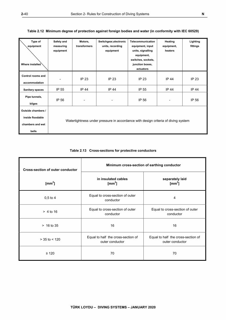
2-40 Section 2- Rules for Construction of Diving Systems N
TÜRK LOYDU – DIVING SYSTEMS – JANUARY 2020
Table 2.12 Minimum degree of protection against foreign bodies and water (in conformity with IEC 60529)
Type of
equipment
Where installed
Safety and
measuring
equipment
Motors,
transformers
Switchgear,electronic
units, recording
equipment
Telecommunication
equipment, input
units, signalling
equipment,
switches, sockets,
junction boxes,
actuators
Heating
equipment,
heaters
Lighting
fittings
Control rooms and
accommodation - IP 23 IP 23 IP 23 IP 44 IP 23
Sanitary spaces IP 55 IP 44 IP 44 IP 55 IP 44 IP 44
Pipe tunnels,
bilges IP 56 - - IP 56 - IP 56
Outside chambers /
inside floodable
chambers and wet
bells
Watertightness under pressure in accordance with design criteria of diving system
Table 2.13 Cross-sections for protective conductors
Cross-section of outer conductor
[mm2]
Minimum cross-section of earthing conductor
in insulated cables [mm2]
separately laid [mm2]
0,5 to 4
Equal to cross-section of outer conductor
4
> 4 to 16
Equal to cross-section of outer conductor
Equal to cross-section of outer conductor
> 16 to 35
16 16
> 35 to < 120
Equal to half the cross-section of outer conductor
Equal to half the cross-section of outer conductor
≥ 120
70 70
N Section 2- Rules for Construction of Diving Systems 2-41
TÜRK LOYDU – DIVING SYSTEMS – JANUARY 2020
This connection serves for the compensation of
the potential between the diving system and
the support ship.
d) The casings of electrical equipment in water
are always to be earthed by an earthing
conductor included in the supply cable. Where
this is not possible, casings mounted on the
outside of the diving bell may also be provided
with a separate external earth. In this case,
however, the entire earth connection
(connecting screws and earthing conductor) is
to be provided corrosion- resistant.
e) The connections between the earthing
conductor and the chamber and to the ship's
earth are to be made with corrosion-resistant
screw connections effectively safeguarded
against accidental loosening. The dimensions
of the screw connections are to be
dimensioned according to the requisite cross-
sections of the earth conductor to be
connected and may not be used for other
purposes.
f) Machines and devices which are mounted on
insulating vibration dampers are to be earthed
by flexible cables, wires or stranded copper
straps.
g) Earth connections are to be accessible for
maintenance and inspection. Wherever
possible, they are to be marked. Earthing
conductors in multi-core cables are to be
marked green and yellow, at least at the
terminals.
h) Earthing conductors are to be provided with
corrosion protection compatible with their
place of installation.
i) Copper earthing conductors are subject to the
following minimum cross-sections:
- external connections on support ship and
water: 10 mm2
- external connections inside chambers and
living compartments: 6 mm2
- Separate earthing conductors inside
switchgear and casings: 4 mm2
- Earthing conductors in multi-core cables up to
a conductor cross-section of 16 mm2 shall
correspond to the cross-section of the main
conductor, subject to a minimum of 1 mm2
- Earthing conductors in multi-core cables with a
conductor cross-section of more than 16 mm2
equal to at least half that of the main conductor
If other materials are used, the minimum
crosssection is to be determined by the ratio of
the electrical conductivity of these materials to
the electrical conductivity of copper.
j) Cable sheaths and armouring are not to be
used as earthing conductors.
3. Power supply
3.1 Principles
3.1.1 All electrical equipment essential to the safety
of divers and diving operations is to be connected to a
mutually independent main and emergency power
supply.
3.1.2 Where provision is made for automatic
switching from the main to the emergency power
supply, each such switching operation has to actuate in
the central control position of the diving system a (visual
and audible) signal requiring acknowledgement. An
indicator has to show which supply is connected.
3.1.3 The main power supply to the diving system
can be taken directly from the main switchboard of the
support ship or from the main power source of the
diving system.
3.1.4 The following may be used as an independent
emergency power source:
- An electrical generator with its own drive
- An emergency battery of sufficient capacity
- The emergency power supply of the support

2-42 Section 2- Rules for Construction of Diving Systems N
TÜRK LOYDU – DIVING SYSTEMS – JANUARY 2020
ship provided that this is designed to meet the
additional emergency power of the diving
system
3.1.5 The emergency power source for the diving
system is to be installed in a space separated from the
main power source and the main switchboard so that it
also remains operational in case of a fire or other major
damage affecting the main power supply.
3.2 Main power supply
3.2.1 A power balance is to be prepared to prove
that units for the generation, storage and conversion of
electric power are adequately rated. This balance shall
take account of the full power consumption of those
consumers which are permanently required in service.
3.2.2 The power consumption of consumers which
are connected for limited periods may be determined by
applying a simultaneity factor.
3.2.3 To meet the power requirements during brief
peak loads, e.g. when motors are started automatically,
a reserve capacity is to be shown.
3.2.4 The generating equipment of the main power
supply is to be so designed that the voltage and
frequency variations allowed by the TL Electric Rules,
Section 1 are not exceeded.
3.3 Emergency power supply
3.3.1 The emergency power supply shall be able to
meet the emergency power requirements of the diving
system for a period of at least 48 hours.
3.3.2 The emergency power supply shall be able to
meet simultaneously the requirements of at least the
following items of equipment:
- Emergency lighting systems in decompression
chambers and diving bells as well as in the
spaces required for operation
- Emergency communication systems
- Life support systems required for emergency
- Launch, recovery and transfer systems
required for emergency
- Central control position as well as required
surveillance and alarm systems
3.3.3 In the design of the emergency power supply
system, appropriate reserve capacity is to be provided
to meet peak loads (e.g. caused by the starting of
electric motors).
In determining the necessary battery capacity,
allowance is also to be made for the cut-off voltage and
voltage drop of battery.
3.3.4 Diving bells are to be equipped with their own
independent emergency power supply capable of
meeting the power requirements of the autonomous life
support system of the diving bell for at least 24 hours.
3.4 Storage batteries and battery chargers
3.4.1 Storage batteries, general
3.4.1.1 Storage batteries are to be rated such as to be
capable of supplying the consumers during the period
specified in accordance with the power balance, when
charged to 80 % of their rated capacity.
3.4.1.2 At the end of the supply period the voltage in
the storage battery or at the consumers shall at least
reach the values quoted in the TL Electric Rules,
Section 1, F. and Section 3, C.
3.4.1.3 Approved storage batteries are lead-acid
storage batteries with diluted sulphuric acid as
electrolyte and steel storage batteries with nickel-
cadmium cells and diluted potassium hydroxide as
electrolyte.
3.4.1.4 Further types of batteries may be approved
under consideration and test of the following points:
- Resistance to short circuits
- Fuse elements at occurring short circuits
- Electrical monitoring elements

N Section 2- Rules for Construction of Diving Systems 2-43
TÜRK LOYDU – DIVING SYSTEMS – JANUARY 2020
- Fire risk/fire behaviour including consequences
on adjacent cells or components
- Special requirements for the installation
location
- Suitability of the used belonging electrical
components
- Integration in the electrical plant including
switch gears
- Charging devices and automation system for
charging
3.4.1.5 Storage batteries are to be designed such as
to retain their undisturbed function at inclinations of up
to 22,5° and such that for inclinations of up to 45°
electrolyte will not leak. Cells without covers are not
admissible.
3.4.1.6 The casing is to be resistant to electrolytes,
mineral oils and cleaning agents, as well as to corrosion
due to saline mist. Glass and readily flammable
materials are not approved as materials for casings.
3.4.1.7 In the case of storage batteries containing
liquid electrolyte it shall be possible to check the
electrolyte level. The maximum admissible electrolyte
level is to be marked.
3.4.1.8 Lead and alkaline storage batteries shall not be
accommodated in the same space or be placed in direct
proximity to each other.
3.4.1.9 Where the installed battery capacity is 1000 Ah
or more, the battery is to be divided into smaller battery
units so that restricted operation is still possible in the
event of a fault.
3.4.1.10 The weight of the biggest portable unit shall
not exceed 100 kg.
3.4.1.11 The rating data of the storage batteries are to
be indicated on rating plates.
Storage batteries are to be serviced and operated in
accordance with manufacturers' instructions.
3.4.1.12 Measures are to be taken to ensure that
neither the crew nor the operational equipment can be
endangered by emissions of electrolyte fumes.
3.4.1.13 A sign is to be mounted at the entrance of
battery spaces pointing out that only insulated tools are
to be used inside and conductive objects like keys,
ballpoint pens, watches with conductive watch straps
have to be taken off. Explosion hazard shall be pointed
out.
3.4.1.14 Storage batteries are to be installed in such a
way that mechanical damage is as far as possible
excluded. Safe operation under the environmental
conditions stated in D. is to be ensured and the leakage
of electrolyte is to be prevented.
Suitable measures, e.g. provision of plastic trays or
flexible rubber bags, are to be taken to prevent
electrolyte from entering the battery space bilges in the
event of mechanical damage to individual battery cells.
3.4.2 Special requirements for lead batteries
3.4.2.1 Battery spaces shall be arranged and
ventilated, as required for the type of battery, to prevent
the accumulation of ignitable gas mixtures.
3.4.2.2 The quantity of air to be supplied and
exhausted during charging shall be so calculated, that
the lower explosion limit for a hydrogen air mixture will
not be exceeded.
H2-monitors permanently mounted at suitable points
have to measure the gas concentration in the battery
space, the exhaust system and, where necessary, in
further spaces of the diving system. If the gas
concentration reaches and exceeds a level equivalent to
35 % of the lower explosion limit (LEL), this shall
automatically release a visual and audible alarm at a
central control position. Equipment for monitoring the H2
- concentration shall be type approved.
3.4.2.3 Battery spaces shall contain no other electrical
appliances apart from the storage batteries themselves.
Lights, fuses (single voltage measuring device) and
measuring devices for H2 concentration may be
installed if they are in accordance with the requirements
2-44 Section 2- Rules for Construction of Diving Systems N
TÜRK LOYDU – DIVING SYSTEMS – JANUARY 2020
for an atmosphere containing H2 (see recommendations
IEC 60079).
3.4.3 Battery chargers
3.4.3.1 Battery chargers are to be rated such that the
maximum admissible charging currents cannot be
exceeded.
3.4.3.2 The power demand of the consumers is to be
taken into account when selecting the battery chargers.
3.4.3.3 The battery chargers are to be rated such that
the tolerances of the limited characteristics and constant
characteristics respectively are adhered to irrespective
of external disturbance effects.
3.4.3.4 Battery chargers have to cut out automatically
in case of:
- Failure of the battery space ventilation (if an
ignitable gas mixture may be created)
- Excessive temperature of charging generator
- Overtemperature of the electrolyte (if a
temperature control of the single cells is
provided)
3.4.3.5 For lead batteries is to be considered
additionally:
- If during charging simultaneously consumers
are fed, the maximum charging voltage shall
not exceed 120 % of the rated voltage.
- Preferably chargers with IU or IUI or IUW
characteristics shall be employed.
- If a H2 concentration measuring device is
provided, the charging device has to cut off
automatically, if the H2 concentration is too
high, e.g. 60 % LEL.
4. Power distribution
4.1 Distribution and switchgear
4.1.1 Electrical distribution systems are to be so
designed that a fault or failure in one circuit cannot
impair the operation of other circuits or the power
supply.
4.1.2 The following consumers at least are to be
supplied via individual circuits equipped with all
necessary safety devices and switchgear from a
distribution panel supplied directly from the main
switchboard of the support ship:
- Launch, recovery and transfer systems of the
support ship for the diving bell/wet bell
- Lighting system for decompression chambers
and diving bells
- The electrical consumers of the life support
systems
- Communication systems
4.1.3 In normal operation the emergency power
distribution system may be supplied via a transfer line
from the main power distribution system.
4.1.4 Distribution boards with their own individual
feed circuits may not be mounted in a shared casing,
i.e. each of these switchgear units has to have its own
enclosure.
4.1.5 Effective measures are to be taken to prevent
the occurrence of vagabond voltages inside switchgear.
Circuits at protective low voltage may not be routed with
circuits at higher voltage in a joint conductor bundle or
cable duct. Terminals for different voltage levels are to
be arranged separately and are to be clearly identified.
4.1.6 Switchgear units for a connected load of 50 kW
and over are to be tested in the manufacturer's works in
the presence of a TL Surveyor. The test shall be
performed in accordance with the TL Electric Rules,
Section 5, H.
N Section 2- Rules for Construction of Diving Systems 2-45
TÜRK LOYDU – DIVING SYSTEMS – JANUARY 2020
4.1.7 Switchgear units for a connected load of less
than 50 kW are to undergo an internal works test of the
same scope. These tests are to be certified by a
Manufacturer Inspection Certificate. Test Certificates
are to be submitted to TL not later than the trial of the
diving system.
For voltage ratings below 60 V, the voltage test is to be
performed at a power-frequency withstand voltage of
500 V.
4.2 Switching and protective devices
4.2.1 Each circuit is to be protected against overload
and short-circuit.
4.2.2 All consumers circuits are to be fitted with
switches. The switching action shall be on all poles.
4.2.3 Electrical switches for circuits with a current
rating above 0,5 A are permitted inside decompression
chambers and diving bells only subject to the use of
additional safety features (e.g. pressurized enclosure in
protective gas).
4.2.4 Electrical fuses may not be located inside
decompression chambers and diving bells. Wherever
possible, fuses for the independent emergency power
supply to the diving bell are to be located outside the
chamber. If installed inside the diving bell, special
protective measures are necessary. The fuses shall in
any case be protected against intervention by the
occupants of the chamber.
4.2.5 Electric motors installed inside chambers are to
be fitted with an overcurrent alarm. The alarm is to be
tripped in good time before the motor protection
responds. This does not apply to those electric motors
which cannot be endangered by overcurrent. For motors
in the diving bell, the alarm may take place in the diving
bell.
4.2.6 Devices are to be fitted which, in the event of
danger, enable the power supply to all the electrical
consumers in the pressure chamber to be quickly
disconnected. The switches needed for this purpose are
to be mounted at the central control position. Means are
to be provided to enable the disconnection separately
for each chamber.
4.2.7 All unearthed distribution systems, including
the groups of consumers and individual consumers
supplied via isolating transformers, safety transformers,
rectifiers and inverters, are to be equipped with a
continuously operating insulation monitoring system.
For systems using protective low voltage, an alarm is to
be actuated at the central control position if the
insulation value drops below a preset limit. For higher
voltage systems, the insulation monitor shall trip an
alarm at the central control position when a
predetermined fault current is reached, and the system
concerned is to be automatically disconnected, if no
endangerment is created hereby.
For the electrical equipment of the diving bell, the alarm
actuated by the insulation monitoring system may take
place in the diving bell.
Note:
The current/time characteristics of insulation
monitoringsystems directly concerned with personel safety
has to meet the requirements of diver protection. In assessing
the time characteristics, account is to be taken of the response
time of the insulation monitoring system and of the tripping
time of the switching devices which it actuates.
4.2.8 Electrical installations are to be so arranged
that a flooding with gases or water is to be excluded. If
this cannot be avoided, electrical installations are to be
designed gas-tight/water-tight or with the ability to be
shut-off or other protection measures are to be
provided.
4.3 Enclosures for electrical equipment
4.3.1 All items of electrical equipment belonging to a
diving system are to be encased or sealed in a suitable
enclosure compatible with their nature, location and
protection class.
4.3.2 The enclosures of electrical equipment
installed inside decompression chambers and diving
bells which are operated in water have to be approved
by TL.
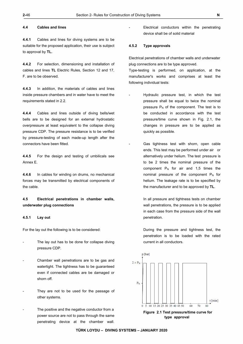
2-46 Section 2- Rules for Construction of Diving Systems N
TÜRK LOYDU – DIVING SYSTEMS – JANUARY 2020
4.4 Cables and lines
4.4.1 Cables and lines for diving systems are to be
suitable for the proposed application, their use is subject
to approval by TL.
4.4.2 For selection, dimensioning and installation of
cables and lines TL Electric Rules, Section 12 and 17,
F. are to be observed.
4.4.3 In addition, the materials of cables and lines
inside pressure chambers and in water have to meet the
requirements stated in 2.2.
4.4.4 Cables and lines outside of diving bells/wet
bells are to be designed for an external hydrostatic
overpressure at least equivalent to the collapse diving
pressure CDP. The pressure resistance is to be verified
by pressure-testing of each made-up length after the
connectors have been fitted.
4.4.5 For the design and testing of umbilicals see
Annex E.
4.4.6 In cables for winding on drums, no mechanical
forces may be transmitted by electrical components of
the cable.
4.5 Electrical penetrations in chamber walls,
underwater plug connections
4.5.1 Lay out
For the lay out the following is to be considered:
- The lay out has to be done for collapse diving
pressure CDP.
- Chamber wall penetrations are to be gas and
watertight. The tightness has to be guaranteed
even if connected cables are be damaged or
shorn off.
- They are not to be used for the passage of
other systems.
- The positive and the negative conductor from a
power source are not to pass through the same
penetrating device at the chamber wall.
- Electrical conductors within the penetrating
device shall be of solid material
4.5.2 Type approvals
Electrical penetrations of chamber walls and underwater
plug connections are to be type approved.
Type-testing is performed, on application, at the
manufacturer's works and comprises at least the
following individual tests:
- Hydraulic pressure test, in which the test
pressure shall be equal to twice the nominal
pressure PN of the component. The test is to
be conducted in accordance with the test
pressure/time curve shown in Fig. 2.1, the
changes in pressure are to be applied as
quickly as possible.
- Gas tightness test with shorn, open cable
ends. This test may be performed under air or
alternatively under helium. The test pressure is
to be 2 times the nominal pressure of the
component PN for air and 1,5 times the
nominal pressure of the component PN for
helium. The leakage rate is to be specified by
the manufacturer and to be approved by TL.
In all pressure and tightness tests on chamber
wall penetrations, the pressure is to be applied
in each case from the pressure side of the wall
penetration.
During the pressure and tightness test, the
penetration is to be loaded with the rated
current in all conductors.
Figure 2.1 Test pressure/time curve for type approval
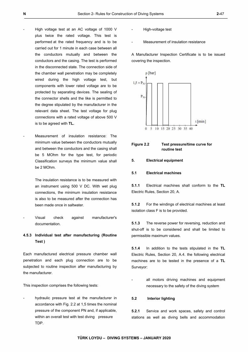
N Section 2- Rules for Construction of Diving Systems 2-47
TÜRK LOYDU – DIVING SYSTEMS – JANUARY 2020
- High voltage test at an AC voltage of 1000 V
plus twice the rated voltage. This test is
performed at the rated frequency and is to be
carried out for 1 minute in each case between all
the conductors mutually and between the
conductors and the casing. The test is performed
in the disconnected state. The connection side of
the chamber wall penetration may be completely
wired during the high voltage test, but
components with lower rated voltage are to be
protected by separating devices. The sealing of
the connector shells and the like is permitted to
the degree stipulated by the manufacturer in the
relevant data sheet. The test voltage for plug
connections with a rated voltage of above 500 V
is to be agreed with TL.
- Measurement of insulation resistance: The
minimum value between the conductors mutually
and between the conductors and the casing shall
be 5 MOhm for the type test, for periodic
Classification surveys the minimum value shall
be 2 MOhm.
The insulation resistance is to be measured with
an instrument using 500 V DC. With wet plug
connections, the minimum insulation resistance
is also to be measured after the connection has
been made once in saltwater.
- Visual check against manufacturer's
documentation.
4.5.3 Individual test after manufacturing (Routine
Test )
Each manufactured electrical pressure chamber wall
penetration and each plug connection are to be
subjected to routine inspection after manufacturing by
the manufacturer.
This inspection comprises the following tests:
- hydraulic pressure test at the manufacturer in
accordance with Fig. 2.2 at 1,5 times the nominal
pressure of the component PN and, if applicable,
within an overall test with test diving pressure
TDP.
- High-voltage test
- Measurement of insulation resistance
A Manufacturer Inspection Certificate is to be issued
covering the inspection.
Figure 2.2 Test pressure/time curve for routine test
5. Electrical equipment
5.1 Electrical machines
5.1.1 Electrical machines shall conform to the TL
Electric Rules, Section 20, A.
5.1.2 For the windings of electrical machines at least
isolation class F is to be provided.
5.1.3 The reverse power for reversing, reduction and
shut-off is to be considered and shall be limited to
permissible maximum values.
5.1.4 In addition to the tests stipulated in the TL
Electric Rules, Section 20, A.4. the following electrical
machines are to be tested in the presence of a TL
Surveyor:
- all motors driving machines and equipment
necessary to the safety of the diving system
5.2 Interior lighting
5.2.1 Service and work spaces, safety and control
stations as well as diving bells and accommodation
2-48 Section 2- Rules for Construction of Diving Systems N,O
TÜRK LOYDU – DIVING SYSTEMS – JANUARY 2020
areas of decompression chambers are to be equipped
with normal and emergency lighting. Emergency lights
are to be marked as such to facilitate easy identification.
5.2.2 The normal lighting is to be so designed and
arranged that the interior of the chambers is illuminated
at least with 300 Lux.
As far as possible the interior lighting shall be arranged
glare-free.
5.2.3 The lighting is to be so designed and arranged
that all important instruments and markings can be read
and any necessary operations can be safely performed.
5.2.4 All lighting fixtures shall be so mounted that
combustible parts are not ignited by the generated heat,
and they themselves are not exposed to damage.
5.2.5 The emergency lighting is to be independent
from the main lighting. This concerns the power
generation as well as the distribution and cable network.
The emergency lighting has to be automatically
switched on in case of failure of the main lighting.
Switches are to be arranged only locally, e.g. for
switching-off at the control stand.
O. Automation, Communication and Locating
Equipment
1. General
1.1 The following rules supplement the TL Electric
Rules and Automation Rules and are to be applied to
the construction and use of surveillance, control,
communications, video monitoring and locating
equipment in diving systems.
1.2 The documents to be submitted to TL are listed
in E.7.
1.3 The necessary tests are stated in G.8. Only
components and units approved by TL may be used.
1.4 Central control position
1.4.1 Diving systems are to be so arranged and
equipped that centralized control of the safe operation
of the system can be maintained under all weather
conditions.
1.4.2 For the monitoring and control of the diving
system a central control position is to be provided which
shall be equipped with indicators displaying all essential
information about the decompression chambers and
diving bells, as well as wet bells, its interior conditions
and the operating states of the auxiliary systems and
with all the regulating and control devices needed to
operate the diving system including its wireless, video
and communications equipment. All essential data are
to be automatically registered and stored.
1.4.3 At the central control position grouping and
arrangement of the instruments for monitoring, open
and closed loop control of the diving system shall
conform to the principles of safety technology and
ergonomics.
1.4.4 All monitoring and control devices are to be
unambiguously labelled and marked.
1.4.5 Indicating instruments and synoptic indications
are to be arranged and labelled to enable a quick and
unambiguously reading.
1.4.6 It shall be possible to check the function of
important indication lamps during operation.
1.4.7 As far as feasible and rational, initiated control
functions are to be indicated on the console or
switchboards respectively.
1.4.8 No units or equipment liable to impede the
monitoring and control of the diving system may be
installed in the area of the control stand. In addition the
operation may not be essentially impaired by
communication systems, tripping alarms and general
noise.
1.4.9 The central control position has to offer
sufficient protection against other operation spaces
(noise protection, visual protection, no access/passing
to other operating spaces).
1.4.10 The central control position is to be so
equipped with a separate ventilation and exhausting
system to achieve optimum conditions for personel and
O Section 2- Rules for Construction of Diving Systems 2-49
TÜRK LOYDU – DIVING SYSTEMS – JANUARY 2020
equipment. The intake of the air is to be routed from an
area not subject to explosion hazard.
1.4.11 As far as possible the installation of piping
systems and cable trays is to be performed separately
according to constructional groups, in order to avoid that
failures in one constructional group may lead to the
failure of several constructional groups.
1.4.12 The central control position is to be monitored
concerning fire protection and the possibility of effective
fire fighting herein is to be provided without endangering
the safe operation of the diving system.
1.5 Equipment of the central control position
1.5.1 For each of the functions to be performed on
the central control position of the diving system the
following indicating instruments are to be provided:
1.5.2 Position indications for diving bells
- Video camera
- One depth indicator
The scale of the depth indicator is to extend at
least 20 % beyond the nominal diving depth
NDD. The instrument shall give a reading
accuracy of 1 % at NDD and shall not be
significantly affected by pressure variations.
- Indication of pressure difference between
internal and external pressure, if applicable
1.5.3 Chamber atmosphere
- Indicators and alarms specified in M. for
monitoring the chamber atmosphere
1.5.4 Electrical equipment
- Battery current and voltage indicators
- If a capacity indication for the batteries has to
be provided will be defined by TL in each
single case.
- Insulation monitor displays (for complex
systems)
1.5.5 Safety equipment/indicators
- Machinery alarm systems
- Fire detection and alarm system
- General alarm system
- Filling level for ballast tanks, if existing
- Indication for release weight
- Pressure gauge for all compressed-air
receivers
- Pressure gauge for all oxygen and breathing
gas storage tanks
- Pressure gauges for hydraulic systems
1.5.6 Steering and control systems
1.5.6.1 The central control position of the diving
system is to be equipped at least with the following
systems:
- Chronometer
- External communication
- Internal communication
- Control of the chamber atmosphere in relation
to pressure, temperature and humidity, oxygen
metering and air renewal rates
- Emergency stopping systems
- Control of electrical power
- Control of auxiliary systems, e.g. hydraulic
units and similar
1.5.6.2 Command and control functions are, as far as
possible and expedient, to be indicated by displays on
monitors or system schemes on the control console.
2-50 Section 2- Rules for Construction of Diving Systems O
TÜRK LOYDU – DIVING SYSTEMS – JANUARY 2020
1.6 Wet bells
At the central control position of the diving system the
parameters defined in S.5. are to be considered.
2. Automation equipment
2.1 Design principles
2.1.1 All equipment for the automatic surveillance
and control of diving system operating parameters is to
be designed and constructed so that it works properly
under the design and environmental conditions
specified for the diving system.
2.1.2 Any fault or failure which may occur in the
automation system shall not provoke a critical operating
condition in the decompression chambers or diving
bells.
2.1.3 As far as possible, automation equipment is to
be safeguarded against faulty operation.
2.1.4 Automation systems are to be in the position,
to keep the operation parameters of the diving system.
2.1.5 Any inadmissible variations in the operating
parameters has to actuate an automatic/visual and
audible) alarm at the central control position. The same
shall also occur in the event of automatic switching
operations in the gas and power supply systems or
faults in the control and surveillance system.
2.1.6 In addition to electronic control and
surveillance equipment, independent safety devices are
to be fitted which prevent a fault in one system from
provoking an improper response in another system.
2.1.7 Automatic surveillance and control equipment
shall be capable of being switched to manual operation
at all times.
2.1.8 The response values of automation equipment
are to be so coordinated with each other that, when a
threshold is reached, a warning is initiated, followed,
after a certain warning period or if the process variable
continues to change at a preset speed, by the actuation
of safety devices.
2.1.9 The integral operation of automation systems
is to be designed to take account of the lags and time
constants of the units and elements making up the
system (e.g. by allowing for the length and crosssection
of piping systems and the response times of gas
analyzers).
2.1.10 For electrical systems IEC 60533
(Electromagnetic Compatibility of Electric Installation in
Ships) is taken as standard for interference immunity.
2.2 Structure
2.2.1 Electronic automation systems should
comprise easily replaceable assemblies, of the plug-in
type wherever possible. Standardization of units is to be
encouraged. The number of assembly types is to be
kept small in order to minimize the spare parts
inventory.
2.2.2 Plug-in cards are to be clearly marked or
coded to prevent inadvertent confusion.
2.2.3 Measures are to be taken to prevent
condensation inside electronic units, even when
switched off. Shutdown heating is recommended.
2.2.4 Wherever possible, automation equipment
should be capable of operation without forced
ventilation. The function of an cooling system, if
existing, is to be monitored.
2.2.5 Components are to be effectively secured. Any
mechanical loading of wires and soldered connections
due to vibration or jolting is to be reduced to a minimum.
2.2.6 The structure of systems and units is to be
simple and straightforward. Good accessibility is to be
ensured to facilitate measurements and repairs.
2.2.7 Input equipment such as limit switches,
transducers, transformers and reading-in machines, as
well as control elements, fire alarm systems, remote
control devices for drive systems, engine alarm systems
and combined equipment for the recording of
measurement data and interferences are to be tested
according to 2.5.

O Section 2- Rules for Construction of Diving Systems 2-51
TÜRK LOYDU – DIVING SYSTEMS – JANUARY 2020
2.3 Circuitry
2.3.1 Signalling equipment open and closed loop
control systems with a safety function are to be
designed on the failsafe principle, i.e. faults due to
short-circuit, earthing or circuit breaks shall not be
capable of provoking situations hazardous to personel
and/or the system. In this respect, it is to be assumed
that faults occur singly. The failure of one unit, e.g. due
to short-circuit, shall not result in damage to other units.
2.3.2 In stored-program control systems, the
electrical characteristics of the signal transmitters shall
conform to the safety requirements for instruction and
control devices. This means principally
- Activation at H level, i.e. by energization across
NO contacts
- Deactivation at L level, i.e. by de-energization
across NC contacts
The requirements of 2.3.1 are unaffected.
2.3.3 Instruction and control units for safety
functions, e.g. emergency stop buttons, shall be
independent of stored-program control systems and
shall act directly on the output unit, e.g. the stop
solenoid.
2.3.4 Stored-program control systems should be
reactionless and, in case of fault, should cause no
malfunctions in program-independent safety interlocks
or stepped safety circuits for fixed subroutines.
2.3.5 Freely accessible potentiometers and other
units for equipment trimming or operating point settings
are to be capable of being locked in the operation
position.
2.3.6 Mechanical switchgear is to be so designed
that the operation of the system is not adversely
affected by contact chatter.
2.3.7 Conductive tracks forming part of circuits which
extend outside the enclosure housing the circuit boards
must have qualified short-circuit protection, i.e. in case
of an external short-circuit only the safety devices
provided may respond without destroying the
conductive tracks.
2.3.8 The equipment shall not be damaged by brief
overvoltages in the power supply, due to switching
operations. The design is to allow for overvoltages
equal to approximately 2,5 times the rated voltage and
lasting 1 ms.
Where systems are supplied by static converters, it may
be necessary to make allowance for periodic voltage
pulses lasting about 0,5 ms. The pulse amplitude
depends on the converter type and is to be investigated
in each case.
2.4 Power supply
2.4.1 Mains units for automation equipment have to
contain at least one short-circuit protection and one
overload protection device.
2.4.2 The reference conductor system is to be
designed to preclude circuit breaks as far as possible.
This may, for example, be achieved by duplicating
exposed reference conductor joints and connections.
2.4.3 Automation equipment must be capable of
reliable operation under the conditions of voltage and
frequency variation stated in the TL Electric Rules,
Section 1
2.5 Tests
Automation equipment is to be approved by TL,
preferably type approved components are to be
employed.
The nature and scope of the tests will be determined by
TL in each single case.
Type test is to be performed in line with the TL
Guidelines for the Performance of Type Approvals.
3. Communication equipment
3.1 Voice communication systems
3.1.1 Diving systems are to be equipped with a
2-52 Section 2- Rules for Construction of Diving Systems O
TÜRK LOYDU – DIVING SYSTEMS – JANUARY 2020
suitable communication system providing direct voice
communication between the central control position
and:
- Divers in water
- Diving bell
- Each compartment of the chambers
- Control stand for launch, recovery and transfer
systems
- Mating system
- Control stand for dynamic positioning, if
applicable
- Bridge or working floor or Platform and
necessary operating rooms
3.1.2 In diving systems using helium gas mixtures,
each decompression chamber compartment and the
diving bell are to be connected to a speech
unscrambler. The unscrambling devices shall be
designed to achieve maximum noise suppression and
the automatic compensation of sound level fluctuations.
3.1.3 It is recommended that the central control
position should be equipped to record all voice
communications with the divers.
3.1.4 Voice communications between the
decompression chamber compartments and the central
control position as well as between the diving bell and
the central control position is to be provided by a
communication system with loudspeaker which is
permanently switched to "Receive" on the control
console. Switches for reversing the direction of
communication are to be of the self-resetting type. In
addition, each decompression chamber compartment is
to be provided with at least one headset.
3.1.5 A telephone link independent of the mains
power supply is to be provided in addition to the
communication system specified in 3.1.4.
3.1.6 Electrically powered voice communication
systems shall be provided with a reliable power supply.
This normally means that the equipment shall be
supplied from a storage battery with a parallel
connected mains unit and battery charger supplied with
energy in accordance with N.
3.1.7 In wet rooms microphone and receiver systems
are to be constructed to prevent the penetration of
water. Where considerations of design render this
impossible, the penetration of water shall not
permanently impair the serviceability of the equipment.
3.1.8 Microphone and receivers in diver masks,
hoods and diver helmets are to be functionally
separated from each other.
3.2 Video surveillance equipment
3.2.1 Diving systems where the divers have to stay
more than 12 hours in the chamber system, are to be
equipped with a video surveillance system.
3.2.2 The number of cameras and their visual angle
are to be chosen in a way that, as far as possible, the
complete interior of the chamber to be monitored is
covered.
3.2.3 A sufficient number of video monitors is to be
provided. On each monitor it shall be possible to
definitely recognize which room is shown at the
moment.
3.3 Other signalling systems
3.3.1 Diving bells are to be equipped with an
independent underwater communications system for
use in emergencies.
3.3.2 Suitable alternative communications equipment
(e.g. a 3-button signalling system) is to be provided in
all decompression chamber compartments and in the
diving bell.
4. Emergency location and communication
4.1 Emergency locating equipment
Each diving bell is to be equipped with an emergency
locating device which works at a frequency of 37,5 kHz
and is designed to establish and maintain contact
O Section 2- Rules for Construction of Diving Systems 2-53
TÜRK LOYDU – DIVING SYSTEMS – JANUARY 2020
between the diving bell under water and the surface, if
the normal connections to the surface would be
damaged. The device includes the following
components:
4.1.1 Transponder
4.1.1.1 The transponder shall be provided with a
pressure-proof housing suitable at least for the nominal
diving depth NDD and equipped with salt water
activation contacts. The batteries shall be of the readily
available "alkaline" type and, if possible, be
interchangeable with those of the diver and surface
interrogator/ receiver.
4.1.1.2 The transponder shall be designed to operate
with the following characteristics:
common emergency reply frequency: 37,5 kHz
individual interrogation frequencies:
- channel A: 38,5 +/- 0,05 kHz
- channel B: 39,5 +/- 0,05 kHz
receiver sensitivity: + 15 dB referred
to 1μ bar
minimum interrogation pulse width: 4 ms
turnaround delay: 125,7 ± 0,2 ms
reply frequency: 37,5 ± 0,05 kHz
- more than 20 % of
battery life remaining: once per second
- less than 20 % of
battery life remaining: once per 2 seconds
minimum transponder output
power: 85 dB referred to
1 μ bar at 1 m
minimum transducer polar
radiation: 6 dB at ± 135° solid
angle, centred on
the transponder vertical
axis and transmitting
towards the surface
Minimum listening life in water: 10 weeks
Minimum battery life replying
at 85 dB: 5 days
4.1.2 Diver-held interrogator/receiver
4.1.2.1 The interrogator/receiver shall be provided with
a pressure-proof housing suitable at least for the
nominal diving depth NDD with pistol grip and compass.
The front end shall contain the directional hydrophone
array and the rear end the 3-digit LED display readout
calibrated in metres. Controls are to be provided for
"on/off receiver gain" as well as "channel selection". The
battery pack shall be of the readily available "alkaline"
type and, if possible, be interchangeable with that of the
interrogator and transponder.
4.1.2.2 The interrogator/receiver shall be designed to
operate with the following characteristics:
common emergency reply frequency: 37,5 kHz
individual interrogation frequencies:
- channel A: 38,5 kHz
- channel B: 39,5 kHz
minimum transmitter output
power: 85 dB referred to
1 μ bar at a
distance of 1 m
transmit impulse duration: 4 ms
sensitivity for direction: ± 15°
Ability to function
in immediate
proximity to the
transponder is to be
secured.
detectable range: more than 500 m
2-54 Section 2- Rules for Construction of Diving Systems O,P
TÜRK LOYDU – DIVING SYSTEMS – JANUARY 2020
4.2 Emergency communication
In addition to the communication systems referred to
above, a standard tapping code for emergency
communication between persons in the diving bell and
rescue divers is to be adopted.
A copy of this tapping code is to be displayed inside and
outside the diving bell and also in the central control
position.
Tapping code Meaning
3.3.3 Communication opening procedure
1 Yes or affirmative or agreed
3 No or negative or disagreed
2.2 Repeat please
2 Stop
5 Have you got a seal?
6 Stand by to be pulled up
1.2.1.2 Get ready for through water transfer
(open your hatch)
2.3.2.3 You will NOT release your ballasts!
4.4 Do release your ballast in 30 minutes
from now!
1.2.3 DO increase your pressure
3.3.3 Communication closing procedure
P. Fire Protection
1. General
1.1 The rules of this Section apply to the fire
protection of diving systems holding TL Class or with TL
System Certificate, which are permanently or
temporarily installed on a support ship.
1.2 The documents to be submitted to TL for
approval are listed in E.8.
1.3 The necessary tests are stated in G.10.
2. Structural fire protection
2.1 Area of installation of diving system
2.1.1 For the support ship on which the diving
system is installed, the fire protection rules of the
competent Classification Society respectively the
relevant regulations of the International Convention for
the Safety of Life at Sea (SOLAS) of 1974, as amended
are to be met.
2.1.2 In the area of installation of the diving system,
the gas storage facility and the central controlposition,
sources of ignition and fire loads are to be reduced to a
minimum. As far as possible, materials which are at
least flame-retardant are to be used. Heat insulation is
to be made of incombustible materials.
2.1.3 Diving systems on support ships are only be
installed and operated in areas not subject to explosion
hazard in accordance with I.3.
2.1.4 Where diving systems or parts thereof are
installed in closed spaces, these spaces including the
central control position are to be separated from the
deck and the rest of the ship by partitions of type “A- 60”
2.1.5 Enclosed spaces or parts thereof are to be
provided with a forced ventilation system capable of
effecting at least 8 changes of air per hour. The air is to
be drawn from an area not subject to explosion hazard.
2.2 Interiors of decompression chambers and
diving bells
2.2.1 As far as possible, all materials used in
decompression chambers and diving bells are to be at
least flame retardant (for the purpose of these Rules
flame-retardant refers to materials which do not
continue to burn spontaneously in a compressed air
atmosphere of at least 6 bar absolute).
2.2.2 As far as possible, fire loads and sources of
ignition are to be avoided. Electrical heating appliances
and heaters are to be fitted with protection against
overheating.
2.2.3 Components and materials are to be selected
with the view to minimizing the danger of static charges.
3. Fire surveillance
3.1 Fire detection and alarm systems
3.1.1 Interior spaces containing parts of the diving
P Section 2- Rules for Construction of Diving Systems 2-55
TÜRK LOYDU – DIVING SYSTEMS – JANUARY 2020
system, such as decompression chambers, diving bells,
filling stations, compressors and control positions are to
be monitored by an automatic fire detection system.
3.1.2 The detected fire is to be signalled visually and
audibly in the permanently manned central control
position.
3.1.3 The fire alarm may be actuated manually from
the permanently manned central control position or may
be automatically activated by the fire detection system.
3.2 Fire detection system
3.2.1 Fire detection systems including central fire
detection station, fire detectors and wiring of the
detection loops require the approval of TL.
3.2.2 Fire detection systems are to be so
constructed that any fault, as e.g. supply failure,
shortcircuit or wire breakage in the detection loops, or
the removal of a detector from its base, triggers a visual
and audible signal at the fire detection station in the
central control position.
3.2.3 For the design and arrangement of fire
detection and alarm systems the TL Electric Rules and
Automation Rules are to be observed.
4. Fire extinguishing systems
4.1 Area of installation of the diving system
4.1.1 Every support ship on which a diving system is
installed is to be equipped with a general water fire
extinguishing system consisting of hydrants as well as
portable and mobile fire extinguishers and extinguishing
equipment according to the TL Machinery Rules,
Section 18.
4.1.2 Where pressure chambers are situated in
enclosed spaces, a permanently installed water spray
system having an application rate of 10 ℓ/m2 and per
minute related to the horizontal protected area is to be
provided for cooling in the event of fire. These water
spray systems may be manually activated and
operated.
4.1.3 For pressure chambers installed on the open
deck, cooling by means of fire hoses connected to the
general fire extinguishing system is permitted.
4.1.4 Interior spaces containing diving systems or
parts thereof are to be additionally equipped with
approved manual fire extinguishers. One of the portable
fire extinguishers shall in every case be situated close
to the entrance to the space concerned.
4.2 Decompression chambers
4.2.1 Each compartment of a decompression
chamber is to be equipped with suitable means for
extinguishing a fire in the interior by providing for the
rapid and efficient distribution of the extinguishing agent
to any area of the chamber.
4.2.2 The fire extinguishing system shall safely deal
with every conceivable outbreak of fire under all the
environmental conditions for which the diving system is
designed. Actuation of the fire extinguishing system
may not cause any unacceptable pressure drop inside
the chamber. The extinguishing system may be
actuated by hand.
4.2.3 Water is the preferred extinguishing agent.
Extinguishing agents with a toxic or narcotic effect are
not permitted.
4.3 Diving bells
A fire protection/fire extinguishing system adequate to
size, mission and equipment of the diving bell is to be
provided.
5. Other fire protection equipment
The central control position of the diving system is to be
equipped with at least one independent compressed air
respirator of approved design having an operating
capability of at least 30 minutes and fitted with
equipment for voice communication with the divers.
2-56 Section 2- Rules for Construction of Diving Systems Q
TÜRK LOYDU – DIVING SYSTEMS – JANUARY 2020
Q. Launch, Recovery, Transfer and Mating
Systems
1. General
1.1 These Rules apply to all equipment for the
launch and recovery of diving bells of diving systems
holding TL Class. The requirements for transfer and
mating are defined in 6.
1.2 The documents to be submitted to TL are listed
in E.9.
1.3 The necessary tests and markings are stated
in G.11. and H.5.
1.4 If the systems fulfil the defined requirements
and are constructed and tested under TL surveillance, a
Certificate for the system can be issued and a Register
of launching appliances can be opened. The purpose of
the latter is to provide information about the actual
situation with regard to general data plus the test,
examination and maintenance status.
1.5 For the eventuality of a single component
failure in the launch and recovery system, an alternative
system is to be provided to enable the divers to be
brought to the decompression chamber. This alternative
system is to be supplied with power independently of
the normal launch and recovery system. In addition,
provision is to be made for emergency retrieval of the
diving bell should both, the normal launch and recovery
system as well as the alternative system fail.
1.6 Between the launch and recovery system and
the coil-up/coil-off mechanism for umbilicals, if
separately arranged, a communication facility with the
central control position according to O.1.4 is to be
established.
2. Principles for design
2.1 General principles
2.1.1 The launch and recovery equipment shall be
capable of safely launch and recover the diving bell/wet
bell in the seaway conditions stated in D.
2.1.2 The launch and recovery equipment should be
fitted with devices for reducing the dynamic loads during
launch and recovery operations in a seaway.
2.1.3 Devices are to be provided to stabilize the
diving bell/wet bell during launch and recovery. This can
be done e.g. by the tensioned wires between a dropped
ground weight and the launching system.
2.1.4 The launch and recovery system shall enable a
safe and easy to control transport of the diving bell/wet
bell.
2.1.5 Unless otherwise specified in the following
Sections, the mechanical equipment of launch and
recovery systems is to conform to the TL Guidelines for
the Construction and Survey of Lifting Appliances.
2.2 Power supply, mechanical drives
2.2.1 The launch and recovery system is to be
provided with at least two mutually independent power
sources, each of which shall be capable of supplying all
the power needed to launch and recover the diving
bell/wet bell. For hydraulic drives two power pumping
sets independent from each other are to be provided.
2.2.2 The power sources, together with their feed
lines and switchgear, are to be so arranged that a
failure or burn-out of one system cannot lead to the
failure of the standby system.
2.2.3 The launch and recovery system is to be
equipped with auxiliary drives enabling a launch or
recovery manoeuvre which has already been started to
be safely concluded should the winches or hydraulic
pumps fail.
2.2.4 Launch and recovery systems using an "A"
frame are to be equipped with two hydraulic cylinders
which are to be so designed and arranged that each is
fully capable of safely performing the launch and
recovery operation under load. In addition, they are to
be connected to the hydraulic system in such a way that
a single fault in the hydraulic system cannot lead to the
failure of both hydraulic cylinders.

Q Section 2- Rules for Construction of Diving Systems 2-57
TÜRK LOYDU – DIVING SYSTEMS – JANUARY 2020
2.3 Control equipment
2.3.1 Launch and recovery systems are to be fitted
with control equipment enabling the system to be
operated intermittently with smooth accelerations. In
addition, the controls are to be designed and arranged
in such a way that the operator has the diving bell/wet
bell in view throughout complete launch and recovery
and is fully able to perform all the necessary actions
safely.
2.3.2 The controls are to be fitted with blocking
devices which ensure that only those commands can be
performed simultaneously which do not produce a
dangerous or unintended condition.
2.3.3 Control systems are to be provided with an
emergency shut-off button.
2.3.4 Wherever possible, control units are to be
provided to the fail-safe principle.
2.3.5 Control units with remote control are to be
additionally equipped with a direct control override. In
the event of failure or malfunction of the remote control,
all operating sequences which have been initiated shall
be automatically stopped.
2.3.6 All control units are to be clearly and
permanently marked and shall be adequately
illuminated.
2.3.7 An operating platform with good view over the
complete launch and recovery system is to be provided.
3. Calculation
3.1 Design loads
3.1.1 The minimum "safe working load SWL" of the
launch and recovery system summarizes as follows:
- Weight of the diving bell, including its
equipment, ballast weights, etc.
- Payload NL of the diving system
- Weight of the load transmitting devices which
are not connected in a fixed way with the
launch and recovery system
- Resulting loads of the umbilical according to
5.3 if this is transferred via the launch and
recovery system
- Ground weight and guide wires.
3.1.2 Calculations are normally to be based on the
assumption that the angle of engagement of the load
hoisting rope may be 12° off perpendicular in any
direction.
3.1.3 For the Calculation also possible external
loads, which may occur during operation (e.g.
dynamics, wind loads, ice accretion, etc.) are to be
considered.
3.1.4 Finally also the forces from maximum ship
motions and green seas, wind, ice, etc. have to be
checked for the launching and recovery system in
resting position and stowed on the support ship. A proof
of strength considering the seaway and wind conditions
according to D. is to be submitted.
3.1.5 Further on the minimum lifting speed is to be
specified by the manufacturer and to be agreed by TL.
3.1.6 The driving machine of the winch has to be
designed in a way, that a maximum torque according to
a maximum pull of 1,5 times the nominal pull of the
winch can be developed at reduced speed for at least 5
minutes. In analogy the hydraulic cylinders are to be laid
out for 1,5 times the nominal cylinder force. For both a
calculation proof is to be provided.
3.2 Materials
3.2.1 For the manufacture, processing and testing of
materials the TL Material Rules are valid.
3.2.2 Other materials as defined in 3.2.1 are to be
manufactured and processed according to recognized
standards or according to specifications of the material
manufacturer checked and approved by TL.
2-58 Section 2- Rules for Construction of Diving Systems Q
TÜRK LOYDU – DIVING SYSTEMS – JANUARY 2020
3.3 Calculation procedure
3.3.1 The calculation of the launch and recovery
system as well as of the coil-up/coil-off mechanism for
umbilicals is to be performed according to the principles
of TL Guidelines for the Construction and Survey of
Lifting Appliances. For this computation the system is to
be considered as offshore lifting gear.
If the system is equipped with shock absorbers or swell
compensators approved by TL, a reduction of the
working load may be dispensed with totally or partially if
agreed by TL.
3.3.2 Deviating from the design of offshore lifting
gears, for the dimensioning of launch and recovery
systems a hoist load coefficient of 2,7 and a dead load
coefficient of 1,5 are to be considered independently of
type and size of their safe working load. Hereby is
assumed that the operation is restricted to seaway with
significant wave heights up to 2 m.
Where it is proposed that launch or recovery operations
should be performed in even more unfavourable
conditions, previous agreement with TL is necessary.
4. Equipment
4.1 Where cranes are used for launch and
recovery, measures are to be taken to prevent the
uncontrolled turning or slewing of the crane in a
seaway. The turning or slewing gear has to be capable
of holding the crane in any position. The gear is also to
be designed to ensure that all movements are initiated
and arrested smoothly.
4.2 Launch and recovery systems are to be
equipped to prevent excessive turning or swinging of
the diving bell/wet bell during recovery (e.g. by the use
of non-spin ropes and additional pendants).
4.3 Measures are to be provided to prevent the
diving bell/wet bell from striking against the ship's hull or
against the launch and recovery gear.
4.4 Winches are to be equipped with two
independent brakes. One of the brakes is to be energy
independent, shall be activated in case of energy failure
and shall react directly on the rope drum.
4.5 The capacity of the brakes has to be sufficient
to safely hold the dynamic test load specified in G.11.1.
4.6 The final positions of the launch and recovery
system, like upper and lower hook and jib position as
well as the slewing range, are to be monitored.
The starting and braking velocities are to be controlled.
4.7 All interchangeable single components such as
blocks, hooks, shackles, etc. are to conform to
recognized standards, shall have a safety of 8 against
fracture related to the safe working load SWL and are to
be marked with their safe working load.
4.8 The maximum static tensile stress imposed on
steel wire ropes by the safe working load may not
exceed 1/8 of the proven rupture strength.
4.9 The use of ropes made of fibres is only
permissible in special cases and with consent of TL. For
the use of natural or synthetic fibres the maximum static
tensile stress imposed by the safe working load may not
exceed 1/10 of the proven rupture strength.
5. Coil-up/coil-off mechanism for umbilicals
5.1 Coil-up and coil-off mechanism for umbilicals
describe the complete equipment for handling of the
umbilical on the support ship. They may be of different
types, but often an umbilical winch is an integrated part
of this system.
5.2 An adequate coil-up and coil-off mechanism is
to be provided for the umbilical, which is tracking the
umbilical without restriction of the freedom to move and
without additional mechanical loads to the diving
bell/wet bell under water.
5.3 The following requirements are to be
considered for the design of coil-up and coil-off
mechanism for umbilicals:
- Specified operating conditions, e.g. wave
height and type of the support ship
- Safe working load SWL of the coil-up and
coiloff mechanism for umbilicals considering
Q Section 2- Rules for Construction of Diving Systems 2-59
TÜRK LOYDU – DIVING SYSTEMS – JANUARY 2020
the weight of the umbilical, its buoyancy in
water (filled and empty) as well as the friction
in water and dynamic effects, e.g. by the
seaway
- The radius of the umbilical in the coil-up and
coil-off mechanism is not to be less than the
specified bending radius of the umbilical.
- The most unfavourable arrangement of the
umbilical in relation to the coil-up and coil-off
mechanism (e.g. coil-up angle, position of the
winch drum, application of guide pulleys, etc.)
is to be considered.
- The material Certificates have to be in
accordance to the TL Rules Guidelines for the
Construction and Survey of Lifting Appliances.
- The coil-up and coil-off mechanism have to
have a power source which is in the condition
to safely coil-up and coil-off the umbilical under
the specified conditions.
- The coil-up and coil-off mechanism is to be
equipped with auxiliary drives to be able to
finish an already started coil-up and coil-off
procedure in a safe way if the main drive
respectively the hydraulic pump are failing.
- To avoid overstressing of umbilical and the
coil-up and coil-off mechanism measuring of
the tension force is to be provided at a suitable
position of the system, which triggers an alarm
at the control station in case of exceeding the
safe working load SWL.
6. Transfer and mating systems
6.1 Stowage and deck transport
6.1.1 General
6.1.1.1 As stowage and deck transport the transfer of
the diving bell/wet bell recovered by the launch and
recovery system to a deposit location aboard is to be
understood. The deposit location is to be protected
normally against environmental influences, especially if
maintenance and repair work has to be done. The
diving bell/wet bell is to be safely transferred stowed
and lashed for all thinkable ship movements.
Within the scope of the total diving system the following
requirements are to be recognized.
6.1.1.2 If requested, in addition the transport of a
diving bell to the decompression chamber or to its
mating equipment is to be enabled.
6.1.2 Principles for design and equipment
The requirements of the IMO Code A.714(17): “Code of
the Safe Practice for Cargo Stowage and Securing” are
to be considered.
6.1.2.1 Mechanical requirements
Aboard of the support ship and under consideration of
maximum ship movements, sufficiently dimensioned
measures, like cargo securing elements are to be
provided from ship side for:
- The complete transport way
- Storage of the diving bell/wet bell
- Lashing on deck or within the containers
- Lashing of containers with equipment
6.1.2.2 Electrical requirements
6.1.2.2.1 At the superstructures of the support ship a
connecting possibility in form of a connecting plate with
stay bolt preferably M 12 is to be provided at an easily
accessible position, on which the protective conductor
of the diving bell/wet bell can be connected without
using tools.
6.1.2.2.2 For the stay of the diving bell/wet bell on deck
of the support ship the measures defined in 6.1.2.2.1
are to be so arranged, that an uninterrupted
equalization of the potential is possible.
6.1.2.2.3 Areas for transport and stowage are to
sufficiently illuminated.
2-60 Section 2- Rules for Construction of Diving Systems Q,R
TÜRK LOYDU – DIVING SYSTEMS – JANUARY 2020
6.1.2.3 Fire and explosion protection
The stowage location for the diving bell/wet bell on the
support ship is to be equipped with suitable fire
extinguishing systems. This system may be a part of the
fire extinguishing system of the support ship.
Explosion protection measures for areas with explosion
danger, from which the diving bell/wet bell shall undergo
missions, are to be provided.
6.2 Mating equipment
6.2.1 If it is necessary to transfer divers under
pressure from their working place under water to the
support ship for a longer lasting decompression
procedure with a diving bell, a mating equipment
suitable to the decompression chamber on board of the
support ship is to be provided. The same is valid for the
pre-compression of divers to their working conditions
under water.
6.2.2 The mating system shall enable the connection
and disconnection of the diving bell and the
decompression chamber to be effected easily and
securely even under conditions where the ship is rolling,
pitching or listing to permissible degrees.
6.2.3 Where a power actuating system is used for
mating operations, an auxiliary power actuating system
or an appropriate means is to be provided to connect
the diving bell to the decompression chamber in the
event of failure of the normal power actuating system.
6.2.4 The mating system is to be provided with a
safety interlock between the diving bell and the
decompression chamber.
6.2.5 Further design and construction requirements
are to be agreed with TL.
R. Hyperbaric Evacuation System
1. General
1.1 An emergency system is to be provided to
evacuate the divers under pressure, in the case that the
support ship has to be abandoned.
1.2 Possible evacuation systems
Depending on the local, geographical and other service
conditions, different kinds of evacuation systems are
conceivable, including:
1.2.1 Hyperbaric self-propelled lifeboats.
1.2.2 Towable hyperbaric evacuation units.
1.2.3 Hyperbaric evacuation units, which may be
towable, suitable for offloading onto an attendant
vessel.
1.2.4 Transfer of the diving bell to another ship.
1.2.5 Transfer of the divers from one diving bell to
another when in the water and under pressure.
1.2.6 Negatively buoyant unit with inherent reserves
of buoyancy, stability and life support capable of
returning to the surface after a certain time to await
independent recovery.
1.3 The documentation submitted for approval is
stated in E.10.
1.4 The necessary tests are stated in G.12. Official
regulations may necessitate further tests.
1.5 If a self-propelled or towable hyperbaric
evacuation system permanently connected to the diving
system is provided, the following requirements are to be
applied.
2. Design principles
2.1 Pressure chamber
2.1.1 The pressure chamber of the hyperbaric
evacuation system shall be so designed that all the
divers in the diving system can be evacuated
simultaneously at nominal diving depth NDD. At least
one seat with safety harness is to be provided for each
diver.
2.1.2 The hyperbaric evacuation system is to be
equipped with its own life support system enabling the
pressure, temperature, humidity and gas composition in
R Section 2- Rules for Construction of Diving Systems 2-61
TÜRK LOYDU – DIVING SYSTEMS – JANUARY 2020
the pressure chamber to be maintained for at least 72
hours.
The life support systems are to be provided with
connections for external supply and surveillance. These
connections are to be marked easily visible and in a
permanent way and are to be provided in the following
way:
- cold/hot water supply: ¾" NPT female
thread
- breathing gases: ¼" NPT female
thread
The requirements according to M. are to be considered
in analogous way.
2.1.3 The hyperbaric evacuation system is to be
equipped with the regulating and control devices
needed to guarantee a safe environment for the divers.
2.1.4 An adequate supply of the occupants with
provisions and water is to be provided. For these and
medical duties a lock with interlocking against
simultaneous opening of the internal and external cover
is to be provided. The size of the lock has to enable e.g.
the entrance of standardized CO2 absorption units.
2.1.5 The connection flange of the pressure chamber
is to be s o designed that it is also able to mate to an
extraneous system. It has to be possible to open the
doors from both sides, but only after pressure
equalization. The recovery of unconscious divers is to
be enabled.
2.1.6 The pressure chamber is to be fitted with view
ports in such a way that, wherever possible, all the
occupants can be observed from outside.
2.1.7 The pressure chamber is to be provided with
the necessary connections to enable the internal
pressure, temperature, gas composition and humidity to
be maintained.
2.1.8 The pressure chamber is to be adequately
illuminated.
2.2 Boat part of the evacuation system
2.2.1 The boat part is to be so designed that its
behaviour in a seaway corresponds to that of an
enclosed lifeboat. The stability for the system with
maximum load and also under consideration of rescue
personnel on the system is to be proven.
2.2.2 The system is to be self-propelled and capable
of navigation or shall be provided with means (e.g.
suitably equipped rescue boat) enabling the complete
evacuation system to be towed away quickly after
launching.
2.2.3 The evacuation system is to be provided with
lifting attachments enabling it to be hoisted by a
standard ship's crane.
2.2.4 The evacuation system is to be constructed of
materials which are at least flame-retardant and shall be
equipped with a water spray system for cooling the
surface in the event of fire.
2.2.5 If the life boats of the support ship are
designed as fire-protected life boats, their requirements
are also to be applied to hyperbaric evacuation
systems.
2.3 Electrical installations
2.3.1 The hyperbaric evacuation system is to be
equipped with its own power supply capable of keeping
the electrical installations in operation for at least 72
hours.
2.3.2 For electrical installations the requirements
according to N. are to be considered in analogous way.
2.4 Communication
2.4.1 The hyperbaric evacuation system is to be
equipped with a two-way communication system for
talking to the divers. If helium gas mixtures are used, a
speech unscrambler is to be provided. The
unscrambling devices should be designed to achieve
maximum noise suppression and the automatic
compensation of sound level fluctuations
A second communication system is to be provided.
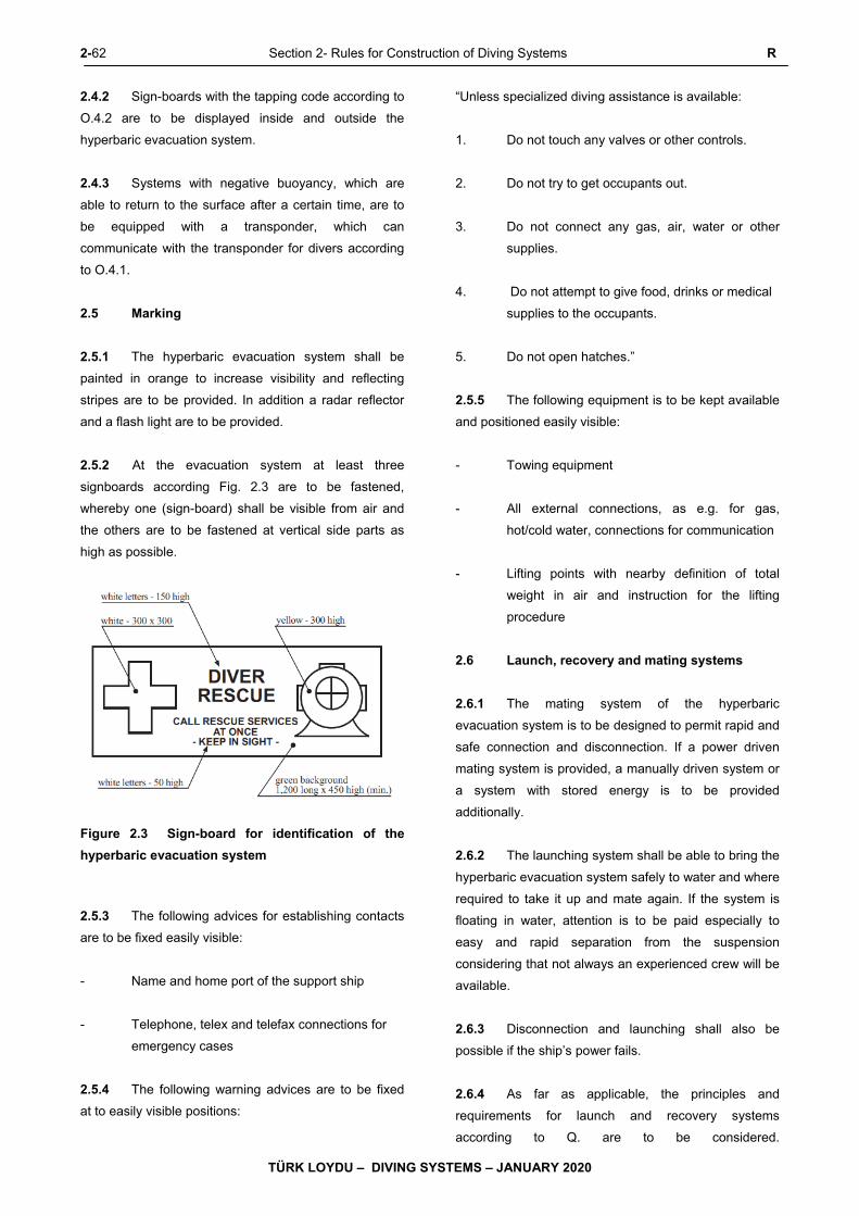
2-62 Section 2- Rules for Construction of Diving Systems R
TÜRK LOYDU – DIVING SYSTEMS – JANUARY 2020
2.4.2 Sign-boards with the tapping code according to
O.4.2 are to be displayed inside and outside the
hyperbaric evacuation system.
2.4.3 Systems with negative buoyancy, which are
able to return to the surface after a certain time, are to
be equipped with a transponder, which can
communicate with the transponder for divers according
to O.4.1.
2.5 Marking
2.5.1 The hyperbaric evacuation system shall be
painted in orange to increase visibility and reflecting
stripes are to be provided. In addition a radar reflector
and a flash light are to be provided.
2.5.2 At the evacuation system at least three
signboards according Fig. 2.3 are to be fastened,
whereby one (sign-board) shall be visible from air and
the others are to be fastened at vertical side parts as
high as possible.
Figure 2.3 Sign-board for identification of the
hyperbaric evacuation system
2.5.3 The following advices for establishing contacts
are to be fixed easily visible:
- Name and home port of the support ship
- Telephone, telex and telefax connections for
emergency cases
2.5.4 The following warning advices are to be fixed
at to easily visible positions:
“Unless specialized diving assistance is available:
1. Do not touch any valves or other controls.
2. Do not try to get occupants out.
3. Do not connect any gas, air, water or other
supplies.
4. Do not attempt to give food, drinks or medical
supplies to the occupants.
5. Do not open hatches.”
2.5.5 The following equipment is to be kept available
and positioned easily visible:
- Towing equipment
- All external connections, as e.g. for gas,
hot/cold water, connections for communication
- Lifting points with nearby definition of total
weight in air and instruction for the lifting
procedure
2.6 Launch, recovery and mating systems
2.6.1 The mating system of the hyperbaric
evacuation system is to be designed to permit rapid and
safe connection and disconnection. If a power driven
mating system is provided, a manually driven system or
a system with stored energy is to be provided
additionally.
2.6.2 The launching system shall be able to bring the
hyperbaric evacuation system safely to water and where
required to take it up and mate again. If the system is
floating in water, attention is to be paid especially to
easy and rapid separation from the suspension
considering that not always an experienced crew will be
available.
2.6.3 Disconnection and launching shall also be
possible if the ship’s power fails.
2.6.4 As far as applicable, the principles and
requirements for launch and recovery systems
according to Q. are to be considered.

S Section 2- Rules for Construction of Diving Systems 2-63
TÜRK LOYDU – DIVING SYSTEMS – JANUARY 2020
S. Wet Bells
1. General
1.1 Wet bells serve the purpose of safely carrying
divers and their equipment from the deck of a support
ship to and from the site, using either compressed air or
gas mixtures as breathing gas, depending on the depth,
however, without saturation being reached.
1.2 The documents to be submitted to TL for
approval are listed in E.11.
1.3 The required tests are to be taken from G.14.,
the marking of wet bells is defined in H.2.
2. Design principles
2.1 Wet bells should be designed for the carriage
of at least two divers, including their equipment.
Normally, they consist of an upper part at head and
shoulder level supporting a gas pocket and an open
lower part provided with a platform enabling the divers
to stand safely and as far as applicable with suitable
seating.
2.2 Wet bells and the persons inside are to be
adequately protected against impacts during lowering or
recovering.
2.3 The supply lines for breathing gas, hot water,
etc. are to be arranged from the surface through the wet
bell to the divers. Alternatively, supply by a joint
umbilical is possible, which is connected to the
connections in the wet bell for the individual diver
umbilicals.
The wet bell is to be equipped with devices for coiling
up the diver umbilicals.
2.4 Wet bells are to be provided with emergency
supplies of breathing gas sufficient to supply the divers
at nominal diving depth NDD for a period of two hours
and with an emergency breathing mask foreach diver.
2.5 The upper part of the bell supporting the gas
pocket is to be equipped for scavenging with the
respective breathing gas employed.
2.6 The wet bells are to be equipped with
appropriate devices for the salvaging and securing of
divers having suffered an accident.
2.7 Lighting is to be installed in the wet bell for
working and for emergency purposes. In addition a
surface communication line is to be provided.
2.8 Wet bells are to be provided with appropriate
devices ensuring indication of the respective diving
depth in the central control position.
3. Launching and recovery systems
3.1 Launching and recovery systems for wet bells
have to safeguard safe launching and recovery under all
admissible seaway and weather conditions.
3.2 The launching device has to enable that the
decompression phases in the water are reliably and
exactly observed. Jerky motions of the wet bell due to
ropes becoming slack in a seaway are to be avoided by
appropriate design measures.
3.3 Where the hoisting rope and umbilicals are
arranged separately appropriate measures are to be
taken for preventing these from twisting and from
damaging each other during launching and/or recovery
operations.
3.4 It is to be ensured that upon recovery the wet
bell will be deposited on deck without jerks and impacts.
3.5 As far as applicable, the requirements defined
in Q. are to be observed.
4. Equipment for breathing gas supply
4.1 For the wet bell system in accordance with the
nominal diving depth NDD and mission periods supplies
of breathing gas of appropriate composition are to be
kept available.
4.2 Where during a diving operation and the
pertinent decompression phases different kinds of
breathing gas are employed, it is to be ensured that
each of the gases employed can at any time be
identified at the central control position.
2-64 Section 2- Rules for Construction of Diving Systems S
TÜRK LOYDU – DIVING SYSTEMS – JANUARY 2020
5. Central control position
The central control position according to O.1.4 is to be
equipped with all necessary devices ensuring that the
parameters quoted below are at any time adhered to
and monitored:
- Supply of divers with adequate quantities of the
proper breathing gas
- Possibly supply of divers' thermal suits with an
adequate quantity of hot water of adequate
temperature
- Indication of diving depth of wet bell
- Adherence to decompression phases and
periods
- Maintained communication with divers
- Insulation values of the wet bell's electrical
equipment
A visual monitoring of the wet bell and the operating site
by video system is recommended.
6. Diver basket
6.1 Diver baskets are simplified wet bells, but no
upper part with a gas pocket is existing.
6.2 For diver baskets the relevant requirements for
wet bells are to be applied in analogous way.

Section 3- Rules for Construction of Diving Simulators 3-1
TÜRK LOYDU – DIVING SYSTEMS – JANUARY 2020
SECTION 3
RULES for CONSTRUCTION of DIVING SIMULATORS
Page
A. GENERAL RULES and INSTRUCTIONS ........................................................................................................ 3- 2
1. General
2. Definitions
3. Main Dimensions and Main Parameters
4. Components of Diving Simulators
5. Environmental Conditions
6. Documents for Approval
7. Tests and Trials
8. Marking
B. PRINCIPLES of DESIGN and CONSTRUCTION of DIVING SIMULATORS .................................................. 3- 8
1. General Principles
2. Environmental Conditions
3. Conditions in Chamber
4. Arrangement
5. Chamber Equipment and Chamber Facilities
6. Corrosion Protection
C. VESSELS and APPARATUS UNDER PRESSURE ......................................................................................... 3-10
1. Pressure Chambers
2. Pressure Vessels, Gas Cylinders and Apparatus Under Pressure
D. PIPES, VALVES, FITTINGS, HOSES, UMBILICALS ....................................................................................... 3-12
E. COMPRESSORS .............................................................................................................................................. 3-12
F. LIFE SUPPORT SYSTEMS .............................................................................................................................. 3-12
1. General
2. Gas Supply
3. Control and Instrumentation
G. ELECTRICAL INSTALLATIONS ....................................................................................................................... 3-17
H. AUTOMATION EQUIPMENT and COMMUNICATION EQUIPMENT .............................................................. 3-17
1. General
2. Automation Equipment
3. Communication Equipment
I. FIRE PROTECTION ............................................................................................................................................ 3-17
1. General
2. Structural Fire Protection
3. Fire Surveillance
4. Fire Extinguishing Equipment
5. Other Fire Protection Equipment
J. HYPERBARIC EVACUATION SYSTEM ............................................................................................................ 3-17
1. General
2. Design Principles
3-2 Section 3- Rules for Construction of Diving Simulators A
TÜRK LOYDU – DIVING SYSTEMS – JANUARY 2020
A. General Rules and Instructions
1. General
1.1 The following Rules of Construction apply to
diving simulators which are permanently installed in a
building or similar structure and which are built under
the survey and in accordance with the Rules of TL and
which shall receive an appropriate System Certificate.
As diving simulator a pressure chamber system is
understood, in which training of divers or manned and
unmanned tests can be performed in dry or wet
environment, at conditions which are adequate to an
underwater mission.
1.2 On application by the manufacturer or
operator, diving simulators built in accordance with 1.1
may also be classified by TL.
1.3 Buildings, power generating plants, fuel
storage and gas storage facilities and similar are
required to comply with the relevant national regulations
of the country in which the facilities are established.
1.4 Designs other than those stated in the Rules of
Construction may be approved provided their suitability
has been verified by TL and they have been recognized
as equivalent.
1.5 TL reserve the right to impose requirements
additional to those contained in the Rules in respect of
all types of facility should this become necessary in the
light of new knowledge or practical experience or to
sanction exceptions to the Rules in specially justified
cases.
1.6 National regulations existing alongside the TL
Rules are unaffected.
2. Definitions
Definitions are to be obtained from Section 2, C.1.
Additional special definitions for diving simulators are
defined in the following:
2.1 Working gas
All gases needed for performing underwater operations
such as torch work, cutting, welding etc.
2.2 Handling and transfer system
The plant and equipment necessary for raising, lowering
and transporting the diving bell between the work
location and the decompression chamber.
2.3 Areas subject to explosion hazard
Those locations in which an explosive gas-air mixture is
continuously present, or present for long periods (zone
0); in which an explosive gas-air mixture is likely to
occur in normal operation (zone 1); in which an
explosive gas-air mixture is not likely to occur and, if it
does, will persist for only a short time (zone 2).
2.4 Hyperbaric evacuation system
An emergency system whereby in case of troubles with
the diving simulator divers under pressure can be safely
evacuated to a location where decompression can be
carried out.
2.5 Wet chamber
Pressure chamber with a water pool, in which training of
divers as well as manned and unmanned tests can be
performed at conditions which are adequate to an
underwater mission.
2.6 Test chamber
A pressure chamber in which manned as well as
unmanned tests can be carried out.
2.7 Living compartment
The part of the decompression chamber which can be
used as the main habitation for the divers during diving
simulations and which is adequately equipped.
3. Main dimensions and main parameters
Main dimensions and main parameters are to be
obtained from Section 2, C.2. Special definitions for
diving simulators are defined in the following:
A Section 3- Rules for Construction of Diving Simulators 3-3
TÜRK LOYDU – DIVING SYSTEMS – JANUARY 2020
3.1 Capacity of the wet chamber VW
The maximum filling capacity of water in the wet
chamber is VW [ℓ].
3.2 Height of water level hW
The height of water level in the wet chamber for
maximum capacity VW is hW [m].
3.3 Nominal diving pressure NDP
The nominal diving pressure NDP, which is adequate to
the nominal diving depth NDD [m], is the internal
pressure for unrestricted operation of the diving
Simulator resp. of its chambers and is to be defined for
each chamber [bar].
4. Components of diving simulators
Where present, the following components form part of
the diving simulator system and are to be designed,
manufactured and tested in accordance with these
Rules:
- Decompression chambers
- Wet chambers
- Diving bells
- Test chambers
- Gas cylinders
- Pressure vessels
- Pipes, valves, fittings and hoses
- Breathing gas systems
- Life support systems
- Welding gas absorbers
- Diver heating system
- Sanitary systems
- Communication systems
- Automation and control equipment
- Gas analyzing systems
- Electrical systems and equipment
- Fire prevention, fire detection and
extinguishing equipment
- Compressors
- Gas mixers
- Helium reclaim system
- Water systems
- Hyperbaric evacuation system
5. Environmental conditions
5.1 General
As a minimum requirement, the design, selection and
arrangement of all machinery, instruments and
equipment of diving simulators are to be based on the
environmental conditions stated in the following. For
special environmental conditions coordination with TL is
required.
5.2 Water
For the design of diving simulators and their
components the temperature range of the water and the
type of water (fresh or salt water) is to be defined. If not
agreed otherwise, the values of Table 3.1 are to be
used.
5.3 Climate
Standard values for climate conditions inside or outside
the chambers are to be applied from Table 3.1. For
extreme installation locations the values to be observed
are to coordinated with TL. Equipment and instruments
in pressure chambers have to function satisfactorily up
to the maximum allowable working pressure.
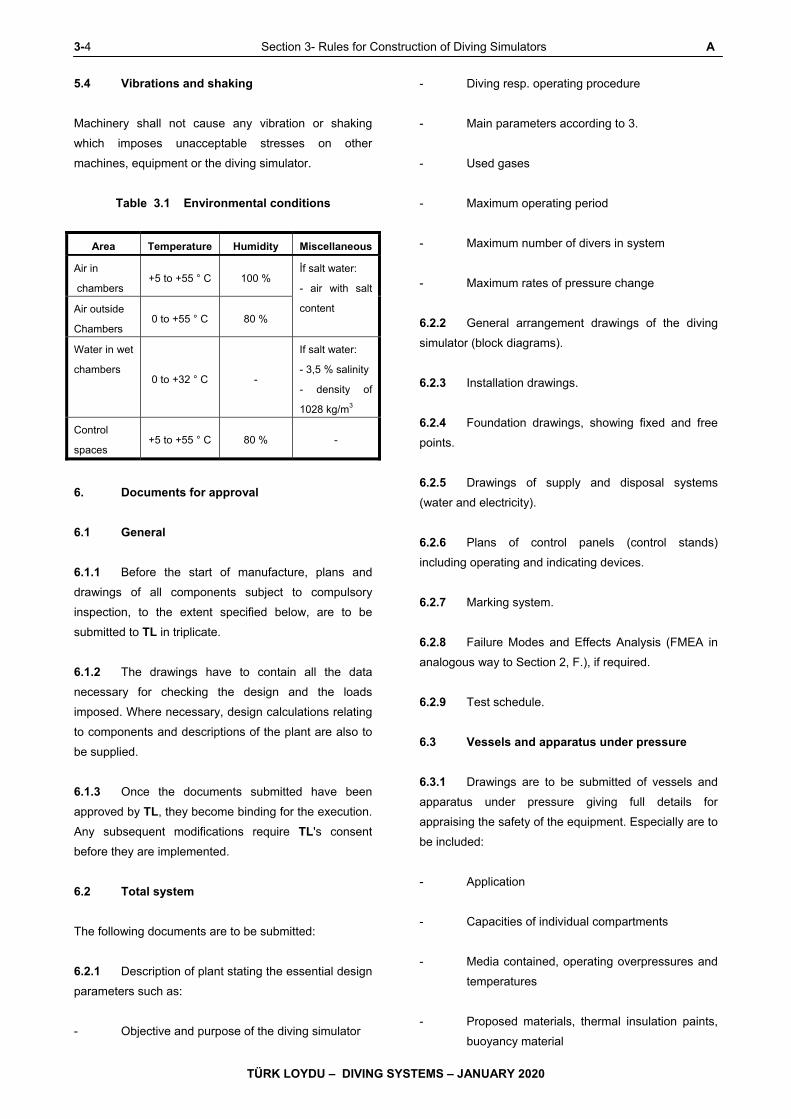
3-4 Section 3- Rules for Construction of Diving Simulators A
TÜRK LOYDU – DIVING SYSTEMS – JANUARY 2020
5.4 Vibrations and shaking
Machinery shall not cause any vibration or shaking
which imposes unacceptable stresses on other
machines, equipment or the diving simulator.
Table 3.1 Environmental conditions
Area Temperature Humidity Miscellaneous
Air in
chambers +5 to +55 ° C 100 %
İf salt water:
- air with salt
content Air outside
Chambers 0 to +55 ° C 80 %
Water in wet
chambers 0 to +32 ° C -
If salt water:
- 3,5 % salinity
- density of
1028 kg/m3
Control
spaces +5 to +55 ° C 80 % -
6. Documents for approval
6.1 General
6.1.1 Before the start of manufacture, plans and
drawings of all components subject to compulsory
inspection, to the extent specified below, are to be
submitted to TL in triplicate.
6.1.2 The drawings have to contain all the data
necessary for checking the design and the loads
imposed. Where necessary, design calculations relating
to components and descriptions of the plant are also to
be supplied.
6.1.3 Once the documents submitted have been
approved by TL, they become binding for the execution.
Any subsequent modifications require TL's consent
before they are implemented.
6.2 Total system
The following documents are to be submitted:
6.2.1 Description of plant stating the essential design
parameters such as:
- Objective and purpose of the diving simulator
- Diving resp. operating procedure
- Main parameters according to 3.
- Used gases
- Maximum operating period
- Maximum number of divers in system
- Maximum rates of pressure change
6.2.2 General arrangement drawings of the diving
simulator (block diagrams).
6.2.3 Installation drawings.
6.2.4 Foundation drawings, showing fixed and free
points.
6.2.5 Drawings of supply and disposal systems
(water and electricity).
6.2.6 Plans of control panels (control stands)
including operating and indicating devices.
6.2.7 Marking system.
6.2.8 Failure Modes and Effects Analysis (FMEA in
analogous way to Section 2, F.), if required.
6.2.9 Test schedule.
6.3 Vessels and apparatus under pressure
6.3.1 Drawings are to be submitted of vessels and
apparatus under pressure giving full details for
appraising the safety of the equipment. Especially are to
be included:
- Application
- Capacities of individual compartments
- Media contained, operating overpressures and
temperatures
- Proposed materials, thermal insulation paints,
buoyancy material
A Section 3- Rules for Construction of Diving Simulators 3-5
TÜRK LOYDU – DIVING SYSTEMS – JANUARY 2020
- Specifications for welding
- Heat treatment
- Manufacturing tolerances
- Non-destructive tests
6.3.2 Drawings are also to be submitted of individual
items of vessel equipment, such as:
- Windows, window flanges, retaining rings
- Door leaves and frames
- Bayonet locks
- Coupling clamps
- Block flange
- Internal facilities
6.4 Gas Supply
6.4.1 Piping diagrams and descriptions are to be
furnished for the entire gas supply system, including a
list of valves and fittings.
6.4.2 Description of proposed cleaning procedure for
breathing gas system.
6.4.3 Details of gas analysis, including an equipment
list.
6.4.4 Description of compressors and their drives
with definition of essential design and operating data.
6.5 Life support systems
The following are to be submitted:
6.5.1 Piping diagrams, block diagrams and
descriptions of systems.
6.5.2 Descriptions of system components and
equipment.
6.5.3 Calculation of cooling and heating
requirements.
6.5.4 Description and drawings of the water supply,
disposal, circulation and treatment systems.
6.5.5 Description and design details of the diver
heating system.
6.6 Electrical equipment
6.6.1 General arrangement drawing of the electrical
equipment containing at least the following information:
- Voltage rating of systems
- Power or current ratings of electrical
- Switchgear, indicating settings for short-circuit
and overload protection; fuses with details of
current ratings
- Cable types and cross-sections
6.6.2 Energy balance of the main and emergency
power supply system.
6.6.3 Drawings of switchgear and distribution
equipmen witht part lists.
6.6.4 Complete documentation for electric motor
drives with details of control, measuring and monitoring
systems.
6.6.5 Battery installation drawing with details of
battery types, chargers and battery room ventilation.
6.6.6 Details of electrical penetrations through
pressure chamber walls.
6.7 Automation and communications
equipment
It is to be submitted:
6.7.1 General arrangement drawings/block diagrams
of control equipment, including lists of measuring points.

3-6 Section 3- Rules for Construction of Diving Simulators A
TÜRK LOYDU – DIVING SYSTEMS – JANUARY 2020
6.7.2 Equipment list for sensors, indicating
instruments, etc.
6.7.3 Drawings and descriptions of electronic
components such as instrument amplifiers, computers
and peripheral units.
6.7.4 General arrangement drawings and equipment
lists for communication systems and signalling
equipment.
6.7.5 Arrangement drawing and description of the
video system.
6.8 Fire protection
It is to be submitted:
6.8.1 Description of the preventive fire protection
measures.
6.8.2 Details of the fire loads in the system.
6.8.3 Drawings and descriptions of:
- Fire detection system
- Fire alarm equipment
- Fire extinguishing system(s)
- Building
- Drawings of fire protection and fire escapes
6.9 Hyperbaric evacuation system
The following are to be submitted:
6.9.1 Description of system.
6.9.2 Arrangement drawing.
6.9.3 Construction drawing of the evacuation
chamber.
6.9.4 Drawings of mating and handling system.
6.9.5 Emergency plan with definition of procedures
for all kinds of emergency cases.
7. Tests and trials
7.1 General
7.1.1 Diving simulators and their ancillary equipment
are subject to constructional and materials tests as well
as to pressure and tightness tests and trials. All the
tests called for in the following are to be performed
under TL supervision.
7.1.2 For serial manufactured parts, test procedures
other than those prescribed may be agreed with TL
provided that they are recognized as equivalent by TL.
7.1.3 TL reserve the right to increase the scope of
the tests, if necessary, and also to extend tests to parts
for which testing is not expressly required according to
the Rules.
7.1.4 Parts requiring approval are to be replaced
with tested parts. The same applies to spare parts.
7.1.5 Gas storage, pressure chambers and life
support systems including piping system are to be
subjected to a tightness test with the adequate
breathing gas or a gas mixture with similar properties at
maximum allowable working pressure. As maximum
permissible leakage rate 1 % pressure drop within 24
hours for the whole pressure chamber system is valid.
7.1.6 After the pressure chambers and their ancillary
equipment have been installed in the operations
building, the diving simulator and its auxiliary systems
are to be subjected to a functional test. All items of
safety equipment are to be tested except where an
adequate test has already been carried out in the
manufacturer's works in the presence of TL.
7.2 Vessels and apparatus under pressure
7.2.1 On completion, vessels and apparatus under
pressure are to be subjected to a constructional test.
This test covers verification that the vessel conforms to
the approved drawings and that the workmanship is
satisfactory. All components have to be accessible to
allow proper inspection.
7.2.2 The materials test Certificates for the materials
used, the reports on the non-destructive testing of welds
and, where applicable, the results of inspection of
A Section 3- Rules for Construction of Diving Simulators 3-7
TÜRK LOYDU – DIVING SYSTEMS – JANUARY 2020
workmanship the proofs for heat treatments applied are
to be submitted.
7.2.3 A hydraulic pressure test is to be performed
prior to insulation and preservation treatment of the
vessels. Each pressure chamber compartment is to be
tested individually. The walls may exhibit no permanent
deformation or leakage.
7.2.4 The test pressure normally applied to vessels
and apparatus shall be 1,5 time the maximum allowable
working pressure.
7.2.5 Diving bells and vessels which may be
exposed in service to external overpressure are, in
addition, to be subjected to an external pressure test.
7.2.6 Vessels and pressure tight housings, which are
arranged internally in pressure chambers and may be
subjected to external overpressure, are to be tested with
1,5 times of the maximum allowable working pressure in
the chamber.
7.3 Pressure chamber windows
7.3.1 Each pressure chamber window shall be
subjected to a hydraulic pressure test which may be
performed in a testing device or for the window and
pressure chamber together after assembly. The test
pressure shall normally be equal to 1,5 times the
maximum allowable working pressure.
7.3.2 After the pressure test, the windows shall not
exhibit any scratches, cracks or permanent deformation
7.4 Compressors
7.4.1 Compressor components subjected to
pressure have to undergo a hydraulic pressure test at a
test pressure equal to 1,5 times the delivery pressure of
the stage concerned.
7.4.2 On completion, compressors are to be
subjected to a tightness test at the maximum allowable
working pressure applicable. In addition a performance
test shall be performed during which the final moisture
content and any possible contamination of the
compressed gas shall also be determined.
7.5 Piping systems
7.5.1 On completion but before the application of
insulation or paint, all piping systems are to be
subjected to a hydraulic pressure test at 1,5 times the
design pressure.
7.5.2 Wherever possible, all butt welded joints in gas
lines for life support systems are to be subjected to 100
% X-ray examination.
7.5.3 Piping systems for breathing gas and oxygen
are to be subjected to a purity test.
7.6 Hoses, hose assembly, umbilicals
7.6.1 All aspects for tests and trials of umbilicals are
defined in Annex E, D.
7.6.2 As far as the requirements in Annex E,
especially in B.2.4, are right for hoses, these have to be
applied.
7.7 Life support systems
A functional test is to be performed to demonstrate the
satisfactory operation of the life support systems under
normal and emergency operating conditions.
7.8 Electrical equipment
7.8.1 Electrical machines, components, cables and
lines are to be subjected to testing in the manufacturer's
works in accordance with the TL Electric Rules.
7.8.2 All electrical systems and equipment are to be
surveyed and tested before the diving simulator is put
into operation.
7.8.3 The electrical safety devices are to be tested
and, in addition, the electrical equipment in the pressure
chambers is to be subjected to an insulation test.
7.9 Automation and communications
equipment
7.9.1 Indicating and monitoring instruments are to be
checked for the accuracy of their readings and their limit
settings.
3-8 Section 3- Rules for Construction of Diving Simulators A,B
TÜRK LOYDU – DIVING SYSTEMS – JANUARY 2020
7.9.2 The satisfactory operation of automatic control
systems is to be checked under service conditions.
Proof is required of the autonomy of safety systems.
7.9.3 The communications equipment for normal and
emergency operation is to be subjected to a functional
test. The suitability of the helium speech unscrambler is
to be verified at the nominal diving pressure NDP of the
facility.
7.10 Fire protection
7.10.1 The fire behaviour of the chamber equipment is
to be checked by reference to the relevant test
Certificates and symbols.
7.10.2 A check is to be made as to whether the
electrical heating systems and heaters are fitted with
protection against overheating.
7.10.3 Fire alarm, detection and extinguishing
appliances are to be subjected to a functional test.
7.11 Hyperbaric evacuation system
By a functional test it is to be proven that the hyperbaric
evacuation system is able to convey divers under
pressure to a safe position and to supply and keep them
under surveillance during this mission.
8. Marking
Concerning marking reference is made to Section 2, H.
This is to be applied to diving simulators in analogous
way.
B. Principles of Design and Construction of
Diving Simulators
1. General principles
1.1 Wherever appropriate and practicable, diving
simulators are to be designed and built in such a way
that the failure of any single component cannot cause a
dangerous situation.
1.2 Diving simulators and their components are to
be designed for the conditions of service described in
the equipment specification.
1.3 Diving simulators are to be so designed that
the planned diving operation can be performed with
maximum safety for the simulator crew.
1.4 Diving simulators for technical experiments
are to be equipped with suitable test chambers which
shall be separable from the remaining chamber system
in respect of operating media, pressure and
atmospheric conditions. The living compartment of the
simulator is to be so arranged that its occupants are not
endangered or inconvenienced by the experiments.
1.5 Diving simulators which can be operated
simultaneously with different chamber pressures are to
be provided with effective means of preventing any
unintentional pressure drift within the chamber system.
1.6 Diving simulators are to be designed in such a
way that injured divers can be carried on a stretcher
inside the pressure chamber system.
1.7 It is recommended that diving simulators shall
be equipped with a hyperbaric rescue system.
1.8 If a handling and transfer system for the diving
bell is used it is to be designed and constructed
according to recognized regulations.
1.9 Diving simulators are to be designed and built
to perform safe operation, adequate maintenance and
necessary surveys.
1.10 All parts of a diving simulator are to be
designed, constructed and mounted in a way which
facilitates cleaning and desinfection.
2. Environmental conditions
Diving simulators, including their accessories and
ancillary equipment, are to be designed for the
environmental conditions likely to be encountered at the
installation site or to be expected under the planned
diving and test conditions, compare A.5.
3. Conditions in chambers
3.1 Diving simulators are to be equipped in such a
way that a breathable atmosphere can be maintained in
B Section 3- Rules for Construction of Diving Simulators 3-9
TÜRK LOYDU – DIVING SYSTEMS – JANUARY 2020
the pressure chambers throughout the total period of
operation.
3.2 The partial pressure of CO2 in the chamber
atmosphere has to be kept permanently below 0,005
bar and for this purpose a CO2 production of 0,05 Nm³/h
per diver shall be assumed.
3.3 Under steady conditions, diving simulators
shall be capable of keeping the temperature in the
decompression chamber constant to ± 1 °C in the range
from 27 to 36 °C while maintaining a relative
atmospheric humidity of at least 50 %.
3.4 Pressure chambers are to be so arranged and
equipped that a uniform chamber atmosphere can be
maintained (CO2 and O2 levels, temperature and
humidity).
3.5 Under steady conditions, the permanent noise
level (over 8 hours) in the pressure chambers shall not
exceed 65 dB(A).
3.6 In test chambers or for special simulation
missions deviations from the aforementioned chamber
conditions are permitted in agreement with TL, if the
safety of the divers is guaranteed by special measures.
4. Arrangement
4.1 Diving simulators may only be installed and
operated in areas not subjected to an explosion hazard.
4.2 As far as possible, the area of installation of
diving simulators is to be kept free of fire loads.
4.3 Diving simulators and breathing gas storage
facilities are to be located in areas which can be
adequately ventilated and provided with suitable electric
lighting.
4.4 The area of installation of diving simulators is
to be separated from other operational facilities. The
partition has to possess, as a minimum requirement,
Class F 30 fire resistance as defined in DIN 4102.
5. Chamber equipment and chamber facilities
5.1 Pressure chamber equipment and facilities are
to be suitable for operation in hyperbaric atmospheres.
Under these conditions they shall not liberate any toxic
or strongly irritant gases. This also applies to protective
coatings and paints used inside chambers.
5.2 Only incombustible, or at least flameretardant,
materials should be used in the chambers.
5.3 Permanently installed chamber equipment is to
be so designed that it suffers no damage when the
chamber is subjected to hydraulic pressure tests.
5.4 Equipment items in pressure chambers are to
be designed and installed in such a way as to minimize
the danger of injury to the divers and leave sufficient
room for movement. In addition, chamber equipment
and experimental apparatus shall not prevent or limit
unduly the possibility of observing the divers from
outside the test chamber resp. with the aid of video
equipment.
5.5 Ancillary systems and equipment needed to
perform tests or create experimental boundary
conditions are to be designed and constructed so that
they are able to perform their functions safely without
danger to the divers or the simulator. The relevant
requirements will be stipulated by TL in each case.
5.6 If diving bells are part of a diving simulator, the
equipment, if applicable, shall conform to Section 2, J.
6. Corrosion protection
6.1 Diving simulators and all their ancillary
components are to be effectively protected against
corrosion. The corrosion protection shall be capable of
being repaired or retouched at a later stage.
6.2 Anti-corrosion coatings exposed to the
chamberconditions have to meet the requirements
stated in 5. In addition, they shall not tend to blister or
flake off under hyperbaric conditions. In wet chambers it
may be necessary to make special provision for the
effect of helium-saturated seawater.

3-10 Section 3- Rules for Construction of Diving Simulators B,C
TÜRK LOYDU – DIVING SYSTEMS – JANUARY 2020
6.3 Wet chambers are to be provided with an
adequate anodic protection system.
C. Vessels and Apparatus under Pressure
1. Pressure chambers
1.1 General
1.1.1 The following Rules apply to pressure vessels
used as pressure chambers in diving simulators.
1.1.2 The documents to be submitted to TL for
approval are listed in A.6.3.
1.1.3 The necessary tests and markings are stated
in A.7.1 - 7.3 and A.8.
1.2 Design principles
1.2.1 General requirements
1.2.1.1 Each pressure chamber or compartment is to
be so equipped that it is protected against inadmissible
working pressure and inadmissible pressure drops.
1.2.1.2 All open penetrations for gas, measurements
and analysis are to be protected by replaceable filters
mounted on the inside of the pressure chamber.
1.2.1.3 Locks are to be designed to prevent accidental
opening under pressure; if necessary, suitable
interlocks are to be provided.
1.2.1.4 Each pressure chamber compartment is to be
fitted with view ports so that, wherever possible, all the
occupants can be observed from outside.
1.2.1.5 Wherever necessary, the view ports of
pressure chambers are to be protected internally and
externally against mechanical damage. View ports are
also to be protected against ultraviolet radiation and
unacceptably high temperatures.
1.2.1.6 Each pressure chamber compartment is to be
sufficiently illuminated.
1.2.1.7 Wet and test chambers are to be provided with
drainage connections at their lowest points. Sumps and
other drains are to be protected to prevent impurities
being sucked in.
1.2.1.8 Pressure chambers are to be provided with
external insulation compatible with the test conditions
and with the environmental conditions at the location
where the simulator is installed.
1.2.2 Decompression chambers
1.2.2.1 Decompression chambers are to be designed
to allow at least two persons to pass in or out
simultaneously through the locks without subjecting the
other divers in the system to a change of pressure.
1.2.2.2 The living compartment of decompression
chambers shall be so designed and equipped that the
occupants can stand upright and each diver is provided
with a bunk on which he is able to stretch out
comfortably. A toilet and shower are also to be
provided. The toilet and shower are to be located in a
separate space. Toilets with arrangements for the
external discharge of human waste as well as further
waste water systems are to be equipped with suitable
interlocks to prevent pressure losses in the chamber
system.
1.2.2.3 The living compartment of decompression
chambers and other compartments used for
decompression are to be provided with a lock through
which provisions, medicines and equipment can be
passed in and out without subjecting the occupants of
the chamber to a change of pressure.
1.2.3 Wet chambers
1.2.3.1 Wet chambers may be designed as chambers
for training of divers and general duties and also as test
chambers. The special conditions for test chambers are
summarized in 1.2.4.
1.2.3.2 Where water partitions are fitted, an Access
opening with a clear diameter of at least 800 mm is to
be provided. The water level control system is to be so
designed, that no water can penetrate into dry
compartments in the event of pressure variations.
1.2.3.3 Water circuits are to be designed and
constructed so that switching from high-pressure to
C Section 3- Rules for Construction of Diving Simulators 3-11
TÜRK LOYDU – DIVING SYSTEMS – JANUARY 2020
lowpressure circuits cannot cause any inadmissible
pressure drop in the test chamber. Furthermore, such
switching operations shall not cause any unacceptable
rise in pressure in low-pressure circuit.
1.2.4 Test chambers
1.2.4.1 Test chambers are to be designed and built in
such a way that the proposed tests can be performed
safely and any danger to the rest of the chamber
system is avoided.
1.2.4.2 The dimensional design of test chamber walls
is to allow for possible additional loads due to test
equipment.
1.2.4.3 Depending on the type of tests, test chambers
are to be separated by double doors from the rest of the
chamber system.
1.2.4.4 Test chambers for technical tests are to be
provided with a lock for materials.
1.2.4.5 Test chambers compartment are to be
provided with sufficient mountings for test equipment.
Adequate means are also to be provided for the
transport and handling of test equipment.
1.2.4.6 Each test chamber compartment is to be
equipped with separate gas analysis connection.
1.2.4.7 Each test chamber compartment is to be
provided with separate connections for communications
equipment. In addition, at least one blind flange each is
to be fitted for power and measuring data transmission.
1.2.5 Diving bells
If diving bells are part of a diving simulator, these are to
be laid out according Section 2, J
1.2.6 Doors and access openings
1.2.6.1 Doors and mating devices in diving simulators
which are not sealed by pressure are to be equipped
with a closing mechanism which precludes opening
under pressure. The closing mechanism is to be so
designed that the correct position of closure is clearly
indicated before pressure is applied.
1.2.6.2 Means are to be provided to enable doors to
be opened from both sides.
Door trunks are to be provided with pressure equalizing
valves.
Devices are to be fitted which hold doors in the open
position.
Doors which open or close under their own weight are
to be so designed that divers are not endangered when
operating them.
1.2.6.3 Doors and access openings for persons shall
have a clear diameter of at least 500 mm, or at least
700 mm in the case of test chambers.
1.2.6.4 The length of door trunks should not exceed
the trunk diameter.
1.2.6.5 For doors in wet chambers, the sealing groove
and seal counter face should be made of not corroding
materials.
1.2.6.6 Hydraulically operated doors have to meet the
following additional requirements:
- The doors are to be capable of being opened
manually if the hydraulic system fails.
- Steps are to be taken to ensure that doors
which open under their own weight if
thehydraulic system fails cannot endanger the
divers.
- Steps are to be taken to ensure that the
opening action can only be initiated after the
pressure has been equalized.
- Operating elements fitted outside chambers
to be arranged so that the operations of
opening and closing the door can be observed
through the view ports provided in the
chamber.
- The design and dimensions of the hydraulic
system for internal doors shall be compatible
with the specified working pressures and with
3-12 Section 3- Rules for Construction of Diving Simulators C,D,E,F
TÜRK LOYDU – DIVING SYSTEMS – JANUARY 2020
the boundary conditions of the pressure
chamber system. The hydraulic fluid has to be
suitable for use in the chambers and shall not
under hyperbaric conditions release gas or
vapours which are toxic or capable of
supporting combustion. combustion.
1.2.6.7 Doors and access openings are to be laid out
for the maximum allowable working pressure.
1.2.7 Pressure-proof bulkheads
Pressure-proof bulkheads for subdivision of the internal
space are to be laid out for the maximum allowable
working pressure.
1.3 Materials
For materials used for diving simulators the provisions
of Section 2, J.1.3 are to be considered.
1.4 Principles of manufacture and construction
Pressure vessels for diving simulators are to be
manufactured and constructed in accordance with
Section 2, J.1.4.
1.5 Calculations
Calculations relating to pressure vessels for diving
simulators are to be performed in accordance with
Section 2, J.1.5. If a calculation of the diving bell for
external pressure is required, this is to be agreed with
TL according to the specification.
1.6 Acrylic windows
Acrylic windows are to be designed and manufactured
in accordance with Annex C.
2. Pressure vessels, gas cylinders and
apparatus under pressure
2.1 Pressure vessels, gas cylinders and
apparatus under external pressure
The dimensioning procedure of Annex A or of an
internationally, by recognized standard is to be applied.
2.2 Pressure vessels, gas cylinders and
apparatus under internal pressure
For pressure vessels, gas cylinders and apparatus
under internal pressure the requirements defined in the
TL Machinery Rules, Section 14 or in other recognized
regulations are valid.
D. Pipes, Valves, Fittings, Hoses, Umbilicals
Pipes, valves, fittings, hoses and umbilicals for diving
simulators are to be designed and manufactured in
accordance with Section 2, K.
E. Compressors
Compressors for the compression of breathing gases
for diving simulators are to be designed and
manufactured in accordance with Section 2, L.
F. Life Support Systems
1. General
1.1 These Rules apply to all parts and components
of the system which are necessary to ensure the life
support and safe environment of the occupants of a
diving simulator.
1.2 The documents to be submitted to TL for
approval are listed in A.6.5.
1.3 The necessary tests and markings are stated
in A.7.7. and A.8.
2. Gas supply
2.1 Filling stations
2.1.1 Filling stations serve to fill the gas storage with
breathing gas. The station has to include the complete
equipment to fill the containers. The boundary of the
gas production and filling station is located immediately
behind the shut-off valve at the gas line for filling or at
the suction side of the delivery system.

F Section 3- Rules for Construction of Diving Simulators 3-13
TÜRK LOYDU – DIVING SYSTEMS – JANUARY 2020
2.1.2 Filling stations are to be constructed and
operated, that operating, surveillance and maintenance
personnel or other persons nearby are not endangered.
2.1.3 Filling stations for breathing gases are not to
be installed in areas where internal combustion engines
or boilers are in operation.
2.1.4 Filling stations for breathing gases are to be
arranged with sufficient place for operation,
maintenance and cleaning, escape and rescue corridors
as well as for fire extinguishing.
2.1.5 Pipe connections between filling stations for
compressed air for production of breathing gases and
other compressed air systems of the plant are only be
established with special approval of TL and under
consideration of additional protection measures.
2.1.6 Filling pipes/hoses and connection or coupling
fittings/hoses are to be suitable for rendering pressure-
less without danger. Gas under pressure, which is
discharged by the safety devices is to be drawn off in a
suitable way.
2.1.7 Filling connections are to be designed and
marked in a way, where confusion of gases to be filled
is safely avoided and a correct connection is enabled.
2.1.8 At the position of the gas delivery, the filling
station is to be equipped with a manometer showing the
delivery pressure.
2.1.9 Filling stations for breathing gases are to be
operated manually and to be monitored.
2.2 Gas storage facilities
2.2.1 Each diving simulator is to be provided with a
permanently installed gas storage facility or with a
suitable location for the storage of gas cylinders.
2.2.2 The capacity of the gas storage facility shall be
such that for all planned diving missions a sufficient
number and quantity of gas mixtures are available to
supply sufficiently all pressure chambers and divers with
the right gases at all simulated depths under both
normal and emergency conditions.
2.2.3 The emergency breathing gas supply is to be
stored separately in gas cylinders which shall not be
opened for normal operation.
2.2.4 Wherever possible, the gas storage facility is to
be housed in a separate building. Rooms for the storage
of oxygen are to be constructed of components having
at least class F 30 fire resistance according to DIN
4102.
2.2.5 The gas storage facility is to be separated from
adjoining rooms by fireproof partitioning (F 90 acc. to
DIN 4102), if these rooms are subject to a fire or
explosion hazard.
2.2.6 The roofing of the gas storage facility shall
have adequate resistance to airborne incandescent
particles and radiant heat. The floor covering is to be at
least flame-retardant.
2.2.7 Gas store rooms are to be adequately
ventilated. The exits are to be so arranged that it is
possible to quit the rooms quickly in case of danger.
Rooms where oxygen may escape, are to be equipped
with oxygen indicating and alarm devices. The sensor
for oxygen is to be installed near the floor. A monitored
suction of the room air near the floor may be provided
as an alternative.
2.2.8 No combustible materials shall be stored in the
gas storage facility.
2.2.9 Gas stores in the open are to be established in
such a way that they are protected from mechanical
damage and the action of outside fires. The containers
shall be readily accessible from all sides. The valves are
to be capable of being operated from a fixed control
point.
2.2.10 Gas storage facilities are to be safeguarded
against unauthorized entry. In addition, warning
signboards are to be mounted prohibiting the
introduction of mobile fire loads as well as the use of
open fires and smoking inside the gas store.

3-14 Section 3- Rules for Construction of Diving Simulators F
TÜRK LOYDU – DIVING SYSTEMS – JANUARY 2020
2.3 Gas distribution
2.3.1 General
2.3.1.1 The gas supply system shall be so designed
that the pressure in the living compartment of the
decompression chamber can be raised at a rate of at
least 2 bar/min up to 2 bar and thereafter at a rate of 1
bar/min.
2.3.1.2 The gas venting system shall be so designed
that the pressure in a decompression chamber or diving
bell can be lowered to 1 bar at a rate of at least 1
bar/min.
2.3.1.3 Sets of breathing apparatus controlled by
respiration which supply breathing gas to persons under
pressure and also remove the exhaust gas
independently of the chamber atmosphere are to be
designed for a gas flow equivalent to 3 times the
required breathing rate per minute (AMV).
The required breathing rate per minute depends on the
activity to be performed and the environmental
conditions (where heavy work is performed in open
water, the rate may be as much as 75 litres/ min per
person).
When designing the breathing mask gas supply and
exhaust gas disposal system, the number of persons
simultaneously connected to the system is to be allowed
for as defined in Table 3.2: Table 3.2 Required quantity of breathing gas for breathing masks
Number of persons Quantity of breathing gas
[litres/min]
1 2 3 4 5 6 7 8
z>8
1 x AMV x 3 2 x AMV x 1,8 3 x AMV x 1,6 4 x AMV x 1,4 5 x AMV x 1,3 6 x AMV x 1,2 7 x AMV x 1,1 8 x AMV x 1,1 z x AMV x 1,0
2.3.1.4 The gas circulating systems are to be so
designed that the chamber conditions stated in B.3. are
maintained.
2.3.1.5 Each pressure chamber is to be equipped with
at least the following gas systems:
- 2 independent gas supply systems for
compression which may deliver into a single
inlet pipe immediately at the chamber
- 1 chamber exhaust gas system
- 1 independent mask supply system (BIBS)
- 1 mask exhaust gas system
- 1 gas circulating system for maintaining a
breathable chamber atmosphere
Where pure oxygen or gas containing more than 25 %
O2 by volume is supplied to the chamber, a separate
piping system is to be provided for this purpose.
2.3.1.6 Valves in gas systems are to be arranged so
that a leaking valve cannot cause any unintended
mixing of gases respectively no oxygen or oxygenlike
gas can penetrate into lines intended for other gases.
Intersections between oxygen and non-oxygen systems
are to be isolated by twin shut-off valves with a vent
valve placed between them.
2.3.1.7 Filters and automatic pressure reducers are to
be fitted in such a way that they can be dismounted
without having to interrupt major gas supply lines.
2.3.1.8 All gas supply and exhaust lines are to be
effectively protected against mechanical damage. When
routed through zones subject to fire hazard they shall be
provided with fireproof cladding.
2.3.1.9 If the composition of the gas of the chamber
atmosphere is not breathable or contaminated, special
measures (e.g. redundant masks und pressure
reducers) are to be established and agreed with TL.
2.3.2 Pressure chambers
2.3.2.1 At least one breathing mask is to be provided
for each occupant of each separately pressurized
chamber compartment.

F Section 3- Rules for Construction of Diving Simulators 3-15
TÜRK LOYDU – DIVING SYSTEMS – JANUARY 2020
2.3.2.2 The masks are to be joined either permanently
or by plug connectors to the mask gas supply and
exhaust system.
2.3.2.3 The exhaust gas (exhalation line) side of the
masks is to be protected against any inadmissible
pressure drop or inadmissible pressure difference.
2.3.2.4 The supply of gas to the chamber is to be
arranged so as to ensure that a homogeneous gas
distribution inside the chamber is achieved as quickly as
possible.
2.4 Conditioning of chamber atmosphere
2.4.1 Each accessible pressure chamber is to be
equipped with an oxygen dosing device and a chamber
gas circulating unit in which the CO2 can be absorbed
and the air temperature and humidity can be regulated.
The rate of circulation shall be such as to satisfy the
conditions stated in Section 2, I.2.
2.4.2 Each diving simulator is to be equipped with at
least 2 chamber gas treatment units which are to be so
arranged that they can be switched to adjoining
chambers.
2.4.3 Test chambers for the performance of manned
experiments in which gases, vapours, dust or fumes
injurious to health are generated are to be equipped
with extraction systems capable of aspirating the
harmful substances as close as possible to their point of
origin.
Such test chambers are also to be provided with
purification systems (welding gas absorbers) for
keeping the chamber atmosphere breathable, inert and
within the permitted temperature limits, e.g. during
welding operations. In addition to this, such test
chambers are to be equipped with a personal breathing
system and respirators independent of the chamber
atmosphere. Additional equipment is to be provided to
enable not only the chamber atmosphere but also the
breathing gases supplied to the divers to be
permanently monitored directly at the mask when
work/tests are being carried out in a non-breathable
atmosphere.
2.5 Treatment and mixing of breathing gases
The use of closed breathing circuits, gas mixing
systems for direct breathing gas supply and helium
reclaim systems is subject to approval by TL.
3. Control and instrumentation
3.1 Central control position
The surveillance and control of the life support systems
has to be performed with the assistance of the central
control position of the diving simulator according to
H.1.4, where all essential chamber data are indicated as
well as the chamber pressures are controlled and the
gases are distributed, if more than one chamber is
existing. In addition the operating conditions of the
ancillary systems are indicated there.
3.2 Instrumentation
3.2.1 Indicating instruments
3.2.1.1 The instruments for the surveillance, control
and operation of the diving simulator are to be grouped
and arranged in the central control position in
accordance with the principles of safety technology and
ergonomics.
3.2.1.2 In the central control position a separate
control console is to be provided for each independently
operated pressure chamber compartment. For test
chambers, an additional independent control position
should be placed in the immediate vicinity of the test
chambers.
3.2.1.3 At least the following operating parameters are
to be displayed at the central control position for each
manned pressure chamber compartment:
- Pressure
- Temperature
- Humidity
- Partial oxygen pressure
3-16 Section 3- Rules for Construction of Diving Simulators F
TÜRK LOYDU – DIVING SYSTEMS – JANUARY 2020
- Partial CO2 pressure
- Pressure of connected breathing gas
containers/ gas cylinders
- Pressure at pressure reducer outlets
- Oxygen content in supply lines to
- umbilicals
- chamber compartments
- breathing masks in chambers
3.2.1.4 The instrumentation of test chambers used
exclusively for unmanned tests shall be compatible with
the test conditions.
3.2.1.5 The pressure gauges of pressure chambers
shall give a reading accuracy of to ± 0,25 % of the full
instrument scale subject to a maximum deviation of 30
cm water column. All other pressure readings may be
accurate ± 1 % of the full instrument scale.
3.2.1.6 Inadmissible deviations from reference values
of the vital parameters shall actuate a visual and audible
alarm at the central control position. Automatically
actuated switching operations in the gas supply system
and similar functions shall also trip such alarms.
3.2.1.7 Pressure chamber compartments are to be
equipped with pressure and temperature gauges which
can be read from inside.
3.2.1.8 Pressure indicators connected directly to the
pressure chamber system are to be fitted with a shutoff
valve.
3.2.2 Analyzer systems
3.2.2.1 Each diving simulator is to be equipped with at
least one oxygen and one CO2 analyzing system.
3.2.2.2 Throughout the entire period of operation, the
oxygen analyzer has to give a reading accuracy of at
least ± 0,015 bar partial oxygen pressure.
3.2.2.3 Throughout the entire period of operation, the
CO2 analyzer has to give a reading accuracy of at least
± 0,001 bar partial CO2 pressure.
3.2.2.4 Decompression chamber living compartments
are to be equipped in addition with independent
instruments for monitoring the oxygen and CO2 levels.
3.2.2.5 Where gas mixtures other than air or helium-
oxygen or He/N2/O2 are used in diving operation,
suitable additional analyzing devices are to be provided
for analyzing the gases used. The necessary
instrumentation is in each case to be defined together
with TL.
3.2.2.6 Test chambers in which welding operations are
performed are to be equipped with analyzers for
continuously monitoring the chamber atmosphere for
impurities such as CO, NO, NOx, hydrocarbons and
ozone. It is necessary to ensure that the analyzers are
also able to monitor the chamber atmosphere of the
other pressure chambers. Devices are also to be
provided for the analysis of pure gases, breathing gas
mixtures and purified helium gases.
The accuracy of the analyzer readings shall be such
that the discrepancy between the partial pressure in the
gas and the partial pressure readings on the instrument
does not exceed 10 %.
3.2.2.7 For diving simulators where the chamber
atmosphere is not subject to contamination as a result
of technical experiments, test tubes may be recognized
as a suitable means of monitoring the chamber
atmosphere for contamination.
3.3 Control equipment
3.3.1 The central control position is to be equipped
with controls for at least the following functions:
- Pressurization and pressure control of each
independently operated pressure chamber
compartment and each diving bell
- Decompression of each independently
operated pressure chamber compartment and
each diving bell
F,G,H Section 3- Rules for Construction of Diving Simulators 3-17
TÜRK LOYDU – DIVING SYSTEMS – JANUARY 2020
- Pressure equalization between chamber
compartments
- Oxygen addition to the chamber compartments
- Control of gas supply to breathing maks
- Control of temperature and humidity in the
pressure chambers
3.3.2 At the control position for the gas distribution a
system mimic diagram is to be provided showing the
functions of the various valves and the different gas
lines marked in colour.
G. Electrical Installations
1. Electrical installations and systems for diving
simulators are to be designed and constructed
according to Section 2, N.
The electrical components and systems which are
installed outside pressure chambers are to be at least
equivalent to a recognized standard such as e.g. VDE,
DIN resp. IEC.
2. The documents for approval are defined in
A.6.6.
3. The required tests are defined in A.7.8.
H. Automation Equipment and
Communications Equipment
1. General
1.1 The following Rules supplement of TL Electric
Rules are to be applied to the construction and
application of equipment for the surveillance, control
and closed loop control of diving simulators as well as
for communications and video monitoring systems.
1.2 The documents for approval to TL are listed in
A.6.7.
1.3 The necessary tests are stated in A.7.9. Only
components and units which have been approved by TL
may be installed.
1.4 Central control position
The requirements for the central control position are to
be applied in analogous way according to Section 2,
O.1.4.
2. Automation equipment
Automation equipment for diving simulators is to be
designed and constructed in accordance with Section 2,
O.2.
3. Communication equipment
3.1 Voice communication systems
3.1.1 Diving simulators are to be equipped with a
suitable communications systems allowing direct
communication between the central control position
and:
- Diving bells
- Each compartment of pressure chambers
- Test equipment control positions
- Pressure chamber control consoles
- Ancillary units
- Offices and service rooms (e.g. the operations
manager's office and mechanical and electrical
workshops)
3.1.2 Where diving simulators are operated with
helium gas mixtures, each pressure chamber
compartment is to be connected to a helium speech
unscrambler. The speech unscramblers shall be
designed for maximum noise suppression and
automatic compensation of changes in signal level.
3.1.3 It is recommended that the central control
position is equipped to record all communications with
the divers.

3-18 Section 3- Rules for Construction of Diving Simulators H,I
TÜRK LOYDU – DIVING SYSTEMS – JANUARY 2020
3.1.4 Voice communications between the pressure
chamber compartments and the central control position
is to be provided by a communication system with
loudspeaker which is permanently switched to
"Receive" at the control console. Switches for reversing
the direction of communication are to be of the self-
resetting type. In addition, each pressure chamber
compartment is to be provided with at least one
headset.
3.1.5 A mains-independent telephone link shall be
provided in addition to the telephone system called for
in 3.1.4.
3.1.6 Electrically powered telephone systems are to
be provided with a reliable power supply. This normally
means that they are to be supplied from a storage
battery with a parallel-connected mains unit and battery
charger supplied with energy in accordance with
Section 2, N.
3.1.7 In wet rooms microphone and receiver
systems are to be designed to prevent the penetration
of water. Where this cannot be ensured by the design,
the penetration of water shall not render the equipment
permanently unserviceable.
3.1.8 The microphone and receiver in diver's masks,
hoods and diver helmets are to be functionally
separated from each other.
3.2 Video surveillance equipment
3.2.1 Diving simulators are to be equipped with a
video surveillance system.
3.2.2 The number of cameras and their angles of
view shall be chosen to cover all chambers of the diving
simulator. In wet chambers it is to be considered that
the chambers may be partially filled with water and
adjustable test equipment may obstruct the view.
3.2.3 A sufficient number of video monitors is to be
provided. Each video monitor has to indicate clearly
which compartment is being viewed at any time.
3.2.4 The image reproduced on the monitors has to
enable the recognition of necessary details.
3.2.5 The installation of a video recorder is
recommended.
3.3 Other communications equipment
3.3.1 All pressure chamber compartments are to be
provided with suitable alternative communications
equipment (e.g. a 3-button signalling system).
3.3.2 Diving simulators should be provided with
equipment for transmission of radio and video
programmes which can, if necessary, carry operational
telephone communications as priority traffic.
I. Fire Protection
1. General
1.1 The following Rules apply to the fire protection
of diving simulators built in accordance with the Rules of
TL.
1.2 The documents to be submitted to TL for
approval are listed in A.6.8.
1.3 The necessary tests are stated in A.7.10.
2. Structural fire protection
2.1 Area of installation of the diving simulator
2.1.1 Buildings for diving simulators and their
ancillary units are to be designed and constructed in
accordance with the building regulations in force at the
site where the diving simulator is to be installed.
2.1.2 Diving simulators may only be installed and
operated in areas not subject to an explosion hazard.
2.1.3 The rooms in which the diving simulator, the
central control position and the gas storage facility are
installed are to be separated from other service rooms
by floors and walls with class F 30 fire protection
according to DIN 4102. If the adjoining rooms are
considered to be subject to a fire hazard, the relevant
partitions are to be established fireproof (F 90).

I Section 3- Rules for Construction of Diving Simulators 3-19
TÜRK LOYDU – DIVING SYSTEMS – JANUARY 2020
2.1.4 The rooms in which diving simulators and their
ancillary units are installed are to be provided with
forced ventilation systems capable of effecting at least 8
changes of air per hour. The air is to be aspirated from
an area not subject to an explosion hazard. The rooms
are also to be equipped with an effective smoke
extraction system.
2.1.5 In the area of installation of the diving
simulator, the gas storage facility and the central control
position, sources of ignition and fire loads are to be
limited to a minimum. Wherever possible, materials
which are at least fire-retardant are to be used. Heat
insulation is to be made of non-combustible materials.
2.2 Pressure chamber interiors
2.2.1 Wherever possible, all materials used in
pressure chambers are to be at least flame-retardant.
(For the purpose of these Rules, flame-retardant refers
to materials which do not sustain combustion on their
own in a compressed air atmosphere of at least 6 bar
absolute.)
2.2.2 As far as possible, fire loads and sources of
ignition are to be avoided. Electrical heating appliances
and heaters are to be fitted with protection against
overheating.
2.2.3 Components or materials are to be selected
with a view to avoid acquisition of static charges as far
as possible.
3. Fire surveillance
3.1 Fire detection systems and alarm systems
3.1.1 The rooms in which diving simulators and their
ancillary units are installed are to be protected by an
automatic fire detection system.
3.1.2 The fire detection system has to trip visual and
audible signals at least in the permanently manned
central control position.
3.1.3 The fire alarm can be activated manually from
the permanently manned central control position or
automatically by the fire detection system.
3.2 Fire detection systems
3.2.1 Fire detection equipment such as the central
fire detection station, the detectors and the wiring of the
detection loops are to be recognized by TL.
3.2.2 Fire detection systems are to be constructed
so that any faults, e.g. failure of the power supply, short-
circuit or wire breakage in the detection loops or the
removal of a detector from its base, trip visual and
audible signals in the fire detection station at the central
control position.
3.2.3 For the installations and arrangement of fire
detection and signalling systems the TL Electric Rules,
Section 9, C. and Automation are to be observed.
4. Fire extinguishing equipment
4.1 Area of installation of the diving simulator
4.1.1 The area of installation of the diving simulator
and its ancillary units is to be equipped with a water fire
extinguishing system as well as with portable and
mobile fire extinguishers and extinguishing appliances.
4.1.2 The water fire extinguishing system is to be fed
by a wet 100 mm nominal width ring main in the
building. The ring main is to be fitted with hose
connections in a way which ensures that a fire inside
the building can be effectively and safely combated.
Hose connections are to conform to DIN 14461, Part 3.
Suitable hose boxes (e.g. to DIN 14461, Part 1)
containing hoses and nozzles are to be placed close to
the hose connections.
In addition, a non-freeze water hydrant is to be placed
close to the diving simulator operations building (e.g. an
underfloor hydrant acc. to DIN 3221 or an abovefloor
hydrant acc. to DIN 3222).
4.1.3 In the case of diving simulators without a
hyperbaric evacuation system, the pressure chamber
system is to be provided with means of cooling in case
of fire in the form of a permanently installed water spray
system with a capacity of at least 10 ℓ/m2 per minute
related to the projected horizontal area concerned. The
water spray system has to encompass at least all the
3-20 Section 3- Rules for Construction of Diving Simulators I,J
TÜRK LOYDU – DIVING SYSTEMS – JANUARY 2020
living areas. These spray systems may be activated and
operated by hand.
4.1.4 Rooms in which diving simulators and their
ancillary units are installed are to be equipped
additionally with approved hand extinguishers. In each
case, one of the portable extinguishers is to be mounted
close to the entrance to the room concerned.
4.1.5 Where the room in which the diving Simulator
is installed is also used wholly or in part as a workshop,
the room in question is to be additionally equipped with
at least one mobile 50 kg dry extinguisher.
4.2 Pressure chambers
4.2.1 Each compartment inside a pressure chamber
is to be equipped with suitable means of extinguishing a
fire in the interior and such means shall be capable of
applying the extinguishing agent quickly and effectively
to all parts of the chamber.
4.2.2 The fire extinguishing system is to be designed
and constructed in such a way that it is fully able to deal
with any conceivable cases of fire under all
environmental conditions for which the diving simulator
is designed. Activation of the fire extinguishing system
shall cause no inadmissible loss of pressure in the
chamber. The extinguishing system may be activated by
hand.
4.2.3 The preferred extinguishing agent is water.
Extinguishing agents with a toxic or narcotic effect are
not allowed.
4.3 Diving bells
A fire protection/fire system equipment according to
size, mission and equipment of the diving bell is to be
provided.
5. Other fire protection equipment
The central control position of the diving simulator is to
be provided with at least one independent compressed-
air respirator of approved design having an operating
capability of at least 30 minutes and fitted with
equipment for voice communication with the divers.
J. Hyperbaric Evacuation System
1. General
1.1 Where a hyperbaric evacuation system
permanently connected to the diving simulator is
provided, the following Rules are to be applied.
1.2 Where the evacuation chamber is also to be
used as a decompression chamber the relevant
requirements for decompression chambers in this
Section are also to be applied additionally.
1.3 The documents to be submitted to TL for
approval are listed in A.6.9. The necessary tests are
stated in A.7.11.
2. Design principles
2.1 Evacuation chamber
2.1.1 The hyperbaric evacuation chamber is to be
designed for the simultaneous rescue of all the divers in
the diving simulator at the nominal diving depth NDD. At
least one seat with safety harness is to be provided for
each diver.
2.1.2 The evacuation chamber is to be provided with
a lock for supplies.
2.1.3 The evacuation chamber is to be equipped
with view ports enabling all the occupants to be
observed from outside.
2.1.4 The chamber connections for gas, water and
electrical energy are to be designed for rapid coupling
and uncoupling.
2.1.5 The evacuation chamber is to be illuminated
adequately.
2.1.6 The rescue chamber is to be equipped with an
autonomous life support system enabling the pressure,
temperature and gas composition in the chamber to be
maintained for at least eight hours. The life support
system respectively the rescue chamber is to be
provided with connections for external supply and
surveillance.
J Section 3- Rules for Construction of Diving Simulators 3-21
TÜRK LOYDU – DIVING SYSTEMS – JANUARY 2020
2.1.7 The evacuation chamber is to be equipped
externally with regulating and control devices enabling a
safe atmosphere for the divers to be maintained in the
chamber.
2.1.8 The evacuation chamber is to be equipped
with a telephone system allowing communication with
the divers.
2.1.9 The evacuation chamber is to be provided with
its own power supply enabling the operation of the
essential electrical installations for at least eight hours.
2.1.10 The evacuation chamber is to be so designed
that it can be operated in the open air.
2.1.11 The evacuation chamber is to be equipped
with a mating and handling system enabling it to be
quickly and safely connected and disconnected and
conveyed to a safe position without external power.
2.1.12 The evacuation chamber is to be provided with
attachment points enabling it to be hoisted by a
standard crane.
Section 4- Rules for Construction of Diver Pressure Chambers 4-1
TÜRK LOYDU – DIVING SYSTEMS – JANUARY 2020
SECTION 4
RULES FOR CONSTRUCTION OF DIVER PRESSURE CHAMBERS
Page
A. GENERAL RULES and INSTRUCTIONS .............................................................................................................. 4- 2
1. Scope
2. Definitions
3. Documents for Approval
4. Tests and Trials
5. Marking
B. PRINCIPLES for DESIGN and CONSTRUCTION ................................................................................................. 4- 4
1. General Principles
2. Treatment Chambers
3. Transportable Chambers
4. Materials
5. Manufacture
6. Calculations
4-2 Section 4- Rules for Construction of Diver Pressure Chambers A
TÜRK LOYDU – DIVING SYSTEMS – JANUARY 2020
A. General Rules and Instructions
1. Scope
1.1 The following Rules apply to diver pressure
chambers (treatment chambers, transport chambers)
which are intended for the treatment or transport of sick
divers under pressure and which are constructed under
survey of and in conformity with the Rules of TL and are
to get an adequate Certificate. They also apply to all
equipment necessary to the safe operation of the diver
pressure chambers.
2. Definitions
Definitions are to be learned from Section 2, C.1.
Additional special definitions for diver pressure
chambers are defined in the following:
2.1 Breathing connection
Connection between the demand breathing system and
the user's respiratory passages.
2.2 Working pressure
The internal over pressure in a part of the system
necessary for the operation.
2.3 Treatment chamber
Diver pressure chamber intended for the treatment of
diver sicknesses under pressure.
2.4 Compressed air /breathing gas stock
Total quantity of stored compressed air or breathing
gases.
2.5 Main chamber
Part of pressure chamber used for carrying out
treatment under pressure.
2.6 Demand breathing system
Respiration-controlled metering system.
2.7 Test pressure
The overpressure to which a component is subjected for
test purposes.
2.8 Diver pressure chamber
Pressure chamber intended for the treatment or
transport of sick divers under pressure.
2.9 Transportable chamber
Mobile diver pressure chamber intended for the
transport of sick divers to a treatment chamber under
pressure.
2.10 Antechamber
Part of pressure chamber for the lock in and out of
persons and equipment
3. Documents for approval
3.1 General
3.1.1 Before the start of manufacture, plans and
drawings of all components subject to compulsory
inspection are to be submitted to TL in triplicate.
3.1.2 The drawings shall contain all the data
necessary to check the design and the loading of the
equipment. Wherever necessary, calculations relating to
components and descriptions of the system are to be
submitted.
3.1.3 Once the documents submitted have been
approved by TL, they become binding for execution.
Any subsequent modifications require TL's consent
before they are implemented
3.2 Pressure chambers, vessels and apparatus
under pressure
3.2.1 Drawings are to be submitted of pressure
chambers, vessels and apparatus under pressure giving
full details for appraising the safety of the equipment. In
addition component drawings and detailed data of the
A Section 4- Rules for Construction of Diver Pressure Chambers 4-3
TÜRK LOYDU – DIVING SYSTEMS – JANUARY 2020
equipment of pressure chambers and vessels are to be
submitted.
3.2.2 Plans, block diagrams and descriptions,
including lists of valves and fittings are to be submitted
for the supply, operating and control systems.
4. Tests and trials
4.1 General
4.1.1 Diver pressure chambers and their ancillary
equipment are subject to preliminary examination,
constructional and materials tests as well as to pressure
and tightness tests and trials. All the tests called for in
the following are to be performed under TL supervision.
4.1.2 After the diver pressure chambers and ancillary
equipment have been installed at the installation
location, the system is to be subjected to functional
testing and all items of safety equipment are to be
tested except where this has already been done on the
manufacturer's premises in the presence of TL.
4.2 Diver pressure chambers, vessels and
apparatus under pressure
4.2.1 On completion, pressure chambers, vessels
and apparatus under pressure are to be subjected to a
constructional test.
The constructional test includes verification that the
vessel conforms to the approved drawings and that the
workmanship is faultless. All components are to be
accessible for adequate inspection.
4.2.2 The material test Certificates for the materials
used, the reports on the non-destructive testing of welds
as well as the results of inspections of workmanship and
evidence of the heat treatments applied are to be
submitted, where appropriate.
4.2.3 A hydraulic pressure test is to be performed
prior to preservation treatment of the vessel. Each
pressure chamber compartment is to be tested
individually. The walls may exhibit no permanent
deformation or leakage.
4.2.4 The test pressure shall normally be equivalent
to 1,5 times the maximum allowable working pressure.
4.2.5 The gas storage facility and the diver pressure
chamber including the piping system are to be
subjected to a tightness test using air at the maximum
allowable working pressure.
4.2.6 Gas cylinders are to be checked to determine
whether they bear the test date and marking applied by
a recognized expert and whether the test period has not
yet expired.
4.3 Pressure chamber windows
4.3.1 Each pressure chamber window has to
undergo a hydraulic pressure test which may be
performed after installation together with the pressure
chamber or in a testing device. The test pressure shall
normally be equivalent to 1,5 times the maximum
allowable working pressure, and the pressure direction
is to be permanently marked in the window.
4.3.2 After the pressure test, windows shall exhibit
no scratches, cracks or permanent deformation.
4.4 Compressors
Compressors are to be subjected to a tightness test at
their maximum allowable working pressure of the
compressor stage concerned. In addition, a
performance test is to be carried out in which the final
moisture content and any possible contamination of the
compressed gas are to be determined. The safety
devices are to be checked.
4.5 Piping systems
On completion of manufacture but before insulation or
painting, all piping systems are to be subjected by the
manufacturer to a hydraulic pressure test at 1,5 times
the maximum allowable working pressure and are to be
cleaned. A Manufacturer Test Report is to be issued to
this effect.
4-4 Section 4- Rules for Construction of Diver Pressure Chambers A,B
TÜRK LOYDU – DIVING SYSTEMS – JANUARY 2020
4.6 Control, communications and safety
equipment
4.6.1 Indicating and monitoring instruments are to be
tested for the accuracy of their readings and their limit
value settings.
4.6.2 Automatic monitoring systems are to be
checked for satisfactory performance under service
conditions.
4.6.3 Normal and emergency communications
equipment is to be subjected to a functional test.
4.6.4 Proof is required of the reliable functioning of
all safety systems.
4.7 Electrical equipment
4.7.1 All electrical systems and equipment are to be
inspected and tested before the diver pressure chamber
is put into service.
4.7.2 Electrical protective devices are to be checked;
in addition, an insulation test is to be performed on the
electrical equipment in the pressure chambers.
4.8 Fire protection
4.8.1 The fire behaviour of the chamber equipment is
to be checked by reference to the relevant test
Certificates and symbols, as applicable.
4.8.2 A check is to be made as to whether the
electrical heating systems and heaters are fitted with
protection against overheating.
4.8.3 Fire extinguishing appliances are to be
subjected to a functional test, as far as applicable,
4.9 Mating systems
4.9.1 The mating procedure is to be tested; in case
of power drive the main drive as well as the auxiliary
drive has to be tested for correct functioning.
4.9.2 A check is to be carried out to verify that the
bayonet flange connection cannot be subjected to
pressure until the inner ring of the bayonet mechanism
has turned fully home, and that the bayonet flange
connection cannot be opened until the pressure has
been relieved. Furthermore, the pressure relief device of
the flange connection is to be checked.
5. Marking
5.1 All diver pressure chambers are to be fitted in a
prominent position with a permanently mounted name
plate containing at least the following details:
- Name or company designation of manufacturer
- Year of construction and serial number
- Maximum allowable working pressure [bar]
- Test pressure [bar]
- Capacity [ℓ] (data of each chamber
compartment)
- Total weight including persons (only for
transport chambers) [kg]
- Maximum permissible number of persons for
each chamber compartment
- Date of test
- Test stamp
5.2 Concerning the marking of all other pressure
vessels and gas bottles reference is made to Section 2,
H.4.
5.3 Concerning the marking of all valves and
fittings, operating elements, indicators and warning
devices reference is made to Section 2, H.3.
B. Principles for Design and Construction
1. General principles
1.1 Diver pressure chambers are to be designed
and built to ensure safe operation and facilitate the
B Section 4- Rules for Construction of Diver Pressure Chambers 4-5
TÜRK LOYDU – DIVING SYSTEMS – JANUARY 2020
performance of proper maintenance and necessary
surveys.
1.2 All parts of diver pressure chambers are to be
designed, constructed and mounted in such a way as to
facilitate cleaning and disinfection.
1.3 Diver pressure chambers are to be so
designed that a working pressure of at least 5 bar can
be reached and maintained without fail. Provision is to
be made for raising the working pressure from 0 bar to 5
bar within 6 minutes. A pressure reduction from 0,4 bar
to 0,2 bar shall be possible within one minute.
1.4 Diver pressure chambers are to be equipped
with a suitable safety device which automatically
prevents the maximum allowable working pressure from
being exceeded by more than 10 %.
In addition, diver pressure chambers are to so be
equipped, that they are safeguarded against
inadmissible pressure drop.
1.5 Safety valves are to be so designed that they
respond only when the maximum allowable working
pressure has been exceeded and close before the
pressure drops below this level.
Safety valves are to be mounted in such a way that they
are protected from mechanical damage and accidental
operation.
The connection of safety valves on diver pressure
chambers are to be so designed that they cannot be
sealed off unintentionally.
1.6 Instead of the pressure relief device,
equipment may be fitted which automatically interrupts
the pressure supply when the maximum allowable
working pressure is exceeded and simultaneously trips
a visual and audible alarm. The alarm signal shall be
such that it is at all times clearly perceptible to the
operating personnel.
1.7 The door opening of diver pressure chambers
shall allow the passage of a patient laying on a stretcher
according to DIN 13024. Round door openings are to
have a clear diameter of at least 0,70 m. Doors fitted
with an interlock shall be capable of being operated
from both sides when the pressure has been equalized.
Diver pressure chambers operated on ships, floating
structures or in containers have to be fitted with a
device that avoids swinging of the doors also in the
open position.
1.8 Diver pressure chambers are to be fitted with
observation windows giving a good view of all the
occupants of treatment chambers and of the head of the
occupant of transport chambers. The windows are to be
made of acrylic plastic.
1.9 Each pressurized gas supply and exhaust line
has to be fitted at least with a shut-off valve immediately
at the pressure chamber wall. This shut-off valve may
be dispensed with if the connection to the first valve is
short and well protected.
1.10 Diver pressure chambers are to be so
designed and equipped that the noises in the chamber
do not exceed a peak level of 90 dB(A) measured as an
A(pulse) acoustic pressure level according to DIN
45645, part 2 or an evaluation level (according to DIN
45645, part 1, related to 3 hours) of 70 dB(A).
These values apply to the head level of persons
situated inside.
1.11 The interior equipment of diver pressure
chambers shall be made of materials which are at least
flame-retardant (class B1 acc. to DIN 4102 or acc. to
ISO 6941). The use of plastics for the interior equipment
of chambers is to be kept to a minimum.
2. Treatment chambers
2.1 General requirements
2.1.1 Treatment chambers have to comprise at least
a main chamber and an antechamber. They should also
be equipped with a connecting flange for transport
chambers subject to DIN 13256, part 6, (NATO flange).
2.1.2 The inside diameter of the treatment chamber
should be at least 1,48 m.
4-6 Section 4- Rules for Construction of Diver Pressure Chambers B
TÜRK LOYDU – DIVING SYSTEMS – JANUARY 2020
2.1.3 The configuration of the main chamber shall
provide space for at least one person laying down and
two persons seated.
The number of persons allowed in the main chamber is
to be stated on a plate easily visible and permanently
fixed above the entrance.
2.1.4 Seats have to be provided according to the
number of persons admitted. Seats are to be designed
to provide each person with a seat width of at least 0,5
m and a seat depth of at least 0,4 m and shall avoid
loss of body heat due to contact with cold surfaces.
2.1.5 After deduction for interior equipment, the
chamber shall provide at least 0,5 m3 of space for each
person to be accommodated.
2.1.6 The main chamber is to be equipped with
means of changing the air.
2.1.7 Each person to be accommodated is to be
provided in the main chamber with a source of oxygen
supplying at least 75 ℓ/min at atmospheric pressure.
The oxygen is to be supplied to the breathing
connection via a demand breathing system at the
pressure prevailing in the chamber. The exhaled gas
shall not be introduced in the chamber atmosphere.
2.1.8 Main chamber and antechamber shall be
separately serviced with air and oxygen for breathing.
Means are to be provided to prevent the pressure in the
antechamber exceeding that in the main chamber.
2.1.9 The main chamber is to be equipped with
heating. The heating capacity has to be equivalent to at
least 0,25 kW per m3 of chamber volume and shall have
at least 3 settings.
2.1.10 The main chamber is to be provided with a
supply lock. The dimensions of the supply lock shall not
be less than 200 mm in diameter and 300 mm in length.
The means of closure of the supply lock are to be
interlocked in such a way that they can on no account
open simultaneously. Pressure equalizing apertures are
to be safeguarded to prevent them from being rendered
ineffective by obstructions. The pressure in the supply
lock is to be indicated by a pressure gauge or a suitable
device mounted externally at the lock controls.
2.1.11 The vessel wall of the main chamber is to be
fitted with at least one DN 80 blind flange for later
installations.
2.1.12 The main chamber has to be provided with
easily accessible means of mounting for an additional
pressure gauge for checking the chamber pressure.
2.1.13 The configuration of the antechamber shall be
such that it can accommodate two seated persons.
2.2 Compressed air and oxygen supply
2.2.1 A supply of compressed air is to be provided
for the operation of the treatment chamber which is
sufficient to
- Raise the pressure in the main chamber once
and in the antechamber twice from 0 bar to 5
bar overpressure,
- Hold an overpressure of 5 bar in the main
chamber for 30 minutes with an adequate rate
of air change, and
- Hold an overpressure of 1 bar overpressure in
the main chamber for 300 minutes with an
adequate rate of air change.
The design of the air change system is adequate if it is
capable of exchanging 30 litres of air per minute per
person at working pressure.
In the main chamber it shall be possible to effect the
aforementioned pressure rise within 6 minutes.
2.2.2 The air supply system is also to be equipped
with an air compressor at least capable of meeting the
air change requirements stipulated in 2.2.1.
2.2.3 The capacity of the air compressor called for in
2.2.2 may be reduced provided that the treatment
chamber is equipped with an efficient CO2 absorber and
suitable quantities of lime or other CO2 absorption
media are carried.
2.2.4 Notwithstanding 2.2.2 an air compressor may
be dispensed with if an additional emergency air supply
is carried in compressed air containers which

B Section 4- Rules for Construction of Diver Pressure Chambers 4-7
TÜRK LOYDU – DIVING SYSTEMS – JANUARY 2020
corresponds to at least 50 % of the quantity of air
specified in 2.2.1.
2.2.5 The air supply system is to be provided with an
additional inlet for compressed air.
2.2.6 The air supplied to the treatment chamber shall
conform at least to the purity requirements specified in
EN 12021 "Compressed Air for Breathing Apparatus".
2.2.7 For oxygen treatment a supply of oxygen of at
least 20 m3 has to be provided.
2.2.8 For treatment chambers which are designed
for a working pressure higher than 5 bar, above
requirements for the available gas volumes are to be
applied in analogous way.
2.3 Electrical equipment
2.3.1 All electrical equipment including lighting shall
conform to DIN 57100, part 706/VDE 0100, part 706
and VDE 0100.
2.3.2 All electrical equipment is to be safeguarded to
prevent overheating.
2.3.3 The lighting in the antechamber and main
chamber of treatment chambers has to provide a
nominal illuminance of at least 200 lux at the seating
level. It shall be possible to illuminate lying surfaces with
an illuminance of 500 lux (e.g. by adjustable spotlight).
2.3.4 An emergency power supply is to be provided
to illuminate the treatment chamber, the control console
and all consumers necessary to operational safety. In
case of mains failure, this has to take over the power
supply to the consumers and shall ensure continued
operation for at least 5 hours.
2.4 Controls and indicating instruments
2.4.1 The controls and indicating instruments for the
antechamber and main chamber are to be grouped in
one control console. They are to be clearly marked,
arranged according to function and shall be illuminated
in accordance with DIN 5035, part 2. The nominal
illuminance shall be 300 lux.
2.4.2 The pressure in each antechamber and main
chamber is to be indicated by at least one class 0,25
pressure gauge.
2.4.3 A facility is to be provided for continuously
recording the pressure in the main chamber. The
system shall register pressure variations of 0,03 bar and
time intervals of 1,0 min in a manner which enables the
data to be evaluated. The pressure variations over the
previous 2 hours shall be visible.
2.4.4 The console is also to be fitted with indicators
registering the following:
- Pressure in the compressed air storage
containers
- Pressure in the oxygen storage containers or
further breathing gas storage containers
- Scavenge air flow rate
- Inside temperature in the main chamber
- Volumetric concentration or partial pressure of
the oxygen
2.4.5 A clock with a second hand, independent of the
mains supply, is to be mounted where it can be seen at
the control console. Clocks with a digital display as the
sole indicator are not permitted.
2.5 Communications
2.5.1 A communication system with loudspeaker is
to be provided between antechamber and control
console and between main chamber and control
console. The communication system is to be
permanently switched to "Receive" on the control
console, and reversal of the direction of communication
shall be possible only by self-resetting switches.
2.5.2 A telephone link independent of the mains
supply shall be provided in addition to the
communication system called for in 2.5.1.
2.5.3 At least one emergency signalling system each
has to be installed between the antechamber and the
4-8 Section 4- Rules for Construction of Diver Pressure Chambers B
TÜRK LOYDU – DIVING SYSTEMS – JANUARY 2020
control console and between the main chamber and the
control console. The signal buttons in the chambers are
to be clearly marked and easily accessible.
2.6 Fire protection equipment
Treatment chambers are to be equipped with suitable
fire-extinguishing appliances (e.g. deluge system,
bucket spray, fire-extinguishing blanket).
3. Transportable chambers
3.1 For consideration of safety the use of one man
transportable chambers should no longer be envisaged.
In addition to the sick diver the transport chamber
should be capable of accommodating an accompanying
person. Apart from the general requirements according
to 1. the following requirements apply.
3.2 Transportable chambers shall have an inside
length of at least 2,0 m and shall have an access port
with a clear diameter of at least 0,5 m.
3.3 It shall be possible to lodge the diver in the
transportable chamber securely enough to prevent
injury due to motions during transfer. Suitable holding
devices or belts are to be provided.
3.4 Transportable chambers shall regarding their
total weight and dimensions be designed such that they
can be carried or moved otherwise by helpers over
short distances and loaded onto a transport vehicle
without the assistance of a crane.
3.5 Transportable chambers are to be equipped
with lifting handles, at least two fastening eyes and the
necessary hoisting sling.
3.6 Transportable chambers are to be fitted with a
bayonet flange connection as per DIN 13256, part 6,
(NATO flange) to enable them to be coupled to a
treatment chamber. It has to be secured that the
bayonet flange connection cannot get under
impermissible overpressure.
3.7 The design has to ensure that, for operation
according to instructions, the means of closure of the
transportable chamber can only be opened until the
closure is subjected to the same pressure from inside
and outside.
3.8 Transportable chambers are to be equipped
with compressed air containers with at least 8000 litres
(at atmospheric pressure) air supply.
This supply of air is intended for the sole purpose of
scavenging the atmosphere in the event of an
interruption of the normal air supply. Adequate
scavenging of the atmosphere means 25 litres per
minute and person measured at the maximum pressure
in the chamber.
3.9 Transportable chambers are to be equipped
with at least the following controls and monitoring
instruments:
- Air inlet valve
- Exhaust air valve
- Scavenge air valve
- Pressure gauge (class 0,25) for chamber
pressure
- Pressure-reducing valve, with inlet and outlet
pressure gauge, to which the compressed air
containers called for in 3.8 are connected
- An additional means of connection, with shut-
off device, comprising a suitable high-pressure
hose at least 1,5 m in length for connecting the
operational compressed air supply to the
pressure reducing valve
- Measuring instrument for monitoring of the
oxygen volume concentration or partial
pressure
3.10 The controls and indicating instruments shall
continue to be capable of being operated or observed
when the transportable chamber is coupled to the
treatment chamber. They are to be located close to a
window in the vessel in such a way that the operating
personnel can observe the persons in the transportable
chamber without having to change position.
3.11 A flow of scavenge air of at least 25 litres per
minute and person (measured at the chamber pressure)
shall be secured at each pressure stage.
B Section 4- Rules for Construction of Diver Pressure Chambers 4-9
TÜRK LOYDU – DIVING SYSTEMS – JANUARY 2020
3.12 For the purpose of scavenging transportable
chambers shall be operated only with breathing air
meeting the purity requirements as per EN 12021,
"Compressed Air for Breathing Apparatus". Connections
for sources of oxygen as per 2.1.7 are to be provided.
3.13 A communication system with loudspeakers is
to be provided between the inside of the transportation
chamber and the outside controls. On the outside, the
system shall be permanently switched to "Receive", and
reversal of the direction of communication shall only be
possible by the operation of a self-resetting switch
mounted on the outside. On the outside the
communication system is also to be equipped with a
head-set.
3.14 Transportable chambers are to be provided
with a supply lock as per 2.1.10.
4. Materials
The materials used for walls subjected to pressure are
subject to the requirements set out in Section 2, J.1.3.
5. Manufacture
The manufacture of diver pressure chambers is subject
to the requirements set out in Section 2, J.1.4.
6. Calculations
For the calculation of diver pressure chambers Section
2, J.1.5 is valid.
Annex A - Calculation of the Pressure Hull A-1
TÜRK LOYDU – DIVING SYSTEMS – JANUARY 2020
ANNEX A
CALCULATION of the PRESSURE HULL
Page
A. GENERAL ....................................................................................................................................................... A- 2
B. FATIGUE STRENGTH ................................................................................................................................... A- 3
C. STRESSES AT NOMINAL DIVING PRESSURE ........................................................................................... A- 3
D. STRESSES AT TEST DVING PRESSURE .................................................................................................... A- 3
E. PROOF OF ULTIMATE STRENGTH AT COLLAPSE DIVING PRESSURE .................................................. A- 3
F. CALCULATION .............................................................................................................................................. A- 4
G. LITERATURE ................................................................................................................................................. A-22
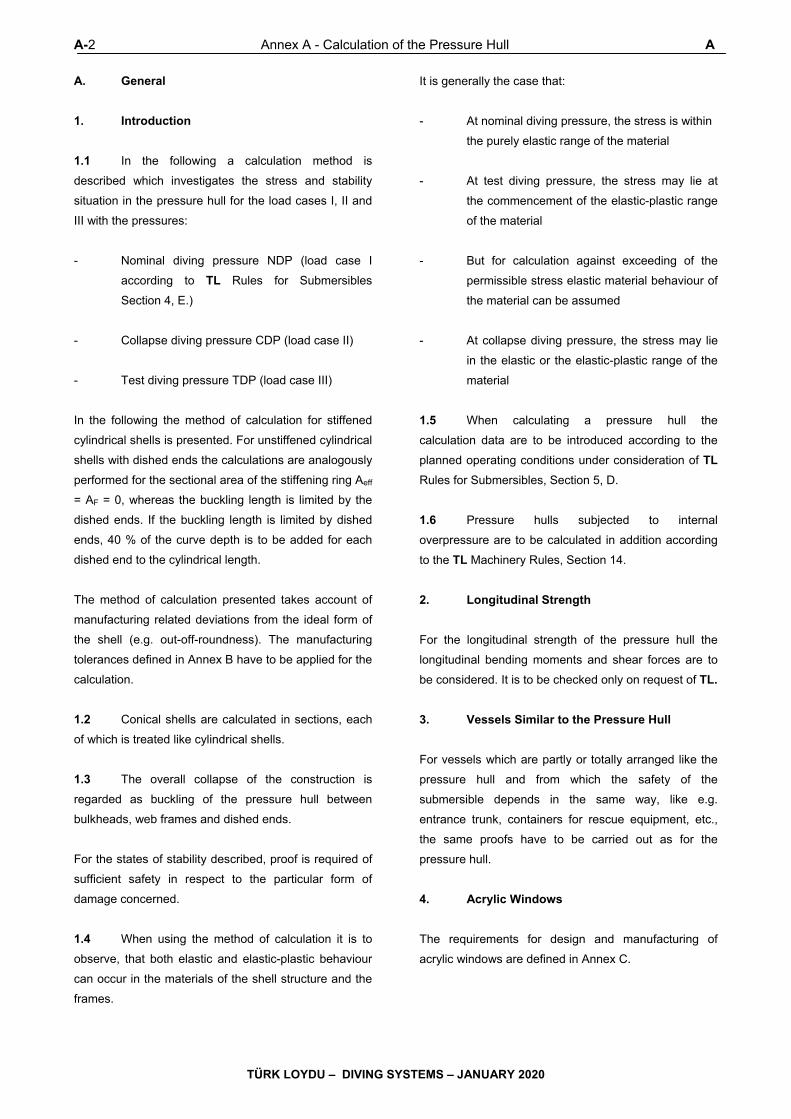
A-2 Annex A - Calculation of the Pressure Hull A
TÜRK LOYDU – DIVING SYSTEMS – JANUARY 2020
A. General
1. Introduction
1.1 In the following a calculation method is
described which investigates the stress and stability
situation in the pressure hull for the load cases I, II and
III with the pressures:
- Nominal diving pressure NDP (load case I
according to TL Rules for Submersibles
Section 4, E.)
- Collapse diving pressure CDP (load case II)
- Test diving pressure TDP (load case III)
In the following the method of calculation for stiffened
cylindrical shells is presented. For unstiffened cylindrical
shells with dished ends the calculations are analogously
performed for the sectional area of the stiffening ring Aeff
= AF = 0, whereas the buckling length is limited by the
dished ends. If the buckling length is limited by dished
ends, 40 % of the curve depth is to be added for each
dished end to the cylindrical length.
The method of calculation presented takes account of
manufacturing related deviations from the ideal form of
the shell (e.g. out-off-roundness). The manufacturing
tolerances defined in Annex B have to be applied for the
calculation.
1.2 Conical shells are calculated in sections, each
of which is treated like cylindrical shells.
1.3 The overall collapse of the construction is
regarded as buckling of the pressure hull between
bulkheads, web frames and dished ends.
For the states of stability described, proof is required of
sufficient safety in respect to the particular form of
damage concerned.
1.4 When using the method of calculation it is to
observe, that both elastic and elastic-plastic behaviour
can occur in the materials of the shell structure and the
frames.
It is generally the case that:
- At nominal diving pressure, the stress is within
the purely elastic range of the material
- At test diving pressure, the stress may lie at
the commencement of the elastic-plastic range
of the material
- But for calculation against exceeding of the
permissible stress elastic material behaviour of
the material can be assumed
- At collapse diving pressure, the stress may lie
in the elastic or the elastic-plastic range of the
material
1.5 When calculating a pressure hull the
calculation data are to be introduced according to the
planned operating conditions under consideration of TL
Rules for Submersibles, Section 5, D.
1.6 Pressure hulls subjected to internal
overpressure are to be calculated in addition according
to the TL Machinery Rules, Section 14.
2. Longitudinal Strength
For the longitudinal strength of the pressure hull the
longitudinal bending moments and shear forces are to
be considered. It is to be checked only on request of TL.
3. Vessels Similar to the Pressure Hull
For vessels which are partly or totally arranged like the
pressure hull and from which the safety of the
submersible depends in the same way, like e.g.
entrance trunk, containers for rescue equipment, etc.,
the same proofs have to be carried out as for the
pressure hull.
4. Acrylic Windows
The requirements for design and manufacturing of
acrylic windows are defined in Annex C.

B,C,D,E Annex A - Calculation of the Pressure Hull Annex A-3
TÜRK LOYDU – DIVING SYSTEMS – JANUARY 2020
B. Fatigue Strength
1. Proof of fatigue strength has to be carried out
for load case I determined by nominal diving pressure
NDP according to the TL Rules for Submersibles
Section 4, B.2.1. and Underwater Equipment, Section 3,
C.1.6.1.1.
2. The proof of stresses is to be based on the
nominal geometry.
3. For the calculation of the stresses in the
pressure hull, the following influences have to be
considered with sufficient accuracy:
- Increase of stress at frames, web frames,
bulkheads and tripping/transition rings
- Increase of stress at penetrations
- Disturbances of the state of stress because of
connection with pressure-proof extensions
C. Stresses at Nominal Diving Pressure
1. Proof of stress has to be carried out for load
case I characterized by nominal diving pressure NDP
according to the Rules for Submersibles, Section 4,
B.2.1 respectively Underwater Equipment, Section 3,
C.1.6.1.1.
2. For the calculation of the stresses in the
pressure hull the stress limits are defined in the Rules
for Submersibles, Section 5, D.3.
3. The proof of stress has to be performed using
the methods in F.1., F.6.2, F.4.4, F.7.2 and F.7.4.
D. Stresses at Test Diving Pressure
1. Proof of stresses has to be carried out for load
case III characterized by test diving pressure TDP
according to TL Rules for Submersibles, Section 4,
B.2.2 respectively Underwater Equipment, Section 3,
C.1.6.1.3.
2. For the calculation of the stresses in the
pressure hull the stress limits are defined in the TL
Rules for Submersibles, Section 5, D.3.
3. For nominal diving pressures of at least 10 bar
proof of strength for load case III can be omitted.
4. The proof of stress has to be performed using
the methods in F.1., F.6.2, F.4.4), F.7.2 and F.7.4.
E. Proof of Ultimate Strength at Collapse
Diving Pressure
1. The proof of ultimate strength has to be carried
out for load case II characterized by the collapse diving
pressure CDP according to the TL Rules for
Submersibles, Section 4, B.2.3 respectively Underwater
Equipment, Section 3, C.1.6.1.2 as proof of stability and
stress.
For the following types of failure it has to be proven that
the pressures for a failure are greater or equal to the
collapse diving procedure:
- Symmetric buckling between the frames
- Asymmetric buckling between the frames
- General instability under consideration of the
partial effect of the web frames
- Tilting of the frames
- Buckling of the dished ends and spheres
- Local yielding in the area of discontinuities
2. For the calculation of the stresses in the
pressure hull the stress limits are defined in the Rules
for Submersibles, Section 5, D.3.
3. The proof of stress has to be performed using
the methods in F.1., F.6.2, F.4.4, F.5.3, F.7.2 and F.7.4.
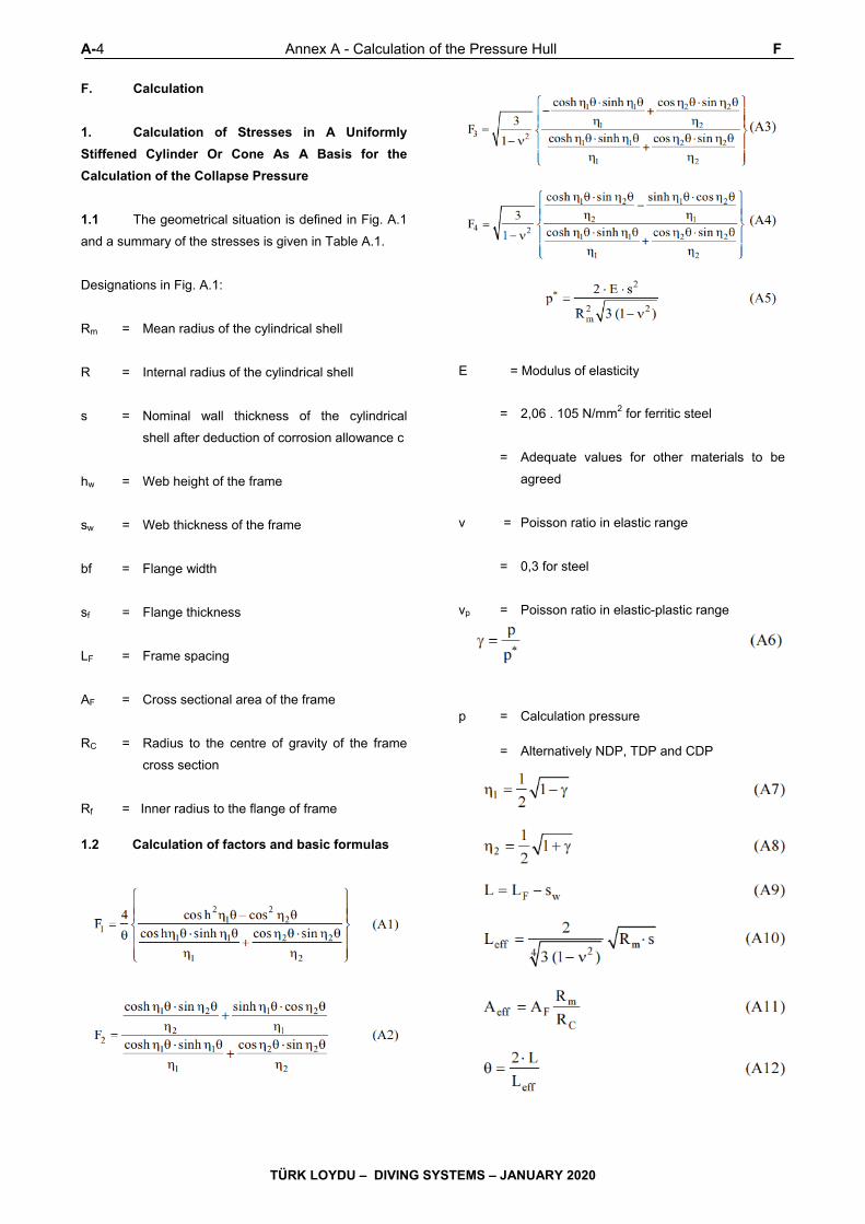
A-4 Annex A - Calculation of the Pressure Hull F
TÜRK LOYDU – DIVING SYSTEMS – JANUARY 2020
F. Calculation
1. Calculation of Stresses in A Uniformly
Stiffened Cylinder Or Cone As A Basis for the
Calculation of the Collapse Pressure
1.1 The geometrical situation is defined in Fig. A.1
and a summary of the stresses is given in Table A.1.
Designations in Fig. A.1:
Rm = Mean radius of the cylindrical shell
R = Internal radius of the cylindrical shell
s = Nominal wall thickness of the cylindrical
shell after deduction of corrosion allowance c
hw = Web height of the frame
sw = Web thickness of the frame
bf = Flange width
sf = Flange thickness
LF = Frame spacing
AF = Cross sectional area of the frame
RC = Radius to the centre of gravity of the frame
cross section
Rf = Inner radius to the flange of frame
1.2 Calculation of factors and basic formulas
E = Modulus of elasticity
= 2,06 . 105 N/mm2 for ferritic steel
= Adequate values for other materials to be
agreed
ν = Poisson ratio in elastic range
= 0,3 for steel
νp = Poisson ratio in elastic-plastic range
p = Calculation pressure = Alternatively NDP, TDP and CDP

F Annex A - Calculation of the Pressure Hull Annex A-5
TÜRK LOYDU – DIVING SYSTEMS – JANUARY 2020
Figure A.1 Geometrical situation of frames stiffening the pressure hull
Table A.1 Summary of stresses in a stiffened cylindrical shell
Stress in the cylindrical shell
Types of stresses
At the frame In the middle of the field Circumferential Equivalent Axial Circumferential Equivalent Axial
Membrane stress
mσ F,
(A19)
mσ F,x
(A17)
mσ M,
(A18)
mσ M,x
(A18)
Membrane equivalent stres
mσ F,v
(A14)
mσ M,v
(A14)
Bending stress
bσ F,
(A23)
bσ F,x
(A21)
bσ M,
(A22)
Normal stres outside
bσ mσ F,F,
(A19) + (A23)
bσ mσ F,F, xx
(A17) + (A21)
bσ mσ M,M,
(A18) + (A22)
bσ mσ M,M, xx
(A18) + (A22)
Equivalent normal stres outside
bmoF,v,σ
(A14)
bmoM,v,σ
(A14)
Normal stres inside
bσ mσ F,F,
(A19) - (A23)
bσ mσ F,F, xx
(A17) - (A21)
bσ mσ M,M,
(A18) - (A22)
bσ mσ M,M, xx
(A17) - (A20)
Equivalent normal stres inside
bmiF,v,σ
(A14)
bmiM,v,σ
(A14)
Remark The numbers in brackets represent the numbers of the formulas to be applied.
A-6 Annex A - Calculation of the Pressure Hull F
TÜRK LOYDU – DIVING SYSTEMS – JANUARY 2020
For the stress designations the following indices are
valid:
0 - reference value
m - membrane stress
b - bending stress
v - equivalent stress
x - longitudinal direction
φ - circumferential direction
r - radial direction
t - tangential direction
o - outer side
i - inner side
F - at the frame
D - at the web frame
F/D - at the frame/ at the web frame
M - in the middle of the field
f - in the flange of the frame
w - in the web of the frame
C - at the centre of gravity of the frame cross
section
c - in the crown of the dished ends
The reference stress is the circumferential stress in the
unstiffened cylindrical pressure hull:
The equivalent stresses are composed of the single stresses in longitudinal and circumferential direction:
The radial displacement in the middle between the frames wM:
The radial displacement at the frames wF:
Average membrane stress in longitudinal direction
(independent of the longitudinal coordinate x):
Membrane stress in circumferential direction in the
middle between the frames:
and at the frames:
Bending stresses in longitudinal direction in the middle
between the frames:
and at the frames:
The positive sign is valid for the outside of the cylindrical
shell, the negative preceding sign for the inner side.
Bending stresses in circumferential direction in the
middle between the frames:
and at the frames:
The circumferential stress follows from the radial
displacement to:
İn the frame foot, respectively in the frame flange.
F Annex A - Calculation of the Pressure Hull Annex A-7
TÜRK LOYDU – DIVING SYSTEMS – JANUARY 2020
The equivalent stresses as well as the circumferential
stresses in the frame summarized in Table A.1 are to be
limited with the value of the permissible stresses
σperm,NDP, σperm,TDP or σperm,CDP belonging to each load
case according to TL Rules for Submersibles, Section
5, D.3.
1.3 Calculation of the stresses for a conical
pressure hull
The formulas given above are also applicable to
stiffened conical shells.
The relevant formulas have to be modified using the half
apex angle α. For this, the mean radius yields to:
and the equivalent frame spacing turns to:
Rm = Radius midway between the frames of the
area under consideration
The calculation has to be carried out for both frames of
the bay under evaluation. The dimensions of the frames
have to be multiplied by the radius ratio Rm/Rm,F. For the
following calculation of the collapse pressures the
(absolutely) greatest value is decisive.
2. Calculation of the collapse pressure for the
asymmetric interstiffener buckling of the shell in
uniformly stiffened sections of the pressure hull
2.1 For conical pressure hulls the same values as
defined for the stress calculation above are to be used.
For calculation of the minimum buckling pressure which
depends on the number of circumferential lobes, the
following approximation may be used:
2.2 Elastic buckling pressure
Theoretical elastic-plastic pressure: with:
For secant module:
For tangential module:
For elastic-plastic Poisson’s ratio:
f, σv, Es, Et are functions of the elastic-plastic buckling
pressure pcri to be determined. For the iterative
evaluation of pcri the value f can be computed for the
calculation pressure CDP and be assumed as constant
in the following calculation. σv can be determined by
linear extrapolation starting from the value of the
calculation pressure CDP.
2.3 Secant module and tangential module of steels
For various types of steel is valid:
σe = Limit of proportional extension
σ0,2 = 0,2 % yield strength, ReH

A-8 Annex A - Calculation of the Pressure Hull F
TÜRK LOYDU – DIVING SYSTEMS – JANUARY 2020
z = 0,8 for ferritic steel
= 0,6 for austenitic steel
If σv > σe the formulas defined in 2.3.1 and 2.3.2 are
valid.
For σv ≤ σe is valid:
2.3.1 Modules for z ≥ 0,8 2.3.2 Modules for z < 0,8
k has to be calculated from the condition:
at least with the accuracy of two decimals.
2.4 Secant modules and tangent modules for
other metallic materials
For other metallic materials z is to be agreed.
2.5 It has to be proven, that the collapse pressure,
which is the theoretical elastic-plastic buckling pressure
Pcri multiplied by the reduction factor r, is at least equal
to the calculation pressure CDP of the pressure hull.
With the reduction factor:
3. Calculation of the Collapse Pressure for the
Symmetric Interstiffener Buckling of the Shell in
Uniformly Stiffened Sections of the Pressure Hull
3.1 For conical pressure hulls the equivalent
values as defined for the stress calculation above have
to be used
3.2 Elastic buckling pressure
Theoretical elastic-plastic buckling pressure:
with:
F Annex A - Calculation of the Pressure Hull Annex A-9
TÜRK LOYDU – DIVING SYSTEMS – JANUARY 2020
The procedure for the evaluation of the theoretical
elastic-plastic buckling pressure is analogous to that
described for asymmetric buckling.
3.3 It has to be proven, that the collapse pressure,
which is the theoretical elastic-plastic buckling pressure
pcri multiplied by the reduction factor r, is at least equal
to the calculation pressure CDP of the pressure hull.
ith the reduction factor:
4. Proof of the Collapse Pressure for the
General İnstability Under Consideration of the Web
Frames
4.1 The proof of the general instability has to be
done on the basis of a stress calculation which meets
the equilibrium criteria in a deformed state. As
predeformation, the out-of-roundness of the frames has
to be considered. It has to be proven, that the out-of-
roundness permissible according to Annex B can not
lead to a global collapse.
4.2 Consideration of the stress-strain
behaviour
For austenitic steels and other materials, for which σ0,01
< 0,8 . σ0,2 is valid, the actual stress-strain behaviour
has to be considered by adequate calculation. The
pressure hull, pre-deformed to the permissible out-of-
roundness and inclinations of the frames, has to be
incrementally pressure loaded. For the calculation of the
increasing elastic displacement and stresses, the
deformations in equilibrium condition and the actual,
local material behaviour have to be considered.
For materials with σ0,01 > 0,8 . σ0,2 a linear elastic
behaviour can be assumed for a stress calculation
according to a theory of 2nd order. In this case the
following stress limits (without consideration of local
weaknesses) have to be met:
- The sum of basic stress and stress due to out-
of-roundness in the frame flange shall not
exceed σ0,2.
- The sum of basic stress and stress due to out-
of-roundness in the web frame flange shall not
exceed 80 % of σ0,2
4.3 The calculation procedure is described in
the following:
Definitions:
p = Collapse diving pressure of the pressure
hull CDP
n ≥ 2 = Number of circumferential lobes of out-of-
roundness
w0 = Maximum permissible out-of-roundness of
the pressure hull according to Annex B
Rm = Mean radius of the pressure hull in the
considered field
Rm,F/D = Mean radius of the pressure hull at
particular frame or web frame
e = Distance from the centroid of the frame or
web frame plus the effective length of shell
to the furthest surface of the flange (see
Fig. A.2). For conical shells e' =e/cosα is
valid.
RC = Radius to the centroid of the frame or web
frame cross section
LD = Length of the generating shell line at the
considered area of the web frame
LD,r, LD,l = Length of the generating shell line of the
left hand or the right hand adjacent field,
depending on the field boundary for which
the proof is made (see Fig. A.3)
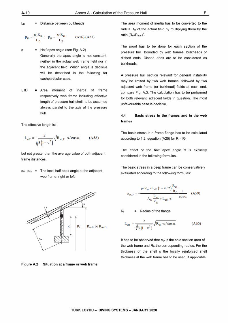
A-10 Annex A - Calculation of the Pressure Hull F
TÜRK LOYDU – DIVING SYSTEMS – JANUARY 2020
LB = Distance between bulkheads
α = Half apex angle (see Fig. A.2)
Generally the apex angle is not constant,
neither in the actual web frame field nor in
the adjacent field. Which angle is decisive
will be described in the following for
eachparticular case.
I, ID = Area moment of inertia of frame
respectively web frame including effective
length of pressure hull shell, to be assumed
always paralel to the axis of the pressure
hull.
The effective length is:
but not greater than the average value of both adjacent
frame distances.
αDl, αDr = The local half apex angle at the adjacent
web frame, right or left
Figure A.2 Situation at a frame or web frame
The area moment of inertia has to be converted to the
radius Rm of the actual field by multiplying them by the
ratio (Rm/Rm,F)4.
The proof has to be done for each section of the
pressure hull, bounded by web frames, bulkheads or
dished ends. Dished ends are to be considered as
bulkheads.
A pressure hull section relevant for general instability
may be limited by two web frames, followed by two
adjacent web frame (or bulkhead) fields at each end,
compare Fig. A.3. The calculation has to be performed
for both relevant, adjacent fields in question. The most
unfavourable case is decisive.
4.4 Basic stress in the frames and in the web
frames
The basic stress in a frame flange has to be calculated
according to 1.2, equation (A25) for R = Rf.
The effect of the half apex angle α is explicitly
considered in the following formulas.
The basic stress in a deep frame can be conservatively
evaluated according to the following formulas:
Rf = Radius of the flange
It has to be observed that AD is the sole section area of
the web frame and RD the corresponding radius. For the
thickness of the shell s the locally reinforced shell
thickness at the web frame has to be used, if applicable.
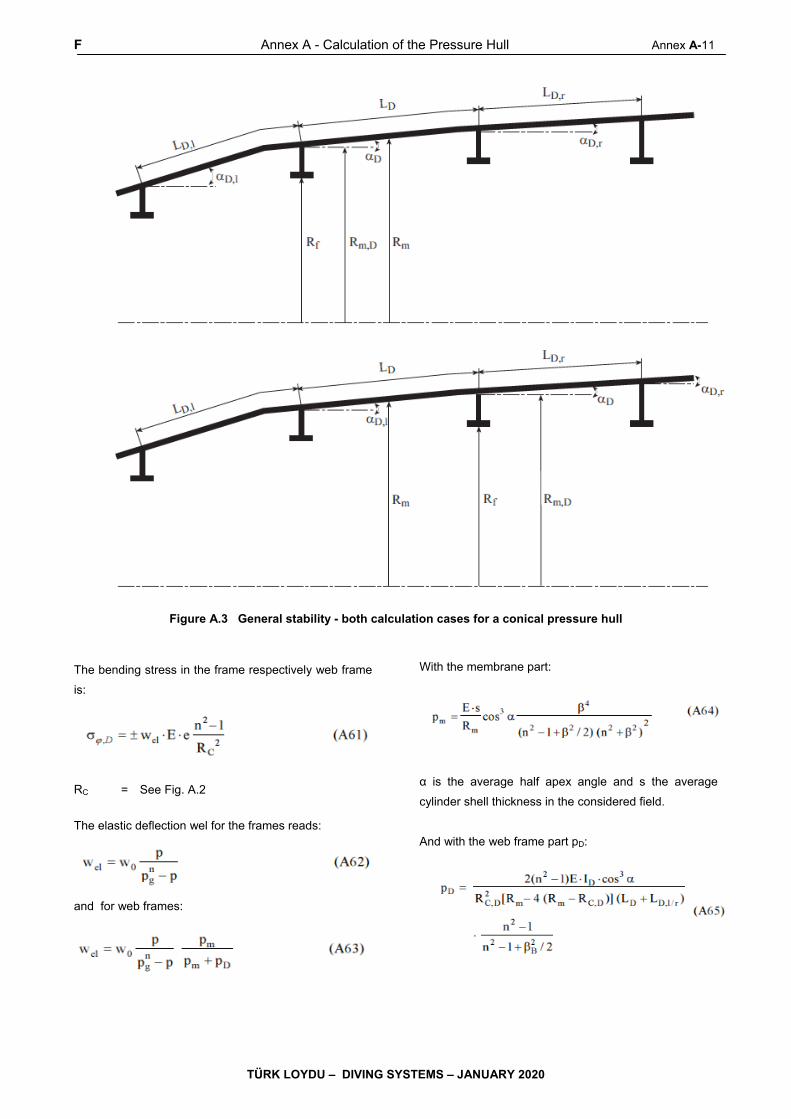
F Annex A - Calculation of the Pressure Hull Annex A-11
TÜRK LOYDU – DIVING SYSTEMS – JANUARY 2020
Figure A.3 General stability - both calculation cases for a conical pressure hull
The bending stress in the frame respectively web frame
is:
RC = See Fig. A.2
The elastic deflection wel for the frames reads:
and for web frames:
With the membrane part:
α is the average half apex angle and s the average
cylinder shell thickness in the considered field.
And with the web frame part pD:
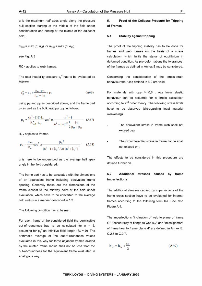
A-12 Annex A - Calculation of the Pressure Hull F
TÜRK LOYDU – DIVING SYSTEMS – JANUARY 2020
α is the maximum half apex angle along the pressure
hull section starting at the middle of the field under
consideration and ending at the middle of the adjacent
field:
αmax = max (α; αDl) or αmax = max (α; αDr)
see Fig. A.3
RC,D applies to web frames.
The total instability pressure pgn has to be evaluated as
follows:
using pm and pD as described above, and the frame part
pF as well as the bulkhead part pB as follows:
RC,F applies to frames.
α is here to be understood as the average half apex
angle in the field considered.
The frame part has to be calculated with the dimensions
of an equivalent frame including equivalent frame
spacing. Generally these are the dimensions of the
frame closest to the midway point of the field under
evaluation, which have to be converted to the average
field radius in a manner described in 1.3.
The following condition has to be met:
For each frame of the considered field the permissible
out-of-roundness has to be calculated for n = 5,
assuming for pg5 an infinitive field length (βD = 0). The
arithmetic average of the out-of-roundness values
evaluated in this way for three adjacent frames divided
by the related frame radius shall not be less than the
out-of-roundness for the equivalent frame evaluated in
analogous way.
5. Proof of the Collapse Pressure for Tripping
of Frames
5.1 Stability against tripping
The proof of the tripping stability has to be done for
frames and web frames on the basis of a stress
calculation, which fulfils the status of equilibrium in
deformed condition. As pre-deformations the tolerances
of the frames as defined in Annex B may be considered.
Concerning the consideration of the stress-strain
behaviour the rules defined in 4.2 are valid.
For materials with σ0,01 ≥ 0,8 . σ0,2 linear elastic
behaviour can be assumed for a stress calculation
according to 2nd order theory. The following stress limits
have to be observed (disregarding local material
weakening):
- The equivalent stress in frame web shall not
exceed σ0,2.
- The circumferential stress in frame flange shall
not exceed σ0,2.
The effects to be considered in this procedure are
defined further on.
5.2 Additional stresses caused by frame
imperfections
The additional stresses caused by imperfections of the
frame cross section have to be evaluated for internal
frames according to the following formulas. See also
Figure A.4.
The imperfections "inclination of web to plane of frame
Θ", "eccentricity of flange to web uex" and "misalignment
of frame heel to frame plane d" are defined in Annex B,
C.2.5 to C.2.7.

F Annex A - Calculation of the Pressure Hull Annex A-13
TÜRK LOYDU – DIVING SYSTEMS – JANUARY 2020
σ0 = Basic stress in flange according to 5.3 / 5.4.
n = Number of circumferential lobes of
imperfections; the calculation has to be
performed for n = 3.
Figure A.4 Local situation at the frame
Amplitudes of the elastic displacement u and twist ω of
the connection web-flange:
with

A-14 Annex A - Calculation of the Pressure Hull F
TÜRK LOYDU – DIVING SYSTEMS – JANUARY 2020
Where:
Stresses in the flange are as follows:
Bending stress around radial axis, and
Torsion around the tangential axis, which is phase-
shifted against σr,F/Df b by a quarter period.
The bending stress at the toe of the web is:
with
and
The stresses resulting from imperfections of the frames
are to be checked for frames and web frames, using
different procedures.
5.3 Frames
For the stress σ0 always σ0,2 of the frame material has
to be used.
The bending rigidity of the flange has to be neglected,
i.e. set to zero (If = 0).
The equivalent stress at the web toe has to be
evaluated with the calculation pressure for both signs of
the bending stress σr,Fw b according to formula (A102).
Circumferential stress:
with σϕ,Fwm according to 1.2, equation (A24), compare
Fig. A.5 and
with σϕ,Ffm
according to 1.2, equation (A25).
Radial stress:
The equivalent stress: shall not exceed σ0,2.

F Annex A - Calculation of the Pressure Hull Annex A-15
TÜRK LOYDU – DIVING SYSTEMS – JANUARY 2020
Figure A.5 Situation of the frame in relation to the axis of the pressure hull
5.4 Web frames
For the basic stress in the flange σ0 the absolute value
of the circumferential stress │σϕ,D│according to formula
(A59) has to be taken, as obtained for the half value of
the permissible out-of-roundness resulting from the
general instability proof performed for n = 2
circumferential lobes according to 4.
It has to be proven that:
with σr,Dfb
according to formula (A100) and t,Df
according to formula (A101) considering the relevant
dimensions of the web frames
and the equivalent stress at the web toe.
The circumferential stress σφ is the sum of the basic
stress σφ,D obtained with the formula (A59) in 4.4 and ν-
times the web bending stress σr,Dwb according to formula
(A102):
The radial stress is:
For calculation of σ0 the following simplified Formula
can be used:
5.5 Modifications for frames arranged outside
For frames arranged outside all radii (R, Rf, RDf) have
to be applied as negative values.
6. Spherical Shells and Dished Ends
6.1 General
Spherical shells and dished ends are to be investigated
for the load cases defined in TL Rules for Submersibles,
Section 4, E. respectively Underwater Equipment,
Section 3, C.1.6. against exceeding stresses and
buckling. For dished ends the stresses in the crown and
the knuckle are to be investigated. Spheres are to be
treated like the crown area of dished ends.
6.2 Stresses
For the crown area the stress results from Formula
(A118). For the knuckle area the stress can be
evaluated by formula (A119). The coefficients β are to
be determined according to the TL Machinery Rules,
Section 12, D.4.3.2. They can also be evaluated directly
with assistance of the following formulas:
For torispherical ends:
= 0,6148 -1,6589 x - 0,5206 . x2 -0,0571 x3 (A115) And for semi-ellipsoidal ends: = 1,3282 -0,3637 x - 0,1293 . x2 -0,0171 x3 (A116)

A-16 Annex A - Calculation of the Pressure Hull F
TÜRK LOYDU – DIVING SYSTEMS – JANUARY 2020
with x = ln (s/Da) (A117) for range of validity 0,001 ≤ s/Da ≤ 0,1
Da = Outside diameter of the dished end
In the range besides the transition to the
cylinder the coefficient β = 1,1 for hemispherical ends.
Under the assumption that deviations in the form of
dished ends stay within the permissible tolerances, the
stresses can be calculated with the following formulas. If
the tolerances are exceeded, a separate proof of stress
is to be performed.
Rc,o,l = Local outside radius of sphere crown of the
dished end
Rc,m,l = Local radius of the sphere crown of the
dished end at half thickness of the shell
For p NDP, TDP and CDP are to be introduced
respectively.
The proof has been made if the permissible stresses
according to the Rules for Submersibles, Section 5, D.3.
are not exceeded.
6.3 Calculation of the collapse pressure
The calculations are based on the local thickness and
curvature of the shell and they are considering an out-
of-roundness of the shell in the sense of a local
flattening up to maximum u = 0,218 . sl / Ro. This is valid
for pressed spherical shells and is adequate to a local
outside curvature radius of Ro,l = 1,3 . Ro of the outer
nominal radius.
The out-of-roundness and herewith the local radius is to
be evaluated with a bridge gauge as described in Annex
B, E. There a measuring length Lcr,l according to formula
(A120) has to be used. The out-ofroundness defined in
this way is to be understood as local flattening from the
theoretical form of the sphere within the diameter Lcr,l.
For the lay out a local radius of 1,3 times the nominal
radius and a nominal thickness of the shell (eventually
reduced by the corrosion addition) is to be assumed.
The corrosion addition shall be considered by keeping
the outside radius.
If other tolerances are provided or another out-of-
roundness is resulting from the measurement checks
according to Annex B, E.3. or E.4., then a recalculation
of the permissible pressure according Annex B, E.5. is
required.
For mechanically machined spherical shells local radii
less than 1,05 . Ro are reachable from point of
manufacturing. The more favourable geometrical
condition of the shell can be introduced in the
calculation with at minimum Ro,l = 1,05 . Ro under the
assumption that the measurement procedure, as
described in Annex B, has proven a maximum
permissible local flattening of u = 0,035 . s1 / Ro with an
accuracy of at least 0,001 . s.
6.4 Definitions
The following definitions are valid:
Rm,l = Maximum local mean radius of curvature of
the sphere at shell half thickness
R0,1 = Maximum local outside radius of curvature
of the sphere
s = Nominal thickness of the shell
s1 = Local average shell thickness
Critical arc length or diameter of the measuring circle to
be used for measuring the deviations from the perfect
form of the sphere according to Annex B, E.3. and E.4.:
Rs0,5
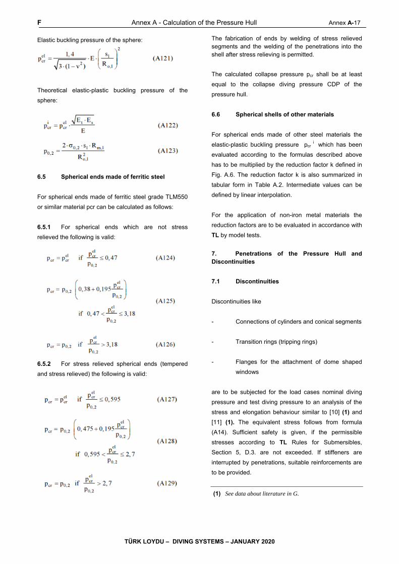
F Annex A - Calculation of the Pressure Hull Annex A-17
TÜRK LOYDU – DIVING SYSTEMS – JANUARY 2020
Elastic buckling pressure of the sphere:
Theoretical elastic-plastic buckling pressure of the
sphere:
6.5 Spherical ends made of ferritic steel
For spherical ends made of ferritic steel grade TLM550
or similar material pcr can be calculated as follows:
6.5.1 For spherical ends which are not stress
relieved the following is valid:
6.5.2 For stress relieved spherical ends (tempered
and stress relieved) the following is valid:
The fabrication of ends by welding of stress relieved segments and the welding of the penetrations into the shell after stress relieving is permitted.
The calculated collapse pressure pcr shall be at least
equal to the collapse diving pressure CDP of the
pressure hull.
6.6 Spherical shells of other materials
For spherical ends made of other steel materials the
elastic-plastic buckling pressure pcr i which has been
evaluated according to the formulas described above
has to be multiplied by the reduction factor k defined in
Fig. A.6. The reduction factor k is also summarized in
tabular form in Table A.2. Intermediate values can be
defined by linear interpolation.
For the application of non-iron metal materials the
reduction factors are to be evaluated in accordance with
TL by model tests.
7. Penetrations of the Pressure Hull and Discontinuities
7.1 Discontinuities
Discontinuities like
- Connections of cylinders and conical segments
- Transition rings (tripping rings)
- Flanges for the attachment of dome shaped
windows
are to be subjected for the load cases nominal diving
pressure and test diving pressure to an analysis of the
stress and elongation behaviour similar to [10] (1) and
[11] (1). The equivalent stress follows from formula
(A14). Sufficient safety is given, if the permissible
stresses according to TL Rules for Submersibles,
Section 5, D.3. are not exceeded. If stiffeners are
interrupted by penetrations, suitable reinforcements are
to be provided.
(1) See data about literature in G.

A-18 Annex A - Calculation of the Pressure Hull F
TÜRK LOYDU – DIVING SYSTEMS – JANUARY 2020
Figure A.6 Reduction factor “k” for different kinds of steel treatment Table A.2 Reduction factor “k” for different kinds of steel treatment
Pressure relation Reduction factor
Pel/p0,2 As fabricated Stress relieved
0,470 1,000 1,000 0,495 0,963 1,000 0,595 0,834 1,000 0,700 0,738 0,874 0,800 0,670 0,789 0,900 0,647 0,757 1,000 0,646 0,753 1,100 0,653 0,758 1,200 0,664 0,766 1,300 0,677 0,778 1,400 0,691 0,792 1,500 0,706 0,806 1,600 0,723 0,822 1,700 0,739 0,838 1,800 0,757 0,855 1,900 0,775 0,873 2,000 0,792 0,890 2,100 0,810 0,907 2,200 0,828 0,925 2,300 0,846 0,943 2,400 0,865 0,962 2,500 0,883 0,980 2,600 0,902 0,999 2,700 0,921 1,000 2,800 0,940 1,000 2,900 0,958 1,000 3,000 0,978 1,000 3,100 0,997 1,000 3,200 1,000 1,000
7.2 Penetrations in the cylindrical or conical
part of the pressure hull - area comparison principle
Penetrations in cylinders are to be preferably evaluated
according to the TL Machinery Rules, Section 12, D.
2.3.4 with a design pressure pc for which NDP, TDP or
CDP are to be inserted alternatively. There is:
Di = 2 . R
and
sA = Necessary wall thickness at the penetration
boundary according to TL Machinery Rules
Section 12,D.2.2 which is to be evaluated by
iteration.
The following rules for dimensioning are valid under the
assumption that the material strength is the same for
the shell of the pressure hull and for the reinforcement
of the penetration boundary.
For different material characteristics the rules have to
be modified in an analogous way.
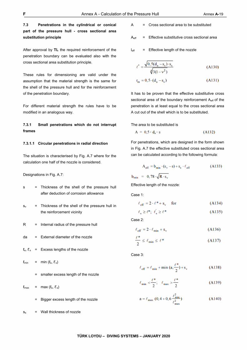
F Annex A - Calculation of the Pressure Hull Annex A-19
TÜRK LOYDU – DIVING SYSTEMS – JANUARY 2020
7.3 Penetrations in the cylindrical or conical
part of the pressure hull - cross sectional area
substitution principle
After approval by TL the required reinforcement of the
penetration boundary can be evaluated also with the
cross sectional area substitution principle.
These rules for dimensioning are valid under the
assumption that the material strength is the same for
the shell of the pressure hull and for the reinforcement
of the penetration boundary.
For different material strength the rules have to be
modified in an analogous way.
7.3.1 Small penetrations which do not interrupt
frames
7.3.1.1 Circular penetrations in radial direction
The situation is characterised by Fig. A.7 where for the
calculation one half of the nozzle is considered.
Designations in Fig. A.7:
s = Thickness of the shell of the pressure hull
after deduction of corrosion allowance
sv = Thickness of the shell of the pressure hull in
the reinforcement vicinity
R = Internal radius of the pressure hull
da = External diameter of the nozzle
ℓs, ℓ’s = Excess lengths of the nozzle
ℓmin = min (ℓs, ℓ’s)
= smaller excess length of the nozzle
ℓmax = max (ℓs, ℓ’s)
= Bigger excess length of the nozzle
ss = Wall thickness of nozzle
A = Cross sectional area to be substituted
Aeff = Effective substitutive cross sectional area
leff = Effective length of the nozzle
It has to be proven that the effective substitutive cross
sectional area of the boundary reinforcement Aeff of the
penetration is at least equal to the cross sectional area
A cut out of the shell which is to be substituted.
The area to be substituted is
For penetrations, which are designed in the form shown
in Fig. A.7 the effective substituted cross sectional area
can be calculated according to the following formula:
Effective length of the nozzle: Case 1: Case 2: Case 3:

A-20 Annex A - Calculation of the Pressure Hull F
TÜRK LOYDU – DIVING SYSTEMS – JANUARY 2020
Figure A.7 Penetration through the enforced shell
7.3.1.2 Flush form of circular penetrations in radial
direction
Penetrations in flush form of the pressure hull (ℓs = 0),
may have in the penetration area a cut out to include a
zinc ring, see Fig. A.8.
In this case ℓeff can be evaluated with the formulas given
above. In addition the strength of the cross section A-A
has to be proven.
In the case that the wall of the pressure hull is not
reinforced, the following condition has to be met:
7.3.1.3 Non-circular penetrations or penetrations
not in radial direction to the shell
If the penetration is not circular or does not cut the shell
of the pressure hull in radial direction the diameter da
has to be replaced by:
Lx = Width of the penetration line in longitudinal direction
Lφ = Width of the penetration line in
circumferential direction
σxm = Membrane stress in the pressure hull in
longitudinal direction
σφm = Membrane stress in the pressure hull in
circumferential direction
In special cases, if the Rules can only be utilized in
limited way, the strength has to be proven by numerical
computation
7.3.2 Big penetrations interrupting frames
For preliminary dimensioning the following procedure
can be used:
The effective border reinforcement for the penetration
has, in a similar way as for the small penetrations, to
substitute the area cut out. The cross sections of the
interrupted frame webs are to be considered
additionally. The effective substitutive cross sectional
area has to be evaluated in analogous way as for small
penetrations. Compact reinforcement rings are fully load
carrying if they are located directly in the penetration
line.

F Annex A - Calculation of the Pressure Hull Annex A-21
TÜRK LOYDU – DIVING SYSTEMS – JANUARY 2020
The construction in the flange plane of the frame has to
be designed in such a way that the maximal permissible
forces in the flange (Af . σperm) can be transmitted
further.
For σperm the value of the permissible stress belonging
to the individual load case acc. to TL Rules for
Submersibles, Section 5, D.3. is to be inserted.
Big penetrations have to be proven by numerical
computation.
7.4 Penetrations of spherical shells
Penetrations in spherical shells are to be evaluated
according to the TL Machinery Rules, Section 12,
D.4.3.3 with a design pressure pc for which 1,2 NDP,
1,2 TDP or 1,2 CDP are to be inserted alternatively.
There is:
Di = 2 . R
and
sA = Necessary wall thickness at the penetration
boundary according to TL Machinery Rules,
Section 12,D.2.2 which is to be evaluated
by iteration.
After approval by TL the cross sectional area
substitution principle as described in 7.3 may be applied
analogously. For this R is the internal radius of the
sphere.
In cases, where area comparison respectively cross
sectional area substitution principle are not fulfilled, a
numerical proof has to be done. For this the local radius
of the spherical shell according to 6.3 is to be chosen
adequately in the vicinity of the penetration. The
achieved failure pressure is then to be reduced like the
elastic-plastic buckling pressure, which has been
evaluated for undisturbed dished ends, see Fig. A.6.
Figure A.8 Penetration of flush form

A-22 Annex A - Calculation of the Pressure Hull F,G
TÜRK LOYDU – DIVING SYSTEMS – JANUARY 2020
Figure A.9 Penetrations of spherical shells
G. Literature
[1] TL Rules, Part B, Chapter 4, Machinery
[2] AD 2000 Regelwerk, Merkblätter Reihe B,
Berechnung von Druckbehältern, Herausgeber:
Arbeitsgemeinschaft Druckbehälter
[3] The Stress Analysis of Pressure Vessels and
Pressure Vessel Compartments, Herausgeber:
S.S. Gill, Pergamon Press, 1970
[4] John C. Pulos und Vito L. Salerno:
Axisymmetric Elastic Deformations and
Stresses in a Ring-Stiffened, Perfectly
Circular Cylindrical Shell under External
Hydrostatic Pressure, DTMB-Report No. 1497
[5] Development in Pressure Vessel Technology,
Herausgeber: R. W. Nichols, Applied Science
Publishers, 1983
[6] European Recommendations for Steel
Construction: Buckling of Shells, Herausgeber:
ECCS-CECM-EKS, Brüssel, 1984
[7] DIN 4114, Blatt 2: Stabilitätsfälle (Knickung,
Kippung, Beulung), Ausgabe 2.53
[8] Myron E. Lunchick: Plastic Axisymmetric
Buckling of Ring-Stiffened Cylindrical Shells
Fabricated from Strainhardening Materials
and Subjected to External Hydrostatic
Pressure, DTMB-Report No. 1393
[9] Krenske, Martin A. und Kierman, Thomas J.:
The Effect of Initial Imperfections on the
Collapse Strength of Sherical Shells,
DTMBReport No. 1757
[10] ASME Boiler and Pressure Vessel Code,
Section VIII, Division 2
[11] Raymond J. Roark and Warren C. Young:
Formulars for Stress and Strain, Mc Graw -
Hill Book Company
[12] William F. Blumenberg: The Effect of
Intermediate Heavy Frames on the Elastic
General- Instability Strength of Ring-Stiffened
Cylinders Under External Hydrostatic Pressure,
DTMB-Report No. 1844
[13] Thomas E. Reynolds: Inelastic Lobar Buckling
of Cylindrical Shells Under External Hydrostatic
Pressure, DTMB-Report No. 1392.

Annex B – Manufacturing Tolerances for the Pressure Hull B- 1
TÜRK LOYDU – DIVING SYSTEMS – JANUARY 2020
ANNEX B
MANUFACTURING TOLERANCES for the PRESSURE HULL
Page
A. GENERAL .......................................................................................................................................................... B- 2
B. DIMENSIONS of the PRESSURE HULL ........................................................................................................... B- 2
C. PRESSURE HULL FRAMES ............................................................................................................................. B- 4
D. OUT-OF-ROUNDNESS of the CYLINDRICAL or CONICAL PRESSURE HULL ........................................... B- 5
E. SPHERICAL SHELLS and DISHED ENDS ....................................................................................................... B- 9
F. LITERATURE .................................................................................................................................................... B- 11
B-2 Annex B – Manufacturing Tolerances for the Pressure Hull A,B
TÜRK LOYDU – DIVING SYSTEMS – JANUARY 2020
A. General
1. This Annex describes the permissible
manufacturing tolerances for the pressure hull as
prerequisite for the application of the strength
calculations defined in Annex A.
2. All tests are to be performed by the
manufacturer in presence of a TL Surveyor and a
measurement report has to be sent by the manufacturer
to TL.
3. The required checks defined in the following
are only to be performed, if no following changes of the
measurement values are to be expected. Areas with
welding seams which have been worked over in the
mean time because of impermissible defects have to be
measured again.
The component to be investigated shall be cooled down
to ambient temperature and is so to be relieved from
any tensions by means of installation aids in order to
prevent falsification of the measurement results.
B. Dimensions of the Pressure Hull
1. General
1.1 As far as not defined otherwise in these Rules
the following tolerances are valid.
1.2 All longitudinal and circumferential seams in
the pressure hull plating shall be inspected for edge
offset, weld sinkage, undercuts and hollow grinding.
This shall also be valid for the welding connection of the
plating with the tripping/transition ring. The inner and
outer surface of the plates is to be inspected for
damage.
2. Dimensions of the Cylindrical and Conical
Parts
2.1 Diameter
The actual mean outside diameter of cylindrical
respectively conical pressure hulls shall, calculated from
the circumference, deviate not more than ± 0,5 % from
the outside diameter on which the calculation is based.
The measurements are to be performed in distances of
maximum 3 R s over the complete length of the
component.
s = Nominal shell thickness [mm]
R = Internal radius of the shell [mm]
2.2 Generating line
The deviation of the theoretical generating line from the
straight line shall not exceed ± 0,2 % of the length of the
straight forward part of a cylinder or cone over three
adjacent measuring points, which are given by web
frames, bulkheads and connections of cones and
dished ends. If web frames, cones and bulkheads are
not provided, only between dished ends is to be
measured. The deviation is to be measured at minimum
8 positions equally distributed over the circumference.
2.3 Length
The length of the pressure hull rings in manufacturing is
to be measured at minimum 4 positions equally
distributed over the circumference and to be averaged.
The allowable tolerance of the length of the pressure
hull ring shall not be bigger than the sum of the existing
deviations of the frame distances within this ring. If no
frames are provided, the tolerance is ± 1 % of the
nominal length, but not more than 15 mm.
3. Dimensions of Spherical Shells and Dished
Ends
3.1 Radius of spherical shells and crown of
dished ends
For determination of the spherical form of the spherical
shell the outside radius is to be evaluated according to
E.3.
The spherical form of the spherical shell has to remain
within a tolerance of ± 1 % of the nominal outside
radius.
3.2 Course of theoretical geometry lines of
dished ends (knuckle/crown radius)
The tolerances are to be defined by the manufacturer

B Annex B – Manufacturing Tolerances for the Pressure Hull B- 3
TÜRK LOYDU – DIVING SYSTEMS – JANUARY 2020
according to recognized regulations and deviations from
it are to be approved by TL, compare E.2.
4. Component Thickness
Tolerances for components of the pressure hull: –0/+ t
Tolerance value t according to material delivery
specifications (if the material delivery standard allows
minus tolerances, these are to be considered for the
calculations)
5. Edge Offset and Weld Sinkage
5.1 The radial deviations x1 and x2 are the basis for
the determination of weld sinkage and edge ofset of
sheet metal surfaces with regard to their nominal
positions next to a welding seam, compare Fig. B.1.
They are measured at a distance v = smax + 20 mm on
both sides centred over the welding seam.
5.2 The tolerances for the gradient of the
theoretical line of the middle plane at the
tripping/transition ring are to be documented in the
manufacturing protocols and to be checked.
5.3 Edge offset for cylindrical and conical parts
The edge offset of both plates which is determined by
the difference of the measuring values │x2 – x1│,
compare Fig. B.1.
For circumferential seams the edge offset shall not
exceed 15 % of the nominal thickness of the thinner
plate, but maximum 4 mm.
For longitudinal seams the edge offset shall not exceed
10 % of the nominal thickness of the thinner plate, but
maximum 3 mm.
5.4 Edge offset for spherical shells and dished
ends
For butt joints within these shells and dished ends the
edge offset shall not exceed 10 % of the nominal
thickness of the thinner plate, but maximum 3 mm.
5.5 Weld sinkage for cylindrical and conical
parts
The mean value of the deviations
h = (x1 + x2) / 2
is defined as weld sinkage. If not otherwise agreed with
TL, the following tolerances are valid:
For circumferential seams the weld sinkage shall not
exceed h = ¼ . s, but maximum 5 mm.
For longitudinal seams the weld sinkage shall not
exceed h ≤ 1/6 . s, but not more than 3 mm.
Figure B.1 Radial deviation of the sheet metal
surface of the pressure hull
5.6 Weld sinkage for spherical shells and
dished ends
For butt joints within these shells and dished ends the
weld sinkage shall not exceed h = 1/6 . s, but maximum
3 mm.
6. Damages to the Component Surface
Damage to the surface, such as scores, scratches, arc
strikes, indentation pits, etc. shall be thoroughly
smoothed and inspected for surface cracks. The flaws
treated in this way are permissible without proof of
strength, if the following requirements are met:
- The depth shall at maximum 0,05 . s or 3 mm,
the smaller value is decisive.

B-4 Annex B – Manufacturing Tolerances for the Pressure Hull B,C
TÜRK LOYDU – DIVING SYSTEMS – JANUARY 2020
- The area of the undercut of the thickness shall
be within a circular area with 2 . s as diameter
or 60 mm, the smaller value is decisive.
- The distance between two areas of thickness
undercut and the distance from points of
disturbance, like e.g. penetrations, shall be at
least 2.R .s .
Deeper flaws are to be treated specially in agreement
with TL.
C. Pressure Hull Frames
1. Measurements
The following measurements shall be carried out on
every frame of the pressure hull at eight measuring
points uniformly distributed around the circumference:
- Flange width
- Flange thickness
- Web thickness
- Frame spacing (measured at frame heel)
- Frame height at frame moulding edge
- Eccentricity flange to web
- Web tilt to plane of frame
The spacing k of the frame heel from a reference plane
shall be determined by direct measurement, see Fig.
B.2. The location of the frame heel is shown as detail
"A" in this Figure. For cylindrical pressure hull parts this
measurement shall be carried out on a minimum of one
frame per ring (with a ring length of up to a maximum of
8 pressure hull frames) and for conical pressure hull
parts on every frame at 16 points uniformly distributed
around the circumference.
2. Tolerances
2.1 The following tolerances are maximum values
and shall not be exceeded. The tolerances calculated
from percentages may be rounded up to half of a
millimetre.
2.2 Flange width: 0 % to + 4,5 %
Flange thickness: 0 mm to + 3 mm
Web thickness: 0 mm to + 3 mm
With regard to the flange width or flange thickness the
nominal cross sectional area of the flange is considered
to be a permissible acceptance criteria. Height
tolerances of 0,2 + 0,04 . s ≤ 1 mm (s = material
thickness in mm) due to flat grinding of nicks may be
exceeded locally, however, the nominal cross section of
the flange or web shall not be reduced to more than 90
%.
2.3 Frame spacing: generally ± 1 %
At circumferential seams
+1 % to –3 %
2.4 Frame height at frame moulding edge:
0 % to + 5 %
Tolerances up to –2 % are allowed locally if the mean
value of the 8 measuring points reaches nominal value.
2.5 Eccentricity of flange to web:
2 % of frame height
2.6 Inclination of web to reference plane of frame:
± 2 °
2.7 Misalignment of frame heel to reference plane:
+ 4 mm for frames
± 6 mm for web frames
If the maximum difference of determined spacings (kmax
– kmin) is larger than 8 mm for frames and 12 mm for
web frames, the real deviations of h shall be determined
by evaluation according to the following formula:
hi = ki – k0 - kx sin φi - ky cos φi (B1)

C,D Annex B – Manufacturing Tolerances for the Pressure Hull B- 5
TÜRK LOYDU – DIVING SYSTEMS – JANUARY 2020
k0 = 1/J (k1 + k2 + k3 + ….. + kJ) (B2)
kx = 2/J (k1 sin φ1 + k2 sin φ2 + k3 sin φ3
+ ….. + kJ sin φJ) (B3)
ky = 2/J (k1 cos φ1 + k2 cos φ2 + k3 cos φ3
+….. + kJ cos φJ) (B4)
φi = 360° i /J
hi = Deviation of the frame heel from the actual
plane of frame at measuring point i
ki = Measured distance of frame heel from the
reference plane of measuring point i
J = Number of measuring points
3. Transition Rings and Strengthening of
Pressure Hull
Transition rings, strengthenings of cut-outs and other
strengthenings of the pressure hull are not to be applied
with tolerances which weaken the components.
D. Out-of Roundness of the Cylindrical or
Conical Pressure Hull
1. The out-of-roundness shall be measured at
each frame and also at each transition ring. The
measurements are to be conducted with a maximum
distance according to 3.R .s over the complete length
of the component. For frame spacings above 3.R .s
the out-of-roundness is to be determined also at the
shell between the frames considering this measuring
distance.
Moreover the course of the theoretical geometry lines at
the transition ring is to be determined.
2. The following requirements shall be met prior
to conducting out-of-roundness measurements:
- The required tests shall only be carried out
when no subsequent changes of measured
values are to be expected.
- The section is to be cooled down to ambient
temperature and relieved from any tension by
means of appropriate aids in order to prevent
falsification of measurement results.
Figure B.2 Definition of the reference plane of a frame
B-6 Annex B – Manufacturing Tolerances for the Pressure Hull D
TÜRK LOYDU – DIVING SYSTEMS – JANUARY 2020
3. The measurement of the pressure hull can be
carried out from outside or from inside. In principle the
measurement of out-of-roundness shall be carried out at
24 points distributed as uniformly as possible around
the circumference. It can be conducted with the help of
a circular template, callipers, a two point bridge gage
(see Fig. B.4), photogrammetry or theodolite methods,
in which case access has to be provided by appropriate
means. If the measuring of individual values is not
possible due to constructionalreasons (e.g. in the area
of larger openings), it shall be supplemented as far as
practically possible (in generalby linear interpolation).
The measurement shall not be impaired by welding
seams (e.g. weld reinforcement)or local imperfections
on the surface.
4. The results of the evaluation shall be
presented to TL as tables and graphs.
5. The maximum permissible out-of-roundness is
± 0,5 % of the nominal pressure hull diameter unless
otherwise agreed by TL.
6. Measuring Method 1: Direct Measurement
of the Radii and Their Deviation From Constant
Radius; From Inside or From Outside
The measurement can be performed from inside -
measurement of the radii, and from outside –
measurement of the deviations from the constant, mean
radius by rotating the pressure hull around an assumed
axis (centre). The assumed centre shall be as near to
the true centre as possible, compare Fig. B.3.
The following formulas apply to J = 24 measuring points
distributed uniformly around the circumference:
ui =Ri – R - x sin φi - y cos φi (B5)
R = 1/J (R1 + R2 + R3 + ….. + RJ) (B6)
x = 2/J (R1 sin φ1 + R2 sin φ2 + R3 sin φ3
+ ….. + RJ sin φJ) (B7)
y = 2/J (R1 cos φ1 + R2 cos φ2 + R3 cos φ3
+….. + RJ cos φJ) (B8)
i = Measuring points 1 to J
(for above formula J = 24)
Ri = Radial measuring value at the curve shape at
measuring point i; measured from assumed
centre
R = Average calculated radius
Δx = Deviation of measurement, horizontal
Δy = Deviation of measurement, vertical
ui = Calculated out-of-roundness of the pressure
hull at the measuring point i
φi = Angle of the measuring point, see C.2.7
The calculation procedure shall be documented
according to Table B.1.
7. Measuring Method 1: Non-Uniformly
Distributed Measuring Points
In case of non-uniformly distributed measuring points
and angular separation of measuring points ≤ 18° the
following formulas apply:
ui =Ri – R’ - x’ sin φi - y’ cos φi (B9)
R’ = [1/(2πD)] [R1 x2 + R2 (x3-x1) + R3
(x4 – x2) + ….. + RJ (x1 –xJ-1 + πD)] (B10)
x’ = [1/(πD)] [R1 sin φ1 x2 + R2 sin φ2 (x3 – x1)
+ R3 sin φ3 (x4-x2)+ …..
+ RJ sin φJ (x1-xJ-1 + π D)] (B11)
y’ = [1/(πD)] [R1 cos φ1 x2 + R2 cos φ2 (x3 – x1)
+ R3 cos φ3 (x4-x2)+ …..
+ RJ cos φJ (x1-xJ-1 + π D)] (B12)
i = Measuring points 1 to J (for above formula
J = 24)
J = Actual number of measuring points
Ri = See definition in 6.

D Annex B – Manufacturing Tolerances for the Pressure Hull B- 7
TÜRK LOYDU – DIVING SYSTEMS – JANUARY 2020
R ’ = Average calculated radius
Δx’ = Deviation of measurement, horizontal
Δy’ = Deviation of measurement, vertical
ui = See definition in 6.
D = Diameter of the measuring circuit
xi = Circumferential coordinate at measuring
point i (measuring distance from starting
point xJ = x0 = 0)
φi = Angle at measuring point
= 360 . xi / (π D)
Table B.1 Protocol and calculation table for evaluation of the out-of-roundness according to method 1
(1) (2) (3) (4) (5) (6) (7) (8) (9) (10) (11)
i Ri [mm] φi [°] sin φi cos φi Ri sin φi Ri cos φi x .
sin φi
y.
cos φi
(7)+(8) (9)+R ui = (1)-
(10)
1 15 0,2588 0,9659
2 30 0,5000 0,8660
3 45 0,7071 0,7071
4 60 0,8660 0,5000
5 75 0,9659 0,5000
6 90 1,0000 0,0000
7 105 0,9659 -0,2588
8 120 0,8660 -0,5000
9 135 0,8660 -0,7071
10 150 0,5000 -0,8660
11 165 0,2588 -0,9659
12 180 0,0000 -1,0000
13 195 -0,2588 -0,9659
14 210 -0,5000 -0,8660
15 225 -0,7071 -0,8660
16 240 -0,8660 -0,5000
17 255 -0,9659 -0,2588
18 270 -1,0000 0,0000
19 285 -0,9659 0,2588
20 300 -0,8660 0,5000
21 315 -0,8660 0,7071
22 330 -0,5000 0,8660
23 345 -0,2588 0,9659
24 360 0,0000 1,0000

B-8 Annex B – Manufacturing Tolerances for the Pressure Hull D
TÜRK LOYDU – DIVING SYSTEMS – JANUARY 2020
Figure. B.3 Measurement of the out-of-roundness at the cylinder; measuring method 1, explanation of symbols
8. Measuring Method 2: Indirect Measurement
of the Deviation From The Average Arc Height of
The Measuring Bridge; From Outside
The number of planes used for measuring the out-of-
roundness of cylindrical pressure vessels is to be
agreed with TL. For each measuring plane, at least J =
24 measuring points shall be provided and evenly
distributed round the circumference. The height of arc x
(j) is measured with a bridge extending over a string
length Ls = 4 . π . R0/J (see Fig. B.4). From the values x
(j) and the influence coefficients C, the out-of-roundness
values can be calculated by applying formula (B13).
Table B.2 gives the influence coefficients C where J =
24. The values of the out-of-roundness U (j) measured
in this way shall not exceed the maximum permissible
values defined in 5.
R0 means here the outer radius of the cylindrical shell.
Example for out-of-roundness U at the point j=2 for
J=24:
Figure B.4 Measuring the uot-of-roundness of a
cylindrical shell, measuring method 2
Table B.2 Influence factor Ci for J=24
İ=j C│i-j│
İ=j C│i-j│ 0 1 2 3 4 5 6 7 8 9
10 11
1,76100 0,85587 0,12834 -0,38800 -0,68359 -0,77160 -0,68487 -0,47097 -0,18614 0,11136 0,36793 0,54051
12 13 14 15 16 17 18 19 20 21 22 23
0,60124 0,54051 0,36793 0,11136 -0,18614 -0,47097 -0,68487 -0,77160 -0,68359 -0,38800 0,12834 0,85587
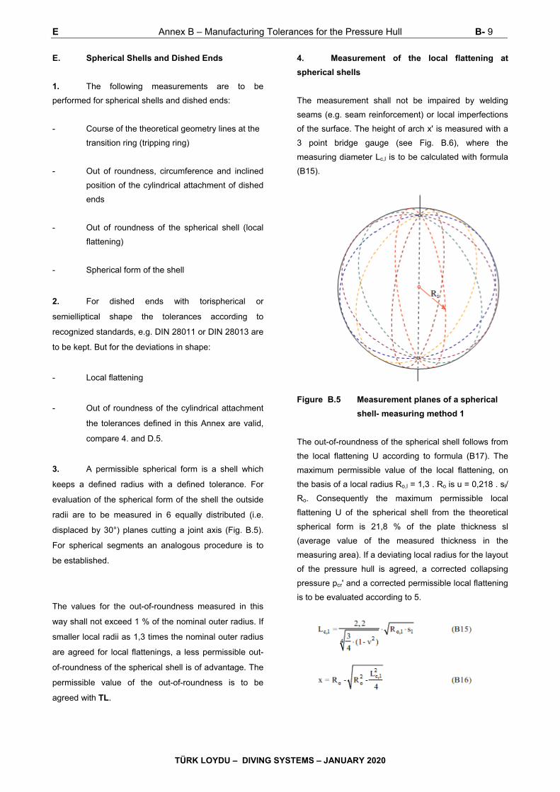
E Annex B – Manufacturing Tolerances for the Pressure Hull B- 9
TÜRK LOYDU – DIVING SYSTEMS – JANUARY 2020
E. Spherical Shells and Dished Ends
1. The following measurements are to be
performed for spherical shells and dished ends:
- Course of the theoretical geometry lines at the
transition ring (tripping ring)
- Out of roundness, circumference and inclined
position of the cylindrical attachment of dished
ends
- Out of roundness of the spherical shell (local
flattening)
- Spherical form of the shell
2. For dished ends with torispherical or
semielliptical shape the tolerances according to
recognized standards, e.g. DIN 28011 or DIN 28013 are
to be kept. But for the deviations in shape:
- Local flattening
- Out of roundness of the cylindrical attachment
the tolerances defined in this Annex are valid,
compare 4. and D.5.
3. A permissible spherical form is a shell which
keeps a defined radius with a defined tolerance. For
evaluation of the spherical form of the shell the outside
radii are to be measured in 6 equally distributed (i.e.
displaced by 30°) planes cutting a joint axis (Fig. B.5).
For spherical segments an analogous procedure is to
be established.
The values for the out-of-roundness measured in this
way shall not exceed 1 % of the nominal outer radius. If
smaller local radii as 1,3 times the nominal outer radius
are agreed for local flattenings, a less permissible out-
of-roundness of the spherical shell is of advantage. The
permissible value of the out-of-roundness is to be
agreed with TL.
4. Measurement of the local flattening at
spherical shells
The measurement shall not be impaired by welding
seams (e.g. seam reinforcement) or local imperfections
of the surface. The height of arch x' is measured with a
3 point bridge gauge (see Fig. B.6), where the
measuring diameter Lc,l is to be calculated with formula
(B15).
Figure B.5 Measurement planes of a spherical
shell- measuring method 1
The out-of-roundness of the spherical shell follows from
the local flattening U according to formula (B17). The
maximum permissible value of the local flattening, on
the basis of a local radius Ro,l = 1,3 . Ro is u = 0,218 . sl/
Ro. Consequently the maximum permissible local
flattening U of the spherical shell from the theoretical
spherical form is 21,8 % of the plate thickness sl
(average value of the measured thickness in the
measuring area). If a deviating local radius for the layout
of the pressure hull is agreed, a corrected collapsing
pressure pcr' and a corrected permissible local flattening
is to be evaluated according to 5.
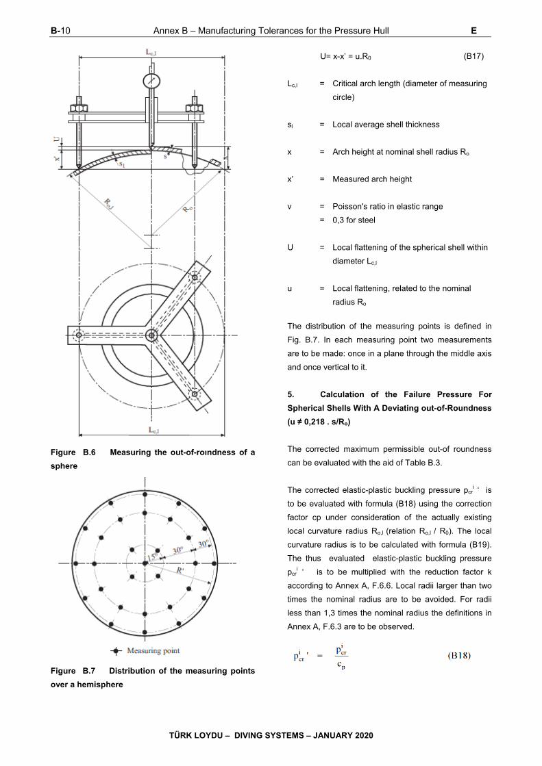
B-10 Annex B – Manufacturing Tolerances for the Pressure Hull E
TÜRK LOYDU – DIVING SYSTEMS – JANUARY 2020
Figure B.6 Measuring the out-of-roındness of a
sphere
Figure B.7 Distribution of the measuring points
over a hemisphere
U= x-x’ = u.R0 (B17)
Lc,l = Critical arch length (diameter of measuring
circle)
sl = Local average shell thickness
x = Arch height at nominal shell radius Ro
x’ = Measured arch height
ν = Poisson's ratio in elastic range
= 0,3 for steel
U = Local flattening of the spherical shell within
diameter Lc,l
u = Local flattening, related to the nominal
radius Ro
The distribution of the measuring points is defined in
Fig. B.7. In each measuring point two measurements
are to be made: once in a plane through the middle axis
and once vertical to it.
5. Calculation of the Failure Pressure For
Spherical Shells With A Deviating out-of-Roundness
(u ≠ 0,218 . s/Ro)
The corrected maximum permissible out-of roundness
can be evaluated with the aid of Table B.3.
The corrected elastic-plastic buckling pressure pcri ‘ is
to be evaluated with formula (B18) using the correction
factor cp under consideration of the actually existing
local curvature radius Ro,l (relation Ro,l / R0). The local
curvature radius is to be calculated with formula (B19).
The thus evaluated elastic-plastic buckling pressure
pcri ‘ is to be multiplied with the reduction factor k
according to Annex A, F.6.6. Local radii larger than two
times the nominal radius are to be avoided. For radii
less than 1,3 times the nominal radius the definitions in
Annex A, F.6.3 are to be observed.
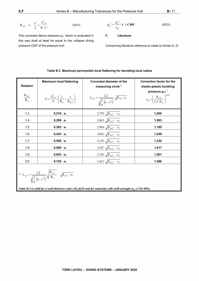
E,F Annex B – Manufacturing Tolerances for the Pressure Hull B- 11
TÜRK LOYDU – DIVING SYSTEMS – JANUARY 2020
The corrected failure pressure pcr' which is evaluated in
this way shall at least be equal to the collapse diving
pressure CDP of the pressure hull:
F. Literature
Concerning literature reference is made to Annex A, G.
Table B.3 Maximum permissible local flattening for deviating local radius
Relation
o
o,1
R
R
Maximum local flattening
o,1o
2c,1
R
1
R
1
8
LU
Corrected diameter of the
measuring circle *
1o,1
4 2c,1 sR
ν14
3
2,2L
Correction factor for the
elastic-plastic buckling
pressure pcri ‘ 1,07
o
o,1p R1,3
Rc
1,3 0,218 s1 1o,1 sR2,759 1,000
1,4 0,290 s1 1o,1 sR2,863 1,083
1,5 0,363 s1 1o,1 sR2,964 1,165
1,6 0,435 s1 1o,1 sR3,061 1,249
1,7 0,508 s1 1o,1 sR3,155 1,332
1,8 0,580 s1 1o,1 sR3,247 1,417
1,9 0,653 s1 1o,1 sR3,336 1,501
2,0 0,725 s1 1o,1 sR3,422 1,586
1o,1
o
o,1
4 2c,1 sR
R
R
ν14
3
2,2L *
Table B.3 is valid for a wall thickness ratio s/Ro0,02 and for materials with yield strength 0,2 550 MPa.

Annex C – Acrylic Windows C-1
TÜRK LOYDU – DIVING SYSTEMS – JANUARY 2020
ANNEX C
ACRYLIC WINDOWS
Page
A. GENERAL .......................................................................................................................................................... C-2
B. MATERIALS ...................................................................................................................................................... C-2
C. MANUFACTURE of WINDOWS ........................................................................................................................ C-3
D. WINDOW SHAPES and SIZES ......................................................................................................................... C-3
E. INSTALLATION of WINDOWS ........................................................................................................................ C-4

C-2 Annex C – Acrylic Windows A,B
TÜRK LOYDU – DIVING SYSTEMS – JANUARY 2020
A. General 1. Scope
In the sense of these Rules, acrylic windows are flat or
curved windows for the view ports of pressure hulls
which are made of cast, unlaminated polymethyl
methacrylate plastic.
2. Limits of application
For acrylic windows following limits for application apply:
- designed service life 10 or 20 years (see
explanatory notes below)
- temperature range -18 °C to +66 °C
- rate of pressurization max. 10 bar/s
- pressure cycles at design pressure max. 10.000
- period under pressure
at design pressure max. 40.000 h
- maximum allowable
working pressure max. 1380 bar
The design service life for acrylic windows depends on
numerous factors, in particular on the kind of loading.
The maximum design service life to be assumed for
spherical or cylindrical windows subjected to external
overpressure, which are exclusively exposed to
compressive stresses or minor bending stresses only, is
generally 20 years, while for flat windows with flat seat it
is 10 years. The design service life starts with the date
of manufacturing regardless of the use in the
submersible.
Depending on the previous actual loads acting on the
windows and testing to be agreed with TL in detail,
extension of the service life of acrylic windows may be
approved.
3. Permissions/Approvals
For the design and manufacturing of acrylic windows
the following permissions/approvals are required:
- Approval of drawings and of the design for
each type of window and each form of
application by TL
- Approval as material manufacturer by TL
- Manufacturer Inspection Certificate for the
material, compare B.3.
- Approval by TL as manufacturer of acrylic
Windows
- TL Certificate which certifies the
manufacturing inspections and the pressure
tests according to C.6.
B. Materials
1. Materials for acrylic windows are to be
manufactured in accordance with a recognized
Standard (e.g. ANSI/ASME PVHO 1, Section 2). The
producer is required to certify this before manufacture
commences.
2. Acrylic windows have to meet the minimum
physical requirements stated in Table C.1.
3. For each batch of acrylic plastic processed to
windows the manufacturer has to issue a Manufacturer
Inspection Certificate containing at least the following
details:
- Number and date of Certificate
- Manufacturer's name and address
- Designation and application of casting type
- Batch number, quantity, shape and size of
castings
- Marking of castings
- Results of tests applied in accordance with
Table C.1
- Stamp and signature

B,C,D Annex C – Acrylic Windows C-3
TÜRK LOYDU – DIVING SYSTEMS – JANUARY 2020
4. Where a Manufacturer Inspection Certificate of
the kind required is not available for the acrylic plastic or
where the conditions for recognition of the Inspection
Certificate are not satisfied, the tests are to be extended
in a manner to be agreed with TL in each individual
case.
5. Each casting is to be provided at one point at
least with a marking which identifies the type of casting,
the batch number, the date of manufacture and the
name of the manufacturer.
C. Manufacture of Windows
1. The manufacture of acrylic windows covered
by these Rules may only take place in specialized
workshops which have been approved by TL for that
purpose. Such approval can be granted only to those
companies which employ properly trained specialists
and which have available the necessary technical
facilities enabling them to undertake the expert forming,
machining, heat treatment and quality control of acrylic
windows. Application for approval is to be made to TL
before the manufacture of windows commences.
2. The acrylic plastic to be used has to meet the
requirements stated in B. After machining and any
necessary forming operations, each window is to be
subjected to heat treatment (tempering) in accordance
with the acrylic plastic manufacturer's specification.
After tempering no further mechanical polishing may be
carried out on the window.
Flat disk windows for diving chambers where only the
surrounding area is professionally machined need not to
undergo a heat treatment after manufacturing.
3. Window surfaces are to be polished in such a
way as to meet the optical clarity requirement stated in
Table C.1.
4. For each window or series of windows the
window manufacturer has to issue a component
Certificate specifying all the stages of manufacture such
as cutting, sticking, polishing, forming and tempering. In
addition the tests carried out, the test results, the
marking of the windows and the date of manufacture
are to be indicated.
5. Each window is to be permanently marked with
at least the following details:
- Design pressure PR = NDP [bar]
- Design temperature [°C]
- TL approval stamp
- Manufacturer's name or identifying mark
- Serial number and year of manufacture.
- Direction of pressure, if it is not clear
Wherever possible, the marking is to be engraved in the
non-load-bearing portion of the window edge. The use
of punches is not allowed.
6. Acrylic windows are to be presented to TL for
an inspection of manufacture. In addition, each window
is to be subjected, in the presence of a TL Surveyor, to
a pressure test in accordance with TL Rules for
Underwater Equipment, Chapter 54, Section 2, G.4. At
the pressure test the direction of pressure has to be
observed. If the windows are subjected to pressure from
both sides, this is to be considered for the testing.
D. Window Shapes and Sizes
1. The standard shapes and sizes shown in Table
C.2, C.3 and C.4 are to be selected for the acrylic
windows. For design pressure PR in general the
nominal diving pressure NDP is to be used, see also the
Rules for Submersibles, Table 4.2 or Underwater
Equipment, Table 3.2.
2. Acrylic windows of other shapes and sizes or
for other ranges of pressure may be used on application
if approved by TL or if they are designed and
manufactured to a standard recognized by TL.
Acrylic windows may be performed e.g. according to
ASME PVHO-1, Section 2.
3. The design temperature to be assumed for
acrylic windows shall be the mean value of the
C-4 Annex C – Acrylic windows D,E
TÜRK LOYDU – DIVING SYSTEMS – JANUARY 2020
maximum external and internal temperatures to be
expected under design pressure conditions.
4. Windows subjected to pressure from both
sides are to be designed for the maximum pressure
applied, regardless of whether this pressure is external
or internal.
5. Pressure may only be applied to the convex
side of spherical shell windows.
6. The thickness of the window has to be
everywhere equal to, or greater than, the minimum
value determined by reference to Tables C.2, C.3 and
C.4. For intermediate temperatures linear interpolation
may be applied.
7. With flat windows having right-angled edge
and an O-ring seal, the outside diameter of the disk
shall be within + 0,00/-0,25 mm of the nominal value, or
within + 0,00/-0,75 mm where flat gasket seals are
used.
8. Because of stress increasing effects grooves
for seals shall not be located in the acrylic window
bearing surface and also not in the window itself.
9. The greater diameter of the conical bearing
surface of an acrylic window shall be within +0,000/-
0,002 Do of the nominal value.
The included conical angle of the window shall be within
+ 0,25/-0,00 degrees of the nominal value.
10. The concave or convex surface of the window
shall not differ from an ideal spherical sector by more
than ± 0,5 % of the nominal external spherical radius.
11. The surface roughness Ra of the window
bearing surface shall be 0,75 μm or better.
E. Installation of Windows
1. If the window seat is not made of corrosion
resistant material, it is to be sufficiently preserved with a
suitable agent. In addition window and window seat are
to be carefully cleaned using only cleaning material
which is compatible with acrylic glass.
2. Conical window seats are to be treated with
silicone or a suitable grease before the installation.
3. During installation of the window care is to be
taken that the bolts of the fastening ring are to be
tightened with the prescribed and all the same torque.
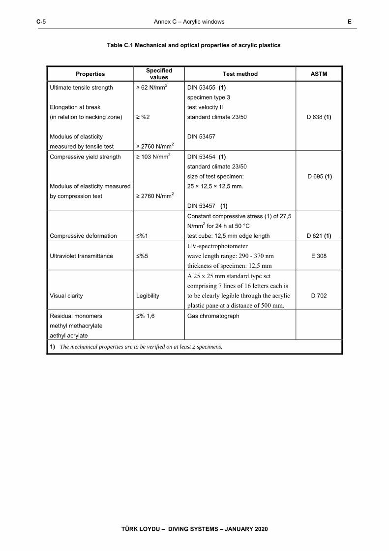
C-5 Annex C – Acrylic windows E
TÜRK LOYDU – DIVING SYSTEMS – JANUARY 2020
Table C.1 Mechanical and optical properties of acrylic plastics
Properties Specified
values Test method ASTM
Ultimate tensile strength
Elongation at break
(in relation to necking zone)
Modulus of elasticity
measured by tensile test
≥ 62 N/mm2
≥ %2
≥ 2760 N/mm2
DIN 53455 (1)
specimen type 3
test velocity II
standard climate 23/50
DIN 53457
D 638 (1)
Compressive yield strength
Modulus of elasticity measured
by compression test
≥ 103 N/mm2
≥ 2760 N/mm2
DIN 53454 (1)
standard climate 23/50
size of test specimen:
25 × 12,5 × 12,5 mm.
DIN 53457 (1)
D 695 (1)
Compressive deformation
≤%1
Constant compressive stress (1) of 27,5
N/mm2 for 24 h at 50 °C
test cube: 12,5 mm edge length
D 621 (1)
Ultraviolet transmittance
≤%5
UV-spectrophotometer
wave length range: 290 - 370 nm
thickness of specimen: 12,5 mm
E 308
Visual clarity
Legibility
A 25 x 25 mm standard type set
comprising 7 lines of 16 letters each is
to be clearly legible through the acrylic
plastic pane at a distance of 500 mm.
D 702
Residual monomers
methyl methacrylate
aethyl acrylate
≤% 1,6 Gas chromatograph
1) The mechanical properties are to be verified on at least 2 specimens.
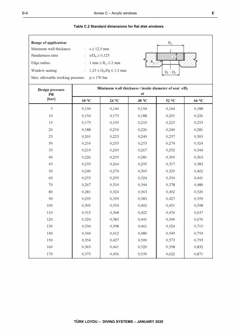
C-6 Annex C – Acrylic windows E
TÜRK LOYDU – DIVING SYSTEMS – JANUARY 2020
Table C.2 Standard dimensions for flat disk windows

E Annex C – Acrylic windows C-7
TÜRK LOYDU – DIVING SYSTEMS – JANUARY 2020
Table C.3 Standard dimensions for spherical shell Windows with conical seat (opening angle 60° / 90°)
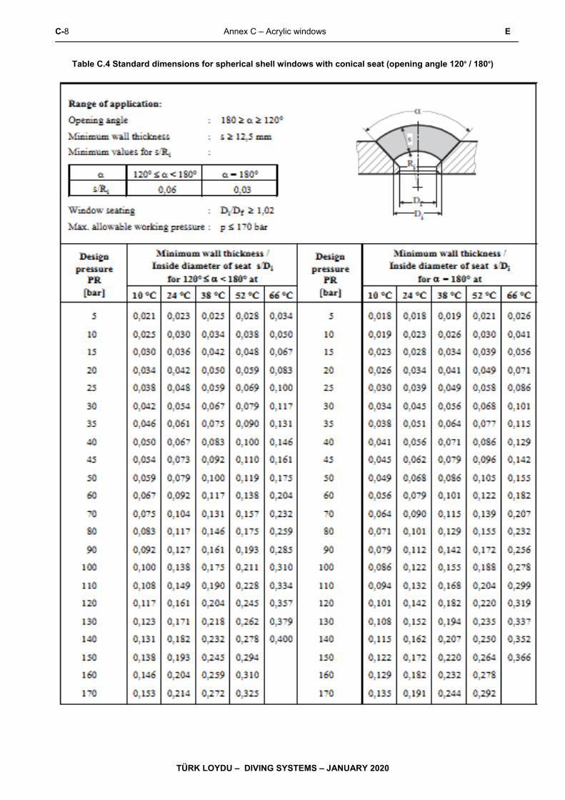
C-8 Annex C – Acrylic windows E
TÜRK LOYDU – DIVING SYSTEMS – JANUARY 2020
Table C.4 Standard dimensions for spherical shell windows with conical seat (opening angle 120° / 180°)
Annex D– Manufacture and Treatment of Fibre Reinforced Plastics (FRP) D-1
TÜRK LOYDU – DIVING SYSTEMS – JANUARY 2020
ANNEX D
MANUFACTURE and TREATMENT of FIBRE REINFORCED PLASTICS (FRP)
Page
A. GENERAL .......................................................................................................................................................... D- 2
B. REQUIREMENTS for the MATERIALS and THEIR PROCESSING ................................................................ D- 2
C. REQUIREMENTS for the DESIGN ................................................................................................................... D- 3

D-2 Annex D– Manufacture and Treatment of Fibre Reinforced Plastics (FRP) A,B
TÜRK LOYDU – DIVING SYSTEMS – JANUARY 2020
A. General
1. Definition
Fibre rei nforced plastics are heterogeneous materials,
consisting of a thermosetting resin as the matrix and an
embedded fibrous reinforcing material.
2. Scope of application
For submersibles plastics are mainly used for the
following components:
- Exostructure
- Rudder and propeller
- Pressure vessels
B. Requirements for the Materials and their
Processing
1. Materials
1.1 Approval
1.1.1 The materials used for the manufacturing of
components from FRP shall be assessed and approved
by TL.
1.1.2 The approval refers only to the approved
material. The applicability of this material in connection
with other materials shall be demonstrated
independently by the manufacturer or the user in a
suitable manner.
1.2 Quality assurance
1.2.1 A constant material quality shall be secured by
the manufacturer through constant quality assurance
measures.
1.2.2 TL reserve the right to demand or carry out
spot tests of the material properties during the duration
of the material approval.
1.3 Types of materials
For the construction of submersibles in general the
following materials are to be considered:
- Laminated resins, e.g. cold-setting or hot-
setting unsaturated polyester (UP) resins and
cold setting epoxy (EP) resins
- Reinforcing materials, e.g. fibre reinforcements
made of glass and carbon
- Prepregs as reinforcing materials, which are
preimpregnated with a thermosetting resin and
which can be processed without any further
addition of resin or hardener
- Core materials, e.g. rigid foams with adequate
compressive strength
- Adhesives, e.g. cold- and hot-setting
thermosetting adhesives and hot-melt
adhesives
- Flame retardant laminates produced by
additives to the resin system, whereby the
viscosity of the resin or the mechanical
properties of the manufactured laminates not
be changed essentially
Other materials may be approved in agreement with TL
Head Office.
2. Manufacturing
2.1 Approval
2.1.1 Manufacture of FRP-components shall only be
performed by workshops which are approved by TL for
the manufacture of components made from fibre-
reinforced thermosetting resins.
2.1.2 The manufacture of FRP-components shall
only be carried out by persons with Professional
knowledge. This professional knowledge shall in
general be verified by certificates of the corresponding
training courses.
B,C Annex D– Manufacture and Treatment of Fibre Reinforced Plastics (FRP) D-3
TÜRK LOYDU – DIVING SYSTEMS – JANUARY 2020
2.1.3 All manufacturing facilities, store-rooms and
their operational equipment shall fulfil the requirements
of the responsible authorities. The manufacturer is
alone responsible for compliance with these
requirements.
2.2 Store rooms and laminating workshops
The danger of contamination of laminating materials is
to be minimized through separation of production
facilities from store rooms.
2.3 Guidelines for processing
2.3.1 As a matter of principle, only materials
approved by TL shall be used. In addition to the choice
of suitable and approved materials, special care shall be
taken when working with them because of the great
influence on the properties of the product.
2.3.2 For the preparation and processing of the resin
compounds and reinforcing material, beside the TL
Rules, the instructions issued by the material
manufacturers and the regulations of the competent
authorities are to be observed.
2.4 Manufacturing surveillance
For components made of FRP, manufacturing
surveillance has to consist of the quality control of the
basic materials, production surveillance and the quality
inspection of the finished components.
2.5 Repair of components
2.5.1 Repairs of structural FRP-components shall
only be performed by workshops which are approved by
TL.
2.5.2 For the approval of a repair, all design and
repair drawings needed to assess the repair of the
relevant components are to be submitted to TL. The
repair plan is to be examined by TL Head Office and
approved.
2.5.3 A report is to be established for each repair
which has to be signed by the head of the repair team.
2.5.4 If the materials and laminates used for the
repair are not identical to those employed when the
component was manufactured, equivalence of the
combination of materials shall be verified with respect to
their properties.
C. Requirements for the Design
1. Design data
The mechanical properties and the nominal thickness of
the laminate as well as weight, type and portion of the
reinforcement layers, which can be individually used,
are to be defined on the design drawings.
2. Design measures
For the design of components the following measures
are to be considered:
2.1 Changes in the laminate thickness are to be
established with a smooth transition of 25 mm per 600
g/m². In the transition area from a sandwich design to
massive laminate the core material is to be gradually
tapered (at least 3 : 1).
2.2 In general frame and stiffening sections are to
be built up by layer and layer on the laminate, as far as
the last layer is not yet cured. Where internal structural
members are crossing each other, special care is to be
taken that the load-bearing capacity remains
unchanged.
2.3 Closed hollow spaces in the structure which
may be subjected to external pressure are to be
avoided.
2.4 If core materials are used in areas which may
be subjected to external pressure, pressure-proof
materials like e.g. rigid foams are to be used.
2.5 Stress concentrations, peaks in stiffness and
discontinuities are to be avoided. It has to be ensured,
that because of cut-outs, openings in load carrying
elements and the connection of fittings the strength of
the component is not impaired.
D-4 Annex D– Manufacture and Treatment of Fibre Reinforced Plastics (FRP) C
TÜRK LOYDU – DIVING SYSTEMS – JANUARY 2020
2.6 If various components which have been
produced in different moulds are to be connected with
each other, then the connecting laminates have to be
finished before curing of the components.
If components of FRP are bolted which each other or
with components of other materials, the connecting
elements (bolts, nuts, washers) are to be of seawater
resistant material. Bolted connections are to be
dimensioned according to the occurring forces.
2.7 In areas with local force introduction (e.g.
connecting elements of the exostructure, bitts, cleats)
sole pieces and/or shims of adequate strength are to be
situated. The strength, e.g. bearing strength is to be
proven in a suitable way. The connecting area of these
sole pieces is to be prepared in a suitable way and shall
be free of contamination.
2.8 Metallic materials used in the design, like e.g.
steel or aluminium alloys have to be suitable for the
intended purpose and shall not impair the curing of the
laminating resins.
Local reinforcements of metallic materials are to be
cleaned and degreased carefully and, if possible, are to
be shot blasted or roughened up to achieve a toothing
effect.
2.9 For sandwich laminates in way of bolted
connections and fittings, inserts of a material, which can
withstand the compression and the design loads, are to
be provided. The inserts are to be connected with the
core material and the laminate layers in the best way.
2.10 Laminate edges and holes are to be sealed.
2.11 Further design measures which are
recommendable for different shipbuilding components
made of plastics are contained in the TL Rules for
Yachts.
Annex E- Basic Requirements for Umbilicals E-1
TÜRK LOYDU – DIVING SYSTEMS – JANUARY 2020
ANNEX E
BASIC REQUIREMENTS for UMBILICALS
Page
A. GENERAL .......................................................................................................................................................... E- 2
B. PRINCIPLES for LAYOUT and DESIGN .......................................................................................................... E- 2
C. DOCUMENTS for APPROVAL ......................................................................................................................... E- 7
D. TESTS and TRIALS .......................................................................................................................................... E- 7
E. MARKING .......................................................................................................................................................... E- 9

E-2 Annex E- Basic Requirements for Umbilicals A,B
TÜRK LOYDU – DIVING SYSTEMS – JANUARY 2020
A. General
1. Definition
The umbilical is regarded as the connecting link
between support ship and an element under water,
which may include hose assemblies for liquid and gas
transport and monitoring, communication, data transfer
and energy supply cables as well eventually a lifting
cable.
This bundled or integrated supply line may also be used
between elements under water.
As elements under water in the sense of this Annex are
to be regarded e.g.:
– diving chambers
– non-autonomous (manned) and remotely
controlled (unmanned) submersibles
– launchers
– underwater working machines
– diving equipment
The integrated or also independent lifting cable serves
for launching and recovery, as well as for lifting and
lowering of an element under water as well as for
absorption of tension loads during operation. The lifting
cable may also be designed as bearing element, e.g. as
netting within the sheathing of the umbilical.
2. Scope
This Annex is valid for the technical requirements and
the testing of umbilicals including connecting pieces as
well as shut-off devices at the ends and the load
transfer points. The load transfer points of the support
ship/element are not subject of this Annex.
Furtheron this Annex is valid for cables and hose
asemblies which may be subjected to external
overpressure and integrated lifting cables.
The penetration into the pressure hull or a vessel under
pressure is part of the element.
Some basic requirements for the coil-up/coil-off
mechanism are defined.
The supply systems for the materials, data and energies
transferred by the umbilical form part of the support ship
or element and are not treated in this Annex.
Umbilical systems for production duties, as e.g. used in
the oil and gas industry, are primarily not subject of this
Annex.
3. Quality Management System
The manufacturer of umbilicals has to apply a
recognized quality management system, like e.g. ISO
9001 or equivalent. This system has to cover design,
manufacture and testing.
4. Equivalence
Umbilicals deviating from this Annex in their type,
structure and the compliance with some detailed
requirements may be accepted by TL, provided that
they are found to be equivalent to the principle
requirements defined in this Annex.
B. Principles for Layout and Design
1. General
1.1 The requirements defined in the following are
minimum requirements for the majority of the
prospective applications. For special use the selection
of the requirements is to be agreed with TL.
1.2 Generally the following requirements are to be
considered for the design:
– environmental influences, see the TL Rules for
Submersibles, Section 2, D.
– influence of weight (deadweight, empty, full)
– buoyancy behaviour (positive and negative
buoyancy, neutral buoyancy)
– dynamic influences because of ship
movements and increasing and lowering the
pressure inside
B Annex E- Basic Requirements for Umbilicals E-3
TÜRK LOYDU – DIVING SYSTEMS – JANUARY 2020
– thermal influences on expansion and shrinking
because of possible temperature changes
inside and outside
– thermal influences because of power cables
partly on drum
– pressure differences in hoses between upper
and lower end of umbilical
– chemical and electrochemical influences
1.3 The control of the coil-up/coil-off mechanism
for the umbilical and the monitoring of the supply flow
through the umbilical including the production of
materials to be supplied are to be concentrated at a
central position.
For manned, non-autonomous submersibles the control
and monitoring is to be integrated into the control stand
which maintains the connection with the submersible.
For unmanned, remotely controlled submersibles and
other elements these are to be integrated into the
control station.
1.4 Umbilicals shall be produced in one piece for
the complete required length and shall not be divided
into different parts.
1.5 Requirements and tests of umbilicals for hose
supplied diving equipment are to be taken from
Standard EN 15333-1.
2. Mechanical requirements
2.1 Materials
Only materials according to generally recognized
standards are to be used and their application has to be
clearly recorded and traced.
The materials are to be suitable for the use in salt water.
If a mission in other media than water is planned, these
are to be adequately considered.
The material of hose assemblies is to be suitable for
the media to be transported.
The materials are to be suitable for permanent and
varying bending stress.
If hoses are used for breathing gases their suitability is
to be proven (e.g. off-gassing test).
Umbilicals, hose assemblies and cables are to be
protected against abrasion and damages.
For the protection cover of umbilicals attention is to be
given that no internal pressure can be built up if little
leakages occur in the hose. Metal inserts in the
protection cover are to be avoided.
2.2 Tensile load
2.2.1 For umbilicals with integrated lifting cable the
mechanical characteristics are to be judged according
to the submitted documentation. Hereby the maximum
permissible tension load and the minimum breaking
load of the umbilical are to be defined by the
manufacturer. For the use of lifting cables made of steel
the maximum static tension load created by the safe
working load shall not exceed 1/8 of the proven
breaking load of the cable. For the use of lifting cables
made of chemical fibre the maximum static tension load
created by the safe working load shall not exceed 1/10
of the proven breaking load of the cable.
For the use of lifting cables for simple scientific devices
a reduced breaking load of the cable may be approved
in agreement with TL under consideration of risk
potential and intended use.
Further on the functionality of the elements contained in
the umbilical at maximum possible longitudinal
extension of the umbilical is to be considered.
The umbilical is to be constructed to reach neutrality to
tension for the whole range of tensional stresses.
2.2.2 If there is no lifting cable included, the
integrated cables and hose lines are to be protected
from longitudinal stress by a strain relief. The minimum
tension load is to be defined considering the duty of the
mission, is to be agreed with TL and to be proven.
E-4 Annex E- Basic Requirements for Umbilicals B
TÜRK LOYDU – DIVING SYSTEMS – JANUARY 2020
2.2.3 If buoyancy elements or weights are used to
change the buoyancy behaviour, these are to be
securely fastened without damaging the umbilical.
Over the complete appearing tension range no
additional torsional effects shall be created.
For hoses with non corrosion-resistant wire mesh inlets
the mesh is to be protected against the surrounding
media.
2.3 Bending and buckling
Umbilicals shall be buckling safe and bending resistant
respectively being adequately arranged to avoid
buckling safely. According to the structure of the
umbilical the minimum bending radius is to be agreed
with TL.
The minimum bending radius of a single component
(e.g. lifting cable, cable, hose assembly, etc.) shall not
be bigger than the minimum bending radius of the
complete umbilical.
If special elements are used for avoidance of bending
and buckling, these have to be securely fastened
without damaging the umbilical.
2.4 Hose lines
2.4.1 Lay out
For the layout is to be considered:
– Each hose line is to be designed for an internal
burst pressure, which shall at least be for
liquids 4 times, for gases 5 times of the
maximum allowable working pressure.
– Hose assemblies to be subjected to external
pressure, are to be designed for at least 1,1
times (manned submersibles) and 1,0 times
(unmanned submersibles and other elements)
the collapse diving pressure CDP.
– Moreover the maximum possible pressure
difference Δp between inside and outside
pressure has to be considered.
2.4.2 Type test
– Burst pressure test:
Each hose is to be subjected to internal
pressure until bursting. The minimum burst
pressure is to be for liquids 4 times, for gases
5 times the allowable maximum working
pressure.
– External pressure test:
Hose assemblies which are additionally
subjected to external overpressure have to
undergo a hydraulic pressure test with 1,5
times the maximum possible pressure
difference between inside and outside (but at
least 10 bar).
2.4.3 Routine test
Within the series production the routine test contains the
following test steps:
– Pressure test:
Before integration into an umbilical, each hose
is to be tested with an internal pressure
according to 1,5 times (metallic hose
assemblies) respectively 2 times (non-metallic
hose lines) maximum allowable working
pressure.
– External pressure test:
Hoses which are additionally subjected to
external overpressure have to undergo a
hydraulic pressure test with 1,5 times the
maximum possible pressure difference
between inside and outside.
2.5 Fittings
Connecting elements and fittings have to meet the
same inside and outside design pressures as the
umbilical, shall not unintentionally disconnect, shall be
corrosion resistant and suitable for the planned media.
B Annex E- Basic Requirements for Umbilicals E-5
TÜRK LOYDU – DIVING SYSTEMS – JANUARY 2020
3. Electrical requirements
3.1 Umbilicals may contain monitoring and
communication/ data transfer cables and also energy
supply lines.
3.2 Lay out
For the lay out has to be considered:
– Flexible cables or highly flexible cables e.g.
of class 5 acc. to IEC have to be used,
whereby for energy supply cables a minimum
sectional area of the single copper conductor
of 2,5 mm2 is to be provided. Empty spaces
are to be filled with suitable filler material like
petroleum jelly, to maintain form stability.
– Electrical cables and optical conductors are to
be designed according to their specification.
The maximum length is to be considered
hereby.
– For special duties it may be necessary to
construct cables with longitudinal water
tightness.
– For different cables with several levels of
voltage negative influences between them
have to be avoided.
– For cables mechanical forces shall not be
transferred by the conductors or their
insulation.
– ables have to provided at least cross water
tight.
– Each cable is to be designed for an external
Pressure which is at least for manned
submersibles 1,1 times and for unmanned
submersibles and other elements 1,0 times the
collapse diving pressure CDP.
– Extended stowage of cables in water shall not
lead to a remarkable reduction of the insulation
resistance.
3.3 Type test
Fundamentally the electric and electronic characteristics
specified for the project have to be proven, e.g. by a
type test according to IEC 60092-350/351.
The type test contains the following test steps:
– visual check
– check of dimensions, structure and marking
– The cross - watertightness of electrical cables /
single conductors is in general to be tested
with 2 × PN (cyclic). If the cables are integrated
in a cross-watertight umbilical, the test may be
cancelled in agreement with TL.
– evaluation of voltage insulation strength
according to Table E.1
Measurement of the insulation of energy supply lines
with at least 500 V (guiding value: > 500 MΩ × km)
For cables with a nominal voltage up to 1 kV a check of
the insulation values is to be performed with a test
voltage equal to 2 times the nominal voltage, but at
least 500 V.
For energy supply lines with a nominal voltage above 1
kV a check of the insulation values is to be performed
with a test voltage of at least the nominal voltage.
The test comprises the evaluation of the insulation value
of all conductors against each other as well as of each
single conductor against the external insulation layer.
The measurement of the insulation is to be performed
before and after the test of cross water tightness and
after the test for voltage insulation strength.
– resistance measurement of all single
conductors
– measurement of partial discharging according
to IEC 60885-2 at voltages above 3,6/6 kV
(U0/U) for all single conductors of the cable
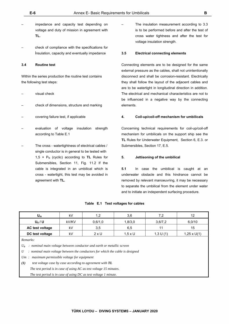
E-6 Annex E- Basic Requirements for Umbilicals B
TÜRK LOYDU – DIVING SYSTEMS – JANUARY 2020
– impedance and capacity test depending on
voltage and duty of mission in agreement with
TL.
– check of compliance with the specifications for
İnsulation, capacity and eventually impedance
3.4 Routine test
Within the series production the routine test contains
the following test steps:
– visual check
– check of dimensions, structure and marking
– covering failure test, if applicable
– evaluation of voltage insulation strength
according to Table E.1
– The cross - watertightness of electrical cables /
single conductor is in general to be tested with
1,5 × PN (cyclic) according to TL Rules for
Submersibles, Section 11, Fig. 11.2 If the
cable is integrated in an umbilical which is
cross - watertight, this test may be avoided in
agreement with TL.
– The insulation measurement according to 3.3
is to be performed before and after the test of
cross water tightness and after the test for
voltage insulation strength.
3.5 Electrical connecting elements
Connecting elements are to be designed for the same
external pressure as the cables, shall not unintentionally
disconnect and shall be corrosion-resistant. Electrically
they shall follow the layout of the adjacent cables and
are to be watertight in longitudinal direction in addition.
The electrical and mechanical characteristics are not to
be influenced in a negative way by the connecting
elements.
4. Coil-up/coil-off mechanism for umbilicals
Concerning technical requirements for coil-up/coil-off
mechanism for umbilicals on the support ship see the
TL Rules for Underwater Equipment, Section 6, E.3. or
Submersibles, Section 17, E.5.
5. Jettisoning of the umbilical
5.1 In case the umbilical is caught at an
underwater obstacle and this hindrance cannot be
removed by relevant manoeuvring, it may be necessary
to separate the umbilical from the element under water
and to initiate an independent surfacing procedure.
Table E.1 Test voltages for cables
Um kV 1,2 3,6 7,2 12
U0 / U kV/KV 0,6/1,0 1,8/3,0 3,6/7,2 6,0/10
AC test voltage kV 3,5 6,5 11 15
DC test voltage kV 2 x U 1,5 x U 1,3 U (1) 1,25 x U(1)
Remarks:
U0 : nominal main voltage between conductor and earth or metallic screen
U : nominal main voltage between the conductors for which the cable is designed
Um : maximum permissible voltage for equipment
(1) test voltage case by case according to agreement with TL
The test period is in case of using AC as test voltage 15 minutes.
The test period is in case of using DC as test voltage 1 minute.

B,C,D Annex E- Basic Requirements for Umbilicals E-7
TÜRK LOYDU – DIVING SYSTEMS – JANUARY 2020
5.2 For manned submersibles it has to be possible
to drop respectively to cut-off the umbilical by the crew
from inside the submersible. The jettisoning system is to
be so designed that two operational actions which are
independent from each other and which need no electric
energy are required to activate the separation.
5.3 For unmanned elements, for which jettisoning
is required, the umbilical has to be dropped respectively
cut-off at the connecting point with the submersible from
the control station. The jettisoning system is to be
designed that an unintentional jettisoning is avoided.
5.4 For other elements under water the possibility
for jettisoning is to be agreed with TL according to type
and mission duty.
C. Documents for Approval
It is to be submitted:
– general description of the mission duty
– description of the structure and the applied
materials of the single components
– definition of main parameter, compare E.
– drawing of the cross section
– data concerning connecting elements and
fittings, eventually drawings, if existing
– data concerning pressure and flow conditions
and capacity for gas and liquid transport
– data concerning the energy, communication
and data transfer, e.g. voltage, amperage,
transfer rates
– specification of impedance, capacity and
resistance values
– data concerning tests with Certificates already
performed
– data concerning installation, maintenance,
operation and repair
– description of marking
D. Tests and Trials
1. General
1.1 The required tests are to be divided into a
type test for the prototype and a routine test within the
manufacturing for the effective use.
1.2 A trial and test program is to be established by
the manufacturer of the umbilical according to the
specification of the requirements profile defined by the
end client (element producer or operator) and to be
submitted to TL for approval. Generally this program
shall contain at least the test steps defined in the
following.
1.3 About the scope of the presence of TL
Surveyors at these tests and trials TL will decide in
each individual case.
2. Type test
2.1 Mechanical requirements
The type test contains the following test steps:
– visual check
– check of dimensions, structure and markings
– weight evaluation:
The effective weight for missions of the
umbilical [t/1000 m] is to be determined in air,
water (if not specified otherwise: seawater with
1028 kg/m3) empty and filled and under
defined dynamic load (with friction in water)
with the aim to determine the safe working load
SWL at the upper end of the umbilical.
– Test of tensile strength:
E-8 Annex E- Basic Requirements for Umbilicals D
TÜRK LOYDU – DIVING SYSTEMS – JANUARY 2020
The minimum tensile strength of the elements
provided for the tension load of the umbilical is
to be determined.
– Buckling test:
The umbilical is to buckle 5000 times with the
defined bending radius at one location and in
one direction. Subsequently insulation and
resistance measurement of the single
conductors are to be performed.
– Torsion test:
A part of at least 1 m length is to be loaded
vertically with 0,3 SWL and to be twisted by
90° for 5 minutes. After the test no remarkable
lengthening or twist shall be noticeable.
Subsequently electrical lines are subjected to a
resistance measurement, hose lines to a
tightness test under working pressure.
– Stretch loading test:
A part of at least 1,5 m length is to be fixed at
the ends and a pretension in longitudinal
direction will be brought up. The size of the
pretension is to be agreed with TL. For 5
cycles the size of the pretension will be
increased by 5 times and lowered again.
Subsequently electrical lines are subjected to a
resistance measurement, hose lines to a
tightness test under working pressure.
– External pressure test:
In general the umbilical is to be subjected to a
cyclic hydraulic pressure test with 2 times the
nominal pressure of the umbilical PN. For big
water depths the test pressure is to be agreed
with TL.
Attention is to be paid to the fact, that for the
use of hose lines the internal pressure is not
below the diving pressure, as far as possible.
– Tightness test of the complete umbilical type:
All hose assemblies are to be subjected at the
same time to the maximum allowable working
pressure and an eventual loss of pressure
because of leakage is to be checked. A
maximum allowable leakage rate of 1 %
pressure loss within 24 hours is acceptable for
the different hose lines.
– If gases with a content by volume greater 25 %
oxygen shall be transported, all materials
coming into contact with oxygen are to be
checked for their oxygen suitability (e.g.
according to EN 559). For allowable working
pressures of more than 25 bar an oxygen
pressure surge test is to be performed (e.g.
according to EN 15333-1).
– In an actual case of application, depending on
mission duty and operational conditions it will
be decided by TL if all defined tests are to be
performed.
– If required, the specified liquid and gas volume
which can be put through is to be checked (if
need be with projection to the effective length
of the umbilical).
2.2 Electrical/electronic requirements
Principally the electric and electronic characteristics
specified for the project are to be proven e.g. by a type
test according to IEC 60092-350.
The type test contains the following steps:
– Each single cable has to meet the
requirements according to B.3.3.
– The cross - watertightness of the umbilical is to
be proven within the external pressure test
according to 2.1.
– The measurements of the insulation according
to B.3.3 are to be performed before or after the
test of cross - watertightness.
– Impedance and/or capacity tests are to be
performed depending on voltage and duty of
mission in agreement with TL.
D,E Annex E- Basic Requirements for Umbilicals E-9
TÜRK LOYDU – DIVING SYSTEMS – JANUARY 2020
– evaluation of voltage insulation strength
according to Table E.1
– check of compliance with the specifications for
insulation, capacity and eventually impedance
– check of transfer of the specified data volume/
time unit
(If data cables are tracked together with cables
for voltage supply within the umbilical, the
check of data transfer is to be done with active
nominal voltage. Voltage peaks by e.g.
switching actions are to be considered.)
3. Routine test
3.1 Mechanical requirements
Within the series production the routine test contains
the following test steps:
– visual check
– check of dimensions
– external pressure test:
In general the umbilical is to be subjected to a
hydraulic pressure test with 1,5 times the
nominal pressure of the umbilical PN (cyclic
according to the TL Rules for
Submersibles, Section 11, Fig. 11.2).
Attention is to be paid to the fact, that for the
use of hose assemblies the internal pressure is
not below the diving pressure.
– pressure and tightness test of the complete
finally assembled umbilical including end
fittings:
All hose lines are to be subjected to 1,5 times
(metallic hose lines) or 2 times (non-metallic
hose lines) the maximum allowable working
pressure at the same time using the original
media (as far as possible) and an eventual
pressure decrease because of leakage is to be
checked.
– The cleanliness of the hose lines is to be
checked.
3.2 Electric/electronic requirements
Within the series production the routine test contains
the following test steps:
– Each single cable has to meet the
requirements according to B.3.4.
– covering failure test, if applicable
– Measurements of the insulation according to
B.3.4 are to be performed before and after the
test of cross water tightness within the external
pressure test according to 3.1.
– evaluation of voltage insulation strength
according to Table E.1 in agreement with TL.
– check of faultless transfer of the specified data
volume/time unit by the data cables.
E. Marking
1. Marking of umbilicals
A durable marking fixed at the upper end of the
umbilical shall contain the following data:
– name of manufacturer
– year of construction and serial number
– safe working load of the umbilical SWL [t]
– total length [m]
– overall diameter [mm]
– minimum bending radius [m]
– maximum allowable internal working pressure
of hose lines [bar]

E-10 Annex E- Basic Requirements for Umbilicals E
TÜRK LOYDU – DIVING SYSTEMS – JANUARY 2020
– allowable external pressure of the umbilical PN
[bar]
– data about cables for transmission of electric
power (maximum voltage and amperage)
– data concerning communication/data transfer
Further on the umbilical is to be marked with a
longitudinal marking for torsion control as well as with
longitudinal markings every 100 m and at the first and
last 100 m every 10 m.
Placed markings shall not contain elements which may
create corrosion damages.
2. Marking of hose assemblies
The marking on hose assemblies shall contain the
following data:
– name of manufacturer
– year of construction and serial number
– outside and internal diameter [mm]
– maximum allowable working pressure of the
hose line [bar]
– media of the different hose lines
The different hose assemblies of the umbilical are to
be repeatedly marked at suitable distance to easily
recognize duty and medium.
3. Marking of cables
– name of manufacturer
– year of construction and serial number
– maximum voltage [V]
– maximum amperage [A]
– cross section of the single conductors [mm2]
It is recommended to mark the different electrical wires
with different colours.
The cables are to be repeatedly marked at suitable
distance.