Chapter 4 - Ammonia Production Technologies
43
CHAPTER 4 Ammonia Production Technologies K.H.R. ROUWENHORST • P.M. KRZYWDA • N.E. BENES • G. MUL • L. LEFFERTS INTRODUCTION Ammonia (NH 3 ) is produced from nitrogen (N 2 ) and hydrogen (H 2 ), both naturally and synthetically (see Eq. 4.1)[1,2]. Often, breaking the N^N triple bond is the rate-limiting step in nitrogen fixation, due to a high dissociation energy (941 kJ/mol). Whilst the syn- thetic ammonia production routes have developed over the past century, some organisms in nature fix nitrogen in the form of ammonia with nitrogenase [1e4]. Other sources of fixed nitrogen are atmospheric deposition, recycling of crop residues, and animal manures such as guano [5,6]. Furthermore, ammonium sulphate was produced as a by-product of coke and town gas production from coal at the end of the 19th century [7]. However, only half of the required nitrogen fixation could be obtained from these sources around the turn of the 20th century [5]. 3H 2 þ N 2 #2NH 3 ðDH o ¼ 91:8 kJ=molÞ (4.1) This notion was addressed by Thomas R. Malthus in An Essay on the Principle of Population in 1798, in which he argued that the exponential increase in the human population would lead to starvation due to the finite re- sources of the earth and the exponential potential for pop- ulation increase [8]. About a century later (in 1898), Sir William Crookes gave an historical speech at the British Association for the Advancement of Science in Bristol, in which he argued that the world population would starve by 1921 due to the depletion of natural nitrate fertilizer located in deposits in Chile [9]. Crookes called onto the scientists around the world to develop a synthetic process for nitrogen fixation and many heeded the call. About half of the fixed nitrogen is nowadays pro- duced via a synthetic method, namely the HabereBosch process, which is a synthetic thermochemical ammonia synthesis process [5,10]. As shown in Fig. 4.1, the world population has dramatically increased since the indus- trial realization of the HabereBosch process. Without the HabereBosch process, the world would be about 40% less populated [10]. Thus, the HabereBosch process is one of the most important discoveries of the 20th century [5,10]. The HabereBosch process consumes about 1%e2% of the energy, as well as 5% of the natural gas consumption worldwide, at the cost of 1.6% of the CO 2 emissions worldwide [10]. Further- more, about half of the nitrogen in the human body has been processed via the HabereBosch process [10]. BIOLOGICAL NITROGEN FIXATION Various bacteria, blue-green algae and water ferns can fix atmospheric nitrogen, either by themselves or in a symbiosis with a host plant [4], as first reported in 1888 [11,12]. For example, Rhizobium bacteria settle in the root nodules of legumes [13]. Blue-green algae are self-sufficient for nitrogen fixation by photosyn- thesis [4]. The enzyme nitrogenase performs the ammonia synthesis, which is due to the NIF gene (a family of proteins) present in these bacteria and algae [4,14]. However, not all organisms can synthesize ammonia and at sufficient rates. Therefore, synthetic ammonia synthesis technologies are required. Recently, bio-inspired catalysts have been researched for on-site fer- tilizer production on the seeds of plants [15]. Nitrogenase can serve as an inspiration for the design of these catalysts. Three types of nitrogenases have been identified, the most commonly found being Mo-nitrogenase. The other types of nitrogenases are V-nitrogenase and Fe-only nitrogenase [1]. The protein cycles of Mo-nitrogenase are discussed in Ref. [1,3,16,17]. The enzymes of these nitrogenases stabilize transition states for ammonia syn- thesis, thereby allowing for ammonia synthesis at near ambient conditions (see Fig. 4.2). Dinitrogenase binds and destabilizes the N 2 molecules, whilst reductase re- duces the dinitrogenase protein to form ammonia [11]. The enzyme structure in nitrogenase limits the access to electrons, thereby limiting the hydrogen evolution reac- tion. In the ideal case, ammonia is formed from air and water according to Eq. (4.2). In practice, one catalytic Techno-Economic Challenges of Green Ammonia as an Energy Vector. https://doi.org/10.1016/B978-0-12-820560-0.00004-7 Copyright © 2021 Elsevier Inc. All rights reserved. 41
-
Upload
khangminh22 -
Category
Documents
-
view
7 -
download
0
Transcript of Chapter 4 - Ammonia Production Technologies

CHAPTER 4
Ammonia Production TechnologiesK.H.R. ROUWENHORST • P.M. KRZYWDA • N.E. BENES • G. MUL • L. LEFFERTS
INTRODUCTIONAmmonia (NH3) is produced from nitrogen (N2) andhydrogen (H2), both naturally and synthetically (seeEq. 4.1) [1,2]. Often, breaking the N^N triple bondis the rate-limiting step in nitrogen fixation, due to ahigh dissociation energy (941 kJ/mol). Whilst the syn-thetic ammonia production routes have developedover the past century, some organisms in nature fixnitrogen in the form of ammonia with nitrogenase[1e4]. Other sources of fixed nitrogen are atmosphericdeposition, recycling of crop residues, and animalmanures such as guano [5,6]. Furthermore, ammoniumsulphate was produced as a by-product of coke andtown gas production from coal at the end of the 19thcentury [7]. However, only half of the required nitrogenfixation could be obtained from these sources aroundthe turn of the 20th century [5].
3H2 þN2#2NH3 ðDHo ¼ �91:8 kJ=molÞ (4.1)
This notion was addressed by Thomas R. Malthus inAn Essay on the Principle of Population in 1798, in whichhe argued that the exponential increase in the humanpopulation would lead to starvation due to the finite re-sources of the earth and the exponential potential for pop-ulation increase [8]. About a century later (in 1898), SirWilliam Crookes gave an historical speech at the BritishAssociation for the Advancement of Science in Bristol, inwhich he argued that the world population would starveby 1921 due to the depletion of natural nitrate fertilizerlocated in deposits in Chile [9]. Crookes called onto thescientists around the world to develop a synthetic processfor nitrogen fixation and many heeded the call.
About half of the fixed nitrogen is nowadays pro-duced via a synthetic method, namely the HabereBoschprocess, which is a synthetic thermochemical ammoniasynthesis process [5,10]. As shown in Fig. 4.1, the worldpopulation has dramatically increased since the indus-trial realization of the HabereBosch process. Withoutthe HabereBosch process, the world would be about
40% less populated [10]. Thus, the HabereBoschprocess is one of the most important discoveries ofthe 20th century [5,10]. The HabereBosch processconsumes about 1%e2% of the energy, as well as 5%of the natural gas consumption worldwide, at the costof 1.6% of the CO2 emissions worldwide [10]. Further-more, about half of the nitrogen in the human body hasbeen processed via the HabereBosch process [10].
BIOLOGICAL NITROGEN FIXATIONVarious bacteria, blue-green algae and water ferns canfix atmospheric nitrogen, either by themselves or in asymbiosis with a host plant [4], as first reported in1888 [11,12]. For example, Rhizobium bacteria settlein the root nodules of legumes [13]. Blue-green algaeare self-sufficient for nitrogen fixation by photosyn-thesis [4]. The enzyme nitrogenase performs theammonia synthesis, which is due to the NIF gene (afamily of proteins) present in these bacteria and algae[4,14]. However, not all organisms can synthesizeammonia and at sufficient rates. Therefore, syntheticammonia synthesis technologies are required. Recently,bio-inspired catalysts have been researched for on-site fer-tilizer production on the seeds of plants [15]. Nitrogenasecan serve as an inspiration for the design of these catalysts.
Three types of nitrogenases have been identified, themost commonly found being Mo-nitrogenase. The othertypes of nitrogenases are V-nitrogenase and Fe-onlynitrogenase [1]. The protein cycles of Mo-nitrogenaseare discussed in Ref. [1,3,16,17]. The enzymes of thesenitrogenases stabilize transition states for ammonia syn-thesis, thereby allowing for ammonia synthesis at nearambient conditions (see Fig. 4.2). Dinitrogenase bindsand destabilizes the N2 molecules, whilst reductase re-duces the dinitrogenase protein to form ammonia [11].The enzyme structure in nitrogenase limits the access toelectrons, thereby limiting the hydrogen evolution reac-tion. In the ideal case, ammonia is formed from airand water according to Eq. (4.2). In practice, one catalytic
Techno-Economic Challenges of Green Ammonia as an Energy Vector. https://doi.org/10.1016/B978-0-12-820560-0.00004-7Copyright © 2021 Elsevier Inc. All rights reserved. 41

cycle involves eight electrons, as given by Eq. (4.3). Thus,two electrons are used for the formation of hydrogen,rather than ammonia.
0.5 N2 þ 1.5 H2O / NH3 þ 0.75 O2(DF298
0 ¼ 20.0�1GJ/tNH3 and DH2980
¼ 22.5 GJ/tNH3) (4.2)
N2 þ 8 Hþ þ 8 e� / 2 NH3 þ H2 (4.3)
The competing hydrogen evolution reaction is anissue in electrocatalytic ammonia synthesis. Thus, bio-logical nitrogen fixation can serve as inspiration for elec-trocatalysis. Current research focuses on the applicationof biological nitrogen fixation as well as the funda-mental understanding of the mechanism in the nitroge-nase enzyme [14].
The active site for biological nitrogen fixation is aMoFe7S9N cluster (FeMo-cofactor), which producesammonia from solvated protons, electrons, and nitro-gen under ambient conditions [18]. The nitrogen is hy-drogenated via an associative mechanism (i.e.molecular di-nitrogen is hydrogenated rather than ni-trogen dissociation followed by hydrogenation)[19e22]. About 16 adenosine triphosphate or26e30 GJ/tNH3 are required for ammonia synthesis un-der ambient conditions [17]. However, a maximumoverall efficiency of about 10%e15% is estimated for
the enzyme nitrogenase (150e225 GJ/tNH3), and evenlower for the bacteria as a whole [4].
HISTORY OF SYNTHETIC AMMONIASYNTHESISIndustrially, nitrogen has been fixed along various path-ways, namely by a plasma-assisted nitrogen fixationprocess (the BirkelandeEyde process), by a cyanamideprocess (the FrankeCaro process), and a thermochem-ical synthesis process (the HabereBosch process) [23].The BirkelandeEyde process and the FrankeCaroprocess are discussed elsewhere [1]. In the first 2 de-cades of the 20th century, these processes wereemployed in parallel [24]. From 1927 onward, theHabereBosch process started to win over from theBirkelandeEyde process and FrankeCaro process, andfrom the 1940s onward, nitrogen has been fixed almostexclusively by the HabereBosch process due to its lowerenergy consumption per fixed nitrogen and upscalingpotential [1,6].
The thermochemical ammonia synthesis process waspublished and patented by Haber and Le Rossignol in1913 and 1916, which would be termed the HabereBosch process in the years to follow [25e27]. The feasi-bility of this process was demonstrated by Haber and LeRossignol in 1908 with a tabletop system operating at
0
2
4
6
8
10
12
1850 1875 1900 1925 1950 1975 2000 2025
Arbi
trar
y un
it
YearFIG. 4.1 The dependence of the human population on the HabereBosch process. Dotted black line: Worldpopulation (�107 humans). Fully grey line: Annual Chilean nitrate export (�103 kt/y). Full black line: Ammoniaproduction by the HabereBosch process (�107 tfixed-N/y).
42 Techno-Economic Challenges of Green Ammonia as an Energy Vector

500e550�C, 100e200 atm and in the presence of anosmium catalyst, producing about two kgNH3/d [24].Nernst amongst others had concluded that ammoniasynthesis was not feasible during the 14th GeneralConvention of the Bunsen Society, only 1 year before[28]. However, Nernst’ values for the thermodynamicsproved erroneous and synthetic ammonia synthesiswas feasible after all. Mittasch et al. developed andpatented the use of a multicomponent (‘mehrstoff’)iron catalyst as a more abundant alternative to osmium
for ammonia synthesis in 1909e12 and 15 [29,30]. Af-ter extensive research performed by many researchers[31], the surface mechanism over the multicomponentiron catalysts was only resolved by Ertl et al. towardsthe end of the 1970s [32]. Subsequent engineeringchallenges regarding burst-proof converter materialdevelopment were dealt with by Bosch et al. in the1910s [33]. Up to this point, no industrial processeswere operated at hundreds of bars [33,34]. Optimizingthe metallurgy in the chemical industry remains an
FIG. 4.2 Schematic of ammonia formation in nitrogenase. (Reprinted from Seefeldt LC, Hoffman BM, DeanDR. Electron transfer in nitrogenase catalysis. Curr Opin Chem Biol. 2012;16(1e2):19e25with permission ofElsevier Ltd.)
CHAPTER 4 Ammonia Production Technologies 43
active field of research [35]. Other major contributors tothe understanding of the HabereBosch process includeAika, Boudart, Dumesic, Emmett, Liu, Nielsen,Nørskov, Ostwald, Ozaki, Somorjai, Taylor, and Top-søe, amongst many, many others.
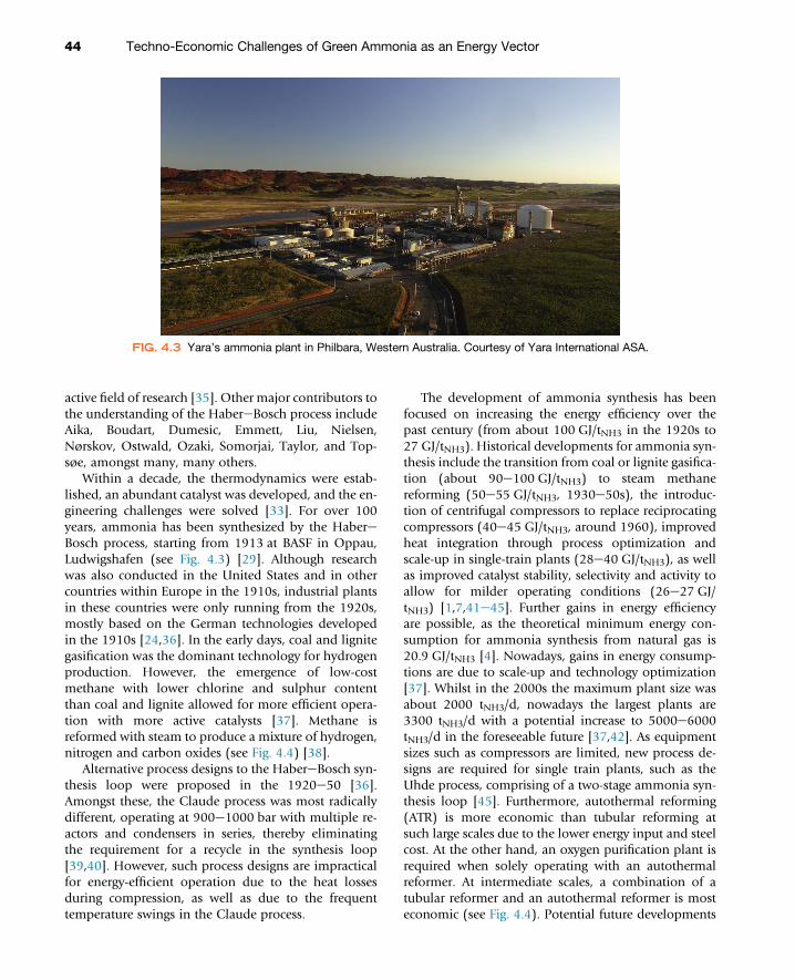
Within a decade, the thermodynamics were estab-lished, an abundant catalyst was developed, and the en-gineering challenges were solved [33]. For over 100years, ammonia has been synthesized by the HabereBosch process, starting from 1913 at BASF in Oppau,Ludwigshafen (see Fig. 4.3) [29]. Although researchwas also conducted in the United States and in othercountries within Europe in the 1910s, industrial plantsin these countries were only running from the 1920s,mostly based on the German technologies developedin the 1910s [24,36]. In the early days, coal and lignitegasification was the dominant technology for hydrogenproduction. However, the emergence of low-costmethane with lower chlorine and sulphur contentthan coal and lignite allowed for more efficient opera-tion with more active catalysts [37]. Methane isreformed with steam to produce a mixture of hydrogen,nitrogen and carbon oxides (see Fig. 4.4) [38].
Alternative process designs to the HabereBosch syn-thesis loop were proposed in the 1920e50 [36].Amongst these, the Claude process was most radicallydifferent, operating at 900e1000 bar with multiple re-actors and condensers in series, thereby eliminatingthe requirement for a recycle in the synthesis loop[39,40]. However, such process designs are impracticalfor energy-efficient operation due to the heat lossesduring compression, as well as due to the frequenttemperature swings in the Claude process.
The development of ammonia synthesis has beenfocused on increasing the energy efficiency over thepast century (from about 100 GJ/tNH3 in the 1920s to27 GJ/tNH3). Historical developments for ammonia syn-thesis include the transition from coal or lignite gasifica-tion (about 90e100 GJ/tNH3) to steam methanereforming (50e55 GJ/tNH3, 1930e50s), the introduc-tion of centrifugal compressors to replace reciprocatingcompressors (40e45 GJ/tNH3, around 1960), improvedheat integration through process optimization andscale-up in single-train plants (28e40 GJ/tNH3), as wellas improved catalyst stability, selectivity and activity toallow for milder operating conditions (26e27 GJ/tNH3) [1,7,41e45]. Further gains in energy efficiencyare possible, as the theoretical minimum energy con-sumption for ammonia synthesis from natural gas is20.9 GJ/tNH3 [4]. Nowadays, gains in energy consump-tions are due to scale-up and technology optimization[37]. Whilst in the 2000s the maximum plant size wasabout 2000 tNH3/d, nowadays the largest plants are3300 tNH3/d with a potential increase to 5000e6000tNH3/d in the foreseeable future [37,42]. As equipmentsizes such as compressors are limited, new process de-signs are required for single train plants, such as theUhde process, comprising of a two-stage ammonia syn-thesis loop [45]. Furthermore, autothermal reforming(ATR) is more economic than tubular reforming atsuch large scales due to the lower energy input and steelcost. At the other hand, an oxygen purification plant isrequired when solely operating with an autothermalreformer. At intermediate scales, a combination of atubular reformer and an autothermal reformer is mosteconomic (see Fig. 4.4). Potential future developments
FIG. 4.3 Yara’s ammonia plant in Philbara, Western Australia. Courtesy of Yara International ASA.
44 Techno-Economic Challenges of Green Ammonia as an Energy Vector

include the development of more active catalysts, whichmay lower the temperature and pressure in theammonia synthesis loop to about 30 bar (i.e. the pres-sure of the steam methane reforming section) [46],although this can increase the energy consumption forammonia condensation and the refrigeration compres-sion [7].
Synthetic ammonia is classified as brown ammonia,blue ammonia and green ammonia. Brown ammonia re-fers to ammonia synthesized with hydrogen productionbased on carbon sources, such as methane, naphtha,heavy fuel oil and coal. Fossil hydrogen producedfrom coal, natural gas and lignite is referred to as black,grey, and brown hydrogen, respectively [48]. Amongstthese technologies, the ammonia synthesis processbased on methane as a feedstock with steam methanereforming (SMR) for hydrogen synthesis is primarilyused. A process scheme of a steam methanereforming-based ammonia synthesis process is shownin Fig. 4.4. Ammonia synthesis technologies emit about2.0 tCO2/tNH3 on average (see Table 4.1). The total CO2equivalent emissions have decreased from about 33.4million tCO2 in 1990 to 23.9 million tCO2 in 2016within the European Union [49]. About two-third ofthe CO2 is produced during the reforming of hydrocar-bons, whilst a third is required for the fuel combustion
for the synthesis plant (about 7.2e9.0 GJ/tNH3 [50]).Brown ammonia synthesis technologies are discussedextensively in various references [4,44,51e56]. As listedin Table 4.1, the best synthetic ammonia productionprocesses already outperform nitrogenase in nature interms of energy efficiency (see Fig. 4.5). Although theHabereBosch process is an energy-intensive process,the net energy consumption is low. The synthesis pres-sure for the steam methane reforming section is typi-cally 30 bar, whilst the synthesis loop operates at100e300 bar.
Decarbonization of heating through electric heatingis a recent trend for the chemical industry [57,58]. Inthe case of brown ammonia synthesis, electric heatingfor steam methane reforming is proposed to decreasethe methane consumption for heating purposes [59].The footprint of electrified steam methane reformingis about two orders of magnitude smaller than gas-fired steam methane reforming [59]. Furthermore,the start-up of electrified steam methane reforming isonly a few minutes, as compared to hours or evendays for the conventional, fire-heated steam methanereformers. Electrification of ammonia synthesis plantsis attractive in areas with low cost, abundant renewableelectricity, as was already pointed out by Ernst in the1920s [23].
FIG. 4.4 Process scheme of steam methane reforming-based ammonia synthesis. (Reprinted from HellmanA, Honkala K, Dahl S, Christensen CH, Nørskov JK. Ammonia synthesis: state of the bellwether reaction. In:Comprehensive inorganic chemistry (II). 2nd ed. Elsevier Ltd;2013. with permission of Elsevier Ltd.)
CHAPTER 4 Ammonia Production Technologies 45

Blue ammonia is classified as ammonia synthesizedin a similar manner as brown ammonia, with a lowernet carbon footprint. This reduced carbon footprintcan be obtained by combining hydrogen productionprocesses with carbon capture storage (CCS). Electrifica-tion of heating processes within steammethane reform-ing (eSMR) can also reduce the carbon footprint [59].Hydrogen can also be obtained as a byproduct in otherprocesses, resulting in a lower carbon footprint forammonia synthesis. Ethylene crackers, chlorine plants,carbon black plants and plastic gasification plants areexamples of sources for byproduct hydrogen with areduced carbon footprint [62,63].
Green ammonia can be classified as ammonia syn-thesized with essentially zero carbon footprint. Greenammonia can be produced along various pathways,namely with conventional technology for the ammoniasynthesis loop combined with electrolysis-basedhydrogen (see Fig. 4.6) and with nonconventional tech-nologies for ammonia synthesis. Before the availability
of cheap natural gas in the 1950s and onwards,electrolysis-based ammonia synthesis with hydropowerwas one of the most used technologies, only second tocoal gasification. Lastly, biomass-based hydrogen pro-duction with carbon capture storage can be consideredas an alternative for small scale, green ammonia synthe-sis [64e67].
In the 1920s, the first electrolysis-based HabereBosch process started operation, with an energy con-sumption of about 46e48 GJ/tNH3 [23,40]. Four driverscan be identified for the production of green ammonia,namely the sustainability of the reactants, a low energyconsumption, modular scalability, and economicviability [23,68,69]. Green ammonia technologiesbased on the conventional, high-pressure ammoniasynthesis loop with electrolysis-based hydrogen are dis-cussed in Section 4.4-4.9. The theoretical minimum en-ergy required for ammonia synthesis from water and airis 22.5 GJ/tNH3 [44]. Nonconventional technologies arediscussed in Section 4.10.
TABLE 4.1Energy Requirement and CO2 Footprint of Brown Ammonia, Blue Ammonia, and Green Ammonia Based onthe Conventional High Pressure Ammonia Synthesis Loop. The Best Available Technology (BAT)Represents the BAT in the Year 2020, Whilst the Potential Represents the Year 2050.
ENERGY REQUIREMENT(GJ/tNH3)
CO2 FOOTPRINT(tCO2/tNH3)
Relative IInvestmentBAT Potential BAT Potential
Brown ammonia 26 26 1.6 1.6 1.0
SMR 26 26 1.6 1.6 1.0
Naphtha 35 e 2.5 e 1.1e1.2
Heavy fuel oil 38 e 3.0 e 1.5
Coal 42 e 3.6 e 1.8e2.1
Blue ammonia 33 26 0.4 0.2 1.5
Byproduct hydrogen e e 1.5e1.6 0.6 e
SMR with CCS 33 27 0.4 0.2 1.5
Coal with CCS 57 e 1.0e2.0 0.5 2.5e3.0
eSMR e 26 e 1.1 1.0
Green ammonia 33 26 0.1 0.0 1.2e1.5
Low temperature electrolysis 33 31 0.1 0.0 1.2e1.5
High-temperature electrolysis e 26 e 0.0 1.5e2.0
Biomass (with CCS) e 33 1.1e1.2a 0.5a 1.2e3.0
Global average 35 27 2.0 1.4
a The CO2 emitted is part of a short carbon cycle, as opposed to the CO2 emitted for natural gas, naphtha, heavy fuel oil, and coal feedstocks.Estimates based on [37,42,44,50,60e62,65,66,69e72].
46 Techno-Economic Challenges of Green Ammonia as an Energy Vector

ELECTROLYSIS-BASED HYDROGENPRODUCTIONGreen hydrogen can be synthesized by electrolysis. Thenet reaction is given by Eq. (4.4), and the heat of reac-tion is DHr
0 ¼ 250 kJ/molH2, indicating a high energyrequirement either through heating or electrical energy(or the combination of both) [73]. The thermal decom-position of water is not discussed here, as this is mainlyrelevant for the steam reforming of hydrocarbons.
2H2O/2H2 þO2 (4.4)
Electrolysis is performed in an electrolysis cellcomposed of an electrolyte (the ion conductor), activelayers for the redox reactions, and a current andmaterialcollector (the electronic conductor), which enables theelectricity supply, as well as the supply and collectionof reactants and products [74]. Electrolysis systemsalso require gas cooling, purification, compression,and H2 storage capacity [75]. Furthermore, safety andcontrol systems are installed to condition the powerfrom the power source [76]. Pretreatment of the feedwater is performed by mechanical vapour compression,
0
100
200
300
400
1900 1925 1950 1975 2000 2025 2050 2075
Ener
gy c
onsu
mpt
ion
(GJ /
t NH3
)
Year
Nitrogenase
Synthetic nitrogen fixation
Birkeland-Eyde process
Frank-Caro process
Haber-Bosch process
Steam methane reforming Electrolysis Coal gasification
FIG. 4.5 Energy consumption nitrogenase and energy consumption of best available technology (BAT) fordominant synthetic nitrogen fixation processes. (Based on Patil BS, Hessel V, Seefeldt LC, Dean DR,Hoffman BM, Cook BJ, et al. Nitrogen fixation. In: Ullmann’s encyclopedia of industrial chemistry. 2017; Smil V.Enriching the earth: Fritz Haber, Carl Bosch, and the transformation of world food production. Cambridge (MA);2004; CEFIC. European chemistry for growth: unlocking a competitive, low carbon and energy efficient future[Internet]. 2013. Available from: http://www.cefic.org/Documents/RESOURCES/Reports-and-Brochure/Energy-Roadmap-The Report-European-chemistry-for-growth.pdf; Hansen JB, Han P. The SOC4NH3 projectin Denmark. In: NH3 event. Rotterdam (The Netherlands); 2019.)
FIG. 4.6 Schematic of green ammonia synthesis process with electrolysis-based hydrogen production.
CHAPTER 4 Ammonia Production Technologies 47

reverse osmosis or electrodialysis, depending on thefeed impurities, purity required and scale of application[77,78].
Various technologies for electrolysis are commer-cially available, such as alkaline electrolysis and protonexchange membrane (PEM) electrolysis (see Table 4.2).Some technologies are in the demonstration stage, suchas solid oxide electrolysis. Other technologies areresearched in academia, such as anion exchange mem-brane electrolysis [73]. The efficiency and capital costof the system depend on the scale of the application.
All commercial systems have load responses in theseconds range in hot standby [79], which is requiredfor adequate coupling with intermittent renewableelectricity sources. However, in cold standby, PEM elec-trolysis is the only technology capable of rampingwithin seconds. The schematic representation ofalkaline electrolysis, PEM electrolysis and solid oxideelectrolysis are shown in Fig. 4.7.
Alkaline electrolysis operates with electrodesimmersed in a liquid electrolyte (20e40 wt.% KOH),separated by a diaphragm. OH� ions pass through the
TABLE 4.2Electrolysis Technologies.
Alkaline PEM Solid Oxide
Temperature (�C) 60e90 50e80 600e1000
Pressure (bar) 1e30 10e200 1e25
System energy consumption (GJ/tNH3) 29e46 31e46 24e27
Current density (A/cm) 0.2e0.45 0.6e2.0 0.3e2.0
Hydrogen purity (vol.%) >99.5 99.99 99.9
Maximum installed capacity (MW) 165 20 0.2
Load range (%) 10e110 0e160 20e100
Installed capital cost (kV tp/dNH3-) 2020 165e465 365e600 935e18652030 135e285 215e500 265e935Long term 65e235 65e300 165e335
Electrolyte 20e40 wt.% KOH Nafion YSZ/SSZ
System size Large Compact Compact
Stack lifetime (h �1000) 2020 60e90 30e90 10e302030 90e100 60e90 40e60Long term 100e150 100e150 75e100
Technology readiness level (TRL) 9 8e9 5e6
Estimates based on [48,61,73,79,85e87].
FIG. 4.7 Schematic representation of electrolysis systems: (A) alkaline electrolysis, (B) PEM electrolysis and(C) solid oxide electrolysis. (Reprinted from Steinmüller H, Reiter G, Tichler R, Friedl C, Furtlehner M, LindorferJ, et al. Power to Gas - eine Systemanalyse: Markt- und Technologieschouting und -analyse [Internet]. Linz;2014. Available from: https://www.ea.tuwien.ac.at/fileadmin/t/ea/projekte/PtG/Endbericht_-_Power_to_Gas_-_eine_Systemanalyse_-_2014.pdf with permission of TU Wien.)
48 Techno-Economic Challenges of Green Ammonia as an Energy Vector

diaphragm, forming hydrogen at the cathode (Ni orNieMo), and oxygen and water at the anode (Ni or NieCo). From the 1920s up to the 1990s, alkaline electro-lysers were typically used to produce hydrogen incountries with hydropower resources such as Egypt,Norway and Peru, after which steam methane reform-ing took over [23,24,48]. Novel approaches to enhancethe performance (and energy efficiency) include thedecoupling of the hydrogen evolution and oxygenevolution reactions by a two-step cycle [81], and thecombination of a battery function and an electrolyserfunction in a single unit [82,83].
In the case of PEM electrolysis protons pass throughthe membrane. At the cathode (Pt or PtePd), the pro-tons are recombined to form hydrogen and at the anode(RuO2 or IrO2) protons and oxygen are produced.Because of the corrosive acidic condition of the mem-brane, noble metals are used for the electrodes, leadingto high capital costs for PEM electrolysis [73]. Platinumreplacements such as molybdenum disulphide andphosphides may lower the costs with a performanceclose to platinum [84]. Improving the stability of suchmaterials is one of the key research focuses.
Solid oxide electrolysis operates with steam ratherthan liquid water, reducing the electrical energydemand for hydrogen production. Thus, solid oxideelectrolysers can operate at a lower energy input thanalkaline electrolysis and PEM electrolysis (a minimumenergy input of about 250 kJ/molH2 instead of 285 kJ/molH2). At the cathode (Ni or FeCr), hydrogen isproduced, whilst oxygen anions pass through theyttria-stabilized zirconia (YSZ) or scandia-stabilizedzirconia (SSZ) membrane to recombine to oxygenover the perovskite-type lanthanum strontium manga-nese or anthanum strontium cobalt ferrite anode. Abenefit of solid oxide electrolysers is the possibility ofproducing the hydrogen and nitrogen feed in a singleunit, thereby omitting the need for a separate nitrogenproduction unit [61]. This is facilitated by the combus-tion of oxygen from air with part of the producedhydrogen. Solid oxide electrolysers are expected to becommercially available at the MW scale in 2025e30[61,73,88]. Current research focuses on cost reductionand increasing the performance at reduced tempera-tures (from about 1000 to 600�C), thereby increasingthe lifetime of the stack [89]. Apart from oxygenanion-conducting membranes, proton-conductingmembranes are also investigated, potentially allowingfor operation at lower temperatures (400e700�C) andhydrogen production without moisture content[90e92].
Combinations of electrolysis-based hydrogen andhydrogen derived from methane are also proposed.
For instance, a hybrid plant with a solid oxide electro-lyser and an ATR can be beneficial, as purified oxygenis required for the autothermal reformer and suppliedby the solid oxide electrolyser. An autothermal reformeroperates via partial combustion of methane with puri-fied oxygen and is especially attractive for large-scaleammonia synthesis due to the expensive oxygen purifi-cation plant, which is only economically viable at largescales. In a solid oxide electrolyser, purified oxygen isproduced in any case, potentially making autothermalreforming feasible at smaller scales. Such a configura-tion can save up to 22% in terms of natural gasconsumption [88].
BIOMASS-BASED HYDROGENPRODUCTIONBiomass-based hydrogen production is an alternativefor electrolysis-based hydrogen production for small-scale ammonia synthesis [64e67]. In industrializedcountries, about 9%e13% of the total energy supplyis facilitated by biomass, making it the most usedrenewable to date [93]. In developing countries, thisfigure is as high as 20%e35% [93]. By the end of the1990s, about 40 GW biomass capacity was installedworldwide [93]. Typical biomass-based facilities arelimited by the logistics (i.e. the supply of biomass),implying plant capacities are usually below 50 MW[94]. The key metric for the cost of hydrogen is thecost of biomass, which strongly depends on the typeof biomass and the location.
Biomass-based hydrogen can be produced via boththermochemical processes and biochemical processes[98,101]. Various biomass-based hydrogen synthesistechnologies are listed in Table 4.3. A benefit ofbiomass-based hydrogen production is the compati-bility with the technologies used in conventional brownhydrogen production process. The products of thermo-chemical or biochemical processing of the biomass arethe feedstock of the steam methane reforming reactor,as used in brown ammonia synthesis. A drawback ofbiomass-based hydrogen production is the complexprocessing of the biomass [48]. Furthermore, thetechnical potential of biomass to satisfy the demandfor hydrogen is orders of magnitude smaller than thatof renewable electricity resources, such as tidal, solarand wind, due to the limited availability of biomass[48]. Typical sources of biomass include bagasse, crops,straw, switchgrass, wood and wood chips [100e103].The typical products of biomass processing are biogas,bio-oil and biochar [98]. An alternative for naturalbiomass feedstocks is the recycling of municipal waste[104]. An example of a waste-to-ammonia process is
CHAPTER 4 Ammonia Production Technologies 49

the use of recycled plastic, as is in operation in Japan forselective catalytic reduction purposes [105].
In the case of thermochemical processes, thebiomass is either converted into bio-oil, gas and charvia pyrolysis or into a mixture of hydrogen, carbonmonoxide, carbon dioxide and methane via gasification[48,99]. A benefit of thermochemical processes overbiochemical processes is that no microorganisms needto be added for the conversion [98]. Furthermore,biochemical processes have slow kinetics and largereactors due to the near-ambient operation [100].
Pyrolysis is the thermal decomposition of biomass athigh temperatures (350e750�C) in the absence of areactive, oxidative environment. The major product ofpyrolysis is bio-oil (45e70 wt.%), the remainder beinggases (10e35 wt.%) and char (15e25 wt.%) [98]. Thedirect production of hydrogen from pyrolysis is insuffi-cient for commercial applications, even in the presenceof a catalyst. Therefore, the products of pyrolysis need tobe processed to syngas in a steam reformer.
Biomass gasification is a direct pathway for syngasproduction, as all of the biomass feedstock can be con-verted directly to gaseous products [97,99]. Biomassgasification gained attention in the 1980s [93]. Thisprocess scheme is similar to that of coal gasification,which allows for some blending in biomass in coalfeedstocks to minimize the carbon footprint. Chemicaland physical reactions occurring in the biomass gasifica-tion process include drying, pyrolysis, reduction andcombustion [98]. There are some demonstration plants
for biomass gasification [48]. Current technologicalchallenges include catalyst poisoning due to the forma-tion of tars [48]. Sorbents such as CaO can be used toremove CO2 in situ, thereby shifting the equilibriumposition for the water gas shift reaction [98]. In thecase of steam gasification, the thermal energy-to-hydrogen efficiencies can attain 35%e52% [98].
In the case of biochemical processes, microorgan-isms convert biomass into biogas via anaerobic diges-tion or into acids, alcohols and gases via fermentation[48,98]. Anaerobic digestion converts biomass intobiogas in the absence of oxygen, whilst in the presenceof microorganisms. The process operates at near-ambient conditions (20e80�C). The biogas producedfrom anaerobic digestion typically contains primarilymethane (50e75 wt.%), as well as a substantial portionof CO2 (25e50 wt.%). Anaerobic digestion is one ofthe most technologically advanced biomass conversiontechnologies, but only part of the biomass can be pro-cessed, such as process sewage sludge, agriculturalwaste, food processing waste, household waste andenergy crops [48].
The fermentation of biomass is can produce variousproducts in the presence of enzymes, such as acids, alco-hols and gases. The non-edible cellulosic parts of plantscan be processed in the case of fermentation [48]. Adrawback of such biochemical processes is thenear-ambient operation, implying slow kinetics andlarge reactors [100]. Lastly, vegetable oil fromenergy crops can be converted into glycerol via
TABLE 4.3Technologies for Biomass-Based Hydrogen Production. For Reference, the Best Steam MethaneReformers Operate at 26 GJ/tNH3.
THERMOCHEMICAL BIOCHEMICAL
Pyrolysis Gasification Anaerobic Fermentation
Temperature (�C) 350e750 500e1150 20e80 30e70
Pressure (bar) 1e5 225e350 1 1
Energy consumption (kWh/mH23) e 7.1e10.1 e e
(GJ/tNH3) e 50e72 e e
Hydrogen yield (vol.%) e 20e65 e e
Biomass conversion products Bio-oil, gas, char H2, CO, CO2, CH4 Biogas Acids, alcohols, gases
Capacity range (MW) 0.1 0.1e100 <10 <2
Load range (%) e e e e
Cost of hydrogen (V/kg) 2020 e >1.3 e ePotential e 0.6e1.1 e e
TRL 3e5 5e7 6e9 9
Estimates based on [48,93,95e100].
50 Techno-Economic Challenges of Green Ammonia as an Energy Vector

transesterification, which can be converted into syngas[98]. The typical operation conditions for transesterifi-cation of vegetable oils are 50e80�C and ambientpressure, in the presence of a base [100].
Biogas from biomass can be combined with renew-able electricity as well. An example of such a system isanaerobic digestion for biogas production combinedwith electrified tubular steam reforming reactors.Another example is the combination of a biogas reactorwith a solid oxide electrolyser and an autothermalreformer.
NITROGEN PURIFICATIONPurified nitrogen gas is produced from the air usingvarious technologies, namely an air separation unit(ASU, cryogenic distillation), pressure swing adsorption(PSA), membrane permeation and hydrogen combus-tion [106]. In steam methane reforming, the air isusually introduced in the hydrogen production section,and the oxygen is combusted with part of the hydrogen.Hydrogen combustion can be employed in a solid ox-ide electrolyser to generate the heat for the hydrogenproduction from water [61,107]. The three other tech-nologies can be employed in combination with alkalineor PEM electrolysers, where the hydrogen and nitrogenare produced in separate units (see Table 4.4).
The preferred alternative depends on the requirednitrogen purity and the scale of application [108]. Forboth pressure swing adsorption and membrane perme-ation, a deoxo system is required to remove residualoxygen content [106]. Oxygen is removed by catalyticcombustion with hydrogen, after which the water isremoved in a regenerative dryer [106]. Oxygen must
be removed before the gas mixture enters the synthesisloop, as oxygen compounds are detrimental for theammonia synthesis catalyst. Nitrogen purification isdiscussed in various references [106,108,109].
AMMONIA SYNTHESIS LOOPAmmonia synthesis from nitrogen and hydrogen is anexothermic process favored by a decrease in tempera-ture and an increase in pressure (see Fig. 4.8). However,due to the limited activity of industrially appliediron-based catalysts for breaking the N^N triple bondand the desorption limitations for ammonia [111],typical operating conditions are 350e550�C and100e450 bar [44,78,112,113]. As shown in Fig. 4.8,near-complete conversion to ammonia is not achiev-able under industrially relevant conditions. Thus, asignificant recycle is required in the HabereBoschprocess.
A typical industrial ammonia synthesis process isshown in Fig. 4.4. After the production of hydrogenand nitrogen feed in the steam methane reforming sec-tion, the nitrogen and hydrogen feed is compressed to100e450 bar and combined with the recycle. Thisstream is fed into the ammonia synthesis reactor atabout 300e350�C into a multiple bed reactor andfeed is converted to about 15e20 mol.% ammoniawith an outlet temperature of about 450e500�C [47].Then, ammonia is separated from the nitrogen andhydrogen gases by condensation at �20 to 30�C. About2e5 mol.% ammonia is fed back to the ammonia syn-thesis reactor with the recycle stream [44], which is dueto the substantial ammonia vapour pressure at separa-tion conditions (see Fig. 4.9). Some industrial processes
TABLE 4.4Nitrogen Purification Technologies.
ASU (Cryogenic) PSA Membrane
Temperature (�C) �195 to �170 20e35 40e60
Pressure (bar) 1e10 6e10 6e25
Purity (wt.%) 99.999 99.8 99.5a
Energy consumption (kWh/kgN2) 0.1 0.2e0.3 0.2e0.6(GJ/tNH3) 0.3 0.7e1.0 0.7e2.0
Capacity range (Nm3/h) 250e50000 25e3000 3e3000
Load range (%) 60e100 30e100 e
Investment cost (kV/tpdNH3) <8 4e25 25e45
TRL 9 9 8e9
a In most cases membranes are used for nitrogen enrichment of air, rather than the production of highly purified nitrogen.Estimates based on [78,106,108e110].
CHAPTER 4 Ammonia Production Technologies 51

combine the feed with the recycle before the ammoniasynthesis reactor, whereas other processes combine thefeed with the recycle before the condenser [44].
CatalystsAfter the development of the multiple promoted ironcatalyst by Mittasch et al. in 1909e12 from Gallivaremagnetite (an iron ore from Sweden), the industriallymost used catalyst has remained remarkably similar.Whilst the catalyst formulation in the first part of the20th century was mostly focused on stability againstchemical poisoning by sulphur and chlorine com-pounds, afterwards the focus has been on the catalyticactivity due to a reduced fraction of catalyst poisonsin the synthesis loop. Iron catalysts derived from
magnetite ore (Fe3O4) with structural promoters for sta-bility enhancements (Al2O3, CaO, MgO, SiO2) andelectronic promoters for activity enhancement (K2O)are mostly used in industry due to the very high thermalstability and chemical stability against oxygen species.The catalyst is activated by reducing the iron oxide tometallic iron, whilst the promoters remain in theiroxide phases. The reaction mechanism via dissociativenitrogen adsorption, subsequent hydrogenation, anddesorption of ammonia from iron-based catalysts iswell understood [31,32,47,115,116], and the reactionrates of industrial catalysts can be modeled with micro-kinetic models over a wide range of conditions[47,117,118]. Ultrahigh vacuum surface science withideal Fe surfaces was successfully applied to predict
0
20
40
60
80
100
150 200 250 300 350 400 450
Equi
libriu
m N
H3
cont
ent (
mol
.%)
Temperature (°C)
1 bar15 bar150 bar
FIG. 4.8 Ammonia equilibrium mole fraction for various temperatures and pressures. H2:N2 ¼ 3:1, no inert.
0
5
10
15
20
-50 -25 0 25 50
NH
3va
pour
pre
ssur
e(b
ar)
Temperature (°C)FIG. 4.9 Ammonia vapour pressure as function of temperature. (Antoine parameters reproduced from StullDR. Vapor pressure of pure substances. Organic and inorganic compounds. Ind Eng Chem. 1947;39(4):517e540.)
52 Techno-Economic Challenges of Green Ammonia as an Energy Vector

the catalytic reaction over iron-based catalysts underindustrial conditions, bridging a ‘pressure gap’ of nineorders of magnitude [117,119].
The first development in iron-based catalyst was theintroduction of about 5 wt.% Co to the iron oxide. Theintroduction of Co to the iron oxide lowers the reduc-tion temperature, which increases the exposure of themost active Fe(111) plane for ammonia synthesis anddecreases ammonia desorption limitations [44,120].Another development is the use of wüstite (Fe1-xO)rather than magnetite during the preparation [121],which changes the distribution of promoters in thecatalyst. As compared tomagnetite-based catalysts, wüs-tite-based catalysts are known to have a lower reductiontemperature and less hydrogen inhibition at lowtemperatures [121]. However, the thermal stability ofwüstite-based catalysts is lower than that ofmagnetite-based catalysts [122]. This is due to a lowerstabilizing effect of Al2O3 in wüstite-based catalysts,which is replaced by MgO and CaO [121]. Recent aca-demic contributions to industrial iron-based catalystsinclude the addition of Co to wüstite-based catalyst[123], the addition of iron nanoparticles to maximizethe iron surface area [124], and the addition of rareearth metals to the iron oxide precursor [125].
Ruthenium-based catalysts are also industriallyapplied for ammonia synthesis. Ruthenium-based cata-lysts are more active than iron-based catalysts at lowpressures and at high conversions, due to less ammoniadesorption limitations [126,127]. Ruthenium-basedcatalysts were developed and patented in the industryin the 1970 and 1980s [44], whilst academic researchwas also conducted (especially in Japan) [128e132].A multiple promoted ruthenium catalyst supportedon activated carbon was developed, which is used inthe Kellogg Advanced Ammonia Process (KAAP). Anenergy saving of about 1.17 GJ/tNH3 was achieved ascompared to iron-based processes [44]. Furthermore,the capital cost of the KAAP process is lower than con-ventional processes, due to the lower operating pressureand the single-stage synthesis gas compressor, albeit at ahigher catalyst cost [33,54]. A drawback of ruthenium-based catalysts is the scarcity, making scale-up to allammonia synthesis plants difficult [133]. Processeswith ruthenium-based catalysts generally operate atlower pressures as well as lower H2:N2 ratios than thosewith iron-based catalysts, due to the hydrogen inhibi-tion on ruthenium-based catalysts [44,112].
As opposed to bulk iron-based catalysts, ruthenium-based catalysts consist of ruthenium nanoparticlessupported on an activated carbon (AC) support oroxide support [44,47,116]. Alkali (Cs, K) and alkaline
earth metals (Ba) are introduced to electronically in-crease the activity by orders of magnitude [134,135].The KAAP process uses a Ru/AC catalyst with Ba andK promoters. Methanation of the carbon support is anissue for Ru/AC catalysts, causing a shorter catalystlifetime. The Ba reduces the rate of methanation ofthe support, stabilizes the nanoparticles and maximizesthe number of active sites for ammonia synthesis [136].Alkali promoters (Cs, K) enhance the nitrogen dissocia-tion rate and lower the surface coverage of NHX specieson the catalyst species [115,136].
Process ConditionsThe choice of the catalyst has little influence on theoperating efficiency of the synthesis loop [53,137].However, the operating temperatures and pressuresvary depending on the choice of catalyst (see Table 4.5).This becomes especially relevant upon scale-down andintermittent operation, as milder operating conditionslead to less heat losses upon decreasing degree of heatintegration. Furthermore, green hydrogen productionimplies a change in heat and mass flows in the process,thereby requiring different heat integration schemes[56,138]. Various catalysts are often combined in a sin-gle reactor with different beds [139,140]. Typically,ammonia synthesis reactors are multiple-bed adiabaticreactors [45,55]. The first beds operate at high tempera-tures (up to 500e550�C), whilst later beds operate atmilder temperatures. Thus, highly stable catalysts athigh temperatures are mostly preferred for the firstbeds, whereas the activity at mild conditions is increas-ingly important for the last beds.
SCALE-DOWN AND INTERMITTENCYRecent trends in ammonia synthesis technologies arefurther scale-up for minor improvements in energyconsumption (mega conventional, mostly for brownand blue ammonia production), and scale-down forcoupling with intermittent, renewable energy sources(small decentralized, for green ammonia) [88]. Decen-tralization of ammonia synthesis processes is mainlyconducted along two pathways, namely by using theconventional electrolysis-based Haber-Bosch technol-ogy, and by using nonconventional technology withmilder reaction and separation conditions [46]. Thenonconventional technologies are discussed in section4.10.
Up to the 1990s, electrolysis-based HabereBoschprocess was operated in various places with hydropower,such as Norway and Peru [143]. Thus, electrolysis-basedHabereBosch processes are proven technology at large-
CHAPTER 4 Ammonia Production Technologies 53

scale operation (300 tNH3/d with alkaline electrolysers of135 MW capacity). Currently, only one large-scale, alka-line electrolysis-based HabereBosch plant with hydro-power resources remains operational in Cusco, Peru(built in 1962). The current aim is to operate theseelectrolysis-based HabereBosch processes as energy effi-cient as possible and at the scale of single wind turbinesor at the scale of solar or wind farms. Demonstrationplants were recently opened in various countries,including Japan and the United Kingdom. Demonstra-tion plants in the United States include solar-poweredsystems and wind-powered systems located in areaswith extensive farmlands [144e148]. Commercial PEMelectrolysis-based HabereBosch plants operating witha PSA unit and a high-pressure ammonia synthesisloop are in operation in various countries includingArgentina, China and Switzerland [149,150]. A benefitof small-scale plants (�50 tNH3/d) is that these are notconsidered as industrial sites, implying regulatory obsta-cles are usually smaller [151].
Upon scale-down, heat losses increase and theenergy consumption increases (see Fig. 4.10). A large-scale ammonia plant (�1000 tNH3/d) consumes about2e7 GJ/tNH3 for pressurizing, heating, pumping andutilities [56]. At intermediate scales (3e20 tNH3/d),this energy consumption increases to typically13e14 GJ/tNH3 [152,153]. At ammonia synthesis scalesdown to 5 tNH3/d, losses in high-pressure synthesis pro-cesses are primarily due to scale effects. At very smallscales (<0.1 tNH3/d), heat is even required to keep theammonia synthesis reactor at the synthesis temperature
due to radial heat losses, and hydrogen and nitrogenproduction also becomes less efficient [147,154,155].Thus, milder operating conditions in the synthesisloop are required for effective scale-down.
As shown in Fig. 4.10, the energy consumption is afunction of the ammonia synthesis capacity. The energyconsumption of electrolysis-based HabereBosch pro-cesses can be estimated based on Eq. (4.5), which isvalid in the range 101e106 kgNH3/h capacity.
E ¼ (52.58*log10(capacity in kg/h))�0.30 (4.5)
Intermittent solar power and wind power cause var-iations in electricity supply. Therefore, the synthesisloop should either be able to ramp up and down fast,or batteries should be installed to operate the synthesisloop at constant load. The latter option is technicallyfeasible, but expensive [69]. Ramp up and down canbe achieved to some extent by varying the H2:N2 ratiowithin the synthesis loop [46]. Nitrogen can be usedas an inert in the synthesis loop when low amounts ofhydrogen are present. However, ammonia must bepresent in the synthesis loop to enable condensation.Upon ramping down, the energy consumption peramount of ammonia produced can drastically increase[78], although control strategies have been proposedwith a minimum increase in energy consumption[156]. To put ramping up and down in perspective:the cold start-up time of large-scale plant takes one to2 days [70]. Thus, shut-down can be considered whenelectricity supply is not available for a few weeks (i.e.beyond the storage time of a battery). Again, milder
TABLE 4.5Comparison of SMR-Based Ammonia Synthesis Processes With Commercial Iron-Based and Ruthenium-Based Catalysts.
IRON RUTHENIUM
Fe3O4 Fe3O4 with Co Fe1-xO RueBaeK/AC
Year 1913 1979 1986 1992
Temperature (�C) 360e520 350e500 300e500 325e450
Pressure (bar) 120e450 100e300 100e250 70e100
Energy consumption (GJ/tNH3) 28 28 27e28 26e27
H2:N2 ratio 2e3 2e3 2e3 1.5e2
Catalyst lifetime (y) >14 e 6e10 �10
Relative activity 1.0 1.2 1.5 2e10
Thermal stability High Medium/Low Medium Low
Relative catalyst cost 1.0 1.5 1.1 150e230
Based on [4,44,78,112,141,142].
54 Techno-Economic Challenges of Green Ammonia as an Energy Vector

conditions in the synthesis loop are expected to enableintermittent operation at lower energy losses. Further-more, the separation of ammonia in the gas phaserather than by condensation can be beneficial for inter-mittent operation [46].
COST OF ELECTROLYSIS-BASEDHABEReBOSCH PROCESSESThe installed capital cost of an electrolysis-basedHabereBosch plant consists of equipment for hydrogenproduction, nitrogen production, ammonia synthesisand ammonia storage. Various cost-scaling relationswere proposed for alkaline electrolysis-based and PEMelectrolysis-based HabereBosch processes with a PSAfor nitrogen purification [108,157,158]. The installedcost of various electrolysis-based HabereBoschprocesses as well as some proposed scaling-relations isshown in Fig. 4.11.
The installed costs of various electrolysers and nitro-gen purification units are listed in Tables 4.2 and 4.4.About half to two-third of the investment is requiredfor the electrolyser, depending on the process scale[77,78]. The cost of electrolysers is expected to decreasein the next decade, as listed in Table 4.2. The cost ofelectrolysers scales with a factor 0.6 with an installedcapacity in the range 0.1e50 MW [157]. At larger scalesof 50e1000 MW, the cost-scaling increases from 0.6 to
0.85 for PEM electrolysis-based HabereBosch plants[65].
A cost-scaling relation based on installed costs ofammonia synthesis loops is given by Eq. (4.6), whereCIHB is the installed cost in V and X is the ammoniacapacity in tNH3/d (1 MWz3 tNH3 d�1). The cost-scaling relation is valid in the range 1e20 MW.
CIHB ¼2:0� 106 � X0:6 (4.6)
The most accurate cost-scaling relation includinghydrogen production, nitrogen production, ammoniasynthesis and ammonia storage was proposed by Mor-gan et al. [157]. The cost-scaling relation is given byEq. (4.7), where CItot is the installed cost in V and Xis the ammonia capacity in tNH3/d (1 MW e 3 tNH3/d).This cost-scaling relation is valid in the range of0.1e50 MW. For comparison, a biogas-based plantwith a capacity of 22.5 tNH3/d has an investment costof 14.4 MV [161]. Furthermore, an SMR-based plantwith a capacity of 1800 tNH3/d has an investment costof about 199 MV [4].
CItot ¼3:3� 106 � X0:6 (4.7)
The operating costs of an electrolysis-based HabereBosch process can be divided into the owner’s costs andthe electricity costs. About 75%e95% of the electricityis required for hydrogen production in the electrolyser
0
20
40
60
80
100
-1 0 1 2 3 4 5 6
Ener
gy co
nsum
ptio
n
Log10(kg/h NH3 capacity)
Haldor TopsøeLarge-scale AlkalineMorgan et al.MorrisNFUEL®PfrommSchmuecker et al.ThyssenKrupp
Current industrial SMR-based Haber-Bosch plants
First Haber-Bosch plants
(GJ/
t NH3
)
FIG. 4.10 Energyconsumption of various electrolysis-basedHaber-Boschprocesses (academic and industrialestimates). The bold line represents the thermodynamic minimum energy consumption (22.5 GJ/tNH3).(Reproduced and modified from Rouwenhorst KHR, Van Der Ham AGJ, Mul G, Kersten SRA. Islanded ammoniapower systems: technology review & conceptual process design. Renew Sustain Energy Rev. 2019;114.)
CHAPTER 4 Ammonia Production Technologies 55

in a large-scale electrolysis-based HabereBosch process[61,137,150,162]. As shown in Fig. 4.10, the electricityconsumption and cost depends on the scale andlocation of the plant. The owner’s costs are 120 kV/y/tpd for a 3 tNH3/d plant [78].
Hydrogen production is the major cost contributorfor ammonia synthesis. Various alternatives can beconsidered, depending on the location. The cost ofbrown hydrogen produced from steam methanereforming is 845e1585 V/t (excluding CCS, costs in-crease to 1305e2145 V/t with CCS) [48]. The cost ofelectrolysis-based, renewable hydrogen ranges frombelow 1440 V/t to above 3605 V/t, depending on thecumulative solar and wind load hours at a given loca-tion [48]. Electrified steam methane reforming can beconsidered when the electricity cost is below 15e25V/MWh, depending on the cost of natural gas at a givenlocation. As compared to electrolysis, a benefit of elec-trified steam methane reforming is the compatibilitywith existing steam methane reforming plants forhydrogen production, as well as the lower capitalinvestment.
Biomass-based ammonia with thermochemical pro-cessing typically costs 380e1875V/t, depending on thescale of application, the source of the biomass and thelocation [64,101e103]. The cost of ammonia producedfrom recycled municipal waste is as high as 2135 V/t[104].
NONCONVENTIONAL TECHNOLOGIESEven though green ammonia synthesis is feasible withthe technology existing for about a century, nonconven-tional technologies are widely researched to allow forscale-down, intermittent operation, and potentiallyhigher energy efficiencies [56]. Nonconventional tech-nologies focus on improving the catalytic ammoniasynthesis reaction at milder conditions, as well as onenhancing ammonia separation using sorbents.Research varies from fundamental concepts to the useof commercial materials at the pilot plant scale.Examples of research areas include nonconventionalheterogeneous catalysis, adsorbents, absorbents,non-thermal plasma technology, electrochemicalsynthesis, photochemical synthesis, homogeneouscatalysis, as well as chemical looping approaches[69,163e167]. The nonconventional technologies typi-cally allow for scale-down and operation in remoteareas. Thus, the economic risks of the innovations aresmaller as compared to conventional, large-scale plants,and a faster pace of innovation may occur.
Discoveries of new catalytic systems is nowadays acombination of experimental work in the laboratory,and computer-aided experiments [163,168,169].Comparative assessment with calculated ammoniasynthesis for heterogeneous catalysts has become reli-able in recent years [170]. Cross-cutting approachesamongst enzyme catalysis, homogeneous catalysis
1
10
100
1000
0.01 0.1 1 10 100 1000 10000
Inst
alle
d co
st(M€)
Ammonia capacity (t/d)
Morgan et al. (2014)Sánchez et al. (2018)Morris (2007)Proton Ventures (2014, 2017)Midwest BioEnergy Ltd (2015)SMR & Haber-Bosch (1998)
FIG. 4.11 Estimated and realized installed cost of electrolysis-based HabereBosch processes with PSA fornitrogen production. The estimated installed cost of Morgan et al. Sánchez et al., and Morris plant includeequipment for H2 production, N2 production, NH3 synthesis and storage. The quota from Proton Ventures onlyincludes the NH3 synthesis loop. The Midwest BioEnergy Ltd. plant is based on biogas rather than electrolysis.As a point of reference, a 1800 tNH3/d SMR-based ammonia plant is included as well (lump turnkey cost ofplant). (Based on [4,78,108,157,159,160].)
56 Techno-Economic Challenges of Green Ammonia as an Energy Vector

and heterogeneous catalysis also allow for new insightsand potential pathways towards ammonia synthesisunder milder conditions and at sufficiently high rates[163,171]. An example of this is the similarity betweenheterogeneous catalysis over ruthenium-based catalystsand enzyme catalysis in MoFe6S9 complexes [171].Furthermore, progress is made for in situ and operandospectroscopy, which increases the understanding of theammonia synthesis reaction under relevant conditions[163].
The nonconventional technologies researched arelisted in Table 4.6. It should be noted that some tech-nologies have been investigated even before the HabereBosch process, such as plasma technology and thermo-chemical looping, being commercialized as theBirkelandeEyde process and the FrankeCaro process(see Fig. 4.5) [1,43]. Furthermore, novel approachessuch as single-atom catalysis have also been proposedfor various categories of catalytic ammonia synthesis[172,173].
Nonconventional Heterogeneous CatalysisHeterogeneously catalysed ammonia synthesis has beenstudied for over a century. However, new discoveries arestill common for the bellwether reaction in
heterogeneous catalysis [178,179]. The search for newefficient heterogeneous catalysts for ammonia synthesisin the 21st century is different from that in the 20th cen-tury. Whilst thousands of catalysts were experimentallytested in lab reactors in the facilities of Mittasch in theearly days [30], nowadays predictive computer-aidedexperiments are performed, based on scaling relationsamongst transition metals and first-principle calcula-tion [168,169,180e184]. Even though early attemptsfor the volcano curve in ammonia synthesis date fromthe 1970s [185], predictive theory provided additionalevidence on the most active transition metals forammonia synthesis from the early 2000s onwards. Asfollows from the volcano curve (see Fig. 4.12), the bind-ing strength of nitrogen is a descriptor for the ammoniasynthesis rate and Fe, Ru and Os are the best transitionmetals for ammonia synthesis [126,186,187]. Metalsbinding nitrogen very strongly have a low barrier forN2 activation, but the activity is low due to the desorp-tion limitations of ammonia from the surface. On theother hand, metals binding nitrogen weakly have toohigh activation barriers for N2 dissociation. The opti-mum activity is found in between these extremes (i.e.the top of the volcano). Whilst the choice of the transi-tion metal is of fundamental importance, the electronic
TABLE 4.6Best Reported and Potential Energy Requirement of Various Non-conventional Technologies.
ENERGY REQUIREMENT (GJ/tNH3)
Relative Cost of AmmoniaReported Potential
Benchmark electrolysis-basedHabereBosch process
33 26 1.0
Electrolysis-based HabereBoschprocesses with
46e50 30e35 1.0e1.5
Absorbent-enhanced synthesis loop 47e50 30e35 1.0e1.5
Adsorbent-enhanced synthesis loop 46e50 30e35 1.0e1.5
Non-thermal plasma technology 155 60e70 2.0e4.5
Electrochemical and photochemicalsynthesis
135 27e29 e
Electrochemical synthesis 135 27e29 e
Photochemical synthesis e 200a e
Other technologies 64 55 e
Electro-thermochemical looping 64 55 e
Redox cycles e 79b e
Homogeneous catalysis 900 159 e
a About 199 GJ/tNH3 is required as direct solar energy.b About 35 GJ/tNH3 is required as direct solar energy.Estimates based on [14,60,61,150,166,174e177].
CHAPTER 4 Ammonia Production Technologies 57

factor influenced by the support and promoters can alsoalter the activity by orders of magnitude [116,134].
Bimetallic catalysts represent the first generation ofthe discoveries combined with computational activitytrends. By combining two transition metals, the result-ing binding energy for nitrogen is of an intermediatestrength (see Fig. 4.12), giving rise to an interpolationin the periodic table [186]. Examples of such bimetalliccatalysts with activities on par or better than industrialFe and Ru catalysts are CoeMo catalysts[186,188,189], CoeRe catalysts [190,191] and FeeCocatalysts [192,193].
The CoeMo catalysts are the most active of a seriesof nitride structures (Co3Mo3N, Fe3Mo3N, andNi3Mo3N), which show higher activities than industrialiron-based catalysts, especially in the low-temperatureregime (325e400�C) [194]. The activity enhancementin the low-temperature regime can be understoodfrom nitrogen adsorption via a Mars-van Krevelenmechanism rather than a LangmuireHinshelwoodmechanism [195e197]. A drawback of Co3Mo3N isthe high-temperature nitrification process for thecatalyst preparation, which makes the production ofcatalysts with high surface areas difficult [47]. Similarto Fe and Ru-based catalysts, the activity of bimetallicnitride catalysts is enhanced by the addition of variousalkali promoters [194]. Bimetallic rhenium-containingcatalysts such as Co-Re are primarily of scientific
interest, as Re is far too expensive (even more expensivethan Ru) and activities are not higher than for Fe or Rucatalysts. Similarly, studies on barium promoted FeeCoalloys supported on carbon offer scientific insights onthe reduced ammonia inhibition due to the presenceof Co, whilst the observed activity is not higher thanthat of industrial Fe catalysts [192].
A major portion of recent research has focused onimproving ruthenium-based catalysts [112]. Whilstmechanistic understanding has substantially increasedover the past decades regarding the effect of nanopar-ticle sizes and the distribution of sizes (i.e. the struc-tural factor) [180,198e202], most research nowfocuses on the electronic factor by altering the supportand promoter formulation [203]. The first focus area isthe development of oxide-supported ruthenium-basedcatalysts to replace activated carbon as a support [44].Activated carbon is known to be prone to methanationin the presence of hydrogen [44,51]. A wide range ofoxides, as well as nitrides, has been tested[129e131]. A general observed trend is an increasedactivity for ammonia synthesis with decreasing electro-negativity of the oxide supports [135]. The catalyticactivity can be enhanced further by the addition ofalkali (Cs, K) and alkaline earth metals (Ba), whichenhance the nitrogen dissociation rate and lower thesurface coverage of NHX species on the catalyst species[115,136].
FIG. 4.12 Calculated turnover frequencies for ammonia synthesis as a function of the adsorption energy ofnitrogen (at 400�C, 50 bar, H2:N2 ¼ 3:1% and 5% NH3). (Reprinted from Jacobsen CJH, Dahl S, Clausen BGS,Bahn S, Logadottir A, Nørskov JK. Catalyst design by interpolation in the periodic table: bimetallic ammoniasynthesis catalysts. J Am Chem Soc. 2001;123(34):8404e8405 with permission of the American ChemicalSociety.)
58 Techno-Economic Challenges of Green Ammonia as an Energy Vector

Over the past decade, Co and Ru catalysts with sub-stantially enhanced electronic properties have beendeveloped, leading to catalysts with hydrogenation asthe rate step-limiting rather than the N2 dissociationstep [204]. Examples of these catalysts are Co and Ruon 12CaO.7Al2O3 electride [204e208], metallic elec-trides [209,210] and BaeCa(NH2)2 (ammines)[211e213]. The electride supports act as electron-donating support for these ruthenium-based catalystswith ammonia synthesis rates order of magnitudehigher than conventional oxide-supported catalysts[205]. Furthermore, hydrogen can be stored in the elec-tride cages, therebyminimizing the hydrogen poisoningeffect usually observed for ruthenium-based catalysts[207]. The ammine (NH2) structure in the supportand the Ba layer on the Ru particles enhance theammonia synthesis rate, such that the hydrogenationrate is the rate-limiting step rather than N2 dissociation[211]. Researchers in Japan aim to commercialize theRu/BaeCa(NH2)2 catalyst for low-pressure (10 bar)ammonia synthesis in the upcoming decade [214].Furthermore, transition metals combined with metalhydrides have been developed, which separate the N2dissociation and hydrogenation steps, resulting ina high catalytic activity at low temperatures(200e350�C) and pressures (1e10 bar) [69,215].
Nowadays science-based approaches are used to pre-dict potential catalysts [168,180e183]. Computationalmethods can be used to search for nonconventionalcatalyst structures not on the scaling line of transitionmetals [169,183]. Ammonia synthesis catalysts basedon three-dimensional structures rather than two-dimensional transition metal planes can be discovered.Furthermore, inspiration can be obtained from
nitrogenase structures for the development of singlemetal atom catalysts. Such catalysts operate with anassociative mechanism instead of a dissociative mecha-nism [18], which may eventually allow for ammoniasynthesis under mild conditions. A few practical issuesassociated with such catalysts are transport limitationsto such sites and the lack of high active site densitiesdue to low loadings.
Absorbent-Enhanced Haber-Bosch andAdsorbent-Enhanced Haber-BoschAcademic research has focused on enhancing the activ-ity of ammonia synthesis catalysts to lower theammonia synthesis temperature and pressure [216], asmore active catalysts allow for a lower operating tem-perature and consequently a lower operating pressure,matching pressure of H2 and N2 production pressure[46]. This can save about 1 GJ/tNH3 for the syngascompression step [33]. However, even when substan-tially more active catalysts are developed, the separationefficiency by condensation is limited by the ammoniavapour pressure (see Fig. 4.9). Other ammonia separa-tion technologies are required to lower the operatingpressure to 10e30 bar.
A proposed solution is an absorbent- or adsorbent-enhanced ammonia synthesis loop operating at10e30 bar [46,56,217,218]. This technology utilizesan absorbent or adsorbent to remove ammonia morecompletely from the hydrogen and nitrogen than bycondensation (see Table 4.7). This allows for theoperation of the synthesis loop at lower pressures, lesstemperature swing within the synthesis loop, as wellas less feed compression [46,152,154,155,219].Combining non-conventional heterogeneous catalysts
TABLE 4.7Comparison of Ammonia Separation Technologies.
Condensation Activated Carbon Metal Halides Zeolites
Separation temperature (�C) �20 to 30 20e50 150e250 20e100
Desorption temperature (�C) e 200 350e400 200e250
Pressure (bar) 100e450 20e50 10e30 10e30
Energy consumption (GJ/tNH3 3e5 15e35 6e11 8
Ammonia at outlet (mol.%) 2e5 0.5ee2.0 0.1ee0.3 0.1e0.3
Ammonia capacity (wt.%) 100 2e5 5e30 5e15
Ammonia density (kg/m�2) 680 10e25 100e600 30e90
Chemical stability e High Low/Medium High
TRL 9 3 4e5 4e5
Based on [46,225,232e234].
CHAPTER 4 Ammonia Production Technologies 59
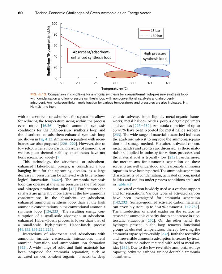
with an absorbent or adsorbent for separation allowsfor reducing the temperature swing within the processeven more [46,56]. Typical ammonia synthesisconditions for the high-pressure synthesis loop andthe absorbent- or adsorbent-enhanced synthesis loopare shown in Fig. 4.13. Ammonia separation with mem-branes was also proposed [220e222]. However, due tolow selectivities at low partial pressures of ammonia, aswell as poor thermal stability, membranes have notbeen researched widely [7].
This technology, the absorbent- or adsorbent-enhanced Haber-Bosch process, is considered a lowhanging fruit for the upcoming decades, as a largedecrease in pressure can be achieved with little techno-logical innovation [46,69]. The ammonia synthesisloop can operate at the same pressure as the hydrogenand nitrogen production units [46]. Furthermore, thecatalysts are generally more active at the low ammoniaconcentrations in the absorbent- or adsorbent-enhanced ammonia synthesis loop than at the highammonia concentrations in the conventional ammoniasynthesis loop [126,223]. The resulting energy con-sumption of a small-scale absorbent- or adsorbent-enhanced HabereBosch process is lower than that ofa small-scale, high-pressure Haber-Bosch process[46,152,154,224,225].
Interactions of absorbents and adsorbents withammonia include electrostatic interactions, metalammine formation and ammonium ion formation[142]. A wide range of solid and fluid materials hasbeen proposed for ammonia separation, such asactivated carbon, covalent organic frameworks, deep
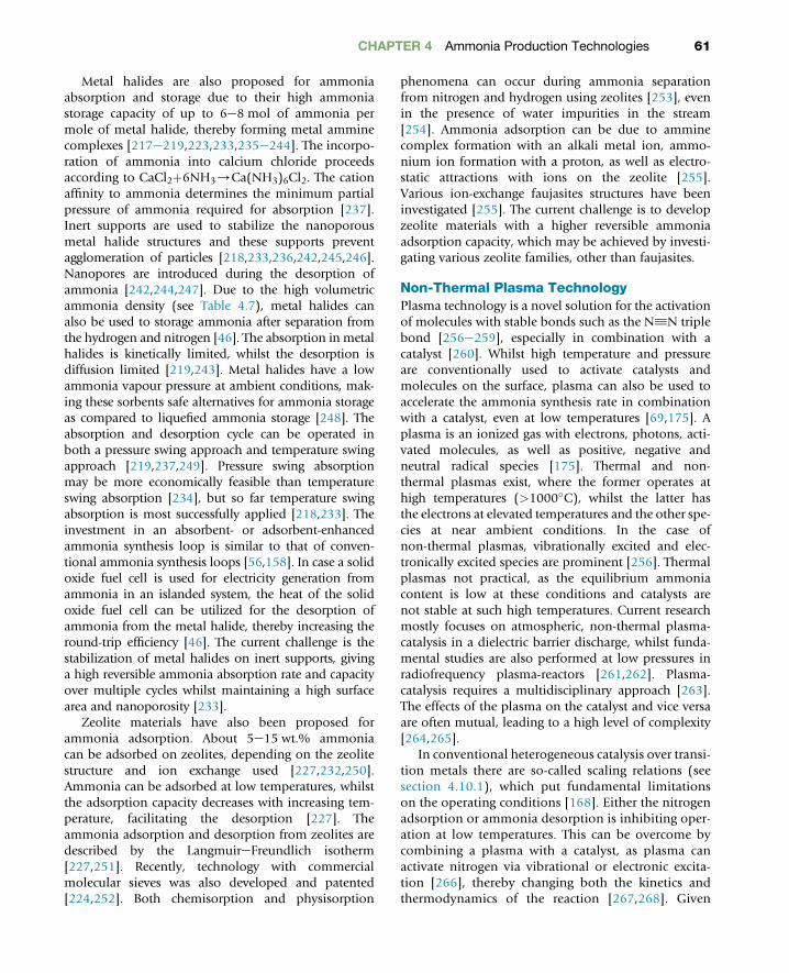
eutectic solvents, ionic liquids, metal-organic frame-works, metal halides, oxides, porous organic polymersand zeolites [225e232]. Ammonia capacities of up to55 wt.% have been reported for metal halide sorbents[233]. The wide range of materials researched indicatesthe academic interest to improve the ammonia separa-tion and storage method. Hereafter, activated carbon,metal halides and zeolites are discussed, as these mate-rials are applied in industry for various processes andthe material cost is typically low [232]. Furthermore,the mechanisms for ammonia separation on thesesorbents are well understood and reasonable ammoniacapacities have been reported. The ammonia separationcharacteristics of condensation, activated carbon, metalhalides and zeolites under process conditions are listedin Table 4.7.
Activated carbon is widely used as a catalyst supportand for separations. Various types of activated carbonhave been investigated for ammonia separation[142,232]. Surface-modified activated carbon materialscan reversibly store up to 5 wt.% ammonia [142,232].The introduction of metal oxides on the surface in-creases the ammonia capacity due to an increase in elec-trostatic attractions [232]. On the other hand, thehydrogen present in the loop removes functionalgroups at elevated temperatures, thereby lowering theammonia capacity irreversibly [232]. Both the reversibleand irreversible ammonia adsorption increases by treat-ing the activated carbon material with acid or metal ox-ides [232]. Due to the low reversible ammonia storagecapacity, activated carbons are not desirable ammoniaadsorbents.
0
20
40
60
80
100
150 200 250 300 350 400 450
Equi
libriu
m N
H3
cont
ent (
mol
.%)
Temperature (°C)
15 bar150 bar
High pressure synthesis loop
Absorbent/adsorbent-enhanced synthesis loop
FIG. 4.13 Comparison in conditions for ammonia synthesis for conventional high-pressure synthesis loopwith condensation and low-pressure synthesis loop with nonconventional catalysts and absorbent/adsorbent. Ammonia equilibrium mole fraction for various temperatures and pressures are also indicated. H2:N2 ¼ 3:1, no inert.
60 Techno-Economic Challenges of Green Ammonia as an Energy Vector
Metal halides are also proposed for ammoniaabsorption and storage due to their high ammoniastorage capacity of up to 6e8 mol of ammonia permole of metal halide, thereby forming metal amminecomplexes [217e219,223,233,235e244]. The incorpo-ration of ammonia into calcium chloride proceedsaccording to CaCl2þ6NH3/Ca(NH3)6Cl2. The cationaffinity to ammonia determines the minimum partialpressure of ammonia required for absorption [237].Inert supports are used to stabilize the nanoporousmetal halide structures and these supports preventagglomeration of particles [218,233,236,242,245,246].Nanopores are introduced during the desorption ofammonia [242,244,247]. Due to the high volumetricammonia density (see Table 4.7), metal halides canalso be used to storage ammonia after separation fromthe hydrogen and nitrogen [46]. The absorption in metalhalides is kinetically limited, whilst the desorption isdiffusion limited [219,243]. Metal halides have a lowammonia vapour pressure at ambient conditions, mak-ing these sorbents safe alternatives for ammonia storageas compared to liquefied ammonia storage [248]. Theabsorption and desorption cycle can be operated inboth a pressure swing approach and temperature swingapproach [219,237,249]. Pressure swing absorptionmay be more economically feasible than temperatureswing absorption [234], but so far temperature swingabsorption is most successfully applied [218,233]. Theinvestment in an absorbent- or adsorbent-enhancedammonia synthesis loop is similar to that of conven-tional ammonia synthesis loops [56,158]. In case a solidoxide fuel cell is used for electricity generation fromammonia in an islanded system, the heat of the solidoxide fuel cell can be utilized for the desorption ofammonia from the metal halide, thereby increasing theround-trip efficiency [46]. The current challenge is thestabilization of metal halides on inert supports, givinga high reversible ammonia absorption rate and capacityover multiple cycles whilst maintaining a high surfacearea and nanoporosity [233].
Zeolite materials have also been proposed forammonia adsorption. About 5e15 wt.% ammoniacan be adsorbed on zeolites, depending on the zeolitestructure and ion exchange used [227,232,250].Ammonia can be adsorbed at low temperatures, whilstthe adsorption capacity decreases with increasing tem-perature, facilitating the desorption [227]. Theammonia adsorption and desorption from zeolites aredescribed by the LangmuireFreundlich isotherm[227,251]. Recently, technology with commercialmolecular sieves was also developed and patented[224,252]. Both chemisorption and physisorption
phenomena can occur during ammonia separationfrom nitrogen and hydrogen using zeolites [253], evenin the presence of water impurities in the stream[254]. Ammonia adsorption can be due to amminecomplex formation with an alkali metal ion, ammo-nium ion formation with a proton, as well as electro-static attractions with ions on the zeolite [255].Various ion-exchange faujasites structures have beeninvestigated [255]. The current challenge is to developzeolite materials with a higher reversible ammoniaadsorption capacity, which may be achieved by investi-gating various zeolite families, other than faujasites.
Non-Thermal Plasma TechnologyPlasma technology is a novel solution for the activationof molecules with stable bonds such as the N^N triplebond [256e259], especially in combination with acatalyst [260]. Whilst high temperature and pressureare conventionally used to activate catalysts andmolecules on the surface, plasma can also be used toaccelerate the ammonia synthesis rate in combinationwith a catalyst, even at low temperatures [69,175]. Aplasma is an ionized gas with electrons, photons, acti-vated molecules, as well as positive, negative andneutral radical species [175]. Thermal and non-thermal plasmas exist, where the former operates athigh temperatures (>1000�C), whilst the latter hasthe electrons at elevated temperatures and the other spe-cies at near ambient conditions. In the case ofnon-thermal plasmas, vibrationally excited and elec-tronically excited species are prominent [256]. Thermalplasmas not practical, as the equilibrium ammoniacontent is low at these conditions and catalysts arenot stable at such high temperatures. Current researchmostly focuses on atmospheric, non-thermal plasma-catalysis in a dielectric barrier discharge, whilst funda-mental studies are also performed at low pressures inradiofrequency plasma-reactors [261,262]. Plasma-catalysis requires a multidisciplinary approach [263].The effects of the plasma on the catalyst and vice versaare often mutual, leading to a high level of complexity[264,265].
In conventional heterogeneous catalysis over transi-tion metals there are so-called scaling relations (seesection 4.10.1), which put fundamental limitationson the operating conditions [168]. Either the nitrogenadsorption or ammonia desorption is inhibiting oper-ation at low temperatures. This can be overcome bycombining a plasma with a catalyst, as plasma canactivate nitrogen via vibrational or electronic excita-tion [266], thereby changing both the kinetics andthermodynamics of the reaction [267,268]. Given
CHAPTER 4 Ammonia Production Technologies 61

that the hydrogenation reactions are sufficiently fastover the catalytic surface, plasma-catalysis can beused to synthesize ammonia over late-transitionmetals with nitrogen adsorption limitations at nearambient conditions. Activation of nitrogen moleculescauses a shift in the volcano curve for ammoniasynthesis towards more noble metals, as shown inFig. 4.14. The activation barrier for ammonia synthesisover Ru-based catalysts was found to decrease from 60to 115 kJ/mol to 20e40 kJ/mol, which can be attrib-uted to N2 activation in the plasma [268].
Investment cost benefits are not expected for a 180tNH3/d plasma-based plant as compared to a bench-mark Haber-Bosch plant [176]. However, small-scaleapplications with highly intermittent energy supplymay provide a niche market for processes withnon-thermal plasma technology with low operatingtemperatures and pressures combined with an absor-bent or adsorbent for separation [269], given that theenergy input for plasma-catalysis can be decreased sub-stantially. The best-reported energy input for plasma-catalysis is about 95 GJ/tNH3 at about 0.2 mol.%ammonia [270], whilst the energy consumption mustbe decreased to about 18e24 GJ/tNH3 at about1.0 mol.% ammonia for small-scale application[175,268]. From this, it follows that a catalyst wouldbe required in any case to assist nitrogen dissociation,as the full nitrogen dissociation by the plasma wouldrequire 28 GJ/tNH3 [268]. Current strategies to producemore ammonia at a lower energy input include plasma-reactor optimization such as pulsed plasmas, a changein operating pressure, and catalyst optimization.
Inspiration for catalyst design can be obtained from het-erogeneous catalysts [268].
Electrochemical SynthesisDue to the emergence of low cost, renewable electricity,electrochemical conversionshave recently gained consider-able interest [57,271]. For this reason, electrochemicalammonia synthesis is widely researched [15], inspiredon the biological nitrogen fixation, where proton-coupled electron transfer occurs under mild conditionsin the enzyme nitrogenase (see section 4.2) [272]. Electro-chemical ammonia synthesis has several potential advan-tages over the HabereBosch process [273], such as thecompact design due to the integration of hydrogen pro-duction fromwater and nitrogen reduction in a single pro-cess unit. Furthermore, the formation of gaseous hydrogencan be totally bypassed by using water oxidation as acounter reaction in an electrochemical cell, which deliversprotons for the nitrogen reduction reaction (NRR).
Electrochemical ammonia synthesis involves theoxidation of hydrogen (Eq. 4.8) or water (Eq. 4.9) onthe anode, transport of protons through a liquid orsolid electrolyte, and transport of electrons via anexternal circuit to the cathode, where nitrogen isreduced to ammonia (Eq. 4.10). An example of an elec-trochemical cell is shown in Fig. 4.15.
3H2 / 6Hþ þ 6e� (4.8)
3H2 / 6Hþ þ 6e�þ3/2O2 (4.9)
N2 þ 6Hþ þ 6e� / 2NH3 (4.10)
FIG. 4.14 Left: Effect of plasma-induced N2 activation on the catalytic activity at T ¼ 200�C and 1 bar. Thedashed line represents the maximum possible hydrogenation rate. (Reprinted from Mehta P, Barboun P,Herrera FA, Kim J, Rumbach P, Go DB, et al. Overcoming ammonia synthesis scaling relations with plasma-enabled catalysis. Nat Catal. 2018;1(4):269e275 with permission of Springer Nature Limited. Right: Proposedmechanism for plasma-enhanced catalytic ammonia synthesis via plasma-activated N2 dissociation.Reprinted from Rouwenhorst KHR, Kim H-H, Lefferts L. Vibrationally excited activation of N2 in plasma-enhanced catalytic ammonia synthesis: a kinetic analysis. ACS Sustain Chem Eng. 2019 with permission of theAmerican Chemical Society.)
62 Techno-Economic Challenges of Green Ammonia as an Energy Vector

The reaction mechanism for the electrochemical ni-trogen reduction reaction is currently debated. Variousalternatives reaction mechanisms for nitrogen activa-tion on a solid surface have been proposed, as shownin Fig. 4.15. The mechanism depends on the catalystused and the operating conditions [272,274]. In thecase of the dissociative pathway, dinitrogen is dissoci-ated to atomic nitrogen on the surface, after whichhydrogenation occurs to ammonia, with subsequentdesorption. This mechanism is predicted to occur atelevated temperatures due to the high activation barrierfor breaking the triple N^N bond. Thus, associativepathways with the breaking of the nitrogen bond onlyafter partial hydrogenation to N2HX species are morelikely to occur at low temperatures. This mechanism issimilar to that of nitrogenase (see Section 4.2) [272].Hydrazine was detected for Au nanorods in an alkalineelectrolyte [275]. Furthermore, surface-enhancedinfrared absorption spectroscopy on Au in an alkalineelectrolyte showed weak signals for N2Hx species[276], which suggests that an associative pathway maybe relevant for the nitrogen reduction reaction on Ausurfaces in alkaline electrolytes. Apart from these mech-anisms, a Mars-van Krevelen mechanism may occur inthe case of metal nitride catalysts, in which N fromthe catalyst lattice is hydrogenated to ammonia, leavingan N vacancy on the surface, which can be regeneratedwith a nitrogen atom [277]. The Mars-van Krevelenmechanism was reported on a VN catalyst, based onquantitative 14N2/
15N2 isotope exchange experiments
[278]. All in all, little experimental data is currentlyavailable to substantiate which mechanism is dominantfor electrochemical ammonia synthesis, especiallyconsidering the low ammonia concentrations.
Various approaches to electrochemical ammoniasynthesis can be distinguished based on the tempera-ture of operation, namely high-temperature solid-stateelectrolyte reactors (400e750�C, high-temperatureelectrochemical ammonia synthesis), molten salt reac-tors and composite membrane reactors (100e500�C,intermediate temperature electrochemical ammoniasynthesis), and liquid electrolyte reactors andlow-temperature solid-state electrolyte reactors(20e100�C, low-temperature electrochemical ammoniasynthesis) [279,280]. Solid-state electrolytes are probablymost promising, as these separate the hydrogen feedfrom the ammonia production [279,281].
Solid-state ammonia synthesis is usually investi-gated at high temperatures (>500�C) to ensure highproton conductivity within the solid oxide electrolytes.A dense electrolyte is placed in between two porouselectrodes and ions are transported through the solidoxide electrolytes (usually Hþ or O2� ions), as shownin Fig. 4.15. Perovskite materials are generally used aselectrolytes, but fluorite- or pyrochlore-type structureshave also been reported [279,282]. The high tempera-ture aids the nitrogen activation and enhances thereaction kinetics, but it has a negative influence onthe thermodynamic equilibrium, thereby limiting theattainable conversion to ammonia [271,283,284].
FIG. 4.15 Left: Example of an electrochemical cell for high-temperature ammonia synthesis using a solidelectrolyte. (Reprinted from Kyriakou V, Garagounis I, Vasileiou E, Vourros A, Stoukides M. Progress in theelectrochemical synthesis of ammonia. Catal Today. 2017;286:2e13 with permission of Elsevier Ltd. Right:Proposed reaction mechanisms for the electrochemical nitrogen reduction reaction. Reprinted from ShipmanMA, Symes MD. Recent progress towards the electrosynthesis of ammonia from sustainable resources. CatalToday. 2017;286:57e68 with permission of Elsevier Ltd.)
CHAPTER 4 Ammonia Production Technologies 63

Furthermore, high operating temperatures can cause is-sues due to material degradation [13]. The reportedammonia formation rate is in the order of magnitudeof 10�9 mol/s/cm and the Faradaic efficiency of theprocess is usually below 50%, based on the amountof electrochemically supplied hydrogen [13,271]. Thehighest reported Faradaic efficiency is around 80%[285,286]. When water is used as the proton source,the Faradaic efficiency drops to below 1%[271,284,287]. Research efforts focus on the develop-ment of more stable electrolytes, with a higher conduc-tivity at milder operating conditions.
To overcome problems with ammonia decomposi-tion at higher temperatures, as well as material stabilityissues, intermediate temperature electrochemicalammonia synthesis is studied, which operates at100e500�C. Molten salts and composite membraneswith the addition of a eutectic mixture of alkali metalsalts are usually used as electrolytes [279,288e292]. Itshould be noted that composite membranes havebeen operated at temperatures of up to 650�C [293],which is considered high-temperature electrochemicalammonia synthesis. The mixture of eutectic solvents en-sures a good ionic conductivity at lower temperatures. Acommon approach is to reduce dinitrogen to N3� onthe cathode, which often migrates towards the anode,where it reacts with hydrogen to form ammonia[294]. However, the addition of a Li3N precursor (i.e.a nitrogen source) to the electrolyte in most of thestudies makes it difficult to estimate the real efficiencyof the process [290,295]. Ammonia formation rates inthe range 10�11e10�8 mol/s/cm with Faradaic effi-ciencies mostly below 10% have been reported [271].The highest reported Faradaic efficiency of 80% wasfound to be unstable, and dropped to 10% after sometime [296], which may indicate a nitrogen-containingprecursor being present in the system rather than acatalytic effect. A disadvantage of molten salt electro-lytes is their corrosiveness, leading to a low stability ofthe electrode materials [297].
Low-temperature electrochemical ammonia synthe-sis (20e100�C) recently gained interest [298,299],with about 100 academic publications per year. Forlow-temperature systems, ammonia decomposition isnot an issue. Polymer electrolytes with high Hþ conduc-tivity have been used, such Nafion [300,301] or sulpho-nated polysulphone [302]. The reported ammoniaformation rate is in the range 10�10e10�8 mol/s/cmat 80�C, but Faradaic efficiencies below 1% are gener-ally reported [271,303]. Studies at room temperaturesare performed with liquid electrolytes, which areusually aqueous-based electrolytes [273,304,305],
whilst organic solvents [306,307] and ionic liquids[308] have also been used. An advantage of aqueous-based electrolytes is that water can be used directly asthe proton source [271]. Acidic electrolytes are suitablefor reduction reactions, as protons are abundantly avail-able, whilst an alkaline environment can suppress thehydrogen evolution reaction, which competes withthe nitrogen reduction reaction to ammonia [309].
A wide variety of catalysts was tested, starting fromnoble metals such as Ag, Ag, Pd, Pt, Rh and Ru[275,300,310e316], after which metal oxides basedon Ce, Co, Fe, Mo, Mn, Nb, Ta, Ti and V [317e328],metal sulphides based on Co, Fe and Mo [329e332],and metal carbides based on Mo [333] were also stud-ied experimentally. Another group of catalysts consistsof transition metal nitride materials such as CrON,Mo2N and VN [334e336], for which the possibility ofa Mars-Van Krevelen mechanism is considered [277].The activity of organometallic complexes based on Aland Ti [337,338], and metal-free catalysts such as B,BN, P and polymeric carbon nitride [339e342] werealso evaluated. Limited reports are available aboutsingle-atom catalysts for the nitrogen reductionreaction, such as Au, Fe, and Ru [343e346]. Various re-views provide a more detailed description of low-temperature electrochemical ammonia synthesis[13,273,304,309,347e349].
Despite many recent academic publications, lowammonia production rates of 10�12e10�9 mol/s/cmwith Faradaic efficiencies below 10% are generallyreported at room temperature. Various publications re-ported higher Faradaic efficiencies [323,343,350e352],even up to 67.8% [353]. However, the presented Fara-daic efficiencies are usually measured at low currentdensities (sometimes below �0.1 mA/cm) and at lowammonia concentrations (usually <1 ppm). Thus, anyammonia contamination in the system causes a large er-ror in the apparent ammonia synthesis rate and Fara-daic efficiency [354].
Ammonia is a common impurity in the air [355], itcan easily dissolve in water and adsorb at a wide varietyof surfaces [356], which makes it very easy to find it ascontamination. It means that researchers working onthe nitrogen reduction reaction should pay extra atten-tion to those contaminations. Ammonia can be foundin gas tubes, glassware, gloves, nitrogen streams andeven human breath. Trace contaminations can appearat certain stages of the experiment, such as membranepre-treatment, improper reactor cleaning, samplepost-treatment, storage and ammonia detection [354].Moreover, nitrogen-containing compounds present ascontaminations in nitrogen streams, such as nitrates,
64 Techno-Economic Challenges of Green Ammonia as an Energy Vector
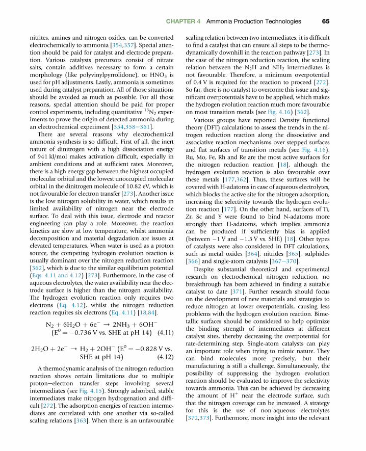
nitrites, amines and nitrogen oxides, can be convertedelectrochemically to ammonia [354,357]. Special atten-tion should be paid for catalyst and electrode prepara-tion. Various catalysts precursors consist of nitratesalts, contain additives necessary to form a certainmorphology (like polyvinylpyrrolidone), or HNO3 isused for pH adjustments. Lastly, ammonia is sometimesused during catalyst preparation. All of those situationsshould be avoided as much as possible. For all thosereasons, special attention should be paid for propercontrol experiments, including quantitative 15N2 exper-iments to prove the origin of detected ammonia duringan electrochemical experiment [354,358e361].
There are several reasons why electrochemicalammonia synthesis is so difficult. First of all, the inertnature of dinitrogen with a high dissociation energyof 941 kJ/mol makes activation difficult, especially inambient conditions and at sufficient rates. Moreover,there is a high energy gap between the highest occupiedmolecular orbital and the lowest unoccupied molecularorbital in the dinitrogen molecule of 10.82 eV, which isnot favourable for electron transfer [273]. Another issueis the low nitrogen solubility in water, which results inlimited availability of nitrogen near the electrodesurface. To deal with this issue, electrode and reactorengineering can play a role. Moreover, the reactionkinetics are slow at low temperature, whilst ammoniadecomposition and material degradation are issues atelevated temperatures. When water is used as a protonsource, the competing hydrogen evolution reaction isusually dominant over the nitrogen reduction reaction[362], which is due to the similar equilibrium potential(Eqs. 4.11 and 4.12) [273]. Furthermore, in the case ofaqueous electrolytes, the water availability near the elec-trode surface is higher than the nitrogen availability.The hydrogen evolution reaction only requires twoelectrons (Eq. 4.12), whilst the nitrogen reductionreaction requires six electrons (Eq. 4.11) [18,84].
N2 þ 6H2O þ 6e� / 2NH3 þ 6OH�
(E0 ¼ �0.736 V vs. SHE at pH 14) (4.11)
2H2O þ 2e� / H2 þ 2OH� (E0 ¼ �0.828 V vs.SHE at pH 14) (4.12)
A thermodynamic analysis of the nitrogen reductionreaction shows certain limitations due to multipleprotoneelectron transfer steps involving severalintermediates (see Fig. 4.15). Strongly adsorbed, stableintermediates make nitrogen hydrogenation and diffi-cult [272]. The adsorption energies of reaction interme-diates are correlated with one another via so-calledscaling relations [363]. When there is an unfavourable
scaling relation between two intermediates, it is difficultto find a catalyst that can ensure all steps to be thermo-dynamically downhill in the reaction pathway [273]. Inthe case of the nitrogen reduction reaction, the scalingrelation between the N2H and NH2 intermediates isnot favourable. Therefore, a minimum overpotentialof 0.4 V is required for the reaction to proceed [272].So far, there is no catalyst to overcome this issue and sig-nificant overpotentials have to be applied, which makesthe hydrogen evolution reaction much more favourableon most transition metals (see Fig. 4.16) [362].
Various groups have reported Density functionaltheory (DFT) calculations to assess the trends in the ni-trogen reduction reaction along the dissociative andassociative reaction mechanisms over stepped surfacesand flat surfaces of transition metals (see Fig. 4.16).Ru, Mo, Fe, Rh and Re are the most active surfaces forthe nitrogen reduction reaction [18], although thehydrogen evolution reaction is also favourable overthese metals [177,362]. Thus, these surfaces will becovered with H-adatoms in case of aqueous electrolytes,which blocks the active site for the nitrogen adsorption,increasing the selectivity towards the hydrogen evolu-tion reaction [177]. On the other hand, surfaces of Ti,Zr, Sc and Y were found to bind N-adatoms morestrongly than H-adatoms, which implies ammoniacan be produced if sufficiently bias is applied(between �1 V and �1.5 V vs. SHE) [18]. Other typesof catalysts were also considered in DFT calculations,such as metal oxides [364], nitrides [365], sulphides[366] and single-atom catalysts [367e370].
Despite substantial theoretical and experimentalresearch on electrochemical nitrogen reduction, nobreakthrough has been achieved in finding a suitablecatalyst to date [371]. Further research should focuson the development of new materials and strategies toreduce nitrogen at lower overpotentials, causing lessproblems with the hydrogen evolution reaction. Bime-tallic surfaces should be considered to help optimizethe binding strength of intermediates at differentcatalyst sites, thereby decreasing the overpotential forrate-determining step. Single-atom catalysts can playan important role when trying to mimic nature. Theycan bind molecules more precisely, but theirmanufacturing is still a challenge. Simultaneously, thepossibility of suppressing the hydrogen evolutionreaction should be evaluated to improve the selectivitytowards ammonia. This can be achieved by decreasingthe amount of Hþ near the electrode surface, suchthat the nitrogen coverage can be increased. A strategyfor this is the use of non-aqueous electrolytes[372,373]. Furthermore, more insight into the relevant
CHAPTER 4 Ammonia Production Technologies 65

reaction mechanism is required for catalystdevelopment.
A lot of complex strategies are required for electro-chemical ammonia synthesis to become feasible forpractical application, which is an interesting scientificchallenge. To make electrochemical ammonia synthesiseconomically feasible, a current density of 300 mA/cmwith a Faradaic efficiency of 90% is desired, whichgives an ammonia production rate of approximately10�6 mol/s/cm [13]. For now, electrochemicalammonia synthesis should not be considered as a po-tential replacement of the HabereBosch process forlarge-scale ammonia production, but rather as a tech-nology for small-scale, intermittent ammonia produc-tion. When aqueous electrolytes are used, this wouldallow for localized, on-demand ammonia productionfor fertilizer application.
Photochemical SynthesisPhotocatalysis provides an interesting approach for theconversion of molecular nitrogen to ammonia, whichhas attracted widespread attention in recent years[374]. Similar to the electrochemical ammoniasynthesis, the main advantage of this approach is thepossibility to use water as a reducing agent for nitrogenfixation in ambient conditions. Instead of an electroca-talyst, a semiconductor is used. There are three main
steps in the photochemical reaction. First, light isabsorbed by a semiconductor, which produces chargecarriers. For this step to occur, the energy of absorbedphotons needs to be equal or higher than the energygap of the semiconductor. Then, the electrons are pro-moted from the valence band to the conductionband of the semiconductor, which results inphoto-generated electrons and holes in the valenceband. Afterwards, the electrons and holes migrate tothe surface of semiconductor, where redox reactionscan take place. Water can be oxidized to O2 and Hþ
by surface holes when the valence band is more positivethan 1.23 V versus NHE (normal hydrogen electrode),whilst N2 can be reduced by electrons from the conduc-tion band and hydrogenated by water-liberated Hþ
[375,376]. The mechanism of the nitrogen reduction re-action on semiconductors is not fully understood, but itis suggested that it follows an associative pathway ratherthan a dissociative pathway, similar to nitrogenase andelectrochemical ammonia synthesis (see Fig. 4.15)[272,304].
Two types of solar-driven nitrogen fixationapproaches can be distinguished [298]. In the photo-chemical process, semiconductor nanoparticles aresuspended in an aqueous solution and both redoxhalf-reactions happen on the different sites of thesame particles (see Fig. 4.17). The downside of this
FIG. 4.16 Left: limiting potential for the nitrogen reduction reaction and hydrogen evolution reaction overstep sites on transition metals. (Reprinted from Montoya JH, Tsai C, Vojvodic A, Jens KN. The challenge ofelectrochemical ammonia synthesis: a new perspective on the role of nitrogen scaling relations.ChemSusChem. 2015;8(13):2180e2186 with permission of John Wiley & Sons, Inc. Right: Volcano plots fortransition metal surfaces for the nitrogen reduction reaction via the dissociative and associative reactionmechanisms. Reprinted from Skúlason E, Bligaard T, Gudmundsdóttir S, Studt F, Rossmeisl J, Abild-PedersenF, et al. A theoretical evaluation of possible transition metal electro-catalysts for N2 reduction. Phys ChemChem Phys. 2012;14(3):1235e1245 with permission of the Royal Society of Chemistry.)
66 Techno-Economic Challenges of Green Ammonia as an Energy Vector

reactor type is the possibility of re-oxidation of theproduced ammonia by photo-generated holes on thesemiconductor. Another possibility of this approach isthe combination of a photocatalyst with an electro-chemical cell (see Fig. 4.17). The photoelectrode (i.e.the photocathode or photoanode) creates holes aswell as electrons after light absorption, and then thecharge is separated between two electrodes with anexternal bias applied. That causes both redox half-reactions to occur at two different electrodes, which hin-ders the recombination of holes and electrons, therebyincreasing the solar conversion efficiency [298,377].
Early attempts of photo-nitrogen fixation utilizedTiO2 semiconductors as the photocatalyst with variousdifferent doping variations [378e381]. Other oxidesbased on Fe, V and W as well as sulphides were alsoinvestigated [382e386]. A major group of test materialswas based on Bi-oxyhalides, as well as graphitic carbonnitride materials [387e391]. Research is mainlyfocusing on the modification of known catalysts byvarying oxygen-, nitrogen-, sulphur vacancies, as wellas on co-catalysts, morphology and heterojunctionengineering [377]. Despite a significant number ofstudies, no efficient photochemical system forammonia synthesis was developed. All tested systemshave a low production rate and usually there is noquantum efficiency reported. Moreover, the informa-tion is presented in varying units, using differentconditions, as well as different light sources, whichmakes the performance difficult to compare. Therefore,standards and benchmarks were proposed to reportdata in a consistent manner [392].
The issues with solar-driven nitrogen fixation aresimilar to the ones in the case of electrochemical synthe-sis, which originates from inertness of the nitrogenmolecule and the unfavourable electron transferkinetics to nitrogen at in ambient conditions (seesection 4.10.4). Similarly, an aqueous environmentcauses issues with the competing hydrogen evolutionreaction, as well as transport of nitrogen to the activesites of the catalyst due to its low solubility incommonly used electrolytes. When no external bias isapplied, the produced ammonia can be oxidized byphoto-generated holes on the semiconductor as well,as both electrons and holes can recombine before theredox reaction occurs. Thus, the overall efficiency isdecreased along various pathways. Another issue is thepoor stability of the photocatalyst and the low utiliza-tion of the light, which leads to a low solar-to-ammoniaconversion [304,374,375]. Finally, due to low conver-sion values, special attention should be paid to propercontrol experiments to avoid false results, as describedfor electrochemical ammonia synthesis (see section4.10.4) [354].
For now, there is no reason to think about photo fix-ation of nitrogen as a future industrial process. Thefocus should be on fundamental research, both theoret-ical and experimental, such as potential reaction mech-anisms, finding catalysts which can bind and activatenitrogen in ambient conditions and materials thatcapture solar energy more efficiently [375,392]. Thereis limited data available about photoelectrochemicalsystems, which can aid for efficient charge separation af-ter photoexcitation, implying more research is required
FIG. 4.17 (A) Schematic representation of semiconductor for NRR. Typical reactor configuration used in (B)photochemical and, (C) photo(electro)chemical NRR. ((A) Reproduced from Vu MH, Sakar M, Do TO. Insightsinto the recent progress and advanced materials for photocatalytic nitrogen fixation for ammonia (NH3)production. Catalysts. 2018;8(12). (B) and (C) Reprinted from Zhang S, Zhao Y, Shi R, Waterhouse GIN, ZhangT. Photocatalytic ammonia synthesis: recent progress and future. Energy. 2019;1(2):100013 with permission ofElsevier Ltd.)
CHAPTER 4 Ammonia Production Technologies 67

[298,377]. It is estimated that an energy efficiency of0.1% for solar-to-ammonia is required to evaluate theprocess as a potential alternative for ammonia synthesis[392], which has only been reported in a few cases[393].
Homogeneous CatalysisVolpin et al. [394,395] reported the first homogeneousnitrogen reduction reactions in the 1960s. Various ho-mogeneous nitrogen fixation reactions, catalytic andnon-catalytic, were reported in the decades to follow[12,14]. Some of the most significant contributionsinclude single atom transition metal Mo complexes,which reduce N2 to ammonia at ambient conditions[396e398], at the same energy input as biological N2fixation. Other studied systems include Fe complexes[399e401] and Zr complexes [402]. The nature of thereaction intermediates has been studied with a mecha-nistic comparison to biological nitrogen fixation[3,403,404], and various ligands have been investigatedfor the Mo complex [405]. A strategy for a highammonia selectivity (i.e. similar to nitrogenase) is theuse of a solvent with a low solubility for the reactants,thereby limiting the rate of the hydrogen evolution reac-tion [396].
So far, homogeneous catalysis has not found prac-tical application due to low yields (up to 8e12 equiva-lents of ammonia per equivalent of the catalyst[396,397]), fast catalyst deactivation, and expensivecatalyst compounds [3,14]. Furthermore, the reactionsare complex, and selective formation of ammonia isdifficult without the use of excessive amounts of solvent
[14]. Thus, homogeneous catalysts for ammonia syn-thesis are currently most useful for understanding nitro-genase [406]. Synthetic nitrogenase-like complexes mayfind applications for on-site fertilizer production on theseeds of plants [163].
Chemical Looping ApproachesAmmonia can also be synthesized by chemical loopingapproaches. The main advantage of this kind ofapproach is the possibility of independent control ofnitrogen activation and ammonia formation (i.e. thenitrogen reduction can be performed in the absence ofreactive protons [407]). Chemical looping approachesinvolve separate thermodynamically stable reaction in-termediates. This allows for optimizing the operatingconditions of each step separately. Three main ap-proaches for chemical looping have been proposedfor ammonia synthesis, namely hydrogen chemicallooping, water chemical looping, and alkali or alkalineearth metal hydride chemical looping, as well as theircombination with electrocatalysis (see Fig. 4.18)[15,299,408]. A general benefit of chemical looping ap-proaches is that mild pressures down to atmosphericpressures can be applied.
The water chemical looping approach is based onthe nitridation, oxidation, and reduction of a metal ina cycle. The metal nitride is hydrolysed with steaminto ammonia and a metal oxide. The metal oxide issubsequently reduced and nitridated for the next cycle[15,299,409]. An example of a hydrogen chemicallooping cycle is the reduction and subsequent nitrida-tion of Al2O3 to AlN in the presence of nitrogen and
FIG. 4.18 Schematic representation of chemical looping approaches for ammonia synthesis: (A) waterchemical looping cycles, (B) hydrogen chemical looping cycles, and (C) alkali or alkaline earth metal hydridecycles. (Reprinted from Gao W, Guo J, Wang P, Wang Q, Chang F, Pei Q, et al. Production of ammonia via achemical looping process based on metal imides as nitrogen carriers. Nat Energy. 2018;3(12):1067e1075 withpermission of Springer Nature Limited.)
68 Techno-Economic Challenges of Green Ammonia as an Energy Vector

methane, with subsequent hydrolysation to Al2O3whilst forming ammonia [410]. Other systems werealso studied [411,412], such as MoO2-based andMgO-based systems [408,413]. An advantage of waterchemical looping systems is the direct hydrogenationof nitrogen with water, which implies a separatehydrogen production step is not required. A disadvan-tage of water chemical looping systems is the hightemperature required for reduction of the metal oxides(usually >1000�C), as well as the use of sacrificialagents like CO and CH4.
The hydrogen chemical looping approach is verysimilar to the water chemical looping approach. Italso involves a metal nitride as a nitrogen source forammonia synthesis. In the hydrogen chemical loopingcycle, a metal undergoes nitridation in a nitrogenstream, after which it is reduced back to the metallicstate in presence of hydrogen, whilst forming ammonia.Several metal nitrides were studied, such as Mo2N,Ca3N2, Sr2N and MnxNy [414e417]. However, a reduc-tion from the metal nitride to the metal only occurs athigh temperatures (>500�C).
In the case of alkali or alkaline earthmetal hydride cy-cles, nitrogen is reduced by a metal hydride rather than apure metal. In this process, a metal imide is formed,which is subsequently reduced back to the metal hydridein the presence of hydrogen whilst forming ammoniaand closing the loop [409,418]. Ammonia can be formedat temperatures as low as 100�C and at atmosphericpressure over a NieBaH2/Al2O3 system [409].
An example of an electrochemically assisted chemicalcycle is lithium-mediated ammonia synthesis [419,420].As discussed in Section 4.10.4, hydrogen evolution is acompeting reaction for electrochemical ammonia syn-thesis. A cyclic, lithium mediated ammonia synthesisapproach separates the nitrogen activation from the hy-drogenation step, thereby eliminating the issue of thecompeting hydrogen evolution reaction. The first stepis the electrochemical reduction of Liþ to metallic Li,which deposits on the electrode. Then, the electrodewith the Li layer is exposed to a nitrogen atmosphereat room temperature and atmospheric pressure. SinceLi has very strong reducing properties, it reacts with nitro-gen to form Li3N. Subsequently, Li3N is treated withwater or another proton source, which producedammonia and Liþ salt, thereby closing the loop (seeFig. 4.19) [174,299]. Electrochemically assisted,lithium-mediated ammonia synthesis has also beenoperated in a molten salt electrolyte at 450�C, attainingenergy requirements as low as 64 GJ/tNH3 [407]. Howev-er, the theoretical minimum energy consumption is
55 GJ/tNH3, leaving little space for improvements [407].Other variations were also studied, including a contin-uous process, in which nitrogen is bubbled through atetrahydrofuran electrolyte with ethanol and Li[292,421]. This allows for ammonia synthesis at ambientconditions due to the difference in reaction rates betweenLi-nitridation and ethanol reduction on Li [422,423].Current research focuses on systems with different metalsto reduce energy consumption.
SUMMARYAs presented in this chapter, the Haber-Bosch process isone of the most impactful inventions in human history.The Haber-Bosch process has prevented mass starvationin the past century, and it potentially has a substantialrole to play in the hydrogen economy. This technologyfor large-scale, high-pressure ammonia synthesis hasbeen optimized from an energy consumption of about100 GJ/tNH3 in the 1930s down to about 26 GJ/tNH3nowadays. Currently, most ammonia is producedfrom fossil fuels, although green ammonia synthesisvia the electrolysis-based Haber-Bosch process is alsomature technology with a century of operational experi-ence. The current challenge is to match green ammoniasynthesis with intermittent renewables, such as solarand wind energy. Academic research focuses onammonia synthesis under mild conditions, potentiallyallowing for intermittent and decentralized greenammonia production. The areas of research are diverse,but most academic research focuses on the electrochem-ical reduction of atmospheric nitrogen to ammonia,allowing for producing ammonia directly from airand water. However, so far this remains an unsolvedtechnologic challenge.
FIG. 4.19 Schematic representation of Li electrochemical/thermochemical cycling for ammonia synthesis. (Reprintedfrom Jiao F, Xu B. Electrochemical ammonia synthesis andammonia fuel cells. Adv Mater. 2018;1e5 with permission ofJohn Wiley & Sons, Inc.)
CHAPTER 4 Ammonia Production Technologies 69

REFERENCES[1] Patil BS, Hessel V, Seefeldt LC, Dean DR, Hoffman BM,
Cook BJ, et al. Nitrogen fixation. In: Ullmann’s encyclo-pedia of industrial Chemistry; 2017.
[2] Appl M. Ammonia, 1. Introduction. In: Ullmann’s ency-clopedia of industrial chemistry; 2011.
[3] Foster SL, Bakovic SIP, Duda RD, Maheshwari S,Milton RD, Minteer SD, et al. Catalysts for nitrogenreduction to ammonia. Nat Catal 2018;1(July).
[4] Appl M. In: Appl M, editor. Ammonia: principles and in-dustrial practice. 1st ed. Weinheim (Germany): Wiley-VCH Verlag GmbH; 1999.
[5] Smil V. Detonator of the population explosion. Nature1999;400(6743):415.
[6] Smil V. Enriching the earth: Fritz Haber, Carl Bosch, andthe transformation of world food production. 2004.Cambridge (MA).
[7] Nielsen SE. Ammonia synthesis: catalyst andtechnologies. ACS Symp Ser 2009;1000:15e39.
[8] Malthus TR. An Essay on the principle of population.1798.
[9] Hager T. The alchemy of air: a jewish genius, a doomedtycoon, and the scientific discovery that fed the worldbut fueled the rise of Hitler. New York (NY): HarmonyBooks; 2008.
[10] Erisman JW, Sutton MA, Galloway J, Klimont Z,Winiwarter W. How a century of ammonia synthesischanged the world. Nat Geosci 2008;1(10):636e9.
[11] Burris RH, Roberts GP. Biological nitrogen fixation.Annu Rev Nutr 1993;13:317e35.
[12] Bazhenova TA, Shilov AE. Nitrogen fixation in solution.Coord Chem Rev 1995;144(C):69e145.
[13] McPherson IJ, Sudmeier T, Fellowes J, Tsang SCE. Mate-rials for electrochemical ammonia synthesis. DaltonTrans 2019;48(5):1562e8.
[14] Cherkasov N, Ibhadon AO, Fitzpatrick P. A review of theexisting and alternative methods for greener nitrogenfixation. Chem Eng Process Process Intensif [Internet]2015;90:24e33. Available from: https://doi.org/10.1016/j.cep.2015.02.004.
[15] Nørskov J, Chen J, BullockM, Chorkendorff I, Jaramillo T,Jones A, et al. Sustainable Ammonia Synthesis Exploringthe scientific challenges associated with discovering alter-native, sustainable processes for ammonia production.Dulees, VA: DOE Roundtable Rep; 2016.
[16] Seefeldt LC, Hoffman BM, Dean DR. Electron transfer innitrogenase catalysis. Curr Opin Chem Biol 2012;16(1e2):19e25.
[17] Burgess BK, Lowe DJ. Mechanism of molybdenumnitrogenase. Chem Rev 1996;96(7):2983e3011.
[18] Skúlason E, Bligaard T, Gudmundsdóttir S, Studt F,Rossmeisl J, Abild-Pedersen F, et al. A theoretical evalu-ation of possible transition metal electro-catalysts for N2
reduction. Phys Chem Chem Phys 2012;14(3):1235e45.
[19] Dance I. Calculated details of a mechanism for conver-sion of N2 to NH3 at the FeMo cluster of nitrogenase.Chem Commun 1997;(2):165e6.
[20] Rod TH, Hammer B, Nørskov JK. Nitrogen adsorptionand hydrogenation on a MoFe6S9 complex. Phys RevLett 1999;82(20):4054e7.
[21] Rod TH, Nørskov JK. Modeling the nitrogenase FeMocofactor. J Am Chem Soc 2000;122(51):12751e63.
[22] Hoffman BM, Dean DR, Seefeldt LC. Climbing nitroge-nase: toward a mechanism of enzymatic nitrogenfixation. Acc Chem Res 2009;42(5):609e19.
[23] Ernst FA. Industrial chemical monographs: fixation of at-mospheric nitrogen. London (UK): Chapman & Hall,Ltd.; 1928.
[24] Travis AS. Nitrogen capture: the growth of an interna-tional industry (1900e1940). Springer InternationalPublishing; 2018.
[25] Haber F, Le Rossignol R. The production of syntheticammonia. Ind Eng Chem 1913;5(4):328e31.
[26] Haber F, Le Rossignol R. Production of ammonia[internet]. Germany; 1202995. 1916. Available from:https://patents.google.com/patent/US1202995A/.
[27] Sheppard D, Robert Le R. 1884e1976: engineer of the“Haber” process. R Soc J Hist Sci 2017;71:263e96.
[28] Nernst W. Über das Ammoniakgleichgewicht. Zeitschriftfur Elektrochemie und Angew Phys Chemie 1907;13(32).
[29] Farber E. From Chemistry to philosophy: the way ofAlwin Mittasch (1869e1953). Chymia 1966;11:157e78.
[30] Mittasch A, Frankenburg W. Early studies of multicom-ponent catalysts. Adv Catal 1950;2(C):81e104.
[31] Ozaki A, Taylor H, Boudart M. Kinetics and mechanismof the ammonia synthesis. Proc R Soc A Math Phys EngSci 1960;258(1292):47e62.
[32] Ertl G. Surface science and catalysisdstudies on themechanism of ammonia synthesis: the P. H. Emmettaward address. Catal Rev 1980;21(2):201e23.
[33] Prieto G, Schüth F. The Yin and Yang in the develop-ment of catalytic processes: catalysis research and reac-tion engineering. Angew Chem Int Ed 2015;54(11):3222e39.
[34] Bosch C. The development of the chemical high pressuremethod during the establishment of the new ammoniaindustry. 1932. Available from: https://www.nobelprize.org/uploads/2018/06/bosch-lecture.pdf.
[35] Murkin C, Brightling JR. Eighty years of steam reforming.Johnson Matthey Technol Rev 2016;60(4):263e9.
[36] van Rooij A. Engineering contractors in the chemical in-dustry. The development of ammonia processes,1910e1940. Hist Technol 2005;21(4):345e66.
[37] Brightling JR. Ammonia and the fertiliser industry: thedevelopment of ammonia at Billingham. Johnson Mat-they Technol Rev 2018;62(1):32e47.
[38] Rostrup-Nielsen JR. Catalytic steam reforming. In: AJ S,Boudart M, editors. Catalysis: science and technology. 1sted. Berlin Heidelberg: Springer-Verlag; 1984. p. 1e117.
[39] The Claude process for ammonia synthesis. Nature1921;107(2702):765.
[40] West JH. The Claude synthetic ammonia process andplant. J Soc Chem Ind 1921;40(22).
70 Techno-Economic Challenges of Green Ammonia as an Energy Vector

[41] Philibert C. Renewable Energy for Industry: from greenenergy to green materials and fuels [Internet]. Paris Cedex(France). 2017. Available from: https://www.iea.org/publications/insights/insightpublications/Renewable_Energy_for_Industry.pdf.
[42] European Fertilizer Manufacturers’ Association. Produc-tion of Ammonia [Internet]. Best available techniquesfor pollution prevention and control in the European fer-tilizer industry. Brussels (Belgium). 2000. Available from:https://www.ocinitrogen.com/Media.Library/Ammonia.process-BA.Production.of.ammonia.(2000)-Brochure.pdf.
[43] Patil BS, Wang Q, Hessel V, Lang J. Plasma N2-fixation:1900e2014. Catal Today [Internet] 2015;256:49e66. Avail-able from: https://doi.org/10.1016/j.cattod.2015.05.005.
[44] Liu H. Ammonia synthesis catalysts: innovation andpractice. World Scientific; 2013.
[45] Pattabathula V. Ammonia. In: Kirk-othmer encyclopediaof chemical technology; 2019.
[46] Rouwenhorst KHR, Van Der Ham AGJ, Mul G,Kersten SRA. Islanded ammonia power systems: tech-nology review & conceptual process design. Renew Sus-tain Energy Rev 2019;114.
[47] Hellman A, Honkala K, Dahl S, Christensen CH,Nørskov JK. Ammonia synthesis: state of the bellwetherreaction. In: Comprehensive inorganic chemistry (II).2nd ed. Elsevier Ltd; 2013.
[48] International Energy Agency. The Future of hydrogen:seizing today’s opportunities. 2019.
[49] CEFIC. Facts & figures of the European chemical indus-try [Internet]. 2018. Available from: https://cefic.org/app/uploads/2018/12/Cefic_FactsAnd_Figures_2018_Industrial_BROCHURE_TRADE.pdf.
[50] Bazzanella AM, Ausfelder F. Technology study: low car-bon energy and feedstock for the European chemical in-dustry [Internet]. Dechema: Gesellschaft für ChemischeTechnik und Biotechnologie e.V; 2017. Available from:https://dechema.de/dechema_media/Technology_study_Low_carbon_energy_and_feedstock_for_the_European_chemical_industry-p-20002750.pdf.
[51] Appl M. Ammonia, 3. Production plants. In: Ullmann’sencyclopedia of industrial chemistry; 2012. p. 295e338.
[52] Eggeman T. Updated by staff. Ammonia. Kirk-othmer encyclchem technol [Internet]. 2010. p. 1e33. Available from:https://doi.org/10.1002/0471238961.0113131503262116.a01.pub3.
[53] Jennings JM. Catalytic ammonia synthesis: fundamen-tals and practice. 1st ed. New York: Plenum Press;1991.
[54] Nielsen A. In: Nielsen A, editor. Ammonia: catalysis andmanufacture. 1st ed. Berlin Heidelberg: Springer-Verlag;1995.
[55] Appl M. Ammonia, 2. Production processes. In: Ull-mann’s encyclopedia of industrial chemistry; 2012.p. 295e338.
[56] Smith C, Hill AK, Torrente-Murciano L. Current andfuture role of HabereBosch ammonia in a carbon-freeenergy landscape. Energy Environ Sci 2020;13(2):331e44.
[57] Van Geem KM, Galvita VV, Marin GB. Making chemicalswith electricity. Science 2019;364(6442):734e5.
[58] Schiffer ZJ, ManthiramK. Electrification and decarbonizationof the chemical industry. Joule [Internet] 2017;1(1):10e4.Available from: https://doi.org/10.1016/j.joule.2017.07.008.
[59] Wismann ST, Engbæk JS, Vendelbo SB, Bendixen FB,Eriksen WL, Aasberg-Petersen K, et al. Electrified methanereforming: a compact approach to greener industrialhydrogen production. Science 2019;364(6442):756e9.
[60] CEFIC. European chemistry for growth: unlocking acompetitive, low carbon and energy efficient future[Internet]. 2013. Available from: http://www.cefic.org/Documents/RESOURCES/Reports-and-Brochure/Energy-Roadmap-The Report-European-chemistry-for-growth.pdf.
[61] Hansen JB, Han P. The SOC4NH3 project in Denmark.In: NH3 event. Rotterdam (The Netherlands); 2019.
[62] Elgowainy A. Resourcing byproduct hydrogen from in-dustrial operations. In: H2@Scale workshop. Houston(TX); 2017.
[63] Brown T. Innovations in ammonia. In: H2@Scale R&Dconsortium kick-off meeting.
[64] Arora P, Hoadley AFA, Mahajani SM, Ganesh A. Small-scale Ammonia production from biomass: a techno-enviro-economic perspective. Ind Eng Chem Res 2016;55(22):6422e34.
[65] Demirhan CD, Tso WW, Powell JB. Sustainableammonia production through process synthesis andglobal optimization. AIChE J 2019;65(7).
[66] Arora P, Sharma I, Hoadley A, Mahajani S, Ganesh A.Remote, small-scale, ‘greener’ routes of ammoniaproduction. J Clean Prod [Internet] 2018;199:177e92. Avail-able from: https://doi.org/10.1016/j.jclepro.2018.06.130.
[67] Frattini D, Cinti G, Bidini G, Desideri U, Ciof R, Jannelli E.A system approach in energy evaluation of differentrenewable energies sources integration in ammonia pro-duction plants. Renew Energy 2016;99:472e82.
[68] Soloveichik G. Future of Ammonia production: improve-ment of Haber-Bosch process or electrochemical synthesis?.In: NH3 fuel conference [Internet]. Minneapolis (MN);2017. Available from: https://nh3fuelassociation.org/2017/10/01/future-of-ammonia-production-improvement-of-haber-bosch-process-or-electrochemical-synthesis/.
[69] Soloveichik G. Electrochemical synthesis of ammonia asa potential alternative to the Habere Bosch process. NatCatal 2019;2(May):377e80.
[70] European Commission. Reference document on bestavailable techniques for the manufacture of large vol-ume inorganic chemicals - ammonia, acids and fertil-isers [Internet]. 2007. Available from: http://eippcb.jrc.ec.europa.eu/reference/BREF/lvic_aaf.pdf.
[71] International Energy Agency, Associations IC of C.DECHEMA Gesellschaft fur Chemische Technik und Bio-technologie e.v. Technology Roadmap: Energy and GHGReductions in the Chemical Industry via Catalytic Pro-cesses [Internet]. 2013. Available from: https://www.iea.org/publications/freepublications/publication/TechnologyRoadmapEnergyandGHGReductionsintheChemicalIndustryviaCatalyticProcesses.pdf.
CHAPTER 4 Ammonia Production Technologies 71

[72] Zhou W, Zhu B, Li Q, Ma T, Hu S, Griffy-brown C. CO2
emissions and mitigation potential in China’s ammoniaindustry. Energy Pol 2010;38(7):3701e9.
[73] Buttler A, Spliethoff H. Current status of water electrol-ysis for energy storage, grid balancing and sectorcoupling via power-to-gas and power-to-liquids: areview. Renew Sustain Energy Rev 2018;82(September2017):2440e54.
[74] Olivier P, Bourasseau C, Bouamama PB. Low-temperature electrolysis system modelling: a review.Renew Sustain Energy Rev 2017;78(May):280e300.
[75] Koponen J. Review of water electrolysis technologiesand design of renewable hydrogen production systems(MSc thesis) [Internet]. Lappeenranta (Finland); 2015.Available from: https://www.doria.fi/bitstream/handle/10024/104326/MScThesis_JKK.pdf.
[76] Ursua A, Gandia LM, Sanchis P. Hydrogen productionfrom water electrolysis: current status and future trends.Proc IEEE [Internet] 2012;100(2):410e26. Availablefrom: http://ieeexplore.ieee.org/ielx5/5/6132586/05898382.pdf?tp=&arnumber=5898382&isnumber=6132586%5Cnhttp://ieeexplore.ieee.org/xpls/abs_all.jsp?arnumber=5898382.
[77] Morgan ER. Techno-economic feasibility study ofammonia plants powered by offshore wind [internet].University of Massachusetts Amherst; 2013. Availablefrom: https://scholarworks.umass.edu/cgi/viewcontent.cgi?article=1704&context=open_access_dissertations.
[78] Bañares-Alcántara R, Dericks III G, Fiaschetti M,Grünewald P, Lopez JM, Tsang E, et al. Analysis ofislanded ammonia-based energy storage systems[internet]. Oxford (United Kingdom). 2015. Availablefrom: http://www.eng.ox.ac.uk/systemseng/publications/Ammonia-based_ESS.pdf.
[79] Schmidt O, Gambhir A, Staffell I, Hawkes A, Nelson J,Few S. Future cost and performance of water electrolysis:an expert elicitation study. Int J Hydrogen Energy[Internet] 2017;42(52):30470e92. Available from:https://doi.org/10.1016/j.ijhydene.2017.10.045.
[80] Steinmüller H, Reiter G, Tichler R, Friedl C, Furtlehner M,Lindorfer J, et al. Power to Gas - eine Systemanalyse:markt- und Technologieschouting und -analyse[Internet]. Linz; 2014. Available from: https://www.ea.tuwien.ac.at/fileadmin/t/ea/projekte/PtG/Endbericht_-_Power_to_Gas_-_eine_Systemanalyse_-_2014.pdf.
[81] Dotan H, Landman A, Sheehan SW, Malviya KD,Shter GE, Grave DA, et al. Decoupled hydrogen and ox-ygen evolution by a two-step electrochemicalechemicalcycle for efficient overall water splitting. Nat Energy2019;4:786e95.
[82] Mulder FM, Weninger BMH, Middelkoop J, Ooms FGB,Schreuders H. Efficient electricity storage with a batto-lyser, an integrated NieFe battery and electrolyser. En-ergy Environ Sci [Internet] 2017;10(3):756e64.Available from: http://xlink.rsc.org/?DOI=C6EE02923J.
[83] Weninger BMH, Mulder FM. Renewable hydrogen andelectricity dispatch with multiple Ni-Fe electrodestorage. ACS Energy Lett 2019;4(2):567e71.
[84] Seh ZW, Kibsgaard J, Dickens CF, Chorkendorff I,Nørskov JK, Jaramillo TF. Combining theory and exper-iment in electrocatalysis: insights into materials design.Science 2017;355(6321).
[85] Carmo M, Fritz DL, Mergel J, Stolten D.A comprehensive review on PEM water electrolysis. IntJ Hydrogen Energy 2013;38(12):4901e34.
[86] Bertuccioli L, Chan A, Hart D, Lehner F, Madden B,Standen E. Development of water electrolysis in the Eu-ropean Union: final report [Internet]. 2014. Availablefrom: http://www.fch.europa.eu/sites/default/files/studyelectrolyser_0-Logos_0_0.pdf.
[87] RVO, Gas TKI. Overzicht van Nederlandse waterstofini-tiatieven, -plannen en -toepassingen: input voor eenroutekaart waterstof [Internet]. 2017. Available from:https://topsectorenergie.nl/sites/default/files/uploads/TKI Gas/publicaties/Overzicht waterstofinitiatieven TKIGas dec 2017.pdf.
[88] Hansen JB, Han PA. Roadmap to all electric ammoniaplants. In: NH3 fuel conference. Pittsburgh (PA);2018.
[89] Ouweltjes JP, Berkeveld L, Rietveld B. Recent progress inthe development of solid oxide electrolyzers at ECN. In:Stolten D, Grube T, editors. 18th world hydrogen energyconference [Internet]. Essen (Germany): Forschungszen-trum Jxlich GmbH, Zentralbibliothek, Verlag; 2010. Avail-able from: http://juser.fz-juelich.de/record/135448/files/HP3b_2_Lefebvre-Joud-_Ouweltjes_.pdf.
[90] Vøllestad E, Strandbakke R, Tarach M, Catalán-Martínez D, Fontaine ML, Beeaff D, et al. Mixed protonand electron conducting double perovskite anodesfor stable and efficient tubular proton ceramicelectrolysers. Nat Mater 2019;18(7):752e9.
[91] Duan C, Kee R, Zhu H, Sullivan N, Zhu L, Bian L, et al.Highly efficient reversible protonic ceramic electrochem-ical cells for power generation and fuel production. NatEnergy 2019;4(3):230e40.
[92] Lei L, Zhang J, Yuan Z, Liu J, Ni M, Chen F. Progressreport on proton conducting solid oxide electrolysiscells. Adv Funct Mater 2019:1e17.
[93] Faaij A. Modern biomass conversion technologies. MitigAdapt Strategies Glob Change 2006;11(2):343e75.
[94] IRENA. Renewable power generation costs in 2018.2019. Abu Dhabi.
[95] Holladay JD, Hu J, King DL, Wang Y. An overview ofhydrogen production technologies. Catal Today 2009;139(4):244e60.
[96] Mathieu P, Dubuisson R. Performance analysis of abiomass gasifier. Energy Convers Manag 2002;43(9e12):1291e9.
[97] Ni M, Leung DYC, Leung MKH, Sumathy K. An overviewof hydrogen production from biomass. Fuel ProcessTechnol 2006;87(5):461e72.
[98] Dou B, Zhang H, Song Y, Zhao L, Jiang B, He M. Sustain-able Energy & Fuels Hydrogen production from the
72 Techno-Economic Challenges of Green Ammonia as an Energy Vector

thermochemical conversion of biomass: issues andchallenges. Sustain Energy Fuels 2019;3:314e42.
[99] Navarro RM, PeñaMA, Fierro JLG. Hydrogen productionreactions from carbon feedstocks: fossil fuels andbiomass. Chem Rev 2007;107(10):3952e91.
[100] Serrano-Ruiz JC, Ruiz-Ramiro MP, Faria J. Biologicalfeedstocks for biofuels. In: An introduction to greenChemistry methods; 2013. p. 116e30.
[101] Sánchez A, Martín M, Vega P. Biomass based sustainableammonia production: digestion vs gasification. ACSSustainable Chem Eng 2019;7(11):9995e10007.
[102] Arora P, Hoadley AFA, Mahajani SM, Ganesh A. Multi-objective optimization of biomass based ammonia pro-duction - potential and perspective in differentcountries. J Clean Prod 2017;148:363e74.
[103] Andersson J, Lundgren J. Techno-economic analysis ofammonia production via integrated biomassgasification. Appl Energy 2014;130:484e90.
[104] Paixão VP, Secchi AR, Melo PA. Preliminary design of amunicipal solid waste biorefinery for environmentallyfriendly NH3 production. Ind Eng Chem Res 2018;57(45):15437e49.
[105] Showa Denko KK. ECOANN TM [internet]. 2018 [cited2018 May 18]. Available from: http://www.sdk.co.jp/english/products/104/105/ecoann.html.
[106] Hardenburger TL, Ennis M. Nitrogen. Kirk-OthmerEncycl Chem Technol. 2005:1e23.
[107] Hansen JB, Hendriksen PV. The SOC4NH3 project. Pro-duction and use of ammonia by solid oxide cells. In:Eguchi K, Singhal SC, editors. ECS transactions. Kyoto(Japan). Electrochemical Society Inc.; 2019. p. 2455e65.
[108] Sánchez A, Martín M. Scale up and scale down issues ofrenewable ammonia plants: towards modular design.Sustain Prod Consum 2018;16:176e92.
[109] Bocker N, Grahl M. Nitrogen. Ullmann’s Encycl IndChem. 2013:1e27. encyclopedia article.
[110] Sánchez A, Martín M. Optimal renewable production ofammonia from water and air. J Clean Prod 2018;178:325e42.
[111] Vojvodic A, Medford AJ, Studt F, Abild-Pedersen F,Khan TS, Bligaard T, et al. Exploring the limits: a low-pressure, low-temperature Haber-Bosch process. ChemPhys Lett 2014;598:108e12.
[112] Liu H. Ammonia synthesis catalyst 100 years: practice,enlightenment and challenge. Cuihua Xuebao/Chinese JCatal [Internet] 2014;35(10):1619e40. Available from:https://doi.org/10.1016/S1872-2067(14)60118-2.
[113] Schlögl R. Inorganic reactions: ammonia synthesis. In:Ertl G, Knözinger H, Weitkamp J, editors. Handbookof heterogeneous catalysis. 2nd ed. Weinheim (Ger-many): Wiley-VCH Verlag GmbH & Co. KGaA; 2008.p. 1697e748.
[114] Stull DR. Vapor pressure of pure substances. Organic andinorganic compounds. Ind Eng Chem 1947;39(4):517e40.
[115] Ertl G. Mechanisms of heterogeneous catalysis. In: Reac-tions at solid surfaces. 1st ed. Hoboken (NJ): JohnWiley& Sons, Inc.; 2009. p. 123e39.
[116] Dahl S, Logadottir A, Jacobsen CJH, Norskov JK. Elec-tronic factors in catalysis: the volcano curve and the ef-fect of promotion in catalytic ammonia synthesis.Appl Catal Gen 2001;222(1e2):19e29.
[117] Stoltze P, Nørskov JK. Bridging the “pressure gap” be-tween ultrahigh-vacuum surface physics and high-pressure catalysis. Phys Rev Lett 1985;55(22):2502e5.
[118] Sehested J, Jacobsen CJH, Törnqvist E, Rokni S, Stoltze P.Ammonia synthesis over a multipromoted iron catalyst:extended set of activity measurements, microkineticmodel, and hydrogen inhibition. J Catal 1999;188(1):83e9.
[119] Stoltze P, Nørskov JK. A description of the high-pressureammonia synthesis reaction based on surface science.J Vac Sci Technol A Vacuum, Surfaces, Film [Internet]1987;5(4):581e5. Available from: http://avs.scitation.org/doi/10.1116/1.574677.
[120] Kale�nczuk RJ. Cobalt promoted fused iron catalyst forammonia synthesis. Int J Inorg Mater 2000;2(2e3):233e9.
[121] Liu H, Han W. Wüstite-based catalyst for ammonia syn-thesis: structure , property and performance. CatalToday 2017;297:276e91.
[122] Lendzion-Bieluñ Z, ArabczykW, Figurski M. The effect ofthe iron oxidation degree on distribution of promotorsin the fused catalyst precursors and their activity in theammonia synthesis reaction. Appl Catal Gen 2002;227(1e2):255e63.
[123] q C, Lendzion-Bielu�n Z. Wustite based iron-cobalt cata-lyst for ammonia synthesis. Catal Today 2017;286:114e7.
[124] Li L, Han W-F, Li L-H, Liu H-Z. Modification of wüstitebased ammonia synthesis catalyst with fine Feparticles. J Mol Catal [Internet 2017;31(3). Availablefrom: http://www.jmcchina.org/ch/reader/create_pdf.aspx?file_no=20170302.
[125] Yu X, Lin B, Lin J, Wang R, Wei K. A novel fused iron cata-lyst for ammonia synthesis promoted with rare earthgangue. J Rare Earths [Internet] 2008;26(5):711e6. Avail-able from: https://doi.org/10.1016/S1002-0721(08)60168-4.
[126] Jacobsen CJH, Dahl S, Boisen A, Clausen BS, Topsøe H,Logadottir A, et al. Optimal catalyst curves: connectingdensity functional theory calculations with industrialreactor design and catalyst selection. J Catal 2002;205(2):382e7.
[127] Hinrichsen O, Rosowski F, Muhler M, Ertl G. The micro-kinetics of ammonia synthesis catalyzed by cesium-promoted supported ruthenium. Chem Eng Sci 1996;51(10):1683e90.
[128] Aika K, Hori H, Ozaki A. Activation of nitrogen by al-kali metal promoted transition metal I. Ammonia syn-thesis over ruthenium promoted by alkali metal.J Catal 1972;27(3):424e31.
[129] Aika K-I, Shimazaki K, Hattori Y, Ohya A, Ohshima S,Shirota K, et al. Support and promoter effect of ruthe-nium catalyst. I. Characterization of alkali-promoted
CHAPTER 4 Ammonia Production Technologies 73

ruthenium/alumina catalysts for ammonia synthesis.J Catal 1985;92(2):296e304.
[130] Aika K, Ohya A, Ozaki A, Inoue Y, Yasumori I. Supportand promoter effect of ruthenium catalyst: II. Ruthe-nium/alkaline earth catalyst for activation ofdinitrogen. J Catal 1985;92(2):305e11.
[131] Aika K, Kumasaka M, Oma T, Kato O, Matsuda H,Watanabe N, et al. Support and promoter effect of ruthe-nium catalyst. III. Kinetics of ammonia synthesis overvarious Ru catalysts. Appl Catal 1986;28(C):57e68.
[132] Aika K, Takano T, Murata S. Preparation and charact-erization of chlorine-free ruthenium catalysts and thepromoter effect in ammonia synthesis. 3. A magnesia-supported ruthenium catalyst. J Catal 1992;136(1):126e40.
[133] Laursen AB, Sehested J, Chorkendorff I, Vesborg PCK.Availability of elements for heterogeneous catalysis: pre-dicting the industrial viability of novel catalysts. Chin JCatal 2018;39(1):16e26.
[134] Aika K. Role of alkali promoter in ammonia synthesisover ruthenium catalystsdeffect on reactionmechanism. Catal Today [Internet 2017;286:14e20.Available from: https://doi.org/10.1016/j.cattod.2016.08.012.
[135] Ozaki A. Development of alkali-promoted ruthenium asa novel catalyst for ammonia synthesis. Acc Chem Res1981;14(1):16e21.
[136] Kowalczyk Z, Krukowski M, Raróg-Pilecka W,Szmigiel D, Zielinski J. Carbon-based ruthenium cata-lyst for ammonia synthesis: role of the barium andcaesium promoters and carbon support. Appl CatalGen 2003;248(1e2):67e73.
[137] Pfromm PH. Towards sustainable agriculture: fossil-freeammonia. J Renew Sustain Energy 2017;9(3).
[138] Cinti G, Frattini D, Jannelli E, Desideri U, Bidini G.Coupling solid oxide electrolyser (SOE) and ammoniaproduction plant. Appl Energy [Internet] 2017;192:466e76. Available from: https://doi.org/10.1016/j.apenergy.2016.09.026.
[139] The Catalyst Group. Ammonia production: catalyst andprocess technology advances yielding cost efficienciesand CO2 reductions (Multi-client study proposal). PA,United States): Spring House; 2016.
[140] Pan H, Li Y, Jiang W, Liu H. Effects of reaction conditionson performance of Ru catalyst and iron catalyst forammonia synthesis. Chin J Chem Eng 2011;19(2):273e7.
[141] Brown DE, Edmonds T, Joyner RW, McCarroll JJ,Tennison SR. The genesis and development of the com-mercial BP doubly promoted catalyst for ammoniasynthesis. Catal Lett 2014;144(4):545e52.
[142] Liu CY. Development of materials for ammoniaseparation-storage in a small scale ammonia synthesis.Tokyo University of Technology; 2002.
[143] Stevens R. Decarbonize. In: NH3 event. Rotterdam (TheNetherlands); 2019.
[144] Corporation JGC. Ammonia synthesis demonstrationplant begins operation [Internet]. 2018. Availablefrom: http://www.jgc.com/en/ViewPdf/view/1940.
[145] Nayak-Luke R, Bañares-Alcántara R. Long-term chemicalenergy storage: electrofuels for weekly/monthly storage.In: Perspectives on energy storage systems [Internet].Copenhagen (Denmark); 2018. Available from: http://www.iea-isgan.org/wp-content/uploads/2018/05/Presentations-CEM0-Side-Event-Perspectives-on-Energy-Storage-Systems-2018-05-24-1.pdf.
[146] Reese M, Marquart C, Malmali M, Wagner K,Buchanan E, McCormick A, et al. Performance of asmall-scale Haber process. Ind Eng Chem Res 2016;55(13):3742e50.
[147] Cesaro Z, Bañares-Alcántara R. Siemens demonstratorupdate & investigation into ammonia for energy infra-structure in developing countries. In: NH3 event. Rotter-dam (The Netherlands); 2019.
[148] Schmuecker J, Toyne D. Making demonstrationammounts of renewable ammonia and using it to fuel afarm tractor. In: NH3 event. Rotterdam (TheNetherlands);2019.
[149] Patil A, Laumans L, Vrijenhoef H. Solar to ammonia - viaProton’s NFuel units. Procedia Eng [Internet] 2014;83:322e7. Available from: https://doi.org/10.1016/j.proeng.2014.09.023.
[150] Proton Ventures BV. Sustainable ammonia for foodand power. NitrogenþSyngas [Internet] 2018;1e10.Available from: http://www.protonventures.com/wp-content/uploads/2018/09/NS-354-Small-scale-plant-design-PROTON-VENTURES-3-1.pdf.
[151] Bennani Y, Perl A, Patil A, van Someren CEJ, Heijne LJM,van Steenis M. Power-to-Ammonia: rethinking the role ofammonia - from a value product to a flexible energy car-rier (FlexNH3) [Internet]. 2016. Available from: https://projecten.topsectorenergie.nl/storage/app/uploads/public/5b1/550/ded/5b1550ded80e0784988187.pdf.
[152] Palys M, McCormick A, Daoutidis P. Design optimiza-tion of a distributed Ammonia generation system. In:NH3 fuel conference [internet]. Minneapolis (MN);2017. Available from: https://nh3fuelassociation.org/2017/10/01/design-optimization-of-a-distributed-ammonia-generation-system/.
[153] te Roller E. Ammoniak biedt sleutel tot duurzametoekomst. Nederlandse Procestechnologen [Internet].2016. Available from: http://www.voltachem.com/images/uploads/NPT_Power2Ammonia.pdf.
[154] Palys MJ, Kuznetsov A, Tallaksen J, Reese M, Daoutidis P.Design optimization of an ammonia-based distributedsustainable agricultural energy system. In: NH3 fuelconference [internet]. Pittsburgh (PA); 2018. Availablefrom: https://nh3fuelassociation.org/2018/12/08/design-optimization-of-an-ammonia-based-distributed-sustainable-agricultural-energy-system/.
[155] Smith C, Malmali M, Liu C-Y, McCormick A, Cussler EL.Ammonia absorption and desorption in ammines. In:NH3 fuel conference. Pittsburgh (PA); 2018.
[156] Ostuni R, Zardi F. Method for load regulation of anammonia plant [Internet]. Switzerland. US9463983B2.2012. Available from: https://patents.google.com/patent/US9463983.
74 Techno-Economic Challenges of Green Ammonia as an Energy Vector

[157] Morgan E, Manwell J, McGowan J. Wind-poweredammonia fuel production for remote islands: a casestudy. Renew Energy [Internet] 2014;72:51e61. Avail-able from: https://doi.org/10.1016/j.renene.2014.06.034.
[158] Palys M, McCormick A, Cussler E, Daoutidis P.Modeling and optimal design of absorbent enhancedammonia synthesis. Processes 2018;6(7):91.
[159] Vrijenhoef JP. Opportunities for small scale ammoniaproduction. In: International Fertiliser Society [Internet].London (UK); 2017. p. 1e16. Available from: http://www.protonventures.com/wp-content/uploads/2017/07/Paper-Opportunities-for-small-scale-ammonia-pro-duction_ProtonVentures_HansVrijenhoef.pdf.
[160] Reese M. Ammonia from wind, an update. In: NH3 fuelconference. San Francisco (CA); 2007.
[161] Brown T. Midwest BioEnergy [Internet]. Monmouth, IL:Ammonia Industry; 2019 [cited 2019 Sep 9]. Availablefrom: https://ammoniaindustry.com/monmouth-il-midwest-bioenergy/.
[162] Morgan ER, Manwell JF, McGowan JG. Sustainableammonia production from U.S. Offshore wind farms:a techno-economic review. ACS Sustainable Chem Eng2017;5(11):9554e67.
[163] U.S. Department of energy. Sustainable ammonia syn-thesis. 2016. Dulles (VA).
[164] Martin AJ, Shinagawa T, Perez-Ramirez J. Electrocatalyticreduction of nitrogen: from Haber-Bosch to ammoniaartificial leaf. Inside Chem 2019;5(2):263e83.
[165] Chen JG, Crooks RM, Seefeldt LC, Bren KL, Bullock RM,Darensbourg MY, et al. Beyond fossil fueledriven nitro-gen transformations. Science 2018;360(6391).
[166] Wang L, Xia M, Wang H, Huang K, Qian C,Maravelias CT, et al. Greening ammonia toward the so-lar ammonia refinery. Joule 2018:1e20.
[167] Ye L, Nayak-Luke R, Bañares-Alcántara R, Tsang E. Reac-tion: “green” ammonia production. Inside Chem 2017;3(5):712e4.
[168] Medford AJ, Vojvodic A, Hummelshøj JS, Voss J, Abild-pedersen F, Studt F, et al. From the Sabatier principle toa predictive theory of transition-metal heterogeneouscatalysis. J Catal 2015;328:36e42.
[169] Nørskov JK, Bligaard T, Rossmeisl J, Christensen CH. To-wards the computational design of solid catalysts. NatChem 2009;1:37e46.
[170] Medford AJ, Wellendorff J, Vojvodic A, Studt F, Abild-pedersen F, Jacobsen KW, et al. Assessing the reliabilityof calculated catalytic ammonia synthesis rates. Science2014;345(6193):197e200.
[171] Rod TH, Logadóttir A, Nørskov JK. Ammonia synthesisat low temperatures. J Chem Phys 2010;112(12):5343e7.
[172] Wang A, Li J, Zhang T. Heterogeneous single-atomcatalysis. Nat Rev Chem 2018;2(6):65e81.
[173] liu xin, Jiao Y, Zheng Y, Jaroniec M, Qiao S-Z. Buildingup a picture of the electrocatalytic nitrogen reduction ac-tivity of transition metal single atom catalysts. J AmChem Soc 2019;141(24):9664e72.
[174] Jiao F, Xu B. Electrochemical ammonia synthesis andammonia fuel cells. Adv Mater 2018;1e5.
[175] Kim H-H, Teramoto Y, Ogata A, Takagi H, Nanba T.Plasma catalysis for environmental treatment and en-ergy applications. Plasma Chem Plasma Process 2016;36(1):45e72.
[176] Hu J, Tian H, Luo Y, Bai X, Shekhawat D, Wildfire C,et al. Microwave catalysis for ammonia synthesis undermild reaction conditions. In: NH3 fuel conference. Pitts-burgh (PA); 2018.
[177] Singh AR, Rohr BA, Statt MJ, Schwalbe JA, Cargnello M,Nørskov JK. Strategies toward selective electrochemicalammonia synthesis. ACS Catal 2019;9:8316e24.
[178] Boudart M. Ammonia synthesis: the bellwether reaction inheterogeneous catalysis. Top Catal 1994;1(3e4):405e14.
[179] Schlögl R. Catalytic synthesis of ammonia - a “never-ending story”? Angew Chem Int Ed 2003;42(18):2004e8.
[180] Honkala K, Hellman A, Remediakis IN, Logadottir A,Carlsson A, Dahl S, et al. Ammonia synthesis fromfirst-principles calculations. Science 2005;307(5709):555e8.
[181] Jones G, Bligaard T, Abild-Pedersen F, Nørskov JK. Usingscaling relations to understand trends in the catalytic ac-tivity of transition metals. J Phys Condens Matter 2008;20(6).
[182] Wang S, Petzold V, Tripkovic V, Kleis J, Howalt JG,Skúlason E, et al. Universal transition state scaling rela-tions for (de)hydrogenation over transitionmetals. PhysChem Chem Phys 2011;13(46):20760e5.
[183] Singh AR, Montoya JH, Rohr BA, Tsai C, Vojvodic A,Nørskov JK. Computational design of active site struc-tures with improved transition-state scaling forammonia synthesis. ACS Catal 2018;8(5):4017e24.
[184] Hansgen DA, Vlachos DG, Chen JG. Using first princi-ples to predict bimetallic catalysts for the ammoniadecomposition reaction. Nat Chem 2010;2(6):484e9.
[185] Aika K, Yamaguchi J, Ozaki A. Ammonia synthesis overrhodium, iridium and platinum promoted bypotassium. Chem Lett 1973;2(2):161e4.
[186] Jacobsen CJH, Dahl S, Clausen BGS, Bahn S,Logadottir A, Nørskov JK. Catalyst design by interpola-tion in the periodic table: bimetallic ammonia synthesiscatalysts. J Am Chem Soc 2001;123(34):8404e5.
[187] Logadottir A, Rod TH, Nørskov JK, Hammer B, Dahl S,Jacobsen CJH. The Brønsted-Evans-Polanyi relationand the volcano plot for ammonia synthesis over transi-tion metal catalysts. J Catal 2001;197(2):229e31.
[188] Kojima R, Aika K-I. Cobalt molybdenum bimetallicnitride catalysts for ammonia synthesis. Chem Lett2000;(5):514e5.
[189] Hargreaves JSJ. Nitrides as ammonia synthesis catalystsand as potential nitrogen transfer reagents. Appl Petro-chemical Res 2014;4(1):3e10.
[190] Kojima R, Aika K-I. Cobalt rhenium binary catalyst forammonia synthesis. Chem Lett 2000;8:912e3.
[191] Kojima R, Aika KI. Rhenium containing binary catalystsfor ammonia synthesis. Appl Catal Gen 2001;209(1e2):317e25.
CHAPTER 4 Ammonia Production Technologies 75

[192] Hagen S, Barfod R, Fehrmann R, Jacobsen CJH,Teunissen HT, Chorkendorff I. Ammonia synthesiswith barium-promoted iron-cobalt alloys supportedon carbon. J Catal 2003;214(2):327e35.
[193] Hagen S, Barfod R, Fehrmann R, Jacobsen CJH,Teunissen HT, Stahl K, et al. New efficient catalystfor ammonia synthesis: barium-promoted cobalt oncarbon. Chem Commun 2002;11:1206e7.
[194] Kojima R, Aika KI. Cobalt molybdenum bimetallicnitride catalysts for ammonia synthesis: Part 2. Kineticstudy. Appl Catal Gen 2001;218(1e2):121e8.
[195] Mckay D, Gregory DH, Hargreaves JSJ, Hunter SM,Sun X. Towards nitrogen transfer catalysis: reactive lat-tice nitrogen in cobalt molybdenum nitride. ChemCommun 2007;7(29):3051e3.
[196] Zeinalipour-Yazdi CD, Hargreaves JSJ, Catlow CRA. Ni-trogen activation in a Mars-van Krevelen mechanism forammonia synthesis on Co3Mo3N. J Phys Chem C 2015;119(51):28368e76.
[197] Zeinalipour-Yazdi CD, Hargreaves JSJ, Catlow CRA.Low-T mechanisms of ammonia synthesis onCo3Mo3N. J Phys Chem C 2018;122(11):6078e82.
[198] Leterme C, Fernández C, Eloy P, Gaigneaux EM, Ruiz P.The inhibitor role of NH3 on its synthesis process at lowtemperature, over Ru catalytic nanoparticles. CatalToday 2017;286:85e100.
[199] Fernández C, Pezzotta C, Gaigneaux EM, Bion N,Duprez D, Ruiz P. Disclosing the synergistic mechanismin the catalytic activity of different-sized Ru nanopar-ticles for ammonia synthesis at mild reactionconditions. Catal Today 2015;251:88e95.
[200] Fernández C, Sassoye C, Debecker DP, Sanchez C,Ruiz P. Effect of the size and distribution of supportedRu nanoparticles on their activity in ammonia synthesisunder mild reaction conditions. Appl Catal Gen 2014;474:194e202.
[201] Jacobsen CJH, Dahl S, Hansen PL, Törnqvist E, Jensen L,Topsøe H, et al. Structure sensitivity of supported ruthe-nium catalysts for ammonia synthesis. J Mol CatalChem 2000;163(1e2):19e26.
[202] Gavnholt J, Schiøtz J. Structure and reactivity of ruthe-nium nanoparticles. Phys Rev B Condens Matter 2008;77(3):1e10.
[203] SaadatjouN, Jafari A, Sahebdelfar S. Rutheniumnanoca-talysts for ammonia synthesis: a review. Chem EngCommun 2015;202(4):420e48.
[204] Kobayashi Y, Kitano M, Kawamura S, Yokoyama T,Hosono H. Kinetic evidence: the rate-determining stepfor ammonia synthesis over electride-supported Ru cat-alysts is no longer the nitrogen dissociation step. CatalSci Technol 2017;7(1):47e50.
[205] Hara M, Kitano M, Hosono H. Ru-loaded C12A7:e- elec-tride as a catalyst for ammonia synthesis. ACS Catal[Internet] 2017;7(4):2313e24. Available from: http://pubs.acs.org/doi/pdf/10.1021/acscatal.6b03357.
[206] Kitano M, Inoue Y, Yamazaki Y, Hayashi F, Kanbara S,Matsuishi S, et al. Ammonia synthesis using a stable
electride as an electron donor and reversible hydrogenstore. Nat Chem 2012;4(11):934e40.
[207] Kitano M, Kanbara S, Inoue Y, Kuganathan N,Sushko PV, Yokoyama T, et al. Electride support boostsnitrogen dissociation over ruthenium catalyst and shiftsthe bottleneck in ammonia synthesis. Nat Commun[Internet] 2015;6:1e9. Available from: https://doi.org/10.1038/ncomms7731.
[208] Inoue Y, Kitano M, Tokunari M, Taniguchi T, Ooya K,Abe H, et al. Direct activation of cobalt catalyst by12CaO$7Al2O3 electride for ammonia synthesis. ACSCatal 2019;9(3):1670e9.
[209] Gong Y, Wu J, Kitano M, Wang J, Ye T, Li J, et al. Ternaryintermetallic LaCoSi as a catalyst for N2 activation. NatCatal 2018;1(3):178e85.
[210] Wu J, Li J, Gong Y, Kitano M, Inoshita T, Hosono H.Communications intermetallic catalysts hot paper inter-metallic electride catalyst as a platform for ammoniasynthesis communications angewandte. Angew ChemInt Ed 2019;58(3):825e9.
[211] Kitano M, Inoue Y, Sasase M, Kishida K, Kobayashi Y,Nishiyama K, et al. Self-organized ruthenium-bariumcore-shell nanoparticles on a mesoporous calciumamide matrix for efficient low-temperature ammoniasynthesis. Angew Chem Int Ed 2018;57(10):2648e52.
[212] Inoue Y, Kitano M, Kishida K, Abe H, Niwa Y, Sasase M,et al. Efficient and stable Ammonia synthesis by self-organized flat Ru nanoparticles on calcium amide.ACS Catal 2016;6(11):7577e84.
[213] Gao W, Wang P, Guo J, Chang F, He T, Wang Q, et al.Barium hydride-mediated nitrogen transfer and hydro-genation for ammonia synthesis: a case study ofcobalt. ACS Catal 2017;7(5):3654e61.
[214] Degnan T. New catalytic developments may promotedevelopment of smaller scale ammonia plants. FocusCatal 2018;2018(4):1.
[215] Wang P, Chang F, GaoW,Guo J,WuG,He T, et al. Breakingscaling relations to achieve low-temperature ammonia syn-thesis through LiH-mediated nitrogen transfer andhydrogenation. Nat Chem [Internet] 2017;9(1):64e70.Available from: https://doi.org/10.1038/nchem.2595.
[216] Vojvodic A, James A, Studt F, Abild-pedersen F, Suvra T,Bligaard T, et al. Exploring the limits: a low-pressure ,low-temperature Haber e Bosch process. Chem PhysLett [Internet] 2014;598:108e12. Available from:https://doi.org/10.1016/j.cplett.2014.03.003.
[217] Cussler E, McCormick A, Reese M, Malmali M.Ammonia synthesis at low pressure. J Vis Exp [Internet]2017:126. Available from: https://www.jove.com/video/55691/ammonia-synthesis-at-low-pressure.
[218] Wagner K, Malmali M, Smith C, McCormick A,Cussler EL, Zhu M, et al. Column absorption for repro-ducible cyclic separation in small scale Ammoniasynthesis. AIChE J 2017;63(7):3058e68.
[219] Smith C, McCormick AV, Cussler EL. Optimizing theconditions for ammonia production using absorption.ACS Sustainable Chem Eng 2019;7:4019e29.
76 Techno-Economic Challenges of Green Ammonia as an Energy Vector

[220] Tricoli V, Cussler EL. Ammonia selective hollow fibers.J Membr Sci 1995;104(1e2):19e26.
[221] Phillip WA, Martono E, Chen L, Hillmyer MA,Cussler EL. Seeking an ammonia selective membranebased on nanostructured sulfonated block copolymers.J Membr Sci 2009;337(1e2):39e46.
[222] Daniel V, Laciak L, Quinn R, Pez GP, Appleby JB,Puri PS. Selective permeation of ammonia and carbondioxide by novel membranes. Separ Sci Technol 1990;25(13e15):1295e305.
[223] Malmali M, Reese M, McCormick AV, Cussler EL. Con-verting wind energy to ammonia at lower pressure.ACS Sustainable Chem Eng 2017;6(1):827e34.
[224] Beach J, Kintner J, Welch A. Rapid ramp NH3 prototypereactor update. In: NH3 fuel conference. Pittsburgh(PA); 2018.
[225] Beach JD, Kintner JD, Welch AW. Removal of gaseousNH3 from an NH3 reactor product stream [Internet].United States. 2018. Available from: https://patentimages.storage.googleapis.com/62/ef/a4/83ada6d54f30fe/US20180339911A1.pdf.
[226] Wang J, Zeng S, Chen N, Shang D, Zhang X, Li J.Research progress of ammonia adsorption materials.Guocheng Gongcheng Xuebao/The Chinese J ProcessEng. 2019;19(1):14e24.
[227] Helminen J, Helenius J, Paatero E, Turunen I. Compari-son of sorbents and isotherm models for NH3-gas sepa-ration by adsorption. AIChE J 2000;46(8):1541e55.
[228] Rieth AJ, Dinca M. Controlled gas uptake in metal-organic frameworks with record ammonia sorption.J Am Chem Soc 2018;140(9):3461e6.
[229] Li Y, Ali MC, Yang Q, Zhang Z, Bao Z, Su B, et al. Hybriddeep eutectic solvents with flexible hydrogen- bondedsupramolecular networks for highly efficient uptake ofNH3. ChemSusChem 2017;10(17):3368e77.
[230] Zeng S, Liu L, Shang D, Feng J, Dong H, Xu Q, et al. Effi-cient and reversible absorption of ammonia by cobaltionic liquids through Lewis acidebase and cooperativehydrogen bond interactions. Green Chem 2018;20(9):2075e83.
[231] Doonan CJ, Tranchemontagne DJ, Glover TG, Hunt JR,Yaghi OM. Exceptional ammonia uptake by a covalentorganic framework. Nat Chem 2010;2(3):235e8.
[232] Liu CY, Aika K. Modification of active carbon and zeoliteas ammonia separation materials for a new de-NOxprocess with ammonia on-site synthesis. Res ChemIntermed 2002;28(5):409e17.
[233] Malmali M, Le G, Hendrickson J, Prince J, McCormick A,Cussler E. Better absorbents for ammonia separation.ACS Sustainable Chem Eng 2018;6(5):6536e46.
[234] Liu CY, Aika K. Effect of the Cl/Br molar ratio of a CaCl2-CaBr2 mixture used as an ammonia storagematerial. IndEng Chem Res. 2004;43(22):6994e7000.
[235] Zhang T, Miyaoka H, Miyaoka H, Ichikawa T, Kojima Y.Review on ammonia absorption materials: metal hy-drides, halides, and borohydrides. ACS Appl EnergyMater 2018;1(2):232e42.
[236] Liu CY, Aika K. Ammonia absorption on alkaline earthhalides as ammonia separation and storage procedure.Bull Chem Soc Jpn 2004;77(1):123e31.
[237] Liu CY, Aika K. Ammonia absorption into alkaline earthmetal halide mixtures as an ammonia storage material.Ind Eng Chem Res [Internet] 2004;43(23):7484e91. Avail-able from: http://pubs.acs.org/doi/abs/10.1021/ie049874a.
[238] Vegge T, Sørensen RZ, Klerke A, Hummelshøj JS,Johannessen T, Nørskov JK. Indirect hydrogen storagein metal ammines. In: Solid-state hydrogen storage: ma-terials and chemistry; 2008. p. 533e64.
[239] Chakraborty D, Petersen HN, Elkjær C, Cagulada A,Johannessen T. Solid ammonia as energy carrier: currentstatus and future prospects. Fuel Cell Bull 2009;2009(10):12e5.
[240] Malmali M, Wei Y, McCormick A, Cussler EL. Ammoniasynthesis at reduced pressure via reactive separation. IndEng Chem Res 2016;55(33):8922e32.
[241] Himstedt HH, Huberty MS, McCormick AV,Schmidt LD, Cussler EL. Ammonia synthesis enhancedby magnesium chloride absorption. AIChE J 2015;61(4):1364e71.
[242] Huberty MS, Wagner AL, McCormick A, Cussler E.Ammonia absorption at Haber process conditions.AlChE J 2012;58(11):3526e32.
[243] Smith C, Malmali M, Liu CY, McCormick AV, Cussler EL.Rates of ammonia absorption and release in calciumchloride. ACS Sustainable Chem Eng 2018;6(9):11827e35.
[244] Christensen CH, Sørensen Z, Johannessen T, Quaade UJ,Honkala K, Elmøe TD, et al. Metal ammine complexesfor hydrogen storage. J Mater Chem 2005;15(38):4106e8.
[245] Malmali M, McCormick A, Cussler EL, Prince J, Reese M.Lower pressure ammonia synthesis. In: NH3 fuel confer-ence [Internet]. Minneapolis (MN); 2017. Availablefrom: https://nh3fuelassociation.org/2017/10/01/lower-pressure-ammonia-synthesis/.
[246] McCormick A, Cussler E, Daoutidis P, Dauenhauer P,Schmidt L, Ruan R, et al. Potential strategies for distributedsustainable ammonia production. In: NH3 fuel conference[Internet]. Chicago (IL); 2015. Available from: https://nh3fuelassociation.org/wp-content/uploads/2016/08/mccormick-nh3-fuel-conference-21sep2015.pdf.
[247] Hummelshøj JS, Sørensen RZ, Kustova MY,Johannessen T, Nørskov JK, Christensen CH. Generationof nanopores during desorption of NH3 fromMg(NH3)6Cl2. J Am Chem Soc 2006;128(1):16e7.
[248] Christensen CH, Johannessen T, Sørensen RZ,Nørskov JK. Towards an ammonia-mediated hydrogeneconomy? Catal Today 2006;111(1e2):140e4.
[249] Liu CY, Aika K. Absorption and desorption behavior ofammonia with alkali earth halide and mixed halide.Chem Lett 2002;8(5):798e9.
[250] Peng P, Li Y, Cheng Y, Deng S, Chen P, Ruan R. Atmo-spheric pressure ammonia synthesis using non-thermalplasma assisted catalysis. Plasma Chem Plasma Process2016;36(5):1201e10.
CHAPTER 4 Ammonia Production Technologies 77

[251] Helminen J, Helenius J, Paatero E, Turunen I. Adsorp-tion equilibria of ammonia gas on inorganic andorganic sorbents at 298. 15 K. J Chem Eng Data 2001;46(2):391e9.
[252] Beach J, Kintner J, Welch A, Ganley J, O’Hayre R. Fast-ramping reactor for CO2-free NH3 synthesis. In: NH3
fuel conference [Internet]. Minneapolis (MN); 2017.Available from: https://nh3fuelassociation.org/2017/10/01/fast-ramping-reactor-for-co2-free-nh3-synthesis/.
[253] Takeuchi M, Tsukamoto T, Kondo A, Matsuoka M.Investigation of NH3 and NH4
þ adsorbed on ZSM-5 zeo-lites by near and middle infrared spectroscopy. Catal SciTechnol 2015;5(9):4587e93.
[254] Takeuchi M, Tsukamoto T, Kondo A, Bao Y,Matsuoka M. Near infrared study on the adsorptionstates of NH3 and NH4
þ on hydrated ZSM-5 zeolites.J Near Infrared Spectrosc 2019;27(3):241e9.
[255] Liu CY, Aika K-I. Ammonia adsorption on ionexchanged Y-zeolites as ammonia storage material.J Japan Pet Inst. 2003;46(5):301e7.
[256] Bogaerts A, Neyts EC. Plasma technology: an emergingtechnology for energy storage. ACS Energy Lett 2018;3(4):1013e27.
[257] Song Y, Johnson D, Peng R, Hensley DK, Bonnesen PV,Liang L, et al. A physical catalyst for the electrolysis of ni-trogen to ammonia. Sci Adv 2018;4(4).
[258] Peng P, Schiappacasse C, Zhou N, Addy M, Cheng Y,Zhang Y, et al. Sustainable non-thermal plasma-assistednitrogen fixation - Synergistic catalysis. ChemSusChem2019;1e12.
[259] Carreon ML. Plasma catalytic ammonia synthesis: stateof the art and future directions. J Phys D Appl Phys2019;52(48).
[260] Mehta P, Barboun P, Go DB, Hicks JC, Schneider WF.Catalysis enabled by plasma activation of strong chem-ical bonds: a review. ACS Energy Lett 2019;4(5):1115e33.
[261] Hong J, Prawer S, Murphy AB. Plasma catalysis as analternative route for ammonia production: status, mech-anisms, and prospects for progress. ACS SustainableChem Eng 2018;6(1):15e31.
[262] Peng P, Chen P, Schiappacasse C, Zhou N, Anderson E,Chen D, et al. A review on the non-thermal plasma-assisted ammonia synthesis technologies. J Clean Prod2018;177:597e609.
[263] Kim H-H, Teramoto Y, Negishi N, Ogata A.A multidisciplinary approach to understand the interac-tions of nonthermal plasma and catalyst: a review. CatalToday 2015;256(Part 1):13e22.
[264] Neyts EC, Ostrikov K, Sunkara MK, Bogaerts A. Plasmacatalysis: synergistic effects at the nanoscale. Chem Rev2015;115(24):13408e46.
[265] Neyts EC, Bogaerts A. Understanding plasma catalysisthrough modelling and simulation d a review. J PhysD Appl Phys 2014;47(22):1e18.
[266] Mehta P, Barboun P, Herrera FA, Kim J, Rumbach P,Go DB, et al. Overcoming ammonia synthesis scaling
relations with plasma-enabled catalysis. Nat Catal2018;1(4):269e75.
[267] Hansen FY, Henriksen NE, Billing GD, Guldberg A. Cata-lytic synthesis of ammonia using vibrationally excited ni-trogen molecules: theoretical calculation of equilibriumand rate constants. Surf Sci 1992;264(1e2):225e34.
[268] Rouwenhorst KHR, Kim H-H, Lefferts L. Vibrationallyexcited activation of N2 in plasma-enhanced catalyticammonia synthesis: a kinetic analysis. ACS SustainableChem Eng 2019;7(20):17515e22.
[269] Brandenburg R, Bogaerts A, Bongers W, Fridman A,Fridman G, Locke BR, et al. White paper on the futureof plasma science in environment, for gas conversionand agriculture. Plasma Process Polym April 2018:1e18. 2018.
[270] Kim H-H, Teramoto Y, Ogata A, Takagi H, Nanba T.Atmospheric-pressure nonthermal plasma synthesis ofammonia over ruthenium catalysts. Plasma ProcessPolym 2017;14(6):1e9.
[271] Kyriakou V, Garagounis I, Vasileiou E, Vourros A,Stoukides M. Progress in the electrochemical synthesisof ammonia. Catal Today 2017;286:2e13.
[272] van der Ham CJM, Koper MTM, Hetterscheid DGH.Challenges in reduction of dinitrogen by proton andelectron transfer. Chem Soc Rev 2014;43(15):5183e91.
[273] Cui X, Tang C, Zhang Q. A review of electrocatalyticreduction of dinitrogen to ammonia under ambientconditions. Adv Energy Mater 2018;8(22):1800369.
[274] Shipman MA, Symes MD. Recent progress towards theelectrosynthesis of ammonia from sustainableresources. Catal Today 2017;286:57e68.
[275] Bao D, Zhang Q, Meng F-L, Zhong H-X, Shi M-M,Zhang Y, et al. Electrochemical reduction of N2 underambient conditions for artificial N2 fixation and renew-able energy storage using N2/NH3 cycle. Adv Mater2017;29(3):1604799.
[276] Yao Y, Zhu S, Wang H, Li H, Shao M. A spectroscopicstudy on the nitrogen electrochemical reduction reac-tion on gold and platinum surfaces. J Am Chem Soc2018;140(4):1496e501.
[277] Abghoui Y, Skúlasson E. Transition metal nitride cata-lysts for electrochemical reduction of nitrogen toammonia at ambient conditions. Procedia Comput Sci2015;51(1):1897e906.
[278] Yang X, Nash J, Chang X, Yan Y, Xu B, Kattel S, et al.Quantification of active sites and elucidation of the reac-tion mechanism of the electrochemical nitrogen reduc-tion reaction on vanadium nitride. Angew Chem IntEd 2019;1e6.
[279] Giddey S, Badwal SPS, Kulkarni A. Review of electrochem-ical ammonia production technologies and materials. IntJ Hydrogen Energy 2013;38(34):14576e94.
[280] James JD, vanDelft YC. Power to ammonia process options:input to power to ammonia value chains and business cases[Internet]. 2017. Available from: https://www.ecn.nl/publications//PdfFetch.aspx?nr=ECN-E–17-039.
78 Techno-Economic Challenges of Green Ammonia as an Energy Vector

[281] Kyriakou V, Garagounis I, Vourros A, Vasileiou E,Stoukides M. An electrochemical Haber-bosch process.Joule 2020;4:1e17.
[282] Amar IA, Lan R, Petit CTG, Tao S. Solid-state electro-chemical synthesis of ammonia: a review. J Solid StateElectrochem 2011;15(9):1845e60.
[283] Vasileiou E, Kyriakou V, Garagounis I, Vourros A,Manerbino A, Coors WG, et al. Electrochemicalenhancement of ammonia synthesis in a BaZr0.7-Ce0.2Y0.1O2.9 solid electrolyte cell. Solid State Ionics2016;288:357e62.
[284] Yun DS, Joo JH, Yu JH, Yoon HC, Kim JN, Yoo CY. Elec-trochemical ammonia synthesis from steam and nitro-gen using proton conducting yttrium doped bariumzirconate electrolyte with silver, platinum, andlanthanum strontium cobalt ferrite electrocatalyst.J Power Sources 2015;284:245e51.
[285] Marnellos G, Stoukides M. Ammonia synthesis at atmo-spheric pressure. Science 1998;282(5386):98e100.
[286] Xie YH, Wang J De, Liu RQ, Su XT, Sun ZP, Li ZJ. Prep-aration of La 1.9 Ca 0.1 Zr 2 O 6.95 with pyrochlorestructure and its application in synthesis of ammoniaat atmospheric pressure. Solid State Ionics 2004;168(1e2):117e21.
[287] Garagounis V, Stoukides D, Stoukides. Electrochemicalsynthesis of ammonia: recent efforts and futureoutlook. Membranes 2019;9(9):112.
[288] Kim K, Yoo CY, Kim JN, Yoon HC, Han JI. Electrochem-ical synthesis of ammonia from water and nitrogen cata-lyzed by nano-Fe2O3 and CoFe2O4 suspended in amolten LiCl-KCl-CsCl electrolyte. Kor J Chem Eng2016;33(6):1777e80.
[289] Licht S, Cui B, Wang B, Li F-F, Lau J, Liu S. Ammonia syn-thesis by N2 and steam electrolysis in molten hydroxidesuspensions of nanoscale Fe2O3. Science 2014;345(6197):637e40.
[290] Murakami T, Nishikiori T, Nohira T, Ito Y. Electrolyticsynthesis of ammonia in molten salts under atmo-spheric pressure. J Am Chem Soc 2003;125(2):334e5.
[291] Köleli F, Kayan DB. Low overpotential reduction of dini-trogen to ammonia in aqueous media. J ElectroanalChem 2010;638(1):119e22.
[292] Tsuneto A, Kudo A, Sakata T. Lithium-mediated electro-chemical reduction of high pressure N2 to NH3.J Electroanal Chem 1994;367(1e2):183e8.
[293] Wang K, Smith D, Zheng Y. Electron-driven heteroge-neous catalytic synthesis of ammonia: current statesand perspective. Carbon Resour Convers 2018;1(1):2e31.
[294] Bicer Y, Dincer I. Electrochemical synthesis of ammoniain molten salt electrolyte using hydrogen and nitrogenat ambient pressure. J Electrochem Soc 2017;164(8):H5036e42.
[295] Guo X, Zhu Y, Ma T. Lowering reaction temperature:electrochemical ammonia synthesis by coupling variouselectrolytes and catalysts. J Energy Chem 2017;26(6):1107e16.
[296] Murakami T, Nohira T, Araki Y, Goto T, Hagiwara R,Ogata YH. Electrolytic synthesis of ammonia from waterand nitrogen under atmospheric pressure using a boron-doped diamond electrode as a nonconsumable anode.Electrochem Solid State Lett 2007;10(4):10e2.
[297] Yang J, Weng W, Xiao W. Electrochemical synthesis ofammonia in molten salts. J Energy Chem 2019;43:195e207.
[298] Xue X, Chen R, Yan C, Zhao P, Hu Y, Zhang W, et al. Re-view on photocatalytic and electrocatalytic artificial ni-trogen fixation for ammonia synthesis at mildconditions: advances, challenges and perspectives.Nano Res 2019;12(6):1229e49.
[299] Wang Q, Guo J, Chen P. Recent progress towards mild-condition ammonia synthesis. J Energy Chem 2019:25e36.
[300] Kordali V, Kyriacou G, Lambrou C. Electrochemical syn-thesis of ammonia at atmospheric pressure and lowtemperature in a solid polymer electrolyte cell. ChemCommun 2000;17:1673e4.
[301] Xu G, Liu R, Wang J. Electrochemical synthesis ofammonia using a cell with a Nafion membrane andSmFe0.7Cu0.3-x Ni x O3 (x ¼ 0-0.3) cathode at atmo-spheric pressure and lower temperature. Sci China, SerB Chem. 2009;52(8):1171e5.
[302] Liu R, Xu G. Comparison of electrochemical synthesis ofammonia by using sulfonated polysulfone and nafionmembrane with Sm1.5Sr0.5NiO4. Chin J Chem 2010;28(2):139e42.
[303] Garagounis I, Kyriakou V, Skodra A, Vasileiou E,Stoukides M. Electrochemical synthesis of ammonia insolid electrolyte cells. Front Energy Res 2014;2(January).
[304] Guo C, Ran J, Vasileff A, Qiao S. Rational design of elec-trocatalysts and photo(electro)catalysts for nitrogenreduction to ammonia (NH3) under ambientconditions. Energy Environ Sci 2017;11:45e56.
[305] Zhao R, Xie H, Chang L, Zhang X, Zhu X, Tong X, et al.Recent progress in the electrochemical ammonia syn-thesis under ambient conditions. Energy 2019;1(2):1e29.
[306] Kim K, Lee N, Yoo C-Y, Kim J-N, Yoon HC, Han J-I.Communicationdelectrochemical reduction of nitro-gen to ammonia in 2-propanol under ambient temper-ature and pressure. J Electrochem Soc 2016;163(7):F610e2.
[307] KimK, Yoo C-Y, Kim J-N, YoonHC,Han J-I. Electrochem-ical synthesis of ammonia from water and nitrogen inethylenediamine under ambient temperature andpressure. J Electrochem Soc 2016;163(14):F1523e6.
[308] Zhou F, Azofra LM, Ali M, Kar M, Simonov AN,McDonnell-Worth C, et al. Electro-synthesis ofammonia from nitrogen at ambient temperature andpressure in ionic liquids. Energy Environ Sci 2017;10(12):2516e20.
[309] Chen G, Ren S, Zhang L, Cheng H, Luo Y, Zhu K, et al.Advances in electrocatalytic N2 reductiondstrategies totackle the selectivity challenge. Small Methods 2019;3(6):1800337.
CHAPTER 4 Ammonia Production Technologies 79

[310] Cheng S, Gao YJ, Yan YL, Gao X, Zhang SH, Zhuang GL,et al. Oxygen vacancy enhancing mechanism of nitrogenreduction reaction property in Ru/TiO2. J Energy Chem2019;39:144e51.
[311] Kugler K, Luhn M, Schramm JA, Rahimi K, Wessling M.Galvanic deposition of Rh and Ru on randomly struc-tured Ti felts for the electrochemical NH3 synthesis.Phys Chem Chem Phys 2015;17(5):3768e82.
[312] Liu HM, Han SH, Zhao Y, Zhu YY, Tian XL, Zeng JH,et al. Surfactant-free atomically ultrathin rhodiumnanosheet nanoassemblies for efficient nitrogenelectroreduction. J Mater Chem 2018;6(7):3211e7.
[313] Wang H, Yu H, Wang Z, Li Y, Xu Y, Li X, et al. Elec-trochemical fabrication of porous Au film on Ni foamfor nitrogen reduction to ammonia. Small 2019;1804769:1e7.
[314] Lan R, Irvine JTS, Tao S. Synthesis of ammonia directlyfrom air and water at ambient temperature andpressure. Sci Rep 2013;3:1e7.
[315] Wang J, Yu L, Hu L, Chen G, Xin H, Feng X. Ambientammonia synthesis via palladium-catalyzed electrohy-drogenation of dinitrogen at low overpotential. NatCommun 2018;9(1).
[316] Huang H, Xia L, Shi X, Asiri AM, Sun X. Ag nanosheet forefficient electrocatalytic N2 fixation to NH3 at ambientconditions. Chem Commun 2018;54(81):11427e30.
[317] Hu L, Khaniya A, Wang J, Chen G, Kaden WE, Feng X.Ambient electrochemical ammonia synthesis with highselectivity on Fe/Fe-oxide catalyst. ACS Catal 2018;8(10):9312e9.
[318] Xiang X, Wang Z, Shi X, Fan M, Sun X. Ammonia synthe-sis from electrocatalytic N2 reduction under ambientconditions by Fe2O3 nanorods. ChemCatChem 2018;10(20):4530e5.
[319] Xu B, Xia L, Zhou F, Zhao R, Chen H, Wang T, et al.Enhancing electrocatalytic N2 reduction to NH3 byCeO2 nanorod with oxygen vacancies. ACS SustainableChem Eng 2019;7(3):2889e93.
[320] Fu W, Zhuang P, Oliverlam Chee M, Dong P, Ye M,Shen J. Oxygen vacancies in Ta2O5 nanorods for highlyefficient electrocatalytic N2 reduction to NH3 underambient conditions. ACS Sustainable Chem Eng 2019;7(10):9622e8.
[321] Zhang G, Ji Q, Zhang K, Chen Y, Li Z, Liu H, et al. Trig-gering surface oxygen vacancies on atomic layered mo-lybdenum dioxide for a low energy consumption pathtoward nitrogen fixation. Nanomater Energy 2019;59(January):10e6.
[322] Han J, Ji X, Ren X, Cui G, Li L, Xie F, et al. MoO3 nano-sheet for efficient electrocatalytic N2 fixation to NH3.J Mater Chem 2018;6(27):12974e7.
[323] Huang L, Wu J, Han P, Al-Enizi AM, Almutairi TM,Zhang L, et al. NbO2 electrocatalyst toward 32% faradaicefficiency for N2 fixation. Small Methods 2018;3(6):1e6.
[324] Han J, Liu Z, Ma Y, Cui G, Xie F, Wang F, et al. AmbientN2 fixation to NH3 at ambient conditions: using Nb2O5
nanofiber as a high-performance electrocatalyst. Nano-mater Energy 2018;52(July):264e70.
[325] Zhang R, Ren X, Shi X, Xie F, Zheng B, Guo X, et al.Enabling effective electrocatalytic N2 conversion to NH3
by the TiO2 nanosheets array under ambient conditions.ACS Appl Mater Interfaces 2018;1(34):28251e5.
[326] Wu X, Xia L, Wang Y, Lu W, Liu Q, Shi X, et al. Mn3O4
nanocube: an efficient electrocatalyst toward artificialN2 fixation to NH3. Small 2018;1803111:6e11.
[327] Chu K, Liu YP, Li YB, Zhang H, Tian Y. Efficient electro-catalytic N2 reduction on CoO quantum dots. J MaterChem 2019;7(9):4389e94.
[328] Zhang R, Guo H, Yang L, Wang Y, Niu Z, Huang H, et al.Electrocatalytic N2 fixation over hollow VO2 micro-spheres at ambient conditions. ChemElectroChem2019;6(4):1e5.
[329] Li X, Li T, Ma Y, Wei Q, Qiu W, Guo H, et al. Boostedelectrocatalytic N2 reduction to NH3 by defect-richMoS2 nanoflower. Adv Energy Mater 2018;8(30):1e8.
[330] Zhao X, Lan X, Yu D, Fu H, Liu Z, Mu T. Deep eutectic-solvothermal synthesis of nanostructured Fe3S4 for elec-trochemical N2 fixation under ambient conditions.Chem Commun 2018;54(92):13010e3.
[331] Chen P, Zhang N, Wang S, Zhou T, Tong Y, Ao C, et al.Interfacial engineering of cobalt sulfide/graphene hy-brids for highly efficient ammonia electrosynthesis.Proc Natl Acad Sci USA 2019;116(14):6635e40.
[332] Zhang L, Ji X, Ren X, Ma Y, Shi X, Tian Z, et al. Electro-chemical ammonia synthesis via nitrogen reduction re-action on a MoS2 catalyst: theoretical andexperimental studies. Adv Mater 2018;1800191:2e7.
[333] Ren X, Zhao J, Wei Q, Ma Y, Guo H, Liu Q, et al. High-performance N2-to-NH3 conversion electrocatalyzed byMo2C nanorod. ACS Cent Sci 2018;5(1):116e21.
[334] Yuan X-Z, Zhu S, Gu M, Shao M, Wang H, Wang Y, et al.Chromium oxynitride electrocatalysts for electrochemi-cal synthesis of ammonia under ambient conditions.Small Methods 2018;1800324:1800324.
[335] Zhang R, Zhang Y, Ren X, Cui G, Asiri AM, Zheng B, et al.High-efficiency electrosynthesis of ammonia with highselectivity under ambient conditions enabled by VNnanosheet array. ACS Sustainable Chem Eng 2018;6(8):9545e9.
[336] Ren X, Cui G, Chen L, Xie F, Wei Q, Tian Z, et al. Electro-chemical N2 fixation to NH3 under ambient conditions:Mo2N nanorod as a highly efficient and selectivecatalyst. Chem Commun 2018;54(61):8474e7.
[337] Sherbow TJ, Thompson EJ, Arnold A, Sayler RI, Britt RD,Berben LA. Electrochemical reduction of N2 to NH3 atlow potential by a molecular aluminum complex.Chem Eur J 2019;25(2):454e8.
[338] Jeong EY, Yoo CY, Jung CH, Park JH, Park YC, Kim JN,et al. Electrochemical ammonia synthesis mediated bytitanocene dichloride in aqueous electrolytes underambient conditions. ACS Sustainable Chem Eng 2017;5(11):9662e6.
80 Techno-Economic Challenges of Green Ammonia as an Energy Vector

[339] Lv C, Qian Y, Yan C, Ding Y, Liu Y, Chen G, et al. Defectengineering metal-free polymeric carbon nitride electro-catalyst for effective nitrogen fixation under ambientconditions. Angew Chem Int Ed 2018;57(32):10246e50.
[340] Yu X, Han P, Wei Z, Huang L, Gu Z, Peng S, et al. Boron-Doped graphene for electrocatalytic N2 reduction. Joule2018;2(8):1610e22.
[341] Zhang L, Ding LX, Chen GF, Yang X, Wang H. Ammoniasynthesis under ambient conditions: selective electrore-duction of dinitrogen to ammonia on black phosphorusnanosheets. Angew Chem Int Ed 2019;1e6.
[342] Zhao J, Ren X, Li X, Fan D, Sun X, Ma H, et al. High-performance N2-to-NH3 fixation by a metal-freeelectrocatalyst. Nanoscale 2019;11(10):4231e5.
[343] Zeng J, Geng Z, Du J, Liu Z, Si R, Li P, et al. Achieving arecord-high yield rate of 120.9 mgNH3 mgcat.�1 h�1for N2 electrochemical reduction over Ru single-atomcatalysts. Adv Mater 2018;30(40):1803498.
[344] Tao H, Choi C, Ding LX, Jiang Z, Han Z, Jia M, et al. Ni-trogen fixation by Ru single-atom electrocatalyticreduction. Inside Chem 2019;5(1):204e14.
[345] Wang X, Wang W, Qiao M, Wu G, ChenW, Yuan T, et al.Atomically dispersed Au1 catalyst towards efficient elec-trochemical synthesis of ammonia. Sci Bull 2018;63(19):1246e53.
[346] Lü F, Zhao S, Guo R, He J, Peng X, Bao H, et al. Nitrogen-coordinated single Fe sites for efficient electrocatalyticN2 fixation in neutral media. Nanomater Energy 2019;61(February):420e7.
[347] Zhao S, Lu X, Wang L, Gale J, Amal R. Carbon-basedmetal-free catalysts for electrocatalytic reduction of ni-trogen for synthesis of ammonia at ambientconditions. Adv Mater 2019;31(13):1e9.
[348] Liu H, Wei L, Liu F, Pei Z, Shi J, Wang ZJ, et al. Homo-geneous, heterogeneous, and biological catalysts forelectrochemical N2 reduction toward NH3 underambient conditions. ACS Catal 2019:5245e67.
[349] Wang S, Ichihara F, Pang H, Chen H, Ye J. Nitrogen fix-ation reaction derived from nanostructured catalyticmaterials. Adv Funct Mater 2018;28(50):1e26.
[350] Hao YC, Guo Y, Chen LW, ShuM,Wang XY, Bu TA, et al.Promoting nitrogen electroreduction to ammonia withbismuth nanocrystals and potassium cations in water.Nat Catal 2019;2(5):448e56.
[351] Nazemi M, El-Sayed MA. Electrochemical synthesis ofammonia from N2 and H2O under ambient conditionsusing pore-size-controlled hollow gold nanocatalystswith tunable plasmonic properties. J Phys Chem Lett2018;9(17):5160e6.
[352] Wang M, Liu S, Zhong J, Yan C. Over 56.55% Faradaicefficiency of ambient ammonia synthesis enabled bypositively shifting the reaction potential. Nat Commun2019;10(1):1e8.
[353] Xue Z-H, Zhang S-N, Lin Y-X, Su H, Zhai G-Y, Han J-T,et al. Electrochemical reduction of N2 into NH3 bydonor-acceptor couples of Ni and Au nanoparticles
with a 67.8% faradaic efficiency. J Am Chem Soc2019;0(ja) [null-null].
[354] Andersen SZ, �Coli�c V, Yang S, Schwalbe JA,Nielander AC, McEnaney JM, et al. A rigorous electro-chemical ammonia synthesis protocol with quantitativeisotope measurements. Nature 2019;570:504e8.
[355] Butler T, Vermeylen F, Lehmann CM, Likens GE,Puchalski M. Increasing ammonia concentration trendsin large regions of the USA derived from the NADP/AMoN network. Atmos Environ 2016;146(3):132e40.
[356] Shah SB, Grabow GL, Westerman PW. Ammoniaadsorption in five types of fle 2006;22(September2005):919e23.
[357] Dabundo R, Lehmann MF, Treibergs L, Tobias CR,Altabet MA, Moisander PH, et al. The contaminationof commercial15N2 gas stocks with15N-labeled nitrateand ammonium and consequences for nitrogen fixationmeasurements. PloS One 2014;9(10).
[358] Greenlee LF, Renner JN, Foster SL. The use of controls forconsistent and accuratemeasurements of electrocatalyticammonia synthesis from dinitrogen. ACS Catal 2018;8(9):7820e7.
[359] Ren Y, Yu C, Tan X, Han X, Huang H, Huang H, et al. Is itappropriate to use the nafionmembrane in electrocatalyticN2 reduction? Small Methods 2019;1900474:1900474.
[360] Li L, Tang C, Yao D, Zheng Y, Qiao S-Z. Electrochemicalnitrogen reduction: identification and elimination ofcontamination in electrolyte. ACS Energy Lett 2019;4(9):2111e6.
[361] Suryanto BHR, Du H, Wang D, Chen J, Simonov AN,Macfarlane DR. Challenges and prospects in the catalysisof electroreduction of nitrogen to ammonia. Nat Catal2019;2(1):290e6.
[362] Montoya JH, Tsai C, Vojvodic A, Jens KN. The challengeof electrochemical ammonia synthesis: a new perspec-tive on the role of nitrogen scaling relations. ChemSu-sChem 2015;8(13):2180e6.
[363] Montemore MM, Medlin JW. Scaling relations betweenadsorption energies for computational screening anddesign of catalysts. Catal Sci Technol 2014;4(11):3748e61.
[364] Höskuldsson ÁB, Abghoui Y, Gunnarsdóttir AB,Skúlason E. Computational screening of rutile oxidesfor electrochemical ammonia formation. ACS Sustain-able Chem Eng 2017;5(11):10327e33.
[365] Abghoui Y, Skúlason E. Electrochemical synthesis ofammonia via Mars-van Krevelen mechanism on the(111) facets of group IIIeVII transition metalmononitrides. Catal Today [Internet] 2017;286:78e84.Available from: https://doi.org/10.1016/j.cattod.2016.06.009.
[366] Abghoui Y, Sigtryggsson SB, Skúlason E. BiomimeticAvailable from: nitrogen fixation catalyzed by transitionmetal sulfide surfaces in an electrolytic cell. ChemSu-sChem 2019;12(18):4265e73.
[367] Zhao J, Chen Z. Single Mo atom supported on defectiveboron nitride monolayer as an efficient electrocatalyst
CHAPTER 4 Ammonia Production Technologies 81

for nitrogen fixation: a computational study. J AmChemSoc 2017;139(36):12480e7.
[368] Choi C, Back S, KimNY, Lim J, Kim YH, Jung Y. Suppres-sion of hydrogen evolution reaction in electrochemicalN2 reduction using single-atom catalysts: a computa-tional guideline. ACS Catal 2018;8(8):7517e25.
[369] Zhao J, Zhao J, Cai Q. Single transition metal atomembedded into a MoS2 nanosheet as a promising cata-lyst for electrochemical ammonia synthesis. PhysChem Chem Phys 2018;20(14):9248e55.
[370] Guo R, Hu M, Zhang W, He J. Boosting electrochemicalnitrogen reduction performance over binuclear Moatoms on N-doped nanoporous graphene: a theoreticalinvestigation. Molecules 2019;24(9).
[371] Kibsgaard J, Nørskov JK, Chorkendorff I. The difficultyof proving electrochemical ammonia synthesis. ACS En-ergy Lett 2019:2986e8.
[372] Zhang L, Mallikarjun Sharada S, Singh AR, Rohr BA,Su Y, Qiao L, et al. A theoretical study of the effect ofa non-aqueous proton donor on electrochemicalammonia synthesis. Phys Chem Chem Phys 2018;20(7):4982e9.
[373] Singh AR, Rohr BA, Schwalbe JA, Cargnello M, Chan K,Jaramillo TF, et al. Electrochemical ammonia synthesis- the selectivity challenge. ACS Catal 2017;7(1):706e9.
[374] Chen X, Li N, Kong Z, Ong WJ, Zhao X. Photocatalyticfixation of nitrogen to ammonia: state-of-the-art ad-vancements and future prospects. Mater Horizons2018;5(1):9e27.
[375] Zhang S, Zhao Y, Shi R, Waterhouse GIN, Zhang T. Pho-tocatalytic ammonia synthesis: recent progress andfuture. Energy 2019;1(2):100013.
[376] Vu MH, Sakar M, Do TO. Insights into the recent prog-ress and advanced materials for photocatalytic nitrogenfixation for ammonia (NH3) production. Catalysts2018;8(12).
[377] Ithisuphalap K, Zhang H, Guo L, Yang Q, Yang H, WuG.Photocatalysis and photoelectrocatalysis methods of ni-trogen reduction for sustainable ammonia synthesis.Small Methods 2019;3(6):1800352.
[378] Schrauzer GN, Guth TD. Photolysis of water and photo-reduction of nitrogen on titaniumDioxide1. J Am ChemSoc 1977;99(22):7189e93.
[379] Zhao Y, Zhao Y, Shi R, Wang B, Waterhouse GIN,Wu LZ,et al. Tuning oxygen vacancies in ultrathin TiO2 nano-sheets to boost photocatalytic nitrogen fixation up to700 nm. Adv Mater 2019;31(16):1e9.
[380] Yang J, Guo Y, Jiang R, Qin F, Zhang H, LuW, et al. High-efficiency “working-in-tandem” nitrogen photofixationachieved by assembling plasmonic gold nanocrystals onultrathin titania nanosheets. J Am Chem Soc 2018;140(27):8497e508.
[381] Liu S, Wang Y, Wang S, You M, Hong S, Wu TS, et al.Photocatalytic fixation of nitrogen to ammonia by sin-gle Ru atom decorated TiO2 nanosheets. ACS Sustain-able Chem Eng 2019;7(7):6813e20.
[382] Lashgari M, Zeinalkhani P. Photocatalytic N2 conversionto ammonia using efficient nanostructured solar-energy-materials in aqueous media: a novel hydrogenationstrategy and basic understanding of the phenomenon.Appl Catal Gen 2017;529:91e7.
[383] Li X, Wang W, Jiang D, Sun S, Zhang L, Sun X. Efficientsolar-driven nitrogen fixation over carbonetungstic-acidhybrids. Chem Eur J 2016;22(39):13819e22.
[384] Zhang N, Jalil A, Wu D, Chen S, Liu Y, Gao C, et al.Refining defect states in W18O49 by Mo doping: a strat-egy for tuning N2 activation towards solar-driven nitro-gen fixation. J Am Chem Soc 2018;140(30):9434e43.
[385] Cao Y, Hu S, Li F, Fan Z, Bai J, Lu G, et al. Photofixationof atmospheric nitrogen to ammonia with a novelternary metal sulfide catalyst under visible light. RSCAdv 2016;6(55):49862e7.
[386] Sun S, Li X,WangW, Zhang L, Sun X. Photocatalytic robustsolar energy reduction of dinitrogen to ammonia on ultra-thin MoS2. Appl Catal B Environ 2017;200:323e9.
[387] Li H, Shang J, Ai Z, Zhang L. Efficient visible light nitro-gen fixation with BiOBr nanosheets of oxygen vacancieson the exposed {001} Facets. J Am Chem Soc 2015;137(19):6393e9.
[388] Wang S, Hai X, Ding X, Chang K, Xiang Y, Meng X, et al.Light-switchable oxygen vacancies in ultrafine Bi5O7 Brnanotubes for boosting solar-driven nitrogen fixationin pure water. Adv Mater 2017;29(31):1e7.
[389] Hu S, Chen X, Li Q, Li F, Fan Z, Wang H, et al. Fe3þ
doping promoted N2 photofixation ability of honey-combed graphitic carbon nitride: the experimental anddensity functional theory simulation analysis. ApplCatal B Environ 2017;201:58e69.
[390] Shiraishi Y, Shiota S, Kofuji Y, Hashimoto M,Chishiro K, Hirakawa H, et al. Nitrogen fixation withwater on carbon-nitride-based metal-free photocatalystswith 0.1% solar-to-ammonia energy conversionefficiency. ACS Appl Energy Mater 2018;1(8):4169e77.
[391] Wang Z, Hu X, Liu Z, Zou G, Wang G, Zhang K. Recentdevelopments in polymeric carbon nitride-derived pho-tocatalysts and electrocatalysts for nitrogen fixation. ACSCatal 2019;9(11):10260e78.
[392] Medford AJ, Hatzell MC. Photon-driven nitrogen fixa-tion: current progress, thermodynamic considerations,and future outlook. ACS Catal 2017;7(4):2624e43.
[393] Huang P, Liu W, He Z, Xiao C, Yao T, Zou Y, et al. Singleatom accelerates ammonia photosynthesis. Sci ChinaChem 2018;61(9):1187e96.
[394] Volpin ME, Shur VB, Ilatovskaya MA. Fixation of nitro-gen by systems based on dicyclopentadienyltitaniumdichloride. Bull Acad Sci USSR Div Chem Sci 1964;13(9):1644.
[395] Volpin ME, Ilatovskaya MA, Kosyakova LV, Shur VB.Catalytic fixation of nitrogen. Chem Commun 1968;(18):1074e5.
[396] Yandulov DV, Schrock RR. Catalytic reduction of dini-trogen to ammonia at a single molybdenum center. Sci-ence 2003;301(5629):76e8.
82 Techno-Economic Challenges of Green Ammonia as an Energy Vector

[397] Arashiba K, Miyake Y, Nishibayashi Y. A molybdenumcomplex bearing PNP-type pincer ligands leads to thecatalytic reduction of dinitrogen into ammonia. NatChem 2010;3(2):120e5.
[398] Tanaka H, Arashiba K, Kuriyama S, Sasada A,Nakajima K, Yoshizawa K, et al. Unique behaviour ofdinitrogen-bridged dimolybdenum complexes bearingpincer ligand towards catalytic formation of ammonia.Nat Commun 2014;5.
[399] Rodriguez MM, Bill E, Brennessel WW, Holland PL. N2
reduction and hydrogenation to ammonia by a moleculariron-potassium complex. Science 2011;334(6057):780e3.
[400] Anderson JS, Rittle J, Peters JC. Catalytic conversion ofnitrogen to ammonia by an ironmodel complex. Nature2013;501(7465):84e7.
[401] Kuriyama S, Arashiba K, Nakajima K, Matsuo Y,Tanaka H, Ishii K, et al. Catalytic transformation of dini-trogen into ammonia and hydrazine by iron-dinitrogencomplexes bearing pincer ligand. Nat Commun 2016;7.
[402] Pool JA, Lobkovsky E, Chirik PJ. Hydrogenation andcleavage of dinitrogen to ammonia with a zirconiumcomplex. Nature 2004;427(6974):527e30.
[403] Yandulov DV, Schrock RR. Studies relevant to catalyticreduction of dinitrogen to ammonia by molybdenum tria-midoamine complexes. Inorg Chem2005;44(4):1103e17.
[404] Neese F. The Yandulov/Schrock cycle and the nitroge-nase reaction: pathways of nitrogen fixation studied bydensity functional theory. Angew Chem Int Ed 2006;45(2):196e9.
[405] Chin JM, Schrock RR, Müller P. Synthesis of diamido-pyrrolyl molybdenum complexes relevant to reductionof dinitrogen to ammonia. Inorg Chem 2010;49(17):7904e16.
[406] Dance I. Mimicking nitrogenase. Dalton Trans 2010;39(12):2972e83.
[407] McEnaney JM, Singh AR, Schwalbe JA, Kibsgaard J,Lin JC, Cargnello M, et al. Ammonia synthesis fromN2 and H2O using a lithium cycling electrification strat-egy at atmospheric pressure. Energy Environ Sci 2017;10(7):1621e30.
[408] Swearer DF, Knowles NR, Everitt HO, Halas NJ. Light-driven chemical looping for ammonia synthesis. ACSEnergy Lett 2019;4(7):1505e12.
[409] Gao W, Guo J, Wang P, Wang Q, Chang F, Pei Q, et al.Production of ammonia via a chemical looping processbased on metal imides as nitrogen carriers. Nat Energy2018;3(12):1067e75.
[410] Gálvez ME, Halmann M, Steinfeld A. Ammonia pro-duction via a two-step Al2O3/AlN thermochemical cycle.1. Thermodynamic, environmental, and economicanalyses. Ind Eng Chem Res 2007;46(7):2042e6.
[411] Cao G, Fisica D, Universitaria C, Sestu SS, Ca M,Sanna S, et al. Synthesis of bulk MgB 2 superconductorsby pulsed electric current. AIChE J 2006;58(10):3203e13.
[412] Michalsky R, Pfromm PH. An ionicity rationale todesign solid phase metal nitride reactants for solarammonia production. J Phys Chem C 2012;116(44):23243e51.
[413] Michalsky R, Pfromm PH, Steinfeld A. Rational designof metal nitride redox materials for solar-drivenammonia synthesis. Interface Focus 2015;5(3):1e10.
[414] Shan N, Chikan V, Pfromm P, Liu B. Fe and Ni dopantsfacilitating ammonia synthesis on Mn4N and mecha-nistic insights from first-principles methods. J PhysChem C 2018;122(11):6109e16.
[415] Laassiri S, Zeinalipour-Yazdi CD, Catlow CRA,Hargreaves JSJ. The potential of manganese nitridebased materials as nitrogen transfer reagents for nitro-gen chemical looping. Appl Catal B Environ 2018;223:60e6.
[416] Michalsky R, Parman BJ, Amanor-Boadu V, Pfromm PH.Solar thermochemical production of ammonia fromwater, air and sunlight: thermodynamic and economicanalyses. Energy 2012;42(1):251e60.
[417] Michalsky R, Avram AM, Peterson BA, Pfromm PH,Peterson AA. Chemical looping of metal nitride cata-lysts: low-pressure ammonia synthesis for energystorage. Chem Sci 2015;6(7):3965e74.
[418] Wang QR, Guan YQ, Gao WB, Guo JP, Chen P. Thermo-dynamic properties of ammonia production from hy-drogenation of alkali and alkaline earth metal amides.ChemPhysChem 2019;20(10):1376e81.
[419] Kim K, Lee SJ, Kim DY, Yoo CY, Choi JW, Kim JN, et al.Electrochemical synthesis of ammonia from water andnitrogen: a lithium-mediated approach using lithium-ion conducting glass ceramics. ChemSusChem 2018;11(1):120e4.
[420] Kim K, Chen Y, Han J-I, Yoon HC, Li W. Lithium-mediated ammonia synthesis from water and nitrogen:a membrane-free approach enabled by an immiscibleaqueous/organic hybrid electrolyte system. GreenChem 2019;21(14):3839e45.
[421] Tsuneto A, Kudo A, Sakata T. Efficient electrochemicalreduction of N2 to NH3 catalyzed by lithium. ChemLett 1993;22:851e4.
[422] Lazouski N, Schiffer ZJ, Williams K, Manthiram K. Un-derstanding continuous lithium-mediated electrochem-ical nitrogen reduction. Joule 2019;3(4):1127e39.
[423] Lazouski N, Manthiram K. Ambient lithium-mediatedammonia synthesis. Trends Chem 2019;1(1):141e2.
CHAPTER 4 Ammonia Production Technologies 83