STUDY OF THE AMMONIA ABSORPTION PROCESS INTO ...
183
STUDY OF THE AMMONIA ABSORPTION PROCESS INTO AMMONIA/WATER SOLUTIONS USING POLYMERIC MEMBRANES FOR ABSORPTION-RESORPTION REFRIGERATION SYSTEMS Miguel Ángel Berdasco Ruiz ADVERTIMENT. L'accés als continguts d'aquesta tesi doctoral i la seva utilització ha de respectar els drets de la persona autora. Pot ser utilitzada per a consulta o estudi personal, així com en activitats o materials d'investigació i docència en els termes establerts a l'art. 32 del Text Refós de la Llei de Propietat Intel·lectual (RDL 1/1996). Per altres utilitzacions es requereix l'autorització prèvia i expressa de la persona autora. En qualsevol cas, en la utilització dels seus continguts caldrà indicar de forma clara el nom i cognoms de la persona autora i el títol de la tesi doctoral. No s'autoritza la seva reproducció o altres formes d'explotació efectuades amb finalitats de lucre ni la seva comunicació pública des d'un lloc aliè al servei TDX. Tampoc s'autoritza la presentació del seu contingut en una finestra o marc aliè a TDX (framing). Aquesta reserva de drets afecta tant als continguts de la tesi com als seus resums i índexs. ADVERTENCIA. El acceso a los contenidos de esta tesis doctoral y su utilización debe respetar los derechos de la persona autora. Puede ser utilizada para consulta o estudio personal, así como en actividades o materiales de investigación y docencia en los términos establecidos en el art. 32 del Texto Refundido de la Ley de Propiedad Intelectual (RDL 1/1996). Para otros usos se requiere la autorización previa y expresa de la persona autora. En cualquier caso, en la utilización de sus contenidos se deberá indicar de forma clara el nombre y apellidos de la persona autora y el título de la tesis doctoral. No se autoriza su reproducción u otras formas de explotación efectuadas con fines lucrativos ni su comunicación pública desde un sitio ajeno al servicio TDR. Tampoco se autoriza la presentación de su contenido en una ventana o marco ajeno a TDR (framing). Esta reserva de derechos afecta tanto al contenido de la tesis como a sus resúmenes e índices. WARNING. Access to the contents of this doctoral thesis and its use must respect the rights of the author. It can be used for reference or private study, as well as research and learning activities or materials in the terms established by the 32nd article of the Spanish Consolidated Copyright Act (RDL 1/1996). Express and previous authorization of the author is required for any other uses. In any case, when using its content, full name of the author and title of the thesis must be clearly indicated. Reproduction or other forms of for profit use or public communication from outside TDX service is not allowed. Presentation of its content in a window or frame external to TDX (framing) is not authorized either. These rights affect both the content of the thesis and its abstracts and indexes.
-
Upload
khangminh22 -
Category
Documents
-
view
3 -
download
0
Transcript of STUDY OF THE AMMONIA ABSORPTION PROCESS INTO ...
STUDY OF THE AMMONIA ABSORPTION PROCESS INTO AMMONIA/WATER
SOLUTIONS USING POLYMERIC MEMBRANES FOR ABSORPTION-RESORPTION REFRIGERATION SYSTEMS
Miguel Ángel Berdasco Ruiz
ADVERTIMENT. L'accés als continguts d'aquesta tesi doctoral i la seva utilització ha de respectar els drets
de la persona autora. Pot ser utilitzada per a consulta o estudi personal, així com en activitats o materials d'investigació i docència en els termes establerts a l'art. 32 del Text Refós de la Llei de Propietat Intel·lectual (RDL 1/1996). Per altres utilitzacions es requereix l'autorització prèvia i expressa de la persona autora. En qualsevol cas, en la utilització dels seus continguts caldrà indicar de forma clara el nom i cognoms de la persona autora i el títol de la tesi doctoral. No s'autoritza la seva reproducció o altres formes d'explotació efectuades amb finalitats de lucre ni la seva comunicació pública des d'un lloc aliè al servei TDX. Tampoc s'autoritza la presentació del seu contingut en una finestra o marc aliè a TDX (framing). Aquesta reserva de drets afecta tant als continguts de la tesi com als seus resums i índexs. ADVERTENCIA. El acceso a los contenidos de esta tesis doctoral y su utilización debe respetar los
derechos de la persona autora. Puede ser utilizada para consulta o estudio personal, así como en actividades o materiales de investigación y docencia en los términos establecidos en el art. 32 del Texto Refundido de la Ley de Propiedad Intelectual (RDL 1/1996). Para otros usos se requiere la autorización previa y expresa de la persona autora. En cualquier caso, en la utilización de sus contenidos se deberá indicar de forma clara el nombre y apellidos de la persona autora y el título de la tesis doctoral. No se autoriza su reproducción u otras formas de explotación efectuadas con fines lucrativos ni su comunicación pública desde un sitio ajeno al servicio TDR. Tampoco se autoriza la presentación de su contenido en una ventana o marco ajeno a TDR (framing). Esta reserva de derechos afecta tanto al contenido de la tesis como a sus resúmenes e índices. WARNING. Access to the contents of this doctoral thesis and its use must respect the rights of the author. It
can be used for reference or private study, as well as research and learning activities or materials in the terms established by the 32nd article of the Spanish Consolidated Copyright Act (RDL 1/1996). Express and previous authorization of the author is required for any other uses. In any case, when using its content, full name of the author and title of the thesis must be clearly indicated. Reproduction or other forms of for profit use or public communication from outside TDX service is not allowed. Presentation of its content in a window or frame external to TDX (framing) is not authorized either. These rights affect both the content of the thesis and its abstracts and indexes.

Miguel Ángel Berdasco Ruiz
STUDY OF THE AMMONIA ABSORPTION PROCESS INTO
AMMONIA/WATER SOLUTIONS USING POLYMERIC
MEMBRANES FOR ABSORPTION-RESORPTION
REFRIGERATION SYSTEMS
DOCTORAL THESIS
Tarragona, 2018
UNIVERSITAT ROVIRA I VIRGILI STUDY OF THE AMMONIA ABSORPTION PROCESS INTO AMMONIA/WATER SOLUTIONS USING POLYMERIC MEMBRANES FOR ABSORPTION-RESORPTION REFRIGERATION SYSTEMS Miguel Ángel Berdasco Ruiz

Chapter 1: Introduction, Objectives, Methodology and Structure of the Thesis
ii Doctoral Thesis, Miguel Ángel Berdasco Ruiz
UNIVERSITAT ROVIRA I VIRGILI STUDY OF THE AMMONIA ABSORPTION PROCESS INTO AMMONIA/WATER SOLUTIONS USING POLYMERIC MEMBRANES FOR ABSORPTION-RESORPTION REFRIGERATION SYSTEMS Miguel Ángel Berdasco Ruiz

Doctoral Thesis, Miguel Ángel Berdasco Ruiz
Miguel Ángel Berdasco Ruiz
STUDY OF THE AMMONIA ABSORPTION PROCESS INTO
AMMONIA/WATER SOLUTIONS USING POLYMERIC
MEMBRANES FOR ABSORPTION-RESORPTION
REFRIGERATION SYSTEMS
DOCTORAL THESIS
Supervised by
Prof. Alberto Coronas
Dr. Manel Vallès
Department of Mechanical Engineering
Tarragona, 2018
UNIVERSITAT ROVIRA I VIRGILI STUDY OF THE AMMONIA ABSORPTION PROCESS INTO AMMONIA/WATER SOLUTIONS USING POLYMERIC MEMBRANES FOR ABSORPTION-RESORPTION REFRIGERATION SYSTEMS Miguel Ángel Berdasco Ruiz

Chapter 1: Introduction, Objectives, Methodology and Structure of the Thesis
iv Doctoral Thesis, Miguel Ángel Berdasco Ruiz
UNIVERSITAT ROVIRA I VIRGILI STUDY OF THE AMMONIA ABSORPTION PROCESS INTO AMMONIA/WATER SOLUTIONS USING POLYMERIC MEMBRANES FOR ABSORPTION-RESORPTION REFRIGERATION SYSTEMS Miguel Ángel Berdasco Ruiz

Doctoral Thesis, Miguel Ángel Berdasco Ruiz
UNIVERSITAT ROVIRA I VIRGILI STUDY OF THE AMMONIA ABSORPTION PROCESS INTO AMMONIA/WATER SOLUTIONS USING POLYMERIC MEMBRANES FOR ABSORPTION-RESORPTION REFRIGERATION SYSTEMS Miguel Ángel Berdasco Ruiz

Chapter 1: Introduction, Objectives, Methodology and Structure of the Thesis
vi Doctoral Thesis, Miguel Ángel Berdasco Ruiz
UNIVERSITAT ROVIRA I VIRGILI STUDY OF THE AMMONIA ABSORPTION PROCESS INTO AMMONIA/WATER SOLUTIONS USING POLYMERIC MEMBRANES FOR ABSORPTION-RESORPTION REFRIGERATION SYSTEMS Miguel Ángel Berdasco Ruiz

i Universitat Rovira i Virgili, Tarragona (Spain)
AGRADECIMIENTOS
La realización de esta tesis doctoral ha sido un largo camino que queda culminado con la
redacción de este documento. Muchas personas me han ayudado a poder realizarlo y desde
estas líneas quisiera tener un recuerdo para todas ellas. Ante todo, quisiera agradecer a mis
directores Alberto Coronas y Manel Vallès por tener siempre su puerta abierta para atenderme
y ayudarme. A ti, Alberto, por confiar en mi para realizar esta tesis, por todo lo que me has
enseñado y por tu infinita paciencia incluso en mis momentos más bajos. A ti, Manel, por
ayudarme tanto en el trabajo diario de la tesis, bajando a echarme una mano a la planta piloto
si era necesario o dedicando muchísimas horas durante la elaboración de los modelos.
Muchísimas gracias a los dos.
Gracias también al Ministerio de Economía y Competitividad (MINECO) del Gobierno de España
por otorgarme una de sus “Ayudas para contratos predoctorales para la formación de doctores”
(BES-2013-066917) que me ha permitido dedicarme al 100% a la elaboración de esta tesis
gracias a su sustento económico. Gracias también al MINECO por los proyectos del Plan Nacional
I+D+I (DPI2012-38841-C02-01, DPI2015-71306-R y ENE2015-64117-C5-3-R) que han permitido
financiar esta investigación, así como a la Universitat Rovira i Virgili por poner a mi disposición
sus recursos.
Gracias al Prof. Dr.-Ing. Ullrich Hesse del Institut für Energietechnik de la Technische Universität
Dresden (Alemania) por permitirme realizar allí mi estancia investigadora y gracias también a
todos los compañeros del grupo de investigación de Kälte-, Kryo- und Kompressorentechnik
(Martin, Christiane, Thobias, Marcel, Felix, etc) por la ayuda y amabilidad mostrada durante toda
mi estancia. Quisiera agradecer una vez más al MINECO por su programa de “Ayudas a la
movilidad predoctoral para la realización de estancias breves en centros de I+D españoles y
extranjeros 2014” (EEBB-I-15-10494), que permitió financiar mi estancia investigadora en
Alemania.
A la Dra. M. Soledad Larrechi del Departamento de Química Analítica y Química Orgánica por su
inestimable ayuda durante el trabajo realizado con el NIR. Fue un placer colaborar contigo en
ese proyecto. A todos mis compañeros del Grup d’Innovació Tecnològica en Revalorització
Energètica i Refrigeració (CREVER), especialmente a Adriana, Isabel, Andry, Maycon, Rubén y
Jaume, con quienes he tenido la suerte de poder compartir muchas horas de oficina o de planta
piloto pero también muy buenos ratos fuera del trabajo. Muchas gracias también al Dr. Daniel
Salavera por su ayuda y predisposición siempre que necesité utilizar cualquier instrumento del
laboratorio, y a Samuel García y Maria José Durán por facilitarnos tanto las cosas con todo lo
relativo a trámites y papeleos. Finalmente, me gustaría tener un recuerdo especial para el
profesor Hugo Segura de la Universidad de Concepción (Chile) y para el Dr. James Muye,
compañero del CREVER, a quienes el destino quiso que nos dejaran demasiado pronto. A ti,
Hugo, por haber sido tan buen anfitrión durante nuestra estancia en Chile. A ti, James, por tu
amistad y ayuda en las interminables horas que pasamos juntos en la planta piloto. Te mando
un fuerte abrazo allá donde estés.
Pero no todo ha sido trabajo durante estos cuatro años. He tenido la inmensa suerte de conocer
gente maravillosa fuera de la URV. Empezando por los Néstor, Olga, Ricardo, Jenny, Elena y
compañía, que me acogieron en su grupo con los brazos abiertos nada más llegar a Tarragona y
que tan buenos ratos pasamos juntos. Muchas gracias a todo el clan villacucarachero por vuestra
amistad: Rafa, Ana, Laura, Simo, Jose, Jesús y muy especialmente María y Neus, con quienes
UNIVERSITAT ROVIRA I VIRGILI STUDY OF THE AMMONIA ABSORPTION PROCESS INTO AMMONIA/WATER SOLUTIONS USING POLYMERIC MEMBRANES FOR ABSORPTION-RESORPTION REFRIGERATION SYSTEMS Miguel Ángel Berdasco Ruiz

Chapter 1: Introduction, Objectives, Methodology and Structure of the Thesis
ii Doctoral Thesis, Miguel Ángel Berdasco Ruiz
tantas risas y buenos momentos he compartido. Por suerte, aun nos quedan mucho más buenos
ratos que pasar juntos, ya sea alrededor de un buen juego de mesa, con unas cañas en las manos
o de viaje. Pero si algo realmente importante me tenía reservado el destino cuando me vine a
vivir a Tarragona fue poder encontrarme con la persona más especial que he conocido nunca.
Aquella que me complementa y con quien deseo pasar el resto de mi vida a su lado. Esa persona
eres tú, Maria. T´estimo molt.
Por último, y no por ello menos importante, quiero dar las gracias a mi maravillosa familia, de la
que cada día me siento más orgulloso. Gracias por vuestro cariño, apoyo y respeto.
Especialmente quiero dedicar esta tesis a mis padres, por sus sacrificios para sacar adelante
nuestra familia. A mi madre, que es quien más ha sufrido por los 700 km de distancia que nos
separan y a quien admiro más que a nadie en este mundo por su manera de cuidar y amar a
todos sus seres queridos. A mi padre, por todo lo que me has enseñado a lo largo de mi vida y
con quien comparto tantos gustos y aficiones. Gracias por transmitirme tu interés por la ciencia,
sin duda eso ha sido clave para llegar a donde he llegado. Pero sobre todo gracias por enseñarme
a ver el mundo con una mirada crítica, a no creerme todo lo que nos cuentan sino a buscar la
verdad oculta detrás de las apariencias.
UNIVERSITAT ROVIRA I VIRGILI STUDY OF THE AMMONIA ABSORPTION PROCESS INTO AMMONIA/WATER SOLUTIONS USING POLYMERIC MEMBRANES FOR ABSORPTION-RESORPTION REFRIGERATION SYSTEMS Miguel Ángel Berdasco Ruiz

iii Universitat Rovira i Virgili, Tarragona (Spain)
RESUMEN
Los sistemas de refrigeración por absorción son una excelente alternativa a los sistemas de
refrigeración de compresión convencionales cuando hay disponible una fuente de calor de baja
temperatura que puede ser aprovechada. Sin embargo, este tipo de sistemas no han conseguido
ampliar su nicho de mercado principalmente por su elevado coste y tamaño, lo cual ha limitado
mucho su utilización en ciertas aplicaciones en las que hay gran cantidad de calor residual
disponible, como por ejemplo el sector del transporte.
En los últimos años se han llevado a cabo varias investigaciones sobre el uso de materiales
poliméricos en los sistemas de refrigeración por absorción con la idea de reducir el tamaño, peso
y coste de estos equipos. Entre estos estudios destacan especialmente aquellos referidos al uso
de membranas poliméricas porosas absorbedores y desorbedores, ya que gracias a su elevada
relación superficie/volumen permiten reducir el tamaño y peso de estos componentes de forma
muy importante. La gran mayoría de estos estudios se han llevado a cabo para la mezcla
agua/bromuro de litio ya que las típicamente elevadas presiones de trabajo de la mezcla
amoniaco/agua limita la utilización de materiales poliméricos. Ante esta situación, en esta tesis
se propone la utilización de la tecnología de absorción-resorción como solución a esta
problemática. Estos ciclos proporcionan una gran flexibilidad de operación que permite reducir
la alta presión de trabajo de forma muy importante al utilizar disoluciones de amoniaco/agua
en lugar de amoniaco puro en el circuito de refrigeración. El objetivo principal de esta tesis es
estudiar el proceso de absorción de amoniaco en disoluciones de amoniaco/agua usando
membranas porosas como contactores para ser utilizadas en los sistemas de refrigeración por
absorción-resorción. De esta forma se podrían diseñar equipos más compactos, ligeros y baratos
con los que poder ampliar la utilización de los sistemas de refrigeración por absorción.
En primer lugar, se realizó un estudio del ciclo de refrigeración por absorción-resorción de
amoniaco/agua para determinar el rango de presiones de operación cuando las temperaturas
de trabajo han sido fijadas. El hecho de poder variar la alta presión en un amplio intervalo dota
a estos ciclos de una gran flexibilidad, teniendo siempre en cuenta que una reducción de la alta
presión del ciclo implica una disminución en el COP. Mediante el desarrollo de un modelo
termodinámico se determinó que la mejor configuración del ciclo es aquella que no utiliza
rectificador después del generador ya que la mejora en términos de COP es pequeña (menor del
8%) y sin embargo la complejidad y coste del equipo será mucho mayor si se incluye el
rectificador. Este hecho supone una gran ventaja de los ciclos de absorción-resorción en
comparación con los ciclos de absorción convencionales. A su vez, se puso de manifiesto la gran
importancia del parámetro de la eficacia del intercambiador de calor del circuito de resorción
ya que si esta eficacia es menor de un cierto valor límite no solo se ve afectado el COP del ciclo,
sino que el sistema sería incapaz de funcionar a las condiciones de temperatura previamente
fijadas. El modelo termodinámico fue también utilizado para el estudio de sensibilidad del ciclo
y para establecer unas condiciones de operación que permitan un buen compromiso entre
reducción de la presión de trabajo, COP y potencia de refrigeración.
Se desarrolló un segundo modelo termodinámico en el que se tuvo en cuenta la transferencia
de calor a los fluidos externos. Dicho modelo se utilizó para determinar la influencia de la
temperatura de las corrientes externas así como del tamaño de los intercambiados de calor (UA)
en el funcionamiento del ciclo. A su vez, el modelo fue empleado para analizar el funcionamiento
de una planta de absorción-resorción de 25kW de potencia de refrigeración nominal situada en
la Technische Universität Dresden (Alemania). De dicho análisis se concluyó que el proceso de
UNIVERSITAT ROVIRA I VIRGILI STUDY OF THE AMMONIA ABSORPTION PROCESS INTO AMMONIA/WATER SOLUTIONS USING POLYMERIC MEMBRANES FOR ABSORPTION-RESORPTION REFRIGERATION SYSTEMS Miguel Ángel Berdasco Ruiz

Chapter 1: Introduction, Objectives, Methodology and Structure of the Thesis
iv Doctoral Thesis, Miguel Ángel Berdasco Ruiz
absorción en el resorbedor debe ser mejorado. Del trabajo experimental llevado a cabo con el
equipo de 25kW cabe destacar la dificultad de mantenerlo operando en condiciones estables,
lo cual ya había sido señalado anteriormente por varios autores. Como propuesta de mejora del
funcionamiento de la planta se propuso un sistema de control basado en las medidas de
concentración de las disoluciones de amoniaco/agua usando espectroscopía de infrarrojo
cercano (NIR).
Por otra parte, se realizó un estudio teórico-experimental del proceso de absorción adiabático
de amoniaco en disoluciones de amoniaco/agua utilizando un módulo de membrana plana como
contactor. Para ello se diseñó y construyó un banco de ensayos donde realizar los experimentos
y se desarrolló un modelo teórico que fue validado con los resultados experimentales. Este
modelo fue empleado para determinar las características requeridas por una membrana
polimérica porosa para ser utilizada en el proceso de absorción de amoniaco, lo cual supone una
novedad ya que no había sido determinado con anterioridad para la mezcla de amoniaco/agua.
Dichas características son: hidrofobicidad del material, tamaño de poro entre 0.03μm y 0.1μm,
porosidad mayor del 40% y un grosor menor de 400μm siempre y cuando le permita mantener
su resistencia mecánica. Teniendo en cuenta estas características, se seleccionó un módulo
comercial de membranas de fibra hueca con flujo cruzado que cumpliera con estos requisitos ya
que dicha configuración proporciona mayor relación superficie/volumen y un mejor coeficiente
transferencia de materia que el módulo de membrana plana previamente utilizado. Se realizó
un estudio experimental del proceso de absorción adiabático de amoniaco en las condiciones
de trabajo previamente determinadas durante el estudio del ciclo de absorción-resorcion. Se
obtuvieron flujos de absorción entre 5.4·10-5 y 3.1·10-4 kg/(m2·s) en los experimentos realizados
en las condiciones de presión (1.3-1.5 bar) y fracción másica de amoniaco (0.29-0.32) del
absorbedor y flujos de absorción entre 6.3·10-5 y 9.7·10-4 kg/(m2·s) en los experimentos
realizados en las condiciones de presión (5.0-5.5 bar) y fracción másica de amoniaco (0.56-0.60)
del resorbedor. Se desarrolló a su vez un modelo bidimensional que fue validado con los
resultados experimentales y que permite analizar la evolución de las temperaturas,
concentración de la disolución y flujo de absorción en la dirección axial y radial del módulo de
membranas. Este modelo fue utilizado como base para el desarrollo de un nuevo modelo
bidimensional de un módulo de membranas de fibra hueca con intercambiador de calor
integrado (HEXHFMA), el cual permitirá diseñar absorbedores y resorbedores más compactos y
ligeros para los sistemas de refrigeración por absorción-resorción de amoniaco/agua.
Con el modelo previamente desarrollado se diseñaron dos módulos de membranas de fibra
hueca con intercambiador de calor integrado para ser empleados en el absorbedor y en el
resorbedor de un equipo de absorción-resorción de amoniaco/agua de 25kW de potencia
refrigeradora. Como principales conclusiones destacar que la integración de módulos de
membranas en el resorbedor requiere de una modificación del propio ciclo de refrigeración, ya
que la corriente de vapor procedente del generador debe ser enfriada antes de entrar en el
módulo de membranas para así evitar su condensación dentro de la membrana y con ello
impedir el bloqueo de los poros de la membrana. Además, el diseño del módulo de membranas
para el resorbedor requiere un 22% más de área de membrana que para el caso del absorbedor
debido a que la menor temperatura del vapor a la entrada del absorbedor (-5oC) favorece el
proceso de absorción. Finalmente se pudo confirmar que los módulos de membranas permiten
reducir el peso y el tamaño de los equipos de absorción de forma muy significativa ya que
proporcionan relaciones de carga térmica/volumen de hasta 10000 kW/m3, significativamente
mayores que las proporcionadas por los absorbedores de placas (2000 kW/m3) o los de carcasa
y tubos (300 kW/m3).
UNIVERSITAT ROVIRA I VIRGILI STUDY OF THE AMMONIA ABSORPTION PROCESS INTO AMMONIA/WATER SOLUTIONS USING POLYMERIC MEMBRANES FOR ABSORPTION-RESORPTION REFRIGERATION SYSTEMS Miguel Ángel Berdasco Ruiz

v Universitat Rovira i Virgili, Tarragona (Spain)
ABSTRACT
Absorption refrigeration systems are a great alternative to the conventional compression
refrigeration systems when a low-grade waste heat is available to drive the cycle. However,
these systems have not been fully implemented in the market mainly due to their large size and
cost, which is an important concern for the integration of the absorption systems in some
applications where a great amount of low-grade waste heat is available, such as the transport
sector.
In recent years, several research works have been done related to the use of polymeric materials
in absorption cycles with the aim of reducing the size, weight and cost of these systems.
Particularly interesting are those referred to the use of polymeric porous membranes in the
absorber and desorber of the absorption systems due to the high surface/volume ratio provided
by the membranes that enable to reduce the size and weight of the components in a very
significant way. The vast majority of studies have been carried out for the water/lithium bromide
mixture since the typically high working pressures of the ammonia/water mixture limits the use
of polymeric materials. To face this problem, the use of the ammonia/water absorption-
resorption technology could be a good solution thanks to the operation flexibility provided by
these systems that enable to greatly decrease the working pressure by reducing the
concentration of the ammonia/water solutions circulating in the absorption and resorption
circuits. For this reason, the main objective of this thesis is to study the ammonia absorption
process into ammonia/water solutions using polymeric porous membranes as contactors in
order to be used in absorption-resorption refrigeration systems. In this way, more compact,
lighter and cheaper thermally driven systems could be designed to expand the niche market of
absorption refrigeration systems.
First, a study of the ammonia/water absorption-resorption refrigeration cycle was carried out
and the determination of the operational pressure ranges was showed. Resorption systems
provides a great flexibility but considering that a reduction in the high-pressure implies a
decrease in the COP. A thermodynamic model was developed and used for a sensitivity analysis
of the cycle. It was concluded that removing the rectifier after the generator lead into a lower
complexity and cost of the system with low COP losses (less than 8%). This fact is a great
advantage of absorption-resorption cycles compared to conventional absorption cycles. At the
same time, the importance of the effectiveness of the solution heat exchanger in the resorption
circuit was highlighted because if this effectiveness is lower than a certain limit value, not only
the COP of the cycle is affected, but also the system cannot work at the previously set
temperature conditions. Finally, adequate working conditions were suggested for the base case
in order to obtain a good compromise between the reduction of high-pressure, COP and cooling
capacity. Such operating conditions were used for the subsequent study of the ammonia
absorption process using membrane modules as contactors.
Another thermodynamic model with external heat transfer was developed and used for studying
the influence of the inlet temperatures of the external streams and the size of the heat
exchangers (UA) on the cycle performance. Moreover, this model was also used for the analysis
of the performance of a 25-kW ammonia/water absorption-resorption refrigeration plant set at
Technische Universität Dresden (Germany) and it was determined that the absorption process
in the resorber should be improved. From the experimental work carried out with the
experimental plant, it is worth highlighting the difficulty of keeping the system operating under
stable conditions. This problem was pointed out by several authors in previous studies. A
UNIVERSITAT ROVIRA I VIRGILI STUDY OF THE AMMONIA ABSORPTION PROCESS INTO AMMONIA/WATER SOLUTIONS USING POLYMERIC MEMBRANES FOR ABSORPTION-RESORPTION REFRIGERATION SYSTEMS Miguel Ángel Berdasco Ruiz
Chapter 1: Introduction, Objectives, Methodology and Structure of the Thesis
vi Doctoral Thesis, Miguel Ángel Berdasco Ruiz
method based on the measurements of the ammonia concentration in the solution circuits using
Near-infrared (NIR) spectroscopy was proposed to improve the performance of the plant.
Furthermore, a theoretical and experimental study of the adiabatic ammonia absorption process
using a flat sheet membrane module as contactor was done. For this purpose, a test bench was
designed and built, and a theoretical model was developed and validated with the experimental
results. This model was used for a sensitivity analysis of the absorption process and for the
determination of the main characteristics required of a polymeric membrane to be used as
contactor in the ammonia absorption process. These characteristics are: hydrophobicity of the
material, pore size between 0.03μm and 0.1μm, porosity higher than 40% and a membrane
thickness lower than 400μm in order to obtain a low transport resistance across the pores of
the membrane but at the same time keeping the mechanical robustness. This study constituted
a novelty because these membrane characteristics were reported in the literature for the
water/lithium bromide mixture but not for the ammonia/water working pair. The membrane
characteristics previously determined were considered for the selection of a commercial cross-
flow hollow fibre membrane module, which provides much higher surface-to-volume ratio and
better mass transfer coefficient than the flat sheet membrane module. An experimental study
of the adiabatic ammonia absorption process was carried out using the hollow fibre membrane
module as contactor and the working conditions during the experiments were previously
determined in the study of the ammonia/water absorption-resorption refrigeration cycle. The
ammonia absorption rates obtained range between 5.4·10-5 and 3.1·10-4 kg/(m2·s) for the
experiments carried out at absorber working conditions (pressure between 1.3-1.5 bar and
ammonia mass fraction between 0.29-0.32). In the case of the experiments done at resorber
working conditions (pressure between 5.0-5.5 bar and ammonia mass fraction between 0.56-
0.60) the absorption rate obtained range between 6.3·10-5 and 9.7·10-4 kg/(m2·s). Furthermore,
a two-dimensional model was developed and validated with the experimental results. This
model was used to study the evolution of the temperatures, ammonia solution concentration
and absorption rate in the axial and radial directions in the membrane module. This validated
model was used as basis for a new two-dimensional model of a hollow fibre membrane absorber
with heat exchanger integrated (HEXHFMA), which enable to design more compact and lighter
absorbers and resorbers for the ammonia/water absorption-resorption refrigeration systems.
By means of the previously developed model, two HEXHFMA were designed to be used in the
absorber and in the resorber of a 25-kW ammonia/water absorption-resorption refrigeration
system. It is important to note that the integration of membrane modules in the resorber
requires a modification of the configuration of the cycle, since the hot vapour stream from the
generator must be cooled down before entering the membrane module of the resorber to avoid
condensation of the water and pore blocking. In addition, the design of the HEXHFMA for the
resorber requires 22% more membrane area than in the case of the absorber because of the
much lower temperature of the vapour at the inlet of the absorber (-5oC) enhance the
absorption process in a very significant way. Finally, it was confirmed that using membrane
modules allow to reduce the weight and size of the absorption systems since they provide heat
duties per absorber volume up to 10000 kW/m3, significantly higher than those provided by the
plate absorbers (2000 kW/m3) or shell and tube absorbers (300 kW/m3).
UNIVERSITAT ROVIRA I VIRGILI STUDY OF THE AMMONIA ABSORPTION PROCESS INTO AMMONIA/WATER SOLUTIONS USING POLYMERIC MEMBRANES FOR ABSORPTION-RESORPTION REFRIGERATION SYSTEMS Miguel Ángel Berdasco Ruiz

vii Universitat Rovira i Virgili, Tarragona (Spain)
CONTRIBUTIONS BY THE AUTHOR
Articles in scientific journals
➢ M.I. Barba, M. Berdasco, D. Salavera, M.S. Larrechi, A. Coronas, Implementing a method based on near infrared spectroscopy for the 'in-situ' determination of ammonia/water composition in an absorber test bench. Journal of Physics: Conference Series (745), 2016, 032106. doi:10.1088/1742-6596/745/3/032106.
➢ M. Berdasco, A. Coronas, M. Vallès, Theoretical and experimental study of the ammonia/water absorption process using a flat sheet membrane module, Applied Thermal Engineering 124 (2017) 477–485. doi:10.1016/j.applthermaleng.2017.06.027.
➢ M.I. Barba, M. Berdasco, D. Salavera, M.S. Larrechi, A. Coronas, A method based on near-infrared spectroscopy for the in-situ determination of the ammonia concentration in ammonia/water mixtures in an absorber test bench, Talanta. 175 (2017) 528–534. doi:10.1016/j.talanta.2017.07.083.
➢ M. Berdasco, A. Coronas, M. Vallès, Study of the adiabatic absorption process in polymeric
hollow fiber membranes for ammonia/water absorption refrigeration systems, Applied Thermal Engineering 137 (2018) 594–607. doi:10.1016/j.applthermaleng.2018.04.004.
➢ M. Berdasco, M. Vallès, A. Coronas, Ammonia/water resorption heat pumps: theoretical
study and determination of the optimal working conditions, Energy (in progress).
➢ M. Berdasco, A. Coronas, M. Vallès, Design of a hybrid heat exchanger-hollow fibre membrane absorber for the ammonia/water absorption-resorption refrigeration cycle, Applied Thermal Engineering (in progress).
➢ M. Berdasco, A. Coronas, M. Vallès, Study of the effect of the water content on the
ammonia/water absorption process using polymeric membranes as contactors, Applied Thermal Engineering (in progress).
Communications in Congresses, Conferences, Seminars, Workshops and Symposia
➢ M. Berdasco, A. Coronas, M. Vallès, Estudio teórico-experimental del proceso de absorción de amoniaco en disoluciones de amoniaco-agua utilizando membranas porosas poliméricas: resultados preliminares. Libro de Actas del IX Congreso Nacional de Ingeniería Termodinámica (9CNIT). Cartagena, Spain, 3-5 June, 2015, (Oral presentation). ISBN: 978-84-606-8931-7.
➢ M. Berdasco, A. Coronas, M. Vallès, U. Hesse, C. Thomas, M. Grund, T. Weimer, Estudio del
funcionamiento de sistemas de refrigeración por absorción-resorción con amoniaco-agua. Libro de Actas del IX Congreso Nacional de Ingeniería Termodinámica (9CNIT). Cartagena, Spain, 3-5 June, 2015, (Oral presentation). ISBN: 978-84-606-8931-7.
➢ M.I. Barba, M. Berdasco, D. Salavera, M.S. Larrechi, A. Coronas, Implementing a method
based on near infrared spectroscopy for the 'in-situ' determination of ammonia/water composition in an absorber test bench. 7th European Thermal-Sciences Conference (EUROTHERM), 19-23 June, Krakow, Poland, 2016, (Poster presentation).
UNIVERSITAT ROVIRA I VIRGILI STUDY OF THE AMMONIA ABSORPTION PROCESS INTO AMMONIA/WATER SOLUTIONS USING POLYMERIC MEMBRANES FOR ABSORPTION-RESORPTION REFRIGERATION SYSTEMS Miguel Ángel Berdasco Ruiz

Chapter 1: Introduction, Objectives, Methodology and Structure of the Thesis
viii Doctoral Thesis, Miguel Ángel Berdasco Ruiz
➢ M. Berdasco, A. Coronas, M. Vallès, Theoretical and experimental study of NH3 absorption
into ammonia/water solution using polymeric porous membranes. Proceedings of the 12th International Conference on Heat Transfer, Fluid Mechanics and Thermodynamics (HEFAT). Malaga, Spain, 11-13 July, 2016.
➢ M. Berdasco, A. Coronas, M. Vallès, Membrane absorber integration in absorption-resorption
refrigeration systems. 6th International Seminar on Thermodynamic Engineering of Fluids. Universitat Rovira i Virgili, 25th-26th July 2016, Tarragona, Spain, (Oral presentation).
➢ L.C. Mendoza, M. Berdasco, A. Coronas, J. Schiffmann, Theoretical study of a novel oil-free
co-rotating scroll compressor integrated into a hybrid absorption heat pumps. Proceedings of the 12th IIR Gustav Lorentzen Conference on Natural Refrigerants (GL2016), Edinburgh, United Kingdom, August 21st-24th, 2016. ISBN: 9782362150180.
➢ M. Berdasco, A. Coronas, M. Vallès, U. Hesse, C. Thomas, M. Grund, T. Weimer, Theoretical
study of the performance of an ammonia/water absorption-resorption refrigeration system. Proceedings of the 12th IIR Gustav Lorentzen Conference on Natural Refrigerants (GL2016), Edinburgh, United Kingdom, August 21st-24th, 2016 (Oral presentation). ISBN: 9782362150180.
➢ M. Berdasco, A. Coronas, M. Vallès, Study of the performance of three different polymeric
porous membrane modules for NH3 absorption into NH3/H2O solution. Proceedings of the Innovative Materials for Processes in Energy Systems 2016 (IMPRES 2016), Taormina, Italy, (Oral presentation). ISBN: 978-4-944005-21-5.
➢ M. Berdasco, A. Coronas, M. Vallès, Study of the adiabatic absorption process in polymeric
hollow fiber membranes for ammonia/water absorption-resorption refrigeration systems. Proceedings of the 9th World Conference on Experimental Heat Transfer, Fluid Mechanics and Thermodynamics (ExHFT-9), Foz do Iguaçu, Brazil, 11-15 June 2017, (Oral presentation).
➢ M. Berdasco, A. Coronas, M. Vallès, Theoretical study of a hybrid membrane absorber–heat
exchanger for the ammonia/water absorption-resorption cycle. 7th International Workshop on Thermodynamic Engineering of Fluids (7IWTEF), Universitat Rovira i Virgili, Tarragona, 24-25 July 2017, Spain (Oral presentation).
➢ M. Berdasco, A. Coronas, Absorption/resorption refrigeration systems working with
ammonia/water mixtures: modelling and performance. 9ème édition du colloque francophone en énergie, environnement, économie et thermodynamique (COFRET2018), Strasbourg, 28-29 June 2018, France. (Accepted).
Participation in projects
➢ Desarrollo de Nuevos Fluidos de Trabajo, Componentes y Configuraciones para Bombas de
Calor de Absorción de Altas Prestaciones. Ministerio de Economía y Competitividad. Plan
Nacional I+D+I (DPI2012-38841-C02-01). CREVER - Research Group of Applied Thermal
Engineering. Tarragona (Spain), 01/01/2013 - 01/01/2016.
UNIVERSITAT ROVIRA I VIRGILI STUDY OF THE AMMONIA ABSORPTION PROCESS INTO AMMONIA/WATER SOLUTIONS USING POLYMERIC MEMBRANES FOR ABSORPTION-RESORPTION REFRIGERATION SYSTEMS Miguel Ángel Berdasco Ruiz

ix Universitat Rovira i Virgili, Tarragona (Spain)
Internships
➢ Technische Universität Dresden, Department of Refrigeration, Cryogenics and
Compressor Technology, Faculty of Mechanical Engineering (Germany).
Advisor: Prof. Ullrich Hesse. Period: 1st April – 29th July 2015. Topic: Study of the ammonia/water absorption-resorption refrigeration systems. Grant: Ministerio de Economía y Competitividad. Ayudas a la movilidad predoctoral para la realización de estancias breves en centros de I+D españoles y extranjeros 2014. Ref: EEBB-I-15-10494.
UNIVERSITAT ROVIRA I VIRGILI STUDY OF THE AMMONIA ABSORPTION PROCESS INTO AMMONIA/WATER SOLUTIONS USING POLYMERIC MEMBRANES FOR ABSORPTION-RESORPTION REFRIGERATION SYSTEMS Miguel Ángel Berdasco Ruiz

Chapter 1: Introduction, Objectives, Methodology and Structure of the Thesis
x Doctoral Thesis, Miguel Ángel Berdasco Ruiz
UNIVERSITAT ROVIRA I VIRGILI STUDY OF THE AMMONIA ABSORPTION PROCESS INTO AMMONIA/WATER SOLUTIONS USING POLYMERIC MEMBRANES FOR ABSORPTION-RESORPTION REFRIGERATION SYSTEMS Miguel Ángel Berdasco Ruiz

11 Universitat Rovira i Virgili, Tarragona (Spain)
LIST OF CONTENTS
AGRADECIMIENTOS ....................................................................................................................... I
RESUMEN ..................................................................................................................................... III
ABSTRACT ..................................................................................................................................... V
CONTRIBUTIONS BY THE AUTHOR ............................................................................................. VII
Articles in scientific journals ............................................................................................... VII
Communications in Congresses, Conferences, Seminars, Workshops and Symposia ...... VII
Participation in projects .................................................................................................... VIII
Internships ........................................................................................................................... IX
LIST OF FIGURES .......................................................................................................................... 15
LIST OF TABLES ............................................................................................................................ 21
CHAPTER 1. INTRODUCTION, OBJECTIVES, METHODOLOGY AND STRUCTURE OF THE
THESIS ......................................................................................................................................... 23
1.1 Introduction .................................................................................................................. 25
1.2 Resorption refrigeration systems: fundamentals ........................................................ 26
1.2.1 Working fluids ....................................................................................................... 27
1.2.2 Types of resorption cycles ..................................................................................... 27
1.2.3 Compression-resorption cycles ............................................................................. 30
1.2.4 Absorption-resorption cycles ................................................................................ 31
1.2.4.1 Theoretical studies of the absorption-resorption cycle ................................. 32
1.2.4.2 Absorption-resorption experimental plants .................................................. 32
1.3 Polymeric materials in absorption cycles .................................................................... 35
1.3.1 Polymeric membrane contactors used in water/lithium bromide absorption
systems. Literature review ............................................................................................. 36
1.3.2 Polymeric membrane contactors used in ammonia/water absorption systems.
Literature review ............................................................................................................ 38
1.4 Objectives, thesis structure, and methodological approach ....................................... 40
1.4.1 Specific objectives ................................................................................................. 40
1.4.2 Thesis structure and methodological approach .................................................... 41
CHAPTER 2. STUDY OF THE AMMONIA/WATER ABSORPTION-RESORPTION REFRIGERATION
SYSTEM ....................................................................................................................................... 43
2.1 Configuration of the ammonia/water absorption-resorption refrigeration cycle ..... 45
UNIVERSITAT ROVIRA I VIRGILI STUDY OF THE AMMONIA ABSORPTION PROCESS INTO AMMONIA/WATER SOLUTIONS USING POLYMERIC MEMBRANES FOR ABSORPTION-RESORPTION REFRIGERATION SYSTEMS Miguel Ángel Berdasco Ruiz

Chapter 1: Introduction, Objectives, Methodology and Structure of the Thesis
12 Doctoral Thesis, Miguel Ángel Berdasco Ruiz
2.2 Thermodynamic model of the absorption-resorption cycle ....................................... 47
2.2.1 Operational high and low-pressure ranges in the ammonia/water absorption-
resorption cycle .............................................................................................................. 50
2.2.2 Sensitivity analysis of the performance of the cycle ............................................. 52
2.2.2.1 Influence of the temperature of the heat sources on the operational pressure
ranges ........................................................................................................................ 52
2.2.2.2 Influence of the effectiveness of the solution heat exchangers on the COP . 55
2.2.2.3 Influence of the cycle pressure ratio on the COP ........................................... 58
2.2.2.4 Cycle configuration: influence of the rectifier on the COP ............................ 59
2.2.2.5 Working conditions for the base case ........................................................... 60
2.2.3 Thermodynamic model with external heat transfer (UA-type) ............................ 61
2.2.3.1 Model of the resorber .................................................................................... 63
2.2.3.2 Input data for the sensitivity analysis ........................................................... 64
2.2.4 Sensitivity analysis using the thermodynamic model with external heat
transfer ........................................................................................................................... 65
2.2.4.1 Effect of the inlet temperature of the external streams on the performance
of the cycle ................................................................................................................ 65
2.2.4.2 Effect of the UA values of the heat exchangers on the performance of the
cycle ........................................................................................................................... 67
2.3 Performance of the ammonia/water absorption-resorption refrigeration plant
operating in a test bench .................................................................................................... 69
2.3.1 Description of the plant and the test bench ......................................................... 70
2.3.2 Analysis of the experimental performance of the plant ....................................... 73
2.3.3 Analysis of the experimental performance using the thermodynamic model ..... 73
2.4 Measures to improve the performance of absorption-resorption refrigeration
plants ................................................................................................................................... 76
2.5 Conclusions ................................................................................................................... 78
Nomenclature of Chapter 2 ................................................................................................ 80
CHAPTER 3. THEORETICAL AND EXPERIMENTAL STUDY OF THE AMMONIA/WATER
ABSORPTION PROCESS USING A FLAT SHEET MEMBRANE MODULE ....................................... 81
3.1 Experimental set-up...................................................................................................... 83
3.2 Theoretical model ......................................................................................................... 86
3.2.1 Mass transfer across the pores of the membrane ................................................ 86
3.2.2 Mass transfer in the liquid phase .......................................................................... 87
UNIVERSITAT ROVIRA I VIRGILI STUDY OF THE AMMONIA ABSORPTION PROCESS INTO AMMONIA/WATER SOLUTIONS USING POLYMERIC MEMBRANES FOR ABSORPTION-RESORPTION REFRIGERATION SYSTEMS Miguel Ángel Berdasco Ruiz

13 Universitat Rovira i Virgili, Tarragona (Spain)
3.2.3 Heat transfer ......................................................................................................... 88
3.3 Results ........................................................................................................................... 89
3.3.1 Parametric study ................................................................................................... 89
3.3.2 Experimental results and validation of the model ................................................ 94
3.3.3 Comparison with the experimental results obtained by Schaal ........................... 96
3.4 Conclusions ................................................................................................................... 98
Nomenclature of Chapter 3 .............................................................................................. 100
CHAPTER 4. THEORETICAL AND EXPERIMENTAL STUDY OF THE AMMONIA/WATER
ABSORPTION PROCESS USING A HOLLOW FIBRE MEMBRANE MODULE ............................... 103
4.1 Experimental set-up.................................................................................................... 105
4.2 Theoretical model ....................................................................................................... 106
4.2.1 Mass transfer in the membrane .......................................................................... 108
4.2.2 Mass transfer in the liquid phase ........................................................................ 109
4.2.3 Heat transfer ....................................................................................................... 111
4.3 Results ......................................................................................................................... 112
4.3.1 Experimental results and validation of the model .............................................. 112
4.3.1.1 Comparison with the experimental results obtained by Schaal .................. 114
4.3.1.2 Selection of the correlation for determining the mass transfer coefficient in
the shell side ............................................................................................................ 115
4.3.1.3 Validation of the model ............................................................................... 117
4.3.2 Case study............................................................................................................ 119
4.4 Conclusions ................................................................................................................. 126
Nomenclature of Chapter 4 .............................................................................................. 128
CHAPTER 5. DESIGN OF A HYBRID HEAT EXCHANGER-HOLLOW FIBRE MEMBRANE ABSORBER
FOR THE AMMONIA/WATER ABSORPTION-RESORPTION REFRIGERATION CYCLE ............... 131
5.1 Theoretical model ....................................................................................................... 134
5.1.1 Adiabatic absorption stages ................................................................................ 135
5.1.2 Refrigeration stages............................................................................................. 136
5.2 Operating conditions of the absorption-resorption cycle ......................................... 136
5.3 Design of a hybrid heat exchanger-hollow fibre membrane absorber for the 25-kW
ammonia/water absorption-resorption refrigeration cycle ........................................... 138
5.3.1 Absorber design ................................................................................................... 141
UNIVERSITAT ROVIRA I VIRGILI STUDY OF THE AMMONIA ABSORPTION PROCESS INTO AMMONIA/WATER SOLUTIONS USING POLYMERIC MEMBRANES FOR ABSORPTION-RESORPTION REFRIGERATION SYSTEMS Miguel Ángel Berdasco Ruiz

Chapter 1: Introduction, Objectives, Methodology and Structure of the Thesis
14 Doctoral Thesis, Miguel Ángel Berdasco Ruiz
5.3.1.1 Evolution of the main parameters along the HEXHFMA (Absorber) ........... 143
5.3.2 Resorber design ................................................................................................... 147
5.3.2.1 Evolution of the main parameters along the HEXHFMA (Resorber) ........... 149
5.3.3 Comparison between both designs (Absorber and Resorber) ............................ 152
5.4 Discussion of the results obtained ............................................................................. 153
5.4.1 Comparison with Schaal and Chen et al .............................................................. 154
5.4.2 Comparison between the hybrid heat exchanger-hollow fibre membrane
absorber and the typically used absorbers .................................................................. 155
5.4.3 Alternative designs of polymeric membrane absorbers with heat exchanger
integrated ..................................................................................................................... 156
5.5 Conclusions ................................................................................................................. 157
Nomenclature of Chapter 5 .............................................................................................. 158
CHAPTER 6. GENERAL CONCLUSIONS AND FUTURE WORK .................................................... 161
6.1 General conclusions .................................................................................................... 163
6.2 Future work ................................................................................................................. 165
REFERENCES .............................................................................................................................. 167
ANNEX A: Experimental results in the absorber test bench ................................................... 173
A.1 Experimental data obtained during the experiments with the flat sheet membrane
module .............................................................................................................................. 173
A.2 Experimental data obtained during the experiments with the hollow fibre
membrane module (absorber conditions) ....................................................................... 174
A.3 Experimental data obtained during the experiments with the hollow fibre
membrane module (resorber conditions)........................................................................ 175
ANNEX B: Flowchart used in the EES simulation of the hollow fibre membrane module ..... 176
UNIVERSITAT ROVIRA I VIRGILI STUDY OF THE AMMONIA ABSORPTION PROCESS INTO AMMONIA/WATER SOLUTIONS USING POLYMERIC MEMBRANES FOR ABSORPTION-RESORPTION REFRIGERATION SYSTEMS Miguel Ángel Berdasco Ruiz

15 Universitat Rovira i Virgili, Tarragona (Spain)
LIST OF FIGURES
Figure 1.1 (a) Compression-resorption system. (b) Absorption-resorption system. .................. 27
Figure 1.2 Scheme of the resorption circuit. .............................................................................. 28
Figure 1.3 Resorption circuit on the PTX diagram of the ammonia/water mixture. Influence of
the ammonia solution concentration on (a) Working temperatures; (b) Operating pressures; (c)
Temperature glide in the desorber and resorber ....................................................................... 29
Figure 1.4 Comparison between the conventional NH3/H2O absorption cycle and the NH3/H2O
absorption-resorption cycle. (a) Absorption cycle. (b) Absorption-resorption cycle with rectifier
and bleeding line ......................................................................................................................... 31
Figure 1.5 80-kW ammonia/water absorption-resorption refrigeration plant delivered by
Makatec GmbH to a chicken farm, Geflügelhof Zapf, in Gengenbach (Germany) ..................... 33
Figure 1.6 Scheme of the combined boiler/absorption-resorption cooling system. Source:
Institute of Combustion and Power Plant Technology of the University of Stuttgart [28]......... 34
Figure 1.7 1-kW ammonia-water absorption-resorption plant set at TU Dresden [20].. ........... 35
Figure 1.8 Pictures/schemes of commercially available membrane modules typically used for
filtration applications. (a) Alfa Laval M39 Plate-and-frame membrane module. (b) Daicen
Membrane Systems FS03 Hollow Fibre membrane module. (c) Fujifilm Spiral wound membrane
module. ....................................................................................................................................... 36
Figure 1.9 Polymer-based heat exchanger developed by Makatec GmbH. (a) Inside view (from
the top). (b) External view. ......................................................................................................... 40
Figure 1.10 Methodological approach ........................................................................................ 42
Figure 2.1 (a) Scheme of the absorption-resorption cycle. (b) Absorption-resorption cycle on the
PTX diagram of the ammonia/water mixture. ............................................................................ 46
Figure 2.2 Absorption-resorption cycle with rectifier and bleeding line. ................................... 48
Figure 2.3 PTX diagram of the ammonia/water mixture. Absorber (ABS); Desorber (DES);
Generator (GEN); Resorber (RES); Condenser (C) and Evaporator (E). (a) Absorption cycle for a
fixed temperature levels of the heat sources. (b) Some of the possible absorption-resorption
cycles for the same temperature levels ...................................................................................... 51
Figure 2.4 (a) Determination of plow,lower and plow,upper on the PTX diagram. (b) Representation of
the operational high and low-pressure ranges ........................................................................... 52
Figure 2.5 (a) Influence of Tdes on the operational pressure ranges (Tgen=80oC; Tres=Tabs=25oC). (b)
Influence of Tdes depicted on the PTX diagram ........................................................................... 53
Figure 2.6 (a) Influence of Tgen on the operational pressure ranges (Tres=Tabs=25oC; Tdes=-5oC). (b)
Influence of Tgen depicted on the PTX diagram ........................................................................... 54
Figure 2.7 (a) Influence of Tabs and Tres on the operational pressure ranges (Tgen=80oC;Tdes=-5oC).
(b) Influence of Tabs and Tres depicted on the PTX diagram ......................................................... 55
Figure 2.8 Operational pressure ranges for the case study selected ......................................... 56
UNIVERSITAT ROVIRA I VIRGILI STUDY OF THE AMMONIA ABSORPTION PROCESS INTO AMMONIA/WATER SOLUTIONS USING POLYMERIC MEMBRANES FOR ABSORPTION-RESORPTION REFRIGERATION SYSTEMS Miguel Ángel Berdasco Ruiz

Chapter 1: Introduction, Objectives, Methodology and Structure of the Thesis
16 Doctoral Thesis, Miguel Ángel Berdasco Ruiz
Figure 2.9 (a) Effect of EffSHX1 on the COP (phigh=5bar). (b) Effect of EffSHX2 on the COP (phigh=5bar).
(c) Effect of EffSHX1 on the COP (phigh=8bar). (d) Effect of EffSHX2 on the COP (phigh=8bar) ........... 57
Figure 2.10 Effect of EffSHX2 on the operational pressure ranges............................................. 58
Figure 2.11 (a) Influence of the pressure ratio on the COP at several phigh. (b) Influence of the
pressure ratio on the cooling capacity at several phigh ................................................................ 58
Figure 2.12 Operational pressure ranges when Trect≥25oC. Cycle configuration: only rectification
..................................................................................................................................................... 59
Figure 2.13 Influence of the cycle configuration (bleeding or bleeding+rectifier) on the COP. (a)
phigh=9 bar and phigh=2 bar. (b) phigh=6 bar and phigh=4 bar .......................................................... 60
Figure 2.14 Absorption-resorption refrigeration cycle with bleeding and external streams ..... 62
Figure 2.15 Scheme of the adiabatic mixing before the resorber .............................................. 63
Figure 2.16 Location of the temperature sensors in the absorption-resorption refrigeration
system of TU Dresden. ................................................................................................................ 65
Figure 2.17 Effect of the inlet temperature of the external streams on the plow and the COP: (a)
inlet temperature of the ethylene-glycol/water mixture (30%) in the desorber (Tin,HS,des); (b) Inlet
temperature of the hot water in the generator (Tin,HS,gen); (c) Inlet temperature of the cooling
water in the absorber and resorber (Tin,CW). ............................................................................... 66
Figure 2.18 Effect of the inlet temperature of the external streams on the cooling capacity (Qdes)
and on the gliding temperature (ΔTgliding): (a) Inlet temperature of the ethylene-glycol/water
mixture (30%) in the desorber (Tin,HS,des); (b) Inlet temperature of the hot water in the generator
(Tin,HS,gen); (c) Inlet temperature of the cooling water in the absorber and resorber (Tin,CW). ..... 67
Figure 2.19 Effect of the UA of the heat exchangers on the COP and plow. (a) Desorber; (b)
Generator; (c) Absorber; (d) Resorber. UAo represents the UA value assumed in the base case of
Table 2.2. ..................................................................................................................................... 68
Figure 2.20 Effect of the UA of the heat exchangers on the ΔTgliding and plow. (a) Desorber; (b)
Generator; (c) Absorber; (d) Resorber. UAo represents the UA value assumed in the base case of
Table 2.2 ...................................................................................................................................... 69
Figure 2.21 Ammonia/water absorption-resorption refrigeration test bench. Technische
Universität Dresden (Germany) .................................................................................................. 71
Figure 2.22 Flow configuration in the plate heat exchangers. Scheme provided by Alfa Laval. 72
Figure 2.23 Control panel of the absorption-resorption refrigeration test bench ..................... 72
Figure 2.24 Scheme of the ammonia/water absorption-resorption refrigeration system.
Comparison between the experimental and theoretical results. Green colour represent input
data. Red colour represent the results predicted by the model. Black colour represents the
experimental results. .................................................................................................................. 74
Figure 2.25 Scheme of the ammonia/water absorption-resorption refrigeration system.
Comparison between the experimental and theoretical results assuming subcooling at the outlet
of the resorber and the absorber. Green colour represents input data. Red colour represents
the results predicted by the model. Black colour represents the experimental results ............ 75
UNIVERSITAT ROVIRA I VIRGILI STUDY OF THE AMMONIA ABSORPTION PROCESS INTO AMMONIA/WATER SOLUTIONS USING POLYMERIC MEMBRANES FOR ABSORPTION-RESORPTION REFRIGERATION SYSTEMS Miguel Ángel Berdasco Ruiz
17 Universitat Rovira i Virgili, Tarragona (Spain)
Figure 2.26 Experimental set up for the data acquisition using a NIR measurement system .... 77
Figure 2.27 Scheme of the ammonia/water absorption-resorption cycle with the NIR
measurement system integrated. Green, blue, red and orange-coloured lines represent the
optical fibres ................................................................................................................................ 78
Figure 3.1 SEPA-CF membrane module assembly provided by Sterlitech [58] .......................... 84
Figure 3.2 (a) Picture of the pilot plant experimental test bench. (b) Picture of the outlet of the
membrane module with the PTFE tube. ..................................................................................... 85
Figure 3.3 Scheme of the pilot plant membrane absorber test bench ....................................... 86
Figure 3.4 Schematic diagram of the absorption process modelled. ........................................ 88
Figure 3.5 Variation of the ammonia concentration and the temperature in the bulk solution
throughout the membrane module. ........................................................................................... 90
Figure 3.6 Variation of the ammonia absorption rate throughout the membrane module. ..... 91
Figure 3.7 Effect of the solution mass flow rate on mass transfer resistances. ......................... 91
Figure 3.8 Effect of the solution inlet temperature on mass transfer resistances. .................... 92
Figure 3.9 Effect of the solution inlet concentration on mass transfer resistances. .................. 92
Figure 3.10 Effect of the membrane pore diameter on mass transfer resistances. ................... 93
Figure 3.11 Effect of the membrane porosity on mass transfer resistances. ............................. 93
Figure 3.12 Effect of the membrane thickness on mass transfer resistances. ........................... 94
Figure 3.13 Effect of the subcooling of the inlet solution on the ammonia flux at different
solution mass flow rates. (a) 15kg/h; (b) 25kg/h; (c) 35kg/h; (d) 45kg/h. .................................. 95
Figure 3.14 Comparison with the experimental results obtained by Schaal. (a) Ammonia
absorption rate vs subcooling of the inlet solution. (b) Total amount of ammonia absorbed vs
subcooling of the inlet solution ................................................................................................... 98
Figure 4.1 Illustration of the Liqui-Cel® Extra-Flow membrane contactor provided by Membrana
GmbH [67] ................................................................................................................................. 106
Figure 4.2 Scheme of the discretization of the module. (a) Axial and radial sectional view. (b)
Cross flow configuration in the elementary cells. The blue arrows represent the gas flow inside
the hollow fibres and the black arrows represent solution flow over the outside of the hollow
fibres.......................................................................................................................................... 107
Figure 4.3 Mass transfer process in the liquid phase. .............................................................. 109
Figure 4.4 Effect of the subcooling of the inlet solution on the ammonia flux at different solution
mass flow rates. (a) Absorber working conditions. (b) Resorber working conditions. ............. 113
Figure 4.5 Comparison with the experimental results obtained by Schaal with the membrane
module 2 and flow to the shell side. (a) Ammonia absorption rate vs subcooling of the inlet
solution. (b) Total amount of ammonia absorbed vs subcooling of the inlet solution. ........... 115
Figure 4.6 Comparison of J experimental with the J obtained with the theoretical model ..... 118
UNIVERSITAT ROVIRA I VIRGILI STUDY OF THE AMMONIA ABSORPTION PROCESS INTO AMMONIA/WATER SOLUTIONS USING POLYMERIC MEMBRANES FOR ABSORPTION-RESORPTION REFRIGERATION SYSTEMS Miguel Ángel Berdasco Ruiz

Chapter 1: Introduction, Objectives, Methodology and Structure of the Thesis
18 Doctoral Thesis, Miguel Ángel Berdasco Ruiz
Figure 4.7 (a) Contours of the ammonia concentration profile in the hollow fibre membrane
module. (b) Evolution of ammonia concentration in the radial direction (n from 0 to 35) in the
first section of the module. (c) Evolution of ammonia concentration in the radial direction (n
from 36 to 70) in the second section of the module. ............................................................... 120
Figure 4.8 (a) Contours of the ammonia absorption rate profile in the hollow fibre membrane
module. (b) Evolution of ammonia absorption rate in the radial direction (n from 0 to 35) in the
first section of the module. (c) Evolution of ammonia absorption rate in the radial direction (n
from 36 to 70) in the second section of the module. ............................................................... 121
Figure 4.9 (a) Contours of the bulk solution temperature profile in the hollow fibre membrane
module. (b) Evolution of bulk solution temperature in the radial direction (n from 0 to 35) in the
first section of the module. (c) Evolution of bulk solution temperature in the radial direction (n
from 36 to 70) in the second section of the module. ............................................................... 122
Figure 4.10 (a) Contours of the gas temperature profile in the hollow fibre membrane module.
(b) Evolution of gas temperature in the radial direction (n from 0 to 35) in the first section of the
module. (c) Evolution of gas temperature in the radial direction (n from 36 to 70) in the second
section of the module. .............................................................................................................. 122
Figure 4.11 (a) Contours of the solution subcooling profile in the hollow fibre membrane
module. (b) Subcooling evolution in the radial direction (n from 0 to 35) in the first section of
the module. (c) Subcooling evolution in the radial direction (n from 36 to 70) in the second
section of the module. .............................................................................................................. 123
Figure 4.12 (a) Contours of the temperature difference between the solution and the gas (TBL-
TBG) in the hollow fiber membrane module. (b) TBL-TBG evolution in the radial direction (n from 0
to 35) in the first section of the module. (c) TBL-TBG evolution along the radial direction (n from
36 to 70) in the second section of the module. ........................................................................ 124
Figure 4.13 (a) Contours of the ammonia absorption rate profile in the hollow fibre membrane
module. Solution mass flow rate 600 kg/h. (b) Evolution of the ammonia absorption rate in the
radial direction (n from 0 to 35) in the first section of the module. (c) Evolution of the ammonia
absorption rate in the radial direction (n from 36 to 70) in the second section of the module.
................................................................................................................................................... 125
Figure 4.14 (a) Contours of the solution subcooling profile in the hollow fibre membrane
module. Solution mass flow rate 600 kg/h. (b) Subcooling evolution in the radial direction (n
from 0 to 35) in the first section of the module. (c) Subcooling evolution in the radial direction
(n from 36 to 70) in the second section of the module. ........................................................... 126
Figure 5.1 In series adiabatic absorber + cooling stage configuration ..................................... 133
Figure 5.2 Axial sectional view of the hybrid heat exchanger-hollow fibre membrane absorber
................................................................................................................................................... 134
Figure 5.3 Scheme of the discretization of the module. (a) Axial and radial sectional view. (b)
Cross flow configuration in the elementary cells. The blue arrows represent the gas flow inside
the porous hollow fibres, the green arrows represent que cooling water flow inside the non-
porous hollow fibres and the black arrows represent solution flow over the outside of the hollow
fibres.......................................................................................................................................... 135
UNIVERSITAT ROVIRA I VIRGILI STUDY OF THE AMMONIA ABSORPTION PROCESS INTO AMMONIA/WATER SOLUTIONS USING POLYMERIC MEMBRANES FOR ABSORPTION-RESORPTION REFRIGERATION SYSTEMS Miguel Ángel Berdasco Ruiz

19 Universitat Rovira i Virgili, Tarragona (Spain)
Figure 5.4 Absorption-resorption refrigeration cycle. Input variables for determining the
operating conditions of the base case ...................................................................................... 137
Figure 5.5 Absorption-resorption refrigeration cycle modified: precooling of the vapour before
entering the resorber ................................................................................................................ 137
Figure 5.6 Working conditions in the absorber and in the resorber ........................................ 138
Figure 5.7 Adiabatic membrane absorber. Red lines represent the porous hollow fibre
membranes ............................................................................................................................... 139
Figure 5.8 Hybrid heat exchanger-hollow fibre membrane absorber with one cooling stage and
one adiabatic absorption stage. Red lines represent the porous hollow fibre membranes and
blue lines represent the non-porous hollow fibre membranes ................................................ 139
Figure 5.9 Hybrid heat exchanger-hollow fibre membrane absorber with several adiabatic
absorption and cooling stages .................................................................................................. 140
Figure 5.10 Final design of the hybrid heat exchanger-hollow fibre membrane absorber ...... 141
Figure 5.11 Scheme of the final design of the absorber for the 25-kW absorption-resorption
refrigeration cycle ..................................................................................................................... 142
Figure 5.12 Comparison between the working conditions of the 25-kW absorption-resorption
refrigeration cycle and the results obtained with the model of the HEXHFMA: absorber ....... 143
Figure 5.13 (a) Contours of the ammonia concentration profile in the HEXMFMA (Absorber). (b)
Evolution of ammonia concentration in the radial direction (n from 0 to 350) in the first section
of the module. (c) Evolution of ammonia concentration in the radial direction (n from 351 to
700) in the second section of the module ................................................................................ 144
Figure 5.14 (a) Contours of the bulk solution temperature profile in the HEXHFMA (Absorber).
(b) Evolution of bulk solution temperature in the radial direction (n from 0 to 350) in the first
section of the module. (c) Evolution of bulk solution temperature in the radial direction (n from
351 to 700) in the second section of the module ..................................................................... 145
Figure 5.15 (a) Contours of the ammonia absorption rate profile in the HEXHFMA (Absorber).
(b) Evolution of ammonia absorption rate in the radial direction (n from 0 to 350) in the first
section of the module. (c) Evolution of ammonia absorption rate in the radial direction (n from
351 to 700) in the second section of the module ..................................................................... 146
Figure 5.16 (a) Contours of the solution subcooling profile in the HEXHFMA (Absorber). (b)
Subcooling evolution in the radial direction (n from 0 to 350) in the first section of the module.
(c) Subcooling evolution in the radial direction (n from 351 to 700) in the second section of the
module ...................................................................................................................................... 146
Figure 5.17 (a) Contours of the temperature difference between the solution and the fluid inside
the fibres (gas and cooling water) in the HEXHFMA (Absorber). (b) TBL-TFibres evolution in the
radial direction (n from 0 to 350) in the first section of the module. (c) TBL-TFibres evolution along
the radial direction (n from 351 to 700) in the second section of the module ........................ 147
Figure 5.18 Comparison between the working conditions of the 25-kW absorption-resorption
refrigeration cycle and the results obtained with the model of the HEXHFMA: resorber ....... 148
UNIVERSITAT ROVIRA I VIRGILI STUDY OF THE AMMONIA ABSORPTION PROCESS INTO AMMONIA/WATER SOLUTIONS USING POLYMERIC MEMBRANES FOR ABSORPTION-RESORPTION REFRIGERATION SYSTEMS Miguel Ángel Berdasco Ruiz

Chapter 1: Introduction, Objectives, Methodology and Structure of the Thesis
20 Doctoral Thesis, Miguel Ángel Berdasco Ruiz
Figure 5.19 (a) Contours of the ammonia concentration profile in the HEXMFMA (Resorber). (b)
Evolution of ammonia concentration in the radial direction (n from 0 to 390) in the first section
of the module. (c) Evolution of ammonia concentration in the radial direction (n from 391 to
780) in the second section of the module ................................................................................ 149
Figure 5.20 (a) Contours of the bulk solution temperature profile in the HEXHFMA (Resorber).
(b) Evolution of bulk solution temperature in the radial direction (n from 0 to 390) in the first
section of the module. (c) Evolution of bulk solution temperature in the radial direction (n from
391 to 780) in the second section of the module ..................................................................... 150
Figure 5.21 (a) Contours of the ammonia absorption rate profile in the HEXHFMA (Resorber). (b)
Evolution of ammonia absorption rate in the radial direction (n from 0 to 390) in the first section
of the module. (c) Evolution of ammonia absorption rate in the radial direction (n from 391 to
780) in the second section of the module ................................................................................ 151
Figure 5.22 (a) Contours of the solution subcooling profile in the HEXHFMA (Resorber). (b)
Subcooling evolution in the radial direction (n from 0 to 390) in the first section of the module.
(c) Subcooling evolution in the radial direction (n from 391 to 780) in the second section of the
module ...................................................................................................................................... 151
Figure 5.23 (a) Contours of the temperature difference between the solution and the fluid inside
the fibres (gas and cooling water) in the HEXHFMA (Resorber). (b) TBL-TFibres evolution in the radial
direction (n from 0 to 350) in the first section of the module. (c) TBL-TFibres evolution along the
radial direction (n from 351 to 700) in the second section of the module ............................... 152
Figure 5.24 Comparison between the results obtained in the absorber at two different inlet
temperatures of the vapour ...................................................................................................... 153
Figure 5.25 Scheme of the membrane absorber with cooling integrated designed by Makatec
GmbH. Illustration taken from Weimer [27] ............................................................................. 156
UNIVERSITAT ROVIRA I VIRGILI STUDY OF THE AMMONIA ABSORPTION PROCESS INTO AMMONIA/WATER SOLUTIONS USING POLYMERIC MEMBRANES FOR ABSORPTION-RESORPTION REFRIGERATION SYSTEMS Miguel Ángel Berdasco Ruiz

21 Universitat Rovira i Virgili, Tarragona (Spain)
LIST OF TABLES
Table 2.1 Input values of the variables selected in the base case. ............................................. 55
Table 2.2 Input values of the variables selected for the sensitivity analysis. ............................. 64
Table 2.3 Nominal conditions of the 25-kW absorption-resorption refrigeration plant ............ 70
Table 2.4 Datasheet of the heat exchangers used in the experimental plant ............................ 72
Table 3.1 Measured variable and accuracy of the instruments. ................................................ 84
Table 3.2 Input values for the parametric study......................................................................... 90
Table 3.3 Input values for the experimental study. .................................................................... 94
Table 3.4 Solution outlet temperature obtained. Experimental and model. ............................. 96
Table 3.5 Data of the membrane modules used by Schaal [43] ................................................. 97
Table 4.1 Geometric dimensions and characteristics of the hollow fibre membrane module. 105
Table 4.2 Measured variable and accuracy of the instruments. .............................................. 106
Table 4.3 Empirical correlations for shell-side mass transfer in cross-flow commercial modules
................................................................................................................................................... 110
Table 4.4 Range of working conditions during the experiments. ............................................. 112
Table 4.5 Range of working conditions selected for the comparison ...................................... 114
Table 4.6 Experimental data selected for the comparison between correlations of Table 4.3 116
Table 4.7 Comparison between the correlations and the experimental data ................... 116-117
Table 4.8 Outlet temperature of the solution after the absorption process. Comparison between
the experimental and the theoretical results. .......................................................................... 118
Table 4.9 Case study selected for the theoretical study. .......................................................... 119
Table 5.1 Geometric dimensions and membrane characteristics of the HEXHFMA designed to be
used as an absorber in the 25-kW ammonia/water absorption-resorption refrigeration system
................................................................................................................................................... 141
Table 5.2 Geometric dimensions and membrane characteristics of the HEXHFMA designed to be
used as a resorber in the 25-kW ammonia/water absorption-resorption refrigeration system
................................................................................................................................................... 148
Table 5.3 Absorber heat duties per absorber volume of different types of ammonia/water
absorbers reported in the literature ......................................................................................... 155
UNIVERSITAT ROVIRA I VIRGILI STUDY OF THE AMMONIA ABSORPTION PROCESS INTO AMMONIA/WATER SOLUTIONS USING POLYMERIC MEMBRANES FOR ABSORPTION-RESORPTION REFRIGERATION SYSTEMS Miguel Ángel Berdasco Ruiz

Chapter 1: Introduction, Objectives, Methodology and Structure of the Thesis
22 Doctoral Thesis, Miguel Ángel Berdasco Ruiz
UNIVERSITAT ROVIRA I VIRGILI STUDY OF THE AMMONIA ABSORPTION PROCESS INTO AMMONIA/WATER SOLUTIONS USING POLYMERIC MEMBRANES FOR ABSORPTION-RESORPTION REFRIGERATION SYSTEMS Miguel Ángel Berdasco Ruiz

23 Universitat Rovira i Virgili, Tarragona (Spain)
Chapter 1
Introduction, Objectives, Methodology and Structure of the Thesis
UNIVERSITAT ROVIRA I VIRGILI STUDY OF THE AMMONIA ABSORPTION PROCESS INTO AMMONIA/WATER SOLUTIONS USING POLYMERIC MEMBRANES FOR ABSORPTION-RESORPTION REFRIGERATION SYSTEMS Miguel Ángel Berdasco Ruiz

Chapter 1: Introduction, Objectives, Methodology and Structure of the Thesis
24 Doctoral Thesis, Miguel Ángel Berdasco Ruiz
UNIVERSITAT ROVIRA I VIRGILI STUDY OF THE AMMONIA ABSORPTION PROCESS INTO AMMONIA/WATER SOLUTIONS USING POLYMERIC MEMBRANES FOR ABSORPTION-RESORPTION REFRIGERATION SYSTEMS Miguel Ángel Berdasco Ruiz

Chapter 1: Introduction, Objectives, Methodology and Structure of the Thesis
25 Universitat Rovira i Virgili, Tarragona (Spain)
1.1 Introduction Every part of our society depends on energy. The spread of the access to energy has improved
the living conditions of people all around the world and this continuous increase in energy
consumption, which is mainly based on fossil fuels, has caused that our society faces three
fundamental problems: the global warming, the pollution and the strong dependency on a finite
supply of fossil fuels. The European Union has taken very seriously the fight against these
problems by the adoption of several directives focused on the need to use renewable energy
sources and on the maximum harnessing of energy that reduces as much as possible the waste
of resources.
Energy consumer sectors include the buildings, industry, and transport. Many large factories
have optimized their energy consumption by the implementation of cogeneration and
trigeneration systems. However, these systems have not been fully implemented in small and
medium-sized enterprises (SMEs) due to their high cost. The high initial cost is also the main
obstacle that has impeded a wide diffusion of systems that reduce the primary energy
consumption in buildings. Recent Commission Recommendation (EU) 2016/1318 of 29 July 2016
[1] set that all new buildings in the European Union should be nearly zero energy buildings
(NZEB) by the end of 2020, so the development of cost-effective systems that meet the cooling,
heating and electricity demands of buildings becomes a very important issue.
Refrigeration industry plays a major role in today´s global economy. According to a recent report
from the International Institute of Refrigeration (IIR), this sector consumes about 17% of the
overall electricity used worldwide and is expected to grow further in the coming years because
of increasing cooling needs in numerous fields and global warming [2]. Refrigeration is required
in the vast majority of sectors, but it becomes crucial in food industry because refrigeration
ensures optimal preservation of perishable foodstuffs and provides consumers with safe and
healthy products. However, the food cold chain needs to be improved in order to reduce food
waste and economic losses. According to IIR [2], food losses from the absence of refrigeration
account for nearly 9% of the total food production in developed countries, and 23% on average
in developing countries. The transport sector plays a very important role in maintaining the cold
chain. This fact, together with the need to reduce the fossil fuels consumption, have produced
a growing interest over the last years in developing compact and lightweight refrigeration
systems that enable to reduce the fuel consumption by means of the harnessing of the waste
heat generated in the engines.
Vapour-compression refrigeration systems, which are based on the reverse Rankine cycle, are
the most commonly used systems for refrigeration purposes in the vast majority of sectors.
Nowadays, the refrigerants typically used in the vapour-compression cycles are
hydrofluorocarbons (HFCs) with no ozone depletion, but they are potent greenhouse gases
(GHG). Although the vapour compression cycle is a well-known technology and provides very
good performance, the rising cost of electricity and the need to reduce environmental impacts
has renewed interest in thermally driven technologies, such as absorption refrigeration.
Difference between both systems lies in the way how refrigerant vapour is compressed from the
low-pressure to the high-pressure level. The absorption refrigeration systems do not use a
mechanical compressor because the compression process is done by a “thermal compressor”
(solution circuit) which consists mainly of an absorber, a solution pump, a generator and an
expansion device. It is a well-known fact that the energy required for compressing a vapour is
much higher than the energy required for pumping a liquid, so the mechanical/electrical energy
consumption in the absorption cycle is almost negligible compared to the vapour-compression
UNIVERSITAT ROVIRA I VIRGILI STUDY OF THE AMMONIA ABSORPTION PROCESS INTO AMMONIA/WATER SOLUTIONS USING POLYMERIC MEMBRANES FOR ABSORPTION-RESORPTION REFRIGERATION SYSTEMS Miguel Ángel Berdasco Ruiz

Chapter 1: Introduction, Objectives, Methodology and Structure of the Thesis
26 Doctoral Thesis, Miguel Ángel Berdasco Ruiz
cycle. The rest of the energy required for driving the absorption cycle is provided by a source of
heat. Although the energy efficiency of the absorption systems is much lower than the vapour
compression, when a low-grade waste heat is available for driving the absorption cycle these
systems become a very interesting alternative. Moreover, absorption systems typically use
natural refrigerants (such us ammonia/water) which means zero ozone depletion as well as zero-
global warming potential.
Despite the advantages of using absorption refrigeration systems driven by low-grade energy
sources, these systems have not been fully implemented in the industry, transport and tertiary
sector compared to the vapour-compression systems. The main problem lies in the higher cost
and size of the absorption systems, so developing more compact and cheaper absorption
systems is a key factor to make the absorption technology cost competitive in the market. The
size can be reduced by more compact designs of the main components. The cost is a function of
the size and the assembly materials. The materials must be chemically resistant to the working
fluid used and, at the same time, they must be mechanically resistant to the working pressure
level of the system.
Two possible solutions are proposed in this thesis to face the problems of size and cost of the
absorption refrigeration systems: First, the use of polymeric membranes as contactors between
the vapour and the solution in the absorbers to solve the problem of the large size of the
components in the cycle due to the high surface/volume ratio provided by the membrane
modules. Using polymeric materials would also reduce the price of the absorption systems but
these materials do not withstand the typically high working pressure of the absorption cycles.
For this reason, the second solution proposed in this thesis consists in using the resorption
technology to reduce the operating high-pressure of the conventional absorption refrigeration
systems.
1.2 Resorption refrigeration systems: fundamentals The concept of resorption is based on the following principles [3]:
• The working fluid is a zeotropic mixture (refrigerant/absorbent) with a large boiling
temperature difference (typical of working fluids for absorption heat pumps).
• The conventional evaporating and condensing processes taking place at the evaporator
and condenser are replaced by desorption and absorption processes at non-isothermal
conditions (Lorentz Cycle) that take place in the desorber and in the resorber,
respectively.
As the evaporation in the desorber of the zeotropic mixture is not complete, along with the
vapor stream a residual solution stream is generated and returns to the resorber by means of a
solution circuit called “resorption circuit”. The two pressure levels in the conventional reverse
Rankine cycle are fixed by the condensing and evaporating temperatures, however in the
resorption cycle there is an additional degree of freedom so the pressure levels can be varied,
within certain limits, by changing the concentration of the working fluid mixture at fixed
temperature values in the resorber and the desorber [4]. A very significant reduction of the high-
pressure level in the system can be achieved just by decreasing the concentration of the
refrigerant in the mixture, so that it opens up new possibilities for using cheaper assembly
materials. In the same way, it is also possible to operate at the same pressure level of that of the
conventional absorption cycle but at much higher working temperatures. All these advantages
UNIVERSITAT ROVIRA I VIRGILI STUDY OF THE AMMONIA ABSORPTION PROCESS INTO AMMONIA/WATER SOLUTIONS USING POLYMERIC MEMBRANES FOR ABSORPTION-RESORPTION REFRIGERATION SYSTEMS Miguel Ángel Berdasco Ruiz

Chapter 1: Introduction, Objectives, Methodology and Structure of the Thesis
27 Universitat Rovira i Virgili, Tarragona (Spain)
make the resorption refrigeration systems a very interesting technological alternative that
provide more flexible design options compared to vapour-compression or absorption systems.
1.2.1 Working fluids The typical working pairs (refrigerant/absorbent) in resorption systems are water/lithium
bromide and ammonia/water, both natural refrigerants with excellent thermophysical
properties. Apart from the conventional working pairs, the mixture carbon dioxide/organic
solvent has showed a very good potential to be used as working fluid in resorption systems.
Water/lithium bromide mixtures are typically used for air-conditioning applications
(evaporation temperature above 5oC). In this working pair, water is the refrigerant while the salt
(LiBr) is the absorbent. The use of water/lithium bromide offers outstanding features such as
the high enthalpy of vaporization of water and the non-volatility of the absorbent. The main
drawbacks of this working pair are the corrosion, the crystallization problems at high
temperature and high LiBr concentration and finally the complications associated to work under
high vacuum conditions in the system. The addition of other salts to the conventional working
fluid pair, such as LiI, LiNO3, and LiCl, have been reported in the literature [5–7]. Some of these
mixtures reduce in a very significant way the corrosion and crystallization problems.
Carbon dioxide meets all environmental requirements. It is non-toxic, non-flammable,
abundantly available and inexpensive. However, conventional transcritical carbon dioxide-based
refrigeration systems operate at ultra-high pressures (above 70 bar). In order to overcome this
issue, the use of resorption technology with carbon dioxide/organic solvent as working pair
enables to reduce the working pressure below 35 bar, thus becoming a very attractive
alternative to the conventional working fluids due to the better technical performance [8].
Ammonia/water mixtures are typically used when deep low temperatures are needed and
provide a wider operating range compared to the water/lithium bromide because it does not
present crystallization problems under typical working conditions. In this working pair, ammonia
is the refrigerant and water is the absorbent. There are some drawbacks that are important to
mention: toxicity of the ammonia, high vapour pressure of the ammonia and problems related
to the fact that both ammonia and water are volatile. In the case of the resorption cycles,
problems related to the high ammonia vapour pressure and the volatility of the ammonia and
water can be easily avoided (Chapter 2). For this reason, the ammonia/water mixture is the most
widely used working pair in resorption cycles.
1.2.2 Types of resorption cycles
Figure 1.1 (a) Compression-resorption system. (b) Absorption-resorption system.
Resorption circuit Resorption circuit
vapour
vapour
vapour
(a) (b)
UNIVERSITAT ROVIRA I VIRGILI STUDY OF THE AMMONIA ABSORPTION PROCESS INTO AMMONIA/WATER SOLUTIONS USING POLYMERIC MEMBRANES FOR ABSORPTION-RESORPTION REFRIGERATION SYSTEMS Miguel Ángel Berdasco Ruiz

Chapter 1: Introduction, Objectives, Methodology and Structure of the Thesis
28 Doctoral Thesis, Miguel Ángel Berdasco Ruiz
Resorption refrigeration systems can be classified as compression-resorption or absorption-
resorption depending on how the compression process takes place: with a “mechanical
compressor” or with a “thermal compressor”, respectively. Figures 1.1a and 1.1b show a scheme
of both configurations [3]. In order to improve the COP of such cycles, a solution heat exchanger
is used for internal heat recovery. Figure 1.2 shows a scheme of the main components of the
resorption circuit.
Figure 1.2 Scheme of the resorption circuit.
As mentioned before, ammonia/water is the most commonly used working pair in resorption
cycles because many of the drawbacks associated to this mixture (high pressure and low relative
volatility of ammonia and water) can be avoided thanks to the use of the resorption technology.
Therefore, ammonia/water resorption systems are a very interesting option for heating at high
temperatures, refrigeration at deep low temperatures, or heating and cooling simultaneously at
high-temperature lift conditions. Some of the advantages of the resorption systems compared
to the conventional absorption systems are summarized below:
• Can operate delivering heat at higher temperatures (resorber) or with higher
temperature lift conditions.
• Can operate at lower high-pressures and lower pressure ratios.
• Better efficiencies due to the lower irreversibilities by the non-isothermal behaviour of
the desorption and absorption processes when sensible heat sources and sinks are used
[9].
In order to better understand all these advantages, the resorption circuit has been represented
on the Dühring diagram (PTX) of the mixture ammonia/water (Figure 1.3). The state-points
showed in Figure 1.3 correspond to those represented in the scheme of the resorption circuit of
Figure 1.2. Figure 1.3a shows how a change in the concentration of the solution at constant high
and low pressures can be used to achieve higher heat sink temperatures. In the case study
showed in Figure 1.3a, the high-pressure is set at 20bar, the low-pressure at 2bar, the outlet
temperature in the resorber (state-point 6) is 80oC and the ammonia mass fraction of the
solution leaving the desorber is 0.40 (state-point 3). By way of example, for the same high-
UNIVERSITAT ROVIRA I VIRGILI STUDY OF THE AMMONIA ABSORPTION PROCESS INTO AMMONIA/WATER SOLUTIONS USING POLYMERIC MEMBRANES FOR ABSORPTION-RESORPTION REFRIGERATION SYSTEMS Miguel Ángel Berdasco Ruiz

Chapter 1: Introduction, Objectives, Methodology and Structure of the Thesis
29 Universitat Rovira i Virgili, Tarragona (Spain)
pressure value (20bar) the temperature in the resorber can be increased to 140oC (state-point
6’) just decreasing the ammonia mass fraction of the solution leaving the desorber to 0.10 (state-
point 3’).
Figure 1.3 Resorption circuit of Figure 1.2 represented on the PTX diagram of the
ammonia/water mixture. Influence of the ammonia solution concentration on (a) Working
temperatures; (b) Operating pressures; (c) Temperature glide in the desorber.
On the other hand, Figure 1.3b shows how the operating pressures can be modified just
changing the composition of the solution circulating between the resorber and the desorber at
constant temperatures. In the example showed in Figure 1.3b can be observed how the high-
pressure value is reduced from 8bar to 5bar just decreasing the ammonia mass fraction in the
resorption circuit from 0.33 to 0.25. In the case of the compression-resorption systems, the
compressor can be feed with lower or higher density vapour just decreasing or increasing the
ammonia concentration of the solution, resulting in a capacity control of the system but keeping
constant the compressor rotary speed. Moreover, reducing the pressure ratio in the compressor
not only provides lower power consumption, but also reduces the compressor discharge
temperature in a very significant way [3].
Finally, Figure 1.3c shows how the temperature glide in the desorber and resorber can be
modified by changing the solution concentration difference (Δx) in the resorption circuit at
constant high and low working pressures. The resulting temperature glides can be matched to
the temperature glides of the heat source and heat sink streams, thereby reducing the exergetic
losses by heat exchange. This may lead to improvements of the COP of the cycle. In the example
showed in Figure 1.3c, the ammonia mass fraction of the solution in the desorber decreases
(a)
(b)
(c)
6’
3’
5’
8’
6’ 5’
8’ 3’
ΔTgliding
8’
6’
UNIVERSITAT ROVIRA I VIRGILI STUDY OF THE AMMONIA ABSORPTION PROCESS INTO AMMONIA/WATER SOLUTIONS USING POLYMERIC MEMBRANES FOR ABSORPTION-RESORPTION REFRIGERATION SYSTEMS Miguel Ángel Berdasco Ruiz

Chapter 1: Introduction, Objectives, Methodology and Structure of the Thesis
30 Doctoral Thesis, Miguel Ángel Berdasco Ruiz
from 0.50 (state-point 8) to 0.35 (state-point 3), which corresponds to a temperature glide
(ΔTgliding) of 25oC because the temperature of the solution increases from 20oC at the inlet to
45oC at the outlet of the desorber. However, this temperature glide can be doubled (from -5oC
at the inlet to 45oC at the outlet of the desorber) just increasing the solution concentration
difference (Δx) in the resorption circuit from state point 8’ (ammonia mass fraction 0.80) to
state-point 3 (ammonia mass fraction 0.35).
As a conclusion, the wide operation flexibility is one of the main strengths of the resorption
systems because it allows to adjust the working temperatures and pressures to the application
requirements.
1.2.3 Compression-resorption cycles Compression-resorption cycles are also known in the literature with different names such as
“Vapor compression cycles with solution circuit” [10], “compression/absorption hybrid cycles”
[11] or “Osenbrück Cycle”, because it was patented in 1895 by August Osenbrück [12]. As shown
in Figure 1.2, vapour and liquid leaving the desorber are separated in two different streams; the
vapour (stream 1) proceeds to the compressor and the liquid (stream 3) is re-circulated to the
resorber by means of a solution pump. The compressed vapour (stream 2) is absorbed by the
solution (stream 5) in the resorber. Finally, the enriched solution leaving the resorber (stream
6) returns to the desorber (stream 8), closing then the cycle.
In 1950 Altenkirch [13] carried out a theoretical study showing its large energy-saving potential.
Since 1980, research activities in this technology have increased rapidly and several pilot plants
have been built due to this potential and the additional need to replace the halogenated
refrigerants in vapour-compression refrigeration systems. Despite the potential of efficiency
improvement that the compression-resorption cycles offered compared to single fluid Rankine
cycles, Altenkirch [14] pointed out that the superiority of the compression-resorption systems
depends greatly on being able to make the driving temperature difference (pinch) in the
resorber and desorber very small (ΔT<<10oC) and on the use of countercurrent flow. An
ammonia/water compression-resorption heat pump was designed and built by Stokar and Trepp
[15] in order to study the performance of the cycle. The test plant was equipped with an oil-free
compressor and it was able to heat water from 40 to 70oC and cool water from 40 to 15oC
simultaneously. In that study, Stokar and Trepp showed the wide range of capacity control of
the system by simply adjusting the composition of the solution in the resorption circuit. Finally,
they also highlighted the improvement on the COP compared to the conventional Rankine cycles
due to gliding temperatures in resorber and desorber.
Since 1995, the Institute for Energy Technology (Norway) has been doing research on industrial
energy recovery and as a result, it was developed a 60-kW compression-resorption heat pump
using ammonia/water as working fluid and standard components for the compressor and heat
exchangers. It was designed and built to evaluate the performance and long-term operation
consequences. The heat pump system was designed to simultaneously deliver heat at 95 °C and
cooling at 5°C using waste heat of 50°C as a heat source, with a COP of 3.4 [16]. As a result of
this research work, a pilot plant hybrid heat pump was installed in a Norwegian dairy factory
and in the year 2004 the company Hybrid Energy AS was formed, providing commercial
compression-resorption heat pumps to several companies mainly located in Denmark and
Norway.
An experimental ammonia/water compression-resorption test facility was constructed and
tested by Hewitt et al. [17]. They provided a detailed description of the start-up process and it
UNIVERSITAT ROVIRA I VIRGILI STUDY OF THE AMMONIA ABSORPTION PROCESS INTO AMMONIA/WATER SOLUTIONS USING POLYMERIC MEMBRANES FOR ABSORPTION-RESORPTION REFRIGERATION SYSTEMS Miguel Ángel Berdasco Ruiz

Chapter 1: Introduction, Objectives, Methodology and Structure of the Thesis
31 Universitat Rovira i Virgili, Tarragona (Spain)
was highlighted the considerable scope for composition modulation of the working fluid and
thus the capability to operate over a wide range of source and sink conditions. In 2013, Kim et
al. [11] carried out an experimental study of the NH3/H2O compression-resorption heat pump.
The aim of the study was to observe the characteristics of the heat pump system with respect
to the ammonia concentration of the solution. They found an optimum composition of
ammonia/water mixture (0.421) for the desired operating conditions (hot water production at
temperatures over 90oC using heat source and sink at 50oC) and the system showed
approximately 10 kW of heating capacity. They concluded that the composition of
ammonia/water mixture for an initial charge of the system should be determined carefully
considering a target temperature and capacity.
It is particularly interesting the case where the resorption system incorporates a “wet”
compressor, which is able to perform a compression of the two-phase stream leaving the
desorber, because in this way the resulting device has the same number of components as a
conventional vapour-compression system, that is, two heat exchangers (desorber and resorber),
a "wet" compressor and an expansion device. Another important advantage of the “wet”
compression is the lubrication effect provided by the liquid inside the compressor, leading in a
reduction of the discharge temperature. Following this concept, a carbon dioxide/organic
solvent compression-resorption refrigeration system was patented by Spauschus and Hesse in
the year 2000 [8]. The performance of this system showed a significant reduction of the working
pressure (below 35 bar) and improved cooling capacities thanks to the resorption technology
and the use of a scroll-compressor. Regarding the ammonia/water mixture there is still a lot of
research work to do in order to design a “wet” compressor that can work under the cycle
requirements [18].
1.2.4 Absorption-resorption cycles
Figure 1.4 Comparison between the conventional NH3/H2O absorption cycle and the NH3/H2O
absorption-resorption cycle. (a) Absorption cycle. (b) Absorption-resorption cycle with rectifier
and bleeding line.
The absorption-resorption cycle was first proposed by Altenkirch in 1913 [19] and it can be
considered as a modification of the conventional absorption cycle, where the condenser and the
evaporator have been replaced by a second absorber called resorber and a second generator
called desorber, respectively. Figure 1.4 compares both cycles: Figure 1.4a shows a scheme of
the absorption cycle and Figure 1.4b a scheme of the absorption-resorption cycle, both working
Resorption circuit Absorption circuit
(a) (b) Subcooler
Solution
Heat
Exchanger 1
Solution
Heat
Exchanger 1
Solution
Heat
Exchanger 2
UNIVERSITAT ROVIRA I VIRGILI STUDY OF THE AMMONIA ABSORPTION PROCESS INTO AMMONIA/WATER SOLUTIONS USING POLYMERIC MEMBRANES FOR ABSORPTION-RESORPTION REFRIGERATION SYSTEMS Miguel Ángel Berdasco Ruiz

Chapter 1: Introduction, Objectives, Methodology and Structure of the Thesis
32 Doctoral Thesis, Miguel Ángel Berdasco Ruiz
with ammonia/water. Figure 1.4b shows that the absorption-resorption cycle consists of two
solution circuits (absorption and resorption circuits), coupled to each other through two vapour
streams.
As mentioned before, the main advantage of the absorption-resorption systems compared to
the compression-resorption ones is the fact that they can be driven by low-grade heat with very
small electrical consumption. Nevertheless, only if the heat required for driving the cycle is
available at very low cost the absorption-resorption systems are cost competitive for
refrigeration applications compared to the compression technology. This is because, at the same
cooling capacity, the absorption-resorption systems consume seven times more heat compared
to the electricity consumption of the compression refrigeration systems [20].
1.2.4.1 Theoretical studies of the absorption-resorption cycle
Most of the available references in the literature related to absorption-resorption systems
correspond to theoretical studies and very few experimental works can be found. Baehr [21]
studied the performance of the ammonia/water absorption and the ammonia/water
absorption-resorption heat pumps for the heating of buildings. In that work, absorption-
resorption was proposed in order to reduce the relatively high working pressures of the
conventional ammonia/water absorption heat pumps. It was concluded that the advantage of
having lower working pressure must be paid for by a reduction in the COP. Pande and Herold
[22] described and modelled an ammonia/water absorption-resorption heat pump for high-
temperature applications. They studied the effect of changes in solution mass flow rate, external
streams inlet temperatures and heat exchangers size on the COP and heat capacity. Pande and
Herold pointed out that the resorption cycle is unstable because any mismatch in the mass
balance between both solution circuits tends to cause more mismatches, so it would be required
an active control to maintain operation of the system under steady-state conditions. In practice,
this problem could be solved by control devices such as liquid level, temperature or
concentration measurements. Costiuc and Costiuc [23] presented a theoretical study of a solar-
powered ammonia/water absorption-resorption refrigeration system. They analysed the
performance of the cycle at different heat sources temperatures provided by the solar collector.
In their book, Herold et al. [24] studied the water/lithium bromide absorption-resorption
refrigeration cycle and a UA-type thermodynamic model was developed. They pointed out the
need of active controls to make the cycle operate stably. It was also suggested the possibility of
using this kind of system as a component of more complex multi-stage cycles. A theoretical
comparison between water/lithium bromide absorption and absorption-resorption cycles was
done by Sabir and Eames [25]. They concluded that absorption-resorption cycle produces higher
COPs than the conventional absorption cycle. This improvement can be explained because a
better temperature matching of the internal and external streams results in a better system
performance. This relative improvement was higher at lower chilled water temperature, so the
use of absorption-resorption systems would be more interesting for refrigeration applications.
Finally, in spite of the fact that in an absorption-resorption cycle there are two solution pumps,
the pumping requirements are not doubled compared to the absorption cycle due to the smaller
pressure difference between the low and high-pressure sides.
1.2.4.2 Absorption-resorption experimental plants
In the year 1994, a European Project entitle “Ammonia resorption refrigeration plant for chilled
water production with district heating” was coordinated by the German company DEUTSCHE
BABCOCK-BORSIG AG [26]. A 500-kW ammonia/water absorption-resorption refrigeration
system was designed and tested to produce chilled water using district heating at very low
UNIVERSITAT ROVIRA I VIRGILI STUDY OF THE AMMONIA ABSORPTION PROCESS INTO AMMONIA/WATER SOLUTIONS USING POLYMERIC MEMBRANES FOR ABSORPTION-RESORPTION REFRIGERATION SYSTEMS Miguel Ángel Berdasco Ruiz

Chapter 1: Introduction, Objectives, Methodology and Structure of the Thesis
33 Universitat Rovira i Virgili, Tarragona (Spain)
supply temperatures (80oC). The resorption system was planned to be installed in Berlin but the
detail planning for the integration into the existing supply and consumer system showed that
for a yearly operating time of less than 1000 h/a such an investment could not be justified from
an economical point of view. Furthermore, a modified design for a refrigeration demand of 250-
kW (at temperature below 0oC) was completed in order to be used in a food processing plant,
where a yearly operating time of more than 5000 h/a seems to be possible and a cogeneration
system with combustion motors should be installed. However, one more time the installation of
the refrigeration unit was cancelled due to the high investment cost.
More recently, the German company Makatec GmbH, in collaboration with various research
centres, designed and tested several ammonia/water absorption-resorption machines over the
last years. One of them was a 1-2 kW experimental prototype presented by Helle et al. [27]. In
that system, a cyclone and a packed column were used for phase separation after the generator
and the desorber, respectively. In order to assure the continuous supply of fluid to the pumps,
two reservoirs were installed downstream of the absorber and the resorber. The preliminary
results of the performance of the system were presented and a maximum COP of 0.5 was
obtained. The problems related to the process stability were pointed out, however they showed
that a stable and reliable process is possible. They highlighted that further investigation must be
done in order to develop an automatic control of the pumps and the bleeding.
Figure 1.5 80-kW ammonia/water absorption-resorption refrigeration plant delivered by
Makatec GmbH to a chicken farm, Geflügelhof Zapf, in Gengenbach (Germany).
UNIVERSITAT ROVIRA I VIRGILI STUDY OF THE AMMONIA ABSORPTION PROCESS INTO AMMONIA/WATER SOLUTIONS USING POLYMERIC MEMBRANES FOR ABSORPTION-RESORPTION REFRIGERATION SYSTEMS Miguel Ángel Berdasco Ruiz
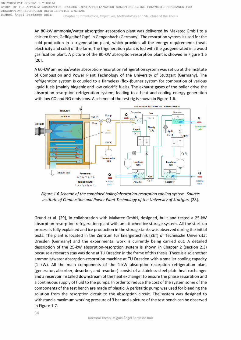
Chapter 1: Introduction, Objectives, Methodology and Structure of the Thesis
34 Doctoral Thesis, Miguel Ángel Berdasco Ruiz
An 80-kW ammonia/water absorption-resorption plant was delivered by Makatec GmbH to a
chicken farm, Geflügelhof Zapf, in Gengenbach (Germany). The resorption system is used for the
cold production in a trigeneration plant, which provides all the energy requirements (heat,
electricity and cold) of the farm. The trigeneration plant is fed with the gas generated in a wood
gasification plant. A picture of the 80-kW absorption-resorption plant is showed in Figure 1.5
[20].
A 60-kW ammonia/water absorption-resorption refrigeration system was set up at the Institute
of Combustion and Power Plant Technology of the University of Stuttgart (Germany). The
refrigeration system is coupled to a flameless (flox-)burner system for combustion of various
liquid fuels (mainly biogenic and low calorific fuels). The exhaust gases of the boiler drive the
absorption-resorption refrigeration system, leading to a heat and cooling energy generation
with low CO and NO emissions. A scheme of the test rig is shown in Figure 1.6.
Figure 1.6 Scheme of the combined boiler/absorption-resorption cooling system. Source:
Institute of Combustion and Power Plant Technology of the University of Stuttgart [28].
Grund et al. [29], in collaboration with Makatec GmbH, designed, built and tested a 25-kW
absorption-resorption refrigeration plant with an attached ice storage system. All the start-up
process is fully explained and ice production in the storage tanks was observed during the initial
tests. The plant is located in the Zentrum für Energietechnik (ZET) of Technische Universität
Dresden (Germany) and the experimental work is currently being carried out. A detailed
description of the 25-kW absorption-resorption system is shown in Chapter 2 (section 2.3)
because a research stay was done at TU Dresden in the frame of this thesis. There is also another
ammonia/water absorption-resorption machine at TU Dresden with a smaller cooling capacity
(1 kW). All the main components of the 1-kW absorption-resorption refrigeration plant
(generator, absorber, desorber, and resorber) consist of a stainless-steel plate heat exchanger
and a reservoir installed downstream of the heat exchanger to ensure the phase separation and
a continuous supply of fluid to the pumps. In order to reduce the cost of the system some of the
components of the test bench are made of plastic. A peristaltic pump was used for bleeding the
solution from the resorption circuit to the absorption circuit. The system was designed to
withstand a maximum working pressure of 3 bar and a picture of the test bench can be observed
in Figure 1.7.
UNIVERSITAT ROVIRA I VIRGILI STUDY OF THE AMMONIA ABSORPTION PROCESS INTO AMMONIA/WATER SOLUTIONS USING POLYMERIC MEMBRANES FOR ABSORPTION-RESORPTION REFRIGERATION SYSTEMS Miguel Ángel Berdasco Ruiz

Chapter 1: Introduction, Objectives, Methodology and Structure of the Thesis
35 Universitat Rovira i Virgili, Tarragona (Spain)
Figure 1.7 1-kW ammonia-water absorption-resorption plant set at TU Dresden [20].
Ammonia/water absorption-resorption refrigeration systems have been much less studied and
developed than the compression-resorption systems, probably due to the difficulty of keeping
the system working under steady-state conditions that was pointed out by several authors.
Another disadvantage is the bigger size of the absorption-resorption systems due to the higher
number of components in the cycle. This fact makes the study of more compact designs for the
absorber/desorber a very important task.
1.3 Polymeric materials in absorption cycles In recent years, several research works have been done related to the use of polymeric materials
in absorption cycles, particularly for the use of polymeric membranes as contactors in the
absorber and desorber of water/lithium bromide absorption refrigeration systems. The use of
polymeric membranes in this field has a very high potential for reducing the size and weight of
the modules but keeping a large surface area. These advantages make polymeric membrane
modules as great candidates for being used in absorption refrigeration systems in order to
design more compact, lighter and cheaper systems. There is a wide variety of polymeric
membrane contactors typically used in the industry. However, hollow fibre membrane and
plate-and-frame/flat sheet membrane modules are the types mostly investigated as membrane-
based components in the absorption refrigeration systems [30]. According to the literature, the
hollow fibre membrane module allows more efficient mass transfer due to the external
transverse flow but it also provides higher pressure drops compared to the plate-and-frame/flat
sheet membrane module [30]. That is why hollow fibre membrane modules have been mainly
selected as contactor for the ammonia/water absorption systems and the plate-and-frame/flat
UNIVERSITAT ROVIRA I VIRGILI STUDY OF THE AMMONIA ABSORPTION PROCESS INTO AMMONIA/WATER SOLUTIONS USING POLYMERIC MEMBRANES FOR ABSORPTION-RESORPTION REFRIGERATION SYSTEMS Miguel Ángel Berdasco Ruiz

Chapter 1: Introduction, Objectives, Methodology and Structure of the Thesis
36 Doctoral Thesis, Miguel Ángel Berdasco Ruiz
sheet membrane contactor for the water/lithium bromide absorption systems. Figure 1.8 shows
three schemes of commercially available microporous membrane modules typically used for
filtration applications. Figure 1.8(a) shows a scheme of a plate and frame membrane module
provided by Alfa Laval. It consists of several flat sheet membranes individually stacked between
plates. Figure 1.8(b) shows a picture of a hollow fibre membrane module provided by Daicen
Membrane Systems. It consists of a hollow fibre bundle inside of a housing. Fluids can flow both
inside and over the outside the hollow fibres. Finally, Figure 1.8(c) depicts a scheme of a spiral
wound membrane module provided by Fujifilm.
Figure 1.8 Pictures/schemes of commercially available membrane modules typically used for
filtration applications. (a) Alfa Laval M39 Plate-and-frame membrane module. (b) Daicen
Membrane Systems FS03 Hollow Fibre membrane module. (c) Fujifilm Spiral wound membrane
module.
1.3.1 Polymeric membrane contactors used in water/lithium bromide absorption
systems. Literature review Several authors have studied the absorption and desorption processes of the water/lithium
bromide working mixture using membrane contactors. Ali and Schwerdt [31] experimentally and
theoretically determined the desired membrane characteristics for absorption chiller
applications of the water/lithium bromide mixture: high permeability to the refrigerant (water
vapour), hydrophobic to the aqueous solution with a high liquid entry pressure to avoid
wettability of the membrane pores and no capillary condensation of water vapour to prevent
the pores from blocking. For practical use, the membrane should have a thin hydrophobic
microporous active layer up to 60μm thick, mean pore sizes around 0.45μm and a porosity of up
to 80%. In a subsequent study, Ali [32] designed a compact plate-and-frame absorber with a
hydrophobic microporous membrane contactor. The results clearly indicate that the aqueous
solution channel thickness is the most significant design parameter affecting the compactness
of the absorber. Furthermore, the study showed that the countercurrent cooling water flow with
the aqueous solution has a positive effect on the absorber compactness. Yu et al. [33] developed
a b
c
UNIVERSITAT ROVIRA I VIRGILI STUDY OF THE AMMONIA ABSORPTION PROCESS INTO AMMONIA/WATER SOLUTIONS USING POLYMERIC MEMBRANES FOR ABSORPTION-RESORPTION REFRIGERATION SYSTEMS Miguel Ángel Berdasco Ruiz

Chapter 1: Introduction, Objectives, Methodology and Structure of the Thesis
37 Universitat Rovira i Virgili, Tarragona (Spain)
a theoretical model and studied the performance of a membrane-based absorber for potential
use in water/lithium bromide absorption refrigeration systems. They concluded that the
solution film thickness is the critical parameter affecting the absorption rate, consequently a
constrained thin film absorber design was proposed. They also pointed out that increasing the
solution velocity enhances the absorption rate by bringing fresher layers of the solution to the
vapour for absorption. Wang et al. [34] studied at lab-scale the application of vacuum membrane
distillation to a lithium bromide absorption refrigeration system using a hollow fiber membrane
module made of polyvinylidene fluoride (PVDF) as a desorption device. They concluded that feed
temperature has the greatest effect on the water vapour permeation flux, followed by vacuum
pressure in the permeation side and, finally, the feed flux. Finally, they proposed that PVDF
hollow fibre membrane modules could be used as a traditional generator or as a secondary
generator to enhance the COP of the whole system.
Isfahani et al. [35] went one step further and studied the efficacy of highly porous nanofibrous
membranes in membrane-based absorbers and generators. An experimental plant with all the
main components present in the absorption refrigeration systems (evaporator, absorber,
generator, and condenser) was set up. Absorption and desorption rates were significantly higher
than those of conventional falling film absorbers and generators. More recently, Asfand et al.
[36] carried out a CFD simulation to investigate heat and mass transfer processes in a
membrane-based absorber for water/lithium bromide absorption cooling systems. The absorber
consists of a plate-and-frame absorber module incorporating membrane contactor at the
solution-vapour interface. They found an optimum value of 0.5 mm for the solution channel
thickness and a solution inlet velocity of about 0.005 m/s was recommended to achieve high
absorption rates with acceptable pressure drop along the solution channel. In a subsequent
study, Asfand et al. [37] showed that the membrane characteristics have a less prominent effect
on the absorption rate and the solution resistance is dominant in refrigerant mass transfer in
the case of thicker solution channels, so that the selection of appropriate membrane
characteristics should be made taking into account the solution channel thickness. In accordance
with the results obtained in their previous study, a solution channel thickness of about 0.5 mm
was considered appropriate to avoid a higher pressure drop in the solution channel and because
the effect of membrane characteristics is low when the solution channel thickness is in the range
of 0.5 mm. Finally, Asfand et al. [38] studied (by CFD simulations) the heat and mass transfer
processes in the membrane-based absorber with no conventional working pairs in order to cope
with the limitations of the conventional water/lithium bromide working pair (thermal instability,
crystallization and corrosion problems). The working pairs and applications selected were
H2O/(LiBr + LiI + LiNO3 + LiCl) for air-cooled systems and H2O/(LiNO3 + KNO3 + NaNO3) for multi-
stage high-temperature heat source absorption cooling systems. Very promising results were
obtained in terms of absorption rate for H2O/(LiBr + LiI + LiNO3 + LiCl) and lower pressure drops
in the case of H2O/(LiNO3 + KNO3 + NaNO3) because of the higher operating pressure.
Venegas et al. [39] presented a model for optimizing the geometry and operating conditions of
the lithium bromide/water membrane absorber under typical operating conditions of
absorption cooling chillers. A microporous membrane was proposed in combination with
rectangular microchannels in the absorber of an absorption chiller with the aim of reducing the
size of this cooling technology. These authors pointed out the importance of reducing the
solution film thickness in order to improve the absorber performance and reduce their size. For
maximizing the ratio between the cooling capacity of the chiller and the absorber volume, it was
not recommended using very long channels because the increase of the absorber size is higher
than the increment obtained in the cooling power. Finally, they reported a maximum value of
UNIVERSITAT ROVIRA I VIRGILI STUDY OF THE AMMONIA ABSORPTION PROCESS INTO AMMONIA/WATER SOLUTIONS USING POLYMERIC MEMBRANES FOR ABSORPTION-RESORPTION REFRIGERATION SYSTEMS Miguel Ángel Berdasco Ruiz

Chapter 1: Introduction, Objectives, Methodology and Structure of the Thesis
38 Doctoral Thesis, Miguel Ángel Berdasco Ruiz
the ratio between the cooling capacity of the chiller and absorber volume of 1090 kW/m3, more
than twice the one obtained using falling film absorbers of conventional diameter tubes. In a
subsequent study, Venegas et al. [40] determined the most important parameters (in decreasing
order of importance) in the design stage of the membrane absorber: porosity and pore diameter
of the membrane, solution channel depth, thicknesses of the membrane and the interface wall
between the solution and the cooling water, solution channel width and cooling water channel
depth. Their conclusions were in good agreement with those presented by Ali and Schwerdt
[31]. Finally, Venegas et al. [41] compared the performance of adiabatic and non-adiabatic
membrane-based rectangular micro-absorbers for water/lithium bromide absorption chillers.
As expected, the results provided by the models showed that the non-adiabatic absorber
performs better in terms of pressure potential (subcooling), absorption rate, and cooling power
along the membrane module because the absorption heat is extracted by the cooling water and
the solution is continuously cooled. However, they also pointed out that adiabatic configuration
combined with pre-cooling using ambient air has significant advantages respect to the non-
adiabatic one in terms of a higher ratio between cooling capacity and absorber volume (kW/m3)
and fabrication simplicity.
1.3.2 Polymeric membrane contactors used in ammonia/water absorption systems.
Literature review The use of membrane contactors in absorption and desorption processes for the
ammonia/water absorption cycle has been much less studied than in the case of water/lithium
bromide, probably due to the fact that the pressure conditions of the ammonia/water
absorption cycle is not favourable for the use of polymeric materials. As far as the author
concerns, there are no available studies in the literature concerning the use of membrane
contactors for the desorption process of the ammonia/water mixture, whereas with regard to
the absorption process only two references were found. One of these studies was carried out
by Chen et al. [42], that developed a unidimensional model to study the performance of a hybrid
absorber-heat exchanger device using hollow fibre membranes (HFMAE) for application to the
ammonia/water absorption heat pump. The HFMAE absorber proposed utilized porous fibres
for the heat and mass transfer between the solution and the vapour phase, while nonporous
fibres were used for the heat transfer between the solution and the cooling fluid. The
performance of the HFMAE absorber in a typical ammonia/water absorption refrigeration cycle
was compared to the performance provided by a plate heat exchanger falling film type absorber
(PHEFFA). They concluded that the HFMAE absorber provided higher absorption performance
than PHEFFA absorber due to its vast interfacial area. The study also highlighted that the only
significant factor affecting the performance of the HFMAE absorber was the solution mass
transfer. Finally, it was also concluded that applying the HFMAE absorber increases by 14.8% the
COP of the refrigeration cycle and reduces the overall exergy loss by 26.7%.
In his doctoral thesis, Schaal [43] carried out several lab-scale experiments in order to study the
absorption process of the ammonia vapour into ammonia/water solutions using microporous
membranes as contactors. Three different prototypes of hollow fibre membrane absorbers were
tested under typical absorber conditions of an ammonia/water absorption refrigeration plant.
The hollow fibre membranes were made of polypropylene in all cases, but the pore diameter,
number of fibres, packing density, housing material, length of the module and thickness of the
fibres were different for each module. The hollow fibre membrane modules designed and built
for the study were tested under adiabatic conditions because no cooling channels were
UNIVERSITAT ROVIRA I VIRGILI STUDY OF THE AMMONIA ABSORPTION PROCESS INTO AMMONIA/WATER SOLUTIONS USING POLYMERIC MEMBRANES FOR ABSORPTION-RESORPTION REFRIGERATION SYSTEMS Miguel Ángel Berdasco Ruiz

Chapter 1: Introduction, Objectives, Methodology and Structure of the Thesis
39 Universitat Rovira i Virgili, Tarragona (Spain)
integrated inside the membrane module. Two parallel flow configurations were tested during
the experiments:
• Gas flowing inside the hollow fibres and solution supplied to the shell side. This
configuration could lead to lower absorption rates if there is a wide gap between the
hollow fibre bundle and the housing. Then, this flow configuration requires an optimal
design and construction in order to avoid this issue.
• Solution flowing inside the hollow fibres and ammonia gas through the shell side. This
configuration provided higher pressure drops than the previous one.
Schaal pointed out that the pressure control in the gas and liquid sides is a key parameter during
the absorption process in order to avoid liquid breakthroughs when the pressure in the liquid
side exceeds the gas pressure by the so-called breakthrough pressure. The breakthrough
pressure depends on the surface tension and the pore size of the membrane. Small pore sizes
increase the breakthrough pressure. When liquid breakthroughs occur, the liquid blocks the
pores and the absorption rate drops or even stops.
The main advantage of the membrane absorbers over other technologies such as plate or shell
and tube absorbers is that they are smaller and lighter because the membranes have higher
surface areas per volume unit. This advantage was pointed out and quantified by Schaal [43] by
achieving stable operation in an ammonia/water absorption refrigeration plant with a
membrane-based absorber integrated in the system. The membrane absorber was placed in
parallel with a plate absorber in order to compare the performance of both configurations. It
was showed that membranes can reduce the absorber size up to 10 times more than plate
absorbers and 100 times more than shell and tube absorbers. The operating capability of
membrane absorbers was then demonstrated but the need of designing a membrane absorber
with heat exchanger integrated was also pointed out in order to obtain a more compact designs.
Unlike in the case of the water/lithium bromide, neither of the two mentioned studies
determined the characteristics required for a membrane in order to be used as contactor in the
ammonia/water absorption process. Such important membrane characteristics as porosity, pore
diameter or thickness are required to be studied to select the adequate membrane contactor
available in the market before starting the experimental work.
As mentioned before, the major drawback for using polymeric materials in ammonia/water
absorption refrigeration systems is the typically high working pressure that impedes its use in
the components of the high-pressure side of the cycle (the generator and the solution heat
exchanger). That is why the studies carried out in this field were only focused in the absorber,
because the pressure in this component is the lowest one in all the absorption refrigeration
system. For this reason, the use of resorption technology becomes particularly interesting
because the reduction of the pressure enables the integration of polymeric materials in all the
components of the cycle. By way of example, the German company Makatec GmbH developed
a polymer-based heat exchanger for substitution of the solution stainless steel HEX in the
ammonia/water absorption-resorption cycle. The spiral winding in combination with spacers
creates flow channels in a pressure resistant design (up to six bar) and provides a heat exchanger
thermal capacity of 3 kW/K. Figure 1.9 shows a picture of the device [20].
UNIVERSITAT ROVIRA I VIRGILI STUDY OF THE AMMONIA ABSORPTION PROCESS INTO AMMONIA/WATER SOLUTIONS USING POLYMERIC MEMBRANES FOR ABSORPTION-RESORPTION REFRIGERATION SYSTEMS Miguel Ángel Berdasco Ruiz

Chapter 1: Introduction, Objectives, Methodology and Structure of the Thesis
40 Doctoral Thesis, Miguel Ángel Berdasco Ruiz
Figure 1.9 Polymer-based heat exchanger developed by Makatec GmbH. (a) Inside view (from
the top). (b) External view.
1.4 Objectives, thesis structure, and methodological approach As have been reported in previous sections, ammonia/water absorption-resorption refrigeration
systems are a very interesting technological option that make possible to achieve a very
significant reduction of the high-pressure level compared to the conventional absorption
systems, so that it opens up new possibilities for using cheaper assembly materials (such as
polymers) in the main components. Furthermore, the absorption-resorption systems can be
driven by low-grade energy sources, so the electrical consumption would be much lower
compared to the vapour-compression technology. However, the large size and cost of the
absorption-resorption systems are their main handicaps.
In turn, membrane absorbers have been studied in recent years in order to be used as an
alternative to the conventional plate or shell and tube absorbers typically used in absorption
refrigeration systems. The use of polymeric membrane modules in this field has a very high
potential for reducing the size and weight of the modules but keeping a large surface area. These
advantages make possible to design more compact, lighter and cheaper absorbers. Therefore,
the aim of this research work is to study the ammonia absorption process using polymeric
membranes as contactors in order to be used in ammonia/water absorption-resorption
refrigeration systems.
1.4.1 Specific objectives To reach the above-mentioned objective, the more specific objectives were raised as follows:
• Study of the ammonia/water absorption-resorption refrigeration cycle and suggest an adequate operating condition for the base case selected that take advantage of the strengths of the absorption-resorption cycles.
• Determination of the main characteristics required for the membrane in order to be
used as contactor for the ammonia/water absorption process.
(a) (b)
UNIVERSITAT ROVIRA I VIRGILI STUDY OF THE AMMONIA ABSORPTION PROCESS INTO AMMONIA/WATER SOLUTIONS USING POLYMERIC MEMBRANES FOR ABSORPTION-RESORPTION REFRIGERATION SYSTEMS Miguel Ángel Berdasco Ruiz

Chapter 1: Introduction, Objectives, Methodology and Structure of the Thesis
41 Universitat Rovira i Virgili, Tarragona (Spain)
• Experimental and theoretical study of the adiabatic ammonia/water absorption process using a commercial membrane module as contactor. Validation of the model with the experimental results.
• Use the theoretical model previously validated as a basis for developing a theoretical
model of a hybrid membrane absorber-heat exchanger. • Design two hybrid membrane absorber-heat exchanger: One for the absorption circuit
and the other one for the resorption circuit of the ammonia/water absorption-resorption refrigeration cycle.
1.4.2 Thesis structure and methodological approach The thesis was composed of the following chapters:
CHAPTER 1 is dedicated to explaining the background and justifications of this research that
raise the motivation and objectives of this thesis. The fundamentals of the resorption
technology, a literature review and a compilation of the ammonia/water absorption-resorption
experimental plants available in several research centres/companies were presented. Finally,
literature review related to the use of membrane contactors in absorption refrigeration systems
was showed.
CHAPTER 2 is dedicated to study the ammonia/water absorption-resorption refrigeration
system. The different configurations of the cycle (with or without rectifier) are described and it
is showed how the operating pressure range can be determined when the working temperatures
are previously fixed. A thermodynamic model of the cycle is described and used for determining
the influence of the pressure, the effectiveness of the heat exchangers and the
presence/absence of the rectifier on the performance of the cycle. This theoretical study is also
used for suggesting an adequate operating condition for the base case previously set.
Furthermore, another thermodynamic model with external heat transfer (A-type model) is
described for studying the influence of the temperatures of the external streams and the UA
values of the heat exchangers on the performance of the cycle, low-pressure level, cooling
capacity and gliding temperature in the desorber. Furthermore, a description of a 25-kW
ammonia/water absorption-resorption experimental plant set at TU Dresden is included and its
performance is analysed by means of the thermodynamic model. Finally, a new method based
on near-infrared spectroscopy for the “in-situ” determination of the ammonia concentration in
ammonia/water mixtures is described and proposed to be used as an alternative to improve the
performance of the absorption-resorption plants.
CHAPTER 3 is dedicated to study the ammonia/water absorption process using a flat sheet
membrane module. The heat and mass transfer process in the adiabatic flat sheet membrane
module is investigated experimentally and analytically. Moreover, a detailed description of the
experimental test bench used is shown in this chapter. On the other hand, a unidimensional
model was validated with the experimental results and used to evaluate the influence of the
temperature, concentration, flow rate and membrane characteristics on the absorption process.
The conclusions obtained about the characteristics required for the membrane to be used as
contactor for the ammonia absorption process will be taken into account for the selection of the
commercial hollow fibre membrane module used in Chapter 4.
CHAPTER 4 is dedicated to study the ammonia/water absorption process using a hollow fibre
membrane module. The experimental work was carried out in the test bench described in
UNIVERSITAT ROVIRA I VIRGILI STUDY OF THE AMMONIA ABSORPTION PROCESS INTO AMMONIA/WATER SOLUTIONS USING POLYMERIC MEMBRANES FOR ABSORPTION-RESORPTION REFRIGERATION SYSTEMS Miguel Ángel Berdasco Ruiz
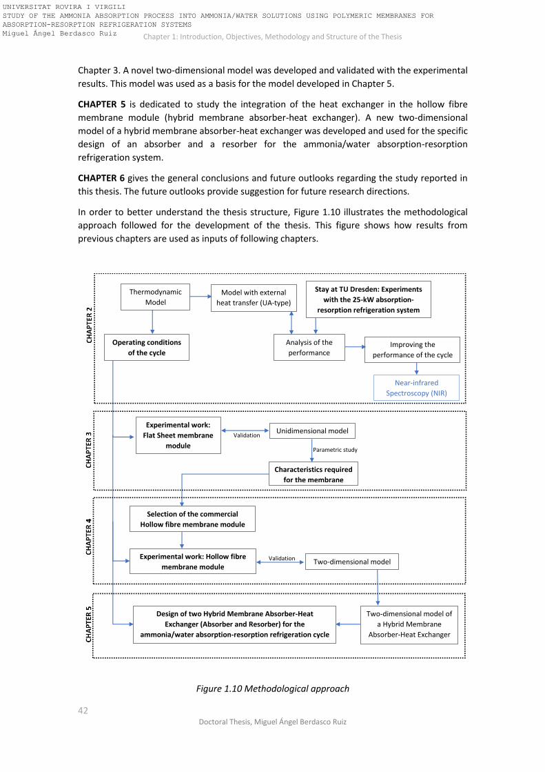
Chapter 1: Introduction, Objectives, Methodology and Structure of the Thesis
42 Doctoral Thesis, Miguel Ángel Berdasco Ruiz
Chapter 3. A novel two-dimensional model was developed and validated with the experimental
results. This model was used as a basis for the model developed in Chapter 5.
CHAPTER 5 is dedicated to study the integration of the heat exchanger in the hollow fibre
membrane module (hybrid membrane absorber-heat exchanger). A new two-dimensional
model of a hybrid membrane absorber-heat exchanger was developed and used for the specific
design of an absorber and a resorber for the ammonia/water absorption-resorption
refrigeration system.
CHAPTER 6 gives the general conclusions and future outlooks regarding the study reported in
this thesis. The future outlooks provide suggestion for future research directions.
In order to better understand the thesis structure, Figure 1.10 illustrates the methodological
approach followed for the development of the thesis. This figure shows how results from
previous chapters are used as inputs of following chapters.
Figure 1.10 Methodological approach
Model with external
heat transfer (UA-type)
Operating conditions
of the cycle
Stay at TU Dresden: Experiments
with the 25-kW absorption-
resorption refrigeration system
Analysis of the
performance
Near-infrared
Spectroscopy (NIR)
Improving the
performance of the cycle
Experimental work:
Flat Sheet membrane
module
Unidimensional model Validation
Characteristics required
for the membrane
Parametric study
Selection of the commercial
Hollow fibre membrane module
Two-dimensional model Validation
Two-dimensional model of
a Hybrid Membrane
Absorber-Heat Exchanger
Design of two Hybrid Membrane Absorber-Heat
Exchanger (Absorber and Resorber) for the
ammonia/water absorption-resorption refrigeration cycle
Experimental work: Hollow fibre
membrane module
Thermodynamic
Model
UNIVERSITAT ROVIRA I VIRGILI STUDY OF THE AMMONIA ABSORPTION PROCESS INTO AMMONIA/WATER SOLUTIONS USING POLYMERIC MEMBRANES FOR ABSORPTION-RESORPTION REFRIGERATION SYSTEMS Miguel Ángel Berdasco Ruiz
43 Universitat Rovira i Virgili, Tarragona (Spain)
Chapter 2
Study of the Ammonia/Water
Absorption-Resorption Refrigeration Cycle
UNIVERSITAT ROVIRA I VIRGILI STUDY OF THE AMMONIA ABSORPTION PROCESS INTO AMMONIA/WATER SOLUTIONS USING POLYMERIC MEMBRANES FOR ABSORPTION-RESORPTION REFRIGERATION SYSTEMS Miguel Ángel Berdasco Ruiz

Chapter 1: Introduction, Objectives, Methodology and Structure of the Thesis
44 Doctoral Thesis, Miguel Ángel Berdasco Ruiz
UNIVERSITAT ROVIRA I VIRGILI STUDY OF THE AMMONIA ABSORPTION PROCESS INTO AMMONIA/WATER SOLUTIONS USING POLYMERIC MEMBRANES FOR ABSORPTION-RESORPTION REFRIGERATION SYSTEMS Miguel Ángel Berdasco Ruiz

Chapter 2. Study of the Ammonia/Water Absorption-Resorption Refrigeration Cycle
45 Universitat Rovira i Virgili, Tarragona (Spain)
The aim of this chapter is to study the ammonia/water absorption-resorption refrigeration cycle.
For that purpose, the first step is to describe the cycle emphasizing specially the wide operation
flexibility provided by the resorption technology in terms of reduction of the high-pressure. The
determination of the operational high and low-pressure ranges at fixed working temperatures
is explained in detail and the influence of such temperatures on the operational pressure ranges
was also studied. Two thermodynamic models of the ammonia/water absorption-resorption
refrigeration cycle were developed. The first model considers only the internal variables of the
cycle and it was used for studying the influence of the effectiveness of the solution heat
exchangers, the presence/absence of the rectifier and the operational pressure ratio on the
performance of the cycle. The base case for the theoretical study was selected from the typical
working conditions of the ammonia/water absorption-resorption refrigeration systems. Finally,
adequate operating conditions are suggested for the base case that enables to harness the
strengths of the absorption-resorption refrigeration cycle.
The second thermodynamic model considers the external heat transfer (UA-type) on the main
thermal components, so a study of the effect of the temperature of the external streams and
the size of the heat exchangers on the performance of the cycle was done. This model was also
used to analyse the experimental performance of a 25-kW absorption-resorption refrigeration
plant operating in a test bench at Technische Universität Dresden (Germany). Finally, some
modifications in the plant were suggested for improving the performance and control.
2.1 Configuration of the ammonia/water absorption-resorption
refrigeration cycle Figure 2.1a shows the scheme of an absorption-resorption refrigeration cycle while Figure 2.1b
represents the main state points of the cycle on the PTX diagram of the ammonia/water mixture.
As mentioned in the previous chapter, the cycle consists of two solution loops (the absorption
circuit and the resorption circuit) coupled to each other through two vapour streams. Regarding
the absorption circuit, the ammonia vapour stream (vapour 2) coming from the desorber (DES)
is absorbed by the inlet ammonia/water solution (state-point 4) in the absorber (ABS). This
absorption process is exothermic and in order to maintain the absorption potential, the heat
generated during the absorption process is transferred to an external fluid (usually water or air).
The solution rich in ammonia leaving the absorber (state-point 1) is then pumped to the high-
pressure side by means of a solution pump (P1). This rich solution is pre-heated in the solution
heat exchanger 1 (SHX1) before entering to the generator (GEN), where heat is supplied by an
external heat source to desorb the ammonia. The ammonia vapour produced (vapour 1) is sent
to the resorber (RES) and the remaining solution (poor in ammonia) leaves the generator (state-
point 3) and is sent back to the absorber. Before entering the absorber, the poor solution 1 is
cooled down in the SHX1 by the rich solution 1 and then passes through the expansion valve
(V1) where it undergoes an abrupt reduction in pressure to the state-point 4. The aim of
including an internal heat recovery by means of a solution heat exchanger is to increase the COP
of the cycle.
Regarding the resorption circuit, the vapour coming from the generator (vapour 1) is absorbed
by the poor solution (state-point 6) in the resorber, releasing heat to an external cooling fluid.
The rich solution leaving the resorber (state-point 7) is cooled down by the poor solution in the
solution heat exchanger 2 (SHX2) and throttled in the expansion valve (V2). This rich and cold
solution (state-point 8) enters to the low-pressure desorber, where heat is supplied by an
external load in order to desorb the ammonia. The ammonia vapour released in the desorber
UNIVERSITAT ROVIRA I VIRGILI STUDY OF THE AMMONIA ABSORPTION PROCESS INTO AMMONIA/WATER SOLUTIONS USING POLYMERIC MEMBRANES FOR ABSORPTION-RESORPTION REFRIGERATION SYSTEMS Miguel Ángel Berdasco Ruiz

Chapter 2. Study of the Ammonia/Water Absorption-Resorption Refrigeration Cycle
46 Doctoral Thesis, Miguel Ángel Berdasco Ruiz
(vapour 2) is then absorbed in the absorber by the poor solution of the absorption circuit (state-
point 4), closing the cycle.
Figure 2.1 (a) Scheme of the absorption-resorption cycle. (b) Absorption-resorption cycle on the
PTX diagram of the ammonia/water mixture.
In the conventional ammonia/water absorption cycle is necessary to incorporate a rectification
stage after the generator in order to purify the vapour in ammonia, otherwise an excessively
high-temperature glide in the evaporator would take place. However, absorption-resorption
Solution Heat Exchanger 1 (SHX 1)
Solution Heat Exchanger 2 (SHX2)
Generator (GEN)
Absorber (ABS)
Resorber (RES)
Desorber (DES)
vapour 1
vapour 2 Heat sink
Heat supply
Heat supply
Heat sink
Ric
h s
olu
tio
n1
Rich
solu
tion
2
Po
or so
lutio
n1
Po
or
solu
tio
n2
2 3
4158
67
Absorption circuitResorption circuit
High
pressu
re side
Low
pre
ssure
side
P1P2 V1V2
Vap
ou
r P
ress
ure
Temperature
phigh
plow
SHX 1SHX 2
V1V2 P1P2
1
2 3
45
67
8ABSDES
RES GEN
(a)
(b)
UNIVERSITAT ROVIRA I VIRGILI STUDY OF THE AMMONIA ABSORPTION PROCESS INTO AMMONIA/WATER SOLUTIONS USING POLYMERIC MEMBRANES FOR ABSORPTION-RESORPTION REFRIGERATION SYSTEMS Miguel Ángel Berdasco Ruiz

Chapter 2. Study of the Ammonia/Water Absorption-Resorption Refrigeration Cycle
47 Universitat Rovira i Virgili, Tarragona (Spain)
cycles do not have this limitation because the vaporization is partial, so the gliding temperature
can be chosen. As shown in Figure 2.1a, there are two vapour streams in the absorption-
resorption cycle; one leaving the generator (vapour 1) and the other one leaving the desorber
(vapour 2). The ammonia concentration and mass flow rate of these vapour streams are
different because they are generated under different conditions. At the typical working
conditions (pressure, temperature and composition) of the cycle, the concentration of water in
vapour 1 is higher than in vapour 2. As a result of this, the water content in the resorption circuit
is continuously increasing which leads to a slow depletion of the solution concentration in the
resorption circuit. For this reason, it would be necessary to equilibrate the mass balance
between both circuits in order to keep the system running under the desired working conditions.
Three solutions are possible:
• Use a rectification stage after the generator in order to obtain the same concentration
in vapour 1 than in vapour 2. This option implies some limitations that we should take
into account. Depending on the working conditions of the cycle, the required
temperature in the rectifier could be lower than the temperature provided by the
external fluid used for cooling the rectifier. If this happens, another refrigeration system
is needed for reducing the temperature of the refrigeration fluid. In these situations,
rectification is not a good choice.
• Another option is the use of a “bleeding” or mixing pipe for connecting both solution
circuits, thus the excess of water from the resorption circuit can be transferred to the
absorption circuit. The bleeding flow is transferred from the high-pressure side of the
resorption cycle to the low-pressure side of the absorption cycle. Thus, for the
transportation of the solution no additional pump is required. This option is the best
from an economical and design point of view because the rectifier is removed. However,
an accurate control of the concentrations in the circuits is required in order to regulate
the bleeding mass flow rate and avoid the system to drift away from its thermodynamic
point of operation.
• The third option is a combination of the previous ones. The rectification stage after the
generator is remained in the system but always with the bleeding line as a backup
(Figure 1.4b), otherwise the operating range of the cycle would be limited by the
temperature of the cooling water in the rectifier. From an economic point of view, this
option is the worst because the number of components is increased respect the other
options, but the control of the system would be easier.
A deeper study about the influence of the presence/absence of the rectifier on the COP can be
found in section 2.2.2.3.
2.2 Thermodynamic model of the absorption-resorption cycle This section describes the thermodynamic model used for studying the performance of the
ammonia/water absorption-resorption system. This model considers only the internal variables
of the cycle and it was used for analysing the influence of the effectiveness of the solution heat
exchangers, the cycle configuration (presence/absence of the rectifier) and the pressure ratio
on the performance of the cycle. According to the results obtained in this section, an adequate
operating condition (pressure, ammonia concentration and solution mass flow rates) is
suggested for the base case that enables to harness the strengths of the absorption-resorption
refrigeration cycle.
UNIVERSITAT ROVIRA I VIRGILI STUDY OF THE AMMONIA ABSORPTION PROCESS INTO AMMONIA/WATER SOLUTIONS USING POLYMERIC MEMBRANES FOR ABSORPTION-RESORPTION REFRIGERATION SYSTEMS Miguel Ángel Berdasco Ruiz

Chapter 2. Study of the Ammonia/Water Absorption-Resorption Refrigeration Cycle
48 Doctoral Thesis, Miguel Ángel Berdasco Ruiz
A scheme of the configuration of the absorption-resorption cycle considered for the model is
shown in Figure 2.2. It can be observed that the configuration selected includes the rectifier and
the bleeding line. This configuration was selected in order to study the influence of the rectifier
on the performance of the cycle.
Figure 2.2 Absorption-resorption cycle with rectifier and bleeding line.
The thermodynamic model was developed using Engineering Equation Solver (EES) and is based
on the mass and energy balances on each component of the cycle. The thermodynamic
properties of the ammonia/water mixture were determined using the EES database [44].
Equations 2.1, 2.2 and 2.3 show the total mass balance, the ammonia mass balance and the
energy balance in the desorber, respectively.
𝑚13 = 𝑚8 + 𝑚14 (2.1)
𝑚13 · 𝑥13 = 𝑚8 · 𝑥8 + 𝑚14 · 𝑥14 (2.2)
𝑄𝑑𝑒𝑠 + 𝑚13 · ℎ13 = 𝑚8 · ℎ8 + 𝑚14 · ℎ14 (2.3)
Equations 2.4 and 2.5 show the total and ammonia mass balances in the combined generator-
rectifier unit, while Equations 2.6, 2.7 and 2.8 show the total mass balance, ammonia mass
balance and energy balance in the rectifier. Equation 2.9 shows the energy balance in the
generator while Equations 2.10 and 2.11 show the energy balance in the absorber and resorber,
respectively.
𝑚3 = 𝑚4 + 𝑚7 (2.4)
𝑚3 · 𝑥3 = 𝑚4 · 𝑥4 + 𝑚7 · 𝑥7 (2.5)
𝑚15 = 𝑚16 + 𝑚7 (2.6)
Solution Heat Exchanger 1
Solution Heat Exchanger 2
Generator
Absorber
Resorber
Desorber
vapour
2
34
1
5
86
7
P1P2V1
V2
Rectifier
9
18
19
20
15
14
16
V3
vapour
vapour
Bleeding line
10
11 17
12
13
Qgen
Qdes Qabs
Qres
Qrect
SP
MP
UNIVERSITAT ROVIRA I VIRGILI STUDY OF THE AMMONIA ABSORPTION PROCESS INTO AMMONIA/WATER SOLUTIONS USING POLYMERIC MEMBRANES FOR ABSORPTION-RESORPTION REFRIGERATION SYSTEMS Miguel Ángel Berdasco Ruiz

Chapter 2. Study of the Ammonia/Water Absorption-Resorption Refrigeration Cycle
49 Universitat Rovira i Virgili, Tarragona (Spain)
𝑚15 · 𝑥15 = 𝑚16 · 𝑥16 + 𝑚7 · 𝑥7 (2.7)
𝑚15 · ℎ15 = 𝑄𝑟𝑒𝑐𝑡 + 𝑚16 · ℎ16 + 𝑚7 · ℎ7 (2.8)
𝑄𝑔𝑒𝑛 + 𝑚3 · ℎ3 + 𝑚16 · ℎ16 = 𝑚4 · ℎ4 + 𝑚15 · ℎ15 (2.9)
𝑚6 · ℎ6 + 𝑚14 · ℎ14 = 𝑄𝑎𝑏𝑠 + 𝑚1 · ℎ1 (2.10)
𝑚17 · ℎ17 + 𝑚7 · ℎ7 = 𝑄𝑟𝑒𝑠 + 𝑚11 · ℎ11 (2.11)
Power consumption in the solution pumps of the absorption and resorption circuits are shown
in Equations 2.12 and 2.13, respectively. Equations 2.14 and 2.15 show the effectiveness and
the energy balance in the solution heat exchanger of the absorption circuit, respectively.
Equations 2.16 and 2.17 show the effectiveness and the energy balance in the solution heat
exchanger of the resorption circuit. The equations for the effectiveness of the solution heat
exchangers (Equations 2.14 and 2.16) are written supposing that the streams with lower
ammonia concentration (poor solution) are limiting the heat transfer.
𝑊𝑃1 = 𝑚1 · 𝑣1 · (𝑝ℎ𝑖𝑔ℎ − 𝑝𝑙𝑜𝑤) (2.12)
𝑊𝑃2 = 𝑚8 · 𝑣8 · (𝑝ℎ𝑖𝑔ℎ − 𝑝𝑙𝑜𝑤) (2.13)
𝐸𝑓𝑓𝑠ℎ𝑥1 =(𝑇4 − 𝑇5)
(𝑇4 − 𝑇2)
(2.14)
𝑚2 · (ℎ3 − ℎ2) = 𝑚4 · (ℎ4 − ℎ5) (2.15)
𝐸𝑓𝑓𝑠ℎ𝑥2 =(𝑇10 − 𝑇9)
(𝑇11 − 𝑇9)
(2.16)
𝑚9 · (ℎ10 − ℎ9) = 𝑚11 · (ℎ11 − ℎ12) (2.17)
Regarding the bleeding line, the following equations are required. Equation 2.18 corresponds to
the mass balance in the split point (SP) of the stream 10. Equations 2.19 and 2.20 show the total
and ammonia mass balances between both solution circuits, while Equations 2.21, 2.22 and 2.23
correspond to the total mass, ammonia mass and energy balances in the mixing point (MP) of
the absorption circuit.
𝑚10 = 𝑚18 + 𝑚17 (2.18)
𝑚7 = 𝑚14 + 𝑚18 (2.19)
𝑚7 · 𝑥7 = 𝑚14 · 𝑥14 + 𝑚18 · 𝑥18 (2.20)
𝑚19 + 𝑚20 = 𝑚6 (2.21)
𝑚19 · 𝑥19 + 𝑚20 · 𝑥20 = 𝑚6 · 𝑥6 (2.22)
𝑚19 · ℎ19 + 𝑚20 · ℎ20 = 𝑚6 · ℎ6 (2.23)
Finally, Equation 2.24 shows the coefficient of performance (COP) of the refrigeration cycle
expressed as the ratio between the refrigeration load and the energy inputs.
𝐶𝑂𝑃 =𝑄𝑑𝑒𝑠
𝑄𝑔𝑒𝑛+𝑊𝑃1+𝑊𝑃2 (2.24)
The following assumptions were considered [22] for modelling the cycle:
UNIVERSITAT ROVIRA I VIRGILI STUDY OF THE AMMONIA ABSORPTION PROCESS INTO AMMONIA/WATER SOLUTIONS USING POLYMERIC MEMBRANES FOR ABSORPTION-RESORPTION REFRIGERATION SYSTEMS Miguel Ángel Berdasco Ruiz

Chapter 2. Study of the Ammonia/Water Absorption-Resorption Refrigeration Cycle
50 Doctoral Thesis, Miguel Ángel Berdasco Ruiz
• Heat losses/gains in the components are negligible.
• The cycle operates at steady-state conditions. • Pressure drops in piping and components are not considered except on the throttling
devices. • The flow arrangement of solution heat exchangers is countercurrent.
• The solution streams leaving the desorber, absorber, generator, rectifier, and resorber are saturated.
• Pumping processes are isentropic and expansion processes in valves are isenthalpic. • The vapour stream exits the generator at equilibrium conditions with the inlet solution
(countercurrent flow arrangement). • The vapour stream exists the desorber at equilibrium conditions with the outlet solution
(parallel flow arrangement).
Finally, the number of independent variables of the cycle must be specified. Applying the
method described in Ayou et al. [45], it was determined that 10 independent variables should
be chosen as an input data to close the cycle. The variables selected were:
• The outlet temperature of the solution in the generator (Tgen), desorber (Tdes), absorber
(Tabs), resorber (Tres), and rectifier (Trect).
• The high and low-pressure levels in the system (phigh and plow).
• The volumetric flow rate of the solution pump (P2) of the resorption circuit.
• The effectiveness of the solution heat exchangers 1 and 2.
2.2.1 Operational high and low-pressure ranges in the ammonia/water absorption-
resorption cycle In the conventional absorption cycle, the low and high-pressures are dependent of the
temperature in the evaporator (TE) and condenser (TC), respectively. However, in the case of the
absorption-resorption cycle there is a range of working pressures that can be chosen for the
same temperatures of the heat sources just varying the ammonia concentration of the solution
circulating in both solution circuits. This fact can be clearly observed using the PTX diagram of
the ammonia/water mixture for representing the operating conditions of the cycle. Figure 2.3a
depicts the conventional absorption cycle. Once the temperatures in the condenser and
evaporator are set, the high and low-pressure values are thus determined by the cut-off point
of the temperature and the line of 100% ammonia mass fraction. In the case of the absorption-
resorption cycle, for the same working temperatures, there is a wide variety of cycles working
at different pressures and concentrations. Figure 2.3b depicts three of these cycles. The number
of all possible cycles are limited within a range that can be determined. The determination of
these operational pressure ranges is a very useful tool for the study of the cycle.
Figure 2.4a represents the absorption-resorption cycle on the PTX when Tabs, Tres, Tdes and Tgen
are fixed. Tabs is considered to be equal to Tres and xabs, xres, xdes and xgen are the ammonia mass
fractions of the solutions leaving the absorber, resorber, desorber and generator, respectively.
The maximum value of the high-pressure (phigh,max) corresponds to the vapour pressure of the
ammonia at Tres, which means that pure ammonia is leaving the resorber. The minimum value
of the high-pressure (phigh,min) corresponds to the vapour pressure of the water at Tgen, which
means that pure water is leaving the generator. When the high-pressure is set to a certain value
(phigh), the low-pressure (plow) can in turn vary between plow,lower and plow,upper (Figure 2.4a).
UNIVERSITAT ROVIRA I VIRGILI STUDY OF THE AMMONIA ABSORPTION PROCESS INTO AMMONIA/WATER SOLUTIONS USING POLYMERIC MEMBRANES FOR ABSORPTION-RESORPTION REFRIGERATION SYSTEMS Miguel Ángel Berdasco Ruiz

Chapter 2. Study of the Ammonia/Water Absorption-Resorption Refrigeration Cycle
51 Universitat Rovira i Virgili, Tarragona (Spain)
Figure 2.3 PTX diagram of the ammonia/water mixture. Absorber (ABS); Desorber (DES);
Generator (GEN); Resorber (RES); Condenser (C) and Evaporator (E). (a) Absorption cycle for a
fixed temperature levels of the heat sources. (b) Some of the possible absorption-resorption
cycles for the same temperature levels.
plow,lower is obtained when the ammonia concentration in both streams of the absorption circuit
are equal (xabs=xgen→Δxabs=0), i.e., there are no absorption/desorption processes in the
absorption circuit. plow,upper is obtained when the ammonia concentration in both streams of the
resorption circuit are equal (xres=xdes→Δxres=0), i.e., there is no absorption/desorption processes
in the resorption circuit. Figure 2.4b show the operational high and low-pressure ranges
obtained when plow,lower and plow,upper are calculated all over the range of phigh. Thus, the yellow-
coloured area of Figure 2.4b represents all the possible combinations of phigh and plow for a
certain value of Tabs, Tres, Tdes and Tgen.
(a)
(b)
UNIVERSITAT ROVIRA I VIRGILI STUDY OF THE AMMONIA ABSORPTION PROCESS INTO AMMONIA/WATER SOLUTIONS USING POLYMERIC MEMBRANES FOR ABSORPTION-RESORPTION REFRIGERATION SYSTEMS Miguel Ángel Berdasco Ruiz

Chapter 2. Study of the Ammonia/Water Absorption-Resorption Refrigeration Cycle
52 Doctoral Thesis, Miguel Ángel Berdasco Ruiz
Figure 2.4 (a) Determination of plow,lower and plow,upper on the PTX diagram. (b) Representation of
the operational high and low-pressure ranges.
2.2.2 Sensitivity analysis of the performance of the cycle A sensitivity analysis of the performance of the cycle was carried out. First, the influence of the
temperatures of the heat sources on the operational pressure ranges was evaluated. Secondly,
it was studied the effect of the effectiveness of the solution heat exchangers, the pressure ratio
and the presence of the rectifier on the COP.
2.2.2.1 Influence of the temperature of the heat sources on the operational pressure ranges
The operational pressure ranges previously shown can be modified when the temperature
values of any of the main components of the cycle are changed. The working temperatures
phigh
plow
phigh,maxphigh,min
plow,upper
plow,lower
(a)
(b)
UNIVERSITAT ROVIRA I VIRGILI STUDY OF THE AMMONIA ABSORPTION PROCESS INTO AMMONIA/WATER SOLUTIONS USING POLYMERIC MEMBRANES FOR ABSORPTION-RESORPTION REFRIGERATION SYSTEMS Miguel Ángel Berdasco Ruiz

Chapter 2. Study of the Ammonia/Water Absorption-Resorption Refrigeration Cycle
53 Universitat Rovira i Virgili, Tarragona (Spain)
selected as base case were: Tgen= 80oC, Tdes= -5oC, Tabs=Tres= 25oC. Figure 2.5a shows the influence
of Tdes on the operational pressure ranges. It can be observed that the higher is the value of Tdes
the wider is the range because plow,upper increases. In order to explain this effect, Figure 2.5b
depicts the cycle on the PTX diagram. When Tdes increases to T’des, then plow,upper increases to
p’low,upper.
Figure 2.5 (a) Influence of Tdes on the operational pressure ranges (Tgen=80oC; Tres=Tabs=25oC). (b)
Influence of Tdes depicted on the PTX diagram.
Figure 2.6a shows how the operational pressure ranges change with the value of Tgen. Increasing
Tgen means phigh,min is higher, but at the same time plow,lower decreases, leading to a bigger
0
1
2
3
4
5
6
7
0 1 2 3 4 5 6 7 8 9 10 11
plo
w [b
ar]
phigh [bar]
T_des=-10 ºC
T_des=0 ºC
T_des=10 ºC
Tdes
Tdes=0oC Tdes= -10oC
Tdes= -10oC
Tdes= 0oC
Tdes= 10oC
Plow,upper
Tdes=10oC
(a)
(b)
UNIVERSITAT ROVIRA I VIRGILI STUDY OF THE AMMONIA ABSORPTION PROCESS INTO AMMONIA/WATER SOLUTIONS USING POLYMERIC MEMBRANES FOR ABSORPTION-RESORPTION REFRIGERATION SYSTEMS Miguel Ángel Berdasco Ruiz

Chapter 2. Study of the Ammonia/Water Absorption-Resorption Refrigeration Cycle
54 Doctoral Thesis, Miguel Ángel Berdasco Ruiz
operational pressure range area. Figure 2.6b depicts the cycle on the PTX diagram when Tgen
increases to T’gen.
Figure 2.6 (a) Influence of Tgen on the operational pressure ranges (Tres=Tabs=25oC; Tdes=-5oC). (b)
Influence of Tgen depicted on the PTX diagram.
Finally, the influence of Tabs and Tres on the operational pressure range is analyzed in Figure 2.7a.
It is assumed that the absorber and the resorber operates at the same temperature (Tabs=Tres).
It can be clearly observed that an increase in these temperatures leads to a narrower global
operating range but at the same time, higher values of phigh are possible because phigh,max
increases. In order to better understand this effect, Figure 2.7b depicts the cycle on the PTX
diagram when Tabs= Tres decreases to T’abs= T’res.
0
1
2
3
4
0 1 2 3 4 5 6 7 8 9 10 11
plo
w[b
ar]
phigh [bar]
T_gen= 65 ºC
T_gen= 80 ºC
T_gen=100 ºC
Tgen
Plow,lower
Phigh, min
Tgen= 65oC
Tgen= 80oC
Tgen= 100oC
Tgen=100oC
Tgen
=80oC
Tgen
= 65oC
(a)
(b)
UNIVERSITAT ROVIRA I VIRGILI STUDY OF THE AMMONIA ABSORPTION PROCESS INTO AMMONIA/WATER SOLUTIONS USING POLYMERIC MEMBRANES FOR ABSORPTION-RESORPTION REFRIGERATION SYSTEMS Miguel Ángel Berdasco Ruiz

Chapter 2. Study of the Ammonia/Water Absorption-Resorption Refrigeration Cycle
55 Universitat Rovira i Virgili, Tarragona (Spain)
Figure 2.7 (a) Influence of Tabs and Tres on the operational pressure ranges (Tgen=80oC; Tdes=-5oC).
(b) Influence of Tabs and Tres depicted on the PTX diagram.
2.2.2.2 Influence of the effectiveness of the solution heat exchangers on the COP
Table 2.1 lists the input data selected as base case except for the phigh and plow values because
they will be varied in the sensitivity analysis. The values selected for the base case correspond
to the typical operating conditions in the ammonia/water absorption-resorption refrigeration
cycle [29][27]. Unless otherwise indicated, these input values will be used in the rest of the
sensitivity study.
Table 2.1 Input data for the base case.
Tgen [oC] Tdes [oC] Tabs=Tres=Trect [oC] EffSHX1= EffSHX2 qvp2 [l/min]
80 -5 25 0.85 9
0
1
2
3
4
0 2 4 6 8 10 12 14
plo
w[b
ar]
phigh [bar]
T_abs_res=10 ºC
T_abs_res= 25ºC
T_abs_res=35 ºC
Tabs=Tres = 10oC
Tabs=Tres = 25oC
Tabs=Tres = 35oC
(a)
(b)
phigh,max
plow,lower
plow,upper
UNIVERSITAT ROVIRA I VIRGILI STUDY OF THE AMMONIA ABSORPTION PROCESS INTO AMMONIA/WATER SOLUTIONS USING POLYMERIC MEMBRANES FOR ABSORPTION-RESORPTION REFRIGERATION SYSTEMS Miguel Ángel Berdasco Ruiz

Chapter 2. Study of the Ammonia/Water Absorption-Resorption Refrigeration Cycle
56 Doctoral Thesis, Miguel Ángel Berdasco Ruiz
Once the temperatures of the main components of the cycle are set, the operating pressure
ranges can be determined. This range is showed in Figure 2.8 and is necessary for the sensitivity
analysis in order to determine the limits of the variables. For example, at phigh=5bar, the plow can
vary between 0.76 and 1.65 bar.
Figure 2.8 Operational pressure ranges for the case study selected.
In a conventional absorption refrigeration cycle, the effectiveness of the solution heat exchanger
of the absorption circuit has a strong influence on the COP of the cycle. In an absorption-
resorption refrigeration cycle, there are two solution heat exchangers; one placed in the
absorption circuit and the other one placed in the resorption circuit (Figure 2.2). Both heat
exchangers are very important elements for the study of the performance of the cycle. Figure
2.9 shows the influence of the effectiveness of the solution heat exchangers on the COP at
several pressure-ratio values (β=phigh/plow). phigh was set at 5bar and plow was varied all over the
range (between 0.76 and 1.65 bar). In Figure 2.9a the EffSHX1 was varied from 0 to 1, while the
EffSHX2 was kept constant with a value of 1. In Figure 2.9b the EffSHX2 was varied from 0 to 1, while
the EffSHX1 was kept constant with a value of 1. Comparing Figure 2.9a and 2.9b, the following
conclusions can be deduced:
• EffSHX1 has a stronger effect on the performance of the cycle than the EffSHX2 when the pressure-ratio is higher than 4.
• EffSHX2 becomes critical at lowest pressure-ratio values (β<4). The cycle cannot work below certain values of EffSHX2. In the case of β=3.6 the limit is EffSHX2≈0.15 and for β=3.3
the limit is EffSHX2≈0.5.
Figures 2.9c and 2.9d show the results obtained when phigh increases to 8bar. In this case, EffSHX1
has a stronger effect on the performance of the cycle than the EffSHX2 along most of the range.
Only at the lowest pressure ratio limit (β<3) EffSHX2 has a stronger effect on the performance of
the cycle than EffSHX1. Comparing Figures 2.9b and 2.9d, it can be concluded that the higher the
phigh, the less critical is the value of the EffSHX2 on the performance of the cycle.
0
1
2
3
4
0 1 2 3 4 5 6 7 8 9 10 11
plo
w[b
ar]
phigh [bar]
1.65
0.76
UNIVERSITAT ROVIRA I VIRGILI STUDY OF THE AMMONIA ABSORPTION PROCESS INTO AMMONIA/WATER SOLUTIONS USING POLYMERIC MEMBRANES FOR ABSORPTION-RESORPTION REFRIGERATION SYSTEMS Miguel Ángel Berdasco Ruiz

Chapter 2. Study of the Ammonia/Water Absorption-Resorption Refrigeration Cycle
57 Universitat Rovira i Virgili, Tarragona (Spain)
Figure 2.9 (a) Effect of EffSHX1 on the COP (phigh=5bar). (b) Effect of EffSHX2 on the COP
(phigh=5bar). (c) Effect of EffSHX1 on the COP (phigh=8bar). (d) Effect of EffSHX2 on the COP
(phigh=8bar).
Figure 2.10 compares the operational pressure ranges obtained at two different values of EffSHX2
(0.6 and 1). It can be observed that the operational pressure range obtained in the case of
EffSHX2=0.6 (red line) is slightly smaller than in the case of EffSHX2=1. The yellow-coloured area
represents the zone with the lowest pressure ratio values (β<3). As mentioned before, EffSHX2
becomes critical at low pressure-ratio values, even making the cycle cannot work for the
temperatures selected. This reduction in the operational pressure range can be explained
analysing the scheme of the resorption circuit of the cycle showed in Figure 2.2. The strong and
hot solution coming from the resorber is cooled down in the SHX2 by the cold and weak solution
leaving the desorber. The lower the EffSHX2 , the higher the inlet temperature of the solution in
the desorber is. If the inlet temperature of the solution in the desorber is higher than the desired
outlet temperature of the solution in the desorber, the cooling production in the cycle stops.
0
0.1
0.2
0.3
0.4
0.5
0.6
0.7
0.8
0.0 0.2 0.4 0.6 0.8 1.0
CO
P
EffSHX1
β=6.25 β=5
β=4.2 β=3.6
β=3.3
0
0.1
0.2
0.3
0.4
0.5
0.6
0.7
0.8
0.0 0.2 0.4 0.6 0.8 1.0
CO
P
EffSHX2
β=6.25 β=5β=4.2 β=3.6β=3.3
Phigh=5bar
0
0.1
0.2
0.3
0.4
0.5
0.6
0.7
0.8
0.0 0.2 0.4 0.6 0.8 1.0
CO
P
EffSHX1
β=5.3 β=4.6 β=3.6
β=3.3 β=2.9
Phigh=8bar
0
0.1
0.2
0.3
0.4
0.5
0.6
0.7
0.8
0.0 0.2 0.4 0.6 0.8 1.0
CO
P
EffSHX2
β=5.3 β=3.6 β=3.3
β=3.0 β=2.9
Phigh=8bar
(a)
Phigh=5bar
(b)
(c) (d)
UNIVERSITAT ROVIRA I VIRGILI STUDY OF THE AMMONIA ABSORPTION PROCESS INTO AMMONIA/WATER SOLUTIONS USING POLYMERIC MEMBRANES FOR ABSORPTION-RESORPTION REFRIGERATION SYSTEMS Miguel Ángel Berdasco Ruiz

Chapter 2. Study of the Ammonia/Water Absorption-Resorption Refrigeration Cycle
58 Doctoral Thesis, Miguel Ángel Berdasco Ruiz
Therefore, the cycle cannot work under the working temperatures previously fixed. For this
reason, a proper design of the solution heat exchanger in the resorption circuit becomes crucial.
Figure 2.10 Effect of EffSHX2 on the operational pressure ranges.
2.2.2.3 Influence of the cycle pressure ratio on the COP
The influence of the pressure-ratio (β) on the COP is shown in Figure 2.11a. It can be observed
that all the curves show a maximum value. The higher the value of phigh, the higher the maximum
value of COP is. Regarding the plow, it would be interesting to avoid working close to the plow,upper
of the range (lowest β) because the COP drops rapidly in that zone. Figure 2.11b shows the
influence of the pressure-ratio on the cooling capacity. The higher phigh and the higher β, the
higher the cooling capacity is. This conclusion is in good agreement with the previous one
because the lowest β leads to a cooling capacity and a COP close to zero. Comparing Figure 2.11a
and 2.11b it can be concluded that is not possible to reach a maximum COP and a maximum
cooling capacity at the same time just varying the pressures. It would be necessary to find a
compromise between the cooling capacity and COP depending on the process requirements.
Figure 2.11 (a) Influence of the pressure ratio on the COP at several phigh. (b) Influence of the
pressure ratio on the cooling capacity at several phigh.
0.0
0.1
0.2
0.3
0.4
0.5
0.6
0.7
2.5 3.0 3.5 4.0 4.5 5.0 5.5 6.0
CO
P
β (phigh/plow)
P_high=2
P_high=4
P_high=6
P_high=8
0
20
40
60
80
100
120
140
2.5 3.0 3.5 4.0 4.5 5.0 5.5 6.0
Co
olin
gca
pac
ity
[kW
]
β (phigh/plow)
P_high=2P_high=4P_high=6P_high=8
EffSHX2=1.0
EffSHX2=0.6
(a) (b)
UNIVERSITAT ROVIRA I VIRGILI STUDY OF THE AMMONIA ABSORPTION PROCESS INTO AMMONIA/WATER SOLUTIONS USING POLYMERIC MEMBRANES FOR ABSORPTION-RESORPTION REFRIGERATION SYSTEMS Miguel Ángel Berdasco Ruiz

Chapter 2. Study of the Ammonia/Water Absorption-Resorption Refrigeration Cycle
59 Universitat Rovira i Virgili, Tarragona (Spain)
2.2.2.4 Cycle configuration: influence of the rectifier on the COP
This section analyses the influence of the rectifier on the performance of the cycle in order to
determine if it can be removed from the cycle but keeping a good performance in the system.
As mentioned in section 2.1, there are three possible configurations for equilibrating the mass
balance between the absorption and the resorption circuits: only bleeding, only rectification or
a combination of rectification + bleeding. The possibility of using only rectification is not
recommended due to the limitations in the working temperature of the rectifier. These
limitations can be observed in Figure 2.12, where the operational pressure range was
determined considering only rectification, that is to say, there is not a bleeding line in the system
so the mass balance between the solution circuits must be equilibrated by means of changing
the temperature in the rectifier in order to obtain the same ammonia concentration in the
vapour at the outlet of the rectifier than at the outlet of the desorber. The rest of the
temperature values of the base case (Tgen, Tdes, Tabs, and Tres) were considered constant. In order
to make a more realistic study, a constraint in the lowest temperature value at the outlet of the
rectifier was considered (Trect≥25oC). Figure 2.12 shows that the operational pressure range is
much smaller compared to the case with the rectifier + bleeding line (Figure 2.8). This fact can
be explained by the limitation in the temperature in the rectifier. To obtain the same operational
pressure range than in Figure 2.8 it would be necessary to reduce the temperature in the rectifier
below 25oC (which is also the same working temperature considered for the absorber and
resorber), and that would mean using a colder cooling water than the one used for cooling the
absorber and the resorber. Hence, this cycle configuration is not recommended because in most
of cases another refrigeration system would be necessary for cooling down the water.
Figure 2.12 Operational pressure ranges when Trect≥25oC. Cycle configuration: only rectification.
Then, there are only two possible configurations: only bleeding or bleeding + rectifier. The
influence of both configurations on the COP is compared in Figure 2.13. The comparison was
done at four different values of phigh in order to cover most of the operating pressure range
(phigh=2 bar and phigh=9 bar in Figure 2.13a; phigh=4 bar and phigh=6 bar in Figure 2.13b). In all cases,
the combination of bleeding and rectifier provides a slight increase on the COP compared to the
configuration without the rectifier. The improvement on the COP observed in the case of phigh=2
bar ranges from 3.5 to 8%. In the rest of cases, the improvement remains below 5%. It is
important to highlight that the rectifier is usually a quite large and complex component [46], so
0
1
2
3
4
0 1 2 3 4 5 6 7 8 9 10 11
plo
w[b
ar]
phigh [bar]
Trect=25oC
Trect>25oC
UNIVERSITAT ROVIRA I VIRGILI STUDY OF THE AMMONIA ABSORPTION PROCESS INTO AMMONIA/WATER SOLUTIONS USING POLYMERIC MEMBRANES FOR ABSORPTION-RESORPTION REFRIGERATION SYSTEMS Miguel Ángel Berdasco Ruiz

Chapter 2. Study of the Ammonia/Water Absorption-Resorption Refrigeration Cycle
60 Doctoral Thesis, Miguel Ángel Berdasco Ruiz
removing the rectifier would lead to cheaper and much more compact absorption-resorption
systems with an acceptable level of performance loss.
Figure 2.13 Influence of the cycle configuration (bleeding or bleeding+rectifier) on the COP. (a)
phigh=9 bar and phigh=2 bar. (b) phigh=6 bar and phigh=4 bar.
2.2.2.5 Working conditions for the base case
As mentioned before, one of the main advantages of the absorption-resorption cycles compared
to the conventional absorption cycles is the possibility of reducing the operating high-pressure
in a very significant way but working at the same temperature levels than in a conventional
absorption cycle. However, this reduction of the pressure results in a loss of performance. The
conventional absorption cycle is the top limiting case of all possible absorption-resorption cycles
when the solution of the resorption circuit is just pure ammonia and the resorber and the
desorber are replaced by a condenser and an evaporator respectively. Therefore, there is no
point of using the absorption-resorption cycle if the working pressure level is similar to the
working pressure of the conventional absorption cycle because the cycle is more complex and
difficult to control. It would be recommended to take the advantage that the absorption-
resorption technology offers and try to find a compromise between the performance and the
0
0.1
0.2
0.3
0.4
0.5
0.6
0.7
2.0 3.0 4.0 5.0 6.0 7.0 8.0 9.0
CO
P
β (phigh/plow)
p_high=9bar bleeding
p_high=9bar bleeding+rectifier
p_high=2bar bleeding
p_high=2bar bleeding+rectifier
0
0.1
0.2
0.3
0.4
0.5
0.6
2.0 3.0 4.0 5.0 6.0 7.0 8.0
CO
P
β (phigh/plow)
p_high=6 bar bleedingp_high=6 bar bleeding + rectifierp_high=4 bar bleedingp_high=4 bar bleeding + rectifier
(b)
(a)
UNIVERSITAT ROVIRA I VIRGILI STUDY OF THE AMMONIA ABSORPTION PROCESS INTO AMMONIA/WATER SOLUTIONS USING POLYMERIC MEMBRANES FOR ABSORPTION-RESORPTION REFRIGERATION SYSTEMS Miguel Ángel Berdasco Ruiz

Chapter 2. Study of the Ammonia/Water Absorption-Resorption Refrigeration Cycle
61 Universitat Rovira i Virgili, Tarragona (Spain)
high-pressure level. The following considerations were taken into account for choosing the
operating conditions for the base case (Table 2.1):
• Cycle configuration with the bleeding line (removing the rectifier).
• A 50% reduction of the phigh value compared to the phigh of the conventional absorption
cycle. Then, for the base case selected phigh=5 bar.
• A plow value above the atmospheric pressure in order to avoid working under vacuum.
• Pressure ratio (β) around 4 in order to obtain a good compromise between the cooling
capacity and the COP.
Attending to the previous considerations and the working conditions of the base case, the
thermodynamic model was run to determine the mass flow rate and the ammonia concentration
in the solution circuits. The working conditions suggested for the base case are shown below:
• phigh= 5 bar; plow=1.3 bar
• Mass flow rate in the absorption circuit 1.25 times higher than the mass flow rate in the
resorption circuit.
• Ammonia mass fraction of the solution leaving the absorber and the resorber→
xabs=0.36; xres=0.61
• Ammonia mass fraction difference in both circuits → ∆xabs≈0.07; ∆xres≈0.05
• COP=0.52
• Qdes=18kW; Qgen=35kW; Qres=19kW; Qabs=31kW
2.2.3 Thermodynamic model with external heat transfer (UA-type) The second thermodynamic model developed is a UA-type model that includes also the external
streams and it was used for studying the effect of the inlet temperature of the external streams
and the size of the heat exchangers (UA values) on the low-pressure, the COP, the cooling
capacity (Qdes) and the temperature glide in the desorber (ΔTgliding). According to the results
obtained in section 2.2.2.3, a cycle configuration with only bleeding was assumed, as shown in
Figure 2.14.
The mass and energy balances in the desorber (Equations 2.1-2.3), absorber (Equation 2.10),
resorber (Equation 2.11), pumps (Equations 2.12-2.13) and solution heat exchangers (Equations
2.14-2.17) described in the previous model were also used in this one. The mass and energy
balances in the generator are shown in Equations 2.25-2.27. Note that these equations are
different from the ones used in the previous model due to the absence of the rectifier.
𝑚3 = 𝑚4 + 𝑚7 (2.25)
𝑚3 · 𝑥3 = 𝑚4 · 𝑥4 + 𝑚7 · 𝑥7 (2.26)
𝑄𝑔𝑒𝑛 + 𝑚3 · ℎ3 = 𝑚4 · ℎ4 + 𝑚7 · ℎ7 (2.27)
Regarding the bleeding line, the following equations are required. Equation 2.28 corresponds to
the mass balance in the split point (SP) of the stream 10. Equations 2.29 and 2.30 show the total
and ammonia mass balances between both solution circuits, while Equations 2.31, 2.32 and 2.33
correspond to the total mass, ammonia mass and energy balances in the mixing point (MP) of
the absorption circuit.
𝑚10 = 𝑚15 + 𝑚17 (2.28)
UNIVERSITAT ROVIRA I VIRGILI STUDY OF THE AMMONIA ABSORPTION PROCESS INTO AMMONIA/WATER SOLUTIONS USING POLYMERIC MEMBRANES FOR ABSORPTION-RESORPTION REFRIGERATION SYSTEMS Miguel Ángel Berdasco Ruiz

Chapter 2. Study of the Ammonia/Water Absorption-Resorption Refrigeration Cycle
62 Doctoral Thesis, Miguel Ángel Berdasco Ruiz
𝑚7 = 𝑚14 + 𝑚15 (2.29)
𝑚7 · 𝑥7 = 𝑚14 · 𝑥14 + 𝑚15 · 𝑥15 (2.30)
𝑚18 + 𝑚16 = 𝑚6 (2.31)
𝑚18 · 𝑥18 + 𝑚16 · 𝑥16 = 𝑚6 · 𝑥6 (2.32)
𝑚18 · ℎ18 + 𝑚16 · ℎ16 = 𝑚6 · ℎ6 (2.33)
Figure 2.14 Absorption-resorption refrigeration cycle with bleeding and external streams.
Equations 2.34-2.41 are required for determining the heat transferred to the external streams
in the generator, absorber, resorber, and desorber, which should be equal to the heat
exchanged in the internal streams due to the assumption of negligible heat losses/gains from
the components. Water was considered as external fluid for heating the generator and cooling
the absorber and the resorber. A mixture of ethylene-glycol/water (30%) was considered for
heating the desorber.
𝑄𝑔𝑒𝑛 = 𝑚𝐻𝑆,𝑔𝑒𝑛 · (ℎ21 − ℎ22) (2.34)
𝑄𝑔𝑒𝑛 = 𝑈𝐴𝑔𝑒𝑛 · ∆𝑇𝑙𝑚𝑡𝑑,𝑔𝑒𝑛 (2.35)
𝑄𝑎𝑏𝑠 = 𝑚𝐶𝑊,𝑎𝑏𝑠 · (ℎ20 − ℎ19) (2.36)
𝑄𝑎𝑏𝑠 = 𝑈𝐴𝑎𝑏𝑠 · ∆𝑇𝑙𝑚𝑡𝑑,𝑎𝑏𝑠 (2.37)
𝑄𝑟𝑒𝑠 = 𝑚𝐶𝑊,𝑟𝑒𝑠 · (ℎ24 − ℎ23) (2.38)
𝑄𝑟𝑒𝑠 = 𝑈𝐴𝑟𝑒𝑠 · ∆𝑇𝑙𝑚𝑡𝑑,𝑟𝑒𝑠 (2.39)
SHX1SHX2
Generator
Absorber
Resorber
Desorber
Bleeding line
vapour
vapour
1
25
6
18
7
14
34
813
9
10
1711
12
15
16
1920
2423 2221
2526
Qgen
Qdes Qabs
Qres
CW,abs
CW,res HS,gen
HS,des
SP
MP
UNIVERSITAT ROVIRA I VIRGILI STUDY OF THE AMMONIA ABSORPTION PROCESS INTO AMMONIA/WATER SOLUTIONS USING POLYMERIC MEMBRANES FOR ABSORPTION-RESORPTION REFRIGERATION SYSTEMS Miguel Ángel Berdasco Ruiz

Chapter 2. Study of the Ammonia/Water Absorption-Resorption Refrigeration Cycle
63 Universitat Rovira i Virgili, Tarragona (Spain)
𝑄𝑑𝑒𝑠 = 𝑚𝐻𝑆,𝑑𝑒𝑠 · (ℎ25 − ℎ26) (2.40)
𝑄𝑑𝑒𝑠 = 𝑈𝐴𝑑𝑒𝑠 · ∆𝑇𝑙𝑚𝑡𝑑,𝑑𝑒𝑠 (2.41)
where UA is the product of the overall heat transfer coefficient and the heat transfer area and
ΔTlmtd is the logarithmic mean temperature difference. In order to improve the numerical
performance of the model, Chen’s approximation [47] was used to determine the logarithmic
mean temperature difference of the heat exchanger. Chen’s approximation is given as a function
of the hot (h) and cold (c) end temperature differences (∆𝑇𝑘ℎ and ∆𝑇𝑘
𝑐 , respectively) as shown
in Equation 2.42:
∆𝑇𝑙𝑚𝑡𝑑𝑘 ≅ [∆𝑇𝑘
ℎ · ∆𝑇𝑘𝑐 ·
∆𝑇𝑘ℎ+∆𝑇𝑘
𝑐
2]
1/3
(2.42)
2.2.3.1 Model of the resorber
The resorption circuit is similar to the absorption circuit in an absorption heat transformer,
where the absorber is placed at the high-pressure side of the cycle and the desorber at the low-
pressure side. As mentioned in section 2.2.2.2, this configuration of the cycle makes the solution
heat exchanger of the resorption circuit (SHX2) playing an important role in the performance of
the cycle. The weak and cold solution leaving the desorber is preheated in the SHX2 by the rich
solution leaving the resorber, therefore, the solution stream entering the resorber is always
colder than the solution leaving the resorber. Therefore, for modelling the resorber it is assumed
that the vapour leaving the generator is partially absorbed by the cold stream (under adiabatic
conditions) before entering the resorber [24,48]. Due to the exothermic absorption process, the
solution is heated up until saturation conditions (liquid+vapour) and then enters to the resorber
at higher temperature. In the resorber, the two-phase solution is cooled down by the external
cooling water, all the vapour is absorbed, and the solution leaves the resorber saturated at Tres
and phigh. The determination of the actual inlet temperature of the solution (after adiabatic
absorption process) in the resorber is crucial for determining the heat transferred using Equation
2.39. Figure 2.15 shows the mixing configuration assumed before the resorber in order to
determine the inlet temperature of the solution.
Figure 2.15 Scheme of the adiabatic mixing before the resorber.
m7 h7 T7 x7
m17 h17 T17 x17
SHX2
Cooling water
UNIVERSITAT ROVIRA I VIRGILI STUDY OF THE AMMONIA ABSORPTION PROCESS INTO AMMONIA/WATER SOLUTIONS USING POLYMERIC MEMBRANES FOR ABSORPTION-RESORPTION REFRIGERATION SYSTEMS Miguel Ángel Berdasco Ruiz

Chapter 2. Study of the Ammonia/Water Absorption-Resorption Refrigeration Cycle
64 Doctoral Thesis, Miguel Ángel Berdasco Ruiz
The mass and energy balances of the adiabatic absorption process are shown below:
𝑚17 · 𝑥17 + 𝑚7 · 𝑥7 = 𝑚𝑖𝑛,𝑟𝑒𝑠 · 𝑥𝑖𝑛,𝑟𝑒𝑠 (2.43)
𝑚17 · ℎ17 + 𝑚7 · ℎ7 = 𝑚𝑖𝑛,𝑟𝑒𝑠 · ℎ𝑖𝑛,𝑟𝑒𝑠 (2.44)
Once xin,res, hin,res, and pressure are known, Tin,res is determined using the ammonia/water
properties [44] and then ∆Tlmtd and Qres (Equation 2.39) can be obtained.
The following assumptions were considered for modelling the cycle:
• Heat losses/gains in the components are negligible. • The cycle operates at steady-state conditions. • Pressure drops in piping and components are not considered except on the throttling
devices.
• The flow arrangement of solution heat exchangers is countercurrent. • The solution streams leaving the desorber, absorber, generator, and resorber are
saturated. • Pumping processes are isentropic and expansion processes in valves are isenthalpic. • The vapour streams exist the desorber and the generator at equilibrium conditions with
the outlet solution (parallel flow arrangement).
• Equilibrium conditions of the two-phase liquid-vapour mixture after the adiabatic
absorption process before entering to the resorber and to the absorber.
2.2.3.2 Input data for the sensitivity analysis
According to the method described by Ayou et al. [45], 17 independent variables should be
chosen as an input data for modelling the cycle. The input variables selected were the following:
• The inlet temperatures and flow rates of the four external streams.
• The product of the global heat transfer coefficient and the heat transfer area (UA) of the
four heat exchangers (generator, absorber, resorber, and desorber).
• The solution flow rate in the two solution pumps.
• The high-pressure level of the system.
• The effectiveness of the solution heat exchangers.
The input values selected for the base case were taken from the operating conditions of the
ammonia/water absorption-resorption refrigeration plant of TU Dresden. Table 2.2 lists the
values of all the input variables selected for the sensitivity analysis.
Table 2.2 Input values of the variables selected for the sensitivity analysis.
qvin,CW,abs
[m3/h] qvin,HS,gen
[m3/h] qvin,CW,res
[m3/h] qvin,HS,des
[m3/h] Tin,CW,abs
Tin,CW,res
[oC]
Tin,HS,gen
[oC] Tin,HS,des
[oC] Phigh [bar]
3.4 9.5 3.3 7.0 21.2 88.6 0.1 5.0
UAabs [kW/K]
UAgen
[kW/K] UAres
[kW/K] UAdes
[kW/K] EffSHX1 EffSHX2 qvP1
[l/min] qvP2
[l/min]
10.4 9.9 6.9 7.7 0.88 0.85 18.9 14.8
UNIVERSITAT ROVIRA I VIRGILI STUDY OF THE AMMONIA ABSORPTION PROCESS INTO AMMONIA/WATER SOLUTIONS USING POLYMERIC MEMBRANES FOR ABSORPTION-RESORPTION REFRIGERATION SYSTEMS Miguel Ángel Berdasco Ruiz
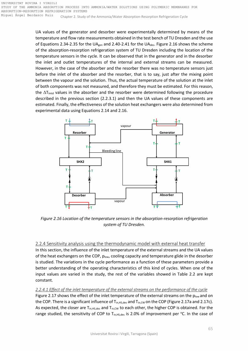
Chapter 2. Study of the Ammonia/Water Absorption-Resorption Refrigeration Cycle
65 Universitat Rovira i Virgili, Tarragona (Spain)
UA values of the generator and desorber were experimentally determined by means of the
temperature and flow rate measurements obtained in the test bench of TU Dresden and the use
of Equations 2.34-2.35 for the UAgen and 2.40-2.41 for the UAdes. Figure 2.16 shows the scheme
of the absorption-resorption refrigeration system of TU Dresden including the location of the
temperature sensors in the cycle. It can be observed that in the generator and in the desorber
the inlet and outlet temperatures of the internal and external streams can be measured.
However, in the case of the absorber and the resorber there was no temperature sensors just
before the inlet of the absorber and the resorber, that is to say, just after the mixing point
between the vapour and the solution. Thus, the actual temperature of the solution at the inlet
of both components was not measured, and therefore they must be estimated. For this reason,
the ΔTlmtd values in the absorber and the resorber were determined following the procedure
described in the previous section (2.2.3.1) and then the UA values of these components are
estimated. Finally, the effectiveness of the solution heat exchangers were also determined from
experimental data using Equations 2.14 and 2.16.
Figure 2.16 Location of the temperature sensors in the absorption-resorption refrigeration
system of TU Dresden.
2.2.4 Sensitivity analysis using the thermodynamic model with external heat transfer In this section, the influence of the inlet temperature of the external streams and the UA values
of the heat exchangers on the COP, plow, cooling capacity and temperature glide in the desorber
is studied. The variations in the cycle performance as a function of these parameters provide a
better understanding of the operating characteristics of this kind of cycles. When one of the
input values are varied in the study, the rest of the variables showed in Table 2.2 are kept
constant.
2.2.4.1 Effect of the inlet temperature of the external streams on the performance of the cycle
Figure 2.17 shows the effect of the inlet temperature of the external streams on the plow and on
the COP. There is a significant influence of Tin,HS,des and Tin,CW on the COP (Figure 2.17a and 2.17c).
As expected, the closer are Tin,HS,des and Tin,CW to each other, the higher COP is obtained. For the
range studied, the sensitivity of COP to Tin,HS,des is 2.0% of improvement per oC. In the case of
SHX1SHX2
Generator
Absorber
Resorber
Desorber
Bleeding line
vapour
vapour
T
T
T T
T T
T T
T T
T
TT TT
TT
UNIVERSITAT ROVIRA I VIRGILI STUDY OF THE AMMONIA ABSORPTION PROCESS INTO AMMONIA/WATER SOLUTIONS USING POLYMERIC MEMBRANES FOR ABSORPTION-RESORPTION REFRIGERATION SYSTEMS Miguel Ángel Berdasco Ruiz

Chapter 2. Study of the Ammonia/Water Absorption-Resorption Refrigeration Cycle
66 Doctoral Thesis, Miguel Ángel Berdasco Ruiz
Tin,CW, the COP decreases a rate of approximately 1.9% per oC. On the other hand, increasing
Tin,HS,gen leads into a decreasing rate on the COP of approximately 1.0% per oC (Figure 2.17b).
Regarding the low-pressure level (plow), it is highly influenced by Tin,HS,des and to a lesser degree
by Tin,HS,gen whereas the effect of the Tin,CW on the plow value is negligible. The sensitivity of plow to
Tin,HS,des is 0.024 bar of increment per oC and to Tin,HS,gen is 0.017 bar of decreasing per oC.
Figure 2.17 Effect of the inlet temperature of the external streams on the plow and the COP: (a)
inlet temperature of the ethylene-glycol/water mixture (30%) in the desorber (Tin,HS,des); (b) Inlet
temperature of the hot water in the generator (Tin,HS,gen); (c) Inlet temperature of the cooling
water in the absorber and resorber (Tin,CW).
Figure 2.18 shows the effect of the inlet temperature of the external streams on the cooling
capacity of the system (Qdes) and on the gliding temperature in the desorber (ΔTgliding), which is
defined as the difference between the inlet temperature and the outlet temperature of the
external stream in the desorber. Regarding the cooling capacity, there is a positive effect on Qdes
when Tin,HS,des and Tin,HS,gen are increased (Figure 2.18a and 2.18b), while there is a negative effect
when the inlet temperature of the cooling water (Tin,CW) is increased (Figure 2.18c). In the case
of Tin,HS,des and Tin,HS,gen the cooling capacity increases in a rate of 1.1 kW/oC and 0.3 kW/oC,
respectively. In the case of the Tin,CW the Qdes decreases in a rate of 1.6 kW/oC. Regarding the
gliding temperature it can be observed that the trends are similar to the ones obtained for the
cooling capacity. Figure 2.18a and 2.18c show that the higher Tin,HS,des and the lower Tin,CW, the
-0.2
0.2
0.6
1.0
1.4
1.8
2.2
2.6
3.0
0.0
0.1
0.2
0.3
0.4
0.5
0.6
-5.0 -2.0 1.0 4.0 7.0 10.0
CO
P
Tin,HS,des [oC]
plo
w[b
ar]
(a)
-0.2
0.2
0.6
1.0
1.4
1.8
2.2
2.6
3.0
0.0
0.1
0.2
0.3
0.4
0.5
0.6
78.0 85.0 92.0 99.0 106.0
CO
P
Tin,HS,gen [oC]
plo
w[b
ar]
(b)
-0.2
0.2
0.6
1.0
1.4
1.8
2.2
2.6
3.0
0.0
0.1
0.2
0.3
0.4
0.5
0.6
15.0 18.0 21.0 24.0 27.0 30.0
CO
P
Tin,CW [oC]
plo
w[b
ar]
(c)
UNIVERSITAT ROVIRA I VIRGILI STUDY OF THE AMMONIA ABSORPTION PROCESS INTO AMMONIA/WATER SOLUTIONS USING POLYMERIC MEMBRANES FOR ABSORPTION-RESORPTION REFRIGERATION SYSTEMS Miguel Ángel Berdasco Ruiz

Chapter 2. Study of the Ammonia/Water Absorption-Resorption Refrigeration Cycle
67 Universitat Rovira i Virgili, Tarragona (Spain)
higher gliding temperature in the desorber is obtained. For the case studied in this section, a
maximum gliding temperature of 5.1oC was obtained when Tin,HS,des=10oC. A similar gliding
temperature value (5.0oC) was obtained when Tin,CW=15oC. On the other hand, the influence of
the Tin,HS,gen on the ΔTgliding is not significant.
Figure 2.18 Effect of the inlet temperature of the external streams on the cooling capacity (Qdes)
and on the gliding temperature (ΔTgliding): (a) Inlet temperature of the ethylene-glycol/water
mixture (30%) in the desorber (Tin,HS,des); (b) Inlet temperature of the hot water in the generator
(Tin,HS,gen); (c) Inlet temperature of the cooling water in the absorber and resorber (Tin,CW).
2.2.4.2 Effect of the UA values of the heat exchangers on the performance of the cycle
The heat exchange area multiplied by the overall heat transfer coefficient (UA value) is a very
important parameter when designing the heat exchanger because it represents the size of the
heat exchanger. Figure 2.19 shows the effect of the UA of the heat exchangers on the COP and
on the cooling capacity (Qdes). The abscissa of the plots is the relative UA value normalized to the
base case UA value of Table 2.2. Regarding the COP, the curves obtained for the resorber,
absorber and desorber show a similar trend, which is in good agreement with the behaviour
showed in the model developed by Pande and Herold [22]. In their work, Pande and Herold
pointed out that, as in the conventional absorption cycles, COP is not particularly sensitive to
changes in the heat exchanger size because the increased capacity associated with increased UA
causes increased thermodynamic losses, balancing both effects and providing a COP essentially
constant over a wide range of UA values. The decrease in COP observed at UA/UAo values lower
than 0.5 can be explained because a heat transfer bottleneck exists in the cycle and the
0.0
1.0
2.0
3.0
4.0
5.0
6.0
7.0
8.0
0.0
5.0
10.0
15.0
20.0
25.0
30.0
35.0
40.0
-5.0 -2.0 1.0 4.0 7.0 10.0
Qd
es[k
W]
Tin,HS,des [oC]
(a)
ΔT
glidin
g[ oC
]
0.0
1.0
2.0
3.0
4.0
5.0
6.0
7.0
8.0
0.0
5.0
10.0
15.0
20.0
25.0
30.0
35.0
40.0
78.0 85.0 92.0 99.0 106.0
Qd
es[k
W]
Tin,HS,gen [oC]
(b)
ΔT
glidin
g[ oC
]
0.0
1.0
2.0
3.0
4.0
5.0
6.0
7.0
8.0
0.0
5.0
10.0
15.0
20.0
25.0
30.0
35.0
40.0
15.0 18.0 21.0 24.0 27.0 30.0
Qd
es[k
W]
Tin,CW [oC]
ΔT
glidin
g[ oC
]
(c)
UNIVERSITAT ROVIRA I VIRGILI STUDY OF THE AMMONIA ABSORPTION PROCESS INTO AMMONIA/WATER SOLUTIONS USING POLYMERIC MEMBRANES FOR ABSORPTION-RESORPTION REFRIGERATION SYSTEMS Miguel Ángel Berdasco Ruiz

Chapter 2. Study of the Ammonia/Water Absorption-Resorption Refrigeration Cycle
68 Doctoral Thesis, Miguel Ángel Berdasco Ruiz
irreversibilities in that component tend to decrease the overall performance. According to the
results showed in Figure 2.19, the sizing considered in the base case for the heat exchangers of
the desorber, absorber, and resorber was suitable because no significant improvements on the
COP are observed (less than 5% in all cases) when UA is increased. However, in the case of the
generator (Figure 2.19b) the curve of the COP shows a maximum for a normalized UA-value of
0.2 and then drops rapidly when UA/UAo<0.2. This can be explained because the reduction of
the heat supplied to the generator due to the reduction in the UA-value is higher than the loss
of cooling capacity that take place in the range of 0.2<UA/UAo<1.0.
Regarding the cooling capacity, a similar behaviour is observed than in the COP study. For
UA/UAo values below 0.5, the cooling capacity drops rapidly in all cases. A 10% increase in the
cooling capacity can be reached if the UA of the desorber, absorber or resorber is tripled. In the
case of the generator no significant improvement on the cooling capacity is observed when the
UAgen value is increased with regard to the value of the base case.
Figure 2.19 Effect of the UA of the heat exchangers on the COP and plow. (a) Desorber; (b)
Generator; (c) Absorber; (d) Resorber. UAo represents the UA value assumed in the base case of
Table 2.2.
Figure 2.20 shows the influence of the UA values of the heat exchangers on the plow and on the
gliding temperature (ΔTgliding) in the desorber. Regarding the low-pressure level (plow), it is highly
influenced by the UA values of the main components of the absorption circuit (generator and
absorber). When the normalized UA-value of the generator or the absorber are lowered below
0.0
5.0
10.0
15.0
20.0
25.0
30.0
35.0
0.0
0.1
0.2
0.3
0.4
0.5
0.0 0.5 1.0 1.5 2.0 2.5 3.0
Qd
es[k
W]
CO
P
(UA/UAo)des
(a)
0.0
5.0
10.0
15.0
20.0
25.0
30.0
35.0
0
0.1
0.2
0.3
0.4
0.5
0.0 0.5 1.0 1.5 2.0 2.5 3.0
Qd
es[k
W]
CO
P
(UA/UAo)gen
(b)
0.0
5.0
10.0
15.0
20.0
25.0
30.0
35.0
0.0
0.1
0.2
0.3
0.4
0.5
0.0 0.5 1.0 1.5 2.0 2.5 3.0
Qd
es[k
W]
CO
P
(UA/UAo)abs
(c)
0.0
5.0
10.0
15.0
20.0
25.0
30.0
35.0
0
0.1
0.2
0.3
0.4
0.5
0.0 0.5 1.0 1.5 2.0 2.5 3.0
Qd
es[k
W]
CO
P
(UA/UAo)res
(d)
UNIVERSITAT ROVIRA I VIRGILI STUDY OF THE AMMONIA ABSORPTION PROCESS INTO AMMONIA/WATER SOLUTIONS USING POLYMERIC MEMBRANES FOR ABSORPTION-RESORPTION REFRIGERATION SYSTEMS Miguel Ángel Berdasco Ruiz
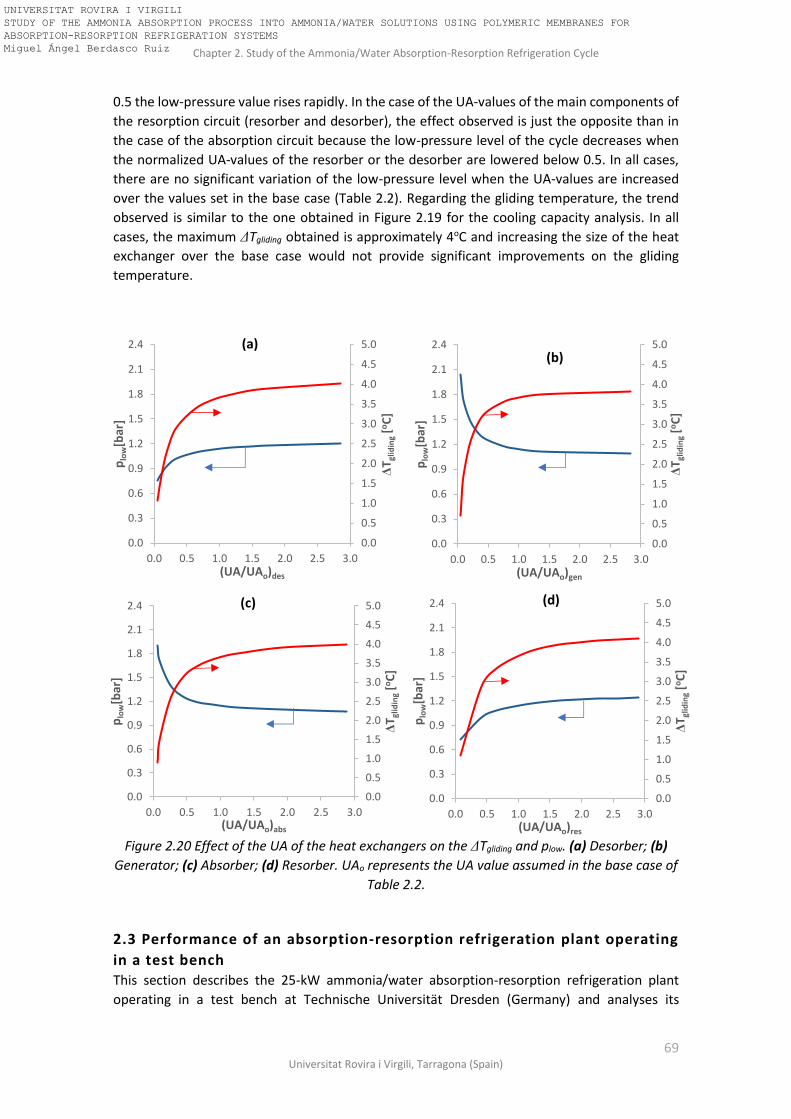
Chapter 2. Study of the Ammonia/Water Absorption-Resorption Refrigeration Cycle
69 Universitat Rovira i Virgili, Tarragona (Spain)
0.5 the low-pressure value rises rapidly. In the case of the UA-values of the main components of
the resorption circuit (resorber and desorber), the effect observed is just the opposite than in
the case of the absorption circuit because the low-pressure level of the cycle decreases when
the normalized UA-values of the resorber or the desorber are lowered below 0.5. In all cases,
there are no significant variation of the low-pressure level when the UA-values are increased
over the values set in the base case (Table 2.2). Regarding the gliding temperature, the trend
observed is similar to the one obtained in Figure 2.19 for the cooling capacity analysis. In all
cases, the maximum ΔTgliding obtained is approximately 4oC and increasing the size of the heat
exchanger over the base case would not provide significant improvements on the gliding
temperature.
Figure 2.20 Effect of the UA of the heat exchangers on the ΔTgliding and plow. (a) Desorber; (b)
Generator; (c) Absorber; (d) Resorber. UAo represents the UA value assumed in the base case of
Table 2.2.
2.3 Performance of an absorption-resorption refrigeration plant operating
in a test bench This section describes the 25-kW ammonia/water absorption-resorption refrigeration plant
operating in a test bench at Technische Universität Dresden (Germany) and analyses its
0.0
0.5
1.0
1.5
2.0
2.5
3.0
3.5
4.0
4.5
5.0
0.0
0.3
0.6
0.9
1.2
1.5
1.8
2.1
2.4
0.0 0.5 1.0 1.5 2.0 2.5 3.0
ΔT g
lidin
g[o
C]
plo
w[b
ar]
(UA/UAo)des
(a)
0.0
0.5
1.0
1.5
2.0
2.5
3.0
3.5
4.0
4.5
5.0
0.0
0.3
0.6
0.9
1.2
1.5
1.8
2.1
2.4
0.0 0.5 1.0 1.5 2.0 2.5 3.0
ΔT g
lidin
g[o
C]
plo
w[b
ar]
(UA/UAo)gen
(b)
0.0
0.5
1.0
1.5
2.0
2.5
3.0
3.5
4.0
4.5
5.0
0.0
0.3
0.6
0.9
1.2
1.5
1.8
2.1
2.4
0.0 0.5 1.0 1.5 2.0 2.5 3.0
ΔT g
lidin
g[o
C]
plo
w[b
ar]
(UA/UAo)abs
(c)
0.0
0.5
1.0
1.5
2.0
2.5
3.0
3.5
4.0
4.5
5.0
0.0
0.3
0.6
0.9
1.2
1.5
1.8
2.1
2.4
0.0 0.5 1.0 1.5 2.0 2.5 3.0
ΔT g
lidin
g[o
C]
plo
w[b
ar]
(UA/UAo)res
(d)
UNIVERSITAT ROVIRA I VIRGILI STUDY OF THE AMMONIA ABSORPTION PROCESS INTO AMMONIA/WATER SOLUTIONS USING POLYMERIC MEMBRANES FOR ABSORPTION-RESORPTION REFRIGERATION SYSTEMS Miguel Ángel Berdasco Ruiz

Chapter 2. Study of the Ammonia/Water Absorption-Resorption Refrigeration Cycle
70 Doctoral Thesis, Miguel Ángel Berdasco Ruiz
experimental performance by means of the thermodynamic model with external heat transfer
previously developed.
2.3.1 Description of the plant and the test bench The plant was designed with the nominal conditions showed in Table 2.3. These conditions were
not achieved during the experiments due to several factors that will be explained in detail in this
section. Figure 2.21 shows three pictures of the ammonia/water absorption-resorption
refrigeration test bench place in the Zentrum für Energietechnik (ZET) of TU Dresden. In these
pictures, the main components of the system have been highlighted and labelled. The cycle
configuration is similar to the one showed in Figure 2.14; there is no rectifier, so a bleeding pipe
is used for equilibrating the mass balances between the absorption and resorption circuits
supplying the weak solution at the inlet of the resorber to the inlet of the absorber. As a safety
measure, the system is inside of a cabinet with plastic strip shields to protect the workers from
any leakage in the test bench. On the top of the cabinet, there is a fan which is automatically
switched on when a certain concentration of ammonia is detected.
Table 2.3 Nominal conditions of the 25-kW absorption-resorption refrigeration plant.
Component Heat duty [kW] mwater [kg/h] Tin,water [oC] Tout,water [oC]
Generator 55 6.0 90.0 82.0
Desorber 25 6.0 4.1 0.5
Resorber 40 6.0 26.0 31.7
Absorber 42.5 8.0 26.0 30.6
Every main component of the absorption-resorption refrigeration plant (generator, desorber,
absorber, and resorber) consist of a stainless-steel plate heat exchanger (provided by Alfa Laval)
and a reservoir installed downstream of the heat exchanger to ensure the phase separation and
a continuous supply of fluid to the pumps as well. The solution heat exchangers of both circuits
are also plate heat exchangers provided by Alfa Laval. Figure 2.22 shows a scheme of the flow
configuration in the plate heat exchangers and Table 2.4 lists their technical data. A special
feature of this system is the high number of sight glasses which allow observing what is
happening inside the main components of the test bench. The expansion device in both solution
circuits is a flow restrictor valve. Finally, a vertical multistage electric pump (EBARA EVM 3
7N5/0.75 M) was selected to be used as solution pump in the absorption and resorption circuits.
Regarding the test bench, the heat is supplied by a district heating network to the generator,
where the temperatures of the heating medium can be set in a range of 60-95oC. The flow rate
of the heating water can be set from 4 m3/h to 12 m3/h, providing heating rates up to 100 kW.
The cooling of the absorber and resorber is realized by a cooling water from a cooling tower.
The cooling water flow rate available is 7m3/h. Here there is the first limitation that impedes to
reach the nominal operating conditions of the refrigeration system because the total cooling
water flow rate required for reaching the nominal 25-kW of cooling capacity is 14 m3/h (8 m3/h
for the absorber and 6 m3/h for the resorber). For the cooling distribution (heat supply to the
desorber), a 30% glycol-water-mixture with a freezing point of -14oC is used. The cold glycol-
water mixture was used for ice production in a storage system consisting of 5 ice storage tanks.
UNIVERSITAT ROVIRA I VIRGILI STUDY OF THE AMMONIA ABSORPTION PROCESS INTO AMMONIA/WATER SOLUTIONS USING POLYMERIC MEMBRANES FOR ABSORPTION-RESORPTION REFRIGERATION SYSTEMS Miguel Ángel Berdasco Ruiz
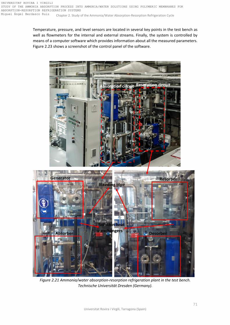
Chapter 2. Study of the Ammonia/Water Absorption-Resorption Refrigeration Cycle
71 Universitat Rovira i Virgili, Tarragona (Spain)
Temperature, pressure, and level sensors are located in several key points in the test bench as
well as flowmeters for the internal and external streams. Finally, the system is controlled by
means of a computer software which provides information about all the measured parameters.
Figure 2.23 shows a screenshot of the control panel of the software.
Figure 2.21 Ammonia/water absorption-resorption refrigeration plant in the test bench.
Technische Universität Dresden (Germany).
Absorption circuit Resorption circuit
Resorber
Desorber
Generator
Absorber
Bleeding pipe
Solution heat
exchangers
UNIVERSITAT ROVIRA I VIRGILI STUDY OF THE AMMONIA ABSORPTION PROCESS INTO AMMONIA/WATER SOLUTIONS USING POLYMERIC MEMBRANES FOR ABSORPTION-RESORPTION REFRIGERATION SYSTEMS Miguel Ángel Berdasco Ruiz

Chapter 2. Study of the Ammonia/Water Absorption-Resorption Refrigeration Cycle
72 Doctoral Thesis, Miguel Ángel Berdasco Ruiz
Table 2.4 Datasheet of the heat exchangers used in the experimental plant.
Component Model Material number of plates
Type of plates
Size (mm)
Generator AlfaNova 76 Stainless steel
AISI 316 50 Corrugated 767x192x157
Desorber AlfaNova 76 Stainless steel
AISI 316 50 Corrugated 767x192x157
Resorber AlfaNova 76 Stainless steel
AISI 316 50 Corrugated 767x192x157
Absorber AlfaNova 76 Stainless steel
AISI 316 50 Corrugated 767x192x157
SHX1 (absorption circuit)
AlfaNova 76 Stainless steel
AISI 316 40 Corrugated 767x192x128
SHX2 (resorption circuit)
AlfaNova 76 Stainless steel
AISI 316 20 Corrugated 767x192x71
Figure 2.22 Flow configuration in the plate heat exchangers. Scheme provided by Alfa Laval.
Figure 2.23 Control panel of the absorption-resorption refrigeration plant in the test bench.
UNIVERSITAT ROVIRA I VIRGILI STUDY OF THE AMMONIA ABSORPTION PROCESS INTO AMMONIA/WATER SOLUTIONS USING POLYMERIC MEMBRANES FOR ABSORPTION-RESORPTION REFRIGERATION SYSTEMS Miguel Ángel Berdasco Ruiz

Chapter 2. Study of the Ammonia/Water Absorption-Resorption Refrigeration Cycle
73 Universitat Rovira i Virgili, Tarragona (Spain)
2.3.2 Analysis of the experimental performance of the plant As mentioned in the literature review of Chapter 1, several authors had already pointed out the
inherent instability of the resorption cycles due to the additional degree of freedom and this fact
make these systems particularly difficult to control. An accurate control of the concentrations in
the circuits is required to regulate the bleeding mass flow rate and avoid the system to drift
away from its thermodynamical point of operation. Since there is no automatic control of the
experimental plant, a solenoid valve placed in the bleeding pipe must be activated manually for
the bleeding process. An increment of the water content in the resorption circuit leads to an
increase in the temperatures in the desorber due to the lower ammonia concentration in the
solution [29]. When this situation takes place, the solenoid valve of the bleeding pipe must be
opened for a certain period of time to equilibrate the mass balances between both circuits. This
procedure leads to the following issues: first, the system is always working in a discontinuous
way. Secondly, the lack of a flowmeter in the bleeding pipe make difficult to know the amount
of solution transferred to the absorption circuit. Furthermore, the adjustment of the speed of
the solution pumps to reach stable working conditions is also quite difficult. It is necessary to
carefully balance the speed of the pumps in order to avoid the reservoirs being flooded and/or
emptied. For all these reasons, the possibility of working under steady-state conditions for a
long period of time becomes a challenge.
Additionally, pumping problems in the resorption circuit were also found. The solution leaving
the desorber is under saturation conditions due to the boiling process in the desorber. For this
reason, cavitation problems in the suction line of the pump are quite frequent, impeding the
system to work properly even stopping the flow in the resorption circuit because the pump runs
completely dry. This problem could be avoided increasing the height between the desorber
reservoir and the intake of the pump, but due to the component location in the test bench
(Figure 2.21) it was not possible to change the design of the plant. This problem was partially
solved when the pump was changed by a new one with lower NPSH (EBARA EVM 3 7N5/0.75
M). With the new pump, the number of shutdowns during the experiments were significantly
lower. Cavitation problems do not affect the pump of the absorption circuit, probably because
the solution leaving the absorber is not really saturated.
2.3.3 Analysis of the experimental performance using the thermodynamic model Despite the difficulties found during the experimental work, some good experimental results
were obtained. The difficulty of working under steady-state conditions was already pointed out,
so it was necessary to select just the experimental data obtained during a short period of time
(when the system was working under quasi-stable conditions) to allow direct comparison
between the experimental results and the results obtained with the steady-state model
described in section 2.2.3. Figure 2.24 shows a scheme of the absorption-resorption cycle with
the experimental and theoretical results depicted on it. Black-coloured data represent the
results obtained with the model while red-coloured data represent the experimental results.
The input data for the simulation (UA values of the heat exchangers, the effectiveness of the
solution heat exchangers, the inlet temperature and flow rate of the external streams, the flow
rate in the solution circuits and the high-pressure value of the system) were directly taken from
the experimental data and are represented by colour green. During the experiment, a pressure
drop of 0.2 bar between the absorption and the resorption circuit was registered, so the model
was modified in order to take into account this pressure drop. The experimental UA values were
determined as shown in section 2.2.3.2. The experimental data selected for this study
correspond to the average value for a period of time of 15 minutes.
UNIVERSITAT ROVIRA I VIRGILI STUDY OF THE AMMONIA ABSORPTION PROCESS INTO AMMONIA/WATER SOLUTIONS USING POLYMERIC MEMBRANES FOR ABSORPTION-RESORPTION REFRIGERATION SYSTEMS Miguel Ángel Berdasco Ruiz
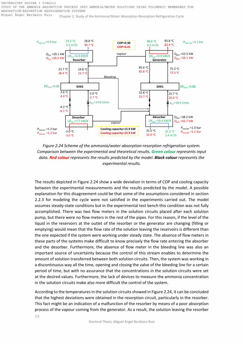
Chapter 2. Study of the Ammonia/Water Absorption-Resorption Refrigeration Cycle
74 Doctoral Thesis, Miguel Ángel Berdasco Ruiz
Figure 2.24 Scheme of the ammonia/water absorption-resorption refrigeration system.
Comparison between the experimental and theoretical results. Green colour represents input
data. Red colour represents the results predicted by the model. Black colour represents the
experimental results.
The results depicted in Figure 2.24 show a wide deviation in terms of COP and cooling capacity
between the experimental measurements and the results predicted by the model. A possible
explanation for this disagreement could be that some of the assumptions considered in section
2.2.3 for modeling the cycle were not satisfied in the experiments carried out. The model
assumes steady-state conditions but in the experimental test bench this condition was not fully
accomplished. There was two flow meters in the solution circuits placed after each solution
pump, but there were no flow meters in the rest of the pipes. For this reason, if the level of the
liquid in the reservoirs at the outlet of the resorber or the generator are changing (filling or
emptying) would mean that the flow rate of the solution leaving the reservoirs is different than
the one expected if the system were working under steady state. The absence of flow meters in
these parts of the systems make difficult to know precisely the flow rate entering the absorber
and the desorber. Furthermore, the absence of flow meter in the bleeding line was also an
important source of uncertainty because the control of this stream enables to determine the
amount of solution transferred between both solution circuits. Then, the system was working in
a discontinuous way all the time, opening and closing the valve of the bleeding line for a certain
period of time, but with no assurance that the concentrations in the solution circuits were set
at the desired values. Furthermore, the lack of devices to measure the ammonia concentration
in the solution circuits make also more difficult the control of the system.
According to the temperatures in the solution circuits showed in Figure 2.24, it can be concluded
that the highest deviations were obtained in the resorption circuit, particularly in the resorber.
This fact might be an indication of a malfunction of the resorber by means of a poor absorption
process of the vapour coming from the generator. As a result, the solution leaving the resorber
SHX1SHX2
Generator
Absorber
Resorber
Desorber
Bleeding
vapour
vapour
25.7 oC26.6 oC
75.3 oC73.3 oC
85.6 oC85.8 oC
32.8 oC33.7 oC
19.8 oC23.7 oC
23.7 oC28.4 oC
3.6 oC4.4 oC
-4.2 oC-6.1 oC
-2.0 oC-2.7 oC
21.2 oC3.4 m3/h
88.6 oC9.5 m3/h
21.2 oC3.3 m3/h
31.0 oC32.0 oC
83.8 oC83.4 oC
28.8 oC30.7 oC
-2.0 oC-3.0 oC
EffHEX1=0.88EffHEX1=0.85
qv1=18.9 l/minqv2=14.8 l/min
UAabs=10.4 kW/K
UAgen=9.9 kW/KUAres=6.9 kW/K
UAdes=7.7 kW/K
Phigh,abs=5.1 barPhigh,res=4.9 bar
Plow,res =1.2 barPlow,res =1.3 bar
Plow,abs =1.0 barPlow,abs =1.1 bar
COP=0.30COP=0.41
Cooling capacity=15.9 kWCooling capacity=22.9 kW
Qabs =38.2 kWQabs =42.7 kW
Qres =29.1 kWQres =36.5 kW
Qgen =52.5 kWQgen =56.1 kW
UNIVERSITAT ROVIRA I VIRGILI STUDY OF THE AMMONIA ABSORPTION PROCESS INTO AMMONIA/WATER SOLUTIONS USING POLYMERIC MEMBRANES FOR ABSORPTION-RESORPTION REFRIGERATION SYSTEMS Miguel Ángel Berdasco Ruiz

Chapter 2. Study of the Ammonia/Water Absorption-Resorption Refrigeration Cycle
75 Universitat Rovira i Virgili, Tarragona (Spain)
would be far from the saturation conditions and then the assumption made in section 2.2.3
concerning to the saturation conditions of the solution leaving the resorber could not be
satisfied. Since both the absorber and the resorber have the same design, the subcooling at the
outlet of the absorber should be also taken into consideration. However, the subcooling in the
absorber is expected to be lower than in the resorber because a better agreement between the
experimental results and the ones provided by the model was obtained. Hence, the
thermodynamic model of the cycle was modified according to the following assumption: the
solutions leaving the resorber and the absorber are not saturated, so there is a certain degree
of subcooling. The subcooling of the solutions leaving the resorber (ΔTsub,res) and the absorber
(ΔTsub,abs) are defined as follows:
∆𝑇𝑠𝑢𝑏,𝑟𝑒𝑠 = 𝑇𝑠𝑎𝑡,𝑟𝑒𝑠 − 𝑇11 (2.48)
∆𝑇𝑠𝑢𝑏,𝑎𝑏𝑠 = 𝑇𝑠𝑎𝑡,𝑎𝑏𝑠 − 𝑇1 (2.49)
where Tsat,res and Tsat,abs are the saturation temperature of the solution at the concentration and
pressure conditions at the outlet of the resorber and the absorber, respectively. The subcooling
conditions showed in Equations 2.48 and 2.49 are input variables in the new version of the
model, replacing the previous assumptions of saturation conditions at the outlet of the absorber
and resorber.
A parametric table was created varying the subcooling of the solution at the outlet of the
resorber (ΔTsub,res) and the absorber (ΔTsub,abs). The temperature values, COP and heat
supplied/released on each component obtained in the parametric study were analyzed to
determine if there is a significant improvement in the agreement between the experimental
results and the ones obtained with the model. Indeed, a very good agreement was obtained
when ΔTsub,res=8.3oC and ΔTsub,abs=1.5oC, as shown in Figure 2.25.
Figure 2.25 Comparison between the experimental and theoretical results assuming subcooling
at the outlet of the resorber and the absorber. Green colour represents input data. Red colour
represents the results predicted by the model. Black colour represents the experimental results.
SHX1SHX2
Generator
Absorber
Resorber
Desorber
Bleeding
vapour
vapour
25.7 oC25.4 oC
75.3 oC74.3 oC
85.6 oC86.2 oC
32.8 oC32.7 oC
19.8 oC19.8 oC
23.7 oC23.6 oC
3.6 oC3.4 oC
-4.2 oC-4.3 oC
-2.0 oC-1.8 oC
21.2 oC3.4 m3/h
88.6 oC9.5 m3/h
21.2 oC3.3 m3/h
0.1 oC7.0 m3/h
31.0 oC30.9 oC
83.8 oC83.8 oC
28.8 oC28.8 oC
-2.0 oC-2.0 oC
EffHEX1=0.88EffHEX1=0.85
qv1=18.9 l/minqv2=14.8 l/min
UAabs=10.4 kW/K
UAgen=9.9 kW/KUAres=6.9 kW/K
UAdes=7.7 kW/K
Phigh,abs=5.1 barPhigh,res=4.9 bar
Plow,res =1.2 bar Plow,abs =1.0 bar
COP=0.30COP=0.31
Cooling capacity=15.9 kWCooling capacity=15.8 kW
Qabs =38.2 kWQabs =38.1 kW
Qres =29.1 kWQres =29.1 kW
Qgen =52.5 kWQgen =51.3 kW
UNIVERSITAT ROVIRA I VIRGILI STUDY OF THE AMMONIA ABSORPTION PROCESS INTO AMMONIA/WATER SOLUTIONS USING POLYMERIC MEMBRANES FOR ABSORPTION-RESORPTION REFRIGERATION SYSTEMS Miguel Ángel Berdasco Ruiz

Chapter 2. Study of the Ammonia/Water Absorption-Resorption Refrigeration Cycle
76 Doctoral Thesis, Miguel Ángel Berdasco Ruiz
The deviation between the temperatures predicted by the model and the experimental ones
were lower than 1oC in all cases, and the deviation obtained in the COP and cooling capacity was
nearly zero. As expected, the subcooling obtained at the outlet of the resorber was much higher
than the one obtained in the absorber, so the hypothesis of the poor absorption process in the
resorber has been evidenced. A possible reason for this different performance between the
resorber and the absorber could be the different temperature of the vapour. In the case of the
absorber, the vapour coming from the desorber is much colder than the solution, leading into a
cooling effect of the solution that enhance the absorption process. On the contrary, in the case
of the resorber, the vapour coming from the generator is much hotter than the solution, leading
into a heating effect that runs against the absorption process. If so, the heat transfer area of the
resorber must be higher than in the case of the absorber or the vapour distribution into the
solution must be improved in order to enhance the mass and heat transfer and then reduce the
size of the heat exchanger.
2.4 Measures to improve the performance of absorption -resorption
refrigeration plants In order to enhance the performance of the ammonia/water absorption-resorption refrigeration
plant, the research group of Refrigeration, Cryogenics and Compressor Technology of TU
Dresden is investigating how to improve the ammonia vapour distribution into the
ammonia/water solution using stainless steel lance with drilled holes and membrane lances. The
preliminary results obtained show an increase of cooling capacity and the COP [49]. They also
studied the optimisation of the bleeding flow rate to maintain continuous operation under
stationary conditions. They achieved stable operation for a period of 30 minutes by means of
setting the bleeding flow rate at 0.2 l/min.
As mentioned before, the control of the absorption-resorption refrigeration system could be
also improved by means of the integration of devices for the in-situ determination of the
ammonia concentration in some key points of the cycle. This measurement system of the
ammonia concentration should be linked to the control of the flow rate in the bleeding line to
ensure the cycle to work under steady-state conditions. For systems based on ammonia/water
mixtures, composition is usually measured in real-time from density by means of Coriolis flow
and density-meters, but the cost of these devices limits their application when several devices
need to be installed. Thus, the challenge for research is to find more economic analytical
methods for the in-situ analysis of the working fluid mixture. In the frame of this doctoral thesis,
a method based on near-infrared (NIR) spectroscopy for the in-situ determination of the
ammonia concentration was studied.
Near-infrared (NIR) spectroscopy is one of the most commonly used techniques for the in-situ
analysis of samples due to the low cost of optical fibers that work in this region, to the variety
of probes and cells available to work in extreme conditions of pressure and temperature and to
the chemometric facilities that are incorporated in the software of the instruments. There are
many referenced applications of this technique joint to the multivariate analysis of the spectral
data for the analysis of the composition of complex mixtures and for the analysis and control of
chemical and physical properties of compounds involved in processes [50–52]. However, this
technique has not been fully implemented in absorption heat pumps/refrigeration systems so
far. In recent years, our research group have made many efforts to incorporate this technique
in experimental test benches to measure the composition of the mixtures typically used in
absorption cycles [53–55]. The work carried out in this thesis was mainly focused in the
implementation of the NIR spectroscopy to determine the composition of the ammonia/water
UNIVERSITAT ROVIRA I VIRGILI STUDY OF THE AMMONIA ABSORPTION PROCESS INTO AMMONIA/WATER SOLUTIONS USING POLYMERIC MEMBRANES FOR ABSORPTION-RESORPTION REFRIGERATION SYSTEMS Miguel Ángel Berdasco Ruiz

Chapter 2. Study of the Ammonia/Water Absorption-Resorption Refrigeration Cycle
77 Universitat Rovira i Virgili, Tarragona (Spain)
mixture circulating in an absorber test bench. The results obtained were published in the
International Journal TALANTA [56].
The experimental set up of the NIR measurement system integrated in the absorber test bench
consist of a stainless-steel flow cell 15cm high and with an outlet diameter of 5cm equipped with
two sapphire windows through which the light passes. The cell was designed and constructed in
our research group, however it is possible to find flow cells in the market at a very competitive
price. One of the companies that markets these cells is Avantes. Optical fibers were used to
direct and record the light from the lamp (HL-2000-CAL tungsten halogen light source) to the
detector (Maya 2000 Pro Vis-NIR spectrophotometer). The detector was connected to the
computer for spectra acquisition. The data recorded was pretreated using MATLAB subroutines.
Pressure and temperature sensors were placed next to the cell. Figure 2.26 shows a picture of
the NIR measurement system integrated in the absorber test bench.
The ammonia/water solution flows through the cell whereas the light coming from the source
passes across the cell in order to be collected in the spectrophotometer, where the spectra were
recorded between 997.6 and 1065 nm. The absorbance values at the maximum of the
absorption band (1041 nm) are considered as response in order to determine the relationship
between the ammonia mass fraction, pressure, temperature and absorbance. The 1041
absorption band is attributable to the stretching vibration of the -NH functional group present
in the NH3. All the details about the calibration method and the validation of the technique can
be found in Barba et al. [56].
Figure 2.26 Experimental set up for the data acquisition using a NIR measurement system.
The most expensive components of the NIR measurement system are the lamp and the detector.
Nevertheless, by means of a multiplexor it would be possible to determine the ammonia
concentration at several points in the absorption cycle just using one detector and one lamp.
This would lead into an important advantage compared to the conventional Coriolis density
meters. As an example, Figure 2.27 shows a scheme of the ammonia/water absorption-
Detector
Optical fibres Lamp
Stainless steel cell
UNIVERSITAT ROVIRA I VIRGILI STUDY OF THE AMMONIA ABSORPTION PROCESS INTO AMMONIA/WATER SOLUTIONS USING POLYMERIC MEMBRANES FOR ABSORPTION-RESORPTION REFRIGERATION SYSTEMS Miguel Ángel Berdasco Ruiz

Chapter 2. Study of the Ammonia/Water Absorption-Resorption Refrigeration Cycle
78 Doctoral Thesis, Miguel Ángel Berdasco Ruiz
resorption cycle with the NIR measurement system integrated on each stream of the solution
circuits. The location of the cells proposed in the scheme was determined to ensure that the
solution flowing in such places is highly subcooled in order to avoid two-phase flow that could
disturb the measurements of the NIR. As future work, the development of an automated control
system of the absorption-resorption cycle based on the NIR measurements could be a very
interesting research project because the NIR technique is reliable and cost competitive and
might improve the control of the ammonia/water absorption-resorption systems in a very
significant way.
Figure 2.27 Scheme of the ammonia/water absorption-resorption cycle with the NIR
measurement system integrated. Green, blue, red and orange-coloured lines represent the
optical fibres.
2.5 Conclusions In this chapter, the ammonia/water absorption-resorption refrigeration cycle has been studied
and its wide operation flexibility was showed. This flexibility can be used for reducing the high-
pressure of the system by means of reducing the ammonia concentration in the solution circuits
but keeping the same temperature levels of the heat sources. Two thermodynamic models have
been developed and used for a sensitivity analysis of the cycle. The main conclusions are listed
below:
• The cycle configuration without rectifier is the most favourable because the complexity, size and cost of the system would be lower, and the loss of performance is not significant (below 8%).
• The effectiveness of the solution heat exchanger of the resorption circuit becomes critical below certain values. Then, a proper design of the solution heat exchanger of the resorption circuit is essential not only for the COP but also for the working of the cycle at desired temperatures.
• Reducing the high-pressure leads into lower COP. Furthermore, reaching a maximum value of COP and cooling capacity at the same time is not possible, so it is necessary to find a compromise between the reduction of the high-pressure, the COP and the cooling capacity.
SHX1SHX2
Generator
Absorber
Resorber
Desorber
Lamp
Detector
Multiplexor 1
Multiplexor 2
12
3 4
Measuring cell
Computer
UNIVERSITAT ROVIRA I VIRGILI STUDY OF THE AMMONIA ABSORPTION PROCESS INTO AMMONIA/WATER SOLUTIONS USING POLYMERIC MEMBRANES FOR ABSORPTION-RESORPTION REFRIGERATION SYSTEMS Miguel Ángel Berdasco Ruiz

Chapter 2. Study of the Ammonia/Water Absorption-Resorption Refrigeration Cycle
79 Universitat Rovira i Virgili, Tarragona (Spain)
Finally, attending to the results obtained during the study of the cycle, the working conditions
suggested for the base case (Table 2.1) were:
• phigh= 5 bar; plow=1.3 bar
• Mass flow rate in the absorption circuit 1.25 times higher than the mass flow rate in the resorption circuit.
• Ammonia mass fraction of the solution leaving the absorber and the resorber→ xabs=0.36; xres=0.61
• Ammonia mass fraction difference in both circuits → ∆xabs≈0.07; ∆xres≈0.05
• COP=0.52
• Qdes=18kW; Qgen=35kW; Qres=19kW; Qabs=31kW
A 25-kW ammonia/water absorption-resorption refrigeration plant set up at TU Dresden was
described and the difficulty of working under steady-state conditions was pointed out during
the experimental work. The implementation of measures for improving the control of the
system are required. The thermodynamic model with external heat transfer was used for the
analysis of the performance of the plant and it was concluded that the absorption process in the
resorber needs to be enhance. A possible explanation to this malfunction could be the higher
temperature of the vapour in the resorber (≈85oC) compared to the absorber (≈0oC), that leads
into a heating effect that runs against the absorption process. Thus, the size of the resorber must
be higher than in the case of the absorber or the vapour distribution into the solution must be
improved in order to enhance the mass and heat transfer processes.
Finally, a new method based on near-infrared spectroscopy for the in-situ determination of the
ammonia concentration was proposed in order to improve the performance of the absorption-
resorption plants. By means of a multiplexor, this new method allows to measure the ammonia
concentration in several points of the cycle just using one detector and one lamp, leading then
in a cheaper alternative than using the conventional Coriolis density-meters.
UNIVERSITAT ROVIRA I VIRGILI STUDY OF THE AMMONIA ABSORPTION PROCESS INTO AMMONIA/WATER SOLUTIONS USING POLYMERIC MEMBRANES FOR ABSORPTION-RESORPTION REFRIGERATION SYSTEMS Miguel Ángel Berdasco Ruiz

Chapter 2. Study of the Ammonia/Water Absorption-Resorption Refrigeration Cycle
80 Doctoral Thesis, Miguel Ángel Berdasco Ruiz
Nomenclature of chapter 2
COP [-] Coefficient of performance
EffSHX1 [-] Effectiveness of the solution heat exchanger of the absorption circuit
EffSHX2 [-] Effectiveness of the solution heat exchanger of the resorption circuit
h [J/kg] Specific enthalpy
m [kg/s] Mass flow rate
qv [l/min] Volumetric flow rate
Qdes [kW] Cooling capacity
T [oC] Temperature
UA [W/K] Product of the overall heat transfer coefficient and the heat transfer area
Wp [kW] Power consumption of the pump
x [-] Ammonia mass fraction
Special characters
β [-] Pressure ratio (phigh/plow)
ν [m3/kg] Specific volume
Subscripts
abs Absorption
CW Cooling water
ext External
gen Generator
HS Heat supply
in Inlet
liq Liquid
lmtd Logarithmic mean temperature difference
max Maximum
min Minimum
out Outlet
p1 Solution pump of the absorption circuit
p2 Solution pump of the resorption circuit
rect Rectifier
res Resorber
sub Subcooling
sat Saturation
vap Vapour
UNIVERSITAT ROVIRA I VIRGILI STUDY OF THE AMMONIA ABSORPTION PROCESS INTO AMMONIA/WATER SOLUTIONS USING POLYMERIC MEMBRANES FOR ABSORPTION-RESORPTION REFRIGERATION SYSTEMS Miguel Ángel Berdasco Ruiz

Chapter 2. Study of the Ammonia/Water Absorption-Resorption Refrigeration Cycle
81 Universitat Rovira i Virgili, Tarragona (Spain)
Chapter 3
Theoretical and Experimental Study of the Ammonia/Water
Absorption Process Using a Flat Sheet Membrane Module
UNIVERSITAT ROVIRA I VIRGILI STUDY OF THE AMMONIA ABSORPTION PROCESS INTO AMMONIA/WATER SOLUTIONS USING POLYMERIC MEMBRANES FOR ABSORPTION-RESORPTION REFRIGERATION SYSTEMS Miguel Ángel Berdasco Ruiz

Chapter 2. Study of the Ammonia/Water Absorption-Resorption Refrigeration Cycle
82 Doctoral Thesis, Miguel Ángel Berdasco Ruiz
UNIVERSITAT ROVIRA I VIRGILI STUDY OF THE AMMONIA ABSORPTION PROCESS INTO AMMONIA/WATER SOLUTIONS USING POLYMERIC MEMBRANES FOR ABSORPTION-RESORPTION REFRIGERATION SYSTEMS Miguel Ángel Berdasco Ruiz

Chapter 3: Theoretical and Experimental Study of the Ammonia/Water Absorption Process Using a Flat Sheet Membrane Module
83 Universitat Rovira i Virgili, Tarragona (Spain)
The main objective of this chapter is the determination of the desired membrane characteristics
to be used as contactor for the ammonia absorption process into ammonia/water solutions. As
showed in Chapter 1, several authors have already determined the characteristics of the
membranes required for the water absorption process into water/lithium bromide mixtures.
Regarding the ammonia/water mixture, Schaal [43] highlighted the importance of the pore size
and the use of hydrophobic materials in the membrane in order to avoid liquid breakthroughs,
but there was no information related to the optimum pore size, thickness or porosity required
for the ammonia absorption process.
In this chapter, a hydrophobic microporous flat sheet membrane contactor was proposed and
studied as an absorber for the ammonia/water absorption-resorption refrigeration cycle. The
heat and mass transfer process in the adiabatic flat sheet membrane module was investigated
experimentally and analytically. For the experimental study, a membrane absorber test bench
was designed and built. Taking advantage of the availability in our research group of a reverse
osmosis flat sheet membrane module, we decided to use it for this first experimental study
before buying another commercial hollow fibre membrane module. The information provided
by Schaal was used as a basis for the selection of the hydrophobic microporous flat sheet
membrane used in this chapter. Moreover, a unidimensional model was developed and
validated with the experimental results. The influence of the temperature, concentration, flow
rate and membrane characteristics on the absorption process was evaluated. The membrane
characteristics suggested at the end of this study were used for the selection of the commercial
hollow fibre membrane module used in Chapter 4. The results presented in this chapter were
published in Applied Thermal Engineering [57].
3.1 Experimental set-up An experimental test bench was set up to study the ammonia vapour absorption process in an
ammonia/water solution using polymeric porous membranes as contactors. Because there are
no commercial membrane modules available on the market for this specific application, a
membrane module designed by the manufacturer for reverse osmosis (Sterlitech SEPA CF
Module) had to be adapted to meet the requirements of the absorption process. The membrane
used (9.5 cm x 14.6 cm) was a hydrophobic polytetrafluoroethylene (PTFE) laminated membrane
(Sterlitech) with an average pore size of 0.05 μm. The 60-μm thin active layer (PTFE) is laminated
onto a 0.18 mm polypropylene layer. Figure 3.1 shows a scheme of the flat sheet membrane
module. The ammonia/water weak solution enters the membrane module and is
homogeneously distributed by the feed spacer all over the membrane surface. The ammonia
vapour enters the module from the top, crosses the pores of the membrane and is absorbed by
the solution in the liquid interface. Then, the ammonia/water solution exits the absorber at
higher concentration and higher temperature.
Figures 3.2 and 3.3 show a picture and a detailed diagram of the experimental test bench,
respectively. The plant consists of two tanks; one for the weak solution (feed tank) and the other
for the strong solution that leaves the membrane absorber (product tank). In turn, it has a
solution diaphragm pump (Weimer Hydra-Cell series D03), two filters (90 and 7 microns) for
preventing any solid particles from soiling the membrane, a thermostatic bath (HUBER CC 308)
for setting the inlet temperature of the solution, a mass flow controller (ALICAT MCS 5slpm) for
measuring the ammonia vapour flux, a flat sheet membrane module (Sterlitech SEPA CF Module)
and a Coriolis flow and density-meter (EMERSON Micro Motion® Elite® CMF010M) for
measuring the flow rate and the density of the solution. The ammonia concentration of the
solution was determined from the density, pressure and temperature measurements. The
UNIVERSITAT ROVIRA I VIRGILI STUDY OF THE AMMONIA ABSORPTION PROCESS INTO AMMONIA/WATER SOLUTIONS USING POLYMERIC MEMBRANES FOR ABSORPTION-RESORPTION REFRIGERATION SYSTEMS Miguel Ángel Berdasco Ruiz

Chapter 3: Theoretical and Experimental Study of the Ammonia/Water Absorption Process Using a Flat Sheet Membrane Module
84 Doctoral Thesis, Miguel Ángel Berdasco Ruiz
method described in the previous chapter for the determination of the ammonia concentration
using near infrared spectroscopy was not used because this experimental study was conducted
prior to the work carried out with the NIR technique. The ammonia used for the experiments
was supplied by Carburos Metálicos (purity>99.98%). Finally, several pressure and temperature
sensors were located at key points in the plant so that the heat transfer process could be studied.
Table 3.1 shows the parameters measured and the accuracy of each instrument.
Figure 3.1 SEPA-CF membrane module assembly provided by Sterlitech [58].
Table 3.1 Measured variable and accuracy of the instruments
Instrumentation Variable measured Accuracy
Coriolis flow and density meter (CMF010M) Pressure transmitter (WIKA S-10) PT100
Density and flow rate of the solution. Pressure [bar] Temperature
±0.5 kg/m3; ±0.05% of flow rate [kg/h] ±0.25% (full scale) ±0.1 K
Mass flow controller (ALICAT MCS 5 slpm)
Mass flow rate of the ammonia vapour
±0.1 l/min (standard conditions)
The solution inlet conditions (pressure, temperature and flow rate) had to be set before the
solution entered the membrane module. During the set-up process the solution was recirculated
to the feed tank by using the recirculation circuit and keeping the valve V2 (Figure 3.3) closed.
Once the solution inlet conditions had been set to the desired values, V2 was opened and the
experiment started. The ammonia vapour flow rate was then increased using the mass flow
controller (MFC) until bubbles were observed at the outlet of the membrane module. In order
to observe the bubbles, a section of PTFE-tube was installed at the outlet of the membrane
CELL BODY TOP
CELL BODY BOTTOM
SOLUTION INLET SOLUTION OUTLET
VAPOUR INLET
MEMBRANE
FEED SPACER (1.65 mm)
SHIM (0.13 mm)
UNIVERSITAT ROVIRA I VIRGILI STUDY OF THE AMMONIA ABSORPTION PROCESS INTO AMMONIA/WATER SOLUTIONS USING POLYMERIC MEMBRANES FOR ABSORPTION-RESORPTION REFRIGERATION SYSTEMS Miguel Ángel Berdasco Ruiz

Chapter 3: Theoretical and Experimental Study of the Ammonia/Water Absorption Process Using a Flat Sheet Membrane Module
85 Universitat Rovira i Virgili, Tarragona (Spain)
module (Figure 3.2b). The valve V1 remained closed throughout the experiment so it can be
assumed that all the ammonia entering the module was absorbed into the solution. The driving
force of the absorption process was the difference between the operating gas pressure and the
ammonia vapour partial pressure at the membrane-liquid interface. The pressure on both sides
of the membrane module had to be controlled to prevent liquid breakthroughs inside the pores
when pliq>pgas [43]. For this reason, the pressure difference between the liquid and gas side was
kept below 0.1 bar during the experiments by means of V4.
Figure 3.2 (a) Picture of the pilot plant experimental test bench. (b) Picture of the outlet of the
membrane module with the PTFE tube.
(a)
(b)
UNIVERSITAT ROVIRA I VIRGILI STUDY OF THE AMMONIA ABSORPTION PROCESS INTO AMMONIA/WATER SOLUTIONS USING POLYMERIC MEMBRANES FOR ABSORPTION-RESORPTION REFRIGERATION SYSTEMS Miguel Ángel Berdasco Ruiz

Chapter 3: Theoretical and Experimental Study of the Ammonia/Water Absorption Process Using a Flat Sheet Membrane Module
86 Doctoral Thesis, Miguel Ángel Berdasco Ruiz
Figure 3.3 Scheme of the pilot plant membrane absorber test bench
3.2 Theoretical model A unidimensional model was developed using Engineering Equation Solver (EES) to study the
adiabatic absorption process when a microporous membrane was used as contactor. Essentially
the model determines the amount of ammonia absorbed and the heat generated during the
absorption process. The input data are the feed inlet conditions (pressure, temperature, flow
rate and ammonia concentration of the solution). The flat sheet membrane module (14.6cm x
9.5cm) was discretized in 146 elements, and the mass and energy balances, transport equations
and equilibrium conditions were applied to each one of them.
As far as the thermodynamic and transport properties of the working fluids are concerned, the
density and enthalpy were taken from Ibrahim [44], the thermal conductivity was calculated
using the Bohne equation from Cuenca et al. [59] and the viscosity, heat capacity and diffusion
coefficient of ammonia in water were calculated from Conde [60].
3.2.1 Mass transfer across the pores of the membrane Two transport resistances were considered to model the ammonia flow across the membrane:
the resistance in the liquid boundary layer and the transport resistance across the pores of the
membrane. The resistance in the vapour boundary layer was neglected because the ammonia
in the gas side is assumed to be pure. Depending on the value of the Knudsen number, Kn
(defined as the ratio of the molecule mean free path to pore characteristic diameter), the
mechanism by which vapour is transported through the membrane can be any one of the
following: (a) Knudsen diffusion (Kn≥10), (b) viscous or Poiseuille flow (Kn<0.01) and (c)
transition flow (0.01≤Kn<10). The dusty-gas model [61] assumes that the Knudsen diffusion
resistance RK is in parallel with the Poiseuille flow resistance RP, obtaining:
1
𝑅𝑚=
1
𝑅𝐾+
1
𝑅𝑝= 𝐾𝑚
(3.1)
UNIVERSITAT ROVIRA I VIRGILI STUDY OF THE AMMONIA ABSORPTION PROCESS INTO AMMONIA/WATER SOLUTIONS USING POLYMERIC MEMBRANES FOR ABSORPTION-RESORPTION REFRIGERATION SYSTEMS Miguel Ángel Berdasco Ruiz

Chapter 3: Theoretical and Experimental Study of the Ammonia/Water Absorption Process Using a Flat Sheet Membrane Module
87 Universitat Rovira i Virgili, Tarragona (Spain)
Due to the Knudsen number range obtained in this study (between 1.1 and 1.3), a transition flow
has been considered and both resistances have been taken into account. According to the
resistance analogy the mass transport coefficient (Km) can be written as [37]:
𝐾𝑚 =𝑀𝑁𝐻3
𝛿· (
𝐷𝑘
𝑅 · 𝑇𝑀𝑀,𝑚𝑒𝑎𝑛+
𝑝𝑔𝑎𝑠 · 𝐵0
𝑅 · 𝑇𝑀𝑀,𝑚𝑒𝑎𝑛 · 𝜇𝐵𝐺)
(3.2)
where pgas is the pressure in the gas side, TMM,mean is the mean membrane temperature which is
calculated as the average of the vapour and solution interface temperatures and μBG is the gas
viscosity. The tortuosity factor (τ) is calculated by [40]:
𝜏 =(2 − 휀)2
휀
(3.3)
The Knudsen diffusion coefficient (Dk) is calculated using equation 3.4 [37]:
𝐷𝑘 = 𝐾0 (8 · 𝑅 · 𝑇𝑀𝑀,𝑚𝑒𝑎𝑛
𝜋 · 𝑀𝑁𝐻3)
(3.4)
where K0 and B0 are constants defined as follows [33]:
𝐾0 =휀 · 𝑑𝑝
3𝜏
(3.5)
𝐵0 =휀 · (
𝑑𝑝
2 )2
8𝜏
(3.6)
Finally, the ammonia flux across the membrane (J) is obtained with equation 3.7.
𝐽 = 𝐾𝑚 · (𝑝𝑔𝑎𝑠 − 𝑝𝑖𝑛𝑡) (3.7)
where pgas is the gas pressure and pint is the partial ammonia vapour pressure at the temperature
and concentration of the interface. The ammonia flux (J) is calculated for every element of the
discretized membrane module because the temperature and the composition change
throughout the module.
3.2.2 Mass transfer in the liquid phase Using the film theory [62], the ammonia concentration at the interface (xint) can be calculated
from a mass balance across the solution concentration boundary layer as:
𝑥𝑖𝑛𝑡 = 𝑥𝐵𝐿 · 𝑒𝑥𝑝 (𝐽
𝜌𝑁𝐻3 · 𝐾𝐵𝐿)
(3.8)
where ρNH3 is the density of the liquid ammonia, xint is the ammonia concentration at the liquid
interface boundary layer and KBL is the mass transfer coefficient between the liquid interface and
the bulk solution. KBL is calculated using the formula presented by Gabelman and Hwang [63] for
the rectangular membrane module (Eq. 3.9).
UNIVERSITAT ROVIRA I VIRGILI STUDY OF THE AMMONIA ABSORPTION PROCESS INTO AMMONIA/WATER SOLUTIONS USING POLYMERIC MEMBRANES FOR ABSORPTION-RESORPTION REFRIGERATION SYSTEMS Miguel Ángel Berdasco Ruiz

Chapter 3: Theoretical and Experimental Study of the Ammonia/Water Absorption Process Using a Flat Sheet Membrane Module
88 Doctoral Thesis, Miguel Ángel Berdasco Ruiz
𝑆ℎ =𝐾𝐵𝐿 · 𝑑ℎ
𝐷𝐵𝐿
= 0.18𝑅𝑒0.86𝑆𝑐0.33 (3.9)
where DBL is the diffusion coefficient of ammonia in water. The mass flow rate of the ammonia
(vapour) absorbed is determined by:
𝑚𝑎𝑏𝑠 = 𝐽 · 𝑑𝐴 (3.10)
where dA is the discretized membrane area. Finally, the total and species mass balances are
presented in Eq. (3.11-3.13) and Figure 3.4 shows the schematic diagram of the absorption
process. A co-current flow between liquid and vapour is assumed.
𝑚𝐵𝐿[𝑛 + 1] = 𝑚𝐵𝐿[𝑛] + 𝑚𝑎𝑏𝑠 (3.11)
𝑚𝐵𝐺[𝑛 + 1] = 𝑚𝐵𝐺[𝑛] − 𝑚𝑎𝑏𝑠 (3.12)
𝑚𝐵𝐿[𝑛 + 1] · 𝑥𝐵𝐿[𝑛 + 1] = 𝑚𝐵𝐿[𝑛] · 𝑥𝐵𝐿[𝑛] + 𝑚𝑎𝑏𝑠 (3.13)
Figure 3.4 Schematic diagram of the absorption process modelled.
3.2.3 Heat transfer Because the absorber considered is adiabatic, heat is assumed not to be lost to the surroundings
[43] and all the heat released during the absorption process is completely transferred to the
liquid and vapour phase. The energy balances for the liquid and the vapour sides are shown in
equations 3.14 and 3.15, respectively.
𝑚𝐵𝐿[𝑛] · ℎ𝐵𝐿[𝑛] + 𝑚𝑎𝑏𝑠[𝑛] · ∆ℎ𝑎𝑏𝑠[𝑛] = 𝑚𝐵𝐿[𝑛 + 1] · ℎ𝐵𝐿[𝑛 + 1] + 𝑈[𝑛] · 𝑑𝐴 · (𝑇𝐵𝐿[𝑛] − 𝑇𝐵𝐺[𝑛])
(3.14)
𝑚𝐵𝐺[𝑛] · ℎ𝐵𝐺[𝑛] + 𝑈 · 𝑑𝐴 · (𝑇𝐵𝐿[𝑛] − 𝑇𝐵𝐺 [𝑛]) = 𝑚𝐵𝐺[𝑛 + 1] · ℎ𝐵𝐺[𝑛 + 1] (3.15)
U is the overall heat transfer coefficient (Eq. 3.16) and ∆habs is the heat released in the absorption
process.
1
𝑈=
1
𝛼𝐵𝐿+
𝛿
𝜆𝑀𝑀+
1
𝛼𝐵𝐺
(3.16)
UNIVERSITAT ROVIRA I VIRGILI STUDY OF THE AMMONIA ABSORPTION PROCESS INTO AMMONIA/WATER SOLUTIONS USING POLYMERIC MEMBRANES FOR ABSORPTION-RESORPTION REFRIGERATION SYSTEMS Miguel Ángel Berdasco Ruiz

Chapter 3: Theoretical and Experimental Study of the Ammonia/Water Absorption Process Using a Flat Sheet Membrane Module
89 Universitat Rovira i Virgili, Tarragona (Spain)
where αBL is the heat transfer coefficient in the liquid phase and is obtained using the analogy
between the heat and mass transfer [32]. αBG is the heat transfer coefficient in the gas phase
and is obtained using the correlation shown in Eq. (3.17) developed by Shah and London [64] for
rectangular channels.
𝑁𝑢𝐵𝐺 = 8.235 · (1 − 2.0421 (𝐻
𝑊) + 3.0853 (
𝐻
𝑊)
2
− 2.4765 (𝐻
𝑊)
3
+ 1.0578 (𝐻
𝑊)
4
− 0.1861 (𝐻
𝑊)
5
)
(3.17)
where (H/W) is the aspect ratio (height/width) of the rectangular channel.
𝜆𝑀𝑀 = 휀 · λBG + (1 − ε) · λmat (3.18)
λMM is the membrane thermal conductivity, obtained using Eq. (3.18), where λBG and λmat are the
thermal conductivity of the bulk gas and the membrane, respectively. The value of λmat is 0.25
W/(m·K) and it was taken from Khayet et al. [65]. Finally, the interface temperatures are
determined with the following energy balance at the liquid-membrane interface (Eq. 3.19) and
the energy balance at the vapour-membrane interface (Eq. 3.20).
𝛼𝐵𝐿[𝑛] · (𝑇𝑙𝑖𝑞,𝑖𝑛𝑡[𝑛] − 𝑇𝐵𝐿[𝑛]) = 𝐽[𝑛] · ∆ℎ𝑎𝑏𝑠[𝑛] −𝜆𝑀𝑀
𝛿· (𝑇𝑙𝑖𝑞,𝑖𝑛𝑡[𝑛] − 𝑇𝑣𝑎𝑝,𝑖𝑛𝑡[𝑛]) (3.19)
𝛼𝐵𝐺[𝑛] · (𝑇𝑣𝑎𝑝,𝑖𝑛𝑡[𝑛] − 𝑇𝐵𝐺[𝑛]) =𝜆𝑀𝑀
𝛿· (𝑇𝑙𝑖𝑞,𝑖𝑛𝑡[𝑛] − 𝑇𝑣𝑎𝑝,𝑖𝑛𝑡[𝑛]) (3.20)
where Tliq,int and Tvap,int are the solution-membrane and vapour-membrane interface
temperatures, respectively.
3.3 Results
3.3.1 Parametric study This section discusses how various parameters evolve throughout the membrane module. The
base case working conditions in the absorber were set according to the operating conditions
proposed in Chapter 2 for the absorber of the ammonia/water absorption-resorption
refrigeration cycle. Table 3.2 lists the working conditions and geometrical dimensions of the
membrane module used in the study.
Figure 3.5 shows the evolution of the bulk solution concentration and the bulk solution
temperature throughout the membrane module at different mass flow rates. Figure 3.6 shows
the variation of the ammonia absorption rate (J) throughout the membrane module at different
mass flow rates. As expected, the ammonia concentration increases and, because of the
adiabatic absorption process, so does the solution temperature. It can also be observed that the
higher the flow rate is the lower the increment in the temperature and concentration value
(Figure 3.5), but also the higher the ammonia absorption rate is obtained (Figure 3.6). These
effects can be explained because the higher amount of ammonia absorbed when the flow rate
is increased is not high enough to balance the dilution effect produced when the ammonia
vapour is absorbed in a larger amount of solution as a result of the increase in the flow rate. Due
to the increment in the temperature and concentration of the ammonia solution, the driving
force of the absorption process decreases, so the ammonia flux across the membrane has to
decrease throughout the membrane module. This effect can be observed in Figure 3.6.
UNIVERSITAT ROVIRA I VIRGILI STUDY OF THE AMMONIA ABSORPTION PROCESS INTO AMMONIA/WATER SOLUTIONS USING POLYMERIC MEMBRANES FOR ABSORPTION-RESORPTION REFRIGERATION SYSTEMS Miguel Ángel Berdasco Ruiz

Chapter 3: Theoretical and Experimental Study of the Ammonia/Water Absorption Process Using a Flat Sheet Membrane Module
90 Doctoral Thesis, Miguel Ángel Berdasco Ruiz
Table 3.2 Input values for the parametric study.
Base case Range
Pressure
Inlet solution temperature
Inlet gas temperature
Inlet solution concentration
Solution mass flow rate
Membrane porosity, ε
Membrane thickness, δm
Pore diameter, dp
Solution/gas channel width
Solution/gas channel length
Solution channel height
Gas channel height
1.3 bar
25 °C
25 oC
32wt%
45 kg/h
70%
60 μm
0.05 μm
9.5 cm
14.6 cm
1.7 mm
0.17 mm
NA
10-31 oC
NA
26-35 wt%
10-200 kg/h
20-90 %
20-1000 μm
0.01-0.2 μm
NA
NA
NA
NA
Figure 3.5 Variation of the ammonia concentration and the temperature in the bulk solution
throughout the membrane module.
25
26
27
28
29
30
0.3195
0.3200
0.3205
0.3210
0.3215
0.3220
0.3225
0.3230
0.3235
0.00 0.03 0.06 0.09 0.12 0.15
Bu
lk s
olu
tio
n c
on
cen
trat
ion
z [m]
NH3 concentration (15 kg/h)NH3 concentration (45kg/h)T_BL (15 kg/h)T_BL (45 kg/h) B
ulk
solu
tion
tem
pe
rature
[°C]
UNIVERSITAT ROVIRA I VIRGILI STUDY OF THE AMMONIA ABSORPTION PROCESS INTO AMMONIA/WATER SOLUTIONS USING POLYMERIC MEMBRANES FOR ABSORPTION-RESORPTION REFRIGERATION SYSTEMS Miguel Ángel Berdasco Ruiz

Chapter 3: Theoretical and Experimental Study of the Ammonia/Water Absorption Process Using a Flat Sheet Membrane Module
91 Universitat Rovira i Virgili, Tarragona (Spain)
Figure 3.6 Variation of the ammonia absorption rate throughout the membrane module.
The effect of several operating parameters on mass transfer resistances is discussed below. Base
case parameters from Table 3.2 were used as default. Resistance to mass transfer inside the
membrane was determined using Eq. (3.1) and resistance to mass transfer inside the bulk
solution (Rs) was calculated according to Venegas et al [40], where psat is the saturated ammonia
pressure corresponding to the bulk solution temperature and ρNH3 is the liquid ammonia density.
𝑅𝑠 =𝑝𝑠𝑎𝑡
𝜌𝑁𝐻3·𝐾𝐵𝐿
(3.21)
Figure 3.7 shows the considerable influence of the solution mass flow rate on the mass transfer
resistance in the liquid phase.
Figure 3.7 Effect of the solution mass flow rate on mass transfer resistances
For the whole range studied, the mass transfer process is mainly governed by the resistance in
the liquid phase. This effect is even more marked when the flow rate is lower than 35 kg/h.
Increasing the solution mass flow rate decreases the resistance in the liquid phase and the
resistance in the membrane becomes significant. Thus, for example, at a solution mass flow rate
0.0E+00
5.0E-04
1.0E-03
1.5E-03
2.0E-03
2.5E-03
3.0E-03
3.5E-03
4.0E-03
0.00 0.03 0.06 0.09 0.12 0.15
J [k
g/m
2·s
]
z [m]
J (15 kg/h)
J (45kg/h)
0
5
10
15
20
25
30
35
40
0.0E+00
1.0E+07
2.0E+07
3.0E+07
4.0E+07
5.0E+07
6.0E+07
7.0E+07
0 20 40 60 80 100 120 140 160 180 200
Re
sist
ance
[P
a·m
2 ·s/
kg]
Solution mass flow rate [kg/h]
R_membrane
R_liquid
Me
mb
rane
resistan
ce co
ntrib
utio
n[%
]
UNIVERSITAT ROVIRA I VIRGILI STUDY OF THE AMMONIA ABSORPTION PROCESS INTO AMMONIA/WATER SOLUTIONS USING POLYMERIC MEMBRANES FOR ABSORPTION-RESORPTION REFRIGERATION SYSTEMS Miguel Ángel Berdasco Ruiz

Chapter 3: Theoretical and Experimental Study of the Ammonia/Water Absorption Process Using a Flat Sheet Membrane Module
92 Doctoral Thesis, Miguel Ángel Berdasco Ruiz
of 200 kg/h the membrane resistance represents 35% of the total resistance. Figures 3.8 and 3.9
indicate that for the range studied, the effect of the solution inlet temperature and solution inlet
concentration on the mass transfer resistance is almost negligible.
Figure 3.8 Effect of the solution inlet temperature on mass transfer resistances.
Figure 3.9 Effect of the solution inlet concentration on mass transfer resistances.
The effect of the main membrane characteristics on the mass transfer resistances was also
studied. Figure 3.10 shows the effect of the membrane pore diameter on the mass transfer
resistances. It can be observed that for pore diameters below 0.03μm the mass transfer
resistance across the pores of the membrane is considerable and contributes 44.4% of the total
resistance for a pore diameter value of 0.01μm. However, for pore diameters higher than 0.1μm
the total resistance is clearly governed by the resistance in the liquid phase. So, it can be
deduced that the optimal pore diameter of the membrane is between 0.03μm and 0.1μm. Pore
diameters smaller than 0.03μm mean that the resistance of the membrane is too high. On the
other hand, pore diameters larger than 0.1μm have no influence on the total resistance (because
the liquid resistance is significantly higher) and liquid breakthroughs can take place more easily
[43]. Similar behaviour can be observed in Figure 3.11 which shows the effect of the membrane
0
5
10
15
20
25
30
0.0E+00
3.0E+06
6.0E+06
9.0E+06
1.2E+07
1.5E+07
1.8E+07
2.1E+07
2.4E+07
5 10 15 20 25 30 35
Re
sist
ance
[P
a·m
2·s
/kg]
Solution inlet temperature [ºC]
R_membraneR_liquid% R_membrane contribution
Me
mb
rane
resistan
ce co
ntrib
utio
n[%
]
0
5
10
15
20
25
30
0.0E+00
3.0E+06
6.0E+06
9.0E+06
1.2E+07
1.5E+07
1.8E+07
2.1E+07
2.4E+07
0.25 0.27 0.29 0.31 0.33 0.35
Re
sist
ance
[P
a·m
2·s
/kg]
Solution inlet concentration
R_membrane
R_liquid
Me
mb
rane
resistan
ce co
ntrib
utio
n[%
]
UNIVERSITAT ROVIRA I VIRGILI STUDY OF THE AMMONIA ABSORPTION PROCESS INTO AMMONIA/WATER SOLUTIONS USING POLYMERIC MEMBRANES FOR ABSORPTION-RESORPTION REFRIGERATION SYSTEMS Miguel Ángel Berdasco Ruiz

Chapter 3: Theoretical and Experimental Study of the Ammonia/Water Absorption Process Using a Flat Sheet Membrane Module
93 Universitat Rovira i Virgili, Tarragona (Spain)
porosity. As expected, the lower the porosity the higher the membrane resistance. Membrane
porosity higher than 40% ensure that the membrane resistance is not dominant.
Figure 3.10 Effect of the membrane pore diameter on mass transfer resistances.
Figure 3.11 Effect of the membrane porosity on mass transfer resistances.
The membrane thickness is also an important parameter that has a considerable influence on
the mass transfer resistance. The thicker the membrane is the further the molecules have to
travel, and the higher the resistance of the membrane will be. Figure 3.12 shows that the
relation between the membrane thickness and the mass transfer resistance in the membrane is
directly proportional. According to the results showed in Figure 3.12, a membrane thickness
lower than 400μm would be recommended to avoid resistance of the membrane becomes
dominant.
0
5
10
15
20
25
30
35
40
45
50
0.0E+00
3.0E+06
6.0E+06
9.0E+06
1.2E+07
1.5E+07
1.8E+07
2.1E+07
2.4E+07
0.00 0.03 0.06 0.09 0.12 0.15 0.18
Re
sist
ance
[P
a·m
2 ·s/
kg]
Pore diameter [μm]
R_membraneR_liquid% R_membrane contribution
Me
mb
rane
resistan
ce co
ntrib
utio
n[%
]
0
10
20
30
40
50
60
70
80
0.0E+00
1.0E+07
2.0E+07
3.0E+07
4.0E+07
5.0E+07
6.0E+07
7.0E+07
0.1 0.2 0.3 0.4 0.5 0.6 0.7 0.8 0.9 1.0
Re
sist
ance
[P
a·m
2 ·s/
kg]
Membrane porosity
R_membraneR_liquid% R_membrane contribution2
Me
mb
rane
resistan
ce co
ntrib
utio
n[%
]
UNIVERSITAT ROVIRA I VIRGILI STUDY OF THE AMMONIA ABSORPTION PROCESS INTO AMMONIA/WATER SOLUTIONS USING POLYMERIC MEMBRANES FOR ABSORPTION-RESORPTION REFRIGERATION SYSTEMS Miguel Ángel Berdasco Ruiz

Chapter 3: Theoretical and Experimental Study of the Ammonia/Water Absorption Process Using a Flat Sheet Membrane Module
94 Doctoral Thesis, Miguel Ángel Berdasco Ruiz
Figure 3.12 Effect of the membrane thickness on mass transfer resistances.
The results obtained in this section are in good agreement with the main conclusions drawn by
Ali and Schwerdt [31] and Venegas et al [40] for the water/lithium bromide mixture. The higher
the solution mass flow rate is, the lower the resistance in the liquid phase due to the higher
value of the mass transfer coefficient (KBL). The porosity of the membrane should be as high as
possible and the thickness as low as reasonable in order to maintain the mechanical strength.
Regarding the pore diameter, it is important to reduce the mass transfer resistance in the
membrane but also to avoid liquid breakthroughs. In order to meet both requirements, an
optimal pore size between 0.03μm and 0.1μm is recommended.
3.3.2 Experimental results and validation of the model Several experiments were carried out in the adiabatic membrane absorber test bench to validate
the theoretical results. In all the experimental results presented, the ammonia concentration of
the inlet solution was kept within 31.5 and 32.5 wt%. All experiments were done at constant
solution mass flow rates. Then, the inlet temperature of the solution was changed within the
range selected (subcooling range between 0.6 °C and 11 °C) and the ammonia absorption rate
was measured. The same procedure was repeated at different solution mass flow rates. Table
3.3 shows the input values for the experimental study.
Table 3.3 Input values for the experimental study.
Base case Range
Inlet solution temperature -- 22-31 °C Inlet gas temperature Room temperature NA Solution mass flow rate -- 15-45 kg/h Membrane porosity, ε 70% NA Membrane thickness, δm 60 μm NA Pore diameter, dp 0.05 μm NA Pressure 1.3 bar NA
0
10
20
30
40
50
60
70
80
0.0E+00
5.0E+06
1.0E+07
1.5E+07
2.0E+07
2.5E+07
3.0E+07
3.5E+07
4.0E+07
4.5E+07
5.0E+07
0 200 400 600 800 1000
Re
sist
ance
[P
a·m
2· s
/kg]
Membrane thickness [μm]
R_membrane
R_liquid
% R_membrane contributionM
em
bran
e re
sistance
con
tribu
tion
[%]
UNIVERSITAT ROVIRA I VIRGILI STUDY OF THE AMMONIA ABSORPTION PROCESS INTO AMMONIA/WATER SOLUTIONS USING POLYMERIC MEMBRANES FOR ABSORPTION-RESORPTION REFRIGERATION SYSTEMS Miguel Ángel Berdasco Ruiz

Chapter 3: Theoretical and Experimental Study of the Ammonia/Water Absorption Process Using a Flat Sheet Membrane Module
95 Universitat Rovira i Virgili, Tarragona (Spain)
Figure 3.13 shows the experimental ammonia absorption flux obtained at different subcooling
conditions of the inlet solution. Uncertainty bars have also been included taking into account
the accuracy of the instruments shown in Table 3.1 and the uncertainty associated with the
experimental procedure.
Figure 3.13 Effect of the subcooling of the inlet solution on the ammonia flux at different
solution mass flow rates. (a) 15kg/h; (b) 25kg/h; (c) 35kg/h; (d) 45kg/h.
As can be observed, there is good agreement between the experimental and the theoretical
results, and the Mean Absolute Error of the model predictions with respect to the experimental
data is ± 3.7·10-4 kg/m2s. As expected, the subcooling conditions of the solution have a
considerable influence on the ammonia absorption rate; the higher the subcooling is, the higher
the ammonia absorption rate and the increase is almost linear. At the highest solution flow rate
of 45 kg/h and the highest subcooling inlet conditions (Tsat-Tin=11 °C), the absorption rate
obtained was 4.7 ·10-3kg/(m2s). Figure 3.13 also shows the effect of the solution mass flow rate
on the ammonia flux. The higher the solution mass flow rate is, the higher the ammonia
absorption rate. However, this increase in the ammonia absorption rate is more pronounced in
the range 15-25 kg/h than in the range 35-45 kg/h because the decrease in the liquid mass
transfer resistance is lower for the range 35-45 kg/h than for the range 15-25 kg/h (Figure 3.7).
Finally, Table 3.4 shows the outlet temperature of the solution obtained in the experiments (Tout)
and the one predicted by the model (Tout,model). The Mean Absolute Error of the model
predictions with respect to the experimental data is ±0.6 °C. The largest deviations between the
experimental and theoretical values of the outlet temperature of the solution can be explained
by the high thermal inertia of the membrane module used (it is a 28-kg-stainless-steel cell) and
several experiments were carried out consecutively at different working temperatures.
(b) (a)
(c) (d)
UNIVERSITAT ROVIRA I VIRGILI STUDY OF THE AMMONIA ABSORPTION PROCESS INTO AMMONIA/WATER SOLUTIONS USING POLYMERIC MEMBRANES FOR ABSORPTION-RESORPTION REFRIGERATION SYSTEMS Miguel Ángel Berdasco Ruiz

Chapter 3: Theoretical and Experimental Study of the Ammonia/Water Absorption Process Using a Flat Sheet Membrane Module
96 Doctoral Thesis, Miguel Ángel Berdasco Ruiz
Table 3.4 Solution outlet temperature obtained. Experimental and model.
mBL [kg/h] Tin [°C] Tsat-Tin [°C] Tout,exp [°C] Tout,model [°C]
14.9 22.0 10.0 24.8 25.1
15.2 25.0 8.0 27.8 27.6
15.1 27.0 5.7 28.7 28.9
15.2 29.1 3.5 29.3 30.3
15.1 31.0 1.0 30.6 31.4
25.1 22.0 10.2 24.5 24.8
25.1 25.1 8.5 26.8 27.6
24.9 27.1 6.5 27.9 29.0
25.1 29.2 3.9 29.9 30.4
25.3 31.0 1.8 31.0 31.6
35.1 22.1 10.7 23.6 24.9
35.0 25.1 7.5 26.2 27.0
35.1 27.1 5.3 27.8 28.5
35.0 29.1 2.9 29.4 29.9
35.1 31.0 0.6 31.2 31.2
45.1 22.1 11.1 23.5 24.7
45.1 24.9 8.4 26.1 26.8
45.1 27.0 5.9 27.6 28.3
45.0 29.0 3.4 29.2 29.9
45.2 31.0 1.1 30.9 31.4
3.3.3 Comparison with the experimental results obtained by Schaal In the study carried out by Schaal [43] three different hollow fibre membrane modules were
tested. Table 3.5 lists the main characteristics of each module. Two flow configurations were
studied: solution flowing inside the hollow fibres and solution flowing over the outside of the
hollow fibres (shell side of the membrane module). The pressure drop was much higher when
the solution was flowing inside the hollow fibres so liquid breakthroughs can take place more
easily using this configuration.
UNIVERSITAT ROVIRA I VIRGILI STUDY OF THE AMMONIA ABSORPTION PROCESS INTO AMMONIA/WATER SOLUTIONS USING POLYMERIC MEMBRANES FOR ABSORPTION-RESORPTION REFRIGERATION SYSTEMS Miguel Ángel Berdasco Ruiz
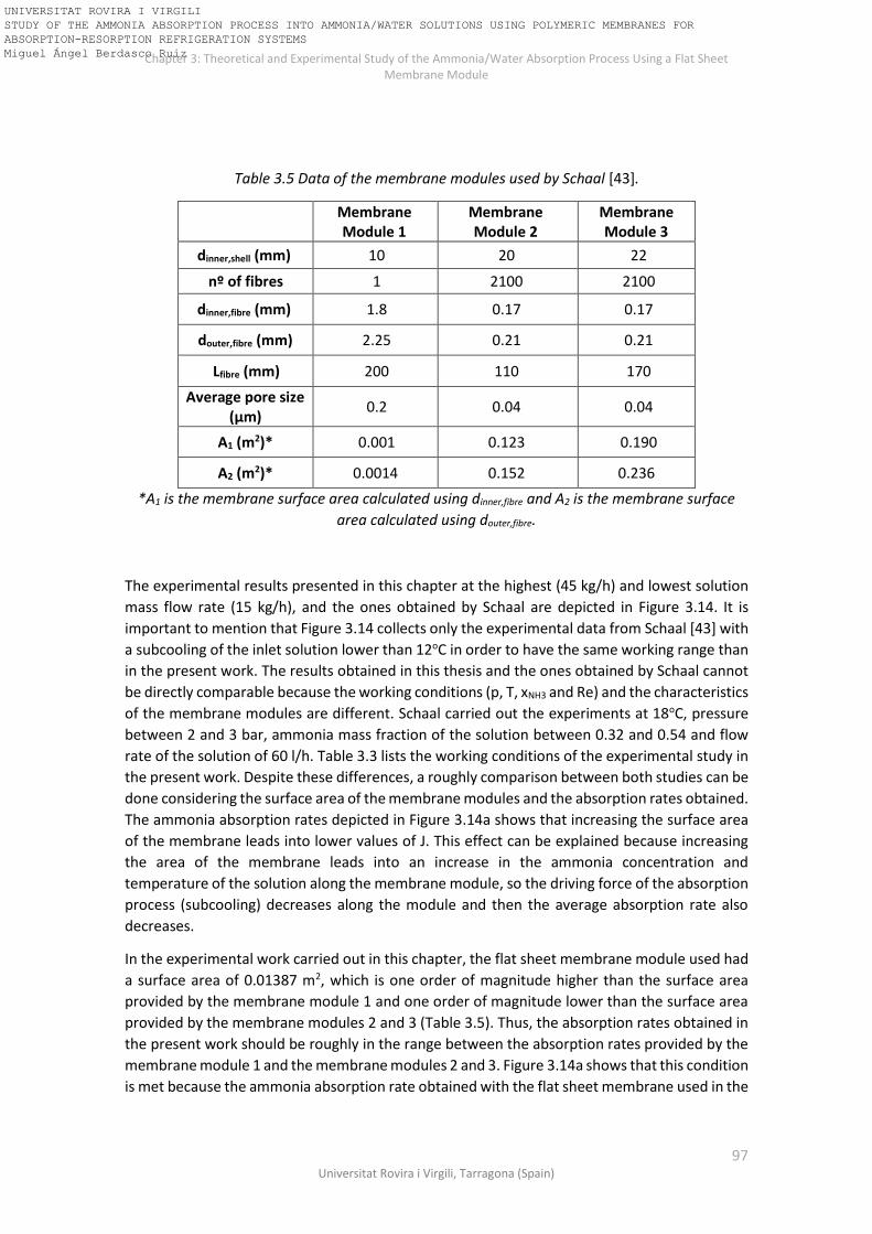
Chapter 3: Theoretical and Experimental Study of the Ammonia/Water Absorption Process Using a Flat Sheet Membrane Module
97 Universitat Rovira i Virgili, Tarragona (Spain)
Table 3.5 Data of the membrane modules used by Schaal [43].
Membrane Module 1
Membrane Module 2
Membrane Module 3
dinner,shell (mm) 10 20 22
nº of fibres 1 2100 2100
dinner,fibre (mm) 1.8 0.17 0.17
douter,fibre (mm) 2.25 0.21 0.21
Lfibre (mm) 200 110 170
Average pore size (μm)
0.2 0.04 0.04
A1 (m2)* 0.001 0.123 0.190
A2 (m2)* 0.0014 0.152 0.236
*A1 is the membrane surface area calculated using dinner,fibre and A2 is the membrane surface
area calculated using douter,fibre.
The experimental results presented in this chapter at the highest (45 kg/h) and lowest solution
mass flow rate (15 kg/h), and the ones obtained by Schaal are depicted in Figure 3.14. It is
important to mention that Figure 3.14 collects only the experimental data from Schaal [43] with
a subcooling of the inlet solution lower than 12oC in order to have the same working range than
in the present work. The results obtained in this thesis and the ones obtained by Schaal cannot
be directly comparable because the working conditions (p, T, xNH3 and Re) and the characteristics
of the membrane modules are different. Schaal carried out the experiments at 18oC, pressure
between 2 and 3 bar, ammonia mass fraction of the solution between 0.32 and 0.54 and flow
rate of the solution of 60 l/h. Table 3.3 lists the working conditions of the experimental study in
the present work. Despite these differences, a roughly comparison between both studies can be
done considering the surface area of the membrane modules and the absorption rates obtained.
The ammonia absorption rates depicted in Figure 3.14a shows that increasing the surface area
of the membrane leads into lower values of J. This effect can be explained because increasing
the area of the membrane leads into an increase in the ammonia concentration and
temperature of the solution along the membrane module, so the driving force of the absorption
process (subcooling) decreases along the module and then the average absorption rate also
decreases.
In the experimental work carried out in this chapter, the flat sheet membrane module used had
a surface area of 0.01387 m2, which is one order of magnitude higher than the surface area
provided by the membrane module 1 and one order of magnitude lower than the surface area
provided by the membrane modules 2 and 3 (Table 3.5). Thus, the absorption rates obtained in
the present work should be roughly in the range between the absorption rates provided by the
membrane module 1 and the membrane modules 2 and 3. Figure 3.14a shows that this condition
is met because the ammonia absorption rate obtained with the flat sheet membrane used in the
UNIVERSITAT ROVIRA I VIRGILI STUDY OF THE AMMONIA ABSORPTION PROCESS INTO AMMONIA/WATER SOLUTIONS USING POLYMERIC MEMBRANES FOR ABSORPTION-RESORPTION REFRIGERATION SYSTEMS Miguel Ángel Berdasco Ruiz
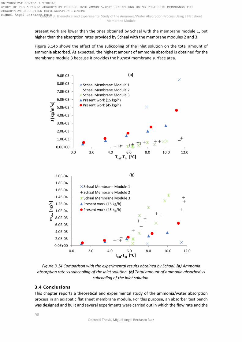
Chapter 3: Theoretical and Experimental Study of the Ammonia/Water Absorption Process Using a Flat Sheet Membrane Module
98 Doctoral Thesis, Miguel Ángel Berdasco Ruiz
present work are lower than the ones obtained by Schaal with the membrane module 1, but
higher than the absorption rates provided by Schaal with the membrane modules 2 and 3.
Figure 3.14b shows the effect of the subcooling of the inlet solution on the total amount of
ammonia absorbed. As expected, the highest amount of ammonia absorbed is obtained for the
membrane module 3 because it provides the highest membrane surface area.
Figure 3.14 Comparison with the experimental results obtained by Schaal. (a) Ammonia
absorption rate vs subcooling of the inlet solution. (b) Total amount of ammonia absorbed vs
subcooling of the inlet solution.
3.4 Conclusions This chapter reports a theoretical and experimental study of the ammonia/water absorption
process in an adiabatic flat sheet membrane module. For this purpose, an absorber test bench
was designed and built and several experiments were carried out in which the flow rate and the
0.0E+00
1.0E-03
2.0E-03
3.0E-03
4.0E-03
5.0E-03
6.0E-03
7.0E-03
8.0E-03
9.0E-03
0.0 2.0 4.0 6.0 8.0 10.0 12.0
J [k
g/m
2·s
]
Tsat-Tin [oC]
Schaal Membrane Module 1
Schaal Membrane Module 2
Schaal Membrane Module 3Present work (15 kg/h)
Present work (45 kg/h)
0.0E+00
2.0E-05
4.0E-05
6.0E-05
8.0E-05
1.0E-04
1.2E-04
1.4E-04
1.6E-04
1.8E-04
2.0E-04
0.0 2.0 4.0 6.0 8.0 10.0 12.0
mab
s[k
g/s]
Tsat-Tin [oC]
Schaal Membrane Module 1
Schaal Membrane Module 2
Schaal Membrane Module 3
Present work (15 kg/h)
Present work (45 kg/h)
(b)
(a)
UNIVERSITAT ROVIRA I VIRGILI STUDY OF THE AMMONIA ABSORPTION PROCESS INTO AMMONIA/WATER SOLUTIONS USING POLYMERIC MEMBRANES FOR ABSORPTION-RESORPTION REFRIGERATION SYSTEMS Miguel Ángel Berdasco Ruiz

Chapter 3: Theoretical and Experimental Study of the Ammonia/Water Absorption Process Using a Flat Sheet Membrane Module
99 Universitat Rovira i Virgili, Tarragona (Spain)
subcooling conditions of the solution were varied. The working conditions in the absorber were
determined from the simulation results of the absorption-resorption refrigeration cycle
obtained in the previous chapter.
A mathematical model was developed of the heat and mass transfer processes taking place in
the membrane module so that the evolution of the concentration, temperature and ammonia
flux throughout the membrane module during the absorption process could be studied. The
model was validated with the experimental results and the Mean Absolute Error of the model
predictions with respect to the experimental data were ±3.7·10-4 kg/m2s for the ammonia
absorption rate and ±0.6 °C for the outlet temperature of the solution.
For the conditions considered in this study, the absorption process is clearly governed by the
mass transfer in the liquid phase. At the highest solution flow rate of 45 kg/h and the highest
subcooling inlet conditions (Tsat-Tin=11 °C), the absorption rate was 4.7 ·10-3kg/m2s. The
experimental results obtained in this work are in accordance with the ones provided by Schaal
[43].
The influence of the geometrical parameters of the membrane was studied using a
mathematical model. The results showed that the optimal pore diameter of the membrane was
between 0.03μm and 0.10μm. Pore diameters smaller than 0.03μm mean that the resistance of
the membrane is too high. On the other hand, pore diameters larger than 0.10μm do not
improve the mass transfer and can lead more readily to liquid breakthroughs. The porosity of
the membrane should be as high as possible (at least higher than 40%) and the thickness lower
than 400μm in order to obtain a low transport resistance across the pores of the membrane but
at the same time keeping the mechanical robustness. These membrane characteristics will be
considered for the selection of the commercial hollow fibre membrane module used in the next
chapter.
UNIVERSITAT ROVIRA I VIRGILI STUDY OF THE AMMONIA ABSORPTION PROCESS INTO AMMONIA/WATER SOLUTIONS USING POLYMERIC MEMBRANES FOR ABSORPTION-RESORPTION REFRIGERATION SYSTEMS Miguel Ángel Berdasco Ruiz

Chapter 3: Theoretical and Experimental Study of the Ammonia/Water Absorption Process Using a Flat Sheet Membrane Module
100 Doctoral Thesis, Miguel Ángel Berdasco Ruiz
Nomenclature of chapter 3
A [m2] Area
COP [-] Coefficient of performance
D [m2/s] Diffusion coefficient
Dk [m2/s] Knudsen diffusion coefficient
dh [m] Hydraulic diameter
dp [m] Pore diameter
h [J/kg] Specific enthalpy
H [m] Height of the rectangular channel
J [kg/(m2·s)] Mass flux
Kb [m/s] Mass transfer coefficient in the liquid phase
Km [kg/(Pa·s·m2)] Mass transport coefficient in the pores of the membrane
m [kg/s] Mass flow rate
MNH3 [g/mol] Ammonia molecular weight
Nu [-] Nusselt number
p [Pa] Pressure
R [J/(K·mol)] Gas constant
Rm [Pa·m2·s/kg] Mass transfer resistance in the membrane
Rk [Pa·m2·s/kg] Knudsen diffusion resistance
Rp [Pa·m2·s/kg] Poiseuille flow resistance
Rs [Pa·m2·s/kg] Mass transfer resistance in the bulk liquid
Re [-] Reynolds number
Sc [-] Schmidt number
Sh [-] Sherwood number
T [K] Temperature
U [W/m2·K] Overall heat transfer coefficient
W [m] Width of the rectangular channel
x [-] Ammonia mass fraction
Special characters
α [W/(m2·K)] Heat transfer coefficient
δ [m] Membrane thickness
ε [-] Membrane porosity
λ [W/(m·K)] Thermal conductivity
μ [Pa·s] Dynamic Viscosity
UNIVERSITAT ROVIRA I VIRGILI STUDY OF THE AMMONIA ABSORPTION PROCESS INTO AMMONIA/WATER SOLUTIONS USING POLYMERIC MEMBRANES FOR ABSORPTION-RESORPTION REFRIGERATION SYSTEMS Miguel Ángel Berdasco Ruiz

Chapter 3: Theoretical and Experimental Study of the Ammonia/Water Absorption Process Using a Flat Sheet Membrane Module
101 Universitat Rovira i Virgili, Tarragona (Spain)
ρ [kg/m3] Density
τ [-] Tortuosity factor
Subscripts
abs Absorption
BG Bulk gas
BL Bulk liquid
in Inlet
int Interface
liq Liquid
mat Material
MM Membrane
out Outlet
sat Saturation
vap Vapour
UNIVERSITAT ROVIRA I VIRGILI STUDY OF THE AMMONIA ABSORPTION PROCESS INTO AMMONIA/WATER SOLUTIONS USING POLYMERIC MEMBRANES FOR ABSORPTION-RESORPTION REFRIGERATION SYSTEMS Miguel Ángel Berdasco Ruiz

Chapter 3: Theoretical and Experimental Study of the Ammonia/Water Absorption Process Using a Flat Sheet Membrane Module
102 Doctoral Thesis, Miguel Ángel Berdasco Ruiz
UNIVERSITAT ROVIRA I VIRGILI STUDY OF THE AMMONIA ABSORPTION PROCESS INTO AMMONIA/WATER SOLUTIONS USING POLYMERIC MEMBRANES FOR ABSORPTION-RESORPTION REFRIGERATION SYSTEMS Miguel Ángel Berdasco Ruiz

Chapter 4. Theoretical and Experimental Study of the Ammonia/Water Absorption Process Using a Hollow Fibre Membrane Module
103 Universitat Rovira i Virgili, Tarragona (Spain)
Chapter 4
Theoretical and Experimental Study of the Ammonia/Water Absorption Process Using a
Hollow Fibre Membrane Module
UNIVERSITAT ROVIRA I VIRGILI STUDY OF THE AMMONIA ABSORPTION PROCESS INTO AMMONIA/WATER SOLUTIONS USING POLYMERIC MEMBRANES FOR ABSORPTION-RESORPTION REFRIGERATION SYSTEMS Miguel Ángel Berdasco Ruiz

Chapter 3: Theoretical and Experimental Study of the Ammonia/Water Absorption Process Using a Flat Sheet Membrane Module
104 Doctoral Thesis, Miguel Ángel Berdasco Ruiz
UNIVERSITAT ROVIRA I VIRGILI STUDY OF THE AMMONIA ABSORPTION PROCESS INTO AMMONIA/WATER SOLUTIONS USING POLYMERIC MEMBRANES FOR ABSORPTION-RESORPTION REFRIGERATION SYSTEMS Miguel Ángel Berdasco Ruiz

Chapter 4. Theoretical and Experimental Study of the Ammonia/Water Absorption Process Using a Hollow Fibre Membrane Module
105 Universitat Rovira i Virgili, Tarragona (Spain)
This chapter presents a theoretical and experimental study of the adiabatic absorption process
of ammonia into an ammonia/water solution using a polymeric hollow fibre membrane module
(Liqui-Cel G501 2.5x8 Extra-Flow) as contactor. The experimental test bench described in
Chapter 3 was also used in this study but replacing the flat sheet membrane module by the
hollow fibre membrane module. The effect of the subcooling conditions and the mass flow rate
of the inlet solution on the ammonia absorption flux was studied. A two-dimensional model was
also developed and validated with the experimental results and two case studies were made at
different solution mass flow rates to determine the evolution of the ammonia solution
concentration, ammonia absorption rate, bulk solution temperature, gas temperature and
solution subcooling throughout the hollow fibre membrane module. The two-dimensional
model enables to study the evolution of the main operating parameters in the axial and radial
direction of the membrane module. The results presented in this chapter were published in
Applied Thermal Engineering [66].
4.1 Experimental set up The test bench described in Chapter 3 was used for the experimental study carried out in this
chapter. The membrane characteristics (pore size, porosity, material, and thickness) suggested
in the previous chapter were considered for the selection of the commercial hollow fibre
membrane module. The membrane module selected was provided by Liqui-Cel® (G501 2.5x8
Extra-Flow) and consisted of a bundle of 10000 hollow fibre membranes. The geometric
dimensions of the membrane module are shown in Table 4.1. The ammonia/water solution
flows over the outside of the hollow fibres (shell side). The membrane module contains a baffle
in the middle of the contactor, which directs the liquid radially across the membrane array [67].
The ammonia vapour stream flows inside the hollow fibres, crosses the pores of the membrane
and is absorbed by the solution at the liquid interface. Then, the ammonia/water solution exits
the absorber at higher concentration and higher temperature. A scheme of the membrane
module can be observed in Figure 4.1. The membrane needs to be hydrophobic and the pressure
controlled to prevent liquid breakthroughs inside the pores of the membrane [43]. For this
reason, a polypropylene hollow fibre membrane was selected and the pressure difference
between the liquid and gas side was kept below 0.3 bar during the experiments.
Table 4.1 Geometric dimensions and characteristics of the hollow fibre membrane module.
Fibres
Number of fibres 10000 Material Polypropylene
Inner diameter, di (μm) 210 Outer diameter, do (μm) 300
Average pore diameter, dp (μm) Effective hollow fibre length, L (m)
0.03 0.15
Porosity, ε (%) 45 Effective membrane area (m2) 1.4
Shell
Material Polypropylene Inside diameter, Ds (cm) 5.55
Central tube diameter, Dt (cm) 2.22
UNIVERSITAT ROVIRA I VIRGILI STUDY OF THE AMMONIA ABSORPTION PROCESS INTO AMMONIA/WATER SOLUTIONS USING POLYMERIC MEMBRANES FOR ABSORPTION-RESORPTION REFRIGERATION SYSTEMS Miguel Ángel Berdasco Ruiz

Chapter 4. Theoretical and Experimental Study of the Ammonia/Water Absorption Process Using a Hollow Fibre Membrane Module
106 Doctoral Thesis, Miguel Ángel Berdasco Ruiz
Figure 4.1 Illustration of the Liqui-Cel® Extra-Flow membrane contactor provided by Membrana
GmbH [67].
Because the membrane area of the Liqui-Cel® Extra-Flow membrane contactor is 100 times
larger than the area of the flat sheet membrane used in Chapter 3, the amount of ammonia
absorbed in the experiments carried out in this chapter will be significantly higher. For this
reason, the mass flow controller used for measuring the ammonia vapour flux was replaced by
another one with wider operating range (Aalborg GFC67). Table 4.2 lists the parameters
measured and the accuracy of each instrument.
Table 4.2 Measured variable and accuracy of the instruments.
Instrumentation Variable measured Accuracy
Coriolis flowmeter (CMF010M)
Pressure transmitter
(WIKA S-10)
PT100
Density and flow rate of the solution.
Pressure [bar]
Temperature
±0.5 kg/m3; ±0.05% of flow rate [kg/h]
±0.25% (full scale)
±0.1 K
Mass flow controller (Aalborg GFC67)
Mass flow rate of the ammonia vapour
±1 l/min (standard conditions)
4.2 Theoretical model A two-dimensional model using Engineering Equation Solver (EES) was developed to study the
adiabatic absorption process when a hollow fibre membrane module was used as a contactor.
The model predicts the amount of ammonia absorbed (mass transfer process) and the heat
exchange rate during the absorption process. Feed inlet conditions (pressure, temperature,
Gas inlet
Gas outlet
UNIVERSITAT ROVIRA I VIRGILI STUDY OF THE AMMONIA ABSORPTION PROCESS INTO AMMONIA/WATER SOLUTIONS USING POLYMERIC MEMBRANES FOR ABSORPTION-RESORPTION REFRIGERATION SYSTEMS Miguel Ángel Berdasco Ruiz

Chapter 4. Theoretical and Experimental Study of the Ammonia/Water Absorption Process Using a Hollow Fibre Membrane Module
107 Universitat Rovira i Virgili, Tarragona (Spain)
mass flow rate, and ammonia concentration) are input data. As can be observed in Figure 4.1,
the membrane module is divided into two parts by an internal baffle, so the model was also
divided into two sections. In the first, the feed flows from the central distribution tube to the
periphery of the contactor. In the second, the feed flows from the periphery to the centre. Each
section was discretized following the scheme shown in Figure 4.2 and a cross-flow configuration
between the solution and the gas was assumed.
Figure 4.2 Scheme of the discretization of the module. (a) Axial and radial sectional view. (b)
Cross flow configuration in the elementary cells. The blue arrows represent the gas flow inside
the hollow fibres and the black arrows represent solution flow over the outside of the hollow
fibres.
Each section of the module was discretized into 15 elements in the axial direction (m) and 35
rings in the radial direction (n). The stage number (m,n), “m” corresponds to the axial division
and “n” to the radial one, as depicted in Figure 4.2. Each ring is considered to be slightly wider
mBG[m,n]TBG[m,n]hBG[m,n]
mBG[m+1,n]TBG[m+1,n]hBG[m+1,n]
mBL[m,n-1] ; TBL[m,n-1]hBL[m,n-1] ; xBL[m,n-1]
mBL[m,n] ; TBL[m,n]hBL[m,n] ; xBL[m,n]
mBG[m+2,n]TBG[m+2,n]hBG[m+2,n]
mBL[m+1,n-1] ; TBL[m+1,n-1]hBL[m+1,n-1] ; xBL[m+1,n-1]
mBL[m+1,n] ; TBL[m+1,n]hBL[m+1,n] ; xBL[m+1,n]
mBG[m,n+1]TBG[m,n+1]hBG[m,n+1]
mBG[m+1,n+1]TBG[m+1,n+1]hBG[m+1,n+1]
mBL[m,n+1] ; TBL[m,n+1]hBL[m,n+1] ; xBL[m,n+1]
mBG[m+2,n+1]TBG[m+2,n+1]hBG[m+2,n+1]
mBL[m+1,n+1] ; TBL[m+1,n+1]hBL[m+1,n+1] ; xBL[m+1,n+1]
Elementary cells
n
mdx
dy
(a)
(b)
UNIVERSITAT ROVIRA I VIRGILI STUDY OF THE AMMONIA ABSORPTION PROCESS INTO AMMONIA/WATER SOLUTIONS USING POLYMERIC MEMBRANES FOR ABSORPTION-RESORPTION REFRIGERATION SYSTEMS Miguel Ángel Berdasco Ruiz

Chapter 4. Theoretical and Experimental Study of the Ammonia/Water Absorption Process Using a Hollow Fibre Membrane Module
108 Doctoral Thesis, Miguel Ángel Berdasco Ruiz
than the fibre diameter (dy > do), where dy is the pitch (gap between the fibres) in the radial
and angular direction. The mass and energy balances, transport equations and equilibrium
conditions were applied to each of the elements. As far as the thermodynamic and transport
properties of the working fluids are concerned, the density, enthalpy, and equilibrium data were
taken from Ibrahim and Klein [44], the thermal conductivity was calculated using the Bohne
equation from Cuenca at al. [59] and the viscosity, heat capacity and diffusion coefficient of
ammonia in water were calculated from Conde [60]. At the end of the first section of the module,
the mass and energy balances are applied in order to determine the solution inlet conditions for
the second section of the module.
4.2.1 Mass transfer in the membrane Two transport resistances have been considered for modelling the ammonia flow across the
membrane: the resistance of the liquid boundary layer and the transport resistance across the
pores of the membrane. Resistance in the vapour boundary layer is neglected because the
ammonia in the gas side is assumed to be pure. The ammonia vapour crosses the pores of the
membrane and is absorbed by the solution in the liquid-membrane interface. The dusty-gas
model was used to model the mass transport inside the pores of the membrane, so the Knudsen
diffusion resistance is parallel to the Poiseuille flow resistance [40]. The range of the Knudsen
number (Kn) in this study was between 0.05 and 1.9. This range meets the requirements of the
transition flow (0.01<Kn<10), so both resistances have been taken into account and the mass
transport coefficient (Km) can be written as [37]:
𝐾𝑚 =𝑀𝑁𝐻3
𝛿· (
𝐷𝑘
𝑅 · 𝑇𝑀𝑀,𝑚𝑒𝑎𝑛+
𝑝𝑔𝑎𝑠 · 𝐵0
𝑅 · 𝑇𝑀𝑀,𝑚𝑒𝑎𝑛 · 𝜇𝐵𝐺)
(4.1)
where pgas is the pressure on the gas side, TMM,mean is the mean membrane temperature which is
calculated as the average of the vapour and solution interface temperatures and μBG is the gas
viscosity. According to the information provided by the manufacturer, the tortuosity factor (τ)
was 2.5. The membrane thickness (δ) was taken from the data sheet of the membrane (45μm).
The Knudsen diffusion coefficient (Dk) is calculated using Eq. (4.2) [37]:
𝐷𝐾 = 𝐾0 · (8 · 𝑅 · 𝑇𝑀𝑀,𝑚𝑒𝑎𝑛
𝜋 · 𝑀𝑁𝐻3)
0.5
(4.2)
where Ko and Bo are constants defined as follows [33]:
𝐾0 =휀 · 𝑑𝑝
3𝜏
(4.3)
𝐵0 =휀 · (
𝑑𝑝
2 )2
8𝜏
(4.4)
where ε is the membrane porosity and dp is the mean pore diameter. The ammonia flux across
the membrane (J) is obtained with Eq. (4.5):
𝐽 = 𝐾𝑚 · (𝑝𝑔𝑎𝑠 − 𝑝𝑖𝑛𝑡) (4.5)
UNIVERSITAT ROVIRA I VIRGILI STUDY OF THE AMMONIA ABSORPTION PROCESS INTO AMMONIA/WATER SOLUTIONS USING POLYMERIC MEMBRANES FOR ABSORPTION-RESORPTION REFRIGERATION SYSTEMS Miguel Ángel Berdasco Ruiz

Chapter 4. Theoretical and Experimental Study of the Ammonia/Water Absorption Process Using a Hollow Fibre Membrane Module
109 Universitat Rovira i Virgili, Tarragona (Spain)
where pint is the partial ammonia vapour pressure at the temperature and concentration of the
interface (Tint and xint respectively). pint is calculated for every element of the discretized
membrane module because the temperature and the composition change throughout the
module.
4.2.2 Mass transfer in the liquid phase Figure 4.3 shows a scheme of the mass transfer process in the liquid phase. After crossing the
pores of the membrane, the ammonia vapour is absorbed by the solution in the liquid interface.
Then, the ammonia absorbed diffuses from the liquid-membrane interface to the bulk solution
due to the concentration gradient.
Figure 4.3 Mass transfer process in the liquid phase.
According to the film theory [62], the ammonia concentration at the interface (xint) can be
calculated using Eq. (4.6):
𝑥𝑖𝑛𝑡 = 𝑥𝐵𝐿 · 𝑒𝑥𝑝 (𝐽
𝜌𝑁𝐻3·𝐾𝐵𝐿) (4.6)
where ρNH3 is the density of the liquid ammonia, xint is the ammonia concentration at the liquid
interface boundary layer and KBL is the mass transfer coefficient between the solution boundary
layer and the bulk solution. There are many correlations reported in the literature for the
determination of KBL in the shell side of cross-flow hollow fibre membrane modules. Table 4.3
lists the most widely used. In a following section (4.3.1.1), a comparison between all of the
correlations presented in Table 4.3 was carried out in order to select the one that provides the
best agreement between the experimental and the theoretical results. In such correlations, DBL
is the diffusion coefficient of ammonia in water, do is the outer diameter of the hollow fibre and
dh is the hydraulic diameter, which is defined as follows:
𝑑ℎ =𝐷𝑠
2 − 𝐷𝑡2 − 𝑛𝑓 · 𝑑𝑜
2
𝑛𝑓,𝑡𝑜𝑡𝑎𝑙 · 𝑑0
(4.7)
where Ds is the inner diameter of the housing of the membrane module, Dt is the outer diameter
of the distribution/collection tube and nf,total is the total number of fibres. Due to the cross-flow
UNIVERSITAT ROVIRA I VIRGILI STUDY OF THE AMMONIA ABSORPTION PROCESS INTO AMMONIA/WATER SOLUTIONS USING POLYMERIC MEMBRANES FOR ABSORPTION-RESORPTION REFRIGERATION SYSTEMS Miguel Ángel Berdasco Ruiz

Chapter 4. Theoretical and Experimental Study of the Ammonia/Water Absorption Process Using a Hollow Fibre Membrane Module
110 Doctoral Thesis, Miguel Ángel Berdasco Ruiz
configuration of the Liqui-Cel® 2.5x8 Extra-Flow membrane module (Figure 4.1), the solution
velocity (v) in between the hollow fibres in the module was determined using the equation
presented by Mahmud et al. [68].
𝑣 =
2·𝑞𝑣𝜋·𝐿·(𝐷𝑠−𝐷𝑡)
·log(𝐷𝑠𝐷𝑡
)
1−𝜑 (4.8)
where qv is the volume flow rate of the solution. The length of each compartment is half the
module length, L, as the module was split in the centre by an internal baffle (Figure 4.1). The
packing fraction (φ) is calculated as following [69]:
𝜑 =𝑛𝑓,𝑡𝑜𝑡𝑎𝑙·𝑑𝑜
2
𝐷𝑠2−𝐷𝑡
2 (4.9)
Table 4.3 Empirical correlations for shell-side mass transfer in cross-flow commercial modules.
Authors Correlation
Wickramasinghe et al. [70]
𝑆ℎ =𝐾𝐵𝐿 · 𝑑𝑜
𝐷𝐵𝐿= 0.15 · 𝑅𝑒0.8𝑆𝑐0.33 𝑤ℎ𝑒𝑛 𝑅𝑒 > 2.5
𝑆ℎ =𝐾𝐵𝐿 · 𝑑𝑜
𝐷𝐵𝐿= 0.12 · 𝑅𝑒 · 𝑆𝑐0.33 𝑤ℎ𝑒𝑛 𝑅𝑒 ≤ 2.5
Fouad et al. [71]* 𝑆ℎ =
𝐾𝐵𝐿 · 𝑑ℎ
𝐷𝐵𝐿= 0.41 · 𝑅𝑒0.36𝑆𝑐0.33
Zheng et al. [69] 𝑆ℎ =
𝐾𝐵𝐿 · 𝑑ℎ
𝐷𝐵𝐿= 2.15 · 𝑅𝑒0.42𝑆𝑐0.33
Baudot et al. [72] 𝑆ℎ =
𝐾𝐵𝐿 · 𝑑ℎ
𝐷𝐵𝐿= 0.56 · 𝑅𝑒0.62𝑆𝑐0.33
Shen et al. [73] 𝑆ℎ =
𝐾𝐵𝐿 · 𝑑ℎ
𝐷𝐵𝐿= 0.055 · 𝑅𝑒0.72𝑆𝑐0.33
Schöner et al. [74]* 𝑆ℎ =
𝐾𝐵𝐿 · 𝑑ℎ
𝐷𝐵𝐿= ε · 1.76 · 𝑅𝑒0.82𝑆𝑐0.33
Mahmud et al. [75] 𝑆ℎ =
𝐾𝐵𝐿 · 𝑑𝑜
𝐷𝐵𝐿= 0.39 · 𝑅𝑒0.59𝑆𝑐0.33
*Correlations modified by Shen et al. [73].
The mass flow rate of the ammonia vapour absorbed (mabs) is determined by:
𝑚𝑎𝑏𝑠[𝑚, 𝑛] = 𝐽[𝑚, 𝑛] · 𝑑𝐴[𝑛] (4.10)
where dA is the discretized membrane area that is calculated as follows:
𝑑𝐴[𝑛] = 𝑁𝑓[𝑛] · 𝜋 · 𝑑𝑜 · 𝑑𝑥 (4.11)
UNIVERSITAT ROVIRA I VIRGILI STUDY OF THE AMMONIA ABSORPTION PROCESS INTO AMMONIA/WATER SOLUTIONS USING POLYMERIC MEMBRANES FOR ABSORPTION-RESORPTION REFRIGERATION SYSTEMS Miguel Ángel Berdasco Ruiz

Chapter 4. Theoretical and Experimental Study of the Ammonia/Water Absorption Process Using a Hollow Fibre Membrane Module
111 Universitat Rovira i Virgili, Tarragona (Spain)
Nf is the number of fibres on each ring, do is the outer diameter of the fibre and dx is the length
of the elementary cell in the axial direction.
𝑁𝑓[𝑛] =𝐿𝑐𝑖𝑟𝑐[𝑛]
𝑑𝑦 (4.12)
where Lcirc[n] is the outer perimeter of each ring and dy is the width of the ring and also the
distance between the fibres in the ring (Figure 4.2a).
𝐿𝑐𝑖𝑟𝑐[𝑛] = 𝜋 · 𝐷𝑟[𝑛] (4.13)
Dr[n] is the outer diameter of each ring and is calculated as follows:
𝐷𝑟[𝑛] = 𝐷𝑡 + 2 · 𝑛 · 𝑑𝑦 (4.14)
where “n” is the radial stage number.
Finally, the total and species mass balances are required in order to complete the model.
𝑚𝐵𝐿[𝑚, 𝑛] = 𝑚𝐵𝐿[𝑚, 𝑛 − 1] + 𝑚𝑎𝑏𝑠 [𝑚, 𝑛] (4.15)
𝑚𝐵𝐺[𝑚 + 1, 𝑛] = 𝑚𝐵𝐺[𝑚, 𝑛] − 𝑚𝑎𝑏𝑠[𝑚, 𝑛] (4.16)
𝑚𝐵𝐿[𝑚, 𝑛] · 𝑥𝐵𝐿[𝑚, 𝑛] = 𝑚𝐵𝐿[𝑚, 𝑛 − 1] · 𝑥𝐵𝐿[𝑚, 𝑛 − 1] + 𝑚𝑎𝑏𝑠[𝑚, 𝑛] (4.17)
4.2.3 Heat transfer An adiabatic absorber was considered in the model, so all the heat released during the
absorption process is completely transferred to liquid and vapour and heat is assumed not to be
lost to the surroundings. The energy balances for the liquid and the vapour sides are shown in
equations (4.18) and (4.19), respectively.
𝑚𝐵𝐿[𝑚, 𝑛 − 1] · ℎ𝐵𝐿[𝑚, 𝑛 − 1] + 𝑚𝑎𝑏𝑠[𝑚, 𝑛] · ∆ℎ𝑎𝑏𝑠 = 𝑚𝐵𝐿[𝑚, 𝑛] · ℎ𝐵𝐿[𝑚, 𝑛] +
𝑈 · 𝑑𝐴[𝑛] · (𝑇𝐵𝐿[𝑚, 𝑛] − 𝑇𝐵𝐺[𝑚, 𝑛]) (4.18)
𝑚𝐵𝐺[𝑚, 𝑛] · ℎ𝐵𝐺[𝑚, 𝑛] + 𝑈 · 𝑑𝐴[𝑛] · (𝑇𝐵𝐿[𝑚, 𝑛] − 𝑇𝐵𝐺[𝑚, 𝑛]) = 𝑚𝐵𝐺[𝑚 + 1, 𝑛] ·
ℎ𝐵𝐺[𝑚 + 1, 𝑛] (4.19)
∆habs is the heat released in the absorption process. A constant value of ∆habs (2007046.4 J/kg)
was taken from Mahmoud [76]. U is the overall heat transfer coefficient and is define as:
1
𝑈=
1
𝛼𝐵𝐿+
𝑑0 · ln (𝑑0𝑑𝑖
)
2 · 𝜆𝑀𝑀+
𝑑0
𝑑𝑖 · 𝛼𝐵𝐺
(4.20)
where di is the inner diameter of the fibre, αBL is the heat transfer coefficient in the liquid phase
and is obtained using the analogy between the heat and mass transfer [32] and αBG is the heat
transfer coefficient in the gas phase. According to the Hausen correlation [77] for laminar flow
in circular tubes, the Nusselt number in the gas can be determined as follows:
UNIVERSITAT ROVIRA I VIRGILI STUDY OF THE AMMONIA ABSORPTION PROCESS INTO AMMONIA/WATER SOLUTIONS USING POLYMERIC MEMBRANES FOR ABSORPTION-RESORPTION REFRIGERATION SYSTEMS Miguel Ángel Berdasco Ruiz

Chapter 4. Theoretical and Experimental Study of the Ammonia/Water Absorption Process Using a Hollow Fibre Membrane Module
112 Doctoral Thesis, Miguel Ángel Berdasco Ruiz
𝑁𝑢𝐵𝐺 = 3.66 +(0.0668 ·
𝑑𝑖𝐿
· 𝑅𝑒𝐵𝐺 · 𝑃𝑟𝐵𝐺)
(1 + 0.04 · (𝑑𝑖𝐿
· 𝑅𝑒𝐵𝐺 · 𝑃𝑟𝐵𝐺)2/3
)
(4.21)
Thermal conductivity of the polypropylene (λMM) is taken to be equal to 0.17 W·m-1K-1 following
the literature [78]. Finally, the interface temperatures are determined with the following energy
balance at the liquid-membrane interface (Eq. 4.22) and the energy balance at the vapour-
membrane interface (Eq. 4.23).
𝛼𝐵𝐿 · (𝑇𝑙𝑖𝑞,𝑖𝑛𝑡[𝑚, 𝑛] − 𝑇𝐵𝐿[𝑚, 𝑛]) · 𝑑0 = 𝐽[𝑚, 𝑛] · ∆ℎ𝑎𝑏𝑠[𝑚, 𝑛] · 𝑑0 −2·𝜆𝑀𝑀
𝑙𝑛(𝑑0𝑑𝑖
)· (𝑇𝑙𝑖𝑞,𝑖𝑛𝑡[𝑚, 𝑛] −
𝑇𝑣𝑎𝑝,𝑖𝑛𝑡[𝑚, 𝑛]) (4.22)
𝛼𝐵𝐺 · (𝑇𝑣𝑎𝑝,𝑖𝑛𝑡[𝑚, 𝑛] − 𝑇𝐵𝐺[𝑚, 𝑛]) · 𝑑𝑖 =2·𝜆𝑀𝑀
𝑙𝑛(𝑑0𝑑𝑖
)· (𝑇𝑙𝑖𝑞,𝑖𝑛𝑡[𝑚, 𝑛] − 𝑇𝑣𝑎𝑝,𝑖𝑛𝑡[𝑚, 𝑛]) (4.23)
where Tliq,int and Tvap,int are the solution-membrane and vapour-membrane interface
temperatures, respectively.
4.3 Results
4.3.1 Experimental results and validation of the model The experiments were carried out assuming the inlet operating conditions of the absorption-
resorption refrigeration cycle for the absorber and the resorber. These operating conditions
were determined in Chapter 2. It should be pointed out that the experiments were carried out
under adiabatic conditions with no cooling water during the absorption process. The effect of
the solution mass flow rate and the subcooling conditions of the inlet solution on the ammonia
absorption rate was studied. Table 4.4 lists the range of the working conditions during the
experiments.
Table 4.4 Range of working conditions during the experiments.
ABSORBER RESORBER
xNH3 0.29 – 0.32 0.56 – 0.60 p [bar] 1.3 – 1.5 5.0 – 5.5
Tinlet [oC] 24 - 35 15 - 28 ms [kg/h] 50-75-100 50-100-150
Figure 4.4 shows the effect of the subcooling of the inlet solution on the ammonia flux. Figure
4.4a shows the results obtained working under the absorber conditions of the absorption
resorption cycle at three solution mass flow rates. Figure 4.4b shows the results obtained
working under the resorber conditions.
UNIVERSITAT ROVIRA I VIRGILI STUDY OF THE AMMONIA ABSORPTION PROCESS INTO AMMONIA/WATER SOLUTIONS USING POLYMERIC MEMBRANES FOR ABSORPTION-RESORPTION REFRIGERATION SYSTEMS Miguel Ángel Berdasco Ruiz
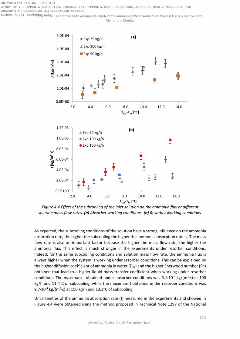
Chapter 4. Theoretical and Experimental Study of the Ammonia/Water Absorption Process Using a Hollow Fibre Membrane Module
113 Universitat Rovira i Virgili, Tarragona (Spain)
Figure 4.4 Effect of the subcooling of the inlet solution on the ammonia flux at different
solution mass flow rates. (a) Absorber working conditions. (b) Resorber working conditions.
As expected, the subcooling conditions of the solution have a strong influence on the ammonia
absorption rate; the higher the subcooling the higher the ammonia absorption rate is. The mass
flow rate is also an important factor because the higher the mass flow rate, the higher the
ammonia flux. This effect is much stronger in the experiments under resorber conditions.
Indeed, for the same subcooling conditions and solution mass flow rate, the ammonia flux is
always higher when the system is working under resorber conditions. This can be explained by
the higher diffusion coefficient of ammonia in water (DBL) and the higher Sherwood number (Sh)
obtained that lead to a higher liquid mass transfer coefficient when working under resorber
conditions. The maximum J obtained under absorber conditions was 3.1·10-4 kg/(m2·s) at 100
kg/h and 11.4oC of subcooling, while the maximum J obtained under resorber conditions was
9.7·10-4 kg/(m2·s) at 150 kg/h and 13.3oC of subcooling.
Uncertainties of the ammonia absorption rate (J) measured in the experiments and showed in
Figure 4.4 were obtained using the method proposed in Technical Note 1297 of the National
0.0E+00
1.0E-04
2.0E-04
3.0E-04
4.0E-04
5.0E-04
2.0 4.0 6.0 8.0 10.0 12.0 14.0
J [k
g/m
2 ·s]
Tsat-Tin [oC]
Exp 75 kg/h
Exp 100 kg/h
Exp 50 kg/h
0.0E+00
2.0E-04
4.0E-04
6.0E-04
8.0E-04
1.0E-03
1.2E-03
2.0 4.0 6.0 8.0 10.0 12.0 14.0
J [k
g/m
2·s
]
Tsat-Tin [oC]
Exp 50 kg/h
Exp 100 kg/h
Exp 150 kg/h
(b)
(a)
UNIVERSITAT ROVIRA I VIRGILI STUDY OF THE AMMONIA ABSORPTION PROCESS INTO AMMONIA/WATER SOLUTIONS USING POLYMERIC MEMBRANES FOR ABSORPTION-RESORPTION REFRIGERATION SYSTEMS Miguel Ángel Berdasco Ruiz

Chapter 4. Theoretical and Experimental Study of the Ammonia/Water Absorption Process Using a Hollow Fibre Membrane Module
114 Doctoral Thesis, Miguel Ángel Berdasco Ruiz
Institute of Standards and Technology Technical (NIST) and implemented in EES software [79].
Regarding the effective hollow fibre length and the number of fibres of the bundle, there are
small discrepancies between the values provided by the manufacturer (Table 4.1) and the values
measured by Schöner et al. [74]. These discrepancies were quantified in 0.15cm±0.01cm for the
effective hollow fibre length and 10000±50 for the number of fibres. Then, these uncertainties
and the ones showed in Table 4.2 were used for the uncertainty propagation.
4.3.1.1 Comparison with the experimental results obtained by Schaal
In Chapter 3 (section 3.3.3) a comparison between the experimental results obtained by Schaal
[43] and the experimental results obtained with the flat sheet membrane module was done.
Due to the differences in the experimental conditions and designs of the membrane modules
between both studies, a rough comparison was only possible. However, for the experimental
results obtained under resorber conditions in this chapter it would be possible to make a more
accurate comparison because in both studies a hollow fibre membrane module was used and
the experimental conditions are close to each other (Table 4.5). The data selected from Schaal
[43] for this comparison corresponds to the experiments carried out in the Membrane module
2 with the solution flowing to the shell side because this configuration is most similar to the flow
configuration of the Liqui-Cel hollow fibre membrane module used in this chapter.
Table 4.5 Range of working conditions selected for the comparison.
Schaal [43] (Membrane module 2)
Present work (Resorber)
xNH3 0.50-0.53 0.56 – 0.60 p [bar] 3.0-3.3 5.0 – 5.5
Tinlet [oC] 18 15 - 28 ms [kg/h] 45 50-100-150
Amembrane [m2] 0.152 1.4
Figure 4.5 compares the results obtained by Schaal and the results obtained in the present work
in terms of ammonia absorption rate (J) and total amount of ammonia absorbed (mabs) and a
good agreement was obtained. The comparison in terms of J (Figure 4.5a) shows that the
ammonia absorption rate obtained by Schaal is higher than the one obtained in the present work
at similar mass flow rate (50 kg/h), which was to be expected because the membrane surface
area of the Membrane module 2 is ten times lower than the membrane surface area of the Liqui-
Cel membrane module. In fact, the results obtained by Schaal in terms of J are similar to the
results obtained at 150 kg/h in the Liqui-Cel module. However, the total amount of ammonia
absorbed is significantly higher in the case of the experiments carried out with the Liqui-Cel
hollow fibre membrane module due to the higher flow rate and membrane surface area (Figure
4.5b). Comparing the results obtained at similar mass flow rate (45 kg/h in Schaal and 50kg/h in
the present work), the higher amount of ammonia absorbed in the present work leads into a
higher increment in the concentration than in the case of Schaal.
UNIVERSITAT ROVIRA I VIRGILI STUDY OF THE AMMONIA ABSORPTION PROCESS INTO AMMONIA/WATER SOLUTIONS USING POLYMERIC MEMBRANES FOR ABSORPTION-RESORPTION REFRIGERATION SYSTEMS Miguel Ángel Berdasco Ruiz

Chapter 4. Theoretical and Experimental Study of the Ammonia/Water Absorption Process Using a Hollow Fibre Membrane Module
115 Universitat Rovira i Virgili, Tarragona (Spain)
Figure 4.5 Comparison with the experimental results obtained by Schaal with the membrane
module 2 and flow to the shell side. (a) Ammonia absorption rate vs subcooling of the inlet
solution. (b) Total amount of ammonia absorbed vs subcooling of the inlet solution.
4.3.1.2 Selection of the correlation for determining the mass transfer coefficient in the shell side
In this section, the results obtained with the model using the correlations showed in Table 4.3
are compared with the experimental results obtained in the test bench in order to select the
one that provides the best agreement between the theoretical and the experimental results.
The experimental data selected for the comparison are shown in Table 4.6. Data from 1 to 3
correspond to the experiments carried out under absorber working conditions and data from 4
to 6 correspond to the experiments carried out under resorber working conditions. Table 4.7
shows the results obtained when the model described in section 4.2 was run using the
correlations showed in Table 4.3 for the determination of the solution mass transfer coefficient
in the shell side (kBL). The input data for the model are the experimental data showed in Table
4.6 (pressure, inlet temperature, ammonia solution concentration and solution mass flow rate).
The values of the ammonia absorption rate (J) and the temperature of the solution at the outlet
of the membrane module obtained with the model are compared with the experimental ones
in terms of relative error for the J (Eq. 4.24) and temperature deviation for Tout (Eq. 4.25). Finally,
the selection of the correlation that provides the best agreement between the theoretical and
the experimental results was done in terms of the Mean Absolute Error (MAE) for J and Tout.
0.0E+00
2.0E-04
4.0E-04
6.0E-04
8.0E-04
1.0E-03
1.2E-03
2.0 4.0 6.0 8.0 10.0 12.0 14.0
J [k
g/m
2·s
]
Tsat-Tin [oC]
Resorber 50 kg/h
Resorber 100 kg/h
Resorber 150 kg/h
Schaal 45 kg/h
(a)
0.0E+00
2.0E-04
4.0E-04
6.0E-04
8.0E-04
1.0E-03
1.2E-03
1.4E-03
1.6E-03
2.0 5.0 8.0 11.0 14.0
mab
s[k
g/s]
Tsat-Tin [oC]
Resorber 50 kg/h
Resorber 100 kg/h
Resorber 150 kg/h
Schaal 45 kg/h
(b)
UNIVERSITAT ROVIRA I VIRGILI STUDY OF THE AMMONIA ABSORPTION PROCESS INTO AMMONIA/WATER SOLUTIONS USING POLYMERIC MEMBRANES FOR ABSORPTION-RESORPTION REFRIGERATION SYSTEMS Miguel Ángel Berdasco Ruiz

Chapter 4. Theoretical and Experimental Study of the Ammonia/Water Absorption Process Using a Hollow Fibre Membrane Module
116 Doctoral Thesis, Miguel Ángel Berdasco Ruiz
𝐸𝑟𝑟𝑜𝑟 𝐽 (%) = (𝐽𝑚𝑜𝑑𝑒𝑙−𝐽𝑒𝑥𝑝
𝐽𝑒𝑥𝑝) · 100
(4.24)
𝐸𝑟𝑟𝑜𝑟 𝑇𝑜𝑢𝑡 = 𝑇𝑜𝑢𝑡,𝑚𝑜𝑑𝑒𝑙 − 𝑇𝑜𝑢𝑡,𝑒𝑥𝑝
(4.25)
Table 4.6 Experimental data selected for the comparison between the correlations of Table 4.3.
Data ms [kg/h] Tinlet [oC] xNH3,inlet p [bar] Tsat-Tin [oC] J [kg/(m2·s)] Tout [oC]
1 49.0 31.4 0.292 1.4 7.0 1.1E-04 36.9 2 75.0 31.8 0.294 1.4 6.7 1.8E-04 37.4 3 100.0 28.2 0.302 1.4 8.8 2.3E-04 33.9
4 50.0 24.8 0.556 5.2 7.7 1.8E-04 31.0 5 101.0 22.9 0.578 5.3 7.5 3.1E-04 28.9 6 152.0 23.1 0.597 5.6 6.8 4.5E-04 28.2
Table 4.7 Comparison between the correlations and the experimental data.
Zheng et al. [69] *Schöner et al. [74]
Data J
[kg/(m2·s)] Tout [oC] Error J [%]
Error Tout [oC]
J [kg/(m2·s)]
Tout [oC] Error J
[%]
Error Tout [oC]
1 1.8E-04 36.8 59.9 -0.1 1.7E-04 36.8 55.7 -0.1 2 3.0E-04 37.0 67.6 -0.4 2.9E-04 37.0 63.2 -0.4 3 2.8E-04 34.6 23.7 0.7 2.8E-04 34.6 23.1 0.7
4 1.8E-04 31.5 -0.6 0.5 1.7E-04 31.5 -2.1 0.5 5 3.3E-04 29.5 6.3 0.6 3.3E-04 29.5 6.1 0.6 6 4.1E-04 28.7 -9.7 0.5 4.1E-04 28.7 -9.6 0.5
MAE (J) MAE Tout MAE (J) MAE Tout
±5·10-5 kg/(m2·s) ±0.5oC ±5·10-5 kg/(m2·s) ±0.5oC
Wickramasinghe et al. [70] Mahmud et al. [75]
Data J
[kg/(m2·s)] Tout [oC] Error J [%]
Error Tout [oC]
J [kg/(m2·s)]
Tout [oC] Error J
[%]
Error Tout [oC]
1 1.2E-04 36.9 11.9 0.0 1.6E-04 36.8 48.8 -0.1 2 2.0E-04 36.9 11.5 -0.5 2.7E-04 37.0 51.5 -0.4 3 2.5E-04 34.1 7.4 0.2 2.8E-04 34.6 21.0 0.7
4 1.5E-04 31.2 -14.4 0.2 1.7E-04 31.5 -4.7 0.5 5 3.0E-04 29.1 -2.7 0.2 3.2E-04 29.4 4.6 0.5 6 3.8E-04 28.4 -16.5 0.2 4.0E-04 28.7 -10.9 0.5
MAE (J) MAE Tout MAE (J) MAE Tout
±3·10-5 kg/(m2·s) ±0.2oC ±4·10-5 kg/(m2·s) ±0.5oC
UNIVERSITAT ROVIRA I VIRGILI STUDY OF THE AMMONIA ABSORPTION PROCESS INTO AMMONIA/WATER SOLUTIONS USING POLYMERIC MEMBRANES FOR ABSORPTION-RESORPTION REFRIGERATION SYSTEMS Miguel Ángel Berdasco Ruiz

Chapter 4. Theoretical and Experimental Study of the Ammonia/Water Absorption Process Using a Hollow Fibre Membrane Module
117 Universitat Rovira i Virgili, Tarragona (Spain)
Shen et al. [73] Baudot et al. [72]
Data J
[kg/(m2·s)] Tout [oC] Error J [%]
Error Tout [oC]
J [kg/(m2·s)]
Tout [oC] Error J
[%]
Error Tout [oC]
1 1.2E-04 36.9 8.2 0.0 1.7E-04 36.8 51.0 -0.1 2 1.8E-04 37.0 3.2 -0.4 2.7E-04 37.0 55.1 -0.4 3 2.3E-04 33.6 -1.5 -0.3 2.8E-04 34.6 21.7 0.7
4 1.5E-04 30.9 -18.7 -0.1 1.7E-04 31.5 -4.0 0.5 5 2.7E-04 28.5 -12.9 -0.4 3.2E-04 29.5 5.1 0.6 6 3.3E-04 27.8 -26.9 -0.4 4.0E-04 28.7 -10.5 0.5
MAE (J) MAE Tout MAE (J) MAE Tout
±4·10-5 kg/(m2·s) ±0.3oC ±5·10-5 kg/(m2·s) ±0.5oC
*Fouad et al. [71]
J [kg/(m2·s)]
Tout [oC] Error J [%] Error
Tout [oC]
1.5E-04 36.8 40.5 -0.1
2.4E-04 36.9 35.4 -0.5
2.7E-04 34.5 17.2 0.6
1.7E-04 31.5 -7.2 0.5
3.1E-04 29.3 0.4 0.4
3.8E-04 28.4 -16.8 0.2
MAE (J) MAE Tout
±4·10-5 kg/(m2·s) ±0.4oC
The results obtained in Table 4.7 show that the correlations provided by Zheng et al., Schöner
et al., Mahmud et al., Baudot et al., and Fouad et al. provide a good agreement with the
experimental results under resorber conditions. However, they provide wide deviations when
compared with the experimental data obtained under absorber conditions. In the case of the
correlation provided by Shen et al. the conclusion is just the opposite; very good agreement
under absorber conditions but not so good under resorber conditions. Finally, the correlation of
Wickramasinghe et al. provides good results in both working conditions and also provides the
lowest Mean Absolute Error in both the outlet temperature and the ammonia absorption rate.
For this reason, the correlation provided by Wickramasinghe et al. was selected for the
determination of the mass transfer coefficient of the solution flowing in the shell side of the
module.
4.3.1.3 Validation of the model
The theoretical model has been validated with the experimental results obtained in the test
bench. Figure 4.6 shows a comparison between the ammonia absorption rate (J) measured
during the experiments and the results predicted by the model. The comparison shows a good
agreement between the predictions and the experimental results, with a relative error lower
than 20% in all cases. The Mean Absolute Error of the model predictions with respect to the
experimental data is ±3·10-5 kg/m2s. Deviations were highest for resorber working conditions at
UNIVERSITAT ROVIRA I VIRGILI STUDY OF THE AMMONIA ABSORPTION PROCESS INTO AMMONIA/WATER SOLUTIONS USING POLYMERIC MEMBRANES FOR ABSORPTION-RESORPTION REFRIGERATION SYSTEMS Miguel Ángel Berdasco Ruiz

Chapter 4. Theoretical and Experimental Study of the Ammonia/Water Absorption Process Using a Hollow Fibre Membrane Module
118 Doctoral Thesis, Miguel Ángel Berdasco Ruiz
subcooling above 10oC. No significant differences were obtained when the mass flow rate was
increased. Regarding the heat transfer process, Table 4.8 shows the outlet temperature of the
solution obtained in the experiments (Tout,exp) and the one predicted by the model (Tout,model). The
Mean Absolute Error of the model predictions with respect to the experimental data is ±0.3°C.
Figure 4.6 Comparison of the J experimental with the J obtained with the theoretical model.
Table 4.8 Outlet temperature of the solution after the absorption process. Comparison between
the experimental and the theoretical results.
ABSORBER RESORBER
Tsat-Tin [oC]
Tin [oC]
Tout,exp
[oC] Tout,model
[oC] Tsat-Tin
[oC] Tin
[oC] Tout,exp
[oC] Tout,model
[oC]
50 kg/h
3.1 33.6 35.8 35.8 3.9 28.2 30.9 31.3
4.5 33.7 36.7 37.0 7.7 24.8 31.0 31.1
7.0 31.4 36.9 36.5 10.9 22.3 30.7 30.9
11.3 27.9 36.4 36.6 11.6 21.7 30.8 31.0
13.9 24.1 34.1 34.1 13.6 14.8 26.1 26.4
75 kg/h
3.2 34.7 37.7 37.0
5.4 33.4 37.3 36.9
6.7 31.8 37.4 36.8 NA NA NA NA
9.9 28.7 36.3 35.9
12.5 24.2 33.6 32.9
100 kg/h
4.1 31.8 34.6 34.2 2.7 28.2 30.1 30.2
4.9 32.1 35.2 35.2 4.5 27.5 30.9 30.9
5.6 34.8 38.8 38.6 5.4 25.6 29.4 29.8
8.8 28.2 33.9 33.6 7.4 23.1 28.8 29.0
10.1 28.5 35.1 35.4 10.3 21.0 28.7 29.2
11.4 24.7 32.3 32.5 12.8 16.9 27.1 27.7
150 kg/h
3.3 25.4 27.8 27.7
5.8 24.4 28.7 28.8
NA NA NA NA 6.8 23.1 28.2 28.4
9.9 21.2 29.0 29.1
13.3 19.0 29.7 30.0
0.0E+00
2.0E-04
4.0E-04
6.0E-04
8.0E-04
1.0E-03
1.2E-03
0.0E+00 2.0E-04 4.0E-04 6.0E-04 8.0E-04 1.0E-03 1.2E-03
J mo
de
l [kg
·m-2
·s-1
]
Jexperimental [kg·m-2·s-1]
Absorber
Resorber
-20%
+20%
UNIVERSITAT ROVIRA I VIRGILI STUDY OF THE AMMONIA ABSORPTION PROCESS INTO AMMONIA/WATER SOLUTIONS USING POLYMERIC MEMBRANES FOR ABSORPTION-RESORPTION REFRIGERATION SYSTEMS Miguel Ángel Berdasco Ruiz

Chapter 4. Theoretical and Experimental Study of the Ammonia/Water Absorption Process Using a Hollow Fibre Membrane Module
119 Universitat Rovira i Virgili, Tarragona (Spain)
4.3.2 Case study The theoretical model validated with the experimental results is used in this section to study the
evolution of several parameters in the membrane module. The case study selected was taken
from the experiments carried out under absorber working conditions. It should be pointed out
that at the inlet the solution is subject to considerable subcooling (Tsat-Tin=11.7oC) to prevent the
liquid from reaching saturation conditions in the membrane module. The inlet conditions of the
case study selected are listed in Table 4.9.
Table 4.9 Case study selected for the theoretical study.
Tin [ºC] p [bar] xNH3 Tgas [oC] mBL [kg/h]
29 1.6 0.3045 19.8 98.8
Figures 4.7-4.11 show the evolution of the ammonia solution concentration, ammonia
absorption rate, bulk solution temperature, gas temperature and solution subcooling in the
membrane module, respectively. All the figures are divided into three parts: (a) shows a scheme
of the upper part of the hollow fibre membrane module (based on the scheme shown in Figure
4.2a) and the contours of the parameters studied in each figure by means of a colour scale; (b)
and (c) show the evolution of each parameter in the radial and axial direction in the first and
second section of the module, respectively. The radial direction (n) in the first section is
discretized into 35 rings (n from 1 to 35), starting in the central tube and finishing at the top of
the module, where the solution is collected before entering the second section. The second
section is also discretized into 35 rings (n from 36 to 70), but in this case starting at the top of
the module and finishing in the central tube, where the solution is finally collected. The
membrane module was also discretized into 30 elements in the axial direction (m) but only
elements 1, 3, 5, 15, 16, 18, 20 and 30 were selected for representation in the figures.
In the first section of the module (Figures 4.7b-4.11b), the ammonia solution concentration
(xNH3=0.317) is highest in the upper-left side of the section (Figures 4.7a and 4.7b line m=1). This
is because the temperature of the gas is much lower than the liquid temperature in this area
(line m=1 of Figures 4.9b and 4.10b) so there is a cooling effect in the solution that improves the
driving force of the absorption process. For the same reason, Figure 4.8b shows that the
ammonia absorption rate (J) is significantly higher at the beginning of the module (m=1) than in
the rest of the first section (m=3-15). As expected, there is a downward trend of J in the radial
direction due to the increase in the ammonia concentration (Figure 4.7b) and the temperature
of the bulk solution (Figure 4.9b). The temperature of the bulk solution increases in the radial
direction due to the heat generated during the absorption process. The temperature of the gas
shows a trend similar to that of the temperature of the bulk solution, and reaches its maximum
value in the upper-right part of the section (Figure 4.10a). It is also important to highlight that
the temperature of the gas is nearly the same as the temperature of the bulk solution in the
axial half of the first section. To see this effect clearly, Figure 4.12 depicts the evolution of the
temperature difference between the solution and the gas (TBL-TBG) in the membrane module.
Figure 4.12b shows that the temperature difference remains below 1ºC in most of the first
section. The subcooling degree of the solution (Figure 4.11b) is similar to the ammonia flux (J)
because both are directly proportional (Eq. 4.5).
In the second section of the module (Figures 4.7c-4.11c), the evolution of the ammonia solution
concentration, ammonia absorption rate, bulk solution temperature and solution subcooling
UNIVERSITAT ROVIRA I VIRGILI STUDY OF THE AMMONIA ABSORPTION PROCESS INTO AMMONIA/WATER SOLUTIONS USING POLYMERIC MEMBRANES FOR ABSORPTION-RESORPTION REFRIGERATION SYSTEMS Miguel Ángel Berdasco Ruiz

Chapter 4. Theoretical and Experimental Study of the Ammonia/Water Absorption Process Using a Hollow Fibre Membrane Module
120 Doctoral Thesis, Miguel Ángel Berdasco Ruiz
show the same trend as in the first section. However, in the second section there is greater
uniformity in the axial direction than in the first section. There are two reasons for this. First, the
driving force of the absorption process is much lower in the second section due to the higher
concentration and temperature of the solution. And second, the temperature difference
between the gas and liquid is smaller in this section (Figure 4.12c). Figure 4.12c (lines m=18, 20,
and 30) shows that (TBL-TBG) are close to zero, so the cooling effect of the gas stream generated
in the first section (which enhances the mass transfer) is almost negligible in most of the second
section of the module. The importance of the cooling effect produced by the gas stream is
particularly evident in line m=16 in Figure 4.12c, where the gas stream at the bottom left of the
second section (this cold gas comes from the bottom right of the first section of the module)
cools the solution and increases the absorption rate (J) in this area instead of decreasing it
(Figure 4.8c).
Figure 4.7 (a) Contours of the ammonia concentration profile in the hollow fibre membrane
module. (b) Evolution of ammonia concentration in the radial direction (n from 0 to 35) in the
first section of the module. (c) Evolution of ammonia concentration in the radial direction (n
from 36 to 70) in the second section of the module.
0.300
0.303
0.306
0.309
0.312
0.315
0.318
0.321
0 5 10 15 20 25 30 35
x NH
3
n
m=1
m=3
m=5
m=15
0.300
0.303
0.306
0.309
0.312
0.315
0.318
0.321
35 40 45 50 55 60 65 70
x NH
3
n
m=16
m=18
m=20
m=30
(c)
(a)
(b)
Solution
inlet
UNIVERSITAT ROVIRA I VIRGILI STUDY OF THE AMMONIA ABSORPTION PROCESS INTO AMMONIA/WATER SOLUTIONS USING POLYMERIC MEMBRANES FOR ABSORPTION-RESORPTION REFRIGERATION SYSTEMS Miguel Ángel Berdasco Ruiz

Chapter 4. Theoretical and Experimental Study of the Ammonia/Water Absorption Process Using a Hollow Fibre Membrane Module
121 Universitat Rovira i Virgili, Tarragona (Spain)
Figure 4.8 (a) Contours of the ammonia absorption rate profile in the hollow fibre membrane
module. (b) Evolution of ammonia absorption rate in the radial direction (n from 0 to 35) in the
first section of the module. (c) Evolution of ammonia absorption rate in the radial direction (n
from 36 to 70) in the second section of the module.
0.0E+00
2.0E-04
4.0E-04
6.0E-04
8.0E-04
1.0E-03
0 5 10 15 20 25 30 35
J [k
g/m
2·s
]
n
m=1m=3m=5m=15
(b)
0.0E+00
2.0E-04
4.0E-04
6.0E-04
8.0E-04
1.0E-03
35 40 45 50 55 60 65 70
J [k
g/m
2·s
]
n
m=16m=18m=20m=30
(c)
(a)
(a)
UNIVERSITAT ROVIRA I VIRGILI STUDY OF THE AMMONIA ABSORPTION PROCESS INTO AMMONIA/WATER SOLUTIONS USING POLYMERIC MEMBRANES FOR ABSORPTION-RESORPTION REFRIGERATION SYSTEMS Miguel Ángel Berdasco Ruiz

Chapter 4. Theoretical and Experimental Study of the Ammonia/Water Absorption Process Using a Hollow Fibre Membrane Module
122 Doctoral Thesis, Miguel Ángel Berdasco Ruiz
Figure 4.9 (a) Contours of the bulk solution temperature profile in the hollow fibre membrane
module. (b) Evolution of bulk solution temperature in the radial direction (n from 0 to 35) in the
first section of the module. (c) Evolution of bulk solution temperature in the radial direction (n
from 36 to 70) in the second section of the module.
Figure 4.10 (a) Contours of the gas temperature profile in the hollow fibre membrane module.
(b) Evolution of gas temperature in the radial direction (n from 0 to 35) in the first section of
the module. (c) Evolution of gas temperature in the radial direction (n from 36 to 70) in the
second section of the module.
29
30
31
32
33
34
35
36
37
0 5 10 15 20 25 30 35
TB
L[o
C]
n
m=1
m=3
m=5
m=15
(b)
29
30
31
32
33
34
35
36
37
35 40 45 50 55 60 65 70
TB
L[o
C]
n
m=16m=18m=20m=30
(c)
24
26
28
30
32
34
36
38
0 5 10 15 20 25 30 35
T BG
[oC
]
n
m=1
m=3
m=5
m=15
(b)
24
26
28
30
32
34
36
38
35 40 45 50 55 60 65 70
T BG
[oC
]
n
m=16
m=18
m=20
m=30
(c)
(a)
UNIVERSITAT ROVIRA I VIRGILI STUDY OF THE AMMONIA ABSORPTION PROCESS INTO AMMONIA/WATER SOLUTIONS USING POLYMERIC MEMBRANES FOR ABSORPTION-RESORPTION REFRIGERATION SYSTEMS Miguel Ángel Berdasco Ruiz

Chapter 4. Theoretical and Experimental Study of the Ammonia/Water Absorption Process Using a Hollow Fibre Membrane Module
123 Universitat Rovira i Virgili, Tarragona (Spain)
Figure 4.11 (a) Contours of the solution subcooling profile in the hollow fibre membrane
module. (b) Subcooling evolution in the radial direction (n from 0 to 35) in the first section of
the module. (c) Subcooling evolution in the radial direction (n from 36 to 70) in the second
section of the module.
0
2
4
6
8
10
12
0 5 10 15 20 25 30 35
TB
L,sa
t-T
BL
[oC
]
n
m=1m=3m=5m=15
(b)
0
2
4
6
8
10
12
35 40 45 50 55 60 65 70
T BL,
sat-
T BL
[oC
]
n
m=16
m=18
m=20
m=30
(c)
(a)
(a)
UNIVERSITAT ROVIRA I VIRGILI STUDY OF THE AMMONIA ABSORPTION PROCESS INTO AMMONIA/WATER SOLUTIONS USING POLYMERIC MEMBRANES FOR ABSORPTION-RESORPTION REFRIGERATION SYSTEMS Miguel Ángel Berdasco Ruiz

Chapter 4. Theoretical and Experimental Study of the Ammonia/Water Absorption Process Using a Hollow Fibre Membrane Module
124 Doctoral Thesis, Miguel Ángel Berdasco Ruiz
Figure 4.12 (a) Contours of the temperature difference between the solution and the gas (TBL-
TBG) in the hollow fibre membrane module. (b) TBL-TBG evolution in the radial direction (n from 0
to 35) in the first section of the module. (c) TBL-TBG evolution along the radial direction (n from
36 to 70) in the second section of the module.
Figures 4.8 and 4.11 clearly show that much of the ammonia is absorbed in the first section of
the membrane module. This is explained by the adiabatic working conditions that rapidly
decrease the driving force in the membrane module. However, a higher amount of ammonia
can be absorbed if the solution mass flow rate is increased. According to the data sheet provided
by the manufacturer of the hollow fibre membrane module, the maximum mass flow rate for
the solution on the shell side is around 600 kg/h, four times higher than the maximum flow rate
tested during the experiments (150 kg/h). Due to limitations in the experimental test bench it
was not possible to reach higher mass flow rates. However, the theoretical model previously
validated can be used to predict the performance of the membrane module working at
maximum flow rate. Figures 4.13 and 4.14 show the ammonia absorption rate and the solution
subcooling in the membrane module for the same case study listed in Table 4.9 but in this case
the solution mass flow rate (mBL) is increased to 600 kg/h.
A comparison of Figures 4.13b and 4.13c with Figures 4.8b and 4.8c shows that the ammonia
absorption rate at 600 kg/h is much higher than in the first case study (98.8 kg/h). In fact, the
lowest J obtained at the end of the second section in Figure 4.13c (0.00079 kg·m-2·s-1) is close to
the maximum J obtained in the first case study at the inlet of the module in Figure 4.8b (0.00093
kg·m-2·s-1). This may be because the mass transfer process is clearly governed by the mass
transfer resistance in the liquid phase, so the higher the Reynolds number is, the higher the mass
transfer coefficient in the liquid phase (Table 4.3). In the membrane module, there are no big
differences in the evolution of the subcooling in the axial direction in the case with a mass flow
rate of 600 kg/h (Figure 4.14b), there are more uniformity compared to the case study with
mBL=98.8 kg/h (Figure 4.11b). The subcooling of the solution at the outlet of the second section
(Figure 4.14c) is 3oC, significantly higher than in the case study shown in Figure 4.11c (below
1.5oC).
The experimental and theoretical results obtained show that the Liqui-Cel G501 2.5x8 Extra-
Flow membrane module is a reliable and useful device for the ammonia absorption process.
However, due to the limitations of the adiabatic absorption process, the possibility of integrating
some non-porous fibres for the cooling water in the membrane absorber needs to be studied in
-1
0
1
2
3
4
5
6
7
8
9
0 5 10 15 20 25 30 35
TB
L-T B
G[o
C]
n
m=1m=3m=5m=15
(b)
-1
0
1
2
3
4
5
6
7
8
9
35 40 45 50 55 60 65 70
TB
L-T B
G[o
C]
n
m=16
m=18
m=20
m=30
(c)
UNIVERSITAT ROVIRA I VIRGILI STUDY OF THE AMMONIA ABSORPTION PROCESS INTO AMMONIA/WATER SOLUTIONS USING POLYMERIC MEMBRANES FOR ABSORPTION-RESORPTION REFRIGERATION SYSTEMS Miguel Ángel Berdasco Ruiz
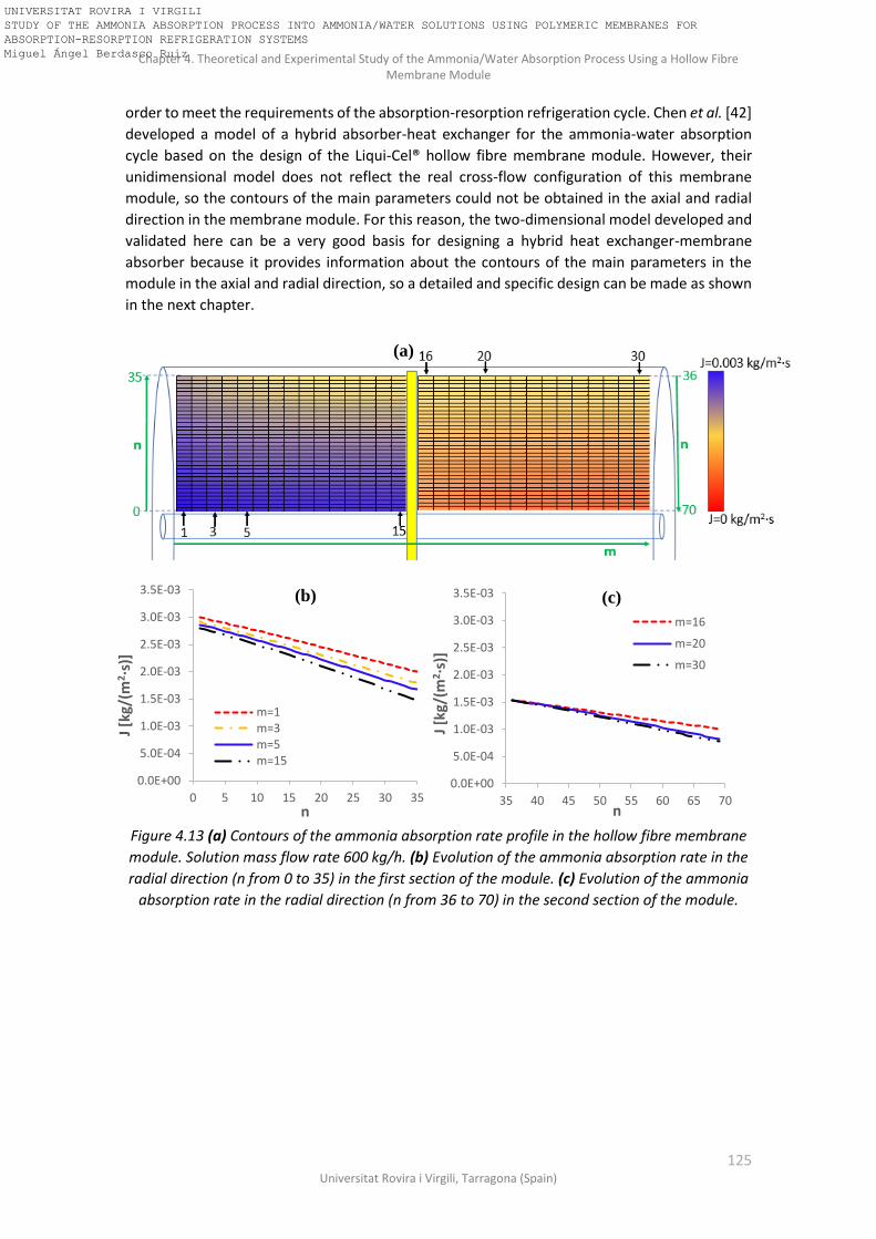
Chapter 4. Theoretical and Experimental Study of the Ammonia/Water Absorption Process Using a Hollow Fibre Membrane Module
125 Universitat Rovira i Virgili, Tarragona (Spain)
order to meet the requirements of the absorption-resorption refrigeration cycle. Chen et al. [42]
developed a model of a hybrid absorber-heat exchanger for the ammonia-water absorption
cycle based on the design of the Liqui-Cel® hollow fibre membrane module. However, their
unidimensional model does not reflect the real cross-flow configuration of this membrane
module, so the contours of the main parameters could not be obtained in the axial and radial
direction in the membrane module. For this reason, the two-dimensional model developed and
validated here can be a very good basis for designing a hybrid heat exchanger-membrane
absorber because it provides information about the contours of the main parameters in the
module in the axial and radial direction, so a detailed and specific design can be made as shown
in the next chapter.
Figure 4.13 (a) Contours of the ammonia absorption rate profile in the hollow fibre membrane
module. Solution mass flow rate 600 kg/h. (b) Evolution of the ammonia absorption rate in the
radial direction (n from 0 to 35) in the first section of the module. (c) Evolution of the ammonia
absorption rate in the radial direction (n from 36 to 70) in the second section of the module.
0.0E+00
5.0E-04
1.0E-03
1.5E-03
2.0E-03
2.5E-03
3.0E-03
3.5E-03
0 5 10 15 20 25 30 35
J [k
g/(m
2·s
)]
n
m=1m=3m=5m=15
(b)
0.0E+00
5.0E-04
1.0E-03
1.5E-03
2.0E-03
2.5E-03
3.0E-03
3.5E-03
35 40 45 50 55 60 65 70
J [k
g/(m
2·s
)]
n
m=16
m=20
m=30
(c)
(a)
UNIVERSITAT ROVIRA I VIRGILI STUDY OF THE AMMONIA ABSORPTION PROCESS INTO AMMONIA/WATER SOLUTIONS USING POLYMERIC MEMBRANES FOR ABSORPTION-RESORPTION REFRIGERATION SYSTEMS Miguel Ángel Berdasco Ruiz

Chapter 4. Theoretical and Experimental Study of the Ammonia/Water Absorption Process Using a Hollow Fibre Membrane Module
126 Doctoral Thesis, Miguel Ángel Berdasco Ruiz
Figure 4.14 (a) Contours of the solution subcooling profile in the hollow fibre membrane
module. Solution mass flow rate 600 kg/h. (b) Subcooling evolution in the radial direction (n
from 0 to 35) in the first section of the module. (c) Subcooling evolution in the radial direction
(n from 36 to 70) in the second section of the module.
4.4 Conclusions This chapter reports a theoretical and experimental study of the adiabatic ammonia/water
absorption process in a commercial hollow fibre membrane module. Several experiments were
carried out in which the solution mass flow rate and the inlet subcooling conditions of the
solution were varied. The working conditions were determined from the simulation results of
the absorption-resorption refrigeration cycle obtained in Chapter 2. The higher the subcooling
conditions of the solution, the more ammonia absorption rate was recorded. The same
behaviour was observed when the solution mass flow rate was increased. The maximum J
obtained under absorber conditions was 3.1·10-4 kg/(m2·s) at 100 kg/h and 11.4oC of subcooling,
while the maximum J obtained under resorber conditions was 9.7·10-4 kg/(m2·s) at 150 kg/h and
13.3oC of subcooling. It was observed a significant difference between the results obtained
under resorber and absorber working conditions; for the same subcooling conditions and mass
flow rate, the ammonia flux observed working under resorber conditions is much higher than
when working under absorber conditions. This fact can be explained by the higher diffusion
coefficient of ammonia in water (DBL) and the higher Sherwood number (Sh) obtained that lead
to a higher liquid mass transfer coefficient when working under resorber conditions. A two-
dimensional model was also developed and validated with the experimental results and
agreement was very good. The Mean Absolute Error of the model predictions of J with respect
to the experimental data is ±3·10-5 kg/m2s and ±0.3°C for the predictions of the temperature of
the solution at the outlet of the membrane module.
0
2
4
6
8
10
12
0 5 10 15 20 25 30 35
TB
L,sa
t-T
BL
[oC
]
n
m=1
m=3
m=5
m=15
(b)
0
2
4
6
8
10
12
35 40 45 50 55 60 65 70
TB
L,sa
t-T
BL
[oC
]
n
m=16
m=20
m=30
(c)
(a)
UNIVERSITAT ROVIRA I VIRGILI STUDY OF THE AMMONIA ABSORPTION PROCESS INTO AMMONIA/WATER SOLUTIONS USING POLYMERIC MEMBRANES FOR ABSORPTION-RESORPTION REFRIGERATION SYSTEMS Miguel Ángel Berdasco Ruiz

Chapter 4. Theoretical and Experimental Study of the Ammonia/Water Absorption Process Using a Hollow Fibre Membrane Module
127 Universitat Rovira i Virgili, Tarragona (Spain)
The two-dimensional model was used to study the evolution of the ammonia solution
concentration, ammonia absorption rate, bulk solution temperature, gas temperature and
solution subcooling in the membrane module. The results obtained in the first case study
(mBL=98.8 kg/h) show that the ammonia is mainly absorbed in the first section of the module
due to the adiabatic process that leads to a continuous decrease in the subcooling conditions of
the solution in the membrane module. As expected, this effect was also observed when the
solution mass flow rate was increased to 600 kg/h, but in this case the ammonia absorption rate
was an order of magnitude greater due to the higher mass transfer coefficient in the liquid phase
obtained. Also, the subcooling of the solution at the outlet of the membrane module was
significantly higher when the solution mass flow rate was increased. The model validated in this
chapter is used as a basis for a new two-dimensional model of a hybrid heat exchanger-hollow
fibre membrane absorber that is shown in the next chapter. The new two-dimensional model
with integrated heat exchanger enables to design more compact and enhanced absorbers and
resorbers for the ammonia/water absorption-resorption refrigeration cycle.
UNIVERSITAT ROVIRA I VIRGILI STUDY OF THE AMMONIA ABSORPTION PROCESS INTO AMMONIA/WATER SOLUTIONS USING POLYMERIC MEMBRANES FOR ABSORPTION-RESORPTION REFRIGERATION SYSTEMS Miguel Ángel Berdasco Ruiz

Chapter 4. Theoretical and Experimental Study of the Ammonia/Water Absorption Process Using a Hollow Fibre Membrane Module
128 Doctoral Thesis, Miguel Ángel Berdasco Ruiz
Nomenclature of chapter 4
dA [m2] Discretized membrane area
D [m2/s] Diffusion coefficient
Dk [m2/s] Knudsen diffusion coefficient
d0 [m] Outer diameter of the hollow fiber
di [m] Inner diameter of the hollow fiber
dp [m] Pore diameter
Ds [m] Inner diameter of the shell of the module
Dt [m] Outer diameter of the central tube
dx [m] Length of the discretization element in the axial direction
dy [m] Width of the discretization ring in the radial direction. Also gap between the fibers
h [J/kg] Specific enthalpy
J [kg/(m2·s)] Mass flux
KBL [m/s] Mass transfer coefficient in the liquid phase
Km [kg/(Pa·s·m2)] Mass transport coefficient in the pores of the membrane
L [m] Membrane module length
m [-] Segment m
mabs [kg/s] Mass flow rate of the ammonia (vapour) absorbed
mBL [kg/s] Solution mass flow rate
mBG [kg/s] Gas mass flow rate
MNH3 [g/mol] Ammonia molecular weight
n [-] Segment n
Nf [-] Number of fibers
Nu [-] Nusselt number
p [Pa] Pressure
R [J/(K·mol)] Gas constant
Re [-] Reynolds number
Sc [-] Schmidt number
Sh [-] Sherwood number
T [K] Temperature
U [W/m2·K] Overall heat transfer coefficient
x [-] Ammonia mass fraction
Special characters
α [W/(m2·K)] Heat transfer coefficient
UNIVERSITAT ROVIRA I VIRGILI STUDY OF THE AMMONIA ABSORPTION PROCESS INTO AMMONIA/WATER SOLUTIONS USING POLYMERIC MEMBRANES FOR ABSORPTION-RESORPTION REFRIGERATION SYSTEMS Miguel Ángel Berdasco Ruiz

Chapter 4. Theoretical and Experimental Study of the Ammonia/Water Absorption Process Using a Hollow Fibre Membrane Module
129 Universitat Rovira i Virgili, Tarragona (Spain)
δ [m] Membrane thickness
ε [-] Membrane porosity
φ [-] Packing fraction
λ [W/(m·K)] Thermal conductivity
μ [Pa·s] Dynamic Viscosity
ρ [kg/m3] Density
τ [-] Tortuosity factor
Subscripts
abs Absorption
BG Bulk gas
BL Bulk liquid
in Inlet
int Interface
liq Liquid
MM Membrane
out Outlet
sat Saturation
vap Vapour
UNIVERSITAT ROVIRA I VIRGILI STUDY OF THE AMMONIA ABSORPTION PROCESS INTO AMMONIA/WATER SOLUTIONS USING POLYMERIC MEMBRANES FOR ABSORPTION-RESORPTION REFRIGERATION SYSTEMS Miguel Ángel Berdasco Ruiz

Chapter 4. Theoretical and Experimental Study of the Ammonia/Water Absorption Process Using a Hollow Fibre Membrane Module
130 Doctoral Thesis, Miguel Ángel Berdasco Ruiz
UNIVERSITAT ROVIRA I VIRGILI STUDY OF THE AMMONIA ABSORPTION PROCESS INTO AMMONIA/WATER SOLUTIONS USING POLYMERIC MEMBRANES FOR ABSORPTION-RESORPTION REFRIGERATION SYSTEMS Miguel Ángel Berdasco Ruiz
Chapter 5. Design of a Hybrid Heat Exchanger-Hollow Fibre Membrane Absorber for the Ammonia/Water Absorption-Resorption Refrigeration Cycle
131 Universitat Rovira i Virgili, Tarragona (Spain)
Chapter 5
Design of a Hybrid Heat Exchanger-Hollow Fibre Membrane Absorber for
the Ammonia/Water Absorption-Resorption Refrigeration Cycle
UNIVERSITAT ROVIRA I VIRGILI STUDY OF THE AMMONIA ABSORPTION PROCESS INTO AMMONIA/WATER SOLUTIONS USING POLYMERIC MEMBRANES FOR ABSORPTION-RESORPTION REFRIGERATION SYSTEMS Miguel Ángel Berdasco Ruiz

Chapter 5. Design of a Hybrid Heat Exchanger-Hollow Fibre Membrane Absorber for the Ammonia/Water Absorption-Resorption Refrigeration Cycle
132 Doctoral Thesis, Miguel Ángel Berdasco Ruiz
UNIVERSITAT ROVIRA I VIRGILI STUDY OF THE AMMONIA ABSORPTION PROCESS INTO AMMONIA/WATER SOLUTIONS USING POLYMERIC MEMBRANES FOR ABSORPTION-RESORPTION REFRIGERATION SYSTEMS Miguel Ángel Berdasco Ruiz

Chapter 5. Design of a Hybrid Heat Exchanger-Hollow Fibre Membrane Absorber for the Ammonia/Water Absorption-Resorption Refrigeration Cycle
133 Universitat Rovira i Virgili, Tarragona (Spain)
In previous chapters, the adiabatic ammonia absorption process was studied experimentally and
theoretically. However, only one adiabatic absorption stage is not enough to reach the desired
ammonia concentration at the outlet of the absorber in a real cycle due to the heat released
during the absorption process. This heat leads into an increase of the temperature of the
solution, and therefore the ammonia absorption rate drops rapidly. To achieve a greater
increment in the ammonia solution concentration it would be necessary to transfer the heat
released to an external fluid in order to avoid the temperature of the solution increasing during
the absorption process. There are two options for studying the integration of membrane
modules as contactors in absorption cycles:
• Adiabatic absorption + Cooling in heat exchangers (several stages), as shown in Figure
5.1. This configuration was tested by Schaal [43] in an ammonia/water absorption
refrigeration plant. A plate heat exchanger was used for cooling the solution before the
adiabatic absorption stage. The operating capability of membrane absorbers was
demonstrated but it was not possible to achieve the desired cooling capacity (6.7 kW)
because the number of membrane modules required would provide too high pressure
drop.
Figure 5.1 In series adiabatic absorber + cooling stage configuration.
• Hybrid heat exchanger-membrane absorber, where the absorption and cooling
processes take place in the same device. This configuration provides more compact
refrigeration systems, but the design of the module is more complex. As far as the
author concern, there are no commercial hybrid heat exchanger-membrane absorbers
available in the market. This configuration was proposed by Chen et al. [42] in order to
be integrated in an absorption chiller.
This chapter aims to design two hybrid heat exchanger-hollow fibre membrane absorbers in
order to be used as an absorber and as a resorber in a 25-kW ammonia/water absorption-
resorption refrigeration cycle. To achieve this goal, the hollow fibre membrane module
described in Chapter 4 was taken as a basis for the design of the hybrid heat-exchanger-hollow
fibre membrane absorber. The same characteristics of the membrane (pore size, porosity,
thickness and material) and flow configuration (cross-flow) were considered (Table 4.1 of
Chapter 4). Furthermore, the model developed and validated in the previous chapter was
modified to include some non-porous hollow fibres inside the membrane module for the cooling
water flow, as shown in Figure 5.2. These non-porous hollows fibres are supposed to have the
same thickness, diameter and material (polypropylene) than the porous fibres showed in Table
4.1 of Chapter 4.
UNIVERSITAT ROVIRA I VIRGILI STUDY OF THE AMMONIA ABSORPTION PROCESS INTO AMMONIA/WATER SOLUTIONS USING POLYMERIC MEMBRANES FOR ABSORPTION-RESORPTION REFRIGERATION SYSTEMS Miguel Ángel Berdasco Ruiz

Chapter 5. Design of a Hybrid Heat Exchanger-Hollow Fibre Membrane Absorber for the Ammonia/Water Absorption-Resorption Refrigeration Cycle
134 Doctoral Thesis, Miguel Ángel Berdasco Ruiz
Figure 5.2 Axial sectional view of the hybrid heat exchanger-hollow fibre membrane absorber.
5.1 Theoretical model A two-dimensional model using Engineering Equation Solver (EES) was developed to study the
non-adiabatic ammonia absorption process when a hybrid heat exchanger-hollow fibre
membrane module was used as a contactor. The model predicts the amount of ammonia
absorbed (mass transfer process) and the heat transferred to the cooling water. Feed inlet
conditions (pressure, temperature, mass flow rate, and ammonia concentration) and cooling
water inlet conditions (mass flow rate, temperature and pressure) are input data. As shown in
Figure 5.2, the membrane module consists of adiabatic absorption stages, where the solution
absorbs the ammonia vapour that crosses the porous hollow fibres, and of refrigeration stages,
where the solution is cooled down by the cooling water flowing inside the non-porous hollow
fibres and no absorption takes place. The number of stages for the absorption and for the cooling
were determined in order to meet the requirements of the base case selected for the absorber
and for the resorber in a 25-kW ammonia/water absorption-resorption refrigeration cycle. As it
was explained in Figure 4.1 of the previous chapter, the membrane module is divided into two
parts by an internal baffle, so the model was also divided into two sections. In the first, the feed
flows from the central distribution tube to the periphery of the contactor. In the second, the
feed flows from the periphery to the centre. Each section was discretized following the scheme
shown in Figure 5.3 and a cross-flow configuration between the solution and the gas and
between the solution and the cooling water was assumed. Each section of the module was
discretized into 15 elements in the axial direction (m). The number of rings in the radial direction
(n), and therefore the size of the membrane module, will be varied in order to determine the
membrane surface area required to meet the requirements of the base case selected from the
study of the absorption-resorption refrigeration cycle. The stage number (m,n), “m”
corresponds to the axial division and “n” to the radial one, as depicted in Figure 5.3.
The mass and energy balances, transport equations and equilibrium conditions were applied to
each of the elements. As far as the thermodynamic and transport properties of the working
fluids are concerned, the density, enthalpy, and equilibrium data of the ammonia/water mixture
were taken from Ibrahim and Klein [44], the thermal conductivity was calculated using the
Bohne equation from Cuenca et al. [59] and the viscosity, heat capacity and diffusion coefficient
of ammonia in water were calculated from Conde [60]. The thermodynamic properties of the
water were already implemented in the EES database and they were taken from McBride et al.
[80]. At the end of the first section of the module a complete mixing of the solution is considered.
UNIVERSITAT ROVIRA I VIRGILI STUDY OF THE AMMONIA ABSORPTION PROCESS INTO AMMONIA/WATER SOLUTIONS USING POLYMERIC MEMBRANES FOR ABSORPTION-RESORPTION REFRIGERATION SYSTEMS Miguel Ángel Berdasco Ruiz
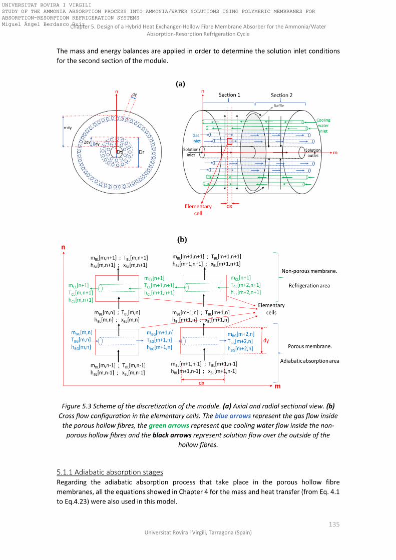
Chapter 5. Design of a Hybrid Heat Exchanger-Hollow Fibre Membrane Absorber for the Ammonia/Water Absorption-Resorption Refrigeration Cycle
135 Universitat Rovira i Virgili, Tarragona (Spain)
The mass and energy balances are applied in order to determine the solution inlet conditions
for the second section of the module.
Figure 5.3 Scheme of the discretization of the module. (a) Axial and radial sectional view. (b)
Cross flow configuration in the elementary cells. The blue arrows represent the gas flow inside
the porous hollow fibres, the green arrows represent que cooling water flow inside the non-
porous hollow fibres and the black arrows represent solution flow over the outside of the
hollow fibres.
5.1.1 Adiabatic absorption stages Regarding the adiabatic absorption process that take place in the porous hollow fibre
membranes, all the equations showed in Chapter 4 for the mass and heat transfer (from Eq. 4.1
to Eq.4.23) were also used in this model.
mBG[m,n]TBG[m,n]hBG[m,n]
mBG[m+1,n]TBG[m+1,n]hBG[m+1,n]
mBL[m,n-1] ; TBL[m,n-1]hBL[m,n-1] ; xBL[m,n-1]
mBL[m,n] ; TBL[m,n]hBL[m,n] ; xBL[m,n]
mBG[m+2,n]TBG[m+2,n]hBG[m+2,n]
mBL[m+1,n-1] ; TBL[m+1,n-1]hBL[m+1,n-1] ; xBL[m+1,n-1]
mBL[m+1,n] ; TBL[m+1,n]hBL[m+1,n] ; xBL[m+1,n]
mCL[n+1]TCL[m,n+1]hCL[m,n+1]
mCL[n+1]TCL[m+1,n+1]hCL[m+1,n+1]
mBL[m,n+1] ; TBL[m,n+1]hBL[m,n+1] ; xBL[m,n+1]
mCL[n+1]TCL[m+2,n+1]hCL[m+2,n+1]
mBL[m+1,n+1] ; TBL[m+1,n+1]hBL[m+1,n+1] ; xBL[m+1,n+1]
Elementary cells
n
mdx
dy
Non-porous membrane.
Refrigeration area
Porous membrane.
Adiabatic absorption area
(a)
(b)
UNIVERSITAT ROVIRA I VIRGILI STUDY OF THE AMMONIA ABSORPTION PROCESS INTO AMMONIA/WATER SOLUTIONS USING POLYMERIC MEMBRANES FOR ABSORPTION-RESORPTION REFRIGERATION SYSTEMS Miguel Ángel Berdasco Ruiz

Chapter 5. Design of a Hybrid Heat Exchanger-Hollow Fibre Membrane Absorber for the Ammonia/Water Absorption-Resorption Refrigeration Cycle
136 Doctoral Thesis, Miguel Ángel Berdasco Ruiz
5.1.2 Refrigeration stages In these stages, the heat generated during the adiabatic absorption process is transferred to the
cooling water that is flowing inside the non-porous hollow fibres. There is no mass transfer
process in these stages. The energy balances for the solution and the cooling water sides are
shown in equations (5.1) and (5.2), respectively.
𝑚𝐵𝐿[𝑚, 𝑛 − 1] · ℎ𝐵𝐿[𝑚, 𝑛 − 1] + 𝑈𝐶𝐿 · 𝑑𝐴[𝑛] · (𝑇𝐶𝐿[𝑚, 𝑛] − 𝑇𝐵𝐿[𝑚, 𝑛]) = 𝑚𝐵𝐿[𝑚, 𝑛] ·
ℎ𝐵𝐿[𝑚, 𝑛] (5.1)
𝑚𝐶𝐿[𝑛] · ℎ𝐶𝐿[𝑚 − 1, 𝑛] − 𝑈𝐶𝐿 · 𝑑𝐴[𝑛] · (𝑇𝐵𝐿[𝑚, 𝑛] − 𝑇𝐶𝐿[𝑚, 𝑛]) = 𝑚𝐶𝐿[𝑛] · ℎ𝐶𝐿[𝑚, 𝑛] (5.2)
Where TCL, mCL and hCL are the temperature, mass flow rate and enthalpy of the cooling water.
UCL is the overall heat transfer coefficient and is defined as follows:
1
𝑈𝐶𝐿=
1
𝛼𝐵𝐿+
𝑑0 · ln (𝑑0𝑑𝑖
)
2 · 𝜆𝑀𝑀+
𝑑0
𝑑𝑖 · 𝛼𝐶𝐿
(5.3)
where di is the inner diameter of the fibre, αBL and αCL are the heat transfer coefficient in the
solution and in the cooling water, respectively. αBL is obtained using the correlation of
Wickramasinghe et al. [70]. Regarding αCL, the Hausen correlation [77] for laminar flow in circular
tubes was used and the Nusselt number in the cooling water was obtained using Eq. (4.21).
Thermal conductivity of the polypropylene (λMM) is taken to be equal to 0.17 W·m-1K-1 following
the literature [78].
5.2 Operating conditions of the absorption-resorption cycle In this section, the model of the absorption-resorption cycle described in section 2.2.3 of
Chapter 2 was used to determine the ammonia concentration and the solution flow rate in the
absorber and the resorber that meet the requirements showed in Figure 5.4. These
requirements correspond to the case study selected in Chapter 2 for the sensitivity analysis of
the cycle.
Before starting to design the hybrid heat exchanger-hollow fibre membrane absorbers is
important to point out that the integration of a membrane contactor in the resorber would
require some modifications in the cycle configuration. The reason is because the vapour coming
from the generator is a saturated mixture of ammonia/water and has a higher temperature than
the solution entering the resorber. Thus, when the vapour and the solution are put in contact
by means of a membrane, the vapour would reduce its temperature and then condensation
would take place, blocking the pores of the membrane and therefore reducing the mass transfer
across the membrane. In order to avoid this issue, before entering the vapour into the
membrane module it would be necessary to cool down the vapour to a temperature equal or
lower than the temperature of the solution entering the resorber. This can be done by means of
an additional external heat exchanger using a cooling water stream or by means of an internal
heat transfer between the cold solution leaving the desorber and the vapour obtained in the
generator. This last option was selected in our model and the resulting cycle configuration can
UNIVERSITAT ROVIRA I VIRGILI STUDY OF THE AMMONIA ABSORPTION PROCESS INTO AMMONIA/WATER SOLUTIONS USING POLYMERIC MEMBRANES FOR ABSORPTION-RESORPTION REFRIGERATION SYSTEMS Miguel Ángel Berdasco Ruiz

Chapter 5. Design of a Hybrid Heat Exchanger-Hollow Fibre Membrane Absorber for the Ammonia/Water Absorption-Resorption Refrigeration Cycle
137 Universitat Rovira i Virgili, Tarragona (Spain)
be observed in Figure 5.5. The condensed solution obtained in the additional heat exchanger is
returned to the generator. In the case of the absorber, this problem does not take place because
the vapour generated in the desorber is always colder than the solution entering the absorber.
Another important effect of this new configuration on the performance of the cycle is the
reduction of the flow rate in the bleeding pipe (nearly zero) due to the water condensation
produced in the heat exchanger 3.
Figure 5.4 Absorption-resorption refrigeration cycle. Input variables for determining the
operating conditions of the base case.
Figure 5.5 Absorption-resorption refrigeration cycle modified: precooling of the vapour before
entering the resorber.
UNIVERSITAT ROVIRA I VIRGILI STUDY OF THE AMMONIA ABSORPTION PROCESS INTO AMMONIA/WATER SOLUTIONS USING POLYMERIC MEMBRANES FOR ABSORPTION-RESORPTION REFRIGERATION SYSTEMS Miguel Ángel Berdasco Ruiz

Chapter 5. Design of a Hybrid Heat Exchanger-Hollow Fibre Membrane Absorber for the Ammonia/Water Absorption-Resorption Refrigeration Cycle
138 Doctoral Thesis, Miguel Ángel Berdasco Ruiz
The theoretical model of the ammonia/water absorption-resorption refrigeration cycle modified
according to Figure 5.5 was run and the operating conditions obtained for the absorber and for
the resorber are showed in Figure 5.6. These conditions will be taken as a reference in the
following section for the design of the hybrid heat exchanger-hollow fibre membrane absorbers.
Figure 5.6 Working conditions in the absorber and in the resorber.
5.3 Design of a hybrid heat exchanger-hollow fibre membrane absorber for
the 25-kW ammonia/water absorption-resorption refrigeration cycle The following procedure was carried out to design the hybrid heat exchanger-hollow fibre
membrane absorbers (HEXHFMA) that meet the requirements of the cycle of Figure 5.6. In order
to better understand the procedure, Figures 5.7-5.10 are also included.
1. The geometric dimensions and membrane characteristics of the Liqui-Cel® hollow fibre membrane module showed in Table 4.1 of Chapter 4 were taken as initial values for the design of the HEXHFMA. However, in order to avoid high pressure drops in the membrane module the manufacturer recommended solution flow rates lower than 0.68 m3/h, which is lower than the solution flow rates required in the base case of Figure 5.6. Then, for the design of the HEXHFMA of the base case it would be necessary to reduce the velocity of the solution through the shell side of the module in order to minimize the pressure drop. Thus, the initial length of the membrane module is assumed to be double than the length of the membrane module described in Chapter 4 (2x15cm=30cm).
2. The two-dimensional adiabatic model described and validated in Chapter 4 is used for the initial step. The model is run using as input values the inlet variables of the absorber showed in Figure 5.6. Then, the results obtained at the outlet of the membrane absorber are compared to the outlet conditions in the absorber showed in Figure 5.6. If the outlet solution of the membrane module is far from the saturation conditions and far from the desired ammonia concentration, the absorption area is then increased by adding new rings of porous hollow fibre membranes. This process is repeated until the outlet conditions of the solution are close to the saturation, that is to say, no significant improvements are observed in the solution concentration at the outlet of the module.
UNIVERSITAT ROVIRA I VIRGILI STUDY OF THE AMMONIA ABSORPTION PROCESS INTO AMMONIA/WATER SOLUTIONS USING POLYMERIC MEMBRANES FOR ABSORPTION-RESORPTION REFRIGERATION SYSTEMS Miguel Ángel Berdasco Ruiz

Chapter 5. Design of a Hybrid Heat Exchanger-Hollow Fibre Membrane Absorber for the Ammonia/Water Absorption-Resorption Refrigeration Cycle
139 Universitat Rovira i Virgili, Tarragona (Spain)
Figure 5.7 Adiabatic membrane absorber. Red lines represent the porous hollow fibre membranes.
3. The non-porous hollow fibre membranes for cooling are integrated just after the adiabatic absorption stage. As initial assumption, each cooling stage consists of 25 rings. Initially, the velocity of the cooling water flowing inside the non-porous hollow fibres is assumed to be 1 m/s. The model of the membrane absorber with cooling integrated was already described in section 5.1 of this chapter.
4. The model with the cooling stage integrated is run. If the outlet conditions of the solution do not meet the requirements of the base case, additional adiabatic and cooling stages are added. Points 2 to 4 of this procedure are repeated until obtaining the outlet conditions of the solution approach to the outlet conditions required for the base case.
Figure 5.8 Hybrid heat exchanger-hollow fibre membrane absorber with one cooling stage and one adiabatic absorption stage. Red lines represent the porous hollow fibre membranes and blue lines represent the non-porous
hollow fibre membranes.
5. The number of rings required on each cooling stage is optimized. The model is run and
the temperature difference between the solution and the cooling water on each ring is
Solution inlet
Solution OutletΔTsubcooling>>0oC
xNH3,out<<xNH3,target
30 cm
Gasinlet
Gasinlet
Increasing the size of the absorption stage
Solution inlet
Solution OutletΔTsubcooling ≈ 0oC
xNH3,out<<xNH3,target
Integration of cooling stage
Solution inlet
Cooling water inlet
Solution OutletxNH3,out<<xNH3,target
Increasing the number of absorption and cooling stages
UNIVERSITAT ROVIRA I VIRGILI STUDY OF THE AMMONIA ABSORPTION PROCESS INTO AMMONIA/WATER SOLUTIONS USING POLYMERIC MEMBRANES FOR ABSORPTION-RESORPTION REFRIGERATION SYSTEMS Miguel Ángel Berdasco Ruiz

Chapter 5. Design of a Hybrid Heat Exchanger-Hollow Fibre Membrane Absorber for the Ammonia/Water Absorption-Resorption Refrigeration Cycle
140 Doctoral Thesis, Miguel Ángel Berdasco Ruiz
analyzed. If this temperature difference approach to zero before the end of the cooling stage mean that the cooling stage is oversized and some non-porous hollow fibres can be removed. If possible, the temperature difference between the cooling water and the solution should be kept over 3oC.
6. The number of rings required on each absorption stage is also optimized. If possible, the ammonia absorption rate (J) on each ring must be kept above 10-4 kg/(m2·s). This condition was specially referred to the first section of the module, where the high subcooling of the solution (high driving force) allow to keep high absorption rates. In the second section of the module this condition cannot be satisfied because the solution is close to the saturation conditions.
Figure 5.9 Hybrid heat exchanger-hollow fibre membrane absorber with several adiabatic
absorption and cooling stages.
7. Finally, the cooling water flow rate is optimized in order to reduce water flow rate but keeping the outlet conditions of the solution within the range desired ( ± 15% of deviation in the total amount of ammonia absorbed).
Solution inlet
Solution OutletxNH3,out ≈ xNH3,target
Ch
eck if th
e size
of th
e
coo
ling stages can
be
redu
ced
Ad
iab
atic
ab
sorp
tio
n s
tage
s
UNIVERSITAT ROVIRA I VIRGILI STUDY OF THE AMMONIA ABSORPTION PROCESS INTO AMMONIA/WATER SOLUTIONS USING POLYMERIC MEMBRANES FOR ABSORPTION-RESORPTION REFRIGERATION SYSTEMS Miguel Ángel Berdasco Ruiz

Chapter 5. Design of a Hybrid Heat Exchanger-Hollow Fibre Membrane Absorber for the Ammonia/Water Absorption-Resorption Refrigeration Cycle
141 Universitat Rovira i Virgili, Tarragona (Spain)
Figure 5.10 Final design of the hybrid heat exchanger-hollow fibre membrane absorber.
5.3.1 Absorber design The procedure previously explained was used for the design of a HEXHFMA for the absorber of
the 25-kW ammonia/water absorption-resorption refrigeration cycle. The geometric dimensions
and membrane characteristics of the HEXHFMA are listed in Table 5.1 and a scheme of the
membrane module designed can be observed in Figure 5.11. The same gap between the hollow
fibre bundle and the housing of the membrane module than in the Liqui-Cel® membrane module
was assumed (0.55 cm).
Table 5.1 Geometric dimensions and membrane characteristics of the HEXHFMA designed to be
used as an absorber in the 25-kW ammonia/water absorption-resorption refrigeration system.
HEXHFMA (ABSORBER)
Total number of fibres 446522 Total effective membrane area (m2) 126
Number of porous fibres 322614 Total effective porous membrane area (m2) 91.2
Number of non-porous fibres 123908 Number of absorption stages 6
Number of cooling stages 5 Material Polypropylene
Fibres inner diameter, di (μm) 210 Fibres outer diameter, do (μm) 300
Average pore diameter, dp (μm) Effective hollow fibre length, L (m)
0.03 0.30
Porosity, ε (%) 45 Surface-to-volume ratio (m2/m3) 5802
Shell
Material Polypropylene Outer diameter (cm) 32.0
Inside diameter, Ds (cm) 30.9 Central tube diameter, Dt (cm) 2.22
Solution inlet
Solution OutletxNH3,out ≈ xNH3,target
Final design
Co
olin
gw
áter inle
t
Optimization of the cooling
water flow rate
UNIVERSITAT ROVIRA I VIRGILI STUDY OF THE AMMONIA ABSORPTION PROCESS INTO AMMONIA/WATER SOLUTIONS USING POLYMERIC MEMBRANES FOR ABSORPTION-RESORPTION REFRIGERATION SYSTEMS Miguel Ángel Berdasco Ruiz

Chapter 5. Design of a Hybrid Heat Exchanger-Hollow Fibre Membrane Absorber for the Ammonia/Water Absorption-Resorption Refrigeration Cycle
142 Doctoral Thesis, Miguel Ángel Berdasco Ruiz
Figure 5.11 Scheme of the final design of the absorber for the 25-kW absorption-resorption
refrigeration cycle.
Six adiabatic absorption stages were required to absorb all the ammonia. The first adiabatic
section consists of 99 rings, the second one consists of 50 rings, sections three to five consist of
35 rings each one and the last section consists of 15 rings. Moreover, five cooling stages were
required for rejecting the heat generated during the absorption process by means of a cooling
water supply of 9.7 m3/h at 22oC. This flow rate provides a water velocity inside the fibres of
0.63 m/s. The first cooling stage consists of 21 rings and the rest of stages comprises 15 rings
each one. The overall results obtained with the model and their comparison with the working
conditions of the 25-kW absorption-resorption refrigeration cycle are depicted in Figure 5.12.
The results obtained show a very good agreement between the target conditions and the ones
obtained. There is a small deviation in the outlet solution concentration that corresponds to a
reduction in the total amount of ammonia absorbed of 7.5%. The deviation obtained in the
outlet temperature of the solution was 0.7oC. It is important to highlight that the saturation
conditions assumed at the outlet of the absorber in the model of the absorption-resorption cycle
are not a realistic assumption in practice. In absorption machines there is always a certain
subcooling in the solution at the outlet of the absorbers because reaching saturation conditions
would require a very large absorber area.
Solution inlet
Co
olin
g wáter in
letA
mm
on
ia g
as in
let
SolutionOutlet
Ø 3
0.9
cm
30 cm
UNIVERSITAT ROVIRA I VIRGILI STUDY OF THE AMMONIA ABSORPTION PROCESS INTO AMMONIA/WATER SOLUTIONS USING POLYMERIC MEMBRANES FOR ABSORPTION-RESORPTION REFRIGERATION SYSTEMS Miguel Ángel Berdasco Ruiz

Chapter 5. Design of a Hybrid Heat Exchanger-Hollow Fibre Membrane Absorber for the Ammonia/Water Absorption-Resorption Refrigeration Cycle
143 Universitat Rovira i Virgili, Tarragona (Spain)
Figure 5.12 Comparison between the working conditions of the 25-kW absorption-resorption
refrigeration cycle and the results obtained with the model of the HEXHFMA: absorber.
5.3.1.1 Evolution of the main parameters along the HEXHFMA (Absorber)
Figures 5.13-5.17 show the evolution of the ammonia solution concentration, bulk solution
temperature, ammonia absorption rate, subcooling of the solution and the temperature
difference between the solution and the fluid inside the fibres (ammonia gas and cooling water)
in the HEXHFMA, respectively. All the figures are divided into three parts: (a) shows a scheme of
the upper part of the hollow fibre membrane module (based on the scheme shown in Figure
5.3a) and the contours of the parameters studied in each figure by means of a colour scale; (b)
and (c) show the evolution of each parameter in the radial direction in the first and second
section of the module, respectively. The radial direction (n) in the first section is discretized into
350 rings (n from 1 to 350), starting in the central tube and finishing at the top of the module,
where the solution is collected before entering the second section. The second section is also
discretized into 350 rings (n from 351 to 700), but in this case starting at the top of the module
and finishing in the central tube, where the solution is finally collected. The membrane module
was also discretized into 30 elements in the axial direction (m) but only elements 1, 3, 5, 15, 16,
20 and 30 were selected for representation in the figures. The plateaus showed in Figure 5.13,
the peaks showed in Figures 5.14, 5.16 and 5.17 and the blank areas of Figure 5.15 are caused
by the cooling stages of the HEXHFMA.
In the first section of the module (Figures 5.13b-5.17b), the ammonia solution concentration is
highest in the upper-left side of the section (Figures 5.13a and 5.13b line m=1). This is because
the temperature of the gas is much lower than the liquid temperature in this area (line m=1 of
Figure 5.17b) so there is a cooling effect in the solution that improves the driving force of the
absorption process. This effect is particularly evidenced in Figure 5.15b, where the evolution of
the ammonia absorption rate (J) is studied. Figure 5.15b shows that the trend of the ammonia
Absorber
22.0oCCooling water
Tin,vap,abs=-5.0oCXin,vap,abs=0.9995min,vap,abs=106 kg/h
Tin,abs=31.7oCXin,abs=0.285min,abs=916 kg/h
Tout,abs=25.0oCXout,abs=0.359mout,abs=1022 kg/hSaturated solution
Plow =1.3 bar
Saturatedvapour
Tout,HEXHFMA=25.7oCXout, HEXHFMA =0.354mout, HEXHFMA =1014 kg/hΔTsubcooling=0.2oC
26.2oC9.7 m3/h
Outlet conditions obtained with the HEXHFMA
UNIVERSITAT ROVIRA I VIRGILI STUDY OF THE AMMONIA ABSORPTION PROCESS INTO AMMONIA/WATER SOLUTIONS USING POLYMERIC MEMBRANES FOR ABSORPTION-RESORPTION REFRIGERATION SYSTEMS Miguel Ángel Berdasco Ruiz

Chapter 5. Design of a Hybrid Heat Exchanger-Hollow Fibre Membrane Absorber for the Ammonia/Water Absorption-Resorption Refrigeration Cycle
144 Doctoral Thesis, Miguel Ángel Berdasco Ruiz
absorption rate is completely different at the beginning of the module (m=1) than in the rest of
the first section (m=3-15). For m=3-15, as expected, there is a downward trend of J in the radial
direction due to the increase in the ammonia concentration and the temperature of the bulk
solution. However, for m=1 the ammonia absorption rate increases in the upper part of the
module due to the large temperature difference (≈18oC) between the gas and the solution
(Figure 5.17b) that cool down the solution (Figure 5.14b). The maximum J and xNH3 obtained
were 1.36·10-3 kg/(m2·s) and 0.382 respectively, and both were obtained in this area (m=1).
Unfortunately, due to the low temperature of the solution in this area, the cooling water causes
a heating effect on the solution (m=1, Figure 5.14b) that leads into a reduction of the subcooling
(m=1, Figure 5.16b). In any case, this behaviour only takes place in the area close to the gas inlet
(m=1) because the temperature of the gas and the temperature of the solution approach to each
other rapidly (m=3-15, Figure 5.17b) and the cooling effect of the gas stream becomes almost
negligible.
Comparing the results obtained in the first section (Figures 5.13b-5.17b) with the second section
(Figures 5.13c-5.17c) it can be clearly observed that in the second section there is greater
uniformity in the axial direction in all the parameters studied. This effect can be explained
because the temperature difference between the solution and the fluids inside the fibres
(ammonia gas and cooling water) is smaller in this section (Figure 5.17c).
Figure 5.13 (a) Contours of the ammonia concentration profile in the HEXMFMA (Absorber). (b)
Evolution of ammonia concentration in the radial direction (n from 0 to 350) in the first section
of the module. (c) Evolution of ammonia concentration in the radial direction (n from 351 to
700) in the second section of the module.
0.285
0.305
0.325
0.345
0.365
0.385
0 50 100 150 200 250 300 350
x NH
3
n
m=1
m=3
m=5
m=15
(b)
0.285
0.305
0.325
0.345
0.365
0.385
350 400 450 500 550 600 650 700
x NH
3
n
m=16
m=20
m=30
(c)
(a)
UNIVERSITAT ROVIRA I VIRGILI STUDY OF THE AMMONIA ABSORPTION PROCESS INTO AMMONIA/WATER SOLUTIONS USING POLYMERIC MEMBRANES FOR ABSORPTION-RESORPTION REFRIGERATION SYSTEMS Miguel Ángel Berdasco Ruiz
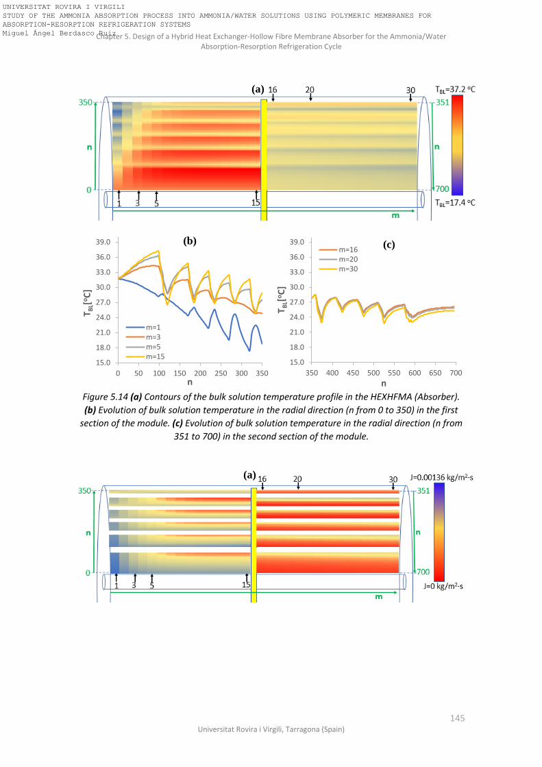
Chapter 5. Design of a Hybrid Heat Exchanger-Hollow Fibre Membrane Absorber for the Ammonia/Water Absorption-Resorption Refrigeration Cycle
145 Universitat Rovira i Virgili, Tarragona (Spain)
Figure 5.14 (a) Contours of the bulk solution temperature profile in the HEXHFMA (Absorber).
(b) Evolution of bulk solution temperature in the radial direction (n from 0 to 350) in the first
section of the module. (c) Evolution of bulk solution temperature in the radial direction (n from
351 to 700) in the second section of the module.
15.0
18.0
21.0
24.0
27.0
30.0
33.0
36.0
39.0
0 50 100 150 200 250 300 350
TB
L[oC
]
n
m=1m=3m=5m=15
(b)
15.0
18.0
21.0
24.0
27.0
30.0
33.0
36.0
39.0
350 400 450 500 550 600 650 700
TB
L[oC
]
n
m=16m=20m=30
(c)
(a)
(a)
UNIVERSITAT ROVIRA I VIRGILI STUDY OF THE AMMONIA ABSORPTION PROCESS INTO AMMONIA/WATER SOLUTIONS USING POLYMERIC MEMBRANES FOR ABSORPTION-RESORPTION REFRIGERATION SYSTEMS Miguel Ángel Berdasco Ruiz
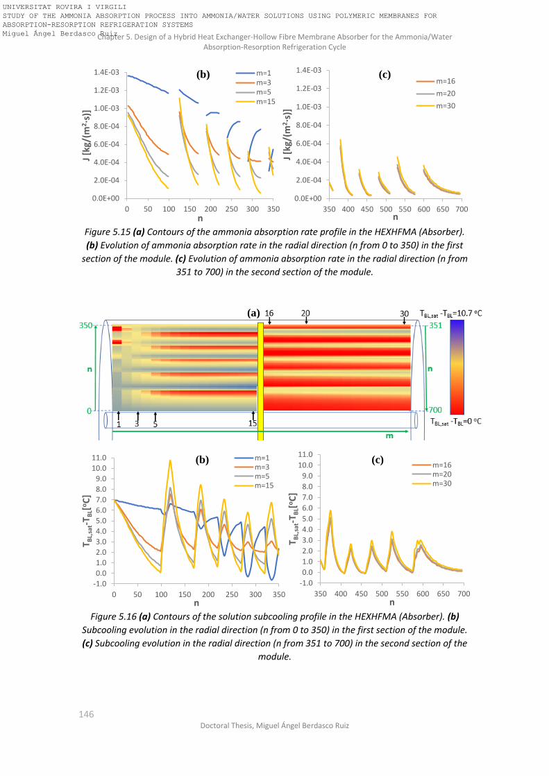
Chapter 5. Design of a Hybrid Heat Exchanger-Hollow Fibre Membrane Absorber for the Ammonia/Water Absorption-Resorption Refrigeration Cycle
146 Doctoral Thesis, Miguel Ángel Berdasco Ruiz
Figure 5.15 (a) Contours of the ammonia absorption rate profile in the HEXHFMA (Absorber).
(b) Evolution of ammonia absorption rate in the radial direction (n from 0 to 350) in the first
section of the module. (c) Evolution of ammonia absorption rate in the radial direction (n from
351 to 700) in the second section of the module.
Figure 5.16 (a) Contours of the solution subcooling profile in the HEXHFMA (Absorber). (b)
Subcooling evolution in the radial direction (n from 0 to 350) in the first section of the module.
(c) Subcooling evolution in the radial direction (n from 351 to 700) in the second section of the
module.
0.0E+00
2.0E-04
4.0E-04
6.0E-04
8.0E-04
1.0E-03
1.2E-03
1.4E-03
0 50 100 150 200 250 300 350
J [k
g/(m
2·s
)]
n
m=1m=3m=5m=15
(b)
0.0E+00
2.0E-04
4.0E-04
6.0E-04
8.0E-04
1.0E-03
1.2E-03
1.4E-03
350 400 450 500 550 600 650 700
J [k
g/(m
2·s
)]
n
m=16
m=20
m=30
(c)
-1.0
0.0
1.0
2.0
3.0
4.0
5.0
6.0
7.0
8.0
9.0
10.0
11.0
0 50 100 150 200 250 300 350
T BL,
sat-
T BL[
oC
]
n
m=1m=3m=5m=15
(b)
-1.0
0.0
1.0
2.0
3.0
4.0
5.0
6.0
7.0
8.0
9.0
10.0
11.0
350 400 450 500 550 600 650 700
T BL,
sat-
T BL[
oC
]
n
m=16m=20m=30
(c)
(a)
UNIVERSITAT ROVIRA I VIRGILI STUDY OF THE AMMONIA ABSORPTION PROCESS INTO AMMONIA/WATER SOLUTIONS USING POLYMERIC MEMBRANES FOR ABSORPTION-RESORPTION REFRIGERATION SYSTEMS Miguel Ángel Berdasco Ruiz

Chapter 5. Design of a Hybrid Heat Exchanger-Hollow Fibre Membrane Absorber for the Ammonia/Water Absorption-Resorption Refrigeration Cycle
147 Universitat Rovira i Virgili, Tarragona (Spain)
Figure 5.17 (a) Contours of the temperature difference between the solution and the fluid
inside the fibres (gas and cooling water) in the HEXHFMA (Absorber). (b) TBL-TFibres evolution in
the radial direction (n from 0 to 350) in the first section of the module. (c) TBL-TFibres evolution
along the radial direction (n from 351 to 700) in the second section of the module.
5.3.2 Resorber design The same procedure was also used for the design of a HEXHFMA for the resorber of the 25-kW
ammonia/water absorption-resorption refrigeration cycle. The geometric dimensions and
membrane characteristics are listed in Table 5.2. Seven adiabatic absorption stages were
required to absorb all the ammonia. The first adiabatic section consists of 99 rings, the second
one consists of 50 rings, sections three to five consist of 35 rings each one, section six has 30
rings and the last section 10 rings. Moreover, six cooling stages were required for rejecting the
heat generated during the absorption process by means of a cooling water supply of 15.1 m3/h
at 22oC. This flow rate provides a water velocity inside the fibres of 0.75 m/s. The first cooling
stage consists of 21 rings and the rest of stages comprises 15 rings each one. The overall results
obtained with the model and their comparison with the working conditions of the 25-kW
absorption-resorption refrigeration cycle are depicted in Figure 5.18.
-5.0
-2.0
1.0
4.0
7.0
10.0
13.0
16.0
19.0
22.0
0 50 100 150 200 250 300 350
TB
L-T
Fib
res
[oC
]
n
m=1m=3m=5m=15
(b)
-5.0
-2.0
1.0
4.0
7.0
10.0
13.0
16.0
19.0
22.0
350 400 450 500 550 600 650 700
T BL-
TFi
bre
s[o
C]
n
m=16m=20m=30
(c)
(a)
UNIVERSITAT ROVIRA I VIRGILI STUDY OF THE AMMONIA ABSORPTION PROCESS INTO AMMONIA/WATER SOLUTIONS USING POLYMERIC MEMBRANES FOR ABSORPTION-RESORPTION REFRIGERATION SYSTEMS Miguel Ángel Berdasco Ruiz

Chapter 5. Design of a Hybrid Heat Exchanger-Hollow Fibre Membrane Absorber for the Ammonia/Water Absorption-Resorption Refrigeration Cycle
148 Doctoral Thesis, Miguel Ángel Berdasco Ruiz
Table 5.2 Geometric dimensions and membrane characteristics of the HEXHFMA designed to be
used as a resorber in the 25-kW ammonia/water absorption-resorption refrigeration system.
HEXHFMA (RESORBER)
Total number of fibres 546554 Total effective membrane area (m2) 154.5
Number of porous fibres 384899 Total effective porous membrane area (m2) 108.8
Number of non-porous fibres 161655 Number of absorption stages 7
Number of cooling stages 6 Material Polypropylene
Fibres inner diameter, di (μm) 210 Fibres outer diameter, do (μm) 300
Average pore diameter, dp (μm) Effective hollow fibre length, L (m)
0.03 0.30
Porosity, ε (%) 45 Surface-to-volume ratio (m2/m3) 5815
Shell
Material Polypropylene Outer diameter (cm) 35.2
Inside diameter, Ds (cm) 34.1 Central tube diameter, Dt (cm) 2.22
Figure 5.18 Comparison between the working conditions of the 25-kW absorption-resorption
refrigeration cycle and the results obtained with the model of the HEXHFMA: resorber.
As expected, the complete saturation of the solution was not achieved and 0.4oC of subcooling
was obtained at the outlet. The small deviation in the outlet solution concentration corresponds
Resorber
22.0oC
Cooling water
Tout,res=25.0oCXout,res=0.610mout,res=926 kg/hSaturated solution
Phigh =5.0 bar
Saturatedvapour
Tout,HEXHFMA=25.3oCXout, HEXHFMA =0.604mout, HEXHFMA =910 kg/hΔTsubcooling=0.4oC
24.4oC15.1 m3/h
Outlet conditions obtained with the HEXHFMA
Tin,vap,res=22.0oCXin,vap,res=0.9993min,vap,res=106 kg/h
Tin,res=22.0oCXin,res=0.560min,res=820 kg/h
UNIVERSITAT ROVIRA I VIRGILI STUDY OF THE AMMONIA ABSORPTION PROCESS INTO AMMONIA/WATER SOLUTIONS USING POLYMERIC MEMBRANES FOR ABSORPTION-RESORPTION REFRIGERATION SYSTEMS Miguel Ángel Berdasco Ruiz

Chapter 5. Design of a Hybrid Heat Exchanger-Hollow Fibre Membrane Absorber for the Ammonia/Water Absorption-Resorption Refrigeration Cycle
149 Universitat Rovira i Virgili, Tarragona (Spain)
to a reduction in the total amount of ammonia absorbed of 15%. The deviation obtained in the
outlet temperature of the solution was 0.3oC.
5.3.2.1 Evolution of the main parameters along the HEXHFMA (Resorber)
Figures 5.19-5.23 show the evolution of the ammonia solution concentration, bulk solution
temperature, ammonia absorption rate, subcooling of the solution and the temperature
difference between the solution and the fluid inside the fibres (ammonia gas and cooling water)
in the HEXHFMA designed for the resorber, respectively. The radial direction (n) in the first
section is discretized into 390 rings (n from 1 to 390), starting in the central tube and finishing
at the top of the module, where the solution is collected before entering the second section.
The second section is also discretized into 390 rings (n from 391 to 780), but in this case starting
at the top of the module and finishing in the central tube, where the solution is finally collected.
The membrane module was also discretized into 30 elements in the axial direction (m) but only
elements 1, 3, 5, 15, 16, 20 and 30 were selected for representation in the figures. The plateaus
showed in Figure 5.19, the peaks showed in Figures 5.20, 5.22 and 5.23 and the blank areas of
Figure 5.21 are caused by the cooling stages of the HEXHFMA.
Figure 5.19 (a) Contours of the ammonia concentration profile in the HEXMFMA (Resorber). (b)
Evolution of ammonia concentration in the radial direction (n from 0 to 390) in the first section
of the module. (c) Evolution of ammonia concentration in the radial direction (n from 391 to
780) in the second section of the module.
In the case of the resorber, the inlet temperature of the ammonia gas is the same than the inlet
temperature of the solution, so the cooling effect observed in the previous section (absorber
working conditions) do not take place in the resorber. For this reason, the profiles of the
0.560
0.565
0.570
0.575
0.580
0.585
0.590
0.595
0.600
0.605
0.610
0 50 100 150 200 250 300 350 400
x NH
3
n
m=1m=3m=5m=15
(b)
0.560
0.565
0.570
0.575
0.580
0.585
0.590
0.595
0.600
0.605
0.610
390 435 480 525 570 615 660 705 750
x NH
3
n
m=16m=20m=30
(c)
(a)
UNIVERSITAT ROVIRA I VIRGILI STUDY OF THE AMMONIA ABSORPTION PROCESS INTO AMMONIA/WATER SOLUTIONS USING POLYMERIC MEMBRANES FOR ABSORPTION-RESORPTION REFRIGERATION SYSTEMS Miguel Ángel Berdasco Ruiz

Chapter 5. Design of a Hybrid Heat Exchanger-Hollow Fibre Membrane Absorber for the Ammonia/Water Absorption-Resorption Refrigeration Cycle
150 Doctoral Thesis, Miguel Ángel Berdasco Ruiz
parameters studied show a similar trend all along the membrane module. As expected, the
maximum ammonia absorption rate (1.24·10-3 kg/m2·s) was obtained at the inlet of the solution
(Figure 5.21b), where the subcooling of the solution was also the highest (9.1oC), as shown in
Figure 5.22b. The temperature difference between the solution and the gas remains always
below 3oC for m=1, and it is nearly zero from m=5 to the end of the membrane module (Figure
5.23b and 5.23c).
Figure 5.20 (a) Contours of the bulk solution temperature profile in the HEXHFMA (Resorber).
(b) Evolution of bulk solution temperature in the radial direction (n from 0 to 390) in the first
section of the module. (c) Evolution of bulk solution temperature in the radial direction (n from
391 to 780) in the second section of the module.
22.0
23.0
24.0
25.0
26.0
27.0
28.0
29.0
30.0
0 50 100 150 200 250 300 350 400
T BL
[oC
]
n
m=1m=3m=5m=15
(b)
22.0
23.0
24.0
25.0
26.0
27.0
28.0
29.0
30.0
390 440 490 540 590 640 690 740 790
T BL
[oC
]
n
m=16m=20m=30
(c)
(a)
(a)
UNIVERSITAT ROVIRA I VIRGILI STUDY OF THE AMMONIA ABSORPTION PROCESS INTO AMMONIA/WATER SOLUTIONS USING POLYMERIC MEMBRANES FOR ABSORPTION-RESORPTION REFRIGERATION SYSTEMS Miguel Ángel Berdasco Ruiz

Chapter 5. Design of a Hybrid Heat Exchanger-Hollow Fibre Membrane Absorber for the Ammonia/Water Absorption-Resorption Refrigeration Cycle
151 Universitat Rovira i Virgili, Tarragona (Spain)
Figure 5.21 (a) Contours of the ammonia absorption rate profile in the HEXHFMA (Resorber).
(b) Evolution of ammonia absorption rate in the radial direction (n from 0 to 390) in the first
section of the module. (c) Evolution of ammonia absorption rate in the radial direction (n from
391 to 780) in the second section of the module.
Figure 5.22 (a) Contours of the solution subcooling profile in the HEXHFMA (Resorber). (b)
Subcooling evolution in the radial direction (n from 0 to 390) in the first section of the module.
(c) Subcooling evolution in the radial direction (n from 391 to 780) in the second section of the
module.
0.0E+00
2.0E-04
4.0E-04
6.0E-04
8.0E-04
1.0E-03
1.2E-03
1.4E-03
0 50 100 150 200 250 300 350 400
J [k
g/(m
2·s
)]
n
m=1m=3m=5m=15
(b)
0.0E+00
2.0E-04
4.0E-04
6.0E-04
8.0E-04
1.0E-03
1.2E-03
1.4E-03
390 440 490 540 590 640 690 740 790
J [k
g/(m
2·s
)
n
m=16m=20m=30
(c)
0.0
1.0
2.0
3.0
4.0
5.0
6.0
7.0
8.0
9.0
10.0
0 50 100 150 200 250 300 350 400
T BL,
sat-
T BL
[oC
]
n
m=1m=3m=5m=15
(b)
0.0
1.0
2.0
3.0
4.0
5.0
6.0
7.0
8.0
9.0
10.0
390 440 490 540 590 640 690 740 790
T BL,
sat-
T BL
[oC
]
n
m=16m=20m=30
(c)
(a)
UNIVERSITAT ROVIRA I VIRGILI STUDY OF THE AMMONIA ABSORPTION PROCESS INTO AMMONIA/WATER SOLUTIONS USING POLYMERIC MEMBRANES FOR ABSORPTION-RESORPTION REFRIGERATION SYSTEMS Miguel Ángel Berdasco Ruiz

Chapter 5. Design of a Hybrid Heat Exchanger-Hollow Fibre Membrane Absorber for the Ammonia/Water Absorption-Resorption Refrigeration Cycle
152 Doctoral Thesis, Miguel Ángel Berdasco Ruiz
Figure 5.23 (a) Contours of the temperature difference between the solution and the fluid
inside the fibres (gas and cooling water) in the HEXHFMA (Resorber). (b) TBL-TFibres evolution in
the radial direction (n from 0 to 350) in the first section of the module. (c) TBL-TFibres evolution
along the radial direction (n from 351 to 700) in the second section of the module.
5.3.3 Comparison between both designs (Absorber and Resorber) Despite the amount of ammonia vapour entering the absorber and the resorber was the same
(106 kg/h), the resorber design required a bigger membrane area than the absorber and much
more cooling water flow rate. Specifically, the resorber designed was 22% bigger (in terms of
total effective membrane area) than the absorber. According to the experimental results
obtained in Chapter 4, the adiabatic working conditions in the resorber leads into higher mass
transfer coefficient in the solution side and hence higher ammonia absorption rates (J).
However, the results obtained in this section shows just the opposite behaviour. Two main
factors can explain this discrepancy: first, the higher temperature difference between the
solution and the cooling fluid when the HEXHFMA is working under absorber conditions. This
larger temperature difference leads into more efficient heat transfer in the cooling stages and
hence into a lower cooling water flow rate. The second factor is the inlet temperature of the
vapour. In the experimental results obtained in Chapter 4 the inlet temperature of the gas was
not controlled, so the gas entered to the membrane module at room temperature (around 20-
25oC). In the absorber of the absorption-resorption refrigeration cycle of the case study the inlet
temperature of the gas is -5oC. This cold vapour stream leads into a cooling effect on the
ammonia/water solution in the area close to the vapour inlet that increases the absorption rate
in a very significant way. In order to confirm this hypothesis, the model of the HEXHFMA for the
-0.5
0.5
1.5
2.5
3.5
4.5
5.5
6.5
7.5
0 50 100 150 200 250 300 350 400
T BL-
T Fib
res
[oC
]
n
m=1m=3m=5m=15
(b)
-0.5
0.5
1.5
2.5
3.5
4.5
5.5
6.5
7.5
390 440 490 540 590 640 690 740 790
T BL-
T Fib
res
[oC
]
n
m=16m=20m=30
(c)
(a)
UNIVERSITAT ROVIRA I VIRGILI STUDY OF THE AMMONIA ABSORPTION PROCESS INTO AMMONIA/WATER SOLUTIONS USING POLYMERIC MEMBRANES FOR ABSORPTION-RESORPTION REFRIGERATION SYSTEMS Miguel Ángel Berdasco Ruiz

Chapter 5. Design of a Hybrid Heat Exchanger-Hollow Fibre Membrane Absorber for the Ammonia/Water Absorption-Resorption Refrigeration Cycle
153 Universitat Rovira i Virgili, Tarragona (Spain)
absorber was run with the same inlet conditions showed in Figure 5.6 except for the inlet
temperature of the vapour, that was increased in order to be equal to the inlet temperature of
the solution (31.7oC). With this modification, the cooling effect of the gas stream cannot take
place and a much lower amount of ammonia should be absorbed. Figure 5.24 depicts the results
obtained.
Figure 5.24 Comparison between the results obtained in the absorber at two different inlet
temperatures of the vapour.
The results obtained in the comparison shows clearly the influence of the inlet temperature of
the vapour. The amount of ammonia absorbed fell in 13 kg/h (12% of the total) when the inlet
temperature of the vapour was increased from -5oC to 31.7oC.
According to the results obtained in this chapter it can be concluded that the HEXHFMA
performs better if it is placed in the absorber. The low inlet temperature of the vapour coming
from the desorber leads into higher ammonia absorption rates and, therefore, into smaller
designs of the HEXHFMA. Furthermore, the integration of the HEXHFMA in the resorber would
mean that the absorption-resorption cycle must be modified because an additional heat
exchanger must be integrated in order to reduce the temperature of the vapour at the inlet of
the resorber and then avoid water condensation in the membrane that could block the pores.
5.4 Discussion of the results obtained In this section, the results previously showed are compared to the ones obtained by Schaal [43]
and Chen et al. [42]. Moreover, a comparison was made between the hybrid heat exchanger-
hollow fibre membrane absorber designed in this chapter and the typically used absorbers in
absorption cycles (plate absorbers and shell and tube absorbers). The comparison was made in
terms of absorber heat duty per absorber volume.
Absorber
22.0oCCooling water
Tin,vap,abs=31.7oCXin,vap,abs=0.9995min,vap,abs=106 kg/h
Tin,abs=31.7oCXin,abs=0.285min,abs=916 kg/h
Plow =1.3 bar
Saturatedvapour
Tout,HEXHFMA=27.1oCXout, HEXHFMA =0.346mout, HEXHFMA =1001 kg/hΔTsubcooling=0.1oC
27.1oC9.7 m3/h
Results for Tin,vap,abs=31.7oC
Tout,HEXHFMA=25.7oCXout, HEXHFMA =0.354mout, HEXHFMA =1014 kg/hΔTsubcooling=0.2oC
Results for Tin,vap,abs=-5oC
UNIVERSITAT ROVIRA I VIRGILI STUDY OF THE AMMONIA ABSORPTION PROCESS INTO AMMONIA/WATER SOLUTIONS USING POLYMERIC MEMBRANES FOR ABSORPTION-RESORPTION REFRIGERATION SYSTEMS Miguel Ángel Berdasco Ruiz

Chapter 5. Design of a Hybrid Heat Exchanger-Hollow Fibre Membrane Absorber for the Ammonia/Water Absorption-Resorption Refrigeration Cycle
154 Doctoral Thesis, Miguel Ángel Berdasco Ruiz
5.4.1 Comparison with Schaal and Chen et al. As mentioned at the beginning of this chapter, Schaal [43] studied the performance of an
ammonia/water absorption refrigeration plant when the hollow fibre membrane contactors
were integrated in the absorber. The experimental configuration of the membrane absorber was
similar to the one showed in Figure 5.1, where the adiabatic absorption stage consisted of
several hollow fibre membrane absorbers arranged in parallel. A plate heat exchanger were used
for cooling the solution before the adiabatic absorption stage. The operating capability of
membrane absorbers was demonstrated but it was not possible to implement a membrane
absorber with enough membrane surface to absorb all the ammonia required to meet the
nominal cooling capacity (6.7 kW) of plant due to the high pressure drop registered. Therefore,
the refrigeration plant was operated at lower cooling capacity and the driving force for the
absorption inside the absorber was very high. The subcooling of the solution at the inlet of the
absorber varied from 20oC to 29oC, leaving the membrane absorber with a subcooling above
10oC in all cases. The absorber heat duty per absorber volume reported by Schaal varies from
9000 to 15000 kW/m3, depending on the working conditions and the arrangement of the
membrane modules. It is important to note that these values reported by Schaal were obtained
as the product of the volumetric ammonia absorption rate (mol·m-3·s-1) in the membrane
absorber and the enthalpy of vaporization of the ammonia (kJ/mol), so the volume of the plate-
heat exchanger used for cooling down the solution before entering the membrane absorber was
not taken into consideration. Therefore, when the additional volume for the cooling will be
taken into account, lower values of the volume-specific heat duty are expected.
The results obtained in this chapter show a heat duty per volume of 2400 kW/m3 for the
absorber and 1700 kW/m3 for the resorber, which are far from most of the values provided by
Schaal. This discrepancy can be explained because in our case study the subcooling of the
solution was much lower both at the inlet (7oC) and at the outlet (0.2oC). When the solution
approaches the saturation conditions the driving force of the absorption process approaches
zero and then a very large membrane area is required to continue absorbing ammonia.
In the work presented by Chen et al. [42], a simulation study of the integration of a hybrid
membrane absorber-heat exchanger in an ammonia-water absorption chiller was carried out.
The cycle selected for the study was based in the one presented by Chua et al. [81] which
includes heat integrations in the refrigerant heat exchanger, rectifier, solution heat exchanger
and solution-cooled heat exchanger. The membrane modules designed by Chen et al. [42] were
also based in the cross-flow design provided by the Liqui-Cel® hollow fibre membrane contactor
[67], but for the mathematical model a counter-current flow configuration was assumed. Two
hybrid membrane absorber-heat exchanger were designed by Chen et al. One for the solution-
cooled absorber and the other for the water-cooled absorber. Regarding the solution-cooled
absorber, the results obtained by Chen et al. agree very well in terms of heat duty per absorber
volume (2300 kW/m3) with the results obtained in this chapter (2400 kW/m3). However, in the
case of the water-cooled absorber the heat duty per absorber volume was five times higher
(11000 kW/m3). This fact can be explained by two factors: first, the inlet temperature difference
between the cooling water (35oC) and the solution (70oC) was much higher than in the case study
analysed in this chapter (22oC the cooling water and 31.7oC the solution). Secondly, the ratio
between the cooling water mass flow rate and the solution mass flow rate was much higher in
the case study of Chen et al. (Ratio=26) than in the present work (Ratio=10).
As mentioned before, the improvement of the absorber heat duty per absorber volume
obtained in the HEXHFMA designed in this chapter is restricted by the low subcooling conditions
UNIVERSITAT ROVIRA I VIRGILI STUDY OF THE AMMONIA ABSORPTION PROCESS INTO AMMONIA/WATER SOLUTIONS USING POLYMERIC MEMBRANES FOR ABSORPTION-RESORPTION REFRIGERATION SYSTEMS Miguel Ángel Berdasco Ruiz

Chapter 5. Design of a Hybrid Heat Exchanger-Hollow Fibre Membrane Absorber for the Ammonia/Water Absorption-Resorption Refrigeration Cycle
155 Universitat Rovira i Virgili, Tarragona (Spain)
of the solution along the membrane module (Figures 5.16 and 5.22), reaching almost complete
saturation at the outlet. In real absorption refrigeration systems, there is usually a certain degree
of subcooling (3-5oC) at the outlet of the absorbers in order to minimize the surface area of the
absorber. Therefore, if the subcooling conditions of the solution and the solution mass flow rate
of the case study (Figure 5.12) were higher, then the amount of ammonia absorbed and,
therefore, the heat duty per absorber volume, would increase in a very significant way. To
confirm this statement, the model of the HEXHFMA for the absorber (Table 5.1) was run but
now the inlet conditions were modified in order to increase the subcooling of the inlet solution
from 7oC to 25oC. The solution and the cooling water flow rate were also increased from 916
kg/h to 2000 kg/h and from 9.7 m3/h to 15.3 m3/h, respectively. The results obtained under
these new working conditions show a four-fold increase in the total amount of ammonia
absorbed and a heat duty per absorber volume of 10000 kW/m3 for the same HEXHFMA design
showed in Table 5.1. The outlet subcooling of the solution was 1.5oC. These results confirm the
potential in terms of compactness of the membrane modules reported by Schaal [43] and Chen
et al. [42].
5.4.2 Comparison between the hybrid heat exchanger-hollow fibre membrane absorber
and the typically used absorbers Table 5.3 lists the heat duties per absorber volume of different types of ammonia/water
absorbers reported in the literature and in the present work. They correspond to the shell and
tube absorbers (falling film type) and to the plate and frame absorbers (both falling film and
bubble).
Table 5.3 Absorber heat duties per absorber volume of different types of ammonia/water
absorbers reported in the literature.
Reference Type of absorber Absorber heat duty per
volume [kW/m3]
Schaal [43] Shell and tube (Falling film) 300
Lee et al. [82] Shell and tube (Falling film) 100-300
Kwon and Jeong [83]
Helical coil (Falling film) 20-220
Schaal [43] Plate heat exchanger (Falling film) 1000
Triché et al. [84] Plate heat exchanger (Falling film) 500-1600
Cerezo et al. [85] Plate heat exchanger (bubble) 1000-2300
Present work (TU Dresden)
Plate heat exchanger (bubble) 1600 - 2400
The lowest values were reported by the shell and tubes absorbers (around 300 kW/m3). On the
other hand, the results obtained when the plate heat exchangers were used as an absorber
showed heat duties per absorber volume one order of magnitude greater; around 1000 kw/m3
for the falling-film type and around 2000 kW/m3 for the bubble absorber type. These values are
UNIVERSITAT ROVIRA I VIRGILI STUDY OF THE AMMONIA ABSORPTION PROCESS INTO AMMONIA/WATER SOLUTIONS USING POLYMERIC MEMBRANES FOR ABSORPTION-RESORPTION REFRIGERATION SYSTEMS Miguel Ángel Berdasco Ruiz
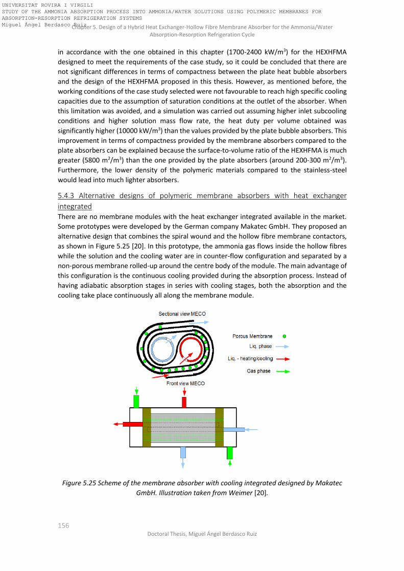
Chapter 5. Design of a Hybrid Heat Exchanger-Hollow Fibre Membrane Absorber for the Ammonia/Water Absorption-Resorption Refrigeration Cycle
156 Doctoral Thesis, Miguel Ángel Berdasco Ruiz
in accordance with the one obtained in this chapter (1700-2400 kW/m3) for the HEXHFMA
designed to meet the requirements of the case study, so it could be concluded that there are
not significant differences in terms of compactness between the plate heat bubble absorbers
and the design of the HEXHFMA proposed in this thesis. However, as mentioned before, the
working conditions of the case study selected were not favourable to reach high specific cooling
capacities due to the assumption of saturation conditions at the outlet of the absorber. When
this limitation was avoided, and a simulation was carried out assuming higher inlet subcooling
conditions and higher solution mass flow rate, the heat duty per volume obtained was
significantly higher (10000 kW/m3) than the values provided by the plate bubble absorbers. This
improvement in terms of compactness provided by the membrane absorbers compared to the
plate absorbers can be explained because the surface-to-volume ratio of the HEXHFMA is much
greater (5800 m2/m3) than the one provided by the plate absorbers (around 200-300 m2/m3).
Furthermore, the lower density of the polymeric materials compared to the stainless-steel
would lead into much lighter absorbers.
5.4.3 Alternative designs of polymeric membrane absorbers with heat exchanger
integrated There are no membrane modules with the heat exchanger integrated available in the market.
Some prototypes were developed by the German company Makatec GmbH. They proposed an
alternative design that combines the spiral wound and the hollow fibre membrane contactors,
as shown in Figure 5.25 [20]. In this prototype, the ammonia gas flows inside the hollow fibres
while the solution and the cooling water are in counter-flow configuration and separated by a
non-porous membrane rolled-up around the centre body of the module. The main advantage of
this configuration is the continuous cooling provided during the absorption process. Instead of
having adiabatic absorption stages in series with cooling stages, both the absorption and the
cooling take place continuously all along the membrane module.
Figure 5.25 Scheme of the membrane absorber with cooling integrated designed by Makatec
GmbH. Illustration taken from Weimer [20].
UNIVERSITAT ROVIRA I VIRGILI STUDY OF THE AMMONIA ABSORPTION PROCESS INTO AMMONIA/WATER SOLUTIONS USING POLYMERIC MEMBRANES FOR ABSORPTION-RESORPTION REFRIGERATION SYSTEMS Miguel Ángel Berdasco Ruiz

Chapter 5. Design of a Hybrid Heat Exchanger-Hollow Fibre Membrane Absorber for the Ammonia/Water Absorption-Resorption Refrigeration Cycle
157 Universitat Rovira i Virgili, Tarragona (Spain)
However, all these prototypes had to face the same problem: the potting material required to
avoid internal leakages between the cooling water and the solution. This potting material must
withstand the working conditions of the absorber (pressure and temperature) and the chemical
attack produced by the ammonia. This problem could not be solved in the prototypes developed
by Makatec and some internal leakages between the solution side and the cooling water side
were detected. This challenge needs to be solved in order to have reliable membrane absorbers.
5.5 Conclusions In this chapter, the design of two hybrid heat exchanger-hollow fibre membrane absorber
(HEXHFMA) was carried out. Each one was designed in order to be used as an absorber and as a
resorber in a 25-kW ammonia/water absorption-resorption refrigeration plant, respectively. The
theoretical model developed was based on the model validated in Chapter 4 for the study of the
adiabatic ammonia absorption process using a hollow fibre membrane module as contactor. In
order to integrate the cooling inside the membrane module, some non-porous hollow fibre
membranes were used for the flow of the cooling water. The HEXHFMA consist of several
interleaved adiabatic absorption stages and cooling stages until obtained the desired conditions
of the solution (temperature and ammonia concentration) at the outlet of the module.
Before starting to design the hybrid heat exchanger-hollow fibre membrane absorbers, the
configuration of the absorption-resorption cycle had to be modified in order to avoid water
condensation in the membrane of the resorber. The modification consists of an additional heat
transfer between the cold solution leaving the desorber and the vapour produced in the
generator.
A procedure for the design of the HEXHFMA was described and the results obtained showed
that the membrane area of the HEXHFMA for the resorber is 22% bigger than for the absorber.
Moreover, the resorber requires 35% more cooling water than the absorber. These diferences
can be explained by the higher temperature difference between the solution and the cooling
water when the HEXHFMA is working under absorber conditions and by the much lower inlet
temperature of the vapour entering the absorber compared to inlet temperature of the vapour
entering to the resorber (-5oC and 22oC respectively). This cold vapour produces a cooling effect
that improves the mass transfer in the absorber.
The compactness of the design of the HEXHFMA was evaluated in terms of absorber heat duty
per absorber volume. The values obtained for the HEXHFMA designed in this chapter were far
(2400 kW/m3) from the ones reported by Schaal (between 9000 and 15000 kW/m3). This
discrepancy can be explained by two main reasons: first, the values reported by Schaal did not
consider the volume of the plate-heat exchanger used for cooling down the solution before
entering the adiabatic membrane absorber; and second, because in our case study the
subcooling of the solution was much lower all along the membrane module, reaching almost
saturation conditions at the outlet. However, when more favourable working conditions (higher
subcooling and solution mass flow rate) are considered, the heat duty per absorber volume
increases up to 10000 kW/m3 for the same HEXHFMA design. These results confirm the potential
in terms of compactness of the membrane absorbers, especially when they are compared to the
shell and tube absorbers (300 kW/m3) and the plate bubble absorbers (2000 kW/m3).
Furthermore, due to the much lower density of the polymeric materials compared to the
stainless steel it would be expected that the HEXHFMA leads into much lighter absorbers.
UNIVERSITAT ROVIRA I VIRGILI STUDY OF THE AMMONIA ABSORPTION PROCESS INTO AMMONIA/WATER SOLUTIONS USING POLYMERIC MEMBRANES FOR ABSORPTION-RESORPTION REFRIGERATION SYSTEMS Miguel Ángel Berdasco Ruiz

Chapter 5. Design of a Hybrid Heat Exchanger-Hollow Fibre Membrane Absorber for the Ammonia/Water Absorption-Resorption Refrigeration Cycle
158 Doctoral Thesis, Miguel Ángel Berdasco Ruiz
Nomenclature of chapter 5
dA [m2] Discretized membrane area
d0 [m] Outer diameter of the hollow fiber
di [m] Inner diameter of the hollow fiber
dp [m] Pore diameter
Ds [m] Inner diameter of the shell of the module
Dt [m] Outer diameter of the central tube
dx [m] Length of the discretization element in the axial direction
dy [m] Width of the discretization ring in the radial direction. Also gap between the fibers
EffHEX1 [-] Effectiveness of the solution heat exchanger of the absorption circuit
EffHEX2 [-] Effectiveness of the solution heat exchanger of the resorption circuit
h [J/kg] Specific enthalpy
J [kg/(m2·s)] Mass flux
L [m] Membrane module length
m [-] Segment m
mBL [kg/s] Solution mass flow rate
mBG [kg/s] Gas mass flow rate
mCL [kg/s] Cooling water mass flow rate
n [-] Segment n
p [Pa] Pressure
T [K] Temperature
U [W/m2·K] Overall heat transfer coefficient
x [-] Ammonia mass fraction
Special characters
α [W/(m2·K)] Heat transfer coefficient
ε [-] Membrane porosity
λ [W/(m·K)] Thermal conductivity
UNIVERSITAT ROVIRA I VIRGILI STUDY OF THE AMMONIA ABSORPTION PROCESS INTO AMMONIA/WATER SOLUTIONS USING POLYMERIC MEMBRANES FOR ABSORPTION-RESORPTION REFRIGERATION SYSTEMS Miguel Ángel Berdasco Ruiz

Chapter 5. Design of a Hybrid Heat Exchanger-Hollow Fibre Membrane Absorber for the Ammonia/Water Absorption-Resorption Refrigeration Cycle
159 Universitat Rovira i Virgili, Tarragona (Spain)
Subscripts
abs Absorber
BG Bulk gas
BL Bulk liquid
CL Cooling water
in Inlet
liq Liquid
MM Membrane
out Outlet
res Resorber
sat Saturation
vap Vapour
UNIVERSITAT ROVIRA I VIRGILI STUDY OF THE AMMONIA ABSORPTION PROCESS INTO AMMONIA/WATER SOLUTIONS USING POLYMERIC MEMBRANES FOR ABSORPTION-RESORPTION REFRIGERATION SYSTEMS Miguel Ángel Berdasco Ruiz

Chapter 5. Design of a Hybrid Heat Exchanger-Hollow Fibre Membrane Absorber for the Ammonia/Water Absorption-Resorption Refrigeration Cycle
160 Doctoral Thesis, Miguel Ángel Berdasco Ruiz
UNIVERSITAT ROVIRA I VIRGILI STUDY OF THE AMMONIA ABSORPTION PROCESS INTO AMMONIA/WATER SOLUTIONS USING POLYMERIC MEMBRANES FOR ABSORPTION-RESORPTION REFRIGERATION SYSTEMS Miguel Ángel Berdasco Ruiz

Chapter 5. Design of a Hybrid Heat Exchanger-Hollow Fibre Membrane Absorber for the Ammonia/Water Absorption-Resorption Refrigeration Cycle
161 Universitat Rovira i Virgili, Tarragona (Spain)
Chapter 6
General Conclusions and Future Work
UNIVERSITAT ROVIRA I VIRGILI STUDY OF THE AMMONIA ABSORPTION PROCESS INTO AMMONIA/WATER SOLUTIONS USING POLYMERIC MEMBRANES FOR ABSORPTION-RESORPTION REFRIGERATION SYSTEMS Miguel Ángel Berdasco Ruiz

Chapter 6. General Conclusions and Future Work
162 Doctoral Thesis, Miguel Ángel Berdasco Ruiz
UNIVERSITAT ROVIRA I VIRGILI STUDY OF THE AMMONIA ABSORPTION PROCESS INTO AMMONIA/WATER SOLUTIONS USING POLYMERIC MEMBRANES FOR ABSORPTION-RESORPTION REFRIGERATION SYSTEMS Miguel Ángel Berdasco Ruiz

Chapter 6. General Conclusions and Future Work
163 Universitat Rovira i Virgili, Tarragona (Spain)
6.1 General conclusions Despite the advantages of using absorption refrigeration systems when low-grade energy
sources are available to drive the cycle, these systems have not been fully implemented in the
market compared to the vapour-compression technology. The main problem lies in the higher
cost and size of the absorption systems, so developing more compact and cheaper equipment
is a key factor to make the absorption technology more competitive. Two possible solutions
have been proposed in this thesis to face the problems of size and cost of the absorption
refrigeration systems: First, the use of polymeric membranes as contactors between the vapour
and the solution in the absorbers to reduce their size due to the high surface/volume ratio
provided by the membrane modules. Using polymeric materials would also reduce the price of
the absorption systems but these materials do not withstand the typically high working pressure
of the ammonia/water absorption systems. For this reason, the second solution proposed in this
thesis consisted in using the resorption technology to reduce the operating high-pressure of the
conventional ammonia/water absorption refrigeration systems.
The initial step was the study of the ammonia/water absorption-resorption refrigeration cycle
in order to identify the key factors affecting the performance of the system. Adequate operating
conditions were suggested for the base case selected. Next, a theoretical and experimental
study was done on the adiabatic ammonia absorption process into ammonia/water solutions
using polymeric membranes as contactors. For the experimental work, a test bench was
designed and built. The study was divided into two parts: first, a flat sheet membrane module
was used for the determination of the desired membrane characteristics for the ammonia
absorption process. These characteristics were considered for the selection of a commercial
hollow fibre membrane module used in the subsequent step: the study of the adiabatic
ammonia absorption process using a hollow fibre membrane module as contactor, where a two-
dimensional model was developed and validated with the experimental results. Because there
are no commercial hollow fibre membrane modules with heat exchanger integrated available in
the market, all the previous studies had to be done under adiabatic conditions. However, the
absorption-resorption refrigeration systems require to cool down the solution during the
absorption processes in order to keep the absorption potential as high as possible along the
absorber. Therefore, the two-dimensional model previously validated was used as a basis for
developing a theoretical model of a hybrid heat exchanger-hollow fibre membrane absorber
(HEXHFMA). Finally, this model was used for designing two HEXHFMA: One for the absorption
circuit and the other one for the resorption circuit of a 25-kW ammonia/water absorption-
resorption refrigeration plant.
The following conclusions can be taken from this research work:
• The absorption-resorption systems provide great flexibility in terms of reduction of the high-pressure. However, this reduction in the pressure must be paid for by a reduction of the COP.
• A proper design of the solution heat exchanger of the resorption circuit is essential. If the effectiveness is lower than a certain value, the cycle cannot operate at the desired temperatures.
• The cycle configuration without rectifier is the most favourable because the complexity, size and cost of the system would be lower, and the loss of performance is not significant (below 8%).
UNIVERSITAT ROVIRA I VIRGILI STUDY OF THE AMMONIA ABSORPTION PROCESS INTO AMMONIA/WATER SOLUTIONS USING POLYMERIC MEMBRANES FOR ABSORPTION-RESORPTION REFRIGERATION SYSTEMS Miguel Ángel Berdasco Ruiz

Chapter 6. General Conclusions and Future Work
164 Doctoral Thesis, Miguel Ángel Berdasco Ruiz
• An accurate control of the absorption-resorption systems is a challenge due to the inherent instability of the resorption cycles provided by the additional degree of freedom. The experimental work carried out during the research stay at TU Dresden showed the difficulties for keeping the system working under steady-state conditions.
• A Thermodynamic model of the cycle was developed and used for the analysis of the performance of the 25-kW experimental plant set up at TU Dresden. Such analysis identified a poor absorption process in the resorber. Increasing the size of the plate-heat exchanger or improving the gas/liquid distribution was recommended to enhance the heat and mass transfer.
• A method based on near-infrared (NIR) spectroscopy for the in-situ determination of the ammonia concentration in absorption cycles was developed and the results published in the International Journal TALANTA [56]. Thus, this technique was proposed to improve the performance of the absorption-resorption cycle. By means of a multiplexor, this new method allows to measure the ammonia concentration at several points of the cycle just using one detector and one lamp, leading then in a cheaper alternative than using the conventional Coriolis density-meters.
• The desired membrane characteristics to be used as contactor for the ammonia absorption process are: hydrophobicity, pore size between 0.03μm and 0.10μm, porosity higher than 40% and thickness as low as possible (lower than 400μm) in order to obtain a low transport resistance across the pores of the membrane but at the same time keeping the mechanical robustness. This study constitutes a novelty because it had not been done before for the ammonia/water mixture and the results obtained were published in Applied Thermal Engineering [57].
• According to the desired membrane characteristics previously obtained, a commercial cross-flow hollow fibre membrane module was selected (Liqui-Cel® G501 2.5x8 Extra-Flow) for the experimental study of the adiabatic ammonia absorption process. The results showed an excellent performance of the membrane module working both under absorber and resorber conditions, reaching ammonia absorption rates up to 9.7·10-4 kg/(m2·s).
• A two-dimensional model was developed and validated with the experimental results obtained with the hollow fibre membrane module. This model constitutes a novelty compared to previous works because it enables to study the evolution of the main operating parameters in the axial and radial direction of the membrane module, so a more realistic information about the profiles inside the cross-flow hollow fibre membrane module can be obtained. The results obtained were published in Applied Thermal Engineering [86]. The Mean Absolute Error of the model predictions with respect to the experimental data was ±3·10-5 kg/m2s for the ammonia absorption rate and ±0.3°C for the prediction of the outlet temperature of the solution.
• In order to use the membrane absorbers in absorption-resorption refrigeration systems it is necessary to integrate the heat transfer because with the adiabatic absorption is not possible to absorb all the ammonia required. Thus, a model of a hybrid heat exchanger-hollow fibre membrane absorber was developed based on the model previously validated of the adiabatic hollow-fibre membrane module. This model was used for designing the absorber and the resorber of a 25-kW ammonia/water absorption-resorption refrigeration plant.
• The ammonia/water absorption-resorption plant must be modified when membrane modules are used as contactors in the resorber. Due to the water content of the vapour produced in the generator, this stream should be cooled down before entering the
UNIVERSITAT ROVIRA I VIRGILI STUDY OF THE AMMONIA ABSORPTION PROCESS INTO AMMONIA/WATER SOLUTIONS USING POLYMERIC MEMBRANES FOR ABSORPTION-RESORPTION REFRIGERATION SYSTEMS Miguel Ángel Berdasco Ruiz

Chapter 6. General Conclusions and Future Work
165 Universitat Rovira i Virgili, Tarragona (Spain)
membrane module in order to avoid water condensation and pore blocking that could reduce the mass transfer across the membrane.
• The absorber designed consists of six absorption stages and five cooling stages, 126 m2 of total effective membrane area, 30 cm length and 30.9 cm of diameter. It requires 9.7m3/h of cooling water at 22oC.
• The resorber designed consists of seven absorption stages and six cooling stages, 154.5 m2 of total effective membrane area, 30 cm length and 35.2 cm of diameter. It requires 15.1m3/h of cooling water at 22oC.
• The resorber requires 22% more membrane area and 35% more cooling water than the absorber. These differences can be explained by the higher temperature difference between the solution and the cooling fluid when the HEXHFMA was working under absorber conditions and by the much lower inlet temperature of the vapour entering the absorber compared to inlet temperature of the vapour entering to the resorber (-5oC and 22oC respectively). This cold vapour produces a continue cooling effect that improves the mass transfer in the absorber.
• The results obtained in this thesis confirm the potential in terms of compactness (heat duty per absorber volume up to 10000 kW/m3) and the performance of the membrane absorbers, especially when they are compared to the shell and tube absorbers (300 kW/m3) and the plate bubble absorbers (2000 kW/m3). Furthermore, due to the much lower density of the polymeric materials compared to the stainless steel it would be expected that the HEXHFMA leads into much lighter absorbers.
6.2 Future work Lastly, suggestions for future research directions are listed below:
• Develop and test an automated control system for the absorption-resorption system based on the NIR measurements.
• Study the integration of membrane contactors in the generator and in the desorber of
the ammonia/water absorption-resorption cycles. Particularly challenging is the integration of polymeric membranes in the generator because of the high temperatures.
• Develop a new two-dimensional model of the hybrid heat exchanger-hollow fibre
membrane absorber where the presence of water in the vapour was taken into consideration.
• Design and optimization of new configurations of membrane absorber with heat
exchanger integrated: spiral wound, plate-and-frame, etc. • Test new materials that provide chemical resistance, mechanical strength, thermal
stability and good thermal conductivity. Low cost and weight of the material are also essential.
• Design, construction and integration of prototypes of hybrid heat exchanger-membrane
absorbers in an experimental test bench and study the performance.
UNIVERSITAT ROVIRA I VIRGILI STUDY OF THE AMMONIA ABSORPTION PROCESS INTO AMMONIA/WATER SOLUTIONS USING POLYMERIC MEMBRANES FOR ABSORPTION-RESORPTION REFRIGERATION SYSTEMS Miguel Ángel Berdasco Ruiz

Chapter 6. General Conclusions and Future Work
166 Doctoral Thesis, Miguel Ángel Berdasco Ruiz
UNIVERSITAT ROVIRA I VIRGILI STUDY OF THE AMMONIA ABSORPTION PROCESS INTO AMMONIA/WATER SOLUTIONS USING POLYMERIC MEMBRANES FOR ABSORPTION-RESORPTION REFRIGERATION SYSTEMS Miguel Ángel Berdasco Ruiz

References
167 Universitat Rovira i Virgili, Tarragona (Spain)
REFERENCES
[1] COMMISSION RECOMMENDATION (EU) 2016/1318 of 29 July 2016, (n.d.). http://eur-lex.europa.eu/legal-content/EN/TXT/PDF/?uri=CELEX:32016H1318&from=EN (accessed May 5, 2018).
[2] D. Coulomb, A. Pichard, 29th Informatory Note on Refrigeration Technologies. The Role of Refrigeration in the Global Economy, 2015.
[3] A. Coronas, M. Berdasco, J. Prieto, J.C. Bruno, Current development and perspectives of resorption heat pumps, in: Int. Conf. Mater. Energy, Tianjin (China), 2017.
[4] J. Berghmans, Heat pumps fundamentals, NATO Advanced Study Institutes Series.Series E, Applied Sciences; No 53., in: 1983.
[5] M. Bourouis, M. Vallès, M. Medrano, A. Coronas, Absorption of water vapour in the falling film of water–(LiBr+LiI+LiNO3+LiCl) in a vertical tube at air-cooling thermal conditions, Int. J. Therm. Sci. 44 (2005) 491–498. doi:10.1016/j.ijthermalsci.2004.11.009.
[6] M. Bourouis, M. Vallès, M. Medrano, A. Coronas, Performance of air-cooled absorption air-conditioning systems working with water-(LiBr + Lil + LiNO3 + LiCl), Proc. Inst. Mech. Eng. Part E J. Process Mech. Eng. 219 (2005) 205–213. doi:10.1243/095440805X8601.
[7] J. Mesones, Phase Equilibria of Ammonia Solutions for Absorption Refrigeration Systems. Experimental Determination and Modeling, Universitat Rovira i Virgili, 2014.
[8] H.O. Spauschus, U. Hesse, Reduced pressure carbon dioxide-based refrigeration system, US006073454, 2000.
[9] R. Radermacher, Y. Hwang, Vapor Compression Heat Pumps with Refrigerant Mixtures, CRC, 2005.
[10] Q. Zhou, R. Radermacher, Development of a vapor compression cycle with a solution circuit and desorber/absorber heat exchange, Int. J. Refrig. 20 (1997) 85–95. doi:10.1016/S0140-7007(96)00072-2.
[11] J. Kim, S.R. Park, Y.J. Baik, K.C. Chang, H.S. Ra, M. Kim, Y. Kim, Experimental study of operating characteristics of compression/absorption high-temperature hybrid heat pump using waste heat, Renew. Energy. 54 (2013) 13–19. doi:10.1016/j.renene.2012.09.032.
[12] A. Osenbrück, Verfahren zur Kälteerzeugung bei Absorptionsmaschinen. Deutsches Reichspatent, 1895.
[13] E. Altenkirch, Kompressionskältemachine mit lösungskreislauf, Kältetechnik. 2 (1950).
[14] E. Altenkirch, Der Einfluss endlicher Temperaturdifferenzen auf die Betriebskosten von Kompressionsanlagen mit und ohne Lösungskreislauf, Kältetechnik. 3 (1951).
[15] M. Stokar, C. Trepp, Compression heat pump with solution circuit. Part 1: design and experimental results, Int. J. Refrig. 10 (1987) 87–96.
[16] Institute for Energy Technology, (2018). https://www.ife.no/en/ife/departments/energy_systems/projects/cahp?set_language=en (accessed January 30, 2018).
[17] N.J. Hewitt, J.T. McMullan, B. Mongey, G.A. Molyneaux, Performance Trends in Ammonia-Water Resorption Cycle, in: Proc. 20th Int. Congr. Refrig. IIR/IIF, Sydney,
UNIVERSITAT ROVIRA I VIRGILI STUDY OF THE AMMONIA ABSORPTION PROCESS INTO AMMONIA/WATER SOLUTIONS USING POLYMERIC MEMBRANES FOR ABSORPTION-RESORPTION REFRIGERATION SYSTEMS Miguel Ángel Berdasco Ruiz

References
168 Doctoral Thesis, Miguel Ángel Berdasco Ruiz
Australia, 1999.
[18] L.C.M. Itard, Wet compression-resorption heat pump cycles: Thermodynamic analysis and design, Delft University of Technology, 1998. uuid:d51f9478-aa4e-4403-aa8d-11c840f7e7ff.
[19] E. Altenkirch, Reversible Absorptionsmaschinen, Z.f.d. Gesamte Kälte-Industrie 20. (1913) 1–9.
[20] T. Weimer, Resorption cycles for cooling with waste heat using natural refrigerants and compact plate and spiral heat exchangers, in: Int. Work. New Work. Fluids Absorpt. Heat Pumps Refrig. Syst. 22-23 July, Tarragona, Spain, 2013.
[21] H.D. Baehr, The COP of absorption and resorption heat pumps with ammonia-water as working fluid, 1981. doi:10.1016/0140-7007(81)90064-5.
[22] M. Pande, K.E. Herold, The resorption cycle using ammonia and water, in: ASHRAE Trans. Symp., 1996: pp. 1110–1117.
[23] L. Costiuc, I. Costiuc, Solar powered resorption cooling system, in: Bull. Transilv. Univ. Brasov, 2010: p. 2010.
[24] K.E. Herold, R. Radermacher, S.A. Klein, Absorption Chillers and Heat Pumps, Second Edition, CRC Press, 2016. doi:doi:10.1201/b19625-2.
[25] H.M. Sabir, I.W. Eames, Theoretical comparison between lithium bromide/water vapour resorption and absorption cycles, Appl. Therm. Eng. 18 (1998) 683–692. doi:10.1016/S1359-4311(97)00050-1.
[26] Community Research and Development Information Service (CORDIS), (n.d.). http://cordis.europa.eu/project/rcn/16408_en.html (accessed January 25, 2018).
[27] K. Helle, M. Morschel, S. Peil, T. Weimer, S. Haep, Experimental investigation of a new resorption cycle using ammonia as refrigerant, in: 4th IIR Conf. Ammon. Refrig. Technol., Ohrid, Macedonia, 2011.
[28] Institute of Combustion and Power Plant Technology of the University of Stuttgart, (n.d.). http://www.ifk.uni-stuttgart.de/forschung/exp_ein/halbtechnisch/biocool.en.html.
[29] M. Grund, U. Hesse, T. Weimer, K. Rühling, Desing of a novel resorption refrigeration system with an attached ice storage system, in: Proceedings, 6th IIR Conf. Ammon. CO2 Refrig. Technol., Ohrid, Macedonia, 2015.
[30] F. Asfand, M. Bourouis, A review of membrane contactors applied in absorption refrigeration systems, Renew. Sustain. Energy Rev. 45 (2015) 173–191. doi:10.1016/j.rser.2015.01.054.
[31] A.H.H. Ali, P. Schwerdt, Characteristics of the membrane utilized in a compact absorber for lithium bromide–water absorption chillers, Int. J. Refrig. 32 (2009) 1886–1896. doi:10.1016/j.ijrefrig.2009.07.009.
[32] A.H.H. Ali, Design of a compact absorber with a hydrophobic membrane contactor at the liquid – vapor interface for lithium bromide – water absorption chillers, Appl. Energy. 87 (2010) 1112–1121. doi:10.1016/j.apenergy.2009.05.018.
[33] D. Yu, J. Chung, S. Moghaddam, Parametric study of water vapor absorption into a constrained thin film of lithium bromide solution, Int. J. Heat Mass Transf. 55 (2012) 5687–5695. doi:10.1016/j.ijheatmasstransfer.2012.05.064.
UNIVERSITAT ROVIRA I VIRGILI STUDY OF THE AMMONIA ABSORPTION PROCESS INTO AMMONIA/WATER SOLUTIONS USING POLYMERIC MEMBRANES FOR ABSORPTION-RESORPTION REFRIGERATION SYSTEMS Miguel Ángel Berdasco Ruiz

References
169 Universitat Rovira i Virgili, Tarragona (Spain)
[34] Z. Wang, Z. Gu, S. Feng, Y. Li, Application of vacuum membrane distillation to lithium bromide absorption refrigeration system, Int. J. Refrig. 32 (2009) 1587–1596. doi:10.1016/j.ijrefrig.2009.07.002.
[35] R. Nasr Isfahani, K. Sampath, S. Moghaddam, Nanofibrous membrane-based absorption refrigeration system, Int. J. Refrig. 36 (2013) 2297–2307. doi:10.1016/j.ijrefrig.2013.07.019.
[36] F. Asfand, Y. Stiriba, M. Bourouis, CFD simulation to investigate heat and mass transfer processes in a membrane-based absorber for water-LiBr absorption cooling systems, Energy. 91 (2015) 517–530. doi:10.1016/j.energy.2015.08.018.
[37] F. Asfand, Y. Stiriba, M. Bourouis, Impact of the solution channel thickness while investigating the effect of membrane characteristics and operating conditions on the performance of water-LiBr membrane-based absorbers, Appl. Therm. Eng. 108 (2016) 866–877. doi:10.1016/j.applthermaleng.2016.07.139.
[38] F. Asfand, Y. Stiriba, M. Bourouis, Performance evaluation of membrane-based absorbers employing H2O/(LiBr + LiI + LiNO3 + LiCl) and H2O/(LiNO3 + KNO3 + NaNO3) as working pairs in absorption cooling systems, Energy. 115 (2016) 781–790. doi:10.1016/j.energy.2016.08.103.
[39] M. Venegas, M. de Vega, N. García-Hernando, U. Ruiz-Rivas, A simple model to predict the performance of a H2O-LiBr absorber operating with a microporous membrane, Energy. 96 (2016) 383–393. doi:10.1016/j.energy.2015.12.059.
[40] M. Venegas, M. De Vega, N. García-Hernando, Parametric study of operating and design variables on the performance of a membrane-based absorber, Appl. Therm. Eng. 98 (2016) 409–419. doi:10.1016/j.applthermaleng.2015.12.074.
[41] M. Venegas, M. de Vega, N. García-Hernando, U. Ruiz-Rivas, Adiabatic vs non-adiabatic membrane-based rectangular micro-absorbers for H2O-LiBr absorption chillers, Energy. 134 (2017) 757–766. doi:10.1016/j.energy.2017.06.068.
[42] J. Chen, H. Chang, S. Chen, Simulation study of a hybrid absorber–heat exchanger using hollow fiber membrane module for the ammonia–water absorption cycle, Int. J. Refrig. 29 (2006) 1043–1052. doi:10.1016/j.ijrefrig.2006.02.002.
[43] F. Schaal, Membranabsorberfür die Absorptionskältetechnik. Dissertation, Universität Stuttgart, 2008.
[44] O.M. Ibrahim, S.A. Klein, Thermodynamic Properties of Ammonia-Water Mixtures, in: ASHRAE Trans., 1992: pp. 1495–1502.
[45] D.S. Ayou, J.C. Bruno, A. Coronas, Steady-state operational degrees of freedom in absorption chillers and heat pumps: Methodology and case study, Int. J. Refrig. 35 (2012) 1570–1582. doi:10.1016/j.ijrefrig.2012.04.003.
[46] R. Wechsler, P. Wagner, R. Rieberer, Modelling and experimental analysis of the desorber of a gas-fired absorption heat pump, in: I.I. of Refrigeration (Ed.), Proc. 12th IIR-Gustav Lorentzen Nat. Work. Fluids Conf. Edinburgh (United Kingdom), 2016: pp. 744–751.
[47] T.F. Edgar, D.M. Himmelblau, L.S. Lasdon, Optimization of chemical processes, McGraw-Hill, 2001.
[48] J.K. Jensen, W.B. Markussen, L. Reinholdt, B. Elmegaard, On the development of high temperature ammonia-water hybrid absorption-compression heat pumps, Int. J. Refrig.
UNIVERSITAT ROVIRA I VIRGILI STUDY OF THE AMMONIA ABSORPTION PROCESS INTO AMMONIA/WATER SOLUTIONS USING POLYMERIC MEMBRANES FOR ABSORPTION-RESORPTION REFRIGERATION SYSTEMS Miguel Ángel Berdasco Ruiz

References
170 Doctoral Thesis, Miguel Ángel Berdasco Ruiz
58 (2015) 79–89.
[49] O. Ziegler, U. Hesse, C. Thomas, Absorption Resorption Refrigeration System - Recirculation of the Solution (Mix Flow) and Fluid Distribution in Plate Heat Exchangers, (n.d.). https://tu-dresden.de/ing/maschinenwesen/iet/kkt/forschung/poster.
[50] M. Blanco, I. Villarroya, NIR spectroscopy: a rapid-response analytical tool, TrAC Trends Anal. Chem. 21 (2002) 240–250. doi:10.1016/S0165-9936(02)00404-1.
[51] S. Macho, M.S. Larrechi, Near-infrared spectroscopy and multivariate calibration for the quantitative determination of certain properties in the petrochemical industry, TrAC Trends Anal. Chem. 21 (2002) 799–806. doi:10.1016/S0165-9936(02)01202-5.
[52] R.M. Balabin, E.I. Lomakina, R.Z. Safieva, Neural network (ANN) approach to biodiesel analysis: Analysis of biodiesel density, kinematic viscosity, methanol and water contents using near infrared (NIR) spectroscopy, Fuel. 90 (2011) 2007–2015. doi:10.1016/j.fuel.2010.11.038.
[53] M.I. Barba, Determinación cuantitativa de la composición de mezclas de trabajo para sistemas de refrigeración mediante espectroscopia de infrarrojo cercano, Universitat Rovira i Virgili, 2016.
[54] M.I. Barba, D. Salavera, M.S. Larrechi, A. Coronas, Determining the composition of ammonia/water mixtures using short-wave near-infrared spectroscopy, Talanta. 147 (2016) 111–116. doi:10.1016/j.talanta.2015.09.037.
[55] M.I. Barba, M.S. Larrechi, A. Coronas, Quantitative analysis of the hydration of lithium salts in water using multivariate curve resolution of near-infrared spectra, Anal. Chim. Acta. 919 (2016) 20–27. doi:10.1016/j.aca.2016.03.022.
[56] M.I. Barba, M. Berdasco, D. Salavera, M.S. Larrechi, A. Coronas, A method based on near-infrared spectroscopy for the in-situ determination of the ammonia concentration in ammonia/water mixtures in an absorber test bench, Talanta. 175 (2017). doi:10.1016/j.talanta.2017.07.083.
[57] M. Berdasco, A. Coronas, M. Vallès, Theoretical and experimental study of the ammonia/water absorption process using a flat sheet membrane module, Appl. Therm. Eng. 124 (2017) 477–485. doi:10.1016/j.applthermaleng.2017.06.027.
[58] Sterlitech Corporation. SEPA CF Cell Manual V1.2., (n.d.).
[59] Y. Cuenca, D. Salavera, A. Vernet, M. Vallès, Thermal conductivity of ammonia + water mixtures over a wide range of concentrations, Int. J. Refrig. 36 (2013) 998–1003. doi:10.1016/j.ijrefrig.2012.10.039.
[60] M. Conde, Thermophysical Properties of {NH3 + H2O} Mixtures for the Industrial Design of Absorption Refrigeration Equipment, Update. (2006).
[61] E.A. Manson, A.P. Malinauskas, Gas transport in porous media: the dusty-gas model., Elsevier, 1983.
[62] L. Martínez, J.M. Rodríguez-Maroto, On transport resistances in direct contact membrane distillation, J. Memb. Sci. 295 (2007) 28–39. doi:10.1016/j.memsci.2007.02.029.
[63] A. Gabelman, S.-T. Hwang, Hollow fiber membrane contactors, J. Memb. Sci. 159 (1999) 61–106. doi:10.1016/S0376-7388(99)00040-X.
UNIVERSITAT ROVIRA I VIRGILI STUDY OF THE AMMONIA ABSORPTION PROCESS INTO AMMONIA/WATER SOLUTIONS USING POLYMERIC MEMBRANES FOR ABSORPTION-RESORPTION REFRIGERATION SYSTEMS Miguel Ángel Berdasco Ruiz

References
171 Universitat Rovira i Virgili, Tarragona (Spain)
[64] R.K. Shah, A.L. London, Laminar Flow Forced Convection in Ducts: A Source Book for Compact Heat Exchanger Analytical Data, Advances in Heat Transfer, Academic Press, Suppl. 1., New York, 1978.
[65] M. Khayet, J.I. Mengual, T. Matsuura, Porous hydrophobic/hydrophilic composite membranes, J. Memb. Sci. 252 (2005) 101–113. doi:10.1016/j.memsci.2004.11.022.
[66] M. Berdasco, A. Coronas, M. Vallès, Study of the adiabatic absorption process in polymeric hollow fiber membranes for ammonia/water absorption refrigeration systems, Appl. Therm. Eng. 137 (2018) 594–607. doi:10.1016/j.applthermaleng.2018.04.004.
[67] Liqui-Cel® (3M Separation and Purification Sciences Division). Product data sheet of the EXTRA-FLOW 2.5x8 X50 hollow fiber membrane module, (n.d.).
[68] H. Mahmud, A. Kumar, R.M. Narbaitz, T. Matsuura, A study of mass transfer in the membrane air-stripping process using microporous polyproplylene hollow fibers, J. Memb. Sci. 179 (2000) 29–41. doi:10.1016/S0376-7388(00)00381-1.
[69] J. Zheng, Z. Dai, F. Wong, Z. Xu, Shell side mass transfer in a transverse flow hollow fiber membrane contactor, J. Memb. Sci. 261 (2005) 114–120. doi:10.1016/j.memsci.2005.02.035.
[70] S.R. Wickramasinghe, M.J. Semmens, E.L. Cussler, Mass transfer in various hollow fiber geometries, J. Memb. Sci. 69 (1992) 235–250. doi:10.1016/0376-7388(92)80042-I.
[71] E.A. Fouad, H.J. Bart, Separation of zinc by a non-dispersion solvent extraction process in a hollow fiber contactor, Solvent Extr. Ion Exch. 25 (2007) 857–877.
[72] A. Baudot, J. Floury, H.E. Smorenburg, Liquid-liquid extraction of aroma compounds with hollow fiber contactor, Am. Intitute Chem. Eng. J. 47 (2001) 1780–1793.
[73] S. Shen, S.E. Kentish, G.W. Stevens, Shell-Side Mass-Transfer Performance in Hollow-Fiber Membrane Contactors, Solvent Extr. Ion Exch. 28 (2010) 817–844.
[74] P. Schöner, P. Plucinski, W. Nitsch, U. Daiminger, Mass transfer in the shell side of cross flow hollow fiber modules, Chem. Eng. Sci. 53 (1998) 2319–2326.
[75] H. Mahmud, A. Kumar, R.M. Narbaitz, T. Matsuura, Mass transport in the membrane air-stripping process using microporous polypropylene hollow fibers: Effect of toluene in aqueous feed, J. Memb. Sci. 209 (2002) 207–219. doi:10.1016/S0376-7388(02)00320-4.
[76] I. Mahmoud, Mass and heat transfer during absorption of ammonia vapor into ammonia-water mixture. Dissertation, Saga University, 2004.
[77] H.Z. Hausen, VDI Beih, Verfahrenstech., 4, 91, 1943.
[78] J.E. Mark, Polymer Data Handbook, Oxford University Press, New York, (1999).
[79] B.N. Taylor, C.E. Kuyatt, Guidelines for evaluating and expressing the uncertainty of NIST measurement results, National Institute of Standards and Technology Technical Note 1297, (1994).
[80] B.J. McBride, M.J. Zehe, S. Gordon, NASA Glenn Coefficients for Calculating Thermodynamic Properties of Individual Species. NASA/TP-2002-211556, (2002).
[81] H.T. Chua, H.K. Toh, K.C. Ng, Thermodynamic modeling of an ammonia–water absorption chiller, Int. J. Refrig. 25 (2002) 896–906. doi:10.1016/S0140-7007(01)00101-3.
UNIVERSITAT ROVIRA I VIRGILI STUDY OF THE AMMONIA ABSORPTION PROCESS INTO AMMONIA/WATER SOLUTIONS USING POLYMERIC MEMBRANES FOR ABSORPTION-RESORPTION REFRIGERATION SYSTEMS Miguel Ángel Berdasco Ruiz

References
172 Doctoral Thesis, Miguel Ángel Berdasco Ruiz
[82] S. Lee, L.K. Bohra, S. Garimella, A.K. Nagavarapu, Measurement of absorption rates in horizontal-tube falling-film ammonia-water absorbers, Int. J. Refrig. 35 (2012) 613–632. doi:10.1016/j.ijrefrig.2011.08.011.
[83] K. Kwon, S. Jeong, Effect of vapor flow on the falling-film heat and mass transfer of the ammonia/water absorber, Int. J. Refrig. 27 (2004) 955–964. doi:10.1016/j.ijrefrig.2004.06.009.
[84] D. Triché, S. Bonnot, M. Perier-Muzet, F. Boudéhenn, H. Demasles, N. Caney, Experimental and numerical study of a falling film absorber in an ammonia-water absorption chiller, Int. J. Heat Mass Transf. 111 (2017) 374–385. doi:10.1016/j.ijheatmasstransfer.2017.04.008.
[85] J. Cerezo, M. Bourouis, M. Vallès, A. Coronas, R. Best, Experimental study of an ammonia–water bubble absorber using a plate heat exchanger for absorption refrigeration machines, Appl. Therm. Eng. 29 (2009) 1005–1011. doi:10.1016/j.applthermaleng.2008.05.012.
[86] M. Berdasco, A. Coronas, M. Vallès, Study of the adiabatic absorption process in polymeric hollow fiber membranes for ammonia/water absorption refrigeration systems, Appl. Therm. Eng. 137 (2018). doi:10.1016/j.applthermaleng.2018.04.004.
UNIVERSITAT ROVIRA I VIRGILI STUDY OF THE AMMONIA ABSORPTION PROCESS INTO AMMONIA/WATER SOLUTIONS USING POLYMERIC MEMBRANES FOR ABSORPTION-RESORPTION REFRIGERATION SYSTEMS Miguel Ángel Berdasco Ruiz
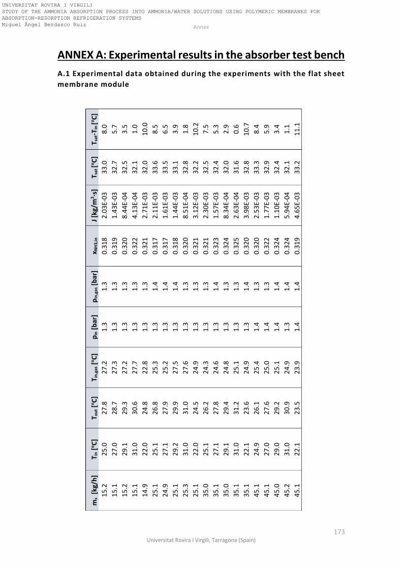
Annex
173 Universitat Rovira i Virgili, Tarragona (Spain)
ANNEX A: Experimental results in the absorber test bench
A.1 Experimental data obtained during the experiments with the flat sheet
membrane module
ms
[kg/
h]
T i
n [
oC
] T o
ut [
oC
] T i
n,g
as [
oC
] p
in [
bar
] p
in,g
as [
bar
] x N
H3,
in
J [k
g/m
2·s
] T s
at [o
C]
T sat
-Tin
[oC
]
15
.2
25
.0
27
.8
27
.2
1.3
1
.3
0.3
18
2
.03
E-03
3
3.0
8
.0
15
.1
27
.0
28
.7
27
.3
1.3
1
.3
0.3
19
1
.43
E-03
3
2.7
5
.7
15
.2
29
.1
29
.3
27
.2
1.3
1
.3
0.3
20
8
.44
E-04
3
2.5
3
.5
15
.1
31
.0
30
.6
27
.7
1.3
1
.3
0.3
22
4
.13
E-04
3
2.1
1
.0
14
.9
22
.0
24
.8
22
.8
1.3
1
.3
0.3
21
2.7
1E-
03
32
.0
10
.0
25
.1
25
.1
26
.8
25
.3
1.3
1
.4
0.3
17
2
.11
E-03
3
3.6
8
.5
24
.9
27
.1
27
.9
25
.2
1.3
1
.4
0.3
17
1
.61
E-03
3
3.5
6
.5
25
.1
29
.2
29
.9
27
.5
1.3
1
.4
0.3
18
1
.44
E-03
3
3.1
3
.9
25
.3
31
.0
31
.0
27
.6
1.3
1
.3
0.3
20
8
.51
E-04
3
2.8
1
.8
25
.1
22
.0
24
.5
24
.9
1.3
1
.3
0.3
21
3
.12
E-03
3
2.2
1
0.2
35
.0
25
.1
26
.2
24
.3
1.3
1
.3
0.3
21
2
.30
E-03
3
2.5
7
.5
35
.1
27
.1
27
.8
24
.6
1.3
1
.4
0.3
23
1
.57
E-03
3
2.4
5
.3
35
.0
29
.1
29
.4
24
.8
1.3
1
.3
0.3
24
8
.34
E-04
3
2.0
2
.9
35
.1
31
.0
31
.2
25
.1
1.3
1
.3
0.3
25
2.6
3E-
04
31
.6
0.6
35
.1
22
.1
23
.6
24
.9
1.3
1
.4
0.3
20
3
.98
E-03
3
2.8
1
0.7
45
.1
24
.9
26
.1
25
.4
1.4
1
.3
0.3
20
2
.53
E-03
3
3.3
8
.4
45
.1
27
.0
27
.6
25
.0
1.4
1
.3
0.3
22
1
.77
E-03
3
2.9
5
.9
45
.0
29
.0
29
.2
25
.1
1.4
1
.4
0.3
24
1
.10
E-03
3
2.4
3
.4
45
.2
31
.0
30
.9
24
.9
1.3
1
.4
0.3
24
5
.94
E-04
3
2.1
1
.1
45
.1
22
.1
23
.5
23
.9
1.4
1
.4
0.3
19
4
.65
E-03
3
3.2
1
1.1
UNIVERSITAT ROVIRA I VIRGILI STUDY OF THE AMMONIA ABSORPTION PROCESS INTO AMMONIA/WATER SOLUTIONS USING POLYMERIC MEMBRANES FOR ABSORPTION-RESORPTION REFRIGERATION SYSTEMS Miguel Ángel Berdasco Ruiz

Annex
174 Doctoral Thesis, Miguel Ángel Berdasco Ruiz
A.2 Experimental data obtained during the experiments with the hollow
fibre membrane module (Absorber conditions)
ms
[kg/
h]
T i
n [
oC
] T o
ut [
oC
] T i
n,g
as [
oC
] p
in [
bar
] p
in,g
as [
bar
] x N
H3,
in
J [k
g/m
2·s
] T s
at [o
C]
T sat
-Tin
[oC
]
49
.4
24
.1
34
.1
21
.9
1.4
1
.4
0.2
94
1
.96
E-04
3
8.0
1
3.9
48
.8
27
.9
36
.4
23
.7
1.4
1
.4
0.2
90
1
.66
E-04
3
9.2
1
1.3
48
.9
31
.4
36
.9
24
.7
1.4
1
.4
0.2
92
1
.10
E-04
3
8.4
7
.0
50
.7
33
.7
36
.7
21
.7
1.4
1
.4
0.2
94
6
.82
E-05
3
8.2
4
.5
50
.2
33
.6
35
.8
22
.8
1.4
1
.4
0.3
01
5
.36
E-05
3
6.7
3
.1
75
.2
34
.7
37
.7
23
.9
1.3
1
.3
0.2
91
1
.03
E-04
3
7.9
3
.2
76
.0
33
.4
37
.3
16
.3
1.4
1
.4
0.2
91
1
.32
E-04
3
8.8
5
.4
75
.0
31
.8
37
.4
18
.2
1.4
1
.4
0.2
94
1.7
6E-
04
38
.5
6.7
76
.0
28
.7
36
.3
17
.3
1.4
1
.4
0.2
97
2
.37
E-04
3
8.6
9
.9
75
.2
24
.2
33
.6
14
.4
1.4
1
.4
0.3
06
2
.90
E-04
3
6.7
1
2.5
100
.5
34
.8
38
.8
19
.7
1.4
1
.4
0.2
90
1
.71
E-04
4
0.4
5
.6
100
.0
28
.2
33
.9
19
.5
1.4
1
.3
0.3
02
2
.30
E-04
3
7.0
8
.8
100
.6
32
.1
35
.2
21
.2
1.5
1
.5
0.3
13
1
.35
E-04
3
7.0
4
.9
98
.5
24
.7
32
.3
13
.0
1.4
1
.4
0.3
13
3
.07
E-04
3
6.1
1
1.4
100
.0
31
.8
34
.6
20
.0
1.5
1
.5
0.3
21
1
.27
E-04
3
5.9
4
.1
99
.0
28
.5
35
.1
19
.5
1.5
1
.5
0.3
07
2
.65
E-04
3
8.6
1
0.1
UNIVERSITAT ROVIRA I VIRGILI STUDY OF THE AMMONIA ABSORPTION PROCESS INTO AMMONIA/WATER SOLUTIONS USING POLYMERIC MEMBRANES FOR ABSORPTION-RESORPTION REFRIGERATION SYSTEMS Miguel Ángel Berdasco Ruiz

Annex
175 Universitat Rovira i Virgili, Tarragona (Spain)
A.3 Experimental data obtained during the experiments with the hollow
fibre membrane module (Resorber conditions)
ms
[kg/
h]
T i
n [
oC
] T o
ut [
oC
] T i
n,g
as [
oC
] p
in [
bar
] p
in,g
as [
bar
] x N
H3,
in
J [k
g/m
2·s
] T s
at [o
C]
T sat
-Tin
[oC
]
49
.5
21
.7
30
.8
18
.4
5.1
5
.1
0.5
48
2
.66
E-04
3
3.3
1
1.6
50
.6
22
.3
30
.7
22
.0
5.2
5
.1
0.5
53
2
.49
E-04
3
3.2
1
0.9
50
.0
24
.8
31
.0
24
.6
5.2
5
.2
0.5
56
1
.78
E-04
3
2.5
7
.7
49
.3
28
.2
30
.9
25
.2
5.2
5
.1
0.5
60
6
.32
E-05
3
2.1
3
.9
50
.3
14
.8
26
.1
21
.7
5.4
5
.4
0.5
98
2
.83
E-04
2
8.4
1
3.6
103
.7
21
.0
28
.7
21
.1
5.2
5
.2
0.5
68
4
.55
E-04
3
1.3
1
0.3
106
.6
23
.1
28
.8
22
.6
5.2
5
.1
0.5
73
3
.09
E-04
3
0.5
7
.4
99
.8
25
.6
29
.4
21
.4
5.1
5
.0
0.5
63
2.1
8E-
04
31
.0
5.4
101
.9
27
.5
30
.9
18
.8
5.1
5
.1
0.5
60
2
.10
E-04
3
2.0
4
.5
101
.0
28
.2
30
.1
24
.9
5.1
5
.1
0.5
66
1
.06
E-04
3
0.9
2
.7
100
.9
22
.9
28
.9
21
.4
5.3
5
.2
0.5
78
3
.07
E-04
3
0.4
7
.5
102
.1
16
.9
27
.1
20
.1
5.6
5
.5
0.5
97
5
.99
E-04
2
9.7
1
2.8
151
.0
19
.0
29
.7
18
.1
5.7
5
.7
0.5
83
9
.70
E-04
3
2.3
1
3.3
148
.4
21
.2
29
.0
20
.0
5.7
5
.6
0.5
92
6
.68
E-04
3
1.1
9
.9
151
.9
23
.1
28
.2
22
.6
5.6
5
.5
0.5
97
4
.52
E-04
2
9.9
6
.8
155
.9
24
.4
28
.7
20
.7
5.4
5
.3
0.5
84
3
.61
E-04
3
0.2
5
.8
15
5.6
2
5.4
2
7.8
2
3.0
5
.6
5.5
0
.608
1
.72
E-04
2
8.7
3
.3
UNIVERSITAT ROVIRA I VIRGILI STUDY OF THE AMMONIA ABSORPTION PROCESS INTO AMMONIA/WATER SOLUTIONS USING POLYMERIC MEMBRANES FOR ABSORPTION-RESORPTION REFRIGERATION SYSTEMS Miguel Ángel Berdasco Ruiz

Annex
176 Doctoral Thesis, Miguel Ángel Berdasco Ruiz
ANNEX B: Flowchart used in the EES simulation of the
hollow fibre membrane module
UNIVERSITAT ROVIRA I VIRGILI STUDY OF THE AMMONIA ABSORPTION PROCESS INTO AMMONIA/WATER SOLUTIONS USING POLYMERIC MEMBRANES FOR ABSORPTION-RESORPTION REFRIGERATION SYSTEMS Miguel Ángel Berdasco Ruiz