Chapter-12 12.1 Understand the working principle of DC motor.
15
• Diploma in Engineering. • Fourth Semester. • Subject: DC Machines -66742 • Chapter-06 • Topic: Understand the principle of winding of DC generator.
-
Upload
khangminh22 -
Category
Documents
-
view
1 -
download
0
Transcript of Chapter-12 12.1 Understand the working principle of DC motor.
• Diploma in Engineering.
• Fourth Semester.
• Subject: DC Machines -66742
• Chapter-06
• Topic: Understand the principle of
winding of DC generator.

MOHAMMAD SOLAIMAN
JUNIOR INSTRUCTOR (TECH-ELECTRICAL)
DEPARTMENT : ELECTRICAL TECHNOLOGY
DHAKA POLYTECHNIC INSTITUTE.
2

Chapter-12 12.1 Understand the working principle of DC motor.
Working principle of a DC motor : An electric motor is an electrical machine which converts electrical energy into mechanical energy. The basic working principle of a DC motor is: "whenever a current carrying conductor is placed in a magnetic field, it experiences a mechanical force". The direction of this force is given by Fleming's left-hand rule and its magnitude is given by F = BIL. Where, B = magnetic flux density, I = current and L = length of the conductor within the magnetic field.

12.2 Mention the types or Classification of DC Motor.

12.3 Explain generator action of motor.
Generator Action in a Motor. A
generator action is developed in
every motor. When a conductor
cuts lines of force, an EMF is
induced in that conductor.
Current to start the armature
turning will flow in the direction
determined by the applied DC
power source.

12.4 Explain the significance of the back emf.
What is Back EMF in DC Motor?
We know whenever conductor cuts the magnetic
field,e.m.f will induce in conductor.This also applies for
conductors in armature too.When the armature of a d.c.
motor rotates under the influence of the driving torque,
the armature conductors move through the magnetic
field and hence e.m.f. is induced in them as in a
generator. The induced e.m.f. acts in opposite direction
to the applied voltage V (Lenz’s law) and in known as
back e.m.f or counter e.m.f. denoted with Eb.
Net voltage across armature circuit = V – Eb
If Ra is the armature circuit resistance, then, Ia = (V –
Eb)/Ra .
The back emf Eb(= PΦZN/60 A) is always less than the
applied voltage V, although this difference is small
when the motor is running under normal conditions.

The significance of Back EMF
Back emf is very significant in the working of a dc motor.The presence of back emf makes the d.c. motor a self-regulating machine i.e., it makes the motor to draw as much armature current as is just sufficient to develop the torque required by the load.
Armature current (Ia),
When the motor is running on no load, small torque is required to overcome the friction and windage losses. Therefore, the armature current Ia is small and the back emf is nearly equal to the applied voltage.
If the motor is suddenly loaded, the first effect is to cause the armature to slow down. Therefore, the speed at which the armature conductors move through the field is reduced and hence the back emf Eb falls.

If the load on the motor is decreased, the driving torque is momentarily
in excess of the requirement so that armature is accelerated.
As the armature speed increases, the back emf Eb also increases and causes
the armature current Ia to decrease. The motor will stop accelerating when the
armature current is just sufficient to produce the reduced torque required by
the load.
Therefore, the back emf in a DC motor regulates the flow of armature current
i.e., it automatically changes the armature current to meet the load
requirement.

12.5 Express the deduction of voltage equation of motor.

Back emf Equation of Diff: DC Motor :--
DC Shunt Motor :
IL = Ia + Ish
V = Eb + Ia Ra + BCD
DC Series Motor :
IL = Ise Rse = Ia
V = Eb + Ise Rse + Ia Ra + BCD
= Eb + Ia ( Rse+ Ra ) + BCD
Short Shunt Compound
Motor :
IL = Ise = Ia + Ish
V = Eb+ Ise Rse + Ia Ra + BCD
Long Shunt Compound Motor
:
Ise = Ia
IL = Ise + Ish = Ia + Ish
V = Eb + Ise Rse + Ia Ra + BCD
Where Ra = armature resistance
Induced e.m.f or Back e.m.f.,= Eb
Where BCD = brush contact drop ( usually 1V
/ brush )
Ra = armature ( winding )
resistance
IL= Load Current
Ish = Shunt Current
Ia = Armature Current

12.6 Define the term torque (mentioning its unit), running torque and break down torque.
What is break down torque of a DC Motor ?
The maximum torque that a motor can develop at its rated applied voltage
and frequency without an abrupt drop in speed.
What is Running torque of a DC motor ?
The torque of the DC Motor is proportional to the field flux and the armature
current. In the DC shunt motor the flux is constant, therefore the torque is
proportional to the armature current. Google uses 200+ ranking factors.
Torque T = F × r (N-m) …where, F = force and r = radius of the armature Work done
by this force in once revolution = Force × distance = F × 2πr
(where, 2πr = circumference of the armature)

12.7 Plot the torque/speed curve of series, shunt and compound motors.
Characteristics of DC motors :
Generally, three characteristic curves are considered important for DC motors which
are, (i) Torque vs. armature current, (ii) Speed vs. armature current and (iii) Speed vs.
torque. These are explained below for each type of DC motor. These characteristics are
determined by keeping the following two relations in mind.
Ta ∝ ɸ.Ia and N ∝ Eb/ɸ
These above equations can be studied at - emf and torque equation of dc machine. For
a DC motor, magnitude of the back emf is given by the same emf equation of a dc
generator i.e. Eb = PɸNZ / 60A.
For a machine, P, Z and A are constant, therefore, N ∝ Eb/ɸ

Characteristics of DC shunt motors :
In case of DC shunt motors, we can assume the field flux ɸ to be constant. Though
at heavy loads, ɸ decreases in a small amount due to increased armature
reaction. As we are neglecting the change in the flux ɸ, we can say that torque is
proportional to armature current. Hence, the Ta-Ia characteristic for a dc shunt
motor will be a straight line through the origin.
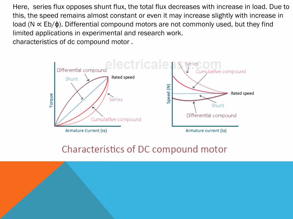
Here, series flux opposes shunt flux, the total flux decreases with increase in load. Due to
this, the speed remains almost constant or even it may increase slightly with increase in
load (N ∝ Eb/ɸ). Differential compound motors are not commonly used, but they find
limited applications in experimental and research work.
characteristics of dc compound motor .

THANKS TO ALL OF MY ATTENTIVE STUDENTS.
STAY HOME,STAY SAFE .
SAVE YOUR FAMILY .
SAVE YOUR COUNTRY .
BE CONSCIOUS TO PREVENT COVID-19.