Hycon Catalogue 12.1 Web.pdf
164
hycon hydraulics Components Catalogue Issue 12.1 HYCON Hydraulic Control Technology HYCON
-
Upload
khangminh22 -
Category
Documents
-
view
3 -
download
0
Transcript of Hycon Catalogue 12.1 Web.pdf

hycon hydraulics
ComponentsCatalogue
Issue 12.1
HYCONHydraulic Control Technology
Hyd
rau
lic C
on
trol Te
chn
olo
gy
HY
CO
N

www.hycon.co.uk
New products including.....
AC & DC Powerpacks
see page.. 93
Manifolds & Subplates
see page.. 69
Flow distribution blocks
see page.. 21
New Circuitry valves
page.. 6 onwards
6 port solenoid valve 90 l/min
see page.. 14
The complete hydraulic Solution… 0118 978 2555
BF901 Valve
c/w integrated Flow control.. 90 lpm 3/4”
page.. 44
SSPV Cooler rangeInternal bypass and thermostatic valve
page.. 148

TEL. 0118 978 2555 FAX. 0118 978 2545 SA
LES@H
YCO
N.C
O.U
K
Hycon LimitedYour Single off the shelf source for all Hydraulic Components...
Accumulators 154-158
Bell Housings & Drive Couplings
90-92
CETOP Valves 56-68
Subplates 69-74
Flow Controls 16-20
Cylinders 131-133
Hydraulic Power Packs
93-95
Electric Motors 96
Directional Control Valves
33-55
Diverter Valves 11-15
Filters 108-115
Rotational Couplings 32
Circuitry Valves 4-1021-32
Gearboxes & Clutch Units
87-89
Gear Pumps 79-85
Hand Pumps 75-78
Hydraulic Motors 123-129
Piston Pumps & Motors
86
Heat Exchangers 134-153
Oil Tanks 98-101
Tank Furniture 102-107
SAE Flanges & Pump Flanges
118-122

Page 4
TEL.
011
8 97
8 25
55
FA
X. 0
118
978
2545
S
ALE
S@H
YCO
N.C
O.U
K
Pressure Relief valves in Single and Dual operation in various options, flow rates up to 180 l/min.
Pressure Relief Valves
PartNumber bsp
Max Flow l/min
Max Pressure
bar
Spring Xadj. bar
Spring Uadj. bar
Spring Kadj. bar
StandardCP 20 14 1/4” 20 350 10-100 20-230 100-350CP 40 38 3/8” 40 350 10-100 20-230 100-350CP 40 12 1/2” 40 350 10-100 20-230 100-350CP 80 12 1/2” 80 350 10-100 20-230 100-350CP 80 34 3/4” 80 350 10-100 20-230 100-350CP 150 34 3/4” 150 350 10-100 20-230 100-350CP 150 10 1” 150 350 10-100 20-230 100-350
Pressure Relief Valve Direct Acting CP
Pressure Relief Valve Direct Acting CP/L
PartNumber bsp
Max Flow l/min
Max Pressure
bar
Spring Xadj. bar
Spring U
adj. bar
Spring Kadj. bar
StandardCP/L 40 38 3/8” 40 350 10-100 20-230 100-350CP/L 40 12 1/2” 40 350 10-100 20-230 100-350CP/L 80 12 1/2” 80 350 10-100 20-230 100-350CP/L 80 34 3/4” 80 350 10-100 20-230 100-350CP/L 150 34 3/4” 150 350 10-100 20-230 100-350CP/L 150 10 1” 150 350 10-100 20-230 100-350
PartNumber bsp
Max Flowl/min
Max Pressure
bar
Spring1
bar max
Spring2
bar max
Spring3
bar max
Spring4
bar max
VMDR10140 1/4” 20 350 40 110 250 STD 350VMDR40380 3/8” 40 300 110 210 300 STD —VMDR40120 1/2” 40 300 110 210 300 STD —VMDR90120 1/2” 90 350 100 250 350 STD —VMDR90340 3/4” 90 350 100 250 350 STD —VMDR120340 3/4” 120 350 100 250 350 STD —VMDR120100 1” 120 350 100 250 350 STD —
Pressure Relief Valve Direct Acting VMDR
Hand Wheel Adjustment ‘CK’ available
Pressure Relief Valve High Flow 2 ported Direct Acting Poppet VMPD-T
PartNumber bsp Max Flow
l/min
Max Pressure
bar
Spring adj. bar
VMPD-T-100 1” 180 350 40-350VMPD-T-114 1 1/4” 180 350 40-350

Page 5
TEL. 0118 978 2555 FAX. 0118 978 2545 SA
LES@H
YCO
N.C
O.U
K
Pressure Relief valves in Single and Dual operation in various options, flow rates up to 180 l/min.
Pressure Relief Valves
Dual Pressure Relief Valve Direct Acting CP DI/L
PartNumber bsp
Max Flow l/min
Max Pressure
bar
Spring Xadj. bar
Spring Uadj. bar
Spring Kadj. bar
StandardCP DI L 40 38 3/8” 40 350 10-100 20-230 100-350
CP DI L 40 12 1/2” 40 350 10-100 20-230 100-350
CP DI L 80 12 1/2” 80 350 10-100 20-230 100-350
CP DI L 80 34 3/4” 80 350 10-100 20-230 100-350
CP DI L 150 34 3/4” 150 350 10-100 20-230 100-350
CP DI L 150 10 1” 150 350 10-100 20-230 100-350
Motor Mounting Pressure Relief Valves for OMP/OMR/OMS/OMT Motors
PartNumber Type bsp
Max Flowl/min
Max Pressure
bar
Standard Pressure
Range bar
VAU 1/2” SE OMP OMR Single 1/2” 60 350 30-180
VAU 1/2” SE OMP OMR SF Single with Brake Release 1/2” 60 350 30-180
VAU 1/2” DE OMP OMR Dual 1/2” 60 350 30-180VAU 1/2” DE OMP OMR SF Dual with Brake Release 1/2” 60 350 30-180VAU 1/2” SE OMS Single 1/2” 50 350 30-180VAU 1/2” SE OMS SF Single with Brake Release 1/2” 50 350 30-180VAU 1/2” DE OMS Dual 1/2” 50 350 30-180VAU 1/2” DE OMS SF Dual with Brake Release 1/2” 50 350 30-180VAU 3/4” SE OMT Single 3/4” 100 350 30-180VAU 3/4” DE OMT Dual 3/4” 100 350 30-180
Dual Pressure Relief Valves -c/w Anti-cavitation or Pilot Check
PartNumber Type bsp
Max Flowl/min
Max Pressure
bar
Standard Pressure
Range bar
VAUAC 3/8” Dual with Anti-cavitation 3/8” 45 350 10-180
VAUAC 1/2” Dual with Anti Cavitation 1/2” 70 350 10-180
VAUAC 3/4” Dual with Anti Cavitation 3/4” 110 350 10-180
VBLP 3/8” Dual with Pilot Operated Check valves 3/8” 35 350
VBLP 1/2” Dual with Pilot Operated Check valves 1/2” 70 350
VBLP 3/4” Dual with Pilot Operated Check valves 3/4” 110 350

Page 6
TEL.
011
8 97
8 25
55
FA
X. 0
118
978
2545
S
ALE
S@H
YCO
N.C
O.U
K
Dual Pump ’Hi-Low’ Unloading Valves& Pressure Reducing Valves
Dual Pump ‘Hi-Low’ Unloader with Relief, CETOP Interface VABP FL
Part NumberCetop
Interface Size
AP Flow l/min
BP Max Flow l/min
T Max Flow l/min
Max Pressure
bar
AP Pressure
Range bar
BP Pressure
Range bar
AP ports bsp
BP/U ports bsp
A/B/T ports bsp
VABP FL6 3 20 40 60 350 50-350 20-80 1/4” 3/8” 1/2”VABP FL10 5 30 50 80 350 50-350 20-80 3/8” 1/2” 3/4”VABP FL16 7 40 100 120 350 50-350 20-80 1/2” 3/4” 1”
Dual Pump ‘Hi-Low’ Unloader with Relief, Inline body VABP
Part Number
AP Flow l/min
BP Max Flow l/min
T Max Flow l/min
Max Pressure
bar
AP Pressure
Range bar
BP Pressure
Range bar
AP bsp
BP/U bsp
T bsp
VABP 38 20 40 60 350 50-350 20-80 1/4” 3/8” 1/2”VABP 12 30 50 80 350 50-350 20-80 3/8” 1/2” 3/4”VABP 34 40 80 120 350 50-350 20-80 1/2” 3/4” 1”
Pressure Reducing valves Direct Acting, VRP/VRPRLwith or without Check valve
PartNumber
P,T,Reg.bsp
Max Flowl/min
Max Pressure
bar
StandardSetting range
bar
OptionalSetting range
barVRP 3/8” 3/8” 30 350 35-180 10-60VRP 1/2” 1/2” 30 350 35-180 10-60VRPRL 3/8” 3/8” 30 350 35-180 10-60VRPRL 1/2” 1/2” 30 350 35-180 10-60
VRP
VRPRL
Page 7
TEL. 0118 978 2555 FAX. 0118 978 2545 SA
LES@H
YCO
N.C
O.U
K
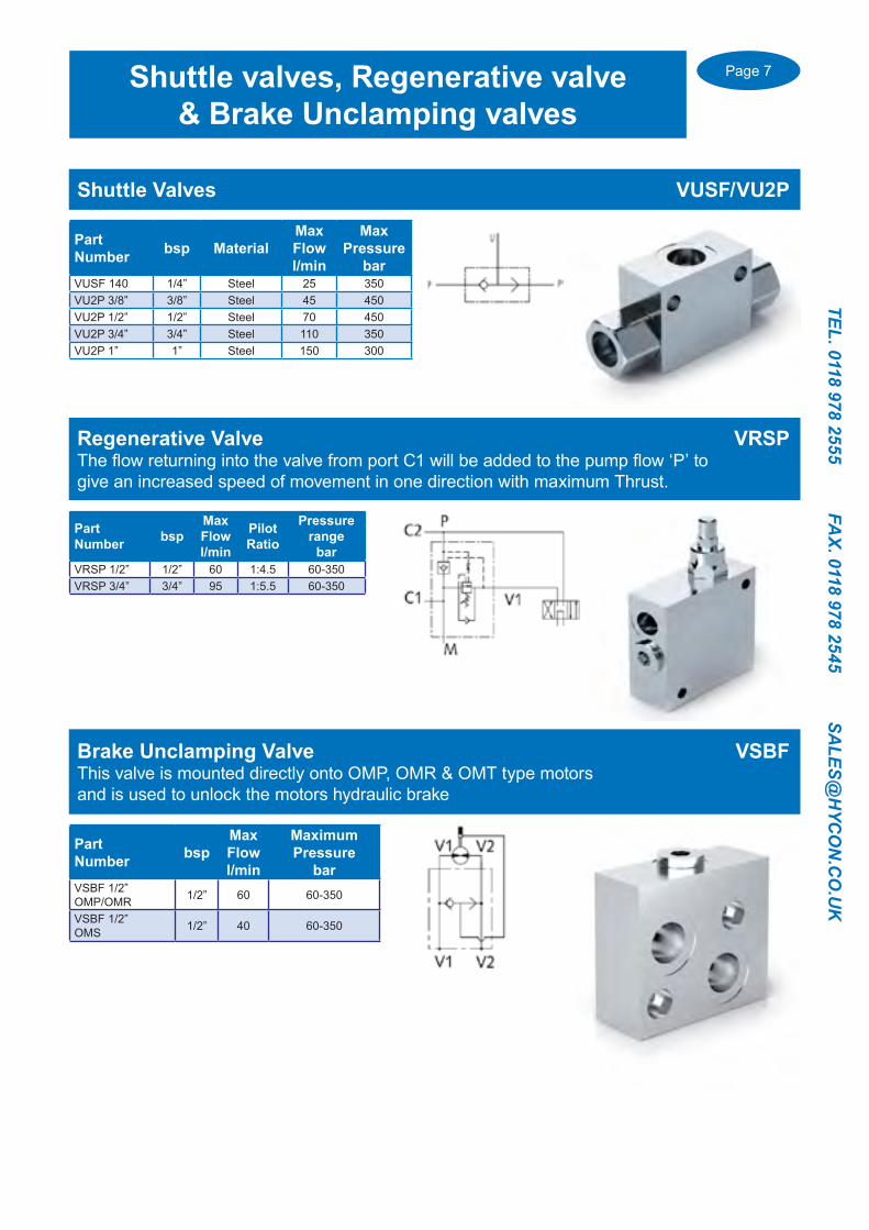
Shuttle Valves VUSF/VU2P
PartNumber bsp Material
Max Flowl/min
Max Pressure
barVUSF 140 1/4” Steel 25 350VU2P 3/8” 3/8” Steel 45 450VU2P 1/2” 1/2” Steel 70 450VU2P 3/4” 3/4” Steel 110 350VU2P 1” 1” Steel 150 300
Shuttle valves, Regenerative valve& Brake Unclamping valves
Regenerative Valve VRSPThe flow returning into the valve from port C1 will be added to the pump flow ‘P’ to give an increased speed of movement in one direction with maximum Thrust.
PartNumber bsp
Max Flowl/min
Pilot Ratio
Pressure range
barVRSP 1/2” 1/2” 60 1:4.5 60-350VRSP 3/4” 3/4” 95 1:5.5 60-350
Brake Unclamping Valve VSBFThis valve is mounted directly onto OMP, OMR & OMT type motors and is used to unlock the motors hydraulic brake
PartNumber bsp
Max Flowl/min
MaximumPressure
barVSBF 1/2” OMP/OMR 1/2” 60 60-350
VSBF 1/2”OMS 1/2” 40 60-350

Page 8
TEL.
011
8 97
8 25
55
FA
X. 0
118
978
2545
S
ALE
S@H
YCO
N.C
O.U
K
Mechanical spool Operation 1/4” up to 3/4” bsp
2 Way End Run Valves
End Stroke Valves Normally Open Type V-NA/ V-FCR1T
NormallyOpen bsp
Max Flowl/min
Max Pressure
barV-101-3/8”-NA 3/8” 45 350V-121-1/2”-NA 1/2” 60 350
NormallyOpen bsp
Max Flowl/min
Max Pressure
barV-FCR1T-60 3/8” 60 350V-FCR1T-80 1/2” 80 350V-FCR1T-120 3/4” 120 350
End Stroke Valves Normally Closed Type FCM / V-NC / V-FCR2T
NormallyClosed bsp
Max Flowl/min
Max Pressure
barFCM140 1/4” 25 350FCM380 3/8” 40 350V101-3/8”-NC 3/8” 50 350V-121-1/2”-NC 1/2” 70 350V-201-3/4”-NC 3/4” 100 350
NormallyClosed bsp
Max Flowl/min
Max Pressure
barV-FCR2T-60 3/8” 60 350V-FCR2T-80 1/2” 80 350V-FCR2T-120 3/4” 120 350
NormallyOpen with Check valve
bspMax Flowl/min
Max Pressure
barV-101-3/8”-NA-VU 3/8” 45 350V-121-1/2”-NA-VU 1/2” 60 350

Page 9
TEL. 0118 978 2555 FAX. 0118 978 2545 SA
LES@H
YCO
N.C
O.U
K
Normally Closed bsp Max Flowl/min
Max Pressure bar
VAS-NC-14 1/4” 40 320VAS-NC-38 3/8” 50 320VAS-NC-12 1/2” 70 320VAS-NC-34 3/4” 70 320VAS-NC-100 1” 150 320VAS-NC-114 1 1/4” 260 350
Normally Open bsp Max Flowl/min
Max Pressure bar
VAS-NA-14 1/4” 40 320VAS-NA-38 3/8” 50 320VAS-NA-12 1/2” 70 320VAS-NA-34 3/4” 70 320VAS-NA-100 1” 150 320VAS-NA-114 1 1/4” 260 350
2 Way Poppet Valves High Pressure Steel bodied VASN.B. VAS Valves are checked in only one direction when in the closed position, allowing free flow in the other direction. Available in 12 or 24 DC & 24, 110 or 230 AC
NormallyClosed
NormallyOpen
N.B. The 1 1/4” bsp Valve has a closed path from B to A port, Not A to B port as other sizes !
Steel Bodied up to 320 bar 1/4” up to 1 1/4” bsp
2 Way Solenoid Operated Poppet Valves
2 WAY POPPET CHECKED IN BOTH DIRECTIONS Type KV-2/2N.B. KV Valves are checked in both directions when in the closed position.Available in 12, 24, 48 DC & 110 or 230 AC
Part Number bsp Max Flowl/min
Max Pressure
barKV-2/2-6-S-A-3/8 NORMALLY OPEN 3/8” 30 210
KV-2/2-6-S-B-3/8 NORMALLY CLOSED 3/8” 30 210

Page 10
TEL.
011
8 97
8 25
55
FA
X. 0
118
978
2545
S
ALE
S@H
YCO
N.C
O.U
K
Part Number bsp DN Max Pressure barRS2 1/4” FF 1/4” 6 500RS2 3/8” FF 3/8” 10 500RS2 1/2” FF 1/2” 13 500RS2 3/4” FF 3/4” 20 400RS2 1”FF 1” 25 350RS2 1 1/4”FF 1 1/4” 25 350RS2 1 1/2”FF 1 1/2” 25 350RS2 2” (Without mounting holes) 2” 40 350
High Pressure Ball Valves in Zinc Plated SteelAll valves have pre drilled Mounting holes..
High Pressure Ball Valves
2 Way High Pressure Ball Valve Type RS2
3 Way High Pressure Ball Valve Type RS3
Part Number bsp DN Max Pressure barRS3 1/4”FF 1/4” 6 500RS3 3/8”FF 3/8” 10 500RS3 1/2”FF 1/2” 13 500RS3 3/4” FF 3/4” 20 400RS3 1”FF 1” 25 350RS3 1 1/4”FF 1 1/4” 25 350RS3 1 1/2”FF 1 1/2” 25 350

Page 11
TEL. 0118 978 2555 FAX. 0118 978 2545 SA
LES@H
YCO
N.C
O.U
K
3 Way Cast Iron Diverter valve 3 Way Type D3V
Part Number(with type ‘A’ Open centre / ‘B’ Closed centre) bsp Max Flow
l/minMax Pressure
barD3V-38 A (B) 3/8” 60 300D3V-12 A (B) 1/2” 90 300D3V-34 A (B) 3/4” 120 300D3V-10 A (B) 1” 200 280
Manual Rotary Lever Operation 3 Way
3 Way Diverter valves
3 Way High Pressure Steel Diverter valve (500 bar) 3 Way Type G3V
Part Number (with type ‘A’ Open Centre) bsp Max Flow
l/minMax Pressure
barG3V-14 A 1/4” 40 500G3V-38 A 3/8” 60 500G3V-12 A 1/2” 90 500G3V-34 A 3/4” 120 500G3V-10 A 1” 180 500
‘A’ Open centre
‘B’ Closed centre
‘A’ Open centre
‘B’ Closed centre

Page 12
TEL.
011
8 97
8 25
55
FA
X. 0
118
978
2545
S
ALE
S@H
YCO
N.C
O.U
K
3 Way Solenoid Operated Diverter Type KVC-3/2Steel Body, max pressure 350 bar (with YZ Drain)
Available in 12,24 & 48 DC & 24, 110 or 230 AC, Emergency Push button option, suffix ‘G’
3 Way Solenoid OperatedDiverter valves
Part Number bsp Max Flowl/min
Max Pressurebar
KVC-3/2-4-14 1/4” 20 160KVC-3/2-10-38 3/8” 60 250KVC-3/2-10-38-YZ 3/8” 60 350KVC-3/2-10-12 1/2” 60 250KVC-3/2-10-12-YZ 1/2” 60 350KVC-3/2-10-34 3/4” 70 250KVC-3/2-10-34-YZ 3/4” 100 350
KVC-3/2-4KVC-3/2-10
3 Way Solenoid Operated Diverter 3 Way Type E3VAluminium Body, max pressure 250 barAvailable in 12,24 & 48 DC & 24, 110 or 230 AC
Part Number bsp Max Flowl/min
Max Pressurebar
E3V-3/8” 3/8” 35 250
E3V-1/2” 1/2” 35 250
Page 13
TEL. 0118 978 2555 FAX. 0118 978 2545 SA
LES@H
YCO
N.C
O.U
K
Manual 4, 6 & 8 Way Valves Rotary and Lever operation
4,6 & 8 Way Manual Diverters
6 Way Lever Operated Diverter Valve, max 350 bar Type KV-6/2-R(RA)
Part Number LeverControl bsp
MaxFlowl/min
Max Pressure bar(Max Pressure
with drain port ‘L’Connected)
KV-6/2-6-R-3/8”-YZ-S50 Spring Return 3/8” 60 160 (350)
KV-6/2-6-RA-3/8”-YZ-S50 Detented 3/8” 60 160 (350)
KV-6/2-6-R-1/2”-YZ-S50 Spring Return 1/2” 60 160 (350)
KV-6/2-6-RA-1/2”-YZ-S50 Detented 1/2” 60 160 (350)
KV-6/2-10-R-1/2”-YZ Spring Return 1/2” 120 160 (350)
KV-6/2-10-RA-1/2”-YZ Detented 1/2” 120 160 (350)
KV-6/2-10-R-3/4”-YZ Spring Return 3/4” 120 160 (350)
KV-6/2-10-RA-3/4”-YZ Detented 3/4” 120 160 (350)
C A D B
L P1 P2
4 Way Rotary Diverter valve 4 Way Type D4V
Part Number‘A’ Open centre‘B’ Closed centre
bspMax Flowl/min
Max Pressure
barD4V-38 A (B) 3/8” 60 300D4V-12 A (B) 1/2” 90 300D4V-34 A (B) 3/4” 120 300D4V-10 A (B) 1” 200 280
‘A’ Open centre
‘B’ Closed centre
Part Number‘A’ Open centre)‘B’ Closed centre
Ports bsp Max Flowl/min
Max Pressure
bar
D6V-14 A 6 1/4” 60 + 60 300D6V-38 A 6 3/8” 60 + 60 300D6V-12 A 6 1/2” 90 + 90 300D6V-34 A 6 3/4” 120 + 120 300D6V-10 A 6 1” 200 + 200 280
6 Way Rotary Diverter valve 6 Way Type D6V
‘A’ Open centre
‘B’ Closed centre
Part Number Ports bsp Max Flowl/min
Max Pressure
barDFV-38 A 6 3/8 40 + 40 300DFV-12 A 6 3/8” 60 + 60 300
Page 14
TEL.
011
8 97
8 25
55
FA
X. 0
118
978
2545
S
ALE
S@H
YCO
N.C
O.U
K
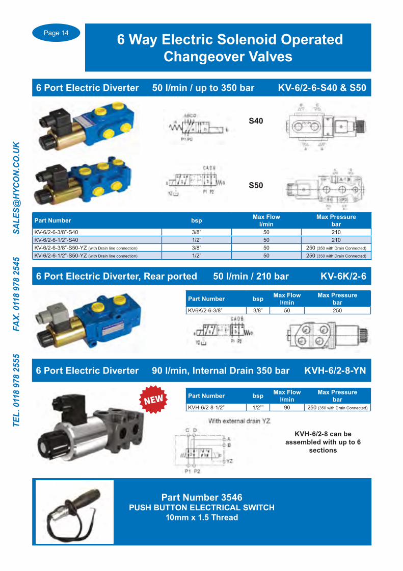
6 Way Electric Solenoid Operated Changeover Valves
Part Number bsp Max Flowl/min
Max Pressurebar
KV6K/2-6-3/8” 3/8” 50 250
6 Port Electric Diverter, Rear ported 50 l/min / 210 bar KV-6K/2-6
Part Number bsp Max Flowl/min
Max Pressurebar
KV-6/2-6-3/8”-S40 3/8” 50 210KV-6/2-6-1/2”-S40 1/2” 50 210KV-6/2-6-3/8”-S50-YZ (with Drain line connection) 3/8” 50 250 (350 with Drain Connected)
KV-6/2-6-1/2”-S50-YZ (with Drain line connection) 1/2” 50 250 (350 with Drain Connected)
6 Port Electric Diverter 50 l/min / up to 350 bar KV-6/2-6-S40 & S50
S40
S50
6 Port Electric Diverter 90 l/min, Internal Drain 350 bar KVH-6/2-8-YN
Part Number bsp Max Flowl/min
Max Pressurebar
KVH-6/2-8-1/2” 1/2”” 90 250 (350 with Drain Connected)
KVH-6/2-8 can be assembled with up to 6
sections
Part Number 3546PUSH BUTTON ELECTRICAL SWITCH
10mm x 1.5 Thread

Page 15
TEL. 0118 978 2555 FAX. 0118 978 2545 SA
LES@H
YCO
N.C
O.U
K
6 & 8 Way Electric Solenoid Operated Changeover Valves
Part Number bsp Max Flowl/min
Max Pressure bar
KV-6/2-10-1/2”-YZ-S40 1/2” 90 250 (350 with Drain Connected)
KV-6/2-10-3/4”-YZ-S40 3/4” 120 250 (350 with Drain Connected)
6 Port Electric Diverter Max 120 l/min, up to 350 bar KV-6/2-10-S40
Part Number bsp Max Flowl/min
Max Pressure bar
KV-6/2-16-XN 1” SAE Flange Ported 250 250 (350 with Drain Connected)
6 Port Electric Diverter 250 l/min, max 350 bar KV-6/2-16
8 & 10 Port Electric Diverters 50 l/min & 80 l/min KV-6/2-6 & KV-6/2-10
Part Number Number of ports bsp
Max Flowl/min
Pressure bar(Max Pressure with
drain port connected)
KV-8/3-6-3/8” 8 3/8” 50 210KV-8/3-6-1/2” 8 1/2” 50 210
KVH-6/2-10-12-N2-S40 8 1/2” 90 250 (315 with Drain Line connected)
KVH-6/2-10-34-N2-S40 8 3/4” 120 250 (315 with Drain Line connected)

Page 16
TEL.
011
8 97
8 25
55
FA
X. 0
118
978
2545
S
ALE
S@H
YCO
N.C
O.U
K
Inline and Panel Mount Needle and Speed Control valves 1/8” up to 1 1/2” bsp
Suitable for panle mounting with seperate lock nut
Flow Control Valves, Bi Directional & Uni Directional Flow STBF/STUFPanel Mount model supplied with Spindle Mounting Nut
Inline Flow Control Valves
Bi Directional Valve bsp Max Flowl/min
Max Pressurebar
STBF 180 1/8” 10 400STBF 140 1/4” 15 400STBF 380 3/8” 30 400STBF 120 1/2” 50 400STBF 340 3/4” 80 400STBF 100 1” 150 400STBF 114 1 1/4” 200 300STBF 112 1 1/2” 300 300
Barrel Flow Control Valves Type VRB/VRFBi directional & Uni Directional Flow Control
Bi Directional Valve bsp
Max Flowl/min
Max Pressure
barVRB 140 1/4” 20 300VRB 380 3/8” 45 300VRB 120 1/2” 70 300VRB 340 3/4” 110 250VRB 100 1” 160 250
Uni Directional Valve bsp
Max Flowl/min
Max Pressure
barVRF 140 1/4” 20 300VRF 380 3/8” 45 300VRF 120 1/2” 70 300VRF 340 3/4” 110 250VRF 100 1” 160 250VRF 114 1 1/4” 210 230VRF 112 1 1/2” 280 230
Lock Nuts for Panel Mounting Valve size84100022 1/4” & 3/8”84100023 1/2”84100024 3/4” & 1”84100030 1 1/4” & 1 1/2”
Uni Directional Valve bsp Max Flowl/min
Max Pressurebar
STUF 180 1/8” 10 400STUF 140 1/4” 15 400STUF 380 3/8” 30 400STUF 120 1/2” 50 400STUF 340 3/4” 80 400STUF 100 1” 150 400STUF 114 1 1/4” 200 300STUF 112 1 1/2” 300 300

Page 17
TEL. 0118 978 2555 FAX. 0118 978 2545 SA
LES@H
YCO
N.C
O.U
K
Pressure CompensatedFlow Control Valves
Pressure Compensated Speed Control 10 up to 160 l/min
Uni DirectionalValve bsp
Max Flowl/min
Max Pressure
barVRC 140 1/4” 10 250VRC 380 3/8” 18 250VRC 120 1/2” 33 250
Pressure Compensated Flow Control, Uni Directional Flow Type VRC
For Priority Adjustable Flow Dividerssee pages 18-19…..
For Flow Dividerssee page 20…..
2 port Flow Compensated Control Valve 350 Bar Rated Type RFP2The flow rate is constant despite changes in the inlet pressure
Part Number bsp Max Inlet Flow
l/min
Max Pressure
barRFP2 3/8” 3/8” 30 350RFP2 1/2” 1/2” 50 350RFP2 3/4” 3/4” 90 350RFP2 1” 1” 160 350

Page 18
TEL.
011
8 97
8 25
55
FA
X. 0
118
978
2545
S
ALE
S@H
YCO
N.C
O.U
K
Priority Adjustable Flow Control Valves
Pressure Compensated Priority Adjustable Flow Control Valves , 3/8” up to 1” bsp port sizes
Part Number bspMax Flowl/min
Adj. Range l/min
Operating Pressure
barTVTC-12 1/2” & 3/4” P 32 1 to12 5 up to 350TVTC-25 1/2” & 3/4” P 65 1 to 25 5 up to 350TVTC-50 1/2” & 3/4” P 65 1 to 50 5 up to 350With Pressure ReliefTVTC-12-VV 1/2” & 3/4” P 32 1 to12 5 up to 350TVTC-25-VV 1/2” & 3/4” P 65 1 to 25 5 up to 350TVTC-50-VV 1/2” & 3/4” P 65 1 to 50 5 up to 350With Reverse Flow TVTC-12-NV 1/2” & 3/4” P 32 1 to12 5 up to 350TVTC-25-NV 1/2” & 3/4” P 65 1 to 25 5 up to 350TVTC-50-NV 1/2” & 3/4” P 65 1 to 50 5 up to 350
Priority Adjustable Flow Divider 12, 25 & 50 l/min 350 bar Type TVTCSteel Body
Part Number bsp
Max InletFlowl/min
Maximum Pressure
barRF 40P 3/8” & 1/2” 40 250RF 70P 1/2” & 3/4” 90 250RF 150 P 3/4” & 1” 150 250
Priority Adjustable Flow Divider. 50 & 90 l/min 250 bar Type RFPCast body
Part Number bsp
Max Inlet Flowl/min
Max Pressure
bar
Pressure Relief Valve
settingbar
RF 70 PVX 1/2” & 3/4” 80 250 70(10-100)RF 70 PVU 1/2” & 3/4” 80 250 140(50-230)RF 70 PVK 1/2” & 3/4” 80 250 200(100-250)
Priority Adjustable Flow Divider with Pressure Relief Valve Type RFPV90 l/min ..250 bar Cast body
Page 19
TEL. 0118 978 2555 FAX. 0118 978 2545 SA
LES@H
YCO
N.C
O.U
K
Priority Adjustable Flow Control Valves
Pressure Compensated Priority Adjustable Flow Control Valves3/8” up to 1” bsp port sizes
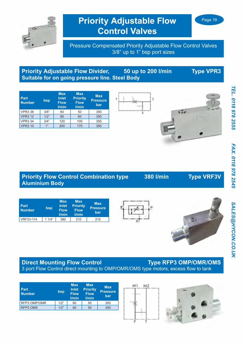
Priority Adjustable Flow Divider, 50 up to 200 l/min Type VPR3Suitable for on going pressure line. Steel Body
Part Number bsp
Max Inlet Flowl/min
Max Priority
Flowl/min
Max Pressure
bar
VPR3 38 3/8” 60 50 350VPR3 12 1/2” 80 60 350VPR3 34 3/4” 120 100 350VPR3 10 1” 200 170 350
Direct Mounting Flow Control Type RFP3 OMP/OMR/OMS3 port Flow Control direct mounting to OMP/OMR/OMS type motors, excess flow to tank
Part Number bsp
MaxInlet Flowl/min
MaxPriority
Flowl/min
MaxPressure
bar
RFP3 OMP/OMR 1/2” 60 50 350RFP3 OMS 1/2” 60 50 350
Priority Flow Control Combination type 380 l/min Type VRF3VAluminium Body
Part Number bsp
Max Inlet Flowl/min
Max Priority
Flowl/min
Max Pressure
bar
VRF3V-114 1 1/4” 380 210 210

Page 20
TEL.
011
8 97
8 25
55
FA
X. 0
118
978
2545
S
ALE
S@H
YCO
N.C
O.U
K
Flow Divider / Combiner Valves
Pressure Compensated Flow Divider/Combiner valves
50%-50% Flow Divider/Combiner Cast Iron 250 bar Type VEQ
50%-50% Flow Divider/Combiner Type DTP
Part Number bsp
Max Flowl/min
Min Flowl/min
MaxPressure
barDTP-6-20 3/8” 20 8 350DTP-6-35 3/8” 35 12 350DTP-6-50 3/8” 50 16 350DTP-10-70 1/2” 70 35 350
Part Number bsp Material Max Flow
l/minMin Flow
l/min
Max W.P (Peak)
Pressure bar
DFL 1-3 3/8” Steel 3 1 250(300)DFL 3-6 3/8” Steel 6 3 250(300)DFL 6-10 3/8” Steel 10 6 250(300)DFL 10-20 3/8” Steel 20 10 250(300)DFL 20-32 3/8” Steel 32 20 250(300)DFL 25-40 3/8” & 1/2” Steel 40 25 250(300)DFL 40-60 3/8” & 1/2” Steel 60 40 250(300)DFL 60-80 3/8” & 1/2” Steel 80 60 250(300)DFL 80-100 1/2” & 3/4” Steel 100 80 250(300)DFL 100-120 3/4” & 1” Steel 120 100 250(300)DFL 120-150 3/4” & 1” Steel 150 120 250(300)
50%-50% Flow Divider/Combiner Type DFL
Part No bsp
Inlet Flow Rangel/min
WorkingPressure
bar
Max PeakPressure
barVEQ-8 3/8” 1-3 250 300VEQ-10 3/8” 3-6 250 300VEQ-15 3/8” 6-10 250 300VEQ-20 3/8” 10-20 250 300VEQ-22 3/8” 20-32 250 300VEQ-25 3/8” &1/2” 25-40 250 300VEQ-30 3/8” &1/2” 40-60 250 300VEQ-50 3/8” &1/2” 60-80 250 300
Page 21
TEL. 0118 978 2555 FAX. 0118 978 2545 SA
LES@H
YCO
N.C
O.U
K
Flow distribution Manifolds
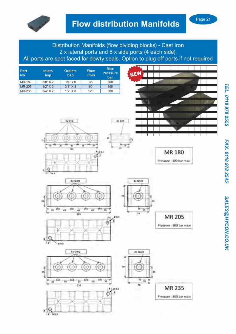
Part No
Inletsbsp
Outletsbsp
Flow l/min
MaxPressure
barMR-180 3/8” X 2 1/4” x 8 35 300MR-205 1/2” X 2 3/8” X 8 60 300MR-235 3/4” X 2 1/2” X 8 120 300
Distribution Manifolds (flow dividing blocks) - Cast Iron2 x lateral ports and 8 x side ports (4 each side).
All ports are spot faced for dowty seals. Option to plug off ports if not required
Page 22
TEL.
011
8 97
8 25
55
FA
X. 0
118
978
2545
S
ALE
S@H
YCO
N.C
O.U
K
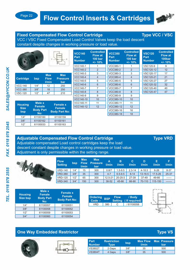
Flow Control Inserts & Cartridges
VCC140Part Number
Controlled Flow at 100 bar+/- 10%
VCC140-1 1VCC140-2 2VCC140-3 3VCC140-4 4VCC140-5 5VCC140-6 6VCC140-7 7VCC140-8 8VCC140-9 9VCC140-10 10VCC140-11 11VCC140-12 12
VCC380Part Number
Controlled Flow at 100 bar+/- 10%
VCC380-1 1VCC380-2 2VCC380-3 3VCC380-4 4VCC380-5 5VCC380-6 6VCC380-7 7VCC380-8 8VCC380-9 9VCC380-10 10VCC380-11 11VCC380-12 12VCC380-16 16VCC380-18 18
VSC120PartNumber
Controlled Flow at 100bar+/- 10%
VSC120-9 9VSC120-12 12VSC120-17 17VSC120-21 21VSC120-27 27VSC120-32 32VSC120-40 40VSC120-47 47
Cartridge bspMax Flowl/min
Max Pressure
barVCC-140 1/4” 12 250VCC-380 3/8” 18 250VSC-120 1/2” 47 210
HousingSize bsp
Male x Female
Body Part No:
Female x Female
Body Part No:
1/4” 61100160 611001593/8” 61100162 611001611/2” 61100033 61100163
Fixed Compensated Flow Control Cartridge Type VCC / VSCVCC / VSC Fixed Compensated Load Control Valves keep the load descent constant despite changes in working pressure or load value.
Part Number
Restriction Type bsp Max Flow
l/minMax Pressure
barVS3802T 2 Gaps 3/8” 35 500VS3804T 4 Gaps 3/8” 35 500
One Way Embedded Restrictor Type VS
Adjustable Compensated Flow Control Cartridge Type VRDAdjustable compensated Load control cartridges keep the load descent constant despite changes in working pressure or load value. Adjustment is only permissible within the setting range.
Flow Setting bsp
Max Flow l/min
Max Pressure
bar
Al/min
Bl/min
Cl/min
Dl/min
El/min
Fl/min
VRD-140 1/4” 15 300 0.8/7 1.5-9.5 2.3-14 4-18.5 6-26 8-37VRD-380 3/8” 35 300 4-7 6.5-9.5 8-14 13-18.5 17.5-26 25-37VRD-120 1/2” 65 300 12.5-21 20-29.5 27-39 37-49 49-66 ——VRD-340 3/4” 150 300 38-52 45-66 66-90 70-110 115-150 ——-
Housing Size bsp
Male x Female
Body Part No:
Female x Female
Body Part No:
1/4” 61100057 611000513/8” 61100058 611000521/2” 61100059 611000533/4” 61100060 61100054
Ordering Code :- BSP Flow
Setting/ Body
( If required)VRD 380 C / 61100058
Page 23
TEL. 0118 978 2555 FAX. 0118 978 2545 SA
LES@H
YCO
N.C
O.U
K
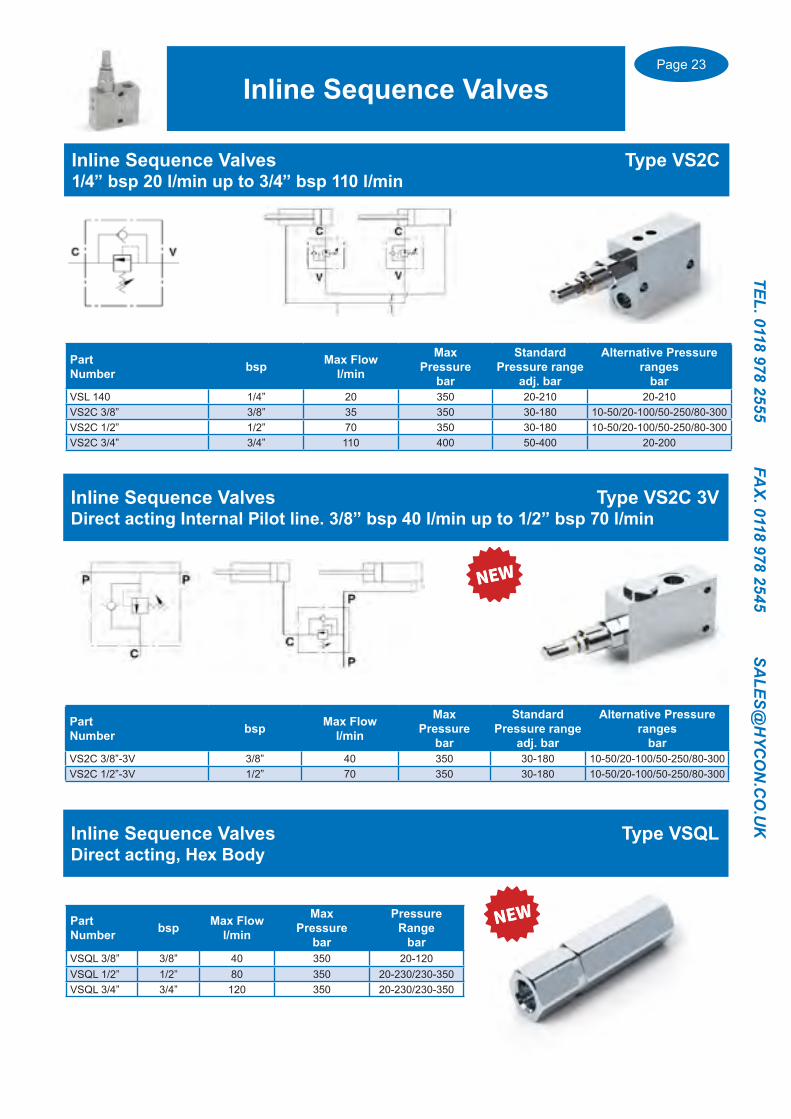
PartNumber bsp Max Flow
l/min
Max Pressure
bar
Standard Pressure range
adj. bar
Alternative Pressure ranges
barVSL 140 1/4” 20 350 20-210 20-210VS2C 3/8” 3/8” 35 350 30-180 10-50/20-100/50-250/80-300VS2C 1/2” 1/2” 70 350 30-180 10-50/20-100/50-250/80-300VS2C 3/4” 3/4” 110 400 50-400 20-200
Inline Sequence Valves Type VS2C1/4” bsp 20 l/min up to 3/4” bsp 110 l/min
Inline Sequence Valves
Inline Sequence Valves Type VS2C 3V Direct acting Internal Pilot line. 3/8” bsp 40 l/min up to 1/2” bsp 70 l/min
PartNumber bsp Max Flow
l/min
Max Pressure
bar
Standard Pressure range
adj. bar
Alternative Pressure ranges
barVS2C 3/8”-3V 3/8” 40 350 30-180 10-50/20-100/50-250/80-300VS2C 1/2”-3V 1/2” 70 350 30-180 10-50/20-100/50-250/80-300
Inline Sequence Valves Type VSQLDirect acting, Hex Body
PartNumber bsp Max Flow
l/min
Max Pressure
bar
Pressure Range
barVSQL 3/8” 3/8” 40 350 20-120VSQL 1/2” 1/2” 80 350 20-230/230-350VSQL 3/4” 3/4” 120 350 20-230/230-350
Page 24
TEL.
011
8 97
8 25
55
FA
X. 0
118
978
2545
S
ALE
S@H
YCO
N.C
O.U
K
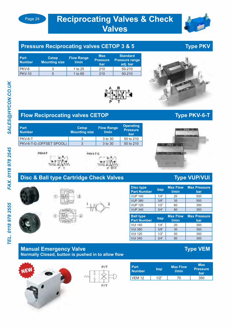
Pressure Reciprocating valves CETOP 3 & 5 Type PKV
Reciprocating Valves & Check Valves
PartNumber
Cetop Mounting size
Flow Rangel/min
Max Pressure
bar
Standard Pressure range
adj. barPKV-6 3 1 to 25 210 50-210PKV-10 5 1 to 60 210 50-210
Flow Reciprocating valves CETOP Type PKV-6-T
PartNumber
Cetop Mounting size
Flow Rangel/min
Operating Pressure
barPKV-6-T 3 3 to 30 50 to 210PKV-6-T-G (OFFSET SPOOL) 3 3 to 30 50 to 210
Disc & Ball type Cartridge Check Valves Type VUP/VUIDisc type Part Number bsp Max Flow
l/minMax Pressure
barVUP 140 1/4” 20 500VUP 380 3/8” 35 500VUP 120 1/2” 60 350VUP 340 3/4” 80 350
Ball type Part Number bsp Max Flow
l/minMax Pressure
barVUI 140 1/4” 20 350VUI 380 3/8” 30 350VUI 120 1/2” 50 350VUI 340 3/4” 80 350
Disc & Ball type Cartridge Check Valves Type VUP/VUI
Manual Emergency Valve Type VEMNormally Closed, button is pushed in to allow flow
PartNumber bsp Max Flow
l/min
MaxPressure
barVEM 12 1/2” 70 350

Page 25
TEL. 0118 978 2555 FAX. 0118 978 2545 SA
LES@H
YCO
N.C
O.U
K
Female/Female ported bsp Max Flowl/min
Cracking Pressure bar
Max Pressurebar
VUR 180 SF1 1/8” 5 1 400VUR 140 SP1 1/4” 20 1 350VUR 140 SP3 1/4” 15 3 400VUR 140 SP5 1/4” 20 5 350VUR 140 SP6 1/4” 15 6 400VUR 140 SP8 1/4” 20 8 350VUR 380 SP1 3/8” 45 1 350VUR 380 SP3 3/8” 30 3 400VUR 380 SP5 3/8” 45 5 350VUR 380 SP6 3/8” 30 6 400VUR 380 SP8 3/8” 45 8 350VUR 120 SP1 1/2” 70 1 350VUR 120 SP3 1/2” 50 3 400VUR 120 SP5 1/2” 70 5 350VUR 120 SP6 1/2” 50 6 400VUR 120 SP8 1/2” 70 8 350VUR 340 SP1 3/4” 110 1 350VUR 340 SP3 3/4” 90 3 350VUR 340 SP4.5 3/4” 90 4.5 350VUR 340 SP6 3/4” 90 6 350VUR 340 SP8 3/4” 110 8 350VUR 100 SP1 1” 160 1 350VUR 100 SP3 1” 150 3 350VUR 100 SP4.5 1” 150 4.5 350VUR 100 SP6 1” 150 6 350VUR 100 SP8 1” 160 8 350VUR 114 SP1 1 1/4” 250 1 300VUR 114 SP3 1 1/4” 200 3 350VUR 114 SP4.5 1 1/4” 200 4.5 350VUR 114 SP6 1 1/4” 200 6 350VUR 112 SP1 1 1/2” 350 1 300VUR 112 SP3 1 1/2” 300 3 350VUR 112 SP4.5 1 1/2” 300 4.5 350VUR 112 SP6 1 1/2” 300 6 350VUR 200 SP1 2” 430 1 300
Male/Male Ported
VUMM 1/4” 1/4” 8 1 350VUMM 3/8” 3/8” 20 1 350VUMM 1/2” 1/2” 50 1 350VUMM 3/4” 3/4” 90 1 350VUMM 1” 1” 150 1 320VUMM 1 1/4” 1 1/4” 240 1 320VUMM 1 1/2” 1 1/2” 300 1 320VUMM 2” 2” 650 1 320
Inline Non Return / Check valve Type VUR / VUMM
Non Return Check Valves
Stainless Steel Check valves
available upon request...
Page 26
TEL.
011
8 97
8 25
55
FA
X. 0
118
978
2545
S
ALE
S@H
YCO
N.C
O.U
K
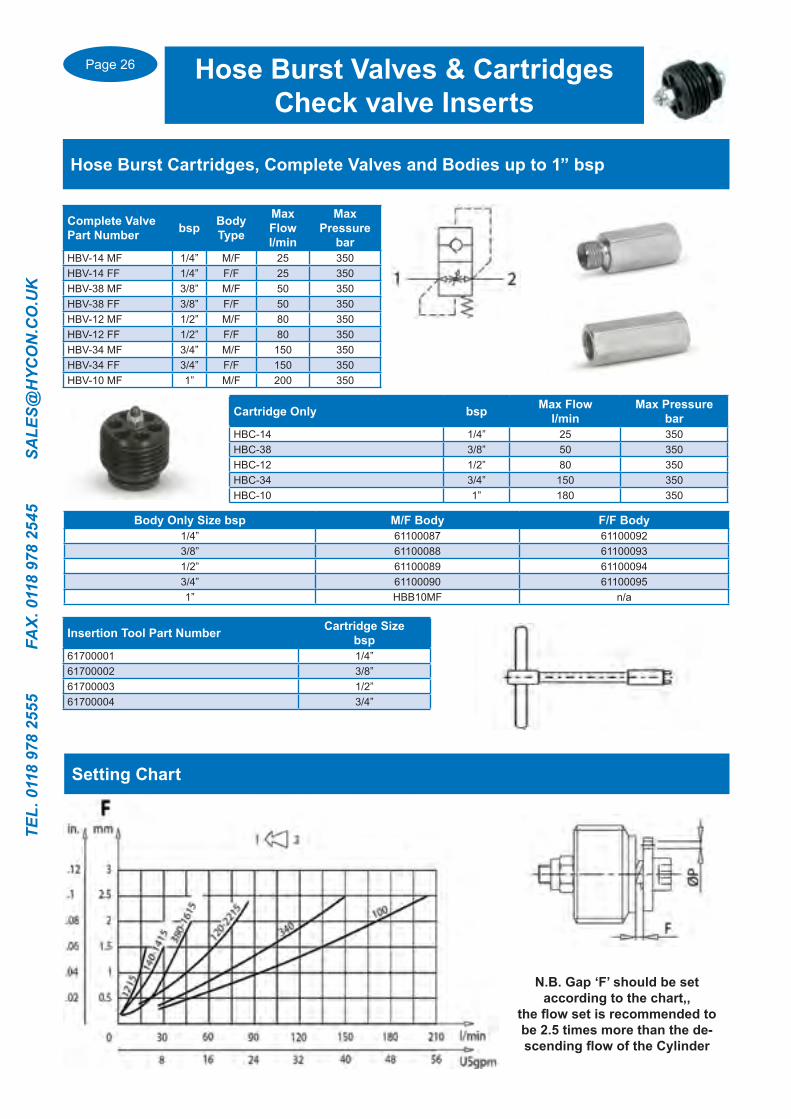
Complete Valve Part Number bsp Body
Type
Max Flowl/min
Max Pressure
barHBV-14 MF 1/4” M/F 25 350HBV-14 FF 1/4” F/F 25 350HBV-38 MF 3/8” M/F 50 350HBV-38 FF 3/8” F/F 50 350HBV-12 MF 1/2” M/F 80 350HBV-12 FF 1/2” F/F 80 350HBV-34 MF 3/4” M/F 150 350HBV-34 FF 3/4” F/F 150 350HBV-10 MF 1” M/F 200 350
Cartridge Only bsp Max Flowl/min
Max Pressurebar
HBC-14 1/4” 25 350HBC-38 3/8” 50 350HBC-12 1/2” 80 350HBC-34 3/4” 150 350HBC-10 1” 180 350
Hose Burst Cartridges, Complete Valves and Bodies up to 1” bsp
Hose Burst Valves & CartridgesCheck valve Inserts
Body Only Size bsp M/F Body F/F Body1/4” 61100087 611000923/8” 61100088 611000931/2” 61100089 611000943/4” 61100090 611000951” HBB10MF n/a
Insertion Tool Part Number Cartridge Sizebsp
61700001 1/4”61700002 3/8”61700003 1/2”61700004 3/4”
N.B. Gap ‘F’ should be set according to the chart,,
the flow set is recommended to be 2.5 times more than the de-scending flow of the Cylinder
Setting Chart

Page 27
TEL. 0118 978 2555 FAX. 0118 978 2545 SA
LES@H
YCO
N.C
O.U
K
Single Pilot Operated Check Valves
Single Pilot Operated Check valves Type VBPSE C/RUBwith Manual shut off
Part Number bsp
LeverSide
L or R
Max Flowl/min
Max Pressure
bar
Pilot Ratio
VBPSE 1/4” L C/RUB 1/4” L 20 350 1:5.5VBPSE 1/4” R C/RUB 1/4” R 20 350 1:5.5VBPSE 3/8” L C/RUB 3/8” L 30 350 1:5.5VBPSE 3/8” R C/RUB 3/8” R 30 350 1:5.5VBPSE 1/2” L C/RUB 1/2” L 50 350 1:5VBPSE 1/2” R C/RUB 1/2” R 50 350 1:5
Single Check valves, Inline, internal Pilot Type VBPSE A
Part Number bsp
Max Flowl/min
Max Pressure
bar
Pilot Ratio
VBPSE 1/4” A 1/4” 20 350 1:5.5VBPSE 3/8” A 3/8” 30 350 1:5.5VBPSE 1/2” A 1/2” 55 350 1:4.5
Part Number bsp Max Flow
l/minMax Pressure
barPilot Ratio
VRPE 140 1/4” 25 350 1:3.6VRPE 380 3/8” 40 350 1:3.2VRPE 120 1/2” 60 350 1:2.8VRPE 340 3/4” 100 300 1:3.2VRPE 100 1” 150 300 1:6.2
Single Check valves, external Pilot Type VRPE
Part Number bspMax Flow l/min
Max Pressure
bar
Pilot Ratio
VBPSE 1/4” L4 VIE 1/4” 20 350 1:5.5VBPSE 3/8” L4 VIE 3/8” 35 350 1:5.5VBPSE 3/8” 4 VIE 3/8” 45 350 1:5VBPSE 1/2” L4 VIE 1/2” 50 350 1:5.5VBPSE 1/2” 4 VIE 1/2” 70 350 1:5VBPSE 3/4” 4 VIE 3/4” 100 350 1:4
Single Check valves Type VBPSE L
Single Check valves, High Pilot ratio, internal Pilot Type VBL/3
Part Number bsp
Max Flowl/min
Max Pressure
bar
Pilot Ratio
VBL/3 SE 1/4” 1/4” 20 350 1:8VBL/3 SE 3/8” 3/8” 40 350 1:8VBL/3 SE 1/2” 1/2” 70 350 1:7

Page 28
TEL.
011
8 97
8 25
55
FA
X. 0
118
978
2545
S
ALE
S@H
YCO
N.C
O.U
K
Dual Pilot Operated Check Valves
Dual Pilot Operated Check valves, Inline, internal Pilot VBPDE A
Part Number bsp
Max Flowl/min
Max Pressure
bar
Pilot Ratio
VBPDE 1/4” A 1/4” 20 350 1:5.5VBPDE 3/8” A 3/8” 30 350 1:5.5VBPDE 1/2” A 1/2” 55 350 1:4.5VBPDE 3/4” A 3/4” 100 350 1.3.7
Dual Pilot Operated Check valves, for Tube mounting VBPDE CC/CEXC
Part Number bsp
Tube ODmm
Max Flowl/min
Max Pressure
bar
Pilot Ratio
VBPDE 1/4” L2 CEXC-10L 1/4” 10 20 350 1:5.5VBPDE 1/4” L2 CEXC 1/4” 12 20 350 1:5.5VBPDE 3/8” L2 CC 3/8” 12 35 350 1:5.5VBPDE 1/2” L2 CC 1/2” 15 50 350 1.5
Dual Pilot operated Check valves VBPDE (L)
Part Number bsp
Max Flowl/min
Max Pressure
bar
Pilot Ratio
VBPDE 1/4” L 1/4” 20 350 1:5.5VBPDE 3/8” L 3/8” 35 350 1:5.5VBPDE 3/8” 3/8” 45 350 1:5VBPDE 1/2” L 1/2” 50 350 1:5VBPDE 1/2” 1/2” 70 350 1:4VBPDE 3/4” 3/4” 100 300 1:4
Dual Pilot Operated Check valves with Manual shut off VBPDE C/RUB
Part Number bsp
LeverSide
L or R
Max Flowl/min
Max Pressure
bar
Pilot Ratio
VBPDE 1/4” L C/RUB 1/4” L 20 350 1:5.5VBPDE 1/4” R C/RUB 1/4” R 20 350 1:5.5VBPDE 3/8” L C/RUB 3/8” L 30 350 1:5.5VBPDE 3/8” R C/RUB 3/8” R 30 350 1:5.5VBPDE 1/2” L C/RUB 1/2” L 50 350 1:5VBPDE 1/2” R C/RUB 1/2” R 50 350 1:5

Page 29
TEL. 0118 978 2555 FAX. 0118 978 2545 SA
LES@H
YCO
N.C
O.U
K
Pilot Operated Check Valve Tube Mounting Kits & Fittings
Complete Kit Part Number
Thread bsp
Min Length
mm
Max Total Length
mm
Tube Size mm
Max Flow l/min
Max Pressure
barList of Components
HRDP 1/4” 1/4” 236 703 12 20 350 1x VBPDE 1/4 L2 CEXC 1x R1200 1x R1243500 2x R1350 4x 1/4” Bonded Seal
HRDP 3/8” 3/8” 260 786 12 35 350 1x VBPDE 3/8 L2CC 1x R1210 1x R1273500 2x R1360 4x 3/8” Bonded Seal
HRDP 1/2” 1/2” 284 600 15 50 350 1x VBPDE 1/2 L2CC 2x R1260 2x R1370 4x 1/2” Bonded Seal
A Complete kit that includes the Pilot Operated Check valve, hydraulic tubing with banjo fittings, banjo bolts and seals to enable you to enable you to fit a
Hydraulic Pilot operated check valve directly to a cylinder
Banjo Tube Banjo Size bsp
Tube diamm
Length of tubefrom centre line of Banjo
mmR1150 1/4” 12 38R1200 1/4” 12 112R1240 1/4” 12 205R1243500 1/4” 12 505R1160 3/8” 12 40R1210 3/8” 12 106R1250 3/8” 12 199R1271300 3/8” 12 300R1272400 3/8” 12 400R1273500 3/8” 12 500R1170 1/2” 15 44R1220 1/2” 15 109R1260 1/2” 15 202
Banjo Bolt Banjo Size bsp
Tube diamm
R1350 1/4” 12R1360 3/8” 12R1370 1/2” 15
Nipple with Nut & Olive Thread Size bsp
Nut and OliveSize
R1120 1/4” 12LR1110 3/8” 12LR1130 1/2” 12LR1140 1/2” 15L
Banjo with Nut & Olive Thread Size bsp
Nut and OliveSize
R1280 1/4” 12LR1290 3/8” 12LR1300 1/2” 15L
Page 30
TEL.
011
8 97
8 25
55
FA
X. 0
118
978
2545
S
ALE
S@H
YCO
N.C
O.U
K
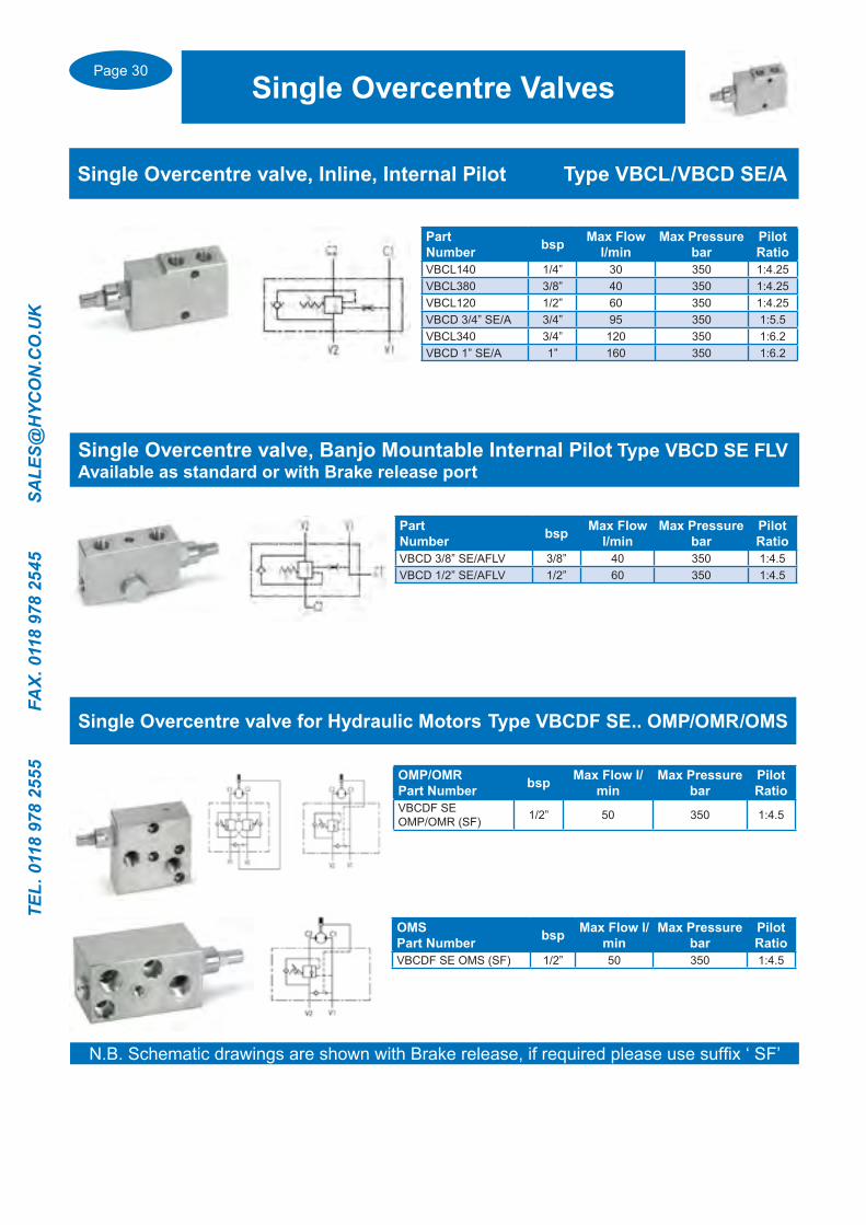
Single Overcentre Valves
N.B. Schematic drawings are shown with Brake release, if required please use suffix ‘ SF’
Single Overcentre valve, Inline, Internal Pilot Type VBCL/VBCD SE/A
Part Number bsp Max Flow
l/minMax Pressure
barPilot Ratio
VBCL140 1/4” 30 350 1:4.25VBCL380 3/8” 40 350 1:4.25VBCL120 1/2” 60 350 1:4.25VBCD 3/4” SE/A 3/4” 95 350 1:5.5VBCL340 3/4” 120 350 1:6.2VBCD 1” SE/A 1” 160 350 1:6.2
Part Number bsp Max Flow
l/minMax Pressure
barPilot Ratio
VBCD 3/8” SE/AFLV 3/8” 40 350 1:4.5VBCD 1/2” SE/AFLV 1/2” 60 350 1:4.5
Single Overcentre valve, Banjo Mountable Internal Pilot Type VBCD SE FLVAvailable as standard or with Brake release port
OMP/OMRPart Number bsp Max Flow l/
minMax Pressure
barPilot Ratio
VBCDF SE OMP/OMR (SF) 1/2” 50 350 1:4.5
Single Overcentre valve for Hydraulic Motors Type VBCDF SE.. OMP/OMR/OMS
OMSPart Number bsp Max Flow l/
minMax Pressure
barPilot Ratio
VBCDF SE OMS (SF) 1/2” 50 350 1:4.5
Page 31
TEL. 0118 978 2555 FAX. 0118 978 2545 SA
LES@H
YCO
N.C
O.U
K
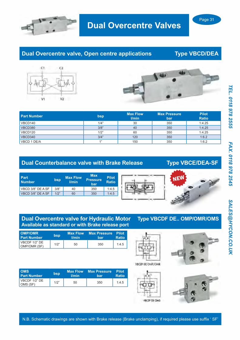
Dual Overcentre Valves
N.B. Schematic drawings are shown with Brake release (Brake unclamping), if required please use suffix ‘ SF’
Part Number bsp Max Flow l/min
Max Pressurebar
Pilot Ratio
VBCD140 1/4” 30 350 1:4.25VBCD380 3/8” 40 350 1:4.25VBCD120 1/2” 60 350 1:4.25VBCD340 3/4” 120 350 1:6.2VBCD 1 DE/A 1” 150 350 1:6.2
Dual Overcentre valve, Open centre applications Type VBCD/DEA
Dual Counterbalance valve with Brake Release Type VBCE/DEA-SF
Part Number bsp Max Flow
l/min
Max Pressure
bar
Pilot Ratio
VBCD 3/8” DE A SF 3/8” 40 350 1:4.5VBCD 3/8” DE A SF 1/2” 60 350 1:4.5
OMP/OMRPart Number bsp Max Flow
l/minMax Pressure
barPilot Ratio
VBCDF 1/2” DEOMP/OMR (SF) 1/2” 50 350 1:4.5
Dual Overcentre valve for Hydraulic Motor Type VBCDF DE.. OMP/OMR/OMSAvailable as standard or with Brake release port
OMSPart Number bsp Max Flow
l/minMax Pressure
barPilot Ratio
VBCDF 1/2” DEOMS (SF) 1/2” 50 350 1:4.5

Page 32
TEL.
011
8 97
8 25
55
FA
X. 0
118
978
2545
S
ALE
S@H
YCO
N.C
O.U
K
Pressure Switches Type TS-4
Part Number Adjustment Method bsp Adjustment range bar
Max Pressurebar
TS-4-70-N-A Allen Key 1/4” 4-70 400TS-4-70-N-B Rotary Knob 1/4” 4-70 400TS-4-70-N-C Lockable Rotary Knob 1/4” 4-70 400TS-4-160-N-A Allen Key 1/4” 17-160 400TS-4-160-N-B Rotary Knob 1/4” 17-160 400TS-4-160-N-C Lockable Rotary Knob 1/4” 17-160 400TS-4-250-N-A Allen Key 1/4” 20-250 400TS-4-250-N-B Rotary Knob 1/4” 20-250 400TS-4-250-N-C Lockable Rotary Knob 1/4” 20-250 400TS-4-400-N-A Allen Key 1/4” 25-400 400TS-4-400-N-B Rotary Knob 1/4” 25-400 400TS-4-400-N-C Lockable Rotary Knob 1/4” 25-400 400
Pressure Switches
Pressure Swivel Couplings.. Rotational Type GGMounted between the end of a flexible hose and a fixed component to prevent damage due to hose twist and Rotation. They are not suitable for high speed rotation.
Straight Coupling
Threadbsp
Max Flow l/min
Max Pressure of Rotation bar
Max Pressurebar
Max Speed ofRotation rpm
GGL 1/4” 1/4” 25 200 400 212GGL 3/8” 3/8” 35 200 400 173GGL 1/2” 1/2” 60 150 300 160GGL 3/4” 3/4” 100 150 300 120GGL 1” 1” 180 100 300 100GGL 1 1/4” 1 1/4” 270 100 300 86GGL 1 1/2” 1 1/2” 350 80 300 73GGL 2” 2” 700 50 250 35
90 Degree Coupling
Threadbsp
Max Flow l/min
Max Pressure of Rotation bar
Max Pressurebar
Max Speed ofRotation rpm
GG90 1/4” 1/4” 25 200 400 212GG90 3/8” 3/8” 35 200 400 173GG90 1/2” 1/2” 60 150 300 160GG90 3/4” 3/4” 100 150 300 120GG90 1” 1” 180 100 300 100GG90 1 1/4” 1 1/4” 270 100 300 86GG90 1 1/2” 1 1/2” 350 80 300 73GG90 2” 2” 700 50 250 35
Cetop Manifolds machined for pressure switches see pages...... 72/73
Page 33
TEL. 0118 978 2555 FAX. 0118 978 2545 SA
LES@H
YCO
N.C
O.U
K
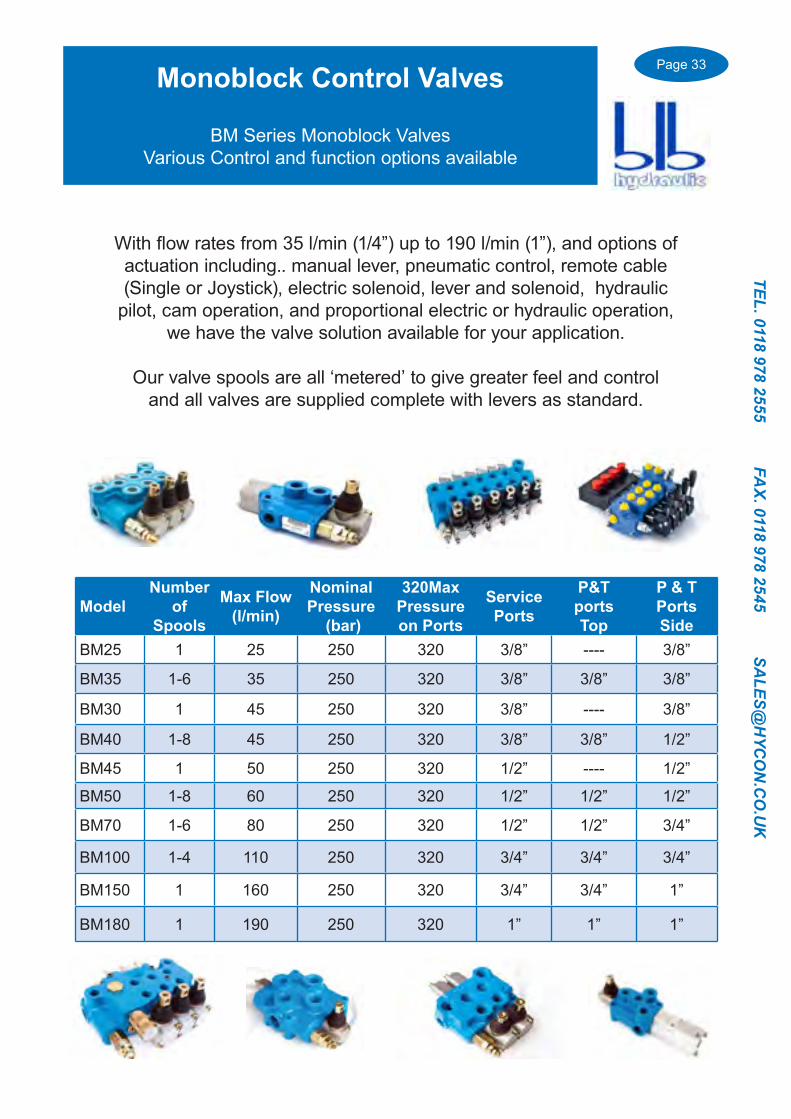
With flow rates from 35 l/min (1/4”) up to 190 l/min (1”), and options of actuation including.. manual lever, pneumatic control, remote cable (Single or Joystick), electric solenoid, lever and solenoid, hydraulic
pilot, cam operation, and proportional electric or hydraulic operation, we have the valve solution available for your application.
Our valve spools are all ‘metered’ to give greater feel and control and all valves are supplied complete with levers as standard.
ModelNumber
of Spools
Max Flow (l/min)
Nominal Pressure
(bar)
320Max Pressureon Ports
Service Ports
P&T portsTop
P & TPortsSide
BM25 1 25 250 320 3/8” ---- 3/8”
BM35 1-6 35 250 320 3/8” 3/8” 3/8”
BM30 1 45 250 320 3/8” ---- 3/8”
BM40 1-8 45 250 320 3/8” 3/8” 1/2”
BM45 1 50 250 320 1/2” ---- 1/2”
BM50 1-8 60 250 320 1/2” 1/2” 1/2”
BM70 1-6 80 250 320 1/2” 1/2” 3/4”
BM100 1-4 110 250 320 3/4” 3/4” 3/4”
BM150 1 160 250 320 3/4” 3/4” 1”
BM180 1 190 250 320 1” 1” 1”
Monoblock Control Valves
BM Series Monoblock Valves Various Control and function options available
Page 34
TEL.
011
8 97
8 25
55
FA
X. 0
118
978
2545
S
ALE
S@H
YCO
N.C
O.U
K
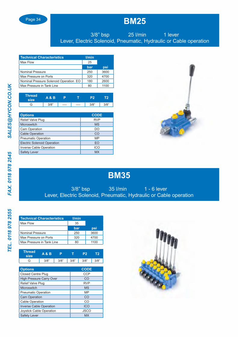
BM253/8” bsp 25 l/min 1 lever
Lever, Electric Solenoid, Pneumatic, Hydraulic or Cable operation
Technical Characteristics l/minMax Flow 25
bar psiNominal Pressure 250 3600Max Pressure on Ports 320 4700Nominal Pressure Solenoid Operation EO 180 2600Max Pressure in Tank Line 80 1100
Thread size A & B P T P2 T2
G 3/8” —- —- 3/8” 3/8”
Options CODERelief Valve Plug RVPMicroswitch MSCam Operation DOCable Operation COPneumatic Operation MPElectric Solenoid Operation EOInverse Cable Operation ICOSafety Lever MX
BM353/8” bsp 35 l/min 1 - 6 lever
Lever, Electric Solenoid, Pneumatic, Hydraulic or Cable operation
Technical Characteristics l/minMax Flow 35
bar psiNominal Pressure 250 3600Max Pressure on Ports 320 4700Max Pressure in Tank Line 80 1100
Options CODEClosed Centre Plug CCPHigh Pressure Carry Over CORelief Valve Plug RVPMicroswitch MSPneumatic Operation MPCam Operation COCable Operation COInverse Cable Operation ICOJoystick Cable Operation JSCOSafety Lever MX
Thread size A & B P T P2 T2
G 3/8” 3/8” 3/8” 3/8” 3/8”
Page 35
TEL. 0118 978 2555 FAX. 0118 978 2545 SA
LES@H
YCO
N.C
O.U
K
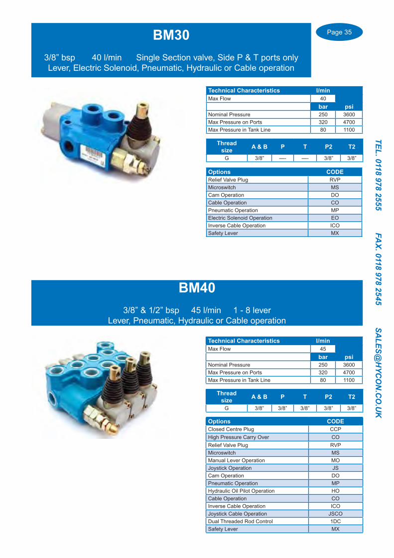
BM303/8” bsp 40 l/min Single Section valve, Side P & T ports onlyLever, Electric Solenoid, Pneumatic, Hydraulic or Cable operation
Thread size A & B P T P2 T2
G 3/8” —- —- 3/8” 3/8”
Options CODERelief Valve Plug RVPMicroswitch MSCam Operation DOCable Operation COPneumatic Operation MPElectric Solenoid Operation EOInverse Cable Operation ICOSafety Lever MX
Technical Characteristics l/minMax Flow 40
bar psiNominal Pressure 250 3600Max Pressure on Ports 320 4700Max Pressure in Tank Line 80 1100
BM403/8” & 1/2” bsp 45 l/min 1 - 8 lever
Lever, Pneumatic, Hydraulic or Cable operation
Options CODEClosed Centre Plug CCPHigh Pressure Carry Over CORelief Valve Plug RVPMicroswitch MSManual Lever Operation MOJoystick Operation JSCam Operation DOPneumatic Operation MPHydraulic Oil Pilot Operation HOCable Operation COInverse Cable Operation ICOJoystick Cable Operation JSCODual Threaded Rod Control 1DCSafety Lever MX
Technical Characteristics l/minMax Flow 45
bar psiNominal Pressure 250 3600Max Pressure on Ports 320 4700Max Pressure in Tank Line 80 1100
Thread size A & B P T P2 T2
G 3/8” 3/8” 3/8” 3/8” 3/8”
Page 36
TEL.
011
8 97
8 25
55
FA
X. 0
118
978
2545
S
ALE
S@H
YCO
N.C
O.U
K
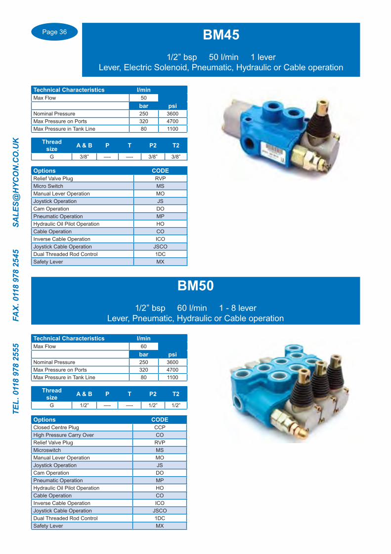
BM451/2” bsp 50 l/min 1 lever
Lever, Electric Solenoid, Pneumatic, Hydraulic or Cable operation
Technical Characteristics l/minMax Flow 50
bar psiNominal Pressure 250 3600Max Pressure on Ports 320 4700Max Pressure in Tank Line 80 1100
Options CODERelief Valve Plug RVPMicro Switch MSManual Lever Operation MOJoystick Operation JSCam Operation DOPneumatic Operation MPHydraulic Oil Pilot Operation HOCable Operation COInverse Cable Operation ICOJoystick Cable Operation JSCODual Threaded Rod Control 1DCSafety Lever MX
Thread size A & B P T P2 T2
G 3/8” —- —- 3/8” 3/8”
BM501/2” bsp 60 l/min 1 - 8 lever
Lever, Pneumatic, Hydraulic or Cable operation
Technical Characteristics l/minMax Flow 60
bar psiNominal Pressure 250 3600Max Pressure on Ports 320 4700Max Pressure in Tank Line 80 1100
Thread size A & B P T P2 T2
G 1/2” —- —- 1/2” 1/2”
Options CODEClosed Centre Plug CCPHigh Pressure Carry Over CORelief Valve Plug RVPMicroswitch MSManual Lever Operation MOJoystick Operation JSCam Operation DOPneumatic Operation MPHydraulic Oil Pilot Operation HOCable Operation COInverse Cable Operation ICOJoystick Cable Operation JSCODual Threaded Rod Control 1DCSafety Lever MX

Page 37
TEL. 0118 978 2555 FAX. 0118 978 2545 SA
LES@H
YCO
N.C
O.U
K
Options CODEClosed Centre Plug CCPHigh Pressure Carry Over CORelief Valve Plug RVPMicro Switch MSManual Lever Operation MOJoystick Operation JSCam Operation DOPneumatic Operation MPHydraulic Oil Pilot Operation HOCable Operation COInverse Cable Operation ICOJoystick Cable Operation JSCODual Threaded Rod Control 1DCSafety Lever MX
BM701/2” & 3/4” bsp 80 l/min 1 - 6 lever
Lever, Electric Solenoid, Pneumatic, Hydraulic or Cable operation
Technical Characteristics l/minMax Flow 80
bar psiNominal Pressure 250 3600Max Pressure on Ports 320 4700Max Pressure in Tank Line 80 1100
Thread size A & B P T P2 T2
G 1/2” 1/2” 1/2” 3/4” 3/4”
BM1003/4” bsp 110 l/min 1-4 lever
Lever, Pneumatic, Hydraulic or Cable operation
Technical Characteristics l/minMax Flow 110
bar psiNominal Pressure 250 3600Max Pressure on Ports 320 4700Max Pressure in Tank Line 80 1100
Thread size A & B P T P2 T2
G 3/4” 3/4” 1/2” 3/4” 3/4”
Options CODEClosed Centre Plug CCPHigh Pressure Carry Over CORelief Valve Plug RVPMicro Switch MSManual Lever Operation MOJoystick Operation JSCam Operation DOPneumatic Operation MPHydraulic Oil Pilot Operation HOCable Operation COInverse Cable Operation ICOJoystick Cable Operation JSCODual Threaded Rod Control 1DCSafety Lever MX

Page 38
TEL.
011
8 97
8 25
55
FA
X. 0
118
978
2545
S
ALE
S@H
YCO
N.C
O.U
K
BM1503/4” & 1” bsp 160 l/min Single lever valve
Option for integrated Pressure relief and anti cavitation valves
Technical Characteristics l/minMax Flow 160
bar psiNominal Pressure 250 3600Max Pressure on Ports 320 4700Max Pressure in Tank Line 80 1100
Thread size A & B P T P2 T2
G 3/4” 3/4” 3/4” 1” 1”
Options CODEClosed Centre Plug CCPHigh Pressure Carry Over CORelief Valve Plug RVPManual Lever Operation MOPneumatic Operation MPHydraulic Oil Pilot Operation HOCable Operation COInverse Cable Operation ICOService Port Pressure Relief Valves VLAnti-Cavitation valves VCService Port Relief & Anti Cavitation Valves VLC
BM1801” bsp 190 l/min Single lever valve
Option for integrated Pressure relief and anti cavitation valves
Technical Characteristics l/minMax Flow 190
bar psiNominal Pressure 250 3600Max Pressure on Ports 320 4700Max Pressure in Tank Line 80 1100
Thread size A & B P T P2 T2
G 1” 1” 1” 1” 1”
Options CODEClosed Centre Plug CCPHigh Pressure Carry Over CORelief Valve Plug RVPManual Lever Operation MOPneumatic Operation MPHydraulic Oil Pilot Operation HOCable Operation COInverse Cable Operation ICOService Port Pressure Relief Valves VLAnti-Cavitation valves VCService Port Relief & Anti Cavitation Valves VLC
Page 39
TEL. 0118 978 2555 FAX. 0118 978 2545 SA
LES@H
YCO
N.C
O.U
K
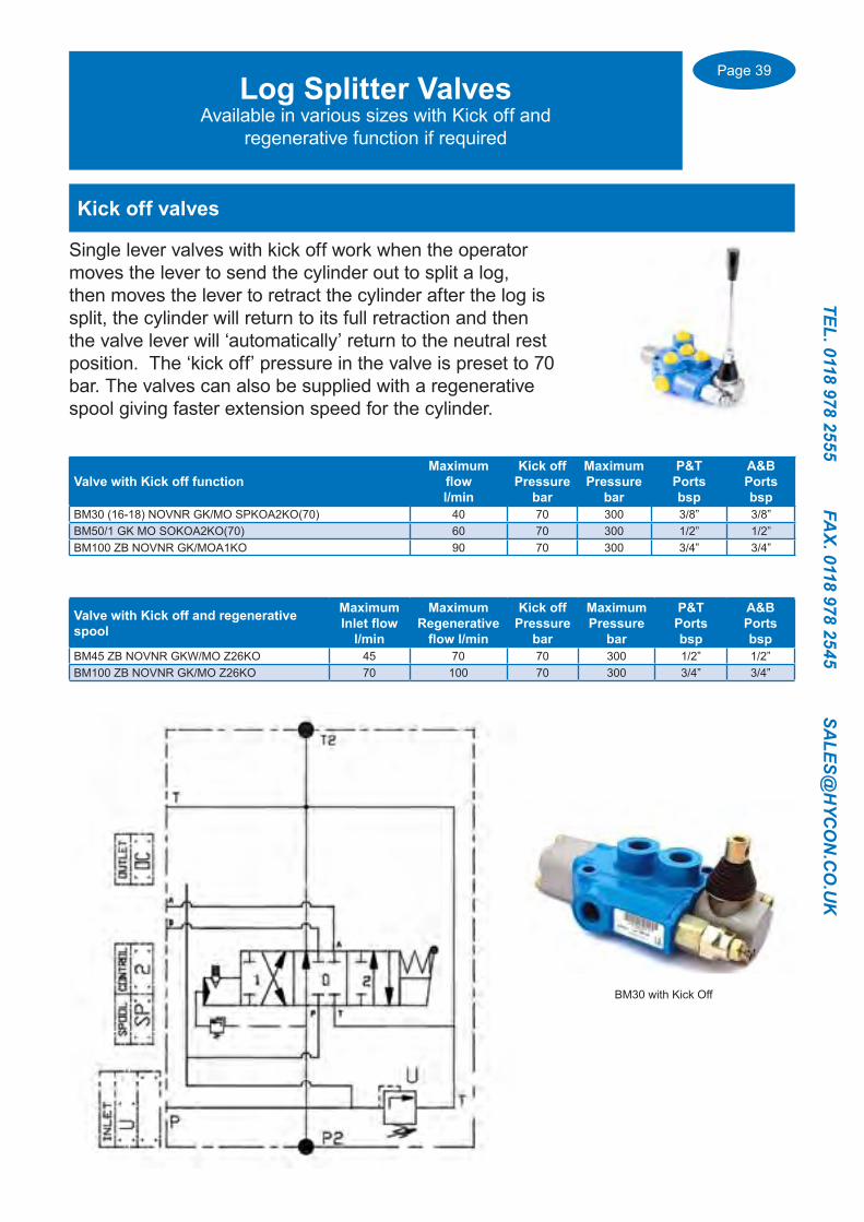
Log Splitter ValvesAvailable in various sizes with Kick off and
regenerative function if required
Kick off valves
Single lever valves with kick off work when the operator moves the lever to send the cylinder out to split a log, then moves the lever to retract the cylinder after the log is split, the cylinder will return to its full retraction and then the valve lever will ‘automatically’ return to the neutral rest position. The ‘kick off’ pressure in the valve is preset to 70 bar. The valves can also be supplied with a regenerative spool giving faster extension speed for the cylinder.
Valve with Kick off functionMaximum
flowl/min
Kick offPressure
bar
Maximum Pressure
bar
P&T Portsbsp
A&BPortsbsp
BM30 (16-18) NOVNR GK/MO SPKOA2KO(70) 40 70 300 3/8” 3/8”BM50/1 GK MO SOKOA2KO(70) 60 70 300 1/2” 1/2”BM100 ZB NOVNR GK/MOA1KO 90 70 300 3/4” 3/4”
Valve with Kick off and regenerative spool
Maximum Inlet flow
l/min
MaximumRegenerative
flow l/min
Kick offPressure
bar
Maximum Pressure
bar
P&T Portsbsp
A&BPortsbsp
BM45 ZB NOVNR GKW/MO Z26KO 45 70 70 300 1/2” 1/2”BM100 ZB NOVNR GK/MO Z26KO 70 100 70 300 3/4” 3/4”
BM30 with Kick Off

Page 40
TEL.
011
8 97
8 25
55
FA
X. 0
118
978
2545
S
ALE
S@H
YCO
N.C
O.U
K
Log Splitter ValvesAuto speed function
Auto-Speed valves
When the lever is first moved to extend the cylinder it moves at a much higher speed towards its full extension. When the cylinder nears full extension the Auto-speed valve automatically reduces the flow and thus decreases the speed of the cylinder.
This enables cylinder extension at high speed and low pressure then at the end of the stroke low speed with high pressure.
Valve with Auto-Speed unctionMaximum Inlet flow
l/min
MaximumRegenerative
flow l/min
Maximum Pressure
bar
P&T Portsbsp
A&BPortsbsp
BM70/1 GKB/MC S6/AUTOSPEED 60 90 300 3/4” 1/2”
Page 41
TEL. 0118 978 2555 FAX. 0118 978 2545 SA
LES@H
YCO
N.C
O.U
K
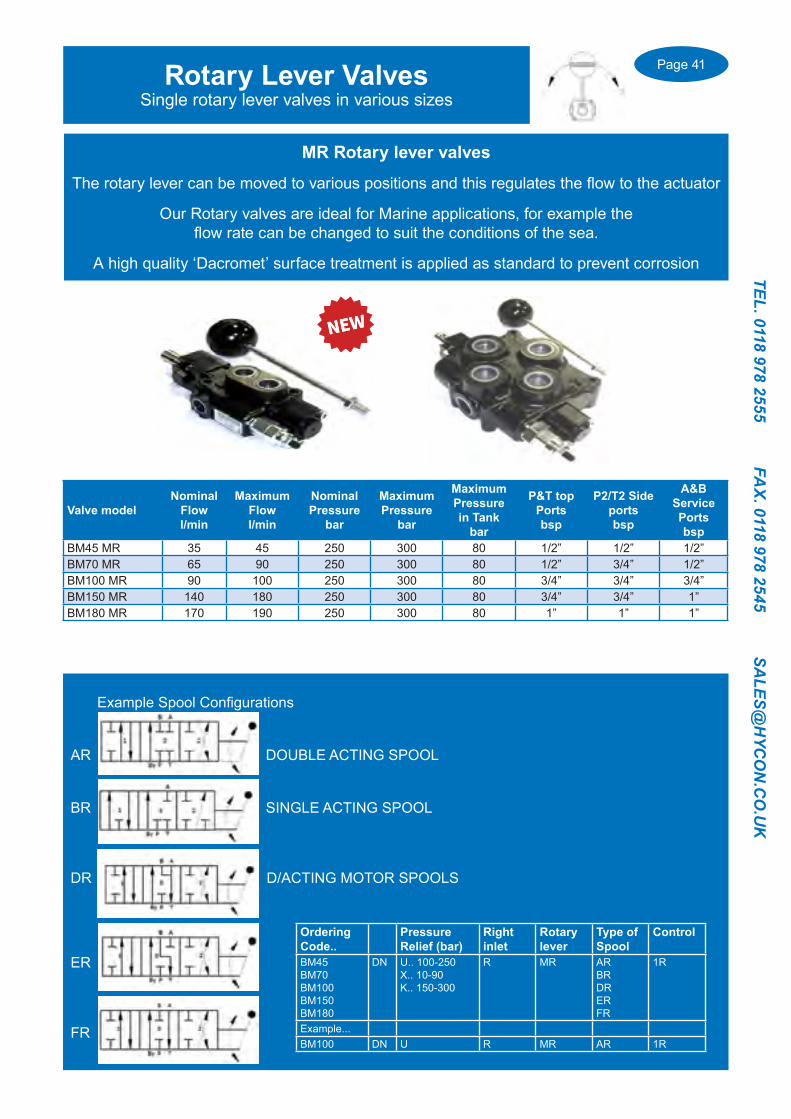
Rotary Lever ValvesSingle rotary lever valves in various sizes
MR Rotary lever valves
The rotary lever can be moved to various positions and this regulates the flow to the actuator
Our Rotary valves are ideal for Marine applications, for example the flow rate can be changed to suit the conditions of the sea.
A high quality ‘Dacromet’ surface treatment is applied as standard to prevent corrosion
Valve modelNominal
Flowl/min
Maximum Flowl/min
NominalPressure
bar
Maximum Pressure
bar
MaximumPressure in Tank
bar
P&T top Portsbsp
P2/T2 Side portsbsp
A&B ServicePortsbsp
BM45 MR 35 45 250 300 80 1/2” 1/2” 1/2”BM70 MR 65 90 250 300 80 1/2” 3/4” 1/2”BM100 MR 90 100 250 300 80 3/4” 3/4” 3/4”BM150 MR 140 180 250 300 80 3/4” 3/4” 1”BM180 MR 170 190 250 300 80 1” 1” 1”
BM100 MR
Example Spool Configurations
AR DOUBLE ACTING SPOOL
BR SINGLE ACTING SPOOL
DR D/ACTING MOTOR SPOOLS
ER
FR
Ordering Code..
PressureRelief (bar)
Rightinlet
Rotarylever
Type ofSpool
Control
BM45BM70BM100BM150BM180
DN U.. 100-250X.. 10-90K.. 150-300
R MR ARBRDRERFR
1R
Example...BM100 DN U R MR AR 1R

Page 42
TEL.
011
8 97
8 25
55
FA
X. 0
118
978
2545
S
ALE
S@H
YCO
N.C
O.U
K
ValveModel
NumberSpools
Max Flowl/min
Max Pressure
bar
Service PortsA & Bbsp
P & T PortsSide (Top)
BF201/1 1 TO 5 25 250 1/4” 3/8” (1/4”)BF401/1 1 TO 6 45 250 3/8” 1/2” (3/8”)BF701/1 1 TO 5 80 250 1/2” 3/4” (1/2”)BF901/1 1 120 250 3/4” 3/4” (3/4”)
The BF range of mono block valves derive from the BM series. They differ from them by having a built in priority adjustable and pressure compensated flow regulator (RFP) or two way Integrated pressure compensated flow regulator (RFS) in the Inlet of the valve.
With the RFP version the exceeding flow is recuperated into the system and allows the simultaneous use of the two spools, the first spool has the priority flow (PF) and the second spool the exceeding flow (EF). An RFS version is also available where the exceeding flow (EF) goes to the tank.
An important factor in the BF valves is that the flow regulator is only in function when a spool receiving the priority flow is actuated, on the contrary the oil goes to the tank without the flow regulator being actuated. Therefore without loss of flow or heating. The standard downstream spools get the exceeding flow when the priority spool is operated and the entire oil flow when it is not operated. One or more Priority spools are available in a valve.
Example 1.
One single BF401/1 valve with a high pressure carry over supplying a single BM40/1 valve.
The flow to the motor (A) is regulated by the priority valve (PF) by means of the adjustment knob. The exceeding flow (EF) is recuperated so that it can be supplied through the high pressure carry over to the downstream single lever valve. When the 1st valve is not in function the 2nd valve will have the full flow, and when the 1st valve ie Motor (A) is working the 2nd valve and cylinder (B) will work with the excess flow available.Example 2.
A two lever BF401/2 valve working a motor and cylinder.
The flow to the motor (A) is regulated by the priority valve (PF) by means of the adjustment knob. The exceeding flow (EF) is recuperated so that it can be used to work the cylinder (B) at the same.When the motor (A) is not in function, Cylinder (B) will have the full flow of the pump.
One advantage of this valve system is when the motor (A) is in function and the cylinder (B) is worked the motor will not drop in rotation speed..
For Spools and control options please see pages 49-52
Monoblock With Priority Adjustable Flow Control

Page 43
TEL. 0118 978 2555 FAX. 0118 978 2545 SA
LES@H
YCO
N.C
O.U
K
Monoblock With Priority Adjustable Flow Control
BF2011/4” bsp 25 l/min 1 - 5 Spool
Technical Characteristics l/minNominal Flow 17
Max Flow 25bar psi
Nominal Pressure 250 3600Max Pressure on Ports 320 4700
Max Pressure in Tank Line 80 1100
Thread size A & B P T P2 T2
G 1/4” 1/4” 3/8” 3/8” 3/8”
BF4013/8” bsp 45 l/min 1 - 6 Spool
Technical Characteristics l/minNominal Flow 35
Max Flow 45bar psi
Nominal Pressure 250 3600Max Pressure on Ports 320 4700
Max Pressure in Tank Line 80 1100
Thread size A & B P T P2 T2
G 3/8” 3/8” 3/8” 1/2” 1/2”

Page 44
TEL.
011
8 97
8 25
55
FA
X. 0
118
978
2545
S
ALE
S@H
YCO
N.C
O.U
K
Monoblock With Priority Adjustable Flow Control
BF7011/2” bsp 80 l/min 1 - 5 Spool
Technical Characteristics l/minNominal Flow 70
Max Flow 80bar psi
Nominal Pressure 250 3600Max Pressure on Ports 320 4700
Max Pressure in Tank Line 80 1100
Thread size A & B P T P2 T2
G 1/2” 1/2” 1/2” 3/4” 3/4”
BF9013/4” bsp 120 l/min Single Spool
Technical Characteristics l/minNominal Flow 90
Max Flow 120bar psi
Nominal Pressure 250 3600Max Pressure on Ports 320 4700
Max Pressure in Tank Line 80 1100
Thread size A & B P T P2 T2
G 3/4” 3/4” 3/4” 3/4” 3/4”

Page 45
TEL. 0118 978 2555 FAX. 0118 978 2545 SA
LES@H
YCO
N.C
O.U
K
Model BC35 BC40 BC60 BC150Max flow (l/min) 35 45 70 180Max flow Electric operation (l/min) 35 40 40 300Max pressure (bar) 250 300 300 ——-Max pressure.. Electric operation (bar) 220 200 250 ——-Max pressure in tank line ( bar) 40 40 40 40
Port sizes Service ports A & B (bsp) 3/8 3/8 1/2 3/4Side ports P & T (bsp) 3/8 1/2 1/2 1
Control optionsManual lever operation ✓ ✓ ✓ ✓
Manual joystick operation ✓ ✓
Electric solenoid operation ✓
Electric solenoid & manual lever ✓
Proportional solenoid operation ✓
Proportional hydraulic operation ✓
Pneumatic operation ✓ ✓ ✓ ✓
Hydraulic oil pilot operation ✓ ✓ ✓
Cable control ✓ ✓ ✓ ✓
Elements AvailableStandard element (S) ✓ ✓ ✓
Service port relief valves (VL) ✓ ✓ ✓
Anti Cavitation valves (VC) ✓ ✓ ✓
Flow control (RFP/RFS) ✓ ✓
Integrated flow control (CF) ✓ ✓
Integrated flow control with service port valves (CF VL/CF VC) ✓ ✓
Priority element (P) ✓ ✓ ✓
Recuperation element (R) ✓ ✓ ✓
4 position float spool ✓ ✓ ✓
4 position float spool with Integrated flow control ✓ ✓
Catalogue page number 55 58 61 55
Bankable Control Valves Type BC
Flow rates from 35 l/min (3/8” bsp) up to 180 l/min (1”bsp)Various models with options of Manual Lever, Electric Solenoid, Manual Lever and Dual Electric Solenoid, Pneumatic, Hydraulic Oil Pilot, and Cable control
Page 45
Page 46
TEL.
011
8 97
8 25
55
FA
X. 0
118
978
2545
S
ALE
S@H
YCO
N.C
O.U
K
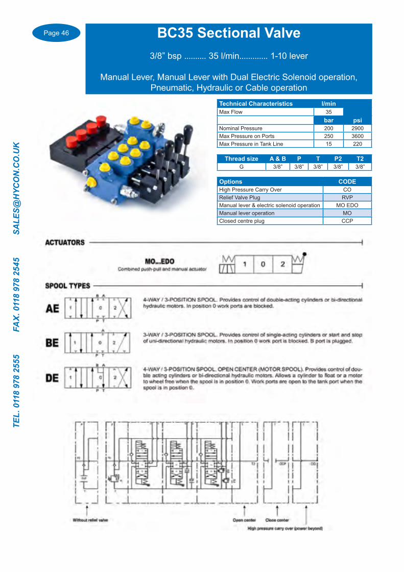
BC35 Sectional Valve3/8” bsp .......... 35 l/min............. 1-10 lever
Manual Lever, Manual Lever with Dual Electric Solenoid operation, Pneumatic, Hydraulic or Cable operation
Technical Characteristics l/minMax Flow 35
bar psiNominal Pressure 200 2900Max Pressure on Ports 250 3600Max Pressure in Tank Line 15 220
Thread size A & B P T P2 T2G 3/8” 3/8” 3/8” 3/8” 3/8”
Options CODEHigh Pressure Carry Over CORelief Valve Plug RVPManual lever & electric solenoid operation MO EDOManual lever operation MOClosed centre plug CCP

Page 47
TEL. 0118 978 2555 FAX. 0118 978 2545 SA
LES@H
YCO
N.C
O.U
K
Thread size A & B P T P2 T2
G 3/8” 1/2” 1/2” 1/2” 1/2”
Options CODEHigh Pressure Carry Over CORelief Valve Plug RVPClosed Centre Plug CCPMicroswitch MSManual Lever Operation MOJoystick Operation JSPneumatic Operation MPCable Operation COInverse Cable Operation ICOJoystick Cable Operation JSCO
BC40 Sectional Valve3/8” & 1/2” bsp 45 l/min 1 - 10 lever
Manual Lever, Pneumatic, Hydraulic or Cable operation
Technical Characteristics l/minMax Flow 45
bar psiNominal Pressure 250 3600Max Pressure on Ports 320 4700Max Pressure in Tank Line 40 550
BC60 Sectional Valve1/2” bsp 70 l/min 1 - 10 lever
Manual Lever, Pneumatic, Hydraulic or Cable operation
Technical Characteristics l/minMax Flow 70
bar psiNominal Pressure 250 3600Max Pressure on Ports 320 4700Max Pressure in Tank Line 40 550
Thread size A & B P T P2 T2
G 1/2” 1/2” 1/2” 1/2” 1/2”
Options CODEHigh Pressure Carry Over CORelief Valve Plug RVPClosed Centre Plug CCPMicroswitch MSManual Lever Operation MOJoystick Operation JSPneumatic Operation MPHydraulic Pilot Operation HOCable Operation COInverse Cable Operation ICOJoystick Cable Operation JSCO
Page 48
TEL.
011
8 97
8 25
55
FA
X. 0
118
978
2545
S
ALE
S@H
YCO
N.C
O.U
K
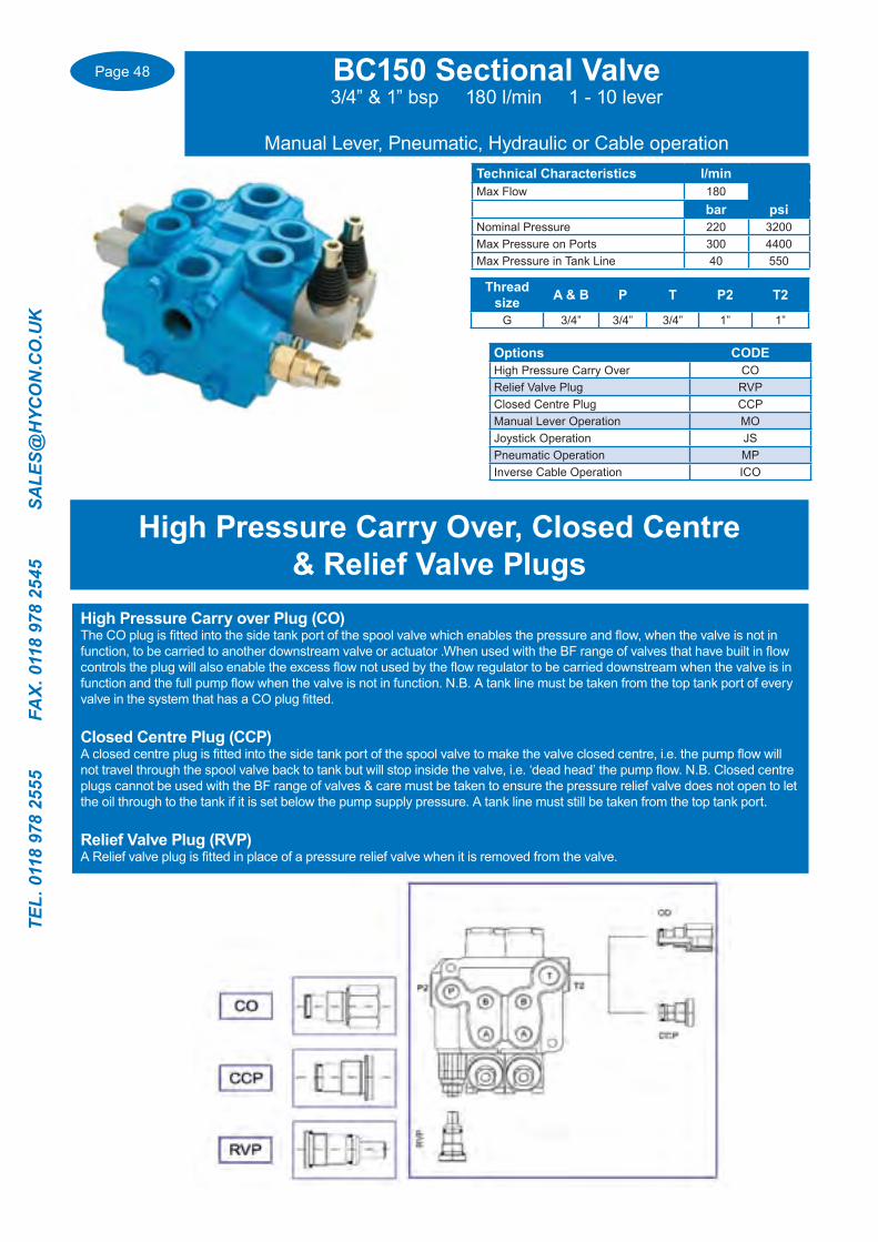
Technical Characteristics l/minMax Flow 180
bar psiNominal Pressure 220 3200Max Pressure on Ports 300 4400Max Pressure in Tank Line 40 550
BC150 Sectional Valve3/4” & 1” bsp 180 l/min 1 - 10 lever
Manual Lever, Pneumatic, Hydraulic or Cable operation
Thread size A & B P T P2 T2
G 3/4” 3/4” 3/4” 1” 1”
Options CODEHigh Pressure Carry Over CORelief Valve Plug RVPClosed Centre Plug CCPManual Lever Operation MOJoystick Operation JSPneumatic Operation MPInverse Cable Operation ICO
High Pressure Carry Over, Closed Centre & Relief Valve Plugs
High Pressure Carry over Plug (CO)The CO plug is fitted into the side tank port of the spool valve which enables the pressure and flow, when the valve is not in function, to be carried to another downstream valve or actuator .When used with the BF range of valves that have built in flow controls the plug will also enable the excess flow not used by the flow regulator to be carried downstream when the valve is in function and the full pump flow when the valve is not in function. N.B. A tank line must be taken from the top tank port of every valve in the system that has a CO plug fitted.
Closed Centre Plug (CCP)A closed centre plug is fitted into the side tank port of the spool valve to make the valve closed centre, i.e. the pump flow will not travel through the spool valve back to tank but will stop inside the valve, i.e. ‘dead head’ the pump flow. N.B. Closed centre plugs cannot be used with the BF range of valves & care must be taken to ensure the pressure relief valve does not open to let the oil through to the tank if it is set below the pump supply pressure. A tank line must still be taken from the top tank port.
Relief Valve Plug (RVP)A Relief valve plug is fitted in place of a pressure relief valve when it is removed from the valve.

Page 49
TEL. 0118 978 2555 FAX. 0118 978 2545 SA
LES@H
YCO
N.C
O.U
K
ActuatorOption Prefix
BF201BC35BM35
BM30BM40BM50BF401BC40
BM70BM100
BF701/901BC60
BM150BM180BC150
Manual Lever MO
✓
✓
✓
✓
✓
✓
✓
✓
✓
✓
✓
✓
✓
Inverse ManualLever DX
✓
✓
✓
✓
✓
✓
✓
✓
✓
✓
✓
✓
✓
Lever with Threaded
RodMC
✓
✓
✓
✓
✓
✓
✓
✓
✓
✓
✓
✓
✓
SafetyLever MX
✓
✓
✓
✓
✓
✓
✓
✓
✓
✓
✓
✓
✓
Lever with Stroke Limiter ML
✓
✓
✓
✓
✓
✓
✓
✓
✓
✓
✓
✓
✓
Cam Operation DO
✓
✓
✓
✓
✓
✓
✓
✓
✓
✓
✓
Dual Controlwith threaded rod end 1DC
✓
✓
✓
✓
✓
✓
✓
✓
✓
✓
✓
JoystickManipulator JS
✓
✓
✓
✓
✓
✓
✓
✓
✓
✓✓
Valve Actuator OptionsAll valves are supplied complete with levers and 3 position
spring return to neutral control unless otherwise stated

Page 50
TEL.
011
8 97
8 25
55
FA
X. 0
118
978
2545
S
ALE
S@H
YCO
N.C
O.U
K
Valve Actuator OptionsAll valves are supplied complete with levers and 3 position
spring return to neutral control unless otherwise stated
ActuatorOption Prefix
BF201BC35BM35
BM30BM40BM50BF401BC40
BM70BM100
BF701/901BC60
BM150BM180BC150
Cable Operation CO
✓
✓
✓
✓
✓
✓
✓
✓
✓
✓
✓
✓
✓
Inverse CableOperation CO DX
✓
✓
✓
✓
✓
✓
✓
✓
✓
✓
✓
✓
✓
Joystick CableOperation CO JS
✓
✓
✓
✓
✓
✓
✓
✓
✓
✓
✓
✓
PneumaticActuator 1P
✓
✓
✓
✓
✓
✓
✓
✓
✓
✓
HydraulicPilot Operation HO
✓
✓
✓
✓
✓
✓
✓
✓
MicroswitchOption MSW
✓
✓
✓
✓
✓
✓
✓
✓
✓
✓
MicroswitchOption MS
✓
✓
✓
✓
✓
✓
✓
✓
MicroswitchOption MSP
✓
✓
✓
✓

Page 51
TEL. 0118 978 2555 FAX. 0118 978 2545 SA
LES@H
YCO
N.C
O.U
K
Spool & Control optionsAll valves are supplied complete with levers and 3 position
spring return to neutral control unless otherwise stated
BM45
BC50
BM25
BC35 BC60BM45
BC50
BM25
BC35 BC60
BM25 BM45BC50
BC35 BC60
AVAILABLE CONFIGURATIONS
Page 52
TEL.
011
8 97
8 25
55
FA
X. 0
118
978
2545
S
ALE
S@H
YCO
N.C
O.U
K
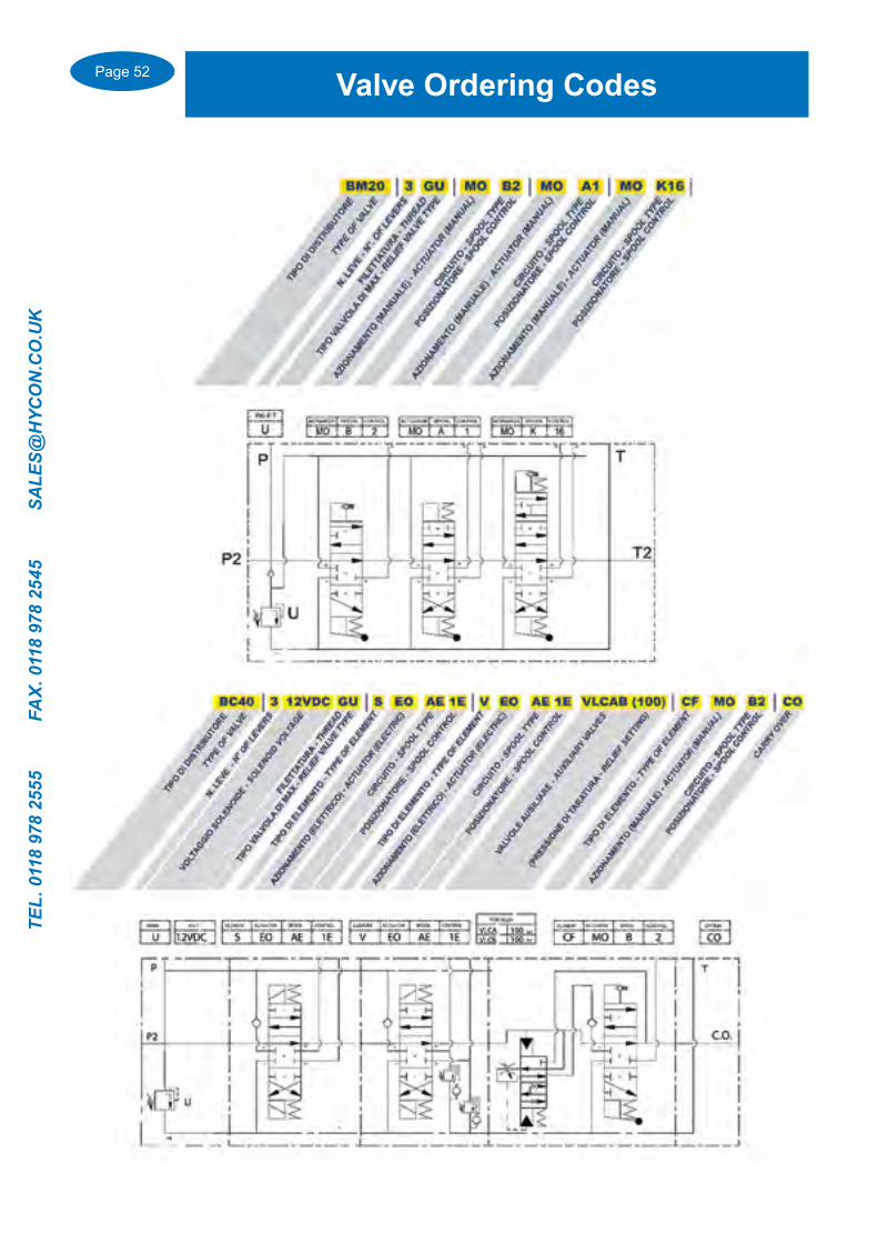
Valve Ordering Codes
Page 53
TEL. 0118 978 2555 FAX. 0118 978 2545 SA
LES@H
YCO
N.C
O.U
K
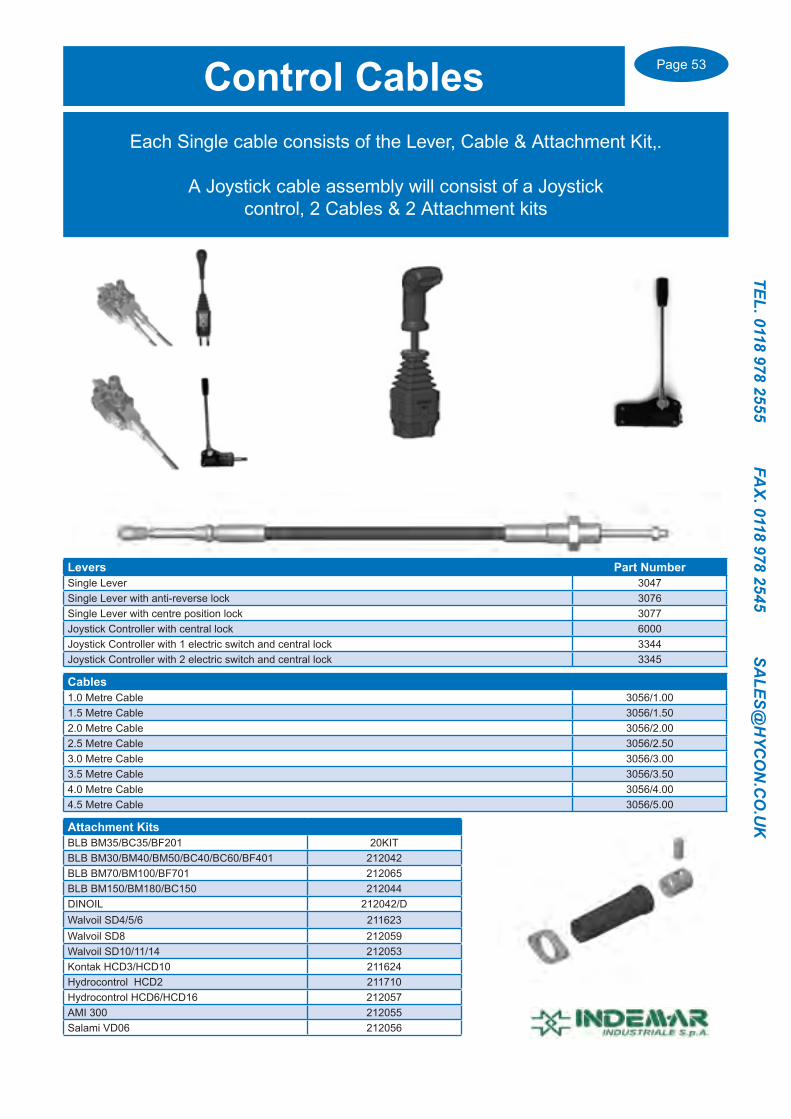
Levers Part NumberSingle Lever 3047Single Lever with anti-reverse lock 3076Single Lever with centre position lock 3077Joystick Controller with central lock 6000Joystick Controller with 1 electric switch and central lock 3344Joystick Controller with 2 electric switch and central lock 3345
Cables1.0 Metre Cable 3056/1.001.5 Metre Cable 3056/1.502.0 Metre Cable 3056/2.002.5 Metre Cable 3056/2.503.0 Metre Cable 3056/3.003.5 Metre Cable 3056/3.504.0 Metre Cable 3056/4.004.5 Metre Cable 3056/5.00
Attachment KitsBLB BM35/BC35/BF201 20KITBLB BM30/BM40/BM50/BC40/BC60/BF401 212042BLB BM70/BM100/BF701 212065BLB BM150/BM180/BC150 212044DINOIL 212042/DWalvoil SD4/5/6 211623Walvoil SD8 212059Walvoil SD10/11/14 212053Kontak HCD3/HCD10 211624Hydrocontrol HCD2 211710Hydrocontrol HCD6/HCD16 212057AMI 300 212055Salami VD06 212056
Each Single cable consists of the Lever, Cable & Attachment Kit,.
A Joystick cable assembly will consist of a Joystick control, 2 Cables & 2 Attachment kits
Control Cables

Page 54
TEL.
011
8 97
8 25
55
FA
X. 0
118
978
2545
S
ALE
S@H
YCO
N.C
O.U
K
ProportionalElectro-Hydraulic Valve & Control
System
Max Flow 70 l/min
Max Pressure 320 bar
1 to 10 Sections
KPF Proportional Valve

Page 55
TEL. 0118 978 2555 FAX. 0118 978 2545 SA
LES@H
YCO
N.C
O.U
K
KPF Proportional Electro-Hydraulic Valve
Page 56
TEL.
011
8 97
8 25
55
FA
X. 0
118
978
2545
S
ALE
S@H
YCO
N.C
O.U
K
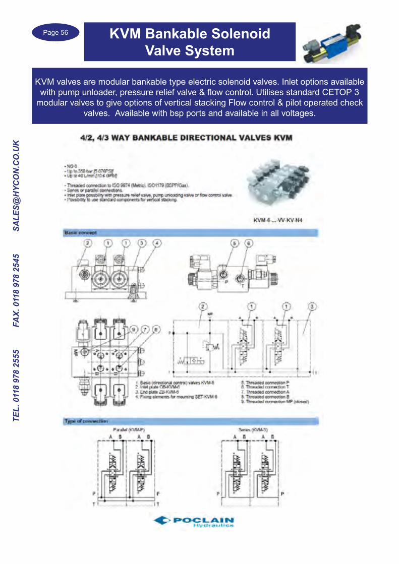
KVM valves are modular bankable type electric solenoid valves. Inlet options available with pump unloader, pressure relief valve & flow control. Utilises standard CETOP 3
modular valves to give options of vertical stacking Flow control & pilot operated check valves. Available with bsp ports and available in all voltages.
KVM Bankable Solenoid Valve System

Page 57
TEL. 0118 978 2555 FAX. 0118 978 2545 SA
LES@H
YCO
N.C
O.U
K
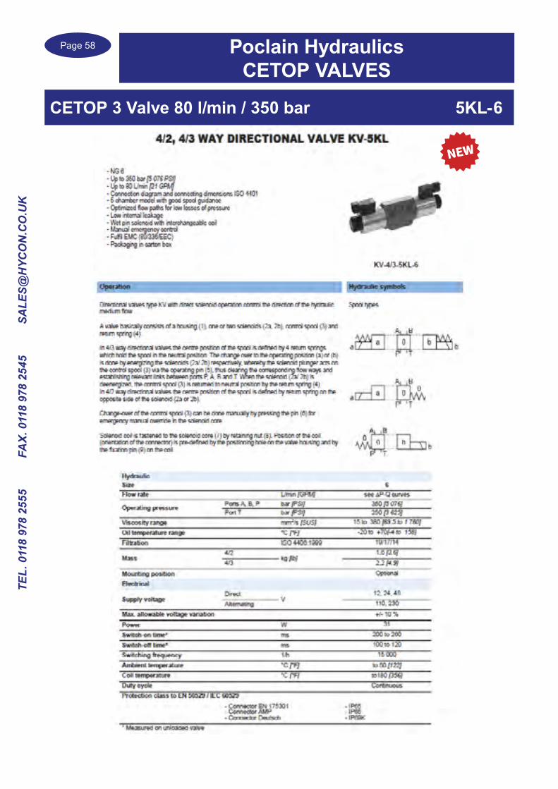
CETOP 3 Valve 40 l/min / 250 bar 3KO-6
Poclain HydraulicsCETOP VALVES
Page 58
TEL.
011
8 97
8 25
55
FA
X. 0
118
978
2545
S
ALE
S@H
YCO
N.C
O.U
K
Poclain HydraulicsCETOP VALVES
CETOP 3 Valve 80 l/min / 350 bar 5KL-6

Page 59
TEL. 0118 978 2555 FAX. 0118 978 2545 SA
LES@H
YCO
N.C
O.U
K
CETOP 3 Proportional Valve 30 l/min / 350 bar KVP
Poclain HydraulicsCETOP VALVES

Page 60
TEL.
011
8 97
8 25
55
FA
X. 0
118
978
2545
S
ALE
S@H
YCO
N.C
O.U
K
Poclain HydraulicsCETOP VALVES
CETOP 3 Valve with Manual Lever overide
CETOP Spool & supply voltage options

Page 61
TEL. 0118 978 2555 FAX. 0118 978 2545 SA
LES@H
YCO
N.C
O.U
K
CETOP 5 Valve 120 l/min / 350 bar 5KO-10
Poclain HydraulicsCETOP VALVES
Page 62
TEL.
011
8 97
8 25
55
FA
X. 0
118
978
2545
S
ALE
S@H
YCO
N.C
O.U
K
Poclain HydraulicsCETOP VALVES
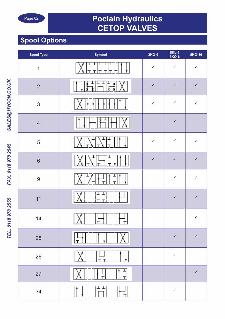
Spool Options
Spool Type Symbol 3KO-6 5KL-65KO-6 5KO-10
1 ✓ ✓ ✓
2 ✓ ✓ ✓
3 ✓ ✓ ✓
4 ✓
5 ✓ ✓ ✓
6 ✓ ✓ ✓
9 ✓ ✓
11 ✓ ✓
14 ✓
25 ✓ ✓
26 ✓
27 ✓
34 ✓
Page 63
TEL. 0118 978 2555 FAX. 0118 978 2545 SA
LES@H
YCO
N.C
O.U
K
Poclain HydraulicsCETOP VALVES
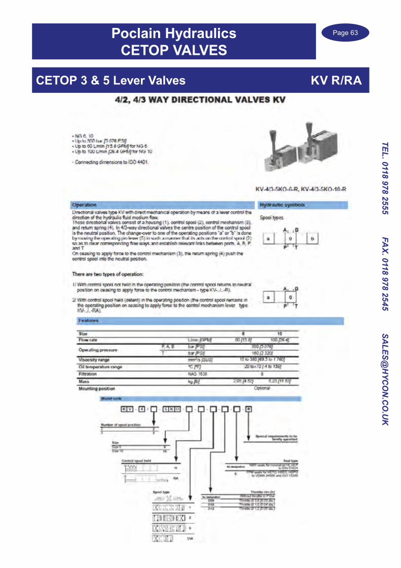
CETOP 3 & 5 Lever Valves KV R/RA
Page 64
TEL.
011
8 97
8 25
55
FA
X. 0
118
978
2545
S
ALE
S@H
YCO
N.C
O.U
K
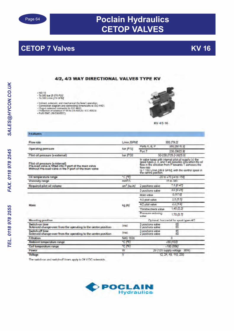
CETOP 7 Valves KV 16
Poclain HydraulicsCETOP VALVES

Page 65
TEL. 0118 978 2555 FAX. 0118 978 2545 SA
LES@H
YCO
N.C
O.U
K
CETOP 7 Valves KV 16
Poclain HydraulicsCETOP VALVES
Page 66
TEL.
011
8 97
8 25
55
FA
X. 0
118
978
2545
S
ALE
S@H
YCO
N.C
O.U
K
Cetop 3
Part number
Relief in port
Max flowl/min
Maximum Pressure
bar
Maximum Adjustment
pressure (up to) bar
VP-RT-6-EP-100 P 50 350 100VP-RT-6-EP-315 P 50 350 315VP-RT-6-EA-100 A 50 350 100VP-RT-6-EA-315 A 50 350 315VP-RT-6-EB-100 B 50 350 100VP-RT-6-EB-315 B 50 350 350VP-RT-6-D-100 A&B to T 50 350 100VP-RT-6-D-315 A&B to T 50 350 315
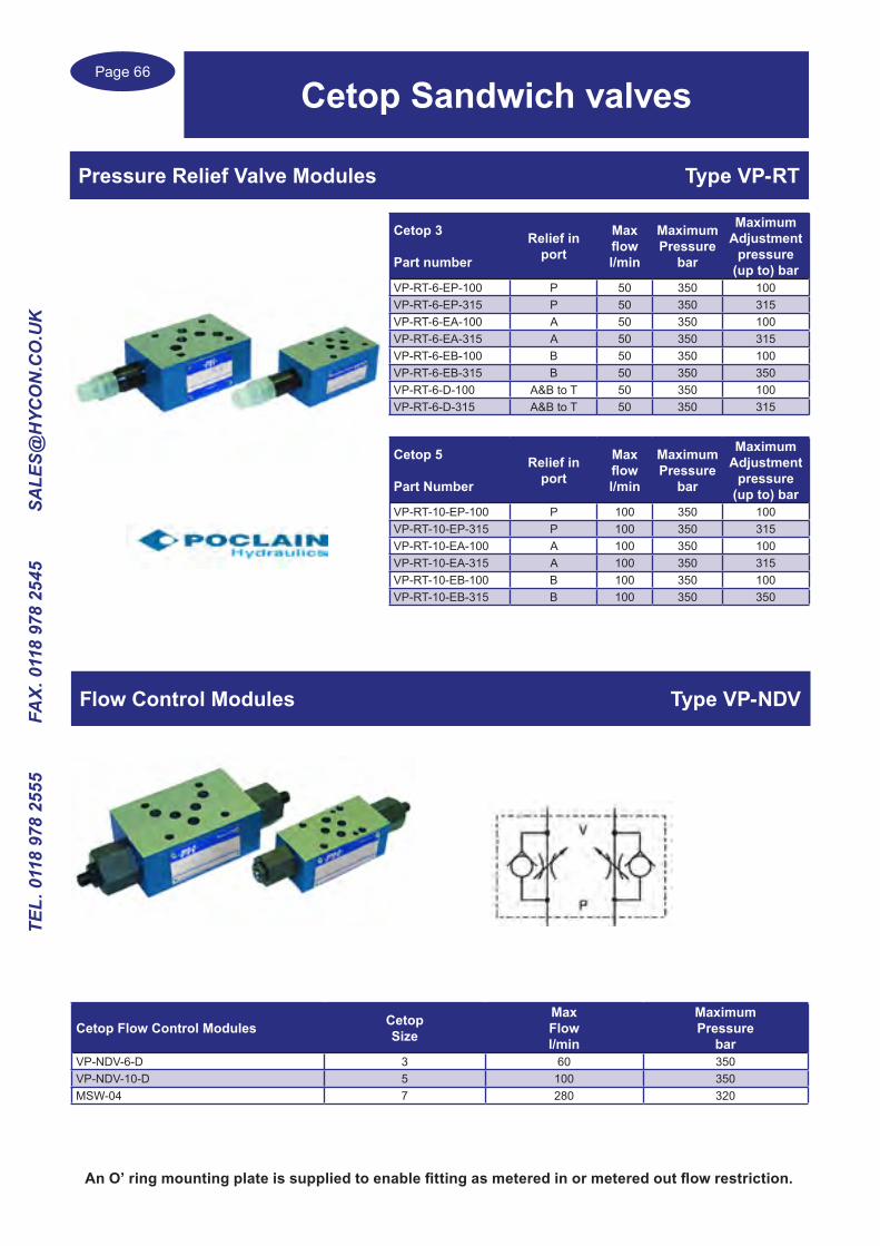
Pressure Relief Valve Modules Type VP-RT
Cetop Sandwich valves
An O’ ring mounting plate is supplied to enable fitting as metered in or metered out flow restriction.
Cetop 5
Part Number
Relief in port
Max flowl/min
Maximum Pressure
bar
Maximum Adjustment
pressure (up to) bar
VP-RT-10-EP-100 P 100 350 100VP-RT-10-EP-315 P 100 350 315VP-RT-10-EA-100 A 100 350 100VP-RT-10-EA-315 A 100 350 315VP-RT-10-EB-100 B 100 350 100VP-RT-10-EB-315 B 100 350 350
Flow Control Modules Type VP-NDV
Cetop Flow Control Modules CetopSize
Max Flowl/min
Maximum Pressure
barVP-NDV-6-D 3 60 350VP-NDV-10-D 5 100 350MSW-04 7 280 320

Page 67
TEL. 0118 978 2555 FAX. 0118 978 2545 SA
LES@H
YCO
N.C
O.U
K
CETOP 3 Part number
Check in port
MaximumFlow l/min
Maximum Pressure bar
VP-NV-6-PP P 50 350VP-NV-6-AP / AV A 50 350VP-RT-6-BP / BV B 50 350VP-RT-6-TV T 50 350
Check Valve modular plates Type VP-NV
CETOP 5Part number
Check in port
MaximumFlow l/min
Maximum Pressure bar
VP-NV-10-PP P 100 350VP-NV-10-AP / AV A 100 350VP-RT-10-BP / BV B 100 350VP-RT-10-TV T 100 350
Pilot Operated Check Modules Cetop Size Check on port
Maximum Flow l/min
Maximum Pressure
bar
Pilot ratio
VP-NOV-6-D 3 A&B 60 350 1:3.9VP-NOV-6-EA 3 A 60 350 1:3.9VP-NOV-6-EB 3 B 60 350 1:3.9
VP-NOV-10-D 5 A&B 100 350 1:3.6VP-NOV-10-EA 5 A 100 350 1:3.6VP-NOV-10-EB 5 B 100 350 1:3.6
MPW-04 7 A&B 300 350MPA-04 7 A 300 350MPB-04 7 B 300 350
Pilot Operated Check Modules VP-NOV / MPW
Cetop Sandwich valves

Page 68
TEL.
011
8 97
8 25
55
FA
X. 0
118
978
2545
S
ALE
S@H
YCO
N.C
O.U
K
Cetop Overcentre Valve Modules Type VBCD
Single Overcentre Modules Cetop size Acting on port
Maximum Flow l/min
Maximum Pressure bar
Pilot ratio
VBCD SE/A NG6 3 A 40 350 1:4.25VBCD SE/B NG6 3 B 40 350 1:4.25VBCD SE/A NG10 5 A 80 350 1:4.5VBCD SE/B NG10 5 B 80 350 1:4.5
Cetop Dual Overcentre Modules Cetop size Acting on port
Maximum Flow l/min
Maximum Pressure bar
Pilot ratio
VBCD DE NG6 3 A&B 40 350 1:4.5VBCD DE NG10 5 A&B 80 350 6.2:1
Cetop Sandwich Valve ModulesBlanking Plates
Cetop Blanking Plates Type MRF
Part Number Cetop size MaterialMRF-3 3 SteelMRF-5 5 SteelMRF-7 7 SteelMRF-8 8 Steel

Page 69
TEL. 0118 978 2555 FAX. 0118 978 2545 SA
LES@H
YCO
N.C
O.U
K
CETOP Subplates & ManifoldsCetop 3,5,7 & 8 sizes in aluminium, cast iron and steel in
various configerations
Single Subplates without Pressure Relief valve
Part Number
Cetop 3
Cetop size
Portsbsp Material Port
OrientationPort
Configeration
MaxFlowl/min
Max Pressure
bar
BSA 06 AL 3 1/4” Aluminium Side ported One port each side 45 300
BSA 06 APL 3 1/4” Aluminium Side & bottom P&T rear / A&B side 45 300
BSA 06 ALL 3 1/4” Aluminium Side P&T one sideA&B opposite side 45 300
BSG 06 AP 3 1/4” Steel Bottom All on bottom face 45 300BSA 06 BL 3 3/8” Aluminium Side ported one port each side 70 300MRSL3-3/8” 3 3/8” Cast iron Side ported one port each side 60 350BSA 06 BPL 3 3/8”” Aluminium Side & bottom P&T rear / A&B side 70 300
BSA 06 BLL 3 3/8”” Aluminium Side P&T one sideA&B opposite side 70 300
MRSK3-3/8” 3 3/8” Cast iron Bottom All on bottom face 60 350
MR3-1G 3 A & B 3/8”P&T 1/2” Cast iron Side P&T edge sides
A&B long side 60 300
MR3-1G/ALU 3 A & B 3/8”P&T 1/2” Aluminium Side P&T edge sides
A&B long side 60 250
MRSL3-1/2” 3 1/2” Cast iron Side ported one port each side 80 350
Cetop 5
BSA 10 CL 5 1/2” Aluminium Side ported One port each side 80 300BSA 10 CPL 5 1/2” Aluminium Side & bottom P&T rear / A&B side 80 300
BSA 10 CLL 5 1/2” Aluminium Side P&T one sideA&B opposite side 80 300
MRSK5-1/2” 5 1/2” Cast iron Bottom All on bottom face 120 300
MR5-1G 3A&B 1/2”
P 3/4”T 1”
Cast iron Side P&T edge sidesA&B long side 120 300
BSA 10 DL 5 3/4” Aluminium Side ported One port each side 100 300BSA 06 DPL 5 3/4” Aluminium Side & bottom P&T rear / A&B side 100 300
BSA 10 DLL 5 3/4” Aluminium Side P&T one sideA&B opposite side 100 300
BSG 10 DP 5 3/4” Steel Bottom All on bottom face 100 300
Cetop 7
MR7-1-3/4”G 7A&B 3/4” P1”
T 1.1/4”X&Y 1/4”
Cast Iron Side P&T, X&Y edge sideA&B long side 220 300
MR7-1-1”G 7
A&B 1” P 1.1/4”T 1.1/2”X&Y 1/4”
Cast Iron Side P&T, X&Y edge sideA&B long side 270 300
PPKV-16-G1” 7 1” Steel Bottom All on bottom face 300 350
Cetop 8
MR8-1-1”G 8
A&B 1”P 1.1/4”T 1.1/2”X&Y 1/2”
Cast Iron Side P&T, X&Y edge sideA&B long side 350 300
Page 70
TEL.
011
8 97
8 25
55
FA
X. 0
118
978
2545
S
ALE
S@H
YCO
N.C
O.U
K
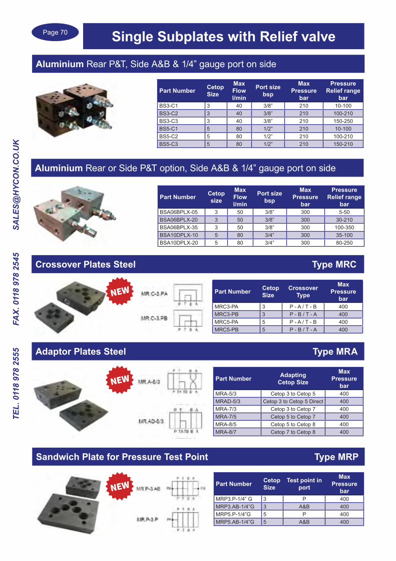
Aluminium Rear P&T, Side A&B & 1/4” gauge port on side
Part Number Cetop Size
Max Flowl/min
Port size bsp
MaxPressure
bar
PressureRelief range
barBS3-C1 3 40 3/8” 210 10-100BS3-C2 3 40 3/8” 210 100-210BS3-C3 3 40 3/8” 210 150-250BS5-C1 5 80 1/2” 210 10-100BS5-C2 5 80 1/2” 210 100-210BS5-C3 5 80 1/2” 210 150-210
Part Number Cetop size
MaxFlowl/min
Port size bsp
MaxPressure
bar
PressureRelief range
barBSA06BPLX-05 3 50 3/8” 300 5-50BSA06BPLX-20 3 50 3/8” 300 30-210BSA06BPLX-35 3 50 3/8” 300 100-350BSA10DPLX-10 5 80 3/4” 300 35-100BSA10DPLX-20 5 80 3/4” 300 80-250
Aluminium Rear or Side P&T option, Side A&B & 1/4” gauge port on side
Crossover Plates Steel Type MRC
Part Number Cetop Size
Crossover Type
MaxPressure
barMRC3-PA 3 P - A / T - B 400MRC3-PB 3 P - B / T - A 400MRC5-PA 5 P - A / T - B 400MRC5-PB 5 P - B / T - A 400
Adaptor Plates Steel Type MRA
Part Number Adapting Cetop Size
MaxPressure
barMRA-5/3 Cetop 3 to Cetop 5 400MRAD-5/3 Cetop 3 to Cetop 5 Direct 400MRA-7/3 Cetop 3 to Cetop 7 400MRA-7/5 Cetop 5 to Cetop 7 400MRA-8/5 Cetop 5 to Cetop 8 400MRA-8/7 Cetop 7 to Cetop 8 400
Sandwich Plate for Pressure Test Point Type MRP
Part Number Cetop Size
Test point in port
MaxPressure
barMRP3.P-1/4” G 3 P 400MRP3.AB-1/4”G 3 A&B 400MRP5.P-1/4”G 5 P 400MRP5.AB-1/4”G 5 A&B 400
Single Subplates with Relief valve
Page 71
TEL. 0118 978 2555 FAX. 0118 978 2545 SA
LES@H
YCO
N.C
O.U
K
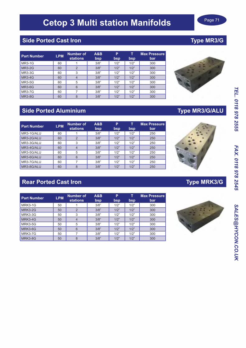
Cetop 3 Multi station Manifolds
Side Ported Cast Iron Type MR3/G
Part Number LPM Number ofstations
A&Bbsp
Pbsp
Tbsp
Max Pressurebar
MR3-1G 60 1 3/8” 1/2” 1/2” 300MR3-2G 60 2 3/8” 1/2” 1/2” 300MR3-3G 60 3 3/8” 1/2” 1/2” 300MR3-4G 60 4 3/8” 1/2” 1/2” 300MR3-5G 60 5 3/8” 1/2” 1/2” 300MR3-6G 60 6 3/8” 1/2” 1/2” 300MR3-7G 60 7 3/8” 1/2” 1/2” 300MR3-8G 60 8 3/8” 1/2” 1/2” 300
Side Ported Aluminium Type MR3/G/ALU
Part Number LPM Number ofstations
A&Bbsp
Pbsp
Tbsp
Max Pressurebar
MR3-1G/ALU 60 1 3/8” 1/2” 1/2” 250MR3-2G/ALU 60 2 3/8” 1/2” 1/2” 250MR3-3G/ALU 60 3 3/8” 1/2” 1/2” 250MR3-4G/ALU 60 4 3/8” 1/2” 1/2” 250MR3-5G/ALU 60 5 3/8” 1/2” 1/2” 250MR3-6G/ALU 60 6 3/8” 1/2” 1/2” 250MR3-7G/ALU 60 7 3/8” 1/2” 1/2” 250MR3-8G/ALU 60 8 3/8” 1/2” 1/2” 250
Rear Ported Cast Iron Type MRK3/G
Part Number LPM Number ofstations
A&Bbsp
Pbsp
Tbsp
Max Pressurebar
MRK3-1G 50 1 3/8” 1/2” 1/2” 300MRK3-2G 50 2 3/8” 1/2” 1/2” 300MRK3-3G 50 3 3/8” 1/2” 1/2” 300MRK3-4G 50 4 3/8” 1/2” 1/2” 300MRK3-5G 50 5 3/8” 1/2” 1/2” 300MRK3-6G 50 6 3/8” 1/2” 1/2” 300MRK3-7G 50 7 3/8” 1/2” 1/2” 300MRK3-8G 50 8 3/8” 1/2” 1/2” 300
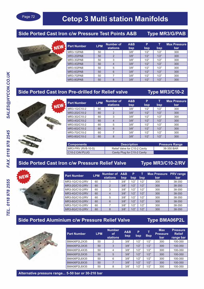
Page 72
TEL.
011
8 97
8 25
55
FA
X. 0
118
978
2545
S
ALE
S@H
YCO
N.C
O.U
K
Side Ported Cast Iron c/w Pressure Test Points A&B Type MR3/G/PAB
Part Number LPM Number ofstations
A&Bbsp
Pbsp
Tbsp
Max Pressurebar
MR3-1GPAB 50 1 3/8” 1/2” 1/2” 300MR3-2GPAB 50 2 3/8” 1/2” 1/2” 300MR3-3GPAB 50 3 3/8” 1/2” 1/2” 300MR3-4GPAB 50 4 3/8” 1/2” 1/2” 300MR3-5GPAB 50 5 3/8” 1/2” 1/2” 300MR3-6GPAB 50 6 3/8” 1/2” 1/2” 300MR3-7GPAB 50 7 3/8” 1/2” 1/2” 300MR3-8GPAB 50 8 3/8” 1/2” 1/2” 300
Side Ported Cast Iron Pre-drilled for Relief valve Type MR3/C10-2
Part Number LPM Number ofstations
A&Bbsp
Pbsp
Tbsp
Max Pressurebar
MR3-1G/C10-2 60 1 3/8” 1/2” 1/2” 300MR3-2G/C10-2 60 2 3/8” 1/2” 1/2” 300MR3-3G/C10-2 60 3 3/8” 1/2” 1/2” 300MR3-4G/C10-2 60 4 3/8” 1/2” 1/2” 300MR3-5G/C10-2 60 5 3/8” 1/2” 1/2” 300MR3-6G/C10-2 60 6 3/8” 1/2” 1/2” 300MR3-7G/C10-2 60 7 3/8” 1/2” 1/2” 300MR3-8G/C10-2 60 8 3/8” 1/2” 1/2” 300
Components Description Pressure RangeMR3-PRV (RV8-10-S) Relief Valve for C10-2 Cavity 38-350 BARC10-2 CAV.PLUG Cavity Plug for C10-2 Cavity
Side Ported Cast Iron c/w Pressure Relief Valve Type MR3/C10-2/RV
Part Number LPM Number ofstations
A&Bbsp
Pbsp
Tbsp
Max Pressurebar
PRV rangebar
MR3-1G/C10-2/RV 60 1 3/8” 1/2” 1/2” 300 38-350MR3-2G/C10-2/RV 60 2 3/8” 1/2” 1/2” 300 38-350MR3-3G/C10-2/RV 60 3 3/8” 1/2” 1/2” 300 38-350MR3-4G/C10-2/RV 60 4 3/8” 1/2” 1/2” 300 38-350MR3-5G/C10-2/RV 60 5 3/8” 1/2” 1/2” 300 38-350MR3-6G/C10-2/RV 60 6 3/8” 1/2” 1/2” 300 38-350MR3-7G/C10-2/RV 60 7 3/8” 1/2” 1/2” 300 38-350MR3-8G/C10-2/RV 60 8 3/8” 1/2” 1/2” 300 38-350
Cetop 3 Multi station Manifolds
Part Number LPMNumber
ofstations
A&Bbsp
P bsp
T Bsp
Max Pressure
bar
PressureRelief
range barBMA06P2L2X35 50 2 3/8” 1/2” 1/2” 300 100-350BMA06P2L3X35 50 3 3/8” 1/2” 1/2” 300 100-350BMA06P2L4X35 50 4 3/8” 1/2” 1/2” 300 100-350BMA06P2L5X35 50 5 3/8” 1/2” 1/2” 300 100-350BMA06P2L6X35 50 6 3/8” 1/2” 1/2” 300 100-350BMA06P2L8X35 50 7 3/8” 1/2” 1/2” 300 100-350BMA06P2L8X35 50 8 3/8” 1/2” 1/2” 300 100-350
Side Ported Aluminium c/w Pressure Relief Valve Type BMA06P2L
Alternative pressure range... 5-50 bar or 30-210 bar

Page 73
TEL. 0118 978 2555 FAX. 0118 978 2545 SA
LES@H
YCO
N.C
O.U
K
Side Ported Cast Iron Type MR5/G
Part Number LPM Number ofstations
A&Bbsp
Pbsp
Tbsp
Max Pressurebar
MR5-1G 120 1 1/2” 3/4” 1” 300MR5-2G 120 2 1/2” 3/4” 1” 300MR5-3G 120 3 1/2” 3/4” 1” 300MR5-4G 120 4 1/2” 3/4” 1” 300MR5-5G 120 5 1/2” 3/4” 1” 300MR5-6G 120 6 1/2” 3/4” 1” 300MR5-7G 120 7 1/2” 3/4” 1” 300MR5-8G 120 8 1/2” 3/4” 1” 300
Rear Ported Cast Iron Type MRK5/G
Part Number LPM Number ofstations
A&Bbsp
Pbsp
Tbsp
Max Pressurebar
MRK5-1G 120 1 1/2” 3/4” 1” 300MRK5-2G 120 2 1/2” 3/4” 1” 300MRK5-3G 120 3 1/2” 3/4” 1” 300MRK5-4G 120 4 1/2” 3/4” 1” 300MRK5-5G 120 5 1/2” 3/4” 1” 300MRK5-6G 120 6 1/2” 3/4” 1” 300MRK5-7G 120 7 1/2” 3/4” 1” 300MRK5-8G 120 8 1/2” 3/4” 1” 300
Part Number LPM Number ofstations
A&Bbsp
Pbsp
Tbsp
Max Pressurebar
MR5-1GPAB 120 1 1/2” 3/4” 1” 300MR5-2GPAB 120 2 1/2” 3/4” 1” 300MR5-3GPAB 120 3 1/2” 3/4” 1” 300MR5-4GPAB 120 4 1/2” 3/4” 1” 300MR5-5GPAB 120 5 1/2” 3/4” 1” 300MR5-6GPAB 120 6 1/2” 3/4” 1” 300MR5-7GPAB 120 7 1/2” 3/4” 1” 300MR5-8GPAB 120 8 1/2” 3/4” 1” 300
Side Ported Cast Iron c/w Pressure Test Points A&B Type MR5/G/PAB
Side Ported Cast Iron pre-drilled for Relief valve Type MR5/C10-2
Part Number LPM Number ofstations
A&Bbsp
Pbsp
Tbsp
Max Pressurebar
MR5-1G/C10-2 120 1 1/2” 3/4” 1” 300MR5-2G/C10-2 120 2 1/2” 3/4” 1” 300MR5-3G/C10-2 120 3 1/2” 3/4” 1” 300MR5-4G/C10-2 120 4 1/2” 3/4” 1” 300MR5-5G/C10-2 120 5 1/2” 3/4” 1” 300MR5-6G/C10-2 120 6 1/2” 3/4” 1” 300MR5-7G/C10-2 120 7 1/2” 3/4” 1” 300MR5-8G/C10-2 120 8 1/2” 3/4” 1” 300
Components Description Pressure RangeMR5-PRV Relief Valve for C10-2 Cavity 35-350 BARC10-2 CAV.PLUG Cavity Plug for C10-2 Cavity
Cetop 5 Multi station Manifolds

Page 74
TEL.
011
8 97
8 25
55
FA
X. 0
118
978
2545
S
ALE
S@H
YCO
N.C
O.U
K
Cetop 5 Multi station Manifolds
Side Ported Cast Iron c/w Pressure Relief Valve Type MR5/C10-2/RV
Part Number LPM Number ofstations
A&Bbsp
Pbsp
Tbsp
Max Pressure
bar
PRV rangebar
MR5-1G/C10-2/RV 120 1 1/2” 3/4” 1” 300 35-350MR5-2G/C10-2/RV 120 2 1/2” 3/4” 1” 300 35-350MR5-3G/C10-2/RV 120 3 1/2” 3/4” 1” 300 35-350MR5-4G/C10-2/RV 120 4 1/2” 3/4” 1” 300 35-350MR5-5G/C10-2/RV 120 5 1/2” 3/4” 1” 300 35-350MR5-6G/C10-2/RV 120 6 1/2” 3/4” 1” 300 35-350MR5-7G/C10-2/RV 120 7 1/2” 3/4” 1” 300 35-350MR5-8G/C10-2/RV 120 8 1/2” 3/4” 1” 300 35-350
Cetop 7 Manifolds Cast Iron side ports
Part Number
Cetop size LPM Number of
stationsA&Bbsp
Pbsp
Tbsp
X,Ybsp
Max Pressure
barMR7-1-3/4”G 7 220 1 3/4” 1” 1 1/4” 3/8” 300MR7-1-1”G 7 270 1 1” 1 1/4” 1 1/2” 3/8” 300MR7-2-1”G 7 270 2 1” 1 1/4” 1 1/2” 3/8” 300MR7-3-1”G 7 270 3 1” 1 1/4” 1 1/2” 3/8” 300
Part Number
Cetop size LPM Number of
stationsA&Bbsp
Pbsp
Tbsp
X,Ybsp
Max Pressure
barMR8-1-1”G 8 350 1 1” 1 1/4” 1 1/2” 1/2” 300MR8-2-1”G 8 350 2 1” 1 1/4” 1 1/2” 1/2” 300
Cetop 8 Manifolds Cast Iron side ports

Page 75
TEL. 0118 978 2555 FAX. 0118 978 2545 SA
LES@H
YCO
N.C
O.U
K
Hand Pumps Industrial Applications
Double Stroke Function Auxiliary pump Type GL
Single Acting pump with Release Knob Type GLR

Page 76
TEL.
011
8 97
8 25
55
FA
X. 0
118
978
2545
S
ALE
S@H
YCO
N.C
O.U
K
Hand Pumps Industrial Applications
Single Acting pump mounted on its own tank Type GLBwith relief valve and release knobStandard tank size is 4 Litre, 10 Litre available upon request
Changeover valve to mount directly onto pumps type GL, GLR & GLB which adapts the pump for use with double acting cylinders Type GL4VN

Page 77
TEL. 0118 978 2555 FAX. 0118 978 2545 SA
LES@H
YCO
N.C
O.U
K
Hand Pumps Mobile Applications
Part Number Displacementcm3
Max Pressure
bar
Portssize bsp
PMTP6 6 500 3/8”PMTP12 12 380 3/8”PMTP25 25 350 3/8”PMTP45 45 280 3/8”
Double Acting hand pump with Pilot Check valves Type PMTPumps have rubber gator protection as standard
Single Acting hand pump double stroke function Type PMSPPumps have a Pressure Relief valve rubber gator protection as standard
Part Number Displacementcm3
Max Pressure
bar
Portssize bsp
PMSP6RV 6 500 3/8”PMSP12RV 12 380 3/8”PMSP25RV 25 350 3/8”PMSP45RV 45 280 3/8”
Double Acting hand pump open centre Type PMAPPumps have a Pressure Relief valve rubber gator protection as standard
Part Number Displacementcm3
Max Pressure
bar
Portssize bsp
PMAP6RV 6 500 3/8”PMAP12RV 12 380 3/8”PMAP25RV 25 350 3/8”PMAP45RV 45 280 3/8”
Part Number Displacementcm3
Max Pressure
bar
Portssize bsp
PMIP6RV 6 500 3/8”PMIP12RV 12 380 3/8”PMIP25RV 25 350 3/8”PMIP45RV 45 280 3/8”
Double Acting hand pump closed centre Type PMIPPumps have a Pressure Relief valve rubber gator protection as standard

Page 78
TEL.
011
8 97
8 25
55
FA
X. 0
118
978
2545
S
ALE
S@H
YCO
N.C
O.U
K
Hand Pumps Mobile Applications
Single Acting hand pump for power pack mounting Type PME1PPumps have rubber gator protection as standard
Part Number Displacementcm3
Max Pressure
bar
Portssize bsp
PME1P18 8 380 3/8”PME1P115 15 350 3/8”
Two Speed hand pump for Single acting cylinder Type PMEP580Pumps have rubber gator protection as standard, Option of Automatic device
Part Number
Stage 1Pressure
bar
Stage 1cm3
Stage 2Pressure
bar
Stage 2cm3
PMEP580 20 80 500 5With Automatic DevicePMEP580CA 20 80 500 5
With Automatic Device & pressure relief valvePMEP580CARV
20 80 500 5
Steel Oil Tanks for hand pumps Type TNKTanks are coated black RAL9005, supplied with air breather
Part Number
CapacityLitre
TNK 1 1TNK 2 2TNK 3 3TNK 5 5TNK 7 7TNK 10 10
Tanks can be mounted horizontally or vertically
Foot operated pump Type PME3Seperate release foot pedal
Part Number Displacementcm3
Max Pressure
bar
Portssize bsp
ReservoirVolume
PME3 14 220 1/4” 1.5 ltr
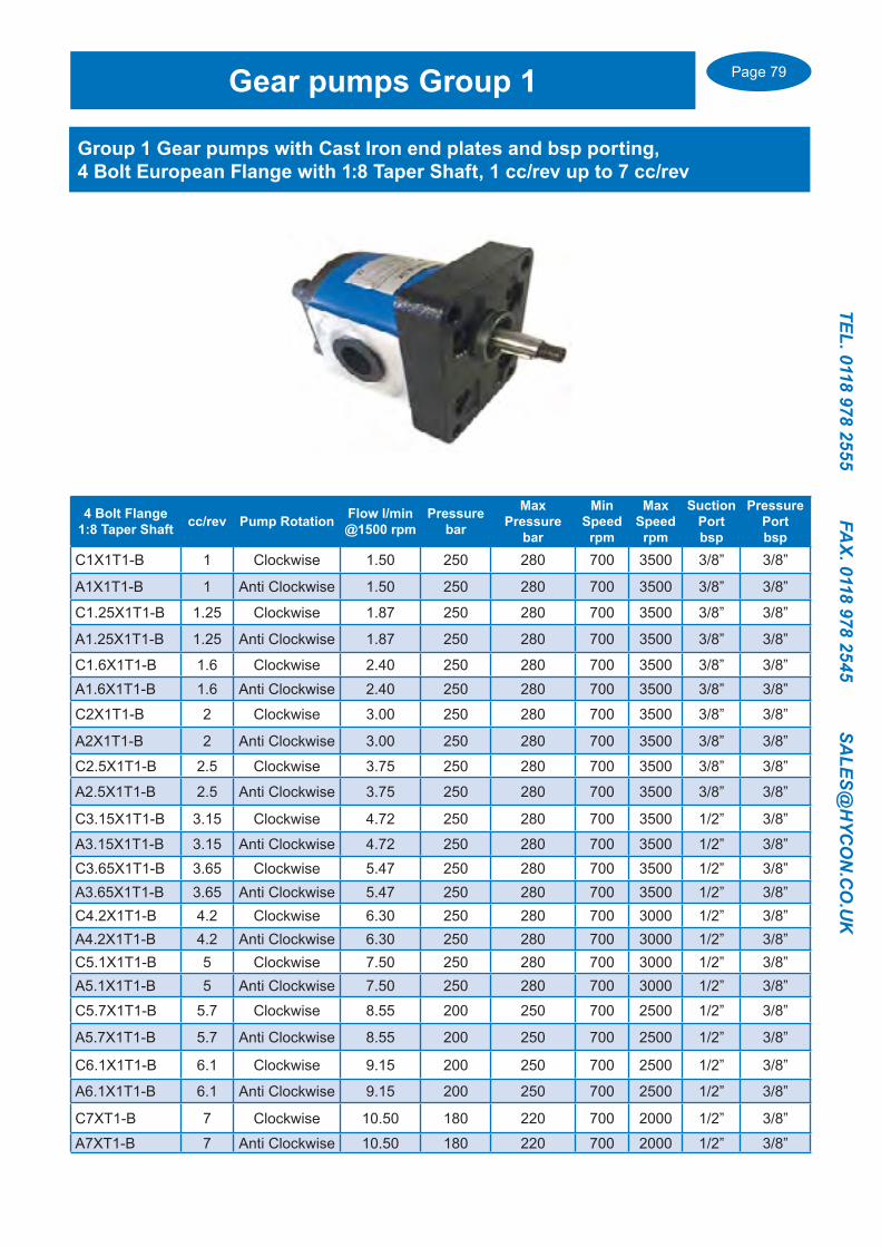
Page 79
TEL. 0118 978 2555 FAX. 0118 978 2545 SA
LES@H
YCO
N.C
O.U
K
4 Bolt Flange1:8 Taper Shaft cc/rev Pump Rotation Flow l/min
@1500 rpmPressure
bar
Max Pressure
bar
MinSpeedrpm
Max Speedrpm
SuctionPortbsp
PressurePortbsp
C1X1T1-B 1 Clockwise 1.50 250 280 700 3500 3/8” 3/8”
A1X1T1-B 1 Anti Clockwise 1.50 250 280 700 3500 3/8” 3/8”
C1.25X1T1-B 1.25 Clockwise 1.87 250 280 700 3500 3/8” 3/8”
A1.25X1T1-B 1.25 Anti Clockwise 1.87 250 280 700 3500 3/8” 3/8”
C1.6X1T1-B 1.6 Clockwise 2.40 250 280 700 3500 3/8” 3/8”A1.6X1T1-B 1.6 Anti Clockwise 2.40 250 280 700 3500 3/8” 3/8”
C2X1T1-B 2 Clockwise 3.00 250 280 700 3500 3/8” 3/8”
A2X1T1-B 2 Anti Clockwise 3.00 250 280 700 3500 3/8” 3/8”
C2.5X1T1-B 2.5 Clockwise 3.75 250 280 700 3500 3/8” 3/8”
A2.5X1T1-B 2.5 Anti Clockwise 3.75 250 280 700 3500 3/8” 3/8”
C3.15X1T1-B 3.15 Clockwise 4.72 250 280 700 3500 1/2” 3/8”
A3.15X1T1-B 3.15 Anti Clockwise 4.72 250 280 700 3500 1/2” 3/8”C3.65X1T1-B 3.65 Clockwise 5.47 250 280 700 3500 1/2” 3/8”A3.65X1T1-B 3.65 Anti Clockwise 5.47 250 280 700 3500 1/2” 3/8”C4.2X1T1-B 4.2 Clockwise 6.30 250 280 700 3000 1/2” 3/8”A4.2X1T1-B 4.2 Anti Clockwise 6.30 250 280 700 3000 1/2” 3/8”C5.1X1T1-B 5 Clockwise 7.50 250 280 700 3000 1/2” 3/8”A5.1X1T1-B 5 Anti Clockwise 7.50 250 280 700 3000 1/2” 3/8”
C5.7X1T1-B 5.7 Clockwise 8.55 200 250 700 2500 1/2” 3/8”
A5.7X1T1-B 5.7 Anti Clockwise 8.55 200 250 700 2500 1/2” 3/8”
C6.1X1T1-B 6.1 Clockwise 9.15 200 250 700 2500 1/2” 3/8”
A6.1X1T1-B 6.1 Anti Clockwise 9.15 200 250 700 2500 1/2” 3/8”
C7XT1-B 7 Clockwise 10.50 180 220 700 2000 1/2” 3/8”
A7XT1-B 7 Anti Clockwise 10.50 180 220 700 2000 1/2” 3/8”
Gear pumps Group 1
Group 1 Gear pumps with Cast Iron end plates and bsp porting, 4 Bolt European Flange with 1:8 Taper Shaft, 1 cc/rev up to 7 cc/rev

Page 80
TEL.
011
8 97
8 25
55
FA
X. 0
118
978
2545
S
ALE
S@H
YCO
N.C
O.U
K
Gear pumps Group 2Group 2 Gear pumps with Cast Iron end plates, bsp ports and 2 or 4 bolt flange
4 Bolt European Flange with 1:8 Taper shaft
Part Number cc/rev Pump Rotation
Flow l/min@1500 rpm
Pressurebar
Max Pressure bar
Minspeedrpm
Max speedrpm
SuctionPort bsp
PressurePort bsp
C4X2T1-B 4 Clockwise 6 250 270 700 3500 1/2” 1/2”A4X2T1-B 4 Anti Clockwise 6 250 270 700 3500 1/2” 1/2”C6X2T1-B 6 Clockwise 9 250 270 700 3500 1/2” 1/2”A6X2T1-B 6 Anti Clockwise 9 250 270 700 3500 1/2” 1/2”C9X2T1-B 9 Clockwise 13.5 250 270 700 3500 1/2” 1/2”A9X2T1-B 9 Anti Clockwise 13.5 250 270 700 3500 1/2” 1/2”C11X2T1-B 11 Clockwise 16.5 250 270 700 3500 3/4” 1/2”A11X2T1-B 11 Anti Clockwise 16.5 250 270 700 3500 3/4” 1/2”C14X2T1-B 14 Clockwise 21 250 270 700 3500 3/4” 1/2”A14X2T1-B 14 Anti Clockwise 21 250 270 700 3500 3/4” 1/2”C16X2T1-B 16 Clockwise 24 250 270 700 3000 3/4” 1/2”A16X2T1-B 16 Anti Clockwise 24 250 270 700 3000 3/4” 1/2”C19X2T1-B 19 Clockwise 28.5 230 240 700 2500 3/4” 1/2”A19X2T1-B 19 Anti Clockwise 28.5 230 240 700 2500 3/4” 1/2”C22X2T1-B 22 Clockwise 33 230 240 700 2500 3/4” 1/2”A22X2T1-B 22 Anti Clockwise 33 230 240 700 2500 3/4” 1/2”C26X2T1-B 26 Clockwise 39 210 220 700 2000 3/4” 1/2”A26X2T1-B 26 Anti Clockwise 39 210 220 700 2000 3/4” 1/2”C28X2T1-B 28 Clockwise 42 210 220 700 2000 3/4” 3/4”A28X2T1-B 28 Anti Clockwise 42 210 220 700 2000 3/4” 3/4”
2 Bolt SAE ‘A’ Flange with 9 tooth Spline shaft2 Bolt Flange9 Tooth Spline cc/rev Pump
RotationFlow l/min@1500 rpm
Pressurebar
Max Pressure bar
Minspeedrpm
Max speedrpm
SuctionPort bsp
PressurePort bsp
C4X4T5-B 4 Clockwise 6 250 270 700 3500 1/2” 1/2”A4X4T5-B 4 Anti Clockwise 6 250 270 700 3500 1/2” 1/2”C6X4T5-B 6 Clockwise 9 250 270 700 3500 1/2” 1/2”A6X4T5-B 6 Anti Clockwise 9 250 270 700 3500 1/2” 1/2”C9X4T5-B 9 Clockwise 13.5 250 270 700 3500 1/2” 1/2”A9X4T5-B 9 Anti Clockwise 13.5 250 270 700 3500 1/2” 1/2”C11X4T5-B 11 Clockwise 16.5 250 270 700 3500 3/4” 1/2”A11X4T5-B 11 Anti Clockwise 16.5 250 270 700 3500 3/4” 1/2”C14X4T5-B 14 Clockwise 21 250 270 700 3500 3/4” 1/2”A14X4T5-B 14 Anti Clockwise 21 250 270 700 3500 3/4” 1/2”C16X4T5-B 16 Clockwise 24 250 270 700 3000 3/4” 1/2”A16X4T5-B 16 Anti Clockwise 24 250 270 700 3000 3/4” 1/2”C19X4T5-B 19 Clockwise 28.5 230 240 700 2500 3/4” 1/2”A19X4T5-B 19 Anti Clockwise 28.5 230 240 700 2500 3/4” 1/2”C22X4T5-B 22 Clockwise 33 230 240 700 2500 3/4” 1/2”A22X4T5-B 22 Anti Clockwise 33 230 240 700 2500 3/4” 1/2”C26X4T5-B 26 Clockwise 39 210 220 700 2000 3/4” 1/2”A26X4T5-B 26 Anti Clockwise 39 210 220 700 2000 3/4” 1/2”C28X4T5-B 28 Clockwise 42 210 220 700 2000 3/4” 3/4”A28X4T5-B 28 Anti Clockwise 42 210 220 700 2000 3/4” 3/4”

Page 81
TEL. 0118 978 2555 FAX. 0118 978 2545 SA
LES@H
YCO
N.C
O.U
K
Group 2 Displacement cc/rev
Flow l/min@1500 rpm
Suction Portbsp
Pressure portbsp
Minspeedrpm
Max speed
rpm
Max continuous
Pressure bar @ 1500 rpm
Max Pressure bar @ 1500 rpm
PNP4 4 6 1/2” 1/2” 600 4000 280 310
PNP6 6 9 1/2” 1/2” 600 3500 270 310
PNP8 8 12 1/2” 1/2” 600 3500 270 310
PNP11 11 16.5 3/4” 1/2” 600 3500 270 310PNP14 14 21 3/4” 1/2” 500 3000 260 300
PNP16 16 24 3/4” 1/2” 500 3000 250 290
PNP20 20 30 3/4” 1/2” 500 3000 230 250
PNP22.5 22.5 33.7 3/4” 1/2” 400 3000 210 230
PNP26 26 39 3/4” 1/2” 400 3000 200 230
Group 2 Petrone High Pressure Gear pumpLow noise generation, Quiet Running pumps, bsp ports
Example Ordering Code
Group 2 Rotation Displacement Shaft type Mounting Flange Ports
PNP2 D.. ClockwiseS.. Anti-Clockwise Size cc/rev
CO01 (1:8 Tapered Shaft)CO02 (1:5 Tapered Shaft)CI01 (15mm Parallel, 4mm key width)CI03 (16mm Parallel, 4mm key width)SC01 (DIN5482 9T Splined)SC02 (SAE A 9 T Splined)SC03 (SAE A 11 T Splined,24mm Long)SC04 (SAE A 10 T Splined 51mm long)SC05 (SAE A 11Tooth 51mm Long
01.. 4 Bolt Standard European
02.. SAE ‘A’ 2 Bolt
03.. 4 Bolt flange 80mm Spigot
A.. Threaded Bsp
B.. Flange Ports
ExamplePNP2 D 11 CO01 01 A
Gear pumps Group 2..Quiet Running

Page 82
TEL.
011
8 97
8 25
55
FA
X. 0
118
978
2545
S
ALE
S@H
YCO
N.C
O.U
K
Gear pumps Group 3
4 Bolt European Flange with 1:8 Taper shaft
Part Number cc/rev Pump Rotation
Flow l/min@1500 rpm
Pressurebar
Max Pressure bar
Minspeedrpm
Max speedrpm
SuctionPort bsp
PressurePort bsp
30C20XF068NT 20 Clockwise 30 250 280 700 2500 3/4” 3/4”30A20XF068NT 20 Anti Clockwise 30 250 280 700 2500 3/4” 3/4””30C25XF068NT 25 Clockwise 37.5 250 280 700 2500 3/4” 3/4””30A25XF068NT 25 Anti Clockwise 37.5 250 280 700 2500 3/4” 3/4””30C28XF068NT 28 Clockwise 42 250 280 700 2500 3/4” 3/4”30A28XF068NT 28 Anti Clockwise 42 250 280 700 2500 3/4” 3/4”30C32XF068NT 32 Clockwise 48 250 280 700 2500 1” 3/4”30A32XF068NT 32 Anti Clockwise 48 250 280 700 2500 1” 3/4”30C36XF068NT 36 Clockwise 54 250 280 700 2300 1” 3/4”30A36XF068NT 36 Anti Clockwise 54 250 280 700 2300 1” 3/4”30C42XF068NT 42 Clockwise 63 230 250 700 2300 1” 3/4”30A42XF068NT 42 Anti Clockwise 63 230 250 700 2300 1” 3/4”30C46XF068NT 46 Clockwise 69 230 250 700 2100 1” 3/4”30A46XF068NT 46 Anti Clockwise 69 230 250 700 2100 1” 3/4”30C50XF068NT 50 Clockwise 75 200 230 700 2100 1” 3/4”30A50XF068NT 50 Anti Clockwise 75 200 230 700 2100 1” 3/4”30C55XF068NT 55 Clockwise 82.5 200 230 700 1750 1” 3/4”30A55XF068NT 55 Anti Clockwise 82.5 200 230 700 1750 1” 3/4”30C63XF068NT 63 Clockwise 94.5 160 190 700 1750 1 1/4” 1”30A63XF068NT 63 Anti Clockwise 94.5 160 190 700 1750 1 1/4”” 1”
2 Bolt SAE ‘B’ Flange with 13 tooth Spline shaft
Part Number cc/rev Pump Rotation
Flow l/min@1500 rpm
Pressurebar
Max Pressure bar
Minspeedrpm
Max speedrpm
SuctionPort bsp
PressurePort bsp
30C20XF014NT 20 Clockwise 30 250 280 700 2500 3/4” 3/4”30A20XF014NT 20 Anti Clockwise 30 250 280 700 2500 3/4” 3/4””30C25XF014NT 25 Clockwise 37.5 250 280 700 2500 3/4” 3/4””30A25XF014NT 25 Anti Clockwise 37.5 250 280 700 2500 3/4” 3/4””30C28XF014NT 28 Clockwise 42 250 280 700 2500 3/4” 3/4”30A28XF014NT 28 Anti Clockwise 42 250 280 700 2500 3/4” 3/4”30C32XF014NT 32 Clockwise 48 250 280 700 2500 1” 3/4”30A32XF014NT 32 Anti Clockwise 48 250 280 700 2500 1” 3/4”30C36XF014NT 36 Clockwise 54 250 280 700 2300 1” 3/4”30A36XF014NT 36 Anti Clockwise 54 250 280 700 2300 1” 3/4”30C42XF014NT 42 Clockwise 63 230 250 700 2300 1” 3/4”30A42XF014NT 42 Anti Clockwise 63 230 250 700 2300 1” 3/4”30C46XF014NT 46 Clockwise 69 230 250 700 2100 1” 3/4”30A46XF014NT 46 Anti Clockwise 69 230 250 700 2100 1” 3/4”30C50XF014NT 50 Clockwise 75 200 230 700 2100 1” 3/4”30A50XF014NT 50 Anti Clockwise 75 200 230 700 2100 1” 3/4”30C55XF014NT 55 Clockwise 82.5 200 230 700 1750 1” 3/4”30A55XF014NT 55 Anti Clockwise 82.5 200 230 700 1750 1” 3/4”30C63XF014NT 63 Clockwise 94.5 160 190 700 1750 1 1/4” 1”30A63XF014NT 63 Anti Clockwise 94.5 160 190 700 1750 1 1/4”” 1”
Group 3 Gear pumps with Cast Iron end plates and bsp porting

Page 83
TEL. 0118 978 2555 FAX. 0118 978 2545 SA
LES@H
YCO
N.C
O.U
K
Group 3 Displacementcc/rev
Minimumspeedrpm
Maximum speedrpm
Max continuousPressure bar @ 1500 rpm
Max Pressure bar @ 1500 rpm
Flow LPM@ 1500 rpm
PNP3D28 28 600 3000 250 270 42
PNP3D33 33 600 3000 250 270 49.5
PNP3D38 38 800 3000 250 270 57
PNP3D44 44 800 2500 230 250 66
PNP3D55 55 800 2500 200 230 82.5
Gear pumps Group 3..Quiet Running
Group 3 Petrone High Pressure Gear pumpsLow noise generation, Quiet Running pumps, bsp ports
Example Ordering Code
Group 3 Rotation Displacement Shaft type Mounting Flange Ports
PNP3D.. ClockwiseS.. Anti Clockwise
** cc/revCO01 (1:8 Tapered Shaft)SC01 (DIN5482 13T Splined)CI01 (24 mm Parallel)
01.. 4 Bolt Standard European02.. SAE ‘B’ 2 Bolt
A.. Threaded BspB.. Flange Ports
ExamplePNP3 D 33 CO01 01 A

Page 84
TEL.
011
8 97
8 25
55
FA
X. 0
118
978
2545
S
ALE
S@H
YCO
N.C
O.U
K
Gear pumps Group 4 & 5
Group 4Part Number
Displacementcc/rev
Flow l/min@1500 rpm
Maximum speedRpm
RatedPressure
bar
Max Pressure
bar
SuctionPort bsp
PressurePort bsp
95 43 64.5 2000 165 190 1” 1”120 54.5 81.75 2000 135 160 1” 1”140 63.5 95.25 2000 135 160 1 1/4” 1”165 75 112.5 2000 95 120 1 1/4” 1”
Group 5Part Number
Displacementcc/rev
Flow l/min@1500 rpm
Maximum speedRpm
RatedPressure
bar
Max Pressure
bar
SuctionPort bsp
PressurePort bsp
170 77 115.5 1750 165 190 1 1/2” 1 1/4”215 98 147 1750 135 160 1 1/2” 1 1/4”280 127 190.5 1750 135 160 1 1/2” 1 1/4”325 147 220.5 1750 95 120 1 1/2” 1 1/4”
Rotation Part number Suffix code
C.. ClockwiseA.. Anti Clockwise X(T)
C 120 XT
Part Number
Pumpsize Support Shaft Spline Bush
SP-U1P Group 1 18 mm Parallel B-U1P / 10003SP-S2 Group 2 18 mm Parallel B-2CA / 10005SP-R2 Group 2 Heavy Duty 22 mm Parallel B-R2U / 10007SP-2C Group 2 1 : 8 Taper B-2CA / 10005SP-3U Group 3 24 mm Parallel B-3 / 10014SP-3.5U Group 3.5 28 mm Parallel B-35U / 10017
GEAR PUMP BEARING SUPPORTSFlange connected directly to the Pump they protect the shafts of Pumps and Motors
from high Radial Loads. Cast Aluminium Body and Steel Parallel or Taper ShaftsPump shafts are connected by a splined coupling DIN5482
Example Ordering Code
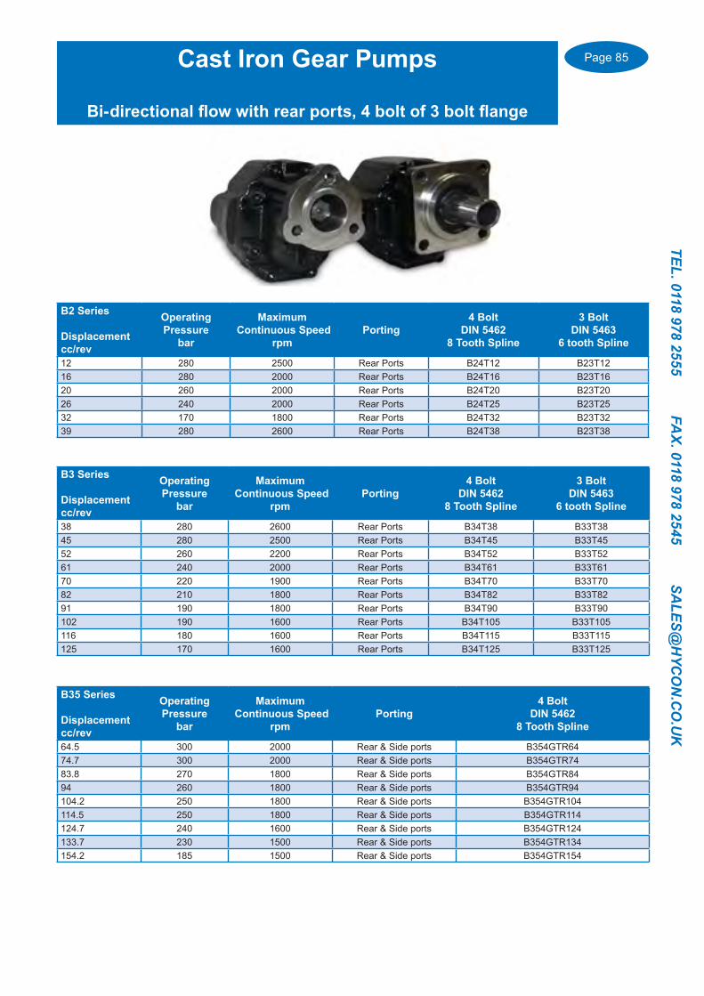
Page 85
TEL. 0118 978 2555 FAX. 0118 978 2545 SA
LES@H
YCO
N.C
O.U
K
Cast Iron Gear Pumps
Bi-directional flow with rear ports, 4 bolt of 3 bolt flange
B2 Series
Displacementcc/rev
OperatingPressure
bar
Maximum Continuous Speed
rpmPorting
4 Bolt DIN 5462
8 Tooth Spline
3 Bolt DIN 5463
6 tooth Spline
12 280 2500 Rear Ports B24T12 B23T1216 280 2000 Rear Ports B24T16 B23T1620 260 2000 Rear Ports B24T20 B23T2026 240 2000 Rear Ports B24T25 B23T2532 170 1800 Rear Ports B24T32 B23T3239 280 2600 Rear Ports B24T38 B23T38
B3 Series
Displacementcc/rev
OperatingPressure
bar
Maximum Continuous Speed
rpmPorting
4 Bolt DIN 5462
8 Tooth Spline
3 Bolt DIN 5463
6 tooth Spline
38 280 2600 Rear Ports B34T38 B33T3845 280 2500 Rear Ports B34T45 B33T4552 260 2200 Rear Ports B34T52 B33T5261 240 2000 Rear Ports B34T61 B33T6170 220 1900 Rear Ports B34T70 B33T7082 210 1800 Rear Ports B34T82 B33T8291 190 1800 Rear Ports B34T90 B33T90102 190 1600 Rear Ports B34T105 B33T105116 180 1600 Rear Ports B34T115 B33T115125 170 1600 Rear Ports B34T125 B33T125
B35 Series
Displacementcc/rev
OperatingPressure
bar
Maximum Continuous Speed
rpmPorting
4 Bolt DIN 5462
8 Tooth Spline
64.5 300 2000 Rear & Side ports B354GTR6474.7 300 2000 Rear & Side ports B354GTR7483.8 270 1800 Rear & Side ports B354GTR8494 260 1800 Rear & Side ports B354GTR94104.2 250 1800 Rear & Side ports B354GTR104114.5 250 1800 Rear & Side ports B354GTR114124.7 240 1600 Rear & Side ports B354GTR124133.7 230 1500 Rear & Side ports B354GTR134154.2 185 1500 Rear & Side ports B354GTR154

Page 86
TEL.
011
8 97
8 25
55
FA
X. 0
118
978
2545
S
ALE
S@H
YCO
N.C
O.U
K
Bent Axis Piston Pumps 17 to 172 cc/rev Cast Iron up to 81cc, Aluminium in 108 to 172 ccLow noise and safe easy change of rotationOther flange and shaft options available..
Part Number
DIN 5462.. 4 Bolt flange with 8 tooth spline shaft
Displacement
cc/rev
MaximumOperatingPressure
Material
BIF 17M 17 400 Cast IronBIF 25M 26 400 Cast IronBIF 30M 32 400 Cast IronBIF 40M 42 400 Cast IronBIF 50M 50 400 Cast IronBIF 60M7 60 400 Cast IronBIF 80P7 81 400 Cast IronBI 110P7 108 350 AluminiumBI 140H9 142 350 AluminiumBI 160H9 156 350 AluminiumBI 170H9 172 300 Aluminium
Bent Axis Piston Motors 17 to 81 cc/rev
Cast Iron body, other flange and shaft options available..
Part Number
DIN 5462.. 4 Bolt flange with 8 tooth spline shaft
Displacement
cc/rev
MaximumOperatingPressure
Maximum Continuous Speed
rpmMBIF 17M 17 400 5400MBIF 25M 26 400 5400MBIF 30M 32 400 5400MBIF 40M 42 400 5400MBIF 50M 50 400 5400MBIF 60M7 60 400 5000MBIF 80M7 81 350 5000
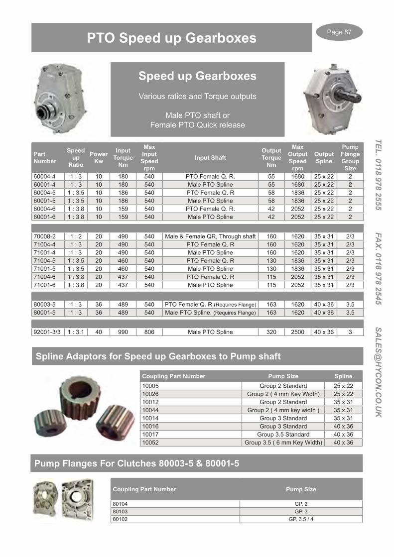
Page 87
TEL. 0118 978 2555 FAX. 0118 978 2545 SA
LES@H
YCO
N.C
O.U
K
Part Number
Speed up
Ratio
Power Kw
Input Torque
Nm
Max Input
Speed rpm
Input ShaftOutput Torque
Nm
Max Output Speed rpm
Output Spine
Pump Flange Group Size
60004-4 1 : 3 10 180 540 PTO Female Q. R. 55 1680 25 x 22 260001-4 1 : 3 10 180 540 Male PTO Spline 55 1680 25 x 22 260004-5 1 : 3.5 10 186 540 PTO Female Q. R 58 1836 25 x 22 260001-5 1 : 3.5 10 186 540 Male PTO Spline 58 1836 25 x 22 260004-6 1 : 3.8 10 159 540 PTO Female Q. R. 42 2052 25 x 22 260001-6 1 : 3.8 10 159 540 Male PTO Spline 42 2052 25 x 22 2
70008-2 1 : 2 20 490 540 Male & Female QR, Through shaft 160 1620 35 x 31 2/371004-4 1 : 3 20 490 540 PTO Female Q. R 160 1620 35 x 31 2/371001-4 1 : 3 20 490 540 Male PTO Spline 160 1620 35 x 31 2/371004-5 1 : 3.5 20 460 540 PTO Female Q. R 130 1836 35 x 31 2/371001-5 1 : 3.5 20 460 540 Male PTO Spline 130 1836 35 x 31 2/371004-6 1 : 3.8 20 437 540 PTO Female Q. R 115 2052 35 x 31 2/371001-6 1 : 3.8 20 437 540 Male PTO Spline 115 2052 35 x 31 2/3
80003-5 1 : 3 36 489 540 PTO Female Q. R.(Requires Flange) 163 1620 40 x 36 3.580001-5 1 : 3 36 489 540 Male PTO Spline. (Requires Flange) 163 1620 40 x 36 3.5
92001-3/3 1 : 3.1 40 990 806 Male PTO Spline 320 2500 40 x 36 3
Speed up GearboxesVarious ratios and Torque outputs
Male PTO shaft or Female PTO Quick release
Spline Adaptors for Speed up Gearboxes to Pump shaft
Coupling Part Number Pump Size Spline10005 Group 2 Standard 25 x 2210026 Group 2 ( 4 mm Key Width) 25 x 2210012 Group 2 Standard 35 x 3110044 Group 2 ( 4 mm key width ) 35 x 3110014 Group 3 Standard 35 x 3110016 Group 3 Standard 40 x 3610017 Group 3.5 Standard 40 x 3610052 Group 3.5 ( 6 mm Key Width) 40 x 36
PTO Speed up Gearboxes
Pump Flanges For Clutches 80003-5 & 80001-5
Coupling Part Number Pump Size
80104 GP. 280103 GP. 380102 GP. 3.5 / 4

Page 88
TEL.
011
8 97
8 25
55
FA
X. 0
118
978
2545
S
ALE
S@H
YCO
N.C
O.U
K
Reduction Gearboxes
Speed Reduction Gearboxes
Part Number RatioInput
TorquedaNm
Powerkw
Max Input Speed
rpm
Input Shaft/ Flange
Output TorquedaNm
MaxOutputSpeed
OutputShaft
95001-4 3 : 1 6.7 10 600 25 mm, / SAE A 2 Bolt Mounting 20.1 200 35 mm
95001-5 3.5 : 1 6.3 10 700 25 mm, / SAE A 2 Bolt Mounting 21.4 200 35 mm
95001-6 3.8 : 1 4.9 10 760 25 mm, / SAE A 2 Bolt Mounting 18.6 200 35 mm
96071-4 3 : 1 19 20 600 25 mm, / SAE A 2 Bolt Mounting 57 200 35 mm
96071-5 3.5 : 1 15.1 20 680 25 mm, / SAE A 2 Bolt Mounting 53 200 35 mm
96071-6 3.8 : 1 13.8 20 760 25 mm, / SAE A 2 Bolt Mounting 52.5 200 35 mm
97001-4 3 : 1 44 68 600 25 mm, / SAE A 2 Bolt Mounting 132 200 35 mm
Mechanical Clutches Reversible
Part Number Pump Group Output Shaft
Internal Spline
Max Torque daNm
Max Speed rpm
Max Power Kw
Axial Load daNm
30100-RV Groups 1 & 2 20 mm 25 x 22 9 2000 30 12030300-RV Groups 2 & 3 28 mm 35 x 31 18.5 2700 40 16030311-RV Group 2 SAE A Mount 28 mm 35 x 31 18.5 2700 40 16030312-RV Group 3 SAE B Mount 28 mm 35 x 31 18.5 2700 40 160
30500-RV Requires Pump Flange, page 130. 42 mm 48 x 44 58 2700 60 260
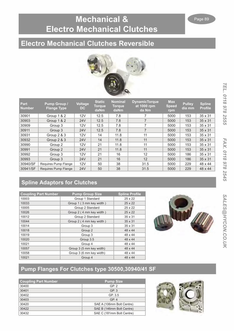
Page 89
TEL. 0118 978 2555 FAX. 0118 978 2545 SA
LES@H
YCO
N.C
O.U
K
Mechanical & Electro Mechanical Clutches
Part Number
Pump Group / Flange Type
Voltage DC
Static Torque daNm
Nominal Torque daNm
DynamicTorqueat 1000 rpm
da Nm
Max Speed rpm
Pulley dia mm
SplineProfile
30901 Group 1 & 2 12V 12.5 7.8 7 5000 153 35 x 3130903 Group 1 & 2 24V 12.5 7.8 7 5000 153 35 x 3130909 Group 3 12V 12.5 7.8 7 5000 153 35 x 3130911 Group 3 24V 12.5 7.8 7 5000 153 35 x 3130931 Group 2 & 3 12V 14 11.8 11 5000 153 35 x 3130932 Group 2 & 3 24V 14 11.8 11 5000 153 35 x 3130990 Group 2 12V 21 11.8 11 5000 153 35 x 3130991 Group 2 24V 21 11.8 11 5000 153 35 x 3130992 Group 3 12V 21 16 12 5000 186 35 x 3130993 Group 3 24V 21 16 12 5000 186 35 x 3130940/SF Requires Pump Flange 12V 50 38 31.5 5000 229 48 x 4430941/SF Requires Pump Flange 24V 50 38 31.5 5000 229 48 x 44
Electro Mechanical Clutches Reversible
Spline Adaptors for Clutches
Coupling Part Number Pump Group Size Spline Profile10003 Group 1 Standard 25 x 2210033 Group 1 ( 3 mm key width ) 25 x 2210005 Group 2 Standard 25 x 2210026 Group 2 ( 4 mm key width ) 25 x 2210012 Group 2 Standard 35 x 3110044 Group 2 ( 4 mm key width ) 35 x 3110014 Group 3 35 x 3110018 Group 2 48 x 4410019 Group 3 48 x 4410020 Group 3.5 48 x 4410021 Group 4 48 x 4410057 Group 3 (5 mm key width) 48 x 4410058 Group 3 (6 mm key width) 48 x 4410021 Group 4 48 x 44
Pump Flanges For Clutches type 30500,30940/41 SF
Coupling Part Number Pump Size30400 GP. 230401 GP. 330402 GP. 3.530403 GP. 430420 SAE A (106mm Bolt Centre)30422 SAE B (146mm Bolt Centre)30432 SAE C (181mm Bolt Centre)

Page 90
TEL.
011
8 97
8 25
55
FA
X. 0
118
978
2545
S
ALE
S@H
YCO
N.C
O.U
K
Pump Group
Motor Frame
Motor kW
MotorShaft mm
Bell HousingPart Re
Ally DriveCoupling
Steel Coupling
Bell HousingGasket
PumpGasket
05 D63 0.12-0.18 11 LS140 ND01 AGN01 GL140 GP051 D63 0.12-0.18 11 LS141 ND03 AGN03 GL140 GP105 D71 0.25-0.37 14 LS160 ND1 AGN1 GL160 GP051 D71 0.25-0.37 14 LS161 ND2 AGN2 GL160 GP105 D80 0.55-0.75 19 LS200 ND4 AGN4 GL200 GP051 D80 0.55-0.75 19 LS201 ND5 AGN5 GL200 GP12 D80 0.55-0.75 19 LS203 ND7 AGN7A GL200 GP23 D80 0.55-0.75 19 LSE206 ND50A GL200 GP33.5 D80 0.55-0.75 19 LSE213 ND50B GL200 GP351 D90 1.1-1.5 24 LS201 ND70A AGN8 GL200 GP11 H/DUTY D90 1.1-1.5 24 LS201 ND8 AGN8 GL200 GP12 D90 1.1-1.5 24 LS203 ND10 AGN10A GL200 GP23 D90 1.1-1.5 24 LSE206 ND51A GL200 GP33.5 D90 1.1-1.5 24 LSE213 ND51B GL200 GP351 D100/112 2.2-4 28 LS250 ND11 AGN11 GL250 GP12 D100/112 2.2-4 28 LS252 ND13 AGN12C GL250 GP23 D100/112 2.2-4 28 LS255 ND61C AGN14 GL250 GP33 H/DUTY D100/112 2.2-4 28 LS255 ND15 AGN14 GL250 GP33.5 D100/112 2.2-4 28 LSE259 ND52A GL250 GP351 D132 5.5-9 38 LS310 ND900S ND900S GL300 GP12 D132 5.5-9 38 LS300 ND16 AGN15A GL300 GP23 D132 5.5-9 38 LS302 ND17 AGN16 GL300 GP33.5 D132 5.5-9 38 LS306 ND18 AGN18 GL300 GP352 D160 11-15 42 LS350 ND43A AGN19A GL350 GP23 D160 11-15 42 LS352 ND43C AGN20 GL350 GP353.5 D160 11– 15 42 LSE356 ND21 AGN22 GL350 GP354 D160 11-15 42 LSE358 ND22 AGN24 GL350 GP42 D180 18.5-22 48 LS350 ND44A AGN25A GL350 GP23 D180 18.5-22 48 LS352 ND44C AGN26 GL350 GP33.5 D180 18.5-22 48 LSE356 ND25 AGN28 GL350 GP354 D180 18.5-22 48 LSE358 ND26 AGN30 GL350 GP43 D200 30 55 LSE401 ND40 AGN31 GL400 GP33.5 D200 30 55 LSE405 ND41 AGN32A GL400 GP354 D200 30 55 LSE407 ND42 AGN33A GL400 GP43 D225 37-45 60 LS456 ND32 GL400 GP33.5 D225 37-45 60 LS451 ND30 AGN34A NA GP354 D225 37-45 60 LS453 ND31 AGN35A NA GP4
Bell Housings and Drive Couplings
Bell housings and Drive couplings for Gear pumps with standard 4 bolt European Flange and 1:8 taper shaft to B5/B35 Flange Electric Motors.Many other connections are available, please contact us with your pump and motor details………...
Large size Bell housings and Drive couplings for Electric Motors up to 355 kW are available with various Pump mountings.
Please contact us with your pump and Motor details…...
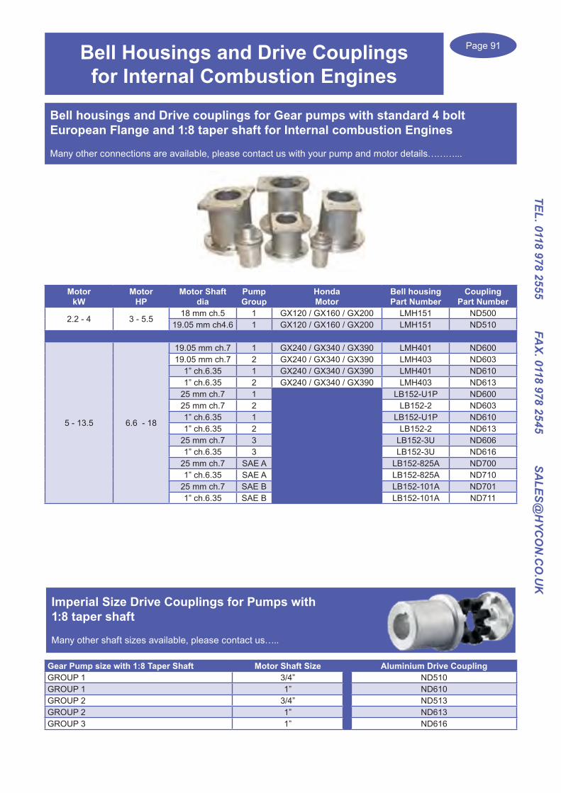
Page 91
TEL. 0118 978 2555 FAX. 0118 978 2545 SA
LES@H
YCO
N.C
O.U
K
Gear Pump size with 1:8 Taper Shaft Motor Shaft Size Aluminium Drive CouplingGROUP 1 3/4” ND510GROUP 1 1” ND610GROUP 2 3/4” ND513GROUP 2 1” ND613GROUP 3 1” ND616
Motor kW
Motor HP
Motor Shaft dia
PumpGroup
Honda Motor
Bell housingPart Number
CouplingPart Number
2.2 - 4 3 - 5.518 mm ch.5 1 GX120 / GX160 / GX200 LMH151 ND500
19.05 mm ch4.6 1 GX120 / GX160 / GX200 LMH151 ND510
5 - 13.5 6.6 - 18
19.05 mm ch.7 1 GX240 / GX340 / GX390 LMH401 ND60019.05 mm ch.7 2 GX240 / GX340 / GX390 LMH403 ND603
1” ch.6.35 1 GX240 / GX340 / GX390 LMH401 ND6101” ch.6.35 2 GX240 / GX340 / GX390 LMH403 ND613
25 mm ch.7 1 LB152-U1P ND60025 mm ch.7 2 LB152-2 ND6031” ch.6.35 1 LB152-U1P ND6101” ch.6.35 2 LB152-2 ND613
25 mm ch.7 3 LB152-3U ND6061” ch.6.35 3 LB152-3U ND616
25 mm ch.7 SAE A LB152-825A ND7001” ch.6.35 SAE A LB152-825A ND710
25 mm ch.7 SAE B LB152-101A ND7011” ch.6.35 SAE B LB152-101A ND711
Imperial Size Drive Couplings for Pumps with 1:8 taper shaft
Many other shaft sizes available, please contact us…..
Bell Housings and Drive Couplings for Internal Combustion Engines
Bell housings and Drive couplings for Gear pumps with standard 4 bolt European Flange and 1:8 taper shaft for Internal combustion Engines
Many other connections are available, please contact us with your pump and motor details………...
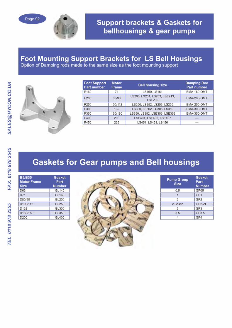
Page 92
TEL.
011
8 97
8 25
55
FA
X. 0
118
978
2545
S
ALE
S@H
YCO
N.C
O.U
K Foot SupportPart number
Motor Frame Bell housing size Damping Rod
Part numberP160 71 LS160, LS161 BMA-160-OMT
P200 80/90 LS200, LS201, LS203, LSE213, LSE206 BMA-200-OMT
P250 100/112 LS250, LS252, LS253, LS255 BMA-250-OMTP300 132 LS300, LS302, LS306, LS310 BMA-300-OMTP350 160/180 LS350, LS352, LSE356, LSE358 BMA-350-OMTP400 200 LSE401, LSE405, LSE407 —P450 225 LS451, LS453, LS456 —
Foot Mounting Support Brackets for LS Bell HousingsOption of Damping rods made to the same size as the foot mounting support
Support brackets & Gaskets for bellhousings & gear pumps
Gaskets for Gear pumps and Bell housingsB5/B35 Motor Frame Size
GasketPart
NumberD63 GL140D71 GL160D80/90 GL200D100/112 GL250D132 GL300D160/180 GL350D200 GL400
Pump Group Size
GasketPart Number
0.5 GP051 GP12 GP2
2 Bosch GP2-ZF3 GP3
3.5 GP3.54 GP4

Page 93
TEL. 0118 978 2555 FAX. 0118 978 2545 SA
LES@H
YCO
N.C
O.U
K
Hydraulic Power Packs
Micro & Compact AC & DC Power packs
0.2 up to 25 lpm
AC & DC Motors to 4KW
Pressure up to 300 bar +
Single, Double & Reversible circuits for all applications
Options of hand pumps,pressure & flow controls, 2, 3 & 4 way directional valves, proportional flow & pressure controls
Large stock of components to offer a quick, off the shelf delivery
Please contact us with your enquiry................
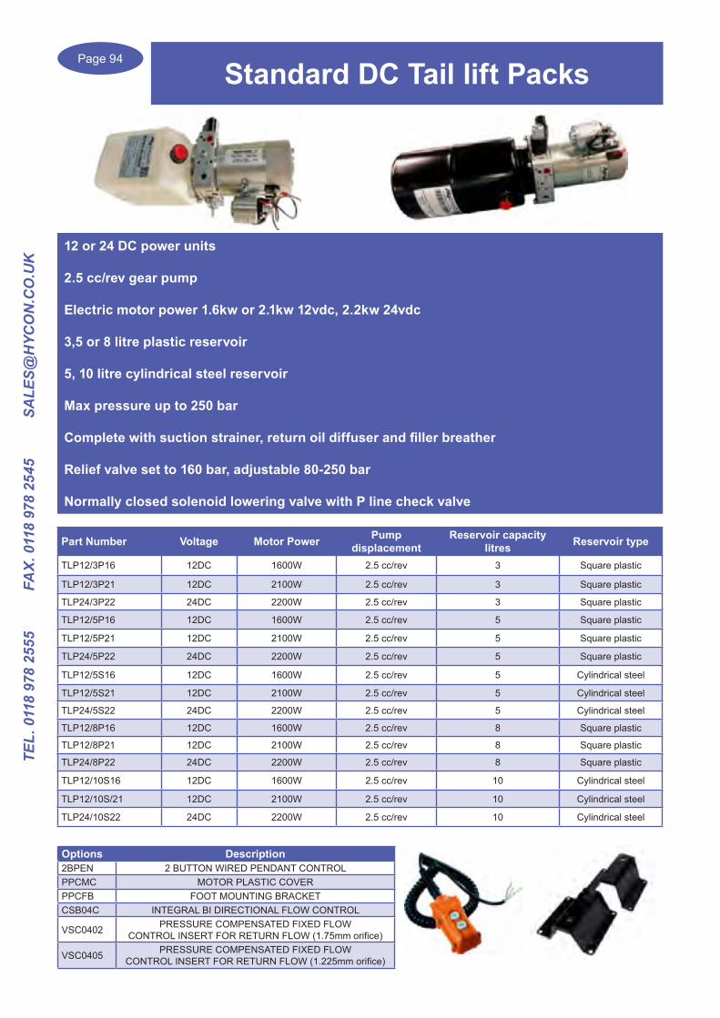
Page 94
TEL.
011
8 97
8 25
55
FA
X. 0
118
978
2545
S
ALE
S@H
YCO
N.C
O.U
K
Standard DC Tail lift Packs
12 or 24 DC power units
2.5 cc/rev gear pump
Electric motor power 1.6kw or 2.1kw 12vdc, 2.2kw 24vdc
3,5 or 8 litre plastic reservoir
5, 10 litre cylindrical steel reservoir
Max pressure up to 250 bar
Complete with suction strainer, return oil diffuser and filler breather
Relief valve set to 160 bar, adjustable 80-250 bar
Normally closed solenoid lowering valve with P line check valve
Part Number Voltage Motor Power Pump displacement
Reservoir capacitylitres Reservoir type
TLP12/3P16 12DC 1600W 2.5 cc/rev 3 Square plastic
TLP12/3P21 12DC 2100W 2.5 cc/rev 3 Square plastic
TLP24/3P22 24DC 2200W 2.5 cc/rev 3 Square plastic
TLP12/5P16 12DC 1600W 2.5 cc/rev 5 Square plastic
TLP12/5P21 12DC 2100W 2.5 cc/rev 5 Square plastic
TLP24/5P22 24DC 2200W 2.5 cc/rev 5 Square plastic
TLP12/5S16 12DC 1600W 2.5 cc/rev 5 Cylindrical steel
TLP12/5S21 12DC 2100W 2.5 cc/rev 5 Cylindrical steel
TLP24/5S22 24DC 2200W 2.5 cc/rev 5 Cylindrical steel
TLP12/8P16 12DC 1600W 2.5 cc/rev 8 Square plastic
TLP12/8P21 12DC 2100W 2.5 cc/rev 8 Square plastic
TLP24/8P22 24DC 2200W 2.5 cc/rev 8 Square plastic
TLP12/10S16 12DC 1600W 2.5 cc/rev 10 Cylindrical steel
TLP12/10S/21 12DC 2100W 2.5 cc/rev 10 Cylindrical steel
TLP24/10S22 24DC 2200W 2.5 cc/rev 10 Cylindrical steel
Options Description2BPEN 2 BUTTON WIRED PENDANT CONTROLPPCMC MOTOR PLASTIC COVERPPCFB FOOT MOUNTING BRACKETCSB04C INTEGRAL BI DIRECTIONAL FLOW CONTROL
VSC0402 PRESSURE COMPENSATED FIXED FLOW CONTROL INSERT FOR RETURN FLOW (1.75mm orifice)
VSC0405 PRESSURE COMPENSATED FIXED FLOW CONTROL INSERT FOR RETURN FLOW (1.225mm orifice)

Page 95
TEL. 0118 978 2555 FAX. 0118 978 2545 SA
LES@H
YCO
N.C
O.U
K
Design, manufacture and supply of all Hydraulic Power Units
In all Electric motor voltages or diesel/petrol engine units
Hydraulic power packs built to any specification
Please contact us with your enquiry..........
Hydraulic Power Packs
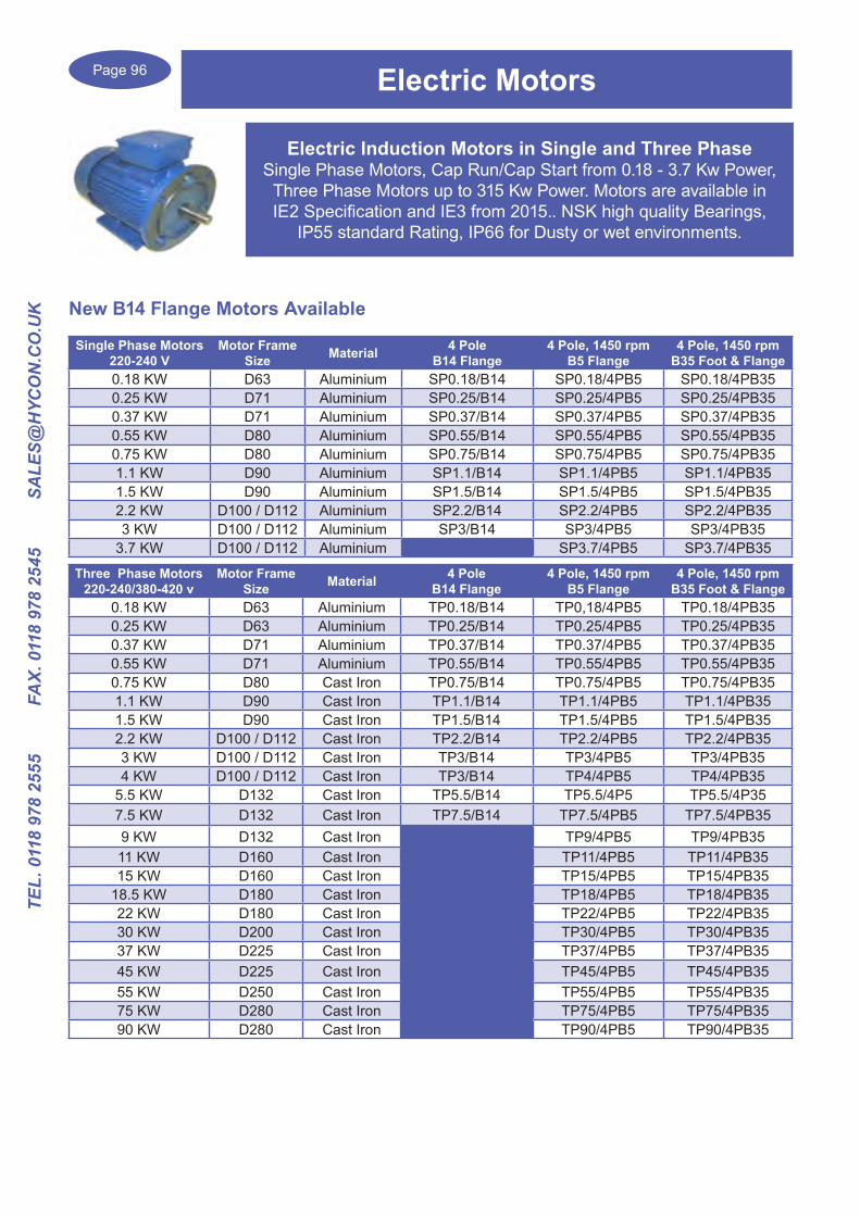
Page 96
TEL.
011
8 97
8 25
55
FA
X. 0
118
978
2545
S
ALE
S@H
YCO
N.C
O.U
K
Electric Induction Motors in Single and Three PhaseSingle Phase Motors, Cap Run/Cap Start from 0.18 - 3.7 Kw Power,
Three Phase Motors up to 315 Kw Power. Motors are available in IE2 Specification and IE3 from 2015.. NSK high quality Bearings,
IP55 standard Rating, IP66 for Dusty or wet environments.
Electric Motors
Single Phase Motors220-240 V
Motor Frame Size Material 4 Pole
B14 Flange4 Pole, 1450 rpm
B5 Flange4 Pole, 1450 rpm
B35 Foot & Flange0.18 KW D63 Aluminium SP0.18/B14 SP0.18/4PB5 SP0.18/4PB350.25 KW D71 Aluminium SP0.25/B14 SP0.25/4PB5 SP0.25/4PB350.37 KW D71 Aluminium SP0.37/B14 SP0.37/4PB5 SP0.37/4PB350.55 KW D80 Aluminium SP0.55/B14 SP0.55/4PB5 SP0.55/4PB350.75 KW D80 Aluminium SP0.75/B14 SP0.75/4PB5 SP0.75/4PB351.1 KW D90 Aluminium SP1.1/B14 SP1.1/4PB5 SP1.1/4PB351.5 KW D90 Aluminium SP1.5/B14 SP1.5/4PB5 SP1.5/4PB352.2 KW D100 / D112 Aluminium SP2.2/B14 SP2.2/4PB5 SP2.2/4PB353 KW D100 / D112 Aluminium SP3/B14 SP3/4PB5 SP3/4PB35
3.7 KW D100 / D112 Aluminium SP3.7/4PB5 SP3.7/4PB35
Three Phase Motors220-240/380-420 v
Motor Frame Size Material 4 Pole
B14 Flange4 Pole, 1450 rpm
B5 Flange4 Pole, 1450 rpm
B35 Foot & Flange0.18 KW D63 Aluminium TP0.18/B14 TP0,18/4PB5 TP0.18/4PB350.25 KW D63 Aluminium TP0.25/B14 TP0.25/4PB5 TP0.25/4PB350.37 KW D71 Aluminium TP0.37/B14 TP0.37/4PB5 TP0.37/4PB350.55 KW D71 Aluminium TP0.55/B14 TP0.55/4PB5 TP0.55/4PB350.75 KW D80 Cast Iron TP0.75/B14 TP0.75/4PB5 TP0.75/4PB351.1 KW D90 Cast Iron TP1.1/B14 TP1.1/4PB5 TP1.1/4PB351.5 KW D90 Cast Iron TP1.5/B14 TP1.5/4PB5 TP1.5/4PB352.2 KW D100 / D112 Cast Iron TP2.2/B14 TP2.2/4PB5 TP2.2/4PB353 KW D100 / D112 Cast Iron TP3/B14 TP3/4PB5 TP3/4PB354 KW D100 / D112 Cast Iron TP3/B14 TP4/4PB5 TP4/4PB35
5.5 KW D132 Cast Iron TP5.5/B14 TP5.5/4P5 TP5.5/4P357.5 KW D132 Cast Iron TP7.5/B14 TP7.5/4PB5 TP7.5/4PB359 KW D132 Cast Iron TP9/4PB5 TP9/4PB3511 KW D160 Cast Iron TP11/4PB5 TP11/4PB3515 KW D160 Cast Iron TP15/4PB5 TP15/4PB35
18.5 KW D180 Cast Iron TP18/4PB5 TP18/4PB3522 KW D180 Cast Iron TP22/4PB5 TP22/4PB3530 KW D200 Cast Iron TP30/4PB5 TP30/4PB3537 KW D225 Cast Iron TP37/4PB5 TP37/4PB3545 KW D225 Cast Iron TP45/4PB5 TP45/4PB3555 KW D250 Cast Iron TP55/4PB5 TP55/4PB3575 KW D280 Cast Iron TP75/4PB5 TP75/4PB3590 KW D280 Cast Iron TP90/4PB5 TP90/4PB35
New B14 Flange Motors Available

Page 97
TEL. 0118 978 2555 FAX. 0118 978 2545 SA
LES@H
YCO
N.C
O.U
K
Damping Rods & Rings
Damping Rods are two steel rods moulded into a mineral oil resistant vulcanised rubber to fit between the electric motor and the tank cover.
Damping Rods will reduce the noise generated by the power transmission output by approximately 3-5 dB.
Damping RodsNot pre machined for Electric Motor mount
Damping Rod with mounting threads for
standard Electric Motors
Motor Frame Size
BMA-71 BMA-71-F D71BMA-71 BMA-80-F D80BMA-90 BMA-90L-F D90LBMA-90 BMA-90-S D90SBMA-90 BMA-100L-F D100LBMA-90 BMA-112M-F D112MBMA-132 BMA-132S-F D132SBMA-132 BMA-132M-F D132MBMA-160L BMA-160L-F D160LBMA-160M BMA-160M-F D160MBMA-180 BMA-180L-F D180LBMA-180 BMA-180M-F D180MBMA-200 BMA-200L-F D200LBMA-225 BMA-225S-F D225SBMA-250 BMA-250M-F D250MBMA-280 BMA-280S-F D280SBMA-280 BMA-280M-F D280M
BMA-132M-F
BMA-132
Damping Rings for OMT Bell housingsTwo rings moulded into a mineral oil resistant vulcanised rubber to fit between the bell housing and the tank cover. The Damping Rings will reduce the noise generated by the power transmission output by approximately 3-5 dB.
Damping Ring Motor Frame Bell housing sizeA200 80/90 LS200,LS201,LS203,LSE213,LSE206A250 100/112 LS250,LS252,LS253,LS255A300 132 LS300,LS302,LS306,LS310A350 160/180 LS350,LS352,LSE356,LSE358A400 200 LSE401,LSE405,LSE407
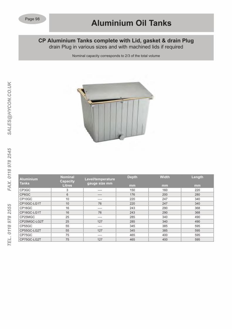
Page 98
TEL.
011
8 97
8 25
55
FA
X. 0
118
978
2545
S
ALE
S@H
YCO
N.C
O.U
K
AluminiumTanks
Nominal Capacity
Litres
Level/temperature gauge size mm
Depth
mm
Width
mm
Length
mmCP3GC 3 —- 150 160 220CP6GC 6 —- 176 200 280CP10GC 10 —- 220 247 340CP10GC-LG1T 10 76 220 247 340CP16GC 16 —- 243 290 368CP16GC-LG1T 16 76 243 290 368CP25MGC 25 —- 285 340 490CP25MGC-LG2T 25 127 285 340 490CP55GC 55 —- 345 385 595CP55GC-LG2T 55 127 345 385 595CP75GC 75 —- 465 400 595CP75GC-LG2T 75 127 465 400 595
CP Aluminium Tanks complete with Lid, gasket & drain Plug drain Plug in various sizes and with machined lids if required
Nominal capacity corresponds to 2/3 of the total volume
Aluminium Oil Tanks

Page 99
TEL. 0118 978 2555 FAX. 0118 978 2545 SA
LES@H
YCO
N.C
O.U
K
Tank components including Sight Levels, Inspection covers, Filler Breathers, Filters, Pressure Gauges, etc…. Pages 108 onwards
Pre Machined Steel Lid for 10 Litre Tank & power unit components
Lid Code Bell housing Frame dia A B C D ECCP10 MC140 140 mm 88 82 101 115 9.5CCP10 MC160 160 mm 98 92 115 130 9.5CCP10 MC200 200 mm 116 112 135 165 11.5
A Fully machined cover for use on CP10Tanks, with or withoutStandard component
Parts to assemble Power packs
Part Description Type1 Cover CCP10 MC...2 Filler Breather TR-13 Return Line Filter (25 Micron) OMTF091C254 Special Fitting R12 MC5 Base Plate BMC-VC26 Cetop Stackable Plate ML31
Aluminium Oil Tanks
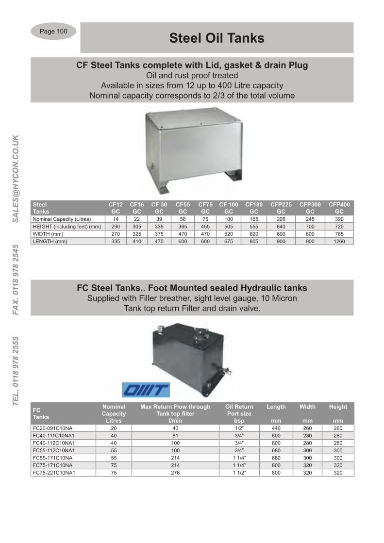
Page 100
TEL.
011
8 97
8 25
55
FA
X. 0
118
978
2545
S
ALE
S@H
YCO
N.C
O.U
K
Steel Tanks
CF12GC
CF16GC
CF 30GC
CF55GC
CF75GC
CF 100GC
CF180GC
CFP225GC
CFP300GC
CFP400GC
Nominal Capacity (Litres) 14 22 39 58 75 100 165 205 245 390HEIGHT (including feet) (mm) 290 305 335 365 455 505 555 640 700 720WIDTH (mm) 270 325 375 470 470 520 620 600 600 765LENGTH (mm) 335 410 470 600 600 675 805 900 900 1260
CF Steel Tanks complete with Lid, gasket & drain PlugOil and rust proof treated
Available in sizes from 12 up to 400 Litre capacityNominal capacity corresponds to 2/3 of the total volume
Steel Oil Tanks
FCTanks
Nominal Capacity
Litres
Max Return Flow through Tank top filter
l/min
Oil ReturnPort size
bsp
Length
mm
Width
mm
Height
mmFC20-091C10NA 20 40 1/2” 440 260 260FC40-111C10NA1 40 81 3/4” 600 280 280FC40-112C10NA1 40 100 3/4” 600 280 280FC55-112C10NA1 55 100 3/4” 680 300 300FC55-171C10NA 55 214 1 1/4” 680 300 300FC75-171C10NA 75 214 1 1/4” 800 320 320FC75-221C10NA1 75 276 1 1/2” 800 320 320
FC Steel Tanks.. Foot Mounted sealed Hydraulic tanksSupplied with Filler breather, sight level gauge, 10 Micron
Tank top return Filter and drain valve.
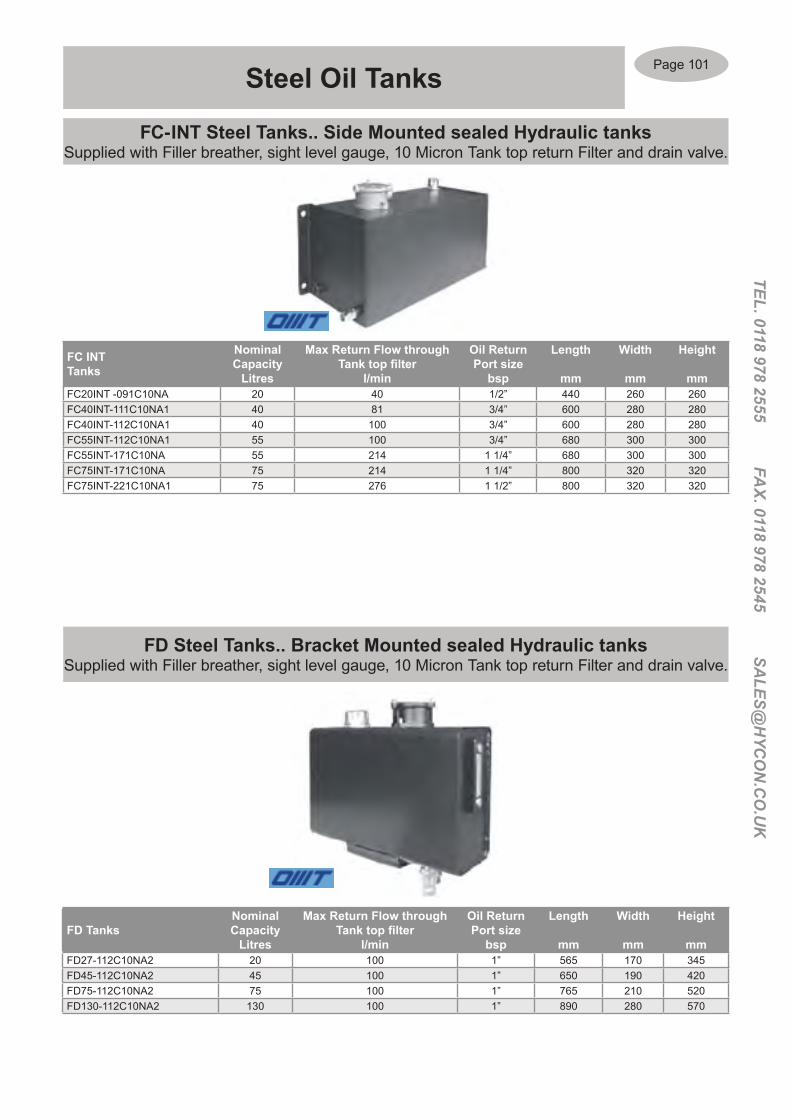
Page 101
TEL. 0118 978 2555 FAX. 0118 978 2545 SA
LES@H
YCO
N.C
O.U
K
Steel Oil Tanks
FC INTTanks
Nominal Capacity
Litres
Max Return Flow through Tank top filter
l/min
Oil ReturnPort size
bsp
Length
mm
Width
mm
Height
mmFC20INT -091C10NA 20 40 1/2” 440 260 260FC40INT-111C10NA1 40 81 3/4” 600 280 280FC40INT-112C10NA1 40 100 3/4” 600 280 280FC55INT-112C10NA1 55 100 3/4” 680 300 300FC55INT-171C10NA 55 214 1 1/4” 680 300 300FC75INT-171C10NA 75 214 1 1/4” 800 320 320FC75INT-221C10NA1 75 276 1 1/2” 800 320 320
FC-INT Steel Tanks.. Side Mounted sealed Hydraulic tanksSupplied with Filler breather, sight level gauge, 10 Micron Tank top return Filter and drain valve.
FD Steel Tanks.. Bracket Mounted sealed Hydraulic tanksSupplied with Filler breather, sight level gauge, 10 Micron Tank top return Filter and drain valve.
FD TanksNominal Capacity
Litres
Max Return Flow through Tank top filter
l/min
Oil ReturnPort size
bsp
Length
mm
Width
mm
Height
mmFD27-112C10NA2 20 100 1” 565 170 345FD45-112C10NA2 45 100 1” 650 190 420FD75-112C10NA2 75 100 1” 765 210 520FD130-112C10NA2 130 100 1” 890 280 570

Page 102
TEL.
011
8 97
8 25
55
FA
X. 0
118
978
2545
S
ALE
S@H
YCO
N.C
O.U
K
Part Number Diameter Number of Mounting holes
Size of Mounting holes
SI 275G 275 mm 6 9 mmSI 400G 400 mm 8 9 mmSE 350 350 mm 4 11.5 mmSE 475 475 mm 6 11.5 mm
Inspection covers for Oil Tanks
Die cast Aluminium supplied with a Gasket
Tank Inspection Covers& Electric Oil Level Switches
Electric Oil Level SwitchesAn electrical signal is supplied when the min. or max. (or
both) oil levels are reached within the tankAvailable with a Flange mount or M18X1.5 mm Male thread mount
Flange mount …Minimum Level Min & Max Level Depth of Rod
Into tank (mmSuitable for Tank type
LM1F-130 LM2F-130 130 CF12, CF16LMIF-150 LM2F-150 150 CF30, CF75LM1F-200 LM2F-200 200 CF100, CF180LM1F-250 LM2F-250 250 CF100, CF180,CFP225LM1F-300 LM2F-300 300 CF180, CFP225LM1F-350 LM2F-350 350 CFP225, CFP300LM1F-400 LM2F-400 400 CFP300, CFP400LM1F-450 LM2F-450 450LM1F-500 LM2F-500 500
Threaded mount …Minimum Level Min & Max Level
Depth of RodInto tank mm
Suitable for Tank type
LM1D-130 LM2D-130 130 CF12, CF16LMID-150 LM2D-150 150 CF30, CF75LM1D-200 LM2D-200 200 CF100, CF180LM1D-250 LM2D-250 250 CF100, CF180,CFP225LM1D-300 LM2D-300 300 CF180, CFP225LM1D-350 LM2D-350 350 CFP225, CFP300LM1D-400 LM2D-400 400 CFP300, CFP400LM1D-450 LM2D-450 450LM1D-500 LM2D-500 500

Page 103
TEL. 0118 978 2555 FAX. 0118 978 2545 SA
LES@H
YCO
N.C
O.U
K
Part Number OutsideDiameter
Width ofBasket
Length ofBasket
TR1 52 mm 27 mm 65 mmTP1.02601 83 mm 50 mm 80 mmTP1.02602 83 mm 50 mm 150 mmTP1.02603 83 mm 50 mm 203 mm
Part Number OutsideDiameter
Width ofBasket
Length ofBasket
TP2.02604 83 mm 50 mm 80 mmTP2.02605 83 mm 50 mm 150 mm
Part Number Connection type Outside
DiameterWidth of Basket
Length ofBasket
TPB-2D
Basket Mounted 6 x 5 mm screws
Cap M52 x 2 Threaded
91 44 mm 110 mm
TPM-2M52 M52 x 2 mm 91 —— ——-
Filler Breathers
FILLER BREATHERSChrome Plated Steel and Nylon type with Bayonet Closure
FILLER BREATHERSChrome Plated Steel with Key Lockable cap
PV9.01746… Angled Extension for Filler Breathers
Suitable for Filler Breathers type TP1.02601/02/03/04/05
FILLER BREATHERSIn Nylon with M52 x 2 Threaded connection

Page 104
TEL.
011
8 97
8 25
55
FA
X. 0
118
978
2545
S
ALE
S@H
YCO
N.C
O.U
K
Part Number Pressurebar
OutsideDiameter
Thread Sizebsp Micron
TP9.02615 0.35 75 mm 3/4” 40
PRESSURISED FILLER BREATHERChrome Plated Steel Cap,10 Micron Sponge Air Filtration
Filler / Air Breathers
WELDABLE FILLER BREATHERSChrome Plated Steel with Bayonet closure, with extractable basket and rubber gasket
Part Number
OutsideDiameter
Outside Diameterof collar
TotalLength
TRBS 83 mm 38 mm 180 mm
AIR BREATHER CAPChrome Plated Steel with BSP Thread, 40 Micron
Part Number BSPThread Micron Outside
Diameter mmRecommended Air
Flow m3/hourTP8.02613 1/4” 40 48 15TRM-1-14S1 1/4” 10 47 9TRM-1-38 3/8” 40 47 15TRM-1-38S1 3/8” 10 47 15TRM-1-12 1/2” 40 47 15TRM-1-12S1 1/2” 10 47 15TRM-2-12 1/2” 40 75 21TRM-2-12S1 1/2” 10 75 21TP8.02614 3/4” 40 76 42TP8.03842 3/4” 10 76 42TRM-2-100 1” 40 75 60TRM-100-S1 1” 10 75 6
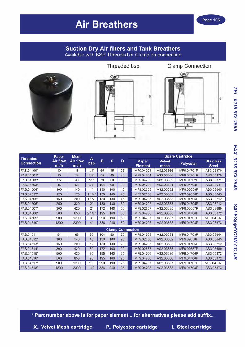
Page 105
TEL. 0118 978 2555 FAX. 0118 978 2545 SA
LES@H
YCO
N.C
O.U
K
Air Breathers
Suction Dry Air filters and Tank BreathersAvailable with BSP Threaded or Clamp on connection
ThreadedConnection
PaperAir flow
m3/h
MeshAir flow
m3/h
Absp B C D
Spare CartridgePaper
ElementVelvetmesh Polyester Stainless
SteelFAS.04499* 10 18 1/4” 55 45 25 MF9.04701 AS2.03666 MF9.04701P AS3.05370FAS.04501* 10 18 3/8” 55 45 30 MF9.04701 AS2.03666 MF9.04701P AS3.05370FAS.04502* 25 40 1/2” 79 60 30 MF9.04702 AS2.03662 MF9.04702P AS3.05371FAS.04503* 45 68 3/4” 104 90 30 MF9.04703 AS2.03681 MF9.04703P AS3.03644FAS.04504* 100 140 1” 130 100 40 MF9.02658 AS2.03682 MF9.02658P AS3.03645FAS.04519* 125 170 1 1/4” 130 100 40 MF9.02658 AS2.03682 MF9.02658P AS3.03645FAS.04505* 150 200 1 1/2” 130 130 45 MF9.04705 AS2.03683 MF9.04705P AS3.03712FAS.04506* 250 320 2” 130 130 60 MF9.04705 AS2.03683 MF9.04705P AS3.03712FAS.04507* 300 420 2” 172 160 50 MF9.02657 AS2.03685 MF9.02657P AS3.03689FAS.04508* 500 650 2 1/2” 195 160 60 MF9.04706 AS2.03686 MF9.04706P AS3.05372FAS.04509* 900 1200 3” 290 190 60 MF9.04707 AS2.03687 MF9.04707P MF9.04707IFAS.04510* 1800 2300 4” 336 240 60 MF9.04708 AS2.03688 MF9.04708P AS3.05373
Clamp ConnectionFAS,04511* 54 68 20 104 90 20 MF9.04703 AS2.03681 MF9.04703P AS3.03644FAS.04512* 100 140 40 130 100 20 MF9.02658 AS2.03682 MF9.02658P AS3.03645FAS.04513* 150 200 52 130 130 20 MF9.04705 AS2.03683 MF9.04705P AS3.03712FAS.04514* 300 420 60 172 160 20 MF9.02657 AS2.03685 MF9.02657P AS3.03689FAS.04515* 500 420 80 195 160 25 MF9.04706 AS2.03686 MF9.04706P AS3.05372FAS.04516* 500 650 90 195 160 25 MF9.04706 AS2.03686 MF9.04706P AS3.05372FAS.04517* 900 1200 100 290 190 25 MF9.04707 AS2.03687 MF9.04707P MF9.04707IFAS.04518* 1800 2300 140 336 240 25 MF9.04708 AS2.03688 MF9.04708P AS3.05373
* Part number above is for paper element... for alternatives please add suffix..
X.. Velvet Mesh cartridge P.. Polyester cartridge I.. Steel cartridge
Threaded bsp Clamp Connection

Page 106
TEL.
011
8 97
8 25
55
FA
X. 0
118
978
2545
S
ALE
S@H
YCO
N.C
O.U
K
Filler Caps
PLASTIC FILLER CAPSInner Breather and filter, made from black polyamide with red cover
For applications with high oil spray a sintered bronze air filter is available, add suffix ‘B’
Part Number
Thread sizebsp
Micron & filter
material
Outside Diameter
of cap mm
Air Flow m3/h
TPL.38 3/8” 40 sponge 36 12TPL.38B 3/8” 30 bronze 36 12TPL.12 1/2” 40 sponge 41 13.8TPL.12B 1/2” 30 bronze 41 13.8TPL.34 3/4” 40 sponge 47 21TPL.34B 3/4” 40 bronze 47 21TPL.1 1” 40 sponge 52 24TPL.1B 1” 40 bronze 52 24TPL.114 1 1/4” 40 sponge 63 36TPL.114B 1 1/4” 40 bronze 63 36TPL.112 1 1/2” 40 sponge 63 36TPL.112B 1 1/2” 30 bronze 63 36
VISUAL OIL LEVEL CAPSOption of Polyamide Plastic or Aluminium alloy caps
Plastic type Thread sizebsp
Max Pressure
bar
Diameter of cap mm
SL.14 1/4”bsp 10 20.5SL.38 3/8”bsp 10 22SL.12 1/2”bsp 10 28SL.34 3/4”bsp 10 36SL.1 1”bsp 10 42SL.114 1 1/4”bsp 10 51SL.112 1 1/2”bsp 10 58SL.2 2”bsp 10 74SL.1415 M14x1.5 10 20SL.1615 M16x1.5 10 22SL.1815 M18x1.5 10 25.5SL.2015 M20x1.5 10 28SL.2215 M22x1.5 10 28SL.4015 M40x1.5 10 51
Metal type
Thread sizebsp
Max Pressure
bar
Diameter of cap mm
SLM.14 1/4” bsp 20 20.5SLM.38 3/8” bsp 20 22SLM.12 1/2” bsp 20 28SLM.34 3/4” bsp 20 36SLM.1 1” bsp 20 42SLM.114 1 1/4” bsp 20 51
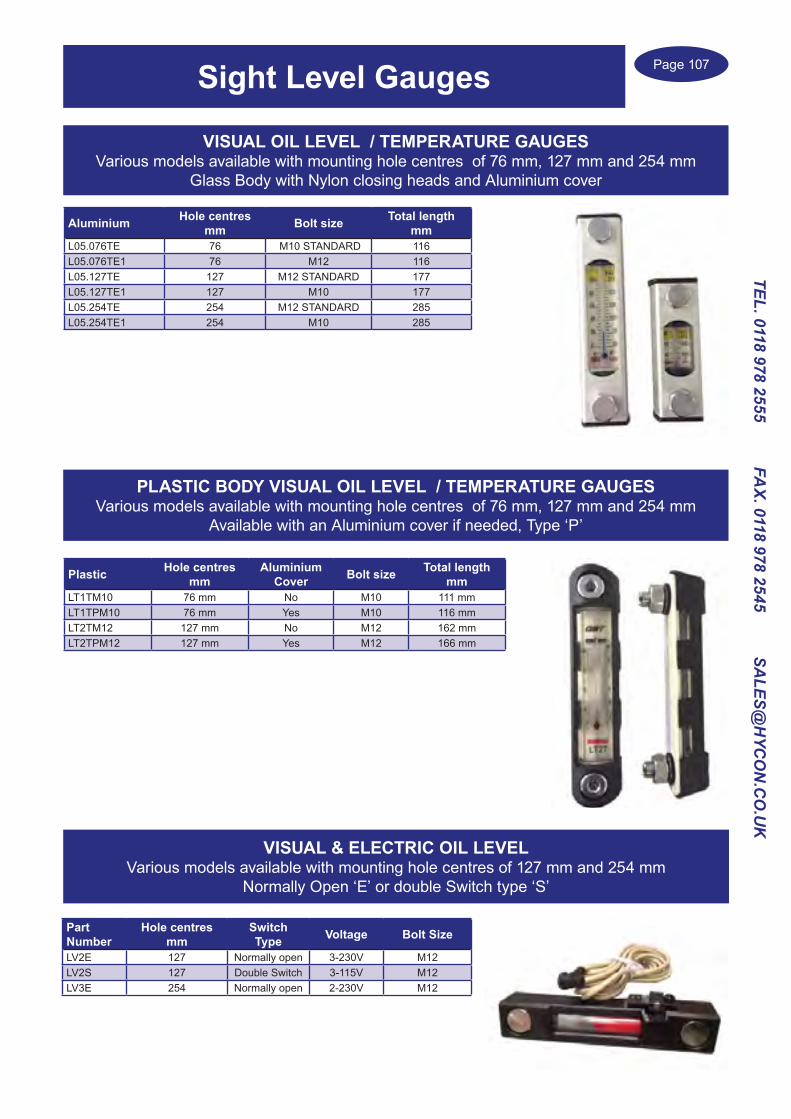
Page 107
TEL. 0118 978 2555 FAX. 0118 978 2545 SA
LES@H
YCO
N.C
O.U
K
Aluminium Hole centresmm Bolt size Total length
mmL05.076TE 76 M10 STANDARD 116L05.076TE1 76 M12 116L05.127TE 127 M12 STANDARD 177L05.127TE1 127 M10 177L05.254TE 254 M12 STANDARD 285L05.254TE1 254 M10 285
Plastic Hole centresmm
Aluminium Cover Bolt size Total length
mmLT1TM10 76 mm No M10 111 mmLT1TPM10 76 mm Yes M10 116 mmLT2TM12 127 mm No M12 162 mmLT2TPM12 127 mm Yes M12 166 mm
Sight Level Gauges
VISUAL OIL LEVEL / TEMPERATURE GAUGESVarious models available with mounting hole centres of 76 mm, 127 mm and 254 mm
Glass Body with Nylon closing heads and Aluminium cover
Part Number
Hole centres mm
Switch Type Voltage Bolt Size
LV2E 127 Normally open 3-230V M12LV2S 127 Double Switch 3-115V M12LV3E 254 Normally open 2-230V M12
VISUAL & ELECTRIC OIL LEVELVarious models available with mounting hole centres of 127 mm and 254 mm
Normally Open ‘E’ or double Switch type ‘S’
PLASTIC BODY VISUAL OIL LEVEL / TEMPERATURE GAUGESVarious models available with mounting hole centres of 76 mm, 127 mm and 254 mm
Available with an Aluminium cover if needed, Type ‘P’

Page 108
TEL.
011
8 97
8 25
55
FA
X. 0
118
978
2545
S
ALE
S@H
YCO
N.C
O.U
K
Part Ref Flow Ratel/min
Threadbsp Micron Length
mmDiameter
mmFR5.02361 6 1/4” 90 37 32FR5.02334 10 1/4” 90 32 50FR1.02360 12 3/8” 90 39 32FR1.06600 15 3/8” 160 55 45FR1.04483 17 3/8” 160 75 45FI1.10M90 19 3/8” 90 89 50FI2.10M90 25 1/2” 90 89 50FI2.15M90 29 1/2” 90 93 69FR2.04485 40 3/4” 160 110 63FI3.15M90 45 3/4” 90 93 69FI3.20M90 55 3/4” 90 142 69FI4.20M90 58 1” 90 142 69FI4.25M90 59 1” 90 94 100FI4.30M90 84 1” 90 143 100FR8.06625 80 1” 160 144 89FI5.30M90 115 1 1/4” 90 143 100FI5.35M90 120 1 1/4” 90 180 100FI5.40M90 138 1 1/4” 90 230 140FI5.45M90 128 1 1/4” 90 93 140FI6.40M90 136 1 1/2” 90 230 100FI6.50M90 136 1 1/2” 90 105 140FI6.55M90 160 1 1/2” 90 165 140FR8.04489 145 1 1/2” 160 200 89FI7.55M90 200 2” 90 165 140FI7.60M90 235 2” 90 213 140FI7.65M90 240 2” 90 260 140FI7.70M90 245 2” 90 320 140FI8.65M90 300 2 1/2” 90 268 140FI8.70M90 320 2 1/2” 90 326 140FI9.70M90 400 3” 90 290 150FR8.04493 500 3” 160 270 150
Oil Suction Strainers, Steel cover endsSuction Line Filters with bsp threaded connection.
Metal mesh fabric with galvanised steel ends.
Suction Strainers
Oil Suction Strainers, Plastic connection endsSuction Line Filters with bsp threaded connection.
Part Ref Flow Ratel/min
Threadbsp Micron Length
mmDiameter
mmFRP1.07400 10 3/8” 125 58 46FRP1.07401 16 3/8” 125 73 46FRP1.07402 18 3/8” 125 93 46FRP2.07403 23 1/2” 125 123 46FRP3.07404 48 3/4” 125 130 64FRP4.07405 62 1” 125 161 64FRP4.07406 80 1” 125 165 86FRP5.07407 75 1 1/4” 125 165 86FRP6.07408 100 1 1/2” 125 165 86FRP6.07409 130 1 1/2” 125 225 86FRP7.07410 180 2” 125 286 86FRP7.07411 225 2” 125 178 150FRP8.07412 350 2 1/2” 125 243 150FRP9.07413 500 3” 125 303 150
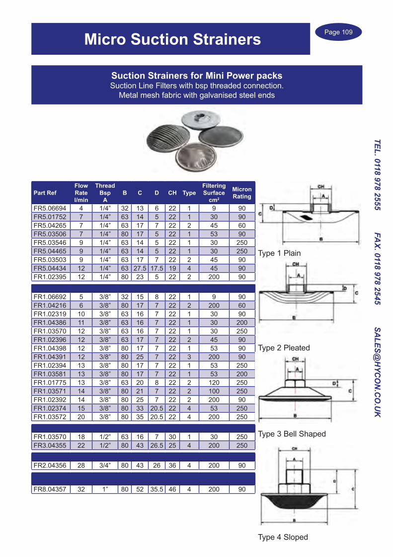
Page 109
TEL. 0118 978 2555 FAX. 0118 978 2545 SA
LES@H
YCO
N.C
O.U
K
Type 1 Plain
Type 2 Pleated
Type 3 Bell Shaped
Type 4 Sloped
Suction Strainers for Mini Power packsSuction Line Filters with bsp threaded connection.
Metal mesh fabric with galvanised steel ends
Part RefFlow Ratel/min
ThreadBsp
AB C D CH Type
FilteringSurface
cm2
MicronRating
FR5.06694 4 1/4” 32 13 6 22 1 9 90FR5.01752 7 1/4” 63 14 5 22 1 30 90FR5.04265 7 1/4” 63 17 7 22 2 45 60FR5.03506 7 1/4” 80 17 5 22 1 53 90FR5.03546 9 1/4” 63 14 5 22 1 30 250FR5.04465 9 1/4” 63 14 5 22 1 30 250FR5.03503 9 1/4” 63 17 7 22 2 45 90FR5.04434 12 1/4” 63 27.5 17.5 19 4 45 90FR1.02395 12 1/4” 80 23 5 22 2 200 90
FR1.06692 5 3/8” 32 15 8 22 1 9 90FR1.04216 6 3/8” 80 17 7 22 2 200 60FR1.02319 10 3/8” 63 16 7 22 1 30 90FR1.04386 11 3/8” 63 16 7 22 1 30 200FR1.03570 12 3/8” 63 16 7 22 1 30 250FR1.02396 12 3/8” 63 17 7 22 2 45 90FR1.04398 12 3/8” 80 17 7 22 1 53 90FR1.04391 12 3/8” 80 25 7 22 3 200 90FR1.02394 13 3/8” 80 17 7 22 1 53 250FR1.03581 13 3/8” 80 17 7 22 1 53 200FR1.01775 13 3/8” 63 20 8 22 2 120 250FR1.03571 14 3/8” 80 21 7 22 2 100 250FR1.02392 14 3/8” 80 25 7 22 2 200 90FR1.02374 15 3/8” 80 33 20.5 22 4 53 250FR1.03572 20 3/8” 80 35 20.5 22 4 200 250
FR1.03570 18 1/2” 63 16 7 30 1 30 250FR3.04355 22 1/2” 80 43 26.5 25 4 200 250
FR2.04356 28 3/4” 80 43 26 36 4 200 90
FR8.04357 32 1” 80 52 35.5 46 4 200 90
Micro Suction Strainers

Page 110
TEL.
011
8 97
8 25
55
FA
X. 0
118
978
2545
S
ALE
S@H
YCO
N.C
O.U
K
Inline Return Filters
Complete Filter Part No. bsp Flow
l/minMicron Rating
FiltrationMedia
Canister Part No
Canisterlength mm
Head Part number
THL.10ST2+FHL.1M10 3/4” 64 10 Resin treated Cellulose FHL.1M10 145 THL.10ST2THL.10ST2+FHL.1M25 3/4” 72 25 Resin treated Cellulose FHL.1M25 145 THL.10ST2THL.10ST2+FHL.1A03 3/4” 50 3 absolute Inorganic Fibre FHL.1A03 145 THL.10ST2THL.10ST2+FHL.1A06 3/4” 51 6 absolute Inorganic Fibre FHL.1A05 145 THL.10ST2THL.10ST2+FHL.1A10 3/4” 62 10 absolute Inorganic Fibre FHL.1A10 145 THL.10ST2
THL.10ST2+FHL.2M10 3/4” 71 10 Resin treated Cellulose FHL.2M10 165 THL.10ST2THL.10ST2+FHL.2M25 3/4” 77 25 Resin treated Cellulose FHL.2M25 165 THL.10ST2THL.10ST2+CS06FN 3/4” 53 3 absolute Inorganic Fibre CS06FN 190 THL.10ST2THL.10ST2+CS06NN 3/4” 61 6 absolute Inorganic Fibre CS06NN 190 THL.10ST2THL.10ST2+FHL.2A10 3/4” 64 10 absolute Inorganic Fibre FHL.2A10 165 THL.10ST2
THL.20ST2+FHL.3M10 1 1/4” 158 10 Resin treated Cellulose FHL.3M10 180 THL.20ST2THL.20ST2+FHL.3M25 1 1/4” 170 25 Resin treated Cellulose FHL.3M25 180 THL.20ST2THL.20ST2+FHL.3A03 1 1/4” 83 3 absolute Inorganic Fibre FHL.3A03 180 THL.20ST2THL.20ST2+FHL.3A06 1 1/4” 105 6 absolute Inorganic Fibre FHL.3A05 180 THL.20ST2THL.20ST2+FHL.3A10 1 1/4” 128 10 absolute Inorganic Fibre FHL.3A10 180 THL.20ST2
THL.20ST2+FHL.4M10 1 1/4” 164 10 Resin treated Cellulose FHL.4M10 205 THL.20ST2THL.20ST2+FHL.4M25 1 1/4” 182 25 Resin treated Cellulose FHL.4M25 205 THL.20ST2THL.20ST2+CS15FN 1 1/4” 120 3 absolute Inorganic Fibre CS15FN 205 THL.20ST2THL.20ST2+CS15NN 1 1/4” 128 6 absolute Inorganic Fibre CS15NN 205 THL.20ST2THL.20ST2+FHL.4A10 1 1/4” 144 10 absolute Inorganic Fibre FHL.4A10 205 THL.20ST2
THL.30ST2+FHL.3M10X2 1 1/2” 300 10 Resin treated Cellulose FHL.3M10X2 180 THL.30ST2THL.30ST2+FHL.3M25X2 1 1/2” 330 25 Resin treated Cellulose FHL.3M25X2 180 THL.30ST2THL.30ST1+FHL.3A03X2 1 1/2” 165 3 absolute Inorganic Fibre FHL.3A03X2 180 THL.30ST2THL.30ST1+FHL.3A06X2 1 1/2” 210 6 absolute Inorganic Fibre FHL.3A06X2 180 THL.30ST2THL.30ST1+FHL.3A10X2 1 1/2” 250 10 absolute Inorganic Fibre FHL.3A10X2 180 THL.30ST2
THL.30ST2+FHL.4M10X2 1 1/2” 315 10 Resin treated Cellulose FHL.4M10X2 205 THL.30ST2THL.30ST2+FHL.4M25X2 1 1/2” 350 25 Resin treated Cellulose FHL.4M25X2 205 THL.30ST2THL.30ST2+CS15FNX2 1 1/2” 235 3 absolute Inorganic Fibre CS15FNX2 205 THL.30ST2THL.30ST2+CS15NNX2 1 1/2” 250 6 absolute Inorganic Fibre CS15NNX2 205 THL.30ST2THL.30ST2+FHL.4A10X2 1 1/2” 280 10 absolute Inorganic Fibre FHL.4A10X2 205 THL.30ST2
THL.40ST2+FHL.3M10X2 1 1/2” 300 10 Resin treated Cellulose FHL.3M10X2 180 THL.40ST2THL.40ST2+FHL.3M25X2 1 1/2” 330 25 Resin treated Cellulose FHL.3M25X2 180 THL.40ST2THL.40ST2+FHL.3A03X2 1 1/2” 165 3 absolute Inorganic Fibre FHL.3A03X2 180 THL.40ST2THL.40ST2+FHL.3A06X2 1 1/2” 210 6 absolute Inorganic Fibre FHL.3A06X2 180 THL.40ST2THL.40ST2+FHL.3A10X2 1 1/2” 250 10 absolute Inorganic Fibre FHL.3A10X2 180 THL.40ST2
THL.40ST2+FHL.4M10X2 1 1/2” 315 10 Resin treated Cellulose FHL.4M10X2 205 THL.40ST2THL.40ST2+FHL.4M25X2 1 1/2” 350 25 Resin treated Cellulose FHL.4M25X2 205 THL.40ST2THL.40ST2+CS15FNX2 1 1/2” 235 3 absolute Inorganic Fibre CS15FNX2 205 THL.40ST2THL.40ST2+CS15NNX2 1 1/2” 250 6 absolute Inorganic Fibre CS15NNX2 205 THL.40ST2THL.40ST2+FHL.4A10X2 1 1/2” 280 10 absolute Inorganic Fibre FHL.4A10X2 205 THL.40ST2
Return Line Spin on FiltersSuitable for installation on the Return line with various
filter elements to ensure maximum filtrationThere is a Bypass valve in the head opening at 1.7 bar
Operating pressure 12 barElement collapse pressure is 5 bar
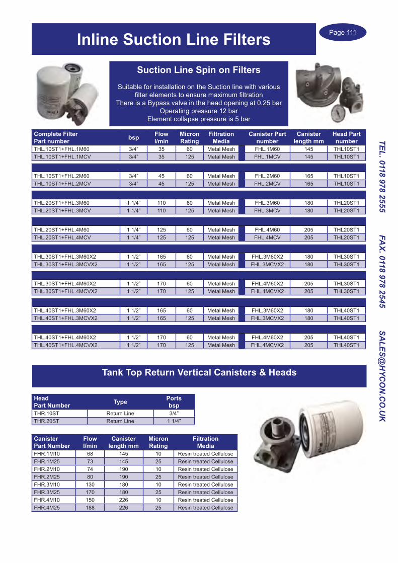
Page 111
TEL. 0118 978 2555 FAX. 0118 978 2545 SA
LES@H
YCO
N.C
O.U
K
Inline Suction Line Filters
Complete Filter Part number bsp Flow
l/minMicron Rating
FiltrationMedia
Canister Part number
Canister length mm
Head Part number
THL.10ST1+FHL.1M60 3/4” 35 60 Metal Mesh FHL.1M60 145 THL10ST1THL.10ST1+FHL.1MCV 3/4” 35 125 Metal Mesh FHL.1MCV 145 THL10ST1
THL.10ST1+FHL.2M60 3/4” 45 60 Metal Mesh FHL.2M60 165 THL10ST1THL.10ST1+FHL.2MCV 3/4” 45 125 Metal Mesh FHL.2MCV 165 THL10ST1
THL.20ST1+FHL.3M60 1 1/4” 110 60 Metal Mesh FHL.3M60 180 THL20ST1THL.20ST1+FHL.3MCV 1 1/4” 110 125 Metal Mesh FHL.3MCV 180 THL20ST1
THL.20ST1+FHL.4M60 1 1/4” 125 60 Metal Mesh FHL.4M60 205 THL20ST1THL.20ST1+FHL.4MCV 1 1/4” 125 125 Metal Mesh FHL.4MCV 205 THL20ST1
THL.30ST1+FHL.3M60X2 1 1/2” 165 60 Metal Mesh FHL.3M60X2 180 THL30ST1THL.30ST1+FHL.3MCVX2 1 1/2” 165 125 Metal Mesh FHL.3MCVX2 180 THL30ST1
THL.30ST1+FHL.4M60X2 1 1/2” 170 60 Metal Mesh FHL.4M60X2 205 THL30ST1THL.30ST1+FHL.4MCVX2 1 1/2” 170 125 Metal Mesh FHL.4MCVX2 205 THL30ST1
THL.40ST1+FHL.3M60X2 1 1/2” 165 60 Metal Mesh FHL.3M60X2 180 THL40ST1THL.40ST1+FHL.3MCVX2 1 1/2” 165 125 Metal Mesh FHL.3MCVX2 180 THL40ST1
THL.40ST1+FHL.4M60X2 1 1/2” 170 60 Metal Mesh FHL.4M60X2 205 THL40ST1THL.40ST1+FHL.4MCVX2 1 1/2” 170 125 Metal Mesh FHL.4MCVX2 205 THL40ST1
Suction Line Spin on FiltersSuitable for installation on the Suction line with various
filter elements to ensure maximum filtrationThere is a Bypass valve in the head opening at 0.25 bar
Operating pressure 12 barElement collapse pressure is 5 bar
Tank Top Return Vertical Canisters & Heads
HeadPart Number Type Ports
bspTHR.10ST Return Line 3/4”THR.20ST Return Line 1 1/4”
CanisterPart Number
Flowl/min
Canister length mm
MicronRating
FiltrationMedia
FHR.1M10 68 145 10 Resin treated CelluloseFHR.1M25 73 145 25 Resin treated CelluloseFHR.2M10 74 190 10 Resin treated CelluloseFHR.2M25 80 190 25 Resin treated CelluloseFHR.3M10 130 180 10 Resin treated CelluloseFHR.3M25 170 180 25 Resin treated CelluloseFHR.4M10 150 226 10 Resin treated CelluloseFHR.4M25 188 226 25 Resin treated Cellulose

Page 112
TEL.
011
8 97
8 25
55
FA
X. 0
118
978
2545
S
ALE
S@H
YCO
N.C
O.U
K
AFR Suction & Return line Filters
Four sizes with Flow rates up to 200 l/minMade from die cast Aluminium, Operating pressure 15 barBurst pressure 45 bar, Element collapse pressure 10 bar
Tank Top Filters
Suction Line Part Number Port Size bsp Flow rate l/min Micron Rating Filtration Medium Spare Element
Part NumberAFR30R60NA 1/2” 12 60 Square Mesh Aisi 304 CR091R60NAAFR30R125NA 1/2” 15 125 Square Mesh Aisi 304 CR091R125NAAFR60R60NA 3/4” 27 60 Square Mesh Aisi 304 CP111R60NAAFR60R125NA 3/4” 30 125 Square Mesh Aisi 304 CR111R125NAAFR100R60NA 1” 47 60 Square Mesh Aisi 304 CR112R60NAAFR100R125NA 1” 50 125 Square Mesh Aisi 304 CR112R125NAAFR180R60NA 1 1/4” 69 60 Square Mesh Aisi 304 CR171R60NAAFR180R125NA 1 1/4” 80 125 Square Mesh Aisi 304 CR171R125NAReturn Line Part Number Port Size bsp Flow rate l/min Micron Rating Filtration Medium Spare Element
Part NumberAFR30C10NR 1/2” 16 10 Resin Coated Cellulose CR091C10NRAFR30C25NR 1/2” 20 25 Resin Coated Cellulose CR091C25NRAFR30F10NR 1/2” 13 10 Inorganic Fibre CR091F10NRAFR60C10NR 3/4” 49 10 Resin Coated Cellulose CR111C10NRAFR60C25NR 3/4” 65 25 Resin Coated Cellulose CR111C25NRAFR60F10NR 3/4” 32 10 Inorganic Fibre CR111F10NRAFR100C10NR 1” 85 10 Resin Coated Cellulose CR112C10NRAFR100C25NR 1” 110 25 Resin Coated Cellulose CR112C25NRAFR100F10NR 1” 56 10 Inorganic Fibre CR112F10NRAFR180C10NR 1 1/4” 150 10 Resin Coated Cellulose CR171C10NRAFR180C25NR 1 1/4” 189 25 Resin Coated Cellulose CR171C25NRAFR180F10NR 1 1/4” 123 10 Inorganic Fibre CR171F10NR
Part Number bsp Flowl/min
Filtration Micron & Filter Medium
Breathing Element Micron
Tank Drilling dia mm
Bowl Length
mm
Spare Element Part Number
OMTP020C10NA 1/2” 35 10 Resin Coated Cellulose 10 paper 60 178 OMTPR020C10NOMTP020C25NB 1/2” 35 25 Resin Coated Cellulose 40 paper 60 178 OMTPR020C25NOMTP020C10NA 1/2” 40 10 Resin Coated Cellulose 10 paper 60 178 OMTPR020C10NOMTP020C25NB 1/2” 40 25 Resin Coated Cellulose 40 paper 60 178 OMTPR020C25N
OMTP101C10NA 3/4” 60 10 Resin Coated Cellulose 10 paper 60 110 OMTPR101C10NOMTP101C25NB 3/4” 60 25 Resin Coated Cellulose 40 paper 60 110 OMTPR101C25NOMTP102C10NA 3/4” 80 10 Resin Coated Cellulose 10 paper 60 175 OMTPR102C10NOMTP102C25NB 3/4” 80 25 Resin Coated Cellulose 40 paper 60 175 OMTPR102C25NOMTP103C10NA 3/4” 100 10 Resin Coated Cellulose 10 paper 60 275 OMTPR103C10NOMTP103C25NB 3/4” 100 25 Resin Coated Cellulose 40 paper 60 275 OMTPR103C25N
OMTP103C10N2A 1” 100 10 Resin Coated Cellulose 10 paper 60 275 OMTPR103C10NOMTP103C25NB2 1” 100 25 Resin Coated Cellulose 40 paper 60 275 OMTPR103C25N
OMTP Tank Top Return Filterswith breathing element and service cover
Flow rates up to 150 l/min10 or 40 Micron Air Breathing Filtration
Aluminium Head, Glass Reinforced Nylon Bowl and CoverMax Working Pressure 10 bar
Element Collapse Pressure 5 bar, Bypass valve pressure 1.5 bar
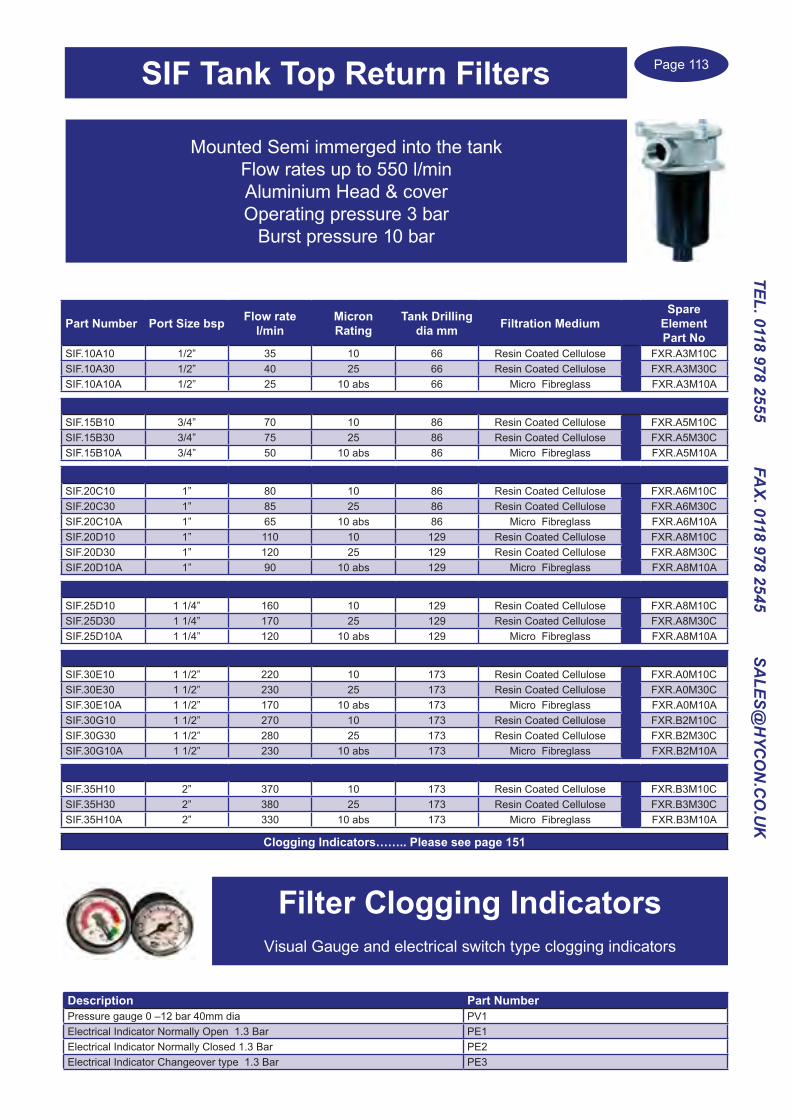
Page 113
TEL. 0118 978 2555 FAX. 0118 978 2545 SA
LES@H
YCO
N.C
O.U
K
Filter Clogging IndicatorsVisual Gauge and electrical switch type clogging indicators
Description Part NumberPressure gauge 0 –12 bar 40mm dia PV1Electrical Indicator Normally Open 1.3 Bar PE1Electrical Indicator Normally Closed 1.3 Bar PE2Electrical Indicator Changeover type 1.3 Bar PE3
SIF Tank Top Return Filters
Mounted Semi immerged into the tankFlow rates up to 550 l/minAluminium Head & coverOperating pressure 3 bar
Burst pressure 10 bar
Part Number Port Size bsp Flow rate l/min
Micron Rating
Tank Drilling dia mm Filtration Medium
Spare Element Part No
SIF.10A10 1/2” 35 10 66 Resin Coated Cellulose FXR.A3M10CSIF.10A30 1/2” 40 25 66 Resin Coated Cellulose FXR.A3M30CSIF.10A10A 1/2” 25 10 abs 66 Micro Fibreglass FXR.A3M10A
SIF.15B10 3/4” 70 10 86 Resin Coated Cellulose FXR.A5M10CSIF.15B30 3/4” 75 25 86 Resin Coated Cellulose FXR.A5M30CSIF.15B10A 3/4” 50 10 abs 86 Micro Fibreglass FXR.A5M10A
SIF.20C10 1” 80 10 86 Resin Coated Cellulose FXR.A6M10CSIF.20C30 1” 85 25 86 Resin Coated Cellulose FXR.A6M30CSIF.20C10A 1” 65 10 abs 86 Micro Fibreglass FXR.A6M10ASIF.20D10 1” 110 10 129 Resin Coated Cellulose FXR.A8M10CSIF.20D30 1” 120 25 129 Resin Coated Cellulose FXR.A8M30CSIF.20D10A 1” 90 10 abs 129 Micro Fibreglass FXR.A8M10A
SIF.25D10 1 1/4” 160 10 129 Resin Coated Cellulose FXR.A8M10CSIF.25D30 1 1/4” 170 25 129 Resin Coated Cellulose FXR.A8M30CSIF.25D10A 1 1/4” 120 10 abs 129 Micro Fibreglass FXR.A8M10A
SIF.30E10 1 1/2” 220 10 173 Resin Coated Cellulose FXR.A0M10CSIF.30E30 1 1/2” 230 25 173 Resin Coated Cellulose FXR.A0M30CSIF.30E10A 1 1/2” 170 10 abs 173 Micro Fibreglass FXR.A0M10ASIF.30G10 1 1/2” 270 10 173 Resin Coated Cellulose FXR.B2M10CSIF.30G30 1 1/2” 280 25 173 Resin Coated Cellulose FXR.B2M30CSIF.30G10A 1 1/2” 230 10 abs 173 Micro Fibreglass FXR.B2M10A
SIF.35H10 2” 370 10 173 Resin Coated Cellulose FXR.B3M10CSIF.35H30 2” 380 25 173 Resin Coated Cellulose FXR.B3M30CSIF.35H10A 2” 330 10 abs 173 Micro Fibreglass FXR.B3M10A
Clogging Indicators…….. Please see page 151

Page 114
TEL.
011
8 97
8 25
55
FA
X. 0
118
978
2545
S
ALE
S@H
YCO
N.C
O.U
K
HMM / HPM Indicators Visual, Electrical and Visual/Electrical switch, set at 5 or 8 bar
High Pressure Filters
HMM High Pressure Filter220 bar Max Pressure
Flow rates up to 170 l/min
Aluminium head and Steel bowl
Bypass 6 bar
Part Number bspMax Flow l/min
Max Pressure
bar
Filtration Micron
Element Filtration type
Total Length
mm
Bowl dia mm
Head dia mm
Spare Element Part Number
HMM281F03XNR 1/2” 17 220 3 Inorganic Fibre 189 70 87 CHP281F03XNHMM281F06XNR 1/2” 20 220 6 Inorganic Fibre 189 70 87 CHP281F06XNHMM281F10XNR 1/2” 35 220 10 Inorganic Fibre 189 70 87 CHP281F10XNHMM281F25XNR 1/2” 50 220 25 Inorganic Fibre 189 70 87 CHP281F25XN
HMM282F03XNR1 3/4” 26 220 3 Inorganic Fibre 219 70 87 CHP282F03XNHMM282F06XNR1 3/4” 40 220 6 Inorganic Fibre 219 70 87 CHP282F06XNHMM282F10XNR1 3/4” 55 220 10 Inorganic Fibre 219 70 87 CHP282F10XNHMM282F25XNR1 3/4” 80 220 25 Inorganic Fibre 219 70 87 CHP282F25XN
HMM283F03XNR1 3/4” 38 220 3 Inorganic Fibre 319 70 87 CHP283F03XNHMM283F06XNR1 3/4” 50 220 6 Inorganic Fibre 319 70 87 CHP283F06XNHMM283F10XNR1 3/4” 70 220 10 Inorganic Fibre 319 70 87 CHP283F10XNHMM283F25XNR1 3/4” 95 220 25 Inorganic Fibre 319 70 87 CHP283F25XN
HMM421F03XNR 3/4” 55 220 3 Inorganic Fibre 277 78 113 CHP421F03XNHMM421F06XNR 3/4” 65 220 6 Inorganic Fibre 277 78 113 CHP421F06XNHMM421F10XNR 3/4” 80 220 10 Inorganic Fibre 277 78 113 CHP421F10XNHMM421F25XNR 3/4” 104 220 25 Inorganic Fibre 277 78 113 CHP421F25XN
HMM422F03XNR1 1” 100 220 3 Inorganic Fibre 390 78 113 CHP422F03XNHMM422F06XNR1 1” 113 220 6 Inorganic Fibre 390 78 113 CHP422F06XNHMM422F10XNR1 1” 135 220 10 Inorganic Fibre 390 78 113 CHP422F10XNHMM422F25XNR1 1” 170 220 25 Inorganic Fibre 390 78 113 CHP422F25XN

Page 115
TEL. 0118 978 2555 FAX. 0118 978 2545 SA
LES@H
YCO
N.C
O.U
K
High Pressure Filters
HPM High Pressure Filter420 bar Max Pressure Flow rates up to 410 l/min
Cast Iron head and Steel bowl Bypass 6 bar
Part Number bspMax Flow l/min
Max Press
bar
Filtration Micron
Element Filtration
type
Length mm
Bowl Dia mm
Head dia mm
Spare Element Part Number
HPM281F03XNR 1/2” 17 420 3 Inorganic Fibre 189 70 85 CHP281F03XNHPM281F06XNR 1/2” 20 420 6 Inorganic Fibre 189 70 85 CHP281F06XNHPM281F10XNR 1/2” 35 420 10 Inorganic Fibre 189 70 85 CHP281F10XNHPM281F25XNR 1/2” 50 420 25 Inorganic Fibre 189 70 85 CHP281F25XN
HPM282F03XNR1 3/4” 26 420 3 Inorganic Fibre 219 70 85 CHP282F03XNHPM282F06XNR1 3/4” 40 420 6 Inorganic Fibre 219 70 85 CHP282F06XNHPM282F10XNR1 3/4” 55 420 10 Inorganic Fibre 219 70 85 CHP282F10XNHPM282F25XNR1 3/4” 80 420 25 Inorganic Fibre 219 70 85 CHP282F25XN
HPM283F03XNR1 3/4” 38 420 3 Inorganic Fibre 319 70 85 CHP283F03XNHPM283F06XNR1 3/4” 50 420 6 Inorganic Fibre 319 70 85 CHP283F06XNHPM283F10XNR1 3/4” 70 420 10 Inorganic Fibre 319 70 85 CHP283F10XNHPM283F25XNR1 3/4” 95 420 25 Inorganic Fibre 319 70 85 CHP283F25XN
HPM421F03XNR 3/4” 55 420 3 Inorganic Fibre 277 78 110 CHP421F03XNHPM421F06XNR 3/4” 65 420 6 Inorganic Fibre 277 78 110 CHP421F06XNHPM421F10XNR 3/4” 80 420 10 Inorganic Fibre 277 78 110 CHP421F10XNHPM421F25XNR 3/4” 104 420 25 Inorganic Fibre 277 78 110 CHP421F25XN
HPM422F03XNR1 1” 100 420 3 Inorganic Fibre 390 78 110 CHP422F03XNHPM422F06XNR1 1” 113 420 6 Inorganic Fibre 390 78 110 CHP422F06XNHPM422F10XNR1 1” 135 420 10 Inorganic Fibre 390 78 110 CHP422F10XNHPM422F25XNR1 1” 170 420 25 Inorganic Fibre 390 78 110 CHP422F25XN
HPM621F03XNR 1” 110 420 3 Inorganic Fibre 273 110 140 CHP621F03XNHPM621F06XNR 1” 125 420 6 Inorganic Fibre 273 110 140 CHP621F06XNHPM621F10XNR 1” 145 420 10 Inorganic Fibre 273 110 140 CHP621F10XNHPM621F25XNR 1” 190 420 25 Inorganic Fibre 273 110 140 CHP621F25XN
HPM622F03XNR1 1 1/4” 206 420 3 Inorganic Fibre 393 110 140 CHP622F03XNHPM622F06XNR1 1 1/4” 250 420 6 Inorganic Fibre 393 110 140 CHP622F06XNHPM622F10XNR1 1 1/4” 300 420 10 Inorganic Fibre 393 110 140 CHP622F10XNHPM622F25XNR1 1 1/4” 345 420 25 Inorganic Fibre 393 110 140 CHP622F25XN
HPM623F03XNR2 1 1/2” 250 420 3 Inorganic Fibre 533 110 140 CHP623F03XNHPM623F06XNR2 1 1/2” 290 420 6 Inorganic Fibre 533 110 140 CHP623F06XNHPM623F10XNR2 1 1/2” 330 420 10 Inorganic Fibre 533 110 140 CHP623F10XNHPM623F25XNR2 1 1/2” 375 420 25 Inorganic Fibre 533 110 140 CHP623F25XN
HPM624F03XNR2 1 1/2” 285 420 3 Inorganic Fibre 673 110 140 CHP624F03XNHPM624F06XNR2 1 1/2” 330 420 6 Inorganic Fibre 673 110 140 CHP624F06XNHPM624F10XNR2 1 1/2” 360 420 10 Inorganic Fibre 673 110 140 CHP624F10XNHPM624F25XNR2 1 1/2” 410 420 25 Inorganic Fibre 673 110 140 CHP624F25XN
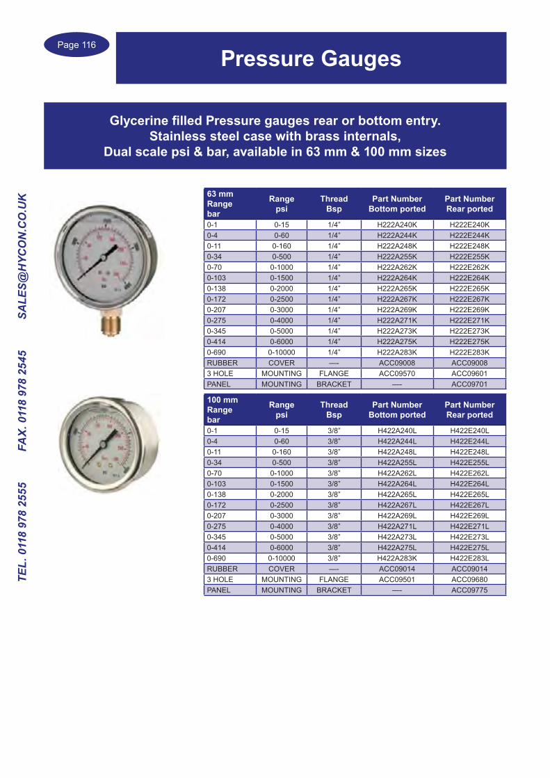
Page 116
TEL.
011
8 97
8 25
55
FA
X. 0
118
978
2545
S
ALE
S@H
YCO
N.C
O.U
K
Pressure Gauges
Glycerine filled Pressure gauges rear or bottom entry.Stainless steel case with brass internals,
Dual scale psi & bar, available in 63 mm & 100 mm sizes
63 mmRangebar
Rangepsi
Thread Bsp
Part NumberBottom ported
Part NumberRear ported
0-1 0-15 1/4” H222A240K H222E240K0-4 0-60 1/4” H222A244K H222E244K0-11 0-160 1/4” H222A248K H222E248K0-34 0-500 1/4” H222A255K H222E255K0-70 0-1000 1/4” H222A262K H222E262K0-103 0-1500 1/4” H222A264K H222E264K0-138 0-2000 1/4” H222A265K H222E265K0-172 0-2500 1/4” H222A267K H222E267K0-207 0-3000 1/4” H222A269K H222E269K0-275 0-4000 1/4” H222A271K H222E271K0-345 0-5000 1/4” H222A273K H222E273K0-414 0-6000 1/4” H222A275K H222E275K0-690 0-10000 1/4” H222A283K H222E283KRUBBER COVER —- ACC09008 ACC090083 HOLE MOUNTING FLANGE ACC09570 ACC09601PANEL MOUNTING BRACKET —- ACC09701
100 mmRangebar
Rangepsi
Thread Bsp
Part NumberBottom ported
Part NumberRear ported
0-1 0-15 3/8” H422A240L H422E240L0-4 0-60 3/8” H422A244L H422E244L0-11 0-160 3/8” H422A248L H422E248L0-34 0-500 3/8” H422A255L H422E255L0-70 0-1000 3/8” H422A262L H422E262L0-103 0-1500 3/8” H422A264L H422E264L0-138 0-2000 3/8” H422A265L H422E265L0-172 0-2500 3/8” H422A267L H422E267L0-207 0-3000 3/8” H422A269L H422E269L0-275 0-4000 3/8” H422A271L H422E271L0-345 0-5000 3/8” H422A273L H422E273L0-414 0-6000 3/8” H422A275L H422E275L0-690 0-10000 3/8” H422A283K H422E283LRUBBER COVER —- ACC09014 ACC090143 HOLE MOUNTING FLANGE ACC09501 ACC09680PANEL MOUNTING BRACKET —- ACC09775
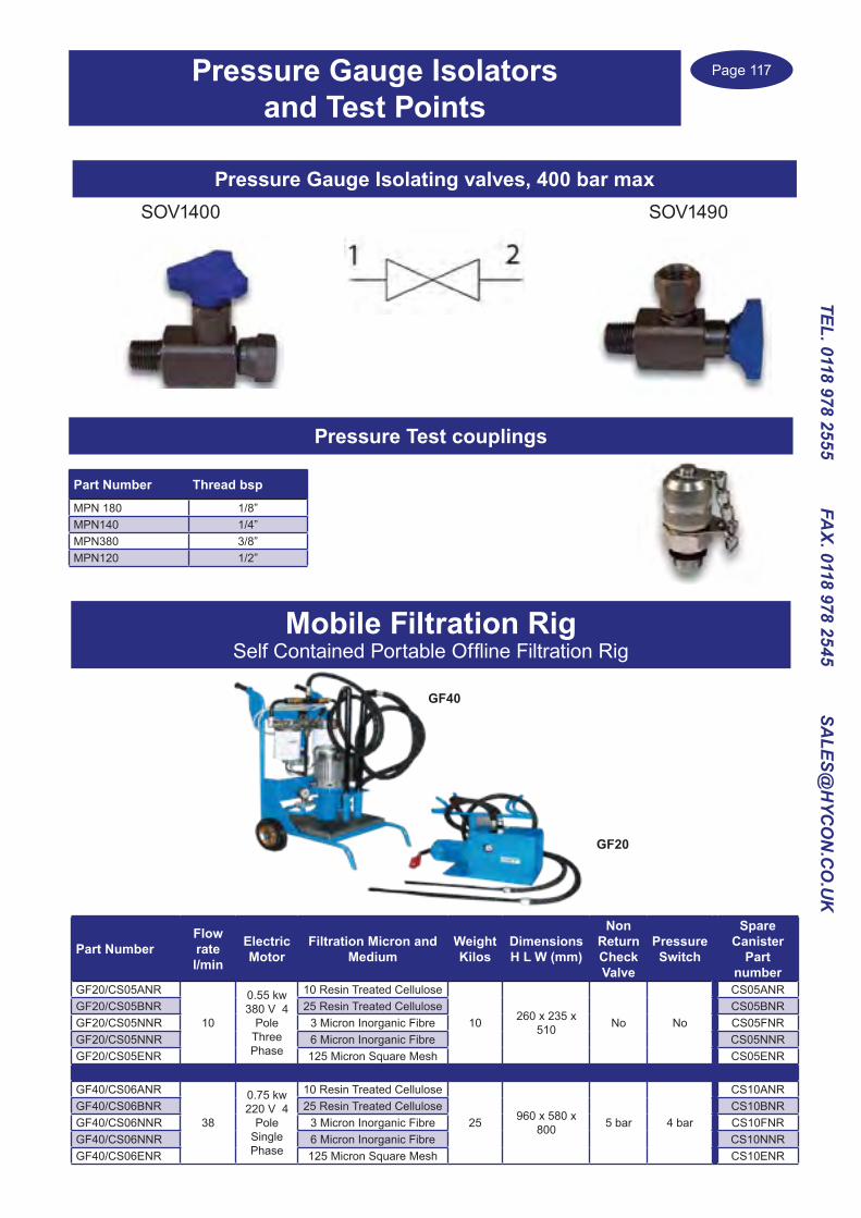
Page 117
TEL. 0118 978 2555 FAX. 0118 978 2545 SA
LES@H
YCO
N.C
O.U
K
Part NumberFlow rate l/min
Electric Motor
Filtration Micron and Medium
Weight Kilos
Dimensions H L W (mm)
Non Return Check Valve
Pressure Switch
Spare Canister
Part number
GF20/CS05ANR
10
0.55 kw 380 V 4
Pole Three Phase
10 Resin Treated Cellulose
10 260 x 235 x 510 No No
CS05ANRGF20/CS05BNR 25 Resin Treated Cellulose CS05BNRGF20/CS05NNR 3 Micron Inorganic Fibre CS05FNRGF20/CS05NNR 6 Micron Inorganic Fibre CS05NNRGF20/CS05ENR 125 Micron Square Mesh CS05ENR
GF40/CS06ANR
38
0.75 kw 220 V 4
Pole Single Phase
10 Resin Treated Cellulose
25 960 x 580 x 800 5 bar 4 bar
CS10ANRGF40/CS06BNR 25 Resin Treated Cellulose CS10BNRGF40/CS06NNR 3 Micron Inorganic Fibre CS10FNRGF40/CS06NNR 6 Micron Inorganic Fibre CS10NNRGF40/CS06ENR 125 Micron Square Mesh CS10ENR
Mobile Filtration RigSelf Contained Portable Offline Filtration Rig
GF40
GF20
Pressure Gauge Isolators and Test Points
Pressure Gauge Isolating valves, 400 bar maxSOV1490SOV1400
Pressure Test couplings
Part Number Thread bsp
MPN 180 1/8”MPN140 1/4”MPN380 3/8”MPN120 1/2”

Page 118
TEL.
011
8 97
8 25
55
FA
X. 0
118
978
2545
S
ALE
S@H
YCO
N.C
O.U
K
Pump Flanged CouplingsSteel Type RPA

Page 119
TEL. 0118 978 2555 FAX. 0118 978 2545 SA
LES@H
YCO
N.C
O.U
K
Pump Flanged CouplingsAluminium Type RP
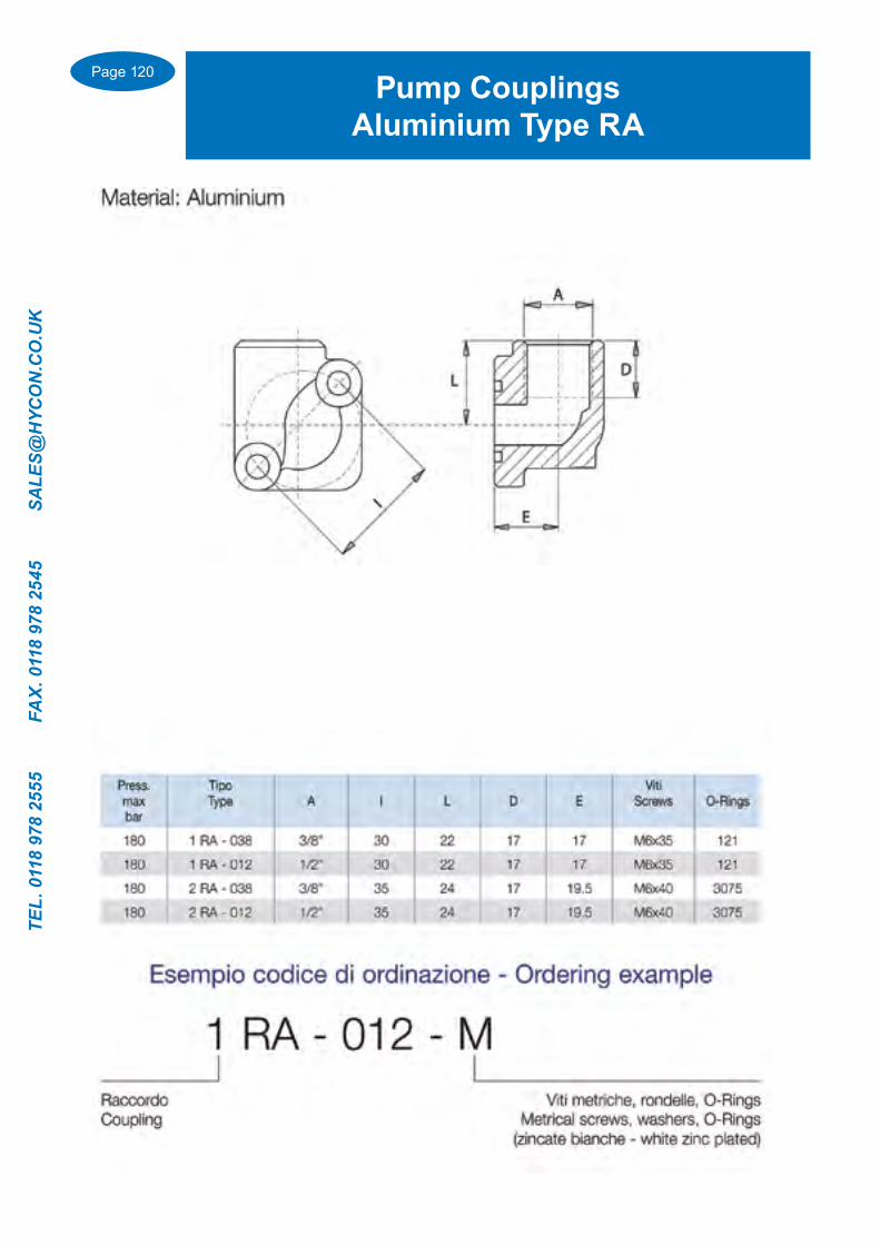
Page 120
TEL.
011
8 97
8 25
55
FA
X. 0
118
978
2545
S
ALE
S@H
YCO
N.C
O.U
K
Pump CouplingsAluminium Type RA

Page 121
TEL. 0118 978 2555 FAX. 0118 978 2545 SA
LES@H
YCO
N.C
O.U
K
Pump CouplingsType RIA

Page 122
TEL.
011
8 97
8 25
55
FA
X. 0
118
978
2545
S
ALE
S@H
YCO
N.C
O.U
K
SAE Flanges BSP Threaded 3000 & 6000 psi

Page 123
TEL. 0118 978 2555 FAX. 0118 978 2545 SA
LES@H
YCO
N.C
O.U
K
MAMM MINI MOTORSHigh Output Torque compact Motor with Side or Rear ports
Standard 3 bolt or a 2 Bolt Flange Mounted option is availableParallel or Splined shafts, 8.2 up to 50 cc/rev displacements
Hydraulic Mini Motors
Model code Porting Mounting Displacement cc/rev Shaft optionMAMM Omit for Standard Rear port
S Side Ports 1/4” bsp
Omit for standard 3 bolt
F 2 Bolt Flange
8 8.212.5 12.920 19.932 31.640 39.850 50.3
C 16mm ParallelCO 5/8” ParallelS 16.5mm Spline
Example...MAMM S 12.5 C
Type MAMM8
MAMM12.5
MAMM20
MAMM32
MAMM40
MAMM50
Displacement(cc/rev) 8.2 12.9 19.9 31.6 39.8 50.3
Max. Speed (rpm)
Cont. 1950 1550 1000 630 500 400Int. 2450 1940 1250 800 630 500
Max. Torque(Nm)
Cont. 11 16 25 41 42 46Int. 15 23 35 57 58 59
Peak 21 33 51 64 66 80Max. Output(Kw)
Cont. 1.8 2.4 2.4 2.4 1.8 1.8Int. 2.6 3.2 3.2 3.2 3.0 2.1
Max. pressure drop(bar)
Cont. 100 100 100 100 80 70Int. 140 140 140 140 110 90
Peak 200 200 200 200 140 125Max. Oil flow(l/min)
Cont. 16 20 20 20 20 20Int. 20 25 25 25 25 25
Max. Inlet pressure(bar)
Cont. 140 140 140 140 140 140Int. 175 175 175 175 175 175
Peak 225 225 225 225 225 225Weight (kg) 1.9 2 2.1 2.2 2.3 2.4
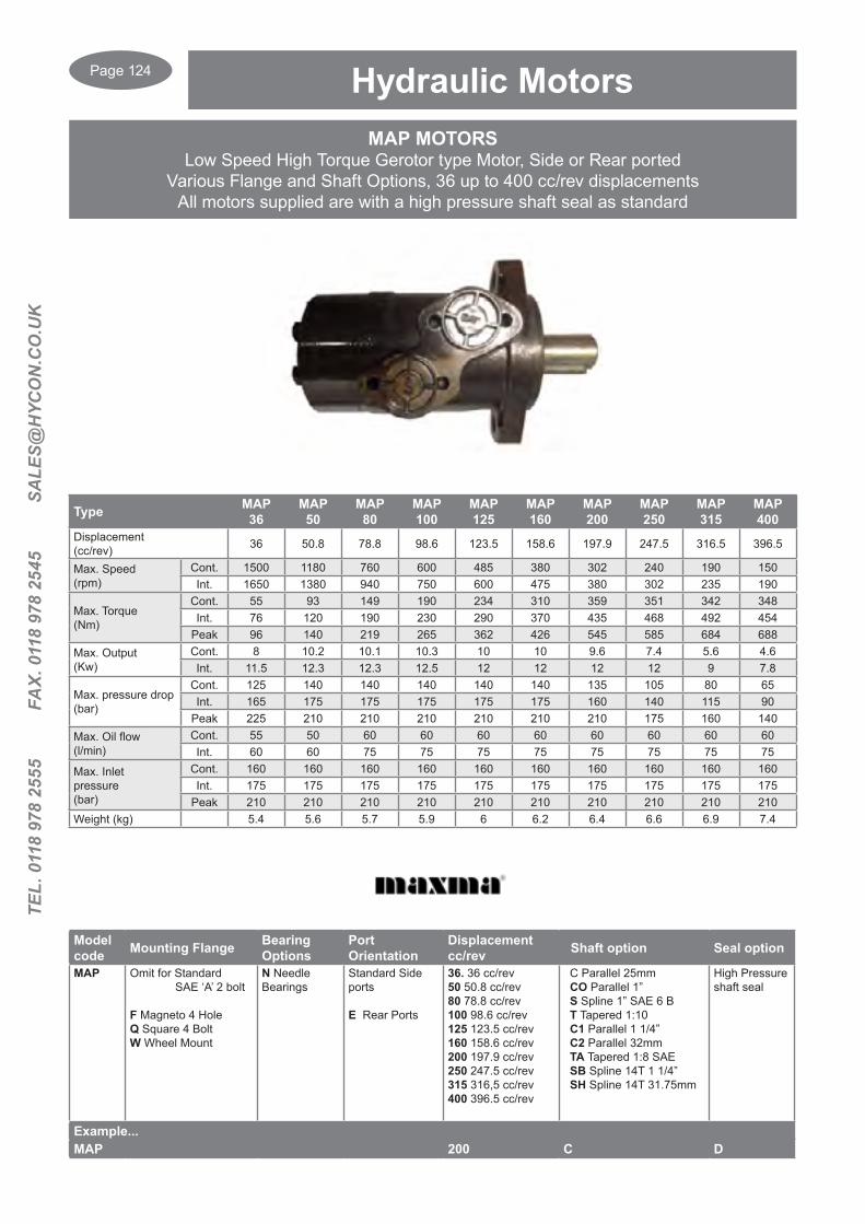
Page 124
TEL.
011
8 97
8 25
55
FA
X. 0
118
978
2545
S
ALE
S@H
YCO
N.C
O.U
K
MAP MOTORSLow Speed High Torque Gerotor type Motor, Side or Rear ported
Various Flange and Shaft Options, 36 up to 400 cc/rev displacementsAll motors supplied are with a high pressure shaft seal as standard
Hydraulic Motors
Type MAP36
MAP50
MAP80
MAP100
MAP125
MAP160
MAP200
MAP250
MAP315
MAP400
Displacement(cc/rev) 36 50.8 78.8 98.6 123.5 158.6 197.9 247.5 316.5 396.5
Max. Speed (rpm)
Cont. 1500 1180 760 600 485 380 302 240 190 150Int. 1650 1380 940 750 600 475 380 302 235 190
Max. Torque(Nm)
Cont. 55 93 149 190 234 310 359 351 342 348Int. 76 120 190 230 290 370 435 468 492 454
Peak 96 140 219 265 362 426 545 585 684 688Max. Output(Kw)
Cont. 8 10.2 10.1 10.3 10 10 9.6 7.4 5.6 4.6Int. 11.5 12.3 12.3 12.5 12 12 12 12 9 7.8
Max. pressure drop(bar)
Cont. 125 140 140 140 140 140 135 105 80 65Int. 165 175 175 175 175 175 160 140 115 90
Peak 225 210 210 210 210 210 210 175 160 140Max. Oil flow(l/min)
Cont. 55 50 60 60 60 60 60 60 60 60Int. 60 60 75 75 75 75 75 75 75 75
Max. Inlet pressure(bar)
Cont. 160 160 160 160 160 160 160 160 160 160Int. 175 175 175 175 175 175 175 175 175 175
Peak 210 210 210 210 210 210 210 210 210 210Weight (kg) 5.4 5.6 5.7 5.9 6 6.2 6.4 6.6 6.9 7.4
Model code Mounting Flange Bearing
OptionsPort Orientation
Displacement cc/rev Shaft option Seal option
MAP Omit for Standard SAE ‘A’ 2 bolt
F Magneto 4 HoleQ Square 4 BoltW Wheel Mount
N Needle Bearings
Standard Side ports
E Rear Ports
36. 36 cc/rev50 50.8 cc/rev80 78.8 cc/rev100 98.6 cc/rev125 123.5 cc/rev160 158.6 cc/rev200 197.9 cc/rev250 247.5 cc/rev315 316,5 cc/rev400 396.5 cc/rev
C Parallel 25mm CO Parallel 1” S Spline 1” SAE 6 B T Tapered 1:10 C1 Parallel 1 1/4” C2 Parallel 32mm TA Tapered 1:8 SAE SB Spline 14T 1 1/4” SH Spline 14T 31.75mm
High Pressure shaft seal
Example...MAP 200 C D
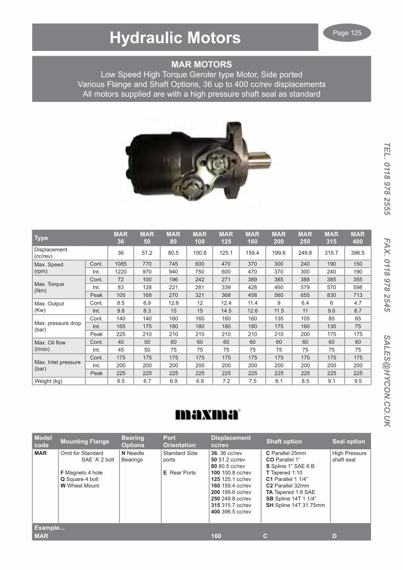
Page 125
TEL. 0118 978 2555 FAX. 0118 978 2545 SA
LES@H
YCO
N.C
O.U
K
MAR MOTORSLow Speed High Torque Geroler type Motor, Side ported
Various Flange and Shaft Options, 36 up to 400 cc/rev displacementsAll motors supplied are with a high pressure shaft seal as standard
Hydraulic Motors
Model code Mounting Flange Bearing
OptionsPort Orientation
Displacement cc/rev Shaft option Seal option
MAR Omit for Standard SAE ‘A’ 2 bolt
F Magneto 4 holeQ Square 4 boltW Wheel Mount
N Needle Bearings
Standard Side ports
E Rear Ports
36. 36 cc/rev50 51.2 cc/rev80 80.5 cc/rev100 100.8 cc/rev125 125.1 cc/rev160 159.4 cc/rev200 199.6 cc/rev250 249.8 cc/rev315 315.7 cc/rev400 396.5 cc/rev
C Parallel 25mm CO Parallel 1” S Spline 1” SAE 6 B T Tapered 1:10 C1 Parallel 1 1/4” C2 Parallel 32mm TA Tapered 1:8 SAE SB Spline 14T 1 1/4” SH Spline 14T 31.75mm
High Pressure shaft seal
Example...MAR 160 C D
Type MAR36
MAR50
MAR80
MAR100
MAR125
MAR160
MAR200
MAR250
MAR315
MAR400
Displacement(cc/rev) 36 51.2 80.5 100.8 125.1 159.4 199.6 249.8 315.7 396.5
Max. Speed (rpm)
Cont. 1085 770 745 600 470 370 300 240 190 150Int. 1220 970 940 750 600 470 370 300 240 190
Max. Torque(Nm)
Cont. 72 100 196 242 271 389 385 388 385 355Int. 83 128 221 281 339 428 460 579 570 598
Peak 105 168 270 321 368 458 560 655 830 713Max. Output(Kw)
Cont. 8.5 6.9 12.6 12 12.4 11.4 9 6.4 6 4.7Int. 9.8 8.3 15 15 14.5 12.6 11.5 11 9.6 8.7
Max. pressure drop(bar)
Cont. 140 140 160 160 160 160 135 105 85 65Int. 165 175 180 180 180 180 175 160 130 75
Peak 225 210 210 210 210 210 210 200 175 175Max. Oil flow(l/min)
Cont. 40 50 60 60 60 60 60 60 60 60Int. 45 50 75 75 75 75 75 75 75 75
Max. Inlet pressure(bar)
Cont. 175 175 175 175 175 175 175 175 175 175Int. 200 200 200 200 200 200 200 200 200 200
Peak 225 225 225 225 225 225 225 225 225 225Weight (kg) 6.5 6.7 6.9 6.9 7.2 7.5 8.1 8.5 9.1 9.5

Page 126
TEL.
011
8 97
8 25
55
FA
X. 0
118
978
2545
S
ALE
S@H
YCO
N.C
O.U
K
MAS MOTORSHigh Specification Motors Side or Rear ported
Various Flange and Shaft Options, 80 up to 400 cc/rev displacements
Hydraulic Motors
Model code Mounting Flange Port
OrientationDisplacement cc/rev Shaft option
MAS Omit for Standard SAE ‘A’ 4 bolt
A SAE ‘A’, 2 boltF Magneto, 4 holeQ Square, 4 boltW Wheel mountS Short mount motor
Omit for Std. Side ports
E Rear Ports
80 80.8 cc/rev100 99.8 cc/rev125 125.2 cc/rev160 159.5 cc/rev200 200 cc/rev250 252.3 cc/rev315 315.1 cc/rev400 397 cc/rev
C Parallel 32mm CO Parallel 1 1/4”S Spline 1” SAE 6 BTB Tapered 1:10C1 Parallel 25mmC2 Parallel 1”TA Tapered 1:8 SAESB Spline 1 1/4” 14TSH Spline 31.75mm 14TSL PTO Spline
Example...MAS 200 C
Type MAS80
MAS100
MAS125
MAS160
MAS200
MAS250
MAS315
MAS400
Displacement(cc/rev) 80.8 99.8 125.2 159.5 200 252.3 315.1 397
Max. Speed (rpm)
Cont. 805 746 598 465 373 298 236 187Int. 1000 900 718 560 447 360 290 230
Max. Torque(Nm)
Cont. 198 244 307 340 395 450 541 580Int. 237 293 368 469 490 535 630 690
Peak 260 322 405 485 648 682 840 850Max. Output(Kw)
Cont. 16.4 19.4 20 12 14 13.6 11.5 10Int. 22 26 24 21.8 21 21.2 13.5 13
Max. pressure drop(bar)
Cont. 175 175 175 160 150 140 120 100Int. 210 210 210 210 180 175 140 120
Peak 225 225 225 225 225 200 185 140Max. Oil flow(l/min)
Cont. 65 75 75 75 75 75 75 75Int. 80 90 90 90 90 90 90 90
Max. Inlet pressure(bar)
Cont. 210 210 210 210 210 210 210 210Int. 250 250 250 250 250 250 250 250
Peak 300 300 300 300 300 300 300 300Weight (kg) 10 10.3 10.5 11 11.4 11.9 12.5 13.5
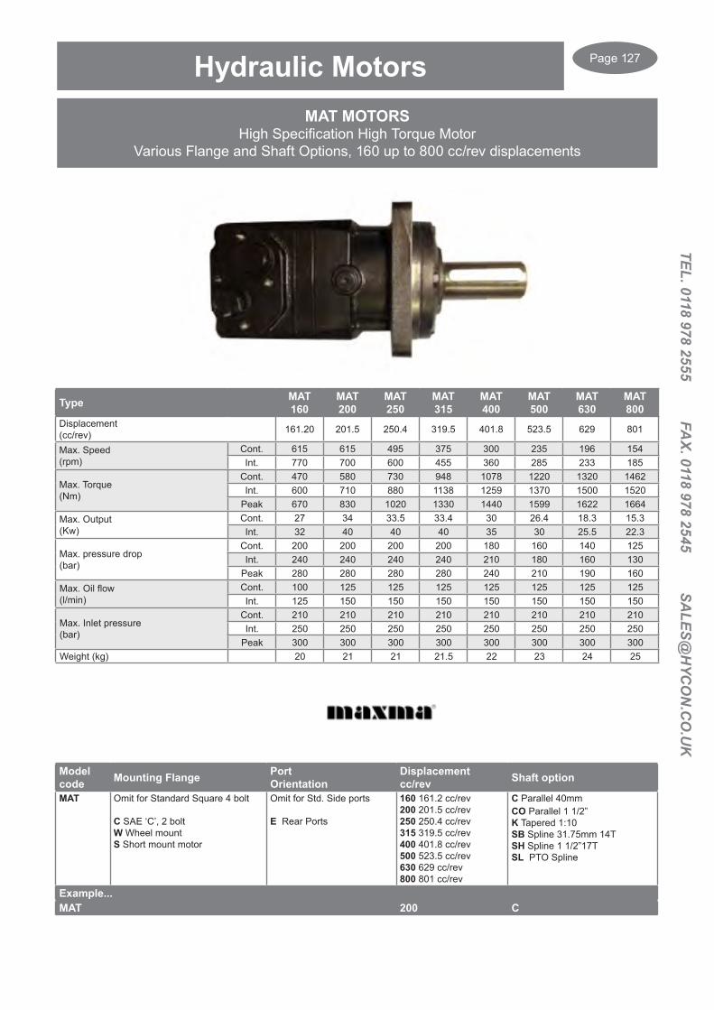
Page 127
TEL. 0118 978 2555 FAX. 0118 978 2545 SA
LES@H
YCO
N.C
O.U
K
MAT MOTORSHigh Specification High Torque Motor
Various Flange and Shaft Options, 160 up to 800 cc/rev displacements
Hydraulic Motors
Model code Mounting Flange Port
OrientationDisplacement cc/rev Shaft option
MAT Omit for Standard Square 4 bolt
C SAE ‘C’, 2 boltW Wheel mountS Short mount motor
Omit for Std. Side ports
E Rear Ports
160 161.2 cc/rev200 201.5 cc/rev250 250.4 cc/rev315 319.5 cc/rev400 401.8 cc/rev500 523.5 cc/rev630 629 cc/rev800 801 cc/rev
C Parallel 40mmCO Parallel 1 1/2”K Tapered 1:10SB Spline 31.75mm 14TSH Spline 1 1/2”17TSL PTO Spline
Example...MAT 200 C
Type MAT160
MAT200
MAT250
MAT315
MAT400
MAT500
MAT630
MAT800
Displacement(cc/rev) 161.20 201.5 250.4 319.5 401.8 523.5 629 801
Max. Speed (rpm)
Cont. 615 615 495 375 300 235 196 154Int. 770 700 600 455 360 285 233 185
Max. Torque(Nm)
Cont. 470 580 730 948 1078 1220 1320 1462Int. 600 710 880 1138 1259 1370 1500 1520
Peak 670 830 1020 1330 1440 1599 1622 1664Max. Output(Kw)
Cont. 27 34 33.5 33.4 30 26.4 18.3 15.3Int. 32 40 40 40 35 30 25.5 22.3
Max. pressure drop(bar)
Cont. 200 200 200 200 180 160 140 125Int. 240 240 240 240 210 180 160 130
Peak 280 280 280 280 240 210 190 160Max. Oil flow(l/min)
Cont. 100 125 125 125 125 125 125 125Int. 125 150 150 150 150 150 150 150
Max. Inlet pressure(bar)
Cont. 210 210 210 210 210 210 210 210Int. 250 250 250 250 250 250 250 250
Peak 300 300 300 300 300 300 300 300Weight (kg) 20 21 21 21.5 22 23 24 25
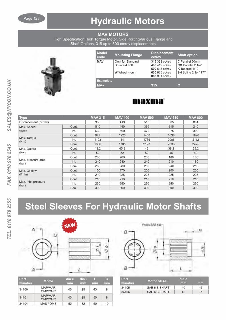
Page 128
TEL.
011
8 97
8 25
55
FA
X. 0
118
978
2545
S
ALE
S@H
YCO
N.C
O.U
K
MAV MOTORSHigh Specification High Torque Motor, Side PortingVarious Flange and
Shaft Options, 315 up to 800 cc/rev displacements
Hydraulic Motors
Model code Mounting Flange Displacement
cc/rev Shaft option
MAV Omit for Standard Square 4 bolt
W Wheel mount
315 333 cc/rev400 419 cc/rev500 518 cc/rev630 665 cc/rev800 801 cc/rev
C Parallel 50mm CO Parallel 2 1/4”K Tapered 1:10SH Spline 2 1/4” 17T
Example...MAv 315 C
Type MAV 315 MAV 400 MAV 500 MAV 630 MAV 800Displacement (cc/rev) 333 419 518 665 801Max. Speed (rpm)
Cont. 510 490 395 315 240Int. 630 590 470 375 300
Max. Torque(Nm)
Cont. 927 1223 1450 1638 1820Int. 1103 1441 1786 2005 2112
Peak 1350 1705 2123 2338 2475Max. Output(Kw)
Cont. 43.2 45.3 48 38.2 35.2Int. 52 52 52 46 40
Max. pressure drop(bar)
Cont. 200 200 200 180 160Int. 240 240 240 210 180
Peak 280 280 280 240 210Max. Oil flow(l/min)
Cont. 150 170 200 200 200Int. 210 225 225 225 225
Max. Inlet pressure(bar)
Cont. 210 210 210 210 210Int. 250 250 250 250 250
Peak 300 300 300 300 300
Steel Sleeves For Hydraulic Motor Shafts
Part Number Motor sHAFT dia e
mmL
mm34105 SAE 6 B SHAFT 40 4534106 SAE 6 B SHAFT 40 37
Part Number Motor dia e
mmdia i mm
L mm
Cmm
34100 MAP/MAROMP/OMR 40 25 43 8
34101 MAP/MAROMP/OMR 40 25 50 8
34104 MAS / OMS 50 32 50 10
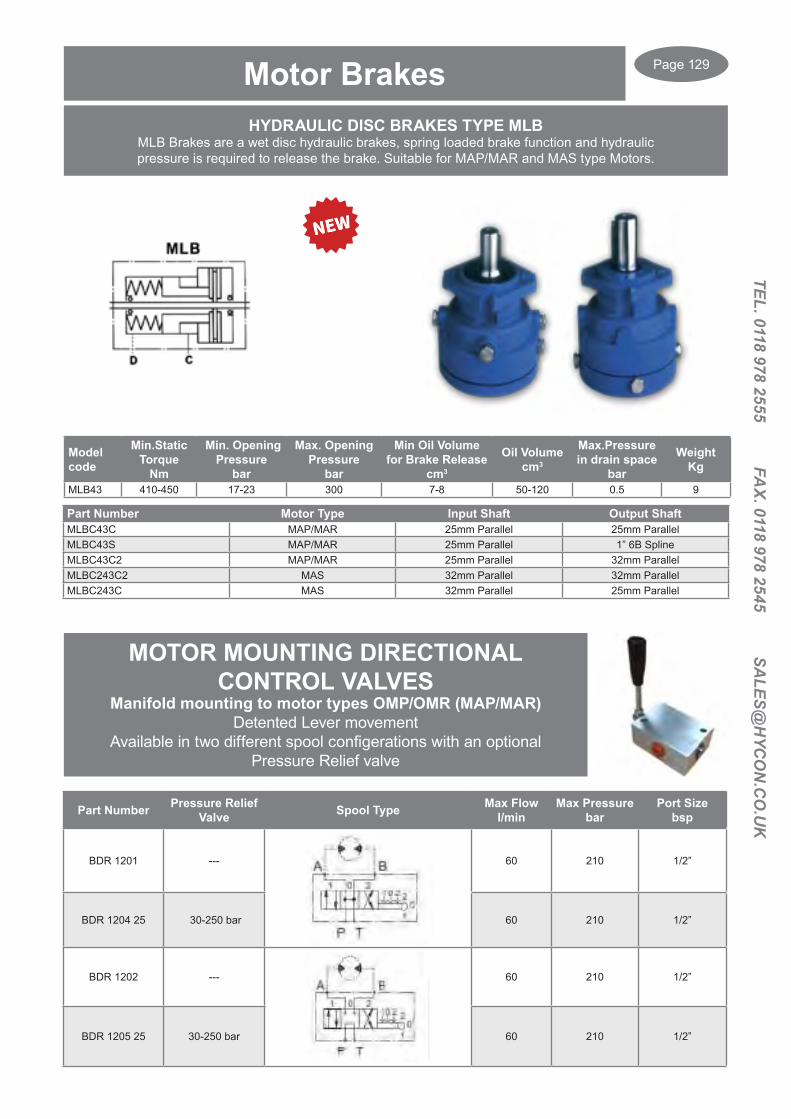
Page 129
TEL. 0118 978 2555 FAX. 0118 978 2545 SA
LES@H
YCO
N.C
O.U
K
HYDRAULIC DISC BRAKES TYPE MLBMLB Brakes are a wet disc hydraulic brakes, spring loaded brake function and hydraulic pressure is required to release the brake. Suitable for MAP/MAR and MAS type Motors.
Model code
Min.Static Torque
Nm
Min. Opening Pressure
bar
Max. Opening Pressure
bar
Min Oil Volume for Brake Release
cm3
Oil Volumecm3
Max.Pressurein drain space
bar
WeightKg
MLB43 410-450 17-23 300 7-8 50-120 0.5 9
Part Number Motor Type Input Shaft Output ShaftMLBC43C MAP/MAR 25mm Parallel 25mm ParallelMLBC43S MAP/MAR 25mm Parallel 1” 6B SplineMLBC43C2 MAP/MAR 25mm Parallel 32mm ParallelMLBC243C2 MAS 32mm Parallel 32mm ParallelMLBC243C MAS 32mm Parallel 25mm Parallel
Motor Brakes
MOTOR MOUNTING DIRECTIONAL CONTROL VALVES
Manifold mounting to motor types OMP/OMR (MAP/MAR)Detented Lever movement
Available in two different spool configerations with an optional Pressure Relief valve
Part Number Pressure Relief Valve Spool Type Max Flow
l/minMax Pressure
barPort Size
bsp
BDR 1201 --- 60 210 1/2”
BDR 1204 25 30-250 bar 60 210 1/2”
BDR 1202 --- 60 210 1/2”
BDR 1205 25 30-250 bar 60 210 1/2”

Page 130
TEL.
011
8 97
8 25
55
FA
X. 0
118
978
2545
S
ALE
S@H
YCO
N.C
O.U
K
Poclain HydraulicsPHast Delivery Program
The PHast Europe Delivery program for Motors includes....
• Wheel & Shaft motors • Single and two speeds • With or without brake • For maximum versatility, all PHast motors have.. Additional drain port. Pre disposition for speed sensor High pressure shaft seal or duo-cone seal Heat treated shaft Butterfly valving for higher rpm (except for MS50 Single speed)
Please contact us with your enquiry...
For replacement components please supply the full part number and Serial number ?
Seal Kits and Spare parts are available
PHast quantity is limited to four motors per size

Page 131
TEL. 0118 978 2555 FAX. 0118 978 2545 SA
LES@H
YCO
N.C
O.U
K
ROD/BORE SIZES 16/25, 20/32, 25/40, & 30/50
Double Acting Cylinders
Part Number D ALBore
ARod
Strokemm I G G1 IT M S P R F
bsp KG
DA25160050
35 25 16
50 160
33 22 31 12.1 25 25 35 1/4”
1.00DA25160100 100 210 1.20DA25160150 150 260 1.40DA25160200 200 310 1.70DA32200050
42 32 20
50 205
33 35 51 16.2 30 35 40 1/4”
1.70DA32200100 100 255 2.10DA32200150 150 305 2.40DA32200200 200 355 2.80DA32200250 250 405 3.10DA32200300 300 455 3.50DA32200400 400 555 4.20DA32200500 500 655 4.80DA32200600 600 755 5.60DA32200700 700 855 6.30DA40250100
50 40 25
100 270
40 38 65 20.25 35 40 50 3/8”
3.00DA40250150 150 320 3.40DA40250200 200 370 3.90DA40250250 250 420 4.40DA40250300 300 470 4.80DA40250400 400 570 5.80DA40250500 500 670 6.70DA40250600 600 770 7.60DA40250700 700 870 8.60DA40250800 800 970 9.50DA40251000 1000 1170 11.30DA50300100
60 50 30
100 300
43 42 85 25.25 40 45 60 3/8”
4.40DA50300150 150 350 5.00DA50300200 200 400 5.60DA50300250 250 450 6.20DA50300300 300 500 6.90DA50300400 400 600 8.10DA50300500 500 700 9.30DA50300600 600 800 10.50DA50300700 700 900 11.80DA50300800 800 1000 13.00DA50300900 900 1100 14.20DA50301000 1000 1200 15.50
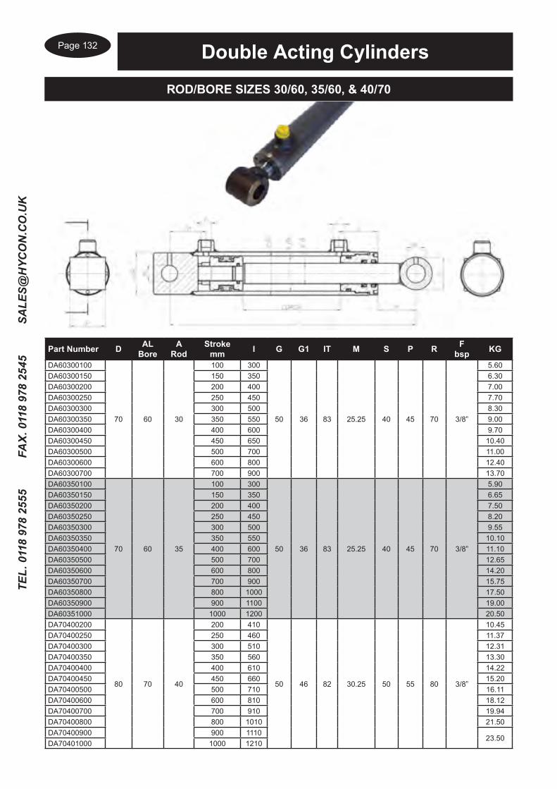
Page 132
TEL.
011
8 97
8 25
55
FA
X. 0
118
978
2545
S
ALE
S@H
YCO
N.C
O.U
K
ROD/BORE SIZES 30/60, 35/60, & 40/70
Double Acting Cylinders
Part Number D ALBore
ARod
Strokemm I G G1 IT M S P R F
bsp KG
DA60300100
70 60 30
100 300
50 36 83 25.25 40 45 70 3/8”
5.60DA60300150 150 350 6.30DA60300200 200 400 7.00DA60300250 250 450 7.70DA60300300 300 500 8.30DA60300350 350 550 9.00DA60300400 400 600 9.70DA60300450 450 650 10.40DA60300500 500 700 11.00DA60300600 600 800 12.40DA60300700 700 900 13.70DA60350100
70 60 35
100 300
50 36 83 25.25 40 45 70 3/8”
5.90DA60350150 150 350 6.65DA60350200 200 400 7.50DA60350250 250 450 8.20DA60350300 300 500 9.55DA60350350 350 550 10.10DA60350400 400 600 11.10DA60350500 500 700 12.65DA60350600 600 800 14.20DA60350700 700 900 15.75DA60350800 800 1000 17.50DA60350900 900 1100 19.00DA60351000 1000 1200 20.50DA70400200
80 70 40
200 410
50 46 82 30.25 50 55 80 3/8”
10.45DA70400250 250 460 11.37DA70400300 300 510 12.31DA70400350 350 560 13.30DA70400400 400 610 14.22DA70400450 450 660 15.20DA70400500 500 710 16.11DA70400600 600 810 18.12DA70400700 700 910 19.94DA70400800 800 1010 21.50DA70400900 900 1110
23.50DA70401000 1000 1210

Page 133
TEL. 0118 978 2555 FAX. 0118 978 2545 SA
LES@H
YCO
N.C
O.U
K
ROD/BORE SIZES 40/80 & 50/100
Double Acting Cylinders
Part Number D ALBore
ARod
Strokemm I G G1 IT M S P R F
bsp KG
DA80400200
92 80 40
200 410
60 42 70 30.25 50 55 90 3/8”
13.26DA80400250 250 460 14.46DA80400300 300 510 15.54DA80400350 350 560 17.62DA80400400 400 610 18.00DA80400500 500 710 20.00DA80400600 600 810 22.00DA80400700 700 910 24.50DA80400800 800 1010 26.50DA80400900 900 1110 29.00DA804001000 1000 1210 31.00DA100500200
115 100 50
200 425
66 45 75 30.25 60 70 115 1/2”
26.00DA100500300 300 525 30.00DA100500400 400 625 34.00DA100500500 500 725 38.00DA100500700 700 925 41.10DA100500900 900 1125 45.00DA1005001000 1000 1225 52.00
Part Number Rod SizeSRBR20SL 20 mmSRBR25SL 25 mm
Trailer Brake Cylinders are supplied with a slotted clevis yoke to give freeMovement in the brake cylinder in mechanical braking applications,
1/4” bsp threaded male connection20 mm rod will give a thrust force of 3142 N @ 100 bar25 mm rod will give a thrust force of 4909 N @ 100 bar
Also available with Square or Round Axle mounting and external springs
Trailer Brake Cylinders

Page 134
TEL.
011
8 97
8 25
55
FA
X. 0
118
978
2545
S
ALE
S@H
YCO
N.C
O.U
K
Air and Oil Heat Exchangers, (Air Blast Coolers) are designed to be used on the return line of the Hydraulic System.
The Aluminium cooler element provides a high conductivity and thermic exchange.
Three options available ‘ ST’ Standard and ‘SDT’ for high flows.Nominal Pressure 16 bar, Test Pressure 25 bar.
Heat Exchangers ST
ST50 Suggested Oil Flow 10-80 l/min
Type RPM Power Kw
Fan diamm
dB(A)
Q air(m3/h)
Capacity (Litre)
Weight(kg) IP Rating
12 DC 3000 0.1 190 68 1300 0.48 6.5 6724 DC 3000 0.1 190 68 1300 0.48 6.5 67

Page 135
TEL. 0118 978 2555 FAX. 0118 978 2545 SA
LES@H
YCO
N.C
O.U
K
Type RPM Power Kw
Fan diamm
dB(A)
Q air(m3/h)
Capacity (Litre)
Weight(kg) IP Rating
12 DC 3000 0.175 305 79 2100 1.5 7.5 6724 DC 3000 0.175 305 82 2200 1.5 7.5 67
ST60 Suggested Oil Flow 20-130 l/min
Heat Exchangers ST
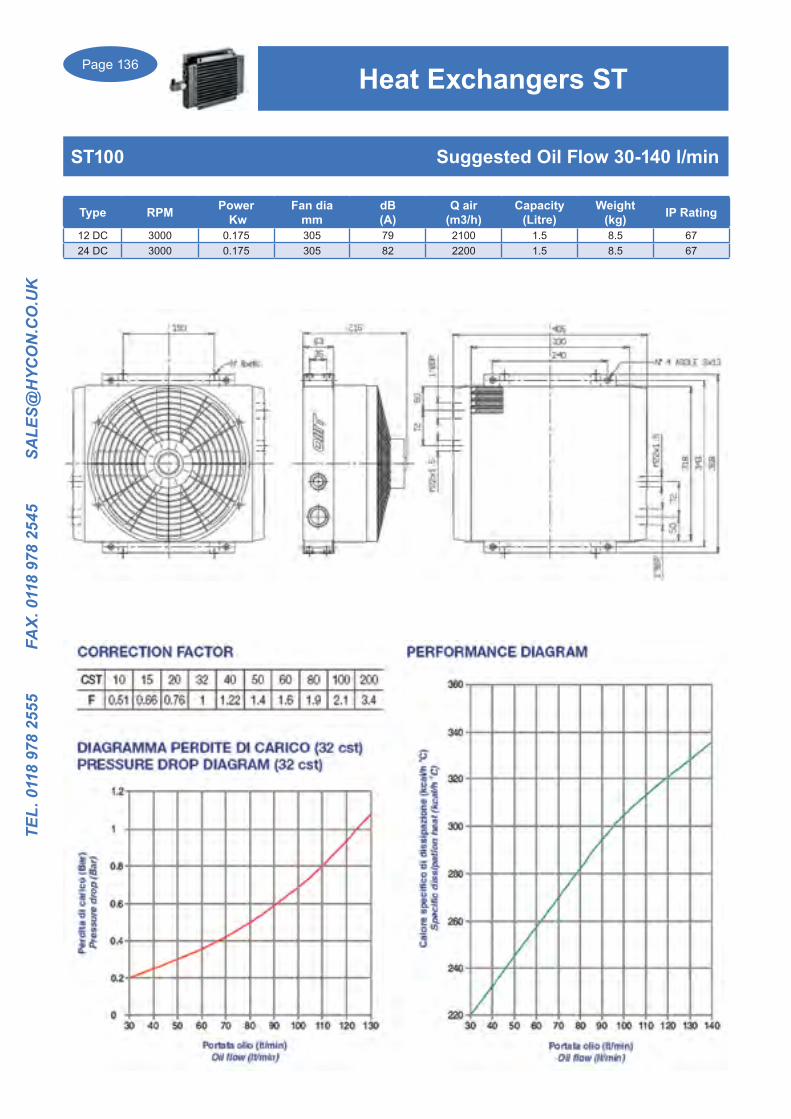
Page 136
TEL.
011
8 97
8 25
55
FA
X. 0
118
978
2545
S
ALE
S@H
YCO
N.C
O.U
K
Type RPM Power Kw
Fan diamm
dB(A)
Q air(m3/h)
Capacity (Litre)
Weight(kg) IP Rating
12 DC 3000 0.175 305 79 2100 1.5 8.5 6724 DC 3000 0.175 305 82 2200 1.5 8.5 67
ST100 Suggested Oil Flow 30-140 l/min
Heat Exchangers ST

Page 137
TEL. 0118 978 2555 FAX. 0118 978 2545 SA
LES@H
YCO
N.C
O.U
K
Type RPM Power Kw
Fan diamm
dB(A)
Q air(m3/h)
Capacity (Litre)
Weight(kg) IP Rating
12 DC 3000 0.175 305 79 2100 1.5 14 6724 DC 2500 0.175 305 82 2200 1.5 14 67
ST150 Suggested Oil Flow 35-140 l/min
Heat Exchangers ST
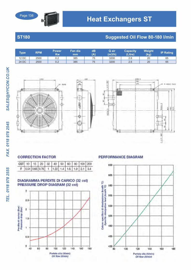
Page 138
TEL.
011
8 97
8 25
55
FA
X. 0
118
978
2545
S
ALE
S@H
YCO
N.C
O.U
K
Type RPM Power Kw
Fan diamm
dB(A)
Q air(m3/h)
Capacity (Litre)
Weight(kg) IP Rating
12 DC 2500 0.2 385 75 3200 2.6 20 6524 DC 2500 0.2 385 75 3200 2.6 20 65
ST180 Suggested Oil Flow 80-180 l/min
Heat Exchangers ST

Page 139
TEL. 0118 978 2555 FAX. 0118 978 2545 SA
LES@H
YCO
N.C
O.U
K
Type RPM Power Kw
Fan diamm
dB(A)
Q air(m3/h)
Capacity (Ltr)
Weight(kg) IP Rating
12 DC 2500 0.2 385 75 3200 2.6 26 6524 DC 2500 0.2 385 75 3200 2.6 26 65
ST210 Suggested Oil Flow 80-260 l/min
Heat Exchangers ST

Page 140
TEL.
011
8 97
8 25
55
FA
X. 0
118
978
2545
S
ALE
S@H
YCO
N.C
O.U
K
Heat Exchangers SS
SS10 Suggested Oil Flow 5-40 l/min
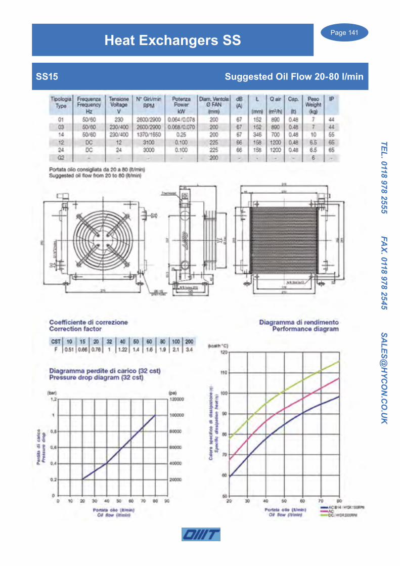
Page 141
TEL. 0118 978 2555 FAX. 0118 978 2545 SA
LES@H
YCO
N.C
O.U
K
Heat Exchangers SS
SS15 Suggested Oil Flow 20-80 l/min

Page 142
TEL.
011
8 97
8 25
55
FA
X. 0
118
978
2545
S
ALE
S@H
YCO
N.C
O.U
K
Heat Exchanger SS
SS20 Suggested Oil Flow 30-100 l/min

Page 143
TEL. 0118 978 2555 FAX. 0118 978 2545 SA
LES@H
YCO
N.C
O.U
K
Heat Exchangers SS
SS24 Suggested Oil Flow 40-120 l/min

Page 144
TEL.
011
8 97
8 25
55
FA
X. 0
118
978
2545
S
ALE
S@H
YCO
N.C
O.U
K
Heat Exchangers SS
SS30 Suggested Oil Flow 35-140 l/min

Page 145
TEL. 0118 978 2555 FAX. 0118 978 2545 SA
LES@H
YCO
N.C
O.U
K
Heat Exchangers SS
SS40 Suggested Oil Flow 40-160 l/min

Page 146
TEL.
011
8 97
8 25
55
FA
X. 0
118
978
2545
S
ALE
S@H
YCO
N.C
O.U
K
Heat Exchangers SS
SS50 Suggested Oil Flow 50-180 l/min
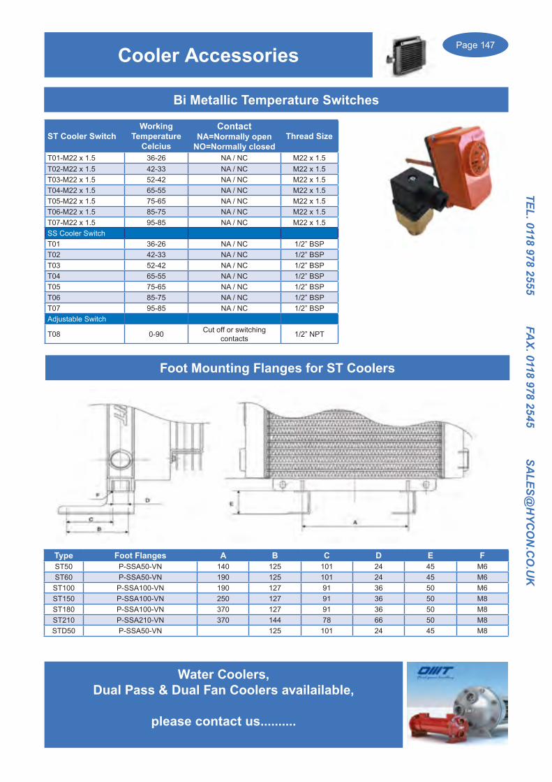
Page 147
TEL. 0118 978 2555 FAX. 0118 978 2545 SA
LES@H
YCO
N.C
O.U
K
Bi Metallic Temperature Switches
ST Cooler Switch Working
TemperatureCelcius
ContactNA=Normally open
NO=Normally closedThread Size
T01-M22 x 1.5 36-26 NA / NC M22 x 1.5T02-M22 x 1.5 42-33 NA / NC M22 x 1.5T03-M22 x 1.5 52-42 NA / NC M22 x 1.5T04-M22 x 1.5 65-55 NA / NC M22 x 1.5T05-M22 x 1.5 75-65 NA / NC M22 x 1.5T06-M22 x 1.5 85-75 NA / NC M22 x 1.5T07-M22 x 1.5 95-85 NA / NC M22 x 1.5SS Cooler SwitchT01 36-26 NA / NC 1/2” BSPT02 42-33 NA / NC 1/2” BSPT03 52-42 NA / NC 1/2” BSPT04 65-55 NA / NC 1/2” BSPT05 75-65 NA / NC 1/2” BSPT06 85-75 NA / NC 1/2” BSPT07 95-85 NA / NC 1/2” BSPAdjustable Switch
T08 0-90 Cut off or switching contacts 1/2” NPT
Water Coolers, Dual Pass & Dual Fan Coolers availailable,
please contact us..........
Cooler Accessories
Foot Mounting Flanges for ST Coolers
Type Foot Flanges A B C D E FST50 P-SSA50-VN 140 125 101 24 45 M6ST60 P-SSA50-VN 190 125 101 24 45 M6ST100 P-SSA100-VN 190 127 91 36 50 M6ST150 P-SSA100-VN 250 127 91 36 50 M8ST180 P-SSA100-VN 370 127 91 36 50 M8ST210 P-SSA210-VN 370 144 78 66 50 M8STD50 P-SSA50-VN 125 101 24 45 M8

Page 148
TEL.
011
8 97
8 25
55
FA
X. 0
118
978
2545
S
ALE
S@H
YCO
N.C
O.U
K
Air and Oil Heat Exchangers, (Air Blast Coolers) are designed to be used on the return line of the Hydraulic System.
The Aluminium cooler element provides a high conductivity and thermic exchange.
The new range of SSPV coolers can now incorporate a built in Bypass and Thermostatic valve
Single and two pass Coolers available
Heat Exchangers SSPV
HE
AT
EX
CH
AN
GE
RS
SSPVSeries New Heat Exchangers
3
HEAT EXCHANGERS
Cooler with the valve thermostatic by-pass incorporate
Incorporation of the valve thermostatic by-pass in the cooler
Continuous research and technical development lead to the SSPV heat exchanger series which consider the needs of the market.
Customers expressed many times dissatisfaction whit the process of assembling heat exchangers.
The main complain was about the obligation of adding an external bypass valve which was able to outflow any high pressure, mainly caused by the variation of oil viscosity and/or multiplication of the flow.
The SSPV series can simplify this process of assembly and marking it cheaper :
1 In fact, the SSPV series integrates the by-pass valve and thermostatic valve together in the same heat exchanger. So, it controls any peaks of pressure.
2 The presence of the thermostatic valve is strategic in case of freezing temperatures of the oil as it by-passes the oil outside the core until the oil temperature reaches 40°C
This new series is original because it eliminates many problems such as the loss of load when the oil viscosity is higher. It also allows to increase the temperature inside the pipes, grantig the best control on the oil temperature inside them.

Page 149
TEL. 0118 978 2555 FAX. 0118 978 2545 SA
LES@H
YCO
N.C
O.U
K
Heat Exchangers SSPV
HE
AT
EX
CH
AN
GE
RS
7
HEAT EXCHANGERS
SSPVSeries Key for series SSPV
SSPV30 > 14 > 02 > A > 0 > 0
SPECIAL APPLICATIONS For special solutions or particular applications, please contact OMT commercial department.
Fan Motor01 230V 50/60 Hz Angle phase03 400V 50/60 Hz Three phase14 230/400V 50/60 Hz Three phase B1412 12V CC24 24V CCG2 Arranged for hydraulic motor GR2G3 Arranged for hydraulic motor GR3
SSPV30 > 14
SSPV30 Type Type (two pass)SSPV 12 SSPV 212 ( two pass )SSPV 18 SSPV 218 ( two pass )SSPV 24 SSPV 224 ( two pass )SSPV 30 SSPV 230 ( two pass )SSPV 36 SSPV 236 ( two pass )SSPV 42 SSPV 242 ( two pass )SSPV 50 SSPV 250 ( two pass )SSPV 52 SSPV 252 ( two pass )
Bimetallic fixed temperature switches00 No switch01 Fixed switch 36-26 °C02 Fixed switch 43-33 °C03 Fixed switch 52-42 °C04 Fixed switch 65-55 °C05 Fixed switch 75-65 °C06 Fixed switch 85-75 °C07 Fixed switch 85-95 °CAdjustable switch08 Adjustable switch 0-90 °C
SSPV30 > 14 > 02
FansA SuctionS Blowing
SSPV30 > 14 > 02 > ABy-Pass tarature0 Without By-pass3 3 bar6 6 bar8 8 bar
SSPV30 > 14 > 02 > A > 0
Termostatic valve0 Without valve4 Value 40 °C
SSPV30 > 14 > 02 > A > 0 > 0
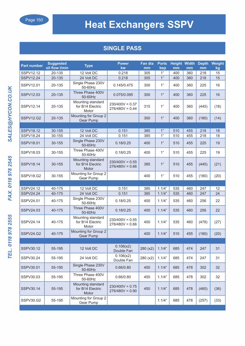
Page 150
TEL.
011
8 97
8 25
55
FA
X. 0
118
978
2545
S
ALE
S@H
YCO
N.C
O.U
K
Heat Exchangers SSPV
Part number Suggested oil flow l/min Type Power
kwFan dia
mmPorts bsp
Heightmm
Widthmm
Depthmm
Weightkg
SSPV12.12 20-135 12 Volt DC 0.218 305 1” 400 360 218 15SSPV12.24 20-135 24 Volt DC 0.218 305 1” 400 360 218 15
SSPV12.01 20-135 Single Phase 230V 50-60Hz 0.145/0.475 300 1” 400 360 225 16
SSPV12.03 20-135 Three Phase 400V50-60Hz 0.075/0.095 300 1” 400 360 225 16
SSPV12.14 20-135Mounting standard
for B14 Electric Motor
230/400V = 0.37276/480V = 0.44 315 1” 400 360 (445) (18)
SSPV12.G2 20-135 Mounting for Group 2 Gear Pump 300 1” 400 360 (180) (14)
SSPV18.12 30-155 12 Volt DC 0.151 385 1” 510 455 218 18SSPV18.24 30-155 24 Volt DC 0.151 385 1” 510 455 218 18
SSPV18.01 30-155 Single Phase 230V 50-60Hz 0.18/0.25 400 1” 510 455 225 19
SSPV18.03 30-155 Three Phase 400V50-60Hz 0.18/0.25 400 1” 510 455 225 19
SSPV18.14 30-155Mounting standard
for B14 Electric Motor
230/400V = 0.55276/480V = 0.66 385 1” 510 455 (445) (21)
SSPV18.G2 30-155 Mounting for Group 2 Gear Pump 400 1” 510 455 (180) (20)
SSPV24.12 40-175 12 Volt DC 0.151 385 1.1/4” 535 460 247 12SSPV24.24 40-175 24 Volt DC 0.151 385 1.1/4” 535 460 247 24
SSPV24.01 40-175 Single Phase 230V 50-60Hz 0.18/0.25 400 1.1/4” 535 460 256 22
SSPV24.03 40-175 Three Phase 400V50-60Hz 0.18/0.25 400 1.1/4” 535 460 256 22
SSPV24.14 40-175Mounting standard
for B14 Electric Motor
230/400V = 0.55276/480V = 0.66 400 1.1/4” 535 460 (478) (27)
SSPV24.G2 40-175 Mounting for Group 2 Gear Pump 400 1.1/4” 510 455 (180) (20)
SSPV30.12 55-195 12 Volt DC 0.106(x2) Double Fan 280 (x2) 1.1/4” 685 474 247 31
SSPV30.24 55-195 24 Volt DC 0.106(x2) Double Fan 280 (x2) 1.1/4” 685 474 247 31
SSPV30.01 55-195 Single Phase 230V 50-60Hz 0.66/0.80 450 1.1/4” 685 478 302 32
SSPV30.03 55-195 Three Phase 400V50-60Hz 0.66/0.80 450 1.1/4” 685 478 302 32
SSPV30.14 55-195Mounting standard
for B14 Electric Motor
230/400V = 0.75276/480V = 0.90 450 1.1/4” 685 478 (460) (36)
SSPV30.G2 55-195 Mounting for Group 2 Gear Pump 1.1/4” 685 478 (257) (33)
SINGLE PASS

Page 151
TEL. 0118 978 2555 FAX. 0118 978 2545 SA
LES@H
YCO
N.C
O.U
K
Heat Exchangers SSPV
Part number Suggested oil flow l/min Type Power
kwFan dia
mmPorts bsp
Heightmm
Widthmm
Depthmm
Weightkg
SSPV36.12 55-220 12 Volt DC 0.218(x2) Double Fan 305(x2) 1.1/4” 785 617 247 50
SSPV36.24 55-220 24 Volt DC 0.218(x2) Double Fan 305(x2) 1.1/4” 785 617 247 50
SSPV36.01 55-220 Single Phase 230V 50-60Hz 0.67/0.80 500 1.1/4” 785 617 315 51
SSPV36.03 55-220 Three Phase 400V50-60Hz 0.10/0.13 500 1.1/4” 785 617 315 51
SSPV36.14 55-220Mounting standard
for B14 Electric Motor
230/400V = 1.10276/480V = 1.12 500 1.1/4” 785 617 (470) (59)
SSPV36.G2 55-220 Mounting for Group 2 Gear Pump 500 1.1/4” 785 617 (261) (52)
SSPV42.01 60-260 Single Phase 230V 50-60Hz 0.75/0.98 560 1.1/4” 935 617 315 54
SSPV42.03 60-260 Three Phase 400V50-60Hz 1.07/0.125 560 1.1/4” 935 617 315 54
SSPV42.14 60-260Mounting standard
for B14 Electric Motor
230/400V = 1.10276/480V = 1.30 560 1.1/4” 935 617 (450) (55)
SSPV42.G2 60-260 Mounting for Group 2 Gear Pump 560 1.1/4” 935 617 (310) (60)
SSPV50.01 75-320 Single Phase 230V 50-60Hz 0.75/0.98 630 1.1/2” 955 740 400 90
SSPV50.03 75-320 Three Phase 400V50-60Hz 0.70/0.93 630 1.1/2” 955 740 400 90
SSPV50.14 75-320Mounting standard
for B14 Electric Motor
230/400V = 1.10276/480V = 1.30 630 1.1/2” 955 740 (480) 90
SSPV50.G2 75-320 Mounting for Group 2 Gear Pump 630 1.1/2” 955 740 (400) 90
SSPV52.01 80-340 Single Phase 230V 50-60Hz 0.75/0.98 630 1.1/2” 955 742 400 96
SSPV52.03 80-340 Three Phase 400V50-60Hz 0.70/0.93 630 1.1/2” 955 742 400 96
SSPV52.14 80-340Mounting standard
for B14 Electric Motor
230/400V = 1.10276/480V = 1.30 630 1.1/2” 955 742 (480) (98)
SSPV52.G2 80-340 Mounting for Group 2 Gear Pump 630 1.1/2” 935 617 (310) (95)
SINGLE PASS
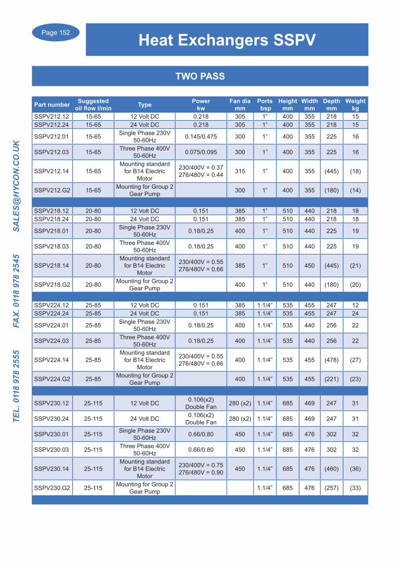
Page 152
TEL.
011
8 97
8 25
55
FA
X. 0
118
978
2545
S
ALE
S@H
YCO
N.C
O.U
K
Heat Exchangers SSPV
TWO PASS
Part number Suggested oil flow l/min Type Power
kwFan dia
mmPorts bsp
Heightmm
Widthmm
Depthmm
Weightkg
SSPV212.12 15-65 12 Volt DC 0.218 305 1” 400 355 218 15SSPV212.24 15-65 24 Volt DC 0.218 305 1” 400 355 218 15
SSPV212.01 15-65 Single Phase 230V 50-60Hz 0.145/0.475 300 1” 400 355 225 16
SSPV212.03 15-65 Three Phase 400V50-60Hz 0.075/0.095 300 1” 400 355 225 16
SSPV212.14 15-65Mounting standard
for B14 Electric Motor
230/400V = 0.37276/480V = 0.44 315 1” 400 355 (445) (18)
SSPV212.G2 15-65 Mounting for Group 2 Gear Pump 300 1” 400 355 (180) (14)
SSPV218.12 20-80 12 Volt DC 0.151 385 1” 510 440 218 18SSPV218.24 20-80 24 Volt DC 0.151 385 1” 510 440 218 18
SSPV218.01 20-80 Single Phase 230V 50-60Hz 0.18/0.25 400 1” 510 440 225 19
SSPV218.03 20-80 Three Phase 400V50-60Hz 0.18/0.25 400 1” 510 440 225 19
SSPV218.14 20-80Mounting standard
for B14 Electric Motor
230/400V = 0.55276/480V = 0.66 385 1” 510 450 (445) (21)
SSPV218.G2 20-80 Mounting for Group 2 Gear Pump 400 1” 510 440 (180) (20)
SSPV224.12 25-85 12 Volt DC 0.151 385 1.1/4” 535 455 247 12SSPV224.24 25-85 24 Volt DC 0.151 385 1.1/4” 535 455 247 24
SSPV224.01 25-85 Single Phase 230V 50-60Hz 0.18/0.25 400 1.1/4” 535 440 256 22
SSPV224.03 25-85 Three Phase 400V50-60Hz 0.18/0.25 400 1.1/4” 535 440 256 22
SSPV224.14 25-85Mounting standard
for B14 Electric Motor
230/400V = 0.55276/480V = 0.66 400 1.1/4” 535 455 (478) (27)
SSPV224.G2 25-85 Mounting for Group 2 Gear Pump 400 1.1/4” 535 455 (221) (23)
SSPV230.12 25-115 12 Volt DC 0.106(x2) Double Fan 280 (x2) 1.1/4” 685 469 247 31
SSPV230.24 25-115 24 Volt DC 0.106(x2) Double Fan 280 (x2) 1.1/4” 685 469 247 31
SSPV230.01 25-115 Single Phase 230V 50-60Hz 0.66/0.80 450 1.1/4” 685 476 302 32
SSPV230.03 25-115 Three Phase 400V50-60Hz 0.66/0.80 450 1.1/4” 685 476 302 32
SSPV230.14 25-115Mounting standard
for B14 Electric Motor
230/400V = 0.75276/480V = 0.90 450 1.1/4” 685 476 (460) (36)
SSPV230.G2 25-115 Mounting for Group 2 Gear Pump 1.1/4” 685 476 (257) (33)
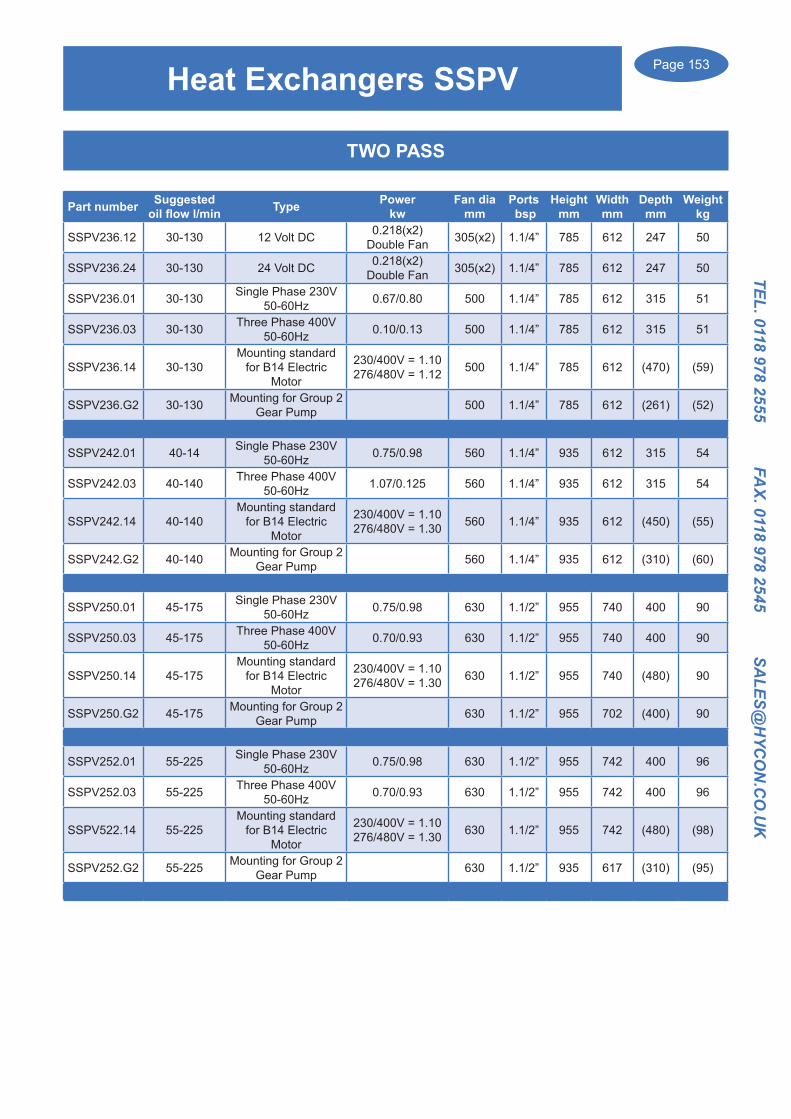
Page 153
TEL. 0118 978 2555 FAX. 0118 978 2545 SA
LES@H
YCO
N.C
O.U
K
Heat Exchangers SSPV
TWO PASS
Part number Suggested oil flow l/min Type Power
kwFan dia
mmPorts bsp
Heightmm
Widthmm
Depthmm
Weightkg
SSPV236.12 30-130 12 Volt DC 0.218(x2) Double Fan 305(x2) 1.1/4” 785 612 247 50
SSPV236.24 30-130 24 Volt DC 0.218(x2) Double Fan 305(x2) 1.1/4” 785 612 247 50
SSPV236.01 30-130 Single Phase 230V 50-60Hz 0.67/0.80 500 1.1/4” 785 612 315 51
SSPV236.03 30-130 Three Phase 400V50-60Hz 0.10/0.13 500 1.1/4” 785 612 315 51
SSPV236.14 30-130Mounting standard
for B14 Electric Motor
230/400V = 1.10276/480V = 1.12 500 1.1/4” 785 612 (470) (59)
SSPV236.G2 30-130 Mounting for Group 2 Gear Pump 500 1.1/4” 785 612 (261) (52)
SSPV242.01 40-14 Single Phase 230V 50-60Hz 0.75/0.98 560 1.1/4” 935 612 315 54
SSPV242.03 40-140 Three Phase 400V50-60Hz 1.07/0.125 560 1.1/4” 935 612 315 54
SSPV242.14 40-140Mounting standard
for B14 Electric Motor
230/400V = 1.10276/480V = 1.30 560 1.1/4” 935 612 (450) (55)
SSPV242.G2 40-140 Mounting for Group 2 Gear Pump 560 1.1/4” 935 612 (310) (60)
SSPV250.01 45-175 Single Phase 230V 50-60Hz 0.75/0.98 630 1.1/2” 955 740 400 90
SSPV250.03 45-175 Three Phase 400V50-60Hz 0.70/0.93 630 1.1/2” 955 740 400 90
SSPV250.14 45-175Mounting standard
for B14 Electric Motor
230/400V = 1.10276/480V = 1.30 630 1.1/2” 955 740 (480) 90
SSPV250.G2 45-175 Mounting for Group 2 Gear Pump 630 1.1/2” 955 702 (400) 90
SSPV252.01 55-225 Single Phase 230V 50-60Hz 0.75/0.98 630 1.1/2” 955 742 400 96
SSPV252.03 55-225 Three Phase 400V50-60Hz 0.70/0.93 630 1.1/2” 955 742 400 96
SSPV522.14 55-225Mounting standard
for B14 Electric Motor
230/400V = 1.10276/480V = 1.30 630 1.1/2” 955 742 (480) (98)
SSPV252.G2 55-225 Mounting for Group 2 Gear Pump 630 1.1/2” 935 617 (310) (95)

Page 154
TEL.
011
8 97
8 25
55
FA
X. 0
118
978
2545
S
ALE
S@H
YCO
N.C
O.U
K
Diaphragm AccumulatorsEnergy Accumulators/Pulsation Dampeners
Electron-beam welded Hydraulic Accumulators • Large volume and performance range • 0.7 to 3.5 Litre Capacity • Pressure range up to 350 bar (high bursting strength) • Low maintenance Design • Long service life Energy accumulation • Controlled energy delivery for hydraulic applications Application-specific design • The most varied diaphragm and housing materials • Refilable • Low permeation Pulsation damping • Vibration and noise reduction with pressure surges • Efficiency and extension of service life
43
Accumulatori a membrana
Diaphragm accumulators
Accumulatori a Membrana IntegralIntegral Diaphragm AccumulatorDATI TECNICI - TECHNICAL DATA
TipoType
CodiceArticle no.* Volume
nominalvolume
[l]
MBSP 0,07–250 007-1315-013-6X1 0.07 250 6kt32 G1/2" – M28x1.5 64 117 0.7 1:8MBSP 0,07–250 007-1315-074-6X1 0.07 250 6kt19 – M14x1.5 M28x1.5 64 107 0.7 1:8MBSP 0,16–250 016-1315-024-6X1 0.16 250 6kt32 G1/2" – M28x1.5 75 126 1.0 1:6MBSP 0,32–210 032-1315-044-6X1 0.32 210 6kt32 G1/2" – M28x1.5 92 141 1.5 1:8MBSP 0,50–210 050-1315-013-6X1 0.5 210 6kt41 G1/2" – M28x1.5 107 159 2.0 1:8MBSP 0,50–210 050-1315-023-6X1 0.5 210 6kt41 G1/2" M33x1.5 M28x1.5 107 170 2.0 1:8MBSP 0,50–330 050-1315-033-7X1 0.5 330 6kt41 G1/2" – M28x1.5 110 162 2.7 1:8MBSP 0,50–330 050-1315-013-7X1 0.5 330 6kt41 G1/2" M33x1.5 M28x1.5 110 159 2.7 1:8MBSP 0,60–330 060-1315-013-7X1 0.6 330 6kt41 G1/2" – M28x1.5 110 178 3.0 1:4MBSP 0,60–330 060-1315-023-7X1 0.6 330 6kt41 G1/2" M33x1.5 M28x1.5 110 171 3.0 1:4MBSP 0,75–210 075-1315-043-6X1 0.75 210 6kt41 G1/2" – M28x1.5 122 176 2.6 1:8MBSP 0,75–210 075-1315-053-6X1 0.75 210 6kt41 G1/2" M33x1.5 M28x1.5 122 169 2.6 1:8MBSP 0,75–250 075-1315-063-6X1 0.75 250 6kt41 G1/2" – M28x1.5 124 176 3.2 1:8MBSP 0,75–250 075-1315-073-6X1 0.75 250 6kt41 G1/2" M33x1.5 M28x1.5 124 169 3.2 1:8MBSP 0,75–350 075-1315-012-7X1 0.75 350 6kt41 G1/2" – M28x1.5 129 180 4.0 1:8MBSP 0,75–350 075-1315-022-7X1 0.75 350 6kt41 G1/2" M33x1.5 M28x1.5 129 173 4.0 1:8MBSP 1,0–210 100-1315-083-6X1 1.0 210 6kt41 G1/2" – M28x1.5 136 188 3.7 1:8MBSP 1,0–210 100-1315-063-6X1 1.0 210 6kt41 G1/2" M33x1.5 M28x1.5 136 181 3.7 1:8MBSP 1,0–350 100-1315-043-7X1 1.0 350 6kt41 G1/2" – M28x1.5 129 206 5.0 1:4MBSP 1,0–350 100-1315-053-7X1 1.0 350 6kt41 G1/2" M33x1.5 M28x1.5 129 199 5.0 1:4MBSP 1,4–140 140-1315-033-5X1 1.4 140 6kt41 G1/2" – M28x1.5 147 191 4.5 1:8MBSP 1,4–140 140-1315-043-5X1 1.4 140 6kt41 G1/2" M33x1.5 M28x1.5 147 202 4.5 1:8MBSP 1,4–210 140-1315-143-6X1 1.4 210 6kt41 G1/2" – M28x1.5 147 191 4.5 1:8MBSP 1,4–210 140-1315-153-6X1 1.4 210 6kt41 G1/2" M33x1.5 M28x1.5 147 202 4.5 1:8MBSP 1,4–250 140-1315-112-6X1 1.4 250 6kt41 G1/2" – M28x1.5 152 202 5.5 1:8MBSP 1,4–250 140-1315-122-6X1 1.4 250 6kt41 G1/2" M33x1.5 M28x1.5 152 195 5.5 1:8MBSP 1,4–350 140-1315-012-7X1 1.4 350 6kt41 G1/2" – M28x1.5 156 201 7.0 1:8MBSP 1,4–350 140-1315-022-7X1 1.4 350 6kt41 G1/2" M33x1.5 M28x1.5 156 194 7.0 1:8MBSP 2,0–250 200-1315-142-6X1 2.0 250 6kt41 G3/4" – M28x1.5 156 255 9.5 1:6MBSP 2,0–350 200-1315-042-7X1 2.0 350 6kt41 G3/4" – M28x1.5 156 255 9.5 1:6MBSP 2,8–250 280-1315-032-6X1 2.8 250 6kt41 G3/4" – M28x1.5 169 270 8.5 1:6MBSP 3,5–250 350-1315-072-6X1 3.5 250 6kt41 G3/4" – M28x1.5 169 309 10.2 1:4
Pressionedi lavoropermissibleoperatingpressure
[bar]
Valvole oliooil-port
SW IG AG
Valvole Gasgas-port
Ø
[mm]
Altezzaheight
H[mm]
Pesoweight
ca.
[kg]
Rapporto pressione massimamax permissible pressure ratio
* X equivale alla identificazione del materiale della membrana interna:materiale standard NBR (-10/+80)°C = 1; materiale IIR = 2; FKM = 3; materiale ECO (-35/+80)°C = 4; altri materiali su richiesta* rapporto di compressione ammissibile per diaframma/membrana = PO (pressione di riempimento del gas) / P2 (pressione di lavoro)
*X equates to identification figure at current diaphragm material:standard material NBR (-10/+80)°C = 1 ; material IIR = 2 ; material FKM = 3; material ECO (-35/+80)°C = 4; other materials on requiry*permissible pressure ratio for diaphragm = PO (gas filling pressure)/P2 (working pressure)

Page 155
TEL. 0118 978 2555 FAX. 0118 978 2545 SA
LES@H
YCO
N.C
O.U
K
Bladder AccumulatorsCarbon Steel
OMT codeEUROPEAN Description without precharge Volum "L" MAWP "Bar"
Nitrogen connection Oil connection
4
Accumulatori a sacca acciaio al carbonioHigh Bladder European carbon steel accumulators
design EN14359 97/23/EC(1-50)L (350/355)bar @ T(-45/+120)°C
A-51C-E001NK-DCA-51C-E02.5NK-CCA-51C-E004NK-CCA-51C-E005NK-CCA-51C-E006NK-CCA-51C-E010NK-ACA-51C-E020NK-ACA-51C-E024.5NK-ACA-51C-E032NK-ACA-51C-E050NK-AC
ACC. 1 380BAR CE M10X5/8" NBR 3/4" 1 380 5/8" M10x1,5 3/4" gas cil fACC. 2.5 350BAR CE M10X5/8" NBR 1 1/4" 2,5 350 5/8" M10x1,5 1"1/4 gas cil fACC. 4 350BAR CE M10X5/8" NBR 1 1/4" 4 350 5/8" M10x1,5 1"1/4 gas cil fACC. 5 350BAR CE M10X5/8" NBR 1 1/4" 5 350 5/8" M10x1,5 1"1/4 gas cil fACC. 6 350BAR CE M10X5/8" NBR 1 1/4" 6 350 5/8" M10x1,5 1"1/4 gas cil f
ACC. 10 355BAR CE M10X5/8" NBR 2" 10 355 5/8" M10x1,5 2" gas cil fACC. 20 355BAR CE M10X5/8" NBR 2" 20 355 5/8" M10x1,5 2" gas cil f
ACC. 24.5 355BAR CE M10X5/8" NBR 2" 24,5 355 5/8" M10x1,5 2" gas cil fACC. 32 355BAR CE M10X5/8" NBR 2" 32 355 5/8" M10x1,5 2" gas cil fACC. 50 355BAR CE M10X5/8" NBR 2" 50 355 5/8" M10x1,5 2" gas cil f
Kg
A-51C-E001NK-DCA-51C-E02.5NK-CCA-51C-E004NK-CCA-51C-E005NK-CCA-51C-E006NK-CCA-51C-E010NK-ACA-51C-E020NK-ACA-51C-E024.5NK-ACA-51C-E032NK-ACA-51C-E050NK-AC
6 328 115 22 5/8” 3/4" gas cil f 24411 548 115 22 5/8” 1"1/4 gas cil f 45014 420 169 22 5/8” 1"1/4 gas cil f 45019 897 115 22 5/8” 1"1/4 gas cil f 45020 559 170 22 5/8” 1"1/4 gas cil f 45030 568 219 22 5/8” 2" gas cil f 90050 888 219 22 5/8” 2" gas cil f 90053 1028 219 22 5/8” 2" gas cil f 90080 1380 219 22 5/8” 2" gas cil f 900
100 1885 219 22 5/8” 2" gas cil f 900
Amm
Dmm
dmm N2 valvOMT code
Flow maxL/min
Fluid port F
A
D
d
F
Hydropneumatic Accumulators
Volumes up to 500 Litre Capacity
Maximum working pressures up to 470 bar
Repairable bladder accumulators include a carbon steel/stainless steel, forged/welded body, a repairable bladder, a
nitrogen valve connection and an oil valve connection with seals.
Design EN14359 97/23/EC (1-50)L (350/355)bar @ T(-45/+120)0C

Page 156
TEL.
011
8 97
8 25
55
FA
X. 0
118
978
2545
S
ALE
S@H
YCO
N.C
O.U
K
Bladder AccumulatorsCarbon Steel
5
Accumulatori a sacca acciaio al carbonioHigh Bladder European carbon steel accumulators
design ASME U-STAMP (10-50)L (3000/10000)psi @ T(-40/+93)°C
OMT codeEUROPEAN Description without precharge Volum "L" MAWP "Psi/Bar"
Nitrogen connection Oil connection
A-51CEU010NK-ACA-51CEU020NK-AC
A-51CEU024.5NK-ACA-51CEU032NK-ACA-51CEU050NK-AC
ACC. 10 3000Psi U STAMP M10X5/8" NBR 2" 10 3000/320 5/8" M10x1,5 2" gas cil fACC. 20 3000Psi U STAMP M10X5/8" NBR 2" 20 3000/320 5/8" M10x1,5 2" gas cil f
ACC. 24.5 3000Psi U STAMP M10X5/8" NBR 2" 24,5 3000/320 5/8" M10x1,5 2" gas cil fACC. 32 3000Psi U STAMP M10X5/8" NBR 2" 32 3000/320 5/8" M10x1,5 2" gas cil fACC. 50 3000Psi U STAMP M10X5/8" NBR 2" 50 3000/320 5/8" M10x1,5 2" gas cil f
OMT codeEUROPEAN Description without precharge Volum "L" MAWP "Psi"
Nitrogen connection Oil connection
A-51C4U010NK-ACA-51C4U020NK-AC
A-51C4U024.5NK-ACA-51C4U032NK-ACA-51C4U050NK-AC
ACC. 10 4000Psi U STAMP M10X5/8" NBR 2" 10 4000 5/8" M10x1,5 2" gas cil fACC. 20 4000Psi U STAMP M10X5/8" NBR 2" 20 4000 5/8" M10x1,5 2" gas cil f
ACC. 24.5 4000Psi U STAMP M10X5/8" NBR 2" 24,5 4000 5/8" M10x1,5 2" gas cil fACC. 32 4000Psi U STAMP M10X5/8" NBR 2" 32 4000 5/8" M10x1,5 2" gas cil fACC. 50 4000Psi U STAMP M10X5/8" NBR 2" 50 4000 5/8" M10x1,5 2" gas cil f
OMT code Description without precharge Volum "L" MAWP "Psi"Nitrogen
connection Oil connection
A-51C6U010NK-ACA-51C6U020NK-AC
A-51C6U024.5NK-ACA-51C6U032NK-ACA-51C6U050NK-AC
ACC. 10 6666Psi U STAMP M10X5/8" NBR 2" 10 6666 5/8" M10x1,5 2" gas cil fACC. 20 6666Psi U STAMP M10X5/8" NBR 2" 20 6666 5/8" M10x1,5 2" gas cil f
ACC. 24.5 6666Psi U STAMP M10X5/8" NBR 2" 24,5 6666 5/8" M10x1,5 2" gas cil fACC. 32 6666Psi U STAMP M10X5/8" NBR 2" 32 6666 5/8" M10x1,5 2" gas cil fACC. 50 6666Psi U STAMP M10X5/8" NBR 2" 50 6666 5/8" M10x1,5 2" gas cil f
OMT codeEUROPEAN Description without precharge Volum "L" MAWP "Psi"
Nitrogen connection Oil connection
A-51C1U010NK-ACA-51C1U020NK-AC
A-51C1U024.5NK-ACA-51C1U032NK-ACA-51C1U050NK-AC
ACC. 10 10000Psi U STAMP M10X5/8" NBR 2" 10 10000 5/8" M10x1,5 2" gas cil fACC. 20 10000Psi U STAMP M10X5/8" NBR 2" 20 10000 5/8" M10x1,5 2" gas cil f
ACC. 24.5 10000Psi U STAMP M10X5/8" NBR 2" 24,5 10000 5/8" M10x1,5 2" gas cil fACC. 32 10000Psi U STAMP M10X5/8" NBR 2" 32 10000 5/8" M10x1,5 2" gas cil fACC. 50 10000Psi U STAMP M10X5/8" NBR 2" 50 10000 5/8" M10x1,5 2" gas cil f
KgEU/4
A-51C(EU4/6/1)010NK-ACA-51C( EU4/6/1)020NK-AC
A-51C( EU4/6/1)024.5NK-ACA-51C( EU4/6/1)032NK-ACA-51C( EU4/6/1)050NK-AC
30 36 95 219 245 267 22 5/8” 2" gas cil f 90050 54 134 219 245 267 22 5/8” 2" gas cil f 90053 75 170 219 245 267 22 5/8” 2" gas cil f 90080 100 227 219 245 267 22 5/8” 2" gas cil f 900
100 138 318 219 245 267 22 5/8” 2" gas cil f 900
Kg6
Kg1
DEU/4mm
D6
mm
D1
mm
dmm
N2valvOMT code
Flow maxL/min
Fluid port F
OMT codeEUROPEAN Description without precharge Volum "L" MAWP "Bar"
Nitrogen connection Oil connection
4
Accumulatori a sacca acciaio al carbonioHigh Bladder European carbon steel accumulators
design EN14359 97/23/EC(1-50)L (350/355)bar @ T(-45/+120)°C
A-51C-E001NK-DCA-51C-E02.5NK-CCA-51C-E004NK-CCA-51C-E005NK-CCA-51C-E006NK-CCA-51C-E010NK-ACA-51C-E020NK-ACA-51C-E024.5NK-ACA-51C-E032NK-ACA-51C-E050NK-AC
ACC. 1 380BAR CE M10X5/8" NBR 3/4" 1 380 5/8" M10x1,5 3/4" gas cil fACC. 2.5 350BAR CE M10X5/8" NBR 1 1/4" 2,5 350 5/8" M10x1,5 1"1/4 gas cil fACC. 4 350BAR CE M10X5/8" NBR 1 1/4" 4 350 5/8" M10x1,5 1"1/4 gas cil fACC. 5 350BAR CE M10X5/8" NBR 1 1/4" 5 350 5/8" M10x1,5 1"1/4 gas cil fACC. 6 350BAR CE M10X5/8" NBR 1 1/4" 6 350 5/8" M10x1,5 1"1/4 gas cil f
ACC. 10 355BAR CE M10X5/8" NBR 2" 10 355 5/8" M10x1,5 2" gas cil fACC. 20 355BAR CE M10X5/8" NBR 2" 20 355 5/8" M10x1,5 2" gas cil f
ACC. 24.5 355BAR CE M10X5/8" NBR 2" 24,5 355 5/8" M10x1,5 2" gas cil fACC. 32 355BAR CE M10X5/8" NBR 2" 32 355 5/8" M10x1,5 2" gas cil fACC. 50 355BAR CE M10X5/8" NBR 2" 50 355 5/8" M10x1,5 2" gas cil f
Kg
A-51C-E001NK-DCA-51C-E02.5NK-CCA-51C-E004NK-CCA-51C-E005NK-CCA-51C-E006NK-CCA-51C-E010NK-ACA-51C-E020NK-ACA-51C-E024.5NK-ACA-51C-E032NK-ACA-51C-E050NK-AC
6 328 115 22 5/8” 3/4" gas cil f 24411 548 115 22 5/8” 1"1/4 gas cil f 45014 420 169 22 5/8” 1"1/4 gas cil f 45019 897 115 22 5/8” 1"1/4 gas cil f 45020 559 170 22 5/8” 1"1/4 gas cil f 45030 568 219 22 5/8” 2" gas cil f 90050 888 219 22 5/8” 2" gas cil f 90053 1028 219 22 5/8” 2" gas cil f 90080 1380 219 22 5/8” 2" gas cil f 900
100 1885 219 22 5/8” 2" gas cil f 900
Amm
Dmm
dmm N2 valvOMT code
Flow maxL/min
Fluid port F
A
D
d
F
Design ASME U-STAMP (10-50)L (3000-10000)psi @ T(-40/+93)0C
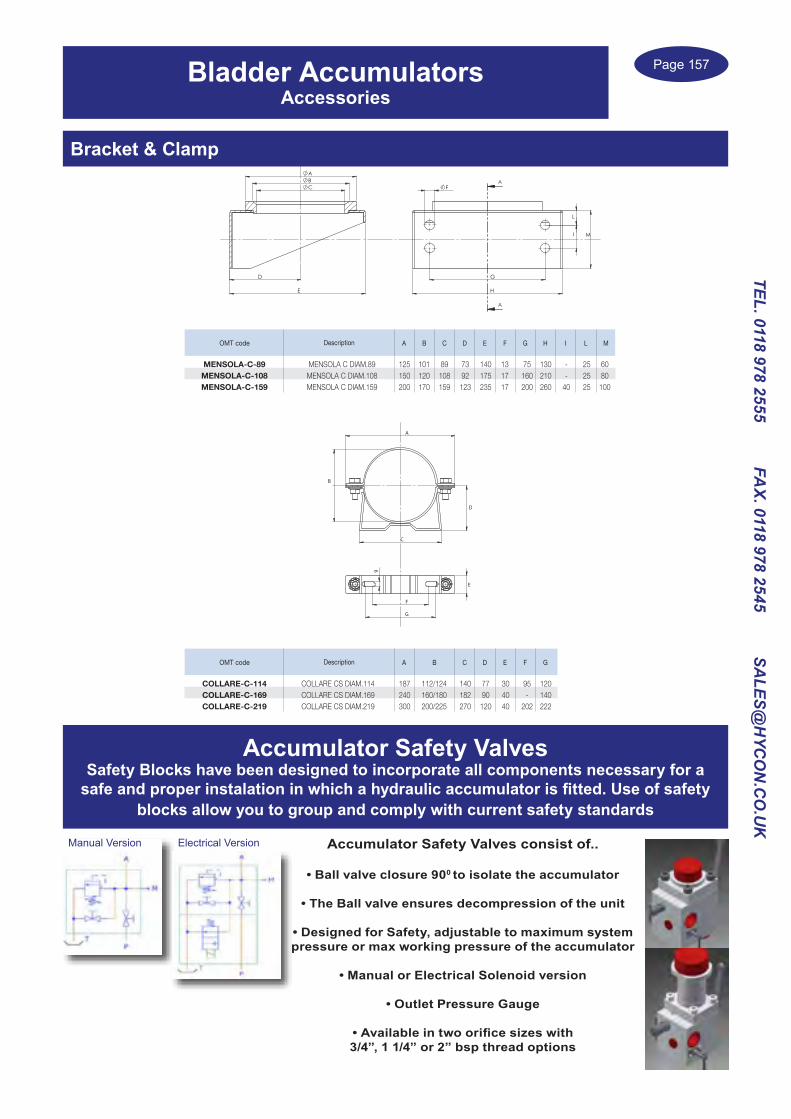
Page 157
TEL. 0118 978 2555 FAX. 0118 978 2545 SA
LES@H
YCO
N.C
O.U
K
Accessori / AccessoriesMensola / Bracket
Collare / Clamp
9
OMT code Description A B C D E F G H I L M
MENSOLA-C-89MENSOLA-C-108MENSOLA-C-159
MENSOLA C DIAM.89 125 101 89 73 140 13 75 130 - 25 60MENSOLA C DIAM.108 150 120 108 92 175 17 160 210 - 25 80MENSOLA C DIAM.159 200 170 159 123 235 17 200 260 40 25 100
H
L
G
I
F
M
A
A
C
E
B
D
A
B
E
F
G
9
D
C
A
OMT code Description A B C D E F G
COLLARE-C-114COLLARE-C-169COLLARE-C-219
COLLARE CS DIAM.114 187 112/124 140 77 30 95 120COLLARE CS DIAM.169 240 160/180 182 90 40 - 140COLLARE CS DIAM.219 300 200/225 270 120 40 202 222
Bladder AccumulatorsAccessories
Bracket & Clamp
Accumulator Safety ValvesSafety Blocks have been designed to incorporate all components necessary for a
safe and proper instalation in which a hydraulic accumulator is fitted. Use of safety blocks allow you to group and comply with current safety standards
Accumulator Safety Valves consist of..
• Ball valve closure 900 to isolate the accumulator
• The Ball valve ensures decompression of the unit
• Designed for Safety, adjustable to maximum system pressure or max working pressure of the accumulator
• Manual or Electrical Solenoid version
• Outlet Pressure Gauge
• Available in two orifice sizes with 3/4”, 1 1/4” or 2” bsp thread options
Manual Version Electrical Version

Page 158
TEL.
011
8 97
8 25
55
FA
X. 0
118
978
2545
S
ALE
S@H
YCO
N.C
O.U
K
AccumulatorsAccessories
Pre Charging Nitrogen Kit Type PCNK
Nitrogen Control pressure kit Type NCPK
Stainless Steel Bladder Accumulatorsavailable upon request...

Page 159
TEL. 0118 978 2555 FAX. 0118 978 2545 SA
LES@H
YCO
N.C
O.U
K
Notes

Page 160
TEL.
011
8 97
8 25
55
FA
X. 0
118
978
2545
S
ALE
S@H
YCO
N.C
O.U
K
Notes
Page 161
TEL. 0118 978 2555 FAX. 0118 978 2545 SA
LES@H
YCO
N.C
O.U
K
Company Number VAT Number
Acc's Contact Name Acc's email
Postcode
if different
Postcode
Telephone Fax
Buyer Name Buyer email
Trade Ref one Trade Ref two
Name Name
Address Address
Telephone Telephone
Bank Name
Sort code - - Account Number
Bank Address
I have read Hycon Limited Condition and fully agree to the terms.
Authorised Signature
Name & Position
Company's Registered Name
Invoice address
Delivery address
Credit Account Application Form
HYCON LTDHYDRAULIC CONTROL TECHNOLOGY
HYCON LIMITEDUNIT 11 METRO CENTRE TOUTLEY ROAD, WOKINGHAM
BERKSHIRE RG41 1QW
BER Phone: 01189 782555 Fax: 01189 782545 Email: [email protected] Co Reg: 3316060
HYCON USE ONLY
IIF
LIMIT
ACCP
S/U
ACCPC NO
IFF NO

Page 162
TEL.
011
8 97
8 25
55
FA
X. 0
118
978
2545
S
ALE
S@H
YCO
N.C
O.U
K
HYCON LIMITED CONDITIONS OF SALE
Hycon is listed below by name or the title of the ‘company’. The buyer or client of Hycon shall be listed as the ‘purchaser or buyer’
1. General All conditions entered into by the company are subject to and governed by these conditions Which may only be varied by the company
2. Settlements and Acceptance For all subsequent supplies and deliveries are nett 30 days from date of invoice, except where other specific arrangements have been made, in which case the terms will be agreed in writing.
3. Deliveries and Acceptance (a) The company does not accept responsibility for any direct or indirect loss or damage due to delay in delivery and all dates
quoted are estimated only (b) The purchaser must check all deliveries. Signatures for goods will be considered as binding receipt for the sale (c) The company reserve the right to suspend deliveries or refuse orders when unpaid invoices exceed the purchasers credit
limits.
4. Claims (a) Must be reported within 7 days from receipt of goods. Otherwise the company cannot be held responsible for shortage, wrong
parts or damaged goods (b) In the event of wrong goods being ordered by the purchaser, Hycon Ltd will at their discretion take such goods back. A minimum
charge of 25% of the value of the invoice will be made on such purchases, this will take place in the way of a credit note issuedagainst the purchase account, and no other means of credit for returned good is available.
(c) No returned goods or claims will be accepted on goods which are working outside their design and recommended parameters as listed in the technical catalogues of said products.
5. Defects (a) Every care will be taken to ensure that all goods supplied are satisfactory, if nevertheless any article is found to be defective
within a reasonable period of delivery the company should be notified immediately and goods returned for examination and at the company’s discretion they will replaced or repaired
(b) The company does not accept liability for any damage or loss consequential or otherwise arising through defect in goods supplied by the company on fitting and use thereof.
(c) Expenditure by the customer in the salvaging of defective material or workmanship may under exceptional circumstances be a matter for agreement between the customer and the company made in writing, but in the absence of such agreement it shall not be chargeable to the company. In no circumstances whatsoever does the company accept any liability for direct, indirect, consequential loss or damage including claims for death or personal injury attributed directly or indirectly to our products.
6. Risks and Title
(a) The risk in the goods shall pass to the purchaser on delivery. (b) Not withstanding delivery the good shall remain the absolute property of the company until payment by the purchaser off all
invoices outstanding from time to time (c) In the event of the buyer entering into liquidation or bankruptcy or having a winding up order against it or having appointed in
respect of its assets, the company shall be entitled to enter the premises of the purchaser and repossess any goods to which itis entitled to under this condition.
7. Indemnities
(a) The purchaser shall indemnify the company in respect of any claim. (b) Which may be made that the use to which the goods are put infringes the present copyright or other industrial property rights of
any third party. (c) Which may be made against the company under section 6 of the health and safety at work at 1974.
8. Discounts and delivery charges
(a) The company may at their discretion enter into discount with certain purchasers in writing. (b) A minimum order valve of £30.00 nett will apply on all goods packed and despatched by carriers, unless they are a nature of
spare parts, which must be agreed by the company. (c) A next delivery of up to 25kg in one box will be charged at £12.50 nett, other special delivery arrangements will be quoted by
the company the current time, carriage is only free of charge if agreed in writing by the company.
9. Interest at the rate of 6% per month is chargeable on all money due and payable by the purchaser on all invoices that are deemed to be at the company’s discretion past the reasonable period of payment
10. These conditions of sale shall be subject to and interpreted in accordance with the laws of England and the conditions or contractsthere under shall be deemed to have been made in England

TEL. 0118 978 2555 FAX. 0118 978 2545 SA
LES@H
YCO
N.C
O.U
K
Alphabetical IndexAAir blast Coolers 134Air Breathers 104Accumulators 148
BBall Valves, High Pressure 2 & 3 way 10Bearing Supports 84Bell Housings 90Bent Axis Piston Pumps 86Bladder Accumulator 149Brake Unclamping valve for Hydraulic Motor 7Brakes for Hydraulic Motors 129
CCetop 3 valves, 3KO 57Cetop 3 valves, 5KL 58Cetop 3 valve, KVM Bankable valve 56Cetop 3 & 5 Manual Lever valves 63Cetop 3 valves with Manual Lever & Solenoid
60
Cetop 3 valves, Proportional Solenoid Operation KVP
59
Cetop 5 valves 61Cetop 7 valves 64Cetop Sandwich Valve Modules 66Cetop Subplates & manifolds 69Changeover Solenoid valves 12, 15Check valves, Inline 25Check valves, Disc type 24Check valves Cetop 3 67Clutch Units, Mechanical & Electrical 88Control cables 53Counterbalance valve Cetop 3 68Counterbalance with Brake release 31Cylinders, Double Acting 131Cylinders, Trailer Brake 133
DDamping Rings 97Damping Rods 97Diaphragm Accumulators 148Directional Control valves, Lever & Electric 46Directional Control valves, Monoblock 33Directional Control valves for Log Splitter 39Directional Control valves, with Flow control 50Directional Control valves, Proportional 54Directional Control valves, Rotary Lever 41Directional Control valves, Sectional 45Distribution blocks 21Diverter valves, 3 way Manual 11Diverter valves, 3 way Solenoid operated 12Diverter valves, 4 & 6 way Manual 13Diverter valves, 6/8/10 way Sol. operated 14Drive Couplings, Aluminium & Steel 90Dual Pump Unloader Valves 6
EElectric Motors 96End Run valves 8
FFiller Breathers 103Filler Caps, Plastic 106Filters, High Pressure 114Filters, Spin on cannister Return Line 110Filters, Spin on cannister Suction Line 111Filters, Suction Strainers 106Filters, Tank Top 112Filtration Transfer Rig 117
FFlanges, pump flanges 118Flanges, SAE Threaded BSP 122Flow controls, Barrel type 16Flow Controls, Cartridge 22Flow Controls, Cetop 66Flow splitting manifolds 21Flow Controls, Speed Control valves 16Flow Controls, Motor mounting 19Flow Controls, Needle valves 16Flow Controls, Pressure Compensated 17Flow Controls, Priority adjustable 18Flow Reciprocating valve 24Flow Divider / Combiner valves 20Foot mounting Brackets for Bell Housings 92
GGaskets, for Pumps and Bell housings 92Gauge Isolators 117Gearboxes, Reduction 88Gearboxes, Speed Up 87Gear Pumps, Commercial Vehicle 85Gear Pumps, Group 1 79Gear Pumps, Group 2 80 Gear Pumps, Group 2 Quieter Running 81Gear Pumps Group 3 82Gear Pumps, Group 3 Quieter Running 83Gear Pumps, Group 4 & 5 84
HHand Pumps, Industrial 75Hand Pumps, Mobile applications 77Heat Exchangers 134Hose Burst valves & cartridges 26
IInspection Covers for Oil Tanks 102
KKVM Sectional Cetop 3 valve 56
LLog Splitter valves 39Level Switches 102Level Gauges 107
MManifolds 21, 69Manual Emergency valve 24Motors, MAMM Mini motors 123Motors, MAP Gerotor motor 124Motors, MAR Geroler motor 125Motors, MAS Torque motor 126Motors, MAT Torque motor 127Motors, MAV Torque motor 128Motor Brake 129Motor, Piston Bent axis 86
NNeedle Flow Control valves 16Nitrogen Pre Charging Kit 152Non Return Check Valves 25
OOil Level Switches 102Oil Tanks, Aluminium 98Oil Tanks, Steel 100Oil Tanks, Steel Commercial Vehicle 101
OOvercentre valves, Banjo Mount 30Overcentre valves, Cetop 3 & 5 68Overcentre valves, Dual 31Overcentre valves, Motor mounting 30,31Overcentre valves, Single 30
PPiston Pumps & Motors, Bent Axis 86Pressure Gauges 116Pressure Gauge Isolators 117Pressure Reciprocating valve 24Pressure Relief valves, CETOP 3 & 5 66Pressure Relief valves, Single Inline 4Pressure Relief valves, Dual Inline 5Pressure relief valves, Motor Mounting 5Pressure Relief valves, Dual Anti-cavitation 5Pressure Relief valves, Dual with pilot check 5Pressure Switches 32Pilot Operated Check Valves, Cetop 3 & 5 67Pilot Operated Check valves, Dual 28Pilot operated Check valves, manual lever 27,28Pilot Operated Check valves, Single 27Pilot Operated Check valves, Tube mounting 29Poclain Hydraulics, Pumps, Motors & Components
130
Poppet Valves, 2 ported, 2/2 valves 9Pre Charging Nitrogen Kit 152Pressure Couplings 32Pressure Reducing Valves 6Pump Bearing Supports 84Pump Unloader Valves 6Push Button Electric Switch 14
RRegenerative Valve 7Rotational Couplings 32Rotary Lever valves 41
SSequence valves 23Shuttle valves 7Subplates 69Sight Level & Temperature gauges 107Suction Strainers 106Speed Control Valves 16Swivel Under Pressure Couplings 32
THydraulic Power Packs 93Thermostatic Temperature Switch 147
UUnloader Valves, Inline 6
VValve Cable Controls 53

Hyd
rau
lic C
on
trol Te
chn
olo
gy
HY
CO
N
Hycon LimitedThe complete hydraulic Solution…
Tel : 0118 978 2555 Fax : 0118 978 2545email : [email protected] www.hycon.co.uk
Hycon LimitedUnit 11 Metro Centre
Toutley Road, Wokingham, Berkshire.
United KingdomRG41 1QW
Although every effort has been made to ensure that the information in this catalogue is correct; the specifications, dimensions, Characteristics, written and published information of all products are indicative only.
We reserve the right to modify without notice the specifications, list prices of any products featured in this catalogue.No part of this catalogue whatsoever may be reproduced or published in any form or by any means without the prior written notice of the producer Hycon Limited.
All transactions are subject to our standard Terms and conditions of Sale a copy of which is available upon request. Products shown in the catalogue are preferentially supplied but we reserve the right to supply an equivalent
product or different manufactured item if stock on the original catalogue item is unavailable. This catalogue and all contents of this catalogue are the intellectual property of the creator and producer Hycon Limited.
All rights reserved. Hycon Limited 2019.
hycon hydraulics