Training book-Communication Principle NEC Microwave Communication Principle & design
60
Ver.2.2 Training book-Communication Principle NEC Microwave Communication Principle & design
-
Upload
independent -
Category
Documents
-
view
2 -
download
0
Transcript of Training book-Communication Principle NEC Microwave Communication Principle & design

Ver.2.2
Training book-Communication Principle
NEC
Microwave CommunicationPrinciple & design

Page 2 Training book- NEC Copyrights
1. Application & construction
4. Multipath fading & countermeasure
5. Frequency plan
3. Path clearance requirement
7. Review & summary
6. Design flow chart
2. Microwave propagation character
CONTENTS
Page 3 Training book- NEC Copyrights
Terminal
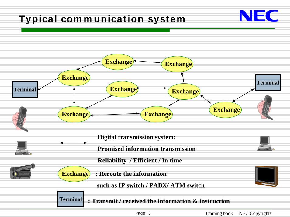
Digital transmission system:
Promised information transmission
Reliability / Efficient / In time
Typical communication system
: Transmit / received the information & instruction
Exchange
Terminal
Exchange : Reroute the information
such as IP switch / PABX/ ATM switch
Exchange
Exchange
Exchange Exchange
Exchange
Exchange
Exchange
Terminal

Page 4 Training book- NEC Copyrights
Various transmission methods
Satellite
Fiber-optics cable
Radio link
Coaxial cable
Exchange Exchange

Page 5 Training book- NEC Copyrights
2MB SDH
[ Drop & Insert ][Repeater]
radio SDH SDH 2MB
SDH
[FOTS]
2MB
Various application
Case 1 Mix with FOTS
radioradio
SDH : SDH Multiplex Equipment
radio radio radio
radio : Microwave Radio Equipment FOTS : Fiber Optics Transmission System

Page 6 Training book- NEC Copyrights
SDH SDH2MB 2MB
[FOTS]
Various application
Case 2 Protection for the FOTS
SDH : SDH Multiplex Equipment
radio : Microwave Radio Equipment FOTS : Fiber Optics Transmission System
radio radio radio radio radio radio

Page 7 Training book- NEC Copyrights
radio
radio
SDH
63x2 MB
STM-1 RING
radioSDHradio
Various application
Case 3 Ring protection
Same as above
Same as above
SDH : SDH Multiplex Equipment
radio : Microwave Radio Equipment
3→11→3
W
W
3→11→3
P
P
SW
SW
3
2
1
4
3→11→3
3→11→3
SW
SW
Failure
3
2
1
4
Note: Microwave as transmission mediaSNCP Ring protection function realized in MUX.
STM-1STM-4 Ring

Page 8 Training book- NEC Copyrights
BTS
Cellular/UMTSNetwork
BTS
BTSBTS
BTS
BTS
BTS STMSTM--1 Ring1 Ring
STMSTM--0 / PDH Approach0 / PDH Approach
BTS
Application for cellular network

Page 9 Training book- NEC Copyrights
Main strongpoint of microwave
Overcome the topography difficulty such as mountain & river
Less Immune to natural disasters such as flooding & earthquakes
Avoid the trouble of accidental damage such as building and road construction works
Easier Single Point Security Protection such as against subversive terrorist

Page 10 Training book- NEC Copyrights
Main strongpoint of microwave
Faster in Service Implementation & Easy Maintenance
Compatible with the Existing Infrastructure(Site building, Tower etc.)
Radio grows with the network: Easily expandable and accommodates future relocation
Avoid the trouble to borrow the land from the private owner

Page 11 Training book- NEC Copyrights
Outlook of microwave room:
Concrete
Guy-support
Self-support
Microwave roomRoof mount

Page 12 Training book- NEC Copyrights
ODU
IF cable or waveguide
Tower
Cable clamp
Antenna bracket
DDF/LDF
LDF & DDF
Antenna
PBD
IDU
ETSI
Cable rack
Construction of micro room
Side view

Page 13 Training book- NEC Copyrights
Construction of micro room
Outdoor cable rack
Through wall hole
Groundingcable
Signal cable
Power cable Microwave
room170mm
170m
m
68.6mmWeight = 3kg
IDU
ODU
Top view

Page 14 Training book- NEC Copyrights
1
432
1
432
4E11
432
1
30
34,368 Mbit/s
8,448 Mbit/s
2,048 Mbit/s
64 kbit/s
8.448 Mbit/s E2
2/34 Mbit/s PDHADM155
155.520 Mbit/s STM-1
16E1
PCM2,048 Mbit/s E1
34.268 Mbit/s E3
139.264 Mbit/s E464E1PDH
Digital system hierarchy
SDH

Page 15 Training book- NEC Copyrights
1. Application & construction
4. Multipath fading & countermeasure
5. Frequency plan
3. Path clearance requirement
7. Review & summary
6. Design flow chart
2. Microwave propagation character
CONTENTS

Page 16 Training book- NEC Copyrights
Electromagnetic wave
E
H
Direction of propagationZ
Y
X
Electromagnetic wave & polarization
Narrow side
Wide side
Electric field distribution
Rectangular waveguide cross section
V (vertical) polarization
H (Horizontal) polarization

Page 17 Training book- NEC Copyrights
Radio frequency allocation
30 KHz 300 3MHz 30 300M 3GHz 30 300G 3 T Hz
10Km 1 100m 10 1 100mm 10 1 100μm
VLF
Very-long
LF
long
UHF
Ultra-high
VHF
very-high
MF
middle
HF
short
SHF
super-high
EHF
optical
Band
Wavelength
Sub-band
Mainapplication
voyage
Raido voyage
broadcast broadcast FMbroadcastT VT V
T V satellite
Micro-wave
repeater
Microwavespectrum

Page 18 Training book- NEC Copyrights
Features of microwave transmission
1. Line of sight propagation (LOS)
○ Select the station with high elevation
○ Add the repeater or shorten the distance

Page 19 Training book- NEC Copyrights
Features of microwave transmission
2. Reflection, refraction , diffraction and scattering etc.
Reflection
Refraction Diffraction
Scattering
○ Multi-path fading○ Raining & snow attenuation (Above 10G)

Page 20 Training book- NEC Copyrights
1. Application & construction
4. Multipath fading & countermeasure
5. Frequency plan
3. Path clearance requirement
7. Review & summary
6. Design flow chart
2. Microwave propagation character
CONTENTS

Page 21 Training book- NEC Copyrights
1st Fresnel radius :F1
d1 d2
d
d
T R
P
2λ
+=+ dPRPT
22 λ+=+ dPRPT
N Fresnel radius:
Fresnel zone introduction
dfdd
ddd
F⋅⋅⋅
=⋅⋅
= 2121 3001
λ
dfddn
dddn
Fn⋅
⋅⋅⋅=
⋅⋅⋅= 2121 300λ
Earth
1st Fresnel radius
2ndt Fresnel radius
Direction wave
Reflection wave

Page 22 Training book- NEC Copyrights
Line of Sight
Line of sight
Near LoS
None LoS

Page 23 Training book- NEC Copyrights
Calculation of Path Clearance
: Actual Earth radius 6370Km( ) hskRddhh
ddhhc −−−−=
02212111 0R
hc
hs
2h
1h
1d 2dd

Page 24 Training book- NEC Copyrights
1.0 F1 at K=4/3
0.577 F1 at K=2/3 (When flat terrain)
0 F1 at K=2/3 (When obstacle is ridge)
0.3 F1 at K=2/3 (When obstacle is not ridge)
Path clearance criteria
For main antenna For S/D antenna
0.6 F at K = 4/3
* F1 is the first Fresnel Region

Page 25 Training book- NEC Copyrights
Constructionheight
Example
? ? 11 08
NEC CORPORATION
LuwubeLatitude 00 45 51.20 NLongitude 032 33 12.60 EAzimuth 352.14�Elevation 1287 m ASLAntenna CL 35.0 m AGL
KalubangaLatitude 01 19 24.90 NLongitude 032 28 36.30 EAzimuth 172.14�Elevation 1161 m ASLAntenna CL 35.0 m AGL
Frequency (MHz) = 7425.0K = 1.33, 0.67
%F1 = 100.00, 60.00
Path length (62.44 km)0 5 10 15 20 25 30 35 40 45 50 55 60
Elev
atio
n (m
)
1040
1060
1080
1100
1120
1140
1160
1180
1200
1220
1240
1260
1280
1300
1320
1340
1360
K=4/3
K=2/3
100%Fresnel Zone
Hc K=4/3
Hc K=2/3
60%Fresnel Zone

Page 26 Training book- NEC Copyrights
Countermeasure for the insufficient LOS
By means of Google earth softwarecheck the construction condition especial in urban

Page 27 Training book- NEC Copyrights
Countermeasure for the insufficient LOS
Field survey the path along the linkconstruction height/site coordinate
Re-routeAvailable adjacent sitecoordinate/ tower height
Adding the microwave repeater stationnear the road/ with high elevation
Page 28 Training book- NEC Copyrights
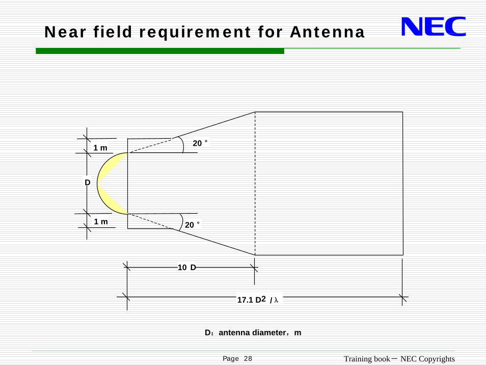
Near field requirement for Antenna
D
1 m
1 m 20 °
20 °
10 D
17.1 D2 /λ
D:antenna diameter,m

Page 29 Training book- NEC Copyrights
1. Application & construction
4. Multipath fading & countermeasure
5. Frequency plan
3. Path clearance requirement
7. Review & summary
6. Design flow chart
2. Microwave propagation character
CONTENTS

Page 30 Training book- NEC Copyrights
Received level variation with time changing
What’s fading
fadingMulti-path

Page 31 Training book- NEC Copyrights
SD (Space Diversity)
H
○ More antenna installation○ Considered tower workload
Multi-path fading independent in space
Measure against Fading
Main path
SD path

Page 32 Training book- NEC Copyrights
1+1 Hot-standby
SD application

Page 33 Training book- NEC Copyrights
FD (Frequency Diversity)
F2 path
F1 path
Multi-path fading independent in enough frequency space
○ More frequency point needed
Example : 1+1 twin-path /N+1
Measure against Fading

Page 34 Training book- NEC Copyrights
1+1 Twin-path
FD application
2 single polarization antenna 1 dual polarization antenna

Page 35 Training book- NEC Copyrights
FD & SD Hybrid configuration
1+1 Hybrid Diversity

Page 36 Training book- NEC Copyrights
1. Application & construction
4. Multipath fading & countermeasure
5. Frequency plan
3. Path clearance requirement
7. Review & summary
6. Design flow chart
2. Microwave propagation character
CONTENTS

Page 37 Training book- NEC Copyrights
frequency plan shall be conformed with ITU - R
U4GHz Rec. ITU - R F. 382 - 74 GHz Rec. ITU - R F. 635 --4
5 GHz Rec. ITU - R F. 1099--2 L6 GHz Rec. ITU - R F. 383 - 5
U6 GHz Rec. ITU - R F. 384 - 6
L7 GHz Rec. ITU - R F. 385 - 6U7GHz Rec. ITU - R F. 385 - 6L8GHz Rec. ITU - R F. 386 - 511GHz Rec. ITU - R F. 387 - 713GHz Rec. ITU - R F. 497 - 515GHz Rec. ITU - R F. 636 - 318GHz Rec. ITU - R F. 595 - 3
Frequency recommendation

Page 38 Training book- NEC Copyrights
XS:Adjacent frequency separation on the same polarizationYS:Center gap frequency of the go and return channelsZS: Guard Band DS: TX/RX Duplexer Spacing
XSDS
YS
ZS
Frequency recommendation specification
Fo
Fo: Center frequency

Page 39 Training book- NEC Copyrights
Example
Site A Site B Site C Site DU7GHz band
ITU-R Rec.385-6 Annex 3(7,110 - 7,750 MHz)
7121
1'
7177
7233
7275
7317
7373
7429
1
2
3
4
5
f0
2'
3'
4'
5'
1V
3V
1'V
3'V
7149
7205
7345
7401
2H
2'H
2V
4V
2'V
4'V
1H
1'H
1H
1'H
3H
3'H
XS
YS
DS

Page 40 Training book- NEC Copyrights
85432 10 201 30 40 50
1.5
Public access network
Backbone transmission network
Regional & local transmission network
2G/3G
P-MP
Bluetooth
STM-1/XPIC
STM-1/ 16E1/4E1
3.6
GHz
11 GHz
Microwave frequency application sketch
high frequency band / abundant frequency point
P-P(SS)

Page 41 Training book- NEC Copyrights
Priority adopt the high frequency bandabundant frequency point available
Priority adopt the vertical polarizationless the raining attenuation affection
Avoid the same frequency band TX High & Lowviolation in the same station
Reduce the internal frequency interference Overreach interference & Front-back interference
Key factor for frequency allocation plan

Page 42 Training book- NEC Copyrights
Avoid TX High & Low violation
Tx: LowTx: HighTx:High & LowTx: Low

Page 43 Training book- NEC Copyrights
Example
Tx: LowTx: HighTx: LowTx: High

Page 44 Training book- NEC Copyrights
Internal frequency interference analysis
θ
D
U
TXcSite A
Site B
Site C
Ant.BTXa
○ Changing polarization every hop○ Changing frequency point○ Increasing the link angle
Front to back interference
H
V

Page 45 Training book- NEC Copyrights
TXa
45°
=45.3 – 53 =- 7.7 dB
=45.3 – 70 =-24.7 dB
Radiation Pattern Envelop of Antenna
Example: Antenna Gain: 45.3 dB (HPX10-77) H polarization H polarization
Antenna gain in this direction
H to H
Antenna gain in this direction

Page 46 Training book- NEC Copyrights
Internal frequency interference analysis
○ Changing polarization every 2 hops ○ Changing frequency point○ Increasing the link twist
Overreach interference
Site A
Site B
Site C
Site DD
U
θtθrAnt.A
Ant.D
H H
V

Page 47 Training book- NEC Copyrights
CH1 CH3
CH2
CH5 CH7
CH4 CH6 CH8
CH1’
Frequency point & polarization arrangement
interval channel co-polarization
Adjacent channel different polarization

Page 48 Training book- NEC Copyrights
CH1
Co-channel Cross-polarization
CH3 CH5 CH7
CH2 CH4 CH6 CH8
CH1’
Frequency point & polarization arrangement
Antenna: HXPD
Equipment: XPIC technology

Page 49 Training book- NEC Copyrights
1. Application & construction
4. Multipath fading & countermeasure
5. Frequency plan
3. Path clearance requirement
7. Review & summary
6. Design flow chart
2. Microwave propagation character
CONTENTS

Page 50 Training book- NEC Copyrights
Key design value: Flat Fade Margin (FFM)
Threshold
Designreceivedlevel
Flat Fading Margin

Page 51 Training book- NEC Copyrights
AntennaG1
Waveguide
Branching (filters + circulators)
Transmit power: Pt dBm Receive power: Prn dBm
G2
RxTx
Prn (dBm) = Pt (dBm) + G1 (dB) + G2 (dB) - F.S.L. (dB) - Losses (dB) (Waveguides + Branching)
D Km
Free Space Loss = 92.4 + 20log f (GHz) d (km) (dB)
Key design value: Flat Fade Margin (FFM)
FFM (dB) =Prn (dBm) - Threshold (dBm) FFM normal requirement > 35 dB

Page 52 Training book- NEC Copyrights
24 dPt
π
Power per unit area:
tP
d
Free Space Loss definition

Page 53 Training book- NEC Copyrights
G1 =
IF cable
Transmit power: Pt dBm
G2=
RxTx
Prn (dBm) = 25+41+41-138.2-0 = - 31.2 dB
15 Km
Free Space Loss = 92.4 + 20log f (GHz) d (km) (dB)
FFM (dB) =Prn (dBm) - Threshold (dBm) =31.2 – (-88.0) =56.8 dB
Example
Equipment type : 13G 4E1 1+0
Threshold : -88.0 dBm
41dBi
Cable & connect loss = 0
25dBm
20* log (13*15) = 45.8
F.S.L. (dB) = 92.4 +45.8 = 138.2 dB
41dBi

Page 54 Training book- NEC Copyrights
Enter Customer Data
Calculated clearance satisfy
specification?
Calculate SESR & unavailability
Performance meet customer’s requirement?
Station coordinate & Rain zone
& Available frequency
Adjust antenna height& Re-route
& Adding repeater stations
Modify antenna sizefrequency band, or re-routeEquipped with SD or FD
No
Yes
No
Yes
BOQ
Design software tools: Pathloss
Calculated clearance satisfy
specification?
Existing the F-B or overreach interference ?
Adjust frequency point/frequency band
/polarization
Yes
No

Page 55 Training book- NEC Copyrights
Example
Step 1 : Get the relative information Site nameCoordinateE1 requirementtower height
Step 2 : Input the information to Pathloss
Step 3 :Link the site to BSC

Page 56 Training book- NEC Copyrights
Example
Step 4 : Check each hop LOS
LOS is not OK

Page 57 Training book- NEC Copyrights
Example
? ? 06 08
NEC CORPORATION
Site 5Latitude 11 21 41.60 NLongitude 029 44 55.20 EAzimuth 143.72�Elevation 572 m ASLAntenna CL 50.0 m AGL
Site 9Latitude 11 00 04.89 NLongitude 030 00 58.19 EAzimuth 323.77�Elevation 529 m ASLAntenna CL 50.0 m AGL
Frequency (MHz) = 7425.0K = 1.33, 0.67
%F1 = 100.00, 30.00
Path length (49.41 km)0 5 10 15 20 25 30 35 40 45
Elev
atio
n (m
)
480
500
520
540
560
580
600
620
640
660
Site5—site 9 profile

Page 58 Training book- NEC Copyrights
Example
Step 5 : add the microwave repeater
Step 6 : Adjust the frequency allocation
Step 7 : Adjust antenna size & FD & SD

Page 59 Training book- NEC Copyrights
Review & summary
1, Microwave spectrum band300MHz-300GHz
2, Features of microwave transmissionLine of sight propagation (LOS)
Reflection, refraction , diffraction and scattering etc
3, Measure against Fading
4, Internal frequency interferenceDue to the Tx High / Low alternate configuration
5, Key design value: Flat Fade MarginFront to back interference / Overreach interference
FFM (dB) =Prn (dBm) - Threshold (dBm)
FD/SD/low frequency / short distance/ increase antenna size

Page 60 Training book- NEC Copyrights