aletljit 44. EL kun og RL, bd We got - able 1 du le tritabellucu
Upload
khangminh22Category
view
4download
0
Chao-Hai Du · Pu-Kun Liu
Millimeter-Wave Gyrotron Traveling-Wave Tube Ampli� ers
Millimeter-Wave Gyrotron Traveling-Wave TubeAmplifiers

Chao-Hai Du • Pu-Kun Liu
Millimeter-Wave GyrotronTraveling-Wave TubeAmplifiers
123
Chao-Hai DuPu-Kun LiuSchool of Electronics Engineering
and Computer SciencePeking UniversityBeijing, China
ISBN 978-3-642-54727-0 ISBN 978-3-642-54728-7 (eBook)DOI 10.1007/978-3-642-54728-7Springer Heidelberg New York Dordrecht London
Library of Congress Control Number: 2014940850
© Springer-Verlag Berlin Heidelberg 2014This work is subject to copyright. All rights are reserved by the Publisher, whether the whole or part ofthe material is concerned, specifically the rights of translation, reprinting, reuse of illustrations, recitation,broadcasting, reproduction on microfilms or in any other physical way, and transmission or informationstorage and retrieval, electronic adaptation, computer software, or by similar or dissimilar methodologynow known or hereafter developed. Exempted from this legal reservation are brief excerpts in connectionwith reviews or scholarly analysis or material supplied specifically for the purpose of being enteredand executed on a computer system, for exclusive use by the purchaser of the work. Duplication ofthis publication or parts thereof is permitted only under the provisions of the Copyright Law of thePublisher’s location, in its current version, and permission for use must always be obtained from Springer.Permissions for use may be obtained through RightsLink at the Copyright Clearance Center. Violationsare liable to prosecution under the respective Copyright Law.The use of general descriptive names, registered names, trademarks, service marks, etc. in this publicationdoes not imply, even in the absence of a specific statement, that such names are exempt from the relevantprotective laws and regulations and therefore free for general use.While the advice and information in this book are believed to be true and accurate at the date ofpublication, neither the authors nor the editors nor the publisher can accept any legal responsibility forany errors or omissions that may be made. The publisher makes no warranty, express or implied, withrespect to the material contained herein.
Printed on acid-free paper
Springer is part of Springer Science+Business Media (www.springer.com)
Preface
A gyrotron traveling-wave tube (gyro-TWT) amplifier is capable of generating high-power and broadband coherent electromagnetic radiation on the level of hundreds ofkilowatts in the millimeter-wave range. It is one of the most promising candidatesof the electromagnetic-wave power amplifier for the next generation of imagingradars and long-range high-data-rate wireless communications. It would play animportant role in many fields, such as national security, small objects tracking inthe outer space, accurate atmosphere and weather monitoring, and so on. A gyro-TWT amplifies the driving power based on the convective instability principle ofthe relativistic electron cyclotron maser (ECM). The amplification simultaneouslysuffers from competing absolute instabilities, which lead to complicated self-excitedoscillations. As a result, the instability competition not only stops the system fromefficient operation but also hinders practical applications. Investigating the physicsof the instability competition and exploring solutions to suppress self-excited oscil-lations turn into primary factors essentially related to the gyro-TWT development.Hence, it is of important academic value and engineering application to study thebeam-wave interaction mechanism and to reveal the instability competition physicsin depth, as a way to further enhance the amplifier performance and promote itsapplication in high-power millimeter-wave radars and communication systems.
This book focuses on the beam-wave interaction mechanisms and the compe-tition relations between the convective instability and the absolute instability ingyro-TWT amplifiers. The book starts with a technical review of the gyro-TWTdevelopment in past decades in Chap. 1. Chapter 2 presents a comprehensivepresentation of the linear theory and nonlinear theory of ECM interaction. Themain content of the book is conveyed in Chaps. 3, 4, and 5, including detailedinvestigation of the lossy dielectric-loaded (DL) waveguide, ultrahigh gain gyro-TWT amplifier, and lossy DL gyro-TWT amplifier. Chapter 6 is arranged as anexploratory section. Three novel concepts related to amplifier interaction circuit areintroduced here. Chapter 7 presents some key technologies related to developing agyrotron amplifier.
The contents of the book originate from recent years theoretical and engineeringworks on developing gyrotron amplifiers in our group. We try to present them in
v
vi Preface
a comprehensive way, especially a lot of vivid figures are conceived to illustratethe complicated physics. The millimeter-wave gyrotron amplifier has experienceda tremendous advance in the past decade. We hope this book would be helpful topromote its further development.
Beijing, China Chao-Hai DuPu-Kun Liu
Contents
1 Review of Gyrotron Traveling-Wave Tube Amplifiers . . . . . . . . . . . . . . . . . . . 11.1 Microwave Electronics. . . . . . . . . . . . . . . . . . . . . . . . . . . . . . . . . . . . . . . . . . . . . . . . . . 11.2 Electrons Cyclotron Maser and Gyrotron . . . . . . . . . . . . . . . . . . . . . . . . . . . . . . 4
1.2.1 The Principle of ECM .. . . . . . . . . . . . . . . . . . . . . . . . . . . . . . . . . . . . . . . . . 41.2.2 The Characteristics of a Gyrotron. . . . . . . . . . . . . . . . . . . . . . . . . . . . . . 61.2.3 The Category of Gyrotron Tubes. . . . . . . . . . . . . . . . . . . . . . . . . . . . . . . 7
1.3 Gyrotron Traveling-Wave-Tube Amplifiers. . . . . . . . . . . . . . . . . . . . . . . . . . . . 101.3.1 The Development of Gyro-TWTs. . . . . . . . . . . . . . . . . . . . . . . . . . . . . . 101.3.2 Comments on Technologies . . . . . . . . . . . . . . . . . . . . . . . . . . . . . . . . . . . . 141.3.3 Problems and Prospects . . . . . . . . . . . . . . . . . . . . . . . . . . . . . . . . . . . . . . . . 19
References . . . . . . . . . . . . . . . . . . . . . . . . . . . . . . . . . . . . . . . . . . . . . . . . . . . . . . . . . . . . . . . . . . . . . 21
2 Fundamental Theory of the Electron Cyclotron Maser . . . . . . . . . . . . . . . . . 272.1 Introduction . . . . . . . . . . . . . . . . . . . . . . . . . . . . . . . . . . . . . . . . . . . . . . . . . . . . . . . . . . . . . 272.2 Theory of the Waveguides . . . . . . . . . . . . . . . . . . . . . . . . . . . . . . . . . . . . . . . . . . . . . . 29
2.2.1 Theory of Uniform Dielectric-Loaded Waveguide . . . . . . . . . . . . 302.2.2 Theory of Periodic Dielectric-Loaded Waveguide . . . . . . . . . . . . 34
2.3 Theory of the Electron Cyclotron Maser in Waveguide System . . . . . . 392.3.1 Partitioning the Transverse Plane of an ECM System . . . . . . . . 402.3.2 The Linear Theory of Dielectric-Lined ECM System . . . . . . . . 422.3.3 The Nonlinear Theory of Dielectric-Loaded ECM System. . . 452.3.4 Basic Concepts . . . . . . . . . . . . . . . . . . . . . . . . . . . . . . . . . . . . . . . . . . . . . . . . . . 47
2.4 Summary . . . . . . . . . . . . . . . . . . . . . . . . . . . . . . . . . . . . . . . . . . . . . . . . . . . . . . . . . . . . . . . . 50Appendix I: Derivation of the Linear Theory
in Dielectric-Lined Waveguide . . . . . . . . . . . . . . . . . . . . . . . . . . . . . . . . . . . . . . . . . 501. The Field Expression in GCC . . . . . . . . . . . . . . . . . . . . . . . . . . . . . . . . . . . . . . . 512. The Transverse Perturbed Beam Current. . . . . . . . . . . . . . . . . . . . . . . . . . . . 523. The Laplace Transformation . . . . . . . . . . . . . . . . . . . . . . . . . . . . . . . . . . . . . . . . . 55
References . . . . . . . . . . . . . . . . . . . . . . . . . . . . . . . . . . . . . . . . . . . . . . . . . . . . . . . . . . . . . . . . . . . . . 58
vii
viii Contents
3 Novel Propagation Characteristics of LossyDielectric-Loaded Waveguides . . . . . . . . . . . . . . . . . . . . . . . . . . . . . . . . . . . . . . . . . . . . . 613.1 Introduction . . . . . . . . . . . . . . . . . . . . . . . . . . . . . . . . . . . . . . . . . . . . . . . . . . . . . . . . . . . . . 613.2 Dielectric Loss-Induced Modal Transition. . . . . . . . . . . . . . . . . . . . . . . . . . . . . 63
3.2.1 Eigenvalue and Mode Identification . . . . . . . . . . . . . . . . . . . . . . . . . . . 633.2.2 Modal Transition. . . . . . . . . . . . . . . . . . . . . . . . . . . . . . . . . . . . . . . . . . . . . . . . 663.2.3 Modal Degeneration . . . . . . . . . . . . . . . . . . . . . . . . . . . . . . . . . . . . . . . . . . . . 693.2.4 Modal Selection. . . . . . . . . . . . . . . . . . . . . . . . . . . . . . . . . . . . . . . . . . . . . . . . . 71
3.3 Periodic DL Waveguide with Suppressed Property of Periodicity. . . . 743.3.1 Eigenvalue and Mode Identification . . . . . . . . . . . . . . . . . . . . . . . . . . . 753.3.2 Influence of Dielectric Slot Ratio . . . . . . . . . . . . . . . . . . . . . . . . . . . . . . 753.3.3 Modal Transition in a Periodic Dielectric
Waveguide System . . . . . . . . . . . . . . . . . . . . . . . . . . . . . . . . . . . . . . . . . . . . . . 783.3.4 Suppressing the System Periodicity Using
Dielectric Loss . . . . . . . . . . . . . . . . . . . . . . . . . . . . . . . . . . . . . . . . . . . . . . . . . . 813.4 Mode Mapping . . . . . . . . . . . . . . . . . . . . . . . . . . . . . . . . . . . . . . . . . . . . . . . . . . . . . . . . . . 823.5 Conclusion . . . . . . . . . . . . . . . . . . . . . . . . . . . . . . . . . . . . . . . . . . . . . . . . . . . . . . . . . . . . . . 87References . . . . . . . . . . . . . . . . . . . . . . . . . . . . . . . . . . . . . . . . . . . . . . . . . . . . . . . . . . . . . . . . . . . . . 88
4 Instability Competition in an Ultrahigh Gain Gyro-TWT Amplifier . . 914.1 Introduction . . . . . . . . . . . . . . . . . . . . . . . . . . . . . . . . . . . . . . . . . . . . . . . . . . . . . . . . . . . . . 91
4.1.1 Analysis Method of the Instability Competition . . . . . . . . . . . . . . 924.1.2 The Key Factors of Instability Competition . . . . . . . . . . . . . . . . . . . 93
4.2 Balance Between the Backward Wave and Forward Wavein an Absolute Instability . . . . . . . . . . . . . . . . . . . . . . . . . . . . . . . . . . . . . . . . . . . . . . . 944.2.1 Internal Feedback Dynamics of an Absolute Instability . . . . . . 964.2.2 Magnetic Tuning . . . . . . . . . . . . . . . . . . . . . . . . . . . . . . . . . . . . . . . . . . . . . . . . 984.2.3 High-Order Axial Mode . . . . . . . . . . . . . . . . . . . . . . . . . . . . . . . . . . . . . . . . 1014.2.4 Waveguide Wall Loss . . . . . . . . . . . . . . . . . . . . . . . . . . . . . . . . . . . . . . . . . . . 1044.2.5 A Multistage Interaction Gyro-TWT Circuit . . . . . . . . . . . . . . . . . . 106
4.3 Oscillation with Multi-steady States . . . . . . . . . . . . . . . . . . . . . . . . . . . . . . . . . . . 1094.3.1 Self-Consistent Nonlinear Instability Study . . . . . . . . . . . . . . . . . . . 1094.3.2 Attenuation Strength of the Lossy Linear Stage. . . . . . . . . . . . . . . 1104.3.3 Multi-steady States of Absolute Instability Oscillation . . . . . . . 1114.3.4 Applying Magnetic Field Tapering to Enhance
Nonlinear Stage Stability . . . . . . . . . . . . . . . . . . . . . . . . . . . . . . . . . . . . . . . 1144.3.5 Influence of the Downstream Port Reflection . . . . . . . . . . . . . . . . . 1164.3.6 Pre-bunched ECM Radiation . . . . . . . . . . . . . . . . . . . . . . . . . . . . . . . . . . . 117
4.4 Summary . . . . . . . . . . . . . . . . . . . . . . . . . . . . . . . . . . . . . . . . . . . . . . . . . . . . . . . . . . . . . . . . 118References . . . . . . . . . . . . . . . . . . . . . . . . . . . . . . . . . . . . . . . . . . . . . . . . . . . . . . . . . . . . . . . . . . . . . 119
Contents ix
5 A Lossy Ceramic-Loaded Millimeter-Wave Gyro-TWT Amplifier . . . . 1215.1 Introduction . . . . . . . . . . . . . . . . . . . . . . . . . . . . . . . . . . . . . . . . . . . . . . . . . . . . . . . . . . . . . 1215.2 Propagation Characteristics Approximation . . . . . . . . . . . . . . . . . . . . . . . . . . . 123
5.2.1 The Propagation Characteristicsof the Dielectric-Loaded Waveguide . . . . . . . . . . . . . . . . . . . . . . . . . . . 123
5.2.2 Linear and Nonlinear Instability Study . . . . . . . . . . . . . . . . . . . . . . . . 1265.3 Linear Study of Full-Wave Interaction
in Dielectric-Loaded Waveguide . . . . . . . . . . . . . . . . . . . . . . . . . . . . . . . . . . . . . . . 1325.3.1 Linear Instability Competition Study . . . . . . . . . . . . . . . . . . . . . . . . . . 1335.3.2 Linear Growth Rate Study. . . . . . . . . . . . . . . . . . . . . . . . . . . . . . . . . . . . . . 135
5.4 Nonlinear Study of Full-Wave Interactionin Dielectric-Loaded Waveguide . . . . . . . . . . . . . . . . . . . . . . . . . . . . . . . . . . . . . . . 1375.4.1 Nonlinear Instability Competition Study . . . . . . . . . . . . . . . . . . . . . . 1385.4.2 Amplification Characteristics . . . . . . . . . . . . . . . . . . . . . . . . . . . . . . . . . . 140
5.5 Beam-Wave Coupling Strength. . . . . . . . . . . . . . . . . . . . . . . . . . . . . . . . . . . . . . . . . 1435.6 Summary . . . . . . . . . . . . . . . . . . . . . . . . . . . . . . . . . . . . . . . . . . . . . . . . . . . . . . . . . . . . . . . . 149References . . . . . . . . . . . . . . . . . . . . . . . . . . . . . . . . . . . . . . . . . . . . . . . . . . . . . . . . . . . . . . . . . . . . . 149
6 Exploring New Mechanisms for High PowerMillimeter-Wave Gyrotron Amplifiers . . . . . . . . . . . . . . . . . . . . . . . . . . . . . . . . . . . . 1516.1 Introduction . . . . . . . . . . . . . . . . . . . . . . . . . . . . . . . . . . . . . . . . . . . . . . . . . . . . . . . . . . . . . 1516.2 An ECM-Cascaded Amplifier . . . . . . . . . . . . . . . . . . . . . . . . . . . . . . . . . . . . . . . . . . 153
6.2.1 The Concept of ECM-Cascaded Amplifier . . . . . . . . . . . . . . . . . . . . 1546.2.2 Beam-Wave Interaction in an ECM-Cascaded Amplifier . . . . . 1556.2.3 Discussion . . . . . . . . . . . . . . . . . . . . . . . . . . . . . . . . . . . . . . . . . . . . . . . . . . . . . . . 157
6.3 High-Order Mode Drift Tube . . . . . . . . . . . . . . . . . . . . . . . . . . . . . . . . . . . . . . . . . . . 1586.3.1 The Concept of High-Order Mode Drift Tube . . . . . . . . . . . . . . . . 1586.3.2 Beam-Wave Interaction in Overmoded Drift Tube . . . . . . . . . . . . 1596.3.3 Discussion . . . . . . . . . . . . . . . . . . . . . . . . . . . . . . . . . . . . . . . . . . . . . . . . . . . . . . . 161
6.4 High-Power Gyrotron Amplifier Based on Bi-modes Operation . . . . . 1616.4.1 The Concept of Bi-modes Operation . . . . . . . . . . . . . . . . . . . . . . . . . . 1616.4.2 The Principle of Bi-modes Operation. . . . . . . . . . . . . . . . . . . . . . . . . . 163
6.5 High-Power Gyrotron Amplifier Based on ECM-Cascadeand Pre-bunching Scheme (Gyro-CPA) . . . . . . . . . . . . . . . . . . . . . . . . . . . . . . . . 1646.5.1 Key Technologies Related to a Gyro-CPA. . . . . . . . . . . . . . . . . . . . . 1646.5.2 Principle of Amplifier Based on ECM Cascade
and Pre-bunching Excitation . . . . . . . . . . . . . . . . . . . . . . . . . . . . . . . . . . . 1656.5.3 Discussion . . . . . . . . . . . . . . . . . . . . . . . . . . . . . . . . . . . . . . . . . . . . . . . . . . . . . . . 171
6.6 Conclusion . . . . . . . . . . . . . . . . . . . . . . . . . . . . . . . . . . . . . . . . . . . . . . . . . . . . . . . . . . . . . . 171References . . . . . . . . . . . . . . . . . . . . . . . . . . . . . . . . . . . . . . . . . . . . . . . . . . . . . . . . . . . . . . . . . . . . . 172
x Contents
7 Technologies Related to Gyrotron Amplifiers . . . . . . . . . . . . . . . . . . . . . . . . . . . . 1757.1 Introduction . . . . . . . . . . . . . . . . . . . . . . . . . . . . . . . . . . . . . . . . . . . . . . . . . . . . . . . . . . . . . 1757.2 Input Coupler . . . . . . . . . . . . . . . . . . . . . . . . . . . . . . . . . . . . . . . . . . . . . . . . . . . . . . . . . . . . 176
7.2.1 A Ka-Band TE11 Mode Input Coupler . . . . . . . . . . . . . . . . . . . . . . . . . 1777.2.2 A Ka-Band TE01 Mode Input Coupler . . . . . . . . . . . . . . . . . . . . . . . . . 1787.2.3 A W-Band Multichannel TE01 Mode Converter. . . . . . . . . . . . . . . 178
7.3 Broadband Output Window. . . . . . . . . . . . . . . . . . . . . . . . . . . . . . . . . . . . . . . . . . . . . 1817.3.1 A Ka-Band TE11 Mode Output Window . . . . . . . . . . . . . . . . . . . . . . 1817.3.2 A Ka-Band TE01 Mode Output Window . . . . . . . . . . . . . . . . . . . . . . 182
7.4 A Small-Orbit Gun . . . . . . . . . . . . . . . . . . . . . . . . . . . . . . . . . . . . . . . . . . . . . . . . . . . . . . 1827.5 Measurement of Lossy Dielectric Materials . . . . . . . . . . . . . . . . . . . . . . . . . . . 1857.6 Summary . . . . . . . . . . . . . . . . . . . . . . . . . . . . . . . . . . . . . . . . . . . . . . . . . . . . . . . . . . . . . . . . 190References . . . . . . . . . . . . . . . . . . . . . . . . . . . . . . . . . . . . . . . . . . . . . . . . . . . . . . . . . . . . . . . . . . . . . 191
Chapter 1Review of Gyrotron Traveling-Wave TubeAmplifiers
Abstract The review starts with a simple introduction to the microwave elec-tronics, and then it addresses the well-known concept of the relativistic electroncyclotron maser (ECM) and the operation principles of the gyrotron devices. Thetechnical review of the gyrotron traveling-wave tube (gyro-TWT) amplifiers focuseson the electron beam-wave interaction schemes and a series of key techniques,including controlling instability competitions by waveguide wall loss, high-poweroperation based on a higher-order mode, low magnetic field operation on a highercyclotron harmonic, and broadband operation by employing dispersion shaping.It is revealed that most of the problems in developing a high-power gyro-TWTamplifier are closely related to the instability competitions. Finally, it concludes thatovercoming the challenging problem of instability competition in the interactioncircuit is the key to promote the development of the high-power gyro-TWTamplifiers.
Keywords Electron cyclotron maser • Gyro-TWT amplifier • Wall loss •Cyclotron harmonic • Instability competition
1.1 Microwave Electronics
The electromagnetic wave greatly influenced the development of science andtechnology, and it has become an indispensable part of our daily life. The mostprominent contribution to the study of electromagnetic wave was made by JamesClerk Maxwell in 1860s. He formulated a complete set of equations, nowadayscalled Maxwell Equations, to unify electricity, magnetism, and optics into a singleframe, namely, electromagnetic field [1]. In the following decades, numerous scien-tists devoted to develop electromagnetic wave theory and technology. The vacuumelectronic device (VED), a kind of important electromagnetic wave radiation source,is a typical achievement in this field [1]. It influences the development of radar,
C.-H. Du and P.-K. Liu, Millimeter-Wave Gyrotron Traveling-Wave Tube Amplifiers,DOI 10.1007/978-3-642-54728-7__1, © Springer-Verlag Berlin Heidelberg 2014
1
2 1 Review of Gyrotron Traveling-Wave Tube Amplifiers
communication, energy, and medical field. The microwave tube is a kind of VEDin microwave band. Most of the early microwave tubes are invented before orduring World War II. A microwave tube was employed as the microwave sourceof a radar transmitter and was called the heart of the radar. Microwave tubesmade an outstanding contribution to the victory of the world anti-fascist war.After the World War II, the microwave tube experienced rapid development due toexpanding civilian and military requirements. Many kinds of microwave electronicdevices based on various kinds of novel interaction mechanisms were proposed,and thus microwave electronic devices gradually became a huge device family.In the 1960s, competing with solid-state amplifiers, microwave tubes graduallylost their advantages in low-frequency, low-power, and integration application,but they thrived in applications related to high frequency, high power, and highefficiency [2]. At present, high-power microwave tubes play an irreplaceable rolein high-power microwave imaging radar, electronic warfare, microwave weapons,satellite communication, navigation, accelerator, controlled nuclear fusion plasmaheating, and so on. The power of the devices has almost covered the range between1 W and 10 GW, and the frequency band has covered the range between 1 GHzand 1 THz [1–4]. With the development of microwave tubes and the discoveryof various novel interaction mechanisms, the interaction between the electronbeam and electromagnetic wave has been extensively studied. All these researchactivities and achievements gradually formed a thriving and prosperous researchsubject, namely, microwave electronics. With the rapid development of scienceand technology, the microwave electronics has already become an interdisciplinarysubject, covering electromagnetic waves, electric engineering, applied physics,plasma physics, methods of mathematical physics, computer science, and otherrelated fields [1–4].
The development of VEDs can be roughly divided into three phases: traditionalgrid-controlled electron tubes; microwave electronic tubes based on cavities orslow-wave structures; and high-power millimeter-wave, submillimeter-wave, andterahertz devices based on novel interaction mechanisms [1, 2]. In a traditional grid-controlled electron tube, the electron beam emitted from cathode is modulated bythe input signal on the grid electrode, and it gradually evolves into electron bunchesduring transiting across the free space between the grids. Finally, the modulatedelectron beam induces currents in the output circuit and excites electromagneticwave radiation. In order to achieve positive energy transferred from the electronbeam to the wave, an electron bunch must leave the drifting space before the inducedfield reverts its direction. The limited electron transit time makes the size of thegrid-controlled electron tubes become smaller at higher frequency, which imposesmanufacture challenges and severely decreases power capacity [1–4].
In order to overcome the limited electron transit time and power restriction, a newkind of VED based on cavities or slow-wave circuits emerged, and the VED evolvedinto the second stage. A slow-wave VED uses a slow-wave circuit to reduce theelectromagnetic wave phase velocity lower than the speed of the free space light, sothat the electron beam in the tube is able to catch up with the phase of the slow wave,in other words, to be synchronizing with the slow wave. Thus, the electron beam can
1.1 Microwave Electronics 3
transfer its axial energy to the electromagnetic wave and induce microwave radiationthrough lasting synchronizing beam-wave interaction [5]. For the microwave tubesbased on cavity structures, high-frequency field is confined by cavities to interactwith the electron beam and extract the beam axial energy [6]. The operatingfrequency of the VEDs based on slow-wave circuit or cavities can reach microwaveband or even step into the millimeter-wave band. However, the development ofmodern radio electronics and related subjects continuously calls for microwavetubes of higher frequency and higher power. Hence, the classical VEDs once againencountered severe limitation from both size and power capacity in millimeter-wave range. In 1950s, scientists turned their interests to a series of interactionmechanisms based on relative electronics. Many new radiation mechanisms capableof radiating high power in millimeter-wave band were discovered, such as, magneticcontrolled bremsstrahlung radiation, transition radiation, and wiggler field-inducedradiation [2]. These discoveries greatly promoted VEDs development in millimeterand even towards THz wave band. They also made the microwave electronicsbecome abundant and better thriving.
In recent years, with the development of radar, communication, and other relatedsubjects, scientific research in the wave spectrum from millimeter to THz (30 GHz–3 THz) has become one of the most active topics [7]. However, on one hand, due tothe comparable relation between the wavelength and VED dimension, both the sizeand output power of the conventional VEDs decrease sharply with the increasingfrequency in millimeter-wave band. As a result, the conventional VEDs are notpreferred for high-power millimeter-wave applications. On the other hand, a laserbased on the energy level transition is capable of radiates intense electromagneticwave in form of photons. But it is difficult to find out an appropriate operationmaterial in the far-infrared band. Therefore, it is challenging to efficiently generatemillimeter waves or THz waves, no matter using whichever the conventional VEDscommon in low-frequency band or the quantum electronic devices in high-frequencyband. This is a problem recognized as THz Gap [7].
The electron cyclotron maser (ECM) is based on the relativistic radiationmechanism. It provides a solution for “THz Gap” [7]. The ECM takes advantageof the interaction between an electron cyclotron beam and electromagnetic wave.It is inherently with the advantages of both emitting multiple photons from asingle electron and long-range lasting beam-wave interaction. The axial energyof electrons provides condition for broadband Doppler-shifted synchronization,and the electron beam transfers their azimuthal kinetic energy into electromag-netic radiation through azimuthal interaction due to electron cyclotron resonance[7–9]. Studying on the ECM radiation mechanism directly leads to the inventions ofgyrotron oscillator, gyrotron amplifier, cyclotron auto-resonance maser (CARM),and a series of high-power millimeter-wave-THz electronic devices, which openup a new microwave electronics branch, namely, the relativistic electronics [8].The research in this field promotes the development of high-power millimeter-waveradar, millimeter-wave weapon, controlled nuclear fusion plasma heating, materialprocessing, and so on. Now, the microwave electronics becomes an attractiveresearch field [1–9].
4 1 Review of Gyrotron Traveling-Wave Tube Amplifiers
1.2 Electrons Cyclotron Maser and Gyrotron
In an electron cyclotron maser (ECM) device, the electron beam transfers itsazimuthal kinetic energy to electromagnetic radiation through azimuthal interaction[7–9]. This kind of device is capable of producing continuous wave radiation ashigh as to megawatt level in millimeter-wave band. Based on different beam-wave interaction structures, various kinds of gyrotron devices were developed. Thissection is devoted to introduce the basic principle of ECM interaction, the categoriesand characteristics of gyrotron devices, and their general applications.
1.2.1 The Principle of ECM
In the late 1950s, similar fast-wave radiation mechanisms were independentlydiscovered by Australian astronomer R. Q. Twiss [10], the Soviet scientist A. V.Gaponov [11], and American scientist J. Schneider [12]. Later, J. L. Hirshfield andJ. M. Wachtel proposed the concept of electron cyclotron maser (ECM) in 1964,and they verified this radiation mechanism in experiments [13]. These discoveriessparked an upsurge of research activities on fast-wave electron devices. It leads tothe invention and the development of the gyrotrons, which are capable of efficientlyradiating electromagnetic wave in millimeter-wave to THz wave band [7].
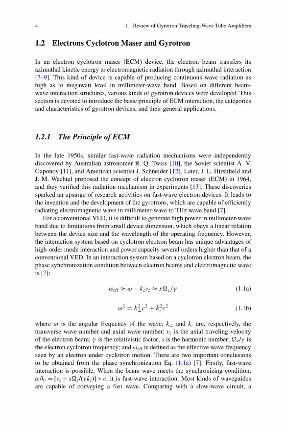
For a conventional VED, it is difficult to generate high power in millimeter-waveband due to limitations from small device dimension, which obeys a linear relationbetween the device size and the wavelength of the operating frequency. However,the interaction system based on cyclotron electron beam has unique advantages ofhigh-order mode interaction and power capacity several orders higher than that of aconventional VED. In an interaction system based on a cyclotron electron beam, thephase synchronization condition between electron beams and electromagnetic waveis [7]:
!eff � ! � kzvz � s�e=� (1.1a)
!2 D k2?c2 C k2z c2 (1.1b)
where ! is the angular frequency of the wave; k? and kz are, respectively, thetransverse wave number and axial wave number; vz is the axial traveling velocityof the electron beam; � is the relativistic factor; s is the harmonic number; �e/� isthe electron cyclotron frequency; and !eff is defined as the effective wave frequencyseen by an electron under cyclotron motion. There are two important conclusionsto be obtained from the phase synchronization Eq. (1.1a) [7]. Firstly, fast-waveinteraction is possible. When the beam wave meets the synchronizing condition,!/kz D [vz C s�e/(�kz)] > c, it is fast-wave interaction. Most kinds of waveguidesare capable of conveying a fast wave. Comparing with a slow-wave circuit, a
1.2 Electrons Cyclotron Maser and Gyrotron 5
a
weff
weff
weff
E⊥
B⊥
ex¬ex
¬
sΩe /gsΩe /g
b
E⊥
B⊥
weff
ey¬
ey¬
f
B0ez¬
qr
v⊥
¬B0ez
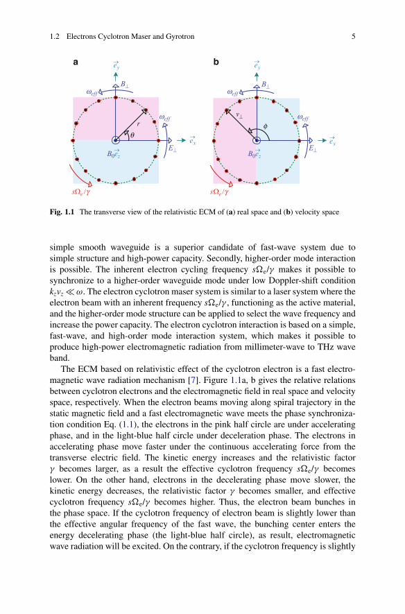
Fig. 1.1 The transverse view of the relativistic ECM of (a) real space and (b) velocity space
simple smooth waveguide is a superior candidate of fast-wave system due tosimple structure and high-power capacity. Secondly, higher-order mode interactionis possible. The inherent electron cycling frequency s�e/� makes it possible tosynchronize to a higher-order waveguide mode under low Doppler-shift conditionkzvz � !. The electron cyclotron maser system is similar to a laser system where theelectron beam with an inherent frequency s�e/� , functioning as the active material,and the higher-order mode structure can be applied to select the wave frequency andincrease the power capacity. The electron cyclotron interaction is based on a simple,fast-wave, and high-order mode interaction system, which makes it possible toproduce high-power electromagnetic radiation from millimeter-wave to THz waveband.
The ECM based on relativistic effect of the cyclotron electron is a fast electro-magnetic wave radiation mechanism [7]. Figure 1.1a, b gives the relative relationsbetween cyclotron electrons and the electromagnetic field in real space and velocityspace, respectively. When the electron beams moving along spiral trajectory in thestatic magnetic field and a fast electromagnetic wave meets the phase synchroniza-tion condition Eq. (1.1), the electrons in the pink half circle are under acceleratingphase, and in the light-blue half circle under deceleration phase. The electrons inaccelerating phase move faster under the continuous accelerating force from thetransverse electric field. The kinetic energy increases and the relativistic factor� becomes larger, as a result the effective cyclotron frequency s�e/� becomeslower. On the other hand, electrons in the decelerating phase move slower, thekinetic energy decreases, the relativistic factor � becomes smaller, and effectivecyclotron frequency s�e/� becomes higher. Thus, the electron beam bunches inthe phase space. If the cyclotron frequency of electron beam is slightly lower thanthe effective angular frequency of the fast wave, the bunching center enters theenergy decelerating phase (the light-blue half circle), as result, electromagneticwave radiation will be excited. On the contrary, if the cyclotron frequency is slightly
6 1 Review of Gyrotron Traveling-Wave Tube Amplifiers
TE31,8Fª20l
TE22,4Fª15l
TE62Fª4l
TE02Fª2l
TE15,4
Fª10l
1980 1990 1995 2000
Fig. 1.2 The transverse distributions of the operation modes in gyrotrons
higher than the wave frequency, the electron bunch enters the accelerating phase (thepink half circle), electromagnetic wave will loss energy, and electron beam will beazimuthally accelerated. The relation is summarized as,
s�e=� � !eff .exciting radiation/ (1.2a)
s�e=� � !eff .accelerating electron beam/ (1.2b)
1.2.2 The Characteristics of a Gyrotron
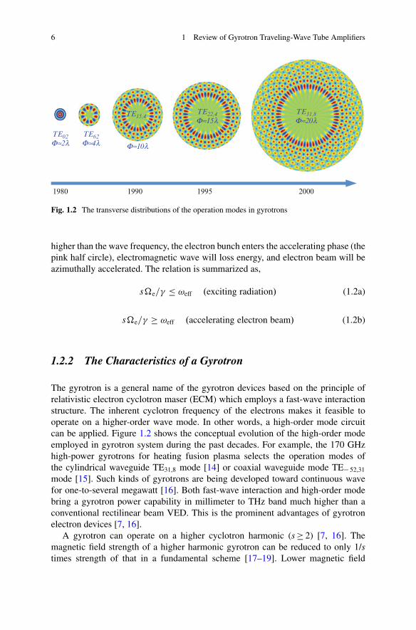
The gyrotron is a general name of the gyrotron devices based on the principle ofrelativistic electron cyclotron maser (ECM) which employs a fast-wave interactionstructure. The inherent cyclotron frequency of the electrons makes it feasible tooperate on a higher-order wave mode. In other words, a high-order mode circuitcan be applied. Figure 1.2 shows the conceptual evolution of the high-order modeemployed in gyrotron system during the past decades. For example, the 170 GHzhigh-power gyrotrons for heating fusion plasma selects the operation modes ofthe cylindrical waveguide TE31,8 mode [14] or coaxial waveguide mode TE� 52,31
mode [15]. Such kinds of gyrotrons are being developed toward continuous wavefor one-to-several megawatt [16]. Both fast-wave interaction and high-order modebring a gyrotron power capability in millimeter to THz band much higher than aconventional rectilinear beam VED. This is the prominent advantages of gyrotronelectron devices [7, 16].
A gyrotron can operate on a higher cyclotron harmonic (s � 2) [7, 16]. Themagnetic field strength of a higher harmonic gyrotron can be reduced to only 1/stimes strength of that in a fundamental scheme [17–19]. Lower magnetic field
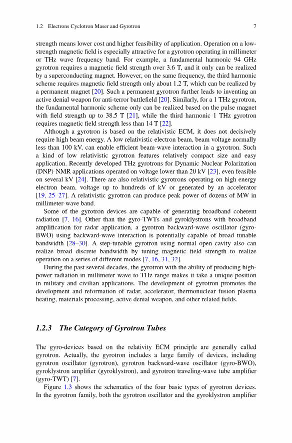
1.2 Electrons Cyclotron Maser and Gyrotron 7
strength means lower cost and higher feasibility of application. Operation on a low-strength magnetic field is especially attractive for a gyrotron operating in millimeteror THz wave frequency band. For example, a fundamental harmonic 94 GHzgyrotron requires a magnetic field strength over 3.6 T, and it only can be realizedby a superconducting magnet. However, on the same frequency, the third harmonicscheme requires magnetic field strength only about 1.2 T, which can be realized bya permanent magnet [20]. Such a permanent gyrotron further leads to inventing anactive denial weapon for anti-terror battlefield [20]. Similarly, for a 1 THz gyrotron,the fundamental harmonic scheme only can be realized based on the pulse magnetwith field strength up to 38.5 T [21], while the third harmonic 1 THz gyrotronrequires magnetic field strength less than 14 T [22].
Although a gyrotron is based on the relativistic ECM, it does not decisivelyrequire high beam energy. A low relativistic electron beam, beam voltage normallyless than 100 kV, can enable efficient beam-wave interaction in a gyrotron. Sucha kind of low relativistic gyrotron features relatively compact size and easyapplication. Recently developed THz gyrotrons for Dynamic Nuclear Polarization(DNP)-NMR applications operated on voltage lower than 20 kV [23], even feasibleon several kV [24]. There are also relativistic gyrotrons operating on high energyelectron beam, voltage up to hundreds of kV or generated by an accelerator[19, 25–27]. A relativistic gyrotron can produce peak power of dozens of MW inmillimeter-wave band.
Some of the gyrotron devices are capable of generating broadband coherentradiation [7, 16]. Other than the gyro-TWTs and gyroklystrons with broadbandamplification for radar application, a gyrotron backward-wave oscillator (gyro-BWO) using backward-wave interaction is potentially capable of broad tunablebandwidth [28–30]. A step-tunable gyrotron using normal open cavity also canrealize broad discrete bandwidth by tuning magnetic field strength to realizeoperation on a series of different modes [7, 16, 31, 32].
During the past several decades, the gyrotron with the ability of producing high-power radiation in millimeter wave to THz range makes it take a unique positionin military and civilian applications. The development of gyrotron promotes thedevelopment and reformation of radar, accelerator, thermonuclear fusion plasmaheating, materials processing, active denial weapon, and other related fields.
1.2.3 The Category of Gyrotron Tubes
The gyro-devices based on the relativity ECM principle are generally calledgyrotron. Actually, the gyrotron includes a large family of devices, includinggyrotron oscillator (gyrotron), gyrotron backward-wave oscillator (gyro-BWO),gyroklystron amplifier (gyroklystron), and gyrotron traveling-wave tube amplifier(gyro-TWT) [7].
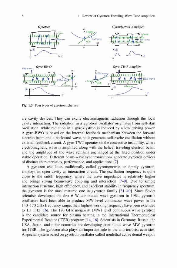
Figure 1.3 shows the schematics of the four basic types of gyrotron devices.In the gyrotron family, both the gyrotron oscillator and the gyroklystron amplifier
8 1 Review of Gyrotron Traveling-Wave Tube Amplifiers
sWe
e-beam
EM-wave EM-wave EM-wave
e-beam
EM-wave
e-beam
EM-wave
e-beam
EM-wave
e-beam
e-beamEM-wave
Gyrotron
Gyro-BWO Gyro-TWT Amplifer
Gyroklystron Amplifier
kz
0
w
kz
0
w
kz
0
w
0Z
|E|
0Z
|E|
0Z
|E|
0
Z
|E|
e-beam
sWe
sWe
Fig. 1.3 Four types of gyrotron schemes
are cavity devices. They can excite electromagnetic radiation through the localcavity interaction. The radiation in a gyrotron oscillator originates from self-startoscillation, while radiation in a gyroklystron is induced by a low driving power.A gyro-BWO is based on the internal feedback mechanism between the forwardelectron beam and a backward wave, so it generates self-excite oscillation withoutexternal feedback circuit. A gyro-TWT operates on the convective instability, whereelectromagnetic wave is amplified along with the helical traveling electron beam,and the amplitude of the wave remains unchanged at the fixed position understable operation. Different beam-wave synchronizations generate gyrotron devicesof distinct characteristics, performance, and applications [7].
A gyrotron oscillator, traditionally called gyromonotron or simply gyrotron,employs an open cavity as interaction circuit. The oscillation frequency is quiteclose to the cutoff frequency, where the wave impedance is relatively higherand brings strong beam-wave coupling and interaction [7–9]. Due to simpleinteraction structure, high efficiency, and excellent stability in frequency spectrum,the gyrotron is the most matured one in gyrotron family [31–40]. Since Sovietscientists developed the first 6 W continuous wave gyrotron in 1964, gyrotronoscillators have been able to produce MW level continuous wave power in the140–170 GHz frequency range, their highest working frequency have been extendedto 1.3 THz [16]. The 170 GHz megawatt (MW) level continuous wave gyrotronis the candidate source for plasma heating in the International ThermonuclearExperimental Reactor (ITER) program [14, 16]. Scientists in Germany, Russia, theUSA, Japan, and other countries are developing continuous wave MW gyrotronfor ITER. The gyrotron also plays an important role in the anti-terrorist activities.A special system based on gyrotron oscillator called nonlethal active denial weapon
1.2 Electrons Cyclotron Maser and Gyrotron 9
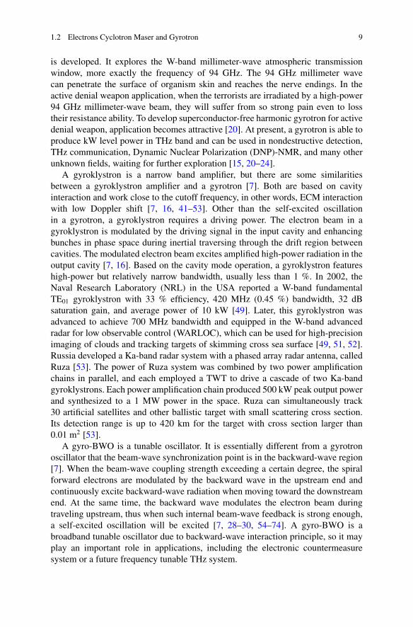
is developed. It explores the W-band millimeter-wave atmospheric transmissionwindow, more exactly the frequency of 94 GHz. The 94 GHz millimeter wavecan penetrate the surface of organism skin and reaches the nerve endings. In theactive denial weapon application, when the terrorists are irradiated by a high-power94 GHz millimeter-wave beam, they will suffer from so strong pain even to losstheir resistance ability. To develop superconductor-free harmonic gyrotron for activedenial weapon, application becomes attractive [20]. At present, a gyrotron is able toproduce kW level power in THz band and can be used in nondestructive detection,THz communication, Dynamic Nuclear Polarization (DNP)-NMR, and many otherunknown fields, waiting for further exploration [15, 20–24].
A gyroklystron is a narrow band amplifier, but there are some similaritiesbetween a gyroklystron amplifier and a gyrotron [7]. Both are based on cavityinteraction and work close to the cutoff frequency, in other words, ECM interactionwith low Doppler shift [7, 16, 41–53]. Other than the self-excited oscillationin a gyrotron, a gyroklystron requires a driving power. The electron beam in agyroklystron is modulated by the driving signal in the input cavity and enhancingbunches in phase space during inertial traversing through the drift region betweencavities. The modulated electron beam excites amplified high-power radiation in theoutput cavity [7, 16]. Based on the cavity mode operation, a gyroklystron featureshigh-power but relatively narrow bandwidth, usually less than 1 %. In 2002, theNaval Research Laboratory (NRL) in the USA reported a W-band fundamentalTE01 gyroklystron with 33 % efficiency, 420 MHz (0.45 %) bandwidth, 32 dBsaturation gain, and average power of 10 kW [49]. Later, this gyroklystron wasadvanced to achieve 700 MHz bandwidth and equipped in the W-band advancedradar for low observable control (WARLOC), which can be used for high-precisionimaging of clouds and tracking targets of skimming cross sea surface [49, 51, 52].Russia developed a Ka-band radar system with a phased array radar antenna, calledRuza [53]. The power of Ruza system was combined by two power amplificationchains in parallel, and each employed a TWT to drive a cascade of two Ka-bandgyroklystrons. Each power amplification chain produced 500 kW peak output powerand synthesized to a 1 MW power in the space. Ruza can simultaneously track30 artificial satellites and other ballistic target with small scattering cross section.Its detection range is up to 420 km for the target with cross section larger than0.01 m2 [53].
A gyro-BWO is a tunable oscillator. It is essentially different from a gyrotronoscillator that the beam-wave synchronization point is in the backward-wave region[7]. When the beam-wave coupling strength exceeding a certain degree, the spiralforward electrons are modulated by the backward wave in the upstream end andcontinuously excite backward-wave radiation when moving toward the downstreamend. At the same time, the backward wave modulates the electron beam duringtraveling upstream, thus when such internal beam-wave feedback is strong enough,a self-excited oscillation will be excited [7, 28–30, 54–74]. A gyro-BWO is abroadband tunable oscillator due to backward-wave interaction principle, so it mayplay an important role in applications, including the electronic countermeasuresystem or a future frequency tunable THz system.
10 1 Review of Gyrotron Traveling-Wave Tube Amplifiers
A gyrotron traveling-wave tube (gyro-TWT) is based on the interaction betweena cyclotron electron beam and a forward wave. It works on the convective instabilityin forward-wave region, which means it is capable of broadband coherent amplifi-cation [7]. Hence a gyro-TWT is the most proposed candidate for a high-resolutionremote-imaging radar and is attractive for military application. However, the severeparasitic oscillations originating from instability competitions in the interactionstructure limit its performance. The gyro-TWT experienced rises and falls, andrecently it is right during the transition stage of transferring from experiment labto applications.
1.3 Gyrotron Traveling-Wave-Tube Amplifiers
A gyro-TWT is based on the convective instability of the relativistic ECM mech-anism. It can generate coherent radiation of several hundreds of kilowatts inmillimeter-wave band, which makes it the most suitable candidate for transmittersource of the next-generation high-resolution imaging radar and high-data-rateremote communication system. Hence, it is of great significance in national securitystratagem. After more than half a century development, the gyro-TWT is now in thetransition stage from laboratory experiments to engineering applications, and thereare also many problems need to be solved.
1.3.1 The Development of Gyro-TWTs
The development process of the gyro-TWT is roughly divided into three stages [75].Between 1970s and 1980s, it was the initial exploring stage. Later, the gyro-TWTentered the stage of rapid development in 1990s, and it enters the stage of practicalapplication from 2000 and then on. The Ref. [16] reviewed the major experimentsof the world. The ECM interaction not only requires efficient and stable extractionof energy from electron beam but also effectively controls and transmits the high-power electromagnetic wave. Therefore, interaction circuit is the key component.To some extent, the development of the gyro-TWTs is the evolutionary process ofthe interaction circuits [7].
In early 1980s, the NRL used metal circular waveguide and TE01 mode ingyro-TWT experiments [76, 77]. Around 1990s, NRL successfully explored thebroadband operation of the gyro-TWTs by using transverse dimension-taperedrectangular waveguide [78]. However its power, efficiency, and gain were limitedby severe instability oscillation.
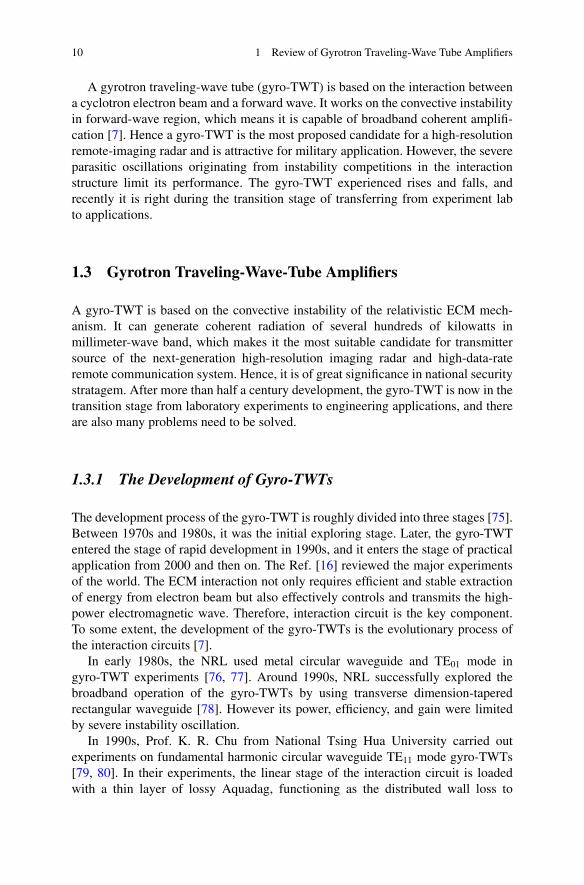
In 1990s, Prof. K. R. Chu from National Tsing Hua University carried outexperiments on fundamental harmonic circular waveguide TE11 mode gyro-TWTs[79, 80]. In their experiments, the linear stage of the interaction circuit is loadedwith a thin layer of lossy Aquadag, functioning as the distributed wall loss to
1.3 Gyrotron Traveling-Wave-Tube Amplifiers 11
CopperWaveguide
LossyAquadag
e-beam
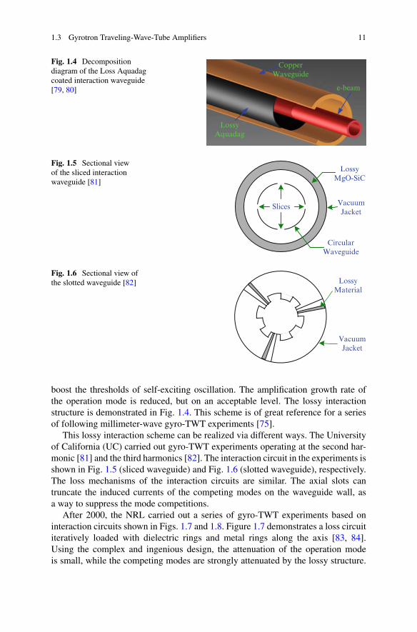
Fig. 1.4 Decompositiondiagram of the Loss Aquadagcoated interaction waveguide[79, 80]
Slices
LossyMgO-SiC
VacuumJacket
CircularWaveguide
Fig. 1.5 Sectional viewof the sliced interactionwaveguide [81]
LossyMaterial
VacuumJacket
Fig. 1.6 Sectional view ofthe slotted waveguide [82]
boost the thresholds of self-exciting oscillation. The amplification growth rate ofthe operation mode is reduced, but on an acceptable level. The lossy interactionstructure is demonstrated in Fig. 1.4. This scheme is of great reference for a seriesof following millimeter-wave gyro-TWT experiments [75].
This lossy interaction scheme can be realized via different ways. The Universityof California (UC) carried out gyro-TWT experiments operating at the second har-monic [81] and the third harmonics [82]. The interaction circuit in the experiments isshown in Fig. 1.5 (sliced waveguide) and Fig. 1.6 (slotted waveguide), respectively.The loss mechanisms of the interaction circuits are similar. The axial slots cantruncate the induced currents of the competing modes on the waveguide wall, asa way to suppress the mode competitions.
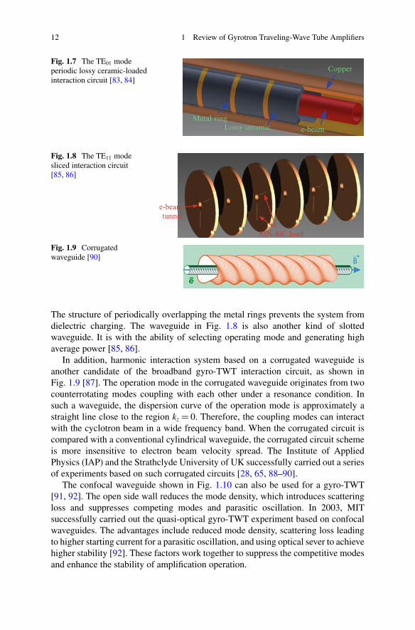
After 2000, the NRL carried out a series of gyro-TWT experiments based oninteraction circuits shown in Figs. 1.7 and 1.8. Figure 1.7 demonstrates a loss circuititeratively loaded with dielectric rings and metal rings along the axis [83, 84].Using the complex and ingenious design, the attenuation of the operation modeis small, while the competing modes are strongly attenuated by the lossy structure.
12 1 Review of Gyrotron Traveling-Wave Tube Amplifiers
Copper
Lossy ceramic e-beamMetal ring
Fig. 1.7 The TE01 modeperiodic lossy ceramic-loadedinteraction circuit [83, 84]
e-beamtunnel
AlN-SiC load
Fig. 1.8 The TE11 modesliced interaction circuit[85, 86]
Fig. 1.9 Corrugatedwaveguide [90]
The structure of periodically overlapping the metal rings prevents the system fromdielectric charging. The waveguide in Fig. 1.8 is also another kind of slottedwaveguide. It is with the ability of selecting operating mode and generating highaverage power [85, 86].
In addition, harmonic interaction system based on a corrugated waveguide isanother candidate of the broadband gyro-TWT interaction circuit, as shown inFig. 1.9 [87]. The operation mode in the corrugated waveguide originates from twocounterrotating modes coupling with each other under a resonance condition. Insuch a waveguide, the dispersion curve of the operation mode is approximately astraight line close to the region kz D 0. Therefore, the coupling modes can interactwith the cyclotron beam in a wide frequency band. When the corrugated circuit iscompared with a conventional cylindrical waveguide, the corrugated circuit schemeis more insensitive to electron beam velocity spread. The Institute of AppliedPhysics (IAP) and the Strathclyde University of UK successfully carried out a seriesof experiments based on such corrugated circuits [28, 65, 88–90].
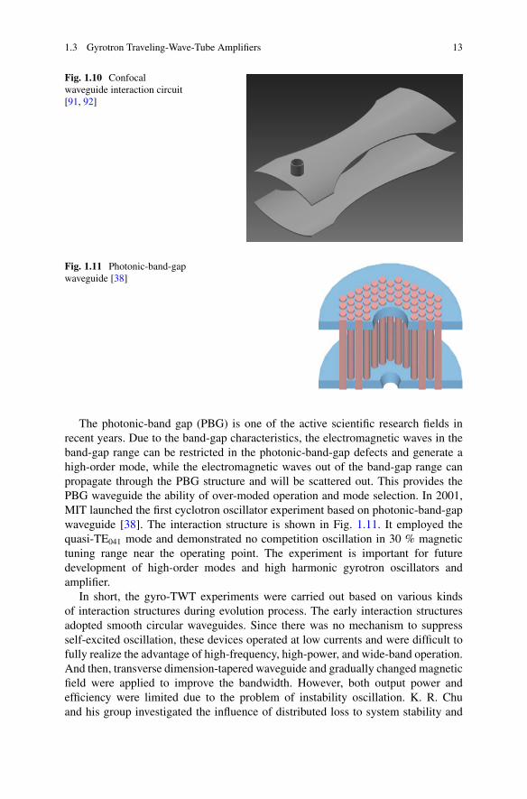
The confocal waveguide shown in Fig. 1.10 can also be used for a gyro-TWT[91, 92]. The open side wall reduces the mode density, which introduces scatteringloss and suppresses competing modes and parasitic oscillation. In 2003, MITsuccessfully carried out the quasi-optical gyro-TWT experiment based on confocalwaveguides. The advantages include reduced mode density, scattering loss leadingto higher starting current for a parasitic oscillation, and using optical sever to achievehigher stability [92]. These factors work together to suppress the competitive modesand enhance the stability of amplification operation.
1.3 Gyrotron Traveling-Wave-Tube Amplifiers 13
Fig. 1.10 Confocalwaveguide interaction circuit[91, 92]
Fig. 1.11 Photonic-band-gapwaveguide [38]
The photonic-band gap (PBG) is one of the active scientific research fields inrecent years. Due to the band-gap characteristics, the electromagnetic waves in theband-gap range can be restricted in the photonic-band-gap defects and generate ahigh-order mode, while the electromagnetic waves out of the band-gap range canpropagate through the PBG structure and will be scattered out. This provides thePBG waveguide the ability of over-moded operation and mode selection. In 2001,MIT launched the first cyclotron oscillator experiment based on photonic-band-gapwaveguide [38]. The interaction structure is shown in Fig. 1.11. It employed thequasi-TE041 mode and demonstrated no competition oscillation in 30 % magnetictuning range near the operating point. The experiment is important for futuredevelopment of high-order modes and high harmonic gyrotron oscillators andamplifier.
In short, the gyro-TWT experiments were carried out based on various kindsof interaction structures during evolution process. The early interaction structuresadopted smooth circular waveguides. Since there was no mechanism to suppressself-excited oscillation, these devices operated at low currents and were difficult tofully realize the advantage of high-frequency, high-power, and wide-band operation.And then, transverse dimension-tapered waveguide and gradually changed magneticfield were applied to improve the bandwidth. However, both output power andefficiency were limited due to the problem of instability oscillation. K. R. Chuand his group investigated the influence of distributed loss to system stability and
14 1 Review of Gyrotron Traveling-Wave Tube Amplifiers
greatly improved the stability of the gyro-TWT, which promoted the developmentof the gyro-TWT. At the same time, the spiral corrugated waveguide was employedin the gyro-TWT, which demonstrated broadband operation, and stable to electronvelocity spread. New kinds of interaction structures continually enlarged the visionof the scientists and simultaneously brought new possibilities.
1.3.2 Comments on Technologies
Various kinds of interaction circuits were applied during the past gyro-TWTsexperiments [7, 75]. Each of these experiments explored solutions to the problemsof certain aspect. The key technology developed during these experiments promotesthe evolution and development of the amplifier. In order to better understand thesetechnologies, we will introduce the problems in four aspects, including technologyof wall loss, high-order mode interaction, harmonic interaction, and bandwidthextending.
1.3.2.1 Waveguide Wall Loss
Until now, the waveguide wall loss is the most successful solution to suppressthe instability competition problem in gyro-TWTs [7, 75]. The waveguide wallloss is realized by loading a certain kind of wave dissipating material on thewaveguide wall and imposing a distributed loss effect to wave mode during itspropagation, while disturbance to the operating mode distribution is negligible.Through introducing propagation attenuation, it makes the convective instability-induced amplification operate on a reduced strength, and it imposes relativelystronger disturbance and attenuation to the competing modes, as a way to increasestart-oscillation thresholds of the competing instabilities [7, 75, 79, 80, 93]. Thetechnology, to some extent, is proved to be generally valid to solve the instabilitycompetitions in a series of gyro-TWTs experiments [7, 75].
In early 1980s, a series of experiments in American NRL revealed that theinteraction circuits loaded with distributed wall loss were capable of improvingthe gain and stability of a gyro-TWT [94–97]. The first gyro-TWT based on thedistributed loss interaction circuit operated in Ka band, using TE01 mode interaction,beam current 3 A, and pitch factor 1.5, and it achieved a linear gain of 50 dB [76].
In 1990s, Prof. K. R. Chu and his group carried out a series of Ka-band gyro-TWT experiments under strong theoretical backup [7, 75, 79, 80, 93]. In 1998, a Ka-band fundamental harmonic TE11 mode gyro-TWT experiment achieved ultrahighgain up to 70 dB. It achieved saturation peak power 93 kW, the gain 70 dB, efficiency26.5 %, and 3 dB bandwidth 3 GHz. The experimental results demonstrated thatthe distributed loss could effectively suppress various parasitic oscillations, and the
1.3 Gyrotron Traveling-Wave-Tube Amplifiers 15
threshold current was increased from 0.9 to 3.5 A. These experiments demonstrateda generally valid solution to instability competition in a gyro-TWT system and alsoplayed a role of milestone during the history of gyro-TWTs.
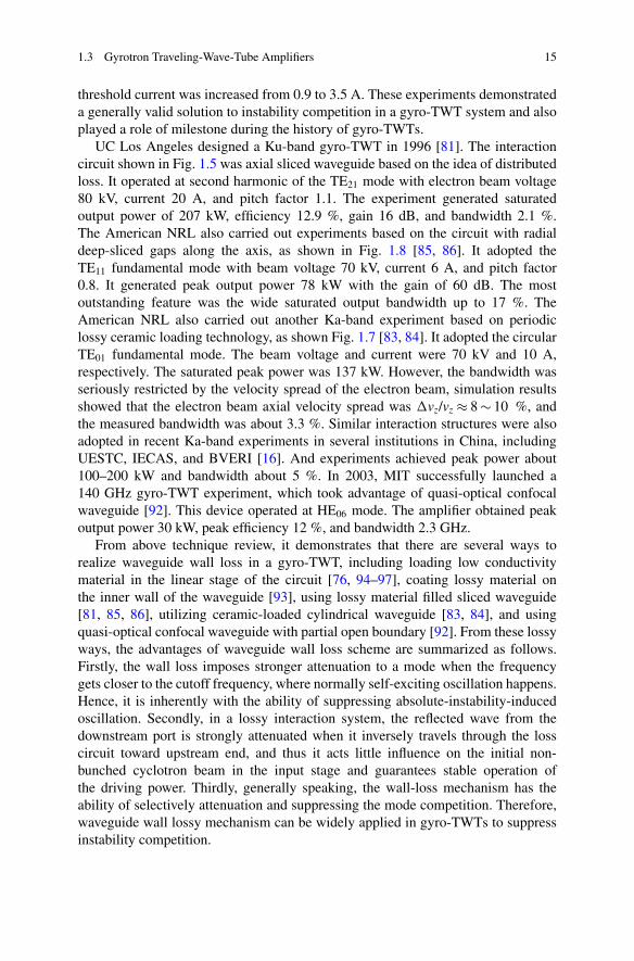
UC Los Angeles designed a Ku-band gyro-TWT in 1996 [81]. The interactioncircuit shown in Fig. 1.5 was axial sliced waveguide based on the idea of distributedloss. It operated at second harmonic of the TE21 mode with electron beam voltage80 kV, current 20 A, and pitch factor 1.1. The experiment generated saturatedoutput power of 207 kW, efficiency 12.9 %, gain 16 dB, and bandwidth 2.1 %.The American NRL also carried out experiments based on the circuit with radialdeep-sliced gaps along the axis, as shown in Fig. 1.8 [85, 86]. It adopted theTE11 fundamental mode with beam voltage 70 kV, current 6 A, and pitch factor0.8. It generated peak output power 78 kW with the gain of 60 dB. The mostoutstanding feature was the wide saturated output bandwidth up to 17 %. TheAmerican NRL also carried out another Ka-band experiment based on periodiclossy ceramic loading technology, as shown Fig. 1.7 [83, 84]. It adopted the circularTE01 fundamental mode. The beam voltage and current were 70 kV and 10 A,respectively. The saturated peak power was 137 kW. However, the bandwidth wasseriously restricted by the velocity spread of the electron beam, simulation resultsshowed that the electron beam axial velocity spread was �vz/vz � 8 � 10 %, andthe measured bandwidth was about 3.3 %. Similar interaction structures were alsoadopted in recent Ka-band experiments in several institutions in China, includingUESTC, IECAS, and BVERI [16]. And experiments achieved peak power about100–200 kW and bandwidth about 5 %. In 2003, MIT successfully launched a140 GHz gyro-TWT experiment, which took advantage of quasi-optical confocalwaveguide [92]. This device operated at HE06 mode. The amplifier obtained peakoutput power 30 kW, peak efficiency 12 %, and bandwidth 2.3 GHz.
From above technique review, it demonstrates that there are several ways torealize waveguide wall loss in a gyro-TWT, including loading low conductivitymaterial in the linear stage of the circuit [76, 94–97], coating lossy material onthe inner wall of the waveguide [93], using lossy material filled sliced waveguide[81, 85, 86], utilizing ceramic-loaded cylindrical waveguide [83, 84], and usingquasi-optical confocal waveguide with partial open boundary [92]. From these lossyways, the advantages of waveguide wall loss scheme are summarized as follows.Firstly, the wall loss imposes stronger attenuation to a mode when the frequencygets closer to the cutoff frequency, where normally self-exciting oscillation happens.Hence, it is inherently with the ability of suppressing absolute-instability-inducedoscillation. Secondly, in a lossy interaction system, the reflected wave from thedownstream port is strongly attenuated when it inversely travels through the losscircuit toward upstream end, and thus it acts little influence on the initial non-bunched cyclotron beam in the input stage and guarantees stable operation ofthe driving power. Thirdly, generally speaking, the wall-loss mechanism has theability of selectively attenuation and suppressing the mode competition. Therefore,waveguide wall lossy mechanism can be widely applied in gyro-TWTs to suppressinstability competition.
16 1 Review of Gyrotron Traveling-Wave Tube Amplifiers
1.3.2.2 High-Order-Mode Interaction Circuit
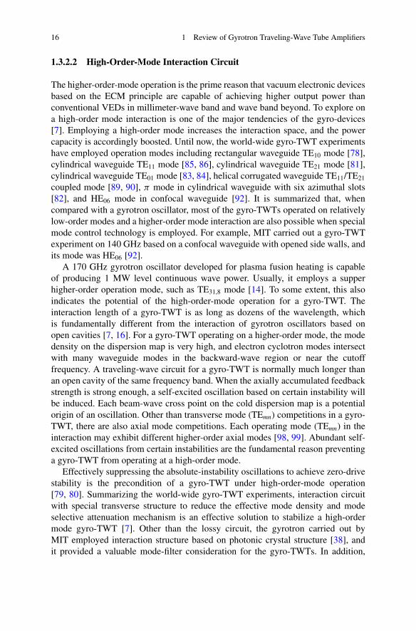
The higher-order-mode operation is the prime reason that vacuum electronic devicesbased on the ECM principle are capable of achieving higher output power thanconventional VEDs in millimeter-wave band and wave band beyond. To explore ona high-order mode interaction is one of the major tendencies of the gyro-devices[7]. Employing a high-order mode increases the interaction space, and the powercapacity is accordingly boosted. Until now, the world-wide gyro-TWT experimentshave employed operation modes including rectangular waveguide TE10 mode [78],cylindrical waveguide TE11 mode [85, 86], cylindrical waveguide TE21 mode [81],cylindrical waveguide TE01 mode [83, 84], helical corrugated waveguide TE11/TE21
coupled mode [89, 90], � mode in cylindrical waveguide with six azimuthal slots[82], and HE06 mode in confocal waveguide [92]. It is summarized that, whencompared with a gyrotron oscillator, most of the gyro-TWTs operated on relativelylow-order modes and a higher-order mode interaction are also possible when specialmode control technology is employed. For example, MIT carried out a gyro-TWTexperiment on 140 GHz based on a confocal waveguide with opened side walls, andits mode was HE06 [92].
A 170 GHz gyrotron oscillator developed for plasma fusion heating is capableof producing 1 MW level continuous wave power. Usually, it employs a supperhigher-order operation mode, such as TE31,8 mode [14]. To some extent, this alsoindicates the potential of the high-order-mode operation for a gyro-TWT. Theinteraction length of a gyro-TWT is as long as dozens of the wavelength, whichis fundamentally different from the interaction of gyrotron oscillators based onopen cavities [7, 16]. For a gyro-TWT operating on a higher-order mode, the modedensity on the dispersion map is very high, and electron cyclotron modes intersectwith many waveguide modes in the backward-wave region or near the cutofffrequency. A traveling-wave circuit for a gyro-TWT is normally much longer thanan open cavity of the same frequency band. When the axially accumulated feedbackstrength is strong enough, a self-excited oscillation based on certain instability willbe induced. Each beam-wave cross point on the cold dispersion map is a potentialorigin of an oscillation. Other than transverse mode (TEmn) competitions in a gyro-TWT, there are also axial mode competitions. Each operating mode (TEmn) in theinteraction may exhibit different higher-order axial modes [98, 99]. Abundant self-excited oscillations from certain instabilities are the fundamental reason preventinga gyro-TWT from operating at a high-order mode.
Effectively suppressing the absolute-instability oscillations to achieve zero-drivestability is the precondition of a gyro-TWT under high-order-mode operation[79, 80]. Summarizing the world-wide gyro-TWT experiments, interaction circuitwith special transverse structure to reduce the effective mode density and modeselective attenuation mechanism is an effective solution to stabilize a high-ordermode gyro-TWT [7]. Other than the lossy circuit, the gyrotron carried out byMIT employed interaction structure based on photonic crystal structure [38], andit provided a valuable mode-filter consideration for the gyro-TWTs. In addition,
1.3 Gyrotron Traveling-Wave-Tube Amplifiers 17
the experiments of coaxial cavity gyrotron [16, 29, 100, 101] and coaxial cavitygyroklystrons [26] also proved that the mode selection capability and systemstability can be enhanced by using the special coaxial interaction structure.
1.3.2.3 Higher-Order Harmonic Operation
Developing a gyro-TWT of a high-order harmonic is of great significance [7].Firstly, the magnetic field strength is inversely proportional to the harmonic number;hence harmonic interaction reduces the magnetic field intensity. For militaryapplication, making the Ka-band gyrotron amplifier as an example, the second-harmonic scheme requires a magnetic field strength of about 0.6 T and normal coilmagnet is available, while the fundamental harmonic scheme requires a magneticfield strength of about 1.2 T and superconducting magnet is the first choice. Agyrotron amplifier based on a normal coil magnet will much improve the reliabilityand reduce the cost. Secondly, the coupling strength of the operating mode is smallerthan the fundamental interaction, which increases the threshold current of theabsolute instability. Thus the device may work at higher current and achieve strongerwave radiation power [102]. Thirdly, large-orbit cyclotron beams with electronguiding center rc D 0 are suggested in a higher-order harmonic interaction system.Therefore, only for the modes with azimuthal index equaling to the cyclotronharmonic number, their beam-wave coupling coefficient is nonzero. That is, in alarge-orbit interaction system, TEmn mode (m D s) can only effectively interact withthe s harmonic mode, which, to some extent, suppresses the influence of modecompetition.
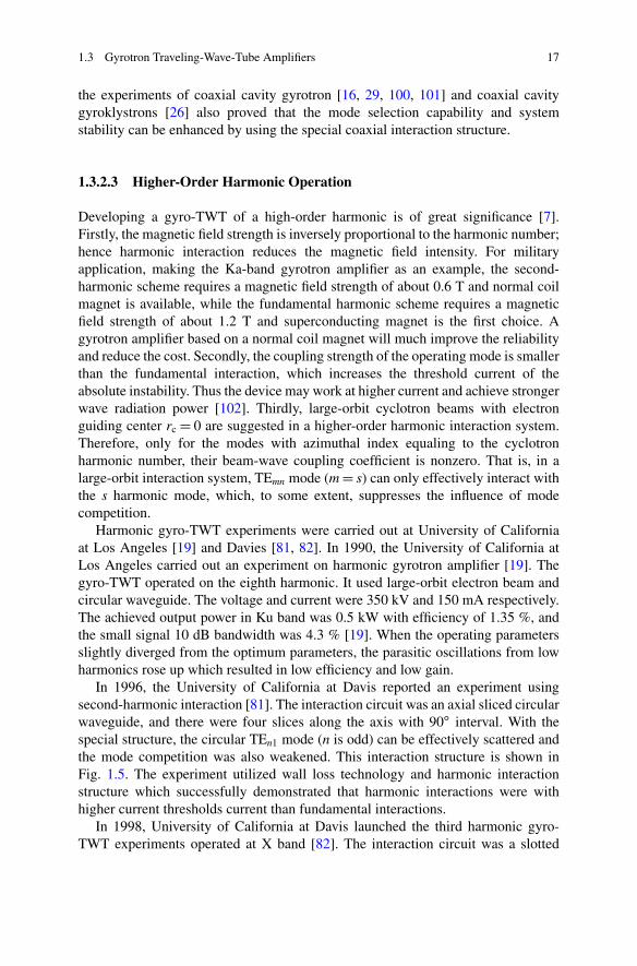
Harmonic gyro-TWT experiments were carried out at University of Californiaat Los Angeles [19] and Davies [81, 82]. In 1990, the University of California atLos Angeles carried out an experiment on harmonic gyrotron amplifier [19]. Thegyro-TWT operated on the eighth harmonic. It used large-orbit electron beam andcircular waveguide. The voltage and current were 350 kV and 150 mA respectively.The achieved output power in Ku band was 0.5 kW with efficiency of 1.35 %, andthe small signal 10 dB bandwidth was 4.3 % [19]. When the operating parametersslightly diverged from the optimum parameters, the parasitic oscillations from lowharmonics rose up which resulted in low efficiency and low gain.
In 1996, the University of California at Davis reported an experiment usingsecond-harmonic interaction [81]. The interaction circuit was an axial sliced circularwaveguide, and there were four slices along the axis with 90ı interval. With thespecial structure, the circular TEn1 mode (n is odd) can be effectively scattered andthe mode competition was also weakened. This interaction structure is shown inFig. 1.5. The experiment utilized wall loss technology and harmonic interactionstructure which successfully demonstrated that harmonic interactions were withhigher current thresholds current than fundamental interactions.
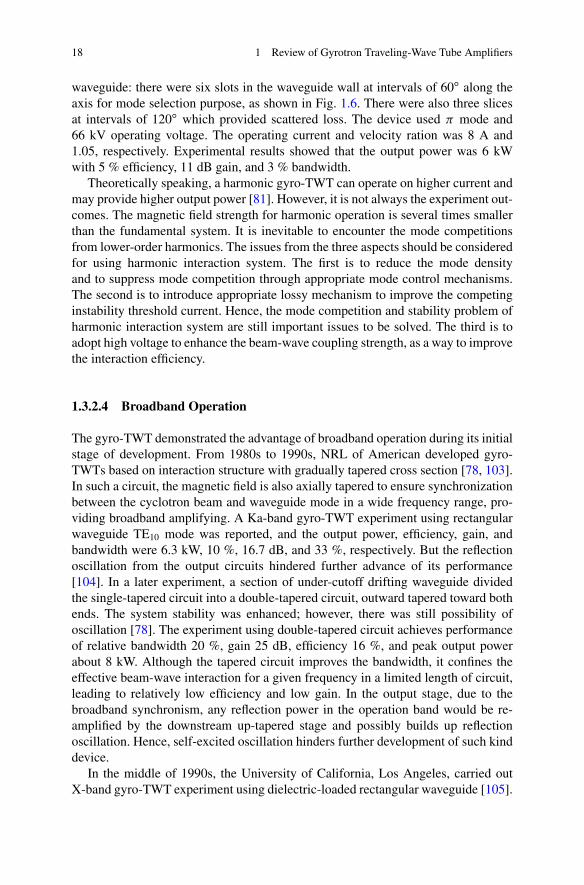
In 1998, University of California at Davis launched the third harmonic gyro-TWT experiments operated at X band [82]. The interaction circuit was a slotted
18 1 Review of Gyrotron Traveling-Wave Tube Amplifiers
waveguide: there were six slots in the waveguide wall at intervals of 60ı along theaxis for mode selection purpose, as shown in Fig. 1.6. There were also three slicesat intervals of 120ı which provided scattered loss. The device used � mode and66 kV operating voltage. The operating current and velocity ration was 8 A and1.05, respectively. Experimental results showed that the output power was 6 kWwith 5 % efficiency, 11 dB gain, and 3 % bandwidth.
Theoretically speaking, a harmonic gyro-TWT can operate on higher current andmay provide higher output power [81]. However, it is not always the experiment out-comes. The magnetic field strength for harmonic operation is several times smallerthan the fundamental system. It is inevitable to encounter the mode competitionsfrom lower-order harmonics. The issues from the three aspects should be consideredfor using harmonic interaction system. The first is to reduce the mode densityand to suppress mode competition through appropriate mode control mechanisms.The second is to introduce appropriate lossy mechanism to improve the competinginstability threshold current. Hence, the mode competition and stability problem ofharmonic interaction system are still important issues to be solved. The third is toadopt high voltage to enhance the beam-wave coupling strength, as a way to improvethe interaction efficiency.
1.3.2.4 Broadband Operation
The gyro-TWT demonstrated the advantage of broadband operation during its initialstage of development. From 1980s to 1990s, NRL of American developed gyro-TWTs based on interaction structure with gradually tapered cross section [78, 103].In such a circuit, the magnetic field is also axially tapered to ensure synchronizationbetween the cyclotron beam and waveguide mode in a wide frequency range, pro-viding broadband amplifying. A Ka-band gyro-TWT experiment using rectangularwaveguide TE10 mode was reported, and the output power, efficiency, gain, andbandwidth were 6.3 kW, 10 %, 16.7 dB, and 33 %, respectively. But the reflectionoscillation from the output circuits hindered further advance of its performance[104]. In a later experiment, a section of under-cutoff drifting waveguide dividedthe single-tapered circuit into a double-tapered circuit, outward tapered toward bothends. The system stability was enhanced; however, there was still possibility ofoscillation [78]. The experiment using double-tapered circuit achieves performanceof relative bandwidth 20 %, gain 25 dB, efficiency 16 %, and peak output powerabout 8 kW. Although the tapered circuit improves the bandwidth, it confines theeffective beam-wave interaction for a given frequency in a limited length of circuit,leading to relatively low efficiency and low gain. In the output stage, due to thebroadband synchronism, any reflection power in the operation band would be re-amplified by the downstream up-tapered stage and possibly builds up reflectionoscillation. Hence, self-excited oscillation hinders further development of such kinddevice.
In the middle of 1990s, the University of California, Los Angeles, carried outX-band gyro-TWT experiment using dielectric-loaded rectangular waveguide [105].
1.3 Gyrotron Traveling-Wave-Tube Amplifiers 19
The loaded dielectric effectively reduced the dispersion characteristics of the guidedmode and extended the beam-wave synchronizing bandwidth. The experimentmeasured output power of 55 kW, efficiency of 11 %, gain of 27 dB, and constantdrive bandwidth of 11 %. Improving the mode dispersion characteristics is just oneaspect of developing gyro-TWT system [106–109], and suppressing the instabilitycompetition should be considered first in order to obtain high-power and broadbandoperation [7].
A gyrotron amplifier based on a helical corrugated waveguide operates on acoupled mode and is capable of broadband operation [87]. This kind of gyro-TWTs was extensively studied by cooperation groups from Russia Institute ofApplied Physics (IAP) and University of Strathclyde, Glasgow, UK. Since 1998,IAP and University of Strathclyde cooperated to study gyro-TWTs based on helicalcorrugated waveguides [87, 89, 90, 108]. The initial experiment used second-harmonic interaction operated in X band using voltage 200 kV and current 25 A[90]. It generated peak power 1 MW, efficiency 20 %, gain 23 dB, and saturatedbandwidth greater than 10 %. An improved version employed voltage 180 kV. Itachieved output power 1.1 MW, saturated gain 37 dB, and relative bandwidth 21 %.Another Ka-band experiment was carried out around 2002, it employed a large-orbitelectron beam of 20 A and a reduced voltage about 80 kV. It achieved peak power180 kW, efficiency 27 %, gain about 27 dB, and bandwidth about 10 %. In a recentX-band experiment using a electron beam of voltage 185 kV and current 6 A, itreported an achieve output power 220 kW, saturated gain 24 dB, and bandwidth of2 GHz [108].
The gyro-TWT based on a helical corrugated waveguide has major advantagesfrom two aspects. Firstly, it operates on a coupled mode close to a region withsmall propagation constant kz � 0, which makes performance insensitive to electronbeam velocity spread. Secondly, harmonic operation is inherently with muchlower magnetic field strength than the fundamental harmonic scheme. Previousexperiments proved the potential of realizing high-power and broad bandwidth byemploying helical corrugated circuit. However, little publication was reported onsuppressing the instability competition-related problems in such kind of interactionsystem.
1.3.3 Problems and Prospects
Based on the relativistic ECM principle, a gyro-TWT amplifier employs a cyclotronelectron beam to interact with a fast wave, and it is with the advantage of generatinghigh-power and broadband coherent radiation in the millimeter-wave band andbeyond, which makes the gyro-TWT one of the most promising candidates forthe high-power transmitter of high-resolution imaging radar. After decades ofinvestigation, the key problems related to its development, including instabilitycompetition, higher-order mode operation, broadband operation, and high averagepower operation, have been investigated in depth.
20 1 Review of Gyrotron Traveling-Wave Tube Amplifiers
The instability competition is one of the problems essentially hindering thedevelopment of the gyro-TWTs [7]. In the interaction system, when a cyclotronharmonic strongly couples with a waveguide mode near the cutoff frequency orin the backward-wave region, an oscillation originating from absolute instabilitywould be excited. When the input and output coupler are not perfectly matched,reflected power from both ends would be re-amplified and possibly excite reflectionoscillation. During the experiment of a gyro-TWT, several kinds of parasiticoscillations may be present simultaneously in the interaction system, and suppressthe amplification of the driving signal, which limits the system operate on arelatively low power-level state.
The high-order mode operation is the only way to achieve high power in high-frequency band. Employing a high-order mode circuit increases the transversedimension of the interaction circuit and improves system power capacity, whichis also the basic reason that a gyro-TWT generates higher power in millimeter-wave band than a conventional linear beam amplifier. In a conventional metalwaveguide interaction circuit, the higher-order mode operation encounters moresevere instability competitions due to higher mode density.
High average power operation is a basic requirement for engineering application.A gyro-TWT operating in the millimeter-wave band is with relatively limited circuitdimension, which limits the capability of heating dissipation. In order to suppressthe instability competition, the circuit of a gyro-TWT usually is loaded with lossymaterial. The thermal conductivity of the lossy material and related fabricationtechnology also compose the bottleneck to the system average power.
A gyro-TWT is also characterized by its broadband operation capability. How-ever, due to instability competition and sensitivity to electron beam velocity spread,engineering realized performance is normally much inferior to the theoreticalprediction. Taking suppressing instability competition into consideration, exploringthe broadband operation capability is relatively challenging.
A gyro-TWT is a complicated system. Suppressing instability competition isthe precondition of the normal amplification. The following prospects would bemeaningful for future investigation:
The waveguide wall loss is a general valide solution to suppress self-excitedoscillation. Exploring high average power circuit based on waveguide wall loss isvery important to the application of high stability, high-power gyro-TWTs.
A gyro-TWT based on helical corrugated waveguide is with much improvedstability to beam velocity spread. It is of great development potential for broadbandand high-power operation.
The high harmonic operation reduces the magnetic strength and possibly replacesthe fragile and bulky superconducting magnet by a normal compact coil magnet.A gyro-TWT based on normal coil magnet undoubtedly enhances the systemreliability and shortens the start-up time of the radar system for military application.Therefore, study of high stability harmonic interaction gyro-TWT has theoreticalimportance and engineering significance.
Coaxial waveguide, confocal waveguide, and photonic-band-gap structure arenewly emerged interaction circuits applied in gyrotrons. In addition, researchers

References 21
also proposed new interaction system using multi-electron beams [39, 40, 110].Investigating such higher-order mode interaction system and carrying out thecorresponding experiments introduce new possibility for millimeter–terahertz wavegyro-TWTs.
After developing for more than half a century, researchers tried various interac-tion circuits for gyro-TWTs. The instability competition exhibits to be a decidingfactor hindering its way to practical applications. Recent theoretical and experimen-tal investigations demonstrate that the waveguide wall loss scheme based on loadinghigh-thermal-conductive lossy ceramic in the interaction circuit is greatly advancedto matured capability of engineering application [7, 83–86, 111, 112]. The coaxialwaveguide and helical corrugated waveguide are increasingly attractive for gyro-TWT applications [28, 113, 114]. Therefore, combining the existed technologiesand simultaneously exploring new interaction system would bring a promisingfuture for gyro-TWTs and high-power millimeter-wave radars.
References
1. Gilmour AS (2011) Principles of klystrons, traveling wave tubes, magnetrons, cross-field amplifiers, and gyrotrons. Artech House, Incorporated, ISBN-13918-1-60807-184-5,685 Canton Street, Norwood, UA02062
2. Liu SG, Li HF, Wang WX (1985) Introduction to microwave electronics. National DefenceIndustry Press, Beijing (In Chinese)
3. Zhang KQ, Li DJ (2001) Electromagnetic theory for microwave and optoelectronics. Publish-ing House of Electronics Industry, Beijing (In Chinese)
4. Liao FJ, Sun ZP, Yan TC (2008) Vacuum electronics the heart of information weapons.National Defence Industry Press, Beijing (In Chinese)
5. Pierce JR (1950) Traveling wave tubes. Van Nostrand, New York6. Varian RH, Varian SH (1939) A high frequency oscillator and amplifier. J Appl Phys 10:3217. Chu KR (2004) The electron cyclotron maser. Rev Mod Phys 76:489–5408. Liu LSG (1987) Relativistic electronics. Science Press, Beijing (In Chinese)9. Nusinovich GS (2004) Introduction to the physics of gyrotrons. The Johns Hopkins University
Press, Baltimore/London10. Twiss RQ (1958) Radiation transfer and the possibility of negative absorption in radio
astronomy. Aust J Phys 11:567–57911. Gaponov AV (1959) Interaction between rectilinear electron beams and electromagnetic
waves in transmission lines. Izv VUZov Radiofiz 2:836–83712. Schneider J (1959) Stimulated emission of radiation by relativistic electrons in a magnetic
field. Phys Rev Lett 2:504–50513. Hirshfield JL, Wachtell JM (1964) Electron cyclotron maser. Phys Rev Lett 12:533–53614. Sakamoto K, Kasugai A, Takahashi K et al (2007) Achievement of robust high-efficiency 1
MW oscillation in the hard-self-excitation region by a 170GHz continuous-wave gyrotron.Nat Phys 3:411–414
15. Beringer MH, Kern S, Thumm M (2013) Mode selection and coaxial cavity design fora 4-MW 170-GHz gyrotron, including thermal aspects. IEEE Trans Plasma Sci 41(4):853–861
16. Thumm M (2013) State-of-the-art of high power gyro-devices and free electron masers,Update 2012. KIT Scientific Report 7641, KIT Scientific Publishing
22 1 Review of Gyrotron Traveling-Wave Tube Amplifiers
17. Bratman VL, Fedotov AE, Kalynov YK et al (1999) Moderately relativistic high-harmonicgyrotrons for millimeter/submillimeter wavelength band. IEEE Trans Plasma Sci 27:456–461
18. Idehara T, Ogawa I, Mitsudo S et al (2004) A high harmonic gyrotron with an axis-encirclingelectron beam and a permanent magnet. IEEE Trans Plasma Sci 32:903–909
19. Furuno DS, Mcdermott DB, Kou CS et al (1990) Operation of a large-orbit high-harmonicgyro-traveling-wave tube amplifier. IEEE Trans Plasma Sci 18:313–320
20. Neilson J, Read M, Ives L (2009) Design of a permanent magnet gyrotron for activedenial systems. In: 34th international conference on infrared, millimeter, and terahertz waves(IRMMW-THz 2009), 21–25 Sept 2009, Busan, Korea
21. Glyavin MY, Luchinin AG, Golubiatnikov GY (2008) Generation of 1.5-kW, 1-THz coherentradiation from a gyrotron with a pulsed magnetic field. Phys Rev Lett 100:015101
22. Bratman VL, Kalynov YK, Manuilov VN (2009) Large-orbit gyrotron operation in theterahertz frequency range. Phys Rev Lett 102:245101
23. Hornstein MK, Bajaj VS, Griffin RG, Temkin RJ (2007) Efficient low voltage operation of aCW gyrotron oscillator at 223 GHz. IEEE Trans Plasma Sci 35(1):27–30
24. Glyavin MY, Zavolskiy NA, Sedov AS, Nusinovich GS (2013) Low-voltage gyrotrons. PhysPlasmas 20:033103
25. Granatstein VL, Vitello P, Chu KR et al (1985) Design of gyrotron amplifiers for driving-1Tev E-EC linear colliders. IEEE Trans Nucl Sci 32:2957–2959
26. Lawson W, Cheng J, Calame JP et al (1998) High-power operation of a three-cavity X-bandcoaxial gyroklystron. Phys Rev Lett 81:3030–3033
27. Menninger WL, Danly GG, Temkin RJ (1996) Multimegawatt relativistic harmonic gyrotrontraveling-wave tube amplifier experiments. IEEE Trans Plasma Sci 24:687–699
28. He W, Donaldson CR, Zhang L, Ronald K, McElhinney P, Cross AW (2013) High powerwideband gyrotron backward wave oscillator operating towards the terahertz region. PhysRev Lett 110(16):165101
29. Hung CL, Syu MF, Yang MT, Chen KL (2012) Selective mode suppression in a W-bandsecond harmonic coaxial waveguide gyrotron backward-wave oscillator. Appl Phys Lett101(3):033504
30. Chen NC, Chang TH, Yuan CP, Idehara T, Ogawa I (2010) Theoretical investigation of a highefficiency and broadband subterahertz gyrotron. Appl Phys Lett 96(16):161501
31. Thumm M, Arnold A, Borie E, Braz O, Dammertz G, Dumbrajs O, Koppenburg K, KuntzeM, Michel G, Piosczyk B (2001) Frequency step-tunable (114–170 GHz) megawatt gyrotronsfor plasma physics applications. Fusion Eng Des 53:407–421
32. Kreischer KE, Temkin RJ (1987) Single-mode operation of a high-power, step-tunablegyrotron. Phys Rev Lett 59(5):547–550
33. Fliflet AW, Hargreaves TA, Manheimer WM et al (1989) Operation of a quasioptical gyrotronwith variable mirror separation. Phys Rev Lett 62:2664–2667
34. Fliflet AW, Hargreaves TA, Manheimer WM et al (1990) Initial operation of a high-powerquasi-optical gyrotron. IEEE Trans Plasma Sci 18:306–312
35. Gantenbein G, Borie E, Dammertz G et al (1994) Experimental results and numericalsimulations of a high-power 140-GHz gyrotron. IEEE Trans Plasma Sci 22:861–870
36. Chang TH, Chen SH, Barnett LR et al (2001) Characterization of stationary and nonstationarybehavior in gyrotron oscillators. Phys Rev Lett 87(6):064802
37. Nusinovich GS, Sinitsyn OV, Antonsen TM (2007) Mode switching in a gyrotron withazimuthally corrugated resonator. Phys Rev Lett 98:205101
38. Sirigiri JR, Kreischer KE, Machuzak J et al (2001) Photonic-band-gap resonator gyrotron.Phys Rev Lett 86:5628–5631
39. Liu SG, Yuan XS, Fu WJ et al (2007) The coaxial gyrotron with two electron beams. I. Lineartheory and nonlinear theory. Phys Plasmas 14:103113
40. Liu SG, Yuan XS, Liu DW et al (2007) The coaxial gyrotron with two electron beams. II.Dual frequency operation. Phys Plasmas 14:103114
References 23
41. Lawson W, Latham PE (1987) The design of a small-orbit large-orbit gyroklystron experi-ment. J Appl Phys 61:519–528
42. Chu KR, Granatstein VL, Latham PE et al (1985) A 30-MW gyroklystron-amplifier designfor high-energy linear accelerators. IEEE Trans Plasma Sci 13:424–434
43. Lawson W, Calame JP, Hogan B et al (1991) Efficient operation of a high-power X-bandgyroklystron. Phys Rev Lett 67:520–523
44. Lawson W, Calame JP, Hogan BP et al (1992) Performance-characteristics of a high-powerX-band 2-cavity gyroklystron. IEEE Trans Plasma Sci 20:216–223
45. Calame JP, Cheng J, Hogan B et al (1994) Measurements of velocity ratio in a 90 MWgyroklystron electron-beam. IEEE Trans Plasma Sci 22:476–485
46. Lawson W, Hogan B, Flaherty MKE et al (1996) Design and operation of a two-cavity thirdharmonic Ka-band gyroklystron. Appl Phys Lett 69:1849–1851
47. Blank M, Danly BG, Levush B et al (1997) Experimental demonstration of a W-bandgyroklystron amplifier. Phys Rev Lett 79:4485–4488
48. Lawson W (2000) Design of a 70-GHz second-harmonic gyroklystron experiment for radarapplications. IEEE Microw Guided Wave Lett 10:108–110
49. Blank M, Danly BG, Levush B (2000) Experimental demonstration of W-band gyroklystronamplifiers with improved gain and efficiency. IEEE Trans Plasma Sci 28:706–711
50. Lawson W, Ives RL, Mizuhara M et al (2001) Design of a 10-MW, 91.4-GHz frequency-doubling gyroklystron for advanced accelerator applications. IEEE Trans Plasma Sci 29:545–558
51. Danly BG, Cheung J, Gregers-Hansen V, et al (2002) WARLOC: a high-power millimeter-wave radar. In: 27th international conference on infrared and millimeter waves, 22–26 Sept2002. Conference digest, SANDIEGO, CA, USA
52. Linde GJ, Ngo MT, Danly BG et al (2008) WARLOC: a high-power coherent 94 GHz radar.IEEE Trans Aerosp Electron Syst 44:1102–1117
53. Tolkachev A (1998) A large-aperture radar phased antenna of Ka band. In: Proceedings of the28th Moscow international conference on antenna theory and technology, pp 22–24, Moscow,Russia
54. Ganguly AK, Ahn S (1989) Optimization of the efficiency in gyrotron backward-waveoscillator via a tapered axial magnetic-field. Appl Phys Lett 54:514–516
55. Lin AT (1992) Mechanisms of efficiency enhancement in gyrotron backward-wave oscillatorswith tapered magnetic-fields. Phys Rev A 46:R4516–R4519
56. Kou CS, Chen SH, Barnett LR et al (1993) Experimental-study of an injection-lockedgyrotron backward-wave oscillator. Phys Rev Lett 70:924–927
57. Kou CS (1994) Starting oscillation conditions for gyrotron backward-wave oscillators. PhysPlasmas 1:3093–3099
58. Basten MA, Guss WC, Kreischer KE et al (1995) Experimental investigation of a 140-GHzgyrotron-backward wave oscillator. Int J Infrared Millim Waves 16:889–905
59. Walter MT, Gilgenbach RM, Luginsland JW et al (1996) Effects of tapering on gyrotronbackward-wave oscillators. IEEE Trans Plasma Sci 24:636–647
60. Chen SH, Chu KR, Chang TH (2000) Saturated behavior of the gyrotron backward-waveoscillator. Phys Rev Lett 85:2633–2636
61. Chen SH, Chang TH, Pao KF et al (2002) Linear and time-dependent behavior of the gyrotronbackward-wave oscillator. Phys Rev Lett 89:268303
62. Grudiev A, Schunemann K (2002) Nonstationary behavior of the gyrotron backward-waveoscillator. IEEE Trans Plasma Sci 30:851–858
63. Yeh YS, Chang TH, Wu TS (2004) Comparative analysis of gyrotron backward-waveoscillators operating at different cyclotron harmonics. Phys Plasmas 11:4547–4553
64. Hung CL, Yeh YS (2005) Stability analysis of a coaxial-waveguide gyrotron traveling-waveamplifier. Phys Plasmas 12:103102
65. He W, Cross AW, Phelps ADR et al (2006) Theory and simulations of a gyrotron backwardwave oscillator using a helical interaction waveguide. Appl Phys Lett 89:091504
24 1 Review of Gyrotron Traveling-Wave Tube Amplifiers
66. Pao KF, Chang TH, Chen SH et al (2006) Rise and fall time behavior of the gyrotronbackward-wave oscillator. Phys Rev E 74:046405
67. Chen NC, Yu CF, Chang TH (2007) A TE21 second-harmonic gyrotron backward-waveoscillator with slotted structure. Phys Plasmas 14:123105
68. Chang TH, Fan CT, Pao KF et al (2007) Stability and tunability of the gyrotron backward-wave oscillator. Appl Phys Lett 90:191501
69. Fan CT, Chang TH, Pao KF et al (2007) Stable, high efficiency gyrotron backward-waveoscillator. Phys Plasmas 14:093102
70. Du CH, Liu PK, Xue QZ et al (2008) Effect of a backward wave on the stability of an ultrahighgain gyrotron traveling-wave amplifier. Phys Plasmas 15:123107
71. Chang TH, Yu CF, Hung CL et al (2008) W-band TE01 gyrotron backward-wave oscillatorwith distributed loss. Phys Plasmas 15:073105
72. Chang TH, Idehara T, Ogawa I et al (2009) Frequency tunable gyrotron using backward-wavecomponents. J Appl Phys 105:063304
73. Yuan CP, Chang TH, Chen NC et al (2009) Magnetron injection gun for a broadband gyrotronbackward-wave oscillator. Phys Plasmas 16:073109
74. Du CH, Qi XB, Liu PK, Chang TH, Xu SX, Geng ZH, Hao BL, Xiao L, Liu GF, Li ZD, ShiSH, Wang H (2014) Theory and experiment of a W-band tunable gyrotron oscillator. IEEETrans Electron Devices, to be published in July Issue 2014
75. Chu KR (2002) Overview of research on the gyrotron traveling-wave amplifier. IEEE TransPlasma Sci 30:903–908
76. Barnett LR, Baird JM, Lau YY et al (1980) A high gain single stage gyrotron traveling-waveamplifier. Int Electron Devices Meet 26:314–317
77. Barnett LR, Chu KR, Baird JM et al (1979) Gain, saturation, and bandwidth measurementsof the NRL gyrotron travelling wave amplifier. Int Electron Devices Meet 25:164–167
78. Park GS, Choi JJ, Park SY et al (1995) Gain broadening of 2-stage tapered gyrotron traveling-wave tube amplifier. Phys Rev Lett 74:2399–2402
79. Chu KR, Barnett LR, Chen HY et al (1995) Stabilization of absolute instabilities in thegyrotron traveling-wave amplifier. Phys Rev Lett 74:1103–1106
80. Chu KR, Chen HY, Hung CL et al (1998) Ultrahigh gain gyrotron traveling wave amplifier.Phys Rev Lett 81:4760–4763
81. Wang QS, McDermott DB, Luhmann NC (1996) Operation of a stable 200-kW second-harmonic gyro-TWT amplifier. IEEE Trans Plasma Sci 24:700–706
82. Chong CK, McDermott DB, Luhmann NC (1998) Large-signal operation of a third-harmonicslotted gyro-TWT amplifier. IEEE Trans Plasma Sci 26:500–507
83. Calame JP, Garven M, Danly BG et al (2002) Gyrotron-traveling wave-tube circuits based onlossy ceramics. IEEE Trans Electron Devices 49:1469–1477
84. Garven M, Calame JP, Danly BG et al (2002) A gyrotron-traveling-wave tube amplifierexperiment with a ceramic loaded interaction region. IEEE Trans Plasma Sci 30:885–893
85. Pershing DE, Nguyen KT, Calame JP et al (2004) A TE11 Ka-band gyro-TWT amplifier withhigh-average power compatible distributed loss. IEEE Trans Plasma Sci 32:947–956
86. Nguyen KT, Calame JP, Pershing DE et al (2001) Design of a Ka-band gyro-TWT for radarapplications. IEEE Trans Electron Devices 48:108–115
87. Denisov GG, Bratman VL, Phelps ADR et al (1998) Gyro-TWT with a helical operatingwaveguide: new possibilities to enhance efficiency and frequency bandwidth. IEEE TransPlasma Sci 26:508–518
88. Burt G, Samsonov SV, Ronald K et al (2004) Dispersion of helically corrugated waveguides:analytical, numerical, and experimental study. Phys Rev E 70:046402
89. Bratman VL, Cross AW, Denisov GG et al (2000) High-gain wide-band gyrotron travelingwave amplifier with a helically corrugated waveguide. Phys Rev Lett 84:2746–2749
90. Denisov GG, Bratman VL, Cross AW et al (1998) Gyrotron traveling wave amplifier with ahelical interaction waveguide. Phys Rev Lett 81:5680–5683
References 25
91. Sirigiri JR (ed) (1999) Theory and design study of a novel quasi-optical gyrotron travelingwave amplifier, M.S. Thesis, Dept of Electrical Engineering and Computer Science, MIT,Oct, 1999
92. Sirigiri JR, Shapiro MA, Temkin RJ (2003) High-power 140-GHz quasioptical gyrotrontraveling-wave amplifier. Phys Rev Lett 90:258302
93. Chu KR, Chen HY, Hung CL et al (1999) Theory and experiment of ultrahigh-gain gyrotrontraveling wave amplifier. IEEE Trans Plasma Sci 27:391–404
94. Lau YY, Barnett LR, Granatstein VL (1982) Gyrotron traveling wave amplifier: IV. Analysisof launching losses. Int J Infrared Millim Waves 3:45–62
95. Lau YY, Chu KR, Barnett LR et al (1981) Gyrotron traveling wave amplifier: I. Analysis ofoscillations. Int J Infrared Millim Waves 2:373–393
96. Lau YY, Chu KR, Barnett LR et al (1981) Gyrotron traveling wave amplifier: II. Effects ofvelocity spread and wall resistivity. Int J Infrared Millim Waves 2:395–413
97. Lau YY, Chu KR (1981) Gyrotron traveling wave amplifier: III. A proposed wideband fastwave amplifier. Int J Infrared Millim Waves 2:415–425
98. Chang TH, Chen NC (2006) Transition of absolute instability from global to local modes ina gyrotron traveling-wave amplifier. Phys Rev E 74:016402
99. Du CH, Liu PK (2009) Stabilization of the potential multi-steady-state absolute instabilitiesin a gyrotron traveling-wave amplifier. Phys Plasmas 16:103107
100. Piosczyk B, Arnold A, Dammertz G et al (2002) Coaxial cavity gyrotron – recent experimen-tal results. IEEE Trans Plasma Sci 30:819–827
101. Hung CL (2006) Linear analysis of a coaxial-waveguide gyrotron traveling-wave tube. PhysPlasmas 13:033109
102. Wang QS, Mcdermott DB, Luhmann NC (1995) Demonstration of marginal stability theoryby a 200-kW 2nd-harmonic gyro-TWT amplifier. Phys Rev Lett 75:4322–4325
103. Barnett LR, Lau YY, Chu KR et al (1981) An experimental wideband gyrotron traveling-waveamplifier. IEEE Trans Electron Devices 28:872–875
104. Park GS, Park SY, Kyser RH et al (1994) Broad-band operation of a Ka-band tapered gyro-traveling wave amplifier. IEEE Trans Plasma Sci 22:536–543
105. Leou KC, McDermott DB, Luhmann NC (1996) Large-signal characteristics of a wide-banddielectric-loaded gyro-TWT amplifier. IEEE Trans Plasma Sci 24:718–726
106. Rao SJ, Jain PK, Basu BN (1996) Broadbanding of a gyro-TWT by dielectric-loading throughdispersion shaping. IEEE Trans Electron Devices 43:2290–2299
107. Rao SJ, Jain PK, Basu BN (1996) Two-stage dielectric-loading for broadbanding a gyro-TWT.IEEE Electron Device Lett 17:303–305
108. Cross AW, He W, Phelps ADR et al (2007) Helically corrugated waveguide gyrotron travelingwave amplifier using a thermionic cathode electron gun. Appl Phys Lett 90:253501
109. Guo H, Chen L, Keren H et al (1982) Measurement of gain for slow cyclotron waves on anannular electron beam. Phys Rev Lett 49:730–733
110. Fu WJ, Yan Y, Yuan XS et al (2009) Two-beam magnetron injection guns for coaxial gyrotronwith two electron beams. Phys Plasmas 16:23103
111. Yan R, Luo Y, Liu G, Pu Y (2012) Design and experiment of a Q-band gyro-TWT loadedwith lossy dielectric. IEEE Trans Electron Devices 59(12):3612–3617
112. Wang E, Zeng X et al (2012) Experimental study of high-power gyrotron traveling-wave tubewith periodic lossy material loading. IEEE Trans Plasma Sci 40(7):1846–1853
113. Zhang SC, Ouyang ZB, Qiu CR et al (2004) Coaxial-waveguide gyrotron amplifier operatingwith high power and ultrahigh gain in millimeter and submillimeter waves. IEEE TransPlasma Sci 32:981–986
114. Hung CL (2012) High-power, stable Ka/V dual-band gyrotron traveling-wave tube amplifier.Appl Phys Lett 100(20):203502
Chapter 2Fundamental Theory of the ElectronCyclotron Maser
Abstract This chapter builds up the theoretical foundation for the book. Thefundamental theories of the uniform dielectric-lined waveguide and the periodicdielectric-loaded waveguide are reviewed first. Since high-power endurable lossywaveguide becomes an indispensable component of the gyrotron amplifier circuit, itis a precondition to understand the wave properties in the waveguide system for thebeam-wave interaction study. Secondly, from the point of view of the partitioningtransverse plane of the interaction space, it proposes a general ECM theoreticalmodel, which fits well most of the waveguide interaction systems. Thirdly, usingthe waveguide theory and the general ECM model, the linear interaction theoryand the nonlinear theory of the dielectric-lined gyro-TWT is developed. When thelossy dielectric layer becomes infinitely thin, the dielectric-lined interaction theoryreturns to classic form of the cylindrical waveguide theory. These theories build upthe theoretical foundation for further investigating the instability competition in theinteraction system.
Keywords Electron cyclotron maser • Lossy dielectric-loaded waveguide •Modal transition • Absolute instability • Convective instability
2.1 Introduction
The operation principle of a gyrotron traveling-wave tube (gyro-TWT) amplifier isbased on the convective instability of the relativistic electron cyclotron maser (ECM)[1]. The ECM interaction employs a cycling electron beam with an inherent gyratingfrequency s�e, which makes it feasible to interact with a fast electromagnetic wave(EM wave), in particular, a high-order waveguide mode. Figure 2.1a shows thetransverse plane of an ECM system, for simpler illustration, using an angularlypolarized waveguide mode. The electron projections on the transverse plane aregyrating with the Larmor radius rL, which is determined by the longitudinal static
C.-H. Du and P.-K. Liu, Millimeter-Wave Gyrotron Traveling-Wave Tube Amplifiers,DOI 10.1007/978-3-642-54728-7__2, © Springer-Verlag Berlin Heidelberg 2014
27
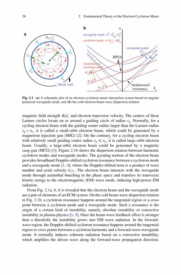
28 2 Fundamental Theory of the Electron Cyclotron Maser
2rLrg
B0
O
Metal wall
ee
e
e
ee
e
e
Eq
Eq
Eq
Eq
ab
Fig. 2.1 (a) A schematic plot of an electron cyclotron maser interaction system based on angularpolarized waveguide mode, and (b) the cold electron beam-wave dispersion relation
magnetic field strength B0Eez and electron transverse velocity. The centers of theseLarmor circles locate on or around a guiding circle of radius rg. Normally, for acycling electron beam with the guiding center radius larger than the Larmor radiusrg > rL, it is called a small-orbit electron beam, which could be generated by amagnetron injection gun (MIG) [2]. On the contrary, for a cycling electron beamwith relatively small guiding center radius rg � rL, it is called large-orbit electronbeam. Usually, a large-orbit electron beam could be generated by a magneticcusp gun (MCG) [3]. Figure 2.1b shows the dispersion relation between harmoniccyclotron modes and waveguide modes. The gyrating motion of the electron beamprovides broadband Doppler-shifted cyclotron resonance between a cyclotron modeand a waveguide mode [1, 4], where the Doppler-shifted term is a product of wavenumber and axial velocity kzvz. The electron beam interacts with the waveguidemode through azimuthal bunching in the phase space and transfers its transversekinetic energy to the electromagnetic (EM) wave mode, inducing high-power EMradiation.
From Fig. 2.1a, b, it is revealed that the electron beam and the waveguide modeare a pair of elements of an ECM system. On the cold beam-wave dispersion relationin Fig. 2.1b, a cyclotron resonance happens around the tangential region or a crosspoint between a cyclotron mode and a waveguide mode. Such a resonance is theorigin of a certain kind of instability, namely, absolute instability or convectiveinstability in plasma physics [1, 5]. Once the beam-wave feedback effect is strongerthan a threshold, the instability grows into EM wave radiation. In the forward-wave region, the Doppler-shifted cyclotron resonance happens around the tangentialregion or cross points between a cyclotron harmonic and a forward-wave waveguidemode. It normally induces coherent radiation based on a convective instability,which amplifies the driven wave along the forward-wave propagation direction.
2.2 Theory of the Waveguides 29
In the backward-wave region, a cyclotron resonance happens around the crosspoint between a cyclotron harmonic and a backward-wave mode. The backward-wave mode grows from the noise-level disturbance and bunches the forwardmoving electron beam. The electron beam in turn induces stronger radiation on thebackward-wave mode. In such a way, a kind of internal feedback effect is formed.If such internal feedback is strong enough, it will induce self-excitation oscillationor the backward-wave oscillation (BWO) [1].
In order to address the fundamental theory of the ECM in a more comprehensiveway in this chapter, the basic waveguide theory is reviewed first, including theory ofuniform dielectric-loaded waveguide [6] and periodic dielectric-loaded waveguide[7]. And then, a frequency domain theoretical model of ECM system is developedbased on the point of view of partitioning transverse plane of the interactionspace, which is generally applicable to most of the ECM waveguide. Finally, thefundamental ECM theory of the lossy dielectric-lined waveguide is developed.
2.2 Theory of the Waveguides
Since 1970s, the world-wide gyro-TWT research has employed various kinds ofinteraction circuits [1], including cylindrical waveguides [8, 9], rectangular waveg-uides, transverse varying rectangular waveguides [10], dielectric-loaded cylindricalwaveguides [11], distributed loss-loaded cylindrical waveguides [12, 13], radiallysliced radiating lossy cylindrical waveguides [14–16], lossy dielectric-loaded cylin-drical waveguides [17], helically grooved waveguides [18–20], and quasi-opticalconfocal waveguides [21]. Other than the abovementioned interaction circuits, opencavities employed by gyrotron oscillators, such as coaxial cavities [22], cavities withcorrugated insert [23], and cavities based on photonic-band-gap defect structure[24], also provide new possibilities to mode control for the gyro-TWTs. Theseexperiments indicated that in order to maintain broadband cyclotron resonancebetween the electron beam and a waveguide mode, it is specially required to payattention to self-excited oscillations, and a certain kind of disturbance or controlmethod should be introduced into a gyro-TWT circuit to suppress oscillations andprotect the amplification [1].
Until now, the operation mode control methods in a gyro-TWT circuit mainlyinclude waveguide wall loss (Aquadag-loaded [12] or lossy ceramic-loaded waveg-uide [16, 17]), dispersion relation control technology (helical grooved waveguide[18]), and mode filter technology (confocal waveguide or PBG structure [21, 24]).Controlling the propagation characteristics of the operation mode would directlyinfluence the electron beam-wave interaction. Hence, to study the propagationcharacteristics of the interaction waveguide is the precondition of the ECM inter-action investigation. This section reviews the theory of dielectric-loaded waveguidewhich provides theoretical foundation for studying the waveguide propagationcharacteristics.
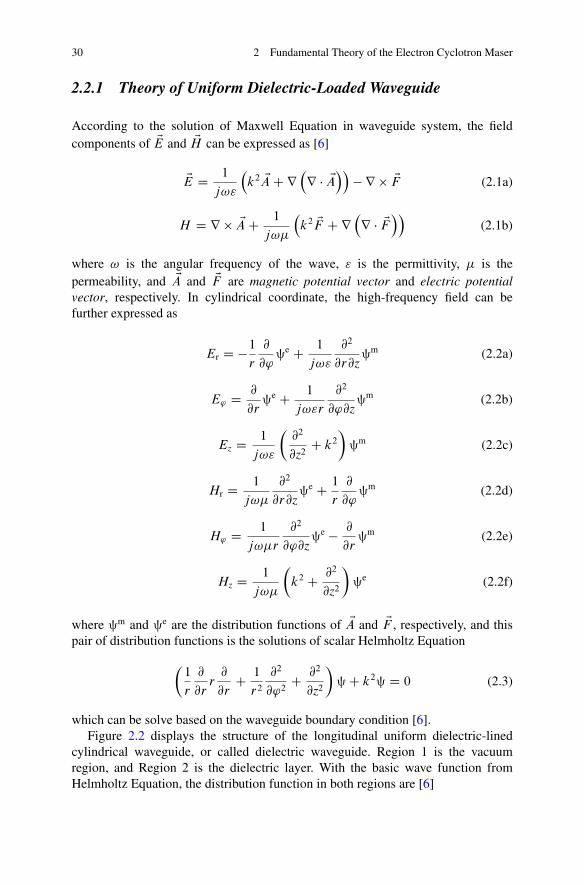
30 2 Fundamental Theory of the Electron Cyclotron Maser
2.2.1 Theory of Uniform Dielectric-Loaded Waveguide
According to the solution of Maxwell Equation in waveguide system, the fieldcomponents of EE and EH can be expressed as [6]
EE D 1
j!"
�k2 EA C r
�r � EA
��� r EF (2.1a)
H D r EA C 1
j!�
�k2 EF C r
�r � EF
��(2.1b)
where ! is the angular frequency of the wave, " is the permittivity, � is thepermeability, and EA and EF are magnetic potential vector and electric potentialvector, respectively. In cylindrical coordinate, the high-frequency field can befurther expressed as
Er D �1
r
@
@'§e C 1
j!"
@2
@r@z§m (2.2a)
E' D @
@r§e C 1
j!"r
@2
@'@z§m (2.2b)
Ez D 1
j!"
�@2
@z2C k2
�§m (2.2c)
Hr D 1
j!�
@2
@r@z§e C 1
r
@
@'§m (2.2d)
H' D 1
j!�r
@2
@'@z§e � @
@r§m (2.2e)
Hz D 1
j!�
�k2 C @2
@z2
�§e (2.2f)
where §m and §e are the distribution functions of EA and EF , respectively, and thispair of distribution functions is the solutions of scalar Helmholtz Equation
�1
r
@
@rr
@
@rC 1
r2
@2
@'2C @2
@z2
�§ C k2§ D 0 (2.3)
which can be solve based on the waveguide boundary condition [6].Figure 2.2 displays the structure of the longitudinal uniform dielectric-lined
cylindrical waveguide, or called dielectric waveguide. Region 1 is the vacuumregion, and Region 2 is the dielectric layer. With the basic wave function fromHelmholtz Equation, the distribution function in both regions are [6]
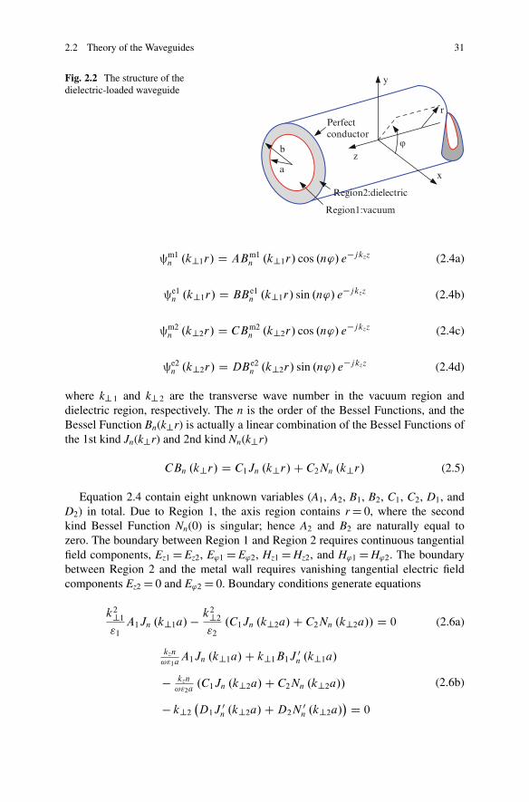
2.2 Theory of the Waveguides 31
x
y
z
r
ϕ
a
b
Region1:vacuum
Region2:dielectric
Perfect conductor
Fig. 2.2 The structure of thedielectric-loaded waveguide
§m1n .k?1r/ D ABm1
n .k?1r/ cos .n'/ e�jkzz (2.4a)
§e1n .k?1r/ D BBe1
n .k?1r/ sin .n'/ e�jkzz (2.4b)
§m2n .k?2r/ D CBm2
n .k?2r/ cos .n'/ e�jkzz (2.4c)
§e2n .k?2r/ D DBe2
n .k?2r/ sin .n'/ e�jkzz (2.4d)
where k? 1 and k? 2 are the transverse wave number in the vacuum region anddielectric region, respectively. The n is the order of the Bessel Functions, and theBessel Function Bn(k?r) is actually a linear combination of the Bessel Functions ofthe 1st kind Jn(k?r) and 2nd kind Nn(k?r)
CBn .k?r/ D C1Jn .k?r/ C C2Nn .k?r/ (2.5)
Equation 2.4 contain eight unknown variables (A1, A2, B1, B2, C1, C2, D1, andD2) in total. Due to Region 1, the axis region contains r D 0, where the secondkind Bessel Function Nn(0) is singular; hence A2 and B2 are naturally equal tozero. The boundary between Region 1 and Region 2 requires continuous tangentialfield components, Ez1 D Ez2, E'1 D E'2, Hz1 D Hz2, and H'1 D H'2. The boundarybetween Region 2 and the metal wall requires vanishing tangential electric fieldcomponents Ez2 D 0 and E'2 D 0. Boundary conditions generate equations
k2?1
"1
A1Jn .k?1a/ � k2?2
"2
.C1Jn .k?2a/ C C2Nn .k?2a// D 0 (2.6a)
kzn
!"1aA1Jn .k?1a/ C k?1B1J 0
n .k?1a/
� kzn
!"2a.C1Jn .k?2a/ C C2Nn .k?2a//
� k?2
�D1J 0
n .k?2a/ C D2N 0n .k?2a/
� D 0
(2.6b)
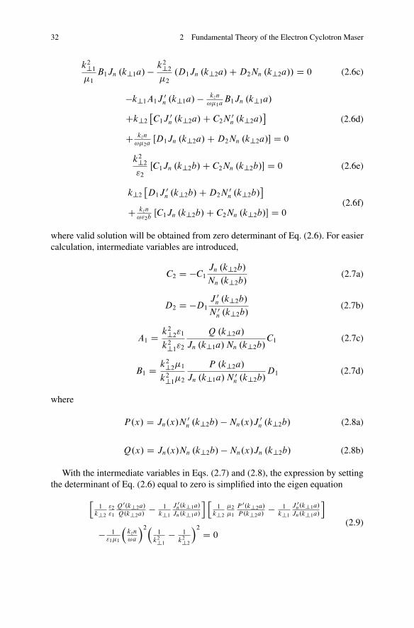
32 2 Fundamental Theory of the Electron Cyclotron Maser
k2?1
�1
B1Jn .k?1a/ � k2?2
�2
.D1Jn .k?2a/ C D2Nn .k?2a// D 0 (2.6c)
�k?1A1J 0n .k?1a/ � kzn
!�1aB1Jn .k?1a/
Ck?2
�C1J 0
n .k?2a/ C C2N 0n .k?2a/
C kzn
!�2aŒD1Jn .k?2a/ C D2Nn .k?2a/� D 0
(2.6d)
k2?2
"2
ŒC1Jn .k?2b/ C C2Nn .k?2b/� D 0 (2.6e)
k?2
�D1J 0
n .k?2b/ C D2N 0n .k?2b/
C kzn
!"2bŒC1Jn .k?2b/ C C2Nn .k?2b/� D 0
(2.6f)
where valid solution will be obtained from zero determinant of Eq. (2.6). For easiercalculation, intermediate variables are introduced,
C2 D �C1
Jn .k?2b/
Nn .k?2b/(2.7a)
D2 D �D1
J 0n .k?2b/
N 0n .k?2b/
(2.7b)
A1 D k2?2"1
k2?1"2
Q .k?2a/
Jn .k?1a/ Nn .k?2b/C1 (2.7c)
B1 D k2?2�1
k2?1�2
P .k?2a/
Jn .k?1a/ N 0n .k?2b/
D1 (2.7d)
where
P.x/ D Jn.x/N 0n .k?2b/ � Nn.x/J 0
n .k?2b/ (2.8a)
Q.x/ D Jn.x/Nn .k?2b/ � Nn.x/Jn .k?2b/ (2.8b)
With the intermediate variables in Eqs. (2.7) and (2.8), the expression by settingthe determinant of Eq. (2.6) equal to zero is simplified into the eigen equation
h1
k?2
"2
"1
Q0.k?2a/
Q.k?2a/� 1
k?1
J 0n.k?1a/
Jn.k?1a/
i h1
k?2
�2
�1
P 0.k?2a/
P .k?2a/� 1
k?1
J 0n.k?1a/
Jn.k?1a/
i
� 1"1�1
�kzn
!a
�2�1
k2?1
� 1
k2?2
�2 D 0
(2.9)
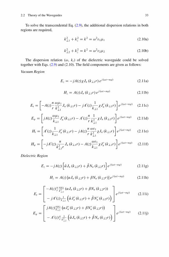
2.2 Theory of the Waveguides 33
To solve the transcendental Eq. (2.9), the additional dispersion relations in bothregions are required,
k2?1 C k2z D k2 D !2"1�1 (2.10a)
k2?2 C k2z D k2 D !2"2�2 (2.10b)
The dispersion relation (!, kz) of the dielectric waveguide could be solvedtogether with Eqs. (2.9) and (2.10). The field components are given as follows:
Vacuum Region
Ez D �jA.z/�Jn .k?1r/ ej .!t�n'/ (2.11a)
Hz D A.z/Jn .k?1r/ ej .!t�n'/ (2.11b)
Er D�A.z/
n
r
!�1
k2?1
Jn .k?1r/ � jA0.z/1
k?1
�J 0n .k?1r/
�ej .!t�n'/ (2.11c)
E' DjA.z/
!�1
k?1
J 0n .k?1r/ � A0.z/
n
r
1
k2?1
�Jn .k?1r/
�ej .!t�n'/ (2.11d)
Hr DA0.z/
1
k?1
J 0n .k?1r/ � jA.z/
n
r
!"1
k2?1
�Jn .k?1r/
�ej .!t�n'/ (2.11e)
H' D�jA0.z/
n
k2?1rJn .k?1r/ � A.z/
!"1
k?1
�J 0n .k?1r/
�ej .!t�n'/ (2.11f)
Dielectric Region
Ez D �jA.z/h
Q̨Jn .k?2r/ C Q̌Nn .k?2r/i
ej .!t�n'/ (2.11g)
Hz D A.z/ Œ˛Jn .k?2r/ C ˇNn .k?2r/� ej .!t�n'/ (2.11h)
Er D
264
�A.z/ nr
!�2
k2?2
.˛Jn .k?2r/ C ˇNn .k?2r//
� jA0.z/ 1k?2
�Q̨J 0
n .k?2r/ C Q̌N 0n .k?2r/
�
375 ej .!t�n'/ (2.11i)
E' D
264
jA.z/ !�2
k?2
�˛J 0
n .k?2r/ C ˇN 0n .k?2r/
�
� A0.z/ nr
1
k2?2
�Q̨Jn .k?2r/ C Q̌Nn .k?2r/
�
375 ej .!t�n'/ (2.11j)
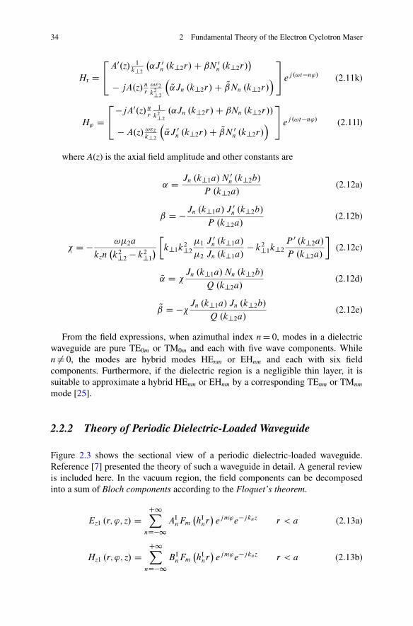
34 2 Fundamental Theory of the Electron Cyclotron Maser
Hr D24
A0.z/ 1k?2
�˛J 0
n .k?2r/ C ˇN 0n .k?2r/
�
� jA.z/ nr
!"2
k2?2
�Q̨Jn .k?2r/ C Q̌Nn .k?2r/
�35 ej .!t�n'/ (2.11k)
H' D24
�jA0.z/ nr
1
k2?2
.˛Jn .k?2r/ C ˇNn .k?2r//
� A.z/ !"2
k?2
�Q̨J 0
n .k?2r/ C Q̌N 0n .k?2r/
�35 ej .!t�n'/ (2.11l)
where A(z) is the axial field amplitude and other constants are
˛ D Jn .k?1a/ N 0n .k?2b/
P .k?2a/(2.12a)
ˇ D �Jn .k?1a/ J 0n .k?2b/
P .k?2a/(2.12b)
� D � !�2a
kzn�k2?2 � k2?1
�k?1k2?2
�1
�2
J 0n .k?1a/
Jn .k?1a/� k2?1k?2
P 0 .k?2a/
P .k?2a/
�(2.12c)
Q̨ D �Jn .k?1a/ Nn .k?2b/
Q .k?2a/(2.12d)
Q̌ D ��Jn .k?1a/ Jn .k?2b/
Q .k?2a/(2.12e)
From the field expressions, when azimuthal index n D 0, modes in a dielectricwaveguide are pure TE0m or TM0m and each with five wave components. Whilen ¤ 0, the modes are hybrid modes HEnm or EHnm and each with six fieldcomponents. Furthermore, if the dielectric region is a negligible thin layer, it issuitable to approximate a hybrid HEnm or EHnm by a corresponding TEnm or TMnm
mode [25].
2.2.2 Theory of Periodic Dielectric-Loaded Waveguide
Figure 2.3 shows the sectional view of a periodic dielectric-loaded waveguide.Reference [7] presented the theory of such a waveguide in detail. A general reviewis included here. In the vacuum region, the field components can be decomposedinto a sum of Bloch components according to the Floquet’s theorem.
Ez1 .r; '; z/ DC1X
nD�1AI
nFm
�hI
nr�
ejm'e�jknz r < a (2.13a)
Hz1 .r; '; z/ DC1X
nD�1B I
nFm
�hI
nr�
ejm'e�jknz r < a (2.13b)
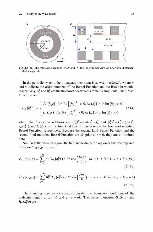
2.2 Theory of the Waveguides 35
a
vacuum
dielectric
metal
b
x
y
D
dielectricb
metal
a
vacuum
e1 m1
e2 m2
e1 m1
e2 m2
L
a b
Fig. 2.3 (a) The transverse sectional view and (b) the longitudinal view of a periodic dielectric-loaded waveguide
In the periodic system, the propagation constant is kn D kz C n(2� /L), where mand n indicate the order numbers of the Bessel Function and the Bloch harmonic,respectively. AI
n and BIn are the unknown coefficients of fields amplitude. The Bessel
Functions are
Fm
�hI
nr� D
8̂<:̂
Jm
�hI
nr�
for Reh�
hIn
�2i> 0; Re
�hI
n
�> 0; Im
�hI
n
�> 0
Im
�t Inr�
for Reh�
t In
�2i> 0; Re
�t In
�> 0; Im
�t In
�> 0
(2.14)
where the dispersion relations are (hIn)2 D (!/c)2 � k2
n and (tIn)2 D k2
n � (!/c)2.Jm(hI
nr) and Im(tInr) are the first kind Bessel Function and the first kind modified
Bessel Function, respectively. Because the second kind Bessel Function and thesecond kind modified Bessel Function are singular at r D 0, they are all omittedhere.
Similar to the vacuum region, the field in the dielectric region can be decomposedinto standing eigenwaves,
Ez2 .r; '; z/ DC1XlD0
AIIl Gm
�hII
l r�
ejm' cos
�l�z
b
�.a < r < D; nL < z < b C nL/
(2.15a)
Hz2 .r; '; z/ DC1XlD1
B IIl Hm
�hII
l r�
ejm' sin
�l�z
b
�.a < r < D; nL < z < b C nL/
(2.15b)
The standing eigenwaves already consider the boundary conditions of thedielectric region at z D nL and z D b C nL. The Bessel Function Gm(hII
l ) andHm(hII
l ) are
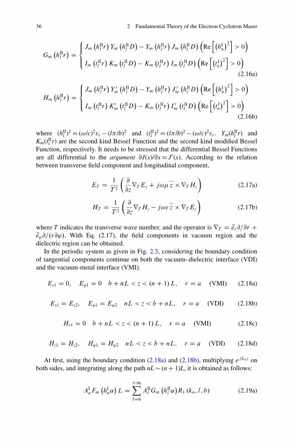
36 2 Fundamental Theory of the Electron Cyclotron Maser
Gm
�hII
l r� D
8<̂:̂
Jm
�hII
l r�
Ym
�hII
l D� � Ym
�hII
l r�
Jm
�hII
l D� �
Reh�
hIn
�2i> 0
�
Im
�t IIl r�
Km
�t IIl D
� � Km
�t IIl r�
Im
�t IIl D
� �Reh�
t In
�2i> 0
�
(2.16a)
Hm
�hII
l r� D
8̂<:̂
Jm
�hII
l r�
Y 0m
�hII
l D� � Ym
�hII
l r�
J 0m
�hII
l D� �
Reh�
hIn
�2i> 0
�
Im
�t IIl r�
K 0m
�t IIl D
� � Km
�t IIl r�
I 0m
�t IIl D
� �Reh�
t In
�2i> 0
�
(2.16b)
where (hIIl )2 D (!/c)2"r � (l� /b)2 and (tII
l )2 D (l� /b)2 � (!/c)2"r. Ym(hIIl r) and
Km(tIIl r) are the second kind Bessel Function and the second kind modified Bessel
Function, respectively. It needs to be stressed that the differential Bessel Functionsare all differential to the argument @J(x)/@x D J0(x). According to the relationbetween transverse field component and longitudinal component,
ET D 1
T 2
�@
@zrT Ez C j!�
*z rT Hz
�(2.17a)
HT D 1
T 2
�@
@zrT Hz � j!"
*z rT Ez
�(2.17b)
where T indicates the transverse wave number, and the operator is rT D Eer@=@r CEe'@=.r@'/. With Eq. (2.17), the field components in vacuum region and thedielectric region can be obtained.
In the periodic system as given in Fig. 2.3, considering the boundary conditionof tangential components continue on both the vacuum–dielectric interface (VDI)and the vacuum-metal interface (VMI).
Ez1 D 0; E'1 D 0 b C nL < z < .n C 1/ L; r D a .VMI/ (2.18a)
Ez1 D Ez2; E'1 D E'2 nL < z < b C nL; r D a .VDI/ (2.18b)
Hr1 D 0 b C nL < z < .n C 1/ L; r D a .VMI/ (2.18c)
Hz1 D Hz2; H'1 D H'2 nL < z < b C nL; r D a .VDI/ (2.18d)
At first, using the boundary condition (2.18a) and (2.18b), multiplying ejknz onboth sides, and integrating along the path nL � (n C 1)L, it is obtained as follows:
AInFm
�hI
n˛�
L DC1XlD0
AIIl Gm
�hII
l ˛�R1 .kn; l; b/ (2.19a)
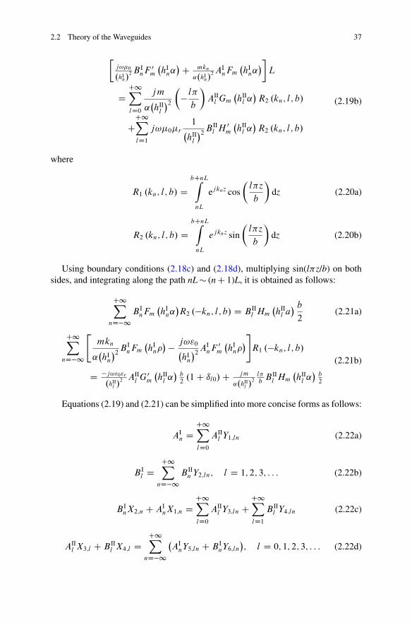
2.2 Theory of the Waveguides 37
j!�0
.hIn/
2 B InF 0
m
�hI
n˛�C mkn
˛.hIn/
2 AInFm
�hI
n˛��
L
DC1XlD0
jm
˛�hII
l
�2�
� l�
b
�AII
l Gm
�hII
l ˛�
R2 .kn; l; b/
CC1XlD1
j!�0�r
1�hII
l
�2 B IIl H 0
m
�hII
l ˛�
R2 .kn; l; b/
(2.19b)
where
R1 .kn; l; b/ DbCnLZ
nL
ejknz cos
�l�z
b
�dz (2.20a)
R2 .kn; l; b/ DbCnLZ
nL
ejknz sin
�l�z
b
�dz (2.20b)
Using boundary conditions (2.18c) and (2.18d), multiplying sin(l�z/b) on bothsides, and integrating along the path nL � (n C 1)L, it is obtained as follows:
C1XnD�1
B InFm
�hI
n˛�R2 .�kn; l; b/ D B II
l Hm
�hII
l a� b
2(2.21a)
C1XnD�1
"mkn
˛�hI
n
�2 B InFm
�hI
n� � j!"0�
hIn
�2 AInF 0
m
�hI
n�#
R1 .�kn; l; b/
D �j!"0"r
.hIIl /
2 AIIl G0
m
�hII
l ˛�
b2
.1 C ıl0/ C jm
˛.hIIl /
2l�b
B IIl Hm
�hII
l ˛�
b2
(2.21b)
Equations (2.19) and (2.21) can be simplified into more concise forms as follows:
AIn D
C1XlD0
AIIl Y1;ln (2.22a)
B Il D
C1XnD�1
B IIn Y2;ln; l D 1; 2; 3; : : : (2.22b)
B InX2;n C AI
nX1;n DC1XlD0
AIIl Y3;ln C
C1XlD1
B IIl Y4;ln (2.22c)
AIIl X3;l C B II
l X4;l DC1X
nD�1
�AI
nY5;ln C B InY6;ln
�; l D 0; 1; 2; 3; : : : (2.22d)
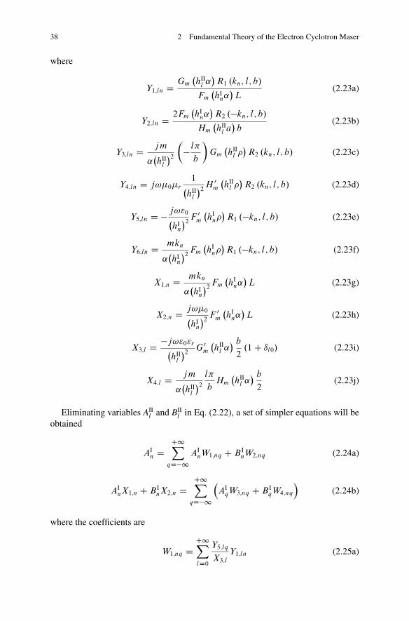
38 2 Fundamental Theory of the Electron Cyclotron Maser
where
Y1;ln D Gm
�hII
l ˛�
R1 .kn; l; b/
Fm
�hI
n˛�
L(2.23a)
Y2;ln D 2Fm
�hI
n˛�
R2 .�kn; l; b/
Hm
�hII
l a�
b(2.23b)
Y3;ln D jm
˛�hII
l
�2�
� l�
b
�Gm
�hII
l �
R2 .kn; l; b/ (2.23c)
Y4;ln D j!�0�r
1�hII
l
�2 H 0m
�hII
l �
R2 .kn; l; b/ (2.23d)
Y5;ln D � j!"0�hI
n
�2 F 0m
�hI
n�
R1 .�kn; l; b/ (2.23e)
Y6;ln D mkn
˛�hI
n
�2 Fm
�hI
n�
R1 .�kn; l; b/ (2.23f)
X1;n D mkn
˛�hI
n
�2 Fm
�hI
n˛�
L (2.23g)
X2;n D j!�0�hI
n
�2 F 0m
�hI
n˛�
L (2.23h)
X3;l D �j!"0"r�hII
l
�2 G0m
�hII
l ˛� b
2.1 C ıl0/ (2.23i)
X4;l D jm
˛�hII
l
�2l�
bHm
�hII
l ˛� b
2(2.23j)
Eliminating variables AIIl and BII
l in Eq. (2.22), a set of simpler equations will beobtained
AIn D
C1XqD�1
AInW1;nq C B I
nW2;nq (2.24a)
AInX1;n C B I
nX2;n DC1X
qD�1
�AI
qW3;nq C B IqW4;nq
�(2.24b)
where the coefficients are
W1;nq DC1XlD0
Y5;lq
X3;l
Y1;ln (2.25a)
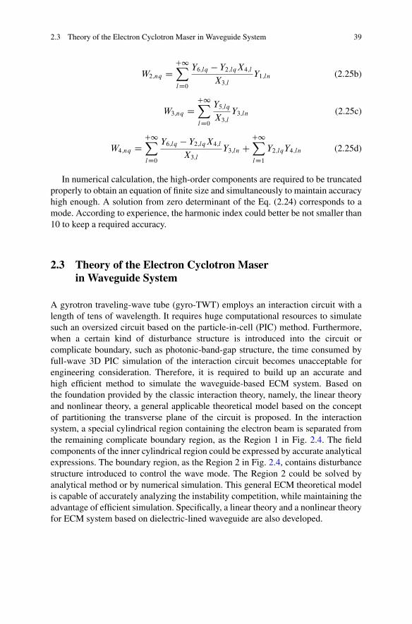
2.3 Theory of the Electron Cyclotron Maser in Waveguide System 39
W2;nq DC1XlD0
Y6;lq � Y2;lqX4;l
X3;l
Y1;ln (2.25b)
W3;nq DC1XlD0
Y5;lq
X3;l
Y3;ln (2.25c)
W4;nq DC1XlD0
Y6;lq � Y2;lqX4;l
X3;l
Y3;ln CC1XlD1
Y2;lqY4;ln (2.25d)
In numerical calculation, the high-order components are required to be truncatedproperly to obtain an equation of finite size and simultaneously to maintain accuracyhigh enough. A solution from zero determinant of the Eq. (2.24) corresponds to amode. According to experience, the harmonic index could better be not smaller than10 to keep a required accuracy.
2.3 Theory of the Electron Cyclotron Maserin Waveguide System
A gyrotron traveling-wave tube (gyro-TWT) employs an interaction circuit with alength of tens of wavelength. It requires huge computational resources to simulatesuch an oversized circuit based on the particle-in-cell (PIC) method. Furthermore,when a certain kind of disturbance structure is introduced into the circuit orcomplicate boundary, such as photonic-band-gap structure, the time consumed byfull-wave 3D PIC simulation of the interaction circuit becomes unacceptable forengineering consideration. Therefore, it is required to build up an accurate andhigh efficient method to simulate the waveguide-based ECM system. Based onthe foundation provided by the classic interaction theory, namely, the linear theoryand nonlinear theory, a general applicable theoretical model based on the conceptof partitioning the transverse plane of the circuit is proposed. In the interactionsystem, a special cylindrical region containing the electron beam is separated fromthe remaining complicate boundary region, as the Region 1 in Fig. 2.4. The fieldcomponents of the inner cylindrical region could be expressed by accurate analyticalexpressions. The boundary region, as the Region 2 in Fig. 2.4, contains disturbancestructure introduced to control the wave mode. The Region 2 could be solved byanalytical method or by numerical simulation. This general ECM theoretical modelis capable of accurately analyzing the instability competition, while maintaining theadvantage of efficient simulation. Specifically, a linear theory and a nonlinear theoryfor ECM system based on dielectric-lined waveguide are also developed.
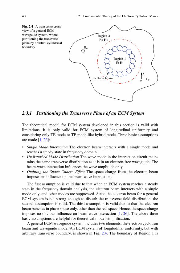
40 2 Fundamental Theory of the Electron Cyclotron Maser
x
y
o
B0
electron beam
Region 1EI HI
Region 2EII HII
Fig. 2.4 A transverse crossview of a general ECMwaveguide system, wherepartitioning the transverseplane by a virtual cylindricalboundary
2.3.1 Partitioning the Transverse Plane of an ECM System
The theoretical modal for ECM system developed in this section is valid withlimitations. It is only valid for ECM system of longitudinal uniformity andconsidering only TE mode or TE mode-like hybrid mode. Three basic assumptionsare made [1, 26]:
• Single Mode Interaction The electron beam interacts with a single mode andreaches a steady state in frequency domain.
• Undisturbed Mode Distribution The wave mode in the interaction circuit main-tains the same transverse distribution as it is in an electron-free waveguide. Thebeam-wave interaction influences the wave amplitude only.
• Omitting the Space Charge Effect The space charge from the electron beamimposes no influence on the beam-wave interaction.
The first assumption is valid due to that when an ECM system reaches a steadystate in the frequency domain analysis, the electron beam interacts with a singlemode only, and other modes are suppressed. Since the electron beam for a generalECM system is not strong enough to disturb the transverse field distribution, thesecond assumption is valid. The third assumption is valid due to that the electronbeam bunches in phase space only, other than the real space. Hence, the space chargeimposes no obvious influence on beam-wave interaction [1, 26]. The above threebasic assumptions are helpful for theoretical model simplification.
A general ECM waveguide system includes two elements, the electron cyclotronbeam and waveguide mode. An ECM system of longitudinal uniformity, but witharbitrary transverse boundary, is shown in Fig. 2.4. The boundary of Region 1 is
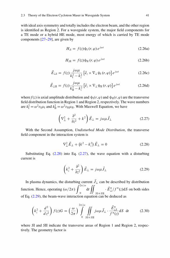
2.3 Theory of the Electron Cyclotron Maser in Waveguide System 41
with ideal axis symmetry and totally includes the electron beam, and the other regionis identified as Region 2. For a waveguide system, the major field components fora TE mode or a hybrid HE mode, most energy of which is carried by TE modecomponents [27–29], are given by
HzI D f .z/§I .r; '/ ej!t (2.26a)
HzII D f .z/§II .r; '/ ej!t (2.26b)
EE?I D f .z/j!�
k2I � k2
z
�Eez r?§I .r; '/
ej!t (2.26c)
EE?II D f .z/j!�
k2II � k2
z
�Eez r?§II .r; '/
ej!t (2.26d)
where f (z) is axial amplitude distribution and §I(r, ') and §II(r, ') are the transversefield distribution function in Region 1 and Region 2, respectively. The wave numbersare k2
I D !2"I�I and k2II D !2"II�II. With Maxwell Equation, we have
�r2? C @2
@z2C k2
�EE? D j!� EJ? (2.27)
With the Second Assumption, Undisturbed Mode Distribution, the transversefield component in the interaction system is
r2? EE? C �k2 � k2
z
� EE? D 0 (2.28)
Substituting Eq. (2.28) into Eq. (2.27), the wave equation with a disturbingcurrent is
�k2
z C @2
@z2
�EE? D j!� EJ? (2.29)
In plasma dynamics, the disturbing current EJ? can be described by distribution
function. Hence, operating .!=2�/
Z 2�=!
0
dt
“
SICSII
� EE�?=f �.z/dS on both sides
of Eq. (2.29), the beam-wave interaction equation can be deduced as
�k2
z C d 2
d z2
�f .z/G D
� !
2�
� 2�=!Z
0
“
SICSII
j!� EJ? �EE�?I
f �.z/dS dt (2.30)
where SI and SII indicate the transverse areas of Region 1 and Region 2, respec-tively. The geometry factor is
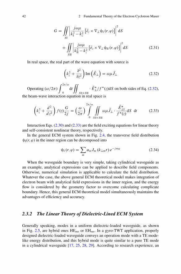
42 2 Fundamental Theory of the Electron Cyclotron Maser
G D“
SI
ˇ̌ˇ̌ j!�
k2I � k2
z
�Eez r?§I .r; '/ˇ̌ˇ̌
2
dS
C“
SII
ˇ̌ˇ̌ j!�
k2II � k2
z
�Eez r?§II .r; '/ˇ̌ˇ̌
2
dS (2.31)
In real space, the real part of the wave equation with source is
�k2
z C @2
@z2
�Im� EE?
�D !� EJ? (2.32)
Operating .!=2�/
Z 2�=!
0
dt
“
SICSII
� EE�?=f �.z/dS on both sides of Eq. (2.32),
the beam-wave interaction equation in real space is
�k2
z C d 2
d z2
�f .z/
G
2jD� !
2�
� 2�=!Z
0
“
SICSII
!� EJ? �EE�?I
f �.z/dS dt (2.33)
Interaction Eqs. (2.30) and (2.33) are the field exciting equations for linear theoryand self-consistent nonlinear theory, respectively.
In the general ECM system shown in Fig. 2.4, the transverse field distribution§I(r, ') in the inner region can be decomposed into
§I .r; '/ DX
m
˛mJm .k?mr/ e�jm' (2.34)
When the waveguide boundary is very simple, taking cylindrical waveguide asan example, analytical expressions can be applied to describe field components.Otherwise, numerical simulation is applicable to calculate the field distribution.Whatever the case, the above general ECM theoretical model makes integration ofelectron beam with analytical field expressions in the inner region, and the energyflow is considered by the geometry factor to overcome calculating complicateboundary. Hence, this general ECM theoretical model simultaneously maintains theadvantages of efficiency and accuracy.
2.3.2 The Linear Theory of Dielectric-Lined ECM System
Generally speaking, modes in a uniform dielectric-loaded waveguide, as shownin Fig. 2.5, are hybrid ones HEmn or EHmn. In a gyro-TWT application, properlydesigned dielectric-loaded waveguide conveys an operation mode with a TE mode-like energy distribution, and this hybrid mode is quite similar to a pure TE modein a cylindrical waveguide [17, 25, 28, 29]. According to research experience, an
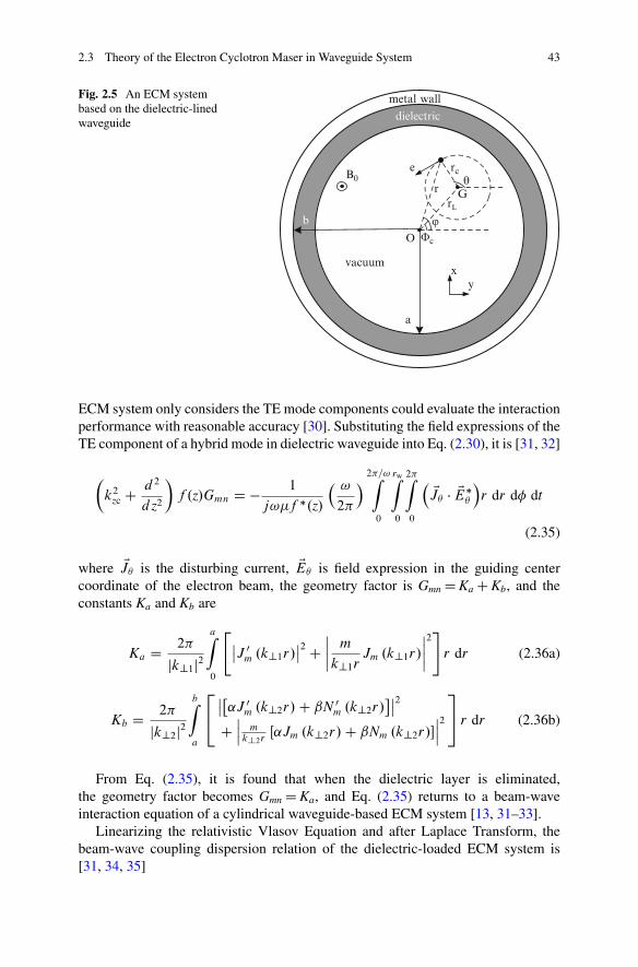
2.3 Theory of the Electron Cyclotron Maser in Waveguide System 43
a
vacuum
dielectric
metal wall
b
B0
rL
rc
rθ
O
e
G
xy
Φc
ϕ
Fig. 2.5 An ECM systembased on the dielectric-linedwaveguide
ECM system only considers the TE mode components could evaluate the interactionperformance with reasonable accuracy [30]. Substituting the field expressions of theTE component of a hybrid mode in dielectric waveguide into Eq. (2.30), it is [31, 32]
�k2
zc C d 2
d z2
�f .z/Gmn D � 1
j!�f �.z/
� !
2�
� 2�=!Z
0
rwZ
0
2�Z
0
� EJ � EE�
�r dr d� dt
(2.35)
where EJ is the disturbing current, EE is field expression in the guiding centercoordinate of the electron beam, the geometry factor is Gmn D Ka C Kb, and theconstants Ka and Kb are
Ka D 2�
jk?1j2aZ
0
"ˇ̌J 0
m .k?1r/ˇ̌2 C
ˇ̌ˇ̌ m
k?1rJm .k?1r/
ˇ̌ˇ̌2#
r dr (2.36a)
Kb D 2�
jk?2j2bZ
a
24ˇ̌�
˛J 0m .k?2r/ C ˇN 0
m .k?2r/ˇ̌2
Cˇ̌ˇ m
k?2rŒ˛Jm .k?2r/ C ˇNm .k?2r/�
ˇ̌ˇ2
35 r dr (2.36b)
From Eq. (2.35), it is found that when the dielectric layer is eliminated,the geometry factor becomes Gmn D Ka, and Eq. (2.35) returns to a beam-waveinteraction equation of a cylindrical waveguide-based ECM system [13, 31–33].
Linearizing the relativistic Vlasov Equation and after Laplace Transform, thebeam-wave coupling dispersion relation of the dielectric-loaded ECM system is[31, 34, 35]
44 2 Fundamental Theory of the Electron Cyclotron Maser
Ddisp .kz/ D �k2
zc � k2z
�Gmn � _
S1 .kz/ D 0 (2.37)
and field amplitude is
F.z/ D4X
iD1
"F.0/
bS0 .kzi / � jkzi Gmn
jD0disp .kzi /
C F 0.0/Gmn
jD0disp .kzi /
#e�jkzi z (2.38)
where kzc is the cold propagating constant of the waveguide, and constants bS1 .kz/
and bS0 .kz/ are respectively
bS1 .kz/ D 4�2e2�1
k2?1m0
rwZ
0
rcdrc
1Z
0
p?dp?1Z
0
dpzf0
�
1X
sD�1
"�ˇ2
t
�!2 � k2
z c2�
Hsm
.! � s� � kzvz/2
C .! � kzvz/ Tsm � k?vt Usm
.! � kzvz � s�e/
#
(2.39)
bS0 .kz/ D j4�2e2�1
k2?1m0
rwZ
0
rcdrc
1Z
0
p?dp?1Z
0
dpzf0
�
1X
sD�1
�kzv2t Hsm
.! � kzvz � s�e/2
C vzTsm
.! � kzvz � s�e/
�(2.40)
where f0 is the electron beam distribution function under undisturbed state
f0 D Ib
4�2e
NXiD1
Wi
rci vzi pti
ı .rc � rci / ı .pz � pzi / ı .pt � pti / (2.41)
where the weight factor of the macro particles is given byP N
i D 1Wi D 1. Thelongitude and transverse normalized velocities are ˇz D vz/c and ˇ? D v?/c. Otherexpressions are
Hsm .x; y/ D ˇ̌J 0
s .x/Jm�s.y/ˇ̌2
(2.42a)
Tsm .x; y/ D 2Hsm C 2Re�xJ 0
s .x/J 00s .x/
jJm�s.y/j2 � xJ 0�s .x/Js.x/
h
1yJ �
m�s.y/J 0m�s.y/ C y�
yjJ 0
m�s.y/j2 C J �m�s.y/J 00
m�s.y/i
(2.42b)
2.3 Theory of the Electron Cyclotron Maser in Waveguide System 45
Usm .x; y/ D��x
2
�J 0�
s .x/
�JsC1.x/
y�
yjJm�s�1.y/j2 � jJm�s.y/j2
�
CJs�1.x/
y�
yjJm�sC1.y/j2 � jJm�s.y/j2
� (2.42c)
where the variables are x D k? 1rL and y D k? 1rc. The linear theory takes intoconsideration the influence of the dielectric layer loaded to the propagation char-acteristics and field distribution and is capable of efficiently analyzing the ECMinteraction. More details about the derivation of the linear theory are given inAppendix I.
2.3.3 The Nonlinear Theory of Dielectric-Loaded ECM System
Similar to the linear theory, the nonlinear theory of the dielectric-loaded waveguideconsiders a pure TE mode or the TE mode component of a hybrid mode. Substitutingthe field components into Eq. (2.33), it is obtained as follows:
�k2
z C d2
dz2
�f .z/ D �2 jIbj
Gmn
NXiD1
Wi
v i
vzi�"
1
k?1
1XsD�1
J 0s .k?1rLi /Jm�s .k?1rci /e
jƒi
#�
(2.43)
where the beam current is assumed to be
EJ D �2� jIbj!
NXiD1
Wi
1
ri
ı .r � ri / ı .' � 'i /ı .t � ti /
*v i
vzi(2.44)
where the phase distribution is ƒi D !ti � s i � (m � s)�ci and the weight factor ofmacro particle follows
P Ni D 1Wi D 1.
Equation (2.43) describes the effect of electron beam exciting EM mode. Inorder to self-consistently determine the electron beam-wave interaction, it is furthernecessary to specify the Lorentz Force to drive the electrons,
d*p
dtD �e
*
E � e*v
�*
B C *
B0
�(2.45)
In the guiding center of a cyclotron electron, the differential to time is trans-formed to differential to displacement via
1
vz
d
dtEp D d
dzEp D �P
d
dz
*e rL C d
dzP
*e C d
dzPz
*e z (2.46)
46 2 Fundamental Theory of the Electron Cyclotron Maser
The force acting on an electron includes EM force EF and static magneticforce ER
*
F C *
R D�
�e*
E � e*v *
B
�� e
*v *
Bext (2.47)
The components of the EM force EF are
FrL D �eErL � e .v Bz � vzB / (2.48a)
F D �eE � evzBrL (2.48b)
Fz D ev BrL (2.48c)
The components of the static force ER are
RrL D �eB0v C gevzB0rc sin . � �c/ (2.49a)
R D geB0rLvz C gevzB0rc cos . � �c/ (2.49b)
Rz D �geB0rLv � gev B0rc cos . � �c/ (2.49c)
where ErL , E , B , BrL , and Bz are the relevant field components in guiding centercoordinate [1, 32]. Finally, the components of the Lorentz Force are
d
dzPz D 1
vz.Fz C Rz/ (2.50a)
d
dzP D 1
vz.F C R / (2.50b)
P
d
dzD � 1
vz.FrL C RrL/ (2.50c)
Other than the momentum components of an electron, the position of eachparticle is also needed to be determined. A transformation between the globalcoordinate and the guiding center coordinate is
rej� D rLej C rcej�c (2.51)
2.3 Theory of the Electron Cyclotron Maser in Waveguide System 47
Differential to above equation generates
drc
dzD�
1
eB0
p
d
dz� p
pz
�sin . � �c/
��
1
eB0
dp
dz� p
eB20
dB0
dz
�cos . � �c/ (2.52a)
rcd�c
dzD�
p
pz� 1
eB0
p
d
dz
�cos . � �c/
��
1
eB0
dp
dz� p
eB20
dB0
dz
�sin . � �c/ (2.52b)
The transformation between the time and space is
dt
dzD 1
vz(2.52c)
In this frequency domain theory, the electron cyclotron beam is modeled bymacro particles. The wave exciting equation (Eq. (2.43)) evaluates the overallcontributions from the macro particles to the wave, and the state of each macroparticles will be determined by the particle motion equations (Eqs. (2.50) and(2.52)). Hence, if the electron beam is modeled by N macro particles, there are6NC1 equations to describe the whole ECM system. The wave exciting equation(Eq. (2.43)) and together with the particle motion equations (Eqs. (2.50) and (2.52))constitutes the complete nonlinear theory in dielectric-loaded waveguide.
2.3.4 Basic Concepts
2.3.4.1 Frequency Domain Steady State
Under a set of given operating parameters, an ECM system reaches a steady-stategenerating radiation at a specified wave frequency. The typical characteristic of afrequency domain steady state is a fixed longitudinal field amplitude distribution ofthe EM field in the interaction circuit. Theoretically, the frequency domain analysisindicates investigating all possible steady states of an ECM system to study thesystem performance. Actually, only the typical states need to be specified, such asthe start-oscillation state, the linear amplification, the saturated states, and so on.Two major states attract attention in a gyro-TWT, namely, self-exiting oscillationand steady amplification [1]. An absolute instability is an inherent factor leading to
48 2 Fundamental Theory of the Electron Cyclotron Maser
a self-exciting oscillation. Regenerate amplification induced by circuit discontinuityor reflection from either end of the circuit might be another factor that leads tooscillation. Steady amplification means the input power is amplified and growsalong the beam moving direction in the circuit based on convective instability, andthe output power will be turned off once the input power is switched off, which isalso called zero-drive stability.
2.3.4.2 Instability Threshold
If the beam-wave coupling reaches a certain strength level, the ECM system turnsinto a state of self-exciting oscillation, and the threshold parameters of switching onthis oscillation are assigned as instability thresholds. The operating parameters of agyro-TWT are required to be below the thresholds of all potential oscillations, as away to avoid self-exciting oscillation and to realize zero-drive stability.
The ECM system of a gyro-TWT is a semi-opening system, transverse of whichis closed by waveguide wall, or with certain lossy structures, and both upstream portand downstream port exchange energy with external. Such a system may be stableunder different states according to operation parameters and boundary conditions.Hence, no matter linear theory or nonlinear theory, the boundary conditions todetermining both self-exciting oscillation and amplification analysis are the same.Other than the EM field boundary condition, the electron beam also could betreated as a kind of external power injected into the circuit to determine the systemstate.
2.3.4.3 The Weight Factor
For an ECM system, an electron beam injects into the upstream port and exits fromthe downstream port. The input state of the electron beam is determined by thedistribution functions in Eqs. (2.41) or (2.44). The weight factor is applied to buildelectron beam with certain parameter distribution,
NXiD1
Wi D A
NXiD1
exp
"�.Ci � C0/2
2.�C0/2
#D 1 (2.53)
where N is the macro particle number; A is the normalized factor; C0, �C0, and Ci
are the average value, variance value, and specified value of each macro particle;and this value C can be assigned to model the velocity or position distribution of theelectron beam. The state for each macro particle is determined self-consistently bythe interaction integration along the circuit.
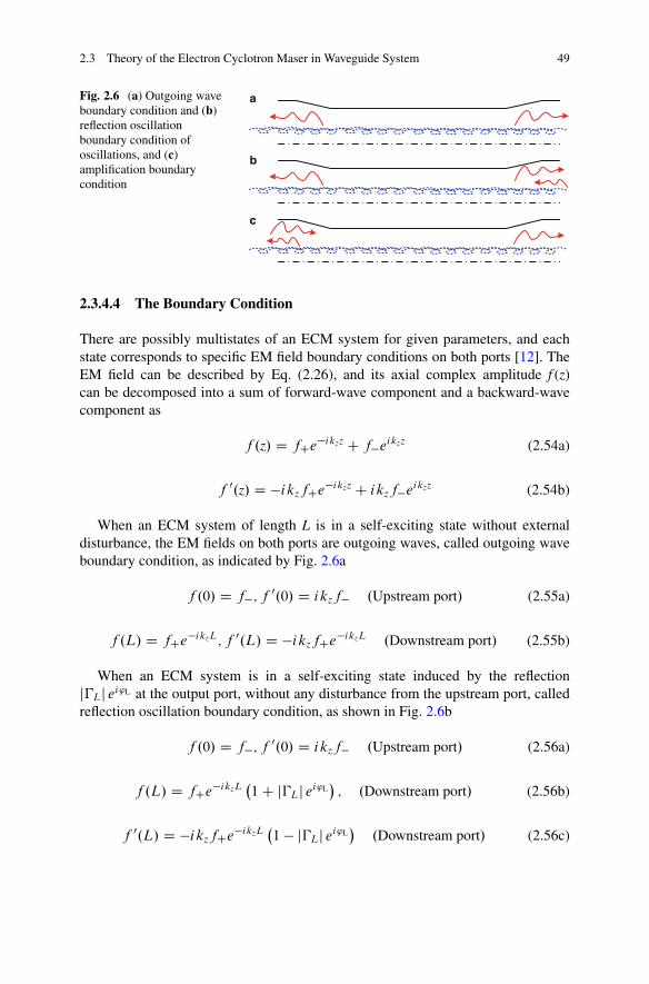
2.3 Theory of the Electron Cyclotron Maser in Waveguide System 49
a
b
c
Fig. 2.6 (a) Outgoing waveboundary condition and (b)reflection oscillationboundary condition ofoscillations, and (c)amplification boundarycondition
2.3.4.4 The Boundary Condition
There are possibly multistates of an ECM system for given parameters, and eachstate corresponds to specific EM field boundary conditions on both ports [12]. TheEM field can be described by Eq. (2.26), and its axial complex amplitude f (z)can be decomposed into a sum of forward-wave component and a backward-wavecomponent as
f .z/ D fCe�ikzz C f�eikzz (2.54a)
f 0.z/ D �ikzfCe�ikzz C ikzf�eikzz (2.54b)
When an ECM system of length L is in a self-exciting state without externaldisturbance, the EM fields on both ports are outgoing waves, called outgoing waveboundary condition, as indicated by Fig. 2.6a
f .0/ D f�; f 0.0/ D ikzf� .Upstream port/ (2.55a)
f .L/ D fCe�ikzL; f 0.L/ D �ikzfCe�ikzL .Downstream port/ (2.55b)
When an ECM system is in a self-exciting state induced by the reflectionj�Lj ei'L at the output port, without any disturbance from the upstream port, calledreflection oscillation boundary condition, as shown in Fig. 2.6b
f .0/ D f�; f 0.0/ D ikzf� .Upstream port/ (2.56a)
f .L/ D fCe�ikzL�1 C j�Lj ei'L
�; .Downstream port/ (2.56b)
f 0.L/ D �ikzfCe�ikzL�1 � j�Lj ei'L
�.Downstream port/ (2.56c)
50 2 Fundamental Theory of the Electron Cyclotron Maser
When an ECM system is in an ideal amplification state, at the upstream port,other than the driving power, there is also a backward wave due to certain factors,such as circuit discontinuity. While the downstream port is an ideal outgoing wave,called amplification boundary condition, as given in Fig. 2.6c
f .0/ D fC�1 C j�0j ei'0
�.Upstream port/ (2.57a)
f 0.0/ D �ikzfC�1 � j�0j ei'0
�.Downstream port/ (2.57b)
f .L/ D fCe�ikzL; f 0.L/ D �ikzfCe�ikzL .Downstream port/ (2.57c)
2.4 Summary
The theories of uniform and periodic dielectric-loaded waveguides are reviewedfirst. And then a general applicable theoretical model for ECM waveguide systemis proposed, which is based on partitioning the transverse plane of the interactioncircuit. Finally, linear theory and nonlinear theory of the ECM system based ondielectric-loaded waveguide is developed. The theory of dielectric-loaded ECMsystem is based on a TE mode approximation, which is omitting the TM modecomponent of a hybrid mode. When the dielectric layer is negligibly thin, the theoryreturns to that of the ECM based on simple cylindrical waveguide, and to someextent, the theory is verified. In the last section, some fundamental concept forgyro-TWT research is clarified. By the way, although various kinds of nonlineartheories are developed for specified gyro-devices, the linear theory is still one of themost efficient theoretical solutions to estimate the preliminary characteristics of agyro-TWT.
Appendix I: Derivation of the Linear Theoryin Dielectric-Lined Waveguide
A cross view of the dielectric-lined waveguide is again displayed in Fig. A1.1. Inorder to better understand the linear theory, the detailed derivation of the lineartheory is introduced here [1, 34, 35]. We rewrite the Eq. (2.35) in this chapter here,
�k2
zc C d 2
d z2
�f .z/Gmn D � 1
j!�f �.z/
� !
2�
� 2�=!Z
0
rwZ
0
2�Z
0
� EJ � EE�
�r dr d� dt
(A1.1)
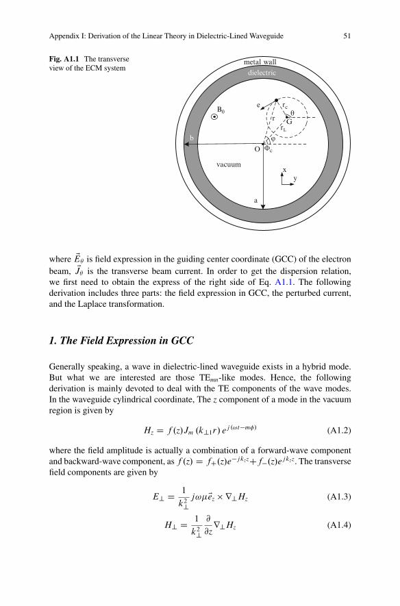
Appendix I: Derivation of the Linear Theory in Dielectric-Lined Waveguide 51
a
vacuum
dielectric
metal wall
b
B0
rL
rc
rθ
O
e
G
xy
ϕΦc
Fig. A1.1 The transverseview of the ECM system
where EE is field expression in the guiding center coordinate (GCC) of the electronbeam, EJ is the transverse beam current. In order to get the dispersion relation,we first need to obtain the express of the right side of Eq. A1.1. The followingderivation includes three parts: the field expression in GCC, the perturbed current,and the Laplace transformation.
1. The Field Expression in GCC
Generally speaking, a wave in dielectric-lined waveguide exists in a hybrid mode.But what we are interested are those TEmn-like modes. Hence, the followingderivation is mainly devoted to deal with the TE components of the wave modes.In the waveguide cylindrical coordinate, The z component of a mode in the vacuumregion is given by
Hz D f .z/Jm .k?1r/ ej .!t�m�/ (A1.2)
where the field amplitude is actually a combination of a forward-wave componentand backward-wave component, as f .z/ D fC.z/e�jkzzCf�.z/ejkzz. The transversefield components are given by
E? D 1
k2?j!�Eez r?Hz (A1.3)
H? D 1
k2?
@
@zr?Hz (A1.4)
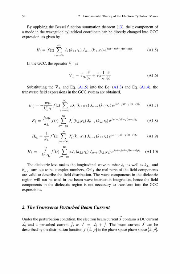
52 2 Fundamental Theory of the Electron Cyclotron Maser
By applying the Bessel function summation theorem [13], the z component ofa mode in the waveguide cylindrical coordinate can be directly changed into GCCexpression, as given by
Hz D f .z/1X
sD�1Js .k?1rL/ Jm�s .k?1rc/ ej!t�js�j .m�s/�c (A1.5)
In the GCC, the operator r? is
r? D *e rL
@
@rC *
e
1
rL
@
@(A1.6)
Substituting the r? and Eq. (A1.5) into the Eq. (A1.3) and Eq. (A1.4), thetransverse field expressions in the GCC system are obtained,
ErL D � !�
k2?rLf .z/
1XsD�1
sJs .k?1rL/ Jm�s .k?1rc/ ej!t�js�j .m�s/�c (A1.7)
E D j!�
k?f .z/
1XsD�1
J 0s .k?1rL/ Jm�s .k?1rc/ ej!t�js�j .m�s/�c (A1.8)
HrL D 1
k?f 0.z/
1XsD�1
J 0s .k?1rL/ Jm�s .k?1rc/ ej!t�js�j .m�s/�c (A1.9)
H D � j
k2?rLf 0.z/
1XsD�1
sJs .k?1rL/ Jm�s .k?1rc/ ej!t�js�j .m�s/�c (A1.10)
The dielectric loss makes the longitudinal wave number kz, as well as k? 1 andk? 2, turn out to be complex numbers. Only the real parts of the field componentsare valid to describe the field distribution. The wave components in the dielectricregion will not be used in the beam-wave interaction integration, hence the fieldcomponents in the dielectric region is not necessary to transform into the GCCexpressions.
2. The Transverse Perturbed Beam Current
Under the perturbation condition, the electron beam current EJ contains a DC currentEJ0 and a perturbed current Ej , as EJ D EJ0 C Ej . The beam current EJ can be
described by the distribution function f�Ex; Ep� in the phase space phase space
˝Ex; Ep˛.
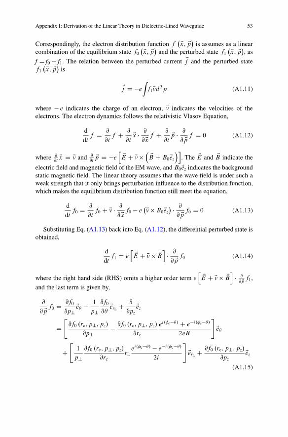
Appendix I: Derivation of the Linear Theory in Dielectric-Lined Waveguide 53
Correspondingly, the electron distribution function f�Ex; Ep� is assumes as a linear
combination of the equilibrium state f0
�Ex; Ep� and the perturbed state f1
�Ex; Ep�, as
f D f0 C f1. The relation between the perturbed current Ej and the perturbed statef1
�Ex; Ep� is
Ej D �e
Zf1Evd 3p (A1.11)
where � e indicates the charge of an electron, Ev indicates the velocities of theelectrons. The electron dynamics follows the relativistic Vlasov Equation,
d
dtf D @
@tf C @
@tEx � @
@Ex f C @
@tEp � @
@ Ep f D 0 (A1.12)
where @@t
Ex D Ev and @@t
Ep D �eh EE C Ev
� EB C B0Eez
�i. The EE and EB indicate the
electric field and magnetic field of the EM wave, and B0Eez indicates the backgroundstatic magnetic field. The linear theory assumes that the wave field is under such aweak strength that it only brings perturbation influence to the distribution function,which makes the equilibrium distribution function still meet the equation,
d
dtf0 D @
@tf0 C Ev � @
@Ex f0 � e�Ev B0Eez
� � @
@ Ep f0 D 0 (A1.13)
Substituting Eq. (A1.13) back into Eq. (A1.12), the differential perturbed state isobtained,
d
dtf1 D e
h EE C Ev EBi
� @
@ Ep f0 (A1.14)
where the right hand side (RHS) omits a higher order term eh EE C Ev EB
i� @
@ Ep f1,
and the last term is given by,
@
@ Ep f0 D @f0
@p?Ee � 1
p?@f0
@EerL C @
@pzEez
D"
@f0 .rc; p?; pz/
@p?� @f0 .rc; p?; pz/
@rc
ei.�c�/ C e�i.�c�/
2eB
#Ee
C"
1
p?@f0 .rc; p?; pz/
@rcrL
ei.�c�/ � e�i.�c�/
2i
#EerL C @f0 .rc; p?; pz/
@pzEez
(A1.15)
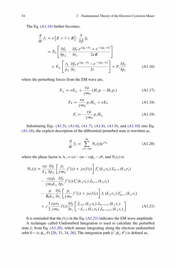
54 2 Fundamental Theory of the Electron Cyclotron Maser
The Eq. (A1.14) further becomes,
d
dtf1 D e
�E C Ev B
� @
@ Ep f0
D F
"@f0
@p?� @f0
@rc
ei.�c�/ C e�i.�c�/
2eB
#
C FrL
"rL
p?@f0
@rc
ei.�c�/ � e�i.�c�/
2i
#C Fz
@f0
@pz(A1.16)
where the perturbing forces from the EM wave are,
FrL D eErL C e�
�m0
.Hzpt � H pz/ (A1.17)
F D e�
�m0
pzHrL C eE (A1.18)
Fz D � e�
�m0
pt HrL (A1.19)
Substituting Eqs. (A1.5), (A1.6), (A1.7), (A1.8), (A1.9), and (A1.10) into Eq.(A1.16), the explicit description of the differential perturbed state is rewritten as,
d
dtf1 D
1XsD�1
<s.z/ejƒs (A1.20)
where the phase factor is ƒs D !t � (m � s)�c � s , and <s(z) is
<s.z/ D e�
k?@f0
@p?
pz
�m0
f 0.z/ C j!f .z/
�J 0
s .k?rL/ Jm�s .k?rc/
� e�pt
�m0k?@f0
@pzf 0.z/J 0
s .k?rL/ Jm�s .k?rc/
� �
B0k?@f0
@rc
pz
�m0
f 0.z/ C j!f .z/
�Js .k?rL/ J 0
m�s .k?rc/
C j1
2
e�rL
�m0
f .z/@f0
@rc
JsC1 .k?rL/ Jm�s�1 .k?rc/
�Js�1 .k?rL/ Jm�sC1 .k?rc/
�(A1.21)
It is reminded that the f (z) in the Eq. (A1.21) indicates the EM wave amplitude.A technique called Undisturbed Integration is used to calculate the perturbed
state f1 from Eq. (A1.20), which means integrating along the electron undisturbedorbit 0 � (t, �c, ) [26, 31, 34, 36]. The integration path (t0, �
0
c, 0) is defined as,
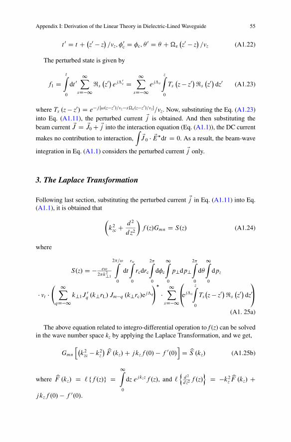
Appendix I: Derivation of the Linear Theory in Dielectric-Lined Waveguide 55
t 0 D t C �z0 � z
�=vz; �0
c D �c; 0 D C �e�z0 � z
�=vz (A1.22)
The perturbed state is given by
f1 DtZ
0
dt 01X
sD�1<s
�z0� ejƒ0
s D1X
sD�1ejƒs
zZ
0
Ts
�z � z0�<s
�z0� dz0 (A1.23)
where Ts .z � z0/ D e�j Œ!.z�z0/=vz�s�e.z�z0/=vz�=vz. Now, substituting the Eq. (A1.23)into Eq. (A1.11), the perturbed current Ej is obtained. And then substituting thebeam current EJ D EJ0 C Ej into the interaction equation (Eq. (A1.1)), the DC current
makes no contribution to interaction,Z
EJ 0 � EE�dt D 0. As a result, the beam-wave
integration in Eq. (A1.1) considers the perturbed current Ej only.
3. The Laplace Transformation
Following last section, substituting the perturbed current Ej in Eq. (A1.11) into Eq.(A1.1), it is obtained that
�k2
zc C d 2
d z2
�f .z/Gmn D S.z/ (A1.24)
where
S.z/ D � e!
2�k2?1
2�=!Z
0
dt
rwZ
0
rcdrc
2�Z
0
d�c
1Z
0
p?dp?2�Z
0
d
1Z
0
dpz
� vt � 1X
qD�1k?1J 0
q .k?rL/ Jm�q .k?rc/ejƒq
!��
1XsD�1
0@ejƒs
zZ
0
Ts
�z � z0�<s
�z0� dz0
1A
(A1. 25a)
The above equation related to integro-differential operation to f (z) can be solvedin the wave number space kz by applying the Laplace Transformation, and we get,
Gmn
h�k2
zc � k2z
� bF .kz/ C jkzf .0/ � f 0.0/i
D bS .kz/ (A1.25b)
where bF .kz/ D ` ff .z/g D1Z
0
dz ejkzzf .z/, and `n
d2
d z2 f .z/o
D �k2zbF .kz/ C
jkzf .0/ � f 0.0/.
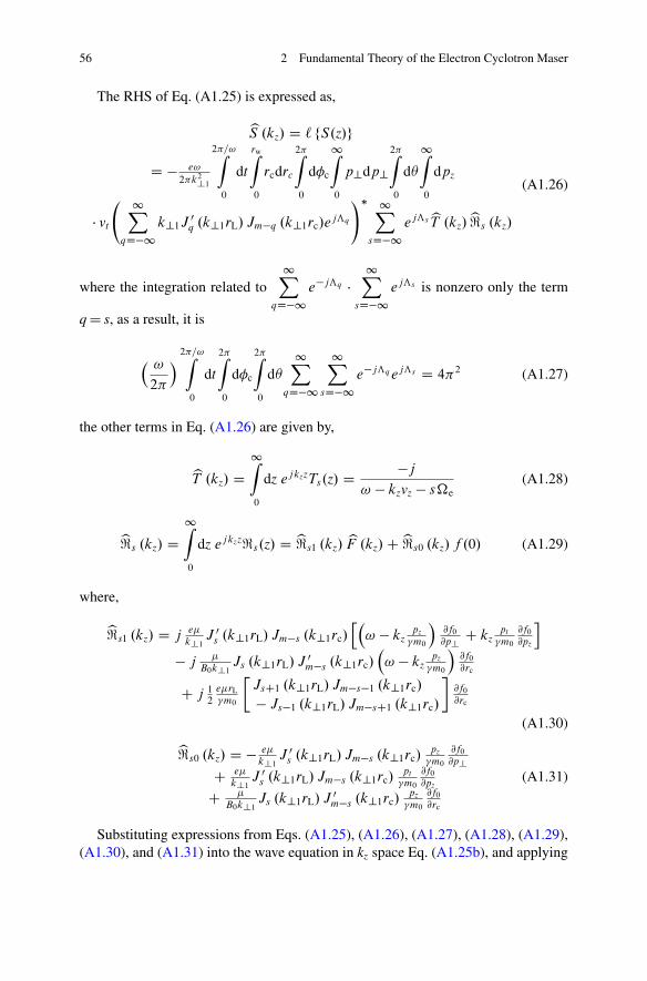
56 2 Fundamental Theory of the Electron Cyclotron Maser
The RHS of Eq. (A1.25) is expressed as,
bS .kz/ D ` fS.z/g
D � e!
2�k2?1
2�=!Z
0
dt
rwZ
0
rcdrc
2�Z
0
d�c
1Z
0
p?dp?2�Z
0
d
1Z
0
dpz
� vt
1XqD�1
k?1J 0q .k?1rL/ Jm�q .k?1rc/e
jƒq
!� 1XsD�1
ejƒsbT .kz/b<s .kz/
(A1.26)
where the integration related to1X
qD�1e�jƒq �
1XsD�1
ejƒs is nonzero only the term
q D s, as a result, it is
� !
2�
� 2�=!Z
0
dt
2�Z
0
d�c
2�Z
0
d
1XqD�1
1XsD�1
e�jƒq ejƒs D 4�2 (A1.27)
the other terms in Eq. (A1.26) are given by,
bT .kz/ D1Z
0
dz ejkzzTs.z/ D �j
! � kzvz � s�e(A1.28)
b<s .kz/ D1Z
0
dz ejkzz<s.z/ D b<s1 .kz/ bF .kz/ C b<s0 .kz/ f .0/ (A1.29)
where,
b<s1 .kz/ D je�
k?1J 0
s .k?1rL/ Jm�s .k?1rc/h�
! � kzpz
�m0
�@f0
@p?C kz
pt
�m0
@f0
@pz
i
� j�
B0k?1Js .k?1rL/ J 0
m�s .k?1rc/�! � kz
pz�m0
�@f0
@rc
C j 12
e�rL�m0
JsC1 .k?1rL/ Jm�s�1 .k?1rc/
� Js�1 .k?1rL/ Jm�sC1 .k?1rc/
�@f0
@rc
(A1.30)
b<s0 .kz/ D � e�
k?1J 0
s .k?1rL/ Jm�s .k?1rc/pz
�m0
@f0
@p?
C e�
k?1J 0
s .k?1rL/ Jm�s .k?1rc/pt
�m0
@f0
@pz
C �
B0k?1Js .k?1rL/ J 0
m�s .k?1rc/pz
�m0
@f0
@rc
(A1.31)
Substituting expressions from Eqs. (A1.25), (A1.26), (A1.27), (A1.28), (A1.29),(A1.30), and (A1.31) into the wave equation in kz space Eq. (A1.25b), and applying
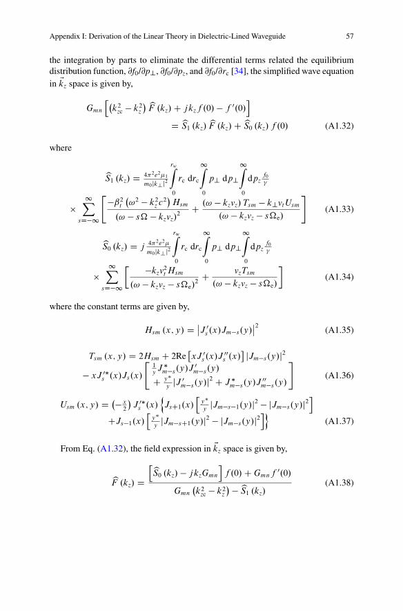
Appendix I: Derivation of the Linear Theory in Dielectric-Lined Waveguide 57
the integration by parts to eliminate the differential terms related the equilibriumdistribution function, @f0/@p?, @f0/@pz, and @f0/@rc [34], the simplified wave equationin Ekz space is given by,
Gmn
h�k2
zc � k2z
� bF .kz/ C jkzf .0/ � f 0.0/i
D bS1 .kz/ bF .kz/ C bS0 .kz/ f .0/ (A1.32)
where
bS1 .kz/ D 4�2e2�1
m0jk?j2
rwZ
0
rc drc
1Z
0
p? dp?1Z
0
dpzf0
�
1X
sD�1
"�ˇ2
t
�!2 � k2
z c2�
Hsm
.! � s� � kzvz/2
C .! � kzvz/ Tsm � k?vt Usm
.! � kzvz � s�e/
#(A1.33)
bS0 .kz/ D j4�2e2�
m0jk?j2
rwZ
0
rc drc
1Z
0
p? dp?1Z
0
dpzf0
�
1X
sD�1
�kzv2t Hsm
.! � kzvz � s�e/2
C vzTsm
.! � kzvz � s�e/
�(A1.34)
where the constant terms are given by,
Hsm .x; y/ D ˇ̌J 0
s .x/Jm�s.y/ˇ̌2
(A1.35)
Tsm .x; y/ D 2Hsm C 2Re�xJ 0
s .x/J 00s .x/
jJm�s.y/j2
� xJ 0�s .x/Js.x/
"1yJ �
m�s.y/J 0m�s.y/
C y�
yjJ 0
m�s.y/j2 C J �m�s.y/J 00
m�s.y/
#(A1.36)
Usm .x; y/ D �� x2
�J 0�
s .x/nJsC1.x/
hy�
yjJm�s�1.y/j2 � jJm�s.y/j2
i
CJs�1.x/h
y�
yjJm�sC1.y/j2 � jJm�s.y/j2
io(A1.37)
From Eq. (A1.32), the field expression in Ekz space is given by,
bF .kz/ DhbS0 .kz/ � jkzGmn
if .0/ C Gmnf 0.0/
Gmn
�k2
zc � k2z
� � bS1 .kz/(A1.38)
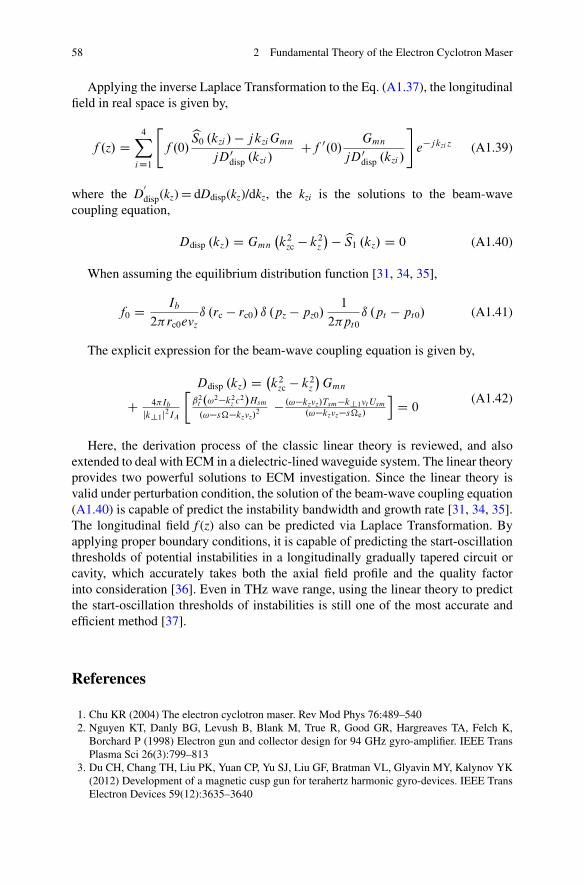
58 2 Fundamental Theory of the Electron Cyclotron Maser
Applying the inverse Laplace Transformation to the Eq. (A1.37), the longitudinalfield in real space is given by,
f .z/ D4X
iD1
"f .0/
bS0 .kzi / � jkzi Gmn
jD0disp .kzi /
Cf 0.0/Gmn
jD0disp .kzi /
#e�jkzi z (A1.39)
where the D0
disp(kz) D dDdisp(kz)/dkz, the kzi is the solutions to the beam-wavecoupling equation,
Ddisp .kz/ D Gmn
�k2
zc � k2z
� � bS1 .kz/ D 0 (A1.40)
When assuming the equilibrium distribution function [31, 34, 35],
f0 D Ib
2�rc0evzı .rc � rc0/ ı .pz � pz0/
1
2�pt0
ı .pt � pt0/ (A1.41)
The explicit expression for the beam-wave coupling equation is given by,
Ddisp .kz/ D �k2
zc � k2z
�Gmn
C 4�Ib
jk?1j2IA
ˇ2
t .!2�k2z c2/Hsm
.!�s��kzvz/2 � .!�kzvz/Tsm�k?1vt Usm
.!�kzvz�s�e/
iD 0
(A1.42)
Here, the derivation process of the classic linear theory is reviewed, and alsoextended to deal with ECM in a dielectric-lined waveguide system. The linear theoryprovides two powerful solutions to ECM investigation. Since the linear theory isvalid under perturbation condition, the solution of the beam-wave coupling equation(A1.40) is capable of predict the instability bandwidth and growth rate [31, 34, 35].The longitudinal field f (z) also can be predicted via Laplace Transformation. Byapplying proper boundary conditions, it is capable of predicting the start-oscillationthresholds of potential instabilities in a longitudinally gradually tapered circuit orcavity, which accurately takes both the axial field profile and the quality factorinto consideration [36]. Even in THz wave range, using the linear theory to predictthe start-oscillation thresholds of instabilities is still one of the most accurate andefficient method [37].
References
1. Chu KR (2004) The electron cyclotron maser. Rev Mod Phys 76:489–5402. Nguyen KT, Danly BG, Levush B, Blank M, True R, Good GR, Hargreaves TA, Felch K,
Borchard P (1998) Electron gun and collector design for 94 GHz gyro-amplifier. IEEE TransPlasma Sci 26(3):799–813
3. Du CH, Chang TH, Liu PK, Yuan CP, Yu SJ, Liu GF, Bratman VL, Glyavin MY, Kalynov YK(2012) Development of a magnetic cusp gun for terahertz harmonic gyro-devices. IEEE TransElectron Devices 59(12):3635–3640
References 59
4. Nusinovich GS (2004) Introduction to the physics of gyrotrons. The Johns Hopkins UniversityPress, Baltimore/London
5. Du CH, Pu-Kun Liu, Qian-Zhong Xue, Ming-Hong Wang (2008) Effect of a backwardwave on the stability of an ultrahigh gain gyrotron traveling-wave amplifier. Phys Plasmas15(12):123107
6. Harrington RF (ed) (2001) Time-harmonic electromagnetic fields. Wiley/IEEE Press, Piscat-away, ISBN0-471-20806-X, John Wilson, Inc, 605 Third Avenue, New York
7. Tigelis IG, Vomvoridis JL, Tzima S (1998) High-frequency electromagnetic modes in adielectric-ring loaded beam tunnel. IEEE Trans Plasma Sci 26:922–930
8. Barnett LR, Baird JM, Lau YY et al (1980) A high gain single stage gyrotron traveling-waveamplifier. Int Electron Devices Meet 26:314–317
9. Barnett LR, Chu KR, Baird JM et al (1979) Gain, saturation, and bandwidth measurements ofthe NRL gyrotron travelling wave amplifier. Int Electron Devices Meet 25:164–167
10. Park GS, Choi JJ, Park SY et al (1995) Gain broadening of 2-stage tapered gyrotron traveling-wave tube amplifier. Phys Rev Lett 74:2399–2402
11. Leou KC, McDermott DB, Luhmann NC (1996) Large-signal characteristics of a wide-banddielectric-loaded gyro-TWT amplifier. IEEE Trans Plasma Sci 24:718–726
12. Chu KR, Chen HY, Hung CL et al (1998) Ultrahigh gain gyrotron traveling wave amplifier.Phys Rev Lett 81:4760–4763
13. Chu KR, Chen HY, Hung CL et al (1999) Theory and experiment of ultrahigh-gain gyrotrontraveling wave amplifier. IEEE Trans Plasma Sci 27:391–404
14. Wang QS, McDermott DB, Luhmann NC (1996) Operation of a stable 200-kW second-harmonic gyro-TWT amplifier. IEEE Trans Plasma Sci 24:700–706
15. Chong CK, McDermott DB, Luhmann NC (1998) Large-signal operation of a third-harmonicslotted gyro-TWT amplifier. IEEE Trans Plasma Sci 26:500–507
16. Pershing DE, Nguyen KT, Calame JP et al (2004) A TE11 K-a-band gyro-TWT amplifier withhigh-average power compatible distributed loss. IEEE Trans Plasma Sci 32:947–956
17. Garven M, Calame JP, Danly BG et al (2002) A gyrotron-traveling-wave tube amplifierexperiment with a ceramic loaded interaction region. IEEE Trans Plasma Sci 30:885–893
18. Denisov GG, Bratman VL, Phelps ADR et al (1998) Gyro-TWT with a helical operatingwaveguide: new possibilities to enhance efficiency and frequency bandwidth. IEEE TransPlasma Sci 26:508–518
19. Bratman VL, Cross AW, Denisov GG et al (2000) High-gain wide-band gyrotron travelingwave amplifier with a helically corrugated waveguide. Phys Rev Lett 84:2746–2749
20. Denisov GG, Bratman VL, Cross AW et al (1998) Gyrotron traveling wave amplifier with ahelical interaction waveguide. Phys Rev Lett 81:5680–5683
21. Sirigiri JR, Shapiro MA, Temkin RJ (2003) High-power 140-GHz quasioptical gyrotrontraveling-wave amplifier. Phys Rev Lett 90:258302
22. Advani R, Hogge JP, Kreischer KE et al (2001) Experimental investigation of a 140-GHzcoaxial gyrotron oscillator. IEEE Trans Plasma Sci 29:943–950
23. Dumbrajs O, Zaginaylov GI (2004) Ohmic losses in coaxial gyrotron cavities with corrugatedinsert. IEEE Trans Plasma Sci 32:861–866
24. Sirigiri JR, Kreischer KE, Machuzak J et al (2001) Photonic-band-gap resonator gyrotron. PhysRev Lett 86:5628–5631
25. Lee CS, Lee SW, Chuang SL (1986) Normal modes in an overmoded circular waveguide coatedwith lossy material. IEEE Trans Microw Theory Tech 34:773–785
26. Liu LSG (1987) Relativistic electronics. Science Press, Beijing (In Chinese)27. Calame JP, Garven M, Danly BG et al (2002) Gyrotron-traveling wave-tube circuits based on
lossy ceramics. IEEE Trans Electron Devices 49:1469–147728. Du CH, Liu PK (2009) A lossy dielectric-ring loaded waveguide with suppressed periodicity
for gyro-TWTs applications. IEEE Trans Electron Devices 56:2335–234229. Du CH, Xue QZ, Liu PK et al (2009) Modal transition and reduction in a lossy dielectric-coated
waveguide for gyrotron-traveling-wave tube amplifier applications. IEEE Trans ElectronDevices 56:839–845
60 2 Fundamental Theory of the Electron Cyclotron Maser
30. Du CH, Liu PK (2009) Stability study of a gyrotron-traveling-wave amplifier based on a lossydielectric-loaded mode-selective circuit. Phys Plasmas 16:073104
31. Du CH, Liu PK (2010) Linear full-wave-analysis of a gyrotron-traveling-wave-tube amplifierbased on a lossy dielectric-lined circuit. IEEE Trans Plasma Sci 38(6):1219–1226
32. Du CH, Liu PK (2010) Nonlinear full-wave-interaction analysis of a gyrotron-traveling-wave-tube amplifier based on a lossy dielectric-lined circuit. Phys Plasmas 17:033104
33. Jiao CQ (2007) Theoretical study and numerical simulation of the gyrotron traveling waveamplifier. Doctorial dissertation (In Chinese), Chinese Academy of Science, Beijing, China
34. Chu KR, Lin AT (1988) Gain and bandwidth of the gyro-TWT and CARM amplifiers. IEEETrans Plasma Sci 16(2):90–103
35. Kou CS, Wang QS, McDermott DB, Lin AT, Chu KR, Luhmann NC Jr (1992) High powerharmonic gyro-TWT’s-Part I: linear theory and oscillation study. IEEE Trans Plasma Sci20(3):155–162
36. Kou CS, Tseng F (1998) Linear theory of gyrotron traveling wave tube with nonuniform andlossy interaction structures. Phys Plasmas 5(6):2454
37. Kao SH, Chiu CC, Chu KR (2012) A study of sub-terahertz and terahertz gyrotron oscillators.Phys Plasmas 19:023112
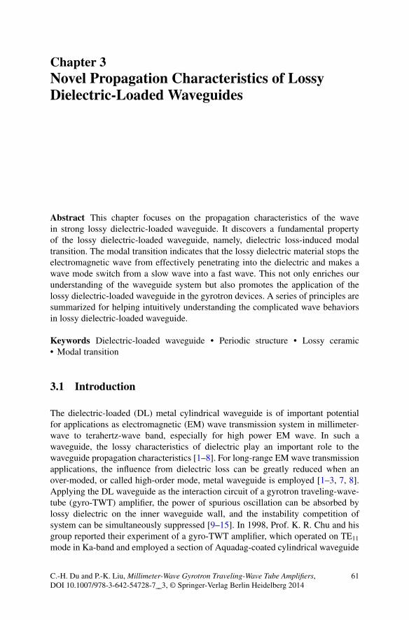
Chapter 3Novel Propagation Characteristics of LossyDielectric-Loaded Waveguides
Abstract This chapter focuses on the propagation characteristics of the wavein strong lossy dielectric-loaded waveguide. It discovers a fundamental propertyof the lossy dielectric-loaded waveguide, namely, dielectric loss-induced modaltransition. The modal transition indicates that the lossy dielectric material stops theelectromagnetic wave from effectively penetrating into the dielectric and makes awave mode switch from a slow wave into a fast wave. This not only enriches ourunderstanding of the waveguide system but also promotes the application of thelossy dielectric-loaded waveguide in the gyrotron devices. A series of principles aresummarized for helping intuitively understanding the complicated wave behaviorsin lossy dielectric-loaded waveguide.
Keywords Dielectric-loaded waveguide • Periodic structure • Lossy ceramic• Modal transition
3.1 Introduction
The dielectric-loaded (DL) metal cylindrical waveguide is of important potentialfor applications as electromagnetic (EM) wave transmission system in millimeter-wave to terahertz-wave band, especially for high power EM wave. In such awaveguide, the lossy characteristics of dielectric play an important role to thewaveguide propagation characteristics [1–8]. For long-range EM wave transmissionapplications, the influence from dielectric loss can be greatly reduced when anover-moded, or called high-order mode, metal waveguide is employed [1–3, 7, 8].Applying the DL waveguide as the interaction circuit of a gyrotron traveling-wave-tube (gyro-TWT) amplifier, the power of spurious oscillation can be absorbed bylossy dielectric on the inner waveguide wall, and the instability competition ofsystem can be simultaneously suppressed [9–15]. In 1998, Prof. K. R. Chu and hisgroup reported their experiment of a gyro-TWT amplifier, which operated on TE11
mode in Ka-band and employed a section of Aquadag-coated cylindrical waveguide
C.-H. Du and P.-K. Liu, Millimeter-Wave Gyrotron Traveling-Wave Tube Amplifiers,DOI 10.1007/978-3-642-54728-7__3, © Springer-Verlag Berlin Heidelberg 2014
61
62 3 Novel Propagation Characteristics of Lossy Dielectric-Loaded Waveguides
b
dielectricI
metal
a
vacuum
e1 m1
e2 m2
L
a b
x
y
z
r
ϕ
a
b
Region1:vacuum
Region2:dielectric
Perfect conductor
Fig. 3.1 (a) Uniform lossy dielectric-loaded (DL) waveguide and (b) periodic lossy dielectric-loaded waveguide
as the interaction circuit. It achieved performance of saturated peak power 93 kW,ultrahigh gain 70 dB, efficiency 26.5 %, and �3 dB bandwidth 3 GHz [9, 10]. In2002, the American Naval Research Laboratory (NRL) reported the experimentof a Ka-band gyro-TWT amplifier based on the lossy ceramic-loaded circuit. Itoperated on the fundamental harmonic TE01 mode and achieved saturated peakpower 137 kW, �3 dB bandwidth 3.3 % under the condition of voltage 70 kVand beam current 10 A [13, 14]. The instability competition of this experimentis well suppressed. The lossy DL waveguide not only plays an important role ininteraction circuit for high power gyro-TWT amplifiers, but also can be loaded in thedrifting tunnels for gyrotron amplifiers and oscillators [12, 16], as well as loadingin a waveguide to filtrate unwanted modes.
The dielectric-loaded waveguide, as a typical waveguide structure, has beenthoroughly investigated. Studies are normally concentrated on exploring the weaklossy transmission characteristics [1–8]. However, the gyro-devices usually adoptdielectric-loaded waveguides with strong lossy characteristics to adjust the attenua-tion rate of the operate mode, and it brings convenience for system stability control[10, 13, 16]. In addition, the dispersion property of the system also can be changedby loading dielectric, and it is beneficial for broadband synchronization betweenEM wave and cyclotron beam. The high thermal conductivity of dielectric materialand waveguide structure together endows the gyro-devices high average powercapability. The lossy dielectric provides advantages of suppressing oscillations inthe interaction waveguide. However, it makes the system more complicated andbrings disturbance to the mode distribution and transmission characteristics, whichmakes it more difficult to analyze the system. Hence, through investigating lossydielectric-loaded waveguide, it brings us better understanding and promotes itsapplication in gyro-devices.
The propagation characteristics of an EM mode in a dielectric waveguideare relatively complicated. For a high-order mode gyro-TWT, both uniform DLwaveguide and the periodic DL waveguide are usually adopted, as shown inFig. 3.1a, b respectively. When the thickness of dielectric layer is on the order ofwaveguide radius, the EM power in dielectric layer cannot be ignored [10, 13].
3.2 Dielectric Loss-Induced Modal Transition 63
Loading a dielectric layer enlarges the transverse cross area of the waveguide, andit theoretically enriches the mode density in a given frequency band, accordingly.When the dielectric is lossless, waveguides shown in Fig. 3.1a, b are ideal slow-wave systems. While, in case of loading strong lossy dielectric, the EM wavecould not effectively penetrate into dielectric layer, and the major power of themode is confined in the hollow region. Under such a condition, the propagationcharacteristics of the EM wave are quite similar to that in a nonideal conductivecylindrical waveguide. When a special lossy ceramic is adopted, a given EM modenormally exists as a fast wave in the low frequency region and as a slow wave inthe high-frequency region. In different waveguides with both identical structuresand operation frequency band, but loading with material of different loss strength,the EM wave may exists as a slow-wave mode in one waveguide, but a fast-wave inanother waveguide [17–19]. These novel phenomena of modal transition are usuallyignored in other research fields, but it is significant to design a high power gyro-TWT amplifier with lossy ceramics loaded [17].
Based on the theory about lossy DL waveguide introduced in Chap. 2, twosimulation programs UDW (uniform dielectric-lined waveguide program) and PDW(periodic dielectric-lined waveguide program) were coded to study lossy DL waveg-uides. Reliability of both programs was also verified [17–19]. In Sect. 3.2 of thischapter, the propagation characteristics, field distribution, and the phenomenon ofmodal transition in the uniform DL waveguide are investigated [18, 19]. Section 3.3shows the further investigation of the periodic DL waveguide, where an importantproperty is observed that the lossy characteristic of dielectric, to some extent, iscapable of suppressing the periodicity effect of waveguide structure [17]. Mappingrelations between modes in uniform DL waveguide, periodic DL waveguide, andsmooth cylindrical waveguide are addressed in Sect. 3.4. Summary is given inSect. 3.5.
3.2 Dielectric Loss-Induced Modal Transition
As shown in Fig. 3.1a, there is a special dielectric parameter region, the metalcylindrical waveguide is loaded with a layer of lossy ceramic on the inner wall.Increasing the dielectric loss tangent from 0 to the extreme lossy condition,an original slow-wave mode turns into a fast-wave mode due to dielectric lossenhancement and suppressing wave energy penetrating into dielectric layer [17–19].In this section, the complicated characteristics of mode transition in dielectric-loaded waveguide will be addressed in depth.
3.2.1 Eigenvalue and Mode Identification
The mode identification in a waveguide originates from the eigen solutions of theeigen equation. In a simple waveguide system, such as an ideal metal cylindrical
64 3 Novel Propagation Characteristics of Lossy Dielectric-Loaded Waveguides
waveguide, boundary condition generates simple eigen equations, J0
m(xmn) D 0 fora TEmn mode and J
0
m(xmn) D 0 for a TEmn mode, in which the solutions are realnumbers and independent of frequency and the waveguide dimensions. Hence amode in an ideal metal cylindrical waveguide always keeps the same transverse fielddistribution. As a result, the mode identification TEmn and TEmn are directly relatedto transverse field distributions. But in a dielectric-loaded waveguide as shown inFig. 3.1a, the eigen equation is a transcendental equation as given in Chap. 2,
1
k?2
"2
"1
Q0 .k?2a/
Q .k?2a/� 1
k?1
J 0n .k?1a/
Jn .k?1a/
� 1
k?2
�2
�1
P 0 .k?2a/
P .k?2a/� 1
k?1
J 0n .k?1a/
Jn .k?1a/
�
� 1
"1�1
�kzn
!a
�2�1
k2?1
� 1
k2?2
�2
D 0 (3.1)
Each region of the waveguide is limited by
k?12 C k2
z D k2 D !2"1�1 hollow region (3.2a)
k?22 C k2
z D k2 D !2"2�2 dielectric region (3.2b)
where the roots are related to frequency, dielectric parameters, and waveguidestructure [19].
Figure 3.2a shows the dispersion map of the circular polarized TE01, TE02,and TE03 in a lossless dielectric-loaded waveguide. The phase velocity of modesbetween light D and light V is lower than the free space light speed, and the regionbetween light D and light V is called slow-wave region. While the phase velocityof modes between light V and vertical coordinates is higher than free space lightspeed, this region is called a fast-wave region. Several characteristics should bespecified. An EM mode near cutoff frequency region is a fast-wave mode and turnsinto a slow-wave mode after it gets across the light V at a higher frequency. Fora high-order mode, there is an obvious transition region indicated by a T, locatingbetween the fast-wave region and the slow-wave region. In Fig. 3.2b, the transversemode distributions are given by superimposing the amplitudes of TE02 mode E'(r)component sampled during a period. A vertical dashed line indicates the interfacebetween vacuum region and dielectric region. The ratio of the RF power carried bythe vacuum region to that carried by the whole dielectric waveguide is defined asfractional e-power (FEP). We define the FEP related to the field energy distribution;it is
FEP D
“
V
"r EE � EE�dS
“
VCD
"r EE � EE�dS
(3.3)
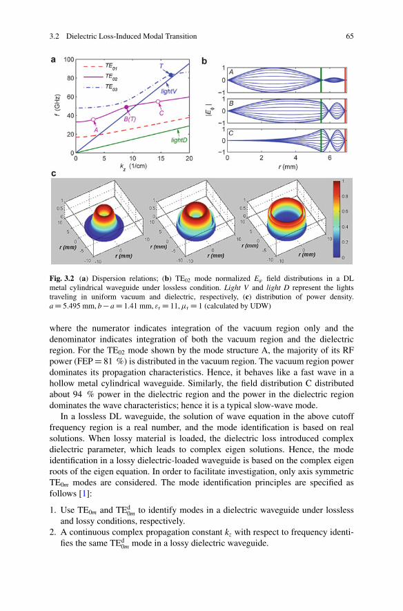
3.2 Dielectric Loss-Induced Modal Transition 65
Fig. 3.2 (a) Dispersion relations; (b) TE02 mode normalized E' field distributions in a DLmetal cylindrical waveguide under lossless condition. Light V and light D represent the lightstraveling in uniform vacuum and dielectric, respectively, (c) distribution of power density.a D 5.495 mm, b � a D 1.41 mm, "r D 11, �r D 1 (calculated by UDW)
where the numerator indicates integration of the vacuum region only and thedenominator indicates integration of both the vacuum region and the dielectricregion. For the TE02 mode shown by the mode structure A, the majority of its RFpower (FEP D 81 %) is distributed in the vacuum region. The vacuum region powerdominates its propagation characteristics. Hence, it behaves like a fast wave in ahollow metal cylindrical waveguide. Similarly, the field distribution C distributedabout 94 % power in the dielectric region and the power in the dielectric regiondominates the wave characteristics; hence it is a typical slow-wave mode.
In a lossless DL waveguide, the solution of wave equation in the above cutofffrequency region is a real number, and the mode identification is based on realsolutions. When lossy material is loaded, the dielectric loss introduced complexdielectric parameter, which leads to complex eigen solutions. Hence, the modeidentification in a lossy dielectric-loaded waveguide is based on the complex eigenroots of the eigen equation. In order to facilitate investigation, only axis symmetricTE0m modes are considered. The mode identification principles are specified asfollows [1]:
1. Use TE0m and TEd0m to identify modes in a dielectric waveguide under lossless
and lossy conditions, respectively.2. A continuous complex propagation constant kz with respect to frequency identi-
fies the same TEd0m mode in a lossy dielectric waveguide.
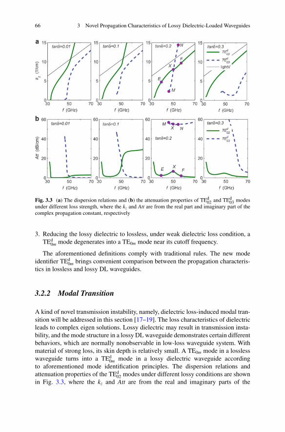
66 3 Novel Propagation Characteristics of Lossy Dielectric-Loaded Waveguides
Fig. 3.3 (a) The dispersion relations and (b) the attenuation properties of TEd02 and TEd
03 modesunder different loss strength, where the kz and Att are from the real part and imaginary part of thecomplex propagation constant, respectively
3. Reducing the lossy dielectric to lossless, under weak dielectric loss condition, aTEd
0m mode degenerates into a TE0m mode near its cutoff frequency.
The aforementioned definitions comply with traditional rules. The new modeidentifier TEd
0m brings convenient comparison between the propagation characteris-tics in lossless and lossy DL waveguides.
3.2.2 Modal Transition
A kind of novel transmission instability, namely, dielectric loss-induced modal tran-sition will be addressed in this section [17–19]. The loss characteristics of dielectricleads to complex eigen solutions. Lossy dielectric may result in transmission insta-bility, and the mode structure in a lossy DL waveguide demonstrates certain differentbehaviors, which are normally nonobservable in low-loss waveguide system. Withmaterial of strong loss, its skin depth is relatively small. A TE0m mode in a losslesswaveguide turns into a TEd
0m mode in a lossy dielectric waveguide accordingto aforementioned mode identification principles. The dispersion relations andattenuation properties of the TEd
02 modes under different lossy conditions are shownin Fig. 3.3, where the kz and Att are from the real and imaginary parts of the
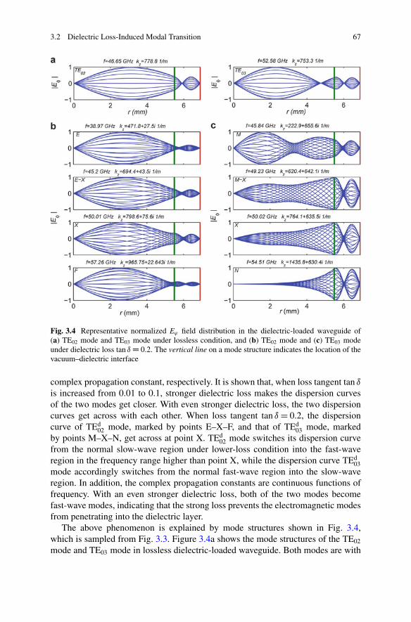
3.2 Dielectric Loss-Induced Modal Transition 67
Fig. 3.4 Representative normalized E' field distribution in the dielectric-loaded waveguide of(a) TE02 mode and TE03 mode under lossless condition, and (b) TE02 mode and (c) TE03 modeunder dielectric loss tan ı D 0.2. The vertical line on a mode structure indicates the location of thevacuum–dielectric interface
complex propagation constant, respectively. It is shown that, when loss tangent tan ı
is increased from 0.01 to 0.1, stronger dielectric loss makes the dispersion curvesof the two modes get closer. With even stronger dielectric loss, the two dispersioncurves get across with each other. When loss tangent tan ı D 0.2, the dispersioncurve of TEd
02 mode, marked by points E–X–F, and that of TEd03 mode, marked
by points M–X–N, get across at point X. TEd02 mode switches its dispersion curve
from the normal slow-wave region under lower-loss condition into the fast-waveregion in the frequency range higher than point X, while the dispersion curve TEd
03mode accordingly switches from the normal fast-wave region into the slow-waveregion. In addition, the complex propagation constants are continuous functions offrequency. With an even stronger dielectric loss, both of the two modes becomefast-wave modes, indicating that the strong loss prevents the electromagnetic modesfrom penetrating into the dielectric layer.
The above phenomenon is explained by mode structures shown in Fig. 3.4,which is sampled from Fig. 3.3. Figure 3.4a shows the mode structures of the TE02
mode and TE03 mode in lossless dielectric-loaded waveguide. Both modes are with
68 3 Novel Propagation Characteristics of Lossy Dielectric-Loaded Waveguides
fixed radial standing-wave points and are quite consistent with our experientialunderstanding. When a lossy dielectric of the same size is loaded, somethinganomalous happens. Figure 3.4 shows that, in the fast-wave region, both the modestructure E of TEd
02 mode and the mode structure M of TEd03 mode are quite similar
to that under a lossless condition. The dispersion curves of both TEd02 and TEd
03modes cross at point X on the dispersion map of Fig. 3.3, where each mode presentsa transitional mode structure. But the mode structures of TEd
02 and TEd03 at the point
X are quite different from each other. In the frequency range above the crossingpoint X, the mode structure F of TEd
02 mode presents a TE03-like mode, whereas themode structure N of TEd
03 mode presents a TE02-like mode. Considering togetherwith Figs. 3.3 and 3.4, each of TEd
02 mode and TEd03 mode under the condition of
dielectric loss tan ı D 0.2 experiences continuous evolution of mode structure alongthe dispersion curves.
The dielectric loss results in transmission instability, namely, modal transitionbetween a pair of modes [17–19]. Further analysis will be shown from two aspects.On one hand, the mode structures in lossy dielectric-loaded waveguide can be quali-tatively classified into weak lossy mode and strong lossy mode. The former is similarto the field structure of TE02 in fast-wave region, where the major power of the modeis focused in vacuum region. A mode with weak lossy field structure exists as a fast-wave mode. For a strong lossy mode, major power of the mode is focused inside thelossy dielectric layer, and the mode behaves as a slow-wave mode. Here, we definethe concept of modal transition in a lossy DL waveguide that a pair of independentmodes in a lossy DL waveguide transfers between each other due to material chang-ing. For each mode, study demonstrates the frequency-dependent field structuresand attenuation strength. Although the dispersion curves of such a pair of modescross at certain frequency, they still belong to different solutions of the eigen modesand demonstrate quite distinctive transverse field structures. The difference in prop-agation attenuation reveals the inherent mode-selecting ability of the DL waveguide.For example, in Figs. 3.3 and 3.4, the attenuation property indicates that whentan ı D 0.2, transmission attenuation of TEd
02 mode keeps lower than 6.5 dB/cmbetween 40 and 60 GHz, while that of TEd
03 mode keeps higher than 55 dB/cm.It is obvious that the TEd
02 mode survives, and the TEd03 mode will be absorbed and
eliminated after propagating through a short section of such lossy DL waveguide.The characteristics of transverse field structures in a lossy DL waveguide will be
further investigated. For a given mode at a specified frequency, it shows a differenttransverse mode structure under loss condition compared to lossless condition.Comparing Fig. 3.2 with Fig. 3.4, it reveals that the transverse field structure intraditional lossless waveguide exists in the form of pure standing wave along theradial direction, and the field demonstrates fixed standing-wave points. While, inlossy-dielectric waveguide, the transverse field structure exists in form of partialstanding wave. Figure 3.5 shows the variation of TEd
02 in a half period. Thetransverse partial standing wave distribution demonstrates that there is a radialpower flowing along the radial direction from the vacuum region into the lossydielectric layer. Such unstable field structure could be explained as follows. Ina waveguide system, the wave vector can be written as Ek D Ekz C Ek?, where
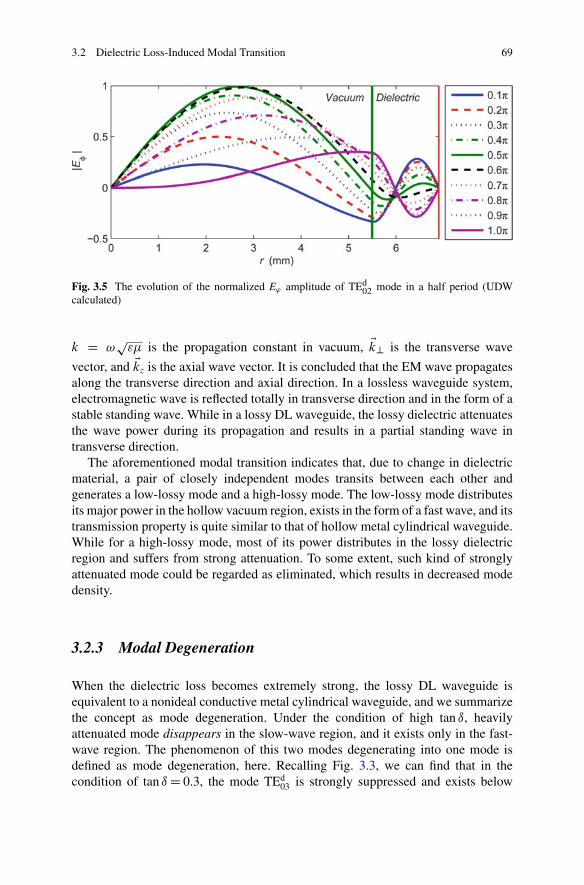
3.2 Dielectric Loss-Induced Modal Transition 69
Fig. 3.5 The evolution of the normalized E' amplitude of TEd02 mode in a half period (UDW
calculated)
k D !p
"� is the propagation constant in vacuum, Ek? is the transverse wave
vector, and Ekz is the axial wave vector. It is concluded that the EM wave propagatesalong the transverse direction and axial direction. In a lossless waveguide system,electromagnetic wave is reflected totally in transverse direction and in the form of astable standing wave. While in a lossy DL waveguide, the lossy dielectric attenuatesthe wave power during its propagation and results in a partial standing wave intransverse direction.
The aforementioned modal transition indicates that, due to change in dielectricmaterial, a pair of closely independent modes transits between each other andgenerates a low-lossy mode and a high-lossy mode. The low-lossy mode distributesits major power in the hollow vacuum region, exists in the form of a fast wave, and itstransmission property is quite similar to that of hollow metal cylindrical waveguide.While for a high-lossy mode, most of its power distributes in the lossy dielectricregion and suffers from strong attenuation. To some extent, such kind of stronglyattenuated mode could be regarded as eliminated, which results in decreased modedensity.
3.2.3 Modal Degeneration
When the dielectric loss becomes extremely strong, the lossy DL waveguide isequivalent to a nonideal conductive metal cylindrical waveguide, and we summarizethe concept as mode degeneration. Under the condition of high tan ı, heavilyattenuated mode disappears in the slow-wave region, and it exists only in the fast-wave region. The phenomenon of this two modes degenerating into one mode isdefined as mode degeneration, here. Recalling Fig. 3.3, we can find that in thecondition of tan ı D 0.3, the mode TEd
03 is strongly suppressed and exists below
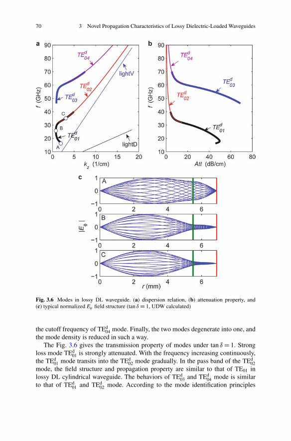
70 3 Novel Propagation Characteristics of Lossy Dielectric-Loaded Waveguides
Fig. 3.6 Modes in lossy DL waveguide. (a) dispersion relation, (b) attenuation property, and(c) typical normalized E' field structure (tan ı D 1, UDW calculated)
the cutoff frequency of TEd04 mode. Finally, the two modes degenerate into one, and
the mode density is reduced in such a way.The Fig. 3.6 gives the transmission property of modes under tan ı D 1. Strong
loss mode TEd01 is strongly attenuated. With the frequency increasing continuously,
the TEd01 mode transits into the TEd
02 mode gradually. In the pass band of the TEd02
mode, the field structure and propagation property are similar to that of TE01 inlossy DL cylindrical waveguide. The behaviors of TEd
03 and TEd04 mode is similar
to that of TEd01 and TEd
02 mode. According to the mode identification principles
3.2 Dielectric Loss-Induced Modal Transition 71
based on continuous eigen roots, the TEd01 mode and TEd
02 mode under such strongdielectric loss condition degenerate into a single mode. Further calculation indicatesthat, in the high-frequency region, the dispersion curve of TEd
02 superimposes that ofthe equivalent empty waveguide TE01 mode. Similar behavior also happens betweenTEd
04 and empty waveguide TE02 mode. Figure 3.6c gives the variation along disper-sion curves (A-B-C) of TEd
01- TEd02. In a DL waveguide with strong lossy material,
the EM wave cannot effectively penetrate into dielectric layer, and a majority ofenergy is confined in the hollow vacuum region. From the above description, it isconcluded that the strong attenuation property of dielectric is helpful to preventenergy from penetrating into the dielectric layer. With strong dielectric loss, lossyDL waveguide can be approximated by a hollow metal cylindrical waveguide withimperfect conducting sidewall. The radius of hollow cylindrical waveguide is equalto the radius of vacuum region of lossy DL waveguide [18, 19].
3.2.4 Modal Selection
Following study uses parameters given in Ref. [13]. The radius of vacuum regionin metal cylindrical waveguide is a D 5.945 mm, the main content of dielectricis AlN (80 %) and SiC (20 %), the dielectric constant is "r D 11 � j 2.2, and theoperation frequency is 35 GHz. Analysis will be concentrated on circular polarizedTEd
0m mode. Figure 3.7a shows the variation of propagation constant and attenuationproperty of TEd
01 and TEd02 in lossy dielectric waveguide relative to thickness of
dielectric. The calculation result has a good agreement with that in Ref. [13].Figure 3.7b shows the field structure of four typical loading cases. In the case ofA, the main energy of TEd
01 is concentrated in lossy dielectric. This high-lossy fieldstructure is similar to that of TE01 in lossless DL waveguide. In the case of B, C,and D, TEd
02 transfers continuously from TE02-like field structure to TE03-like fieldstructure. B and D are typical low-lossy mode. Attenuation of the conditions C andE become stronger as enhancement of the relative power in dielectric. The TEd
02mode changes gradually from the field structure B to D, and the attenuation propertyincreases and decreases periodically. During this process, propagate constant hasno jump or singular point, which demonstrates the mode transition in lossy DLwaveguide from another aspect.
The phenomenon of the modal transition is common in a lossy DL waveguide.Figure 3.8 shows the characteristics of the first seven circular electric field modesin lossy DL waveguide. The regions where modal transitions happen are marked bycircles A, B, C, and D.
The major powers of TEd02 and TEd
04 modes are in the vacuum region and exhibitquite similar to that of the TE01 and TE02 in lossless metal waveguide, respectively,which also leads to the similarity of the dispersion curves between TEd
02 and TE01
mode and that between TEd04 and TE02. From Fig. 3.8c, usually, minority power of
TEd01, TEd
03, and TEd05 modes distributes in vacuum, and accordingly major power
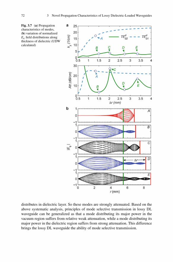
72 3 Novel Propagation Characteristics of Lossy Dielectric-Loaded Waveguides
Fig. 3.7 (a) Propagationcharacteristics of modes,(b) variation of normalizedE' field distributions alongthickness of dielectric (UDWcalculated)
distributes in dielectric layer. So these modes are strongly attenuated. Based on theabove systematic analysis, principles of mode selective transmission in lossy DLwaveguide can be generalized as that a mode distributing its major power in thevacuum region suffers from relative weak attenuation, while a mode distributing itsmajor power in the dielectric region suffers from strong attenuation. This differencebrings the lossy DL waveguide the ability of mode selective transmission.
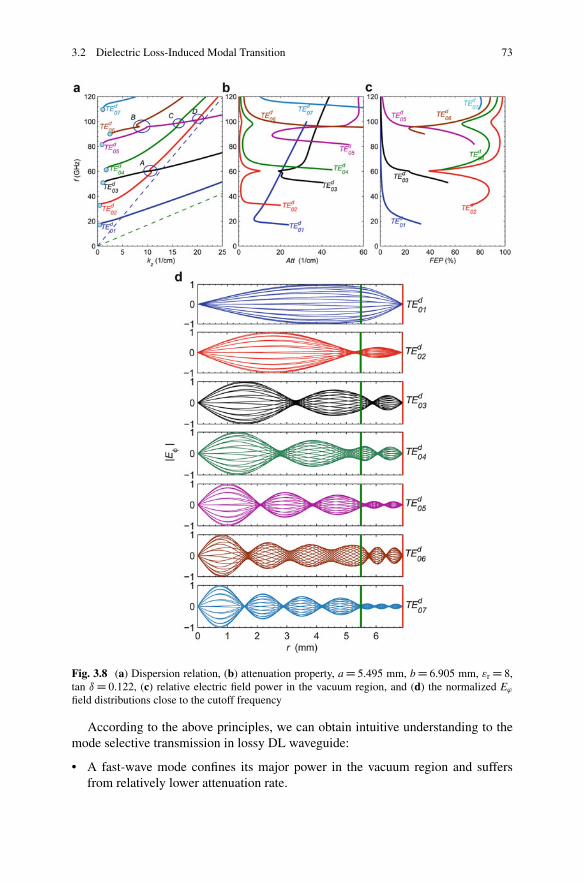
3.2 Dielectric Loss-Induced Modal Transition 73
Fig. 3.8 (a) Dispersion relation, (b) attenuation property, a D 5.495 mm, b D 6.905 mm, "r D 8,tan ı D 0.122, (c) relative electric field power in the vacuum region, and (d) the normalized E'
field distributions close to the cutoff frequency
According to the above principles, we can obtain intuitive understanding to themode selective transmission in lossy DL waveguide:
• A fast-wave mode confines its major power in the vacuum region and suffersfrom relatively lower attenuation rate.
74 3 Novel Propagation Characteristics of Lossy Dielectric-Loaded Waveguides
• A slow-wave mode distributes considerable power in the dielectric region andsuffers from relatively higher attenuation rate.
• For a mode with its power mainly restrained in vacuum, its dispersion curve issimilar to that of a fast-wave mode in simple metal cylindrical waveguide andnormally propagates with low attenuation rate.
• For a mode with its power mainly restrained in dielectric, its dispersion curve issimilar to that of a slow-wave mode in lossless dielectric waveguide and normallypropagates with strong attenuation.
According to the analysis of mode selective property, intuitive estimationabout transverse field structure and its attenuation property will be acquired bydispersion relation of lossy DL waveguide. These characteristics of mode selectionof distributed lossy structure make it possible to apply in design of gyro-TWTamplifier operating on high-order modes.
In this section, the instability of modal transition and degeneration in a lossyDL waveguide are investigated. In a lossy DL waveguide, the transverse fieldstructure behaves as a partial standing wave. When the attenuation property ofdielectric material is higher than some specific values, modal transition occursbetween two independent nearby modes. One is with lower attenuation rate andthe other is with strong attenuation rate. The strong loss of dielectric is helpfulto prevent energy from going into dielectric. With the strong lossy dielectric, DLwaveguide can be equivalent to hollow waveguide with imperfect conducting walls.The cross section of lossless dielectric-loaded metal waveguide is bigger than that ofcorresponding metal waveguide. Hence, mode density of lossless dielectric-loadedmetal waveguide is higher than that of metal waveguide. During the degenerationprocess of dielectric waveguide to imperfect metal waveguide, modal transitionand modal degeneration reduce the mode density. Intuitive understanding of modeselection are summarized as a weak attenuated mode is restrained in the vacuumregion and exists as a fast-wave mode, while a strong attenuated mode normallydistributes a considerable power in the dielectric region and behaves as a slow-wavemode.
3.3 Periodic DL Waveguide with Suppressed Propertyof Periodicity
In practical application of a gyro-TWT, in order to adjust the waveguide transmis-sion property, as well as avoiding dielectric charging, lossy DL waveguide withperiodical structure is adopted as the interactive circuit, as shown in Fig. 3.1b[13–19]. In this section, the influence from lossy dielectric property to the trans-mission characteristic of periodic DL waveguide will be investigated. The specifieddimensions of dielectric structure for Ka-band gyro-TWT application are innerdiameter a D 5.495 mm, thickness of dielectric b � a D 1.7 mm, "r D 7.11 � 1.1 j,�r D 1.
3.3 Periodic DL Waveguide with Suppressed Property of Periodicity 75
3.3.1 Eigenvalue and Mode Identification
For the gyro-TWT application, in order to avoid dielectric charging, lossy dielectricalso periodically loaded in the waveguide wall. The periodic DL waveguide providesadditional freedom of adjusting the transmission property than a uniform DL waveg-uide [13–15]. As shown in Fig. 3.1b, because of high-order Bloch components,standing-wave harmonics and matching boundary conditions are introduced byperiodic structure, and the eigen equation of such a system becomes the determinantof a large sparse matrix. The theorem of periodic system is already reviewedin Chap. 2. In the following study, the mode identification of periodically lossyDL waveguide is also based on the continuous eigenvalues of eigen equation.A more intuitive method for mode identification of the periodic DL waveguidewill be introduced. The corresponding relations of modes in periodically lossy DLwaveguide, uniformly lossy DL waveguide, and smooth cylindrical waveguide willbe given in the following discussions.
3.3.2 Influence of Dielectric Slot Ratio
In Fig. 3.1b, the inner radius of waveguide is a D 5.495 mm, the thickness ofdielectric b � a D 1.7 mm, the permittivity "r D 7.11 � 1.1 j, and the permeability�r D 1. The influence from the slot ratio I/L of the dielectric slot on the operatingTE01 mode is considered first, as shown in Fig. 3.9. The wave numbers of theforward-wave and backward-wave components vary symmetrically besides theBrillouin Edge. Generally speaking, increasing the slot ratio I/L of the dielectric slotmakes the operating TE01 mode in the periodic DL waveguide evolve from the TE01
mode distribution in a hollow waveguide toward the TEd02 mode distribution in a
uniform DL waveguide at 35 GHz. Figure 3.9 also comparatively reveals that, underfull dielectric loading condition I/L D 1, there is some difference to the solutionsbetween the UDW [18, 19] and PDW [15, 17]. It is caused by the difference in thephysical models of the codes. The UDW solves the eigen modes of a uniform DLwaveguide, while the PDW solves the eigen modes of a periodic structure. Evenunder full dielectric loading, I/L D 1, the physical model in PDW still preserves aninfinite thin metal interface between a pair of nearby periods. Around the region ofI/L � 0.2, due to a resonant mode in the dielectric slot, both the propagation constantand attenuation rate are sensitive to the slot ratio I/L. The vivid field distributions inFig. 3.10 under different slot ratio conditions demonstrate the resonant and travelingcharacteristics of the operating mode in a periodic system. Taking both Figs. 3.9and 3.10a consideration, there is a sharply resonant enhancement in attenuationinduced by fundamental resonant mode in the dielectric region under the low slotfraction I/L � 0.2. Increasing the slot ratio from this point makes it hard to load thefundamental resonant mode and weakens the field strength in the slot. As a result,
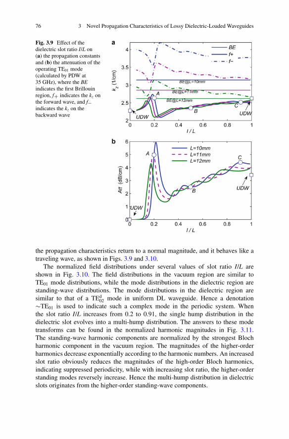
76 3 Novel Propagation Characteristics of Lossy Dielectric-Loaded Waveguides
Fig. 3.9 Effect of thedielectric slot ratio I/L on(a) the propagation constantsand (b) the attenuation of theoperating TE01 mode(calculated by PDW at35 GHz), where the BEindicates the first Brillouinregion, fC indicates the kz onthe forward wave, and f�indicates the kz on thebackward wave
the propagation characteristics return to a normal magnitude, and it behaves like atraveling wave, as shown in Figs. 3.9 and 3.10.
The normalized field distributions under several values of slot ratio I/L areshown in Fig. 3.10. The field distributions in the vacuum region are similar toTE01 mode distributions, while the mode distributions in the dielectric region arestanding-wave distributions. The mode distributions in the dielectric region aresimilar to that of a TEd
02 mode in uniform DL waveguide. Hence a denotation�TE01 is used to indicate such a complex mode in the periodic system. Whenthe slot ratio I/L increases from 0.2 to 0.91, the single hump distribution in thedielectric slot evolves into a multi-hump distribution. The answers to these modetransforms can be found in the normalized harmonic magnitudes in Fig. 3.11.The standing-wave harmonic components are normalized by the strongest Blochharmonic component in the vacuum region. The magnitudes of the higher-orderharmonics decrease exponentially according to the harmonic numbers. An increasedslot ratio obviously reduces the magnitudes of the high-order Bloch harmonics,indicating suppressed periodicity, while with increasing slot ratio, the higher-orderstanding modes reversely increase. Hence the multi-hump distribution in dielectricslots originates from the higher-order standing-wave components.
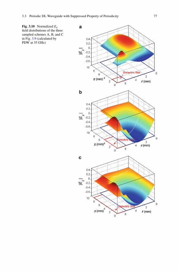
3.3 Periodic DL Waveguide with Suppressed Property of Periodicity 77
Fig. 3.10 Normalized E'
field distributions of the threesampled schemes A, B, and Cin Fig. 3.9 (calculated byPDW at 35 GHz)
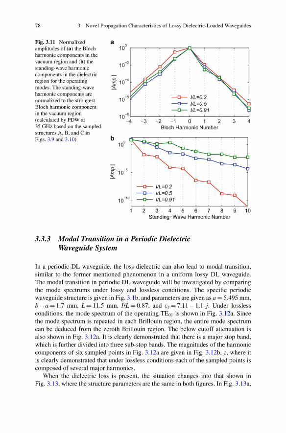
78 3 Novel Propagation Characteristics of Lossy Dielectric-Loaded Waveguides
Fig. 3.11 Normalizedamplitudes of (a) the Blochharmonic components in thevacuum region and (b) thestanding-wave harmoniccomponents in the dielectricregion for the operatingmodes. The standing-waveharmonic components arenormalized to the strongestBloch harmonic componentin the vacuum region(calculated by PDW at35 GHz based on the sampledstructures A, B, and C inFigs. 3.9 and 3.10)
3.3.3 Modal Transition in a Periodic DielectricWaveguide System
In a periodic DL waveguide, the loss dielectric can also lead to modal transition,similar to the former mentioned phenomenon in a uniform lossy DL waveguide.The modal transition in periodic DL waveguide will be investigated by comparingthe mode spectrums under lossy and lossless conditions. The specific periodicwaveguide structure is given in Fig. 3.1b, and parameters are given as a D 5.495 mm,b � a D 1.7 mm, L D 11.5 mm, I/L D 0.87, and "r D 7.11 � 1.1 j. Under losslessconditions, the mode spectrum of the operating TE01 is shown in Fig. 3.12a. Sincethe mode spectrum is repeated in each Brillouin region, the entire mode spectrumcan be deduced from the zeroth Brillouin region. The below cutoff attenuation isalso shown in Fig. 3.12a. It is clearly demonstrated that there is a major stop band,which is further divided into three sub-stop bands. The magnitudes of the harmoniccomponents of six sampled points in Fig. 3.12a are given in Fig. 3.12b, c, where itis clearly demonstrated that under lossless conditions each of the sampled points iscomposed of several major harmonics.
When the dielectric loss is present, the situation changes into that shown inFig. 3.13, where the structure parameters are the same in both figures. In Fig. 3.13a,
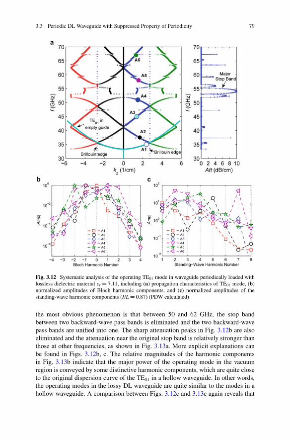
3.3 Periodic DL Waveguide with Suppressed Property of Periodicity 79
Fig. 3.12 Systematic analysis of the operating TE01 mode in waveguide periodically loaded withlossless dielectric material "r D 7.11, including (a) propagation characteristics of TE01 mode, (b)normalized amplitudes of Bloch harmonic components, and (c) normalized amplitudes of thestanding-wave harmonic components (I/L D 0.87) (PDW calculated)
the most obvious phenomenon is that between 50 and 62 GHz, the stop bandbetween two backward-wave pass bands is eliminated and the two backward-wavepass bands are unified into one. The sharp attenuation peaks in Fig. 3.12b are alsoeliminated and the attenuation near the original stop band is relatively stronger thanthose at other frequencies, as shown in Fig. 3.13a. More explicit explanations canbe found in Figs. 3.12b, c. The relative magnitudes of the harmonic componentsin Fig. 3.13b indicate that the major power of the operating mode in the vacuumregion is conveyed by some distinctive harmonic components, which are quite closeto the original dispersion curve of the TE01 in a hollow waveguide. In other words,the operating modes in the lossy DL waveguide are quite similar to the modes in ahollow waveguide. A comparison between Figs. 3.12c and 3.13c again reveals that
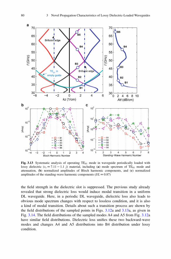
80 3 Novel Propagation Characteristics of Lossy Dielectric-Loaded Waveguides
Fig. 3.13 Systematic analysis of operating TE01 mode in waveguide periodically loaded withlossy dielectric ("r D 7.11 � 1.1 j) material, including (a) mode spectrum of TE01 mode andattenuation, (b) normalized amplitudes of Bloch harmonic components, and (c) normalizedamplitudes of the standing-wave harmonic components (I/L D 0.87)
the field strength in the dielectric slot is suppressed. The previous study alreadyrevealed that strong dielectric loss would induce modal transition in a uniformDL waveguide. Here, in a periodic DL waveguide, dielectric loss also leads toobvious mode spectrum changes with respect to lossless condition, and it is alsoa kind of modal transition. Details about such a transition process are shown bythe field distributions of the sampled points in Figs. 3.12a and 3.13a, as given inFig. 3.14. The field distributions of the sampled modes A4 and A5 from Fig. 3.12ahave similar field distributions. Dielectric loss unifies these two backward-wavemodes and changes A4 and A5 distributions into B4 distribution under lossycondition.
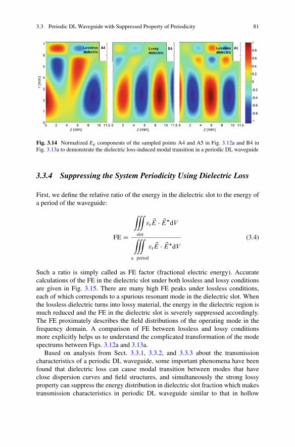
3.3 Periodic DL Waveguide with Suppressed Property of Periodicity 81
Fig. 3.14 Normalized E' components of the sampled points A4 and A5 in Fig. 3.12a and B4 inFig. 3.13a to demonstrate the dielectric loss-induced modal transition in a periodic DL waveguide
3.3.4 Suppressing the System Periodicity Using Dielectric Loss
First, we define the relative ratio of the energy in the dielectric slot to the energy ofa period of the waveguide:
FE D
•
slot
"r EE � EE�dV
•
a period
"r EE � EE�dV
(3.4)
Such a ratio is simply called as FE factor (fractional electric energy). Accuratecalculations of the FE in the dielectric slot under both lossless and lossy conditionsare given in Fig. 3.15. There are many high FE peaks under lossless conditions,each of which corresponds to a spurious resonant mode in the dielectric slot. Whenthe lossless dielectric turns into lossy material, the energy in the dielectric region ismuch reduced and the FE in the dielectric slot is severely suppressed accordingly.The FE proximately describes the field distributions of the operating mode in thefrequency domain. A comparison of FE between lossless and lossy conditionsmore explicitly helps us to understand the complicated transformation of the modespectrums between Figs. 3.12a and 3.13a.
Based on analysis from Sect. 3.3.1, 3.3.2, and 3.3.3 about the transmissioncharacteristics of a periodic DL waveguide, some important phenomena have beenfound that dielectric loss can cause modal transition between modes that haveclose dispersion curves and field structures, and simultaneously the strong lossyproperty can suppress the energy distribution in dielectric slot fraction which makestransmission characteristics in periodic DL waveguide similar to that in hollow
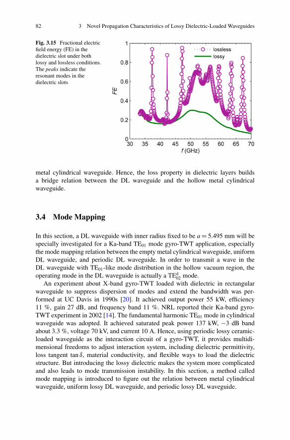
82 3 Novel Propagation Characteristics of Lossy Dielectric-Loaded Waveguides
Fig. 3.15 Fractional electricfield energy (FE) in thedielectric slot under bothlossy and lossless conditions.The peaks indicate theresonant modes in thedielectric slots
metal cylindrical waveguide. Hence, the loss property in dielectric layers buildsa bridge relation between the DL waveguide and the hollow metal cylindricalwaveguide.
3.4 Mode Mapping
In this section, a DL waveguide with inner radius fixed to be a D 5.495 mm will bespecially investigated for a Ka-band TE01 mode gyro-TWT application, especiallythe mode mapping relation between the empty metal cylindrical waveguide, uniformDL waveguide, and periodic DL waveguide. In order to transmit a wave in theDL waveguide with TE01-like mode distribution in the hollow vacuum region, theoperating mode in the DL waveguide is actually a TEd
02 mode.An experiment about X-band gyro-TWT loaded with dielectric in rectangular
waveguide to suppress dispersion of modes and extend the bandwidth was per-formed at UC Davis in 1990s [20]. It achieved output power 55 kW, efficiency11 %, gain 27 dB, and frequency band 11 %. NRL reported their Ka-band gyro-TWT experiment in 2002 [14]. The fundamental harmonic TE01 mode in cylindricalwaveguide was adopted. It achieved saturated peak power 137 kW, �3 dB bandabout 3.3 %, voltage 70 kV, and current 10 A. Hence, using periodic lossy ceramic-loaded waveguide as the interaction circuit of a gyro-TWT, it provides multidi-mensional freedoms to adjust interaction system, including dielectric permittivity,loss tangent tan ı, material conductivity, and flexible ways to load the dielectricstructure. But introducing the lossy dielectric makes the system more complicatedand also leads to mode transmission instability. In this section, a method calledmode mapping is introduced to figure out the relation between metal cylindricalwaveguide, uniform lossy DL waveguide, and periodic lossy DL waveguide.
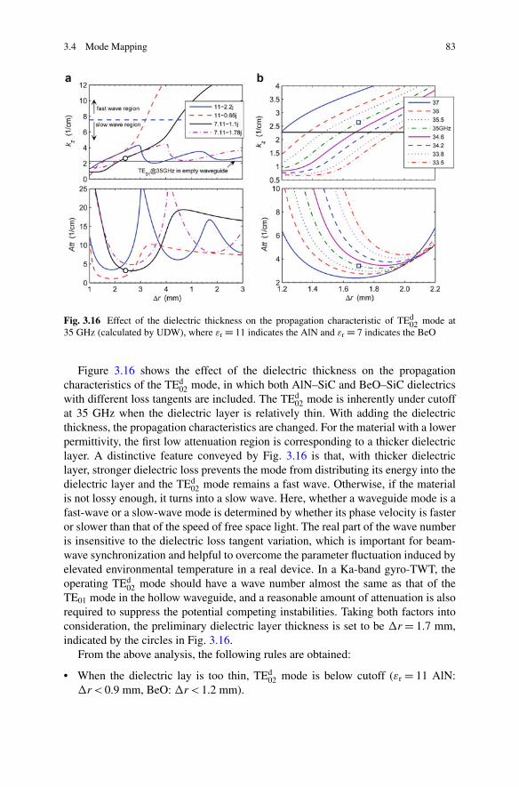
3.4 Mode Mapping 83
Fig. 3.16 Effect of the dielectric thickness on the propagation characteristic of TEd02 mode at
35 GHz (calculated by UDW), where "r D 11 indicates the AlN and "r D 7 indicates the BeO
Figure 3.16 shows the effect of the dielectric thickness on the propagationcharacteristics of the TEd
02 mode, in which both AlN–SiC and BeO–SiC dielectricswith different loss tangents are included. The TEd
02 mode is inherently under cutoffat 35 GHz when the dielectric layer is relatively thin. With adding the dielectricthickness, the propagation characteristics are changed. For the material with a lowerpermittivity, the first low attenuation region is corresponding to a thicker dielectriclayer. A distinctive feature conveyed by Fig. 3.16 is that, with thicker dielectriclayer, stronger dielectric loss prevents the mode from distributing its energy into thedielectric layer and the TEd
02 mode remains a fast wave. Otherwise, if the materialis not lossy enough, it turns into a slow wave. Here, whether a waveguide mode is afast-wave or a slow-wave mode is determined by whether its phase velocity is fasteror slower than that of the speed of free space light. The real part of the wave numberis insensitive to the dielectric loss tangent variation, which is important for beam-wave synchronization and helpful to overcome the parameter fluctuation induced byelevated environmental temperature in a real device. In a Ka-band gyro-TWT, theoperating TEd
02 mode should have a wave number almost the same as that of theTE01 mode in the hollow waveguide, and a reasonable amount of attenuation is alsorequired to suppress the potential competing instabilities. Taking both factors intoconsideration, the preliminary dielectric layer thickness is set to be �r D 1.7 mm,indicated by the circles in Fig. 3.16.
From the above analysis, the following rules are obtained:
• When the dielectric lay is too thin, TEd02 mode is below cutoff ("r D 11 AlN:
�r < 0.9 mm, BeO: �r < 1.2 mm).
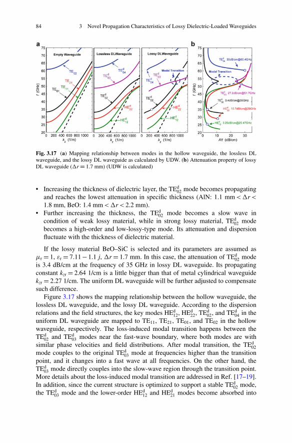
84 3 Novel Propagation Characteristics of Lossy Dielectric-Loaded Waveguides
Fig. 3.17 (a) Mapping relationship between modes in the hollow waveguide, the lossless DLwaveguide, and the lossy DL waveguide as calculated by UDW. (b) Attenuation property of lossyDL waveguide (�r D 1.7 mm) (UDW is calculated)
• Increasing the thickness of dielectric layer, the TEd02 mode becomes propagating
and reaches the lowest attenuation in specific thickness (AlN: 1.1 mm < �r <
1.8 mm, BeO: 1.4 mm < �r < 2.2 mm).• Further increasing the thickness, the TEd
02 mode becomes a slow wave incondition of weak lossy material, while in strong lossy material, TEd
02 modebecomes a high-order and low-lossy-type mode. Its attenuation and dispersionfluctuate with the thickness of dielectric material.
If the lossy material BeO–SiC is selected and its parameters are assumed as�r D 1, "r D 7.11 � 1.1 j, �r D 1.7 mm. In this case, the attenuation of TEd
02 modeis 3.4 dB/cm at the frequency of 35 GHz in lossy DL waveguide. Its propagatingconstant kzr D 2.64 1/cm is a little bigger than that of metal cylindrical waveguidekzr D 2.27 1/cm. The uniform DL waveguide will be further adjusted to compensatesuch difference.
Figure 3.17 shows the mapping relationship between the hollow waveguide, thelossless DL waveguide, and the lossy DL waveguide. According to the dispersionrelations and the field structures, the key modes HEd
12, HEd22, TEd
02, and TEd04 in the
uniform DL waveguide are mapped to TE11, TE21, TE01, and TE02 in the hollowwaveguide, respectively. The loss-induced modal transition happens between theTEd
02 and TEd03 modes near the fast-wave boundary, where both modes are with
similar phase velocities and field distributions. After modal transition, the TEd02
mode couples to the original TEd03 mode at frequencies higher than the transition
point, and it changes into a fast wave at all frequencies. On the other hand, theTEd
03 mode directly couples into the slow-wave region through the transition point.More details about the loss-induced modal transition are addressed in Ref. [17–19].In addition, since the current structure is optimized to support a stable TEd
02 mode,the TEd
03 mode and the lower-order HEd12 and HEd
21 modes become absorbed into
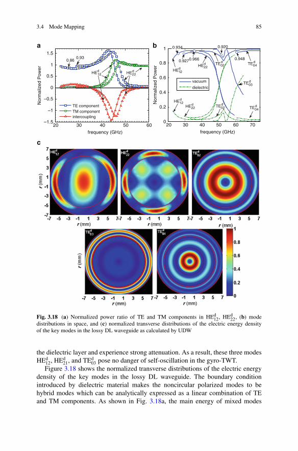
3.4 Mode Mapping 85
20 30 40 50 60–1.5
–1
–0.5
0
0.5
1
1.5
a
c
b
frequency (GHz)
Nor
mal
ized
Pow
er
TE componentTM componentintercoupling
HE2d2
HE2d2
0.860.93
HEd12
20 30 40 50 60 700
0.2
0.4
0.6
0.8
1
frequency (GHz)
Nor
mal
ized
Pow
er
vacuum
dielectric
0.9270.966 0.948
0.934 0.920
HE1d2
TE0d2 TE0
d4
TE0d3
TE0d4
TE0d2HE2
d2
HE1d2
Fig. 3.18 (a) Normalized power ratio of TE and TM components in HEd12, HEd
22, (b) modedistributions in space, and (c) normalized transverse distributions of the electric energy densityof the key modes in the lossy DL waveguide as calculated by UDW
the dielectric layer and experience strong attenuation. As a result, these three modesHEd
12, HEd21, and TEd
03 pose no danger of self-oscillation in the gyro-TWT.Figure 3.18 shows the normalized transverse distributions of the electric energy
density of the key modes in the lossy DL waveguide. The boundary conditionintroduced by dielectric material makes the noncircular polarized modes to behybrid modes which can be analytically expressed as a linear combination of TEand TM components. As shown in Fig. 3.18a, the main energy of mixed modes
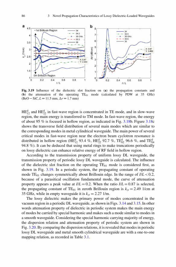
86 3 Novel Propagation Characteristics of Lossy Dielectric-Loaded Waveguides
Fig. 3.19 Influence of the dielectric slot fraction on (a) the propagation constants and(b) the attenuation of the operating TE01 mode (calculated by PDW at 35 GHz)(BeO � SiC, L D 11.5 mm, �r D 1.7 mm)
HEd12 and HEd
22 in fast-wave region is concentrated in TE mode, and in slow-waveregion, the main energy is transferred to TM mode. In fast-wave region, the energyof about 95 % is focused in hollow region, as indicated in Fig. 3.18b. Figure 3.18cshows the transverse field distribution of several main modes which are similar tothe corresponding modes in metal cylindrical waveguide. The main power of severalcritical modes in fast-wave region near the electron beam cyclotron resonance isdistributed in hollow region (HEd
12 93.4 %, HEd22 92.7 %, TEd
02 96.6 %, and TEd04
94.8 %). It can be deduced that using metal rings to make truncations periodicallyon lossy dielectric can enhance relative energy of RF field in hollow region.
According to the transmission property of uniform lossy DL waveguide, thetransmission property of periodic lossy DL waveguide is calculated. The influenceof the dielectric slot fraction on the operating TE01 mode is considered first, asshown in Fig. 3.19. In a periodic system, the propagating constant of operatingmode TE01 changes symmetrically about Brillouin edge. In the range of I/L < 0.2,because of a parasitical oscillation fundamental mode, the curve of attenuationproperty appears a peak value at I/L D 0.2. When the ratio I/L D 0.87 is selected,the propagating constant of TE01 in zeroth Brillouin region is kzr D 2.49 1/cm at35 GHz, while in empty waveguide it is kzr D 2.27 1/m.
The lossy dielectric makes the primary power of modes concentrated in thevacuum region in a periodic DL waveguide, as shown in Figs. 3.14 and 3.15. In otherwords attenuation property of dielectric in periodic system makes the main energyof modes be carried by special harmonic and makes such a mode similar to modes ina smooth waveguide. Considering the special harmonic carrying majority of energy,the dispersion relation and attenuation property of periodic system are shown inFig. 3.20. By comparing the dispersion relations, it is revealed that modes in periodiclossy DL waveguide and metal smooth cylindrical waveguide are with a one-to-onemapping relation, as recorded in Table 3.1.
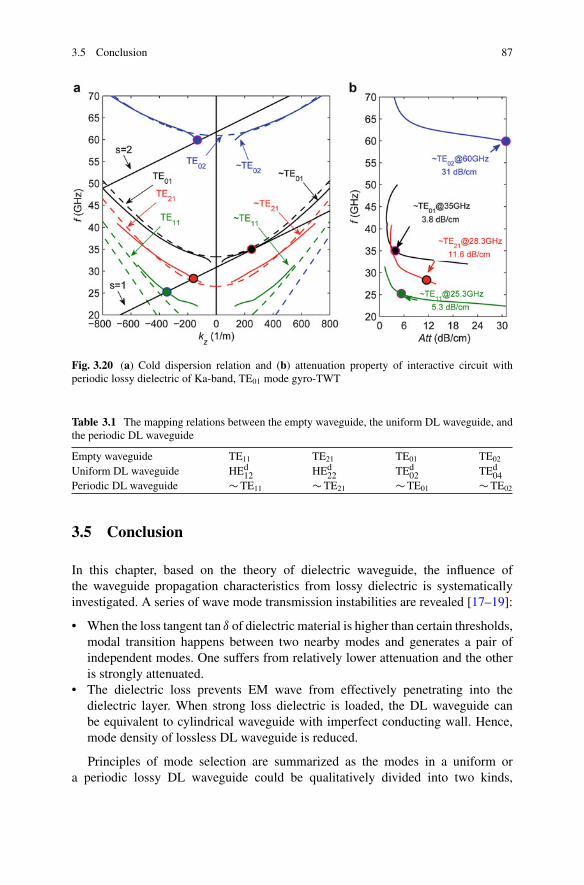
3.5 Conclusion 87
Fig. 3.20 (a) Cold dispersion relation and (b) attenuation property of interactive circuit withperiodic lossy dielectric of Ka-band, TE01 mode gyro-TWT
Table 3.1 The mapping relations between the empty waveguide, the uniform DL waveguide, andthe periodic DL waveguide
Empty waveguide TE11 TE21 TE01 TE02
Uniform DL waveguide HEd12 HEd
22 TEd02 TEd
04Periodic DL waveguide � TE11 � TE21 � TE01 � TE02
3.5 Conclusion
In this chapter, based on the theory of dielectric waveguide, the influence ofthe waveguide propagation characteristics from lossy dielectric is systematicallyinvestigated. A series of wave mode transmission instabilities are revealed [17–19]:
• When the loss tangent tan ı of dielectric material is higher than certain thresholds,modal transition happens between two nearby modes and generates a pair ofindependent modes. One suffers from relatively lower attenuation and the otheris strongly attenuated.
• The dielectric loss prevents EM wave from effectively penetrating into thedielectric layer. When strong loss dielectric is loaded, the DL waveguide canbe equivalent to cylindrical waveguide with imperfect conducting wall. Hence,mode density of lossless DL waveguide is reduced.
Principles of mode selection are summarized as the modes in a uniform ora periodic lossy DL waveguide could be qualitatively divided into two kinds,
88 3 Novel Propagation Characteristics of Lossy Dielectric-Loaded Waveguides
namely, weak attenuated modes and strong attenuated modes. A weak attenuatedmode distributes major power in the hollow region. A strong loss mode distributesconsiderable power in the dielectric layer, and it can be suppressed and eliminatedby dielectric loss. For a periodic DL waveguide with high slot ratio, the strongdielectric loss can prevent wave mode from distributing power in the dielectric slot;hence, the system periodicity would be suppressed by the lossy dielectric. Hence,periodic lossy property in dielectric layers can be regarded as a bridge between a DLwaveguide and a hollow metal cylindrical waveguide. This is very important for theapplication in gyro-TWTs. In designing an interaction circuit for a Ka-band TE01
mode gyro-TWT with periodic lossy DL waveguide, the mode mapping relationbetween the empty waveguide and the DL waveguide provides important evidenceto simplify theoretical investigation of the ECM beam-wave interaction based onthe DL waveguide circuit.
References
1. Lee CS, Lee SW, Chuang SL (1986) Normal modes in an overmoded circular waveguide coatedwith lossy material. IEEE Trans Microw Theory Tech 34:773–785
2. Carlin JW, D’Agostino P (1971) Low-loss modes in dielectric lined waveguide. Bell Syst TechJ 50:1631–1643
3. Miyagi M, Kawakami S (1984) Design theory of dielectric-coated circular metallic waveguidesfor infrared transmission. J Lightwave Technol 2:116–126
4. Yeh P, Yariv A, Marom E (1978) Theory of bragg fiber. Opt Soc Am 68:1196–12015. Ibanescu M, Fink M, Fan S (2000) An all-dielectric coaxial waveguide. Science 289:415–4196. Ibanescu M, Johnson SG, Soljacic M (2003) Analysis of mode structure hollow dielectric
waveguide fibers. Phys Rev E 67:0466087. Miyagi M, Hongo A, Kawakami S (1983) Transmission characteristics of dielectric-coated
metallic waveguide for infrared transmission: slab waveguide model. IEEE Trans MicrowTheory Tech 19:136–145
8. Carlin JW, D’Agostino P (1973) Normal modes in overmoded dielectric-lined circularwaveguide. Bell Syst Tech J 52:453–486
9. Chu KR, Chen HY, Hung CL et al (1998) Ultrahigh gain gyrotron traveling wave amplifier.Phys Rev Lett 81:4760–4763
10. Chu KR, Chen HY, Hung CL et al (1999) Theory and experiment of ultrahigh-gain gyrotrontraveling wave amplifier. IEEE Trans Plasma Sci 27:391–404
11. Chou RC, Lee SW (1988) Modal attenuation in multilayered coated waveguides. IEEE TransMicrow Theory Tech 36:1167–1176
12. Levush B, Blank J, Calame J (1999) Modeling and design of millimeter wave gyroklystron.Phys Plasmas 6:2233–2240
13. Calame JP, Garven M, Danly BG et al (2002) Gyrotron-traveling wave-tube circuits based onlossy ceramics. IEEE Trans Electron Devices 49:1469–1477
14. Garven M, Calame JP, Danly BG et al (2002) A gyrotron-traveling-wave tube amplifierexperiment with a ceramic loaded interaction region. IEEE Trans Plasma Sci 30:885–893
15. Tigelis IG, Vomvoridis JL, Tzima S (1998) High-frequency electromagnetic modes in adielectric-ring loaded beam tunnel. IEEE Trans Plasma Sci 26:922–930
16. Blank M, Danly BG, Levush B (2000) Experimental demonstration of W-band gyroklystronamplifiers with improved gain and efficiency. IEEE Trans Plasma Sci 28:706–711
References 89
17. Du CH, Liu PK (2009) A lossy dielectric-ring loaded waveguide with suppressed periodicityfor gyro-TWTs applications. IEEE Trans Electron Devices 56:2335–2342
18. Du CH, Xue QZ, Liu PK et al (2009) Modal transition and reduction in a lossy dielectric-coatedwaveguide for gyrotron-traveling-wave tube amplifier applications. IEEE Trans ElectronDevices 56:839–845
19. Du CH, Xue QZ, Liu PK (2008) Loss-induced modal transition in a dielectric-coated metalcylindrical waveguide for gyro-traveling-wave-tube applications. IEEE Electron Device Lett29:1256–1258
20. Leou KC, McDermott DB, Luhmann NC (1996) Large-signal characteristics of a wide-banddielectric-loaded gyro-TWT amplifier. IEEE Trans Plasma Sci 24:718–726
Chapter 4Instability Competition in an Ultrahigh GainGyro-TWT Amplifier
Abstract In a gyrotron traveling-wave tube amplifier (gyro-TWT) circuit, one ofthe cyclotron harmonic couples with an eigen wave mode. Such a beam-wavecoupling forms a growing instability mechanism. Under the condition that theabsolute instabilities are not strong enough to build up oscillations, a convectiveinstability is capable of amplifying a driving wave. In order to achieve high powerand high gain, a gyro-TWT is normally with the interaction circuit exceeding tensof wavelengths. In such a long interaction circuit, it is extremely challenging for theconvective instability to survive, simultaneously suppressing all competing absoluteinstabilities. This chapter takes a Ka-band gyro-TWT as an example. It presents aseries of basic concepts and a general analyzing process. Studying the instabilitycompetition is relatively complicated, but the related principles are very interestingand are generally applicable to all kinds of gyro-devices.
Keywords Gyro-TWT • Absolute instability • Convective instability • Instabilitycompetition
4.1 Introduction
High-power coherent millimeter-wave sources attract worldwide intense attentiondue to its potential value in a series of important applications, including high-resolution radar, millimeter-wave electronic countermeasure, high data rate commu-nication, nonlethal weapons, nondestructive detection, accelerator, plasma heatingin fusion, industry heating, ceramic sintering, and so on [1]. A gyrotron traveling-wave tube (gyro-TWT) amplifier based on the relativistic electron cyclotron maser(ECM) is capable of radiating electromagnetic (EM) power on the level of hundredsof kilowatts, which makes it the first-choice candidate source for the radiatingtransmitter of next-generation high-power millimeter-wave radar. Since the 1970s,a series of experiments have adopted various kinds of interaction circuits to improvethe instability and performance of gyro-TWTs [1]. In 1998, Prof. K. R. Chu
C.-H. Du and P.-K. Liu, Millimeter-Wave Gyrotron Traveling-Wave Tube Amplifiers,DOI 10.1007/978-3-642-54728-7__4, © Springer-Verlag Berlin Heidelberg 2014
91
92 4 Instability Competition in an Ultrahigh Gain Gyro-TWT Amplifier
and his research group reported a Ka-band TE11 mode gyro-TWT experimentbased on lossy Aquadag-loaded distributed loss circuit. The excellent experimentachievement, especially ultrahigh gain up to 70 dB, proved the feasibility ofdistributed wall lossy to suppress the instability competition and leaded to a researchupsurge focusing on gyro-TWTs [2]. Later, a series of lossy circuits based onvarious kinds of lossy schemes were tested in experiments [3–5]. These encouragingachievements proved the general feasibility of strong lossy scheme to stabilize theserious instability competition in a gyro-TWT. In other words, during the past halfcentury, suppressing the instability competition by strong lossy material is the majorbreakthrough in gyro-TWT research, which promotes the gyro-TWTs transferringfrom lab to applications.
4.1.1 Analysis Method of the Instability Competition
A gyro-TWT employs a helically traveling electron beam to interact with an EMmode in the waveguide circuit. Under amplification state, a gyro-TWT operateson the convective instability, and the EM wave injected by input power is ampli-fied along the direction electron beam is traveling. Once the driving power isswitched off, the zero-drive stability requires the system turn off the output powerimmediately [1, 6]. In the interaction circuit of a gyro-TWT, the ECM resonancehappens anywhere when a cyclotron mode harmonic gets resonant with a waveguidemode on a specified frequency and wavelength. If the electron beam-wave couplingexceeds certain threshold strength, the absolute instability of the ECM resonancebuilds up a self-exciting oscillation [7]. Besides, refection on both ports of theinteraction circuit may induce oscillation based on regenerative amplification ofreflected EM power [6], which belongs to oscillation from convective instability.In a word, if beam-wave coupling strength exceeds certain threshold, an absoluteinstability or convective instability becomes the origin of an oscillation. The self-excited oscillation from absolute instability is the inherent characteristic of theinteraction system, while the regenerative amplification-induced oscillations is atechnique factor which could be suppressed by improving matching conditions onboth wave ports. Exploring solutions to suppress various kinds of oscillations is themajor subject to study the instability competition.
The threshold parameters of an oscillation, such as the threshold current andcritical length, are normally employed to identify the system stability. Theseparameters are among the primary considerations to maintain amplification andsimultaneously suppress oscillation. A gyro-TWT amplifier with operating currentlower than the threshold current, or with interaction circuit length shorter than thecritical length, will operate without self-excited oscillation.
After decades of theoretical and experimental research on gyro-TWTs, threeinvestigation methods are proposed here, namely, linear theory based on plasmakinetics, self-consistent nonlinear theory based on frequency domain particle track-ing, and particle-in-cell simulation (PIC). The first one, the linear theory, is concise

4.1 Introduction 93
and of high simulation efficiency, but it is valid only under perturbation condition.Therefore, it is suitable for primary diagnosis and start-oscillation investigation.Especially, it is efficient in determining the threshold parameters of a simple system.The second method, the self-consistent nonlinear theory, is a method of semi-analytical and semi-numerical method of high accuracy and mediate simulationspeed. It employs analytical solution to describe the transverse distribution ofthe EM field and numerical integration to calculate the longitudinal amplitudeevolution. Hence, it is suitable for most of the traveling-wave circuit-based gyro-TWTs. The third method, the PIC simulation, is a full numerical FDTD method withcharged particles, and it performs the approximation of highest accurately to the realcondition. Unfortunately, a gyro-TWT is of relatively oversized system which takestoo much computational resources. So it is proposed to carry out preliminary large-scale parameter investigation based on the linear theory and nonlinear theory and thefinal stage verification based on PIC simulation. This chapter focuses on the lineartheory and nonlinear theory only. Both theoretical tools are efficient in estimatingthe threshold parameters of the system.
The linear theory, after proper approximation, would generate stability criteriafor a simple and homogeneous system. However, the real situation is that theinstability competition in the interaction circuit has strong dependence on theelectron beam parameter distribution, nonuniform circuit, and boundary condition.The linear theory is of relative inability to manage all of these complicated factors.The nonlinear theory is capable of taking most of the sensitive factors in toconsideration. Especially, it is capable of modeling a circuit of multistage structureand efficiently calculating both amplification and self-exciting oscillation. Takingadvantage of the outstanding simulation efficiency of the linear theory and nonlineartheory to investigate the system performance and oscillation thresholds is the majortopic of this chapter.
4.1.2 The Key Factors of Instability Competition
It is complicated to systematically study the instability competition in the interactioncircuit. A gyro-TWT is a multi-degree freedom system. A systematic method toanalyze the instability competition is conveyed through investigating the fundamen-tal harmonic TE11 mode gyro-TWT, parameters are from Refs. [6, 8]. Since theTE11 mode is the lowest order cylindrical waveguide, it is the simplest example,and this chapter considers the absolute instability from the TE(1)
11 mode and the TE(2)21
mode only, where the superscript (n) indicates nth cyclotron harmonic interaction.The internal feedback influence of the backward wave plays an important rolein the absolute instability [6]; therefore, this chapter explores the backward-waveinfluence first [8]. A gyro-TWT is normally constituted of several stages. In order toachieve global zero-drive stability, each stage should be locally stabilized first. Localstability investigation focuses on the potential oscillations in each stage, includingbackward-wave oscillation in the input coupler stage, distributed-loss-loaded linear
94 4 Instability Competition in an Ultrahigh Gain Gyro-TWT Amplifier
stage oscillation, and unloaded nonlinear stage oscillation. Other problems arealso investigated, such as multi-steady states of the instability, reflection-inducedoscillations, and influence from magnetic tapering. An important conclusion willbe finalized that the distributed wall loss linear stage inherently imposes bunchingonto the electron beam, and such a kind of pre-bunching is an essential condition forefficient interaction in the downstream nonlinear stage. Based on this, a conceptualdesign scheme called pre-bunching exciting amplification will be proposed forfurther improving the performance of a gyro-TWT.
4.2 Balance Between the Backward Wave and ForwardWave in an Absolute Instability
This section mainly addresses how to determine the threshold parameters of a self-exciting oscillation in the beam-wave interaction system and reveals the role abackward wave played in the absolute instability oscillation. A gyro-TWT normallyoperates with zero-drive stability, which means the output power will immediatelyshut down once the input driving power is turned off, demonstrating no oscillation.To achieve the zero-drive stability, the operating parameters of a gyro-TWT shouldbe carefully balanced during the design stage, as a way to explore an oscillation-freeoperation-parameter window and to achieve reasonable amplification performance.The threshold parameters of oscillation, normally absolute instability oscillation,will be determined first to estimate the safe parameter window for amplification.When a cyclotron electron beam is injected into an interaction system and aspurious oscillation is excited, outgoing EM waves propagate out of both upstreamport and downstream port. Theoretical investigation in frequency domain searchesfor converged solutions meeting outgoing boundary condition on both ports. Aconverged solution means a set of parameters to determine all of the systemfreedoms. Such a solution is a possible oscillation state of the system. Linear theorybased on the linearized Vlasov equation and Laplace transformation is capable ofdetermining the axial field profile of the system. By applying outgoing boundarycondition, it could be employed to determine an oscillation state. Since the lineartheory is built up based on perturbation assumption, it only converges on systemsolutions of perturbation influence. Hence, each converged solution from the lineartheory indicates a start-oscillation state. The operating parameters of such a solutionare the thresholds of this oscillation. It is relatively more complicated to determinethe thresholds by nonlinear theory. Since nonlinear theory can converge on solutionsof any interaction strength, such a solution indicates a real system case, whichmay be under perturbation condition, linear interaction, saturated condition, oreven oversaturated condition. The beam-wave interaction efficiency is applied toqualitatively identify the beam-wave interaction strength. According to enormoussimulation experiences, a system state with interaction efficiency between 10�6 and10�3 normally becomes most sensitive to operating parameters. Hence, in nonlineartheory investigation, any system state with interaction efficiency between 10�6 and
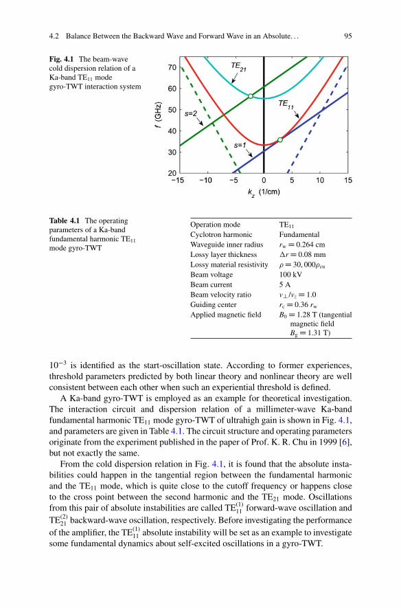
4.2 Balance Between the Backward Wave and Forward Wave in an Absolute. . . 95
Fig. 4.1 The beam-wavecold dispersion relation of aKa-band TE11 modegyro-TWT interaction system
Table 4.1 The operatingparameters of a Ka-bandfundamental harmonic TE11
mode gyro-TWT
Operation mode TE11
Cyclotron harmonic FundamentalWaveguide inner radius rw D 0.264 cmLossy layer thickness �r D 0.08 mmLossy material resistivity D 30, 000cu
Beam voltage 100 kVBeam current 5 ABeam velocity ratio v?/vz D 1.0Guiding center rc D 0.36 rw
Applied magnetic field B0 D 1.28 T (tangentialmagnetic fieldBg D 1.31 T)
10�3 is identified as the start-oscillation state. According to former experiences,threshold parameters predicted by both linear theory and nonlinear theory are wellconsistent between each other when such an experiential threshold is defined.
A Ka-band gyro-TWT is employed as an example for theoretical investigation.The interaction circuit and dispersion relation of a millimeter-wave Ka-bandfundamental harmonic TE11 mode gyro-TWT of ultrahigh gain is shown in Fig. 4.1,and parameters are given in Table 4.1. The circuit structure and operating parametersoriginate from the experiment published in the paper of Prof. K. R. Chu in 1999 [6],but not exactly the same.
From the cold dispersion relation in Fig. 4.1, it is found that the absolute insta-bilities could happen in the tangential region between the fundamental harmonicand the TE11 mode, which is quite close to the cutoff frequency or happens closeto the cross point between the second harmonic and the TE21 mode. Oscillationsfrom this pair of absolute instabilities are called TE(1)
11 forward-wave oscillation andTE(2)
21 backward-wave oscillation, respectively. Before investigating the performanceof the amplifier, the TE(1)
11 absolute instability will be set as an example to investigatesome fundamental dynamics about self-excited oscillations in a gyro-TWT.
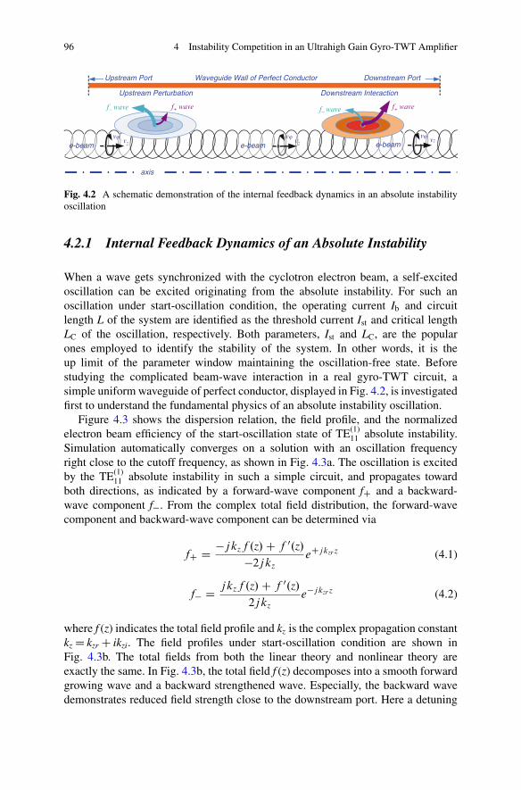
96 4 Instability Competition in an Ultrahigh Gain Gyro-TWT Amplifier
e-beamvz
vj
f+ wave f− wave f+ wavef− wave
Upstream Perturbation Downstream Interaction
Waveguide Wall of Perfect Conductor
axis
e-beamvz
vj
e-beamvz
vj
Upstream Port Downstream Port
Fig. 4.2 A schematic demonstration of the internal feedback dynamics in an absolute instabilityoscillation
4.2.1 Internal Feedback Dynamics of an Absolute Instability
When a wave gets synchronized with the cyclotron electron beam, a self-excitedoscillation can be excited originating from the absolute instability. For such anoscillation under start-oscillation condition, the operating current Ib and circuitlength L of the system are identified as the threshold current Ist and critical lengthLC of the oscillation, respectively. Both parameters, Ist and LC, are the popularones employed to identify the stability of the system. In other words, it is theup limit of the parameter window maintaining the oscillation-free state. Beforestudying the complicated beam-wave interaction in a real gyro-TWT circuit, asimple uniform waveguide of perfect conductor, displayed in Fig. 4.2, is investigatedfirst to understand the fundamental physics of an absolute instability oscillation.
Figure 4.3 shows the dispersion relation, the field profile, and the normalizedelectron beam efficiency of the start-oscillation state of TE(1)
11 absolute instability.Simulation automatically converges on a solution with an oscillation frequencyright close to the cutoff frequency, as shown in Fig. 4.3a. The oscillation is excitedby the TE(1)
11 absolute instability in such a simple circuit, and propagates towardboth directions, as indicated by a forward-wave component fC and a backward-wave component f�. From the complex total field distribution, the forward-wavecomponent and backward-wave component can be determined via
fC D �jkzf .z/ C f 0.z/�2jkz
eCjkzr z (4.1)
f� D jkzf .z/ C f 0.z/2jkz
e�jkzr z (4.2)
where f (z) indicates the total field profile and kz is the complex propagation constantkz D kzr C ikzi. The field profiles under start-oscillation condition are shown inFig. 4.3b. The total fields from both the linear theory and nonlinear theory areexactly the same. In Fig. 4.3b, the total field f (z) decomposes into a smooth forwardgrowing wave and a backward strengthened wave. Especially, the backward wavedemonstrates reduced field strength close to the downstream port. Here a detuning
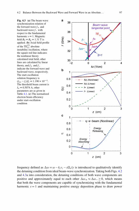
4.2 Balance Between the Backward Wave and Forward Wave in an Absolute. . . 97
Fig. 4.3 (a) The beam-wavesynchronization relation ofthe forward-wave fC andbackward-wave f� withrespect to the fundamentalharmonic s D 1. Magneticfield B0 D Bg D 1.31 T isapplied. (b) Axial field profile
of the TE(1)11 absolute
instability oscillation, wherethe square red line indicatesthe nonlinear theorycalculated total field, otherlines are calculated by lineartheory, and fC and f�indicate the forward wave andbackward wave, respectively.The start-oscillationsolution frequency is(fosc � fc)/fc D 1.190 � 10� 4.The threshold beam current isIst D 0.5074 A, otherparameters are as given inTable 4.1. (c) The normalizedelectron beam efficiencyunder start-oscillationcondition
frequency defined as �! D ! � kzvz � s�e/� is introduced to qualitatively identifythe detuning condition from ideal beam-wave synchronization. Taking both Figs. 4.2and 4.3a into consideration, the detuning conditions of both wave components arepositive and approximately equal to each other �!C � �!� � 0, which meansthat both the wave components are capable of synchronizing with the fundamentalharmonic s D 1 and maintaining positive energy deposition phase to draw power
98 4 Instability Competition in an Ultrahigh Gain Gyro-TWT Amplifier
from the electron beam. From the normalized electron beam efficiency in Fig. 4.3c,it is easy to understand the field profiles in Fig. 4.3b. When an undisturbed cyclotronelectron beam is injected from the upstream port, it encounters the backwardwave of the highest strength and will be modulated to get synchronizing in phasespace. During this initial modulation, some electrons will be decelerated to gainhigher angular frequency, and others will be accelerated to slow down angularfrequency. The overall effect of such initial modulation stage demonstrates electronabsorbing energy, as shown in Fig. 4.3c that the electron efficiency initially growsin the minus region. Since both wave components meet energy-releasing condition�!C � �!� > 0, after the initial bunching stage, both forward wave and backwardwave are capable of continuously extracting energy from electron beam-basedelectron cyclotron maser (ECM) interaction.
It is generally summarized that the EM wave from disturbance of the absoluteinstability propagates toward both upstream and downstream directions. For a waveclose to the cutoff frequency region, it is of extremely low group velocity andof the highest beam-wave coupling strength. Hence, a close-to-cutoff oscillationoriginating from an absolute instability is easy to be excited, and both wavecomponents therein are with low group velocity and approximately equal detuningconditions. In other words, both wave components in the oscillation are capableof continuously modulating the electron beam. In a uniform interaction circuitwithout any additional disturbance on both wave ports, the forward wave andbackward wave in the oscillation are both essential traveling waves and grow alonginverse directions. The backward wave bunches the incoming electron beam, andthe forward wave also could bunch the forward traveling electron beam. Keep inmind that the group velocity vg of the wave is normally much slower than the axialvelocity of the electron beam vz. The downstream electron beam becomes bettermodulated and normally more strongly interacts with both the wave components. Ifthe beam-wave coupling is strong enough, interaction from such internal feedback iscapable of growing up from noise-level perturbation into efficient strong radiation.
4.2.2 Magnetic Tuning
Magnetic tuning is constantly applied to optimize the performance of a gyrotron.The magnetic field directly determines the electron cyclotron frequency �e and thedetuning condition �! from ideal beam-wave synchronization. Hence, it is also oneof the most sensitive parameters influencing the thresholds of a potential oscillation.Figure 4.4 demonstrates the influence of the magnetic tuning to the threshold currentIst and critical length LC of the TE(1)
11 oscillation in a uniform circuit. From Fig. 4.4a,for a circuit of fixed length L D 3 cm, stronger magnetic field strength resultsa higher start-oscillation current Ist and higher oscillation frequency fosc. FromFig. 4.4b, for a fixed beam current of Ib D 5 A, stronger magnetic field strength alsoleads to longer critical length LC. Taking both figures into consideration, generallyspeaking, either higher beam current or longer interaction circuit makes positive
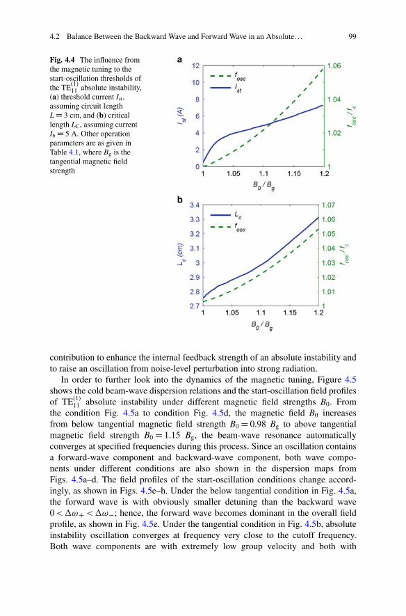
4.2 Balance Between the Backward Wave and Forward Wave in an Absolute. . . 99
Fig. 4.4 The influence fromthe magnetic tuning to thestart-oscillation thresholds ofthe TE(1)
11 absolute instability,(a) threshold current Ist,assuming circuit lengthL D 3 cm, and (b) criticallength LC, assuming currentIb D 5 A. Other operationparameters are as given inTable 4.1, where Bg is thetangential magnetic fieldstrength
contribution to enhance the internal feedback strength of an absolute instability andto raise an oscillation from noise-level perturbation into strong radiation.
In order to further look into the dynamics of the magnetic tuning, Figure 4.5shows the cold beam-wave dispersion relations and the start-oscillation field profilesof TE(1)
11 absolute instability under different magnetic field strengths B0. Fromthe condition Fig. 4.5a to condition Fig. 4.5d, the magnetic field B0 increasesfrom below tangential magnetic field strength B0 D 0.98 Bg to above tangentialmagnetic field strength B0 D 1.15 Bg, the beam-wave resonance automaticallyconverges at specified frequencies during this process. Since an oscillation containsa forward-wave component and backward-wave component, both wave compo-nents under different conditions are also shown in the dispersion maps fromFigs. 4.5a–d. The field profiles of the start-oscillation conditions change accord-ingly, as shown in Figs. 4.5e–h. Under the below tangential condition in Fig. 4.5a,the forward wave is with obviously smaller detuning than the backward wave0 < �!C < �!�; hence, the forward wave becomes dominant in the overall fieldprofile, as shown in Fig. 4.5e. Under the tangential condition in Fig. 4.5b, absoluteinstability oscillation converges at frequency very close to the cutoff frequency.Both wave components are with extremely low group velocity and both with
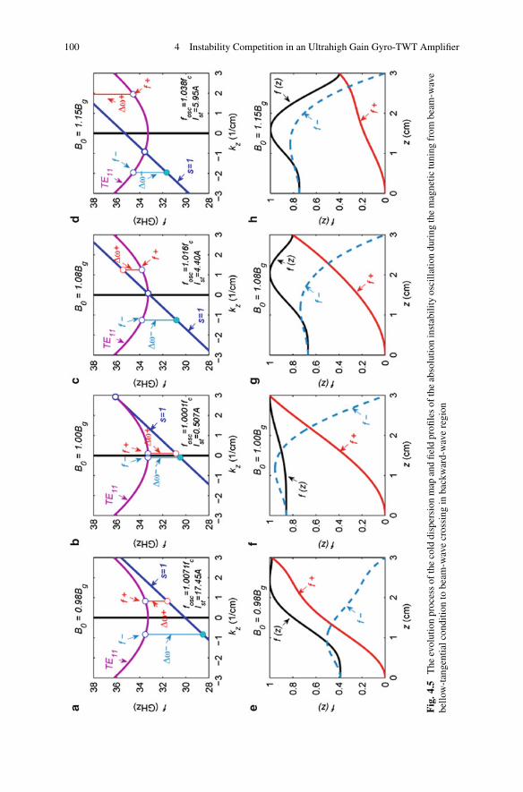
100 4 Instability Competition in an Ultrahigh Gain Gyro-TWT Amplifier
Fig
.4.5
The
evol
utio
npr
oces
sof
the
cold
disp
ersi
onm
apan
dfie
ldpr
ofile
sof
the
abso
lutio
nin
stab
ility
osci
llatio
ndu
ring
the
mag
netic
tuni
ngfr
ombe
am-w
ave
bello
w-t
ange
ntia
lcon
ditio
nto
beam
-wav
ecr
ossi
ngin
back
war
d-w
ave
regi
on
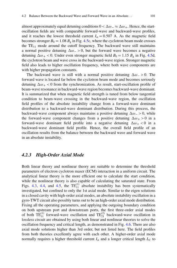
4.2 Balance Between the Backward Wave and Forward Wave in an Absolute. . . 101
almost approximately equal detuning conditions 0 < �!� � �!C. Hence, the start-oscillation fields are with comparable forward-wave and backward-wave profiles,and it reaches the lowest threshold current Ist D 0.507 A. As the magnetic fieldbecomes stronger B0 D 1.08 Bg in Fig. 4.5c, where the cyclotron beam mode crossesthe TE11 mode around the cutoff frequency. The backward wave still maintainsa normal positive detuning �!� > 0, but the forward wave becomes a negativedetuning �!C < 0. Under even stronger magnetic field B0 D 1.15 Bg in Fig. 4.5d,the cyclotron beam and wave cross in the backward-wave region. Stronger magneticfield also leads to higher oscillation frequency, where both wave components arewith higher propagation constants.
The backward wave is still with a normal positive detuning �!� > 0. Theforward wave is located far below the cyclotron beam mode and becomes seriouslydetuning �!C < 0 from the synchronization. As result, start-oscillation profile ofbeam-wave resonance in backward-wave region becomes backward-wave dominant.It is summarized that when magnetic field strength is tuned from below tangentialcondition to beam-wave crossing in the backward-wave region, the oscillationfield profiles of the absolute instability change from a forward-wave dominantdistribution to a backward-wave dominant distribution. During this process, thebackward-wave component always maintains a positive detuning �!� > 0, whilethe forward-wave component changes from a positive detuning �!C > 0 in aforward-wave dominant field profile into a negative detuning �!C < 0 in abackward-wave dominant field profile. Hence, the overall field profile of anoscillation results from the balance between the backward wave and forward wavein an absolute instability.
4.2.3 High-Order Axial Mode
Both linear theory and nonlinear theory are suitable to determine the thresholdparameters of electron cyclotron maser (ECM) interaction in a uniform circuit. Theanalytical linear theory is the more efficient one to calculate the start condition,while the nonlinear theory is also capable of calculating the saturated state. FromFigs. 4.3, 4.4, and 4.5, the TE(1)
11 absolute instability has been systematicallyinvestigated, but confined to only the 1st axial mode. Similar to the eigen solutionsin a closed cavity with high-order axial modes, an absolute instability oscillation in agyro-TWT circuit also possibly turns out to be an high-order axial mode distribution.Fixing all the operating parameters, and applying the outgoing boundary conditionon both upstream port and downstream ports, the first three-order axial modesof both TE(1)
11 forward-wave oscillation and TE(2)21 backward-wave oscillation in
lossless circuit are obtained by using both linear and nonlinear theories to solve theoscillation frequency and critical length, as demonstrated in Fig. 4.6. There are alsoaxial mode solutions higher than 3rd order, but not listed here. The field profilesfrom both theories excellently agree with each other. A higher-order axial modenormally requires a higher threshold current Ist and a longer critical length LC to
102 4 Instability Competition in an Ultrahigh Gain Gyro-TWT Amplifier
Fig. 4.6 The normalized field profiles of the first three orders of (a) TE(1)11 oscillation and (b)
TE(2)21 oscillation, where the fC and f� indicate the forward-wave component and backward-wave
component, respectively, assuming waveguide of perfect conductor and beam current Ib D 10 A.Other parameters are the same as in Table 4.1. Both the red lines and the square lines indicate thetotal field profiles of the absolute instabilities
build up oscillation. One axial mode is just a possible solution of the oscillation.It means that if the oscillation is built up, it may steadily exhibit in one of theaxial mode or may iteratively switch between several axial modes. If the beam-wavecoupling strength exceeds the critical strength, such as operation current Ib higherthan the threshold current Ist, or if the circuit length L is longer than the criticallength LC to enhance the internal feedback influence, one axial mode or iterativelyseveral axial modes may be built up. Oscillation of each axial mode also can bedecomposed into a forward-wave component and a backward-wave component andmeets the outgoing boundary condition at both ports. Several methods could beapplied to determine the order of the axial mode, such as the transit angle [9],electron beam energy deposition rate [9], and axial field profile [8]. Applying thefield profile shape to determine the order of an axial mode is more intuitional andconvenient. In this chapter, the order of the axial mode will be determined basedon the numbers of the concave-convex shapes of the field profile. Figure 4.6 revealsthat a forward-wave oscillation generated by TE(1)
11 forward-wave absolute instabilityis dominated by the forward-wave component, and a backward-wave oscillationgenerated by the TE(2)
21 backward-wave absolute instability is dominated by thebackward-wave component. For both kinds of oscillations, a high-order axial modeis with a longer critical length LC and oscillates at a higher frequency. Normally, ahigh-order axial mode is with a larger wave number kz.
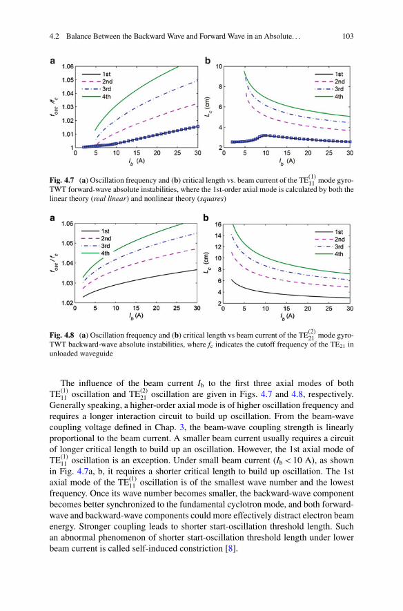
4.2 Balance Between the Backward Wave and Forward Wave in an Absolute. . . 103
Fig. 4.7 (a) Oscillation frequency and (b) critical length vs. beam current of the TE(1)11 mode gyro-
TWT forward-wave absolute instabilities, where the 1st-order axial mode is calculated by both thelinear theory (real linear) and nonlinear theory (squares)
Fig. 4.8 (a) Oscillation frequency and (b) critical length vs beam current of the TE(2)21 mode gyro-
TWT backward-wave absolute instabilities, where fc indicates the cutoff frequency of the TE21 inunloaded waveguide
The influence of the beam current Ib to the first three axial modes of bothTE(1)
11 oscillation and TE(2)21 oscillation are given in Figs. 4.7 and 4.8, respectively.
Generally speaking, a higher-order axial mode is of higher oscillation frequency andrequires a longer interaction circuit to build up oscillation. From the beam-wavecoupling voltage defined in Chap. 3, the beam-wave coupling strength is linearlyproportional to the beam current. A smaller beam current usually requires a circuitof longer critical length to build up an oscillation. However, the 1st axial mode ofTE(1)
11 oscillation is an exception. Under small beam current (Ib < 10 A), as shownin Fig. 4.7a, b, it requires a shorter critical length to build up oscillation. The 1staxial mode of the TE(1)
11 oscillation is of the smallest wave number and the lowestfrequency. Once its wave number becomes smaller, the backward-wave componentbecomes better synchronized to the fundamental cyclotron mode, and both forward-wave and backward-wave components could more effectively distract electron beamenergy. Stronger coupling leads to shorter start-oscillation threshold length. Suchan abnormal phenomenon of shorter start-oscillation threshold length under lowerbeam current is called self-induced constriction [8].
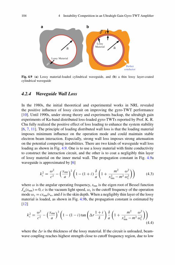
104 4 Instability Competition in an Ultrahigh Gain Gyro-TWT Amplifier
a
Lossy Material
a
r
LossyMaterial
Perfectconductor
a b
Fig. 4.9 (a) Lossy material-loaded cylindrical waveguide, and (b) a thin lossy layer-coatedcylindrical waveguide
4.2.4 Waveguide Wall Loss
In the 1980s, the initial theoretical and experimental works in NRL revealedthe positive influence of lossy circuit on improving the gyro-TWT performance[10]. Until 1990s, under strong theory and experiments backup, the ultrahigh gainexperiments of Ka-band distributed loss-loaded gyro-TWTs reported by Prof. K. R.Chu fully realized the positive effect of loss loading to enhance the system stability[6, 7, 11]. The principle of loading distributed wall loss is that the loading materialimposes minimum influence on the operation mode and could maintain stableelectron beam interaction. Especially, strong wall loss imposes strong attenuationon the potential competing instabilities. There are two kinds of waveguide wall lossloading as shown in Fig. 4.9. One is to use a lossy material with finite conductivityto construct the interaction circuit, and the other is to coat a negligibly thin layerof lossy material on the inner metal wall. The propagation constant in Fig. 4.9awaveguide is approximated by [6]
k2z D !2
c2��xmn
a
�2�
1 � .1 C i/ı
a
�1 C m2
x2mn � m2
!2
!2c
��(4.3)
where ! is the angular operating frequency, xmn is the eigen root of Bessel functionJ
0
m(xmn) D 0, c is the vacuum light speed, !c is the cutoff frequency of the operationmode !c D cxmn/rw, and ı is the skin depth. When a negligibly thin layer of the lossymaterial is loaded, as shown in Fig. 4.9b, the propagation constant is estimated by[12]
k2z D !2
c2��xmn
a
�2�
1 � .1 � i/ tan
��r
1 C i
ı
�ı
a
�1 C m2
x2mn � m2
!2
!2c
��
(4.4)
where the �r is the thickness of the lossy material. If the circuit is unloaded, beam-wave coupling reaches highest strength close to cutoff frequency region, due to low
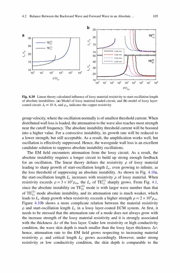
4.2 Balance Between the Backward Wave and Forward Wave in an Absolute. . . 105
100 101 102 103 104 10510
15
20
25
30
cu
L c /r
w
L c /r
wL c
/rw
TE(2)
TE(1)
21
11
10
20
30
40
50
cu
10
15
20
25
0.08 mm
0.06 mm
0.04 mm
0.02 mm
TE(1)11
TE(2)21
100 101 102 103 104 105 106 107 108
a
b
Fig. 4.10 Linear theory calculated influence of lossy material resistivity to start-oscillation lengthof absolute instabilities. (a) Model of lossy material-loaded circuit, and (b) model of lossy layer-coated circuit. Ib D 10 A, and cu indicates the copper resistivity
group velocity, where the oscillation normally is of smallest threshold current. Whendistributed wall loss is loaded, the attenuation to the wave also reaches most strengthnear the cutoff frequency. The absolute instability threshold current will be boostedinto a higher value. For a convective instability, its growth rate will be reduced toa lower strength, but still acceptable. As a result, the amplification works well, butoscillation is effectively suppressed. Hence, the waveguide wall loss is an excellentcandidate solution to suppress absolute instability oscillations.
The EM field encounters attenuation from the lossy circuit. As a result, theabsolute instability requires a longer circuit to build up strong enough feedbackfor an oscillation. The linear theory defines the resistivity of lossy materialleading to sharp growth of start-oscillation length Lc, even growing to infinite, asthe loss threshold of suppressing an absolute instability. As shown in Fig. 4.10a,the start-oscillation length Lc increases with resistivity of lossy material. Whenresistivity exceeds D 3 102cu, the Lc of TE(1)
11 sharply grows. From Fig. 4.1,since the absolute instability on TE(2)
21 mode is with larger wave number than thatof TE(1)
11 mode absolute instability, and its attenuation rate is much weaker, whichleads to Lc sharp growth when resistivity exceeds a higher strength D 2 104cu.Figure 4.10b shows a more complicate relation between the material resistivity and start-oscillation length Lc in a lossy layer-coated ECM system. At first, itneeds to be stressed that the attenuation rate of a mode does not always grow withthe increase strength of the lossy material resistivity and it is strongly associatedwith the thickness �r of the loss layer. Under low resistivity or high conductivitycondition, the wave skin depth is much smaller than the lossy layer thickness �r;hence, attenuation rate to the EM field grows respecting to increasing materialresistivity , and critical length LC grows accordingly. However, under strongresistivity or low conductivity condition, the skin depth is comparable to the
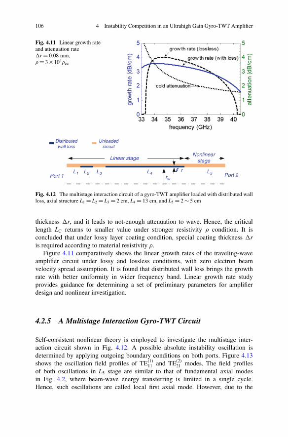
106 4 Instability Competition in an Ultrahigh Gain Gyro-TWT Amplifier
Fig. 4.11 Linear growth rateand attenuation rate�r D 0.08 mm, D 3 � 104cu
L1 L2 L3 L4 L5
Linear stageNonlinear
stage
Port 1 Port 2
Distributedwall loss
Unloadedcircuit
rw
r
Fig. 4.12 The multistage interaction circuit of a gyro-TWT amplifier loaded with distributed wallloss, axial structure L1 D L2 D L3 D 2 cm, L4 D 13 cm, and L5 D 2 � 5 cm
thickness �r, and it leads to not-enough attenuation to wave. Hence, the criticallength LC returns to smaller value under stronger resistivity condition. It isconcluded that under lossy layer coating condition, special coating thickness �ris required according to material resistivity .
Figure 4.11 comparatively shows the linear growth rates of the traveling-waveamplifier circuit under lossy and lossless conditions, with zero electron beamvelocity spread assumption. It is found that distributed wall loss brings the growthrate with better uniformity in wider frequency band. Linear growth rate studyprovides guidance for determining a set of preliminary parameters for amplifierdesign and nonlinear investigation.
4.2.5 A Multistage Interaction Gyro-TWT Circuit
Self-consistent nonlinear theory is employed to investigate the multistage inter-action circuit shown in Fig. 4.12. A possible absolute instability oscillation isdetermined by applying outgoing boundary conditions on both ports. Figure 4.13shows the oscillation field profiles of TE(1)
11 and TE(2)21 modes. The field profiles
of both oscillations in L5 stage are similar to that of fundamental axial modesin Fig. 4.2, where beam-wave energy transferring is limited in a single cycle.Hence, such oscillations are called local first axial mode. However, due to the
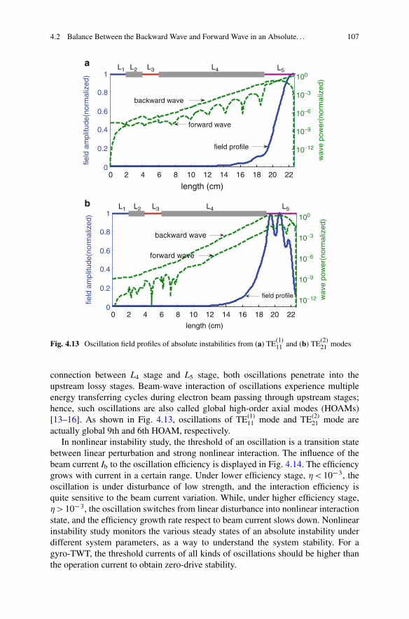
4.2 Balance Between the Backward Wave and Forward Wave in an Absolute. . . 107
0 2 4 6 8 10 12 14 16 18 20 220
0.2
0.4
0.6
0.8
1
length (cm)
field
am
plitu
de(n
orm
aliz
ed)
10−12
10−9
10−6
10−3
100
10−12
10−9
10−6
10−3
100
wav
e po
wer
(nor
mal
ized
)
forward wave
backward wave
field profile
L1
L1
L2
L2
L3
L3
L4
L4
L5
L5
0 2 4 6 8 10 12 14 16 18 20 220
0.2
0.4
0.6
0.8
1
length (cm)
field
am
plitu
de(n
orm
aliz
ed)
wav
e po
wer
(nor
mal
ized
)
field profile
backward wave
forward wave
a
b
Fig. 4.13 Oscillation field profiles of absolute instabilities from (a) TE(1)11 and (b) TE(2)
21 modes
connection between L4 stage and L5 stage, both oscillations penetrate into theupstream lossy stages. Beam-wave interaction of oscillations experience multipleenergy transferring cycles during electron beam passing through upstream stages;hence, such oscillations are also called global high-order axial modes (HOAMs)[13–16]. As shown in Fig. 4.13, oscillations of TE(1)
11 mode and TE(2)21 mode are
actually global 9th and 6th HOAM, respectively.In nonlinear instability study, the threshold of an oscillation is a transition state
between linear perturbation and strong nonlinear interaction. The influence of thebeam current Ib to the oscillation efficiency is displayed in Fig. 4.14. The efficiencygrows with current in a certain range. Under lower efficiency stage, < 10� 3, theoscillation is under disturbance of low strength, and the interaction efficiency isquite sensitive to the beam current variation. While, under higher efficiency stage, > 10� 3, the oscillation switches from linear disturbance into nonlinear interactionstate, and the efficiency growth rate respect to beam current slows down. Nonlinearinstability study monitors the various steady states of an absolute instability underdifferent system parameters, as a way to understand the system stability. For agyro-TWT, the threshold currents of all kinds of oscillations should be higher thanthe operation current to obtain zero-drive stability.
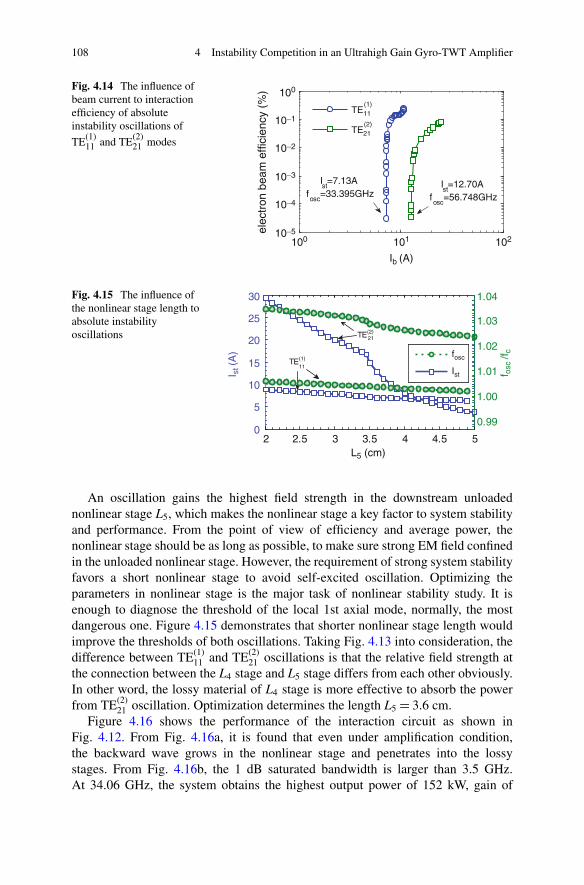
108 4 Instability Competition in an Ultrahigh Gain Gyro-TWT Amplifier
100 101 10210−5
10−4
10−3
10−2
10−1
100
Ib (A)el
ectr
on b
eam
effi
cien
cy (
%)
Ist=7.13A
fosc
=33.395GHzIst=12.70A
fosc
=56.748GHz
TE11(1)
TE21(2)
Fig. 4.14 The influence ofbeam current to interactionefficiency of absoluteinstability oscillations of
TE(1)11 and TE(2)
21 modes
2.50
5
10
15
20
25
30
f
2 3 3.5 4 4.5 5
I st (
A) fosc
Ist
0.99
1.00
1.01
1.02
1.03
1.04
TE(1)
11
TE(2)21
L5 (cm)
f osc
/fc
Fig. 4.15 The influence ofthe nonlinear stage length toabsolute instabilityoscillations
An oscillation gains the highest field strength in the downstream unloadednonlinear stage L5, which makes the nonlinear stage a key factor to system stabilityand performance. From the point of view of efficiency and average power, thenonlinear stage should be as long as possible, to make sure strong EM field confinedin the unloaded nonlinear stage. However, the requirement of strong system stabilityfavors a short nonlinear stage to avoid self-excited oscillation. Optimizing theparameters in nonlinear stage is the major task of nonlinear stability study. It isenough to diagnose the threshold of the local 1st axial mode, normally, the mostdangerous one. Figure 4.15 demonstrates that shorter nonlinear stage length wouldimprove the thresholds of both oscillations. Taking Fig. 4.13 into consideration, thedifference between TE(1)
11 and TE(2)21 oscillations is that the relative field strength at
the connection between the L4 stage and L5 stage differs from each other obviously.In other word, the lossy material of L4 stage is more effective to absorb the powerfrom TE(2)
21 oscillation. Optimization determines the length L5 D 3.6 cm.Figure 4.16 shows the performance of the interaction circuit as shown in
Fig. 4.12. From Fig. 4.16a, it is found that even under amplification condition,the backward wave grows in the nonlinear stage and penetrates into the lossystages. From Fig. 4.16b, the 1 dB saturated bandwidth is larger than 3.5 GHz.At 34.06 GHz, the system obtains the highest output power of 152 kW, gain of
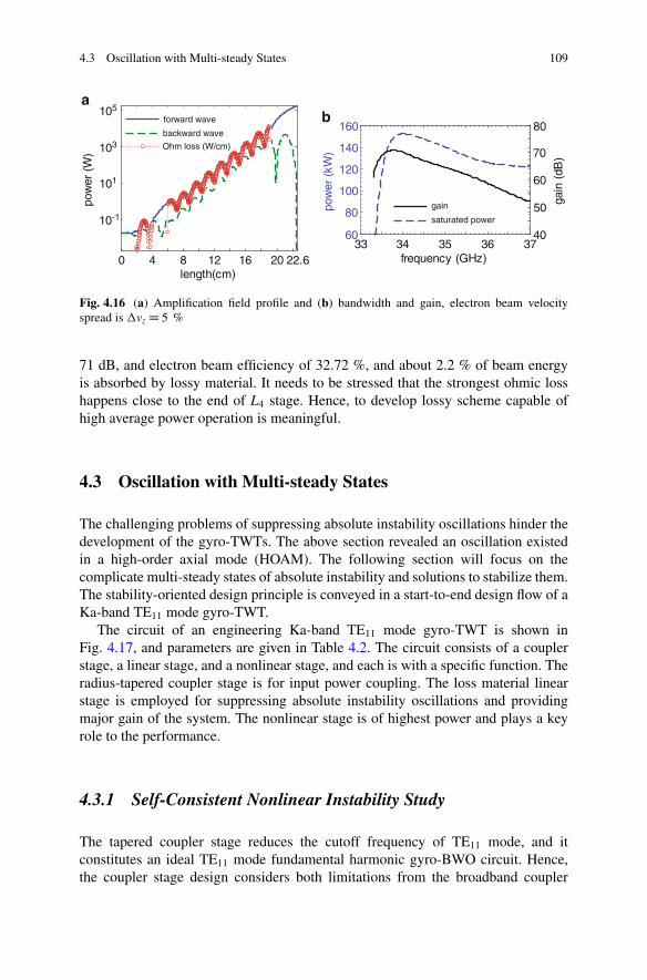
4.3 Oscillation with Multi-steady States 109
0 4 8 12 16 20 22.6
10-1
101
103
105
length(cm)
pow
er (
W)
forward wave
backward wave
Ohm loss (W/cm)
33 34 35 36 3760
80
100
120
140
160
frequency (GHz)
pow
er (
kW)
40
50
60
70
80
gain
(dB
)
gain
saturated power
ab
Fig. 4.16 (a) Amplification field profile and (b) bandwidth and gain, electron beam velocityspread is �vz D 5 %
71 dB, and electron beam efficiency of 32.72 %, and about 2.2 % of beam energyis absorbed by lossy material. It needs to be stressed that the strongest ohmic losshappens close to the end of L4 stage. Hence, to develop lossy scheme capable ofhigh average power operation is meaningful.
4.3 Oscillation with Multi-steady States
The challenging problems of suppressing absolute instability oscillations hinder thedevelopment of the gyro-TWTs. The above section revealed an oscillation existedin a high-order axial mode (HOAM). The following section will focus on thecomplicate multi-steady states of absolute instability and solutions to stabilize them.The stability-oriented design principle is conveyed in a start-to-end design flow of aKa-band TE11 mode gyro-TWT.
The circuit of an engineering Ka-band TE11 mode gyro-TWT is shown inFig. 4.17, and parameters are given in Table 4.2. The circuit consists of a couplerstage, a linear stage, and a nonlinear stage, and each is with a specific function. Theradius-tapered coupler stage is for input power coupling. The loss material linearstage is employed for suppressing absolute instability oscillations and providingmajor gain of the system. The nonlinear stage is of highest power and plays a keyrole to the performance.
4.3.1 Self-Consistent Nonlinear Instability Study
The tapered coupler stage reduces the cutoff frequency of TE11 mode, and itconstitutes an ideal TE11 mode fundamental harmonic gyro-BWO circuit. Hence,the coupler stage design considers both limitations from the broadband coupler
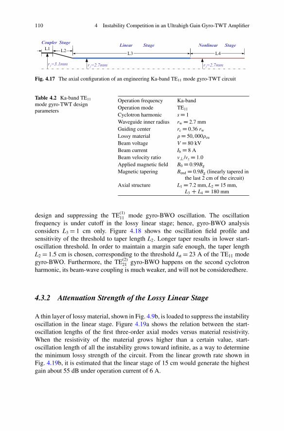
110 4 Instability Competition in an Ultrahigh Gain Gyro-TWT Amplifier
L2L1L3 L4
Coupler StageLinear Nonlinear Stage
r2=2.7mmr2=2.7mmr1=3.1mm
Stage
Fig. 4.17 The axial configuration of an engineering Ka-band TE11 mode gyro-TWT circuit
Table 4.2 Ka-band TE11
mode gyro-TWT designparameters
Operation frequency Ka-bandOperation mode TE11
Cyclotron harmonic s D 1Waveguide inner radius rw D 2.7 mmGuiding center rc D 0.36 rw
Lossy material D 50, 000cu
Beam voltage V D 80 kVBeam current Ib D 8 ABeam velocity ratio v?/vz D 1.0Applied magnetic field B0 D 0.99Bg
Magnetic tapering Bend D 0.9Bg (linearly tapered inthe last 2 cm of the circuit)
Axial structure L1 D 7.2 mm, L2 D 15 mm,L3 C L4 D 180 mm
design and suppressing the TE(1)11 mode gyro-BWO oscillation. The oscillation
frequency is under cutoff in the lossy linear stage; hence, gyro-BWO analysisconsiders L3 D 1 cm only. Figure 4.18 shows the oscillation field profile andsensitivity of the threshold to taper length L2. Longer taper results in lower start-oscillation threshold. In order to maintain a margin safe enough, the taper lengthL2 D 1.5 cm is chosen, corresponding to the threshold Ist D 23 A of the TE11 modegyro-BWO. Furthermore, the TE(2)
21 gyro-BWO happens on the second cyclotronharmonic, its beam-wave coupling is much weaker, and will not be consideredhere.
4.3.2 Attenuation Strength of the Lossy Linear Stage
A thin layer of lossy material, shown in Fig. 4.9b, is loaded to suppress the instabilityoscillation in the linear stage. Figure 4.19a shows the relation between the start-oscillation lengths of the first three-order axial modes versus material resistivity.When the resistivity of the material grows higher than a certain value, start-oscillation length of all the instability grows toward infinite, as a way to determinethe minimum lossy strength of the circuit. From the linear growth rate shown inFig. 4.19b, it is estimated that the linear stage of 15 cm would generate the highestgain about 55 dB under operation current of 6 A.
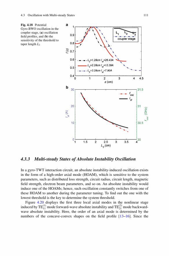
4.3 Oscillation with Multi-steady States 111
Fig. 4.18 PotentialGyro-BWO oscillation in thecoupler stage, (a) oscillationfield profiles, and (b) thesensitivity of the threshold totaper length L2
4.3.3 Multi-steady States of Absolute Instability Oscillation
In a gyro-TWT interaction circuit, an absolute instability-induced oscillation existsin the form of a high-order axial mode (HOAM), which is sensitive to the systemparameters, such as distributed loss strength, circuit radius, circuit length, magneticfield strength, electron beam parameters, and so on. An absolute instability wouldinduce one of the HOAMs; hence, such oscillation constantly switches from one ofthese HOAM to another during the parameter tuning. To find out the one with thelowest threshold is the key to determine the system threshold.
Figure 4.20 displays the first three local axial modes in the nonlinear stageinduced by TE(1)
11 mode forward-wave absolute instability and TE(2)21 mode backward-
wave absolute instability. Here, the order of an axial mode is determined by thenumbers of the concave-convex shapes on the field profile [13–16]. Since the
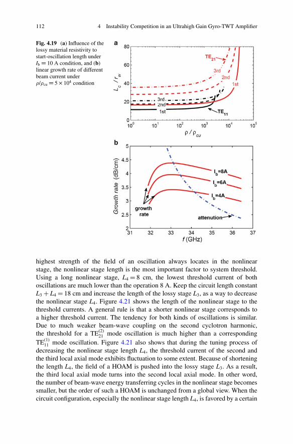
112 4 Instability Competition in an Ultrahigh Gain Gyro-TWT Amplifier
Fig. 4.19 (a) Influence of thelossy material resistivity tostart-oscillation length underIb D 10 A condition, and (b)linear growth rate of differentbeam current under/cu D 5 � 104 condition
highest strength of the field of an oscillation always locates in the nonlinearstage, the nonlinear stage length is the most important factor to system threshold.Using a long nonlinear stage, L4 D 8 cm, the lowest threshold current of bothoscillations are much lower than the operation 8 A. Keep the circuit length constantL3 C L4 D 18 cm and increase the length of the lossy stage L3, as a way to decreasethe nonlinear stage L4. Figure 4.21 shows the length of the nonlinear stage to thethreshold currents. A general rule is that a shorter nonlinear stage corresponds toa higher threshold current. The tendency for both kinds of oscillations is similar.Due to much weaker beam-wave coupling on the second cyclotron harmonic,the threshold for a TE(2)
21 mode oscillation is much higher than a correspondingTE(1)
11 mode oscillation. Figure 4.21 also shows that during the tuning process ofdecreasing the nonlinear stage length L4, the threshold current of the second andthe third local axial mode exhibits fluctuation to some extent. Because of shorteningthe length L4, the field of a HOAM is pushed into the lossy stage L3. As a result,the third local axial mode turns into the second local axial mode. In other word,the number of beam-wave energy transferring cycles in the nonlinear stage becomessmaller, but the order of such a HOAM is unchanged from a global view. When thecircuit configuration, especially the nonlinear stage length L4, is favored by a certain
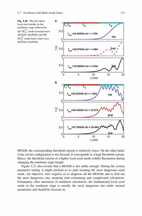
4.3 Oscillation with Multi-steady States 113
Fig. 4.20 The first threelocal axial modes in thenonlinear stage induced by
(a) TE(1)11 mode forward-wave
absolute instability and (b)
TE(2)21 mode back-ward wave
absolute instability
HOAM, the corresponding threshold current is relatively lower. On the other hand,if the circuit configuration is not favored, it corresponds to a high threshold current.Hence, the threshold current of a higher local axial mode exhibit fluctuation duringchanging the nonlinear stage length.
Figure 4.21 also reveals that a HOAM is not stable enough. During the systemparameter tuning, it might mislead us to omit tracking the most dangerous axialmode. An objective view requires us to diagnose all the HOAMs and to find outthe most dangerous one, meaning time-consuming and complicated calculation.Fortunately, after enormous of nonlinear calculation, the fundamental local axialmode in the nonlinear stage is usually the most dangerous one under normalparameters and should be focused on.
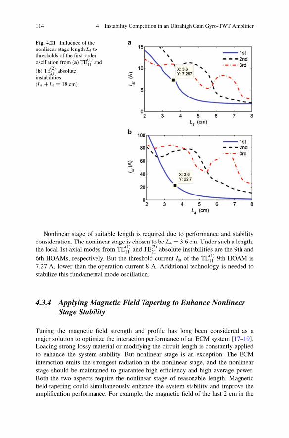
114 4 Instability Competition in an Ultrahigh Gain Gyro-TWT Amplifier
Fig. 4.21 Influence of thenonlinear stage length L4 tothresholds of the first-orderoscillation from (a) TE(1)
11 and
(b) TE(2)21 absolute
instabilities(L3 C L4 D 18 cm)
Nonlinear stage of suitable length is required due to performance and stabilityconsideration. The nonlinear stage is chosen to be L4 D 3.6 cm. Under such a length,the local 1st axial modes from TE(1)
11 and TE(2)21 absolute instabilities are the 9th and
6th HOAMs, respectively. But the threshold current Ist of the TE(1)11 9th HOAM is
7.27 A, lower than the operation current 8 A. Additional technology is needed tostabilize this fundamental mode oscillation.
4.3.4 Applying Magnetic Field Tapering to Enhance NonlinearStage Stability
Tuning the magnetic field strength and profile has long been considered as amajor solution to optimize the interaction performance of an ECM system [17–19].Loading strong lossy material or modifying the circuit length is constantly appliedto enhance the system stability. But nonlinear stage is an exception. The ECMinteraction emits the strongest radiation in the nonlinear stage, and the nonlinearstage should be maintained to guarantee high efficiency and high average power.Both the two aspects require the nonlinear stage of reasonable length. Magneticfield tapering could simultaneously enhance the system stability and improve theamplification performance. For example, the magnetic field of the last 2 cm in the
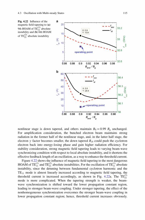
4.3 Oscillation with Multi-steady States 115
Fig. 4.22 Influence of themagnetic field tapering to (a)
9th HOAM of TE(1)11 absolute
instability and (b) 6th HOAM
of TE(2)21 absolute instability
nonlinear stage is down tapered, and others maintain B0 D 0.99 Bg unchanged.For amplification consideration, the bunched electron beam maintains strongradiation in the former half of the nonlinear stage, and, in the latter half stage, theelectron � factor becomes smaller, the down tapered Bz0 could push the cyclotronelectron back into energy-losing phase and gain higher radiation efficiency. Forstability consideration, strong magnetic field tapering leads to varying beam-wavesynchronizing condition with respect to local absolute instability, and it shortens theeffective feedback length of an oscillation, as a way to enhance the threshold current.
Figure 4.22 shows the influence of magnetic field tapering to the most dangerousHOAM of TE(1)
11 and TE(2)21 absolute instabilities. For the oscillation of TE(1)
11 absoluteinstability, since the detuning between fundamental cyclotron harmonic and theTE11 mode is almost linearly increased according to magnetic field tapering, thethreshold current is increased accordingly, as shown in Fig. 4.22a. The TE(2)
21mode is more complicated. When the tapering strength is weaker, the beam-wave synchronization is shifted toward the lower propagation constant region,leading to stronger beam-wave coupling. Under stronger tapering, the effect of thenonhomogeneous synchronization overcomes the stronger beam-wave coupling inlower propagation constant region; hence, threshold current increases obviously.
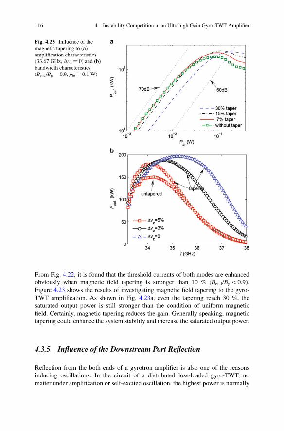
116 4 Instability Competition in an Ultrahigh Gain Gyro-TWT Amplifier
Fig. 4.23 Influence of themagnetic tapering to (a)amplification characteristics(33.67 GHz, �vz D 0) and (b)bandwidth characteristics(Bend/Bg D 0.9, pin D 0.1 W)
From Fig. 4.22, it is found that the threshold currents of both modes are enhancedobviously when magnetic field tapering is stronger than 10 % (Bend/Bg < 0.9).Figure 4.23 shows the results of investigating magnetic field tapering to the gyro-TWT amplification. As shown in Fig. 4.23a, even the tapering reach 30 %, thesaturated output power is still stronger than the condition of uniform magneticfield. Certainly, magnetic tapering reduces the gain. Generally speaking, magnetictapering could enhance the system stability and increase the saturated output power.
4.3.5 Influence of the Downstream Port Reflection
Reflection from the both ends of a gyrotron amplifier is also one of the reasonsinducing oscillations. In the circuit of a distributed loss-loaded gyro-TWT, nomatter under amplification or self-excited oscillation, the highest power is normally
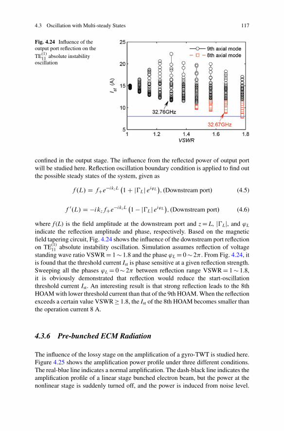
4.3 Oscillation with Multi-steady States 117
Fig. 4.24 Influence of theoutput port reflection on the
TE(1)11 absolute instability
oscillation
confined in the output stage. The influence from the reflected power of output portwill be studied here. Reflection oscillation boundary condition is applied to find outthe possible steady states of the system, given as
f .L/ D fCe�ikzL�1 C j�Lj ei'L
�; .Downstream port/ (4.5)
f 0.L/ D �ikzfCe�ikzL�1 � j�Lj ei'L
�; .Downstream port/ (4.6)
where f (L) is the field amplitude at the downstream port and z D L, j�Lj, and 'L
indicate the reflection amplitude and phase, respectively. Based on the magneticfield tapering circuit, Fig. 4.24 shows the influence of the downstream port reflectionon TE(1)
11 absolute instability oscillation. Simulation assumes reflection of voltagestanding wave ratio VSWR D 1 � 1.8 and the phase 'L D 0 � 2� . From Fig. 4.24, itis found that the threshold current Ist is phase sensitive at a given reflection strength.Sweeping all the phases 'L D 0 � 2� between reflection range VSWR D 1 � 1.8,it is obviously demonstrated that reflection would reduce the start-oscillationthreshold current Ist. An interesting result is that strong reflection leads to the 8thHOAM with lower threshold current than that of the 9th HOAM. When the reflectionexceeds a certain value VSWR � 1.8, the Ist of the 8th HOAM becomes smaller thanthe operation current 8 A.
4.3.6 Pre-bunched ECM Radiation
The influence of the lossy stage on the amplification of a gyro-TWT is studied here.Figure 4.25 shows the amplification power profile under three different conditions.The real-blue line indicates a normal amplification. The dash-black line indicates theamplification profile of a linear stage bunched electron beam, but the power at thenonlinear stage is suddenly turned off, and the power is induced from noise level.
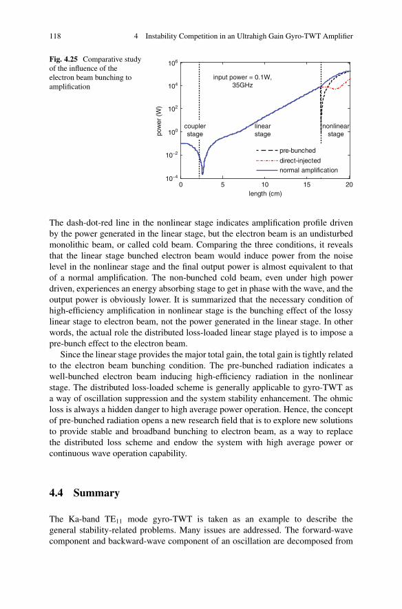
118 4 Instability Competition in an Ultrahigh Gain Gyro-TWT Amplifier
0 5 10 15 2010−4
10−2
100
102
104
106
length (cm)
pow
er (
W)
pre-bunched
direct-injected
normal amplification
input power = 0.1W,35GHz
linearstage
couplerstage
nonlinearstage
Fig. 4.25 Comparative studyof the influence of theelectron beam bunching toamplification
The dash-dot-red line in the nonlinear stage indicates amplification profile drivenby the power generated in the linear stage, but the electron beam is an undisturbedmonolithic beam, or called cold beam. Comparing the three conditions, it revealsthat the linear stage bunched electron beam would induce power from the noiselevel in the nonlinear stage and the final output power is almost equivalent to thatof a normal amplification. The non-bunched cold beam, even under high powerdriven, experiences an energy absorbing stage to get in phase with the wave, and theoutput power is obviously lower. It is summarized that the necessary condition ofhigh-efficiency amplification in nonlinear stage is the bunching effect of the lossylinear stage to electron beam, not the power generated in the linear stage. In otherwords, the actual role the distributed loss-loaded linear stage played is to impose apre-bunch effect to the electron beam.
Since the linear stage provides the major total gain, the total gain is tightly relatedto the electron beam bunching condition. The pre-bunched radiation indicates awell-bunched electron beam inducing high-efficiency radiation in the nonlinearstage. The distributed loss-loaded scheme is generally applicable to gyro-TWT asa way of oscillation suppression and the system stability enhancement. The ohmicloss is always a hidden danger to high average power operation. Hence, the conceptof pre-bunched radiation opens a new research field that is to explore new solutionsto provide stable and broadband bunching to electron beam, as a way to replacethe distributed loss scheme and endow the system with high average power orcontinuous wave operation capability.
4.4 Summary
The Ka-band TE11 mode gyro-TWT is taken as an example to describe thegeneral stability-related problems. Many issues are addressed. The forward-wavecomponent and backward-wave component of an oscillation are decomposed from
References 119
the total field throughout the circuit, through which the physical feeding-backmechanism of all the absolute instability-induced oscillations is clearly analyzed.In an engineering gyro-TWT circuit, the oscillation of an absolute instability existsin a form of HOAM, which would present in different orders due to parametertuning and shows multi-steady states. Based on the start-to-end design principle,in order to guarantee high stability of each circuit section, the stability study of agyro-TWT is introduced in detail. Sharp magnetic field tapering is introduced toimprove the nonlinear stage stability as well as the performance. The concept ofpre-bunching amplification is proposed. It is revealed that the necessary conditionof high-efficiency amplification in the nonlinear stage is a well pre-bunched electronbeam provided by the loss-loaded linear stage. Systematic exploring of thesephysical principles is very helpful for understanding the instability competition anddeveloping a gyro-TWT of high stability.
References
1. Chu KR (2004) The electron cyclotron maser. Rev Mod Phys 76:489–5402. Chu KR (2002) Overview of research on the gyrotron traveling-wave amplifier. IEEE Trans
Plasma Sci 30:903–9083. Calame JP, Garven M, Danly BG et al (2002) Gyrotron-traveling wave-tube circuits based on
lossy ceramics. IEEE Trans Electron Devices 49:1469–14774. Pershing DE, Nguyen KT, Calame JP et al (2004) A TE11 K-a-band gyro-TWT amplifier with
high-average power compatible distributed loss. IEEE Trans Plasma Sci 32:947–9565. Sirigiri JR, Shapiro MA, Temkin RJ (2003) High-power 140-GHz quasioptical gyrotron
traveling-wave amplifier. Phys Rev Lett 90:2583026. Chu KR, Chen HY, Hung CL et al (1999) Theory and experiment of ultrahigh-gain gyrotron
traveling wave amplifier. IEEE Trans Plasma Sci 27:391–4047. Chu KR, Barnett LR, Chen HY et al (1995) Stabilization of absolute instabilities in the gyrotron
traveling-wave amplifier. Phys Rev Lett 74:1103–11068. Du CH, Liu PK, Xue QZ et al (2008) Effect of a backward wave on the stability of an ultrahigh
gain gyrotron traveling-wave amplifier. Phys Plasmas 15:1231079. Chang TH, Chen NC (2006) Transition of absolute instability from global to local modes in a
gyrotron traveling-wave amplifier. Phys Rev E 74:01740210. Barnett LR, Baird JM, Lau YY et al (1980) A high gain single stage gyrotron traveling-wave
amplifier. Int Electron Devices Meet 26:314–31711. Chu KR, Chen HY, Hung CL et al (1998) Ultrahigh gain gyrotron traveling wave amplifier.
Phys Rev Lett 81:4760–476312. Luo JR, Jiao CQ (2006) Effect of the lossy layer thickness of metal cylindrical waveguide wall
on the propagation constant of electromagnetic modes. Appl Phys Lett 88:1–813. Chang TH, Chen SH, Barnett LR et al (2001) Characterization of stationary and nonstationary
behavior in gyrotron oscillators. Phys Rev Lett 87(6):06480214. Chang TH, Fan CT, Pao KF et al (2007) Stability and tunability of the gyrotron backward-wave
oscillator. Appl Phys Lett 90:19150115. Chen SH, Chu KR, Chang TH (2000) Saturated behavior of the gyrotron backward-wave
oscillator. Phys Rev Lett 85:2633–263616. Pao KF, Chang TH, Fan CT et al (2005) Dynamics of mode competition in the gyrotron
backward-wave oscillator. Phys Rev Lett 95:185101
120 4 Instability Competition in an Ultrahigh Gain Gyro-TWT Amplifier
17. Dumbrajs O, Nusinovich GS, Pavelyev AB (1988) Mode competition in a gyrotron withtapered external magnetic-field. Int J Electron 64:137–145
18. Gantenbein G, Borie E (1990) Gyrotron with a tapered external magnetic-field. Int J InfraredMillim Waves 11:837–850
19. Chang TH, Idehara T, Ogawa I et al (2009) Frequency tunable gyrotron using backward-wavecomponents. J Appl Phys 105:063304
Chapter 5A Lossy Ceramic-Loaded Millimeter-WaveGyro-TWT Amplifier
Abstract Loading lossy ceramic of high thermal conductivity is a proposed schemefor developing a high-power millimeter-wave gyro-TWT amplifier for engineeringapplication. This chapter focuses on investigating lossy ceramic-loaded gyro-TWTs.It addresses proper approximation methods to simplified analyzing ceramic-loadedgyro-TWTs. The propagation characteristics approximation considers only theinfluence from the ceramic to the wave dispersion and attenuation properties whileassuming ideal empty waveguide mode distribution. On the other hand, by usingfull-wave interaction method, it could relatively accurately consider influence fromthe ceramic to both dispersion and mode distribution. Finally, the concept of thebeam-wave coupling strength in a gyro-TWT is investigated. It brings some newexplanations to the amplifier performance.
Keywords Lossy ceramic • High power • Gyro-TWT • Coupling impedance
5.1 Introduction
A high-power and broadband millimeter-wave gyrotron traveling-wave tube ampli-fier (gyro-TWT) is of great prospects in applications, including high-resolutionradar, electron countermeasure system, outer space detection, and high data ratecommunication [1]. Based on the interaction of electron cyclotron maser (ECM), agyro-TWT employs a helically traveling electron beam to interact with a fast wave,transfers the kinetic energy to wave through transverse interaction, and inducescoherent radiation in broadband. Since it is based on fast wave interaction, a gyro-TWT could radiate power higher than normal rectilinear vacuum electronic devices(VEDs). During the past half century, international researchers carried out extensiveinvestigations focusing on the subject of instability competition in a gyro-TWT andtried to explore solutions to suppress these unfavorable competitions.
It is found that introducing proper attenuation to waves in the interaction circuitis capable of absorbing oscillation and maintaining amplification [1, 2]. At the end
C.-H. Du and P.-K. Liu, Millimeter-Wave Gyrotron Traveling-Wave Tube Amplifiers,DOI 10.1007/978-3-642-54728-7__5, © Springer-Verlag Berlin Heidelberg 2014
121
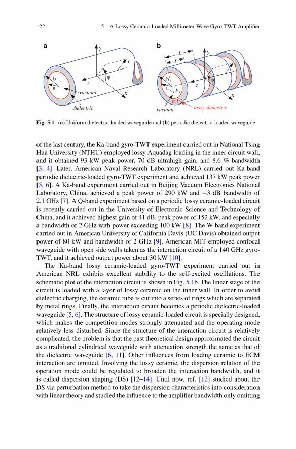
122 5 A Lossy Ceramic-Loaded Millimeter-Wave Gyro-TWT Amplifier
x
y
z
r
ϕ
a
b
vacuum
dielectric
a
b
vacuum lossy dielectric
x
y
z
rI
Lba
ϕ
e1 m1
e2 m2
Fig. 5.1 (a) Uniform dielectric-loaded waveguide and (b) periodic dielectric-loaded waveguide
of the last century, the Ka-band gyro-TWT experiment carried out in National TsingHua University (NTHU) employed lossy Aquadag loading in the inner circuit wall,and it obtained 93 kW peak power, 70 dB ultrahigh gain, and 8.6 % bandwidth[3, 4]. Later, American Naval Research Laboratory (NRL) carried out Ka-bandperiodic dielectric-loaded gyro-TWT experiment and achieved 137 kW peak power[5, 6]. A Ka-band experiment carried out in Beijing Vacuum Electronics NationalLaboratory, China, achieved a peak power of 290 kW and �3 dB bandwidth of2.1 GHz [7]. A Q-band experiment based on a periodic lossy ceramic-loaded circuitis recently carried out in the University of Electronic Science and Technology ofChina, and it achieved highest gain of 41 dB, peak power of 152 kW, and especiallya bandwidth of 2 GHz with power exceeding 100 kW [8]. The W-band experimentcarried out in American University of California Davis (UC Davis) obtained outputpower of 80 kW and bandwidth of 2 GHz [9]. American MIT employed confocalwaveguide with open side walls taken as the interaction circuit of a 140 GHz gyro-TWT, and it achieved output power about 30 kW [10].
The Ka-band lossy ceramic-loaded gyro-TWT experiment carried out inAmerican NRL exhibits excellent stability to the self-excited oscillations. Theschematic plot of the interaction circuit is shown in Fig. 5.1b. The linear stage of thecircuit is loaded with a layer of lossy ceramic on the inner wall. In order to avoiddielectric charging, the ceramic tube is cut into a series of rings which are separatedby metal rings. Finally, the interaction circuit becomes a periodic dielectric-loadedwaveguide [5, 6]. The structure of lossy ceramic-loaded circuit is specially designed,which makes the competition modes strongly attenuated and the operating moderelatively less disturbed. Since the structure of the interaction circuit is relativelycomplicated, the problem is that the past theoretical design approximated the circuitas a traditional cylindrical waveguide with attenuation strength the same as that ofthe dielectric waveguide [6, 11]. Other influences from loading ceramic to ECMinteraction are omitted. Involving the lossy ceramic, the dispersion relation of theoperation mode could be regulated to broaden the interaction bandwidth, and itis called dispersion shaping (DS) [12–14]. Until now, ref. [12] studied about theDS via perturbation method to take the dispersion characteristics into considerationwith linear theory and studied the influence to the amplifier bandwidth only omitting
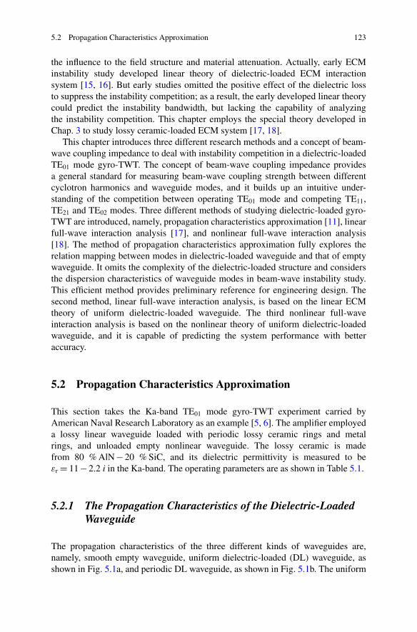
5.2 Propagation Characteristics Approximation 123
the influence to the field structure and material attenuation. Actually, early ECMinstability study developed linear theory of dielectric-loaded ECM interactionsystem [15, 16]. But early studies omitted the positive effect of the dielectric lossto suppress the instability competition; as a result, the early developed linear theorycould predict the instability bandwidth, but lacking the capability of analyzingthe instability competition. This chapter employs the special theory developed inChap. 3 to study lossy ceramic-loaded ECM system [17, 18].
This chapter introduces three different research methods and a concept of beam-wave coupling impedance to deal with instability competition in a dielectric-loadedTE01 mode gyro-TWT. The concept of beam-wave coupling impedance providesa general standard for measuring beam-wave coupling strength between differentcyclotron harmonics and waveguide modes, and it builds up an intuitive under-standing of the competition between operating TE01 mode and competing TE11,TE21 and TE02 modes. Three different methods of studying dielectric-loaded gyro-TWT are introduced, namely, propagation characteristics approximation [11], linearfull-wave interaction analysis [17], and nonlinear full-wave interaction analysis[18]. The method of propagation characteristics approximation fully explores therelation mapping between modes in dielectric-loaded waveguide and that of emptywaveguide. It omits the complexity of the dielectric-loaded structure and considersthe dispersion characteristics of waveguide modes in beam-wave instability study.This efficient method provides preliminary reference for engineering design. Thesecond method, linear full-wave interaction analysis, is based on the linear ECMtheory of uniform dielectric-loaded waveguide. The third nonlinear full-waveinteraction analysis is based on the nonlinear theory of uniform dielectric-loadedwaveguide, and it is capable of predicting the system performance with betteraccuracy.
5.2 Propagation Characteristics Approximation
This section takes the Ka-band TE01 mode gyro-TWT experiment carried byAmerican Naval Research Laboratory as an example [5, 6]. The amplifier employeda lossy linear waveguide loaded with periodic lossy ceramic rings and metalrings, and unloaded empty nonlinear waveguide. The lossy ceramic is madefrom 80 % AlN � 20 % SiC, and its dielectric permittivity is measured to be"r D 11 � 2.2 i in the Ka-band. The operating parameters are as shown in Table 5.1.
5.2.1 The Propagation Characteristics of the Dielectric-LoadedWaveguide
The propagation characteristics of the three different kinds of waveguides are,namely, smooth empty waveguide, uniform dielectric-loaded (DL) waveguide, asshown in Fig. 5.1a, and periodic DL waveguide, as shown in Fig. 5.1b. The uniform
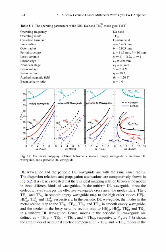
124 5 A Lossy Ceramic-Loaded Millimeter-Wave Gyro-TWT Amplifier
Table 5.1 The operating parameters of the NRL Ka-band TE(1)01 mode gyro-TWT
Operating frequency Ka-bandOperating mode TE01
Cyclotron harmonic FundamentalInner radius a D 5.495 mmOuter radius b D 6.905 mmPeriod structure L D 11.5 mm, I D 10 mmLossy ceramic "r D 11 � 2.2j, �r D 1Linear stage L1 D 230 mmNonlinear stage L2 D 40 mmBeam voltage V D 70 kVBeam current Ib D 10 AApplied magnetic field B0 D 1.26 TBeam velocity ratio ˛ D 1.0
Fig. 5.2 The mode mapping relation between a smooth empty waveguide, a uniform DLwaveguide, and a periodic DL waveguide
DL waveguide and the periodic DL waveguide are with the same inner radius.The dispersion relations and propagation attenuations are comparatively shown inFig. 5.2. It is clearly revealed that there is ideal mapping relation between the modesin three different kinds of waveguides. In the uniform DL waveguide, since thedielectric layer enlarges the effective waveguide cross area, the modes TE11, TE21,TE01 and TE02 in smooth empty waveguide map to the high-order modes HEd
12,HEd
22, TEd02 and TEd
04, respectively. In the periodic DL waveguide, the modes in themetal section map to the TE11, TE21, TE01 and TE02 in smooth empty waveguide,and the modes in the lossy ceramic section map to HEd
12, HEd22, TEd
02 and TEd04
in a uniform DL waveguide. Hence, modes in the periodic DL waveguide aredefined as � TE11, � TE21, � TE01, and � TE02, respectively. Figure 5.3a showsthe amplitudes of azimuthal electric component of � TE01 and � TE02 modes in the
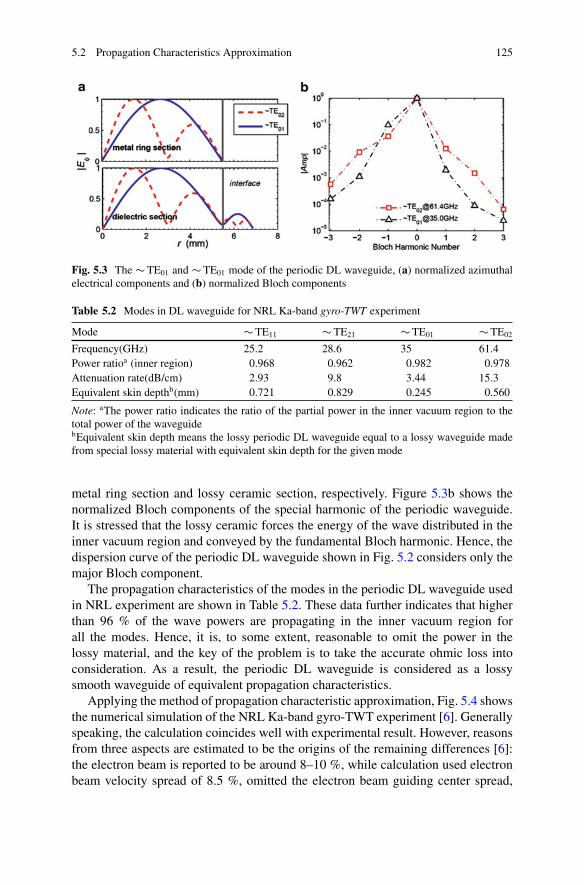
5.2 Propagation Characteristics Approximation 125
Fig. 5.3 The � TE01 and � TE01 mode of the periodic DL waveguide, (a) normalized azimuthalelectrical components and (b) normalized Bloch components
Table 5.2 Modes in DL waveguide for NRL Ka-band gyro-TWT experiment
Mode � TE11 � TE21 � TE01 � TE02
Frequency(GHz) 25.2 28.6 35 61.4Power ratioa (inner region) 0.968 0.962 0.982 0.978Attenuation rate(dB/cm) 2.93 9.8 3.44 15.3Equivalent skin depthb(mm) 0.721 0.829 0.245 0.560
Note: aThe power ratio indicates the ratio of the partial power in the inner vacuum region to thetotal power of the waveguidebEquivalent skin depth means the lossy periodic DL waveguide equal to a lossy waveguide madefrom special lossy material with equivalent skin depth for the given mode
metal ring section and lossy ceramic section, respectively. Figure 5.3b shows thenormalized Bloch components of the special harmonic of the periodic waveguide.It is stressed that the lossy ceramic forces the energy of the wave distributed in theinner vacuum region and conveyed by the fundamental Bloch harmonic. Hence, thedispersion curve of the periodic DL waveguide shown in Fig. 5.2 considers only themajor Bloch component.
The propagation characteristics of the modes in the periodic DL waveguide usedin NRL experiment are shown in Table 5.2. These data further indicates that higherthan 96 % of the wave powers are propagating in the inner vacuum region forall the modes. Hence, it is, to some extent, reasonable to omit the power in thelossy material, and the key of the problem is to take the accurate ohmic loss intoconsideration. As a result, the periodic DL waveguide is considered as a lossysmooth waveguide of equivalent propagation characteristics.
Applying the method of propagation characteristic approximation, Fig. 5.4 showsthe numerical simulation of the NRL Ka-band gyro-TWT experiment [6]. Generallyspeaking, the calculation coincides well with experimental result. However, reasonsfrom three aspects are estimated to be the origins of the remaining differences [6]:the electron beam is reported to be around 8–10 %, while calculation used electronbeam velocity spread of 8.5 %, omitted the electron beam guiding center spread,
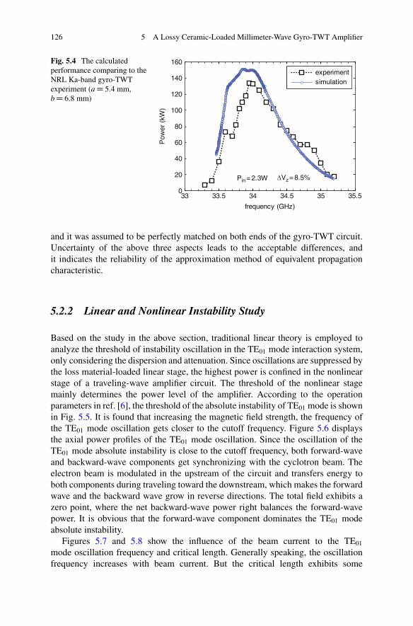
126 5 A Lossy Ceramic-Loaded Millimeter-Wave Gyro-TWT Amplifier
33 33.5 34 34.5 35 35.50
20
40
60
80
100
120
140
160
frequency (GHz)
Pow
er (
kW)
experimentsimulation
Pin= 2.3W ΔVz= 8.5%
Fig. 5.4 The calculatedperformance comparing to theNRL Ka-band gyro-TWTexperiment (a D 5.4 mm,b D 6.8 mm)
and it was assumed to be perfectly matched on both ends of the gyro-TWT circuit.Uncertainty of the above three aspects leads to the acceptable differences, andit indicates the reliability of the approximation method of equivalent propagationcharacteristic.
5.2.2 Linear and Nonlinear Instability Study
Based on the study in the above section, traditional linear theory is employed toanalyze the threshold of instability oscillation in the TE01 mode interaction system,only considering the dispersion and attenuation. Since oscillations are suppressed bythe loss material-loaded linear stage, the highest power is confined in the nonlinearstage of a traveling-wave amplifier circuit. The threshold of the nonlinear stagemainly determines the power level of the amplifier. According to the operationparameters in ref. [6], the threshold of the absolute instability of TE01 mode is shownin Fig. 5.5. It is found that increasing the magnetic field strength, the frequency ofthe TE01 mode oscillation gets closer to the cutoff frequency. Figure 5.6 displaysthe axial power profiles of the TE01 mode oscillation. Since the oscillation of theTE01 mode absolute instability is close to the cutoff frequency, both forward-waveand backward-wave components get synchronizing with the cyclotron beam. Theelectron beam is modulated in the upstream of the circuit and transfers energy toboth components during traveling toward the downstream, which makes the forwardwave and the backward wave grow in reverse directions. The total field exhibits azero point, where the net backward-wave power right balances the forward-wavepower. It is obvious that the forward-wave component dominates the TE01 modeabsolute instability.
Figures 5.7 and 5.8 show the influence of the beam current to the TE01
mode oscillation frequency and critical length. Generally speaking, the oscillationfrequency increases with beam current. But the critical length exhibits some
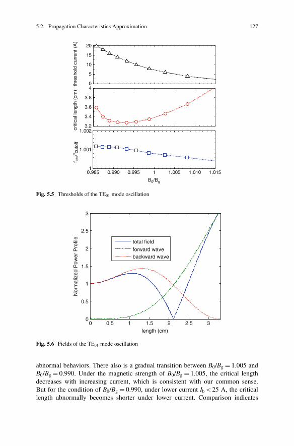
5.2 Propagation Characteristics Approximation 127
3.2
3.4
3.6
3.8
4
criti
cal l
engt
h (c
m)
0.985 0.990 0.995
f osc
/f cut
off
1 1.005 1.010 1.0151
1.001
1.002
B0/Bg
0
5
10
15
20
thre
shol
d cu
rren
t (A
)
Fig. 5.5 Thresholds of the TE01 mode oscillation
0 0.5 1 1.5 2 2.5 30
0.5
1
1.5
2
2.5
3
length (cm)
Nor
mal
ized
Pow
er P
rofil
e
total field
forward wavebackward wave
Fig. 5.6 Fields of the TE01 mode oscillation
abnormal behaviors. There also is a gradual transition between B0/Bg D 1.005 andB0/Bg D 0.990. Under the magnetic strength of B0/Bg D 1.005, the critical lengthdecreases with increasing current, which is consistent with our common sense.But for the condition of B0/Bg D 0.990, under lower current Ib < 25 A, the criticallength abnormally becomes shorter under lower current. Comparison indicates
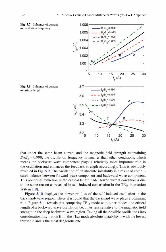
128 5 A Lossy Ceramic-Loaded Millimeter-Wave Gyro-TWT Amplifier
Fig. 5.7 Influence of currentto oscillation frequency
Fig. 5.8 Influence of currentto critical length
that under the same beam current and the magnetic field strength maintainingB0/Bg D 0.990, the oscillation frequency is smaller than other conditions, whichmeans the backward-wave component plays a relatively more important role inthe oscillation and enhances the feedback strength accordingly. This is obviouslyrevealed in Fig. 5.9. The oscillation of an absolute instability is a result of compli-cated balance between forward-wave component and backward-wave component.This abnormal reduction in the critical length under lower current condition is dueto the same reason as revealed in self-induced constriction in the TE11 interactionsystem [19].
Figure 5.10 displays the power profiles of the self-induced oscillation in thebackward-wave region, where it is found that the backward wave plays a dominantrole. Figure 5.11 reveals that comparing TE11 mode with other modes, the criticallength of a backward-wave oscillation becomes less sensitive to the magnetic fieldstrength in the deep backward-wave region. Taking all the possible oscillations intoconsideration, oscillation from the TE01 mode absolute instability is with the lowestthreshold and is the most dangerous one.

5.2 Propagation Characteristics Approximation 129
Fig. 5.9 The balancebetween forward-wavecomponent andbackward-wave componentof the sampled conditions
Fig. 5.10 Normalized axialpower profile of oscillation inbackward-wave region
1.25 1.255 1.26 1.265 1.27 1.275 1.283
4
5
6
7
8
9
B0 (T)
criti
cal l
engt
h (c
m)
TE11
TE21
TE02
TE01
B0/Bg= 0.99
Fig. 5.11 Influence ofmagnetic field to the criticallength
The nonlinear self-consistent theory could take both the linear stage and thenonlinear stage into consideration [11, 19, 20]. Figure 5.12 shows the axial fieldprofiles of the four oscillations in the circuit, under both lossy dielectric andAquadag ( D 8 e 4cu) conditions. The lossy material suppresses the fields ofoscillations, and the high power of each mode is limited in the nonlinear stage.These oscillations are also called local axial modes [21]. Comparatively studyFigs. 5.5, 5.9, 5.10, and 5.12, it is found that the oscillation profiles in the nonlinearstage, or called local fundamental axial modes, are quite consistent with that of
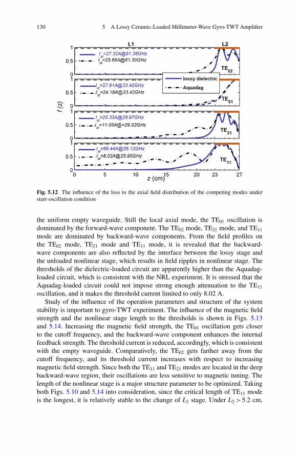
130 5 A Lossy Ceramic-Loaded Millimeter-Wave Gyro-TWT Amplifier
Fig. 5.12 The influence of the loss to the axial field distribution of the competing modes understart-oscillation condition
the uniform empty waveguide. Still the local axial mode, the TE01 oscillation isdominated by the forward-wave component. The TE02 mode, TE21 mode, and TE11
mode are dominated by backward-wave components. From the field profiles onthe TE02 mode, TE21 mode and TE11 mode, it is revealed that the backward-wave components are also reflected by the interface between the lossy stage andthe unloaded nonlinear stage, which results in field ripples in nonlinear stage. Thethresholds of the dielectric-loaded circuit are apparently higher than the Aquadag-loaded circuit, which is consistent with the NRL experiment. It is stressed that theAquadag-loaded circuit could not impose strong enough attenuation to the TE11
oscillation, and it makes the threshold current limited to only 8.02 A.Study of the influence of the operation parameters and structure of the system
stability is important to gyro-TWT experiment. The influence of the magnetic fieldstrength and the nonlinear stage length to the thresholds is shown in Figs. 5.13and 5.14. Increasing the magnetic field strength, the TE01 oscillation gets closerto the cutoff frequency, and the backward-wave component enhances the internalfeedback strength. The threshold current is reduced, accordingly, which is consistentwith the empty waveguide. Comparatively, the TE02 gets farther away from thecutoff frequency, and its threshold current increases with respect to increasingmagnetic field strength. Since both the TE11 and TE21 modes are located in the deepbackward-wave region, their oscillations are less sensitive to magnetic tuning. Thelength of the nonlinear stage is a major structure parameter to be optimized. Takingboth Figs. 5.10 and 5.14 into consideration, since the critical length of TE11 modeis the longest, it is relatively stable to the change of L2 stage. Under L2 > 5.2 cm,

5.2 Propagation Characteristics Approximation 131
0.985 0.99 0.995 1 1.005 1.01 1.01510
20
30
40
50
60
70
B0/Bg
I c (
A)
TE01
TE02TE21
TE11
Fig. 5.13 Influence ofmagnetic field to thresholdcurrent
I c (
A)
L2 (cm)3 3.5 4 4.5 5 5.5 6
0
20
40
60
80
100
TE21
TE02
TE11
TE01
Fig. 5.14 Influence of thenonlinear stage length tothreshold current
the threshold currents of both TE21 and TE02 mode oscillations are smaller than10 A, and the threshold currents of TE01 mode oscillation become quite close to the10 A. During the engineering design of a gyro-TWT, a margin safe enough shouldbe maintained between the operation current and the threshold current to guaranteezero-drive stability.
The amplification performances of the system under velocity spread of 3 %are demonstrated in Figs. 5.15 and 5.16. The amplification profile in Fig. 5.15shows that the backward wave grows inversely in the nonlinear stage and seriouslyattenuated in the lossy linear stage during propagating toward upstream. Theforward-wave component exponentially grows along with the forward travelingelectron beam. The dissipated power by ohm loss primarily concentrates in thedownstream end of the lossy stage, which determines the average power level of thesystem. The amplification profile in Fig. 5.16 shows that the system could generate223 kW at frequency of 33.59 GHz under 3 W drive power and efficiency about
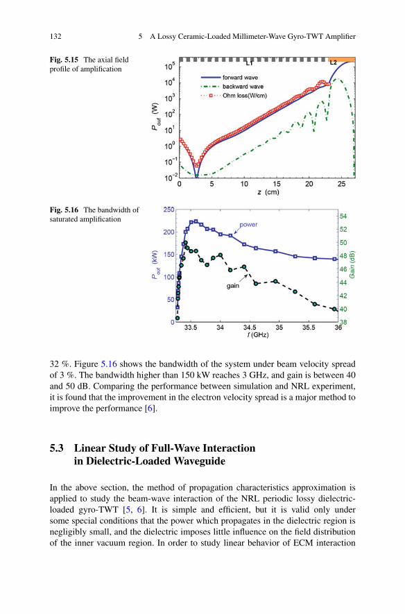
132 5 A Lossy Ceramic-Loaded Millimeter-Wave Gyro-TWT Amplifier
Fig. 5.15 The axial fieldprofile of amplification
Fig. 5.16 The bandwidth ofsaturated amplification
32 %. Figure 5.16 shows the bandwidth of the system under beam velocity spreadof 3 %. The bandwidth higher than 150 kW reaches 3 GHz, and gain is between 40and 50 dB. Comparing the performance between simulation and NRL experiment,it is found that the improvement in the electron velocity spread is a major method toimprove the performance [6].
5.3 Linear Study of Full-Wave Interactionin Dielectric-Loaded Waveguide
In the above section, the method of propagation characteristics approximation isapplied to study the beam-wave interaction of the NRL periodic lossy dielectric-loaded gyro-TWT [5, 6]. It is simple and efficient, but it is valid only undersome special conditions that the power which propagates in the dielectric region isnegligibly small, and the dielectric imposes little influence on the field distributionof the inner vacuum region. In order to study linear behavior of ECM interaction
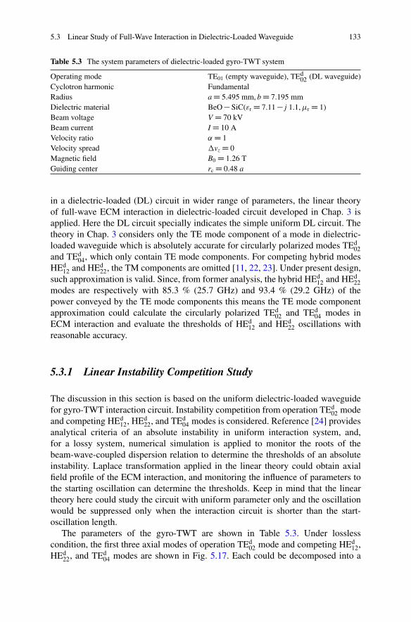
5.3 Linear Study of Full-Wave Interaction in Dielectric-Loaded Waveguide 133
Table 5.3 The system parameters of dielectric-loaded gyro-TWT system
Operating mode TE01 (empty waveguide), TEd02 (DL waveguide)
Cyclotron harmonic FundamentalRadius a D 5.495 mm, b D 7.195 mmDielectric material BeO � SiC("r D 7.11 � j 1.1, �r D 1)Beam voltage V D 70 kVBeam current I D 10 AVelocity ratio ˛ D 1Velocity spread �vz D 0Magnetic field B0 D 1.26 TGuiding center rc D 0.48 a
in a dielectric-loaded (DL) circuit in wider range of parameters, the linear theoryof full-wave ECM interaction in dielectric-loaded circuit developed in Chap. 3 isapplied. Here the DL circuit specially indicates the simple uniform DL circuit. Thetheory in Chap. 3 considers only the TE mode component of a mode in dielectric-loaded waveguide which is absolutely accurate for circularly polarized modes TEd
02and TEd
04, which only contain TE mode components. For competing hybrid modesHEd
12 and HEd22, the TM components are omitted [11, 22, 23]. Under present design,
such approximation is valid. Since, from former analysis, the hybrid HEd12 and HEd
22modes are respectively with 85.3 % (25.7 GHz) and 93.4 % (29.2 GHz) of thepower conveyed by the TE mode components this means the TE mode componentapproximation could calculate the circularly polarized TEd
02 and TEd04 modes in
ECM interaction and evaluate the thresholds of HEd12 and HEd
22 oscillations withreasonable accuracy.
5.3.1 Linear Instability Competition Study
The discussion in this section is based on the uniform dielectric-loaded waveguidefor gyro-TWT interaction circuit. Instability competition from operation TEd
02 modeand competing HEd
12, HEd22, and TEd
04 modes is considered. Reference [24] providesanalytical criteria of an absolute instability in uniform interaction system, and,for a lossy system, numerical simulation is applied to monitor the roots of thebeam-wave-coupled dispersion relation to determine the thresholds of an absoluteinstability. Laplace transformation applied in the linear theory could obtain axialfield profile of the ECM interaction, and monitoring the influence of parameters tothe starting oscillation can determine the thresholds. Keep in mind that the lineartheory here could study the circuit with uniform parameter only and the oscillationwould be suppressed only when the interaction circuit is shorter than the start-oscillation length.
The parameters of the gyro-TWT are shown in Table 5.3. Under losslesscondition, the first three axial modes of operation TEd
02 mode and competing HEd12,
HEd22, and TEd
04 modes are shown in Fig. 5.17. Each could be decomposed into a
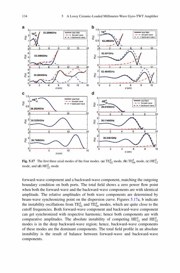
134 5 A Lossy Ceramic-Loaded Millimeter-Wave Gyro-TWT Amplifier
Fig. 5.17 The first three axial modes of the four modes. (a) TEd02 mode, (b) TEd
04 mode, (c) HEd12
mode, and (d) HEd22 mode
forward-wave component and a backward-wave component, matching the outgoingboundary condition on both ports. The total field shows a zero power flow pointwhen both the forward-wave and the backward-wave components are with identicalamplitude. The relative amplitudes of both wave components are determined bybeam-wave synchronizing point on the dispersion curve. Figures 5.17a, b indicatethe instability oscillations from TEd
02 and TEd04 modes, which are quite close to the
cutoff frequencies. Both forward-wave component and backward-wave componentcan get synchronized with respective harmonic; hence both components are withcomparative amplitudes. The absolute instability of competing HEd
12 and HEd22
modes is in the deep backward-wave region; hence, backward-wave componentsof these modes are the dominant components. The total field profile in an absoluteinstability is the result of balance between forward-wave and backward-wavecomponents.
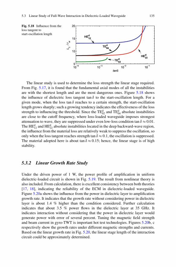
5.3 Linear Study of Full-Wave Interaction in Dielectric-Loaded Waveguide 135
Fig. 5.18 Influence from theloss tangent tostart-oscillation length
The linear study is used to determine the loss strength the linear stage required.From Fig. 5.17, it is found that the fundamental axial modes of all the instabilitiesare with the shortest length and are the most dangerous ones. Figure 5.18 showsthe influence of dielectric loss tangent tan ı to the start-oscillation length. For agiven mode, when the loss tan ı reaches to a certain strength, the start-oscillationlength grows sharply; such a growing tendency indicates the effectiveness of the lossstrength to influencing the threshold. Since the TEd
02 and TEd04 absolute instabilities
are close to the cutoff frequency, where loss-loaded waveguide imposes strongestattenuation to wave, they are suppressed under even low-loss condition tan ı � 0.01.The HEd
12 and HEd22 absolute instabilities located in the deep backward-wave region,
the influence from the material loss are relatively weak to suppress the oscillation, soonly when the loss tangent reaches strength tan ı � 0.1, the oscillation is suppressed.The material adopted here is about tan ı � 0.15; hence, the linear stage is of highstability.
5.3.2 Linear Growth Rate Study
Under the driven power of 1 W, the power profile of amplification in uniformdielectric-loaded circuit is shown in Fig. 5.19. The result from nonlinear theory isalso included. From calculation, there is excellent consistency between both theories[17, 18], indicating the reliability of the ECM in dielectric-loaded waveguide.Figure 5.20a shows the influence from the power in dielectric layer to amplificationgrowth rate. It indicates that the growth rate without considering power in dielectriclayer is about 1.4 % higher than the condition considered. Further calculationindicates that about 3.5 % power flows in the dielectric layer at 35 GHz. Itindicates interaction without considering that the power in dielectric layer wouldgenerate power with error of several percent. Tuning the magnetic field strengthand beam current in gyro-TWT is important hot test technologies. Figures 5.20b, crespectively show the growth rates under different magnetic strengths and currents.Based on the linear growth rate in Fig. 5.20, the linear stage length of the interactioncircuit could be approximately determined.
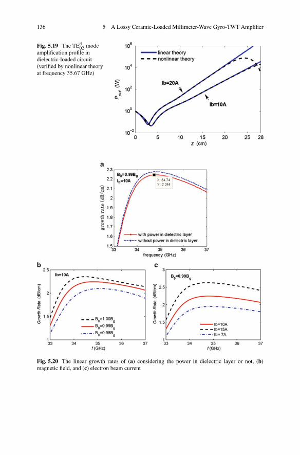
136 5 A Lossy Ceramic-Loaded Millimeter-Wave Gyro-TWT Amplifier
Fig. 5.19 The TEd02 mode
amplification profile indielectric-loaded circuit(verified by nonlinear theoryat frequency 35.67 GHz)
Fig. 5.20 The linear growth rates of (a) considering the power in dielectric layer or not, (b)magnetic field, and (c) electron beam current
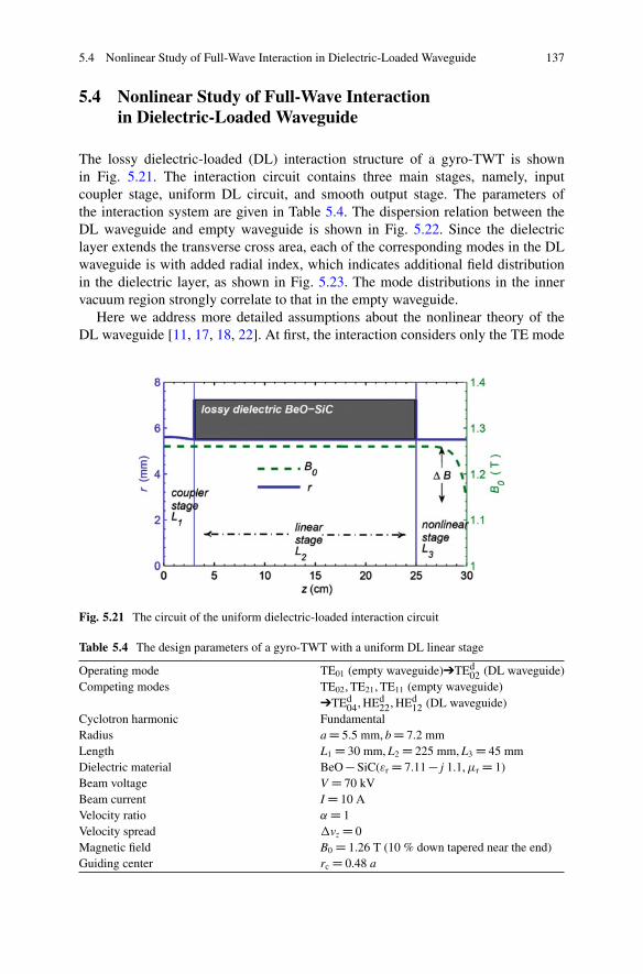
5.4 Nonlinear Study of Full-Wave Interaction in Dielectric-Loaded Waveguide 137
5.4 Nonlinear Study of Full-Wave Interactionin Dielectric-Loaded Waveguide
The lossy dielectric-loaded (DL) interaction structure of a gyro-TWT is shownin Fig. 5.21. The interaction circuit contains three main stages, namely, inputcoupler stage, uniform DL circuit, and smooth output stage. The parameters ofthe interaction system are given in Table 5.4. The dispersion relation between theDL waveguide and empty waveguide is shown in Fig. 5.22. Since the dielectriclayer extends the transverse cross area, each of the corresponding modes in the DLwaveguide is with added radial index, which indicates additional field distributionin the dielectric layer, as shown in Fig. 5.23. The mode distributions in the innervacuum region strongly correlate to that in the empty waveguide.
Here we address more detailed assumptions about the nonlinear theory of theDL waveguide [11, 17, 18, 22]. At first, the interaction considers only the TE mode
Fig. 5.21 The circuit of the uniform dielectric-loaded interaction circuit
Table 5.4 The design parameters of a gyro-TWT with a uniform DL linear stage
Operating mode TE01 (empty waveguide)➔TEd02 (DL waveguide)
Competing modes TE02, TE21, TE11 (empty waveguide)➔TEd
04, HEd22, HEd
12 (DL waveguide)Cyclotron harmonic FundamentalRadius a D 5.5 mm, b D 7.2 mmLength L1 D 30 mm, L2 D 225 mm, L3 D 45 mmDielectric material BeO � SiC("r D 7.11 � j 1.1, �r D 1)Beam voltage V D 70 kVBeam current I D 10 AVelocity ratio ˛ D 1Velocity spread �vz D 0Magnetic field B0 D 1.26 T (10 % down tapered near the end)Guiding center rc D 0.48 a

138 5 A Lossy Ceramic-Loaded Millimeter-Wave Gyro-TWT Amplifier
Fig. 5.22 The dispersion relations in (a) a uniform dielectric-loaded circuit and (b) emptywaveguide
7HE
d12 HE
d22 TE
d02 TE
d04
5
3
1
3 5 7 7−7 −7−5 −3 −1 1 53 7−5 −3 −1 1 53 −7 70
0.2
0.4
0.6
0.8
1
−5 −3 −1 1 53
radius(mm)radius(mm)radius(mm)radius(mm)
radi
us(m
m)
−1
1−1
−3
−3
−5
−5−7
−7
Fig. 5.23 Field distribution of the modes in DL waveguide
component, which is addressed in the last section. Secondly, the field amplitudeis assumed to be continuous at a connection between the dielectric waveguideand empty waveguide. Reasons are as follows: inner radius of the connection iscontinuous and the boundary matching condition at a connection leads to high-ordercomponents which are much weaker than the major mode; the power of a modeis concentrated in the inner vacuum region. The ratios of the power in the vacuumregion-to-total power are respectively HEd
12 mode 0.934 (26 GHz), HEd22 mode 0.927
(29.6 GHz), TEd02 mode 0.965 (35 GHz), and TEd
04 mode 0.948 (61 GHz). Thirdly,the axial field strength at a connection is relatively weak comparing to that of thenonlinear stage. The error from the assumption is with relative small influence.In a word, nonlinear theory could evaluate the interaction in the DL circuit withacceptable accuracy.
5.4.1 Nonlinear Instability Competition Study
Due to the mapping relation between the modes in DL waveguide and smoothwaveguide, a lot of the Ka-band DL gyro-TWT studies focus on instabilitycompetition between the mode pairs TEd
02 � TE01, TEd04 � TE02, HEd
12 � TE11, andHEd
22 � TE21. From the cold dispersion relation in Fig. 5.22, it is found that
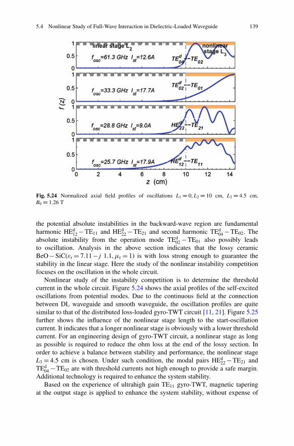
5.4 Nonlinear Study of Full-Wave Interaction in Dielectric-Loaded Waveguide 139
Fig. 5.24 Normalized axial field profiles of oscillations L1 D 0, L2 D 10 cm, L3 D 4.5 cm,B0 D 1.26 T
the potential absolute instabilities in the backward-wave region are fundamentalharmonic HEd
12 � TE11 and HEd22 � TE21 and second harmonic TEd
04 � TE02. Theabsolute instability from the operation mode TEd
02 � TE01 also possibly leadsto oscillation. Analysis in the above section indicates that the lossy ceramicBeO � SiC("r D 7.11 � j 1.1, �r D 1) is with loss strong enough to guarantee thestability in the linear stage. Here the study of the nonlinear instability competitionfocuses on the oscillation in the whole circuit.
Nonlinear study of the instability competition is to determine the thresholdcurrent in the whole circuit. Figure 5.24 shows the axial profiles of the self-excitedoscillations from potential modes. Due to the continuous field at the connectionbetween DL waveguide and smooth waveguide, the oscillation profiles are quitesimilar to that of the distributed loss-loaded gyro-TWT circuit [11, 21]. Figure 5.25further shows the influence of the nonlinear stage length to the start-oscillationcurrent. It indicates that a longer nonlinear stage is obviously with a lower thresholdcurrent. For an engineering design of gyro-TWT circuit, a nonlinear stage as longas possible is required to reduce the ohm loss at the end of the lossy section. Inorder to achieve a balance between stability and performance, the nonlinear stageL3 D 4.5 cm is chosen. Under such condition, the modal pairs HEd
22 � TE21 andTEd
04 � TE02 are with threshold currents not high enough to provide a safe margin.Additional technology is required to enhance the system stability.
Based on the experience of ultrahigh gain TE11 gyro-TWT, magnetic taperingat the output stage is applied to enhance the system stability, without expense of
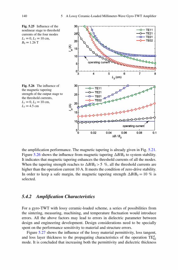
140 5 A Lossy Ceramic-Loaded Millimeter-Wave Gyro-TWT Amplifier
Fig. 5.25 Influence of thenonlinear stage to thresholdcurrents of the four modesL1 D 0, L2 D 10 cm,B0 D 1.26 T
Fig. 5.26 The influence ofthe magnetic taperingstrength of the output stage tothe threshold currents,L1 D 0, L2 D 10 cm,L3 D 4.5 cm
the amplification performance. The magnetic tapering is already given in Fig. 5.21.Figure 5.26 shows the influence from magnetic tapering �B/B0 to system stability.It indicates that magnetic tapering enhances the threshold currents of all the modes.When the tapering strength reaches to �B/B0 > 5 %, all the threshold currents arehigher than the operation current 10 A. It meets the condition of zero-drive stability.In order to keep a safe margin, the magnetic tapering strength �B/B0 D 10 % isselected.
5.4.2 Amplification Characteristics
For a gyro-TWT with lossy ceramic-loaded scheme, a series of possibilities fromthe sintering, measuring, machining, and temperature fluctuation would introduceerrors. All the above factors may lead to errors in dielectric parameter betweendesign and engineering development. Design considerations need to be speciallyspent on the performance sensitivity to material and structure errors.
Figure 5.27 shows the influence of the lossy material permittivity, loss tangent,and loss layer thickness to the propagating characteristics of the operation TEd
02mode. It is concluded that increasing both the permittivity and dielectric thickness
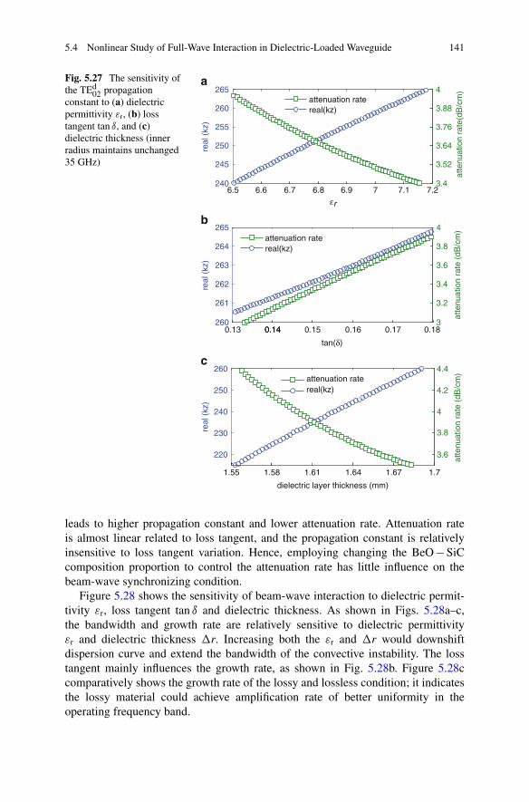
5.4 Nonlinear Study of Full-Wave Interaction in Dielectric-Loaded Waveguide 141
6.5 6.6 6.7 6.8 6.9 7 7.1 7.2240
245
250
255
260
265
real
(kz
)
a
b
c
3.4
3.52
3.64
3.76
3.88
4
atte
nuat
ion
rate
(dB
/cm
)
attenuation ratereal(kz)
0.13 0.14 0.15 0.16 0.17 0.18260
261
262
263
264
265
tan(δ)
εrre
al (
kz)
0.143
3.2
3.4
3.6
3.8
4
atte
nuat
ion
rate
(dB
/cm
)
attenuation ratereal(kz)
1.55 1.58 1.61 1.64 1.67 1.7
220
230
240
250
260
dielectric layer thickness (mm)
real
(kz
)
3.6
3.8
4
4.2
4.4
atte
nuat
ion
rate
(dB
/cm
)
attenuation ratereal(kz)
Fig. 5.27 The sensitivity ofthe TEd
02 propagationconstant to (a) dielectricpermittivity "r, (b) losstangent tan ı, and (c)dielectric thickness (innerradius maintains unchanged35 GHz)
leads to higher propagation constant and lower attenuation rate. Attenuation rateis almost linear related to loss tangent, and the propagation constant is relativelyinsensitive to loss tangent variation. Hence, employing changing the BeO � SiCcomposition proportion to control the attenuation rate has little influence on thebeam-wave synchronizing condition.
Figure 5.28 shows the sensitivity of beam-wave interaction to dielectric permit-tivity "r, loss tangent tan ı and dielectric thickness. As shown in Figs. 5.28a–c,the bandwidth and growth rate are relatively sensitive to dielectric permittivity"r and dielectric thickness �r. Increasing both the "r and �r would downshiftdispersion curve and extend the bandwidth of the convective instability. The losstangent mainly influences the growth rate, as shown in Fig. 5.28b. Figure 5.28ccomparatively shows the growth rate of the lossy and lossless condition; it indicatesthe lossy material could achieve amplification rate of better uniformity in theoperating frequency band.
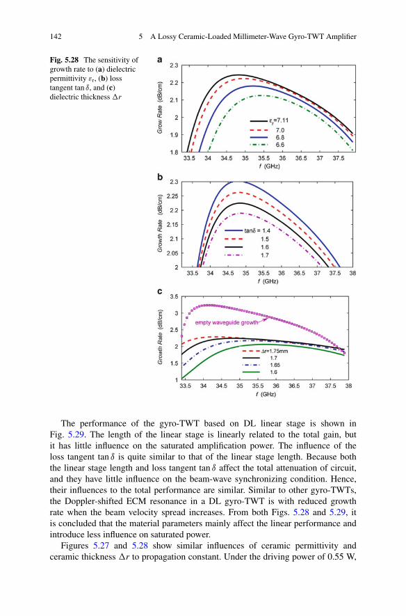
142 5 A Lossy Ceramic-Loaded Millimeter-Wave Gyro-TWT Amplifier
Fig. 5.28 The sensitivity ofgrowth rate to (a) dielectricpermittivity "r, (b) losstangent tan ı, and (c)dielectric thickness �r
The performance of the gyro-TWT based on DL linear stage is shown inFig. 5.29. The length of the linear stage is linearly related to the total gain, butit has little influence on the saturated amplification power. The influence of theloss tangent tan ı is quite similar to that of the linear stage length. Because boththe linear stage length and loss tangent tan ı affect the total attenuation of circuit,and they have little influence on the beam-wave synchronizing condition. Hence,their influences to the total performance are similar. Similar to other gyro-TWTs,the Doppler-shifted ECM resonance in a DL gyro-TWT is with reduced growthrate when the beam velocity spread increases. From both Figs. 5.28 and 5.29, itis concluded that the material parameters mainly affect the linear performance andintroduce less influence on saturated power.
Figures 5.27 and 5.28 show similar influences of ceramic permittivity andceramic thickness �r to propagation constant. Under the driving power of 0.55 W,
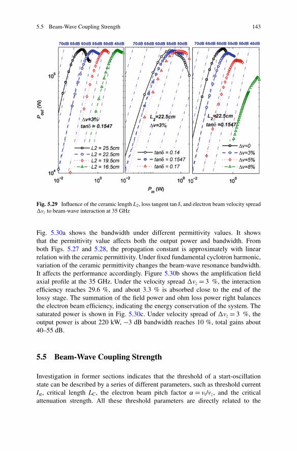
5.5 Beam-Wave Coupling Strength 143
Fig. 5.29 Influence of the ceramic length L2, loss tangent tan ı, and electron beam velocity spread�vz to beam-wave interaction at 35 GHz
Fig. 5.30a shows the bandwidth under different permittivity values. It showsthat the permittivity value affects both the output power and bandwidth. Fromboth Figs. 5.27 and 5.28, the propagation constant is approximately with linearrelation with the ceramic permittivity. Under fixed fundamental cyclotron harmonic,variation of the ceramic permittivity changes the beam-wave resonance bandwidth.It affects the performance accordingly. Figure 5.30b shows the amplification fieldaxial profile at the 35 GHz. Under the velocity spread �vz D 3 %, the interactionefficiency reaches 29.6 %, and about 3.3 % is absorbed close to the end of thelossy stage. The summation of the field power and ohm loss power right balancesthe electron beam efficiency, indicating the energy conservation of the system. Thesaturated power is shown in Fig. 5.30c. Under velocity spread of �vz D 3 %, theoutput power is about 220 kW, �3 dB bandwidth reaches 10 %, total gains about40–55 dB.
5.5 Beam-Wave Coupling Strength
Investigation in former sections indicates that the threshold of a start-oscillationstate can be described by a series of different parameters, such as threshold currentIst, critical length LC, the electron beam pitch factor ˛ D vt/vz, and the criticalattenuation strength. All these threshold parameters are directly related to the

144 5 A Lossy Ceramic-Loaded Millimeter-Wave Gyro-TWT Amplifier
Fig. 5.30 (a) Sensitivity ofthe output power to ceramicpermittivity, (b) amplificationprofile and interactionefficiency, and (c) saturatedpower and efficiency(velocity spread �vz D 3 %)
beam-wave coupling strength. Once the beam-wave coupling strength exceeds thecritical strength of start-oscillation state, the ECM system turns into efficient self-excited oscillation from perturbation. A gyro-TWT is a complicated system ofmultiple dimensions of freedoms, and the beam-wave coupling strength involvesfactors of various aspects, including the transverse kinetic energy of the electronbeam, beam velocity spread, guiding center location, the EM wave impedance,and waveguide wall loss. Not only beam current Ib, voltage V, and pitch factor ˛
affect the transverse beam kinetic energy but also the beam velocity spread �vz/vz
influences the effective energy interacting with the wave. In a cavity circuit, thequality factor Q is applied to describe the ratio between the energy stored inside and

5.5 Beam-Wave Coupling Strength 145
the dissipation power. While in a gyro-TWT, there is not only the mainly traveling-wave circuit but also some unavoidable disturbance, which may excite small localreflection and rise low-Q spurious mode in the circuit. Keep in mind that a self-excited oscillation in a gyro-TWT circuit oscillates at a frequency decided by boththe traveling-wave circuit and beam condition, not exactly the oscillation frequencyof the low-Q spurious mode in an electron-free circuit. How to describe the beam-wave coupling strength to include the major factors? Former a dimensionlesscoupling factor is defined as [1–3]
Hsm .x; y/ D ˇ̌J 0
s .x/Jm�s.y/ˇ̌2
(5.1)
where x D k?rL, and y D k?rc, k? indicates the transverse wave number, rL andrc indicate the Larmor radius and guiding center radius of the electron beam, sindicates the harmonic number, and m indicates the order of the Bessel Functionof the first kind. Actually, in the field of vacuum electronic devices (VEDs), beam-wave coupling impedance K is applied to describe the beam-wave coupling strengthof a rectilinear VED
K D jU j22P
(5.2)
where U is an equivalent voltage from the�!E of the field and P is the power flows
in the circuit. To make the impedance K suitable to describe an ECM system, theequivalent voltage is defined as the azimuthal integration of the synchronized EMfield component on the Larmor circle
U DZ �
2s
0
Es cos .s/ rLd (5.3)
where s is the cyclotron harmonic number and Es is the synchronized componentof angular electric field on the Larmor circle
Es D j!�1
k?1
f .z/J 0s .k?1rL/ Jm�s .k?1rc/ (5.4)
In a uniform dielectric-loaded waveguide, the coupling impedance is defined as[25]
K D �1jk?1j2 r2L
s2
vp
Gmn
Hsm (5.5)
where the phase velocity of the wave is vp D !/kz and the geometer factor is definedas Gmn D Ka in a uniform empty waveguide
Ka D 2�
jk?1j2aZ
0
"ˇ̌J 0
m .k?1r/ˇ̌2 C
ˇ̌ˇ̌ m
k?1rJm .k?1r/
ˇ̌ˇ̌2#
rdr (5.6)
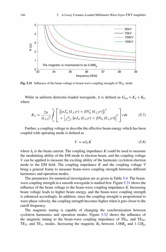
146 5 A Lossy Ceramic-Loaded Millimeter-Wave Gyro-TWT Amplifier
33 34 35 36 37 38 390
1
2
3
4
5
frequency (GHz)
K (
Ω)
50kV70kV100kV
150kV
The magnetic is maintained to be 0.99Bg
Fig. 5.31 Influence of the beam voltage to beam-wave coupling strength of TE01 mode
While in uniform dielectric-loaded waveguide, it is defined as Gmn D Ka C Kb,where
Kb D 2�
jk?2j2bZ
a
24ˇ̌�
˛J 0m .k?2r/ C ˇN 0
m .k?2r/ˇ̌2
Cˇ̌ˇ m
k?2rŒ˛Jm .k?2r/ C ˇNm .k?2r/�
ˇ̌ˇ2
35 rdr (5.7)
Further, a coupling voltage to describe the effective beam energy which has beencoupled with operating mode is defined as
V D ˛IbK (5.8)
where Ib is the beam current. The coupling impedance K could be used to measurethe modulating ability of the EM mode to electron beam, and the coupling voltageV can be applied to measure the exciting ability of the harmonic cyclotron electronmode to the EM field. The coupling impedance K and the coupling voltage Vbring a general frame to measure beam-wave coupling strength between differentharmonics and operation modes.
The parameters for numerical investigation are as given in Table 5.4. The beam-wave coupling strength in a smooth waveguide is studied first. Figure 5.31 shows theinfluence of the beam voltage to the beam-wave coupling impedance K. Increasingbeam voltage leads to higher beam energy, and the beam-wave coupling strengthis enhanced accordingly. In addition, since the coupling strength is proportional towave phase velocity, the coupling strength becomes higher when it gets closer to thecutoff frequency.
The magnetic tuning is capable of changing the synchronization betweencyclotron harmonics and operation modes. Figure 5.32 shows the influence ofthe magnetic tuning to the beam-wave coupling impedance of TE01 and TE02,TE21 and TE11 modes. Increasing the magnetic B0 between 1.00Bg and 1.12Bg,
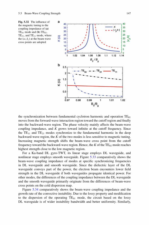
5.5 Beam-Wave Coupling Strength 147
Fig. 5.32 The influence ofthe magnetic tuning to thecoupling impedance of (a)TE01 mode and (b) TE02,TE21, and TE11 mode, wherethe (!, kz) at the beam-wavecross points are adopted
the synchronization between fundamental cyclotron harmonic and operation TE01
moves from the forward-wave interaction region toward the cutoff region and finallyinto the backward-wave region. The phase velocity mainly affects the beam-wavecoupling impedance, and K grows toward infinite at the cutoff frequency. Sincethe TE11 and TE21 modes synchronize to the fundamental harmonic in the deepbackward-wave region, the K of the two modes is less sensitive to magnetic tuning.Increasing magnetic strength shifts the beam-wave cross point from the cutofffrequency toward the backward-wave region. Hence, the K of the TE02 mode reacheshighest strength close to the low magnetic region.
For a Ka-band DL gyro-TWT, its linear stage employs DL waveguide, andnonlinear stage employs smooth waveguide. Figure 5.33 comparatively shows thebeam-wave coupling impedance of modes at specific synchronizing frequenciesin DL waveguide and smooth waveguide. Since the dielectric layer of the DLwaveguide conveys part of the power, the electron beam encounters lower fieldstrength in the DL waveguide if both waveguides propagate identical power. Forother modes, the differences of the coupling impedance between the DL waveguideand the smooth waveguide primarily originate from the differences of beam-wavecross points on the cold dispersion map.
Figure 5.34 comparatively shows the beam-wave coupling impedance and thegrowth rate of the convective instability. Due to the lossy property and modificationto the dispersion of the operating TE01 mode, the circuit based on the lossyDL waveguide is of wider instability bandwidth and better uniformity. Similarly,
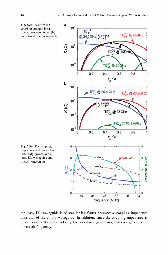
148 5 A Lossy Ceramic-Loaded Millimeter-Wave Gyro-TWT Amplifier
Fig. 5.33 Beam-wavecoupling strength in (a)smooth waveguide and (b)dielectric-loaded waveguide
Fig. 5.34 The couplingimpedance and convectiveinstability growth rate inlossy DL waveguide andsmooth waveguide
the lossy DL waveguide is of smaller but flatter beam-wave coupling impedancethan that of the empty waveguide. In addition, since the coupling impedance isproportional to the phase velocity, the impedance gets stronger when it gets close tothe cutoff frequency.
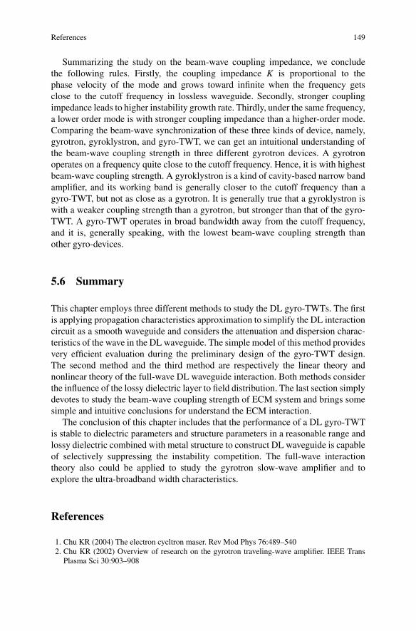
References 149
Summarizing the study on the beam-wave coupling impedance, we concludethe following rules. Firstly, the coupling impedance K is proportional to thephase velocity of the mode and grows toward infinite when the frequency getsclose to the cutoff frequency in lossless waveguide. Secondly, stronger couplingimpedance leads to higher instability growth rate. Thirdly, under the same frequency,a lower order mode is with stronger coupling impedance than a higher-order mode.Comparing the beam-wave synchronization of these three kinds of device, namely,gyrotron, gyroklystron, and gyro-TWT, we can get an intuitional understanding ofthe beam-wave coupling strength in three different gyrotron devices. A gyrotronoperates on a frequency quite close to the cutoff frequency. Hence, it is with highestbeam-wave coupling strength. A gyroklystron is a kind of cavity-based narrow bandamplifier, and its working band is generally closer to the cutoff frequency than agyro-TWT, but not as close as a gyrotron. It is generally true that a gyroklystron iswith a weaker coupling strength than a gyrotron, but stronger than that of the gyro-TWT. A gyro-TWT operates in broad bandwidth away from the cutoff frequency,and it is, generally speaking, with the lowest beam-wave coupling strength thanother gyro-devices.
5.6 Summary
This chapter employs three different methods to study the DL gyro-TWTs. The firstis applying propagation characteristics approximation to simplify the DL interactioncircuit as a smooth waveguide and considers the attenuation and dispersion charac-teristics of the wave in the DL waveguide. The simple model of this method providesvery efficient evaluation during the preliminary design of the gyro-TWT design.The second method and the third method are respectively the linear theory andnonlinear theory of the full-wave DL waveguide interaction. Both methods considerthe influence of the lossy dielectric layer to field distribution. The last section simplydevotes to study the beam-wave coupling strength of ECM system and brings somesimple and intuitive conclusions for understand the ECM interaction.
The conclusion of this chapter includes that the performance of a DL gyro-TWTis stable to dielectric parameters and structure parameters in a reasonable range andlossy dielectric combined with metal structure to construct DL waveguide is capableof selectively suppressing the instability competition. The full-wave interactiontheory also could be applied to study the gyrotron slow-wave amplifier and toexplore the ultra-broadband width characteristics.
References
1. Chu KR (2004) The electron cycltron maser. Rev Mod Phys 76:489–5402. Chu KR (2002) Overview of research on the gyrotron traveling-wave amplifier. IEEE Trans
Plasma Sci 30:903–908
150 5 A Lossy Ceramic-Loaded Millimeter-Wave Gyro-TWT Amplifier
3. Chu KR, Chen HY, Hung CL et al (1998) Ultrahigh gain gyrotron traveling wave amplifier.Phys Rev Lett 81:4760–4763
4. Lau YY, Barnett LR, Granatstein VL (1982) Gyrotron traveling wave amplifier: IV. Analysisof launching losses. Int J Infrared Millim Waves 3:45–62
5. Calame JP, Garven M, Danly BG et al (2002) Gyrotron-traveling wave-tube circuits based onlossy ceramics. IEEE Trans Electron Devices 49:1469–1477
6. Garven M, Calame JP, Danly BG et al (2002) A gyrotron-traveling-wave tube amplifierexperiment with a ceramic loaded interaction region. IEEE Trans Plasma Sci 30:885–893
7. Wang E, Zeng X, Liu BT, Qian LJ, Li ZL, Feng JJ, Zhu SQ (2012) Experimental study of highpower gyrotron traveling wave tube with periodic lossy material loading. IEEE Trans PlasmaSci 40(7):1846–1853
8. Yan R, Luo Y, Liu G, Pu YL (2012) Design and experiment of a Q-band gyro-TWT loadedwith lossy dielectric. IEEE Trans Electron Devices 59(12):3612–3617
9. Song HH, McDermott DB, Hirata Y et al (2004) Theory and experiment of a 94 GHz gyrotrontraveling-wave amplifier. Phys Plasmas 11:2935–2941
10. Sirigiri JR, Shapiro MA, Temkin RJ (2003) High-power 140-GHz quasioptical gyrotrontraveling-wave amplifier. Phys Rev Lett 90:258302
11. Du CH, Liu PK (2009) Stability study of a gyrotron-traveling-wave amplifier based on a lossydielectric-loaded mode-selective circuit. Phys Plasmas 16:073104
12. Rao SJ, Jain PK, Basu BN (1996) Broadbanding of a gyro-TWT by dielectric-loading throughdispersion shaping. IEEE Trans Electron Devices 43:2290–2299
13. Singh G, Chandra SMSR, Bhaskar PV et al (2004) Analysis of a vane-loaded gyro-TWT forthe gain-frequency response. IEEE Trans Plasma Sci 32:2130–2138
14. Singh G, Basu BN (2005) Improved approach for gain-frequency response of vane-loadedgyro-TWT. IEEE Trans Plasma Sci 33:1443–1446
15. Chu KR, Ganguly AK, Granatstein VL et al (1981) Theory of a slow wave cyclotron amplifier.Int J Electron 51:493–502
16. Choe JY, Uhm HS, Ahn S (1981) Analysis of the wide band gyrotron amplifier in a dielectricloaded waveguide. J Appl Phys 52:4508–4516
17. Du CH, Liu PK (2010) Linear full-wave-analysis of dielectric-lined waveguide. IEEE TransPlasma Sci 38(6):1219–1226
18. Du CH, Liu PK (2010) Nonlinear full-wave-analysis dielectric loaded gyro-TWT. PhysPlasmas 17:033104
19. Du CH, Liu PK, Xue QZ et al (2008) Effect of a backward wave on the stability of an ultrahighgain gyrotron traveling-wave amplifier. Phys Plasmas 15:123107
20. Du CH, Liu PK (2009) Stabilization of the potential multi-steady-state absolute instabilities ina gyrotron traveling-wave amplifier. Phys Plasmas 16:103107
21. Chang TH, Chen NC (2006) Transition of absolute instability from global to local modes in agyrotron traveling-wave amplifier. Phys Rev E 74:016402
22. Du CH, Liu PK (2009) A lossy dielectric-ring loaded waveguide with suppressed periodicityfor gyro-TWTs applications. IEEE Trans Electron Devices 56:2335–2342
23. Du CH, Xue QZ, Liu PK et al (2009) Modal transition and reduction in a lossy dielectric-coatedwaveguide for gyrotron-traveling-wave tube amplifier applications. IEEE Trans ElectronDevices 56:839–845
24. Chu KR, Lin AT (1988) Gain and bandwidth of the gyro-TWT and CARM amplifiers. IEEETrans Plasma Sci 16:90–104
25. Du CH, Liu PK (2010) Beam-wave coupling strength analysis in a gyrotron traveling-waveamplifier. J Infrared Millim Terahz Waves 31:714–723
Chapter 6Exploring New Mechanisms for High PowerMillimeter-Wave Gyrotron Amplifiers
Abstract A complex gyrotron amplifier, namely, gyrotron-cascaded pre-bunchingamplifier (gyro-CPA), is proposed in this chapter. The amplifier employs threeinteresting schemes, which are called electron cyclotron maser (ECM)-cascadedamplifier, high-order mode drift tube, and bi-mode operation. These topics areintended for providing solutions to the challenges related to lossy material error con-trol, suppressing instability competitions, and high-power capability in engineeringdeveloping a gyrotron amplifier.
Keywords High power • Millimeter-wave • Gyrotron amplifier • High-ordermode • Lossy ceramic
6.1 Introduction
This section presents some considerations related to dielectric-loaded circuits ofgyrotron amplifier. The major aim is to address some interesting physics in somenovel circuits and provide stimulating ideas for engineering applications. Reviewingthe past gyro-TWTs experiments, various kinds of beam-wave interaction structuresand schemes are innovated, as a way to continuously promote the amplifierdevelopment. These novel interaction circuits include [1–3]:
• Broadband interaction circuit based on tapered waveguide cross section: In the1980s and 1990s, the Naval Research Laboratory (NRL) employed taperedrectangular waveguide as interaction circuit and adjusted the magnetic fieldprofile to ensure the beam-wave synchronization along the circuit. Experimentssuccessfully explored the broadband operation capability of the gyro-TWTs andobtained bandwidth up to 33 % [3–5].
• Interaction circuit based on the wall loss: In the 1990s, K. R. Chu and his groupfrom National Tsing Hua University (NTHU) carried out experiments based ondistributed wall loss interaction circuit. It successfully demonstrated the potentialof the wall loss to improve the system stability. Ultrahigh gain and high output
C.-H. Du and P.-K. Liu, Millimeter-Wave Gyrotron Traveling-Wave Tube Amplifiers,DOI 10.1007/978-3-642-54728-7__6, © Springer-Verlag Berlin Heidelberg 2014
151
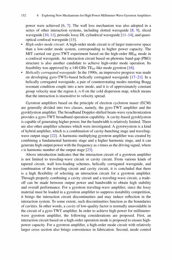
152 6 Exploring New Mechanisms for High Power Millimeter-Wave Gyrotron Amplifiers
power were achieved [6, 7]. The wall loss mechanism was also adopted in aseries of other interaction systems, including slotted waveguide [8, 9], slicedwaveguide [10, 11], periodic lossy DL cylindrical waveguide [11–14], and quasi-optical confocal waveguide [15].
• High-order mode circuit: A high-order mode circuit is of larger transverse spacethan a low-order mode system, corresponding to higher power capacity. TheMIT carried out gyro-TWT experiment based on the high-order HE06 mode ina confocal waveguide. An interaction circuit based on photonic band-gap (PBG)structure is also another candidate to achieve high-order mode operation. Itsfeasibility was approved by a 140 GHz TE04-like mode gyrotron [16].
• Helically corrugated waveguide: In the 1990s, an impressive progress was madeon developing gyro-TWTs-based helically corrugated waveguide [17–21]. In ahelically corrugated waveguide, a pair of counterrotating modes meeting Braggresonant condition couple into a new mode, and it is of approximately constantgroup velocity near the region kz � 0 on the cold dispersion map, which meansthat the interaction is insensitive to velocity spread.
Gyrotron amplifiers based on the principle of electron cyclotron maser (ECM)are generally divided into two classes, namely, the gyro-TWT amplifier and thegyroklystron amplifier. The broadband Doppler-shifted beam-wave synchronizationprovides a gyro-TWT broadband operation capability. A cavity-based gyroklystronis capable of generating higher power, but the bandwidth is relatively limited. Thereare also other amplifier schemes which were investigated. A gyrotwystron is a kindof hybrid amplifier, which is a combination of cavity-bunching stage and traveling-wave output stage [22]. A harmonic-multiplying gyrotron amplifier was created bycombining a fundamental harmonic stage and a higher harmonic stage, and it cangenerate high output power with the frequency as s times as the driving signal, wheres is harmonic number of the output stage [23].
Above introduction indicates that the interaction circuit of a gyrotron amplifieris not limited to traveling-wave circuit or cavity circuit. From various kinds oftapered circuit, wall loss-loading schemes, helically corrugated waveguide, andcombination of the traveling circuit and cavity circuit, it is concluded that thereis a high flexibility of selecting an interaction circuit for a gyrotron amplifier.Through properly combining a cavity circuit and a traveling-wave circuit, a trade-off can be made between output power and bandwidth to obtain high stabilityand overall performance. For a gyrotron traveling-wave amplifier, since the lossymaterial must be loaded in a gyrotron amplifier to suppress instability competition,it brings the interaction circuit discontinuities and may induce reflection in theinteraction system. To some extent, such discontinuities function as the boundariesof cavities. In other words, a cavity of low-quality factor is normally unavoidable inthe circuit of a gyro-TWT amplifier. In order to achieve high power for millimeter-wave gyrotron amplifier, the following considerations are proposed. First, aninteraction circuit based on a high-order operation mode is proposed to ensure high-power capacity. For a gyrotron amplifier, a high-order mode circuit with relativelylarger cross section also brings convenience in fabrication. Second, mode control
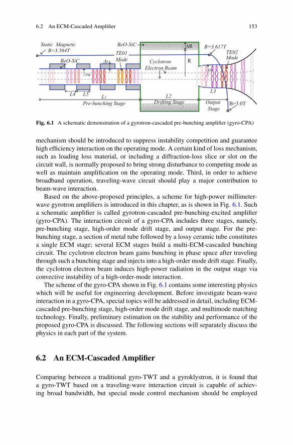
6.2 An ECM-Cascaded Amplifier 153
ra
L4 L5 L1L3
Output Stage
BeO-SiC
BeO-SiCTE02Mode
B=3.617T
B=3.0TPre-bunching Stage
Cyclotron Electron Beam
R
ΔR
Δr
Static Magnetic B=3.564T
L2Drifting Stage
rb
TE01Mode
Fig. 6.1 A schematic demonstration of a gyrotron-cascaded pre-bunching amplifier (gyro-CPA)
mechanism should be introduced to suppress instability competition and guaranteehigh efficiency interaction on the operating mode. A certain kind of loss mechanism,such as loading loss material, or including a diffraction-loss slice or slot on thecircuit wall, is normally proposed to bring strong disturbance to competing mode aswell as maintain amplification on the operating mode. Third, in order to achievebroadband operation, traveling-wave circuit should play a major contribution tobeam-wave interaction.
Based on the above-proposed principles, a scheme for high-power millimeter-wave gyrotron amplifiers is introduced in this chapter, as is shown in Fig. 6.1. Sucha schematic amplifier is called gyrotron-cascaded pre-bunching-excited amplifier(gyro-CPA). The interaction circuit of a gyro-CPA includes three stages, namely,pre-bunching stage, high-order mode drift stage, and output stage. For the pre-bunching stage, a section of metal tube followed by a lossy ceramic tube constitutesa single ECM stage; several ECM stages build a multi-ECM-cascaded bunchingcircuit. The cyclotron electron beam gains bunching in phase space after travelingthrough such a bunching stage and injects into a high-order mode drift stage. Finally,the cyclotron electron beam induces high-power radiation in the output stage viaconvective instability of a high-order-mode interaction.
The scheme of the gyro-CPA shown in Fig. 6.1 contains some interesting physicswhich will be useful for engineering development. Before investigate beam-waveinteraction in a gyro-CPA, special topics will be addressed in detail, including ECM-cascaded pre-bunching stage, high-order mode drift stage, and multimode matchingtechnology. Finally, preliminary estimation on the stability and performance of theproposed gyro-CPA is discussed. The following sections will separately discuss thephysics in each part of the system.
6.2 An ECM-Cascaded Amplifier
Comparing between a traditional gyro-TWT and a gyroklystron, it is found thata gyro-TWT based on a traveling-wave interaction circuit is capable of achiev-ing broad bandwidth, but special mode control mechanism should be employed
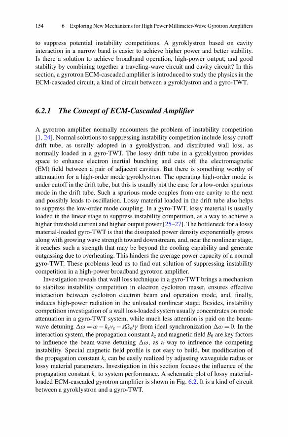
154 6 Exploring New Mechanisms for High Power Millimeter-Wave Gyrotron Amplifiers
to suppress potential instability competitions. A gyroklystron based on cavityinteraction in a narrow band is easier to achieve higher power and better stability.Is there a solution to achieve broadband operation, high-power output, and goodstability by combining together a traveling-wave circuit and cavity circuit? In thissection, a gyrotron ECM-cascaded amplifier is introduced to study the physics in theECM-cascaded circuit, a kind of circuit between a gyroklystron and a gyro-TWT.
6.2.1 The Concept of ECM-Cascaded Amplifier
A gyrotron amplifier normally encounters the problem of instability competition[1, 24]. Normal solutions to suppressing instability competition include lossy cutoffdrift tube, as usually adopted in a gyroklystron, and distributed wall loss, asnormally loaded in a gyro-TWT. The lossy drift tube in a gyroklystron providesspace to enhance electron inertial bunching and cuts off the electromagnetic(EM) field between a pair of adjacent cavities. But there is something worthy ofattenuation for a high-order mode gyroklystron. The operating high-order mode isunder cutoff in the drift tube, but this is usually not the case for a low-order spuriousmode in the drift tube. Such a spurious mode couples from one cavity to the nextand possibly leads to oscillation. Lossy material loaded in the drift tube also helpsto suppress the low-order mode coupling. In a gyro-TWT, lossy material is usuallyloaded in the linear stage to suppress instability competition, as a way to achieve ahigher threshold current and higher output power [25–27]. The bottleneck for a lossymaterial-loaded gyro-TWT is that the dissipated power density exponentially growsalong with growing wave strength toward downstream, and, near the nonlinear stage,it reaches such a strength that may be beyond the cooling capability and generateoutgassing due to overheating. This hinders the average power capacity of a normalgyro-TWT. These problems lead us to find out solution of suppressing instabilitycompetition in a high-power broadband gyrotron amplifier.
Investigation reveals that wall loss technique in a gyro-TWT brings a mechanismto stabilize instability competition in electron cyclotron maser, ensures effectiveinteraction between cyclotron electron beam and operation mode, and, finally,induces high-power radiation in the unloaded nonlinear stage. Besides, instabilitycompetition investigation of a wall loss-loaded system usually concentrates on modeattenuation in a gyro-TWT system, while much less attention is paid on the beam-wave detuning �! D ! � kzvz � s�e/� from ideal synchronization �! D 0. In theinteraction system, the propagation constant kz and magnetic field B0 are key factorsto influence the beam-wave detuning �!, as a way to influence the competinginstability. Special magnetic field profile is not easy to build, but modification ofthe propagation constant kz can be easily realized by adjusting waveguide radius orlossy material parameters. Investigation in this section focuses the influence of thepropagation constant kz to system performance. A schematic plot of lossy material-loaded ECM-cascaded gyrotron amplifier is shown in Fig. 6.2. It is a kind of circuitbetween a gyroklystron and a gyro-TWT.
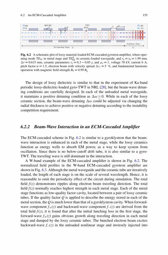
6.2 An ECM-Cascaded Amplifier 155
L3L4
L1
BeO-SiC TE01Mode
Pre-bunching Stage
Dr
L2
Nonlinear Stage
RFin
RFout
rara
Fig. 6.2 A schematic plot of lossy material-loaded ECM-cascaded gyrotron amplifier, where oper-ating mode TE01 in metal stage and TEd
02 in ceramic-loaded waveguide, and ra D rb D 1.99 mm,�r D 0.615 mm, ceramic parameters "r D 6.3 � 0.85 j, and �r D 1, voltage 70 kV, current 6 A,pitch factor ˛ D 1.5, electron beam with velocity spread �vz D 5 %, and fundamental harmonicoperation with magnetic field strength B0 D 0.99 Bg
The design of lossy dielectric is similar to that in the experiment of Ka-bandperiodic lossy-dielectric-loaded gyro-TWT in NRL [28], but the beam-wave detun-ing conditions are carefully designed. In each of the unloaded metal waveguide,it maintains a positive detuning condition as �! � 0. While in each of the lossyceramic section, the beam-wave detuning �! could be adjusted via changing theradial thickness to achieve positive or negative detuning according to the instabilitycompetition requirement.
6.2.2 Beam-Wave Interaction in an ECM-Cascaded Amplifier
The ECM-cascaded scheme in Fig. 6.2 is similar to a gyroklystron that the beam-wave interaction is enhanced in each of the metal stage, while the lossy ceramicsfunction as energy wells to absorb EM power, as a way to keep system fromoscillation. Since there is no below-cutoff drift tube, it is also similar to a gyro-TWT. The traveling wave is still dominant in the interaction.
A W-band example of the ECM-cascaded amplifier is shown in Fig. 6.2. Thenormalized field profiles in the W-band ECM-cascaded gyrotron amplifier areshown in Fig. 6.3. Although the metal waveguide and the ceramic tube are iterativelyloaded, the length of each stage is on the scale of several wavelength. Hence, it isreasonable to omit the periodicity effect of the circuit during simulation. The totalfield f (z) demonstrates ripples along electron beam traveling direction. The totalfield f (z) normally reaches highest strength in each metal stage. Each of the metalstage functions as low-quality factor cavity, located between a pair of lossy ceramictubes. If the quality factor Q is applied to describe the energy stored in each of themetal section, the Q is much lower than that of a gyroklystron cavity. When forward-wave component fC(z) and backward-wave component f�(z) are derived from thetotal field f (z), it is found that after the initial lunching loss in the first stage, theforward-wave fC(z) gains obvious growth along traveling direction in each metalstage and damped by the lossy ceramic tubes. The bunched electron beam excitesbackward-wave f�(z) in the unloaded nonlinear stage and inversely injected into
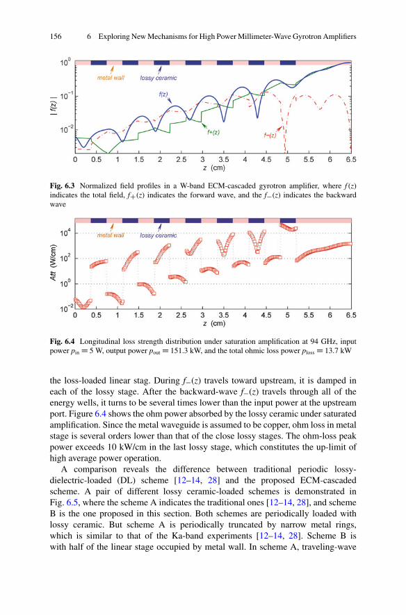
156 6 Exploring New Mechanisms for High Power Millimeter-Wave Gyrotron Amplifiers
Fig. 6.3 Normalized field profiles in a W-band ECM-cascaded gyrotron amplifier, where f (z)indicates the total field, fC(z) indicates the forward wave, and the f�(z) indicates the backwardwave
Fig. 6.4 Longitudinal loss strength distribution under saturation amplification at 94 GHz, inputpower pin D 5 W, output power pout D 151.3 kW, and the total ohmic loss power ploss D 13.7 kW
the loss-loaded linear stag. During f�(z) travels toward upstream, it is damped ineach of the lossy stage. After the backward-wave f�(z) travels through all of theenergy wells, it turns to be several times lower than the input power at the upstreamport. Figure 6.4 shows the ohm power absorbed by the lossy ceramic under saturatedamplification. Since the metal waveguide is assumed to be copper, ohm loss in metalstage is several orders lower than that of the close lossy stages. The ohm-loss peakpower exceeds 10 kW/cm in the last lossy stage, which constitutes the up-limit ofhigh average power operation.
A comparison reveals the difference between traditional periodic lossy-dielectric-loaded (DL) scheme [12–14, 28] and the proposed ECM-cascadedscheme. A pair of different lossy ceramic-loaded schemes is demonstrated inFig. 6.5, where the scheme A indicates the traditional ones [12–14, 28], and schemeB is the one proposed in this section. Both schemes are periodically loaded withlossy ceramic. But scheme A is periodically truncated by narrow metal rings,which is similar to that of the Ka-band experiments [12–14, 28]. Scheme B iswith half of the linear stage occupied by metal wall. In scheme A, traveling-wave

6.2 An ECM-Cascaded Amplifier 157
Fig. 6.5 Comparative demonstration of the saturated amplification at 93.7 GHz of a pair ofschemes. The loading structures along z direction are shown on the top of the figure. Real linesindicate the growing profiles of the driving waves. Circle-dashed line and square-dashed lineindicate the ohm loss power density (W/cm). Other parameters are the same as Fig. 6.2
interaction in the lossy ceramic tube mainly contributes to linear amplification,while in scheme B, the driving wave is mainly amplified in the metal stages and iseither damped or without obvious growth in ceramics stages. Since there is morelossy ceramic loaded, scheme A requires driving power about one order higherthan that of scheme B. The saturated amplifications in the output stage are almostidentical for both schemes.
6.2.3 Discussion
It is concluded that in traditional periodic DL gyro-TWT as scheme A in Fig. 6.5,the lossy ceramic circuit simultaneously plays the roles of amplifying and sup-pressing oscillations. While in an ECM-cascaded amplifier, these two functions arecarried by metal stage and lossy stage, respectively. Each metal stage plays therole of amplification, and the lossy ceramic absorbs the power and suppressingoscillations. According to engineering experience, the ceramic sintering is quitedifficult to achieve product of monolithic parameters, and it is also very difficultto achieve high accuracy during ceramic machining. The traditional DL gyro-TWTrequires accurate beam-wave synchronizing in circuit, but engineering experiment isrelatively challenging to realize the designed condition due to errors from ceramics.An obvious advantage is that the performance of the ECM-cascaded amplifier isquite stable to lossy ceramic parameter errors and dimension errors, because itabsorbs power only.
In an EMC-cascaded gyrotron amplifier, a metal tube and a lossy ceramic tubeare combined to build an ECM stage, and multi-ECM stages constitute the bunching
158 6 Exploring New Mechanisms for High Power Millimeter-Wave Gyrotron Amplifiers
stage. In each of the ECM stage, the cyclotron electron beam synchronizes with theEM wave to enhance its phase bunching characteristics. The periodically loadedceramic tubes function as energy wells for EM wave power and enhance the systemstability. Since the electron beam gains excellent phase bunching characteristics,it induces hyper-exponential amplification in the output stage. Amplification testshows that the system is inherent with broadband capability.
6.3 High-Order Mode Drift Tube
Investigation on the effect of wall loss on a gyro-TWT circuit reveals that loss-loaded linear stage brings pre-bunching to the electron beam in broad operatingfrequency band. Such kind of pre-bunching is the precondition of high efficiencyinteraction in the downstream unloaded nonlinear stage. This section focuses onan overmoded drift tube between the lossy linear stage and unloaded nonlinearstage [29].
6.3.1 The Concept of High-Order Mode Drift Tube
In a loss-loaded traveling-wave interaction circuit, the EM field exponentially grows[25–27]. As a result, the dissipated energy also reaches highest strength at thedownstream end of the lossy stage, as demonstrated in Fig. 6.5. The thermalconductivity there determines the average power capability of the interactionsystem. Former investigation shows that the lossy stage brings necessary pre-bunching to electron beam. Hence, the problem is whether there is a solution whichsimultaneously bunches the electron beam and is capable of enduring high-powercapability. Former solution in a gyroklystron is to load a below-cutoff drift tube tocutoff coupling between a pair of nearby cavities. The below-cutoff drift tube iswith smaller radius than a normal circuit, and it encounters danger of interceptingelectron beam and becomes overheated.
One high average power solution proposed here is to add an overmoded driftingtube, a section of circuit with very high-order mode, to separate the bunching stagefrom the output stage. A gyrotron amplifier loaded with a section of overmodeddrift tube is shown in Fig. 6.6. In the pre-bunching stage, the driving power imposesbunching onto the electron beam, and it is enhanced to reasonable strength via linearbeam-wave interaction in wall loss stage. The bunched electron beam injects intothe lossy material loaded overmode drift tube, and the transition space there furtherenhances the bunching strength. Finally, efficient radiation is induced in the outputstage. This scheme is, to some extent, similar to a traditional gyrotwistron, but alsowith some inherent differences. Firstly, other than the narrow band staggered tuningcavities in a gyrotwistron, the pre-bunching stage adopts broadband wall loss-loadedstage. Secondly, a loss-loaded overmoded drift tube is employed to replace the

6.3 High-Order Mode Drift Tube 159
ra
TE01Mode
Pre-bunching Stage L1 Nonlinear Stage L3
RFin
RFout
Driflting stage L2
BeO-SiC
Distributed wall loss
Dr
rbra
Fig. 6.6 The system structure of the overmoded drift tube-loaded gyrotron amplifier, whereoperating mode TE01 in metal stage and TEd
07 in ceramic-loaded waveguide, pre-bunching stagewall loss strength D 2.5 � 105cu, and ra D 1.99 mm, rb D 5.35 mm, �r D 2.00 mm, ceramicparameters "r D 6.3 � 0.85 j, and �r D 1, voltage 70 kV, current 6 A, pitch factor ˛ D 1.5, electronbeam with velocity spread �vz D 5 %, and fundamental harmonic operation with magnetic fieldstrength B0 D 0.99 Bg
cutoff drift tube. The distributed lossy stage is shorter than a normal gyro-TWT,which results in much lower power level in this lossy stage and brings higher powercapability here. The overmoded drifting tube extends the thermal dissipation areaand simultaneously enhances the beam bunching characteristics.
6.3.2 Beam-Wave Interaction in Overmoded Drift Tube
The key of this section is to investigate the physics in the overmoded drift tube. Inthe scheme as shown in Fig. 6.6, the operating modes in both the pre-bunching stageL1 and nonlinear stage L3 are the TE01 mode. The overmoded drift tube is designedto convey a propagating TEd
06 mode, which is with close propagation constant kz
with that of TE01 mode in L1 and L3. In addition, a TEd0n mode, (n � 5) is also above
cutoff in the overmoded drift tube. As a result, other than the drift tube of zero-fieldstrength in a gyroklystron, the overmoded drift tube here is inherently a high-ordermode interaction circuit. Figure 6.7 demonstrates the power density distributions ofthe modes in the circuit. Due to special design, the cyclotron electron beam bearssimultaneous strongest coupling with TE01 mode in L1 (and L3) and TEd
06 modein overmoded circuit. Since a TEd
0n mode (n � 5) is with kz larger than the TE01
mode and with strongest field strength shifting away from electron beam location,theoretical simulation only considers TEd
06 mode in the drift tube and assumes fieldamplitude and phase continuous at the interfaces between L1, L2, and L3.
In order to understand the beam-wave interaction in the gyrotron amplifierwith overmoded drift tube, Fig. 6.8 demonstrates the field profiles under saturatedamplification. Comparing with a normal gyro-TWT, the forward-wave field profilein the pre-bunching stage L1 is under conventional traveling-wave amplification.Considering larger waveguide transverse cross and strong loss, the growth rate in
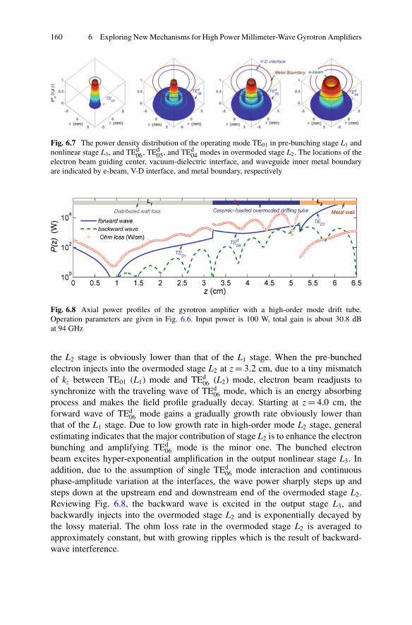
160 6 Exploring New Mechanisms for High Power Millimeter-Wave Gyrotron Amplifiers
Fig. 6.7 The power density distribution of the operating mode TE01 in pre-bunching stage L1 andnonlinear stage L3, and TEd
06, TEd05, and TEd
04 modes in overmoded stage L2. The locations of theelectron beam guiding center, vacuum-dielectric interface, and waveguide inner metal boundaryare indicated by e-beam, V-D interface, and metal boundary, respectively
Fig. 6.8 Axial power profiles of the gyrotron amplifier with a high-order mode drift tube.Operation parameters are given in Fig. 6.6. Input power is 100 W, total gain is about 30.8 dBat 94 GHz
the L2 stage is obviously lower than that of the L1 stage. When the pre-bunchedelectron injects into the overmoded stage L2 at z D 3.2 cm, due to a tiny mismatchof kz between TE01 (L1) mode and TEd
06 (L2) mode, electron beam readjusts tosynchronize with the traveling wave of TEd
06 mode, which is an energy absorbingprocess and makes the field profile gradually decay. Starting at z D 4.0 cm, theforward wave of TEd
06 mode gains a gradually growth rate obviously lower thanthat of the L1 stage. Due to low growth rate in high-order mode L2 stage, generalestimating indicates that the major contribution of stage L2 is to enhance the electronbunching and amplifying TEd
06 mode is the minor one. The bunched electronbeam excites hyper-exponential amplification in the output nonlinear stage L3. Inaddition, due to the assumption of single TEd
06 mode interaction and continuousphase-amplitude variation at the interfaces, the wave power sharply steps up andsteps down at the upstream end and downstream end of the overmoded stage L2.Reviewing Fig. 6.8, the backward wave is excited in the output stage L3, andbackwardly injects into the overmoded stage L2 and is exponentially decayed bythe lossy material. The ohm loss rate in the overmoded stage L2 is averaged toapproximately constant, but with growing ripples which is the result of backward-wave interference.

6.4 High-Power Gyrotron Amplifier Based on Bi-modes Operation 161
6.3.3 Discussion
Reconsidering the field profiles in Fig. 6.8, the original intention of introducinga high-order mode drift tube to gyrotron amplifier is to replace the bellow cutoffdrift tube in a gyroklystron or to replace a section of wall loss section close tooutput stage. The high-order mode L2 stage, as is called drift tube, is mainlyto bunch the electron beam and maintains the wave growth rate as low level aspossible. The high-order mode circuit is with larger inner radius, and it extendsthe interference space between the lossy material and wave, as a way to enhancethe average power operation capability. The convective instability in the overmodedcircuit is with low growth rate, and it also can effectively absorb backward wave.As a result, the ohm loss in the overmoded drift tube is relatively spread out withbetter improved longitudinal uniformity than that of a distributed wall-loaded gyro-TWT. It is estimated that for a traditional wall-loaded gyro-TWT, there is about5 % electron energy dissipated on the lossy circuit under saturated amplification,especially, confined at the downstream end of the lossy circuit. Here, the proposedamplifier with an overmoded drift tube is with overall ohm loss power comparableto a gyro-TWT, but with dissipation area about 10 times larger. It is concluded thatfor the proposed overmoded drift tube scheme, the loss material-loaded circuit nomore turns to be the bottleneck of heat dissipation in the gyrotron amplifier.
6.4 High-Power Gyrotron Amplifier Basedon Bi-modes Operation
High-order mode interaction [29] much enhances system power capacity which isthe inherent advantage for a gyrotron device over a traditional linear-beam vacuumtube [30]. But if without special mode control mechanism, there will be challengesto high-order mode interaction, such as instability competition and high-order modeexcitation. We will discuss a compromising approach, the bi-modes operation. Thedesign is based on a low-order pre-bunching stage and a high-order mode outputstage. The concept of bi-modes operation is based on the high stability of the wallloss-loaded linear stage and high-power capacity of the high-order mode outputstage.
6.4.1 The Concept of Bi-modes Operation
In an ECM system, the cyclotron beam is with inherent cyclotron frequency, whichmakes it possible to operate on a high-order mode and generate much higher powerthan a rectilinear beam vacuum tube. Hence, higher-order mode interaction is amajor development tendency for gyrotron devices. A gyrotron oscillator operateson a cavity mode and generates radiation based on a single frequency. During the

162 6 Exploring New Mechanisms for High Power Millimeter-Wave Gyrotron Amplifiers
ra
L1
TE01
Mode
Pre-bunching Stage
L2Nonlinear Stage
RFin
RFoutDistributed wall loss
rb
TE02
ModeTransition
load
Fig. 6.9 Schematic plot of a bi-modes operation gyrotron amplifier, where operating mode TE01
in pre-bunching stage and TE02 in nonlinear stage, the wall loss strength D 2.5 � 105cu, andra D 1.99 mm, rb D 3.64 mm, voltage 70 kV, current 6 A, pitch factor ˛ D 1.5, electron beam withvelocity spread �vz D 5 %, and fundamental harmonic operation with magnetic field strengthB0 D 0.99 Bg
development of high-power gyrotron, it experienced operation on circular modes,whispering-gallery modes, and high-order volume mode [3]. This, to some extent,also demonstrates the great potential of high-order mode operation for a gyrotronamplifier. However, a gyrotron amplifier is based on the Doppler-shifted synchro-nization. To achieve broadband radiation, it encounters the challenge of suppressinginstability competition in the traveling wave circuit.
The zero-drive stability is the basic requirement for a gyrotron amplifier, whichmeans high-power radiation is induced by the driving power only, and it switchesoff once the driving power is turned off. A high-order mode gyrotron amplifier relieson fundamental technologies, including a high-order mode excitation and stableinteraction. Normal input couplers can effectively excite a low-order mode andcircular polarized mode. But when the mode order index increases, it encountersmuch serious problems of low excitation efficiency, poor mode purity, and parasiticmodes. In a high-order mode system, abundant beam-wave coupling happensbetween cyclotron harmonics and waveguide modes. Hence, a high-power gyrotronamplifier needs a circuit to convey a high-order mode interaction and simultaneouslysuppressing instability competition. Now available interaction circuits for high-power gyrotron includes cavity, wall loss-loaded structure with mode selectionability, and other structures.
The concept of bi-modes operation is proposed for application in a gyrotronamplifier. The bi-modes operation means combination of a low-order mode in pre-bunching stage and a high-order mode in the nonlinear stage, as is shown in Fig. 6.9.The linear stage L1 bunches the electron beam and provides main gain for theamplifier. The nonlinear stage L2 generates the major high power. The lower-ordermode is easier to be excited and to achieve zero-drive stability. The excitation ofthe higher-order mode much relies on the bunched electron beam. The upstreamlower-order mode and the downstream high-order mode constitute a mode pair. Theselection of such a mode pair must meet a condition that the location of the electronbeam simultaneously couples with both modes at their highest strength. A modepair is usually with the same azimuthal index and different radial index.
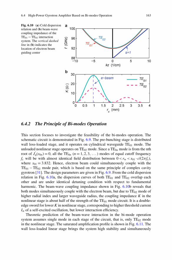
6.4 High-Power Gyrotron Amplifier Based on Bi-modes Operation 163
Fig. 6.10 (a) Cold dispersionrelation and (b) beam-wavecoupling impedance of theTE01 � TE02 interactionsystem. The vertical dashedline in (b) indicates thelocation of electron beamguiding center
6.4.2 The Principle of Bi-modes Operation
This section focuses to investigate the feasibility of the bi-modes operation. Theschematic circuit is demonstrated in Fig. 6.9. The pre-bunching stage is distributedwall loss-loaded stage, and it operates on cylindrical waveguide TE01 mode. Theunloaded nonlinear stage operates on TE02 mode. Since a TE0n mode is from the nthroot of J
0
0(x0n) D 0, all the TE0n (n D 1, 2, 3, : : : ) modes of equal cutoff frequencyfc will be with almost identical field distribution between 0 < rw < x01 � c/(2� fc),where x01 D 3.832. Hence, electron beam could simultaneously couple with theTE01 � TE02 mode pair, which is based on the same principle of complex cavitygyrotron [31]. The design parameters are given in Fig. 6.9. From the cold dispersionrelation in Fig. 6.10a, the dispersion curves of both TE01 and TE02 overlap eachother and are under identical detuning condition with respect to fundamentalharmonic. The beam-wave coupling impedance shown in Fig. 6.10b reveals thatboth modes simultaneously couple with the electron beam, but due to TE02 mode ofhigher radial index and larger waveguide radius, the coupling impedance K in thenonlinear stage is about half of the strength of the TE01 mode circuit. It is a double-edge sword for lower K in nonlinear stage, corresponding to higher threshold currentIst of a self-excited oscillation, but lower interaction efficiency.
Theoretic prediction of the beam-wave interaction in the bi-mode operationsystem assumes single mode in each stage of the circuit, that is, only TE02 modein the nonlinear stage. The saturated amplification profile is shown in Fig. 6.11. Thewall loss-loaded linear stage brings the system high stability and simultaneously
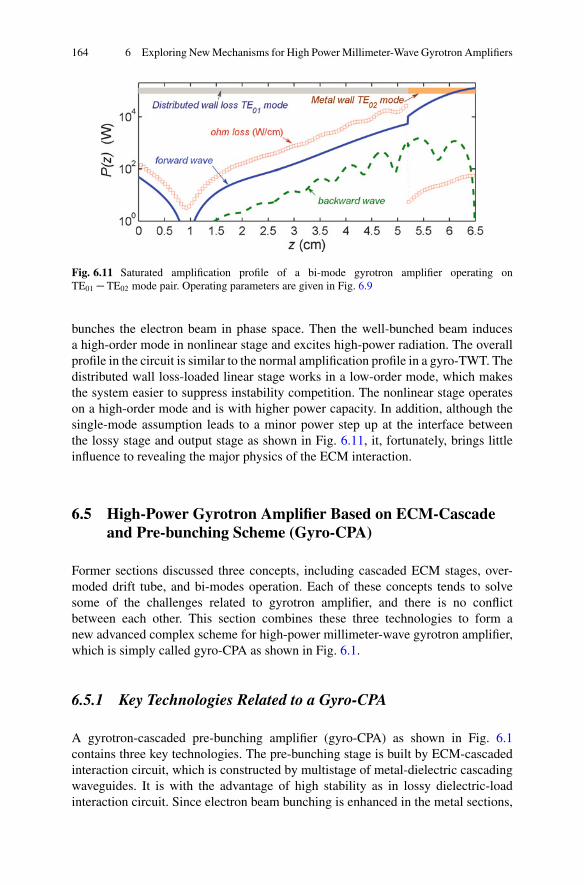
164 6 Exploring New Mechanisms for High Power Millimeter-Wave Gyrotron Amplifiers
Fig. 6.11 Saturated amplification profile of a bi-mode gyrotron amplifier operating onTE01 � TE02 mode pair. Operating parameters are given in Fig. 6.9
bunches the electron beam in phase space. Then the well-bunched beam inducesa high-order mode in nonlinear stage and excites high-power radiation. The overallprofile in the circuit is similar to the normal amplification profile in a gyro-TWT. Thedistributed wall loss-loaded linear stage works in a low-order mode, which makesthe system easier to suppress instability competition. The nonlinear stage operateson a high-order mode and is with higher power capacity. In addition, although thesingle-mode assumption leads to a minor power step up at the interface betweenthe lossy stage and output stage as shown in Fig. 6.11, it, fortunately, brings littleinfluence to revealing the major physics of the ECM interaction.
6.5 High-Power Gyrotron Amplifier Based on ECM-Cascadeand Pre-bunching Scheme (Gyro-CPA)
Former sections discussed three concepts, including cascaded ECM stages, over-moded drift tube, and bi-modes operation. Each of these concepts tends to solvesome of the challenges related to gyrotron amplifier, and there is no conflictbetween each other. This section combines these three technologies to form anew advanced complex scheme for high-power millimeter-wave gyrotron amplifier,which is simply called gyro-CPA as shown in Fig. 6.1.
6.5.1 Key Technologies Related to a Gyro-CPA
A gyrotron-cascaded pre-bunching amplifier (gyro-CPA) as shown in Fig. 6.1contains three key technologies. The pre-bunching stage is built by ECM-cascadedinteraction circuit, which is constructed by multistage of metal-dielectric cascadingwaveguides. It is with the advantage of high stability as in lossy dielectric-loadinteraction circuit. Since electron beam bunching is enhanced in the metal sections,
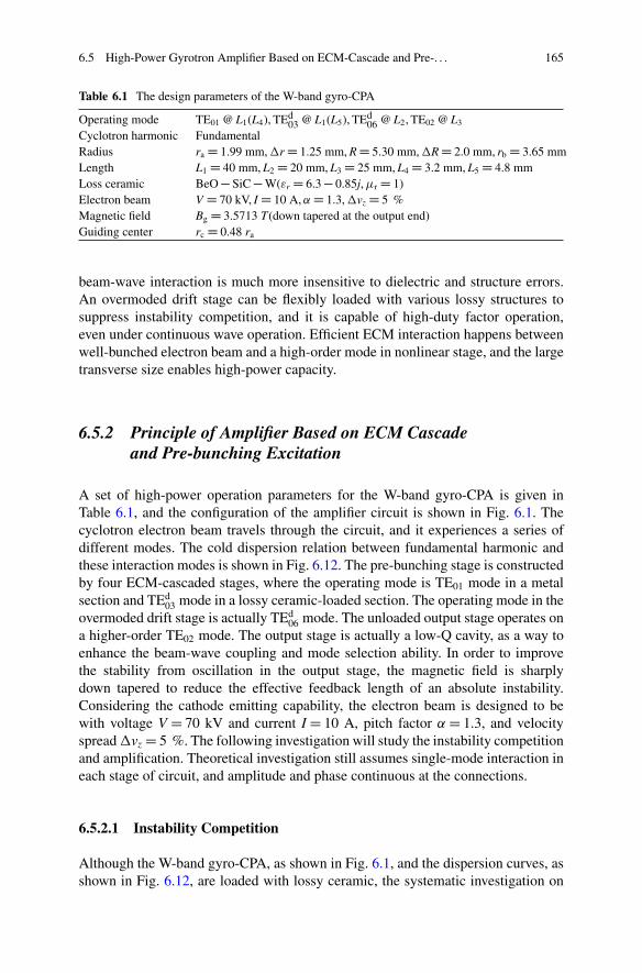
6.5 High-Power Gyrotron Amplifier Based on ECM-Cascade and Pre-. . . 165
Table 6.1 The design parameters of the W-band gyro-CPA
Operating mode TE01 @ L1(L4), TEd03 @ L1(L5), TEd
06 @ L2, TE02 @ L3
Cyclotron harmonic FundamentalRadius ra D 1.99 mm, �r D 1.25 mm, R D 5.30 mm, �R D 2.0 mm, rb D 3.65 mmLength L1 D 40 mm, L2 D 20 mm, L3 D 25 mm, L4 D 3.2 mm, L5 D 4.8 mmLoss ceramic BeO � SiC � W("r D 6.3 � 0.85j, �r D 1)Electron beam V D 70 kV, I D 10 A, ˛ D 1.3, �vz D 5 %Magnetic field Bg D 3.5713 T(down tapered at the output end)Guiding center rc D 0.48 ra
beam-wave interaction is much more insensitive to dielectric and structure errors.An overmoded drift stage can be flexibly loaded with various lossy structures tosuppress instability competition, and it is capable of high-duty factor operation,even under continuous wave operation. Efficient ECM interaction happens betweenwell-bunched electron beam and a high-order mode in nonlinear stage, and the largetransverse size enables high-power capacity.
6.5.2 Principle of Amplifier Based on ECM Cascadeand Pre-bunching Excitation
A set of high-power operation parameters for the W-band gyro-CPA is given inTable 6.1, and the configuration of the amplifier circuit is shown in Fig. 6.1. Thecyclotron electron beam travels through the circuit, and it experiences a series ofdifferent modes. The cold dispersion relation between fundamental harmonic andthese interaction modes is shown in Fig. 6.12. The pre-bunching stage is constructedby four ECM-cascaded stages, where the operating mode is TE01 mode in a metalsection and TEd
03 mode in a lossy ceramic-loaded section. The operating mode in theovermoded drift stage is actually TEd
06 mode. The unloaded output stage operates ona higher-order TE02 mode. The output stage is actually a low-Q cavity, as a way toenhance the beam-wave coupling and mode selection ability. In order to improvethe stability from oscillation in the output stage, the magnetic field is sharplydown tapered to reduce the effective feedback length of an absolute instability.Considering the cathode emitting capability, the electron beam is designed to bewith voltage V D 70 kV and current I D 10 A, pitch factor ˛ D 1.3, and velocityspread �vz D 5 %. The following investigation will study the instability competitionand amplification. Theoretical investigation still assumes single-mode interaction ineach stage of circuit, and amplitude and phase continuous at the connections.
6.5.2.1 Instability Competition
Although the W-band gyro-CPA, as shown in Fig. 6.1, and the dispersion curves, asshown in Fig. 6.12, are loaded with lossy ceramic, the systematic investigation on
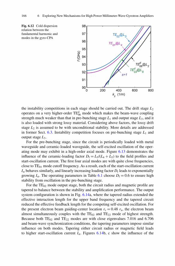
166 6 Exploring New Mechanisms for High Power Millimeter-Wave Gyrotron Amplifiers
Fig. 6.12 Cold dispersionrelation between thefundamental harmonic andmodes in the gyro-CPA
the instability competitions in each stage should be carried out. The drift stage L2
operates on a very higher-order TEd06 mode which makes the beam-wave coupling
strength much weaker than that in pre-bunching stage L1 and output stage L3, and itis also loaded with strong lossy material. Considering above factors, the lossy driftstage L2 is assumed to be with unconditional stability. More details are addressedin former Sect. 6.3. Instability competition focuses on pre-bunching stage L1 andoutput stage L3.
For the pre-bunching stage, since the circuit is periodically loaded with metalwaveguide and ceramic-loaded waveguide, the self-excited oscillation of the oper-ating mode may exhibit in a high-order axial mode. Figure 6.13 demonstrates theinfluence of the ceramic-loading factor Df D L5/(L4 C L5) to the field profiles andstart-oscillation current. The first four axial modes are with quite close frequencies,close to TE01 mode cutoff frequency. As a result, each of the start-oscillation currentIst behaves similarly, and linearly increasing loading factor Df leads to exponentiallygrowing Ist. The operating parameters in Table 6.1 choose Df D 0.6 to ensure highstability from oscillation in the pre-bunching stage.
For the TE02 mode output stage, both the circuit radius and magnetic profile aretapered to balance between the stability and amplification performance. The outputsystem configuration is shown in Fig. 6.14a, where the tapered radius extended theeffective interaction length for the upper band frequency and the tapered circuitreduced the effective feedback length for the competing self-excited oscillation. Forthe present electron beam guiding-center location rc D 0.48 ra, the electron beamalmost simultaneously couples with the TE02 and TE22 mode of highest strength.Because both TE02 and TE22 modes are with close eigenvalues 7.016 and 6.706and beam-wave synchronization conditions, the tapering parameters impose similarinfluence on both modes. Tapering either circuit radius or magnetic field leadsto higher start-oscillation current Ist. Figures 6.14b, c show the influence of the
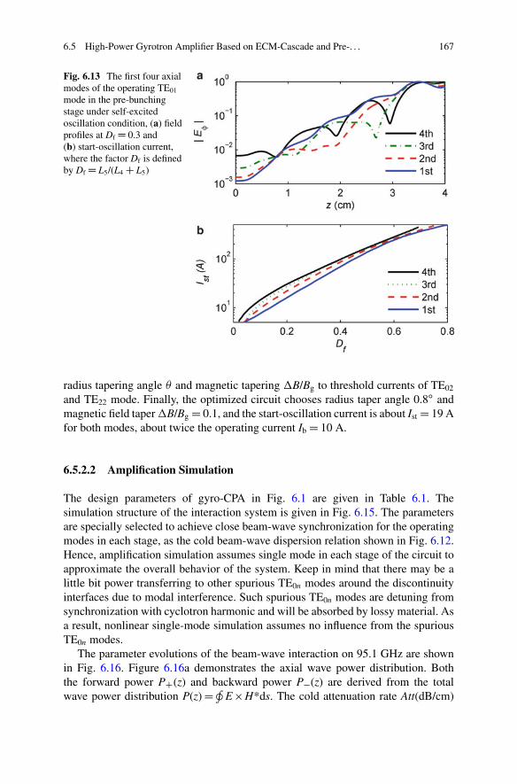
6.5 High-Power Gyrotron Amplifier Based on ECM-Cascade and Pre-. . . 167
Fig. 6.13 The first four axialmodes of the operating TE01
mode in the pre-bunchingstage under self-excitedoscillation condition, (a) fieldprofiles at Df D 0.3 and(b) start-oscillation current,where the factor Df is definedby Df D L5/(L4 C L5)
radius tapering angle and magnetic tapering �B/Bg to threshold currents of TE02
and TE22 mode. Finally, the optimized circuit chooses radius taper angle 0.8ı andmagnetic field taper �B/Bg D 0.1, and the start-oscillation current is about Ist D 19 Afor both modes, about twice the operating current Ib D 10 A.
6.5.2.2 Amplification Simulation
The design parameters of gyro-CPA in Fig. 6.1 are given in Table 6.1. Thesimulation structure of the interaction system is given in Fig. 6.15. The parametersare specially selected to achieve close beam-wave synchronization for the operatingmodes in each stage, as the cold beam-wave dispersion relation shown in Fig. 6.12.Hence, amplification simulation assumes single mode in each stage of the circuit toapproximate the overall behavior of the system. Keep in mind that there may be alittle bit power transferring to other spurious TE0n modes around the discontinuityinterfaces due to modal interference. Such spurious TE0n modes are detuning fromsynchronization with cyclotron harmonic and will be absorbed by lossy material. Asa result, nonlinear single-mode simulation assumes no influence from the spuriousTE0n modes.
The parameter evolutions of the beam-wave interaction on 95.1 GHz are shownin Fig. 6.16. Figure 6.16a demonstrates the axial wave power distribution. Boththe forward power PC(z) and backward power P�(z) are derived from the totalwave power distribution P(z) D H
E H*ds. The cold attenuation rate Att(dB/cm)
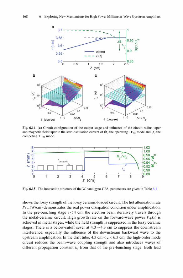
168 6 Exploring New Mechanisms for High Power Millimeter-Wave Gyrotron Amplifiers
Fig. 6.14 (a) Circuit configuration of the output stage and influence of the circuit radius taperand magnetic field taper to the start-oscillation current of (b) the operating TE02 mode and (c) thecompeting TE22 mode
Fig. 6.15 The interaction structure of the W-band gyro-CPA, parameters are given in Table 6.1
shows the lossy strength of the lossy ceramic-loaded circuit. The hot attenuation ratePloss(W/cm) demonstrates the real power dissipation condition under amplification.In the pre-bunching stage z < 4 cm, the electron beam iteratively travels throughthe metal-ceramic circuit. High growth rate on the forward-wave power PC(z) isachieved in metal stages, while the field strength is suppressed in the lossy ceramicstages. There is a below-cutoff sever at 4.0 � 4.3 cm to suppress the downstreaminterference, especially the influence of the downstream backward wave to theupstream amplification. In the drift tube, 4.3 cm < z < 6.3 cm, the high-order modecircuit reduces the beam-wave coupling strength and also introduces waves ofdifferent propagation constant kz from that of the pre-bunching stage. Both lead
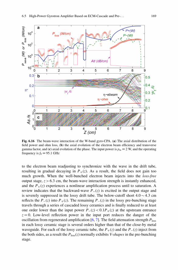
6.5 High-Power Gyrotron Amplifier Based on ECM-Cascade and Pre-. . . 169
Fig. 6.16 The beam-wave interaction of the W-band gyro-CPA. (a) The axial distribution of thefield power and ohm loss, (b) the axial evolution of the electron beam efficiency and transversegamma factor, and (c) axial evolution of the phase. The input power is pin D 2 W, and the operatingfrequency is f0 D 95.1 GHz
to the electron beam readjusting to synchronize with the wave in the drift tube,resulting in gradual decaying in PC(z). As a result, the field does not gain toomuch growth. When the well-bunched electron beam injects into the loss-freeoutput stage, z > 6.3 cm, the beam-wave interaction strength is instantly enhanced,and the PC(z) experiences a nonlinear amplification process until to saturation. Areview indicates that the backward-wave P�(z) is excited in the output stage andis severely suppressed in the lossy drift tube. The below-cutoff short 4.0 � 4.3 cmreflects the P�(z) into PC(z). The remaining P�(z) in the lossy pre-bunching stagetravels through a series of cascaded lossy ceramics and is finally reduced to at leastone order lower than the input power P�(z) < 0.1PC(z) at the upstream entrancez D 0. Low-level reflection power in the input port reduces the danger of theoscillation from regenerated amplification [6, 7]. The field attenuation strength Ploss
in each lossy ceramic stage is several orders higher than that of the close-by metalwaveguide. For each of the lossy ceramic tube, the PC(z) and the P�(z) inject fromthe both sides, as a result the Ploss(z) normally exhibits V-shapes in the pre-bunchingstage.
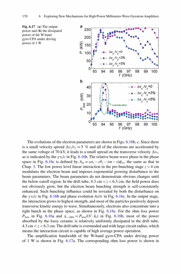
170 6 Exploring New Mechanisms for High Power Millimeter-Wave Gyrotron Amplifiers
Fig. 6.17 (a) The outputpower and (b) the dissipatedpower of the W-bandgyro-CPA under drivingpower of 1 W
The evolutions of the electron parameters are shown in Figs. 6.16b, c. Since thereis a small velocity spread �vz/vz D 5 % and all of the electrons are accelerated bythe same voltage of 70 kV, it leads to a small spread on the transverse velocity �vt,as is indicated by the �vt/c in Fig. 6.16b. The relative beam-wave phase in the phasespace in Fig. 6.16c is defined by Asi D !ti � s i � (m � s)�ci, the same as that inChap. 3. The low power level linear interaction in the pre-bunching stage z < 4 cmmodulates the electron beam and imposes exponential growing disturbance to thebeam parameters. The beam parameters do not demonstrate obvious changes untilthe below-cutoff region. In the drift tube, 4.3 cm < z < 6.3 cm, the field power doesnot obviously grow, but the electron beam bunching strength is self-consistentlyenhanced. Such bunching influence could be revealed by both the disturbance onthe �vt/c in Fig. 6.16b and phase evolution As/� in Fig. 6.16c. In the output stage,the interaction grows to highest strength, and most of the particles positively deposittransverse kinetic energy to wave. Simultaneously, electrons also concentrate into atight bunch in the phase space, as shown in Fig. 6.16c. For the ohm loss powerPloss in Fig. 6.16a and � ohm D Ploss/(V � Ib) in Fig. 6.16b, most of the powerabsorbed by the lossy ceramic is relatively uniformly dissipated in the drift tube,4.3 cm < z < 6.3 cm. The drift tube is overmoded and with large circuit radius, whichmeans the interaction circuit is capable of high average power operation.
The amplification bandwidth of the W-band gyro-CPA under driving powerof 1 W is shown in Fig. 6.17a. The corresponding ohm loss power is shown in
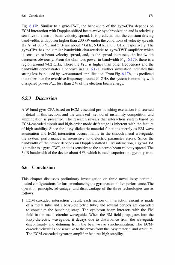
6.6 Conclusion 171
Fig. 6.17b. Similar to a gyro-TWT, the bandwidth of the gyro-CPA depends onECM interaction with Doppler-shifted beam-wave synchronization and is relativelysensitive to electron beam velocity spread. It is predicted that the constant drivingbandwidths with power higher than 200 kW under the conditions of velocity spreads�vz/vz of 0, 3 %, and 5 % are about 7 GHz, 5 GHz, and 3 GHz, respectively. Thegyro-CPA has the similar bandwidth characteristic to gyro-TWT amplifier whichis sensitive to beam velocity spread, and, as the spread increases, the bandwidthdecreases obviously. From the ohm loss power in bandwidth Fig. 6.17b, there is aregion around 94.2 GHz, where the Ploss is higher than other frequencies and thebandwidth demonstrates a concave in Fig. 6.17a. Further simulation indicates thisstrong loss is induced by oversaturated amplification. From Fig. 6.17b, it is predictedthat other than the overdrive frequency around 94 GHz, the system is normally withdissipated power Ploss less than 2 % of the electron beam energy.
6.5.3 Discussion
A W-band gyro-CPA based on ECM-cascaded pre-bunching excitation is discussedin detail in this section, and the analyzed method of instability competition andamplification is presented. The research reveals that interaction system based onECM-cascaded circuit and high-order mode drift stage is inherent with the featureof high stability. Since the lossy-dielectric material functions merely as EM waveattenuation and ECM interaction occurs mainly in the smooth metal waveguide,the system performance is insensitive to dielectric parameter errors. Since thebandwidth of the device depends on Doppler-shifted ECM interaction, a gyro-CPAis similar to a gyro-TWT, and it is sensitive to the electron beam velocity spread. The3 dB bandwidth of the device about 4 %, which is much superior to a gyroklystron.
6.6 Conclusion
This chapter discusses preliminary investigation on three novel lossy ceramic-loaded configurations for further enhancing the gyrotron amplifier performance. Theoperation principle, advantage, and disadvantage of the three technologies are asfollows:
1. ECM-cascaded interaction circuit: each section of interaction circuit is madeof a metal tube and a lossy-dielectric tube, and several periods are cascadedto constitute the bunching stage. The cyclotron beam interacts with the EMfield in the metal circular waveguide. When the EM field propagates into thelossy-dielectric waveguide, it decays due to disturbance from the waveguidediscontinuity and detuning from the beam-wave synchronization. The ECM-cascaded circuit is not sensitive to the errors from the lossy material and structure.The ECM-cascaded gyrotron amplifier features high stability.
172 6 Exploring New Mechanisms for High Power Millimeter-Wave Gyrotron Amplifiers
2. High-order mode drift tube: a drift tube which absolutely cuts off all kinds of theEM fields is difficult to be realized, especially, in a high-order mode gyrotronamplifier. The high-order mode drift tube introduces a loss-loaded high-ordermode waveguide as the drift tube. Due to the loss material in the drift tube,it is highly stable to self-excited oscillation. Since the mode density in theovermoded drift tube is relatively high, there is always a mode approximatelysynchronizing with the cyclotron electron beam. The phase bunching of theelectron beam would be enhanced by the joint influence from the inertia driftand a synchronizing mode interaction.
3. Bi-modes operation: for a gyrotron amplifier, the pre-bunching stage operates ona low-order mode, and the output stage operates on another high-order mode. Thelow-order mode bunching stage maintains low-level interaction strength, whichprovides the major gain of the system and is with high stability. The high-ordermode output stage is with larger power capacity and generates the major highpower. The high-order mode excitation relies on the bunched electron beam.
Combining the three technologies, a W-band gyrotron-cascaded pre-bunchingamplifier (gyro-CPA) is investigated. The output circuit of the gyro-CPA is similarto an open cavity with low-quality factor. Self-excited oscillations in output circuitare suppressed by adjustment of structure and magnetic field. A gyro-CPA adoptsthe similar mechanism to traditional gyrotwystron, but it is realized with differenttechnologies. A gyro-CPA has the equivalent output power level to a gyroklystronand comparable bandwidth to a gyro-TWT.
This chapter introduced three interaction structures to the gyrotron amplifier,namely, ECM-cascaded bunching stage, high-order mode drift tube, and Bi-modesoperation. The feasibility of each is preliminarily verified. They provide helpfulinspirations for future gyrotron amplifier development.
References
1. Chu KR (2004) The electron cyclotron maser. Rev Mod Phys 76:489–5402. Chu KR (2002) Overview of research on the gyrotron traveling-wave amplifier. IEEE Trans
Plasma Sci 30:903–9083. Thumm M (2013) State-of-the-art of high power gyro-devices and free electron masers, Update
2012. KIT Scientific Report 7641, KIT Scientific Publishing4. Park GS, Choi JJ, Park SY et al (1995) Gain broadening of 2-stage tapered gyrotron traveling-
wave tube amplifier. Phys Rev Lett 74:2399–24025. Barnett LR, Lau YY, Chu KR et al (1981) An experimental wideband gyrotron traveling-wave
amplifier. IEEE Trans Electron Devices 28:872–8756. Chu KR, Chen HY, Hung CL et al (1998) Ultrahigh gain gyrotron traveling wave amplifier.
Phys Rev Lett 81:4760–47637. Chu KR, Chen HY, Hung CL et al (1999) Theory and experiment of ultrahigh-gain gyrotron
traveling wave amplifier. IEEE Trans Plasma Sci 27:391–4048. Wang QS, McDermott DB, Luhmann NC (1996) Operation of a Stable 200-kW second-
harmonic gyro-TWT amplifier. IEEE Trans Plasma Sci 24:700–706
References 173
9. Chong CK, McDermott DB, Luhmann NC (1998) Large-signal operation of a third-harmonicslotted gyro-TWT amplifier. IEEE Trans Plasma Sci 26:500–507
10. Pershing DE, Nguyen KT, Calame JP et al (2004) A TE11 K-a-band gyro-TWT amplifier withhigh-average power compatible distributed loss. IEEE Trans Plasma Sci 32:947–956
11. Nguyen KT, Calame JP, Pershing DE et al (2001) Design of a Ka-band gyro-TWT for radarapplications. IEEE Trans Electron Devices 48:108–115
12. Liu BT, Feng JJ, Wang EF, Li ZL, Zeng X, Qian LJ, Wang H (2011) Design and experimentalstudy of a Ka-band gyro-TWT with periodic dielectric loaded circuit. IEEE Trans Plasma Sci39(8):1665–1672
13. Wang E, Zeng X, Liu BT, Qian LJ, Li ZL, Feng JJ, Zhu SQ (2012) Experimental study of highpower gyrotron traveling wave tube with periodic lossy material loading. IEEE Trans PlasmaSci 40(7):1846–1853
14. Yan R, Luo Y, Liu G, Pu YL (2012) Design and experiment of a Q-band gyro-TWT loadedwith lossy dielectric. IEEE Trans Electron Devices 59(12):3612–3617
15. Sirigiri JR, Shapiro MA, Temkin RJ (2003) High-power 140-GHz quasioptical gyrotrontraveling-wave amplifier. Phys Rev Lett 90:258302
16. Sirigiri JR, Kreischer KE, Machuzak J et al (2001) Photonic-band-gap resonator gyrotron. PhysRev Lett 86:5628–5631
17. Denisov GG, Bratman VL, Phelps ADR et al (1998) Gyro-TWT with a helical operatingwaveguide: new possibilities to enhance efficiency and frequency bandwidth. IEEE TransPlasma Sci 26:508–518
18. Burt G, Samsonov SV, Ronald K et al (2004) Dispersion of helically corrugated waveguides:analytical, numerical, and experimental study. Phys Rev E 70:046402
19. Bratman VL, Cross AW, Denisov GG et al (2000) High-gain wide-band gyrotron travelingwave amplifier with a helically corrugated waveguide. Phys Rev Lett 84:2746–2749
20. Denisov GG, Bratman VL, Cross AW et al (1998) Gyrotron traveling wave amplifier with ahelical interaction waveguide. Phys Rev Lett 81:5680–5683
21. Cross AW, He W, Phelps ADR et al (2007) Helically corrugated waveguide gyrotron travelingwave amplifier using a thermionic cathode electron gun. Appl Phys Lett 90:253501
22. Blank M, Danly BG, Levush B (1999) Experimental demonstration of a W-band (94 GHz)gyrotwystron amplifier. IEEE Trans Plasma Sci 27(2):405–411
23. Baik CW, Jeon SG, Kim DH, Sato N, Yokoo K, Park GS (2005) Third-harmonic frequencymultiplication of a two-stage tapered gyrotron TWT amplifier. IEEE Trans Electron Devices52(5):829–838
24. Lau YY, Chu KR, Barnett LR et al (1981) Gyrotron traveling wave amplifier.1. Analysis ofoscillations. Int J Infrared Millim Waves 2:373–393
25. Du CH, Liu PK (2009) A lossy dielectric-ring loaded waveguide with suppressed periodicityfor gyro-TWTs applications. IEEE Trans Electron Devices 56:2335–2342
26. Du CH, Xue QZ, Liu PK et al (2009) Modal transition and reduction in a lossy dielectric-coatedwaveguide for gyrotron-traveling-wave tube amplifier applications. IEEE Trans ElectronDevices 56:839–845
27. Du CH, Xue QZ, Liu PK (2008) Loss-induced modal transition in a dielectric-coated metalcylindrical waveguide for gyro-traveling-wave-tube applications. IEEE Electron Device Lett29:1256–1258
28. Garven M, Calame JP, Danly BG et al (2002) A gyrotron-traveling-wave tube amplifierexperiment with a ceramic loaded interaction region. IEEE Trans Plasma Sci 30:885–893
29. Tsai WC, Chang TH, Chen NC et al (2004) Absolute instabilities in a high-order-modegyrotron traveling-wave amplifier. Phys Rev E 70:056402
30. Chen SH, Chang TH, Pao KF et al (2002) Linear and time-dependent behavior of the gyrotronbackward-wave oscillator. Phys Rev Lett 89:268303
31. Fliflet AW, Lee RC, Read ME (1988) Self-consistent field model for the complex cavitygyrotron. Int J Electron 65(3):273–283

Chapter 7Technologies Related to Gyrotron Amplifiers
Abstract This chapter presents some key technologies related to engineeringdevelopment of millimeter-wave gyrotron amplifiers, including input power cou-plers, output windows, electron gun, and lossy material measurement. The designmethods and considerations are helpful for developing millimeter-wave gyrotronamplifier of high-power capability.
Keywords Gyrotron amplifier • Input coupler • Output window • Electron gun• Lossy material
7.1 Introduction
A gyrotron traveling-wave tube (gyro-TWT) amplifier is characterized by high-power, high gain, and broad bandwidth, but it is sensitive to electron beam velocityspread. In order to fully realize the potential of a gyro-TWT, the challenges relatedto a series of technologies need to be overcome [1, 2]. A gyro-TWT primarilyconsists of an electron gun, an input coupler, an interaction circuit, a tapered outputwaveguide, a collector, a broadband output window.
The electron gun is employed to generate a high-power cyclotron electron beam[3–14]. There are two main kinds of electron gun applied in gyrotrons, namely,the magnetron injection gun (MIG) and the magnetic CUSP gun [12]. The cyclingelectron beam guiding center rc, the Larmor radius rL, velocity ratio ˛ D v?/vz,and velocity spread �vz/vz are important parameters of an electron gun. A MIG isused to generate small-orbit electron beam rc > rL, while a CUSP gun is used togenerate a large orbit electron beam rc � 0. Moreover, there is also strict limitationson the electron gun structure, including building the required electric field andsimultaneously avoiding high-voltage arcing.
The input coupler not only injects the driving power into the interaction circuitand builds up a required EM mode, but also can separate the inner vacuumenvironment from outside atmospheric surroundings by vacuum sealing [15, 16].
C.-H. Du and P.-K. Liu, Millimeter-Wave Gyrotron Traveling-Wave Tube Amplifiers,DOI 10.1007/978-3-642-54728-7__7, © Springer-Verlag Berlin Heidelberg 2014
175
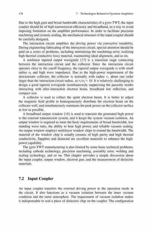
176 7 Technologies Related to Gyrotron Amplifiers
Due to the high gain and broad bandwidth characteristics of a gyro-TWT, the inputcoupler should be of high transmission efficiency and broadband, as a way to avoidimposing limitation on the amplifier performance. In order to facilitate precisionmachining and ceramic sealing, the mechanical structure of the input coupler shouldbe carefully designed.
The interaction circuit amplifies the driving power via convective instability.During engineering fabricating of the interaction circuit, special attention should bepaid on a series of problems, including minimizing the machining error, realizinghigh thermal conductive lossy material, maintaining ideal alignment, and so on.
A nonlinear tapered output waveguide [17] is a transition stage connectingbetween the interaction circuit and the collector. Since the interaction circuitoperates close to the cutoff frequency, the tapered output waveguide is with smallradius r0 and high wave impedance. Due to the high-power requirement of thedownstream collector, the collector is normally with radius r1 about one orderlarger than the interaction circuit radius, as r1/r0 � 10. It is relatively challenging todesign a good tapered waveguide simultaneously suppressing the parasitic modesinteracting with after-interaction electron beam, broadband low reflection, andcompact size.
A collector is used to collect the spent electron beam. It is better to adjustthe magnetic field profile to homogeneously distribute the electron beam on thecollector wall, and simultaneously maintains the peak power on the collector surfaceas low as possible.
A broadband output window [18] is used to transmit the generated high powerto the external transmission system, and it keeps the system vacuum isolation. Anoutput window is required to meet the basic requirements of broad bandwidth, lowstanding wave ratio, the ability to bear high power, and reliable vacuum sealing.An output window employs multilayer window chips to extend the bandwidth. Thematerial of the window chip is usually ceramic of high purity and high thermalconductivity. Sapphire and diamond are excellent materials to enhance the high-power capability.
The gyro-TWT manufacturing is also limited by some basic technical problems,including cathode technology, precision machining, assembly error, welding andsealing technology, and so on. This chapter provides a simple discussion aboutthe input coupler, output window, electron gun, and the measurement of dielectricmaterials.
7.2 Input Coupler
An input coupler transfers the external driving power to the operation mode inthe circuit. It also functions as a vacuum isolation between the inner vacuumcondition and the outer atmosphere. The requirement of vacuum isolation makesit indispensable to seal a piece of dielectric chip on the coupler. The configuration
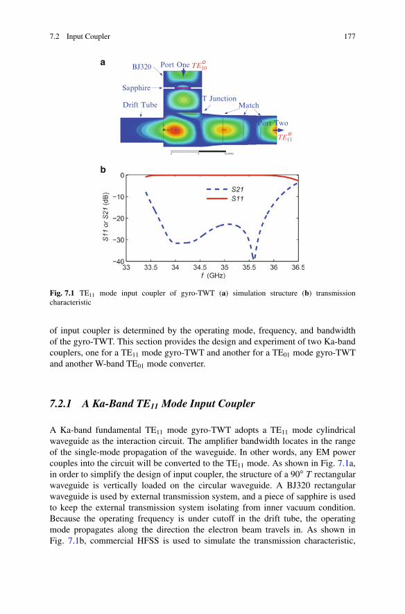
7.2 Input Coupler 177
BJ320
Sapphire
T JunctionDrift Tube
Port One
Port Two
Match
TE10
TE11
a
b
°
°
Fig. 7.1 TE11 mode input coupler of gyro-TWT (a) simulation structure (b) transmissioncharacteristic
of input coupler is determined by the operating mode, frequency, and bandwidthof the gyro-TWT. This section provides the design and experiment of two Ka-bandcouplers, one for a TE11 mode gyro-TWT and another for a TE01 mode gyro-TWTand another W-band TE01 mode converter.
7.2.1 A Ka-Band TE11 Mode Input Coupler
A Ka-band fundamental TE11 mode gyro-TWT adopts a TE11 mode cylindricalwaveguide as the interaction circuit. The amplifier bandwidth locates in the rangeof the single-mode propagation of the waveguide. In other words, any EM powercouples into the circuit will be converted to the TE11 mode. As shown in Fig. 7.1a,in order to simplify the design of input coupler, the structure of a 90ı T rectangularwaveguide is vertically loaded on the circular waveguide. A BJ320 rectangularwaveguide is used by external transmission system, and a piece of sapphire is usedto keep the external transmission system isolating from inner vacuum condition.Because the operating frequency is under cutoff in the drift tube, the operatingmode propagates along the direction the electron beam travels in. As shown inFig. 7.1b, commercial HFSS is used to simulate the transmission characteristic,
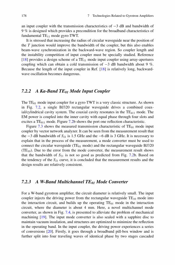
178 7 Technologies Related to Gyrotron Amplifiers
an input coupler with the transmission characteristics of �3 dB and bandwidth of9 % is designed which provides a precondition for the broadband characteristics offundamental TE11 mode gyro-TWT.
It is stressed that increasing the radius of circular waveguide near the position ofthe T junction would improve the bandwidth of the coupler, but this also enablesbeam-wave synchronization in the backward-wave region. So coupler length andthe instability competition of input coupler must be specially studied. Reference[18] provides a design scheme of a TE11 mode input coupler using array-aperturescoupling which can obtain a cold transmission of �3 dB bandwidth about 9 %.Because the length of the input coupler in Ref. [18] is relatively long, backward-wave oscillation becomes dangerous.
7.2.2 A Ka-Band TE01 Mode Input Coupler
The TE01 mode input coupler for a gyro-TWT is a very classic structure. As shownin Fig. 7.2, a single BJ320 rectangular waveguide drives a combined coax-ial/cylindrical cavity system. The coaxial cavity resonates in the TE411 mode. TheEM power is coupled into the inner cavity with equal phase through four slots andexcites a TE011 mode. Figure 7.2b shows the port one reflection characteristic.
Figure 7.3 shows the measured transmission characteristic of TE01 mode inputcoupler by vector network analyzer. It can be seen from the measurement result thatthe �3 dB bandwidth of S21 is 1.5 GHz and the �6 dB is 3 GHz. It is necessary toexplain that in the process of the measurement, a mode converter must be used toconnect the circular waveguide (TE01 mode) and the rectangular waveguide BJ320(TE10). Due to the error from the mode converter, the measurement result showsthat the bandwidth of S21 is not so good as predicted from Fig. 7.2b. Based onthe tendency of the S21 curve, it is concluded that the measurement results and thedesign results are relatively consistent.
7.2.3 A W-Band Multichannel TE01 Mode Converter
For a W-band gyrotron amplifier, the circuit diameter is relatively small. The inputcoupler injects the driving power from the rectangular waveguide TE10 mode intothe interaction circuit, and builds up the operating TE01 mode in the interactioncircuit, where the diameter is about 4 mm. Here, a novel multichannel modeconverter, as shown in Fig. 7.4, is presented to alleviate the problem of mechanicalmachining [19]. The input mode converter is also sealed with a sapphire disc tomaintain vacuum insulation, and structures are optimized to minimize the reflectionin the operating band. In the input coupler, the driving power experiences a seriesof conversions [20]. Firstly, it goes through a broadband pill-box window and isfurther split into four traveling waves of identical phase by two stages cascaded
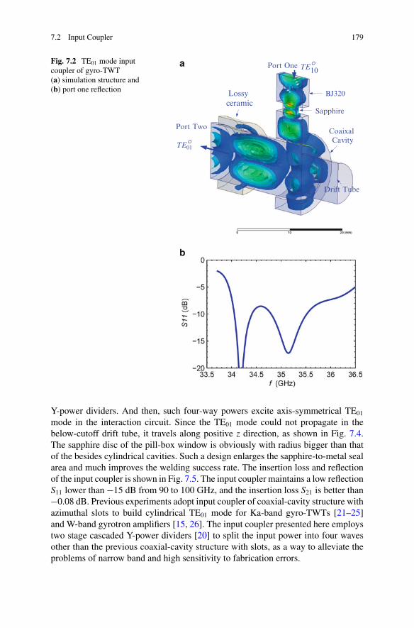
7.2 Input Coupler 179
BJ320
Sapphire
Coaixal Cavity
Drift Tube
Port Two
10Port One TE
TE01
Lossy ceramic
∞
∞a
b
Fig. 7.2 TE01 mode inputcoupler of gyro-TWT(a) simulation structure and(b) port one reflection
Y-power dividers. And then, such four-way powers excite axis-symmetrical TE01
mode in the interaction circuit. Since the TE01 mode could not propagate in thebelow-cutoff drift tube, it travels along positive z direction, as shown in Fig. 7.4.The sapphire disc of the pill-box window is obviously with radius bigger than thatof the besides cylindrical cavities. Such a design enlarges the sapphire-to-metal sealarea and much improves the welding success rate. The insertion loss and reflectionof the input coupler is shown in Fig. 7.5. The input coupler maintains a low reflectionS11 lower than �15 dB from 90 to 100 GHz, and the insertion loss S21 is better than�0.08 dB. Previous experiments adopt input coupler of coaxial-cavity structure withazimuthal slots to build cylindrical TE01 mode for Ka-band gyro-TWTs [21–25]and W-band gyrotron amplifiers [15, 26]. The input coupler presented here employstwo stage cascaded Y-power dividers [20] to split the input power into four wavesother than the previous coaxial-cavity structure with slots, as a way to alleviate theproblems of narrow band and high sensitivity to fabrication errors.
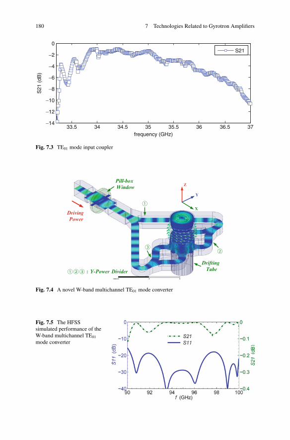
180 7 Technologies Related to Gyrotron Amplifiers
33.5 34 34.5 35 35.5 36 36.5 37−14
−12
−10
−8
−6
−4
−2
0
frequency (GHz)
S21
(dB
)
S21
Fig. 7.3 TE01 mode input coupler
X
Y
Z
Driving
Power
Pill-box
Window
: Y-Power Divider
Drifting
Tube
Fig. 7.4 A novel W-band multichannel TE01 mode converter
Fig. 7.5 The HFSSsimulated performance of theW-band multichannel TE01
mode converter
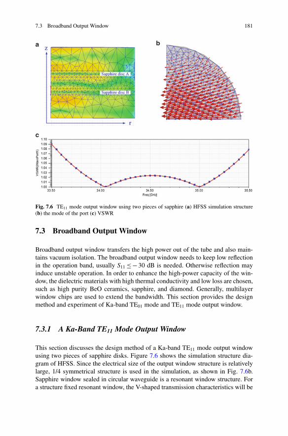
7.3 Broadband Output Window 181
Fig. 7.6 TE11 mode output window using two pieces of sapphire (a) HFSS simulation structure(b) the mode of the port (c) VSWR
7.3 Broadband Output Window
Broadband output window transfers the high power out of the tube and also main-tains vacuum isolation. The broadband output window needs to keep low reflectionin the operation band, usually S11 � � 30 dB is needed. Otherwise reflection mayinduce unstable operation. In order to enhance the high-power capacity of the win-dow, the dielectric materials with high thermal conductivity and low loss are chosen,such as high purity BeO ceramics, sapphire, and diamond. Generally, multilayerwindow chips are used to extend the bandwidth. This section provides the designmethod and experiment of Ka-band TE01 mode and TE11 mode output window.
7.3.1 A Ka-Band TE11 Mode Output Window
This section discusses the design method of a Ka-band TE11 mode output windowusing two pieces of sapphire disks. Figure 7.6 shows the simulation structure dia-gram of HFSS. Since the electrical size of the output window structure is relativelylarge, 1/4 symmetrical structure is used in the simulation, as shown in Fig. 7.6b.Sapphire window sealed in circular waveguide is a resonant window structure. Fora structure fixed resonant window, the V-shaped transmission characteristics will be
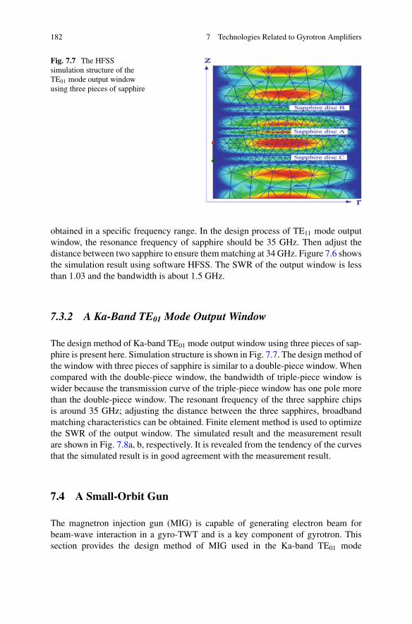
182 7 Technologies Related to Gyrotron Amplifiers
Fig. 7.7 The HFSSsimulation structure of theTE01 mode output windowusing three pieces of sapphire
obtained in a specific frequency range. In the design process of TE11 mode outputwindow, the resonance frequency of sapphire should be 35 GHz. Then adjust thedistance between two sapphire to ensure them matching at 34 GHz. Figure 7.6 showsthe simulation result using software HFSS. The SWR of the output window is lessthan 1.03 and the bandwidth is about 1.5 GHz.
7.3.2 A Ka-Band TE01 Mode Output Window
The design method of Ka-band TE01 mode output window using three pieces of sap-phire is present here. Simulation structure is shown in Fig. 7.7. The design method ofthe window with three pieces of sapphire is similar to a double-piece window. Whencompared with the double-piece window, the bandwidth of triple-piece window iswider because the transmission curve of the triple-piece window has one pole morethan the double-piece window. The resonant frequency of the three sapphire chipsis around 35 GHz; adjusting the distance between the three sapphires, broadbandmatching characteristics can be obtained. Finite element method is used to optimizethe SWR of the output window. The simulated result and the measurement resultare shown in Fig. 7.8a, b, respectively. It is revealed from the tendency of the curvesthat the simulated result is in good agreement with the measurement result.
7.4 A Small-Orbit Gun
The magnetron injection gun (MIG) is capable of generating electron beam forbeam-wave interaction in a gyro-TWT and is a key component of gyrotron. Thissection provides the design method of MIG used in the Ka-band TE01 mode
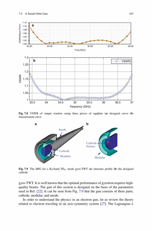
7.4 A Small-Orbit Gun 183
1.12
1.10
1.08
1.06
1.04
VS
WR
(Wav
e P
ort1
)
1.02
1.0033.50 34.00 34.50
Freq [GHz]
35.00 35.50 36.00
33.5 34 34.5 35 35.5 36 36.5 371
1.05
1.1
1.15
1.2
1.25
1.3
frequency (GHz)
VS
WR
VSWR
a
b
Fig. 7.8 VSWR of output window using three pieces of sapphire (a) designed curve (b)measurement curve
Anode
Modular
Cathode
Modular
CathodeEmitter
a b
Fig. 7.9 The MIG for a Ka-band TE01 mode gyro-TWT (a) structure profile (b) the designedcathode
gyro-TWT. It is well known that the optimal performance of gyrotron requires high-quality beams. The gun of this section is designed on the basis of the parametersused in Ref. [22]. It can be seen from Fig. 7.9 that the gun consists of three parts,cathode, modular, and anode.
In order to understand the physics in an electron gun, let us review the theoryrelated to electron traveling in an axis-symmetry system [27]. The Lagrangian L
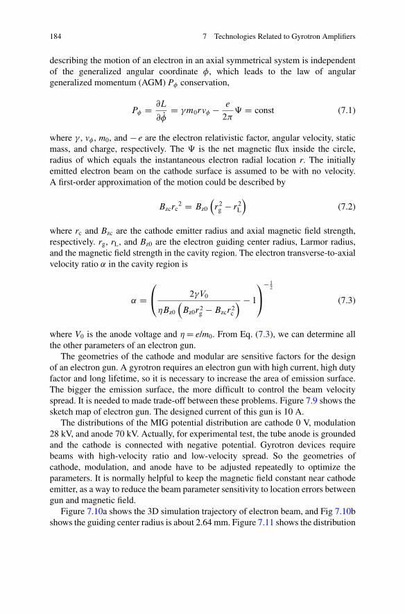
184 7 Technologies Related to Gyrotron Amplifiers
describing the motion of an electron in an axial symmetrical system is independentof the generalized angular coordinate �, which leads to the law of angulargeneralized momentum (AGM) P� conservation,
P� D @L
@ P� D �m0rv� � e
2�‰ D const (7.1)
where � , v� , m0, and � e are the electron relativistic factor, angular velocity, staticmass, and charge, respectively. The ‰ is the net magnetic flux inside the circle,radius of which equals the instantaneous electron radial location r. The initiallyemitted electron beam on the cathode surface is assumed to be with no velocity.A first-order approximation of the motion could be described by
Bzcrc2 D Bz0
�r2
g � r2L
�(7.2)
where rc and Bzc are the cathode emitter radius and axial magnetic field strength,respectively. rg, rL, and Bz0 are the electron guiding center radius, Larmor radius,and the magnetic field strength in the cavity region. The electron transverse-to-axialvelocity ratio ˛ in the cavity region is
˛ D0@ 2�V0
Bz0
�Bz0r2
g � Bzcr2c
� � 1
1A
� 12
(7.3)
where V0 is the anode voltage and D e/m0. From Eq. (7.3), we can determine allthe other parameters of an electron gun.
The geometries of the cathode and modular are sensitive factors for the designof an electron gun. A gyrotron requires an electron gun with high current, high dutyfactor and long lifetime, so it is necessary to increase the area of emission surface.The bigger the emission surface, the more difficult to control the beam velocityspread. It is needed to made trade-off between these problems. Figure 7.9 shows thesketch map of electron gun. The designed current of this gun is 10 A.
The distributions of the MIG potential distribution are cathode 0 V, modulation28 kV, and anode 70 kV. Actually, for experimental test, the tube anode is groundedand the cathode is connected with negative potential. Gyrotron devices requirebeams with high-velocity ratio and low-velocity spread. So the geometries ofcathode, modulation, and anode have to be adjusted repeatedly to optimize theparameters. It is normally helpful to keep the magnetic field constant near cathodeemitter, as a way to reduce the beam parameter sensitivity to location errors betweengun and magnetic field.
Figure 7.10a shows the 3D simulation trajectory of electron beam, and Fig 7.10bshows the guiding center radius is about 2.64 mm. Figure 7.11 shows the distribution
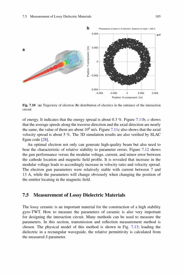
7.5 Measurement of Lossy Dielectric Materials 185
0.004
0.002
Y
Z X
−0.002
−0.004
−0.004 −0.002 0.002 0.004
all
0
Position: X-component / [m]
Phasespace of plane in Z-direction, distance to origin = 300.0.
Pos
ition
: Y-c
ompo
nent
/ [m
]
0
a
b
Fig. 7.10 (a) Trajectory of electron (b) distribution of electrics in the entrance of the interactioncircuit
of energy. It indicates that the energy spread is about 0.3 %. Figure 7.11b, c showsthat the average speeds along the traverse direction and the axial direction are nearlythe same, the value of them are about 108 m/s. Figure 7.11c also shows that the axialvelocity spread is about 5 %. The 3D simulation results are also verified by SLACEgun code [28].
An optimal electron not only can generate high-quality beam but also need tobear the characteristic of relative stability to parameter errors. Figure 7.12 showsthe gun performance versus the modular voltage, current, and minor error betweenthe cathode location and magnetic field profile. It is revealed that increase in themodular voltage leads to accordingly increase in velocity ratio and velocity spread.The electron gun parameters were relatively stable with current between 7 and13 A, while the parameters will change obviously when changing the position ofthe emitter locating in the magnetic field.
7.5 Measurement of Lossy Dielectric Materials
The lossy ceramic is an important material for the construction of a high stabilitygyro-TWT. How to measure the parameters of ceramic is also very importantfor designing the interaction circuit. Many methods can be used to measure theparameters. In this section, transmission and reflection measurement method ischosen. The physical model of this method is shown in Fig. 7.13; loading thedielectric in a rectangular waveguide, the relative permittivity is calculated fromthe measured S parameter.
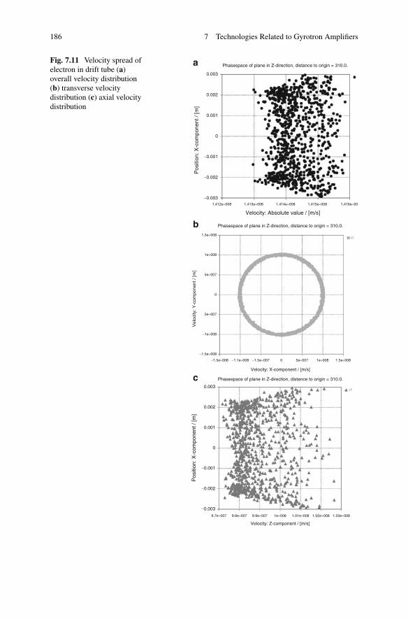
186 7 Technologies Related to Gyrotron Amplifiers
Phasespace of plane in Z-direction, distance to origin = 310.0.
Phasespace of plane in Z-direction, distance to origin = 310.0.
Phasespace of plane in Z-direction, distance to origin = 310.0.
0.003
0.002
0.001
−0.002
−0.0031.412e+008
1.5e+008
1e+008
5e+007
5e+007
−1e+008
−1.5e+008
−1.5e+008 −1.1e+008 −1.5e+007 5e+007 1e+008 1.5e+0080
0
1.413e+008 1.414e+008 1.415e+008 1.416e+00
all
all
−0.001
0
Pos
ition
: X-c
ompo
nent
/ [m
]V
eloc
ity: Y
-com
pone
nt /
[m]
0.003
0.002
0.001
−0.002
−0.003
−0.001
0
Pos
ition
: X-c
ompo
nent
/ [m
]
Velocity: Absolute value / [m/s]
9.7e+007 9.8e+007 9.9e+007 1e+008 1.01e+008 1.02e+008 1.03e+008
Velocity: Z-component / [m/s]
Velocity: X-component / [m/s]
a
b
c
Fig. 7.11 Velocity spread ofelectron in drift tube (a)overall velocity distribution(b) transverse velocitydistribution (c) axial velocitydistribution
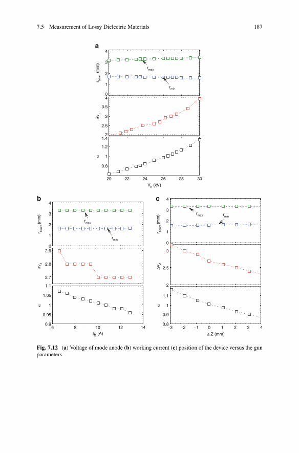
7.5 Measurement of Lossy Dielectric Materials 187
0
1
2
3
4a
r beam
(mm
)
2
2.5
3
3.5
4Δ
v zα
20 22 24 26 28 30
0.8
1
1.2
1.4
Vb (kV)
rmax
rmin
b c
r beam
(mm
)
r beam
(mm
)
Δv z
Δ Z (mm)
Δv z
α α
0
1
2
3
4
6 8 10 12 140.9
0.95
1
1.05
1.1
Ib (A)
2.7
2.8
2.9
rmax
rmin0
1
2
3
4
2
2.5
3
−3 −2 −1 0 1 2 3 40.8
0.9
1
1.1
rmax rmin
Fig. 7.12 (a) Voltage of mode anode (b) working current (c) position of the device versus the gunparameters
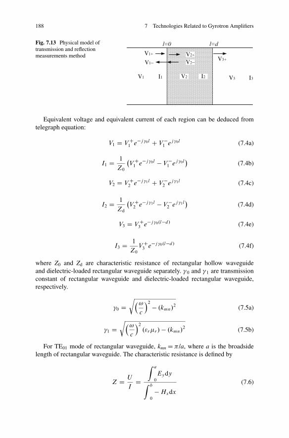
188 7 Technologies Related to Gyrotron Amplifiers
I1 V3 I3V2 I2
l=0 l=d
V1+
V1−
V1
V2+
V2−V3+
Fig. 7.13 Physical model oftransmission and reflectionmeasurements method
Equivalent voltage and equivalent current of each region can be deduced fromtelegraph equation:
V1 D V C1 e�j �0l C V �
1 ej �0l (7.4a)
I1 D 1
Z0
�V C
1 e�j �0l � V �1 ej �0l
�(7.4b)
V2 D V C2 e�j �1l C V �
2 ej �1l (7.4c)
I2 D 1
Zd
�V C
2 e�j �1l � V �2 ej �1l
�(7.4d)
V3 D V C3 e�j �0.l�d/ (7.4e)
I3 D 1
Z0
V C3 e�j �0.l�d/ (7.4f)
where Z0 and Zd are characteristic resistance of rectangular hollow waveguideand dielectric-loaded rectangular waveguide separately. �0 and �1 are transmissionconstant of rectangular waveguide and dielectric-loaded rectangular waveguide,respectively.
�0 Dr�!
c
�2 � .kmn/2 (7.5a)
�1 Dr�!
c
�2
."r�r/ � .kmn/2 (7.5b)
For TE01 mode of rectangular waveguide, kmn D � /a, where a is the broadsidelength of rectangular waveguide. The characteristic resistance is defined by
Z D U
ID
Z a
0
Eydy
Z b
0
� Hxdx
(7.6)
7.5 Measurement of Lossy Dielectric Materials 189
We can obtain that
Zd
Z0
D �0
�1
�r (7.7)
According to the boundary condition of dielectric surface
V1 D V2; I1 D I2 l D 0 (7.8a)
V2 D V3; I2 D I3: l D d (7.8b)
We get
41
S21
D 1
T
�1 C 1 C �
1 � �
��1 C 1 � �
1 C �
�C T
�1 � 1 C �
1 � �
��1 � 1 � �
1 C �
�
(7.9a)
4S11
S21
D 1
T
�1 C 1 C �
1 � �
��1 � 1 � �
1 C �
�C T
�1 � 1 C �
1 � �
��1 C 1 � �
1 C �
�
(7.9b)
where T D e�j �1d is transmission factor and � D (Zd � Z0)/(Zd C Z0) is reflectioncoefficient. Solving Eq. (7.6), expression of material parameters is
�r D ˙s
Y 2
k2 � .�=a/2
ln.X/
jd
�2
(7.10a)
"r D
ln.X/
jd
�2
C .�=a/2
�rk2(7.10b)
where X and Y are
X D S21 .1 � Y /
1 C S11 C .S11 � 1/ Y(7.11a)
Y D ˙s
S221 � S2
11 � 1 � 2S11
S221 � S2
11 � 1 C 2S11
(7.11b)
We need to pay attention to some problems. Generally speaking, the result mustsatisfy the condition of real(�r) > 0 and real("r) � 1. When using transmissionand reflection method to measure the material with thickness thicker than halfof the guided wave wavelength, the measurement result normally turns to be illconditioned, and it leads to multi roots due to measured complex parameters.
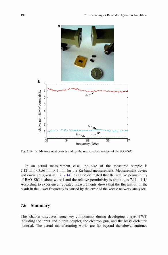
190 7 Technologies Related to Gyrotron Amplifiers
33 34 35 36 370
1
2
3
4
5
6
7
8
frequency (GHz)
rela
tive
perm
ittiv
ity/p
erm
eabi
lity
μi μr
εr
εi
a
b
Fig. 7.14 (a) Measurement devices and (b) the measured parameters of the BeO–SiC
In an actual measurement case, the size of the measured sample is7.12 mm 3.56 mm 1 mm for the Ka-band measurement. Measurement deviceand curve are given in Fig. 7.14. It can be estimated that the relative permeabilityof BeO–SiC is about �r � 1 and the relative permittivity is about "r � 7.11 � 1.1j.According to experience, repeated measurements shows that the fluctuation of theresult in the lower frequency is caused by the error of the vector network analyzer.
7.6 Summary
This chapter discusses some key components during developing a gyro-TWT,including the input and output coupler, the electron gun, and the lossy dielectricmaterial. The actual manufacturing works are far beyond the abovementioned
References 191
complicity. The process of a gyrotron device manufacture includes electrical design,mechanical design, machining, welding, degasification, cold test, and hot testand may require refurbishment. The designers, engineers, and the techniciansshould keep well communication with each other to fully understand the mutuallimitations and balance relation between the theory design and engineering practice.Generally, minor deviation between the measurement result and the design value isunavoidable. The solution is to bring these deviations under control.
References
1. Chu KR (2004) The electron cyclotron maser. Rev Mod Phys 76:489–5402. Chu KR, Chen HY, Hung CL et al (1999) Theory and experiment of ultrahigh-gain gyrotron
traveling wave amplifier. IEEE Trans Plasma Sci 27:391–4043. Yuan CP, Chang TH, Chen NC et al (2009) Magnetron injection gun for a broadband gyrotron
backward-wave oscillator. Phys Plasmas 16:0731094. Fu WJ, Yan Y, Yuan XS et al (2009) Two-beam magnetron injection guns for coaxial gyrotron
with two electron beams. Phys Plasmas 16:231035. Barroso JJ, Montes A, Silva CAB (1985) The use of a synthesis method in the design of
gyrotron electron guns. Int J Electron 59:33–476. Lygin VK, Manuilov VN, Kuftin AN et al (1995) Inverse magnetron injection gun for a coaxial
1.5mw, 140 Ghz gyrotron. Int J Electron 79:227–2357. Lygin VK, Piosczyk B, Dammertz G et al (1997) A diode electron gun for a 1 MW 140 GHz
gyrotron. Int J Electron 82:193–2018. Kartikeyan MV, Borie E (2000) Design of an electron gun for a 42 GHz, 200 kW, TE5,2 mode
gyrotron using the BFCRAY code. IETE Tech Rev 17:275–2819. Piosczyk B (2001) A novel 4.5-MW electron gun for a coaxial cavity gyrotron. IEEE Trans
Electron Devices 48:2938–294410. Anderson JP, Korbly SE, Temkin RJ et al (2002) Design and emission uniformity studies of a
1.5-MW gyrotron electron gun. IEEE Trans Plasma Sci 30:2117–212311. Einat M, Jerby E, Rosenman G (2002) Spectral measurements of gyrotron oscillator with
ferroelectric electron gun. Appl Phys Lett 81:1347–134912. Harriet SB, McDermott DB, Gallagher DA et al (2002) Cusp gun TE21 second-harmonic
Ka-band Gyro-TWT amplifier. IEEE Trans Plasma Sci 30:909–91413. Manuilov VN, Idehara T, Kamada M et al (2006) Electron gun for large orbit gyrotron (LOG)
with decreased influence of cathode plasma on electron beam properties. Int J Infrared MillimWaves 27:343–353
14. Piosczyk B (2006) A coaxial magnetron injection gun (CMIG) for a 2 MW, 170 GHz coaxialcavity gyrotron. Int J Infrared Millim Waves 27:1041–1061
15. Song HH, McDermott DB, Hirata Y, Barnett LR, Domier CW, Hsu HL et al (2004) Theory andexperiment of a 94 GHz gyrotron traveling-wave amplifier. Phys Plasmas 11:2935–2941
16. McDermott DB, Song HH, Hirata Y et al (2002) Design of a W-Band TE01 mode gyrotrontraveling-wave amplifier with high power and broad-band capabilities. IEEE Trans Plasma Sci30:894–902
17. Lawson WG (1990) Theoretical evaluation of nonlinear tapers for a high-power gyrotron. IEEETrans Microw Theory Tech 38:1617–1622
18. Pershing DE, Nguyen KT, Calame JP et al (2004) A TE11 K-a-band Gyro-TWT amplifier withhigh-average power compatible distributed loss. IEEE Trans Plasma Sci 32:947–956
192 7 Technologies Related to Gyrotron Amplifiers
19. Chao-Hai Du, Tsun-Hsu Chang, Pu-Kun Liu, Yi-Cheng Huang, Pin-Xian Jiang, Shou-Xi Xu,Zhi-Hui Geng, Bao-Liang Hao, Liu Xiao, Gao-Feng Liu, Zheng-Di Li, Shao-Hui Shi (2013)Design of a W-band Gyro-TWT amplifier with a lossy ceramic loaded circuit. IEEE TransElectron Devices 60(7):2388–2394
20. Chang TH, Lee CS, Wu CN, Yu CF (2008) Exciting circular TEmn modes at low terahertzregion. Appl Phys Lett 93(11):111503
21. Garven M, Calame JP, Danly BG, Nguyen KT, Levush B, Wood FN (2002) A gyrotron-traveling-wave tube amplifier experiment with a ceramic loaded interaction region. IEEE TransPlasma Sci 30:885–893
22. Calame JP, Garven M, Danly BG, Levush B, Nguyen KT (2002) Gyrotron-traveling wave-tubecircuits based on lossy ceramics. IEEE Trans Electron Devices 49:1469–1477
23. Liu B, Feng J, Wang E, Li Z, Zeng X, Qian L, Wang H (2011) Design and experimentalstudy of a Ka-band gyro-TWT with periodic dielectric loaded circuits. IEEE Trans Plasma Sci39(8):1665–1672
24. Yan R, Luo Y, Liu G, Pu Y (2012) Design and experiment of a Q-band gyro-TWT loaded withlossy dielectric. IEEE Trans Electron Devices 59(12):3612–3617
25. Wang E, Liu B, Qian L, Li Z, Feng J, Zhu S (2012) Experimental study of high-power gyrotrontraveling-wave tube with periodic lossy material loading. IEEE Trans Plasma Sci 40(7):1846–1853
26. Blank M, Danly BG, Levush B (2000) Experimental demonstration of W-band gyroklystronamplifiers with improved gain and efficiency. IEEE Trans Plasma Sci 28:706–712
27. Du C-H, Chang TH, Liu PK, Yuan CP, Yu SJ, Liu GF, Bratman VL, Glyavin MY, Kalynov YK(2012) Development of a magnetic cusp gun for terahertz harmonic gyro-devices. IEEE TransElectron Devices 59(12):3635–3640
28. Herrmannsfeldt WB (1988) EGUN, an electron optics and gun design program [M]. StanfordLinear Accelerator Center, Stanford University, Menlo Park
Copyright © 2022 FDOKUMEN