Chemical Vapor Deposition of Conformal, Functional, and Responsive Polymer Films
Journal Identification = CHERD Article Identification = 587 Date: May 17, 2011 Time: 5:42 am
Cd
OD
1
OiproodsTFap
ucpS
0d
chemical engineering research and design 8 9 ( 2 0 1 1 ) 593–602
Contents lists available at ScienceDirect
Chemical Engineering Research and Design
journa l homepage: www.e lsev ier .com/ locate /cherd
FD simulation of laser enhanced modified chemical vaporeposition process
.K. Mohammed Hafiz1, Anugrah Singh ∗
epartment of Chemical Engineering, Indian Institute of Technology Guwahati, Guwahati 781039, Assam, India
a b s t r a c t
The modified chemical vapor deposition (MCVD) process is one of the most widely used processes to manufacture the
optical fiber preforms. There have been several experimental and numerical studies to establish that thermophoresis
is the dominant mechanism for the transport of silica particles to the preform wall. There also exists several mod-
ification of this process to increase the deposition efficiency in the MCVD process. In this work we have carried out
computational fluid dynamics simulation of the coupled equations of mass, momentum, energy and species trans-
port in the laser enhanced thermophoretic deposition process using the conservative finite volume scheme. The
effect of laser heating on different parameters such as thermophoresis, conversion rate and deposition efficiency is
examined in this study. The presence of laser heating alters the velocity and temperature profile that leads to increase
in the conversion and deposition efficiency due to high thermophoresis. The results of numerical simulations are
in support of experimental and analytical studies. Our numerical simulations using the conservative finite volume
scheme show that deposition efficiency increases with increasing power of the laser.
© 2010 The Institution of Chemical Engineers. Published by Elsevier B.V. All rights reserved.
Keywords: Simulation; Transport processes; Heat transfer; Particle formation; Optical fiber; Computational fluid
dynamics
dominant mass transfer mechanism in the MCVD process
. Introduction
ptical fibers are fibers of glass, usually about 10–100 �mn diameter, which are used to carry signals in the form ofulses of light over distances up to 50 km without the need forepeaters. There has been a tremendous increase in the usef optical fiber, especially for telecommunications, since fiberptics technology emerged, because of its advantages like highata transmission rate and bandwidth, low loss, small cableize and weight, safety due to lack of sparks, data safety etc.here are mainly two stages in the production of optical fibers.irst, the preforms are produced by vapor deposition of silicand various dopants inside the wall of a silica tube. Then thereforms are drawn to fiber in the second stage.
The modified chemical vapor deposition process is widelysed to manufacture optical preforms for high quality opti-al fiber production. In this process an oxy-hydrogen torch isassed underneath a silica tube, which is rotating in a lathe.
ilicon tetrachloride, oxygen, and dopant species such as ger-∗ Corresponding author. Tel.: +91 361 2582259; fax: +91 361 2582291.E-mail address: [email protected] (A. Singh).Received 3 December 2008; Received in revised form 11 May 2010; Acc
1 Present address: Shell India Markets Pvt. Ltd., Bangalore 560048, Ind263-8762/$ – see front matter © 2010 The Institution of Chemical Engioi:10.1016/j.cherd.2010.09.005
manium tetrachloride are introduced at one end of the tube,where oxidation reactions take place, generating oxides of sil-ica and other dopants. These oxide particles move axially withthe gases and are deposited on the inner wall of the tube bythermophoresis; that is, from the net force that a suspendedparticle experiences in the direction of decreasing tempera-ture. This deposited layer of the particles is fused due to hightemperature of traversing torch and glassy layer is formed inthe interior of the substrate tube. When the torch completesits traverse to the end of the tube, one layer of depositionis obtained. By controlling the dopant chemical composition,desired refractive index profile can be obtained. Germania isthe most common dopant used to increase the refractive indexof the preform to form a guiding core (Wood et al., 1987). Thefabrication of preform is completed when the deposited par-ticle layers fill the substrate tube.
It was proved experimentally that thermophoresis is the
epted 8 September 2010ia.
(MacChesney et al., 1974; Simpkins et al., 1979). Walker et
neers. Published by Elsevier B.V. All rights reserved.
Journal Identification = CHERD Article Identification = 587 Date: May 17, 2011 Time: 5:42 am
594 chemical engineering research and design 8 9 ( 2 0 1 1 ) 593–602
Nomenclature
C molar concentration of gas mixture, mol m−3
CSO molar concentration of SiO2, mol m−3
Cp heat capacity of gas, J kg−1 K−1
Cp0, Cp1, Cp2 constants to calculate heat capacityDCl diffusivity of Cl2 in O2, m2 s−1
DO2 diffusivity of O2, m2 s−1
DSC diffusivity of SiCl4 in O2, m2 s−1
DSC,0, DO2,O constants to calculate diffusivities of SiCl4and O2
ED deposition efficiencyER SiCl4 conversion efficiencyESC activation energy for oxidation of SiCl4, J mol−1
�HSC heat of reaction for SiCl4 oxidation, J mol−1
I intensity of the laser beam, W m−2
k thermal conductivity of carrier gas, W m−1 K−1
ka particle absorption coefficient, m−1
kSC,0 pre-exponential factor of Arrhenius rate con-stant, s−1
kSC,1 pre-exponential factor of Arrhenius rate con-stant, m3 mol−1 s−1
K thermophoretic coefficientL1, L2 axial distances in the reaction zoneM average molecular weight of gas mixturesp pressureP power of the laser beam, Wr radial distance, mrSC reaction rate for SiCl4 oxidationR preform radius, mRG gas constant, 8.314 J mol−1 K−1
T gas temperature, KTmax maximum temperature at the tube wall, KTmin minimum temperature on the tube wall, KT0 inlet gas temperature, Kuz axial velocity, m s−1
U average gas velocity at the inlet, m s−1
ur radial velocity, m s−1
vT thermophoretic velocity of SiO2, m/svn net gas velocity in radial direction, m/sXO2 mole fraction of O2
XO2,0 mole fraction of O2 at the tube inletXSC mole fraction of SiCl4XSC,0 mole fraction of SiCl4 at the tube inletXSO mole fraction of SiO2
YCl mass fraction of Cl2YO2 mass fraction of O2
YSC mass fraction of SiCl4YSO mass fraction of SiO2
z axial distance, m
Greek lettersˇ inverse of half-width of Gaussian Laser profile,
m� dynamic viscosity, kg m−1 s−1
� kinematic viscosity, m2 s−1
�0 constant for calculation of kinematic viscosity� density, kg m−3
SubscriptsCl Cl2()m mixing cup average0 inlet condition
O2 O2
SC SiCl4SO SiO2
z axial distance from the inlet
al. (1980) showed that thermophoresis is the particulatedeposition mechanism in the MCVD process by comparingexperimental measurements and quantitative theoretical pre-dictions. In the MCVD process as described above, the radialtemperature gradient which is responsible for thermophoreticdeposition decays exponentially with the axial direction fromthe heated reaction zone. As a consequence only about half ofthe aerosol particles are deposited on the wall and it resultsin lower deposition efficiency. Increased use of optical fibershas demanded reduction in fabrication costs, increased pro-ductivity and high quality. The MCVD process using externalheating by oxy-hydrogen torch offers limited heat transferfrom outer wall of the substrate and suffers from low produc-tivity where a very thick cladding is required. The quality ofthe fiber also suffers due to heat source fluctuations. Severalmodification of the process has been suggested to improvethe deposition efficiency. Fiebig et al. (1986) proposed thatthe deposition efficiency and conversion rate in MCVD canbe increased by inserting and maintaining at high tempera-ture a concentric annular tube inside the preform. FurnaceMCVD provides heat transfer mostly by radiation and pro-vides uniform and homogeneous hot zones resulting intohigher heat transfer efficiencies and increased homogeneityof the product. However design of hot zone for different pro-cess conditions and process control can be difficult. Morseand Cipolla (1984) using theoretical analysis of laser enhancedthermophoresis found that very high deposition efficiency canbe attained by axial laser heating in sufficiently long tubes.They have formulated the governing equations for the laminartube flow of an aerosol–gas mixture. The effect of laser heatingwas modeled as a source term in the energy equation which isproportional to the concentration dependent absorption coef-ficient. The magnitude of the temperature increase as well asthe change in aerosol concentration to be expected from laserirradiation was estimated through analytical results of thegoverning equations. Scattering and spontaneous emissionwere neglected in this study. Morse et al. (1986) showed exper-imentally that axial laser radiation can significantly alter thequality and quantity of soot deposition in the modified chemi-cal vapor deposition process. In order to improve the efficiencyof the process, a laser beam is applied at the center of the tubealong the axial direction. The laser beam heats the particles atthe centre region of the tube and makes a large temperaturegradient along the radial direction. Subsequently more parti-cles are deposited on the wall because of the increase in thethermophoresis and gives higher deposition efficiency in theMCVD process. The laser serves as a volumetric heating whichis proportional to the product of the local absorption coeffi-cient of the particles and the laser intensity. It was observedthat deposition efficiency could be significantly increased byheating with laser of sufficient power and large beam diam-eter so that maximum numbers of aerosol particles interactwith the laser beam.
The transport of heat and mass transfer during the MCVDprocess has attracted several experimental, theoretical and
numerical studies. Choi et al. (1987) carried out detailed anal-
Journal Identification = CHERD Article Identification = 587 Date: May 17, 2011 Time: 5:42 am
chemical engineering research and design 8 9 ( 2 0 1 1 ) 593–602 595
yojPtaMtbcplcttaKugtpSwgtcaisiaaPrtoodftssoestaaioov
mflWovtatpso
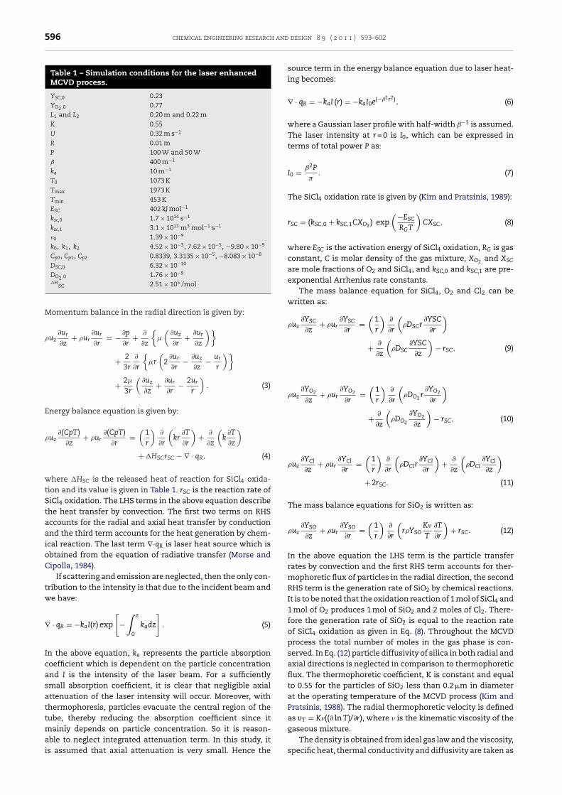
Fig. 1 – Schematic diagram of the MCVD reactor with axiallaser heating.
z∂z
r∂r ∂z r ∂r ∂r ∂z{ ( )}
sis of the effects of tube rotation and variable propertiesn the three-dimensional temperature fields, particle tra-
ectories and deposition for a fast moving torch. Kim andratsinis (1988) were first to present a model accounting forhe concurrent heat transfer, chemical kinetics, and silicaerosol dynamics during waveguide preform fabrication byCVD. Simultaneous diffusion, thermophoresis and coagula-
ion of submicron aerosol in laminar tube flow were studiedy Pratsinis and Kim (1989). They showed that at low inletoncentration coagulation does not affect the particle trans-ort to the wall since characteristic time for coagulation is
onger than process residence time. At these conditions, pro-ess deposition efficiency is determined by diffusion andhermophoresis. But at higher inlet concentration, coagula-ion increases the particle size during the course of the flowlong the tube axis thus reducing the deposition efficiency.im and Pratsinis (1989) presented a finite difference sim-lation of Navier–Stokes equations accounting for variableas properties, chemical reaction, convection, diffusion, andhermophoresis and released heat of reaction. The effects ofrocess variables like gas flow rate and inlet concentration ofiCl4 on MCVD operation were examined. High process yieldsere obtained with high inlet SiCl4 concentration and fast
as flow rates through the preform tube. They also reportedhat heat of reaction reduces the radial diffusion of the parti-les and subsequently the MCVD deposition efficiency. Theyttributed this behavior to the possibility of coagulation of sil-ca particles at higher temperature. In the present work wehow that this unexpected result could be due to numericalnaccuracy in their simulation due to coarse grid and neglectedxial diffusion in governing equations. Co-deposition of SiO2
nd GeO2 during the MCVD process was analyzed by Kim andratsinis (1990). In their analysis, reversibility of the GeCl4eaction was accounted for as well as the simultaneous reac-ion kinetics and transport phenomena of SiCl4 and GeCl4xidation were studied. Lin et al. (1991) studied the effectsf buoyancy, variable properties and tube rotation in a three-imensional numerical analysis of the flow and heat transferor the MCVD process. Jia et al. (1992) analyzed the effect ofhermal radiation on particle deposition. Joh and Greif (1995)tudied heat and mass transfer, particle formation and depo-ition in a MCVD process. In this study both SiCl4 and GeCl4xidation reactions and the effects of buoyancy, variable prop-rties and tube rotation were included. Park and Choi (1994)tudied the conjugate heat transfer and particle depositionhat occur during the modified chemical vapor deposition. Chond Choi (1995) have carried out experimental study of heatnd mass transfer and measured the deposited film thicknessn outside vapor deposition process. Park et al. (2000) carriedut the numerical analysis of unsteady heat and mass transfern the codeposition of SiO2 and GeO2 in the modified chemicalapor deposition.
An experimental and numerical simulation study of ther-ophoretic deposition of aerosol particles in laminar tube
ow with mixed convection has been recently performed byalsh et al. (2006). In their study, experimental data was
btained in an attempt to qualitatively and quantitativelyalidate the model predictions for the effects of free convec-ion on cumulative deposition efficiencies. In their theoreticalpproach, gas phase governing equations (continuity, momen-um and energy) and population balance equation for particlehase is solved. They observed that model prediction of depo-
ition efficiency is not sensitive to the inlet concentrationr particle size. There was only a slight change in deposi-tion efficiency when inlet concentration was varied. They alsofound that coagulation is not occurring in appreciable amountin experiments even though they took higher inlet concen-tration of the particles than the limit presented in Pratsinisand Kim (1989) in order to neglect the effects of coagulation.Their model prediction of the deposition efficiency was ingood agreement with experimental results and concluded thatthere was no significant coagulation of the particles occurring.
These observations have motivated us to examine theeffect of heating on the deposition efficiency and presentan analysis of the MCVD process with external heating. Inthis study we have considered the analysis of laser enhancedMCVD process by performing CFD simulations which hasnot been taken up previously. We have solved coupledNavier–Stokes equation of mass, momentum, energy balanceand species transport for SiCl4, O2, Cl2 and SiO2 with andwithout laser heating. The evolution of temperature, axial andradial gas velocities, SiCl4 conversion and SiO2 deposition areinvestigated along the preform axis in the absence of laser aswell as in the presence of laser beams of different powers.
2. Theory
Fig. 1 presents a schematic diagram of the MCVD process withlaser heating at the centre of the tube. The reactant gas mix-tures (SiCl4 and O2) enter the silica tube of radius R as fullydeveloped laminar flow. There, the mixture is heated by anexternal heat source and exothermic oxidation reaction takesplace and SiO2 and Cl2 are formed as products.
SiCl4(g) + O2(g) → SiO2(s) + 2Cl2(g)
The products flow into the deposition zone, where SiO2 parti-cles cool down because of the low temperature. There, a partof the silica particles is deposited onto the tube wall mostlyby thermophoresis, while the rest exit the perform tube byconvection. When the rotation speed of the silica tube is innormal range (60–120 rpm) it has been found that the deposi-tion in circumferential direction is uniform (Park et al., 2000).In such cases, two-dimensional axisymmetric model of thereactive flow simulation can be considered.
The continuity equation can be written as:
∂(�uz)∂z
+ 1r
∂(�rur)∂r
= 0. (1)
Momentum balance in axial direction is given by:
�u∂uz + �u
∂uz = − ∂p + 1 ∂{
�r
(∂uz + ∂ur
)}
+ 23
∂
∂z� 2
∂uz
∂z− ∂ur
∂r− ur
r. (2)
Journal Identification = CHERD Article Identification = 587 Date: May 17, 2011 Time: 5:42 am
596 chemical engineering research and design 8 9 ( 2 0 1 1 ) 593–602
Table 1 – Simulation conditions for the laser enhancedMCVD process.
YSC,0 0.23YO2 ,0 0.77L1 and L2 0.20 m and 0.22 mK 0.55U 0.32 m s−1
R 0.01 mP 100 W and 50 Wˇ 400 m−1
ka 10 m−1
T0 1073 KTmax 1973 KTmin 453 KESC 402 kJ mol−1
ksc,0 1.7 × 10¹⁴ s−1
ksc,1 3.1 × 10¹³ m3 mol−1 s−1
�0 1.39 × 10⁻⁹
k0, k1, k2 4.52 × 10⁻³, 7.62 × 10⁻⁵, −9.80 × 10⁻⁹
Cp0, Cp1, Cp2 0.8339, 3.3135 × 10⁻⁵, −8.083 × 10⁻⁸
DSC,0 6.32 × 10⁻¹⁰
DO2 ,0 1.76 × 10⁻⁹
�HSC 2.51 × 10⁵ /mol
Momentum balance in the radial direction is given by:
�uz∂ur
∂z+ �ur
∂ur
∂r= − ∂p
∂r+ ∂
∂z
{�
(∂uz
∂r+ ∂ur
∂z
)}
+ 23r
∂
∂r
{�r
(2
∂ur
∂r− ∂uz
∂z− ur
r
)}
+ 2�
3r
(∂uz
∂z+ ∂ur
∂r− 2ur
r
). (3)
Energy balance equation is given by:
�uz∂(CpT)
∂z+ �ur
∂(CpT)∂r
=(
1r
)∂
∂r
(kr
∂T
∂r
)+ ∂
∂z
(k
∂T
∂z
)
+ �HSCrSC − ∇ · qR, (4)
where �HSC is the released heat of reaction for SiCl4 oxida-tion and its value is given in Table 1. rSC is the reaction rate ofSiCl4 oxidation. The LHS terms in the above equation describethe heat transfer by convection. The first two terms on RHSaccounts for the radial and axial heat transfer by conductionand the third term accounts for the heat generation by chem-ical reaction. The last term ∇·qR is laser heat source which isobtained from the equation of radiative transfer (Morse andCipolla, 1984).
If scattering and emission are neglected, then the only con-tribution to the intensity is that due to the incident beam andwe have:
∇ · qR = −kaI(r) exp
[−
∫ z
0
kadz
]. (5)
In the above equation, ka represents the particle absorptioncoefficient which is dependent on the particle concentrationand I is the intensity of the laser beam. For a sufficientlysmall absorption coefficient, it is clear that negligible axialattenuation of the laser intensity will occur. Moreover, withthermophoresis, particles evacuate the central region of thetube, thereby reducing the absorption coefficient since itmainly depends on particle concentration. So it is reason-
able to neglect integrated attenuation term. In this study, itis assumed that axial attenuation is very small. Hence thesource term in the energy balance equation due to laser heat-ing becomes:
∇ · qR = −kaI (r) = −kaI0e(−ˇ2r2), (6)
where a Gaussian laser profile with half-width ˇ−1 is assumed.The laser intensity at r = 0 is I0, which can be expressed interms of total power P as:
I0 = ˇ2P
�. (7)
The SiCl4 oxidation rate is given by (Kim and Pratsinis, 1989):
rSC = (kSC,0 + kSC,1CXO2 ) exp(−ESC
RGT
)CXSC, (8)
where ESC is the activation energy of SiCl4 oxidation, RG is gasconstant, C is molar density of the gas mixture, XO2 and XSC
are mole fractions of O2 and SiCl4, and kSC,0 and kSC,1 are pre-exponential Arrhenius rate constants.
The mass balance equation for SiCl4, O2 and Cl2 can bewritten as:
�uz∂YSC
∂z+ �ur
∂YSC
∂r=
(1r
)∂
∂r
(�DSCr
∂YSC
∂r
)
+ ∂
∂z
(�DSC
∂YSC
∂z
)− rSC, (9)
�uz∂YO2
∂z+ �ur
∂YO2
∂r=
(1r
)∂
∂r
(�DO2 r
∂YO2
∂r
)
+ ∂
∂z
(�DO2
∂YO2
∂z
)− rSC, (10)
�uz∂YCl
∂z+ �ur
∂YCl
∂r=
(1r
)∂
∂r
(�DClr
∂YCl
∂r
)+ ∂
∂z
(�DCl
∂YCl
∂z
)
+ 2rSC. (11)
The mass balance equations for SiO2 is written as:
�uz∂YSO
∂z+ �ur
∂YSO
∂r=
(1r
)∂
∂r
(r�YSO
K�
T
∂T
∂r
)+ rSC. (12)
In the above equation the LHS term is the particle transferrates by convection and the first RHS term accounts for ther-mophoretic flux of particles in the radial direction, the secondRHS term is the generation rate of SiO2 by chemical reactions.It is to be noted that the oxidation reaction of 1 mol of SiCl4 and1 mol of O2 produces 1 mol of SiO2 and 2 moles of Cl2. There-fore the generation rate of SiO2 is equal to the reaction rateof SiCl4 oxidation as given in Eq. (8). Throughout the MCVDprocess the total number of moles in the gas phase is con-served. In Eq. (12) particle diffusivity of silica in both radial andaxial directions is neglected in comparison to thermophoreticflux. The thermophoretic coefficient, K is constant and equalto 0.55 for the particles of SiO2 less than 0.2 �m in diameterat the operating temperature of the MCVD process (Kim andPratsinis, 1988). The radial thermophoretic velocity is definedas vT = K�((∂ ln T)/∂r), where � is the kinematic viscosity of thegaseous mixture.
The density is obtained from ideal gas law and the viscosity,specific heat, thermal conductivity and diffusivity are taken as
Journal Identification = CHERD Article Identification = 587 Date: May 17, 2011 Time: 5:42 am
chemical engineering research and design 8 9 ( 2 0 1 1 ) 593–602 597
f
ItfSc
E
E
Iit
Y
Ba
Taet
T
T
a
T
Asedda
3
Ts2
temperature. Beyond this zone, both increase of the torch tem-perature and the heat released due to reaction further rise the
unctions of temperature (Kim and Pratsinis, 1989).
� = pM
RGT;
�
�= � = �0T1.65; Cp = Cp0 + Cp1T + Cp2T2;
k = k0 + k1T + k2T2; DSC = DSC,0T1.66; DO2 = DO2,0T1.66.
(13)
t is to be noted that we solve only the species transport equa-ion of SiO2, SiCl4 and O2. The mass fraction of Cl2 is obtainedrom mass balance. The SiCl4 conversion efficiency (ER) andiO2 deposition efficiency (ED) at any axial location can bealculated as:
R = 1 − (CuzXSC)m,z
(CuzXSC)m,0, (14)
D = ER − (CuzXSO)m,z
(CuzXSC)m,0. (15)
n the above equations ()m,0 denote the area average at thenlet and ()m,z denote the area average at any location z alonghe tube axis.
The inlet conditions are given at z = 0 for all r as:
T = T0; uz = 2U
(1 −
(r
R
)2)
;
SC = YSC,0; YO2 = YO2,0; YCl = YSO = ur = 0. (16)
y cylindrical symmetry, the boundary conditions at r = 0 forll z are:
∂T
∂r= ∂uz
∂r= ∂YSC
∂r= ∂YO2
∂r= ∂YCl
∂r= ∂YSO
∂r= ur = 0. (17)
he tube wall temperature profile in the MCVD process is givens a function of axial distance (Kim and Pratsinis, 1989; Morset al., 1985). The boundary conditions at the tube wall (r = R) inhe reaction zone are:
W (z) = T0 + (Tmax − T0)(
z
L1
)2for 0 ≤ z < L1, (18)
W (z) = Tmax − (Tmax − Tmin)(
z − L1
L2 − L1
)for L1 ≤ z < L2, (19)
nd in the deposition zone:
W (z) = Tmin for z ≥ L2. (20)
t the tube wall we use zero-flux for all the species and no-lip velocity boundary condition is used in the momentumquation. At the outlet we have used outflow boundary con-ition. This boundary condition is appropriate for the fullyeveloped condition and it applies zero normal gradient forll flow variables and species which is:
∂T
∂z= ∂ur
∂z= ∂uz
∂z= ∂YSC
∂z= ∂YO2
∂z= ∂YCl
∂z= ∂YSO
∂z= 0. (21)
The pressure at the outlet was fixed at 1 atm.
. Solution procedure
he Eqs. (1)–(4) along with (9)–(12) form coupled non-linear
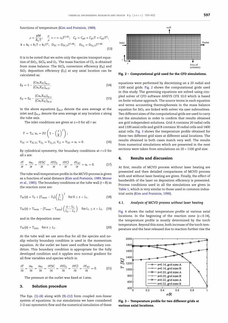
ystem of equations. In our simulations we have considered-D axi-symmetric flow and the numerical simulation of theseFig. 2 – Computational grid used for the CFD simulations.
equations were performed by discretizing on a 20 radial and1100 axial grids. Fig. 2 shows the computational grids usedin this study. The governing equations are solved using cou-pled solver of CFD software ANSYS CFX 10.0 which is basedon finite volume approach. The source terms in each equationand terms accounting thermophoresis in the mass balanceequation for SiO2 are linked with solver via user subroutines.Two different sizes of the computational grids are used to carryout the simulation in order to confirm that results obtainedare grid independent solutions. Grid A contains 20 radial cellsand 1100 axial cells and grid B contains 30 radial cells and 1400axial cells. Fig. 3 shows the temperature profile obtained forthese two different grid sizes at different axial locations. Theresults obtained in both cases match very well. The resultsfrom numerical simulations which are presented in the nextsections were taken from simulations on 20 × 1100 grid size.
4. Results and discussion
At first, results of MCVD process without laser heating arepresented and then detailed comparisons of MCVD processwith and without laser heating are given. Finally, the effect ofbandwidth of the laser on deposition efficiency is presented.Process conditions used in all the simulations are given inTable 1, which is very similar to those used in common indus-trial units (Kim and Pratsinis, 1990).
4.1. Analysis of MCVD process without laser heating
Fig. 4 shows the radial temperature profile at various axiallocations. In the beginning of the reaction zone (z < 0.14),the temperature profile is mostly determined by the torch
Fig. 3 – Temperature profile for two different grids atvarious axial locations.
Journal Identification = CHERD Article Identification = 587 Date: May 17, 2011 Time: 5:42 am
598 chemical engineering research and design 8 9 ( 2 0 1 1 ) 593–602
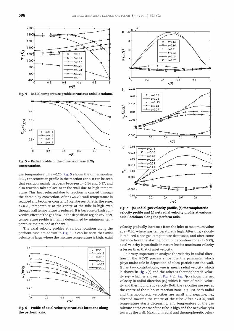
Fig. 4 – Radial temperature profile at various axial locations.
Fig. 5 – Radial profile of the dimensionless SiCl4
Fig. 7 – (a) Radial gas velocity profile, (b) thermophoreticvelocity profile and (c) net radial velocity profile at various
concentration.
gas temperature till z = 0.20. Fig. 5 shows the dimensionlessSiCl4 concentration profile in the reaction zone. It can be seenthat reaction mainly happens between z = 0.14 and 0.17, andalso reaction takes place near the wall due to high temper-ature. This heat released due to reaction is carried throughthe domain by convection. After z = 0.20, wall temperature isreduced and becomes constant. It can be seen that in the zone,z > 0.20, temperature at the centre of the tube is high eventhough wall temperature is reduced. It is because of high con-vective effect of the gas flow. In the deposition region (z > 0.22),temperature profile is mainly determined by minimum tem-perature maintained at the wall.
The axial velocity profiles at various locations along theperform tube are shown in Fig. 6. It can be seen that axial
velocity is large where the mixture temperature is high. AxialFig. 6 – Profile of axial velocity at various locations alongthe perform axis.
axial locations along the perform axis.
velocity gradually increases from the inlet to maximum valueat z = 0.20, where, gas temperature is high. After this, velocityis reduced since gas temperature decreases, and after somedistance from the starting point of deposition zone (z > 0.22),axial velocity is parabolic in nature but its maximum velocityis lesser than that of inlet velocity.
It is very important to analyze the velocity in radial direc-tion in the MCVD process since it is the parameter whichplays major role in deposition of silica particles on the wall.It has two contributions; one is mean radial velocity whichis shown in Fig. 7(a) and the other is thermophoretic veloc-ity (vT) which is shown in Fig. 7(b). Fig. 7(c) shows the netvelocity in radial direction (vn) which is sum of radial veloc-ity and thermophoretic velocity. Both the velocities are zero atthe centre of the tube. In reaction zone, z ≤ 0.20, both radialand thermophoretic velocities are small and negative, i.e.,directed towards the centre of the tube. After z > 0.20, walltemperature starts decreasing, and temperature of the gas
mixture at the centre of the tube is high and the net velocity istowards the wall. Maximum radial and thermophoretic veloc-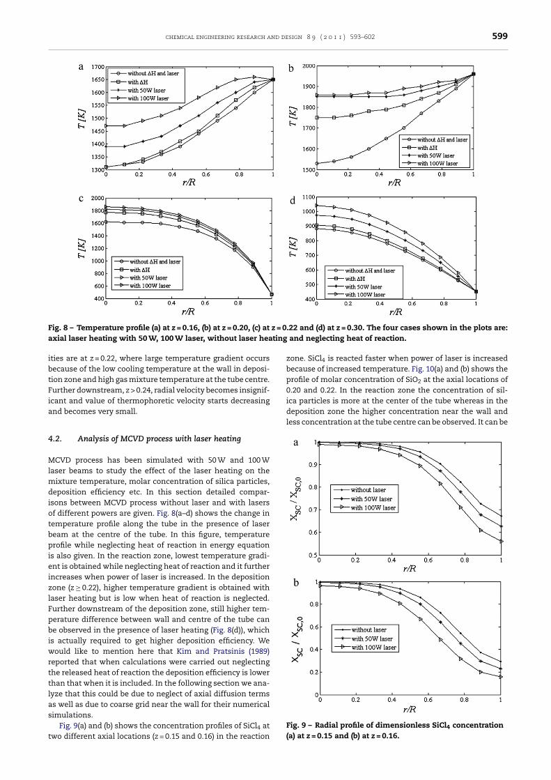
Journal Identification = CHERD Article Identification = 587 Date: May 17, 2011 Time: 5:42 am
chemical engineering research and design 8 9 ( 2 0 1 1 ) 593–602 599
Fig. 8 – Temperature profile (a) at z = 0.16, (b) at z = 0.20, (c) at z = 0.22 and (d) at z = 0.30. The four cases shown in the plots are:a ting
ibtFia
4
MlmdiotbpieizlFpbiwrttlas
t
deposition zone the higher concentration near the wall andless concentration at the tube centre can be observed. It can be
xial laser heating with 50 W, 100 W laser, without laser hea
ties are at z = 0.22, where large temperature gradient occursecause of the low cooling temperature at the wall in deposi-ion zone and high gas mixture temperature at the tube centre.urther downstream, z > 0.24, radial velocity becomes insignif-cant and value of thermophoretic velocity starts decreasingnd becomes very small.
.2. Analysis of MCVD process with laser heating
CVD process has been simulated with 50 W and 100 Waser beams to study the effect of the laser heating on the
ixture temperature, molar concentration of silica particles,eposition efficiency etc. In this section detailed compar-
sons between MCVD process without laser and with lasersf different powers are given. Fig. 8(a–d) shows the change inemperature profile along the tube in the presence of laseream at the centre of the tube. In this figure, temperaturerofile while neglecting heat of reaction in energy equation
s also given. In the reaction zone, lowest temperature gradi-nt is obtained while neglecting heat of reaction and it furtherncreases when power of laser is increased. In the depositionone (z ≥ 0.22), higher temperature gradient is obtained withaser heating but is low when heat of reaction is neglected.urther downstream of the deposition zone, still higher tem-erature difference between wall and centre of the tube cane observed in the presence of laser heating (Fig. 8(d)), which
s actually required to get higher deposition efficiency. Weould like to mention here that Kim and Pratsinis (1989)
eported that when calculations were carried out neglectinghe released heat of reaction the deposition efficiency is lowerhan that when it is included. In the following section we ana-yze that this could be due to neglect of axial diffusion termss well as due to coarse grid near the wall for their numericalimulations.
Fig. 9(a) and (b) shows the concentration profiles of SiCl4 atwo different axial locations (z = 0.15 and 0.16) in the reaction
and neglecting heat of reaction.
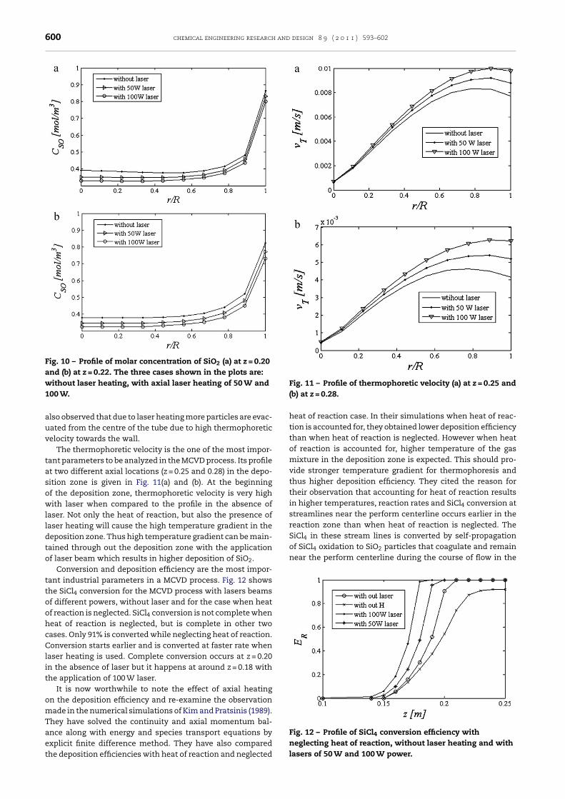
zone. SiCl4 is reacted faster when power of laser is increasedbecause of increased temperature. Fig. 10(a) and (b) shows theprofile of molar concentration of SiO2 at the axial locations of0.20 and 0.22. In the reaction zone the concentration of sil-ica particles is more at the center of the tube whereas in the
Fig. 9 – Radial profile of dimensionless SiCl4 concentration(a) at z = 0.15 and (b) at z = 0.16.
Journal Identification = CHERD Article Identification = 587 Date: May 17, 2011 Time: 5:42 am
600 chemical engineering research and design 8 9 ( 2 0 1 1 ) 593–602
Fig. 10 – Profile of molar concentration of SiO2 (a) at z = 0.20and (b) at z = 0.22. The three cases shown in the plots are:without laser heating, with axial laser heating of 50 W and Fig. 11 – Profile of thermophoretic velocity (a) at z = 0.25 and
of SiCl4 oxidation to SiO2 particles that coagulate and remainnear the perform centerline during the course of flow in the
Fig. 12 – Profile of SiCl4 conversion efficiency with
100 W.
also observed that due to laser heating more particles are evac-uated from the centre of the tube due to high thermophoreticvelocity towards the wall.
The thermophoretic velocity is the one of the most impor-tant parameters to be analyzed in the MCVD process. Its profileat two different axial locations (z = 0.25 and 0.28) in the depo-sition zone is given in Fig. 11(a) and (b). At the beginningof the deposition zone, thermophoretic velocity is very highwith laser when compared to the profile in the absence oflaser. Not only the heat of reaction, but also the presence oflaser heating will cause the high temperature gradient in thedeposition zone. Thus high temperature gradient can be main-tained through out the deposition zone with the applicationof laser beam which results in higher deposition of SiO2.
Conversion and deposition efficiency are the most impor-tant industrial parameters in a MCVD process. Fig. 12 showsthe SiCl4 conversion for the MCVD process with lasers beamsof different powers, without laser and for the case when heatof reaction is neglected. SiCl4 conversion is not complete whenheat of reaction is neglected, but is complete in other twocases. Only 91% is converted while neglecting heat of reaction.Conversion starts earlier and is converted at faster rate whenlaser heating is used. Complete conversion occurs at z = 0.20in the absence of laser but it happens at around z = 0.18 withthe application of 100 W laser.
It is now worthwhile to note the effect of axial heatingon the deposition efficiency and re-examine the observationmade in the numerical simulations of Kim and Pratsinis (1989).They have solved the continuity and axial momentum bal-ance along with energy and species transport equations by
explicit finite difference method. They have also comparedthe deposition efficiencies with heat of reaction and neglected(b) at z = 0.28.
heat of reaction case. In their simulations when heat of reac-tion is accounted for, they obtained lower deposition efficiencythan when heat of reaction is neglected. However when heatof reaction is accounted for, higher temperature of the gasmixture in the deposition zone is expected. This should pro-vide stronger temperature gradient for thermophoresis andthus higher deposition efficiency. They cited the reason fortheir observation that accounting for heat of reaction resultsin higher temperatures, reaction rates and SiCl4 conversion atstreamlines near the perform centerline occurs earlier in thereaction zone than when heat of reaction is neglected. TheSiCl4 in these stream lines is converted by self-propagation
neglecting heat of reaction, without laser heating and withlasers of 50 W and 100 W power.
Journal Identification = CHERD Article Identification = 587 Date: May 17, 2011 Time: 5:42 am
chemical engineering research and design 8 9 ( 2 0 1 1 ) 593–602 601
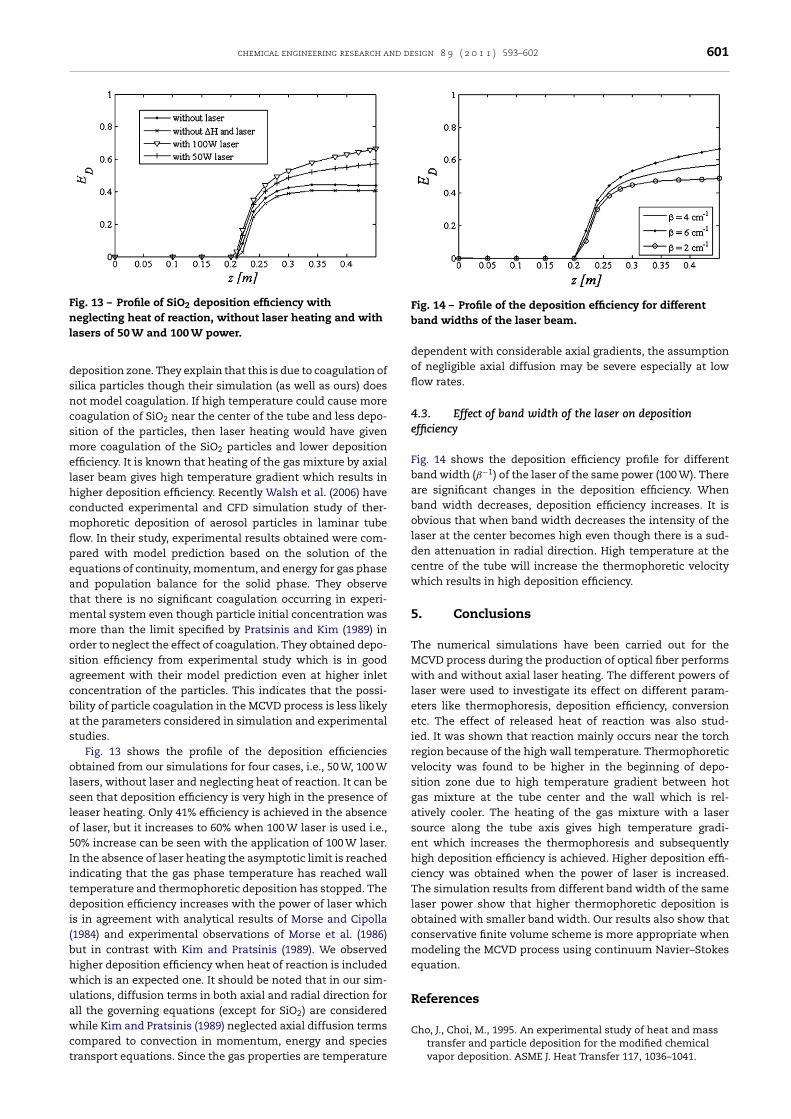
Fig. 13 – Profile of SiO2 deposition efficiency withneglecting heat of reaction, without laser heating and withlasers of 50 W and 100 W power.
dsncsmelhcmflpeatmmosacbas
olslo5Iitdi(bhwuawct
Fig. 14 – Profile of the deposition efficiency for different
eposition zone. They explain that this is due to coagulation ofilica particles though their simulation (as well as ours) doesot model coagulation. If high temperature could cause moreoagulation of SiO2 near the center of the tube and less depo-ition of the particles, then laser heating would have givenore coagulation of the SiO2 particles and lower deposition
fficiency. It is known that heating of the gas mixture by axialaser beam gives high temperature gradient which results inigher deposition efficiency. Recently Walsh et al. (2006) haveonducted experimental and CFD simulation study of ther-ophoretic deposition of aerosol particles in laminar tube
ow. In their study, experimental results obtained were com-ared with model prediction based on the solution of thequations of continuity, momentum, and energy for gas phasend population balance for the solid phase. They observehat there is no significant coagulation occurring in experi-
ental system even though particle initial concentration wasore than the limit specified by Pratsinis and Kim (1989) in
rder to neglect the effect of coagulation. They obtained depo-ition efficiency from experimental study which is in goodgreement with their model prediction even at higher inletoncentration of the particles. This indicates that the possi-ility of particle coagulation in the MCVD process is less likelyt the parameters considered in simulation and experimentaltudies.
Fig. 13 shows the profile of the deposition efficienciesbtained from our simulations for four cases, i.e., 50 W, 100 W
asers, without laser and neglecting heat of reaction. It can beeen that deposition efficiency is very high in the presence ofeaser heating. Only 41% efficiency is achieved in the absencef laser, but it increases to 60% when 100 W laser is used i.e.,0% increase can be seen with the application of 100 W laser.n the absence of laser heating the asymptotic limit is reachedndicating that the gas phase temperature has reached wallemperature and thermophoretic deposition has stopped. Theeposition efficiency increases with the power of laser which
s in agreement with analytical results of Morse and Cipolla1984) and experimental observations of Morse et al. (1986)ut in contrast with Kim and Pratsinis (1989). We observedigher deposition efficiency when heat of reaction is includedhich is an expected one. It should be noted that in our sim-lations, diffusion terms in both axial and radial direction forll the governing equations (except for SiO2) are consideredhile Kim and Pratsinis (1989) neglected axial diffusion terms
ompared to convection in momentum, energy and speciesransport equations. Since the gas properties are temperature
band widths of the laser beam.
dependent with considerable axial gradients, the assumptionof negligible axial diffusion may be severe especially at lowflow rates.
4.3. Effect of band width of the laser on depositionefficiency
Fig. 14 shows the deposition efficiency profile for differentband width (ˇ−1) of the laser of the same power (100 W). Thereare significant changes in the deposition efficiency. Whenband width decreases, deposition efficiency increases. It isobvious that when band width decreases the intensity of thelaser at the center becomes high even though there is a sud-den attenuation in radial direction. High temperature at thecentre of the tube will increase the thermophoretic velocitywhich results in high deposition efficiency.
5. Conclusions
The numerical simulations have been carried out for theMCVD process during the production of optical fiber performswith and without axial laser heating. The different powers oflaser were used to investigate its effect on different param-eters like thermophoresis, deposition efficiency, conversionetc. The effect of released heat of reaction was also stud-ied. It was shown that reaction mainly occurs near the torchregion because of the high wall temperature. Thermophoreticvelocity was found to be higher in the beginning of depo-sition zone due to high temperature gradient between hotgas mixture at the tube center and the wall which is rel-atively cooler. The heating of the gas mixture with a lasersource along the tube axis gives high temperature gradi-ent which increases the thermophoresis and subsequentlyhigh deposition efficiency is achieved. Higher deposition effi-ciency was obtained when the power of laser is increased.The simulation results from different band width of the samelaser power show that higher thermophoretic deposition isobtained with smaller band width. Our results also show thatconservative finite volume scheme is more appropriate whenmodeling the MCVD process using continuum Navier–Stokesequation.
References
Cho, J., Choi, M., 1995. An experimental study of heat and mass
transfer and particle deposition for the modified chemicalvapor deposition. ASME J. Heat Transfer 117, 1036–1041.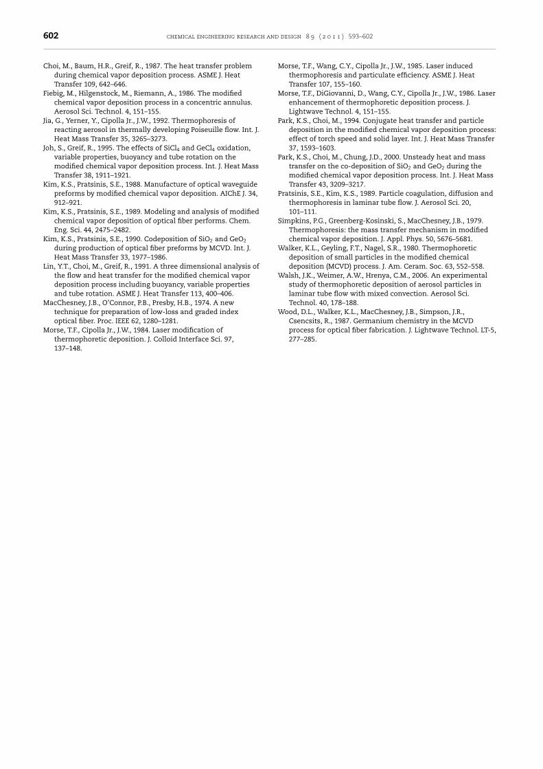
Journal Identification = CHERD Article Identification = 587 Date: May 17, 2011 Time: 5:42 am
602 chemical engineering research and design 8 9 ( 2 0 1 1 ) 593–602
process for optical fiber fabrication. J. Lightwave Technol. LT-5,
Choi, M., Baum, H.R., Greif, R., 1987. The heat transfer problemduring chemical vapor deposition process. ASME J. HeatTransfer 109, 642–646.
Fiebig, M., Hilgenstock, M., Riemann, A., 1986. The modifiedchemical vapor deposition process in a concentric annulus.Aerosol Sci. Technol. 4, 151–155.
Jia, G., Yerner, Y., Cipolla Jr., J.W., 1992. Thermophoresis ofreacting aerosol in thermally developing Poiseuille flow. Int. J.Heat Mass Transfer 35, 3265–3273.
Joh, S., Greif, R., 1995. The effects of SiCl4 and GeCl4 oxidation,variable properties, buoyancy and tube rotation on themodified chemical vapor deposition process. Int. J. Heat MassTransfer 38, 1911–1921.
Kim, K.S., Pratsinis, S.E., 1988. Manufacture of optical waveguidepreforms by modified chemical vapor deposition. AIChE J. 34,912–921.
Kim, K.S., Pratsinis, S.E., 1989. Modeling and analysis of modifiedchemical vapor deposition of optical fiber performs. Chem.Eng. Sci. 44, 2475–2482.
Kim, K.S., Pratsinis, S.E., 1990. Codeposition of SiO2 and GeO2
during production of optical fiber preforms by MCVD. Int. J.Heat Mass Transfer 33, 1977–1986.
Lin, Y.T., Choi, M., Greif, R., 1991. A three dimensional analysis ofthe flow and heat transfer for the modified chemical vapordeposition process including buoyancy, variable propertiesand tube rotation. ASME J. Heat Transfer 113, 400–406.
MacChesney, J.B., O’Connor, P.B., Presby, H.B., 1974. A newtechnique for preparation of low-loss and graded indexoptical fiber. Proc. IEEE 62, 1280–1281.
Morse, T.F., Cipolla Jr., J.W., 1984. Laser modification of
thermophoretic deposition. J. Colloid Interface Sci. 97,137–148.Morse, T.F., Wang, C.Y., Cipolla Jr., J.W., 1985. Laser inducedthermophoresis and particulate efficiency. ASME J. HeatTransfer 107, 155–160.
Morse, T.F., DiGiovanni, D., Wang, C.Y., Cipolla Jr., J.W., 1986. Laserenhancement of thermophoretic deposition process. J.Lightwave Technol. 4, 151–155.
Park, K.S., Choi, M., 1994. Conjugate heat transfer and particledeposition in the modified chemical vapor deposition process:effect of torch speed and solid layer. Int. J. Heat Mass Transfer37, 1593–1603.
Park, K.S., Choi, M., Chung, J.D., 2000. Unsteady heat and masstransfer on the co-deposition of SiO2 and GeO2 during themodified chemical vapor deposition process. Int. J. Heat MassTransfer 43, 3209–3217.
Pratsinis, S.E., Kim, K.S., 1989. Particle coagulation, diffusion andthermophoresis in laminar tube flow. J. Aerosol Sci. 20,101–111.
Simpkins, P.G., Greenberg-Kosinski, S., MacChesney, J.B., 1979.Thermophoresis: the mass transfer mechanism in modifiedchemical vapor deposition. J. Appl. Phys. 50, 5676–5681.
Walker, K.L., Geyling, F.T., Nagel, S.R., 1980. Thermophoreticdeposition of small particles in the modified chemicaldeposition (MCVD) process. J. Am. Ceram. Soc. 63, 552–558.
Walsh, J.K., Weimer, A.W., Hrenya, C.M., 2006. An experimentalstudy of thermophoretic deposition of aerosol particles inlaminar tube flow with mixed convection. Aerosol Sci.Technol. 40, 178–188.
Wood, D.L., Walker, K.L., MacChesney, J.B., Simpson, J.R.,Csencsits, R., 1987. Germanium chemistry in the MCVD
277–285.
Copyright © 2022 FDOKUMEN