Analysis of heat transfer in a chemical vapor deposition reactor: an eigenfunction expansion...
10
Analysis of heat transfer in a chemical vapor deposition reactor: an eigenfunction expansion solution approach Hsiao-Yung Chang, Raymond A. Adomaitis * Department of Chemical Engineering and Institute for Systems Research, University of Maryland, College Park, MD 20742, USA Received 25 November 1997; accepted 8 August 1998 Abstract A numerical solution procedure is developed to solve a model for the steady-state gas velocity and temperature distributions in a low-pressure chemical vapor deposition reactor. The gas velocity and three-dimensional temperature fields are both represented in terms of globally defined trial functions; the gas temperature field is discretized using a combined collocation/eigenfunction ex- pansion technique. The enthalpy flux across wafer/gas boundary is calculated explicitly and is found to vary significantly as a function of wafer position. An average heat transfer coecient is computed from the spatially resolved gas temperature fields and is compared to typical radiative heat transfer rates in these systems. The convergence properties of the discretization method devel- oped are also discussed in the context of quantifying solution accuracy. Ó 1999 Elsevier Science Inc. All rights reserved. Keywords: Chemical vapor deposition; Eigenfunction expansions; Weighted residual methods; Collocation International Journal of Heat and Fluid Flow 20 (1999) 74–83 * Corresponding author. E-mail: [email protected] Notation A yz the y–z cross sectional area of the gas domain a lm ; b lmn ; c lmn ; mode amplitude coecients d lmn ; f lmn ; g lmn B, C, G, F column vectors for coecients b lmn ; c lmn ; g lmn ; f lmn C 1 ; C 2 dimensionless variables of gas temperature boundary conditions C p gas mixture heat capacity, J/(kg K) f ; g representative functions to define inner prod- uct h average heat transfer coecient, J =m 2 Ks I identity matrix I i ith integral I, J, L, M, N numbers of modes P characteristic pressure drop in x direction, Pa Q radiant energy flux, J/(m 2 s) q wafer/gas interface energy flux, J/(m 2 s) R residual of gas temperature equation R v residual of gas flow equation R 1 aspect ratio R 2 radius of susceptor/wafer, m R s susceptor radius, m R w wafer radius, m r radial position on wafer T amb ambient inlet temperature, K T g gas temperature T g;z0 gas temperature boundary condition at z 0 T w wafer/susceptor temperature T wall wall temperature T X ; T oX gas temperature defined by Eq. (4) t time hvi average gas flow velocity in chamber, m/s v x gas flow velocity in x direction v max maximum gas flow velocity in the chamber, m/s ^ v x gas flow velocity/pressure drop ratio in x direction 2 X ; 2 Y ; 2 Z characteristic lengths of gas domain, m x; y ; z streamwise, spanwise, and normal coordinates Greek a v ; b v dimensionless constants of gas momentum balance equation a w dimensionless parameter in wafer energy bal- ance equation R 2 w =jD z T amb b gt ; c gt ; d gt dimensionless constants of gas energy balance equation w dimensionless parameter in wafer energy bal- ance equation 2rR 2 w T 3 amb =jD z f; /; w trial function components of gas temperature f 0 trial function of gas temperature f 0 z 0 6 0 g trial function of gas velocity j gas mixture thermal conductivity, J/(mKs) K column vector of eigenvalues k eigenvalues defined by (6) l gas mixture viscosity, kg/(m s) n normalized trial function of gas velocity 0142-727X/99/$ – see front matter Ó 1999 Elsevier Science Inc. All rights reserved. PII: S 0 1 4 2 - 7 2 7 X ( 9 8 ) 1 0 0 4 2 - 5
Transcript of Analysis of heat transfer in a chemical vapor deposition reactor: an eigenfunction expansion...
Analysis of heat transfer in a chemical vapor deposition reactor:an eigenfunction expansion solution approach
Hsiao-Yung Chang, Raymond A. Adomaitis *
Department of Chemical Engineering and Institute for Systems Research, University of Maryland, College Park, MD 20742, USA
Received 25 November 1997; accepted 8 August 1998
Abstract
A numerical solution procedure is developed to solve a model for the steady-state gas velocity and temperature distributions in a
low-pressure chemical vapor deposition reactor. The gas velocity and three-dimensional temperature ®elds are both represented in
terms of globally de®ned trial functions; the gas temperature ®eld is discretized using a combined collocation/eigenfunction ex-
pansion technique. The enthalpy ¯ux across wafer/gas boundary is calculated explicitly and is found to vary signi®cantly as a
function of wafer position. An average heat transfer coe�cient is computed from the spatially resolved gas temperature ®elds and is
compared to typical radiative heat transfer rates in these systems. The convergence properties of the discretization method devel-
oped are also discussed in the context of quantifying solution accuracy. Ó 1999 Elsevier Science Inc. All rights reserved.
Keywords: Chemical vapor deposition; Eigenfunction expansions; Weighted residual methods; Collocation
International Journal of Heat and Fluid Flow 20 (1999) 74±83
* Corresponding author. E-mail: [email protected]
Notation
Ayz the y±z cross sectional area of the gas domainalm; blmn; clmn; mode amplitude coe�cientsdlmn; flmn; glmn
B, C, G, F column vectors for coe�cientsblmn; clmn; glmn; flmn
C1;C2 dimensionless variables of gas temperatureboundary conditions
Cp gas mixture heat capacity, J/(kg K)f ; g representative functions to de®ne inner prod-
ucth average heat transfer coe�cient, J=�m2K s�I identity matrixIi ith integralI, J, L, M, N numbers of modesP characteristic pressure drop in x direction, PaQ radiant energy ¯ux, J/(m2 s)q wafer/gas interface energy ¯ux, J/(m2 s)R residual of gas temperature equationRv residual of gas ¯ow equationR1 aspect ratioR2 radius of susceptor/wafer, mRs susceptor radius, mRw wafer radius, mr radial position on waferTamb ambient inlet temperature, KTg gas temperature
Tg;z�0 gas temperature boundary condition at z � 0Tw wafer/susceptor temperatureTwall wall temperatureTX; ToX gas temperature de®ned by Eq. (4)t timehvi average gas ¯ow velocity in chamber, m/svx gas ¯ow velocity in x directionvmax maximum gas ¯ow velocity in the chamber,
m/sv̂x gas ¯ow velocity/pressure drop ratio in x
direction2 �X ; 2 �Y ; 2 �Z characteristic lengths of gas domain, mx; y; z streamwise, spanwise, and normal coordinates
Greekav; bv dimensionless constants of gas momentum
balance equationaw dimensionless parameter in wafer energy bal-
ance equation �� R2w�=�jDzTamb��
bgt; cgt; dgt dimensionless constants of gas energy balanceequation
�w dimensionless parameter in wafer energy bal-ance equation �� 2r�R2
wT 3amb=�jDz��
f;/;w trial function components of gas temperaturef0 trial function of gas temperature
�f0�z � 0� 6� 0�g trial function of gas velocityj gas mixture thermal conductivity, J/(mKs)K column vector of eigenvaluesk eigenvalues de®ned by (6)l gas mixture viscosity, kg/(m s)n normalized trial function of gas velocity
0142-727X/99/$ ± see front matter Ó 1999 Elsevier Science Inc. All rights reserved.
PII: S 0 1 4 2 - 7 2 7 X ( 9 8 ) 1 0 0 4 2 - 5
1. Introduction
Chemical vapor deposition (CVD) is a technique exten-sively used in the semiconductor industry to form nonvolatilesolid ®lms on a substrate from chemical reactions fed by thegas phase transport of the reacting species. The quality of the®lm, e.g., the thickness, composition, and microstructure, is acritical manufacturing requirement. Moreover, the ®lm qualitymust be reproducible from wafer to wafer and must also bespatially uniform across each wafer.
Temperature, along with pressure, position, and reactantgas composition, is one of the most important factors in high-quality deposition processes. Because the deposition reaction isinitiated when the vapor phase reactants receive su�cient en-ergy from the wafer surface or other heat sources, a detailedtemperature distribution pro®le, including the gas phase andwafer, is required for a complete process model. This tem-perature information also can be used to design and controlthe reactor to operate at processing conditions that reduceunwanted gas phase reactions which might result in particlecontamination.
There is a large literature on the mathematical modelingand simulation of di�erent CVD systems. Kleijn (1995) pro-vides an overview of these modeling issues. Middleman andHochberg (1993) discuss di�erent modeling aspects from achemical engineering viewpoint, and Badgwell et al. (1995)summarized modeling and control issues in CVD. Most pub-lished CVD system models are solved numerically, either bythe ®nite volume method (Kleijn et al., 1991), ®nite elementmethod (Mo�at and Jensen, 1988), or ®nite di�erence method(Duverneuil and Couderc, 1992). These discretization methodsare based on spatially localized trial functions, and are well-suited for solving problems with irregular geometries. Thelarge number of algebraic or di�erential equations that are
generated by these discretization procedures, however, maymake the resulting simulations inappropriate to use for real-time control applications or iterative optimization methods.On the other hand, those models su�ciently simple to besolved explicitly may be incapable of resolving importantphysical features.
In this work, we develop an analytical approximation so-lution based on global trial function expansions to solve acombined set of CVD system gas ¯ow and temperature mod-eling equations. This choice was motivated by the excellentconvergence properties of spectral methods (Gottlieb andOrszag, 1977), and the clear connections that remain duringthe solution procedure between model parameters and thesolution behavior. We see our approach as a method inter-mediate between the ®nite element and explicit solution pro-cedures; we feel the techniques presented in this paper areparticularly well-suited to distinguishing factors which mayrequire more detailed simulation from those which can beidenti®ed as unimportant.
For the CVD system studied, the gas ¯ow ®eld is solved ®rstusing a Galerkin projection on a set of globally de®ned poly-nomial trial functions. We then use a two-dimensional eigen-function expansion method, conjugated with a one-pointcollocation discretization in the spanwise direction, to computethe three-dimensional gas temperature pro®le. The heattransfer rate at the wafer surface is calculated explicitly fromthe eigenfunction expansion solution. We compare the con-tributions of conductive and convective mechanisms to typicalradiative heat transfer rates in CVD systems and present asimpli®ed heat transfer coe�cient computed by averaging thewafer/gas boundary ¯ux across the wafer.
2. Model formulation
2.1. The CVD system
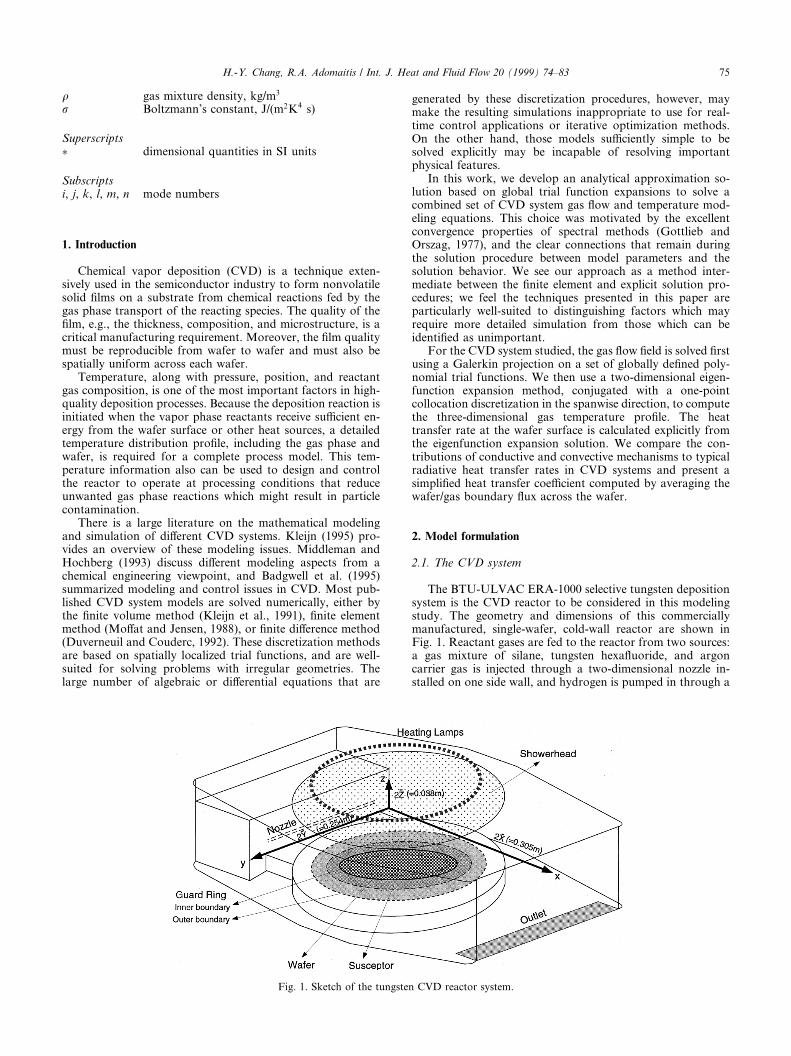
The BTU-ULVAC ERA-1000 selective tungsten depositionsystem is the CVD reactor to be considered in this modelingstudy. The geometry and dimensions of this commerciallymanufactured, single-wafer, cold-wall reactor are shown inFig. 1. Reactant gases are fed to the reactor from two sources:a gas mixture of silane, tungsten hexa¯uoride, and argoncarrier gas is injected through a two-dimensional nozzle in-stalled on one side wall, and hydrogen is pumped in through a
q gas mixture density, kg/m3
r Boltzmann's constant, J/(m2K4 s)
Superscripts� dimensional quantities in SI units
Subscriptsi, j, k, l, m, n mode numbers
Fig. 1. Sketch of the tungsten CVD reactor system.
H.-Y. Chang, R.A. Adomaitis / Int. J. Heat and Fluid Flow 20 (1999) 74±83 75
transparent showerhead mounted in the top of the reactorchamber. Gases mix in the chamber and react at the surface ofa 4 inch wafer located at the chamber center. The wafer issupported by a slowly rotating 0.16 m diameter quartz sus-ceptor and the wafer edge is covered by a quartz guard ring tohelp reduce edge heat loss. This leaves a 0.076 m diameter areaof wafer surface exposed to reaction. An incoherent tungsten±halogen lamp ring is used to heat the wafer to 310°C throughthe transparent showerhead. Typical deposition runtimes last 5min after operating temperature is reached.
2.2. Gas ¯ow ®eld
Although feed gas can enter from both the showerhead andside slits, we will only consider the case where the gas ¯ow ®eldover the wafer is assumed to be dominated by the horizontal¯ow, generated by the feed gas entering through the side wallnozzle. This assumption is suitable in our simulated operatingcondition in which H2 is not used; it is also supported by thegas ¯ow visualization tests performed by the system manu-facturer (BTU-ULVAC, 1996) using a TiO2 tracer whichdemonstrates that a rectangular pipe ¯ow model may be asuitable approximation for the reactant gas mixture in theneighborhood of the wafer. The fully developed, laminar ve-locity pro®le is obtained by solving steady state Navier±Stokesand continuity equations. The transport and gas thermody-namic properties are assumed constant and are evaluated atthe reference temperature Tamb. It is also assumed that the slowwafer rotation as well as buoyancy-induced secondary ¯ows,such as longitudinal and transverse recirculation resultingfrom free thermal convection near the wafer surface andchamber walls, do not a�ect the ¯ow ®eld. Since the Grashofnumber evaluated at the gas inlet is small (Gr� 1.99) in oursimulation, transverse recirculations should not occur in thislow-pressure system according to the criteria suggested byIngle and Mountziaris (1994). Other studies, such as Holsteinand Fitzjohn (1989) and Jensen (1989), reveal that longitudinalrecirculations occur in atmospheric pressure CVD systems athigher Rayleigh numbers (>1780) than those representative ofour system (Ra� 1.3463) and so also should not occur.Therefore, the governing equations for the ¯ow ®eld compo-nent in the x direction are written as
ovx
ox� 0;
o2vx
oy2� av
o2vx
oz2� bv:
The dimensionless pressure drop term bv � 2PY2=�lhviX �
can only be determined after the ¯ow ®eld equations aresolved. Thus, de®ning the ¯ow velocity/pressure drop ratio asv̂x � vx=bv; the momentum balance equation can be written as
o2v̂x
oy2� av
o2v̂x
oz2� 1; �1�
subject to no-slip boundary conditions at y � 0; 1 andz � 0; 1.
2.3. Gas temperature ®eld
Neglecting heat generated by viscous dissipation and boththe gas phase and surface chemical reactions, the gas phaseenergy balance equation gives
vxoTg
ox� dgt
o2Tg
ox2� bgt
o2Tg
oy2� cgt
o2Tg
oz2: �2�
Gas temperature boundary conditions are based on as-suming the showerhead temperature equals the chamber walltemperature and that the convective heat transfer dominates atthe reactor gas outlet. Gas temperature is set equal to wafer/susceptor temperature Tw inside the region of radius R2 atz � 0, and to the wall temperature Twall outside this region:
Tg � 0 at x � 0;
oTg
ox� 0 at x � 1;
Tg � C1�T �wall� at y � 0; 1;
Tg � C1�T �wall� at z � 1;
Tg �C2�T �w� at z � 0; �xÿ 0:5�2 � R2
1�y ÿ 0:5�26R22;
C1�T �wall� at z � 0; R22 < �xÿ 0:5�2 � R2
1�y ÿ 0:5�2:
(�3�
In the above equations, the following dimensionless pa-rameters and variables are used: x � x�=2X ; y � y�=2Y ; z �z�=2Z; vx � v�x=hvi; Tg � �T �g ÿ Tamb�=Tamb. Here, Tamb is theinlet gas temperature and hvi is average gas entrance velocity.Parameters C1 and C2 are de®ned as �T �wall ÿ Tamb�=Tamb and�T �w ÿ Tamb�=Tamb, respectively. The aspect ratio is R1 � Y =Xand the radius of the wafer/susceptor is R2 � Rs=2X . For thespecial case where the chamber wall temperature is set equal toconstant inlet ambient temperature, the wafer/susceptor be-comes the only heat source in the system and C1 � 0, givinghomogeneous boundary conditions at all boundaries exceptz � 0.
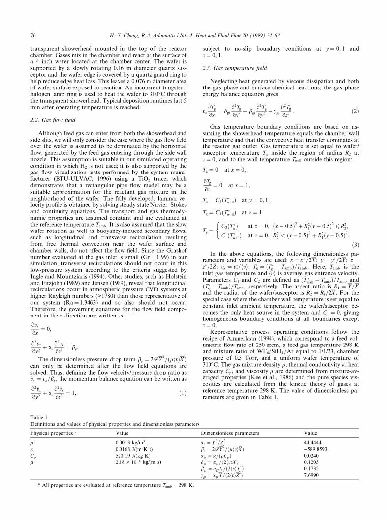
Representative process operating conditions follow therecipe of Ammerlaan (1994), which correspond to a feed vol-umetric ¯ow rate of 250 sccm, a feed gas temperature 298 Kand mixture ratio of WF6=SiH4=Ar equal to 1/1/23, chamberpressure of 0.5 Torr, and a uniform wafer temperature of310°C. The gas mixture density q, thermal conductivity j, heatcapacity Cp, and viscosity l are determined from mixture-av-eraged properties (Kee et al., 1986) and the pure species vis-cosities are calculated from the kinetic theory of gases atreference temperature 298 K. The value of dimensionless pa-rameters are given in Table 1.
Table 1
De®nitions and values of physical properties and dimensionless parameters
Physical properties a Value Dimensionless parameters Value
q 0.0013 kg/m3 av � Y2=Z
244.4444
j 0.0168 J/(m K s) bv � 2PY2=�lhviX � )589.8593
Cp 520.19 J/(kg K) agt � j=�qCp� 0.0240
l 2.18 ´ 10ÿ5 kg/(m s) dgt � agt=�2hviX � 0.1203
bgt � agtX=�2hviY 2� 0.1732
cgt � agtX=�2hviZ2� 7.6990
a All properties are evaluated at reference temperature Tamb � 298 K.
76 H.-Y. Chang, R.A. Adomaitis / Int. J. Heat and Fluid Flow 20 (1999) 74±83
3. Flow ®eld solution
A Galerkin technique is used to compute the ¯ow ®eldvelocity component v̂x as a function of y and z. We choose thetrial functions gij to satisfy the no-slip boundary conditionsand continuity equation by de®nition,
gij � �yi ÿ yi�1��zj ÿ zj�1� i � 1; . . . ; I ; j � 1; . . . ; J
and normalize this sequence with a numerical Gram±Schmidtorthonormalization procedure to de®ne the trial function nij.The residual is formed by substituting the truncated seriesexpansion approximation v̂x �
PI ;Ji;j�1 dijnij into Eq. (1) to ob-
tain
Rv �XI ;Ji;j�1
dijo2nij
oy2� av
o2nij
oz2
!ÿ 1:
The mode amplitude coe�cients dij are computed by mini-mizing the residual with the Galerkin projection, i.e., project-ing the residual onto each trial function nmn:
XI ;Ji;j�1
dijo2
oy2� av
o2
oz2
� �nij; nmn
� �� h1; nmni
m � 1; . . . ; I ; n � 1; . . . ; J ;
where the inner product is de®ned as
hf ; gi �Z1
0
Z10
fg dy dz:
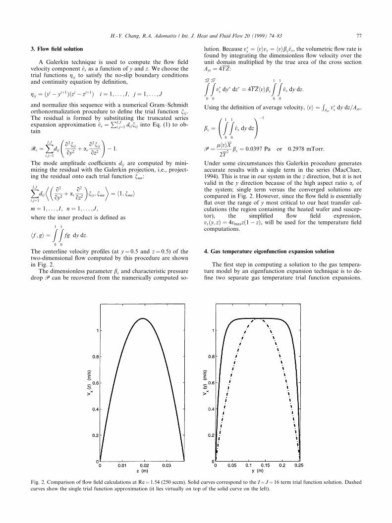
The centerline velocity pro®les (at y� 0.5 and z� 0.5) of thetwo-dimensional ¯ow computed by this procedure are shownin Fig. 2.
The dimensionless parameter bv and characteristic pressuredrop P can be recovered from the numerically computed so-
lution. Because v�x � hvivx � hvibvv̂x, the volumetric ¯ow rate isfound by integrating the dimensionless ¯ow velocity over theunit domain multiplied by the true area of the cross sectionAyz � 4Y Z:
Z2Z
0
Z2Y
0
v�x dy� dz� � 4Y Zhvibv
Z10
Z10
v̂x dy dz:
Using the de®nition of average velocity, hvi � RAyzv�x dy dz=Ayz;
bv �Z1
0
Z10
v̂x dy dz
0@ 1Aÿ1
P � lhviX2Y
2bv � 0:0397 Pa or 0:2978 mTorr:
Under some circumstances this Galerkin procedure generatesaccurate results with a single term in the series (MacCluer,1994). This is true in our system in the z direction, but it is notvalid in the y direction because of the high aspect ratio av ofthe system; single term versus the converged solutions arecompared in Fig. 2. However, since the ¯ow ®eld is essentially¯at over the range of y most critical to our heat transfer cal-culations (the region containing the heated wafer and suscep-tor), the simpli®ed ¯ow ®eld expression,vx�y; z� � 4vmaxz�1ÿ z�, will be used for the temperature ®eldcomputations.
4. Gas temperature eigenfunction expansion solution
The ®rst step in computing a solution to the gas tempera-ture model by an eigenfunction expansion technique is to de-®ne two separate gas temperature trial function expansions.
Fig. 2. Comparison of ¯ow ®eld calculations at Re� 1.54 (250 sccm). Solid curves correspond to the I� J� 16 term trial function solution. Dashed
curves show the single trial function approximation (it lies virtually on top of the solid curve on the left).
H.-Y. Chang, R.A. Adomaitis / Int. J. Heat and Fluid Flow 20 (1999) 74±83 77
The ®rst is used to minimize the temperature equation residualinside the reactor gas domain �TX� and the second expresses thee�ect of the nonhomogeneous boundary condition on thetemperature ®eld �ToX�:Tg � TX � ToX: �4�
The trial functions of each series are de®ned by the productof three individual functions corresponding to each directionof the physical domain shown in Fig. 1
Tg �XL;M ;N
l;m;n�1
blmn/l�x�wm�y�fn�z� �XL;M ;
l;m;�1
alm/l�x�wm�y�f0�z�:
In the above equation, blmn and alm are mode amplitude co-e�cients, /l;wm; and fn are trial function components in thethree physical directions, and f0 is chosen to not vanish atz � 0.
The solution procedure developed combines collocationdiscretization in the spanwise (y) direction and an eigenfunc-tion expansion in the (x, z) planes de®ned at each collocationpoint ym. The solution approximately satis®es the governingequation at each collocation position and the three-dimen-sional results can be reconstructed even when a single interiorcollocation point is used.
We can write the collocation-discretized trial function ex-pansion as
Tg�x; ym; z� � w�ym�XL;Nl;n�1
blmn/l�x�fn�z�
� w�ym�XL
l�1
alm/l�x�f0�z� m � 1; . . . ;M ; �5�
where w�ym� is the scalar value of the single trial function w atthe mth collocation point. The trial function components /�x�and f�z� then are computed from the eigenfunctions of the heatequation subject to homogeneous boundary conditions, i.e.,solving for nontrivial solutions to
dgto2TX
ox2� cgt
o2TX
oz2� ÿkTX; �6�
where k is the eigenvalue, subject to boundary condition TX � 0at z � 0; 1 and x � 0; and oTX=ox � 0 at x � 1. Applying theseparation of variables technique to Eq. (6), the eigenfunctionsand eigenvalues are calculated as
/l�x� � sin2lÿ 1
2px
� �;
fn�z� � sin�npz�;
kln � dgt2lÿ 1
4
� �2
� cgtn2
" #p2; �7�
thus, the TX trial function expansion contribution to the tem-perature ®eld is given by the eigenfunction expansion
TX � w�ym�XL;Nl;n�1
blmn sin2lÿ 1
2px
� �sin�npz�:
De®ning f0 � 1ÿ z; ToX can be represented as
ToX � w�ym�XL
l�1
alm sin2lÿ 1
2px
� ��1ÿ z�: �8�
The nonhomogeneous boundary condition Eq. (3), denoted asTg;z�0, is approximated by projecting the trial function expan-sion Eq. (8) evaluated at z � 0 onto the trial functions /l�x�Eq. (7) to determine the coe�cents alm:
w�ym�XL
i�1
aim
Z10
/i�x�/l�x� dx �Z1
0
Tg;z�0/l�x�dx
�Z1=2�R2
1=2ÿR2
C2/l�x� dx;
l � 1; . . . ; L
to ®nd
alm � 8C2
�2lÿ 1�pw�ym� sin2lÿ 1
4p
� �sin
2lÿ 1
2pR2
� �:
Substituting the trial function expansion Eq. (4) into theheat Eq. (2) de®nes the residual:
R � dgto2TX
ox2� cgt
o2TX
oz2
� �� dgt
o2ToX
ox2� cgt
o2ToX
oz2
�ÿvx�y; z� oToX
ox
�ÿ vx�y; z� oTX
ox� bgt
o2TX
oy2� bgt
o2ToX
oy2
and at the mth collocation point in the y direction
R�x; ym; z� �XL;Nl;n�1
blmnw�ym� dgtd2/l
dx2fn
��cgt/l
d2fn
dz2
�
�XL
l�1
almw�ym� dgtd2/l
dx2f0
�ÿvx�ym; z� d/
dxf0
�
ÿXL;Nl;n�1
blmnw�ym�vx�ym; z�d/dx
fn � bgt
XL;Nl;n�1
blmnd2w�ym�
dy2/lfn
� bgt
XL
l�1
almd2w�ym�
dy2/lf0 m � 1; . . . ;M : �9�
Eigenfunction expansions are used to approximate allnonhomogeneous terms and all terms which are not expresseddirectly in terms of the eigenfunctions /lfn de®ned in Eq. (7).This allows the eigenfunction expansion approximation to theresidual to be written as
R�x; ym; z� � w�ym�XL;Nl;n�1
blmn�ÿkln�/lfn
ÿ w�ym�XL;Nl;n�1
clmn/lfn ÿ w�ym�XL;Nl;n�1
flmn/lfn
� bgtd2w�ym�
dy2
XL;Nl;n�1
blmn/lfn � bgtd2w�ym�
dy2
XL;Nl;n�1
glmn/lfn
�XL;Nl;n�1
�� � ��/lfn m � 1; . . . ;M :
The mode amplitude coe�cients are (for the detailed calcula-tions, see Appendix A)
78 H.-Y. Chang, R.A. Adomaitis / Int. J. Heat and Fluid Flow 20 (1999) 74±83
clmn � dgtp2n�2lÿ 1�2alm � 8vmax
n3p3a1�1ÿ �ÿ1�2lÿ1��2� �ÿ1�n�alm
� 8vmax
n3p3�2� �ÿ1�n�
XL
j�1j 6�l
ajm�2jÿ 1�
� 1ÿ �ÿ1�l�jÿ1
l� jÿ 1� 1ÿ �ÿ1�lÿj
lÿ j
!;
flmn � 8vmax
1
3
�� 1
n2p2
�blmn � 16
vmax
p2
XL
j
XN
k�1k 6�n
bjmk
� 1� �ÿ1�k�n
�k � n�2
ÿ 1� �ÿ1�kÿn
�k ÿ n�2!� 4vmax
1
3� 1
n2p2
� �
� �2lÿ 1�XL
j�1j 6�l
XN
k�1
bjmk1ÿ �ÿ1�l�jÿ1
l� jÿ 1� 1ÿ �ÿ1�lÿj
lÿ j
!
� 8vmax
p2
XL
j�1j6�l
XN
k�1k 6�n
bjmk�2jÿ 1� 1ÿ �ÿ1�l�jÿ1
l� jÿ 1
� 1ÿ �ÿ1�lÿj
lÿ j
!� 1� �ÿ1�k�n
�k � n�2 ÿ 1� �ÿ1�kÿn
�k ÿ n�2 !
;
glmn � 2
npalm:
Projecting the residual approximation onto each trialfunction /lfn and setting the resulting equation to zero gives,
w�ym�kln ÿ bgtd2w�ym�
dy2
� �blmn
� w�ym�XL;Nj;k�1
bjmkI5I6 � ÿw�ym�clmn
� bgtd2w�ym�
dy2glmn l � 1; . . . ; L; n � 1; . . . ;N ;
where flmn is replaced byPL;N
j;k�1 bjmkI5I6; and I5; I6 are de®ned inAppendix A.
A computationally e�cient method for calculating the blmn
is to rearrange each blmn; clmn; glmn; and kln array into columnvector format B,C,G, K, respectively, and to reorder thefourth-order tensor, generated by the product of I5 and I6, intoan array F. This gives
I w�ym�Kÿ bgtd2w�ym�
dy2
� �� w�ym�F
� �B
� ÿw�ym�C� bgtd2w�ym�
dy2G; �10�
where I is identity matrix. Since there are L�M � N unknownblmn coe�cients and L�M � N equations, this linear systemcan be solved directly to ®nd gas phase temperature, given the¯ow ®eld characteristic vmax and wafer/susceptor and ambientgas temperatures used to compute C2.
5. Results and discussions
Based on the preceding analysis, representative results arepresented for the computed gas temperature pro®le at thecenterline of the reactor chamber when the trial function w inthe y direction is selected as 4y�1ÿ y�. This corresponds toM � 1 and y1 � 0:5.
5.1. Solution convergence
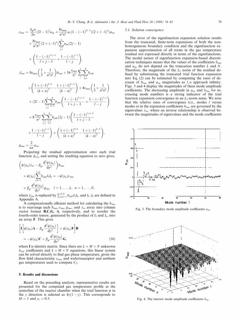
The error of the eigenfunction expansion solution resultsfrom the truncated, ®nite-term expansions of both the non-homogeneous boundary condition and the eigenfunction ex-pansion approximation of all terms in the gas temperatureresidual not expressed directly in terms of the eigenfunctions.The modal nature of eigenfunction expansion-based discreti-zation techniques means that the values of the coe�cients blmn
and alm do not depend on the truncation number L and N .Therefore, the magnitude of the L2 norm of the residual de-®ned by substituting the truncated trial function expansioninto Eq. (2) can be estimated by computing the rates of de-crease of blmn and alm magnitudes as l; n approach in®nity.Figs. 3 and 4 display the magnitudes of these mode amplitudecoe�cients. The decreasing amplitude in alm and blmn for in-creasing mode numbers is a strong indicator of the trialfunction expansion convergence in an L2-norm sense. We notethat the relative rates of convergence (i.e., modes l versusmodes n) in the expansion coe�cients blmn are governed by theeigenvalues kln; where an inverse relationship is observed be-tween the magnitudes of eigenvalues and the mode coe�cients
Fig. 3. The boundary mode amplitude coe�cients alm.
Fig. 4. The interior mode amplitude coe�cients blm.
H.-Y. Chang, R.A. Adomaitis / Int. J. Heat and Fluid Flow 20 (1999) 74±83 79
when solving the linear system Eq. (10). Furthermore, asrepresented in Eq. (7), the eigenvalue magnitude depends morestrongly on mode number n relative to l because the dimen-sionless parameter cgt is much larger than dgt. These di�erentcontributions to eigenvalue growth rate results in the ampli-tudes blmn becoming small after only several modes of n, re-quiring a larger total mode number L relative to N to achieve a``balanced'' convergence behavior in the x and z directions.
5.2. Gas temperature and Gibbs phenomenon
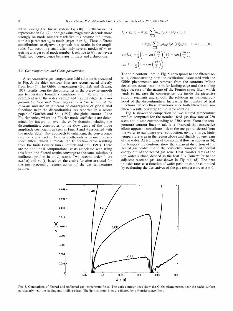
A representative gas temperature ®eld solution is presentedin Fig. 5; the thick contour lines are reconstructed directlyfrom Eq. (5). The Gibbs phenomenon (Gottlieb and Orszag,1977) results from the discontinuities in the piecewise-smoothgas temperature boundary condition at z � 0, and is mostprominent near the wafer leading and trailing edges. It is im-portant to stress that these wiggles are a true feature of thesolution, and are an indicator of convergence of global trialfunctions near the discontinuities. As reported in a recentpaper of Gottlieb and Shu (1997), the global nature of theFourier series, where the Fourier mode coe�cients are deter-mined by integration over the entire domain including thediscontinuities, contributes to the slow decay of the modeamplitude coe�cients as seen in Figs. 3 and 4 associated withthe modes /l�x�: One approach to enhancing the convergencerate for a given set of Fourier coe�cients is to use Fourier-space ®lters, which eliminate the truncation error resultingfrom the ®nite Fourier sum (Gottlieb and Shu, 1997). Thereare no additional computational costs associated with usingthis ®lter, and ®ltered results converge to the same solution asun®ltered pro®les in an L2 sense. Two, second-order ®ltersrX�l; n� and roX�l� based on the cosine function are used forthe post-processing reconstruction of the gas temperaturepro®le:
Tg�x; ym; z� � w�ym�XL;Nl;n�1
blmnrX�l; n�/l�x�fn�z�
� w�ym�XL
l�1
almroX�l�/l�x�f0�z�; m � 1; . . . ;M ;
rX�l; n� � 1
41� cos
plL
� �� �1� cos
pnN
� �� �roX�l� � 1
21� cos
plL
� �� �:
The thin contour lines in Fig. 5 correspond to the ®ltered re-sults, demonstrating how the oscillations associated with theGibbs phenomenon are removed from the contours. Minordeviations occur near the wafer leading edge and the trailingedge because of the nature of the Fourier-space ®lter, whichtends to increase the convergence rate inside the piecewisesmooth segments and smooth the solutions in the neighbor-hood of the discontinuities. Increasing the number of trialfunctions reduces these deviations since both ®ltered and un-®ltered results converge to the same solution.
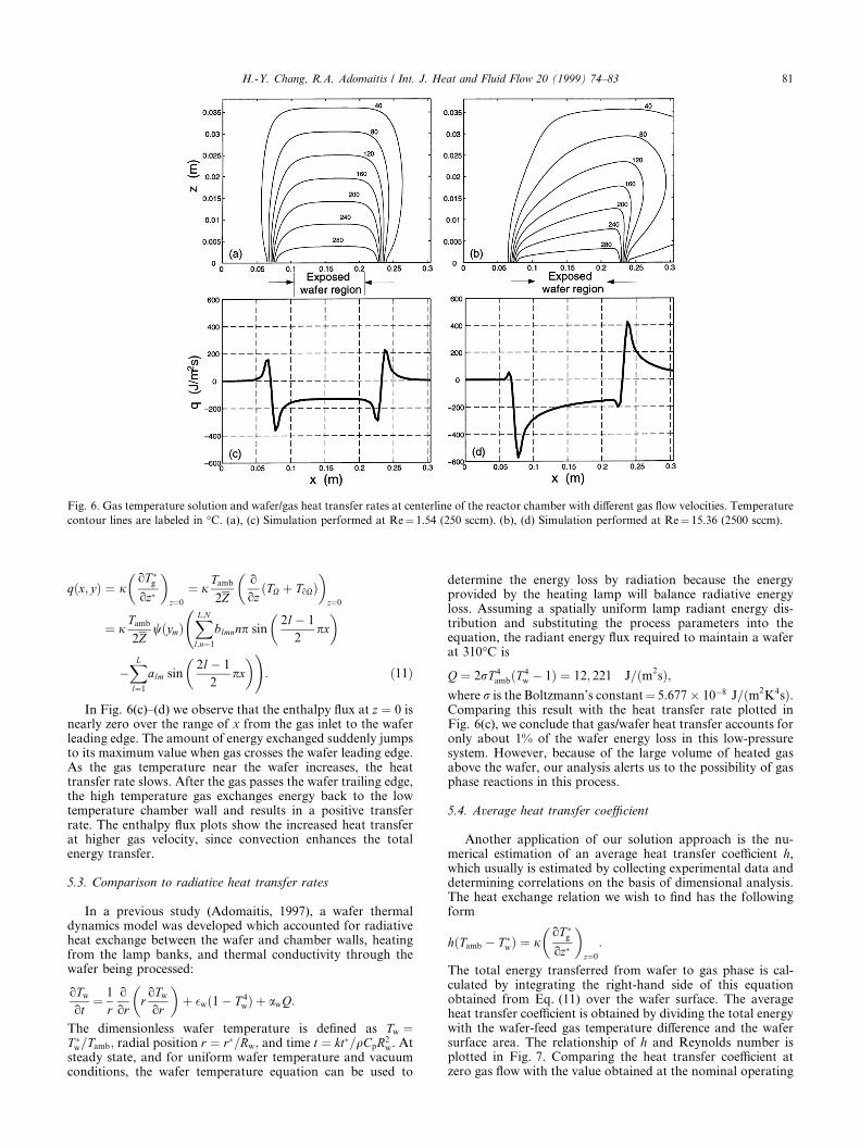
Fig. 6 shows the comparison of two ®ltered temperaturepro®les computed for the nominal feed gas ¯ow rate of 250sccm and a case corresponding to 2500 sccm. From the tem-perature contour lines in (a), it is observed that convectivee�ects appear to contribute little to the energy transferred fromthe wafer to gas phase over conduction, giving a large, high-temperature area in the region above and slightly downstreamof the wafer. At ten times of the nominal ¯ow, as shown in (b),the temperature contours show the apparent distortion of theheated gas pro®le due to the convective transport of thermalenergy out of the heated gas zone. Heat transfer rates at thetop wafer surface, de®ned as the heat ¯ux from wafer to theadjacent reactant gas, are shown in Fig. 6(c)±(d). The heattransfer rates as a function of wafer position can be computedby evaluating the derivatives of the gas temperature at z � 0
Fig. 5. Comparison of ®ltered and un®ltered gas temperature ®elds. The dark contour lines show the Gibbs phenomenon near the wafer surface
particularly near the leading and trailing edges. The light contour lines are ®ltered by a Fourier-space ®lter.
80 H.-Y. Chang, R.A. Adomaitis / Int. J. Heat and Fluid Flow 20 (1999) 74±83
q�x; y� � joT �goz�
� �z�0
� jTamb
2Zooz�TX � ToX�
� �z�0
� jTamb
2Zw�ym�
XL;Nl;n�1
blmnnp sin2lÿ 1
2px
� �
ÿXL
l�1
alm sin2lÿ 1
2px
� �!: �11�
In Fig. 6(c)±(d) we observe that the enthalpy ¯ux at z � 0 isnearly zero over the range of x from the gas inlet to the waferleading edge. The amount of energy exchanged suddenly jumpsto its maximum value when gas crosses the wafer leading edge.As the gas temperature near the wafer increases, the heattransfer rate slows. After the gas passes the wafer trailing edge,the high temperature gas exchanges energy back to the lowtemperature chamber wall and results in a positive transferrate. The enthalpy ¯ux plots show the increased heat transferat higher gas velocity, since convection enhances the totalenergy transfer.
5.3. Comparison to radiative heat transfer rates
In a previous study (Adomaitis, 1997), a wafer thermaldynamics model was developed which accounted for radiativeheat exchange between the wafer and chamber walls, heatingfrom the lamp banks, and thermal conductivity through thewafer being processed:
oTw
ot� 1
roor
roTw
or
� �� �w�1ÿ T 4
w� � awQ:
The dimensionless wafer temperature is de®ned as Tw �T �w=Tamb; radial position r � r�=Rw; and time t � kt�=qCpR2
w. Atsteady state, and for uniform wafer temperature and vacuumconditions, the wafer temperature equation can be used to
determine the energy loss by radiation because the energyprovided by the heating lamp will balance radiative energyloss. Assuming a spatially uniform lamp radiant energy dis-tribution and substituting the process parameters into theequation, the radiant energy ¯ux required to maintain a waferat 310°C is
Q � 2rT 4amb�T 4
w ÿ 1� � 12; 221 J=�m2s�;
where r is the Boltzmann's constant� 5:677� 10ÿ8 J=�m2K4s�.
Comparing this result with the heat transfer rate plotted inFig. 6(c), we conclude that gas/wafer heat transfer accounts foronly about 1% of the wafer energy loss in this low-pressuresystem. However, because of the large volume of heated gasabove the wafer, our analysis alerts us to the possibility of gasphase reactions in this process.
5.4. Average heat transfer coe�cient
Another application of our solution approach is the nu-merical estimation of an average heat transfer coe�cient h,which usually is estimated by collecting experimental data anddetermining correlations on the basis of dimensional analysis.The heat exchange relation we wish to ®nd has the followingform
h�Tamb ÿ T �w� � joT �goz�
� �z�0
:
The total energy transferred from wafer to gas phase is cal-culated by integrating the right-hand side of this equationobtained from Eq. (11) over the wafer surface. The averageheat transfer coe�cient is obtained by dividing the total energywith the wafer-feed gas temperature di�erence and the wafersurface area. The relationship of h and Reynolds number isplotted in Fig. 7. Comparing the heat transfer coe�cient atzero gas ¯ow with the value obtained at the nominal operating
Fig. 6. Gas temperature solution and wafer/gas heat transfer rates at centerline of the reactor chamber with di�erent gas ¯ow velocities. Temperature
contour lines are labeled in °C. (a), (c) Simulation performed at Re� 1.54 (250 sccm). (b), (d) Simulation performed at Re� 15.36 (2500 sccm).
H.-Y. Chang, R.A. Adomaitis / Int. J. Heat and Fluid Flow 20 (1999) 74±83 81
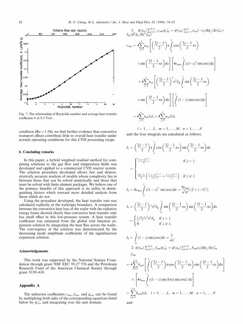
condition (Re� 1.54), we ®nd further evidence that convectivetransport e�ects contribute little to overall heat transfer undernormal operating conditions for this CVD processing recipe.
6. Concluding remarks
In this paper, a hybrid weighted residual method for com-puting solutions to the gas ¯ow and temperature ®elds wasdeveloped and applied to a commercial CVD reactor system.The solution procedure developed allows fast and demon-stratively accurate analysis of models whose complexity lies inbetween those that can be solved analytically and those thatmust be solved with ®nite element packages. We believe one ofthe primary bene®ts of this approach is its utility in distin-guishing factors which warrant more detailed analysis fromthose which do not.
Using the procedure developed, the heat transfer rate wascalculated explicitly at the wafer/gas boundary. A comparisonbetween the convective heat loss of the wafer with the radiativeenergy losses showed clearly that convective heat transfer onlyhas small e�ect in this low-pressure system. A heat transfercoe�cient was estimated from the global trial function ex-pansion solution by integrating the heat ¯ux across the wafer.The convergence of the solution was demonstrated by thedecreasing mode amplitude coe�cients of the eigenfunctionexpansion solution.
Acknowledgements
This work was supported by the National Science Foun-dation through grant NSF EEC 95-27 576 and the PetroleumResearch Fund of the American Chemical Society throughgrant 31391-G9.
Appendix A
The unknown coe�cients clmn; flmn; and glmn can be foundby multiplying both sides of the corresponding equations listedbelow by /lfn and integrating over the unit domain.
1. w�ym�PL;N
j;k�1 cjmk/jfk � w�ym�PL
j�1 ajm ÿvx�d/j=dx�f0�ÿ
dgt�d2/j=dx2�f0�
clmn � 4XL
j�1
ajm2jÿ 1
2
� �pZ1
0
cos2jÿ 1
2px
� �24
� sin2lÿ 1
2px
� �dx
35 4vmax
Z10
z�124 ÿz�2 sin�npz�dz
35
� 4XL
j�1
ajm2jÿ 1
2
� �2
p2dgt
Z10
sin2jÿ 1
2px
� �24
� sin2lÿ 1
2px
� �dx
35 Z10
�1ÿ z� sin�npz�dz
24 35
� 4XL
j�1
ajmI1I2 � 4XL
j�1
ajmI3I4
l � 1; . . . ; L; m � 1; . . . ;M ; n � 1; . . . ;N
and the four integrals are calculated as follows.
I1 � 2jÿ 1
2
� �pZ1
0
cos2jÿ 1
2px
� �sin
2lÿ 1
2px
� �dx
�
1ÿ�ÿ1�2lÿ1
4if j � l;
�2jÿ1�4
1ÿ�ÿ1�l�jÿ1
l�jÿ1� 1ÿ�ÿ1�lÿj
lÿj
� �if j 6� l;
8>>>><>>>>:I2 � 4vmax
Z10
z�1ÿ z�2 sin�npz�dz � 8vmax
n3p3�2� �ÿ1�n�;
I3 � 2jÿ 1
2
� �2p2dgt
Z10
sin2jÿ 1
2px
� �sin
2lÿ 1
2px
� �dx
�12�2lÿ1
2�2p2dgt
if j � l;
0 if j 6� l;
(
I4 �Z1
0
�1ÿ z� sin�npz�dz � 1
np;
2. w�ym�PL;N
j;k�1 fjmk/jfk � w�ym�PL;N
j;k�1 bjmkvx�dwj=dx�fk
flmn
� 4XL;Nj;k�1
bjmk
Z10
2jÿ 1
2
� �pcos
2jÿ 1
2px
� �sin
2lÿ 1
2px
� �dx
24 35� 4vmax
Z10
z�1ÿ z� sin�kpz� sin�npz� dz
24 35�XL;Nj;k�1
bjmkI5I6 l � 1; . . . ; L; m � 1; . . . ;M ; n � 1; . . . ;N
and
Fig. 7. The relationship of Reynolds number and average heat transfer
coe�cient h at 0.5 Torr.
82 H.-Y. Chang, R.A. Adomaitis / Int. J. Heat and Fluid Flow 20 (1999) 74±83
I5 � 4
Z10
2jÿ 1
2
� �pcos
2jÿ 1
2px
� �sin
2lÿ 1
2px
� �dx
�2 if j � l;
�2jÿ 1� 1ÿ�ÿ1�l�jÿ1
l�jÿ1� 1ÿ�ÿ1�lÿj
lÿj
� �if j 6� l;
8><>:I6 � 4vmax
Z10
z�1ÿ z�sin�kpz� sin�npz�dz
�4vmax� 1
12� 1
4n2p2� if k � n;
2vmax
p2
1��ÿ1�k�n
�k�n�2 ÿ1��ÿ1�kÿn
�kÿn�2� �
if k 6� n;
8><>:3: �d2w�ym�=dy2�
XL;N
j;k�1gjmk/jfk � �d2w�ym�=dy2�
XL
j�1
ajm/jf0
glmn � 4XL
j�1
ajm
Z10
sin2jÿ 1
2px
� �sin
2lÿ 1
2px
� �dx
24 35�
Z10
�1ÿ z� sin�npz�dz
24 35
�
2np alm if j � l;
0 if j 6� l; l � 1; . . . ; L; m � 1; . . . ;M ;
n � 1; . . . ;N
8>>>><>>>>:References
Adomaitis, R.A., 1997. An orthogonal collocation technique for rapid
thermal processing system discretization. Institute for Systems
Research, University of Maryland, College Park. Technical Report
TR97±63.
Ammerlaan, J.A.M., 1994. Kinetics and characterization of Tungsten
CVD processes. Delft University Press, Netherlands, pp. 64±71.
Badgwell, T.A., Breedijk, T., Bushman, S.G., Butler, S.W., Chatterjee,
S., Edgar, T.F., Toprac, A.T., Trachtenberg, I., 1995. Modeling
and control of microelectronics materials processing. Computers
Chem. Eng. 19, 1±41.
BTU-ULVAC Inc., 1996. BTU-ULVAC ERA-1000 Selective Tung-
sten Deposition System. North Billerica, MA.
Duverneuil, P., Couderc, J.P., 1992. Two-dimensional modeling of
low-pressure chemical vapor deposition hot wall tubular reactor. J.
Electrochem. Soc. 139, 296±304.
Gottlieb, D., Orszag, S.A., 1977. Numerical Analysis of Spectral
Methods: Theory and Applications. Society for Industrial and
Applied Mathematics, Philadelphia, pp. 155±157.
Gottlieb, D., Shu, C.-W., 1997. On the Gibbs phenomena and its
resolution. SIAM Review 39, 644±668.
Holstein, W.L., Fitzjohn, J.L., 1989. E�ect of buoyancy forces and
reactor orientation of ¯uid ¯ow and growth rate uniformity in
cold-wall channel CVD reactors. J. Crystal Growth 94, 145±158.
Ingle, N.K., Mountziaris, T.J., 1994. The onset of transverse recircu-
lations during ¯ow of gases in horizontal ducts with di�erentially
heated lower walls. J. Fluid Mech. 277, 249±269.
Jensen, K.F., 1989. Transport phenomena and chemical reaction issues
in OMUPE of compound semiconductors. J. Crystal Growth 98,
148±166.
Kee, R.J., Dixon-Lewis, G., Warnatz, J., Coltrin, M.E., Miller, J.,
1986. A FORTRAN computer code package for the evaluation of
gas-phase multicomponent transport properties. Sandia National
Laboratories, Albuquerque/Livermore, Technical Report
SAND86±8246.
Kleijn, C.R., 1995. Chemical vapor deposition processes. In: Meyyap-
pan, M. (Ed.), Computational Modeling in Semiconductor Pro-
cessing. Artech House, Boston, pp. 97±229.
Kleijn, C.R., Hoogendoorn, C.J., Hasper, A., Holleman, J., Middel-
hoek, J., 1991. Transport phenomena in tungsten LPCVD in a
single-wafer reactor. J. Electrochem. Soc. 138, 509±517.
MacCluer, C.R., 1994. Boundary Value Problems and Orthogonal
Expansions. IEEE Express, New York, pp. 290±292.
Middleman, S., Hochberg, A., 1993. Process Engineering Analysis in
Semiconductor Device Fabrication. McGraw-Hill, New York, pp.
478±573.
Mo�at, H.K., Jensen, K.F., 1988. Three-dimensional ¯ow e�ects in
silicon CVD in horizontal reactors. J. Electrochem. Soc. 135, 459±
471.
H.-Y. Chang, R.A. Adomaitis / Int. J. Heat and Fluid Flow 20 (1999) 74±83 83