Atmospheric Fe deposition modes at Bermuda and the adjacent Sargasso Sea
Upload
khangminh22Category
view
1download
0
HAL Id: hal-02396275https://hal.archives-ouvertes.fr/hal-02396275
Submitted on 12 Dec 2019
HAL is a multi-disciplinary open accessarchive for the deposit and dissemination of sci-entific research documents, whether they are pub-lished or not. The documents may come fromteaching and research institutions in France orabroad, or from public or private research centers.
L’archive ouverte pluridisciplinaire HAL, estdestinée au dépôt et à la diffusion de documentsscientifiques de niveau recherche, publiés ou non,émanant des établissements d’enseignement et derecherche français ou étrangers, des laboratoirespublics ou privés.
Chemical Vapor Deposition of Al 13 Fe 4 HighlySelective Catalytic Films for the Semi-Hydrogenation of
AcetyleneIoannis Aviziotis, Thomas Duguet, Khaled Soussi, Marc Heggen,
Marie-Christine Lafont, Franck Morfin, Shashank Mishra, Stéphane Daniele,Andreas Boudouvis, Constantin Vahlas
To cite this version:Ioannis Aviziotis, Thomas Duguet, Khaled Soussi, Marc Heggen, Marie-Christine Lafont, et al.. Chem-ical Vapor Deposition of Al 13 Fe 4 Highly Selective Catalytic Films for the Semi-Hydrogenation ofAcetylene. physica status solidi (a), Wiley, 2017, 215 (2), pp.1700692. �10.1002/pssa.201700692�.�hal-02396275�
1
Article Type: Full Paper
Chemical Vapor Deposition of Al13Fe4 Highly Selective Catalytic Films for the Semi-
Hydrogenation of Acetylene
I.G. Aviziotis, T. Duguet, K. Soussi, M. Heggen, M.-C. Lafont, F. Morfin, S. Mishra, S. Daniele, A.G.
Boudouvis, and C. Vahlas*
Dr. Ioannis G. Aviziotis, Prof. Andreas G. Boudouvis
School of Chemical Engineering, National Technical University of Athens, Heroon Polytechniou 9,
15780 Zografou, Greece
Dr. Ioannis G. Aviziotis, Dr. Thomas Duguet, Dr. Marie-Christine Lafont, Dr. Constantin Vahlas
CIRIMAT, Université de Toulouse – CNRS, 4 alleé Emile Monso, BP44362, 31030 Toulouse cedex
4, France
Dr. Khaled Soussi, Prof. Shashank Mishra, Franck Morfin, Prof. Stephane Daniele
IRCELYON, Université Lyon 1 – CNRS, 2 Avenue Albert Einstein, 69626 Villeurbanne cedex,
France
Dr. Marc Heggen
Ernst Ruska-Centrum und Peter Grünberg Institut, Forschungszentrum Jülich, Wilhelm-Johnen-
Straße 52428 Jülich, Germany
E-mail: [email protected]
Keywords: chemical vapor deposition; sequential deposition; m-Al13Fe4 phase; catalysis; semi-
hydrogenation of acetylene
Abstract
Catalytic properties of coatings containing the Al13Fe4 intermetallic phase are tested in the reaction
of semi-hydrogenation of acetylene. The selectivity to ethylene is found as high as 74 % close to the
reported values for pure, unsupported Al13Fe4. The initial conversion of acetylene to ethylene is 84 %
and rapidly drops due to the catalytic formation of carbon-based by-products on secondary Al-Fe
phases. Coatings are processed through sequential chemical vapor deposition (CVD) of aluminum (5
Torr, 180°C) and iron (40 Torr, 140°C) layers, followed by in situ annealing for 60 min at 575°C.
Deposition proceeds at high growth rate, resulting in 15 µm thick films. After annealing, coatings are
composed of the Al13Fe4 phase, co-existing with minor secondary Al-Fe intermetallic phases. Overall,
we show that films containing complex Al-Fe intermetallic phases can be processed by CVD, opening
new routes to the engineering of pure, supported Al13Fe4 catalysts on 3D or porous supports.
2
1. Introduction
When ethylene, a major building block in the polymers industry[1], is produced by the steam
cracking method, the process suffers from the pollution by acetylene which acts as a poison for the
downstream polymerization catalyst[2]. Therefore, the removal of acetylene from ethylene streams is
of paramount importance. Its semi-hydrogenation is performed by noble metal catalysts which are
active at mild conditions but not always selective towards the targeted product[3]. The intermetallic
compound Al13Fe4 (usually called Al3Fe[4, 5]), is composed of common metals and shows excellent
selectivity in semi-hydrogenation of alkynes[6]. The high potential of Al13Fe4 to replace Pt and Pd
noble metals or their intermetallic phases[6, 7] in this catalytic process is due to its crystal structure,
where Fe atoms are coordinated by Al atoms, and the arrangement of Fe-Al-Fe groups in 3D Al
cavities[8] results in potential Fe catalytic sites according to the site-isolation concept[6]. Therefore,
the implementation of Al13Fe4 catalysts in industrial heterogeneous reactions is expected to meet two
prerequisites: (a) the replacement of expensive and rare noble metals, (b) the improvement of catalytic
processes through increased selectivity[9].
Several studies have been reported on the formation of intermetallic phases in the Al–Fe
system[10, 11]. Various deposition techniques have been applied to obtain Al-Fe intermetallic coatings,
including thermal spraying and magnetron sputtering[11, 12] or mechanical alloying[13]. Despite the
effective production of Al-Fe intermetallics, these methods suffer a number of drawbacks, such as
the swelling phenomenon because of rapid and violent phase transformations during sintering, or
technical difficulties related to considerable differences of properties of the substrate and the coating
materials (e.g. their coefficient of thermal expansion and reactivity resulting in a poor interfacial
adherence). Furthermore, catalytic processes require high catalyst surface to volume ratio and for this
reason, processing of Al-Fe films on supports (such as powders or preforms) is foreseen and may
strengthen the catalytic performance of the intermetallic compound[6].
Unfortunately, there is no established scalable and economic process for the production of
Al13Fe4 catalysts with high specific surface area. The present work is a first step in this direction. By

3
operating at relatively low to moderate temperatures; i.e., in the limits of the reaction-limited regime,
chemical vapor deposition (CVD) can meet the requirements for the processing of Al-Fe coatings on
complex, non-line-of-sight surfaces and powders such as honeycomb structures and gamma alumina
catalytic supports, due to the predominance of the reaction kinetics over the transport phenomena[14].
Despite these advantages, there are but few reports on the processing of intermetallic phases by
CVD[15], mainly due to the complicated coupling of the chemistry of the different organometallic
precursors involved in the process.
The attempts of formation of iron aluminides by CVD mostly involve high temperature
diffusion processes on iron and steels substrates.[16] Targeted applications are then oxidation and/or
corrosion resistance, calling for compact microstructures of the aluminide film. This contrasts with
the specifications of films used in catalytic applications, where high specific surface area is desired.
In this paper, we describe an innovative route for the processing of Al13Fe4 films by sequential
CVD of the two metals followed by in situ thermal annealing to stimulate reactive diffusion. This
work is based on our recent investigations of the kinetics and the transport phenomena of the CVD
of unary Al[17, 18] and Fe[19]. We characterize the structure and composition of the films, we report
preliminary results on the semi-hydrogenation of acetylene with the obtained Al-Fe films as catalysts
and we propose correlations between the catalytic behavior and the characteristics of the films.
2. Results and discussion
2.1. Films structure and composition
The as-processed coatings present a uniform mat gray color all over the surface of the
substrates. Figure 1 presents the XRD pattern of the annealed bilayer stack at 575 °C. It is compared
with the Al13Fe4 XRD pattern adapted from a previous reference[5]. Reflections at low 2θ angles,
between 20° and 30° as well as the large peaks between 40° and 50° and some smaller ones at higher
2θ angles (see full arrows in Figure 1) are characteristic of the monoclinic Al13Fe4 phase.

4
Figure 1. XRD pattern of the annealed coating (top) and diffraction pattern of the Al13Fe4 phase
(bottom) adapted from previous works [5]. Full arrows point on Al13Fe4 peaks, whereas dashed and
dotted arrows point on Al and Al5Fe2 peaks, respectively. The most intense peak at ca. 45° also
corresponds to fcc Fe.
Other peaks, indicated by dashed and dotted arrows in Figure 1 do not match the Al13Fe4
pattern, revealing that other phases co-exist with Al13Fe4. Specifically, the peak at 39°-40° can be
attributed to the Al5Fe2 phase and to elemental Al (JCPDS cards no. 29-0043 and 04-0787,
respectively). The peak at 50° is indexed to the Al5Fe2 phase. The intensity of the peak at approx. 45°
implies that there still exists unreacted Fe within the film (JCPDS card no. 87-0722). The peak at 82°
matches well both the fcc Al and the bcc Fe crystalline structures whereas the two last peaks at approx.
112° and 117° correspond to fcc Al alone.
Radio frequency glow discharge optical emission spectroscopy (GD-OES), X-ray
photoelectron spectrometry (XPS) and transmission electron microscopy (TEM) are used to monitor
5
composition uniformity, to confirm the formation of Al13Fe4 and to identify secondary phases, and
finally to get a better insight into the film microstructure.
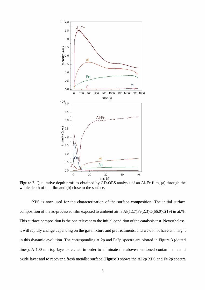
Figure 2 presents GD-OES qualitative Al, C, Fe, O composition profiles through the film
thickness. The Al and Fe profiles are spread through the entire thickness revealing that intermixing
between Al and Fe occurs during the in situ annealing without achieving homogeneous composition
along the thickness of the stack in the annealing conditions applied. The Fe concentration increases
from the surface of the film to the interface with the substrate, despite the fact that it is deposited on
the outer part of the bilayer, on the surface of the Al film. Inversely, the Al:Fe ratio decreases from
the area close to the surface towards the substrate (Figure 2a). This observation is in agreement with
results reported by Naoi et al.[20], following which, the formation of stable intermetallic phases in the
binary Al-Fe system occurs at the interface with the substrate in the temperature range 550 °C – 640
°C. The decrease of the Al:Fe ratio through the film towards the substrate is further confirmed by
TEM and STEM/EDX discussed hereafter. O and C contamination remains low within the film.
Indeed, by zooming in at the surface level (Figure 2b, sputtering time lower than 40 s), it can be
observed that O and C heteroatoms are located at the surface and can be considered as superficial
contaminants.
6
Figure 2. Qualitative depth profiles obtained by GD-OES analysis of an Al-Fe film, (a) through the
whole depth of the film and (b) close to the surface.
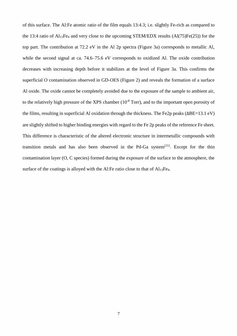
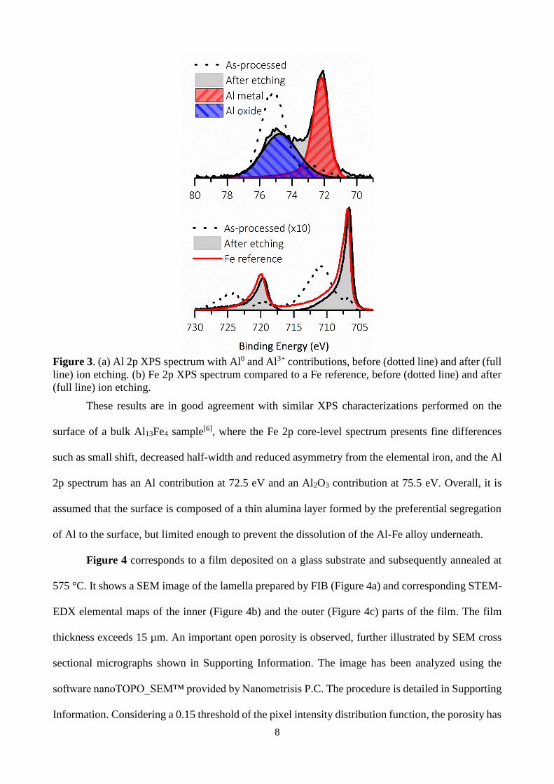
XPS is now used for the characterization of the surface composition. The initial surface
composition of the as-processed film exposed to ambient air is Al(12.7)Fe(2.3)O(66.0)C(19) in at.%.
This surface composition is the one relevant to the initial condition of the catalysis test. Nevertheless,
it will rapidly change depending on the gas mixture and pretreatments, and we do not have an insight
in this dynamic evolution. The corresponding Al2p and Fe2p spectra are plotted in Figure 3 (dotted
lines). A 100 nm top layer is etched in order to eliminate the above-mentioned contaminants and
oxide layer and to recover a fresh metallic surface. Figure 3 shows the Al 2p XPS and Fe 2p spectra
7
of this surface. The Al:Fe atomic ratio of the film equals 13:4.3; i.e. slightly Fe-rich as compared to
the 13:4 ratio of Al13Fe4 and very close to the upcoming STEM/EDX results (Al(75)Fe(25)) for the
top part. The contribution at 72.2 eV in the Al 2p spectra (Figure 3a) corresponds to metallic Al,
while the second signal at ca. 74.6–75.6 eV corresponds to oxidized Al. The oxide contribution
decreases with increasing depth before it stabilizes at the level of Figure 3a. This confirms the
superficial O contamination observed in GD-OES (Figure 2) and reveals the formation of a surface
Al oxide. The oxide cannot be completely avoided due to the exposure of the sample to ambient air,
to the relatively high pressure of the XPS chamber (10-8 Torr), and to the important open porosity of
the films, resulting in superficial Al oxidation through the thickness. The Fe2p peaks (ΔBE=13.1 eV)
are slightly shifted to higher binding energies with regard to the Fe 2p peaks of the reference Fe sheet.
This difference is characteristic of the altered electronic structure in intermetallic compounds with
transition metals and has also been observed in the Pd-Ga system[21]. Except for the thin
contamination layer (O, C species) formed during the exposure of the surface to the atmosphere, the
surface of the coatings is alloyed with the Al:Fe ratio close to that of Al13Fe4.
8
Figure 3. (a) Al 2p XPS spectrum with Al0 and Al3+ contributions, before (dotted line) and after (full
line) ion etching. (b) Fe 2p XPS spectrum compared to a Fe reference, before (dotted line) and after
(full line) ion etching.
These results are in good agreement with similar XPS characterizations performed on the
surface of a bulk Al13Fe4 sample[6], where the Fe 2p core-level spectrum presents fine differences
such as small shift, decreased half-width and reduced asymmetry from the elemental iron, and the Al
2p spectrum has an Al contribution at 72.5 eV and an Al2O3 contribution at 75.5 eV. Overall, it is
assumed that the surface is composed of a thin alumina layer formed by the preferential segregation
of Al to the surface, but limited enough to prevent the dissolution of the Al-Fe alloy underneath.
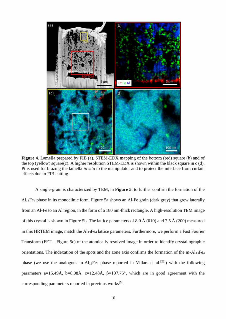
Figure 4 corresponds to a film deposited on a glass substrate and subsequently annealed at
575 °C. It shows a SEM image of the lamella prepared by FIB (Figure 4a) and corresponding STEM-
EDX elemental maps of the inner (Figure 4b) and the outer (Figure 4c) parts of the film. The film
thickness exceeds 15 µm. An important open porosity is observed, further illustrated by SEM cross
sectional micrographs shown in Supporting Information. The image has been analyzed using the
software nanoTOPO_SEM™ provided by Nanometrisis P.C. The procedure is detailed in Supporting
Information. Considering a 0.15 threshold of the pixel intensity distribution function, the porosity has
9
been evaluated to be 16-17 %. It is attributed to the rough microstructures of the two initial layers,
reported in references [18] and [19] for Al and Fe films, respectively, further perturbed by the extended
interdiffusion during annealing. In that lamella, no pure Al regions are observed, confirming that
diffusion is effective across the whole stack. The Fe concentration is higher at the interface and
decreases up to the surface in agreement with the GD-OES results. For instance, we observe in Figure
4b (red square in Figure 4a) that more than 50 vol. % of the bottom part of the lamella is composed
of Fe-rich grains (in green). Local quantitative EDX analysis shows regions with elemental
compositions of e.g. Al(25)Fe(75) or Al(15)Fe(85). Towards the free surface, the fraction of Fe-rich
grains decreases until the top 2-3 µm-thick layer where the composition is homogeneous. Figure 4c
shows the mapping of the chemical composition in the top region (yellow square of Figure 4a). Except
for some Fe-rich inclusions at the bottom, we measure a homogeneous Al(75)Fe(25) matrix
composition by quantitative EDX, corresponding to the m-Al13Fe4 composition. A higher resolution
map corresponding to the white square of Fig. 4c is shown in Figure 4d. A few 20-40 nm wide
Al(53)Fe(47) inclusions (bright green contrast) are found. At the edges of the matrix, and surrounding
pores, we find an Al content slightly higher than in the matrix (Al(79)Fe(21)). This Al enrichment is
correlated with the presence of O. Al preferential oxidation is common in Al-transition metal alloys,
and this is in agreement with the formation of Al oxide at free surfaces as confirmed by XPS
measurements (Figure 3 and description thereof). We cannot assess, though, if this oxidation occurs
during film formation or ex situ during the lamella preparation/transfer.
10
Figure 4. Lamella prepared by FIB (a). STEM-EDX mapping of the bottom (red) square (b) and of
the top (yellow) square(c). A higher resolution STEM-EDX is shown within the black square in c (d).
Pt is used for brazing the lamella in situ to the manipulator and to protect the interface from curtain
effects due to FIB cutting.
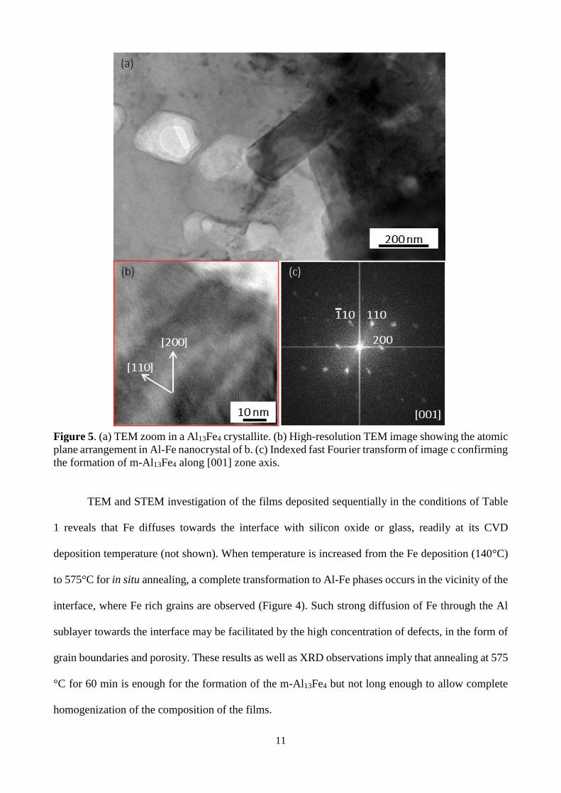
A single-grain is characterized by TEM, in Figure 5, to further confirm the formation of the
Al13Fe4 phase in its monoclinic form. Figure 5a shows an Al-Fe grain (dark grey) that grew laterally
from an Al-Fe to an Al region, in the form of a 180 nm-thick rectangle. A high-resolution TEM image
of this crystal is shown in Figure 5b. The lattice parameters of 8.0 Å (010) and 7.5 Å (200) measured
in this HRTEM image, match the Al13Fe4 lattice parameters. Furthermore, we perform a Fast Fourier
Transform (FFT – Figure 5c) of the atomically resolved image in order to identify crystallographic
orientations. The indexation of the spots and the zone axis confirms the formation of the m-Al13Fe4
phase (we use the analogous m-Al13Fe4 phase reported in Villars et al.[22]) with the following
parameters a=15.49Å, b=8.08Å, c=12.48Å, β=107.75°, which are in good agreement with the
corresponding parameters reported in previous works[5].
11
Figure 5. (a) TEM zoom in a Al13Fe4 crystallite. (b) High-resolution TEM image showing the atomic
plane arrangement in Al-Fe nanocrystal of b. (c) Indexed fast Fourier transform of image c confirming
the formation of m-Al13Fe4 along [001] zone axis.
TEM and STEM investigation of the films deposited sequentially in the conditions of Table
1 reveals that Fe diffuses towards the interface with silicon oxide or glass, readily at its CVD
deposition temperature (not shown). When temperature is increased from the Fe deposition (140°C)
to 575°C for in situ annealing, a complete transformation to Al-Fe phases occurs in the vicinity of the
interface, where Fe rich grains are observed (Figure 4). Such strong diffusion of Fe through the Al
sublayer towards the interface may be facilitated by the high concentration of defects, in the form of
grain boundaries and porosity. These results as well as XRD observations imply that annealing at 575
°C for 60 min is enough for the formation of the m-Al13Fe4 but not long enough to allow complete
homogenization of the composition of the films.
12
2.2. Semi-hydrogenation of acetylene
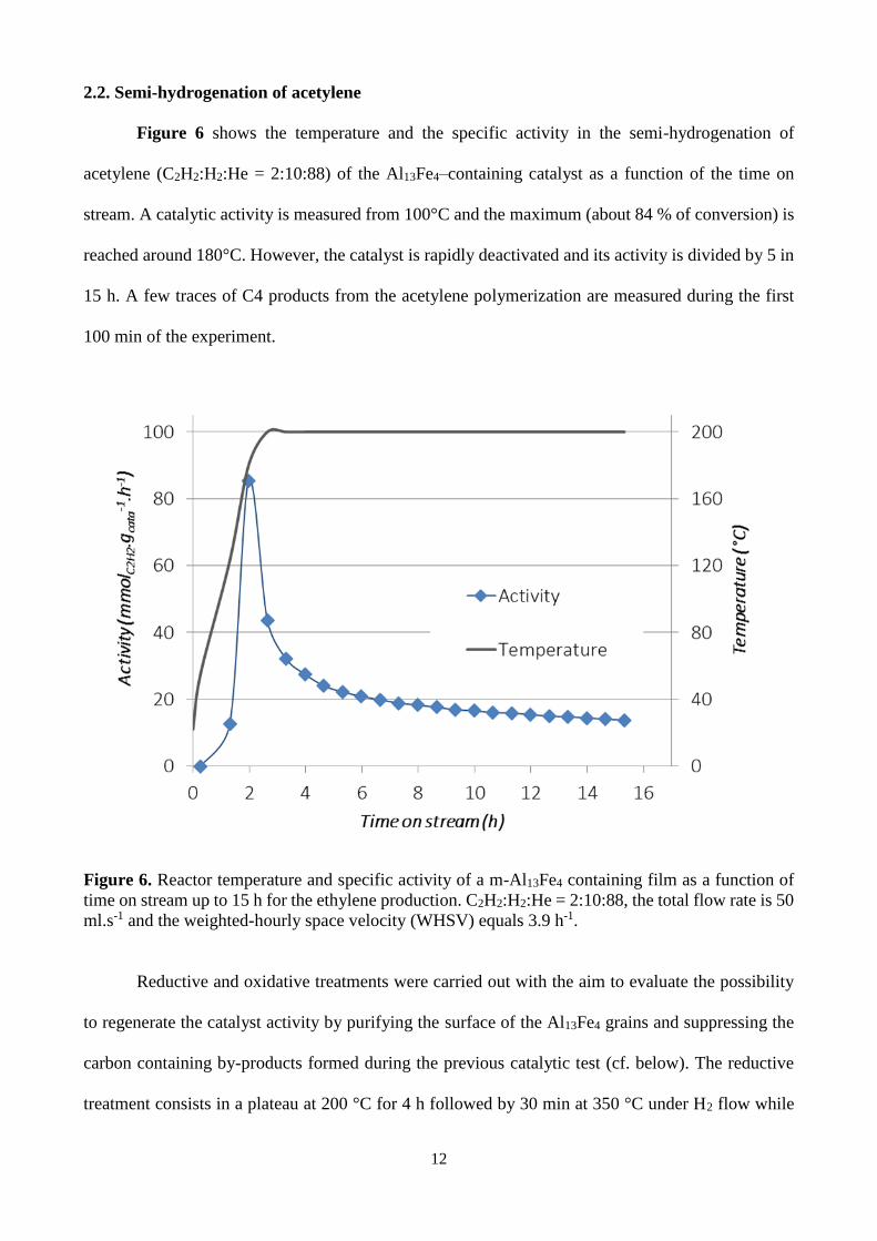
Figure 6 shows the temperature and the specific activity in the semi-hydrogenation of
acetylene (C2H2:H2:He = 2:10:88) of the Al13Fe4–containing catalyst as a function of the time on
stream. A catalytic activity is measured from 100°C and the maximum (about 84 % of conversion) is
reached around 180°C. However, the catalyst is rapidly deactivated and its activity is divided by 5 in
15 h. A few traces of C4 products from the acetylene polymerization are measured during the first
100 min of the experiment.
Figure 6. Reactor temperature and specific activity of a m-Al13Fe4 containing film as a function of
time on stream up to 15 h for the ethylene production. C2H2:H2:He = 2:10:88, the total flow rate is 50
ml.s-1 and the weighted-hourly space velocity (WHSV) equals 3.9 h-1.
Reductive and oxidative treatments were carried out with the aim to evaluate the possibility
to regenerate the catalyst activity by purifying the surface of the Al13Fe4 grains and suppressing the
carbon containing by-products formed during the previous catalytic test (cf. below). The reductive
treatment consists in a plateau at 200 °C for 4 h followed by 30 min at 350 °C under H2 flow while

13
the oxidative treatment is a plateau under O2 flow at 200 °C for 30 min. Moreover to favor the activity
and to counteract the catalyst deactivation the C2H2/H2 ratio was decreased in the feed stream after
pre-treatments (ie, (C2H2:H2:He = 0.5:5:94.5). The activity slightly increases; i.e. it doubles,
especially after the oxidizing treatment which must make it possible to clean the surface more
efficiently. However in both cases the catalyst continues to deactivate in spite of a smaller C2H2/H2
ratio.
The initial conversion is 84 % but it rapidly drops to 2 %. It drops to a slightly higher value
of 11% when the catalytic test is performed at 450oC. The strong deactivation is assumed to originate
from the formation of carbonaceous species, revealed by visual observations and XPS. Actually, soot
is observed as a black/brown precipitate in the reactor after the catalytic experiments. Fe is a well-
known catalyst for the formation of various carbon based materials, such as soot[23] or carbon
nanostructures[24]. It is worth noting that a threefold increase of soot has also been reported in
ethylene/oxygen flames after addition of Fe[25]. These carbon residues are not bonded to the surface
and are easily removed. On the other hand, XPS spectra (not shown) show a 3 to 6-fold increase of
the carbides component of the C1s peak within the film after catalysis. Therefore, we state that the
sharp decrease of the conversion is not related to the Al13Fe4 phase where isolated Fe atoms are
protected by Al shells; but to other Fe containing phases (Fe, Al5Fe2) which catalyze the formation
of soot and are deactivated by subsequent carbidization.
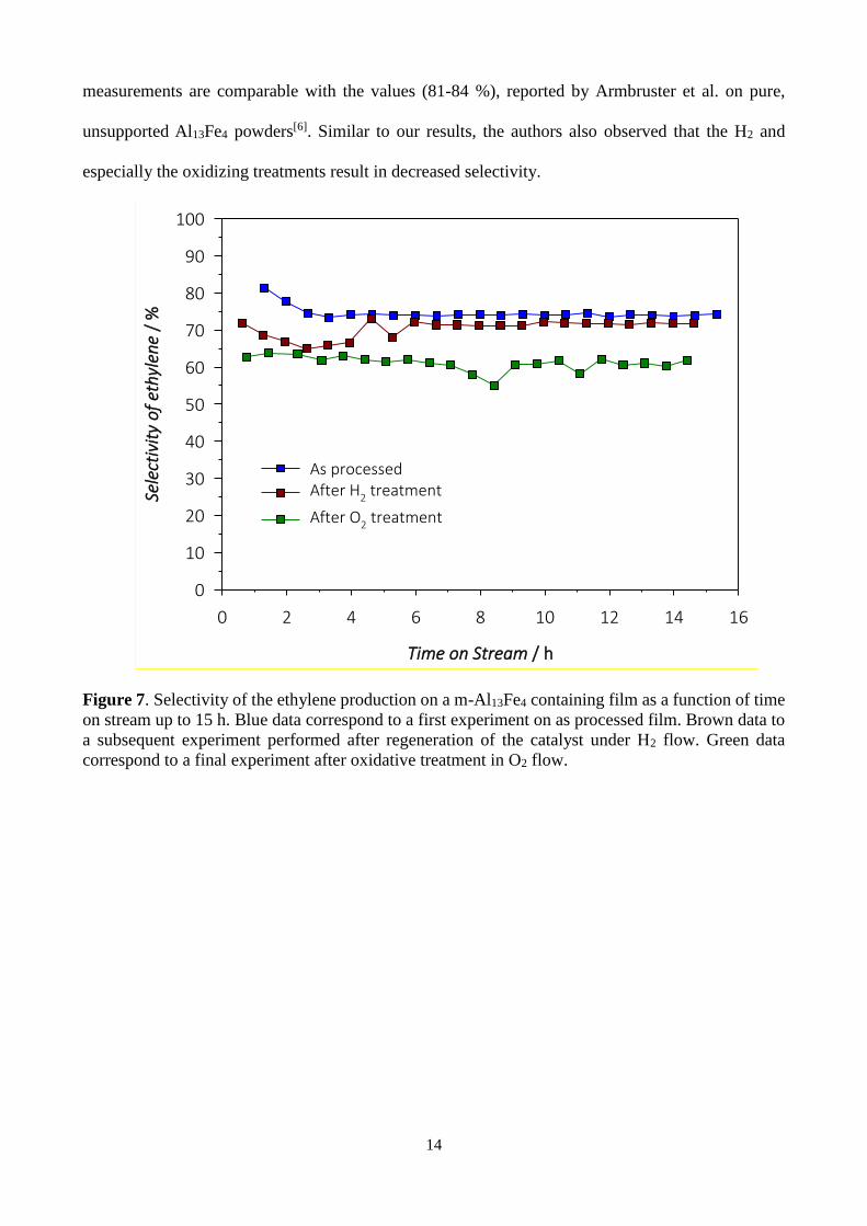
Figure 7 shows the selectivity of the Al13Fe4–containing catalyst as a function of the time on
stream for the three sequential experiments. The beginning of the recording for each curve
corresponds to the time when the temperature of the bench attains 200 °C. For the as-processed
sample, the selectivity in ethylene starts at 81-82 %; it continuously decreases and is stabilized at ca.
74 % after 2 h at 200 °C, until the end of the test corresponding to 15 h of operation. As expected, the
selectivity slightly decreases for the two experiments carried out with a smaller C2H2/H2 ratio; more
precisely it decreases to constant value of ca. 71% for the reductive treatment. In contrast, it suffers
significantly on treating the catalytic film in O2 at 200 °C where it caps at 61 %. The present selectivity
14
measurements are comparable with the values (81-84 %), reported by Armbruster et al. on pure,
unsupported Al13Fe4 powders[6]. Similar to our results, the authors also observed that the H2 and
especially the oxidizing treatments result in decreased selectivity.
Figure 7. Selectivity of the ethylene production on a m-Al13Fe4 containing film as a function of time
on stream up to 15 h. Blue data correspond to a first experiment on as processed film. Brown data to
a subsequent experiment performed after regeneration of the catalyst under H2 flow. Green data
correspond to a final experiment after oxidative treatment in O2 flow.
Time on Stream / h
0 2 4 6 8 10 12 14 16
Sele
ctiv
ity
of
eth
ylen
e /
%
0
10
20
30
40
50
60
70
80
90
100
As processedAfter H2 treatment
After O2 treatment

15
3. Conclusions
The sequential chemical vapor deposition of Al/Fe bilayers from DMEAA and Fe(CO)5,
respectively, followed by in situ post deposition annealing resulted, for the first time of films
containing the approximant m-Al13Fe4 phase as demonstrated by XRD, and zone axis indexation and
determination of interatomic parameters in HRTEM micrographs. GD-OES and STEM/EDX reveal
that the 15 µm thick films present a composition gradient from the Al-rich surface to the Fe-rich
interface with the silicon oxide substrate and are globally slightly over stoichiometric in Fe with
regard to the targeted Al:Fe = 13:4 ratio. They contain a significant open porosity which has been
developed during the reactive interdiffusion of the two metals. XPS measurements indicate the
peculiar position of the Fe 2p peak corresponding to that in the Al13Fe4 phase and confirm that the
formation of a thin passivating layer of Al oxide does not impact the Al13Fe4 phase underneath.
Catalytic tests with these materials for the semi-hydrogenation of acetylene show selectivity
to ethylene as high as 74 % over 15 h time on stream, close to the reported values for pure,
unsupported Al13Fe4. The initial conversion of 84 % rapidly drops due to soot production by catalytic
reaction of Fe atoms on acetylene, and to carbidation. The high selectivity and especially the poor
conversion are expected to be improved by engineering the CVD process and the annealing conditions
so as to obtain Al13Fe4 films with still high specific surface but exempted from Fe-rich phases.
4. Experiments
Depositions are performed in a vertical, cylindrical, stagnant flow, cold wall, stainless steel
CVD reactor as described in detail[26] and modeled[17, 27] in previous works. Substrates are 20x12x2
mm3 glass and 10x10x1 mm3 thermally oxidized Si coupons in order to avoid the formation of
silicides (if Si substrates are used). The substrates are sonicated in acetone and ethanol for 5 min,
dried under pure Ar stream and baked at 60 ºC for 30 min. They are weighted using a microbalance
(Sartorius) before and after deposition for the determination of the mass gain (±1 μg) over the
experiment duration, thus providing a mean value of the deposition rate for every set of process
conditions. In each experiment 5 substrates are placed horizontally at different radial positions, on a
16
58 mm diameter susceptor (substrate holder) heated by a resistance coil gyred just below the surface.
A homogeneous gas distribution is ensured by a perforated shower plate facing the substrates[28].
Gases flow rates are controlled by mass flow controllers (MKS).
Al films are formed by the decomposition of the liquid precursor dimethylethylamine alane
(DMEAA), provided by NanoMePS (www.nanomeps.fr, last accessed October 18, 2017). For all
deposition experiments the DMEAA containing bubbler is thermally regulated at 7 ºC, where its
saturated vapor pressure is 0.7 Torr[29]. During the deposition of the Al film, N2 (99.9992% Air
Products) flows through DMEAA (QN2,DMEAA = 25 standard cubic centimeters, sccm) and as dilution
gas (QN2 = 325 sccm). The maximum flow rate of DMEAA in these conditions equals 2 sccm[30].
Films processed at low deposition temperature, Td ca. 140 °C show scattered grains on the surface
and form rough morphologies with poor uniformity and no continuity. By increasing Td grains
coalesce and the density of the film increases. Details of the microstructure and the growth rate of the
Al films have been reported in [17].
Fe films are processed from iron pentacarbonyl (Fe(CO)5), a high saturated vapor pressure
liquid precursor which yields pure Fe films with C and O contaminants at the level of a few at%[31].
Fe(CO)5 (>99.99%, Sigma-Aldrich) is transported to the deposition area by direct liquid injection
(DLI – VapboxTM, Kemstream). Small batches of 4 mL of pure Fe(CO)5 are used thus limiting storage
degradation. DLI conditions result in a controlled flow rate of 0.02 mL/min of Fe(CO)5 in the reactor
chamber. As for the Al films, low Td ca. 130 °C results in Fe deposition in the form of scattered grains
on the surface and in films with poor uniformity and no continuity. With increasing Td faceted Fe
larger grains start to form and the density of the film increases because of grains coalescence. At Td
higher than 170 °C angular and sharply-faceted grains are first formed followed by films with an
acicular morphology above 200 °C. Details on the microstructure and the growth rate of the Fe films
can be found in [19].
17
Based on these results on the growth rate and on the microstructure of the two elements, bi-
layers were processed by first depositing Al at Td and Pd 180 ºC and 5 Torr followed by deposition
of Fe at 140 ºC and 40 Torr.
Post-deposition annealing is applied to the Al/Fe bilayers immediately after deposition to
stimulate reactive diffusion. It is performed in situ for 60 min, at different temperatures, under primary
vacuum of 1 x 10⁻¹ Torr, thus limiting the contamination of the films. The choice of the range of the
annealing temperature is based on the Al–Fe phase diagram[33] and on the results reported on the
formation of Al–Fe intermetallic phases determined by high-temperature XRD[11]. However, results
are shown only for 575oC, since the intermetallic Al13Fe4 phase is only formed at this temperature.
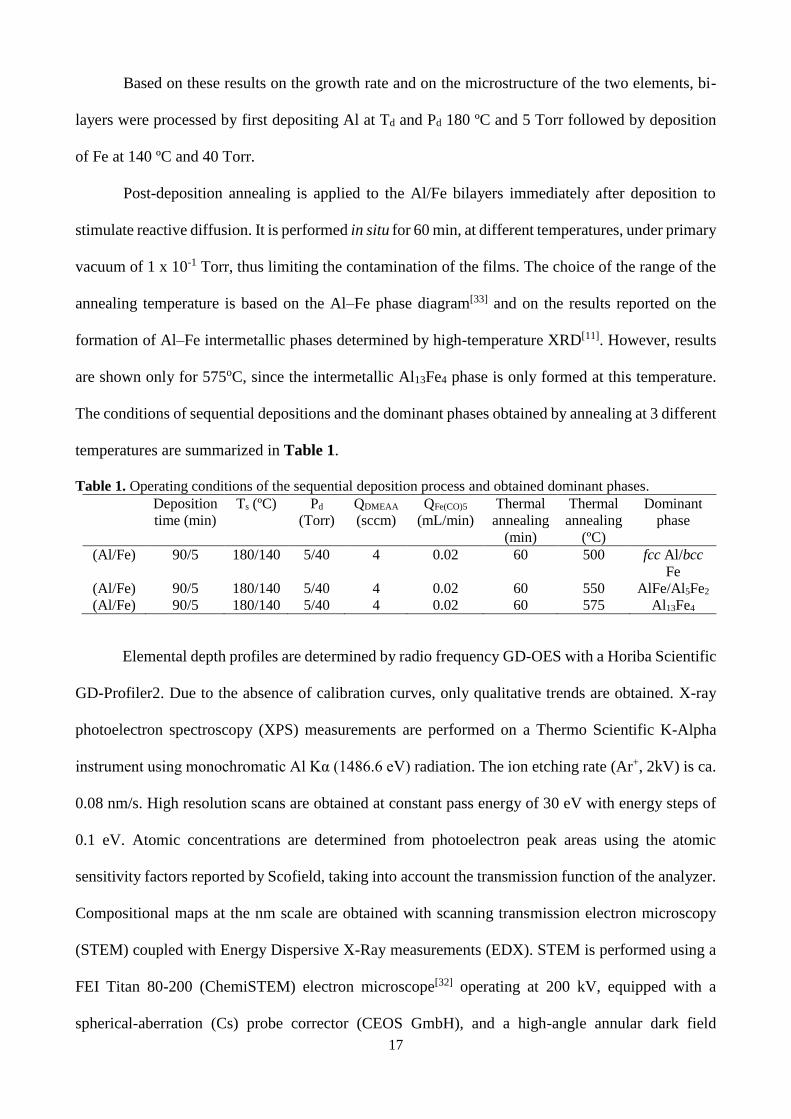
The conditions of sequential depositions and the dominant phases obtained by annealing at 3 different
temperatures are summarized in Table 1.
Table 1. Operating conditions of the sequential deposition process and obtained dominant phases.
Deposition
time (min)
Ts (ºC) Pd
(Torr)
QDMEAA
(sccm)
QFe(CO)5
(mL/min)
Thermal
annealing
(min)
Thermal
annealing
(ºC)
Dominant
phase
(Al/Fe) 90/5 180/140 5/40 4 0.02 60 500 fcc Al/bcc
Fe
(Al/Fe) 90/5 180/140 5/40 4 0.02 60 550 AlFe/Al5Fe2
(Al/Fe) 90/5 180/140 5/40 4 0.02 60 575 Al13Fe4
Elemental depth profiles are determined by radio frequency GD-OES with a Horiba Scientific
GD-Profiler2. Due to the absence of calibration curves, only qualitative trends are obtained. X-ray
photoelectron spectroscopy (XPS) measurements are performed on a Thermo Scientific K-Alpha
instrument using monochromatic Al Kα (1486.6 eV) radiation. The ion etching rate (Ar+, 2kV) is ca.
0.08 nm/s. High resolution scans are obtained at constant pass energy of 30 eV with energy steps of
0.1 eV. Atomic concentrations are determined from photoelectron peak areas using the atomic
sensitivity factors reported by Scofield, taking into account the transmission function of the analyzer.
Compositional maps at the nm scale are obtained with scanning transmission electron microscopy
(STEM) coupled with Energy Dispersive X-Ray measurements (EDX). STEM is performed using a
FEI Titan 80-200 (ChemiSTEM) electron microscope[32] operating at 200 kV, equipped with a
spherical-aberration (Cs) probe corrector (CEOS GmbH), and a high-angle annular dark field
18
(HAADF) detector. A probe semi-angle of 25 mrad and an inner collection semi-angle of the detector
of 88 mrad are used. Elemental analysis is performed using four large-solid-angle symmetrical Si
drift detectors. For EDX analysis, Fe K and Al K peaks are used. Crystallographic structures are
determined by X-ray diffraction (XRD) on a SEIFERT-3000TT instrument using a Cu Kα (1.5418 Å)
X-ray tube operated at 40 kV and 40 mA, a Ni filter and solid-state Lynxeye detector. Diffraction
patterns were acquired with a 2θ step size of 0.25° over a 2θ range of 0 to 120°. Surface morphology
is observed using scanning electron microscopy (SEM) on a LEO 435VP instrument. Cross section
micrographs of selected samples are prepared and observed with a FEI Helios 600i station composed
of a focused ion beam (FIB) and a field emission gun (FEG) SEM, operating at 5 kV. Transmission
eletron microscopy (TEM) coupled with EDX measurements is performed with a JEOL JEM 2100F
high resolution microscope operating at 200 kV and equipped with a BRUKER EDX spectrometer
for chemical analysis. High resolution TEM (HR-TEM) analysis is also performed in the same
instrument for crystallographic characterizations of the Al13Fe4 crystal. TEM lamellas are prepared
by FIB.
Catalytic tests for the semi-hydrogenation of acetylene are carried out at 200 °C under
atmospheric pressure in a continuous flow fixed-bed reactor which consists of a cylindrical glass tube
of 16 mm diameter equipped with a sintered glass filter to support the catalyst. The reactor is placed
in a ceramic furnace and the temperature is controlled via a thermocouple. The reactive gases
(C2H2:H2:He) are mixed using mass flow controllers (Brooks and Vögtlin) with a ratio 2:10:88,
respectively and flowing through the reactor with a total rate of 50 sccm. The effluent gases are
analyzed online using Shimadzu GC-2014 gas chromatograph equipped with a Supelco alumina
sulfate plot coupled with a silica capillary column and a FID detector. Large samples were
synthesized in the same conditions on thermally grown silica on Si substrates, in order to provide 25
mg equivalent of Al13Fe4 containing film. Samples are crushed with the aim to mimic the deposition
of a supported catalyst on a powder substrate. The powder is then introduced in the catalytic reactor.
19
The set-up is placed on the test bench under N2 atmosphere while avoiding contact of the catalyst
with O2 and moisture.
Acknowledgements
This work was supported by IFPEN, Solaize, France through the grant number #268821. IGA
acknowledges the financial support provided by the National Scholarship Foundation of Greece
(IKY-Siemens Program) and KS acknowledges the one provided by the French LABEX iMUST
(ANR-10-LABX-0064) of Université de Lyon, within the program “Investissements d’Avenir”
(ANR-11-IDEX-0007) operated by the French National Research Agency (ANR). We are indebted
to Claudie Josse, Raymond Castaing Microanalysis Centre for help with FIB–SEM analysis, to
Vassilios Constandoudis and George Papavieros, Nanometrisis P.C. for the pores size analysis, to
HORIBA Jobin Yvon SAS for the realization of GD-OES measurements, and to the European
Integrated Center for the Development of New Metallic Alloys and Compounds (C-MAC) for
support.
Received: ((will be filled in by the editorial staff))
Revised: ((will be filled in by the editorial staff))
Published online: ((will be filled in by the editorial staff))
References
[1] W. R. True, in Oil Gas J., Vol. 111, PennWell Petroleum Group, Huston, TX 2013, 90.
[2] F. Studt, F. Abild-Pedersen, T. Bligaard, R. Z. Sorensen, C. H. Christensen, J. K. Norskov,
Science 2008, 320, 1320.
[3] G. Kyriakou, M. B. Boucher, A. D. Jewell, E. A. Lewis, T. J. Lawton, A. E. Baber, H. L.
Tierney, M. Flytzani-Stephanopoulos, E. C. H. Sykes, Science 2012, 335, 1209.
[4] P. J. Black, Acta Crystallogr. 1955, 8, 43.
[5] M. Ellner, Acta Crystallogr. B 1995, 51, 31; J. Grin, U. Burkhardt, M. Ellner, K. Peters, Z.
Kristallogr. 1994, 209, 479.
[6] M. Armbruster, K. Kovnir, M. Friedrich, D. Teschner, G. Wowsnick, M. Hahne, P. Gille, L.
Szentmiklosi, M. Feuerbacher, M. Heggen, F. Girgsdies, D. Rosenthal, R. Schlogl, Y. Grin, Nat.
Mater. 2012, 11, 690.
[7] M. Armbruster, G. Wowsnick, M. Friedrich, M. Heggen, R. Cardoso-Gil, J. Am. Chem. Soc.
2011, 133, 9112; H. R. Zhou, X. F. Yang, L. Li, X. Y. Liu, Y. Q. Huang, X. L. Pan, A. Q. Wang, J.
Li, T. Zhang, ACS Catal. 2016, 6, 1054; T. Ghosh, B. M. Leonard, Q. Zhou, F. J. DiSalvo, Chem.
Mater. 2010, 22, 2190.
20
[8] J. Ledieu, E. Gaudry, L. N. S. Loli, S. A. Villaseca, M. C. de Weerd, M. Hahne, P. Gille, Y.
Grin, J. M. Dubois, V. Fournee, Phys. Rev. Lett. 2013, 110.
[9] Q. C. Feng, S. Zhao, Y. Wang, J. C. Dong, W. X. Chen, D. S. He, D. S. Wang, J. Yang, Y.
M. Zhu, H. L. Zhu, L. Gu, Z. Li, Y. X. Liu, R. Yu, J. Li, Y. D. Li, J. Am. Chem. Soc. 2017, 139,
7294.
[10] A. Csanady, J. R. Gunter, P. B. Barna, J. Mayer, Thin Solid Films 1988, 167, 203; S. R.
Teixeira, C. A. Dossantos, P. H. Dionisio, W. H. Schreiner, I. J. R. Baumvol, Mat. Sci. Eng. 1987,
96, 285; S. R. Teixeira, F. L. Freire, I. J. R. Baumvol, Appl. Phys. A: Mater. Sci. Process. 1989, 48,
481.
[11] F. Haidara, M. C. Record, B. Duployer, D. Mangelinck, Intermetallics 2012, 23, 143.
[12] S. Kumar, V. Selvarajan, P. V. A. Padmanabhan, K. P. Sreekumar, Surf. Coat. Technol. 2006,
201, 1267; G. J. Yang, H. T. Wang, C. J. Li, C. X. Li, Surf. Coat. Technol. 2011, 205, 5502.
[13] A. Canakci, F. Erdemir, T. Varol, S. Ozkaya, Powder Techn. 2013, 247, 24.
[14] C. Vahlas, in Complex Metallic Alloys: Surfaces and Coatings, (Ed: E. Belin-Ferré), World
Scientific, Singapore 2010, 49.
[15] N. Prud’homme, T. Duguet, D. Samélor, F. Senocq, C. Vahlas, Appl. Surf. Sci. 2013, 283,
788.
[16] Y. Zhang, B. A. Pint, K. M. Cooley, J. A. Haynes, Surf. Coat. Technol. 2008, 202, 3839; J.
T. John, R. S. Srinivasa, P. K. De, Thin Solid Films 2004, 466, 339; Z. D. Xiang, P. K. Datta, Surf.
Coat. Technol. 2004, 184, 108.
[17] I. G. Aviziotis, T. Duguet, K. Soussi, G. Kokkoris, N. Cheimarios, C. Vahlas, A. G.
Boudouvis, Phys. Status Solidi C 2015, 12, 923.
[18] I. G. Aviziotis, N. Cheimarios, T. Duguet, C. Vahlas, A. G. Boudouvis, Chem. Eng. Sci. 2016,
155, 449.
[19] I. G. Aviziotis, T. Duguet, C. Vahlas, A. G. Boudouvis, Adv. Mater. Interfaces 2017,
1601185.
[20] D. Naoi, M. Kajihara, Mat. Sci. Eng., A 2007, 459, 375.
[21] K. Kovnir, M. Armbruster, D. Teschner, T. V. Venkov, L. Szentmiklosi, F. C. Jentoft, A.
Knop-Gericke, Y. Grin, R. Schlogl, Surf. Sci. 2009, 603, 1784.
[22] P. Villars, Handbook of Ternary Alloy Phase Diagrams, ASM International, Materials Park,
OH 1995.
[23] J. H. Hahn, N. M. Hwang, D. Y. Yoon, J. Mat. Sci. Lett. 1996, 15, 1240.
[24] R. Marangoni, P. Serp, R. Feurer, Y. Kihn, P. Kalck, C. Vahlas, Carbon 2001, 39, 443.
[25] A. S. Feitelberg, J. P. Longwell, A. F. Sarofim, Combust. Flame 1993, 92, 241.
[26] T. C. Xenidou, A. G. Boudouvis, N. C. Markatos, D. Samélor, F. Senocq, A. N. Gleizes, N.
Prud’homme, C. Vahlas, Surf. Coat. Technol. 2007, 201 8868.
[27] I. G. Aviziotis, N. Cheimarios, C. Vahlas, A. G. Boudouvis, Surf. Coat. Technol. 2013, 230,
273.
[28] T. C. Xenidou, N. Prud’homme, C. Vahlas, N. C. Markatos, A. G. Boudouvis, J. Electrochem.
Soc. 2010, 157, D633.
[29] D. M. Frigo, G. J. M. Vaneijden, P. J. Reuvers, C. J. Smit, Chem. Mater. 1994, 6, 190.
[30] S. D. Hersee, J. M. Ballingall, J. Vac. Sci. Technol. 1990, A8, 800.
[31] R. B. Jackman, J. S. Foord, Surf. Sci. 1989, 209, 151.
[32] A. Kovács, R. Schierholz, K. Tillmann, JLSRF 2016, 2, 1.
21
Text for the table of contents
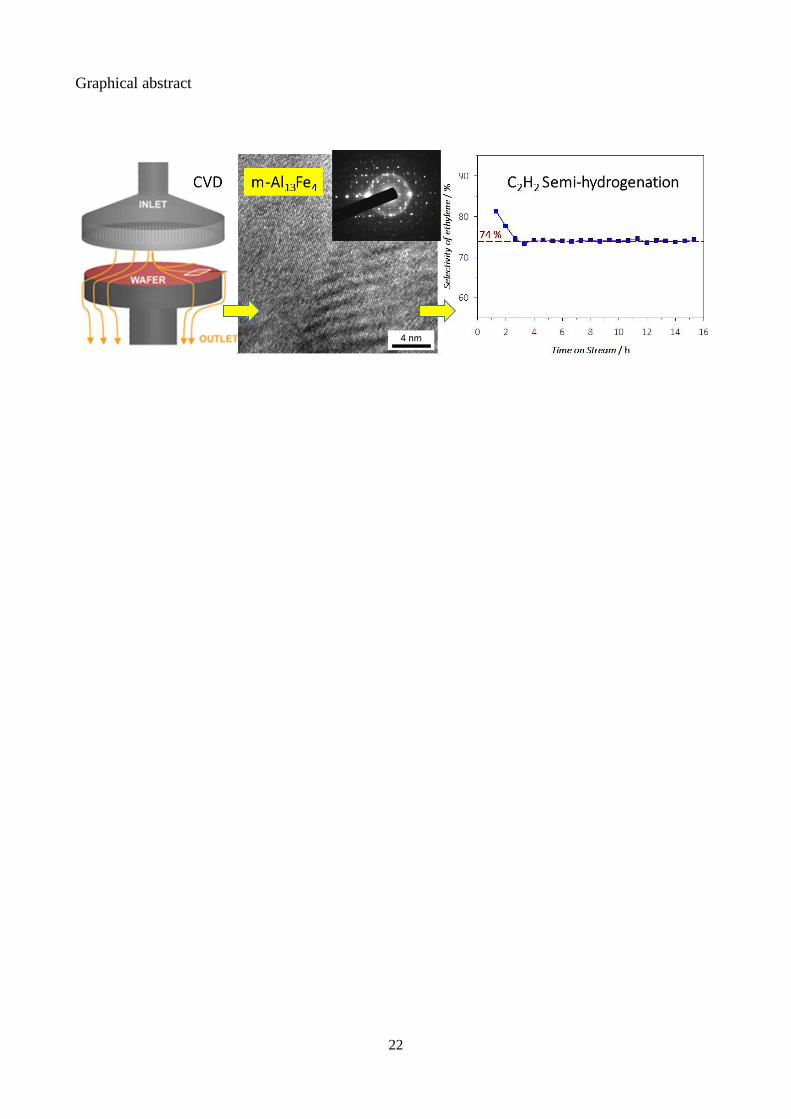
Films containing the noble metals-free, monoclinic Al13Fe4 phase are produced by chemical vapor
deposition. The selectivity of the catalytic semi-hydrogenation of ethylene performed on them is as
high as 74 % close to the reported values for pure, unsupported Al13Fe4. New routes are open, to the
engineering of pure, supported Al13Fe4 catalysts on 3D or porous supports.
22
Graphical abstract
Copyright © 2022 FDOKUMEN