A Biological Examination of Lake Michigan in the Traverse ...
1.0 INTRODUCTION
Tachymetry is a system of rapid surveying, by which the positions, both horizontal
and vertical, of points on the earth surface relatively to one another are determined
without using a chain or tape or a separate levelling instrument.
These difficulties led to the introduction of tachymetry, in which, instead of the
prism pole formerly employed to mark a point. This is marked with heights from
the foot, and is graduated according to the form of tachymetry in use.
The azimuth angle is determined as formerly. Thus all the measurements requisite
to locate a point both vertically and horizontally with reference to the point where
the tachymetry is centred are determined by an observer at the instrument without
any assistance beyond that of a man to hold the prism pole.
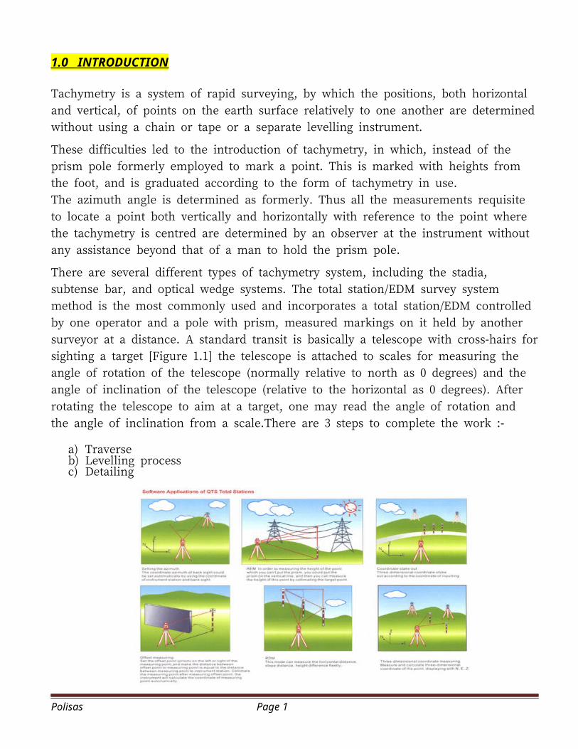
There are several different types of tachymetry system, including the stadia,
subtense bar, and optical wedge systems. The total station/EDM survey system
method is the most commonly used and incorporates a total station/EDM controlled
by one operator and a pole with prism, measured markings on it held by another
surveyor at a distance. A standard transit is basically a telescope with cross-hairs for
sighting a target [Figure 1.1] the telescope is attached to scales for measuring the
angle of rotation of the telescope (normally relative to north as 0 degrees) and the
angle of inclination of the telescope (relative to the horizontal as 0 degrees). After
rotating the telescope to aim at a target, one may read the angle of rotation and
the angle of inclination from a scale.There are 3 steps to complete the work :-
a) Traverseb) Levelling processc) Detailing
Polisas Page 1
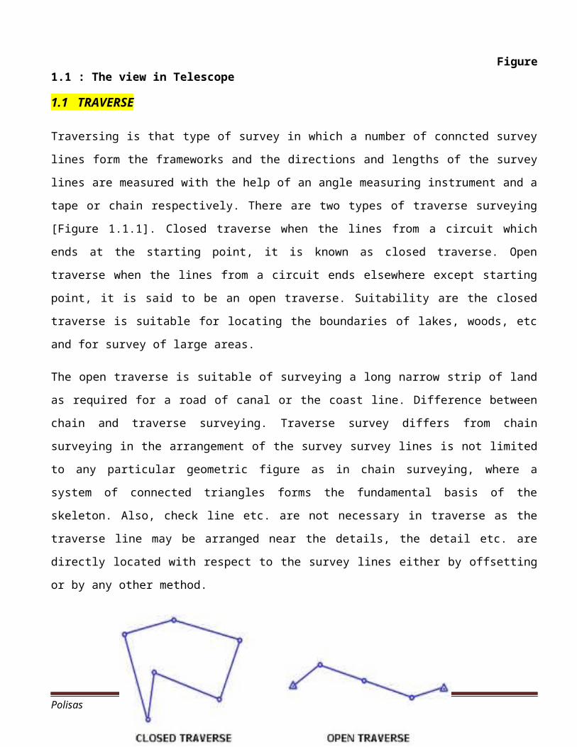
Figure1.1 : The view in Telescope
1.1 TRAVERSE
Traversing is that type of survey in which a number of conncted survey
lines form the frameworks and the directions and lengths of the survey
lines are measured with the help of an angle measuring instrument and a
tape or chain respectively. There are two types of traverse surveying
[Figure 1.1.1]. Closed traverse when the lines from a circuit which
ends at the starting point, it is known as closed traverse. Open
traverse when the lines from a circuit ends elsewhere except starting
point, it is said to be an open traverse. Suitability are the closed
traverse is suitable for locating the boundaries of lakes, woods, etc
and for survey of large areas.
The open traverse is suitable of surveying a long narrow strip of land
as required for a road of canal or the coast line. Difference between
chain and traverse surveying. Traverse survey differs from chain
surveying in the arrangement of the survey survey lines is not limited
to any particular geometric figure as in chain surveying, where a
system of connected triangles forms the fundamental basis of the
skeleton. Also, check line etc. are not necessary in traverse as the
traverse line may be arranged near the details, the detail etc. are
directly located with respect to the survey lines either by offsetting
or by any other method.
Polisas Page 2
Figure 1.1.1: Closed
traverse & Open traverse
1.2 LEVELLING
Levelling is the general term applied to any of the various processes
by which elevations of points or differences in elevation are
determined [Figure 1.2.1]. Leveling result are used to design highways,
railroads, canals, sewers, water supply systems, having grade lines
that best conform the existing topography, to lay out construction
projects according to planned elevations, to calculate volume of
earthworks and other materials and to investigate drainage
characteristics of an area. Levelling is a branch of surveying, the
object of which is to find the elevation of a given point with respect
to the given or assumed datum. Levelling is the measurement of geodetic
height using an optical leveling instrument and a level staff or rod
Polisas Page 3
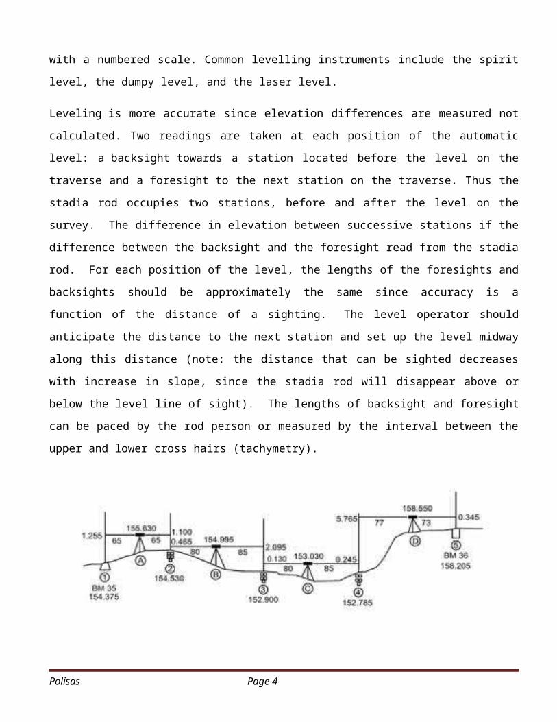
with a numbered scale. Common levelling instruments include the spirit
level, the dumpy level, and the laser level.
Leveling is more accurate since elevation differences are measured not
calculated. Two readings are taken at each position of the automatic
level: a backsight towards a station located before the level on the
traverse and a foresight to the next station on the traverse. Thus the
stadia rod occupies two stations, before and after the level on the
survey. The difference in elevation between successive stations if the
difference between the backsight and the foresight read from the stadia
rod. For each position of the level, the lengths of the foresights and
backsights should be approximately the same since accuracy is a
function of the distance of a sighting. The level operator should
anticipate the distance to the next station and set up the level midway
along this distance (note: the distance that can be sighted decreases
with increase in slope, since the stadia rod will disappear above or
below the level line of sight). The lengths of backsight and foresight
can be paced by the rod person or measured by the interval between the
upper and lower cross hairs (tachymetry).
Polisas Page 4
Figure
1.2.1 : Differential levelling
1.3 DETAILING
The actual depiction of the features to be shown on the map can be
performed either on the ground or, since the invention of photography,
aviation, and rocketry, by interpretation of aerial photographs and
satellite images. On the ground the framework is dissected into even
smaller areas as the surveyor moves from one point to another, fixing
further points on the features from each position by combinations of
angle and distance measurement and finally sketching the features.
Detail can generally be subdivided into either:
· Natural or man made features whose extent and shape can be shown onthe plan to scale;
· Natural or man made features whose extent cannot be shown on the plan
to scale, but which are sufficiently prominent to be of importance.
Detail of this type is normally depicted by a standardised symbol.
This detail can be further classified as either:
· Definite Detail : Normally man made features such as buildings,roads,
walls and fences whose position can easily be defined and checked both
on the ground and on the plan.
· Indefinite Detail : Typically, natural features such as areas of vegetation
or water, which are incapable of exact definition or are liable to
change.
Polisas Page 5
· Overhead Detail : Detail which constitutes no obstruction at ground
level. (e.g.overhead gantries, power lines etc.)
· Underground Detail: Detail located below ground surface level.(E.g.water
pipes, sewer pipes etc.)
· Interior Detail : Internal features of a building which may or may not
determine property boundaries. Normally internal features shown on
Ordnance Survey maps are restricted to the divisions between buildings,
where they can be seen to extend through the whole building, and to
roof level. Surveyors may occasionally be called upon to survey
internal floor layouts for land registration cases, particularly when
there are overlapping extents at different levels – typically in
veryold properties.
1.4 SETTING OUT
A definition of setting out, often used, is that it is the reverse of
surveying. Whereas surveying is a process for forming maps and plans of
a particular site or area, setting out begins with plans and ends with
the various elements of a particular plan correctly positioned on site.
However most techniques and equipment used in surveying are also used
in setting out i.e. while surveying may be the opposite of setting out,
the processes and instruments are almost identical.
Polisas Page 6
The International Organisation for Standardisation (ISO) define setting
out as: Setting out is the establishment of the marks and lines to
define the position and level of the elements for the construction work
so that works may proceed with reference to them. This process may be
contrasted with the purpose of surveying which is to determine by
measurement the position of existing features.
-Setting out is one application of surveying.
-Most of the techniques and equipment used in surveying are also used
in setting out.
-Mistakes in setting out can be costly.
-For setting out to be undertaken successfully good work practices
should be employed.
-There are three parties involved in the construction procedures: the
employer, the engineer and the contractor.
-Although the engineer checks the work, the setting out is the
responsibility of the contractor.
-The cost of correcting any errors in the setting out has to be paid
for by the Contractor, provided the engineer has supplies reliable
information in writing.
Polisas Page 7
2.0 EQUIPMENT
2.1 TOTAL STATION
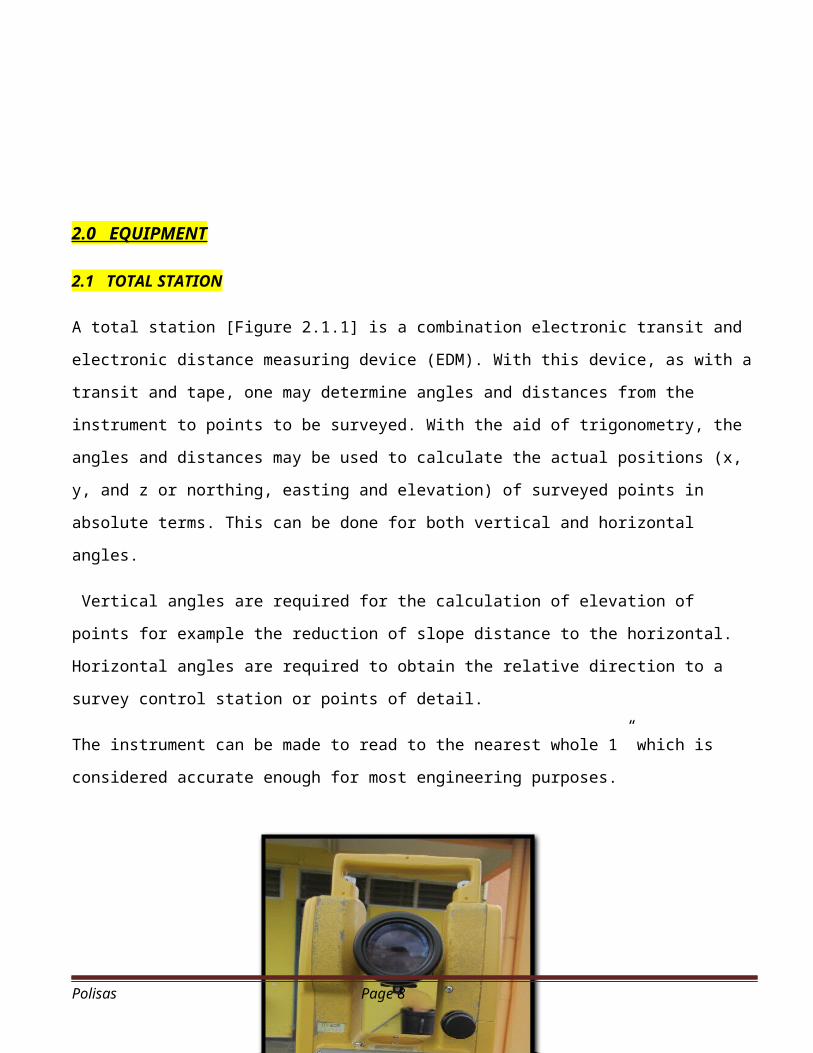
A total station [Figure 2.1.1] is a combination electronic transit and
electronic distance measuring device (EDM). With this device, as with a
transit and tape, one may determine angles and distances from the
instrument to points to be surveyed. With the aid of trigonometry, the
angles and distances may be used to calculate the actual positions (x,
y, and z or northing, easting and elevation) of surveyed points in
absolute terms. This can be done for both vertical and horizontal
angles.
Vertical angles are required for the calculation of elevation of
points for example the reduction of slope distance to the horizontal.
Horizontal angles are required to obtain the relative direction to a
survey control station or points of detail.
The instrument can be made to read to the nearest whole 1” which is
considered accurate enough for most engineering purposes.
Polisas Page 8
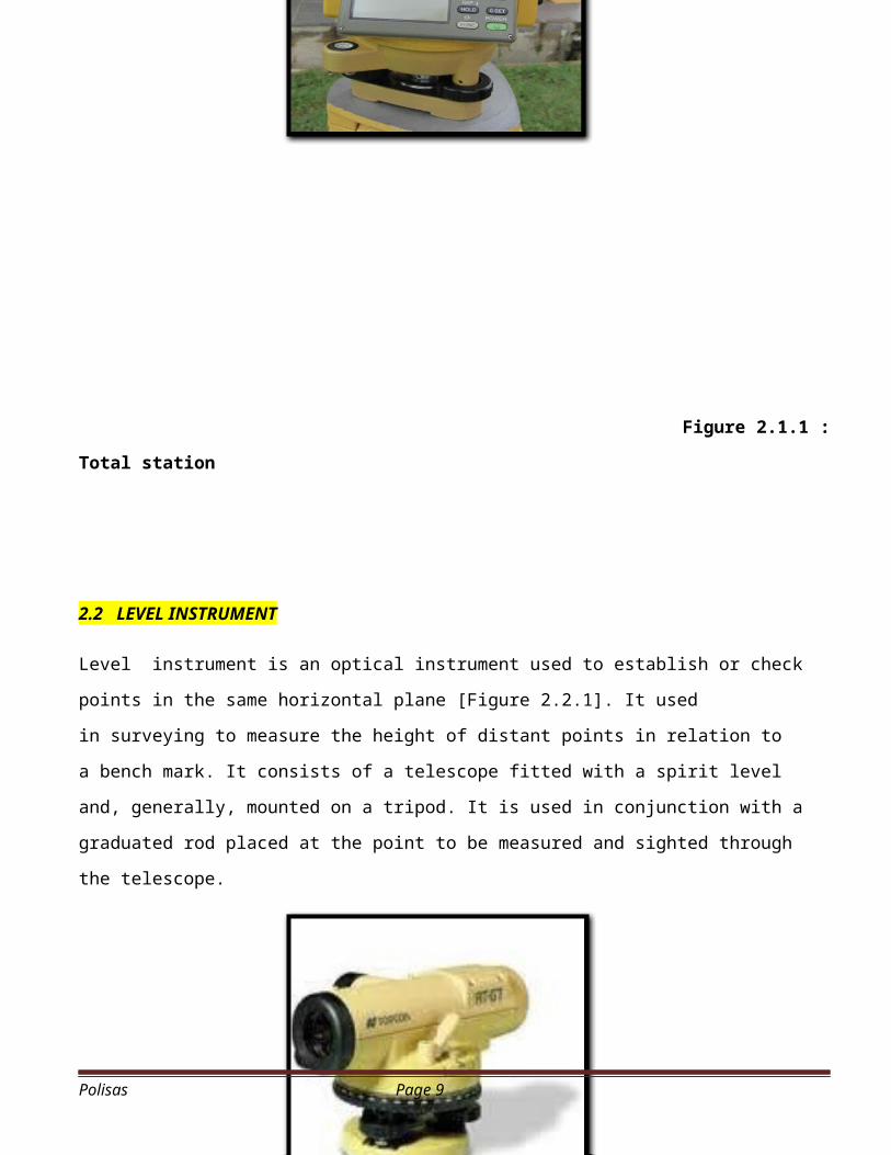
Figure 2.1.1 :
Total station
2.2 LEVEL INSTRUMENT
Level instrument is an optical instrument used to establish or check
points in the same horizontal plane [Figure 2.2.1]. It used
in surveying to measure the height of distant points in relation to
a bench mark. It consists of a telescope fitted with a spirit level
and, generally, mounted on a tripod. It is used in conjunction with a
graduated rod placed at the point to be measured and sighted through
the telescope.
Polisas Page 9
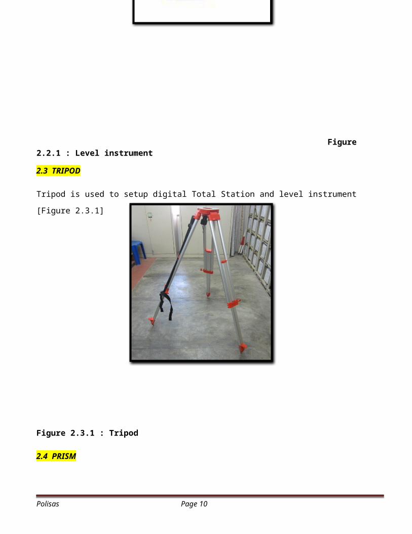
Figure 2.2.1 : Level instrument
2.3 TRIPOD
Tripod is used to setup digital Total Station and level instrument
[Figure 2.3.1]
Figure 2.3.1 : Tripod
2.4 PRISM
Polisas Page 10
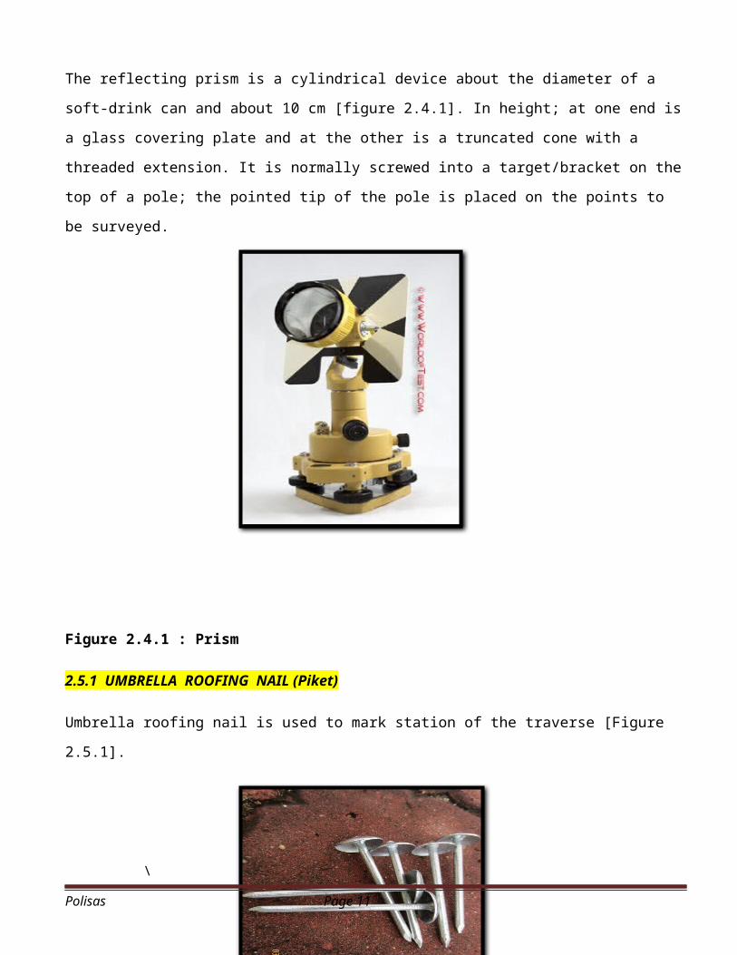
The reflecting prism is a cylindrical device about the diameter of a
soft-drink can and about 10 cm [figure 2.4.1]. In height; at one end is
a glass covering plate and at the other is a truncated cone with a
threaded extension. It is normally screwed into a target/bracket on the
top of a pole; the pointed tip of the pole is placed on the points to
be surveyed.
Figure 2.4.1 : Prism
2.5.1 UMBRELLA ROOFING NAIL (Piket)
Umbrella roofing nail is used to mark station of the traverse [Figure
2.5.1].
\
Polisas Page 11
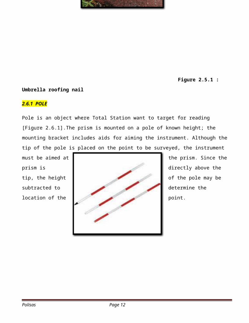
Figure 2.5.1 :
Umbrella roofing nail
2.6.1 POLE
Pole is an object where Total Station want to target for reading
[Figure 2.6.1].The prism is mounted on a pole of known height; the
mounting bracket includes aids for aiming the instrument. Although the
tip of the pole is placed on the point to be surveyed, the instrument
must be aimed at the prism. Since the
prism is directly above the
tip, the height of the pole may be
subtracted to determine the
location of the point.
Polisas Page 12
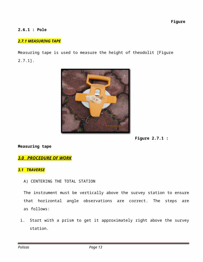
Figure
2.6.1 : Pole
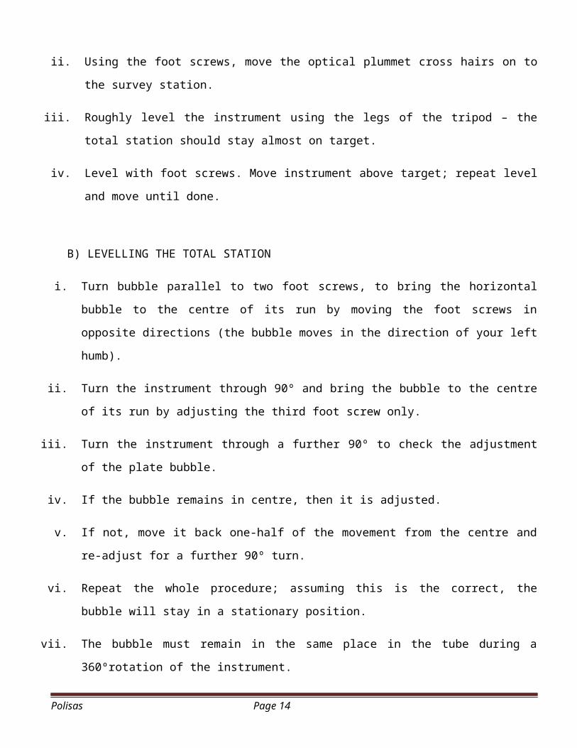
2.7.1 MEASURING TAPE
Measuring tape is used to measure the height of theodolit [Figure
2.7.1].
Figure 2.7.1 :
Measuring tape
3.0 PROCEDURE OF WORK
3.1 TRAVERSE
A) CENTERING THE TOTAL STATION
The instrument must be vertically above the survey station to ensure
that horizontal angle observations are correct. The steps are
as follows:
i. Start with a prism to get it approximately right above the survey
station.
Polisas Page 13
ii. Using the foot screws, move the optical plummet cross hairs on to
the survey station.
iii. Roughly level the instrument using the legs of the tripod – the
total station should stay almost on target.
iv. Level with foot screws. Move instrument above target; repeat level
and move until done.
B) LEVELLING THE TOTAL STATION
i. Turn bubble parallel to two foot screws, to bring the horizontal
bubble to the centre of its run by moving the foot screws in
opposite directions (the bubble moves in the direction of your left
humb).
ii. Turn the instrument through 90º and bring the bubble to the centre
of its run by adjusting the third foot screw only.
iii. Turn the instrument through a further 90º to check the adjustment
of the plate bubble.
iv. If the bubble remains in centre, then it is adjusted.
v. If not, move it back one-half of the movement from the centre and
re-adjust for a further 90º turn.
vi. Repeat the whole procedure; assuming this is the correct, the
bubble will stay in a stationary position.
vii. The bubble must remain in the same place in the tube during a
360ºrotation of the instrument.
Polisas Page 14
viii. If the stationary position of the bubble is still off the centre,
then a permanent adjustment should be made.
C) TRAVERSE FIELD WORK
Traversing is carried out with three(3) tripod, one(1)tripod is for
the instrument and the other two(2) are for the back and front
stations. A minimum of three people is required in a traversing team.
The leader of the team, setting up and reads the instrument, while
the 2nd person has the important job of recording the readings on the
booking sheet. The 3rd person has the task of moving and setting up
the prism as the traverse progresses. There are several steps which
should be followed that will lead to a smooth traverse.
i. Four picket(station) were established at the proposed site.(peg 1, peg 2, peg 3 & peg 4).
ii. The total station was plumbed over peg 2 and accurately leveled.
Prism were plumbed over peg 1&3.
iii. Set the total station to read zero and target peg 1.
iv. Distance was measured by pointed the staff at peg 1, and vertical
and horizontal angles are displayed in relation to markings on the
staff, which determines distance and elevation. The reading was
taken and entered in the field book. Distance between peg 2 and 3
also done with the same technique.
v. Record face left horizontal reading to back station(peg 1).
vi. Turn instrument and sight front station.
vii. Record face left horizontal reading to front station(peg 3).Polisas Page 15
viii. Transit the instrument to change to the face right setting.
ix. Record face right horizontal reading to front station(peg 3).
x. Turn instrument to face back station.
xi. Record face right horizontal reading to back station(peg 1).
xii. The total station was moved to peg 3. Prism were plumbed over peg
2 and 4. Peg2 was sighted on face left with total station set to
the reading taken from step 9.
xiii. Peg 4 was sighted and the horizontal angle was taken. The
instrument was set to face right and peg 4 was sighted again. Then
peg 2 was sighted and the reading was taken.
xiv. Step 2-11 was repeated on peg 4 & peg1.All readings were observed and recorded
3.2 LEVELLING
a) Survey the site for putting the picket signs.
b) Level instrument must be properly fitted and used the water coil
to determine the position of level equipment.The level is set up
at some convenient position and BS of 0.325m is taken to TBM
1(44.984m).
c) The position of the change point is at Station 3, the staff is
moved to this and a FS of 4.101m is taken.
Polisas Page 16
d) While the staff remains at station 3, the instrument is moved to
another position. A change point must be used in order to reach
station 1 & 2.
e) The staff is then moved to station 2 and intermediate sights of
1.426m are taken.
f) A BS of 1.204m is taken from the new level position to the staff
at station 1.
g) While the staff remains at station 1, the instrument is moved to
another position. The position of the change point is at Station
4, the staff is moved to this and a FS of 1.260m is taken.
h) The instrument is moved to another position and after that the
staff is moved to CP1 and readings of 0.855m (FS) are taken where
CP1 is another change point.
i) The last step is move to a position and a BS of 4.260m taken to
CP1 and a FS of 1.445m is taken to TBM 1. The final staff position
is at a TBM 1, this is most important as all levelling field work
must start at and end at a bench mark – otherwise it would be
difficult to detect errors when levelling.
j) Calculating reduced levels using the height of collimation method
and also calculating the correction and misclosure.
Polisas Page 17
3.3 DETAILING
a) Setting up the total station by putting it on the tripod stand
at station 1.
b)Focus on the surveying point using optical plummet eyepiece.
Center the surveying point by adjusting the leg of the tripod.
c)Center the bubble in the circular level and plate level by using
foot screw and tripod legs.
d)Do the temporary adjustment.
e)Record the instrument height (H.I.).
f)Set the back bearing from station 1 to station 4.
g)Loosen horizontal and vertical clamp; swing the telescope
direction roughly to the prism which the prism is being placed
vertically at each corner of the building, trees, spot height and
all the details around the station.
h)Using the slow motion screw horizontal and vertical, place to the
reflection point on the prism.
i)The telescope is pointed at the prism, and vertical and horizontal
angles are displayed in relation to markings on the prism, which
determines distance and elevation. Recorded the reading in the
form tachymetry.
Polisas Page 18
j) Record the vertical and horizontal distance in the form
tachymetry.
k) After that,remove the equipment level at any other point and
repeat step 2 to step 10.
l) The same was done at others the station( 2, 3, & 4).
3.4 SETTING OUT (Pipeline)
This operation falls into the first category of setting out. General
considerations that sewers normally follow the natural fall in the land
and are laid at gradients which induce self-cleansing velocity.
a) Horizontal control: the working drawings will show the directions
of the sewer pipes and the positions of the manholes. The line of
the sewer is normally pegged at 60m intervals using coordinate
methods of positioning from reference points or in relation to
existing detail. The direction of the line can be sighted using a
levelling instrument and pegs.
Polisas Page 19
b) Vertical control: involves the erection of sight rails some
convenient height above the invert level of the pipe.
c) Erection and use of sight rails: the sight rail uprights are
hammered firmly into the ground, usually offset from the line
rather than straddling it. Using the TBM2 (R.L 45.216) and
levelling equipment, the reduced levels of the tops of the
uprights.
d) Where the natural slope of the ground is not approximately
parallel to the proposed pipe gradient, sight rails can be used to
control the dept of excavation.
Polisas Page 20
4.0 PRACTICAL DATA
4.1 TRAVERSE
Polisas Page 21

Polisas Page 22
4.2 LEVELLING
Polisas Page 23
4.3 DETAILING
Polisas Page 24
4.4 SETTING OUT
(Pipeline)
Polisas Page 25

4.5 DRAWING
Polisas Page 26
5.0 DISCUSSION
A standard transit is basically a total station with cross-hairs for sighting a target;
the total station is attached to scales for measuring the angle of rotation of the
telescope (normally relative to north as 0 degrees) and the angle of inclination of
the telescope (relative to the horizontal as 0 degrees). After rotating the telescope to
aim at a target, one may read the angle of rotation and the angle of inclination
from a scale. The electronic transit provides a digital read-out of those angles
instead of a scale; it is both more accurate and less prone to errors arising from
interpolating between marks on the scale or from mis-recording. The readout is also
continuous; so angles can be checked at any time.
The various elements of the scheme must be correct in all three
dimensions both relatively and absolutely, that is each must be its
correct size, in its correct plan position and correct reduced level
In this session we learnt to:
a) Understand the basic concepts of Optical Distance Measurement.
b) Calculate the reduce level of point by using the tachymetry
Polisas Page 27
system.
c) Understand the procedure to implement the field work.
d) Show the steps to process the observation data and determines
the errors.
e) Describe the application of tachymetry in land surveying.
f) Describe various tacheometric methods.
g) Carry out tachymetry surveying.
h) Understand the roles of the various different types of personnel
who are involved in the setting out process.
i) Understand the aims of setting out.
j) Refer to the different types of plans that may be used in the
setting out process.
k) Appreciate the good working practices that should be undertaken
in order that the aims of setting out can be achieved.
l) Understand the procedures required to ensure that the horizontal
and vertical control requirements of setting out operations can
be met.
m) Set out design points on site by a number of methods.
n) Apply horizontal and vertical control techniques to second-stage
setting out operations.
o) Appreciate the application of laser instruments in surveying and
setting out.
6.0 CONCLUSION
Polisas Page 28
During the traverse, the horizontal angles, vertical angle and
distances are measured. Horizontal angles are used in determining
azimuths and vertical angles are used in determining the deferent in
height between stations. The distance is used in conjunction with the
horizontal and vertical angles to determine coordinates and height. For
traverse surveying of low relative accuracy, where only horizontal
angles and distances are required, the stadia method is a useful rapid
method. Tachymetry is used for :
a) Preparation of topographic map where both horizontal and vertical
distances are required to be measured;
b) Survey work in difficult terrain where direct methods of
measurements are inconvenient;
c) Reconnaissance survey for highways and railways etc;
d) Establishment of secondary control points.
There are two main aims when undertaking setting out operations:
a) The various elements of the scheme must be correct in all three
dimensions both relatively and absolutely, that is each must be
its correct size, in its correct plan position and correct reduced
level
b) Once setting out begins it must proceed quickly with little or no
delay in order that the works can proceed smoothly and the cost
can be minimised. It must always be remembered that the
contractors main commercial purpose is to make a profit –
therefore setting out needs to be done efficiently.
Polisas Page 29
7.0 REFERENCE
a)Panel Buku nota POLISAS CC201b)Arthur Bannister et al “Surveying” 7th Ed Longman 1998, chapter 11.
Polisas Page 30
Copyright © 2022 FDOKUMEN