CC103-Theodolite traverse survey
10
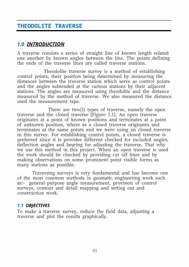
THEODOLITE TRAVERSE 1.0 INTRODUCTION A traverse consists a series of straight line of known length related one another by known angles between the line. The points defining the ends of the traverse lines are called traverse stations. Theodolite traverse survey is a method of establishing control points, their position being determined by measuring the distances between the traverse station which serve as control points and the angles subtended at the various stations by their adjacent stations. The angles are measured using theodolite and the distance measured by the method of traverse. We also measured the distance used the measurement tape. There are two(2) types of traverse, namely the open traverse and the closed traverse [Figure 1.1]. An open traverse originates at a point of known positions and terminates at a point of unknown position, where as a closed traverse originates and terminates at the same points and we were using an closed traverse in this survey. For establishing control points, a closed traverse is preferred since it is provides different checked for included angles, deflection angles and bearing for adjusting the traverse. That why we use this method in this project. When an open traverse is used the work should be checked by providing cut off lines and by making observations on some prominent point visible forms as many stations as possible. Traversing surveys is very fundamental and has become one of the most common methods in geomatic engineering work such as:- general purpose angle measurement, provision of control surveys, contour and detail mapping and setting out and construction work. 1.1 OBJECTIVES To make a traverse survey, reduce the field data, adjusting a traverse and plot the results graphically. [1]
Transcript of CC103-Theodolite traverse survey
THEODOLITE TRAVERSE
1.0 INTRODUCTIONA traverse consists a series of straight line of known length related one another by known angles between the line. The points definingthe ends of the traverse lines are called traverse stations.
Theodolite traverse survey is a method of establishing control points, their position being determined by measuring the distances between the traverse station which serve as control pointsand the angles subtended at the various stations by their adjacent stations. The angles are measured using theodolite and the distance measured by the method of traverse. We also measured the distanceused the measurement tape.
There are two(2) types of traverse, namely the open traverse and the closed traverse [Figure 1.1]. An open traverse originates at a point of known positions and terminates at a point of unknown position, where as a closed traverse originates and terminates at the same points and we were using an closed traversein this survey. For establishing control points, a closed traverse is preferred since it is provides different checked for included angles, deflection angles and bearing for adjusting the traverse. That why we use this method in this project. When an open traverse is used the work should be checked by providing cut off lines and by making observations on some prominent point visible forms as many stations as possible.
Traversing surveys is very fundamental and has become one of the most common methods in geomatic engineering work such as:- general purpose angle measurement, provision of control surveys, contour and detail mapping and setting out and construction work.
1.1 OBJECTIVESTo make a traverse survey, reduce the field data, adjusting a traverse and plot the results graphically.
[1]

Figure 1.1 : Open travers & Closed traverse
2.0 THEODOLITE PRINCIPLES AND APPLICATIONS
A theodolite is an instrument which is capable of measuring angles to the nearest whole second [Figure 2.1]. This can be done for bothvertical and horizontal angles. Vertical angles are required for the calculation of elevation of points for example the reduction of slopedistance to the horizontal.
Horizontal angles are required to obtain the relative direction to a survey control station or points of detail. Basically there are two types of modern theodolite which are in use today. These are the:
(i)Optical theodolite; and
(ii)Electronic Digital theodolite.
Both types of instrument can be made to read to the nearest whole 1 which is considered accurate enough for most engineering”purposes. With the advancement of modern electronics, most of thetheodolites made today are of the electronic digital type. But the older optical types are still being used except that it will take longertime to read the angles than with an electronic one.
The value of the angle observed however will be the same. Electronic theodolites are more versatile than the optical type. Useful features in the form of software can be added to an electronic theodolite. Thus modern instruments can be used in a variety of surveying situations.
[2]

Optical theodolite Electronic Digital theodolite Figure 2.1 : Optical theodolite & Electronic Digital theodolite
3.0 CONSTRUCTION OF A THEODOLITEAll theodolites have the same common features [Figure 3.1] which can be described as follows:
1.Tribrach
Allows the instrument to be connected to the top of a tripod and also allows the instrument to be levelled with respect to a plate bubble.
2.Horizontal Circle Compartment
This compartment is comprised of:
(i) The lower plate that carries the horizontal circle. In most instruments it is made of glass with the graduations from 0 to 360 photographicallyetched around the edge.º º
(ii) The upper plate that carries the horizontal circle indexing device and fits concentric with the lower plate. Attached to the upper plate is the plate bubble. When centered, the plate bubble ensures that the instrument axis is vertical. In modern electronic theodolites, the spirit bubble has been replaced with an electronicone. This electronic means of levelling has made initial levelling of the instrument a less time consuming task.
[3]
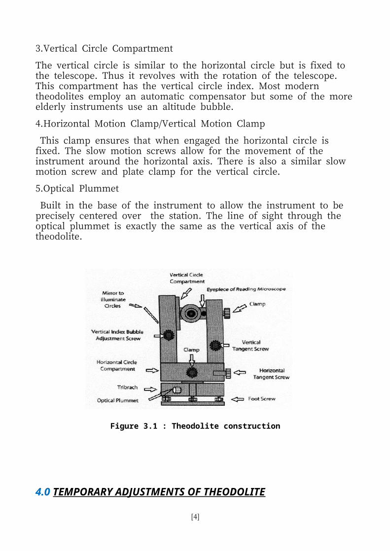
3.Vertical Circle Compartment
The vertical circle is similar to the horizontal circle but is fixed to the telescope. Thus it revolves with the rotation of the telescope. This compartment has the vertical circle index. Most modern theodolites employ an automatic compensator but some of the moreelderly instruments use an altitude bubble.
4.Horizontal Motion Clamp/Vertical Motion Clamp
This clamp ensures that when engaged the horizontal circle is fixed. The slow motion screws allow for the movement of the instrument around the horizontal axis. There is also a similar slow motion screw and plate clamp for the vertical circle.
5.Optical Plummet
Built in the base of the instrument to allow the instrument to be precisely centered over the station. The line of sight through the optical plummet is exactly the same as the vertical axis of the theodolite.
Figure 3.1 : Theodolite construction
4.0 TEMPORARY ADJUSTMENTS OF THEODOLITE
[4]

The temporary adjustments are steps that must be carried out everytime at theodolite is used. It is a procedure of setting up a theodolite that involves the following process:
a) centering;
b) leveling; and
c) removing parallax.
4.1 CENTERING THE THEODOLITE
The instrument must be vertically above the survey station to ensure that horizontal angle observations are correct. The steps are as follows:
1.Start with a plumbob to get it approximately right above the survey station [Figure 4.1].
2.Using the foot screws, move the optical plummet cross hairs on tothe survey station.
3.Roughly level the instrument using the legs of the tripod the –theodolite should stay almost on target.
4.Level with foot screws. Move instrument above target; repeat leveland move until done.
4.2 LEVELLING THE THEODOLITE
1.Turn bubble parallel to two foot screws A and B [Figure 4.2], to bring the horizontal bubble to the centre of its run by moving the foot screws in opposite directions (the bubble moves in the direction of your left humb).
2.Turn the instrument through 90 and bring the bubble to the ºcentre of its run by adjusting the third foot screw C only.
3.Turn the instrument through a further 90 to check the ºadjustment of the plate bubble.
4.If the bubble remains in centre, then it is adjusted.
5.If not, move it back one-half of the movement from the centre and re-adjust for a further 90 turn.º6.Repeat the whole procedure; assuming this is the correct, the bubble will stay in a stationary position.
7.The bubble must remain in the same place in the tube during a 360 rotation of the instrument.º8.If the stationary position of the bubble is still off the centre, thena permanent adjustment should be made.
[5]

4.3 REMOVING THE PARALLAX
Parallax is a condition happen when the image formed by the objective is not in the plane of the cross-hairs. Parallax should be eliminated in order to have accurate sighting. There are two ways to overcome or eliminate the parallax. There are by accurately focusing the cross-hairs against a light background and focusing theinstrument on a distant target or by focusing the eye-piece for distinct vision of the cross hairs.
Figure 4.1 : Centering the theodolite Figure 4.2 : Levelling the theodolite
5.0 PERMANENT ADJUSTMENTS OF THEODOLITEThese adjustments are carried out once and will not alter unless it is being roughly handled or tampered with. There are certain basic requirements for a theodolite that must be established particularly when using it. The basic requirements are as follows:
(a) The vertical axis of a theodolite should be truly vertical.
(b) The line of sight should be perpendicular to the horizontal axis.
(c) The horizontal axis should be truly horizontal.
(d) The cross hairs should be truly vertical and horizontal.
(e) The vertical circle should be at zero when the line of sight is horizontal.
For this study it is appropriate to know only the basic requirementsfor permanent adjustments. The steps in carrying out the
[6]
adjustments should be handled by the qualified person at the laboratory.
6.0 TRAVERSE FIELD WORKTraversing is carried out with one(1) tripod and two(2) wooden stands with plumbob. Tripod is for the instrument and the other two(2) wooden stands are for the back and front stations. A minimum of three people is required in a traversing team.
The leader of the team, setting up and reads the instrument, while the 2nd person has the important job of recording the readings on the booking sheet. The 3rd person has the task of moving and setting up the wooden stands with plumbob as the traverse progresses. There are several steps which should be followed that will lead to a smooth traverse [Figure 6.1].
1.Three picket(station) were established at the proposed site.(peg 1,peg 2 & peg 3).
2.The theodolite was plumbed over peg 2 and accurately leveled. Wooden stands were plumbed over peg 1&3.
3.Level and center the instrument.
4.Set the theodolite to read zero.
5.Distance was measured by collimating the center of peg 1 by measuring tape. The reading was taken and entered in the field book. Distance between peg 2 and 3 also done with the same technique.
6.Record face left horizontal reading to back station(peg 1).
7.Turn instrument and sight front station.
8.Record face left horizontal reading to front station(peg 3).
9.Transit the instrument to change to the face right setting.
10.Record face right horizontal reading to front station(peg 3).
11.Turn instrument to face back station.
12.Record face right horizontal reading to back station(peg 1).
13.The theodolite was moved to peg 3. Wooden stands were plumbed over peg 1 and 2. Peg2 was sighted on face left with theodolite set to the reading taken from step 10.
14.Peg 1 was sighted and the horizontal angle was taken. The instrument was set to face right and peg 1 was sighted again. Then peg 2 was sighted and the reading was taken.
[7]

15.Step 13-14 was repeated on peg 1.All readings were observed andrecorded.
Figure 6.1 : Field traversing
7.0 TRAVERSING ERRORSTraversing errors normally falls into three categories, i.e. centering, angular and distance. By taking precautions during the field work, itis possible to reduce their effect.
1.Centering
It is important to ensure that the theodolite instrument and targets are centered correctly over each survey station. Remember that angles and distances may be required from or to a known station. This will not be the case if the theodolite or targets are not centered correctly.
2.Angles
When clamping the instrument, apply light clamp to the vertical and horizontal locks. Hard clamping can affect the pointing of the instrument and is not necessary. Failure to eliminate parallax and poor focusing can affect accurate pointing.
Always keep the target in the center of the field of view. All movement of the theodolite should be kept as smooth as possible and all movement around the instrument should be kept to a minimum.
3.Distances
When recording these, all distances should be obtained to 3 decimalplaces and three readings should be taken and the mean calculated.
[8]

There is a possibility that that some of the errors outlined below will occur from time to time, so be aware of them. Don t ’rush and hopefully you will not forget to record any information which is required.
a)Turning the wrong screw.
b)Sighting the wrong target.
c)Using the stadia instead of the cross-hairs.
d)Forgetting to set the micrometer reading before taking a reading.
e)Misreading the circles.
f)Transposing the figures when booking the data.
8.0 DISCUSSION1.Before doing the survey, there are a few things
that must be considered. There are: All screw must be parallel to the centre line Tripod stand must be in a straight line with the
picket(station). After setting out, wooden adjustment legs and
theodolite must be in a straight line to the picket. Value from bearing must be entered correctly. Distance between one point to the others must clearly
seen. 2.When survey was taking on, there are several things
that must be clearly taking place which are: The cross hair must be clearly seen by observer. The parallax error might be occur when reading was
taken.Therefore the observer must be the same person and very sure that the reading taken was correctly.
During the changing of left face and right face, be suretahat the position of tripod did not change.
Distance between one point to another was taken correctly.
3.After field wprk was complete, proceed with analyzing data. The correction between latitude anddeparture must be placed with correct sign and value.
4.A closed traverse enables a check by plotting or
[9]

computation with a gap called the linear misclosure.
9.0 CONCLUSIONTraversing is a form of a control survey that requires the establishment of a series of stations that are linked together by the angles and distances. The angles are measured by theodolites, and the distances are measured conventionally by tapes or electronic distance measuring equipment.
A theodolite is an instrument which is capable of measuringboth vertical and horizontal angles to the nearest whole seconds.
Basically there are two types of modern theodolite i.e. the optical theodolite and electronic digital theodolite. But both have thesame common features in terms of their construction.
The theodolite system is comprised of the horizontal circle where it is perpendicular to the vertical axis and the vertical circle where it is perpendicular to the horizontal axis. Theodolites in correct adjustment have their axes and line of sight of the telescopemutually perpendicular. All three should intersect at one point.
10.0 REFERENCE1. http://www.southgeosystems.com/index.html2. http://www.geomaticsurveys.systems.com3. http://www.scribd.com/doc/38971159/Traverse-Survey4. http://www.ce.memphis.edu/1112/notes/traverse/
Surveying_traverse
[10]