Traversing the Border: Community-Based Planning and Transnational Migrants Introduction
Upload
khangminh22Category
view
0download
0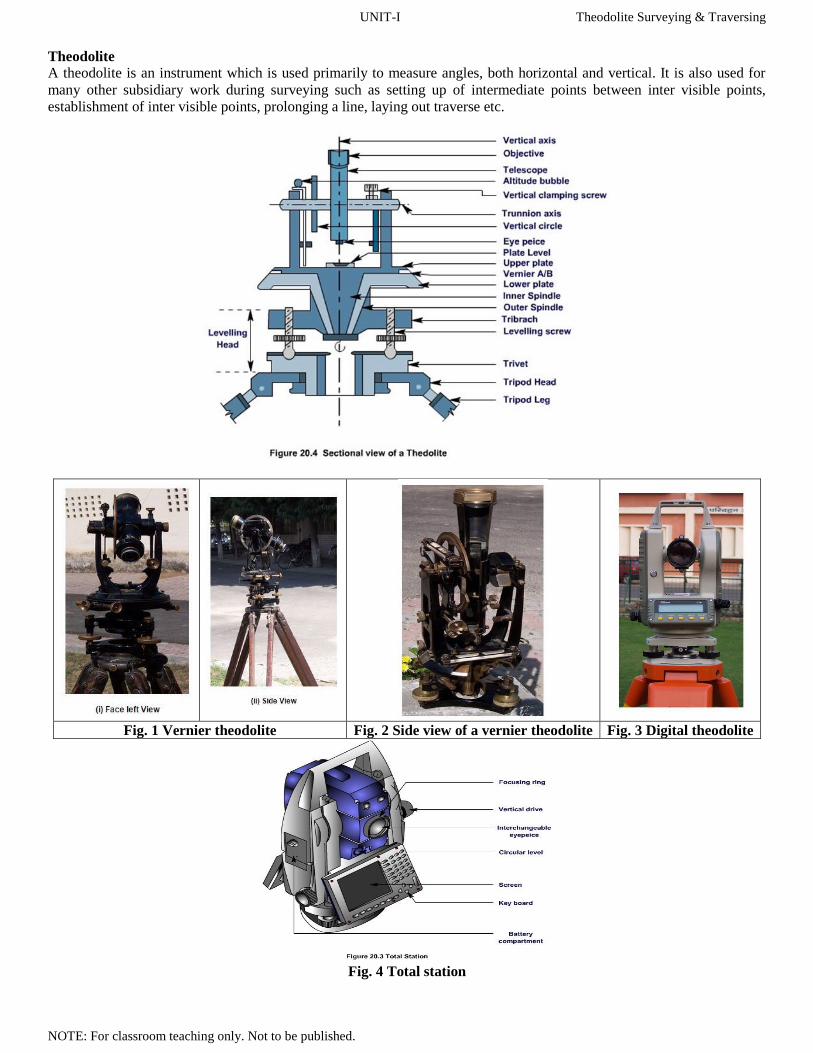
UNIT-I Theodolite Surveying & Traversing
NOTE: For classroom teaching only. Not to be published.
Theodolite
A theodolite is an instrument which is used primarily to measure angles, both horizontal and vertical. It is also used for
many other subsidiary work during surveying such as setting up of intermediate points between inter visible points,
establishment of inter visible points, prolonging a line, laying out traverse etc.
Fig. 1 Vernier theodolite Fig. 2 Side view of a vernier theodolite Fig. 3 Digital theodolite
Fig. 4 Total station

UNIT-I Theodolite Surveying & Traversing
NOTE: For classroom teaching only. Not to be published.
The Theodolites may be classified as:
(a) Transit theodolite, and (b) Non-transit theodolite
A transit theodolite is the one in which the line of sight can be reversed by revolving the telescope through 180° in the
vertical plane.
The non-transit theodolites are Y-theodolites or plain theodolites in which the telescope cannot be transited.
Vernier Theodolite
This is most commonly used. In this type of instrument, observations are taken by using the principle of vernier caliper.
The precision of this type of instrument varies in the order of 10" to 20". A typical vernier theodolite and its sectional
view in Figure 1.
Digital Theodolite: (Figure 3) This type of theodolite provides the value of observation directly in viewing panel. The
precision of this type of instrument varies in the order of 1" to 10".
Total station
This is an electronic instrument. In this instrument, all the parameters required to be observed during surveying can be
obtained (Figure 4). The value of observation gets displayed in a viewing panel. The precision of this type of instrument
varies in the order of 0.1" to 10".
Different Parts of a Vernier Theodolite
Each type of theodolite is peculiar in its construction and mode of operation. However, inherent fundamentals of all are
same. In this course, the details will be considered for vernier type theodolite which is most popular and is being widely
used. The salient parts of a vernier theodolite have been discussed below:
Levelling Head: It is the lowermost part of a theodolite. It consists of two parallel horizontal plates separated by
three levelling screws. The lower plate with a large threaded hole in its centre is called trivet or foot plate. It
provides a means to place the instrument on (tripod) stand and get it screwed. Its central aperture provides a way
for suspending a plumb bob. The upper plate of the levelling head is called the tribrach. It contains a tapered
bearing at the centre. It has three arms each carrying a levelling screw. It provides a support for the upper part of
the instrument. The principal use of levelling head is to provide a means for levelling the instrument.
Shifting Head: It consists of a pair of horizontal plates and an annular treaded ring. One of the plates is placed
below the lower plate but above the tribrach and the other below the tribrach. The annular treaded ring is placed in
between lower plate and the tribrach which is used to tighten/untighten the whole of the instrument. The shifting
head is used for exact centring of the instrument after levelling has been completed.
Lower Plate: It is a horizontal circular plate monolithically constructed with the outer spindle. A scale is
engraved at its bevelled edge with divisions in degrees and minutes increasing in clockwise direction. It provides
the main scale reading of a horizontal angle and a means to fix or unfix the whole of the instrument.
Upper Plate: It is a horizontal circular plate monolithically constructed with the inner spindle. It is fitted with two
diametrically opposite vernier scales designated as A and B. Functions of upper plates are to support a pair of
magnifiers for the verniers, a pair of plate levels, a pair of support frames for telescope and a means to fix or unfix
the upper plate of the instrument with its lower plate.
Plate Levels: A pair of level tubes is placed at right angles on the upper plate. These are used to make the vertical
axis of the instrument truly vertical i.e., for levelling of the instrument.
Standard (or a Frame): Two standards resembling the letter A are attached on the upper plate. This provides the
bearings of the pivots of the telescope allowing it to rotate on its trunion axis in vertical plane. The vernier frame
and arm of vertical circle clamp are also attached to it.
Vernier Frame: Also called T-frame or index frame, consists of a vertical leg known as clipping arm and a
horizontal bar called the index arm engraved with verniers C and D at its ends. Each of the verniers at C and D are
having two scales which increase in opposite directions. It is used as seat for altitude bubble and also provides
vernier reading for vertical angle measurement (figure 5).

UNIT-I Theodolite Surveying & Traversing
NOTE: For classroom teaching only. Not to be published.
Fig. 5 Vernier frame
Telescope: The telescope of a theodolite is identical in structure and uses, as in case of a dumpy level. But, in
theodolite, the telescope is mounted on a horizontal spindle called the horizontal axis or the trunnion axis to rotate
it also in vertical plane.
Vertical Circle: The vertical circle is attached with the trunnion axis. It is engraved with a scale reading vertical
angle in degrees and minutes. The vertical circle is divided into four quadrants each reading 0° to 90° with 0° - 0°
either along vertical or in horizontal. It provides the main scale reading for vertical angle.
Altitude Bubble: A sensitive level tube placed on vernier frame is called altitude bubble. It is used to make
horizontal axis truly horizontal.
Screws: A theodolite instrument has number of screws as its component parts. These are classified into different
types depending on their functions.
o Leveling Screws: These are present in the leveling head of a theodolite in between trivet and tribrach.
These work in threaded holes in the tribrach arms and their lower ends rest in recesses in the trivet. These
screws are used for leveling the instrument i.e., to make plate level axis truly horizontal.
o Lower plate Clamp Screw: The clamp screw attached to the lower plate of a theodolite is called lower
plate clamp screw. When it is tightened, the outer spindle gets fixed with the tribrach, and, thus, the lower
plate gets fixed in position.
o Upper plate Clamp Screw: The clamp screw attached with the upper plate of a theodolite is called upper
plate clamp screw. When it is tightened, the inner spindle gets fixed with the outer spindle and, thus, the
upper plate gets fixed in position. The manipulation of the upper plate and lower plate clamp screws
provide three conditions:
When both the upper plate clamp screw and the lower plate clamp screw are tightened, the
instrument gets fully fixed.
When the upper plate clamp screw is tightened and the lower plate clamp screw is opened, the
instrument rotates on its outer axis, there is no relative motion between the two plate and the
readings in the horizontal vernier scales do not change.
When the lower plate clamp screw is tightened, and the upper plate is opened, the instrument
rotates on the inner axis with outer axis fixed. The readings in the horizontal vernier scales
change.
o Vertical plate Clamp Screw: It is present on a frame fixed with standard and above the shaft of trunnion
axis. It is used to clamp the telescope in any plane and hence at any desired vertical angle.
o Tangent Screws: With each clamping screw, there is a tangent screw present in the instrument to provide
fine movement. The tangent screws work only after its clamping screws get tightened. Thus when the
upper clamp screw has been tightened, small movement of the upper plate can be made by the upper
tangent screw; when the lower clamp screw has been tightened, small movement of the lower plate can be
made by the lower tangent screw and similarly for vertical clamp screw.
Tripod Stand: The theodolite is mounted on a strong tripod when being used in the field. The legs of the tripod
are solid or framed. At the lower ends of the legs, pointed steel shoes are provided to get them pushed into
ground. The tripod head has male screws on which the trivet of the leveling head is screwed.
Important terms:
Horizontal Axis: The horizontal axis is the axis about which the telescope can be rotated in a vertical plane. It is also
called the trunnion axis or transverse axis.
Vertical Axis: The vertical axis is the axis about which the telescope can be rotated in a horizontal plane.
Line of Collimation: It is also known as the line of sight. It is an imaginary line joining the intersection of crosshairs of
the diaphragm to the optical centre of the object glass and its continuation.

UNIT-I Theodolite Surveying & Traversing
NOTE: For classroom teaching only. Not to be published.
from a small hook attached to the underside of the vertical axis of the theodolite.
Axis of Telescope: The axis of the telescope is the line joining the optical centre of the object glass to the centre of the
eyepiece.
Axis of Level Tube: The axis of the level or bubble tube is the straight line tangential to the longitudinal curve of the
level tube at the centre of the tube. It is also called the bubble line.
Transiting: It is also known as plunging or reversing. The process of turning the telescope over its horizontal axis
through 180° in a vertical plane, thus bringing it upside down and making it point exactly in the opposite direction.
Swinging the telescope: Turning the telescope in a horizontal plane. A swing is called right or left, according as the
telescope is rotated clockwise or anti-clockwise.
Face Left: When the vertical circle of the instrument is on the left of the observer when taking a reading.
Face Right: When the vertical circle of the instrument is on the right of the observer when taking a reading.
Centring: It means setting the theodolite exactly over a station mark. It can be done by means of suspending a plumb bob.
Telescope normal: A telescope is said to be normal or direct when the face of the vertical circle is left of the observer and
the altitude bubble is up.
Telescope inverted: A telescope is said to be inverted or reversed when the face of the vertical circle is to the right of the
observer and the altitude bubble is down.
Temporary Adjustment of Vernier Theodolite
At each station point, before taking any observation, it is required to carry out some operations in sequence. The set of
operations those are required to be done on an instrument in order to make it ready for taking observation is known as
temporary adjustment. Temporary adjustment of a vernier theodolite consists of following operations:
Setting: The setting operation consists of fixing the theodolite with the tripod stand along with approximate
levelling and centring over the station. For setting up the instrument, the tripod is placed over the station with its
legs widely spread so that the centre of the tripod head lies above the station point and its head approximately
level (by eye estimation). The instrument is then fixed with the tripod by screwing through trivet. The height of
the instrument should be such that observer can see through telescope conveniently. After this, a plumb bob is
suspended from the bottom of the instrument and it should be such that plumb bob should point near to the station
mark.
Centring: The operation involved in placing the vertical axis of the instrument exactly over the station mark is
known as centring. First, the approximate centring of the instrument is done by moving the tripod legs radially or
circumferentially as per need of the circumstances. It may be noted that due to radial movement of the legs, plumb
bob gets shifted in the direction of the movement of the leg without seriously affecting the level of the instrument.
On the other hand, when the legs are moved sideways or circumferentially, the plumb does not shift much but the
level gets affected. Sometimes, the instrument and the tripod have to be moved bodily for centring. It must be
noted that the centring and levelling of instrument is done recursively. Finally, exact centring is done by using the
shifting head of the instrument. During this, first the screw-clamping ring of the shifting head is loosened and the
upper plate of the shifting head is slid over the lower one until the plumb bob is exactly over the station mark.
After the exact centring, the screw clamping ring gets tightened.
Levelling: Levelling of an instrument is done to make the vertical axis of the instrument truly vertical. Generally,
there are three levelling screws and two plate levels are present in a theodolite instrument. Thus, levelling is being
achieved by carrying out the following steps (Figure 6):
o Step 1: Bring one of the level tubes parallel to any two of the foot screws, by rotating the upper part of the
instrument.
o Step 2: The bubble is brought to the centre of the level tube by rotating both the foot screws either inward
or outward. The bubble moves in the same direction as the left thumb. [Figure 6(a)]
o Step 3: The bubble of the other level tube is then brought to the centre of the level tube by rotating the
third foot screw either inward or outward [Figure 6(b)]. [In step 1 itself, the other plate level will be
parallel to the line joining the third foot screw and the centre of the line joining the previous two foot
screws.]
o Step 4: Repeat Step 2 and step 3 in the same quadrant till both the bubble remain central.
o Step 5: By rotating the upper part of the instrument through 180°, the level tube is brought parallel to first
two foot screws in reverse order. The bubble will remain in the centre if the instrument is in permanent
adjustment.
Otherwise, repeat the whole process starting from step1 to step5.
UNIT-I Theodolite Surveying & Traversing
NOTE: For classroom teaching only. Not to be published.
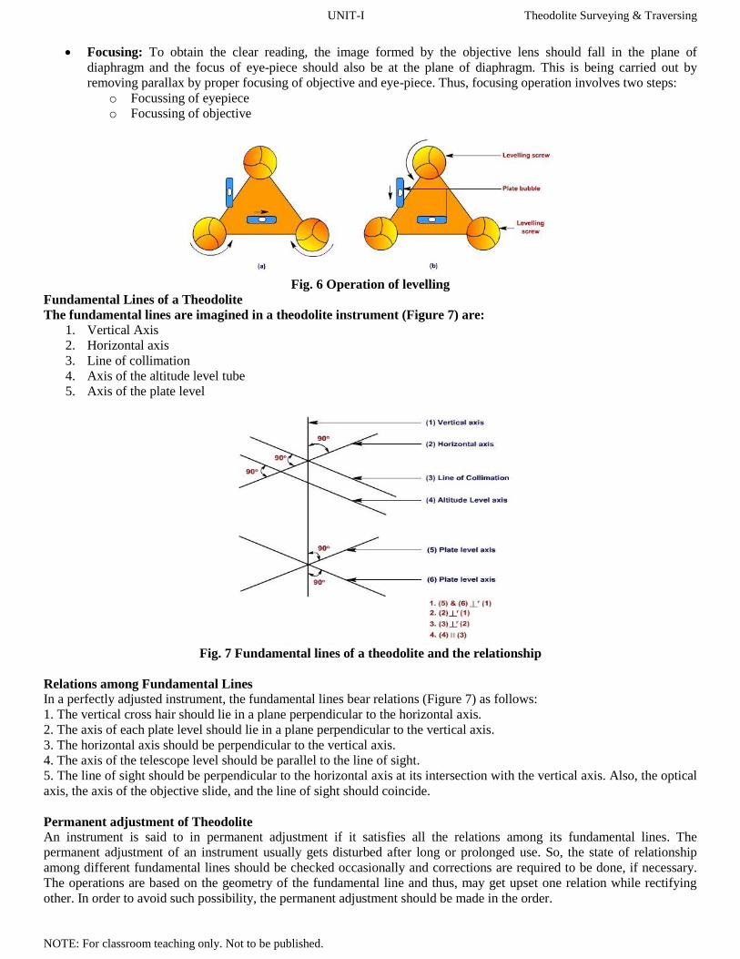
Focusing: To obtain the clear reading, the image formed by the objective lens should fall in the plane of
diaphragm and the focus of eye-piece should also be at the plane of diaphragm. This is being carried out by
removing parallax by proper focusing of objective and eye-piece. Thus, focusing operation involves two steps:
o Focussing of eyepiece
o Focussing of objective
Fig. 6 Operation of levelling
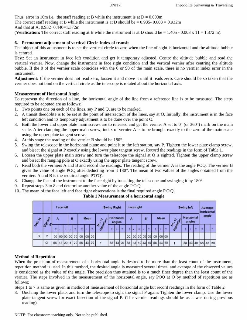
Fundamental Lines of a Theodolite
The fundamental lines are imagined in a theodolite instrument (Figure 7) are:
1. Vertical Axis
2. Horizontal axis
3. Line of collimation
4. Axis of the altitude level tube
5. Axis of the plate level
Fig. 7 Fundamental lines of a theodolite and the relationship
Relations among Fundamental Lines
In a perfectly adjusted instrument, the fundamental lines bear relations (Figure 7) as follows:
1. The vertical cross hair should lie in a plane perpendicular to the horizontal axis.
2. The axis of each plate level should lie in a plane perpendicular to the vertical axis.
3. The horizontal axis should be perpendicular to the vertical axis.
4. The axis of the telescope level should be parallel to the line of sight.
5. The line of sight should be perpendicular to the horizontal axis at its intersection with the vertical axis. Also, the optical
axis, the axis of the objective slide, and the line of sight should coincide.
Permanent adjustment of Theodolite
An instrument is said to in permanent adjustment if it satisfies all the relations among its fundamental lines. The
permanent adjustment of an instrument usually gets disturbed after long or prolonged use. So, the state of relationship
among different fundamental lines should be checked occasionally and corrections are required to be done, if necessary.
The operations are based on the geometry of the fundamental line and thus, may get upset one relation while rectifying
other. In order to avoid such possibility, the permanent adjustment should be made in the order.

UNIT-I Theodolite Surveying & Traversing
NOTE: For classroom teaching only. Not to be published.
Adjustment of vertical cross hair;
Adjustment of plate level axes;
Adjustment of line of sight;
Adjustment of horizontal axis;
Adjustment of the axis of the telescope;
Adjustment of vertical circle index.
1. Permanent adjustment of vertical cross hair of telescope of transit
The vertical cross hair should lie in a plane perpendicular to the horizontal axis.
Test: To conduct a test for this, first the instrument is to be temporarily adjusted on any station and sight a well-defined
point object at a distance of about 100m. Get the object point bisected on the vertical cross hair. Keeping both the upper
and lower plate main screw clamped, rotate the telescope in vertical direction. If the point appears to move continuously
on the vertical hair, the cross hair lies in a plane perpendicular to the horizontal axis [Figure 8(a)].
Fig. 8 Adjustment of vertical cross hair of transit
Adjustment : If the point object appears to depart from the cross hair [Figure 8(b)], loosen two adjacent capstan screws
and twist the cross-hair ring in the telescope tube, so that the point appear on the vertical cross hair. Tighten the two
screws. Carry out the test again and make adjustment, if required, until the point traverses the entire length of the hair as
the telescope is swung in vertical direction.
2. Permanent adjustment of plate level axes of transit
The axis of each plate level should lie in a plane perpendicular to the vertical axis.
Test: In order to test it, one of the level tubes is brought parallel to any two of the foot screws, by rotating the upper part
of the instrument (by clamping the lower plate main screw and opening the upper plate main screw). The bubble is
brought to the centre of the level tube by rotating foot screws. The level tube is then brought over the third foot screw
again by rotating the upper part of the instrument. The bubble is then again brought to the centre of the level tube by
rotating the third foot screw. These operations are repeated by rotating the upper part of the instrument in the same
quadrant and levelling till the bubble remains central in both the positions. Now clamp the upper plate main screw and
open the lower plate main screw and rotating the whole instrument through 180°. If the bubble in the plate level remains
in the centre, the axis of the plate level lie in a plane perpendicular to the vertical axis. Similar, test has to be carried out
for the other level tube also.
Fig. 9 Adjustment of level tube by reversion

UNIT-I Theodolite Surveying & Traversing
NOTE: For classroom teaching only. Not to be published.
Adjustment: If the bubble in any level tube gets displaced from centre, bring it back halfway by adjusting two foot
screws parallel to it (figure 9) and other half by adjusting the capstan screws fitted at one end of the plate level tube.
Rotate the whole instrument through 180° and repeat the steps of testing and adjustment if required till the bubble remains
central for all positions of the instrument as it revolved through 360° about the vertical axis.
3. Permanent adjustment of Line of Sight of transit In a properly adjusted instrument, the line of sight is perpendicular to the horizontal axis.
Test: In order to test it, first the instrument is temporarily adjusted on a station and sight a point say, X (Figure 10) about
150 m away from the station point with telescope in the direct position. Keeping main screws of both the upper and lower
plates of the instrument clamped plunge the telescope and set another point Y in the opposite direction of the transit. Open
the lower plate clamp screw and swing the instrument about the vertical axis to bring X again on the vertical cross hair.
Tighten the lower plate clamp screw and plunge the telescope as before; if Y appears on the vertical cross hair, the line of
sight is perpendicular to the horizontal axis.
Fig. 10 Adjustment of line of sight of transit
Adjustment: If Y does not appear on the vertical cross hair, set a point Z on the line of sight of the instrument. Mark
another point P, one-fourth of the distance from Y to Z, and adjust the cross-hair ring (by means of the two opposite
horizontal screws) until the line of sight passes through P. Tighten the diaphragm screws, keeping the vertical hair in that
position. Repeat the test and adjustment till X and Y points, before and after plunging, is in the same line of sight of the
telescope. The points sighted should be at about the same elevation as the transit.
4. Permanent adjustment of Horizontal Axis of telescope / transit The horizontal axis is required to be perpendicular to the vertical axis.
Test: In order to test it, first the instrument (in face left condition) is temporarily adjusted in front of high building or
structure on which a well-defined point, say X, can be marked at considerable height. Then opening the vertical clamp,
sight at the point X in such a way that the point appears on the vertical cross hair of the telescope. Now, with the
horizontal motions clamped, depress the telescope and set a point Y on or near the ground. If the horizontal axis is
perpendicular to the vertical axis, X and Y will be in the same vertical plane. Then, bisect the point X again in the face
right condition. On depression of the telescope as before, if the line of sight falls on Y, the horizontal axis is perpendicular
to the vertical axis [Figure 11(a)].
Fig. 11 Adjustment of horizontal axis of transit

UNIT-I Theodolite Surveying & Traversing
NOTE: For classroom teaching only. Not to be published.
Adjustment: On depression of the telescope (on face right condition), if the line of sight does not falls on Y, but at some
other point say Z (Figure 11), the instrument requires adjustment. Now, select another point say Q, halfway between Y
and Z and at the same level should be marked. The telescope is then focused the point in such a way using upper plate
tangent screw that Q appears on the vertical cross hair and then, elevate the telescope until the line of sight is beside X;
loosen the screws of the bearing cap, and raise or lower the adjustable end of the trunnion axis until the line of sight is
intersects X.
When the trunnion axis has been adjusted, the line of sight intersects both X and Q as the telescope is rotated about the
vertical plane about the horizontal axis.
Raising or lowering the trunnion axis may cause movement of the vertical crosshair away from the point Q. So. After each
movement of the adjusting screw, the point Q on the staff should be checked. If necessary, it should be adjusted using one
of the horizontal tangent screws.
5. Permanent adjustment of Axis of the Telescope of transit
Test: Two pegs are set at some distance (of about 60 to 90 m) on a fairly level ground. A theodolite is set up on a point
which is equidistant from the pegs and preferably, in a line with the pegs. With the line of sight set on the rod reading
established for a horizontal line, the correction is made by raising or lowering one end of the telescope level tube until the
bubble is centred. Staff readings are taken at the pegs, say the readings are a and b respectively. Then, the true difference
in elevation between the points is h = (a~b). Now, the instrument is set on the line joining the pegs near one of the pegs
but opposite to the other peg, as shown in Figure 12. Let D1 and D2 are the distances of the near and far peg from the
instrument position. Staff readings are again taken at the pegs, say the readings are c and d respectively. Then, the
apparent difference in elevation between the points is h' = (c~d). Now, if h' is found to be equal to h, the line of sight of
the level is parallel to the axis of the bubble tube. Otherwise, an adjustment of the bubble tube is required.
Adjustment
This method is known as two peg method. In this method, due account need to be taken about sign throughout the test.
Example: A transit was set up midway between two peg points 100m apart. The readings on the staff at the two pegs
were 1.650m and 1.210m respectively. The instrument was then moved, by 10 m ahead of the second peg, in line with the
two pegs. The respective staff readings were 1.405m and 0.935m. Calculate the staff readings on the two pegs to provide a
horizontal line of sight.
Solution: Let A and B be the two peg points at a distance of 100m and the instrument position be C when midway and D when 10m
from B.
While the instrument is at C,
True difference in elevation between the peg points is obtained and is given by, d = 1.650-1.210 = 0.440m (B higher than
A)
Assuming there is no error in the line of collimation of the instrument, while the instrument is at D,
If the staff reading at B i.e., 0.935 is correct. Then, the staff reading at A should be = (0.935 +0.440) m = 1.375 m (<
observed reading i.e., 1.405m)
This shows that the line of collimation of the instrument is not in adjustment and it is inclined upward.
The amount of error = 1.405 - 1.375 =0.030m in 100m
UNIT-I Theodolite Surveying & Traversing
NOTE: For classroom teaching only. Not to be published.
Thus, error in 10m i.e., the staff reading at B while the instrument is at D = 0.003m
The correct staff reading at B while the instrument is at D should be = 0.935- 0.003 = 0.932m
And that at A, 0.932+0.440=1.372m
(Verification: The correct staff reading at B while the instrument is at D should be = 1.405 - 0.003 x 11 = 1.372 m).
6. Permanent adjustment of vertical Circle Index of transit The object of this adjustment is to set the vertical circle to zero when the line of sight is horizontal and the altitude bubble
is centred.
Test: Set an instrument in face left condition and get it temporary adjusted. Centre the altitude bubble and read the
vertical vernier. Now, change the instrument in face right condition and the vertical vernier after centring the altitude
bubble. If the 0 of the vernier scale coincides with the 0 or 90 of the main scale, there is no vernier index error in the
instrument.
Adjustment: If the vernier does not read zero, loosen it and move it until it reads zero. Care should be so taken that the
vernier does not bind on the vertical circle as the telescope is rotated about the horizontal axis.
Measurement of Horizontal Angle
To represent the direction of a line, the horizontal angle of the line from a reference line is to be measured. The steps
required to be adopted are as follows:
1. Two points one on each of the lines, say P and Q, are to be marked.
2. A transit theodolite is to be set at the point of intersection of the lines, say at O. Initially, the instrument is in the face
left condition and its temporary adjustment is to be done over the point O.
3. Both the lower and upper plate main screws are to released and get the vernier A set to 0° (or 360°) mark on the main
scale. After clamping the upper main screw, index of vernier A is to be brought exactly to the zero of the main scale
using the upper plate tangent screw.
4. At this stage the reading of the vernier B should be 180°.
5. Swing the telescope in the horizontal plane and point it to the left station, say P. Tighten the lower plate clamp screw,
and bisect the signal at P exactly using the lower plate tangent screw. Record the readings in the form of Table 1.
6. Loosen the upper plate main screw and turn the telescope the signal at Q is sighted. Tighten the upper clamp screw
and bisect the ranging pole at Q exactly using the upper plate tangent screw.
7. Read both the verniers A and B and record the readings. The reading of the vernier A is the angle POQ. The vernier B
gives the value of angle POQ after deducting from it 180°. The mean of two values of the angles obtained from the
verniers A and B is the required angle P'O'Q'.
8. Change the face of the instrument to the face right by transiting the telescope and swinging it by 180°.
9. Repeat steps 3 to 8 and determine another value of the angle P'O'Q'.
10. The mean of the face left and face right observations is the final required angle P'O'Q'.
Table 1 Measurement of a horizontal angle
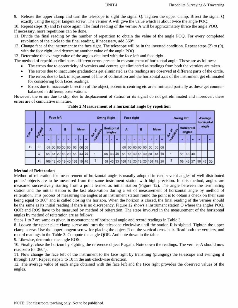
Method of Repetition When the precision of measurement of a horizontal angle is desired to be more than the least count of the instrument,
repetition method is used. In this method, the desired angle is measured several times, and average of the observed values
is considered as the value of the angle. The precision thus attained is to a much finer degree than the least count of the
vernier. The steps involved in the measurement of the horizontal angle, say POQ at O by method of repetition are as
follows:
Steps 1 to 7 is same as given in method of measurement of horizontal angle but record readings in the form of Table 2
8. Unclamp the lower plate, and turn the telescope to sight the signal P again. Tighten the lower clamp. Use the lower
plate tangent screw for exact bisection of the signal P. (The vernier readings should be as it was during previous
reading).
UNIT-I Theodolite Surveying & Traversing
NOTE: For classroom teaching only. Not to be published.
9. Release the upper clamp and turn the telescope to sight the signal Q. Tighten the upper clamp. Bisect the signal Q
exactly using the upper tangent screw. The vernier A will give the value which is about twice the angle POQ.
10. Repeat steps (8) and (9) once again. The final reading of the vernier A will be approximately thrice the angle POQ.
If necessary, more repetitions can be done.
11. Divide the final reading by the number of repetition to obtain the value of the angle POQ. For every completed
revolution of the circle to the final reading, if necessary, add 360°.
12. Change face of the instrument to the face right. The telescope will be in the inverted condition. Repeat steps (2) to (9),
with the face right, and determine another value of the angle POQ.
13. Determine the average value of the angles obtained with the face left and face right.
The method of repetition eliminates different errors present in measurement of horizontal angle. These are as follows:
The errors due to eccentricity of verniers and centres get eliminated as readings from both the verniers are taken.
The errors due to inaccurate graduations get eliminated as the readings are observed at different parts of the circle.
The errors due to lack in adjustment of line of collimation and the horizontal axis of the instrument get eliminated
for considering both faces readings.
Errors due to inaccurate bisection of the object, eccentric centring etc are eliminated partially as these get counter-
balanced in different observations.
However, the errors due to slip, due to displacement of station or its signal do not get eliminated and moreover, these
errors are of cumulative in nature.
Table 2 Measurement of a horizontal angle by repetition
Method of Reiteration
Method of reiteration for measurement of horizontal angle is usually adopted in case several angles of well distributed
points/ objects are to be measured from the same instrument station with high precision. In this method, angles are
measured successively starting from a point termed as initial station (Figure 12). The angle between the terminating
station and the initial station is the last observation during a set of measurement of horizontal angle by method of
reiteration. This process of measuring the angles at an instrument station round the point is to obtain a check on their sum
being equal to 360° and is called closing the horizon. When the horizon is closed, the final reading of the vernier should
be the same as its initial reading if there is no discrepancy. Figure 12 shows a instrument station O where the angles POQ,
QOR and ROS have to be measured by method of reiteration. The steps involved in the measurement of the horizontal
angles by method of reiteration are as follows:
Steps 1 to 7 are same as given in measurement of horizontal angle and record readings in Table 3.
8. Loosen the upper plate clamp screw and turn the telescope clockwise until the station R is sighted. Tighten the upper
clamp screw. Use the upper tangent screw for placing the object R on the vertical cross hair. Read both the verniers, and
record readings in the Table 3. Compute the angle QOR. And note down in the table.
9. Likewise, determine the angle ROS.
10. Finally, close the horizon by sighting the reference object P again. Note down the readings. The vernier A should now
read zero (or 360°).
11. Now change the face left of the instrument to the face right by transiting (plunging) the telescope and swinging it
through 180°. Repeat steps 3 to 10 in the anti-clockwise direction.
12. The average value of each angle obtained with the face left and the face right provides the observed values of the
angles.

UNIT-I Theodolite Surveying & Traversing
NOTE: For classroom teaching only. Not to be published.
Table 3 Measurement of a horizontal angle by reiteration method
Measurement of Vertical Angle A vertical angle is the angle between the inclined line of sight and the horizontal plane through the trunnion axis of the
instrument. Prior to the measurement of vertical angle, instrument is required to be leveled with reference to the altitude
level. Figure 13 shows vertical angles.
The procedure for measuring a vertical angle is as follows:
1. The temporary adjustment of the instrument is to be done on the station.
2. Then, leveling of theodolite is to be done using altitude level (the operations involved are same as leveling using plate
level).
3. Loosen the vertical circle clamp, and direct the telescope towards the object whose vertical angle is required to be
measured. Clamp the vertical circle, and bisect the point by turning the vertical tangent screw.
4. Read and record the scale with vernier C and D in Table 4
5. Change the face of the instrument and read the vertical angle again.
6. The required vertical angle is the average of the values in steps 4 and 5.
Fig. 12 Measurement of horizontal
angle by method of reiteration
Fig. 13 Vertical angles
Table 4 Measurement of vertical angles
UNIT-I Theodolite Surveying & Traversing
NOTE: For classroom teaching only. Not to be published.
Instrumental Error
Errors due to imperfections and/or non-adjustment of instrument are all systematic, and these can either be eliminated or
reduced to a negligible amount by adopting appropriate methods. The instrumental errors involved in theodolite surveying
are
• Error due to imperfect adjustment of the plate level in Horizontal angles
• Error in Vertical angles due to imperfect adjustment of the plate level
• Error due to line of Collimation not being perpendicular to horizontal axis
• Error due to Horizontal axis not being perpendicular to the Vertical axis
• Other Instrumental Errors
Personal Errors
Personal errors arise from the limitations of the human capability and experience in making temporary adjustment and in
taking observations. Personal errors usually prevalent in theodolite observations are:
• Error in setting up of the Instrument
• Error in centring of the Instrument
• Errors in setting and reading the Vernier
• Error in ranging pole location or Staff Station
• Error in Focusing (parallax)
Mistakes in reading or laying of direction of a line using Theodolite
• Reading the wrong vernier scale
• Misreading the vernier
There are two sets of vernier scales marked on a single vernier. While taking reading, use that set of figures which
increase in the same direction as the figure in the main direction.
• Reading the vernier in the wrong direction.
• Turning the wrong tangent screws
• Failing to tighten the clamp screw.
• Reading the numbers on the horizontal scale from the wrong row.
• Reading angles in the wrong direction.
• Sighting on the wrong signals or setting up over the wrong station
• Booking the wrong values
• Missing the wrong right or left in deflection angle
• Using haphazard field procedure.
Excersice:
Ex.1 Enumerate the fundamental lines of a theodolite instrument and state their relationship in a permanently adjusted
instrument.
Ex.2 Enumereate the different parts of a vernier theodolite and explain their function.
Ex.3 Differentiate between Clamp screw and Tangent screw.
Ex.4 What do you mean by temporary 'adjustment' of a theodolite ? Describe in brief the steps of temporary adjustment in
proper order.
Ex.5 Difference between:
(i) Transiting and swinging of the telescope; (ii) Face left and face right reading; (iii) Clamp screw and tangent screw of a
theodolite; (iv) Telescope normal and telescope inverted.
Ex.6 Differentiate between methods of repetition and reiteration for measurement of horizontal angles.

UNIT-I Theodolite Surveying & Traversing
NOTE: For classroom teaching only. Not to be published.
Traversing
A traverse consists of a series of straight lines connected successively at established points, along the route of a survey.
The points defining the ends of the traverse line are called traverse stations or traverse points.
Types of Traverse
Fundamentally, there are two types of traverses:
Open Traverse: An open traverse originates from a point whose position may be known or unknown but terminates to a
point whose position is not known. In this type of traverse, computational check is not possible to detect error or blunder
in distances or directions. To minimize error, repeated observations for measurements need to be taken. An open traverse
is generally used for exploratory purpose such as mine surveying.
Closed Traverse: When a traverse originates from a known position and also terminates to known position then it is
called a closed traverse. (If the origin and terminating points are the same then it is called closed-loop traverse [figure
15(a)]. This type of traverse permits an internal check on the accuracy of angular measurements, provides an indication of
the consistency of measuring distances as well as angles. But detection of systematic errors in linear measurement or
errors in the orientation of the traverse is not possible. This type of traverse is recommended for minor projects. A closed
traverse that originates from a known point and terminates to another known point [Figure 15(b)] is the most reliable. This
type of traverse henceforth called as open looped close traverse provides computational checks allowing detection of
systematic errors in both distance and direction and, therefore, preferred to all other types of traverse.
Fig. 15(a) Closed loop traverse
Fig. 15(b) Closed traverse (open loop)
Traverse Computations
Traverse surveying in the field yields observed angles or directions and length of the traverse sides. Thus, these
parameters are used in traverse computations which are performed in a plane rectangular coordinate system. The traverse
computations involve calculation of consecutive coordinates of traverse stations, checking in error of closure,
determination of the amount of closing error, adjustment of traverse by balancing of consecutive coordinates, calculation
of independent coordinates and determination of corrected distances and azimuth of sides.
Fig. 16 Departures and latitudes of traverse sides
UNIT-I Theodolite Surveying & Traversing
NOTE: For classroom teaching only. Not to be published.
Dependent Coordinates (or Consecutive Coordinates)
Dependent or Consecutive coordinates of a station is designated by its departure and latitude from its previous station as
origin. Departure of a traverse side is defined as its component perpendicular to the reference meridian and the component
of the traverse side along or parallel to the reference meridian is known as latitude. Thus, if l and q are the length and
azimuth of a traverse side, then departure and latitude of the side are given by l sin q and l cosine q respectively. The
algebraic sign of the departure and latitude of a traverse side depends on its azimuth value thus on the sign of the
trigonometric parameters associated with these. In Figure 16, the side AB has length and bearing as 442.56m and 34° 52'
respectively. Thus, its departure and latitude are 253.0m (442.56m sine 34° 52') and 363.11m (442.56 cosine 34° 52')
respectively. Similarly, the departure and latitude of the sides BC (478.23m, 112°) is 441.93m and 182.75m respectively.
Independent Coordinates
The departure and latitude of a station with reference to an origin are known as independent coordinates. The independent
coordinate of at least one of the stations with reference to the considered origin is required to be known as priori. Thus, if
the independent coordinates of any station, say i, is known to be (Xi, Yi), the independent coordinates of another station
say j, (XJ, YJ) can be determined by using the following relations:
Xj = Xi + xij ------------ (Equation 1)
Yj = Yi + yij ------------ (Equation 2)
where (xij, yij) are the departure and latitude of the side ij.
Error of Closure:
A check in the accuracy of traverse observation with length and azimuth considered together can be done by checking the
error of closure of the traverse. The error of closure considering both length and azimuth together can be done by using
consecutive coordinates of the station points of the traverse. Since, in any closed traverse, the algebraic sum of the
departure should be equal to the difference between the X coordinates of the initial and terminating stations of the
traverse. Similarly, the algebraic sum of the latitudes should be equal to the difference between the Y coordinates of the
initial and terminating stations. Thus, for a n-stations traverse.
Xn - X1 = Σ departures -------------- (Equation 3)
Yn - Y1 = Σ latitudes -------------- (Equation 4)
(X1, Y1) and (Xn, Yn) are the independent coordinates of the initial and terminating stations of the traverse.
In a closed-loop traverse, since the initial and terminating station of the traverse is the same, Eq. (3) and Eq. (4) reduces to
Σ departures = 0 -------------- (Equation 5)
Σ latitudes = 0 -------------- (Equation 6)
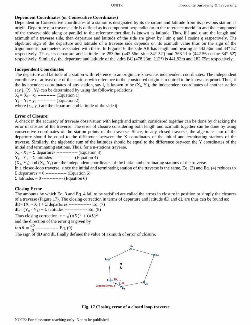
Closing Error
The amounts by which Eq. 3 and Eq. 4 fail to be satisfied are called the errors in closure in position or simply the closures
of a traverse (Figure 17). The closing correction in terms of departure and latitude dD and dL are thus can be found as:
dD= (Xn - X1) + Σ departures --------------- Eq. (7)
dL= (Yn - Y1) + Σ latitudes --------------- Eq. (8)
Thus closing correction, e = √( ) ( )
and the direction of the error q is given by
--------------- Eq, (9)
The sign of dD and dL finally defines the value of azimuth of error of closure.
Fig. 17 Closing error of a closed loop traverse
UNIT-I Theodolite Surveying & Traversing
NOTE: For classroom teaching only. Not to be published.
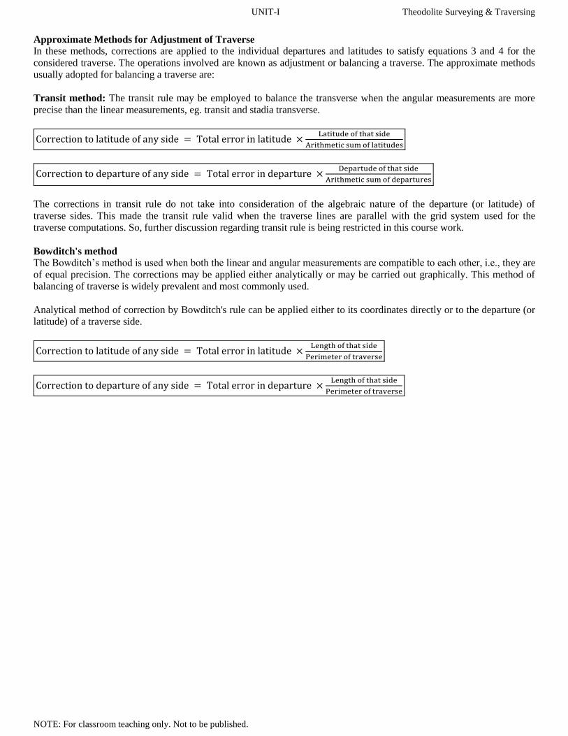
Approximate Methods for Adjustment of Traverse
In these methods, corrections are applied to the individual departures and latitudes to satisfy equations 3 and 4 for the
considered traverse. The operations involved are known as adjustment or balancing a traverse. The approximate methods
usually adopted for balancing a traverse are:
Transit method: The transit rule may be employed to balance the transverse when the angular measurements are more
precise than the linear measurements, eg. transit and stadia transverse.
The corrections in transit rule do not take into consideration of the algebraic nature of the departure (or latitude) of
traverse sides. This made the transit rule valid when the traverse lines are parallel with the grid system used for the
traverse computations. So, further discussion regarding transit rule is being restricted in this course work.
Bowditch's method
The Bowditch’s method is used when both the linear and angular measurements are compatible to each other, i.e., they are
of equal precision. The corrections may be applied either analytically or may be carried out graphically. This method of
balancing of traverse is widely prevalent and most commonly used.
Analytical method of correction by Bowditch's rule can be applied either to its coordinates directly or to the departure (or
latitude) of a traverse side.
Copyright © 2022 FDOKUMEN