Lincoln 4-H Surveying Club - Members Problems
27
University of Nebraska - Lincoln University of Nebraska - Lincoln DigitalCommons@University of Nebraska - Lincoln DigitalCommons@University of Nebraska - Lincoln Nebraska 4-H Clubs: Historical Materials and Publications 4-H Youth Development 1940 4-H Surveying Club - Members Problems : Extension Circular 4-H Surveying Club - Members Problems : Extension Circular 7-31-2 1940 7-31-2 1940 Follow this and additional works at: https://digitalcommons.unl.edu/a4hhistory Part of the Service Learning Commons "4-H Surveying Club - Members Problems : Extension Circular 7-31-2 1940" (1940). Nebraska 4-H Clubs: Historical Materials and Publications. 176. https://digitalcommons.unl.edu/a4hhistory/176 This Article is brought to you for free and open access by the 4-H Youth Development at DigitalCommons@University of Nebraska - Lincoln. It has been accepted for inclusion in Nebraska 4-H Clubs: Historical Materials and Publications by an authorized administrator of DigitalCommons@University of Nebraska - Lincoln.
-
Upload
khangminh22 -
Category
Documents
-
view
4 -
download
0
Transcript of Lincoln 4-H Surveying Club - Members Problems

University of Nebraska - Lincoln University of Nebraska - Lincoln
DigitalCommons@University of Nebraska - Lincoln DigitalCommons@University of Nebraska - Lincoln
Nebraska 4-H Clubs: Historical Materials and Publications 4-H Youth Development
1940
4-H Surveying Club - Members Problems : Extension Circular 4-H Surveying Club - Members Problems : Extension Circular
7-31-2 1940 7-31-2 1940
Follow this and additional works at: https://digitalcommons.unl.edu/a4hhistory
Part of the Service Learning Commons
"4-H Surveying Club - Members Problems : Extension Circular 7-31-2 1940" (1940). Nebraska 4-H Clubs: Historical Materials and Publications. 176. https://digitalcommons.unl.edu/a4hhistory/176
This Article is brought to you for free and open access by the 4-H Youth Development at DigitalCommons@University of Nebraska - Lincoln. It has been accepted for inclusion in Nebraska 4-H Clubs: Historical Materials and Publications by an authorized administrator of DigitalCommons@University of Nebraska - Lincoln.

\
*v
oli
Revised1940
U. of F
NebraskaCOOPERATIVE EXTENSION WSK
IN AGRICULTURE AND HOME ECONOMICSAgr. College & U. S. Dept of Agr. Cooperating
W, H. Brokaw, Director, Lincoln
Ext. Cir .7-31-2
i 1
iMEMBERS PROBLEMS
Pi£vr*]g»]bkiai
10 1970
COLLEGE OF AGRICULTURELIBRARY
'

-3-
Problem .1 .'. .•;-."•'. . ,;
PACING EXERCISE . .. ,
Distances are very frequently judged "by stepping them off. Unless thelength of the step or pace is very definitely known, the estimated figure for thedistance may vary as much as ten percent, which, is too great an error for even arough guess. In this problem, you will work out the average length of your pace.I1 his information will "be very useful to you in stepping off a field, determiningthe length of a corn row, and in many other places where you want to know thedistance.
A pace is the distance from the toe of one foot to the toe of the otherfoot and taken when a step is made. This distance is taken in the direction oftravel .
.TOOLS Al'ID SUPPLIES P
1. One hundred foot steel tape.
2. Two stakes at least 4 feet long. Two lath may be used.
3. Kotebook and pencil.
OUTLIH3 OF WORK(
1. Lay off a measured distance of 300 feet using the steel tape. Placea 4-foot stake at each end of this course.
2. Using your natural pace, step off the length of the 300 foot distance.
3. Record in your notebook the number of paces you took to cover thedistance.
4. Repeat your pacing exercise until the course has been covered at leastsix times.
I 5. Add up the results of the six or more trials and divide the numberof trials made to get the average number of paces required to coverthe distance.
*6. Divide 300 feet, the length of the course, by the average number of
paces required to step off the distance to determine the length ofyour natural pace in feet.
7. Transfer the results obtained from your notebook to the work sheetat the end of the problem.
10548mh

SAMPLE COPY OP NOTES
PACING EXESCISE
Length of Course- ------------------------ 300 feet.
TJn n _ __ „.__ _ _ _ _ ___ _-t 11?J.11J . _L ™ '" ..... ° ........ - . . — ...... iJ_O»
it i! r> _______ __ ..... .__ _.___._. .__.__ _____ :_ n 7 'n tt" " "" ' "~ ~ — - . — •- - — - ' ""*
it it -2- __ .„_ ..... „_ _ _ . in p P; uU ....... " " """ "'" "" " ~~ ' """ ..... -..—.- .. - — .— - ..... J_ X <O • c-1
! ! » / „ , _ _ _._ _ -i -i p n M%C " — '™ ' "" ™" "" "~ ™" ™~ *"* ~ ~ "" ~" - - ~ - J_J»(,y»\
it if 5 ---------------------------- _ --------------- 112.7 n
n n p. _____ . ____ ,. ._ _ _ .___ „ i n c it^j . .„., ,„ ,. „ „ ._ ~ ™. ™ . .... - -,, ........ .... , . . , . , „„ .. JL 4. »*f * *-*
II II 7 1 1 p K !!f . — . . . . ,™ .. ... ... . .,. ..... .„ ---- ,., .._ „,. ..,.., ------ , ..., ™, „ „ .-, ..„ ------ , ,- ,_ X J-O » O
n " 8 -------------------------------------------- 113.0 »
" " Q - - 1 1 p n 1!-j — - — ™ . ----- ~ . ^^ ~ ~. .......... ~ ....... j_ JLfj • w
» ii. i A __ _ _ _ _ n a" V "iJL w • " ..... " ~" ' ....... ' — " ~ ""' " ~" "" "" "" '""" -" - * ' — •— •-" ™ ' " • •'- • "~ • - • - X i.O • O ITOTAL 1123.5 »
AVEPiAGE 112.35 "
Average Length of Pace 300 = 2.56 feet" " " 112.35
In the above ta"ble, the number of steps required to cover the course eachtime has "been recorded to the nearest one-tenth of a, step. You will find as youstep off the distance that you seldom end up with a full step. The length of thelast pace is estimated to the nearest one-tenth.
10548mh
-5-
(
Late
PROBLEM I .
WORK SHEET - GLOB MEMBER'S COPY '.'"
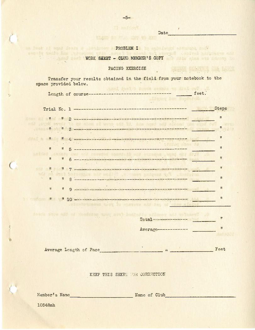
PACING EXERCISE
Transfer your results obtained in the field, from your notebook to thespace provided "below.
4Jettg wi 01 course - •-• ~ JL ee o .
i "1 T\Tn "1 - .-__
II II p
M ' It X ~ '• - - - •,._-——_- . _
I' H A . ___
II II K . •______.„-.
II II A
II II 7 _. . . ._____„_ _
H II ft , .. -_ .,
ii it q .,..„.
ii ii i n _ -
fTl* 4-QT
•erage Length of Pace =
•Steps-
it
n
11
11
1!
II
II
It
11
tl
1!
Feet
KEEP THIS SHEEt '.'OH CORRECTION
Member* s llame Hame of Club
10548mh

-6- ••
Problem II
USE OF TH3 TA.73 OR CHAIN
When accurate knowledge of distances is reouired, a steel tape is used asthe measuring device. Surveys for deeds of farms, city property, and other piecesof ground are made with the use of a steel tape, usually 100 feet long.
TOOLS AID SUPPLIES HEEDED
1. Hundred foot steel tape. . : • ' :...... f.-'. ,. -..
2. Two lath or stakes about 4 feet long.
3. Hotebook and pencil.
OUTLINE OJ WQBK ... . . . . . . . . .
. ...UoteJ- This problem is easiest worked out with two or three boys in eachcrew. Two boys may handle the tape and if the crew is made up of three boys, thethird may. .carry .the notebook and record the measurements as the work'progresses.
. .1, Designate two points approximately 1,000 feet-apart and place a lathat each point.
2. With the tape, measure the distance between the two stakes, taking.,. - care to follow as straight a line as possible.
. 5.. Record this measurement to the nearest one-tenth of a foot in thenotebook. For keeping recorc.s, follow the suggested form on thework sheet at the end of the problem.
.4... . Repeat the measuring exercise, at least four times.
5. . Add the results of the four or more trials and divide by the number oftrials made to get the average of your measurements.
6. Transfer the results obtained from your notebook to the work sheetbefore the next meeting.
10548inh
NOTES FOE STUDY" • - '?>
MEASURING WITH THE M&IHEMS' TAPE '
Measuring is done with all sorts of devices such as 100' tapes, 6P1 chainsand calibrated wires. Tapes are ordinarily calibrated in feet and the standard .surveyor's tapes are 100', 200', and 500' in length. The 66' chain has one advantage,and that is that the length of a field in chains may "be multiplied "by the width inchains and the answer is directly in acres after one place is marked off in theresulting figure. Thus, & field 20 chains long by 20 chains wide would contain40 acres. (20 x 20 =400 square chains = 40 acres.)
Anyone using the 100' tape should learn how to do up a tape properly, howto throw it into a double circle and also how to let it'out again for measuringpurposes. A great deal of time is lost in straightening out snarled tapes unlessthis process is learned. The process scarcely can be described in words and mustbe learned by demonstration.
Chaining Pins. When using a 100' tape, the surveyor ordinarily useseleven chaining pins made from 3/16" iron and from 14" to 18" long. The top isbent into a ring for convenience in carrying. Ordinarily, a-red rag is tied throughthe ring to permit the back chairman to find the pin.
For quick and effective measuring work, two operators are required whenusing a chain or tape-. The rear chainman takes one pin and the front chairman ten.•The chain is stretched up in the proper direction and pulled tight. The rearchainman calls "stick11 as soon as he has the end of the 'tape even with the back pin.The front chainman sticks the pin and calls "stuck". The rear chainman should thendrop the chain and allow it to drag, or at least carry the end without tension inthe tape. The distance measured at any time will be the number of loose pins thatthe rear chainman has in his hand.
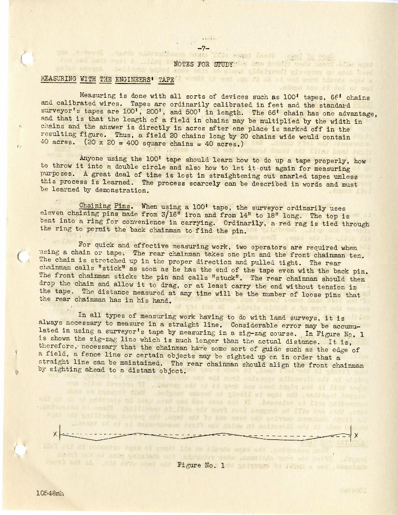
In all types of measuring work having to do with land surveys, it isalways necessary to measure in a straight line. Considerable error may be accumu-lated in using a surveyor's tape by measuring in a zig-zag course. In Figure No. 1is shown the zig-zag line which is much longer than the actual distance. It is,therefore,-necessary that the chainman have some sort of guide such as the edge ofa field, a fence line or certain objects may be sighted up on in order that astraight line can be maintained. The rear chairman should align the front chainmanby sighting ahead to a distant object.
Figure No. 1
10548mh

-8-
Care of Tape. Steel tapes will stand, considerable abuse. However, anytape will break when kinked and subjected to a slight pull. A tape that has not"been done up properly invariably tends to kink when being uncoiled. Anyone usinga tape should know how to do it up, how to throw it in a double circle and alsohow to let it out again, . ." J : :
DOIHC- 13? THE TAPE • .-, ..,.,, .To dp up a tape, grasp it in both hands in such a manner that both thumbs
extend forward. Place the thumb of the left hand on the zero mark and allow thetape to slip through 'the right hand until the-5;foot mark is reached. Move the '.-•"right hand straight forward and place the 5.foot mark on top of the zero mark•mderneath the left thumb. Let more of the tape pass through the fingers of theright hand until the thumb touches the 10 foot mark. Place the 10 foot mark overthe 5 .foot graduation and repeat the'operations until all of the tape has been doneup in coils each 5 feet long. If taken up correctly,, the coils in the tape will . .assume the form of a figure "8". Care should be taken that none of the coils arepermitted to drop qr change from the position in which they were placed under theleft thumb. ''.' ' • • ,." .'.'" : ' ' '>';-.
When all of the tape has been taken up in the manner just described, it •is necessary to securely tie both ends with the rawhide thongs with which each endof the tape is provided. First fasten the end of the tape that is on the innerside of the coil., Carefully and securely wrap the-thong six.or eight times, aroundall coils of the. tape. Then make an opening between any two of the., coils;:~put- •-- "••••;•the loose end of the thong thro'ugh this opening and pull it up tight. How follow. > • • • • - 'the same procedure with the thong on the other end of- the tape... . . . .
. . .Grasp the tape tightly in both hands at. or .near .the center..of the figure
"8". Extend the right hand straight forward and pull the left hand back along theleft side of the body" as 'far as the c'oils of the tape will permit. Hold the righthand extended and rigid," Turn the left wrist in such a way that .the little fingerof the left hand comes inward and upward. Without undue strain the..coils willassume the form of a double circle. Do not try to forcibly twist the coils. Diffi-culties will be encountered if the various coils of the.tape have not been tiedcarefully and securely in the positions in which they were respectively done up.
UNCOILING; THE TAPE ; " . . ' . .A.tape that, has been properly done up is easily uncoiled. First the ;
coils should be brought back into the form of a figure "8". Next the thongs areuntied, talcing care that each coll remains in its original position. Holding thetape firmly in the left hand, in such a way that the loose end of the upper coilpoints in the direction opposite from the one which the person Is facing, take theupper coil in the right hand and drop it to the ground. If several coils aredropped together, the tape is likely to become tangled. Walk forward as eachsucceeding coil is released. If the zero end has been used in starting to do up thetape, this end will be dropped last from the coil in uncoiling. Since in measuring,the front chairman carries the zero end of the tape, the person uncoiling the tapeshould walk in the direction in which the first measurement is to be taken.
HANDLING THE TAPEWhen measuring, the tape should at all times be kept extended in its full
length. Often the rear chainman, when returning the chaining pins to the frontchainman, has a habit of carrying the rear end of the tape with him. As the front
10548mh

chainman again proceeds forward the double tape often forms a loop or kink. Thishat it is the cause of "broken tapes.
A tape can "be taken, for short distances, from field to field or fromfarm to farm "by simply dragging it along. Dragging the tape on hard and gravellysurfaces, however, will cause the "babbitt graduations to wear off.
The driving of vehicles over tapes should "be guarded against.- A pneumatictire may no't damage a tape when the tape lies flat on smooth ground. Hard-tiredvehicles driven'over a tape will leave a distinct bend, causing a weak spot whichoften* breaks under a slight pull. "
;
Steel tapes rust easily and when not in use should be kept in a dry place.If the tape is damp at the end of a-day's measuring,, wipe it dry, moisten a clothwith a thin .oil' and run the "tape through this cloth. Whenever the tape is to beput away for a considerable length of time,' a light application of oil is advisable.
10548mh
i
t

-10--
• ''' Problem III-, ; „ > : .' - -
MEASURING AND COMPUTING HELD'AREAS(Regularly Shaped) •
Perhaps t-he' most useful''application of surveying to the farm is that ofmeasuring land. To determine the area of a field, it is necessary to measure twoor more of'its sides. Several fields may be measured .Taut -each boy is required tomake a sketch and the'necessary computations for one field which he measured orhelped measure and record his results as suggested on the work sheet at the end ofthis problem. • .
• "/.'','• By far the greatest proportion of all fields' in Nebraska are rectangles.This Is due to the system of' rectangular land surveys insitituted in middle-western .states. In the notes for study, a number of the more comiue-n shaped fields'areshown together with formulas for computing the areas o f such fields. .• " - '.
TOOLS AND SUPPLIES NEEDED t.
1. One hundred foot steel tape.
2. Eleven (ll) chaining pins (?/16" rod iron and from 14" to 18" long).
3. Notebook, small ruler, and pencil.
OUTLINE OP WORK
Note:- The problem is easiest worked out with two or three boys in each /crew. Two boys are necessary to handle the tape and the third nay record themeasurements in the notebook.
1. After the field to be measured has been decided upon, make use ofthe study notes to determine what measurements are necessary to obtainthe area of the field.
2. Make the necessary measurements, using fence lines as the boundariesof the field. Do not measure sides that do not contribute to solvingthe problem.
3. Record to the nearest foot, all measurements as they are being made.
4. Repeat the measurements, giving each one of the members in the partya different job.
5. Make a sketch of the field in the space provided on the work sheetat the end of this lesson showing the measurements which were made.
6. Set up the ecuation and compute the area of the field.
10548inh
!

-'.; i-
NOTES FOR STUDY
Following will be found a number of the most commonly shaped fields withthe essential measurements indicated. In the right hand column is the formula forcomputing the area.
Ft ELD SHAPES FORMULA FOR COMPUTING THE AREA
A
L
r A + C x B = AreaB 2 ' ' ,
Figure 2
ong narrow rectangles measure sidesA, C and B. • '•-' •"
A
D
A + C ^ B + D ^ AT,pn
3 , 2C & . ; - . <
B: Figure S
Square fields or those nearly square,sides A, B, C and D should be^measured.
D
B
Figure 4
Measure sides A, B, C and D.
A +__C x B + D o Area2 2
A
D
B
C
Figure 5Measure sides A, E, C and D.
I0548mh
s
A
FIELDSHAPES
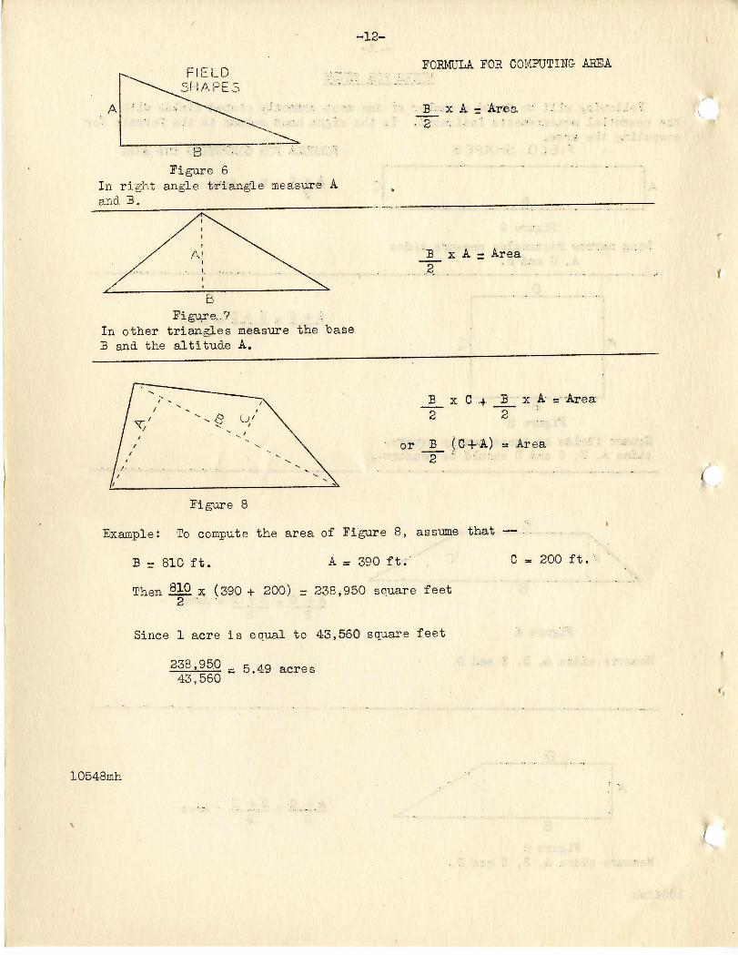
> • • • : B ' ;--:>; ' • .; - ; • . " •Figure 6
In right angle triangle measure Aand B.
D
In other triangles measure the ~ba.seB and the altitude A.
FORMULA FOR COMPUTING AREA
B-'- x A - Ar:ea •' -'8 -. '.' ' ' ..• ;... ,
'B x A = Area2 ' '
E x C 4. B2 2
x A ="Area
or _B_ (04-A) = Area2 '" ' '-
Figure 8
Example: To compute the area of Figure 8, assume that —
B - 810 ft. A = 390 ft.' C
Then .§i£ x (390+ 200) - 238,950 square feetd
Since 1 acre is equal to 43,560 square feet
200 ft,
i
10548mh

Date
PROBLEM III
WORK SHEET —•-- CLUB MEMBER1 S.. COPY.-; , MEASURING AND COMPUTING- FIELD AREAS
1. In the space "below, make a sketch of the field that has been measured.
2. Set up the equation for computing the area of the field.
'
KEEP THIS SHEET FOR CORRECTION
Member's Name / Name of Club
10548mh

Problem IV
MEASURING AND COMPUTING .FIELD AREAS(Irregularly Shaped)
This problem is a continuation .of -the preceding one in which the measure-ments of the more regularly shaped fields were discussed and studied. At thistime, some attention should "be given to irregularly shaped fields. Many fields-•re bordered by rivers, creeks, and gullies, while others have gullies and otherunproductive areas extending into or running through them. A few irregularlyshaped fields, together with formulas for computing areas, are given in the notesfor study.
Several fields may be measured, but each boy is required to make thesketch and the necessary computations for one field which he measured or helpedmeasure, and record his results as suggested on the work sheet at the end of thisproblem*
TOOLS AND SUPPLIES NEEDED
1. One hundred foot steel tape.
2. Eleven (ll) chaining pins (3/16" iron, 14" to 18" long).
3. A number of stakes or lath.
4. Notebook, small ruler, pencil.
Note:- It is advisable that the work in the field be done by crews oftwo or three boys.
1. After the field to be measured has been decided upon, study the fieldand determine what measurements should be taken to compute its area.
2, Make the measurements required, using fence lines and edges ofcultivated land along gullies or creeks as boundaries.
2. Record to the nearest foot all measurements as they are being made.
4. Repeat the measurements, giving each one of the members in the crewa different job.
5. On the work sheet at the end of the lesson, make a sketch of thefield measured, indicate what measurements have been ma5.e, set upthe equation, and compute the area.
10548mh
-15-
HOTES FOH STUDY ' '
Notes for Study.Since every irregularly shaped field Is actually broken up into regular-
ly shaped areas before the total area of such a field can "be determined, it isdeemed advisable .t-o review the study notes under Problem III*
Below are given a number of irregularly shaped fields. Suggestions asto the proper procedure in measuring and computing the area are given with eachexample.
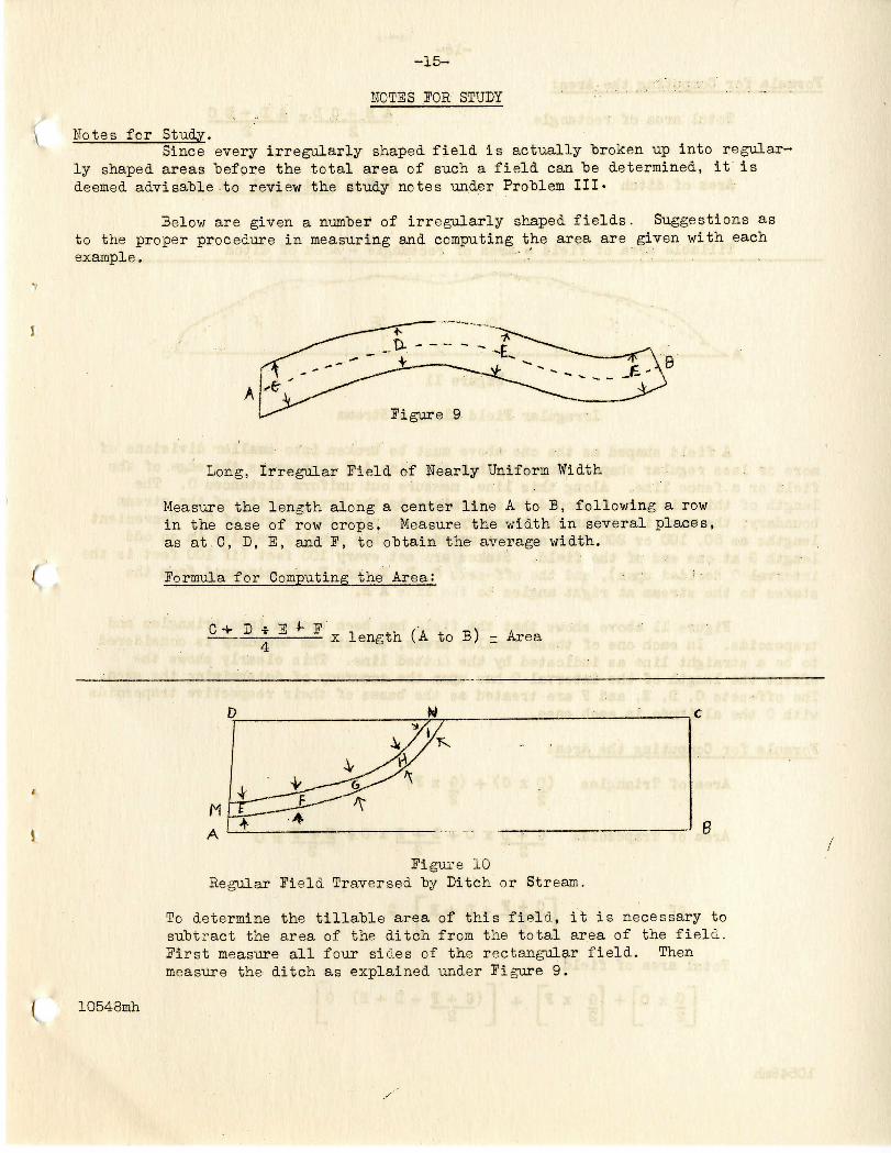
Figure 9
'
Long, Irregular Field of Nearly Uniform Width
Measure the length along a center line A to B, following a rowin the case of row crops. Measure the width in several places,as at.C, D, E, and F, to obtain the average width.
Formula for Computing the Area: t ;"
C-V D * E -f- F"•x length (A to B) - Area
D
I 10548mh
Figure 10Regular Field Traversed by Ditch or Stream.
To determine the tillable area of this field, it is necessary tosubtract the area of the ditch from the total area of the field.First measure all four sides of the rectangular field. Thenmeasure the ditch as explained under Figure 9.

-16-
Formula for Computing the Area;
Total area of rectangle A.B + C DT A D +.B C
Area of ditch M N x (E -4-F'-k &. +H•5.
Tillable area, of field.- Area of rectangle .- Ar,ea of ditch
' . Figure 11 .: . . '. ' ;•'•
•Irregular Field Along a Stream • . ' •
A field shaped as the one above must "be "broken into smaller divisions ofmore or less regular shape. Suppose that the line A B represents the edge of thefield or a fence line. Along this line, measure .out; uniform distances 0. Thelength of this distance 0 should "be determined by the irregularity of the streamboundary; the more irregular the boundary,- the shorter the length of 0. Convenientlengths as 50, 100. or 200 feet are recommended. This usually- results in an oddlength G at one end of the field. Stakes are set every 100 feet (if 100 feet is theinterval 0 decided upon), and the off-sets C, D, E, and F are measured from thestakes to the stream at right angles to tlie -line A B. :
Figure 11 above shows that the field has been broken into, triangles andtrapezoids. In each one of these smaller areas, the stream boundary is consideredto be a straight line as indicated by the dotted line. This clearly shows theeffect the length of the interval 0 has upon the accuracy of determining the area.The off-sets C, D, 1, and F are treated as the bases of their respective trapezoidswith 0 the altitude in each case.
Formula for Computing the Area;
Area of Triangles (0 x C) •+- (& x I1} .2 2 < • •
Area of Trapezoids C_ x 0 -t- D +- E
or
Total area of field
0 x Cp
G x F~]2 !
D -I- E
;C_-t-jF2
D H- E) 0t
10548mh

17-
Example:
Assuming the following lengths:
0 = 100" G - 80' • C = 60' .D = 72'
Then
180L
x 6 x 70 -t
E - 75' J = 70'
75 100
50 x 60 4- 40 x 70 + 212 x 100
3,000 -I- 2800 -+-21,200 = 27,000 square feet
<
(
i O O
6
Figure 12
Irregular Field Along a Stream
By carefully analyzing the shape of the field shown above, it becomesapparent that much time can be saved if the trapezoid A, B, G, D is measured first,The line G D can then be used as a base from which off-sets G, E, I, etc. can betaken. Measure the trapezoid as shown in Figure 5, Problem III. For the rest ofthe field, follow the discussion on Figure 11, using D C as the base line.
Fo r mul a for Co input i ng t he Ar e a
Area of trapezoid
A B -i D C x 3 C + D E2 " " 2
Area of irregular portion of field
TG 4- M° xGJ. , » x l l 4LS j p -c y
Prepared by Aldei-t Molenaar.10548mh
•f H + I + J + K -4- I | 0_J !
Approved "by the Dept, of Agr.

-18-
Dat e • '
PROBLEM IV
WORK SHEET - - CLUB MEMBER'1 S COPY
Measuring and Computing Field Areas
1. In the space "below, make a neat sketch of the field that ha? "been measured.
!. Set up the equation and compute the area of the field.
KEEP THIS SHS1T POR CORRECTION
Member's Name Glut Name
10548mb.

i
-19-
Problem V
PIELD NOTES AND FARM MAPPING
Keeping a neat and complete set of field notes is a very essential partof surveying. This problem will.deal with Keeping a complete set of field notes,After mastering the method of keeping notes, you will proceed to measure your farm,"being careful to keep a complete set of notes.
TOOLS AND SUPPLIES • HEEDED
1. One hundred foot steel tape
2. Eleven (ll) chaining pins
3. Notebook and fairly hard lead pencil (preferably No. 3)
OUTLINE OP WORK
1. It will be necessary first to study very carefully and thoroughly themethod of taking, notes as given on the following pages. Remember thatafter studying these notes you must be able to keep an accurate andcomplete set of notes as you measure your field. . .
Hotel- The field work should be done by crews of two or three. How-ever, each boy should draw a map of his own farm. In case a boy doesnot live on a farm a map of a friend's or neighbor's farm may be made.When a crew is composed of three boys, it will be necessary for theseboys to measure three farms. It would be advisable for each boy tokeep the set of notes for his farm. .:
2. Using one of the boundary lines of the farm as a base line and one ofthe corners on this line as a starting point, proceed to measure in acounter-clockwise direction. Keep your se't of notes complete as youproceed.
3. Record all measurements to the nearest foot as they are being made.
4. Measure" the first side, noting all landmarks such as cross fences, andother field dimensions along the way. (See sample notes Fig. Nos. 13
• to 17.) ...
5. Continue along the remaining sides of the farm in a similar manner.
6. When the outer boundary hat; been established, make any additionalinside measurements necessary to establish the boundaries of allfields, pasture, farmstead, .etc. (See sample notes Fig. No. 17.)
10548mh

NOTES IDS/STUDY
Measuring and Keeping Notes - - - - . . > . - • • :;, . :.-';'•"'.:"-' ".-•..";,.
An important part of measuring land is a satisfactory- method of recordingthe •m-easxrremetits on paper. Especially where, several .fields are included in the:tract -to "be measured and the area of 'each individual field, as.well as ;-the area ofthe whole tract are desired, complete and legible notes are necessary. :.•"'••'"••
In many cases, a fairly accurate map of a farm may he desired.. The 1. •information needed for a complete farm map can "be gotten in several ways. The mostsatisfactory method is to measure completely around;, the farm indicating distancesfrom corners to cross-fences and field divisions and then complete any additionalmeasurements of fields within the "boundaries of• the farm. The'map of•the farm,Pig. No. 18, was drawn from measurements thus obtained. A copy of the notes obtainedin the field is shown on Jig. No-. 13 to 17. Extreme care should "be used-in makingall measurements. • • *' '
The sketches on the following pages represent a reproduction of the note-book pages on which the. measurements of the farm on Pig. No. 18 were recorded inthe fieldi The map shdwn has "been drawn from only the notes reproduced here. Itvras.'.necessary to1'scale several of the division lines between fields in order todetermine the area of the various fields..
The line through the center of the right hand page of the notebook repre-sents in each case the line along, which the measurements were being made. Each•cross1 line on the same- page indicates a field division or fence between fields.These division lines are identified directly opposite p.n the. left hand page of the /notebook. The figures in the extreme left hand column designate the'distance thateach'division:line is from the starting point. For instance, in the notes on Fig.No. 18 the east edge of the wheat field, which is to the left of the line beingmeasured, is located 2,237 feet from the.fence at the road. When measured completelyacross the farm from west to east, the total,length of/the line was found to be3,980 feet as indicated in the last figure of,the column; : • '•.-•' '
When measuring a farm especially where the measurements are to be usedfor making a map of the farm, it is best to, .use one of the line fences, preferablythe one along the road, as a base or reference line. A reference line is of specialvalue where the shape of the farm does net approach either a square or a rectangle.In making-;the map, consider the -reference line to be a straight line and one of thecorners adjacent to this 'line as a 'right angle. Where a farm is located in acorner of the section, the angle which the fence lines make in the corner wherethe two roads cross can in many cases be considered as a right angle. The southfence was used as a reference line and the southeast corner was considered to be aright angle,
. The measuring may be started at any convenient corner of the'farm. Asthe first line is being measured, it is advisable to record the distance from thestarting point to any cross-fences, as this will result in a considerable savingof time in establishing the boundaries of fields. Beferring to the notes, Jig. No. 13,,
10548mh

-21- ••:
suppose that the measuring of the farm was started in the southwest corner andproceeded along the south "boundary in a counter-clockwise direction. When the frontchairman reached the cross-fence, the fence along the east side of the temporarypasture, he stopped, alined the zero end;-of the tape with the fence, tut did notset a pin. The rear chairman walked up ''to the place where the front chairman hadset the last pin and read the distance this pin was from the cross-fence. In theillustration, the last pin was set at 200 feet from the starting point and therear chairman read 90 feet on the tape. • The total distance from the 'startingpoint to the cross fence was, therefore, 290 feet. The rear chainman-remainedat the pin while the front chainman moved along the south fence line. The sameprocess is repeated each time a cross—fence is reached. When the southeast cornerof the farm was reached, the total length of the south side was 3,967 feet.
•
'
£ ; ! i : ; ^r:oi:;:;;:BOAD;;..;ntEci:;.:.;
'2g:or;:: :r: IT: : ;~4 .'• ; :
! ! ; !
2594 i i i i
236S ! : j . . i
3085; [13"! . . i .. -•TVjT; ' 1 ; i,J- ,. 1 -*_J : ; -
39E7; £ASt..:: £;E.NC.E
f SO,. - L I N E GOING EAST ^
"PASTURE '
•WHEAT
OATb
LORN
,SW, C.l ;
PMS3s3. ?».\^_ (_.„ ,
OATS
. 1 .j
Figure Ko. 1310548mh

-22-
/
0
i$9:7"
22S
3M1i— :
i • • ~"\.
.: LN:E
CORNER OF: FARM
coli ;
iiMki-C A
• • ' •;
r:oFvRM
-J
f E AST LI N E GO 1 N G N 0 A
BOATS' '
"ALFALFA . .
"CORN :; :; ;
::i::::::.:::;::::::::::::.:::::..::7
Figure No. 14
C '• \ • 10 ;N E' CORMF'R OF
• • : t a^ B K /(
S4.0 ! W. EDG-E CORNL ; ; . FIELD
t i b l"'r j i SSby
r NO, LINE GOING WEST A
v
::C;QRH ::;;::.:
-OATS
'.'CORN
."ROAD y
<
Figure Ho. 15

-23-
/ : r T ^ >«0 !Rw:"OORNERrO'F'
;.i i FARM7765 ' 1
'2:144 \ \ ..:
2624; \'
i • • i ' .
t ! ; i J
'"WEST LINE <
r
GOING
.CORN
FARM-STEAD
TEMF--PAST-URE
RO
so; A
WHEAT
AD..-
/
'Figure No. 16
I
^ ai ; ! VCENTER LINE W, TO E- ^IMIPS!;
"475 e'DG'e OF FARMSfEAD
2237 £ EDGE OF iWi-lEAT FIELD
Z6T5' E EDGE OF! OATS
?78'6
2872
3095'
3IZB
39SO'
E EDGE OF-: CORNLARGt. FIELD
£• EDGE OR CORN
E EDGtt OLD SW; CL,
\A'i 'ff'DGE OF; ALFALFA
E EDGE N£W sw , CL.
.: W ...£.D,S£.....QF: SSfi.N
IFARM'STEA'D
[
::::::: WHEAT [t™ : CORN
OAT3
CORN i .-- --
OLD SW, CL,OATS
N!EW....sp:.cx4 . _...
t A LF ALFA '
" ' ' ''.""", i TOSTv!EASf iL.IN'e : , ] 1
• ; ' •— r- I: ; '••, ; 1 - i
10548mhFigure He. 17.

-24-
Owner
Address "
Tenant
Address
legal Description of Farm: NWi, U-|, of SW-|, W% of KE-|, Mi of SB ,•'-•;/; ; •.! Section 15, T.' 11 IT. R. 4 W. :,
Measurements, "by Aldert Molenaar-Computations "by " ";Map:drawn "by • " "
Scale 1M. -: 600' Date August 6, 1936
FABM MAP
3974'j it X -
js
X
Tn<o
x_
•x
i 4oO.i y __,_...._,_
* < t- : Jf— <^
--. -™. = X
<c£*.
x cr ' "J :<£ C; xU_ i
V ^
X ~
LUC) '1 crz* -;Qx
• 1 -. '1 -.«-((\ , f-\J
i*roQ- "Xv^
CL-< ^*s x
h-onUJ
1* 2.90'
j > ., ,.-• ... j
j: : : : . i
<. ; CORN 131.55 AC, f) co ^ *
^ FIELD NO. 1 < 0 a) 9 6 -jo- Z ° rj Z 0J
V) 2 Q ~ -, , A . ~CO (,| T Z" :"-J " 1o' J LU cr LUeg i U- O u_
U( ' V) t
• • ' H-•** - " • • . ' • • ' < t . . '
.. . . • 0 263 540t >
\j ALFALFA Tc^ ... , [ " " 4 i^H.72 AC. &"° 2 3 1 1 _ J J^J J p , p , D NO t o
_ , . _ 0 I j -s r -» 1 |'-J — Xi »A-.'! I.U. l».t' ' >"^-'' ' V. _ — 17/s.T ' 3 7 8 »<5/ X^-^Pft-
1 ' OC I 1 ' '«^>[ , | U\J.
0 . i i I50| 654'D '«* ' l,j 'U 1
O 1 O | cO | . ,_ tJ
W H E A T - 73.08 AC. § 2-J^Z_ ^ \I ^ ^- - 'X' • . — I 1 ^ iTv /^ ^
FIELD NO. 2' J - S -3^1 ' H co ^ Z V
• . , . : - . - .. " </> ^ 'i*1 ^ il|.te!- 7 3 ~'f— ^~v Yn i M I t uj<t 1 [ Q -1- 1 r~; — *
O , w n ^ i <L LLJ/--1 '[ -*^ y-X ***
: . . r... -- , 0 LU LU 0
o CL.Z '1 1 ' 1
I9P41 380' *27 1' I2?0'l228'i 654'v - V . ! *^_i v X - - I - X * -i— X = X. --X X X, X X
;
!
/
<
i
<.
t —
NO~irO
<
'.
<I
<
<
!.
'H
L0548mh Figure No. 18

1
-25-,
Problem VI-
DRAWING THE FARM MAP •••' •', ,• ••"•
In the preceding problems, considerable work has been done on measuringdistances and fields. In the last problem, a farm was completely measured. Thenext step will be to draw a map of this farm from the notes taken in the previousproblem. . . -
TOOLS AND SUPPLIES /'.
1. Notebook
2. Ruler, hard lead pencil and eraser .
OUTLINE OF WORK
1. With the aid of notes taken in Problem V, draw up a map of the farm.See Problem V for sample map.
2. Compute the area of each field, pasture, farmstead, etc., also thearea of the farm as a whole, bounded by the line fences.
NOTES FOP. STUDY
Mapping
With the aid of the field notes taken in Problem V, proceed to draw themap of the farm. An ordinary 12-inch ruler can be used for a scale. A fairlyhard pencil should be used to produce a neat map. Neatness and good workmanshipare two things which should be observed in drawing the map.
In making the map, it will be necessary to reproduce the distances onpaper to a convenient scale. The scale used in drawing the map shown in Problem Vwas 1 inch equals 600 feet. Others commonly used are 1 inch equals 200, 300, 400or 500 feet. Be sure that the scale used will nermit the farm being reproducedon the following page.
The map of the farm in Problem V was made by combining individual fieldmeasurements. The pastures and. farmsteads were the only areas not measured. Thisfarm is made up of six 40-acre tracts and in making the map it was assumed thatthe original land survey had been accurately made and every side of a 40-acretract would measure 1,320 feet, or a quarter of a mile. To obtain the area of thepastures, waste land, roads, and farmsteads, therefore, it was necessary to add allof the areas of the measured farm land and subtract this total from 240 acres. Thenotes are recorded in the field have been reproduced in Fig. No. 13 to 17. A/"
The map should be drawn on the following page. Be sure that all blanks /are filled in properly. The direction arrow pointing to the north should always be''included. The arrow shown at the side should be drawn as shown with the letter 'N1^at the tip. When it is possible the top of the map should be to the north witharrow pointing in that direction.
10548mh

-26-
Problem VI
WOEZ SHEET - CLUB MEMBER'S COPY
•.••."• ;..; • • . ;.; • . . ; • : ....... . ..FAEM MAPPJHO
Owner of Farm Tenant
Description of Farm of Section , Township H, Range-- • • • E. or W, . !
Township___ _County_ State
Measurements "by [ ,
Computations "by
Map drawn by .
Scale Date
i
KEEP THIS/SHEET JOS CORRECTION f
Member's Hame ' Name of Club10548mh

-27-
COMPUTATIOH OF AGEEA53
Total Area of Farm, Bounded "by Line Fences Acres (l)\a of Farm in Crop Land
Field #1 Acres
Field #2 "
Field f3 "i ________
Field #4 ".('
Field $5 «
i!
II
II
Total Area in Crop Land Acres
Area of Farm in Hay Land
Alfalfa Acres
Wild Hay "
Total Area in Hay Land • Acres
Area of Farm in Pasture
Permanent Pasture— Acres
Temporary Pasture— "
Total Area in Pasture Acres
Area of Farm in Farmstead—•
^ Farmstead Acres
Total Area in Farmstead Acres
Total Area in Crop Land, Hay Land, Pasture, and Farmstead Acres (2)
Difference between (l) and (2) Acres
10548mh
'