
CAPITULO 3: OPTIMIZACION DEL SISTEMA CELULAR
313
211 CAPITULO 3: OPTIMIZACION DEL SISTEMA CELULAR El objetivo principal de los sistemas de telefonía fija como de los de telefonía móvil es brindar la comunicación de voz entre sus clientes y los abonados de otras redes, en las mejores condiciones de calidad y economía. El factor básico que diferencia la telefonía móvil de la fija es la forma de acceso al cliente, ya que intervienen varias condiciones como la movilidad geográfica, la distribución de carga de tráfico a lo largo del día, el fenómeno de la estacionalidad esporádica de abonados y la velocidad de crecimiento de las redes de telefonía móvil que en nada se parece a la telefonía fija. La optimización del sistema celular involucra toda esta serie de conceptos que tienen interacciones muy complejas entre sí, y la modificación de cada uno de ellos impacta en el funcionamiento del sistema. Por otra parte está la rapidez con la que es necesario actuar para atender a unas condiciones de entorno variables, de forma que, en cada momento se proporcione al usuario una calidad de servicio prefijada. En el proceso de la optimización intervienen todas las áreas del Departamento Técnico de las operadoras celulares, ya que todas realizan funciones particulares que en conjunto dan vida a las comunicaciones móviles. En el presente capítulo se trata a la optimización desde el punto de vista de los parámetros que se manejan en la central celular, en donde los Ingenieros de Conmutación son los llamados a realizar este trabajo. A continuación se presenta una introducción acerca de los conceptos que abarcan de manera general los procesos de optimización y que se deben tener en cuenta en la operación del sistema celular, luego de lo cual se procederá a explicar los ambientes en que se envuelve la comunicación celular y que son en los que se debe poner mayor atención al momento de realizar una optimización, como son: el handoff, el tráfico, la movilidad y la radio frecuencia.
-
Upload
khangminh22 -
Category
Documents
-
view
2 -
download
0
Transcript of CAPITULO 3: OPTIMIZACION DEL SISTEMA CELULAR

211
CAPITULO 3: OPTIMIZACION DEL SISTEMA CELULAR
El objetivo principal de los sistemas de telefonía fija como de los de telefonía
móvil es brindar la comunicación de voz entre sus clientes y los abonados de
otras redes, en las mejores condiciones de calidad y economía.
El factor básico que diferencia la telefonía móvil de la fija es la forma de acceso al
cliente, ya que intervienen varias condiciones como la movilidad geográfica, la
distribución de carga de tráfico a lo largo del día, el fenómeno de la estacionalidad
esporádica de abonados y la velocidad de crecimiento de las redes de telefonía
móvil que en nada se parece a la telefonía fija.
La optimización del sistema celular involucra toda esta serie de conceptos que
tienen interacciones muy complejas entre sí, y la modificación de cada uno de
ellos impacta en el funcionamiento del sistema. Por otra parte está la rapidez con
la que es necesario actuar para atender a unas condiciones de entorno variables,
de forma que, en cada momento se proporcione al usuario una calidad de servicio
prefijada.
En el proceso de la optimización intervienen todas las áreas del Departamento
Técnico de las operadoras celulares, ya que todas realizan funciones particulares
que en conjunto dan vida a las comunicaciones móviles.
En el presente capítulo se trata a la optimización desde el punto de vista de los
parámetros que se manejan en la central celular, en donde los Ingenieros de
Conmutación son los llamados a realizar este trabajo.
A continuación se presenta una introducción acerca de los conceptos que abarcan
de manera general los procesos de optimización y que se deben tener en cuenta
en la operación del sistema celular, luego de lo cual se procederá a explicar los
ambientes en que se envuelve la comunicación celular y que son en los que se
debe poner mayor atención al momento de realizar una optimización, como son:
el handoff, el tráfico, la movilidad y la radio frecuencia.

212
3.1. CICLO DE CRECIMIENTO DEL SISTEMA
El proceso iterativo del sistema incluye la relación de varios factores, como el
crecimiento de abonados, requerimientos de canales físicos y administración de
radio frecuencia RF. Este ciclo es marcado por la necesidad de minimizar la
interferencia de RF (vía pérdidas de las antenas, direccionalidad, sectorización de
las celdas, etc.) mientras el sistema incrementa la capacidad en erlangs, tal como
se indica en la figura 3.1. Los procesos para controlar la propagación de RF e
incrementar la capacidad son muy dinámicos, lo que obliga a los operadores a
tomar decisiones difíciles y convierte a la ingeniería en un proceso igual de
dinámico y complejo.
DiseñoInicial delSistema
Técnicas decontrol de RF
Crecimientode abonados
Requerimientosde canales
Minimizar las interferencias de RF mientrasse incrementa la capacidad del sistema
Fig. 3.1: Ciclo de crecimiento del sistema
3.2. CICLO DE OPTIMIZACION
Como en todo proceso que involucra la puesta en servicio de algún sistema en
particular, el diseño primero es desarrollado sobre el papel para luego proceder a
las pruebas de simulación. Por ejemplo, cuando se va a poner en servicio una
celda, se simula su cobertura generando una señal de portadora en los posibles

213
puntos donde se piensa poner la celda, una vez obtenidos estos resultados se los
compara con la predicción teórica y se harán las respectivas modificaciones. Una
vez realizadas las pruebas en vivo y cargado el tráfico, se procederán a hacer
futuras optimizaciones si son requeridas.
Como un sistema va madurando (ciclo de crecimiento), el área geográfica que fue
previamente optimizada deberá ser revisada debido a las interferencias en la
celda o se tomarán otras acciones compensatorias como por ejemplo la
inclinación de las antenas. Estas acciones se repiten en el ciclo de la
optimización, el cual es mostrado en la figura 3.2.
Diseno delsistema
Análisis Detección; OperaciónInicial
Fíg. 3.2: Ciclo de optimización
Con el ciclo de crecimiento, la complejidad del sistema se incrementa de forma no
lineal. Los procesos de optimización e ingeniería establecidos son esenciales para
el mejoramiento, mantenimiento y rendimiento del sistema.
3.3. PERSPECTIVAS DEL RENDIMIENTO DEL SISTEMA
Hay dos perspectivas generales acerca del rendimiento del sistema que son
aceptadas en telefonía celular: perspectiva de ingeniería y perspectiva del usuario
final.
214
La perspectiva de ingeniería, toma aspectos relevantes que impactan el diseño
del sistema que tienen correlación con el acceso ai sistema que son la movilidad y
la realización de las llamadas. De las dos perspectivas es la más comprensiva y la
que más conceptos abarca. Ya que la perspectiva de ingeniería se enfoca en la
identificación de las causas y efectos de las interacciones del sistema, esta
perspectiva es la que más se toma en consideración cuando se realiza la
optimización de un sistema celular.
La perspectiva del usuario final fue desarrollada, primeramente, para manejar la
cuantificación del rendimiento de las llamadas como una relación con la
experiencia del usuario final en el sistema. Algunas operadoras escogen el uso de
esta perspectiva para identificar el índice del rendimiento del sistema. Las
limitaciones de la perspectiva de usuario final en la identificación y ubicación de
problemas en el sistema, reducen directamente la efectividad de esta perspectiva
en los esfuerzos de optimización del sistema.
Algunas áreas donde existen diferencias notables entre estas perspectivas son
las siguientes:
1. Fallas de proceso de llamadas (no hay detección de SAT sobre el canal de voz
después de enviarse la designación de cana! de voz inicial en el canal de
control directo), son percibidas como:
- Perspectiva de usuario final: bloqueo
- Perspectiva de ingeniería: falla en la llamada.
Si el bloqueo fue el problema, entonces añadiendo recursos adicionales se
debería aliviar el problema. Caso contrario puede haber otras causas como
mensajes recibidos que no son revisados efectivamente, inconsistencias entre
los canales de voz y de control, un problema en la codificación de atenuación
móvil del canal de voz o de control, o una falla puntual en el radio.

215
2. Completación de llamadas a una máquina o buzón de mensajes en lugar de
un directorio de datos designado, son percibidos como:
- Perspectiva de usuario final: intento de llamada infructuosa.
- Perspectiva de ingeniería: llamada completada.
Para cuantificar correctamente los eventos de fallas, todas las llamadas que
no sufren fallas fuertes (por ejemplo, pérdidas de SAT de cualquier tipo)
deben ser consideradas como una terminación desde la perspectiva de un
canal de radio. Cuando un canal de tráfico es accesado a un tratamiento u
otra entidad, la posibilidad de perder el SAT existe. Si la condición ocurre y la
completación no es contada, entonces las estadísticas de caídas de llamadas
serán erróneas para el sistema.
El punto de vista del usuario final es válido como un punto de referencia, pero
trabajado en paralelo con la perspectiva de ingeniería, por lo que esta
actividad deberá ser tomada como un parámetro más no como fuente para el
análisis del sistema.
3.4. CONCEPTOS DE FALLAS FUERTES VS LEVES
Una falla fuerte puede ser definida como un fenómeno indeseable en el cual una
llamada válida no se ha tramitado o no se ha terminado apropiadamente. Las
fallas fuertes incluyen un conjunto de eventos asociados con las medidas
estándar de la industria tales como el recurso de bloqueo, sobrecarga del
procesamiento, falla de enganche de la llamada, caídas de llamada y caídas por
handoff. Hay dos clasificaciones para las fallas fuertes: de orden alto y de orden
bajo.
Las fallas suaves crean degradación de las llamadas pero no necesariamente
causan que la llamada se caiga prematuramente. Las fallas suaves son posibles
debido al comportamiento de las llamadas y al acondicionamiento del usuario,
éstos están relacionados con el control del sistema y el usuario final.

216
La figura 3.3 identifica los casos de identificación de fallas.
Fig. 3.3: Jerarquía de /as fallas
3.5. DEPENDENCIAS FUNCIONALES Y ANÓMALAS
Para la optimización, el ingeniero debe tomar en consideración varios niveles de
dependencias funcionales con respecto a la operación del sistema. Estas
dependencias comprenden los sucesos de flujo de llamadas y eventos de fallas,
los efectos de actividades anómalas, y las interacciones complejas de RF.
Para manejar el rendimiento de una llamada, los ingenieros primero deben ser
capaz de conocer el proceso básico del flujo de las llamadas ya explicados en los
capítulos anteriores para establecer las acciones que se deban tomar según las
condiciones que se presenten; además de entender las capacidades y
limitaciones del sistema en la detección de los eventos de fallas. Por ejemplo, una
caída de llamada es detectada vía la expiración del tiempo del SAT que ocurre en
una llamada activa (activa es definida como un canal donde el SAT ha sido
detectado previamente), donde la limitación de este método de detección puede
ser vista si se ha dado una condición falsa del SAT. El sistema "piensa" que el
intento de acceso o el handoff ha ocurrido cuando en realidad una falla se ha
dado, causando erróneamente una falla en el establecimiento de la llamada o

217
caída por /?ando/ftomando esto como una caída de llamada (llamada establecida)
cuando el SAT eventualmente no ha sido detectado.
Otro tipo de dependencias consiste de la interacción de cierto tipo de eventos de
fallas sobre otras áreas del rendimiento del sistema. Entender las causas directas
e indirectas de un problema son cruciales para resolver los problemas del
sistema. Los eventos de falla pueden ser detectados, pero no significa que
pueden ser tan fácilmente deducidos lo que es causa de riesgo de una anomalía.
Las interacciones complejas del sistema tales como la cobertura de RF y las
dependencias de características deben ser entendidas si los análisis y técnicas de
modificación del sistema son exitosos. Entender el concepto de área de cobertura
efectiva y los impactos del trayecto directo en el acceso del sistema y del trayecto
inverso en control de RF y el handoff, son requerimientos fundamentales en la
valoración de los efectos de actividades anómalas o ajustes en los parámetros del
sistema. La interacción de las características puede jugar un papel fuerte en la
contribución de eventos anómalos o ayudar en el "enmascaramiento" de una
causa de riesgo, por ejemplo, el nivel del canal de control seteado a un valor alto
puede aliviar la respuesta dual pero puede limitar los intentos legítimos para el
acceso al sistema.
Muchas de las anomalías detectadas en la operación del sistema celular tienen
causas y efectos potenciales. Debido a estas interdependencias, no está por
demás tener en cuenta las jerarquías mostradas en la figura 3.3 que pueden
volver a una anomalía en un problema común, tal como podría ser un alto
porcentaje de caídas de llamadas, el cual es realmente un problema complejo.
3.6. OPTIMIZACION DE PROCESOS
Las acciones resultantes de la detección y de la fase de análisis, dan como
resultado la identificación de anomalías de distinta naturaleza que impactan en el
funcionamiento del sistema. Algunas anomalías se las puede tolerar cuando se
tienen limitaciones para poderlas resolver, como fallas graves en los equipos y no

218
se dispone de los repuestos necesarios, o grados de falla donde intervienen los
niveles superiores que generalmente son los fabricantes; aunque en general las
anomalías que se presentan son resueltas por el propio personal técnico de las
operadoras.
En e] presente capítulo se va a describir de manera particular desde el punto de
vista de los parámetros que se manejan en la Central Celular, los procesos más
importantes y cuyo correcto funcionamiento depende el funcionamiento general
de la red, por lo que requieren de un estudio constante para realizar un
seguimiento de su comportamiento.
La optimización se analizará sobre los siguientes procesos:
Procesos de handoff.
Procesos de tráfico.
- Procesos de movilidad.
- Procesos de radio frecuencia.
3.6.1. OPTIMIZACION DE LOS PROCESOS DE HANDOFF
3.6.1.1. INTRODUCCIÓN AL HANDOFF
Los sistemas celulares requieren un método lógico para que los usuarios móviles
puedan cambiar de frecuencias de radios según como se estén moviendo a través
de las diferentes áreas de cobertura. El handoff es el proceso de transferencia de
la unidad móvil que está siendo servido por las diferentes estaciones bases.
El propósito principal del proceso de handoffes mantener la señal recibida desde
el móvil a un nivel que no degrade la calidad de voz. La transferencia es
disparada por mecanismos, los cuales están relacionados al nivel de señal
recibida, calidad de la llamada, o la capacidad del sistema.

219
El handoff puede ser intra-partición, inter-partición o inter-sistema. Hay que anotar
que el handoff puede ser también inter-modo, es decir entre AMPS y TDMA, en
cada uno de los eventos. El término partición se refiere a un anillo, un sector, o
cualquier grupo de canales en un área geográfica exacta de una celda.
Las razones principales para que se produzca el handoff son:
- Mantener la calidad de la señal y la configuración de las celdas
- Balance de tráfico entre particiones.
- Para propósitos de mantenimiento de canales de voz libres.
- Mantenimiento de la calidad de la señal y configuración de las celdas
Ante todo la razón principal de ser del handoff es mantener la calidad de la
señal y la configuración de las celdas, con una aceptable relación de
carrier/interferencia (C/l) entre la unidad del usuario y la estación base, según
como el usuario se mueva de partición a partición. Esto se debe a que las
particiones no pueden usar la misma frecuencia de radio.
Para asegurar la calidad de la señal, el nivel de la señal desde el usuario es
monitoreado por el canal de voz sirviente a la celda por medio de la calidad
del indicador o medida de señal recibida (RSI - Rece/Ved Signa! Indicator), la
tasa de bits errados (BER - Bit Error Rate) y la relación C/l. El indicador de
señal recibida en la estación base es comparado en función del nivel bajo de
umbral de tenc/o/Festablecido (HTL- Handoff Threshold Low), debajo del cual
la señal es considerada de pobre calidad y el handoff se encuentra listo para
mirar a otro canal candidato de voz.
Ya que los caminos desde la celda al usuario y desde el usuario a la celda
están típicamente diseñados para que las ganancias sean muy cercanas
entre los dos, el nivel de señal recibida en la celda tiende a ser un indicador
confiable del nivel de señal recibida por el usuario.

220
Como el usuario móvil viaja lejos de las diferentes particiones, el RSI decrece.
Una vez que el nivel de señal cae por debajo del nivel bajo de umbral de
handoff, la celda notifica ai sistema que la llamada es una candidata para
realizar handoff. El sistema pregunta a las particiones sirvientes circundantes
(la partición en la cual está actualmente operando) y determina la mejor
partición a la cual la llamada debería ser transferida. Cuando un canal de voz
está disponible, la unidad móvil es instruida por la partición servidora a
resintonizarse a una frecuencia residente en la partición señalada (partición a
la cual el móvil será transferido). De este modo, el usuario es "entregado" y el
nivel de señal es mantenido.
Las consideraciones que el sistema debe tomar para manejar la calidad de la
señal en las transacciones de handoff son:
- El handoff debe ocurrir antes de que la degradación de la señal sea
evidente al usuario.
- Las medidas de la calidad de la señal deben ser promediadas durante un
período de tiempo para minimizar el efecto de desvanecimiento de
Rayleigh y otros efectos, caso contrario, el handoff puede ocurrir con
excesiva frecuencia.
- El nivel de señal asociado con la partición señalada debe ser suficiente tal
que en una llamada no se produzca el efecto "ping pong" entre particiones.
Esto reduce los handoffs innecesariamente.
- Los cambios de nivel de potencia en el usuario deben ser tomados en
cuenta.
Balance de tráfico entre particiones
La segunda razón de ser del handoff es balancear el tráfico entre particiones
de modo que una condición de sobrecarga no sea experimentada en una

221
partición. El método de balance de carga se conoce como handoff dirigido,
donde se setea un umbral de ocupación de canales de voz. Este umbral es un
porcentaje de no ocupación de los canales de voz.
- Mantenimiento del sistema
La tercera razón es para mantenimiento del sistema. Un mantenimiento de
handoff es iniciado cuando se va a realizar el handoff de una llamada a un
canal de la misma partición. Por ejemplo, cuando un canal de localización es
usado como backup del canal de control, un canal de voz será backup del
canal de localización. Una llamada en ese canal de voz está en
mantenimiento previo la conversión del radio a canal de localización. Otro
ejemplo es que un canal de voz activo no responderá a una petición de
ocupado a menos que se produzca un handoff a otro canal. Si el handoff no
es satisfactorio, la llamada se caerá o se reintentará más adelante.
3.6.1.2. TIPOS DE HANDOFF'POR DESTINO DESIGNADO
Hay diferentes tipos de handoff. El handoff es la condición que generalmente se
refiere al proceso de transferencia a una llamada de un canal a otro.
La siguiente es una lista de tipos de handoffs descritos por el destino designado:
- Handoff interpartición / intercelda.
- Handoff inírapartición / ¡ntracelda,
- /-/ar?c/o\/erintracelda o intersector.
- Handoff intersistema.
- Handoff interpartición / intercelda
Un handoff interpartición / intercelda ocurre cuando una llamada es pasada a
otra partición desde la partición sirviente. Se producen disparos de los niveles
de señal de los usuarios necesarios para un handoff, entonces, las celdas

222
vecinas son "empadronadas" como candidatas potenciales para las cuales el
usuario puede hacer handoff.
Handoff intrapartición I intracelda
Un handoff desde el actual canal sirviente a otro canal en la misma partición
es conocido como un handoff intrapartición / intracelda.
Una forma notable de handoff intrapartición es un modo de handoff de TDMA
a AMPS, deseado para mejorar la calidad de voz de una llamada cuando un
móvil en el modo TDMA está en un área pobre de cobertura (por ejemplo, con
pobre relación C/l) sin particiones adyacentes elegibles para handoff. Bajo
tales condiciones pobres de C/l, la calidad de voz analógica puede parecerle
mejor al usuario que la calidad de voz digital, especialmente con vocoders
VSELP.
Handover intracelda o íntersector
Un handoff de un sector de una celda a otro sector de la misma celda es
referido como un handover. Con algunos tipos de radios, el handover es
disparado por el radio cuando la medida de señal recibida de un sector
adyacente es más grande que la medida de señal recibida del sector actual.
Los canales de localización no están envueltos en estos handovers.
Handoff intersistema
Un handoff de un sistema celular a otro sistema celular (por ejemplo, entre
dos centrales celulares separadas) es referido a un handoff intersistema. Este
tipo de handoff requiere el uso del protocolo IS-41.

223
3.6.1.3. DIAGRAMA GENERAL DEL FLUJO DE HANDOFF
A continuación se va a describir los flujos de llamadas de handoff usando el nivel
de disparo por debajo del umbral para llamadas analógicas y digitales,
respectivamente.
• Handoff Analógico
En la figura 3.4 se presenta un diagrama de flujo que representa la operación
básica del proceso de handoff analógico. Los canales de localización
analógicos determinan los candidatos potenciales de handoff.
Solicitud deHandoff
La CCSbüetkrdicNa lasc e I d a sHrch/terfé nte s
Reporte de lasdeterminac ón
Orden de handoff
El móvil se está moviendoentre las 2 celdas
Celda sirviente
Medida del nivel de señal del_móvil por medio de los LCR's
lecturas a la CCC, yde la mejor celda
Petición y orna de un canal libre
• Orden de
1Tono ST
SAT presente
El VCH empieza a transmitiry a esperar el SAT
handoff-
1de 50 ms •
SAT sobre el nuevo canal
•<
Nueva celda sirviente •
Fíg. 3.4: Flujo de handoff analógico

224
Cuando el móvil está conectado a otro abonado (público o privado), como se
lo explicó en el capítulo 2, el FVC emite dos mensajes: de handoff (fig, 2.21) y
de nivel de potencia (fig. 2.22). Cuando se dispone de control dinámico de
potencia, durante la conversación el canal de radio en la celda está
monitoreando constantemente la señal del móvil RSI. Por lo que sí éste se
aleja de la celda el RSI disminuye, y en cambio, si se acerca su RSI aumenta.
Los niveles de potencia para las estaciones móviles son medidos en dBW. La
unidad AMPS del usuario debe ser capaz de reducir o incrementar la potencia
por comando de la estación base que especifique el nivel de potencia de O a 7
(excepto O y 1 para los teléfonos portátiles). A! detectarse estas variaciones
de señal, el mensaje de nivel de potencia enviado en el FVC es el que puede
regular hasta ciertas instancias la potencia de salida del móvil.
Así mismo, el FVC juega su papel fundamental en el proceso de handoff. Una
vez que el móvil ha alcanzado su valor máximo de potencia y el RSI sigue
disminuyendo, el radio de la celda al detectar que la señal del móvil está por
debajo del umbral establecido, le indica al cerebro de la central celular que
existe un candidato para realizar el handoff (en modo AMPS no hay la
capacidad de que el móvil provea de lecturas del RSI al transceiver de la
celda). La central mediante su algoritmo patentado, revisa su base de datos y
determina que celdas están adyacentes a la celda servidora, y emite una
orden a los canales receptores de localización (LCR) de estas celdas que
sintonicen el canal al qué está enganchado el móvil, midan la señal que ellos
ven y reporten esos datos de vuelta a la central. Los canales de localización
bajo condiciones normales pueden medir 6 ó 7 unidades móviles por
segundo, y tienen la propiedad de poder sintonizarse a cualquier canal de voz
y medir el RSI del móvil (39).
Una vez recibidas las lecturas de los diferentes LCR's, la central analiza estos
valores y determina qué celda adyacente le está mirando al móvil con mejor
potencia que la actualmente servidora, entonces se realiza la petición y toma

225
de un canal libre de la nueva celda y se empieza a transmitir el SAT de ese
canal.
En este punto, la celda sirviente envía el mensaje de handoff en el FVC
mediante el método de silencio y ráfaga a la unidad móvil. El móvil recibe este
mensaje y responde por medio de un tono de señal de 50 ms a la celda como
acuse de recibo de la orden de handoff. El proceso sigue adelante y la
conversación conmuta al radio de la nueva celda, el móvil se sintoniza al
canal asignado, reconoce el SAT y responde al SAT en el RECC. Una vez
recibido el SAT, la celda desconecta el antiguo canal de voz y habilita el audio
del nuevo cana! de voz.
Handoff digital
En cuanto al proceso de handoff digital (ver figura 3.5), los sistemas TDMA
pueden basar sus medidas mediante el canal receptor de localización digital
(DLR - Digital Locating Receiver) y también por el proceso denominado
handoff asistido por el móvil (MAHO - Mobile Assisted Handoff) con/sin
medidas del DLR .
El móvil recibe el mensaje de orden de medición de la señal en el DTCH
(capítulo 2, fig. 2.34) por medio del canal de control asociado rápido (FACCH
- equivalente al tono de señal de 50 ms en el handoff analógico), y continúa
hasta recibir una orden de detener la medición. Una vez obtenidos los datos,
el móvil reporta las medidas por medio de los mensajes de calidad del canal,
transportados cada segundo en el canal de control asociado lento (SACCH).
Las mediciones realizadas consisten de la intensidad de la señal RSI y del
BER del DTCH sirviente, además del RSI de la lista de celdas adyacentes.
Para el canal de voz de servicio, se toman 25 muestras de 40 ms cada una
(25 tramas TDMA), calculando los valores del RSI y el BER con el promedio
de las muestras.

226
ce
CELL1
CLc
^ i •-
Solicitud dehandoff a la CCC
Enmarcamiento de lasceldas candidatas
Reporte cdetermir
) D [. C ': c c\ \-
e las Iac ón
n y to
>.
SA-
3 CELL 2r D D D &
L C 'H C C (
El móvil se está moviendoentre las 2 celdas
4 PrlH-
EI móorde
Reporte4 MAHO
Vledida de la señal del móvilpor medio de los DLCR's
ecturas a la CCC, yde la mejor celda
í Hj
-*-
sirviE
vil reci de IV
BER
de asal rad
de ha
r ' £z * mH i
ibe la ,lAHO
medidas delo sirviente
El DTCH empieza a transmitiry a esperar el DVCC
DVCC sobre el nuevo canal ̂
< Nueva celda sirviente >
Fig. 3.5: Flujo de handoff digital
El MAHO es un método de medición del nivel, en el cual las propias unidades
móviles monitorean el nivel o intensidad de la señal que reciben de su celda
sirviente y de las celdas vecinas para determinar el instante en el que el handoff
es necesario. En los intervalos libres del canal de conversación DTCH, el móvil
puede monitorear la calidad con que llega la señal de hasta 12 celdas
adyacentes, tal como se muestra en la figura 3.6.

227
tx(fl)
6.67 ms
Ubre Libre . . Lit
40 ms (25 tramas/seg)
iré Libre
Fig. 3.6: Formato del monitoreo de señal
El MAHO tal como se (o define en el estándar IS-136, simplemente es un
soporte para ayudar al proceso de handoff. Hay tres escenarios básicos para
los handoffs digitales: sólo MAHO, MAHO con DLR y sólo DLR.
- Sólo MAHO: Las lecturas de RSl medidas en el móvil son comparadas
para escoger la mejor celda. Como se mencionó anteriormente, máximo
12 son los canales del MAHO a ser medidos por ei móvil.
- MAHO con DLR: Las lecturas son usadas para escoger 4 candidatos
fuera de la lista de las celdas adyacentes. Después que los 4 candidatos
son definidos, las lecturas de los DLR's son realizadas y sus medidas son
usadas para escoger la mejor celda.
- Sólo DLR: Las lecturas son similares a los handoffs analógicos, ya que los
canales de localización son usados para medir el nivel de señal vistos por
las celdas adyacentes, y la mejor celda se encuentra basado en las
lecturas de los DLR's. Para completar el handoff basado en sólo DLR,
todas las celdas adyacentes preguntadas durante el proceso de handoff
deben tener DLR's. Si se tiene deshabilitado el MAHO y no existe DLR en
alguna celda, no es posible un handoffJDMA a esa celda.
Es importante explicar las condiciones en las cuales se da un handoff de
TOMA a AMPS, ya que esta interacción se presenta sólo en los siguientes
casos:

228
Si las celdas analógicas adyacentes disponen de DLR's, usando las
medidas de localización de estos canales un handoff TDMA a AMPS
puede ocurrir, ya que las celdas pre-exploradas tienen DLR.
- Si no existieran DLR's en las celdas analógicas candidatas, por medio de
las lecturas de la MAHO puede ocurrir un handoff de TDMA a AMPS, dado
que en los parámetros de software de la central celular a la MAHO se la
puede programar para que se entienda con los canales de control
analógico o digitales.
- Si no existiera DLR's y el MAHO es deshabilitado, no será posible realizar
el handoff de TDMA a AMPS.
3.6.1.4. LÓGICA Y PROCESO DEL HANDOFF
Se puede decir que existen cinco etapas básicas para la operación del handoff:
- Medición: Son las condiciones físicas que envuelven al proceso de handoff.
Las medidas del RS1, BER y la relación C/l son tomadas durante la etapa
inicial del handoff.
- Disparo: El disparo determina si un handoff deberla ser solicitado, por lo que
la central realiza el pedido de lectura del RSi del móvil que necesita sufrir un
handoff a todas las celdas que tienen la posibilidad de aceptar la llamada.
- Exploración: En la etapa de exploración se reúne la información para elegir
las celdas candidatas que tienen condiciones para aceptar la llamada. La
exploración se utiliza también para eliminar solicitudes inválidas.
- Selección: Las celdas candidatas son clasificadas y la mejor es seleccionada
para que reciba al usuario que va a realizar el handoff.

229
- Ejecución: Cuando todos los estados anteriores han sido completados
satisfactoriamente, el handoff es ejecutado
El más común de los procesos de handoff ocurre cuando el canal de voz sirviente
a un móvil determina que el RSI del móvil ha disminuido de un umbral
determinado. Midiendo los valores del RSI sobre los sectores o celdas
adyacentes, la central celular lo que hace es localizar un mejor lugar para servir al
usuario, y si uno puede ser encontrado, entonces el móvil es transferido a un
canal de voz disponible y la llamada procede con interrupciones no muy
evidentes.
Aunque el concepto de handoff es simple, el mismo tiene un número de
parámetros sofisticados y algoritmos propios de cada central de conmutación
celular que le permiten al operador controlar y optimizar su comportamiento.
NOTA: Para entender de mejor manera los procesos de handoff, en el anexo C se
describen con más detalle los cinco estados del mismo.
En las celdas, cada canal de voz está provisto de un umbral que es utilizado para
determinar cuando un proceso de handoff básico debería ser disparado, el cual
fue mencionado en la parte de mantenimiento de la calidad de la señal y
configuración de las celdas y se lo conoce como nivel bajo de umbral de handoff
(HTL). Debido a esto los canales sirvientes realizan dos funciones principales en
el proceso del handoff: medir el RSI del móvil durante toda la duración de la
llamada (el RSI es medido en el cabal de voz de reversa), y soportar la ejecución
del handoff.
Las medidas ayudan a suprimir la variabilidad inherente en las lecturas del RSI, y
proveen más seguridad en la información que puede ser usada para deducir la
distancia del móvil desde el centro de la celda y la calidad de la llamada.

230
3.6.1.5. AMBIENTE DEL HANDOFF
Uno de los aspectos a considerar en los parámetros del handoff es la movilidad
del usuario, ya que bajo ciertas circunstancias algunos umbrales del handoff
pueda que se los deba ajustar para permitir que el sistema tenga un tiempo
adecuado para procesar una solicitud de handoff en ambientes de alta velocidad.
Los handoffs son disparados a un nivel de RSI específico como ya se lo explicó
anteriormente, pero requieren de una cantidad de tiempo discreto para
completarlo. El móvil tenderá a tener un nivel más bajo que el nivel presentado en
el momento en que fue solicitado, y los móviles que viajan a velocidades altas
pueden presentar niveles significativamente más bajos todavía. La figura 3.7
ilustra esta situación
RSIA
HTLA
Handoff lento
Handoff rápido
ASolicitud
de handoff
Fig. 3.7: Curva del nivel de handoff
Para tratar de obtener resultados normales de handoff, el operador debe tener el
suficiente criterio para ingresar los valores de los umbrales que permitan "retrasar"
un poco el handoff en ciertos casos como el de los móviles rápidos,
especialmente en celdas pequeñas.

231
También se debe tomar en cuenta los efectos de las inherentes interferencias de
radiofrecuencia, tanto en las llamadas analógicas como en digitales. Para tratar
de evitar esto se realizan pruebas a los diferentes radios para mantener en óptima
condición su funcionamiento. Las pruebas más comunes que se les realiza a los
transceptores son las pruebas de canal que prueban la capacidad del radio de
recibir y transmitir sólo la señal deseada, y las pruebas fuera del canal que
prueban la capacidad del receptor para recibir una señal deseada en ia presencia
de señales no deseadas y la capacidad del transmisor de confinar las
transmisiones al ancho de banda autorizado.
Un factor determinante para la calidad de la transmisión celular es trabajar
constantemente en la reducción de interferencias, para lo cual se debe tratar de
asegurar que la relación carrier/interferencia (C/I) se la mantenga en un valor de
17 dB o superior por toda el área de cobertura; para esto es muy importante que
los radios tengan una buena sensibilidad de recepción. Una manera muy utilizada
de medir la sensibilidad es por medio del SINAD, que es una relación que
establece la calidad de la señal de comunicación, y que se la expresa de la
siguiente manera (40)
n r . r . _ señal + rindo + distorsión ,_ _ , ,SINAD = (Ec. 3.1)
ruido + distorsión
Esta relación toma en cuenta el ruido generado durante el proceso de
demodulación en el radio, y la distorsión del amplificador de audio en banda base.
En los equipos de radio celular, una entrada de -116 dBm es equivalente a un
SINAD de 12 dB, y si el.radio está dentro de este rango como mínimo, se dice que
tiene una sensitividad de recepción efectiva.
Los handoffs pueden ser controlados, además de la intensidad de la señal, por la
relación C/I. La importancia de que el C/I sea mayor o igual a 17 dB, es que no
sólo es útil para la calidad del handoff, sino también para realizar un adecuado
reuso de frecuencias y reducir la interferencia cocanal. La mínima distancia en la
cual se permite que la misma frecuencia sea reusada dependerá de algunos

232
factores, tales como el número de celdas cocanales en la vecindad del centro de
la celda, el tipo de contorno geográfico, la altura de la antena y la potencia
transmitida a cada celda.
La distancia del reuso de frecuencia puede ser determinada por la siguiente
expresión:
(Ec. 3.2)
Donde:
N es el patrón de reuso de frecuencia (en el Ecuador N = 7).
D es la distancia entre las celdas cocanales.
- R es el radio de la celda.
La interpretación gráfica de la ecuación 3.2 se lo presenta en la figura 3.8.
Fig. 3.8: Patrón de reuso de frecuencia N-7
Para encontrar el valor apropiado para D, la ubicación de cada móvil se asocia
con su C/I recibido. Con el patrón N = 7 la relación D/R es igual a 4.5825, valor

233
que va a gobernar la separación de dos celdas cocanales, ilustradas por la celda
7 de la figura anterior.
Un ejemplo práctico que puede producir interferencia cocanal son las "islas" de
señal, las cuales por diferentes causas se escapan a la planeación de los
ingenieros de radiofrecuencia. Las islas de señal cuando tienen una intensidad
considerable de señal pueden crear las condiciones necesarias para que se
produzcan llamadas desde las unidades móviles, que luego resultarán en caídas
de las mismas debido a que las islas no tienen definidas celdas adyacentes para
tener la posibilidad de realizar un handoffy salvar las conversaciones. En la figura
3.9 se presenta el caso de una isla de señal situada entre dos celdas adyacentes.
Un móvil que se está desplazando de la celda A a la celda B atraviesa una isla
proveniente de la celda C, la cual está reusando las frecuencias de la celda A. Las
celdas A y C se encuentran separadas la distancia D que dicta la ecuación 3.2, a
pesar de esto el móvil es medido por las dos celdas.
RSI Jf1) = -95dBm
Fig. 3.9: Posible Interferencia cocanal

234
Es necesario notar que la diferencia entre las medidas de las celdas A y C es de
20 dB, valor que es mayor al requerido por la relación C/l de 17 dB, asegurando la
calidad de la llamada. Pero si esa diferencia hubiese sido menor que los 17 dB's
se presentaría ruido e interferencia cocanal, y la llamada pasaría a un estado
susceptible de caerse.
3.6.1.6. OPTIMIZACION DEL HANDOFF
La optimización del handoff es un proceso continuo, ya que la complejidad de los
algoritmos de handoff, combinados con la variabilidad de la radio frecuencia y las
variaciones entre los móviles, conducen a menudo a un proceso de ensayo y error
que llevan a un consumo de tiempo ineficaz.
En la optimización se trata de eliminar las conjeturas, estableciendo un proceso
general que se lo pueda aplicar a cualquier observación al funcionamiento del
handoff. El propósito es tener claro el comportamiento del handoff para que desde
una central de conmutación celular se conozcan los parámetros que puedan ser
modificados, y cuando deben ser modificados.
Quienes intentan realizar ía optimización del handoff tratan de asegurarse que las
funciones del sistema cumplan con los criterios de la operadora. Pero a pesar de
que las diferentes funciones difieran de una operadora a otra, los principios
subyacentes siguen siendo los mismos, por lo que todos comparten una misma
estructura en general: un ciclo continuo de medición, evaluación y modificación.
En la figura 3.10 se presenta un diagrama de flujo con los pasos más generales
que se deben seguir en el momento de realizar el proceso de optimización del
handoff.
Cada paso en la optimización es importante, y requiere una buena comprensión
de los procesos que son optimizados y de los candidatos contra los cuales los
procesos serán medidos. En un ambiente dinámico como es la telefonía celular,

235
los trabajos realizados con segundad deberán ser revisados posteriormente, por
lo que la realización de la optimización nunca se puede decir que está realizado.
Uno de las tareas más difíciles en el proceso de la optimización es decidir dónde
empezar, esto es, determinar el seteo inicial de los parámetros que controlan la
operación. Lo ideal es escoger un conjunto de valores que cumplirán con los
criterios del rendimiento, sin embargo cuando mejor es el seteo inicial, menos son
los ciclos de optimización que serán requeridos para optimizar el sistema.
Modificación de lasmedidas
No
Determinación de losparámetros ¡njc'iales.
Realización de lasmedidas
Sí
Fig. 3.10: Proceso genera! para la optimización del handoff
En el caso particular del handoff hay un gran número de parámetros que afectan
su comportamiento y su rendimiento, algunos de los cuales son controlados
desde la central celular, otros son recursos donde intervienen diferentes áreas de

236
la operadora (transmisiones, planificación, etc.), y otros externos al sistema. Estos
parámetros incluyen:
- Campos del software propio de la central y parámetros de oficina.
Recursos físicos, tales como la ubicación de las celdas y su configuración.
- Consideraciones del móvil y el tipo de equipo del usuario.
- Efectos geográficos, debido al terreno, vegetación, edificios, autopistas y otros.
- Factores ambientales, con más incidencia la lluvia.
De los factores descritos, los últimos tres están más allá de la capacidad de los
operadores para controlar y manipular, aunque deben estar enterados de cómo
pueden afectar al proceso de handoff. Los ingenieros de conmutación tienen más
influencia en los parámetros propios del sistema, a pesar de que se puede tener
injerencia en las decisiones tomadas por otras áreas involucradas con la central.
El enfoque principal es la optimización de los parámetros de la central, los cuales
tienen un efecto determinante en el rendimiento.
En ausencia de cualquier otra información, muchos parámetros de handoff
pueden ser seteados a los valores recomendados por los documentos de la
propia operadora. Si los valores son seteados incorrectamente, el rendimiento del
handoff puede sufrir de manera muy determinante, consecuentemente muchas
operadoras intentan predecir cuales serán los valores adecuados para su sistema,
basados en su mayoría en los análisis de propagación de radio frecuencia y
medidas de campo, en lo posible antes de poner tráfico en las zonas
involucradas.
Las medidas del rendimiento le proveen al operador de la información necesaria
para determinar si su sistema se está comportando de acuerdo a lo esperado.
Típicamente, los sistemas proveen abundantes datos acerca de lo que está

237
pasando, el juego es decidir qué es importante y qué se puede ignorar. Para el
handoff, muchas operadoras utilizan un conjunto bastante común de mediciones
(aunque los métodos específicos de cálculo sean diferentes), entre las cuales se
disponen los siguientes:
Medidas exitosas de handoff, como tasas de caídas de llamadas y caídas de
handoff.
- Medidas de la actividad del handoff, como solicitudes de handoff por llamada y
reintentos por solicitud.
- Medidas de la actividad de los canales receptores de localización,
- Medidas de la eficacia del handoff, como ubicación de las fronteras,
incremento en el RSI después del handoff y niveles de interferencia.
- Medidas de la calidad del handoff, como el ruido y los tiempos de silencio.
Esencialmente las medidas del rendimiento no tienen sentido si no se dispone de
algún criterio para compararlas entre sí. Para cada medida el operador debe llevar
un rastreo, debe tener un valor establecido para determinar si esa función en
particular es realizada según lo deseado.
En muchos casos esto involucra elegir un número que represente un grado de
•servicio aceptable, como por ejemplo la tasa de caída de handoffs. Si la medida
de este parámetro debe cumplir el 1%, el momento que el criterio está por debajo
de este valor el sistema está funcionando bien, caso contrario requiere
investigación y posibles ajustes.
En algunas circunstancias, se debe tener en cuenta que el valor absoluto de una
medida puede ser no tan importante como la tendencia de la misma. De aquí que
los pasos del ciclo comparen las medidas del rendimiento del sistema con los
criterios establecidos por el operador. Si el sistema satisface o excede los

238
criterios, no se necesita que se tomen acciones posteriores, y el ciclo de
optimización empezaría nuevamente. Pero si algún aspecto del sistema no puede
realizarse según lo esperado o deseado, entonces el operador debe determinar
los cambios específicos que sean necesarios para que el funcionamiento del
sistema se enmarque dentro de los parámetros investigados.
El determinar que el rendimiento del sistema no sea óptimo es bastante sencillo,
decidir como mejorarlo es lo dificultoso. Diferentes problemas pueden afectar a
algunas medidas, y un problema en particular puede afectar a algunas medidas.
Un número de parámetros puede ser que se los tenga que modificar para
alcanzar el efecto deseado, mientras e! cambiar un parámetro en particular puede
afectar todo el sistema.
Antes de que cualquier cambio sea realizado en el sistema, el operador debe
determinar la raíz del problema, y además debe determinar el impacto en su
totalidad de cualquier solución propuesta. Caso contrario, hay el riesgo de
degradar el rendimiento del sistema en su totalidad, o en alguno de sus aspectos
en particular.
Bajo ciertas circunstancias puede ser que no haya acción a seguir cuando suceda
algún tipo de problema, generalmente cuando la solución planteada no es práctica
como el requerimiento del aumento de canales a una celda o levantar más celdas
en una zona en particular. Fuera de esto, una vez que la decisión ha sido tomada
para modificar el comportamiento del sistema, el operador debe decidir hasta
donde desea llegar. La obtención de los resultados darán las medidas propias de
cada central, reforzando la necesidad de continuar con el ciclo de optimización.
Como se puede entender hasta el momento el proceso de ftando/Tinteractúa con
los móviles, las celdas, la central y los aspectos de la radio frecuencia. Debido a
esto, aunque el comportamiento del handoffes predecible, no se puede garantizar
que todo el tiempo va a ser exitoso. La medida y la mejora de funcionamiento del
handoff, entonces, se centra en la optimización de la operación del proceso sin
cargar el sistema innecesariamente.

239
Los handoffs pueden fallar de diversas maneras, pudiendo esos problemas
agrupar o generalizar en cuatro categorías:
Localización del handoff, ya que no ocurre donde lo esperábamos.
Ejecución del handoff, ya que no se completan correctamente.
- Calidad del handoff, ya que las llamadas no tienen buen audio antes, durante y
después del handoff.
Procesamiento del handoff, ya que los procesos están cargando al sistema.
• Localización del handoff
Cuando un nuevo sistema es levantado o se realizan cambios a la
configuración del mismo, ya sea en hardware o software (parámetros del
sistema), uno de los aspectos principales del rendimiento del handoff que
puede ser afectado es la ubicación de las fronteras, donde físicamente
ocurrirá el handoff.
Puesto que el límite del handoff en cierto modo determina el área efectiva de
cobertura de radío frecuencia de una celda, las localizaciones incorrectas del
handoff pueden conducir a serios problemas de rendimiento, teniendo su
consecuencia en el efecto conocido como arrastre de llamadas. El arrastre de
llamadas significa que un móvil se mueve hacia el área de cobertura de otra
celda antes de realizar el handoff (en el peor de los casos el handoff nunca
ocurre). Este comportamiento altera el plan de reuso de frecuencias para el
sistema y lleva a altas interferencias y caídas de llamadas; esta situación
provoca de manera adicional el desperdicio de recursos, ya que la llamada
dura tanto tiempo que ios canales ocupados ocasionan bloqueo en las celdas.
El arrastre de llamadas se puede presentar bajo las siguientes circunstancias:

240
1. El handoff no es disparado a tiempo, causado porque el valor del HTL de
la celda sirviente está seteado con valores bajos. Otra posible causa es
que la tasa de muestreo del RSI de la celda sirviente programada en la
central tenga un valor alto, por lo que hasta que se genere el disparo del
handoff pasaría mucho tiempo y se produciría el arrastre de la llamada; la
solución obvia es bajar los tiempos de muestreo del RSI.
2. La celda adyacente no es preguntada, lo cual es causado por varias
razones. La primera causa obvia es que la celda adyacente no sea
preguntada ya que no se encuentra ingresada en la programación de la
celda sirviente, por lo que se debería añadirla inmediatamente. Otra
posible causa es un seteo bajo de los valores involucrados con el proceso
del handoff. También puede darse el caso de que la celda adyacente no
se encuentre dentro del área de servicio móvil (MSA - Mobiie Service
Área) del usuario, por lo que habría que chequear las celdas adyacentes
del MSA en la región de servicio móvil (MSR - Mobile Service Región) del
usuario, y actualizar los valores para normalizar el sistema.
3. El disparo del handoff sin respuesta, lo cual es más bien un problema del
hardware de la celda (las antenas en su mayoría), teniendo su causa en
un insuficiente traslapamiento de las celdas.
4. La respuesta de! LCR desde la celda adyacente no existe, cuya posible
causa es que el RSle de la celda candidata no alcanza el mínimo criterio
de handoff. También hay que considerar los casos en que por factores
climáticos y de suelo, el móvil haya pasado a través de un corto silencio y
haber sido capturado; para esto se puede usar dos opciones: aumentar el
muestro y el factor del RSI, y segundo manejar un valor de compensación
para el RSI conocido como histéresis.
5. También puede pasar que ya no se dispongan de canales en la celda
adyacente, provocando bloqueo en la celda y que exista congestión. La
mejor opción es aumentar la capacidad de la celda en radios para más

241
canales de voz (siempre y cuando el comportamiento de la celda lo
justifique), o una solución más inmediata es reducir virtualmente el área de
cobertura de la celda candidata.
• Ejecución del handoff
Una vez que se ha determinado que el móvil debería hacer handoff y dónde
debería hacer handoff, éste debería ocurrir con el menor impacto posible para
el usuario. Debido a que los handoffs generalmente ocurren en los bordes de
una celda, donde la comunicación entre la celda y el móvil son deterioran,
existe un riesgo definido de interrumpir o perder la llamada con cada handoff.
Durante la ejecución del handoff se pueden presentar varios problemas, pero
los más generales son:
1. Caída de llamadas durante los procesos de handoffs, generado por
tiempos largos y que pueden ser superados con los criterios aplicados en
la localización del handoff. También se puede presentar problemas de
interferencia en el borde de la celda sirviente, por lo que primero se
debería solicitar un drive test para evaluar la calidad de la llamada y medir
los niveles de interferencia, y con estos resultados poder variar en la
central los parámetros que puedan aportar con soluciones válidas, usar las
relaciones de C/l o BER para realizar el handoff u obligar a un teléfono
digital cambiarse de un DTCH a un AVCH cuando tenga niveles bajos de
señal.
2. Efecto de ping pong debido a handoffs rápidos, ocasionado porque los
tiempos de disparo son muy rápidos.
• Calidad del handoff
Los usuarios de la red no están conscientes (y tampoco deben) de todo el
escenario que existe detrás del establecimiento de una llamada y de los

242
factores que intervienen para que su comunicación se mantenga en el
sistema. El movimiento de la llamada mediante el handoffde un canal a otro,
de una celda a otra, etc., puede resultar en cambios de las condiciones de
radio frecuencia que afectan de manera sensible o audible en la llamada del
suscripíor.
Aunque el usuario puede tolerar un cierto número de interrupciones durante la
llamada, los ingenieros de conmutación como responsables del
funcionamiento de la red deben maximizar la calidad percibida de las
llamadas sin la necesidad de cargar al sistema con mensajería y exceso de
actividad de procesamiento.
De igual manera, durante el handoffel usuario puede percibir ciertas falencias
en el proceso. Las posibles causas que pueden afectar la calidad del handoff,
se puede decir que en concepto son las mismas indicadas en la parte de
localización y ejecución del handoff.
• Procesamiento del handoff
Idealmente, el sistema debería ser capaz de determinar inmediatamente
cuando un móvil sale de un área de cobertura de una celda, e
instantáneamente identificar a cual celda está ingresando. En la realidad, el
sistema solamente puede estimar la distancia del móvil desde la celda, y debe
interrogar a las celdas circundantes para averiguar donde se encuentra el
abonado.
En la red se debe cuidar el grado de servicio, por lo que se debe evitar una
sobrecarga en el sistema debido al procesamiento del handoff. Se debe
minimizar la mensajería innecesaria para que los canales involucrados
puedan trabajar en lo posible dentro de los parámetros establecidos por cada
fabricante.

243
A continuación se listan los posibles síntomas por los cuales se puede ver
afectado el procesamiento del handoff:
1. Alto conteo de reintentos por muchas solicitudes de handoff innecesarios,
que puede ser causado porque el HTL de la celda sirviente está muy alto,
por lo que se debería comparar las solicitudes con los reintentos.
2. Tiempo de muestreo del RSI muy corto, por lo que se debería incrementar
este tiempo para disparar el handoff.
3. Sobreflujo en el canal receptor de localización, debido a muchas
solicitudes de RSI de las celdas adyacentes. Aunque la razón más a la
vista sería el hecho de que no existan los suficientes LCR's en las celdas
adyacentes, si son analógicos se deberían aumentar más canales y si son
digitales se debería jugar con el MAHO para reducir el número de
solicitudes existentes en ios DLR's.
3.6.2. OPTIMIZACION DE LOS PROCESOS DE TRAFICO
3.6.2.1. FUNDAMENTOS DE TRAFICO
La ingeniería de tráfico establece básicamente un adecuado conjunto de canales
de tráfico y troncales para soportar la actividad de llamadas. Se debe implementar
procedimientos y pruebas para la funcionalidad de parámetros en la central
celular para mejorar las técnicas de asignación de tipos de canales (analógicos,
digitales o ambos), y evaluar el impacto del crecimiento de abonados con
respecto a la capacidad de la red.
La capacidad de tráfico de un sistema celular es el máximo número de servicios
que pueden ser soportados por el sistema y que pueden ser limitados por un
componente o varios componentes.

244
El tráfico telefónico que fluye a través de los componentes de conmutación de la
central celular varía básicamente de acuerdo al tiempo del día, días de [a semana,
de mes a mes, y días festivos. Esta variación va de niveles bajos a picos muy
altos, por lo que para las operadoras que son capaces de ofrecer un buen servicio
a precios razonables, es imperativo que se estudie el comportamiento del tráfico.
Con el estudio del comportamiento del tráfico se intenta cuantificar las
variaciones, de tal modo que ios ingenieros puedan estimar la cantidad y tipos de
equipos a ser dimensionado en el sistema. La manera más común de hacerlo es
recolectando información de las horas de más alto tráfico en el día, luego el
número de muestras es promediada para después calcular eí tráfico.
El tráfico es definido como el producto del número de llamadas durante un
período de tiempo y su longitud promedia. También se debe hacer una distinción
entre los términos densidad de tráfico e intensidad de tráfico; la densidad
representa el número de llamadas simultáneas en un momento dado y la
intensidad representa la densidad de tráfico promedio durante un período dado.
La cantidad de densidad de tráfico usada en el cálculo del número de
conmutadores solicitados es la intensidad de tráfico.
Otros términos que deben ser diferenciados son el tráfico cursado y el tráfico
ofrecido, utilizados para la ocupación del tráfico verdadero. El tráfico cursado es el
volumen de tráfico manejado actualmente y es tomado de los reportes de tráfico
generados en la central, en tanto que el tráfico ofrecido es definido como la
cantidad de tráfico cursado añadido la cantidad de tráfico perdido o bloqueado.
Esto se lo puede ilustrar en el gráfico 3.11.

245
Grado deservicio
Tiempodiario
Fig. 3.11: Variación diaria del tráfico
Las variaciones de tráfico ¡mpactan al sistema en cualquier período de tiempo de
ocupación de los recursos. Por lo que cuando se intenta dimensionar una central,
algunas definiciones de períodos de tiempo del volumen de tráfico son
necesarias. Las compañías operadoras hacen uso de varios tipos de muestras
para caracterizar los períodos cuando hay sobrecarga en el tratamiento del tráfico,
como son: hora ocupada (BH - Busy Hour), hora ocupada rechazada (BBH -
Bouncing Busy Hour), día ocupado (BD - Busy Day) y día total (24-hour).
El tráfico generalmente es bajo durante la noche y se incrementa de manera
rápida en las mañanas cuando las oficinas, los locales comerciales y las fábricas
inician su actividad laboral. La intensidad de tráfico disminuye de manera gradual
durante la hora de almuerzo y nuevamente se eleva en la tarde. Los patrones de
incremento y disminución del flujo de tráfico se observan también durante el curso
de la semana, por ejemplo, el promedio más alto de intensidad es en días hábiles
(especialmente el día viernes) y las actividades más bajas, durante los fines de
semana y vacaciones.
Sin tomar las previsiones del caso, el comportamiento del tráfico puede causar
anomalías al sistema, las cuales son usualmente referidas a eventos inesperados
o impredecibles que podrán trastornar la operación normal del sistema. Las
anomalías más graves son las referentes a desastres naturales, pero otros tipos
de anomalías ocurren cuando los usuarios reaccionan a ciertos acontecimientos

246
planeados o no por las operadoras. Un ejemplo de esto, es las promociones de
planes de tarifas celulares, que si son acogidas de muy buena manera, ocasionan
que más suscriptores se adhieran a la compañía y esto puede ocasionar
desborde tráfico para las capacidades actuales. Para prevenir este tipo de
problemas, los proveedores del sistema deben tener algún tipo de plan de
contingencia para evitar el bloqueo de llamadas, como disponer del hardware
necesario para un crecimiento sostenido si las condiciones del mercado lo
permiten.
• Unidades de tráfico
La unidad básica del volumen de tráfico telefónico es el cali second, que es el
número de llamadas multiplicadas por su duración en segundos. Las medidas
de volumen de tráfico son aplicables a la mayoría de las unidades de la
central celular, tales como las troncales de voz o la matriz de conmutación,
responsables de la duración global de la llamada o parte de una llamada.
La intensidad de tráfico se mide en erlangs, equivalente a un circuito en uso
por hora o 3600 seg.; se le denomina erlang en honor al matemático danés
A. K. Erlang, creador de la teoría de tráfico telefónico.
Una unidad derivada usada para la medición del tráfico es el CCS por hora
(tiempo de llamadas por cien segundos de operación), que resulta de la suma
del número de circuitos usados, proveídos de las troncales usadas que fueron
muestreadas una vez cada 100 segundos (36 CCS equivale a 1 erlang).
Estas dos unidades de medida se las puede expresar de la siguiente manera:
^ 7 N° llamadas x promedio de duración de llamada (seg.) ,_ _ _.Eríane = £ (Ec. 3.3)
* 3600 '
N° llamadas x promedio de duración de llamada (seg.) ,( tC.
100

247
Con un número determinado de abonados, los erlangs por usuario y el
porcentaje de bloqueo permitido, es posible calcular el número de canales
necesarios en una celda dada. Se va a suponer que se tiene 25 usuarios,
cada uno habla un promedio de 12 minutos y el bloqueo permitido es del 2%;
entonces se va a necesitar:
25x7203600
= 5 erlangs
Con este resultado se puede acudir a la tabla de erlangs para saber cuántos
radios son necesarios en la estación base para satisfacer a los 25 abonados.
En el cuadro 3.1 se muestran algunos valores de porcentaje de bloqueo tanto
para la capacidad analógica como digital de la celda, donde se puede
observar que para los 5 erlangs con un bloqueo al 2% se necesitan 10 radios
analógicos y 4 digitales.
N°Radios
123456789101112
% de bloqueo Erlang-B1%
AMPS
0.01010.1530.4550.8691.361.912.503.133.784.465.165.88
TOMA
0.4551.913.785.888.1110.4
•12.815.317.820.322.925.5
2%AMPS
0.02040.2230,6021.091.662.282.943.634.345.085.846.61
TOMA
0.6022.284.346.619.0111.514.016.619.321.924.627.3
5%AMPS
0.05260.3810.8991.522.222.963.744.545.396.227.087.95
TOMA
0.8992.965.377.9510.613.416.219.021.924.827.730.7
Cuadro 3.1: Tráfico en erlangs
Por lo tanto, al conocer el total de tráfico en erlangs es posible calcular el
número de canales necesarios.

248
Otra unidad de tráfico que se puede utilizar se conoce como minutos de uso
(MOU - Minute Of Use), el cual es equivalente a 60 segundos de llamada de
uso, por lo que relacionando las tres unidades que se han revisado, se tiene
lo siguiente:
- 1 erlang = 60 MOU = 36 CCS
- 1 MOU = 0.16 erlang = 0.6 CCS
- 1 CCS = 0.028 erlang = 1.67 MOU
Grado de servicio (GOS - Grade of Service)
El grado de servicio de una central se define como un componente de ía
calidad del servicio celular, probando ía respuesta del sistema a las
variaciones del tráfico mientras el resto de componentes estén libres de fallas
y problemas internos.
Es una medida de la probabilidad de que una llamada ofrecida en una celda
determinada no encontrará un canal de voz desocupado en el primer intento,
es decir, que cualquier llamada será bloqueada (congestión en equipos o
troncales). El grado de servicio se mide en porcentaje, por lo que existe la
posibilidad de que un porcentaje del total de las llamadas durante una hora
pico probablemente serán bloqueadas a través de problemas de congestión.
Típicamente el bloqueo móvil está entre 2% y 5%, mientras que en troncales
de tierra el bloqueo es del 1%. Una tasa del 2% de bloqueo significa que un
sistema será capaz de procesar al menos el 98% de los intentos de llamada.
El bloqueo exacto de cada celda en el sistema, sin embargo, puede ser más o
menos alto que el 2% en horas ocupadas.
El bloqueo es afectado por el número de solicitudes para obtener servicio a
cualquier tiempo dado y la disponibilidad de infraestructura para obtener
servicio. El número de circuitos de voz necesarios para una celda depende de
la cantidad de tráfico en la hora ocupada, la tasa de bloqueo y el tipo de

249
tráfico cursado. El tráfico puede ser determinado de algunas maneras:
pronósticos de tráfico (rendimiento actual del sistema), herramientas de
análisis de tráfico o datos recolectados desde registros propios de cada
central celular sobre un período de tiempo.
Como se puede entender en el concepto del GOS, la ingeniería de tráfico
debe tratar de no provocar ni sobredimensionamiento ni
subdimensionamiento. El sobredimensionamiento trae demasiado costo al
sistema (GOS = O %), recursos ineficientes, e ingreso de tráfico demasiado
bajo para soportar los costos. En cambio el subdimensionamiento provoca
bloqueo (GOS > 2%), bajo rendimiento técnico, calidad deficiente, y por ende
aborto de abonados.
Tablas de tráfico
Se disponen de tres tablas de tráfico:
- Tabla Erlang-B
- Tabla Erlang-C
- Tabla de Poisson.
Tabla Erlang-B
La tabla Erlang-B es la más usada en los sistemas celulares. Esta tabla
asume que las llamadas bloqueadas son liberadas, ya que las distribuye
automáticamente hacia otra ruta. En otras palabras, los usuarios quienes
no pueden conseguir un canal de voz esperan antes de intentarlo
nuevamente después, haciendo desaparecer el bloqueo en su totalidad.
La expresión matemática para la tabla Erlang-B es:

250
(Ec. 3.5)
L-i=0
Donde P es la tasa de bloqueo o GOS, N es el número de troncales o
canales, y A es el tráfico llevado o la capacidad de tráfico en erlangs.
Tabla Erlang-C
La tabla Erlang-C es basada en la suposición que las llamadas que se
encuentran bloqueadas son puestas en cola (con Erlang-B se pierden las
colas) y son servidas tan pronto como un canal libre esté disponible.
La expresión matemática para la tabla Erlang-C es:
A**NN}(N -1)
( ; (Ec. 3.6)
Tabla de Poisson
La tabla Poisson está basada en la suposición que las llamadas
bloqueadas son mantenidas. Comparada a la tabla Erlang-B, la tabla de
Poisson es más conservadora; esto es, para el mismo número de tasa de
bloqueo y canales, la capacidad de tráfico es menor.
La expresión matemática para la tabla de Poisson es;
Ai
— (Ec. 3.7)- x '/=o

251
El cuadro 3.2 muestra los valores del tráfico usando estas tres tablas para 20
troncales a un GOS de 1%, 2% y 5%:
N°Troncales
1234567891011121314151617181920
Erlang-BTráfico en erlangs (A)
P = 1%
0.010.150.460.871.361.912.503.133.784.465.165.876.617.358.118.879.6510.4411.2312.03
P = 2%
0.020.230.601.091.662.282.933.634.345.085.876.627.408.209.019.8310.6611.4912.3413.18
P = 5%
0.060.380.901.532.222.963.744.545.376.227.087.958.849.7310.6411.5412.4613.3814.3115.25
Erlang-CTráfico en erlangs (A)
P = 1%0.010.150.430.811.261.762.292.863.464.084.715.366.036.707.408.108.809.5210.2410.98
P = 2%
0.020.210.550.991.502.052.633.253.894.545.215.906.617.328.048.769.5010.2511.0111.77
P = 5%
0.050.340.791.321.912.533.193.874.575.286.026.767.518.279.049.8210.6111.4012.1913.00
PoissonTráfico en erlangs (A)
P = 1%
0.010.150.430.821.281.782.332.913.514.134.775.436.106.787.488.188.899.6210.3411.08
P = 2%
0.020.210.571.011.532.092.683.313.954.625.306.006.707.428.158.899.6410.3911.1511.91
P = 5%
0.050.350.821.371.972.613.293.984.705.436.176.927.698.469.2410.0310.8311.6412.4413.25
Cuadro 3.2: Muestra de tabla de tráfico
Haciendo una comparación entre los tres casos, se ve que para un mismo
número de troncales al 2% de GOS, con Erlang-B se tiene mayor capacidad
de tráfico en erlangs.
3.6.2.2. DISTRIBUCIÓN DEL TRAFICO
La eficiencia de una troncal es menor que la eficiencia de dos o más troncales,
por lo que entre más troncales estén disponibles mayor es la eficiencia del
sistema. Pero no se puede aumentar troncales de manera desmedida o limitar su
número sin una comprensión de cómo afecta el flujo de tráfico a cada elemento

252
del sistema celular en sí. Como se vio en el primer capítulo, la central celular se
compone de varios procesadores que controlan los diferentes elementos de su
arquitectura, los cuales tienen límites de ocupación propios de cada fabricante
para su correcto funcionamiento, por lo que los Ingenieros de Conmutación deben
hacer reportes continuos del funcionamiento de la red, y así prever que no se
degrade el servicio telefónico celular brindado por la operadora.
Debido a esto se debe seguir muy de cerca el comportamiento del procesador
principal; ya que coordina el procesamiento de llamadas, diagnósticos,
mantenimiento, y demás procesos importantes para la central celular. Para los
análisis respectivos se debe manejar apropiadamente el concepto de la capacidad
en tiempo rea! del procesador central, entendiéndose como tiempo real el tiempo
actual durante el cual la unidad de procesamiento central realiza sus funciones. El
procesador está activo el 100% del tiempo, usualmente está realizando una
combinación de actividades de procesamiento de llamadas y no llamadas. Sin
embargo, si solicitudes de llamadas no son recibidas durante un período de
tiempo el procesador se mantiene 100% activo en actividades de no llamadas, las
cuales manejan las operaciones globales del sistema.
La ocupación del procesamiento de llamadas es una medida del porcentaje del
tiempo real del procesador central asignado al proceso de las llamadas, usado
durante un período de estudio caracterizado por los intentos de llamada en la hora
ocupada de más alto tráfico (BHCA - Busy Hour Cali Attempt). Para una central
los intentos de llamadas incluyen las llamadas de móvil a móvil, de móvil a tierra,
de tierra a móvil, envío de llamadas, interconexión IS-41, búsquedas fuera de
tiempo y otras actividades. Las llamadas de voz completadas son sólo una parte
del BHCA de una central típica inalámbrica. Desde el controlador de troncales
digitales a la red telefónica pública conmutada, la capacidad es expresada en
erlangs o en CCS's.
Como se mencionó anteriormente, el estudio del tráfico telefónico envuelve un
intento de calificar las variaciones de los escenarios de llamadas, para establecer
reglas y tendencias para su aplicación y pronóstico en el sistema telefónico

253
optimizado. En una central el flujo de tráfico es el producto del número de
llamadas durante un período de tiempo determinado y su longitud promedio,
llamado también tiempo promedio de retención de la llamada (CHT - Cali Holding
Time).
La forma de expresar las medidas de capacidad varía de acuerdo a cada
operador, algunos prefieren usar los erlangs y otros el BHCA. De cualquier modo
el sentido es el mismo, pero para efectos de comprensión, la relación 3.8 permite
la conversión de erlangs a BHCA y viceversa.
p 7 CHT x BHCAEnan'2- (Ec. 3.8)
6 3600 V '
El primer paso en la ingeniería de tráfico inalámbrico es determinar la carga de
tráfico promedio (en un mercado específico) generado por un abonado durante la
hora ocupada (erlangs por usuario). Conociendo cuan seguido un usuario usa su
teléfono celular (tasa de llamadas) y el tiempo promedio de retención de la
llamada, el promedio de la intensidad de tráfico por usuario en erlangs también
puede ser calculado por la ecuación 3.8. Aunque se puede usar este método para
calcular las predicciones de capacidad a partir de las suposiciones del
comportamiento de la red, no se debe olvidar los registros que cada fabricante
genera con la recopilación de la información de algún aspecto en particular del
sistema que el operador quiera consultar. En todo caso, a continuación se va a
presentar un ejemplo de cómo calcular las predicciones de capacidad en erlangs
a partir de las suposiciones de tráfico, aplicable a cualquier elemento individual
del sistema:
1. Obtener los erlangs por usuario, el tiempo de retención de llamada y el número
total de usuarios. Una vez conocidos estos valores, obtener los erlangs totales
del sistema mediante la aplicación lógica de la siguiente relación:
Erlangs del sistema = Erlangs por usuario x N° de usuarios

254
2. Usando el grado de servicio deseado, y con el valor de los erlangs totales del
sistema, se puede utilizar la tabla de tráfico Erlang-B para calcular el número
de canales que satisfacen ese valor. Una vez determinado el número de
canales de voz que se debe tener en la celda en cuestión para satisfacer la
demanda de abonados que entra en el cálculo, se puede saber si se necesita
o no aumentar más radios para cubrir la demanda de tráfico.
3. Otra manera de predecir los requerimientos de capacidad es utilizar los
erlangs del sistema y el tiempo promedio de retención de las llamadas
mediante la ecuación 3.8, para calcular el BHCA del sistema.
4. Comparando este valor del BHCA calculado con el valor del BHCA
recomendado por cada fabricante, se puede determinar si la capacidad actual
de troncales o líneas es suficiente para manejar los BHCA adicionales.
Como se puede observar es necesario realizar varias consideraciones cuando se
realiza el análisis del estado actual del sistema, incluyendo aspectos como el
manejo del mercado, ciclos de presupuesto y características asociadas con
nuevas versiones de software; necesarios para el manejo del tráfico en este caso.
En los sistemas celulares el tráfico representa el área de más alto crecimiento.
Los usuarios tienen las características de movilidad básica, y otros servicios
verticales como son la transferencia de llamadas en estado de no-confesfeción,
transferencia de llamadas en estado de ocupado, transferencia de llamadas
incondicional y la conferencia tripartita, que sumados a otras propiedades como el
correo de voz, el roaming automático y la entrega de llamadas en general,
ocasionan el aumento de mensajería en el sistema así como el tráfico en la red.
La disponibilidad de estas características o servicios incrementan la demanda por
usuario, y por lo tanto la demanda del sistema.
Por ejemplo, una llamada que podría haber sido enviada a un tratamiento de
ocupado o sólo recibir el tono de timbrado si el usuario no coníesfa, puede ahora
ser desviada a un servicio de correo de voz. El correo una vez que ha registrado

255
el mensaje hará cola esperando una indicación para enviarlo al abonado
correspondiente, aunque el usuario también llama al buzón para extraer sus
mensajes. El número de llamadas resultantes desde el correo de voz y la
transferencia de llamadas incrementa la demanda por usuario, impactando en la
operación en tiempo real del módulo centra] de computación de la central celular.
El análisis de la capacidad de los elementos de la central trae consigo ciertos
conceptos, como los tipos de capacidad en un sistema inalámbrico, los cuales
son:
- La capacidad en tiempo real, que es la cantidad de tiempo disponible en el
procesador de un nodo del sistema para la ejecución de tareas, incluyendo el
procesamiento de llamadas y otras tareas tales como programación,
auditorías, medidas operacionales y mantenimiento.
La capacidad de la memoria, que es la cantidad de memoria requerida por el
sistema, considerando el crecimiento de la base de datos de los usuarios, las
características de cada abonado, equipamiento y nuevas características.
- La capacidad de mensajería, es decir, el rendimiento del procesamiento en un
enlace de mensajes entre los componentes en el sistema.
- La capacidad en los canales, que es el número de canales disponibles en la
red.
La capacidad física, que es el número de terminaciones a un componente o a
un grupo de componentes que dan acceso a la central.
Estos diferentes tipos de capacidades interactúan en la planeación de la
operación de la red. El hecho de asegurar que las cargas de los procesadores
están dentro de los rangos del fabricante, los controladores de las troncales de
voz fijas y los controladores de las celdas estén manejando los BHCA adecuados
dan las bases para realizar el análisis de la capacidad frente a la cobertura.

256
Una celda puede proveer de cobertura, capacidad o ambas. En el estado inicial
de un sistema, las celdas son puestas para brindar cobertura continua en ciertas
áreas. El número de celdas necesarias son determinadas por la calidad de
cobertura que se quiere mantener a través del área servida. La calidad de la
cobertura es normalmente especificada por el nivel de señal deseada y su factor
de contabilidad, lo que significa que en el 90% del área se debe tener un nivel de
señal de por lo menos -80 dBm durante el 90% del tiempo (10)
En el estado avanzado del sistema, el tráfico en ciertas áreas se incrementa o se
puede incrementar más allá de la capacidad del sistema, por lo que más celdas
son añadidas para proveer capacidad adicional. Pero se debe considerar que
esas celdas no extienden el área de cobertura existente, pero son necesarias
para mantener el grado de servicio.
3.6.2.3. PLANIFICACIÓN DEL TRAFICO
Para realizar la planeación del tráfico se requieren de varios elementos de
consideración, los cuales se pueden resumir en los siguientes:
- Tendencias del impacto del mercado,
- Distribución de la demanda.
Distribución del tráfico.
- Impacto de la distribución de las llamadas mixtas en el sistema.
- Anomalías del tráfico.
Bloqueo de las troncales.
- Requerimientos del medio de transmisión.
Condiciones de capacidad y cobertura.
Criterios de ubicación de las celdas y varias tecnologías de servicio.
- Planeación intersistema.
- Sectorización o no de las celdas.
El crecimiento en sistemas estables es relativamente sencillo cuando es
comparado con un sistema que tiene severas fluctuaciones en tráfico. Si el

257
sistema soporta celdas en sitios rurales y metropolitanos, los pronósticos se los
debería realizar por separado (por el área geográfica) para asegurar que el
porcentaje de tráfico y el crecimiento de abonados proyectado no sea equivocado.
Las tendencias son un factor serio que pueden impactar (y de hecho lo hacen) los
pronósticos de crecimiento de tráfico, las cuales se las puede definir como un
cambio en el número de abonados o en la demanda por el servicio. Aunque esos
factores pueden ser identificados o racionalizados, las consecuencias exactas que
esas tendencias tendrán en el crecimiento de-la red son difíciles de predecir. Sin
embargo, los pronósticos deben tratar de coincidir con esos factores, y los planes
de crecimiento deben ser formulados a pesar de la incertidumbre que puedan
causar esos factores.
La competencia en el mercado celular (Conecel y Bellsouth), hace que ésta sea el
factor impactante más grande en el crecimiento de un sistema específico, y la
tendencia de crecimiento se hace más compleja cada día. Cada mercado será
único, y por lo tanto, la ingeniería de tráfico debe considerar cualquier tendencia
adicional que impacte el flujo de tráfico por las diferentes zonas geográficas
(incluyendo las condiciones climáticas), y que pueden cargar tráfico visitante en
unas áreas más que en otras.
Normalmente el pronóstico del tráfico envuelve proyecciones de crecimiento de
tráfico del sistema celular por algunos años en el futuro. Esto hace que el
dimensionamiento del tráfico sea un proceso retador, especialmente cuando no se
cuenta con los datos necesarios. La información más importante con que se debe
empezar el dimensionamiento es el número de subscriptores en las regiones de
interés a los que se piensa servir y su distribución en el sistema, generalizando el
significado de subscriptor como la persona o negocio que se adhiere al servicio
celular para un móvil en particular.
La distribución de las llamadas mixtas es tan importante como la hora ocupada, el
bloqueo, el GOS y la intensidad, cuando el tráfico es analizado y el sistema es
optimizado. Como se explicó anteriormente, las llamadas pueden ser realizadas

258
bajo seis tipos básicos de escenarios manejados por el procesamiento de
llamadas:
- Móvil a fija.
Fija a móvil.
- Móvil a móvil.
- Handoffde llamadas.
Fija a tratamiento.
Entrega de llamadas.
En la red el mayor porcentaje de llamadas se presenta de móvil a fija, seguido de
fija a móvil, y por último de móvil a móvil.
Además de la consideración de la distribución mixta de llamadas, se debe
considerar la aplicación mixta de tecnologías en los sistemas celulares. Como en
el país se manejan las tecnologías AMPS y TOMA, cada proveedor del servicio
debe decidir cuando migrar de AMPS a TDMA para ampliar la capacidad digital, o
simplemente ampliar la capacidad analógica, dependiendo de las tendencias de
tráfico mostrados en los reportes del rendimiento de la red.
Los radios en las celdas pueden funcionar de tres maneras: sólo digital, sólo
analógico o ambos. En el modo sólo digital los radios funcionan en el modo
TDMA-3 con tres canales de tráfico de voz por frecuencia del canal. En el modo
sólo analógico, los radios funcionan en el modo AMPS con un canal de tráfico de
voz por frecuencia del canal. Y por último, el modo ambos es el más conveniente
para el sistema, ya que no se necesita aumentar el hardware de radios en la celda
sino que simplemente se los redefiniría en la central según como se lo necesite, si
como analógico o digital. Además, el mejoramiento de la capacidad de 3 a 1 que
TDMA tiene sobre AMPS, hace que la decisión de implementar TDMA pueda
impactar a la evolución del sistema, por ejemplo, supongamos que tenemos una
celda omnidireccional que está alcanzado los límites de interferencia y capacidad.
La solución obvia podría ser implementar la sectorización para dirigir mejor la

259
cobertura y añadir celdas para cubrir la división de la misma, o retrasar los más
que se pueda la división y añadir canales TOMA.
El crecimiento de los sistemas AMPS y TOMA, y los pasos que se pueden seguir
son indicados en las figuras 3.12 y 3.13.
Balance de potencia, ,,v , resintonización de ll
frecuencias, y ajustesdel handoff
I Incremento de] tráfico ]•Bloqueo de la celda
Fig. 3.12: Crecimiento del sistema AMPS
Incremento del tráfico \mBloqueo de la celda
[Conversión de radios-H Adición de canales
I TOMA
Incremento de lacapacidad
Fig. 3.13: Crecimiento del sistema TDMA
Un aspecto muy importante que no se puede dejar a un lado, es el
aprovisionamiento para la red telefónica fija, la cual es una parte crucial de la
planeación de toda operadora celular. Un buen porcentaje de las llamadas incluirá
en la PSTN, ya sea de móvil a fija o de fijo a móvil. Cuando se realiza el
aprovisionamiento se debería considerar la dirección de las troncales
(unidireccionales o de doble vía), el tipo de señalización, el grado de servicio que
se debe cumplir, y el número de PCM's que van a llevar los canales de voz y de
señalización (en caso de ser SS7). Además, se debe considerar las troncales que
se van a programar y enlazar con equipos periféricos (correo de voz, PBX, etc.) y
con otras centrales de conmutación celular.
La aplicación de la direccionalidad de las troncales depende del servicio que se
quiera brindar a los abonados, las cuales son ilustradas en la figura 3.14.

260
• 1 •TRONCALES 2W w
CENTRAL CELULAR PSTN
luí
CENTRAL CELULAR
TRONCALES OG
TRONCALES IC
2W: Two way (Bidireccional)OG: Outgoing (Saliente)IC: Incomíng (Entrante)
PSTN
Fig. 3.14: Dirección de las troncales
Los medios de transmisión utilizados para llevar el tráfico de los enlaces de voz, y
también los datos o señalización en las diferentes troncales, varían según las
condiciones.
Otro elemento de planeación del tráfico son las celdas de cobertura.
Generalmente, los sistemas son diseñados en cobertura en la primera fase, y en
capacidad en las fases posteriores, ya que el plan de celdas del sistema tiene un
impacto significativo en la distribución de tráfico del sistema. La ubicación de las
celdas puede ser seleccionada bajo las siguientes premisas:
- Añadir nueva cobertura.
- Extender la cobertura.
- Incrementar capacidad.
Combinación de anteriores criterios.
La nueva cobertura involucra la ubicación de celdas en la red "hexagonal" donde
las demandas de cobertura son requeridas. Factores incontrolables, tales como

261
terrenos accidentados, concentración urbana, etc., pueden determinar si las
celdas son o no ubicadas en un arreglo hexagonal; ocasionando que la
realización del plan de frecuencias sea cada vez más complicada.
Extender las celdas obedece a varios factores, especialmente a factores
geográficos, al igual que la división de las mismas. La división de las celdas
responde a dos propósitos: proveer cobertura adicional en edificios y proveer
capacidad de tráfico adicional. Una celda dividida descargará el tráfico en celdas
adyacentes y proveerá capacidad adicional mientras el GOS se mantendrá por
debajo del nivel deseado, a pesar de que esto no es una tarea fácil, debido a que
la adición de celdas trae consigo un reajuste del balance de los caminos de
transmisión para mantener la intensidad de la señal a los usuarios.
Por último, y el mayor dolor de cabeza dentro de la planificación del sistema es la
planeación de las frecuencias, la cual no es realizada directamente por el área de
Conmutación (Central Celular) sino por el área de Planificación, pero no significa
que los Ingenieros de Conmutación no deban tener claro el concepto de cómo se
realiza este proceso, ya que el mismo tiene el mayor impacto en cuanto a calidad
de servicio y afecta a todos los demás procesos de planificación.
La planeación de frecuencias se lleva a cabo para optimizar el uso del espectro
de frecuencias y desarrollar un plan de reuso de frecuencias para hacer más
eficiente el uso de los canales disponibles. Los planes de frecuencias no son sólo
usados para el reuso de las mismas, sino para reducir los diferentes factores que
afectan la calidad de las llamadas. Además tienen una gran influencia sobre el
desempeño en general del sistema, ya que envuelven la agrupación de las
celdas, la asignación de canales de voz, canales de localización y canales de
control en un área de servicio determinada.
La interferencia de radio frecuencia es la mayor preocupación en los sistemas de
comunicación inalámbrica. La medida de este tipo de interferencia es expresada
como la relación carrier a interferencia (C/l), que puede ocurrir desde el mismo
sistema o de otras fuentes. Básicamente se tiene dos tipos de interferencias:

262
interferencia por canales asociados o cocanales (C/I) e interferencia por canales
adyacentes (C/A).
La interferencia cocanal es ocasionada cuando otro transmisor usa la misma
frecuencia. Este escenario puede ocurrir con bastante facilidad en los sistemas
celulares ya que las frecuencias se reusan varias veces. Cuando la distancia es
más grande entre las celdas donde las mismas frecuencias están siendo
reusadas (ver figura 3.9), es menor la probabilidad de que este tipo de problema
ocurra. Otro aspecto que ayuda a reducir la interferencia es la reducción de la
potencia del transmisor. Los usuarios que poseen equipos analógicos, perciben la
interferencia cocanal en forma de cross-talk.
La interferencia adyacente se da cuando hay una sobrecarga de energía de un
canal de mayor o menor número de frecuencia que el afectado, escenario que
ocurre con mayor frecuencia ya que cada canal es reusado en algún lugar deí
sistema. En los equipos analógicos, el usuario percibe la interferencia de canal
adyacente en forma de estática o ruido, y en los equipos digitales como
robotización o silencios.
Como se mencionó en el capítulo I, el servicio celular está dividido en las bandas
A y B. La autorización original de la FCC fue para 40 MHz del espectro que
contenía 666 canales, luego se añadieron 10 MHz o 166 canales adicionales, los
cuales son numerados a partir del 667 denominándose como espectro expandido.
Con estas modificaciones, el espectro tiene un total de 416 canales, 395 canales
de voz y 21 de control, cuyo espaciamiento es de 30 KHz; esto se puede apreciar
en la figura 3.15.
Banda ACanales de
controli
A"Banda A
Canales de voz
<f >
21CcH
Banda BCanales de
control
21
CC
H
Banda BCanales 'de voz
A1 B1
991 1023 1 312 333334 355 666667 716717 799
Fig. 3.15: Distribución de frecuencias

263
Por lo general los números de los canales son referidos como frecuencias, por lo
que se puede establecer relaciones para convertir de números a frecuencias y
viceversa. El cuadro 3.3 muestra las relaciones que son utilizadas para determinar
la frecuencia que corresponde a un número de canal N dado.
Frecuencia (MHz)
TransmisiónRecepción
Espectro normal
0.03N + 8700.03N + 825
Espectro expandido
0.03(N- 1023) + 8700.03(N- 1023) + 825
Cuadro 3.3: Relaciones de conversión
Con esta información se puede estudiar la asignación de canales a las celdas de
la red, para lo cual la planeación celular divide un área de servicio determinada en
varias áreas de servicio más pequeñas. El patrón celular utilizado en el Ecuador
es el arreglo de N = 7 celdas ya sean sectorizadas a 120° u omnidireccionadas.
La sectorización se la realiza debido a interferencias, capacidad de canales y un
mejor control de los patrones de cobertura.
El plan de frecuencias N = 7 divide todas las frecuencias disponibles en 21 grupos
de frecuencias con un canal de control por grupo. Los grupos se reúnen como 1 A,
1B, 1C, y así sucesivamente, y el número total de grupos de frecuencia por celda
es igual a 3. Los grupos son asignados como N, N + 7 y N + 14, donde N es el
número de celda en el cluster (N = 1, 2, 3, ..., 7), asignando de este modo los
grupos 1A, 1B y 1C a la celda 1, 2A, 2B y 2C a la celda2, etc.; proporcionando 7
separaciones de canal dentro de la misma celda pero sin ninguna separación
entre celdas. La adyacencia de los canales reaparece en el patrón de reuso de
frecuencias, lo cual es común en los sistemas N = 7 que requieren utilizar más de
un grupo de frecuencias por celdas.
Los cuadros 3.4 y 3.5 muestran los diferentes grupos de frecuencias para las
bandas A y B.

264
Grupo
CCH
i; "rao £t/> •§
P-S•G-aS re
Ulfi
1A1XI
333
31229127024922820718616514412310281603918
704683
1020999
2B1X2
33231129026924822720618516414312210180593817
703682
1019998
3C1X3
331
31028926824722620518416314212110079583716
702681
1018997
4D1X4
330
3092882672462252041831621411209978573615
701680
1017996
5E1X5
329
3082872662452242031821611401199877563514
700679
1016995
6F1X6
329
3072862652442232021811601391189776553413
699678
1015994
7G1X7
3273062852642432222011801591381179675543312
698677
1014993
8A2Y1
326
3052842632422212001791581371169574533211
697676
1013992
9B2Y2
325
3042832622412201991781571361159473523110
696675
1012991
10C2Y3
324
303282261240219198177156135114937251309
716695674
1011
11D2Y4
323
302281260239218197176155134113927150298
715694673
1010
12E2Y5
322
301280259238217196175154133112917049287
714693672
1009
13F2Y6
321
300279258237216195174153132111906948276
713692671
1008
14G2Y7
320
299278257236215194173152131110896847265
712691670
1007
15A321
319
298277256235214193172151130109886746254711690669
1006
16B322
318
297276255234213192171150129108876645243
710689668
1005
17C323
317
296275254233212191170149128107866544232
709688667
1004
18D324
316
295274253232211190169148127106856443221
708687
1003
19E325
315
29427325223121018916814712610584634221
707686
10231002
20F326
314
29327225123020918816714612510483624120
706685
10221001
21G3Z7
313
29227125022920818716614512410382614019
705684
10211000
Cuadro 3.4: Plan de frecuencias N = 7 para la banda A
Grupo
CCH
i; ra
CJ E
iS3 =
E-Su ̂c, ro
fltf
1H1X1
334
355376397418439460481502523544565586607628649
733754775796
211X2
335
356377398419440461482503524545566587608629650
734755776797
3J1X3
336
357378399420441462483504525546567588609630651
735756777798
4K1X4
337
358379400421442463484505526547568589610631652
736757778799
5L1X5
338
359380401422443464485506527548569590611632653
737758779
6MIX6
339
360381402423444465486507528549570591612633654
717738759780
7N1X7
340
361382403424445466487508529550571592613634655
718739760781
8H2Yl
341
362383404425446467488509530551572593614635656
719740761782
912Y2
342
363384405426447468489510531552573594615636657
720741762783
10J2Y3
343
364385406427448469490511532553574595616637658
721742763784
11K2Y4
344
365386407428449470491512533554575596617638659
722743764785
12L2Y5
345
366387408429450471492513534555576597618639660
723744765786
13M2Y6
346
367388409430451472493514535556577598619640661
724745766787
14N2Y7
347368389410431452473494515536557578599620641662
725746767788
15H321
348
369390411432453474495516537558579600621642663
726747768789
161322
349
370391412433454475496517538559580601622643664
727748769790
17J323
350
371392413434455476497518539560581602623644665
728749770791
18K3Z4
351
372393414435456477498519540561582603624645666
729750771792
19L325
352
373394415436457478499520541562583604625646
730751772793
20M326
353
374395416437458479500521542563584605626647
731752773794
21N327
354
375396417438459480501522543564585606627648
732753774795
'»
Cuadro 3.5: Pian de frecuencias N = 7 para la banda B
Cuando se trata de arreglos omnidireccionales, la distribución de frecuencias de
un c/i/sterpodría quedar como se muestra en el ejemplo de la figura 3.16.

265
Fig. 3.16: Arreglo omnídireccional
El plan de frecuencias para las celdas sectorizadas divide a la celda en tres
sectores de 120° cada uno. Este plan asigna un grupo de frecuencia por sector y
tres grupos por celda. Similarmente, se asignan sólo un tipo de canal de control
por sector o tres por celda. Esto se puede observar en el diagrama 3.17.
Fig. 3.17: Arreglo omnidireccional

266
Los planes de frecuencia raramente se ¡mplementan de acuerdo a los métodos
teóricos en la mayoría de los sistemas celulares. Inicialmente la red puede
implementarse con planes omnidireccionales o sectorizados, pero como resultado
del crecimiento, eventualmente se tiende hacia un plan de frecuencias
"improvisado" o personalizado que se adapta a la realidad de cada sistema.
Un plan de frecuencia personalizado responde a cualquiera o a la combinación de
las siguientes razones:
- Crecimiento y densidad de tráfico no uniforme.
- Variación de las áreas geográficas.
- Variación de la altura de las antenas.
- Celdas de gran cobertura.
- División de los grupos de frecuencia.
La decisión de usar o no un plan de frecuencia estándar es tomado en un
esfuerzo de minimizar las interferencias cocanal y de canal adyacente con la
banda de frecuencia disponible. El plan de frecuencia personalizado puede
optimizar el plan de celdas existentes a un mejor escenario, pero siempre y
cuando se tenga el cuidado de que el plan soporte el crecimiento de nuevas
celdas, sino éste requerirá de una resintonización regular de las frecuencias.
3.6.2.4. OPTIMIZACIÓN DEL TRAFICO
Cuando se habla de la optimización del tráfico, lo que prácticamente se tiene que
realizar es una redistribución de lo que ya está implementado en la red celular
para dar cabida al crecimiento del sistema.
Las redistribuciones del tráfico toman en cuenta la carga de tráfico asimétrico y
los mecanismos de handoff que pueden ser usados para redistribuir el tráfico
dentro de un área geográfica.

267
Redistribución del tráfico móvil
La redistribución del tráfico móvil también tiene que ver con las posibles
redefiniciones de las fronteras del handoff. La idea de redistribuir el tráfico
móvil es reducir la carga de tráfico en una celda antes de que el bloqueo sea
producido; esto provoca una ubicación de la llamada de manera más óptima.
La redefinición de las fronteras del handoff toma ventaja del traslapo de las
coberturas de radio frecuencia entre las celdas y altera el área de cobertura
efectiva de las celdas; sin embargo, este método es efectivo solamente para
usuarios no estacionarios y tiene un impacto pequeño sobre el tráfico
tradicional.
La reducción de cobertura es mejor realizarla directamente alterando los
patrones de cobertura de radio frecuencia. Cuando el control de propagación
de radio frecuencia es limitado, la reducción de cobertura puede ser realizado
variando los parámetros de handoff en la celda cargada y en sus
adyacencias. Un control adicional existe cuando se utilizan los parámetros de
pares de celdas para aislar las relaciones específicas de handoff. La
combinación de los valores bajos de umbral de handoff bidireccionales y
parámetros como la histéresis pueden efectivamente reducir el tráfico en una
celda que está experimentando sobrecarga.
Los cambios de los parámetros en la central deberían ser realizados en
etapas. Los esfuerzos de la primera etapa estarían dirigidos a jugar con los
parámetros que intervienen en los procesos del handoff. Ya que la variación
de estos parámetros serán realizados en celdas donde se tenga un alto
estado de bloqueo, el éxito del procedimiento debe ser visto en un incremento
en los intentos de handoff satisfactorios por la celda. Si los impactos de la
redistribución del tráfico en la primera etapa no son suficientes, y las
condiciones de radio frecuencia todavía lo permiten, la manipulación de los
parámetros como la histéresis pueden proveer un efecto de reducción de
cobertura más pronunciado. Estos parámetros pueden también causar

268
actividad anómala del proceso de handoff, por lo que cualquier cambio
debería ser monitoreado muy cuidadosamente.
Para asegurarse que los cambios ejecutados en la central no degraden el
sistema, se debe solicitar al área de Planificación que se realicen pruebas de
campo, también denominados dríve tests, para poder asegurar que no se
estén produciendo efectos como el del ping pong ni tampoco caídas de
llamadas.
Algunas veces hay problemas con respecto a la cobertura o a la capacidad,
especialmente en áreas relativamente pequeñas. Lo primero que se debe
hacer es analizar los reportes de tráfico para ver el comportamiento de la
celda bloqueada y de sus adyacentes para determinar si la presencia de
bloqueo se debe a un evento en particular o realmente se ha venido
presentando un crecimiento de tráfico en el tiempo de muestreo. Si después
del análisis no queda más remedio que aumentar canales, se tiene que pasar
al estudio de qué tipos de canales realmente se necesita, y lo más importante,
si se dispone de la capacidad para hacerlo.
La idea de hacer una redistribución de tráfico en el sistema es tratar de evitar
al máximo que se tenga bloqueo y aliviar las áreas congestionadas, ya que
esto representa un costo alto a la empresa. La asignación de canales es el
método apropiado para la distribución de los recursos requeridos para
completar una conexión desde el móvil a la central, lo que también incluye el
enlace de los canales de voz a los respectivos circuitos troncales.
AI observar los reportes de tráfico, éstos deben estar divididos en el tráfico de
los canales analógicos y digitales de las celdas. Al presentarse bloqueo en
alguna de estas dos divisiones comienza un análisis que puede resultar muy
sencillo o que se puede complicar si no se tiene la visión de que tecnologías
de teléfonos está soportando la red. Se pueden presentar tres casos de
congestión de los canales de voz:

269
- Congestión digital.
- Congestión analógica.
- Congestión en general.
Con respecto a la parte digital, a los radios digitales de las celdas se los
programa y se los carga para que sean capaces de atender a teléfonos
digitales con codificador VSELP o con codificador EFRC (Enhanced Ful! Rate
Codee). Ahora, el número de canales digitales que se ponga en la celda
depende de lo proyectado por el área de Planificación. Como en el mercado
celular los teléfonos digitales están tendiendo a utilizar EFRC debido a su
mejor resistencia que VSELP, generalmente se pone una relación de canales
de 2 a 1. Esto obliga a que en los Ingenieros de Conmutación discriminen
correctamente el porqué se está presentando congestión en los canales
digitales, sí por falta de canales VSELP o EFRC. Cómo saber esto, en la
central se genera un reporte que ayuda a decidir qué tipos de canales se
debe aumentar o convertir (de VSELP a EFRC o viceversa) para aliviar este
tráfico, generalmente lo que se hace es tratar de equilibrar los porcentajes de
bloqueo en los dos tipos de codificadores.
En el caso analógico, cuando está congestionado se podría decir que
simplemente se tienen que aumentar más canales y punto, pero esto no
siempre es así, y menos con la creciente demanda de teléfonos digitales. Un
patrón típico de congesíionamiento es que la parte analógica esté bloqueada
y la parte digital "sobredimensionada", ante esto se debe tener cuidado de las
decisiones tomadas para aliviar esta congestión. La mayoría de veces por lo
que la parte analógica está bloqueada es que los teléfonos digitales al no
poder acceder a un canal de voz que responda a sus características, éstos
conmutan hacia los canales analógicos, y por ende bloquean la celda. El
patrón de comportamiento de los teléfonos digitales es, si un teléfono VSELP
se engancha a un canal digital VSELP tendría aún libres 2 canales más
debido a la multiplexación de tiempo, pero estos canales sólo serán tomados
por teléfonos VSELP y no por teléfonos EFRC, ocasionando que a pesar de
que se dispongan canales digitales libres, éstos nunca sean tomados y se

270
prefieran engancharse a los canales analógicos. Lo mismo ocurre al revés,
cuando un teléfono EFRC engancha un canal EFRC, los otros dos canales
virtuales sólo aceptarán EFRC y no VSELP. Entonces como se puede ver
para aliviar la congestión analógica se debe considerar este escenario, ya que
se podría solucionar sin aumentar canales analógicos sino simplemente
redefiniendo de la manera adecuada los canales digitales.
En el caso del congestionamiento general de la celda podría ser porque el
patrón de tráfico en la zona donde se encuentra la celda ha sufrido un cambio
(se ha aumentado más construcciones, mayor número de abonados, mayor
circulación de tránsito por esa zona, etc.), o podría ser también que existió
feriado y la zona que cubre la celda es de interés para la población,
sumándose un análisis más, que sería estudiar el comportamiento del tráfico
de las celdas en fechas especiales y cómo se puede tomar las medidas
preventivas para evitar el posible bloqueo en las áreas de cobertura
involucradas.
Redistribución de] tráfico fijo
La redistribución del tráfico fijo se la puede realizar por medio de rutas de
desborde, es decir, el bloqueo algunas veces es desviado cuando un intento
de llamada es transportado a una ruta alterna.
Lo primero que se debe discutir al momento de poner en servicio una
conexión fija entre dos operadoras es el tipo de señalización que se va a
utilizar, ya que esto trae consigo más o menos ventajas con respecto a la
calidad de servicio y a la optimización de recursos. Además de esto se debe
considerar el tipo de servicio que se va a brindar, ya que puede ser que sólo
se necesiten troncales salientes, troncales o bidireccionales.
Con la señalización se gana, primero mayor velocidad en el establecimiento
de una llamada. En la práctica se ve que con señalización R2 al momento de
realizar una llamada desde un celular a un teléfono fijo, éste último timbra por

271
primera vez luego de 6 o 7 segundos después de presionar la tecla de envío
del móvil. En cambio con SS7, el tiempo de espera se reduce a 2 o 3
segundos. Otra ventaja es que se gana más troncales de voz por PCM,
debido a que R2 utiliza un enlace de señalización por E1 y SS7 utiliza un
enlace de señalización por todos los E1's, por lo que con SS7 se puede
programar troncales de voz en los slots de tiempo 16 que en R2 son utilizados
para señalización. Debido a todo esto es que hoy en día se está migrando
todas las conexiones intercentrales de señalización por canal asociado a
señalización por canal común.
La dirección de las troncales es importante en el proceso de la optimización
del tráfico, ya que al programar destinos en la central se está obligando a que
las llamadas se enruten por donde no sobrecarguen ni sobredimensionen al
sistema. Las troncales bidireccionales son utilizadas en la conexión
intercentrales, en cambio que las troncales unidireccionales son utilizadas
entre diversos equipos periféricos y la central celular. Por ejemplo, la conexión
de troncales entre el correo de voz y la central requiere que la mayoría de
ellas sean salientes desde la central, debido a que generalmente los usuarios
llaman al correo de voz y no al contrario, donde el correo de voz llama
solamente a los usuarios que han solicitado este servicio adicional. Otro
ejemplo puede ser la validación de usuarios en una plataforma de servicios
especiales, donde se tendría el mismo número de troncales salientes y de
troncales entrantes, utilizando las troncales salientes para enviar a la
plataforma la información del usuario y las troncales entrantes para que la
central reciba la autorización para que ésta termine de realizar el proceso del
establecimiento de la llamada.
3.6.3. OPTIMIZACIÓN DE LOS PROCESOS DE MOVILIDAD
La movilidad, al igual que los procesos presentados anteriormente, es una
actividad que soporta algunas interacciones complejas que están relacionadas
entre sí. La toma de decisiones acerca de cómo tratar el factor de la movilidad es
responsabilidad de todo el equipo técnico de la operadora celular, ya que está

272
basada sobre los ambientes dinámicos de radio frecuencia, selección de
parámetros en la central celular y la disponibilidad de recursos. Este proceso
asume que ciertas actividades ya han sido realizadas tales como las auditorías de
las celdas, optimización de los procesos de handoff, diseños acertados de
distribución de frecuencias, distribución de tráfico, etc.
Como en los demás procesos, serán tratados aspectos que afectan a la movilidad
desde el punto de vista de las actividades de una central celular, pero para esto
son necesarios ciertos conceptos que ayudarán a tener un criterio adecuado de
los parámetros que son los que se debe manejar para realizar la optimización de
la red dentro de los procesos de la movilidad.
Como se ha visto hasta ahora, los sistemas telefónicos fijos tienen la ventaja de
saber las direcciones en donde sus clientes generan el tráfico. En cambio, en los
sistemas celulares se debe investigar donde se encontrará después nuestro
abonado, por lo que se debe analizar las tendencias pasadas de movilidad,
comparar con las predicciones actuales y tratar de descubrir las tendencias
futuras de posibles sobrecargas.
Como se vio anteriormente, la demanda de tráfico resulta del incremento en el
número de usuarios móviles a medida que el sistema crece. Cada sistema tiene
su conjunto de abonados, cuyos patrones de llamadas reflejan la cultura loca! y
las condiciones empresariales, que sumados dan la perspectiva del
comportamiento que van a tener en la red. Las diferencias de la movilidad de los
abonados van a afectar en la frecuencia de los handoffs que van a ocurrir entre
las celdas, y esto hace una gran diferencia en la capacidad de los sistemas
inalámbricos, ya que la transferencia de llamadas entre las celdas genera un
trabajo considerable en el sistema.
Para ayudar a la red móvil a funcionar bien en cuanto a la movilidad es necesario
definir bien los parámetros de asignación de tonos de supervisión y códigos de
color en todas las celdas existentes, con el fin de que el móvil no se pierda en el
momento de generar una llamada. Otro factor muy importante es tratar de reducir

273
al máximo las interferencias inherentes por el crecimiento de la red y el obligado
reuso del espectro de frecuencias. Además se debe aprovechar las ventajas de
cada tecnología (AMPS y TOMA) para que los usuarios obtengan el mejor servicio
mientras estén moviéndose por todo el sistema.
3.6.3.1.
Como se lo vio en el punto 2.1.3 del capítulo II, el SAT (tono de audio supervisión)
consta de tres frecuencias, las cuales se transmiten en los canales de voz
analógicos. La asignación del SAT se lo realiza bajo las premisas indicadas a
continuación:
- Para la confirmación de las llamadas en los canales analógicos.
- Para supervisar el circuito de voz.
Para la verificación de los handoffs desde los canales analógicos.
El mismo valor de SAT puede ser asignado a todos los canales de voz en el
mismo grupo de canales de voz usados en las celdas, pero las consideraciones
más comunes y lógicas en que se debe realizar la designación de los valores de
frecuencia del SAT son las siguientes:
- Ninguna celda adyacente debe tener el mismo SAT.
Las celdas que reusan los canales en los clusters adyacentes deben también
tener distinto SAT, de manera que los tres valores deberían ser asignados de
tal manera que la distancia de repetición entre las celdas que usan las mismas
frecuencias de canales de voz y el SAT estén los más separadas posibles.
Esto se logra mediante la aplicación sistemática del plan de optimización
propuesto, en el cual si se propaga por todo el sistema la manera en que se debe

274
asignar los SAT's, se garantizará que los canales de las celdas tendrán valores
diferentes. Siempre se debe tener presente que un plan de asignación de SAT
conlleva a problemas en el procesamiento de las llamadas.
La asignación teórica de los tres valores de SAT's en un patrón de varias celdas
con una distancia D de reuso de frecuencias de canales, podría dar una distancia
de VlD para el reuso combinado de las frecuencias de los canales de voz y las
frecuencias de los SAT's, tal como lo ilustra el diagrama 3.18.
SAT2 SATO
SAT2 SATO SAT1
SAT O SAT 1SAT1 J SAT2
SAT1 I SAJ2 I SATO | SAT1 | SAT2 | SATO
SATO t. SAT1 | SAT2 | SAT Q I SAT 1 |f¡ SAT 2 '£ SAT O
SAT 2 SATO SAT1
Fig. 3.18: Asignación de SAT's
La asignación del DCC (código de color digital) para los canales de control realiza
una función similar a la de los SAT's, El DCC consta de cuatro valores diferentes

275
como se indica en el cuadro 2.1 del capítulo II, y su distribución se lo realiza de la
siguiente manera:
Los canales de control de las celdas reusadas deben tener distintos valores de
DCC.
Los DCC's pueden asignarse a todos los canales de control de un cluster, los
cuales deben alternarse los valores de DCC.
Los valores del DCC deben estar ubicados correctamente para evitar las
condiciones de colisión, que ocurre cuando el móvil responde en un canal y es
visto por más de una celda, ocasionando que el sistema se confunda y no distinga
a qué celda el móvil está intentando responder o a donde desea enviar el
mensaje.
Corno se sabe, se dispone de 21 canales de control y de 4 valores para el DCC,
por lo que se tiene una combinación de 84 únicos CCH-DCC, los cuales deben
ser programados bajo ios siguientes criterios;
- Distribuir uniformemente los canales de control. Por ejemplo, no utilizar ei CCH
F1 tres veces cuando el CCH F2 ha sido utilizado una vez.
Distribuir uniformemente los DCC's a través de los canales de control. Por
ejemplo, no utilizar la combinación CCH-DCC F1-0 tres veces cuando la
combinación CCH-DCC F1-1 ha sido utilizada solo una vez.
Dentro de un sistema, los intentos para aislar la duplicación de las
combinaciones CCH-DCC debe ser tanto como sea posible.
- Luego de realizar la distribución de las combinaciones en la red, se debe
realizar el análisis de los registros obtenidos por parte de la central celular
para identificar los posibles problemas de cocanal, o problemas con la
asignación de los DCC's.

276
El diagrama 3.19 muestra un ejemplo teórico de distribución de los valores del
DCC.
SATO | SAT 1 | SAT 2 | SATODCC 00
SAT1 SAT2
SAT 2 SATO SAT1 SAT 2
SAT2 SATO SAT1
SATO SAT1 SAT2 SATO SAT 1 | SAT 2
SATO SAT1 SAT2 SATO
Fig. 3.19: Distribución de los DCC's
En los sistemas digitales, al igual que en los analógicos, se tienen códigos de
color para supervisar los canales digitales de tráfico y de control. El DVCC (código
de color de verificación digital) es el equivalente digital del SAT, el cual debe ser
asignado para cada canal de voz, y es utilizado básicamente para lo siguiente:
- Verificación de la llamada sobre un DTCH.
- Supervisión del radio enlace digital.
- Verificación de los handoffs desde los DTCH's.
El DVCC es un campo de 8 bits, por lo que se disponen de 256 valores, aunque
en realidad se utilizan 255 ya que el O no es usado, los cuales deberían ser

277
asignados de manera que la repetición de éstos entre las celdas que usan las
misma frecuencias de DTCH's y los mismos DVCC's sea lo más grande posible.
La manera en que se asignan los valores del DVCC es por medio de un
parámetro base utilizado en la centra! para cada un grupo de 32 clusters o 224
celdas, este parámetro es conocido como DVCCB. Los 255 valores están
divididos en los 32 grupos base (del O al 31), lo cual permite una fácil asignación a
los 21 grupos de frecuencia en cada cluster, partiendo del DVCCB O para el grupo
de frecuencia A1 hasta el DVCCB 20 para el grupo de frecuencia G3 y así
sucesivamente.
Dentro de cada sector de una celda, cada slot de tiempo (O, 1 y 2) tendrá su
propio y único DVCC, por lo que para saber que valor de DVCC tiene los canales
de voz se debe cumplir con la siguiente relación1:
DVCC = DVCCB-8 + # Slot de tiempo (Ec. 3.9)
El cuadro 3.6 muestra un modelo de asignación de los valores del DVCC a través
de los valores base.
Cabe recalcar que los arreglos del DVCC pueden ser variados fácilmente para los
planes de frecuencias personalizadas por cada operadora.
1 Relación utilizada por Nortel.

278
Cluster
1234567891011121314151617181920212223242526272829303132
A1
021103120930198291872817627165261542514324132231212211
B1
122110211031209301982918728176271652615425143241322312
C1
223211221102110312093019829187281762716526154251432413
D1
324132231212211021103120930198291872817627165261542514
E1
425143241322312122110211031209301982918728176271652615
F1
526154251432413223121221102110312093019829187281762716
G1
627165261542514324132231212211021103120930198291872817
A2
728176271652615425143241322312122110211031209301982918
B2
829187281762716526154251432413223121221102110312093019
C2
930198291872817627165261542514324132231212211021103120
D2
103120930198291872817627165261542514324132231212211021
E2
110211031209301982918728176271652615425143241322312122
F2
121221102110312093019829187281762716526154251432413223
G2
132231212211021103120930198291872817627165261542514324
A3
143241322312122110211031209301982918728176271652615425
B3
154251432413223121221102110312093019829187281762716526
C3
165261542514324132231212211021103120930198291872817627
D3
176271652615425143241322312122110211031209301982918728
E3
187281762716526154251432413223121221102110312093019829
F3
198291872817627165261542514324132231212211021103120930
G3
209301982918728176271652615425143241322312122110211031
Cuadro 3.6: Ejemplo de asignación de los DVCC's
3.6.3.2. OPTIMIZACION DE LA MOVILIDAD EN EL SISTEMA
Para ofrecer un proceso de movilidad en los sistemas analógicos, se debe
realizar en el papel y luego en el campo un diseño impecable en la asignación de
DCC's y SAT's para no darle oportunidad al móvil de fallar en sus intento de
acceso al servicio celular. Los criterios ya se los revisó en el anterior punto, por lo
que realmente no amerita dar más detalles al respecto. Además de que los
móviles analógicos en nuestro sistema no se aplican las búsquedas por zonas,
por lo que la rebúsqueda de los datos de búsqueda del canal de control analógico
es enviado a todas las celdas que está manejando la central celular para permitir

280
frecuencia, traslapamiento de VMLA's, costo en tiempo real y la capacidad de los
DCCH's. Las particiones pueden compartir el mismo número de registración con
tal que pertenezcan al mismo VMLA. El gráfico 3.20 muestra dos VMLA's muy
simples, con diferentes números de registración.
VMLA 2VMLA1
Las celdas de la 1 a la 7 tienen asignadas elNREG 1.Las celdas de la 8 a la 14 tienen asignadas elNREG 2.
Fig. 3.20: VMLA's básicos
Cuando un móvil se registra primero en una partición, se le da una lista de todos
los NREG's que pertenecen al VMLA donde se encuentra esa partición, esto
incluye el NREG que está siendo emitido por la partición que se está registrando,
[a cual se la denominaremos NREG actual. Por ejemplo, en la figura 3.20
supongamos que al móvil que se está registrando en la celda 1 le es entregada
una lista que contiene el NREG 1 (el NREG actual también es 1), la cual es
almacenada en la memoria semipermanente del móvil. Cuando el móvil se mueve
de la celda 1 a la 3, lee el NREG actual 1 emitido en la celda 3 y lo compara con
e! NREG almacenado en la memoria, como se da cuenta que aún sigue en el
VMLA 1 la registración no es necesaria. Cuando el móvil se mueve de la celda 3 a
la celda 13, lee el NREG actual 2 emitido sobre la celda 13 y lo compara con el
NREG almacenado en la memoria, como el NREG no es igual al de su lista
significa que el móvil ha cruzado a un nuevo VMLA y debe re~registrarse. Si la
registración es satisfactoria, al móvil le es dado la lista de NREG que contiene el
NREG 2 del nuevo VMLA para ser almacenado en su memoria.

281
Un VMLA puede contener una cantidad limitada de números de registración que
ie darán un número determinado de celdas a ese VMLA, las cuales no tendrán el
mismo NREG. Esto da la flexibilidad de introducir un concepto muy utilizado en
los VMLA's, que fue explicado en el ítem b del punto 2.3.5.3 del capítulo 2, el cual
es el traslapamiento de las áreas virtuales, mostrado en la figura 3.21.
VMLA1 VIVÍ LA 2
Las celdas de la 1 a la 5 tienen asignadas elNREG 1, y las celdas 3 y 4 el NREG 3.Las celdas de la 8 a la 12 tienen asignadas elNREG 2, y las celdas 3 y 4 el NREG 3.
Fig. 3.21: Traslapamiento de VMLA's
Por ejemplo, un móvil que se esté registrando en la celda 5 será entregado la lista
de NREG 1 y 3. En el momento que esté pasando a la celda 4 debe leer el NREG
actual 2 emitido por ésta celda y lo compara con la lista en su memoria, lo iguala
haciendo innecesario volver a registrarse ya que continúa en el VMLA 1. Cuando
viaja a la celda 3 lee el NREG actual 2 emitido por ésta nueva celda y lo compara
con su lista, al ver que no es igual se da cuenta que ha pasado a otro VMLA
debiendo volver a registrarse. La lista del VMLA incluye los NREG's 2 y 3, por lo
que si el móvil se regresara a la celda 4 no necesita re-regisírarse ya que la celda
4 pertenece también al VMLA 2.
La cantidad de traslapamiento de VMLA, el cual puede ayudar a prevenir las
continuas re-registraciones de los móviles a lo largo de su movimiento a través de
las fronteras del VMLA, depende sobre todo de los patrones de movilidad y la
planeación de radio frecuencia para el área en discusión. En áreas donde las re-

282
registraciones ocurren comúnmente, los VMLA's pueden ser configurados para
traslaparse. Sin embargo, mientras el traslapamiento resuelve la continua re-
registración de los móviles en las fronteras virtuales, esto puede causar otros
problemas en el sistema, los cuales son:
- El traslapamiento de VMLA's requiere que algunas particiones pertenezcan a
dos o más VMLA's, las cuales deben buscar los móviles a las particiones en el
VMLA registrados actualmente, además de ser responsables de más VMLA's
y de muchas más particiones. De este modo, el traslapamiento
sustancialmente incrementa la carga de búsqueda de aquellas particiones
compartidas y puede causar que sus canales de control digitales colapsen.
- El traslapamiento requiere VMLA's para tener más de un número de
registración en sus listas, por lo que una partición pertenezca a más VMLA's
más números de registración habrán en sus listas. Listas grandes de números
de registración implican gran carga en los canales de control digitales debido a
los mensajes de aceptación de registración, que contenidos en las listas
también serán grandes. Se puede reducir la cantidad de registraciones en el
VMLA por medio del traslapamiento, sin embargo, el costo por registración se
vuelve alto debido a las listas grandes de números de registraciones,
ocasionando en muchos casos que la situación de los canales de control
pueda volverse peor si no se realiza un buen diseño. La mejor manera de
prevenir las continuas re-registraciones es evitar poner las fronteras de los
VMLA's en áreas de alta movilidad.
Con esta breve descripción de cómo se comportan los móviles en los VMLA's, se
puede pasar a la tarea de la configuración de los mismos. La configuración varía
de sistema a sistema, y requiere un conocimiento sobre la optimización de la red
en general, ya que además envuelve una gran cantidad de datos a analizarse. El
número de VMLA's, el tamaño, la forma y cuando un VMLA nuevo será añadido o
cómo serán optimizados, son los puntos principales que deben ser considerados
a la hora de proponer una configuración determinada.

283
Para empezar el proceso de configuración se debe contar con el plan de radio
frecuencia y el trazado del área de servicio, datos proveídos por los ingenieros de
Planificación. Luego se debe mirar las áreas dónde el tráfico es pesado y la
movilidad es concentrada, agrupando esas áreas representativas en distintos
conjuntos. Esto será la base de los futuros VMLA's.
Es fundamental el uso de las características del handoff de las celdas adyacentes
para ayudarnos a refinar en el futuro la forma de estos VMLA's preliminares. De
manera general, para particiones con alta actividad de handoff deberían ser el
corazón del VMLA y las adyacencias con baja actividad de handoff deberían ser
utilizados para formar las fronteras del VMLA.
El tamaño del VMLA debería ser considerado por el tráfico de la búsqueda y
registración, ya que son directamente proporcionales al número de miembros del
VMLA. El tamaño del VMLA toma en cuenta los siguientes factores:
Un sistema que tiene un alto porcentaje de terminaciones de llamadas móviles
requiere un VMLA de tamaño pequeño.
Un sistema que tiene una alta carga en movilidad requiere un VMLA de gran
tamaño.
La cantidad de handoffs disponibles en el sistema pueden ser usados para la
configuración inicial del VMLA, relacionando el número de celdas por VMLA
respecto a los handoffs por celda.
- La lista de celdas óptimas en una zona pueden ser usadas para los diseños
iniciales.
El balance del tráfico de búsqueda en el canal de control hacia delante y e!
tráfico de registración en el canal de reversa es necesario, ya que el tráfico en
esas direcciones no debe exceder la capacidad del DCCH.

284
- El costo en tiempo real de la búsqueda y regisíración es una clave para
determinar el punto óptimo del tráfico de estos dos factores.
Las razones principales por las cuales se debe guardar un balance entre el tráfico
de la búsqueda y registración en el proceso de selección del tamaño y forma del
VMLAson:
- Primero, la tasa de búsqueda es mayor y la frecuencia de registración es
pequeña cuando un gran VMLA es usado en el sistema. La tasa de búsqueda
es pequeña y la frecuencia de registración es grande cuando un VMLA
pequeño es usado en el sistema.
- Segundo, la tasa de búsqueda es determinada por el porcentaje de
terminaciones de llamada de un móvil para un VMLA en particular. La tasa de
búsqueda es linealmente proporcional al porcentaje de terminaciones de
llamadas móviles.
Para terminar de dar forma a la configuración de los VMLA's se debe tomar en
consideración la reselección de parámetros necesarios para la verificación y la
sintonización de las áreas virtuales. Cuando múltiples VMLA's son creados, el
viaje de un móvil de un VMLA a otro será realizado en una registración basada en
su ubicación, las cuales serán enganchadas en el nuevo VMLA por medio de los
registros arrojados en la central celular. Debido a que estas registraciones crean
tráfico en el R-DCCH, los datos programados en la central para las fronteras de
las particiones entre los VMLA's deben ser llenadas tal que el móvil haga una
transición limpia de un VMLA al próximo. Para asegurarse que efectivamente esté
pasando lo que teóricamente se predijo, un recorrido de prueba es necesario para
verificar ios resultados obtenidos.
Una vez que los VMLA's han sido configurados y programados en la Central
Celular, como después de todo proceso de optimización, se deben obtener los
resultados de la implementación para saber si lo que se hizo no está causando
efectos contraproducentes en el funcionamiento normal del sistema.

285
3.6.4. OPTIMIZACION DE LOS PROCESOS DE RADIO FRECUENCIA
El objetivo de describir los procesos de radio frecuencia es porque los demás
procesos de optimización anteriormente explicados están totalmente ligados a la
aplicación en el campo de las decisiones tomadas por los Ingenieros de RF.
Como se puede ver, prácticamente este último punto tiene poco o nada que ver
con las actividades que corresponden a los Ingenieros de Conmutación, pero no
por eso es menos necesario que se tengan las ideas fundamentales para el
momento en que se presenten alarmas en la Central Celular que tengan que ver
con RF, se pueda entender lo que realmente significan y poder interpretarlas para
comunicarlas al personal correspondiente.
La Ingeniería de RF incluye la discusión del plan de frecuencia, la configuración
de las celdas, la selección del sitio, e! área de cobertura, interferencia, sistema de
antenas, balance de caminos, recorridos de prueba y estudios de propagación
con su respectivo análisis. Cabe anotar que las pruebas de campo deberían ser
realizadas en lo posible antes de finalizar la selección del sitio para determinar si
ese sitio escogido será el más óptimo, además, una predicción de la cobertura de
la celda también puede ser determinado con anterioridad.
3.6.4.1. AMBIENTE DE RF EN LOS SISTEMAS CELULARES
El ambiente de RF en los sistemas celulares empieza con la planeación de las
frecuencias, cuyo propósito es prevenir las interferencias e incrementar la
capacidad del sistema. En un plan de frecuencias se asigna canales específicos a
celdas específicas, siguiendo un patrón de reuso el cual se reinicia con cada N
grupo de celdas que conforman un cluster. N es el número de celdas en el patrón
de reuso de frecuencias, y puede ir desde 1 hasta 12, además, N es críticamente
importante ya que determina la capacidad del sistema y la interferencia.
Como se ha visto a lo largo de este capítulo, existen dos problemas en el diseño
de los planes de reuso de frecuencias: se necesita conservar una proporción C/I
de 17 dB para evitar interferencias de canales asociados o cocanales, y es

286
deseable dividir los conjuntos de canales en el menor número de grupos de N
posible para maximizar el número de canales por celda. Para tratar de asegurar
de manera teórica que estos dos problemas sean superados se utiliza la relación
indicada en la ecuación 3.2, donde se presenta la relación de N con respecto a
D/R. La distancia D está entre las celdas con canales cocanales, es decir, indica
que para una configuración celular que se repite, la celda central con señal C está
rodeada por seis celdas interferentes (N = 7) distribuidas en forma similar con
interferencia I.
En el modelo de N = 7 teóricamente se espera que las celdas interferentes estén
alejadas a la misma distancia D de la celda central, que tengan el mismo radio R
de cobertura y que transmitan a igual potencia. Aunque esto en realidad nunca se
cumple, se va a asumir esas condiciones para sacar el valor más exacto de C/I
que se debe cumplir para evitar las interferencias, por lo que se debe relacionar
D/R con C/I. Para esto se debe tener en cuenta que en los ambientes de radio
móvil las pérdidas en el camino de propagación son de 40 dB/dec (10), es decir, C
cae a 40 dB/dec con respecto a R, e I de igual manera con respecto a D.
Cumpliéndose que en un ambiente real de radio móvil se tenga las siguientes
relaciones de pérdida de propagación (10):
Ca^ y laV~r (Ec. 3.10)
Donde y es el factor de pérdida en el camino de propagación de la señal.
Teniendo en cuenta esto, se debe recordar que en la relación C/l al móvil
realmente se va a tener involucradas a las interferencias de las celdas asociadas,
por lo que se puede expresar esta relación como se indica en la ecuación 3.11.

287
Relacionando la ecuación 3.10 en la 3.11, entonces ia relación C/l al móvil en
función de D/R puede ser expresada de la siguiente manera:
C
Como se está analizando para el caso de N = 7, entonces K¡ tendrá máximo un
valor de 6 ya que es el número de celdas ¡nterferentes cocanales con este
arreglo, por lo que la ecuación anterior quedaría como sigue:
c i i . r» D, , —.. , _ , , / A / .—\-¿r^oí — )
R6 /
r (Ec. 3.13)
De esta ecuación se conoce que D/R es igual a 4.58 y que y es igual a 4 (40
dB/dec), por lo que despejando C/l se tiene que da un valor de 18.66 dB que se
debe cuidar, aunque en la práctica se debe tratar de asegurar un valor de 17 dB.
Con este análisis se puede entender de mejor manera el porqué se deben realizar
los planes de frecuencia para tratar de cubrir las necesidades de tráfico evitando a
toda costa la interferencia, por lo que algunos pasos que se debe tener en cuenta
al momento de crear un plan son los siguientes:
- Analizar las predicciones de propagación o las medidas obtenidas para
determinar una relación D/R apropiada para cada ambiente en el sistema
celular.
- Usar la relación D/R para seleccionar el total reuso de frecuencias para N.
- Con el N seleccionado se debe asignar los canales específicos para cada
celda, y luego los tonos de supervisión y colores de código.

288
Evaluarlos resultados y anticiparnos a posibles problemas.
Revisar el plan de frecuencias para optimizar la relación C/l donde no fuera
aceptable.
Aún con todas las recomendaciones dadas hasta el momento, las interacciones
que intervienen en RF son bastante complejas y muy difíciles de calcular a
medida que el reuso de portadoras se incrementan en el sistema. Debido a esto
es muy importante el análisis de las interferencias, las cuales se debe tratar de
evitar a toda costa en y durante la implementación del sistema celular.
Básicamente se tiene dos tipos de interferencias que son el dolor de cabeza de
todo ingeniero celular: la interferencia cocanal y la interferencia por canal
adyacente, por lo que a continuación se va a realizar un breve análisis de cada
una de ellas.
• Interferencia cocanal
La interferencia cocanal, como se lo dijo anteriormente, ocurre cuando los
canales de voz de una celda sirviente y/o el canal de control son usados
también por otra celda en el sistema. El método del reuso de frecuencia es
muy útil para incrementar la eficiencia del espectro de frecuencias, pero hay
que poner mucho cuidado para evitar las interferencias. La determinación de
las pérdidas en el sistema requiere identificar las zonas donde están ubicadas
las celdas, ya que cada área está asociada a una pérdida en particular
identificadas por los recorridos de prueba o por una mapa de estudio y
reconocimiento físico.
En general, los factores del terreno afectan las pérdidas asociadas con la
propagación y pueden provocar la presencia de señales indeseadas en forma
de islas de cobertura. La forma del terreno juega un papel fundamental a la
hora de dar el servicio, ya que mientras más irregular sea habrá más
pérdidas, especialmente los terrenos que involucran laderas o montañas
como es el caso de Quito; donde realizar los estudios de RF resulta una tarea

289
muy agotadora por la geografía de la ciudad, sin contar con la diversidad de
edificios existentes. Dependiendo de la calidad de los estudios previamente
realizados, la implementación práctica de los mismos, previendo la altura
adecuada de las celdas, poniendo mucha atención a los obstáculos que
causan deformaciones en la propagación de la señal, los análisis futuros
podrían ser menos pesados.
Debido a esto es importante conocer los modos básicos de propagación de un
móvil. La primera es por espacio libre, donde no hay obstrucciones ni
obstáculos y la señal disminuye en un valor de alrededor de 20 dB/dec. La
propagación por reflexión puede incidir de manera constructiva o destructiva,
ya que dependiendo del tipo de superficie la reflexión puede ser fina o difusa,
y se presenta cuando existe una onda principal y una reflejada que está casi
180° fuera de fase (cuando la reflexión tiene un ángulo muy pequeño). Esta
situación hay que tener en cuenta ya que la onda reflejada tiende a cancelar a
la onda directa, reduciendo de manera considerable el nivel de señal recibida.
La propagación por difracción en bordes, es otro modo básico de
propagación, en la cual la señalización directa es bloqueada por
obstrucciones.
Ahora, se debe aclarar que las señalizaciones de propagación reales nunca
son tan simples como presenta la teoría, ya que incluye combinación de
modos y cada señalización tiene su propia geometría que involucra más
objetos de reflexión y absorción de los que puedan ser tratados
matemáticamente. Entre las complicaciones reales se tiene las obstrucciones
por ambientes con perturbaciones, el cual es el modo más común en las
ciudades, ya que existe absorción y reflexión aieatorias ocasionando pérdidas
adicionales y expansión de retardos de la señal. Otra complicación es la
propagación de señalización múltiple, muy común en el ambiente celular y
cuyas componentes de las señales llegan a amplitudes y fases aleatorias, por
lo que los niveles de señal varían conforme se mueve el usuario provocando
variaciones lentas que son causadas por el bloqueo y la proyección de
sombras de objetos grandes como colinas o edificios, y desvanecimientos

290
rápidos (desvanecimiento Rayleigh) causados cuando las señales recibidas
desde muchas señalizaciones entran y salen de fase. Una complicación real
muy difícil de tratar es la cobertura en edificios, ya que la atenuación de la
señal dentro de éstos comparada con la señal de la calle puede ser más alta
que 12dB. Esta atenuación se incrementará a lo largo de su interior debido a
que los materiales, la geometría, el contenido y los múltiples ángulos son muy
variables.
Con todo esto queda claro lo difícil que es mantener una buena relación C/l,
además cabe mencionar que el grado en el cual el rendimiento del sistema es
degradado es diferente entre los sistemas TOMA y AMPS. Por ejemplo, con
un C/l de 17 dB, el canal analógico experimentará algún ruido detectable
mientras que en un canal TOMA puede empezar a exhibirse una leve
característica artificial asociada con la conversación.
Cuando el C/l se degrada a 14 dB, la calidad de voz de ambas llamadas
analógica y digital se vuelve relativamente peor. En una llamada digital, la voz
empieza a sonar mucho más artificial, con rompimientos en la conversación,
lo cual es resultado de los excesivos silencios. En una llamada analógica se
exhibirá una cantidad obvia de ruido de fondo. Aunque la voz es todavía
comprensible, la calidad de la llamada cada vez es peor, pero conforme el C/l
decrece la calidad de voz de una llamada digital se degrada más rápidamente
que en una llamada analógica. La interferencia cocanal en un sistema TDMA
se manifestará por sí mismo como un incremento en el BER además de otras
interferencias en el sistema, de hecho, la degradación de las llamadas en un
sistema TDMA es siempre asociada con un BER indeseable.
• Interferencia por canal adyacente
Una señal celular no es totalmente independiente de las demás señales
celulares en los canales inmediatamente arriba y abajo en frecuencia, por lo
que la interferencia por canal adyacente ocurre cuando los canales de voz
que están operando en una celda sirviente y/o los canales de control

291
experimentan interferencia desde los canales próximos a ellos, los cuales
están siendo usados por otra celda en el sistema, y al igual que en la
interferencia cocanal no siempre es posible evitar que esto ocurra.
Todo estará bien mientras las señales en los canales adyacentes no sean
más potentes que las señales que se intenta escuchar, y si se pone a
analizar, siempre se va a tener canales adyacentes en todo el sistema por la
asignación de canales en los clusters y cuando se está reusando los mismos;
es más, en un mismo cluster es inevitable tener celdas con frecuencias
adyacentes. En el caso que la señal adyacente sea más potente, esto puede
causar ráfagas de estática cuando el desvanecimiento de Rayleigh debilite
momentáneamente la señal verdadera, provocando que la llamada se termine
sin ninguna razón aparente.
Debido a esto, la mejor manera de evitar la interferencia por canal adyacente
es manteniendo la separación de 21 frecuencias o 630 KHz entre cada uno de
los canales de la banda de frecuencias para los sistemas AMPS/TDMA (tal
como lo dicta la FCC), lo cual se puede observar en los cuadros 3.4 y 3.5
donde se indican los planes de frecuencias para las bandas A y B. Si no se
conserva la separación de 21 frecuencias se presentan pérdidas de inserción,
haciendo que el canal interferido tenga menos potencia provocando que la
llamada se caiga, sin que tenga nada que ver con las características del radio
de la celda. Cuando se trata de problemas en los radios, es que generalmente
no están bien sintonizados, produciendo que las ondas armónicas se vuelvan
considerables comparadas con la onda principal, ocasionando que las
armónicas interfieran a las frecuencias adyacentes de otros canales.
Cabe mencionar que en ningún caso se debe asignar canales adyacentes en
la misma celda o sector. No se debe olvidar que las frecuencias se asignan de
la siguiente manera: NI, N + 7 y N +14.
El siguiente punto dentro del ambiente de RF es la cobertura de las celdas, donde
un sistema celular debe ser diseñado para proveer un rendimiento adecuado en

292
los canales directos y de reversa. La distancia sobre la cual la calidad de la señal
puede ser soportada debería ser igual para los canales en ambos sentidos. La
potencia del canal directo está determinada por los requerimientos de la cobertura
de la celda, en cambio el canal de reverso debería tener un rango de pérdidas de
camino igual o mejor para todos los usuarios. Esto hace que una parte importante
de la Ingeniería de RF sea establecer una adecuada intensidad en ía señal
recibida al móvil y a la celda. Un punto teórico de inicio es tratar de asegurar que
el contorno de cualquier celda en el sistema esté seteado entre 35 dBjaV/m y 32
dBp,V/m (46) dependiendo de las condiciones del área de servicio, pero en la
realidad se obtienen valores de intensidad de campo más bajos y variables como
por ejemplo 23 dBjaV/m, los cuales para saber a qué valores en dBm
corresponden se utiliza la siguiente relación:
-)2 (Ec. 3.14)n
Donde:
- Pr (dBm) = Potencia recibida
E (dBf.iV/m) = Intensidad de campo
- X = Longitud de onda
El corazón de la implementación de las nuevas celdas es la descripción del área
de servicio, por lo que el área de cobertura debe estar especificada bajo los
siguientes parámetros:
El tamaño y la forma geográfica.
Las características topográficas las cuales dan los mapas de RF requeridos.
Las zonas donde los contornos de la señal especificada deben ser proveídas.

293
- Los sitios potenciales dónde estará la celda para proveer la cobertura
requerida que soportará la red celular.
3.6.4.2. OPTIMIZACION DE RF
A pesar de que muchas de las actividades de RF vistas hasta el momento no son
trabajo directo de los Ingenieros de Conmutación, los conceptos son de mucha
utilidad para saber los datos, que son los que se deben programar en la central
celular para aportar al correcto funcionamiento de ios procesos de RF.
La versión de software de las centrales de conmutación contiene parámetros
relacionados a RF. Si esos parámetros no son mantenidos apropiadamente o
totalmente utilizados, ellos pueden perjudicar al rendimiento del sistema. Debido a
esto, al igual que en todos los procesos que soporta la red, es necesario realizar
auditorías permanentes del llenado de los parámetros en los campos
correspondientes.
En el presente punto se va dar una descripción general de los parámetros
utilizados en las centrales celulares para optimizar los procesos de RF. Las
apreciaciones aquí realizadas sólo son recomendaciones básicas, ya que cada
fabricante tiene su propio lenguaje para el ingreso o modificación de datos en sus
centrales. Sin embargo antes de realizar cualquier cambio en los parámetros es
de vital importancia obtener una foto del sistema para saber el estado del mismo,
y un conjunto de registros y contadores que darán los datos sobre el rendimiento
de la red celular. Esto proveerá una base inicial de lo enfrentado, además,
después de que se haya aplicado algún cambio un recorrido de prueba a través
de las áreas afectadas es necesario.
En RF primero se debe partir del hecho del tiempo mínimo que un móvil debe
esperar entre los intentos de registración, el cual es importante que esté
correctamente programado, ya que la central abre una ventana para mirar a los
usuarios y evita que el sistema no mire a los abonados como perdidos. Si se pone
tiempos muy largos podría ser que un abonado que perdiera la registración no se

294
vuelva a activar, que se da generalmente porque está en un área de mala
cobertura y la causa menos común, que sea problema del equipo en sí. Como
todo extremo es malo, tampoco se deben asignar tiempos muy cortos, ya que
abriría ventanas tan seguido que sobrecargaría al procesador principal con
mensajes de registración innecesarios. Se debe tener claro que la registración es
el paso que se toma para informar a la central de la identificación y ubicación de
todos los móviles actualmente activos en las diferentes áreas de servicio móvil.
Ahora, para que el móvil responda a la registración, debe tener alguien que le
pregunte. La encargada de realizar esta función es el campo denominado
frecuencia con la que se envía los mensajes de orden de registración global o, lo
que es lo mismo, la tasa de ocurrencia a la cual los mensajes de identificación son
transmitidos a los móviles. En este campo se deben programar tiempos
obviamente más cortos (un valor adecuado podría ser cada 10 segundos) para
que la central se asegure que en el momento que abra la ventana de registración
los móviles ya hayan recibido varias interrogaciones de reconocimiento por
minuto.
Otros campos importantes son los que incluyen la información específica del
control dinámico de potencia, los códigos de atenuación de potencia y los
umbrales de handoff. Estos campos generalmente son umbrales, los cuales
imponen techos o límites para que ciertos eventos ocurran con cierta frecuencia, o
simplemente nunca ocurra para sobreguardar la calidad en el servicio celular.
Con respecto al handoff, se tiene un parámetro umbral conocido como handoff
dirigido que especifica un límite a una celda seteando un porcentaje de ocupación
de canales de voz, entonces, cuando el tráfico exceda ese límite la central intenta
descargar la celda pasando las llamadas más alejadas hacia las celdas
adyacentes. Si se trabaja con el handoff dirigido, entonces se debe setear un
techo de señal con un valor razonable para reducir las interferencias de RF, para
que la central tenga un control de los móviles que deben saltar de celda. Aunque
en teoría suena agradable utilizar el handoff dirigido, en la práctica es muy
complicado hacerlo, ya que los sistemas manejan un tráfico muy variable y las

295
coberturas de las celdas son muy irregulares, ocasionando que se carguen
innecesariamente a las celdas adyacentes.
Cuando se habia del control dinámico de potencia, se refiere a setear valores que
deberían ser utilizados especialmente en ambientes donde el reuso de
frecuencias es común, y donde los móviles operan muy cerca de las celdas de
cobertura. Con el control dinámico de potencia el transceiver envía un mensaje de
control de potencia al móvil proveyéndole la capacidad de controlarla
autónomamente, esto basado en una ventana de operación de potencia con
umbrales bajos y altos de nivel de señal. Esto permitirá al móvil transmitir a un
nivel de potencia más bajo si físicamente se mueve hacia la celda, y a su vez
también reducirá la oportunidad de que se produzca las interferencias cocanales y
de canales adyacentes. Típicamente el seteo del control dinámico debería ser
relativo al umbral bajo de handoff (HTL), por lo que se debe tener cuidado en la
forma que se configuran los valores de la ventana de potencia, ya que si la
ventana es muy alta puede crear interferencias y excesivos problemas de
silencios cuando se esté operando cerca de la celda, y si la ventana es muy baja
puede forzar al móvil a operar demasiado cerca al piso de ruido.
Los códigos de atenuación VMAC y CMAC son muy útiles especialmente para
conservar la vida útil de los equipos móviles, ya que como todo equipo de
transmisión, mientras más potencia transmita más desgaste tiene y su vida útil
decrementa, Al setear estos campos se le obliga al canal de voz o al de control
transmitir a una potencia determinada. Los valores de los pasos de potencia para
los diferentes tipos de teléfonos se los puede revisar en el cuadro 2.3 del capítulo
2. En las celdas urbanas lo común es poner un valor de 2 para VMAC y CMAC
(ayuda a proteger de la relación C/I), y en las celdas rurales el CMAC y el VMAC
se programa con valores de O (ayuda a mejorar la cobertura del móvil). Algo que
se debe tener en cuenta es que el VMAC no se lo debe programar con valores
mayores al CMAC en una misma celda o sector, ya que esto provocaría excesivas
llamadas con falla en el seteo.

296
Otro campo que se debe optimizar con respecto a (os procesos de RF es el
umbral de ruido, el cual permite administrar canales ruidosos libres y determinar
su disponibilidad de uso. Este parámetro setea el nivel de señal en el cual un
canal de voz libre está experimentando interferencia cocanal, si las medidas del
cana! libre están por encima del umbral de ruido, son puestos a la "cola" para su
uso; y si están por debajo de este umbral remueve los canales de voz de la cola
de ruido y los ubica en la cola de uso. En el momento que un canal de voz es
detectado con interferencia cocanal, debe pasar un tiempo en que la central
espera para saber si la interferencia es o no constante, caso contrario lo liberará,
ese tiempo es otro campo que deber ser optimizado para no provocar casos
extremos como congestión en la celda por no liberar a tiempo los canales con
posibles problemas. Por experiencia práctica, los valores programados para el
umbral de ruido pueden estar entre -102 dBm y -110 dBm, y el tiempo de guarda
puede ser de 1 segundo.
Un parámetro muy importante en RF es el umbral de señal en el canal de control
de la celda en el cual se setea la posibilidad que un móvil pueda originar o no la
llamada. Hay que tener presente que un mal seteo de este valor puede causar
que las llamadas sean rechazadas. Para buscar un valor adecuado se tiene que
tomar muy en cuenta la geografía de la ciudad, por ejemplo, para que los
abonados se puedan comunicar en Quito que es una ciudad sumamente difícil en
cuanto a la cantidad de obstáculos que presenta; es necesario programar un nivel
"malo" de señal para las estadísticas, pero bueno para los usuarios ya que se les
permite acceder al sistema a pesar de que registren niveles bajos de señal,
permitiéndoles realizar llamadas especialmente en edificios y lugares cerrados
donde la señal llega muy atenuada. Debido a este análisis en las celdas urbanas
muchas veces se programa para que los usuarios puedan originar llamadas con
niveles de -110 dBm, y en las celdas rurales no se les impone ninguna clase de
restricción, ya que en esas zonas de cobertura muchas veces no les interesa la
calidad de la llamada sino simplemente el poder comunicarse.
Otro aspecto importante con el que se debe trabajar en RF es la asignación de
canales digitales en las celdas. En este punto la central celular contiene un campo

297
en el cual se define el nivel mínimo de señal aceptable requerido para que una
llamada sea asignada a un canal de voz digital, determinando si un móvil digital
es asignado a un canal de voz analógico o digital. De igual modo, las condiciones
de RF van a incidir en la decisión, pero la consideración que se hace es que en
las celdas urbanas no se tiene definido un valor para que el teléfono móvil digital
del usuario pueda acceder a los servicios digitales mientras pueda hacerlo, pero
en las celdas semi-rurales y rurales la situación es diferente, ya que es preferible
que los abonados se enganchen a un canal analógico que a un digital debido a
que lo analógico es más resistente en lugares de mala señal. Debido a esto en las
celdas rurales se programan con un valor mínimo de señal de alrededor de -102
dBm para preservar lo más que se pueda la calidad del servicio celular. Un criterio
que se debe tener en cuenta es que el valor mínimo de señal de asignación de
canal siempre debe ser mayor al umbral de señal en el canal de control de la
celda.
De manera general, las recomendaciones realizadas en este punto, al ser
implementadas y analizadas según los requerimientos de cada fabricante, serán
de gran ayuda para brindar un servicio telefónico celular eficiente. Aunque, no
está por demás mencionar la importancia de la adecuada optimización en los
procesos de handoff, tráfico y movilidad; para que los procesos de RF aporten
positivamente al rendimiento de la red y viceversa.
3.6.5. RESULTADOS DE LA OPTIMIZACIÓN
Una vez que se han realizado los procesos de optimización, es una obligación
analizar cada uno de los campos y parámetros que se han variado en la central
celular con el fin de saber cual ha sido el impacto causado en el servicio, y en el
caso de que fue afectado negativamente, inmediatamente volver a como se tenía
programado antes de ejecutar los cambios.
El nivel proporcionado a los usuarios depende del grado de desarrollo de la red,
para lo cual la red debe funcionar bajo parámetros o indicadores de calidad

298
expresados en porcentajes, que dirán si se está o no cumpliendo con las
regulaciones del servicio celular para el efecto.
Se debe tener presente que la calidad de servicio de cualquier sistema, realmente
se mide por el grado de satisfacción de los usuarios que lo utilizan.
3.6.5.1. REGULACIÓN DEL SERVICIO CELULAR
La regulación del servicio que brindan las operadoras celulares en el Ecuador
está dictada por la Superintendencia de Telecomunicaciones en la norma técnica
DDS/SDN/F.O001/00 que estipula la calidad de servicio de telefonía móvil
celular, de la cual se va a revisar las normas y parámetros de la calidad de
servicio y la eficacia de la red.
a) Normas y Parámetros de la Calidad de Servicio
La evaluación de servicio se lo realiza a través de;
La calidad de la prestación del servicio dada a sus abonados.
- La eficacia con la que satisface las necesidades y expectativas de los
abonados.
Por tanto, es preciso medir los parámetros de calidad de servicio desde el punto
de vista del abonado y establecer normas de funcionamiento en equilibrio con la
capacidad tecnológica en los costos.
• Mediciones de la calidad de servicio
El nivel de calidad de servicio proporcionado al abonado depende de:

299
- El grado de desarrollo de la red. En la presente norma se establecen los
indicadores que permiten una supervisión de la calidad del servicio y que
garantizan el cumplimiento de las diferentes normas de funcionamiento.
- La eficacia con que el personal de la operadora interviene para determinar
las causas de cualquier degradación de la red y el tiempo de demora en
restablecer la calidad de servicio a niveles admisibles.
Se hace necesario establecer los indicadores relacionados con estos dos
aspectos.
• Indicadores para el desarrollo general de la red
Los indicadores para aceptar una expansión aceptable de la red de telefonía
móvil celular del país y la introducción de servicios y equipos nuevos son:
- Porcentajes de líneas disponibles en las centrales de telefonía móvil
celular.
- Porcentaje de celdas que disponen de nuevos métodos de transmisión
(grado de penetración de nuevas tecnologías).
Porcentaje de solicitudes del servicio que no han podido ser atendidas.
- Números de teléfonos públicos por cada 1000 abonados.
• Indicadores de supervisión de la calidad de servicio
Dentro de los indicadores de supervisión se tienen indicadores generales,
relaciones del abonado con la empresa y relaciones del abonado con el
servicio ofrecido.

300
Los indicadores generales son los señalados por [os abonados y por los
informes sobre alteraciones dados por las operadoras. Son indicadores de la
satisfacción de los abonados respecto al servicio ofrecido. Estos son:
- Número de quejas de abonados por 100 abonados por mes.
- Porcentaje de abonados entrevistados que consideran satisfactorio el
servicio ofrecido.
Las relaciones del abonado con ia empresa son:
- Tiempo medio de espera de los abonados, para la instalación de un
servicio.
- Porcentaje de tiempo de espera de los abonados, para la instalación que
superan un tiempo t.
- Tiempo medio de espera de los abonados, para la reparación del servicio.
- Porcentaje de tiempo de espera de los abonados para la reparación que
supera un tiempo t.
Las relaciones del abonado con el servicio ofrecido son:
- Establecimiento de la conexión que viene dado por la tasa de eficiencia
(porcentaje de llamadas que reciben respuesta), y tiempo de espera para
el establecimiento de una llamada.
- Retención de la conexión, concediéndose importancia particular a las
llamadas de terminación prematura. Se pueden medir por informes de
alteraciones señaladas por el abonado, e informes de alteraciones
señaladas por el área de mantenimiento o de atención al público.

301
- Calidad de la conexión concediéndose importancia particular a la dificultad
para hablar u oír durante la comunicación. Se puede medir por informes de
alteraciones señaladas por el abonado, e informes de alteraciones
señaladas por el área de mantenimiento o de atención ai público.
- Integridad de la facturación, donde los indicadores por reclamos de los
abonados son el porcentaje de los abonados que señalan errores de
facturación y el porcentaje de quejas justificadas sobre la facturación.
b) Eficacia de la Red
Como se mencionó anteriormente, la calidad del sistema se refiere a la eficacia de
la red, por lo que a continuación se va a explicar los parámetros mínimos de
calidad que se deben cumplir y que expone la norma técnica DDS/SDN/F.C-
001/00. Pero es importante anotar que cada operadora maneja parámetros
propios de calidad adicionales que les permitirá saber que está pasando
exactamente en cada etapa de su sistema.
• Intensidad de campo dentro del área de cobertura de la celda
El nivel de intensidad de campo mínimo en los límites de la celda será de 23
dBfiV/m o -90 dBm para teléfonos portátiles de 0.6 W, y de 16 dBjaV/m o -97
dBm para teléfonos móviles transportables de 3 W.
• Reutilización de frecuencias
La relación de portadora a interferencia C/l será:
> 24 dB para celdas analógicas.
> 17 dB para celdas digitales o combinadas (analógicas/digitales)

302
La medición se realizará en el área de cobertura en el límite de -90 dBm de
una determinada celda; se medirá su propia señal y la señal proveniente de
una celda no contigua que reutiliza la frecuencia.
• Grado de servicio y tiempo de ocupación del canal de control
El porcentaje del tiempo de ocupación del canal de control no deberá exceder
al 70% en la hora pico (promedio de horas pico de los días laborables de una
semana).
• Grado de servicio del canal de voz
Se calcula en las horas pico de los días laborables de una semana. El
promedio del grado de servicio de la semana deberá ser menor o igual que el
2%, y esta medida se tendrá que realizar en cada celda.
• Grado de servicio de las troncales de la red telefónica pública
El grado de servicio de las troncales hacia y desde la red telefónica pública se
calcula siguiendo el mismo criterio del punto anterior. La probabilidad de
pérdida será menor o igual que el 1%.
• Grado de servicio en las troncales del sistema celular
Al igual que en el caso anterior, el grado de servicio de las llamadas no
atendidas por bloqueo u ocupación en las troncales del sistema celular no
deberá exceder el 1%.
• Bloqueo de llamadas transferidas por procesos de handoff
El porcentaje promedio de llamadas no completadas por transferencias
(handoff) fallidas no deberá exceder el 2%.

303
Llamadas _ no _ completadas _ por _ handoff _ fallidos ,_ . . _,
efe _ intentos __ de _ handoff
Esta medida se tendrá que realizar a cada celda y en las horas pico de los
días laborables de una semana.
• Grado de servicio del sistema
En este grado de servicio se incluyen, el grado de servicio del canal de voz, el
grado de servicio de los circuitos troncales, e! bloqueo para handoff, el grado
de servicio del canal de control, etc., por lo que el valor obtenido para este
grado de servicio deberá ser menor o igual que el 5 %.
El grado de servicio del sistema se calcula aplicando la siguiente fórmula:
__ Número _ de _ llamadas _ no _ efectivas _
Núm ero to tal de llam adas
Estas medidas deberán realizarse durante la hora más cargada (horas pico)
de los días laborables de una semana, de la cual se debe obtener el
promedio.

304
CAPITULO 4: CONCLUSIONES Y RECOMENDACIONES
1. Lo realizado en la presente tesis de grado, es una base teórica que servirá
de consulta para futuros proyectos relacionados con telefonía celular, cuyo
campo de estudio es muy extenso debido a que es un servicio relativamente
nuevo, que en Ecuador se empezó a brindar aproximadamente desde el año
1994.
2. Un aspecto fundamental en toda red de comunicaciones es el tipo de
señalización que se utiliza para la interconexión entre diferentes sistemas.
En el presente trabajo se describen ios dos tipos de señalización más
comunes entre centrales: señalización número 7 y señalización R2.
Actualmente las operadoras telefónicas fijas y celulares están utilizando
cada vez más el sistema de señalización número 7, la cual presenta ventajas
muy importantes con respecto a la señalización R2, que ha sido la
señalización comúnmente utilizada en el país por las operadoras telefónicas
fijas e inalámbricas. Entre las ventajas más sobresalientes de SS7 frente a
R2, están la de una conmutación más dinámica y por ende un
procesamiento de llamadas hasta un 70% más rápida, la de permitir la
introducción de nuevas facilidades y servicios como la marcación 1-800 de
las operadoras fijas, la de explotar las capacidades digitales de los teléfonos
móviles IS-136 mediante la interconexión entre las operadoras y diversas
plataformas de servicios adicionales (correos de voz, servicio de mensajería
corta, etc.), entre sus principales ventajas.
3. La red telefónica celular es un sistema integral de comunicaciones, en el que
todos los procesos interactúan entre sí. Debido a esto, en la presente tesis
se trata de abarcar los tópicos más relevantes con respecto a los elementos
que conforman el sistema celular, los cuales eran imprescindibles revisarlos
para llegar a entender la estructura y funcionamiento de una oficina central
de conmutación celular.

305
4. La importancia del presente trabajo radica en que la oficina de conmutación
de telefonía móvil se encarga de coordinar la administración, mantenimiento
y operación de la infraestructura telefónica celular. Los Ingenieros de
Conmutación deben ser capaces de mantener el sistema funcionando
constantemente, investigar y evaluar nuevas tecnologías que puedan ser
implementadas en la red celular.
5. Una tarea básica, obligatoria y fundamental de todo Ingeniero de
Conmutación es realizar el monitoreo diario de las alarmas generadas en la
central, ya que permiten hacer un diagnóstico del comportamiento del
sistema celular. Si se presentara algún inconveniente en el sistema, se debe
dar aviso inmediato al personal de las áreas involucradas, para que éste sea
resuelto inmediatamente y no se degrade la calidad del servicio.
6. Es fundamental que los Ingenieros de Conmutación de las operadoras
celulares entren en un proceso constante de investigación, desarrollo,
supervisión y mantenimiento de sus respectivas centrales, con el fin de
encontrar nuevas herramientas y utilidades propias para aumentar el
rendimiento de la red y la confiabilidad del servicio brindado al usuario final.
7. La comprensión de los conceptos expuestos en esta tesis, dan las bases
para entender los principales procesos que inciden directamente en la
calidad de las llamadas, logrando discriminar los efectos que la variación de
los parámetros que controlan cada uno de estos procesos puedan provocar
en el funcionamiento del sistema.
8. Es necesario aclarar que los procesos de optimización del sistema celular
fueron realizados desde el punto de vista del trabajo que se realiza en las
centrales celulares, por lo que es muy recomendable desarrollar otros
proyectos de tesis de grado que topen la optimización desde el punto de
vista de otras áreas, como son el área de transmisiones, el área de datos, el
área de planificación, el área de desarrollo, etc.

306
9. Como se pudo observar en este documento, la central siempre está
generando registros y contadores de cada evento que sucede en el sistema,
por lo que es recomendable llevar estadísticas diarias y semanales de cada
uno de los elementos que conforman la red, como por ejemplo: reportes del
canal de control, reportes del canal de localización, reportes de los procesos
de handoff, reportes del estado de las llamadas, reportes de la carga del
procesador, reportes del tráfico, etc. Esto es de mucha utilidad para realizar
un seguimiento constante de cómo está operando la central celular, además
que se pueden realizar estadísticas mensuales y anuales del crecimiento de
los abonados permitiendo realizar proyecciones del hardware que se
necesitaría para dar soporte a más suscriptores.
10. Debido a que los sistemas celulares son altamente dinámicos, el proceso de
optimización es un proceso continuo, el cual como se ha visto a lo largo del
desarrollo del presente trabajo debe ir de un ajuste grueso a una sintonía
fina para conseguir lograr el mejor desempeño de la red, y cumplir con los
parámetros mínimos de calidad para satisfacción de los abonados celulares.
11. El proceso de optimización envuelve un alto grado de complejidad en las
redes celulares, debido a que se tiene que considerar muchos factores como
el ambiente de radio frecuencia, distancia de las estaciones radio bases, una
distribución correcta del plan de frecuencias por parte de cada operador, y
así evitar la presencia de interferencias que puedan degradar el servicio.
12. Los procesos de optimización descritos en esta tesis, ayudan a mantener el
servicio celular dentro de los parámetros de calidad establecidos en las
regulaciones dictadas por la Superintendencia de Telecomunicaciones para
la telefonía celular. También es importante mencionar que para alcanzar
niveles óptimos de calidad, las operadoras locales deben invertir en el
hardware necesario para ampliar sus redes (tanto en cobertura como en
capacidad de interconexión entre centrales); ya que en la realidad es notorio
la presencia de congestión y de interferencias en determinadas zonas de
307
cobertura que se escapan de [as manos de los Ingenieros Celulares por las
limitaciones actuales de la telefonía celular en el Ecuador.
13. Es importante mencionar el impacto que tiene la implementación de nuevas
estaciones bases celulares en la red celular, pues si no se dimensiona
adecuadamente la cobertura y los parámetros que éstas manejarán, se
afectará de manera grave a las celdas circundantes, sobre todo en las zonas
urbanas donde se tiene un gran factor de reuso de frecuencias.
14. El crecimiento sostenido que presenta la telefonía celular lleva a pensar que
se deben introducir nuevos sistemas que ofrezcan mejor calidad en sus
operaciones, como son PCS, COMA, etc. Pero esta situación de migración
de tecnologías por parte de las operadoras locales no se dará, al menos en
los próximos años, debido a que TOMA (la tecnología utilizada en el país) es
todavía muy manejable para el mercado actual. Pero si llegado el caso, se
tuviera que dar el salto hacia estas tecnologías, las condiciones económicas
de las operadoras deberían ser las más adecuadas, ya que esto implicaría
cambiar toda la infraestructura celular actual debido a la incompatibilidad
entre tecnologías celulares, especialmente con CDMA.
15. Desde el punto de vista del autor de esta tesis, se ha cumplido el objetivo y
los alcances propuestos en la misma, esperando que sea un aporte positivo
para todos aquellos que deseen aprender algo más del mundo de las
comunicaciones inalámbricas celulares.

309
(15) TECNOLOGÍAS DIGITALES DE TELEFONÍA CELULAR GSM Y CDMA,Universidad Dr. Rafael Belloso Chacín, Decanato de Investigación yPostgrado. Programa de Maestría en Telemática, Seminario de InnovaciónTecnológica, Prof. Jesús Cendras» Maracaibo, 09 de Julio de 1999.
(16) PERSONAL COMMUNICATIONS SERVICE (PCS) TUTORIAL TheInternational Engineering Consortium.http://www.webproforum.com
(17) SN DMS 100 DESCRIPTION AND SNSE DMS-100 DESCRIPTION. Páginaoficial de Northern Telecom.http://www.nortel.com
(18) TELECOMMUNICATIONS NETWORKhttp://tenb.mta.ca/it/module3/sub/index.html
(19) HOW ROAMING WORKS, Lasí updated 09/99.http://www.nacn.com/products/wireless/how_works.html
(20) CONCEPTOS DE SEÑALIZACIÓN, Ing. Byron Castro. Octubre 1999.
(21) SEÑALIZACIÓN MFC-R2, Ing. Byron Castro. Octubre 1999.
(22) ESPECIFICACIONES DEL SISTEMA DE SEÑALIZACIÓN R2,SEÑALIZACIÓN DE LA LINEA VERSIÓN ANALÓGICA, RecomendaciónQ. 412 de la UIT-T, UIT 1988, 1993.
(23) EL POCKET GUIDE, The World of E1 by Jhon Tibbs. Wavetek WandelGoltermann.http://www.wwgsolutions.com
(24) INTERNATIONAL TONES AND SIGNALING by Northern Telecom, June1999.
(25) ESPECIFICACIONES DEL SISTEMA DE SEÑALIZACIÓN R2,SEÑALIZACIÓN DE LA LINEA VERSIÓN DIGITAL Recomendación Q.421delaUiT-T, UIT 1988, 1993.
(26) DIGITAL VOICE ENHANCEMENTS ADDENDUM by Nortel, reléase 5.3.http://www.nortel.com
(27) ESPECIF1CA91ONES DEL SISTEMA DE SEÑALIZACIÓN R2,SEÑALIZACIÓN ENTRE REGISTRADORES. Recomendación Q.441 de laUIT-T, UIT 1988, 1993.
(28) SISTEMA DE SEÑALIZACIÓN #7. Estrategias de Prueba para SS7. IngCarlos Usbek Wandemberg.

310
(29) EXTENDING THE RELIABILITY OF SS7 INTERNETWORKING, NormandGlaude Chief Engineer, Signaling Systems Group. PerfomanceTechnologies Inc.http://www.microlegend.com
(30) SS7 TUTORIAL Performance Technologies, Inc.http://www.microlegend.com /whatss7.shtml
(31) INTRODUCTION TO SS7 TECHNOLOGY by GTE Intelligent NetworkServices.http://www.tsi.gte.com/ss7jntroduction2.htm
(32) SIGNALING GATEWAYS SS7 PROTOCOL CONVERSIÓN, RegCableVice, President, Signaling Solutions Group. PerformanceTechnologies Inc.
(33) SIGNALING SYSTEM 7(SS7) by IEC Resources, Web Proforums.http://www.webproforum.com/ss7
(34) SISTEMA DE SEÑALIZACIÓN N° 7, por Datakinetics Ltd.http://www.datakinetics.co.uk/spanish/ss7.html
(35) TIME DIVISIÓN MÚLTIPLE ACCESS (TDMA) TUTORIAL, byWebproforum, 1999-04-01.http://www.webproforum.com
(36) DIGITAL WIRELESS BASICS, by Tom Farley, KD6NSP.http://www.privateline.com
(37) RADIOS CAPACITY PLANNING, by Northern Telecom, August 1998.
(38) TDMA FOCUS GROUP IS-54 OVERVIEW, Colín Crombie, Bell MobilityCellular. NT Users Group Meeting-Richardson, March 1994.
(39) CURSO INTERMEDIO DE INGENIERÍA DE RF, Curso 1000 de NorthernTelecom, Abril 1998.
(40) RECEIVER SENSITIVITY (12 dB SIMAD), by dB TechNote.http://www.decibelproducts.com/mrktng-eng/definitions/msg3.htm
(41) MOBILE PHONE TECHNOLOGY AT A MICROSCOPIO LEVEL,Information System Engineering Year 2, by Rajkumar Periannan.http://www-dse.doc,ic.ac.uk/-nd/surprise_96/journal/voI2/pr4/artcíe2.html
(42) TIME DIVISIÓN MÚLTIPLE ACCESS (TDMA) TUTORÍAL, by UniversalWireless Communications Consortium.
(43) GROWTH PLANNING (TRAFFIC) FOR 800 MHz CELLULAR SYSTEMS,by Northern Telecom, April 1996

311
(44) ESTÁNDAR PROVISIONAL 1S-136.1-A, por la TIA/EIA.
(45) CMS 8800 INTRODUCCIÓN, por Ericsson (Technical Education Center),1998.
(46) CURSO DE RADIO FRECUENCIA, Ing. Iván Cisneros, Diciembre 1999.

312
ANEXO A: RESUMEN DE LAS TECNOLOGÍAS
CELULARES EN EL MUNDO
En los cuadros a.1 y a.2 se presenta un resumen con las tecnologías celulares
analógicas y digitales utilizadas en el mundo hasta ei mes de diciembre de 1999,
obtenido de la revista latinoamericana para las comunicaciones inalámbricas
FRECUENCIA, en la edición N° 15 de noviembre - diciembre de 1999.
I TECNOLOGÍAS CELULARES ANALÓGICAS
AMPS
C-450
C-NETZ
COMVIK
NAMPS
NMT450
NMT900
NMT-F
NTT
RC2000
TACS
Sistema avanzado de teléfonos móviles. Desarrollado por BellLasbsen los años setenta y utilizando comerciaimente por primera vez enEstados Unidos en el año 1983. Opera en la banda de 800 MHz. Esactualmente el estándar celular más utilizado en el mundo.Instalado en Sudáfrica durante la década de los años ochenta.Utiliza la banda de 450 MHz y es muy parecida al estándar. C-Netz.Actualmente conocida como Motorphone y opera por Vodacom S.A.La más antigua tecnología celular, se utiliza principalmente enAlemania y Austria. Utiliza 450 MHz.Lanzada en Suecia en agosto del año 1981 por la red Comvik.Sistema avanzado de teléfonos móviles de banda angosta.Desarrollado por Motorola como tecnología de transición entre laanalógica y la digital. Posee una capacidad tres veces mayor a la deAMPS. Opera en el rango de 800 MHz.Teléfonos nórdicos 7450. Desarrollada especialmente por Ericsson yNokia para responder a los terrenos accidentados que caracterizan alos países nórdicos. Rango 25 Km. Opera a 450 MHz. Utiliza FDDFDMA.Teléfonos móviles nórdicos 7900. Versión mejorada de NMT 450,desarrollada por los, países nórdicos para acomodar mayorescapacidades y teléfonos portátiles. Posee un rango de 25Km. UtilizaTecnología FDD FDMA.Versión francesa de NMT900.Telegrafía y Telefonía nipona. La vieja norma analógica estándar Ade alta capacidad se conoce como HICAP.Radiocom 2000. Sistema francés lanzado en noviembre del año1985.Sistema de comunicaciones de acceso total desarrollado porMotorola. Es similar a AMPS. Se lo utilizó por primera vez en EstadoUnidos, en el año 1985. En Japón se lo conoce como JTAC. Operaen el rango de frecuencia de 900 MHz.
Cuadro a.1: Tecnologías celulares analógicas

313
TECNOLOGÍAS CELULARES DIGITALES
AMPS
C-450
C-NETZ
COMVIK
N-AMPSNMT450
NMT900
NMT-F
NTT
RC2000
DECT
E-NETZFDMAGSM
Nombre austríaco para redes GSM 900.COMA de banda ancha. Conocido como W-CDMA. Se lo utilizará enUMTS.Tecnología inalámbrica que utiliza tanto COMA como TDMA paraaplicaciones en celdas grandes en bandas con licencias o de celdaspequeñas en bandas sin licencias. Utiliza COMA entre celdas yTDMA dentro de ellas. Está basada en la tecnología Omnipunto.Acceso múltiple por división de códigos, Actualmente, existendiversas variaciones del CDMA, además de la N-CDMAoriginalmente inventada por Qualcomm, al comienzo conocidasimplemente como CMDA, pero también conocida en los EstadosUnidos. Como IS-95. Las últimas variantes son B-CDMA, W-CDMAy la CDMA/TDMA compuesta. Se caracteriza por una alta capacidady radios pequeños de celdas. Utiliza tecnología de aspecto extendidoy un esquema especial de codificación. Fue adoptada por una altacapacidad y radios pequeños de celdas. Utiliza tecnología deespectro extendido y un esquema especial de codificación. Fueadoptada por la TÍA en el año 1993. Las primeras redes basadas enCDMA ya son operacionales. B-CDMA será la base para losservicios de tercera generación del estándar UMTS.La primera generación de CDMA para banda angosta (IS-95).La segunda generación de CDMA MoU para inclusión en UMTS.Estándar para los teléfonos inalámbricos digitales de segundageneración.Teléfono inalámbrico digital de tercera generación percusor de latecnología DECT.AMPS digital, versión mejorada del AMPS, también conocida comoIS -54. Utiliza una variante de TDMA. Fue diseñado para responderal problema de utilización mas eficiente de canales existentes: utilizael mismo espaciamiento de canales, de 30 kHz, y las mismasbandas de frecuencias (824-849 y 869-894 MHz) que AMPS peroutilizar TDMA en vez de FDMA, IS- 54 incrementa el número deusuarios de 1 a 3 por canalEstándar digital inalámbrico conocido como GSM 1800. Esta es unaversión diferente a las frecuencias de GSM. Los teléfonos GSM de900 MHz no pueden ser utilizados en redes DCS 1800 a menos quesea de banda dual.Teléfono inalámbrico digital europeo. Se inicio como el CT- 3 deEricsson pero se desarrollo como el estándar para operacionesinalámbricas digitales europeas. Aspira ser un estándar mucho masflexible que el CT2 ya que tiene más canales RF. También posee unmejor rendimiento con multimedios debido que se puedenconcatenar los transmisores de 32 Kbits. Ericsson ha desarrolladoun teléfono dual GSM/DECT.Nombre alemán para redes GSM 1800.Modulación por acceso múltiple por división de frecuencia.Sistema global para comunicaciones móviles. El primer estándar

314
PCS
INMARSAT
IRIDIUM
IS-54
IS-951S-136JS-008
N-CDMA
PACS-TDMA
PDC
PHS
TOMA
TELECENTRE-H
TETRA
ULTRAPHONE
digital europeo desarrollado para establecer compatibilidad celularen toda Europa. Su éxito se ha extendido a todas partes del mundo yahora están operando más de 80 redes GSM. Opera en los 900MHz.Servicio de comunicaciones personales. La banda de frecuenciasPCS es de 1850 a 19990 MHz, que abarca una amplia gama denuevas normas celulares digitales como N-CDMA y GSM 900 deuna sola banda y no pueden ser utilizados en redes PCS.Sistema satelital marítimo internacional. Utiliza algunos satélitesgeoestacionarios. Disponibles en versiones Inmarsat A, B, C y M.Red satelital de telefonía y localización móviles, lanzada ennoviembre del año 1998. Utiliza TDMA para los enlacesintersatelitales. Utiliza la banda de 2 GHz.Tecnología basada en TDMA utilizada por el sistema D-AMPS en los800 MHz.Tecnología basada en CDMA utilizada en los 800 MHz.Tecnología basada en TDMAEstándar basado en CDMA para 1900 MHz.Acceso múltiple por división de códigos para banda angosta osimplemente CDMA en su versión original. También conocido en losEstados Unidos como IS-95. Desarrollada por Qualcomm ycaracterizado por su alta capacidad y pequeño radio de celdas.Posee un interfaz de 1.25 MHz para espectro extendido. Utiliza lasmismas bandas de frecuencia que AMPS y puede operar con AMPSempleando la tecnología de espectro extendido y un esquemaespecial de codificación. Fue adoptado por la TÍA en el año de 1993.Las primeras redes basadas en CDMA ya operanEstándar basado en TDMA para 8 ranuras, utilizando principalmentepara peatones. Derivado de las especificaciones de accesoinalámbricos de Bellcore para aplicaciones en bandas con licencia.Cuenta con el apoyo de Motorola.Operaciones celulares digitales personales. Estándar japonesabasada en TDMA para las bandas de 800 y 15000 MHz.Sistema personal portátil. Sistema Japonés. TDD-TDMA centradoque ofrece servicios de transmisión de datos a altas velocidades yuna excelente claridad de voz. Es básicamente un sistema WLL conuna cobertura limitada de 300m a 3 Km.Acceso múltiple por división de tiempo. El primer estándar digitalestadounidense adoptado por la TÍA en el año 1992. En la actualidadexisten algunas variaciones.Un sistema WLL de propiedad Krone con un rango de 30 Km, a 300-500 MHz y 800-1000 MHz. Utiliza las tecnologías FDD FDM/FDMA yTDM/TDMA.Acceso trans-europeo por radio troncalizado. Sistema PMR diseñadopara transmitir voz y datos en vehículos, automotores públicos yparticulares y en flotas de camiones. Permite efectuar roaming. Esun sistema muy nuevo, todavía no está completamenteimplementado.Sistema WLL de IDC con un rango de 30 Km, a 350-500MHJz.


315
110 Utiliza las tecnologías FDD FDM/TDMA. Permite cuatroconversaciones simultaneas en cada espacio para canales (25kHz).Un sistema WLL típico de 24 canales puede operar con 95 circuitosde voz de duplexación completa en 1.2 MHz.
UMTS
Estándar universal para teléfonos móviles. La próxima generación deservicios celulares globales, que deberá comenzar a funcionar en elaño 2004. Velocidades de transmisión de datos propuestas <2Mbps,utilizando combinaciones de TDMA y W-CDMA.
W-CDMAUno de los últimos componentes de UMTS, junto con TDMA yCDMA 2000. Posee un interfaz aéreo de 5 MHz y es la base de lasvelocidades de datos en anchos de banda más altos.
WLL
Circuitos locales inalámbricos. Sistemas limitados, normalmenteutilizados en zonas remotas en donde es imposible utilizar líneasfijas. La mayoría de los sistemas WLL modernos utilizan tecnologíaCDMA.
Cuadro a.2: Tecnologías celulares digitales

9
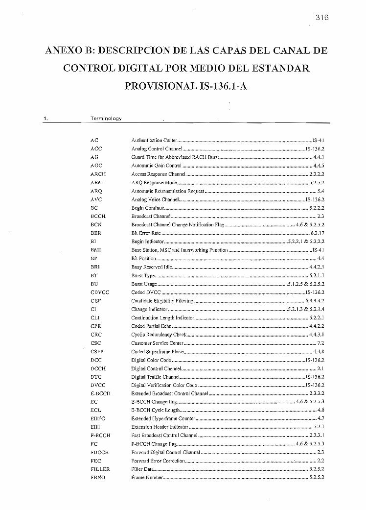
316
ANEXO B: DESCRIPCIÓN DE LAS CAPAS DEL CANAL DE
CONTROL DIGITAL POR MEDIO DEL ESTÁNDAR
PROVISIONAL IS-136.1-A
Terminology
AC
ACC
AG
AGC
ARC1Í
ARM
ARQ
AVC
BC
BCCH
BCN
BER
BI
BMr
BP
BRI
BT
BU
CDVCC
CEF
CI
CL1
CPE
CRC
CSC
CSFP
DCC
DCCH
DTC
DVCC
E-BCCH
EC
ECL
EHFC
EHÍ
F-BCCH
FC
FDCCH
FEC
FILLER
FRNO
Authentication Center
Analog Control Channel
Guard Time for Abbrevíated RACH Burst
Automatic Caín Control
Access Response Channel ,
ARQ Response Mode
Automatic Retransmission Request
Analog Voíce Channel
Begin Continué
Broadcast Channel
Broadcast Channel Change Notificaron Flag
Bit Error Rate
Begin Indicator
Base Station, MSC and Interworkina Function
Bit Position
Busy Reservedldle
Burst Type
Burst Usage
CodedDVCC
Candidato EligibíUty Filtering
Change Indicator
Continuation Length Indicator ,
CodedParíial Echo ,
Cyclíc Redundancy Check ,
Customer Service Center..,
CodedSuperframe Phase ,
Digital Color Code ,
Digital Control Channel
Digital Traffíc Channel ,
Digital Verifi catión Color Code
E-BCCH Change flag
E-BCCH Cycle Length
Extended Hyperframe Counter
Extensión Header Indicator ,
Fast Broadcast Control Channel ,
F-BCCH Change flag
Fonvard Digital Control Channel
Fonvard Error Correction ,
Filler Data
Franie Number
IS-41
IS-136.2
4.4.1
, 4.4.52.3.2.2
5? 5?
5.4
IS-136?
5.2.? .2
2.3
4.6 & 5.2.5.2
6.3.17
5.2.2.1 £5.2.? .2
1S-4I
4.4
4.4.2.1
5.2.1.1
5.1.?.5&5.2.5.?
IS-136.2
6.3.3.4.?
5.2.1.3 & 5.2.1.4
5.2.2.1
4.4.2.2
4.4.3.1
7.2
4.4.8
IS-136.2
2.1
IS-136.2
IS-136.2
2.3.3.?
4.6 & 5.2.5.3
4.6
4.7
5.2.1
2.3.3.1
4.6 & 5.2.5.3
2.3
2.2
5 ~> 5 ?
5.2.5.2

317
FRNO MAP Frame Number Map 5.2.1.4
G *; GuardTime 4.4.4
HF Hyperframe 4.6
HFC ! Hyperframe Counter 4.7
HLR Home Location Register IS-4I
1DT ' .IdentityType 5.1.2.1 & 5.2.1.4
IE Information Element 6.5
IRA -International Reference Alphabet(formerly IA5) ITURecT.50 (1992)
ISOR 'Ineligible for Service Offering Reasons 6.3.3.4.2
L2 Layer2 (genera!)
L3 Layer3 .....(general)
L3DATA LayerSData 5.2.1.4
L3LI LayerS Length Indicator 5.2.1.4
LSB LeastSigm'ficantBit (general)
LTA1 Long-Term MACA 6.3.17.1
LT_RSS Long Term Receíved Signal Strength 6.3.17.1
MACA Mobile Assísled Channel Allocation 6.3.17
MEA Message Encryption Algorithm 5.2.1.4
MEK Message Encryption Key 5.2.1.4
MIN Mobile Station Identification Number 8.1.3
MM Message Mapping 5.2.5.2
MRLQ MonitoringOf Radio Link Quality 5.5
MS Mobile Síation , (general)
MSB MostSignificantBit (general)
NEB Number of E-BCCHslots per Superframe 4.10.2
NFB Number ofF~BCCH slots per Superframe 4.10.2
iVL NeighborList 6.4.1.2.1.1
NL3M Number ofLayer 3 Messages 5.2.1.4
NPS-DCCH Non-Public Mode Search DCCH 6.3.3.1
NR Number of Reserved slots per Superframe 4.10.2
NSB Number ofS-BCCH slots per Superframe. 4.10.2
OLC Overload Class 6.4.1.1.2.3
PACA Priority Access and Channel Allocation 6.3.5
PAID PCH Allocation ID 4.10
PCH Paging Channel 2.3.2.1
PCON Page Continuation 4.8 & 5.2.5.2
PD Ü Protocol Data Unit 2.2
PE PartialEcho 4.11.2 & 5.3.3.1
PEA Partial Echo Assigned 5.2.1.4
PF Paging Frame 4.7
PFC Paging Frame Class 4.7
PFM Paging Frame Modifier 4.7
PFN Paging Frame Number 4.7
PI Polling Indicator 5.2.1.3
PMSID Permanent Mobile Station Jdentity 4.10
POF Prívate Operating Frequency 6.3.3.1
PREAM Preamble 4.4.5
PSP Public Service Profile 6.3.21
PSS Processed Signal Strength 6.3.3.2
R RampTime 4.4.6
R/N Received/Not Received 4.4.2.3
RACH Random Access Control Channel 2.3.1

318
RDCCH Reverse Digital Control Channel 2.3
RSS ReceivedSignalStrength 6.3.2.1
RSVD Reserved (general)
RTC Reselection Trigger Conditions 6.3.3.4.1
S-BCCH Short Message Servíce-Broadcasí Control Channel.. 2.3.3.3
SAP Service Access Point 5.1
SCF Shared Channel Feedback 2.3.5
SF Superframe , 4.5
SFP Superframe Phase 4.5
SMS Short Message Service (general)
SMSCH Short Message Service Point-to-Point Channel 2.3.2.3
SPACH SMS, PCH and ARCH 2.3.2
SSD Shared Secret Data 6.3.12.1
STM Short-Term MACA .6.3.17.1
STU-OI Secure Terminal Unit IS-136.2
ST_RSS Short Term Received Signal Strength 6.3.17.2
SYNC Synchronization IS-Í36.2
SYNC+ Additiona! SYNC for RACH Burst , 4.4.10
TÍR Temporarily Inelígible for Reselection 6.3.3.4.3
TDMA Time División Múltiple Access 4.4
UCID User Group Identification 5.2.5.2
WER Word Error Rate 6.3.17.4.1.1
2. General
2.1 Specification Scope
Four documents together compríse the specification informatíon necessary for development of IS-I36 based producís.IS-136.1 (DCCH - Digital Control Channel. A collection of iogical channels conveyed on radio bearereliminéis using Tt/4 - DQPSK modulation that are used for transmíssion of control Information and short userdata messages behveen the base and mobile stations.) - This document contains specification text for theDCCH aír interface. Distinct sections for Layer 1, Layer 2, Layer 3 and higher layers descriptions areprovided (i.e., a layered document).
IS-136.2 - A modified TIA/EIA 627 standard with no major architectural changes to the document itself(i.e., unlayered approach maintaíned). This document addresses the air interface requirements for the AnaiogControl Channel (ACC), Analog Voice Channel (AVC) and Digital Trafile Channel (DTC- A collection ofIogical channels conveyed on radio bearer channels using 7t/4- DQPSK. modulation that are used fortransmíssion of user informatíon and related control messages between the base and mobile stations).
IS-137 - modified EÍA/TIA 628 standard. This documení addresses the mínimum performance requirementsfor mobile stations.
1S-13S - modified EÍA/TIA 629 standard. This document addresses the minimum performance requirementsfor base stations,
Other useful documents include:
IS-130 SOO MHz Cellular Systems TDMA Radio Interface Radio Link Protocol 1
1S-135 SOO MHz Cellular Systems TDMA Services Async Data and Fax
IS-41 Cellular Radio Telecommunications Intersystem Operations
IS-53 Cellular Feaíures Descríption
IS-54 Cellular System Dual-Mode Mobile Station - Base Síation Compatibility Standard
IS-641 800 MHz Cellular System, TDMA Radio Interface, Enhanced Full-Rate SpeechCodee
ITU E. 163 Numbering Plan for the International Telephone Service

319
2.2
ITU E. 164' Numbering Plan for the ISDN Era
ITU E.212 Identification Plan for Land Mobile Stations
ITU F.69 The International Telex Service - Service and Operational Provisions of TelexDestinatíon Codes anci Telex Network Identification Cotíes 94/06
ITU 1.330 ISDN Numbering and Addressing Principies
ITU 1.334 Principies Relating ISDN Numbers/Subaddresses to the ISO Reference ModelNetwork Layer Addresses
ITU T.50 I nternational Alphabet No. 5
ITU X.12I Internationa! Numbering Plan for Public Data Networks
ITU X.2.13 Network Service Definition for Open Systems Interconnection for CCITTApplications
ITU X.25 • Interface Between Data Terminal Equipment (DTE) and Data Circuil-TerminatingEquipment (DCE) for Termináis Operatíng in the Packet Mode and Connected toPublic Data Networks by Dedicated Circuit 93/03
TIA/EIA 553 Mobile Station-Land Station Compatibílity Specífication
TIA/EIA 627 SOO MHz Cellular System, TDMA Radio Interface, Dual-Mode Mobile Station-BaseStation Compatibility Standard
TIA/EIA 628 SOO MHz Cellular System, TDMA Radio Interface, Mínimum Performance Standardsfor Dual Mode Mobile Stations
TIA/EIA 629 SOO MHz Cellular System, TDMA Radio Interface, Mínimum Performance Standardsfor Base Stations Supporting Dual Mode Mobile Station
TSB 50 User Interface for Authentication Key Entry
EIA Telecommtmications System Bulletín No. 16, March I9S5 -Assignmentof Access Overload Classes in the Cellular Te le Communications Services
Protocol Reference Model
The protocol reference model is provided for Information purposes and is not intended to be exhaustíve.
Figure 2 -1 BMI - DCCH Protocol Reference Model

320
L3
Ll
Layar 3
i
S-BCCHSAP
- L3 Msg-L3L1
1
E-BCCHSAP
- L3 Msg-L3LI
'
F-BCCHSAP
- L3 Msg-L3LI
'
i .
SPACH RDCCHSAP SAP
~L3Msg -L3 Message
- L3 Ll - L3 LI
-MSID "MSID
-IDT-Hll -,-UGID
'
L2 Functlons:(See Section 5}
• HeaderFormatting
er^nu TV Normal Abbreviated ' J;3 MessageFDCCH TX Rnrrw RX Rnrrw RX Concatenation
RDCCH RX RDCCH RX . CRC GenA/er¡fica,
i
\H
SAP
•S-BCCHPDU
1
E-BCCHSAP
•E-BCCHPDU
1
F-BCCHSAP
•F-BCCHPDU
i
\e Mux
-SFP
lr v
Á
SPACHSAP SCF SAP
•SPACH PDU -SCF- Paging group - Sub Ch. No
-BU
v
/
Sub Ch. NoMapplng
-SCF SubC
•SFPDU
v
\x
\-SYNC
'V
iviap
j
7• FDCCH PDU
•
NormaRDCCH SAP
• Mbiu Managemen•FÜIerPDU's
A^bcev ' Retransmíssion Ce
Rnnrw ^AP (ARO)
• Abbrev. PDU • L2 Frame Segmen-SubCruNo. andre-assembly
• SCF SettíngSufa Ch. No • Burst Usage
Mappíng
j .
• Norma! PDL- Sub Ch.No.
h. Noping
• NormalPDU
Preamble ^ Svnc.Sync + . Equaíizatíon
Sync SAÜÜ
ont
nlrol
ficaíionatbn
FDCCH Mux
FDCCH Burst
L1 Functlons:
{See Section 4)• Power Selting• Modulation/Demodulatíon• Tirning Offset Control• Synchronlzatlon Detect• Random Access SubChannel Number Mapping
•FEC• Interleavlng/Delnterleaving
• SPACH Message Continuatlon
Air Interface Air Interface
Figure 2 - 2 MS - DCCH Protocol Reference Mode]

321
Layer 3
L3
RDCCH SAP
- L3 Message-L3U
v-0-
FDCCH SAP
-L3 Message-L3LI
L2
NormalRDCCH TX
- Guard & Ramp
AbbrevlaledRDCCH TX
• Normal PDU- Sub Ch. No.
NormalRDCCH SAP
-Sync
-Sync
v y y v v V
FDCCH RX
• Abbrev. PDU- Sub Ch. No.
AbbrevíatedRDCCH SAP SCFSAP
-SCF
-SubCh. No
-SCF
Super FrameDeMux
•SFPDU
-SFP
RDCCH Mux Data Fíeld De Mux
L2 Functions:(See Sectlon 5)
• Header Formalting• SCF Control• L3 MessageConcatenaron
• CRC GenA/erification• MSID Management•FillerPDU's• Zero Fill• RetransmisiónControl (ARO)
• BCCH Change Detection• L2 Frame Segmentaron
and Re-assembly• SMS Message Number• Burst Usage
L1-SYNC
- RDCCH Burst- Sub Ch. No.
Sub Ch. No.Mapping
1
RDCCH Bu
•FDCCHPDU
L1 Functions:(See Section 4)
• Power Setting• Modulation/Demodulation• Timlng Offset Control• Synchronizatíon Detect• Random Access Sub
Channe! Number Mapping•FEC• Interleaving'Delnterleaving
FDCCH De Mux
RDCCH TX
,
FDCCH
FDCCH RX
Air Interface Air Interface
2.3 Logical Channel Definition
The DCCH comprises the logical channels shown in Figure 2-3. The reverse DCCH (RDCCH) consists of a RACH. The fonvard DCCH(FDCCH) consists of SPACH, BCCH, SCF and Reserved slots.

322
Figure 2 - 3 Logical Channels
DCCH
Reverse
RACH SPACH
PCH
ARCH
SMSCH
BCCH SCF Reserved
2.3.1 Random Access Channel (RACH)
A random access channel is used to request access to the system.
Attributes: Unidirectional (reverse), Shared, Poínt-to-Poínt, Acknotvledged (Acknowledged using SharedChannel Feedback mechanism).
Note: Coniention resolution and/or colusión avoidance feedback is provided on the corresponding SCFchannel.
2.3.2
2.3.2.1
SMS Point-to-Po¡nt, Paging and Access Response Channel (SPACH)
This logícal channel ís used ío broadcast iníbrmaíion to specific rnobile stations regarding SMS Point-to-Point(SMSCH), paging (PCH) and to provide an access response channel (ARCH) as described below. The SPACHmay be considered to be íurther subdivided ¡n 3 logical channels SMSCH, ARCH and PCH, as described below.
Attributes: Unidirectional (fonvard), Shared, Point-to-Point, Acknowledged or Unackiiowledged.
Paging Channel (PCH)
A logical channel subset of the SPACH dedicated to delivering pages and orders.
Note: SPACH ARQ Operation (see Section 5.4) is not supported on this channel.
Attributes: Unidirectional (fonvard), Shared, Point-ío-Point, Unacknowledged.
2.3.2.2 Access Response Channel (ARCH)
A logical channel subset of the SPACH to which the mobile station autonomously moves to, upon successfulcompletion of a contention or reservation based access on a RACH. The ARCH may be used to conveyassignments to another resource or other responses to íhe mobile slation access attempt.
Note: SPACH ARQ operation (see Section 5.4) Ís supported on this channel.
Attributes: Unidirectional (fonvard), Shared, Point-to-Point, Unacknowledged or Acknowledged.
2.3.2.3 SMS Channel (SMSCH)

323
A logical channel used to deliver Teleservice-related messages to a specific mobile síation.
Note: SPACH ARQ operation (see Section 5.4) is supported on this channel.
Attributes: Unidirectional (forward), Shared, Point-to-Point, Unacknowledged or Acknowledged,
2.3.3 Broadcast Control Channel (BCCH)
The BCCH is an acronym used torefer to the F-BCCH, E-BCCH and S-BCCH logical subchannels.These three logical channels are uáed, in general, to carry generic, system-related information.The attributes of these three channels are: Unidirectional (fonvard), Shared, Point-to-Multipoint, Unacknowledged.
2.3.3.1 Fast Broadcast Control Channel (F-BCCH)
This lógica! channel is used to broadcast DCCH strucíure parameters and parameters that are essential for accessing the system.
2.3.3.2 Extended'Broadcast Control Channel (E-BCCH)
The E-BCCH carnes broadcast information that is less lime critica! than F-BCCH for the mobile stations. For the optional information, amessage type and a length indicaíor are included.
2.3.3.3 SMS Broadcast Control Channel (S-BCCH) ^^
This logical channel is used for the broadcast SMS service.
2.3.4 Reserved Channel
This logical channel is de fine d for future use only. Defining it now assures fonvard compatibility with the first generation IS-136 mobilestations.
2.3.5 Shared Channel Feedback (SCF) ___
This logical channel is used in support of Random Access channel operation (see Section 5.3.3).
2.4 Layer 3 Message Mapping Through Layer 2 to Physical Layer
This description of message mapping is only included to aid in the understanding of tiie Standard and only shows one possible mappingsequence.Figure 2-4 shows an example of íiow one L3 Message is mapped inlo several layer 2 frames, an example of a L2 frame mapping onto atime slot, and an example of time slot mapping onto a DCCH channel.The length of aL3 Message is determined by a L3 Length Indicator which is carriedas part of L2header. Thelengthof anL2 frame isfixed, determined by the specific. logical channel. Tai! bits are added to the L2 frames before channel encoding.The length of the FDCCH time sjots and RDCCH burst is fixed. Tliere are two forms of RDCCH bursts which have different fixedlengths. Figure 2-4 assumes an F,DCCH slot and a full-rate DCCH on the Physical Layer.The mapping of assembled FDCCH slots into superframes is also shown in Figure 4-JO. Two superframes are assembled into aHyperframe according ío Figure¡4-11. The grouping of hyperframes into Paging frames is shown in Figure 4-12.
Figure 2 - 4 Message Mapping

324
Layer 3 Message
PD MT Information Element(s) & Padding Layer 3
L2Header
Layer 3Information CRC
Layer 2 Frame
TailBits
L2Header
Layer 3Information CRC
TailBits
L2Header
Layer 3Information
CRCTai!Bits
Layer 2
Channel Coding
Interleaving
SYNC SCF DATA CSFP DATA SCF RSVDOne FDCCH time síot(6.7 ms duraíion)
Superframe - 32 slots (0.64 sec duration)
PhysicalLayer
2.5 Notes
1. Analog Voice Channel (AVC) and Analog Control Channel (ACC) operation is only supported in the 800MHz hyperband.
2. Unless otherwise specified, all mobile stations and BMI shall set ali bits that they are programmed to treat asreserved bits to O (zero) in all messages that they transmit, All mobile stations and BMI shall ignore the stateof all bits that they are programmed to treat as reserved bits in ali messages that they receive.
3. The capabilities of a mobile station shall be consistem across all hyperbands that it supports except foranalog speech, which can only be supported in the 800 MHz hyperband.

325
4. All lines added or mociified during the transition from IS-136 plus IS-136 Addendum are denoted by a singlevertical change bar (|) in the right hand margin.
Optional Mobile Station Facilities
Control Channel Reseiection based on availabiiit}' of services (i.e., Sen'ice Offering) on a candidate controlchannel (see Section 6.3.3.4)
SOC/BSMCsignaling.
Reduction of scanning frequency for RSS measurements of neighboring cells (see Sectíons 6.3.3.1 and6.3.3.2).
SMS SUBMIT (see Section 7.1.2.2).
PFC 2 to PFC 8.
Any type of number other than "unknown" as specifjed in the Type of Number field within the Address InfoInformation element (see Section 6.5).
Any Numbering Plan other than "unknown" as specified ín the Numbering Plan field within the Addressínfo Information element (see Section 6.5).
When the Acidress Info índicates "Type of Number = unknown" and "Numbering Plan - unknown", the IRAencoding of the Address field is optional.
Async Data and G3-Fax Sen'ice Mode.
Support of User Group operation (see Sections 5.1.1.2, 5.2.5, 6.3.16 and S.4). íf supporled, only a singleUser Group ID may be enabled at any poínt in time.
Support of Subaddressing (see Section 6.3.13).
Support of half-rate, double rate and triple rate operation on a Digital Trafile Channel (i.e., data, fax and/orvocoder rates other than full-rate). The capability to opérate on a full-rate or half-rate DCCH with any validSlot Configuration (seeTab!e4-3 in Section 4.10.1) is mandatory.
Message Encryption on the DCCH.
Digital operation in more than one hyperband.
Armlpg Operation.
Support of Delta Time on Digital Trafile Channel.
Support of voice coders.
STU-III.
Physical Layer
4.1 Radio Frequency Carríer Spacing and Designation
As per IS-136.2 (see Section 2.1.1.1).
4.2 Power Output and Modulation Characterlstlcs
As per IS-136.2 (see Sections 2/1.2, 2.1.3.3,3.1.2,3.1.3.3.1 and 3.1.3.3.6).
4.3 Service Access Poínts
Layer I provides the following sen'ice access points (SAPs) to layer 2 both on mobile station and BMI síde. Referto Figures 2-1, 2-2 and 5-1 for the BMI, MS Prolocol Reference models, and for the primitives on the mobilestation and BMI sides from a layer 2 perspecth'e.
F-BCCH SAP
E-BCCH SAP
S-BCCH SAP
SPACH SAP

4.4
SCFSAP
Normal RDCCH SAP
Abbreviated RDCCH SAP.
TOMA Frame Structure
326
The frame structure may be depicted as follows:
Figure 4 - 1 Frame Structure
Time Slot 1,
One Frame - 1944 bits (972 Symbols) = 40 ms. (25 frames per second)
Time Slot 2
One TDMA Block
Time Slot 3
'Time Slot 4 Time Slot 5
TimeSlot
Time Slot 6
A TDMA frame is 40 milliseconds long and consists of six equally sized time slots (1-6), each 162 symbols (324 bits) in length. ATDiVlA Block consists of half a TDMA frame (either slots I to 3 or slots 4 to 6).The Bit Position (BP) of forward and reverse slots/bursts are numbered sequentially from 1 to 324.ín the forward direction, the first transmitted bit of the SYNC has BP = 1 and the last transmiüed bit of the RSVD field has BP = 324. Inthe reverse direction, the first transmitted bit of the Guard has BP = I. In the normal slot formal, the last transmitted bit of the DATAfield has BP = 324. In the abbreviated slot fonnat, the last transmitted bit of the AG ííeld has BP = 324.
Figure 4 - 2 Normal Slot Format MS -> BMI on DCCH
G R PREAM SYNC DATA SYNC+ DATA
16 2S 24 122
Figure 4 - 3 Abbreviated Slot Format MS -> BMI on DCCH
G R PREAM SYNC DATA SYNC-f- DATA AG
16 28 24 78 44
Figure 4 - 4 Slot Format BMI -> MS on DCCH
SYNC SCF DATA CSFP DATA SCF RSVD
28 12 130 12 130 10
Interpretation of the fields is as follows:
AG
CSFP
DATA
G
PREAM
R
RSVD
SCF
SYNC
SYNC+
Guard Time for Abbreviated RACH Burst
Coded Super Frame Phase
Coded ínfonnation Bits
Guard Time
Preamble
Ramp Time
Reserved Field, set to 11
Shared Channel Feedback
Synchronization
Additional Synchronization

327
4.4.1 AG
The AG (Abbreviated Guard) field denotes guard time for the abbreviated access burst formal. The field is 22 symbols (44 bits) ¡nlength. During this time the mobile station shall maintain carrier off condition. Note that the fírst 3 symbols of AG consisí of Ramp.
4.4.2 SCF
The SCF (§hared Channel Feedback) field is used to control accesses on ihe RACH and is comprised of thefollowing: '
Busy/Reserved/Idle (BR1)
Received/Not Received (R/N)
Coded Partial Echo (CPE).
4.4.2.1 BRI
The BRI (Busy/Reserved/Idle) is a 6-bit field and is mapped into FDCCH slots as shown in Figure 4-5. Encoding of the BRI is describedin Section 5.3.2.1.1.
Figure 4 - 5 Bit Mapping of the BRI Field
BRk BRJ4 BR13 BRb BRI0
BI>29 BP33 BP37 BP3l3 BP317 BP32i
4.4.2.2
4.4.2.3
CPE
The CPE (Coded Partial Echo) is an 11-bit field and is mapped into FDCCH slots as shown in Figure 4-6.Encoding of the CPE is described in Section 5.3.2.1.3.
Figure 4 - 6 Bit Mapping of the CPE Field
d6 ¿5 d4 d3 ¿2 di d0 b3 b2 b i b oBP30 BP32 BP34 BP36 BP3S BP40 BP314 BP316 BP3!8 BP320 BP322
R/N
The R/N (Received/Not Received) is a 5-bit field and is mapped into FDCCH slots as shown in Figure 4-7. Encoding of the R/N isdescribed in Section 5.3.2.1.2.
Figure 4 - 7 Bit Mapping of the R/N Field
[l|N4 R/N3 R/N9
BP35 BP39 BP315 BP3i9
4.4.3 DATA
User data bits (coded information bits) are mapped onto the DATA field for transmission. In the fonvard direction, the field is 260 bits inlength. In the reverse direction, the length of the DATA field is 244 bits for the normal slot formal and 200 bits for the abbreviated slotformal.
4.4.3.1 Channel Encoding
The logical channels BCCH, SPACH and RACH (normal and abbreviated) use a rale 1/2 convoiutiona! encoding. The same encodingpolynomials as for fuil-rate speech (see Section 2.1.3.3.3.4 of IS-136.2) are used. The fírst bit received from Iayer2 is the left most bit inFigure 4-S and shal! be the firsttil delivered to channel encoding. The last flve bits sent to the channel encoder are set to zero (tail bits).

328
Figure 4 - 8 Partitíoning of the Data Before Channel Encoding
L2 Header L3 Information • CRC Tail
•109/101/79- 16
4.4.3.2
The combined íength of the L2 Header and L3 Information ñelds are as follo\vs:
SPACH and BCCH: = 130-16-5 = 109
RACH (normal íength): =122-16-5=101
RACH (abbreviated íength) -100-16-5=79 -
Interleaving
For all channel types and bursí lengths, all bits are sent within one burst (i.e., only intra-burst interleaving is performed). The output ofthe inlerleaver is sequentially mapped into the DATA fields, beginning with the first bit (leñmost bit) of the firsí DATA field (leftmostDATA field). The DATA field bits are transmitted o ver the air interface beginning with the first bit of the first DATA field.
4.4.3.2.1 Forward DCCH
The 260 encoded daía bits are iníerleaved in a 13-row by 20-column matrix. The data bits are placed into arectangular interleaving array as shown in the matrix below, where the bits nave been numbered O - 2593
correspondíng to íheir order at the output of the encoder. The data bits are entered into the array column-wise.The bits are then transmitted row-wise using the following algorithm:
Do row = 0,2,4,6,8,10,12Do column = 0 to 19
Transmit (array (row, column))End Do
EndDoDo row =1,3,5,7,9, I I
Do column = 0 to 19Transmit (array(row, column))
EndDoEndDo
O
1
2
11
12
13
14
15
24
25
26
27
28
37
3S
234
235
236
245
246
247
248
249
258
259
Thus, the bits are transmiíted in the order of:
0,13,...,247(rowO),
4.4.3.2.2 Reverse DCCH
Normal Length Burst
11,24 258 (row 11).
The 244 encoded data bits are ¡nterleaved in a 12-row by 21-column matrix with a partial column of 4 bits incolumn 21. The data bits are placed into a rectangular interleaving array as shown in the matrix below, where thebits have been numbered 0-243, corresponding to their order at the output of the encoder. The data bits areentered into the array column-wise. The bits are then transmitted row-wise using the following algorithm:

329
Do row - 0,2Docolumn = 0 to20
Transmit (array(row, column))End Do
End DoDo row = 4,6,8,10
Do co lumn-Oto 19Transmit (array(row, column))
End DoEnd DoDo row = 1,3
Do co lumn~Oto20Transmit (array(row, column))
End DoEnd Do
Do row = 5,7,9,11Do column = Oto 19
Transmit (array(row, column))End Do
End Do
0
1o
3
11
12
13
14
15
23
24
25
26
27
35
228
229
230
231
239
240
241
242
243
N/A
N/A
Note: N/A means not applicable.
Thus, the bits are transmitted Ín the order of:
OJ2,...,240 (rowO),
11,23 ..... 239 (row 11).
Abbrevhited Length Burst
The200encodeddatabitsareinlerleavedina 12-rowby 17-columnmalrix with apartial columnof S bits in column 17, The data bitsare placed into a rectangular iníerleaving array as shown in the matrix below, \vhere the bits have been numbered 0-199, correspondingto their order at the output of the encoder. The data bits are entered into the array column-wise. The bits are then transmined row-wiseusing the following algorithm:
Do row = 0,2,4,6
Do co lumn-Oto 16 'Transmit (array(row, column))
End DoEnd DoDo row = S, I O
Do column = Oto 15Transmit (array(row, column))
End DoEnd Do
Do row = 1,3,5,7Do column-Oto 16
Transmit (array(row, column))

330
EndDoEndDoDo row = 9,11
Do column = 0 to 15Transmit (array(ro\v, column))
EndDoEndDo
910I I
12
13
19
20
21
22
23
24
25
31
32
33
34
35
Thus, the bits are transmitted in the orderof:
0,12,..., 192 (rowO),
10,22,...,190 (row 10),1,13,...,193 (rowl),
11,23 191 (row 11).
ISO181
187
188
189
190
191
192193
199N/AN/AN/AN/A
4.4.4
The G (Guard) fieid provides guard time, and is 3 symbols (6 bits) in duration. During this time, íhe mobile statíon shall maintaincarrier-off condition.
4.4.5 PREAM
The PREAM (Preamble) fieid allows the base station to perform automatic gain control (AGC) and to facilítate symbol synchronizationbefore the subsequent data and burst synchronization portions of the received burst are reached. The fieid is specified by the follcnvingphase changes in radians:
I-TE/4 [-7T/4 I -71/4 1-71/4 I-71/4 -71/4 I - 7t/4 -71/4
4.4.6 R
The R (Ramp) fieid denotes a power ramp up or a power down interval, and is 3 symbols (6 bits) in duration.
4.4.7 RSVD
The RSVD (Reserved) is comprised of t\vo bits set to 11.
4.4.8 CSFP
The CSFP (Coded Superframe Phase) fieid is used to convey information regarding the Superframe Phase (SFP) so that mobile stationscan find the start of íhe superframe (see Section 4.5). The content in this fieid may also be used to discrimínate between DCCH and DTCin that the CSFP of a DCCH and CDVCC of a DTC have no common codewords. This is accomplished by using the same basic codingmethod together with inverting the checkbits of all CSFP codewords before transmittal. The fieid is [2 bits in length.
The channel encoding of the SFP into CSFP is similar to how DVCC is handled in IS-136.2 (Le., a (12,8) code).The LSB of SFP is dO. The bits d7, d6 and d5 are reserved and all set to zero (000). After the encoding,according to the IS-136.2 CDVCC process (see Section 1.2.5 of IS-136.2), the check bits 63, b?, b¡, brj are all
inverted (and denoted b 3, b¿ b \, b o) before forming the resulting CSFP information. The bits aretransmitted as follows:

331
Figure 4 -¿'9 CSFP BitAlIocatíon
d? ¿6 d5 d4 d3 ¿2 di DO b 3 t>2 b i b o
4.4.9
BPI71 BP!72 BP173 BPn4 BP175 BP!76 BP177 BP,7S BP179 BP1SO BP1S1 BP]S2
SYNC
SeelS-136.2,Section 1.2.4.
4,4.10 SYNC+
Tlie SYNC-r field provides additíona! synchronizalion information ío improve base síation receiver performance.The SYNO \vord is specifled by the following phase changes in radians:
7Ü/4 -71/4 37T/4 -371/4 -71/4 -jt/4 -37T/4 37i/4 37E/4 71/4 Tt/4 -Ti/4
4.4.11 Transmit Offset
At the mobile station, the offset'between the forward and reverse slots/bursts shall always be 207 symbo! periods as no time advance isappliedon the DCCH (see Section 1.2.1 ofIS-136.2).
4.5 Superframe
Each superframe (SFJ on the FDCCH is comprisedofanorderedsequence of logical channels asshown in Figure 4-10. Thenumberofslots that can be supported for each logical channel is as shown in Table 4-1. It should be noted that the total number of slots persuperframe is 32 for a full-rate DCCH and 16 for a half-rate DCCH.
Figure 4 - 1 0 Superframe Structure
DCCH
SFP
-(
F-BCCH
F
0
... F
une ¿upe
E-BCCH
E E
órame - i o i UIVLA
S-BCCH
S
..
S
trames - o^ u ms —
Reserved
R R
SPACH
...
31
Table 4 -1 Slot Allocations
F-BCCH (F)
E-BCCH (E)
S-BCCH (S)
Reserved (R)
SPACH (Note 1)
Full-Rate DCCH
Min
3
1
0
02
Max
10
8
15
7
2S
Half-Rate DCCH
Min
3
1
0
0
2
Max
10
S
11
7
12
Note L: Some SPACH slots may be reslricted from allocation as PCH Subchannels (see Sections 4.10.2 and6.4.1.1.1.1).
The SFP increments every TDMA block. SFP starts at O on the first F-BCCH slot and counts modulo 32. For a half-rate DCCH onlyslots with even SFP numbers are used.The first slot in a SF (SFP = 0) shall be allocated ío the first F-BCCH slot (see Figure 4-10). Lf more than one DCCH is allocated on agiven frequency, the start of the SFs must occur in the same TDMA block (Le., SF synchronization is required).
4.6 Hyperframe
A Hyperframe consists of two superframes: one primary and one secondar,'. Every PCH in the primary Superframe is always repeated inthe secondary Superframe. The SPACH information, excluding PCH information, may be different from SF to SF (see Figure 4-11).The F-BCCH carríes the same information in every Superframe on a given DCCH. The E-BCCH information may be different from SFto SF, as the information repeats after a certain period. The length of the E-BCCH cycle is indicated by the L2 ECL field.

332
Any change in the F-BCCH or E-BCCH information elements, except those in Section 6.5 indicated as non-crítical, shall take effect inthe next Hyperframe. Lfa change occurs, notificalion shall be provided by transitioning the L2 BCN flag in all SPACH slots in thepreceding Hyperirame.F-BCCH includes an E-BCCH change flag (EC), which transitions to indícate if the E-BCCH information has changed beginning withthe curren! hyperframe.F-BCCH also includes an F-BCCH change flag (FC), which transitions to indícate if the F-BCCH information has changed beginningwith the current hyperframe.
Figure 4-11 Hyperframe Structure
Hyperframe 0
Superframe 0
primar}'
F EO S° R SPACH'
Superframe 1
Secondary
F El S1 R SPACHJ
Hyperframe 1
Superframe 2
primary
E ^5 *í PAPH
4.7
F denotes F-BCCH
E denotes E-BCCH
S denotes S-BCCH
R denotes Reserved
SPACH can be PCH, ARCH or SMSCH
If SPACH is equal to PCH, then j = i and k= i + 1;
Elsej = i+ 1 and k = i+ 2.
Paging Frame
There are t\vo terms used in determining PF class:
Assigned PF class
Current PF class
A mobile station shall use PFC] (see Figure 4-12) as its Assigned PFC prior to ínitially registering. Once a mobile station hassuccessfully registered on its sen'ing BMi it shall continué using PFCi as its Assigned PFC unless the servíng BMI assigns it a newPFC.The highest PFC supported by the BMf is broadcast on the F-BCCH in MAX_SUPPORTED_PFC. If the MAX_SUPPORTED__PFC isless than its Assigned PFC, the mobüe station shall set its Assigned PFC to MAXJ3UPPORTED_PFC.It should be noted that a mobile síation having an Assigned PFC of N (\vhere N is greater than I) is also capable of supporting PagingFrame Classes PFC] through PFC^_i.If the Paging Frame Modifier (PFM) transmitted on the SPACH (see Section 5.2.5) is set to O, the Current PFC, which is used ío Índexpaging frames, ís equal to the Assigned PFC.
If PFM = 1 and PFM Direction = I (push out) then:
A mobile station capable of supporting one PFC higher than its Assigned PFC shall set its Current PFC to itsAssigned PFC + 1 as long as the MAX_SUPPORTED__PFC is not exceeded. If its Current PFC = PFCg, itshall remain atPFCg.
[f PFM = I and PFM Direction = O (pulí in) then:
The mobile shall set its Current PFC to one PFC less than its Assigned PFC unless its Assigned PFC - PFC¡in which case its Current PFC is not changed.
A Hyperframe counter (HFC) and Primar}' SF indicator are provided in the BCCH. Optionally, an Extended Hyperframe Counter(EHFC) may also be provided in the BCCH. The HFC counts modulo 12, and the EHFC counts modulo 8. The EHFC is required Ínorder to support PFC > 5.
Figure 4 -12 Paging Frame Classes 1, 2, 3, 4

333
HFC
SF
PFC i
PFC2
PFC3
PFC4
0
P
P
P
P
^PFC
3-
1
s
s
s
s
2
P
-
-
-
: ,2
3
s
-
-
-
4
P
P
-
-
PF
)
5
s
s
--
p .L4
6
P
-
P
-
S
7
S
-
S
-
í
8
P
P
-
-
1
9
s
s
--
'
10
P
-
-
-
>
11
s
---
(12
P
P
P
P
13
s
s
s
s
HFC = Hyperframe CounterSF =SuperframePFC = Paging Frame ClassP = Primary PCHsS = Secondao'PCHs
The secondar>' PCH is ahvays transmitted in íhe same hyperframe as the corresponding primary PCH. Examples of PCH assignmentwhich are aligned to HFC = O are shown in Figure 4-12. It should be noíed that for PFC greater tlian 1, alignment wiíh any HFC valué ispossible.
The valid Paging Frame Classes are defined in Table 4-2.
Table 4 - 2 Paging Frame Classes Definition
9 PFC
ft iy 2
il 3fl 4
II 5
11 6n 7
íl 8
PFN (Paging Frame Number)(Periodicity In HF)
I
2
3
6
12
24
48
96
A paging frame is íherefore defined as the number of hyperframes over which a mobile station has a single instance of PCH allocation.
PCH Displacement
PCH Displacement is the process by which the BMI directs a mobile station to continué reading a number of SPACH slots añer it firstreads its assigned PCH Subchannel. Whenever a mobile station reads its assigned PCH Subchannel and determines that there is nomessage addressed to its MSID, it shall read the PCON bit carried in that slot. If the PCON bit is set to O the mobile station may sleepuntil íhe next occurrence of its assigned PCH Subchannel. When the BMI activates PCH Displacement (PCON = 1), the mobile stationshall respond by reading additional SPACH slots as determined by the PCH_DISPLACEMENT parameter sent in the DCCH Structuremessage (see Section 6.4.1.1.1.1).When PCH Displacement is activated on a full-rate DCCH, the mobile station shall read every other SPACH slot añer its assigned PCHSubchannel until PCHJDISPLACEMENT additional SPACH slots have been read or it receives a page message addressed to its MSID.For the case where a mobile station has read the last SPACH slot in a primao' superframe and PCH_DISPLACEMENT still requiresadditional SPACH slots to be read> il shall read the second SPACH slot in the next primary superframe. For the case where a mobilestation has read the second to last SPACH slot in a primao' superframe and PCHJDISPLACEMENT stiil requires additional SPACHsloís lo be read, it shall read the ficst SPACH slot in the next primao' superframe.When PCH Displacement is activated on a half-rate DCCH, the mobile station shall read every SPACH slot añer its assigned PCHSubchannel until PCHJDISPLACEMENT additional SPACH slots have been read or it receives a page message addressed to its MSID.The PCH Displacement process defined herein shall not be affected by the Number of Non-PCH Subchannel Slots parameter sent in theDCCH Strucíure message (see Section 6.4.1.1.1.1), U., any slots that have been restricted from allocaíion as PCH Subchannels shall stillbe read according to PCH displacément rules when PCON = I.An example of PCH Displacement activation on a full-rate DCCH for a mobile staíion having a PCH Subchannel corresponding to SFP= 27 is shown in Figure 4-13. The mobile station determines that there is no message addressed to its MSID in its PCH Subchannel,

334
PCON - 1 and the BMI has set PCH_DISPLACEMENT to 4. The mobile station proceeds to read SPACH slots corresponding lo SFP =29 and 31 in the first primar)' superframe wilhout receiving a message addressed to its MSID. The mobile station continúes to readSPACH slots corresponding to SFP = n + 1 and n + 3 in the second primar}' superframe without receiving a message addressed to itsMSID. At the point where PCHJ3ISPLACEMENT additional SPACH slots have been read, the mobile station may sleep until the nextoccurrence of its assigned PCH Subchannel.Note that each L2 Frame having a BU (see Table 5-7) set to Hard Triple Page, Hard Quadruple Page, Hard Penta Page or PCH Burst(see Section 5.2.5.1) sent in the primar}' superframe is repeated in the secondary superframe in the slot having the same SFP valué. Forthis example a total of n-1 BCCH slots have been aliocated.
Figure 4-13 PCH Dísplacement
Primar}
BCCH
SFP
SF
SPACH
X X X
... 27 28 29 30 31
Secondary SF
BCCH SPACH
Primary
BCCH
SF
SPACH
n
X X
n+1 n+2 n+3 ...
BCCH
4.9 SPACH Message Continuation
SPACH Continuation is the process by which the BMI sends a message over múltiple SPACH slots. A mobile station shall respond toSPACH Message Continuation whenever it determines that a message addressed to its MSID has been sent by the BMI over múltipleSPACH slots. A PCH message spanning more than 1 SPACH slot, when sent on a full-rate DCCH, shall be transmitted using everyother SPACH slot (Le., consecutive SPACH slots shall not be used). A PCH message spanning more than 1 SPACH slot, when sent on ahalf-rate DCCH, shall be transmitted using consecutive SPACH slots. An ARCH or SMSCH message spanning more than 1 SPACH slotshall be transmitted using consecutive SPACH slots unless interrupted (see Section 5.6).The SPACH Message Continuation process defined herem shall not be affected by the Number of Non-PCH Subchannel S lots parametersent in the DCCH Structure message (see Section 6.4.1.1.1.1), i.e., any slots that have been restricted from allocation as PCHSubchannels shall still be read according to SPACH Message Continuation rules.An example of SPACH Message Continuation actlvation on a full-rate DCCH for a mobile station having a PCH Subchannelcorresponding to SFP = 27 is shown in Figure 4-14. The mobile stalion determines that there is no message addressed to its MSID in itsPCH Subchannel, PCON = 1 and the BMI has set PCHJDISPLACEMENT to 4. The mobile station proceeds to read the SPACH slotcorresponding to SFP = 29 and receives the first slot of a three SPACH slot PCH message addressed to its MSID. The mobile stationnext reads the SPACH slot corresponding to SFP = 31 and SFP = n + I in the next primary superframe wliich contains the remainder ofthe PCH message.Note íhat each L2 Frame having a BU (see Table 5-S) set to Hard Triple Page, Hard Quadruple Page, Hard Penta Page or PCH Bursísent in the Primar}' SF is ahvays repeated in the Secondary SF in the slot having the same SFP valué. For this example a total of n-1BCCH slots have been allocated.
Figure 4-14 SPACH Message Continuation (PCH)
Priman
BCCH
SFP
SF
SPACH
X X X
... 27 28 29 30 31
Secondary SF
BCCH SPACH
Primar}'
BCCH
SF
SPACH
nX
n+f n+2 n+3 ...
BCCH
4.10 Mobíle Station PCH Allocation
Each mobile station shall be allocated a specific PCH Subchannel, within its paging frame on a specific DCCH. The available PCHSubchannels and DCCHs can be identified by the DCCH parameters broadcasted on BCCH.
A mobile station may calcúlate its assigned PCH Subchannel using eitlier its User Group ID (UGID) or itsPermanent Mobile Station Identity (PMSID) which can be a MJN or an IMSI. If User Group operation is actívated(see Sectíons 6.3.10 and S.4) and the current DCCH supports User Group operation (see Service Menú in Section6.4.1.2.2.4), the mobile slatíon shall calcúlate its assigned PCH Subchannel using the UGID valué as included inthe User Group information element. Otherwise, the mobile station shall calcúlate its assigned PCH Subchannelusing its PMSID determined as follows:
If a mobile stalion has an IMSI (see Section 8.1.1) but does not have a MIN (see Section 8.1.3), thenIMSI shall be used for PCH Subchannel determination purposes.
If a mobile station has a MIN but does not have an IMSI, then MIN shall be used for PCH Subchanneldetermination purposes.
If a mobile station has both a MIN and an IMSI, then whichever of the two it used for its lastsuccessful registration shall determine its PCH Subchannel.

Í 335». i
í
íf a mobile station has both a MÍN and JMSI but is precluded from registering on iís serving BMÍ (seeSection 6.3.7), tlien MIN shall be used for PCH Subchannel determination purposes.
If a mobile station has both a MIN and an IMS1, and one has been rejected since its last successfulregistraron, then the unrejected PMSID shall be used for PCH Subchannel determination purposes.
Registrations made using TMSI do nol affect the PCH Subchannel determinadon process.
A mobile station shall therefore only monitor a single PCH Subchannel as determined by either UGID or PMSID. If UGID is used todetermine its assigned PCH Subchannel, a mobile station shall still search for PMSID or TMSI based MSID frames as well as UserGroup frames. If PMSID is used to determine the assigned PCH Subchannel, and User Group operation is activated, a mobile stationshall search for eiíher PMSID or TMSI based MSID frames as well as User Group frames.The 1 ó least significant bits of tlie;selected UGID or PMSID are referred to as PAID in Sections 4.10.1,4.10.2 and 4.10.3.
4.10.1 DCCH Selection
Each mobile station is hashed to a DCCH in a cell according to its PAID, the number of DCCHs in the cell, and the number of slotsallocated to the DCCHs. A hashing algorithm, which yields exactly one DCCH channel and slot assignment for a given PAID, isdescribed in the following paragraphs. Note that this algorithm ¡s provided to describe the requirements for DCCH selection but doesnot mándate a specific implementation. Any algorithm that selects the same DCCH channel and slot combination for a given PAID asthis algorithm shall be considerad to meet the requirements for DCCH selection.
The hashing1 process consists of three steps:
The informatíon required to perform DCCH selection must be computad or obtained from layer 3.
An ordered líst of DCCHs in a cell is assembled.
Using its PAID, the mobile slation selects the appropriate DCCH channel and slot from íhe orderedlist.
This hashing algorithm requires that the following informatíon be computed or obtained from the DCCH Structureand Control Channel Seleclion Parameters messages (see Sections 6.4.1.1.1.1 and 6.4.1.1.1,3):
the total number of channels in a cell that contain a DCCH (NC). Nominal!}1, NC is 1 (for the currentDCCH.) However, if the optional information element Additional DCCH Information v/as provided,then NC is 2 + the valué in íhe Number of Additional DCCH Channels field.
The channel number (Cj; Í - 1..NC) for every DCCH in the cell, including the current DCCH. Forother than the current DCCH, Cj shall be obtained from the DCCH Channel field in the Additional
DCCH Information information elemení.
The slot configuraron (S¡; i = 1..NC) and the number of slots (NS¡; i = I..NC) for each channel C¡containing a DCCH. For the current DCCH, S¡ is the valué in the Slot Configuration informationelement. For other than the current DCCH, S¡ is the valué in the Slot Configuraüon field obtainedfrom the Additional DCCH Information information element. In either case, NS¡ is computed as
follows:
(X if S¡ = 0;
2, ifSi = 1;NS¡ H
4, ifSi = 2;
The total number of slots (NS) allocated to the DCCHs in the cell. NS shall be computed as follows:
NC
NS =¡=I
Once all of the necessary informaron is avaílable, the list of DCCH channel numbers,Cj; i = 1 ..NC, shall be sorted in ascending order. The slot configuration list,Sj; i - \, and number of slots ílist, NS¡; i = 1 ..NC, shall be similarly ordered so that the original relationship between channel C¡ and
its slot information lists, Sj and NSj, is preserved.Using the sorted lists Cj, S¡, and NS¡, the algorithm to perform DCCH channel and slot selection is as follows:
SLOT_COUNT = 0LOOP (i - 1..NC) over each channel containing a DCCH
LOOP (j = l..NS¡) over each DCCH slot on mis channel

336
SLOT_COUNT = SLOT_COUNT + 1IF SLOT_COUNT= (PAID mod NS) + 1
THENthe selected DCCH ciíannel shall be C\, and the DCCH rate and slot assignment for theselected DCCH shall be obtaínecí from Table 4-3 using the current valúes of slot índex Q")and Slot Configuration (S¡)
ENDIF
END LOOPEND LOOP
Table 4 - 3 Selected DCCH Rate and Slot Assignment
Slot Index Q")
1
1
2
3
4
5
6
Slot Configuration (S¡)
0
I,2,or3
1,2, or 3
2or3
2 o r 3
3
3
Assigned Slots
1
1 and 4
1 and 4
2 and 5
2 and 5
3 ando
3 and 6
Rate
half-raie
full-raíe
full-raíe
full-rate
full-rate
full-rate
full-rate
4.10.2 PCH Subchannel Selection
For its selected DCCH, a mobile station ís assigned to a PCH Subchannel within the superframe according to thefollowing algorithm:
Case 1: Half-rate
PCH_SUBCH = [[(PAID div NS) mod NP] + NB] * 2
NP = [(16-NB)-NNP]
Case 2: Ful I rate
PCH_SUBCH = [(PAID div NS) mod NP] + NB
NP = [(32-NB) - (NNP * 2)]
where:
PCHJSUBCH = SFP of assigned PCH Subchannel
NP = Number of PCH Subchannels per Superframe [NP > 0]
NB= NFB+NEB + NSB+NR
NFB - Number of F-BCCH slots per Superframe
NEB = Number of E-BCCH slots per Superframe
NSB - Number of S-BCCH siots per Superframe
NR=Number of Reserved slots per Superframe
NNP = valué in Number of Non-PCH Subchannel Slots
NS = Number of Slots computed in Secíion 4.10.1
4.10.3 Hyperframe Selection
For its selected DCCH, a mobile station need only read its assigned PCH Subchannel in a hyperframe for whichthe following condition is satisfied:
[(PAID div NS) div NP] mod PFN = (HFC + EHFC * 12) mod PFN

337
where: PFN = Paging Frame Number (1,2,3,6,12,24,48,96) corresponding to the PFC of the mobile station(see Section 4.7).
HFC =
EHFC =
Hyperframe Counter (broadcast on BCCH)
Extended Hyperframe Counter (optionally broadcast on BCCH). If EHFC is not presenton the BCCH, a EHFC default valué of O is used
Number of Slots computad in Section 4.10.1
Number of PCH sloís computad in Section 4.10.2,
4.11 Subchanneling of the RACH
4.11.1 General
RACH subchanneling exists in order to allow sufficient processing time at both the mobile station and base station in conjunction with arandom access event. In the interest of consistent performance, it is required that the SCF response time be the same for both a full-rateand half-rate DCCH. In order to accomplish this the full-rate DCCH has been deflned to consist of six RACH subchannels, and the half-rate DCCH has been defined to consist of three RACH subchannels.
4.11.2 SCF Flags - RDCCH and FDCCH Burst Associations
The SCF flags are carried in FDCCH time slots and serve to indícate the BMI reception status of bursts sent previously on the RDCCH.The SCF flags are also used lo indícale the availability status (3.e., Busy/Reserved/Idle) of their corresponding RDCCH bursts (seeSection 5.3.2.1.1). A mobile station having an access pending reads SCF flags to determine when to begin its access attenipt.If a full-rate DCCH exists then its .RDCCH bursts and FDCCH slots are multiplexed so as to créate 6 distinct access paths as shown inFigure 4-15. Assuming that path 1 (Pl) in the FDCCH indicates that the next Pl burst in the RDCCH ¡s available (U., Idle) and isselected for an access attempt, a mobile station shall begin sending the first burst of its access at that time (64.S ms after receiving thefull Pl slot in the FDCCH). The mobile station shall then begin reading the SCF flags in the next PI FDCCH slot (41.8 ms aftercompleting transmission of its access burst) to determine the BMI reception status of its initial access burst.It should be noted that the SCF Information carried in any given FDCCH slot is compietely independent of the layer 3 informationcarried therein as the SCF flags occupy bandwidth compietely sepárate from that assigned for BCCH, PCH, ARCH or SMSCHpurposes. It should also be noted that for RACH purposes, 6 distinct access paths wlll ahvays exist for a full-rate DCCH and 3 distinctaccess paths will ahvays exisí for a half-raie DCCH. The access paths associated with one DCCH are compietely distinct from thoseassociated wíth any other DCCH (such tiíat a mobile station assigned to a given DCCH will never make an access attempt using theaccess paths associated with any other DCCH).Figure 4-16 shows the relationship benveen FDCCH SCF flags and RDCCH bursts. The arrows show the order of events associated withan access attempt. Thus, following the arrows from left to right on RACH subchannel Pl, the BRI portion of the SCF flags firstindicates the availability of the nextPl bursíin the RDCCH. Ifaburst is transmitted in that RDCCH burst, then the mobile station readsthe R/N portion of the SCF flags in the next Pl FDCCH slot to determine the BMI reception status of its transmitted bursí. For the caseof the first burst of a random access the mobile station also reads the PE portion of the SCF flags to determine whether or not itsparticular access was captured. The BMI sets the PE valué to reflect the captured mobile station access. If the mobile station determinesthat its access was captured based on PE and that the R/N flag indicates received, it proceeds to send any additional bursts it lias pendingbeginning in the next Pl burst in the RDCCH,
Figure 4-15 RACH Subchannels
FDCCH
I
Pl
2 3 4
P2
5 6 I
P3
2 3 4
P4
5 6 I
P5
2 3 4
P6
5 6 I
Pl
2 3 4
P2
5 6 1
P3
2 3 4
P4
5 6 1
P5
2 Slot No.
Sub Ch.
RDCCH
3 4
P4
5 6 I
P5
2 3 4
P6
5 6 1
Pl
2 3 4
P2
5 6 i
P3
2 3 4
P4
5 6 1
P5
2 3 4
P6
5 6 1
Pl
2 3 4 Slot No.
Sub Ch.
^^

338
Figure 4-15 shows the RACH subchannels that are used in the case of a full-rate DCCH. For a haif-rate DCCH only RACH subchannelsP l ,P3and P5 are used.
In Figure 4-16 an example of a dialogue between a mobile statíon and the BMI is illtlstrated fbr the case of a full-rate DCCH. The mobile station malíes a contention based access, transmitting a total of two bursts and checkingthe PE after sending the first burst. The mobile station transmite in the RDCCH bursts marked with a Z. Themobile station begins looking for an access response from the BMI (e.g., an ARCH message) after successfullycompleting an access. The BMI then responds with a message sent over two FDCCH slots (rnarked with a Y)wíthin the expected time frame. Finally the mobile station makes a reservation based access (at the discretion ofthe BMI), sending a single burst message in the RDCCH. Relevant SCF fíag valúes are also shown in Figure 4-16.
Figure 4-16 RACH Subchannel Dialogue
FDCCH PE PE
I1.x
Pl
4
P2
1
P3
4
P4
1
P5
4
P6
1
3,R
Pl
4
P2
1
P3
4
P4
1
P5
4
Pó
1
I,R
Pl
4
P2
I
P3
Y
4
P4
Y
I
P5
4
1.x
P6
1
Pl
4
P2
1
P3
4
P4
1
P5
4
I,R
P6
1
Pl
4
P2
1
P3
Slot No.
SCF Info
Sub Ch.
BS Transmit
RDCCH
1
P3
4
P4
1
P5
4
P6
1
Pl
Z
4
P2
1
P3
4
P4
1
P5
4
P6
I
Pl
Z
4
P2
1
P3
4
P4
1
P5
4
P6
1
Pl
4
P2
I
P3
4
P4
I
P5
4
P6
Z
1
Pl
4
P2
1
P3
4
P4
SIol No,
Sub Ch.
MS Transmit
to
Time
Notes:1. "x" means "don't care".
2. "Z" means "transmit occasions for the mobile station".
3. "Y" means "base station response".
4. The ílrst fíeld of SCF info represents the BRJ valué and the second field represents the R/N valué.
Layer 2 Operation
5.1 Service Access Points
The descripíion of Service Access Points is included to aid the understanding of the structure of the standard andshould not be regarded as mandatory for implementation on the mobile station or BMI síde.
Layer 2 provides the following Service Access Points (SAPs) to layer 3. Refer to Figures 2-1, 2-2 and 5-1 for theBMI, MS Protocol Reference models, and for the layer 2 prímitives on the mobile station and BMI.
MS Si de:
BMI Síde:
A Forward DCCH Service Access Point (FDCCH SAP)
A Reverse DCCH Service Access Point (RDCCH SAP).
A Fast Broadcast Channel Service Access Point (F-BCCH SAP)
An Extended Broadcast Channel Service Access Point (E-BCCH SAP)

339
A Broadcast Short Message Sen'ice Access Point (S-BCCH SAP)
An SMS Point-to-Point, Paging and Access Response Channel Service Access Point (SPACH SAP)
A Reverse DCCH Service Access Point (RDCCH SAP).
Figure 5-1 Primitives and SAP From a Layer 2 Perspectiva
CQ

340
5.1.1 MS Primitives
5.1.1.1 RDCCH Request
The RDCCFI Request primitive is sent from layer 3 to layer 2 in order to initiate a mobile station access attempton the RACH. Thís primitive coniains the following information:
One or more Iayer 3 messages reflecting the total number of coincidental layer 3 messages associatedwith an access attempt (see Section 6,4). All such Iayer 3 messages shall be concatenated at layer 2using the number of layer 3 messages (NL3M) field to indícate the total number of concatenatedmessages. All concatenated layer 3 messages shall therefore be sent during the same access attempt.
A Layer 3 Length Indicator (L3LÍ) for eacli layer 3 message included within the RDCCH Requestprimitive. Each ínstanceof L3LI identifies the length, in octets, of its correspond'mg Iayer 3 message.
A message encryption indicator (algorithm and key) used to identify the specific form of encryptionapplicable to al! layer 3 messages that are subject to message encryption and included within theRDCCH Request primitive. Layer 3 messages included within the RDCCH Request primitive that arenot subject to message encryption are therefore not affected by the status of the message encryptionindicator (i.e., ahvays sent without any message encryption applied).
Upon iayer 2 determination of an access success/failure condition (see Section 5.3.3), Iayer2 shall indícate the access success/failurestatus to layer 3.
5.1.1.2 FDCCH Indication
The FDCCH [ndication primitive is sent from layer 2 to layer 3 whenever a mobile station correctiy receives alayer 3 message that is either broadcasted or addressed to it on any of the following FDCCH channels:
F-BCCH
E-BCCH
S-BCCH
SPACH.
F-BCCH and E-BCCH
These channels provide no addressing at layer 2 and as such all received layer 2 frames shall beaccepted and processed by a mobile station while in the DCCH Camping state (see Section 6.2.3).When a complete layer 3 message is recovered from received frames, layer 2 sends a FDCCHIndication primitive to layer 3 and includes the following information:
A layer 3 message as defíned in Section 6.4.
A L3LI providing the layer 3 message length in octets.
A BCCH (F-BCCH/E-BCCH) message indication.
S-BCCH
For further sttidy.
PCH
A mobile station listens to its assigned PCHSubchannel (see Section 4.10) while in the DCCHCamping, Registration Proceeding, Origination Proceeding, Terminated Point-to-PointTeleserviceProceeding, SSD Update Proceeding and the Originated Point-to-Point Teleservice Proceeding state.This SPACH channel provides addressing at layer 2 so that received layer 2 frames shall only beaccepted and processed by a mobile station if the layer 2 address information matches its own (seeSecíion 5.2.5).A mobile station having a valid TMSi (see Section S. 1.2.2) need only recognize a TMST based MSIDtype. A mobile station not having a valid TMSI shall only recognize a PMSID based MSID type. Thelast successful registration made using a PMSID shall determine which instance of PMSID (MIN orIMSi) a mobile station will recognize.For the case of a received Hard Triple/Quadrup le/Pe uta Page frame (see Section 5.2.5.1), a mobilestation shall attempt to match its MSID against the MSIDs contained in the received layer 2 frame. If amatching MSID is found, layer 2 sends a FDCCH Indication primitive to layer 3 including thefollowing indications:

341
A PCH message indicaticm.
A Hard Page indication.
For the case of a received Single/Double/Triple/Quadruple MSID frame (see Section 5.2.5.1), a mobile. station having a matching MSID shall process Ihe received layer 2 frame(s). When a complete layer 3message is recovered from received frames, layer 2 sends a FDCCH Indication primitive to layer 3 andincludes the following Information:
A layer 3 message as defined in Section 6.4.
A L3LI providing the layer 3 message length in octets. -Jí
A PCH message indication.
An MSID indication.
'For the case of a received User Group frame (see Section 5.2.5.1), a mobile station shall attempt lomatch its enabled User Group ID against the User Group ID contained in the received layer 2 frame. Ifa User Group match is found, layer 2 sends a FDCCH Indication primitive ío layer 3 including thefollowing information:
A layer 3 message as defined in Section 6.4.
A L3LI providing the layer 3 message length in octets.
A PCH message indication.
A User Group indication,
%ARCI-1
A mobile station listens to the ARCH \vhen expecting a responso to ceríain access attempts. This !SPACHsubchannel provides addressíngat Iayer2so that received layer 2 frames shall only beaccepted and processed by a mobile station ifthe layer 2 MSID address information matches itsown.A mobile station having a validTMSI (see Section 8,1.2.2) need only recognize aTMSI based MSIDtype. A mobile station nol having a valid TMSI shall only recognize a PMSID based MSID type. Theíast successful registration made using a PMSID shall determine which instance of PMSID (MIN orIMSI) a mobile station will recognize,For the case of a received Single/Double/Triple/Quadruple MSID frame (see Section 5.2.5. í), a mobilestation having a matching MSID shall process the received layer 2 frame(s). When a complete layer 3message is recovered from received frames, layer 2 sends a FDCCH Indication primitive to layer 3 andincludes the following information:
A layer 3 message as defined in Section 6.4.
A L3LI providing the layer 3 message length in octets. *-'
An ARCH message indication.
An MSID indication.
For the case of a received User Group frame (see Section 5.2.5.1), a mobile station shall atíempt tomatch its enabled User Group ID against the User Group ID coníained in the received layer 2 frame. Ifa User Group match is found, layer 2 sends a FDCCH Indication primitive to layer 3 including thefollowing information:
A layer 3 message as defined in Section 6.4.
A L3L1 providing the layer 3 message length in octets.
An ARCH message indication. -9>
A User Group indication.
SMSCH
A mobile station listens to the SMSCH when it expects to receive a terminating Point-to-Point SMSmessage, This SPACH subchannel provides addressing at layer 2 so that received layer 2 frames shallonly be accepted and processed by a mobile síation ifthe layer 2 MSID address information matchesits own. When a complete layer 3 message is recovered from received frames, layer 2 sends a FDCCHIndication primitive to layer 3 and includes the following information:

342
A layer 3 message as defined in Section 6.4.
A L3LI providing the layer 3 message length in octets.
An SMSCH message indícation.
A mobile station liaving a valid TMSI (see Section S.l.2.2) shall only recognize aTMSI based MSIDtype. A mobile station not having a valid TMSI shall only recognize a PMSID based MSID type. Thelast successful registration made using a PMSID shall determine \vhich instance of PMSID (MIN or1MSI) a mobile station will recognize.
5.1.2 BMI Primitives
5.1.2.1 RDCCH Indication
The RDCCH Indication primitive is sent from iayer 2 to layer 3, and is used to caro' layer 3 messages received from a mobile station onthe RACH.
The RDCCH Indication primitive includes the following protocol elements:
One or more layer 3 messages as defined in Section 6,4.
One or more L3LIs providing the layer 3 message length in octets.
Mobile Station ID (MSID).
Mobile Station ID Type (IDT), defming the MSID formal, as defined in Table 5-2.
A message encryption ¡ndicator (algorhhm and key) used to identify the specific form of enco'ptionapplicable to the received layer 3 messages that are subject to enco'ption.
5.1.2.2 F-BCCH Request
The F-BCCH Request primitive is sent from Iayer 3 to layer 2, and is used to carry the layer 3 messages to be sent on the F-BCCH.The F-BCCH Request primitive includes the following protocol elements:
A layer 3 message as defined in Section 6.4.
A L3LI providing the layer 3 message length in octeís.
5.1.2.3 E-BCCH Request
The E-BCCH Request primitive is sent from Iayer 3 to layer 2, and is used to carry the layer 3 messages to be sení on the E-BCCH.The E-BCCH Request primitive includes the following protocol elements:
A layer 3 message as defined in Section 6.4.
Layer 3 Length [ndicator, providing the overall layer 3 message length in octets (L3LI). There shall beone L3LI per layer 3 message.
5.1.2.4 S-BCCH Request
For íurtherstudy.
5.1.2.5 SPACH Request
The SPACH Request primitive is sent from Iayer 3 to layer 2, and is used to page mobíle stations and send layer 3 messages to selectedmobile stations on the PCH, ARCH or SMSCH.
The SPACH Request primitive includes the following protocol elements:
Layer 3 messages, as defined in Section 6.4, may be included.
If layer 3 messages are included, then L3Lf shall also be incitided to provide the layer 3 messagelength in octets.
Upto5MSIDs.
One IDT defining the MSID format, as defined in Table 5-7.

343
K Polling Indicator (PI) used to indícate whether or not an ARQ STATUS frame is required (see Table'5-7).
The burst usage (BU) to discriminate ¡f the SPACH Request is intended to be on the PCH, the ARCHor SMSCH.
A message encryption indicator (algorithm and key) used to identify the specific form of encryptionapplicable to the received layer 3 message included in the SPACH Request primitive.
The ARQ .transmission mode is not allowed on the PCH. Table 5-1 shows the restrictions regarding thetransmission mode for dífferent BU types:
Table 5 - 1 Layer 2 Transmission Mode Restrictions
BU = PCH
BU = ARCH
BU = SMSCH
BU = Nuil
BU = Hard Triple Page
BU = Hard Quadruple Page
BU = Hard Penta Page
Layer 2 Acknowledged
Not allowed
Allowed
Allowed
Not allowed
Not aliowed
Not allowed
Not allowed
Layer 2 Unacknowledged
Allowed
Allowed
Allowed
Allowed
Allowed
Allowed
Allowed
Ifthis SPACH request has BU indicating PCH, ARCH or SMSCH, the máximum length of a layer 3 message to be sent is limited by theL3LI (i.e., 255 octets).
5.2 Protocols
The layer 2 protocols used for FDCCH operation are defined tosupportthesendingof layer 3 messages on the SPACH (SMSCH, PCHand ARCH}, F-BCCH, E-BCCH, and the S-BCCH. The layer 2 protocol includes support for an ARQ mode of operation for theSMSCH and ARCH.The layer 2 protocol used for RDCCH operation is defined to support the sending of layer 3 messages on the RACH using SharedChannel Feedback (see Section 4.11.2). Because of the Shared Channel Feedback (SCF) defined for random access channel operation,no further ARQ capability is explicitly built into RACH layer 2 protocol.The layer 2 proíocol frames identified herein are always logically transmitted beginning wíth theleft most bitof a frame and ending withthe riglit most bit of a frame.
5.2.1 FiACH Protocol
The RACH layer 2 protocol is used on the RDCCH where all TOMA bursls are used to carry RACH information. A RACH layer 2protocol frame shall be constructed to fit within a 117/95 (normal/abbreviated) bit envelope (see Section 4.4.3.1). An addítional 5 bitsare reserved for use as tail bits resuliing in a total of 122/100 (normai/abbreviated) bits of information carried within each RACH burst.The layer 2 protocol defined for RACH operaíes using the Shared Channel Feedback mechanism and as stich supports only an ARQ likeoperation. Figures 5-3 through 5-1.6 belo w shows examples ofpossible RACH layer 2 frames. For a complete set of RACH layer 2frames, see Annex C. A summary.of the fields comprising layer 2 protocol frames for RACH operation are provided in Table 5-2.Múltiple L3 messages may be sentin one transaction.The Extensión Header (see Figure 5-2) contains supplementary header information used to identify the Message Encryption Mode used.Thís header is present when the Extensión Header Indicator (EHI) is set to 1. The EHI field is not present in the SPACH ARQ STATUSFrame. The posiiion of the Extensión Header, if present, follows immedialely añer the EHI field.
Figure 5 - 2 Extensión Header
MEA = XX MEK=XX RSVD = 0
5.2.1.1 Normal Length Protocol Frames
When BMI broadcasí information indicaíes that normal length bursts are to be sent during a mobile station access procedure, thefollowing layer 2 frames are used. The size of the LSD ATA field changes based on thesize of MSIDs, the presence of the ExtensiónHeader and the number of layer 3 messages indicated by NL3M.
Figure 5 - 3 BEGIN Frame (MSID type TMSI)

344
BT IDT EHI== 000 =00 0
MSID NL3M L3L= X..X =000 =X..
3 2 1 2 0 3 8
Figure 5 - 4 BEGIN Frame (MSID type M I N )
BT IDT EH1 == 000 =10 0
MSID NL3M L3LI= X..X =000 =X..Í
L3DATA CRCX: = X..X = X..X
64 16
L3DATA CRC< = X..X = X..X
3 2 1 3 4 3 8 5 0 1 6
Figure 5 - 5 BEGIN Frame (MSID type IMSI and Two Layer 3 Messages)
BT IDT EH1 == 000 =11 0
MSID NL3M= X..X =001
3 2 1 50 3
Figure 5 - 6 CONTINUÉ Frame
L3LI1 L= x..x
S
3LI2 L3DATA CRCX..X = X..X = X..X
S 26 16
BT CI= 001 =X
3 1
Figure 5 - 7 END Frame
BT RSVD= 010 =0
3 I
Figure 5-8 BEGIN í
BT IDT EHI == 011 =10 0
L3DATA= X..X
97
L3DATA=x..x
m
md END Frame (MSID type MIN)
MSID NL3M= X..X =000
3 2 1 34 3
Figure 5 - 9 SPACH ARQ STATUS Frame
BT PEA= 100 =X..X
CRC= X..X
16
FILLER CRC= 0..0 = X..X
) 16
L3LI L= X..X
8 «
RSVD FRNO MAP= 00 =X..X
3 7 2
5.2.1.2 Abbreviated Lengíh Protocol Frames
When BMI broadcast íníormation indicates that abbrefollowing Iayer2 frames are used. The size of the L3CHeader and the number of layer 3 messages indicated
Figure 5 -10 BEGIN F
BT IDT EHI== 000 =00 0
26
3DATA FILLER = CRC= X..X 0..0 =X..X
FILLER CRC= 0..0 = X..X
63 16
'iated length bursts are to be sent during a mobile staíion access procedure, theATA fieid changes based on the size of MSIDs, the presence of the ExtensiónbyNL3M.
:rame (MSID type TMSI)
MSID NL3M= X..X =000
L3LI= X..X
L3DATA CRC= X..X = X..X
20 42 16

345
Figure 5-11 BEGIN Frame (MSID íype M I N )
BT= 000
IDT= 10
EHI=0
MSID= X.X
NL3M=000
L3LI= X..X
L3DATA= X..X
CRC= x..x
34 28 16
Figure 5-12 BEGIN Frame (MSID type IMSi)
BT= 000
IDT= 11
EHI =0
MSID= X..X
NL3M=001
L3L11= X..X
L3LI2= X..X
L3DATA= X..X
CRC= X..X
3 2 I 50 3 8 8 4 16
Figure 5 --13 CONTINUÉ Frame
Bfl= oo|
CI= x
L3DATA=x..x
CRC= X..X
75 16
Figure 5-14
Figure 5-15
END Frame
BÍf RSVD= 0
LSD ATA= x..x
FILLER= o..o
CRC= X..X
.1 I ¡ 1^ ^ 16
BEGIN and END Frame (MSID type MIN)
BT= 01!
IDT= 10
EHI= 0
MSID= X..X
NL3M=000
L3LI= X..X
L3DATA= x..x
FILLER =0..0
CRC= x..x
1 T I "\A 1 9 , 00 •, I f í
Figure 5 -'1 SPACH ARQ STATUS Frame
BT= 100
PEA=X..X
RSVD= 00
FRNO MAP= x..x
FILLER= o..o
CRC= X..X
26 41 16
5.2.1,3 Frame Usage
BEGIN Frame
A BEGÍN frame shall always be sent as the initial frame of a random access transaction requiring two or more frames for its completion.The length of the L3DATA fietd \vithin a BEGIN frame is variable as it depends on the size of the MSID included within the frame, thepresence of the Extensión Header, and the number of concatenated layer 3 messages indicated by NL3M. Immediately following theNL3M field are a corresponding number of L3L1 fíelds. If any required L3LI fíelds cannot fit entirely within the BEGIN frame it ispadded with FILLER and the rema'ming L3LI fields are then included immediately prior to the L3DATA field in the subsequenlCONTINUÉ or END frame. The L3DATA field(s) contains layer 3 message Information and begins immediately after the L3LI field(s).One or more complete iayer3 messages may be carried within a BEGIN frame. Additional layer 3 message information which cannotfit within ihe BEGIN frame is carried in subsequent CONTINUÉ or END frames.
CQiNTINUE Frame
A CONTINUÉ frame shall always be sent as an intermedíate frame of a random access transaction requiring three or more frames for itscompletion. The first CONTINUÉ frame sent during a RACH transaction is therefore always preceded by a BEGIN frame and the lastCONTINUÉ frame sent is always followed by an END frame. As many CONTINUÉ frames as needed are sent to complete a multi-frame RACH transaction.

346
The first CONTINUÉ frame sent in support of a RACH transaction shall liave its CI fieid set to 0. The mobile station toggles the CI fieldfor every initial transmission of a CONTINUÉ frame. For an}' repeated transmission of a CONTINUÉ frame, the CI valué remains thesame as its valué in the initial transmission of that frame,The SCF Information received in the FDCCH is used by the mobile station to determine whether or not any given CONTINUÉ frameneeds to be resent. If the SCF indícales that a CONTINUÉ frame was incorrectly received by the BMI, the mobile station shallimmediately resend that CONTINUÉ frame wilhoiit changing the valué of the CI field.
END Frame
An END frame shall always be sent as the last frame of a random access transaction requiring t\vo or more frames for its completion.BEGIN and END Frame
A BEGIN and END frame shall always be sent when a random access transaction requires only a single frame for its completion. Oneor more complete i ayer 3 messages may be carried within a BEGIN and END frame.
SPACH ARQ STATUS Frame
A SPACH ARQ STATUS frame shall be sent to report the partiai or complete status of an ARQ based transmission received by themobile station on the SPACH. A mobile station shall send a SPACH ARQ STATUS frame after receiving an ARQ Mode BEGIN orARQ Mode CONTINUÉ frame on the SPACH where the PI field = I (see Table 5-7).The FRNO MAP bit map field = I for received or = O for not received for each ARQ Mode CONTINUÉ frame received on the SPACH.
5.2.1.4 RACH Field Summaries
Table 5 - 2 FíACH Layer 2 Protocol Fieid Summary
Field Mame
BT = Burst Type
RSVD = Reserved
CI - Change Indicator
EHI = Extensión Header Indicator
IDT = IdentityType
MSID = Mobile Station Identity
NL3M = Number of Layer 3 Messages
L3L1 = Layer 3 Length Indicator( I to 8 instances may be present)
L3DATA = Layer 3 Data
PEA = Partía! Echo Assigned
Length (bits)
3
}A
1
1
2
20/24/34/50
3
8
Variable
7
Valúes
000 = BEGIN001 = CONTINUÉ010 = END011= BEGIN and END1 00 = SPACH ARQ STATUS]0!...I!l=Reserved
Set to zero.
Starts at 0, toggles for every newtransmitted frame. Stays the same forevery repeated frame.
0 = Extensión Header not present1 = Extensión Header is present
00 = 20-bitTMSI01=24-bitTMSI10 = 34-bitMINl l=50-b i t IMSI
20-bitTMSI24-bítTMSI34-b¡tIS-I36.2MIN50-bit IMSI
000 = 1 layer 3 message001 =2 " " "010 = 3 " "011=4 " " "
111 = 8 layer 3 messages
Variable length layer 3 messagessupported from 0 up to a máximum of255 octets.
Contatos a portion (some or all) of thelayer 3 message having an overall lengthas indicated by L3LI. The portion of thisfield not used to carry layer 3information is filled with zeros.
The 7-bit partiai echo valué used by amobile staíion during an ARQ modetransaction (see Section 5.4.2).

347
MEA = Message EncryptionSlgoritlim
2 ' 00 = Reserved01 =10 =1 1 = Reserved for SOC/BSMC
specífic signalíng.
RACH Layer 2 Protocol Field Summary (continued)
MEK = Message Encryption fCey
FRNO MAP = Frame Number Map
FILLER= Burst Filler
CRC = Cyclic Redundancy Code
2
26
Variable
16
00 = Reserved01 =10 =1 1 = Reserved for SOC/BSMC
specific signaling
A partial or complete bit maprepresentation ofthe receíve status of anARCH or SMSCH ARQ modetransaction (I = Frame Received, 0 =Frame Not Received) (see Section 5.4.2)
All fíiler bits are set to zero.
See Section 5.2.6.
5.2.2 F-BCCH Protocol
The F-BCCH layer 2 protocol is used whenever a TOMA slot is used to carry F-BCCH Information. The first F-BCCH slot of asuperframe must have its SFP valué set to zero. All F-BCCH slots in a superframe assume a DVCC valué of zero for íhe purpose ofcalculating íhe layer 2 CRC valué (see Section 5.2.6). It should be noied that a full cycíe of F-BCCH Information (i.e., a set of layer 3messages) always starts in the first F-BCCH slot of a superframe and is completed within the same superframe.A single F-BCCH layer 2 protocol trame shall be constructed to fit within a 125-bit envelope (see Section 4.4.3.1). An additional 5 bitsare reserved for use as tail bits resulting in a total of 130 bits of Information carried within each F-BCCH burst. The layer 2 protocoldefined for F-BCCH operation supports only unacknowledged operation. Figures 5-17 through 5-19 provide examples of possibie F-BCCH frames. For a complete set of F-BCCH layer 2 frames, see Annex C. A summary ofthe tlelds comprising layer 2 protocol framesfor F-BCCH operation are provided in Table 5-3.
Figure 5-17 F-BCCH BEGIN Frame (1 Complete Message)
BC= 0
FC— X
EC= X
L3LI= X..X
L3 DATA=X..X
BI= 0
FILLER= o..o
CRC= x..x
16
Figure 5 -18 F-BCCH BEGIN Frame (Two L3 Messages with the Second L3 Messagecontinued)
BC= 0
L3DATAX..X
BI= 1
L3DATA= X..X
16
Figure 5 -19 F-BCCH CONTINUÉ Frame (Message Ending)
BC= 1
FC= X
EC= X
CL1= X..X
L3DATA =X..X
BI= 0
FILLER«0..0
CRC= X..X
16
5.2.2.1 F-BCCH Frame Usage
BEGIN Frame

348
The BEGIN frame is used for starting the delivery of one or more L3 messages on the F-BCCH. If the opening L3 message is shorterthan one frame, the Begin Indicalor (BI) is added to the end of the L3DATA field to indícate wiietlier or not an additional L3 message isstarted within the BEGIN frame. if BI = O, the rest of the BEGIN frame is padded with FILLER. If BI = 1, a new L3 message is startedin the BEGIN frame. If the L3DATA field ends on a frame boundary, there will be no BI bit and the end of the message is implied. If theL3DATA field ends with less than 9 bits remaining in the frame and another layer 3 message is to be sent, BI is set to O, the rest of theframe is padded wilh FILLER, and the new layer 3 message is sent starting with a BEGIN frame.Whenever there is no layer 3 Information available for íransmission, a BEGIN frame with L3LI = O and FILLER padding shall be sent.
CONTINUÉ Frame
Tlie CONTINUÉ frame is used for continuation of a L3 message which is too long to fit into the previous frame. The CLÍ indicates Iiowmany bits of the frame belong to the continued message. If BI = O, the rest of the CONTINUÉ frame is padded with FILLER. If BI = 1,a new L3 message is started in the CONTINUÉ frame. If the L3DATA field ends on a frame boundary, there will be no BI bit and theend of the message is implied. If the L3DATA field ends with less than 9 bits remaining in the frame and another layer 3 message is tobe sent, BI is set to O, the rest of the frame is padded with FILLER, and the new layer 3 message is sent starting with a BEGIN frame.CLÍ mates it possible for mobile stations to receive any message starting in a CONTINUÉ frame even if the preceding frame was notreceived.
5.2.2,2 F-BCCH Field Summaries
Table 5 - 3 F-BCCH Layer 2 Protocol Field Summary
Field Ñame
BC - Begin / Continué
FC = F-BCCH Change
EC = E-BCCH Change
CLÍ = Continuation Length Indicator
L3LI - Layer 3 Length Indicator
L3DATA = Layer 3 Data
BI = Begin Indicator
FILLER = BurstFiller
CRC = Cyclic Redundancy Code
Length (bits)
1
I
I
7
8
Variable
1
Variable
16
Valúes
0 = Begin1 - Continué
Toggles to indícate a change in theF-BCCH.
Toagles lo indícate a change in the E-BCCH.
Number of bits in the current L2 frameused to carry inforniaiion from apreviously initiated L3 message.
Variable length layer 3 messagessupported from 0 up to a máximum of255 octets.
Contains a portion (so me or all) of thelayer 3 message having an overall lengthas indicated by L3LI. The portion of thisfield not used to carry layer 3information is filled with zeros.
0 = No additional ¡ayer 3 messagepresent
1 = Additional layer 3 messagepresent
All fíller bits are set to zero.
See Section 5.2.6.
5.2.3 E-BCCH Protocol
The E-BCCH layer 2 protocol is used whenever a TOMA burst is used to carry E-BCCH information. Et should be noted Ihat a full cycleof E-BCCH information (i.e., a set of layer 3 messages) need not be aligned to start in the first E-BCCH slot of a superframe and mayspan múltiple superframes.A single E-BCCH layer 2 protocol frame shall be constructed to fit within a 125-bit envelope (see Section 4.4.3.1). An additional 5 bitsarereserved for use as tail bits resulting in a total of 130 bits of information carried within each E-BCCH burst. The layer 2 protocoldefined for E-BCCH operation supporís only unacknowledged operation. Figures 5-20 through 5-22 provide examples of possible E-BCCH frames. For a complete set of E-BCCH layer 2 frames, see Annex C. A summary of the fields comprising layer 2 protocol framesfor E-BCCH operation are provided in Table 5-4.
Figure 5 -20 E-BCCH BEGIN Frame (1 Complete Message)
BC= 0
ECL= X
L3LI= X..X
LSD ATA= X..X
BI= 0
FILLER= o..o
CRC= x..x
16

349
Figure 5 - 21 E-BCCH BEGIN Frame (Two L3 Messages with the Second L3 Messagecontinued)
BC= 0
ECL= X
L3LI= x..x
L3DATA= X..X
Bl= 1
L3LI= X..X
L3DATA= X..X
CRC= X..X
16
Figure 5 -22 E-BCCH CONTINUÉ Frame {Message Ending)
BC= 1
RSVD= 0
CLI= x..x
L3DATA =X..X
BI= 0
FILLER= o..o
CRC= x..x
16
5.2.3.1 E-BCCH Frame Usage
BEGIN Frame
The BEGIN frame is used for starting tiie delivery of one or more L3 messages comprising a full cycle of E-BCCH information on IheE-BCCH. The first L3 message in an E-BCCH cycle shail always be Ihe firsl L3 message carried within a BEGIN frame. If the openingL3 message is shorter than one frame, the Begin Indicator (BI) is added to the end of the L3DATA field to indícate whether or not anadditional L3 message is started within the BEGIN frame. If BI = O, the resí of the BEGIN frame is padded with FILLER. If BI = 1, anew L3 message is started in the BEGIN frame. If the L3DATA field ends on a frame boundary, there will be no BI bit and the end ofthe message is implied. Jf the L3DATA field ends with less than 9 bits remaining in íhe frame and another layer 3 message is to be sent,BI is set to O, the rest of the frame is padded with FILLER, and the new layer 3 message is sent starting with a BEGIN frame.
Whenever there is no layer 3 information avaifable for transmission, a BEGIN frame wilh L3LI = O and FILLER paddíng shall be sent.CONTINUÉ Frame
The CONTIN (JE frame is used for continuation of a L3 message which is too long to fit into Ihe previous frame. The CLI indícales howmany bits of the frame belong to the continued message. If BI = O, the rest of the CONTINUÉ frame ís padded with FILLER. If BI = 1,a new L3 message is started in the CONTINUÉ frame. If the L3DATA fleld ends on a frame boundary, there will be no BI bit and íheend of the message is implied. If the L3DATA fleld ends with less than 9 bits remaining in the frame and another layer 3 message is tobe sent, Bl is set to O, the resí of the frame is padded with FILLER, and the new layer 3 message is sent starting with a BEGIN frame.CLI makes it possible for mobíle stations to receive any message starting in a CONTINUÉ frame even if the preceding frame was notreceived.
5.2.3.2 E-BCCH Field Summaries
TabIe5-4 E-BCCH Layer 2 Protocol Field Summary
Field Ñame
BC = Begin / Continué
ECL = E-BCCH Cycle Length
RSVD = Reserved
CLI = Continuation Length índicator
L3LI = Layer 3 Length Indicator
L3 DATA = Layer 3 Data
Length (bits)
1
S
1
7
8
Variable
Valúes
0 = BeginI = Continué
This field indicates the tota! number of L2frames required for the currení E-BCCHCycle.
Reserved field set to 0.
Number of bits in the current L2 frameused to carry informalion from apreviously initiated L3 message.
Variable length layer 3 messagessupported from 0 up to a máximum of255 octets.
Contains a portion (some or all) of thelayer 3 message havíng an overall lengthas indicated by L3LI. The portion of misfield not used to carry layer 3information is filled with zeros.

350
BI = Begin Indicator
FILLER = BurstFiller
CRC = Cyclic Redundancy Code
1
Variable
16
0 = No additional layer 3 messagepresent
1 = Additional layer 3 messagepresent
All filler bits are set to zero.
See Section 5.2.6.
5.2.4 S-BCCH Protocol
For further study.
5.2.5 SPACH Protocol
The SPACH layer 2 protocol is used \vhenever a slot is used to carry Point-to-Point SMS, Paging, or ARCH information. A singleSPACH layer 2 protocol frame shall be constructed to fit within a 125-bit envelope (see Section 4.4.3.1). An additional 5 bits arereserved for use as tail bits resulting in a total of 130 bits of information carried witllin each slot assigned for SPACH purposes. Figures5-23 through 5-3S provides examples of possible SPACH headers andframes. For a complete set of SPACH layer 2 frames, seeAnnex C. A summary of the fields comprising layer 2 protocol frames for SPACH operation is provided in Tabie 5-7.
Figure 5 - 2 3 SPACH HeaderA
BU= xxx
PCON= x
BCM =X
PFM =X
RSVD= 0
Figure 5 - 24 SPACH HeaderB
BT= xxx
SRM
Figure 5 - 2 5 Extensión Header
MEA= XX
MEK= XX
RSVD= 0
Figure 5 - 2 6 Nuil Frame
Header A(BU=000)
GA= X
FILLER= o..o
CRCX..X
101 16
Figure 5 -27 Hard Triple Page Frame (34-bit MIN, PCH)
Header A(BU=101)
MSI DI= X..X
MS1D2= X..X
MSID3= x..x
CRC= x..x
7 34 34 34 16
Figure 5 -28 Hard Quadruple Page Frame (24-bit TMSI, PCH)
Header A(BU=1IO)
IDT= 01
MSIDÍ= x..x
MSID2— X..X
MSID3= x..x
MSID4= X..X
FILLER= o..o
CRC= x..x
24 24 24 24 16

351
Figure 5 ->29 Hard Penta Page Frame (20-bit TMSI, PCH)
Header A(BU=001)
MSIDI= X..X
MSID2= X..X
MSID3*=X..X
MSID4= X..X
MSID5= X..X
FILLER= o..o
CRC= X..X
20 20 20 20 20 16
Figure 5 -30 User Group Frame (PCH)
Header A( B U = l l l )
Header B(BT=1U)
EHI= 0
FILLER= 0..0
Figure 5 - 31 Single MSID Frame (PCH)
16
Header A(BU=IIl)
Header B(BT=000)
EHI= 0
MSIDI=x..x
L3LII= X..X
LSD ATA i= x,x
FILLER= o..o
CRC= x..x
Figure 5 - 32 Single MStD Frame (ARCH)
16
Header A(BU=Ol l )
Header B(BT = 000)
EHI Extensión Header= X...X
MSIDI= X..X
L3LI1= X..X
L3DATA1= X..X
FILLER= o..o
CRC= X..X
16
Figure 5 - 3 3 Double MSID Frame (ARCH)
Header A(BU=OIL)
Header B(BT=OOl)
EHI=0
L3LI1=X..X
L3DATA2=X..X
FILLER= 0..0
Figure 5 - 34
Header A(BU=Oll)
Figure 5 - 35
Double MSID Frame with Coníinuation (ARCH)
Header B(BT = 001)
EHI= 0
L3DATA1= X..X
CONTINUÉ Frame (ARCH)
16
16
Header A(BU=01 1)
Header B(BT=100)
L3DATA1= X..X
L3DATA2= X..X
FILLER= o..o
CRC= x..x
16
5f
Figure 5 -36 Triple MSID Frame (ARCH, 1 L3 Message for 3 MSIDs)
Header A(BU=OI l )
Header B(BT=010, MM=1)
EHI= 0
CRC= X..X
16

5.2.5.1
352
Figure 5 -37 CONTINUÉ Frame (ARCH)
Header A(BU=011)
Header B(BT=100)
LSD ATA= x..x
FILLER= o..o
CRC= X..X
16
Figure5 -38 ARQ Mode BEGIN Frame (SMSCH)
Header A(BU=IOO)
Header B(BT=101)
EHI=0 =
MSID= x..x =
7 7
Figure 5 - 39 ARQ Mode CONTINUÉ
PEA IX..X
7
Frame
Í.SVD PI= 00 =X
2 1
(SMSCH)
ARtVI= X
L3LI L3DATA CRC= x..x =x..x =x..x
1 S 16
Header A(BU=IOO)
Header B(BT=I10)
PEA= X..X
7 7 7
RSVC= 00
2
PI= X
1
ARiVl= X
I
FRNO= X..X
L3DATA CRC= X..X -X..X
5 79 16
Frame Usage
Frames usage requirements on the SPACH are as follows:
Similar frame formats are used for aíl SPACH cliannels such that ali fraines wíll always have acommon Header A. The content of Header A determines whether or not Header B is present in anygiven trame.
Header A discriminates between hard (no L3 data provided) page bursts, PCH bursts, ARCH burstsand SMSCH bursts.
Header B is used lo define what burst type is used, what identity type is used, the SPACH responsemode and whether or not the L3 data is sent to more than one mobüe station.
A Hard Triple Page frame containing Ihree 34-bit MSIDs can be sent on the PCH (BU = Hard TriplePage).
A Hard Quadruple Page frame containing four 20-bit or 24-bit MSIDs can be sent on the PCH (BU =Hard Quadruple Page).
A Hard Penta Page frame containing five 20-bit MSIDs can be sent on the PCH (BU = Hard PentaPage).
One or more L3 messages may be transmitted in one frame, or continued over many frames.
In addition to Hard Triple, Quadruple and Penta Page frames, MSIDs are carried within frames whereBU = PCH, ARCH or SMSCH with BT = Single MSID, Double MSID, Triple MSID, QuadrupleMSID or ARQ Mode BEGIN (see Table 5-6).
The mobile station identity type field identifíes the format of the MSID or the UGID carried within agiven SPACH burst. For the case of múltiple MSIDs carried in a l'rame no mixing ot'MSID formats isallowed.
For non-ARQ mode operation the L2 SPACH protocol supports sending a single L3 message tomúltiple MSIDs in addiíion to the fixed one to one relationship between MSIDs and L3 messages. TheMessage Mapping field (MM) is used to control this aspectof layer 2 frame operation.
A valué of aíl zeros shall be used to indícate an invalid instance of MSID.
Table 5 - 5 Possible Frame Formats
Single MSID
SMSCH
Y
PCH
Y
ARCH
Y
Can BeContinued
Y

353
DoubleMSID
Triple MSID
Quadruple MSID
Hard Triple Page (MIN)
Hard Quadruple Page (TMSI)
Hard Penta Page (TMSl)
User Group
CONTINUÉ
ARQ Mode BEGIN
ARQ Mode CONTINUÉ
N
N
N
N
N
N
N
Y
Y
Y
Y
Y
Y
Y
Y
Y
Y
Y
N
N
Y
Y
Y
N
N
N
Y
Y
Y
Y
Y
Y
Y
N
N
N
Y
Y
Y
Y
Table 5 - 6 Possible Burst Type / Identity Type Combinations
Identity Type" (IDT)
Burst Type (BT)
Single MSID Frame
Double MSID Frame
Triple MSID Frame
Quadruple MSID Frame
20-bitTMSt
Yes
Yes
Yes
Yes
24-bitTMSl
Yes
Yes
Yes
No
34-bitMIN
Yes
Yes
No
No
50-bit ÍMSI
Yes
No
No
No
SPACH Hender A
The SPACH Header A contains burst usage Information and flags for managjng mobile stations in sleep mode. The BU fjeld provides ahigh level indícation of burst usage. The flags indícate changes in sleep mode configuraron as well as BCCH information. This lieaderís ahvays present in all possible frame types.
SPACH Header B
The SPACH Header B contains supplementary header information used to identify the remaining contení of the layer 2 frame as well asinformation about the layer 2 access mode (resen'ation or contention) to be used in the next access attempt made by the receiving mobilestation. This header is present when Header A indícales a burst usage of type PCH, ARCH or SMSCH.
Extensión Header
The Extensión Header contains supplemenlary header information used to identify the Message Encryption Algorithm and MessageEncryption Key used to encrypt the Layer 3 payload information. This header is only present when the EH1 fíeld is set to 1.
Nui l Frame
The Nuil frame Ís sent as necessary by the BMI when there is nothing else requiring transmission for any given SPACH burst.Hard Triple Page Frame (34-bit MIN]
A Hard Triple Page is a single frame page message containing three 34-bit MINs.Hard Quadruple Page Frame (20- or 34-bit TMSI)
A Hard Quadruple Page is a single frame page message containing four 20 or 24-bit MSID as determined by IDT.Hard Penta Page Frame (20-bitTMSI)
Hard Penta Page is a single frame page message containing five 20-bit TMSls.User Group
The User Group frame is used in support of user group operation.If a L3 message is too long to ílt into a User Group frame then the remaining L3 information is carried using additional CONTINUÉframes as necessary. If a complete. L3 message does fit within a User Group frame it ís padded wilh F1LLER as necessary.
Single MSID Frame
The Single MSID frame is used for starting the delivery of ARCH or SMSCH L3 messages in non-ARQ mode. In addition, this framemay also be used for sending L3 PtH messages which are non-ARQ by defmition.If a U message is too long to fit into a Single MSID frame then the remaining L3 information is carried using additional CONTINUÉframes as necessary. If a complete: L3 message does fit within a Single MSID frame it is padded with FILLER as necessary.
Double MSÍD Frame

354
The Double MSID frame is used for starting the delivery of two ARCH messages in non-ARQ mode or two PCHL3 messages. The mimber of MSIDs is indicated ín the BT field with the same IDT format used for bothínstances of MSID. If any required L3LI fíelds cannot fit entirely within the frame, the frame shall be padded withFILLER and the remaining L3LI fíelds are then included immediately prior to the L3DATA field in thestibsequent CONTINUÉ frame. The L3DATA íleld(s) contains layer 3 message Information and beginsimmediately after the L3LI field(s).
Note that for MM = O, L3LIn and L3DATAn quaiify the message intended for MSlDn.
Triple MSID Frame
The Triple MSID frame is used for starting the delivery of tiiree ARCH L3 messages in non-ARQ mode or threePCH L3 messages. The number of MSIDs is indicated in the BT field with the same IDT format used for allinstances of MSID. If any required L3LI fíelds cannot fit entirely within the frame, the frame shall be paddedwith FILLER and the remaining L3LI fields are then included immediately prior to the L3DATA field in thesubsequent CONTINUÉ frame. The L3DATA field(s) contains layer 3 message Information and beginsimmediately after the L3LI field(s).
Note that for MM = O, L3LIn and L3DATAn quaiify Ihe message intended forMSIDn.
Quadrup le MSID Frame
The Quadruple MSID frame is used for starting Ihe delivery of four ARCH L3 messages in non-ARQ mode orfour PCH L3 messages. The number of MSIDs is indicated in the BT field with the same IDT format used for allinstances of MSID. If any required L3LI fields cannot fit entirely within the frame, the frame shalí be paddedwith FILLER and the remaining L3LI fields are then included immediately prior to the L3DATA field in thesubsequent CONTINUÉ frame. The L3DATA field(s) contains layer 3 message Information and beginsimmediately after the L3LI field(s).
Note that for MM = O, L3LIn and L3DATAn quaiify the message intended for MSIDn.
CONTINUÉ Frame
The CONTINUÉ frame is used for continuation of L3 messages that are too long to fit into a single frame.ARQ Mode BEGIN Frame
An ARQ Mode BEGIN frame shall always be sent to initiate an ARQ mode L3 message delivery on the SMSCH or ARCH. The ARQMode BEGIN frame contains only one MSID within its L2 header as well as a portion of the L3 message to be delivered to a mobilestation. If the L3 message is too longío fit within a single ARQ Mode BEGIN framethen the remaining L3 information is carried usíngadditional ARQ Mode CONTINUÉ frames as necessary. If the L3 message does fit within a single ARQ Mode BEGÍN frame it shallbe padded with FILLER as necessary.The PEA field contains a BMI-assigned partial echo valué that is used by the mobile slation for Ihe duration of the initiated ARQ modetransaction.
ARQ Mode CONTINUÉ Frame
One or more ARQ Mode CONTINUÉ frames shall be sent to complete an ARQ mode L3 delivery on Ihe SMSCH or ARCH.The FRNO field serves to uniquely identify each ARQ Mode CONTINUÉ frame sent in delivering a complete L3 message. The FRNOfield valué is incremented for each new ARQ Mode CONTINUÉ frame sent. When an ARQ Mode CONTINUÉ frame is resent becauseof incorrect frame reception at the mobile statlon, its FRNO field shall be unchanged from the valué used when the frame was initiallysent.
5.2.5.2 SPACH Field Summaries
T a b I e S - 7 SPACH Layer 2 Protocol Field Summary
Field ís'ame
BU = BurstUsage
PCON = PCH Continuation
BCN - BCCH Change Notification
PFM - Paging Frame Modifier
Length (bits)
3
1
I
1
Valúes
000= Nuil001 = Hard Penta Page (20-bit MSID)010 = ReservadO l í «ARCH Burst100 = SMSCH Burst101 = Hard Triple Page (34-bit MSID)1 10 = Hard Quadruple Page (20 or
24- bit MSID)111= PCH Burst
0 = NoPCHContinuaíionI = PCH Continuation
Transitions whenever there is a change inF-BCCHorE-BCCH information.
0 = Use Assigned PFC1 = Use one higher/lower than
Assigned PFC

355
BT = BurstType
IDT = IdentityType
MSID = Mobile Station Identity
UGID = User Group Identity
MM = Message Mapping
L3L1 ~ Layer 3 Length Indicalor
L3DATA - Layer 3 Data
3
2
20/24/34/50
20/24/34/50
I
S
Variable
000 = Single MSID Frame001 = DoübIe MSID Frame010 = Triple MSID FrameOlí =Quadruple MSID Frame100 = CONTINUÉ Franie101= ARQ Mode BEGIN1 10 = ARQ Mode CONTINUÉ111= User Group Frame00 = 20-bitMSlD/UGID01=24-bÍtMS!D/UGID10=34-bitMSID/UGIDU = 50-bit MSID/UGID20-bitTMSI24-bií TMSI34-bit MIN50-bit 1MSI
20-bit Local UGID24-bit SOC UGID34-bit National UGID50-bit International UGID0 = One instance of L3LI and
L3DATA per instance of MSIDI = One instance of L3LI and
L3DATA for múltiple MSIDs.
Variable length layer 3 messages supportedup to a máximum of 255 octets.
Contaíns a portion (some or all) of the layer3 message havingan overall length asindicated by L3LI. Tlie portion of this fíeldnot used to carry layer 3 ínformation isfilled -\vith zeros.
SPACH Layer 2 Protocol Field Summary (continued)
Field Ñame
PEA = Partíal Echo Assigned
PI = PollingIndicator
SRM = SPACH Response Mode
EHI = Extensión Header Indicator
MEA = Message Encryp[¡oti Algorithm
MEK = Message Encryption Key
RSVD = Reserved
Length (bits)
7
1
1
1
2
2
1Á
Valúes
The 7-bií partial echo valué used by amobile stalion during an ARQ modetransaction.
Indicates v/hether or not the BMI íssoliciting a response (ARQ STATUSFrame) from the mobile station.0 = ARQ STATUS Frame not required1 = ARQ STATUS Frame required.
Indicates how a mobile station is to respondonce it has received all frames associatedwith a given SPACH message.0 = Next access attempt made on
RACH to be contention based.1 = Next access attempt made on
RACH to be reservation based.
0 = Extensión Header not present1 = Extensión Header present
00 = Reserved01 =10 =1 1 = Reserved for SOC/BSMC
specific signaling
00 = Reserved01 =10 =1 1 = Reserved for SOC/BSMC
specific signaling
Set to zero

356
ARiVI = ARQ Response Mode
FRNO = Frame Number
GA = Go Away
FILLER = BurstFiller
CRC = Cyclic Redundancy Code
1
5
I
Variable
16
Indicates ho\ a mobile staíion is to respondonce it has received an ARQ frame \vith Plsetto 1.0 = Send SPACH ARQ STATUS
frame on contention basis.! = Send SPACH ARQ STATUS
frame on reservation basis.
Uniquely identifies specific frames sent insupport of an ARQ mode transaction.
Indícales if the DCCH is barred (seeSection 6.3.3.4.1).0 = DCCH not barred1= DCCH barred
A1I filler bits are set to zero.
See Section 5.2.6.
5.2.5.3 Broadcast Change Notificatión
Broadcast Change Notification is controlled by the BCN flag.
If the Broadcast Change Notification (BCN) fiag transitíons in a PCH Subchannel, a mobíle statíon inthe DCCH Camping state (see Section 6.2.3) not having a MSID match for that PCH Subchannel shallignore the PCON flag and proceed to read FC and EC information on the F-BCCH in the nexthyperframe.
If the BCN flag transitíons in a SMSCH or ARCHslot, a mobile station in the DCCH Camping state(see Section 6.2.3) shall ignore the PCON flag and proceed to read EC and FC information on ihe F-BCCH in the next hyperframe.
A mobile station that has left the DCCH Camping state (see Section 6.2.3) for cali processing purposesmay detect a BCN flag íransition, but shall not respond to it until il returns to DCCH Camping síate.
A mobile station that has lefi the DCCH Camping state (see Section 6.2.3) for cali processing purposesshall only respond to PCON - 1 if its current I ayer 3 state supports the reception of a FDCCHIndicatíon primitive containing a PCH message.
After reading FC and EC as a result of BCN notification, a mobile station shall read all current F-BCCH if it detects that the FC has toggled and all current E-BCCH if il detects that the EC has toggled.
The E-BCCH information may be different from SF to SF as the information repeats after a certainperiod. It should be noted that for the proper operation of the BCN flag, ihe BMI should not change F-BCCH or E-BCCH information more frequently than can be accommodated by mobile stationsoperating at the máximum PFC supported by the BMI.
5.2.6 CRC Generation
The CRC polynomial is ihe same as that used for FACCH CRC encoding in IS-136.2 (see Section 2.7.3.1.L.3 of IS-136.2). Generally,the DVCC and the information bits are used when calculating the CRC as per IS-136.2. However, for the F-BCCH, the DVCC valué isset to zero before calculating the CRC. For the E-BCCH, S-BCCH, Reserved, SPACH and RACH, ihe DVCC to be used for CRCcalculation shall be as received in the DCCH Strucíure message. In addition, for the F-BCCH, E-BCCH, S-BCCH and Reserved slots(see Section 4.5) the one's complement of the calculated CRC shall be used in the interest of discriminating these slots from the SPACHsloís.
5.3 MobMe Station Access on the RDCCH
5.3.1 States MS Side
Figure 5 - 4 0 Overvíew of MS States

357
'* i
SPACH Message ReceiveARQ Frame Received, P =
• First Burst S ucees s ful 1}w No More to Send f
• Reserved AccessAttempt FaüureU — __ — í_
n
qij
1 X* -v
I 60 4 Idle J[ ^-^ v y
& SRM = 1 * Unsolicited AccessARM=1 ' spACH Message Received, SRiM=0
, r • ARQ Frame Received, Pl= 1 , ARM=0
/Start Reserved^ ^ w^Start RandotnN
V Access J VÍV~~*\s J
>CIlL " • First Burst Successfully Sení -Nn Mnrn tn .SenH /T\ ^-t /Y i
• Access Fnilure /T*S
' First BurstSuccessfully Sent -More to Send
^-""~~ """-\
• First BurstSuccessfüUy Sent -More to Send
r/ Tntennediate Burstf MoreBursts J\v Sent V J
. • Access Faüure • Access Attempt Failurew /-^J4 "v^y
• Last Burst SentT
í After Last AV^ Burst J
< ' Access Faüure • Access Attempt Failure ^ /^T\ 'W• Last Burst Successfully Sent
v
'
5.3.1.1 Idle
The mobile station is considered to be in tiie Idle state whenever it is not attempting to make an access on the RACH.
5.3.1.2 Start Random Access
The Slart Random Access state is entered under the following conditions:
When the mobile station decides to make an unsolicited system access;
When the mobile station is required to make a solicited system access as a result of Successfullyreceiving a complete SPACH message with SRM = 0;
When the mobile station is required to make a solicited system access as a result of an ARQ modetransaction where the mobile station receives an ARQ frame with Pl = 1 and ARM = 0;
When the mobile station is required to make a solicited system access as a result of receiving a R/N =Nbt Received after sending the First burst of a reserved access attempt.
5.3.1.3 Start Reserved Access
The Start Reserved Access state is entered under the following conditions:
lOOms after a mobile station Successfully receives the last L2 frame of a SPACH message whereSRM=1 ín ail L2 frames used in sending the SPACH message and where the received SPACHmessage solicits a mobile station response on the RDCCH.

358
Immediately after a mobile station successfully receives an ARQ Mode BEGIN frame or an ARQMode CONTINUÉ frame having PI=1 and ARM=1.
5.3.1.4 More Bursts
A mobile station is considered to be in ihe More Bursts state if, after successfully transmitting one or more bursts, there are one or moreadditional bursts pending for its access attempt.
5.3.1.5 After Last Burst
A mobile station is considered to be in the Añer Last Burst state if ít has transmitted the last burst of its access attempt and is awaitingSCF feedback to determine the reception status.
5.3.2 Protocol Elements
5.3.2.1 Encoding of SCF Flags
5.3.2.1.1 BRI
The BRI flag is used to indícate whether the corresponding RDCCH RACH slot (see Section 4,11.2) is Busy, Resen'ed or Idle.Six bits are used for this flag and trie encoded combinaííons are shown in Table 5-8:
Table 5 - 8 BRI Encoding Rules
Busy
Reserved
Idle
BRI5
1
0
0
BRI4
1
0
0
BRI3
1
1
0
BRI2
1
1
0
BRIj.
0
1
0
BRI0
0
1
0
5.3.2.1.2 R/N
The R/N flag is used to indícate whether ihe base received the corresponding RDCCH burst or not.Five bits are used for this flag and the encoded combinatíons are shown in Table 5-9:
Table 5 - 9 R/N Encoding Rules
Received
Not Received
R/N4
1
0
R/N3
10
R/N2
1
0
R/N!i0
R/NOi0
5.3.2.1.3 CPE
The CPE field is used to:
Indícate which mobile station attempting a non-ARQ related contention based access has liad iís initialburst correctly received by the BMI. In this case, the BMI encades the CPE using the 7 leastsignificant bits of the MSID provided by the mobile station in its RACH access attempt.
Indícate which mobile staíion attempíing an ARQ related contention based access has liad its initialburst correctly received by the BMI. In this case, the BMI encodes CPE using the PEA valué includedin ihe received SPACH ARQ STATUS Frame.
Solicit a reservatíon based response from a mobile station having an access pending. For the ARQmode transactions, the BMI encodes the CPH using the PEA valué assigned to the mobile station. Fornon-ARQ mode transactions, the BMI encodes the CPE using the 7 least significant bits of the MSIDused in the last message sent to the mobile station.

359
CPE encoding is similar to DVCQ encoding (see Section 1.2.5 of IS-136.2). The d7 bit is omitted (set to zero) in the encoding processand not transmitted as part of CPE. Note that the LSB of the 7-bit valué used in CPE encoding is denoted as dO (see Secíion 4.4.2.2).
CPE encoding resulte in the check bits b3, 63, b{, and bg, being inverted (denoted b 3fb 2, b j, b QJ before forming the resulting CPEínformation.
Table 5-10 CPE Encoding Rules
Access Mode
Contention-ARQ
Contentíon-non-ARQ
Resen'ation-ARQ
Reservation-non-ARQ
CPE Assignment
PEA
VLSBsofMSID
PEA
7 LSBs of MS1D
5.3.2.2 Decoding of SCF Flags
5.3.2.2.1 BRI Decoding
Table 5-11 shows how the mobile station shall decode the received BRI flag according to Layer 2 state. Note that only the Layer 2 Statesrelevant to BRI decodíng are shoWn.
Table 5-11 BRI Decoding Rules
Lajfr 2 State
Start R&rídom Access
Ií*
í
tStart RlsVved Access
AMtf
}AfteJ
J
e Bursts
,ast Burst
Busy
N/A
N/A
IF < 4 bits differ fromencoded Busy valué
IF < 4 bits differ fromencoded Busy valué
Reserved
N/A
IF < 3 bits differ fromencoded Reserved valué
N/A
N/A
Idle
3IFVBR1; <2AND
i=05
TBRI: <2
i=2
N/A
N/A
N/A
5.3.2.2.2 R/N Decoding
Table 5-12 shows how the mobile station shall decode the R/N flag according ío the Layer 2 state. Note that only the Layer 2 statesrelevant to R/N decodíng are shown.
Table 5 - 1 2 R/N Decoding
Layer 2 State
More BurstsAfter Last Burst
Start Random AccessStart Reserved Access
Received
4VR/N¡ >4
¡-Q
Not Received
4yR/N¡ <4
i-0
5.3.2.2.3 CPE
The mobile station interprets a received CPE valué as correctly decoded if ií differs by less than 3 bits from the correct CPE. This isreferred ío as PE match.

360
5.3.3 Random Access Procedures
The following procedures are used in making contention or reservation based access attempts. These procedures are subject to theRandom Access parameters sent on the Access Parameters message on the F-BCCH, and are summarized in Table 5-13.
Table 5 -13 Random Access Parameters
BCCH Parameter Ñames
Max Busy/Reserved
Max Retries
Max Repetitions
Max Stop Counter
Range of Parameters
0,1
0 - 7
0 - 3
0, 1
5.3.3.1 Mobile Station Side
A mobile station can attempt an access on either a contention or reservation basis. An access shall only be attempted once a mobilestation has read the Access Parameters information on the F-BCCH (see Section 6.4.1.1.1.2).A random delay uniformly distributed between O and 6 TDMA blocks with a granularity of 1 TDMA block for a full-rate DCCH orbetween O and 3 TDMA frames with a granularity of I TDMA frame for a half-rate DCCH, is used by a mobile station after tailing toread BRI = Idle during any given access attempt.
A mobile station is allowed a máximum of Max Retries + 1 access attempts before declaring an Access Failure. Agiven access attempt is considered to have failed if one of the following occurs:
The mobile station does not decode BRI as Idle after one attempt (Max Busy/Reserved = 0) or 10attempts (Max Busy/Reserved = 1),
The mobile station does not find a PE match along with R/N = Receíved after sending the first burst ofan access attempt.
The mobile station does not successfully send any given burst after the number of retries indicated byMax Repetitions.
The mobile station detects a total of Max Stop Counter -i- 1 consecutivo occurrences of either of thefollowing:
BRI ?t Busy after sending an intermedíate burst of an access attempt.
R/N = Not Received and BRI $ Busy after sending the last burst of an access attempt.
After faíling its initial access attempt a mobile station shall proceed as follows:
If Max Retries = O the mobile station shall consider the access to have failed.
If Max Retries = 1 the mobile station shall wait a random delay uniformly distributed between O and 20TDMA blocks with a granularity of 1 TDMA block for a full-rate DCCH or between O and 10 TDMAtrames with a granularity of 1 TDMA frame for a half-rate DCCH, before making its next accessattempt.
If Max Retries > 1 the mobile station shall wait a random delay uniformly distributed between O and 6TDMA blocks with a granularity of 1 TDMA block for a full-rate DCCH or between O and 3 TDMAframes with a granularity of 1 TDMA frame for a half-rate DCCH, before making its second accessattempí and O and 20 TDMA blocks with a granularity of 1 TDMA block for a full-rate DCCH orbetween O and 10 TDMA frames with a granularity of 1 TDMA frame for a half-rate DCCH, beforemaking its third or later access attempt.
Note that a mobile station shall still monitor its assigned PCH Subchannel when making a random access attempt for registration ororigination purposes.
5.3.3.1.1 Start Random Access
When a mobile station Ís in the Síart Random Access state ít shall look for BRI = Idle on the FDCCH of its serving DCCH regardless ofRACH subchanneling (see Section 4.11).If a random access Ís a result of a multi MSID page, the mobile station shall first wait a random time delay between O and 6 TDMAblocks with a granularity of 1 TDMA block for a full-rate DCCH or between O and 3 TDMA frames with a granularity of 1 TDMAframe for a half-rate DCCH, before iookmg for BRI = Idle.If a random access is a result of a Directed Retry (see Section 6.4.3.7), a forced Registration, a Page indicating User Group, Auditindicatíng User Group, or is attempted when the overload control status is enabled (see Section 6.2.3), the mobile station shall first wait

361
a random time,.delay between O arjd 31 TDMA blocks with a granularit}' of 1 TDMA block for a full-rate DCCH or between O and 16TOMA frames with a granularity-bf 1 TDMA frame for a half-rate DCCH, before looking for BRI = Idle.Upon fmding a FDCCH slot witlí BRI # Idle, the mobile station shall wait a random time delay (see Section 5.3.3.1) before looking atanother BRI flag. If the mobile station does not decode BRI = Idle after one attempt (Max Busy/Resen'ed = 0) or 10 attempts (MaxBusy/Reserved = I), it shall consitíer the access attempt to have fallecí. Upon fmding a FDCCH slot with BRI = Tdle, a mobile stationshall send the fírst burst of its access attempt.
After sendíng the fírst burst of an access attempt a mobile station shall then read the CPE field in the next FDCCHslot of iis selected RACH subchannel of its serving DCCH and then proceed as follows:
ff a PE match does not occur the mobile station shall íncrement Rtr_cír (see Figure 5-41) and thendetermine whether or not to make another access attempt based on Max Retries.
If a PE match occurs and there are no more bursts to send the mobile staíion shall proceed as follows:
If R/N = Received, the mobile station shall consider the access attempt as successfully completedand enter the Idle state.
i - • If R/N = Not Received and BRI = Busy, the mobile station shall increment Rep_ctr and Rír__ctr,and consider its access attempt to have failed. Note that the initialization of Rep_ctr (see Figure5-41) results "m immediately declaring an access attempt to have failed when this conditionoccurs.
[f R/N = Not Received and BRI £ Busy, the mobile station shall incremem Stop__ctr, Rep__ctr andRtr_ctr, and consider its access attempt to have failed. Note that the initialization of Stop__ctr andRep_ctr (see Figure 5-41) results in immediately declaring an access attempt to have failed whenthis condition occurs.
If a PE match occurs and there are more bursts to send the mobile station shall proceed as follows:
If BRI í¿ Busy, the mobile station shall increment Stop_ctrf Rep_ctr and Rtr__ctr, and consider itsaccess attempt ío have failed. Note that the initialization of Stop_ctr and Rep__ctr (see Figure 5-41) results in immediately declaring an access attempt ío have failed when this condition occurs,
If BRI = Busy and R/N = Received, the mobile station shal! increment Burst_ctr, set Rep_ctr= Oand Stop_ctr ~ O, then enter the More Bursts state and invoke the More Bursts procedure (seeSection 5.3.3.1.3).
If BRI = Busy and R/N = Not Received, the mobiie station shall increment Rep_ctr and Rtr_ctr,and consider its access attempt to have failed. Note that the initialization of Rep_ctr (see Figure5-41) results in immediately declaring an access attempt to have failed when this conditionoccurs.
5.3.3.1.2 Start Reserved Access
When solicitíng a reservation based access, the specifíc FDCCH slot selected by the BMI for sending CPE andBRI information is completely independent of which RACH subchannel the mobile station may have previouslyused. A mobile station in this state as a result of responding to SRM-1 (see Section 5,3.1.3) shall immediatelybegin looking at the FDCCH slots of all RACH subchannels in an efíbrt to fmd a PE match. A mobile station inthis staíe as a result of receiving an ARQ Mode BEGIN or ARQ Mode CONTINUÉ frame (see Section 5.3.1.3)shall, beginning with the FDCCH slot in which it received the ARQ frame, begin looking at the FDCCH slots ofall RACH subchannels in an effort ío find a PE match. In either case, the mobile station shall then proceed asfollows:
If the mobile station does not fínd a PE match along with BPJ = Reserved within 8 TDMA blocks for afull-rate DCCH (4 TDMA frames for a half-rate DCCH) when aitempíing ío send an ARQ STATUSframe on a reservation basis, it shall enter the Start Random Access state.
If the mobile station does not fmd a PE match along with BRI = Reserved within 32 TDMA blocks fora full-rate DCCH (16 TDMA frames for a half-rate DCCH) when attempíing to send a layer 3 messageon a reservation basis, ií shall enter the Starí Random Access state.
If the mobile station fínds a PE match along with the BRI = Reserved within the expected time frame,it shall send the fírst burst of its access attempt using the next occurrence of the RACH subchannelassociated with the FDCCH siot in which the PE match occurred.
If there are no more bursts ío send, the mobile station shall respond ío the SCF status of its fírst transmítted burstas follows:.
íf R/N = Received, the mobile station shall consider the access attempt as successfully completed.
If R/N = Not Received and BRI = Busy, the mobile station shall increment Rep_ctr and then determinewhether or not to resend the fírst burst based on Max Repetitions. If more than Max Repetitionsconsecutivo resends of the fírst burst have been made, the access attempt is considered to have failed

362
and Rtr_ctr is incremented. Othenvise, the mobile station shall ser Stop_ctr = O and then continué theaccess attempt by sending the first burst.
If R/N = Not Received and BRI ^ Busy, the mobile station shall increment Stop_ctr, Rep_ctr andRtr_ctr, and consider its access attempt to nave failed. Note that the initíalization of Stop_ctr (seeFigure 5-41) results in immediately declaring an access attempt to have failed when thís conditionoccurs.
If there are more bursts to send, ihe mobile station shall respond to the SCF status of its first transmitted burst asfollows:
If BRI £ Busy, the mobile station shall increment Stop_ctr, Rep_ctr and Rtr_ctr, and consider its accessattempt to have failed. Note that the initialization of Stop_Ctr (see Figure 5-41) results in immediatelydeclaring an access attempt to have failed when this condition occurs.
If BRI =* Busy and R/N = Received, the mobile station shall increment Burst_ctr, set Rep__ctr = O andStop_ctr = O, and then enter the More Bursts state and invoke the More Bursts procedure (see Section5.3.3.1.3).
If BRI = Busy and R/N = Not Received, the mobile station shall increment Rep_ctr and then determinewhether or not to resend the first burst based on Max Repetítions. If more than Max Repetitionsconsecutive resends of the first bursí have been made, the access attempt is considered to have failedand Rtr_ctr is incremented. Othenvise, the mobile station shall set Stop__ctr = O, and then continué theaccess attempt by resending the first burst.
5.3.3.1.3 More Bursts
A mobile station having more bursts to send as part of its current access attempt shall first examine the SCFinformation assocíated with its previously sent burst and respond as follows:
If R/N = Received and BRI = Busy, then the mobile station shall set Rep_ctr = O and Stop_ctr = O, andshall send the next burst in the next occurrence of its RACH subchannel. If there are no more bursts tosend, the mobile station shall enter the After Last Burst state and invoke the Afíer Last Burst procedure(see Section 5.3.3.1.4).
If R/N = Not Received and BRI = Busy, then the mobile statíon shall increment Rep__ctr and thendetermine whether or not ío resend the current burst based on Max Repetitions. If more than MaxRepetitions consecutive resends of the current burst have been made, the access attempt is consideredto have failed and Rtr_ctr is incremented. Othenvise, the mobile station shall set Stop_ctr - O and thencontinué the access attempt by resending the current burst.
¡f BRJ ?£ Busy, the mobile station shall increment Stop_ctr, Rep_ctr and then determine if it mayresend the current burst based on Max Repetitions or Max Stop Counter. If more than Max Repetitionsconsecutive resends of the current burst have been made, orMax Stop Counter+1 occurrences of thiscondition have been experienced, the access attempt is considered to have failed and Rtr_ctr isincremented. Otherwise, the mobile station shall continué the access attempt by resending the currentburst.
5.3.3.1.4 After Last Burst
After sending or resending the last burst of its access attempt, a mobile station shall respond to SCF informationreceived on its associated RACH subchannel as follows:
If R/N = Received, the mobile station shall consider the access attempt to be successfully completedand then immediately begin looking for its expected ARCH and/or SMSCH response (as indicated bythe RDCCH Request primitive that precipitated the current access attempt).
If R/N - Not Received and BRI = Busy, then the mobile station shall increment Rep__ctr and thendetermine whether or not to resend the last burst based on Max Repetiíions. If more than MaxRepetitions consecutive resends of the current bust have been made, the access attempt is considered tohave failed and Rtr_cír is incremented. Othenvise, the mobile statíon shall set Stop__ctr - O and thencontinué the access attempt by resending the last burst.
If BRI ?£ Busy, the mobile station shall increment Síop__ctr, Rep_ctr and then determine ¡f it mayresend the last burst based on Max Repetitions or Max Stop Counter. If more than Max Repetitionsconsecutive resends of the last burst have been made, or Max Stop Counter + 1 occurrences of thiscondition have been experienced, the access attempt is considered to have failed and Rtr_ctr isincremented. Otherwise, the mobile statíon shali continué the access attempt by resending the lastburst.

363
If a mobile^tation decides to resend the last burst it shall proceed as follows:
The riiobile station shall immediately begín looking for its expected ARCH/SMSCH response starting withthe next FDCCH slot (i.e., the FDCCH slot following the FDCCH slot from which it read SCF Informationthat resulted in its decisión to resend the last burst).
If the • mobiie station receives ¡ts expected ARCH/SMSCH response prior to successfully resending its íasíburst, it shall consider the access attempt to be successfully completed.
A mobiie station that considers its access attempí to have faiied (after attempting to resend the last burst) shall immediately stop lookingfor its expected ARCH/SMSCH response.

364
5.3.3.1.5 MS Random Access Flow Chart
Figure 5 - 41 Random Access Flow Chart
Figure 5-41 is provided for overview purposes and is not intended to be exhaustive.s ^
Start Raiidom
X = Max Busy/ReservedY = Max RemesZ = Max RepetítionsS = Max Stop CounterBR_ctr= Busy/Reserved ComiterRep_ctr = Repetition CounterRtr_ctr = Retiy CounterStop_cti- = Stop CounterBurst ctr= Burst Counter
5.4 SPACH ARQ
5.4.1 MS ARQ States

365
5.4.1.1 ARQIdle
The mobile station is considerad to be in the ARQ Idle state whenever it is not engaged in an ARQ modetransaction.
5.4.1.2 ARQ Active
The mobile station ís considered to be in the ARQ Active state whenever it is engaged in an ARQ modetransaction.
5.4.2 MS ARQ Procedure
5.4.2.1 ,. Start ARQ Mode
When a rnobile station receives an ARQ Mode BEGIN frame with a MSID matching its own, it shall enter theARQ Active state and proceed as follows:
PEA shall be stored for ARQ Mode transaction i den ti fí catión purposes. PEA uniquely identifies amobile station ARQ transaction. The PEA specifles a unique instance of an ARQ.
The number of pending ARQ Mode CONTINUÉ trames shall be calculated based on the receivedL3LI.
Initialize FRNO MAP by setting all bit positions of this map to 0. The FRNO map is 26 bits long andsupports ARQ mode transactions up to 27 ARQ frames long (1 BEGIN and 26 CONTINUÉ). Bitpositions in FRNO MAP correspond to the ordered sequence of CONTINUÉ frames (see Section5.2,5) and are set to 1 upon correctly receiving the corresponding CONTINUÉ frame. The left most bitposition Of FRNO MAP corresponds to the CONTINUÉ frame received with FRNO = O, and the rightmost bit position of FRNO MAP corresponds to the CONTINUÉ frame received with FRNO =25.
The portion of the L3 message carried in L3DATA shall be stored.
If PI = I and ARM = 1, the mobile station shall send an ARQ STATUS frame on a reservation basis(see Section 5.3.3.1.2).
If PI - I and ARM = O, the mobile station shall send an ARQ STATUS frame on a contention basis(see Section 5.3.3.1.1).
A mobile station in the process of responding to PI = 1 shall be capable of receiving additional ARQMode CONTINUÉ frames.
When an ARQ STATUS frame is sent, it shall reflect the status of the ARQ Mode transaction at thetime the mobile station received an ARQ frame with PI ~ 1.
[f the ARQ STATUS frame is successfully sent, the mobile station shall proceed as follows:
Ifone or more ARQ Mode CONTINUÉ frames are determined to be pending, invoke the ARQMode Continuation procedtire (see Section 5.4.2.2).
If no ARQ Mode CONTINUÉ frames are determined to be pending, termínate the current ARQmode transaction, and enter the ARQ Idle state.
If the ARQ STATUS frame is not successfully sent the mobile station shall termínate the ARQ modetransaction, and enter the ARQ Idle state.
If PI ~ O, the mobile station shall proceed as follows:
If one or more ARQ Mode CONTINUÉ frames are determined to be pending, invoke the ARQMode Continuation procedure (see Section 5.4.2.2).
If no ARQ Mode CONTINUÉ frames are determined to be pending, termínate the current ARQmode transaction, and enter the ARQ Idle state.
5.4.2.2 ARQ Mode Continuation
If an ARQ Mode CONTINUÉ frame with maíching PEA valué is not received within 32 TDMA blocks after a previously received ARQMode BEGIN frame, ARQ Mode CONTINUÉ frame or within 32 TDMA blocks after successfully sending an ARQ STATUS frame,the mobile station shall attempt to send an unsolicited ARQ STATUS frame to the BMI.If the unsolicited ARQ STATUS frame is noí sent successfully (see Section 5.3), the mobile station shall termínate the ARQ modetransaction and enter the ARQ Idle state.

366
I fan ARQ Mode CONTINUÉ frame is not received within 32 TDMA blocks after successfully sending an unsolicited ARQ STATUSframe, the mobile station shall termínate the ARQ mode transaction, and enter the ARQ ídle state.If an ARQ Mode BEGIN frame wíth an MSID matching its own is received while executing this procedure, the mobile station shalltermínate ils current ARQ mode transaction and start a ne\ ARQ mocie transaction by re-entering the Start ARQ Mode procedure (seeSection 5.4.2.1).
I f a n ARQ Mode CONTINUÉ frame wíth matching PEA valué is received within 32 TDMA blocks, the mobilestation shall proceed as foliows:
The received FRNO shall be marked as received within the FRNO MAP.
The portion of the L3 message carried in L3DATA shall be stored.
If PI - 1 and ARM = 1, the mobile station shall send an ARQ STATUS frame 011 a reservation basís(see Section 5.3.3.1.2).
If Pí = 1 and ARM = O, the mobile station shall send an ARQ STATUS frame on a contention basis(see Section 5.3.3.1.1).
A mobile station in the process of responding to PI = I shall be capable of receüving addítionai ARQMode CONTINUÉ frames.
When an ARQ STATUS frame is sent, it shall refiect the status of the ARQ Mode transaction at thetime the mobile station received an ARQ frame with PI = I.
If the ARQ STATUS frame is successfully sent, the mobile station shall proceed as foliows:
If more ARQ Mode CONTINUÉ frames are determined to be pending, remaín in this procedure.
íf no more ARQ Mode CONTINUÉ frames are determined to be pending, termínate the currentARQ mode transaction and enter the ARQ Idle state.
If the ARQ STATUS frame is not successfully sent the mobile station shall termínate the ARQ modetransaction and enter the ARQ Idle state.
íf PI = O, the mobile station shall proceed as foliows:
If one or more ARQ Mode CONTINUÉ frames are determined to be pending, remain in thisprocedure.
If no ARQ Mode CONTINUÉ frames are determined to be pending, termínate the current ARQmode transaction and enter the ARQ Idle state.

367
Figure 5 -'42 ARQ MS - Side
ARQBEGIN andMSID Match
9
ARQCONTINUÉ
rerminate PreviousARO Mode Transacüon
No /ARQBEGIand MSID Mate
9
Full RateDCCH
9Save PEACalcúlate Last FRNO
Mark all frames asnot received
Set UnsolicitedFrame Count ~ O
SetTDMABlock Set TOMA Block
TDMA Bloc NoCount = 32
9
Last FRNOReceived
9
Yes
Send ARQ StatusFrame usina Contention Unsolicited
Frame Countbased access (Note 1)Send ARQ Status
Frame usingReservationbased access
(Note I) Send ARQ Status FrameSet Unsolicited Frame
Count = 1
(Success) ( A
Note 1: A mobile síation in the process of responding to a PI= 1 shall becapabieofreceíving additional ARQ Mode CONTINUÉ frames.
5.5 Monitoring of Radio Link Quality (MRLQ)
5.5.1 Measurement Procedure and Processing
In order to estímate the radio link qualHy, the mobile station shall measure the Word Errors based on CRC check failure and update theMRLQ counter based on the first slot read in the Pagíng Frame.

368
For MRLQ purposes only, a mobile station having an Assigned PFC (see Section 4.7) higher than 1 may, \vlienever it deems appropriate,reduce the interval between MRLQ Word Error measurements and remain at the reduced interval as long as necessar}' to ascertain tiiequality of the radio link. However, the inlerval between MRLQ Word Error measurements shall not be less than one hyperjfranie.The mobile station shall initialize the MRLQ counter to 10 upon entering the DCCH Camping state (see Section 6.2.3). Each MRLQupdating shall íncrease the MRLQ counter by 1 if the CRC check was successful. A CRC check failure shall decrease the MRLQcounter by 1. Note, however, that the MRLQ counter may be updatecl, at most, once per Hyperframe. The MRLQ counter siíall betrtincaíed to til e valué of LO, i.e., its valué shall never exceed 10.
5.5.2 Radio Link Failure Gritería
Whenever the MRLQ counter reaches O, a Radio Link Failure is declared (see Section 6.3.3.4.1). The mobile station shall then perform aControl Channel Reselection (see Section 6.3.3).
5.6 SPACH Message Interruption
SPACH message transmissions are subject to the foliowing rules:
General Rules:
A mobile station shall be required to continué an interrupted ARCH or SMSCH message if theínterriiption did not result in an MSID or UGID match.
A mobile station in the process of receiving an ARQ mode transaction shall not abort that process ifinterrupted by a non-ARQ trame \vith a tnatching MSID or UGID.
A mobíle station in the process of receiving an ARQ mode transaction shall abort that process ifinterrupted by a new ARQ mode transaction with a matching MSID or UGID.
A mobile station in the process of receiving a non-ARQ mode transaction shall not abort that process ífinterrupted by a PCH frame with a matching MSID or UGID.
A mobile station expecting or in the process of receiving an ARCH or SMSCH message shall stillmonitor its assigned PCH Subchannel for PCH messages and respond to PCON = 1 according to PCHdisplacement (see Section 4.8).
The duration of a single instance of an ARCH or SMSCH message interruption on a full-raíe DCCHshall not exceed 32 logicaily consecutivo Layer2 SPACH frames.
The duration of a single instance of an ARCH or SMSCH message interruption on a half-rate DCCHshall not exceed 16 logicaily consecutivo Layer2 SPACH frames.
The total number of interruptions during any given ARCH or SMSCH message is not limited.
A mobile station shall not be required to retain more than 36 Layer 2 frames.
Tables 5-14 and 5-15 summarize the ful! set of SPACH interruption rules.
PCH Message Transmission Rules:
A BMI in the process of transmitting a multi-slot PCH message shall complete the messagetransmission without interruption according to SPACH Message Continuation (see Section 4.9).
ARCH Message Transmission Rules:
A mobile station expecting or in the process of receiving an ARCH message shall also be capable ofreceiving and responding to PCH messages.
A BMI in the process of transmitting a non-ARQ ARCH message siíall not begin transmitting a newARCH or SMSCH message to any mobile station until the transmission of its current non-ARQ ARCHmessage is complete.
A BMI in the process of transmitting an ARQ ARCH message shall not begin transmitting an ARQARCH message with an identical PEA valué to any mobile station until the transmission of its currentARQ ARCH message is either completed or aborted.
A mobile station in the process of receiving an ARQ ARCH message may be interrupted by one ormore instances of a non-ARQ ARCH message; by one or more instances of Nuil frames, Reservedframes, hard pages, PCH messages, or SMSCH messages or by one or more instances of ARQmessages having a difierent PEA valué.
SMSCH Message Transmission Rules:
A mobíle station expecting or in the process of receiving an SMSCH message shall also be capable ofreceiving and responding to PCH messages.

369
& BMI ¡n the process of transmilting a non ARQ SMSCH message shall not begin transmitíing a ne\SMSCH or ARCH message to any mobile station until the transmission of its current non ARQSMSCH message is complete.
A BMT ¡n the process of transmitting an ARQ SMSCH message shall not begin transmitting an ARQSMSCH message with an idéntica! PEA valué to any mobile station until the transmission of its currentARQ SMSCH message is either completed or aborted.
A mobile station in the process of receíving an ARQ SMSCH message may be interrupted by one ormore instances of a non-ARQ SMSCH message; by one or more instances of Nuil frames, Reservedframes, hard pages, PCH messages, or ARCH messages; or by one or more instances of ARQmessages having a different PEA valué.
TableS -14 BMI SPACH Interruptions
Current BMI Message BeingTransmitted
PCH
Non-ARQ ARCH
ARQ ARCH
Non-ARQ SMSCH
ARQ SMSCH
Interruptions Allowed
PCH
N
Y
Y
Y
Y
Non-ARQARCH
N
N
Y
N
Y
ARQARCH
N
N
Y(Note I)
N
Y(Note I)
Non-ARQSMSCH
N
N
Y
N
Y
ARQSMSCH
N
N
Y(Note 1)
N
Y(Note 1)
Note I: The BMI may initiate múltiple parallel ARQ mode transactions using distinct PEA valúes. If the BMI¡nitiaíes another ARQ mode transaction to the same mobile station, it shall abort the current ARQmode transaction for that mobile station.
Table 5 -15 Mobile Station Responso to SPACH Message Interruption
Current BMI Message BeíngReceived
PCH
Non-ARQ ARCH
ARQ ARCH
Non-ARQ SMSCH
ARQ SMSCH
Interruptions Allowed
PCH
N
Y(Note I)
Y(Note 1)
Y(Note 1)
Y(Note 1)
Non-ARQARCH
N
N
Y(Note 1)
N
Y(Note 1)
ARQARCH
N
N
Y(Note 2)
N
Y(Note 2)
Non-ARQSMSCH
N
N
Y(Note 1)
N
Y(Note 1)
ARQSMSCH
N
N
Y(Note 2)
N
Y(Note 2)
Note 1: If the interrupting message is addressed to the mobile station recetving the current BMI message, themobiie station shall not abort its current message.
Note 2: If the interrupting message is addressed to the mobile station receiving the current BMI message, themobile station shall abort its current message.
Layer 3 Operation
Terminology used in Sections 6.2 and 6.3 is as follows:
"FDCCH Indication primitive received containing a PCH message" refers to PCH messages that aredelivered on the mobile station allocated PCH Subchannel. The possible Iayer3 messages that can bedelivered on this PCH Subchannel are specified in Section 6.4.3. In addition, Hard pages (see Section5.2.5) are considerad ío be PCH messages.

370
"FDCCH Indication prirnitive received containing an ARCH message" refers to ARCH messages thatare delivered on the ARCH subchannel. The possible layer 3 messages that can be delivered on thissubchannel are specifíed in Section 6.4.3.
"FDCCH Indication primitive received containing an SMSCH message" refers lo SMSCH messagesthat are delivered on the SMSCH subchannel. The possible layer 3 messages that can be delivered onthis subchannel are specified in Section 6.4.3.
"FDCCH Indication primitive received containing a BCCH message" refers to messages that aredelivered on the F-BCCH, E-BCCH and S-BCCH channels. The possible layer 3 messages that can bedelivered on these channels are specifíed in Sections 6.4.1.
"Layer 2 Access Success Indication" indicates that the requested ¡ayer 3 message(s) have beensuccessfully transmitted on the RACH (See Section 5.3 and 5.1.1.1).
"Layer 2 Access Failure Indication" indicates that the requested layer 3 message(s) have not beentransmitted on the RACH due to an Access Failure (See Sections 5.3 and 5.1.1.1).

371
6.1 Mobile Station State Diagram
Figure 6-1 is provided for overview purposes and is not intended to be exhaustive.
Figure 6 - 1 Mobile Station State Diagram
Fiom ACC/AVC/DTCControl CnannScanning and
Locklng
Power Down. New System.ACC la DCCH
Periodo Reg. TimeoutTest Registration or
New Geographlcal Área
Page. SPACHNotificatíon (Page)or SPACH Notification(Queue Updale)
User Originalion.Auto Originatlon
os Queue DisconnectSPACH Notification
(R-DATA)
07Termlnated
Pt-to-PlTeleservlceProceeding
Time o til,Reoídei/lnlercept,
Queue Uodate,or Queue
DisconneclAck
Pov^er DownRegistíaHonComplete DTC
AsslgnmenReceived
SeelS-136.2
DTCAsslgnmentReceived
SeelS-136,2
AVCAsslgnmentReceived
SeelS-136.2
AVCAsslgnmentReceived
See IS-136.2SSD Update Ofderof SPACH Notificafon(SSD Updale)Page or SPACH
Notificatión (Page)
BSCOCon firma U onReceived
Registration Accepl,No Registration Required,
Test RegistraÜon Response,REO TMR Tímeoul or
Registration Reject
Page of SPACHNo ti n catión (Page) Nole 1: Message Waitlng,
Un'que Challenge Order,User AJert,Para meter Update,Capabllity Request.Better Neighbor DCCH Found.CeK Baríed,Audít Order.SPACH Notification (Queue Disconnect),SPACH Notification (Mobile Asslsled Channel Allocation). orQueue Updale

372
6.2 Mobile Station State Descriptions
6.2.1 Nuil State (D1)
The ¡ayer 3 entity within a mobile station shall bein the Nuil state i f i t i s powered down. When a power up occurs a mobile station shallenter the Control Channel Scanning and Locking state (see Section 6.2.2).
6.2.2 Control Channel Scanning and Locking State (D2)
The layer 3 entity within a mobile station shall be in the Control Channel Scanning and Locking state when it is in the process ofselecting a candidate service provider. While in this state, a mobile station may at any time determine that an analog control channel(ACC) is the preferred service provider in which case it shall enter the Initlalization task (see Section 2.6.1 of IS-I36.2).if a mobile station atlempts to find service on a DCCH, it may searcll for a candidate DCCH following the recornmendations provided inthe DCCH Scanning and Locking procedtire (see Section 6.3.1). If a mobile staíion finds a candidate DCCH, it shall exectite the ControlChannel Selection procedure (see Section 6.3.2).[f the candidate DCCH satisfíes the criteria described in the Control Channel Selection procedure, the rnobile station shall enter theDCCH Camping state (see Section 6.2.3). Othenvise, the mobile station shall search for another candidate DCCH or ACC.If a power down condition occurs while in this state, the mobile station shall attempt to return to the serving control channel it last useddtiring its current power cycle and send a Power Down Regístration if required by that control channel.
6.2.3 DCCH Camping State (D3)
Upon enterina this stale from Control Channel Scanning and Locking state or for the first time on the currentDCCH as a result of control channel reselection, a mobile station shall always make an initial reading of a fullcycle of F-BCCH and E-BCCH. A mobile station in this state shall not make an access attempt unt i l it hascompleted its initíai reading of a full cycle of F-BCCH. After completing its initial reading of F-BCCH, a mobilestation will leave this state in order to process any of the following transactions:
Anoriginatedcall
A terminated cali
A registraron
An SSD Update
A Terminated Poim-to-Point Teleservice
An Originated Po¡nt-to-PoÍnt Telesen'ice
A User Group cali
The layer 3 entity within a mobile station shall be in the DCCH Camping state as long as it is logically connectedto the best DCCH according to the control channel (re)selection rules. While in this state the mobile station shallrespond to the following conditions as indicated:
ACC Service Preferred:
This condition exists whenever a mobile station determines that an ACC is the preferred serviceprovider. Whenever this condition is delected, the mobile station shall enter the Initialization task (seeSection 2.6.1 ofTS-136.2).
Radio LinkFailure:
This condition exisls whenever the MRLQ counter (see Section 5.5) reaches zero on the currentDCCH. Whenever this condition is detected, the mobile station shall invoke the Control ChannelReselection procedure (see Section 6.3.3). The Neighbor List entries acquired on the current DCCH,Prívate Operaling Frequencies (see Section 6.3.21) and/or a DCCH identified as a result ofNon-PublicMode Search (see Section 6.3.19) shall serve as candidates for cell reselection.
Cell Barred:
This condition exists whenever the layer 2 Go Away flag is set (see Section 5.2.5) or the Cell Barredinformatíon element indicates barring (see Section 6.4.1.1.1.2) on the current DCCH. Whenever thiscondition is detected, the mobile station shall invoke the Control Channel Reselection procedure (seeSection 6.3.3). The Neighbor List eníries acquired on the current DCCH, Private OperatingFrequencies (see Section 6.3.21) and/or a DCCH identified as a result ofNon-Public Mode Search (seeSection 6.3.19) shall serve as candidates for cell reselection.

373
Server Degradation:
This condiiion exists whenever C_RESELcurrent< O (seeSeciion 6.3.3.4.2) AND Short_RSScurrent<Long_RSScurrent (see Section 6.3.3.3). Whenever this condition is detected, the mobile station shallinvoke the Control Channel Reselection procedure (see Section 6.3.3). The Neighbor List entríesacquired on the current DCCH, Prívate Operating Frequencies (see Section 6.3.21) and/or a DCCHidentified as a result of Non-Public Mode Search (see Section 6.3.19) shall sen'e as candidates for cellreselection.
Priority System Condition;
This condition exists whenever a mobile station or a mobile station user decides to acquire service on aDCCH supporting a Network Type, SID, PSID or RSID determined to be of hígher priority relatíve to(he current DCCH (see Section 6.3.15 and 6.3.19). Whenever this condition is detected, the mobilestation shall invoke the Control Channel Reselection procedure (see Section 6.3.3). The Neighbor Listentries acquired on the currení DCCH, Prívate Operating Frequencies (see Section 6.3.21) and/or aDCCH identified as a result of Non-Public Mode Search (see Section 6.3,19) shall sen'e as candidatesfor cell reselection.
Service Offering:
This condition exists whenever the mobile station decides to evalúate the sen'ices offered by other.DCCHs (see Section 6.4.1.1.2.4). Whenever this condition is detected the mobile station shall invokethe Control Channel Reselection procedure (see Section 6.3.3). The Neighbor List entries acquired onthe current DCCH, Prívate Operating Frequencies (see Section 6.3.21) and/or a DCCH identified as aresult of Non-Public Mode Search (see Section 6.3.19) shall sen'e as candidates for cell reselection.
Periodic Evaluation:
This condition exisís whenever the mobile station decides to evalúate the signal strength performanceof other DCCHs. This condition shall occur ai least once every SCANINTERVAL (see Section6.3.3. í) when the Full_reseíect_data_3ndicator is set (see Section 6.3.3.3). Whenever this condition isdetected the mobile station shall invoke the Control Channel Reselection procedure (see Section 6.3.3)using the results obtained accordíng to the Signal Strength Measurements procedure (see Section6.3.2.3). The Neighbor List entries acquired on the current DCCH, Prívate Operating Frequencies (seeSection 6,3.21) and/or a DCCH identified as a result oFNon-Public Mode Search (see Section 6.3.19)shall ser\e as candidates for cell reselection.
FDCCH Indication primitive received containing a BCCH message:
The BCCH Update procedure (see section 6.3.18) shall be invoked.
PER TMRTimeout:
The Registration procedure (see Section 6.3.7) shall be invoked.
PER_TMR_indicator is set:
The mobile station shall reset tlie PER_TMRjndÍcator and then invoke the Registration procedure (seeSection 6.3.7) indicating a PERJTMR timeout.
REREGJTMR Timeout:
The Registration procedure (see Section 6.3.7) shall be invoked.
REREG_TMR_indicator is set;
The mobile station shall reset the REREG_TMR_indicator and then invoke the Registration procedure(see Section 6.3.7) indicating a REREG_TMR timeout.
TMSI_TMR Timeout:
The Registration procedure (see Section 6.3.7) shall be invoked.
REGID increment:
Whenever the mobile station increments its valué of REGID, the Registration procedure (see Section6.3.7) shall be invoked.

374
Queued_0rig_mdícator ¡s set:
Whenever Ihis condition is detected the mobile station shall provide the user \vith an appropriateindicatíon of the queued originated cali condition.
Auto Origination:
This condition exists whenever a mobile station has entered this state for the first time on the currentDCCH as result of control channel reselection and Queued_0rig_indicator is set. Whenever thiscondition is detected the mobile station shall re-attempt the queued originated cali by invoking theOrigination procedure (see Section 6.3.5).
Power Up:
This condition exists whenever a mobile station enters this state without having successfully registeredduring ¡ts current power cycle. Whenever this condition is detected, the mobile station shall ínvoke theRegistration procedure (see Section 6.3.7).
Power Down:
This condition exists as a result of a mobile station decisión to power down. The mobile station shallstop all timers and then invoke the Registraíion procedure (see Section 6.3.7).
FDCCH Indicatíon primitive received containing a PCH message:
The Termination procedure (see Section 6.3.4) shall be invoked.
User Origination:
This condition exists whenever a mobile station decides to initiate an originated cali. Whenever thiscondition is detected the Origination procedure (see Section 6.3.5) shall be invoked.
Queue Disconnect:
This condition exists whenever Qiieued__0rig_indicator is set and the mobile station decides to abort itsqueued originated cali. Whenever this condition is detected the Origination procedure (see Section6.3.5) shall be invoked.
MS Originated SOC Message Delivery:
This condition exists when a mobile station decides to invoke SOC Message Delivery, the SOCMessage Delivery message sent on the F-BCCH or E-BCCH indícales that MS Originated SOCMessage Delivery is supported and the BMI is broadcasting a SOC/BSMC Identification message thathas a SOC supported by the mobile station. Whenever this condition is detected, the specific actiontaken is beyond the scope of this specification.
MS Originated BSMC Message Delivery:
This condition exists when a mobile síaíion decides to invoke BSMC Message Delivery and the BMI isbroadcasting a SOC/BSMC Identification message that has a BSMC supported by the mobile station.Whenever this condition is detected, the specific action taken is beyond the scope of this specification.
MS Originated SMS:
The Originated Paint-to-Point Teleservice procedure (see Seclion 6.3.6) shall be invoked.
De-registration Condition:
This condition exists whenever a mobile stalion decides !o either acqtiire service or discontinué serviceon a control channel that does not provide intersystem support (see Reg-Info Map ÍE in Section6.4.1.1.1.4). Whenever this condition ís detected, the Registration procedure (see Section 6.3.7) shallbe invoked.
Non-Publíc Mode Search Condition:

375
This condition exists whenever a mobiie station user decides to initiate a search for non-public mode¿brvice. Whenever this condition ís detected, the Non-Public Mode Search procedure (see Section6.3.19)shall beinvoked.
Test Registration Condition:
This condition exists whenever a mobiie station or a mobiie station user decides to initiate a TestRegistration (see Section 6.3.20) on its current DCCH. Whenever this condition is detected, theRegistration procedure (see Section 6.3.7) shal! be invoked.
User Group Activaíion/Deactivation Condition:
This condiíion exists whenever a mobiie station user decides to actívate, deactivate or modify UserGroup operation. Once User Group operation has been activaíed for a given User Group domain (seeSeclíon 8.4.1), this condition will only exist when User Group operation is to be deactívated ormodifiecí for that User Group domain. Whenever tiiis condition is detected, ihe Registration procedure(see Section 6.3.7) shal I be invoked.
System Transition Condition:
This condition exists whenever a mobiie station Ís registered on a SID, PSID or RSID and desires toacquire service on a different SID, PSID or RSID independen! of a change of DCCH (see Section6.3.8, 6,3.14, 6.3.15 and 6.3.19). Whenever this condition is detected, the Registration procedure (seeSection 6.3.7) shall be invoked.
VMLA Transition Condition:
This condition exists whenever the Present RNUM information element received by a mobiie station(see Section 6.4.1.1.1.4) is not parí of the RNUM list stored in its semi-permanent memory. Wheneverthis condition is delected, the Registration procedure (see Section 6.3.7) shall be invoked.
ACC to DCCH Transition Condition:
This condition exists whenever a mobiie slation is attempting to acquire service on a DCCH and its lastsuccessful regístration was on an ACC during its current power cycle. Whenever this condiíion Ísdetected, the Registration procedure (see Section 6.3.7) shall be invoked.
Hyperband Transition Condition:
This conditions exists whenever a mobiie station is attempting to acquire service on a DCCH and itslast successful registration during its current power cycle was in a different Hyperband. Whenever thiscondition is detected, the Registration procedure (see Section 6.3.7) shall be invoked.
Forced Registration Condition:
This condition exists whenever one of the following occurs:
A mobiie station determines that the FOREG ñag (see Section 6.4.1.1.1.4) has transitioned fromdisabled lo enabled.
Immediately afier power up, a mobiie station determines that the FOREG flag is enabled.
'Whenever íhis condition is detected, the Registration procedure (see Section 6.3.7) shall be invoked.
All other conditions shall be ígnored.
6.2.4 Registration Proceeding (D4)
The layer 3 entity within a mobiie station shall be in the Registration Proceeding state añer it has sent aRegistration or a Test Registration message to the BMI but has not yet received a response. Upon entering thisstate as a result of sending a Registration message, the mobiie station shall store its Assigned PFC in temporarymemory and then set its Assigned PFC and current PFC to PFCi, regardless of the setting of PFM and PFMDirection (see Section 4.7). The mobiie station shall respond to the following conditions as indicated:
Layer 2 Access Success Indicatíon:
If this state was entered as a result of a De-registration condition, the mobiie station shall startDEREG TMR and then remain in the Registration Proceeding state.

376
If this state was entered as a resull of a Power Down condition, the mobile station shall enter the Nuilstate (see Sectkm 6.2.1).
Otherwise, the mobile station shall stop REREG_TMR (if running), start REGJTMR and rernain in theRegistration Proceeding state.
Layer 2 Access Failure Indícation:
[f this state was entered as a result of a De-registration condiíion, Ihe mobile station shall restore itspaging frame class from temporary memor>' and then do one of the following:
Return to DCCH Camping state.
Proceed to acquire sen'ice on the new network.
Ifthis state was entered as a result of a Power Down condition, the mobile station shall enter the Nuilstate (see Section 6.2.1).
Otherwise, the mobile siaíion shall restore its Assigned PFC from temporary memory and then reíurnto DCCH Camping state.
REG_TMRTimeout:
[f the mobile station has resent its registraiion up to the máximum of 5 times k shall return to theDCCH Camping state. Otherwise, it shall set REREG_TMR limer to a random time uniformlydistributed in the inten'al 16 to 40 superframes with a granularity of I superframe, and then enter theDCCH Camping state.
DEREGJTMR Timeotit:
The mobile station shall do one of the following:
Reset DEREGJTMR, resend its Registraiion with a De-registration indication a máximum of onetime and remain in Ihe Regislration Proceeding state.
Proceed to acquire sen'ice on the new network.
FDCCH Indication primitive received containing an ARCH message:
If a Registration Accept message ís received, the mobile station shall determine if the message isintended for it according to the Subaddressing Procedures (see Section 6.3.13). íf the message ¡sintended for it, the mobile station shall invoke the Registration Success procedure (see Section 6.3.10).
[f a Registration Reject message is received, the mobile station shall determine if the message Ísiníended for it according to the Subaddressing Procedures (see Section 6.3.13). If the message isintended for it, the mobile station shall invoke the Registration Reject procedure (see Section 6.3.11).
If a Test Registration Responso message Ís received, the mobile station shall determine Íf Ihe messageis intended for it according to the Subaddressing Procedures (see Section 6.3.13). If the message isintended for it, the mobile station shall update its PSID/RSID list accordíngly, stop REGJTMR andthen return to llie DCCH Camping state.
íf a SOC Message Delivery or BSMC Message Delivery is received, the mobile station shall determineif the message is intended for it according to the Subaddressing Procedures (see Section 6,3.13). If themessage is iníended for it, the mobile station shall process this message (the specific actíon taken isbeyond the scope of this specífication).
If any other ARCH message is received, the mobile station shall ignore it and reniain in RegistrationProceeding state.
FDCCH Indication primitive received containing a PCH message:
If a Page message, a hard page or a SPACH Notificalíon message índicatíng Page ís received and themobile station determines that it should respond according to the Subaddressing Procedures (seeSection 6.3.13), the mobile station shall stop REGJTMR or DEREGJTMR (whichever is running),restore its paging frame class from temporary memory and then invoke the Termination procedure (seeSection 6.3.4).
If a SOC Message Delivery or BSMC Message Delivery is received, the mobile statíon shall determineÍf Ihe message is intended for ¡t according to the Subaddressing Procedures (see Section 6.3.13). If themessage is intended for it, the mobile station shall process this message (the specific action taken Ísbeyond the scope of this specification).

377
I-f any other PCH message is received the mobile station shall Ignore it and remain in the RegistrationRroceeding state.
Power Down:
This condítion exists as a result of a mobile station decisión to power down. The mobile station shallStop all timers and then invoke the Registration procedure (see Section 6.3,7).
AII other conditions shall be ignored.
6.2.5 Origination Proceeding (D5)
The I ayer 3 entity within a mobile station shall be in the Originalion Proceeding state after it has done one of thefollowing:
Sent an Origination message but has not yet received a response from the BM1.
Sent a Queue Disconnect message bul has not yet received a response from the BMI.
The mobile station shall respond to the following conditions as indicated:
Layer 2 Access Success Indication:
The mobile station shall start ORJG__TMR and then remain in the Origination Proceeding state.
Layer 2 Access Faílure Indication:
If a Directed Retry message was received while in this state, the mobile station shall proceed asfollows:
Invoke the Reselection Criteria procedure (see Section 6.3.3.4),
If a DCCH is selected, the mobile station shall formúlate the Origination message with the LastTry bit set to the valué of the Last Try bit received ín the last received Directed Retry message,issue an RDCCH Request primitive containing the Origination message along with any othercoincidental messages required and remain Ín the Origination Proceeding state.
Otherwise, the mobile stalion shall stop ACCESSJTMR and then return to DCCH Camping state.
PERJTMRTimeout:
Set the PER TMR indicator and remain in the Origination Proceeding state.REREGJTMR Timeoüt:
Set the RERJEG TMRJndicator and remain in the Origination Proceeding state.ORIGJfMR or ACCESSJTMR Timeoüt:
The mobile station shall stop ORIG_TMR or ACCESSJf MR (whichever is running) and then return tothe DCCH Camping state.
FDCCH In'dication primitive received containing an ARCH message:
If a Digital Traffic Channel Designation message is received, the mobile stalion shall determine ¡f the•message is inlended for this mobile station in accordance with the Subaddressing Procedures (see_Section 6.3.13). If the message is intended for this mobile stafion, ií shall stop ORIG_TMR andACCESSJTMR, update the parameters as received in the message, reset PER_TMR_indicator and
.REREG_TMR_jndicator, invoke the Registration Update procedure (see Section 6.3.8) and then enterthe Coníírm Initial Traffic Channel task (see Section 2.6.5.2 of IS-I36.2), Et should be noted that if thechannel designation was received as a result of a Directed Retry access, then CAND_l (see Section6.3.3.4.3) becomes the current DCCH and all broadcast parameters read on CAND_¡ shall beconsidered as current by the mobile station.
If an Analog Voice Channel Designation message ís received, the mobile station shall determine if themessage Ís intended for this mobile station Ín accordance with the Subaddressing Procedures (seeSection 6.3.13). If the message Ís intended for this mobile station, it shall stop OR1G_TMR andACCESSJTMR, update the parameters as received in the message, reset PER_TMR_indicator andREREGJTMR_3ndicator, invoke the Registration Update procedure (see Section 6.3.S) and then enter
• ihe ConfTrm Initial Voice Channel task (see Section 2.6.4.2 of IS-136.2). It should be noted that ¡f thechannel designation was received as a result of a Directed Retry access, then CAND_I (see Section6.3.3.4.3) becomes the current DCCH and all broadcast parameters read on CAND_1 shall beconsidered as current by the mobile station,

378
If a Directed Retry message is received, the mobile station shall determine ¡f the message is intendedfor it according to the Subaddressing Procedures (see Section 6.3.13). If the message is intended for it,the mobile station shall proceed as follows:
Stop ORIGJTMR.
Invoke the Reselection Criteria procedure (see Section 6.3.3.4).
If a DCCH is selecíed, the mobile station shall formúlate ¡he Origination message with the LastTry bit set to the valué of the Last Try bit received in the Directed Retry message, issue anRDCCH Request primitive containing the Origination message along with any other coincidentalmessages required and remaní in the Origination Proceeding state.
If a Reorder/lntercept message is received, the mobile station shall determine if the message isintended for it according to the Subaddressing Procedures (see Section 6.3.13). I f t h e message isintended for it, the mobile station shall stop OR1GJTMR, store the cause code and then proceed asfollows:
I f the cause code = Unknown MSID and the mobile station has a permanent MSID (MIN orIMSI) that has not been previously rejected since its last SID based registration (New System),the mobile station may resend an RDCCH Request primitive containing its previous Originationusing the altérnate MSID and remain in the Origination Proceeding state.
Othenvise ihe mobile station shall stop ACCESS__TMR and then return to the DCCH Campingstate.
If a Queue Update message is received the mobüe station shall determine if the message is intended forit according to the Subaddressing Procedures (see Section 6.3.13). íf the message is intended for U themobile station shall proceed as follows:
Stop OR1GJTMR and ACCESS_TMR.
Set Queued_0rig_indicator.
ínvoke the Registration Update procedure (see Section 6.3.S).
If the MACA_LIST and/or the MACAJJST (Oiher Hyperband) Information elements areincluded in the Queue Update message the mobile station shall perform STM measurements onthe current DCCH and the indicated MACA channels according to the STM Measurementsprocedure (see Section 6.3.17.4.2). These MACA channels are distinct from those indicated onthe BCCH and are only reported on as a result of receiving a SPACH Notificaron indicatingMobile Assisted Channel Allocation (see Section 6.3.4).
Update the parameters as received in the message and then return to the DCCH Camping state.
If a Queue Disconnect Ack message is received, the mobile station shall determine Íf the message isintended for it according to the Subaddressing Procedures (see Section 6.3.13). If íhe message isintended for it the mobile stalion shall stop OR1GJTMR and ACCESS_TMR, resetQueued_0rig_jndicator, update the parameters as received in the message and then return to theDCCH Camping state.
If a SOC Message Delivery or BSMC Message Delivery is received, the mobile station shall determinei f the message is intended for it according to the Subaddressing Procedures (see Section 6.3.13). Ifthemessage is inlended for it, the mobile staíion shall process this message (the specific action taken isbeyond the scope of this specifícation).
If any other ARCH message is received, the mobile station shall ignore it and remain in the OriginationProceeding state.
FDCCH Indication primitive received containing a PCH message:
If a SOC Message Delivery or BSMC Message Delivery is received, the mobile station shall determineifthe message ís intended for it according to the Subaddressing Procedures (see Section 6.3.13). If themessage is intended for it, the mobile station shall process this message (the specific action laken isbeyond the scope of this specification).
If any other PCH message Ís received, the mobile station shall ignore it and remain ¡n the OriginationProceeding state.
Power Dcnvn:
This condition exists as a result of a mobile station decisión to power down. The mobile station shallstop all timers and then invoke the Registration procedure (see Section 6.3.7).
A1I other conditions shall be ignored.

379
6.2.6 Waitingfór Order (D6)
The layer 3 entity within a mobile station shall be in the Wailing for Order state after it has done one of thefollowing:
Sent a SPACH Conflrmation message in response to a SPACH Notification Indicating Page but has notyet received a response from the BM1.
Sent a SPACH Confirmation message in response to a SPACH Notification Indicating Queue Updatebut has not yet received a response from the BMI.
Sent a Page Response in response to a Page but has not yet received a response from the BMI,
The mobile station shall respond to the following condiiions as indicaíed:
Layer 2 Access Success Indication:
If this access inciuded a SPACH Conflrmation message sent in response to a SPACHNotification Indicating Page, the mobile station shall start SPACH_TMR and remain In theWaiting for Order state,
If this access inciuded a SPACH Confirmation message sent in response to a SPACHNotification Jndicating Queue Update, the mobile station shall start WAFOJTMR and remain inthe Waiting for Order state.
Othenvise, the mobile station shall start WAFOJTMR and remain in the Waiting for Order slate.
Layer 2 Access Failure Indication:
If a Dírected Reír}' message was received while in this state, íhe mobile station shall proceed asfollows;
Invoke the Reselection Critería procedure (see Section 6.3.3.4).
If a DCCH is selected the mobile station shall formúlate the Page Response message withthe Last Try bit set to the valué of the Last Try bit received in the last received DirectedReto' message, issue an RDCCH Request primitive containing the Page Response messagealong with any other coincidental messages required and remain in the Waiting for Orderstate.
Othenvise, the mobile station shall stop ACCESSJTMR (if running) and then return to theDCCH Camping state.
PERJTMRTimeout:
Set the PERJTMRJmdicator and remain ín the Waiting For Order staíe.REREGJTMRTimeout:
Set the REREG TMRjndicalor and remain in the Waiting For Order state.WAFOJTMR, SPACH JTMR or ACCESS_TMR Timeout;
The mobile slation shall stop WAFOJTMR, SPACHJTMR or ACCESSJTMR (whichever isrunning) and then enter the DCCH Camping state.
FDCCH Indication primitive received containing an ARCH message:
If SPACHJTMR is running and a Page message is received the mobile station shall determine ifthe message is intended for it according to the Subaddressing Procedures (see Section 6.3.13). Ifthe message is intended for it, the mobile station shall issue an RDCCH Request primitivecontaining a Page Response message (see Section 6.4.4) along with any other coincidentalmessages required, stop SPACHJTMR, start ACCESSJTMR and then remain in the Waiting forOrder state.
If WAFO_TMR is running and a Queue Update message is received the mobile station shalldetermine if the message is intended for it according to the Subaddressing Procedures (seeSection 6.3.13). If the message is intended for 5t the mobile siation shall proceed as follows:
Stop WAFOJTMR.
Set Queued_0rigjndicator.
If the MACAJJST and/or the MACA_LIST (Other Hyperband) information elements areinciuded in the Queue Update message the mobile station shall perform STM measurements

380
on the curren! DCCH and the indicated MACA cliannels according to the STMMeasurements procedure (see Section 6.3.17.4.2). These MACA channels are distinct fromthose indicated on the BCCH and are only reported on as a result of receiving a SPACHNotifícalion indicating Mobile Assisled Channel Allocation (see Section 6.3.4).
Update the parameters as received in the message and then return to the DCCH Campingstate.
If \VAFO_TMR is running and a Digital Traffic Channel Designatíon message is received themobile station shall determine if the message is intended for it according to íhe SubaddressingProcedures (see Section 6.3.13). If the message is intended for it the mobile stalion shall stopWAFOJTMR and ACCESSJTMR (if running), update the parameters as received in themessage, reset PER_TMRJndicator and REREG__TMR_ind¡ calor, invoke the RegistrationUpdate procedure (see Section 6.3.S) and then enter the Confirm Initíal Trafñc Channel íask (seeSection 2.6.5.2 ofIS-136.2). It should be noted that i f the channel designation \vas received as aresult of a Directed Retry access, then CAND_1 (see Section 6.3.3.4.3) becomes the currentDCCH and all broadcast parameters read on CAND_I shall be considerad as current by themobile station.
If \VAFO_TMR ¡s running and an Analog Voice Channel Designation message is received themobile station shall determine ifthe message is intended for it according to the SubaddressingProcedures (see Section 6.3.13). I f the message is intended for it the mobile station shall stop\VAFO_TMR and ACCESSjfMR (if running), update the parameters as received in themessage, reset PERJTMRJndi calor and RERE G_TMRjndi calor, invoke the RegistrationUpdate procedure (see Section 6.3.8) and then enter the Confirm Initíal Voice Channel task (seeSection 2.6.4.2 of IS-136.2). U should be noted that ifthe channel designation \vas received as aresult of a Directed Retry access, then CAND_1 (see Section 6.3.3.4.3) becomes the currentDCCH and all broadcast parameters read on CAND_I shall be considered as currenl by themobile station.
If \VAFO_TMR is running and a Directed Retry message is received, the mobile station shalldetermine if the message is intended for it according to the Subaddressing Procedures (seeSection 6.3.13). Ifthe message is intended for it, the mobile station shall:
Stop \VAFO__TMR.
Invoke the Reselection Criteria procedure (see Section 6.3.3.4).
If a DCCH is selected íhe mobile station shall formúlate the Page Response message withíhe Last Try bit set to the valué of the Last Try bit received in the Directed Retry message,issue an RDCCH Request primitive containing the Page Response message along with anyother coincidental messages required and remain in the Waiting for Order state.
If WAFO_TMR ís running and a Reléase message is received, the mobile station shall determineifthe message is intended for it according to the Subaddressing Procedures (see Section 6.3.13).Ifthe message is intended for it, íhe mobile siation shall stop WAFOJTMR and ACCESS_TiMR,store the cause code and then return to DCCH Camping state.
If a SOC Message Delivery or BSMC Message Delivery is received, the mobile station shalldetermine if the message Ís inlended for it according to the Subaddressing Procedures (seeSection 6.3.13). I f t h e message Ís intended for it, the mobile station shall process mis message(íhe specific aclion laken is beyond the scope of this specification).
If any other ARCH message is received, the mobile station shall ignore il and remain in Waitingfor Order state.
Power Down:
This condition exists as a result of a mobile station decisión to power down. The mobile stationshall stop all timers and then invoke the Registration procedure (see Section 6.3.7).
All other conditíons shall be ignored.
6.2.7 Termínated Point-to-Point Teleservice Proceeding (D7)
The layer 3 entity within a mobile station enters íhe Terminaled Point-to-Point Teleservice Proceeding state afterit has sent a SPACH Confírmation in responso to a SPACH Notification indicating R-DATA but has not yetreceived a response from the BMI. The mobile station shall respond to the following conditions as indicated:
Layer 2 Access Success Indicalion:
The mobile station shall start PPTJTMR and remain in the Terminated Point-to-Point TeleserviceProceeding state.
Layer 2 Access Failure Indication:

381
Enter the DCCH Camping siate (i.e., Teleservice Delivery Aborted).
PERJTMRTimeout:
Set the PER_TMR_jndicator and remain in the Terminated Point-to-Point Teleservice Proceedingstate.
REREGJTMRTimeout:
Set the REREGJTMRJndicator and remain in the Terminated Point-to-Point Teleservice Proceedingstate.
PPT TMRTimeout:
Enter the DCCH Camping state (i.e., Teleservice Delivery Aboríed).
FDCCH Indicaíion primitive received containing a SMSCH message:
Stop PPT_TMR
If an R-DATA message is received, the mobile station shall determine if the message is intended for itaccording to the Subaddressing Procedures (see Section 6.3.13). If the message is intended for it, themobile station shall proceed as follows:
If the R-DATA message is acceptable to the mobile station, it shall respond in the required timewindow (see Table 6-15) by sending a R-DATA ACCEPT message with the same R-TransactionIdentifier present in the R-DATA message and then enter íhe DCCH Camping State (see Section6.2.3).
If the R-DATA message is not acceptable to the mobile station, it shall respond in the requiredtime window (see Table 6-15) by sending a R-DATA REJECT message with the same R-Transaction Identifier present in the R-DATA message, and with the mandatory R-CauseInformation element and then enter the DCCH Camping State (see Section 6.2.3).
Jf a SOC Message Delivery or BSMC Message Delivery is received, the mobile station shall determineif the message is intended for it according to the Subaddressing Procedures (see Section 6.3.13). If themessage is intended for U, the mobile station shall process this message (the specific action taken ísbeyond the scope of this specification).
If any other SMSCH message is received, the mobile station shall ignore it and remain in theTerminated Point-to-Point Teleservice Proceeding state.
FDCCH Indicaíion primitíve received containing an ARCH message:
Jf a Digital Trafñc Channel Designation message is received, the mobile station shall determine if themessage is intended for this mobile station in accordance wiíh the Subaddressing Procedures (seeSection 6.3.13). If the message is intended for it, the mobile station shall stop PPTJTMR, update theparameters as received in the message, reset PER_TMR_indicator and REREGJTMRJmdicator,¡nvoke the Registration Update procedure (see Section 6.3.8) and then enter the Confirm Initial TrafileChannel task (see Section 2.6.5.2 of IS-136.2).
If a Reléase message is received, the mobile station shall determine if the message is ¡ntended for itaccording to the Subaddressing Procedures (see Section 6.3.13). If the message is intended for it, the
'mobile station shall stop PPTJTMR, store the cause codeand then enter the DCCH Camping state.
If a SOC Message Delivery or BSMC Message Delivery is received, the mobile station shall determineif the message is intended for it according to the Subaddressing Procedures (see Section 6.3.13). If themessage is intended for it, the mobile station shall process this message (the specific action taken isbeyond the scope of this specification).
If any other ARCH message is received, the mobile station shall ignore it and remain in the TerminatedPoint-io-Point Teleservice Proceeding state.
FDCCH Indication primitíve received containing a PCH message:
If a Page message, a hard page or a SPACH Notification message mdícating Page is received and themobile station determines that it should respond according to the Subaddressing Procedures (seeSection 6.3.13), the mobile station shall stop PPTJTMR then invoke the Termination procedure (seeSection 6.3.4).
If a SOC Message Deliver}' or BSMC Message Delivery is received, the mobile station shall determineif the message Ís inlended for it according to the Subaddressing Procedures (see Section 6.3.13). If themessage Ís intended for it, the mobile station shall process this message (the specific action taken isbeyond the scope of this specification).

382
If any other PCH message is received, the mobile station shall ignore it and remata in the TerminatedPoint-to-Point Teleservice Proceedina state.
Power Down:
This condition exists as a result of a mobile station decisión to power down. The mobile station shallstop al! timers and then invoke the Registration procedure (see Section 6.3.7).
All other conditíons shall be ignored.
6.2.8 SSD Update Proceeding (D8)
The iayer 3 entity within a mobile station shall be in the SSD Update Proceeding state after it has:
sent a SPACH Confirmation in response to a SPACH Notification Indícating SSD Update but has notyet received a response from the BMI; or
sent a Base Slatíon Challenge Order in response to an SSD Update Order but has not yet received aresponse from the BMI; or
sent an SSD Update Order Confirmation.
The mobile station shall respond to the following conditions as indicated:
Layer 2 Access Success Indication:
If the access included a SPACH Confirmation message, the mobile station shall start SPACHJTMRand remata in the SSD Update Proceeding state.
If the access included an SSD Update Order Confirmation, íhe mobile station shall enter the DCCHCamping state.
Otherwise, the mobile station shall start SSDUJTMR and remain in the SSD Update Proceeding state.
Layer 2 Access Failure Indication:
Termínate this procedure and then enter the DCCH Camping state.
PER_TMRTÍmeout:
Set the PER__TMR_Índicator and remain in the SSD Update Proceeding state.REREGJTMRTimeout:
Set íhe REREG_TMR_in di calor and remain in the SSD Update Proceeding state.
SSDUJTMR or SPACHJTMR expires:
Termínate this procedure and then enter the DCCH Camping state.
FDCCH Indication primitiva received containing an ARCH message:
If SPACHJTMR is running and a SSD Update Order is received, the mobile staiion shall determine ifthe message is intended for it according to íhe Subaddressing Procedures (see Section 6.3.13). If themessage is intended for it, the mobile station shall stop SPACHJTMR, send a Base Station ChallengeOrder in the required time window (see Table 6-15) and then remain in SSD Update Proceeding state.
If SSDUJTMR is running and a Base Station Challenge Order Confirmalion is received, the mobilestation shall determine if the message is intended for it according to the Subaddressing Procedures (seeSection 6.3.13). If the message is intended for it, the mobile station shall stop SSDU_TMR, set SSD-Aand SSD-B according to Section 6.3.12.9, ¡ssue an RDCCH Request primitive containing an SSDUpdate Order Confirmation (see Section 6.4.4.16) in the required time window (see Table 6-15) andremain in the SSD Update Proceeding state.
If a SOC Message Delivery or BSMC Message Delivery is received, tlie mobile station shall determineif the message is intended for it according to the Subaddressing Procedures (see Section 6.3.13). If íhemessage is intended for it, the mobile station shall process this message (the specific action taken isbeyond the scope of this specification).
[f any other ARCH message is received, the mobile station shall ignore it and remain in the SSDUpdate Proceeding state.

383
FDCCH Indication prímitive received containing a PCH message:
iTa Page message, a hard page or a SPACH Notíficatíon message índicating Page is received and themobile station determines tliat it should respond according to the Subaddressing Procedures (seeSection 6.3.13), the mobile station shall stop SSDUJTMR or SPACH_TMR (whichever is running),and then invoke the Termination procedure (see Section 6.3.4).
lía SOC Message Delivery or BSMC Message Delivery is received, the mobile station shall determine¡f the message is intended for it according to the Subaddressing Procedures (see Section 6.3.13). If themessage is intended for it, the mobile station shall process thís message (the specífic action taken isbeyond the scope of this specification).
If any other PCH message is received, the mobile stalion shall ignore it and remain in the SSD UpdateProceeding state.
Power Down:
This condition exists as a result of a mobile station decisión to power down. The mobile station shallstop all timers and then invoke the Registration procedure (see Section 6.3.7).
A1I other conditions shall be ignored.
6.2.9 Originated Point-to-Point Teleservice Proceeding (D9)
The I ayer 3 entity within a mobile station shall be in the Originated Point-to-Point Teleservice Proceeding stateafter it has sent an R-DATA message but has not yet received a response frorn the BMI. The mobile station shallrespond to the following conditions as indicated:
Layer 2 Access Success Indication:
The mobile station shall start PPT_ORIG_TMR and remain in the Originated Point-to-PointTeleservice Proceeding state.
Layer 2 Access Failure Indication:
Enter the DCCH Camping state (Le., Teleservice origination aborted).
PERJTMRTimeout:
Set the PER_TMRJndicator and remain in the Originated Point-to-Point Teleservice Proceeding state.RE REGJ'MR Timeout:
Set the REREGJTMRJndicator and remain in the Originated Point-to-Point Teleservice Proceedingstate.
PPT__ORIG_TMR Timeout:
'If this is the first PPT_ORIG_TMR timeout, the mobile station shall do one of the following:
Repeat the R-DATA transmission by invoking the Originated Point-to-Point Teleserviceprocedure (see Section 6.3,6).
Enter the DCCH Camping state.
Jf this is the second PPTJDRIGJTMR timeout, the mobile station shall enter the DCCH Camping-state.
FDCCH Indication primitive received containing an SMSCH message:
If an R__DATA ACCEPT or R_DATA REJECT message is received, the mobile station shalldetermine if the message is intended for it according to the Subaddressing Procedures (see Section6.3.13). If the message is intended for it and has the same R-Transaction Identifier as the one sent in R-DATA message, the mobile station shall stop PPT_ORIG_TMR, actívate DELAYJTMR according tothe R-DATA Delay information element if present and then enter the DCCH Camping state.
[f a SOC Message Delivery or BSMC Message Delivery is received, the mobile station shall determineif the message is intended for it according to the Subaddressing Procedures (see Seclion 6.3.13). If themessage is intended for it, the mobile station shall process this message (the specific action laken ísbeyond the scope of this specification),
If any other SMSCH message is received, Ihe mobile station shall ignore it and remain in the- Originated Point-to-Point Teleservice Proceeding state.
FDCCH Indication primitive received containing an ARCH message:

384
If a Reorder/Iniercept message is received, the mobile station shall determine if the message isintended íbr it according to the Subaddressing Procedures (see Section 6.3.13). If the message isintended for it, the mobile station shall stop PPT__OPJG_TMR and then proceed as follows:
If the canse code = Unknown MSID and íhe mobile station has a permanent MSID (MIN orIMS I) that has not been previously rejected since its last SID based registration (new System), themobile station may resend an RDCCH Request primitive containing its previous R-DATA using
' the altérnate MSID along with any other coincidental messages requíred and remain in theOriginated Point-to-Point Teleservice Proceeding state.
Othenvise íhe mobile station shall return to the DCCH Camping state.
If a SOC Message Delivery or BSMC Message Delivery ís received, the mobile station shall determineíf the message Ís intended for it according to the Subaddressing Procedures (see Section 6.3.13). If íhemessage is intended for it, the mobile station shall process this message (the specifíc action taken Ísbeyond the scope of this specification).
If any other ARCH message is received, the mobile station shall ignore it and remain in the OriginatedPoint-to-Point Teleservice Proceeding state.
FDCCH Indication primitive received containing a PCH message:
If a SOC Message Delivery or BSMC Message Delivery is received, the mobile station shall determineif the message is intended for it according to the Subaddressing Procedures (see Section 6.3.13). If themessage is intended for it, the mobiie síation shall process this message (the specific action taken isbeyond the scope of this specification).
If any other PCH message is received, the mobile station shall ignore it and remain in the OriginatedPoint-to-Point Teleservice Proceeding state.
Power Down:
This condition exists as a result of a mobile station decisión to power down. The mobile station shallstop all timers and then invoke the Registration procedure (see Section 6.3.7).
All other condítions shall be ignored.
6.2.10 User Group Alerting (D10)
The layer 3 entity \vithin a mobile station shall be in the User Group Alerting state once it has received a Pageindicating User Group from the BMI and is awaiting a user accept indication at the mobile station. The mobilestation shall respond to the foliowing conditions as indicated:
PER_TMR Timeout:
Set the PER TMR_ind¡calor and remain in the User Group Alerting state.REREGJMR Timeout:
Set the REREG_TMR_ÍndÍcaíor and remain in the User Group Alerting state.UGAJTMR Timeout:
Termínate user alertíng and return to the DCCH Camping state.
FDCCH Indication primitive received containing an ARCH message;
If a Reléase message indicating MSID or UGID is received, the mobile staiion shall determine if themessage is intended for it according to the Subaddressing Procedures (see Section 6.3.13). If themessage is intended for ít, the mobile station shall stop UGA_TMR, termínate user alerting and thenenter the DCCH Camping state.
If a SOC Message Delivery or BSMC Message Deliver)' is received, the mobile station shail determineif the message Ís intended for Ít according ío the Subaddressing Procedures (see Section 6.3.13). If themessage Ís intended for it, the mobile station shall process this message (the specific action taken isbeyond the scope of this specification).
If any other ARCH message is received, the mobile station shaü ignore it and remain in the UserGroup Alerting síate.
User Accepí Indication:
The mobile station shall stop UGA_TMR, termínate user alerting, issue an RDCCH Requesí primitivecontaining a Page Response message (see Section 6.4.4) along with any other coincidental messagesrequired, start ACCESSJTMR and then enter the Waiting for Order staíe (see Section 6.2.6).

385
If the mobíle station desires to actívate message encryption on an AVC or DTC, the MessageÉncrypíion Mode information element shall be included in the Page Response message. The mobilestation uses the Message Encryption Algorithm Map and Message Encryption Key Map Informationelements provided in the Sen'íce Menú message to make íts1 message encryption selection.
User Reject Indication:
The mobile station shall stop UGA_TMR, termínate user alerting and then enter the DCCH Campingstate.
Power Down:
This conditíon exísís as a result of a mobile station decisión to powér down. The mobile station shalltermínate user alerting, stop all tímers and then invoke the Regístration procedure (see Section 6.3.7).
All other condítions shall be ignored.
6.3 Procedures
6.3.1 DCCH Scanning and Locking
The mobile station may sean all RF channels \vhile searching for a DCCH, and several sírategies may be adopted to speed mobile stationdetermination of DCCH allocation. Some recommendatíons are provided below.One approach a mobile station may use to sean for an acceptable DCCH is provided in Annex D. The reference model presented in thisannex includes the following DCCH search strategies: (1) search based on historie information on DCCH allocation, (2) obtain DCCHlocator information from the CDL fíeld of a DTC (see IS-136.2, Section 1.2.6), (3) read the Control Channel Information message on theACC overhead message traín (see IS-136.2, Section 3.7.1.2.5), (4) utílize neighbor list entríes \vhen a DCCH is found, and (5) conduct aband search for a DCCH as a last resort. The probability block structure described in Section 6.3.1.1 may be used by a mobile station tosegment the search for a DCCH wfien conductíng a band search. It is not recommended. however, that a mobile station uíilíze searchingfor a DCCH by probability blocks until all other search strategies have been exhausted. In the absence of any other information, themobile station shall search any given probabiliíy block in ascending order of channel number. If a mobile station receives DCCH locatorinformation, it shall take precedence over the channel block probability scheme described herein.It is recommended thaí a mobile station use historie information whenever possible to reduce DCCH acquisition times. The mobilestation may store DCCH allocation 'information to assist in the location of control channels at mobile station power-up. For example, amobile station may store the DCCH allocation of Íts home system. U may also store information on the last DCCH of operation prior topower-down. If a mobile station is authorized to opérate on autonomous systems, it may also store DCCH information assocíated withany given autonomous system (see Section 6.3.21).If DCCH information is given upon reléase from an analog voice channel or dígita! traffic channel (see IS-136.2, Sections 3.7.2.1 and3.7.3.1.3.2.6), then the mobile station shal! use this information to sean for a DCCH if digital servíce is the preferred service.If in the courseof searching for a DCCH, a mobile station identifies a DTC. it is recommended that the mobile station decode the CDLfíeld (see IS-136.2, Section 1.2.6). If the CDL valué is non-zero, the mobile station shall examine the indicated channel numbers in anattempt to fmd a DCCH.To accommodate international appiication, several system configurations are supporíed as indicated in Regulatory Configuration (seeSection 6.4.1.2.1.2).
6.3.1.1 General Recommendation for Digital Control Channel Assignments
Radio spectrum may be divided ¡rito one or more frequency bands reflecting the number of operators supported in a geographic área.To aid the mobile station in searching for a DCCH, any given frequency band is comprised of [6 probability blocks. Probability blocksare assigned a relatíve order of probability regarding their potential for DCCH support (see Tables 6-1 through 6-8). The rankingofprobability blocks is only a relative measure of probability and shall not be interpreted as an absolute probability for finding a DCCH.Furthermore, since DCCH allocation is at the discretion of the cellular operator, \vho may choose not to partition DCCHs according toprobability blocks, it is recommended that a mobile station search by probability blocks only after ail other strategies for fíndíng aDCCH have been exhausted, especially in existing SOO Mhz cellular operations.
6.3.1.1,1 Regulatory Configuration Identifier = O
For this RCI, the Regulatory Configuration message is used to define the number of channel groups and their associated boundaríes.Each defmed channel group shall be divided ínto 16 probability blocks where block size is detennined by the number of channels in thefrequency band Div 16.The size of the 16th probability block is the number of channels in the frequency band Div 16 + the number of channels in the frequencyband Mod 16.The relative probability of blocks Usted in descending order of probability is as follows: block 8,9,7,10,6,11,5,12,4,13,3,14,2,15,1,16.
For example, if RCI = O on an SOO MHz DCCH and if three service providers were to opérate with equal spectrumallocation, then the RF Channel Allocation valúes for the 800 MHz hyperband would be as follows:
Field
ParameterType (RF Channel Allocation)
Number of Channel Groups
Valué
1
3

386
Channel Group
Channel Group
Channel Group
1222
223444
445666
For example, if RCI = O on an SOO MHz DCCH and if four service providers were to opérate with equal spectrtimallocation, then the RF Channel Allocation valúes for the SOO MHz hyperband would be as Follows:
Field .
ParameterType (RF Channel Allocation)
Number of Channel Groups
Channel Group
Channel Group
Channel Group
Channel Group
Valué
1
4
991175
176383
384591
592799
For example, if RCI = 0 on a 1900 MHz DCCH and if four service providers were lo opérate wiíh equal spectrumallocation, then the RF Channel Aliocation valúes for the 1900 MHz hyperband would be as follows:
Field
ParameterType (RF Channel Allocation)
Number of Channel Groups
Channel Group
Channel Group
Channel Group
Channel Group
Valué
1
4
2500
5011000
10011500
15011998
6.3.1.1.2 Regulatory Configuration ldentif¡er= 1
For 800 MHz TDMA systems in North America, a mobile station that prefers System A and follows the recommended probabilítyblocks shall begin searching for a DCCH according to Table 6-1. A mobile station that prefers System B and follows the recommendedprobability blocks shall begin searching for a DCCH according to Table 6-2.
Table 6 - Recommended A Band DCCH Allocation
Block Number
I
2
3
4
5
6
7
Channel Number
1 - 26
27 - 52
53 - 78
79 - 104
105-130
131 - 156
157-182
Band
A
A
A
A
A
A
A
Numberof Channels
26
26
26
26
26
26
26
RelatíveProbability
4
5
6
7
8
9
10

387
8
9
10
11
12
13
14
15
16
183-208
209-234
235-260
261-286
287-312
313-333
667-691
692-716
991 - 1023
A
A
A
A
A
A
A1
A1
A"
26
26
26
26
26
21
25
25
33
11
12
13
14
15
16 (Lowest)
3
2
1 (Highest)
Table 6 - 2 Recommended B Band DCCH Allocation
BlockNumber
19
3
4
5
6
7
8
9
10
11
12
13
14
15
16
Channe l Number
334 - 354
355-380
381-406
407-432
433 - 458
459-484
485-510
511 -536
537 - 562
563 - 588
589-614
615-640
641 -666
717-741
742 - 766
767 - 799
Band
B
B
B
B
B
B
B
B
B
B
B
B
B
B'
B1
B1
Nú ni be rof Channels
21
26
26
26
26
26
26
26
26
26
26
26
26
25
25
33
Re la ti veProbabilíty
16 (Lowest)
15
14
13
12
11
10
9
8
7
6
5
4
3
2
1 (Highest)
For 1900 MHzTDMAsystemsin the United States, a mobllestation thatfollows the recommended probability blocksshall beginsearching for a DCCH according to íts preferred band as indlcated in Jabíes 6-3, 6-4, 6-5, 6-6, 6-7 and 6-8.
Table 6 - 3 Recommended 1900 MHz A Band DCCH Allocation
BlockNumber
I
2
3
4
5
6
7
8
9
Channel Number
2-31
32-62
63-93
94 - 124
125-155
156-1S6
187-217
218-248
249-279
Band
A
A
A
A
A
A
A
A
A
Numberof Channels
30
31
31
31
31
31
31
31
31
RelativeProbability
16 (Lowest)
15
14
13
12
11
10
9
8

388
10
1112
13
14
15
16
280-310
311-341
342 - 372
373-403
404 - 434
435 - 405
466 - 498
A
A
A
A
A
A
A
31
31
31
31
31
31
33
7
6
5
4
32
1 (Highest)
Tablee-4 Recommended 1900 MHz B Band DCCH Allocation
Block Number
1
2
3
4
5
6
7
S
910
11
12
13
14
15
16
Channel Number
66S - 698
699 - 729
730-760
761-791
792 - 822
823 - 853
S54-SS4
8S5-915
916-946
947 - 977
97S - 1008
1009- 1039
1040- 1070
1071-1101
1102- 1132
1133-1165
Band
B
B
B
B
B
B
B
B
B
B
B
B
B
B
B
B
Numberof Channels
31
31
31
31
31
3!
31
31
31
31
31
31
31
31
31
33
RelativeProbability
1 6 (Lowest)
15
14
13
12
11
10
9
8
7
6
5
4
3
2
1 (Highest)
Table 6 - 5 Recommended 1900 MHz C Band DCCH Allocation
Block Number
1
2
3
4
5
6
7
8
9
10
11
12
13
14
15
16
Channel Number
1501-1531
1532-1562
1563-1593
1594-1624
1625-1655
1656-1686
1687-1717
1718-1748
1749-1779
1780- 18(0
1811 -1841
1842-1872
1873-1903
1904-1934
1935-1965
1966-1998
Band
C
C
C
C
C
C
C
C
C
C
C
C
C
C
C
C
Numberof Channels
31
31
31
31
31
31
31
31
31
31
31
31
31
31
31
33
RelativeProbability
16 (Lowest)
15
14
13
12
11
10
9
8
7
6
5
4
3
2
1 (Highest)

389
Table 6 - 6 Recommended 1900 MHz. D Band DCCH Allocation
BIockNumber
1
2
3
4
5
6
7
8
9
10
11
12
13
14
15
16
Channel Number
502-511
512-521
522-531
532-541
542-551
552-561
562-571
572-581
582-591
592-601
602-611
612-621
622-631
632-641
642-651
652 - 665
Band
D
D
D
D
D
D
D
D
D
D
D
D
D
D
D
D
Numberof Channels
10
10
10
10
10
10
10
10
10
10
10
10
10
10
10
14
RelativeProbability
16 (Lowest)
15
14
13
12
11
10
9
8
7
6
5
4
3
2
i (Highest)
Table 6 - 7 Recommended 1900 MHz E Band DCCH Allocation
BIockNumber
1
2
3
4
5
6
7
8
9
10
11
12
13
14
15
16
Channel Number
1168-1177
1178-1187
1188-1197
119S-1207
1208-1217
1218- 1227
1228 - 1237
1238 - 1247
1248 - 1257
1258 - 1267
1268-1277
1278 - 1287
1288 - 1297
1298-1307
1308-1317
1318-1332
Band
E
E
E
E
E
E
E
E
E
E
E
E
E
E
E
E
Numberof Channels
10
10
10
10
10
10
10
10
10
10
10
10
10
10
10
15
RelativeProbabílity
16 (Lowest)
15
14
13
12
11
10
9
8
7
6
5
4
3
2
1 (Highest)
Table 6 - 8 Recommended 1900 MHz F Band DCCH Allocation
BIockNumber
1
2
3
4
5
Channel Number
1335-1344
1345- 1354
1355 - 1364
1365-1374
1375 - 1384
Band
F
F
F
F
F
Numberof Channels
10
10
10
10
10
RelativeProbabílity
1 6 (Lowest)
15
14
13
12

390
6
7
8
9
10
11
12
13
14
15
16
1385-1394
1395- 1404
1405-1414
1415-1424
1425 - 1434
1435 - 1444
1445- 1454
1455 - 1464
1465 - 1474
1475- 1484
14S5 - 1498
F
F
F
F
F
F
F
F
F
F
F
10
10
10
10
10
10
10
10
10
10
14
11
10
9
8
7
6
5
4
3
2
i (Híghest)
6.3.1.1.3 Regulatory Configuration ldentifier = 2
Subject to further study.
6.3.1.1.4 Regulatory Configuration Identifier = 3
Subject to further study.
6.3.1.2 Means to Identify a DCCH
The IS-136.2 DTC, T1A/EIA 627 DTC and the FDCCH slots have similar formal. However, there are severalways to distinguís!! a DCCH from a DTC using the Information ín:
The CSFP ¡uid CDVCC Fields
The IS-136.2 DTC, T1A/E1A 627 DTC and the FDCCH slot formal have structural commonality whichallows for dislínguishing a DCCH from a DTC. Because of Ihe dífferences in the channel coding ofDVCC and SFP, there are always 4 bits out of 12 which are dífferent in every pair of CDVCC (seeSection 1.2.5 of IS-136.2) and CSFP (see Section 4.4.8) codewords regardless of which CDVCC orCSFP codeword is transmitted by a base station. Bit errors introduced due to radío channelimpairments may, however, change the extent to which transmitted codewords díffer once they arereceived by a mobile station.Secondly, the CDVCC content is fixed from slot to slot on a DTC whereas the content of the CSFPchanges in a predíctable fashíon from slot to slot on a DCCH.
The DATA Field
The channel coding and interleaving employed on a DTC (both IS-136.2 and TIA/EIA 627) is differentfrom that employed on a DCCH regardless of the DTC service.Itshould be noted that a mobile station can perform DCCH discrímination based on CSFP alone andtherefore can avoid channel decoding of the DATA field untíl the beginning of a superframe isreceived. The beginning of a superframe is comprised of one or more F-BCCH slots which have aDVCC valué of zero used for CRC caiculation purposes.
TheSACCH and RESERVED Fields
The IS-136.2 SACCH and RESERVED fields have different functionality on a DCCH. Henee, thesefields may also be used to distinguish between a DCCH and DTC but the íechníques are lessstraishtforward.
6.3.2 Control Channel Selectíon
The Control Channel Selection procedure is executed ín order to allow a mobile station to determine whether or not a gíven candidatecontrol channel is acceptable for camping purposes. Upon finding a candidate control channel not marked as íneligible, a mobile stationshall proceed to execute the Signal Strength Aspects Determination procedure (see Section 6.3.2.1) and the Service AspectsDeiennination procedure (see Section 6.3.2.2).
6.3.2.1 Signal Strength Aspects Determination
The mobile station uses the followíng criteria to deterniine whether or not a candidate DCCH is suitable from asigna! Strength perspective:
1) C_SELcanci > O dBm AND
2) (MS_ACC_PWRcand ¿ 4 dBm AND Mobile_Station_Power_Class = 4) OR MS_ACC_PWRcand £ 8dBm

391
where:
C_SELcand is: RSSdBm - RSS_ACC__MINdBm - MAX(MS_ACC_PWRdBm - PdBm. OdBm) &r ™e
candidate control channel. C__SEL is set to a negative valué if requírement 2 above is not met.
RSS is the received signal strength, averaged over the last 5 measurements. The minimum time between 2consecutiva measurements shall be 20 milliseconds. See Section 6.3.2.3 for signal strength measurememaccuracy.
RSS_ACC_MIN is a parameter broadcasted on the F-BCCH Control Channel Selection Parametersmessage. U is the minimum received signal leve! required to access the cell.
MS_ACC_P\VR is a parameter broadcasted on the F-BCCH Access Parameters message. It is the máximumnominal output power that the mobile station may use when initially accessing the network.
P is the máximum nomina! output power of the mobile station as defined by íts power class (see Section2.1.2.2 ¡nlS-136.2).
Mobi!e_Station_Power_Class as per 1S-136.2, Table 2.1.2.2.1-1.
If the candidate DCCH does not fulfill the signal strength requirements above the mobile station shall mark it as ineligible, termínate thisprocedure and remaní in the Control Channel Scanning and Locking state (see Section 6.2.2).If the candidate DCCH does fulf i l l the signal strength requirements above the mobile station shall enter the Service AspeéisDeterminatíon procedure.
6.3.2.2 Service Aspects Determinatíon
A mobiie síation shall apply the following criteria to detennine whether or not a candidate DCCH is suitable froma servíce perspectiva:
The mobile station shall read the DCCH Structure and Control Channel Selection Parametersmessages sent on the candidaíe DCCH and use the Additiona! DCCH Information information element(if included) to determine its assigned DCCH according to the Mobile Station PCH Allocationprocedure (see Section 4.10). If its assigned DCCH is not the candidate DCCH, the mobile station shallmark the candidate DCCH as ineligible and re-eníer the Signal Strength Aspects Determinationprocedure, using its assigned DCCH as the candidate DCCH.
Otherwise, the mobile station shall read the Access Parameters message sent on the candidate DCCH.Jf the candidate DCCH is identifíed as Barred according to the Cell Barred information element sent inthe Access Parameters message, the mobile station shall proceed as follows:
Mark the candidate DCCH as ineligible.
If a time is specified in the Cell Barred information element it shall remain ineligible for the timespecified.
Terminate this procedure and remain in the Control Channel Scanning and Locking state.
Otherwise, if the Initial Selecíion Control flag sent in the Control Channel Selection Parametersmessage of the candidate DCCH is sel, the mobile station shall proceed as follows:
The mobile station shall first attempt to find an altérnate control channel (other than the candidateDCCH initially selected) not marked as ineligible. Ef an altérnate control channel is available themobile station sha!! re-enter the Signal Strength Aspects Determination procedure using thealtérnate control channel as a candidate DCCH. Note that any altérnate control channel found tohave its Initial Selection Control flag set shall be marked as ineligible.
Otherwise, the mobile station shall complete this procedure using the candidate DCCH initiallyselected prior to considering any altérnate control channels (if any were considered).
Otherwise, the mobile station shall read the System Ideníity message sent on the candidate DCCH. Ifthe candidate DCCH is not marked with a Network Type (see Section S.3.2) that the mobile staíionsubscribes to, Ihe mobile station shall mark the candidate DCCH as ineligible, termínate this procedureand remain in the Control Channel Scanning and Locking state.
Otherwise, the mobile station may declare the candidate DCCH as acceptable for camping purposes,enable Service Offering based reselecíion by setting RTC5_status = I (see Section 6.3.3.4.1 and6.3.3.4.3), termínate this procedure and enter the DCCH Camping state (see Section 6.2.3).
6.3.2.3 Signal Sfrength Measurements
Signal strength measurements shall be made wilh an absolute accuracy determined according to Figure 6-2.

392
The relative accuracy, defined as the error in dB, between the difference of the two estimated RF levéis and the difference between thecorresponding RF input levéis, is ±3dB in the range -105 to -S5dBm of estimated RF levéis. In addition, if the estimated RF levéis spansa wider range, from-105 to~75dBm, the relative accuracy shall be±5dB.
Overthe temperature range -30°C to -i-600C, the absolute and relative accuracies shall hold.Tlie signa! strength encoding shall be made according to Table 6-9 with encoding increasíng monotonícally with received RF signalstrength.
Figure 6 - 2 Absolute Signal Strength Accuracy
-113
-120 -110 -100 -90 -80 -70 -60 -50 -40 -30
RF Input Level, dBm
Table 6 - 9 RSS Encoding and Quantization
Bit Pattern
00000
00001
00010
00011
.unomu
RSS Valué
-113 dBm orless
-11 i dBm
-109 dBm
-107 dBm
-53 dBm
-51 dBm or greater
6.3.3 Control Channel Reselection
The Control Channel Reselection procedtire is executed in order to allow a mobíle station to determine whether ornot a given candidate control channel is better than its current DCCH with respect to selection criteria. While ¡nDCCH Camping síate, the mobíle station shall:
execuíe the Control Channel Lockíng procedure (seeSection 6.3.3.1),
ejecute the Reselection Criteria procedure (see Section 6.3.3.4).

393
6.3.3.1 Control Channel Locking
The following information elements are included in the Control Channel Selection Parameters message sent on theF-BCCH, ¡n the Neighbor Cell message and in the Neighbor Cell (Multi Hyperband) message sent on the E-BCCH and are used in determining the iníerval ofsignal strength measurements (measurement_¡nterval) for thesen'ing DCCH , NL entríes, Prívate Operating Frequencies (see Section 6.3.21) and any DCCH identífíed as aresult of Non-Public Mode Search (see Section 6.3.19) as follows:
SCANINTERVAL: This information element representa the basic measuremenMntervaí inHyperframes to be used for each frequency identified as requiring signa! strength measurements.
HL__FREQ: There is one instance of this information element for each entry in the NL. HL_FREQ isused to modify the SCANINTERVAL for each entry in the NL as follows:
If HL_FREQ = HIGH, measuremenMntervaí for the associated NL entry is SCANINTERVAL.
If HL_FREQ = LOW, measurement_intervaí for the associated NL entry is twiceSCANINTERVAL. However, a mobile station may choose to measure al! frequencíes as if theyhave HL_FREQ set ío HIGH.
Whenever there is a change in eíther the SCANINTERVAL or the NL contents, the mobile station shall compute measurement__Íntervalfor each entry in the NL. The me asure ment_interval for the serving DCCH, Prívate Operating Frequencies (POFs) and any DCCHidentified as a result of Non-Public Mode Search (NPS-DCCH) shall always be set to SCANINTERVAL. A mobile station's CurrentPFC shall not influence the computation of measuremenMnterva!.
The mobile station'shal! measure the signal strength of the sen'ing DCCH, POFs, NPS-DCCH and all viable NLentries each time theír associated measuremenMnten'al lapses and process the results according to theReselection Criteria procedure (see Section 6,3.3.4). A NL entry is considerad viable if:
It is in a Hyperband supported by the mobile station.
It has a Network Type supported by the mobile station.
It uses a form of modulation supported by the mobile station (Le., FSK, and/or 7T/4-DQPSK).
As an example, for the case where SCANINTERVAL = O and the NL contains 8 entries having HL_FREQ = 1and 8 entries having HL_FREQ = O the following would result:
For the sen'ing DCCH, measuremenMnterval = 1 Hyperframe.
For NL entries having HL_FREQ=l, measuremenMntervaí = 1 Hyperframe.
For NL entries having HL_FREQ=0, measurement_inten'al = 2 Hyperframes.
The total number ofsignal strength measurements made per Hyperframe will then be I + 8 + 8 * 1/2 =13 (including the serving DCCH).
6.3.3.2 Optional Enhancements
If the valué of the Scanning Option Indicator information element sent in the Control Channel SelectionParameters message ¡s set ío O, a mobile station shall not support any optional enhancements tomeasuremenMntervaí. If the valué of the Scanning Option Indicator information eiement is set to 1, a mobilestation has the option of increasing measuremenMnten'al (see Section 6.3.3.1) foroneor more of the NL entries.There are three conditions that a mobile station can detect and respond to by increasing measuremenMntervaí. Amobile station may increase measuremenMnten'al for any given NL entry múltiple times should more than oneof these conditions be coincídenta!. The three conditions that may resulí in a mobile station increasingmeasuremenMntervaí for one or more NL entries are as follows:
1. If the time since the last control channel reselection is greater than one hour, then the mobile station isallowed to increase measuremenMnten'al for all NL entries by a factor of 2.
2. The mobile station shall first make 25 signal strength measurements on the serving DCCH and NLentries in order to produce a valid processed signal strength (PSS) valué. The algorithms used toproduce PSS valúes shaíl consíst of either a linear average (current meas, -i- 24 previous meas, dividedby 25) or an exponential average ((current meas./25) + previous PSS * 24/25). If the change in PSSon the serving DCCH is less than 7 dB over the last 5 minutes AND the change in PSS on all NLentries is less than 7 dB over the last 5 minutes, a mobile station is allowed to increasemeasuremenMntervaí for all NL entries by a factor of 2.
3. If the difference between PSS on the sen'ing DCCH and PSS for aNL entry is less than 10 dB over thelast 5 minutes, a mobile station is allowed to increase the measuremenMntervaí for that "NL entry by afactor of 2.

394
As soon as a condition is no longer valid, the mobile station shail revoke the corresponding increase ¡n measurementjnterval for allaffected NL entries. Whenever Reselection Trígger Conditíons RTC_1,2,3,4, 5 and 7 occur (see Section 6.3.3.4.1) a mobile stationshall immediately termínate ail optional enhancements to measurementjnterval made for all NL entries.
6.3.3.3 Signal Strength Measurement and Processing
The mobile station shall keep a rumiing average of the last five signal strengíh measurements (LongJISS) for each measured frequency.Additionally, the mobile stalion shall keep a rimnlng average of the last two signal strength measurements of the current DCCH(Short_RSS). Both of these valúes shall be used for control channel reselection (see Section 6.3,3.4). The interval of signal slrengthmeasurements for any given frequency ís determined by measurementjnten'al (see Sections 6.3.3.1 and 6.3.3.2).The accuracy of signal strength measurements shall be as defmed in Figure 6-2. The granularity and range of Long_RSS and Short_RSSvalúes shall be as specified in Table 6-9.Upon camping on a control channel the Full_reselect_data__3ndicaíor Ís reset. After collecting 5 signal strength measurements for eachviable Neighbor List entry, the Full_reselect_data_indicator is set to show that valid average Long_RSS valúes are available andNeighbor list control channels can be considered for reselection purposes.The mobile staiion shall also collect 5 signal strength measuremenls for the POFs and NPS-DCCH it has identiíled as requiringmeasurements before the POFs and NPS-DCCH can be considered for reselection purposes. A mobile station may take into account thefací that POF signal strength measurements may be subject to discontinuous base station transmissions (see IS-136.2, Section 3.1.2).
6.3.3.4 Reselection Gritería
The reselection Gritería is comprised of 3 distinct and sequential procedures:
The Reselection Trigger Conditions procedure (see Section 6.3.3.4.1) ¡dentifies the conditions forwhich the mobile station will invoke the Candidate Eligibility Filtering (see Section 6.3.3.4.2).
The Candidate Eligibilíty Filtering procedure specifies the Gritería for the eligíbility and filtering ofcandidate control channels.
The Candidate Reselection Rules procedure (see Section 6.3.3.4.3) uses the candidales identified bythe Candidate Eligibility Filtering procedure to determine if a control channel reselection will takeplace.
6.3.3.4.1 Reselection Trigger Condiíions (RTC)
The following Reselection Trigger Conditions are usted in descending order of precedence and may result incontrol channel reselection:
RTC I : Radio Link Failure Condition:
Whenever this condition is detected (see Section 6.2.3) the mobile station shall invoke the CandidateEligibility Filtering procedure immediately.
RTC2: Cell Barred Condition:
Whenever this condition is detected (see Section 6.2.3) the mobile station shall invoke the CandidateEligibility Filtering procedure immediately. íf this condition is a resull of the Cell Barred InformationElement received in the Access Parameters message, the mobile station shall rnark its current DCCH as"barred" for the time period indícated therein.
RTC3: A Server Degradation Condition:
Whenever this condition is detected (see Section 6.2.3) the mobile station shall invoke the CandidateEligibility Filtering procedure immediately.
RTC4: Dírected Relry Condition:
This condition exists whenever a mobile station receives a Directed Retry message (see Section 6.2.5and 6.2.6). Whenever this condition is detected the mobile station shall invoke the CandidateEligibility Filtering procedure immediately.
RTC7: Priority System Condition:
Whenever this condition is detected (see Secíion 6.2.3) and the mobile station has camped on itscurrent DCCH for a time period greater than that defmed by the DELAY Information Element sent inControl Channel Selection Parameters message (see 6.4.I.1.1.3), the mobile station shall invoke theCandidate Eligibílity Filtering procedure. If the mobile station has not camped on its current DCCHfor a time period greater than that defined by DELAY it shall remaní in the DCCH Camping state.
If a mobile station receives a PCH message while responding to this condition, it shall termínate theControl Channel Reselection procedure and enter the Termination procedure (see Section 6.3.4).

6.3.3.4.2
395
RTC5: Service Offering Condition:
Whenever this condition is detected (see Section 6.2.3) while SERV_SS ¿ O (see Section 6.4.1.2.1.1)and RTC5_status =1 (see Sections 6.3.2.2 and 6.3.3.4.3.3), the mobile station may optionally invokethe Candidate Eligibility FÍItering procedure. If SERV_SS = O or RTC5_status = O the mobile stationshall remain in the DCCH Camping state.
¡f a mobile station receives a PCH message while responding to this condition, it shall termínate theControl Channel Reselection procedure and enter the Terminatíon procedure (see Section 6.3.4).
RTC6: Periodic Evaluation Condition:
Whenever this condition is detected (see Section 6.2.3) and the mobile station has camped on itscurrent DCCH for a time period greater than that defined by the DELAY Information Element sent inControl Channel Selection Parameters message (see 6.4.1.1.1.3), the mobile station shall invoke theCandidate Eligibility Filtering procedure. If the mobile station has not camped on its current DCCHfor a time period greater than that defined by DELAY, it shall remain in the DCCH Camping stale.
I.f a mobile station receives a PCH message while responding to this condition, it shall termínate theControl Channel Reselection procedure and enter the Termination procedure (see Section 6.3.4).
Candidate Eligibility Filtering (CEF)
Invoking the Control Channel Reselection procedure results in the determinalion of the measurementjnterval foreach control channel frequency identified as requíring signal strength measurements (see Sections 6.3.3.1 and6.3.3.2). The set of candidate control channels to be considered for reselection may be a subset of íhe controlchannel frequencies being measured and is deíerm'med as follows:
For RTCl, RTC2, RTC3, RTC5, RTC6 and RTC7, the set of candidate control channels is determinedby the mobile station using all viable NL entries, POFs and/or NPS-DCCH identified whenever thecorresponding reselection írigger condition is initiated (see Section 6.2.3).
For RTC4, the set of candidate control channels is determined by the mobile station as follows:
If one or more ¡nsíances of the Retry Channel Information element are ¡ncluded in the DirectedRetry message (see Section 6.4.3.7), the mobile station shall only consider the control channelsspecified therein as the set of candidate control channels.
Olherwise, the viable NL entries in Neighbor Celi or the Neighbor Cell (Multi Hyperband)message (see Sections 6.4.1.2.1.1 and 6.4.1.2.2.10) marked as valid for directed retry accordinglo the DirectecJ Retry Channel field, shall be considered as the set of candidate control channels.
In addition, the set of candidate control channels to be considered for reselection shall exclude all control channels for which sufficientsignal strength measuremenís have not been matíe (see Section 6.3.3.3). If the set of candidate control channels contains one or moreentries, the mobile station shall invoke the applicable CEF ílltering procedure according to the RTC condition as indicatedin Tableó-10.Otherwise, the mobile station shall invoke íhe Candidate Reselection Rules procedure (see Section 6.3.3.4.3).
Table 6 - 1 0 CEFto RTC Mapping
RTC
RTCl
RTC2
RTC3
RTC4
RTC5
RTC6
RTC7(Notel)
CEF
CEF1
CEF2
CEF2
CEF3
CEF4
CEF5
CEF2 or CEF4
Note I : íf RTC7 occurs when SERV_SS = O, CEF2 shall be invoked. Otherwise CEF4 shall be invoked.
CEFI: lF(C_RESELcandidate>0)
THEN this Control Channel is eligible for reselection.
END1F

396
CEF2: IF(CJlESELCandidate>0 AND Tcandidate > DELAYcandidate AND
CELLTYPEcandidate = PREFERRED AND Long_RSScandidate > SS_SUFFcancj¡date)(cnteria 1 )
THEN this Control Channel is eligible for reselectíon.
ELSE
IF (C_RESELcand¡date > O AND Tcandídate > DELAYcandidate AND C_RES2 > O
AND(CELLTYPEcand¡date ¿ NON_PREFERRED
OR LongJlSScun-em < SS_SUFFclirrent))(cnteria 2 )
THEN this Control Channel is eligible for reselectíon.
ENDIF
ENDIF
CEF3: IF (C_RESELcandidate > O AND CELLTYPEcand¡date = PREFERRED AND
Long_RSScandidate > ss_SUFFcandidate)(criíeria 1 )
THEN this Control Channel is eligible for reseleciion.
ELSE
IF(C_RESELcandjdate>0)(criteria2)
THEN this Control Channel is eligible for reselection.
ENDIF
ENDIF
CEF4: IF (C_RESELcandidate > O AND Tcandidate > DELAYcandidate)
THEN SWITCH (CELLTYPEcandldate)
CASE PREFERRED:
IF (Long_RSScand¡date > SS_SUFFcandidate + SERV_SS OR C_RES2 >SERV_SS)(crileria 1 )
THEN this Control Channel is eligible for reselection.
ELSE
IF (Long_RSScandidate > SS_SUFFcíllldidate - SERV_SS AND
(criteria 2 )
THEN this Control Channel is eligible for reselection.
ELSE
IF (C_RES2 > ~ SERV_SS AND DCCHcand]date?íISOR)
(criteria 3 )
THEN this Control Channel is eligible for reselection,
ENDIF
ENDIF
ENDIF
CASE NON__PREFERRED:
IF (Long_RSScurrent < SSJSUFFcurrent - SERV_SS AND C_RES2 > SERV_SS)
(criteria 4)
THEN this Control Channel is eligible for reseleciion.
ELSE

397
: IF (SS_SUFFcurrent + SERVAS > Long_RSScurrent > SS_SUFFcurrent -SERV_SS AND C_RES2 > - SERVJ5S AND DCCHcandidate ?£ ÍSOR)(criteria 5)
THEN this Control Channel is eligíble for reselection.
ENDIF
END IF
CASE REGULAR:
IF(C_RES2>SERV_SS)(criteria 6)
THEN this Control Channel is eligíble for reselection.
ELSE
ÍF (C_RES2 > - SERV_SS AND DCCHcandidate ¿ ISOR)(criteria 7)
THEN this Control Channel is eligible for reselection.
END LF
ENDIF
END CASE
ENDIF
CEF5: IF (C_RESELcandjdate > O AND Tcandjdate > DELAYcandidate)
THEN SWITCH (CELLTYPEcandidate)
CASE PREFERRED:
IF (Long_RSScandjdaíe > SSj5UFFcandidate + SERVAS OR C_RES2 >SERV_SS)(criteria 1)
THEN this Control Channel is elígible for reselection.
ELSE
IF (LongJISScandjdate > SS_SUFFcandidate AND DCCHcandidate ?£ ISOR)(criteria 2)
THEN this Control Channel is elígible for reselection.
ELSE
IF (C_RES2 > O AND DCCHcand¡date f ISOR)(criteria 3 )
THEN this Control Channel is eligible for reselection.
E N D I F
END IF
ENDIF
CASE NON_PREFERRED:
IF (Long_RSScurrent < SS_SUFFcurrent - SERV_SS AND
C_RES2>SERV_SS)(criteria 4)
THEN this Control Channel is eligible for reselection.
ELSE
IF (Long_RSScurrent < SS_SUFFcurrent ANDC^RES2 > O AND DCCHcand¡date # ISOR)(criteria 5)
THEN this Control Channel is eligible for reselection.
ENDIF

398
END 1F
CASE REGULAR:
1F (C_RES2 > SERVJSS)(criteria 6)
THEN this Control Channel is eíigible for reselection.
ELSE
ÍF (C_RES2 > O AND DCCHcand¡date 5* ISOR)(criteria 7)
THEN this Control Channel is eíigible for reselection.
ENDIF
ENDEF
END CASE
ENDIF
where:
C_RES2 = C_RESELcantjida-[:e - C_RESELcurrení + RESEL_OFFSETcand¡date
C__RESEL = C__SS unless the power requirement is not met, in which case C_RESEL is set to a negativevalué. C_SS and the power requirement are deííned as follows:
C_SS = Long_RSSdBm - RSS_ACC_MINdBm" MAX(MS_ACC_PWRdBm - PdBnv OdBm)-
The power requirement is :
(MS_ACC_P\VRcand < 4 dBm AND Mobile__StationJ>ower__Class = 4) OR MS_ACC_PWRcand > 8dBm
where:
RSS_ACC_MIN is a parameter broadcasted on the F-BCCH Control Channel SelectionParameters message (see Section 6.4.1.1.1.3), on the E-BCCH Neighbor Cell message (seeSection 6.4.1.2.1.1) or the E-BCCH Neighbor Cell (Multi Hyperband) message (see Section6.4.1.2.2.10). It is the mínimum received signal level requiredto access the control channel.
MS_ACC_PWR is a parameter broadcasted on the F-BCCH Access Parameters message (seeSection 6.4.1.1.1.2), on the E-BCCH Neighbor Cell message (see Section 6.4.1.2.1.1) or the E-BCCH Neighbor Cell (Multi Hyperband) message (see Section 6.4.1.2.2.10). Tt is the máximumnominal output power that the mobile station may use when making its ínitial access attempt onthe control channel.
P is the máximum nominal output power of the mobile station as defined by its power class (seeSection 2.1.2.2 in IS-136.2).
MobileJStation_Power_Class as per IS-136.2,Table 2.1.2.2.1-1.
T is a timer which starts when C_RESELcand¡date becomes greater than 0. T is reset when
C_RESELcancjjdate becomes less than or equal to 0.
DELAY is a parameter broadcast on the F-BCCH Control Channel Selection Parameters message (seeSection 6.4.1.1.1.3), on the E-BCCH Neighbor Cell message (see Section 6.4.1.2.1.1) or on the E-BCCHNeighbor Cell (Multi Hyperband) message (see Section 6.4.1.2.2.10).
RESEL_OFFSET is a parameter broadcast on the E-BCCH Neighbor Cell message (see Section 6.4.1.2.1.1)or on the E-BCCH Neighbor Cell (Multi Hyperband) message (see Section 6.4.1.2.2.10).
CELLTYPE is a parameter broadcast on the E-BCCH Neighbor Cell message (see Section 6.4.1.2.1.1) ortheNeighbor Cell (Multi Hyperband) message (see Section 6.4.1.2.2.10). It takes the valúes REGULAR,PREFERRED, orNON_PREFERRED.
SSJSUFF is a parameter broadcast on the F-BCCH Control Channel Selection Parameters message (seeSection 6.4.1.1.1.3), on the E-BCCH Neighbor Cell message (see Section 6.4.1.2.1.1) or the Neighbor Cell(Multi Hyperband) message (see Section 6.4.1.2.2.10).
Long_RSS is the averaged received measured signal strength (see Section 6.3.3.3).
SERV_SS is a service signal strength offset broadcast on the E-BCCH Neighbor Cell message (see Section6.4.1.2. í.l) orón the E-BCCH Neighbor Cell (Multi Hyperband) message (see Section 6.4.1.2.2.10).

399
6.3.3.4.3 Candidate: Reselection Rules
All candidate control channels marked as temporarily ineligible for reselection (TIR) while in this procedure shailcontinué to be marked as TIR untíl this procedure is terminated. In addítion, candidate control channels marked asineligible for service offering reasons (ISOR) while in this procedure may continué to be marked as ISOR aftertermination of this procedure. The mobile síation shall then invoke the CANDJ Determination procedure (seeSection 6.3.3.4.3.1) in an attempt to mark a reselection candidate as CAND_1.
6.3.3.4.3.1 CANDJ Determination
If the Candidate Eligibiliíy Filtering procedure (see Section 6.3.3.4.2) identifies one ormore candidates as eligiblefor reselection, the mobile station shall apply the following rules in determining which reselection candidate tomark as CAND J:
If one or more candidate control channels are eligible as a result of CEF1 (see Section 6.3,3.4.2), thenthe control channel wíth íhe máximum C_RESEL (see Section 6.3.3.4.2), that has not been marked asTIR, shall be marked as CANDJ.
tf this procedure ís ínvokedas a result of CEF2orCEF3 (see Section 6.3.3.4.2), then the mobile stationshall proceed as follows:
If one or more candidate control channels nave been declared eligible according to crlteria 1 thenthe control channel with the máximum CJIES1 (C_RES1 - Long_RSS - SS_SUFF), that has notbeen marked as TIR, shall be marked as CAND_I.
Otherwise, if one or more candidate control channels have been declared eligible according tocriteria 2, then the control channel with the máximum C_RES2 (see Section 6.3.3.4.2), that hasnot been marked as TIR, shall be marked as CAND_1.
If this procedure is Ínvokedas a result of CEF4orCEF5 (see Section 6.3.3.4.2), then the mobile stationshall proceed as follows:
If one or more candidate control channels have been declared eligible according to criteria 1 or 2,then the control channel with the máximum C_RES1, that has not been marked as TIR, shall bemarked as CAND_1.
Otherwise, if one or more candidate control channels have been declared eligible according tocriteria 3, then the control channe] with the máximum C_RES2, that has not been marked as TIR,shall be marked as CAND_1.
Otherwise, if one or more candidate control channels have been declared eligible according tocriteria 4 or 5, then the control channel with the máximum C_RES2, that has not been marked asTIR, shall be marked as CANDJ.
Otherwise, if one or more candidate control channels have been declared eligible according tocriteria 6 or 7, then the control channel with the máximum C_RES2, that has not been rnarked asTIR, shall be marked as CANDJ.
If the Candidate Eligibility Filtering procedure (see Section 6.3.3.4.2) did not identify any candidates eligible forreselection as a result of RTC2 or RTC3 (see Section 6.3.3.4.1), then the mobile station may mark, as CANDJ, acontrol channel that has C_RESEL > O and that has not been marked as TIR, with the following priority:
The control channel having a CELLTYPE - PREFERRED with the greatest C_RESI valué shall bemarked as CANDJ if one is available.
Otherwise, the control channel having the greatest CJIES2 valué shall be marked as CANDJ.
If the mobile station does not identify a CANDJ, it shall invoke the Suitable CANDJ Not Found procedure (see Section 6.3.3.4.3.4).Otherwise, the mobile station shaíl invoke íhe CANDJ Examination procedure (see Section 6.3.3.4.3.2).
6.3.3.4.3.2 CANDJ Examination
If a candidate control channel has been marked as CANDJ, the mobile station shali proceed as follows:
If CANDJ is an ACC and the trigger condition Ís Directed Relry, íhe mobile station shail enter theDirected Retry task (see 2.6.3.14 of IS-136.2). If the mobile station returns from the Directed Retrytask because the corresponding DCC on the DCCH NL is not equal to the DCC received on CANDJthe mobiie station shall proceed as follows:
Mark CAND 1 as TIR.

400
If there are any remaining candidate control channels that are marked as eligible, the mobilestaííon shalí restart the Candidate Reselection Rules procedure (see Section 6.3.3.4.3) todetermine the suitability of the remaining candidate control channels for reselection purposes.Othenvise, the mobile station shall invoke the Suitable CAND__1 Not Found procedure (seeSection 6.3.3.4.3.4).
Othenvise, íf CAND_1 is an ACC, the mobile station shall enter the Iniíialization task (see 2.6.1 of IS-136.2). íf íhe mobile station returns from the Initialization task because the corresponding DCC on theDCCH NL ¡s not equal to the DCC received on CAND_l tiie mobile station shall proceed as follows:
MarfcCANDJ asTIR.
Set Long_RSS and Short_RSS for that candidate control channel to -113 dBm.
If there are any remaining candidate control channels that are marked as eligible, the mobilestation shall restart the Candidate Reselection Rules procedure to determine the suitability of theremaining candidate control channels for reselection purposes. Othenvise, the mobile stationshall invoke the Suitable CAND_1 Not Found procedure (see Section 6.3.3.4.3.4).
Othenvise, if CAND_l is a DCCH and the trigger condition is Directed Retry, íhe mobile station shallread the Registraíion Parameters, System Idenüty, Access Parameters and the Overload Class (ifbroadcasted) messages sent on the selected DCCH. If íhe DVCC received on CAND_1 is equal to thecorresponding DVCC on the DCCH NL and an access is allowed according to CAND_1 overloadcontrol, the mobile station shall return ío the invoking procedure.
Othenvise, Íf CAND_1 is a DCCH and the trigger condition is Directed Retry, if the mobile station isunable to make an access due to CAND_1 overload control it shall proceed as follows:
Mark CAND_1 as TIR.
If there are any remaining candidate control channels that are marked as eligible, the mobilestation shall restart the Candidate Reseíection Rules procedure to determine the suitability of theremaining candidate control channels for reselection purposes. Othenvise, the mobile stationshall invoke the Suitable CAND_1 Not Found procedure (see Section 6.3.3.4.3.4).
Othenvise, if CAND_1 is a DCCH, for any trigger condition the mobile station shall read the DCCHStructure message sent on the seiected DCCH. If the corresponding DVCC on the DCCH NL is notequal to the DVCC sent on CAND_1 the mobile station shall proceed as follows:
Mark CAND 1 as TIR.
If there are any remaining candidate control channels that are marked as eligible, the mobilestation shall restart the Candidate Reselection Rules procedure to determine the suitability of theremaining candidate control channels for reselection purposes. Othenvise, the mobile stationshall invoke the Suitable CAND_1 Not Found procedure (see Section 6.3.3.4.3.4).
Othenvise, if CAND_1 is a DCCH and is identifíed as Barred according to the Cell Barred InformationEiement broadcast ín its Access Parameters rnessage, the mobile station shall proceed as follows:
Mark CAND_I as TIR.
If there are any remaining candidate control channels that are marked as eligible, the mobilestaíion shall restart the Candidate Reselection Rules procedure to determine the suitability of theremaining candidate control channels for reselecíion purposes. Othenvise, the mobile stationshall invoke the Suitable CAND_J Not Found procedure (see Section 6.3.3.4.3.4).
Othenvise, if CAND_I has been declared eligible as a result of RTC5-CEF4 criteria 2, 3, 5 or 7 orRTC6-CEF5 criíeria 2, 3, 5 or 7 (see Sections 6.3.3.4.1 and 6.3.3.4.2) and the mobile stationdetermines that CAND_1 does not offer the desired sen'ice offerings, Network Type, SED, PSID orRSID, íhe mobile station shall mark CAND_1 as 1SOR and then do either of the following:
Termínate íhe Control Channel Reselection procedure and remain in the DCCH Camping state.
If there are any remaining candidate control channels that are marked as eligible, the mobilesíation shall restart the Candidaíe Reselection Rules procedure to determine the suitability of theremaining candidate control channels for reselection purposes. Othenvise, the mobile stationshall invoke the Suitable CAND_1 Not Found procedure (see Section 6.3.3.4.3.4).

401
fOtherwíse, if CANDJ has been declared eligible as a result of RTC5-CEF4 Gritería 1, 4 or 6, or-RTC6-CEF5 Criteria 1, 4 or 6 (see Sections 6.3.3.4.1 and 6.3.3.4.2) and the mobile síation.determines that selecting CAND_1 wouid render it inoperable (e.g., a mobile staíion desiring tomake speech calis wouid not be able to make speech calis), the mobile station shali mark CANDJas ISOR and then do either of the following:
Termínate the Control Channel Reselection procedure and remain in the DCCH Camping state.
If there are any remaining candidate control channels that are marked as eligible, me mobilestation shall restart the Candidate Reselection Rules procedure to determine the suitability of theremaining candidate control channels for reselectíon purposes. Othenvise, the mobile stationshall invoke the Suitable CAND_L Not Found procedure (see Section 6.3.3.4.3.4).
Othenvise, if CANDJ is a DCCH, for any trigger condition the mobile staíion shall read the DCCHStructure and the Control Channel Selecíion Parameters messages sent on CANDJ and use theAdditíonal DCCH Information Information element (if included) to determine its assigned DCCHáccording to the Mobile Síation PCH Allocation procedure (see Section 4.10). If its assigned DCCH isrtot CAND_1, the mobile station shall mark CAND_1 as TIR, use its assigned DCCH as the candidateDCCH and proceed as follows:
If this candidate DCCH is included in the neighbor list of the mobile station's current DCCH andis marked as eligible, ií shall be marked as CANDJ and the mobile station shall invoke theSuitable CANDJ Found procedure (see Section 6.3.3.4.3.3).
Othenvise, if this candidate DCCH is not included in the neighbor lisí of the mobile station'scurrent DCCH it shall be measured áccording to the Signal Strength Aspects Determinationprocedure (see Section 6.3.2.1). If it fulfills ihe signal strength requirements of the SignalStrength Aspects Determination procedure it shall be marked as CAND__I and the mobile stationshall Ínvoke the Suitable CAND__1 Found procedure (see Section 6.3.3.4.3.3).
Othenvise, the mobile síalion shall proceed as follows:
Mark CANDJ as TÍR.
If there are any remaining candidate control channels that are marked as eligible, the mobilestation shall restarí the Candidate Reselection Rules procedure to determine the suitabilityof the remaining candidate control channels for reselection purposes. Othenvise, the mobilestation shall invoke the Suitable CANDJ Not Found procedure (see Section 6.3.3.4.3.4).
Othenvise, a suiíable CANDJ exísts and the mobile station shall invoke the Suitable CANDJ Foundprocedure (see Section 6.3.3.4.3.3).
6.3.3.4.3.3 Suitable GAND 1 Found
Upon fmding a suitable CAND_Í the mobiíe station shall proceed as follows;
íf CAND_1 is a DCCH the mobile station shall proceed as follows:
If CANDJ has been declared eligible as a result of RTC5-CEF4 (see Sections 6.3.3.4.1 and6.3.3.4.2), the mobile station shall mark its current DCCH as ISOR.
The mobile station shall enable Sen'ice Offering based reselection by setting RTC5_status = I.
If CANDJ has been declared eligible as a resulí of RTC6-CEF5-Criteria 1, RTC6-CEF5-Criíeria 4 or RTC6-CEF5-Criteria 6 (see Sections 6.3.3.4.1 and 6.3.3.4.2) and CANDJ ismarked as ISOR, the mobile station shall disable Service Offering based reselection by settingRTC5_status = 0.
' CANDJ is declared as the mobile station's current DCCH and all broadcast parameters read onCAND_1 shall be considered as current by the mobile station.
The mobile staíion shall then termínate this procedure and remain in the DCCH Camping state.
íf CAND_1 is an ACC the mobile station shall proceed as follows:
If CANDJ has been declared eligible as a result of RTC5-CEF4 (see Sections 6.3.3.4.1 and6.3.3.4.2), the mobile station shall mark its current DCCH as ISOR.
The mobile station shall enable Service Offering based reselection by setting RTC5_status = Iand reset QueuedJDrigJndicator.
CANDJ is declared as the mobile station's current ACC and all overhead ¡nformation read onCANDJ shall be considered as current by the mobile station.

402
6.3.3.4.3.4 SuitableCAND 1 Not Found
If a control channel has not been selected as CAND_I añer considering all candidales identified by the CandidateEligíbility Filter'mg procedure (see Section 6.3,3.4.2), or because no candidates were identified by the CandidateEligibility Filtenng procedure or because ACCESS_TMR timeout occurs the mobile station shall proceed asfollows:
For RTC1, RTC2, RTC3 and RTC7 the mobile station may terminate the Control Channel Reselectionprocedure and enter the Control Channel Scanning and Lockíng state. Note that for RTC3 the mobilestation is prohibited from making an access on its current DCCH.
For RTC4, the mobile station shall stop ACCESSJTMR, OR1GJTMR or WAFOJTMR (if any arerunning), termínate the Control Channel Reselection procedure and then enter the DCCH Campingstate (see Section 6.2.3).
For RTC5 or RTC6, the mobile station shall terminate the Control Channel Reselection procedure andremain in the DCCH Camping state (see Secíion 6.2.3).
6.3.4 Termination
When this procedure is invoked, the mobile station shall determine which of the following PCH messages hasbeen received and respond in the required time window (see Table 6-15) as indicated below. If the mobile síationis required to send a message as a result of execuüng this procedure, it shall be sent on the same DCCH where themobile station received the PCH message,
Page or Page indicaüng Hard Page (see Section 5.1.1.2):
The mobile station shall detennine if the message is ¡ntended íbr it in accordance with theSubaddressing Procedures (see Section 6.3.13). If the message is intended for ¡t, the mobile stationshall proceed as follows:
If the Service Code is acceptable, the mobile station shall issue an RDCCH Request primitivecontaíning a Page Response message (see Section 6.4.4) having a Service Code indícating thedesired service, along with any other coincidental messages required (see Section 6.7), startACCESSJTMR, and then enter the Waiting for Order state (see Seciion 6.2.6).
If the Service Code is not acceptable, the mobile station shall issue an RDCCH Request primitivecontaining a Page Response message (see Section 6.4.4) having a Service Code = ServiceRejected, along with any other coincidental messages required (see Section 6.7) and return to (orremain in) the DCCH Camping state.
It should he noted that the default Service Code (see Section 6.5) associated with a Hard Page receivedon an 800 MHz DCCH is "Analog or Digital Speech - Digital Preferred". The default Service Codeassociated with a Hard Page received on a 1900 MHz DCCH is "Digital Speech Only".
Tf the mobile station desires to actívate message encryption on an AVC or DTC, the MessageEncryption Mode Information element shall be included in the Page Response message. The mobilestation uses the Message Encryption Algorithm Map and Message Encryption Key Map informationelements provided in the Service Menú message to make Its message encryption selection.
Page indicating User Group:
The mobile station shall determine if the message is intended for it in accordance with User GroupAddressing Procedures (see Section 6.3.16). If the message is intended for it and the Service Code isacceptable, the mobile station shall start the UGA_TMR and then enter the User Group Alerting state(see Section 6.2.10).
Audit Order indicating User Group:
The mobile station shall detennine if the message is intended for it in accordance with User GroupAddressing Procedures (see Section 6.3.16). If the message is intended for it, the mobile síation shallissue an RDCCH Request primitive containing an Audit Confirmation message (see Section 6.4.4.1),along with any other coincidental messages required (see Section 6.7).
The mobile station shall check the Forced Re-Registration flag of the Audií Order. If enabled themobile station shall invoke the Registration procedure (see Section 6.3.7). Otherwise, the mobilestation shall remain in the DCCH Camping state.
Audit Order:
The mobile station shall determine if the message is intended for it in accordance with theSubaddressing Procedures (see Section 6.3.13). If the message is intended for it, the mobile station

403
shall issue an RDCCH Request prímitive contaíning an Audit Confirmation message (see Section6M.4.1) along \vith any other coíncidental messages required (see Section 6.7).
the mobile station shall check the Forced Re-Registration flag of the Audít Order. If enabled, themobile station shall invoke the Registration procedure (see Secíion 6,3.7). Oíherwise, the mobilestation sliall remain in the DCCH Camping State.
SPACH Noíification indicating Page:
The mobile station shall determine if the message is intended for it ín accordance with theSubaddressing Procedures (see Section 6.3.13). If the message is intended for it, the mobile stationshall íssue an RDCCH Request primitive containing a SPACH Confirmation (see Section 6.4.4.15)message and then enter the Waiting for Order state (see Section 6.2.6). Othenvise, the mobile stationshall remain in the DCCH Camping state.
SPACH Notification indicating SSD Update:
The mobile station shall determine if the message is intended for it in accordance with theSubaddressing Procedures (see Section 6.3.13). If the message is intended for it, the mobile stationshall issue a» RDCCH Request primitive containing a SPACH Confirmation (see Section 6.4.4.15) andthen enter the SSD Update Proceeding state (see Secíion 6.2.8). Othenvise, the mobile station shallremain in the DCCH Camping state.
SPACH Notification indicaling R-DATA:
The mobile station shall determine if the message is intended for it in accordance with theSubaddressing Procedures (see Section 6.3.13). If the message is intended for it, the mobile stationshall proceed as follows:
If a mobile station has receíved the Service Menú message indicating that no point-io-pointteleservices are supported, or the Service Menú message has not been received, the mobile stationmay ignore mis message.
Othenvise, the mobile station shali issue an RDCCH Request primitive containing a SPACHConfirmation (see Section 6.4.4.15) along with any other coincidental rnessages required (seeSection 6.7) and then enter the Terminated Point-ío-Point Teleservice Proceeding síate (seeSection 6.2.7).
Othenvise, the mobile station shall remain in the DCCH Camping state.SPACH Notification indicating Queue Update;
The mobile station shall determine if the message is intended for it Ín accordance with theSubaddressing Procedures (see Section 6.3.13). If the message is intended for it andQueuedjDrig Judie atar is sel the mobile station shall Íssue an RDCCH Request primitive containing aSPACH Confirmation (see Section 6.4.4.15), reset Queue d_0rig_jnd i calor and enter the Waiting forprder state (see Section 6.2.6). Othenvise, the mobile station shall remain in the DCCH Camping staíe.
SPACH Notification indicating Queue Disconnect:
The mobile station shall determine if the message is intended for it in accordance with theSubaddressing Procedures (see Section 6.3.13). If the message is intended for it andQueued_0rig_indicator is set the mobile station shall issue an RDCCH Request primitive coniaining aSPACH Confirmation (see Section 6.4.4.15), reset QueuedjDrigJndicator and remain in the DCCHCamping state. Othenvise, ihe mobile station shall remain Ín the DCCH Camping state.
SPACH Notification indicating Mobile Assísted Channel Allocation:
The mobile staiion shall determine if the message is intended for it in accordance with £heSubaddressing Procedures (see Section 6.3.13). If the message is intended for it andQueuedjDrigJmdicator is set, the mobile station shall issue an RDCCH Request primitive containing aSPACH Confirmation (see Section 6.4.4.15) along with a MACA Report (see Secíion 6.4.4.6) basedon MACA channels provided in the most recently received Queue Update message (see Section6.4.3.25), and remain in the DCCH Camping síaíe. Othenvise, the mobile station shall remain in theDCCH Camping state.
Queue Update:
The mobile staiion shall determine if the message is inlended for it in accordance with theSubaddressing Procedures (see Section 6.3.13). If the message is intended for it andQueuedjDrigJndicator is set the mobile station shall proceed as follows:

404
If the MACAJJST and/or the MACA_LIST (Other Hyperband) information elemente areincluded in the Queue Updlate message the mobile station shall perform STM measurements onthe current DCCH and the indicated MACA channels according to the STM Measurementsprocedure (see Section 6.3.17.4.2).
Update the parameters as received in the message and remain in ihe DCCH Camping state.
SSDUpdate Orden
The mobile station shall determine if the message is intended for it in accordance with theSubaddressing Procedures (see Section 6.3.13). If the message is intended for it, the mobile stationshall Issue an RDCCH Request primitive coiitaining a Base Station Challenge Order (see Section6.4.4.3) along with any other coincidental messages required (see Section 6.7) and then enter the SSDUpdate Proceeding state (see Section 6.2.8).
Unique Challenge Order:
The mobile station shall determine if the message is intended for it in accordance with theSubaddressing Procedures (see Section 6.3.13). If the message ¡s intended for it, the mobile stationshall formúlate a Unique Challenge Order Confirmation according to the Unique Challenge-Responseprocedure (see Section 6.3.12.6), issue an RDCCH Request primitive containing the Unique ChallengeOrder Confirmation (see Section 6.4.4) and remain in the DCCH Camping state.
Message Waiting:
The mobile station shall determine if the message is intended for it in accordance with theSubaddressing Procedures (see Section 6.3.13). If the message is intended for it, the mobile stationshall issue an RDCCH Request primitive containing a SPACH Confirmation (see Section 6,4.4) andremain in the DCCH Camping state.
User Alert:
The mobile station shall determine if the message is intended for it ¡n accordance with theSubaddressing Procedures (see Section 6.3.13). If the message is intended for it, the mobile stationshall issue an RDCCH Request primitive containing a SPACH Confirmation (see Section 6.4.4) andremain in the DCCH Camping state.
Parameter Update:
The mobile station shali determine if the message is intended for it in accordance with theSubaddressing Procedures (see Section 6.3.13). If the message is intended for it, the mobile stationshall examine the Request Number Information element. If the Request Number information element isdifferent from the last Request Number information element received on the current DCCH, the mobileslation shall increment COUNTs_p, otherwise the mobile station shall not increment COUNTs.p. Themobile station shall then issue an RDCCH Request primitive containing a SPACH Confirmalion (seeSection 6.4.4) and remain in the DCCH Camping state.
Capability Request:
The mobile station shall determine if the message is intended for it in accordance with theSubaddressing Procedures (see Section 6.3.13). If the message is intended for it, the mobile stationshall issue an RDCCH Request primitive containing a Capabiliíy Report (see Section 6.4.4) and remainin the DCCH Camping state.
SOC Message Delivery:
The mobile station shall determine if the message is intended for it in accordance with theSubaddressing Procedures (see Section 6.3.13). If the message is intended for it, the mobile stationprocessing of this message is beyond the scope of this specification.
BSMC Message Delivery:
The mobile station shall determine if the message is intended for it in accordance with theSubaddressing Procedures (see Section 6.3.13). If the message is intended for it, the mobile stationprocessing of this message is beyond the scope of this specification.
Other Message:

405
ITany other message is receíved or tlie mobiie station determines that a received message is notihtended for it accordíng to the Sttbaddressing Procedures (see Section 6.3.13) or the User GroupAddressing Procedures (see Section 6.3.16), the mobiie station shall remain in the DCCH Campingstate.
6.3.5 Originaííon
If an emergency cali is being attempted the mobiie station shall disregard the overioad control status and proceed asfollows:
Formúlate an Origination message (see Section 6,4.4) in accordance \vith the Subaddressing Procedures(see Section 6.3.13).
The mobiie station shall then issue an RDCCH request primitive containing an Origination messagealong with any otlier coincidental messages required (see Section 6.7), start ACCESSJTMR and thenenter the Origination Proceeding state (see Section 6.2.5).
For non emergency calis the mobiie station shall first examine the overioad control status (see Section 6.3.1 S). If it is enabled the mobiiestaíion shall re-read the Overioad Class message on the F-BCCH and check the overioad control bit corresponding to its internally síoredOverioad Class. If iis corresponding overioad control bit is disabled, the mobiie station shall remain in DCCH Camping state.
Otherwise, if a Queue Disconnect condition exists (see Section 6.2.3) the mobiie station shall proceed as follows:
Formúlate a Queue Disconnect message (see Section 6.4.4) in accordance with the SubaddressingProcedures (see Section 6.3.13).
Tlie mobiie station shall then issue an RDCCH request primitive containing a Queue Disconnectmessage along with any other coincidental messages required (see Sectíon 6.7), start ACCESS_TMRand then enter the Origination Proceeding state (see Section 6.2.5).
Othenvise, if a User Originalion condition or an Auto Origination condition exisís (see Section 6,2.3) the mobiiestation shall proceed as follows:
Reset Queued_OrÍg_indicator.
Formúlate an Origination message (see Section 6.4.4) in accordance with the Subaddressing Procedures(see Secíion 6.3.13).
If the mobiie station desires to actívate message encryption on an AVC or DTC, the MessageEncryption Mode information element shall be included in the Origination message. The mobiie stationuses the Message Encryption Algorithm Map and Message Encryption Key Map information elementsprovided in the Service Menú message to select its message encryption mode.
The mobile siation shail then issue an RDCCH request primitive containing an Origination messagealong with any other coincideníal messages required (see Section 6.7), start ACCESS_TMR and thenenter the Origination Proceeding state (see Section 6.2.5).
6.3.6 Originated Point-to-Point Teleservice
When this procedure is invoked the mobiie station shali proceed as follows:
If DELAYJTMR is running, the mobile station shall remain ín the DCCH Camping state.
If the overioad control status (see Section 6.3.18) is enabled the mobile station must re-read the F-BCCH and check whether the overioad control bit corresponding to its internally stored OverioadClass is enabled. If its corresponding overioad control bit is disabled the mobile station shall remain inthe DCCH Camping state.
The mobile station shall then examine the R-DATA Message Length information element received inthe Access Parameters message (see Section 6.4.1.1.1.2) which indicates the máximum R-DATAmessage length the mobile station is authorized to send on the RACH. If the message length is greaterthan the máximum R-DATA message length aulhorized by the BMI, the mobile station shall remain inthe DCCH Camping state,
If the R-DATA message contatos an SMS SUBMIT (see Section 7.1.2.2) and the SMS SUBMIT is notsupported by the BMI (see Section 6.4.1.1.2.4) then the mobile station shall termínate this procedureand remain Ín the DCCH Camping state.
Othenvise the mobile station shall do the rbllowmg:
Formúlate an R-DATA message (see Section 6.4.4.9).
Initiate transmission of the R-DATA message by sending an RDCCH Request primitive tolayer 2 containing this message along with any other coincidental messages required (see

406
Section 6.7) and enter the Originated Point-to-Point Teleservice Proceedíng state (seeSection 6.2.9).
6.3.7 Registration
Wlien this procedure is invoked the mobiíe station shall proceed as follows:
If REGJRJEJECT_TMR is running, and the system the mobile desires lo regíster on matches thesystem associated with this timer (see Section 6.3.! 1), the mobile station shall remain in the Campingstate.
If a mobile station determines that a registration is necessary as a resull of this procedure, and theOverload Control status is enabled (see Section 6.3.18), the mobile station shall first reread theOverload Control message on the F-BCCH and check whether the overload control bit correspondingto its internally stored Overload class is enabled. If its corresponding overload control bit is disabledand a De-registration or Power down condition does not exist (see Secíion 6.2.3), the mobile stationshall set REREG_TMR to a random time uniformly distríbuted in the interval 16 to 40 superframeswith a granularity oF 1 superframe and remain in DCCH Camp'mg state.
If the mobile station is in its home SID área, REGH is disabled and a Power Down condition does notexist, tlie mobile station shall remain in the DCCH Camping state.
If the mobile station is not in its home SID área, REGR is disabled and a Power Down condition doesnot exist, the mobile slation shall remain in the DCCH Camping state.
If the current DCCH supports message encrypt'on (see Service Menu in Section 6.4.1.2.2.4) and themobile station desires to actívate DCCH message encryption, the Message Encryption Mode¡nformation element shall be included if a Registration message is sent as a result of this procedure.The mobile station uses the Message Encryption Algorithm Map and Message Encryption K.ey Mapinformatíon elements provided in the Service Menu message to make its DCCH. message encryptionselection. Once DCCH message encryption has been activated (see Section 6.3.10), subsequentregistrations shall only inclucie the Message Encrypüon Mode informatíon element to deactivate ormodify DCCH message encryption.
The mobile station shall then examine the list of condilions below to see if ít musí send a registrationmessage. The conditions are in priority order so that if more than one of the conditions are fulfilledonly one registration message is sent. If a mobile station does send a registration message it shall use aMSID selected according to MSID Management rules (see Section S.1.4.1).
If a Test Registration condition exists (see Section 6.2.3) and the Non-Public RegistrationControl broadcast Information (see Section 6.4.1.1.1.4) indicates that Test Registrations areallowed, the mobile staíion shall formúlate a Test Registration message, issue an RDCCHRequest primitive containing this message and then enter the Registration Proceeding state (seeSection 6.2.4).
Otherwise, if a Power Down condition exists (see Section 6.2.3) and the PDREG flag sent in theRegistration Parameters message is enabled, the mobile staíion shall formúlate a Regislrationmessage with a Power-down indication, issue an RDCCH Request primitive containing thismessage along with any other coincidental messages required (see Section 6.7), and then enterthe Registration Proceeding slate (see Section 6.2.4).
Otherwise, if a De-registration condition exists (see Section 6.2.3) and the DEREG flag sent inthe Registration Parameters message on íhe current DCCH is enabled, then the mobile síationshal! proceed as follows:
Formúlate a Registration message with the Registration Type ínformation elemenl setto De»registration.
The C-Number informatíon element may optionally be included in the Registrationmessage in order to províde the BM1 with network address informatíon specific to thenetwork Ít has decíded to acquire service on. The network support for C-Number isbeyond the scope of this specificatión.
Issue an RDCCH Request primitive containing this message along with any othercoincidental messages required (see Section 6.7), and then enter the RegistrationProceeding state.
Otherwise, if a De-registration condition exists and the DEREG flag is disabled, the mobilestation shall not send a Registration message on the current DCCH prior to acquiring service onthe new network.Otherwise, if a Power Up condition exists (see Section 6.2.3) and the PUREG flag sent in theRegistration Parameters message is enabled, the mobile station shall formúlate a Registrationmessage with a Power-up indication, issue an RDCCH Request primitive containing this messagealong with any other coincidental messages required (see Section 6.7), and then enter the

407
Registration Proceeding state (see Section 6.2.4). If tile Reg-Jnfo Map Information element ispresen! in the Regislration Parameters message, and indicates Ihat a SID Report is requested, thenthe mobile station shall include the SID Report informaüon element in the Registration message.If a Power Up condition exists and the PUREG flag sent in the Registration Parameters messageis disabled, the mobile station shall clear the Power Up condition and return to the DCCHCamping state.Otherwise, if a User Group Activation/Deactivation condition exists (see Section 6.2.3) and thecurrent DCCH supports User Group operation (see Section 6.4.1.2.2.4), the mobile station shallformúlate a Registration message with a User Group índication, include the User Groupinformation element, issue an RDCCH Request primitivo containing this message along with anyother coincídental messages required (see Section 6.7), and then enter the RegistrationProceeding state (see Section 6.2.4).Olhenvise, if a System Transition condition exists (see Section 6.2.3) and the S YREG flag sent inthe Registration Parameters message is enabled, the mobile síation shall formúlate a Registrationmessage with a New System indication, include íhe Selected PSID/RSID information element ifappropriate, issue an RDCCH Request primitivo containing this message along with any othercoincidental messages required (see Section 6.7), and then eníer the Registration Proceeding state(see Section 6.2.4). If the Reg-Info Map information element is present in the RegistrationParameters message, and indícales that a SID Report ís requested, then the mobile station shallinclude the SID Repon information element In the Registration message.Otherwise, if a VMLA Transition condition exists (see Section 6.2.3) and the LAREG flag sent inthe Registration Parameters message is enabled, the mobile síation shatl formúlate a Registrationmessage with a Location Área indication, issue an RDCCH Request primitive containing thismessage along with any other coincidental messages required (see Section 6.7), and then enterthe Registration Proceeding state (see Section 6.2.4).Otherwise, if a Forced Registration condition exists (see Section 6.2.3), the mobile station shallformúlate a Registration message with a Forced indication, issue an RDCCH Request primitivecontaining this message along with any oíher coincidenta! messages required (see Section 6.7),and then enter íhe Registration Proceeding state (see Section 6.2.4).Otherwise, if the mobile station entered this procedure in response to an Audit Order (see Section6.3.4), it shall formúlate a Registration message with a Forced indication, issue an RDCCHRequest primitive containing this message, an Audit Confirmation message and any othercoincidental messages required (see Section 6.7), and then enter the Registration Proceeding state(see Section 6.2.4).Otherwise, if a PER_TMRTimeout condition exists (see Section 6.2.3), the mobile station shallformúlate a Registration message with a Periodic indicaíion, issue an RDCCH Request primitivecontaining this message along with any other coincidental messages required (see Section 6.7),and then enter the Registration Proceeding state (see Section 6.2.4).
Otherwise, if a REREGJTMR Timeout condition exists (see Section 6.2.3), the mobile stationshall formúlate a Registration message with an indication reflecting that of its previousregistralion attempt, issue an RDCCH Request primitive containing this message along with anyother coincidental messages required (see Section 6.7), and then enter the RegistrationProceeding state (see Section 6.2.4).
Otherwise, if a TMSIJTMRTimeout condition exists (see Section 6.2.3),, the mobile station shallformúlate a Registration message with a TMSI Timeout indication, issue an RDCCH Requestprimitive containing this message along with any other coincidental messages required (seeSection 6.7), and then enter the Registration Proceeding state (see Section 6.2.4).
Otherwise, ¡f an ACC to DCCH Transition condition exists (see Section 6.2.3) the mobile stationshall formúlate a Registration message with an ACC to DCCH indication, issue an RDCCHRequest primitive containing this message along with any other coincidental messages required(see Section 6.7), and then enter the Registration Proceeding state (see Section 6.2.4).
Otherwise, if a Hyperband Transition condition exists (see Section 6.2.3) the mobile station shallformúlate a Registration message with a New Hyperband indication, issue an RDCCH Requestprimitive containing this message along with any other coincidental messages required (seeSection 6.7), and then enter the Registration Proceeding state (see Section 6.2.4).
Otherwise, the mobile station shall invoke íhe Periodic Registration Determination procedure(see Section 6.3.9). If a registraron Ís not necessary the mobile station shall remain in DCCHCamping state.
6.3.8 Registration Update
íf the mobile station has received a REG Period information element on its current DCCH but not the REGID Parameters informationelement it shall reset its PER_TMRto (REGPER+ I) * 94 superframes.
If the mobile station has received a REG Period and a REGID Parameters information element on its current DCCH and REG1D_PER>O, it shall set NXTREG = REGID + ((REGPER + I) * 94 / REGID_PER) and store NXTREG in semi-permanent memory.

408
lf the mobile station has received a REC Period and a REGID Parameters information element on its curren! DCCH and REGID__PER =O, it sliall set NXTREG = REGID + ((REGPER + t) * 94) and store NXTREG in seml-permanent memory.
If the mobíle station has received a SID information eiement on its current DCCH it shall store SID in semi-permanent memory.
After performing these updates the mobile station shall termínate this procedure and return to the ínvoking procedure.
6.3.9 Periodic Registration Determination
If the mobile station has received a REG Period and a REGID Parameters information element on its currentDCCH and REGID_PER> O, it shall use the following algorithm to review NXTREG to determine if REGID hascycled through zero:
If NXTREG is greater than or equal to REGID + ((REGPER -f 1) * 94 / REGID_PER) + 5, then
NXTREG shall be replaced by the greater of O or NXTREG -220.
Otherwise do not change NXTREG.
If REGID is greater than or equal to NXTREG the mobile station shall formúlate a Registrationmessage with a Periodic indication, issue an RDCCH Request primitive containing this message along\vith any other coincidenial messages required and then enter the Registration Proceeding state.
If the mobile station has received a REG Period and a REGID Parameters information element on its currentDCCH and REGID_PER = O, it shall use the following algorithm to review NXTREG to determine if REGID hascycled through zero:
If NXTREG is greater than or equal to REGID -i- ((REGPER + 1) * 94) + 5, then NXTREG shall be
replaced by the greater of O or NXTREG -220.
Otherwise do not change NXTREG.
If REGID is greater than or equal lo NXTREG the mobile síation shall formúlate a Registrationmessage with a Periodic indication, issue an RDCCH Request primitive containing this message alongwith any other coincidental messages required and then enier the Registration Proceeding state.
Otherwise, ihe mobile station shall termínate this procedure and return to the ínvoking procedure.
6.3.10 Registration Success
If the current registraron is as a result of a De-registration Condition (see Section 6.2.3) the mobile station shall stop DEREGJTMR,reset Queued_0rigjndicator and then proceed to acquire service on the new network,
Otherwise, the mobile station shall stop REGJTMR, invoke the Registralion Update procedure and then proceedas follows:
If a listof RNUM valúes ís provided in the Registration Accept message the mobile station shall sel itsRNUM list in semi-permanent memory according to the received list.If a list of RNUM valúes is not provided in the Registration Accept message received in response to aregistralion sent díte to a VMLA Transilion Condition, the mobile station shall set its RNUM List to thevalué of the RNUM fíeld sent in the Registration Parameters message.Ef a TMSI is assigned to a mobile station in Ihe Registralion Accept message, the mobile slalion shall startTMS1JTMR (see Seclion S. 1.2 for TMSI administraron).If a User Group ID supported by Ihe mobile stalion is allocated in the Regislralion Accept message, Ihemobile staíion shall consider User Group operation aclivaled and begin monitoring a PCH Subchannel basedon íhe allocated UGID (see Section 4.10). If a User Group was de-allocated in Ihe Regislralion Acceptmessage, the mobile station shall consider User Group operation deactivated and begin moniíoring a PCHSubchannel based on PMSID (see Section 4.10).if a mobile stalion receives a Registration Accept message containing a PFC Assignment informationelement, it shall set its Assigned PFC lo mal valué (see Seclion 4.7). If the Registration Accept message doesnot contain a PFC Assignment information element, the mobile station shall restore its Assigned PFC fromtemporary memory (see Seclion 6.2.4).Upon receivíng a Registration Accepl message in response lo a Registration message that requested theactivalion of DCCH message encryption, the mobile slalion shall consider DCCH message encryplion asactivated according to the selected message encryption algorithm, domain and key. The Registration Acceptmessage may itself be encrypled if idenlifíed as a message subjecl lo encryption according to the selecleddomain. Once activaled, DCCH message encryption shall remain activated until one of the followingoccurs:
The mobile stalion deact!vates DCCH message encryption vía a Regislralion message.
The mobile station determines that Ihe current DCCH does nol support ils activated DCCHmessage encryplion.
The mobile síation receives a Registralion Reject message with Cause = Requested MessageEncryption Mode Temporarily Denied.

409
[f the PSID/RSID Avaiiable infonnatíon element ís included in the Registration Accept message the mobilestatioashall store the S1D and the list of PSID/RSIDs in semi permanent memory and ovenvrite PSID/RSIDvalúes it may have received in a previous Registration Accept message in that SID área and delete theassociated PSID/RSID Alphanumeric Ñames.If the current registration is as a result of a Power Up Condition (see Section 6.2.3), a System TransitionCondition (see Section 6,2.3) or an ACC to DCCH Transition Condition (see Section 6.2.3), the mobilestation shall reset Queiied_OrÍg_ind¡cator.The mobile station shall then consider itself registered forservice on the selecfctlsystemk(SID, PSID orRSID) and enter the DCCH Camping State. If the mobile station has registered forserwce on a PSID/RSID,it shall update PSID/RSID in semí-permanent memory.
6.3.11 Registration Reject Procedure
if the currenl Registraiion Reject message was received as a result of a registration sent wíth a De-registrationíndication, the mobile station shall store the reject cause, reset Queued_Orig_Índicator and then do one of thefollowing:
Resend its Registration wilh a De-registration Índication a máximum of one time and remain in theRegistration Proceeding state.
Stop DEREG_TMR. The mobile station may then proceed to acquire service on the new network,
Otherwise, .the mobile station shall stop REG_TMR, store the reject cause, still consider ilself registered forservice (if currently registered), and then proceed as follows:
If the cause code = Unknown MSID and the mobile station has an alternative permanent MSID (MIN orIMSI) that has not been previously rejected during the current registration attempt, the mobile stalion shailresend its previous Registration using the altérnate MSID and then remain in the Registration Proceedingstate (see Section 6.2.4).
If the cause code = PSID/RSID Removal the mobile station shall remove from memory the PSID or RSÍDthat it attempted to register on, regardless of how the PSID or RSID was acquired. The mobile station shallrestore its Assigned PFC from temporary memory (see Section 6.2.4) and then return to the DCCH Campingstate. ;
Othenvise, the mobile station shall set REG_REJECT_TMR timer based on the Reject Time Informationelement of the Registration Reject message (see Secíion 6.4.3.15). If the Reject Time information element isnot present in the Registration Reject message, the mobile station shail seí REG__REJECT_TMR to 204Ssuperframes. The mobile station shall store the Mobile Country Code, SOC, SID, PSID or RSÍD, asappropriate, of the system which rejected its registration. If the mobile station is not currently registered, itshall continué to use PFC i as its Assigned PFC and then return to DCCH Camping state. If the mobilestation Ís currently registered, it shall resíore its Assigned PFC from temporary memory (see Section 6.2.4)and then return to the DCCH Camping state.
6.3.12 Authentication
The term Authenticaíion refers to the process during which information is exchanged between a mobile station and the BMI for thepurposes of enabling the base station ío confirm the identity of the mobile station. In short, a successful outcome of the authenticationprocess occurs only when ii can be demonstrated ihat the mobile síaíion and base station possess identical sets of Shared Secret Data(SSD).The folíowing DCCH Authentication procedures are equivalent to the ACC Authentication procedures described in 1S-136.2,
6.3.12.1 Shared Secret Data (SSD)
SSD is a 12S-b3t pattern that is generated in the mobile station using the SSD__Generation_Procedure, stored in themobile station (in semi-permanení memory) and readily available ío the BMI. As depicted in Figure 6-3, SSD ispartitioned foto two distinct subsets. Each subset is used to support a different process.
Figure 6 - 3 Partitioning of SSD
Contents SSD-A SSD-B
Length (bits) 64 64
Specifically,
SSD-A is used to support the Authentication procedures, and
SSD-B is used to support voice privacy and message confídenliality.
SSD is generated according to the procedure specifled in Appendix A.
6.3.12.2 Random Challenge Memory (RAND)

410
RANDS ís a 32-bít valué held in the mobile station. It is a valué received on the BCCH, and is used in conjunction wilh SSD-A and otherparameters, as appropriate, to authenticate mobile station originations, terminations, registrations, SPACH Confirmations and R-DATAmessages.
6.3.12.3 Cali History Parameter (COUNTs_p)
The Cali History Parameter is a modulo-64 count held in the mobile station. COUNTs_p is updated at the mobile station upon receipt ofa Parameter Update Order message on a DCCH or a Parameter Updale Order message on the DTC or AVC.
6.3.12.4 MIN1 andM!N2
The 24-bit parameter referred toas MIN1 in the Authentication procedures is derived as indicated inSeclion S.I.4.2.The S-bit parameter referred to as MIN2 in the Authentication procedures is derived as indicated in Section S.l.4.2.
6.3.12.5 Authentication of Mobile Station Registrations
When the AUTH or AUTH Map Information element indícales that the Authentication message for Registrationsis required (see Section 6.4.1.1.1.2), and the mobiie station attempts to register, the following authentication-related procedures shall be performed:
In the mobile slation:
Initialize the autheníication algorithm (Auth_Signature) as illustrated in Figure 6-4.
Execule the Auth_Signature procedure (see Appendix A).
Set AUTHR equal to the IS bits of Auth_Signature algorithm output.
Send AUTHR together with RANDC (eight most significant bits of RAND) and COUNTs»p tothe BMI via the Authentication message.
At the BMI:
Compare the received valúes for RANDC, and optionally COUNT, with the internally storedvalúes associated with the received MSID/ESN.
Compute AUTHR as described above, except use the internally stored valué of SSD-A.
Compare the valué for AUTHR computed internally with the valué of AUTHR received from themobile station.
If any of the comparísons by the BMI faií, the BMI may deem the registration attempt unsuccessful, initiate the Unique Challenge-Response procedure (see Section 6.3.12.6), or commence the process of updating the SSD (see Section 6.3.12.9).
Figure 6 - 4 Computation of AUTHR for Authentication of Mobile Station at Registrations
RAND32
ESN32
MIN124
SSD-A64
IAuth_Signature
AUTHR18
6.3.12.6 Unique Challenge-Response Procedure

411
The Unique; Challenge-Response procedure is initiated by the BMI and is carried out as follows:
Át the BMI:
A 24-bit, random pattern referred to as RANDU is generated and sent to the mobile station víathe Unique Challenge Order message.
Inítialize Auth_Signature as illustrated in Figure 6-5.
Execute the Auth_Signature algorithm (see Appendix A).
Set AUTHU equal to the IS bits of the Auth_Signature algorithm output.
At the mobile station:
Compute AUTHU as described above using the received RANDU and its internaily stored valúesfor the remaining input parameters.
: • Send AUTHU to íhe BMI vía the Uníque Challenge Order Confirmation message.
Upon receipt of the Unique Challenge Order Confirmation from the mobile station, íhe BMI compares the received valué for AUTHU tothat generated/stored internaily. [f the comparison fails, íhe BMÍ may deny further access attempts by the mobile station, drop the cali inprogress, or initiate the process of updating the SSD (see Section 6.3.12.9).
Figure 6 - 5 Computation of AUTHU for Unique Challenge-Response Procedure
R>1IDU$4W
MIN28
ESN32
i '
Auth_Signature
i '
AUTHU18
MIN1 SSD- A24 "64
6.3.12.7 Authentication of Mobile Station Origlnations
When the AUTH or AUTH Map infonnation element indicates that the Authentication message for Originations isrequired (see Section 6.4.1.1.1.2), and the mobile station atlempts to origínate a cali, the following authenticatión-related procedures shall be performed:
In the mobile staííon:
Initialize Auth_Signaíure as illustrated in Figure 6-6.
If there \vere at leas! six digits dialed, then the last six dialed digits símil comprise the D1GITSinput parameter. If there were less than six digits dialed, then the DIGITS input parameler shallbe populaíed as follows:
- MIN1, which is derived according to Section 8.1.4.2, shall be used ío initially fill the DIGITSinput parameter;
- the least significan! 4 bits of the DIGITS input parameter are replaced by the last dialed digit;
- the next least significant 4 bits of the DIGITS input parameter are replaced by the second iastdialed digit;

412
- continué replacing 4-bit segmente of the D1GITS input parameter in this manner until alldialed digits have been included.
Execute the Auth_Signature algorithm (see Appendix A).
Sel AUTHR equal to the 18 bits of the AuthJSignature algorithm output.
Send AUTHR together with RANDC (eight most significant bits of RAND) and COUNTs_p tothe BMI via the Authentication message.
At the BMI:
Compare the received valúes for RANDC, and optionally COUNT, with the inlernally storedvalúes associated with the received MSID/ESN.
Compute AUTHR as described above, except use the internally stored valué of SSD-A.
Compare the valué for AUTHR computad internally with the valué of AUTHR received from themobile station.
If the comparisons at the BMI are successful, the appropriate channel assignment procedures are commenced. Once the mobile station isassigned to a digital trafile channel or an analog voice channel, the BMI may. at the discretion of the System operator, issue a ParameterUpdate Order message ío the mobile station. Mobile stations confírm the receipt of Parameter Update Orders by sending a ParameterUpdate ACK.If any of the comparisons by the BMI fail, the BMI may deny sen'ice, initiate the Unique Challenge-Response procedure (see Section6.3.12.6), or commence the process of updattng the SSD (see Section 6.3.12.9).
Figure 6 - 6 Computation of AUTHR for Authentication of Mobile Station Originatíons
RAND32
ESN32
DIGITS*24
SSD-A64
Auth_Sign ature
AUTHR18
* Last 6 digits transmitted by the mobile station.
6.3.12.8 Authentication of Mobile Station Terminations
When the AUTH or AUTH Map information element indicates that the Authentication message for PageResponses is required (see Section 6.4.1.1.1.2), and Ihe Termínation procedure determines that a Page Response isrequired (see Section 6.3.4), the following authentication-related procedures shall be performed:
In the mobile station:
Initialize Auth_Signature as íllustrated in Figure 6-7.
Execute the Auth_Signature algorilhm (see Appendix A).
Sct AUTHR equal to the IS bits of Ihe AuthJSignature algorithm output.

413
Send AUTHR together with RANDC (eight most significant bits of RAND) and COUNTs.pto' the BMI vía the Authenücation message.
At the BMI:
Compare the received valúes for RANDC, and optionally COUNT, with the internally storedvalúes associated with the received MS1D/ESN.
Compute AUTHR as described above, except use the internally stored valué of SSD-A.
Compare the valué for AUTHR computed internally with the valué of AUTHR received from themobíle station.
If the comparisons at the BMI are successful, the appropriate channel assignment procedtlres are commenced.Once the mobile station is assigned to a digital írafílc channel or an analog voice channel, the BMI may, at thediscretion of the System operator, issue a Parameter Update Order message to the mob'ile station. Mobile stationsconfirm the receípt of Parameter Update Orders by sending Parameter Update ACK.
Figure 6 -.1 Computaíion of AUTHR for Authentication of Mobile Station Terminatíons
RAND32
ESN32
MIN124
SSD-A64
If any of the comparisons by the BMI fail, the BMI may deny service, initiate the Unique Challenge-Response procedure (see Section6.3.12.6), or commence the process of updating theSSD (see Section 6.3.12.9).
6.3.12.9 SSD Update
Updating the SSD involves Ihe application of SSD_Update_Procedure (Appendix A), initialized with mobilestation specifíc Information, random data and the mobile station's A-key.
The A-key is:
64 bits long;
assigned to the mobile station;
stored in the mobile staíion's permanent security and Identification memory; and
is known only to the mobile station and its associated HLR/AC.
Note 1; The last Ítem in the above list is intended to enhance the security of the mobile station's secret data byelíminating the need to pass the A-key itself from BMI ío BMI as the subscriber roams. As aconsequence, SSD updates are carried out only in the mobile station and its associated HLR/AC, not inthe serving BMI. The serving BMI obtains a copy of the SSD computed by the HLR/AC víaintersystem communication (see EIA/TIA IS-41) with the mobile staíion's HLR/AC.
Note 2: Since the SSD Update procedure involves múltiple transactions and can be started on one channel andcompleted on another channel, cali processing and signaling text above and beyond that normallyincludedin this portion ofthe documenthas been included here for the sake of added clarity.

414
An A-key must be entered into the mobile station. See TSB 50, "User Interface for Authentication Key Entry" for details. In addition toTSB 50 procedures, the A-Key may be eníered into the mobiie station vía Over-Air-Activation (see Section 7.2).
More specifically, tipdaling the SSD in the mobile station proceeds as follows (refer to Figure 6-8):
At the BMl:
Send an SSD Update Order, with the RANDSSD fíeld set to the same 56-bit random numberused in the HLR/AC computations, to the mobile station via the SSD Update Order message.
In the mobile station:
Upon receipt of the SSD Update Order, initialize SSD_GeneratÍon_Procedure as illustrated inFigure 6-9.
Execute the SSD_Generaíion_Procedure algoríthm (see Appendix A).
Set SSD-A_NE\ equal to the 64 most sígnificant bits of the SSD_Generation__Procedurealgorithm output, and SSD-B__NEW to the 64 least significan! bits of theSSD__Generation_Procedure algorithm output.
Select a 32-bit random number, RANDBS, and send il to the BMl in a Base Station ChallengeOrder message.
Execute the Auth_Signature algorithm (see Appendix A).
Set AUTHBS equal to the 18 bits of the Auth_Signature algorithm output.
Figure 6 - 8 SSD Update Message Flow

415
MOBILESWION BMI/HLR/AC
RANDSSD A-key
SSD Update Order
(RANDSSD)
A-key RANDSSD
SSD Generation Procedure
SSD-B NEW
SSD-A NEW
Auth_S¡gnature
AUTHBS
AUTHBS
AUTHBS?
SSD Generation Procedure
Base Staíion
SSD-B_NEW
SSD-A NEW
RANDBS
i '
onanenge uroer
(RANDBS)
it YAuth_Signature
Base StationChallenge Order Confirmation
(AUTHBS)
SSD Update Order Confirmation
(success/failure)
Figure 6 - 9 Computation of Shared Secret Data

416
RANDSSD56
ESN32
A-key64
SSDj3eneration_Procedure
SSD-A64
SSD-I64
Figure 6 -10 Computation of AUTHBS
RANDBS32
ESN32
MJN124
SSD-A NEW64
iAuth_Signature
In the BMI:
Upon receipt of the Base Station Challenge Order, inítialize AuthjSignature as illustrated in Figure 6-10, where RANDBS is seí to the valué received in the Base Station Challenge Order.
Execute the Auth_Signature algorithm (see Appendix A).
Set AUTHBS equal ío the IS bits of the AuthjSignature algorithm output.
Acknowledge receipt of the Base Station Challenge Order by including AUTHBS in the Base StationChallenge Order Confirmation message.
In the mobíle station:
Upon receipt of Ihe Base Station Challenge Order Confirmation, compare the AUTHBS received tothat generated iníemally.

417
Ácknowledge receipl of the SSD Update Order as follows:
If the comparison at the mobile staíion Is successful, set SSD-A and SSD-B to SSD-A_NEW and SSD-BJMEW, respective!)' and send an SSD Update Order Confirmationmessage to the BMI with the SSD Update Status Information element set to SSD UpdateSuccessful.
If the comparison at the mobile station fails, discard SSD-A_NE\ and SSD-B_NEW andsend an SSD Update Order Confirmation message to ihe BMI with the SSD Update Statusinformation element set to SSD Update Failed due to AUTHBS mismatch.
In the BMI, if the SSD Update Order Confirmation receivedfrom the mobile station indícales a success, set SSD-A and SSD-B to thevalúes received from the HLR/AC (see El A/TI AIS-41).
6.3.12.10 Authentication of Mobile Station R-DATA Messages
V/hen the AUTH or the AUTH Map information element indícales that the Authentication message for R-DATAMessages is required (see Section 6.4.1.1.1.2), and the mobile station attempts to send an R-DATA Message, thefollowing authentícation-related procedures shali be performed:
In the mobile station:
Initialize ihe authentication algorithm (Auth_Signature) as illusírated in Figure 6-11.
Execute the Auth_SÍgnature procedure (see Appendix A).
Set AUTHR equal to the 18 bits of Auth_Signature algorithm output.
Send AUTHR together with RANDC (eight most significan! bits of RAND) and COUNTs.p tothe BMÍ via the Authentication message.
At the BMI:
Compare the received valúes for RANDC, and opíionally COUNT, with the mternally storedvalúes assocíated with the received MSID/ESN.
Compute AUTHR as described above, except use the interna! ly síored valué of SSD-A.
Compare the valué for AUTHR computed mternally whh the valué of AUTHR received from themobile station.
If any of ihe comparisons by the BMI fail, ihe BMI may deem ihe R-DATA Message transmission attempt unsuccessful, initiate theUnique Challenge-Response procedure (see Section 6.3.12.6), or commence the process of updating the SSD (see Section 6.3.12.9).
Figure 6 - 1 1 Computation of AUTHR for Authentication of Mobile Station R-DATAMessages
;
RAND32
ESN32
M3N124
SSD-A64

418
6.3.12.11 Authentication of Mobile Station SPACH Confirmations
'.*
When the AUTH or AUTH Map information element indícales that the Authentication message for SPACHConfirmations is required (see Section 6.4.1.1.1.2), and the mobile station attempts to send a SPACHConflrmation in response to a SPACH Notífication indicating R-DATA, the following authentication-relatedprocedures shall be performed:
In ¡he mobile station:
Initialize the authen ti catión algorithm (Auth_Sign ature) as illusírated in Figure 6-12.
Execute the Auth_Signature procedure (see Appendix A).
Set AUTHR equal to the 18 bits of Auth__Signature algorithm output
Send AUTHR iogether with RANDC (eight most signlficant bits of RAND) and COUNTs_ptothe BMI vía the Authentication message.
At the BMI:
Compare tlie received valúes for RANDC, and optionally COUNT, with the internally storedvalúes assocíated with the received MSID/ESN.
Compute AUTHR as described above, except use the internally síored valué of SSD-A.
Compare the valué for AUTHR computed internally with the valué of AUTHR received from themobile station.
¡f any of the comparisons by the BMI fail, the BMI may deem the SPACH Confirmation transmission attempt tinsuccessful, iniliate iheUniqueChallenge-Response procedure (see Section 6.3.12.6), orcommence the processof updating the SSD (see Section 6.3.12.9).
Figure 6 -12 Computation of AUTHR for Authentication of Mobile Station SPACHConfirmations
RAND32
ESN32
MIN124
SSD-A64
Auth_Signature
6.3.12.12 Auth^Sígnature, SSDJJpdate and SSD_Generation Procedures Algorithm
For details refer to Appendix A. Appendix A, and its assoclated documents, contain information which is govemed under the U.S.International Traffic and Arms Regulatíon (ITAR) and the Export Adminístration Regulations. TÍA will act as the focal polnt andfacilitator for making such information available. Procedures for distribution of this Information are contained in the TechnologyTransfer Control Plan which is available from TÍA.
6.3.13 Subaddresslng Procedures
The sections below describe the procedures governing the use of Subaddresses as applícable to Cali Control.
6.3.13.1 BMI to Mobile Station Subaddressing

419
The BMI may include the Called Party Subaddress Information element in applicable messages only when the Subaddressing Supportflag in the Access Parameters is enabled (see Section 6.4.1.1.1.2) and the target motóle station supporís subaddressing. If the CalledParty Subaddress information element is present, the mobile station shall compare the contents of the Information element with anysubaddress information the mobile station has. If there is a Subaddress match, the mobile station shall continué to process the message inaccordance with the procedures defined for the message received. If no Subaddress match exists, íhe mobile station shall discard themessage and remain in its present state.If the Called Party Subaddress information element is not included in a message received from the BMI by a mobile station that hassubaddressing capability, the MSID of UGID of the message received shall be the only addressing information used to determine if themobile station shall respond.
6.3.13.2 Mobíle Station to BMI Subaddressing
The mobile station shall not include the Called Party Subaddress or Calling Party Subaddress ¡níbrmalion element(s) in applicablemessages when the Subaddressing Support flag in the Access Parameters is disabled (see Section 6.4.1.1.1.2).
If the Subaddress Support flag is enabled, the following applies;
SPACH Message:
If the mobile station is responding to a SPACH message that included Subaddress information,the mobile station shall include tliis subaddress information in any assocíated response.
If the mobile staíion is responding to a SPACH message that does not include a Subaddressinformation, ií shall senda response that may include the Subaddress information.
RACH Message:
The mobile station may include Subaddress information in a RACH message. The BMI shallattempt to complete the cali regardless of the presence of subaddress information.
The Subaddress Information can only be used by the network in a cali completion if all parts ofthe network involved in the cali setup support íhe use of Subaddress information.
BMI fonvarding of Subaddress information to other nodes or termináis in the network is forfurther study.
6.3.14 Non-Public System Registration
During any gíven power cycle (I.e., between mobile station power up and power down), a mobile station is only allowed to make asingle registration attempt using the Registration message on prívate or residentíal systems for which it does not have a PSID or RSIDmatch, ifsuch registrations are allowed accordingto Non-Public Registration Control (see Section 6.4.1.1.1.4). Ifsuch a registration isattempted it shall be sent imrnediately after camping on and reading at least a full cycle of F-BCCH on a DCCH that supports suchregistraíion. A mobile station may, however, attempt to register as often as necessary on a prívate or residential system for which it doeshave a PSID or RSID match. If a mobile station receives a Registration Reject, it shall not re-register on that prívate or resideniialsystem for the time period indicated by the Registration Reject. If a mobile station receives a Registration Accept that includes thePSID/RSID available information element, it shall retain knowledge of the corresponding Mobile Country Code, SOC, SID and PSID orRSID as appropriate over múltiple power cycles (see Section S.3.4 and 8,3.5).
6.3.15 Non-Public Reselection Based on System Priority
A mobile station shall always attempt to reselectto a DCCH supporting a higher priority Net\vorkType or a higher priority SID, PSID,or RSID (as determined by the mobile station's Network Type ranking list and SID, PSID and RSID ranking list), when a DCCHsupporting a higher priority Network Type, SID, PSID, or RSID is available for reselection. This is accomplished by the mobile stationdeclaring a Priority System Condition (see Section 6.2.3) whenever it determines that a higher priority DCCH is available. Mobilestations shal I therefore be capable of ranking Network Types according lo user preference. The default Network Type ranking in amobile station, from highest to lowest, shall be Residential, Prívate, then Public. Optíonally, a mobile station may be capable of rankingindividual SIDs, PSIDs, or RSIDs.If a mobile station has reselected to a DCCH serving more than one system on which the mobile station is authorized to opérate on, thenthe mobile shall first attempt to register on the SID, PSID or RSID with the highest priority as determined by ranking of Network Typeor SID, PSID and RSID. If a mobile station determines that a higher ranking SID, PSID or RSID is available on the current DCCH, thenthe mobile station shall declare a System Transition Condition (see Section 6.2.3).
6.3.15.1 Autonomous System Reselection
After acquiring service on a public, prívate or residential system, a mobile station may autonomously initiate an attempt to search for andacquire service on another system (see Section 6.3.3.4.1). When attempting to acquire service on a prívate or residential system, amobile station shall only attempt to register using a Registraíion message according to Section 6.3.14.
6.3.15.2 User Initiated System Reselection
Añer acquiring service on a public, prívate or residential system, a mobile station user may initiate an attempt to search for and acquireservice on another system (see Section 6.3.3.4.1). When attempting to acquire service on a prívate or residential system, a mobile stationshall only attempt to regíster using a Registration message according to Secíion 6.3.14.

420
6.3.16 User Group Addressing Procedures
The sections below describe the procedures governing the use of User Group Addressing as appiicable lo Cali Control. PCH Subchannelallocation (see Section 4.10} requires that only a single instanceof UGID may be active at any point in time.
6.3.16.1 Local User Group Addressing
Local User Group Addressing utilizes the 20-b'it Local UGID (see Section 5.2.5.2). An address match for LocalUGIDsexists when:
User Group operation ís activated (see Sections 6.3.7 and 8.4), and
The Local UGID of the received frame matches a Local UGID assigned to the mobüe statíon (seeSection 5.1.1.2).
6.3.16.2 SOC User Group Addressing
SOC User Group Addressing utilizes the 24-bit SOC UGID (see Section 5.2.5.2). An address match for SOCUGIDsexists when:
User Group operation is aclivated (see Sections 6.3.7 and 8.4), and
The SOC UGID of the received frame matches a SOC UGID assigned to the mobile station (seeSection 5.1.1.2).
6.3.16.3 National User Group Addressing
National User Group Addressing utilizes the 34-bit National UGID (see Section 5.2.5.2). An address match forNational UGIDs exits \vhen:
User Group operation is aclivated (see Section 6.3.7 and S.4), and
The National UGID of the received frame matches a National UGID assigned to the mobile station(see Section 5.1.1.2).
6.3.16.4 International User Group Addressing
International User Group Addressing utilizes the 50-bií International UGID (see Section 5.2.5.2). An addressmatch for International UGIDs exits when:
User Group operation is activated (see Section 6.3.7 and 8.4), and
The International UGID of the received frame matches an International UGID assigned to the mobüestation (see Section 5.1.1.2).
6.3.17 Mobile Assisted Channel Allocation
6.3.17.1 General
When the mobile station is in the DCCH Camping state, two Mobile Assisted Channel Allocation (MACA)specific functions may be performed:
Long-Term MACA (LTM). The mobüe station generales a report that íncludes word error rate (\VER),bit error rate (BER), and paging frame received signal strength (LT__RSS) measurements for its servingDCCH (see Section 6.3.17.4.1).
Short-Term MACA (STM). The mobile station generales a report that includes Short Term ReceivedSignal Strength (ST_RSS) measurements for the serving DCCH and, optionally, other channels (seeSection 6.3.17.4.2).
6.3.17.2 MACA Broadcast Information
The Mobüe Assisted Channel Allocation message may be broadcast on the BCCH and contains the following¡nformation:

421
• MAGA_STATUS:i
• MAGA_LIST andMACA LIST(Otríer Hyperband):
• MACA TYPE:
• MACA S CONTROL:
No MACA, LTM, STM, or both LTM and STM.
TheBMIsendsa l i s to fup to 15 channels, other thancurrení DCCH, whích the mobile station shall measure.If the number of channels is greater than 8, íhe mobile station shallmeasure and report on channels other than the current DCCH accordingtoTable6-l2.
What type of access shall include LTM or STM information, if any, asparí of MACA reports. Note that MACA reports are senl coincidentallywitli the RACH messages listed in Table 6-12.
MACA_8_CONTROL shall be included in the Mobile AssistedChannel Allocation message if the number of entríes in the informationelement MACA LIST is areaíer than 8.
Table 6 - General MACA Operatíon Control
MACA
STATUS
00
oí
10
11
MACA TYPE
i XXX
MACA Disabled
LTM for AuditConfírmation
STM for AuditConíirmation
LTM & STM for AuditConfirmaüon
X1XX
MACA Disabled
LTM for Page Response
STM for Page Response
LTM & STM for PageResponse
XXIX
MACA Disabled
LTM for Origination
STM for Origination
LTM & STM forOrigination
XXXI
MACA Disabled
LTM for Registraron
STM for Registraíion
LTM & STM forRegistration
Table 6-12 MACA Operation Control For More Than 8 Channels
MACA TYPE
I XXX(Audit Confírmation)
X1XX(Page Response)
XXIX(Origination)
XXXI(Registration)
MACA 8 CONTROL 1
0
include measurements from all channels inMACA_REPORT
Include measurements from fírst 8 channelsin MACAJIEPORT
Include measurements from fírst S channelsin MACAJIEPORT
Include measurements from all channels inMACA_REPORT
1
Include measurements from all channels inMACAJIEPORT
Include measurements from all channels inMACAJIEPORT
Include measurements from all channels inMACAJIEPORT
Include measurements from all channels inMACAJIEPORT
6.3.17.3 MACA Report Information Contents
MACA reporte contain the following information (see Section 6.4.4.6):
1. What type of MACA report ís being made (LTM, STM, or both).
2. Whether or not a MACA reporí is based on a ful I measurement interval.
3. The measurement results for the selected MACA report.
6.3.17.4 Procedures
6.3.17.4.1 LTM Measurements

422
6.3.17.4.1.1 LTM Measurement Units
The mobile station shall report Cliannel Quality and LTJR.SS, where Channel Qualily ¡s definec! as \VER and BER rneasurements.LT_RSS is based on sígnal strength measurements made ín units of dBm.
6.3.17.4.1.2 LTM Measurement Time Interval
Individual LTM measurement shall be made once per Paging Frame according to the Current PFC (see Section 4.7). A mobile stationuses the Full Measurement Indicator to inform the BMI whelher or not a MACA report ís based on a Ful! Measurement Inlerval (seeSection 6.3.17.4.1.3).
6.3.17.4.1.3 LTM Measurement Techniques
6.3.17.4.1.3.1 BER and WER Measurement Techniques
The mobile station will determine an estímate of bit error information by monitoring the correctness of the datastream at the input to the channel decoder. The Word Error Rate (WER) is estimated by monitoring thecorrectness of IheDCCH Layer2 CRC. The mobile station BER and WIERinfonnation will be derived using thefollowing algorithm.
1. Upon entering the DCCH camping state or selectíng a new DCCH, the mobile station shall clear the conteníof AVE_BER_SUM(average bit error summation buffer) and AVE_WER_SUM.
2. The contente of buffer AVE_BER_FR is cleared at the beginníng of each L2 frame decode, As each DCCHL2 frame is decoded, the number of bit errors divided by the number of bits over \vhich the measurementwas performed is accumulated in AVE__BER_FR. If the DCCH L2 Frame decode resulted in a Word Error,íhe WER_FRissetto I.
3. At the completion of each DCCH L2 frame decode, the contení of AVE BERJFR Ís added to the contení ofAVE_BER_SUM, the contení of WER_FR is added to the contení of AVE_WER_SUM unlil 32 DCCH L2Frames of any lype have been measured.
4. A Full Measurement Interval has been reached when 32 DCCH L2 frames have been measured.
5. For Paging Frames after 32 DCCH L2 frames have been measured, a ne\ AVE_BER_FR and WERJFR arecalculated according to the procedure in item 2. The new AVE_BER_SUM and AVE_WER_SUM arecalculated by multiplying the oíd AVE_BER_SUM and AVE_WERJSUM by íhe ratio (3I/32) respectively,and adding the result to the new valué of AVE_BERJ?R and WER_FR respectively.
6. When a MACA Report is generated and a Full Measurement Inlerval has been reached, BER and WERvalúes senl in the MACA Report shaü be obtained by dividing AVE_BERJSUM and AVE_WER__SUM by32.
When a MACA Reporl is generaled and a Full Measurement Inlerval has noi been reached, BER and WERvalúes senl in íhe MACA Reporl shall be set lo zero. The reponed bil error rale is encoded using the currentAVEJ3ER valúes (in percenl) as given in Table 2.4.5.1-1 of IS-136.2. The reported Word error rale isencoded using íhe field WER (in percenl) of íhe information element LTM Measurement, see Section 6.5.
6.3.17.4.1.3.2 LT_RSS Measurement Technique ^___
The mobile station signa! strength information will be derived using the following algorithm. AII calculatíons areindB.
1. Upon entering the DCCH camping state or selecting a new DCCH, the mobile shall clear íhe conienls ofbuffers LT_RSS_SUM (LT_RSS summalion buffer).
2. The contení of buffer LT_RSSJJR is cleared at the beginning of each DCCH L2 Frame decode. As a DCCHL2 frame is received, one signal strength measurement will be laken and ihe resullstored in íhe LT_RSS_jFRbuffer.
3. Al íhe completion of íhe samplíng process, íhe content ofLT_RSS_FR buffer will be added to the conlenl ofLT_RSS_SUM buffer unlil 32 DCCH L2 frames have been measured.
4. Once the LT_RSS for 32 DCCH L2 frames have been measured, which defines a Full Measuremenl Inlerval,the average will be taken by dividing íhe conlenl LT_RSSJ5UM by 32. This valué ¡s tlien slored in íheLT_RSS_/.VE buffer.
5. For Paging Frames afier 32 DCCH L2 frames have been measured:
a. Once the signal strength measurement is stored in LT_RSS_FR, the content of LT_RSS_AVE issubtracled from LT RSS SUM.

423
b. The contení of LT_RSS_FR is then added to the contení of LT_RSSJSUM.
c. A new LT_RSS__AVE valué is determined by dividing LT_RSSJ5UM by 32 and storing the result inLT_RSS_AVE.
6. The valué of LT__RSS contained in the MACA Report Message is derived by encoding the valué containedin ¡he LT_RSS__AVE buffer as defined in Tabie 6-9, (see Section 6.3.2,3), according to RSS Valué. Thísencoding funclion is perfornied when íhe MACA Report Message is generated.
The LT_RSS requirements regarding absolute accuracy, relative accuracy and the temperature range are as specified for Signal Strengthín Section 6.3.2.3.
6.3.17.4.2 STM Measurements
6.3.17.4.2.1 _ STM Measurement Units _
The mobile station shall report ST_RSS based on Signal Strength measuremenís made in uníts of dBm.
6.3.17.4.2.2 _ STM Measurement Time Interval _
Each ínstance of ST_RSS reportéd to the BMI shall be based on a minimum of 4 signal strength measuremenís for each frequency (seeSection 6.3.17.4.2.3). The minimum time belween two consecutive signal strength measurements on the same frequency shall be 20 ms.The máximum time between two. consecutive measurements on the same frequency shall be 500 ms.
6.3.17.4.2.3 STM Measurement Techniques
Averaging of signal strength measurements (s¡) is done Ín dBm uníts. For each instance of ST_RSS, the averaged signal strength iscalculated as (s ¡ + $2 + ... + sn)/n where n > 4. The MS may make the measurements continuously or prior to an access, Upon enteringthe DCCH camping state or selecting a new DCCH all existing s¡ for all instances of ST_RSS shall be discarded. [f the ST_RSS is noíderived according to iníervals specified in this section forlhe currentDCCH and all of the frequencies specified in íhe MACAJLIST,then the STM Measurements information element shall not be included in íhe MACA Report (see Section 6.4.4.6).The encoding of the averaged signal strength measurements inlo ST_RSS is as defmed in Tabie 6-9 . see Section 6.3.2.3, according toRSS Valué.The ST_RSS requirements regarding absolute accuracy, relative accuracy and the temperature range are as specified for Signa! Sirengthin Section 6.3.2.3.
6.3.18 BCCH J
When this procedure is invoked the mobile station shall determine \vhicli of the following BCCH messages nave been receíved andinvoke the Control Channel Seléclion, Conlrol Channel Reselection or Regislraüon procedures as necessary according lo changes inmessage content.
DCCH Structure:
Update parameters per the received message and ensure that the mobile station is listeníng to theproper PCH Subchannel (see Section 4. 1 0),
Access Parameters:
Update parameters per the received message.
Control Channel Selection Parameters:
Update parameters per the received message and ensure that the mobile station is listening to theproper PCH Subchannel (see Section 4. 1 0).
Registration Parameters:
Update parameters per the received message.
If the received message includes the REG Period information element but does not ínclude the REGIDParameters information element and PERJTMR is not running, the mobile station shall sel PERJTMRto (REGPER -H) * 94 superframes.
If íhe received message includes botli íhe REG Period information element and the REGID Parametersinformation element the mobile stalion shall slop PERJTMR if running. If REGID_P£R > O, íhemobile station shall maintain the valué of REGID either by continuously monitoring il on the F-BCCHor by automatically incrementing it every REG1D_PER superframes. If REG1D_PER= O, íhe mobileslation shall not increment REGID.

424
System Identity:
Update parameters per the received message.
Overload Class:
Updaíe parameters per the received message and sel the overload control status to enabled. Theoverload control status shall be set to disabled if thís message is not present on the current DCCH.
Mobile Assisted Channel Allocation:
Update parameters per the received message.
The Mobile Assisted Channel Allocation procedure shali be invoked as necessary (see Section 6.3. L7).
Mobile Assisied Channel Allocation (Multi Hyperband):
If multi hyperband operation is supported, then the mobile station shall update the parameters per thereceived message and invoke the Mobile Assisted Channel Allocation procedure as necessary (seeSection 6.3.17).
Neighbor Cell:
Update parameters per the received message.
Neighbor Cell (Multi Hyperband):
If multi hyperband operation is supported then the mobile station shall update the parameters per thereceived message.
Regulatory Configuraron:
Update spectrum band configuration and probabiüty block Information per the received message.
Altérnate RCI Info:
Update parameters per the received message.
BSMC Message Delivery:
Mobile station processing of mis message is beyond the scope of this specificatión.
Emergency Information Broadcast:
Update parameters per the received message and alert the mobile station user.
Neighbor Service Info:
Update parameters per the received message.
Neighbor Service Info (Multi Hyperband):
If multi hyperband operation is supported then the mobile station shall update the parameters per thereceived message.
Service Menú:
Update parameters per the received message.
SOC/BSMC Identification:
Update parameters per the received message.
SOC Message Delivery:
Mobile station processing of mis message is beyond the scope of this specification.
Time and Date:

425
(ílpdate parameters per the receíved message.
6.3.19 Non-Public Mode Search
While camping on a DCCH, a mobile station user may decide to initiate a Non-Public Mode Search Condition in order to search forsen'ice with an altérnate system (SID, PSID, or RSID) on the current DCCH and/or other DCCHs. Two possible procedures are definedfor Non-Public Mode Search: New PSID/RSID Searcli and Manual System Search.
6.3.19.1 New PSID/RSID Search
When the user invokes this procedure, the mobile station shall proceed as follows:
1. Collect one signal strength measurement on each frequency in the current band (see Tables 6-1 to 6-S).
2. Make a list of up to 24 channels with the strongest signáis.
3. Tune to the sírongest channel in the list,
4. Determine if this channel contains a DCCH. If the channel contains a DCCH, read the F-BCCH anddetermine if the DCCH is marked with a non-public Network Type (Prívate and/or Residential)enabled in the mobile station. If this is the case, íhen mark the DCCH as DCCH__1. If the channel doesnot contaín a DCCH, or if the DCCH is not marked with a non-public Network Type enabled in themobile station, then go to Step 10.
5. If Test Registrations are allowed on DCCH_I, according to the Non-Public Registration Controlínformation element, then formúlate a Test Regislration message for all PSIDs/RSIDs supported onDCCH__1 and wait for a Test Registration Response on DCCHJ. If Test Registrations are not allowedon DCCHJ, then go to Step 10.
6. Upon receiving a Test Registration Response message, genérate a list of the PSIDs/RSIDs for which an"accepted" indication is provided. Mark an appropriate PSID/RSID in the "accepted" list as SYSJ. Ifan accepted indication is not indicated for any PSIDs/RSIDs supported on DCCHJ, then go to Step10.
7. Display the PSID/RSID Alphanumeric Ñame of the SYSJ non-public system. Details of íhe displayare beyond the scope of this standard. The user has the option to choose or skip this non-public system.
8. If the user chooses SYS_1 then proceed as follows:
If SYSJ is a PSID or RSID already stored in the mobile slation, update the stored PSID/RSIDAlphanumeric Ñame.
If SYSJ is a PSID or RSID not already stored in the mobile station, then store the PSTD or RSIDand the PSID/RSID Alphanumeric Mame along with the associated SID/SOC/MCC.
If the mobile station is currently regisiered on SYS_1, then the mobile station shall termínate thisprocedure and remain in the DCCH Camping state.
If DCCHJ is the current DCCH , then the mobile station shall declare a System TransitionCondition (see Section 6.2.3).
If DCCH_1 is not the current DCCH, then the mobile station shall add DCCHJ lo the list ofchannels identified as requiring measurements (see Section 6.3.3.1). The mobile station shallthen, after an appropriate delay required for channel measurement purposes (see Section 6.3.3.3),declare a Priority System Condition (see Section 6.2.3) using DCCH_1 as the only reselectioncandidate. The CELLTYPE for DCCHJ shall default to PREFERRED until otherwisedetermined. In addilion, the mobile station shall determine the MS_ACC_P\VR,RSS_ACC_MIN, SS_SUFF and DELAY (see Section 6.3.3.4.2) for DCCH_1 prior to invokmgor while executing the Control Channel Reselection procedure (see Section 6.3.3)
9. If the user does not choose SYSJ then proceed as follows:
If the PSID/RSID marked as SYSJ is the last PSID/RSID in the "accepted" list for DCCHJ,then go to step 10.
Otherwise, mark another PSID/RSID in the "accepted" list for DCCHJ as SYSJ and go to step7.
10. If this is the last channel in the list, then end the procedure. Otherwise, the mobile station shall tune tothe next strongest channel in the list and go to Step 4.
If a mobile station receives a PCH message whíle responding to a Non-Public Mode Search Condition, itshall termínate this procedure and enter the Termination procedure (see Section 6.3.4).

426
6.3.19.2 Manual System Search
V/hen the user invokes this procedure, the mobile station shall proceed as follows:
1. Search the current DCCH and neíghboring DCCHs (including Prívate Operating Frequencies if theyexist) for all candidates that support one or more of the following:
• ' PSIDs
RSIDs
preferrcd SID
that the mobile station subscribes to.
2. Display the PS1D/RSID Alphanumeric Ñame of each PSID or RSID supported by the candidatocontrol channels that match a PSiD or RSID stored in the mobile station, and the AlphanumericSystem JD of the preferred SID.
3. Mark as DCCHJ the candidate control channel supporting the SID, PSID, or RSID matching theAlphanumeric System ID or PSID/RSID Alphanumeric Ñame selected by the user. If more than one
. candidate control channel supports the selected PSID, RSID, or SID, then the candidate \víth thehighest signal strength shall be marked as DCCHJ. If no SID, PSID, or RSID is selected by the user,then termínate the procedure.
4. If DCCH_I is the current DCCH, then the mobile station shall proceed as follows:
If the selected SID, PSID, or RSID is the same as the SID, PSID, or RSID \vith which the mobilestation is registered, then this procedure is terminated and the mobile station remains in theDCCH Camping state on the current DCCH.
Otherwise, if the selected SID, PSID, or RSID is different than the SÍD, PSID, or RSID withwhich the rnobile station is regisíered, then a System Transition Condition is declared (seeSection 6.2.3) and this procedure ¡s terminated.
5. If DCCHJ is not the current DCCH, then ihe mobile station shall add DCCHJ to the list of channelsidentified as requiring measurcments (see Section 6.3,3.1). The mobile station shall then, after anappropriate deíay required for channel measurement purposes (see Section 6.3.3.3), declare a PrioritySystem Condition (see Section 6.2.3) using DCCHJ as the only reselection candidate. TheCELLTYPE for DCCH 1 shall default to PREFERRED until otlierwise determined. In addition, themobile station shall determine the MS_ACC_P\YR, RSS_ACC_MIN, SSJ3UFF and DELAY (seeSection 6.3.3.4.2) for DCCH__1 prior to invoking or while executing the Control Channel Reselectionprocedure (seeSecíion 6.3.3)
If a mobile station receives a PCH message while responding to a Non-Public Mode Search Condition, it shall termínate this procedureand enter the Termination procedure (see Section 6.3.4).
6.3.20 Test Registration
Test Registrations may be initiated automatically by the mobile station in order to update a PSID/RSID Alphanumeric Ñame for a PSIDor RSID stored ín the mobile station (see 6.3.20.1), ormay be initiated as apar tof the Non-Public Mode Search procedure (see Section6.3.19). During any given power cycle, a mobile station is allowed to make múltiple Test Registration attempts on prívate or residentíalsysterns, regardless of whetherit has a PSID or RSID match, ifsuch regístrations are allowed according to Non-Public RegistrationControl (see Section 6.4.1.1.1.4). I f a mobile station receives a Test Registration Responso containing a "not accepted" indicationaccording ío the PSID/RSID Map (see Section 6.5), ¡t shall not attempt to register with the "not accepted" PSID or RSID on that DCCH,using the Registration message, for the duration of its current power cycle or until an "accepted" indication is received vía TestRegistration Response. The PSID/RSID Alphanumeric Ñame of a PSID/RSID shall not be displayed for any PSID/RSID for which a"not accepted" indication is received. It should be noted that test regístrations are not intended to trigger IS-41 transaciíons.
6.3.20.1 Alphanumeric Updating
The mobile station may automatically send a Test Registration message Ín an attempt to acquire or update the PSID/RSID AlphanumericÑame. The mobile station shall only send an automatic Test Registration if it is camped on a DCCH that supports a PSID or RSID forwhich an alphanumeric update is desired, ¡f Test Registrations are allowed on that DCCH according to Non-Public Registration Control.The mobile station shall only select those PSIDs/RSIDs it has marked for alphanumeric updating when populating the PSID/RSID Mapfor the Test Registration message. Upon receiving a Test Registration Response message from the BMI, the mobile station shall retainknowledge of the PSID/RSID Alphanumeric Ñame for the numeric PSIDs or RSIDs that were selected in the PSID/RSID Map, and forwhich an "accepted" indication was received. If an Alphanumeric System ID Information ciernen t ís received in a Test RegistrationResponse, the mobile station shall update ils Alphanumeric System ID accordingly. The PSID/RSID Alphanumeric Ñame shall bereíained over múltiple power cyclesof the mobile station until updated or deleted (see Section 6.3.10). The Alphanumeric System IDshall be reíained over múltiple power óyeles of the mobile station until updated.
6.3.21 PSP and POF Determination
An autonomous system is a mícrosystem of Network Type Prívate and/or Residentíal íhat shares frequencíes with the cellular network inan operator's SID área. The number of authorized autonomous systems, and their geographíc locaüons, are controlled by the cellular

427
operator. However, there may bealargenumberof autonomous systems per SID área, and the specific frequencies usedby anyautonomous system may be dynaniic. These factors make it impractical for the cellular net\vork BMls ío ínclude the DCCHs ofautonomous systems as neighbor íist entries. Normal reselection procedures based solely on neighbor list entries must therefore besupplemented for mobile stations searching for autonomous systems.A mobile station shall store two sets of frequencies for each autonomous system's PSID/RSID it retains in memory. The first set offrequencies correspond to control channels that have been assigned to the cellular network BMIs ín the general vicinity of theautonomous system. These frequencies, along with their corresponding DVCC or DCC and SID/SOC/MCC are termed the PublicService Profiles (PSPs) for the autonomous system. The second set of frequencies represent potential operating frequencies of theautonomous system and are termed tlie Prívate Operating Frequencies (POFs). A mobile station shall allo\ for the storage of a mínimumof four PSPs and four POFs per autonomous system PSID or RSID. The procedure for a mobile station to initialize and update PSPs andPOFs is described later in this section.
Each time a mobile station camps on a DCCH, the frequency and DVCC of each stored DCCH PSP shall becompared to the frequency and DVCC of the current DCCH. If both the frequency and DVCC of any of the storedPSPs match the frequency and DVCC of its current DCCH, then acandídate autonomous system is considered asidentified and the mobile station proceeds to examine the supplementar;' PSP Information as follo\vs:
If the SID/SOC/MCC associated with the PSP under consideration corresponds to the PSID/RSID of1 the candidate autonomous system, the mobile station declares a PSP match.
Oíhenvise, the mobile station declares a PSP mismaích for the PSP under consideration,
Each time a mobile staíion tunes to the strongest or second strongest dedicated analog control channel whíle performing the Initialízationlask (see IS-136.2, Section 2.6.1) or optionally the Idle task (see 1S-136.2, Section 2.6.2), the frequency, SID and DCC of each storedACC PSP shalí be compared to the frequency, SID and DCC of this ACC. Note that a mobile station that chooses to search for PSPmatches or make POF measurements in the Idle state \vhile on an ACC may be subject to missed pages. If both the frequency, SID andDCC of any of the stored PSPs match wilh íhe frequency, SID and DCC of the strongest or second strongest dedicated analog controlchannel, the mobile station declares a PSP match. Otherwise, the mobile station declares a PSP mismatch for the PSP underconsideration.When a PSP match is declared while on a DCCH, the mobile station shall add the POFs of the associated autonomous system to the listof channels identified as requiring measurements (see Section 6,3,3.1). The mobile station shall then, afteran appropriate delay asrequired for channe! measurement purposes (see Section 6.3.3.3), declare a Priority System Condition (see Section 6.2.3) and use thePOFs as íhe list of reselection candidates. The CELLTYPE for these reselection candidates shall default to PREFERRED until othenvisedeíermined. In addition, the mobile station shall determine the MS_ACC_PWR, RSS_ACCJvllN, SS_SUFF and DELAY (see Section6.3.3.4.2) for the POFs prior to invoking or while executing the Control Channel Reselection procedure (see Section 6.3.3). When a PSPmatch is declared while on an ACC, the mobile station may determine that a DCCH is the preferred service provider, and enter theControl Channel Scanning and Locídng State (see Section 6.2.2), using the associated POFs as candidates.
A mobile station shall allow for manual initialization of PSPs and POFs for each PSID/RSID corresponding to anautonomous system via NAM programming. A mobile station shall also allow for automatíc initialization of PSPsand POFs upon initial selection of an autonomous syslem as follows:
Whenever a mobile station camps on a DCCH supporting a PSID/RSID that matches a PSID/RSIDstored in its memory (see Sections 8,3.4 and S.3.5), and íhe Public bií of the Network Type is set lozero, íhe mobile station shall update the PSPs and POFs stored for íhe corresponding PSID/RSID.
To update the PSPs, the mobile staíion shall store the first four neighbor list entries received within íheNeighbor Cell message (see Section 6.4.1.2.1.1) or the NeiahborCelI (Multi Hyperband) messase (seeSection 6.4.1.2.2.10), that have a CELLTYPE of NON_PRE FÉRREO. The mobile station shall firstexamine the Neighbor Cell List (TDMA) information element Ín an attempt to find 4 neighbors havinga CELLTYPE of NONJ>REFERRED. If four neighbors are not found Ín the Neighbor Cell List(TDMA) information element, the mobile station shall proceed to examine the Neighbor Cell List(Other Hyperband) and then íhe Neighbor Cell List (Analog) information elements for additíonalneighbors.
To update the POFs, the mobile station shall store the first four neighbor list entries received within theNeighbor Cell message (see Section 6.4.1.2.1.1) or the Neighbor Cell (Multi Hyperband) message (seeSection 6.4.1.2.2.10), that have a CELLTYPE of PREFERRED or REGULAR. The mobile stationshall only examine the Neighbor Cell List (TDMA) information element Ín an atlempt to find 4neighbors having a CELLTYPE of PREFERRED or REGULAR.
Whenever the mobile station stores a new set of PSPs or POFs for a giren autonomous system, it shalldelete the oíd PSPs or POFs for that autonomous system.
6.4 Layer 3 Message Set
The section below describes the Layer 3 messages. In all messages below the information element at the top of thetables shall be regarded as the first when delivered to ¡ayer 2. In the information elements the most signifícant bit(the leftmost bit in the tables) is the first bit when delivered to layer 2. The information element descriptions arefound Ín Section 6.5 in alphabetical order. All specified lengths are Ín bits unless otherwise specified. Thefollowing coding rules apply to this section:
The opening 2 bits of a message is the Protocol Díscriminator (PD). When PD = 00, the supportedlayer 3 message set is as specified in this section.

428
The openíng 4 bits of an optional Information Element (IE) within a message shall be a ParameterType, which uniquely identlfies the optional Information element within the message being sent. In theinterest of future compatibility, the following rules apply for the Parameter Type Codes:
If a mobile station or BM1 reads an optional IE that has an unrecognized parameter type codedefined as comprehension requireci, it shall ignore the IE as well as the rernainder of the receivedmessage. In this case the receiving end shall still treat the message along with all recognizedoptional lEs received up to Ihat point within the message as valid.
If a mobile station or BMI reads an optional IE that has an unrecognized parameter type codedefined as comprehension not requíred, it shall ignore the IE and proceed to attempt to read thenext IE in íhe message.
TableG-13 Parameter Type Coding
Parameter Type
Reserved
Optional Information Element-Comprehensíon required
Extensión
Oplional Information Element-Comprehension not required
Reserved for future expansión
Code
0000
O O O I - O l l O
0111
1000-1 no1 1 1 1
Auxiliary Parameter Type Coding for Parameter Type Code 0111
Auxiliary Parameter Type
Reserved
Optional Information Element-Comprehension required
Reserved for future expansión
Code
0000
0001-1110
l i l i
An optional IE shall be identified by its associated Parameter Type field. If optional lEs are includedin a message their order of inclusión shall reflect their top to bottorn order of appearance within themessages defined by this standard.
When a new revisión of this standard resttlts in the definition of additional optional I Es for a givenmessage, they shall be added following the last optional IE currently defined for the message.
Information elements having parameter type codes 1000 through 1 1 1 0 require an S-bit length indicatorfield (indicating the remaining number of octets in the Information element) iminediately following theparameter type field.
Information elements having a Parameter Type code of O! i I require an Auxiliar)'Parameter Type fieldímmediately following the Parameter Type field.
Mandatory Information elements shall not use Parameter Type, and shall be positioned in the orderdepicted within a message.
The length information of a variable length information element is contained within the Informationelement description, unless otherwise specified,
The máximum length of a layer 3 message is 255 octets with the exception of the F-BCCH which isfurther limited by the number of F-BCCH slots allocated perSuperframe (see Section 4.5).
Layer 3 messages shall be padded with trailing O (zeros) as necessary to the nearest octet boundary.
In the interest of backward compatibillty, a received layer 3 message shall still be accepted if its lengthexceeds the máximum length the receiving end is capable of understanding, í.e., the receiving enddiscards any layer 3 Information it is incapable of understanding.
Mandatory messages and information elements are denoted by an 'M'.
Optional messages and information elements are denoted by an 'O'.
Messages that contain information elements defined by different revisions of IS-136 are provided witha "Rev" column to clearly indícate the revisión of IS-136 for which each information element wasdefined. Messages that have only Rev O informalion elements do not have a revisión column included.

429
6.4.1
6.4.1.1
BCCH Messages
BCCH Messages
DCCH Slrucíure
Access Parameters
Control Channel Selection Parameter
Registration Parameters
System [dentity
Overload Class
Mobile Assisted Channel Allocation (Note 1)
Mobile Assisted Channel Allocation(Multi Hyperband) (Note 1 & 3)
Neighbor Cell
Neighbor Cell (Multi Hyperband) (Note 2}
Regulalory Configuraron
Altérnate RCI Info
BSMC Message Delivery
Emergency Information Broadcast
Neighbor Service Info
Neighbor Sen'ice Info (Multi Hyperband)
Service Menú (Note 1)
SOC/BSMC Identification (Note 1)
SOC Message Deíivery
Time and Date
Subchannels
F-BCCH
M
M
M
M
M
0
0
O
0
0
0
0
E-BCCH
0
o
uoM
0
0
0
o0
o0
0
0
S-BCCH
Note 1: This message may only be sent on one Subchannel.
Note 2: lf this message is not present, a mobile station capable of multi hyperband operation shall use theNeighbor Cell message for Control Channel Reselectíon purposes.
Note 3: lf this message is not present, a mobile station capable of multi hyperband operation shall use theMobile Assisted Channel Allocation message for MACA purposes.
F-BCCH Messages
The F-BCCH carnes broadcast informalion necessary for the mobile stations to flnd the structure of the DCCH and other essential BMIínformation. The ftill set of F-BCCH shall begin and end witllin the same Superframe (see Section 5.2.2). The set of Iayer 3 messagesdefined for transmission on the F-BCCH is as follows.
6.4.1.1.1 Mandatory F-BCCH Messages
.6.4.1.1.1.1 DCCH Structure
This message shall ahvays be sent first. The formal of the DCCH Structure message is as follows:
InfornuRíon Element
P rotocSj^Discri minator
Messag^Type
Numb|fofF-BCCH
Numbffrf E-BCCH
Numb|jofS-BCCH
Numb|J)f Reserved Slots
Hyper|J£me Counter
PrimaalSuperframe IndicatorKM "
Referen ce
4.5
4.5
4.5
4.5
4.7
4.5
Type
M
M
tVI
iVI
M
M
M
M
Length
2
6
3
3
4
3
4
I

430
Slot Configuration
DVCC
MAXJ5UPPORTED_PFC
PCHJDISPLACEMENT
PFMJDIRECTLON
NumberofNon-PCHSubchannel Slots
Extended Hyperframe Counter
CBNJ-íigh
Non-Public Probability Blocks (Note 1)
4.10.1
5.2.6
4.7
4.8
4.7
4.10
4.7
6.3.1
M
M
M
M
M
M
0
0
0
2
8
3
3
12
7
20
9-24
Note 1: If present, this Information element shall not be included in the Neighbor Cell message.
ParameterType Codes for Optional Informat ion Elements
ParameterType
Extended Hyperframe Counter
CBNJ-íigh
Non-Public Probability Blocks
Code
0001
0010
0011
6.4.1.1.1.2 Access Parameters
The formal of the Access Parameters message is as follows:
Information Element
Protocol Discriminator
Message Type
AUTH (Note I)
S
RAND
MS_ACC_PWR
Access Burst Síze
Max Retries
Max Busy/Reserved
Max Repetitions
Max Stop Counter
R-DATA Message Length
Cell Barred
Subaddressing Support
Delay Inten'al Compensation Mode
AUTH Map (Note 2)
Referen ce
6.3. 12
6.3.2. 1
4.4,5.2.1
5.3.3.1
5.3.3.1.1
5.3.3.1
5.3.3.1.4
6.3.6.2.1
6P.3, 6.3.2.2
6.3.13
Rev
0
0
0
0
0
0
0
0
0
0
0
0
0
0
0
A
Type
M
iVÍ
M
M
M
M
M
M
M
M
M
M
M
M
M
0
Length
2
6
1
1
32
4
1
3
1
2
L
3
5
1
1
10
Note I: The Authentication procedttre shall be executed as identified in the Common Crypto£raphic
Algorithms document if AUTH = 1, regardless of the presence of the AUTH Map Information element.
Note 2: In the absence oí'this Information element, the mobile station shall use the AUTH Information elementin order to determine whether or not to include the Authentication message as part of its accessattempt. This information element shail not be present if AUTH = 0.
ParameterType Codes for Optional Information Elements
ParameterType
AUTH Map
Code
0001

431
6.4.1.1.1.3 Control Channel Selection Parameters
The format of the Control Channel Selection Parameíers message is as follows:
Information Element
Protocol Discriminator
Message Type
SSJSUFF
RSS_ACC_M1N
SCANINTERVAL
Initial Selection Control
DELAY
Scanning Option Indicaíor
Addiíional DCCH Information
Rcference
6.3.3.4.2
6.3.2.1
6.3.3.1
6.3.2.2
6.3.3.4.1
6.3.3.2
4.10.1
Type
M
M
M
M
M
M
M
M
0
Length
2
6
5
5
4
1
4
1
20-111
Parameter Type Codes for Optional Information Elements
6.4.1.1.1.4
Parameter Type
Additional DCCH Information
Code
0001
Registraron Parameters
The format of the Registraron ParameEers message is as follows:
Information Element
Protocol Discriminator
Message Type
REGH
REGR
PUREG
PDREG
SYREG
LAREG
DEREG
FOREG
Capability Request
Present RNUM (Note 1)
REG Period (Note 2)
REGID Parameters
Non-Public Registration Control
Reg-lnfo Map (Note 3)
Referen ce
6.3.7
6.3.7
6.3.7
6.3.7
6.3.7
6.3.7
6.3.7
6.3.7
6.3.7
6.3.7
6.3.7
6.3.7,6.3.14
6.2.3, 6.3.7
Rev
0
0
0
0
0
0
0
0
0
0
0
0
0
0
0
A
Type
M
M
M
M
M
M
M
M
M
M
M
O
O
O
0
0
Length
2
6
I
1
1
I
1
1
1
1
1
14
13
28
6
S
Note 1: This information element shall be included if the LAREG = 1.
Note 2: This information element shall be included whenever REGID Parameíers is included. REG Period maybe included even if REGID Parameters is not included.
Note 3: If this information element is not included, IS-41 based intersystem Communications shall be assumedand a SID Report shall not be required in a Registration message.
Parameter Type Codes i'or Optional Information Elements
Parameter Type
Present RNUM
REG Period
Code
0001
0010

6.4.1.1.1.5 System Identity
432
REGID Parameters
Non-Public Registratíon Control
Reg-lnfo Map
001 1
0100
0101
The formal of the System Ideníity message is as follows:
Informat ion Element
Protocol Discriminator
Message Type
SID
Network Type
Protocol Versión
PSID/RSlDSet(Note 1)
Mobiie Countr>' Code
Alphanumeric System ID
Reference
8.3.1
8.3.2
S.3.4, 6.3.2, 6.3.3
8.3.3
Type
M
M
M
M
M
0
0
0
Length
2
6
15
3
4
37+ 1 7 * N
14
12-132
Note 1: This information element shall be included if the Network Type indicates that Prívate or Residentialnetwork are supported.
ParameterType Codes for Optíonal Information Elements
ParameterType
PSID/RSID Set
Mobile Country Code
Alphanumeric System ID
Code
0001
0010
1000
6.4.1.1.2 Optional F-BCCH Messages
6.4.1.1.2.1 BSMC Message Delivery
This message is used to carry BSMC speciflc signaling information whose content is beyond the scope of thisspecification. The format of the BSMC Message Delivery message is as follows:
Information Element
Protocol Discriminator
Message Type
BSMC
Custom Control
Reference Type
M
M
M
M
Length
2
6
8
1-512
6.4.1.1.2.2 Mobile Assisted Channel Allocation
This message is used to order the mobile station to report radio measurements on certain channels. U containsinformation regarding the channels the mobile station shall measure and when to report the measurements formobile assisted channel allocation. The íbrmat of the Mobile Assisted Channel Allocation message is as follows:
Information Element
Protocol Discriminator
Message Type
Reference Type
M
M
Length
2
6

433
MACA_STATUS
MACAJTYPE
MACAJ^CONTROL
MACA_LIST
6,3.17
6.3.17
6.3.17
6.3.17
M
M
O
0
2
4
5
19to(19 + lI*N)(Note 1)
Note I: The total numberof channels included in the MACA LIST íntbrmation element shall notexceed 15.
ParameterXype Codes for Optional Information Elements
ParameterType
MACA_8_CONTROL
MACA_LIST
Code
0001
0010
6.4.1.1.2.3
Thís message is used to regúlate the extent ofaccesses made on the RACH as a result of mobile stations invokingthe Origination, Registration or Originated Point-to-Point teleservice procedure. The format of the OverloadClass message is as follows:
Information Element
Protocol Discríminator
Message Type
OLC
Reference
6.3.5, 6.3.6, 6.3.7
Type
M
M
M
Length
2
6
16
6.4.1.1.2.4 Service Menú
The service menú provides a list of sen'ices supporled by the BMl. The format of the Service Menú message is asfollows:
Informat ion Element
Protocol Discríminator
Message Type
Voíce Privacy Mode Map
Data Privacy Mode Map
Voice Coder Map
Message Encryption Algorithm Map
Message Encryption Key Map
Menú Map
FACCH/SACCH ARQ Map
User Group Map
SMS Map
IRASupport
OATS Support
Reference Rev
0
0
0
0
0
0
0
0
0
0
0
0
A
Type
M
M
M
M
M
M
M
M
M
M
M
M
M
Length
2
6
4
4
6
8-40
4
10
1
1
2
1
1
Note: In the absence of this message, íhe mobile statlon shall assume the following services:
No Voice Privacy
No Data Privacy
VSELP coded digital speech on a full-rate DTC
No Message Encryption
Analog speechNo ARQ support on the FACCH/SACCH
No User Group support

434
NoSMSCMTsupport
NoIRAsupport
No OATS support
6.4.1.1.2.5 SOC / 8SMC Identification
This message is used to identify the SOC and BSMC valué assocíated with the BMI. The format of theSOC/BSMC Identification message is as follows:
Information Element
Protocol Discriminator
Message Type
SOC
BSMC
ALT__SOC_LIST
Referen ce
Annex B
Annex B
Annex B
Rey
0
0
0
0
A
Type
M
r M
M
M
0
Lcngth
2
6
12
8
28*3+8
ParameterType Codes for Optíonal Information Elements
ParameterType
ALT_SOC_LIST
Code
000 í
6.4.1.1.2.6 SOC Message Delivery
This message is used to caro' SOC specific signaling Information whose contení is beyond the scope of thisspecificatíon. The format of the SOC Message Delivery message is as follows:
Information Element
Protocol Discriminator
Message Type
SOC
Custom Control
Reference
Annex B
Type
M
M
M
M
Length
2
6
12
1-512
6.4.1.1.2.7 Mobile Assisted Channel Allocation (Multi Hyperband)
This message is used to order a multi hyperband capable mobile station to report radio measurements on certainchannels. U contains Information regarding the channels the mobile station shall measure and when to report themeasurements for mobile assisted channel allocation. A mobile station capable of multi hyperband operation thatis capable of supporting at least one channel mcluded in the MACAJLIST (Other Hyperband) Informationelement shall consider Information elements included in this message as takíng precedence over correspondingInformation elements included in the Mobile Assisted Channel Allocation (MACA) message (see Section6.4.1.1.2.2).
The format of the Mobile Assisted Channel Allocation (Multi Hyperband) message is as follows:
Information Element
Protocol Discriminator
Message Type
MACA_STATUS
MACAJTYPE
MACA_8_CONTROL
MACA_LIST
MACAJJST (Other Hyperband) (Note I)
Reference
6.3.I7
6.3.17
6.3.17
6.3.17
Type
M
M
M
M
0
0
0
Length
2
6
2
4
5
í9 to (19+ l l*N)(Note 2)
21 to(21 -í- l l*P)(Note2)

435
Note 1: Up to one instance of this information element may be sent for each unique hyperband that is differentfroni the hyperband of íbe current DCCH. Ai least one instance of this information element shall bepresent in this message.
Note 2: The total number of channels included in this message is determined as follows;
If the MACAJJST information element is included in this message, then ((N+l) +.£ ((P-H)¡,i=l to3))< 15.
If the MACA_LIST information element ís not included in this message, then (Z ((P+l)¡. '=' to3)) < 15 - K, \vhere K is the number of channels included in the MACAJLIST informationelement if present Ín the Mobile Assisted Channel Allocatíon message.
ParameterType Codes forOptional Information Elements
ParameterType
MACA_8_CONTROL
MACA_LIST
MACAJJST (Other Hyperband)
Code
0001
0010
0011
6.4.1.2 E-BCCH Messages
The E-BCCH carries broadcast information tliat is less time critical than F-BCCH for mobile stations. Any given E-BCCH niessage mayoccur more than once in an E-BCCH cycle.The set of messages in the E-BCCH may span several Superframes before a repetítion occurs. Any given E-BCCH message may beginand end in different Superframes (see Section 5.2.3). The set of E-BCCH messages is as follows.
6.4.1.2.1 Mandatory E-BCCH Messages
6,4.1.2.1.1 Neighbor Cell
The formal of íhe Neighbor Cell message is as follows:
Informat ion Element
Protocol Discriminator
Message Type
SERVJ3S
Non-Public Probability Blocks (Note I)
Neighbor Cell List (TOMA)
Neighbor Cell List (Analog)(Note 3)
Reference
6.3.3.4.2
6.3.1
6.3.3
6.3.3
Type
M
M
M
0
0
0
Length
2
6
4
9-24
(9 + 57 * N) to(9 + 77 * N)
(Note 2)
9 + 49 * M(Note 2)
Note 1: If present, this information element shall not be included in the DCCH Structure message.
Note 2: The total number of channels included in the Neighbor Cell List (TDMA) and Neighbor Cell List(Analog) information elemente shall not exceed 24.
Note 3: This information element shall not be included if the DCCH is in the 1900 MHz Hyperband (seeSection 6.4.1.2.2.10).
Parameter Type Codes for Optional Information Elements
ParameterType
Non-Public Probability Blocks
Neighbor Cell List (TDMA)
Neighbor Cell List (Analog)
Code
000 1
0010
0011
6.4.1.2.1.2 Regulatory Configuration

436
The formal of Ihe Regtilatory Conñguralion message is as follows:
Information Element
Protocol Discriminator
Message Type
RCI
RF Channel Allocalion (Nole I)
Reference Type
M
M
M
0
Length
2
6
2
32- 1418
Note 1: This Information element shall not be present when RCI is non-zero.
Parameter Type Codes for Optiona! Information Elements
Parameter Type
RF Cliannel Allocalion
Code
0001
6.4.1.2.2 Optional E-BCCH Messages
6.4.1.2.2.1 BSMC Message Delivery
This message is used lo carry BSMC specific signaling Information whose contení is beyond Ihe scope of thisspecificalion. The formal of the BSMC Message Delivery message is as follows:
Information Element
Protocol Discriminator
Message Type
BSMC
Custom Control
Reference Type
M
M
M
M
Length
2
6
8
I - 2024
6.4.1.2.2.2 Emergency Information Broadcast
This message provides emergency informalion lo all mobile stations. The formal of Ihe Emergency InformalionBroadcasl message is as follows:
informat ion Element
Protocol Discriminator
Message Type
Text Message Dala Unit
Signa! (Nole I)
Reference Type
M
M
M
0
Length
2
6
8-2016
16
Nole I: In Ihe absence of this information element the user alerting is mobile statlon specific.
Parameter Type Codes for Optional Information Elements
Parameter Type
Slgnal
Code
0001
6.4.1.2.2.3 Mobile Assisted Channel Allocation
Same as Section 6.4.1.1,2.2.
6.4.1.2.2.4 Service Menú

437
Same as Section 6.4.1.1.2.4. •
B.4.1.2.2.5 SOC / BSMC Identification
Same as Section 6.4,1,1.2.5.
6.4.1.2.2.6 SOC Message Delivery
This message is used to carry SOC specific signaling Information whose coment is beyond the scope of thisspecification. The formal of the SOC Message Delivery message is as follows:
Information Element
Protocol Discriminator
Message Type
SOC
Custom Control
Reference
Annex B
Type
M
M
M
M
Length
2
6
12
1 -2020
6.4.1.2.2.7 Time and Date
The formal of the Time and Date message is as follows:
Information Element
Protocol Discriminator
Message Type
Time from Jan 1, 1980
Time Zone Offset
ReFerence Type
M
M
M
M
Length
2
6
32
12
6.4.1.2.2.8 Neighbor Service Info
This message provides Information regarding services supported by a TDMA neighbor and is formatted asfollows:
Information Element
Protocol Discriminator
Message Type
TDMA Service Info (Note 1)
Referen ce Type
M
M
O
Length
2
6
20 to (20 -i- 1 1 * N)
Notel : ;This Information element shall be inciuded only if the Neighbor Cell List (TDMA) informaíionelement is present ín the Neighbor Cell message. The lisí of TDMA Service Map fields in thisInformation element shall be in llie same order as the llst of channels included in the Neighbor CellList (TDMA) Information element.
Parameter Type Codes for Optional Information Elements
Parameter Type
TDMA Service Info
Code
0001
6.4.1.2.2.9 Altérnate RCI Info
This message provides informaíion regarding a DCCH associated with a regulatory configuration dilTerent from that of the currentDCCH and is formatted as follows:
Information Element
Protocol Discriminator
Message Type
SÍD
Reference
S.3.1
Type
M
M
M
Length
2
6
15

438
CHAN (Note 1)
RCI
Mobile Country Code
Hyperband Info (Note 2)
8.3.3
M
M
O
0
1 1
2
14
6
Note I: This information element identifies a DCCH associated \vith a regulatory configuration of type RCI onthe hyperband given by Hyperband Info.
Note 2: In the absence of this Information element, the same Hyperband as the current DCCH shall beassumed.
Parameter Type Codes for Optional Information Elements
Parameter Type
Mobile Coimtry Code
Hyperband Info
Code
0001
0010
6.4.1.2.2.10 Neighbor Cell (Multi Hyperband)
This niessage is used to convey neighbor cell informalion to mobile stations capable of multi hyperband operation. A mobíle stationcapable of multi hyperband operation that is capable ofsupportingatleastone neighbor DCCH inciuded in the Neighbor Cell List(Other Hyperband) information element shall consider information elements inciuded in this message as taking precedence overcorresponding information elements inciuded in the Neighbor Cell Message (see Section 6.4.1.2.1.1).
The formal of the Neighbor Cell (Multi Hyperband) message is as follows:
Information Element
Protocol Discriminator
Message Type
SERVJ5S
Neighbor Cell List (TOMA)
Neighbor Cell List (Analog)
Neighbor Cell List(Other Hyperband)(Note 2)
Rel'erence
6.3.3
6.3.3
6.3.3
Type
M
M
M
0
0
0
Length
2
6
4
(9+57*N) to(9+77*N)(Note 1)
9 + 49*M(Note 1)
(Il+57*P)to(I1+77*P)(Note 1)
Note 1: The total number of channels inciuded in this niessage is determined as follows:If all optional information elements are inciuded in this
(P¡, i=l to 3)) <24.message,
Note 2:
If the Neighbor Cell List (TDMA) information element is inciuded and the Neighbor Cell List(Analog) information element is not inciuded, then (N + 7 (P¡, i=I to 3)) < (24 - K.), where K =number of channels inciuded in the Neighbor Cell List (Analog) information element if present inthe Neighbor Cell message.
If the Neighbor Cell List (Analog) information element is inciuded and the Neighbor Cell List(TDMA) information element is not inciuded, then (M + £ (P¡, i=I to 3)) < (24 - K.), where K =number of channels inciuded in the Neighbor Cell List (TDMA) information element if present inthe Neighbor Cell message.
If both the Neighbor Cell Lisl (TDMA) and Neighbor Cell List (Analog) information elementsare not inciuded, then £ (P¡, i=l to 3) < (24 - K), where 1C = total number of channels inciuded inboth the Neighbor Cell List (TDMA) and Neighbor Cell List (Analog) information elements ifpresent in the Neighbor Cell niessage.
Up to one instance of this information element may be sent for each unique hyperband that isdifferent from Ihe hyperband of the current DCCH. At least one instance of this informationelement shall be present in this message.
Parameter Type Codes for Optional Information Elements

439
ParameíerType
Neighbor Cell List (TDMA)
Neighbor Cell List (Analog)
Neighbor Cell List (Other Hyperband)
Code
0001
0010
0011
6.4.1.2.2.11
6.4.1.2.2.12
Neighbor Service Info (Mult i Hyperband)
This message provides information regarding services supported by a TDMA neighbor and is formatted asfollows:
Informat ion Element
Protocol Díscriminator
Message Type
TDMA Service Info (Note 1)
TDMA Service Info(Other Hyperband) (Note 2)
Reference Type
M
M
0
0
Length
2
6
20to(20+ll*N)
22to(22+ll*P)
Note 1: This information element shall be included only if the Neighbor Cell List (TDMA) informationelement is present in the Neighbor Cell (Multi Hyperband) message. The list of TDMA Service Mapfields in this information element shall be in the same order as the list of channels included in theNeighbor Cell List (TDMA) information element.
Note 2: One instance of this information element shall be included for each ínstance of Neighbor Cell List(Other Hyperband) included in the Neighbor Cell (Multi Hyperband) message. If múltiple ¡nstances ofthis information element are present, then they shall be included in the same order as the correspondinginstances of the Neighbor Cell List (Other Hyperband) information elemente. The list of TDMAService Map fields in this information element shall be in the same order as the lisí of channelsincluded in the corresponding Neighbor Cell List (Other Hyperband) information element.
ParameferType Codes for Optional Information Elements
ParameterType
TDMA Service Info
TDMA Service Info (Other Hyperband)
Code
0001
0010
Mobile Assisted Channel Allocation (Multi Hyperband)
Same as Section 6.4.1.1.2.7
6.4.1.3 S-BCCH Messages
Use of the S-BCCH is reserved for future study.
6.4.2 Reserved Slots Messages
The Reserved slots are for future use.
6.4.3 SPACH Messages
The SPACH carries mobile specific information and may span several FDCCH slots \vhich may be part of different Superframes. Theset of I ayer 3 messages defined for transmisslon on the SPACH is as follows:
SPACH Messages
Analog Volee Channel Designation
Audit Order
Base Station Challenge Order Confirmation
BSMC Message Delivery
Subchannels
SMSCH
X
PCH
X
X
ARCH
X
X
X

440
Capability Request
Digital Traffic Channel Designation
Directed Retry
Message Waítlng
Page
Parameter Update
Queue Disconnect Ack
Queue Lfpdate
R-DATA
R-DATA ACCEPT
R-DATA REJECT
Registrar! on Accept
Registraron Rejecí
Reléase
Reorder/lntercept
SOC Message Delivery
SPACH Notification
SSD Update Order
Test Registration Response
Unique Challenge Order
User Alert
X
X
X
X
X
X
X
X
X
X
X
X
X
X
X
X
X
X
X
X
X
X
X
X
X
6.4.3.1 Analog Voice Channel Designation
This message is used to assign íhe mobile station to an analog voice channel in the 800 MHz Hyperband. Theformat of the Analog Voice Channel Designation message ís as follows:
Information Element
Protocol Discrimínator
Message Type
MEM
SCC
VMAC
CHAN
Protocol Versión
Subaddress
DTX Support (Note I)
Display
Reference
IS-136.2
IS-136.2
Type
M
M
M
M
M
M
M
0
O
0
Length
2
6
1
2
4
11
4
20 - I S O
6
12-668
Note 1: In the absence ofthis Information element, íhe mobile station shall default to DTX Not Supported.
Parameter Type Codes for Optional Information Elements
Parameter Type
Subaddress
DTX Support
Display
Code
0001
0010
1000

441
6.4.3.2 Audit Order
The BMI sends this message in order to solicit an audit confírmation from the mobile station. The format of theAudit Order message is as foilows:
Information Element
Protocol Discriminator
Message Type
Forced Re-registratíon
Debug Display Allowed
Subaddress
Reference Type
M
M
M
M
0
Length
2
6
1
1
20- 180
ParameterType Codes for Optional Information Elements
ParameterType
Subaddress
Code
0001
6.4.3.3 Base Station Challenge Order Confirmation
This rnessage is a response to ihe Base Station Challenge Order and contains the authentication algorithm output.The format of the Base Station Challenge Order Confírmation message is as follows:
Information Element
Protocol Discriminaíor
Message Type
AUTHBS
Subaddress
Reference
6.3.12.9
Type
M
M
M
0
Length
2
6
18
20- 180
Parameter Type Codes for Optional Information Elements
ParameterType
Subaddress
Code
0001
6.4.3.4 BSMC Message Delivery
This message is used to carry BSMC speciñc signaling ínformation whose content is beyond the scope of thisspecification. The format of the BSMC Message Delivery message is as follows:
Information Element
Protocol Discriminator
Message Type
BSMC
Custom Control
Subaddress
Reference
Annex B
Type
M
M
M
M
O
Length
2
6
8
1 - 2024
20 - I S O
ParameterType Codes for Optional Information Elements
ParameterType
Subaddress
Code
0001

442
6.4.3.5 Capability Request
This message is sent by the BMI in order to query the capabilities of a specific mobile station. The format of theCapabilíty Request message is as follows:
Information Element
Protocol Discrimínator
Message Type
Subaddress
Referen ce Type
M
M
0
Length
2
6
20-180
Parameter Type Codes for Optional Information Elements
6.4.3.6
Parameter Type
Subaddress
Code
0001
Digital Traffic Channel Designation
This message ís used to assign the mobile station to a digital trafile channel. The format of the Digital TrafficChannel Designation messase is as follows:
Information Element
Protocol Discriminator
Message Type
DVCC
DMAC
CHAN
ATS
SB
Protocol Versión
Time Alignment
Delay Interval Compensation Mode
Volee Mode (Note 1)
Subaddress
Message Encryp1'011 Mode (Note 2)
Hyperband Info (Note 3)
Display
Reference
IS-136.2
IS- 136.2
Type
M
M
M
M
M
M
M
M
M
M
O
O
0
o0
Length
2
6
8
4
11
4
1
4
5
1
10
20 - I S O
13
6
12-668
Note 1: This information element may be present for a Speech Cali. If not included, the Voice Mode shalldetault to VSELP voice coder and No Voice Privacy.
Note 2: If the Message Encryption Mode information element is not included, Message Encryption Mode shalldefault ío No Message Encryption.
Note 3: In the absence of this information element, the same Hyperband as the current DCCH shall beassumed.
Parameter Type Codes for Optional Information Elements
Parameter Type
Voice Mode
Subaddress
Message Encryption Mode
Hyperband Info
Display
Code
0001
0010
0011
Oí 00
1000

6.4.3.7
443
Directed Retry
This message is used to forcé a mobile station to reject this DCCH and re-attempt ío access an altérnate controlchannel from íts neighbor list. The format of the Directed Retry message is as follows:
Informat ion Element
Protocol Discriminator
Message Type
Last Try
RCF and AUTH (Note 1)
DTXSupport(Note 1)
Retr>' Channel (Note 2)
Subaddress
Reference
6.2.5, 6.2.6, 6.3.5
Type
M
M
M
O
0
O
0
Length
2
6
1
6
6
17 per instance
20 - I S O
Note 1: This inforrnation element shall be included for Directed Retry to an ACC only.
Note 2: Up to 6 instances of this Information element may be included. The channel identified in thisinformation element shall also be included in eiiher the Neighbor Cell message or the Neighbor Ceü(iVIulti Hyperband) message.
ParametcrType Cacles for Optíorml Informat ion Elements
Parameter Type
RCF and AUTH
DTX Support
Retry Channel
Subaddress
Code
0001
0010
0011
0100
6.4.3.8 Message Waiting
This message is used to inform the mobile station that it has messages waiting. The format of the MessageWaiting message ís as follows:
Informat ion Element
Protocol Discriininaíor
Message Type
Message Waiting Info
Subaddress
Display
Reference Type
M
M
M
0
0
Length
2
6
14- 164
20 - I S O
12-668
Parameter Type Codes for Optíonal Information Elements
Parameter Type
Subaddress
Display
Code
0001
1000
6.4.3.9 Page
This message is used to inform the mobile station that an attempt to set up a mobile station terminated cali Ísunderway. The format of the Page message is as follows:
Information Element
Protocol Discriminator
Message Type
Reference Type
M
M
Length
2
6

444
Service Code
Called Party Subaddress
Signal (Note 1)
Calling Party NumberPresentation Indicator
Calling Party Number
Calling Party Subaddress
Display
Called Party
M
0
0
0
o0
0
0
4
20-180
16
8
20-*
20- 180
12-66820-*
Note 1: This Information element shall be mcluded for the case of a Page message sent to a User Group.
Parameter Type Codes for Optional Information Glements
Parameter Type
Called Party Subaddress
Signal
Calling Party Number Presentation Jndicator
Calling Party Number
Calling Party Subaddress
Display
Called Party
Code
0001
0010
0011
1000
1001
1010
1011
6.4.3.10 Parameter Update
This message is used to inform the mobile station to uptíate its internal cali history parameter that is used in theauthentication process (see Section 6.3.12.3). The format of the Parameter Update message is as follows:
Informat ion Element
Protocol Discriminator
Message Type
Request Number
Subaddress
Referen ce Type
M
M
M
0
Length
2
6
4
2 0 - 1 8 0
Parameter Type Codes for Optional Information Elements
Parameter Type
Subaddress
Code
0001
6.4.3.11 R-DATA
This relay message is used to carry point-to-point telesen'ice layer messages (e.g., SMS CMT, see Section 7.1 orOATS, see Section 7.2). The format ofthe R-DATA message is as follows:
Information Element
Protocol Discriminator
Message Type
R-Transactíon Identifier
R-Data Unit
Teleservice Server Address(Note 1)
Referen ce Type
M
M
M
M
O
Length
2
6
8
16-*
20- *

445
User Destination Address(Note 2)
User Deslination Subaddress (Note 2)
User Originating Address(Note 2)
User Originating Subaddress (Note 2)
User Originating Address PresentaronIndícator (Note 3}
0
0
0
0
0
20-*
20- 180
20-*
20- ISO
8
Note I: Included in the event íhat the Telesen'ice Server sending the short message has included its address ina MS Terminated short message.
Note 2: Included according to the rules and proccdures of the teleservice supported by the R-DATA message.The point code and subsystem number shall only be used in the Teleservice Server Addressmformaíion element.
Note 3: 'Included to identify presentaron restriction and screening related to the User Originating Address,
Parametei* Type Codes for Optional Information Elements
ParamctcrType
Teleservice Server Address
User Destination Address
User Destinaíion Subaddress
User Originating Address
User Originating Subaddress
User Originating Address Presentation Indicator
Code
0001
0010
0011
0100
0101
0110
6,4.3.12 R-DATA ACCEPT
This relay message is used to acknowledge and accept the R-DATA message. The format of the R-DATAACCEPT message is as follows:
Information Element
Protocol Díscriminator
Message Type
R-Transaction Identifier
R-DATA Delay (Note I)
Subaddress
Refere nce Type
M
M
M
0
0
Length
2
6
8
8
20-180
Note 1: Thís iníbrmation element is only included \vhen this message is sent on the SMSCH.
Paramefcr Type Codes for Optional Information Elements
Paramuter Type
R-DATA Delay
Subaddress
Code
0001
0010
6.4.3.13 R-DATA REJECT
This relay message is used to acknowledge and reject the R-DATA message. The format of the R-DATA REJECTmessage is as follows:
Information Element
Protocol Díscriminator
Message Type
Reference Type
M
M
Length
2
6

446
R-Transaclion Identifier
R-Cause
R-D ATA Delay (Note 1)
Subaddress
M
M
O
0
S
8
8
20- 180
Note 1: This Information element is only included \vhen this message is sent on the SMSCH,
ParumeterType Codes for Optional Information Elements
Parameter Type
R-DATA Delay
Subaddress
Code
0001
0010
6.4.3.14 Registraron Accept
The format of the Registraron Accept message is as follows:
Informat ion Element
Protocol Discriminator
Message Type
PFC Assignment
RNUM List
MSID Assignment
User Group
PSID/RSID Available
Display
Director)' Address
Director}' Subaddress
Subaddress
Reference
4.7, 6.3.10
6.3.10
6.3.10
6.3.10
6.3.10
Rev
0
0
0
0
0
0
0
0
0
0
A
Type
M
M
0
0
0
0
0
0
0
0
0
Length
2
6
7
10-510
6,26,30
6,28,32,42,58
25-280
12-668
20-*
20-180
20-180
ParumeterType Codes for Optional Information Elements
Parameter Type
PFC Assignment
RNUM List
MSID Assignment
User Group
PSID/RSID Available
Subaddress
Display
Director,' Address
Director;' Subaddress
Code
0001
0010
0011
0100
0101
0110
1000
1001
1010
6.4.3.15 Registration Reject
The format of the Registration Reject message is as follows:
Information Element
Protocol Discriminator
Message Type
Reference Type
M
M
Length
2
6

447
Cause
Reject Time (Note i)
Subaddress
Dispiay
6.3.11
6.3.11
M
0
O
o
4
12
20-180
12-668
Note 1: In the absence of this Information element, a reject time of 2048 Superframes shall be assumed (seeSection 6.3.11).
ParameterType Codes ior Optional Information Elements
ParameterType
Reject Time
Subaddress
Dispiay
Code
0001
0010
1000
6.4.3.16 Reléase
This message is used when the BMl clears a mobile station terminated cali. The format of the Reléase message isas follows:
Informat ion Elemení
Protocol Discriminator
Message Type
Cause
Signal
Subaddress
Dispiay
Reference Type
M
M
M
0
0
0
Length
2
6
4
16
20-180
12-668
ParameterType Codes for Optional Information Elements
ParameterType
Signal
Subaddress
Dispiay
Code
0001
0010
1000
6.4.3.17 Reorder/lntercept
This message is used when the BMI rejects an Origination or a R-DATA message sent by the mobile station. Theformat of the Reorder/lntercept message is as follows:
Information Element
Protocol Discriminator
Message Type
Cause
Tone Indicator
Subaddress
Dispiay
Reference
6.2.5, 6.2.9
Type
M
M
M
M
0
O
Length
2
6
42
20 - I S O
12-668
ParameterType Codes for Optional Information Elements
ParameterType
Subaddress
Code
0001

448
Display 1000
6.4.3.18 SOC Message Delivery
This message is used to carry SOC specific signaling information \vhose content is beyond Uie scope of thísspecification. The formal of the SOC Message Deliver)' message ¡s as follows:
Information Element
Protocol Discriminaíor
Message Type
SOC
Custom Control
Subaddress
Reference
Annex B
Type
M
M
M
M
0
Length
2
6
12
1 - 2020
20- 180
Parameter Type Codes for Optional Information Elements
Parameter Type
Subaddress
Cock
0001
6.4.3.19 SPACH Notification
This message is used to provide a mobiie station with a Notification or to inform the mobiie station that BMÍintends to deliver a message on the ARCH or the SMSCH. The formal of the SPACH Nolification message is asfollows:
Information Element
Protocol Discriminator
Message Type
SPACH Notification Type
Subaddress
Reference
6.3.4
Type
M
M
M
O
Length
2
6
6
20-180
Parameter Type Codes for Qptional Informat ion Elements
Parameter Type
Subaddress
Code
0001
6.4.3.20 SSD Update Order
This message causes the mobiie station lo execute the authentication algorithm. The format of the SSD UpdateOrder message is as follows:
Informat ion Element
Protocol Discriminator
Message Type
RANDSSD
Subaddress
Reference
6.3.12
Type
M
M
M
0
Length
2
6
56
20-180
Parameter Type Codes l'or Optional Information Elements

449 e
ParameterType
Subaddress
Code
0001
6.4.3.21 Test Registration Response
Thís message is used to inform the mobile station whether it is likely to receive sen'ice upon registraron. Theformat of the Test Registration Response message is as follows:
Informat ion Element
Protocol Discriminator
Message Type
PSID/RSID Map
Subaddress
Alphanumeric System ID
Alphanumeric PSID/RSID List
Relerence Type
M
M
M
0
0
0
Length
2
6
16
20-180
12- 132
12 - 1924
ParameterType Codes l'or Optional Information Elements
ParameterType
Subaddress
Alphanumeric System ID
Alphanurneric PSID/RSID List
Code
0001
1000
1001
6.4.3.22 Unique Challenge Order
This message causes the mobile station to execute the aulhentication algorithm. The format of the UniqueChallenge Order message is as follows:
Informat ion Element
Protocol Discriminator
Message Type
RANDU
Subaddress
Reference
6.3.12
Type
M
M
M
0
Length
2
6
24
20-180
ParameterType Codes for Optional Information Elements
ParameterType
Subaddress
Code
0001
6.4.3.23 User Alert
This message is sent to actívate user alerting at a mobile station. The format of the User Alert message is asfollows:
Information Element
Protocol Discriminator
Message Type
SignaI(Note 1)
Subaddress
Display
Reference Type
M
M
0-
0
0
Length
2
6
16
20-180
12 - 668

450
Note I: In the absence of this information element, a mobile station shall assume standard pitch, cadenee andduration as defined in the Signal information element.
Parameter Type Codes ior Optional Informat ion Elements
ParameterType
Signal
Subaddress
Display
Code
0001
0010
1000
6.4.3.24 Queue Disconnect Ack
This message is used to inform the mobile station that its request to disconnect its queued cali has been receivedby the BMI. The formal of the Queue Disconnect Ack message is as follows:
Information Element
Protocol Discriminator
Message Type
Subaddress
Ref'erence Rev
A
A
A
Type
M
M
0
Length
2
6
20-180
Parameter Type Codes for Optional Information Elements
6.4.3.25
ParameterType
Subaddress
Code
0001
Queue Update
This message is used to inform a mobile station that its originated cali attempt has been queued by Ihe BMI or toprovide a currently queued mobile station with updated queue information. The format of the Queue Updatemessage is as follows:
Information Element
Protocol Discriminator
Message Type
Queue Position
Subaddress
MACAJJST (Note 1)
MACA LIST (Other Hyperband) (Note1, Note 2)
Display
Referen ce Rev
A
A
A
A
A
A
A
Type
M
M
0
0
0
0
0
Length
2
6
8
20-180
l 9 t o ( 1 9 + H * N )
21 to(21 + l l *P)
12-668
Note 1: The total number of channels that may be included in this message is deterniined as foilows:((N-H)+7 «P-H)¡, i=l to 3)) < 15.
Note 2: Up to one instance of this information element may be sent for each unique hyperband that is differentfrom the hyperband of the current DCCH.
ParameterType Codes for Optional Informat ion Elements
ParameterType
Queue Position
Subaddress
MACAJJST
MACAJUST (Other Hyperband)
Code
0001
0010
001 L
0100

451
Display 1000
6.4.4 RACH Messages
The RACH carnes raobile station specific informalion and may span severa! RDCCH slots (see Section 5.2.1).The set of I ayer 3 messages defined for transmission on the RACH is as follows:
RACH Messages
Audit Con firmal ion
Authentication
Base Station Challenge Ortíer
BSMC Message Delivery
Capability Report
MACA Report
Origination
Page Response
Queue Disconnect
R-DATA
R-DATA ACCEPT
R-DATA REJECT
Registration
Serial Number
SOC Message Delivery
SPACH Conflrmation
SSD Update Order Conflrmation
Test Registration
Unique Challenge Order Conflrmation
Subchannel
RACH
X
X
X
X
X
X
X
X
X
X
X
X
X
X
X
X
X
X
X
6.4.4.1 Audit Confirmation
The format of the Audit Confirmation message is as follows:
Information Element
Prolocol Discriminator
Message Type
PFC Minus One
Selected PSID/RS1D (Note 1)
User Group (Note 2)
Subaddress
Display (Note 3)
Reference
6.3.13
Type
M
M
M
0
0
0
0
Length
2
6
3
8
28,32,42,58
20-180
12-668
Note I: Selected PSID/RSID ¡f it is currently registered on a Prívate or Residential system served by thisDCCH.
Note 2: This information element shali be included for íhe case of an AuditConfirmation sent as a result of a User Group Audit.
Note 3: May be included oniy ifthe Audit Order message Debug Display Allowed flag is set.
ParameterType Codes for Optional Information Elements
PaniraeterType
Selected PSID/RSID
Code
0001

452
User Group
Subaddress
Dísplay
0010
0011
1000
6.4.4.2 Authentication
The format of the Authentication message is as follows:
Information Element
Protocol Discriminator
Message Type
COUNT
RANDC
AUTHR
Referen ce
6.3.12
6.3.12
6.3.12
Type
M
M
M
M
M
Length
2
6
6
8
18
6.4.4.3 Base Station Challenge Order
The format of the Base Station Challenge Order message is as follows:
Information Element
Protocol Discriminator
Message Type
RANDBS
Subaddress
Referen ce
6,3.12
6.3.13
Type
M
M
M
0
Length
2
6
32
20- 180
If the S bit is set in the Access Parameter message on the BCCH, the mobile station shall also include the Serial Nuniber message.Parameter Type Codes for Optional Information Elements
Parameter Type
Subaddress
Code
0001.
6.4.4.4 BSMC Message Delivery
This message is used to carry BSMC specific signaling information whose content is beyond the scope of thisspecification. The format of the BSMC Message Delivery message is as follows:
Information Element
Protocol Discriminator
Message Type
BSMC
Custom Control
Subaddress
Reference
Annex B
6.3.13
Type
M
M
M
M
0
Length
2
6
S
1 - 2024
20-180
Parameter Type Codes for Optional Informat ion Elements
Parameter Type
Subaddress
Code
0001
6.4.4.5 Capability Report

453
The formal bf the Capabiiíty Report message ís as follows:
Information Element
Protocol Discriminator
Message Type
Protocol Versión
SCM
Software Vintage
Firm\vare Vintage
Model Number
Manufacturar Code
MAX_SUPPORTED_PFC
SOC Support (Note 1)
BSMC Support
Async Data Support
G3-Fa\t
SMS Broadcast Support
Subaddressing Support
Supported Frequency Bands
IRA Support
User Group Support
800 MHz Analog Speech Support (Note2)
Half-Raíe DTC Support
Double Rate DTC Support
Triple Rate DTC Support
STU-III Support
Subaddress
Voice Coder Map Info (Note 3)
ALTJSOCJSupport (Note 4J
Reference
2.3,2,18-136.2
4.7
6.3.13
Rev
0
0
0
0
0
0
0
0
0
0
0
0
0
0
0
0
0
0
0
0
0
0
A
A
A
A
Type
M
M
M
M
M
M
M
M
M
M
M
M
M
M
M
M
M
M
M
M
M
M
M
O
O
0
Length
2
6
4
5
6
6
4
8
3
f
1
I
1
I
1
8
I
1
1
1
1
1
1
20- 180
10
16
Note 1: Thís information element corresponds to the SOC identified in the SOC information element in theSOC/BSMC Identification message. Since only one SOC can be supported at a time, this informationelement must be set to zero if the mobile station includes the ALTJSOCJSupport informationelement in this message.
Note 2: A mobile station that supports analog operation in the 800 MHz hyperband shall also support digitaloperation (DCCH and DTC) in the 800 MHz hyperband.
Note 3: When this information element is not present, the default voice codershail be VSELP.
Note 4: This information element corresponds to a SOC identified in the ALT_SOC_L1ST informationelement of the SOC/BSMC Identification message. This information element shall not be included ifthe valué of the SOC Support information element in this message is set to 1.
Parameter Type Codes for Opt íonal Information Elements
Parameter Type
Subaddress
Voice Coder Map Info
ALT_SOC_Support
Code
0001
0010
0011
6.4.4.6 MACA Report
The format of the MACA Report message is as follows:

454
Information Element
Protocol Discriminator
Message Type
LTM Measurement
STM Measurement
STM Measurement (Other Hyperband)(Note 1)
Reference
6.3.17
6.3.17
Type
M
M
0
0
0
Length
2
6
16
S+(N+1)*5
14-93
Note 1; One instance of this information element shall be included for each instance of MACA_LIST (OtherHyperband) included in the Mobile Assisted Channel Allocation (Muíti Hyperband) message. Ifmúltiple instances ofthis information element are present, then iheyshall be included in the same orderas the corresponding instances of the MACAJJST (Other Hyperband) information elements.
ParameterType Code for Optional Information Elements
ParameterType
LTM Measurement
STM Measurement
STM Measurement (Other Hyperband)
Code
0001
0010
0011
6.4.4.7 Origination
The format of the Origination message is as follows:
Information Element
Protocol Discriminator
Message Type
Protocol Versión
Emergency Cali
Called Party Number (Note 1)
Last Try
SCM
Service Code
Voice Mode (Note 2)
Dala Mode (Note 3)
Message Encryption Mode
Bandwidth (Note 4)
Calling Party Number Presentation índicator
Calling Party Number
Called Party Subaddress
Calling Party Subaddress
Reference
6.3.5
6.2.5
IS-I36.2
Type
M
M
M
M
M
M
M
M
0
0
0
0
0
0
0
0
Length
2
6
4
1
16-*
1
5
4
10
16
13
7
8
20-*
20- 180
20- 180
Note 1:If the Service Code indicates G3-Fax or Async Data, this information element pro vides authenlicationrelated information. In this case, a 6-digit random number is generated by the mobile station andencoded TBCD.
When Authentication is required (Ihe AUTH or AUTH Map information element indícales that theAuthentication message for Originaüons ís required -seeSection 6.4.1.1.1.2), this information elementshall be encoded TBCD.
Note 2:This information element shall not be included if the Service Code indicates Analog Speech only.

455
Note 3:
Note 4:
Jh\s information element may not be included if the Service Code indicates Digital Speech Only orAnalog or Digital Speech. Jf not included, the Voice Mode shall default to VSELP voice coder and noVoice Privacy.
If múltiple instances of tiiís information element are present, they shall be included in descending orderof user preference.
This information element shall be included if the Service Code indicates ASYNC Data or G3-Fa\
This information element shall not be included if the Service Code indicates Speech.
This information element shall not be included if the Service Code indicates Analog Speech only.
This Information element may noí be included if the Service Code indicates Digital Speech Only orAnalog or Digital Speech. If not included, the Bandwidth shall default to Full-Rate Digital TrafficChannel Only.
This information element shall be included if the Service Code indicates ASYNC Data or G3-Fax,
Parameter Type Code for Optional Information Elements
Parameter Type
Voice Mode
Data Mode
Message Encryption Mode
Bandwidth
Calling Party Number Presentation Indicator
Calling Party Number
Called Party Subaddress
Calling Party Subaddress
Code
0001
0010
001 1
0100
0101
0110
1000
1001
If the AUTH or AUTH Map information element indicates that the Authentication message for Originations ¡s required (see Section6.4.1.1.1.2), the mobile station sliall also include the Authentication message when sending an Origination.If the S bit is set in the Access Parameter message on the BCCH, the mobile station shall also include the Serial Number message.
6.4.4.8 Page Response
The formal of the Page Response message is as follows:
Information Element
Protocol Discriminator
Message Type
Protocol Versión
Lasí TO'
SCM
Service Code
Voice Mode {Note 1)
Data Mode (Note 2)
Message Encryption Mode
Bandwidth (Note 3)
User Group (Note 4)
Subaddress
Referen ce
6.2.6
6.3.4
6.3.13
Type
M
M
M
M
M
M
0
0
0
O
O
O
Length
2
6
4
I
5
4
10
16
13
7
28,32,42,58
20- 180
Note 1:This information element shall not be included if the Service Code indicates Analog Speech only.
This information element may not be included if the Service Code indicates Digital Speech Only orAnalog or Digital Speech. If not included, the Voice Mode shall default to VSELP voice coder and noVoice Privacy.

Note 2:
Note 3:
Note 4:
456
If múltiple instances of this information element are present, they shall be included ín descendíng orderof user preference.
This information element shall be included if the Service Code ¡ndicates ASYNC Data or G3-Fax.
This information element shall not be included if the Service Code indicates Speech.
This information element shall not be included if the Service Code indicates Analog Speech only.
This information element may not be included if the Service Code indicates Digital Speech Only orAnalog or Digital Speech. If not included, the Bandwidth shall default to Full-Rate Digital TrafileChannel Only.
This informalion element shall be included if the Service Code indicates ASYNC Data or G3-Fax.
This information element shall be included for the case of a Page Response sent as a result of a UserGroup Page.
Parameter Type Code for Optional Information Elements
Parameter Type
Voice Mode
Data Mode
Message Enci-yp1'011 Mode
Bandwidth
User Group
Subaddress
Code
0001
0010
0011
0100
0101
0110
I f the AUTH or AUTH Map Information element indicates that the Authentication message for Page Responses is required (see Sectíon6.4.1.1.1.2), the mobile station shall also include the Authentication message when sending a Page Response.I f the S bit is set in the Access Parameter message on the BCCH, the mobile station shall also include the Serial Number message.
6.4.4.9 R-DATA
This relay message is used to carry point-to-point teleservice layer messages (e.g., SMS CMT, see Section 7.1).The formal of the R-DATA message is as follows:
Information Element
Protocol Discriminator
Message Type
R-Transaction Identifier
R-Data Unit
Teleservice Server Address(Note I)
User Destination Address(Note 2)
User Destination Subaddress (Note 2)
User Oríginating Address(Note 2)
User Originating Subaddress (Note 2)
User Originating Address PresentationIndicator (Note 3)
Referen ce
6.3.6
6.3.6
6.3.6
Type
M
M
M
M
0
0
0
0
0
0
Length
2
6
8
16-*
2 0 - *
20-*
20- 180
20-*
20 - i SO
S
Note 1: Included in the event that the Teleservice Server destination address is different from the one in themobile station subscription profile.
Note 2: Included according to the rules and procedures of the teleservice supported by the R-DATA message.
Note 3: Included to identify presentation restriction and screening relaied to the User Originating Address.
Parameter Type Codes for Optional Information Elements

457
Parameter Type
Teleservice Server Address
User Destination Address
User Destination Subaddress
User Originating Address
User Originating Subaddress
User Originating Address Presentation Indicator
Code
0001
0010
0011
0100
0101
0110
If the AUTH or AUTH Map Information element indícales that the Authentication message for R-DATA Messages is required (seeSectíon 6.4.1.1.1.2), the mobile station shall also include the Authentication message when sending an R-DATA Message.If the S bit is set in the Access Parameter message on the BCCH, the mobile station shall also include the Serial Number message.
6,4.4.10 R-DATA ACCEPT
Same as Section 6.4.3.12.
6.4.4.11 R-DATA REJECT
Same as Section 6.4.3.13.
6.4.4.12 Registraron
The formal of the Registration message is as follows:
Information Element
Protocol Discrimínator
Message Type
Registration Type
SCM
Protocol Versión
C-Number
PFC Request
Message Encryption Mode
Selected PSID/RSID
User Group (Note 1)
Subaddress
SIDReport(Note2)
Referen ce
6.3.7
6.3.7
4.7
6.3.7
6.3.13
6.3.7
Rey
0
0
0
0
0
0
0
0
0
0
0
A
Type
M
M
M
M
M
0
O
0
0
0
0
0
Length
2
6
4
5
4
20-*
7
13
8
6,28,32,42,58
20- 180
23
Note 1: This information element shall be ¡ncluded by a mobile station to request User Group operation.
Note 2: This information element shall be included by a mobile station if a Registration message is sent as aresult of a Power Up condition or a System Transition condition (see Section 6.3.7) and íhe Reg-lnfoMap information element in íhe Regisiration Parameters message indicates Ihat a S1D Report isrequested.
Parameter Type Code for Optional Information Element
Parameter Type
C-Number
PFC Request
Message Encryption Mode
Selected PSID/RSID
User Group
Subaddress
Extensión
Code
0001
0010
0011
0100
0101
0110
0111
Aux¡IÍary Parameter Type Code for Parameter Type Code 01.11
Auxiliar)' Parameter Type Code

458
SID Report 0001
If the AUTH or AUTH Map Information element indicates that the Authentication message for Registrations isrequired (see Section 6.4.1.1.1.2), the mobile station shall also include the Authentication message when sending aRegistraron.
If the S bit is set in the Access Parameter message on the BCCH, the mobile station shall also include the SerialNumber message,
6.4.4.13 Sería! Number
The formal of the Serial Number message is as follows:
Information Element
Protocol Discriminator
Message Type
ESN
Reference
8.2
Type
M
M
M
Length
2
6
32
6.4.4.14 SOC Message Delívery
Tiiis message is used to carry SOC specific signaling iníbrmation whose contení is beyond the scope of thisspecification. The format of the SOC Message Deüvery message is as follows:
Information Element
Protocol Discriminator
Message Type
SOC
Ciislom Control
Subaddress
Reference
Annex B
6.3.13
Type
M
M
iVl
M
0
Length
2
6
12
1 - 2024
20-180
Parameter Type Code for Optíonal Information Element
Parameter Type
Subaddress
Code
0001
6.4.4.15 SPACH Confírmation
The format of the SPACH Confírmation messase is as follows:
Information Element
Protocol Discriminator
Message Type
Confirmad Message Type
Subaddress
Reference
6.3.13
Type
M
M
M
0
Length
2
6
6
20-180
If the AUTH or AUTH Map Information elemenl indicates that the Authentication message for SPACH Confirmatíons is required (seeSection 6.4.1.1.1.2) and the mobile station is responding to a SPACH Notification indicating R-DATA, the mobile stalion shall alsoinclude the Authentication message when sending a SPACH Confírmation.If the S bit is set in the Access Parameter message on the BCCH and a SPACH Notification indicating R-DATA was received, themobüe station shall also include the Serial Number message.
Parameter Type Code for Optional Information Element
Parameter Type
Subaddress
Code
0001

459
6.4.4.16 SSD Update Order Confirmation
The format ofthe SSD Update Order Confirmation message is as follows:
Information Element
Protocol Discriminator
Message Type
SSD Update Status
Subaddress
Referen ce
6.3.12.9
6.3.13
Type
M
M
M
0
Length
2
62
20- 180
Parameter Type Code for Optlonal Information Element
Parameter Type
Subaddress
Code
0001
6.4.4.17 Test Registraron
This message is sent by the mobile station to the base to inquire whether it is likely to receive sen'ice should itatiempt to régister on aiiy given PSID/RSID. The format of the Test Registratíon message is as follows:
Information Element
Protocol Discriminator
Message Type
PSID/RSID Map
Subaddress
Rel'erence
6.3.13
Type
M
M
M
0
Length
2
6
16
20 - I S O
Parameter Type Code for Optional Information Element
Parameter Type
Subaddress
Code
0001
6.4.4.18 Unique Challenge Order Confirmation
The format of the Unique Challenge Order Confirrnaüon message is as follows:
Information Element
Protocol Discriminator
Message Type
AUTHU
Subaddress
Referen ce
6.3.12.6
6.3. 13
Type
M
M
M
0
Length
2
6
18
20- 180
6.4.4.19
Parameter Type Code for Optional Information Element
Parameter Type
Subaddress
Code
0001
Queue Dísconnect
This message is sent to the BMI whenever a mobile station requests that its queued originated cali bedísconnected. The format ofthe Queue Disconnect message is as follows:
Information Element Relerence Rev Type Length

6.5
460
Protocol Discrimínator
Message Type
Subaddress
A
A
A
M
M
0
2
6
20-180
ParameterType Codes for Optional Information Elements
ParameterType
Subaddress
Code
0001
Information Element Description
The following coding rules apply to all information element descriptions:
Elements of type "flag" shall have ihe valúes of:
0 - Disable (off, false)
1 - Enable (on, truc)
Changes in F-BCCH and E-BCCH information elements not designated as non-critical shail trigger atransition of the BCN flag in the SPACH.
Changes to Ihe content of information elements designaíed as non-critical may or may not trigger atransiíion of the BCN flag in the SPACH at the discretion of the BMI.
All specified lengths are in bils unless othenvise noted.
Unless identitled by one of the above t>'pes, all infonnation elements are sent as b'mary data (type"valué").
800 MHz Analog Speech Support
This information element indícales whether or not the mobile slation supports analog speech in the SQO MHz hyperband.
Valué
0
I
Functíon
800 MHz Analog Speech Not Supported
800 MHz Analog Speech Supported
Access Burst Size
This infonnation element informs the mobile station of which burst size to use on the RACH (see Section 4.4)according to Ihe following table:
Valué
0
1
Function
Use normal length bursts on the RACH
Use abbreviated length bursts on the RACH
Additional DCCH Information
This optional information element contains infonnation regarding additional DCCH frequencies in this cell andtheir relation to the currcnt DCCH.
Field
ParameterType
Number of Additional DCCH Channels (Note 1) (N - 1)
DCCH Channel Info (Note 2)
Length
4
3
13 per instance

461
Number of Addit ional DCCH Cljannels -The number of additional DCCHchannels in this cell is 1 plus the valué in this íield.DCCH Channel Info - This field eonsists of two subfields: DCCH Channel and Slot Configuration. The valué in DCCH Channel,\vhich is encoded according to Table 2.1.1.1-1 in ÍS-I36.2, is a channel in this cell on which at least one DCCH resides. The SlotConfiguration fleld, which is encocled in the same manner as the Síoí Configuration information eiement described in Section 6,5,indicates the number of slots assighed to DCCHs on the channel in the DCCH Channel field.
Field
DCCH Channel
Slot Configuration
Length
11
2
Note 1: All DCCHs provided in this optional information eiement, plus the current DCCH, together define theentire set of DCCH channels allocated to a multi-channel DCCH. Each DCCH in the set shalltherefore, vía broadcast information, ídentiry the same set of DCCH channel.
Note 2: The number of instancessent equals 1 + the valué in the Number of Additional DCCH Channels field.
Address Info
This field is used in the definition of the C-Number, Called Party, Called Paity Number, Calling Party Number, Teleservice ServerAddress, User Destination Address and User Originating Address.
Field
Length of Address Info contení (N) (in octets) (Note 1)
Type of Number
Numbering Plan Identification
Address Encoding
Address (Note 2)
Length (code)
8
3
4
I
S per instance
Note I: The mínimum valué for N is I because Type of Number, Numbering Plan Identification and AddressEncoding fields shall always be included.
Noíe 2: Up to N-l instances of this field may be sení.
The Type o f N u m b e r field is coded as follows:
Code
000
001
010
O l í
100
110
111
Descriptíon (Note 1)
Unknown (Note 2)
International Number
National Number
Network Specific Nurnber (Note 3)
Subscriber Number
Abbreviated Number
Reserved for Extensión
All other codes are reserved
Note I: For the definition of "international, national and subscriber number", see ITU (formerly CCITT)Recommendation 1.330.
Note 2: The Type of Number "unknown" is used when the user or the neíwork has no knowledge of the TypeofNumber, e.g., international number, national number, etc. In Ihis case, the Address field is organizedaccording to the network dialing plan, e.g., prefix or escape dlgits might be present. Both the BMI andmobile station shall support type of number "unknown".
Note 3: The Type of Number "network-specific number" is used to indícateadministration and service number specific ío the serving network.
The Numbering Plan Identification field is coded as follows:
Code
0000
0001
0011
0100
Descrípüon
Unknown (Note 1)
ISDN/telephony numbering plan (ITU Recommendations E. 164 and E 163)
Data numbering plan (ITU Recommendation X.121)
Telex numbering plan (ITU Recommendation F.69)

462
0110
1001
1100
1110
1111
Land Mobile numbering plan (1TU Recommendation E.212)
Prívate numbering plan
Destination Point Code and Subsystem Number (Note 2)
Internet Address
Reserved for extensión
All other codes are reserved
Note I: Tlie numbering plan "unknown" is used \vhen the user or the network has no knowledge of thenumbering plan. In this case the Address field is organized according to the network dialing plan; e.g.,prefix or escape dígits might be present. Both the BMI and mobile station shall support NumberingPlan Identification "unknown".
Note 2: If the Numbering Plan Identification field indicates that the number is a Destination Poiní Code (DPC)and Subsystem Number (SSN), then the Address Encoding field shall be treated as "resen'ed" and setto O, and the encoding of the Address field is binar)', with the most significan! bit of the DPC beingsent first and the least significant bit of the SSN being sent last.
The Address Encoding specifíes the encoding of the address field.
TBCD (Address Encodíng = 1) or alternatively,
IRA, as specified by Tables 5 and A-l of ITU Recommendation T.50 (1992) (Address Encoding = 0).In this case, the most significant bit of each instance of Address field is set to 0.
In the interest of bandwidth efficiency, TBCD is strongly recommended when addressíng information can be encoded using TBCD.Both BMI and mobile station shall support TBCD address encoding.If a Numbering Plan Identification different íhan unknown is used andrequires usíng a specific address encoding then this codingshall be indicated properly in the Address Encoding field.
The Address field, when encoded using TBCD, contains 2 digits per instance as follows:
Field
Digit 1
Digit 2
Length
4
4
TBCD coding of Digit 1 and Digit 2 is as follows:
Binary Valué
0000
0001
0010
0011
0100
0101
0110
0111
1000
1001
1010
1011
1100
Digit
Filler (Note 1)
1
2
3
4
5
6
7
S
9
0*
#
All other valúes reserved
Note 1: When the number of digits isodd, 1 Filler digit is added in Digit 2 of the last Address field.
Alphanumeric PS1D/RSID List

463
The purpose of this information element is to supply an Alphanumeric PSID/RSID to the user. The ordering of the AlphanumericPSID/RSID list reflects the orderiríg of the PSID/RSID Set sent on the System Identity message. The information contained in thísinformation elemení is coded in IRA characters.
Field
ParameterType
Length of Alphanumeric PSID/RSID List (in octets)
PSID/RSID Alphanumeric Ñame (Note 1)
Length
4
8
4- 124per'msíance
Note 1: Up to 16 instances may be sent. If an odd number of instances are sent, then 4 bits of filler shall beinserted after the last instance.
The JPSID/RSID Alphanumeric Ñame fíeld is coded as follows:
Field
Length of PSID/RSID Alphanumeric Ñame (N)
Display Character (Note 1)
Length
4
S * N
Note 1: N characters are present up to a máximum of 15. The encoding of a single character in DisplayCharacter field is IRA according to ITU Recommendation T.50 (1992) Tables 5 and A-l. The mostsignifícant bit of each octet of Display Characíer is set to 0. The BMI shall not províde displaycharacters (Le., N = 0) for those instances of PSID/RSID indícated as Not Accepted \vithin a TestRegistration Response message.
Alphanumeric System ID
The purpose of the Alphanumeric System ID information element is to supply an alphanumeric system ID to each user. The informationcontained in this information element ís coded ín IRA characters.
Field
ParameterType
Length of Alphanumeric System ID in octets (N)
Display Character (Note 1)
Length
4
S
S * N
Note 1: N characters are present up to a máximum of 15. The encoding of a single character Ín DisplayCharacter fíeld Ís IRA according to ITU Recommendation T.50 (1992) Tables 5 and A-l. The mostsignificant bit of each octet of Display Character is set to 0.
ALT SOC LIST
This information element contains Information regarding the optíonal altérnate SOCs supported by the BMI.
Field
ParameterType
Number of Altérnate SOCs (S)
SOC (Note 1)
SOC PSID/RSID Map (Note 1,2)
Length
4
4
12
16
Note 1: The SOC and SOC PSID/RSID Map are sent as a pair. There may be 1-16 instances of these pairedinformation elements. The number of pairs are 1 plus the valué in the Number of Altérnate SOCs fieid.
Note 2: The SOC PSID/RSID Map field indicates which PSÍDs/RSIDs are associaíed with its paired SOC valué.The bit map ordering of the SOC PSED/RSID Map field corresponds to the ordering of thePSIDS/RSIDs identifíed within the PSID/RSID Set information element of the System Identitymessage.
The SOC field is coded according to the SOC information element.
The SOC PSID/RSID Map field is coded as follows:
Valué
XXXX XXXX XXXX XXXI
XXXX XXXX XXXX XXXO
Function
Ist PSID/RSID Supported
Ist PSID/RSID Not Supported

464
1 XXX XXXX XXXX XXXX
OXXX XXXX XXXX XXXX
...
lÓthPSID/RSIDSupported
16th PSID/RSID Not Supported
ALT_SOC_Support
The ALT_SOC_Support Information element indicates which altérnate SOC that the mobile supports.
Field
ParameterType
SOC
Length
4
12
Async Data Support
This flag indicates whether or not the mobile staíion supports Async Data operation.
ATS
This information element defines the assigned time slot.
Valué
0001
0010
0011
1001
1010
1011
1100
L 1 0 I
¡110
0100
0101
0110
1 1 1 1
Funct ion
Full-rate Digital Traffic Channel on time slots 1, 4
Full-rate Digital Traffic Channel on time slots 2, 5
Full-rate Digital Traffic Channel on time slots 3, 6
Half-rate Digital Traffic Channel on time slot 1
Half-rate Digital Traffic Channel on time slot 2
Half-rate Digital Traffic Channel on time slot 3
Half-rate Digital Traffic Channel on time slot 4
Half-rate Digital Traffic Channel on time slot 5
Half-rate Digital Traffic Channel on time slot 6
Double full-rate Digital Traffic Channel on time slots 1, 4 and 2,
Double full-rate Digital Traffic Channel on time slots 1, 4 and 3,
Double full-rale Digital Traffic Channel on time slots 2, 5 and 3,
Triple full-raíe Digital Traffic Channel on time slots 1 , 2, 3, 4, 5,
5
6
6
6
All other valúes are reserved
AUTH
This flag indicates whether or not the mobile station shall send the Authentication message along with a Registraron, Origínation, PageResponse, SPACH Confirmation message due to a SPACH Notification indicating R-DATA or R-DATA (see Section 6.3.12).
AUTH Map
This information element is used to determine whether or not a mobile station shall include the Authentication message as part of itsaccess attempt.
Valué
0 0 0 0 0 0
XXX XXI
XXX XIX
XXX 1XX
XXI XXX
Function
Authentication message not reqtiired
Authentication message for Registrations required
Authentication message for Originations required
Authentication message for Page Responses and SPACH Confirrnationsrequired (Note 1)
Authentication message for R-DATA Messages required
All other bit map posítions are reserved.

465
Note 1: The inclusión of the Authentication message is limited to the case where a SPACH Confirmation Issent ín response to a SPACH Notlñcation including R-DATA.
AUTHBS
This Information element contains the output from the Authentication procedure (see Section 6.3.12).
AUTHR
This Information element contains the output response of the authentication algonthm for originations, registrations, and terminaüons.
AÜTHÜ '
This Information element contains the output response of the autheniication algonthm for unique challenge orders (see Section 6.3.12).
Bandwidth
Thís information element identifies the digital traffic channel bandwldth requírements for the requested cali.
Field
ParameterType
Bandwidth
Length
4
3
Valué
000
001
010
O l í
100
101
Functíon
Half-Rate Digital Traffic Channel Only
Full-Rate Digital Traffic Channel Only
Half-Rate or Full-Rate Digital Traffic Channel -
Half-Rate or Full-Rate Digital Traffic Channel -
Full-Rate Preferred
Half-Rate Preferred
Double Full-Rate Digital Traffic Channel Only
Triple Full-Rate Digital Traffic Channel Only
All other valúes are resen'ed
BSMC
This Information element identifies the assigned manufacturéis code (see Annex B). The BSMC valué of O is resen'ed. íf the mobilestation receives this BSMC valué, it shall consider it as an unknown base station manufacturar code.
BSMC Support
This flag indícales whether or not the mobile station supports the BSMC sent on the SOC/BSMC Identification message sent on theBCCH.
C-Number
This information element allows the mobile station to provide the BMI witli network address information In conjunction with aregistration of type De-registratlon. The máximum length of this information element is network-dependent.
Field
ParameterType
Address Info
Length
4
16-*
Called Party
This information element idenlifíes the called party associated wíth a mobile slation lerminated cali.
Field
ParameterType
Address Info
Length
4
I 6 - *

466
Called Party Number
This information element identifies the called party associated with a mobile station originated cali. The máximum length ofthisInformation element is network-dependent.
Field
Address Info
Length
16-*
Called Party Subaddress
This information element identifies the subaddress of the called party of acal!. The máximum length ofthis information element is 180bits.
Field
Parameter Type
Subaddress ínfo
Length
4
16- 176
Calling Party Number
This information element identifies Ihe calling pany's network address. The máximum length ofthis information element is network-dependent.
Field
Parameter Type
Address Info
Length
4
16-*
Calling Party Number Presentation Indicator
If present this information element identifies the presentaron restrictions and screening related to the Calling Party Number informationelement.
Field
Parameter Type
Presentation Indicator
Screening Indicator
Length
4
2
2
The Presentation Jndicator field is coded as follows:
Code
00
01
10
11
Function
Presentation Allowed
Presentation Restricted
Number Not Available
Reserved
The Screening Indicator field is coded as follows:
Code
00
01
10
11
Function
User-provided, not screened
User-provided, verified and passed
User-provided, verified and failed
K'etwork-provided

467
Calling Party Subaddress
This information element identificó the subaddress of the calling parí}' of a cali. The máximum length of this information element ís 180bits.
Field
Parame ter Ty pe
Subaddress info
Length
4
16-176
Capability Request
This flag indícales whether or not a mobile station shall also include a Capabilit)' Report message whenever it sends a New Systemregístralion, a Forced registration or a Power-Up registration (see Sectíon 6.3.7).
Cause
This information etement indícales the cause for a Registration Reject, Reléase or Reorder/Intercept.
Code
0000
0001
0010
0011
0100
0101
0110
0111
1000
1001
1010
1011
1100
1101
1110
1111
Cause
Unknown MSID
Congestión
RSS too low
Unknown
Operator Determined Barring
User Group Reléase
User Group Barred
Requested Service Code Not Supported
Requested Service Code Not Avatlable
Authentication Faílure
Addressing Information Not Supported
Requested Message Encryption Mode Temporarily Denied
Unknown UG1D
PSID/RSIDRemoval
Voice Codee Not Available
Reserve d
CBN_High
This non-critical information element contains information to support message encryption on the forward and reverse DCCH and DTC.
Field
Parameter Type
CBN_High
Length
4
16
CBN_High is incremented every 192 SFs when the Extended Hyperframe Cóunter cycles to 0. Proper operation of CBN thereforerequires that the optional Extended Hyperframe Cóunter information element be included in the DCCH Structure message.Note that the modulo count of 192 SFs are derived using the following:
SF count = 2 * 1 2 * EHFC + 2 * HFC + Primao' SF indicator.Aside from SOC/BSMCspecíficsignaling, the use of this information element is for further study.
Cell Barred
This non-critical information element specifies whether or not a cell is barred for access and the Number of 100 SFs the cell can beconsidered barred. The barring period is set according to one plus the valué of the Number of 100 SFs field.
Field
Cell Barred
Number of 100 SFs
Length
I
4

468
CELLTYPE
This information element provides a relative dístínctíon by an operator lo bias mobile station control channel reselectíon decisions inorder Eo insure trafile fiows accprding to an operator's desires.
Valué
00
01
10
11
Function
REGULAR
PREFERRED
NON-PREFERRED
Resen'ed
CELL SYNC
This flag indícales whether or not a candidate DCCH is superframe synchronized with the cttrrent DCCH. If this fiag is enabled themáximum time offset between superírames sent on the candidate DCCH and cunrent DCCH shall be no more than 7.5 symbols, i.e., amobile station sha!I expect to find synchronization on a candidale DCCH within •*•/- 7.5 symbols relative to its current DCCHsuperframe.
CHAN
Forthe 800 MHz hyperband, channel number is defíned inTable2.1.1.1.1-I ofIS-136.2. Forthe 1900 MHz hyperband, channel number¡sdefinedÍnTable2.1.I.1.2-l oFIS-136.2.
Confirmed Message Type
This information element is always set to the valué of the SPACH Notification Type information element included in the SPACHNotification message used to solicit a SPACH Confirmation response from a mobile station.
COUNT
This information elernent consists of the mobile station cali history parameter, used for the Authentication process (see Section 6.3.12).
Custom Control
This information element consists of binan,' data as specified by the SOC/BSMC protocol currently in use.
Data Mode
This information element identifies the mode lo be used for the requesied Data/Fax Cali. The Data Mode flelds are further defíned in IS-130.
Fíeld
Parameter Type
PMJD
SAP
Acked Data
CRC
Data Part
RLP
Length
4
3
1
1
2
3
2
The JPM D field is coded as follows:
Valué
000
001
Function
No Data Privacy
Data Privacy Algorithm A
All other valúes are reserved

469
The SAP fíéld is coded as follows:
Valué
0
1
Functíon
SAP 0 only
SAP 0 and I
The Acked Data field is coded as follows:
Valué
0
1
Function
Acknowledged data, unacknowledged data, or both
Unacknowledged data only
The CRC field is coded as follows:
Valué
00
oí10
11
Function
16-bit Cyclic Redundancy Check
24-bit Cyclic Redundancy Check
No Cyclic Redundancy Check
Reserved
The Data Part field is coded as follows:
Valué
000
001
Functíon
SeelS-135
STU-ÍII (Standard to be determined)
A1I other valúes are reserved.
The RLP field is coded as foliows:
Valué
00
01
Function
RLP1
RLP2
All other valúes are reserved.
Data Privacy Mode Map
This information element ídentifies the forms of data privacy supported by the BMI.
Valué
0000
XXXI
1XXX
Function
No Data Privacy Supported
Data Privacy Algoritlim A Supported
Reserved for SOC/BSMC Specific Signaling
All other bit map positions are reserved
Debug Display Allowed
This flag indicates whetlier or not the mobile station Ís allowed to include a Display intbrmation element in the Audit Confirmation,message.
DELAY

470
This Information element is used for Control Channel Reselection purposes (see Section 6.3.3).
Code
0000
0001
0010
0011
0100
0101
0110
0111
1000
1001
1010
1011
1100
1101
1110
l i l i
Valué (Superframes)
0
15
30
45
60
75
90
105
150
195
240
285
330
375
420
Reserved
Delay Interval Compensaron Mode (DIC)
This flag is used to control the application of the DIC mode in the mobile station. When received ¡n the Access Parameters message, thedomain of DIC applicatlon shall be the DCCH. When received in the Digital Trafile Channel Designation message, the domain of DICapplication shall be the DTC.
DEREG
This flag indícales whether or not De-registraron is enabled.
Dírected Retry Channel
This flag determines whether or not the associated Neighbor List channel is to be considered for Directed Retry purposes.
Directory Address
When the mobile station ¡s sen'ed by a system not networked to its home system, it may be assigned a director}' address different thanthat used in its home system. The purpose of this informatíon element is to transpon the assigned director}' address to the mobile stationuser. The máximum length of this Information element is network-dependent.
Fíeld
P áramete r Ty pe
Address Iníb
Length
4
16-*
Directory Subaddress
The Director}' Stlbaddress is transmitted ¡n conjunction with the Direclory Address. The purpose of this Information element is toconvey the assigned director}' subaddress (extensión number) to the mobile station user.
Field
Parameter Type
Subaddress Info
Length
4
16-176
Display

471
This Information element is used to supply Display informaíion tliat may be displayed to the mobile station user. The Informationcontained in this Information elemént is coded in IRA characters. If a mobile staiion receives this Information element with a lengthexceeding the máximum length thal it supports, the Information element should be truncated.
Fíeld
Parameter Type
Length of Display info in octets (N)
Display Character (IRA) (Note 1)
Length
4
8
S per instance
Note 1: N characters are present up to a máximum of 82. The encoding of a single character in DisplayCharacter fíeld is according to ITU Recommendaiion T.50 (1992) Tables 5 and A-l. The mostsignificant bit of each octet of Display Character is set to 0.
DMAC
This Information element indícales the power level to be used on the assigned digital traffic channel. The coding is according to JS-136.2, Table 2.1.2.2-1.
Double Rate PTC Support
This information element indícales whether or not the mobile statíon supports double rate DTCs.
Valué
0
1
Functíon
Double Rale DTCs Not Supported
Double Rate DTCs Supported
DTX Support
This information element is used to indícate DTX capabilities supported on the analog voice channel.
Field
Parameter Type
DTX
Length
42
The DTX field ¡s coded as follows:
Valúes
00
01
10
11
Function
DTX Not Supported
Reserve d
DTX Supported - up to 8 dB attenuation
DTX Supported - no limit on attenualion
DVCC
This information element is as defined in 1S-136.2 except that a DVCC valué of O may be used by a DCCH.
Emergency Cali
This flag is used to indícate whether or not an origination is an emergency cali. If this flag is set, it indícales an emergency cali and theCalled Paríy Number is ignored by the BMI.
ESN ___
This information element identifies the Electronic Serial Number of the mobile station (see Section 8.2).
Extended Hyperframe Counter __^
A non-critical information elemenl used to support paging frame classes higher than 5. This counter ranges from O to 7 and isincremented each time the modulo 12 HFC wraps around io 0. If this counter is not broadcast, a default valué of O shall be assumed by

472
the mobile station. No discontinuities in the valué of this counter shall occur as a result of a Broadcast Change Notification (see Section5.2.5.3).
Fidel
Par ameter Type
EHFC
Length
4
3
FACCH/SACCH ARQ Map
This Information element ¡dentifies whether or not the BMI supports FACCH/SACCH ARQ mode on its IS-136 digital traffíc channels.
Valué
0
1
Function
FACCH/SACCH ARQ Not Supported
FACCH/SACCH ARQ Supported
Firmware Vintage
This Information element is used to identífy the mobile station's fírmware vintage (specific to a mobile station vendor).
Forced Re-Registration
This flag indicates if the mobile station is required to initiate a Registration attempí \vith Registration Type set to Forced.
FOREG
This flag indicates whether or not forced registraron is enabled.
G3-Fax Support
This flag indicates whether or not the mobile station supports G3-Fax operation.
Half-Rate DTC Support
This information element indicates whether or not the mobile station supports half-rale DTCs.
Valué
0
1
Function
Haif-Rate DTCs Not Supported
Half-Rate DTCs Supported
HL FREQ
This information element is used to determine the frequency of channejjneasurements.
Valué
0
1
Function
Low
High
Hyperband
This information element provides frequency band information as foilows:
Valué
00
01
Function
800 MHz
1900 MHz
All other valúes are reserved

473
Hyperband Info
If present, this information element is used to specify the Hyperband associated \vith the specífíed channel.
Field
ParameterType
Hyperband
Length
42
Hyperframe Counter
This information element is a non-critical counter used to identify which hyperframe is currently being broadcast. This counter rangesfrom O to 11. No discontinuities in the valué ofthis counter shall occuras aresultof a Broadcast ChangeNotiflcation (see Section5.2.5.3).
Initial Selection Control
This flag is used to discourage a mobile station executing the Control Channel Selection procedure (initial selection) from selecting aDCCH for camping purposes.
IRASupport
This information element indicates whether or not a mobile station or BMI supports IRA address encoding in the Address Infoinformation element.
Valué
0
1
Function
IRA Encoding Noí Supported
IRA Encoding Supported
LAREG
This flag indicates whether or not the mobile station is to register when íhe presení RNUM of the current DCCH is not part of its RNUMlist used to define iís location área.
Last Try
If a mobile station receives a Directed Retry message and aítempís a new access on another DCCH, it shall set the Last Try flag in theOrigination or the Page Response message to the valué of the Last Try flag rece! ved in the Directed Retry message. Otherwise themobile station shall set the Last Try flag to dísabled at system access.
LTM Measurernent
This information element provides the Channel Qualíty and LT_RSS of the current channel in the MACA report.
Field
ParameterType
WER
VER
LT__RSS and Full Measurernent Indicator
Length
4
3
3
6
The WER field ís coded as follows:
H Code
IItiti
000
001
O L O
íf O I !¡IÍJ¡i
100
101
110
Estimated WER
0%
> 0 - 2%
> 2 - 4%
> 4 - 8%
> 8 - 1 6 %
> 16-32%
>32-64%

474
> 64%
BER shall be encoded using Tabie 2.4.5.4.1.1-1 in IS-136.2.The LT RSS and Full Measurement Indicator field is defined as follows:
Field
LT_RSS
Full Measurement Indicator
Length
5
1
LT_RSS shail be encoded using Table 6-9 in Section 6.3.2.3, according to RSS Valué.
The Full iVIeasurement Indicator is a fiag indicating whether the associated measurement is based on a ful! measurement or not.
MACA_8_CONTROL
This information element, together with MACAJTYPE and MACA_STATUS, determines the number ofchannels reported.
Field
Parameter Type
Banana
Length
4
1
The Banana fieíd is coded as follows:
Valué
0
1
Function
Page Response and Origínation restricted to 8 channels other than currenlDCCH, see Table 6-12.
No MACA Report restrictions
MACA LIST
This Information element contains information regarding the channels, other than the current DCCH, the mobílestation shall measure for mobile assisted channel allocation.
Field
Parameter Type
Number of MACA Channels (N)
CHAN (Note 1)
Length
4
4
1 1 per instance
Note 1: N + I instances of mis field are included up to a máximum of 15.
MACAJJST (Other Hyperband)
This information element contains information regarding the channels olher than the current DCCH. A mobilestaíion that is not capable of performíng measurements on a channel specífied in this líst shall report a RSS valuéof 00000 for that channel.
Field
Parameter Type
Hyperband
Number of MACA Channels (P)
CHAN (Note 1)
Length
42
4
1 1 per instance
Note 1; P + 1 instances of this field are included up to a máximum of 15.

475
MACA STATUS
This Information element determines \vhich MACA function combinations are enabled.
Valué
00
01
10
11
Function
MACA Disabled
MACA LTM Enabled
MACA STM Enabled
MACA LTM and STM Both Enabled
MACA TYPE
This Information element determines when MACA reporting is to take place.
Valué
1XXX
XI XX
XXIX
XXXI
Function
ReportMACA at Audit Confirmation
Report MACA at Page Responso
Report MACA at Origínation
Report MACA at Regístration
Manufacturer Code
This Information element indícales the rnanufacturer of the mobile station. For administralive purposes, it is anticipated that the samevalué used in IS-136.2, Section 2.3.2 wiü be used for this field.
Max Busy/Reserved
This informaiion element identifies the máximum number of times íhat BRl ¿ Idle can be detected during any given access attemptbefore layer 2 declares an access attempt failure (see Section 5.3.3).
Valué
0
1
Function
1 BRl £ Idle Allowed
10 BRl Asidle Allowed
Max Repetltions
Thís Information element identifies the máximum number of times a speciñc burst within any given access attempt may be sent on theRACH before layer 2 declares an access attempt failure (see Section 5.3.3).
Valué
00
01
10
11
Function
0 Repetition Allowed
1 Repetition Allowed
2 Repetitions Allowed
3 Repetitions Allowed
Max Retries
This information element identifies the máximum number of access attempts that layer 2 can make before it considers the access to havefailed (see Section 5.3.3).
Valué
000
OOí
010
Function
1 Access Attempt Allowed
2 Access Attempts Allowed
3 Access Attempts Allowed

476
O l í
100
101
no111
4 Access Attempts Ailowed
5 Access Attempts Ailowed
6 Access Attempts Ailowed
7 Access Attempts Ailowed
8 Access Attempts Ailowed
Max Stop Counter
This information element identifles the máximum number of times that either of the following conditions can bedetected for any given burst of an access attempt before layer 2 declares an access attempt failure (see Section5.3.3):
BR1 set to Reserved or ídle after sending an intermedíate burst of an access attempt.
R/N set to Not Received along with BRI set to Reserved or fdle after sending the last burst of an accessattempt.
Valué
0
1
Function
1 Occurrence Ailowed
2 Occurrences Ailowed
MAX SUPPORTED PFC
This information element identifies the máximum paging frame class supported by a PCCH or a mobile station.
Valué
000
001
010
O l í
100
101
110
111
Function
PFC i is the only PFC supported
PFC2 is the máximum supported Pag¡ng Frame Class
PFC3 is the máximum supported Paging Frame Class
PFC4 is the máximum supported Paging Frame Class
PFC5 ís the máximum supported Paging Frame Class
PFCg is the máximum supported Pag
PFC7 Ís the máximum supported Pag
PFCg Ís the máximum supported Pag
íng Frame Class
¡ng Frame Class
ing Frame Class
MEM
This information element indícales whether or not message encryption algoriíhm A and message encryption domaín A (see MessageEncryption Algorithm Map information element) are enabled on the assigned voice channel.
Valué
0
1
Function
Message Encryption Algorithm A and Domain A Disabled
Message Encryption Algorithm A and Domain A Enabled
Menú Map
This information element identifies Ihe services supported by the BMI.
Valué
00000 00000
XXXXXXXXX1
XXXXX XXX IX
Function
No Services Supported
30kHz Analog Speech Supported
Half-Rate Digital Speech Supported

477
XXXXXXX1XX
XXXXXX1XXX
XXXXX IXXXX
XXXX1 XXXXX
XXX IX XXXXX
XXI XX XXXXX
FulI-Rate Digital Speech Supported
Half-Raíe Data Supported
FulI-Rate Data Supported
Double Rate Data Supported
Triple Rate Data Supported
STU-Ili Supported
All other bit map positions are reserved
Message Encryption Algorithm Map
This Information element identifíes the message encryption algorithms, domains and keys supported by a DCCH or a DTC.
Field
Domain Map
Encryption Algoriíhms (Note 1)
Length
8
4 per instance
Note 1: The Domain Map field identifies the number of instances and ordering ofthe Encryption Algorithmsfjeld. One instance of Encryption Algoriíhms will be present for every bit position ín the Domain Mapthat ís set to I . The ordering of instances will reflect the Domain Map scanned from left to right (e.g.,if only Domain A Ís supported then íhe only instance of Encryption Algorithms wilf be associated withDomain A).
The Domain Map field Ís coded as follows:
Code
0000 0000
XXXXXXX1
Function
No Domains Supported
Domain A Supported (Note 2)
All other bit map positions are reserved
Note 2: Domain A consists of those portions of FACCH/SACCH messages and Analog Voice Channelmessages identified as being subject to encryption according to Appendix A.
For Domain A the Encryption Algorithms field is coded as follows:
Code
0000
XXXI
I XXX
Function
No Message Encryption Algorithms Supported
Algorithm A Supported (see Appendix A)
Reserved for SOC/BSMCSpecificSignaling
All other bit map positions are reserved
Message Encryption Key Map
This Information element identifies the message encryption keys supported by the BMI.
Valué
0000
XXXI
IXXX
Function
No Message Enco'ption Keys Supported
Message Encryption Key A Supported
Reserved for SOC/BSMC Specifíc Signaling
AI! other bit map positions are reserved
Message Encryption Mode
This Information element identifies the selected message encryption algorilhm, key and domain.
Field Length

The MEA field ís coded as follows:
478
ParameterType
MEA
MED
MEK
4
3
3
3
Valué
000
001
Function
No Message Encryp!í°n
Message Encryption Algorithm A
AII other valúes are reserved
The MED field is coded as follows:
Valué
001
Function
Message Encryption Domain A
All other valúes are reserved
The MEK field ¡s coded as follows:
Valué
001
Function
Message Encryption FCey A
All other valúes are reserved
Message Type
This Information element ¡dentifies the function of messages. Unassígned codes are reserved.
F-BCCH Messages
Access Parameters
BSMC Message Delivery
Control Channel Selection Parameters
DCCH Structure
Mobile Assisted Channel Allocation
Mobile Assisted Channel Allocation (Multi Hyperband)
Overload Class
Registration Parameters
Service Menú
SOC Message Delivery
SOC/BSMC Identification
System Identity
Codc (binary-dec)
000001 - 1
000010-2
000011-3
000100-4
000101-5
10 1001-41
000110-6
00 01 1 1 -1
001000-8
0 0 1 0 0 1 - 9
00 1010- 10
00 1011 - U
E-BCCH Messages
BSMC Message Delivery
Emergency Information Broadcast
Mobile Assisted Channel Allocation
Mobile Assisted Channel Allocation (Mullí Hyperband)
Neighbor Cell
Code (binary-dcc)
000010-2
00 1 100- 12
000101 -5
10 1001 -41
001101-13

479
Neighbor Cell (Multi Hyperband)
Neighbor Service Info
Neighbor Service tafo (Multi Hyperband)
Regulatory Configuration
Altérnate RCI Info
Service Menú
SOC Message Delivery
SOC/BSMC Identification
Time and Date
10 01 11-
oo mo-io 1000-00 1 1 1 1 -
100110-
00 1000-
00 1001 -
00 1010-
010000-
39
14
40
15
38
8
9
10
16
SPACH Messagcs
Analog Voíce Channel Designation
Audit Order
Base Statíon Challenge Order Confirniation
BSMC Message Deiivery
Capabilíty Request
Digital Traffic Channel Designation
Directed Retry
Message Waiting
Page
Parameter Update
Queue Dísconnect (Note 1)
Queue Dísconnect Ack
Queue Update
R-DATA
R-DATA ACCEPT
R-DATA REJECT
Registraüon Accept
Regístration Reject
Reléase
Reorder/lntercept
SOC Message Delivery
SPACH Notification
SSD Update Order
Test Registration Response
Uníque Challenge Order
User Alert
Code (binary-dec)
01 0001-17
010010-18
010011-19
000010-2
010100-20
010101-21
010110-22
01 0111-23
01 1000-24
01 1001-25
101010-42
10 1011-43
101100-44
01 1010-20
01 1011-27
01 1100-28
01 1101-29
01 1110-30
01 1111-31
100000-32
001001-9
100001-33
100010-34
100011-35100100-36
100101-37
Note l : A corresponding SPACH message is not deílned - ihis message type ¡s allocated for SPACHNotification purposes only.
RACH |?essages
Audit CJ^lrmation
AuthentflSítionHH
Base Staf^n Challenge Order
BSMC ¡Jj|ssage Delivery
Capabilj^Report
MACA Jfporí
OriginatH^i
Page Reíanse
Code (binary-dec)
00 0001- 1
000010-2
000011-3
000100-4
000101-5
000110-6
0 0 0 1 1 1 - 7
001000-8

480
Queue Disconnect
R-DATA
R-DATA ACCEPT
R-DATA REJECT
Registration
Serial Number
SOC Message Delivery
SPACH Confirmation
SSD Update Order Confirmation
Test Registration
Unique Challenge Order Confirmation
010011-19
001001-9
00 1010-10
001011-11
001.100-12
001101-13
00 1110-14
00 1111-15
010000-16
010001-17
01 0010-18
Message Waiting Info
This ínformation element indicates the type and number of messages waiting.
Field
Number of valúes
Type and Number of Messages Waiting (Note 1)
Length
4
lOperinstance
Note 1: From 1 to 16 instances of this field may be sent, providing that the Type of Messages is different for allinstances. The number of instances is Number of Valúes + 1.
The Type and Number of Messages Waiting field is defined as 2 subfields as follows:
Subfield
Type of Message Waiting
Number of Messages Waiting
Length
4
6
The Type of Message Waiting subfield indicates the type of messages assocíated with the Number of Messages Waiting subfield, and iscoded as follows.
Valué
0000
0001
0010
0100 to 0111
Function
Volee Messages
SMS Messages
G3-Fax Messages
User Specífic Messages
All other valúes are reserved
The Number of Messages Waiting subfield indicates the number of messages waiting assocíated with the MessageWaiting Type subfield, and is coded as follows.
Valué
000000
000001
...111110
l i l i l í
Function
No Message
1 Message
...
62 Messages
Unknown Number of Messages (One or More)
Mobile Country Code
This Information element indicates the Mobile Country Code of the current DCCH.

481
Fielü
ParameterType
Mobile Country Code (MCC)
Length
4
10
The MCC is the equivalen! of the Mobile Countri' Code deflned in ITU (formerly CCITT) Recommendation E.212. The MCC valúes aredefmed in annex A of E.212. The following valúes are extracted from E.212 and are provided as information only. If other MCC valúesare required, refer to Annex A of E.212 for a complete list of MCC valúes.
Code (decimal)
302
310
311
312
313
314
315
316
334
Country
Canadá
United States of America
United States of America
United States of America
United States of America
United States of America
United States of America
United States of America
México
The 3 decimal digits of the MCC are expressed as the corresponding decimal nuniber(000 < = djdjdj; < = 999) coded in .10 binar)' bits using a normal decimal to binar)' conversión ( O to 999).
Model Number
Thís information element identifies tlie mobile station model number (specific to an mobile station vendor).
MSID Assignment
This optíonal information element contains information specifying the MSID the mobile station jhaü use.
Field
ParameterType
IDT
MSID
Length
4
2
20/24
The IJDT field is coded as follows:
Code
00
01
10
11
Valué
20-bitTMSI
24-bitTMSI
Reserved
Reserved
MS ACC PWR
This information element identifies the máximum nominal output power mal the mobile station shall use when accessing the BMl (seeSection 2.1.2.2 of IS-136.2 for tolerances). The MS_ACC_P\YR is also used when determining criteria for control channel selection andreselection.For 800 MHz TOMA systems in North America, a mobile station shall associate the power levéis Usted below with the broadcastedvalué ofMS ACC PWR.
Code
0000
0001
0010
0011
0100
Valué (in dBm)
36
32
28
24
20

482
0101
0110
0111
1000
1001
1010
16
12
S
4
0
-4
All other codes are reserved
For 1900 MHz TOMA systems in the United States, a mobile station shail associate the power levéis usted below with the broadcastedvalué ofMS ACC PWR.
Code
0000
0001
0010
0011
0100
0101
0110
O l l i
1000
1001
1010
Valué (¡n dBm)
30
30
28
24
20
16
12
S
4
0
-4
All other codes are reserved
Neighbor Cell
This Fieíd provides neighbor DCCH specific information as follows:
Field
CHAN
Protocol Versión
DVCC
RESEL_OFFSET
SS_SUFF
DELAY
HL_FREQ
CELL_SYNC
CELLTYPE
NetworkType
Dírected Relr>' Channel
MS_ACCJ>WR
RSS_ACC_MIN
PSID/RSID Indicator
PSID/RSID Support Length
PSID/RSID Support (Note I)
Length
11
4
S
7
5
4
i
I
2
3
1
4
5
1
O o r 4
O o r 1-16
Note I: The PSID/RSID Support field indicates which PSIDs/RSIDs are supported by a neighbor DCCH. Thebit map ordering of the PSID/RSID Support field corresponds to the ordering of the PSIDS/RSIDsidenüfied within the PSID/RSID Set information element of the System Idenlity message. Theindicated PSIDs/RSIDs, if SOC specific, are associated with the SOC information element of theSOC/BSMC Identification message.
Neighbor Cell List (Analog)

483
This optional information element contains information regardíng the analog channels the mobile station shall measure with regards tothe Control Channel Selection and Reselection procedtires. This infonnation element ahvays specifies analog neighbors in the 800 MHzhyperband.
Field
Parameter Type
Number of Analog Neighbor Ceils (M)
Analog Neighbor Cell (Note 1)
Length
4
5
49 per instance
Note I : Up to "M" insíances of íhis íleid may be sent.
The Analog Neighbor Cell field is coded as follows:
Field
CHAN
Protocol Versión
Digital Color Code (DCC) (as defined in IS- 136.2)
RESEL__OFFSET
SS_SUFF
DELAY
HL_FREQ
CELLTYPE
Network Type
Directed Retry Channel
MS_ACC_PWR
RSS_ACC_MIN
Length
I I
4
2
7
5
4
1
2
3
I
4
5
Neighbor Cell List (Other Hyperband}
This optional information element contains information specifying the digital channels the mobile station may measure in order loacquire service in an altérnate frequency band.
Field
Parameter Type
Hyperband
Number of Neighbor Cells (P)
Neighbor Cell (Note 1)
Length
4
2
5
57 - 77 per instance
Note 1: Upto"P" ínstances ofthis field may be sent.
NeighborCel l List (TOMA )
This optional information element specines the digital channels the mobile station shall measure wilh regards to the Control ChannelSelection and Reselectioniprpced u res.
Field
Parameter Type
Number of TOMA Neighbor Cells (N)
Neighbor Cel! (Note !)
Length
4
5
57 - 77 per instance
Note I: Up to "N" instances ofthis field may be sent.
Network Type
This information element identifies which Network Types are supported on a control channel. See Section 8.3.2 for Network Typedefinitions.

484
Network Type
Public
Prívate
Residentíal
Code
1XX
XIX
XXI
Non-Public Probability Blocks
This Information element indicates whether or not each channel probability block for a given system configuraron contains a DCCH fora non-public system in its current service área.
Field
Par ameter Type
Non-Public Map Length (N)
Non-Public Block Map (Note 1)
Length
4
4
1-16
Note I: The lengthof Ihís field ¡sN plus 1 long.
The Non-Public Block Map field indicates which probability blocks within a band are likely to contain Non-Public service.The ordering of the bits in tllis field reflects the ordering of the probability blocks ofa band in tliat the least significant bit is associatedwith the first probability block ofa band. If a bit in this field is set to 1, then the associated probability block in the band is likely tosupport Non-Public service. If a bit in this field issetto O, then the associated probability biock is not likely to stipport Non-Publicservice.
Forexample, if tiie Ist, 2nd, 3rd and 5th probability blocks o fa band are likely to support Non-Public service, thevalúes of Non-Public Map Length and Non-Public Block Map shall be:
Non-Public Map Length = 0100
Non-Public Block Map = 1 0 1 I I .If theSrd and 16th probability blocks o fa band are likely to support Non-Public service, tlie valúes of Non-PublicMap Length and Non-Public Block Map shall be:
Non-Public Map Length =
Non-Public Block Map =
Non-Public Registration Control
1111
1000000000000100.
This information element infornis the mobile station whether or not a Regisíration attempt is allowed independent of having a PSID orRSID match (see Section 6.3.14), and whether or not the Test Registration is allowed.
Field
Par ameter Type
Non-Public Registration Control
Length
4
o
The Non-Public Registration Control field is coded as follows:
Valué
XI
IX
00
Function
PSID/RSID match independent registration allowed
Test Registration allowed
PSID/RSID match independent registration and Test Registration notallowed (Default case if information element not sent)
Numberof E-BCCH
This information element ideníifies the number of contiguous dedicated E-BCCH slots per superframe. Set to 1 plus the valué ¡n thisfield.
Valué
000
001
Function
1 E-BCCH slot per superframe
2 E-BCCH sloís per superframe

485
010
O l í
100
101
110
111
3 E-BCCH slots per superframe
4 E-BCCH slots per superframe
5 E-BCCH slots per superframe
6 E-BCCH slots per superframe
7 E-BCCH slots per superframe
S E-BCCH slots per superframe
Number of F-BCCH
This Information element identifíes the number of contiguous dedicated F-BCCH slots per superframe. Set to 3 plus the valué in thisfield.
Valué
000
001
010
Olí
100
101
110
111
Function
3 F-BCCH slots per superframe
4 F-BCCH slots per superframe
5 F-BCCH slots per superframe
6 F-BCCH siots per superframe
7 F-BCCH slots per superframe
8 F-BCCH slots per superframe
9 F-BCCH slots per superframe
1 0 F-BCCH slots per superframe
Number of Non-PCH Subchañnel Slots
This information element identifíes the number of SPACH slots that may not be allocated to mobile síations as PCH Subchannels.For a half-rate DCCH, the following valúes apply:
Valué
00
01
10
11
Function
AII SPACH slots are eligible to be allocated as PCH Subchannels
The last SPACH slot cannot be allocated as a PCH Subchañnel
The last two SPACH sloís cannot be allocated as PCH Subchannels
The last three SPACH slots cannot be allocated as PCH Subchannels
For a full-rate DCCH, the following valúes apply:
Valué
00
01
10
11
Function
All SPACH slots are eligible to be allocated as PCH Subchannels
The last two SPACH slots cannot be allocated as a PCH Subchañnel
The last four SPACH slots cannot be allocated as PCH Subchannels
The last six SPACH slots cannot be allocated as PCH Subchannels
Number of Reservad Slots
This information element identifíes trie number of dedicated Reserved slots per superframe.
Number ofS-SCCH
This information element identifíes the number of contiguous dedicated S-BCCH slots per superframe.
OLC
This non-critical information element determines whether or not a mobile station can make an Origination, Registration or OriginatedPoint-to-Po'mt Teleservice. The mobile station tnust examine the valué of the OLC bit map corresponding to its internaliy stored access

486
overload class assignment. If its bit in the OLC bit map is enabled, the mobile station shall continué with its access attempt. Othenvise,it shall not make an access attempt.
The valúes of the Overload Class bit assignments are:
Valué
XXXXXXXXXXXXXXX 1
XXXXXXXXXXXXXX 1 X
XXXXXXXXXXXXX 1XX
XXXXXXXXXXXX 1 XXX
XXXXXXXXXXX 1XXXX
XXXXXXXXXX 1 XXXXX
XXXXXXXXX 1 XXXXXX
XXXXXXXX I XXXXXXX
XXXXXXX 1 XXXXXXXX
XXXXXX I XXXXXXXXX
XXXXX 1 XXXXXXXXXX
XXXX I XXXXXXXXXXX
XXX 1 XXXXXXXXXXXX
XX 1 XXXXXXXXXXXXX
X 1 XXXXXXXXXXXXXX
1 XXXXXXXXXXXXXXX
Fiinction
Uniíbrm distribution assigned to normal subscribers
Uniform distribution assigned to normal subscribers
Uniíbrm distribution assigned to normal subscribers
Uniform distribution assigned to normal subscribers
Uniform distribution assigned to normal subscribers
Uniform distribution assigned to normal subscribers
Uniíbrm distribution assigned to normal subscribers
Uniform distribution assigned to normal subscribers
Uniform distribution assigned to normal subscribers
Uniform distribution assigned to normal subscribers
Test Mobile Stations
Emergency Mobile Stations
Reservad
Reserved
Reserved
Reserved
Any combination of bits are allowed to actívate many OLCs at once.For more information, refer to EIA Telecommunications Systems Bulletin No. 16 (March 1985), "Assignment of Access OverloadClasses in the Cellular Telecommunications Services".
PCH_DISPLACEMENT
This information element idenliifies the number of additional SPACH slots the mobile station shall read when PCON is set.
Valué
000
001
010
...11!
Function
0 additional SPACH slots read
1 additional SPACH slot read
2 additional SPACH slots read
...
7 additional SPACH slots read
PDREG
This flag indícales whether Power Down registraron is turned on or off.
PFC Assignment
This information elemení identifies the Paging Frame Class that a mobile station may be assigned at regislration.
Field
ParameterType
PFC Minus One
Length
4
3
The PFC Minus One field is coded as follows:
CoUe
000
001
010
Valué
Paging Frame Class 1
Paging Frame Class 2
Paging Frame Class 3

487
O l í
100
101
110
111
Paging Frame Class 4
Paging Frame Class 5
Paging Frame Class 6
Paging Frame Class 7
Paging Frame Class 8
PFC Minus One
This information element is used to indícate the current PFC of a mobile station.
Code
000
001
010
Ol í
100
101
110
1 1 1
Valué
Paging Frame Class 1
Paging Frame Class 2
Paging Frame Class 3
Paging Frame Class 4
Paging Frame Class 5
Paging Frame Class 6
Paging Frame Class 7
Paging Frame Class 8
PFC Request
This information element identifies the Paging Frame Class requested by a mobite station.
Field
ParameterType
PFC míinisone
Length
4
3
PFM DIRECTION
This information element defines whether the Iayer 2 PFM flag is a pull-in (reduce the Paging Frame Class by one) or a push-out ílag(increment the Paging Frame Class by one).
Code
0
1
Description
Pull-in (Decrease Paging Frame Class one unit)
Push-out (Increase Paging Frame Class one unit)
PresentRNUM
This information element contains íhe registration number that is used to define a particular mobile station's Virtual Mobile LocationÁrea (VMLA).
Field
ParameterType
RNUM
Length
4
10
Primary Superframe Indicator
This non-critical information element indicates whether or not the current superframe is the primar,' superframe w'ithin a hyperframe.
Valué
0
Function
Primar^'

488
Secondary
Protocol Discriminator
This Information elemen! is used to identífy the layer 3 protocol used forthe message being sent.
Valué
00
Function
IS-136
All other valúes are reserved
Protocol Versión
This Information element ¡dentifíes the Proíocol Versión supported:
Valué
0000
0001
0010
OOil
0100
Function
E1A-553 or IS-54-A
TI A/El A 627
IS-136 RevO
Perrnanently Reserved
IS-136 Rev A
All other valúes are reserved
For optimal interoperability both the mobile station and BMI should restrict their functionality to the lowest common denominalor of thePV of the BMI and PV of the mobile station for point-to-point operaíion.
PSID/RSID AvaÜable
This ínformation element indícales the PSID/RSIDs for which a mobile station will receive service in the currentSID área.
Field
ParameterType
Numberof PSID/RSID (Note 1)
PSID/RSID
Length
4
4
17 per instance
Note I: The number of PSID/RSÍD in this set is 1 plus the valué of mis field.
The PSID/RSID field is structured as follows:
Field
PSID/RSID Type Indicator
PSID/RSID Valué
Length
1
16
The PSID/RSID Type Indicator subfield is coded as follows:
Valué
0
I
Function
PSID Indication
RSID Indication
When the PSID/RSID Valué subfield contatos PSID Information, valúes are assigned as follows:
Valué (hex) Function

489
0000
0001-2FFF
3000-CFFF
DOOO-DFFF
EOOO-EFFF
FOOO-FFFF
Unused
SID Specific PSIDs
SOCSpecificPSIDs
Nationwide PSIDs
International PSIDs
Reserved
See Section 8.3.4 for additional information regarding PSID.When the PSID/RSID Valué subfield contains RS!D information, valúes are assigned as follows:
Valué (hex)
0000
OOOI-FFFF
Functíon
Unused.
SOC Specific RSID
See Section 8.3.5 for additiona! information regarding RSID.
PS1D/RSID Indicator
This field indicates whether or not the PSID/RSID related mapping fields are present for íhe associated DCCH neighbor. Specífically, ifthe PSID/RSID Indicator valué is set to 1, the PSID/RSID Support Length and PSID/RSID Support fields are present. If set to O, thePSID/RSID Support Length and PSID/RSID Support fields are not present.
PSID/RSID Map
This information element is included in the Test Registration message ío indicate which private/residentia! systems nave been queried bythe mobíle station. This information element is included in the Test Registration Response message lo indicate the private/residentialsystems on which the mobile station may receive service. The ordering of the PSID/RSID Map reflects the ordering of the PSID/RSIDSet sent on the System Identity message.
Valué
XXXX XXXX XXXX XXXI
XXXX XXXX XXXX XXXO
...1 XXX XXXX XXXX XXXX
OXXX XXXX XXXX XXXX
Functíon
Ist PSID/RSID Selected/Accepted
Ist PSID/RSID Not Selected/Not Accepted
lóíh PSID/RSID Selected/Accepted
16th PSID/RSID Not Selected/Not Accepted
PSID/RSID Set
A DCCH serving one or more private/residential systems shall use mis information element to identify the PSID/RSID of eachprivate/residential system that it is serving.
Field
ParameterType
SOC
Numberof PSID/RSID (N)
PSID/RSID (Note I)
Length
4
12
4
17 per instance
Note I : N + I instances of this field are present up to a máximum of 16.
The PSID/RSID field is structured as follows:
Field
PSID/RSIDType Indicator
PSID/RSID Valué
Length
1
16
The PSID/RSID Type Indicator subfield is coded as foliows:

490
Valué
0
I
Function
PSID Indication
RSID Indication
\Vhen the PSID/RSID Valué subfield contains PSID Information, valúes are assígned as follows:
Valué (hex)
0000
OOOÍ-2FFF
3000-CFFF
DOOO-DFFF
EOOO-EFFF
FOOQ-FFFF
Function
Unused
SID Specific PSIDs
SOC Specific PSIDs (Note 1)
Nationwide PSIDs
International PSIDs
Reserve d
See Section S.3.4 for additional information regarding PSID.When the PSID/RSID Valué subfíeld contains RSID information, valúes are assigned as follows:
Valué (hex)
0000
OOOI-FFFF
Function
Unused
SOC Specffic RSID (Note 1)
See Section 8.3.5 for additional information resarding RSID.
Note 1: PSIDs/RSIDs Ín this range shall at mínimum be assocíated with the SOC information element íncluded¡n the SOC/BSMC Identification message. PSIDs/RSIDs in this range niay also be associated withadditional SOCs if the ALT_SOC_LIST information element is included in the SOC/BSMCIdentification messase.
PSID/RS1D Support
This field is only present when the PSID/RSID Indicator field is set to 1. When present, the length of this is determined by adding 1 tothe valué of the PSID/RSID Support Length field.The PSID/RSID Support field indicates which PSID/RSID valúes identified in the PSID/RSID Set infonnation element of the SystemIdentity message of the current DCCH are supported by the DCCH neighbor under consideraron. The ordering of the bits Ín this fieldreflects the ordering of the PSID/RSID Set sent Ín the System Identíty message in íliat the least significan! bit ís associaied with the firstPSID/RSID usted in the PSID/RSID Set. If a bit in this field is set to I, then the associated PSID/RSID entry in the PSID/RSID Set issupported by the neighbor cell under consideratíon. If a bit in this field is set to O, then the associated PSID/RSID entry in thePSÍD/RSID Set is not supported by the DCCH neighbor under consideraron.
For example, if 16 PSID/RSIDs are Usted in the System Identity message and the neishbor cell supports the Ist,2nd, 3rd and 5th PSID/RSIDs in the PSID/RSID Set, the valúes of PSID/RSID Support Length and PSID/RSIDSupport shall be:
PSID/RSID Support Lengíh = 0100
PSID/RSID Support =1011 i.
If 16 PSID/RSIDs are Usted in the System Identity message and the neighbor cell supports 3rd and 16thPSID/RSIDs in the PSID/RSID Set, the valúes of PSID/RSID Support Length and PSID/RSID Support shall be:
PSID/RSID Support Length =1111
PSID/RSID Support« 1000000000000100.
PSID/RSID Support Length
This field is only present when the PSID/RSID Indicator field is set to 1. When present, this field is ahvays 4 bits íong and is used todetermine the length of the PSID/RSID Support field.
PUREG

491
This flag indicates whether or not power up registration is enabled..
Queue Position
This information element is used to convey user queue position information.
Fíeld
ParameterType
Queue Position
Length
4
4
The Queue Position field is coded as follows:
Valué
0000
0001
0010
...1111
Function
Reserved
Ist in queue
2nd in queue
I5th ¡n queue
R-Cause
This information element is used to qualify a R-DATA REJECT message.
Field
Cause
Reserved
Length
7
1
Cause Description
Unassigned (unallocated) number
No Route to Transit Network
Cali barred
Short message transfer rejected
Memory capacity exceeded
Destinatíon out of service
Unidentified subscriber
Facility rejected
Unknown subscriber
Network out oforder
Temporary faiiure
Congestión
Resources unavailable, unspecified
Requested facility not implemented
InvaÜd short message transfer reference valué
Invalid message, unspecified
Mandatory information element error
Message type non-existent or not implemented
Message not compatible with short message transferstate or message type non-existent or not implemented
Information element non-existent or not implemented
Invalid information element contents
Direction
B-í-MS
B->MS
B -^ MS
B -*• MS
MS -» B
B -* MS
. B-»MS
B -* MS
B ->• MS
B-»MS
B-J-MS
B->MS
B -* MS
B -> MS
B-í-MS
B ->• MS
both
B ->• MS
B^MS
both
both
Code
Decimal
I
2
10
21
22
27
28
29
30
38
41
42
47
69
SI
95
96
97
98
99
100
Bínary
000 0001
0000010
000 1010
001 0101
0010110
001 1011
001 1100
001 1101
001 1110
0100110
010 1001
0101010
0101111
I O O O I O I
101 0001
101 1111
1100000
1100001
1100010
1100011
1100100

492
Message not compatible with the short message transferstate
Protocol error, unspecified
ínterworking, unspecified
both
bothB-í-MS
101
111
127
1100101
110 1 1 1 1
111 1111
All other valúes are reserved.
R-DATA Delay
This information element is used to control the period between R-DATA message transmissions on the RACH.
Field
ParameterType
DELAY
Length
4
4
The DELAY field is coded as foliows:
Code
0000
0001
0010
0011
0100
0101
O I I O
0 1 1 1
1000
1001
10LO
ion1100
1101
1110
1111
Valué (Superlrames)
0
15
30
45
60
75
90
105
150
195
240
2S5
330
375
420
Reserved
R-DATA Message Length
This information element identifies the máximum length of an R-DATA message that a mobile station may sendon the RACH.
Valué
000
001
010
O l í
100
101
110
111
Function
No R-DATA message on RACH
3 1 octet R-DATA message on RACH allowed
63 octet R-DATA message on RACH allowed
127 octet R-DATA message on RACH allowed
Reserved
Reserved
Reserved
Limited only by Iayer2 format

493
R-Data Unit
This information element contains the Higher Layer Protocol Data Unit and is mandatory Ín an R-DATA message.Field
Length Indicatorin (N) (in octets)
Higher Layer Protocol Identifier
Higher Layer Protocol Data Unit
Length
8
8
S*(N-I )
it should be noted that the valué of N is variable as ii ultimately depends on the tota! octet demands placed uponthe ÍS-41 SMSDeliveryPointToPoint message which is length limited to 254 octets. The IS-41SMSDeliveryPointToPoint message is translated by the MSC mío an IS-136 R-DATA message and vice versa.The demands placed upon tlie contents of an SMSDeliveryPointToPoint message consist of the following:
Various information elements included in an R-DATA message which are translated into theirSMSDeliveryPointToPoint message information element equivalents.
Various information elements included in an SMSDeliveryPoinlToPoinl message which are specific tothe IS-41 MAP layer (i.e., are not derived from the content of an R-DATA message).
The Higher Layer Protocol Identifier field is coded as follows;
Valué
0000 0000
0000 000 í
0000 0010
0000 00 11
10000000
...1111 l i l i
Function
NeUvork Specific
PoinMo-Point SMS (seeSection 7.1)
Resen'ed for Cellular Paging Teleservice
OATS (See Section 7.2)
Resenred for Carrier Specific Teleservices
"u
AI! other valúes are reserved
R-Transaction Identifier
This information element ís used to associate a R-DATA ACCEPT or a R-DATA REJECT message to the R-DATA message beingacknowledged.
RAND __
This information element identifies the random number stored by a mobile station for use in selected authentícation processes.
RANDBS
This information element identifies the random number generated by the mobile station that is used in the SSD Update procedure.
RANDC
This information element identifies the number used to conílrm the last RAND received by the mobile station. It is used in selectedauthentícation processes.
RANDSSD
This information element identifies the random number generated by the BMI that is used in tiie SSD Update procedure.
RANDU
This information element identifies the random number generated by the BMI that is used in the Unique Challenge Response procedure.
RCF and AUTH
This information element of type flag indícales whether or not the mobile station is to read Control Fiüer information and sendAuthentication information when making an access on an ACC as a result of a Directed Retry received ontheDCCH.
Field
ParameterType
Length
4

494
RCF
AUTH
1
1
The RCF field is encoded as follows:
Valué
0
1
Function
Do Not Read RCF
Read RCF
The AUTH field is encoded as follows:
Valué
0
1
Function
Authentication Disabled
Authentication Enabled
RCI
This information element ídentiíies a particular radio frequency system allocation, together with recommended DCCH allocation, asdefined in this standard.
Valué
00
01
10
11
Function
Allocation described in Section 6.3.1.1
Allocation described in Section 6.3. U
Allocation described in Section 6.3.1.1
Allocation described in Section 6.3.1.1
.1
.2
.3
.4
REG Period
This information element identifies the registration periodicity in number of 94 superframes. REGPER valúes are coded from O ío 511indicattng 94 to 48128 superframes (approximately 1 minute to 8.5 hours).
Field
ParameterType
REGPER
Length
4
9
REGPER
00000 0000
00000 0001
000000010
mu 11101 1 1 1 1 l i l i
Valué
94 Superframes
18S Superframes
282 Superframes
...
4S034 Superframes
4S 128 Superframes
Reg-lnfo Map
This information element provides additional information to be used in the registralion process.
Field
ParameterType
Reg-lnfo Map
Length
4
4

495
The Reg-Info Map fleltí is ceded as follows:
Valué
XXXI
XXIX
X1XX
1XXX
Function
IS-41 Based Intersystem Communications Supported
SID Report Requested
Resen'ed
Reserve c¡
REGH
This flag indicates whether or not a home mobile station is allowed to register.
REGID Parameters
This non-critical Information element contains Information on the current REGID valué and the time between stepping REGID. REGIDis a system clock ranging from O to 1048575. REGID_PER indicates how often REGID is incremented and is expressed in superframes.
REGID_PER ranges from O to 15 superframes. The valué O indicates the REGID is not incremented.
Kield
Parameter Type
REGID
REGID_PER
Length
4
20
4
Registration Type
This Information element identifies the type of registration the mobile station is making according to the followingtable:
Valué
0000
0001
0010
0011
0100
0101
0110
0111
1000
1001
1010
Function
Power down
Power up
Location Área
Forced
Periodic
Deregistration
New System
ACC ío DCCH
TMSITimeout
User Group
New Hyperband
AII other valúes are reserved.
REGR
This flag indicates whether or not a roaming mobile station is allowed ío register.
RejectTime
This Information element is used by the system to indícate to a mobile station the inten'al of time when it will be allowed to registeragain (seeSection 6.3.11).
Field
Parameter Type
Length
4

496
Lower time boundary in 100 SF
Uppertíme boundary in 100 SF
4
4
The Lower Time Boundary in 100 SF field and the Upper Time Boundary in 100 SF field are defined asfollows:
Valué
0000
0001
...
1101
1110
l i l i
Function
OSF
LOOSF
L300SF
1400 SF
Until MS power down (Note 1)
Note 1: If this valué is used for both time boundaries, or if it is used only for one, the mobile station shallconsider that no re-registration is allowed un til mobile station power down.
The mobile station finds the re-registration time according to the following:
REG_REJECT_TMR = Lower time boundary in 100 SF + RANDNO * (Upper time boundary in 100SF-Lower time boundary in 100 SF)
where:
RANDNO is a random number uniformly distributed between 0,1 and 1 generated by the mobilestation, with a granularity not greater than 0.1
REG REJECT TMR is the time at which mobile re-resistration is allowed.
Request Number
This information element is used in a Parameter Update message to allow the mobile station to recognize duplicate Parameter Updatemessages.
RESELJ3FFSET
This information element is used to increase/decrease the preference of a new candidate cell being considered for control channelreselection.
Code
0000000
0000001
...O H M I O0111111
1000000
1000001
1111110
1111111
Valué (dB)
-128
-126
...
-4-2
0
2
...
124
126
Retry Channel
This information element is used to specify a channel to be considered for directed retry purposes. The channel identifíed in thisinformation element shall also be Jncluded in the Neighbor Cell message or the Neighbor Cell (Multi Hyperband) message.
Field
Parameter Ty pe
Hyperband and CHAN
Length
4
13

497
The Hyperband and CHAN fleld is further comprised of 2 subfíelds as follows:
Sublield
Hyperband
CHAN
Lengtli
2
U
RF Channel Allocation
This Information element indícales an RF channel allocation forsystem conflgurations that are not described in Ihis standard.Field
Parameter Type
Number of Channel Groups (N)
Channel Group (Note 1)
Length
4
6
22 per instance
Note 1: Channel Group is an ordered pair indicating the first/last RF Channel Numbers assigned to the ChannelGroup. N + 1 instances of this fíeld are provitíed.
The Channel Group fíeld is defined as follows;
Field
First Channel
Last Channei
Length
i l
11
RNUM List
This information element contains the registration number that is used to define a particular mobile stations Virtual Mobiíe LocationÁrea (VMLA).
Field
Parameter Type
Number ofRNUMs
RNUM (Note 1)
Length
4
6
10 per instance
Note 1: Up to 50 instances may be sent.
RSS ACC M1N
This information element is used for the cell (re)selection process. It is the mínimum received signal strength required to access the cell
Code
00000
00001
...
u n ou n í
Valué (dBm)
- co
-111...
-53
-51
This flag indicates whether the mobile station sends the Serial number message along with a Registration, Origination, Page Response,SPACH Confirmalion due to a SPACH Notification indicating R-DATA, R-DATA or Base Station Challenge Order.
SB*>•!#•

498
This flag defines whether the mobile statíon shall use the shortened burst initially on the assigned digital trafilechannel as follows:
0 = do nol send shortened burst.1 = send shortened burst
SCAN1NTERVAL
This information element identifies the basic interval, in Hyperframes, between consecutive signal slrength measurements. The basicinterval is set to 1 plus the valué of this field.
Valué
0000
0001
...
1110
mi
Funct íon
1 Hyperframe interval
2 Hyperframes ¡nterval
...
15 Hyperframes interval
16 Hyperframes interval
Scanning Option Indícator
This flag is used to control whether or not a mobile station can apply the optional enhancemenís (see Section 6.3.3.2) to the signalstrength measurement intenral applícable ío NL entries. If set to 1, a mobile station may apply the optional enhancements. lf set to O, themobile station shall not apply the optional enhancements.
scc
This inform ütion element defines the SAT color code to be used on the assigned analog voice channel.
Bit Pattern
00
01
10
11
SAT Frequency
5970 Hz
6000 Hz
6030 Hz
Reserved
SCM
This information element denotes the power class, transmission capability and bandwidth of the mobile station (see IS-136.2).
Selected PSID/RS1D
This information element índicates which private/residential system in Ihe PS1D/RSID Set the mobile stalion is atíempting to register onor is registered on. In the absence of this informaíion element, the registraron attempt shali be considered to be intended for the SID.
Field
ParameterType
Selected PSID/RSID
Length
4
4
The Selected PS1D/RSID field is coded as follows:
Valué
0000
...
111!
Function
Ist PSID/RSID in Set
16th PSID/RSID in Set
Service Code
This information element indícales the requested servíce.

499
Code
0000
000!
0010
0011
0100
0101
0110
0111
Function
Analog Speech Only
Digital Speech Only
Analog or Digital Speech
Analog or Digital Speech
- Analog Preferred
- Digital Preferred
Async Data
G3Fax
Service Rejected
STU-UI
A1I other cades are reserved
SERV SS
This Information element is used in the control channel reselection process.
Code
0000
0001
1110
1111
Valué (in dB)
Service Offering Reselection Trigg6.3.3.4.1)
er Condítion not allowed (see Section
2
28
30
SID
This Information element provides a digital Identification associated wíth a cellular system where each system is assigned a uniquenumber (see Section 8.3.1).
SID Report
This information element identifies the SID on which a moblle station last successfully registered (SIDs-p. see Sections 6.3.7 and 9.0).
Field
ParameterType (Extensión)
Auxiliar/ ParameterType
SIDs-p
Length
4
4
15
Signal
This Information element conveys alerting Information to a mobile station usen
Field
ParameterType
Pitch
Cadenee
Duraüon
Length
4
2
6
4
The Pitch field is coded as follows:
Valué
00
01
Function
Médium Pitch (standard)
High Pitch

500
10 Low Pitch
All otlier valúes are reserved
Tlie Cadenee field is coded as follows:
Valué
000000
000001
000010
000011
000100
000101
000110
0001 11
001000
001001
001010
00101 I
001100
Function
No Tone: Off
Long: 2.0 s on, 4.0 s off (standard)
Short-Short: O.S s on, 0.4 s off, 0.8 s on, 4.0 s off
Short-Short-Long: 0.4 s on, 0.2 s off, 0.4 s on, 0.2 s off, 0.8 s on, 4.0 s off
Short-Short-2: 1.0 s on, 1.0 s off, 1.0 s on, 3.0 s off
Short-Long-Short: 0,5 s on, 0.5 s off, 1.0 s on, 0.5 s off, 0.5 son, 3.0 soff
Short-Short-Short-Short: 0.5 s on, 0.5 s off, 0.5 s on, 0.5 s off, 0.5 s on,0.5 s off, 0.5 s on, 2.5 s off
PBXLong: 1 .0 son, 2.0 s off
PBX Short-Short: 0.4 s on, 0.2 s off, 0.4 s on, 2.0 s off
PBX Short-Short-Long: 0.4 s on, 0.2 s off, 0.4 s on, 0.2 s off, 0.8 s on, 1 .0soff
PBX Short-Long-Short: 0.4 s on, 0.2 s off, 0.8 s on, 0.2 ssoff
PBX Short-Short-Short-Short: 0.4 s on, 0.2 s off, 0.4 s onon, 0.2 s off, 0.4 s on, 0.8 s off
Pip-Pip-Píp-Pip: 0.1 son, 0.1 soff, 0.1 son, 0.1 soff, 0.10.1 son, 0.1 soff.
off, 0.4 son, 1.0
, 0.2 s on; 0.4 s
s on, 0.1 s off,
All otlier valúes are reserved
The Duration field is coded as follows:
Valué
0000
0001
...
1110
1 1 1 1
Function
1 Cycleof Cadenee
2 Cycles of Cadenee
15 Cycles of Cadenee
Continiiotis Repeatingof Cadenee (Standard)
SlotConfiguration
This information element ídentifies the number of slots dedicated to DCCH on this frequency according to íhefollowingtable:
Valué
00
01
10
11
Function
One half-rate DCCH on slot 1
One full-rate DCCH on slots 1 and 4
One full-rate DCCH on slots 1 and 4, andOne full-rate DCCH on slots 2 and 5
One full-rate DCCH on slots 1 and 4;One full-rate DCCH on slots 2 and 5, andOne full-rate DCCH on slots 3 and 6
SMS Broadcast Support

501
This flag indicates whether or not the mobile stalion supporls SMS Broadcast operatíon.
SMS Map
This informalion element idemifies the extent to which the BMI supports the CMT teleservice.
Valué
00
XI
IX
Function
CMT Teleservice Not Supported
SMS SUBMITSupported(seeSection 7.1. 1.2.1, 7.1.1.1.2, 7.1.1.1.3,7.1.1.3, 7.1.1.4)
SMS DELÍVER Supported (see Section 7.1. 1.1.1, 7.1.1.^.2, 7.1.1.2.3,7.1.1.3, 7.1.1.4)
SOC
This information element idemifies which operator is providing service. [f Ihe mobiie station receives a resen'ed SOC valué, it shallconsider it as an unknown system operator code. See Annex B for SOC allocation. The SOC specific PSÍDs/RSIDs idenüfíed within thePSID/RSID Set information element of the System Identity message are, al mínimum, associated with the SOC valué identified by thisinformation element.
Valué (hex)
000
001 -7FF
800
SOI -FFF
Function
Resen'ed / Unknown
National SOC
Reserved / Unknown
International SOC
SOCSupport
This flag indicates whether or not the mobile station supports the SOC identified by the SOC information element of the SOC/BSMCIdentification message.
Software Vintage
This information element is used to identify the mobile station Software Vintage (specific lo an mobile stalion vendar).
SPACH Notlfication Type
This information element contains the message type identifying the message that the BMI ¡ntends to deliver to Ihe mobile station. Thevalid valúes for SPACH Notification Type shall be limited lo Ihe Message Type associated with Page, SSD Update, R-DATA, QueueUpdate, Queue Disconnect and Mobile Assisted Channel Allocation.
SSD Update Status ^^^
This information element is used to indícate the success, or reason for faílure of an SSD Update Order from themobile station perspective according to the following table:
Valué
00
01
LO
11
Function
SSD Update Successful
SSD Update Failed due to AUTHBS mismatch
Reserved
Resen'ed
SS SUFF
This information element identífies the mínimum signal strength deemed suffícient for a candidate control channel to be considered forcontrol channel reselection. SSJ3UFF is used, ¡n some instances, to control cell reselection using an absolute threshoid.
Code
00000
00001
Valué (dBm)
-co
-111

502
...
uno11111
-53
-51
STM Measurement
This Information element is used to send the measured sisnal strensth of the MACA channels.
Fleld
Parameter Type
Number of valúes (N)
STJISS (Note 1)
Length
4
4
5 per instance
Note 1: N + I instonces of this field are provided. The first instance shall be the ST__RSS for the currentDCCH. Other instances shali be ordered according to the seqtience they appear in the Mobile AssistedChannel Allocation message (see Section 6.4.1.1.2.2).
ST_RSS shall be encoded using Table 6-9 according to RSS Valué.
STM Measurement (Other Hyperband)
This Information element is used to provide the measurement status of MACA channels not included in the STM MeasurementInformation element.
Field
Parameter Type
Repon Map Length (N)
Report Map (Note I)
STJISS (Note 2)
Length
4
4
1 - 15
5 per instance
Note 1: This field is N bits long where N indicates íhe number of MACA channels present in the correspondingMACA_LIST (Other Hyperband) infonnation element. The leñ most bit of this field corresponds tothe first MACA charmel in the corresponding MACAJL1ST (Other Hyperband) Information element.
Note 2: One instance of this field shall be included for each bit posltion set to 1 in the Report Map field.ST RSS shall be encoded using Table 6-9 according to RSS Valué.
STU-III Support
This flag indicates whether or not the mobile station supports STU-III operation.
Valué
0
I
Function
STU-III Not Supported
STU-Ili Supported
Subaddress
This informatíon element identifies the subaddress of a called or caliing party.The máximum length of this infonnation element is 180 bits.
Field
Parameter Type
Subaddress Info
Length
4
16-176
Subaddress Info
This Information element identifies the subaddress of a called or caliing party.

503
Field
Length of Subaddress Info contení (N) (in octets) (Note 1)
Resen'ed
Odd/Even Indicator
Type of Subaddress
Resen'ed
Subaddressing (Note 2)
Length
8 •
3
1
3
1
8 per instance
Note I: The mínimum valué for N is 1 because Odd/Even Indicator, Type of Subaddress ílelds sliall always beincluded.
Note 2: LJp to N-l Instances of thís field may be sent.
The Type oi'Subaddress field is coded as follows:
Code
000
010
Description
NSAP (ITU Recommendatlon X.213 or ISO S348 AD2)
User-specified
All other valúes are reserved
The Odd/Even Indicator field is coded as follows:
Code
0
1
Description
Even Number of Address Signáis
Odd Number of Address Signáis
Note: The Odd/Even Indicator is used when the Type of Subaddress is user-specified and the coding is BCD.
The Subaddressing field is defined as follows:
The NSAP addressshall be encoded usingthe preferred binary encoding specified inITU (formerly CCITT) Recommendation X.213 orISO 8348 AD2.When the AFI = 50 (encoded in BCD as 0101 0000), IRAcharacters are encoded as specified inTables 5 and A-l of ITURecommendation T.50 (1992) or ISO 646 with the eighth bit set to zero. When AFI = 51 (encoded in BCD as 0101 0001), ASCIIcharacters are encoded as specified in ANSÍ X3.4 with the eighth bit set to zero.For a user-specified subaddress, tlie field is encoded according to the user specification, subject to a máximum lengtll of 20 octets. Wheninterworking with ITU (fonnerly CCITT) Recommendation X.25 networks, BCD coding should be applied.
Subaddressing Support
This flag is used to identify whether or not a BMI or a mobile station supports Subaddressing.
Supported Frequency Bands
This information element indícales the frequency bands supported by the mobile station with Digital Traffic ChannelsValué
XXXX XXXI
XXXX XXIX
XXXX XI XX
XXXX 1XXX
XXXI XXXX
XXIX XXXX
XIXX XXXX
1XXX XXXX
Function
800 MHz A & B Bands Supported
1900 MHz A Band Supported
1900 MHz B Band Supported
1900 MHz C Band Supported
1900 MHz D Band Supported
1900 MHz E Band Supported
1900 MHz F Band Supported
Resen'ed
SYREG
This fiag indicates whether or not the mobile slation is to register when it enters a new system identification área.

504
TDMA Neighbor Count
This information element ¡denlifíes the number of TDMA Sen'ice Map instances present in the Neighbor Service Info message. Set to 1plus the valué in thís field.
TDMA Service Info
This information element provides servíce attribute information for TDMA neighbors.
Field
ParameterType
TDMA Neighbor Count (N)
TDMA Sen'ice Map (Note 1)
Length
4
5
1 or 11 per instance
Note 1: N + 1 instances of this field are present.
TDMA Service Info (Other Hyperband)
This information element provides service attribute information for Other Hyperband TDMA neighbors.
Field
ParameterType
Hyperband
TDMA Neighbor Coimt (P)
TDMA Sen'ice Map (Note 1)
Length
4
2
5
1 or 1 1 per instance
Note 1: P 4- ! instances of this field are present.
TDMA Service Map
This information element provides sen'ice information for one or more TDMA neighbors.
Field
Service Map Indicator
Service Map
Length
1
Oor 10
The Service Map Indicator field is used to indícate ¡f the Service Map field is present. The Service MapIndicator is coded as follows:
Valué
0
1
Function
Service Map not present
Service Map present
The Service Map field, when present, provides sen'ice information and is coded as follows:
Valué
00 0000 0000
XXXXXXXXX1
XX XXXX XXI X
XXXXXXXiXX
XX XXXX 1 XXX
XX XXXI XXXX
XX XX IX XXXX
XX X 1 XX XXXXJ J
XXI XXX XXXX
X 1 XXXX XXXX
Function
No Services Supported
AnalogSpeech
GSFax
Async Data
Voice Privacy
Data Privacy
User Group
Point-to-Point SMS

505
1XXXXXXXXX Reserved
Teleservice Server Address
This information element identifíes the Teleservice Server Address for the message being sent.
Fíeld
Parameter Type
Address Iníb
Length
4
16-*
Text Message Data Unit
This information element contains the message to be broadcast.
Field
Length Indícator (N) (in octets)
Encoding Identifier
Reserved
Short Message Character (Notes 1, 2)
Length
8
5
3
8
Note I: As many ínstances as (N- 1) could be sent (providing thatN > 1).
Note 2: The Text Message Data Unit is encoded as specifíed by the Encoding Identifier as follows:0 0 0 0 1 IRA, as specified by Tables 5 and A-l of ÍTU Recommendation
T.50(!992)0 0 0 1 0 Userspecífic
All other valúes are reserved.
If the Encoding Identifier indícales IRA, the most sígnificant bit of each octet of Short MessageCharacter is set to 0.
Time Alignment
This information element indícales the absolute timing offset (see Section 2.1.3.3.5.1 of IS-136.2) from standard offset reference (SOR)position (see Section 1.2.1.1. of IS-136.2).
Descríption
Timing offset = SOR
Timing offset - 1 unit from SOR
Timing offset = 2 units from SOR
Timing offset = 3 uníls from SOR
...
Timing offsel = 28 units from SOR
Timing offset =29 units from SOR
Timing offset - 30 units from SOR
Maintain current liming offsel
Code
00000
00001
00010
000 U
11100
11101
uno11111
Time from Jan 1, 1980
This information element is a non-crítica! sequential time counter in seconds elapsed since January 1, 1980, 00:00 hour, O seconds usingGreenwich Mean Time as the reference point.
Time Zone Offset
This information element is used to identify the lime zone offsel in minutes relative to Greenwich Mean Time (GMT).
Field
Directíon
Length
1

506
Minutes
Daylight Savings Indicator
10
1
The Direction field is coded as follows:
Valué
0
1
Function
Subtract specified minutes from GMT
Add specified minutes to GMT
The Minutes field is coded as follows:
Valué
00000 00000
0000000001
...10110 10000
Function
0 Minutes
I Minute
720 Minutes (12 Hours)
All other valúes are reserved
The Daylight Savings Indicator field is coded as follows:
Valué
0
1
Function
Standard Time
Daylight Savings Time
Tone Indicator
This information element is used to indícate the type of tone to be generated by the mobile station.
Valué
00
01
Function
Reorder (See Section 7.4 of IS-137)
Intercept (See Section 7.4 of IS-137)
All other val Lies are reserved
Triple Rate DTC Support
This information element Jndicates vvhether or not the mobile station siipports triple rate DTCs.
Valué
0
1
Function
Triple Rate DTCs Not Supported
Triple Rate DTCs Supported
User Destination Address
This informaíion element is used to identify íhe user destination address of a short message.The máximum length of mis information element is network-dependení.
Field
Par ameter Type
Address Info
Length
4
16-*

507
User Destination Subaddress
This Information eiement is used to. identify the subaddress of the desíination user of a short message. For the definition of subaddress,see ITU Recommendations 1.330 and 1.334.
Field
Parameter Type
Subaddress Info
Length
4
16-176
User Group
This information element identifies the User Group ID that a mobile stat'ion has requested or has been allocated.
Field
Parameter Type
User Group Status
User Group Type (Note 1)
User Group ID (Note 1)
Length
4
2
0,2
0,20,24,34 or 50
Note 1: Only present if the User Group Status = 00.
The User Group Status fieid ¡s coded as íbliows:
Valué
00
OÍ
10
11
Functíon
Preferred User Group ID allocation request/Allocated User Group ID
Unspecified User Group ID allocation request
De-allocate MS from currently aUocated User Group ID
Reserved
The User Group Type field ís coded as follows:
Valué
00
01
10
11
Function
20-bit Local UGID
24-bit SOC UGID
34-bit National UGED
50-bit International UGID
User Group Map
This information element identifies whether or not the BMl supports User Group operation.
Valué
0
1
Function
User Groups Not Supported
User Groups Supported
User Group Support
This information element indicates whether or not the mobile station supports User Group operatíon.
Valué
0
I
Function
User Group Operation Noí Supported
User Group Operation Supported

User Originating Address
User Originating Address Presentation Indicator
508
This information eiement is used to identify the user Originating address of a short message.The máximum length of this information eiement is network-dependent.
Field
ParameterType
Address Info
Length
4
I 6 - *
The purpose of this information eiement is to identify the presentation restrictions and screening related to User Originating Address orIhe originating MSID.
Field
ParameterType
Presentation Indicator
Screening tndicator
Length
4
2
2
The Presentation Indicator field is coded as follows:
Valué
00
0!
10
11
Function
Presentation Allowed
Presentation Restricted
Number not Available
Resen'ed
The Screening Indicator field is coded as follows:
Valué
00
01
10
11
Function
User-provided, not screened
User-provided, verified and passed
User-provided, verified and faíled
Network-provided
User Originating Subaddress
This information eiement is used to identify the subaddress of the originating user of a short message. For the definition of subaddress,see ITU (formerly CCITT) Recommendations 1.330 and 1.334.
Field
ParameterType
Subaddress ínfo
Length
4
16-176
VMAC
This information eiement indicates the power level to be used on the assianed analog voice channel, The coding is according to ÍS-136.2, Table 2.1.2.2-1.
Voice Coder Map
This information eiement identifies the types of voice coders supported by the BMl.
Valué Function

509
0 0 0 0 0 0
XX XXXI
XXXXLX
IX XXXX
No Voice Coders Supported
VSELP Voice Coder Supported
Altérnate Voice Coder Supported (see IS-64 1 )
Reserved forSOC/BSMC Specific Signaling
All other bit map positions are reserved
Voice Coder Map Info
This information element identiíles the types of voice coders supported by the MS.Field
Parameter Type
Volee Coder Map
Length
4
6
The Voice Coder Map fíeld is coded according to the Voice Coder Map Information element.
Voice Mode
This information element identifles the mode to be used for the requested Voice Cali.
Field
Parameter Type
VC
PM_V
Length
4
3
3
The VC fíeld is coded as foilows:
Valué
000
001
010
110
Function
No Voice Coder
VSELP Voice Coder
Altérnate Voice Coder (see IS-641)
Reserved for SOC/BSMC Specifíc Signaling
All other valúes are reserved
The PM V fíeld is coded as foliows:
Valué
000
001
100
Function
No Voice Privacy
Voice Privacy Aigorithm A
Reserved for SOC/BSMC Specific Signaling
All other valúes are reserved
Voice Privacy Mode Map
This information element identifies the forms of voice privacy supported by the BMI.
Valué
0 0 0 0
XXXI
1XXX
Function
No Voice Privacy Supported
Voice Privacy Aigorithm A Supported
Reserved for SOC/BSMC Specific Signaling
All other bit map posilions are reserved
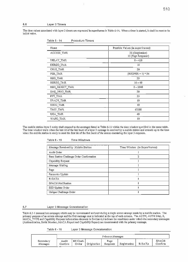
510
6.6 Layer 3 Timers
The time valúes associated with layer 3 timers are expressed in superframes in Table 6-14. When a timer is started, it shall be reset to itsinitial valué.
Table 6-14 Procedure Timers
Ñame
ACCESS JTMR
DELAYJTMR
DEREGJTMR
ORIGJTMR
PERJTMR
REGJTMR
REREG_TMR
REG_REJECT_TMR
SMS_ORIG_TMR
PPTJTMR
SPACHJTMR
SSDU_TMR
TMSIJTMR
UGA_TMR
WAFOJTMR
Possible Valúes (in superframes)
25 (Origination)15 (Page Response)
0-420
10
20
( R E G P E R + I ) * 9 4
25
16-40
0-2048
20
25
10
10
67500
40
10
The mobile station layer 3 entity shall respond to the messages Usted in Table 6-15 wiíhin the time window specified ín the same table.The time window starts when íhe lasí bit of the last burstof a layer 3 message is received by a mobile síation and exíends up ío the timewhen the mobile station is ready to send the firstbit of the first burstof the access containíng the layer 3 response.
Table 6-15 Time Windows
Message Received by Mobile Station
Audit Order
Base Station Challenge Order Confirmation
Capability Request
Message Waiting
Page
Parameter Update
R-DATA
SPACH Notificaíion
SSD Update Order
Unique Challenge Order
Time Window (in Superframes)
1
2
1
1
1
1
1
1
1
1
6.7 Layer 3 Message Concatenation
Table 6.7-1 summarizes messages which may be concatenated and sent during a single access attempt made by a mobile station. Theprimary purpose of an access attempt and the first message sent is indicated at the top of each column. The AUTH, AUTH Map, S,MACAJTYPE and Capability Request information eiements in Section 6.5 indícate the conditions under which the secondary messages(Authentication, Serial Number, MACA Report and Capability Report) are concatenated with the primary message.
Table 6 - 1 6 Layer 3 Message Concatenation
SecondaryMessages
Primary Messages
AuditConfirm
BS Chali.Order Origination
PageResponse Regístration R-DATA
SPACHConfirm

511
Authenti catión
Serial Number
MACA Report
Capabilíty Report
N
N
Y
N
N
Y
N
N
Y
Y
Y
N
Y
Y
Y
N
Y
Y
Y (Note 1)
Y
Y
Y
N
N
Y
Y
Y
N
Note I: MACA Report is not required for a Power Do\vn Registration.

512
ANEXO C: ESTADOS DEL PROCESO DE HANDOFF
c.l. MEDICIÓN
Los canales sirvientes realizan dos funciones principales en el proceso del
handoff. El primero es medir el RSI (Received Signa! Indicator) del móvil durante
toda la duración de la llamada (el RSI es medido en el canal de voz de reversa), y
segundo soportar la ejecución del handoff. Las medidas ayudan a suprimir la
variabilidad inherente en las lecturas del RSI, y proveen más seguridad en la
información que puede ser usada para deducir la distancia del móvil desde el
centro de la celda y la calidad de la llamada.
c.2. DISPARO
Cada canal de voz está provisto con un valor de umbral para cada llamada, el
cual se utiliza para determinar cuando el handoff debería ser disparado. Como se
lo mencionó en la parte de mantenimiento de la calidad de la señal y
configuración de las celdas, este umbral se conoce como nivel bajo de umbral de
handoff (HTL), y es derivado de la configuración de las diferentes celdas y de las
características del móvil en las llamadas. La figura c.1 ilustra el comportamiento
del HTL
Fig. c.1: Diagrama del HTL

513
La frontera entre cualquier par de celdas está definida por un factor conocido
como el nivel bajo de umbral de un par de celdas (PCTL), el cual determina el RSI
al que un móvil que se encuentra lo suficientemente lejos de la celda sirviente, es
considerado como candidato a realizar un handoff.
9 Puesto que el radio del canal de voz no puede determinar la dirección que sigue
el móvil, debe accionar el handoff en el punto más cercano donde podría
apagarse por el nivel de señal. Por esta razón el valor del HTL para una celda se
define como el máximo valor de los factores PCTL con las celdas adyacentes, tal
como se indica en la figura c.2.
HTLA = máx (PCTUe, PCTLAc, ..., PCTLAM)
RSIA < HTLA
Fig. c.2: Nivel bajo de umbral de un par de celdas
c.3. EXPLORACIÓN
Una vez que la central celular recibe la solicitud de handoff, debe entonces
determinar donde se está moviendo el móvil, y si una celda adyacente puede
servir mejor a la llamada.
Ya que la información de la dirección no está disponible, la central sondea las
celdas adyacentes y solicita que se realicen las medidas de RSI. Cualquier celda

514
que cumpla con el criterio mínimo responderá a la solicitud de medida con una
respuesta del canal receptor de localización (LCR) bajo condiciones normales.
Para que una celda sea considerada como adyacente para una petición de
handoff, debe cumplir los siguientes requisitos:
- Ser ingresada en el software de la central que indique los procesos de handoff.
- La celda debe estar dentro de la región de operación de la central celular.
Las medidas del RSI de la celda deben estar por debajo del PCTL establecido
entre la celda sirviente y las celdas adyacente. En el ejemplo de la figura c.2 si
RSU cae por debajo de PCTLAB solamente la celda B empieza a realizar las
mediciones del nivel de RSIBj lo mismo ocurre con la celda C si el RSIA cae
por debajo del PCTLAc-
Básicamente el PCTL asegura que el móvil que se encuentre lo bastante lejos de
la celda sirviente, tenga (posiblemente) acceso al área de cobertura de la celda
adyacente. Cuando la celda ha pasado la verificación de que es adyacente, la
central debe determinar si el móvil se encuentra servido de mejor manera que la
celda anterior. Se debe mencionar que es deseable que el móvil no dispare otro
handoff inmediatamente (a pesar de que esto no siempre sucede) después del
primero, en otras palabras, el móvil debería ser pasado a una celda donde su RSI
esté por encima del HOTL de esa celda. Si esto no es posible, entonces al menos
el handoff no debería intentarse de regreso a la celda original, por lo que el RSI
del móvil debe estar por encima del umbral del PCTL definido en la dirección de
reversa.
Bajo estas circunstancias, puede darse el caso de que se permita al móvil pasar a
una celda con una lectura de RSI más baja. Esto ocurre algunas veces en donde
se tienen escenarios de coberturas de macroceldas/microceldas donde las
medidas del RSI en las macroceldas siempre tienen un valor más alto. Para
facilitar el handoff dentro de las microceldas se puede cambiar el criterio para una

515
señal más fuerte, reemplazando los parámetros respectivos en la programación
de la central celular.
Una celda adyacente es eliminada como un posible candidato para el handoff a
menos que cumpla con al menos uno de los tres criterios de RSI indicados a
continuación, lo que implica el mínimo RSI enviado al LCR;
El RSI de una celda adyacente es más grande que su RSI actual.
El RSI de una celda adyacente es más grande que el HOTL de la celda
adyacente.
El RSI de una celda adyacente es más grande que el umbral del PCTL desde
la celda adyacente a la celda sirviente actual.
La central envía una solicitud de medida del RSI a cada celda adyacente
candidata conteniendo el SAT y el canal a ser medido, y también el mínimo nivel
RSI requerido. Cualquier medida del RSI en una celda adyacente que no exceda
este mínimo valor no es reportada por el LCR.
Los receptores de localización toman las medidas de las particiones adyacentes,
cuyas lecturas son cortas en duración (comparables a las medidas de los canales
de voz), debido al alto volumen de mensajería presente en el sistema. Para
asegurar que la variabilidad en las medidas no vaya en contra de la lógica del
proceso y decisión del handoff, al criterio del RSI se agregan valores de
compensación de histéresis.
Generalmente nacen dos tipos de valores de histéresis, ya que el error esperado
en comparación a dos valores de RSI es más grande en comparación a un umbral
de RSI establecido. De esta reflexión, matemáticamente el valor mínimo
aceptable de RSI para una partición adyacente es el menos de los siguientes
casos:

516
- RSIA+ PCHlSTAB
- PCTLBA+HISTB
- HTLB+HISTB
A continuación se va a proceder a ejemplificar cada uno de los casos anteriores
ya que es importante tener claro el panorama para realizar la optimización de los
procesos de handoff.
. Caso 1 - RSIB > RSIA + PCHISTAB
Se va a suponer que se tiene un móvil que se está moviendo entre dos celdas
homogéneas, como se muestra en la figura c.3.
Fig. c.3: Primer caso de handoff
Como se puede observar en la figura c.3, en la celda sirviente el umbral HTLA
es igual al factor PCTLAB, y conforme el móvil se va alejando de la celda A el
nivel de RSIA va disminuyendo. En el momento en que el móvil se acerca al

517
punto 1 se puede decir que el RSIA es comparable al RSIB, pero todavía no
ocurre el handoff, el móvil estaría ingresando al límite del handoff:
Fig. c.4: Límite de! handoff con posible efecto de ping pong
En este punto, el móvil es mejor servido por la celda B que por la celda
servidora ya que prácticamente se encuentra en la frontera de esta celda,
pero debido a diferentes factores que están fuera del alcance de los
operadores celulares como es los fenómenos físicos, climáticos, de radio
frecuencia, desvanecimiento, etc., las medidas del RSI son susceptibles a
errores.
Como se mencionó anteriormente, se introduce el parámetro de histéresis
PCHIST que define un incremento mínimo en el RSI solicitado, y lo que hace
es retrasar el handoff forzando la medida requerida en la celda candidata para
que sea más fuerte, además de evitar el efecto del ping-pong en
determinados puntos de las fronteras de las celdas. Esto ocasiona que los
handoffs de la celda B a la celda A ocurra en un lugar diferente que el handoff
de la celda A a la celda B, tal como se muestra en la figura c.5

518
HTLA
HTJLB
HandoffB -A
HandoffA - B
Fig. c.5: Límite del handoff con ajuste de histéresis
Con este retraso programado en la central celular, conforme el móvil se
acerca al punto 2 va a sucederse el handoff, ya que justamente en este punto
se va a presentar una pequeña área de sobrecobertura en donde se tiene el
siguiente nivel de señal:
RSIB>RSIA+PCHISTAB (Ec. c.1)
Una vez que el móvil ha cruzado al área plena de cobertura de la celda B, se
han cumplido las condiciones para el proceso del handoff, siendo RSlB mayor
a HTLB y al factor PCTLBAí que además será igual al umbral HTLB.
Caso 2 - RSIB > PCTLBA + HISTB
En este caso se va a ejemplificar el ambiente de macroceldas/microceldas.
Las microceldas son una opción para aliviar la carga de tráfico a las
macroceldas, además de dar cobertura dedicada en los lugares donde la
macrocelda no puede satisfacer las necesidades de ciertos lugares. Esto se
ilustra en ía figura c.6.

519
Fig. c.6: Segundo caso de handoff
Las características principales de las microceldas son que cubren áreas
dedicadas, por lo que la potencia es muy baja. Debido a esto el móvil podría
pasar de la celda A a la celda B sin realizar ningún handoff con la microcelda
C, pero esto no es lo que se desea, ya que uno de los objetivos de la
microcelda es ayudar a la celda A en el manejo del tráfico cursado.
Cuando el móvil se encuentra alrededor del punto 1, empiezan las lecturas del
RSIM cuyo valor es menor que el RSIA, lo cual es posible ya que el manejo
de éstos parámetros son programados en la central celular, que controlan ¡a
funcionalidad de los handoffs en situaciones específicas como en el caso de
las microceldas.
El punto 2 es el lugar donde finalmente ocurre el handoff, y en el que el
parámetro de histéresis juega un papel importante en el tipo de handoff que
se está analizando. Como se trata de un móvil que está ingresando hacia un
área de cobertura con menor nivel de señal que el de la celda sirviente, hay
que añadir el valor de la histéresis HISTc con un valor adecuado respecto al

520
umbral de un par de celdas ya programadas en la central. Este juego de
valores hará que se incremente el valor del factor PCTLCA para evitar que el
proceso de handoff pueda fallar, cumpliéndose la siguiente relación del nivel
de señal:
(Ec. c.2)
Se debe jugar de una manera muy cuidadosa con el valor de HISTC ya que si
está mal elegido se puede producir un efecto de ping pong y el móvil regrese
a su celda original.
Caso 3 - RSIB > HTLB + HISTB
En este caso se deben cumplir ciertas condiciones cuando los móviles se
están moviendo por celdas asimétricas, lo que se puede observar en el
diagrama c.7.
Fig. c.7: Tercer caso de handoff

521
En la figura c.7 cuando el móvil está acercándose al punto 1, el RSIA es
menor que el factor PCTLAB y es aquí donde se da comienzo a la lectura del
RSIB. Mientras el usuario sigue su trayectoria se puede observar que se
cumple la condición del primer caso de handoff, donde el RSIB es mayor que
la suma de los parámetros RSIA y PCHISTAB.
En el momento que el móvil pasa de las fronteras del handoff y se acerca al
punto 2 el RSIB es igual al PCTLBA añadido el parámetro HISTe- Por lo que al
producirse el handoff se cumple con la tercera relación, donde el valor del
umbral HTLB será igual al parámetro PCTLBCí y la medida de señal del móvil
en la celda B es:
RSlB> HTLB + HlSTB (Ec. c.3)
c.4. SELECCIÓN
La selección de la celda a la que se va a realizar el handoff se complica cuando
se disponen más de una celda candidata, y el móvil tiene que decidir a qué celda
pasar, obviamente bajo el criterio de la celda que le ofrece el mejor nivel y con el
menor número de reintentos de solicitud de handoff. Las respuestas del RSl son
seleccionadas basadas en que podría pasar si el móvil estuviera pasando a una
celda candidata, por lo que los criterios de selección son esencialmente los
mismos que para los establecimientos de los RSPs mínimos aceptables.
En ciertos sistemas, una ruta de tráfico pesado puede cortar o cruzar a través de
las "esquinas" de las celdas, lo que produciría handoffs cortos o inmediatos y
posteriormente volvería a pasar a la siguiente celda. A veces estos tipos de
handoffs no son importantes y se podría buscar la manera de evitar esto,
esencialmente cuando se tiene poca diferencia de dB's. Para esto en las centrales
de conmutación se puede programar un factor que se conoce como
predisposición (PDISP), el cual es un mecanismo que le ayuda al móvil segregar
las celdas candidatas y realizar handoffs directos.

522
La figura c.8 ilustra un supuesto caso de handoff directo.
Fig. c.8: Selección de celdas candidatas
En la figura se muestra un móvil que está viajando de la celda A a la celda B, pero
al pasar por la esquina de C el usuario haría un handoff rápido entre A y C; y
luego entre C y B. Lo que se desea es un handoff directo entre las celdas A y B,
por lo que bajo este escenario se introduce el PDSIP, teniendo algunas
posibilidades como las que se indican en el siguiente cuadro:
CELDA
ABC
RSI
-85-78-76
PDISP
030
RSI TOTAL
-80-75-76
Cuadro c.1: Elección de la celda B para realizar el handoff
Como se puede observar, aplicando el PDÍSP al RSI medido el operador puede
influir en el mecanismo de selección, permitiendo a las celdas moverse a
posiciones más altas o bajas en la lista haciendo que la misma se vea más o
menos atractiva que sus celdas vecinas y afecte la dirección del handoff.
Graficando la figura c.8 de otra manera se tendría;

523
B
Fig. c.9: Factor PDISP
Para este caso se puede sacar la siguiente relación:
RSIB> RSIc-PDISPAB
A pesar de esto, es importante recalcar que el PDSIP puede tener valores
positivos o negativos.
c.5. EJECUCIÓN
Una vez que la celda elegida es identificada, la ejecución de! handoffes idéntica
para todos los tipos de handoff. La central setea un nuevo canal de voz en la
celda seleccionada, ordena al móvil resintonizarse a ese canal y liberar los viejos
recursos. Esto se lleva a cabo de tal manera que se minimice ios trastornos en la
llamada, lo que minimiza las oportunidades de falla.