Calibration and Validation Plan - Nisar
162
Copyright 2018 California Institute of Technology. U.S. Government sponsorship acknowledged. Calibration and Validation Plan V0.9 JPL D-80829 5/14/2018 National Aeronautics and Space Administration Jet Propulsion Laboratory California Institute of Technology Pasadena, California
-
Upload
khangminh22 -
Category
Documents
-
view
1 -
download
0
Transcript of Calibration and Validation Plan - Nisar

Copyright 2018 California Institute of Technology. U.S. Government sponsorship acknowledged.
Calibration and Validation Plan
V0.9
JPL D-80829
5/14/2018
National Aeronautics and Space Administration
Jet Propulsion Laboratory California Institute of Technology Pasadena, California

Copyright 2018 California Institute of Technology. U.S. Government sponsorship acknowledged.
Document Change Log Revision Cover Date Sections Changed ECR # Reason, ECR Title, LRS #*
V1.0 05/10/2017 All N/A New document

NISAR V0.9 Cal/Val Plan JPL D-80829 5/14/18
CL# 17-1968 i
KEY AUTHORS Bruce Chapman, Jet Propulsion Laboratory, California Institute of Technology Paul Rosen, Jet Propulsion Laboratory, California Institute of Technology Ian Joughin, University of Washington Paul Siqueira, University of Massachusetts Sassan Saatchi, Jet Propulsion Laboratory, California Institute of Technology Victoria Meyer, Jet Propulsion Laboratory, California Institute of Technology Adrian Borsa, University of California, San Diego Franz Meyer, University of Alaska, Fairbanks Marc Simard, Jet Propulsion Laboratory, California Institute of Technology Rowena Lohman, Cornell University Josef Kellndorfer, EarthBigData, LLC Naiara Pinto, Jet Propulsion Laboratory, California Institute of Technology Ben Holt, Jet Propulsion Laboratory, California Institute of Technology Mark Simons, California Institute of Technology Eric Rignot, University of California, Irvine Cathleen Jones, Jet Propulsion Laboratory, California Institute of Technology Scott Hensley, Jet Propulsion Laboratory, California Institute of Technology Sean Buckley, Jet Propulsion Laboratory, California Institute of Technology Yuhsyen Shen, Jet Propulsion Laboratory, California Institute of Technology Scott Shaffer, Jet Propulsion Laboratory, California Institute of Technology Steve Durden, Jet Propulsion Laboratory, California Institute of Technology Stephen Horst, Jet Propulsion Laboratory, California Institute of Technology Priyanka Sharma, Jet Propulsion Laboratory, California Institute of Technology Chandini Veeramachaneni, Jet Propulsion Laboratory, California Institute of Technology Richard West, Jet Propulsion Laboratory, California Institute of Technology Raj Kumar, Space Applications Center, ISRO Shweta Sharma, Space Applications Center, ISRO Aloke Mathur, Space Applications Center, ISRO

NISAR V0.9 Cal/Val Plan JPL D-80829 5/14/18
CL# 17-1968 ii
TABLE OF CONTENTS 1 Introduction ...................................................................................................... 1
1.1 Purpose ........................................................................................................... 1 1.2 Scope and Objectives ..................................................................................... 1 1.3 Document Overview ........................................................................................ 2
2 Science and Mission Overview ........................................................................ 3
2.1 Science Objectives .......................................................................................... 3 2.1.1 Solid Earth Science Objectives .................................................................... 3 2.1.2 Ecosystems Science Objectives................................................................... 3 2.1.3 Cryosphere Science Objectives ................................................................... 3 2.1.4 Disaster Response Application Objectives ................................................... 4
2.2 Science Requirements .................................................................................... 4 2.2.1 Measurements ............................................................................................. 4 2.2.2 Data Delivery ............................................................................................... 6
2.3 Mission Implementation Approach .................................................................. 6 2.3.1 Measurement Approach ............................................................................... 6
2.4 Science Data Products .................................................................................... 9 2.5 Disaster Response Application Data Products ................................................ 9 2.6 Science Data System (SDS) ......................................................................... 11 2.7 Mission Operations ....................................................................................... 12
2.7.1 Mission Operations Phases........................................................................ 12 2.7.2 Calibration and Validation (Cal/Val) Phase ................................................. 12 2.7.3 Science Observations Phase ..................................................................... 13
3 Calibration and Validation overview .............................................................. 14
3.1 Background ................................................................................................... 14 3.2 Definitions ..................................................................................................... 15 3.3 Pre-Launch Summary ................................................................................... 15
3.3.1 Implementation Verification ........................................................................ 17 3.3.2 Coordinated Pre-Launch Field Campaign Activities ................................... 17
3.4 Post-Launch .................................................................................................. 19 3.4.1 Post-Launch Cal/Val Timeline .................................................................... 19
3.5 Calibration and Validation Database ............................................................. 23 3.6 In Situ Experiment Site Overview .................................................................. 25
3.6.1 Resource Networks .................................................................................... 25 3.7 NISAR Cal/Val Site Overview........................................................................ 31 3.8 Aircraft-based Sensors .................................................................................. 32 3.9 Synergistic Satellite Observations ................................................................. 34

NISAR V0.9 Cal/Val Plan JPL D-80829 5/14/18
CL# 17-1968 iii
3.10 Field Experiments ......................................................................................... 34 3.11 Cal/Val Roles and Responsibilities ................................................................ 38 3.12 Community Engagement ............................................................................... 40 3.13 Cal/Val Program Deliverables ....................................................................... 41
4 Cal/Val Strategies........................................................................................... 42
4.1 Cal/Val Strategy for L-band Instrument ......................................................... 42 4.1.1 Pre-launch Cal/Val for L-band Image Calibration ....................................... 44 4.1.2 Post Launch Cal/Val for L-band Image Calibration ..................................... 46 4.1.3 In Situ Experiment Sites ............................................................................. 49
4.2 Cal/Val Strategy for Solid Earth Science Requirements ................................ 52 4.2.1 Pre-launch Cal/Val for Solid Earth Science Requirements ......................... 57 4.2.2 Post Launch Cal/Val for Solid Earth Science Requirements ....................... 57 4.2.3 In Situ Experiment Sites ............................................................................. 59
4.3 Cal/Val Strategy for Cryosphere Science Requirements ............................... 63 4.3.1 Fast/Slow Deformation of Ice Sheets and Glacier Velocity ......................... 63 4.3.2 Vertical Displacement and Fast Ice-Shelf Flow .......................................... 64 4.3.3 Sea Ice Velocity ......................................................................................... 66 4.3.4 Pre-Launch Cal/Val for Cryosphere ............................................................ 71 4.3.5 Post-Launch Cal/Val for Cryosphere .......................................................... 71
4.4 Cal/Val Strategy for Ecosystem Requirements ............................................. 72 4.4.1 Forest Biomass Cal/Val Strategy................................................................ 73 4.4.2 Forest Disturbance Cal/Val Strategy .......................................................... 80 4.4.3 Crop Area Cal/Val Strategy ........................................................................ 82 4.4.4 Inundation Area Cal/Val Strategy ............................................................... 83 4.4.5 Pre-launch Activities for Ecosystem Science Cal/Val ................................. 87 4.4.6 Post-launch Activities for Ecosystem Science Cal/Val ................................ 93 4.4.7 In Situ Experiment Sites ............................................................................. 97
4.5 Cal/Val Strategy for Disaster Response Applications .................................. 114
5 Calibration and Validation of NISAR Products ............................................ 115
5.1 Level 1 Sensor Products ............................................................................. 115 5.2 Level 2 Data Products ................................................................................. 115 5.3 Level 3 Science Products ............................................................................ 116
6 Joint NASA-ISRO Cal/Val Activities........................................................... 120
7 References .................................................................................................... 122
8 APPENDICES ............................................................................................. 126
8.1 Acronyms .................................................................................................... 126 8.2 Requirements .............................................................................................. 127

NISAR V0.9 Cal/Val Plan JPL D-80829 5/14/18
CL# 17-1968 iv
8.3 UAVSAR Deployments for NISAR Calibration and Validation ..................... 130 8.3.1 Ecosystem UAVSAR Cal/Val Campaign .................................................. 130
8.4 Post-launch wetland inundation UAVSAR campaign .................................. 133 8.5 Generating a Disturbance Validation Dataset from VHR Optical Data for the
NISAR Disturbance Validation .................................................................... 136 8.5.1 VHR Measurement of Forest Fractional Canopy Cover Change .............. 136 8.5.2 Classification Methods ............................................................................. 137 8.5.3 Data Acquisition and Pre-Processing ....................................................... 137 8.5.4 Supervised Classification Approach ......................................................... 138 8.5.5 Error Sources ........................................................................................... 138 8.5.6 Generation of 1-hectare FFCC Change Estimates ................................... 139 8.5.7 WorldView-2 Example of the Direct Change Detection Method ................ 141 8.5.8 References .............................................................................................. 146
8.6 Measuring Inundation Extent Using a DTM and Water Level Gauges ........ 147 8.7 Algorithm for the Active Crop Area Validation Product ................................ 149 8.8 Inundation Validation Products.................................................................... 149
TABLE OF FIGURES Figure 2-1. Regions of coverage for measuring time-varying displacements over land .................. 5 Figure 2-2. Regions of coverage for measuring time-varying displacements over ice and sea ice .. 5 Figure 2-3. Regions of coverage for measuring biomass, disturbance, inundation area, and
cropland area.......................................................................................................................... 6 Figure 2-4. Illustration of NISAR measurement system over the Amazon. ................................... 7 Figure 2-5. Illustration of SDS System Design........................................................................... 11 Figure 3-1. Database architecture illustrated with a subset of NISAR products ........................... 23 Figure 3-2. Database products ................................................................................................... 25 Figure 3-3. Validation sites (stars) overlayed on SMAP HH so image. ....................................... 30 Figure 3-4. Roles and Responsibilities ....................................................................................... 39 Figure 4-1. ALOS-2 L-band SAR image mosaic showing location of Surat Basin ..................... 51 Figure 4-2. ALOS 2 L-band SAR image mosaic at higher resolution. ......................................... 51 Figure 4-3. Nominal Corner Reflector deployment plan f .......................................................... 52 Figure 4-4. Location of 1860 GPS sites in Western US ............................................................... 53 Figure 4-5. Cal/Val sites from Table 4-5 ..................................................................................... 61 Figure 4-6: Preliminary locations of sites used for NISAR ice velocity validation. ..................... 63 Figure 4-7. Example deployment of GPS along a flow line and on the Ross Ice Shelf. .............. 65 Figure 4-8. Example of validation of SAR-derived glacier velocity data using GPS .................... 66 Figure 4-9. Representative maps of Arctic drift buoys ................................................................ 69 Figure 4-10. Representative monthly map of Antarctic drift buoys. ............................................ 69

NISAR V0.9 Cal/Val Plan JPL D-80829 5/14/18
CL# 17-1968 v
Figure 4-11. Examples of buoy and Radarsat-1 (line) trajectories ............................................... 70 Figure 4-12. Alos-1 derived ice motion and buoy-interpolated vector's ....................................... 71 Figure 4-13. Biomass validation approach ................................................................................. 73 Figure 4-14. Modification of WWF terrestrial ecoregions. ......................................................... 78 Figure 4-15. Location of GLAS shots where AGB was estimated, ALOS-2 image mosaic .......... 79 Figure 4-16. Average L-HV versus GLAS estimates of AGB for example sub-ecoregions. ......... 80 Figure 4-17. Biomass Cal/Val sites ............................................................................................ 98 Figure 4-18: GFOI research and development study sites ......................................................... 104 Figure 4-19. Distribution of JECAM sites worldwide. ............................................................. 108 Figure 8-1. First leg of UAVSAR ecosystems "gas and go" loop. ............................................ 131 Figure 8-2. Second leg of UAVSAR ecosystems "gas and go" loop. ........................................ 131 Figure 8-3. UAVSAR ecosystems Single loop scenario ........................................................... 132 Figure 8-4. Nominal flight plan to image Cal/Val wetland sites in Alaska ................................ 133 Figure 8-5. Nominal flight plan to image Cal/Val wetland sites in the Mississippi Delta and
Everglades areas. ............................................................................................................... 134 Figure 8-6. Nominal flight plan to image Cal/Val wetland sites in the Colombia (Mangrove site)
and the Pacaya-Samiria in Peru. ....................................................................................... 134 Figure 8-8. Spectral Bands of WorldView-2. ............................................................................ 137 Figure 8-7. Typical optical reflectance signatures for vegetation and soils. ............................... 137 Figure 8-9. Area mismatch in one-hectare cells........................................................................ 139 Figure 8-10. Histogram equalized false color infrared/red/green imagery of WorldView-2 data 141 Figure 8-11. Band-by-band comparison of all eight WorldView-2 bands .................................. 143 Figure 8-12. Band 5 multi-temporal false color composite Collected polygons for direct change
classification. ..................................................................................................................... 144 Figure 8-13. Band 5 multi-temporal false color composite. Training data polygons for direct
change classification. ......................................................................................................... 144 Figure 8-14. Result of change classification and hectare scale production of fractional forest
canopy cover change from WorldView-2 VHR optical image change detection. ................ 146 Figure 8-15. Determination of inundation extent in wetlands from accurate knowledge of terrain
topography and water level. ............................................................................................. 148 Figure 8-16. Using GPS tracking to delineate inundation extent............................................... 150 Figure 8-17. sUAS imagery using a "red edge" camera for two areas. .................................... 151 Figure 8-18. Redege camera classification by S. Schill versus UAVSAR Freeman-Durden
decomposition, Ogooue river, Gabon. ................................................................................ 152 Figure 8-19. sUAS RGB image of APEX site, Bonanza Creek, June 2017 ............................... 153

NISAR V0.9 Cal/Val Plan JPL D-80829 5/14/18
CL# 17-1968 vi
TABLE OF TABLES Table 2-1. Key Measurement System Characteristics ................................................................... 8 Table 2-2. List of NISAR Data Products. ................................................................................... 10 Table 3-1. Pre-launch Cal/Val Timeline ..................................................................................... 16 Table 3-2 Pre-launch activities regarding field campaigns .......................................................... 18 Table 3-3. Detailed Post-launch In-Orbit Check-out (IOC) phase Timeline ................................. 20 Table 3-4. Post-launch Cal/Val Timeline .................................................................................... 21 Table 3-5. Post-launch activities ................................................................................................ 22 Table 3-6: Summary of GIS and ancillary tables for calibration/validation of NISAR products ... 24 Table 3-7a. Summary of Cal/Val Resource Networks - Ecosystems ............................................ 28 Table 3-7b. Summary of Cal/Val Resource Networks - Cryosphere ............................................ 29 Table 3-7c. Summary of Cal/Val Resource Networks – Solid Earth ............................................ 29 Table 3-7d. Summary of Cal/Val Resource Networks – Sampling of Instrument Calibration
Targets ................................................................................................................................. 30 Table 3-8. Summary of Cal/Val Validation Sites ........................................................................ 32 Table 3-9. Existing or near-term Aircraft-based Sensors ............................................................. 33 Table 3-10. Example high-resolution data from commercial optical sensors .............................. 34 Table 3-11. Scope of field campaigns ........................................................................................ 36 Table 3-12. Field Experiments for NISAR Cal/Val ..................................................................... 37 Table 3-13. Cal/ Val Roles and Responsibilities ......................................................................... 40 Table 4-1. Image calibration and performance requirements ....................................................... 44 Table 4-2 Instrument parameters and calibration requirements.................................................... 45 Table 4-3 Post-launch Summary of Instrument parameters, measurements, and calibration
requirements ........................................................................................................................ 46 Table 4-4 Image performance ..................................................................................................... 49 Table 4-5. Table of Solid Earth Science Cal/Val regions (chosen to represent diversity of targets
and GPS coverage). .............................................................................................................. 60 Table 4-6: Active permafrost sites in Alaska .............................................................................. 62 Table 4-7: Minimum Lidar characteristics. CHM: Canopy Height Model. .................................. 76 Table 4.8. Characteristics of wetland Cal/Val sites .................................................................... 87 Table 4-9. Biomass Cal/Val sites with contemporary field measurements and Lidar data
acquisitions for pre-launch Cal/Val. ................................................................................... 100 Table 4-10. Nominal biomass Cal/Val sites where new Lidar data acquisitions will be needed for
the post-launch validation .................................................................................................. 102 Table 4-11. NEON sites that could be imaged by UAVSAR ecosystem campaign ................... 112 Table 4-12. Other research sites that could be imaged by UAVSAR ecosystem campaign ....... 113 Table 4-13. Disaster Response Low-Latency Operation ............................................................ 114 Table 5-1. Level 1 products and associated Cal/Val requirements ............................................. 115 Table 5-2. Level 2 products and associated Cal/Val requirements ............................................. 116

NISAR V0.9 Cal/Val Plan JPL D-80829 5/14/18
CL# 17-1968 vii
Table 5-3a. Level 3 products and associated Cal/Val requirements – Solid Earth ...................... 117 Table 5-3b. Level 3 products and associated Cal/Val requirements – Cryosphere ..................... 118 Table 5-3c. Level 3 products and associated Cal/Val requirements – Ecosystem ....................... 119 Table 8-1 Level 1 Requirements ............................................................................................... 127 Table 8-2. NISAR Level 1 Science Requirements Summary ..................................................... 128 Table 8-3. Summary of UAVSAR flight campaigns for wetland inundation ............................ 135 Table 8-4. Predictor (band) importance in the trained randomForest model for change detection
from canopy to non-canopy pixels. ..................................................................................... 145 Table 8-5. Confusion matrix of prediction on the testing population ......................................... 145

NISAR V0.9 Cal/Val Plan JPL D-80829 5/14/18
CL# 17-1968 1
1 INTRODUCTION
1.1 Purpose This document describes the plan for calibrating and validating Level 1 through Level 3 science data products of the NASA ISRO Synthetic Aperture Radar (NISAR) Mission. The NISAR Calibration and Validation (Cal/Val) Plan is the basis for implementation of the detailed set of calibration and validation activities that take place during the NISAR mission lifetime.
1.2 Scope and Objectives The NASA-ISRO Synthetic Aperture Radar (SAR), or NISAR, Mission will make global integrated measurements of the causes and consequences of land surface changes. NISAR provides a means of disentangling highly spatial and temporally complex processes ranging from ecosystem disturbances, to ice sheet collapse and natural hazards including earthquakes, tsunamis, volcanoes, and landslides.
NISAR’s unprecedented coverage in space and time will reveal forces acting within the Earth and on its surface, biomass variability, and response of ice masses far more comprehensively than any other measurement method. The detailed observations will reveal information about the evolution and state of the Earth’s crust.
The NASA-ISRO SAR (NISAR) Mission will acquire radar images of surface changes globally. Rapid sampling over years will allow for understanding Earth processes and change. Orbiting radar captures images of the movements of the Earth’s surface, and land and sea ice over time and with sufficient detail to reveal subtle changes and what is happening below the surface. It captures forest volume and biomass over time and with enough detail to reveal changes on hectare scales. It produces images with resolution to see local changes and has broad enough coverage to measure regional events. Images are detailed enough to see local changes, and coverage is broad enough to measure regional trends and events. The detailed observations will reveal information allowing us to better manage resources and prepare for and cope with hazards and global change.
ISRO has identified a range of applications of particular relevance to India that the mission will also specifically address, including monitoring of agricultural biomass over India, snow and glacier studies in the Himalayas, Indian coastal and near-shore ocean studies, and disaster monitoring and assessment.
NISAR mission science requirements are contained in the Science Requirements and Mission Success Criteria (SRMSC) document. Stated in the SRMSC is the requirement that a Calibration and Validation Plan be developed and implemented to assess random errors and spatial and temporal biases in the NISAR products, and that the NISAR validation program shall demonstrate that NISAR retrievals of co-seismic, secular and transient deformation rates, fast and slow ice sheet deformation and glacier velocities, sea ice velocity, permafrost deformation, biomass, forest disturbance, crop area, and inundation extent meet the stated science requirements.
The NISAR Cal/Val Plan includes pre-launch and post-launch activities starting in Phase C and continuing after launch and commissioning through the end of the mission (Phase E). The scope of the Cal/Val plan is the set of activities that enable the pre-and post-launch Cal/Val objectives to be met.

NISAR V0.9 Cal/Val Plan JPL D-80829 5/14/18
CL# 17-1968 2
• The Pre-Launch objectives of the Cal/Val program are to:
- Acquire and process data with which to calibrate, test, and improve models and algorithms used for retrieving NISAR science data products;
- Develop and test techniques and protocols used to acquire validation data and to validate NISAR science products in the post-launch phase.
• The Post-Launch objectives of the Cal/Val program are to:
- Verify and improve the performance of the science algorithms;
- Calibrate or update the calibration of any necessary algorithm parameters;
- Validate the accuracy of the science data products.
1.3 Document Overview Section 1 Provides introductory information on scope and contents. Section 2 Provides an overview of NISAR science objectives, data products, and mission
operations. Section 3 Provides an overview NISAR calibration and validation activities Section 4 Describes calibration and validation strategies for image calibration and for each the
science requirements within each of the science disciplines Section 5 Describes the calibration and validation of NISAR products Section 6 Describes Joint NASA-ISRO Cal/Val activities Section 7 Provides a list of references Section 8 Appendices

NISAR V0.9 Cal/Val Plan JPL D-80829 5/14/18
CL# 17-1968 3
2 SCIENCE AND MISSION OVERVIEW
2.1 Science Objectives Earth's surface and vegetation cover are constantly changing on a wide range of time scales. Measuring these changes globally from satellites would enable breakthrough science with important applications to society. As an all-weather, day/night imaging system, NISAR will expand the value of NASA’s missions for applications that rely on systematic and reliable sampling.
The NISAR mission will be the first NASA’s radar mission to systematically and globally study the solid Earth, the ice masses, and ecosystems, all of which are sparsely sampled at present. The NISAR mission has three science areas and associated science objectives: Solid Earth Science, Ecosystems Science, and Cryosphere Science, as well as a Disaster Response application.
2.1.1 Solid Earth Science Objectives
The NISAR mission will provide radar data and science products to: • Observe secular and local surface deformation on active faults to model earthquakes
and earthquake potential. • Catalog and model aseismic deformation in regions of high hazard risk. • Observe volcanic deformation to model the volcano interior and forecast eruptions. • Map pyroclastic and lahar flows on erupting volcanoes to estimate damage and model
potential future risk. • Map fine-scale potential and extant landslides to assess and model hazard risk. • Characterize aquifer physical and mechanical properties affecting groundwater flow,
storage, and management. • Map and model subsurface reservoirs for efficient hydrocarbon extraction and CO2
sequestration.
2.1.2 Ecosystems Science Objectives
The NISAR mission will provide radar data and science products to: • Determine biomass values of forested areas under 100 Mg per Hectare • Determine locations of disturbance in woody vegetation areas. • Determine the location and area of active crops in agricultural systems. • Determine the extent of wetlands and characterize the dynamics of flooded areas.
2.1.3 Cryosphere Science Objectives
The NISAR mission will provide radar data and science products to: • Understand the response of the ice sheets to climate change. • Incorporate ice sheets displacement information into climate models to understand the
contribution of ice sheets to sea-level change. • Understand the interaction between sea ice and climate.

NISAR V0.9 Cal/Val Plan JPL D-80829 5/14/18
CL# 17-1968 4
• Characterize freeze/thaw state, surface deformation, and permafrost degradation. • Characterize the short-term interactions between the changing polar atmosphere and
changes in sea ice, snow extent, and surface melting. • Characterize surface deformation in permafrost regions.
2.1.4 Disaster Response Application Objectives
The NISAR mission will provide radar data and science products to: • Detect, characterize and model potential hazards and disasters. • Characterize secondary hazards associated with primary events. • Demonstrate rapid damage assessment to support rescue and recovery activities,
system integrity, lifelines, levee stability, urban infrastructure, and environment quality.
2.2 Science Requirements The NISAR Level 1 science requirements are the basis for achieving the science objectives of the mission. The Level 1 science requirements are listed in Appendix, Table 8-1.
2.2.1 Measurements
The NISAR mission is capable of performing repeat-pass interferometry and collecting polarimetric data. The core of the payload consists of an L-band SAR to meet all of the NASA science requirements. A secondary S-band SAR will be contributed by ISRO. It includes a large diameter deployable reflector and a dual frequency antenna feed to implement the SweepSAR concept. The payload also includes a Global Positioning System (GPS) for precision orbit determination. Due to a large amount of science data, a high rate data downlink subsystem and a solid-state recorder are included in the NISAR payload.
The Level 1 ‘Baseline’ and ‘Minimum’ NISAR science requirements are summarized in the appendix, Table 8-2. The requirements are derived from science assessments, reviewed in a series of NASA and community workshops. The science behind these requirements is summarized in the NISAR Science Users’ Handbook: (https://nisar.jpl.nasa.gov/files/nisar/NISAR_Science_Users_Handbook.pdf). The requirements are to be met over areas identified by the regions shown in Figures 2-1, 2-2, and 2-3.

NISAR V0.9 Cal/Val Plan JPL D-80829 5/14/18
CL# 17-1968 5
Figure 2-1. Regions of coverage for measuring time-varying displacements over land
Figure 2-2. Regions of coverage for measuring time-varying displacements over ice and sea ice

NISAR V0.9 Cal/Val Plan JPL D-80829 5/14/18
CL# 17-1968 6
2.2.2 Data Delivery
NISAR requirements are that no later than six months after the end of the observatory commissioning phase (Section 2.6) the NISAR project shall begin the first release of validated Level 0 and Level 1 instrument data products (Section 2.4) for distribution to the public. Similarly, no later than twelve months after the end of the observatory commissioning phase, the NISAR project shall begin the first release of validated Level 3 and Level 4 geophysical data products for distribution to the public. The final processed mission data set shall be available for delivery to the public within six months after the end of the mission.
2.3 Mission Implementation Approach
2.3.1 Measurement Approach
The NISAR measurement configuration is shown in Figure 2-4. Key features of the system are provided in Table 2-1.
Figure 2-3. Regions of coverage for measuring biomass, disturbance, inundation area, and cropland area.

NISAR V0.9 Cal/Val Plan JPL D-80829 5/14/18
CL# 17-1968 7
Figure 2-4. Illustration of NISAR measurement system over the Amazon.
To meet the requirements of all science disciplines, the radar instrument must be able to deliver fast sampling, global access and coverage, at full resolution and with polarimetric diversity. The technological innovation that allowed this was the development of the “SweepSAR” concept, conceived and refined jointly with engineering colleagues at the German Space Agency (DLR) under the DESDynI study phase.
With SweepSAR, the entire incidence angle range is imaged at once as a single strip-map swath, at full resolution depending on the mode, and with full polarization capability if required for a given area of the interest. Azimuth resolution is determined by the 12-m reflector diameter and is of order 8 m. L- and S- band are being designed such that they share clock and frequency references, allowing them to be operated simultaneously.

NISAR V0.9 Cal/Val Plan JPL D-80829 5/14/18
CL# 17-1968 8
Table 2-1. Key Measurement System Characteristics
Units Value Altitude km 747
Repeat Period days 12.0
Eq Ground-Track Spacing km 242
Mission Duration Years 3
Orbit Inclination Degrees 98.5
Orbit Eccentricity 0
Nom. Look direction Left/Right Right
Arctic Polar Hole Degrees 87.5R/77.5L
Antarctic Polar Hole Degrees 77.5R/87.5L
Nodal Crossing Time 6 AM
Antenna diameter m 12
L-band Radar Center Frequency Mhz 1260
L-band Realizable Bandwidths Mhz 5, 20+5, 25, 37.5, 40+5, 80
L-band Realizable polarizations Single through quad-pol,
including split-band dual pol and compact pol
Incidence Angle Range Degrees 34-48
BFPQ bits 16 to 3,4, or 8 (4 nominal)
Pulse Width µs 10-45

NISAR V0.9 Cal/Val Plan JPL D-80829 5/14/18
CL# 17-1968 9
2.4 Science Data Products The NISAR science requirements will be met by generating the data products listed in Table 2-2 for Calibration and Validation sites. The data products will be generated by the NISAR Science Data System (SDS) (Section 2.6). Science software for the data products will be developed using a set of algorithms described in the Algorithm Theoretical Basis Documents (ATBDs). There will be one ATBD for each science data product. The ATBDs form part of the overall NISAR Algorithm Development Plan. Implementation of this Cal/Val Plan will provide documented assessments of the random errors and regional biases in the science data products and will provide verification that the NISAR mission science requirements and objectives are met.
(http://science.nasa.gov/earth-science/earth-science-data/data-processing-levels-for-eosdis-data-products/)
2.5 Disaster Response Application Data Products NISAR has a L1 requirement to reschedule new acquisitions within 24 hours in response to a disaster or disaster forecast notification (‘event’) and to provide data products covering the event site within 5 hours of being collected. This differs from the science product stream only the latency of operations and processing, not in the type of data that is delivered. The NISAR application requirement will be met through the implementation of low-latency streams for tasking/re-tasking the instrument, data downlink and transfer, data processing through L1 and L2 product generation, and product delivery. The process outline is specified in the NISAR Application Plan.

NISAR V0.9 Cal/Val Plan JPL D-80829 5/14/18
CL# 17-1968 10
Table 2-2. List of NISAR Data Products.
Data Product Description Initial data delivery to
NASA DAAC
Initial calibrated delivery to NASA DAAC
Latency of NASA DAAC delivery (Nominal TBD)
Level 0B Raw radar data and associated metadata, reformatted telemetry
2 months after the start of the science phase N/A Within 24 hours of
receipt at JPL
Calibration Data Calibration parameters for high level data processing
2 months after the start of the science phase (preliminary calibration)
5 months after the start of the science phase (fully calibrated)
Within TBD days of periodic calibration update
Precision Orbit Determination Data
Precision orbit data derived from GPS
2 months after the start of the science phase
5 months after the start of the science phase
Within 20 days of receipt at JPL
Level 1 Calibrated Single Look Complex (SLC) Images in Radar Coordinates
2 months after the start of the science phase
8 months after the start of the science phase
Within 30 days of receipt at JPL
Level 2
Geocoded SLC, or Reduced resolution images, interferogram and correlation, polarimetric backscatter, all in engineering and geocoded coordinates
2 months after the start of the science phase
8 months after the start of the science phase
Within 30 days of receipt at JPL
Level 3 Science Products for selected areas
Biomass, disturbance, crop area, inundation area, ground deformation/rates, change proxy, ice sheet/glacier velocity and velocity change, sea ice velocity, in geocoded coordinates.
6 months after the start of the science phase
13 months after the start of the science phase
Within 1 month of periodic calibration/validation update

NISAR V0.9 Cal/Val Plan JPL D-80829 5/14/18
CL# 17-1968 11
2.6 Science Data System (SDS) The high-level design of the NISAR Science Data System (SDS) is shown in Figure 2-7. The SDS consists of a core process management subsystem that executes level 0-2 subsystem codes as the required inputs become available. Output products are delivered to the ASF DAAC and to the NISAR project users. Low level products are also delivered to ISRO. All of these programs will execute in a cloud-based system for operational purposes, and on a SDS Algorithm Testbed to support pre- and post-launch development and Cal/Val activities.
Figure 2-5. Illustration of SDS System Design
The SDS supports Cal/Val, by providing analysis tools that enable generation and assessment
of quality indicators from specified products and by accommodating special data processing needs. External ancillary data including Cal/Val data from field campaigns, in situ networks, and special target data sets provided by the Science Team are ingested into the SDS Life-of-Mission (LOM) storage. Initially, the SDS science product data processing is done with the prelaunch parameter sets and algorithms. Parameters are supplied by instrument system engineering as the hardware is tested. Consistent use of these parameters by the algorithms is checked pre-launch using simulated data Derivation of new sets of processing parameters and their evaluation are performed using the SDS Algorithm Testbed. The SDS supports both the Cal/Val phase and the routine observations phase, which involve extended monitoring and data evaluations through the life of the mission.

NISAR V0.9 Cal/Val Plan JPL D-80829 5/14/18
CL# 17-1968 12
2.7 Mission Operations
2.7.1 Mission Operations Phases
The NISAR Science Observation Phase (SOP) follows the 90-day In-Orbit Check-out (IOC) phase and extends for the duration of the science mission (baseline three years). During the SOP, routine global data coverage and low-loss data delivery are provided to meet the primary science mission objectives.
The first part of the SOP is the Calibration and Validation (Cal/Val) Phase, which extends for five months and includes special field campaigns, data acquisitions, and intensive analysis and performance evaluation of the science algorithms and data product quality.
Following the Cal/Val Phase will be the Routine Observations Phase during which routine science data processing and data quality assessments will be performed. Continued Cal/Val activities will occur during this phase but primarily for the purpose of monitoring and fine-tuning the quality of the science data products. This may lead to Science Team recommendations for algorithm upgrades and reprocessing as needed and within available mission resources.
The tracking-commanding-telemetry acquisition network is used to downlink real-time and playback engineering data and science data once during each of the 14-15 daily orbits. Spacecraft and instrument long-term engineering trend analysis and anomaly resolution standby support are provided. Ephemeris trend analysis and periodic ground commanded maneuvers are used for altitude maintenance. Telemetry, housekeeping, ephemeris, and time correlation data are routinely ingested into the SDS to produce reformatted raw data and science products. The instrument and data product performance are monitored for long-term trending analysis. The Algorithm Testbed within the SDS provides a framework for anomaly resolution associated with the current operational pipelines. Periodic reprocessing is performed on the SDS as directed by the Science Team. The SDS operations staff monitors the performance of the SDS.
2.7.2 Calibration and Validation (Cal/Val) Phase
The first part of the Science Observation Phase will be devoted to a period of Calibration and Validation of the L0-L3 data products.
During the Cal/Val phase, the Science Team evaluates the accuracy and quality of the data products generated by the SDS, following the Cal/Val plan. The L0 and L1 product Cal/Val will include verifying that the geolocated radar backscatter values align to precisely surveyed calibration targets deployed at locations in the US and elsewhere. Known terrestrial features such as coastlines, islands and other significant topographical features will also be used to validate geolocation accuracy. Artificial calibration targets deployed in the US and elsewhere as well as natural targets of relatively stable microwave characteristics (such as cold sky, tropical forest, and ice sheets) will be used to assess the precision and calibration bias stability of the instrument. This activity validates instrument pointing, radiometer and radar operation, and the L0 and L1 data processing. During L0-L1 Cal/Val, terrestrial radio frequency interference in the instrument data will be evaluated to confirm the effectiveness of both flight system and ground processing mitigations. The L3 Cal/Val will include validation using terrestrial in-situ sensor data, airborne microwave sensor data, special field campaign in situ data collections, comparisons with other

NISAR V0.9 Cal/Val Plan JPL D-80829 5/14/18
CL# 17-1968 13
mission sensor data such as from other SAR sensors, and numerical model output data. Some science requirements require long series of measurements to achieve the requirement lasting beyond the nominal Cal/Val period of the SOP.
NISAR is required to begin delivering calibrated and validated L0-L1 science products to a NASA-designated and funded Distributed Active Archive Center (DAAC) within six months after the IOC. Validated L3/4 science products are required to be available for delivery to the DAAC within twelve months after the IOC. At the end of the L0-L1 and L3/4 calibration activities, the previously collected data will be reprocessed using the calibrated/validated algorithms, so that they become part of a consistently processed total mission data set. The DAAC is responsible for permanent archiving and public distribution of the NISAR data products.
2.7.3 Science Observations Phase
During the Science Observations Phase, the instrument and science data product performances are regularly monitored for long-term trend analysis and re-calibration. The trend analyses will be based on comparisons of the science data products against routinely available data from in-situ networks and calibration monitoring sites. Derivation of new sets of processing parameters and algorithm upgrades will be done and implemented on the SDS as directed by the Science Team and within mission resources. Some requirements cannot be validated until data have been acquired for a year or more by NISAR.

NISAR V0.9 Cal/Val Plan JPL D-80829 5/14/18
CL# 17-1968 14
3 CALIBRATION AND VALIDATION OVERVIEW This section provides a high-level overview of the NISAR Calibration and Validation Program. It describes what Calibration and Validation (Cal/Val) means in the context of the mission, a summary and schedule of pre-launch and post-launch Cal/Val activities, and the roles and responsibilities of the extended NISAR community needed for successful Cal/Val: science teams, mission systems personnel, and outside collaborators.
3.1 Background In developing the Cal/Val plan for NISAR there are precedents and experiences that can be utilized. The Committee on Earth Observation Satellites (CEOS) Working Group on Calibration and Validation (WGCV) (http://calvalportal.ceos.org/CalValPortal/welcome.do) has established standards that may be used as a starting point for NISAR. The Land Products Sub-Group (http://lpvs.gsfc.nasa.gov/) has expressed the perspective that “A common approach to validation would encourage widespread use of validation data, and thus help toward standardized approaches to global product validation. With the high cost of in-situ data collection, the potential benefits from international cooperation are considerable and obvious.”
Cal/Val in the context of remote sensing has become synonymous with the suite of processing algorithms that convert raw data into accurate and useful geophysical or biophysical quantities that are verified to be self-consistent. Another activity that falls in the gray area is vicarious calibration, which refers to techniques that make use of natural or artificial sites on the surface of the Earth for the post-launch calibration of sensors.
A useful reference in developing a validation plan is the CEOS Hierarchy of Validation: • Stage 1: Product accuracy has been estimated using a small number of independent
measurements obtained from selected locations and time periods and ground-truth/field program effort.
• Stage 2: Product accuracy has been assessed over a widely distributed set of locations and time periods via several ground-truth and validation efforts.
• Stage 3: Product accuracy has been assessed, and the uncertainties in the product well-established via independent measurements made in a systematic and statistically robust way that represents global conditions
A validation program would be expected to transition through these stages over the mission life span.
The NISAR mission is linked with the NASA Global Ecosystem Dynamics Investigation Lidar (GEDI) mission and the ESA BIOMASS mission due to complementary science requirements for measuring above ground biomass. It is possible that science operations for all three missions will partly overlap in time. Therefore, joint validation of biomass requirements may be possible and desirable.
The NISAR mission is linked with the Surface Water Ocean Topography (SWOT) mission where these two missions will be measuring inundation characteristics in wetland areas and will share some inland wetland Cal/Val site locations. Through the relationship between soil moisture and its impact on the NISAR ecosystem science requirements, the NISAR mission is also linked with the currently operational Soil Moisture Active Passive (SMAP) mission.

NISAR V0.9 Cal/Val Plan JPL D-80829 5/14/18
CL# 17-1968 15
3.2 Definitions In order for the Calibration/Validation Plan to effectively address the achievement of mission requirements, a unified definition base first has to be developed. The NISAR Cal/Val Plan uses the same source of terms and definitions as the NISAR Level 1 and Level 2 requirements. These are documented in the NISAR Science Terms and Definitions document.
NISAR Calibration and Validation are defined as follows:
• Calibration: The set of operations that establish, under specified conditions, the relationship between sets of values of quantities indicated by a measuring instrument or measuring system and the corresponding values realized by standards.
• Validation: The process of assessing by independent means the quality of the data products derived from the system outputs
3.3 Pre-Launch Summary During the pre-launch period there are a variety of activities that fall under calibration and validation. These mainly involve on-ground instrument calibration, algorithm development and evaluation, and establishing the infrastructure and methodologies for post-launch validation. Requirements for Cal/Val related to specific NISAR data products will be identified by the respective science algorithm teams in their Algorithm Theoretical Basis Documents (ATBDs). The production processing algorithms in the ATBDs will be coded and tested in phase C/D of the project. Pre-launch activities will include development of the calibration procedures and algorithms for the NISAR radar (Level 1 products), higher level image products (Level 2) (incorporating such characteristics as geocoding and/or multilooking), and the Level 3 products (which will be used to validate the NISAR science requirements).
Pre-launch instrument calibration will include modeling, analysis, simulations, and laboratory and test-facility measurements. Algorithm development for all products will include testbed simulations, laboratory and test-facility data, field campaigns, exploitation of existing in-situ and satellite data, and utilization of instrument and geophysical models.
Table 3-1 shows a timeline for pre-launch Cal/Val activities. The timeline shows key Cal/Val activities and related project schedule items. The table also indicates possible timing of field campaigns. Section 4 of this document describes the individual items in the schedule in detail.

NISAR V0.9 Cal/Val Plan JPL D-80829 5/14/18
CL# 17-1968 16
Table 3-1. Pre-launch Cal/Val Timeline

NISAR V0.9 Cal/Val Plan JPL D-80829 5/14/18
CL# 17-1968 17
3.3.1 Implementation Verification
Procedures will be developed to test the performance of retrieval algorithms and quantify the expected error attributes of the ancillary data inputs. This information will assist in the generation of an error budget for the products. The ancillary data will be available in the test-bed and available for algorithm testing.
Issues concerning the accuracy of each product will be addressed in the context of ongoing field campaigns and collaborations with other researchers. These field experiments are expected to add to the growing database of historical information on the production of these products.
Existing radar measurements will be used with the associated ground truth data to compare the accuracy of the various algorithms with each other. In general, the implementation verification will involve the following steps:
1- Format and values are as defined 2- When exercised on simulation or test data, the error accuracies meet the expected performance
3.3.2 Coordinated Pre-Launch Field Campaign Activities
Field experiments that will provide data for pre-launch calibration of algorithm parameters and for algorithm validation include:
• Deployment of corner reflectors covering 240 km NISAR swath. • Deployment of GPS receivers in Greenland (in April 2022) and Antarctica • Establish water level gauges and experiments within selected wetland sites • UAVSAR deployment for 12-day repeat over crop areas and other ecosystem sites • Evaluation of permafrost Cal/Val sites • Assess Polarimetric Active Radar Calibrator (PARC) for NISAR calibration • Acquisition, processing, and validation of ecosystem products from Very High-
Resolution optical imagery Table 3-2 describes the objectives of pre-launch activities that may be relevant to calibration
of the NISAR instrument or its science algorithms, or for post-launch Cal/Val activities.

NISAR V0.9 Cal/Val Plan JPL D-80829 5/14/18
CL# 17-1968 18
Table 3-2 Pre-launch activities regarding field campaigns
Determine Corner Reflector Calibration Sites, Deploy and Survey
Find locations where corner reflectors can be deployed over a 240 km swath. Reflectors deployed to support left or right for both ascending/descending orbit directions.
• Step: Find locations that meet our requirements and secure permissions to deploy estimates.
• Determine the minimum number of reflectors needed for beam, radiometric and geometric calibration.
• Transport to site. • Deploy and survey.
Assess Active Calibrator/ Receiver
Assess value and use of PARC and/or calibrated receiver to help calibrate the beam former. UAVSAR project is testing PARC from UofM in 2018.
UAVSAR ecosystem campaign
Acquire 12-day repeats with L-band UAVSAR over ecosystem targets in the east and southeast USA for 9 months.
Evaluate permafrost Cal/Val sites
Evaluate and demonstrate methods for validating the permafrost deformation requirement at sites in Alaska.
Inundation measurements
Experimental measurements of inundation extent measured at the same time as L-band SAR data, including VHR data, thermal IR, deployment of water level gauges and measuring low flood DTM.
Acquisition and processing of Very High-Resolution optical data
For verification of forest disturbance and active crop area. Utilize machine learning approach to simplify classification of the VHR data, in some cases with field work to validate the classification, that will be used post-launch to validate these requirements.
GPS deployment onto glaciers
Deploy GPS receivers in Greenland and Antarctica in preparation for NISAR launch and validation of science requirements.

NISAR V0.9 Cal/Val Plan JPL D-80829 5/14/18
CL# 17-1968 19
3.4 Post-Launch In the post-launch period the calibration and validation activities will address directly the measurement requirements for the L1-L3 data products. Each data product has quantifiable performance specifications to be met over the mission lifetime, with calibration and validation requirements addressed in their respective ATBDs.
Post-launch calibration and validation activities are divided into three main parts following the IOC phase after launch:
1. Three-month instrument checkout phase, after which delivery of validated L1 products to the public archive will begin.
2. Five-month geophysical product Cal/Val phase, after which delivery of validated L3 products to the public archive will begin.
3. Extended monitoring phase (routine science operations) lasting for the remainder of the science mission. During this period, additional algorithm upgrades and reprocessing of data products can be implemented if found necessary (e.g., as a result of drifts or anomalies discovered during analysis of the science products), as well as validation of those science requirements that require a year’s worth of data or more.
3.4.1 Post-Launch Cal/Val Timeline
Table 3-3 shows the detailed L-band SAR timeline until the beginning of the Science Operations Phase and describes the In-Orbit Checkout (IOC) phase of the mission. A similar plan for the S-band SAR and the L/S interleaved plan has also been prepared. The beginning of the Science Operations Phase begins with a 5-month Cal/Val phase before routine science operations commence. The instrument checkout phase occurs between days 19 and 78 after launch. Instrument checkout is focused on initial activation and checkout of all components of the L-band SAR before the science orbit is reached. After the science orbit is reached, the focus of activities is on instrument calibration. Separate left and right looking instrument calibration is required for the nominal mission. As described in Table 4.3, instrument Cal/Val includes thermal noise calibration, antenna pattern verification, polarimetric and radiometric calibration, geometric calibration, time tag calibration, and antenna pointing calibration. In-situ sites, networks and field campaigns are the core of the science algorithm and product Cal/Val in the post-launch phase. This table highlights the operation and occurrence of these.
Coordination of post-launch Cal/Val and Science Data System (SDS) activities is important since the SDS produces the science products, provides storage and management of Cal/Val data, provides data analysis tools, and performs reprocessing and metadata generation of algorithm and product versions.

NISAR V0.9 Cal/Val Plan JPL D-80829 5/14/18
CL# 17-1968 20
Table 3-3. Detailed Post-launch In-Orbit Check-out (IOC) phase Timeline
Table 3-4 shows the timeline for Cal/Val activities in the post-launch phase of the mission
(Phase E). The timeline shows the key Cal/Val activities and relevant project schedule items. Phase E of the mission is divided into the IOC phase, Science Cal/Val phase, and Science Operations phase as discussed in Section 2.7. In the Cal/Val Phase there are two important milestones: (1) release of calibrated L0 and L1 data, and (2) release of L3 data.
The post-launch Cal/Val plans include some activities which require considerable coordination between different parties, like to project team, NST working groups, government agencies, research institutions and universities. Most notably these are the field campaigns where data are obtained that can be used for validating the science products. The field campaign methodology, infrastructure, and logistics will typically be initiated during pre-launch campaigns.
Large scale field experiments that are already in initial planning stages include: • Coordination with UNAVCO Plate Boundary Observatory and other large-scale GPS
networks. • Maintenance of GPS stations to Greenland and Antarctic ice sheets and glaciers. • UAVSAR post launch ecosystem Cal/Val campaigns • Field measurements of inundation extent at wetland Cal/Val sites • Permafrost measurements in Alaska • Corner reflector maintenance • Lidar acquisitions over biomass Cal/Val sites, field measurements of biomass if necessary

NISAR V0.9 Cal/Val Plan JPL D-80829 5/14/18
CL# 17-1968 21
Table 3-4. Post-launch Cal/Val Timeline
Table 3-5 describes the objectives of any pre-launch activities that may be relevant to
calibration of the NISAR instrument or its science algorithms, or for post-launch Cal/Val activities. During phase C/D, more detailed descriptions of post-launch validation activities will be incorporated into the Cal/Val plan. Other collaborative field campaign opportunities that may be useful and cost effective for validation of NISAR science requirements that may arise before launch will also be described.

NISAR V0.9 Cal/Val Plan JPL D-80829 5/14/18
CL# 17-1968 22
Table 3-5. Post-launch activities
Maintain and re-survey corner reflectors
Corner reflectors are sometimes disturbed naturally or by man and must be re-situated and re-surveyed.
Continue to monitor radiometry over large uniform distributed targets such as portions of the Amazon basin.
Calibration targets will be evaluated during pre-launch and depending on actual performance may be identified at additional or replacement
locations.
Polarimetric Active Radar Calibrator
Monitor beam forming and calibration parameters. PARC was designed and built by the University of Michigan and is currently being tested by
UAVSAR. Secular deformation rates, coseismic displacements, transient displacements
Retrieve processed CGPS data located within Cal/Val sites.
Biomass measurements Airborne Lidar observations to derive updated forest canopy height metrics and biomass maps for each Cal/Val site within 15 defined ecoregions.
Inundation measurements Validate measurements of inundation extent measured at the same time from alternative measurements of inundation.
Forest disturbance Acquire Very High Resolution (VHR) optical data prior to and after (~ 1 year later during same season) forest disturbance.
Agricultural active crop area
Acquire time series of Very High Resolution (VHR) optical data over areas with active crop research areas (such as JECAM), validate active
crop area visible in VHR imagery. Maintain GPS network on glaciers
Maintain GPS receivers in Greenland and Antarctica for validation of science requirements.
Sea Ice Velocity Retrieve GPS data (from public websites) from buoys placed on sea ice by other agencies, process sea ice velocity products

NISAR V0.9 Cal/Val Plan JPL D-80829 5/14/18
CL# 17-1968 23
3.5 Calibration and Validation Database The NISAR Cal/Val database will store and organize large-volume datasets, streamlining the derivation of calibration parameters and information sharing among members of the Science Team (ST). The database provides a unified interface to:
• query values and locations of geodetic, hydrological, and biophysical observations while enforcing data access permissions to the ST and external collaborators
• continuously and automatically import raw data from remote repositories, and dynamically update Cal/Val parameters
• integrate land cover products to identify gaps in validation sites, locate outliers for further investigation, and plan post-launch collections
The Cal/Val database is implemented on PostGIS, a spatial extension of PostgreSQL. Each NISAR data product is associated with a schema, and within schema we have tables containing Cal/Val parameters and spatial attributes (Figure 3-1).
Figure 3-1: Database architecture illustrated with a subset of NISAR products We consider datasets as either source, intermediate, or validation products (Figure 3-2).
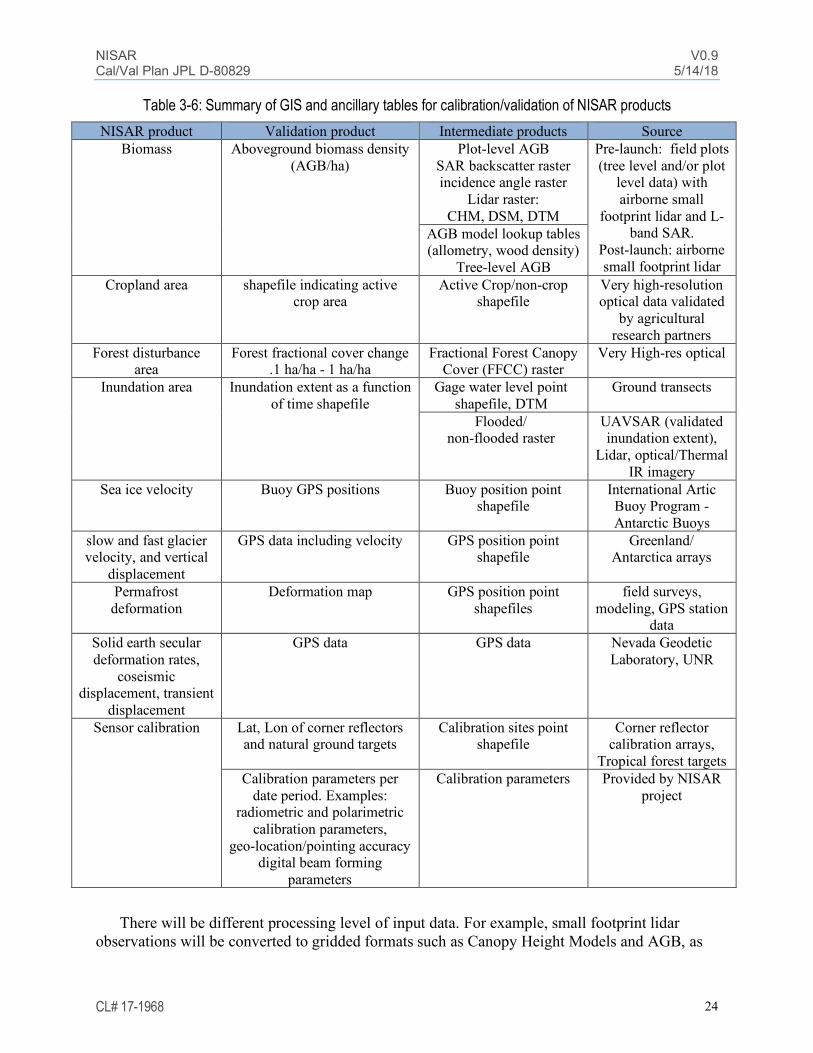
Source observations include in-situ data from discipline-specific networks (GPS, water gages, forest plots) and high-resolution remote sensing (e.g. Lidar) that are fetched from remote servers. Intermediate datasets are source datasets converted into GIS format and conditioned to facilitate the calculation of validation products. Validation products are intermediate datasets optimized for comparison with NISAR observables. Intermediate and validation products are stored in separate tables, such that calculated products are kept separately from measured products in the database. Table 3-6 lists NISAR products and their corresponding source, intermediate, and validation products.
The Cal/Val database will work in conjunction with ancillary routines to dynamically fetch data from remote servers, reformat datasets, and calculate validation products. These routines can have a broad range of complexities. Examples of simple routines are the derivation of inundation area by aggregating flooded/non-flooded maps, and the derivation of ice velocities by the differencing of GPS position values. More complex routines include the implementation of ecological models to estimate aboveground biomass from tree-level data.
Biomass Inundation area Solid earth displacement
GPS position
Vegetation plots
GPS station metadata
Flood/non-flood grid
Water level
Lidar surveys
NISAR Database Postgres server
Schema
Tables
Other Requirements
.......
NISAR V0.9 Cal/Val Plan JPL D-80829 5/14/18
CL# 17-1968 24
Table 3-6: Summary of GIS and ancillary tables for calibration/validation of NISAR products NISAR product Validation product Intermediate products Source
Biomass Aboveground biomass density (AGB/ha)
Plot-level AGB SAR backscatter raster incidence angle raster
Lidar raster: CHM, DSM, DTM
Pre-launch: field plots (tree level and/or plot
level data) with airborne small
footprint lidar and L-band SAR.
Post-launch: airborne small footprint lidar
AGB model lookup tables (allometry, wood density)
Tree-level AGB Cropland area shapefile indicating active
crop area Active Crop/non-crop
shapefile Very high-resolution optical data validated
by agricultural research partners
Forest disturbance area
Forest fractional cover change .1 ha/ha - 1 ha/ha
Fractional Forest Canopy Cover (FFCC) raster
Very High-res optical
Inundation area Inundation extent as a function of time shapefile
Gage water level point shapefile, DTM
Ground transects
Flooded/ non-flooded raster
UAVSAR (validated inundation extent),
Lidar, optical/Thermal IR imagery
Sea ice velocity Buoy GPS positions Buoy position point shapefile
International Artic Buoy Program - Antarctic Buoys
slow and fast glacier velocity, and vertical
displacement
GPS data including velocity GPS position point shapefile
Greenland/ Antarctica arrays
Permafrost deformation
Deformation map GPS position point shapefiles
field surveys, modeling, GPS station
data Solid earth secular deformation rates,
coseismic displacement, transient
displacement
GPS data GPS data Nevada Geodetic Laboratory, UNR
Sensor calibration Lat, Lon of corner reflectors and natural ground targets
Calibration sites point shapefile
Corner reflector calibration arrays,
Tropical forest targets Calibration parameters per
date period. Examples: radiometric and polarimetric
calibration parameters, geo-location/pointing accuracy
digital beam forming parameters
Calibration parameters
Provided by NISAR project
There will be different processing level of input data. For example, small footprint lidar observations will be converted to gridded formats such as Canopy Height Models and AGB, as

NISAR V0.9 Cal/Val Plan JPL D-80829 5/14/18
CL# 17-1968 25
opposed to large LAS files. Whenever source files are archived by partners rather than by the NISAR project, the database will keep metadata documenting its provenance and ownership.
Database development will involve the following: 1. Database design and establishment of data server 2. enable remote queries by the public and ST 3. Routines to dynamically import and re-format data from remote servers and offline
in-situ datasets. This may include QA steps and quality flagging. 4. Implement routines to dynamically calculate Cal/Val parameters 5. Implement routines to integrate Cal/Val parameters with NISAR observables and 6. Formulate procedure for importing and updating sensor Cal/Val parameters 7. Design a front-end web page for querying data and visualizing Cal/Val parameters
The NASA-ESA Mission Analysis Platform (MAP) provides tools for dynamic calculation of Cal/Val parameters and integration with in-situ data, and a pilot is focused on biomass products is currently planned.
Figure 3-2. Database products
3.6 In Situ Experiment Site Overview
3.6.1 Resource Networks In Table 3 -7 and described in the next subsections is a list of independently funded scientific resource networks, separated by science discipline, where ground validation data relevant to the NISAR science disciplines are currently available. These networks represent varied scientific communities in their current efforts to understand the Earth science questions that are at the heart of the NISAR science requirements. The existence of these resource networks and the demand for the information they provide the global scientific community underscores the need by this community of the type of science products that can be derived from NISAR data. Biomass Networks
Many of the biomass resource networks, such as the Smithsonian’s Forest Geo network, have existing collaborative relationships within the NISAR Science Team. The ESA Biomass mission requires extensive Cal/Val for validation of its requirements to measure global biomass, such as the AFRISAR campaign that NASA will be participating in; since the P-band Biomass mission

NISAR V0.9 Cal/Val Plan JPL D-80829 5/14/18
CL# 17-1968 26
will collect data sensitive to the inundation status of forests, there may be opportunities for Cal/Val collaboration. Crop Area Networks
Resource networks valuable for the validation of the agricultural crop area requirement are listed, and collaborative relationships are being developed. The USDA’s National Agricultural Statistics Service (NASS) regularly publishes statistics for cropland in the US. The NASS is the organization that is responsible for the Cropland Data Layer (CDL) of CropScape and combines 48 state-level products every year. One of the principal activities of the NASS is the management of the June Agricultural survey, effectively a ground truth, which covers 11,000 one-square mile segments that incorporate some 41,000 individual farms on a yearly basis (Boryan et al., 2011). While the results of much of this data are available indirectly through CropScape and the CDL, an organizational connection between NISAR and the NASS would be advantageous. The United Nations Food and Agriculture Organization (UN-FAO) develops methods and standards for publishing statistics on food and agricultural resources worldwide. Many of these geographically-specific statistics are available freely on the internet. Some level of coordination with FAO, either directly or indirectly, through a subset of the Group on Earth Observations (GEO) entities would be useful.
GEOGLAM is the part of GEO that performs Global Agricultural Monitoring. GEOGLAM publishes the monthly Crop Monitor on global crop growing and climate conditions that have an impact on agricultural production. Inputs for the Crop Monitor are contributed from international partners and hence could serve as a clearinghouse for validation inputs for the NISAR Crop Area requirement. Among the most advanced users of SAR data (Radarsat-1 and -2) for agricultural applications is Agriculture and Agri-Food Canada (AGR). Although Radarsat-1 and -2 are C-band instruments, researchers at AGR use Radarsat in conjunction with TerraSAR-X and ALOS data for crop classification. AGR is also a partner with JECAM, a subsidiary organization of GEOGLAM for the establishment of agricultural ground validation sites. Among the resources that AGR provides is RISMA, a network soil moisture and meteorological measurement effort concentrated in three locations in the southern agricultural growing regions of Canada.
The Mahalanobis National Crop Forecast Center (NCFC; ncfc.gov.in) in India is named after the Indian statistician P.C. Mahalanobis, who is the namesake of the Mehalanobis distance which is a measure of significance of a measurement with respect to a known distribution. The NCFC regularly publishes crop statistics for the country of India, one of the most intensive agricultural regions in the world and regular users of remote sensing data, especially from RISAT, Radarsat and ALOS. Inundation Networks
The Great Rivers Partnership is a signature program of The Nature Conservancy, addressing flood risk management, sustainable hydropower, and agricultural and water management for eight Great Rivers Partnership basins across four continents. The Smithsonian Environmental Research Center focuses it research on the connections between land and water ecosystems, and conducts research at field sites around the world, with particular attention on the Chesapeake Bay.
The Wildlife Conservation Society (WCS) has a long-term commitment with Pacaya-Samiria National Reserve and other areas in Loreto – Peru and currently supports the fisheries authorities

NISAR V0.9 Cal/Val Plan JPL D-80829 5/14/18
CL# 17-1968 27
in the region in developing a framework for fisheries management that considers wetlands conservation. Pacaya-Samiria is considered one of the most productive areas in terms of fisheries in the entire Amazon Basin and it is critical to understand what are the ecohydrological processes and characteristics that need to be maintained in order to secure this production. As part of other initiatives WCS also assesses the diversity and extent of aquatic habitats – that account approximately a third of the region – to support conservation planning and improve application of biodiversity offset’s mechanisms.
The National Institute for Space Research and the National Institute of Amazonian Research in Brazil have a long history of research and study of the inundation dynamics of the Amazon River basin. The USDA Center of Forested Wetlands Research develops, quantifies, and synthesizes ecological information needed to sustainably manage wetland-dominated forested landscapes, primarily in the Atlantic Coastal Plain of the southeastern US. The US National Park Service manages more than 16 million acres of wetlands. The USGS National Wetlands Research Center performs research and scientific information for the management of southern forested wetlands.

NISAR V0.9 Cal/Val Plan JPL D-80829 5/14/18
CL# 17-1968 28
Table 3-7a. Summary of Cal/Val Resource Networks - Ecosystems
Network Name Country or Region No. Sites Website or description
NASA ABoVE Alaska Alaska and Canada http://above.nasa.gov/
NEON NSF National Ecological Observatory Network - US
20 ecoclimate domains
http://www.neoninc.org/science-design/field-sites
Smithsonian Forest Geo 24 countries 63 plots http://www.forestgeo.si.edu/ Florida Everglades
Research and Education Center
Florida Everglades Everglades http://erec.ifas.ufl.edu/
RAINFOR Amazon Forest Inventory Network Hundreds http://www.rainfor.org/ NSF LTER, Long Term
Ecological Research North America 26 sites https://www.lternet.edu/lter-sites
AFRITRON Africa Dozens http://www.afritron.org/en/map
USDA US Atlantic coast http://www.srs.fs.usda.gov/charleston/
US Geological Survey (USGS) Southern forested wetlands http://www.nwrc.usgs.gov/
US Forest Service (USFS) US states and territories Manages US
forests http://www.fs.fed.us/managing-land
The Nature Conservancy
Mississippi and Colorado river basins; Magdelena and Tapojos River basins; Yangtze and Mekong River basins; Niger and Ogooue river basins.
8
http://www.nature.org/ourinitiatives/habitats/riverslakes/programs/great-rivers-partnership/
The Smithsonian Environmental
Research Center Chesapeake Bay
http://www.serc.si.edu/
European Space Agency BIOMASS Cal/Val sites (i.e. Gabon).
Wildlife Conservation Society – Peru Peru http://peru.wcs.org/en-us/
INPE/INPA (Brazil) Amazon http://www.inpe.br/ingles/
http://portal.inpa.gov.br/
USDA’s National Agricultural Statistics
Service (NASS) US agriculture 48 state level
products
http://www.nass.usda.gov/
UN Food and Agriculture
Organization Global
http://www.fao.org/home/en/
GEOGLAM Global http://www.geoglam-crop-monitor.org/
Agriculture and Agri-Food Canada Canada http://www.agr.gc.ca/eng/home/?id=13
95690825741
Mahalanobis National Crop Forecast Center India
http://ncfc.gov.in/
Cryosphere Networks The NISAR Science Team has extensive experience with validation of glacier and Ice sheet velocities and displacements. The validation of the permafrost displacement requirement will be through validation of permafrost deformation measured in the field through collaboration in

NISAR V0.9 Cal/Val Plan JPL D-80829 5/14/18
CL# 17-1968 29
Alaska with the US Army Corp of Engineers Cold Regions Research and Engineering Laboratory. The NISAR Science Team has extensive experience validating sea ice velocities such as through the MEaSUREs Small-scale kinematics of Arctic Ocean Sea Ice and will utilize international buoy data freely available through the program websites.
Table 3-7b. Summary of Cal/Val Resource Networks - Cryosphere Network Name Country or Region No. Sites Website or description
Circumpolar Active Layer Monitoring (CALM) network
Permafrost monitoring, mostly in the Arctic and Subarctic lowlands
participants from 15 countries http://www.gwu.edu/~calm/
The International Arctic Buoy Program
(IABP) Arctic ocean Network of drifting
buoys http://iabp.apl.washington.edu/
International Programme for Antarctic Buoys
(IPAB)
Southern ocean Network of drifting buoys http://www.ipab.aq/
3.6.1.1 Solid Earth Networks The NISAR Science Team has extensive experience with validation of secular, co-seismic
and transient displacements through existing resource networks listed in Table 3-3c. These networks comprise large and geographically diverse continuous GPS sites established for accomplishing similar regional science. They are ideal for validating requirements at the upper end of the spatial spectrum.
Table 3-7c. Summary of Cal/Val Resource Networks – Solid Earth
Network Name Country or Region No. Sites Website or description
EarthScope Plate Boundary
Observatory (PBO)
Mostly Western USA 1000+ https://www.unavco.org/projects/major-
projects/pbo/pbo.html
Continuously Operating
Caribbean GSP Observational
Network (COCONet)
Caribbean, funded by NSF
GPS network in tropical environment,46 new continuous Global Positioning System (cGPS) and meteorology stations
http://coconet.unavco.org/
GEONET-Japan GSI network Japan
GPS network in forested areas outside of USA
http://www.gsi.go.jp/ENGLISH/
GEONET-New Zealand network New Zealand
GPS network in forested areas outside of USA
https://www.geonet.org.nz/
Hawaii Volcano Observatory (HVO)
USGS HVO - Hawaii 5 http://hvo.wr.usgs.gov/

NISAR V0.9 Cal/Val Plan JPL D-80829 5/14/18
CL# 17-1968 30
Image Calibration Networks The NISAR Project Team has extensive experience with calibration of SAR imagery and operational software for project such as UAVSAR are available, through utilization of the NASA/JPL Rosamond Calibration Array in Southern California. Additional targets are deployed worldwide, and widely shared. Notable arrays are listed in Table 3-7d.
Table 3-7d. Summary of Cal/Val Resource Networks – Sampling of Instrument Calibration
Targets
Network Name Country or Region No. Sites Website or description
NASA/JPL Rosamond
Calibration Array
Southern California
20+ Trihedral l Corner Reflectors http://uavsar.jpl.nasa.gov/technology/calibration.html
ASF Corner Reflector network Alaska
A small array of trihedral corner reflectors
https://www.asf.alaska.edu/news-notes/1-2/reflector-array/
SAOCOM/CONAE calibration targets Argentina Array of precision
reflectors Deployed in 2018, right looking.
JAXA calibration targets Japan 4+ Corner reflectors and PARCS, not continuously deployed
Australia GPS network and
Trihedral corner reflectors
Surat Basin, Queensland, Australia
4 high-precision GNSS continuously operating reference station (CORS) monuments, 40+ radar corner reflectors
http://www.tandfonline.com/doi/full/10.1080/08120099.2015.1040073
Figure 3-3. Validation sites (stars) overlayed on SMAP HH so image.

NISAR V0.9 Cal/Val Plan JPL D-80829 5/14/18
CL# 17-1968 31
At first glance Table 3-7 might indicate that there are a substantial number of in situ resources available for validation. However, there are numerous issues that need to be addressed for these data are to be of value to NISAR validation.
• Data distribution policies of each network should be reviewed and mechanisms for cooperation established. Data latency needs to be considered.
• Many of the larger networks consist of widely scattered points that require a scaling analysis if they are to be used to validate a satellite footprint.
• Verification and temporal stability analysis is needed of all footprint scale networks Establishing or identifying infrastructure in under-represented regions
• Cooperation with some validation programs and archives has to be established and plans initiated for using these resources during NISAR prelaunch activities and extending them.
• Consideration should be given to the roles of emerging networks such as AFRISAR (and other joint calibration sites with ESA and the NASA GEDI mission), NASA ABoVE, and regional GPS networks.
Therefore, in section 3.7 and following sections we describe how these resource networks will be supplemented by NISAR in critical areas with field work, other data acquisitions and data analysis that provide the resources necessary to validate the NISAR science requirements and enhance the scientific value of the NISAR data to the global scientific community represented by these networks.
3.7 NISAR Cal/Val Site Overview In situ observations will be important in validating science products from the NISAR mission. These data will also be valuable throughout the development phase of the mission to support calibration of parameters, and validation of the algorithms. Existing resources that are expected to continue through the life span of NISAR in orbit (2020-2023) are highly desirable. A summary of Cal/Val validation sites is shown in Table 3-8, with detailed description of sites found in section 4.

NISAR V0.9 Cal/Val Plan JPL D-80829 5/14/18
CL# 17-1968 32
Table 3-8. Summary of Cal/Val Validation Sites
Measurement Validation Site Comment
Instrument calibration Corner reflector arrays such as the Rosamond Corner Reflector Array, California; Surat Basin, Australia;
Absolute radiometric calibration, relative calibration, instrument performance, geolocation,beam formation
Instrument calibration Distributed targets in non-flooded, non-deforested tropical forest locations in South America and Africa
Beam forming calibration, Cross-talk calibration, antenna pattern, channel imbalance, relative calibration
Fast/Slow Deformation of Ice Sheets and Glacier Velocity and Vertical Displacement and Fast Ice-Shelf Flow
10 GPS receivers along a divide-to-coast flow line in Greenland. 6 GPS devices on Antarctic Ice Shelf. ISRO and independently funded investigators may have GPS devices at additional locations
Also, could use wider-area data such as Ice Bridge contemporaneous data sets should they exist
Permafrost Deformation Two sites in Alaska, field measurements of deformation In partnership with CRREL
Sea-ice velocities West Arctic, Southern Ocean
Using available buoy data from the International Arctic Buoy Program (IABP) and International Programme for Antarctic Buoys (IPAB)
Secular deformation rate, coseismic displacement, and transient displacement
US Plate Boundary Observatory (PBO), Coconet, Hawaii Volcano Observatory (HVO), GEONET-Japan, GEONET-New Zealand, AGOS, ISRO network if available
processed by UNR
Biomass between 0 and 100 MG/ha
Six Canonical ecoregions with field measurements of biomass: Needleleaf, Broadleaf Deciduous, Mixed Broadleaf/Needleleaf, Broadleaf Evergreen, Savanna/Dry Forest, and Inundated Forest
Pre-launch Collaboration with BIOMASS and GEDI validation campaigns, Lidar acquisitions at 15 post-launch Cal/Val sites
Forest Disturbance > 0.5 ha/ha Targets of opportunity (determined after disturbance events, or from likely locations) Using VHR optical data
Active Crop Area JECAM and LTAR sites VHR optical time series over Agricultural research sites, validated by research partners.
Inundation area
Wetland sites such as NASA funded studies in Alaska (ABoVe) and SWOT Cal/Val sites; South America (Pacaya-Samiria), Florida Everglades, Louisiana Delta, coastal lagoon site.
Collaborators at secondary Cal/Val sites will provide data on inundation extent for evaluation
3.8 Aircraft-based Sensors Airborne sensors play important roles in Earth remote sensing. NASA facility instruments such as UAVSAR and LVIS, the ISRO L/S Airborne Radar, and the GSFC G-LiHt instruments could be deployed multiple times over sites with existing field measurements to provide data for algorithm development and testing as well as product validation.
Airborne sensor systems complement field observations by providing an intermediate spatial scale that links to the satellite footprint. Understanding the scaling of the basic sensor

NISAR V0.9 Cal/Val Plan JPL D-80829 5/14/18
CL# 17-1968 33
measurement (i.e. radar backscatter) as well as the geophysical variable that is being retrieved (such as biomass) is critical to satellite-based remote sensing. These platforms facilitate the observation of a wide range of target features and experimental sample replication, which are logistically difficult with ground-based measurements. Airborne systems are valuable in the demonstration and verification of algorithms and applications in that they can be used to map a spatial domain.
An important aspect that needs to be considered is the calibration of the instruments and their compatibility with the satellite configuration. These topics are the subject of discussion by the community, with a goal of some level of standardization.
To support NISAR Cal/Val planning, the NISAR Science Team (NST) Cal/Val Working Group conducted a survey of existing and planned L-band airborne instruments, and synergistic mission data. The results are provided in Table 3-9. The groups operating each sensor system provided information. Some systems may not be included due to lack of response to the survey or lack of knowledge by the NST of their existence.
Table 3-9. Existing or near-term Aircraft-based Sensors
Airborne Systems Sensor
NASA UAVSAR L-band quad pol repeat pass Insar ,P-band quad-pol SAR, Ka-band single pass inSAR. No restriction on distribution
DLR F-SAR X through P-band quad pol repeat pass INSAR
JAXA Pi-SAR L-band quad-pol SAR. LVIS Scanning laser altimeter. No restriction on distribution. G-LiHt Scanning lidar, profiling lidar, VNIR imaging
spectrometer, thermal imager, freely distributed.
ISRO L/S airborne Radar S-band and L-band SAR, sensitive data could be an issue

NISAR V0.9 Cal/Val Plan JPL D-80829 5/14/18
CL# 17-1968 34
3.9 Synergistic Satellite Observations There are currently in orbit (or planned for launch before NISAR) satellite-borne SAR
sensors that collect observations synergistic to the NISAR science requirements, notably: • JAXA ALOS-2 PALSAR: L-band, Multiple resolution, 14-day repeat • ESA Sentinel 1A/B, C-band, 12-day repeat • JAXA ALOS-4 L-band SAR: 14-day repeat, to be launched in 2021 time-frame. • CONAE SAOCOM A/B: L-band SAR to be launched in 2018. The options and value of data increase with mission overlap. As we move closer to launch,
we can expect the launch of NASA’s Global Ecosystem Dynamics Investigation Lidar (GEDI) to the space station. This Lidar mission has a biomass measurement goal in addition to making forest structural measurements. ESA’s Biomass mission is also expected prior to the NISAR launch. Biomass is a fully polarimetric P-band SAR whose main goal is to measure AGB. In a complementary fashion, the primary biomass objectives of BIOMASS (biomass measured in all areas, more accurate in high biomass areas) is complementary to the NISAR biomass science requirement (biomass measured in areas under 100 Mg/ha). SAOCOM 1A and 1B, which will use L-band SAR for disaster monitoring, is also expected to launch prior to NISAR. There are other programs utilizing a variety of satellite instruments to achieve their objectives, such as Joint Experiment of Crop Assessment and Monitoring (JECAM), developed in the framework of GEO Global Agricultural Monitoring and Agricultural Risk Management.
For the validation of the forest disturbance, agricultural crop area, and inundation extent, there are currently several operational Very High Resolution optical and multiband sensors (Table 3-10). For post-launch time frames, it is expected that similar if not better availability for this type of data will be available. Imagery from Planet Labs, a private remote sensing company, consists of multiple cubesat constellations.
Table 3-10. Example high-resolution data from commercial optical sensors
Sensor Bands Resolution Launch WorldView-1 panchromatic 0.5 m 2007 WorldView-2 multiband 0.5 m 2009 WorldView-3 multiband 0.3 m 2014 WorldView-4 multiband 0.3 m 2016 Geoeye-1 multiband 0.5 m 2008 Planet Labs various various 2013-
3.10 Field Experiments The field experiments listed in Table 3-11 address mission specific calibration and validation requirements for NISAR. Sensor calibration experiments will involve the deployment of passive calibration targets that will be imaged by NISAR during instrument checkout continuing through science operations.
The NISAR project, through collaborative activities coordinated with the Cal/Val resource networks shown in Table 3-8, will also conduct field experiments for validation of science requirements (For example, deployment of GPS receivers for validation of the Slow and Fast deformation Ice Sheet and Glacier Velocity requirements) in which the field experiments provide

NISAR V0.9 Cal/Val Plan JPL D-80829 5/14/18
CL# 17-1968 35
data or deploy equipment that provides data for validation of the science requirements. Table 3-12 tabulates the scope of the activities for each NISAR Cal/Val field campaigns.
In order to sample each of the 12 NISAR sub-beams twice in both ascending and descending orbit directions (for more frequent imaging, especially important during the commissioning phase), 48 corner reflectors will be deployed. Some dihedral reflectors may be used to verify cross pol calibration parameters, but most reflectors will be trihedral designs. This sampling of the NISAR swath will be used to validate the digital beam forming and antenna pattern measurements as well as the polarimetric calibration parameters. The NISAR project also intends to deploy one passive receiver or PARC to validate the NISAR antenna pattern and digital beamforming algorithm and parameters.

NISAR V0.9 Cal/Val Plan JPL D-80829 5/14/18
CL# 17-1968 36
Table 3-11. Scope of field campaigns
Field campaign Workforce expenses Equipment, etc.
Corner Reflector deployment and
maintenance
3 months to deploy, with Geoscience Australia
48 2.4 m trihedral corner reflectors ($2.1K each)
1 month/year to maintain/survey
Rentals
UAVSAR PARC Travel
Deployment of GPS network to
Greenland and Antarctica
2 weeks to deploy 10 GPS units to Greenland
Iridium (~$10 K each) /iridium link Helicopter costs, GPS units
2 weeks year to maintain Greenland array
Helicopter costs and MPC, Iridium
w/ UNAVCO Aircraft time flight hours, GPS units, Iridium
w/UNAVCO Aircraft flight hours, Iridium Travel
Permafrost deformation
map displacements in field, retrieve field measurements
RTK or similar GPS, subcontract
CGPS and InSAR structure function
processing
Structure function processing and GPS analysis
ST activity
Sea Ice velocity Process SAR and Buoy GPS location data
Buoy data available from public websites
Biomass validation (15 Cal/Val sites)
15 sites of Lidar data collection Field plots if necessary
Airborne Lidar data collection (20-50K each site Lidar data processing
Inundation validation (6 Cal/Val
sites)
18 days per site Optical data collection (i.e. from sUAS), Deployment of pressure transducers to measure water level, DTM from lidar or other methods for some sites, UAVSAR Rentals/Travel
Agricultural crop area validation
image classification tasking field validation 2 weeks per site
VHR optical data acquisition, processing (approx. 5 workdays per site), and validation, field validation of VHR data, UAVSAR acquisitions

NISAR V0.9 Cal/Val Plan JPL D-80829 5/14/18
CL# 17-1968 37
Table 3-12. Field Experiments for NISAR Cal/Val
Field experiments/ airborne data/satellite observations
Objectives
Per experiment Number of planned experiments
Workforce Duration Other costs
Pre-launch
Observ. checkout
Cal/Val phase
science operations year 1
science operations year 2
science operations year 3
48 Corner Reflectors Instrument calibration and deformation validation
3-4 6 weeks 48 corner reflectors, Travel cost
1
Inspection and maintenance of 48 CRs Instrument calibration 2 3 weeks Travel costs 1 1 1
Deployment of one passive receiver
Validation of antenna pattern and digital beamforming parameters
2 1 week Cost of receiver, travel costs
1 to 3 1
Biomass from field measurements/airborne Lidar from 15 ecoregions
Calibration of biomass algorithm parameters, and validation of science requirement
nominal 1 flight day/site
planning and processing 1 1 6 7
CGPS and seismic networks in Alaska & Cascades
Validate deformation products ST activity Cal/Val
phase 1 10
UAVSAR 12-day repeat experiment over ecosystem Cal/Val sites
calibrate algorithms and verify with 12-day repeat data
6-9 months pre-launch, with 18-day updates
Flight hours, travel, processing
1 1 1 1
UAVSAR validation data
provide quad pol L-band data at same time as NISAR dual pol data for validation of inundation
3 flights over 18 days per site
Flight hours 6 sites
Field validation of inundation extent for boreal, temperate, and tropical wetlands
Calibration of inundation threshold values and validation of inundation
3 18 days Travel costs 2 3
3
10 GPS receivers Greenland
Velocity measurements for all snow facies and melt states.
3 10 days GPS receivers, aircraft, etc.
1 1
Maintain 10 GPS receivers Greenland
Validate observations for all snow facies and melt states
3 10 days Travel costs, aircraft, etc.
1 1 1
6 GPS receivers on ice shelf in Antarctica
Validate velocity measurements
3 UNAVCO 2 weeks Travel costs,
aircraft, etc. 1 1
Maintain 6 GPS receivers on ice shelf in Antarctica
Validate velocity measurements
3 UNAVCO 2 weeks Travel costs,
aircraft, etc. 1 1 1 1 1

NISAR V0.9 Cal/Val Plan JPL D-80829 5/14/18
CL# 17-1968 38
3.11 Cal/Val Roles and Responsibilities The Calibration and Validation activities described in this plan are the responsibility of the NISAR Project Science Team (PST) under the direction of the NISAR Project Scientist at JPL. Within the PST, the Cal/Val Team Lead organizes, develops, and executes the Cal/Val Plan, supported by the PST, the NASA Science Team (NST, competitively selected and funded by NASA), and the ISRO Science Team (IST). Together the PST, NST, and IST comprise the NISAR Joint Science Team (NJST). The PST/NST will coordinate Cal/Val activities with the IST through the NJST, but without explicit requirements on ISRO for the NASA plan to achieve its objectives of fully calibrating and validating the L-band data and derived science products.
The Cal/Val plan described here is requires close coordination among members of the PST and NST and allows for similar coordination with the IST. It also takes into consideration a broad range of inputs and contributions from the U.S. and international communities, including Cal/Val plans of other Synthetic Aperture Radar (SAR) missions related to the NISAR science disciplines.
The PST/NST will plan and organize field campaign support (e.g. corner reflectors, GPS stations, in situ campaigns). The Science Data System (SDS) will nominally collect and process the radar data. The NISAR SDS and Radar instrument team will work together to regularly update instrument calibration parameters for generating L1 and L2 products. The instrument team will work with the mission planning team to insure appropriate calibration data are acquired. The PST/NST will analyze and evaluate imagery data processed by the SDS, interpret results and generate L3 data products over selected science validation sites. The PST/NST will calibrate and update algorithm parameters (e.g. biomass algorithm parameters, inundation threshold values, etc.) regularly in their calculations of L3 products. The PST/NST will also verify the end to end acquisition, calibration, and processing of the imagery. Lastly, the PST and NST will validate that the science requirements have been achieved by the mission (Figure 3-4).
Resources for Cal/Val are split between the PST and the NST. The NST is competed through a NASA research announcement, and NASA selects members based in part on their responsiveness to their anticipated role in Cal/Val plan. The PST effort is shaped around the expected NST member contributions. In general, the PST is responsible for execution of the plan and major cost elements such as field deployments, airborne campaigns, and large-scale data reduction. The NST is responsible for algorithm development and calibration, establishing networks and accumulating in situ data, and confirming validation of the science requirements. Some of the PST work may be accomplished by NST members if deemed appropriate. Detailed roles and responsibilities for specific tasks are shown in Table 3-13.

NISAR V0.9 Cal/Val Plan JPL D-80829 5/14/18
CL# 17-1968 39
Figure 3-4. Roles and Responsibilities

NISAR V0.9 Cal/Val Plan JPL D-80829 5/14/18
CL# 17-1968 40
Table 3-13. Cal/ Val Roles and Responsibilities
3.12 Community Engagement Community engagement for calibration and validation for some of the NISAR science requirements will be facilitated through regular science and/or Cal/Val workshops held prior to
PST NST SDS Radar
Validation Algorithms
L0a-L0b X X
L0-L1 X X
L1-L2 X X X
L2-L3 X X
Calibration Algorithms
Point Target Analysis X X
Doppler Analysis X X
GPS Network comparisons X X
Tropospheric Phase Calibration X X
Ionosphere (absolute delay/relative split spectrum delay)
X X
Soil Moisture X X
Others?
Calibration Activities
Work associated with Calibration algorithms X X X X
Coding of algorithms (phase C/D) X X X
Acquisition of test data - scoped by each discipline X X
Testing of calibration tools X
Field work - scoped by each discipline X X
Validation activities
Validation field work X X
Processing test data X X X
Processing of mission data X X
Comparison of results to requirements X X X

NISAR V0.9 Cal/Val Plan JPL D-80829 5/14/18
CL# 17-1968 41
and after the NISAR launch. The agricultural crop area, inundation extent within wetland areas, forest biomass, and permafrost deformation requirements in particular seek community engagement to validate results and will host regular Cal/Val workshops to solicit input from the community of interest, and where stakeholders have a keen interest in seeing these requirements validated.
The Cal/Val workshops will be held separately for each discipline, and if possible in conjunction with any NISAR science workshops. The NISAR applications workshops provide a model for how these Cal/Val workshops will be organized. They will be held once per year for each discipline listed.
3.13 Cal/Val Program Deliverables (1) Implementation plans for any identified pre-launch field campaigns; (2) Reports documenting results, archival, and analyses of pre-launch field campaigns and data
acquisitions; (3) Validation report for L1 data (accompanying archived data at post-IOC plus six months); (4) Validation report for L2 data (accompanying archived data at post-IOC plus six months); (5) Validation report for L3 data (accompanying archived data at post-IOC plus twelve months
and at the conclusion of the extended monitoring phase).

NISAR V0.9 Cal/Val Plan JPL D-80829 5/14/18
CL# 17-1968 42
4 CAL/VAL STRATEGIES
4.1 Cal/Val Strategy for L-band Instrument Prior to launch, some characteristics of the instrument must be measured in the lab, such as time delays, attenuator settings, thermal characterizations, and lever arms. The antenna pattern must be predicted based on near field measurements of the feed coupled with antenna geometry. After launch, the final instrument calibration and performance parameters will be based upon analysis of point targets and known uniform distributed targets (such as some regions in the Amazon basin). The results of the validation of digital beam forming will be used to calibrate onboard parameters during the Cal/Val phase. The instrument team plans to calibrate the instrument and work with SDS team to provide pre-launch system parameters which can be used as initial settings for a calibrated L1 product.
Many image formation and performance requirements will be evaluated after launch using an array of point targets deployed across the 240 km NISAR swath. In addition, an array of trihedral corner reflectors (ranging from 0.7 m to 4.8 m in size) is located in the Rosamond Dry Lake in Southern California and is operated by the NASA/JPL UAVSAR project for its image calibration needs. To fully evaluate the calibration within each of the 12 NISAR beams, instrumentation of two sites within each beam with two reflectors (for imaging both ascending and descending passes) for a total of 48 reflectors (nominally trihedral) is planned. Some reflectors may be temporarily oriented to alternate left/right looking geometries during the calibration phase of the mission. As described in section 7, ISRO will also have a reflector array for image calibration located in India, that could help accommodate the various look directions and will include a mix of trihedral and dihedral reflectors. ISRO may also develop a PARC suitable for verification of L-band calibration. The UAVSAR project is currently testing two L-band PARCS developed by the University of Michigan.
The received measurements are a function of the absolute normalization factor, cross-talk, channel imbalance, Faraday rotation, and the target scattering matrix (Shimada et al, 2009).
(3-1)
Where Zpq is the uncalibrated scattering matrix for polarizations [p,q=H or V], R is the slant
range to the target, a is the absolute calibration factor, Spq is the true scattering matrix of the target, dn represent the cross talk between H and V polarizations , fn are the channel imbalance terms, and W is the Faraday rotation angle.
External ground targets imaged by the NISAR radar will be used to estimate the parameters in equation 3-1 using standard methods (i.e., Fore et al, 2015). Similar techniques have been used to calibrate other L-band SAR instruments (Shimada et al, 2009). The results will be used to calibrate the data during subsequent processing. External calibration employs the use of corner

NISAR V0.9 Cal/Val Plan JPL D-80829 5/14/18
CL# 17-1968 43
reflectors and homogeneous areas to estimate the calibration parameters. Trihedral corner reflectors will provide the co-pol imbalance and the absolute calibration factor, while homogenous extended targets such as found in parts of the Amazon basin, will be used to solve for the cross-pol channel imbalance and cross talk terms, dn. Dihedral reflectors may be used to validate cross-pol calibration requirements. The Faraday rotation angle W is linearly proportional to the total electron count (TEC). Note that although the quad pol mode will be useful for analysis of the calibration of the instrument, none of the NASA NISAR science requirements involve the utilization of data collected in this mode.
The image calibration method described in Fore et al (2015), which utilizes calibration methods described in Ainsworth et al (2006), fully calibrates the data, assuming only scattering reciprocity such that the SHV and SVH scattering matrix elements are equal. This method does not rely on the radar system being reciprocal (Ainsworth et al, 2006). However, a calibrated polarimetric active radar calibrator (PARC), if available, could be employed to verify channel imbalance or cross talk estimation by corner reflectors and distributed targets.
When operating in dual pol mode, the cross-pol channel imbalance and cross talk parameters measured while in quad-pol mode will be employed to calibrate the HV data. However, typical cross talk values only meaningfully impact the HV SNR where HH backscatter is high and does not significantly impact the radiometric calibration of the HV channel.
The Interferometric phase will be used to derive displacement and ice velocity estimates from NISAR data. The Interferometric phase is subject to a variety of bias or noise sources including decorrelation, tropospheric path delays, ionospheric path delays, soil moisture, radio frequency interference (RFI), instrument drifts, processing errors, baseline knowledge errors, and topographic knowledge errors. These sources will be independently assessed and, in some cases, corrected if required to meet requirements.
The NISAR instrument team will be responsible for calibrating the on-board digital beamforming algorithm during the NISAR commissioning phase. During this phase of the mission, data will be collected without digital beamforming for calibration using ground systems. The data will cover bright ground targets and the two corner reflectors per sub-beam deployed in the NISAR calibration array. After the calibration parameters are determined, these parameters will be applied on-board, and periodically inspected and refined if necessary throughout the mission for accuracy.
Table 4-1 shows the image calibration requirements and the expected performance as of PDR (mid-2016). ISLR is the Integrated Side Lobe Ration, while QNR refers to the random noise introduced by quantization. The coherence requirement is on the radar including the processing window, but not including geophysical effects such as temporal and volumetric decorrelation.

NISAR V0.9 Cal/Val Plan JPL D-80829 5/14/18
CL# 17-1968 44
Table 4-1. Image calibration and performance requirements Requirement ID Parameter Requirement Expected performance
L2-PRS-562 Co-pol radiometric Cal 0.9 dB <0.9 dB L2-PRS-562 Cross-pol radiometric Cal 1.2 dB <1.2 dB L2-PSR-454 Absolute geolocation +/-10% of SLC res. +/-10% of SLC resolution L3-DSI-163 NE Sigma0 (mode L1) -23 dB -27.5 dB L3-DSI-164 Ambiguity ratio -20 dB
-15 dB for Quad pol -23 dB L3-DSI-163/164/210 Random Cal error 0.5 dB 0.46 dB L3-DSI-172 Systematic Cal error 0.72 dB 0.53 dB L3-DSI-163/164/210 Coherence (mode L1) 0.85 0.89 L3-DSI-173 Systematic phase error 3° 2.8° L3-DSI-210 ISLR -20 dB -22 dB L3-DSI-170 QNR -19 dB -22.4 dB
4.1.1 Pre-launch Cal/Val for L-band Image Calibration
L0-2 SDS Processing Algorithms The L0-2 SDS processing algorithms will be built up pre-launch from the ISCE code set. These algorithms will be tested using four basic types of input data.
1) Simulated point target data 2) Simulated distributed target data 3) Telemetry test data 4) Reformatted data from other radar missions Simulated point target data will test the basic focusing performance of the SAR processor
and quantify the effects of some algorithm approximations on the processing error budget. Performance parameters such as resolution, ISLR and PSLR can be measured. Point target data will also support the development of ancillary Cal/Val tools that will be used to analyze corner reflector measurements taken post-launch. Simulated distributed target data will test the SAR processing algorithms for consistent use of the instrument calibration parameters that underpin the a-priori calibration. These data will also further quantify the impact of approximations and data quantization on the processing error budget and support the development of post-launch Cal/Val tools used to analyze homogeneous scenes like the Amazon rain forests. The noise equivalent backscatter level can also be checked. Telemetry test data supplied by the instrument system-engineering group will test the L0 processors for proper handling of realistic telemetry. Combining point and distributed target simulation with telemetry test data can be used to do more realistic testing of the SAR processing algorithms. Reformatted data from another radar mission provides the opportunity to test with real echo data and uncover algorithm problems that can be missed with simulation testing.
Table 4-2 describes a set of parameters that require pre-launch calibration, the description of the measurement that will be made to calibrate the parameter or function, and the calibration requirement.

NISAR V0.9 Cal/Val Plan JPL D-80829 5/14/18
CL# 17-1968 45
Table 4-2 Instrument parameters and calibration requirements
Parameter or function Measurement description Calibration requirement
Time Delay
Measure electronic timing delays in the transmit/Receive paths so that the range measurements represent the true round-trip time from the antenna phase center as a function of polarization and receive element. This uses an optical delay to make these measurements.
L2-PSR-453, geolocate to better than 10 cm, 1 sigma
Calibrate Attenuator Setting
Measure the achieved attenuation level for each of the nominal attenuator settings. Inject signal of known strength through the attenuator and measure the signal strength after the attenuator with a calibrated power meter. Attenuators are not expected to be used unless RFI is saturating the return but will be calibrated regardless.
L4-RFE-115, track receiver gain changes to 0.1 dB; absolute not needed but track changes between setting to << 0.1 dB
Antenna Pattern Range Measurements
Generate complex far field antenna pattern measurements for the transmit/receive beams as a function of polarization, frequency and polarization. This will involve near field measurements of the feed coupled with antenna geometry CAD models and antenna pattern prediction codes.
L4-RA-176/177 allows max gain uncertainty of 0.2 dB, max phase uncertainty 1.5 degrees
Characterize TR Modules
Measure the amplitude and variations of each TR module as function of temperature to generate appropriate load tables for each module. Additional need to characterize the differential time delay to a fraction (1/10th) of highest range res cell size. Will be characterized for both transmit and receive.
L4-RFE-171, less than 0.6 ns relative delay between channels. This is better than 1/10 cell size, 1.25 ns
Active Element Thermal Characterization
Compute gain/phase calibration curves for any active elements not measured by an onboard calibration signal (Passive elements outside of Cal loop).
L4-RFE-173 outside cal knowledge better than 0.2 dB; L4-RFE-174 phase better than 0.5 deg
Chirp Reference Functions
Optimal match filter chirp reference function to use for range compression. Collect recirculated chirps and average for 10000-100000 pulses the time domain signals after insuring the jitter is a small fraction of an ADC sample. Will produce optimal matched filter reference chirp, which is needed on-board for internal calibration as well as on the ground for processing
ADC jitter < 300 fs, L4-RFE-91
Alignment Matrices and Lever arms
Generate appropriate alignment matrices (or quaternions) so that at a minimum the following coordinate system conversion are known to the specified accuracy:
• GPS to antenna phase center lever arms, will be different for each beam.
• GPS to Observatory center of mass to help fit position data
Coordinate systems defined in JPL D-80882; alignment requirement in L4-RA
Pointing Control As built components will be measured in pieces
L2-PSR-701, pointing control accuracy better than 0.1 degrees

NISAR V0.9 Cal/Val Plan JPL D-80829 5/14/18
CL# 17-1968 46
4.1.2 Post Launch Cal/Val for L-band Image Calibration
Table 4-3 outlines the characterization of instrument calibration that will be conducted during the post-launch Cal/Val phase of the mission:
Table 4-3 Post-launch Summary of Instrument parameters, measurements, and calibration requirements
Parameter Measurement description Calibration requirement
Thermal Noise Characterization
Use sniffer pulses to measure thermal noise levels at the beginning and end of each data take, as well as periodically during a data take.
JPL D-76373 p. 37 defines noise-only measurements in data takes; no requirement on noise measurement accuracy
Common Time Delay Calibration
Compare range measurements on surveyed corner reflectors (after dry topo atmospheric correction to range).
L2-PSR-451 Relative geolocation to 1/128 of the resolution, 0.1 ns time accuracy
Differential Time Delay Calibration
Cross correlate data between polarization channels to measure channel-to-channel mis-registration. Corner reflectors may be used for this as well if have enough SNR. Cross correlate between individual beams during diagnostic data takes when we get two adjacent channels down without combining
L2-PSR-451 Relative geolocation to 1/128 of the resolution, 0.1 ns time accuracy
Time Tag Calibration Use surveyed corner reflectors to establish the geo-location and time tagging accuracy.
L2-PSR-451 Relative geolocation to 1/128 of the resolution, 0.1 ns time accuracy
Yaw, Pitch, Antenna Azimuth Angle Bias Determination
Use bright homogeneous backscatter region to compare measured Doppler centroid to expected Doppler centroid and measure attitude angle biases. Will measure doppler centroid while doing slow "coning" maneuvers to measure errors.
L2-PSR-701 Pointing control accuracy 0.1 degrees; L2-PSR-693 pointing knowledge accuracy 60 millidegree.
MNR Characterization Use a radar opaque fence to measure total MNR plus thermal noise levels.
ISLR < -20 dB (L3-DSI-210), QNR < -19 dB (L3-DSI-170), Ambiguities < -20 dB (L3-PSR-706)
Pointing Control Periodically solve for doppler centroid to get azimuth pointing error.
L2-PSR-701 Overall pointing control accuracy is better than 0.1 deg (273 arcsec); L2-PSR-446 repeat pass pointing control (azimuth) is 53.6 millidegree.
Absolute location accuracy
Process (range compression, azimuth compression + geolocation) high-resolution raw data from a point target for various antenna scan angles and satellite positions.
L2-PSR-451 Relative geolocation to 1/128 of the resolution.
Polarimetric Calibration factors
Analysis of point targets of known characteristics and distributed targets of known characteristics.
L2-PSR-566 cross-pol calibration better than 1.2 dB, L2-PSR-562 co-pol calibration better than 0.9 dB

NISAR V0.9 Cal/Val Plan JPL D-80829 5/14/18
CL# 17-1968 47
In order to demonstrate that the performance of the instrument and processing algorithms meets the NISAR requirements, several tests will be accomplished. Table 4-4 summarizes these performance tests.
The SNR decorrelation portion of the error budget will be quantified by using sniffer pulses to measure the background thermal noise level and impulse response measurement for the MNR to compute the SNR decorrelation based on the backscatter level in a pixel. This will be compared with the NISAR error budget and the resulting phase noise converted to deformation error and compared with the total errors measured by in situ techniques discussed above.
Range spectral filtering will remove a portion of the geometric decorrelation for a flat surface leaving the slope dependent portion uncompensated. The component of the error budget is most easily checked when the baseline is longest and temporal and volumetric correlations are minimal.
• Select sites that have a range of cross-track slopes varying from ±30° that are unvegetated (helps eliminate temporal and volumetric correlation)
• Correct the measured correlation for SNR correlation using sniffer pulses. • Verify residual decorrelation follows the expected variation with slope for range spectral
shifted data (shift computed for a flat surface). The volumetric decorrelation component of the error budget will be measured by taking data
in regions where cleared and forested regions with known heights are adjacent. After normalizing for SNR correlation and baseline correlation the only residual components to the correlation with be from volumetric and temporal decorrelation. Data will be selected from 12-day repeats when wind and other weather parameters have been stable for the sight. This will reduce the effect of temporal decorrelation and the resulting estimated residual decorrelation will be compared with the error budget.
Temporal correlation varies widely with terrain type and local weather conditions. A simple model based on real data is used for system modeling and only provides trend information. Thus, a simple direct comparison with the model function is not possible expect by analyzing temporal decorrelation over a variety of sites for a long period of the statistical behavior to the model. A verification program might go like:
• Select 10 sites for each terrain type that will be imaged on nearly all possible imaging opportunities.
• Use data takes with baselines less than TBD m especially for vegetated sites to eliminate volumetric decorrelation.
• Normalized the observed correlation for SNR and baseline decorrelation (using a DEM for local slope correction)
• Compare the average correlation as a function of time to model. Related to the decorrelation performance is the Interferometric phase stability. Persistent
scatterers in areas of known deformation or areas of no known deformation will be examined to confirm the stability of the Interferometric phase after corrections have been applied.
Processing errors will be verified by running points targets generated from a simulator and verifying phase distortion requirement are met. Some aspects of processing correlation error budget can also be verified this way (e.g. Prati filtering). Use simulated distributed target data to

NISAR V0.9 Cal/Val Plan JPL D-80829 5/14/18
CL# 17-1968 48
verify various interpolator and other contributions to phase error and processor induced temporal decorrelation.
Data driven baseline estimation algorithms can be verified at sites where an array of corner reflectors have been deployed in the cross-track direction where surface deformation is not occurring.
Georeferencing errors are primarily topo induced errors from using the wrong portion of the DEM. Using the georeferencing accuracy discussed from corner reflector data and maximal slope levels and upper bound on the georeferencing error can be obtained and compared with the error budget.
Atmospheric phase noise will be estimated using a combination of dense GPS networks and/or MODIS data. Estimated water vapor power spectral density measurements will be compared with NISAR estimated values using permanent scatterer type techniques over stationary surfaces.
The ionosphere can affect the deformation accuracy in two ways: first by directly modifying the Interferometric phase and secondly through increased MNR and reduced effective looks due to distortion to the radar range and azimuth impulse responses. Verification will consist primarily for verifying the phase component of the error.
• Use fully polarimetric data sets to compare polarimetrically derived TEC and correction level with split spectrum algorithms. This will check consistently but not whether either of the two algorithms is correct.
• Use GPS sensor data when possible to compare radar derived estimates with GPS estimates. This checks the levels but not the high frequency components of the ionosphere.

NISAR V0.9 Cal/Val Plan JPL D-80829 5/14/18
CL# 17-1968 49
Table 4-4 Image performance
Parameter Measurement description Calibration requirement
Range and Azimuth impulse
response 3-db and 10-db resolution
Analysis of corner reflector response in imagery
Range: < 10% degradation of theoretical resolution, unweighted;
Azimuth: < 15% degradation of theoretical resolution, unweighted.
ISLR Analysis of corner reflector response in imagery -20 dB Digitalization
Noise Report only
Geometric decorrelation
�se sniffer pulses to correct measured SNR decorrelation for areas with large slope that are not
vegetated, then report on residual decorrelation. Report only
Volumetric decorrelation
�se sniffer pulses to correct measured SNR decorrelation for areas that are clear of vegetation, and sites that have vegetation of knon height, then
report on residual decorrelation.
Report only
Temporal decorrelation
For 10 sites for each terrain type that will typically be imaged. For pairs with small baseline, correct for SNR decorrelation and baseline decorrelation, then
report on residual decorrelation.
Report only
SNR decorrelation Sniffer pulses to measure background thermal noise Report only
Phase stability Track phase of persistent scatterers Report only Processing Errors Use simulation data Report only
Baseline Estimation Analysis of corner reflector response in imagery
Radio frequency interference Report only
PRF dithering PRF dithering is used to fill transmit interference gaps. Report only
Georeferencing errors Analysis of corner reflector response in imagery Report only
Atmospheric correction
GPS or MODIS results compared with NISAR results Report only
Ionospheric Correction
Compare GPS estimates of TEC with quad-pol estimates of TEC and split-spectrum results. Report only
4.1.3 In Situ Experiment Sites
Rosamond Corner reflector array (Southern California, USA) This array of reflectors has been operational for spaceborne and airborne SAR calibration since the 1990s. It is currently operated by the NASA UAVSAR L-band airborne SAR project and is maintained regularly. It is located on the Rosamond Dry Lake, which lies within the restricted perimeter of Edwards Air Force Base. It is characterized by very low L-band SAR backscatter and very flat terrain with little vegetation. This site will be used for evaluating the impulse response where the sidelobe locations are expected to be low, and in particular for evaluation of the large 4.8 m corner reflector (numbering 4, deployed for AIRMOSS P-bnad SAR calibration)

NISAR V0.9 Cal/Val Plan JPL D-80829 5/14/18
CL# 17-1968 50
response as well as for observing the UAVSAR Polarimetric Active Radar Calibrator (PARC). Currently, half of the 20+ L-band corner reflectors spanning about 10 km in the cross track direction are oriented for the NISAR orbit direction. Geoscience Australia (GA) array (Australia) The Geosciences Australia (GA) array is located in Surat Basin, Queensland Australia. The 40+ reflectors here are deployed and regularly maintained by GA for calibration for multiple SAR missions including Sentinel-1. Most of the current reflectors are deployed for right looking C-band SAR missions. The current site is an agricultural area where GA is able to obtain the permission of land owners to occupy these sites with these reflectors. They are typically surrounded by plastic fencing and mounted on a concrete base. The NISAR project, NASA, and GA are currently discussing an agreement for deployment of the array at a GA calibration site on behalf of NISAR. 48 reflectors plus two spares would be deployed, 24 for ascending orbits and 24 for descending orbits. For each orbit direction, 2 reflectors would be deployed within each of the 12 NISAR sub-beams to calibrate the digital beam forming parameters and then to validate the performance of these digital beam forming parameters throughout the mission. Because the reflectors would sample the entire NISAR swath approximately every 10 km, the reflectors can also be used to validate the relative calibration of the entire 240 km swath.
The site in Australia is the preferred location of the CR array for the following reasons: the site in Australia is generally not deforming due to seismic activity or subsidence; there are no science requirements being validated in this area, therefore the project has more freedom to alter the mode if calibration validation is needed; Geosciences Australia is currently operating an array of trihedral corner reflectors for SAR calibration, and are very experienced in the deployment, survey, and maintenance of such an array; Geosciences Australia has an existing MOU with ISRO for image Cal/Val, as well as existing agreements with NASA; by deploying this array far from the Rosamond Corner Reflector Array, we substantially decrease the time interval between possible corner reflector observations using these two arrays; Geosciences Australia would handle the logistical arrangements including land access for deployment of the NISAR calibration array.
The current CR array located in Surat Basin in Queensland, Australia has 40+ reflectors oriented for a right looking SAR. The size of most of the reflectors is 1.5 m, suitable for C-band SAR image calibration but not for validating NISAR image calibration to the required radiometric accuracy. Figure 4-1 shows a portion of an ALOS-2 L-band SAR mosaic from JAXA centered on the Surat basin array (within the yellow box).
Backup to Australia site In the event that GA is not able to host the CR array, the backup location will consist of TBD
locations in Texas and/or Oklahoma where surface deformations are unlikely. Other alternate locations such as in conjunction with the CONAE or JAXA L-band calibration arrays would be considered.

NISAR V0.9 Cal/Val Plan JPL D-80829 5/14/18
CL# 17-1968 51
Figure 4-1. ALOS-2 L-band SAR image mosaic (c) JAXA, showing location of Surat Basin (yellow box).
The area shown is 200km x 300 km. Figure 4-2 shows higher resolution of a portion of the image shown in Figure 4-1, where
some of the C-band reflectors have been deployed, where it can be seen that this area is mostly agricultural pasture land with some nearby forest and wetland areas. Figure 4-3 shows a nominal deployment plan for right looking observations.
Figure 4-2. ALOS 2 L-band SAR image mosaic (c) JAXA, at higher resolution to see the locations of C-band sized corner reflected for SAR calibration. As can be seen from the L-band imagery (and optical
imagery), the location is mostly agricultural pastures with nearby forest and wetland areas.

NISAR V0.9 Cal/Val Plan JPL D-80829 5/14/18
CL# 17-1968 52
Figure 4-3. Nominal Corner Reflector deployment plan for right looking, ascending and descending orbits,
for 48 trihedral corner reflectors. An alternate plan for left looking has been developed as well.
4.2 Cal/Val Strategy for Solid Earth Science Requirements The most direct validation of NISAR solid earth deformation measurements is with continuous GPS (CGPS) measurements of ground displacements. For individual point locations, CGPS provides continuous time series of 3-component vector ground displacements that can be projected onto the SAR line-of-sight imaging direction to allow direct comparison with InSAR-derived displacement/velocity observations. Validation will be repeated annually in order to assess improvements with increased numbers of image acquisitions and to detect any potential degradation of the system.
Comparisons of CGPS and InSAR observations will be done in regions where many (5+) CGPS observations are available within the footprint of individual InSAR data products (e.g., coseismic displacement map, velocity map, etc.). CGPS secular velocities are now routinely estimated at 1-σ levels of (0.2, 0.2, 0.6) mm/year (east, north, up) – significantly better than NISAR’s L2 requirements. Similarly, coseismic offsets can be estimated at 1-σ (0.8, 0.5, 1.3) mm (east, north, up) using 30-second position solutions (Liu et al., 2014), and significantly better using daily solutions. Generally, validation will occur in locations with stable, linear ground motion, i.e., with no events generating transient displacements, by comparing background noise levels. Validating the ability to detect transients will be done by assessing agreement of contemporaneous CGPS and InSAR measurements of seasonal quasi-periodic displacements where these are known to occur (e.g., over shallow confined aquifers) (e.g., Lanari et al., 2004). Different length scales will be analyzed to validate performance over the length scales described in the level 2 requirement.
This parameterization of ground deformation has a long heritage, both in the analysis of GPS time series and more recently with InSAR data (e.g., Blewitt, 2007, Hetland et al., 2012, Agram et al., 2013). The project will have access to L2 position data for continuous GPS/GNSS stations in third-party networks such NSF’s Plate Boundary Observatory, the HVO network for Hawaii, GEONET-Japan, and GEONET-New Zealand, which are located in target regions for NISAR

NISAR V0.9 Cal/Val Plan JPL D-80829 5/14/18
CL# 17-1968 53
solid earth Cal/Val. Station data are post-processed by analysis centers that include NSF’s GAGE Facility and the Nevada Geodetic Laboratory at the University of Nevada Reno, are freely available, and have latencies of several days to weeks. Current networks contain one or more areas of high-density station coverage (2~20 km nominal station spacing over 100 x 100 km or more), which will support validation of L2 NISAR requirements at a wide range of length scales. Future CGPS networks are likely to have even greater station density due to ongoing infrastructure investment at the federal and state levels.
Figure 4-4: Location of 1860 GPS sites in Western US with histogram of 1-sigma errors of the 3 –
component secular velocities Secular, co-seismic, and transient deformation Cal/Val sites After assessing the current national infrastructure for GPS (GNSS) processing and data availability, the NISAR Solid Earth Science team decided to use the GPS station displacement time series produced by the University of Nevada Reno’s (UNR) Geodetic Laboratory for NISAR Cal/Val. The UNR dataset has global station coverage, uses the openly available GIPSY processing software written and maintained by JPL, and has been produced continuously for over a decade. UNR funds its operations via a mix of federal (NASA, NSF, USGS) and state (Nevada Bureau of Mines and Geology) support. Other processing centers in the USA (NSF’s GAGE Facility, JPL’s Measures program) currently process fewer stations globally and in North

NISAR V0.9 Cal/Val Plan JPL D-80829 5/14/18
CL# 17-1968 54
America, but they make their data openly available and would serve as a backup in the case of disruption to UNR funding or operations, mitigating the risk to the project of using a single processing center.
Each of the solid earth Cal/Val sites includes more GPS stations than are needed for Cal/Val, minimizing the impact of losing any particular station or stations. In North America, GPS station coverage is heavily reliant on NSF’s GAGE (Geodesy Advancing Earth Science) network, which will transition in October 2018 to NSF’s new National Geophysical Observatory for Geoscience (NGEO). It is likely that the GPS station network under NGEO will lose some stations, but the NSF is committed to maintaining a national GPS network for science and state GPS networks are growing rapidly. Since UNR processes all publicly available GPS data, the net effect should be an increase in GPS station availability over time.
The GPS displacement time series used for NISAR Cal/Val will be consistently processed across all Cal/Val sites. Additionally, the NISAR SES team will provide (either through its own work, or by linking to openly available data) corrections for offsets in GPS time series due to GPS-specific instrument changes that would not appear in InSAR time series. GPS and InSAR displacements also differ in their treatment of solid earth and ocean tides, neither of which is currently included in NISAR’s InSAR processing suite. In the case of solid earth tides, UNR corrects GPS displacements using IERS 2010 conventions, although it does not remove the permanent tide. Ocean tide load displacements are modeled and removed using the FES04 model, semiannual tidal loading is removed per IERS 2010 conventions using the hardisp.f program, and all load calculations are made relative to Earth’s center of mass. The SES team will facilitate the development of the phase corrections needed to remove these tidal components in NISAR's interferometric products.
These networks will contain one or more areas of high-density station coverage (2-20 km nominal station spacing over 100 x 100 km or more) to support validation of L2 NISAR requirements at a wide range of length scales.
The Cal/Val sites where the algorithms will be calibrated and the science requirements validated are listed in Table 4-5 and shown geographically in Figure 4-5.
The approach to validating the solid Earth science requirements is described in detail in the Solid Earth Science Algorithm Theoretical Basis Document (ATBD). Two approaches are described. The first is a direct comparison of InSAR derived surface displacements with point observations of surface motion from collocated continuous GPS/GNSS stations. The methodology differs slightly depending on if we perform our comparison directly on interferograms (Requirement 663) versus basis functions derived from sets of interferograms (Requirements 658 660), but the underlying premise is the same: that GPS provides a sufficiently high-quality time series to validate InSAR observations.
The second approach involves examination of the autocorrelation of noise in NISAR interferograms without comparison to GPS/GNSS, under the assumption that surface deformation is essentially zero at all relevant spatial scales. The secular deformation rate, coseismic displacement, and transient displacement requirements will be validated using both these approaches. The validation procedure is described in detail in the Solid Earth Science ATBD.
Cal/Val for permafrost deformation

NISAR V0.9 Cal/Val Plan JPL D-80829 5/14/18
CL# 17-1968 55
As InSAR is inherently a relative measurement, the calibration and validation of permafrost deformation measurements involves (1) the identification of suitable reference points (calibration) to tie NISAR measurements to an absolute datum, as well as (2) the provision of a suitable number of validation points that can be used to analyze the permafrost deformation accuracy that could be achieved by the NISAR system.
In the past, the community has used the following data types for calibration and validation of InSAR-based permafrost measurements: a. Dry floodplain areas as no-deformation sites (Liu et al., 2014; Liu et al., 2010). b. Dry margin of drained lake basins as no-deformation sites (Liu et al., 2013). c. Modelled seasonal subsidence at CALM grids based on active layer thickness and assumed
soil water content (Schaefer et al., 2015). d. Bedrock outcrops as no-deformation sites e. Differential GPS measurements (Iwahana et al., 2016). f. Thaw Tube measurements (Short et al., 2014).
Traditionally, data types (a) – (d) were predominantly used for algorithm calibration while (e) – (f) were used for measurement validation.
In addition to validating deformation measurements directly, Schaefer et al. (2015) used a more indirect approach and validated the InSAR-estimated active layer thickness (i.e., a higher-level product) with the ALT measured from GPR and probing.
In this effort, we will use a combination of previously used methods for both algorithm calibration and requirement validation.
Nature of Reference Data Used for Requirement Validation Validating surface deformation estimates in permafrost regions is difficult due to the extreme seasonality and often remote regions covered by this requirement and due to the fact that in-situ measurements of permafrost deformation are difficult to conduct without disturbing the soil and vegetation. Since the ground thermal regime is largely controlled by the surface mat of organic soils, peats, and/or vegetation any major disturbances to the land cover can lead to subsequent thaw and surface subsidence. To minimize disturbance, our strategy for validation will include two components. First, we will use ground-truth data at sparse locations with known surface deformation to assess the accuracy of NISAR-based permafrost deformation measurements. Second, we will perform statistical analyses of selected NISAR observations to arrive at robust estimates of the achieved precision of NISAR products.
For accuracy assessment, we will use the following types of ground-truth information: 1. We will adopt the common assumption that dry floodplain areas are free of seasonal
surface deformation (Liu et al., 2014; Liu et al., 2010). To a large extent, this assumption is based on the fact that low ice content sandy soils and coarse gravels present in floodplain deposits show very little potential for settlement or upheaval (Pullman et al., 2007). Additionally, the heat transfer from streamflow and spring flooding often causes the permafrost surface to be several or even tens of meters under the riverbed and reduces prevalence of ice-rich permafrost, further contributing to a reduction of long-term thaw settlement (Liu et al., 2010). Dry floodplain areas will be used both for calibration and validation.

NISAR V0.9 Cal/Val Plan JPL D-80829 5/14/18
CL# 17-1968 56
2. Bedrock outcrops in the vicinity to target permafrost regions will be used as both calibration and validation points in similar ways.
3. In addition to these natural areas, regular field measurements at a small set of calibration locations will be taken candidates for these sites are located in the immediate vicinity of Fairbanks, Alaska (Douglas et al., 2008), within the Anaktuvuk River burn scar, a prominent permafrost disturbance site on Alaska’s North slope (Liu et al., 2010; Iwahana et al., 2016), as well as in the Yukon-Kuskokwim delta. These candidate sites were chosen due to their coverage of a range of permafrost biomes and because of the long-term availability of reference measurements at these sites. All proposed sites are also currently being maintained through the NASA ABoVE program, allowing us to leverage previous NASA investments. The quality of these sites will be evaluated pre-launch to arrive at a final set of validation sites as launch approaches.
Two general types of calibration and validation sites will be used for this effort, including sites designated as “passive” and “active” depending on the efforts needed for their maintenance:
• Passive Cal/Val sites include gravely flood plains (sites of type (1)) as well as rock outcrops (sites of type (2)). These sites do not to be maintained long term. Pre-launch tests at passive Cal/Val sites should be conducted to verify their suitably for this effort.
• Additionally, “active” calibration sites should be maintained. Selected sites have historic records of repeated thaw-depth measurements at fixed locations
(several repeated measurements per thaw season), soil moisture, and galvanic electrical resistivity tomography measurements. Repeated airborne LiDAR measurements are also desirable for all proposed sites, providing information on long-term surface elevations. Historic (5 years and counting) thermistor measurements are available at all sites. Cal/Val Resources for each site Many potential passive calibration sites have been used in previous research studies either as reference location or as a means for validation (i.e. Bartsch et al., 2010; Liu et al., 2014; Liu et al., 2012).
For the active Cal/Val sites, historic records of repeated thaw-depth (several repeated measurements per thaw season), soil moisture, and galvanic electrical resistivity tomography measurements should have been collected in the past. Repeated airborne LiDAR measurements are desirable for all proposed sites, providing information on long-term surface lowering. Historic thermistor measurements should be available at all sites. Future field work will be required at some sites sites. Field work measurements will include:
• Thaw-depth measurements along the transects (every 4m) following measurement protocols established by the NASA ABoVE team.
• Soil moisture measurements according to ABoVE protocols• Deformation measurements using differential GPS equipment.• Annual ground penetrating radar measurements at the beginning and end of the thaw
season.Field work should be conducted twice per season, at the beginning (mid-May) and the end
(early October) of the thaw season.

NISAR V0.9 Cal/Val Plan JPL D-80829 5/14/18
CL# 17-1968 57
4.2.1 Pre-launch Cal/Val for Solid Earth Science Requirements
Pre-Launch Cal/Val activities will use publicly available and contemporary InSAR data (such as 12-day repeats from Sentinel-1) in locations that represent a range of climate/surface characteristics that will be encountered by NISAR (Table 4-5). The primary Cal/Val activity will be the evaluation of the semi-variogram of InSAR noise via the structure function analysis described in Lohman and Simons (2005). In areas with negligible deformation, this analysis can be done using InSAR data only. At Cal/Val locations where active deformation is occurring or is expected to occur, the analysis will use continuously operating GPS (cGPS) stations to provide independent estimates of the structure function at distances sampled by the baselines between cGPS station pairs.
This effort will build on work that has already been performed during development of the performance tool. It will also allow the team to verify that various aspects of the time series analysis (e.g., filtering, masking of data, choice of interferograms) do not introduce or remove signals at the magnitudes or spatial scales of our requirements. The importance of split-band processing for ionospheric corrections and the role of corrections using atmospheric weather models will also be explored.
For permafrost sites, the pre-launch activities will also include (1) a down-select of candidate validations sites to a final, smaller set of locations, and (2) a comparison of field work techniques for their suitability to produce reference data for InSAR deformation measurements.
4.2.2 Post Launch Cal/Val for Solid Earth Science Requirements
Secular Deformation Rates To validate this requirement, we will use Line-of-Sight (LOS) velocity data for one or more
target regions featuring dense continuous GPS networks and undergoing active secular deformation (both qualifications are met by most sites in Table 4-5). The LOS velocities will be produced by the InSAR time series decomposition discussed in the SES L2 ATBD, and we will use separate LOS velocities for ascending and descending passes to meet the requirement for two components of motion. Although the requirement specifies that the validation span 3 years of data, we can perform the validation for periods shorter than 3 years provided we mitigate seasonal effects by using data that span multiples of 1 year or by explicitly modeling and removing seasonal displacements.
The rate accuracy over the length scales specified in the Level 1 requirement will be evaluated by comparing the structure function of InSAR LOS velocity differences across the SAR footprint with the structure function of velocity differences between coincident cGPS stations. We will generate GPS velocities from the vector projection of the 3-component GPS position time series into the InSAR LOS direction, and we will only compare velocity differences at the locations of the cGPS stations. The statistical test will be the equivalence of the two structure functions given the formal uncertainties on both, which we will evaluate using a t-test on the means of binned residuals.
Co-seismic Deformation For the co-seismic deformation requirement, we consider the ability of NISAR to accurately
estimate LOS offsets in single interferograms spanning the time of significant earthquakes. Improved estimation accuracy can be obtained by modeling the InSAR time series using

NISAR V0.9 Cal/Val Plan JPL D-80829 5/14/18
CL# 17-1968 58
appropriate basis functions (e.g. a secular displacement rate, a Heaviside step function at the time of the earthquake, and an exponential post-seismic response) and using the offset obtained, but we will focus on the simpler single-interferogram case here. This analysis does not require that an earthquake occurs at one of the Cal/Val sites, but instead validates the requirement by estimating the level of interferometric noise where there is no expected displacement on the 12-day NISAR repeat period and where the primary contribution to the deformation signal is atmospheric noise.
We will validate the co-seismic deformation requirement by generating structure functions for point-to-point relative LOS displacements across unwrapped NISAR interferograms at Cal/Val sites that have not experienced recent earthquakes (Table 4-5). The statistical test will be whether the structure function exceeds the threshold limit defined by the 4(1+L^1/2) mm accuracy requirement, which we will evaluate using a t-test to check whether the mean is statistically less than 4(1+L^1/2) mm over length scales 0.1 km < L < 50 km (e.g. ≤ 5 mm at 0.1 km and ≤ 32 mm at 50 km). Analysis along descending and ascending tracks will be combined to provide results for two components of the vector displacements. We will also validate these structure functions against those from collocated continuous GPS where available, to verify that there are not unanticipated problems within the NISAR processing chain.
Deformation Transients The 12-day time scale of the deformation transient requirement is effectively that of a single
nearest-neighbor NISAR interferogram, so the requirement is similar to that for co-seismic deformation except for the restriction of the coverage area to targeted sites and more rigorous accuracy target. We will therefore follow the Cal/Val procedure specified for the co-seismic requirement, except with a structure function accuracy threshold of 3 (1+L^1/2) mm.
Permafrost Deformation
Field-based measurements of surface deformation (generated using an optimal technique selected as part of pre-launch activities) at calibration sites will be used to validate this requirement.
• Noise performance of the interferometric phase after ionospheric correction can be measured by taking 5x5 boxes and computing the STD of the LOS displacement, or projected displacement after removing a low order (first or second) surface fit.
• Structure functions will be calculated to measure the dependence of noise as a function of spatial scale.
• Accuracy assessments over short length scales (up to approximately 2km) will be done by comparing NISAR with a combination of DGPS and other in situ radar measurements.
To support these activities. Field work will be conducted at the following sites:
• Field work at Fairbanks Cal/Val sites (two trips per season in collaboration with CRREL) • Field work at Anaktuvuk or YK Delta site (two trips per season) • Data analysis of field measurements

NISAR V0.9 Cal/Val Plan JPL D-80829 5/14/18
CL# 17-1968 59
4.2.3 In Situ Experiment Sites
The Cal/Val sites where the algorithms will be calibrated and the science requirements validated are listed in Table 4-5. These sites span a range of potential deformation sources (e.g., tectonics, volcanoes, landslides, aquifers, hydrocarbon extraction, etc.), vegetation cover (desert, forest, shrub, etc.), seasonality (leaf on/off, snow, etc.), and terrain slopes. Since each site will have a long history of data collected during the course of the NISAR mission, there will be time periods or areas with negligible deformation, some with measurable deformation, and possibly some with large deformation signals.
The NISAR project will have access to Level 2 position data for continuous GPS/GNSS stations in third-party networks such as the NSF’s Plate Boundary Observatory (shown in Figure 1). These networks will contain one or more areas of high-density station coverage to support validation of L2 NISAR requirements at a wide range of length scales.
All of the Cal/Val sites listed in Table 4-5 have some collocated GPS/GNSS, and some have extensive network coverage. In all cases, station data will be post-processed by one or more analysis centers, will be freely available, and will have latencies of several days to weeks, as is the case with positions currently produced by the NSF’s GAGE Facility and separately by the University of Nevada Reno.

NISAR V0.9 Cal/Val Plan JPL D-80829 5/14/18
CL# 17-1968 60
Table 4-5. Table of Solid Earth Science Cal/Val regions (chosen to represent diversity of targets and GPS coverage).
Category Site Name Latitude
Range Area
(sq. km) # of cGPS Koppen Index Climate Characteristics Center Lat/Lon
Desert, Scrub,
Savanna
Central Valley, CA Mid 57,823 >100 Csa Temperate/Dry/Hot agriculture, soil moisture, no relief
37.0N, 120.3W
LA Basin/Mojave Mid 35,889 >100 Csa, Bsh Temperate/Dry/Hot, Arid/Steppe/Hot
urban, range of relief and decorrelation sources, change in base elevation
34.6N, 117.6W
Long Valley Caldera Mid 12,565 48 Bwk Arid/Steppe/Cold variable relief, snow, ground type
37.5N, 118.7W
Mejillones, Chile South 89,977 3 Bwk Arid/Desert/Cold hyper-arid, ionosphere, large relief, change in ground type
23.0S, 69.0W
Mixed Forest
SW of Portland, OR North 42,578 38 Csb Temperate/Dry/Warm big trees, forestry, rain
44.5N, 122.7W
North Island, NZ South 205,653 >100 Cfb Temperate/Wet/Warm southern latitude 39.5S, 176.5E Houston/Galveston Mid 55,159 75 Cfa Temperate/Wet/Hot So. U.S. climate,
swamps, urban, no relief
29.6N, 95.2W
Oklahoma Mid 125,819 18 Cfa Temperate/Wet/Hot agriculture, strong atmosphere, no relief
35.0W, 97.2W
Nepal Mid 154,579 6 Cwa Monsoon Monsoon, relief, agriculture, atmosphere
28.3N, 83.5W
Maritime Big Island, HI Mid 24,725 58 Af, Aw, As Tropical/Rainforest, Tropical/Savanna
rain forest, relief, tropical climate, island, lava flows
19.5N, 155.5W
Unimak North 9,741 14 Dfc Cold/Wet subarctic, ocean island, unstable atmosphere, relief, snow
54.5N, 164.0W
Permafrost Alaska CRREL sites North arctic/sub-arctic taiga 64.8N, 147.7W
Anaktuvuk River fire scar North 1,100 Campaign-style
arctic/sub-arctic tundra 69.2N, 150.7W
Yukon-Kuskokwim Delta North arctic/sub-arctic taiga 61.35N,-163.09W

NISAR V0.9 Cal/Val Plan JPL D-80829 5/14/18
CL# 17-1968 61
Figure 4-5. Cal/Val sites from Table 4-5 displayed geographically on this map in dark blue.

NISAR V0.9 Cal/Val Plan JPL D-80829 5/14/18
CL# 17-1968 62
Permafrost deformation Cal/Val sites Cal/Val sites for permafrost deformation fall into three categories:
1. Dry floodplain areas 2. Bedrock outcrops in the vicinity to target permafrost 3. Easy-to-maintain road accessible locations where regular field measurements will be taken
Two general types of Cal/Val sites will be used for this effort, “passive” and “active”, depending on the efforts needed for their maintenance: • Passive Cal/Val sites include gravely flood plains (sites of type (1)) as well as rock outcrops
(sites of type (2)). These sites do not to be maintained long term. Pre-launch tests at passive Cal/Val sites should be conducted to verify their suitably for this effort.
• “Active” calibration sites must be maintained.
Active sites should have historic records of repeated thaw-depth measurements at fixed locations (several repeated measurements per thaw season), soil moisture, and galvanic electrical resistivity tomography measurements. Repeated airborne LiDAR measurements are also desirable for all proposed sites, providing information on long-term surface elevations. Historic (5 years and counting) thermistor measurements should be available at all active sites.
All candidate sites near Fairbanks, Alaska, are currently maintained by the Cold Regions Research and Engineering Laboratory (CRREL) and have continuous measurement records since 2010for many years. CRREL is a part of the U.S. Army Corps of Engineers Engineer Research and Development Center (Table 4-6).
Measurements at the Anaktuvuk river fire scar have been maintained since 2014 by NASA ABoVE PI G. Iwahana, UAF.
Measurements in the Yukon-Kuskokwim Delta are being maintained by NASA ABoVE PI, Roger John Michaelides. An alternate site at the Yukon Delta would be evaluated as a Cal/Val site during pre-launch activities.
Table 4-6: Active permafrost sites in Alaska Site Name Center Coordinates Site owner Permafrost Tunnel 64°57'3.61"N
147°36'51.48"W CRREL
Farmers Loop West 64°52'33.83"N 147°40'47.83"W
CRREL
Farmers Loop East 64°52'32.24"N 147°40'23.14"W
CRREL
Creamers Field 64°52'3.53"N 147°44'17.72"W
CRREL
Goldstream 64°54'41.80"N 147°50'59.24"W
CRREL

NISAR V0.9 Cal/Val Plan JPL D-80829 5/14/18
CL# 17-1968 63
4.3 Cal/Val Strategy for Cryosphere Science Requirements
4.3.1 Fast/Slow Deformation of Ice Sheets and Glacier Velocity
The main validation approach for the ice sheet and glacier requirements will be to compare NISAR-derived velocity with points of known velocity. In particular, the science team and project personal will use stationary points (exposed bedrock) and velocities measured with GPS on moving ice.
Residuals on rock will provide hundreds to thousands of zero-velocity validation points to allow monitoring of several sources of error, particularly the ionosphere. While these points are extremely useful, other data are needed to supplement exposed bedrock because
• Bedrock data have zero motion and provide no information about slope correction errors.
• Scattering characteristics are different for rock and firn surfaces, resulting in generally lower correlation over firn.
• Bedrock points don’t provide information about other ice-related effects (e.g. vertical motion associated with firn compaction)
As a result, GPS data on moving ice will also be used to help validate ice-sheet velocities.
Figure 4-6: Preliminary locations of sites used for NISAR ice velocity validation. Final adjustment of points will occur just prior to deployment to take into acount and avoid hazards such as crevasses. The locations
of the points are designed to span a wide range of surface types and conditions, ranging from rapidly melting bare ice, to radar bright percolation zone where there is strong refreezing of summer melt, to the
radar-dark interior of the ice sheet where accumulation rates are high.

NISAR V0.9 Cal/Val Plan JPL D-80829 5/14/18
CL# 17-1968 64
Greenland has the full range of snow facies, ranging from wet snow through percolation to dry snow. Hence, the mission will install 10 GPS receivers along a divide-to-coast line to validate observations for all snow facies and melt states (Figure 4-6). The GPS will operate throughout the 3-year mission and will collect data with at least daily frequency (e.g., daily 2-hour segments), foregoing continuous (e.g., 15-s) sampling at least during the winter when power is limited. Daily sampling will allow estimation of velocity for any 12-day interval, allowing validation of multiple overlapping tracks that cover the GPS line (e.g., Figure 4-6).
These measurements will provide a consistent validation time series throughout the mission. These sites will be equipped with Iridium links to reduce data latency. Such methods are used routinely and no new technology development is required. Sites will be deployed near launch and maintained with annual service visits. With at least 60 observations per year per site, 10 stations will provide a robust statistical sample for validation (10x60x3=1800 individual image pair comparisons).
Most of the GPS receiver locations will be placed on slower moving ice (<100 m/year). To the extent that there are no safety issues, some GPS devices will be placed on faster moving locations to validate the fast flow requirements.
Measuring the velocity of mountain glaciers is a goal of the NISAR cryospheric science but will only be validated on a best effort basis using data contributed by field programs funded with non-project funding.
On a best effort basis, the project will collect SAR data over the South Pole region by pointing the instrument farther south during left-looking operations, which may degrade the performance relative to standard modes. If these observations occur, the velocity mapping performance will be evaluated using the GPS station at the South Pole Station.
While there are several other ice-velocity products currently being produced with data from other sensors, they were not designed to meet the stricter NISAR requirements. Hence, the noise performance of these products is substantially above (2-5x larger errors) the NISAR requirements (more limited ionospheric correction, more limited collection of data, less interferometric phase data, poorer correlation at C-band). Moreover, these products have not been as rigorously validated via dedicated GPS. Hence agreement with other products can provide some sanity check on NISAR products, they are of insufficient quality for rigorous Cal/Val purposes. Considerable data stacking would be needed with the other sensors in order to use them to demonstrate that we meet our science requirements with one NISAR pass on grounded ice. In the case of floating ice, this would not apply because of the temporal change of the signal to be tested, therefore the existing data would not be useful to demonstrate that we meet our science requirements with NISAR.
4.3.2 Vertical Displacement and Fast Ice-Shelf Flow GPS receivers will also be placed on an ice shelf in Antarctica to validate the Vertical Differential Displacement Measurement requirement. These measurements also will contribute to validating the fast deformation rates (ice shelves have large areas of fast flow with few crevasses, making them well suited to GPS deployment with little risk to the personnel installing them). Specifically, the project will deploy 6 GPS receivers along a flow line and on the Ross Ice shelf near the grounding lines of major ice streams. Figure 4-7 shows a hypothetical deployment assuming left looking observations of this location. To minimize logistics costs, this deployment likely can be carried out by UNAVCO personnel who staff McMurdo research station each

NISAR V0.9 Cal/Val Plan JPL D-80829 5/14/18
CL# 17-1968 65
Austral summer. These measurements will serve three primary functions beyond those receivers deployed in Greenland. Specifically, they will:
• Provide data to validate the vertical differential displacement measurement requirement, as they measure vertical motion due to tidal displacement,
• Provide data to validate velocity requirements in regions that will rely on a tide model for correction, and
• Provide information about the variability of the ionosphere in southern hemisphere.
Figure 4-7. Example deployment of GPS along a flow line and on the Ross Ice Shelf. A Sixth GPS station would be placed at the South Pole. These locations can only be observed during left-looking observations.
In addition, the mission also will piggyback on other independently funded logistics (i.e. ongoing field projects). In particular, these measurements are better suited to fast-flowing areas because the investigators are working in areas where they know the hazards and are doing only short term (a few weeks) deployments. In any given year, several independently funded investigators have GPS stations on the ice in Greenland and Antarctica, although several years out from launch we have no firm knowledge with regard to from whom, when, and where the measurements will come. While such results won’t provide the sampling consistency of project-supported sites, they will greatly expand the spatial coverage, particularly on fast moving ice.
An example of a validation using velocities derived from TerraSAR-X and ALOS is shown in Figure 4-8. In addition to validating results, the GPS data will be useful for determining and analyzing the impact of ionosphere’s total electron content (TEC) on velocity measurements [Meyer, 2014].

NISAR V0.9 Cal/Val Plan JPL D-80829 5/14/18
CL# 17-1968 66
Figure 4-8: Example of validation of SAR-derived glacier velocity data using GPS [Ahlstrøm et al., 2013].
Beyond GPS, the mission will evaluate NISAR products against those derived from other spaceborne sensors (other SARs and optical) by science team and members of the larger community. This activity will help establish that there are no frequency, sweep-SAR or other sensor specific differences.
4.3.3 Sea Ice Velocity For NISAR, sea ice velocity products will be validated using displacement comparisons with drift buoys. The deformation-related output products generated by the NISAR sea ice tracker (divergence, shear, rotation) will not be validated due to the significant expense of mounting an appropriate field campaign and because these quantities are not included in the Level 1 or Level 2 requirements. Errors in measurements of sea ice velocity trajectories, derived from image pairs, come from two primary error sources: errors in determining the location of ice in the second image that corresponds to the same ice in the initial image, and errors in the geolocation of either of the two images.
The geolocation accuracy of NISAR is expected to be better than 10 m. Thus, the primary source of error is expected to come from the first source. Ambiguities in identification of the same ice in two images can arise from deformation and rotation of the ice field, SAR system noise, and variance in backscatter due to environmental conditions that results in reduced contrast of ice features such as ridges. One factor that can affect variations in ice ambiguities in SAR imagery is the repeat sampling interval of the image pairs. In general, previous studies show that 3-4-day intervals are suitable for tracking sea ice within the central pack. For sea ice within the marginal ice zones, shorter repeat intervals of 1-2 days enhance tracking performance largely due to faster ice velocities often encountered in the outer ice zones where the ice is freer to move and less encumbered by surrounding ice. Another source of error will come from the in situ drift buoy data set used for SAR validation.

NISAR V0.9 Cal/Val Plan JPL D-80829 5/14/18
CL# 17-1968 67
The most common approach to validate sea ice velocity (m/s) is by comparison of displacements derived from the SAR imagery with those from drift buoys, which is what will be done for NISAR. Sea ice drift buoy data are openly available from multiple sources, supported by other research programs. The International Arctic Buoy Program (IABP; http://iabp.apl.washington.edu/) began measuring sea ice motion using drift buoys in the Arctic Ocean in 1979 and continues this effort to the present day. This multi-country funded long-running program is expected to continue through the NISAR mission and well into the future. The position error for the older buoys reported by the IABP using the Advanced Research and Global Observation Satellite (ARGOS) positioning system was ~0.3km (Thorndike and Colony, 1982; Rigor et al., 2002). Current buoys using GPS have reduced this error to ~10 m or less and provide daily products at 1-hour intervals. Buoys are deployed in the fall or winter on thick sea ice intended to last through the summer, often remaining within the Arctic Ocean more than one season before exiting out of the Fram Strait. Often up to 15-20 buoys may be present at any one time (Figure 4-9). Additionally, drift buoys are being deployed that include ice and snow thickness measurements (http://imb.crrel.usace.army.mil/buoyinst.htm) as well as upper ocean properties (http://www.whoi.edu/page.do?pid=20756; http://psc.apl.washington.edu/UpTempO/), which can be added to the analysis pool. There is a parallel program for the Southern Ocean named International Programme for Antarctic Buoys (http://www.ipab.aq/, also http://iabp.apl.washington.edu/) (Figure 4-10). However, the coverage is less dense due to deployment logistics and the typical shorter buoy lifespans of <1 year due to the seasonal nature of the ice cover in the southern hemisphere.
Cal/Val data for sea ice velocity will be provided by non-project supported sea ice drift buoys deployed every year in sea ice regions of the Arctic and Antarctic oceans. A representative array would consist of 10 or more GPS buoys semi-randomly distributed across the Arctic which could be sampled over a period of time (between 15-30 days, for example) with consistent SAR-derived motion fields. The buoy positions reflect the continuous motion of the ice as well as provide indications of deformation events of the sea ice cover over time. The accuracy of the trajectories derived from both the drift buoys and the SAR will be compared during selected winter and early melt periods and in both polar regions depending on buoy availability. The buoys are deployed on older/thicker ice floes within the central ice pack. Summer melt reduces sea ice backscatter which makes tracking of ice features more difficult. The sea ice Cal/Val activity will emphasize winter comparisons within the central pack as these conditions are expected to provide the most accurate comparisons based on a combination of available buoys and stable backscatter.
The current nominal mission plan of right/left looking will provide the maximum coincident buoy and SAR data for the Arctic. In a left only mission plan, the number of buoys below 77.5°N are likely reduced compared to the entire Arctic (Figure 4-9), which will reduce the number of opportunities for coincident SAR and buoy data for ice tracking comparisons. A left only mission will not impact the coincident SAR-buoy coincident data because the sea ice cover is northward of 77.5°S (Figure 4-10).
Ice Velocity Errors
The two primary sources of error measuring ice motion with tracking of image pairs are the absolute geographic position of each image pixel and a tracking error, which is the uncertainty in identifying common features from one image to the next image. Ice drift buoys are fixed in the ice upon which they are deployed. Buoy position errors depend on the positioning systems

NISAR V0.9 Cal/Val Plan JPL D-80829 5/14/18
CL# 17-1968 68
utilized (e.g., GPS), as discussed above. The comparison between SAR and buoy ice motion tracking then combines the errors in SAR geolocation, tracking, and buoy positioning. The buoy locations will be estimated for the SAR-derived positions and measurement times using the 1-hourly drift buoy data with linear interpolation.
The errors in motion that will be derived include i) absolute geographic position error (provided by the project), ii) tracking errors between pairs of images, and ii) the mean magnitude and standard deviation of the displacement differences between SAR-derived and buoy-derived displacements.
The uncertainties in ice displacement, u, and spatial differences derived from SAR imagery are discussed by Holt et al. [1992] and Kwok and Cunningham (2002). The error in u has a zero mean and a variance of
(su) 2 = 2(sg) 2 + (sf) 2 where sg and sf are uncertainties in the geolocation of the image data and the tracking of sea
ice features from one image to the next, respectively. Locally, where the geolocation errors between two images are correlated when the points are close together, the calculation of spatial differences to determine velocity is no longer dependent on the geolocation error of the data and the error tends to s2f (Kwok and Cunningham, 2002).
The SAR-derived trajectories are derived from sequential images obtained over a few days interval (approximately 3-5 days with NISAR) based on 5- km grids, with 4 known grid corner points, using feature matching. Using the 1-hourly buoy data, a buoy position is linearly interpolated to the time of SAR image A (sx, sy) and SAR image B (sx’, sy’). The difference in displacement D between the interpolated buoy SAR-image pair (s) and the buoy (b) is then derived for each comparison,
us = ((sx’ – sx)2 + (sy’ –sy)2) ½
ub = ((bx’ – bx)2 + (by’ –by)2) 1/2
D = (us -ub) from which the mean, standard deviation and RMS in m will be derived for multiple comparisons, by season and location.
The tracking error of the buoy/s is zero, since the buoy is stationary on the same piece of ice. The error will then be based on geolocation errors associated with the buoy location, the SAR grid point geolocation and the SAR grid point tracking error. Preliminary analysis of recent data from 12 buoys gives worst case errors of 32 m/day in each component of 3-day velocity estimates, which is of sufficient accuracy to validate the displacement requirement. Significant differences between the image pairs may be due to either sea ice deformation including shear and divergence relative to the SAR and buoy locations, and difference in backscatter due to environmental conditions including warming and presence of melt ponds.
Previous Results Using Radarsat-1
Previous evaluations of ice tracking errors with Radarsat-1 data using 3-day image pairs and IABP buoys (3-hour data, Argos tracking) based on using about 3000 points from several years from November to April/May and one summer from May to August (Lindsay and Stern, 2003). This study found the following displacement errors: The squared correlation coefficient for

NISAR V0.9 Cal/Val Plan JPL D-80829 5/14/18
CL# 17-1968 69
Radarsat-1 and buoy displacements was 0.996 and the median magnitude of the displacement differences was 323 m. The tracking errors gave rise to error standard deviations of 0.5% /day in the divergence, shear, and vorticity. The uncertainty in the area change of a cell was 1.4% due to tracking errors and 3.2% due to resolving the cell boundary with only four points. The largest errors were in the summer period where the ice also had the largest displacements. It was also found that the displacement errors between buoys and SAR at the starting positions were significantly improved when the distance between a SAR image grid point and a buoy were <2 km (Figure 4-11a,b) compared to <5 km (Figure 4-11c, d), with the latter results indicating a greater likelihood of deformation occurring over time and leading to greater errors which were not included in the error tracking.
Figure 4-9. Representative maps of Arctic drift buoys for April 26, 2018 (from IABP). A) Different types of
buoys are shown with different colors. The contours represent sea level pressure fields and ice concentration is shown in gray scale. B) Map showing 60-day traces of Arctic drift buoys.
Figure 4-10. Representative monthly map of Antarctic drift buoys for April 2018 (from IABP). A handful of
buoys are shown within the sea ice cover.

NISAR V0.9 Cal/Val Plan JPL D-80829 5/14/18
CL# 17-1968 70
Figure 4-11. Examples of buoy (dots) and Radarsat-1 (line) trajectories after Lindsay and Stern (2003). Note the very similar displacement differences (<0.5 km) between buoys and SAR tracking over a 40-day
period in (a,b), while a shearing event occurred in days 367-380 which resulted in large displacement differences in (c,d) that were not suitable for error tracking. Similar results to (a, b) will be generated with
NISAR imagery. Buoy data (1-hourly) was obtained of the Arctic (IABP) that overlapped in time and location
with 3 ALOS-1 images taken April 08, April 10, and April 13, 2011 from ASF. Using the procedure described above, SAR motion vectors were derived between April 08-April 10, April 10-April 13, and April 08-April 13 (Figure 4-12). The offsets between the buoy and SAR-interpolated buoys were -22m/day, -24m/day, and -61m/day. According to the ALOS-1 User Handbook, the ScanSAR mode has a resolution of 100 m and PALSAR a geometric accuracy of 9 m. The hourly buoy data with GPS is estimated to be about 30m/day. These sample results using ALOS-1 are quite good and are below the NISAR errors of 100m/day.

NISAR V0.9 Cal/Val Plan JPL D-80829 5/14/18
CL# 17-1968 71
Figure 4-12. a) Alos-1 derived ice motion (white) and buoy-interpolated vector/s (red) using ALOS-1
imagery from April 08 and April 10, 2011 in the Beaufort Sea, with a tracking offset of -22m/day. b) Alos-1 derived ice motion (white) and buoy-interpolated vector/s (red) using ALOS-1 imagery from April 08 and
April 13, 2011 in the Beaufort Sea, with a derived tracking offset of -61 m/day.
4.3.4 Pre-Launch Cal/Val for Cryosphere
Sea Ice Velocity Prelaunch the displacement errors will be derived using image pairs from L-band (ALOS-1, ALOS-2, and potentially SAOCOM) along with C-band imagery from Sentinel-1 as a way to test the tracking algorithm. This will be done for selected times of year and for both polar regions depending on coincident SAR and buoy data. Representative examples using ALOS-1 PALSAR L-band SAR ScanSAR imagery were shown in section 4.3.3.
4.3.5 Post-Launch Cal/Val for Cryosphere
Fast/Slow Deformation Ice Sheet and Glacier Velocity, and Vertical differential displacement measurement.
These requirements will be validated through comparison of NISAR-derived velocities or displacements with points of known velocity or displacement. In particular, stationary points (exposed bedrock) will be used. While extremely useful, other data are needed to supplement exposed bedrock. As a result, GPS data on moving ice will also be used to help validate ice-sheet velocities and vertical differential displacement.
Each GPS location point will be imaged at least twice per cycle (there is enough overlap that culling could be reduced here to provide even more observations). Each site will provide data with which to validate requirements for at least sixty 12-day velocity estimates from NISAR each year (i.e., through direct comparison of GPS and NISAR derived velocities – see Fig. 4-8). At the time scale of 12 days, the errors in the GPS estimates are negligible with respect to the errors in the NISAR velocity requirements, making them an ideal source with which to validate the requirements. The GPS point locations were selected to represent a wide variety of ice types,

NISAR V0.9 Cal/Val Plan JPL D-80829 5/14/18
CL# 17-1968 72
so that we can evaluate whether there any unanticipated biases or errors related to a particular melt facies (e.g., areas with high accumulation or strong melt). Moreover, some points lie in regions where the velocity is fixed at a steady value throughout the year and others where speeds vary seasonally (by 100% or more) at diurnal and greater time scales. The points avoid regions of extreme flow for two reasons: 1) safety issues associated with deploying in heavily crevassed areas and 2) the strong likelihood that the instruments would be lost if a crevasse opened under them or they are calved into the ocean (the fastest ice in Figure 4-8 moves at > 10 km/yr, so any receiver would be rapidly carried seaward).
As shown in figure 4-8, the comparison of these measurements will constitute the validation of the requirement.
Sea Ice Velocity
The accuracy of the derived motion trajectories derived from both the drift buoys and the SAR will be compared during selected winter and spring periods during the evaluation phase and in different polar regions depending on buoy availability.
The two primary possible sources of error in measuring ice motion from NISAR will be the result of any error in the absolute geographic position of each image pixel and in tracking errors, which is the uncertainty in identifying common features from one image to the next image. Ice drift buoys are fixed in the ice upon which they are deployed. Buoy position errors are dependent upon the positioning systems utilized. The comparison between SAR and buoy ice motion tracking then combines the errors in SAR geolocation, tracking, and buoy positioning. The buoy locations will be estimated for the SAR-derived positions and measurement times using the 3-hourly drift buoy data with linear interpolation.
The errors in sea ice motion that will be derived will include 1) absolute geographic position error (provided by the project), 2) tracking errors between pairs of images, and 3) the mean magnitude and standard deviation of the displacement differences between SAR-derived and buoy-derived locations.
Previous evaluation of ice tracking errors using IABP buoys have resulted in mean displacement errors of about 300 m (Lindsay and Stern, 2003; Kwok and Cunningham, 2002), using positions from each source that are less than 2 km apart. Tracking errors were found to have errors equivalent to 1 pixel.
4.4 Cal/Val Strategy for Ecosystem Requirements The NISAR ecosystem science covers a wide range of algorithms and data products that require both calibration and validation that constitute the overall pre-launch and post-launch CAL/VAL activities and requirements. The ecosystem science products include: 1) the estimation of aboveground vegetation biomass as the key biophysical variable to quantify vegetation carbon dynamics at the annual cycle throughout the NISAR mission; 2) changes of forest cover from disturbance and recovery; 3) mapping wetland inundation from seasonal changes of water in wetland ecosystems; and 4) mapping the area of active crops. Each product is based on an algorithm that is based either on analytic estimation approach through model initialization and inversion such as in biomass estimation or based on categorical classification of NISAR time series data into a thematic map such as the forest change, inundation map, and crop area. The

NISAR V0.9 Cal/Val Plan JPL D-80829 5/14/18
CL# 17-1968 73
overarching strategy and objectives for the NISAR ecosystem Cal/Val plan, therefore, can be summarized as, Pre-launch, to:
1. Acquireandprocessdatawithwhichtocalibrate,test,andimprovemodelsandalgorithmsusedforretrievingNISARsciencedataproducts;
2. Developandtesttheinfrastructureandprotocolsforpost-launchvalidation;thisincludesestablishinganairborneobservationstrategyforthepost-launchphase;
and Post-Launch, to:
1. Verifyandimprovetheperformanceofthesciencealgorithms;2. Validatetheaccuracyofthesciencedataproductsanddemonstratethatthe
productsmeettheL2sciencerequirementsTosupportthejointscienceactivitiesinecosystemsbetweenNASAandISRO,
simultaneousobservationsofecosystemCal/ValsitesbyboththeL-bandandS-bandSARsonboardtheNISARmissionarepartofthemissionobservationplan.EcosystemCal/ValsiteswillthereforehavesimilarNISARdataascollectedinIndia,andwillpromoteenhancedscienceinterestintheCal/ValsitesandtheirrelevancetoglobalecosystemsciencetopicsenabledbyNISAR.
4.4.1 Forest Biomass Cal/Val Strategy
Figure 4-13. Biomass validation approach
A multiscale approach based on in situ and Lidar data is necessary for validation of the
NISAR biomass measurement science requirement. At the finest resolution, in situ field measurements of forest characteristics will be used to estimate AGB using allometric equations

NISAR V0.9 Cal/Val Plan JPL D-80829 5/14/18
CL# 17-1968 74
at the hectare or sub-hectare scale. These in situ estimates of AGB will then be upscaled with Airborne Scanning Laser (ALS) Lidar forest canopy metrics to characterize the variations of AGB at the landscape scales (a minimum area of 100-1000 ha depending on the vegetation and topography). The landscape scale distribution of AGB in the form of a map will be used to calibrate algorithms and to validate the NISAR AGB product. (Figure 4-13).
The NISAR biomass algorithm depends upon parameters that are a function of global terrestrial ecoregions (broadleaf evergreen, broadleaf deciduous, needleleaf, mixed broadleaf/needleleaf, and dry forest & woodland savanna). Ecoregions refer to regions with similar climate and dominant plant or vegetation types that may be subdivided into continents to capture additional diversity in species and climate. The NISAR Cal/Val sites are required to represent these ecoregions and span across their structural and topographical diversity to insure the algorithms meet the requirements for global estimation of AGB. For each biome a minimum of two sub-regions for independent training and validation that include the AGB range from 0-100 Mg/ha are recommended. However, a larger number of Cal/Val sites will be selected for data sufficiency and redundancy. The number and location of sites depend on three key requirements: 1) must represent the landscape variability of vegetation, topography and moisture conditions within each biome, 2) must be located in areas with existing data, infrastructure, or programs to guarantee quality control and future data augmentation, and 3) must include a combination of ground plots, Airborne Laser Scanning (ALS), and airborne or satellite L-band SAR imagery.
The pre-launch ecosystem UAVSAR campaign described in appendix 8.3 would be used to Simulate NISAR dual pol 20/40 MHz split spectrum with NISAR noise properties and assess biomass algorithm performance over NEON field sites with biomass estimates versus performance from the fully polarimetric high-resolution SAR data from UAVSAR. Speckle variation would be characterized, the NISAR biomass algorithm would be calibrated over diverse set of incidence angles for selected forest biomass targets, and the NISAR biomass algorithm would be tested for its characterization of temporal variability caused by soil moisture changes.
4.4.1.1 Biomass Cal/Val Data Products Within the multiscale Cal/Val approach, the Cal/Val data required for NISAR include ground plots, airborne lidar data, and L-band radar observations with a minimum of dual HH and HV polarizations. The NISAR algorithm is based on an analytical semi-empirical model with coefficients that are calibrated with structure and biomass information from ground measurements.
The forest inventory data in calibration plots must be distributed in different eco-regions and must be accompanied by ALS observations to extend the ground observations and enable validation of the spatial variations of AGB. The size of plots used for calibration of the NISAR algorithm must be either > 1-ha if used directly with the SAR data or smaller (~ 0.25 ha) if used in conjunction with the ALS observations. In addition, forest inventory data can be used to evaluate and report the uncertainty of NISAR AGB at the national or regional scale and for carbon accounting and assessments. Calculation of aboveground biomass (AGB) from field measurements
Biomass is estimated for every plot of each Cal/Val site based on field measurements. Diameter at breast height (DBH) and maximum height (H) of all trees above a DBH threshold

NISAR V0.9 Cal/Val Plan JPL D-80829 5/14/18
CL# 17-1968 75
(typically 10cm) are measured. In the absence of some height measurements in the field, a diameter-height model can be used to obtain H estimation of all trees. Trees are identified to species, from which wood specific density (WD, or ρ) can be inferred. Health condition (live/dead) should also be provided.
Ground measurements at each plot must include tree size (diameter, height), wood specific gravity (by identifying plants), GPS measurements to characterize the plot shape and size (< 5 m accuracy), and other ancillary (optional) data such as soil moisture, soil properties, phenology, etc. Ground estimated AGB must use established local or global allometric models and must include any uncertainties associated with the ground-estimated AGB. Ground plot data may include all field measurements or only AGB estimates with accurate location and size of plots if there are restrictions on disseminating the tree level measurements.
Field data can be made available by data providers at two levels: “tree level” and “plot level”. Tree level data means that measurements of each tree of a plot are provided. The tree level information can then be used to calculate plot level data, for which one value of AGB density (Mg/ha), mean H and mean WD is obtained for each plot. Plot level information is sufficient to develop the Lidar-derived AGB models.
AGB of each tree is estimated using an allometric equation that relates AGB to structural metrics such as DBH, H and WD. Various allometric equations exist in the literature, for different forest types, from local to regional scales. These equations were fitted by relating structural metrics to AGB measured in the field by cutting trees down and weighing them. The choice of the allometric equation for each site will depend on its location and/or its forest type. AGB of a plot (in Mg/ha) is calculated by summing up the AGB of all trees within a plot, divided by the area of the plot. The uncertainty relative to the AGB estimation from field data can be estimated and used for further error propagation analysis (see Chave et al., 2004). For each plot, AGB density and the error associated to it will be provided. Lidar AGB model and biomass maps
In situ plot level AGB estimations can be upscaled with Airborne Scanning Laser (ALS) Lidar forest canopy metrics to characterize the variations of AGB at the landscape scales. The number of ground plots for each site must suffice to statistically develop the algorithmic model for achieving better than 20% uncertainty in AGB estimation (NISAR requirement). For instance, this number can be expected to be 20-30 plots of 0.25ha, depending on vegetation heterogeneity. Less plots can be used in a homogeneous site. In dense and complex vegetation, such as low biomass tropical forests, it is recommended to use a minimum plot size of 0.25ha, and preferably >1ha (Meyer et al., 2013). In other forest types, smaller plots can be used, provided that the relationship between AGB and the Lidar metrics is satisfactory. The time difference between the collection of field data and Lidar data should not exceed 2 years, to limit errors related to potential changes in forest structure during the two dates.
Lidar height metrics are commonly used to develop AGB models from field measurements (Asner et al, 2012). Other metrics related to canopy cover can also be considered as parameters. Lidar biomass models typically rely on an area-based approach, meaning that the characteristics of a plot (e.g., plot level AGB from field data and Mean top Canopy Height from lidar data) are used, as opposed to a tree-based approach, where individual tree information is used to retrieve AGB.

NISAR V0.9 Cal/Val Plan JPL D-80829 5/14/18
CL# 17-1968 76
If provided, the Lidar point cloud information will be used to produce rasterized Lidar products (1m to 2m resolution). In cases where the point cloud data is not available, the rasterized products made available by the data providers will be used. The canopy height model (CHM) is produced by taking the difference between the Digital Terrain Model (DTM) and the Digital Surface Model (DSM).
Lidar metrics corresponding to each field plot are derived from the CHM using the plot’s shapefile. Mean top Canopy Height (MCH) is often used to relate Lidar to AGB, but other metrics, called “relative height” (rh) such as rh25, rh50, rh75, can also be used (Andersen et al., 2014, Dubayah et al., 2010). They correspond to the percentiles of height within a plot, derived from the CHM. The relationship between AGB from ground measurements and Lidar metrics is often close to a power law, but other fits should be tested to make sure to use the best model and metrics possible. The spatial scale of the model will correspond to the size of the field plots.
In each site, models based on different lidar metrics will be tested. Cross-validation is used to test the robustness of the model (Popescu, 2007). The model with the smallest RMSE will be chosen to produce the biomass maps.
Table 4-7: Minimum Lidar characteristics. CHM: Canopy Height Model.
Biomass maps and uncertainty
Uncertainty assessments are a necessary component of any space mission science product. As such, the uncertainty analysis is an integral part of the validation process for the global biomass products from the three space missions that provide accuracy of the AGB estimation and creditability for the product usage. For satellite-based estimations, validation often refers to comparison of AGB products with independent correlative measurements. Furthermore, the uncertainty of the product after validation must be quantified and presented to the community in a generally accepted form that can facilitate acceptance.
For biomass products, each space mission has a set of accuracy requirements that must be met through the documented validation methodology. The approach can include a variety of data sources such as ground plots, ALS data, field campaigns, or other satellite products. Biomass Cal/Val workshops jointly sponsored by the NASA NISAR and GEDI missions, and the ESA BIOMASS mission, have discussed these methodologies and have provided guidelines that can be adopted by each space mission for developing uncertainty assessments for their individual Cal/Val plans. The key element of model-based inference in satellite remote sensing is to make sure the model or algorithm is correctly specified and can provide unbiased estimate at specified scales. Cal/Val of the model or the algorithm is the most important element of the uncertainty analysis for all three of these space missions. Once the model is reliable and is verified to be an unbiased estimator of AGB without any saturation limits, the overall products remain unbiased and precise over large areas.

NISAR V0.9 Cal/Val Plan JPL D-80829 5/14/18
CL# 17-1968 77
The Cal/Val of algorithms for different ecoregions require a methodology based on ground and ALS samples that are representative of the range of structure and AGB of forests within the eco-region. Pixel-level uncertainty calculation requires either large scale systematic ground samples or the use of ALS derived biomass estimation within known uncertainty. This requirement suggests that for an ecoregion where the model or algorithm is developed, ground sampling or Lidar data must be available.
Meeting the 20 Mg/ha uncertainty requirement for NISAR requires confidence intervals (80% of all pixels) that must be verified through a post-launch validation process in different ecoregions or forest types over the biomass range of 0-100 Mg/ha. The 80% confidence in estimation will be readily evaluated over the ALS derived biomass values over the validation sites for each ecoregion.
Additional validation of biomass products and uncertainty quantification can be performed over large areas where National Forest Inventory data are available, such as forest inventory ground plots in most of temperate managed forests.
4.4.1.2 Definition of Ecoregions for Validation of Biomass Requirement To define the distinct ecoregions requiring Cal/Val sites to calibrate the biomass algorithm
and validate the biomass science requirement, the terrestrial ecoregions defined by the WWF (https://www.worldwildlife.org/biome-categories/terrestrial-ecoregions) establishes the initial geographic partitioning into 15 major habitat types. We first aggregate some of the WWF classes: mangrove is part of Moist Tropical Forests, flooded grassland and savanna is part of Tropical savanna and Temperate savanna classes, tropical coniferous is part of temperate coniferous class, tropical dry forest is part of tropical savannas class, montane grassland is part of temperate grasslands class, and tundra is part of boreal forests class. The tropical wetland class was created by through an intersection of the Tropical Forests class with the wetland mask defined by the NISAR project.
These aggregated ecoregions were then subdivided by continent to arrive at 22 distinct possible ecoregions for the NISAR biomass requirement (see figure 4-14).

NISAR V0.9 Cal/Val Plan JPL D-80829 5/14/18
CL# 17-1968 78
Figure 4-14. Modification of WWF terrestrial ecoregions.
To quantify the number of algorithmic models required to estimate the global vegetation biomass with NISAR observations, an Observing System Simulation Experiment (OSSE) was performed. The primary objective of the OSSE was to simulate the sensitivity of L-band backscatter measurements to aboveground biomass in different ecoregions, develop models for the backscatter sensitivity, and to examine how distinct these models are. The results of the OSSE provide information on the number of algorithmic models necessary to meet the NISAR mission L2 requirements for biomass estimation. The OSSE also provides the number and type of ecoregions to perform the calibration and validation of the NISAR algorithm, described in more detail in the NISAR ecosystem science ATBD.
The OSSE made use of existing global data sets (see figure 4-15): The radar backscatter data from ALOS/PALSAR, a Japan Aerospace Exploration Agency
(JAXA) L-band SAR mission, was used as a proxy for NISAR observations. The publicly released HH and HV backscatter values from a global 2007 mosaic, reduced to 100 m resolution, were used for this study. This global mosaic was corrected for geometric distortion and topographic effects, but significant distortions in areas of high slopes are still present in the imagery.
The Geoscience Laser Altimeter System (GLAS), onboard the Ice, Cloud, and land Elevation Satellite (ICESat; 2003-2008) was used to make global estimates of forest height and vertical structure. In turn, these data were used to derive estimates of forest biomass at the GLAS effective footprint size of approximately 50 m (0.25 ha). While it is known that the footprint size

NISAR V0.9 Cal/Val Plan JPL D-80829 5/14/18
CL# 17-1968 79
changes depending on the lasers used for observation and may be larger or smaller than 0.25 ha effective area, and that the geolocation error of the footprints over land ranges from 10 m to more than 100 m, these errors were considered acceptable for the training of NISAR biomass algorithms when taken over a global context.
Using the models developed for HV-polarized backscatter for all 22 global ecoregions, a statistical F-test to compare the models between 2 or 3 models depending on each ecoregion using a pair-wise statistical test was developed based on the statistical significance of extra sum-of-the-squares F test and the AIC approach. This analysis allowed for the definition of a p-value to be small enough to give a criterion necessary to separate statistically significantly different models among other possible models. The results of the statistical tests provided us with 15 distinct models across the global ecoregions.
Figure 4-15. a) Location of > 5 million GLAS shots where AGB was estimated. b) ALOS-2 25 m dual pol
image mosaic ((c) JAXA) ThedevelopmentofthesemodelswasbasedontheHV-polarizedALOS/PALSARdata.
Foreachforestcategory,afunctionoftheform
!"#$ = &'((1 − ,-.) + (1'2 + 3),4-. . was used. b is the value of Above Ground Biomass, and the coefficients of A, B, C, D,aandgare used for the fitting of data. A, B and D are "radiometric coefficients", whileaandgare "structural" coefficients. In this fitting, only values of AGB up to 200 Mg/ha were used in a chi-square minimization where the coefficients were constrained such that A, B, C and D ≥ 0, 0 <a< 1, and 0 <g< 1. The model follows the formulation shown in the NISAR ecosystem science ATBD document for the overall form of the algorithm with the exponent for the biomass attenuation term assumed to be 1 for all vegetation types and that the soil effects are constant. Figure 4-16 shows some example results of this study. This study ultimately showed that the global validation of the NISAR biomass measurement requirement can be accomplished through validation of results from these 15 distinct "radar biomass" ecoregions.

NISAR V0.9 Cal/Val Plan JPL D-80829 5/14/18
CL# 17-1968 80
Figure 4-16. Average L-HV versus GLAS estimates of AGB for example sub-ecoregions.
4.4.2 Forest Disturbance Cal/Val Strategy
The Level 2 NISAR Disturbance requirement is to classify globally and annually losses of canopy cover greater 50% in one-hectare cells at an accuracy of 80% or better. This entails the detection of a ½ hectare reduction in fractional forest canopy cover (FFCC). While the establishment of the calibration and validation of the accuracy requirement of the forest disturbance algorithm can take on a number of different forms, the primary one used by NISAR will be through the analysis of very high-resolution (VHR) pairs of multi-spectral optical data of 5 m or better pixel resolution, collected about one year apart, in regions where disturbance is known to have occurred and where such data exist.
Several data sources are available to obtain FFCC estimates to support the generation of a calibration/validation data set. With the objective for consistency in the approach, the most suitable data sets are best chosen from globally acquired VHR multi-spectral optical imaging sensors for which NASA has data-buy agreements (e.g. as currently established for World-View satellite data) or can be purchased in pairs in regions where disturbance is known to be occurring

NISAR V0.9 Cal/Val Plan JPL D-80829 5/14/18
CL# 17-1968 81
and where such data have been collected. Given the current availability of these data types, it is expected that they will continue to be available during the NISAR mission calibration and validation time frame.
Some flexibility exists in the combining of observation pairs from different sources. In particular, if a visual interpretation approach for reference data generation (Cohen et al., 1998) is employed. Using heterogeneous data is not ideal and should be avoided, but targets of opportunity for validation after a large natural disturbance event (e.g., fire, tornado) may have a good mix of viable reference data. Ideally, image pairs will be obtained from the same sensor under similar acquisition conditions (e.g. sun angle, time of year).
Alternatives to the optical classification and measurement of of FFCC change are in the use of alternative sources of multi- or hyper-spectral optical, radar, and LIDAR data from space and airborne resources from which viable data sets to determine FFCC. For optical observations (multi-spectral, hyper-spectral, and/or lidar) cloudy areas are masked from the data pairs. Field reference data collected by National Forest Services, research groups, or commercial timber management entities can serve as ancillary sources to provide geographically localized validation data. For a global comprehensive calibration and validation approach, algorithms that have been published in the literature can be used to determine FFCC and changes can be applied to image pairs, collected about one year apart, from these potential data sources (Cho et al., 2012, Chubey et al., 2006 et al., Clark et al., 2004, Falkowski et al., 2009, Immitzer et al., 2012, Ke et al., 2011; Lucas et al., 2008).
For a statistically viable validation approach, the reference image pairs need to be distributed in all observed ecoregions and image subsets of sufficient size need to be chosen to extract enough validation samples to detect all sources of error (see below). To obtain 1000 1 ha samples from a high-resolution image pair requires approximately 3.2 x 3.2 km image subsets. Given potential cloud cover pixel elimination, circa4x4 km subsets will be obtained within which 1 ha samples can be placed. With respect to biome sampling, the stratification after the WWF ecoregions classification will be used (Olson et al., 2004). The 22 sub-ecoregions relevant to biomass Cal/Val efforts will be sampled for disturbance validation, at two sites in each biome, i.e. a total of 44 validation sites.
With annual disturbance rates varying with disturbance type (fires likelihoods, infestations, legal and illegal logging operations), and with the fraction of annually disturbed areas tending to be relatively small, stratified sampling with sample sizes sufficiently large to cover most disturbance scenarios should be used. Forest management agencies will be consulted in advance to identify areas of disturbance to insure bracketing of disturbance events with optical data.
Disturbance will be validated on at least 1000 one-hectare resolution cells for any given area, where each resolution cell is fully mapped FFCC change values. NISAR disturbance detection results will be evaluated against this full sample in order to capture errors of omission (false negative) and commission (false positive). This approach follows guidelines for sample designs, which have been established and discussed in the literature (Olofsson et. al, 2014, Stehman 2005, van Oort, 2006, Woodcock et al., 2001).
Forest disturbance Cal/Val sites will be selected based the availability of alternative measurements of ongoing disturbance such as from cloud-free optical imagery bounding disturbance events or from information provided by forest management agencies. The sites will be distributed globally and in every forest biome.

NISAR V0.9 Cal/Val Plan JPL D-80829 5/14/18
CL# 17-1968 82
Areas known to undergo regular forest disturbance are timber management sites. For example, large tracts in the South-Eastern United States have forest regrowth cycles of 20 years where a stand replacement rate of 5% per year for forest land under timber management. Forest management plans will be obtained for the year after NISAR launch from collaborators in the USDA Forest Service and timer industry sector to determine sites of forest disturbance a priori. International partnerships are established via collaboration in the GEO Global Forest Observing Initiative (GFOI) which operates a network of study regions of deforestation and forest degradation hotspots.
The validation product for disturbance from Very High Resolution optical data is described in appendix 8.4.
The pre-launch ecosystem UAVSAR campaign described in appendix 8.3 would be used to Simulate NISAR dual pol 20/40 MHz split spectrum with NISAR noise properties and assess the disturbance algorithm performance over managed forest sites and target of opportunity VHR identified sites experiencing insect damage, fire, etc., versus performance from the fully polarimetric high-resolution SAR data from UAVSAR. Speckle variation would be characterized, and the NISAR disturbance algorithm would be calibrated over diverse set of incidence angles and a large latitudinal gradient for selected forest targets, and the NISAR disturbance algorithm would be tested for its robustness against temporal variability caused by soil moisture changes and other natural factors.
4.4.3 Crop Area Cal/Val Strategy
The Level 3 product for validation of the NISAR Level-2 Crop Area requirement will be a 1 ha resolution raster classification that includes three classes: 1.) active crop area 2.) inactive crop area, and 3.) other. The classification of inactive crop-area assumes that a previous classification exists for active crop area and other, where inactive crop-area is a region that has transitioned from active crop area to one that is not active crop area (essentially the “other” classification, with the exception that this transition is interpreted to mean that the region has gone fallow for the period of evaluation).
The variety of agricultural practices and crop types make a true assessment of the crop area measure difficult to estimate on a global basis. Within the United States, Canada and Europe, however, there are significant resources for validating the NISAR crop area metric. Within the US, the USDA’s CropScape [Boryan et al., 2011] is used for a yearly assessment of planting and crop types. CropScape uses a combination of optically-based satellite observations (e.g. MODIS, Landsat and AWiFS) in combination with geographically sampled agricultural assessment surveys to perform these estimates, and which are made available at the CropScape Cropland Data Layer (CDL) website (http://nassgeodata.gmu.edu/CropScape/) maintained by George Mason University.
The NISAR mission plan will include simultaneous L and S band observations over NISAR Cal/Val sites, including the crop/area Cal/Val sites. The addition of S-band will provide additional reasons for engagement by the agricultural research community (especially in India), and provide short wavelength observations for understanding the scattering response at L-band by crops over the course of the seasonal observations that will be helpful in algorithm calibration and refinement.

NISAR V0.9 Cal/Val Plan JPL D-80829 5/14/18
CL# 17-1968 83
A critical part of the NISAR crop area algorithm is its use of a dense time series of observations throughout the growing season to measure the changes in the radar cross section as a function of time. Assessment of crop area from the derived coefficient of variation from this time series can be made against the CropScape (or equivalent) published data for agricultural regions within the US and worldwide.
In addition to ground-based reporting of active crop area that would be derived through partnerships with agricultural research centers, an independent remote sensing-based approach will be used to extend the field-based reporting to their larger surrounding geographic areas. This will be achieved through machine learning methods, similar to those Very High Resolution (VHR) data used to validate the NISAR Ecosystems disturbance requirement and commonly used by the agriculture community for performing annual crop classification. This is described in Appendix 8.6 of this Cal/Val plan.
The largest issues of concern for NISAR’s Crop Area algorithm is that there is currently no pre-launch dataset that mimics NISAR’s observing strategy, even for a single growing season or for a limited geographic area. Such a data set, a season of UAVSAR or SAOCOM L-band SAR observations, in addition to providing a sample data set for algorithm validation and verification prior to launch, would be useful for developing scattering models that could be used in alternate geographic regions.
In summary, inputs for the pre-launch NISAR Crop Area assessments will be composed of one or more of: 1.) UAVSAR time series, 2.) ALOS-1, -2 and SAOCOM time series, and/or 3.) Sentinel-1 time series data. Data should minimally be dual-polarized and over regions where ground validation data is available (e.g. from VHR data, CropScape, and LTAR/JECAM resources).
The pre-launch ecosystem UAVSAR campaign described in Appendix 8.3 would be used to simulate NISAR dual-polarized 20/40 MHz split spectrum with NISAR noise properties and assess the disturbance algorithm performance over long term agricultural research sites using the fully polarimetric high-resolution SAR data from UAVSAR. Speckle variation would be characterized, and the NISAR crop area algorithm will be calibrated over a diverse set of incidence angles and a large latitudinal gradient for selected targets. Hence, the NISAR crop area algorithm will be tested for its robustness against temporal variability caused by soil moisture changes and other natural factors.
4.4.4 Inundation Area Cal/Val Strategy
Inundation extent within wetland areas will be validated for two conditions: near-shore open water (within 100 m of a shoreline, or one pixel) and standing water with emergent vegetation. For each 1 ha pixel, the predominate state will be validated. Inundation extent will only be validated when the water and surrounding landscape are not frozen or snow covered.
The measurement of near-shore open water extent by NISAR can often be validated with data from optical sensors, limited only by cloud cover. Open water surfaces generally exhibit low radar backscatter similar to bare ground and beaches. In larger open water surfaces, wind- induce roughening of the water increasing radar brightness, especially at smaller incidence angles. Thus, the selection of thresholds to identify open water surfaces will depend on

NISAR V0.9 Cal/Val Plan JPL D-80829 5/14/18
CL# 17-1968 84
incidence angle and account for the size of the water bodies. However, these thresholds must remain biome independent. Inundation extent will not include snow-covered or frozen water.
Desert areas will be excluded from analysis by the wetlands mask. Error rates for this requirement will only be evaluated within a wetland mask. The initial wetland mask will be determined prior to launch from ancillary sources of information on wetland extent but may be modified after launch if additional information warrants updates. It should encompass an area greater than that which typically experience inundation but will exclude all urban areas, deserts and permanent open water surfaces. The wetland mask will have a seasonal component such that inundation is not evaluated during frozen conditions or freeze/thaw transition periods. The wetland mask will indicate those areas that are agricultural. All Cal/Val sites must be located within the wetland mask.
The Cal/Val sites must represent the varying conditions present in different ecoregions, ranging from boreal to temperate to tropical ecoregions with distinct vegetation differences. The validation of open water is impacted by wind conditions, freeze/thaw state, and the "radar darkness" of the surrounding environment, while the validation of inundated vegetation is impacted by the structure and density of the emergent vegetation. The distribution of inundation Cal/Val sites should sample the cross-track NISAR imaging swath due to expected sensitivity to incidence angle and the noise properties of the SAR data.
The pre-launch and post-launch calibration of the algorithm thresholds, and the post-launch validation of the science requirement should be cost-effective. The planned launch of the NASA SWOT mission nearly coincides with NISAR’s; thus, coordination of Cal/Val activities is recommended for the mutual benefit of these projects. Some sites are also sites being studied through the NASA Arctic BOreal Vulnerability Experiment (ABoVE).
The measurement of inundated vegetation by NISAR is enabled by the high-intensity backscatter observed in the Co-Pol (HH) channel, which results from double bounce reflections that occur when the radar-illuminated area contains vegetation that is vertically emergent from standing water. If the vegetation is small in stature and/or herbaceous, double bounce reflections may be reduced, leading to specular reflection over the open water (i.e. low backscatter). As inundated vegetation transitions to non-inundated vegetation, HH radar brightness reduces to the level of the imaged forest or marsh volume. L-band radar remote sensing is known to be a reliable tool for detection of inundated vegetation and may overperform other remote sensing measurement available for validation.
There are four potential methods that can be utilized for validation. The inundation extent validation must be performed during the NISAR overflight. The combination of these methodologies will be evaluated and selected prior to launch. The potential methods are:
1. Ground transects. This method is the most accurate and provides additional information such as inundation depth and vegetation characteristics. The disadvantages result from logistical considerations which will bias site selection and the likely provide incomplete sampling of the wetland extent. Ground transects performed by research partners could facilitate the acquisition of validation ground transects. Time continuous measurement devices such as pressure transducers and soil moisture probes can be deployed along transects traversing wetlands. This method is best suited to areas where remote observations are expected to be less robust due to extensive canopy cover, such as tropical forests.

NISAR V0.9 Cal/Val Plan JPL D-80829 5/14/18
CL# 17-1968 85
2. 3D inundation extent model. This method relies on the knowledge of water level through time, and accurate knowledge of the wetlands digital terrain model (DTM). The inundation extent is determined by numerically flooding the DTM given measurements recorded by an in situ water level gauge. This is the most efficient and reliable of all methods but is limited by the sparse availability of DTM. The latter can be obtained from ALS during dry periods (Lidar returns will have no reflection where there is standing water, and therefore also has value during inundation periods) or in situ surveys with a Real Time Kinematic-GPS (RTK). To capture inundation extent at the time of NISAR data acquisition, gauges (e.g. pressure transducer) must be recording water level continuously.
3. High-resolution optical data. This method utilizes spaceborne or airborne remote sensing instruments. For examples, it was employed in 2012 using worldview-2 multiband optical data. Malinowski et al, 2015 found overall accuracy greater than 80%. The advantage of this method is that it is possible to efficiently map large areas with good accuracy and low cost. The disadvantages are the reduced accuracy for detecting inundation in areas with dense vegetation cover (>80%), and the non-simultaneous timing of data acquisition with NISAR. The latter effect can be alleviated with the extremely high resolution (cm scale) imagery from UAS-type aircraft overflights coordinated with the NISAR acquisition times. Combined RGB plus IR cameras on UAS can be used to identify both vegetation extent (from RGB) and many cases of inundation (from IR) overlaid on a high resolution digital surface model (DSM) and digital terrain model (DTM) (though significant vegetation will diminish the IR signature of water). This method is best suited to boreal ecosystems where there is less obscuration by woody vegetation, and for open water areas where cloud free images can be obtained.
4. High resolution quad-pol SAR data. While the inundation extent algorithm for NISAR utilizes dual pol HH and HV data, validation could be done with enhanced quad-pol L-band or P-band SAR data (such as available on the airborne NASA UAVSAR platform) by polarimetric decomposition. Polarimetric decomposition evaluates the contributions of the various scattering mechanisms and can therefore be used to isolate the double bounce effect that occurs in inundated areas. However, the methodology itself needs to be validated pre-launch. The advantage is that this approach provides wide area mapping and on-demand timing with NISAR acquisitions. This method itself must be validated, such as by methods described above. However, once validated, this spatially large product can be used to validate the large scale NISAR products.
Since the requirement specifies a resolution of 1 ha, a validation product will be generated for each site that has a resolution of no worse than 0.25 ha and should extend over at least 10 1-ha pixels to produce a robust validation data set. This validation product will be generated for at least four sub-locations at each Cal/Val site, each separated by at least 0.5 km. The four sites together should include roughly equally areas that are both inundated and not inundated. These four validation locations sampled at each Cal/Val site will insure that both false positives and missed detection rates can be determined and provide an independent training data set for calibration of algorithm parameters.
Validation products are discussed in more depth in appendix 8.7.

NISAR V0.9 Cal/Val Plan JPL D-80829 5/14/18
CL# 17-1968 86
The calibration of the NISAR algorithm parameters for classification of inundation extent for each Cal/Val site will be obtained from two of the observed validation sites. Algorithm parameters will be derived that result in the highest possible accuracy over the training sites. The pre-launch observations will be used to verify logistics for post-launch validation, validation product software and procedures for the NISAR inundation algorithm software, the software to generate the calibrated algorithm parameters, and the validation software to assess the classification accuracy. Initial calibration of algorithm parameters at each Cal/Val site will be derived during the pre-launch observations if L-band SAR data is available, while the final calibration parameters will be generated over the two training sites for each Cal/Val site using post-launch NISAR data. The accuracy of the validation product will be estimated from comparison with the ground transect measurements.
Because inundation extent is difficult to measure over a large area in some locations, it is planned to have UAVSAR, NASA's L-band airborne SAR, to image locations at the time of the NISAR acquisitions. For each site, at least two data collections would be acquired, each 6-12 days apart, and on the same day and approximate time as the NISAR acquisitions. At the same time as these UAVSAR acquisitions, field measurements would be used to validate the much higher resolution (~ 6 m) products that can be derived from a polarimetric decomposition of the quad polarized UAVSAR data. Over the 15 km by 100 km UAVSAR image swath, a validated inundation map would be generated for calibration of the NISAR inundation threshold parameters, and validation of the NISAR inundation requirement. The UAVSAR observation plan is described in detail in appendix 8.3. In some cases, resources may be shareable with the SWOT project, as SWOT plans to collect UAVSAR data over selected Cal/Val sites to identify inundation extent as well.
The classification accuracy of the NISAR inundation product will then be assessed through standard pixel-by-pixel comparison of that product against the validation product to derive the classification accuracy such as described here: https://en.wikipedia.org/wiki/Confusion_matrix . Open water and inundated woody vegetation will be separately considered. The success criteria for each Cal/Val site will consist of evaluating the classification accuracy derived from the two non-training sites at each Cal/Val site containing roughly equivalent areas of inundated and non-inundated areas), and where, accounting also for the estimated accuracy of the validation product, this overall classification accuracy meets or exceeds the 80% accuracy requirement.
Nominally, each NISAR observation will be acquired in the standard HH/HV 20+5 MHz observation mode. However, the quad pol or HH/HV 40+5 MHz mode will also be acceptable. It is also acceptable if one out of four sequential validation observations are acquired during a NISAR HH-only mode observation. The NISAR mission plan will include simultaneous L and S band observations over NISAR Cal/Val sites, including the crop/area Cal/Val sites. The addition of S-band will provide additional reasons for engagement by the wetlands community (especially in India), and provide short wavelength observations for understanding the scattering response at L-band over complex wetlands will be helpful in algorithm calibration and refinement.
The NISAR inundation product will be generated from the geocoded SLC image product so that both polarimetric and interferometric analysis can be used to generate the NISAR inundation product.

NISAR V0.9 Cal/Val Plan JPL D-80829 5/14/18
CL# 17-1968 87
The wetland inundation validation sites listed in section 4.8 are designed to capture the following conditions to characterize the requirement for global wetland sites:
Table 4.8. Characteristics of wetland Cal/Val sites Open water Valid anywhere, with nearby bare ground and
vegetation Inundated woody vegetation with various forest structures inundated palms with various additional vegetation types inundated herbaceous with various grass density and height inundated floating herbaceous with various density Coastal wetlands herbaceous and woody vegetation Mangroves tree or shrubs
4.4.5 Pre-launch Activities for Ecosystem Science Cal/Val
4.4.5.1 Forest Biomass Pre-Launch Activities The main objective of pre-launch CAL/VAL activities will be the development of algorithms, validation of algorithm performance, and calibration of algorithm parameters to meet the science requirements using airborne and satellite L-band radar that simulates NISAR observations. Pre-launch activities consists in gathering the Lidar and field data from all Cal/val sites and include them in NISAR Cal/Val database. Data processing will consist of producing Lidar products (CHM and DTM), estimating AGB from field measurements, and creating a 1ha biomass map for each site from Lidar-derived biomass models. The pre-launch calibration of the model and validation of its performance will be conducted over the 15 ecoregions where the algorithmic models are significantly different. The main requirement for pre-launch calibration is the selection of the study sites that represent the variability in structure of the dominant vegetation types.
Calibration of algorithm parameters will usually require a representative number of Cal/Val sites where both field plots and ALS Lidar data are available, as well as L-band SAR data acquired in the same time frame as the field measurements and ALS data.
For all pre-launch Cal/Val sites, the data is already in hand, and no new data collections are required. 30 sites have been selected for pre-launch Cal/Val (Table 4-9), but a total of 65 sites is available as back up. Each site will be evaluated based on its number of field plots and the biomass range they cover (0-20, 20-40, 40-60Mg/ha…).
The biomass range for each study site is chosen to be larger than the sensitivity range of L-band radar backscatter to allow development of the algorithmic model. Within each ecoregion, two study sites representing the variations of vegetation cover, structure, and surface topography are selected. Each site is chosen to be an established ecological or forestry site with existing ground and remote sensing observations. The data requirements for selecting each study site includes:
1. The site extends over 100-1000 ha within each ecoregion, covering the natural or anthropogenic variations of vegetation cover, structure, topography, and heterogeneity observed over the ecoregion. This allows the examination of how well the algorithmic model can be used in realistic conditions.

NISAR V0.9 Cal/Val Plan JPL D-80829 5/14/18
CL# 17-1968 88
2. Each site will have in situ and remote sensing observations to quantify the landscape variations of vegetation structure and biomass. The NISAR project and biomass algorithm development are particularly interested in the ground inventory plot data in conjunction with high resolution airborne remote sensing data.
3. Airborne lidar observations covering a minimum area of 100-1000 ha over the Cal/Val sites will allow for extending the plot level forest structure and biomass to 1-ha pixels compatible with the SAR observations. The combined ground and airborne lidar data will provide the spatial information required for the calibration or initialization of the NISAR biomass algorithm.
4. For each ecoregion, at least two Cal/Val sites separated according to general climate, vegetation type, and topography variations are selected within the ecoregion to allow examination of the validity and the performance of the algorithm across a larger variation of the ecoregion. The algorithmic model is calibrated in one site and validated over the second site. If the performance of the model is sub-optimum from one site to another, a new set of model coefficients that includes within ecoregion variations of vegetation represented by both sites will be developed. Backup study sites may be used to further examine the performance of the algorithm.
5. The model development depends strongly on the existing L-band dual-polarization (HH, and HV) observations over the Cal/Val sites. For this, PALSAR data from the JAXA ALOS-1 and ALOS-2 satellites will be used to simulate NISAR observations. Although it is expected that there will be some differences between the ALOS PALSAR observations and future NISAR measurements, it is assumed that these differences will not impact the development of the algorithm, rather, in the worst case, they may cause a minor recalculation of model coefficients once NISAR is launched. For differences in the incidence angle variations between NISAR (34-48 degrees) compared to ALOS (32-38 degrees), it is assumed that the variations of the local incidence angle due to surface topography is large enough to allow for simulation of the observations of NISAR angle variations over the landscape. It is further assumed that differences in the NISAR versus ALOS calibration will cause only minor differences that will require geographically local adjustments to the NISAR algorithm for biomass and that any differences in the absolute calibration difference will not impact the algorithm performance.
The pre-launch NISAR biomass Cal/Val activities will focus on developing the algorithmic model parameters with existing ground, ALS or SAR data. The calibration or validation will be performed by available time series SAR data (airborne or ALOS PALSAR) and simulations of soil moisture and vegetation phenology. Once algorithms are developed and tested on historical SAR data, they will be either directly applied to NISAR observations or adjusted for NISAR radiometric calibration and configurations during the post-launch CAL/VAL activities.
The algorithmic model has several parameters independent of vegetation biomass and soil moisture and roughness that depend strictly on the general structural features of the vegetation such as the shape of trees, functional types (needle leaf or broad leaf), orientation of branches and leaves, spatial distribution of trees over the landscape, and the relative impact of topography on the structure. These parameters are adjusted over the Cal/Val sites. The pre-launch calibration of the algorithm model will apply to the structural coefficients that remain constant for each ecoregion globally throughout the NISAR mission, and radiometric coefficients that will only deviate slightly from the initial estimates over the Cal/Val sites allowing for local/landscape

NISAR V0.9 Cal/Val Plan JPL D-80829 5/14/18
CL# 17-1968 89
scale heterogeneity of vegetation structure. Using ALOS PALSAR or UAVSAR data that simulates the NISAR observations can be used to estimate these coefficients.
An experiment plan will be developed that describes all data collections to be made. A data processing plan will describe how the calibration of the algorithm will be refined and will describe how requirement will be validated (such as developing a plot for each biome showing error in NISAR biomass estimate versus lidar estimate of AGB for each biome).
The use of historical field measurements, ALS, and SAR data relies on international collaboration. Similarly, validation of the biomass is performed in collaboration with the Cal/Val programs of the NASA Global Ecosystem Dynamics Investigation Lidar (GEDI) and the ESA BIOMASS missions, as well as through partnerships with resource networks and field locations where biomass is measured and monitored.
The number of ground plots for each site must suffice to statistically develop the algorithmic model for achieving better than 20% uncertainty in AGB estimation (NISAR requirement). This number is expected to be 20-30 0.25 ha plots depending on vegetation heterogeneity. Ground measurements at each plot must include tree size (diameter, height), wood specific gravity (by identifying plants), GPS measurements to characterize the plot shape and size (< 5 m accuracy), and other ancillary (optional) data such as soil moisture, soil properties, phenology, etc. Ground estimated AGB must use established local or global allometric models and must include any uncertainties associated with the ground-estimated AGB. Ground plot data may include all field measurements or only AGB estimates with accurate location and size of plots if there are restrictions on disseminating the tree level measurements. For sites without ALS data, the ground plot size must be > 1-ha (100 m x 100 m) to allow direct calibration of the algorithmic model with radar imagery. For sites with ALS data, the plot size can vary from 0.1 ha to 1.0 ha (plot shape variable) depending on vegetation type and heterogeneity.
ALS data must cover the minimum site area (100-1000 ha) with point density necessary to have vegetation vertical structure and height, the digital terrain model (DTM) with less than 1 m vertical resolution and uncertainty at the plot size (2-4 points per m2 depending on vegetation type). The ALS data may include the point density data (LAS files) or only the DTM and DSM (< 1-3 m horizontal resolution depending on vegetation type) if there are restrictions on disseminating the point density data.
Ground plots will be used to derive Lidar-AGB models to convert the ALS vegetation height metrics to develop maps over the CAL/VAL sites and quantify the uncertainty at the 1-ha map grid cells. The AGB maps will be used for calibration and validation SAR algorithm and products including the propagation of uncertainty through all steps of algorithm development and implementation.
If soil moisture and roughness data are not available from ground measurements in the Cal/Val study area, these variables are estimated from areas of low vegetation or bare fields within the study area or the SAR image scene. A crude low vegetation or non-forest mask is generated for the time-series data stack. This mask is obtained by thresholding the HV SAR image scene available over the CAL/VAL site. A threshold of -13 dB has been used to generate such a forest mask on ALOS-1 and 2 data sets by JAXA. By assuming !"#5 < forest_threshold, the non-forest or low-vegetation areas are separated. A similar approach is used in the NISAR algorithm for disturbance and will be the same for both algorithms. Once the mask is developed, the soil dielectric constant and RMS height of the surface roughness is determined by inverting

NISAR V0.9 Cal/Val Plan JPL D-80829 5/14/18
CL# 17-1968 90
the Oh et al., (1992) model. These values are used as the initial condition of the estimation of the structural variables for all areas considered forest or vegetation using a nearest neighbor interpolation approach (Troung-Loi et al., 2015).
4.4.5.2 Disturbance Pre-Launch Activities Calibration and Validation of the NISAR disturbance algorithm will be performed before launch to establish the post-launch Cal/Val approach, test algorithms for the generation of reference data sets, and assess the need for fine-tuning the disturbance algorithm.
ALOS-1 fine-beam and ALOS-2 ScanSAR time series data sets will be used to simulate NISAR acquisitions, recognizing the limits of HV acquisitions available from ALOS. To closer simulate NISAR L-HH and L-HV time series, we will compress the entire record of ALOS-1 data in a simulated one-year acquisition schedule. Because ALOS-1 had a 46-day repeat orbit, dates for the acquisitions shifted each year. Recognizing that environmental conditions have also inter-annual variations, nonetheless, ALOS-1 time series can be constructed providing somewhat denser observations series. For example, for ALOS path 69, row 6900 17 FBD scenes were acquired. For ALOS-2 ScanSAR, 93 observations from 2014 to 2018 are expected to be available over sub-tropical and tropical regions to some members of the NISAR Science Team as per agreement with JAXA.
A selection of pre-launch data stacks will be an intersection of: (a) Biome representation, (b) Density of ALOS-1 FBD acquisitions (c) Availability of suitable reference imagery (for this we need to mine the acquired archival hi-res data sets) (c) Real disturbance events early in the HV acquisitions to simulate post-disturbance signals (recognizing that we would observe 4 years’ worth of ALOS instead of one. (d) range of canopy density values to simulate detection of FFCC change >= 50%, (d) availability of field reference data (least likely to have in a meaningful way for ALOS-1 though). From these reference data, different density classes would be extracted.
Pre-launch efforts are focused on conducting exemplary VHR based validation data set generation for each of the targeted 22 ecoregions at two sites. VHR image pairs from available archival data sources and tasked efforts shall be collected for a combination of prescribed (e.g. logging) and naturally occurring (e.g. fire, wind damage) disturbances. The objective of the pre-launch efforts is to demonstrate feasibility of viable bi-temporal VHR data acquisitions and perform exemplary classifications selecting the appropriate method. Cross-reference accuracy assessments of the VHR based classifications can be accomplished using secondary information, e.g. from logging records or available fire scar and severity maps provided by agencies like the U.S. Forest Service. Pre-launch validation activities also pertain efforts to identify possible validation sites where disturbance events are expected during the NISAR mission time frame. For example, areas under continuous timber management are located in the South Eastern U.S. which can be expected to have disturbance events during the NISAR mission co-located with contemporary activities. Efforts will be undertaken to identify globally a set of candidate regions where VHR image acquisitions can thus be tasked to increase availability of VHR optical data sets for test site selection. Focused pre-launch efforts will also include selective tests of the NISAR algorithm validation in some sites where time series data from L-band are available. Some of these time series are available from the ALOS-1 and 2 sensors to members of the NISAR Science Team who are selected members of the JAXA Kyoto and Carbon Science Team. NISAR data sets can be simulated from ALOS-2 ScanSAR and full-resolution data, and some seasonal acquisitions of L-band dual-polarimetric data sets are available from ALOS-1.

NISAR V0.9 Cal/Val Plan JPL D-80829 5/14/18
CL# 17-1968 91
4.4.5.3 Crop area Pre-Launch Activities Prior to launch, the thresholds used for calibration will be based on a combination of data evaluated from UAVSAR, ALOS-1 and -2, SAOCOM, and Sentinel-1 time series. To determine these thresholds, probability density functions will be estimated from the histograms of the coefficient of variation for HH and VH polarizations from the data sets listed above for crop and non-crop regions, as determined from resources such as CropScape and GLOBCOVER databases.
Detailed characterization of particular crops (e.g. Maize, rice, etc.) made over a period of extended observation by UAVSAR, ALOS-2, SAOCOM, and Sentinel-1 would be useful for building scatterer models that would help extend the error model such that it will connect to the crop scattering dynamics rather than just a comparison between classification methods (i.e. one being NISAR-related, and the other from an alternative source such as CropScape).
During NISAR Phase C/D, the validation strategy will be evaluated. At that time, alternative methods for validation may be identified (through the Agriculture applications interaction that is ongoing) and included in the overall validation plan. Such inputs may include more detailed crop classification layers made available from individual states, government and non-governmental agencies.
The largest issues of concern for NISAR’s Crop Area algorithm in terms of pre-launch calibration and validation is that there are currently no data-sets that mimic NISAR’s observing strategy, even for a single growing season or for a limited geographic area. The ecosystem UAVSAR Cal/Val campaign described in Appendix 8.3 would be used to develop scattering models that would be used in alternate geographic regions. Such a model would be limited however in that the variety of crop types and agricultural practices vary considerably worldwide, and hence true validation will only be available after the launch of the NISAR instrument.
A second source of calibration data is to make use of available spaceborne data, especially ALOS-1 and -2 data, but also potentially from the Argentinian Space Agency’s (CONAE) to-be-launched SAOCOM instrument. To date, ALOS-1 data has been released by JAXA and the Alaska Satellite Facility (ASF) and has been available through agreements between JAXA and individual PIs through JAXA’s Kyoto and Carbon Cycle Initiative. Under these limited circumstances, dense time series coverage has been obtained, but usually under an undesired repeat period (46-day repeat cycle for ALOS-1) and a varying nature of the observing modes throughout the year for both ALOS-1 and -2. Nonetheless, through this effort, a 21-scene series of co-polarized HH data has been collected for a three-year period (2007-2010) in the Madhya Pradesh growing region of Central India. These data were used to first validate the Crop Area algorithm when compared to ESA’s GLOBCOVER land classification product (Siqueira, 2014). Efforts such as this will continue throughout the Crop Area algorithm development of NISAR and will be tested against validation resources as described above.
A third source of data that will be useful for algorithm validation will be the Sentinel-1 data now being made available freely by ESA. While the satellite data is for the shorter-wavelength C-band observations (and hence having a markedly different time-series response than the longer L-band observations), the 12-day repeat cycle is commensurate with that of NISAR, and hence is a valuable resource for testing the NISAR algorithm over much larger geographic areas than has been practiced to date. Time-series data from Sentinel-1 have to date been used for the classification of Corn, Soybeans, Wheat and Pastureland to a better than 80% accuracy (Whelen

NISAR V0.9 Cal/Val Plan JPL D-80829 5/14/18
CL# 17-1968 92
and Siqueira, 2018). A simplification of algorithms for crop classification can easily be used for implementing a binary crop/non-crop algorithm with similar or better results.
Ground validation and regional assessment surveys (such as CropScape) will be critical tools for validating NISAR’s Crop Area requirement. These mostly optically-derived measures of crop class and area will be what is used for validation. Many of these type of assessment resources exists at a lower resolution than will be produced by NISAR, and hence having access to intensively characterized regions, such as would be made available from efforts such as the Group on Earth Observations (GEO’s) Joint Experiment for Crop Assessment and Monitoring (JECAM) will be particularly useful.
4.4.5.4 Inundation Pre-Launch Activities During the pre-launch period for NISAR, the primary and secondary Cal/Val listed listed in appendix 4.4.7.3 will be evaluated as sites for logistics, access to historical data, and ongoing research and collaborative activities that benefit NISAR Cal/Val.
Threshold parameters will be determined by examining the tradeoff in accuracy as the parameters are adjusted, in comparison with results from classification of validation data described in section 3.4.1.4. The accuracy of quad pol classifications for various vegetation structures will be simulated using a polarimetric radar scattering model and will be used to weight the dual pol classification accuracies.
During pre-launch calibration, the threshold values for classification of inundation will be initially determined. The Initial calibration over a variety of targets will be determined by first classifying quad-pol polarimetric decomposition results, which identify the scattering mechanism. Evaluation of the ground cover with alternative data sets such as high-resolution multi-band optical data would be used to identify those scattering conditions that are the result of inundation. A dual-pol subset would then be classified iteratively with varying threshold values. The calibrated parameters for each wetland biome would correspond to highest classification accuracy. L-band Quad pol data from UAVSAR, AIRSAR, SIR-C, and ALOS are available over a wide selection of wetland areas.
Validation sites will include freshwater swamps (found in boreal, temperate, subtropical, and tropical climate zones), coniferous swamps (such as across N. America southward from Alaska), peat swamp forests (in tropical and subtropical moist broadleaf forest ecoregions mostly found in Southeast Asia, but also found in Latin America, Africa, and the Caribbean), flooded grasslands and savannas (such as the Everglades, the Pantanal, and the Colorado River delta), coastal lagoons and marshes, and open water areas. NASA as well as other organizations will be involved in monitoring and studying representatives of these sites. Each deployment will cover a 2-week period.
The calibration parameters are specified in the Algorithm Theoretical Basis Document for the NISAR ecosystem products.
Pre-Launch Cal/Val activities for most Cal/Val sites will consist of evaluating the specific location and methodology for calibrating algorithm parameters. The validation data for some sites will be provided by validation partnerships; for these sites, the process of acquiring the validation data by the partners and the provision to the project will be tested. Some sites will be in partnership with the SWOT project which launches in the same time frame. For those sites,

NISAR V0.9 Cal/Val Plan JPL D-80829 5/14/18
CL# 17-1968 93
field evaluation will be in coordinated between the NISAR and SWOT projects. Some sites are being developed in conjunction with the NASA Arctic BOreal Vulnerability Experiment (ABoVE). The validation product prior to launch will be used to test the procedures for validation and will be acquired in conjunction at least one of Sentinel-1/ALOS-2/SAOCOM/UAVSAR to verify the validation procedure. Pre-launch activities will also include training for field measurements data collection and testing of techniques, especially at local sites such as the Carpinteria salt marsh reserve.
During pre-launch activities, further testing of acquiring thermal IR imagery, to identify areas when and where this technique is sufficiently accurate and feasible, will be tested during pre-launch activities. Using small UAS for deploying the IR cameras over inundated wetlands, the areas will be imaged twice, once at dawn, and once later in the day, to obtain the differential heat signature expected in inundated areas.
As described in section 4.4.7.3, UAVSAR data will be acquired post-launch over selected Cal/Val sites to produce a validated product over a larger area than is feasible through ground and near ground observations. During pre-launch activities, UAVSAR calibration and testing data would be acquired during regular and extended planned acquisitions by UAVSAR while based out of JSC, such as the Mississippi Delta or similar nearby regions. The UAVSAR data acquisition plan is described in appendix 8.3.
4.4.6 Post-launch Activities for Ecosystem Science Cal/Val
4.4.6.1 Forest Biomass Post-Launch Activities The post-launch Cal/Val activities are designed to potentially adjust and verify the performance of the algorithms when NISAR time series data are acquired, and to validate the biomass estimation requirements using data acquired by NISAR. More specifically, the post-launch Cal/Val activities include:
1. All model parameters or coefficients of the biomass algorithm are determined during the pre-launch Cal/Val activities over the study sites. These include the "structural" parameters that are already given for each ecoregion and remains fixed throughout the implementation process.
2. The "radiometric" parameters of the biomass algorithm are also determined during the pre-launch Cal/Val activities for each ecoregion. However, these parameters are always adjusted locally for each pixel through a minimum of 5x5 window using the SAR data during the implementation. Therefore, during the NISAR validation process these parameters are automatically updated during the algorithm implementation with the first few NISAR observations.
3. The algorithm performance for biomass estimation will be evaluated over the post-launch Cal/Val sites using the time series NISAR data. The validation process will provide the uncertainty of the biomass estimation to meet the NISAR mission requirements for each ecoregion. When the validation of algorithm meets the requirement, the algorithm will be benchmarked for implementation of NISAR data over the ecoregion.
4. If the validation of the algorithm for a certain ecoregion does not meet the NISAR L2 requirement, a series of diagnostic tests to determine the cause of the problem will be conducted. These tests will identify why the algorithm performance, which was already evaluated during the pre-launch Cal/Val activities, are sub-optimum when implemented

NISAR V0.9 Cal/Val Plan JPL D-80829 5/14/18
CL# 17-1968 94
using the NISAR data. Based on the diagnostic test results, the algorithm model coefficients will be updated using the NISAR measurements over the CAL/VAL sites and will be evaluated using available backup CAL/VAL sites.
For post-launch Cal/Val activities focused on the validation of the algorithms, we use one Cal/Val study sites for each ecoregion that represent the spatial variability of vegetation cover within the ecoregion and includes a combination of ground and airborne lidar data. There will be a total of 15 post-launch validation sites globally distributed in 15 ecoregions.
We expect the Cal/Val sites for the validation of the biomass algorithm and products will require updated ALS data. This is mainly due to the fact that there will be a significant time between the pre-launch and post-launch activities which cause changes of vegetation structure and biomass due to both natural disturbance and recovery or any human induced disturbance. Therefore, we plan the following data acquisitions for the 15 validation sites for the NISAR post-launch activities:
1. The post-launch CAL/VAL sites are also selected using the same requirements as the pre-launch sites, representing the forest structure and biomass variations and surface topography in the ecoregion.
2. Acquisition of airborne lidar data over the study sites. We will work with partner agencies to plan and acquire airborne data using either a local commercial company or a US company operating in the region depending on the cost benefits and the geographical location of the site. We plan to acquire lidar data within the study region disturbed over various landscape and vegetation characteristics. The cost of collecting data over a study site is often due to the transit flights from the base to the location. Once at the region the cost of data collection drops by increasing the size to a certain size. We expect to have a sufficient number of lidar derived aboveground biomass to validate the algorithm over all different landscape features.
3. We expect be able to use the same lidar biomass models used during pre-launch activities. However, if necessary for some sites, some the ground plots for completeness of data and capturing any changes may be required; or reverting to a backup site if the Cal/Val site has experienced significant disturbance or change since the pre-launch evaluation period.
4. The timing of the lidar acquisition for post-launch Cal/Val activities can start approximately 6-12 months before the launch and 6 months after the launch depending on the site and structure of vegetation. This period will allow us to perform all necessary analysis for ground and lidar data processing before implementation with NISAR time series data.
Data processing will be similar to the pre-launch process: Rasterized Lidar products (CHM and DTM) will be produced, AGB will be estimated from potential new field measurements, and a biomass map at 1ha will be created.
The NISAR biomass product will be generated over the Cal/Val sites. Any refinement to the calibration of algorithm parameters will be possible using the post-launch sites. Through comparison with validation sites (separate from calibration sites), the NISAR biomass product will be compared against the validation data to assess its accuracy.
For developing the level of efforts and the cost the post-launch activities, we assumed the project will acquire a minimum set of data over the 15 study sites. However, we expect that

NISAR V0.9 Cal/Val Plan JPL D-80829 5/14/18
CL# 17-1968 95
through partnership or collaborations there will both cost-sharing options to reduce the overall cost of the post-launch Cal/Val activities. For example, over CONUS, the NSF NEON project is expected to acquire ALS and field data on a yearly basis. This will reduce the cost of Cal/Val activities for the NISAR mission. Similarly, for some of the international sites, we expect partners to provide post-launch data. However, there may be challenges in terms of funding or continuation of NEON data acquisition.
4.4.6.2 Disturbance Post-Launch Activities Ecosystem disturbance can stem from many processes like fire, flood, logging, insect damage, or natural decay, which have different timescales and intensity of the disturbance. Also, different vegetation structural types are found in the various ecoregions of the planet. As such, validation of disturbance algorithms needs to be performed across all ecoregions to capture this possible variability. Except for planned forest management events, where prescribe logging operations can be used to determine a disturbed area a priori, disturbance events cannot readily be predicted. Hence, validation of forest disturbance needs to be performed with a “target of opportunity” approach.
Post-launch efforts will focus on the actual validation of the NISAR algorithm by conducting VHR based validation data sets preparation in the pre-launch selected and target-of-opportunity sites where disturbances occur from prescribed and naturally occurring disturbances. This will include the efforts of data search, co-registration and classification and hectare-scale based validation data set generation. The NISAR disturbance algorithm will be exercised on all test sites that were prepared and validation will be performed.
The main deliverables to the Cal/Val program are high-resolution (<5m) canopy cover change maps allowing the determination of canopy cover loss in an area. These are full spatially explicit maps to determine all errors of commission and omission of the NISAR detection algorithm.
The validation product for disturbance from Very High Resolution optical data is described in the appendix.
4.4.6.3 Inundation Measurement Post-Launch Activities A variety of approaches may be used to validate that NISAR can achieve the inundation requirement. Alternative measurements acquired at the same time as NISAR observations at globally representative wetland locations will be compared against the inundation product results. This corresponds to CEOS definition for validation, stage 1. These alternative measurements will also include airborne sensor data that will allow the product accuracy to be estimated over a significant set of locations and time periods (CEOS validation, stage 2). Many of these alternative measurements have been utilized in previous published methods for validating inundation extent.
The validation algorithm will be a simple geographic comparison between NISAR inundation extent product and that of the alternative geospatial inundation extent product resulting in a classification accuracy assessment. For field measurements or other measurements that do not provide a geospatial inundation extent product, the algorithm would consist of comparing point measurements with the corresponding measurement from the NISAR product for both inundated and not inundated areas and estimating the probabilities for false alarms and missed detections for those points.

NISAR V0.9 Cal/Val Plan JPL D-80829 5/14/18
CL# 17-1968 96
For validation sites, acquisitions are required every 12 days after the first 6 (approximate) months of observations are completed, and assumes that 20 MHz dual polarization HH, HV data are acquired every 12 days for both ascending and descending orbit directions. The input product is the L2, 25 m, radiometric and terrain corrected, multi-look imagery.
Post-Launch activities will consist of collection of data at each site at the same time as NISAR observations. Each post-launch observation period will span 1.5 orbit cycles, which will correspond to two ascending and two descending NISAR observations over 18 days. After launch, the two validation products will be obtained, ideally during two different inundation seasons.
The NISAR inundation products will be generated over the Cal/Val sites, and the validation data will be used to assess their classification accuracy.
Because inundation extent is difficult to measure over a large area in some locations, it is planned to have UAVSAR, NASA's L-band airborne SAR, to image locations at the time of the NISAR acquisitions. For each site, two or three data collections would be acquired, each about 6 -12 days apart, and on the same day and approximate time as the NISAR acquisitions. At the same time as these UAVSAR acquisitions, field measurements would be used to validate the much higher resolution (~ 6 m) products that can be derived from a polarimetric decomposition of the quad polarized UAVSAR data. over the 15 km by 100 km UAVSAR image swath, a validated inundation map would be generated for calibration of the NISAR inundation threshold parameters, and validation of the NISAR inundation requirement. The UAVSAR observation plan is described in detail in appendix 8.3.
4.4.6.4 Crop Area Post-Launch Activities The NISAR Crop Area requirement will be validated based on existing crop assessment resources that are available at the national and international levels (e.g. CropScape and GLOBCOVER), and make use of ground-based developing resources, such as JECAM. Additionally, through the NISAR applications development for agriculture, new connections are being made where other resources are being identified that can be used for validating the algorithm and demonstrating that the NISAR Crop Area requirement is being met; this will include researchers in the US, Canada and India.
The accuracy of the NISAR L3 product of Crop Area will be determined by comparison of the metric for regions identified in the US, India and other regions that will be determined in Phase C/D of the NISAR project. These regions will be checked against CropScape, GLOBCOVER and other available databases. The metric that will be used is classification accuracy.
The validation algorithm will be a geographic comparison between crop area identified by NISAR and that obtained from the validation resource. Validation resource crop area identification will be obtained in either shape file or raster format. The validation data will be resampled to the NISAR raster data using a nearest neighbor interpolation and statistics compiled to determine how well the two measures of crop area agree on a geographic level. Given the simplicity of the NISAR crop/non-crop classification, versus the often more detailed crop-type classification that will be used for validating the requirement, a sorting step for the validation data will be necessary but trivial to implement.

NISAR V0.9 Cal/Val Plan JPL D-80829 5/14/18
CL# 17-1968 97
Below are listed three sites that the NISAR ST has experience with in developing the crop area algorithm. The exact locations of the sites that will be used for the crop area validation will be determined prior to launch, but will include at least the three general sites listed below:
Site 1: Midwestern United States (e.g. Iowa), in regions where L-band quad polarized data will be acquired
Site 2: California’s Central Valley Site 3: India’s Madhya Pradesh region For validation sites, acquisitions will be required every 12 days for the first year of NISAR
operations and assume a 20 MHz dual-polarized (HH and VH) ground-projected, radiometrically terrain corrected data product.
Coordination with partner agencies can prove to be a large task. This will be ameliorated however by the open-nature of many agricultural assessments in the form of web-based resources or reports generated by the constituent organizations.
As described in appendix 8.3, UAVSAR fully polarimetric high resolution data sets over agricultural research sites in the USA, acquired annually throughout the year would be used to further develop and test crop-classification and other algorithms (e.g. yield estimation) that can be used to foster interest of the agriculture community in the NISAR mission, as well as to assist in the calibration of crop area algorithm parameters.
4.4.7 In Situ Experiment Sites
4.4.7.1 Biomass Cal/Val Sites Pre-launch sites A minimum of 30 sites (selected from a pool of 65 sites) shown in Table 4-9, or at least two sites per biome (15) have been selected for the pre-launch calibration of the biomass algorithms. Most of these sites have both lidar and field measurements (Tier 1). A small number of sites do not have Lidar data (Tier 2). Tier 2 sites will be used to evaluate the tier 1 results independent of the LIDAR relationship to biomass. Some sites have Lidar data but no field plots (Tier 3). In that first case, if these forests are very uniform spatially, existing AGB models from nearby locations can be used to produce biomass maps. Tier 3 sites will be backup Cal/Val sites for selected ecoregions. Last, Tier 4 Cal/Val sites will consist of biomass research sites developed during the pre-launch and post-launch periods that could be useful as new methods for validation of the biomass requirement, where quantities related to biomass are measured in new and novel ways, such as through radar tomography.
Several NEON sites will be acquired during the UAVSAR ecosystem campaign that will be used for algorithm validation. GEDI collaboration
We can’t use the post-launch GEDI data itself for NISAR Cal/Val, due to forest variability and the GEDI sampling interval. However, during NISAR pre-launch Cal/Val, the GEDI team has already established some Cal/Val sites with both field plots and Lidar data. This collaboration will pave the way for joint agreements between GEDI and NISAR for this data. Likewise, the NISAR project will try to facilitate joint agreements for data with GEDI.

NISAR V0.9 Cal/Val Plan JPL D-80829 5/14/18
CL# 17-1968 98
Figure 4-17. Biomass Cal/Val sites Pre- launch sites are in red and light blue (if also a post-launch site),
post launch sites are in light blue.
Post-launch sites
At least one site per biome will be selected for post-launch Cal/Val. New acquisition of lidar data and potentially field data will be required in these 15 sites (nominally indicated in Table 4-10). Data might be acquired pre-launch if biomass is not expected to change significantly through validation. It is expected that some post-launch LIDAR data collected by other agencies will be publicly available (e.g., NEON sites in the US).
A pool of additional sites is used as a back-up to minimize the risks to the plan regarding the 15 post-launch Cal/Val sites. For instance, if Lidar data acquisition is not approved for a site, a back-up site from a different country with less restrictions will be used (e.g. the Mondah site in Gabon is a back-up site for the Tomé Açu site in Brazil). Field data collection will not be required in sites where the pre-launch AGB models can be used. But - if logging or fire impacted the area, field data collections may be required if another suitable Cal/Val site is not available. It is expected that some post-launch field data will be publicly available (e.g., NEON sites in the US). The pool of additional sites spans the same ecoregions as the sites listed in Table 4-10.
Post-launch sites are selected based on their location, representativity of the biome, and on the logistics of acquiring data post-launch (e.g., existing contracts).
Each post-launch site will consist of a 10km by 10km area in which four or five Lidar transects will be collected to capture the spatial variability. If needed, field data will be collected

NISAR V0.9 Cal/Val Plan JPL D-80829 5/14/18
CL# 17-1968 99
in 25 field plots of 0.25ha, in one or several of the lidar transects. The number and size of plots can vary depending on the site. The NSF NEON project uses 40km x 40 km as their standard reference target area.
Several NEON sites will be imaged by the UAVSAR ecosystem campaign after launch. The quad pol data from this campaign will be used for additional algorithm verification.
During the pre-launch time period, opportunities for collaboration may arise that would benefit NISAR Cal/Val for its biomass requirement. These opportunities will be evaluated and compared against our current set of pre-launch and post-launch Cal/Val sites, and could lead to substitution of one of these sites over one of the nominally listed sites below. India Cal/Val site The observation plan over ecosystems in India is quite different than over the rest of the ecosystem ecoregions. Therefore, one site in Betul, India, within a moist tropical forest/tropical savanna biome, has been selected to facilitate algorithm assessment with these alternate observational modes. The results over this site will be compared with results from other moist tropical forest ecoregions to evaluate the impact of these differences in SAR observational mode.
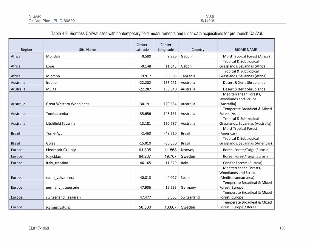
NISAR V0.9 Cal/Val Plan JPL D-80829 5/14/18
CL# 17-1968 100
Table 4-9. Biomass Cal/Val sites with contemporary field measurements and Lidar data acquisitions for pre-launch Cal/Val.
Region Site Name Center
Latitude Center
Longitude Country BIOME NAME
Africa Mondah 0.580 9.326 Gabon Moist Tropical Forest (Africa)
Africa Lope -0.148 11.643 Gabon Tropical & Subtropical Grasslands, Savannas (Africa)
Africa Miombo -9.917 38.383 Tanzania Tropical & Subtropical Grasslands, Savannas (Africa)
Australia InJune -22.282 133.251 Australia Desert & Xeric Shrublands
Australia Mulga -22.287 133.640 Australia Desert & Xeric Shrublands
Australia Great Western Woodlands -30.191 120.654 Australia
Mediterranean Forests, Woodlands and Scrubs (Australia)
Australia Tumbarumba -35.656 148.151 Australia Temperate Broadleaf & Mixed Forest (Asia)
Australia Litchfield Savanna -13.181 130.787 Australia Tropical & Subtropical Grasslands, Savannas (Australia)
Brazil Tomé-Açu -2.460 -48.310 Brazil Moist Tropical Forest (Americas)
Brazil Goiás -15.810 -50.550 Brazil Tropical & Subtropical Grasslands, Savannas (Americas)
Europe Hedmark Cuunty 61.305 11.568 Norway Boreal Forest/Taiga (Eurasia)
Europe Krycklan 64.267 19.767 Sweden Boreal Forest/Taiga (Eurasia)
Europe italy_trentino 46.165 11.329 Italy Conifer Forests (Eurasia)
Europe spain_valsainrect 40.818 -4.027 Spain
Mediterranean Forests, Woodlands and Scrubs (Mediterranean area)
Europe germany_traunstein 47.936 12.665 Germany Temperate Broadleaf & Mixed Forest (Europe)
Europe switzerland_laegeren 47.477 8.363 Switzerland Temperate Broadleaf & Mixed Forest (Europe)
Europe Remningstorp 58.500 13.667 Sweden Temperate Broadleaf & Mixed Forest (Europe)/ Boreal

NISAR V0.9 Cal/Val Plan JPL D-80829 5/14/18
CL# 17-1968 101
North America Ft. Providence 61.200 -117.600 NWT, Canada Boreal Forest/Taiga (North America)
North America Delta Junction - DEJU 63.881 -145.751 USA (Alaska) Boreal Forest/Taiga (North America)
North America Ordway - OSBS 29.689 -81.993 USA (Florida) Conifer Forests (North America)
North America Niwot Ridge Mountain Research Station 40.054 -105.582 USA (Colorado)
Conifer Forests (North America)
North America San Joachin SJER 37.107 -119.720 USA (California)
Mediterranean Forests, Woodlands and Scrubs (Americas)"
North America Howland Forest 45.300 -68.700 USA (Maine) Temperate Broadleaf & Mixed Forest (Americas)
North America Laurentides Wildlife Reserve 47.322 -71.147 Quebec, Canada Temperate Broadleaf & Mixed Forest (Americas)
North America LBJ National Grassland - CLBJ 33.368 -97.587 USA (Texas) Temperate Grasslands, Savannas (North)
North America University of Kansas Field Station (UKFS) 39.040 -95.192 USA(Kansas) Temperate Grasslands, Savannas (North)
SE Asia Sabah Forestry Research Center Area 5.000 117.700 Malaysia Moist Tropical Forest (Asia)
SE Asia Betul, India 21.96 77.94 India Moist Tropical Forest/Tropical Savanna (Asia)

NISAR V0.9 Cal/Val Plan JPL D-80829 5/14/18
CL# 17-1968 102
Table 4-10. Nominal biomass Cal/Val sites where new Lidar data acquisitions will be needed for the post-launch validation
Region Site Name Center Latitude Center Longitude Country BIOME NAME
Biomass range Lidar data
field data (if needed)
Africa
Lowveld, Kruger National Park, South Africa -24.696 31.557
South Africa
Tropical & Subtropical Grasslands, Savannas (Africa)
0-100 Mg/ha
Assumption: must be procured
Assumption: must be procured
South America Argentina site TBD TBD Argentina
Temperate Grasslands, Savannas (South)
TBD Assumption:
must be procured
Assumption: must be procured
Australia Great Western Woodlands -30.191 120.654 Australia
Mediterranean Forests, Woodlands and Scrubs (Australia)
0-50 Mg/ha
Assumption: must be procured
Assumption: must be procured (~$7000)
Australia InJune -22.282 133.251 Australia Desert & Xeric Shrublands
0-100 Mg/ha
Assumption: must be procured
Assumption: must be procured
South America Goiás, Brazil -15.810 -50.550 Brazil
Tropical & Subtropical Grasslands, Savannas (Americas)
0-200 Mg/ha
Assumption: must be procured ($10/ha)
Assumption: must be procured ($20,000
per 25 pltos of 0.25 ha)
South America Tomé-Açu, Brazil -2.460 -48.310 Brazil
Moist Tropical Forest (Americas)
0-280 Mg/ha
Assumption: must be procured ($10/ha)
Assumption: must be procured ($20,000
per 25 pltos of 0.25 ha)
Europe italy_trentino 46.165 11.329 Italy Conifer Forests (Eurasia)
TBD Assumption: must be procured
Assumption: must be procured

NISAR V0.9 Cal/Val Plan JPL D-80829 5/14/18
CL# 17-1968 103
Europe germany_traunstein 47.936 12.665 Germany
Temperate Broadleaf & Mixed Forest (Eurasia)
TBD Assumption:
must be procured
Assumption: must be procured
Europe Krycklan (Sweden) 64.267 19.767 Sweden
Boreal Forest/Taiga (Eurasia)
0-200 Mg/ha
Assumption: must be procured
Assumption: must be procured
North America
Delta Junction - DEJU 63.881 -145.751
USA (Alaska)
Boreal Forest/Taiga (North America)
Publicly available (NEON)
Publicly available (NEON)
North America Lower Teakettle USA
Conifer Forests (North America)
TBD Publicly available (NEON)
Publicly available (NEON)
North America Howland Forest 45.300 -68.700
USA (Maine)
Temperate Broadleaf & Mixed Forest (Americas)
0-200 Mg/ha Publicly
available (NEON)
Publicly available (NEON)
North America San Joachin SJER 37.107 -119.720
USA (California)
Mediterranean Forests, Woodlands and Scrubs (Americas)
TBD
Publicly available (NEON)
Publicly available (NEON)
North America
LBJ National Grassland - CLBJ 33.368 -97.587
USA (Texas)
Temperate Grasslands, Savannas (North)
TBD Publicly
available (NEON)
Publicly available (NEON)
South America Tambopata, Peru TBD TBD Peru
Moist Tropical Forest Wetland
0-300 Mg/ha
Assumption: must be procured ($10/ha)
Assumption: must be procured
SE Asia Betul, India 21.96 77.94 India
Moist Tropical Forest /Tropical Savanna (Asia)
0-300 Mg/ha Provided by
ISRO Provided by
ISRO

NISAR V0.9 Cal/Val Plan JPL D-80829 5/14/18
CL# 17-1968 104
4.4.7.2 Forest Disturbance Cal//Val Sites Forest disturbance Cal/Val sites will be selected based the availability of alternative measurements of ongoing disturbance such as from cloud free optical imagery bounding disturbance events or from information provided by forest management agencies. The sites should be distributed globally and in every forest biome.
Areas known to undergo regular forest disturbance are timber management sites. For examples large tracts in the South-Eastern United States have forest regrowth cycles of 20 years, i.e. a stand replacement rate of 5% per year for forest land under timber management. Forest management plans will be obtained for the year after NISAR launch from collaborators in the USDA Forest Service and timer industry sector to determine sites of forest disturbance a priori. International partnerships are established via collaboration in the GEO Global Forest Observing Initiative (GFOI) which operates a network of study regions of deforestation and forest degradation hotspots. Figure 4-18 illustrates where GFOI has established these study regions and constitutes a network of forest disturbance hotspots and thus a set of first order targets of opportunities for post-launch disturbance monitoring.
Figure 4-18: GFOI research and development study sites where a host of field and satellite data sets are
being used to study forest disturbance. (http://www.gfoi.org/rd/study-sites/)
A resource to use for locating sites for fire-based disturbance is the Fire Information for Resource Management System (FIRMS) (https://earthdata.nasa.gov/earth-observation-data/near-

NISAR V0.9 Cal/Val Plan JPL D-80829 5/14/18
CL# 17-1968 105
real-time/firms). FIRMS distribute Near Real-Time (NRT) active fire data within 3 hours of satellite overpass from both the Moderate Resolution Imaging Spectroradiometer (MODIS) and the Visible Infrared Imaging Radiometer Suite (VIIRS). In the U.S., a resource for the estimation of burn severity is the Burn Area and Severity mapping service by the USGS (https://www.usgs.gov/apps/landcarbon/categories/burn-area/download/). This resource can be used to support the targeting of high-resolution optical image acquisition to estimate FFCC loss from fire disturbances.
During the UAVSAR Ecosystem campaign, both pre-launch and post-launch algorithm verification will be enabled from this quad pol data set acquired over sites of likely forest disturbance in managed forest areas.
4.4.7.3 Inundated Wetland Cal/Val Sites Cal/Val sites will be chosen to represent the following inundation conditions within their typical wetland environments:
1. Open water or open water with macrophytes open water areas may be wind roughened. 2. Inundated emergent woody vegetation Emergent woody vegetation includes forests of different structure characteristics, such as
mangroves, palms, and submerged trees, as well as dead trees killed off by prolonged inundation. These two categories are typically characterized with L-band SAR by two extreme
backscatter values within a radar backscatter image, with open water typically among the lowest backscatter values found in an image, and inundated woody vegetation typically characterized by the highest backscatter values (for HH polarization). The validation challenges in classification of inundation extent include confusion between open water and bare ground, open water in the presence of wind roughened water, open water and grassy vegetation, open water with herbaceous vegetation on the surface, and inundated woody vegetation and high biomass forests. Coastal wetlands including Mangroves possess some particular challenges due to the forest structural characteristics of mangroves and the nature of their surrounding vegetation. Some of these validation challenges are due not just to the sensitivity of the L-band SAR imagery to inundation, but also to the ability of the validation data to be able to differentiate these classes as well. This requirement does not specify that bogs and fens must be separately identified, only the inundation conditions within wetland areas. However, the Cal/Val sites will include samples from both bogs and fens.
For logistical reasons, globally representative wetlands sites that are located in North and South America will be given preference for selection. The signature of inundation in the NISAR data and its validation is largely related to vegetation and forest structures that in many cases are common attributes that can be represented without sampling every geographic biome.
In addition, because open water values are some of the lowest within an L-band SAR image, the noise equivalent �o of the SAR (which will be a function of look angle) as well as the SAR ambiguity ratio must be sufficiently low to enable clear differentiation between open water and other radar dark targets. A noise level near to or higher than bare ground/grassy vegetation and open water radar backscatter values would make differentiating those classes problematic. SAR ambiguities from shorelines and inundated vegetation can contaminate nearby locations in the imagery and make interpretation and classification of the SAR data difficult.

NISAR V0.9 Cal/Val Plan JPL D-80829 5/14/18
CL# 17-1968 106
Therefore, the Cal/Val sites must address each of these factors by sampling wetlands with globally representative vegetation characteristics and shorelines, as well as sampling them at various look angles. The inundation characteristics of wetlands can be dynamic; therefore, the validation of this requirement will also require measurements at various degrees of inundation.
The primary Cal/Val sites will be located where ongoing monitoring and study has been and continues to be present. Priority will be given to sites where partners at the sites are studying inundation dynamics or need such a study for their monitoring activities. Important long-term programs to consider when selecting Cal/Val sites includes the Convention on Wetlands, called the Ramsar Convention, is an intergovernmental treaty that provides the framework for national action and international cooperation for the conservation and wise use of wetlands and their resources. There are over 2000 Ramsar sites around the world, including 38 sites in the United States of America. To address ecological questions that cannot be resolved with short-term observations or experiments, NSF established the Long Term Ecological Research Program (LTER) in 1980. The National Ecological Observatory Network (NEON) is a large facility project funded by the National Science Foundation (NSF). NEON is a continental-scale platform for ecological research. The observatory will gather long-term data to enable fundamental research on biological responses to shifting environmental conditions, land-use changes, and invasive species. Through our partnership with Indian Space Research Organization (ISRO), three Cal/Val sites have been selected where S-band data will be frequently collected as well. Primary Cal/Val sites The Primary Cal/Val sites will be imaged by UAVSAR during the post-launch UAVSAR inundated wetlands campaign, which is described in appendix 9.3.2.
• Boreal wetland sites Bonanza creek/Yukon Flats, AK and a site within the NWT of Canada. NASA Arctic Boreal Vulnerability Experiment (ABoVE) has funded field work and airborne campaigns including wetland sites within this area. The Bonanza Creek LTER is studying the effects of climate change, climate disturbances, and ecosystem dynamics for this region. NSF funded APEX site is studying bogs and fens within Bonanza Creek. Ducks Unlimited has made the western boreal forests of Canada a conservation priority, and since 1997 has been mapping and creating wetlands inventories as a component of their Western Boreal Forest Initiative. A partnership between Wilfred Laurier University and the government of the North West Territories of Canada conducts wetlands inventories in the NWT. This is also a SWOT Cal/Val site. Likely methodology: Ground transects, high resolution optical, and sUAS data.
• Mississippi river delta area, Louisiana site in conjunction with SWOT Cal/Val site. Catahoula Lake is a Ramsar site near the Mississippi River in Louisiana. Likely methodology: Pressure transducers combined with DEM.
• Everglades National Park. This area includes a Ramsar site, the Florida Coastal everglades LTER, the NEON site at the Disney Wilderness preserve that straddles the headwaters of the everglades, as well as other monitoring activities. SWOT Cal/Val site. Likely methodology: Pressure transducers combined with DEM.
• Pacaya-Samiria, Peru. Tropical wetland (palms, etc.), frequent and widespread inundation in areas with substantial emergent woody vegetation. Likely methodology: Pressure transducer and ground transects, lidar if available.

NISAR V0.9 Cal/Val Plan JPL D-80829 5/14/18
CL# 17-1968 107
• Carpinteria salt marsh reserve, California. SWOT Cal/Val site. Likely methodology: Pressure transducer combined with RTK DEM, sUAS imagery.
• Magdalena river, Colombia, existing mangrove study site of Marc Simard. Likely methodology: ground transects and sUAS surveys.
Secondary Cal/Val sites (Partner-provided Cal/Val data) Secondary Cal/Val sites will consist of data collected by partnership arrangements for calibration and validation. Independent assessments of inundation extent will be acquired through these partnerships.
• Bhitarkanika, Odisha (Ramsar site-1205). A Mangrove forest, with saltwater crocodiles & Olive Ridley sea-turtles. Currently being monitored and studied by ISRO scientists with RISAT.
• Chilika Lagoon, Odisha (Ramsar site-229). A Biodiversity, avifauna & Irrawaddy Dolphin site, currently being monitored and studied by ISRO scientists with RISAT.
• Nalsarovar, Gujarat (Ramsar site-2078). A Biodiversity and avifauna site currently being monitored and studied by ISRO scientists with RISAT.
• Akanda shrub mangrove, Pongara tall mangrove and Ogooue river Freshwater marsh, tropical wetland palms, papyrus. AFRISAR site. Likely methodology: UAS imagery water level gauges + DTM.
• Pantanal, Brazil. Partner: TBD. • Sud, South Sudan. Partner: Lisa Rebello, International Water Management Institute. • Mamiraua Sustainable Development Reserve, Brazil. Partner with scientists at Sao
Paulo State University (UNESP).
4.4.7.4 Agricultural Crop Area Cal/Val Sites Part of the Group on Earth Observations, the GEOGLAM initiative has developed a set of agriculture sites distributed worldwide for working with remote sensing data. These are known as the JECAM sites (Joint Experiment for Crop Assessment and Monitoring; www.jecam.org), shown in Figure 4-19 below.

NISAR V0.9 Cal/Val Plan JPL D-80829 5/14/18
CL# 17-1968 108
Figure 4-19. Distribution of JECAM sites worldwide. These sites, and others like them, will be used as the
ground-validation for NISAR’s Crop Area requirement. The distributed JECAM sites provides a useful diversity of crop areas that cover different climate and political zones and will be used, in conjunction with Very High Resolution (VHR) optical data for creating local regions of crop area determination that will be used by NISAR for calibration and validation. A subset of the JECAM sites that covers the five continents and that are being developed by NISAR for this purpose are described below. North America
• Canada 1. Canadian Food Inspection Agency (CFIA) located at 45o 18’ 00”N, longitude 75o 46’
00”W consists of summer crops for corn, soybean, wheat and canola. 2. South Nation Watershed (SNW) located at 45.332 degrees N latitude and 75.050
degrees longitude, consists of corn, soybean, wheat (Triticum spp.) and forages. 3. Red River Watershed (RRW) located in Manitoba, CA, is a 26 x 48 km region that
consists of canola, soybeans, wheat, corn oats, winter wheat, beans and pasture. • United States: South Fork, Iowa, maize and soybean, also serves as a SMAP Cal/Val site. • Mexico: To Be Determined
South America • Argentina: San Antonio de Areco, Buenos Aires, Argentina (34° 7'18.69"S,
59°35'53.05"W). Main grain crops are soybean, maize and wheat. Early wheat is planted in June/July while late wheat is planted at the end of July and August.
• Brazil 1. Sao Paolo, Brazil (Latitude -22.9677, Longitude -48.7274). The main crop is
sugarcane, but a variety of other crops such as corn, soy and oats are in the region and reported as part of JECAM as well.

NISAR V0.9 Cal/Val Plan JPL D-80829 5/14/18
CL# 17-1968 109
2. Tocantins, MATOPIBA consists of summer soybeans and cereals and has fields on the order of 100 ha in size.
Europe • Belgium: The Belgium JECAM site is located at 50.65 degrees North and 5 degrees East.
It consists of a variety of wheat, barley, potatoes, sugar beet, maize, and alfalfa with field sizes between 2 and 15 ha.
• France: The region of Aurade and Lamasquere (43.675 degrees North, 1.075 degrees East) has winter wheat and maize with field sizes of 20 and 30 ha on overage.
• Italy: The region of Apulian Tavoliere (40.80 degrees North, 17.10 degrees East) is a 4000 km2 primarily consists of wheat, and varied other crops.
• Spain: The Las Tiesas region in Barrax-Albacete (39.0544 degrees N, 2.1007 degrees E). Winter and summer crops of Barley, Onion, Rape (Canbola), Alfalfa and other Chickpeas.
• Ukraine: Kyev region (50.355 degrees North, 30.715 degrees East) with 28,000 km2 and 25 x 15 km intensive study sites. Crops consist of winter wheat, winter rapeseed, spring barley, maize, soy beans, sunflowers, sugar beets and vegetables.
Asia
• Bangladesh: CIMMYT Bangladesh (Alamdanga and Barisal) . The main crops are for rain-fed rice production.
• China: Jinhu, located in the Jiangsu province (33°15'22.33"N - 32°58'35.00"N�118°49'39.97"E - 119° 6'51.67"E) consists mostly of rice.
• Vietnam: Vietnam’s National Institute of Agricultural Planning and Projection (NIAPP) has the RIICE program (Remote Sensing based Information and Insurance for Crops in Emerging Economies) for monitoring rice for the Red River and Mekong River deltas in Vietnam, including 24 provinces, and accounts for 70% rice area in the country. Location is 21.18 degrees North and 105.6 degrees East.
• Taiwan: TARI in the Changhua and Yulin counties (23.75 degrees North, 120.5 degrees West) covering approximately 3,170 km2 with two rice-cropping seasons per year. Field sizes vary between 0.5 and 1.1 ha under varying weather conditions in a tropical climate.
Africa • Madagascar: Antsirabe (19.75 degrees South, 47.75 degrees East) is a 3600 km2 region
used for crop classification and crop area mapping in Madagascar consists of maize, wheat, oats and other agriculture fields in a mixed urban and forested landscape.
• Morocco: Tensift, 20,000 km2 region at (31.0 degrees N, 8.5 degrees W) consisting of wheat, cereals, and other crops that are both irrigated and rainfed.
• Tunisia: MERGUELLIL test site (35° 30' North, 10° 00' East) with 1-4 ha field sizes in a Mediterranean climate agriculture of fruit trees, dry cereals and vegetables.

NISAR V0.9 Cal/Val Plan JPL D-80829 5/14/18
CL# 17-1968 110
4.4.7.5 UAVSAR Ecosystem Campaign Cal/Val Sites Out of all disciplines that are encompassed by NISAR, Ecosystems is one in most need of
proxy data (from UAVSAR or similar) that consists of repeated 12-day observations over an extended period of time. To date, many of the airborne time-series coverages have focused on the solid earth and hazards, with these observations being complemented by spaceborne data available from ERS-1 and -2, the Radarsat missions, the Sentinel time series, and others. This has been possible, in part because of the focus of these disciplines on sparsely vegetated surfaces and the fairly straight-forward correspondence of surface scattering properties at both L- and C-band (wavelength of 24 cm and 5 cm respectively). By contrast, Ecosystems targets are almost always vegetated, with the scattering components and volume scattering nature of the target giving different scattering responses at the different wavelength regimes. For this reason, the use of C-band observations as a proxy for NISAR’s L-band, as is often done for other disciplines, is not possible for the development and testing of NISAR algorithms.
In addition to the wavelength scaling challenges for Ecosystem algorithm development, the hydrologic regime for Ecosystem targets is quite different than the other disciplines that will be sharing NISAR resources. By their very nature, Ecosystems thrive on the presence of water, and in regions where water is the most prevalent, we find an equivalent degree of vegetation. For this reason, the characterization of Ecosystems in these regions will be one of the largest beneficiaries of the NISAR mission, which will have an unprecedented consistent and reliable 12-repeat period over most of the world’s vegetated regions. Yet, because of the lack of proxy observations at this frequency and intensity of observations, is exactly what is missing from the inputs for the pre-launch calibration and validation period of NISAR.
While there have been high resolution spaceborne SAR sensors at L-band (Seasat, JERS, ALOS-1, and ALOS-2), the data acquired by these sensors don’t form a good set of proxy observations for development of NISAR ecosystem science algorithms as well, due to their limited temporal sampling for localized regions. The NISAR ecosystem science algorithms are uniquely defined by extensive time series analysis of observations acquired at frequent intervals.
In appendix 9.3, observational plan for UAVSAR is described that can be used to address this lack of information that would be important for NISAR Ecosystem algorithm development and in the pre-launch Cal/Val phase of the mission. Because of the natural overlap with NASA’s Soil Moisture Active Passive (SMAP) mission, this plan has been assembled to incorporate sites that would be of use for SMAP, and in turn would benefit the NISAR mission by foster the development of dual-use Cal/Val sites in the northeastern part of the United States. Further, because of the planned coverage of the Lower Mississippi, and the short repeat-period, this observation scenario will have relevance to SWOT, and hence, in moving forward, will serve as a useful vehicle for engaging that community as well. The UAVSAR ecosystem Cal/Val campaign will acquire data over a selection of field research sites where ongoing monitoring of these regions in ongoing by other federal agencies. NEON Sites The NSF National Ecological Observatory Network (NEON), is a collection of research sites with a common observatory methodology, that is scattered nationally, and meant to provide researchers a common basis for modeling and monitoring ecology over a diverse set of landscapes and extended geographic region. The two fundamental observatory types are 1.) Terrestrial, and 2.) Aquatic. Within each are a shared measurement methodology that provides

NISAR V0.9 Cal/Val Plan JPL D-80829 5/14/18
CL# 17-1968 111
basic measurements such as soil moisture, wind speed, and lake/river stage. Ground observations are complemented by airborne remote sensing measurement of lidar and hyperspectral data. Table 4-11 is a list of NEON sites that are along the eastern US corridor that could be covered by a concerted flight campaign, while Table 4-12 is a list of other research sites of interest falling within the domain of this flight campaign.

NISAR V0.9 Cal/Val Plan JPL D-80829 5/14/18
CL# 17-1968 112
Table 4-11. NEON sites that could be imaged by UAVSAR ecosystem campaign
Mayfield Creek (MAYF), Alabama Core Aquatic, Dense forest wetlands site located 20 miles southeast of Tuscaloosa. The Mayfield Creek area is surrounded by the Oakmulgee Ranger District and is part of the Talladega National Forest. The surrounding area consists of lakes, forests and agriculture.
Talladega National Forest (Tall), Alabama
Core Terrestrial, longleaf pine forest, mixture of hardwoods, wetlands, and regions of agricultural abandonment. East of Tuscaloosa and south of Birmingham, the area of the site is 5300 hectares.
Black Warrior River (BLWA), Alabama
Relocatable Aquatic site is 60 miles southwest of Tuscaloosa and next to DELA.
Dead Lake (DELA), Alabama Relocatable Terrestrial site, next to BLWA, southwest of Tuscaloosa.
Lenoir Landing (LENO), Alabama Relocatable Terrestrial, 100 miles southwest of Tuscaloosa. Next to TOMB.
Tombigbee River (TOMB), Alabama Relocatable Aquatic, next to LENO, southwest of Tuscaloosa.
Smithsonian Environmental Research Center (SERC), Maryland
Relocatable Terrestrial, 16 ha CTFS plot, 5 miles south of Annapolis.
Great Smoky Mountains National Park (GRSM), Tennessee
Relocatable Terrestrial, southeast of Knoxville.
Leconte Creek (LECO), Tennessee Relocatable Aquatic, next to GRSM, southeast of Knoxville.
Oak Ridge National Lab (ORNL), Tennessee
Core Terrestrial, west of Knoxville.
Walker Branch (WALK), Tennessee Core Aquatic, next to ORNL, west of Knoxville.
Lower Hop Brook (HOPB), Massachusetts
Core Aquatic, near the Quabbin reservoir, west of the Harvard Forest.
Harvard Forest (HARV), Massachusetts
Core Terrestrial site, East of Amherst, near the Quabbin reservoir, 1600-hectare research forest, 35 ha CTFS site.

NISAR V0.9 Cal/Val Plan JPL D-80829 5/14/18
CL# 17-1968 113
Table 4-12. Other research sites that could be imaged by UAVSAR ecosystem campaign
Duke Forest, North Carolina The Duke Forest, owned and managed by Duke University, consists of over 7,000 acres of forested land and open fields in North Carolina. Its location is southwest of the city of Durham, in the northeastern corner of the state, and has been managed for teaching and research purposes since 1931. One of the missions of the forest is to facilitate research that addresses fundamental and applied questions concerning forested and aquatic ecosystems. Throughout its history, it has been the target region of a number of remote sensing studies, including SLICER, LVIS, AirSAR and UAVSAR.
Howland Forest, Maine The Howland research forest consists of 225 hectares. The forest is dominated by mixed spruce, hemlock, aspen, and birch stands ranging in age from 45 to 130 years.
Mississippi River Delta The Mississippi River delta is an area of intense interest to several NISAR science requirements, as the area is subject to extensive flooding, forest disturbances, and surface deformation. It is a SWOT Cal/Val site, and there will be infrastructure deployed for measuring water flow and water level. The UAVSAR data in this area will be used to evaluate ground truth validation strategies prior to the launch of NISAR (measuring inundation extent using a network of water level gauges and an accurate DTM, Thermal IR and VHR imagery, and ground transects).
Sullivan Agriculture Site Located at 35.71895 degrees North and 90.04553 degrees West, the core site consists of ~24 highly instrumented fields ranging from 40-100 acres each. The larger region is dominated by rice, soy, cotton, sorghum, corn and winter wheat rotations. The surrounding area has 30 - 50 thousand acres of wetlands and forest intermixed as well. The site itself, developed by Applied GeoSolutions and USDA ARS, is a result of a Public Private Partnership (PPP) that includes Federal and state government, industry, academia, NGOs, and farmers to investigate technologies, sensors, management practice,

NISAR V0.9 Cal/Val Plan JPL D-80829 5/14/18
CL# 17-1968 114
and tools. In addition to crop type, the infield sensors measure soil moisture, water depth where appropriate, LAI, emissions / flux, tillage practice, soil organic carbon, and end of season yield / biomass collected by combine. These regions are intensively farmed, including complex irrigation schemes. In Arkansas, irrigation occurs on 1.82 million ha, the majority of which is in eastern Arkansas and derives largely from the shallow Mississippi River Valley Alluvial Aquifer underlying the alluvial plain. Hence, the region is also being studied for subsidence and a reduction of ground-water supply.
4.5 Cal/Val Strategy for Disaster Response Applications Validation of the disaster response (DR) application requirement will be done through exercise of the low-latency data acquisition and processing stream. The processing stream will be tested pre-launch using simulated data, and the full disaster response stream will be tested postlaunch at each stage individually and in full combination. The steps to be tested, the initiating party and the party responsible for executing the step are given in Table 4-13. It is expected that response initiation can be either manual or automated, e.g., following an earthquake of magnitude higher than a given threshold, and all automatic generation mechanisms will be tested.
Table 4-13. Disaster Response Low-Latency Operation Stage Action Initiating Party Max Latency*
Retasking
Send automatic retasking request to ISRO
SRS 24 hours
Send manual retasking request to ISRO
SRS
Retask L-band SAR ISRO Downlink Downlink DR
scene(s) with priority ISRO?
5 hours
Route DR scene(s) to processing center
ISRO?
Processing Process to L2 Products (no precision orbit)
SRS
Delivery Post products to DAAC
SRS
*Latency is on a best efforts basis

NISAR V0.9 Cal/Val Plan JPL D-80829 5/14/18
CL# 17-1968 115
5 CALIBRATION AND VALIDATION OF NISAR PRODUCTS The NISAR data products are listed earlier in Section 2 (Table 2-4).
5.1 Level 1 Sensor Products Level 1 NISAR science products are the calibrated sensor outputs (i.e. radar backscatter). The accuracy of these products depends on the pre-launch calibration model and the calibration algorithm and coefficients applied in the post-launch processing.
Table 5-1 shows the Level 1 products, their requirements for spatial resolution and accuracy, and associated pre-launch and post-launch Cal/Val requirements.
Table 5-1. Level 1 products and associated Cal/Val requirements
Information and data needed for Cal/Val Level 1 product Description Image Calibration Accuracy Pre-launch Post-Launch
L1-SLC Single Look
complex data
Azimuth Resolution: 7 m, Range Resolution (depends on
mode, from 1.9 m to 30 m), 1.2 dB radiometric accuracy, Noise equivalent so -23 dB,
Ambiguities -20 dB, ISLR -20 dB
Point target simulated data, Distributed target simulated
data, Data derived from other radar missions,
Calibration parameters from instrument system
engineering
Trihedral corner reflectors, established uniform isotropic
stable earth targets, data from contemporary calibrated L-band SAR, aircraft-based observations
during field campaigns
5.2 Level 2 Data Products Level 2 NISAR data products are the derived quantities that will typically be used to derive the Level 3 Science products.
Table 5-2 shows the Level 2 products, their requirements for spatial resolution and accuracy, and associated pre-launch and post-launch Cal/Val requirements.

NISAR V0.9 Cal/Val Plan JPL D-80829 5/14/18
CL# 17-1968 116
Table 5-2. Level 2 products and associated Cal/Val requirements
Information and data needed for Cal/Val Level 2 product Description Image Calibration
Accuracy Pre-launch Post-Launch
L2-MLP
Multilooked & Geocoded
polarimetric images
0.72 dB systematic cal error, Noise equivalent so -23 dB, Ambiguities -20 dB, ISLR -20 dB
Point target simulated data, Distributed target simulated
data, Data derived from other radar missions,
Calibration parameters from instrument system
engineering
Trihedral corner reflectors, established uniform isotropic stable earth targets, data from contemporary calibrated L-band SAR, aircraft-based observations
during field campaigns
L2-MLI
Multilooked & Geocoded
Interferograms and Images
0.72 dB systematic cal error, Noise
equivalent so -23 dB, Ambiguities -20
dB, ISLR -20 dB
Point target simulated data, Distributed target simulated
data, Data derived from other radar missions,
Calibration parameters from instrument system
engineering
Trihedral corner reflectors, established uniform isotropic stable earth targets, data from contemporary calibrated L-band SAR, aircraft-based observations during field campaigns, atmospheric
and ionospheric corrections
L2-GSLC Geocoded SLC
0.72 dB systematic cal error, Noise
equivalent so -23 dB, Ambiguities -20
dB, ISLR -20 dB
Point target simulated data, Distributed target simulated
data, Data derived from other radar missions,
Calibration parameters from instrument system
engineering
Trihedral corner reflectors, established uniform isotropic stable earth targets, data from contemporary calibrated L-band SAR, aircraft-based observations during field campaigns, atmospheric
and ionospheric corrections
5.3 Level 3 Science Products Level 3 products contain derived geophysical parameters whose accuracy depends on the accuracy of the input Level 1 sensor products, Level 2 data products, and the Level 3 geophysical retrieval algorithms.
Table 5-3 shows the Level 3 products associated Cal/Val requirements.

NISAR V0.9 Cal/Val Plan JPL D-80829 5/14/18
CL# 17-1968 117
Table 5-3a. Level 3 products and associated Cal/Val requirements – Solid Earth
Level 3 Product Description Grid Cal/Val metric Level 2 science requirement
L3-SE1
Co-seismic Deformation
100 m
Measured displacements compared with displacements measured by GPS networks
Over three years, the NISAR project shall measure at least two components of the relative vector co-seismic displacement field of at least 80% of regions where earthquakes with sufficient magnitude to generate surface displacements of 100 mm or greater occur, with root-mean-square accuracy of 3.5 (1+L^1/2) mm or better, over length scales 0.1 km < L < 50 km, at 100 m spatial resolution over these regions.
L3-SE2 Secular Deformation Rates
100 m Measured displacements compared with displacements measured by GPS networks
Over three years, the NISAR project shall measure at least two components of the spatially and temporally averaged relative vector velocities over active regions of Earth’s land surface with root-mean-square accuracy of 2 mm/yr or better, over length scales 0.1 km < L < 50 km, over 70% of these regions.
L3-SE3
Deformation Transients
100 m Measured displacements compared with displacements measured by GPS networks
The NISAR project shall measure point-to-point vector displacements over at least 90% (TBC) of order 2,000 targeted sites with root-mean-square accuracy of 3(1+ L^1/2) mm or better, over length scales 0.1 km < L < 50 km, at 100 m resolution, and over 12-day time scales.
L3-SE4 Permafrost relative displacement
100 m
Measured displacements compared with field measurements of displacement
The NISAR project shall measure surface deformation in permafrost-affected areas with 12 day sampling at 100-m resolution during snow free months with accuracy of 4*(1+L^1/2) mm or better, over length scales 0.1 km < L < 50 km, over 80% of selected regions, and over any 90-day interval.

NISAR V0.9 Cal/Val Plan JPL D-80829 5/14/18
CL# 17-1968 118
Table 5-3b. Level 3 products and associated Cal/Val requirements – Cryosphere
Level 3 Product Description Grid Cal/Val metric Level 2 science requirement
L3-CS1 Ice sheet/glacier slow velocity
100 m
Measured velocities compared with velocity measurements along GPS transect
The NISAR Project shall measure ice sheet (> 90% coverage, including both poles) and glaciers and ice-caps (> 80% coverage) horizontal velocity each cold season to 1 m/yr (1-sigma), at 100-m resolution in areas of slow deformation (< 50 m/yr).
L3-CS2 Ice sheet/glacier fast velocity
100 m
Measured velocities compared with velocity measurements along GPS transect
The NISAR Project shall measure ice sheet horizontal velocity (90% coverage, including both poles) to the greater of 3% or 5 m/yr (1-sigma), at 250-m resolution each cold season in areas of fast deformation (>50 m/yr).
L3-CS3 Ice sheet time-varying velocities
100 m
Measured velocities compared with velocity measurements along GPS transect
The NISAR Project shall measure time-varying horizontal velocities of ice-sheets at near-weekly sampling intervals in areas of potential rapid (e.g., outlet glaciers) or seasonal change to the greater of 3% or 10 m/yr (1-sigma) at 500-m resolution (> 80% coverage (action: Eric to verfy)).
L3-CS5
Vertical differential displacement Measurement
100 m Measured displacement vs GPS
The NISAR project shall measure the vertical differential displacement of all floating ice shelves and ice tongues with vertical accuracy of 100 mm at 100-m resolution annually (> 95% coverage) and monthly (>50% coverage).
L3-CS6 Sea ice velocity 5 km
Measured velocities compared with measured velocities from IABP and IPAB.
The NISAR project shall measure sea ice velocity at 100 m/day accuracy on a 5 km grid every 3-days over at least 90% (TBC by Ballard % coverage at 3 days for both right- and left- looking) of the Arctic sea-ice extent and 70% (TBC by Ballard % coverage at 3 days for both right- and left- looking) of the Antarctic sea ice extent.

NISAR V0.9 Cal/Val Plan JPL D-80829 5/14/18
CL# 17-1968 119
Table 5-3c. Level 3 products and associated Cal/Val requirements – Ecosystem
Level 3 Product Description Grid Cal/Val metric Level 2 science requirement
L3-ES1 Biomass 1 ha
Accuracy of biomass estimate compared with alternative measurements
The NISAR project shall measure aboveground woody vegetation biomass annually at the hectare scale (1 ha) to an RMS accuracy of 20 Mg/ha for 80% of areas of biomass less than 100 Mg/ha.
L3-ES2 Disturbance versus time 1 ha
False alarm and missed detection rates compared with high resolution optical assessments of disturbance
The NISAR project shall measure global areas of forest disturbance at 1 hectare resolution annually for areas losing at least 50% canopy cover with a classification accuracy of 80%.
L3-ES3 Crop area 1 ha
Accuracy of classification compared with alternative measurements
The NISAR project shall measure crop area at 1 hectare resolution every 3 months with a classification accuracy of 80%.
L3-ES4 Inundation area 1 ha
Accuracy of classification compared with alternative measurements
The NISAR project shall measure inundation extent within inland and coastal wetlands areas at a resolution of 1 hectare every 12 days with a classification accuracy of 80%.

NISAR V0.9 Cal/Val Plan JPL D-80829 5/14/18
CL# 17-1968 120
6 JOINT NASA-ISRO CAL/VAL ACTIVITIES NASA and ISRO share a common objective for NISAR, i.e. Calibration of all onboard sensors and validation of all science requirements and/or goals. Both agencies will have independent programs to ensure that this is achieved. The activities described in this document in Sections 1-5 characterize the Cal/Val of the NASA requirements, which are solely dependent on the L-band sensor. ISRO requirements depend on L-band as well as S-band. Inter-comparison between L-band and S-band Cal/Val results will provide valuable confirmation of both activities. During the implementation phase of the mission, the specific joint Cal/Val activities will be planned and coordinated for maximum benefit to both NASA and ISRO.
The mission observation plan will include S-band observations over NISAR ecosystem Cal/Val sites to facilitate join L-band and S-band analysis is regions where science validation data are available. These data acquisitions will be in alignment with those that will be acquired over most of India and will be especially valuable for joint studies by NASA and ISRO scientists of agricultural crop area and wetland inundation. Joint science plans are currently under development between US and Indian scientists, where the availability of similar data sets worldwide with ground validation measurements will enhance the value of the joint science activities, application and utilization programs and joint calibration and validation objectives.
Joint NASA-ISRO Cal/Val activities will include the sharing of calibration arrays and identified natural distributed targets, as well as the methodologies of the analysis.
ISRO has two Cal/Val sites (in a desert environment) Desalpar and Amrapura in Rann of Kutch, in Gujarat. Desalpar site is being regularly utilized for the geometric and radiometric calibration of RISAT-1 (C-band) SAR sensors with the deployment of nearly 12 Corner reflectors (various types). Also, it is being used for absolute radiometric calibration of optical sensors onboard Resourcesat-2 (Advanced Wide Field Sensor and LISS-3), INSAT-3D and also Landsat-8 (Optical Land Imager) satellites. This site has a very good dark background for most of the year except during the southwest monsoon season (Aug-Oct) when occasional water logging creates problem in making Cal/Val measurements. It is nearly 7 km long, and its suitability for L-band and S-band needs to be checked. The test of the suitability of this site for the calibration of L-band data is being planned by experimenting with ALOS L band data. Amrapura site is nearly 62 km long and having same background as that of Desalpar site. Because of its large size and uniform background, it is planned to use this site also for the calibration activity. Presently, it is being used for INSAT-3D calibration and validation.
The NASA NISAR calibration array includes the Rosamond Calibration Array (RCA) in the Rosamond Dry Lake bed in southern California. RCA currently includes over 30 trihedral reflectors that are regularly maintained for the calibration of NASA’s airborne SAR, UAVSAR. These reflectors are used to calibrate UAVSAR data (P-band, L-band, and Ka-band). The NISAR calibration array will have targets to span the full 240 km swath of NISAR, and is planned for deployment in Australia in collaboration with Geoscience Australia (GA). Observation planning for L-band and S-band will include scheduling observations for both sensors over these calibration targets as well as other established sites. ISRO has a current agreement with GA in regards to the use of the GA calibraiton array in Australia.
Although ISRO is currently considering suitable sites for NISAR Cal/Val, ISRO’s immediate attention is focused on Cal/Val for their Airborne L&S band SAR, which will have a ground

NISAR V0.9 Cal/Val Plan JPL D-80829 5/14/18
CL# 17-1968 121
resolution of ~5 meters. Calibration sites in India that are currently being utilized for RISAT-1 SAR calibration are under consideration as a Cal/Val sites for this airborne instrument.
ISRO NRSC in Hyderabad is constructing corner reflector targets (trihedrals and dihedrals) suitable for S-Band (~2 meter) and that may be useful at L-band as well. ISRO is in the process of procuring additional units (probably with mesh wire) for deployment at additional sites within India. In order to arrive at a common standard procedure/methodology of the calibration including validation of the theoretical value of RCS of Corner reflectors, both the agencies (NASA and ISRO) shall work together through exchange of results/findings as well as exploring the facilities.
Distributed targets will be used to validate the antenna pattern, for cross-talk estimation, and to validate radiometric calibration accuracy. Portions of the Amazon basin in South America has always been a good distributed target site for Calibration of SAR and has been extensively used for this purpose by many SAR satellites; ISRO has also utilized the Amazon basin for RISAT-1 SAR calibration. ISRO is also investigating island sites with permanent forest cover/water (in India) as a dedicated distributed target.
Both NASA and ISRO are planning to develop passive receivers to validate the digital beamforming algorithms. While these receivers may be specific to a particular band, inter-comparison of results will be valuable in confirmation of the calibration of the imagery.
Because of RISAT, and connections with NCFC, within ISRO there is significant expertise in agricultural applications using SAR data. There is a great deal of common interests by NASA and ISRO using both L-band and S-band data. The NASA requirement to identify crop area is similar to the ISRO application goals in agricultural areas. Agricultural validation sites within the US and within India for joint validation activities are planned.
NASA scientists plan to work closely with ISRO scientists on three wetland areas in India in particular, through Cal/Val activities at those sites as described in section 4.4.7.3. Joint L-band and S-band acquisitions may be valuable for identifying herbaceous wetlands. One ISRO requirement is to monitor disastrous flooding events in India, similar to the NASA requirement to more broadly identify inundation extent. Sites prone to flooding in India will be valuable validation sites for both NASA and ISRO product validation of inundation extent and flooding. These sites can be used as pre and post flood markers for validation.
NASA is interested in biomass sites in India for validation of the NASA science requirement for measuring biomass. Since biomass is an application goal of ISRO (for low vegetation areas like crops as well as high vegetation areas like forests), during the next phase of the mission validation sites will be identified. The NRSC (ISRO) scientists have been measuring biomass at the forests in Betul, India through both field measurements and lidar acquisitions, and will be working with the NISAR Science Team to fully incorporate this site as a NISAR biomass Cal/Val site.
ISRO is considering the placement of GPS receivers on glaciers in Antarctica for validation of an ISRO application goal. During the next phase of the mission, the possible sharing of this site plus the NASA instrumented glacier in Greenland will be evaluated and considered.
It is planned to explore the possibility of sharing the GPS data by an Indian Seismological group, which operates a GPS network in India, for validation of the NASA solid earth requirements. Likewise, the GPS network data acquired by NASA will be shared with ISRO.

NISAR V0.9 Cal/Val Plan JPL D-80829 5/14/18
CL# 17-1968 122
7 REFERENCES Agnew, D. C., SPOTL: Some Programs for Ocean-Tide Loading, SIO Technical Report, Scripps
Institution of Oceanography, http://escholarship.org/uc/item/954322pg, 2012. Agram, P.S. , R. Jolivet, B. Riel, Y. N. Lin, M. Simons et al., New Radar Interferometric Time
Series Analysis Toolbox Released, EOS Transactions, 94, 7, 69-70, 2013. Agram, P.S., Persistent Scatterer Interferometry in Natural Terrain, PhD Thesis, Stanford
University, 2010. Ainsworth, T, L. Ferro-Famil, and J.-S. Lee, “Orientation angle preserving a posteriori
polarimetric SAR calibration,” IEEE Trans. Geosci. Remote Sens., vol. 44, no. 4, pp. 994–1003, Apr. 2006.
Aires, Filipe, Fabrice Papa, and Catherine Prigent, 2013: A long-term, high-resolution wetland dataset over the amazon basin, downscaled from a multiwavelength retrieval using sar data. J. Hydrometeor, 14, 594–607.
Berardino P, G. Fornaro, R. Lanari, and E. Sansosti, A new algorithm for surface deformation monitoring based on small baseline differential SAR interferograms, IEEE Trans. on Geosci. and Rem. Sens., 40, 2375–238, 2002.
Boryan, C., Z. Yang, R. Mueller, and M. Craig, “Monitoring US agriculture: the US Department of Agriculture Statistics Service, Cropland Data Layer Program,” Geocarto International, 1-18, 2011.
Chapman, Bruce, “Summary of results – NISAR inundation measurement requirement”, JPL internal document, October 21, 2014.
Chapman, Bruce, Hamilton, Steve, Celi, Jorge, “Validation of forested inundation extent revealed by L-band polarimetric and interferometric SAR data”, IGARSS 2014, Quebec, Canada July 2014.
Cho M.A., Mathieu R., Asner G.P., Naidoo L., van Aardt J., Ramoelo A., Debba P., Wessels K., Main R., Smit I.P.J., et al. Mapping tree species composition in South African savannas using an integrated airborne spectral and LiDAR system. Remote Sens. Environ. 2012;125:214–226.
Chubey M.S., Franklin S.E., Wulder M.A. Object-based analysis of IKONOS-2 imagery for extraction of forest inventory parameters. Photogramm. Eng. Remote Sens. 2006;72:383–394.
Cohen, W. B., Fiorella, M., Gray, J., Helmer, E., & Anderson, K. (1998). An efficient and accurate method for mapping forest clearcuts in the Pacific Northwest using Landsat imagery.Photogrammetric Engineering and Remote Sensing,64(4), 293–300
Clark D.B., Read J.M., Clark M., Cruz A.M., Dotti M.F., Clark D.A. Application of 1-m and 4-m resolution satellite data to studies of tree demography, stand structure and land use classification in tropical rain forest landscapes. Ecol. Appl. 2004;14:61–67.
Douglas, T. A., Jorgenson, M. T., Kanevskiy, M. Z., Romanovsky, V. E., Shur, Y., & Yoshikawa, K. (2008). Permafrost dynamics at the Fairbanks permafrost experimental station near Fairbanks, Alaska. University of Alaska, Fairbanks.

NISAR V0.9 Cal/Val Plan JPL D-80829 5/14/18
CL# 17-1968 123
Fore, Alexander G., Chapman, Bruce, Hawkins, Brian, Hensley, Scott, Jones, Cathleen, Michel,
Thierry, and Muellerschoen, Ronald, "UAVSAR Polarimetric Calibration," IEEE Transactions on Geoscience and Remote Sensing, vol. 53, no. 6, pp. 3481-3491, Jun. 2015.
Falkowski M.J., Wulder M.A., White J.C., Gillis M.D. Supporting large-area, sample based forest inventories with very high spatial resolution satellite imagery. Prog. Phys. Geogr. 2009;33:403–243.
GFOI (2013) Integrating remote-sensing and ground-based observations for estimation of emissions and removals of greenhouse gases in forests: Methods and Guidance from the Global Forest Observations Initiative: Pub: Group on Earth Observations, Geneva, Switzerland, 2014. ISBN 978-92-990047-4-6
Hensley, S.H., P. Agram, S. Buckley, H. Ghaemi, E. Gurrola, L. Harcke, C. Veeramachaneni and S-H Yun, NISAR Performance Modeling and Error Budget, Jet Propulsion Laboratory, Interoffice Memorandum, January 26, 2016.
Hess L.L., E. M. L. M. Novo , D. M. Slaymaker , J. Holt , C. Steffen , D. M. Valeriano , L. A. K. Mertes , T. Krug , J. M. Melack , M. Gastil , C. Holmes , C. Hayward, “Geocoded digital videography for validation of land cover mapping in the Amazon basin”, International Journal of Remote Sensing Vol. 23, Iss. 7, 2002.
Hess, L. L., Melack, J. M., Novo, E. M. L. M., Barbosa, C. C. F., & Gastil, M. (2003). Dual-season mapping of wetland inundation and vegetation for the Central Amazon region. Remote Sens. Environ., 87, 404-428. DOI:10.1016/j.rse.2003.04.001
Hooper, A., Persistent Scatterer Radar Interferometry for Crustal Deformation Studies and Modeling of Volcanic Deformation, PhD Thesis, Stanford University, 2006.
Immitzer M., Atzberger C., Koukal T. Tree species classification with random forest using very high spatial resolution 8-band WorldView-2 satellite data. Remote Sens. 2012;4:2661–2693.
Jolivet, R., P. Agram, Y.N. Lin, M. Simons, M.-P. Doin, G. Peltzer, and Z. Li, Improving InSAR geodesy using Global Atmospheric Models, J. Geophys. Res., doi 10.1002/2013580/10558, 2014.
Junk, Wolfgang, J.,Maria Teresa Fernandez Piedade, Jochen Schöngart, Mario Cohn-Haft, J. Marion Adeney, Florian Wittmann, “A Classification of Major Naturally-Occurring Amazonian Lowland Wetlands“,Wetlands August 2011, Volume 31, Issue 4, pp 623-640.
Ke Y., Quackenbush L.J. A review of methods for automatic individual tree-crown detection and delineation from passive remote sensing. Int. J. Remote Sens. 2011;32:4725–4747.
Kwok, R., and G. F. Cunningham (2002), Seasonal ice area and volume production of the Arctic Ocean: November 1996 though April 1997, J. Geophysical Res., 107(C10), doi:10.1029/2000JC000469.
Lindsay, R. W., and H. L. Stern (2003), The RADARSAT geophysical processor system: Quality of sea ice trajectory and deformation estimates, J. Atmospheric and Oceanic Technology, 20, 1333-1347

NISAR V0.9 Cal/Val Plan JPL D-80829 5/14/18
CL# 17-1968 124
Lucas R., Bunting P., Paterson M., Chrisholm L. Classification of Australian forest communities using aerial photography, CASI and HyMap data. Remote Sens. Environ. 2008;112:2088–2103.
Malinowski, R.; Groom, G.; Schwanghart, W.; Heckrath, G. Detection and Delineation of Localized Flooding from WorldView-2 Multispectral Data. Remote Sens. 2015, 7, 14853-14875.
Melack, J.M., L.L. Hess, M. Gastil, B.R. Forsberg, S.K. Hamilton, I.B.T. Lima, and E.M.L.M. Novo. 2004. Regionalization of methane emissions in the Amazon Basin with microwave remote sensing. Global Change Biology 10(5):530-544.
Melack, J.M. and L.L. Hess. 2010. Remote sensing of the distribution and extent of wetlands in the Amazon basin. In W.J. Junk and M. Piedade (eds.) Amazonian floodplain forests : Ecochysiology, ecology, biodiversity and sustainable management. Ecological Studies, Springer.
Olofsson, P., Foody, G. M., Herold, M., Stehman, S. V., Woodcock, C. E., & Wulder, M. A. (2014). Good practices for estimating area and assessing accuracy of land change. Remote Sensing of Environment, 148, 42-57.
Papa, F., A. Güntner, F. Frappart, C. Prigent, and W. B. Rossow (2008), Variations of surface water extent and water storage in large river basins: A comparison of different global data sources, Geophys. Res. Lett., 35, L11401, doi:10.1029/2008GL033857.
Papa, F., C. Prigent, F. Aires, C. Jimenez, W.B. Rossow, and E. Matthews, 2010: Interannual variability of surface water extent at global scale, 1993-2004. J. Geophys. Res., 115, D12111, doi:10.1029/2009JD012674.
Prigent, C., F. Papa, F. Aires, W.B. Rossow, and E. Matthews, 2007: Global inundation dynamics inferred from multiple satellite observations, 1993-2000. J. Geophys. Res., 112, D12107, doi:10.1029/2006JD007847.
Prigent, C., F. Papa, F. Aires, C. Jiménez, W.B. Rossow, and E. Matthews, 2012: Changes in land surface water dynamics since the 1990s and relation to population pressure. Geophys. Res. Lett., 39, L08403, doi:10.1029/2012GL051276.
Rigor, I. G., J. M. Wallace, and R. L. Colony (2002), Response of sea ice to the Arctic oscillation, J. Climate, 15, 2648-2663.
Rosen, P. A., S. Hensley, H. A. Zebker, F. H. Webb, and E. J. Fielding, Surface deformation and coherence measurements of Kilauea Volcano, Hawaii, from SIR-C radar interferometry, J. Geophys. Res., 101, 23109–23125, doi:10.1029/96JE01459, 1996
Sanches, Natalia, “NISAR Project Science Requirements Document”, JPL D-76290, December 2, 2014.
Sarabandi, Kamal, Pierce, Leland, Dobson, Craig, Ulaby, Fawwaz, Siles, James, Chiu, TC,De Roo, R, Hartikka, R.., Zambeti, A, and Freeman, Anthony, “Polarimetric Calibration of SIR-C Using Point and Distributed Targets”, IEEE Trans. Geo. Rem. Sens., Vol 33, No. 4, July 1995.

NISAR V0.9 Cal/Val Plan JPL D-80829 5/14/18
CL# 17-1968 125
Shimada, M.,O. Isoguchi, T. Tadono and K. Isono, "PALSAR Radiometric and Geometric Calibration," in IEEE Transactions on Geoscience and Remote Sensing, vol. 47, no. 12, pp. 3915-3932, Dec. 2009.
Siqueira, P. “Scattering model and error assessment for agricultural area determination,” Interoffice memorandum for NISAR Ecosystems, 11 pp., 2014.
Savin, I. “Application of remote sensing data for operational crop monitoring in Russia: modern status and problems,” GLOBCAST Dissemination Event, Brussels, 2015.
Stehman, S. V. (2005). Comparing estimators of gross change derived from complete coverage mapping versus statistical sampling of remotely sensed data. Remote Sensing of Environment, 96(3–4), 466−474.
Thorndike, A.S., and R. Colony (1982), Sea ice motion in response to geostrophic winds, J. Geophysical Res., 80(33), 4501-4513.
Van Oort, P. (2006). Interpreting the change detection error matrix. Remote Sensing of Environment, 108 (1), 1-8.
Wei, M., D. Sandwell and B. Smith-Konter, Optimal combination of InSAR and GPS for measuring interseismic crustal deformation, Adv. in Space Res., 46, 236-249, 2010.
Whelen, T. and P. Siqueira, “A multi-season study of L-band UAVSAR backscatter patterns for agricultural fields in the San Joaquin valley,” submitted to Remote Sensing of the Environment, 22 pp., 2015.
Whelen, T. and P. Siqueira, “Coefficient of variation for use in crop area classification across multiple climates,” Int. J. Appl. Earth. Obs. & Geoinf., 67, 114-122, 2018.
Whelen, T. and P. Siqueira, “Time-series agricultural classification of Sentinel-1 data over North Dakota,” accepted for publication, Rem. Sens. Lett., 9(5), 411-420, 2018.
Whelen, T. and P. Siqueira, “A Multi-season Study of L-band UAVSAR Observations for Agricultural Fields in the San Joaquin Valley,” Rem. Sens. Env., 193, 216-224, 2017.
Woodcock, C. E., Macomber, S. A., Pax-Lenney, M., & Cohen, W. B. (2001). Monitoring large areas for forest change using Landsat: Generalization across space, time and Landsat sensors. Remote Sensing of Environment, 78 (1–2), 194−203.
Zebker, H. A., and J. Villasenor, Decorrelation in interferometric radar echoes, IEEE Trans. on Geosci. Rem. Sens., 30, 950-959, 1992.

NISAR V0.9 Cal/Val Plan JPL D-80829 5/14/18
CL# 17-1968 126
8 APPENDICES
8.1 Acronyms CDR Critical Design Review CGPS Continuous GPS CME Configuration Management Engineer CR Corner Reflector CRREL Cold Regions Research and Engineering Laboratory D Document DocID Document Identifier DSN Deep Space Network ECR Engineering Change Request ETL Export Technical Liaison FPPs JPL Flight Project Practices GA Geoscience Australia GPS Global Positioning System I/ECO Import/Export Control Office ICMP Information and Configuration Management Plan IME Information Management Engineer ISRO Indian Space Research Organisation JPL Jet Propulsion Laboratory LRS Limited Release System NASA National Aeronautics and Space Administration NISAR NASA-ISRO Synthetic Aperture Radar PDR Preliminary Design Review PI Principal Investigator PIP Project Implementation Plan PMSR Project Mission System Review PM Project Manager PST Project Science Team NST NASA Science Team SIR System Integration Review SOW statement of work TBD To Be Determined WBS Work Breakdown Structure

NISAR V0.9 Cal/Val Plan JPL D-80829 5/14/18
CL# 17-1968 127
8.2 Requirements Table 8-1 Level 1 Requirements
Measure time-varying displacements over Earth’s land and ice-covered surfaces with an average sampling capability of 6 days at 100-m scale; displacement error shall be less than 20 mm over any 12-day interval.
Measure sea ice velocities on a 5 km grid every 3 days for both Arctic and Antarctic sea-ice cover; velocity error shall be less than 100 m/day.
Measure time-varying displacements over Earth’s land and ice-covered surfaces with an average sampling capability of 6 days at 100-m scale; displacement error shall be less than 20 mm over any 12-day interval.
Map aboveground woody vegetation biomass and its disturbance and recovery globally at the hectare scale with an accuracy of 20 Mg/ha for areas of biomass less than 100 Mg/ha.
Seasonally map global cropland and inundated areas with a classification accuracy of 80% at hectare scale.
In support of response to major natural or anthropogenic disasters, the mission system shall be capable of scheduling a new acquisition within 24 (TBR) hours of the event and delivering data within 5 (TBR) hours of being collected.

NISAR V0.9 Cal/Val Plan JPL D-80829 5/14/18
CL# 17-1968 128
Table 8-2: NISAR Level 1 Science Requirements Summary From Table 5-1, Table 5-2 Science Definition Team Report for the NASA-ISRO SAR Mission System Requirements Review/Mission Definition Review, and KDP-B
Requirement
Baseline Mission
2-D Solid Earth Displacement
2-D ice Sheet & Glacier
Displacement Sea Ice Velocity Biomass Disturbance Crop,
inundation area
Resolution 100m 100 m 5km grid 1 ha 1 ha 1 ha
Accuracy
3.5 (1+SQRT(L)) mm or better, 0.1 km < L < 50 km,
over 70% of areas of interest
100 mm or better over 70% of fundamental
sampling intervals
<100 m/day over 70% of areas
20 Mg/Ha for areas of biomass
< 100 Mg/ha
80% for areas losing > 50% canopy cover
80% classification
accuracy
Sampling interval
12 days or better, over 80% of all intervals, < 60 day gap over
mission
12 days or better 3 days, Arctic and Antarctic Annually Annually 12 days
Coverage
Land areas predicted to
move faster than 1 mm/yr,
volcanoes, reservoirs, glacial
rebound, landslides
Global ice sheets and glaciers
Arctic and Antarctic sea ice
Global areas of woody biomass
cover
Global areas of woody biomass
cover
Global areas of crops and wetlands
Duration 36 months 36 months 36 months 36 months 36 months 36 months

NISAR V0.9 Cal/Val Plan JPL D-80829 5/14/18
CL# 17-1968 129
Requirement
Threshold Mission
2-D Solid Earth Displacement
2-D ice Sheet & Glacier
Displacement Sea Ice Velocity Biomass Disturbance Crop,
inundation area
Resolution 100m 100 m 5km grid 1 ha 1 ha 1 ha
Accuracy
3.5 (1.5+SQRT(L)) mm or better, 0.1 km < L < 50 km, over 70% of areas of interest
100 mm or better over 70% of fundamental sampling intervals
<100 m/day over 50% of areas N/A
80% for areas losing > 50% canopy cover
80% classification accuracy
Sampling interval
18 days or better, over 80% of all intervals, < 60 day gap over mission
18 days or better 3 days, Arctic and Antarctic N/A Annually 18 days
Coverage
Land areas predicted to move faster than 2 mm/yr, limited volcanoes, reservoirs, glacial rebound, landslides
Coastal ice sheets and glaciers
West Arctic sea ice N/A
Global areas of woody biomass cover
global areas of crops and wetlands
Duration 24 months 24 months 24 months 24 months 24 months 24 months

NISAR V0.9 Cal/Val Plan JPL D-80829 5/14/18
CL# 17-1968 130
8.3 UAVSAR Deployments for NISAR Calibration and Validation 8.3.1 Ecosystem UAVSAR Cal/Val Campaign The objective of this UAVSAR Cal/Val campaign is to acquire high-resolution, fully-polarimetric L-band SAR data over selected Cal/Val sites every 12 days and sustained over a growing season. This collection strategy takes advantage of NASA’s Johnson Space Center (JSC) facility in Houston (Ellington), which has the capacity for hosting UAVSAR and flying it on JSC’s Gulfstream III platform.
In order to create this data set, we explore two flight scenarios: 1. Gas & Go: consists of a flight up and down the east coast, with a refueling stop
nominallyinHartford,CT.Thetotalflighttimeforthisscenariois10hoursand20minutes.
2. Loop: a single-flight loop which reaches as far north as North Carolina prior toreturningtobase.Thisscenariois6hours.
ThenominalcostforflyingUAVSAR,whilenotincurringmission-peculiarcosts(possibleunderbothscenarios),is$3k/flighthour.
8.3.1.1 Utilize JSC G3 out of Houston UAVSAR typically operates on the C-20a aircraft based out of the NASA -Armstrong Flight Research Center. The AIRMOSS project was the first to utilize the UAVSAR electronics infrastructure on the the G-3 aircraft based out of NASA-Johnson Space Center. This G-3 was primarily used on astronaut return missions, but the astronaut-return missions have been assigned a different aircraft, and this G3 is now more frequently available for science missions. The JSC G-3 has been upgraded with the same precision autopilot used on the AFRC C-20a and has been used for UAVSAR L-band operations in addition to AIRMOSS operations. The flight costs for the two aircraft are comparable. The home airport for the JSC G-3 is Ellington Airport near Houston, Texas. Basing the flights out of the home airport for the aircraft will simplify crew scheduling and reduce costs versus the aircraft being on an extended deployment.
8.3.1.2 Gas & Go scenario The first of the flight scenarios is one that is chosen to extend up the eastern coast of the United States and to image NEON and other Ecological sites of interest in the region. The flight track is broken down into two, roughly equal tracks, one northbound and the other southbound, imaging different targets along both parts of the track. Total fight time is approximately 10.2 hours for the two flights.
Northbound, Houston to Hartford
The northbound track consists of New Orleans Delta – Important for applications development Alabama NEON (6) – Mayfield Creek, Black Warrior River, Dead Lake, Talladega National
Forest, Lenoir Landing and Tombigbee River. Duke Forest – Research forest near Durham, NC SERC – Smithsonian Forest Research Site south of Annapolis Howland Forest – Research Forest in central Maine

NISAR V0.9 Cal/Val Plan JPL D-80829 5/14/18
CL# 17-1968 131
Figure 8-1. First leg of UAVSAR ecosystems "gas and go" loop. Southbound, Hartford to Houston The southbound track consists of
• Harvard Forest – NEON site and research forest in western Mass. • Tennessee NEON (4) – Great Smoky Mountains, Leconte Creek, Oak Ridge National
Laboratory and Walker Branch • Sullivan Agriculture Site – well-instrumented agriculture site north of Memphis • Mississippi River – Agriculture and inundation sites in the lower Mississippi river.
Figure 8-2. Second leg of UAVSAR ecosystems "gas and go" loop.
8.3.1.3 Loop scenario An alternate flight scenario was planned to complete as many Ecosystem-relevant observations in a single flight originating out of Houston. This single flight could be completed in six hours.

NISAR V0.9 Cal/Val Plan JPL D-80829 5/14/18
CL# 17-1968 132
Single loop originating and terminating in Houston, TX The loop track consists of
• New Orleans Delta – Important for applications development • Alabama NEON (6) – Mayfield Creek, Black Warrior River, Dead Lake, Talladega
National Forest, Lenoir Landing and Tombigbee River. • Duke Forest – Research forest near Durham, NC • Tennessee NEON (4) – Great Smoky Mountains, Leconte Creek, Oak Ridge National
Laboratory and Walker Branch • Sullivan Agriculture Site – well-instrumented agriculture site north of Memphis • Mississippi River – Agriculture and inundation sites in the lower Mississippi river.
Figure 8-3. UAVSAR ecosystems Single loop scenario, a 6-hour flight plan round trip out of Houston.
8.3.1.4 Pre-launch Plan The goal for this extended observing period would be to fly the same flight track for one growing season with a 12-day repeat. While it may not be possible to get the repeat exactly every 12 days, something close to that period would be very desirable.
In order to avoid conflicts with other extended missions that would utilize UAVSAR during this time period, the following sets of time periods are suggested to capture growing season, wetland dynamics, and forest disturbances.
• Starting Feb 15, 2019 for 9 months (22 flight days) • Starting April 1, 2019 for 6 months (15 flights) • Starting Feb 15, 2020 for 9 months (22 flight days) • Starting April 1, 2020 for 6 months (15 flights)
8.3.1.5 Post-launch Plan After the NISAR launch, rather than consistent 12-day repeats over a longer interval, the requirement would now consist of periodic (once per year) short flight campaigns (3 flights or loops over 18-24 days) that would be used to acquire data to verify image calibration variability and to verify the performance of ecosystem algorithms with the UAVSAR high resolution polarimetric data as reference data sets. In addition, the impact of variability in soil moisture on

NISAR V0.9 Cal/Val Plan JPL D-80829 5/14/18
CL# 17-1968 133
ecosystem algorithm performance would be evaluated using high resolution quad-pol soil moisture retrieval algorithms.
8.4 Post-launch wetland inundation UAVSAR campaign Because inundation extent is difficult to measure over a large area in some locations, it is planned to have UAVSAR, NASA's L-band airborne SAR, to image Cal/Val sites at the time of the NISAR acquisitions. For each site, at least two data collections would be acquired, each about 6 -12 days apart, and on the same day and approximate time as the NISAR acquisitions. At the same time as these UAVSAR acquisitions, field measurements would be used to validate the much higher resolution (~ 6 m) products that can be derived from a polarimetric decomposition of the quad polarized UAVSAR data. over the 15 km by 100 km UAVSAR image swath, a validated inundation map would be generated for calibration of the NISAR inundation threshold parameters, and validation of the NISAR inundation requirement. The three flight plans in Figure 8-4,8-5, and 8-6 below describe the nominal observation plan for imaging the primary wetland inundation Cal/Val sites: Bonanza Creek and Yukon Flats (Alaska); Mississippi Delta and Everglades, Florida; and Magdalena Mangroves, Colombia and Pacaya-Samiria, Peru. The flights would each be flown to coincide as closely as possible to the NISAR planned acquisitions for each site. In order to validate change detection, at least two consecutive 12-day repeat data collections are required; and including one flight to capture the differences between ascending and descending look angles and directions.
These flight campaigns would take place once during the Cal/Val phase of the NISAR mission. The flights would be coordinated with simultaneous field observations.
Figure 8-4. Nominal flight plan to image Cal/Val wetland sites in Alaska: Bonanza Creek and Yukon Flats. Yukon Flats is also a SWOT Cal/Val site. In addition to this 2.5-hour flight plan, to be flown three times in
18 days, two 5-hour flights by UAVSAR are required to deploy the plan in Fairbanks from Palmdale California.

NISAR V0.9 Cal/Val Plan JPL D-80829 5/14/18
CL# 17-1968 134
Figure 8-5 - Nominal flight plan to image Cal/Val wetland sites in the Mississippi Delta and Everglades
areas. The Mississippi Delta is also a SWOT Cal/Val site. This flight is based out of the UAVSAR's Houston Texas airfield. Each flight is 5 hours. These flights will be coordinated with the post-launch
Ecosystem UAVSAR monitoring campaign. There will be three flights over 18 days.
Figure 8-6 - Nominal flight plan to image Cal/Val wetland sites in the Colombia (Mangrove site) and the Pacaya-Samiria in Peru. The flights would be nominally based out of both Panama City and Lima Peru, with one-way transits between the two cities every 6 days for 24 days. In addition, one-way transit time
between Houston and Panama City is 3.5 hours.

NISAR V0.9 Cal/Val Plan JPL D-80829 5/14/18
CL# 17-1968 135
Table 8-3. Summary of UAVSAR flight campaigns for wetland inundation Sites Total Flight Time Cost (assuming
3K/flight hour) Time of Year
Mississippi Delta and Everglades
15.0 45K July
Bonanza Creek and Yukon Flats
17.5 54K June
Magdalena Mangroves and Pacaya Samiria
29.4 88K August

NISAR V0.9 Cal/Val Plan JPL D-80829 5/14/18
CL# 17-1968 136
8.5 Generating a Disturbance Validation Dataset from VHR Optical Data for the NISAR Disturbance Validation The Level 2 NISAR Disturbance requirement is to classify globally and annually losses of canopy cover greater 50% in one-hectare cells at an accuracy of 80% or better. As such, a reference data set for validation is needed that can be used to determine the fraction of forest canopy cover lost over a (circa) one-year period. With the high temporal resolution of NISAR, SAR time series observations used for disturbance classification can be adjusted to the time span of available reference data observations. Two reference data sets available with a time span close to 12 moths, yet time spans between 10 and 14 months are deemed acceptable.
To validate the NISAR disturbance requirement, bi-temporal observations from very high resolution (VHR) optical data sets of resolutions of 5 meters or better are most suitable and practical for global application. An experienced image interpreter can perform a supervised classification of VHR optical data to determine forest fractional canopy cover (FFCC) change that results in viable one-hectare estimates. Also, VHR optical data are available from a host of globally operating commercial satellites. NASA has commercial data buy arrangements for many of these satellites, including the possibility for tasking specific acquisitions after disturbance events if suitable antecedent data sets are available in archives. In some situations, disturbances are known a priori, e.g. from forest management plans, hence, both before and after acquisitions could be tasked for acquisition of VHR optical imagery. In such situations also repeat airborne observations with VHR sensors, including SAR and lidar sensors, constitute viable reference data sources.
8.5.1 VHR Measurement of Forest Fractional Canopy Cover Change Multi-spectral or panchromatic very high resolution optical data allow for detailed classification of canopy and non-canopy pixels. Figure 8-7 shows the typical optical reflectance curves for vegetation and dry and wet soils, which are the critical land cover classes to map in determining FFCC change under most scenarios where a larger soil fraction in a pixel becomes visible when forest is disturbed. In rapidly re-growing tropical environments, vegetation can grow back after disturbance events even in the short period of a year, yet, optical signatures of mature forest canopies and young re-growing vegetation are still distinct enough to allow for change detection of a forest canopy disturbance. Figure 8-8 shows an example of the multi-spectral bands available from the WorldView-2 satellite at 2-meter spatial resolution in the multi-spectral bands and 0.5-meter resolution in the pan-chromatic band.

NISAR V0.9 Cal/Val Plan JPL D-80829 5/14/18
CL# 17-1968 137
8.5.2 Classification Methods FFCC change from bi-temporal image data can typically be determined with one of the following two methods:
Method 1: Bi-temporal classification with post-classification change mapping In this approach, images at time step 1 and time step 2 are separately trained and classified into the desired classes, i.e. canopy and non-canopy pixels. In a post-classification step, the canopy pixels are then tallied in one-hectare grids to determine the change in FFCC per hectare units. This approach might be preferable if imagery with different resolutions or different illumination conditions are compared, as classifiers can be fine-tuned to the respective image characteristics. A disadvantage of this approach is that the final result combines the errors from two classification processes. Method 2: Direct classification with classifier training on change signals in a bi-temporal image data stack. If imagery from one sensor with identical resolutions, multi-spectral bands, and similar illumination conditions can be compared, a direct classification method might be preferable. In this method training polygons are selected for changed and unchanged pixels directly to train a single change classifier. The resulting classification image can directly be used to tally the lost canopy pixels in one-hectare units to determine FFCC change per hectare.
8.5.3 Data Acquisition and Pre-Processing During the NISAR mission time frame, a suite of commercial VHR optical sensors are expected to be operational and NASA will likely continue to have scientific data buy agreements to obtain relevant data sets. Today, NASA-affiliated scientists can obtain VHR optical data from NGA1
1 https://cad4nasa.gsfc.nasa.gov/
Figure 8-8. Spectral Bands of WorldView-2. Figure 8-7. Typical optical reflectance signatures for vegetation and soils.

NISAR V0.9 Cal/Val Plan JPL D-80829 5/14/18
CL# 17-1968 138
and USGS Earth Explorer2 for data sets from sensors like Ikonos, GeoEye, WorldView. Also, data from Planet (planet.com) will constitute a viable data source, although a NASA data agreement is not in place as of yet. While some of the data sets available with NASA’s data buy program are from now decommissioned sensors, they have value in pre-launch calibration efforts to assess suitability of various configurations (resolution/spectral bands) for FFCC change classification.
After acquisition of suitable image pairs for a test site, data pre-processing involves cloud masking (can be part of classification), and geometric image-to-image co-registration.
Co-registration can be performed via automated image matching or manual collection of tie points followed by higher order polynomial fitting to register the reference image to an existing orthorectified data source. These data sources are available in many GIS packages for example via OpenLayers like Google or Bing maps. After orthorectification of the reference VHR dataset, automatic image correlation techniques or manual collection of tie points can be used to co-register the two VHR data sets. Accuracy of the co-registration process shall be reported and included in the error assessment of the classification process.
8.5.4 Supervised Classification Approach Classification of the VHR imagery requires careful selection of training and testing samples by an experienced image interpreter with knowledge of local forest canopy characteristics. No single global algorithm will be available that can work on the diversity of bi-temporal images selected for validation data set generation. Image pairs in the various validation sites will have a diverse set of characteristics, whether it is the ecosystem specific canopy representations in the imagery, or the sun illumination and atmospheric conditions under which they are acquired, or the combination of sensors that provide suitable data for a specific site. Thus, each image pair will need to undergo separate training and testing of a classifier. Once training and testing data sets are collected, a supervised classification will be performed. Modern supervised classification approaches use machine learning techniques like randomForest (Breiman, 2001) or Support Vector Machines (1999). These classifiers are quite robust against overfitting and provide tools for interactive classifier training like out of bag validation and predictor variable importance ranking. To obtain test statistics of classifier performance, stratified test data sampling should be performed following statistical sound principles (Oloffson, 2014).
8.5.5 Error Sources To assess the quality of a validation data set, several error sources need to be considered and should be reported with a validation data set. Following is a list of typical error sources in the VHR based FFCC Change classification:
• Temporal mismatch between VHR acquisitions and NISAR acquisitions. Change on the ground can occur between a VHR optical data acquisition and the NSAR observation. With the NISAR algorithm providing the identified change point (date of change) in its classification approach, NISAR classified change pixels within close date of the VHR acquisitions should be flagged and the cells containing these pixels should be eliminated from the validation data set.
2 https://earthexplorer.usgs.gov/

NISAR V0.9 Cal/Val Plan JPL D-80829 5/14/18
CL# 17-1968 139
• Co-registration errors from geocoding VHR to VHR and VHR to NISAR. The RMS accuracy of the geocoding process needs to be assessed from the offsets of the tie points. The RMS error can then be applied to the mean mismatch of the hectare cells assuming a relative shift of a cell by the RMS amount. For example, a 5 m RMS error in location accuracy between two data sets corresponds to a 13% area mismatch of a one-hectare area, a 2 m RMS error corresponds to 6 %, and a 1 m RMS error corresponds to 3% respectively (Figure 8-9).
• Classification errors based on unresolvable ambiguities due to pixel resolution, distinct imaging conditions (e.g. solar angle from different dates or daytime during data takes.
• Operator error in training data selection resulting in classification error.
8.5.6 Generation of 1-hectare FFCC Change Estimates Let all canopy pixels before and after disturbance be denoted as pixel sets B and A. Let pa be the pixel area for one pixel, e.g. for 5 m resolution data, pa = 25 m2, for 2 m resolution data, pa = 4 m2.
Figure 8-9. Area mismatch in one-hectare cells
depending on co-registration RMS error in meters. (J. Kellndorfer, 2018)

NISAR V0.9 Cal/Val Plan JPL D-80829 5/14/18
CL# 17-1968 140
Then, the before and after FFCCs are: (1) B*pa/ha (2) A*pa/ha The FFCC change in a hectare is: (3) B*pa/ha – A*pa/ha = (B-A)*pa/ha Within a hectare cell, the number of change pixels Nchanged = B-A can be determined from change detection classification, either with the direct or bi-temporal classification method. Then the FFCC change is computed as: (4) FFCC Change = Nchanged * pa/ha or with Npix/ha = 1 ha/pa: (5) FFCC Change = Nchanged / Npix/ha Box 1 shows examples illustrating this approach. (J. Kellndorfer, 2018)
8.5.6.1 Pre-Launch Effort Pre-launch efforts are focused on conducting exemplary VHR based validation data set generation for each of the targeted 22 ecoregions at two sites. VHR image pairs from available archival data sources and tasked efforts shall be collected for a combination of prescribed (e.g. logging) and naturally occurring (e.g. fire, wind damage) disturbances. The objective of the pre-launch efforts is to demonstrate feasibility of viable bi-temporal VHR data acquisitions and perform exemplary classifications selecting the appropriate method. Cross-reference accuracy assessments of the VHR based classifications can be accomplished using secondary information, e.g. from logging records or available fire scar and severity maps provided by agencies like the U.S. Forest Service. Pre-launch validation activities also pertain efforts to identify possible validation sites where disturbance events are expected during the NISAR mission time frame. For example, areas under continuous timber management are located in the South Eastern U.S. which can be expected to have disturbance events during the NISAR mission co-located with contemporary activities. Efforts will be undertaken to identify globally a set of candidate regions where VHR image acquisitions can thus be tasked to increase availability of VHR optical data sets for test site selection. Focused pre-launch efforts will also include selective tests of the NISAR algorithm validation in some sites where time series data from L-band are available. Some of these time series are available from the ALOS-1 and 2 sensors to members of the NISAR Science Team who are selected members of the JAXA Kyoto and Carbon Science Team. NISAR data sets can be simulated from ALOS-2 ScanSAR and full-resolution data, and some
BOX 1: Examples for FFCC Change calculation in 1 hectare cells B, A denote all canopy pixels in a hectare before and after disturbance. Example 1: In a VHR optical data set at 2x2 m resolution 2500 pixels are contained in a hectare.
Scenario 1: B = 2000 pixels, A = 1000 pixels B-A = 1000 FFCC Change = 1000/2500= 40% Scenario 2: B=1500. A=200 B-A=1300 FFCC Change = 1300/2500=52%
Example 2: In a VHR optical data set at 5x5 m resolution 400 pixels are contained in a hectare.
Scenario 1: B = 350 pixels A = 200 pixels B-A = 150 FFCC Change = 150/400= 37.5%
Scenario 2: B=300 A=100 B-A=200
FFCC Change = 200/400=50%

NISAR V0.9 Cal/Val Plan JPL D-80829 5/14/18
CL# 17-1968 141
seasonal acquisitions of L-band dual-polarimetric data sets are available from ALOS-1. Data sets are also expected to be available from the SAOCOM mission.
8.5.6.2 Post-Launch Effort After launch efforts will focus on the actual validation of the NISAR algorithm by conducting VHR based validation data sets preparation in the pre-launch selected and target-of-opportunity sites where disturbances occur from prescribed and naturally occurring disturbances. This will include the efforts of data search, co-registration and classification and hectare-scale based validation data set generation. The NISAR disturbance algorithm will be exercised on all test sites that were prepared and validation will be performed.
8.5.7 WorldView-2 Example of the Direct Change Detection Method An example of the generation of a validation data sets from VHR optical data is provided based on the availability of two WorldView-2 data sets over a test site in Louisiana covering commercial timber operations with frequent selective logging and clearcutting operations. Two WorldView-2 images were identified via the USGS EarthExplorer search tool for data sets from NASA’s commercial data buy pool. The images were acquired on January 15th 2017 and November 15th 2017 respectively. A two-step manual co-registration was performed via the collection of ground control points and application of a third order polynomial fit. In a first step the January image was co-registered with the Google Satellite Image layer available through OpenLayers in the open source QGIS platform. In a second step the November image was co-registered to the January image. A false color infrared comparison of the images shows areas of selective logging and clearcutting (Figure 8-10).
Figure 8-10. Histogram equalized false color infrared/red/green imagery of WorldView-2 data (RGB= Bands 7,5,3). Selectively logged and clear-cut areas can be identified in the change from solid red/green colors to light green and cyan tones in the right hand image. The co-registered orthorectified image subsets cover an
area of 5.7 by 4.5 km2. (J. Kellndorfer, 2018) For the eight spectral bands available from WorldView-2, a band-by-band comparison is
shown in Figure 8-11. It can be seen that different bands have different responses to the change from canopy to non-canopy cover and also the apparent difference in canopies of the riparian

NISAR V0.9 Cal/Val Plan JPL D-80829 5/14/18
CL# 17-1968 142
forests. With the aid of the bi-temporal false color composites, foremost from the red band (band number 5), polygons were selected for the three following classes:
Classes: 1 Canopy remaining canopy 2 Non-canopy remaining non-canopy 3 Canopy changing to non-canopy In this test site a class non-canopy changing to canopy was not a critical class to separate out
since growth rates over the course of 10 months do not allow for this change to occur with a significant image signal change. In some tropical environment, a fourth class representing rapid canopy growth might be necessary to be included.

NISAR V0.9 Cal/Val Plan JPL D-80829 5/14/18
CL# 17-1968 143
Figure 8-11. Band-by-band comparison of all eight WorldView-2 bands from acquisitions on
January 15th and November 15th 2017 acquired over central Louisiana, USA. (J. Kellndorfer,
2018) Columns: Left: 15-Jan-2017 acquisition Center: 15-Nov-2017 acquisition Right: False color bi-temporal composite. Red band = November. Green/Blue = January acquisitions. Rows: Rows correspond to the multi-spectral bands of the WorldView-2 sensor (See Figure 2) Band 1 = Coastal Band 2 = Blue Band 3 = Green Band 4 = Yellow Band 5 = Red Band 6 = Red Edge Band 7 = Near Infrared 1 Band 8 = Near Infrared 2

NISAR V0.9 Cal/Val Plan JPL D-80829 5/14/18
CL# 17-1968 144
Figure 8-12 shows the distribution of collected polygons over the test site. Figure 13 shows a zoom into the upper left region of the image pair.
Figure 8-12. Left: Band 5 multi-temporal false color composite (R=November, G/B = January). Right: Collected polygons for direct change classification. X/Y labels represent raster pixel coordinates. (J.
Kellndorfer, 2018)
Figure 8-13. Left: Band 5 multi-temporal false color composite (R=November, G/B = January). Right: Training data polygons for direct change classification. Zoom into upper left region of Figure 6. X/Y labels
represent raster pixel coordinates. (J. Kellndorfer, 2018)
The polygons were split into training and testing sample populations randomly withholding 20% of the pixels in each class for testing purposes. The training population was used to train a randomForest classifier with 500 trees. Out-of-bag validation showed that a classifier with no

NISAR V0.9 Cal/Val Plan JPL D-80829 5/14/18
CL# 17-1968 145
mismatched pixels was trained. Variable importance for the classifier resulted in the randomForest scores shown in Table 8-4.
It can be seen that highest ranking bands in order were blue, yellow, green, coastal, and red,
with a magnitude lower importance score for the red edge and near infrared bands. The prediction of the testing data set resulted in the confusion matrix in Table 8-5.
It can be seen the only few pixels were misclassified in the testing data set. The prediction of
all pixels applying the randomForest classifier allowed for direct classification of change in canopy pixels to non-canopy pixels. Tallying the change pixels into a one-hectare grid thus allowed for the generation of a gridded image at hectare scale of FFCC change values in percentages. Figure 8-14 show a four-part figure with the band 5 change image, the classification result, the obtained per hectare FFCC change percentages greater a threshold of 10% and the FFCC change percentages for all one-hectare units loosing greater than 50% canopy cover. The threshold of 10% is introduced to recognize a compounded error in the classification of the VHR imagery and to recognize the fact that NISAR classification will need to be tested against false positive where the NISAR algorithm identifies change where no change has occurred. 10% FFCC loss is a reasonable threshold below which NISAR should not have sensitivity to change, so a hectare cell flagged by NISAR as changed should be considered a false positive. If such a threshold was not introduced, any one wrongly classified change pixel in the VHR data sets would label a hectare cell as disturbed and no false positives would exist.
Table 8-4 Predictor (band) importance in the trained randomForest model for change detection from canopy to non-canopy pixels.
Band 1 importance: 0.06845249131318969 Band 2 importance: 0.1307274245337102 Band 3 importance: 0.08105093590737684 Band 4 importance: 0.1075100583898011 Band 5 importance: 0.05664184016600686 Band 6 importance: 0.009997703419058535 Band 7 importance: 0.0012486975068579842 Band 8 importance: 0.0007957569261632505
Table 8-5 Confusion matrix of prediction on the testing population predicted 1 2 3 All reference 1 10941 0 2 10943 2 0 8496 0 8496 3 2 2 8914 8918 All 10943 8498 8916 28357

NISAR V0.9 Cal/Val Plan JPL D-80829 5/14/18
CL# 17-1968 146
Figure 8-14. Result of change classification and hectare scale production of fractional forest canopy cover change from WorldView-2 VHR optical image change detection. Top left: Band 5 false color bi-temporal
composite (R=15-Nov-2017, G/B=15-Jan-2017). Top right: Result of randomForest classified change image. White: Canopy changed to non-canopy; Gray: Non-Canopy remained non-canopy; Black: Canopy
remained Canopy. Bottom left: one hectare gridded absolute FFCC change in percent; white areas are percentages < 10%. Bottom right: FFCC change greater or equal to 50%. (J. Kellndorfer, 2018)
8.5.8 References Josef Kellndorfer, 4/2018 Breiman, L. (2001). Random forests. Machine learning, 45(1), 5-32. Olofsson, P., Foody, G. M., Herold, M., Stehman, S. V, Woodcock, C. E., & Wulder, M. A. (2014). Good practices for estimating area and assessing accuracy of land change. Remote Sensing of Environment, 148, 42–57. http://doi.org/https://doi.org/10.1016/j.rse.2014.02.015 Suykens, J. A. K., & Vandewalle, J. (1999). Least Squares Support Vector Machine Classifiers. Neural Processing Letters, 9(3), 293–300. http://doi.org/10.1023/A:1018628609742

NISAR V0.9 Cal/Val Plan JPL D-80829 5/14/18
CL# 17-1968 147
8.6 Measuring Inundation Extent Using a DTM and Water Level Gauges The main calibration and validation activity for NISAR’s inundation extent requirements is based on accurate knowledge of terrain topography and continuous recording of water level. The methodology is based on the fact that as water level increases the inundation extent also increases if the elevation gradients is smooth along several NISAR pixels (Figure 8-15). And as the water level decreases, the water recedes to the deepest parts of the wetlands. This technique has the advantage of enabling continuous knowledge of inundation extent as the water level gauges record data every 15 minutes, circumventing the need for simultaneous measurement of extent from other remote sensing or in situ personnel.
The technique will be demonstrated as a pre-launch activity. The Science Team will determine locations representative of grass and treed wetlands, where water level changes can be observed within a given season. The wetland sites should be easily accessible for UAVSAR overflights at low and high water. The elevation of the site should be surveyed accurately with RTK-GPS instruments covering the terrain elevation gradients encompassing the full range of water level changes (e.g. from dry to meters). Install 1 or 2 water level gauges positioned in a hydrological basin that is sufficiently large to be covered by several pixels, and with slowly varying topography. The latter is to ensure a water level change will translate into a change in inundation extent. Work Effort: instrumentation: 4 gauges + 2 atmospheric pressure gauges, Preparation and data analysis can be done with 0.1 FTE, travel for 2 people.
Post-launch, the team will conduct additional surveys over a wider range of wetland types representative of global wetland vegetation structure. Wetlands should be at least 1km2 in extent with an elevation gradient sufficient to exhibit at least 200 linear meters as inundation extent grows with water level rise. To validate the ability of NISAR to detect inundation in various plant structure conditions, watch site should display a variety of vegetation density either spatially or seasonally. Each site should be surveyed in situ with RTK-GPS along the wetland’s elevation gradients within the water level range. Work Effort: instrumentation: 30 water level gauges + 10 atmospheric pressure gauges, Preparation and data analysis can be done with 1 FTE, travel for 2 people to 10 sites

NISAR V0.9 Cal/Val Plan JPL D-80829 5/14/18
CL# 17-1968 148
Figure 8-15. Determination of inundation extent in wetlands from accurate knowledge of terrain topography and water level. As water level increase, the inundation extent increases. (Marc Simard, 2018).
Note: the selection of in situ wetlands sites will provide Cal/Val data for both NISAR and
SWOT. However, the SWOT is expected to only fund in situ campaigns in its Tier 1 sites: Mississippi and the Yukon Flats, and only water level is needed. Other wetlands sites, considered Tier 2 SWOT sites, will be funded through SWOT Science Team participation or the NISAR project.
As mentioned earlier, Cal/Val of NISAR wetland inundation requirement, calls for two measurements: water level gauge and elevation. SWOT only requires water level. Therefore, the RTK measurements to obtain accurate elevation in all Cal/Val sites are to be funded by the NISAR project. The NISAR project, however, can leverage Tier 2 SWOT sites for which water level is readily available through global gauge networks. However, elevation measurements are still required.

NISAR V0.9 Cal/Val Plan JPL D-80829 5/14/18
CL# 17-1968 149
8.7 Algorithm for the Active Crop Area Validation Product As in the Disturbance algorithm for creating validation maps of disturbance from Very High Resolution (VHR) imagery (Section 8.4), the Active Crop area product will be derived from time-series optical data obtained over the NISAR Agriculture Cal/Val sites and used in conjunction with the ground validation sites and machine learning techniques to create localized maps of active crop area for the surrounding areas. Such regions are expected to cover 4,000 km2, and, like the CropScape data layers which classify individual crops, will have an accuracy better than 80%. The classified and raw VHR data obtained for NISAR Cal/Val will be shared with partners, which will be asked to verify the accuracy of results based on local knowledge.
In the years prior to NISAR launch, and during the phase of developing Cal/Val partners (described in Section 4.4.7.4), techniques for the classification of active crop area using VHR imagery will be fully developed.
8.8 Inundation Validation Products Validation products for each Cal/Val site will be produced coinciding with the NISAR
observation times. For some sites, the validation product will be derived from remote sensing imagery, which itself will be validated by sampling with hand-held GPS the location of boundaries between bare ground/open water and vegetation/open water and vegetation/ inundated vegetation. Two ground transects will be defined for each site during the pre-launch period, one that is roughly parallel to the inundation border (and subject to change as inundation conditions change), see figure 8-16, and one that is perpendicular to the inundation extent. On this second transect, a series of soil moisture measurements will be collected where not inundated. The accuracy of any validation product will be estimated based on correspondence with ground transect data at the 1 ha scale. The NISAR inundation product will be compared against in-situ soil moisture measurements to evaluate any systematic soil moisture impact to the NISAR inundation product.
Some sites will be suitable for study using high resolution observations from Small Unmanned Aircraft Systems (sUAS). sUAS can be equipped to acquire imagery in the thermal IR (TIR) band to identify wide areas of open water and inundated vegetation for the desired spatial scales and resolution and can be flown at the time of the targeted NISAR observations. Since water is typically a distinct temperature from the surrounding land surface, TIR will identify the presence of water versus land. Inundated vegetation may be less distinct from open water, however for suitable sites for this method, the high resolution possible on an sUAS (centimeters) will allow products to be made indicating the extent of inundation through gaps in the forest canopy, if the sites are properly chosen to contain a gradual gradient in inundation extent.

NISAR V0.9 Cal/Val Plan JPL D-80829 5/14/18
CL# 17-1968 150
Figure 8-16. Using GPS tracking (red line) to delineate inundation extent. Bonanza Creek wetland area, Alaska, June 2017, visualized in google earth image obtained when the area was not flooded.
Figure 8-17 shows examples of using sUAS imagery to classify inundation extent near the Ogooue River in Gabon during the AFRISAR campaign. TIR imagery is expected to be more effective at uniquely identifying the presence of water due to distinct temperature of water versus vegetation and soil. As is shown, detailed vegetation structures are visible within this centimeter scale resolution imagery. Hess et al (2002) also demonstrated the utility of low altitude video surveys for identifying inundation extent (though in this case the platform was a Bandeirante survey plane operated by Brazil's National Institute for Space Research). Recent developments in sUAS and photogrammetry techniques and COTS software have made this technique much less expensive for the relatively small sites required for Cal/Val of NISAR requirements.
Figure 8-18 shows a comparison of a classification of a Red-edge camera image versus a Freeman-Durden decomposition of a UAVSAR image of the same area, collected within a couple days of the Red-edge camera imagery. Figure 8-19a shows an example of trying to use standard RGB cameras on sUAS to identify inundation extent in the presence of macrophytes. It was observed on the ground that the inundation extent shown in figure 8-19b, an L-band UAVSAR SAR image acquired on the same day. As expected, the sUAS RGB imagery does not capture the extent of inundation due to the thick presence of inundated grasses and shrubs that were present at the time of the observations. A Thermal Infrared Sensor (TIR) should provide adequate validation in some cases; an experiment for validating this is being planned for 2018.
Cameras for sUAS are manufactured by several companies, including FLIR http://www.flir.com/suas/content/?id=70733 that can be mounted on a variety of aircraft,

NISAR V0.9 Cal/Val Plan JPL D-80829 5/14/18
CL# 17-1968 151
including the DJI phantom series. In some cases, spaceborne high resolution optical data with a resolution of less than 1m will be used to supplement the validation data set to larger spatial scales, using the sUAS TIR data to validate a product from the high-resolution sensor. This is most valuable at sites where the canopy cover does not obscure the presence of water. Observation scenarios will include imaging inundated wetlands twice a few hours apart (first at dawn, then a few hours later during mid-day) to detect the signature of differential temperature changes between inundated and non-inundated areas as the sun warms the wetland area.
The validation product will be a classification of the TIR data which will separately indicate open water, open water with macrophytes, inundated woody vegetation, non-inundated bare ground, non-inundated herbaceous vegetation, and non-inundated woody vegetation, with all remaining classes grouped in a class that will not be considered relevant to validation of the requirement. in-situ soil moisture measurements will be acquired to further characterize the robustness of the validation product, as well as determination of a subset of any shoreline or other inundation boundaries that are present using a handheld GPS.
This validation product will be evaluated if possible against local expert knowledge of the Cal/Val site. The TIR image mosaic and structure from motion data will be generated using the pix4d software https://pix4d.com/. The classification of the inundation validation product will be generated from the pix4d output using custom developed software.
Figure 8-17. sUAS imagery using a "red edge" camera for two areas. Imagery and classification by Steve Schill of The Nature Conservancy, Ogooue River, Gabon. (Steve Schill, personal communication, 2016).

NISAR V0.9 Cal/Val Plan JPL D-80829 5/14/18
CL# 17-1968 152
Figure 8-18. Redege camera classification by S. Schill versus UAVSAR Freeman-Durden decomposition, Ogooue river, Gabon. a) blue is dry riparian, light blue is flooded shrub, orange is flooded savanna with
occasional macrophytes. c) Freeman-Durden decomposition of a quad pol UAVSAR image collected about the same time as the rededge camera data.

NISAR V0.9 Cal/Val Plan JPL D-80829 5/14/18
CL# 17-1968 153
Figure 8-19. a) sUAS RGB image of APEX site, Bonanza Creek, June 2017, colors enhanced to emphasize the presence of water (Scott Arko personal communication, 2017) b) UAVSAR L-band
Freeman-Durden Decomposition image of the same area (red=double bounce green=volume scatter, and blue =surface scatter), where the dark areas were confirmed by ground inspection to indicate area of
inundation including macrophytes from June 2017. As can be seen, the sUAS RGB imagery does not capture the extent of inundation due to the thick presence of inundated grasses and shrubs that were
present at the time of the observations. However, demonstrations using RedEdge and thermal IR cameras are in progress.