CERTIFICATE OF ACCREDITATION - Martin Calibration
62
This laboratory is accredited in accordance with the recognized International Standard ISO/IEC 17025:2017. This accreditation demonstrates technical competence for a defined scope and the operation of a laboratory quality management system (refer to joint ISO-ILAC-IAF Communiqué dated April 2017). CERTIFICATE OF ACCREDITATION The ANSI National Accreditation Board Hereby attests that Martin Calibration, Inc. 11965 12 th Avenue South Burnsville, MN 55337 Including satellite locations located in: Mundelein, IL and Eau Claire, WI Fulfills the requirements of ISO/IEC 17025:2017 and national standard ANSI/NCSL Z540-1-1994 (R2002) In the fields of CALIBRATION and DIMENSIONAL MEASUREMENT This certificate is valid only when accompanied by a current scope of accreditation document. The current scope of accreditation can be verified at www.anab.org. ______________________________ R. Douglas Leonard Jr., VP, PILR SBU Expiry Date: 06 July 2023 Certificate Number: ACT-1265
-
Upload
khangminh22 -
Category
Documents
-
view
4 -
download
0
Transcript of CERTIFICATE OF ACCREDITATION - Martin Calibration

This laboratory is accredited in accordance with the recognized International Standard ISO/IEC 17025:2017. This accreditation demonstrates technical competence for a defined scope and the operation of a laboratory
quality management system (refer to joint ISO-ILAC-IAF Communiqué dated April 2017).
CERTIFICATE OF ACCREDITATION The ANSI National Accreditation Board
Hereby attests that
Martin Calibration, Inc. 11965 12th Avenue South
Burnsville, MN 55337 Including satellite locations located in: Mundelein, IL and Eau Claire, WI
Fulfills the requirements of
ISO/IEC 17025:2017 and national standard
ANSI/NCSL Z540-1-1994 (R2002) In the fields of
CALIBRATION and DIMENSIONAL MEASUREMENT
This certificate is valid only when accompanied by a current scope of accreditation document. The current scope of accreditation can be verified at www.anab.org.
______________________________
R. Douglas Leonard Jr., VP, PILR SBU Expiry Date: 06 July 2023 Certificate Number: ACT-1265

Version 015 Issued: August 02, 2022 www.anab.org
Page 1 of 61
SCOPE OF ACCREDITATION TO ISO/IEC 17025:2017
AND
ANSI/NCSL Z540-1-1994 (R2002)
Martin Calibration, Inc. 11965 12th Avenue South
Burnsville, MN 55337
Corey Garbers
952-882-1528
CALIBRATION AND DIMENSIONAL MEASUREMENT
Valid to: July 6, 2023 Certificate Number: ACT-1265
Satellite locations in:
Mundelein, IL
Eau Claire, WI

Version 015 Issued: August 02, 2022 www.anab.org
Page 2 of 61
Services performed at Main Site laboratory
Martin Calibration, Inc. 11965 12th Avenue South
Burnsville, MN 55337
Corey Garbers
952-882-1528
CALIBRATION
Acoustics and Vibration Burnsville, MN
Parameter/Equipment Range Expanded Uncertainty of
Measurement (+/-)
Reference Standard,
Method, and/or
Equipment
Sound Level – Fixed Points (94, 104, 114) dB 0.2 dB
Bruel & Kjaer Sound
Pressure Calibrator
Sound Level - Linearity (50 to 143) dB 0.13 dB
Sound Level - Frequency (0.031 to 16) kHz 1 % of reading
Sound Level - Distortion (25 to 123) dB
(0.031 to 16) kHz
0.14 dB
Accelerometers
(5 to 9) Hz
(10 to 99) Hz
100 Hz
(101 to 920) Hz
921 Hz to 5 kHz
(5 to 8) kHz
(8 to 10) kHz
(10 to 15) kHz
2.6 % of reading
1.6 % of reading
0.75 % of reading
1.3 % of reading
2.2 % of reading
3.8 % of reading
4.8 % of reading
8.6 % of reading
PCB Shaker Table with
PCB Reference
Accelerometer
Chemical Quantities Burnsville, MN
Parameter/Equipment Range Expanded Uncertainty of
Measurement (+/-)
Reference Standard,
Method, and/or
Equipment
Conductivity Meters 1
(0.86 to 10) µS/cm
(10 to 100) µS/cm
(100 to 1 500) µS/cm
12 800 µS/cm
0.42 µS/cm
0.89 µS/cm
0.42 % of reading
0.42 % of reading
Conductivity Standards
Refractometers
0.00 Brix
10.00 Brix
40.00 Brix
70.00 Brix
0.000 6 Brix
0.018 Brix
0.019 Brix
0.03 Brix
Calibration Solutions

Version 015 Issued: August 02, 2022 www.anab.org
Page 3 of 61
Chemical Quantities Burnsville, MN
Parameter/Equipment Range Expanded Uncertainty of
Measurement (+/-)
Reference Standard,
Method, and/or
Equipment
pH Meters 1
4 pH
7 pH
10 pH
0.016 pH
0.016 pH
0.016 pH
Buffer Solutions
Electrical – DC/Low Frequency Burnsville, MN
Parameter/Equipment Range Expanded Uncertainty of
Measurement (+/-)
Reference Standard,
Method, and/or
Equipment
DC Voltage – Source 1
Fixed Point 10V 0.5 µV/V
732B Voltage Standards
with Fluke Maps
DC Voltage – Source 1
0V
Up to 1 mV
(1 to 10) mV
(10 to 100) mV
(100 mV to 1) V
(1 to 10) V
(10 to 100) V
(100 to 1 100) V
20 nV
100 nV
22 µV/V + 25 nV
5.3 µV/V
0.5 µV/V
0.31 µV/V
0.35 µV/V
1 µV/V
MI Potentiometer/ Divider
& Fluke 5720A Multi
Product Calibrator
DC Voltage – Measure 1
0V
Up to 1 mV
(1 to 10) mV
(10 to 100) mV
(100 mV to 1) V
(1 to 10) V
(10 to 100) V
(100 to 1 100) V
20 nV
100 nV
22 µV/V + 25 nV
5.3 µV/V
0.5 µV/V
0.31 µV/V
0.35 µV/V
1 µV/V
Nano Voltmeter
Fluke 732BVoltage
Standard with MI
Potentiometer/ Divider
DC High Voltage – Measure 1
(1.1 to 10) kV
(10 to 30) kV
(30 to 50) kV
(50 to 70) kV
(70 to 100) kV
0.05 % of reading
0.055 % of reading
0.079 % of reading
0.12 % of reading
0.83 % of reading
Hipotronics KVM100-A
High Voltage Meter
DC Current – Source &
Measure 1
0 A
(0 to 200) pA
(0.2 to 20) nA
(20 to 100) nA
76 fA
1.9 % of reading + 10 fA
0.29 % of reading + 1 pA
8 µA/A + 1.3 pA
Electrometer

Version 015 Issued: August 02, 2022 www.anab.org
Page 4 of 61
Electrical – DC/Low Frequency Burnsville, MN
Parameter/Equipment Range Expanded Uncertainty of
Measurement (+/-)
Reference Standard,
Method, and/or
Equipment
DC Current – Source &
Measure 1
(0.1 to 1) µA
(1 to 10) µA
(10 to 100) µA
(0.1 to 1) mA
(1 to 10) mA
(10 to 100) mA
(0.1 to 1) A
30 µA/A
6.8 µA/A
6.2 µA/A
4.1 µA/A
4.2 µA/A
3.9 µA/A
17 µA/A
Standard resistors and
DMM and Multifunction
Calibrator
DC Current – Source &
Measure 1
(1 to 20) A
(20 to 120) A
26 µA/A
80 µA/A + 4 mA
Fluke 52120A Amplifier
with shunts
DC Current – Source 1 (100 to 150) A
(150 to 1 025) A
5 mA/A + 20 mA
5.1 mA/A + 0.9 A
Fluke 5520A Multi Product
Calibrator with 50-turn
Coil
DC Power – Source
10.9 µW to 10.9 mW
10.9 mW to 3.06 kW
(3.06 to 20.9) kW
0.18 mW/W
0.17 mW/W
0.54 mW/W
Fluke 5520A Multi Product
Calibrator
AC Power – Source
(45 to 65) Hz
109 µW to 1.09 mW
(1.09 to 297) µW
297 µW to 2.97 mW
2.97 mW to 337 W
337 W to 2.24 kW
(2.24 to 20.9) kW
1.1 mW/W
930 µW/W
780 µW/W
620 µW/W
700 µW/W
780 µW/W
Fluke 5520A Multi Product
Calibrator
AC Voltage –
Source & Measure 1
(0 to 2.2) mV
(10 to 20) Hz
(20 to 40) Hz
(0.04 to 20) kHz
(20 to 50) kHz
(50 to 100) kHz
(100 to 300) kHz
(300 to 500) kHz
(0.5 to 1) MHz
1.1 mV/V + 1.3 µV
490 µV/V + 1.3 µV
280 µV/V + 1.3 µV
540 µV/V + 2 µV
800 µV/V + 2.5 µV
1.5 mV/V + 4 µV
1.6 mV/V + 8 µV
2.3 mV/V + 8 µV
Fluke 5790A AC Standard
w/ 5720A Multi Product
Calibrator

Version 015 Issued: August 02, 2022 www.anab.org
Page 5 of 61
Electrical – DC/Low Frequency Burnsville, MN
Parameter/Equipment Range Expanded Uncertainty of
Measurement (+/-)
Reference Standard,
Method, and/or
Equipment
AC Voltage –
Source & Measure 1
(2.2 to 7) mV
(10 to 20) Hz
(20 to 40) Hz
(0.04 to 20) kHz
(20 to 50) kHz
(50 to 100) kHz
(100 to 300) kHz
(300 to 500) kHz
(0.5 to 1) MHz
(7 to 22) mV
(10 to 20) Hz
(20 to 40) Hz
(0.04 to 20) kHz
(20 to 50) kHz
(50 to 100) kHz
(100 to 300) kHz
(300 to 500) kHz
(0.5 to 1) MHz
(22 to 70) mV
(10 to 20) Hz
(20 to 40) Hz
(0.04 to 20) kHz
(20 to 50) kHz
(50 to 100) kHz
(100 to 300) kHz
(300 to 500) kHz
(0.5 to 1) MHz
(70 to 220) mV
(10 to 20) Hz
(20 to 40) Hz
(0.04 to 20) kHz
(20 to 50) kHz
(50 to 100) kHz
(100 to 300) kHz
(300 to 500) kHz
(0.5 to 1) MHz
570 µV/V + 1.3 µV
250 µV/V + 1.3 µV
140 µV/V + 1.3 µV
270 µV/V + 2 µV
400 µV/V + 2.5 µV
800 µV/V + 4 µV
870 µV/V + 8 µV
1.5 mV/V + 8 µV
190 µV/V + 1.3 µV
130 µV/V + 1.3 µV
73 µV/V + 1.3 µV
140 µV/V + 2 µV
210 µV/V + 2.5 µV
540 µV/V + 4 µV
590 µV/V + 8 µV
1.1 mV/V + 8 µV
160 µV/V + 1.5 µV
80 µV/V + 1.5 µV
43 µV/V + 1.5 µV
87 µV/V + 2 µV
170 µV/V + 2.5 µV
340 µV/V + 4 µV
450 µV/V + 8 µV
730 µV/V + 8 µV
140 µV/V + 1.5 µV
57 µV/V + 1.5 µV
25 µV/V + 1.5 µV
46 µV/V + 2 µV
110 µV/V + 2.5 µV
170 µV/V + 4 µV
250 µV/V + 8 µV
670 µV/V + 8 µV
Fluke 5790A AC Standard
w/ 5720A Multi Product
Calibrator

Version 015 Issued: August 02, 2022 www.anab.org
Page 6 of 61
Electrical – DC/Low Frequency Burnsville, MN
Parameter/Equipment Range Expanded Uncertainty of
Measurement (+/-)
Reference Standard,
Method, and/or
Equipment
AC Voltage –
Source & Measure 1
(220 to 700) mV
(10 to 20) Hz
(20 to 40) Hz
(0.04 to 20) kHz
(20 to 50) kHz
(50 to 100) kHz
(100 to 300) kHz
(300 to 500) kHz
(0.5 to 1) MHz
(0.7 to 2.2) V
(10 to 20) Hz
(20 to 40) Hz
(0.04 to 20) kHz
(20 to 50) kHz
(50 to 100) kHz
(100 to 300) kHz
(300 to 500) kHz
(0.5 to 1) MHz
(2.2 to 7) V
(10 to 20) Hz
(20 to 40) Hz
(0.04 to 20) kHz
(20 to 50) kHz
(50 to 100) kHz
(100 to 300) kHz
(300 to 500) kHz
(0.5 to 1) MHz
(7 to 22) V
(10 to 20) Hz
(20 to 40) Hz
(0.04 to 20) kHz
(20 to 50) kHz
(50 to 100) kHz
(100 to 300) kHz
(300 to 500) kHz
(0.5 to 1) MHz
140 µV/V + 1.5 µV
51 µV/V + 1.5 µV
22 µV/V + 1.5 µV
34 µV/V + 2 µV
53 µV/V + 2.5 µV
120 µV/V + 4 µV
200 µV/V + 8 µV
640 µV/V + 8 µV
130 µV/V
44 µV/V
16 µV/V
31 µV/V
47 µV/V
110 µV/V
170 µV/V
600 µV/V
130 µV/V
45 µV/V
16 µV/V
32 µV/V
54 µV/V
130 µV/V
270 µV/V
800 µV/V
130 µV/V
45 µV/V
18 µV/V
32 µV/V
54 µV/V
130 µV/V
270 µV/V
800 µV/V
Fluke 5790A AC Standard
w/ 5720A Multi Product
Calibrator

Version 015 Issued: August 02, 2022 www.anab.org
Page 7 of 61
Electrical – DC/Low Frequency Burnsville, MN
Parameter/Equipment Range Expanded Uncertainty of
Measurement (+/-)
Reference Standard,
Method, and/or
Equipment
AC Voltage –
Source & Measure
(22 to 70) V
(10 to 20) Hz
(20 to 40) Hz
(0.04 to 20) kHz
(20 to 50) kHz
(50 to 100) kHz
(100 to 300) kHz
(300 to 500) kHz
(0.5 to 1) MHz
(70 to 220) V
(10 to 20) Hz
(20 to 40) Hz
(0.04 to 20) kHz
(20 to 50) kHz
(50 to 100) kHz
(100 to 300) kHz
(300 to 500) kHz
(220 to 700) V
(10 to 20) Hz
(20 to 40) Hz
(0.04 to 20) kHz
(20 to 50) kHz
(50 to 100) kHz
130 µV/V
45 µV/V
21 µV/V
38 µV/V
63 µV/V
130 µV/V
270 µV/V
800 µV/V
130 µV/V
45 µV/V
21 µV/V
46 µV/V
65 µV/V
140 µV/V
330 µV/V
130 µV/V
66 µV/V
27 µV/V
87 µV/V
330 µV/V
Fluke 5790A AC Standard
w/ 5720A Multi Product
Calibrator
AC Voltage –
Source & Measure
Flatness relative to 1 kHz
(0 to 2.2) mV
(10 to 30) Hz
(30 to 120) Hz
(0.12 to 1.2) kHz
(1.2 to 120) kHz
(120 to 500) kHz
(0.5 to 1.2) MHz
(1.2 to 2) MHz
(2 to 10) MHz
(10 to 20) MHz
(20 to 30) MHz
0.1 % of reading + 1.3 µV
0.05 % of reading + 1.3 µV
0.05 % of reading + 1.3 µV
0.05 % of reading + 2 µV
0.07 % of reading + 1 µV
0.07 % of reading + 1 µV
0.07 % of reading + 1 µV
0.17 % of reading + 1 µV
0.32 % of reading + 1 µV
0.7 % of reading + 2 µV
Fluke 5790A AC Standard
w/ 5720A Multi Product
Calibrator
(Wideband)

Version 015 Issued: August 02, 2022 www.anab.org
Page 8 of 61
Electrical – DC/Low Frequency Burnsville, MN
Parameter/Equipment Range Expanded Uncertainty of
Measurement (+/-)
Reference Standard,
Method, and/or
Equipment
AC Voltage –
Source & Measure
Flatness relative to 1 kHz
(2.2 to 7) mV
(10 to 30) Hz
(30 to 120) Hz
(0.12 to 1.2) kHz
(1.2 to 120) kHz
(120 to 500) kHz
(0.5 to 1.2) MHz
(1.2 to 2) MHz
(2 to 10) MHz
(10 to 20) MHz
(20 to 30) MHz
(7 to 22) mV
(10 to 30) Hz
(30 to 120) Hz
(0.12 to 1.2) kHz
(1.2 to 120) kHz
(120 to 500) kHz
(0.5 to 1.2) MHz
(1.2 to 2) MHz
(2 to 10) MHz
(10 to 20) MHz
(20 to 30) MHz
(22 to 70) mV
(10 to 30) Hz
(30 to 120) Hz
(0.12 to 1.2) kHz
(1.2 to 120) kHz
(120 to 500) kHz
(0.5 to 1.2) MHz
(1.2 to 2) MHz
(2 to 10) MHz
(10 to 20) MHz
(20 to 30) MHz
0.1 % of reading
0.05 % of reading
0.05 % of reading
0.05 % of reading
0.07 % of reading + 1 µV
0.07 % of reading + 1 µV
0.07 % of reading + 1 µV
0.1 % of reading + 1 µV
0.17 % of reading + 1 µV
0.37 % of reading + 1 µV
0.1 % of reading
0.05 % of reading
0.05 % of reading
0.05 % of reading
0.07 % of reading
0.07 % of reading
0.07 % of reading
0.1 % of reading
0.17 % of reading
0.37 % of reading
0.1 % of reading
0.05 % of reading %
0.05 % of reading
0.05 % of reading
0.05 % of reading
0.05 % of reading
0.05 %% of reading
0.1 % of reading
0.15 % of reading
0.35 % of reading
Fluke 5790A AC Standard
w/ 5720A Multi Product
Calibrator
(Wideband)

Version 015 Issued: August 02, 2022 www.anab.org
Page 9 of 61
Electrical – DC/Low Frequency Burnsville, MN
Parameter/Equipment Range Expanded Uncertainty of
Measurement (+/-)
Reference Standard,
Method, and/or
Equipment
AC Voltage –
Source & Measure
Flatness relative to 1 kHz
(70 to 220) mV
(10 to 30) Hz
(30 to 120) Hz
(0.12 to 1.2) kHz
(1.2 to 120) kHz
(120 to 500) kHz
(0.5 to 1.2) MHz
(1.2 to 2) MHz
(2 to 10) MHz
(10 to 20) MHz
(20 to 30) MHz
(220 to 700) mV
(10 to 30) Hz
(30 to 120) Hz
(0.12 to 1.2) kHz
(1.2 to 120) kHz
(120 to 500) kHz
(0.5 to 1.2) MHz
(1.2 to 2) MHz
(2 to 10) MHz
(10 to 20) MHz
(20 to 30) MHz
(0.7 to 2.2) V
(10 to 30) Hz
(30 to 120) Hz
(0.12 to 1.2) kHz
(1.2 to 120) kHz
(120 to 500) kHz
(0.5 to 1.2) MHz
(1.2 to 2) MHz
(2 to 10) MHz
(10 to 20) MHz
(20 to 30) MHz
0.1 % of reading
0.04 % of reading
0.04 % of reading
0.04 % of reading
0.04 % of reading
0.05 % of reading
0.05 % of reading
0.1 % of reading
0.15 % of reading
0.35 % of reading
0.1 % of reading
0.03 % of reading
0.03 % of reading
0.03 % of reading
0.03 % of reading
0.05 % of reading
0.05 % of reading
0.1 % of reading
0.15 % of reading
0.35 % of reading
0.1 % of reading
0.03 % of reading
0.03 % of reading
0.03 % of reading
0.03 % of reading
0.05 % of reading
0.05 % of reading
0.1 % of reading
0.15 % of reading
0.35 % of reading
Fluke 5790A AC Standard
w/ 5720A Multi Product
Calibrator
(Wideband)

Version 015 Issued: August 02, 2022 www.anab.org
Page 10 of 61
Electrical – DC/Low Frequency Burnsville, MN
Parameter/Equipment Range Expanded Uncertainty of
Measurement (+/-)
Reference Standard,
Method, and/or
Equipment
AC Voltage –
Source & Measure
Flatness relative to 1 kHz
(2.2 to 7) V
(10 to 30) Hz
(30 to 120) Hz
(0.12 to 1.2) kHz
(1.2 to 120) kHz
(120 to 500) kHz
(0.5 to 1.2) MHz
(1.2 to 2) MHz
(2 to 10) MHz
(10 to 20) MHz
(20 to 30) MHz
0.1 % of reading
0.03 % of reading
0.03 % of reading
0.03 % of reading
0.03 % of reading
0.05 % of reading
0.05 % of reading
0.1 % of reading
0.15 % of reading
0.35 % of reading
Fluke 5790A AC Standard
w/ 5720A Multi Product
Calibrator
(Wideband)
AC Current – Source 1
9 µA to 1 mA
DC to 10 kHz
1 mA to 1 A
DC to 10 kHz
(1 to 20) A
DC to 10 kHz
75 µA/A
28 µA/A
52 µA/A
Fluke 5720A Multi Product
Calibrator w/ A40B Shunts
AC Current – Source 1
(20 to 120) A
DC to 1 kHz
(1 to 6) kHz
3 mA/A
12 mA/A
Fluke 5720A Multi Product
Calibrator w/ A40B Shunts
AC Current – Measure 1
9 µA to 1 mA
(DC to 30) kHz
(30 to 100) kHz
1mA to 1A
(DC to 100) kHz
(1 to 20) A
(DC to 10) kHz
(10 to 30) kHz
(30 to 100) kHz
90 µA/A
0.18 mA/A
35 µA/A
61 µA/A
83 µA/A
0.13 mA/A
Fluke A40B Shunts
AC Current – Measure 1
9 µA to 200 µA
(1 to 10) Hz
10 Hz to 10 kHz
(10 to 30) kHz
(30 to 100) kHz
200 µA to 2 mA
(1 to 10) Hz
10 Hz to 10 kHz
(10 to 30) kHz
(30 to 100) kHz
0.62 mA/A
0.54 mA/A
0.94 mA/A
8.4 mA/A
0.6 mA/A
0.54 mA/A
0.94 mA/A
4.2 mA/A
Fluke 8508A Multimeter

Version 015 Issued: August 02, 2022 www.anab.org
Page 11 of 61
Electrical – DC/Low Frequency Burnsville, MN
Parameter/Equipment Range Expanded Uncertainty of
Measurement (+/-)
Reference Standard,
Method, and/or
Equipment
AC Current – Measure 1
(2 to 20) mA
(1 to 10) Hz
10 Hz to 10 kHz
(10 to 30) kHz
(30 to 100) kHz
(20 to 200) mA
(1 to 10) Hz
10 Hz to 10 kHz
(10 to 30) kHz
200 mA to 2 A
10 Hz to 2 kHz
(2 to 10) kHz
(10 to 30) kHz
(2 to 20) A
10 Hz to 2 kHz
(2 to 10) kHz
0.6 mA/A
0.54 mA/A
0.94 mA/A
4.2 mA/A
0.57 mA/A
0.49 mA/A
0.83 mA/A
0.83 mA/A
0.93 mA/A
3.2 mA/A
1 mA/A
2.7 mA/A
Fluke 8508A Multimeter
Resistance – Source 1
0.001 Ω
0.01Ω
0.1 Ω
1Ω
10Ω
100 Ω
1 kΩ
10 kΩ
100 kΩ
1 MΩ
10 MΩ
100 MΩ
1 GΩ
(1 to 10) GΩ
(10 to 100) GΩ
(100 to 900) GΩ
1 TΩ
10 TΩ
3.5 µΩ/Ω
4.3 µΩ/Ω
1.5 µΩ/Ω
0.67 µΩ/Ω
0.56 µΩ/Ω
0.68 µΩ/Ω
0.51 µΩ/Ω
0.8 µΩ/Ω
0.57 µΩ/Ω
1.3 µΩ/Ω Ω
14 µΩ/Ω
130 µΩ/Ω
26 µΩ/Ω
0.16 % of reading
0.54 % of reading
0.56 % of reading
1.6 % of reading
1.7 % of reading
Standard resistors
Resistance – Measure 1
(10 to 100) µΩ
(0.1 to 1) mΩ
(1 to 10) mΩ
(10 o 100) mΩ
(0.1 to 1) Ω
(1 to 10) Ω
(10 to 100) Ω
0.15 % of reading
15 µΩ/Ω
5.1 µΩ/Ω
1.8 µΩ/Ω
0.67 µΩ/Ω
0.56 µΩ/Ω
0.68 µΩ/Ω
Standard resistors with
bridge and DMM

Version 015 Issued: August 02, 2022 www.anab.org
Page 12 of 61
Electrical – DC/Low Frequency Burnsville, MN
Parameter/Equipment Range Expanded Uncertainty of
Measurement (+/-)
Reference Standard,
Method, and/or
Equipment
Resistance – Measure 1
(0.1 to 1) kΩ
(1 to 10) kΩ
(10 o 100) kΩ
(0.1 to 1) MΩ
(1 to 10) MΩ
0.51 µΩ/Ω
0.8 µΩ/Ω
0.57 µΩ/Ω
1.3 µΩ/Ω
14 µΩ/Ω
Standard resistors with
bridge and DMM
Resistance – Measure 1
(10 to 200) MΩ
(0.2 to 2) GΩ
(2 to 20) GΩ
72µΩ/Ω + 1kΩ
0.18 mΩ/Ω + 100 kΩ
0.67 mΩ/Ω + 10 MΩ
Decade resistors with
bridge and DMM
Resistance – Measure 1
High Voltage Mode
up to 200 V
(2 to 20) MΩ
(20 to 200) MΩ
200 MΩ to 2 GΩ
(2 to 20) GΩ
15 µΩ/Ω + 10 Ω
60 µΩ/Ω + 1 kΩ
0.15 mΩ/Ω + 100 kΩ
0.53 mΩ/Ω + 10 MΩ
Decade resistors with
bridge and DMM
AC Resistance
(Impedance)
(1, 500) kHz, 1 MHz
25 Ω
375 Ω
(1, 250, 500) kHz, 1 MHz
6 kΩ
(1, 25, 50) kHz
100 kΩ
100 µΩ/Ω AC Resistor Set
Capacitance – Measure 1
1 pF @ 1 kHz
10 pF @ 1 kHz
100 pF @ 1kHz
1 nF 1kHz
1 µF @ 1 kHz
1.9 mF/F
1.1 mF/F
1.2 mF/F
1.2 mF/F
1.2 mF/F
QuadTech 1730 LCR
Meter
Capacitance – Source 1
(fixed values)
@ 100 Hz
@ 1 kHz
1 pF
1 nF
10 nF
100 nF
1 µF
1.8 mF/F
0.23 mF/F
0.25 mF/F
0.21 mF/F
0.25 mF/F
Standard Capacitors
Capacitance – Source 1
10 Hz to 10 kHz
10 Hz to 3 kHz
10 Hz to 1 kHz
10 Hz to 1 kHz
10 Hz to 1 kHz
(10 to 600) Hz
10 Hz to 300 Hz
10 Hz to 150 Hz
10 Hz to 120 Hz
0.19 nF to 1.1 nF
(1.1 to 3.3) nF
(3.3 to 11) nF
(11 to 110) nF
(110 to 330) nF
330 nF to 1.1 µF
(1.1 to 3.3) µF
(3.3 to 11) µF
(11 to 33) µF
15 mF/F
8.4 mF/F
3.6 mF/F
3.6 mF/F
3.7 mF/F
3.6 mF/F
3.6 mF/F
3.6 mF/F
5.1 mF/F
Fluke 5520A Multi Product
Calibrator

Version 015 Issued: August 02, 2022 www.anab.org
Page 13 of 61
Electrical – DC/Low Frequency Burnsville, MN
Parameter/Equipment Range Expanded Uncertainty of
Measurement (+/-)
Reference Standard,
Method, and/or
Equipment
Capacitance – Source 1
10 Hz to 80 Hz
(0 to 50) Hz
(0 to 20) Hz
(0 to 6) Hz
(0 to 2) Hz
(0 to 0.6) Hz
(0 to 0.2) Hz
(33 to 110) µF
(110 to 330) µF
330 µF to 1.1 mF
(1.1 to 3.3) mF
(3.3 to 11) mF
(11 to 33) mF
(33 to 110) mF
5.6 mF/F
5.6 mF/F
8.7 mF/F
5.5 mF/F
5.5 mF/F
8.5 mF/F
12 mF/F
Fluke 5520A Multi Product
Calibrator
Inductance – Measure 1
100 µH @ 1 kHz
1 mH @ 1 kHz
10 mH @ 1 kHz
100 mH @ 1 kHz
1 H @ 1 kHz
1.3 mH/H QuadTech 1730 LCR
Meter
Inductance – Source 1
500 µH @ 100 Hz
500 µH @ 1 kHz
2 mH @ 100 Hz
2 mH @ 1 kHz
20 mH @ 100 Hz
20 mH @ 1 kHz
1 H @ 100 Hz
1 H @ 1 kHz
10 H @ 100 Hz
10 H @ 1 kHz
1.2 mH/H
1 mH/H
1.1 mH/H
1 mH/H
1.1 mH/H
1 mH/H
1 mH/H
1 mH/H
1 mH/H
1 mH/H
Standard Inductors
Oscilloscopes 1
Square Wave Signal
50 Ω at 1 kHz
Square Wave Signal
1 MΩ at 1 kHz
DC Voltage, 50 Ω
DC Voltage, 1 MΩ
Leveled Sine Wave
Amplitude
Leveled Sine Wave Flatness
(relative to 50 kHz)
40 µV to 5 V
40 µV to 5 V
1 mV to 5 V
1 mV to 200 V
5 mV to 5 V
4.4 mVpp to 5.6 Vpp
0.1 Hz to 300 MHz
(300 to 550) MHz
1 mV/V
1 mV/V
0.26 mV/V
0.25 mV/V
15 mV/V
43 mV/V
43 mV/V
Fluke 9500B/3200/9530
Oscilloscope Calibrator

Version 015 Issued: August 02, 2022 www.anab.org
Page 14 of 61
Electrical – DC/Low Frequency Burnsville, MN
Parameter/Equipment Range Expanded Uncertainty of
Measurement (+/-)
Reference Standard,
Method, and/or
Equipment
Oscilloscopes 1
Leveled Sine Wave Flatness
(relative to 50 kHz)
Time Marker 50 Ω
Source and Period
Rise/Fall Time - Source
Pulse Width - Source
4.4 mVpp to 3.3 Vpp
550 MHz to 1.1 GHz
(1.1 to 3.2) GHz
9 ns to 55 s
150 ps
(1 to 100) ns
52 mV/V
52 mV/V
0.25 µs/s
27 ps
52 ms/s
Fluke 9500B/3200/9530
Oscilloscope Calibrator
Electrical Simulation of
Thermocouple Indicators 1
Type B
(250 to 350) ºC
(350 to 445) ºC
(445 to 580) ºC
(580 to 750) °C
(750 to 1 000) °C
(1 000 to 1 820) °C
Type C
(0 to 250) ºC
(250 to 1 000) ºC
(1 000 to 1 500) ºC
(1 500 to 1 800) ºC
(1 800 to 2 000) ºC
(2 000 to 2 250) ºC
(2 250 to 2 315) ºC
Type E
(-270 to -245) ºC
(-245 to -195) ºC
(-195 to -155) ºC
(-155 to -90) ºC
(-90 to 15) ºC
(15 to 890) ºC
(890 to 1 000) ºC
Type J
(-210 to -180) ºC
(-180 to -120) ºC
(-120 to -50) ºC
(-50 to 990) ºC
(990 to 1 200) ºC
1.1 °C
0.85 °C
0.67 °C
0.52° C
0.43 °C
0.33° C
0.23 ºC
0.18 ºC
0.21 ºC
0.24 ºC
0.27 ºC
0.33 ºC
0.37 ºC
1.38 ºC
0.21 ºC
0.12 ºC
0.09 ºC
0.08 ºC
0.07 ºC
0.08 ºC
0.14 ºC
0.12 ºC
0.09 ºC
0.08 ºC
0.08 ºC
Ectron 1140A
Thermocouple Simulator

Version 015 Issued: August 02, 2022 www.anab.org
Page 15 of 61
Electrical – DC/Low Frequency Burnsville, MN
Parameter/Equipment Range Expanded Uncertainty of
Measurement (+/-)
Reference Standard,
Method, and/or
Equipment
Electrical Simulation of
Thermocouple Indicators 1
Type K
(-270 to -255) ºC
(-255 to -195) ºC
(-195 to -115) ºC
(-115 to -55) ºC
(-55 to 1 000) ºC
(1 000 to 1 372) ºC
Type N
(-270 to -260) ºC
(-260 to -200) ºC
(-200 to -140) ºC
(-140 to -70) ºC
(-70 to 25) ºC
(25 to 160) ºC
(160 to 1 300) ºC
Type R
(-50 to -30) ºC
(-30 to 45) ºC
(45 to 160) ºC
(160 to 380) ºC
(380 to 775) ºC
(775 to 1 768) ºC
Type S
(-50 to -30) ºC
(-30 to -45) ºC
(-45 to -105) ºC
(-105 to 310) ºC
(310 to 615) ºC
(615 to 1 768) ºC
Type T
(-270 to -255) ºC
(-255 to -240) ºC
(-240 to -210) ºC
(-210 to -150) ºC
(-150 to -40) ºC
(-40 to 100) ºC
(100 to 400) ºC
2.5 ºC
0.81 ºC
0.14 ºC
0.1 ºC
0.08 ºC
0.09 ºC
5.8 ºC
1.2 ºC
0.27 ºC
0.17 ºC
0.14 ºC
0.12 ºC
0.1 ºC
0.75 ºC
0.63 ºC
0.46 ºC
0.35 ºC
0.3 ºC
0.25 ºC
0.71 ºC
0.64 ºC
0.46 ºC
0.38 ºC
0.33 ºC
0.3 ºC
2.1 ºC
0.56 ºC
0.35 ºC
0.21 ºC
0.14 ºC
0.09 ºC
0.08 ºC
Ectron 1140A
Thermocouple Simulator

Version 015 Issued: August 02, 2022 www.anab.org
Page 16 of 61
Electrical – DC/Low Frequency Burnsville, MN
Parameter/Equipment Range Expanded Uncertainty of
Measurement (+/-)
Reference Standard,
Method, and/or
Equipment
Electrical Simulation of
RTD Indicators 1
PT 395 100 Ω
(-200 to 0) ºC
(0 to 100) ºC
(100 to 300) ºC
(300 to 400) ºC
(400 to 630) ºC
(630 to 800) ºC
PT 3926 100 Ω
(-200 to 0) ºC
(0 to 100) ºC
(100 to 300) ºC
(300 to 400) ºC
(400 to 630) ºC
PT 3916 100 Ω
(-200 to -190) ºC
(-190 to -80) ºC
(-80 to 0) ºC
(0 to 100) ºC
(100 to 260) ºC
(260 to 300) ºC
(300 to 400) ºC
(400 to 600) ºC
(600 to 630) ºC
PT 385 200 Ω
(-200 to 100) ºC
(100 to 260) ºC
(260 to 300) ºC
(300 to 400) ºC
(400 to 600) ºC
(600 to 630) ºC
PT 385 500 Ω
(-200 to -80) ºC
(-80 to 100) ºC
(100 to 260) ºC
(260 to 400) ºC
(400 to 600) ºC
(600 to 630) ºC
0.06 ºC
0.08 ºC
0.11 ºC
0.12 ºC
0.14 ºC
0.27 ºC
0.06 ºC
0.08 ºC
0.11 ºC
0.12 ºC
0.14 ºC
0.29 ºC
0.05 ºC
0.06 ºC
0.07 ºC
0.08 ºC
0.09 ºC
0.11 ºC
0.12 ºC
0.27 ºC
0.05 ºC
0.06 ºC
0.14 ºC
0.15 ºC
0.16 ºC
0.19 ºC
0.05 ºC
0.06 ºC
0.07 ºC
0.09 ºC
0.01 ºC
0.13 ºC
Fluke 5520A Multi Product
Calibrator

Version 015 Issued: August 02, 2022 www.anab.org
Page 17 of 61
Electrical – DC/Low Frequency Burnsville, MN
Parameter/Equipment Range Expanded Uncertainty of
Measurement (+/-)
Reference Standard,
Method, and/or
Equipment
Electrical Simulation of
RTD Indicators 1
PT 395 100 Ω
(-200 to 0) ºC
(0 to 100) ºC
(100 to 300) ºC
(300 to 400) ºC
(400 to 630) ºC
(630 to 800) ºC
PT 3926 100 Ω
(-200 to 0) ºC
(0 to 100) ºC
(100 to 300) ºC
(300 to 400) ºC
(400 to 630) ºC
PT 3916 100 Ω
(-200 to -190) ºC
(-190 to -80) ºC
(-80 to 0) ºC
(0 to 100) ºC
(100 to 260) ºC
(260 to 300) ºC
(300 to 400) ºC
(400 to 600) ºC
(600 to 630) ºC
PT 385 200 Ω
(-200 to 100) ºC
(100 to 260) ºC
(260 to 300) ºC
(300 to 400) ºC
(400 to 600) ºC
(600 to 630) ºC
PT 385 500 Ω
(-200 to -80) ºC
(-80 to 100) ºC
(100 to 260) ºC
(260 to 400) ºC
(400 to 600) ºC
(600 to 630) ºC
0.06 ºC
0.08 ºC
0.11 ºC
0.12 ºC
0.14 ºC
0.27 ºC
0.06 ºC
0.08 ºC
0.11 ºC
0.12 ºC
0.14 ºC
0.29 ºC
0.05 ºC
0.06 ºC
0.07 ºC
0.08 ºC
0.09 ºC
0.11 ºC
0.12 ºC
0.27 ºC
0.05 ºC
0.06 ºC
0.14 ºC
0.15 ºC
0.16 ºC
0.19 ºC
0.05 ºC
0.06 ºC
0.07 ºC
0.09 ºC
0.01 ºC
0.13 ºC
Fluke 5520A Multi Product
Calibrator

Version 015 Issued: August 02, 2022 www.anab.org
Page 18 of 61
Electrical – DC/Low Frequency Burnsville, MN
Parameter/Equipment Range Expanded Uncertainty of
Measurement (+/-)
Reference Standard,
Method, and/or
Equipment
Electrical Simulation of
RTD Indicators 1
PT 385 1 000 Ω
(-200 to 0) ºC
(0 to 100) ºC
(100 to 260) ºC
(260 to 300) ºC
(300 to 600) ºC
(600 to 630) ºC
PtNi 120 Ω
(-80 to 100) ºC
(100 to 260) ºC
Cu 427 10 Ω
(-100 to 260) ºC
0.04 ºC
0.05 ºC
0.06 ºC
0.07 ºC
0.08 ºC
0.27 ºC
0.09 ºC
0.16 ºC
0.35 ºC
Fluke 5520A Multi Product
Calibrator
Electrical – RF/Microwave Burnsville, MN
Parameter/Equipment Range Expanded Uncertainty of
Measurement (+/-)
Reference Standard,
Method, and/or
Equipment
RF Power - Measure
Absolute Level 1
(-36 to 20) dBm
9 kHz to 6 GHz
(20 to 30) dBm
(6 to 18) GHz
(18 to 26.5) GHz
0.16 dB
0.44 dB
0.5 dB
Agilent E9304A/N1912A
Agilent N5531S Measuring
Receiver with N5532A
Sensor Module
RF Power - Measure
Absolute Level 1
(-20 to 20) dBm
100 kHz to 30 MHz
30 MHz to 2 GHz
(1 to 18) GHz
(18 to 26.5) GHz
0.2 dB
0.21 dB
0.31 dB
0.4 dB
Agilent N5531S Measuring
Receiver with N5532A
Sensor Module
RF Power - Measure
Absolute Level 1
(-30 to 20) dBm
100 kHz to 30 MHz
3.1 % of reading
Agilent N5531S Measuring
Receiver with 8482A
Sensor
Relative Power – Measure 1
100 kHz to 26.5 GHz
(-10 to 0) dB
(-20 to -10) dB
(-30 to -20) dB
(-40 to -30) dB
(-50 to -40) dB
(-60 to -50) dB
(-70 to -60) dB
(-80 to -70) dB
0.02 dB
0.03 dB
0.03 dB
0.05 dB
0.06 dB
0.06 dB
0.07 dB
0.07 dB
Agilent N5531S Measuring
Receiver with N5532A
Sensor Module

Version 015 Issued: August 02, 2022 www.anab.org
Page 19 of 61
Electrical – RF/Microwave Burnsville, MN
Parameter/Equipment Range Expanded Uncertainty of
Measurement (+/-)
Reference Standard,
Method, and/or
Equipment
Relative Power – Measure 1
100 kHz to 26.5 GHz
(-90 to -80) dB
(-100 to -90) dB
(-110 to -100) dB
(-120 to -110) dB
(-130 to -120) dB
(-140 to -130) dB
0.08 dB
0.08 dB
0.09 dB
0.1 dB
0.1 dB
0.1 dB
Agilent N5531S Measuring
Receiver with N5532A
Sensor Module
RF Power – Source 1
(-90 to -75) dBm
250 kHz to 2 GHz
(2 to 20) GHz
(20 to 32) GHz
(-75 to -10) dBm
250 kHz to 2 GHz
(2 to 20) GHz
(20 to 32) GHz
(-20 to -10) dBm
250 kHz to 2 GHz
(2 to 20) GHz
(20 to 32) GHz
0.73 dB
1 dB
1.2 dB
0.72 dB
1 dB
1.2 dB
1.4 dB
1.3 dB
1.3 dB
Agilent N5183A Signal
Generator
RF Power – Source 1
(-10 to 10) dBm
250 kHz to 2 GHz
(2 to 20) GHz
(20 to 32) GHz
> 10 dBm
250 kHz to 2 GHz
(2 to 20) GHz
(20 to 32) GHz
0.61 dB
0.91 dB
0.93 dB
0.63 dB
0.92 dB
1 dB
Agilent N5183A Signal
Generator
Phase Modulation
- Source 1
100 kHz to 32 GHz
Rate: DC to 1 MHz
DC to 4 MHz 0.59 % of reading + 0.01 rad
Agilent N5183A Signal
Generator
LO Phase Noise @ 1GHz
(-50 to 20) dB
Frequency offset:
(0.10 to 1 000) Hz
(1 to 9 900) kHz
0.48 dB
0.64 dB
Keysight E4440A
Spectrum Analyzer
Amplitude Modulation 1 -
Source
100 kHz to 32 GHz
Rate: DC to 10 kHz
Depths: (1 to 90) % 4.1 % of reading
Agilent N5183A Signal
Generator

Version 015 Issued: August 02, 2022 www.anab.org
Page 20 of 61
Electrical – RF/Microwave Burnsville, MN
Parameter/Equipment Range Expanded Uncertainty of
Measurement (+/-)
Reference Standard,
Method, and/or
Equipment
Amplitude Modulation
- Measure 1
100 kHz to 10 MHz
10 MHz to 3 GHz
10 MHz to 3 GHz
(3 to 26.5) GHz
(3 to 26.5) GHz
Rate: 20 Hz to 10 kHz
Depths: (5 to 99) %
Rate: 50 Hz to 100 kHz
Depths: (20 to 99) %
Rate: 50 Hz to 100 kHz
Depths: (5 to 20) %
Rate: 50 Hz to 100 kHz
Depths: (20 to 99) %
Rate: 50 Hz to 100 kHz
Depths: (5 to 20) %
0.83 % of reading
0.59 % of reading
2.6 % of reading
1.6 % of reading
4.7 % of reading
Agilent N5531S Measuring
Receiver with N5532A
Sensor Modules
Pulse Generation – Source 1
Repetition Frequency:
0.10 Hz to 10.0 MHz
30 ns to 42 s 10 ns Agilent N5183A Signal
Generator
Phase Modulation-Measure 1
100 kHz to 6.6 GHz
100 kHz to 6.6 GHz
(6.6 to 13.2) GHz
(6.6 to 13.2) GHz
(13.2 to 26.5) GHz
(13.2 to 26.5) GHz
Rate: 200 Hz 20 kHz
Dev.: > 0.7 rad
Rate:200 Hz, 20 kHz
Dev.>0.3 rad
Rate: 200 Hz 20 kHz
Dev.: > 2.0 rad
Rate: 200 Hz 20 kHz
Dev.: > 0.6 rad
Rate: 200 Hz 20 kHz
Dev.: > 2.0 rad
Rate: 200 Hz 20 kHz
Dev.: > 0.6 rad
1.1 % of reading
3.1 % of reading
1.1 % of reading
3.1 % of reading
1.1 % of reading
3.1 % of reading
Agilent N5531S Measuring
Receiver with N5532A
Sensor Modules
Frequency Modulation 1
- Source
100 kHz to 32 GHz
1 dB Rate: DC to 3 MHz
3 dB Rate: DC to 7 MHz 2 % of setting + 20 Hz
Agilent N5183A Signal
Generator

Version 015 Issued: August 02, 2022 www.anab.org
Page 21 of 61
Electrical – RF/Microwave Burnsville, MN
Parameter/Equipment Range Expanded Uncertainty of
Measurement (+/-)
Reference Standard,
Method, and/or
Equipment
Freq Modulation-Measure 1
Freq. Dev. Mod Rate
Ratio >0.2
250 kHz to 10 MHz
250 kHz to 10 MHz
10 MHz to 6.6 GHz
10 MHz to 6.6 GHz
(6.6 to 13.2) GHz
(6.6 to 13.2) GHz
Rate: 20 Hz to 10 kHz
Dev.: 200 Hz to 40 kHz
peak
Freq. Dev. Mod Rate
Ratio >0.2
Rate: 20 Hz to 10 kHz
Dev.: 200 Hz to 40 kHz
peak
Freq. Dev. Mod Rate
Ratio >1.2
Rate: 50 Hz to 200kHz
Dev.: 250 Hz to 400 kHz
peak
Freq. Dev. Mod Rate
Ratio >0.2
Rate: 50 Hz to 200kHz
Dev.: 250 Hz to 400 kHz
peak
Freq. Dev. Mod Rate
Ratio >0.45
Rate: 50 Hz to 200kHz
Dev.: 250 Hz to 400 kHz
peak
Freq. Dev. Mod Rate
Ratio >0.2
Rate: 50 Hz to 200kHz
Dev.: 250 Hz to 400 kHz
peak
Freq. Dev. Mod Rate
Ratio >8
1.6 % of reading
1.1 % of reading
1.6 % of reading
1.1 % of reading
2.6 % of reading
1.1 % of reading
Agilent N5531S
Measuring Receiver
with N5532A Sensor
Modules

Version 015 Issued: August 02, 2022 www.anab.org
Page 22 of 61
Electrical – RF/Microwave Burnsville, MN
Parameter/Equipment Range Expanded Uncertainty of
Measurement (+/-)
Reference Standard,
Method, and/or
Equipment
Freq Modulation-Measure 1
Freq. Dev. Mod Rate
Ratio >0.2
(13.2 to 26.5) GHz
(13.2 to 26.5) GHz
Rate: 50 Hz to 200kHz
Dev.: 250 Hz to 400 kHz
peak
Freq. Dev. Mod Rate
Ratio >0.2
Rate: 50 Hz to 200kHz
Dev.: 250 Hz to 400 kHz
peak
3.9 % of reading
1.1 % of reading
Agilent N5531S
Measuring Receiver
with N5532A Sensor
Modules
Length – Dimensional Metrology Burnsville, MN
Parameter/Equipment Range Expanded Uncertainty of
Measurement (+/-)
Reference Standard,
Method, and/or
Equipment
Angle (0.25 to 365) ° 2.4 arc sec Gage Blocks, Gage
Amplifier, Sine Bar
Angle Plates – Squareness 2 Up to 18 in 0.32 m° (5.6 µin/ in) Gage Amplifier with probe,
Master Square(s)
Gage Blocks 2
(0.01 to 1) in
(2 to 3) in
4 in
(1.4 + 1.3L) in
(1.1 + 1.3L) in
6.1 µin
Gage Blocks Gage Block
Comparator
(5 to 12) in
(12 to 20) in (5 + 2L) in
(2 + 2.8L) µin
Horizontal Measuring
Machine
100 mm
(125 to 500) mm
0.17 m
(0.06 + 0.000 6L) m
Comparison to Primary
Master Gage Blocks
Indicators 1,2 (0.000 1 to 6) in (5+8L) µin Horizontal Measuring
Machine
Calipers 1,2 Up to 60 in (5+8L) µin Gage Blocks
Micrometers OD 1,2 Up to 12 in (5+8L) µin Gage Blocks, Optical
Parallels
Height Measuring Devices 1,2 Up to 36 in
(36 to 48) in
(43 + 1.7L) in
(7 + 3L) in Gage Blocks
Grind Gages Up to 100 mm 0.35 mm Digital Indicator

Version 015 Issued: August 02, 2022 www.anab.org
Page 23 of 61
Length – Dimensional Metrology Burnsville, MN
Parameter/Equipment Range Expanded Uncertainty of
Measurement (+/-)
Reference Standard,
Method, and/or
Equipment
Coating Thickness Gages 1,2 Up to 0.02 in 58 µin + 0.6R Coating Thickness
Standards
Coating Thickness Gage
Standards Up to 0.10 in 21 µin
Horizontal Measuring
Machine
External Diameter 1,2 (0.000 1 to 12) in (3 + 3L) µin Horizontal Measuring
Machine
Internal Diameter 1,2 (0.04 to 13) in (3 + 3L) µin Horizontal Measuring
Machine
Thread Plugs 1,2
Pitch Diameter
Major Diameter
Up to 8 in
Pitch (0.2 to 5) mm
Pitch 90 – 4 TPI
Up to 4 in
(81 + 2.3L) µin
(3.5 + 4.6L) µin
Horizontal Measuring
Machine
Thread Measuring Wires
Thread Rings (Adjustable)
Pitch Diameter
Tactile Fit (Set to Plug)
Up to 4 in See footnote5 Thread Setting Plug
Optical Comparators1,2
Linear Accuracy
Magnification
Up to 6 in
6 to 12 in
(5 to 100) X
(43 + 11L) µin
(30 + 7.5L) µin
350 µin
Glass Scale
Glass Scale (Sphere)
Surface Plates 1,2
Overall Flatness
Local Area Flatness
Up to 54 inDL
(54 to 238) inDL
Up to 238 inDL
(17 + 0.7DL) µin
(1 + 1.4DL) µin
34 µin
Laser System
Repeat-O-Meter
Roundness/Cylindricity
Artifacts Up to 150 mm 0.02 µm Rondcom41c
Surface Finish Artifacts Up to 118 µin
118.1 to 500 µin
0.5 µin + 1 % of nominal
0.6 µin + 1.1 % of nominal
Profilometer, Master
Patch
Profilometers 1 Up to 500 µin 0.7 µin + 1.1 % of nominal Master Patch
Optical Flats
Parallelism
Flatness
Up to 6 inD
(0 to 80) µin
2.7 µin
3.5 µin
Gage Block Comparator,
Master Flat
CMMs 1,2
Linearity
Volumetric Repeatability
(0 to 144) in
(6 to 24) in
(0.5 to 2) in
(25 + 2.4L) µin
66 µin
45 µin
Laser Measuring System
Ball Bar
CMM Sphere

Version 015 Issued: August 02, 2022 www.anab.org
Page 24 of 61
Length – Dimensional Metrology Burnsville, MN
Parameter/Equipment Range Expanded Uncertainty of
Measurement (+/-)
Reference Standard,
Method, and/or
Equipment
VMMs 1,2 Linearity (32 + 4.1L) µin Glass Scales
Graduated Scales 1,2
Glass, Steel, Tape
Up to 12 in
(1 to 200) ft
(40 + 1L) µin
(10+ 3L) µin Laser Measuring System
Horizontal Measuring
Systems 1,2
Up to 8 in
(8 to 60) in
(6 + 1.7L) µin
(3 + 2.5L) µin Gage Blocks
Bore Gages 2
2-point
3-point
(0.24 to 9) in
(4.3 + 3L) µin + 0.6R
(85 + 7L) µin + 0.6R
Horizontal Measuring
Machine
Cylindrical Rings
Protractors (0 to 90) º 0.16 º Sine Bar, Gage Blocks
Chamfer Gages 2 (0.179 to 2.749) in 280 µin + 0.6R Chamfer Rings
Cylindrical Squares -
Squareness
Cylindricity
Up to 12 in
1.5 arc seconds
0.02 µm
Gage Amplifier w/
probe, Master Square(s)
Roundness Machine
Feeler/Thickness Gages 2 Up to 0.2 in (4.3 + 3L) µin Horizontal Measuring
System
Gage Amplifier w/
Probe(s) Up to 0.1 in 10 µin Gage Blocks
Gage Balls/Spheres 2 -
Diameter
Roundness
Up to 6 in
(4.3 + 3D) µin
0.02 µm
Gage Blocks, Horizontal
Measuring System
Roundness Machine
Indicator Calibrator 2 -
Linearity Up to 6 in 60 µin + 0.6R
Horizontal Measuring
System
Groove Micrometers 2 Up to 12 in (44 + 2.6L) µin+ 0.6R Gage Blocks
Machinist Levels 2 –
Zero Check
Linearity
Up to 24 in
350 µin
(100 + 0.83L) µin
Master Level Gage Blocks
Microscopes, Stereo
Reticle Linearity Up to 2 in 870 µin Stage Micrometer
Microscopes – Toolmakers 2
Scale Linearity Up to 4 in (774 + 70L) µin + 0.6R Stage Micrometer
Length Standards 2 (1 to 60) in (3.4 + 3.5L) µin Horizontal Measuring
System

Version 015 Issued: August 02, 2022 www.anab.org
Page 25 of 61
Length – Dimensional Metrology Burnsville, MN
Parameter/Equipment Range Expanded Uncertainty of
Measurement (+/-)
Reference Standard,
Method, and/or
Equipment
Micrometers – Inside 2 Up to 8 in
8 to 60 in
(6 + 1.7L) µin
(3 + 2.5L) µin Horizontal Measuring
System
Pi Tapes 2 –
Length
Thickness
Up to 12 in
(12 to 200) in
(40 + 1L) µin
(10+ 3L) µin
240 µin
Laser System
Micrometer
Parallels 2 –
Steel
Granite
Up to 18 in
(96 + 1.8L) µin
(49 + 0.7L) µin
Electronic Amplifier with
Probe
Surface Plate
Pitch Micrometer Standard 2
Length
Angle
(1 to 65) in
60 °
(3.4 + 3.5L) µin
0.004 ° (70 µin/ in)
Horizontal Measuring
System
Vision System
Radius Gages (0.015 625 to 0.5) in 300 µin Vision System
Sine Plates/Bars 2 –
Top Surface Flatness
Overall Length
Up to 0.1 in
Up to 10 in
(41 + 2.2L) µin
(3.4 + 3.5L) µin
Electronic Amplifier with
Probe
Horizontal Measuring
System
Squares 2 Up to 18 in 0.32 m° (5.6 µin/ in)
Electronic Amplifier
with Probe, Master
Square
Straightness and
Straight Edges 2 Up to 60 in (208 + 2.3L) µin
Electronic Amplifier
with Probe, Surface
Plate
Tapered Plugs 2 -
Pitch Diameter
Major Diameter Step
Height
(0.0625 to 6) in
(137 + 3.3L) µin
(123 + 6.7L) µin
280 µin
Horizontal Measuring
System, Sine Block
Thread Wires Height
Gage
Roundness Machine -
Roundness (Spindle
Performance)
Up to 0.016 in 15 µin Master Sphere
Tapered Rings -
Pitch Diameter
Step Height
(0.0625 to 6) in
160 µin
5 µin
NPT Master Plug,
Electronic Amplifier
with Probe
Height Gage

Version 015 Issued: August 02, 2022 www.anab.org
Page 26 of 61
Length – Dimensional Metrology Burnsville, MN
Parameter/Equipment Range Expanded Uncertainty of
Measurement (+/-)
Reference Standard,
Method, and/or
Equipment
Thickness Gages 2 -
Dial
Digital
Up to 1 in
410 µin + 0.6R
44 µin+ 0.6R
Gage Blocks
Thread Micrometers 2
(Screw Thread, Pitch Point)
Linearity
Anvil Wear
Up to 12 in
(44 + 2.6L) µin + 0.6R
690 µin
Gage Blocks Thread
Setting Plug
Granite V Blocks - Side
Parallelism V Parallelism
Squareness
Up to 12 in (51 + 0.47L) µin
Electronic Amplifier
with Probe, Surface
Plate
Extensometers 1 Up to 2 in 16 µin Extensometer
Calibrator
Extensometers 1
Gage Length (0 to 2) in 78 µin Caliper
Mass and Mass Related Burnsville, MN
Parameter/Equipment Range Expanded Uncertainty of
Measurement (+/-)
Reference Standard,
Method, and/or
Equipment
Force 1
Source and Measure
(0.035 to 16) ozf
(1 to 10) lbf
(10 to 50) lbf
(50 to 500) lbf
0.017 % of reading
0.018 % of reading
0.018 % of reading
0.036 % of reading
Dead Weight
(500 to 100 000) lbf 0.04 % of reading Load Cells
(30 000 to 400 000) lb 0.29 % of applied value Load Cells, Class A
(compression only)
Test Machine Crosshead
Displacement 1,2
Up to 1 in
(1 to 36) in
0.000 3 in
(150 + 146L) µin
Indicator
Indicator/Gage Blocks
Cable Tensiometers Up to 600 lb
(600 to 2 000) lb
1.2 % of applied value
1.3 % of applied value
Dead Weight
Load Cells
Viscometers 1
Up to 25 cP
(25 to 1 500) cP
(1 500 to 75 000) cP
0.33 % of reading
0.52 % of reading
0.55 % of reading
Viscosity Standards
Pressure 1 (10 to 17) psia 0.000 4 psi Pressure Calibrator
Pressure
(-14.5 to -0.5) psi
(1 to 500) psi
(500 to 10 000) psi
65 µpsi/psi
65 µpsi/psi
70 µpsi/psi
Dead Weight Tester

Version 015 Issued: August 02, 2022 www.anab.org
Page 27 of 61
Mass and Mass Related Burnsville, MN
Parameter/Equipment Range Expanded Uncertainty of
Measurement (+/-)
Reference Standard,
Method, and/or
Equipment
(0 to 2) inH2O
(2 to 60) inH2O
0.000 35 inH2O
0.009 1 % of reading + 0.000 3 inH2O
Fluke 7250LP Low
Pressure Calibrator
Mass Flow
(Gas)
(5 to 50 000) SCCM
(0.5 to 50) SLPM
(50 to 500) SLPM
0.25 % of reading
0.22 % of reading
0.2 % of reading
Mesa Flow System
Air Velocity
30 FPM
(40 to 60) FPM
(60 to 150) FPM
(150 to 275) FPM
(275 to 9000) FPM
5.1 % of reading
2.6 % of reading
1.2 % of reading
0.99 % of reading
0.74 % of reading
Wind Tunnel with Pitot
Tube
Torque Tools 1
0.5 ozf·in to 200 ozf·in
(5 to 50) lbf·in
(50 to 400) lbf·in
(400 to 1000) lbf·in
(80 to 250) lbf·ft
(250 to 600) lbf·ft
(600 to 2 000) lbf·ft
0.56 % of reading
0.33 % of reading
0.36 % of reading
0.4 % of reading
0.28 % of reading
0.51 % of reading
0.75 % of reading
Torque Tester
Torque Transducers 1 0.5 ozfin to 1 000 lbfft 0.08 % of reading Dead Weight Torque Arms
Graduated Cylinders
(1 to 200) mL
(100 to 1 000) mL
(600 to 6 000) mL
1.9 µL
3.2 µL
26 µL
Balances
Pipettes
Up to 1 µL
(1 to 5) µL
(5 to 10) µL
(10 to 20) µL
(20 to 50) µL
(50 to 100) µL
(100 to 200) µL
(200 to 500) µL
(500 to 1 000) µL
(1 000 to 10 000) µL
(10 to 20) mL
0.041 µL
0.033 µL
0.028 µL
0.034 µL
0.046 µL
0.061 µL
0.27 µL
0.3 µL
0.79 µL
2.7 µL
5.8 µL
Pipette Calibration System
Scales and Balances 1,6
Up to 5 mg
(5 to 500) mg
500 mg to 5 g
(5 to 10) g
(10 to 20) g
(20 to 50) g
(50 to 100) g
(100 to 250) g
0.005 mg
0.006 mg
0.007 mg
0.012 mg
0.014 mg
0.024 mg
0.086 mg
0.092 mg
OIML E2
Class 1 Weights

Version 015 Issued: August 02, 2022 www.anab.org
Page 28 of 61
Mass and Mass Related Burnsville, MN
Parameter/Equipment Range Expanded Uncertainty of
Measurement (+/-)
Reference Standard,
Method, and/or
Equipment
Scales and Balances 1,6
250 g to 1.1 kg
(1.1 to 6.1) kg
(6.1 to 33) kg
1.4 mg
9 mg
90 mg
OIML E2
Class 1 Weights
(0.5 to 2 000) lb 0.01 % of reading Class 6 Weights
Mass
1 mg to 5 g
(5 to 50) g
(50 to 100) g
(100 to 250) g
(250 to 500) g
(500 to 1 kg
(1 to 6) kg
(6 to 25) kg
0.04 mg
0.04 mg
0.04 mg
0.12 mg
0.17 mg
0.9 mg
9 mg
90 mg
Class 1 Weights
Microindentation Hardness
Testers 1
(Knoop and Vickers)
Repeatability under
forces (gf):
100 ≤ HK ≥ 500
HV = 100
2.1 % of Reading
4.1 % of Reading
Indirect Verification to Test
Blocks
Brinell Hardness Testers 1
Repeatability at:
500 kgf
≤ 100 HBW
≥ 64 HBW
1 500 kgf
≤ 257 HBW
≥ 91 HBW
3 000 kgf
≤ 587 HBW
≥ 186 HBW
0.025 mm
0.025 mm
0.025 mm
0.03 mm
0.025 mm
0.025 mm
Indirect Verification to Test
Blocks

Version 015 Issued: August 02, 2022 www.anab.org
Page 29 of 61
Mass and Mass Related Burnsville, MN
Parameter/Equipment Range Expanded Uncertainty of
Measurement (+/-)
Reference Standard,
Method, and/or
Equipment
Rockwell Hardness Testers 1
HRA Low
HRA Middle
HRA High
HRBW Low
HRBW Middle
HRBW High
HRC Low
HRC Middle
HRC High
HREW Low
HREW Middle
HREW High
HRMW Low
HRMW Middle
HRMW High
HR15N Low
HR15N Middle
HR15N High
HR15TW Low
HR15TW Middle
HR15TW High
HR30N Low
HR30N Middle
HR30N High
HR30TW Low
HR30TW Middle
HR30TW High
HR45N Low
HR45N Middle
HR45N High
1.6 HRA
1.6 HRA
1.2 HRA
1.6 HRBW
2.1 HRBW
1.6 HRBW
1.6 HRC
1.6 HRC
1.2 HRC
1.6 HREW
1.6 HREW
1.6 HREW
1.6 HRMW
1.6 HRMW
1.6 HRMW
1.7 HR15N
1.6 HR15N
1.3 HR15N
1.6 HR15TW
1.6 HR15TW
1.6 HR15TW
1.6 HR30N
1.6 HR30N
1.4 HR30N
1.6 HR30TW
1.6 HR30TW
1.6 HR30TW
1.6 HR45N
1.6 HR45N
1.6 HR45N
Indirect Verification to Test
Blocks

Version 015 Issued: August 02, 2022 www.anab.org
Page 30 of 61
Mass and Mass Related Burnsville, MN
Parameter/Equipment Range Expanded Uncertainty of
Measurement (+/-)
Reference Standard,
Method, and/or
Equipment
Durometers
Spring Force
Types A, B, E, O
Types C, D, and DO
Types M, OO, OOO, OOO-S
Indenter Angle
Indenter Length
Indenter Radius
(1.3 to 8.05) N
(4.445 to 44.5) N
(0.294 to 1.932) N
(20 to 40) °
(0.049 to 0.198) in
(0.05 to 0.1) in
0.023 N
0.06 N
0.002 N
0.004 °
220 µin
250 µin
Full Direct Verification
Shore Durometer
Calibrator
Balance
VMM
Thermodynamic Burnsville, MN
Parameter/Equipment Range Expanded Uncertainty of
Measurement (+/-)
Reference Standard,
Method, and/or
Equipment
Temperature - Measure
(-200 to -20) ºC
(-20 to 120) ºC
(120 to 200) ºC
(200 to 300) ºC
(300 to 660) ºC
0.006 2 ºC
0.001 7 ºC
0.023 ºC
0.023 ºC
0.024 ºC
Fluke 5699 SPRT
Fluke 1590 Super
Thermometer
Temperature – Source
(-95 to -20) ºC
(-20 to 120) ºC
(120 to 425) ºC
(425 to 660) ºC
0.032 ºC
0.001 7 ºC
0.038 ºC
0.063 ºC
SPRT
Fluke 1590 Super
Thermometer
With liquid baths and
Metrology Well
Radiation (Infrared)
Thermometers
(-15 to 0) ºC
(0 to 100) ºC
(100 to 200) ºC
(200 to 350) ºC
(350 to 500) ºC
0.54 ºC
0.69 ºC
1.1 ºC
1.6 ºC
2.4 ºC
Fluke 4180 and 4181
Black Body Calibrators
λ = (8 to 14) µm,
Ɛ = (0.9 to 1.0)
Infrared Temperature (550 to 1 500) ºC 0.46 % of reading
Comparison to
Reference Infrared
Thermometer
λ = (8 to 14) µm, Ɛ = 0.95
Humidity 1
Source and Measure
(5 to 10) %RH
(10 to 50) %RH
(50 to 90) %RH
(90 to 95) %RH
0.56 %RH
0.5 %RH
0.55 %RH
0.58 %RH
Humidity Indicator

Version 015 Issued: August 02, 2022 www.anab.org
Page 31 of 61
Time and Frequency Burnsville, MN
Parameter/Equipment Range Expanded Uncertainty of
Measurement (+/-)
Reference Standard,
Method, and/or
Equipment
Frequency – Source 4 10 MHz 5 x 10-11 Hz SRS FS Rubidium GPS
Disciplined Oscillator
DIMENSIONAL MEASUREMENT
2 Dimensional Burnsville, MN
Specific Tests and / or
Properties Measured Range
Expanded Uncertainty of
Measurement (+/-)
Reference Standard,
Method and/or
Equipment
Angle (0.25 to 365) ° 0.69 m° (12 µin/ in) Gage Blocks, Gage
Amplifier, Sine Bar
Angle (0.25 to 365) ° 0.004 ° Coordinate Measuring
Machine
Non-contact (12 x 8 x 4) in (44 + 1L) µin Vision System
Roundness/Cylindricity Up to 150 mm 0.02 µm Rondcom41c
Surface Finish Analysis Up to 118 µin
118.1 to 500 µin
0.5 µin + 1 % of nominal
0.6 µin + 1.1 % of nominal Profilometer, Master Patch
3 Dimensional Burnsville, MN
Specific Tests and / or
Properties Measured Range
Expanded Uncertainty of
Measurement (+/-)
Reference Standard,
Method and/or
Equipment
Dimensional Inspection Contact
(28 x 40 x 28) in (74 + 4.7L) µin Coordinate Measuring
Machine
Return to Site listing (top) Go to Notes (bottom)

Version 015 Issued: August 02, 2022 www.anab.org
Page 32 of 61
Services performed at satellite laboratory 1208 Allanson Road,
Mundelein, IL 60060
847-566-3700
General Manager: Michael Crosby [email protected]
CALIBRATION
Chemical Quantities Mundelein, IL
Parameter/Equipment Range Expanded Uncertainty of
Measurement (+/-)
Reference Standard,
Method, and/or
Equipment
pH Meters 1
4 pH
7 pH
10 pH
0.016 pH
0.016 pH
0.016 pH
Buffer Solutions
Electrical – DC/Low Frequency Mundelein, IL
Parameter/Equipment Range Expanded Uncertainty of
Measurement (+/-)
Reference Standard,
Method, and/or
Equipment
DC Voltage – Source 1
fixed point 10V 0.3 µV/V
732BVoltage Standards
with Fluke Maps
DC Voltage – Source 1
0V
Up to 1 mV
(1 to 10) mV
(10 to 100) mV
(100 mV to 1) V
(1 to 10) V
(10 to 100) V
(100 to 1 100) V
20 nV
100 nV
22 µV/V + 25 nV
5.3 µV/V
0.5 µV/V
0.31 µV/V
0.35 µV/V
1 µV/V
MI Potentiometer/ Divider
& Fluke 5720A Multi
Product Calibrator
DC Voltage – Measure 1
0V
Up to 1 mV
(1 to 10) mV
(10 to 100) mV
(100 mV to 1) V
(1 to 10) V
(10 to 100) V
(100 to 1 100) V
20 nV
100 nV
22 µV/V + 25 nV
5.3 µV/V
0.5 µV/V
0.31 µV/V
0.35 µV/V
1 µV/V
Nano Voltmeter
Fluke 732BVoltage
Standard with MI
Potentiometer/ Divider
DC Voltage – Measure 1 (1.05 to 100) kV 0.1 % of reading Hipotronics KVM100-A
High Voltage Meter

Version 015 Issued: August 02, 2022 www.anab.org
Page 33 of 61
Electrical – DC/Low Frequency Mundelein, IL
Parameter/Equipment Range Expanded Uncertainty of
Measurement (+/-)
Reference Standard,
Method, and/or
Equipment
DC Current – Source &
Measure 1
Up to 100 nA
(0.1 to 1) µA
(1 to 10) µA
(10 to 100) µA
(0.1 to 1) mA
(1 to 10) mA
(10 to 100) mA
(0.1 to 1) A
22 pA
30 µA/A
6.8 µA/A
6.2 µA/A
4.1 µA/A
4.2 µA/A
3.9 µA/A
17 µA/A
Standard resistors and
DMM and Multifunction
Calibrator
DC Current – Source &
Measure 1
(1 to 10) A
(10 to 20) A
(20 to 100) A
80 µA/A + 80 µA
80 µA/A + 800 µA
80 µA/A + 40 mA
Fluke 52120A Amplifier
DC Current – Source 1 (100 to 150) A
(150 to 1 025) A
5 mA/A + 20 mA
5.1 mA/A + 0.9 A
Fluke 5520A Multi Product
Calibrator with 50-turn
Coil
AC Voltage –
Source & Measure 1
(0 to 2.2) mV
(10 to 20) Hz
(20 to 40) Hz
(0.04 to 20) kHz
(20 to 50) kHz
(50 to 100) kHz
(100 to 300) kHz
(300 to 500) kHz
(0.5 to 1) MHz
(2.2 to 7) mV
(10 to 20) Hz
(20 to 40) Hz
(0.04 to 20) kHz
(20 to 50) kHz
(50 to 100) kHz
(100 to 300) kHz
(300 to 500) kHz
(0.5 to 1) MHz
0.035 % of reading + 1.3 µV
0.037 % of reading + 1.3 µV
0.04 % of reading + 1.3 µV
0.025 % of reading + 2 µV
0.027 % of reading + 2.5 µV
0.033 % of reading + 4 µV
0.036 % of reading + 8 µV
0.02 % of reading + 8 µV
0.023 % of reading + 1.3 µV
0.024 % of reading + 1.3 µV
0.022 % of reading + 1.3 µV
0.014 % of reading + 2 µV
0.009 % of reading + 2.5 µV
0.029 % of reading + 4 µV
0.055 % of reading + 8 µV
0.056 % of reading + 8µV
Fluke 5790A AC Standard
w/ 5720A Multi Product
Calibrator
AC Current –
Source and Measure1
Up to 10 mA
(0.01 to 100) kHz
(10 to 20) mA
(0.01 to 100) kHz
(20 to 200) mA
(0.01 to 100) kHz
250 µA/A
250 µA/A
250 µA/A
Fluke 5720A Multi Product
Calibrator and
Fluke 5725A Amplifier w/
A40B Shunts

Version 015 Issued: August 02, 2022 www.anab.org
Page 34 of 61
Electrical – DC/Low Frequency Mundelein, IL
Parameter/Equipment Range Expanded Uncertainty of
Measurement (+/-)
Reference Standard,
Method, and/or
Equipment
AC Current –
Source and Measure 1
(0.2 A to 20) A
0.01 to 1) kHz
(1 to 10) kHz
(10 to 30) kHz
(30 to 100) kHz
250 µA/A
250 µA/A
300 µA/A
350 µA/A
Fluke 5720A Multi Product
Calibrator and
Fluke 5725A Amplifier w/
A40B Shunts
AC Current –
Source and Measure 1 (20 to 100) A 0.015 % of reading Fluke 52120A Amplifier
AC Current – Source 1
(45 to 65) Hz
(65 to 440) Hz
(10 to 16.5) A
(16.5 to 150) A
(150 to 1 025) A
(10 to 16.5) A
(16.5 to 150) A
(150 to 1 025) A
5.9 mA/A + 30 mA
5.7 mA/A + 25 mA
5.7 mA/A + 0.9 A
11 mA/A + 30 mA
10 mA/A + 0.25 A
13 mA/A + 0.9 A
Fluke 5520A Multi Product
Calibrator with 50-turn
Coil
AC Current – Measure 1
Up to 200 µA
(1 to 10) Hz
10 Hz to 10 kHz
(10 to 30) kHz
(30 to 100) kHz
200 µA to 2 mA
(1 to 10) Hz
10 Hz to 10 kHz
(10 to 30) kHz
(30 to 100) kHz
(2 to 20) mA
(1 to 10) Hz
10 Hz to 10 kHz
(10 to 30) kHz
(30 to 100) kHz
(20 to 200) mA
(1 to 10) Hz
10 Hz to 10 kHz
(10 to 30) kHz
200 mA to 2 A
10 Hz to 2 kHz
(2 to 10) kHz
(10 to 30) kHz
0.62 mA/A
0.54 mA/A
0.94 mA/A
8.4 mA/A
0.6 mA/A
0.54 mA/A
0.94 mA/A
4.2 mA/A
0.6 mA/A
0.54 mA/A
0.94 mA/A
4.2 mA/A
0.57 mA/A
0.49 mA/A
0.83 mA/A
0.83 mA/A
0.93 mA/A
3.2 mA/A
Fluke 8508A Multimeter
AC Current – Measure 1
(2 to 20) A
10 Hz to 2 kHz
(2 to 10) kHz
1 mA/A
2.7 mA/A
Fluke 8508A Multimeter

Version 015 Issued: August 02, 2022 www.anab.org
Page 35 of 61
Electrical – DC/Low Frequency Mundelein, IL
Parameter/Equipment Range Expanded Uncertainty of
Measurement (+/-)
Reference Standard,
Method, and/or
Equipment
Resistance – Source 1
0.001 Ω
0.01Ω
0.1 Ω
1Ω
10Ω
100 Ω
1 kΩ
10 kΩ
100 kΩ
1 MΩ
10 MΩ
100 MΩ
1 GΩ
3.5 µΩ/Ω
4.3 µΩ/Ω
1.5 µΩ/Ω
0.85 µΩ/Ω
0.66 µΩ/Ω
1.7µΩ/Ω
1.2 µΩ/Ω
2.4 µΩ/Ω
0.57 µΩ/Ω
1.3 µΩ/Ω Ω
14 µΩ/Ω
130 µΩ/Ω
0.32 µΩ/Ω
Standard resistors
Resistance – Source 1 (0.01 to 10) MΩ
(0.01 to 10) GΩ
10 µΩ/Ω
0.5 % of reading
Decade resistors with
bridge and DMM
Resistance – Source 1 (10 to 100) GΩ 1.2 % of reading Decade Resistor
Resistance – Measure 1
Normal Mode
(10 to 100) µΩ
(0.1 to 1) mΩ
(1 to 10) mΩ
(10 o 100) mΩ
(0.1 to 1) Ω
(1 to 10) Ω
(10 to 100) Ω
(0.01 to 1) kΩ
(1 to 10) kΩ
(10 o 100) kΩ
(0.1 to 1) MΩ
(1 to 10) MΩ
(10 to 200) MΩ
(0.2 to 2) GΩ
(2 to 20) GΩ
0.15 % of reading
15 µΩ/Ω
5.1 µΩ/Ω
1.8 µΩ/Ω
0.92 µΩ/Ω
0.74 µΩ/Ω
1.7 µΩ/Ω
1.3 µΩ/Ω
2.4 µΩ/Ω
1.1 µΩ/Ω
8.2 µΩ/Ω
21µΩ/Ω
72µΩ/Ω + 1kΩ
0.18 mΩ/Ω + 100 kΩ
0.67 mΩ/Ω + 10 MΩ
Decade resistors with
bridge and DMM
Resistance – Measure 1
High Voltage Mode
up to 200 V
(2 to 20) MΩ
(20 to 200) MΩ
200 MΩ to 2 GΩ
(2 to 20) GΩ
15 µΩ/Ω + 10 Ω
60 µΩ/Ω + 1 kΩ
0.15 mΩ/Ω + 100 kΩ
0.53 mΩ/Ω + 10 MΩ
Decade resistors with
bridge and DMM
Capacitance – Measure 1
1 pF @ 1 kHz
10 pF @ 1 kHz
100 pF @ 1kHz
1 nF 1kHz
1 µF @ 1 kHz
1.9 mF/F
1.1 mF/F
1.2 mF/F
1.2 mF/F
1.2 mF/F
QuadTech 1730 LCR
Meter

Version 015 Issued: August 02, 2022 www.anab.org
Page 36 of 61
Electrical – DC/Low Frequency Mundelein, IL
Parameter/Equipment Range Expanded Uncertainty of
Measurement (+/-)
Reference Standard,
Method, and/or
Equipment
Capacitance – Source 1
(fixed values)
@ 100 Hz
@ 1 kHz
1 pF
1 nF
10 nF
100 nF
1 µF
1.8 mF/F
0.23 mF/F
0.25 mF/F
0.21 mF/F
0.25 mF/F
Standard Capacitors
Capacitance – Source 1
10 Hz to 10 kHz
10 Hz to 3 kHz
10 Hz to 1 kHz
10 Hz to 1 kHz
10 Hz to 1 kHz
(10 to 600) Hz
10 Hz to 300 Hz
10 Hz to 150 Hz
10 Hz to 120 Hz
10 Hz to 80 Hz
(0 to 50) Hz
(0 to 20) Hz
(0 to 6) Hz
(0 to 2) Hz
(0 to 0.6) Hz
(0 to 0.2) Hz
0.19 nF to 1.1 nF
(1.1 to 3.3) nF
(3.3 to 11) nF
(11 to 110) nF
(110 to 330) nF
330 nF to 1.1 µF
(1.1 to 3.3) µF
(3.3 to 11) µF
(11 to 33) µF
(33 to 110) µF
(110 to 330) µF
330 µF to 1.1 mF
(1.1 to 3.3) mF
(3.3 to 11) mF
(11 to 33) mF
(33 to 110) mF
15 mF/F
8.4 mF/F
3.6 mF/F
3.6 mF/F
3.7 mF/F
3.6 mF/F
3.6 mF/F
3.6 mF/F
5.1 mF/F
5.6 mF/F
5.6 mF/F
8.7 mF/F
5.5 mF/F
5.5 mF/F
8.5 mF/F
12 mF/F
Fluke 5520A Multi Product
Calibrator
Inductance – Measure 1
100 µH @ 1 kHz
1 mH @ 1 kHz
10 mH @ 1 kHz
100 mH @ 1 kHz
1 H @ 1 kHz
1.2 mH/H QuadTech 1730 LCR
Meter
Inductance – Source 1
500 µH @ 100 Hz
500 µH @ 1 kHz
2 mH @ 100 Hz
2 mH @ 1 kHz
20 mH @ 100 Hz
20 mH @ 1 kHz
1.2 mH/H
1 mH/H
1.1 mH/H
1 mH/H
1.1 mH/H
1 mH/H
Standard Inductors
Inductance – Source 1
1 H @ 100 Hz
1 H @ 1 kHz
10 H @ 100 Hz
10 H @ 1 kHz
1 mH/H
1 mH/H
1 mH/H
1 mH/H
Standard Inductors

Version 015 Issued: August 02, 2022 www.anab.org
Page 37 of 61
Electrical – DC/Low Frequency Mundelein, IL
Parameter/Equipment Range Expanded Uncertainty of
Measurement (+/-)
Reference Standard,
Method, and/or
Equipment
Oscilloscopes 1
Square Wave Signal
50 Ω at 1 kHz
Square Wave Signal
1 MΩ at 1 kHz
40 µV to 5 V
40 µV to 5 V
1 mV/V
1 mV/V
Fluke 9500B/3200/9530
Oscilloscope Calibrator
Oscilloscopes 1
DC Voltage, 50 Ω
DC Voltage, 1 MΩ
Leveled Sine Wave
Amplitude
Leveled Sine Wave Flatness
(relative to 50 kHz)
Time Marker 50 Ω
Source and Period
Rise/Fall Time - Source
Pulse Width - Source
1 mV to 5 V
1 mV to 200 V
5 mV to 5 V
4.4 mVpp to 5.6 Vpp
0.1 Hz to 300 MHz
(300 to 550) MHz
4.4 mVpp to 3.3 Vpp
550 MHz to 1.1 GHz
(1.1 to 3.2) GHz
9 ns to 55 s
150 ps
(1 to 100) ns
0.26 mV/V
0.25 mV/V
15 mV/V
43 mV/V
43 mV/V
52 mV/V
52 mV/V
0.25 μs/s
27 ps
52 ms/s
Fluke 9500B/3200/9530
Oscilloscope Calibrator
Electrical Simulation of
Thermocouple Indicators 1
Type B
(250 to 350) ºC
(350 to 445) ºC
(445 to 580) ºC
(580 to 750) °C
(750 to 1 000) °C
(1 000 to 1 820) °C
Type C
(0 to 250) ºC
(250 to 1 000) ºC
(1 000 to 1 500) ºC
(1 500 to 1 800) ºC
(1 800 to 2 000) ºC
(2 000 to 2 250) ºC
(2 250 to 2 315) ºC
1.1 °C
0.85 °C
0.67 °C
0.52° C
0.43 °C
0.33° C
0.23 ºC
0.18 ºC
0.21 ºC
0.24 ºC
0.27 ºC
0.33 ºC
0.37 ºC
Ectron 1140A
Thermocouple Simulator

Version 015 Issued: August 02, 2022 www.anab.org
Page 38 of 61
Electrical – DC/Low Frequency Mundelein, IL
Parameter/Equipment Range Expanded Uncertainty of
Measurement (+/-)
Reference Standard,
Method, and/or
Equipment
Electrical Simulation of
Thermocouple Indicators 1
Type E
(-270 to -245) ºC
(-245 to -195) ºC
(-195 to -155) ºC
(-155 to -90) ºC
(-90 to 15) ºC
(15 to 890) ºC
(890 to 1 000) ºC
Type J
(-210 to -180) ºC
(-180 to -120) ºC
(-120 to -50) ºC
(-50 to 990) ºC
(990 to 1 200) ºC
Type K
(-270 to -255) ºC
(-255 to -195) ºC
(-195 to -115) ºC
(-115 to -55) ºC
(-55 to 1 000) ºC
(1 000 to 1 372) ºC
Type N
(-270 to -260) ºC
(-260 to -200) ºC
(-200 to -140) ºC
(-140 to -70) ºC
(-70 to 25) ºC
(25 to 160) ºC
(160 to 1 300) ºC
Type R
(-50 to -30) ºC
(-30 to 45) ºC
(45 to 160) ºC
(160 to 380) ºC
(380 to 775) ºC
(775 to 1 768) ºC
1.4 ºC
0.21 ºC
0.12 ºC
0.09 ºC
0.08 ºC
0.07 ºC
0.08 ºC
0.14 ºC
0.12 ºC
0.09 ºC
0.08 ºC
0.08 ºC
2.5 ºC
0.81 ºC
0.14 ºC
0.10 ºC
0.08 ºC
0.09 ºC
5.8 ºC
1.2 ºC
0.27 ºC
0.17 ºC
0.14 ºC
0.12 ºC
0.1 ºC
0.75 ºC
0.63 ºC
0.46 ºC
0.35 ºC
0.3 ºC
0.25 ºC
Ectron 1140A
Thermocouple Simulator

Version 015 Issued: August 02, 2022 www.anab.org
Page 39 of 61
Electrical – DC/Low Frequency Mundelein, IL
Parameter/Equipment Range Expanded Uncertainty of
Measurement (+/-)
Reference Standard,
Method, and/or
Equipment
Electrical Simulation of
Thermocouple Indicators 1
Type S
(-50 to -30) ºC
(-30 to -45) ºC
(-45 to -105) ºC
(-105 to 310) ºC
(310 to 615) ºC
(615 to 1 768) ºC
Type T
(-270 to -255) ºC
(-255 to -240) ºC
(-240 to -210) ºC
(-210 to -150) ºC
(-150 to -40) ºC
(-40 to 100) ºC
(100 to 400) ºC
0.71 ºC
0.64 ºC
0.46 ºC
0.38 ºC
0.33 ºC
0.3 ºC
2.1 ºC
0.56 ºC
0.35 ºC
0.21 ºC
0.14 ºC
0.09 ºC
0.08 ºC
Ectron 1140A
Thermocouple Simulator
Electrical Simulation of
RTD Indicators 1
PT 395 100 Ω
(-200 to 0) ºC
(0 to 100) ºC
(100 to 300) ºC
(300 to 400) ºC
(400 to 630) ºC
(630 to 800) ºC
PT 3926 100 Ω
(-200 to 0) ºC
(0 to 100) ºC
(100 to 300) ºC
(300 to 400) ºC
(400 to 630) ºC
PT 3916 100 Ω
(-200 to -190) ºC
(-190 to -80) ºC
(-80 to 0) ºC
(0 to 100) ºC
(100 to 260) ºC
(260 to 300) ºC
(300 to 400) ºC
(400 to 600) ºC
(600 to 630) ºC
0.06 ºC
0.08 ºC
0.11 ºC
0.12 ºC
0.14 ºC
0.27 ºC
0.06 ºC
0.08 ºC
0.11 ºC
0.12 ºC
0.14 ºC
0.29 ºC
0.05 ºC
0.06 ºC
0.07 ºC
0.08 ºC
0.09 ºC
0.11 ºC
0.12 ºC
0.27 ºC
Fluke 5520A Multi Product
Calibrator

Version 015 Issued: August 02, 2022 www.anab.org
Page 40 of 61
Electrical – DC/Low Frequency Mundelein, IL
Parameter/Equipment Range Expanded Uncertainty of
Measurement (+/-)
Reference Standard,
Method, and/or
Equipment
Electrical Simulation of
RTD Indicators 1
PT 385 200 Ω
(-200 to 100) ºC
(100 to 260) ºC
(260 to 300) ºC
(300 to 400) ºC
(400 to 600) ºC
(600 to 630) ºC
PT 385 500 Ω
(-200 to -80) ºC
(-80 to 100) ºC
(100 to 260) ºC
(260 to 400) ºC
(400 to 600) ºC
(600 to 630) ºC
PT 395 100 Ω
(-200 to 0) ºC
(0 to 100) ºC
(100 to 300) ºC
(300 to 400) ºC
(400 to 630) ºC
(630 to 800) ºC
PT 3926 100 Ω
(-200 to 0) ºC
(0 to 100) ºC
(100 to 300) ºC
(300 to 400) ºC
(400 to 630) ºC
PT 3916 100 Ω
(-200 to -190) ºC
(-190 to -80) ºC
(-80 to 0) ºC
(0 to 100) ºC
(100 to 260) ºC
(260 to 300) ºC
(300 to 400) ºC
(400 to 600) ºC
(600 to 630) ºC
0.05 ºC
0.06 ºC
0.14 ºC
0.15 ºC
0.16 ºC
0.19 ºC
0.05 ºC
0.06 ºC
0.07 ºC
0.09 ºC
0.01 ºC
0.13 ºC
0.06 ºC
0.08 ºC
0.11 ºC
0.12 ºC
0.14 ºC
0.27 ºC
0.06 ºC
0.08 ºC
0.11 ºC
0.12 ºC
0.14 ºC
0.29 ºC
0.05 ºC
0.06 ºC
0.07 ºC
0.08 ºC
0.09 ºC
0.11 ºC
0.12 ºC
0.27 ºC
Fluke 5520A Multi Product
Calibrator

Version 015 Issued: August 02, 2022 www.anab.org
Page 41 of 61
Electrical – DC/Low Frequency Mundelein, IL
Parameter/Equipment Range Expanded Uncertainty of
Measurement (+/-)
Reference Standard,
Method, and/or
Equipment
Electrical Simulation of
RTD Indicators 1
PT 385 200 Ω
(-200 to 100) ºC
(100 to 260) ºC
(260 to 300) ºC
(300 to 400) ºC
(400 to 600) ºC
(600 to 630) ºC
PT 385 500 Ω
(-200 to -80) ºC
(-80 to 100) ºC
(100 to 260) ºC
(260 to 400) ºC
(400 to 600) ºC
(600 to 630) ºC
PT 385 1 000 Ω
(-200 to 0) ºC
(0 to 100) ºC
(100 to 260) ºC
(260 to 300) ºC
(300 to 600) ºC
(600 to 630) ºC
PtNi 120 Ω
(-80 to 100) ºC
(100 to 260) ºC
Cu 427 10 Ω
(-100 to 260) ºC
0.05 ºC
0.06 ºC
0.14 ºC
0.15 ºC
0.16 ºC
0.19 ºC
0.05 ºC
0.06 ºC
0.07 ºC
0.09 ºC
0.01 ºC
0.13 ºC
0.04 ºC
0.05 ºC
0.06 ºC
0.07 ºC
0.08 ºC
0.27 ºC
0.09 ºC
0.16 ºC
0.35 ºC
Fluke 5520A Multi Product
Calibrator
Length – Dimensional Metrology Mundelein, IL
Parameter/Equipment Range Expanded Uncertainty of
Measurement (+/-)
Reference Standard,
Method, and/or
Equipment
Gage Blocks 2
(0.01 to 1) in
(1 to 2) in
4 in
(1.4 + 1.3L) in
(1 + 1.3L) in
9.4 µin
Gage Blocks Gage Block
Comparator
(5 to 12) in
(12 to 20) in (5 + 2L) in
(2 + 2.8L) µin
Horizontal Measuring
Machine
100 mm
(125 to 500) mm
0.17 m
(0.06 + 0.000 6L) m
Comparison to Primary
Master Gage Blocks
Indicators 1,2 (0.000 1 to 6) in (5+8L) µin Horizontal Measuring
Machine

Version 015 Issued: August 02, 2022 www.anab.org
Page 42 of 61
Length – Dimensional Metrology Mundelein, IL
Parameter/Equipment Range Expanded Uncertainty of
Measurement (+/-)
Reference Standard,
Method, and/or
Equipment
Calipers 1,2 Up to 60 in (5+8L) µin Gage Blocks
Micrometers OD 1,2 Up to 12 in (5+8L) µin Gage Blocks, Optical
Parallels
Height Measuring Devices 1,2 Up to 36 in
(36 to 48) in
(45 + 2L) in
(7 + 3L) in Gage Blocks
Grind Gages Up to 100 mm 0.35 mm Digital Indicator
Coating Thickness Gages 1,2 Up to 0.02 in 58 µin + 0.6R Coating Thickness
Standards
Coating Thickness Gage
Standards Up to 0.10 in 21 µin
Horizontal Measuring
Machine
External Diameter 1,2 (0.000 1 to 12) in (3 + 3L) µin Horizontal Measuring
Machine
Internal Diameter 1,2 (0.04 to 13) in (3 + 3L) µin Horizontal Measuring
Machine
Thread Rings (Adjustable)
Pitch Diameter
Tactile Fit (Set to Plug)
Up to 4 in See footnote5 Thread Setting Plug
Thread Plugs 1,2
Pitch Diameter
Major Diameter
Up to 8 in
Pitch (0.2 to 5) mm
Pitch 90 – 4 TPI
Up to 4 in
(87 + 1.9L) µin
(3.5 + 4.6L) µin
Horizontal Measuring
Machine
Thread Measuring Wires
Optical Comparators 1,2
Linear Accuracy
Magnification
Up to 6 in
6 to 12 in
(5 to 100) X
(43 + 11L) µin
(30 + 7.5L) µin
350 µin
Glass Scale
Glass Scale (Sphere)
Surface Plates 1,2
Overall Flatness
Local Area Flatness
Up to 238 inDL
Up to 238 inDL
(25 + 2.9L) µin
34 µin
Laser System
Repeat-O-Meter
Surface Finish Artifacts Up to 500 µin 2.4 µin Profilometer, Master
Patch
Profilometers 1 Up to 500 µin 3.1 µin Master Patch

Version 015 Issued: August 02, 2022 www.anab.org
Page 43 of 61
Length – Dimensional Metrology Mundelein, IL
Parameter/Equipment Range Expanded Uncertainty of
Measurement (+/-)
Reference Standard,
Method, and/or
Equipment
Optical Flats
Parallelism
Flatness
Up to 6 inD
(0 to 80) µin
2.7 µin
3.5 µin
Gage Block Comparator,
Master Flat
CMMs 1,2
Linearity
Volumetric Repeatability
(0 to 144) in
(6 to 24) in
(0.5 to 2) in
(25 + 2.4L) µin
66 µin
45 µin
Laser Measuring System
Ball Bar, CMM Sphere
VMMs 1,2 Linearity (32 + 4.1L) µin Glass Scales
Graduated Scales 1,2
Glass, Steel, Tape
Up to 12 in
(1 to 200) ft
(40 + 1L) µin
(10+ 3L) µin Laser Measuring System
Horizontal Measuring
Systems 1,2
Up to 8 in
8 to 60 in
(6 + 1.7L) µin
(3 + 2.5L) µin Gage Blocks
Protractors (0 to 90) º 0.16 º Sine Bar, Gage Blocks
Length Standards 2 (1 to 60) in (3.4 + 3.5L) µin Horizontal Measuring
System
Micrometers - Inside2 Up to 8 in
8 to 60 in
(6 + 1.7L) µin
(3 + 2.5L) µin Horizontal Measuring
System
Mass and Mass Related Mundelein, IL
Parameter/Equipment Range Expanded Uncertainty of
Measurement (+/-)
Reference Standard,
Method, and/or
Equipment
Force 1
Source and Measure
(0.035 to 16) ozf
(1 to 10) lbf
(10 to 50) lbf
(50 to 500) lbf
0.018 % of reading + 0.21 µozf
0.018 % of reading + 0.33 µlbf
0.018 % of reading + 9.3 mlbf
0.036 % of reading + 5.3 mlbf
Dead Weight
(500 to 1 000) lbf
(10 to 100) klbf
0.05 % of reading
0.06 % of reading Load Cells, Class AA
Force 1
Source and Measure (30 000 to 400 000) lbf 0.29 % of applied value
Load Cells, Class A
(compression only)
Pressure 1 (10 to 17) psia 0.000 4 psi Pressure Calibrator
Pressure 1 (-14.5 to -0.5) psi
(1 to 16 000) psi
65 µpsi/psi
65 µpsi/psi Deadweight Tester

Version 015 Issued: August 02, 2022 www.anab.org
Page 44 of 61
Mass and Mass Related Mundelein, IL
Parameter/Equipment Range Expanded Uncertainty of
Measurement (+/-)
Reference Standard,
Method, and/or
Equipment
Torque Tools 1
0.5 ozf·in to 200 ozf·in
(5 to 50) lbf·in
(50 to 400) lbf·in
(400 to 1000) lbf·in
(80 to 250) lbf·ft
(250 to 600) lbf·ft
(600 to 1 000) lbf·ft
0.56 % of reading
0.33 % of reading
0.36 % of reading
0.4 % of reading
0.28 % of reading
0.51 % of reading
0.75 % of reading
Torque Tester
Scales and Balances 1,6
Up to 5 mg
(5 to 500) mg
500 mg to 5 g
(5 to 10) g
(10 to 20) g
(20 to 50) g
(50 to 100) g
(100 to 250) g
250 g to 1.1 kg
(1.1 to 6.1) kg
(6.1 to 33) kg
0.005 mg
0.006 mg
0.007 mg
0.012 mg
0.014 mg
0.024 mg
0.086 mg
0.092 mg
1.4 mg
9 mg
90 mg
OIML E2
Class 1 Weights
Scales and Balances 1,6 (0.5 to 2 000) lb 0.01 % of reading Class 6 Weights
Indirect Verification of
Microindentation Hardness
Testers 1 (Knoop and Vickers)
Repeatability under forces
(gf):
100 ≤ HK ≥ 500
HV = 100
2.1 % of Reading
4.1 % of Reading
Indirect Verification to
Test Blocks
Brinell Hardness Testers 1
Repeatability
500 kgf
≤ 100 HBW
≥ 64 HBW
1 500 kgf
≤ 257 HBW
≥ 91 HBW
3 000 kgf
≤ 587 HBW
≥ 186 HBW
0.025 mm
0.025 mm
0.025 mm
0.03 mm
0.025 mm
0.025 mm
Indirect Verification to
Test Blocks

Version 015 Issued: August 02, 2022 www.anab.org
Page 45 of 61
Mass and Mass Related Mundelein, IL
Parameter/Equipment Range Expanded Uncertainty of
Measurement (+/-)
Reference Standard,
Method, and/or
Equipment
Rockwell Hardness Testers 1
HRA Low
HRA Middle
HRA High
HRBW Low
HRBW Middle
HRBW High
HRC Low
HRC Middle
HRC High
HREW Low
HREW Middle
HREW High
HRMW Low
HRMW Middle
HRMW High
HR15N Low
HR15N Middle
HR15N High
HR15TW Low
HR15TW Middle
HR15TW High
HR30N Low
HR30N Middle
HR30N High
HR30TW Low
HR30TW Middle
HR30TW High
HR45N Low
HR45N Middle
HR45N High
1.6 HRA
1.6 HRA
1.2 HRA
1.6 HRBW
2.1 HRBW
1.6 HRBW
1.6 HRC
1.6 HRC
1.2 HRC
1.6 HREW
1.6 HREW
1.6 HREW
1.6 HRMW
1.6 HRMW
1.6 HRMW
1.7 HR15N
1.6 HR15N
1.3 HR15N
1.6 HR15TW
1.6 HR15TW
1.6 HR15TW
1.6 HR30N
1.6 HR30N
1.4 HR30N
1.6 HR30TW
1.6 HR30TW
1.6 HR30TW
1.6 HR45N
1.6 HR45N
1.6 HR45N
Indirect Verification to
Test Blocks

Version 015 Issued: August 02, 2022 www.anab.org
Page 46 of 61
Mass and Mass Related Mundelein, IL
Parameter/Equipment Range Expanded Uncertainty of
Measurement (+/-)
Reference Standard,
Method, and/or
Equipment
Durometers
Spring Force
Types A, B, E, O
Types C, D, and DO
Types OO, OOO, OOO-S
Indenter Angle
Indenter Length
Indenter Radius
(1.3 to 8.05) N
(4.445 to 44.5) N
(0.294 to 1.932) N
(20 to 40) °
(0.049 to 0.198) in
(0.05 to 0.1) in
0.023 N
0.06 N
0.002 N
0.05 °
220 µin
250 µin
Shore Durometer
Calibrator
Balance
VMM
Thermodynamic Mundelein, IL
Parameter/Equipment Range Expanded Uncertainty of
Measurement (+/-)
Reference Standard,
Method, and/or
Equipment
Temperature - Measure
(-200 to -20) ºC
(-20 to 120) ºC
(120 to 200) ºC
(200 to 300) ºC
(300 to 600) ºC
0.006 2 ºC
0.001 7 ºC
0.023 ºC
0.023 ºC
0.024 ºC
Fluke 5699 SPRT
Fluke 1590 Super
Thermometer
Temperature – Source
(-20 to 120) ºC
(120 to 425) ºC
(425 to 660) ºC
0.001 7 ºC
0.038 ºC
0.063 ºC
SPRT
Fluke 1590 Super
Thermometer
With liquid baths and
Metrology Well
Radiation (Infrared)
Thermometers
(50 to 100) ºC
(100 to 200) ºC
(200 to 250) ºC
(250 to 300) ºC
(300 to 400) ºC
(400 to 500) ºC
0.8 ºC
0.93 ºC
0.96 ºC
1 ºC
1.1 ºC
1.2 ºC
Black Body Calibrator
Monitored with a PRT
Ɛ = 0.95, λ = (8 to 14) µm
Infrared Temperature (550 to 1 500) ºC 0.46 % of reading
Comparison to
Reference Infrared
Thermometer
λ = (8 to 14) µm, Ɛ = 0.95
Humidity 1
Source and Measure
(20 to 50) %RH
(50 to 90) %RH
1.6 %RH
2.1 %RH Humidity Indicator

Version 015 Issued: August 02, 2022 www.anab.org
Page 47 of 61
DIMENSIONAL MEASUREMENT
2 Dimensional Mundelein, IL
Specific Tests and / or
Properties Measured Range
Expanded Uncertainty of
Measurement (+/-)
Reference Standard,
Method and/or
Equipment
Non-contact (6 x 8) in (239 + 1.4L) µin Vision System
Surface Finish Analysis Up to 500 µin 2.4 µin Profilometer, Master Patch
3 Dimensional Mundelein, IL
Specific Tests and / or
Properties Measured Range
Expanded Uncertainty of
Measurement (+/-)
Reference Standard,
Method and/or
Equipment
Dimensional Inspection Contact
(16 x 18 x 14) in (209 + 1.2L) µin Coordinate Measuring
Machine
Return to Site listing (top) Go to Notes (bottom)

Version 015 Issued: August 02, 2022 www.anab.org
Page 48 of 61
Services performed at satellite laboratory 2524 Alpine Road
Eau Claire, WI 54703
715-214-1130
General Manager: Kevin Gifford [email protected]
CALIBRATION AND DIMENSIONAL MEASUREMENT
CALIBRATION
Electrical – DC/Low Frequency Eau Claire, WI
Parameter/Equipment Range Expanded Uncertainty of
Measurement (+/-)
Reference Standard,
Method, and/or
Equipment
DC Voltage – Source 1
Up to 330 mV
330 mV to 3.3 V
(3.3 to 33) V
(33 to 330) V
(330 to 1 020) V
21 µV/V + 1 µV
11 µV/V + 2 µV
13 µV/V + 20 µV
18 µV/V + 150 µV
18 µV/V + 1.5 mV
5522A Multi Product
Calibrator
DC Voltage – Measure 1
Up to 100 mV
100 mV to 1 V
(1 to 10) V
(10 to 100) V
100 V to 1 kV
12 µV/V + 0.3 µV
10 µV/V + 0.3 µV
10 µV/V + 0.5 µV
13 µV/V + 30 µV
13 µV/V + 100 µV
Keysight 3458A
Multimeter
DC Current – Source 1
Up to 330 µA
330 µA to 3.3 mA
(3.3 to 33) mA
(33 to 330) mA
330 mA to 1.1 A
(1.1 to 3) A
(3 to 11) A
(11 to 20) A
151 µA/A + 20 nA
101 µA/A + 50 nA
101 µA/A + 250 nA
102 µA/A + 2.5 µA
201 µA/A + 40 µA
386 µA/A + 40 µA
504 µA/A + 0.5 mA
1 mA/A + 0.75 mA
5522A Multi Product
Calibrator
DC Current – Measure 1
(10 to 100) µA
100 µA to 1 mA
(1 to 10) mA
(10 to 100) mA
100 mA to 1 A
29 µA/A + 0.8 nA
27 µA/A + 5 nA
28 µA/A + 50 nA
46 µA/A + 0.5 µA
121 µA/A + 10 µA
Keysight 3458A
Multimeter
AC Voltage – Source
Up to 33 mV
(10 to 45) Hz
45 Hz to 10 kHz
(10 to 20) kHz
(20 to 50) kHz
(50 to 100) kHz
(100 to 500) kHz
806 µV/V + 6 µV
176 µV/V + 6 µV
220 µV/V + 6 µV
1 mV/V + 6 µV
3.5 mV/V + 12 µV
8 mV/V + 50 µV
5522A Multi Product
Calibrator

Version 015 Issued: August 02, 2022 www.anab.org
Page 49 of 61
Electrical – DC/Low Frequency Eau Claire, WI
Parameter/Equipment Range Expanded Uncertainty of
Measurement (+/-)
Reference Standard,
Method, and/or
Equipment
AC Voltage – Source
(33 to 330) mV
(10 to 45) Hz
45 Hz to 10 kHz
(10 to 20) kHz
(20 to 50) kHz
(50 to 100) kHz
(100 to 500) kHz
330 mV to 3.3 V
(10 to 45) Hz
45 Hz to 10 kHz
(10 to 20) kHz
(20 to 50) kHz
(50 to 100) kHz
(100 to 500) kHz
(3.3 to 33) V
(10 to 45) Hz
45 Hz to 10 kHz
(10 to 20) kHz
(20 to 50) kHz
(50 to 100) kHz
(33 to 330) V
45 Hz to 1 kHz
(1 to 10) kHz
(10 to 20) kHz
(20 to 50) kHz
(50 to 100) kHz
(330 to 1020) V
45 Hz to 1 kHz
(1 to 5) kHz
(5 to 10) kHz
302 µV/V + 8 µV
148 µV/V + 8 µV
163 µV/V + 8 µV
353 µV/V + 8 µV
804 µV/V + 32 µV
2 mV/V + 70 µV
302 µV/V + 50 µV
153 µV/V + 60 µV
192 µV/V + 60 µV
302 µV/V + 50 µV
703 µV/V + 125 µV
2.4 mV/V + 0.6 mV
302 µV/V + 650 µV
153 µV/V + 600 µV
242 µV/V + 600 µV
353 µV/V + 600 µV
903 µV/V + 1.6 mV
194 µV/V + 2 mV
204 µV/V + 6 mV
253 µV/V + 6 mV
314 µV/V + 6 mV
2 mV/V + 50 mV
302 µV/V + 10 mV
252 µV/V + 10 mV
302 µV/V + 10 mV
5522A Multi Product
Calibrator
AC Voltage – Measure
Up to 10 mV
(1 to 40) Hz
40 Hz to 1 kHz
(1 to 20) kHz
(20 to 50) kHz
(50 to 100) kHz
(100 to 300) kHz
300 µV/V + 3 µV
219 µV/V + 1.1 µV
324 µV/V + 1.1 µV
1 mV/V + 6 µV
5.1 mV/V + 1.1 µV
41 mV/V + 2 µV
Keysight 3458A
Multimeter

Version 015 Issued: August 02, 2022 www.anab.org
Page 50 of 61
Electrical – DC/Low Frequency Eau Claire, WI
Parameter/Equipment Range Expanded Uncertainty of
Measurement (+/-)
Reference Standard,
Method, and/or
Equipment
AC Voltage – Measure
(10 to 100) mV
(1 to 40) Hz
40 Hz to 1 kHz
(1 to 20) kHz
(20 to 50) kHz
(50 to 100) kHz
(100 to 300) kHz
300 kHz to 1 MHz
(1 to 2) MHz
100 mV to 1 V
(1 to 40) Hz
40 Hz to 1 kHz
(1 to 20) kHz
(20 to 50) kHz
(50 to 100) kHz
(100 to 300) kHz
300 kHz to 1 MHz
(1 to 2) MHz
(1 to 10) V
(1 to 40) Hz
40 Hz to 1 kHz
(1 to 20) kHz
(20 to 50) kHz
(50 to 100) kHz
(100 to 300) kHz
300 kHz to 1 MHz
(1 to 2) MHz
(10 to 100) V
(1 to 40) Hz
40 Hz to 1 kHz
(1 to 20) kHz
(20 to 50) kHz
(50 to 100) kHz
(100 to 300) kHz
300 kHz to 1 MHz
(100 to 1 000) V
(1 to 40) Hz
40 Hz to 1 kHz
(1 to 20) kHz
(20 to 50) kHz
(50 to 100) kHz
70 µV/V + 4 µV
83.8 µV/V + 2 µV
157 µV/V + 2 µV
308 µV/V + 2 µV
878 µV/V + 2 µV
3.1 mV/V + 10 µV
10 mV/V + 10 µV
15 mV/V + 10 µV
70 µV/V + 40 µV
80.7 µV/V + 20 µV
154 µV/V + 20 µV
327 µV/V + 20 µV
825 µV/V + 20 µV
3.1 mV/V + 0.1 mV
10 mV/V + 0.1 mV
15 mV/V + 0.1 mV
77 µV/V + 400 µV
81 µV/V + 200 µV
154 µV/V + 200 µV
324 µV/V + 200 µV
816 µV/V + 200 µV
3.1 mV/V + 1 mV
10 mV/V + 1 mV
15 mV/V + 1 mV
200 µV/V + 4 mV
205 µV/V + 2 mV
215 µV/V + 2 mV
358 µV/V + 2 mV
1.2 mV/V + 2 mV
4 mV/V + 2 mV
15 mV/V + 10 mV
400 µV/V + 40 mV
405 µV/V + 20 mV
600 µV/V + 20 mV
1.2 mV/V + 20 mV
3 mV/V + 20 mV
Keysight 3458A
Multimeter

Version 015 Issued: August 02, 2022 www.anab.org
Page 51 of 61
Electrical – DC/Low Frequency Eau Claire, WI
Parameter/Equipment Range Expanded Uncertainty of
Measurement (+/-)
Reference Standard,
Method, and/or
Equipment
AC Current – Measure
Up to 100 µA
(10 to 20) Hz
(20 to 45) Hz
(45 to 100) Hz
100 Hz to 1 kHz
100 µA to 1 mA
(10 to 20) Hz
(20 to 45) Hz
(45 to 100) Hz
100 Hz to 5 kHz
(5 to 20) kHz
(20 to 50) kHz
(50 to 100) kHz
(1 to 10) mA
(10 to 20) Hz
(20 to 45) Hz
(45 to 100) Hz
100 Hz to 5 kHz
(5 to 20) kHz
(20 to 50) kHz
(50 to 100) kHz
(10 to 100) mA
(10 to 20) Hz
(20 to 45) Hz
(45 to 100) Hz
100 Hz to 5 kHz
(5 to 20) kHz
(20 to 50) kHz
(50 to 100) kHz
100 mA to 1 A
(10 to 20) Hz
(20 to 45) Hz
(45 to 100) Hz
100 Hz to 5 kHz
(5 to 20) kHz
(20 to 50) kHz
4 mA/A + 30 nA
1.5 mA/A + 30 nA
605 µA/A + 30 nA
610 µA/A + 30 nA
4 mA/A + 0.2 µA
1.5 mA/A + 0.2 µA
605 µA/A + 0.2 µA
325 µA/A + 0.2 µA
605 µA/A + 0.2 µA
4 mA/A + 0.4 µA
5.5 mA/A + 1.5 µA
4 mA/A + 2 µA
1.5 mA/A + 2 µA
605 µA/A + 2 µA
325 µA/A + 2 µA
605 µA/A + 2 µA
4 mA/A + 4 µA
5.5 mA/A + 15 µA
4 mA/A + 20 µA
1.5 mA/A + 20 µA
605 µA/A + 20 µA
325 µA/A + 20 µA
605 µA/A + 20 µA
4 mA/A + 40 µA
5.5 mA/A + 150 µA
4 mA/A + 0.2 mA
1.6 mA/A + 0.2 mA
805 µA/A + 0.2 mA
1 mA/A + 0.2 mA
3 mA/A + 0.2 mA
10 mA/A + 0.4 mA
Keysight 3458A
Multimeter

Version 015 Issued: August 02, 2022 www.anab.org
Page 52 of 61
Electrical – DC/Low Frequency Eau Claire, WI
Parameter/Equipment Range Expanded Uncertainty of
Measurement (+/-)
Reference Standard,
Method, and/or
Equipment
AC Current – Source
(29 to 330) µA
(10 to 20) Hz
(20 to 45) Hz
45 Hz to 1 kHz
(1 to 5) kHz
(5 to 10) kHz
(10 to 30) kHz
(0.33 to 3.3) mA
(10 to 20) Hz
(20 to 45) Hz
45 Hz to 1 kHz
(1 to 5) kHz
(5 to 10) kHz
(10 to 30) kHz
(3.3 to 33) mA
(10 to 20) Hz
(20 to 45) Hz
45 Hz to 1 kHz
(1 to 5) kHz
(5 to 10) kHz
(10 to 30) kHz
(33 to 330) mA
(10 to 20) Hz
(20 to 45) Hz
45 Hz to 1 kHz
(1 to 5) kHz
(5 to 10) kHz
(10 to 30) kHz
(0.33 to 1.1) A
(10 to 45) Hz
45 Hz to 1 kHz
(1 to 5) kHz
(5 to 10) kHz
(1.1 to 3) A
(10 to 45) Hz
45 Hz to 1 kHz
(1 to 5) kHz
(5 to 10) kHz
2 mA/A + 0.1 µA
1.5 mA/A + 0.1 µA
1.3 mA/A + 0.1 µA
3 mA/A + 0.15 µA
8 mA/A + 0.2 µA
16 mA/A + 0.4 µA
2 mA/A + 0.15 µA
1.3 mA/A + 0.15 µA
1 mA/A + 0.15 µA
2 mA/A + 0.2 µA
5.1 mA/A + 0.3 µA
10 mA/A + 0.6 µA
1.8 mA/A + 2 µA
910 µA/A + 2 µA
423 µA/A + 2 µA
813 µA/A + 2 µA
2 mA/A + 3 µA
4.1 mA/A + 4 µA
1.8 mA/A + 20 µA
909 µA/A + 20 µA
417 µA/A + 20 µA
1 mA/A + 50 µA
2 mA/A + 100 µA
4.1 mA/A + 200 µA
1.8 mA/A + 100 µA
512 µA/A + 100 µA
6 mA/A + 1 mA
25 mA/A + 5 mA
1.8 mA/A + 100 µA
664 µA/A + 100 µA
6 mA/A + 1 mA
25 mA/A + 5 mA
5522A Multi Product
Calibrator

Version 015 Issued: August 02, 2022 www.anab.org
Page 53 of 61
Electrical – DC/Low Frequency Eau Claire, WI
Parameter/Equipment Range Expanded Uncertainty of
Measurement (+/-)
Reference Standard,
Method, and/or
Equipment
AC Current – Source
(3 to 11) A
(45 to 100) Hz
100 Hz to 1 kHz
(1 to 5) kHz
(11 to 20.5) A
(45 to 100) Hz
100 Hz to 1 kHz
(1 to 5) kHz
1.8 mA/A + 100 µA
664 µA/A + 100 µA
6 mA/A + 1 mA
1.2 mA/A + 5 mA
1.5 mA/A + 5 mA
30 mA/A + 5 mA
5522A Multi Product
Calibrator
Resistance - Source1
Up to 11 Ω
(11 to 33) Ω
(33 to 110) Ω
(110 to 330) Ω
330 Ω to 1.1 kΩ
(1.1 to 3.3) kΩ
(3.3 to 11) kΩ
(11 to 33) kΩ
(33 to 110) kΩ
(110 to 330) kΩ
330 kΩ to 1.1 MΩ
(1.1 to 3.3) MΩ
(3.3 to 11) MΩ
(11 to 33) MΩ
(33 to 110) MΩ
(110 to 330) MΩ
330 MΩ to 1.1 GΩ
36 µΩ/Ω
26 µΩ/Ω
23 µΩ/Ω
23 µΩ/Ω
23 µΩ/Ω
23 µΩ/Ω
23 µΩ/Ω
23 µΩ/Ω
24 µΩ/Ω
26 µΩ/Ω
26 µΩ/Ω
42 µΩ/Ω
110 µΩ/Ω
201 µΩ/Ω
400 µΩ/Ω
2.5 mΩ/Ω
12 mΩ/Ω
5522A Multi Product
Calibrator
Resistance – Measure 1
100 µΩ to 10 Ω
(10 to 100) Ω
100 Ω to 1 kΩ
(1 to 10) kΩ
(10 to 100) kΩ
100 kΩ to 1 MΩ
(1 to 10) MΩ
(10 to 100) MΩ
20 µΩ/Ω + 50 µΩ
17 µΩ/Ω + 5 µΩ
15 µΩ/Ω + 500 µΩ
15 µΩ/Ω + 5 mΩ
15 µΩ/Ω + 50 mΩ
20 µΩ/Ω + 2 Ω
83 µΩ/Ω + 100 Ω
820 µΩ/Ω + 1 kΩ
Keysight 3458A
Multimeter
Capacitance – Source
10 Hz to 10 kHz
(220 to 400) pF
(0.4 to 1.1) nF
10 Hz to 3 kHz
(1.1 to 3.3) nF
6.4 mF/F + 10 pF
5.3 mF/F + 10 pF
5.1 mF/F + 10 pF
5522A Multi Product
Calibrator

Version 015 Issued: August 02, 2022 www.anab.org
Page 54 of 61
Electrical – DC/Low Frequency Eau Claire, WI
Parameter/Equipment Range Expanded Uncertainty of
Measurement (+/-)
Reference Standard,
Method, and/or
Equipment
Capacitance – Source
10 Hz to 1 kHz
(3.3 to 11) nF
(11 to 33) nF
(33 to 110) nF
(110 to 330) nF
(10 to 600) Hz
(0.33 to 1.1) µF
(10 to 300) Hz
(1.1 to 3.3) µF
(10 to 150) Hz
(3.3 to 11) µF
(10 to 120) Hz
(11 to 33) µF
(10 to 80) Hz
(33 to 110) µF
(0 to 50) Hz
(110 to 330) µF
(0 to 20) Hz
(0.33 to 1.1) mF
(0 to 6) Hz
(1.1 to 3.3) mF
(0 to 2) Hz
(3.3 to 11) mF
(0 to 0.6) Hz
(11 to 33) mF
(0 to 0.2) Hz
(33 to 110) mF
2.6 mF/F + 10 pF
2.6 mF/F + 100 pF
2.6 mF/F + 100 pF
2.6 mF/F + 300 pF
2.6 mF/F + 1 nF
2.6 mF/F + 3 nF
2.6 mF/F + 10 nF
4.1 mF/F + 30 nF
4.7 mF/F + 0.1 µF
4.6 mF/F + 0.3 µF
4.6 mF/F + 1 µF
4.5 mF/F + 3 µF
4.5 mF/F + 10 µF
7.5 mF/F + 30 µF
11 mF/F + 100 µF
5522A Multi Product
Calibrator
Electrical Simulation of
Thermocouple Indicators 1
Type B
(600 to 800) ºC
(800 to 1 000) ºC
(1 000 to 1 550) ºC
(1 550 to 1 820) °C
Type C
(0 to 150) °C
(150 to 650) °C
(650 to 1 000) °C
(1 000 to 1 800) °C
(1 800 to 2 316) °C
0.44 °C
0.34 °C
0.3 °C
0.33 °C
0.3 °C
0.26 °C
0.31 °C
0.5 °C
0.84 °C
5522A Multi Product
Calibrator
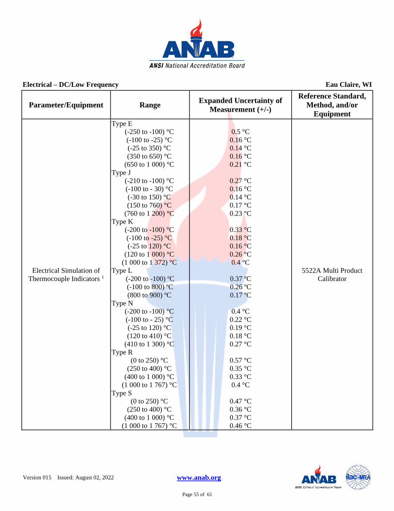
Version 015 Issued: August 02, 2022 www.anab.org
Page 55 of 61
Electrical – DC/Low Frequency Eau Claire, WI
Parameter/Equipment Range Expanded Uncertainty of
Measurement (+/-)
Reference Standard,
Method, and/or
Equipment
Electrical Simulation of
Thermocouple Indicators 1
Type E
(-250 to -100) °C
(-100 to -25) °C
(-25 to 350) °C
(350 to 650) °C
(650 to 1 000) °C
Type J
(-210 to -100) °C
(-100 to - 30) °C
(-30 to 150) °C
(150 to 760) °C
(760 to 1 200) °C
Type K
(-200 to -100) °C
(-100 to -25) °C
(-25 to 120) °C
(120 to 1 000) °C
(1 000 to 1 372) °C
Type L
(-200 to -100) ºC
(-100 to 800) ºC
(800 to 900) ºC
Type N
(-200 to -100) °C
(-100 to - 25) °C
(-25 to 120) °C
(120 to 410) °C
(410 to 1 300) °C
Type R
(0 to 250) °C
(250 to 400) °C
(400 to 1 000) °C
(1 000 to 1 767) °C
Type S
(0 to 250) °C
(250 to 400) °C
(400 to 1 000) °C
(1 000 to 1 767) °C
0.5 °C
0.16 °C
0.14 °C
0.16 °C
0.21 °C
0.27 °C
0.16 °C
0.14 °C
0.17 °C
0.23 °C
0.33 °C
0.18 °C
0.16 °C
0.26 °C
0.4 °C
0.37 ºC
0.26 ºC
0.17 ºC
0.4 °C
0.22 °C
0.19 °C
0.18 °C
0.27 °C
0.57 °C
0.35 °C
0.33 °C
0.4 °C
0.47 °C
0.36 °C
0.37 °C
0.46 °C
5522A Multi Product
Calibrator

Version 015 Issued: August 02, 2022 www.anab.org
Page 56 of 61
Electrical – DC/Low Frequency Eau Claire, WI
Parameter/Equipment Range Expanded Uncertainty of
Measurement (+/-)
Reference Standard,
Method, and/or
Equipment
Electrical Simulation of
Thermocouple Indicators 1
Type T
(-250 to -150) °C
(-150 to 0) °C
(0 to 120) °C
(120 to 400) °C
Type U
(-200 to 0) °C
(0 to 600) °C
0.63 °C
0.24 °C
0.16 °C
0.14 °C
0.56 °C
0.27 °C
5522A Multi Product
Calibrator
Electrical Simulation of
RTD Indicators 1
Pt 385, 100 Ω
(-200 to -80) ºC
(-80 to 0) ºC
(0 to 100) ºC
(100 to 300) ºC
(300 to 400) ºC
(400 to 630) ºC
(630 to 800) ºC
Pt 3926, 100 Ω
(-200 to -80) ºC
(-80 to 0) ºC
(0 to 100) ºC
(100 to 300) ºC
(300 to 400) ºC
(400 to 630) ºC
Pt 3916, 100 Ω
(-200 to -190) ºC
(-190 to -80) ºC
(-80 to 0) ºC
(0 to 100) ºC
(100 to 260) ºC
(260 to 300) ºC
(300 to 400) ºC
(400 to 600) ºC
(600 to 630) ºC
0.05 ºC
0.05 ºC
0.07 ºC
0.09 ºC
0.1 ºC
0.12 ºC
0.23 ºC
0.05 ºC
0.05 ºC
0.07 ºC
0.09 ºC
0.10 ºC
0.12 ºC
0.25 ºC
0.04 ºC
0.05 ºC
0.06 ºC
0.07 ºC
0.08 ºC
0.09 ºC
0.1 ºC
0.23 ºC
5522A Multi Product
Calibrator

Version 015 Issued: August 02, 2022 www.anab.org
Page 57 of 61
Electrical – DC/Low Frequency Eau Claire, WI
Parameter/Equipment Range Expanded Uncertainty of
Measurement (+/-)
Reference Standard,
Method, and/or
Equipment
Electrical Simulation of
RTD Indicators 1
Pt 385, 200 Ω
(-200 to -80) ºC
(-80 to 0) ºC
(0 to 100) ºC
(100 to 260) ºC
(260 to 300) ºC
(300 to 400) ºC
(400 to 600) ºC
(600 to 630) ºC
Pt 385, 500 Ω
(-200 to -80) ºC
(-80 to 0) ºC
(0 to 100) ºC
(100 to 260) ºC
(260 to 300) ºC
(300 to 400) ºC
(400 to 600) ºC
(600 to 630) ºC
Pt 385, 1 000 Ω
(-200 to -80) ºC
(-80 to 0) ºC
(0 to 100) ºC
(100 to 260) ºC
(260 to 300) ºC
(300 to 400) ºC
(400 to 600) ºC
(600 to 630) ºC
PtNi 385, 120 Ω (Ni120)
(-80 to 0) ºC
(0 to 100) ºC
(100 to 260) ºC
Cu 427, 10 Ω
(100 to 260) ºC
0.04 ºC
0.04 ºC
0.04 ºC
0.05 ºC
0.12 ºC
0.13 ºC
0.14 ºC
0.16 ºC
0.04 ºC
0.05 ºC
0.05 ºC
0.06 ºC
0.08 ºC
0.08 ºC
0.09 ºC
0.11 ºC
0.03 ºC
0.03 ºC
0.04 ºC
0.05 ºC
0.06 ºC
0.07 ºC
0.07 ºC
0.23 ºC
0.08 ºC
0.08 ºC
0.14 ºC
0.3 ºC
5522A Multi Product
Calibrator
Length – Dimensional Metrology Eau Claire, WI
Parameter/Equipment Range Expanded Uncertainty of
Measurement (+/-)
Reference Standard,
Method, and/or
Equipment
Indicators 1,2 (0.000 1 to 6) in (8+3L) µin Horizontal Measuring
Machine

Version 015 Issued: August 02, 2022 www.anab.org
Page 58 of 61
Length – Dimensional Metrology Eau Claire, WI
Parameter/Equipment Range Expanded Uncertainty of
Measurement (+/-)
Reference Standard,
Method, and/or
Equipment
Calipers 1,2 Up to 60 in (5+8L) µin Gage Blocks
Micrometers OD 1,2 Up to 60 in
Anvil Flatness
(5+8L) µin
4 µin
Gage Blocks
Optical Parallels
Height Measuring Devices 1,2 Up to 36 in
(36 to 48) in
(45 + 2L) in
(7 + 3L) in Gage Blocks
External Diameter 1,2 (0.000 1 to 6) in (8+3L) µin Horizontal Measuring
Machine
Internal Diameter 1,2 (0.04 to 13) in (8+3L) µin Horizontal Measuring
Machine
Thread Plugs 1,2
Pitch Diameter
Major Diameter
Up to 8 in
Pitch (0.2 to 5) mm
Pitch 90 – 4 TPI Up to 4
in
(87 + 1.9L) µin
(8+3L) µin
Horizontal Measuring
Machine
Thread Measuring Wires
Thread Rings (Adjustable)
Pitch Diameter
Tactile Fit (Set to Plug)
Up to 4 in See footnote5 Thread Setting Plug
Optical Comparators 1,2
Linear Accuracy
Magnification
Up to 6 in
6 to 12 in
5X to 100X
(43 + 11L) µin
(30 + 7.5L) µin
350 µin
Glass Scale
Glass Scale (Sphere)
Surface Plates 1,2
Overall Flatness
Local Area Flatness
Up to 238 inDL
Up to 238 inDL
(25 + 2.9L) µin
34 µin
Laser System
Repeat-O-Meter
CMMs 1,2 (0 to 144) in (25 + 2.4L) µin Laser Measuring System
VMMs 1,2 Up to 6 in (32 + 4.1L) µin Glass Scales
Horizontal Measuring
Systems 1,2
Up to 8 in of Travel
(8 to 60) in
(6 + 1.7L) µin
(3 + 2.5L) µin Gage Blocks
Feeler/Thickness Gages 2 Up to 0.2 in (4.3 + 3L) µin Horizontal Measuring
System
Indicator Calibrator 2
Linearity Up to 6 in 60 µin + 0.6R
Horizontal Measuring
System
Groove Micrometers 2 Up to 12 in (44 + 2.6L) µin+ 0.6R Gage Blocks

Version 015 Issued: August 02, 2022 www.anab.org
Page 59 of 61
Length – Dimensional Metrology Eau Claire, WI
Parameter/Equipment Range Expanded Uncertainty of
Measurement (+/-)
Reference Standard,
Method, and/or
Equipment
Microscopes, Stereo
Reticle Linearity Up to 2 in 870 µin Stage Micrometer
Microscopes – Toolmakers 2
Scale Linearity Up to 4 in (774 + 70L) µin + 0.6R Stage Micrometer
Length Standards 2 (1 to 60) in (3.4 + 3.5L) µin Horizontal Measuring
System
Micrometers – Inside 2 Up to 8 in
8 to 60 in
(6 + 1.7L) µin
(3 + 2.5L) µin Horizontal Measuring
System
Parallels 2
Steel
Granite
Up to 18 in
(96.3 + 1.8L) µin
(48.6 + 0.7L) µin
Electronic Amplifier with
Probe, Surface Plate
Thickness Gages 2
Dial
Digital
Up to 1 in
410 µin + 0.6R
44 µin+ 0.6R
Gage Blocks
Thread Micrometers 2 (Screw
Thread, Pitch Point)
Linearity
Anvil Wear
Up to 12 in
(44 + 2.6L) µin + 0.6R
690 µin
Gage Blocks Thread
Setting Plug
Mass and Mass Related Eau Claire, WI
Parameter/Equipment Range Expanded Uncertainty of
Measurement (+/-)
Reference Standard,
Method, and/or
Equipment
Force 1 Source
(0.035 to 16) ozf
(1 to 10) lbf
(10 to 50) lbf
(50 to 500) lbf
0.018 % of reading + 0.21 µozf
0.018 % of reading + 0.33 µlbf
0.018 % of reading + 9.3 mlbf
0.036 % of reading + 5.3 mlbf
Dead Weight
Pressure 1
(-15 to 30) psig
(0 to 1) inH2O
(0.036 to 1) psig
(0 to 100) psia
(100 to 300) psig
(300 to 1 000) psig
(1 000 to 10 000) psig
19 mpsi
0.003 5 inH2O
1.3 mpsi
0.07 psi
0.12 psi
0.4 psi
4 psi
Pressure Calibrator

Version 015 Issued: August 02, 2022 www.anab.org
Page 60 of 61
Mass and Mass Related Eau Claire, WI
Parameter/Equipment Range Expanded Uncertainty of
Measurement (+/-)
Reference Standard,
Method, and/or
Equipment
Torque Tools 1
(5 to 50) lbf·in
(50 to 400) lbf·in
(400 to 1000) lbf·in
(80 to 250) lbf·ft
(250 to 600) lbf·ft
(600 to 2 000) lbf·ft
0.33 % of reading
0.36 % of reading
0.4 % of reading
0.28 % of reading
0.51 % of reading
0.75 % of reading
Torque Tester
Torque Transducers 1 0.5 ozfin to 1 000 lbfft 0.08 % of reading Dead Weight Torque Arms
Scales and Balances 1,6
(0 to 500) mg
500 mg to 5 g
(5 to 10) g
(10 to 30) g
(30 to 50) g
(50 to 100) g
(100 to 200) g
(200 to 300) g
300 g to 1 kg
(1 to 2) kg
(2 to 3) kg
0.01 mg
0.034 mg
0.05 mg
0.074 mg
0.12 mg
0.25 mg
0.5 mg
0.75 mg
2.5 mg
5 mg
7.5 mg
Class 1 Weights
Scales and Balances 1,6
(3 to 5) kg
(5 to 10) kg
(10 to 20) kg
(20 to 25) kg
(25 to 30) kg
12 mg
25 mg
50 mg
62 mg
75 mg
Class 1 Weights
Scales and Balances 1,6 (0.5 to 1 000) lb 0.01 % of reading Class 6 Weights
Thermodynamic Eau Claire, WI
Parameter/Equipment Range Expanded Uncertainty of
Measurement (+/-)
Reference Standard,
Method, and/or
Equipment
Temperature – Measure 1
(-20 to 100) ºC
(100 to 425) ºC
(425 to 500) ºC
0.058 ºC
0.069 ºC
0.086 ºC
Digital Temperature Gage
Humidity- Measure 1
(10 to 40) %RH
(40 to 90) %RH
(90 to 100) %RH
1.1 %RH
1.3 %RH
1.9 %RH
Humidity Indicator

Version 015 Issued: August 02, 2022 www.anab.org
Page 61 of 61
Time and Frequency Eau Claire, WI
Parameter/Equipment Range Expanded Uncertainty of
Measurement (+/-)
Reference Standard,
Method, and/or
Equipment
Frequency – Source 4 1 MHz 2.5 x 10⁻⁵ Hz 5522A Multi Product
Calibrator
DIMENSIONAL MEASUREMENT
2 Dimensional Eau Claire, WI
Specific Tests and / or
Properties Measured Range
Expanded Uncertainty of
Measurement (+/-)
Reference Standard,
Method and/or
Equipment
Non-contact (15.4 x 10.8) in (126 + 12L) µin Vision System
3 Dimensional Eau Claire, WI
Specific Tests and / or
Properties Measured Range
Expanded Uncertainty of
Measurement (+/-)
Reference Standard,
Method and/or
Equipment
Dimensional Inspection Contact (16 x 18 x 14) in (209+ 1.2L) µin
Coordinate Measuring Machie
Return to Site listing (top)
Calibration and Measurement Capability (CMC) is expressed in terms of the measurement parameter, measurement range, expanded uncertainty of measurement and
reference standard, method, and/or equipment. The expanded uncertainty of measurement is expressed as the standard uncertainty of the measurement multiplied by a
coverage factor of 2 (k=2), corresponding to a confidence level of approximately 95%.
Notes:
1. On-site calibration service is available for this parameter, since on-site conditions are typically more variable than those in the laboratory, larger measurement
uncertainties are expected on-site than what is reported on the accredited scope 2. The use of (R) signifies the Resolution of the unit under test, the use of (L) represents Length in inches, the use of (D) represents Diameter in inches.
3. Uncertainties listed for Electromagnetic - DC/Low Frequency and RF/Microwave does not include possible contributions from a “best available” unit under test 4. Derivatives of 10MHz will have different uncertainties due to resolution, noise, and gating errors.
5. The tactile fit of an adjustable thread ring to a thread-setting plug is not a measurement of pitch diameter. The uncertainty for this pitch diameter setting is based on the
contributors associated with the thread setting plug and environmental contributors only. 6. The CMC for scales and balances are highly dependent upon the resolution of the unit under test. The uncertainties presented here does not include the resolution of
the unit under test. The resolution will be included in the reported measurement uncertainty at the time of calibration.
7. This scope is formatted as part of a single document including Certificate of Accreditation No. ACT-1265.