Temperature Calibration Equipment and Services
196
Temperature Calibration Equipment and Services
-
Upload
khangminh22 -
Category
Documents
-
view
4 -
download
0
Transcript of Temperature Calibration Equipment and Services

Temperature Calibration Equipment and Services

2
See page 63 for moreinformation.
See page 144 for moreinformation.
See page 171 formore information.
See page 58 for moreinformation.

3
Primary standards selection guide . . . . . . . . 4Why buy primary standards from Hart? . . . . . . . . . . . . . . . 6
Quartz-sheath SPRTs . . . . . . . . . . . . . . . . . . . . . . . . . . . . . . . . 8Working standard SPRT . . . . . . . . . . . . . . . . . . . . . . . . . . . . . 10Extended range metal-sheath SPRT . . . . . . . . . . . . . . . . . . . 11Glass capsule SPRTs. . . . . . . . . . . . . . . . . . . . . . . . . . . . . . . . 12Annealing furnace . . . . . . . . . . . . . . . . . . . . . . . . . . . . . . . . . 13Triple point of water cells . . . . . . . . . . . . . . . . . . . . . . . . . . . 14TPW maintenance bath . . . . . . . . . . . . . . . . . . . . . . . . . . . . . 17
Use TPW and ratio method to improve SPRTstability and accuracy. . . . . . . . . . . . . . . . . . . . . . . . . . . . 18
DC bridge . . . . . . . . . . . . . . . . . . . . . . . . . . . . . . . . . . . . . . . . 20Why use Fluke metal freeze-point cells? . . . . . . . . . . . . . 21
ITS-90 fixed-point cells . . . . . . . . . . . . . . . . . . . . . . . . . . . . . 23ITS-90 fixed-point cells . . . . . . . . . . . . . . . . . . . . . . . . . . . . . 24
Traceability and thermometric fixed-point cells . . . . . . . . 26Freeze-point furnaces . . . . . . . . . . . . . . . . . . . . . . . . . . . . . . 28Mini fixed-point cells . . . . . . . . . . . . . . . . . . . . . . . . . . . . . . . 30Mini TPW maintenance apparatus . . . . . . . . . . . . . . . . . . . . . 32Gallium cell maintenance apparatus . . . . . . . . . . . . . . . . . . . 33Mini fixed-point cell furnace . . . . . . . . . . . . . . . . . . . . . . . . . 34LN2 comparison calibrators. . . . . . . . . . . . . . . . . . . . . . . . . . . 35DC resistance standards. . . . . . . . . . . . . . . . . . . . . . . . . . . . . 36Standard AC/DC resistors . . . . . . . . . . . . . . . . . . . . . . . . . . . . 37
Thermometer readout selection guide . . . . 38Super-Thermometer readouts . . . . . . . . . . . . . . . . . . . . . . . . 40
Evaluating calibration system accuracy . . . . . . . . . . . . . . 44International Temperature Scale of 1990 (ITS-90)quick reference. . . . . . . . . . . . . . . . . . . . . . . . . . . . . . . . . 45PRT temperature vs. resistance table . . . . . . . . . . . . . . . . 46Thermocouple EMF and sensitivity chart . . . . . . . . . . . . . 47
The Black Stack thermometer readout . . . . . . . . . . . . . . . . . . 48Tweener thermometer readouts. . . . . . . . . . . . . . . . . . . . . . . 56Handheld thermometer readouts . . . . . . . . . . . . . . . . . . . . . . 58Reference multimeter. . . . . . . . . . . . . . . . . . . . . . . . . . . . . . . 62The DewK thermo-hygrometer . . . . . . . . . . . . . . . . . . . . . . . 63
Thermometer probe selection guide . . . . . 66How accurate is that probe?. . . . . . . . . . . . . . . . . . . . . . . 67
Secondary standard PRTs . . . . . . . . . . . . . . . . . . . . . . . . . . . 68Ultra high-temp PRT . . . . . . . . . . . . . . . . . . . . . . . . . . . . . . . 69Secondary reference temperature standards . . . . . . . . . . . . . 70Secondary PRT with calibration options . . . . . . . . . . . . . . . . 725616 secondary reference PRT . . . . . . . . . . . . . . . . . . . . . . . 74
Sensible temperature specifications . . . . . . . . . . . . . . . . . 76Small diameter industrial PRT . . . . . . . . . . . . . . . . . . . . . . . . 77Precision freezer PRT . . . . . . . . . . . . . . . . . . . . . . . . . . . . . . . 78Precision industrial PRTs . . . . . . . . . . . . . . . . . . . . . . . . . . . . 79Fast response PRTs . . . . . . . . . . . . . . . . . . . . . . . . . . . . . . . . 80
What are stem conduction errors and how can theycreate errors in calibration? . . . . . . . . . . . . . . . . . . . . . . . 81
Thermistor standards probes . . . . . . . . . . . . . . . . . . . . . . . . . 82Secondary referencethermistor probes. . . . . . . . . . . . . . . . . . . . . . . . . . . . . . . . . . 84
Thermistors: the under appreciated temperaturestandards . . . . . . . . . . . . . . . . . . . . . . . . . . . . . . . . . . . . . 86Thermocouples 101... or, maybe... 401! . . . . . . . . . . . . . . 88
Type R and S thermocouple standards . . . . . . . . . . . . . . . . . 90Reference table: letter-designated thermocoupletolerances . . . . . . . . . . . . . . . . . . . . . . . . . . . . . . . . . . . . . 91Temperature conversion table . . . . . . . . . . . . . . . . . . . . . 92Why did my temperature sensor fail calibration?. . . . . . . 93
Software selection guide . . . . . . . . . . . . . . 96Interface-it . . . . . . . . . . . . . . . . . . . . . . . . . . . . . . . . . . . . . . 96MET/TEMP II . . . . . . . . . . . . . . . . . . . . . . . . . . . . . . . . . . . . . 97TableWare . . . . . . . . . . . . . . . . . . . . . . . . . . . . . . . . . . . . . . 100LogWare and LogWare II . . . . . . . . . . . . . . . . . . . . . . . . . . 101LogWare III . . . . . . . . . . . . . . . . . . . . . . . . . . . . . . . . . . . . . 102
Establishing traceability . . . . . . . . . . . . . . . . . . . . . . . . . 103
Bath selection guide . . . . . . . . . . . . . . . . . . 104Buying the right bath . . . . . . . . . . . . . . . . . . . . . . . . . . . 106
Deep-well compact baths . . . . . . . . . . . . . . . . . . . . . . . . . . 108Compact baths . . . . . . . . . . . . . . . . . . . . . . . . . . . . . . . . . . . 110
Why a Hart bath? . . . . . . . . . . . . . . . . . . . . . . . . . . . . . . 112Really cold baths . . . . . . . . . . . . . . . . . . . . . . . . . . . . . . . . . 114Cold baths . . . . . . . . . . . . . . . . . . . . . . . . . . . . . . . . . . . . . . 116Hot baths . . . . . . . . . . . . . . . . . . . . . . . . . . . . . . . . . . . . . . . 118Really hot bath . . . . . . . . . . . . . . . . . . . . . . . . . . . . . . . . . . 120Bath accessories . . . . . . . . . . . . . . . . . . . . . . . . . . . . . . . . . 121Deep-well baths . . . . . . . . . . . . . . . . . . . . . . . . . . . . . . . . . 122Resistor baths . . . . . . . . . . . . . . . . . . . . . . . . . . . . . . . . . . . 124Constant temperature ice bath. . . . . . . . . . . . . . . . . . . . . . . 126
Avoid water problems in cold baths . . . . . . . . . . . . . . . . 127Bath fluids . . . . . . . . . . . . . . . . . . . . . . . . . . . . . . . . . . . . . . 128Controller for Rosemount-designed baths . . . . . . . . . . . . . . 132Benchtop controllers . . . . . . . . . . . . . . . . . . . . . . . . . . . . . . 133
Industrial calibrator selection guide . . . . . 134Selecting an industrial temperature calibrator . . . . . . . . 136
Metrology Well calibrators . . . . . . . . . . . . . . . . . . . . . . . . . . 139Field Metrology Wells . . . . . . . . . . . . . . . . . . . . . . . . . . . . . 144
Understanding the uncertainties associatedwith Metrology Wells . . . . . . . . . . . . . . . . . . . . . . . . . . . 149
Micro-Baths . . . . . . . . . . . . . . . . . . . . . . . . . . . . . . . . . . . . . 152Eliminating sensor errors in loop calibrations . . . . . . . . 154
Field dry-wells. . . . . . . . . . . . . . . . . . . . . . . . . . . . . . . . . . . 156A few dry-well dos and don’ts.... . . . . . . . . . . . . . . . . . . 158
Industrial dual-block calibrator . . . . . . . . . . . . . . . . . . . . . . 160High-accuracy dual-well calibrator . . . . . . . . . . . . . . . . . . . 162Handheld dry-wells . . . . . . . . . . . . . . . . . . . . . . . . . . . . . . . 164Portable lab dry-well . . . . . . . . . . . . . . . . . . . . . . . . . . . . . . 166Thermocouple furnace . . . . . . . . . . . . . . . . . . . . . . . . . . . . . 167Thermocouple calibration furnace . . . . . . . . . . . . . . . . . . . . 168Zero-point dry-well . . . . . . . . . . . . . . . . . . . . . . . . . . . . . . . 1704180 series precision infrared calibrators . . . . . . . . . . . . . . 171Portable IR calibrators . . . . . . . . . . . . . . . . . . . . . . . . . . . . . 174Surface calibrator . . . . . . . . . . . . . . . . . . . . . . . . . . . . . . . . . 176
Other neat stuff selection guide . . . . . . . . 177External battery pack. . . . . . . . . . . . . . . . . . . . . . . . . . . . . . 177Benchtoptemperature/humiditygenerator . . . . . . . . . . . . . . . . . . . . . . . . . . . . . . . . . . . . . . . 178
On rutabagas and their origins…. . . . . . . . . . . . . . . . . . 180Hart Scientific temperature seminars . . . . . . . . . . . . . . . . . . 181
NVLAP accreditation at Hart . . . . . . . . . . . . . . . . . . . . . . 184Calibration services . . . . . . . . . . . . . . . . . . . . . . . . . . . . . . . 186
Guidelines for Hart product specifications . . . . . . . . . . . 194Hart Service . . . . . . . . . . . . . . . . . . . . . . . . . . . . . . . . . . . . . 195How to order . . . . . . . . . . . . . . . . . . . . . . . . . . . . . . . . . . . . 195
Table of Contents

4 Primary Standards
SPRTsModel RTPW Range Page5681 25.5 Ω –200 °C to 670 °C 85683 25.5 Ω –200 °C to 480 °C5684 0.25 Ω 0 °C to 1070 °C5685 2.5 Ω 0 °C to 1070 °C5698 25.5 Ω –200 °C to 670 °C 105699 25.5 Ω –200 °C to 670 °C 115686 25.5 Ω –260 °C to 232 °C 125695 25.5 Ω –200 °C to 500 °C
Fixed-point cellsModel Description Temperature Page5901A-G TPW Cell, 12 mm ID with handle, glass shell 0.01 °C 145901A-Q TPW Cell, 12 mm ID with handle, quartz shell 0.01 °C5901C-G TPW Cell, 13.6 mm ID with handle, glass shell 0.01 °C5901C-Q TPW Cell, 14.4 mm ID with handle, quartz shell 0.01 °C5901D-G TPW Cell, 12 mm ID, glass shell 0.01 °C5901D-Q TPW Cell, 12 mm ID, quartz shell 0.01 °C5901B-G TPW Cell, mini, glass shell 0.01 °C5900 TP Mercury, SST –38.8344 °C 235904 Freezing Point of Indium 156.5985 °C5905 Freezing Point of Tin 231.928 °C5906 Freezing Point of Zinc 419.527 °C5907 Freezing Point of Aluminum 660.323 °C5908 Freezing Point of Silver 961.78 °C5909 Freezing Point of Copper 1084.62 °C5924 Open Freezing Point of Indium 156.5985 °C5925 Open Freezing Point of Tin 231.928 °C5926 Open Freezing Point of Zinc 419.527 °C5927A-L Open Freezing Point of Aluminum, Long 660.323 °C5927A-S Open Freezing Point of Aluminum, Short 660.323 °C5928 Open Freezing Point of Silver 961.78 °C5929 Open Freezing Point of Copper 1084.62 °C5943 Melting Point of Gallium, SST 29.7646 °C5914A Mini Freezing Point of Indium 156.5985 °C 305915A Mini Freezing Point of Tin 231.928 °C5916A Mini Freezing Point of Zinc 419.527 °C5917A Mini Freezing Point of Aluminum 660.323 °C5918A Mini Freezing Point of Silver 961.78 °C5919A Mini Freezing Point of Copper 1084.62 °C5944 Mini Freezing Point of Indium 156.5985 °C5945 Mini Freezing Point of Tin 231.928 °C5946 Mini Freezing Point of Zinc 419.527 °C5947 Mini Freezing Point of Aluminum 660.323 °C
Primary standards selectionguide

Temperature Calibration Equipment 5
ApparatusModel Features/Use Page7012 Maintains: triple point of water and gallium cells. Comparisons: –10 °C to 110 °C. 1167037 Maintains: triple point of water and gallium cells. Comparisons: –40 °C to 110 °C.7312 Maintains: two TPW cells. Compact size, runs quietly. Comparisons: –5 °C to 110 °C. 177341 Maintains: triple point of mercury cell. Comparisons: –45 °C to 150 °C. 1089210 Maintains: mini triple point of water and mini gallium cells. Comparisons: –10 °C to 125 °C. 329230 Maintains: stainless steel gallium cell. Comparisons: 15 °C to 35 °C. 339260 Maintains: indium, tin, zinc, and aluminum cells. Comparisons: 50 °C to 680 °C. 349114 Maintains: indium, tin, zinc, and aluminum cells. Comparisons: 100 °C to 680 °C. 289115A Maintains: aluminum and silver cells. Comparisons: 550 °C to 1000 °C.9116A Maintains: aluminum, silver, gold, and copper cells. Comparisons: 400 °C to 1100 °C.9117 Anneals SPRTs, HTPRTs, and thermocouples to 1100 °C. Protects them against contamination from metal ions. 13
Boiling point of liquid nitrogen7196 Affordable substitute for a triple point of argon system. Provides for low-temperature comparison calibrations at
approximately –196 °C with uncertainties of 2 mK.35
Resistance bridge5581 0.1 ppm accuracy for calibration of standard resistors and SPRTs. 13:1 measurement ratio allows resolution
to 0.001 mK.18
1590 1 ppm accuracy for calibration of SPRTs and thermistors. 40
Standard resistors742A Excellent performance without oil or air baths. Values from 10 ohm to 100 megohm. 365430 Highest stability oil-filled resistors (< 2 ppm/year drift). AC cal uncertainty to 3 ppm. 37
Primary standards selectionguide

Setting up a primary temperature stan-dards lab is no small project. Decisionsmust be made about temperature range,uncertainty requirements, the types ofstandards you need, and the companiesthat can supply your standards. Whoseproducts are reliable? Which companybacks up its performance claims? Whoprovides after-sale support and training?Who really demonstrates the most integ-rity throughout your ownership experi-ence? After all, substantial investmentsare being made, and in many cases thecredibility of your lab can be affected bythe outcome.
So why does Hart Scientific claim to bethe world’s best supplier of primary tem-perature standards? Because our productshave been tested over and over again bynational labs around the world andproven to outperform their specs. Becausethe people who design and build primarytemperature standards at Hart have beendesigning and building primary tempera-ture standards longer than any othersupplier in the world. We not only manu-facture primary standards, we perform ba-sic research and innovate with newprimary standards designs. No one else of-fers the high-quality training and post-sale support that we do. No one!
Metal fixed-point cellsFor realizing the ITS-90 temperature scale,Hart’s metal fixed-point cells provide per-formance you can trust, and we supply thedata with each cell to prove it. Hart’sfixed-point cells benefit from more than20 years of experience in research, de-sign, and manufacturing. Three types ofcells are available: traditional size cells,“mini” quartz cells, and new “mini” metal-cased cells. All three provide outstandingperformance.
Each Hart cell is carefully assembled,tested, and supplied with an assay ofmetal-sample purity. Every traditional-sizecell further undergoes more rigorous test-ing to a CCT-based procedure in ourNVLAP-accredited lab, where we realize atleast three freezing curves and perform adetailed “slope analysis” to confirm cellpurity. If you’d like this more thorough“slope analysis” for a “mini” quartz cell ornew “mini” metal-cased cell, we offer thatas an option. And if you still want more,we can also supply comparison data withour own reference cells that have been in-dependently tested at NIST.
No other commercial company has asmuch experience in the development offixed-point cells as Hart does. Hart’s ownXumo Li was a key contributor to the
development of the ITS-90 scale. That’sone reason you’ll find Hart cells in many ofthe national metrology institutes aroundthe world.
Water triple point cellsLike our metal fixed-point cells, Hart’s tri-ple point of water cells come in traditionaland “mini” quartz sizes, as well as smallstainless steel, which can be realized in adry-well calibrator. Our traditional cellshave been tested at NIST (see chart onfacing page) and are within a few micro-kelvin of NIST’s cells.
If you’re new to primary temperaturestandards and are considering a water tri-ple point cell, one of our cells is sure tomeet your requirements. We offer trainingthrough our seminars, insurance for ourglass cells, and our stainless steel cell justcan’t be broken!
Maintenance apparatusMaintaining fixed-point cells requireshigh-stability apparatus with tight
gradient control so plateaus last longerand your work is more productive. EveryHart maintenance apparatus, including ourmetrology furnaces and fluid baths, usestemperature controllers designed andmanufactured by Hart. These controllersare widely recognized for their unmatchedstability and uniformity control.
For metal fixed-point cells, choose fromone-zone, three-zone, or heat-pipe fur-naces for regular or mini cells. Optionalequilibration blocks fit into the furnacesfor annealing and comparison calibrations.Don’t let the competition try to tell youthat a furnace fitted with process control-lers can provide the same performance asa furnace fitted with controllers designedspecifically for high-stability temperaturecontrol. With a Hart furnace you’ll get lon-ger cell plateaus with smaller gradientsthan you will from any other furnace onthe market.
6 Primary Standards
Why buy primary standardsfrom Hart?

SPRTsSPRTs are the only acceptable ITS-90 in-terpolation devices from the triple point ofhydrogen (13.8033 K) to the freezingpoint of silver (961.78 °C). While mostSPRT manufacturers lost their design ca-pabilities years ago, Hart continues to de-velop new innovative designs with thelowest drift rates.
Hart manufactures quartz SPRTs in fourdifferent temperature ranges, includingcapsule SPRTs for low temperatures, anultra-stable SPRT for the range to 480 °C,and a new “working-standard” SPRT forthe range to 660 °C. Our metal-sheathSPRTs include a 25.5-ohm, contamina-tion-resistant SPRT. Hart SPRTs are thestandards of choice for many national me-trology institutes around the world.
ThermometryTraditionally, SPRT measurements havebeen made using expensive, difficult-to-use bridges. If you need 1 ppm accuracy,there’s nothing that provides a betterprice/performance ratio than Hart’s 1590Super-Thermometer. The 1590 Super-Thermometer provides bridge accuracy ata fraction of the cost and provides a multi-tude of features that improve your produc-tivity. With a Super-Thermometer, there isvirtually no learning curve. It’s so easy touse that you’ll be making measurementswithin minutes after switching it on.
If you truly need 0.1 ppm performance,the 5581 MIL Bridge offers conventionalDC measurement for a wide range. It’sperfect for temperature metrology workand for labs looking to combine tempera-ture with electrical resistance standards.
TrainingOnce you’ve determined which primarystandards products you need and you’vemade a major investment, what abouttraining and after-sales support? Hart’stemperature school offers a fun andunique seminar that provides all the an-swers to your toughest questions. Our 2½-day “Realizing and Approximating ITS-90”seminar provides all the theory and somefirst-rate practical, hands-on experience toget you started. You’ll learn some key tem-perature theory from former national labscientists and take part in practical experi-ments with our lab staff. If you want more,talk to us about individual ITS-90 training,where you can work alongside our cal labstaff in Hart’s primary standards lab, per-forming practical realizations on the cellsthat you just purchased.
We’ve been making and using primarytemperature standards for many years,and we understand the issues you face inyour lab. Our own lab is accredited (NVLAPlab code 200348-0) and our uncertaintiesare among the best in the world. Whenyou buy primary standards, don’t compro-mise the quality of the products, the repu-tation of your supplier, or the level ofservice and training they can provide.
Temperature Calibration Equipment 7
Why buy primary standardsfrom Hart?
Comparison of Hart TPW Cells with NIST TPW Cell s/n A-13-1286NIST Cell 3 is used as a check and NIST Cell 4 is used as a reference
-0.03
-0.02
-0.01
0.00
0.01
0.02
0.03
0 1 2 3 4 5 6
days of measurements
{R[c
ell X
] /R
[cel
l 4(1
)] -
1}
(dT
/dW
) / m
K
Hart TPW Cells/n 5901A-7-1022
Hart TPW Cells/n 5901A-7-1024
NIST TPW Cell 3A-13-1291
NIST TPW Cell 4A-13-1286
Mingjian Zhao, Hart’s director of Primary StandardsEngineering.

Choosing the right platinum thermometeras your primary standard may be the mostcritical purchase decision in your lab. Un-fortunately, other manufacturers are prettysecretive about how their SPRTs are made.They won’t tell you much more than youcan already see by looking at one. Manyof the leaders of a few decades ago havelost their original craftsmen and designscientists. Hart Scientific has one of only afew active SPRT design groups in theworld today.
So how do you know you’re makingthe best purchase? Self-proclaimed exper-tise shouldn’t convince you. You shouldexpect some sound evidence that thecompany is qualified in the ongoing sci-ence of SPRT development. At Hart, we’lltell you how we make an SPRT. We’ll letyou talk to the people here who design,build, and calibrate SPRTs. Finally, whenyou buy one, if you don’t like it, we’ll takeit back and return your money.
Hart has four quartz-sheath SPRTs,covering the ITS-90 range of –200 °C to1070 °C. The 5681 is used from –200 °Cto the aluminum point at 660.323 °C. The5683 is used from –200 °C to 480 °C withgreater long term stability. The 5684 and
the 5685 cover higher temperatures up to1070 °C and can be calibrated at the silverpoint.
Yes, they have all the features youwould expect in a world-class SPRT. Theyhave gold-plated spade lugs, a strain-re-lieved four-wire cable, convection preven-tion disks, the finest quartz glassavailable, delustered stems, and the purestplatinum wire available.
The purity of a thermometer’s platinumwire is critical to meeting ITS-90 require-ments. Platinum resistance is measured bythe resistance ratio “W” at specified ITS-90 fixed points. Maintaining that purityover the life of the thermometer impactslong-term stability. The quartz glass tubeof the SPRT should be properly sealed toprevent contamination of the platinumwire. Others use mechanical assembliesand epoxy seals. These introduce addi-tional materials to the thermometer’s in-ternal environment and can be prone tomechanical failure, risking exposure of theplatinum to impurities.
Theoretically, the best seal would be adirect seal between the quartz glass andthe platinum wire. However, the quartzglass used in thermometer sheaths has a
very small coefficient of expansion whileplatinum has a much larger coefficient ofexpansion. If you simply sealed thesheath’s glass to the platinum wire, thesedifferent rates of expansion would resultin a poor seal as the assembly is exposedto changing temperatures.
We’ve figured out a way to match theexpansion coefficients of the glass sheathand the platinum wires. We do it by creat-ing a graduating seal that’s made of 18separate pieces of glass, each with a dif-ferent coefficient of expansion. The expan-sion and contraction rate of the innermostpiece of glass matches that of the plati-num, resulting in an overall seal that pre-vents gas leakage and impuritypenetration for at least 20 years.
Fusing each piece of glass to the next isa painstaking process. Sure it costs us extra,but the results are worth it!
There’s more!We use only pure quartz glass materials
for the cross frames, disks, and tubes. Wedon’t use mica or ceramic materials. Addi-tionally, we have a special glass-treatingprocess to increase the resistance of thequartz to devitrification and remove moreimpurities than the typical cleaning process.
We’ve done some research to find thebest-performing balance of argon to oxygenin the tube. Some oxygen in the sheath isnecessary to minimize the danger of theplatinum being poisoned by foreign metalsat high temperatures, but too much oxygenat temperatures below 500 °C acceleratesthe oxidation process affecting the integrityof the platinum. We’ve got a balance thatprovides exactly the right protection for theplatinum.
Each of these seemingly small things addsup to better uncertainties and less drift.
5681: –200 °C to 670 °CThis 25-ohm thermometer is the work-horse of the ITS-90 ranges. It can be cali-brated for any of the subranges from thetriple point of argon to the freezing pointof aluminum. The 5681 meets the ITS-90requirements for resistance ratios asfollows:
W(302.9146 K) ≥ 1.11807andW(234.3156 K) ≤ 0.844235
5683: –200 °C to 480 °CWhile SPRTs traditionally cover tempera-tures to the aluminum point (660 °C), mostmeasurements occur between –100 °Cand 420 °C. The 5683 SPRT covers thisrange and more, from –200 °C to 480 °C,and does so with long-term stabilities that
8 Primary Standards
● Drift rates as low as 0.0005 K
● Proprietary gas mixture ensures high stability
● Most experienced SPRT design team in the business
Quartz-sheath SPRTs

extended range SPRTs can’t match. Typi-cal drift is less than 0.5 mK after 100hours at 480 °C.5684 and 5685: 0 °C to 1070 °CITS-90 extended the use of the platinumthermometer from 630 °C to 962 °C. The0.25-ohm HTPRT sensor uses a strip-shaped support made from high-purityquartz glass. The 2.5-ohm model uses aquartz glass cross frame. Stability afterthermal cycling is excellent, and the de-sign is reasonably tolerant of vibration.Choose from 0.25-ohm or 2.5-ohm
nominal RTPW values. In addition to meet-ing the resistance ratio requirementsshown above, these thermometers meetthe following additional criterion:
W(1234.93 K) ≥ 4.2844
These glass probes really are a notchabove the rest!
Ordering Information
5681-S SPRT 25.5 Ω, 670 °C†
5683-S SPRT 25.5 Ω, 480 °C†, Ultrastable5684-S SPRT 0.25 Ω, 1070 °C†
5685-S SPRT 2.5 Ω, 1070 °C†
†Maple carrying case includedSee page 186 for SPRT calibration options.
Temperature Calibration Equipment 9
Specifications 5681 5683 5684 5685
Temperature Range –200 °C to 670 °C –200 °C to 480 °C 0 °C to 1070 °C 0 °C to 1070 °C
Nominal RTPW 25.5 Ω 0.25 Ω 2.5 ΩCurrent 1 mA 10 mA or 14.14 mA 3 or 5 mA
Resistance Ratio W(302.9146 K) ≥ 1.11807 andW(234.3156 K) ≤ 0.844235
W(302.9146 K) ≥ 1.11807 andW(1234.93 K) ≥ 4.2844
Sensitivity 0.1 Ω/ °C 0.001 Ω/ °C 0.01 Ω/ °C
Drift Rate < 0.002 °C/100 hours at661 °C
(typically < 0.001 °C)
< 0.001 °C/100 hours at480 °C (0.0005 °C typical)
< 0.003 °C/100 hours at 1070 °C(typically < 0.001 °C)
Self-heating at TPW < 0.002 °C under 1 mA current < 0.002 °C under 10 mAcurrent
< 0.002 °C under 3 mAcurrent
Reproducibility ± 0.001 °C or better ± 0.00075 °C or better ± 0.0015 °C or better
RTPW drift after ThermalCycling
< 0.00075 °C < 0.0005 °C < 0.001 °C
Sensor Support Quartz glass cross Quartz glass strip withnotches
Quartz glass cross
Diameter of Sensor PtWire
0.07 mm (0.003 in) 0.4 mm (0.016 in) 0.2 mm (0.008 in)
Protective Sheath Quartz glass, Diameter: 7 mm (0.28 in),Length: 520 mm (20.5 in)
Quartz glass, Diameter: 7 mm (0.28 in),Length: 680 mm (26.8 in)
25.52110
25.52115
25.52120
25.52125
25.52130
25.52135
25.52140
25.52145
25.52150
25.52155
25.52160
0 250 500 750 1000 1250Total Heated Time at Different Temperatures (hours)
Rtp
(oh
ms)
At 720 °C At 675 °C At 250 °C At 450 °C At 675 °C
0.5 mK
A typical stability graph of a 5681 SPRT (#71122). Units are calibrated or shipped to customers after about 250hours of annealing.
Quartz-sheath SPRTs
Maximize your SPRT’sperformanceAmazingly high accuracies can be ob-tained from a good SPRT if it is handledcorrectly. Expanded uncertainties as lowas a few tenths of a millikelvin at 0 °Care possible provided you do thefollowing:
● Avoid physical shock or vibration toyour SPRT. An SPRT is a delicateinstrument, highly susceptible tomishandling.
● Make a measurement at the triplepoint of water after eachmeasurement. Use the resistance ratio(W) rather than the absoluteresistance to calculate thetemperature.
● Measure at two different inputcurrents and extrapolate the results todetermine the value at zero power.This will eliminate the often-ignoredeffects of self-heating.
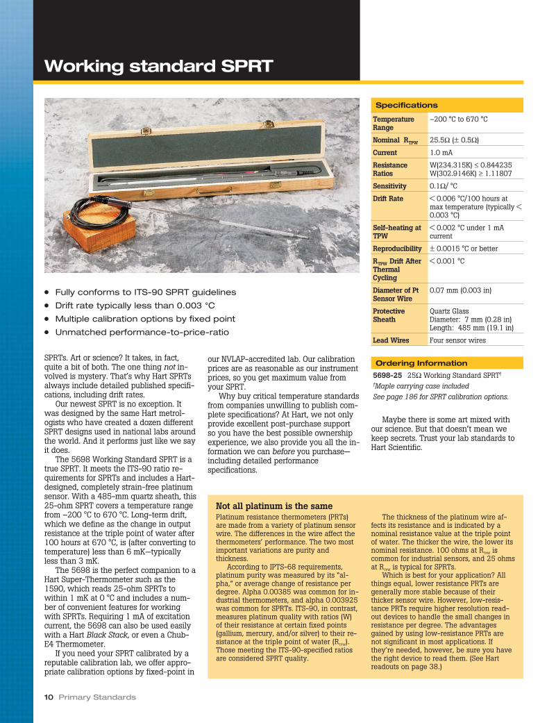
SPRTs. Art or science? It takes, in fact,quite a bit of both. The one thing not in-volved is mystery. That’s why Hart SPRTsalways include detailed published specifi-cations, including drift rates.
Our newest SPRT is no exception. Itwas designed by the same Hart metrol-ogists who have created a dozen differentSPRT designs used in national labs aroundthe world. And it performs just like we sayit does.
The 5698 Working Standard SPRT is atrue SPRT. It meets the ITS-90 ratio re-quirements for SPRTs and includes a Hart-designed, completely strain-free platinumsensor. With a 485-mm quartz sheath, this25-ohm SPRT covers a temperature rangefrom –200 °C to 670 °C. Long-term drift,which we define as the change in outputresistance at the triple point of water after100 hours at 670 °C, is (after converting totemperature) less than 6 mK—typicallyless than 3 mK.
The 5698 is the perfect companion to aHart Super-Thermometer such as the1590, which reads 25-ohm SPRTs towithin 1 mK at 0 °C and includes a num-ber of convenient features for workingwith SPRTs. Requiring 1 mA of excitationcurrent, the 5698 can also be used easilywith a Hart Black Stack, or even a Chub-E4 Thermometer.
If you need your SPRT calibrated by areputable calibration lab, we offer appro-priate calibration options by fixed-point in
our NVLAP-accredited lab. Our calibrationprices are as reasonable as our instrumentprices, so you get maximum value fromyour SPRT.
Why buy critical temperature standardsfrom companies unwilling to publish com-plete specifications? At Hart, we not onlyprovide excellent post-purchase supportso you have the best possible ownershipexperience, we also provide you all the in-formation we can before you purchase—including detailed performancespecifications.
Maybe there is some art mixed withour science. But that doesn’t mean wekeep secrets. Trust your lab standards toHart Scientific.
10 Primary Standards
● Fully conforms to ITS-90 SPRT guidelines
● Drift rate typically less than 0.003 °C
● Multiple calibration options by fixed point
● Unmatched performance-to-price-ratio
Specifications
TemperatureRange
–200 °C to 670 °C
Nominal RTPW 25.5Ω (± 0.5Ω)
Current 1.0 mA
ResistanceRatios
W(234.315K) ≤ 0.844235W(302.9146K) ≥ 1.11807
Sensitivity 0.1Ω/ °C
Drift Rate < 0.006 °C/100 hours atmax temperature (typically <0.003 °C)
Self-heating atTPW
< 0.002 °C under 1 mAcurrent
Reproducibility ± 0.0015 °C or better
RTPW Drift AfterThermalCycling
< 0.001 °C
Diameter of PtSensor Wire
0.07 mm (0.003 in)
ProtectiveSheath
Quartz GlassDiameter: 7 mm (0.28 in)Length: 485 mm (19.1 in)
Lead Wires Four sensor wires
Ordering Information
5698-25 25Ω Working Standard SPRT†
†Maple carrying case includedSee page 186 for SPRT calibration options.
Working standard SPRT
Not all platinum is the samePlatinum resistance thermometers (PRTs)are made from a variety of platinum sensorwire. The differences in the wire affect thethermometers’ performance. The two mostimportant variations are purity andthickness.
According to IPTS-68 requirements,platinum purity was measured by its “al-pha,” or average change of resistance perdegree. Alpha 0.00385 was common for in-dustrial thermometers, and alpha 0.003925was common for SPRTs. ITS-90, in contrast,measures platinum quality with ratios (W)of their resistance at certain fixed points(gallium, mercury, and/or silver) to their re-sistance at the triple point of water (RTPW).Those meeting the ITS-90-specified ratiosare considered SPRT quality.
The thickness of the platinum wire af-fects its resistance and is indicated by anominal resistance value at the triple pointof water. The thicker the wire, the lower itsnominal resistance. 100 ohms at RTPW iscommon for industrial sensors, and 25 ohmsat RTPW is typical for SPRTs.
Which is best for your application? Allthings equal, lower resistance PRTs aregenerally more stable because of theirthicker sensor wire. However, low-resis-tance PRTs require higher resolution read-out devices to handle the small changes inresistance per degree. The advantagesgained by using low-resistance PRTs arenot significant in most applications. Ifthey’re needed, however, be sure you havethe right device to read them. (See Hartreadouts on page 38.)

SPRTs designed by Hart Scientific areknown for their outstanding reliability andminimal long-term drift. They have beencalibrated by national (and other primary)laboratories and proven repeatedly to out-perform competitive models. Now Hart’s5699 Extended Range Metal-Sheath SPRTcombines all the advantages of a Hart-de-signed sensor with the protective sheath-ing materials that allow your SPRT to beused in virtually any furnace or bath withtemperatures as high as 670 °C.
Designed and manufactured by ourprimary standards metrologists, the strain-free sensing element in the 5699 meetsall ITS-90 requirements for SPRTs andminimizes long-term drift.
After one year of regular usage, drift isless than 0.008 °C (< 0.003 °C is typical).Even lower drift rates are possible de-pending on care and handling. A fifth wirefor grounding is added to the four-wiresensor to help reduce electrical noise, par-ticularly for ac measurements. Finally, youcan get an improved version of an old in-dustry-standard Inconel-sheathed SPRT.
The 5699 is constructed with a 0.219-inch-diameter Inconel sheath for high du-rability and fast response times. Inside thesheath, the sensing element is protectedby a thin platinum housing that shieldsthe sensor from contamination from free-floating metal ions found within metal
environments at high temperatures. Re-duced contamination means a low driftrate—even after hours of use in metal-block furnaces at high temperatures.
If you choose not to calibrate the 5699yourself, a wide variety of options is con-veniently available from Hart’s own pri-mary standards laboratory, includingfixed-point calibrations covering anyrange between –200 °C and 661 °C.
At Hart, we use SPRTs every day. Wedesign them, build them, calibrate them,use them as standards, and know what ittakes to make a reliably performing instru-ment. Why buy from anyone else?
Temperature Calibration Equipment 11
● Measures temperatures as high as 670 °C
● Inconel and platinum sheaths guard against contamination
● Less than 8 mK/year drift
● Fifth wire provides shielded ground
Specifications
TemperatureRange
–200 °C to 670 °C
Nominal RTPW 25.5 Ω (± 0.5 Ω)
Current 1 mA
ResistanceRatio
W(302.9146 K) ≥ 1.11807W(234.3156 K) ≤ 0.844235
Sensitivity 0.1Ω/ °C
Drift Rate < 0.008 °C/year(< 0.003 °C/year typical)
Repeatability < 1 mK
Self-heating atTPW
< 0.001 °C under 1 mAcurrent
Reproducibility ± 0.001 °C or better
RTPW Drift AfterThermalCycling
< 0.001 °C
Diameter of PtSensor Wire
0.07 mm(0.003 in)
Lead Wires Four sensor wires plusgrounding wire
ProtectiveSheath
InconelDiameter: 5.56 mm± 0.13 mm (0.219 in± 0.005 in)Length: 482 mm (19 in)
InsulationResistance
> 100 MΩ at 661 °C> 1000 MΩ at 20 °C
Ordering Information
5699-S Extended Range Metal-SheathSPRT†
†Maple carrying case includedSee page 186 for SPRT calibration options.See page 38 for optional readouts.
Extended range metal-sheathSPRT

Sometimes you would like to make SPRTmeasurements but traditional SPRTs are toolong or awkward for a particular application.Our miniature glass capsule SPRTs are per-fect for cryogenics, calorimetry, and othermetrology work requiring small SPRTs.
These are true SPRTs. The high-purityplatinum wire is hand-wound on a glasscross frame in a strain-free design. Theglass capsule is designed to match thethermal expansion of the platinum wire toensure a true seal at all operating temper-atures. The capsules are pressure sealedand come protected in their own maplecases. Both models comply completelywith ITS-90 requirements for platinum
purity including the following resistanceratio:
W(302.9146K) ≥ 1.11807and
W(234.3156K) ≤ 0.844235The 5686 covers temperatures from
–260 °C to 232 °C, so it’s perfect for cryo-genic applications. It is 5.8 mm (.23inches) in diameter and 56 mm (2.2inches) long.
These SPRTs are small but meetcustomary SPRT performance forreproducibility, reliability, and stability.
12 Primary Standards
● Temperatures from –260 °C (13K) to 232 °C
● Stability typically 0.001 °C over a 100 °C range
● Miniature capsule package eliminates stem conduction
Glass Sheath
Platinum Helix Platinum Lead Wires
Glass-Platinum SealSensor Support
Specifications
TemperatureRange
–260 °C to 232 °C(13 K to 505 K)
Nominal RTPW 25.5 Ω
ResistanceRatio
W(302.9146 K) ≥ 1.11807W(234.3156 K) ≤ 0.844235
Drift Rate < 0.005 °C per year overthe entire range
Self-heating atTPW
< 0.002 °C under 1 mAcurrent
Reproducibility ± 0.001 °C or better
RTPW Drift AfterThermalCycling
< 0.001 °C
Filling Gas helium
Lead Wires Four platinum wires, 30 mmlong (1.18 in)
Size 5.8 mm dia. x 56 mm long(0.23 x 2.2 in)
Ordering Information
5686-B Glass Capsule SPRT, –260 °C to232 °C†
†Maple carrying case includedSee page 186 for SPRT calibration options.
Glass capsule SPRTs

You’ve spent some serious money to equipyour lab with some of the finest SPRTs inthe world because they’re the most accu-rate temperature measurement instru-ments you can buy. Now that you’ve gotthem, part of your job is to keep them per-forming at their highest levels. You can dothat with a Hart 9117 Annealing Furnace.
All HTPRTs and SPRTs are subject tomechanical shock no matter how carefullyyou handle them. This shock changes theresistance characteristics of the platinumand shows up as temperature measure-ment errors. Annealing relieves the stresson the platinum sensor caused by me-chanical shock and is recommended priorto any calibration of an SPRT.
In addition to removing mechanicalstrain, annealing also removes the oxida-tion from sensors that have been used for
long periods at temperatures between200 °C and 500 °C. Oxidation impacts thepurity of the element and therefore the ac-curacy of temperature readings. Oxide iseasily removed by annealing at 670 °C forone or two hours.
During the annealing process, contami-nation must be controlled. At temperaturesabove 500 °C, the lattice structure of aquartz sheath is transparent to metal ions.The thermometer must be cleaned and allcontaminating materials removed from itssheath. Annealing should only be done ina furnace that’s designed to avoid emittingmetal ions during its heating cycle. Hartsolves this problem in its 9117 furnace byusing an alumina block that is speciallydesigned to guard against contamination.
The furnace also has a programmablecontroller specifically designed for the an-nealing process.
As a manufacturer of SPRTs, Hartmetrologists understand every aspect ofSPRT use and calibration procedures, in-cluding the annealing process. We usethis furnace in our own lab, so we knowexactly how well it works.
Specifications
TemperatureRange
300 °C to 1100 °C
Stability ± 0.5 °C
Uniformity ± 0.5 °C at 670 °C (overbottom 76 mm [3 in])
Power 230 V ac (± 10 %), 50/60Hz, 12 A, 2500 W
DisplayResolution
0.1 °C below 1000 °C1 °C above 1000 °C
Display Accuracy ± 5 °C
Thermal Wells Five: 8 mm diameter x430 mm long (0.31 x 16.9in)
Controller PID, ramp and soak pro-grammable, thermocouplesensor
Over-TempProtection
Separate circuit protectsfurnace from exceedingrated temperature limit
ExteriorDimensions(HxWxD )
863 x 343 x 343 mm(34 x 13.5 x 13.5 in)
Weight 28 kg (61 lb)
Communications RS-232
Ordering Information
9117 Annealing Furnace(includes 2129 Alumina Block)
2129 Spare Alumina Block, 5 wells2125-C IEEE-488 Interface (RS-232 to IEEE-
488 converter box)
Temperature Calibration Equipment 13
● Guards against contamination
● Anneals both SPRTs and HTPRTs
● Fully programmable
Annealing furnace

The triple point of water (TPW) is not onlythe most accurate and fundamental tem-perature standard available, it’s also oneof the least expensive and simplest to use.
Water cells are essential!Triple point of water cells fill four criticalpurposes. First, they provide the most reli-able way to identify unacceptable ther-mometer drift between calibrations—including immediately after a calibration ifthe thermometer has been shipped. In-terim checks are critical for maintainingconfidence in thermometer readings be-tween calibrations. Second, they provide acritical calibration point with unequaleduncertainties.
Third, for users who characterizeprobes using ratios (that is, they use the
ratios of the resistances at various ITS-90fixed points to the resistance of the ther-mometer at the triple point of water, indi-cated by “W”), interim checks at the triplepoint of water allow for quick and easyupdates to the characterizations of criticalthermometer standards, which can beused to extend calibration intervals.
And lastly, the triple point of water iswhere the practical temperature scale(ITS-90) and the thermodynamic tempera-ture scale meet, since the triple point ofwater is assigned the value 273.16 K(0.01 °C) by the ITS-90 and the Kelvin isdefined as 1/273.16 of the thermody-namic temperature of the triple point ofwater.
Good triple point of water cells containonly pure water and pure water vapor.
(There is almost no residual air left inthem.) When a portion of the water isfrozen correctly and water coexists withinthe cell in its three phases, the “triplepoint of water” is realized. Hart water cellsachieve this temperature with expandeduncertainties of less than 0.0001 °C andreproducibilities within 0.00002 °C.
In simple terms, water cells are madefrom just glass and water, but there’smuch more to it than that! For starters,that’s not just any water in there.
Heavy waterHart cells contain carefully and repetitivelydistilled ocean water and are meticulouslyevacuated and sealed to maintain an iso-topic composition nearly identical to theinternational standard, “Vienna StandardMean Ocean Water,” or “VSMOW.”
The oxygen atoms found in most waterare predominantly comprised of eight pro-tons and eight neutrons (16O). Some oxy-gen atoms, however, have an extraneutron (17O) or two (18O). Similarly, thehydrogen atoms in water normally containonly a single proton (1H), but sometimescontain a neutron also (2H), resulting in“heavy” water. These isotopes coexist invarying proportions in ocean water, polarwater, and continental water, with oceanwater being the heaviest.
The ITS-90 recommends that watercells be made from water with “substan-tially the isotopic composition of oceanwater.” Research has shown that TPW er-rors associated with isotopic compositioncan be as large as 0.00025 °C. The uncer-tainty contribution due to the effect of de-viation from VSMOW in Hart cells is lessthan ± 0.000007 °C. That’s sevenmicrokelvin!
Hart offers two options for verifying theisotopic composition of any purchasedwater cell, both at nominal costs. We cansubmit a sample of water taken from yourown cell to a testing laboratory (after itwas completely manufactured, so you geta valid comparison) and give you the testreport. Or, we can send that water sampleto you in a sealed ampoule for you to con-duct your own tests. We can even providemultiple samples from the same cell (virtu-ally as many as you’d like) so you cancheck for changes over time.
ImpuritiesFurther, the potential for errors due to wa-ter impurity is even greater than the errorsfrom isotopic composition. Hart cells un-dergo multiple distillation processes andutilize special techniques to retain waterpurity. Among other things, our primary
14 Primary Standards
● Easy-to-use, inexpensive standard with uncertainty better than± 0.0001 °C
● Four sizes and two shells (glass and quartz) to choose from
● Isotopic composition of Vienna Standard Mean Ocean Water
Triple point of water cells

standards scientists are able to connectquartz cells directly to the glass distillationsystem without using coupling hardwarethat may invite contamination.
Glass vs. quartzMost Hart water cells may either be pur-chased with borosilicate glass or withfused silica (“quartz”) housings. What’s thedifference? Glass is less expensive thanquartz, but it’s also more porous, allowingimpurities to pass through it over time. Re-search indicates that glass cells generallydrift about 0.000006 °C per year whilequartz cells drift less.
Many sizesHart cells come in four general sizes. Mod-els 5901A, 5901C, and 5901D each comein either quartz or glass shells and include265 mm of thermometer immersion depth.The primary difference between thesemodels (other than the arm on the 5901A)is the inside diameter of the probe well.(See chart on page 16 and note that theinside diameter of the 5901C cells varieswith the shell material). A variety of bathsis available, which can maintain the triplepoint within these cells for many weeks.Accredited (NVLAP) test certificates areavailable with any cell under our Model1904-TPW.
5901A cells include an arm that can beused as a handle, a hook, or a McLeodgauge to demonstrate how much residualair is trapped in the cell. Carefully devel-oped manufacturing processes at Hartkeep the air bubble in a quartz cell assmall as the air bubble in glass cells.
A fourth size, the 5901B cell, comes ina glass version and is significantly smallerthan the other cells. It is designed for usein our Model 9210 Maintenance Appara-tus, which automates the realization andmaintenance of the TPW. The 9210-5901B combination is perfect for both cal-ibrating thermometers and providing peri-odic checks of sensor drift.
AccessoriesFor simplest realization of the TPW in ourlarger cells, the Model 2031A “Quick Stick”Immersion Freezer uses dry ice and alco-hol to facilitate rapid formation of an icemantle within the cell without requiringconstant intervention while the mantleforms.
For best results, use a 3901 bushingwith your triple point of water cell. Abushing is used to improve the thermalcontact between your SPRT and the icemantle of your water triple point cell. Besure to choose a bushing that matches theinner diameter of the reentrant well of thecell and the outer diameter of the SPRT.Additionally, a small piece of foam (<0.5cm) may be placed beneath the bushing toisolate it from the bottom of the cell whichresearch has shown is slightly colder thanthe rest of the cell.
Insurance is also available for eachwater cell purchased from Hart. Watercells are not difficult to handle nor is theTPW difficult to realize, but they are deli-cate and accidents do happen. For a nomi-nal fee, we’ll insure your cell in one-yearincrements. If something goes wrong, justlet us know and we’ll replace your cell. Noquestions asked.
Temperature Calibration Equipment 15
Triple point of water cells
The 2028 Dewar has inside dimensions of 20 cm by50 cm (7.75 in x 19.5 in), and outside dimensions of25 cm by 61 cm ( 9.75 in x 24 in).
Accessories like the “Quick Stick” Immersion Freezerand 3901 bushings add simpler realization and im-proved thermal contact.
Ordering Information
5901A-G TPW Cell, 12 mm ID withhandle, glass shell
5901A-Q TPW Cell, 12 mm ID withhandle, quartz shell
5901C-G TPW Cell, 13.6 mm ID, glassshell
5901C-Q TPW Cell, 14.4 mm ID, quartzshell
5901D-G TPW Cell, 12 mm ID, glassshell
5901D-Q TPW Cell, 12 mm ID, quartzshell
5901B-G TPW Cell, mini, glass shell7012 TPW Maintenance Bath (main-
tains four cells)7312 TPW Maintenance Bath (main-
tains two cells)9210 TPW (5901B-G) Maintenance
Apparatus2028 Dewar (for TPW ice bath)2031A “Quick Stick” Immersion
Freezer1904-TPW Accredited Cell
IntercomparisonINSU-5901 TPW Cell Insurance, one-year5901-ITST Isotopic Composition Analysis,
TPW Cell5901-SMPL Water Sample, TPW Cell
(comes in a sealedglass ampoule)
3901-11 TPW Bushing, 5901/5901A to7.5 mm
3901-12 TPW Bushing, 5901/5901A to5.56 mm (7/32 in)
3901-13 TPW Bushing, 5901/5901A to6.35 mm (1/4 in)
3901-21 TPW Bushing, 5901C to7.5 mm
3901-22 TPW Bushing, 5901C to5.56 mm (7/32 in)
3901-23 TPW Bushing, 5901C to6.35 mm (1/4 in)

16 Primary Standards
Triple point of water cells
5901B-G5901A-G/Q
450
mm
50 mm
12 mm
265
mm
5901C-G
420
mm
265
mm
60 mm
13.6 mm
5901D-G/Q
420
mm
265
mm
60 mm
5901C-Q
420
mm
265
mm
60 mm
12 mm14.4 mm
8 mm
30 mm18
0 m
m
118
mm
Specifications
5901A-G 5901A-Q 5901C-G 5901C-Q 5901D-G 5901D-Q 5901B-G
Expanded Uncertainty (k=2) < 0.0001 °C < 0.0002 °C
Reproducibility 0.00002 °C 0.00005 °C
Dimensions 50 mm OD12 mm ID
450 mm long
60 mm OD13.6 mm ID
420 mm long
60 mm OD14.4 mm ID
420 mm long
60 mm OD12 mm ID
420 mm long
30 mm OD8 mm ID
180 mm long
Immersion Depth (watersurface to well bottom)
265 mm 118 mm
Material BorosilicateGlass
Fused Silica(Quartz)
BorosilicateGlass
Fused Silica(Quartz)
BorosilicateGlass
Fused Silica(Quartz)
BorosilicateGlass
Water Source Ocean
DVSMOW ± 10 ‰ (± 1 %) ± 20 ‰18OVSMOW ± 1.5 ‰ (± 0.15 %) ± 3 ‰
Effect of Deviation fromVSMOW
± 7 µK ± 14 µK

For frequent use of traditional-size triplepoint of water cells, nothing helps saveyou time and hassle like a good mainte-nance bath. The 7312 Triple Point of Wa-ter Maintenance Bath keeps your cells upand running reliably for weeks at a time—even during heavy usage—and comes at aprice you’ll love.
The 7312 accommodates two TPW cellsand includes three pre-cool wells for prop-erly cooling probes prior to measurementswithin the cells. Stability and uniformity areeach better than ± 0.006 °C, so your cellsstay usable for up to eight weeks. Whatevermethod you use for building your ice man-tles, you can be assured they’ll last in a7312 bath.
An independent safety circuit protectsyour water cells from freezing and break-ing by monitoring the temperature of thebath and shutting down its refrigerationsystem should the bath controller fail.Noise-reduction techniques in the manu-facturing process ensure your bath doesn’tadd excessive noise to your lab.
With a temperature range from –5 °C to110 °C, this bath can also be used forcomparison calibrations—particularly oflong-stem probes—or maintenance of gal-lium cells. An optional gallium cell holdingfixture fits two cells, which, in a 7312bath, can maintain their melting plateausfor up to two weeks.
In fact, the 7312 is available with a time-saving 2031A “Quick Stick” ImmersionFreezer so you can build your ice mantlesquickly and hands-free. Just fill the 2031A’scondensing reservoir with dry-ice and alco-hol, insert it into the cell, and get some otherwork done while your ice mantle forms inless than an hour. (Alternatively, LN2 may beused.)
If you’re using traditional-size TPWcells, don’t take the time to create an icemantle only to watch it melt quickly as itsits in a bucket of ice. Maintain your cellsthe right way in a Hart 7312 TPW Mainte-nance Bath.
Temperature Calibration Equipment 17
Hart’s 2031A “Quick Stick” Immersion Freezer offersunmatched convenience and simplicity in formingthe triple point of water ice mantle.
Specifications
Range –5 °C to 110 °C
Stability ± 0.001 °C at 0 °C(alcohol-water mix)± 0.004 °C at 30 °C(alcohol-water mix)
Uniformity ± 0.003 °C at 0 °C(alcohol-water mix)± 0.006 °C at 30 °C(alcohol-water mix)
TPW Duration Six weeks, typical(assumes correctly formedice mantle)
Set-PointAccuracy
± 0.05 °C at 0 °C
Set-PointRepeatability
± 0.01 °C
DisplayResolution
± 0.01 °C
Set-PointResolution
± 0.002 °C; 0.00003 °C inhigh-resolution mode
Access Opening 121 x 97 mm(4.75 x 3.8 in)
Immersion Depth 496 mm (19.5 in)
Volume 19 liters (5 gallons)
Communications RS-232 included
Power 115 V ac (± 10 %), 60 Hzor 230 V ac (± 10 %), 50Hz, specify
Size ( HxWxD ) 819 x 305 x 622 mm(12 x 24.5 x 32.25 in)
Weight 34 kg (75 lb)
Ordering Information
7312 TPW Maintenance Bath (includesTPW Holding Fixture, MPGaHolding Fixture, and RS-232Interface)
2001-IEEE Interface, IEEE-4882031A “Quick Stick” Immersion Freezer
● Maintains TPW cells for up to two months
● Optional immersion freezer for simple cell freezing
● Independent cutout circuit protects cells from breaking
22
TPW maintenance bath

Reprinted from Random News
IntroductionThe Standard Platinum Resistance Ther-mometer (SPRT) is the most accurate ther-mometer in the extended temperaturerange from –259 °C to 962 °C. The uncer-tainty of an SPRT can be as low as a fewtenths of a millikelvin (mK).
More and more metrologists are usingSPRTs as reference standards to calibrateother types of thermometers or to achievea high level of accuracy for any reason.However, the handling and use of anSPRT is as important to achieving a highlevel of accuracy as the design and perfor-mance of the SPRT itself. Several types oferrors can corrupt SPRT measurements.
Sometimes absolute resistance is usedto calculate temperature instead of the re-sistance ratio. When absolute resistance issubstituted for the resistance ratio, errorsof more than 10 mK at 660 °C are com-mon. In addition, even when the correctmeasurement and calculations are made,the resistance of the SPRT in the triplepoint of water should be determined im-mediately after a high accuracy measure-ment is made with the thermometer.
The triple point of water measurementis often overlooked but is vital to accuracy.The relationship of the triple point of wa-ter measurement to SPRT accuracy is ex-plained with a few key points.
TPW and accuracyIn general, SPRTs have excellent stability;however, a small drift in resistance mighthappen now and then, especially aftertransportation, thermal cycling, or acci-dental rough handling. A change as lowas 1 ppm in resistance at about 660 °C(the freezing point of aluminum) will beequivalent to a change of 1.1 mk in tem-perature. The stability required of a high-quality standard resistor is about 1 ppm.The working and environmental condi-tions normally associated with a standardresistor are much better than the condi-tions usually found when working with anSPRT. So a few ppm of stability might bethe best we can expect for most SPRTs.
The ratio of two resistances of an SPRTbased on two temperatures is much morestable than the stability expected when anabsolute resistance at a single fixed tem-perature is used. For example, using onlythe freezing point of silver as a referencepoint over a six year time frame, an SPRTexhibited a change of 5 ppm in its resis-tance [1]; this is equivalent to a change of7.5 mk in temperature. On the other hand,the change in the resistance ratio,
W(961.78 °C) = R(961.78 °C)/R(0.01 °C)
was within 1 ppm (a change of 2 mk intemperature) across the same six-year pe-riod. This explains why the resistance ra-tio W(t) is specified by the InternationalTemperature Scales since 1960 instead ofthe absolute resistance R(t).
The best method for accomplishing thisratio is to use the Triple Point of Water asthe second temperature because of its ex-cellent stability and simplicity. It has beenspecified as a reference point for SPRTssince 1960 [2]. Thus, the highest SPRT ac-curacy possible is achieved when the re-sistance of an SPRT at the triple point of
water (Rtp) is made immediately after ameasurement at any other temperature.
Use of the ratio method also reduces sys-tem error introduced by any electronic read-out. This reduction in system error isimportant because as little as 0.7 PPM of er-ror in resistance will cause an error of 1 mkin temperature at 962 °C (see table below).
Frequency of Rtp measurementWhen accuracy requirements don’t extendto the highest levels, Rtp may need mea-suring only once a day, every few days, orat some other suitable interval. How fre-quently Rtp needs measuring depends onseveral factors, such as acceptable
18 Primary Standards
PrecoolingAccess Hole
SPRT
ThermometerGuide Tube
Water Vapor
BorosilicateGlass
ReentrantThermometer Well
Water from Ice Bathor Alcohol
Water Solid (Ice)
Water Liquid
Metal Bushing
Soft Pad
Ice Bath orMaintenance Bath
Cushion
Use TPW and ratio method to improve
SPRT stability and accuracy

uncertainty, the stability of the SPRT, themeasuring temperature range, and theworking conditions. If the required uncer-tainty is 1 mk or so, Rtp measurementshould follow each Rt measurement. If ac-curacy requirements are 20 mk or more ina temperature range lower than 420 °Cand the SPRT used is quite stable, the Rtpmight be measured once a week. The sta-bility over time of each SPRT must bemeasured, even when using SPRTs manu-factured in the same lot from the samesupplier.
When temperature measurements arehigher than 800 °C, it is better to measurethe Rtp as soon as the SPRT cools down toroom temperature. Whenever possible, anSPRT should cool down to at least 500 °Cwith a low cooling rate (about 100 °C perhour). Otherwise, the SPRT should be an-nealed before making a measurement atthe triple point of water.
A suitable annealing procedure is atwo-hour anneal at 700 °C at the end ofwhich the SPRT is allowed to cool to450 °C over a period of about two and onehalf hours. After this initial cooling period,the SPRT can cool quickly to room temper-ature. Fast cooling from high temperaturesabove 500 °C may cause significant in-creases in Rtp because of the quenching-ineffect on lattice defects found in platinumwire. This increase of Rtp could be as largeas 30 mk.
Can the Rtp given in the “NISTCalibration Report” be used tocalculate the ratio?Some metrologists may feel the Rtp mea-sured by NIST is more accurate than thatmeasured in their own lab, so they preferto use the value for Rtp given in the “NISTCalibration Report” to calculate the resis-tance ratio in the interpolation equation.While it’s true that the accuracy of NIST’smeasurements are generally much betterthan those done in other labs, the Rtp ofyour SPRT may have changed during
transportation, so it should be measuredagain in your own lab. Furthermore, theRtp should be measured using the sameinstrument and time frame as the Rt to re-duce system error with the readout in-cluded in the measuring procedure. It isimportant to always use the same readoutinstrument to measure both Rt and Rtp.
Avoiding mechanical strain and theannealing procedureAn SPRT is a delicate instrument. Shock,vibration, or any other form of accelerationmay cause strains that change its temper-ature-resistance characteristics. Even alight tap, which can easily happen whenan SPRT is put into or taken out of a fur-nace or a triple point of water cell, maycause a change in Rtp as high as 1 mk.Careless handling of an SPRT over thecourse of a year has resulted in Rtp in-creases equivalent to 0.1 °C.
Annealing at 660 °C for an hour willrelieve most of the strains caused by mi-nor shocks and nearly restore the Rtp to itsoriginal value. If the maximum tempera-ture limit for an SPRT is lower than660 °C, it should be annealed at its maxi-mum temperature. Such an annealing pro-cedure is always advisable after any typeof transportation.
The annealing furnace should be veryclean and free of metals, such as copper,iron, and nickel. SPRTs are contaminatedwhen they are annealed in furnaces con-taining a nickel block, even when theSPRTs were separated from the nickelblock by quartz sheaths [ 3 ]. Well de-signed, clean annealing furnaces are im-portant for quality measurements withSPRTs.
ConclusionsSPRTs are among the finest temperaturemeasuring devices known. However, highaccuracy comes at a price and not just interms of money. Patience, care and proper
procedures are major factors in producinghigh quality measurements.
Support instruments such as triplepoint of water cells are inexpensive andsimple to use. Annealing is a well under-stood process. Uncompromised measure-ments are possible in almost everylaboratory situation.
References1, Li, Xumo et al, Realization of the In-
ternational Temperature Scale of 1990 be-tween 0 °C and 961.78 °C at NIM,“Temperature, Its Measurement and Con-trol in Science and Industry,” Volume 6,Part 1, p. 193 (1992).
2, CGPM (1960): Comptes Rendus desSeances de la Onzieme Conference Gener-ale des Poids et Mesures, pp. 124-133.
3, Li, Xumo et al, A New Type of HighTemperature Platinum Resistance Ther-mometer, Metrologie, 18 (1982), p. 203.
Temperature Calibration Equipment 19
Temperature(°C)
The temperature error caused byan error of 1 PPM in resistance
measurement (mK)
The resistance error equivalentto an error of 1 mK in
temperature (PPM)
–200 0.04 25.4
–100 0.14 6.9
0.01 0.25 4.0
232 0.51 2.0
420 0.74 1.4
660 1.1 0.9
962 1.5 0.7
Use TPW and ratio method to improve
SPRT stability and accuracy

Several companies manufacture highquality resistance bridges for both AC andDC applications that can take measure-ments at the 0.1 ppm level. Research hasshown that all of them compensate wellfor any theoretical inaccuracies predictedin their design.
We like the MI bridge because we feelconfident about its measurements, and itssoftware gives us more information thanwe can get from the other instruments.While it’s true we do use the other bridgesfor certain functions we undertake in ourlab, including some experimental testing,we use the MI bridge every day for fixed-point calibrations of SPRTs.
The 5581 Bridge performs a true auto-balancing procedure to nine significantdigits. As the check proceeds, the bridgesteps through an internal comparison ofthe transformer’s windings, the results ofwhich are recorded to track its perfor-mance over time.
Another function of this bridge is itsreal-time uncertainty analysis program. Inthis mode, you enter external uncertaintyfactors such as the uncertainty of your re-sistor, and the 5581 combines your infor-mation with its own uncertainties to
compute a system uncertainty for yourmeasurement.
The optional Windows® compatiblecontrol software offers history logging andregression analysis, along with uncer-tainty analysis and the auto-self-checkfeature. The program also calculates stan-dard deviations if you need them. You canenter coefficients for your SPRT and readtemperature rather than resistance.
Of course, if you prefer, you can operatethe bridge manually. The choice is yours,but either way you’ll find this to be a greatbridge to use.
20 Primary Standards
● Measurement uncertainty to ± 0.025 mK
● Uses conventional standard resistors
Specifications
Bridge
Range/Accuracy
–0.001 Ω to 0.01 Ω: < 5 ppm0.01 Ω to 0.1 Ω: < 0.5 ppm0.1 Ω to 1 Ω: < 0.1 ppm0.1 Ω to 10 KΩ: < 0.1 ppm10 KΩ to 10 KΩ: < 0.2 ppm
Linearity 0.01 ppm
Max Ratio 13:1
TestCurrents
10 μA to 150 mA, 30-Voltcompliance
CurrentReversal
Automatic 4 to 1000 seconds
Power 100, 120, 220, and 240 V(± 10 %), 47–63 Hz, 180 VA
Weight 60 lb (27.3 kg)
Dimensions(WxHxD )
432 x 279 x 381 mm(17 x 11 x 15 in)
Scanner
Inputs 20/10
Operation Matrix
ThermalEMFs
< 500 nanovolts
ErrorContribution
< 20 nanovolts
ContactRatings
Relay2-coil latching
MaxCarryingCurrent
2 A (ac/dc) (optional 30 A)
ContactResistance
<0.007 Ω
InsulationResistance
>1012 Ω
Inputs andOutputs
Tellurium Copper(rear panel)
IEEE-488 24-pin IEEE-488
Weight 5313-001: 18 kg (40 lb)5313-002: 9 kg (20 lb)
Dimensions(WxHxD )
5313-001: 432 x 279 x381 mm (17 x 11 x 15 in)5313-002: 127 mm H (5 in)
Ordering Information
5581 MI Bridge5313-001 Scanner, 20 channels5313-002 Scanner, 10 channels5313-003 IOTech 488 Interface Card5313-004 Windows Software
The DC AdvantageAC bridges are more susceptible to elec-trical interference than DC bridges.Therefore, when AC furnaces are used,DC bridges are preferred. The likelihoodof electrical interference increases attemperatures above the freezing point ofAluminum (660.323 °C), because the in-sulation resistance of the furnace and theSPRT decline significantly.
DC bridge

By now you’ve probably been preparingbudgets for the new primary standardsyou need in your lab. Well, you’ve come tothe right place because we’ve got a com-plete line of the best metal freeze-pointcells you can buy.
Fluke scientists have designed andtested metal freeze-point cells for manyyears. Not only do we manufacture all themajor freeze-points, our metrologists havewritten extensively on the theory and useof cells and have created new designscovering a range of applications no othercompany can match. They can answer ev-ery question you have on freeze-pointsand explain how we have handled the ra-diation losses along the well, minimizedpossible stem error and made pressurecorrections for the highest possible mea-surement accuracy.
Pure metals melt and freeze at a uniquetemperature through a process involvingthe absorption, or liberation, of the latentheat of fusion. If 100% pure metals wereavailable, each cell of a particular typewould melt and freeze at its exact theoret-ical temperature, but since 100% puremetal is not possible, cells vary slightlyfrom their theoretical absolute.
The best freeze-point cells are the onesthat get very close to their theoreticalfreezing temperature and provide a tem-perature plateau that’s stable and longlasting for calibration work. Changes assmall as 0.01 mK (0.00001°C) are measur-able, so cell uncertainty is definable. Flukecells come very, very close to the absolutetheoretical limits possible with today’smaterial science. We use 99.9999% puremetal. Six 9s purity is as good as it gets.Some manufacturers may use five 9s.Make sure they specify purity on theirquotations.
The shape of the curve generated byfreezing a fixed-point cell tells a lot aboutthe purity of the metal. Unlike most manu-facturers we provide certificates for eachmetal fixed-point cell at no extra charge.The certificates we provide include threegraphs of full plateaus, as measured by abridge and SPRT, and a calculated purityfor the metal sample. Exceptions includegallium cells (extremely long plateaus),gold and copper cells (SPRT temperaturerange exceeded).
We test each cell three times so thatwe can evaluate the stability of the pla-teau. This provides evidence that the cellis good and that the metal sample is notbeing contaminated over time. Some ex-amples of freezing curves from Flukefixed-point cells are pictured below. The
graphs also demonstrate the length ofFluke fixed-point cell freezing plateaus.
Freezing plateau length provides an-other quality measure for comparing fixed-point cells. The longer the plateau, thebetter the cell and the more cost-effectiveit is to use. As indicated in the table, Flukemetal fixed-points have plateaus thatrange from 20 hours to 14 days depend-ing on the type of cell. No other producerof fixed-points beats the performance of aFluke fixed-point cell.
Further proof of cell performance isavailable through our accredited cell cer-tification service (NVLAP Lab Code200348-0). This service is a rigorous testthat involves repeatedly testing the melt-ing and freezing plateaus of the fixed-point cell and then comparing the thermo-dynamic temperature to that of a NIST-certified reference cell. The result is ahighly-qualified primary standard
instrument with a certificate traceable tonational and international standards.
All freeze-point cells have to be usedand maintained in specially-designedfreeze-point furnaces. Furnaces come in avariety of temperature ranges, and eachone must have a very uniform temperatureregion for the freezing and melting pro-cess. High accuracy is achieved by the for-mation of two liquid-solid interfacesduring freezing. One interface should beadjacent to the inner surface of the cruci-ble, and the other should be on the outersurface of the central well, which is theclosest point to the thermometer.
A very thin solid shell should form onthe central well, and the concentration ofimpurity in this thin shell should be muchlower than the average impurity in thecore metal. The temperature on the sec-ond liquid-solid interface should be veryclose to that found in a 100% pure metalunder ideal conditions.
Temperature Calibration Equipment 21
Why use Fluke metal freeze-point cells?
Substance Impurity LevelDeviation from Pure
Liquidus PointAcheivable
Plateau LengthMercury 99.999999 % –0.002 mK 30 hoursGallium 99.99999 % –0.014 mK 14 daysIndium 99.9999 % –0.24 mK 25 hoursTin 99.9999 % –0.30 mK 25 hoursZinc 99.9999 % –0.54 mK 25 hoursAluminum 99.9999 % –0.67 mK 20 hoursSilver 99.9999 % –1.12 mK 20 hours
Sample freezing curve for 5904 indium cell

Fluke’s freeze-point furnaces providethe proper temperature, stability and uni-formity to create the longest, most stabletemperature plateau possible.
The immersion depth of a thermometerin the liquid metal (the distance from thesurface of the liquid metal to the middlepoint of the thermometer’s sensor) is ap-proximately 180 mm in cells made byFluke. The outside diameter of each cell is48 mm, the thermometer well is 8 mmand cell length is 290 mm.
Cells are delicate and must be handledwith extreme care. Fluke provides specialstorage cases, gloves for handling andcomplete care instructions. Cells are handcarried rather than shipped to ensurecomplete integrity of measurements.
The performance of every Fluke cell isguaranteed. When you call, ask about ourtemperature calibration school where youcan learn more about the theory and oper-ation of all metal freeze-point cells. We’llanswer every question you have and helpsolve any problem you encounter. We usemetal freeze-point cells in our lab everyday, and our metrologists have decades ofexperience with them.
22 Primary Standards
Why use Fluke metal freeze-point cells?
Sample freezing curve for 5905 tin cell.
Sample freezing curve for 5908 silver cell.

Hart scientists have designed and testedITS-90 fixed-point cells for many years.Not only do we manufacture all the majorfixed points, our metrologists have writtenextensively on the theory and use of cellsand have created new designs covering arange of applications no other companycan match.
Our testing of fixed-point cells is alsounmatched. The scope of our accreditationincludes the testing of ITS-90 fixed-pointcells. Each cell may be purchased with thisintercomparison option, which includescomparing the equilibrium value of yourcell against that of a reference Hart cell.
Traditional freeze-point cellsIf you want true primary temperature stan-dards capability, you want metal freeze-point cells that are very close to the theoret-ical freezing temperature and provide pla-teaus that are both stable and long lasting.
Hart’s metal freeze-point cells are theculmination of more than 20 years of pri-mary standards experience. No other com-pany has as much experience in thedevelopment of metal fixed-point cells asHart. That’s why you’ll find Hart cells in
many national metrology institutes aroundthe world.
Each Hart cell is carefully constructedin our ultra-clean, state-of-the-art lab, us-ing high-density, high-purity graphitecrucibles containing metal samples withpurity of at least 99.9999 % (six 9s) and,in many cases, 99.99999 % (seven 9s).The crucible is enclosed within a sealedquartz glass envelope that is evacuatedand back-filled with high-purity argongas. A special sealing technique is used toseal the cell at the freezing point. Wemeasure and record for you the precisepressure of the argon gas to ensure themost accurate corrections for pressure.
Once manufactured, all Hart cells aretested and supplied with an assay ofmetal-sample purity. Every traditional sizeITS-90 cell further undergoes more rigor-ous testing in our primary standards labwhere we realize melt-freeze curves andperform a detailed “slope analysis” to con-firm cell purity. If you want more data,we’ll give you an optional intercomparisonwith our own reference cells.
Gallium cellsGallium cells are a great reference for vali-dation of instruments subject to drift (likeSPRTs), and they’re important for calibrat-ing sensors used near room or body tem-peratures, in environmental monitoring,and in life sciences applications.
Hart’s 5943 Gallium Cell is sealed in astainless steel envelope. High purity gal-lium (99.99999 %) is enclosed in a plasticand metal shell. The stainless steel con-tainer is then filled with pure argon gas atone standard atmosphere at the melting-point temperature.
Gallium expands by 3.1 % when itfreezes requiring the cell to have flexiblewalls. Unlike some manufacturers’ cells,which are made from PTFE enclosure ma-terials, our cells don’t need pumping andrefilling because they’re not gas perme-able. In fact, we guarantee our cells willmaintain their uncertainty of < 0.1 mK forat least five years. Realization and mainte-nance of the cell is automated with our9230 Maintenance Apparatus (see page33). This apparatus will provide meltingplateaus up to eight days and a conve-nient control to automatically achieve anew melt plateau each week with an in-vestment of just five minutes. Never hasthe maintenance of a world-class galliumcell been easier.
Water cellsWhile simple ice baths are often used as acalibration point at 0 °C, their limitationsinclude gradients, purity problems, repeat-ability issues, and variances in construc-tion and measurement techniques. Triplepoint of water cells not only solve theseproblems; they represent the most usedtemperature on the ITS-90, and they’re in-expensive to own and use.
Hart makes three traditional-size TPWcells (see page 14) that have been repeat-edly proven in national labs to surpasstheir published uncertainty specification of± 0.0001 °C. Ice mantles may be formedusing dry ice, LN2, or immersion freezersand can last for up to two months whenmaintained in our 7012 or 7312 baths.
Open metal cellsMade from the same materials and withthe same manufacturing techniques astheir sealed counterparts, Hart’s new se-ries of “open” metal fixed-point cells in-clude a high quality valve for connectingto a precision pressure-handling systemwithin your lab. Using such a system, thecell can be evacuated, charged, andpurged several times with a pure inert
Temperature Calibration Equipment 23
● Best cell uncertainties commercially available
● Every ITS-90 fixed point available from mercury to copper
● Plateaus last days (gallium for weeks and TPW for months)
● Manufactured and tested by Hart’s primary standards scientists
ITS-90 fixed-point cells

gas, then charged again to a regulatedpressure level while measurements aremade with the cell.
Once assembled and tested, each HartITS-90 open cell further undergoes morerigorous testing in our lab, unlike cellsfrom some manufacturers who providetheir open cells as a kit of parts, withoutany test data.
Because open cells allow users to mea-sure the pressure within the cell, uncer-tainties due to pressure corrections maybe minimized. Use of open cells is nowbeing suggested by the CCT, and opencells can be used for demanding tempera-ture-versus-pressure applications, as wellas precision SPRT calibrations.
The height of these cells has been ex-tended to allow easy access to the gasvalve while the cells are in use. Purequartz-wool insulation and four high-pu-rity graphite discs prevent heat loss fromthe metal sample to the pressure regula-tion system while optimizing vertical tem-perature gradients within the cell. Eachcell has an outside diameter of 50 mm (2
inches) and a height of 600 mm (23.5inches)—(silver and copper cells are 700mm [27.6 inches] tall).
When it comes to primary temperaturestandards, Hart supplies more equipmentthan all of our competitors combined. Ifyour goal is to reduce uncertainty, start by
buying from the company that supports itsproducts better than any other metrologycompany in the world. Why trust your pri-mary standards to any other company?
24 Primary Standards
ITS-90 fixed-point cells
Specifications
ModelFixedPoint Style
AssignedValue ( °C)
OutsideDiameter
InsideDiameter
Total OutsideCell Height Depth‡
CellUncertainty(mK, k=2)
Certification(mK, k=2)†
5900 Mercury Stainless Steel –38.8344 31.8 mm 8.0 mm 417.6 mm 208 mm 0.2 0.25
5904 Indium Traditional QuartzGlass
156.5985 48 mm 8 mm 282 mm 195 mm 0.7 0.7
5905 Tin Traditional QuartzGlass
231.928 48 mm 8 mm 282 mm 195 mm 0.5 0.8
5906 Zinc Traditional QuartzGlass
419.527 48 mm 8 mm 282 mm 195 mm 0.9 1.0
5907 Aluminum Traditional QuartzGlass
660.323 48 mm 8 mm 282 mm 195 mm 1.3 1.8
5908 Silver Traditional QuartzGlass
961.78 48 mm 8 mm 282 mm 195 mm 2.4 4.5
5909 Copper Traditional QuartzGlass
1084.62 48 mm 8 mm 282 mm 195 mm 10.1 12.0
5924 Indium Open Quartz Glass 156.5985 50 mm 8 mm 596 mm 195 mm 0.7 0.7
5925 Tin Open Quartz Glass 231.928 50 mm 8 mm 596 mm 195 mm 0.5 0.8
5926 Zinc Open Quartz Glass 419.527 50 mm 8 mm 596 mm 195 mm 0.9 1.0
5927A-L Aluminum Open Quartz Glass(long)
660.323 50 mm 8 mm 696 mm 195 mm 1.3 1.8
5927A-S Aluminum Open Quartz Glass(short)
660.323 50 mm 8 mm 596 mm 195 mm 1.3 1.8
5928 Silver Open Quartz Glass 961.78 50 mm 8 mm 696 mm 195 mm 2.4 4.5
5929 Copper Open Quartz Glass 1084.62 50 mm 8 mm 696 mm 195 mm 10 12.0
5943 Gallium Stainless Steel 29.7646 38.1 mm 8.2 mm 250 mm 168 mm 0.1 0.1†Certifications at lower uncertainties are available for national laboratories.‡Depth is measured from the bottom of the thermometer well to the top of the pure reference material.
Ordering Information
5900 Mercury Cell, Stainless Steel5904 Indium Cell, Traditional Quartz
Glass5905 Tin Cell, Traditional Quartz
Glass5906 Zinc Cell, Traditional Quartz
Glass5907 Aluminum Cell, Traditional
Quartz Glass5908 Silver Cell, Traditional Quartz
Glass5909 Copper Cell, Traditional Quartz
Glass
5924 Indium Cell, Open Quartz Glass5925 Tin Cell, Open Quartz Glass5926 Zinc Cell, Open Quartz Glass5927A-L Aluminum Cell, Open Quartz
Glass, Long5927A-S Aluminum Cell, Open Quartz
Glass, Short5928 Silver Cell, Open Quartz Glass5929 Copper Cell, Open Quartz Glass5943 Gallium Cell, Metal Cased2068-D Stand, Fixed-Point Cell, Black
Delron
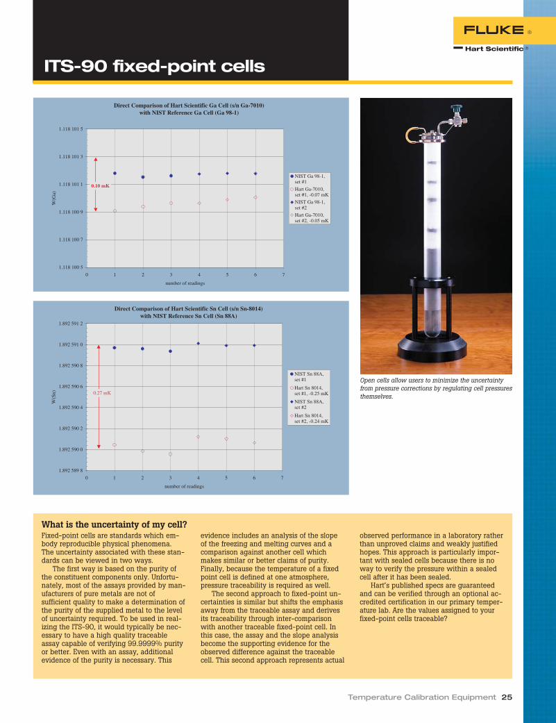
Temperature Calibration Equipment 25
ITS-90 fixed-point cells
Direct Comparison of Hart Scientific Ga Cell (s/n Ga-7010)with NIST Reference Ga Cell (Ga 98-1)
1.118 100 5
1.118 100 7
1.118 100 9
1.118 101 1
1.118 101 3
1.118 101 5
0 1 2 3 4 5 6 7
number of readings
W(G
a)
NIST Ga 98-1,set #1
Hart Ga-7010,set #1, -0.07 mK
NIST Ga 98-1,set #2
Hart Ga-7010,set #2, -0.05 mK
0.10 mK
Direct Comparison of Hart Scientific Sn Cell (s/n Sn-8014)with NIST Reference Sn Cell (Sn 88A)
1.892 589 8
1.892 590 0
1.892 590 2
1.892 590 4
1.892 590 6
1.892 590 8
1.892 591 0
1.892 591 2
0 1 2 3 4 5 6 7
number of readings
W(S
n)
NIST Sn 88A,set #1
Hart Sn 8014,set #1, -0.25 mK
NIST Sn 88A,set #2
Hart Sn 8014,set #2, -0.24 mK
0.27 mK
What is the uncertainty of my cell?Fixed-point cells are standards which em-body reproducible physical phenomena.The uncertainty associated with these stan-dards can be viewed in two ways.
The first way is based on the purity ofthe constituent components only. Unfortu-nately, most of the assays provided by man-ufacturers of pure metals are not ofsufficient quality to make a determination ofthe purity of the supplied metal to the levelof uncertainty required. To be used in real-izing the ITS-90, it would typically be nec-essary to have a high quality traceableassay capable of verifying 99.9999% purityor better. Even with an assay, additionalevidence of the purity is necessary. This
evidence includes an analysis of the slopeof the freezing and melting curves and acomparison against another cell whichmakes similar or better claims of purity.Finally, because the temperature of a fixedpoint cell is defined at one atmosphere,pressure traceability is required as well.
The second approach to fixed-point un-certainties is similar but shifts the emphasisaway from the traceable assay and derivesits traceability through inter-comparisonwith another traceable fixed-point cell. Inthis case, the assay and the slope analysisbecome the supporting evidence for theobserved difference against the traceablecell. This second approach represents actual
observed performance in a laboratory ratherthan unproved claims and weakly justifiedhopes. This approach is particularly impor-tant with sealed cells because there is noway to verify the pressure within a sealedcell after it has been sealed.
Hart’s published specs are guaranteedand can be verified through an optional ac-credited certification in our primary temper-ature lab. Are the values assigned to yourfixed-point cells traceable?
Open cells allow users to minimize the uncertaintyfrom pressure corrections by regulating cell pressuresthemselves.

Reprinted from Random News
What is an intrinsic standard?Intrinsic standards are defined by theNCSL as “standard(s) recognized as havingor realizing, under prescribed conditions ofuse and intended application, an assignedvalue the basis of which is an inherentphysical constant or an inherent and sta-ble physical property.” Thermometricfixed-point cells are included in the NCSL“Catalog of Intrinsic and Derived Stan-dards.” Some other well-known intrinsicstandards include the Josephson-arrayvoltage standard, the Quantum Hall resis-tance standard, and the Cesium atomicfrequency standard.
The definitions themselves do not di-rectly address the issues of uncertainty,traceability, or accreditation. However, inthe case of thermometric fixed points,these issues are covered in the notes tothe definition. The notes indicate that thevalue is assigned by consensus and neednot be established through calibration.The uncertainty is said to have two funda-mental components: (a) that associatedwith its consensus value, and (b) that as-sociated with its construction and applica-tion. Traceability and stability are said tobe established through verification at ap-propriate intervals. Verification can eitherbe based upon application of a consensusapproved test method or throughintercomparison. Furthermore, theintercomparison may be accomplishedwith standards in a local quality controlsystem or external standards includingnational and international standards.
Do fixed-point cells fit thedefinition?The basic parameter of the cell, the phasetransition, is believed to be an inherentand stable physical property of the cellwhen used under prescribed conditions.The generally accepted values for thetemperatures of the phase transitionsalong with corrections due to pressure and
hydrostatic head are assigned by the ITS-90, the current temperature scale adoptedby the BIPM. From the values given and bytaking a few measurements, the theoreti-cal temperature of the phase transitioncan be calculated. Also defined by the ITS-90 is the intended application, namely, asdefining thermometric fixed points to beused in conjunction with an appropriateinterpolation instrument and associatedequations. Finally, the conditions of useare described by supplementary informa-tion to the ITS-90 as well as a significantbody of literature. Although not everyoneagrees on the exact procedures, for themost part, they are quite well understoodand accepted. It appears, then, that fixed-
point cells can indeed be considered in-trinsic standards.
However, several issues arise: First, theITS-90 discusses fixed points based onphase transitions of pure substances. Anideal substance behaves differently thanthe real materials that we are able to ob-tain. The departure depends on the impu-rity content of the sample once it isassembled into a cell. For very highly purematerials, the slope of the plateau can beused to approximately determine the pu-rity, but the absolute temperature remainsdifficult to predict. Second, the ITS-90does not directly specify an optimum celldesign, furnace or cryostat design, or min-imum purity requirements. Quite to thecontrary, many designs and options are
26 Primary Standards
IssueVerification via
SPRTVerification via Industry
Intercomparison NIST MAP Cell Certification
Uncertainty for Cells maybe no maybe yes
Traceability for Cells maybe no maybe yes
Laboratory Apparatus yes yes yes maybe
Laboratory Equipment yes yes yes maybe
SPRT Calibration no maybe yes no
Procedure Evaluation maybe maybe yes no
Computation Evaluation no maybe yes no
Sealed metal freeze-point cells
Traceability and thermometricfixed-point cells

presented in the literature. Although ex-perimental results may suggest one designover another, the conclusions regardinguncertainty are not always clear. Third,the measurement results obtained from acell are highly dependent upon experi-mental conditions. Having a good cell isonly part of the exercise. Fourth, since athermometer always measures its owntemperature, the thermometer must beable to come to thermal equilibrium withthe cell. This is affected by the cell, its ap-paratus, the thermometer, and the tech-nique used to realize the phase transition.Finally, since we wish to perform trace-able calibrations, knowing only the theo-retical temperature is not adequate.
To certify or not to certify?So, how do we demonstrate that our cellsembody the ITS-90 definitions and howdo we establish traceability? Before wetackle those points, there are three issuesthat we must consider. First, whatevermethod we choose, we must perform a ro-bust uncertainty analysis on our measure-ments. The uncertainty associated withthe temperature of the phase transition isonly one component among many thatshould be considered. Second, statisticalprocess control (SPC) is critical wheneverthe measurement relies upon physicalprocesses (such as the realization of aphase transition). Through SPC, we canquantify the repeatability of our processand show that the test experiment repre-sents the process. Third, although SPRTsand sealed cells can be used as transferstandards, intercomparison of fixed-pointcells over long distances is problematic.
That having been said, the simplestmethod is to perform measurements inyour cells using a calibrated SPRT. If theuncertainty of the measurement is suffi-ciently small, the temperature can then beshown to be within the estimated uncer-tainty based upon the theoretical consid-erations of the cell construction. In thecase of low purity cells (five 9s or lower),it may be appropriate to “assign” a tem-perature and uncertainty to the realizationobtained from the cell. These methodsmay be considered the least robust andwill typically result in the largest uncer-tainties, but they can be shown to betraceable determinations.
A similar but more complicated methodis to intercompare calibration results withpeer laboratories or a reference laboratoryusing a suitable transfer standard. Al-though this type of analysis cannot di-rectly “certify” the performance of a fixed-point cell, it will show your laboratory’s
capability to calibrate SPRTs using them.In many cases, this is what you are at-tempting to illustrate. A well-designedintercomparison will evaluate the resultsof the calibration, the raw and intermedi-ate data, and the computations. Much in-sight can be obtained from such scrutiny.NIST offers a measurement assurance pro-gram (MAP) to satisfy this need.
Finally, the cells can be tested by anexperienced laboratory that has the capa-bility to provide traceable results with un-certainties in the neighborhood of yourrequirements. If the laboratory performingthe test is using its own equipment andapparatus, this type of test will show theperformance of the cell only. Additionalexperiment and uncertainty evaluationmay be required for use in your laboratory.Also, this method will not illustrate yourlaboratory’s ability to use the cells prop-erly. The major advantage of this methodis that it can provide the lowest overalluncertainty. Often, this is referred to as“direct comparison.”
So, what should we do?At one time, it was considered acceptableto use a fixed-point cell with plateau anal-ysis to show that the cell was behaving it-self. This approach has proven to beinadequate as our understanding evolvesand we try to improve our laboratories.Moreover, laboratory accreditation re-quires that we follow rigorous proceduresin evaluating our uncertainties. If our un-certainties approach National MetrologyInstitute level, our data and analysis mustjustify this. And, the fixed-point cell is acritical component in the uncertainty eval-uation. The intrinsic standard argumentprovided by the NCSL does state that somelevel of intercomparison is necessary.
Presumably, the NCSL expects theintercomparison to be appropriate to theuncertainty claimed and based on themost current practices.
We must choose the method thatmakes economic sense and that satisfiesour requirements. For example, if we arecalibrating secondary PRTs using minifixed-point cells, we may be justified inusing a calibrated SPRT to verify the per-formance of our cells. Many laboratories(several accredited) use this method withsuccess. Traceability can easily be demon-strated and the uncertainty analysis isstraightforward. On the other hand, if wehave spent tens of thousands of dollars ona system to calibrate SPRTs and theseSPRTs are used for critical measurements,the NIST MAP program is a very good op-tion, provided we qualify. Finally, if wewish to provide cell certifications, we willrequire a set of certified reference cellsalong with a robust uncertainty evalua-tion. At Hart, we use a combination of allthree methods.
Conclusion and recommendationsSo, are fixed point cells intrinsic standardsor certified artifacts? It really doesn’t mat-ter. Both viewpoints require testing andtraceability. Both approaches require rig-orous uncertainty analysis that must sat-isfy the scrutiny of our accreditationassessors, our customers, and our peers.And each perspective can be logically jus-tified. At Hart, we treat some as intrinsicstandards and others as certified artifacts.Our uncertainty analyses are as rigorousas we can make them and we welcomecomment from our peers. Additionally, theNIST thermometry staff is available to as-sist in the development of uncertaintybudgets, meeting traceability and accredi-tation requirements, as well as uniquetesting requirements. Finally, we use theapproach that will result in the lowest un-certainties for a given set of equipmentand techniques. After all, isn’t that whatit’s all about?
Temperature Calibration Equipment 27
Traceability and thermometricfixed-point cells
Water triple point cells

Several companies manufacture freeze-pointfurnaces. Most of these furnaces are of ade-quate theoretical design and of reasonablequality. Most are priced similarly. However,there is a difference that can’t be seen fromspecifications or price, and that’s how wellthe furnace performs with the freeze-pointcells they’re designed to maintain.
Establishing and maintaining a freeze-point plateau is what these furnaces aresupposed to be about. Nothing they do ismore important than this performance issue.
Hart Scientific makes three freeze-pointfurnaces that, when combined with Hartfreeze-point cells, produce the longestplateaus in the industry. A Hart furnaceand cell can establish plateaus that rangefrom 24 to 40 hours or more.
Fixed-point furnaces can also be usedfor comparison calibrations and for an-nealing. In these processes, stability anduniformity are very important, and nothingspeaks more about stability and uniformitythan the length of the plateaus produced
by the furnace. No other furnace beats aHart furnace where it counts.
All three of these furnaces have exter-nal cooling coils for circulation of tapwater at less than 60 PSIG and approxi-mately 0.4 GPM to reduce heat load to thelab. They also come with RS-232 portsand have equilibration blocks available forcomparison calibrations. IEEE-488 inter-face packages are also available, if that’syour preference.
One of Hart’s three fixed-point furnacemodels will meet your needs. Remember,the length of the plateau is the best mea-sure of a furnace’s performance. Call us forperformance data on actual cell freezes andtest data on furnace gradients.
9114This furnace has a range of 100 °C to680 °C, which includes the indium, tin,zinc, and aluminum fixed points, all inone furnace.
The 9114 furnace has an inlet for useof clean dry air or inert gas to initiate the
supercool of a tin cell. Other furnacesrequire the user to remove the hot andfragile tin cell from the furnace by handbefore cooling. In a Hart furnace, you sim-ply turn on your gas, monitor your cellduring its supercool, and turn the gas offwhen the freeze begins.
The 9114 is a three-zone furnace withthe best in Hart digital controller technol-ogy. Hart designs and builds proprietarycontrollers that have a reputation of beingthe best in the business. All of our fixed-point furnaces use them to achieve excel-lent stability and uniformity.
For easy access and visibility, all threezones are controlled from the top of theunit. The primary controller can be set in0.01 °C increments, and actual tempera-ture is readable to two decimal places.
The freezing and melting process can beautomated using eight preset, user-programmable temperature settings. Thetop and bottom zones are slaved to the pri-mary zone using differential thermocouples.A high-temperature PRT acts as the maincontrol sensor for the best accuracy, sensi-tivity, and repeatability.
9115AThe 9115A Sodium Heat Pipe Furnace isspecifically designed for maintenance ofaluminum and silver freeze-point cells.
It has a temperature range of 550 °Cto 1000 °C with gradients of less than± 0.1 °C throughout. The sodium heat-pipe design provides a simple, yet uni-form, single heating zone that ensuresvery uniform changes in states duringheating and cooling.
Melting, freeze initiation, and plateaucontrol for a variety of freeze-point cells arepossible by entering up to eight set-points,ramp rates, and soak times. The controllerdisplays temperature in degrees C or F, andtemperature feedback is done via a ther-mocouple. Freeze-point plateaus of 8 to 10hours are typical, and 24 hours are possibleunder controlled conditions.
External cooling coils are included forcirculation of tap water to reduce chassistemperature and heat load to the lab.Temperature cutouts protect your SPRTsand the furnace from exposure to exces-sive temperatures.
9116AThe Hart Scientific 9116A Furnace has atemperature range of 550 °C to 1100 °Cand is designed for use in achieving alu-minum, silver, or copper freezing pointmeasurements. An advanced high temper-ature Sodium heat pipe extends usage tomore than 1000 hours at 1100 °C and
28 Primary Standards
● Designed for long plateaus
● Automated controllers, RS-232 included
● Top access to high-stability Hart controllers
● External cooling coils
Freeze-point furnaces

Temperature Calibration Equipment 29
5000 hours at 982 °C. The heater is em-bedded in a fiber ceramic insulating block.A hollow section through the center con-tains the heat pipe.
The minimum working temperature ofthe Sodium heat pipe is about 500 °C.Above that temperature, the sodium circu-lates throughout the tube providing a uni-form temperature zone for freezing pointmeasurements. With uniformity of± 0.05 °C, zone adjustments are elimi-nated simplifying installation and increas-ing throughput.
The uniform temperature is maintainedover the full length of the metal freezepoint cell. A programmable temperaturecontroller simplifies freeze initiation, melt-ing and plateau control. Control stability is± 0.15 °C, the best in the industry, en-abling extension of freezing plateaus ofquality fixed point cells for up to 20 hoursand longer. For compatibility with auto-mation programs, plateaus may be con-trolled through standard RS-232 andoptional IEEE-488 PC interfaces.
Specifications 9114 9115A 9116A
Temperature Range 100 °C to 680 °C 550 °C to 1000 °C 550 °C to 1100 °C
Temperature Stability ± 0.03 °C ± 0.25 °C ± 0.15 °C
TemperatureUniformity
± 0.05 °C(± 0.1 °C in the pre-
heat well)
+0.1 °Cfrom bottom of well to
100 mm (3.94 in)
± 0.05 °C
Set-Point Accuracy ± 0.5 °C ± 3.0 °C
Set-Point Resolution 0.01 °C 0.1 °C
Display Resolution 0.01 °C 0.1 °C below 1000 °C1 °C above 1000 °C
Thermal Safety CutoutAccuracy
± 5 °C ± 10 °C
Heater Power End Zones:1000 W each
(at 230 V ac nominal)Primary Zone:
1500 W
2500 W
Exterior Dimensions(HxWxD )
838 x 610 x 406 mm(33 x 24 x 16 in)
Power Requirements 230 V ac (± 10 %), 50/60 Hz, 1 Phase, 22 A maximum
Weight 92 kg (203 lb) 82 kg (180 lb) 82 kg (180 lb)
Specifications - 2127
Dimensions 2127-9114: 54 x 510 mm(2 x 20 in)
Wells Three: 8 mm ID x 488 mm(0.31 x 19.2 in)
ImmersionProtection
Last 156 mm (6.1 in) inalumina
Well-to-WellUniformity
10 mK at 660 °C in 9114
TemperatureRange
Up to 1100 °C
Protect platinum thermometers from metal ion con-tamination with a low-cost alumina block.
Ordering Information
9114 Metrology Furnace (includesCell Support Container)
2125 IEEE-488 Interface (9114 only)2126 Comparison Block, 91142940-9114 Cell Support Container, 91142127-9114 Alumina Block, 91142941 Mini Freeze-Point Cell Basket
Adapter
9115A Sodium Heat Pipe Furnace (in-cludes Cell Support Container)
2940-CC Cell Support Container, 9115A,9116A
9116A Three-Zone Freeze-Point Fur-nace (includes Cell SupportContainer)
2127-CB Block, Ceramic, Non-contami-nating, 9115A/9116A
Freeze-point furnaces

If cuteness were reason enough to buy aproduct, Hart’s Mini Fixed-Point Cellswould win you over easily. But there’s amuch better reason to buy them: they giveyou the least expensive, easiest-to-usefixed-point standards for your lab.
Mini cells eliminate the need for com-parison calibrations. Temperatures offixed-point cells are constant and intrinsic,so only the electrical parameters of thesensor under calibration need to be read.If you’re calibrating industrial thermome-ters, thermocouples, or thermistors andwant the most accurate calibration possi-ble, these mini cells will give it to you. Ifyou need a wide range of temperatures,mini cells cover the triple point of water(0.01 °C) and every ITS-90 point from in-dium (156.5985 °C) to copper(1084.62 °C).
Fixed-points made simpleWith mini cells, realization and mainte-nance are simple. Mini TPW cells can beautomatically realized and maintained inour 9210 Maintenance Apparatus (page30). Realizing the triple point of watertakes only five minutes, but the plateauslast all day.
The realization and maintenance of in-dium, tin, zinc, and aluminum cells arelikewise automated through our 9260 MiniFixed-Point Cell Furnace (page 34). Workwith them at their designated freeze point,or use them at their melting point to sim-plify the calibration process even further.We published a paper, “The ComparisonBetween the Freezing Point and MeltingPoint of Tin,” to help you understand andbenefit from the easier procedure of usingthe melting point of your standard.
These mini cells are made from thesame materials and with the same proce-dures as their full-size counterparts. Infact, they can achieve nearly the same un-certainty levels as Hart’s traditional fixed-point cells. Probes as short as 229 mm (9in) work with these cells. The specifica-tions table (at right) gives you the immer-sion depth and uncertainty for each cell.
In addition to high-accuracy calibra-tions of RTDs and PRTs, these cells areperfect for validating the accuracy ofSPRTs. If you’re doing comparison calibra-tions with SPRTs, then you know the im-portance of occasionally checking theiraccuracy between their own recalibra-tions. Because these cells are easy to use
and maintain, verification checks are sim-ple and convenient.
Metal-cased cellsMetal-cased cells can also be used in the9260 maintenance furnace. Because theyuse stainless steel cases, these cells areeasier to use and transport without thesame risk of breakage. You’ll notice thatwe have designed the metal cased cellswith more immersion depth to give evenbetter uncertainty too!
You’ll find these cells easier to use thanyou expect. You can have a free copy ofXumo Li’s paper comparing freeze-pointmeasurements with melting-point mea-surements, and if you want a high level oftraining in using metal freeze-point cells,you can attend one of Hart’s in-depthtraining classes held in our lab in Utah.
Ordering Information
5901B-G TPW Cell, Mini, Glass Shell5914A Mini Quartz Indium Cell5915A Mini Quartz Tin Cell5916A Mini Quartz Zinc Cell5917A Mini Quartz Aluminum Cell5918A Mini Quartz Silver Cell5919A Mini Quartz Copper Cell5944 Mini Metal Cased Indium Cell5945 Mini Metal Cased Tin Cell5946 Mini Metal Cased Zinc Cell5947 Mini Metal Cased Aluminum Cell9210 Mini TPW Maintenance Appara-
tus (see page 30)9260 Mini Fixed-Point Furnace (for In,
Sn, Zn, Al cells—see page 34)
30 Primary Standards
● Lower uncertainties than comparison calibrations
● All ITS-90 fixed points from TPW to copper
● Reduced equipment and annual recalibration costs
Mini fixed-point cells

Temperature Calibration Equipment 31
Specifications
Uncertainty (mK) k=2Model
Number Fixed-PointTemperature
( °C)Outside
DiameterInside
DiameterTotal Cell
HeightImmersion
Depth1 Cell Only2Simple
Realization2
5901B-G Water T. P. 0.01 30 mm 8 mm 170 mm 117 mm 0.2 0.55914A Indium F. P. 156.5985 43 mm 8 mm 214 mm 140 mm 1.0 2.05915A Tin F. P. 231.928 43 mm 8 mm 214 mm 140 mm 1.4 3.05916A Zinc F. P. 419.527 43 mm 8 mm 214 mm 140 mm 1.6 4.05917A Aluminum F. P. 660.323 43 mm 8 mm 214 mm 140 mm 4.0 10.05918A Silver F. P. 961.78 43 mm 8 mm 214 mm 140 mm 7.0 n/a5919A Copper F. P. 1084.62 43 mm 8 mm 214 mm 140 mm 15.0 n/a5944 Indium F. P. 156.5985 41.3 mm 7.8 mm 222 mm 156 mm 0.7 1.45945 Tin F. P. 231.928 41.3 mm 7.8 mm 222 mm 156 mm 0.8 1.65946 Zinc F. P. 419.527 41.3 mm 7.8 mm 222 mm 156 mm 1.0 2.05947 Aluminum F. P. 660.323 41.3 mm 7.8 mm 222 mm 156 mm 2.0 4.0
1 Distance from the bottom of the central well to the surface of the pure metal.2 “Cell Only” refers to the expanded uncertainty of the cell when realized by traditional methods and maintained using traditional maintenance devices. “Simple Realiza-tion” refers to the expanded uncertainty of the cell when realized using practical methods (melting points instead of freezing points or slush ice instead of an ice mantle,for example) and maintained using Hart’s 9210 and 9260 mini cell maintenance apparatus.
Sn-05009Sn-05008
Sn-15001(Mini)
1.8926945
1.8926955
1.8926965
1.8926975
1.8926985
1.8926995
1.8927005
1.8927015
Sn-05008 Sn-05009 Sn-15001
W(S
n)
Sn-05008
Sn-05009
Sn-15001(Mini)
0.5 mK
Tin Cell Comparison
4.7675
4.7674
4.7673
4.7672
4.7671
4.7670
Rt/
Rs
4/29/9714:22
4/29/9721:31
4/30/974:40
4/30/9718:57
5/1/972:05
5/1/979:12
5/1/9716:20
5/1/9723:27
5/2/976:35
5/2/9713:42
4/30/9711:50
5/2/9720:50
5/3/973:57
The Melting Curve of Tin, Mini-Cell Sn-S-01, 4/29–5/3/97
Date and Time
Mini fixed-point cells
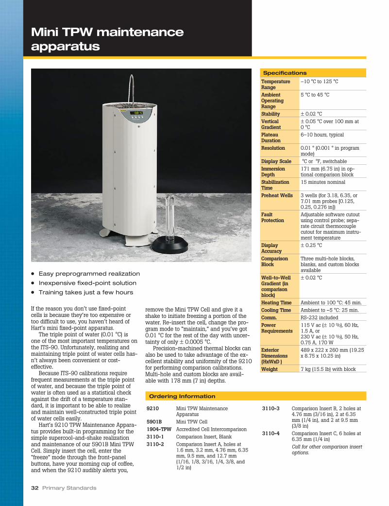
If the reason you don’t use fixed-pointcells is because they’re too expensive ortoo difficult to use, you haven’t heard ofHart’s mini fixed-point apparatus.
The triple point of water (0.01 °C) isone of the most important temperatures onthe ITS-90. Unfortunately, realizing andmaintaining triple point of water cells has-n’t always been convenient or cost-effective.
Because ITS-90 calibrations requirefrequent measurements at the triple pointof water, and because the triple point ofwater is often used as a statistical checkagainst the drift of a temperature stan-dard, it is important to be able to realizeand maintain well-constructed triple pointof water cells easily.
Hart’s 9210 TPW Maintenance Appara-tus provides built-in programming for thesimple supercool-and-shake realizationand maintenance of our 5901B Mini TPWCell. Simply insert the cell, enter the“freeze” mode through the front-panelbuttons, have your morning cup of coffee,and when the 9210 audibly alerts you,
remove the Mini TPW Cell and give it ashake to initiate freezing a portion of thewater. Re-insert the cell, change the pro-gram mode to “maintain,” and you’ve got0.01 °C for the rest of the day with uncer-tainty of only ± 0.0005 °C.
Precision-machined thermal blocks canalso be used to take advantage of the ex-cellent stability and uniformity of the 9210for performing comparison calibrations.Multi-hole and custom blocks are avail-able with 178 mm (7 in) depths.
32 Primary Standards
● Easy preprogrammed realization
● Inexpensive fixed-point solution
● Training takes just a few hours
Specifications
TemperatureRange
–10 °C to 125 °C
AmbientOperatingRange
5 °C to 45 °C
Stability ± 0.02 °CVerticalGradient
± 0.05 °C over 100 mm at0 °C
PlateauDuration
6–10 hours, typical
Resolution 0.01 ° (0.001 ° in programmode)
Display Scale °C or °F, switchableImmersionDepth
171 mm (6.75 in) in op-tional comparison block
StabilizationTime
15 minutes nominal
Preheat Wells 3 wells (for 3.18, 6.35, or7.01 mm probes [0.125,0.25, 0.276 in])
FaultProtection
Adjustable software cutoutusing control probe; sepa-rate circuit thermocouplecutout for maximum instru-ment temperature
DisplayAccuracy
± 0.25 °C
ComparisonBlock
Three multi-hole blocks,blanks, and custom blocksavailable
Well-to-WellGradient (incomparisonblock)
± 0.02 °C
Heating Time Ambient to 100 °C: 45 min.Cooling Time Ambient to –5 °C: 25 min.Comm. RS-232 includedPowerRequirements
115 V ac (± 10 %), 60 Hz,1.5 A, or230 V ac (± 10 %), 50 Hz,0.75 A, 170 W
ExteriorDimensions(HxWxD )
489 x 222 x 260 mm (19.25x 8.75 x 10.25 in)
Weight 7 kg (15.5 lb) with block
Mini TPW maintenanceapparatus
Ordering Information
9210 Mini TPW MaintenanceApparatus
5901B Mini TPW Cell1904-TPW Accredited Cell Intercomparison3110-1 Comparison Insert, Blank3110-2 Comparison Insert A, holes at
1.6 mm, 3.2 mm, 4.76 mm, 6.35mm, 9.5 mm, and 12.7 mm(1/16, 1/8, 3/16, 1/4, 3/8, and1/2 in)
3110-3 Comparison Insert B, 2 holes at4.76 mm (3/16 in), 2 at 6.35mm (1/4 in), and 2 at 9.5 mm(3/8 in)
3110-4 Comparison Insert C, 6 holes at6.35 mm (1/4 in)Call for other comparison insertoptions.

The gallium melting point (29.7646 °C) isa critical temperature. Thermometers usedin life science, environmental monitoring,and many other applications depend on itfor accurate calibrations. Lab standardsrely on it as an ITS-90 check standard andas a means of measuring drift betweencalibrations. Hart Scientific now makes iteasy to use.
The new 9230 Gallium MaintenanceSystem works with Hart’s Model 5943Stainless Steel Gallium Cell to providemelting plateaus that last a week, with re-sults approaching what can be achievedin a Hart maintnance bath. Not a day. Nota day-and-a-half. One week.
The Model 5943 Stainless Steel Gal-lium Cell holds a gallium sample that is99.99999+ % pure. The gallium is sealedin a Teflon envelope in a high purity ar-gon atmosphere, which is itself sealed in-side a stainless steel housing. Thisdouble-sealing method reduces leachinginto the gallium sample and ensures a lifeof ten years or longer for the cell.
Temperature Calibration Equipment 33
Specifications
TemperatureRange
15 °C to 35 °C
AmbientOperatingRange
18 °C to 28 °C
Stability ± 0.02 °C
VerticalGradient
< 0.03 °C over six inchesduring cell maintenance
PlateauDuration
Five days, typical
Resolution 0.01 ° (0.001 ° in programmode)
Display Scale °C or °F, switchable
ImmersionDepth
220 mm (8.75 in) in galliumcell
StabilizationTime
Preprogrammed
Preheat Wells 2
FaultProtection
Heating/cooling rate cutout
DisplayAccuracy
± 0.05 °C at 29.76 °C
ComparisonBlock
Contact Hart
Well-to-WellGradient (incomparisonblock)
n/a
Heating Time Preprogrammed
Cooling Time Preprogrammed
Comm. RS-232 included
PowerRequirements
115 V ac (± 10 %), 60 Hz,1.0 A, or230 V ac (± 10 %), 50 Hz,0.65 A, 175 W
ExteriorDimensions(HxWxD )
489 x 222 x 260 mm(19.25 x 8.75 x 10.25 in)
Weight 8.2 kg (18 lb) without cell
Ordering Information
9230 Gallium Cell MaintenanceApparatus
5943 Stainless Steel Gallium Cell
1904-Ga Accredited Cell Intercomparison
● One week plateau duration
● No hassle automatic realizations
● Used daily in our Primary Lab
Gallium cell maintenanceapparatus

Hart’s 9260 Mini Fixed-Point Cell Furnaceprovides a fixed-point system that cuts inhalf the financial investment required todo fixed-point calibrations and virtually allthe time and training required by tradi-tional systems.
This furnace costs less than half of alarge furnace and works with indium, tin,zinc, and aluminum cells to cover all ITS-90 fixed points from 156.5985 °C to660.323 °C. The cells themselves, using asmaller volume of 99.9999 % pure metal,also cost much less. But cost is only a partof the issue.
The 9260 makes using fixed pointseasy. Simply insert the cell at the end ofthe day and let it sit overnight. The nextmorning, initialize the built-in softwareroutine for your specific cell. Come back inan hour, verify the stability of the cell, andyou can take measurements for the rest ofthe day from a near-perfect temperaturesource!
The built-in software lets you choose be-tween using melting-point curves or freez-ing-point curves for each metal. The ITS-90calls for freezing points, but melting pointsare easier to realize, and the difference in
uncertainty (less than 2 mK for most ap-plications) is generally insignificant.
Comparison blocks are also availablefor the 9260 for high-precision compari-son calibrations at high temperatures. Twoblocks are available with a varietyof pre-drilled wells in addition toblank or custom blocks. Well depth is229 mm (9 in).
34 Primary Standards
Ordering Information
9260 Mini Fixed-Point Furnace5914A Mini Quartz Indium Cell5915A Mini Quartz Tin Cell5916A Mini Quartz Zinc Cell5917A Mini Quartz Aluminum Cell5944 Metal Cased Mini Indium Cell5945 Metal Cased Mini Tin Cell5946 Metal Cased Mini Zinc Cell5947 Metal Cased Mini Aluminum
Cell2940-9260 Container, Mini-Cell Support,
9260
2942-9260 Container, SST Mini-Cell Sup-port, 9260
1904-X Accredited CellIntercomparison
3160-1 Comparison Insert, Blank3160-2 Comparison Insert, 7 holes at
6.35 mm (1/4 in)3160-3 Comparison Insert, 2 holes at
3.2 mm (1/8 in), 2 at 4.76mm (3/16 in), 2 at 6.35 mm(1/4 in), 2 at 9 mm (9/32 in),and 2 at 9.5 mm (3/8 in)Call for other comparison in-sert options.
Specifications
TemperatureRange
50 °C to 680 °C
AmbientOperatingRange
5 °C to 45 °C
Stability ± 0.03 °C to 300 °C± 0.05 °C above 300 °C
VerticalGradient
Top and bottom zones ad-justable by offset
PlateauDuration
6–10 hours typical
Resolution 0.01 °Display Scale °C or °F, switchableImmersionDepth
229 mm (9 in)
StabilizationTime
15 minutes nominal
Preheat Wells 2FaultProtection
Sensor burnout and shortprotection, over-temperaturethermal cutout
DisplayAccuracy
± 0.2 °C to 300 °C± 0.3 °C to 450 °C± 0.5 °C to 680 °C
ComparisonBlock
Two multi-hole blocks,blanks, and custom blocksavailable
Well-to-WellGradient (incomparisonblock)
± 0.02 °C
Heating Time 1.25 hrs. from 25 °C to680 °C
Cooling Time 10.5 hrs. from 680 °C to100 °C
Comm. RS-232 includedPowerRequirements
115 V ac (± 10 %), 60 Hz, 11A, or230 V ac (± 10 %), 50 Hz, 6A, specify, 1200 W
ExteriorDimensions(HxWxD )
489 x 222 x 260 mm(19.25 x 8.75 x 10.25 in)
Weight 20.5 kg (45 lb) with block
● Good introduction to fixed-point calibration
● User friendly and inexpensive
Mini fixed-point cell furnace

While there is a difference between thenominal boiling point of nitrogen(–196 °C) and the argon triple point(–189.3442 °C), the difference can be cor-rected for mathematically, and an uncer-tainty of less than 2 mK from the actualargon triple point is achievable.
Hart’s LN2 Comparison Calibrators con-sist of a super-insulated glass dewar, ahigh-purity copper block, and a precision-fit lid. The dewar is filled with LN2 and thecopper block is suspended in it; an SPRTis inserted into the block and a calibration
is performed against your own calibratedSPRT. The Model 7196-4 includes four8 mm (0.315 in) wells. The 7196-13 in-cludes five 8 mm (0.315 in) wells andeight 6.35 mm (0.25 in) wells.
Hart’s LN2 Comparison Calibrators areneither expensive nor complicated to use.If you need supporting data or would liketo discuss the theory of operating an LN2Comparison Calibrator, call Hart Scientifictoday. (Or come to one of our trainingcourses, and we’ll show you.)
Specifications
Temperature Nominal –196 °C dependingon atmospheric pressure
ThermalWells
7196-4: four 8 mm (0.32 in)I.D. wells7196-13: five 8 mm (0.32 in)I.D. wells, eight 6.35 mm(0.25 in) I.D. wellsBoth blocks: 275 mm immer-sion from top of lid to bottomof well, 150 mm immersioninto copper block
Dimensions 180 mm O.D. x 385 mm high
Stability Typically better than2 mK/20 min
Uniformity < 0.4 mK between holes
Volume 3.5 liters of liquid nitrogen
Evaporation Approx. 25 mm (1 in) per 45minutes
Ordering Information
7196-4 LN2 Comparison Calibrator,4 holes
7196-13 LN2 Comparison Calibrator,13 holes
Temperature Calibration Equipment 35
● Low-cost calibrations to –196 °C
● Simple to use
● Uncertainty less than 2 mK
Insulated Lid
Liquid Nitrogen
Block Support Rod
Super-Insulated Dewar
Oxygen-FreeCopper Block
Aluminum Cover
Calibrated SPRT
SPRT Being Calibrated
51 mm (2 in) dia.
4 wells at8 mm (0.315 in)
5 wells at8 mm (0.315 in)
89 mm (3.5 in) dia.
8 wells at6.35 mm (0.25 in)
LN2 comparison calibrators

Do you need high-accuracy working stan-dards for precise, on-site resistance cali-brations? If you’d like to avoid maintainingtraditional standard resistors in oil baths,Hart has a complete assortment of DC airresistors manufactured by Fluke, withFluke’s proprietary tellurium-copper five-way binding posts.
The Fluke 742A Series covers valuesfrom 1 ohm all the way to 100 megohm.These are the finest-quality air resistorsyou can buy. They’re durable, easy tomaintain, and easy to use. Their excellenttemperature stability allows them to beused from 18 °C to 28 °C with typicallyless than 2 ppm degradation. Using the
calibration table supplied with thestandards, which lists corrections in 0.5 °Cincrements, this uncertainty canbe reduced.
Care has been taken to reduce resis-tance changes brought about by thermaland mechanical shock. Retrace (shift in re-sistance) is typically less than 2 ppm aftercycling between 0 °C and 40 °C.
Each of these resistors comes with aNVLAP-accredited report of calibrationfrom Fluke. Accredited recalibrations areavailable from either Fluke or Hart.
Ordering Information
742A-1 Resistor, DC Standard, 1Ω
742A-10 Resistor, DC Standard, 10Ω
742A-25 Resistor, DC Standard, 25Ω
742A-100 Resistor, DC Standard, 100Ω
742A-1K Resistor, DC Standard, 1 KΩ
742A-10K Resistor, DC Standard, 10 KΩ
742A-100K Resistor, DC Standard, 100 KΩ
742A-1M Resistor, DC Standard, 1 MΩ
742A-10M Resistor, DC Standard, 10 MΩ
742A-7002 Transit Case
1960 Cal, DC Standard Resistor
36 Primary Standards
● Convenient air resistors don’t require oil or air baths
● Calibrate resistance thermometers and other devices
● Includes NIST-traceable calibration data with uncertainty to 1 ppm
● Easily transported for on-site resistance calibration
Specifications
ModelNominalValue Ω
Stability,ppm
6 Months
Stability,ppm
12 Months
Max Change, ppmfrom 23 °C ± 5 °C
(± ppm)
CalibrationUncertainty,
± ppm
742A-1 1 5 8 3.0 1.0
742A-10 10 5 8 3.0 1.0
742A-25 25 5 8 3.0 1.0
742A-100 100 4 6 3.0 1.0
742A-1K 1K 4 6 2.0 1.5
742A-10K 10K 2.5 4 1.5 1.0
742A-100K 100K 4 6 2.0 2.5
742A-1M 1M 6 8 2.0 5.0
742A-10M 10M 6 9 3.0 10.0
DC resistance standards

National laboratories around the worldhave long relied on the standard AC/DCresistors manufactured by Tinsley.Whether they’re used in thermometry orelectrical applications—with AC or DCbridges—these resistors perform betterthan any other AC/DC resistors available.
Six resistors in Hart’s 5430 series coverresistance values from 1 ohm to 10,000ohms. Each one has an actual resistancewithin 10 ppm of its nominal value andholds its resistance within 2 ppm per year.
Each resistor comes with a Tinsley cer-tificate on AC performance, traceable toNPL in the UK, including calibration uncer-tainty of 3 ppm. Additionally, Hart canprovide an optional DC certificate, trace-able to NIST and NVLAP accredited, withuncertainty below 1 ppm.
Designed originally by a national lab,Tinsley resistors are bifilar wound to mini-mize reactance and are filled with oil tominimize both time- and temperature-caused instabilities. AC/DC transfer errorat 90 Hz is only 1 ppm.
For maintaining your oil resistors, Hartprovides baths that range from 51- to167-liter capacity with enough insideshelf space to maintain all your standard
resistors. Our 7009, 7015, and 7108models maintain your resistors with ex-ceptional stability (see page 124).
In our lab, we use both AC and DCbridges in addition to Super-Thermome-ters. We calibrate SPRTs in fixed points,and we calibrate reference resistors. Weuse standard resistors every day, and weunderstand the value of being able to relyon resistors that won’t drift. Tinsley makesthe best AC/DC resistors around, and Hartmakes the best maintenance baths. Askpeople who know. Then don’t compro-mise.
Temperature Calibration Equipment 37
● Long-term stability better than 2 ppm/year (< 1 ppm typical)
● Traceable AC and DC calibrations available
● National lab design proven for more than 25 years
Specifications
Tolerance 10 ppm
CalibrationUncertainty
AC: 3 ppm (10 KΩ: 4 ppm)DC: 1 ppm (optional)
Long-TermStability
2 ppm/year
TemperatureCoefficient
2 ppm/ °C
RecommendedCurrent
1 Ω: 100 mA10 Ω: 32 mA25 Ω: 20 mA100 Ω: 10 mA1 KΩ: 3 mA10 KΩ: 1 mA
MaximumCurrent
1 Ω: 1 A10 Ω: 320 mA25 Ω: 200 mA100 Ω: 100 mA1 KΩ: 32 mA10 KΩ: 10 ma
AC/DC TransferError (at 90 Hz)
0.1 ppm
Ordering Information
5430-1 Resistor, AC/DC Standard, 1Ω
5430-10 Resistor, AC/DC Standard, 10Ω
5430-25 Resistor, AC/DC Standard, 25Ω
5430-100 Resistor, AC/DC Standard, 100Ω
5430-200 Resistor, AC/DC Standard, 200Ω
5430-400 Resistor, AC/DC Standard, 400Ω
5430-1K Resistor, AC/DC Standard, 1 KΩ
5430-10K Resistor, AC/DC Standard, 10 KΩ
1960 Cal, DC Standard Resistor
See page 124 for standard resistor mainte-nance bath options.
Standard AC/DC resistors

38 Thermometry
Readouts
Model Probe Types Accuracy at 0 °C Features Page
1575A SPRTs, PRTs,Thermistors
± 0.001 °C 4 ppm accuracy; resolution to 0.0001 °C for SPRTs and0.00001 °C for thermistors; 2 channels; add 10 more channelswith a mux.
40
1590 SPRTs, PRTsThermistors
± 0.00025 °C 1 ppm accuracy; patented DWF connectors; color display; addup to 50 channels with muxes.
1560 Accepts any combination of the modules below; all are easily added to and removed from the 1560 base. 48
2560 SPRTs, PRTs ± 0.005 °C 2 channels of 25Ω or 100Ω PRTs.
2561 HTPRTs ± 0.013 °C 2 channels to 1200 °C.
2562 PRTs ± 0.01 °C 8 channels of 2-, 3-, or 4-wire RTDs.
2563 Thermistors ± 0.0013 °C 2 channels of resolution to 0.0001 °C.
2564 Thermistors ± 0.0025 °C 8 channels for data acquisition.
2565 Thermocouples ± 0.05 °C Reads most TC types with 0.0001 mV resolution.
2566 Thermocouples ± 0.1 °C Reads any combination up to 12 channels of virtually any typeof TC.
2567 1000Ω PRTs ± 0.006 2 channels of high-resistance PRTs.
2568 1000Ω PRTs ± 0.01 8 channels of high-resistance PRTs.
1529 PRTs, Thermistors,Thermocouples
± 0.006 °C(PRT)
Four channels can all be measured simultaneously; battery-powered; logs up to 8,000 readings; flexible display.
53
1502A PRTs ± 0.006 °C Resolution of 0.001 °C and accuracy to match; uses ITS-90,IPTS-68, CVD, or DIN (IEC 751) conversions.
56
1504 Thermistors ± 0.002 °C Reads thermistors from 0 to 500 KΩ; uses Steinhart-Hart andCVD.
1523 PRTs, Thermistors,Thermocouples
± 0.002 °C Battery-powered, handheld thermometer; INFO-CON connectorreads coefficients without programming; saves 25 readings ondemand; graphs trends.
58
1524 PRTs, Thermistors,Thermocouples
± 0.002 °C Same as 1523 but with inputs for two thermometers; logs upto 15,000 readings and stores 25 more on demand
Thermo-hygrometer
Model Product Features Page
1620A The “DewK”Thermo-Hygrometer
Two chanels measure ambient temperature to ± 0.125 °C and % RH to ± 1.5 % RH.Onboard memory holds up to two yeares of time/date-stamped readings. Visual and audioalarms. Detachable sensors contain their own calibration data for easy recalibrations.Wired and wireless networking options.
63
Reference multimeter
Model Product Features Page
8508A Fluke ReferenceMultimeter
True ohms measurement. 20 amp current measurement. Stores up to 100 PRT coefficients. 62
Thermometer readout selectionguide

When you’re performing temperature cali-brations, the right choice of readout foryour reference probe and units under testis critical. Consider the following:
AccuracyMost readout devices for resistance ther-mometers provide a specification in partsper million (ppm), ohms, and/or tempera-ture. Converting ohms or ppm to tempera-ture depends on the thermometer beingused. For a 100Ω probe, 0.001Ω equals0.0025 °C at 0 °C. One ppm would be thesame as 0.1 mΩ or 0.25 mK. You shouldnote whether the specification is “of read-ing” or “of full range.” One ppm of readingat 100Ω is 0.1 mΩ. However, 1 ppm of fullrange, where full range is 400Ω, is 0.4mΩ.
When reviewing accuracy specifica-tions, remember the readout uncertaintycan be a small contribution to total uncer-tainty and that it may not make economicsense to buy the lowest uncertainty read-out. A 0.1 ppm bridge may cost $50,000,whereas a 1 ppm Super-Thermometercosts less than half that. Yet the bridge of-fers very little improvement—in this case,0.000006 °C (see below).
Measurement errorsWhen making high-accuracy resistancemeasurements, be sure the readout iseliminating thermal EMF errors within themeasurement system. A common tech-nique for removing EMF errors uses aswitched DC or low-frequency AC currentsupply.
ResolutionHaving 0.001 ° resolution does not meanthe unit is accurate to 0.001 °. In general,a readout accurate to 0.01 ° should have aresolution of at least 0.001 °. Display reso-lution is important when detecting smalltemperature changes—for example, whenmonitoring the stability of a calibrationbath.
LinearityMost manufacturers provide an accuracyspecification at one temperature (typically0 °C), but it’s important to know the accu-racy over your working range. The accu-racy of the readout will vary depending onthe measurement. The uncertainty couldbe larger at the temperature you’re mea-suring than it is at 0 °C. Be sure the manu-facturer provides an accuracy specificationthat covers your working range.
StabilityStability is important, since you’ll be mak-ing measurements in a wide variety ofambient conditions and over varyinglengths of time. Be sure to review thetemperature coefficient and long-term sta-bility specifications. Make sure the varia-tions in your ambient conditions will notaffect the readout’s accuracy. Be wary ofthe supplier who quotes “zero drift” speci-fications. Every readout has at least onedrift component.
CalibrationSome readout specifications state “norecalibration necessary.” However, ISOguides require the calibration of all mea-suring equipment. Look for a readout thatcan be calibrated through its front panelwithout special software. Also avoid read-outs that still use manual potentiometeradjustments or that need to be returned tothe factory for recalibration. Most DC read-outs are calibrated using high-stability DCstandard resistors. Calibration of AC read-outs is more complicated, requiring a ref-erence inductive voltage divider andaccurate AC standard resistors.
TraceabilityTraceability of DC readout measurementsis extremely simple through well-estab-lished DC resistance standards. Traceabil-ity of measurements from AC readouts andbridges is more problematic. Many coun-tries have no established AC resistance
traceability. Most countries that havetraceable AC measurements rely on AC re-sistors calibrated with 10 times the uncer-tainty of the readout or bridge, whichsignificantly increases the system mea-surement uncertainty.
Convenience featuresBecause the push for increased productiv-ity is endless, you’ll need a readout withas many time-saving features as possible.Some important ones to look for are directdisplay in temperature rather than justraw resistance or voltage, acceptance of awide variety of thermometer types, ease ofuse for a short learning curve, channel ex-pansion capability through multiplexers,and digital interface (and software) op-tions that allow for automation of mea-surements and calibrations.
Temperature Calibration Equipment 39
Sources of UncertaintyComparison Calibration of PRTs from –196 °C to 420 °C Super-Thermometer Bridge
SPRT 0.001000 °C 0.001000 °C
1 ppm Super-Thermometer (1 ppm) 0.000250 °C n/a
0.1 ppm Bridge n/a 0.000025 °C
Bath Uniformity / Stability 0.005000 °C 0.005000 °C
Estimated Total Uncertainty (k=2)* 0.005105 °C 0.005099 °C
*RSS, assuming uncertainty components were statistically evaluated.
So, for a mere additional $50,000 you can buy a bridge and improve your system uncertainty by a whopping 0.000006 °C. We suggest you stick with a Super-Ther-mometer and treat your boss to dinner with the money you save.
Choosing the righttemperature readout

Hart’s Super-Thermometers are recognizedin metrology laboratories around the worldfor their ease of use and reliable accuracy.The Model 1575A Super-Thermometer isaccurate to 0.001 °C. The Model 1590Super-Thermometer II is accurate to0.00025 °C, or 1 ppm.
Both Super-Thermometers are perfectlysuited for SPRT calibrations. These are thebest lab instruments to take advantage ofSPRT accuracy. They’re easy to use, theyread temperature directly, they have auto-mated data collection, they automaticallycalculate constants for ITS-90, and both ofthem are priced at less than half the priceof the competitors’ resistance bridges.
Of course, there’s more.
BridgesResistance bridges are one of the most ex-pensive pieces of lab equipment you canbuy. Most sell for $30,000 to $50,000. Theresistance bridge market is very small, andthere’s hardly any competition. There’snothing to control the price except yourwillingness to pay.
Resistance bridges are difficult to use.Their learning curve is long and complex,
which means you’ll spend plenty of timelearning to master one. Time spent learn-ing costs you money, and costs multiply ifyou have to train other people!
So why buy a bridge if you have a le-gitimate alternative?
If 1 ppm accuracy gets the job done,the easiest and cheapest way to do it iswith one of Hart’s Super-Thermometers.
1575AThe 1575A Super-Thermometer is a best-selling thermometer because of its ease ofuse, high accuracy, built-in software, andreasonable price. Temperature is read di-rectly on the display in your choice ofscales. There are no manual resistance-to-temperature conversions. Resistance isconverted to temperature for you using theITS-90 algorithm in any one of the instru-ment’s ranges. Up to 16 independent setsof probe characterizations can be stored inthe 1575A’s memory. Switch SPRTs andsimply call up its reference identificationnumber. Forget the extensive, time-con-suming setup required by resistancebridges. Read the features common to
both units and you’ll understand whyeach is a great buy.
1590The 1590 Super-Thermometer II has all ofthe features of the 1575A, plus it has theunbeatable accuracy of 1 ppm and a colorscreen that tilts to create the best viewingangles. With all of these features, it’s stillless than half the price of a bridge.
In many labs with standards that re-quire the use of bridges, Super-Thermom-eters have been accepted as analternative to bridges because they are acombination of bridge technology and mi-croprocessor-based solid-state electron-ics—and they’re much easier to use.
Both Hart Super-Thermometers comewith an accredited calibration.
AccuracyThe typical benchtop thermometer has anerror level 5 to 10 times larger than theSuper-Thermometer, and 20 to 40 timeshigher than a Super-Thermometer II. Withcommon 25- or 100-ohm SPRTs, the1575A Super-Thermometer achieves± 0.002 °C accuracy and ± 0.001 °C accu-racy with a calibrated external standardresistor. The 1590 Super-Thermometer IIis even better with ± 0.00025 °Caccuracy.
ITS-90 specifies the use of 2.5-ohmand 0.25-ohm SPRTs as high-temperaturestandards up to the silver point (962 °C).
40 Thermometry
● Accuracy to 4 ppm (0.001 °C) or 1 ppm (0.00025 °C)
● Bridge-level performance at less than half the cost
● Accepts 0.25-ohm through 100-ohm SPRTs plus thermistors
● Includes all temperature functions and stores setups
22
Super-Thermometer readouts

This very small resistance is difficult tomeasure and is commonly done only withresistance bridges. The Super-Thermome-ters address ITS-90 problems directly andare absolutely the most cost-effective so-lution available.
In addition, resolution with a 25-ohmSPRT is 0.0001 °C. Comparison calibra-tions or calibrations against primary stan-dard fixed points are easily performed.Both instruments have two channels forhandling two probes at once. Display andrecord actual temperatures or choose toread the difference between the two di-rectly from the screen.
Both Super-Thermometers have theirown on-board resistors. Each is a high-stability, low thermal coefficient, four-ter-minal resistor for each of the resistanceranges of the thermometer: 0.25 ohms,2.5 ohms, 10 ohms, 25 ohms, 100 ohms,and thermistor ranges. Resistors arehoused in an internal temperature-con-trolled oven. Can it get any better?
Well, actually it does.
DWF connectorsHart’s patented Model 2392 DWF Connec-tor is unique in the industry (U.S. Patent5,964,625). Each one is machined fromsolid brass and then plated with gold.DWF Connectors accept banana plugs,spade connectors, or bare wires. Bananaplugs are inserted in the top. Bare wiresgo in one of the four side holes and areheld in place by a spring-loaded pressureplate. Spade connectors are inserted be-tween the top of the connector and pres-sure plate and are held in place the sameas bare wire. The connections are solidand difficult to dislodge. Bare wire andspade connectors require nothing morethan pushing the DWF Connector in.There’s nothing to screw down or tighten.
Other featuresSuper-Thermometers convert resistance totemperature using your choice of ITS-90or IPTS-68. ITS-90 requires no conver-sions; just enter your coefficients directly.For IPTS-68 enter R0, ALPHA, DELTA, A4,and C4. Temperature can be convertedfrom IPTS-68 to ITS-90 automatically atyour request. Calendar-Van Dusen equa-tions are also provided in an automatedmode.
Thermistor probes are characterized bycoefficients of a logarithmic polynomial.Save money and use low-cost, ruggedthermistor standards for ± 0.001 °C accu-racy in the low-temperature regions. Otherthermometers don’t do all this.
Measurements can be displayed astemperatures in °C, K, or °F and as resis-tance in ohms or a ratio of probe resis-tance to reference resistance. The currentsource is controllable between 0.001 mAand 15 mA with a resolution of 0.2 %. In-tegration time and digital filtering are pro-grammable to optimize resolution,stability, and response.
Datalogging and memory functionsstore measurements, and each thermome-ter has its own 3.5-inch disc drive for ar-chiving data. The display is a backlit LCDfor visual display of information. It has anRS-232, an IEEE-488, and a parallelprinter port.
These Super-Thermometers are basedon DC electronics, thus eliminating theproblems with national lab certification forAC bridges and the removal of quadratureinterference from AC-heated fixed-pointfurnaces. Read about the complete Theoryof Operation of Hart Super-Thermometersat www.hartscientific.com
MultiplexersIf two channels aren’t enough, add 10more with a Mighty-Mux featuring Hart’shandy DWF connectors. In fact, add up to50 more channels to the 1590.
The Model 2575 provides 10 morechannels for use with a 1575. For the1590, the Model 2590 Mighty-Mux II hasa cascading ability that lets you have up to50 channels by chaining more than oneMux together, and you can now set con-tinuous constant current levels on eachchannel to avoid self-heating effects.Whatever your application, a Mighty-Muxwill make it easier and more efficient.
Both units have low thermal EMF re-lays that are hermetically sealed andmagnetically shielded. You’re making truefour-wire measurements with a floatingguard and support for up to 20 mA of drivecurrent.
Super-Thermometers vs. digitalmultimetersGood eight-and-a-half-digit multimetersmight give you accuracy to ± 0.005 °C inthe resistance measurement. However,DMMs require separate high-stability cur-rent sources, and you have to make EMFoffsets, worry about a scheme to switchbetween forward and reverse current dur-ing the measurement, and devise a switchto get a second channel for an externalstandard resistor.
Once you’ve done all of this, you stillhave to convert resistance to temperaturewith tedious manual calculations.
Super-Thermometers do all of thisautomatically.
Super-Thermometers vs. everythingelse
There really isn’t anything else to com-pare to the 1590 and 1575A. No otherreadout is this easy to use. You’ll be doingcalibrations with it the first day you re-ceive it, not the first day after the trainingprogram is over.
Ordering Information
1575A Super-Thermometer2575 Multiplexer, 15751590 Super-Thermometer II2590 Multiplexer, 1590742A-25 Standard DC Resistor, 25Ω742A-100 Standard DC Resistor, 100Ω
Temperature Calibration Equipment 41
Super-Thermometer readouts
Add 10 channels to a 1575A Super-Thermometerwith a 2575 Mighty-Mux. Or add up to 50 channelsto a 1590 Super Thermometer II with 10-channel2590 Mighty-Mux II multiplexers.
Hart’s patented DWF Connectors—so easy to useyou’ll never want to use anything else.

42 Thermometry
Super-Thermometer readouts
SAMPLING CHANNEL 1
1: 23.47005 C CHANNELMENU
SAMPLEMENU
MEMORYMENU
PROBEMENU
DISPLAYMENU
SYSTEMMENU
23.47005 C
100.26375 C
-76.79325 C
0.00563 C
0.00201 C
HISTORY(-1)
MEMORY
T-MEMORY
SPREAD
STD DEV
OVEN: ON 4-7-97 4:53pm
Customize your display
The graphic screen is easily modified to include information that fits your appli-cation or preferences. Under the display menu you select up to five lines of on-screen information from 19 different options including:
T-MEMORY Current value minus the value in memoryT(1) - T(2) Channel one minus channel twoMAXIMUM Peak reading since last resetMINIMUM Lowest value since last resetSPREAD Maximum difference between readings
AVERAGE Computes average of previous samplesSTD DEV Computes standard deviation of previous samples
SAMPLING CHANNEL 1
1: SELECTCHAN 2
SELECTPROBE
EDITPROBE
CALPROBE
PROBEDISPLAY
RETURN
CHANNEL 2 PROBE2
SERIAL #: 2
CONVERSIN ITS-90
REFERENCE: 100
CURRENT: 1.000 mA
LOW RANGE: 93K - 273K
Ω
39.371592 ΩProbe setup
Each probe’s information is identified by its unique serial number for assignmentto a specific channel. You select the desired resistance-to-temperature conver-sion formula, set the probe constants, and select the reference resistor and thedrive current. A total of 16 probe setups are stored in internal memory. An un-limited number can be stored to disk and selected when needed. After a probe’sinformation is entered the first time, the Super-Thermometer is immediately setto match that probe by simply selecting the probe’s serial number.
SAMPLING CHANNEL 1
1:1.1587391W CALTPW
CALITS-90
RETURN
Zn CALIBRATION
CHANNEL 1 PROBE 1
W(Zn): 2.56891730
MEASURING W: 2.56893941
PRESS ENTER TO ACCEPT
Automatic calculation of constants
The Super-Thermometers automatically calculate the required constants for theITS-90 temperature conversion. Connect your uncalibrated standards probe tothe 1590, measure the resistance at the fixed-points or against a calibrated stan-dard, and the 1590 stores the resistance readings and automatically derives thecorrect constants. You don’t need a calculator and a pad of paper. The Super-Thermometers enter the constants directly to the probe setup, saving you timeand preventing error in the manual entry of constants.
SAMPLING CHANNEL 1
1: 0.01009 C CALTPW
CALITS-90
RETURN
TPW CALIBRATION
0
ENTER THE IMMERSION DEPTH
IN mm TO CORRECT FOR HEAD
PRESSURE OR ENTER 0.
DEPTH:
The triple point of water
Take a reading in the TPW cell just prior to each new measurement. The Super-Thermometers store the current RTPW value and reference it during the conver-sion from resistance to temperature. This eliminates two sources of measurementerror. The drift of RTPW in the SPRT is removed, and the error of the on-board ref-erence resistors is canceled. For convenience and maximum precision, you caneven enter the immersion depth of your SPRT in the cell to correct for hydrostatichead.
SAMPLING CHANNEL 1
1: 17.63723 C CHANNELMENU
SAMPLEMENU
MEMORYMENU
PROBEMENU
DISPLAYMENU
SYSTEMMENU
18.15211
17.22978
Graphing feature
The Super-Thermometers feature real-time, on-scale graphing for monitoringfluid bath stabilization or realizing metal fixed-point plateaus. Simply monitor thegraph for stability on one or multiple channels and take your readings in resis-tance, temperature, or the ratio to the triple point of water. The 3.5-inch discdrive stores readings in an ASCII format for spreadsheet or graphing use. Graph-ing resolution limits can be manually entered, or maximum resolution is auto-matically set as the readings stabilize over time. Temperature measurement labssave time by not monitoring or taking data every few seconds.

Temperature Calibration Equipment 43
Specifications 1575A 1590
NominalResistance
Accuracy (ofindicated value)
Equivalent Temp.Value, at 0 °C
NominalResistance
Accuracy (ofindicated value)
Equivalent Temp.Value, at 0 °C
TransferAccuracy (usingexternalreferenceresistor)
0.252.525
10010 K
40 ppm20 ppm
4 ppm4 ppm
10 ppm
0.01 °C0.005 °C0.001 °C0.001 °C0.00025 °C(thermistor at 25 °C)
0.252.525
10010 K
20 ppm5 ppm1 ppm1 ppm5 ppm
0.005 °C0.00125 °C0.00025 °C0.00025 °C0.000125 °C(thermistor at 25 °C)
AbsoluteAccuracy (usinginternalreferenceresistor)
0.252.525
10010 K
100 ppm40 ppm
8 ppm8 ppm
20 ppm
0.025 °C0.01 °C0.002 °C0.002 °C0.0005 °C(thermistor at 25 °C)
0.252.525
10010 K
40 ppm20 ppm
6 ppm6 ppm
10 ppm
0.01 °C0.005 °C0.0015 °C0.0015 °C0.00025 °C(thermistor at 25 °C)
TypicalResolution
0.252.525
10010 K
10 ppm5 ppm1 ppm1 ppm3 ppm
0.0025 °C0.00125 °C0.00025 °C0.00025 °C0.000075 °C(thermistor at 25 °C)
0.252.525
10010 K
10 ppm2 ppm
0.5 ppm0.5 ppm
2 ppm
0.0025 °C0.0005 °C0.000125 °C0.000125 °C0.00005 °C(thermistor at 25 °C)
ResistanceRange
0 Ω to 500 KΩ
InternalReferenceResistors
1 Ω, 10 Ω, 100 Ω, 10 KΩ
MinimumMeasurementPeriod
2 seconds
Current Source 0.001 mA to 20 mA, programmable
Analog Output –5 to +5 V
Display Monochrome LCD with CCFT backlight Color LCD with CCFT backlight
Power 100–125/200–250 V ac (user switchable), 50/60 Hz, 1 A
Size/Weight 178 mm H x 516 mm W x 320 mm D (7.0 x 20.3 x 12.6 in) / 16 kg (35 lb)
Calibration Includes NIST-traceable accredited calibration
Specifications - Multiplexers
Channels 2575: 102590: 10 per unit, cascade up to 5 units for 50 channels
Connector 4-wire plug, floating guard
Terminals Gold-plated Hart DWF Connectors
Relays Low thermal EMF, hermetically sealed, magnetically shielded
ContactResistance
< 0.1Ω
Isolation 1 x 10¹² between relay legs
Channel Selection Manual or auto
Current Capability 20 mA
Current Levels 1575A:Current on active channel only1590: Standby current 1 mA, 0.5 mA, or 10 μA on all channels
Power Via connection to 1575A or 1590
Size ( HxWxD ) 178 x 516 x 320 mm(7 x 20.3 x 12.6 in)
Super-Thermometer readouts
Is your calibration system accurateenough?
Obviously, a measurement device suchas a PRT can be no more accurate thanthe system used to calibrate it. You would-n’t use a dry-well and a hand-heldmultimeter to calibrate an SPRT, right? Af-ter listing the factors that contribute errorto a PRT (which might include drift, hys-teresis, repeatability, resistance shunting,and others in addition to the calibrationuncertainty), it is clear that the accuracy ofthe calibration system must be muchbetter than the desired accuracy of thePRT. But exactly how accurate does itneed to be?
Test uncertainty ratioIdeally, metrologists evaluate all thesources of uncertainty, including uncer-tainty in calibration, and make sure thecombined uncertainty is within the limitsrequired for the application. However, thisapproach might require too much effort,and in many cases some of the sources oferror, or values for their uncertainties,cannot be known.
For an alternative, we might assumethat the calibration uncertainty should beless than some particular fraction of thespecification—below an established testuncertainty ratio (TUR). This approach isquite simple and is widely used. A com-monly used TUR, as given by theANSI/NCSL Z540 standard, is 4 to 1, mean-ing the uncertainty of the system used tocalibrate a measurement device should beno greater than 25 % of the desired accu-racy of the device. So, if we want a PRT tobe accurate to ± 0.1 °C, its calibrationshould have an uncertainty of ± 0.025 °Cor better.
Uncertainty componentsOnce we’ve established a required uncer-tainty for our calibration system, how dowe determine if our system meets this re-quirement? What we first need to do is listall the sources of uncertainty, and thenassign reasonable values to them. Some ofthe uncertainties that might apply in aPRT calibration system would be those as-sociated with the reference thermometercalibration, reference thermometer stabil-ity, thermometer readouts, bath uniformity,immersion effects, electrical and thermalnoise (including bath stability), and day-to-day process variations.
Some of these can be evaluated statisti-cally, by making repeated measurementsand calculating the standard deviation ofthe measurements. This is often designatedas a type A evaluation. Others might just be
assumed from the best information avail-able, such as manufacturer’s specifications.This is a type B evaluation.
Readout uncertaintyReadout uncertainty is often simply ob-tained from the manufacturer’s specifica-tions. But what do we do if the readout’sspecs are in resistance and we need anuncertainty in terms of temperature? Wehave to do a little conversion by dividingthe resistance spec by the slope of thePRT’s resistance-temperature curve.
Suppose we are using a readout thathas a spec of 6 ppm (of reading) and weare measuring a temperature near 420 °Cwith a 100 Ω PRT. The resistance at thistemperature would be about 257 Ω, andfrom the T vs. R table for the PRT we seethat the resistance changes about0.35 Ω/ °C near 420 °C. So, the spec of thereadout converted to temperature for thismeasurement is
u readout( )( )( )
..= ⋅
°= °
−6 10 257
0 3500044
6 ΩΩ
CC
The same type of calculation can be usedfor thermocouples, using a readout’s voltageaccuracy spec and the thermocouple’s T vs.mV slope at the measured temperature.However, with a thermocouple we alsoneed to consider the uncertainty of the ref-erence junction temperature, along with theT vs. mV slopes at the measured tempera-ture and the reference junction temperature.
Now, with no information that indi-cates otherwise, we should assume thatthe error from the readout is equally likelyto be anywhere within the specification—that is, it follows a uniform distribution. Tobe able to compare and combine uncer-tainty components, they must all be statedas standard deviations. To convert thespec of the readout (now in terms of tem-perature) to an equivalent standard devia-tion, we divide by 3, which makes0.0025 °C for the PRT readout exampleabove.
Combining uncertaintiesWith a list of uncertainties, we can nowcombine them to get the uncertainty of ourcalibration system. The easiest way tocombine them would be to simply addthem up. However, this would give us anumber that is probably much larger thanthe actual uncertainty. If our uncertaintycomponents are independent, the correctway to combine them is using the root-sum-squares formula:
u system u u ua b c( ) = + + +2 2 2�
This will give us the best estimate ofthe standard deviation of the total error inour calibration system. But then we’llwant to apply a coverage factor. We don’twant the error in our system to be withinour limits just some of the time, but we’drather it be within the limits most of thetime. So we would multiply the standarduncertainty by a coverage factor k, such ask=2, to give an expanded uncertainty. Thecomponents of uncertainty and the result-ing expanded uncertainty for a typical PRTcalibration system are shown in the tablebelow.
Uncertainties for a PRT calibrationsystem, at 420 °C
Reference SPRT calibration 0.0030 °C
Reference SPRT stability 0.0005 °C
Thermometer readout, SPRT 0.0025 °C
Thermometer readout, PRT 0.0025 °C
Bath uniformity 0.0025 °C
Immersion effects 0.0015 °C
Thermal (bath stability) andelectrical noise
0.0006 °C
Process variability 0.0030 °C
Combined and expanded un-certainty, k=2
0.0126 °C
For further information on evaluatinguncertainty, recommended sources are ISOGuide to the Expression of Uncertainty inMeasurement or ANSI/NCSLI U.S. Guide tothe Expression of Uncertainty in Measure-ment and ISO/IEC 17025. You might alsoconsider attending one of our seminars,where we spend time discussinguncertainty in measurements and allowyou to have all your questions answered.
44 Thermometry
Evaluating calibration systemaccuracy

ITS-90 fixed point chart (Table 1)T90 refers to ITS-90 temperature. For the official text and definingequations of the ITS-90 go to www.BIPM.org.
WT90 is the ratio of the value of a probes resistance at onetemperature to its resistance at the triple point of water.
WR T
R CT 9090
0 010=
°( )
( . )
R(T90)= Probe resistance at temperature T90WT90= resistance ratio at temperature T90R(0.010°C) = Resistance at the triple point of water (RTPW)
PT100 refers to a platinum resistance thermometer with anominal resistance at the triple point of water of 100 Ω; PT.25refers to an SPRT with a nominal resistance of 0.25 Ω at the tri-ple point of water
ITS-90 subrange chart (Table 2)ΔW = Deviation of resistance ratio from the ITS-90 Referencefunction
ΔW T W T W TT ITS Ref( ) ( ) ( )= − −90 90
The ITS-90 uses two reference function equations for platinumresistance thermometers. One for the above zero subranges and onefor below zero. Subrange 5 extends across both reference functions.
Temperature Calibration Equipment 45
International Temperature Scale of
1990 (ITS-90) quick reference
T90 Resistance ( ) WT90 (ratio)
=0.00385 =0.003926
ITS-90ReferenceFunction
Substance °C K PT100 PT100 PT25 PT10 PT2.5 PT.25 SPRT
Argon Triple Point –189.3442 83.8058 23.11 21.59 5.40 - 0.21585975Mercury Triple Point –38.8344 234.3156 84.73 84.41 21.10 - 0.84414211Water Triple Point 0.010 273.1600 100.00 100.00 25.00 10.00 2.50 0.25 1.00000000Gallium Melting Point 29.7646 302.9146 111.58 111.81 27.95 11.18 2.80 0.28 1.11813889Indium Freezing Point 156.5985 429.7485 159.79 160.98 40.25 16.10 4.02 0.40 1.60980185Tin Freezing Point 231.928 505.0780 187.54 189.28 47.32 18.93 4.73 0.47 1.89279768Zinc Freezing Point 419.527 692.6770 253.80 256.89 64.22 25.69 6.42 0.64 2.56891730Aluminum Freezing Point 660.323 933.4730 332.89 337.60 84.40 33.76 8.44 0.84 3.37600860
Table 1 ITS-90 fixed point chart
Subrange Temperature Range Coefficients ITS-90 Fixed Points Calibration equation (deviation function)
4 –189.3442 to 0.01 °C a4, b4
Argon, Mercury, Water ΔW=a4(W–1)+b4(W–1)ln(W)
5 –38.8344 to 29.7646 °C a5, b5
Mercury, Water, Gallium ΔW=a5(W–1)+b5(W–1)2
6 0°C to 961.78 °C a6, b
6, c6, d6Water, Tin, Zinc,Aluminum, Silver
ΔW=a6(W–1)+ b6(W–1)2 +c6(W–1)3 +d6[W(T)–W(660.323 °C)]2,d6=0 when T < 660.323 °C
7 0°C to 660.323 °C a7, b7, c7
Water, Tin, Zinc, Aluminum ΔW=a7(W–1)+b7(W-1)2+c7(W–1)3
8 0°C to 419.527 °C a8, b8
Water, Tin, Zinc ΔW=a8(W–1)+b8(W–1)2
9 0°C to 231.928 °C a9, b9
Water, Indium, Tin ΔW=a9(W–1)+b9(W–1)2
10 0°C to 156.5985 °C a10
Water, Indium ΔW=a10(W–1)
11 0°C to 29.7646 °C a11
Water, Gallium ΔW=a11(W–1)
Table 2 ITS-90 subrange chart

How to use this chart to calculate equivalenttemperature accuracyA PRT readout's accuracy is specified in ohms. The equivalenttemperature accuracy depends on both the resistance and tem-perature sensitivity of the PRT at temperature (T). Use this chartto estimate PRT resistance and sensitivity, for specific tempera-tures and PRT types. First, select the row (T) with the tempera-ture you are interested in and the columns with the desired PRTtype. For each PRT type, the first column contains the PRT resis-tance reading at specified temperatures and the second columncontains the associated temperature sensitivity. Readout resis-tance accuracy at a specified temperature depends on the resis-tance reading of the PRT, found in the first column for each PRTtype. Equivalent temperature accuracy depends on the resistance
accuracy and also the sensitivity (dR/dT) found in column two foreach PRT type. First, calculate resistance accuracy and then di-vide by the PRT temperature sensitivity (dR/dT) to convert accu-racy from units of resistance to units of temperature.
EXAMPLE: The Black Stack 2560 module has an accuracy of25 ppm and model 5626 is a PT100 (100 Ω PRT) meeting theplatinum purity requirements of the ITS-90 (α = 0.003926).
From the table: at 600 °C, a PT100 with α = 0.003926 wouldhave resistance close to 318.04 and its sensitivity would be 0.33Ω/°C, so the equivalent temperature accuracy would be calculated:(ppm accuracy)(resistance)/(sensitivity)= ± (25ppm)(318.04)/(0.33 Ω/°C) = (25/1000000)(318.04)/(0.33)= ± 0.024 °C.
46 Thermometry
PRT temperature vs. resistancetable
PT100=0.00385
PT100=0.003926
PT25=0.003926
PT10=0.003926
ITS-90Reference Function
T R dR/dT R dR/dT R dR/dT R dR/dT Wr
dW/dT–200 18.52 0.43 16.98 0.43 4.24 0.11 0.16975189 0.00430–180 27.10 0.43 25.64 0.43 6.41 0.11 0.25642164 0.00434–160 35.54 0.42 34.26 0.43 8.57 0.11 0.34263838 0.00428–140 43.88 0.41 42.76 0.42 10.69 0.11 0.42764804 0.00422–120 52.11 0.41 51.15 0.42 12.79 0.10 0.51154679 0.00417–100 60.26 0.41 59.45 0.41 14.86 0.10 0.59454082 0.00413–80 68.33 0.40 67.68 0.41 16.92 0.10 0.67679040 0.00410–60 76.33 0.40 75.84 0.41 18.96 0.10 0.75839970 0.00407–40 84.27 0.40 83.94 0.40 20.99 0.10 0.83943592 0.00404–20 92.16 0.39 91.99 0.40 23.00 0.10 0.91994588 0.004010 100.00 0.39 100.00 0.40 25.00 0.10 10.00 0.040 0.99996011 0.0039920 107.79 0.39 107.95 0.40 26.99 0.10 10.79 0.040 1.07948751 0.0039640 115.54 0.39 115.85 0.39 28.96 0.10 11.59 0.039 1.15853017 0.0039460 123.24 0.38 123.71 0.39 30.93 0.10 12.37 0.039 1.23709064 0.0039280 130.90 0.38 131.52 0.39 32.88 0.10 13.15 0.039 1.31517094 0.00389100 138.51 0.38 139.28 0.39 34.82 0.10 13.93 0.039 1.39277281 0.00387120 146.07 0.38 146.99 0.38 36.75 0.10 14.70 0.038 1.46989789 0.00384140 153.58 0.37 154.65 0.38 38.66 0.10 15.47 0.038 1.54654781 0.00382160 161.05 0.37 162.27 0.38 40.57 0.09 16.23 0.038 1.62272420 0.00380180 168.48 0.37 169.84 0.38 42.46 0.09 16.98 0.038 1.69842880 0.00377200 175.86 0.37 177.37 0.37 44.34 0.09 17.74 0.037 1.77366331 0.00375220 183.19 0.37 184.84 0.37 46.21 0.09 18.48 0.037 1.84842945 0.00373240 190.47 0.36 192.27 0.37 48.07 0.09 19.23 0.037 1.92272884 0.00370260 197.71 0.36 199.66 0.37 49.91 0.09 19.97 0.037 1.99656298 0.00368280 204.90 0.36 206.99 0.37 51.75 0.09 20.70 0.037 2.06993313 0.00366300 212.05 0.36 214.28 0.36 53.57 0.09 21.43 0.036 2.14284029 0.00363320 219.15 0.35 221.53 0.36 55.38 0.09 22.15 0.036 2.21528514 0.00361340 226.21 0.35 228.73 0.36 57.18 0.09 22.87 0.036 2.28726797 0.00359360 233.21 0.35 235.88 0.36 58.97 0.09 23.59 0.036 2.35878867 0.00357380 240.18 0.35 242.98 0.35 60.75 0.09 24.30 0.035 2.42984670 0.00354400 247.09 0.34 250.04 0.35 62.51 0.09 25.00 0.035 2.50044110 0.00352420 253.96 0.34 257.06 0.35 64.26 0.09 25.71 0.035 2.57057048 0.00350440 260.78 0.34 264.02 0.35 66.01 0.09 26.40 0.035 2.64023304 0.00347460 267.56 0.34 270.94 0.34 67.74 0.09 27.09 0.034 2.70942664 0.00345480 274.29 0.34 277.81 0.34 69.45 0.09 27.78 0.034 2.77814885 0.00342500 280.98 0.33 284.64 0.34 71.16 0.08 28.46 0.034 2.84639697 0.00340520 291.42 0.34 72.85 0.08 29.14 0.034 2.91416813 0.00338540 298.15 0.34 74.54 0.08 29.81 0.034 2.98145939 0.00335560 304.83 0.33 76.21 0.08 30.48 0.033 3.04826779 0.00333580 311.46 0.33 77.86 0.08 31.15 0.033 3.11459044 0.00330600 318.04 0.33 79.51 0.08 31.80 0.033 3.18042462 0.00328700 35.02 0.032 3.50219482 0.00316800 38.12 0.030 3.81156573 0.00303900 41.09 0.029 4.10872717 0.002911000 43.94 0.028 4.39418009 0.00280

How to use this chart to calculate equivalenttemperature accuracyThermocouple readout accuracy is specified in either millivolts(mV) or microvolts (μV). Equivalent temperature accuracy de-pends on both the voltage and temperature sensitivity of thethermocouple at temperature (T). Use this chart to estimate ther-mocouple voltage and sensitivity, for specific temperatures andthermocouple types. First, select the row (T) with the temperatureyou are interested in and the columns for the desired thermocou-ple type. The first column contains the thermocouple voltagereading (μV) and the second column contains the sensitivity.Equivalent temperature accuracy depends on the readout's volt-age accuracy and also the thermocouple sensitivity (dV/dT) foundin column two for each thermocouple type. First, calculate read-out voltage accuracy then divide by the thermocouple tempera-ture sensitivity (dV/dT) to convert to units of temperature.
EXAMPLE 1: The Black Stack 2565 module has an accuracy of± 0.002 mV (the same as ± 2 μV). For a Type K thermocouple at600 °C the sensitivity is 43 μV/ °C, so the equivalent temperatureaccuracy would be calculated: ± 2 μV/(43 μV/ °C) = ± 0.047 °C.
EXAMPLE 2: The Black Stack 2565 module reference junctioncompensation (RJC) is ± 0.05 °C. When RJC is used, multiply theRJC accuracy by the thermocouple sensitivity at room tempera-ture. Then divide the result by the thermocouple sensitivity at themeasurement temperature. From the chart a Type K thermocou-ple's sensitivities are 40 μV/ °C at 25 °C (room temperature) and43 μV/ °C at 600 °C. Then, for a measurement at 600 °C the RJCeffect on measurement accuracy is:(± 0.05 °C)(40)/(43)= ± 0.047 °C.
This number should be combined with the result from exam-ple 1 by root sum squares for a total readout measurement accu-racy of ±0.066 °C.
Temperature Calibration Equipment 47
Thermocouple EMF andsensitivity chart
T J E K N R S B
T (°C) VV/°C V
V/°C V
V/°C V
V/°C V
V/°C V
V/°C V
V/°C V
V/°C
–200 –5603.0 15.7 –7890.5 21.7 –8824.6 25.0 –5891.4 15.2 –3990.4 9.9–150 –4648.5 22.3 –6499.8 33.0 –7279.3 36.1 –4912.7 23.5 –3336.3 16.0–100 –3378.6 28.3 –4632.5 41.0 –5237.2 45.1 –3553.6 30.4 –2406.8 20.9–50 –1819.0 33.8 –2431.3 46.6 –2787.2 52.5 –1889.4 35.8 –1268.6 24.3 –226.5 3.7 –235.6 3.90 0.0 38.7 0.0 50.4 0.0 58.6 0.0 39.4 0.0 26.1 0.0 5.3 0.0 5.425 992.0 40.6 1277.3 51.7 1495.1 60.9 1000.2 40.5 658.6 26.8 140.6 5.9 142.6 6.050 2035.7 42.8 2585.3 52.8 3047.6 63.2 2023.1 41.2 1339.8 27.7 296.5 6.5 298.9 6.5100 4278.5 46.7 5268.9 54.4 6318.9 67.5 4096.2 41.4 2774.1 29.6 647.4 7.5 645.9 7.3150 6704.1 50.1 8009.9 55.2 9788.8 71.1 6138.3 40.3 4301.8 31.4 1041.0 8.2 1029.4 8.0200 9288.1 53.1 10778.7 55.5 13421.3 74.0 8138.5 40.0 5913.4 33.0 1468.6 8.8 1440.8 8.5250 12013.4 55.8 13555.2 55.5 17180.6 76.2 10153.4 40.7 7597.0 34.3 1923.4 9.3 1873.6 8.8300 14861.9 58.1 16327.2 55.4 21036.2 77.9 12208.6 41.4 9341.2 35.4 2400.6 9.7 2323.0 9.1350 17818.7 60.1 19090.5 55.2 24964.4 79.1 14293.1 41.9 11136.2 36.3 2896.2 10.1 2785.8 9.4400 20872.0 61.8 21848.1 55.2 28946.0 80.0 16397.1 42.2 12973.7 37.1 3407.7 10.4 3259.4 9.6450 24610.1 55.4 32964.7 80.6 18515.8 42.5 14846.4 37.8 3933.1 10.6 3742.2 9.7500 27392.6 56.0 37005.4 80.9 20644.3 42.6 16747.9 38.3 4471.3 10.9 4233.3 9.9550 30216.1 57.0 41052.8 80.9 22776.4 42.6 18672.0 38.7 5021.5 11.1 4732.2 10.1600 33102.4 58.5 45093.4 80.7 24905.5 42.5 20613.1 39.0 5583.5 11.4 5238.7 10.2650 36070.7 60.3 49115.7 80.2 27024.9 42.3 22566.2 39.1 6157.2 11.6 5753.0 10.4700 39131.8 62.1 53112.4 79.7 29129.0 41.9 24526.7 39.3 6742.7 11.8 6275.2 10.5750 42280.5 63.7 57080.1 79.1 31213.5 41.5 26490.5 39.3 7340.3 12.1 6805.8 10.7800 45494.4 64.6 61017.4 78.4 33275.4 41.0 28454.5 39.3 7949.8 12.3 7345.0 10.9850 48714.9 64.0 64921.8 77.7 35313.1 40.5 30415.6 39.2 8571.4 12.5 7892.8 11.0900 51877.3 62.5 68786.6 76.8 37325.9 40.0 32371.3 39.0 9204.9 12.8 8449.2 11.2 3956.9 8.4950 54955.8 60.7 72602.7 75.8 39313.5 39.5 34318.8 38.9 9849.8 13.0 9014.1 11.4 4386.8 8.81000 57953.4 59.3 76372.8 75.2 41275.6 39.0 36255.5 38.6 10506.0 13.2 9587.1 11.5 4834.3 9.11050 60890.3 58.3 43211.2 38.4 38179.0 38.3 11172.8 13.4 10168.0 11.7 5298.8 9.51100 63792.2 57.8 45118.7 37.9 40086.6 38.0 11849.6 13.6 10756.5 11.8 5779.5 9.81150 66679.0 57.6 46995.5 37.2 41976.4 37.6 12535.2 13.8 11351.1 11.9 6275.6 10.11200 69553.2 57.2 48838.2 36.5 43846.4 37.2 13228.0 13.9 11950.5 12.0 6786.4 10.41250 50643.9 35.7 45693.9 36.7 13926.3 14.0 12553.6 12.1 7311.0 10.61300 52410.3 34.9 47512.8 36.0 14628.7 14.1 13159.1 12.1 7848.2 10.91350 54137.7 34.2 15333.8 14.1 13765.8 12.1 8397.1 11.11400 54886.4 33.9 16040.1 14.1 14372.6 12.1 8956.2 11.31450 16746.2 14.1 14978.3 12.1 9524.1 11.41500 17450.7 14.1 15581.7 12.0 10099.1 11.61550 18152.1 14.0 16181.6 12.0 10679.3 11.61600 18848.9 13.9 16776.8 11.9 11263.0 11.71650 19539.8 13.7 17366.3 11.7 11848.1 11.71700 20221.7 13.5 17947.3 11.5 12432.5 11.71750 20877.0 12.7 18503.3 10.7 13014.3 11.61800 13591.3 11.5

Hart’s Black Stack thermometer has estab-lished itself as one of the most versatile,cost-effective, and accurate readouts inthe world.
Nothing about this instrument says or-dinary. Traditionally, thermometers weresquare boxes configured to do one partic-ular job—such as read a calibrated PRT.However, if you also wanted to measurethermistors, you had to buy another in-strument that could do this specific task.Some thermometers can do multiple jobs,but they’re expensive, complex, and diffi-cult to use. You’re paying for functions youdon’t need and may never use. The BlackStack solves these problems and more.
The 1560 Black Stack can be any kindof thermometer you want it to be, and itworks in three distinctive ways.
It’s a reference thermometer with aNIST traceable calibration; it’s an auto-mated calibration system reading your ref-erence probe and sensors you’re testing;
or it’s a high-accuracy data acquisitionsystem. And it does these functions betterthan any other thermometer currently onthe market.
The Stack consists of up to eight differ-ent modules that fit together to do anytype of thermometry you choose. You canbuy all of them, or any combination ofthem, and change the Stack and its func-tions anytime you want. Each modulestacks behind the preceding one, andwhen you add a module, the Stack’s soft-ware automatically reconfigures itself toinclude all of the new functions suppliedby that module. There’s nothing to takeapart. No boards need to be installed.There’s no software to load, and nothinghas to be calibrated. Just stack a newmodule onto the back of the previousmodules and you’re ready to use the BlackStack and all of its remarkable features.
Hart’s 9935 LogWare II makes theBlack Stack an even more powerful data
acquisition tool. LogWare II providesgraphical and statistical analysis of eachchannel you’re measuring (up to 96 withthe Black Stack). And with alarms that canbe customized, delayed start times, andselectable logging intervals, LogWare IIturns the Black Stack into the most pow-erful temperature data acquisition tool onthe market. (See page 101.)
The base unitThe Stack starts with a base module. Itconsists of two parts: a display with themain processor and a power supply. Thebase module supplies power, communica-tion management, and software coordina-tion for all of the other modules. It has thedisplay, control buttons, and RS-232 portbuilt-in.
Each base module can handle eightthermometer modules stacked behind itwith a maximum of 96 sensor inputs. Thebase module never needs calibration andperforms its own diagnostic self-test eachtime it powers up. The thermometer char-acteristics of each base module are de-fined by the thermometry modules stackedbehind it.
48 Thermometry
● Reads SPRTs, RTDs, thermistors, and thermocouples
● Any configuration you like up to eight modules
● High-accuracy reference thermometer (to ± 0.0013 °C)
● Automates precision data acquisition
22
The Black Stack thermometerreadout

The modulesThere are nine thermometry modules: anSPRT module, a high-temp PRT module, aPRT scanner module, a standards thermis-tor module, a thermocouple scanner mod-ule, a thermistor scanner module, aprecision thermocouple module, and two1000-ohm PRT modules.
Each module has its own processor andconnects to the stack on a proprietary digi-tal bus. Each retains its own calibrationdata and performs all analog measurementfunctions within the module.
SPRT module 2560The SPRT module reads 10-ohm,25-ohm, and 100-ohm four-wire RTDs,PRTs, and SPRTs with very high accuracy.It turns the Stack into a first-rate referencethermometer with an accuracy to± 0.005 °C.
The 2560 has two input channels soyou can collect data with two referencesensors, or you can do comparison calibra-tions of one sensor against a calibratedreference sensor.
Temperature conversion features in-clude direct resistance measurement, ITS-90, W(T90), IPTS-68, Callendar-VanDusen, or an RTD polynomial conversion.The user-changeable default values forthe CVD conversion fit the 100-ohm,0.00385 ALPHA sensor described by IEC-751.
The SPRT modules can be used one ata time or combined together in any com-bination for reading up to 16 different ref-erence thermometers. If you stack an SPRTmodule with a scanner module, you cantest multiple sensors against your refer-ence. Unlike other competitive instru-ments, our PRT Scanner Module operateswith or without the two-channel SPRTmodule. If you can think of a way to use areference thermometer, you can do it withthe Stack.
High-temp PRT module 2561This module reads 2.5-ohm and 0.25-ohmfour-wire HTPRTs and RTDs. The completeresistance range covers up to 5-ohm sen-sors with applications as high as 1200 °C.The temperature conversion features arethe same as for the SPRT module, and likethe SPRT module, the connectors are goldplated.
PRT scanner 2562This module reads eight channels oftwo-, three-, or four-wire 100-ohm PRTsor RTDs. The accuracy is ± 0.01 °C at 0 °Cfor calibration of industrial sensors. Thecommon industrial RTD can be read withthe default values in the CVD temperature
conversion for fast setup of industrial ap-plications, or you can enter individualprobe constants for higher accuracy dataacquisition.Standards thermistor module 2563Special low-drift thermistors are becomingincreasingly popular as reference probesin applications with modest temperatureranges up to 100 °C. This module has atemperature accuracy of ± 0.0013 °C at0 °C with a resolution of 0.0001 °C.
The 2563 Thermistor Module has two in-put channels. It displays direct resistance inohms or converts directly to a temperaturereadout using either the Steinhart-Hartequation or a higher-order polynomial.
Thermistor scanner module 2564This module is usable with any type ofthermistor but has eight channels insteadof the two channels found on the Stan-dards Thermistor Module and operates withor without the Standards Thermistor Mod-ule. This module’s accuracy is ± 0.0025 °Cat 0 °C for all eight channels.
The eight channels make the 2564module an excellent data acquisition tool. Itcan be used in research work or for verifi-cation of biomedical equipment such asDNA sequencing apparatus.
Precision thermocouple module 2565This precision thermocouple module readsany type of thermocouple, including typeS platinum thermocouples and gold-plati-num thermocouples for standards work.This two-channel module has internal ref-erence junction compensation, or you canuse an external source for even greateraccuracy.
All the standard ANSI thermocoupletypes are preprogrammed; however, youcan choose a conversion method and then
enter the probe characteristics of yoursensor, creating a system-calibrated chan-nel. The 2565 module accepts up to threecalibration points for error adjustment inthe individual sensor.A polynomial interpolation function calcu-lates the points between yourmeasurements.
Type R, type S, and gold-platinum con-versions accept complete polynomial cali-bration coefficients. Additionally, athermocouple conversion function calcu-lates temperature by interpolating from atable. You enter the temperature in de-grees C and the corresponding voltage foryour specific sensor from 1 to 10 tempera-tures. Interpolation is performed betweenthe entered points.
Thermocouple scanner module 2566This module has 12 channels and reads K,J, T, S, R, B, E, and N thermocouples. (Sup-port for C and U type thermocouples isavailable. Download the application noteUsing Hart Readouts with Tungsten-Rhe-nium and other Thermocouples fromwww.hartscientific.com.) Each channelcan be set to read a different type of ther-mocouple. All temperature readings areperformed in exactly the same manner aswith the 2565 module.
The connectors on the scanner moduleare special dual connectors that acceptboth the common miniature and standardthermocouple connectors. If you want touse screw terminals, use the appropri-ately-sized connector with the hoodremoved.1000-ohm PRT modules 2567 and2568For 1000-ohm PRTs, these modules pro-vide all the same great features as the2560 and 2562 Modules. The
Temperature Calibration Equipment 49
The Black Stack thermometerreadout
Each module connects and disconnects easily from the Black Stack with just two screws.

two-channel 2567 Module has a resis-tance range of 0 to 4000 ohms and is ac-curate to ± 0.006 °C at 0 °C. The 2568Module reads up to eight 1000-ohm PRTsand at 0 °C is accurate to ± 0.01 °C. Don’tuse an ohmmeter or multimeter to readyour 1000-ohm PRTs when you can use aBlack Stack loaded with convenient tem-perature functions.
Extended communications module3560Need more communications options? The3560 module adds an IEEE-488 (GPIB) in-terface, a Centronics printer interface, andanalog output via a DC signal (± 1.25 VDC).
Features common to all modulesThe 1560 Black Stack is an incrediblethermometer. You buy only the modulesyou need for the work you are doing. Ifyour work changes, simply order the mod-ules with the functions you need and slipthem onto the back of the Stack. Yourthermometer changes its software, dis-play, and method of operation to matchthe new functions you’ve added.
Remember, you never have to open thecase to add modules. There’s no softwareto load. It’s all automatic.
Each module stores its own calibrationinternally, so you can add or change mod-ules without recalibrating the whole stack.Module calibration is digital and is per-formed manually through the base’s frontpanel or over the RS-232 link. If your labhas the capability, you can calibrate mod-ules yourself. If not, send them to us withor without your base unit and we’ll
recalibrate them. Hart calibrations areaccredited.
The LCD screen has multiple methodsof displaying data, including a graphicalstrip chart recorder. The graphical capabil-ity of the Black Stack makes testing tem-perature stability easier than ever. Verticalscaling and graph resolution areautomatic.
The Stack has high-accuracy, two-channel capability or multi-channel func-tionality if you need it. Its memory storesthe most recent 1000 readings, or you cansend your data to your PC through the RS-232 port. Each data point is time and datestamped. An IEEE-488 port is optional.
With the Black Stack you can read dataalmost anyway you like—in ohms, millivolts,or temperature, according to your applica-tion and preference.
Remember, this thermometer’s calibra-tion is traceable to NIST. Its accuracy is ashigh as ± 0.0013 °C, depending on themodule and sensor you’re using.
Hey! Why did you make it look likethat?!We get asked this question a lot! Thereare several reasons for the shape of theBlack Stack.
When we started the design process onthe Black Stack, we wanted a unique in-strument that was a true technologicalleap in thermometry. Incremental im-provements are okay sometimes, but ifyou’re going to lead the industry, youmight as well go out and lead it.
Here are some of the design criteria westarted with. The new thermometer had tobe capable of transforming itself into anykind of thermometry instrument the cus-tomer wanted, and it had to do this with-out having to open the box, replaceboards, or set up anything. All connectionsneeded to be easily accessible from thefront of the instrument, with no connectorson the front panel. The front panel had tobe easy to read, with all features includingprogramming done on the front panel, andthe programming taking advantage of thegraphical capability of the display. Thesoftware had to be as creative and as ver-satile as the instrument. It had to be easyto use and, if at all possible, even fun touse. And finally, it had to be very accurate.
The shape of the Black Stack facilitatesthe function and usability of the instru-ment. And it is unbelievably functionaland fun to use.
The only way you’ll truly understandwhat we’re talking about is to get one andtry it. Hundreds of customers, includingmany national standards labs, alreadyhave it!
50 Thermometry
The Black Stack thermometerreadout
The Black Stack is the perfect foundation to build a totally automated calibration system with Hart heatsources and 9938 MET/TEMP II software (see page 97). No programming or system design nightmares.

Temperature Calibration Equipment 51
The Black Stack thermometerreadout
Specifications
Model 1560 Base Unit
Power: 100 to 240 V ac, 50 or 60 Hz, nominal; Attachable Modules: up to 8; Display: 4.25 in x 2.25 in LCD graphics, LED backlight, adjustable con-trast and brightness; Automatic Input Sequencing: 1 to 96 channels; Communications: RS-232; Non-volatile Memory: channel sequence, probe coef-ficients; Minimum Sample Time: 2 seconds.
Extended Communication Module 3560
The Extended Communication Module adds additional communication interface capability to the system. This module includes a GPIB (IEEE-488) in-terface, Centronics printer interface, and analog output. The GPIB interface connects the 1560 to a GPIB bus. GPIB can be used to control any func-tion of the 1560 and read measurement data. The printer interface allows the 1560 to send measurement data directly to a printer. The analogoutput sources a DC signal (± 1.25 VDC) corresponding to the value of a measurement.
Resistance modules
InputChannels
ResistanceRange
BasicResistance Accuracy
ResistanceResolution
TemperatureRange
EquivalentTemperature
Accuracy†TemperatureResolution
ExcitationCurrent
SPRT Module 2560
2 0 Ω to 400 Ω ± 20 ppm of reading(0.0005 Ω at 25 Ω,0.002 Ω at 100 Ω)
0.0001 Ω –260 °C to962 °C
± 0.005 °C at 0 °C± 0.007 °C at 100 °C
0.0001 °C 1.0 mA,1.4 mA
High-Temp PRT Module 2561
2 0 Ω to 25 Ω ± 50 ppm of reading(0.00013 Ω at 2.5 Ω)
0.00001 Ω 0 °C to1200 °C
± 0.013 °C at 0 °C± 0.018 °C at 100 °C
0.001 °C 3.0 mA,5.0 mA
PRT Scanner 2562
8 0 Ω to 400 Ω ± 40 ppm of reading(0.004 Ω at 100 Ω)
0.0001 Ω –200 °C to850 °C
± 0.01 °C at 0 °C± 0.014 °C at 100 °C
0.0001 °C 1.0 mA,1.4 mA
Standards Thermistor Module 2563
2 0 Ω to 1 MΩ ± 50 ppm of reading(0.5 Ω at 10 KΩ)
0.1 Ω –60 °C to260 °C
± 0.0013 °C at 0 °C± 0.0015 °C at 75 °C
0.0001 °C 2 μA,10 μA
Thermistor Scanner 2564
8 0 Ω to 1 MΩ ± 100 ppm of reading(1 Ω at 10 KΩ)
0.1 Ω –60 °C to260 °C
± 0.0025 °C at 0 °C± 0.003 °C at 75 °C
0.0001 °C 2 μA,10 μA
1000Ω PRT Module 2567
2 0 Ω to 4 KΩ ± 25 ppm of reading(0.025 Ω at 1 KΩ)
0.001 Ω –260 °C to962 °C
± 0.006 °C at 0 °C± 0.009 °C at 100 °C
0.0001 °C 1.0 mA,1.4 mA
1000Ω PRT Scanner 2568
8 0 Ω to 4 KΩ ± 40 ppm of reading(0.04 Ω at 1 KΩ)
0.001 Ω –200 °C to850 °C
± 0.01 °C at 0 °C± 0.014 °C at 100 °C
0.0001 °C 0.1 mA,0.05 mA
Thermocouple modules
InputChannels Millivolt Range Millivolt Accuracy
MillivoltResolution
TemperatureAccuracy,†
Ext. CJC
TemperatureAccuracy,†
Int. CJCTemperatureResolution
Precision Thermocouple Module 2565
2 –10 to 100 mV ± 0.002 mV 0.0001 mV ± 0.05 °C ± 0.1 °C 0.001 °C
Thermocouple Scanner 2566
12 –10 to 100 mV ± 0.004 mV 0.0001 mV ± 0.1 °C ± 0.3 °C 0.001 °C†Temperature accuracy depends on probe type and temperature.

52 Thermometry
The Black Stack thermometerreadout
High Precision Bath HARTSCIENTIFIC
SETSET DOWNDOWN UPUP EXITEXIT
POWER
OFF
ON
HEATER
High Precision Bath HARTSCIENTIFIC
SETSET DOWNDOWN UPUP EXITEXIT
POWERPOWER
OFF
ON
HEATERHEATER
High Precision Bath HARTSCIENTIFIC
SETSET DOWNDOWN UPUP EXITEXIT
POWERPOWER
OFF
ON
HEATERHEATER
High Precision Bath HARTSCIENTIFIC
SETSET DOWNDOWN UPUP EXITEXIT
POWERPOWER
OFF
ON
HEATERHEATER
CalibratedStandards Probe
The Black Stack as a High-Accuracy Reference ThermometerUse the Black Stack with a calibrated standards probe. Using multiple modules, you can have one instrumentread a standards probe in each bath or furnace in your lab.
SPRT/PRT Module
1560 Base Unit
ThermocoupleScanning Module
PRT ScanningModule
ThermistorScanning Module
ReferenceProbe
Probes Under Test
Reference Thermometer
ReferenceProbe
Multiplexer DMM
Probes Under Test
Cold JunctionCompensation
The Black Stack as an Automated Calibration SystemThe 1560 reads sensors under calibration. Traditional techniques require a reference thermometer, digitalmultimeter, scanner, and cold junction compensation for thermocouples. With the Black Stack, one instrumentdoes the whole job.
The Black Stack as a High-Accuracy Data Acquisition SystemUse the 1560 in research work or critical production roles. With calibrated probes attached, the 1560 cali-brates or verifies the performance of ovens, incubators, DNA sequencers, baths, or process equipment.
Ordering Information1560 Black Stack Readout Base Unit2560 SPRT Module, 25 Ω and 100 Ω,
2-channel2561 High-Temp PRT Module, 0.25 Ω
to 5 Ω, 2-channel2562 PRT Scanner Module, 8-channel2563 Standards Thermistor Module,
2-channel2564 Thermistor Scanner Module,
8-channel2565 Precision Thermocouple Module,
2-channel2566 Thermocouple Scanner Module,
12-channel2567 SPRT Module, 1000 Ω,
2-channel2568 PRT Scanner Module, 8-channel,
1000 Ω3560 Extended Communications
Module9935-S LogWare II, Multi Channel, Single
User9935-M LogWare II, Multi Channel, Multi
User9302 Case (holds 1560 and up to five
modules)
Probes5610-6-X Thermistor Probe (0.125 in dia x
6 in), 0 °C to 100 °C5610-9-X Thermistor Probe (0.125 in dia x
9 in), 0 °C to 100 °C5642-X Standards Thermistor Probe5615-6-X Secondary Standard PRT, (0.188
x 6.0 in), –200 to 300 °C5615-9-X Secondary Standard PRT, (0.188
x 9.0 in), –200 to 420 °C5615-12-X Secondary Standard PRT, (0.250
x 12.0 in), –200 to 420 °C5626-12-X Secondary Standard PRT (0.25 in
dia x 12 in), 100 Ω, –200 °C to661 °C
5628-12-X Secondary Standard PRT (0.25 india x 12 in), 25 Ω, –200 °C to661 °C
5628-15-X Secondary Standard PRT (0.25 india x 15 in), 25 Ω, –200 °C to661 °C
X = termination. Specify “B” (bare wire), “D” (5-pinDIN for Tweener Thermometers), “G” (gold pins), “I”(INFO-CON for 1521 or 1522 Handheld Thermome-ters), “J” (banana jacks), “L” (mini spade lugs), “M”(mini banana jacks), or “S” (spade lugs).See pages 66 to 90 for more probes.
Spare connector kits2380-X Miniature Thermocouple Connec-
tor, 12 pcs. (X = TC type. Choosefrom K, T, J, E, R, S, N, or U)
2381-X Standard Thermocouple Connec-tor, 12 pcs. (X = TC type. Choosefrom K, T, J, E, R, S, N, or U)
2382 RTD/Thermistor Connector, 8pcs. (Fits 2562, 2564, and 2568modules)

So you need multiple channels, batterypower, outstanding accuracy, and theability to read many different sensortypes—but you don’t need all the power ofa 1 ppm Super-Thermometer. We havethe answer for you.
Hart’s 1529 Chub-E4 Thermometergives you four channels, three major sen-sor types, lab-quality accuracy, and a tonof great features, all at a price you’ll love.
InputsThe Chub-E4 has four inputs for readingfour different sensors simultaneously, andwe’ll configure those inputs in any ofthree different ways according to yourpreference. Choose four channels of ther-mocouple inputs, four channels ofPRT/thermistor inputs, or two channels ofeach. With this thermometer, readingthermocouples, PRTs, and thermistors ac-curately from the same device is noproblem.
100-ohm, 25-ohm, or 10-ohm PRTsand RTDs are read using ITS-90, IEC-751
(DIN), or Callendar-Van Dusen conversionmethods. Typical accuracies include± 0.004 °C at –100 °C and ± 0.009 °C at100 °C. Thermistor readings are convertedusing the Steinhart-Hart polynomial orstandard YSI-400 curve and are as accu-rate as ± 0.0025 °C at 25 °C with resolu-tion of 0.0001 °.
Thermocouple inputs read all the com-mon thermocouple types, including B, E, J,K, N, R, S, T, and Au-Pt, and allow you tochoose between internal and external ref-erence junction compensation. Typical ac-curacy for a type J thermocouple at 600 °Cis ± 0.35 °C using internal reference junc-tion compensation and not including thethermocouple. (Support for C and U typethermocouples is available. Download theapplication note Using Hart Readouts withTungsten-Rhenium and otherThermocouples fromwww.hartscientific.com.)
PRTs and thermistors connect easily tothe 1529 using Hart’s patented mini DWFconnectors, which accept bare wire, spade
lug, or mini banana plug terminations.Thermocouples connect using standard orminiature terminations. Measurements aretaken each second and can be taken si-multaneously or sequentially. A specialhigh-speed mode allows measurementson one channel to be taken at the rate of10 per second.
DisplayIf you think three sensor types and fourinputs sounds versatile, wait until you seethe display panel on the Chub-E4. Dis-playing measurements in °C, °F, K, ohms,or millivolts and choosing temperatureresolution from 0.01 to 0.0001 are just thebeginning.
You can also select any eight itemsfrom our long list of displayable data fieldsto view on-screen. Choose statistical func-tions such as averages, standard devia-tions, and spreads; choose probeinformation such as probe type and serialnumber; choose T1–T2 functions using in-puts from any two channels; or chooseutility functions such as the date, time,and battery power level. You can evensave up to 10 screen configurations foreasy recall.
The push of a single front-panel but-ton also brings up a simple menu system
Temperature Calibration Equipment 53
● Four channels for PRTs, thermistors, and thermocouples
● Displays eight user-selected data fields from any channel
● Logs up to 8,000 readings with date and time stamps
● Battery provides eight hours of continuous operation
22
Chub-E4 thermometer readout

to easily guide you through all the inter-nal setup and memory options of the1529. Probe coefficients, sample inter-vals, communication settings, passwordsettings, and a host of other functions areall easily accessible.
CommunicationsThe memory and communications capabil-ities of the Chub-E4 make it perfect forbenchtop thermometry, on-site measure-ments, lab calibration work, and remotedata logging. Optional software packagesfrom Hart make this one of the most pow-erful thermometers on the market.
With battery power and memory tostore up to 8,000 measurements (includingdate and time stamps) at user-selected in-tervals, the 1529 has plenty of data loggingcapability. Store 100 individual measure-ments or any number of automatic log ses-sions (up to 8,000 readings), each taggedwith an identifying session label. Fourteendifferent logging intervals may be selected,from 0.1 second to 60 minutes.
With Hart’s 9935 LogWare II (page101), data may be quickly downloaded toyour PC for complete graphical and statis-tical analysis. Separate log sessions mayeven be automatically downloaded to sep-arate files based on session labels. Withthis software, the 1529 can even be usedfor real-time data logging. Log four chan-nels at once directly to your PC with virtu-ally no limit to the number of data pointsyou take. You can analyze data, set alarmevents, and even set delayed start andstop times.
With MET/TEMP II software, the Chub-E4 may be integrated into a completelyautomated calibration system. Use one in-put for your reference thermometer andcalibrate up to three other thermometersautomatically (see page 97). An RS-232port is standard on every unit. An IEEE-488 port is optional.
More great featuresDid we forget some aspect of versatility onthis thermometer? No!
The 1529 runs on AC power from 100to 240 volts, DC power from 12 to 16volts, or off its internal nickel-metal-hy-dride battery for eight hours betweencharging. The standard battery charges inless than three hours and lasts through500 charge/recharge cycles.
If you want to rack-mount your Chub-E4,we’ve even got a rack-mount kit for you.
This unit fits on your benchtop, in your in-strument rack, and even in your hand.
Of course, all the reference thermome-ters you might need for your 1529 are
available from Hart, including secondarystandard PRTs, standard thermistors, andnoble-metal thermocouples.
54 Thermometry
Chub-E4 thermometer readout
RS-232
IEEE-488 (option)
POWER
1 AMP14.5–16 V
CHARGING
FUSES INTERNAL - 1 A T 125 V
FLUKE CORPORATIONHART SCIENTIFIC DIVISION
www.hartscientifc.com
CHANNEL CONFIGURATION
CH1 CH2
CH3 CH4
–+
Choose from three combi-nations of inputs: 2PRT/Thermistor and 2 TC or 4PRT/Thermistor or 4 TC.
PRTs and thermistors con-nect easily with Hart’s pat-ented mini-DWF connectors,which accept bare wire, spadelug, or banana plugterminations.
The Chub-E4 reads 2-, 3-,or 4-wire PRTs with either 25-or 100-ohm nominal resis-tance values. A grounding ter-minal is also included.
Thermocouple receptaclesaccept both standard and min-iature connectors. The Chub-E4reads thermocouple types B, E,J, K, N, R, S, T, and Au-PT.
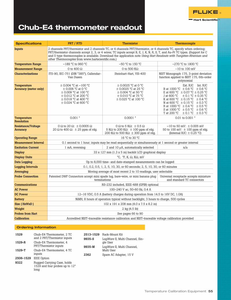
Temperature Calibration Equipment 55
Chub-E4 thermometer readout
Specifications PRT / RTD Thermistor Thermocouple
Inputs 2 channels PRT/thermistor and 2 channels TC, or 4 channels PRT/thermistor, or 4 channels TC, specify when ordering;PRT/thermistor channels accept 2, 3, or 4 wires; TC inputs accept B, E, J, K, N, R, S, T, and Au-Pt TC types. (Support for Cand U type thermocouples is available. Download the application note Using Hart Readouts with Tungsten-Rhenium andother Thermocouples from www.hartscientific.com.)
Temperature Range –189 °C to 960 °C –50 °C to 150 °C –270 °C to 1800 °C
Measurement Range 0 to 400 Ω 0 to 500 KΩ –10 to 100 mV
Characterizations ITS-90, IEC-751 (DIN “385”), Callendar-Van Dusen
Steinhart-Hart, YSI-400 NIST Monograph 175, 3-point deviationfunction applied to NIST 175, 6th-order
polynomial
TemperatureAccuracy (meter only)
± 0.004 °C at –100 °C± 0.006 °C at 0 °C
± 0.009 °C at 100 °C± 0.012 °C at 200 °C± 0.018 °C at 400 °C± 0.024 °C at 600 °C
± 0.0025 °C at 0 °C± 0.0025 °C at 25 °C± 0.004 °C at 50 °C± 0.010 °C at 75 °C± 0.025 °C at 100 °C
Ext. RJC Int. RJCB at 1000 °C ± 0.6 °C ± 0.6 °CE at 600 °C ± 0.07 °C ± 0.25 °CJ at 600 °C ± 0.1 °C ± 0.35 °CK at 600 °C ± 0.15 °C ± 0.4 °CN at 600 °C ± 0.15 °C ± 0.3 °CR at 1000 °C ± 0.4 °C ± 0.5 °CS at 1000 °C ± 0.5 °C ± 0.6 °CT at 200 °C ± 0.1 °C ± 0.3 °C
TemperatureResolution
0.001 ° 0.0001 ° 0.01 to 0.001 °
Resistance/VoltageAccuracy
0 Ω to 20 Ω: ± 0.0005 Ω20 Ω to 400 Ω: ± 25 ppm of rdg.
0 Ω to 5 KΩ: ± 0.5 Ω5 KΩ to 200 KΩ: ± 100 ppm of rdg.
200 KΩ to 500 KΩ ± 300 ppm of rdg.
–10 to 50 mV: ± 0.005 mV50 to 100 mV: ± 100 ppm of rdg.
(Internal RJC: ± 0.25 °C)
Operating Range 16 °C to 30 °C
Measurement Interval 0.1 second to 1 hour; inputs may be read sequentially or simultaneously at 1 second or greater interval
Excitation Current 1 mA, reversing 2 and 10 μA, automatically selected n/a
Display 33 x 127 mm (1.3 x 5 in) backlit LCD graphical display
Display Units °C, °F, K, Ω, KΩ, mV
Data Logging Up to 8,000 time- and date-stamped measurements can be logged
Logging Intervals 0.1, 0.2, 0.5, 1, 2, 5, 10, 30, or 60 seconds; 2, 5, 10, 30, or 60 minutes
Averaging Moving average of most recent 2 to 10 readings, user selectable
Probe Connection Patented DWF Connectors accept mini spade lug, bare-wire, or mini banana plugterminations
Universal receptacle accepts miniatureand standard TC connectors
Communications RS-232 included, IEEE-488 (GPIB) optional
AC Power 100–240 V ac, 50-60 Hz, 0.4 A
DC Power 12–16 VDC, 0.5 A (battery charges during operation from 14.5 to 16V DC, 1.0A)
Battery NiMH, 8 hours of operation typical without backlight, 3 hours to charge, 500 cycles
Size ( HxWxD ) 102 x 191 x 208 mm (4.0 x 7.5 x 8.2 in)
Weight 2 kg (4.5 lb)
Probes from Hart See pages 66 to 90
Calibration Accredited NIST-traceable resistance calibration and NIST-traceable voltage calibration provided
Ordering Information
1529 Chub-E4 Thermometer, 2 TCand 2 PRT/Thermistor inputs
1529-R Chub-E4 Thermometer, 4PRT/Thermistor inputs
1529-T Chub-E4 Thermometer, 4 TCinputs
2506-1529 IEEE Option9322 Rugged Carrying Case, holds
1529 and four probes up to 12”long
2513-1529 Rack-Mount Kit9935-S LogWare II, Multi Channel, Sin-
gle User9935-M LogWare II, Multi Channel,
Multi User2362 Spare AC Adapter, 15 V

One of Hart’s best-selling products is theTweener thermometer, and there’s a rea-son. No other company, not one, has athermometer that comes close to the per-formance and features of the Tweener foranywhere near its price.
1502A Tweener PRT ReadoutThe 1502A Tweener features accuracy upto ± 0.006 °C (the 1504 is even more ac-curate, up to ± 0.002 °C). In addition, itreads 100-ohm, 25-ohm, and 10-ohmprobes, has a resolution of 0.001 °C acrossits entire range, and is the smallest unit inits class. It also has an optional batterypack for completely portable operation.
Each Tweener is programmable tomatch a probe’s constants for maximumlinearity and accuracy. All probe constantsand coefficients are programmed throughsimple, front-panel keystrokes. Tempera-ture is displayed in °C, °F, K, or resistancein ohms.
The 1502A accurately measures the re-sistance of the probe and then convertsthe resistance to a temperature value us-ing its built-in algorithms.
For convenience, the 1502A reads thecommon industrial grade IEC-751 or “385”ALPHA RTD without any programming.Enter the actual R0 and ALPHA of the indi-vidual probe for increased accuracy. Formaximum accuracy, use the ITS-90 formu-las. The Tweener accepts the subranges 4and 6 through 11.
ITS-90 formulas reside in theTweener’s firmware. If your probe hasbeen calibrated for any of the abovesubranges of the ITS-90, you simply enterthe coefficients directly into your Tweener.
Each thermometer comes completewith an RS-232 interface for automationof temperature data collection, calibra-tions, or process control functions. AnIEEE-488 interface is available as anoption.
The 1502A is calibrated digitally usingthe front-panel buttons. You never have toopen the box to calibrate it. This calibra-tion protocol further reduces the cost ofthe 1502A. It goes where you go andworks the way you want it to.
1504 Tweener Thermistor ReadoutIf you need more accuracy in a limitedtemperature range, the Model 1504Tweener gives it to you as a thermistorreadout. Thermistors are less fragile thanPRTs and less likely to be impacted bymechanical shock. Thermistors are moresensitive to temperature, have faster re-sponse times, and come in many shapesfor different applications.
Typical accuracy of a 1504 is± 0.002 °C with a resolution of 0.0001 °C.
SoftwareWith our 9934 LogWare, both Tweenermodels may be used for real-time data ac-quisition. Collect data and analyze it
graphically or statistically. Additionally,Tweeners may be used as referencethermometers with our MET/TEMP IIsoftware. (See our software sectionstarting on page 96.)
Battery optionIf you need to take your work on the road,order Model 9320A battery pack and get 36hours between charges.
Calibration choicesEach Tweener and its accompanyingprobe (sold separately) have their own in-dividual calibration reports. Overall systemerror can be calculated from the individualerrors, rendering the added cost of systemdata unnecessary. However, for those re-quiring it, system data is available at twoor more temperatures of your choice. (Seecalibration options on page 186.)
56 Thermometry
● Two Tweeners to choose from—reading PRTs or thermistors
● Battery packs available
● Best price/performance package
The thermistor version of the “Tweener” gives youmore variety in sensor configurations and evenhigher accuracy over a limited temperature range.
33
Tweener thermometerreadouts

Temperature Calibration Equipment 57
Specifications 1502A 1504
Temperature Range † –200 °C to 962 °C (–328 °F to 1764 °F) Any thermistor range
Resistance Range 0 Ω to 400 Ω, auto-ranging 0 Ω to 1 MΩ, auto-ranging
Probe Nominal RTPW: 10 Ω to 100 ΩRTD, PRT, or SPRT
Thermistors
Characterizations ITS-90 subranges 4, 6, 7, 8, 9, 10, and 11IPTS-68: R0, α, δ, a4, and c4
Callendar-Van Dusen: R0, α, δ, and β
Steinhart-Hart thermistor polynomialCallendar-Van Dusen: R0, α, δ, and β
Resistance Accuracy(ppm of reading) (1 yr)
0 Ω to 20 Ω: 0.0005 Ω20 Ω to 400 Ω: 25 ppm
0 Ω to 5 KΩ: 0.5 Ω5 KΩ to 200 KΩ: 100 ppm200 KΩ to 1 MΩ: 300 ppm
Temperature Accuracy † ± 0.004 °C at –100 °C± 0.006 °C at 0 °C
± 0.009 °C at 100 °C± 0.012 °C at 200 °C± 0.018 °C at 400 °C± 0.024 °C at 600 °C
± 0.002 °C at 0 °C± 0.002 °C at 25 °C± 0.004 °C at 50 °C± 0.010 °C at 75 °C± 0.020 °C at 100 °C
(Using 10 KΩ thermistor sensor, α=0.04.Does not include probe uncertainty or characterization
errors.)
Operating TemperatureRange—Full Accuracy
16 °C to 30 °C 13 °C to 33 °C
Resistance Resolution 0 Ω to 20 Ω: 0.0001 Ω20 Ω to 400 Ω: 0.001 Ω
0 Ω to 10 KΩ: 0.01 Ω10 KΩ to 100 KΩ: 0.1 Ω
100 KΩ to 1 MΩ: 1 Ω
Temperature Resolution 0.001 °C 0.0001 °C
Excitation Current 0.5 and 1 mA, user selectable, 2 Hz 2 and 10 μA, automatically selected
Measurement Period 1 second
Digital Filter Exponential, 0 to 60 seconds time constant (user selectable)
Probe Connection 4-wire with shield, 5-pin DIN connector
Communications RS-232 serial standardIEEE-488 (GPIB) optional
Display 8-digit, 7-segment, yellow-green LED; 0.5-inch-high characters
Power 115 V ac (± 10 %), 50/60 Hz, 1 A, max230 V ac (± 10 %), 50/60 Hz, 1 A, nominal, specify
Size ( HxWxD ) 61 x 143 x 181mm (2.4 x 5.6 x 7.1 in)
Weight 1.0 kg (2.2 lb)
Calibration Accredited NIST-traceable calibration provided
Probes from Hart See pages 68 to 80 See pages 82 to 85†Temperature ranges and accuracy may be limited by the sensor you use.
Tweener thermometerreadouts
Ordering Information
1502A Tweener PRT Readout1504 Tweener Thermistor Readout2505 Spare Connector2506 IEEE Option2508 Serial Cable Kit9934-S LogWare, Single Channel, Single
User9934-M LogWare, Single Channel, Multi
User9320A External Battery Pack, 115 V ac9301 Carrying Case, fits Tweener and
12 in probe
1935 System Cal Report, Thermistors(see pages 186 to 189)
1930 System Cal Report, PRT(see pages 186 to 189)
See pages 66 to 90 for a selection of probesto use with Tweeners and other Hartreadouts.

Finally, a reference thermometer asversatile as you areThe new 1523/24 Reference Thermome-ters from Fluke’s Hart Scientific divisionmeasure, graph, and record PRTs,thermocouples, and thermistors. Thesenew thermometer readouts deliver highaccuracy, wide measurement range, log-ging, and trending, all in a handheld toolyou can take anywhere.
The 1523/24 lets you handle field ap-plications, laboratory measurements, anddata logging with ease. And with the dualchannel measurement capabilities of themodel 1524, you can do twice the work inhalf the time.
Make accurate, consistentmeasurement...anywhereYou need accuracy for compliance, productyields, energy savings, and consistent re-sults. The 1523/24 uses current reversal, atechnique used in high-end instrumentsthat eliminates thermal EMFs, for precisiontemperature measurements. Specificationsare guaranteed from –10 °C to 60 °C am-bient. Special precision resistors and ahighly stable reference voltage sourcekeep 1523/24 accuracy virtually insensi-tive to environmental temperature.
Like all Fluke handheld tools, the1523/24 Reference Thermometers endurerigorous testing in temperature extremesand under harsh conditions of vibration,so you can take it with confidence
anywhere you need to go. An optionalmagnetic hanger allows you to hang thethermometer for easy viewing while free-ing your hands to focus on the job.
Monitor trends in the lab or in thefieldSee trends graphically on the 1523/24thermometer’s 128x64-backlit LCD dis-play. You can change the graph’s resolu-tion at the touch of a button. Now it iseasy to see when the temperature is sta-ble (without statistics or long delays) or tomonitor processes over time to verify cor-rect operation.
Hold readings on the display at thetouch of a button, or document up to 25readings and associated statistics for easyretrieval. Statistics include the averagemaximum and minimum values, and thestandard deviation. View them throughthe display or by uploading it to a PC viaRS-232 connection and 9940 I/O Toolkitsoftware, included free. To monitor andlog more data over time, use a PC andoptional LogWare II software.
RS-232-to-USB adapters are availablefor those who prefer USB connectors. Bat-tery power lasts at least 20 hours on threeAA batteries, or use the dc power adapterfor extended periods of measurement.Power saving features can be enabled ordisabled for longer battery life or greaterconvenience.
INFO-CON connectors ensurecorrect temperature conversionInside the INFO-CON, a memory chipkeeps calibration information for the at-tached probe. Simply plugging in the
58 Thermometry
Measure, graph and record threesensor types with one tool
High accuracy● PRTs: up to ± 0.011 °C
● Thermocouples: up to± 0.24 °C
● Precision thermistors:± 0.002 °C
Two models● 1523: Single channel
standard model withmemory for 25 readings
● 1524: Two channels:memory for logging 15,000measurements; real-timeclock for time and datestamps
Handheld thermometerreadouts
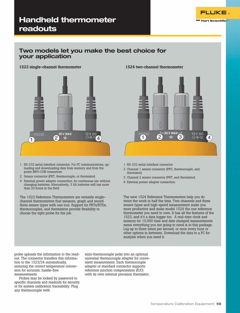
probe uploads the information to the read-out. The connector transfers this informa-tion to the 1523/24 automatically,ensuring the correct temperature conver-sion for accurate, hassle-freemeasurements.
Probes may be locked by password tospecific channels and readouts for securityor for system calibration traceability. Plugany thermocouple with
mini-thermocouple jacks into an optionaluniversal thermocouple adapter for conve-nient measurement. Each thermocoupleadapter or standard connector supportsreference junction compensation (RJC)with its own internal precision thermistor.
Temperature Calibration Equipment 59
Handheld thermometerreadouts
Two models let you make the best choice foryour application
1523 single-channel thermometer 1524 two-channel thermometer
1 RS-232 serial interface connector. For PC communications, up-loading and downloading data from memory and from theprobe INFO-CON connectors.
2 Sensor connector (PRT, thermocouple, or thermistor)4 External power adapter connection, for continuous use without
changing batteries. Alternatively, 3 AA batteries will last morethan 20 hours in the field.
The 1523 Reference Thermometers are versatile single-channel thermometers that measure, graph and recordthree sensor types with one tool. Support for PRTs/RTDs,thermocouples, and thermistors provide flexibility tochoose the right probe for the job.
1 RS-232 serial interface connector2 Channel 1 sensor connector (PRT, thermocouple, and
thermistor)3 Channel 2 sensor connector (PRT, and thermistor)4 External power adapter connection
The new 1524 Reference Thermometers help you dotwice the work in half the time. Two channels and threesensor types and high-speed measurement make youmore productive and make model 1524 the one referencethermometer you need to own. It has all the features of the1523, and it’s a data logger too. A real-time clock andmemory for 15,000 time and date stamped measurementsmean everything you are going to need is in this package.Log up to three times per second, or once every hour orother options in between. Download the data to a PC foranalysis when you need it.

60 Thermometry
Handheld thermometerreadouts
Specifications 1523 1524
Input channels 1 2Resolution PRTs and thermistors: 0.001 °
thermocouples: 0.01 °Logging 25 readings with statistics 25 readings with
statistics15,000 timeand date stamped
Sample interval (normal) 1 second 1 second(simultaneousmeasurement)
Typical sample interval (fast mode)* 0.3 secondsSensor types PRTs, RTDs, thermistors, and thermocouplesThermocouple types C, E, J, K, L, M, N, T, U, B, R, SStatistics Maximum, minimum, average, standard deviationTrending Scale: ± 10 °C (18 °F), ± 1 °C (1.8 °F), ± 0.1°C (0.18 °F),
± 0.01°C (0.018 °F), 10 minutes of real-time dataPower requirements 3 AA alkaline batteries, 12 V dc universal power supplyBattery life 20 hrSize ( HxWxD ) 96 mm x 200 mm x 47 mm (3.75 in x 7.9 in x 1.86 in)Weight 0.65 kg (1.4 lb)Computer interface RS-232, 9940 I/O ToolKit software includedSafety EN61010-1:2001, CAN/CSA C22.2 No. 61010.1-04Environmental conditions for best accuracy: 13 °C to 33 °C (55.4 °F to 91.4 °F)Millivolt range and accuracy –10 mV to 75 mV, ± (0.005 % + 5 µV)Internal reference junctioncompensation
± 0.2 °C (± 0.36 °F)
Resistance range and accuracy 0 Ω to 400 Ω ± (0.004 % + 0.002 Ω)200 Ω to 50 kΩ ± (0.01 % + 0.5 Ω)
50 kΩ to 500 kΩ ± (0.03 %)Temperature coefficient, voltage:–10 °C to 13 °C , +33 °C to 60 °C(14 °F to 55.4 °F, 91.4 °F to 140 °F)
± (0.001 %/°C + 1 mV/°C)
Temperature coefficient, resistance:–10 °C to 13 °C , +33 °C to 60 °C(14 °F to 55.4 °F, 91.4 °F to 140 °F)
0.0008 %/°C + 0.0004 Ω (0 Ω to 400 Ω)0.002 %/°C + 0.1 Ω (0 Ω to 50 kΩ)
0.06 %/°C + 0.1 Ω (50 kΩ to 500 kΩ)Excitation current, resistance 1 mA (0 Ω to 400 Ω)
10 µA (0 Ω to 50 kΩ)2 µA (50 kΩ to 500 kΩ)
*See technical manual for sample interval details by sensor type and number of inputs.
Equivalent temperature accuracies for se-lected sensors derived from primary speci-fications (Ω, mV)
Temperature, thermocouples
Type RangeMeasure
accuraciesJ –200 °C to 0 °C
(–328 °F to 32 °F)0.52 °C(0.94 °F)
0 °C to 1200 °C(32 °F to 2192 °F)
0.23 °C(0.41 °F)
T –200 °C to 0 °C(–328 °F to 32 °F)
0.60 °C(1.08 °F)
0 °C to 400 °C(32 °F to 752 °F)
0.25 °C(0.45 °F)
K –200 °C to 0 °C(-328 °F to 32 °F)
± 0.61 °C(± 1.10 °F)
0 °C to 1370 °C(32 °F to 2498 °F)
± 0.24 °C(± 0.43 °F)
R –20 °C to 0 °C(4 °F to 32 °F)
± 1.09 °C(± 1.96 °F)
0 °C to 500 °C(32 °F to 932 °F)
± 0.97 °C(± 1.71 °F)
500 °C to 1750 °C(932 °F to 3182 °F)
± 0.49 °C(± 0.88 °F)
S –20 °C to 0 °C(4 °F to 32 °F)
± 1.05 °C(± 1.89 °F)
0 °C to 500 °C(32 °F to 932 °F)
± 0.95 °C(± 1.71°F)
500 °C to 1750 °C(932 °F to 3182 °F)
± 0.56 °C(± 1.01 °F)
Accuracies are based on internal referencejunction compensation. Refer to technicalmanual for greatly improved accuracies usingexternal reference junctions.
Temperature, RTD Ranges, and Accuracies(ITS-90)
Accuracy ± °C± 0.011 at –100 °C
± 0.015 at 0 °C± 0.019 at 100 °C± 0.023 at 200 °C± 0.031 at 400 °C± 0.039 at 600 °C
Resolution: 0.001°C (0.001°F)
Temperature, ThermistorAccuracy ± °C± 0.002 at 0 °C± 0.003 at 25 °C± 0.006 at 50 °C± 0.014 at 75 °C± 0.030 at 100 °C
Resolution: 0.001 °C (0.001 °F)Based on a 10 kΩ (at 25 °C) thermister with abeta value of 4000 Ω. See technical manual
for details.
Accuracies of selected readout/probe combinations (± °C)Temperature 5616-12 5615-6 5627A-12 5610-9
–200 °C (-328 °F) 0.014 0.025 0.027 n/a0 °C (32 °F) 0.021 0.021 0.049 0.009
100 °C (212 °F) 0.027 0.028 0.065 0.03300 °C (572 °F) 0.040 0.043 0.103 n/a420 °C (788 °F) 0.050 n/a 0.130 n/a
Includes readout accuracy, probe calibration, and probe drift

Temperature Calibration Equipment 61
Handheld thermometerreadouts
Ordering Information
1523† Reference Thermometer, Handheld, 1 Channel1524† Reference Thermometer, Handheld, 2 Channel, Data Logger1523-P1 1523 Bundled with 5616 PRT [–200 °C to 420 °C (-328 °F to 788 °F), NIST
Traceable Calibration, 100 ohm, 6.35 mm x 305 mm (1/4 in x 12 in)], UniversalTC INFO-CON Connector, TPAK, and Case
1523-P2 1523 Bundled with 5628 PRT [–200 °C to 660 °C (-328 °F to 1220 °F), Accred-ited Calibration, 25 ohm, 6.35 mm x 305 mm (1/4 in x 12 in)], Universal TCINFO-CON Connector, TPAK, and Case
1523-P3 1523 Bundled with 5627A PRT [–200 °C to 420 °C (-328 °F to 788 °F), Accred-ited Calibration, 100 ohm, 6.35 mm x 305 mm (1/4 in x 12 in)], Universal TCINFO-CON Connector, TPAK, and Case
1524-P1 1524 Bundled with 5616 PRT, Universal TC INFO-CON Connector, TPAK, andCase
1524-P2 1524 Bundled with 5628 PRT, Universal TC INFO-CON Connector, TPAK, andCase
1524-P3 1524 Bundled with 5627A PRT, Universal TC INFO-CON Connector, TPAK, andCase
†Requires an optional probeCalibration options1523-CAL 1523 Accredited Calibration1524-CAL 1524 Accredited Calibration1929-2 System Verification, PRT with Readout, Accredited1929-5 System Verification, Thermistor with Readout, Accredited1930 System Calibration, PRT with Readout, Accredited1935 System Calibration, Thermistor with Readout, Accredited1925-A Accredited Thermistor Calibration, 0 °C to 100 °C (23 °F to 212 °F)
Included accessoriesNIST traceable certificate of calibration, users guide, CD-ROM (contains technical manual), 12 V dcuniversal power supply, RS-232 cable, 9940 I/O Toolkit softwareOptional accessories5610-9-P Probe, Precision Thermistor, Stainless Steel, 3.18 mm x 228.6 mm (1/8 in x
9 in), 0 °C to 100 °C (32 °F to 212 °F), NIST traceable calibration5615-6-P Probe, PRT, 100 ohm, 4.76 mm x 152.4 mm (3/16 in x 6 in), –200 °C to 300 °C
(-328 °F to 572 °F), Accredited Calibration5609-9BND-P Probe, PRT, 100 ohm, 6.35 mm x 381 mm (1/4 in x 15 in), 90° bend at 9 in,
–200 °C to 660 °C (–328 °F to 1220 °F), Requires Calibration (i.e. 1924-4-7)FLK80P1 80PK-1, Probe, Thermocouple, Beaded Type KFLK80P3 80PK-3A, Probe, Thermocouple, Surface Measurement Type K9935-S Software, LogWare II, Single User1523-CASE Case, 1523/1524 Readout and Probe CarryingFLUKETPAK TPAK, Meter Hanging Kit2373-LPRT Adapter, INFO-CON (152X) to Mini Grabbers (4-wire)2373-LTC Adapter, INFO-CON (152X) to Universal TC (TC)2384-P INFO-CON (152X) Connector, PRT (Gray Cap), Spare2384-T INFO-CON (152X) Connector, TC (Blue Cap), Spare
Recommended Accessories
A wide array of accessories is available to helpyou maximize productivity, but the followingare essential for most users.
CalibratedTemperatureSessors
TPAKMagneticHanger
Probe andReadout Case
UniversalThermocoupleAdapter
Universal RTDAdapter

At last, now there’s a meter designed spe-cifically for the measurement challengesfaced by metrologists. The Fluke 8508AReference Multimeter is simply the bestyou can buy. Not only does it provide theperformance required for complex mea-surement tasks, it is also extremely easy touse. Moreover, it is specified in a way thatlets you really understand the uncertain-ties of the measurements you make.
Accuracy and stabilityThe Fluke 8508A features 8.5 digit resolu-tion, exceptional linearity, and extremelylow noise and stability, producing superioraccuracy specifications as low as 3 ppmover one year. But measurements need tobe repeatable, and the 8508A deliversthat as well, with 24-hour stability as lowas 0.5 ppm and a 20-minute stability of0.16 ppm. This stability is maintained overa wide operating temperature range andachieved without requiring routine auto-cal or self-calibration, which can compro-mise measurement traceability and his-tory. What’s more, Fluke publishes adetailed 8508A Extended SpecificationsBrochure on www.fluke.com that specifiesin absolute and relative terms, allowingyou to replace Fluke’s calibration uncer-tainty with those that represent traceabil-ity available locally.
Functional and versatileThe Fluke 8508A lets you handle a widerange of applications and achieve yourmeasurement requirements with a singleinstrument. In addition to AC and DC volt-age, AC and DC current, resistance andfrequency, the 8508A also includes a hostof other features designed to increase therange of measurements you can make.True Ohms measurement using current re-versal techniques improves the accuracyof your resistance measurements. The PRTtemperature readout extends the 8508A’sfunctionality into precision temperaturemetrology. The Lo Current Ohms featurereduces measurement errors due to self-heating within the device being mea-sured. A dual input channel ratio feature,under GPIB control, enables the 8508A tobe used as a simple, fast, automatedtransfer standard. High current measure-ment (up to 20 A) extends the operationalrange to address your multi-product cali-brator workload. Up to 200 V complianceon resistance ranges gives you greaterscope to measure high resistances withgreater accuracy.
Easy to useA clear control structure with DualParamatrix™ LCD displays and context-sensitive menus provides an intuitive in-terface that makes the 8508A easy to use.
The menu structures have been designedespecially for metrology applications, soyou can focus on getting the best possiblemeasurements without needing to workthrough complex sequential or multi-in-strument setups, or having to repeatedlyreference supporting documentation.
Specifications
DC Voltage 0 to ± 1050 V1 Year Spec: ± 3 ppm of rdg†
AC Voltage 2 mV to 1050 V, 1 Hz to 1 MHz1 Year Spec: ± 65 ppm of rdg†
DC Current 0 to ± 20 A1 Year Spec: ± 12 ppm of rdg†
AC Current 2 μA to 20 A, 1 Hz to 100 kHz1 Year Spec: ± 200 ppm of rdg†
Resistance 0 to 20 GΩ, ± 7.5 ppm of rdg
Power Voltage: 90–130 V or180–260 VFrequency: 47–63 HzConsumption: 37 VA
Weight 11.5 kg 25.5 lb()
Size(HxWxD )
88 x 427 x 487 mm(3.5 x 16.8 x 19.2 in)
†Best guaranteed specification within mea-surement category.
Ordering Information
8508A Reference Multimeter8508A/01 Reference Multimeter with
Front and Rear 4 mm bindingposts and rear input ratiomeasurement
8508ALEAD Lead kit including two pairs of1 m six-wire PtFe cable termi-nated with gold flashed spacesconnectors and 4 mm plugs
5626-15-S Secondary PRT5699-S Extended Range PRTY8508 Rack-Mount KitY8508S Rack-Mount Slide Kit
62 Thermometry
● True Ohms measurement
● 20 amp current measurement
● Stores up to 100 PRT coefficients
Reference multimeter

Two years ago the 1620 DewK revolution-ized environmental monitoring for calibra-tion labs, but it just got better. Wait untilyou hear about the 1620A!
Now you can easily monitor and recordconditions throughout your entire facilitywith the DewK’s new Ethernet and wire-less connections, and set your upgradedLogWare III software to notify you imme-diately of changing conditions.
You’ll still have the superior conve-nience, dependability, and NIST-traceableaccuracy of a 1620, but your 1620A willgive you the added accessibility andpeace of mind you’ve been looking for.
AccuracyTwo types of sensors are available fromHart, and the DewK may be originally pur-chased with either one. The high-accu-racy sensor (“H” model) reads temperatureto ± 0.125 °C over a calibrated range of16 °C to 24 °C. Relative humidity readingsare to ± 1.5 % RH from 20 % RH to70 % RH.
The standard-accuracy sensor (“S”model) reads temperature to ± 0.25 °Cover its calibrated range of 15 °C to 35 °C.Relative humidity readings are to± 2 % RH from 20 % RH to 70 % RH.
All DewK sensors come with NVLAP ac-credited certificates of calibration for bothtemperature and humidity, complete withdata and NIST traceability. Hart providesexceptional uncertainties, including totaltest uncertainty ratios better than 3:1 forboth temperature and relative humidity—even for the high-accuracy sensors!
Both sensors can also measure temper-ature below their respective calibratedranges to 0 °C and above their respectivecalibrated ranges to 50 °C with typical ac-curacy of ± 0.5 °C. And RH readings from0 % RH to 20 % RH and from 70 % RH to100 % RH are typically within ± 3 % RH.
Ethernet and wireless capabilityThe DewK gives you all the communica-tions options you expect, and then some.With its built-in Ethernet RJ45 jack,
multiple DewKs can be monitored fromthe same screen using our new LogWareIII client-server software. Ethernet alsogives you the possibility for remote con-nectivity over the internet, so you canmonitor critical conditions while you’reaway.
Cables running along the floor can be asafety hazard, and cables hanging fromthe ceiling and walls are an eyesore. Withthe DewK, your wireless dreams will cometrue when you connect your computerthrough an RF modem up to 100 ft away,without the clutter of all the extra cables!
Finally, if you need a printout, senddata to a printer through the RS-232 in-terface in real time.
Math and statistical functionsIn addition to temperature and humidity,the DewK calculates dew point, heat in-dex, and rates of change for both temper-ature and humidity, without the need tobuy additional software. Min, max, and avariety of other statistics are also calcu-lated and can be shown on-screen. Dailysummary statistics, including min, max,and maximum rates of change are storedfor the most recent sixty days.
Calibrated sensorsWith the DewK you get two for the price ofone. Having inputs for two sensors, eachmeasuring both temperature and relativehumidity, one DewK can monitor two loca-tions at the same time. Both sensors can berun via extension cables to remote locationsup to 100 feet away, or one sensor can bedirectly mounted to the top of the DewK.
Each sensor is calibrated for both tem-perature and humidity at Fluke’s Hart Scien-tific Division. The calibration constantsassigned to the sensors reside in a memorychip located inside the sensor housing, sosensors may be used interchangeably be-tween different DewKs, and therecalibration of sensors doesn’t require anaccompanying DewK.
Sensors may also be assigned a uniqueidentifier (up to 16 characters) to facilitaterecord keeping by matching the sensoridentifier with the collected data. EachDewK ships with one sensor, with addi-tional sensors available from Hart. Sparesensors may also be purchased as a kit,which includes a case for the sensor, a wallmounting bracket, and a 25-foot extensioncable.
MemoryThe DewK has enough on-board memoryto store up to 400,000 date- and time-stamped data points. That’s two years’
Temperature Calibration Equipment 63
● Superior accuracy● Network enabled● Powerful logging and analysis tools● Two interchangeable calibrated sensors● Huge memory● Upgraded software
The DewK thermo-hygrometer

worth of data for both measurements fromtwo sensors if readings are taken everyten minutes!
Alarms and battery backupAlarm settings can be set up quickly in theDewK based on temperature, the rate ofchange in temperature, RH, the rate ofchange in RH, and instrument fault condi-tions. Alarms can be both visual (flashingdisplay) and audible (beeping). Likewise,alarm settings can be set up and eventstriggered in LogWare III. The DewK is alsoequipped with a 0 to 12 volt alarm outputthat can trigger a process control system.
A backup battery shuts down theDewK’s display but maintains measure-ments for up to 16 hours in the event of apower failure.
One very cool displayWant to view data from across the room?Want to view data from two temperatureand two humidity inputs simultaneously?Want to view data graphically, statisti-cally, or both? At the same time?! TheDewK does everything you could want—orat least everything we could think of. Upto sixteen different display setups can bestored and recalled at the touch of a singlebutton. And all 16 can be easily modified,so you get exactly what you want.
ConfidenceFluke’s Hart Scientific Division supplies theworld’s finest measurement laboratorieswith world-class temperature standards.We not only measure temperature and hu-midity better than anybody, we maketemperature measurements functional andproductive.
Don’t compromise on your lab stan-dards. Measure with confidence. Partnerwith Hart Scientific.
64 Thermometry
The DewK thermo-hygrometer
LogWare IIIIf you really want to get the most out of your DewK, LogWare III is an investment worth ev-ery penny. As client-server or stand-alone software, it remotely monitors and logs an un-limited number of concurrent log sessions into a single database. That means data frommany DewKs can be managed in real time via Ethernet, RS-232, or wireless connections.
LogWare III allows you to customize your graph trace color, alarms, and statistics as yougo. You can start/stop log sessions and modify sample intervals from your computer.LogWare III supports “hot-swapping,” which allows you to remove and replace sensorswithout shutting down the log session. LogWare III also supports security features such aspasswords for individual users or groups/teams, a built-in administrator account, pre-de-fined user groups, and customizable permissions.
Never again be the last to know about a problem. Customizable e-mail settings allowyou to send e-mails to designated recipients, including cell phones and PDA’s, when a logsession begins, ends, or is aborted; when the DewK’s battery is low; when a sensor cali-bration is due; or when a temperature/humidity alarm is exceeded.
If you cannot be reached via email, you can always arrange to be paged instead. Datastored on the DewK can be imported into the software, which is a handy feature whenpower outages disable the network.
Are you ready for a deep dive into your data? Historical data can be viewed by sensor(model/serial number) location, or log session anddisplayed in a spreadsheet-style grid. Logged datacan also be exported to HTML, RTF or ASCII text foruse in your analytical software, or simply print his-torical data and graphs.
Customizable graphs in LogWare III with zoom-ing capability are an easy way to analyze your datahistory, and data points that need to be explainedcan be highlighted, annotated, and referred to later.LogWare III statistics include min, max, spread, av-erage, and standard deviation functions, andprinted reports keep track of the number of temper-ature and humidity measurements that were foundto be out of tolerance.
For previously stored data, LogWare allows on-screen viewing of raw data. It also exports dataeasily to file formats that can be viewed in Excel orother common spreadsheet and database programs.It’s hard to say which is more versatile: the DewKor LogWare III. This could well be the amazingestcombination we’ve ever produced!
The DewK lets you view data just about any way you like it. Both graphical data and statistical data can beshown for temperature and humidity from one or two inputs. Modifying any of the standard screens is easilydone, so you see exactly what you want—no more, no less.

Temperature Calibration Equipment 65
The DewK thermo-hygrometer
Specifications
Operating Range 0 °C to 50 °C (32 °F to 122 °F); 0 % RH to 100 % RH
Calibrated TemperatureAccuracy (“H” Model)
± 0.125 °C from 16 °C to 24 °C(± 0.225 °F from 60.8 °F to 75.2 °F)
Calibrated temperatureAccuracy (“S” Model)
± 0.25 °C from 15 °C to 35 °C(± 0.45 °F from 59 °F to 95 °F)
Calibrated RH Accuracy(“H” Model)
± 1.5 % RH from 20 % RH to 70 % RH
Calibrated RH Accuracy(“S” Model)
± 2 % RH from 20 % RH to 70 % RH
Expected ExtrapolatedPerformance (Uncertified)
± 0.5 °C (± 0.9 °F) outside calibrated range± 3 % RH outside calibrated range
Delta TemperatureAccuracy
± 0.025 °C for ± 1 ° changes within 15 °C to 35 °C(± 0.045 °F for ± 1 ° changes within 59 °F to 95 °F)
Temperature Resolution User selectable up to 0.001 °C/°F on front-panel display (0.01°recorded)
Delta Humidity Accuracy ± 1.0 % RH for ± 5 % changes within 20 % RH to 70 % RH
RH Resolution User selectable up to 0.01 % on front-panel display (0.1 %recorded)
Inputs Up to two sensors, measure temperature and relative humidity, de-tachable, cable-extendable, interchangeable, self-contained cali-brations, may be assigned unique 16-character identifications
Display 240 x 128 graphics monochrome LCD, displays password-protectedtemperature/humidity data graphically, numerically, and statisti-cally (one or both channels); 16 pre-defined, user-changeablescreen setups
Memory 400,000 typical individual date/time-stamped readings
Alarms Password-protected visual, audible, and external alarms for tem-perature, temperature rate, RH, RH rate, and fault conditions
Alarm Port Output 2.5 mm two-conductor subminiature plug, 0 V normal,11 to 12 V active, sources up to 20 mA
Connectivity Ethernet, RS-232, RF (optional)
Ethernet RJ45 jack, 10 Base-T or 100 Base-TX; static or dynamic (DHCP cli-ent) IP address assignment
Web Page Embedded web page interface features: instrument identification,measurements, password-protected terminal page; can be disabled
Wireless Option Requires wireless modem. 802.15.4 (underlies Zigbee), 2.4 GHz fre-quency, 1 mW transmit power, 30 m (100 ft) typical unobstructedrange; can be disabled
Mounting Wall mounted (hardware included) or set on a bench top
Power 12 V dc from external 100 to 240 V dc power supply
Battery Backup Standard 9 V battery enables continued measuring during powerdisruptions
Size (DewK) ( HxWxD ) 125 mm x 211 mm x 51 mm (4.9 x 8.3 x 2.0 in)
Size (Sensors) ( LxDia ) 79 mm x 19 mm (3.1 x 0.75 in)
Weight 0.7 kg (1.5 lb)
Calibration Certificate of NIST-traceable NVLAP accredited temperature and hu-midity calibration included; As Found and As Left data supplied atthree temperature points and three humidity points each at 20 °C(68 °F); Complies with NCSL/ISO/IEC 17025:2000 and ANSI/NCSLZ540-1-1994
LogWare III(Optional Software)
Requirements include: Microsoft® Windows® 2000 (SP4) or XP(SP2) operating system, IBM compatible Intel Pentium® IV 1 GHz PCprocessor or better, 512 Mb RAM (1Gb or more recommended), 200Mb HDD space for installation (additional free space recommendedfor data storage), CD-ROM drive for installation
Ordering Information
1622A-H The “DewK” Thermo-Hygrome-ter, USB Wireless High-AccuracyValue Kit (includes 1621A-HValue Kit, 2633-RF, and 2633-USB)
1621A-H The “DewK” Thermo-Hygrome-ter, High-Accuracy Value Kit (in-cludes 1620A-H and 2627-Hbelow, and 9936A LogWare IIIsingle-PC license)
1620A-H The “DewK” Thermo-Hygrome-ter, High-Accuracy (includes onehigh-accuracy sensor, wallmount bracket, and RS-232cable)
1622A-S The “DewK” Thermo-Hygrome-ter, USB Wireless Standard-Ac-curacy Value Kit (includes1621A-S Value Kit, 2633-RF,and 2633-USB)
1621A-S The “DewK” Thermo-Hygrome-ter, Standard-Accuracy Value Kit(includes 1620A-S and 2627-Sbelow, and 9936A LogWare IIIsingle-PC license)
1620A-S The “DewK” Thermo-Hygrome-ter, Standard-Accuracy (includesone standard-accuracy sensor,wall mount bracket, and RS-232cable)
2626-H Spare Sensor, high-accuracy2627-H Spare Sensor Kit (includes high-
accuracy sensor, sensor case,sensor wall mount bracket, and7.6 m [25 ft] extension cable)
2626-S Spare Sensor, standard-accuracy2627-S Spare Sensor Kit, (includes stan-
dard-accuracy sensor, sensorcase, sensor wall mount bracket,and 7.6 m [25 ft] extensioncable)
2633-RF Wireless Option (requires wire-less modem)
2633-USB Wireless Modem, USB to wireless2633-232 Wireless Modem, RS-232 to
wireless2628 Cable, Sensor Extension, 7.6 m
(25 ft)2629 Cable, Sensor Extension, 15.2 m
(50 ft)9328 Protective Case for 1620A and
two sensors2607 Protective Case for spare sensor2361 Spare Power Supply, 100 to 240
V ac9936A LogWare III Software (Single
License)For more ordering informationon 9936A LogWare III licenseand upgrade options see page102.
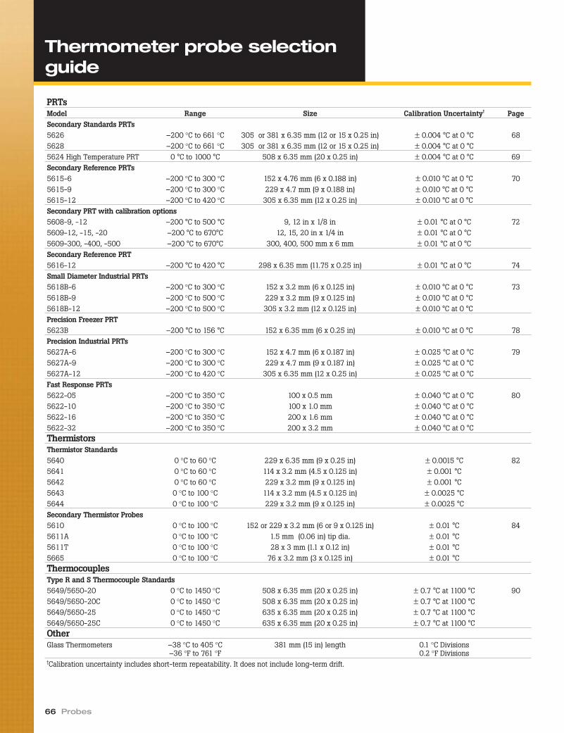
66 Probes
PRTsModel Range Size Calibration Uncertainty† PageSecondary Standards PRTs5626 –200 °C to 661 °C 305 or 381 x 6.35 mm (12 or 15 x 0.25 in) ± 0.004 °C at 0 °C 685628 –200 °C to 661 °C 305 or 381 x 6.35 mm (12 or 15 x 0.25 in) ± 0.004 °C at 0 °C5624 High Temperature PRT 0 °C to 1000 °C 508 x 6.35 mm (20 x 0.25 in) ± 0.004 °C at 0 °C 69Secondary Reference PRTs5615-6 –200 °C to 300 °C 152 x 4.76 mm (6 x 0.188 in) ± 0.010 °C at 0 °C 705615-9 –200 °C to 300 °C 229 x 4.7 mm (9 x 0.188 in) ± 0.010 °C at 0 °C5615-12 –200 °C to 420 °C 305 x 6.35 mm (12 x 0.25 in) ± 0.010 °C at 0 °CSecondary PRT with calibration options5608-9, -12 –200 °C to 500 °C 9, 12 in x 1/8 in ± 0.01 °C at 0 °C 725609-12, -15, -20 –200 °C to 670°C 12, 15, 20 in x 1/4 in ± 0.01 °C at 0 °C5609-300, -400, -500 –200 °C to 670°C 300, 400, 500 mm x 6 mm ± 0.01 °C at 0 °CSecondary Reference PRT5616-12 –200 °C to 420 °C 298 x 6.35 mm (11.75 x 0.25 in) ± 0.01 °C at 0 °C 74Small Diameter Industrial PRTs5618B-6 –200 °C to 300 °C 152 x 3.2 mm (6 x 0.125 in) ± 0.010 °C at 0 °C 735618B-9 –200 °C to 500 °C 229 x 3.2 mm (9 x 0.125 in) ± 0.010 °C at 0 °C5618B-12 –200 °C to 500 °C 305 x 3.2 mm (12 x 0.125 in) ± 0.010 °C at 0 °CPrecision Freezer PRT5623B –200 °C to 156 °C 152 x 6.35 mm (6 x 0.25 in) ± 0.010 °C at 0 °C 78Precision Industrial PRTs5627A-6 –200 °C to 300 °C 152 x 4.7 mm (6 x 0.187 in) ± 0.025 °C at 0 °C 795627A-9 –200 °C to 300 °C 229 x 4.7 mm (9 x 0.187 in) ± 0.025 °C at 0 °C5627A-12 –200 °C to 420 °C 305 x 6.35 mm (12 x 0.25 in) ± 0.025 °C at 0 °CFast Response PRTs5622-05 –200 °C to 350 °C 100 x 0.5 mm ± 0.040 °C at 0 °C 805622-10 –200 °C to 350 °C 100 x 1.0 mm ± 0.040 °C at 0 °C5622-16 –200 °C to 350 °C 200 x 1.6 mm ± 0.040 °C at 0 °C5622-32 –200 °C to 350 °C 200 x 3.2 mm ± 0.040 °C at 0 °CThermistorsThermistor Standards5640 0 °C to 60 °C 229 x 6.35 mm (9 x 0.25 in) ± 0.0015 °C 825641 0 °C to 60 °C 114 x 3.2 mm (4.5 x 0.125 in) ± 0.001 °C5642 0 °C to 60 °C 229 x 3.2 mm (9 x 0.125 in) ± 0.001 °C5643 0 °C to 100 °C 114 x 3.2 mm (4.5 x 0.125 in) ± 0.0025 °C5644 0 °C to 100 °C 229 x 3.2 mm (9 x 0.125 in) ± 0.0025 °CSecondary Thermistor Probes5610 0 °C to 100 °C 152 or 229 x 3.2 mm (6 or 9 x 0.125 in) ± 0.01 °C 845611A 0 °C to 100 °C 1.5 mm (0.06 in) tip dia. ± 0.01 °C5611T 0 °C to 100 °C 28 x 3 mm (1.1 x 0.12 in) ± 0.01 °C5665 0 °C to 100 °C 76 x 3.2 mm (3 x 0.125 in) ± 0.01 °CThermocouplesType R and S Thermocouple Standards5649/5650-20 0 °C to 1450 °C 508 x 6.35 mm (20 x 0.25 in) ± 0.7 °C at 1100 °C 905649/5650-20C 0 °C to 1450 °C 508 x 6.35 mm (20 x 0.25 in) ± 0.7 °C at 1100 °C5649/5650-25 0 °C to 1450 °C 635 x 6.35 mm (20 x 0.25 in) ± 0.7 °C at 1100 °C5649/5650-25C 0 °C to 1450 °C 635 x 6.35 mm (20 x 0.25 in) ± 0.7 °C at 1100 °COtherGlass Thermometers –38 °C to 405 °C
–36 °F to 761 °F381 mm (15 in) length 0.1 °C Divisions
0.2 °F Divisions†Calibration uncertainty includes short-term repeatability. It does not include long-term drift.
Thermometer probe selectionguide

At Hart, we field inquiries every day aboutreference thermometers. Inevitably, as aparticular thermometer is discussed, thesame bottom-line question is asked: “Howaccurate is it?”
This important question deserves acomplete answer, so here are five thingsto consider.
CalibrationOne of the most important contributors tothe accuracy of your reference thermome-ter is the way it was calibrated. Not allcalibrations are equal.
Calibrations by fixed points are gen-erally better than calibrations by compari-son. Calibrations limited to a narrowtemperature range are better thancalibrations done over a needlessly widerange. Calibrations by people who knowwhat they’re doing are better thancalibrations by people who don’t.
Your calibration should describe themethod used, state the uncertainty or test-uncertainty-ratio of the calibration, includea calibration report that meets your qualitystandards and demonstrates traceability toa national laboratory, and be done by anaccredited lab or company you trust. Theuncertainty of your probe’s own calibrationis the first element of accuracy to consider.
Short-term stability (repeatability)Just because your thermometer has beenwell calibrated doesn’t mean it repeatseach identical measurement perfectly.Limitations on the abilities and physicalpurity of the sensing element and othermaterials used in the construction of thethermometer prohibit perfect repeatability.
Different types of thermometers madeby different manufacturers have varyingsusceptibilities to errors from hysteresis,oxidation, and other sources of instability.Thermocouples, for example, are inher-ently less repeatable than reference-gradethermistors. Strain-free SPRTs are morerepeatable than industrial RTDs. The pointis that short-term instabilities cannot be“calibrated out” and must be considered asan additional source of uncertainty.
Long-term stability (drift)Long-term stability, or “drift,” is a criticalspecification for any reference thermom-eter. Many causes of short-term instabil-ity grow worse as a thermometer’sthermal history increases. Normal wearand tear takes its toll on even the bestsensing elements and affects their output.It’s important to note that “normal wearand tear,” in this case, should be definedin the specification.
For example, a drift specification maybe stated as “less than 2 mK after 100hours at 661 °C” (such as on page 9) or as“± 0.025 °C at 0 °C per year maximum,when used periodically to 400 °C” (suchas on page 70). If your intended use of thethermometer is more or less strenuousthan what the manufacturer states, youmay anticipate correspondingly more orless drift.
Many causes of long-term drift can beperiodically addressed and, to some ex-tent, removed. The effects of oxidation, forexample, can be largely removed by occa-sional annealing at high temperatures.Annealing, itself, however, adds morehigh-temperature history to the sensorand should not be done needlessly. One ofthe reasons the drift specification is so im-portant is that it helps identify how longyou can use your thermometer betweenrecalibrations. Be wary of suppliers whodon’t provide a drift specification.
UsageYou won’t find a specification to accountfor all the ways a reference thermometercan be misused (or even abused), but inevaluating specifications it must be under-stood that the manufacturer has made as-sumptions regarding how its instrumentwill be used. At Hart, we tend to write“looser” specifications to allow for instru-ments being used in less ideal conditionsthan those under which we use them. Notevery manufacturer does so.
Typical examples of misuse include in-adequate immersion depth, subjection tomechanical or thermal shock, inadequatethermal contact against the subject beingmeasured, use outside the specified tem-perature range, and extended use at ex-treme ends of the temperature range.Before assuming your thermometer willperform the way the manufacturer says itwill, satisfy yourself that it will be usedwithin the manufacturer’s intended pa-rameters.
Display accuracyThe uncertainty of the thermometer’sreadout device (bridge, DMM, Black Stack,etc.) must be added to the uncertainty ofthe actual thermometer when consideringtotal accuracy. No electrical thermometer(PRT, thermistor, thermocouple, etc.) gen-erates a direct temperature reading. Theresistance or voltage must always be in-terpreted (and usually fitted to an equa-tion), and there are always errors inherentin this process.
In the final analysis...Accuracy is closely related to confidence,and confidence can be enhanced by fol-lowing a few simple guidelines: considerall the appropriate performance specifica-tions, use the thermometer correctly andcarefully, and recalibrate it soon to verifyits performance. As recalibrations yieldpositive results and confidence in an in-strument grows, calibration intervals canbe extended and maintenance costs de-creased. If you’re buying from the rightmanufacturer and handling your ther-mometer correctly, you’ll find it not un-common to experience much better resultsthan what the manufacturer has specified.
Temperature Calibration Equipment 67
How accurate is that probe?
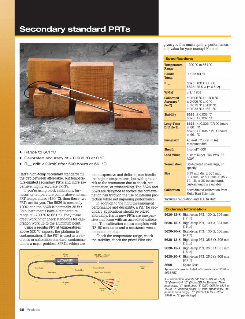
Hart’s high-temp secondary standards fillthe gap between affordable, but tempera-ture-limited secondary PRTs and more ex-pensive, highly accurate SPRTs.
If you’re using block calibrators, fur-naces, or temperature points above normalPRT temperatures (420 °C), then these twoPRTs are for you. The 5626 is nominally100Ω and the 5628 is nominally 25.5Ω.Both instruments have a temperaturerange of –200 °C to 661 °C. They makegreat working or check standards for cali-bration work up to the aluminum point.
Using a regular PRT at temperaturesabove 500 °C exposes the platinum tocontamination. If the PRT is used as a ref-erence or calibration standard, contamina-tion is a major problem. SPRTs, which are
more expensive and delicate, can handlethe higher temperatures, but with greaterrisk to the instrument due to shock, con-tamination, or mishandling. The 5626 and5628 are designed to reduce the contami-nation risk through the use of internal pro-tection while not impairing performance.
In addition to the right measurementperformance and durability, a PRT for sec-ondary applications should be pricedaffordably. Hart’s new PRTs are inexpen-sive and come with an accredited calibra-tion. The calibration comes complete withITS-90 constants and a resistance-versus-temperature table.
Check the temperature range, checkthe stability, check the price! Who else
gives you this much quality, performance,and value for your money? No one!
68 Probes
305, 381, or 508, mm(12", 15", or 20")
≈2 meters(6')
»152 mm(6")
Strain ReliefTerminal Box
Lead Wire
65 mm(2.5")
Inconel Sheath6.35 mm
(.25")
Gold-Plated Terminals
● Range to 661 °C
● Calibrated accuracy of ± 0.006 °C at 0 °C
● RTPW drift < 20mK after 500 hours at 661 °C
Specifications
TemperatureRange
–200 °C to 661 °C
HandleTemp.
0 °C to 80 °C
RTPW 5626: 100 Ω (± 1 Ω)5628: 25.5 Ω (± 0.5 Ω)
W(Ga) ≥ 1.11807
CalibratedAccuracy †
(k=2)
± 0.006 °C at –200 °C± 0.006 °C at 0 °C± 0.015 °C at 420 °C± 0.022 °C at 661 °C
Stability 5626: ± 0.003 °C5628: ± 0.002 °C
Long-TermDrift (k-2)
5626: < 0.006 °C/100 hoursat 661 °C5628: < 0.004 °C/100 hoursat 661 °C
Immersion At least 12.7 cm (5 in)recommended
Sheath Inconel™ 600
Lead Wires 4-wire Super-Flex PVC, 22AGW
Termination Gold-plated spade lugs, orspecify
Size 6.35 mm dia. x 305 mm,381 mm, or 508 mm (0.25 x12, 15, or 20 in) standard,custom lengths available
Calibration Accreditated calibration fromFluke Hart Scientific
†Includes calibration and 100 hr drift
Ordering Information
5626-12-X High-temp PRT, 100 Ω, 305 mm(12 in)
5626-15-X High-temp PRT, 100 Ω, 381 mm(15 in)
5626-20-X High-temp PRT, 100 Ω, 508 mm(20 in)
5628-12-X High-temp PRT, 25.5 Ω, 305 mm(12 in)
5628-15-X High-temp PRT, 25.5 Ω, 381 mm(15 in)
5628-20-X High-temp PRT, 25.5 Ω, 508 mm(20 in)
2609 Spare CaseAppropriate case included with purchase of 5626 or5628 PRT.
X = termination. Specify “A” (INFO-CON for 914X),“B” (bare wire), “D” (5-pin DIN for Tweener Ther-mometers), “G” (gold pins), “I” (INFO-CON for 1521 or1522), “J” (banana plugs), “L” (mini spade lugs), “M”(mini banana plugs), “P” (INFO-CON for 1523 or1524), or “S” (spade lugs).
Secondary standard PRTs
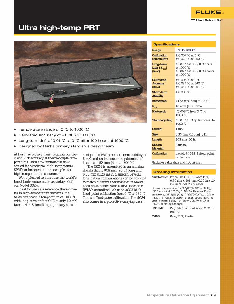
At Hart, we receive many requests for pre-cision PRT accuracy at thermocouple tem-peratures. Until now metrologist havesettled for expensive, high-temperatureSPRTs or inaccurate thermocouples forhigh-temperature measurement.
We’re pleased to introduce the world’sfinest high-temperature secondary PRT,our Model 5624.
Ideal for use as a reference thermome-ter in high-temperature furnaces, the5624 can reach a temperature of 1000 °Cwith long-term drift at 0 °C of only 10 mK!Due to Hart Scientific’s proprietary sensor
design, this PRT has short-term stability of5 mK, and an immersion requirement ofless than 153 mm (6 in) at 700 °C.
The 5624 is assembled in an aluminasheath that is 508 mm (20 in) long and6.35 mm (0.25 in) in diameter. Severaltermination configurations can be selectedto match different thermometer readouts.Each 5624 comes with a NIST-traceable,NVLAP-accredited (lab code 200348-0)fixed-point calibration from 0 °C to 962 °C.That’s a fixed-point calibration! The 5624also comes in a protective carrying case.
Temperature Calibration Equipment 69
Specifications
Range 0 °C to 1000 °C
CalibrationUncertainty
± 0.004 °C at 0 °C± 0.020 °C at 962 °C
Long-termDrift ( Rtpw)(k=2)
<0.01 °C at 0 °C/100 hoursat 1000 °C<0.06 °C at 0 °C/1000 hoursat 1000 °C
CalibratedAccuracy †
(k=2)
± 0.006 °C at 0 °C± 0.031 °C at 660 °C± 0.041 °C at 961 °C
Short-termStability
± 0.005 °C
Immersion <153 mm (6 in) at 700 °C
Rtpw 10 ohm (± 0.1 ohm)
Hysteresis <0.005 °C from 0 °C to1000 °C
Thermocycling <0.01 °C, 10 cycles from 0 to1000 °C
Current 1 mA
Size 6.35 mm (0.25 in) O.D.
Length 508 mm (20 in)
SheathMaterial
Alumina
Calibration Included 1913-6 fixed-pointcalibration
†Includes calibration and 100 hr drift
Ordering Information
5624-20-X Probe, 1000 °C, 10 ohm PRT,6.35 mm x 508 mm (0.25 in x 20in), (includes 2609 case)
X = termination. Specify “A” (INFO-CON for 914X),“B” (bare wire), “D” (5-pin DIN for Tweener Ther-mometers), “G” (gold pins), “I” (INFO-CON for 1521 or1522), “J” (banana plugs), “L” (mini spade lugs), “M”(mini banana plugs), “P” (INFO-CON for 1523 or1524), or “S” (spade lugs).
1913-6 Cal, SPRT by Fixed Point, 0 °C to962 °C
2609 Case, PRT, Plastic
● Temperature range of 0 °C to 1000 °C
● Calibrated accuracy of ± 0.006 °C at 0 °C
● Long-term drift of 0.01 °C at 0 °C after 100 hours at 1000 °C
● Designed by Hart’s primary standards design team
Ultra high-temp PRT

For years, you’ve relied on our 5612, 5613,and 5614 Secondary Reference Probes.These field-durable, lab-accurate PRTshave been replaced by the 5615, whichcomes with a NVLAP accredited calibration.
The 5615-12 is a Platinum ResistanceThermometer (PRT) with an Inconel™ 600sheath that’s 305 mm (12 in) long and6.35 mm (0.250 in) in diameter. It is asecondary reference temperature standarddesigned to bridge the gap between thehighest laboratory standards and indus-trial or second-tier lab locations. It has ac-curacy of ± 0.012 °C at 0.01 °C.
The element is constructed of refer-ence-grade platinum wire (99.999 %pure) for excellent stability. The wire iswound in a coil and placed in a mandrelwhere it’s uniformly supported in a man-ner that virtually eliminates hysteresis.The electrical configuration is a four-wirecurrent-potential hookup that eliminatethe effects of lead-wire resistance.
These Inconel™-sheathed probes havea fully supported sensing element, makingthem more durable than SPRTs. The ele-ment is protected in an ultrahigh-purity
ceramic case with a hermetic glass seal toimprove output stability by locking outmoisture and contaminants.
This probe comes calibrated with ITS-90 coefficients, making it compatible withmany excellent readout devices, includingHart’s 1529 Chub-E4, 1560 Black Stack,and 1502A Tweener. It bridges the gapbetween a 100-ohm industrial RTD andan SPRT.
For those needing faster thermal re-sponse, or where diameter and immersiondepth are problems, order the 5615-9 or5615-6. These probes are excellent refer-ence probes for comparison calibrations ina Hart dry-well. The sheaths of the 5615-6 and 5615-9 are 4.76 mm (0.188 in) indiameter.
A printout of sensor resistance is pro-vided in 1 °C increments for each probe.The 5615-9 and 5615-12 are calibratedfrom –196 °C to 420 °C. The 5615-6 iscalibrated to 300 °C.
We’ve tested many of the probes onthe market. We’ve used them in our man-ufacturing facility and tested them in thelab, and this is an excellent secondary
standards PRT. Other instruments on themarket are priced much higher, havelower stability, or are of lower quality.Remember, these are reliable instrumentsand each probe comes with its own indi-vidual NVLAP-accredited calibration, labcode 200706-0.
70 Probes
● Affordable wide-range accuracy
● Calibrated accuracy ± 0.012 °C at 0 °C
● Reference-grade platinum sensing element
● NVLAP-accredited calibration included, lab code 200706-0
Ordering Information
5615-6-X Secondary Standard PRT, 4.76mm x 152 mm (0.188 x 6.0 in),–200 °C to 300 °C
5615-9-X Secondary Standard PRT, 4.76mm x 229 mm (0.188 x 9.0 in),–200 °C to 420 °C
5615-12-X Secondary Standard PRT, 6.35mm x 305 mm (0.250 x 12.0in), –200 °C to 420 °C
2601 Probe Carrying CaseX = termination. Specify “A” (INFO-CON for914X), “B” (bare wire), “D” (5-pin DIN forTweener Thermometers), “G” (gold pins), “I”(INFO-CON for 1521 or 1522), “J” (bananaplugs), “L” (mini spade lugs), “M” (mini ba-nana plugs), “P” (INFO-CON for 1523 or1524), or “S” (spade lugs).
Secondary referencetemperature standards

Temperature Calibration Equipment 71
Specifications
Temperature range 5615-12 and 5615-9: –200 °C to 420 °C5615-6: –200 °C to 300 °C
Nominal resistance at 0 °C 100 Ω ± 0.10 Ω
Temperature coefficient 0.0039250 Ω/Ω/°C
Accuracy [1] ± 0.024 °C at –200 °C± 0.012 °C at 0 °C± 0.035 °C at 420 °CC
Short-term repeatability [2] ± 0.009 °C at 0.010 °C
Drift [3] ± 0.007 °C at 0.010 °C
Sensor length 28 mm (1.1 in)
Sensor location 6.9 mm ± 3.3 mm from tip (0.27 in ± 0.13 in)
Sheath diameter tolerance ± 0.127 mm (± 0.005 in)
Sheath material Inconel™ 600
Minimum insulationresistance
1000 MΩ at 23 °C
Transition junctiontemperature range [4]
–50 °C to 200 °C
Transition junctiondimensions
71 mm x 13 mm dia (2.8 in x 0.5 in)
Maximum immersion length 5615-6: 102 mm (4 in)5615-9: 178 mm (7 in)5615-12: 254 mm (10 in)
Response time [5] 9 seconds typical
Self heating (in 0 °C bath) 50 mW/°C
Lead-wire cable type Teflon™ insulated with Teflon™ jacket, 22 AWG
Lead-wire length 183 cm (72 in)
Lead-wire temperaturerange
–50 °C to 200 °C
Calibration NVLAP-accredited calibration included, lab code 200706-0.Please see calibration uncertainty table and its explanation ofchangeable uncertainties.
[1]Includes calibration and 100 hr drift (k=2)[2]Three thermal cycles from min to max temp, includes hysteresis, 95 % confidence (k=2)[3]After 100 hrs at max temp, 95 % confidence (k=2)[4]Temperatures outside this range will cause irreparable damage. For best performance, transition junctionshould not be too hot to touch.[5]Per ASTM E 644
Secondary referencetemperature standards
NVLAP † Calibration Uncertainty
TemperatureExpanded
Uncertainty (k=2)–196 °C 0.024 °C–38 °C 0.011 °C0 °C 0.010 °C
200 °C 0.018 °C420 °C‡ 0.029 °C
Calibration uncertainties depend on theuncertainties of the lab performing the cali-bration. Subsequent calibrations of this probeperformed with different processes, at differ-ent facilities, or with changed uncertaintystatements may state different uncertainties.†Lab code 200706-0‡5615-6 excluded
Interim checks save trouble laterYou spend good money getting your refer-ence standards calibrated. How can you besure that they continue to measure accu-rately prior to their next calibration? Oneway is to periodically compare them toother reference standards with higher ac-curacy. Such a test is called an interimcheck.
An interim check that most of us are fa-miliar with is the use of a water triple
point cell to check the stability of a PRT.The ISO 17025 suggests the use of interimchecks as a quality safeguard. Do this regu-larly, keep good records, and you may im-prove your accuracy by more than a factorof 10. And if you find a problem, you’ll beglad you found it sooner rather than later!

If you want a very stable thermometerfrom –200 °C to 670 °C and are particularabout the calibration, then look no furtherthan our 5609 Secondary Reference PRT.Its short-term stability at the triple point ofwater is only ± 7 mK and its one-quarterinch (6.23mm) diameter lets you get accu-rate measurements in only 100 mm of im-mersion. The 5608 is also a ± 7 mK probeat the triple point of water, but its one-eighth inch (3.18 mm) diameter gets youaccurate measurements from –200 °C to500 °C with only 80mm (3.1 in) of immer-sion. With multiple sheath length optionson both of these probes, you can find thedimensions that are just right for your spe-cific application.
The 5608 comes with a one-eighthinch (3.18 mm) diameter sheath in lengthsof 9 inches or 12 inches. The 5609 comeswith a one-quarter inch (6.35 mm) diame-ter sheath in lengths of 12 inches, 15inches, and 20 inches; or with a 6 mm di-ameter in lengths of 300 mm, 400 mm, or500 mm.
When looking for improved responsetime and reduced stem effect in shallowimmersion, look for small diameter probes,because the measurement error called stemeffect is caused by the diameter of the stemrather than the length of the stem.
Both of these probes have Inconel™sheaths and are made using a special
manufacturing process, giving them greatprecision over a wide temperature range.The sensors for these probes are refer-ence-grade platinum and feature four-wire connections with less noisy mea-surements than two-wire counterparts.
These probes come with a certificate ofcompliance to ensure the meet their speci-fications. If you’d like, you can also order aNVLAP-accredited calibration from ourlaboratory, lab code 200348-0. On the re-port of calibration, you’ll get the test dataand the ITS90 calibration coefficients thatyou can easily input into any Hart ther-mometer. If you order your probe with anINFO-CON connector, we’ll program thecoefficients directly into your connector,which loads the coefficients for you whenyou plug it into our 1522 HandheldThermometer.
Call today for your free quote.
72 Probes
● 5608: –200 °C to 500 °C (80 mm minimum immersion)
● 5609: –200 °C to 670 °C (100 mm minimum immersion)
● ± 0.008 °C relative accuracy at 0 °C
● Calibration not included, NVLAP-accredited calibration optional, labcode 200348-0
Ordering Information
5608-9-X Secondary Reference PRT,9 in x 1/8 in, –200 to 500 °C
5608-12-X Secondary Reference PRT,12 in x 1/8 in, –200 to 500 °C
5609-12-X Secondary Reference PRT,12 in x 1/4 in, –200 to 670 °C
5609-15-X Secondary Reference PRT,15 in x 1/4 in, –200 to 670 °C
5609-20-X Secondary Reference PRT,20 in x 1/4 in, –200 to 670 °C
5609-300-X Secondary Reference PRT,300 mm x 6 mm, –200 to670 °C
5609-400-X Secondary Reference PRT,400 mm x 6 mm, –200 to670 °C
5609-500-X Secondary Reference PRT,500 mm x 6 mm, –200 to670 °C
5609-9BND-X Secondary Reference PRT,15 in x 1/4 in, 9 in bend,–200 °C to 670 °C
1922-4-R PRT (5608) Calibration,–200 °C to 500 °C, NVLAPAccredited
1923-4-7 PRT (5609) Calibration,–200 °C to 660 °C, NVLAPAccredited
1924-4-7 PRT (5609-9BND) Calibration,–200 °C to 660 °C, NIST-traceable
1930 Precision Digital Thermome-ter System Calibration byComparison, NVLAP-accred-ited, lab code 200348-0
2601 Plastic PRT Case, for modelsending -9, -12, and -300
2609 Plastic PRT Case, for modelsending -15, -20, -400, and-500
X = termination. Specify “A” (INFO-CON for914X), “B” (bare wire), “D” (5-pin DIN forTweener Thermometers), “G” (gold pins), “I”(INFO-CON for 1521 or 1522), “J” (bananaplugs), “L” (mini spade lugs), “M” (mini ba-nana plugs), “P” (INFO-CON for 1523 or1524), or “S” (spade lugs).
Secondary PRT withcalibration options
Temperature Calibration Equipment 73
Calibration Uncertainty for optionalNVLAP-accredited † calibration
TemperatureExpanded
Uncertainty (k=2)–200 °C 0.025 °C–100 °C 0.025 °C–40 °C 0.025 °C0 °C 0.025 °C
156 °C 0.025 °C230 °C 0.030 °C420 °C 0.045 °C660 °C 0.050 °C
Note: Calibration uncertainties depend on theuncertainties of the lab performing the cali-bration. Subsequent calibrations of this probeperformed with different processes, at differ-ent facilities, or with changed uncertaintystatements may state different uncertainties.†Lab code 200348-0
Secondary PRT withcalibration options
Specifications
Temperature range 5608: –200 °C to 500 °C5609: –200 °C to 670 °C
Nominal resistance at 0.01 °C 100 Ω ± 0.5 Ω
Temperature coefficient 0.0039250 Ω/Ω/°C
Relative Accuracy [1] ± 0.007 °C at –200 °C± 0.008 °C at 0 °C± 0.020 °C at 420 °C± 0.027 °C at 660 °C
Short-term repeatability [2] ± 0.007 °C at 0.010 °C± 0.013 °C at max temp
Drift [3] ± 0.01 °C at 0.010 °C± 0.02 °C at max temp
Hysteresis ± 0.01 °C maximum
Sensor length 30 mm ± 5 mm (1.2 in ± 0.2 in)
Sensor location 3 mm ± 1 mm from tip (0.1 in ± 0.1 in)
Sheath material Inconel™ 600
Minimum insulation resistance 5608: 500 MΩ at 23 °C, 20 MΩ at 500 °C5609: 500 MΩ at 23 °C, 10 MΩ at 670 °C
Transition junction temperaturerange [4]
–50 ºC to 200 °C
Transition junction dimensions 71 mm x 12.5 mm (2.8 in x 0.49 in)
Minimum immersion length [5]
(<5 mK error)5608: 80 mm (3.1 in)5609: 100 mm (3.9 in)
Maximum immersion length 305 mm (12 in)
Response time [5] 5608: 9 seconds typical5609: 12 seconds typical
Self heating (in 0 °C bath) 5608: 75 mW/°C5609: 50 mW/°C
Lead-wire cable type Teflon,™ 24 AWG
Lead-wire length 1.8 m (6 ft)
Lead-wire temperature range –50 °C to 250 °C
Calibration Calibration not included; NVLAP-accredited calibration op-tional, lab code 200348-0. Please see calibration uncertaintytable and its explanation of changeable uncertainties.
[1]Includes short-term repeatability and 100 hr drift. Calibration will add additional uncertainties.[2]Three thermal cycles from min to max temp, includes hysteresis, 95 % confidence (k=2)[3]After 100 hours at max temp, 95 % confidence (k=2)[4]Temperatures outside this range will cause irreparable damage. For best performance, transition junctionshould not be too hot to touch.[5]Per ASTM E 644

You won’t find another NIST-traceable ref-erence temperature sensor that matchesthe accuracy and temperature range of the5616 for the same price.
The 5616-12 is a 100-ohm platinumresistance thermometer (PRT) with excel-lent short-term repeatability and comeswith an unaccredited NIST-traceablecalibration.
The temperature range of the 5616covers –200 °C to 420 °C, and its high-pu-rity platinum element and durability makeit great for calibrating in the lab or in thefield. When choosing a reference with aplatinum element, there are two thingsyou want to look at carefully: the short-term repeatability and the long-term drift.When PRTs are thermally cycled over theirtemperature range as they would be dur-ing a calibration, their resistance at thetriple point of water can move up anddown within an expected range. Hart Sci-entific defines this range (called “short-term repeatability”) as the repeatability atthe triple point of water during three ther-mal cycles. 5616s are among the bestperforming in their class with short-termrepeatability better than ± 0.010 °C(± 0.004 °C is typical). In addition, the
5616’s drift is ± 0.007 °C at the triplepoint of water when exposed up to itsmaximum temperature (420 °C) for 100hours. These specifications are given atk=2 and therefore include a 95 %confidence level.
The 5616’s sealed −INCONEL® 600sheath is 298 mm (11.75 in) long and6.35 mm (0.250 in) in diameter. Theprobe’s Teflon®-jacketed cable is made ofsilver plated copper that ends with four-wire leads, which eliminate the effects oflead-wire resistance on measurements.
Use the 5616 with Hart’s 1560 BlackStack, 1529 Chub-E4, or 1502A Tweenerthermometer readouts.
Each sensor comes with a manufac-turer’s report of calibration. The report in-cludes the expanded uncertainty (k=2) atseven calibration temperature points, ITS-90 calibration coefficients, and a tempera-ture vs. resistance table presented in 1 °Cincrements.
Compare the 5616 to other SecondaryReference PRTs. You’ll like its price, butyou’ll love its performance.
74 Probes
● Temperature range: –200 °C to 420 °C
● Excellent stability: ± 10 mK
● Calibrated accuracy ± 0.011 °C at 0 °C
● NIST-traceable calibration included
Ordering Information
5616-12-X Secondary Reference PRT,6.35 mm x 298 mm(0.250 x 11.75 in),–200 to 420 °C
2601 Probe Carrying CaseX = termination. Specify “A” (INFO-CON for914X), “B” (bare wire), “D” (5-pin DIN forTweener Thermometers), “G” (gold pins), “I”(INFO-CON for 1521 or 1522), “J” (bananaplugs), “L” (mini spade lugs), “M” (mini ba-nana plugs), “P” (INFO-CON for 1523 or1524), or “S” (spade lugs).
5616 secondaryreference PRT

Temperature Calibration Equipment 75
Specifications
Parameter Value
Temperature range –200 °C to 420 °C
Nominal resistance at 0.01 °C 100 Ω ± 0.5 Ω
Temperature coefficient 0.003925 Ω/Ω/°C nominal
Calibrated Accuracy [1] (k=2) ± 0.012 °C at –200 °C± 0.011 °C at 0 °C± 0.028 °C at 420 °C
Short-term repeatability [2] ± 0.007 °C at 0.010 °C
Drift [3] ± 0.007 °C at 0.010 °C
Hysteresis ± 0.010 °C maximum
Sensor length 50.8 mm (2.0 in)
Sensor location 9.5 mm ± 3.2 mm from tip (0.375 in ± 0.125 in)
Sheath diameter tolerance ± 0.08 mm (± 0.003 in)
Sheath material INCONEL® 600
Minimum insulation resistance 500 MW at 23 °C
Transition junction temperaturerange [4]
–50 °C to 150 °C (see footnote)
Transition junction dimensions 76.2 mm x 9.5 mm (3.00 in x 0.375 in)
Minimum immersion length[5](< 5 mK error)
102 mm (4.0 in)
Maximum immersion length 254 mm (10 in)
Response time [5] 8 seconds typical
Self heating (in 0 °C bath) 60 mW/°C
Lead-wire cable type Teflon®-jacketed cable, Teflon® insulated conductors, 24AWG stranded, silver plated copper
Lead-wire length 182.9 cm ± 2.5 cm (72.0 in ± 1.0 in)
Lead-wire temperature range –50 °C to 150 °C
Calibration NIST-traceable calibration[1]Includes calibration uncertainty and 100 hr drift.[2]Three thermal cycles from min to max temp, includes hysteresis, 95 % confidence (k=2)[3]After 100 hrs at max temp, 95 % confidence (k=2)[4]Temperatures outside this range will cause irreparable damage. For best performance, transition junctionshould not be too hot to touch.[5]Per ASTM E 644
Calibration Uncertainty
TemperatureExpanded
Uncertainty (k=2)–197 °C 0.012 °C–80 °C 0.012 °C–38 °C 0.011 °C0 °C 0.009 °C
156 °C 0.011 °C230 °C 0.013 °C420 °C 0.021 °C
Note: Laboratories may periodically reevaluatetheir uncertainties. Calibration uncertaintiesdepend on the calibration process, the stan-dards used, and the instrument performance.
5616 secondaryreference PRT

Based on an article from RandomNewsSpecifications are used to quantify theperformance of platinum resistance ther-mometers (PRTs) and are often the maindeterminant in the customer's probechoice. Therefore marketers sometimesuse a tactic called "specmanship" to artifi-cially enhance their PRT's performance."Specmanship" is defined as presentinginstrument specifications in a misleadingfashion. PRT specmanship can come inmany forms. Here are some of the mostcommon we see in the temperature world:
Incomplete specificationsCompleteness means providing all the in-formation necessary for a user to formproper expectations of PRTs performanceover its intended range and for its in-tended purpose. A specification only givenat one temperature point gives little indi-cation of the PRT's performance over itsfull range.
It is usually not practical to define speci-fications in every detail at every incrementover its range (or for every imaginable ap-plication). However, this is no excuse forintentionally omitting or relocating criticalspecifications in an effort to give a false im-pression of performance. Make sure specifi-cations provide all the information neededto adequately predict performance overyour intended range of use.
Drift is more important than many peo-ple realize, and they often fail to give itthe consideration it deserves. The amountyour probe drifts affects how often it mustbe recalibrated. Drift can be monitored byperiodically measuring the probe's resis-tance shift at the triple point of water(TPW), or 0.01 °C.
Misuse of "typical" and "bestperformance"Unfortunately, manufacturers are notbound by a common standard defininghow to derive or present specifications.Ideally, manufacturers are adequatelyconservative when publishing specifica-tions so that actual performance is betterthan the stated specifications. Thisshould be done not only to provide ahigh level of confidence to the user whenthey validate the PRT's performance, butalso to account for applications that maynot be "typical" or that don't fit the "bestperformance" criteria.
It is important to realize that when amanufacturer qualifies a specification withthe words like "typical", "as good as" or"depends on actual use" that they are notguaranteeing the specification. This is not
to say that such terms may never be used.The term "typical" may be used in litera-ture to give users a general indication ofperformance on non-critical specificationsthat have several variables. For example,the term "typical" can provide the userwith an indication of performance whenthat performance is more within the user'scontrol than the manufacturer's.
However use of such terms may be anindication that inadequate testing hasbeen performed, or that an attempt is be-ing made to exaggerate the actual perfor-mance of the majority of instrumentsbeing produced. These terms and otherslike them may be stated so the manufac-turer may publish the most attractivespecification possible while trying to builda defensible position for when the probedoes not perform to the stated specifica-tion. Don't be fooled by exaggeratedperformance specifications. Ask for aguarantee.
Declaring specifications that aredifficult to interpret or applyNot enough can be said for clearly statedspecifications that are easy to interpretand apply. Some specmanship artisansambiguously represent specifications socustomers are left to their own interpreta-tion of the specification and how to applyit. Once a customer has clarified the "true"meaning, he or she often finds the specifi-cation is not based on the general appli-cation-thus, rendering it useless. Properly
written specifications should therefore ap-ply to the anticipated application.
If you ever see a specification that youdo not understand, please ask. Otherwise,you may be misunderstanding a criticalpart of your probe's performance.
ConclusionSpecmanship exists in the temperature
calibration market today. We suggest athorough examination of PRT specifica-tions on completeness and applicationuse. We understand that thorough specifi-cations can be challenging to develop, butwe excuse no one, including ourselves. Ifyou see a chance for us to improve thepresentation of our specifications, pleaselet us know!
76 Probes
Sensible temperaturespecifications

For secondary level performance with fullITS-90 calibration, Hart’s 5618B seriesPRTs are an excellent choice for criticaltemperature measurements. Featuring a3.2 mm diameter (1/8 in) sheath, these in-dustrial standards probes have reducedresponse time without compromising pre-cision. This small diameter 5618B probeworks well in many applications whereimmersion depth is limited. Larger diame-ter probes give more measurement error inshort immersion depth applications be-cause they conduct more heat betweenambient and the sensor.
With each probe you will receive a fullNVLAP-accredited calibration report, labcode 200706-0. On the report you’ll getthe test data and the ITS-90 calibrationcoefficients that you can easily input intoyour Hart thermometer. If you are using aHandheld Thermometer readout, we’llprogram the coefficients directly into yourINFO-CON connector.
The 5618B is also a great probe to usefor calibrating your Hart 9132 or 9133 in-frared calibrators. In fact, these IR black
body heat sources were designed to becalibrated with this type of probe. Nowyou can calibrate these targets in yourown lab!
For use from –200 °C to 500 °C (thesix-inch model goes to 300 °C), you won’tfind a better industrial standard in thisconfiguration than our 5618B. We recom-mend using the 5618B PRTs with the1523, 1524, 1502A, 1529, or 1560 ther-mometer readouts.
Temperature Calibration Equipment 77
● Small diameter sheath, 3.2mm (0.125 in)
● Excellent stability
● Includes ITS-90 coefficients
● NVLAP-accredited calibration from –200 °C to 500 °C, lab code200706-0
Specifications
Resistance Nominal 100 Ω at 0 °C
TemperatureCoefficient
0.003923 Ω/Ω/ °C nominal
TemperatureRange
–200 °C to 500 °C(–200 °C to 300 °C for 5618B-6-X)
Drift Rate ± 0.1 °C when used periodi-cally to 500 °C
SheathMaterial
316 SST
Leads 22 AWG Teflon, 6’
Termination Specify
Hysteresis Less than 0.01 °C at 0 °Cwhen using –196 °C and420 °C as the end points.
TimeConstant
Four seconds maximum for63.2 % response to stepchange in water movingat 3 fps.
Thermal EMF Less than 25 mV at 420 °C
Calibration Includes manufacturer’sNVLAP-accredited calibrationw/ITS-90 coefficients, R vs. Tvalues in 1 °C increments, labcode 200706-0
Size 5618B-12: 305 mm L x3.2 mm dia. (12 x 1/8 in)5618B-9: 229 mm L x3.2 mm dia. (9 x 1/8 in)5618B-6: 152 mm L x3.2 mm dia. (6 x 1/8 in)
CalibratedAccuracy †
(k=2)
± 0.026 °C at –200 °C± 0.066 °C at 0 °C± 0.219 °C at 500 °C
†Includes calibration uncertainty and driftspecification.
NVLAP † Calibration Uncertainty
TemperatureExpanded
Uncertainty (k=2)–196 °C 0.024 °C–38 °C 0.011 °C0 °C 0.010 °C
200 °C 0.018 °C420 °C‡ 0.029 °C
Calibration uncertainties depend on theuncertainties of the lab performing the cali-bration. Subsequent calibrations of this probeperformed with different processes, at differ-ent facilities, or with changed uncertaintystatements may state different uncertainties.†Lab code 200706-0‡300 °C for 5618B-6
Ordering Information
5618B-12-X 305 mm (12 in) Small DiameterProbe
5618B-9-X 229 mm (9 in) Small DiameterProbe
5618B-6-X 152 mm (6 in) Small DiameterProbe
2601 Probe Carrying Case
X = termination. Specify “A” (INFO-CON for 914X),“B” (bare wire), “D” (5-pin DIN for Tweener Ther-mometers), “G” (gold pins), “I” (INFO-CON for 1521 or1522), “J” (banana plugs), “L” (mini spade lugs), “M”(mini banana plugs), “P” (INFO-CON for 1523 or1524), or “S” (spade lugs).
Small diameter industrial PRT

If you need a precision measurement atlow temperatures, do not look any furtherthan Hart Scientific.
The 5623B, precision “freezer probe,” isspecially sealed from the sensing elementto the end of the probe cable, preventingingress of moisture when exposed to tem-peratures as low as –100 °C. The entireassembly withstands temperatures over itsfull range (–100 °C to 156 °C), which isideal for verification of freezers or auto-claves where a thermo-well isn’t avail-able. The 5623B assembly can be fullyimmersed in fluids when the applicationmay require use in a liquid bath. The5623B is available in a 6.35 mm (0.25 in)dia. × 125 mm (6 in) long Inconel™sheath. With calibration uncertainty ofonly ± 0.010 °C at 0 °C, the 5623B is justright as a secondary standard for calibra-tion of other process sensors.
Most Hart Scientific readouts make anexcellent companion for the 5623B. Werecommend the use of the 1523, 1524,1502A, 1529, or 1560 thermometerreadouts.
With each 5623B, you receive a fullNVLAP-accredited calibration report, labcode 200706-0. This report includes testdata and ITS-90 calibration coefficients toenter into your Hart Scientific thermometerreadout.
78 Probes
● Fully immersible probe assembly to –100 °C
● NVLAP-accredited calibration, lab code 200706-0
● Accuracy to ± 0.05 °C over the full range
Specifications
Resistance Nominal 100 Ω (± 0.1 Ω)
TemperatureCoefficient
0.003925 Ω/Ω/°C nominal
TemperatureRange
–100 °C to 156 °C
TransitionTemperature
–100 °C to 156 °C
Drift Rate ± 0.01 °C per year maximumat 0 °C, when used periodi-cally at max temperature
SheathMaterial
Inconel™ 600
Leads Teflon™-insulated, silver-plated stranded copper, 22AWG.
Termination Specify. See orderinginformation.
Calibration Includes manufacturer’sNVLAP-accredited, lab code200706-0, calibration andtable with R vs. T values in1 °C increments from –80 °Cto 156 °C. ITS-90 coefficientsincluded.
CalibratedAccuracy †
(k=2)
± 0.05 °C over the full range
Cable Length 6.1 meters (20 ft)
Size 6.35 mm (0.25 in) dia. x152 mm (6 in)
†Includes calibration uncertainty and drift.
Ordering Information
5623B-6-X Freezer Probe, RTD 6.35 mm dia.x 152 mm (1/4 in x 6 in),–100 °C to 156 °C
2601 Probe Carrying Case
X = termination. Specify “A” (INFO-CON for 914X),“B” (bare wire), “D” (5-pin DIN for Tweener Ther-mometers), “G” (gold pins), “I” (INFO-CON for 1521 or1522), “J” (banana plugs), “L” (mini spade lugs), “M”(mini banana plugs), “P” (INFO-CON for 1523 or1524), or “S” (spade lugs).
Precision freezer PRT

When buying a PRT, performance isn’t theonly criterion you need to look at. The realissues are price-to-accuracy and price-to-durability ratios.
5627A probes have a temperaturerange up to 420 °C and an accuracy asgood as ± 0.025 °C. They come in threedifferent lengths. (Both six- and nine-inchmodels cover –200 °C to 300 °C.) Each in-strument is shipped with its ITS-90 coeffi-cients and a calibration table in 1 °Cincrements.
One of the best features of this sensoris that it conforms to the standard 385curve, letting you use your DIN/IEC RTDmeters fully. Why use a probe that’s lessaccurate than your meter?
The 5627A is manufactured using acoil suspension element design for in-creased shock and vibration resistance. Ithas a mineral-insulated sheath with aminimum bend radius of 19 mm (3/4-inch) for flexibility and durability. (Bend, ifany, should be specified at time of order.)
Six- and nine-inch 5627As are cali-brated at –196 °C, –38 °C, 0 °C, 200 °C,and 300 °C. For 12-inch versions the pointat 300 °C is replaced by a calibration pointat 420 °C.
Each probe is individually calibratedand includes a NVLAP-accredited report ofcalibration from the manufacturer, labcode 200706-0.
This probe is an excellent value. It hasthe price-to-accuracy and price-to-dura-bility ratios you should demand in everyPRT you buy!
Temperature Calibration Equipment 79
● Vibration and shock resistant
● 19 mm (3/4-inch) bend radius for increased durability
● NVLAP-accredited calibration included, lab code 200706-0
Specifications
Resistance Nominal 100Ω
TemperatureCoefficient
0.00385 Ω/Ω/ °C nominal
TemperatureRange
–200 °C to 420 °C(5627A-6 and 5627A-9 to300 °C; transition and cabletemperature: 0 °C to 150 °C)
Drift Rate(k=2)
± 0.04 °C at 0 °C after 100hours at 420 °C
SheathMaterial
316 Stainless Steel
Leads Teflon™-insulated, nickel-plated stranded copper, 22AWG
Termination Specify. See OrderingInformation.
TimeConstant
Four seconds maximum for63.2 % response to stepchange in water moving at 3fps.
BendingRadius
Sheath may be ordered with abend on a minimum radius of19 mm (3/4 in) except for 50mm (2 in) area of sheath neartip. (Hart lab requires 20 cm [8in] of unbent sheath to re-calibrate.)
Calibration Includes manufacturer’sNVLAP-accredited (lab code200706-0) calibration and ta-ble with R vs. T values in 1 °Cincrements from –196 °C to500 °C (to 300 °C for 5627A-6and 5627A-9).ITS-90 coefficients included.
Immersion At least 100 mm (4 in)recommended
CalibratedAccuracy †
(k=2)
± 0.026 °C at –196 °C± 0.046 °C at 0 °C± 0.077 °C at 200 °C± 0.124 °C at 420 °C
Size 5627A-12: 305 mm x 6.35 mm(12 in x 1/4 in)5627A-9: 229 mm x 4.7 mm(9 in x 3/16 in)5627A-6: 152 mm x 4.7 mm(6 in x 3/16 in)
†Includes calibration uncertainty and 100 hr drift.
Ordering Information
5627A-6-X Secondary PRT, 152 mm x4.7 mm (6 x 3/16 in), –200 °Cto 300 °C
5627A-9-X Secondary PRT, 229 mm x 4.7mm (9 x 3/16 in), –200 °C to300 °C
5627A-12-X Secondary PRT, 305 mm x6.35 mm (12 x 1/4 in), –200 °Cto 420 °C
2601 Probe Carrying CaseX = termination. Specify “A” (INFO-CON for 914X),“B” (bare wire), “D” (5-pin DIN for Tweener Ther-mometers), “G” (gold pins), “I” (INFO-CON for 1521 or1522), “J” (banana plugs), “L” (mini spade lugs), “M”(mini banana plugs), “P” (INFO-CON for 1523 or1524), or “S” (spade lugs).
Precision industrial PRTs

For special temperature measurement ap-plications requiring fast response or shortimmersion over a wide temperature range,Hart’s new 5622 series PRTs are theperfect solution.
Made by Netsushin, one of the world’sleading PRT manufacturers, this series in-cludes four models with stainless steelsheaths ranging from 0.5 to 3.2 mm (0.02to 0.125 in) in diameter. Because thesehigh-quality wire-wound sensors come insmall packages, heat transfer to the sen-sors occurs quickly. Time constants from0 °C to 100 °C are as fast as 0.4 seconds.
Immersion requirements for theseprobes is also a plus, ranging from just 10mm to 64 mm (0.4 to 2.5 inch), dependingon the model. Getting into shallow or tightplaces is not a problem. And becausethese probes can handle temperaturesfrom –200 °C to 350 °C, they’re more ver-satile than most thermistors.
5622 PRTs come with two calibrationoptions. Uncalibrated, each of theseprobes conforms to DIN/IEC Class A re-quirements with accuracy of ± 0.15 °C at0 °C and ± 0.55 °C at 200 °C and –200 °C.Alternatively, any 5622 PRT may be pur-chased with a 1923-4-N ITS-90 NVLAP-accredited comparison calibration (lab
code 200348-0) that includes sevenpoints from –197 °C to 300 °C. With cali-bration, short-term accuracies areachieved as good as ± 0.04 °C at 0 °C.
Readout options for the Model 5622PRTs include Hart’s Little Lord Kelvin andLittle Lord Logger Handheld Thermometers(page 58) as well as the 1502A TweenerThermometer (page 56). Each of thesereadouts will read your PRT as a standardDIN/IEC probe or as an individually cali-brated PRT.
Whatever your thermometry require-ments are, come to Hart. No one else offersa wider range of standards-quality refer-ence thermometers than Hart.
80 Probes
● Time constants as fast as 0.4 seconds
● Available as DIN/IEC Class A PRTs or with NVLAP-accreditedcalibration, lab code 200348-0
● Small probe diameters ranging from 0.5 mm to 3.2 mm
Specifications
TemperatureRange
–200 °C to 350 °C
Nominal RTPW 100 Ω
Sensor Four “385” platinum wires
CalibratedProbeAccuracy(includescalibrationuncertaintyand short-termstability)
5622-05 and 5622-10:± 0.04 °C at –200 °C± 0.04 °C at 0 °C± 0.09 °C at 200 °C± 0.09 °C at 300 °C5622-16 and 5622-32:± 0.04 °C at –200 °C± 0.04 °C at 0 °C± 0.045 °C at 200 °C± 0.055 °C at 300 °C
UncalibratedDIN/IECConformity
DIN/IEC Class A;± 0.15 °C at 0 °C
TimeConstant(63.2 %)
From 0 °C to 100 °C:5622-05: 0.4 seconds5622-10: 1.5 seconds5622-16: 3.0 seconds5622-32: 10 seconds (90 %)
ImmersionDepth
5622-05: 10 mm (0.4 in)5622-10: 20 mm (0.8 in)5622-16: 32 mm (1.25 in)5622-32: 64 mm (2.5 in)
Thermal EMF 20 mV at 350 °C
Sheath 316 SST5622-05: 100 x 0.5 mm(4 x 0.02 in)5622-10: 100 x 1.0 mm(4 x 0.04 in)5622-16: 200 x 1.6 mm(8 x 0.06 in)5622-32: 200 x 3.2 mm(8 x 0.13 in)
Cable PVC, 4-wire cable, 2 meterslong, 90 °C max temp
Ordering Information
5622-05-X Fast Response PRT, 0.5 mm(0.02 in)
5622-10-X Fast Response PRT, 1.0 mm(0.04 in)
5622-16-X Fast Response PRT, 1.6 mm(0.06 in)
5622-32-X Fast Response PRT, 3.2 mm(0.13 in)
(All models come without calibration unless calibra-tion purchased separately.)
1923-4-N NVLAP-accredited Calibration,PRT Comparison, –196 °C to300 °C, lab code 200348-0
2601 Probe Carrying Case
X = termination. Specify “A” (INFO-CON for 914X), “B”(bare wire), “D” (5-pin DIN for Tweener Thermome-ters), “G” (gold pins), “I” (INFO-CON for 1521 or 1522),“J” (banana plugs), “L” (mini spade lugs), “M” (minibanana plugs), “P” (INFO-CON for 1523 or 1524), or“S” (spade lugs).
Fast response PRTs

Reprinted from Random NewsStem conduction is heat conduction alongthe length of a thermometer. When theheat source temperature and the handle,or cable end, of the thermometer are atdifferent temperatures, stem conductionhappens. This difference produces a sen-sor reading that’s different from the actualheat source temperature. Two thermome-ters side by side in the same heat sourcewith stems made of different materialsmay read two different temperatures.
The following chart illustrates the stemconduction effect. Five different, but highquality, thermometers were tested in aliquid bath at 80 °C. The test was per-formed by immersing each of the ther-mometers to a specific depth. Since eachthermometer or probe had design differ-ences, including the length of sensor andthe diameter, the immersion was adjustedfor those variables.
Immersion Depth = Sensor Length + XDiameters
Temperatures were normalized at SL +20 Diameters.
The results show that thermometers 1and 2 read nearly the same temperaturevalues for each depth, while thermometers3, 4, and 5 read very different tempera-tures with less immersion depth. This il-lustrates stem conduction effects. Thissimple test has many implications for thework you do. How much immersion depthdo you need for your sensors?
Factors that impact stem conductionerrorRemember the heat conduction formula:Q = (K x A x Delta T)/d
Q = heat, K = thermal conductance fac-tor, A = cross sectional area, Delta T is thetemperature difference between the
sensor and ambient, and d is the immer-sion depth. Knowing that an increase of Qwill increase the error of the measure-ment, consider each of the components ofthis equation.
Thermal conductance factorA high thermal resistance (hence low con-ductance value) helps to isolate the tem-perature sensor against the conduction ofheat to the ambient air (or vice-versa). Thematerial type and diameter of lead wires,the sheath thickness, and materials ofconstruction all factor into this. The copperlead of a type T thermocouple is clearly ahigh thermal conductor for a given diame-ter of wire and may need to be compen-sated for in some way.
Probe 5 in our test had a heavy walledsheath. The effect of the heat conductedalong this sheath contributed to the errors.A related factor for quartz sheaths is lightpiping.
Cross sectional areaWhatever the heat conduction coefficientof the stem material, the bigger the cross-sectional area of the stem, the more heatconduction, and the greater the error. Us-ing the diameter to determine immersiondepth helps compensate for this. However,a calibration comparison of two thermom-eters of vastly different stem diametersmay actually require the smaller one to beplaced at the same depth as the largerone so both sensors are at the same tem-perature. Labs calibrating short, large di-ameter sensors find it very difficult toobtain a high accuracy calibration becauseof the dominating effect of stemconduction.
Delta TDelta T refers to the temperature differ-ence between the heat source and theambient temperature. Calibrations areusually made over wide temperature
ranges. Stem conduction errors increasedirectly with this temperature differenceas our equation suggests.
DepthMany factors influence the errors relatedto stem conduction but few are as easy tocontrol as depth. The equation shows thatthe other effects can be reduced by in-creasing the value of immersion depth.Immerse the thermometer as far as possi-ble while still keeping all the test and ref-erence sensors as close together aspractical. Remember not to cook the con-nection or handle end of the thermometer.
In our example, we used a liquid bathfor our heat source. If you’re using a dry-well or furnace, stem conduction errorsare greater and more difficult to manage.
The formula given in this brief, simplediscussion of stem conduction error can beused as a general rule-of-thumb for figur-ing immersion depth. You should do somesimilar experiments with your own sen-sors to establish their stem conduction er-rors. Thermometers with low stemconduction errors make good referencesfor checking the uniformity of heatsources.
Temperature Calibration Equipment 81
Temperature error at 80 °C due to stem conduction, degrees C
Depth
Probe 1SPRT, Inconel Sheath,
5.5 mm Dia50 mm SL
Probe 2SPRT, Quartz Sheath,
7 mm Dia29 mm SL
Probe 3SPRT, Inconel Sheath,
6.3 mm Dia.29 mm SL
Probe 4Secondary, InconelSheath, 6.3 mm Dia.
41 mm SL
Probe 5Secondary, InconelSheath, 6.3 mm Dia.
38 mm SL
SL+20D 0 0 0 0 0
SL+17.5D 0 0 –0.001 –0.002 –0.002
SL+15D 0 0 –0.005 –0.003 –0.003
SL+12.5D –0.002 –0.002 –0.010 –0.005 –0.005
SL+10D –0.002 –0.001 –0.015 –0.010 –0.050
SL+7.5D –0.004 –0.003 –0.020 –0.050 –0.100
SL+5D –0.007 –0.005 –0.050 –0.130 –0.430
What are stem conduction errors and
how can they create errors in
calibration?

If you want a high-accuracy probe withexcellent stability at a great price, theModel 5640-series Thermistor StandardsProbes give you all three in a great pack-age. Why pay for an SPRT when you canget ± 0.001 °C accuracy from 0 °C to60 °C in a calibrated thermistor probe forabout one-third the cost of anuncalibrated SPRT alone?
Each probe uses an ultra-stable glassthermistor enclosed in a thin-wall stain-less steel tube. The basic semiconductorelement is a bead of manganese, nickel,and cobalt oxides mounted on 0.1 mmplatinum wires. For long-term stability, thethermistor is aged at various temperaturesfor 16 weeks. During the aging process,verification of the probe’s stability is doneto ensure performance to published specs.
The 5640, 5641, and 5642 thermistorprobes are designed for the temperaturerange of 0 °C to 60 °C. The 5643 and 5644
probes span the 0 °C to 100 °C temperaturerange. They offer stability of either± 0.002 °C or ± 0.005 °C. These stabilitylevels are guaranteed for one full year.
Precision calibration, traceable to NIST,is provided with each probe. A computer-generated table in increments of 0.01 °C isfurnished with each calibration based onthe formula:
R ABT
CT
DT
= + + +⎛⎝⎜
⎞⎠⎟
exp2 3
The constants for the formula are ob-tained from a polynomial regression per-formed on the calibration data obtained.Over the range of 0 °C to 60 °C, calibrationis performed at the triple point of water(0.01 °C) and 15 °C, 25 °C, 30 °C, 37 °C,50 °C and 60 °C. For the 0 °C to 100 °Ctemperature range, the additional calibra-tion points of 80 °C and 100 °C are used.
Each probe is individually calibratedand includes a report of calibration fromthe manufacturer. Contact Hart for calibra-tion in Hart’s NVLAP accredited lab.
Thermistor standards are rugged, pre-cision sensors suitable for use as second-ary or working temperature standards forlaboratory metrology applications. Becausethey generally are not affected by shockand vibration, you can use them in themost difficult field environments withoutworrying about calibration integrity.
Combine these probes with Hart’s 1560Black Stack thermometer to read directly in°C, °F, or K. This combination gives youresolution of 0.0001 degrees and total sys-tem accuracy is better than ± 0.004 °C.
Compare the cost of a 5640 calibratedprobe and a Black Stack thermometer tothe cost of one uncalibrated SPRT. Be-tween 0 °C and 100 °C, nothing beats thevalue of the 5640 Series Thermistors.
82 Probes
● Accuracy to ± 0.002 °C● Affordable system accuracy to ± 0.004 °C or better
● NIST-traceable calibration included from manufacturer; accreditedHart calibration optional
Thermistor standards probes

Ordering Information
5640-X Standards Thermistor Probe5641-X Standards Thermistor Probe5642-X Standards Thermistor Probe5643-X Standards Thermistor Probe5644-X Standards Thermistor Probe
X = termination. Specify “B” (bare wire), “D” (5-pinDIN for Tweener Thermometers), “G” (gold pins), “I”(INFO-CON for 1521 or 1522), “J” (banana plugs), “L”(mini spade lugs), “M” (mini banana plugs), “P”(INFO-CON for 1523 or 1524), or “S” (spade lugs).
Temperature Calibration Equipment 83
Gold-PlatedTerminals
Diameter (See Specs)
≈2 meters(6')
≈152 mm(6")
Length(See Specs) Swaged Hub
Strain Relief
Lead WireShield Lug
Specifications
Model Diameter x Length RangeDrift
°C/YearAccuracy (Mfr.)†
0–60 °C 60–100 °C Wires
NominalResistance at
25 °C
5640 6.35 x 229 mm (0.25 x 9 in) 0 °C–60 °C ± 0.005 °C ± 0.0015 °C n/a 4 4.4 kΩ5641 3.18 x 114 mm (0.125 x 4.5 in) 0 °C–60 °C ± 0.002 °C ± 0.001 °C n/a 4 5 kΩ5642 3.18 x 229 mm (0.125 x 9 in) 0 °C–60 °C ± 0.002 °C ± 0.001 °C n/a 4 4 kΩ5643 3.18 x 114 mm (0.125 x 4.5 in) 0 °C–100 °C ± 0.005 °C ± 0.0015 °C ± 0.0025 °C 4 10 kΩ5644 3.18 x 229 mm (0.125 x 9 in) 0 °C–100 °C ± 0.005 °C ± 0.0015 °C ± 0.0025 °C 4 10 kΩ
†Does not include long-term drift, resistance traceability adds additional ± 0.0025 %.
Thermistor standards probes
Thermistors make great reference thermometers!Contrary to some traditional belief, reference-grade thermistors do indeed make great tem-perature standards. Consider:● Stability. Today’s glass-encapsulated thermistors are well sealed to prevent sensor
oxidation and drift. In fact, standards-level thermistors usually won’t drift more than afew millidegrees in a year.
● Accuracy. Thermistors are easier (than PRTs) to read accurately because of their largerbase resistance and large change in resistance-per-degree. It’s common to getmeaningful and repeatable readings from a thermistor with resolution of 0.0001 °C.
● Durability. While a bare thermistor bead can be fairly delicate, a properly constructedstainless steel-sheathed thermistor probe can be more rugged than a PRT or SPRT.
For about the same cost of a secondary level PRT, you can buy a well-calibrated stan-dards thermistor probe with accuracy and stability that rivals an SPRT. You can also savewear and tear on your SPRT by using a thermistor over the 0 °C to 100 °C temperaturerange.
See the article Thermistors: the under appreciated temperature standards on page 86for a more detailed examination on this subject.

Hundreds of thousands of thermistors aresold every year, but only a few have thestability necessary for use as high-accu-racy thermometry standards. If you'relooking for economical lab-grade thermis-tor probes for accurate work across a nar-row temperature range, Hart's SecondaryReference Series thermistor probes are thebest you can buy.
These thermistors are available in avariety of sheath materials appropriate foryour specific application. In addition to ourmetal-sheathed probes, we offer flexibleTeflon encapsulated and silicone coatedthermistors that have smallertips and can measure those placeswhere even a metal-sheathed thermistorcan't reach.
Teflon encapsulated thermistorThe 5611T is an especially versatile Tef-lon coated thermistor probe. With a Teflonencapsulated tip that is just 3 mm (0.12in) in diameter and a Teflon coating thatmakes it impervious to most liquids, theTeflon Probe is handy for measuring in awide variety of applications, including bio-pharmaceuticals. It's even immersible tonearly 20 feet and flexible enough thatyou could roll it up into a ball in your handif you wanted to!
The 5611T's thermistor bead is encapsu-lated in a Mylar sleeve that is encapsulatedinside a Teflon sleeve. The Teflon sleeve is
then melted around the Teflon-insulatedcable, forming a moisture-proof seal.
Stainless steel sheathed thermistorsOur stainless steel metal-sheath probesinclude our 5610-6 and 5610-9 immer-sion probes, as well as our 5665 fullyimmersible probe. These probes are greatfor measuring in air, liquid or soil.
Silicone coated thermistorWith a diameter at the tip of just 1.5 mm(0.06 in), the 5611A's tip has the smallestdiameter of any of our secondary refer-ence thermistors and can fit nearly any-where. Its faster response time, flexiblesheath, and silicone coating make the5611A great for use in many applications.However, applications involving siliconeoil could damage the thermistor andshould be avoided.
Higher performanceAll of Hart's secondary reference thermis-tors have small diameters and very smallsensing elements, which means they re-quire far less immersion than a PRT toavoid errors caused by stem effect. Selfheating is usually negligible, giving theman advantage when taking measurementsin air. Their small size also improves re-sponse time, allowing measurements to betaken more quickly.
If your application involves frequenthandling, you'll be especially interested to
know thermistors are less susceptible tomechanical shock than PRTs. The bottomline may be better accuracy in fieldwork.
Additionally, higher base resistance andlarger resistance coefficients make it easierto achieve precision readings with thermis-tors, so better resolution and accuracy arepossible for a lower cost. All of thesethermistors have a negative temperaturecoefficient of resistance (NTC). For addi-tional information about thermistors, pleasesee “Thermistors: the under-appreciatedtemperature standards” on page 86.)
ReadoutsThese probes come in a complete assem-bly ready for use, and each works wellwith the uncertainties of our thermometerreadouts: the 1504 Tweener, the 1523and 1524 Handheld Thermometers, the1529 Chub-E4, the 1560 Black Stack, andthe 1575A and 1590 Super-Thermometers.
These probes provide most accuratereadings when coupled with a 2563 Stan-dards Thermistor Module or 1590 Super-Thermometer, but they are most portablewhen used with a handheld ReferenceThermometer.
Calibrated accuracyWhat's more, the Secondary Reference Se-ries Thermistors are accurate to ± 0.01 °Cand cover the temperature range of 0 °C to100 °C. They come with a NIST-traceablecalibration and a resistance-versus-tem-perature table printed in 0.1 °C incrementsthat can be interpolated to 0.0001 °C.NVLAP accredited calibrations as singlethermistors or as systems combined withtheir readouts, are also available.
No other sensors can match the accu-racy and price combination of these high-accuracy thermistor probes. Try one andyou'll agree.
84 Probes
● Short-term accuracy to ± 0.01 °C; one-year drift < ± 0.01 °C
● Accredited NVLAP calibration optional
● Flexible Teflon and silicone coated fast-response models
● Rugged polished stainless steel sheaths
Secondary referencethermistor probes

Temperature Calibration Equipment 85
Secondary referencethermistor probes
Handle your probe correctlyGood thermometer handling procedureshelp maintain calibration accuracy. Hereare a few pointers.Don’t● Don’t subject a PRT to physical shock
or vibration.● Don’t bend a probe that is not
designed for bending.● Don’t subject a thermometer to
sudden extreme temperature changes.● Don’t install compression fittings on a
probe sheath.● Don’t subject a thermometer to
temperatures outside its range.● Don’t subject a thermometer’s
transition junction, handle, or leadwires to temperatures outside theirranges (which likely differ from thethermometer’s range).
● Don’t immerse the probe past thebottom of its handle.
Do● Do immerse a probe to at least its
minimum immersion depth.● Do allow the thermometer time to
stabilize before taking readings.● Do use the proper current to prevent
self-heating errors.● Do check your probe’s RTPW value
frequently.● Do test the shunt resistance of your
probe periodically. (Shunt resistanceis the resistance between the probesensor and the probe sheath.)
Specifications
Resistance Nominal 10,000 Ω at 25 °C
Range 0 °C to 100 °C
Calibration R vs. T table with 0.1 °C increments, interpolation equation furnished
CalibrationUncertainty
Table and equation are accurate to ± 0.01 °COptional accredited† calibration uncertainties ± 0.006 °C
Drift Better than ± 0.01 °C per year (k=3)
Repeatability Better than ± 0.005 °C
Size andConstruction
See illustrations below.
Termination Specify when ordering.†NVLAP Lab Code 200348-0
Ordering Information
5610-6-X 152 mm (6 in) Immersion Probe
5610-9-X 229 mm (9 in) Immersion Probe
5611A-11X Silicone-Bead Probe
5611T-X Teflon Probe
5665-X Miniature Immersion Probe
1925-A Calibration, 100 ° span, 6 pointsover span, NVLAP-accredited
1935-A System calibration, 100 ° span,6 points over span, NVLAP-accredited
2601 Probe Carrying Case
X = termination. Specify “B” (bare wire), “D” (5-pinDIN for Tweener Thermometers), “G” (gold pins), “I”(INFO-CON for 1521 or 1522), “J” (banana plugs), “L”(mini spade lugs), “M” (mini banana plugs), “P”(INFO-CON for 1523 or 1524), or “S” (spade lugs).
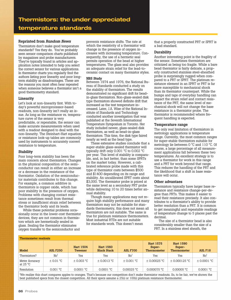
Reprinted from Random NewsThermistors don’t make good temperaturestandards? Yes they do. You’ve probablyseen sensor comparison charts publishedby magazines and probe manufacturers.They’re typically found in articles and ap-plication notes intended to help you selectthe correct sensor for various applications.In thermistor charts you regularly find theauthors listing poor linearity and poor long-term stability as disadvantages. These arethe reasons you most often hear repeatedwhen someone believes a thermistor isn’t agood thermometry standard.
LinearityLet’s look at non-linearity first. With to-day’s powerful microprocessor-basedreadouts, non-linearity isn’t really an is-sue. As long as the resistance vs. tempera-ture curve of the sensor is verypredictable, or repeatable, the sensor canmake accurate measurements when usedwith a readout designed to deal with thenon-linearity. The Steinhart-Hart equationor resistance look-up tables are commonlyused by instruments to accurately convertresistance to temperature.
StabilityPoor long-term stability has been themain concern about thermistors. Changesin the physical composition of the semi-conductor can result in either an increaseor a decrease in the resistance of thethermistor. Oxidation of the semiconduc-tor materials contributes to this change.For example, a common additive inthermistors is copper oxide, which haspoor stability in the presence of oxygen.Problems with changing contact resis-tance sometimes result from thermalstress or insufficient strain relief betweenthe thermistor body and its leads.
While these potential problems occa-sionally occur in the lower-cost thermistordevices, they are not common in thermis-tors which are hermetically sealed inglass. Sealing the thermistor eliminatesoxygen transfer to the semiconductor and
prevents resistance shifts. The rate atwhich the resistivity of a thermistor willchange in the presence of oxygen in-creases with increasing temperature. Con-sequently, the use of a hermetic sealpermits operation of the bead at highertemperatures. The glass seal also providesan adequate strain relief for the lead-to-ceramic contact on many thermistor styles.
NBS StudyBetween 1974 and 1976, the National Bu-reau of Standards conducted a study onthe stability of thermistors. The resultsdemonstrated no significant drift for bead-in-glass thermistors. Non-glass-sealed disktype thermistors showed definite drift thatincreased as the test temperature in-creased. Later, J.A. Wise of the National In-stitute of Standards and Technologyconducted another investigation that waspublished at the Seventh InternationalTemperature Symposium in Toronto. Herstudy included newer, glass-sealed diskthermistors, as well as bead-in-glassthermistors. This time, the disk type fairednearly as well as the bead type.
These extensive studies conclude that asuper-stable glass-sealed thermistor willtypically drift only 0.001 °C to 0.002 °Cper year. This level of stability is compara-ble, and, in fact better, than some SPRTson the market today. However, a cali-brated reference probe made with thistype of thermistor costs between $500and $1400 depending on its range andstability. An uncalibrated SPRT costs about$3,000. The thermistor probe is priced atthe same level as a secondary PRT probewhile delivering 10 to 20 times better an-nual stability.
Though many applications may not re-quire high stability performance and manythermistors may not be suitable for stan-dards thermometry, this does not mean allthermistors are not suitable. The same istrue for platinum resistance thermometers.Most industrial RTDs are not suitablefor standards work. This doesn’t mean
that a properly constructed PRT or SPRT isa bad standard.
DurabilityAnother interesting point is the fragility ofthe sensor. Sometimes thermistors arecriticized as being too fragile. While a barebead thermistor is fairly delicate, a prop-erly constructed stainless steel-sheathedprobe is surprisingly rugged when com-pared to a PRT or SPRT. The platinum re-sistance element in an SPRT or PRT is farmore susceptible to mechanical shockthan its thermistor counterpart. While thebumps and taps of everyday handling canimpact the strain relief and contact resis-tance of the PRT, the same level of me-chanical shock will not change the baseresistance in a thermistor probe. Thethermistor is recommended where fre-quent handling is expected.
Temperature rangeThe only real limitation of thermistors inmetrology applications is temperaturerange. Currently, the most common rangesfor super-stable thermistors suitable formetrology lie between 0 °C and 110 °C. Ofcourse, a large percentage of all measure-ment applications fall between these twotemperatures. An excellent strategy is touse a thermistor for work in this rangeand a PRT for work beyond that range.This reduces the handling of the PRT andthe likelihood that a shift in base resis-tance will occur.
Other advantaesThermistors typically have larger base re-sistance and resistance change-per-de-gree than PRTs. This makes it easier toread their resistance precisely. It also con-tributes to a thermistor’s ability to providebetter resolution than a PRT. It is commonto get meaningful and repeatable readingsof temperature change to 5 places past thedecimal.
The size of a thermistor bead is alsoconsiderably smaller than the size of aPRT. In a stainless steel sheath, the
86 Probes
Thermometer readouts
Model ASL F250Hart 1504Tweener
Hart 1560Black Stack ASL F700
Hart 1575Super-
Thermometer
Hart 1590Super-
Thermometer ASL F18
Thermistors? No† Yes Yes No† Yes Yes No†
Meter Accuracyat 25 °C
± 0.01 °C ± 0.003 °C ± 0.0013 °C ± 0.001 °C ± 0.00025 °C ± 0.000125 °C ± 0.0001 °C
Resolution 0.001 °C 0.0001 °C 0.0001 °C 0.00025 °C 0.000075 °C 0.00005 °C 0.0001 °C†We realize this chart compares apples to oranges. That’s because our competitors don’t make thermistor readouts. So, to be fair, we’ve shown thebest published specs from the closest competition. All their specs assume a 25Ω or 100Ω platinum resistance thermometer.
Thermistors: the under appreciated
temperature standards

thermistor is much less affected by stem-conduction than a PRT. In many applica-tions, a large PRT probe is simply toolarge. For example, the testing or calibra-tion of biomedical devices and analyticalinstruments frequently requires a sensorsmaller than even the bare PRT element,not to mention its tubular packaging. Off-the-shelf thermistor standards are avail-able in diameters of only 1.8 mm (0.07 in)with small gauge leads. Tremendous flexi-bility is possible in custom packagingthermistors for surface, air, and liquidmeasurements.
While Hart manufactures referencePRTs and SPRTs, we do not make thermis-tors. Still, we feel it’s important to promotetheir virtues because their unique advan-tages can contribute significantly to me-trology and calibration work. For thisreason, each of Hart’s thermometer read-outs is available with the ability to readthermistors. When you’re considering thepurchase of a readout, check into the pos-sibility of reading thermistors. If the sales-man tells you a thermistor isn’t a goodstandard, you’ve just had a good indica-tion of the company’s credibility.
Temperature Calibration Equipment 87
Thermistors: the under appreciated
temperature standards
Hart’s 1504 Tweener reads thermistors accurately to ± 0.003 °C.

Reprinted from Random NewsThermocouples are the most commonlyused temperature sensors in the world. Ifyou’re a thermocouple user, particularly ofreference thermocouples, there are a fewthings you should know. It is easy to beled into believing that accurate measure-ments with a thermocouple (two dissimilarpieces of wire joined together at a com-mon junction) are as simple to get asreading a number off a digital display.
Thermocouples react to temperaturegradients by generating a voltage. The ac-curacy of converting that voltage into atemperature is determined by the condi-tion of the thermocouple, the measure-ment technique used, the characteristics(or “type”) of the thermocouple, and itscalibration.
If you don’t know how athermocouple senses temperature,you probably make mistakes inusing them.The junction between the two dissimilarmetals of a thermocouple does not pro-duce the voltage that is measured acrossthe ends of its lead wires. Thermocouplesuse the relationship between temperatureand electricity that was first observed in1821 by Thomas Seebeck. The so-called“Seebeck effect,” which describes howthermal energy is converted into electricalenergy, does not require two dissimilarmetals to be joined together.
Consider two parallel, electrically un-connected wires that are each extendingfrom left to right. The first wire is pureplatinum, and the second is a platinum-rhodium alloy. If the temperature at theleft end of the wires is different from thetemperature at the right end of the wires,then there is an electric potential differ-ence (voltage) between the left and rightends of the wires. However, the voltageacross the pure platinum will be differentthan the voltage across the platinum alloy.For a single wire, we call this voltage theabsolute Seebeck emf. In practice, thisvoltage can never be measured directly.However, once an electrical connection ismade, for example, by making a junctionat the right end by touching the two wirestogether (see the schematic drawings),what is known as a thermocouple is pro-duced. Then, the potential difference mea-sured across the open ends, on the left,depends on the temperature differencebetween the right and left ends of thethermocouple. If the voltage and refer-ence temperature on the left is known,then the measurement temperature on theright can be calculated. Yet, without an
accurate reference temperature, makinghuge measurement errors is as easy asreading numbers off a digital display!
If you don’t know what a referencejunction is, you need to find out.There are a number of ways to obtain anaccurate reference temperature. The exactmanner chosen depends on the desiredaccuracy, budget, available equipment,and expertise of the user.
On one end of the thermocouple is themeasurement junction; the reference junc-tion (if there is one) is on the other end.Generally, a reference junction consists oftwo copper or platinum wires (with verysimilar absolute Seebeck emfs) that areelectrically connected to the thermocou-ple. The reference junction is usuallyplaced in an ice bath, which keeps it at aconstant known temperature of 0.000 °C± 0.002 °C if you’re following the ASTMprocedure E 563-97 for constructing aproper ice bath. Voltage measurementsare then taken across the copper wires,which now reside at a known tempera-ture, rather than at the thermocouplewires.
If a thermocouple does not have a ref-erence junction, it is necessary to usesome sort of electronic reference junctioncompensation (RJC—or “CJC” for “coldjunction compensation”). The meter mea-sures the temperature at the “cold” end ofthe thermocouple. From this temperature,a voltage offset is calculated. The voltageoffset is then added to the voltage
measured by the meter and the total volt-age is used to calculate the temperature.You may have to choose how the readoutor simulator device generates this offset.The wrong choice could mean an error aslarge as 25 °C.
Isn’t “homogeneity” a property ofmilk?Imperfections in thermocouple wire mayproduce undesired results in temperaturemeasurements. Thermocouple wires thatare free from these imperfections arecalled homogenous. This means that thecomposition of the wire is exactly thesame from end to end. A new thermocou-ple ought to be homogenous. An old ther-mocouple may not be. Thermocouplesattached to extension wires are not ho-mogenous and the practice of adding ex-tension wires, for laboratory calibrations,should be avoided. Thermocouple wirethat has been kinked or exposed to tem-peratures, pressures, or chemical environ-ments for which they are not designedmay also behave unpredictably because ofreductions in homogeneity. However, if athermocouple is not homogenous (i.e.where a reference junction has been sol-dered to it) and the temperature is keptconstant along the heterogeneous section(i.e. the reference junction is placed in anice bath), then the previously describederrors will be greatly minimized.
Manufacturers of thermocouples usuallyanneal new thermocouple wire electricallyto relieve the mechanical strain introduced
88 Probes
Thermocouple with no reference junction
Thermocouple with reference junction
+
–
+
–V (T )TC TC
V (T )J1 J
V (T )J2 JV =V (T )+[V (T )+V (T )]o TC TC J1 J J2 J 100°C
20°C
+
–
+
–V (T )TC TC
V (0 °C)J1
[V (0 °C)+V (0 °C)=0]J1 J2
V (0 °C)J2
0 °C
V =V (T )o TC TC100°C20°C
Electrical schematic drawings of thermocouples with and without a reference junction.
Thermocouples 101... or,maybe... 401!

Temperature Calibration Equipment 89
during manufacturing. Also, it is not un-usual for laboratories to annealthermocouples before attempting an accu-rate calibration. No one knows for surewhether annealing will help when otherfactors such as contamination have af-fected homogeneity.
If annealing cannot restore a thermo-couple to a homogeneous state, then itshould be replaced rather thanrecalibrated. Homogeneity is often theleading source of error in thermocouplemeasurements and the leading reason thethermocouple should be thrown away.The lifetime of a thermocouple is affectedby its time exposed to extreme tempera-tures, quenching, vacuum, harsh chemicalenvironments, and mechanical work onthe wires.
Be sure to use the correct type andgauge of thermocouple for your applica-tion. For example, certain types of ther-mocouples may be better suited for aparticular chemical environment than oth-ers. Noble metal thermocouples will makethe best reference thermocouples becauseof their stability over time compared toother thermocouples. A large diameterthermocouple will last longer at elevatedtemperatures, but a smaller diameter ther-mocouple will experience less immersionrelated error.
To sheath or not to sheath?Some thermocouples come with a sheath.Sheaths may be ceramic, glass, or metal.The purpose of a sheath is to protect the
thermocouple from its environment.Sheaths do not improve performance, and,in fact, thermocouples with sheaths areless responsive and require more immer-sion than do similar unsheathedthermocouples. However, using a sheath ispreferred to contaminating or mechani-cally damaging a thermocouple and istherefore a good choice for manyapplications.
To calibrate or replace?Thermocouple types are defined by a par-ticular emf-temperature relationshipwithin a specified limit of error. However,they can be calibrated to achieve resultsthat are more accurate. When a manufac-turer makes a set of thermocouples from aparticular batch of wire, a sample fromthat group may be calibrated as represen-tative of the entire group. Individual ther-mocouple calibrations may achieve moreaccurate results than a batch calibration.
Thermocouples may be calibrated in alaboratory or in situ. In situ calibrationsare recommended for base metalthermocouples. That is because when theyare used in a particular application, errorsdue to changes in the properties of thethermocouple occur that are difficult to re-produce in a laboratory. An in situ calibra-tion is performed using a newthermocouple while the old thermocoupleis still in use. Once located side by side,the difference in the indications of the twothermocouples (old and new) allows the
user to determine the tolerance status ofthe old thermocouple.
Of course, taking everything into con-sideration, the decision to replace orrecalibrate a thermocouple (and how oftento recalibrate) is ultimately yours—you be-ing most familiar with its behavior duringactual usage conditions.
Thermocouples 101... or,maybe... 401!
Copper Wirewith
Silicone Rubber Jacket
Red (+)
Black (–)
Strain ReliefMeasuring Junction Sheath
Reference (or Cold)Junction
Thermocouple Wirewith
Silicone Rubber Jacket
5649 SN:1234
Typical thermocouple construction with a reference or cold junction.

Made from the finest platinum and plati-num-rhodium alloy, the Type R and TypeS Thermocouples cover a temperaturerange of 0 °C to 1450 °C with uncertain-ties as good as 0.15 °C over most of thatrange. With four different models for eachtype, we have the thermocouple to fit yourapplication.
The measuring junction of both the5649 and the 5650 is encased in a 0.25-inch (6.35 mm) alumina sheath that canbe ordered in lengths of 20 or 25 inches(50.8 or 63.5 cm) to fit the specific re-quirements of your application. A refer-ence, or “cold,” junction may also beordered. The reference junction uses astainless steel sheath and is 8.25 incheslong (21 cm) by 0.188 inches in diameter(4.8 mm). The thin diameter minimizes theimmersion depth needed, but the extralength ensures you can get all theimmersion you like.
Special tin-plated, solid-copper con-necting wires with ultra-low EMF proper-ties are used to help retain the integrity ofyour measurement junction where theprobe attaches to your micro voltmeter orHart Black Stack.
Each probe comes from a spool of wirethat has been sample tested using fixed-point standards to ensure uncertaintiesless than 0.5 °C up to 1100 °C. From 1100°C to 1450 °C, the uncertainty increaseslinearly to 3.0°C. If you need greater accu-racy, order an individual calibration withfixed-point standards to reduce uncertain-ties to ± 0.15 °C up to 962°C, ± 0.25 °C upto 1100 °C, and increasing linearly to± 2.0 °C at 1450 °C.
The probe assembly can be easily dis-assembled for performing your own bare-wire calibrations.
90 Probes
● Designed by Hart’s primary standards design team
● Two sizes available, each with or without reference junction
● Uncalibrated accuracy is the greater of ±0.6 °C or ±0.1 % of reading
Specifications
Range 0 °C to 1450 °C
Type Platinum/13 % Rhodium vs.platinum (type R)Platinum/10 % Rhodium vs.platinum (type S)
Calibration Optional fixed point calibrationuncertainties (k=2): ± 0.15 °Cup to 962 °C, increasing linearlyto ± 2.0 °C at 1450 °C
HotJunctionSheathDimensions
6.35 mm (0.25 in) diameter; seeOrdering Information for lengths
ReferenceJunctionSheathDimensions
4.8 mm dia. x 210 mm long(0.188 x 8.25 in)
Long-TermStability
± 0.5 °C to 1100 °C± 2.0 °C to 1450 °C(over one year depending onusage)
Short-TermStabilities
± 0.2 °C to 1100 °C± 0.6 °C to 1450 °C
Immersion At least 152 mm (6 in)recommended
ProtectiveCase
Model 2609 case included
Weight 1 kg (2 lb)
Ordering Information
5649-20-X Type R TC, 508 mm (20 in)5649-20CX Type R TC, 508 mm (20 in),
with reference junction5649-25-X Type R TC, 635 mm (25 in)5649-25CX Type R TC, 635 mm (25 in),
with reference junction5650-20-X Type S TC, 508 mm (20 in)5650-20CX Type S TC, 508 mm (20 in),
with reference junction5650-25-X Type S TC, 635 mm (25 in)5650-25CX Type S TC, 635 mm (25 in),
with reference junctionX = termination. Specify “B” (bare wire), “W” (ge-neric copper-to-copper TC connector), “R” (standardType R/S TC connector), or “T” (INFO-CON for 1523and 1524). Models with reference junctions shouldnot specify “R” and models without reference junc-tions should not specify “W”.
1918-B Four-point calibration by fixedpoint (Sn, Zn, AI, Ag). Extrapo-lated to 1450 °C.
Note: Calibration uncertainty for individually cali-brated 5650s by fixed point is ±0.25 °C below1100 °C and ±2.0 °C above 1100 °C. 2609 case in-cluded with new models.
2609 Spare Case (for 635 mm [25 in]long TC)
Type R and S thermocouplestandards

Temperature Calibration Equipment 91
This table indicates tolerances on initial values of electromotiveforce versus temperature for letter designated thermocouplestypes listed in NIST monograph 175. They apply only to newthermocouple wire. Properties of thermocouple wire will change
with time and use. Due to changes in homogeneity, calibration ofused thermocouples unless performed in-situ may yield irrelevantresults. All tolerances are in degrees Celsius and a referencejunction temperature of 0 °C (32 °F) is assumed.
Reference table: letter-designated
thermocouple tolerances
Standard Tolerances Special TolerancesT (°C) T J E K N R or S B T J E K or N R or S B–200 ± 3.0 ± 2.0 ± 4.0–150 ± 2.3 ± 1.7 ± 3.0–100 ± 1.5 ± 1.7 ± 2.2–50 ± 1.0 ± 1.7 ± 2.2
0 ± 1.0 ± 2.2 ± 1.7 ± 2.2 ± 2.2 ± 1.5 ± 0.5 ± 1.1 ± 1.0 ± 1.1 ± 0.650 ± 1.0 ± 2.2 ± 1.7 ± 2.2 ± 2.2 ± 1.5 ± 0.5 ± 1.1 ± 1.1 ± 1.1 ± 0.6
100 ± 1.0 ± 2.2 ± 1.7 ± 2.2 ± 2.2 ± 1.5 ± 0.5 ± 1.1 ± 1.2 ± 1.1 ± 0.6150 ± 1.1 ± 2.2 ± 1.7 ± 2.2 ± 2.2 ± 1.5 ± 0.6 ± 1.1 ± 1.3 ± 1.1 ± 0.6200 ± 1.5 ± 2.2 ± 1.7 ± 2.2 ± 2.2 ± 1.5 ± 0.8 ± 1.1 ± 1.4 ± 1.1 ± 0.6250 ± 1.9 ± 2.2 ± 1.7 ± 2.2 ± 2.2 ± 1.5 ± 1.0 ± 1.1 ± 1.5 ± 1.1 ± 0.6300 ± 2.3 ± 2.3 ± 1.7 ± 2.3 ± 2.3 ± 1.5 ± 1.2 ± 1.2 ± 1.2 ± 1.2 ± 0.6350 ± 2.6 ± 2.6 ± 1.8 ± 2.6 ± 2.6 ± 1.5 ± 1.4 ± 1.4 ± 1.4 ± 1.4 ± 0.6400 ± 3.0 ± 2.0 ± 3.0 ± 3.0 ± 1.5 ± 1.6 ± 1.6 ± 1.6 ± 0.6450 ± 3.4 ± 2.3 ± 3.4 ± 3.4 ± 1.5 ± 1.8 ± 1.8 ± 1.8 ± 0.6500 ± 3.8 ± 2.5 ± 3.8 ± 3.8 ± 1.5 ± 2.0 ± 2.0 ± 2.0 ± 0.6550 ± 4.1 ± 2.8 ± 4.1 ± 4.1 ± 1.5 ± 2.2 ± 2.2 ± 2.2 ± 0.6600 ± 4.5 ± 3.0 ± 4.5 ± 4.5 ± 1.5 ± 2.4 ± 2.4 ± 2.4 ± 0.6650 ± 4.9 ± 3.3 ± 4.9 ± 4.9 ± 1.6 ± 2.6 ± 2.6 ± 2.6 ± 0.7700 ± 5.3 ± 3.5 ± 5.3 ± 5.3 ± 1.8 ± 2.8 ± 2.8 ± 2.8 ± 0.7750 ± 5.6 ± 3.8 ± 5.6 ± 5.6 ± 1.9 ± 3.0 ± 3.0 ± 3.0 ± 0.8800 ± 4.0 ± 6.0 ± 6.0 ± 2.0 ± 3.2 ± 3.2 ± 0.8850 ± 4.3 ± 6.4 ± 6.4 ± 2.1 ± 3.4 ± 3.4 ± 0.9900 ± 4.5 ± 6.8 ± 6.8 ± 2.3 ± 4.5 ± 3.6 ± 3.6 ± 0.9 ± 2.3950 ± 7.1 ± 7.1 ± 2.4 ± 4.8 ± 3.8 ± 1.0 ± 2.4
1000 ± 7.5 ± 7.5 ± 2.5 ± 5.0 ± 4.0 ± 1.0 ± 2.51050 ± 7.9 ± 7.9 ± 2.6 ± 5.3 ± 4.2 ± 1.1 ± 2.61100 ± 8.3 ± 8.3 ± 2.8 ± 5.5 ± 4.4 ± 1.1 ± 2.81150 ± 8.6 ± 8.6 ± 2.9 ± 5.8 ± 4.6 ± 1.2 ± 2.91200 ± 9.0 ± 9.0 ± 3.0 ± 6.0 ± 4.8 ± 1.2 ± 3.01250 ± 9.4 ± 9.4 ± 3.1 ± 6.3 ± 5.0 ± 1.3 ± 3.11300 ± 3.3 ± 6.5 ± 1.3 ± 3.31350 ± 3.4 ± 6.8 ± 1.4 ± 3.41400 ± 3.5 ± 7.0 ± 1.4 ± 3.51450 ± 3.6 ± 7.3 ± 1.5 ± 3.61500 ± 7.5 ± 3.81550 ± 7.8 ± 3.91600 ± 8.0 ± 4.01650 ± 8.3 ± 4.11700 ± 8.5 ± 4.3

92 Probes
To convert a temperature from Celsius to another temperaturescale, first find the Celsius temperature in the left column andlook up the Fahrenheit or Kelvin temperature in the adjacentcolumns.
°C = 5/9 (°F - 32)°F = 9/5°C + 32Kelvin = °C + 273.15
Temperature conversion table
°C °F K °C °F K °C °F K °C °F K °C °F K–200 –328 73.15 170 338 443.15 540 1004 813.15 910 1670 1183.15 1280 2336 1553.15–195 –319 78.15 175 347 448.15 545 1013 818.15 915 1679 1188.15 1285 2345 1558.15–190 –310 83.15 180 356 453.15 550 1022 823.15 920 1688 1193.15 1290 2354 1563.15–185 –301 88.15 185 365 458.15 555 1031 828.15 925 1697 1198.15 1295 2363 1568.15–180 –292 93.15 190 374 463.15 560 1040 833.15 930 1706 1203.15 1300 2372 1573.15–175 –283 98.15 195 383 468.15 565 1049 838.15 935 1715 1208.15 1305 2381 1578.15–170 –274 103.15 200 392 473.15 570 1058 843.15 940 1724 1213.15 1310 2390 1583.15–165 –265 108.15 205 401 478.15 575 1067 848.15 945 1733 1218.15 1315 2399 1588.15–160 –256 113.15 210 410 483.15 580 1076 853.15 950 1742 1223.15 1320 2408 1593.15–155 –247 118.15 215 419 488.15 585 1085 858.15 955 1751 1228.15 1325 2417 1598.15–150 –238 123.15 220 428 493.15 590 1094 863.15 960 1760 1233.15 1330 2426 1603.15–145 –229 128.15 225 437 498.15 595 1103 868.15 965 1769 1238.15 1335 2435 1608.15–140 –220 133.15 230 446 503.15 600 1112 873.15 970 1778 1243.15 1340 2444 1613.15–135 –211 138.15 235 455 508.15 605 1121 878.15 975 1787 1248.15 1345 2453 1618.15–130 –202 143.15 240 464 513.15 610 1130 883.15 980 1796 1253.15 1350 2462 1623.15–125 –193 148.15 245 473 518.15 615 1139 888.15 985 1805 1258.15 1355 2471 1628.15–120 –184 153.15 250 482 523.15 620 1148 893.15 990 1814 1263.15 1360 2480 1633.15–115 –175 158.15 255 491 528.15 625 1157 898.15 995 1823 1268.15 1365 2489 1638.15–110 –166 163.15 260 500 533.15 630 1166 903.15 1000 1832 1273.15 1370 2498 1643.15–105 –157 168.15 265 509 538.15 635 1175 908.15 1005 1841 1278.15 1375 2507 1648.15–100 –148 173.15 270 518 543.15 640 1184 913.15 1010 1850 1283.15 1380 2516 1653.15–95 –139 178.15 275 527 548.15 645 1193 918.15 1015 1859 1288.15 1385 2525 1658.15–90 –130 183.15 280 536 553.15 650 1202 923.15 1020 1868 1293.15 1390 2534 1663.15–85 –121 188.15 285 545 558.15 655 1211 928.15 1025 1877 1298.15 1395 2543 1668.15–80 –112 193.15 290 554 563.15 660 1220 933.15 1030 1886 1303.15 1400 2552 1673.15–75 –103 198.15 295 563 568.15 665 1229 938.15 1035 1895 1308.15 1405 2561 1678.15–70 –94 203.15 300 572 573.15 670 1238 943.15 1040 1904 1313.15 1410 2570 1683.15–65 –85 208.15 305 581 578.15 675 1247 948.15 1045 1913 1318.15 1415 2579 1688.15–60 –76 213.15 310 590 583.15 680 1256 953.15 1050 1922 1323.15 1420 2588 1693.15–55 –67 218.15 315 599 588.15 685 1265 958.15 1055 1931 1328.15 1425 2597 1698.15–50 –58 223.15 320 608 593.15 690 1274 963.15 1060 1940 1333.15 1430 2606 1703.15–45 –49 228.15 325 617 598.15 695 1283 968.15 1065 1949 1338.15 1435 2615 1708.15–40 –40 233.15 330 626 603.15 700 1292 973.15 1070 1958 1343.15 1440 2624 1713.15–35 –31 238.15 335 635 608.15 705 1301 978.15 1075 1967 1348.15 1445 2633 1718.15–30 –22 243.15 340 644 613.15 710 1310 983.15 1080 1976 1353.15 1450 2642 1723.15–25 –13 248.15 345 653 618.15 715 1319 988.15 1085 1985 1358.15 1455 2651 1728.15–20 –4 253.15 350 662 623.15 720 1328 993.15 1090 1994 1363.15 1460 2660 1733.15–15 5 258.15 355 671 628.15 725 1337 998.15 1095 2003 1368.15 1465 2669 1738.15–10 14 263.15 360 680 633.15 730 1346 1003.15 1100 2012 1373.15 1470 2678 1743.15–5 23 268.15 365 689 638.15 735 1355 1008.15 1105 2021 1378.15 1475 2687 1748.150 32 273.15 370 698 643.15 740 1364 1013.15 1110 2030 1383.15 1480 2696 1753.155 41 278.15 375 707 648.15 745 1373 1018.15 1115 2039 1388.15 1485 2705 1758.15
10 50 283.15 380 716 653.15 750 1382 1023.15 1120 2048 1393.15 1490 2714 1763.1515 59 288.15 385 725 658.15 755 1391 1028.15 1125 2057 1398.15 1495 2723 1768.1520 68 293.15 390 734 663.15 760 1400 1033.15 1130 2066 1403.15 1500 2732 1773.1525 77 298.15 395 743 668.15 765 1409 1038.15 1135 2075 1408.15 1510 2750 1783.1530 86 303.15 400 752 673.15 770 1418 1043.15 1140 2084 1413.15 1520 2768 1793.1535 95 308.15 405 761 678.15 775 1427 1048.15 1145 2093 1418.15 1530 2786 1803.1540 104 313.15 410 770 683.15 780 1436 1053.15 1150 2102 1423.15 1540 2804 1813.1545 113 318.15 415 779 688.15 785 1445 1058.15 1155 2111 1428.15 1550 2822 1823.1550 122 323.15 420 788 693.15 790 1454 1063.15 1160 2120 1433.15 1560 2840 1833.1555 131 328.15 425 797 698.15 795 1463 1068.15 1165 2129 1438.15 1570 2858 1843.1560 140 333.15 430 806 703.15 800 1472 1073.15 1170 2138 1443.15 1580 2876 1853.1565 149 338.15 435 815 708.15 805 1481 1078.15 1175 2147 1448.15 1590 2894 1863.1570 158 343.15 440 824 713.15 810 1490 1083.15 1180 2156 1453.15 1600 2912 1873.1575 167 348.15 445 833 718.15 815 1499 1088.15 1185 2165 1458.15 1610 2930 1883.1580 176 353.15 450 842 723.15 820 1508 1093.15 1190 2174 1463.15 1620 2948 1893.1585 185 358.15 455 851 728.15 825 1517 1098.15 1195 2183 1468.15 1630 2966 1903.1590 194 363.15 460 860 733.15 830 1526 1103.15 1200 2192 1473.15 1640 2984 1913.1595 203 368.15 465 869 738.15 835 1535 1108.15 1205 2201 1478.15 1650 3002 1923.15
100 212 373.15 470 878 743.15 840 1544 1113.15 1210 2210 1483.15 1660 3020 1933.15105 221 378.15 475 887 748.15 845 1553 1118.15 1215 2219 1488.15 1670 3038 1943.15110 230 383.15 480 896 753.15 850 1562 1123.15 1220 2228 1493.15 1680 3056 1953.15115 239 388.15 485 905 758.15 855 1571 1128.15 1225 2237 1498.15 1690 3074 1963.15120 248 393.15 490 914 763.15 860 1580 1133.15 1230 2246 1503.15 1700 3092 1973.15125 257 398.15 495 923 768.15 865 1589 1138.15 1235 2255 1508.15 1710 3110 1983.15130 266 403.15 500 932 773.15 870 1598 1143.15 1240 2264 1513.15 1720 3128 1993.15135 275 408.15 505 941 778.15 875 1607 1148.15 1245 2273 1518.15 1730 3146 2003.15140 284 413.15 510 950 783.15 880 1616 1153.15 1250 2282 1523.15 1740 3164 2013.15145 293 418.15 515 959 788.15 885 1625 1158.15 1255 2291 1528.15 1750 3182 2023.15150 302 423.15 520 968 793.15 890 1634 1163.15 1260 2300 1533.15 1760 3200 2033.15155 311 428.15 525 977 798.15 895 1643 1168.15 1265 2309 1538.15 1770 3218 2043.15160 320 433.15 530 986 803.15 900 1652 1173.15 1270 2318 1543.15 1780 3236 2053.15165 329 438.15 535 995 808.15 905 1661 1178.15 1275 2327 1548.15 1790 3254 2063.15

Temperature is the most commonly mea-sured parameter in the world. Tempera-ture sensors are used in instrumentsdesigned for measuring temperature. Tobe accurate, all temperature sensors mustbe calibrated against a known standard.Only short-term stability is checked duringcalibration. Long term stability should bemonitored and determined by the user.
Occasionally, a temperature sensormight fail during calibration. This canhappen even though the temperature sen-sor seemed to be functioning properlyprior to sending it in for calibration. Thisarticle gives some basic reasons for tem-perature sensor failures and offers somesuggestions to ensure their accuracy andmaximize their useable life. In addition,some background knowledge is given oneach temperature sensor type, includingbasic characteristics and their limitations.
Common temperature sensor typesThermistors, platinum resistance ther-mometers (PRTs), and thermocouples arethe instruments of choice for most temper-ature measurement applications. Each hasspecific characteristics and limitations.Normally, these instruments are reliableand give years of trouble-free service.Mistreating them, however, greatly affectstheir accuracy and useful life. Therefore,it’s imperative that they be handled andused properly. To do so, you must under-stand how they operate and what theirlimitations are.
ThermistorsThermistors are among the most robust ofall temperature sensors. They are con-structed of a solid state device that actslike a variable resistor. As the temperaturechanges, so does its resistance. These de-vices have excellent sensitivity and accu-racy. They come in a wide range ofresistance values. They have excellentlong term drift characteristics and are notshock sensitive, nor do they suffer fromother concerns that other thermometertypes may have. Because they are notshock sensitive, their calibrations gener-ally are not affected by minor vibration,being bumped or dropped. However, theirtemperature ranges are usually limited to100 ºC span.
Platinum resistance thermometers(PRTs)PRTs are perhaps the most versatile of alltemperature sensors because of their widetemperature range and high accuracy.Most are usable from -196 ºC to 420 ºC,with a few exceptions that reach up to500 ºC or even higher. This, of course,
depends on individual model specifica-tions and their respective calibrations.
Even though PRTs are highly accurateand cover a wide temperature range, theydo have limitations. Unlike thermistors,PRTs are subject to changes in calibrationif the platinum wire is contaminated, ex-posed to vibration, bumped or dropped(see photo next page). Changes in cali-bration through these processes are
cumulative. Therefore, great care must betaken when handling and using PRTs.
ThermocouplesBase metal thermocouples have advan-tages in that they have a very broad tem-perature range and are low in cost. Theirdisadvantages include relatively low accu-racy and, at very high temperatures, theyare susceptible to inhomogeneity. Nobelmetal thermocouples have a very broad
Temperature Calibration Equipment 93
Why did my temperaturesensor fail calibration?

temperature range with higher accuracy,but they cost more. Like base metalthermocouples, they are also susceptibleto inhomogeneity.
Causes of failure during calibration
Self-heating in thermistors and PRTsWhen thermistors and PRTs are calibrated,a nominal excitation current is applied.The amount of current that’s required isgenerally stated on the calibration reportor manufacturer’s specifications.
We learn from Ohms Law that when acurrent flows through a resistor, power isdissipated (I2R). This power causes thesensor to heat; which is known as “self-heating.” When the temperature sensor iscalibrated, its self-heating has been ac-counted for.
When using either sensor type, be sureto set the readout for the proper excitationcurrent. Too little or too much current willcause measurement errors. These sensorscan even be damaged if too much currentis applied.
Some readouts will automaticallychoose the proper current when either“thermistor” or “PRT” is selected. Othersmay need to be set manually. The settingsare generally in the probe setup menu. Ifyou select the current manually, always
refer to the thermometer’s specifications orcalibration report for the proper current.
Low insulation resistance and leakagecurrentsLow insulation resistance is sometimes re-ferred to as shunt resistance, because cur-rent is allowed to flow outside of themeasurement circuit. Electrically, it is likeputting another resistance in parallel withthe sensor. When low insulation resis-tance occurs, too often the transition junc-tion temperature has become too hot. (Thehub should not be so hot that it is painfulto touch.)
Additionally, low insulation resistancemay result if the sheath has been bent, orif the seal has been compromised, allow-ing moisture to reach the sensor and leadwires. This problem usually can beavoided through proper use and handling(see resistance illustration).
Transition junctionsThermistors and PRTs generally havetransition junctions. The transition junctionis where the cable lead wires connect tothe sensor lead wires. The lead wires willeither be soldered or spot welded. If theyare soldered and the junction gets too hot,the solder will melt, causing an open orintermittent condition.
Usually, the junction is sealed with ep-oxy to keep out moisture and other con-taminants. If the seal is subjected totemperatures that are beyond what theepoxy can handle, the seal may crack.This allows moisture and other contami-nants to penetrate the seal and reach thelead wires and sensor. Moisture accumu-lation is most noticeable when the tem-perature sensor is left to soak attemperatures below ambient or if theambient humidity is high.
PRTs are often packed with powderedinsulative material. This material makesthe PRT less susceptible to stress causedby mechanical shock. Unless a good sealexists, at low temperatures the insulationabsorbs moisture from the air. Moisture orother contaminants create errors in themeasurements and cause the temperaturesensor to fail calibration. Trapped moisturecan also present a safety concern. If theinsulation has absorbed a lot of moistureand the temperature sensor is put into ahigh temperature heat source, the mois-ture will turn to steam, possibly causingthe seal to blow or rupture the sheath.
94 Probes
Why did my temperaturesensor fail calibration?
Damaged coils from a dropped sensor.
C1P1 P2
C2PRT Leads
PRT Element
PRT MetalSheath
PRT Insulation
The resistance of the insulation between the metalsheath and any of the four PTR leads prevents leak-age currents.

Broken or intermittent lead wiresIf the temperature sensor cable is pulled,overworked or stressed, the lead wiresmay break, causing an open or an inter-mittent connection. On occasion, open orintermittent sensor or sensor lead wiresmay occur. Some intermittent events arenot noticeable until the temperature sen-sor is heated, causing the wire to expandand separate.
Even if great care has been taken toprevent broken or intermittent connec-tions, they still may occur given enoughtime and use. The repeated expansion andcontraction of the lead and sensor wiresmay eventually take its toll, causing thewire to break.
ContaminationContamination can be caused by chemi-cals, metal ions or oxidation.
Chemical contamination can occur inPRTs if a liquid reaches the lead or sensorwires. This can change the purity of theplatinum, which alters its electrical char-acteristics. Any changes in the purity willbe permanent.
Metal Ion contamination of platinumwire usually occurs at 600 ºC and higher.Because PRT sensors are manufacturedusing high purity platinum wire, they arethe most susceptible to this type of con-tamination. Metal ion contamination is notreversible and will cause a PRT to con-stantly drift upwards in temperature. Thisis particularly noticeable in a triple-point-of-water cell, where the reference tem-perature is extremely stable. When a PRTis manufactured for extremely high tem-peratures, it’s constructed in such a waythat the sensor is protected from ioncontamination.
Temperature sensor sheaths are usu-ally sealed to guard against contamina-tion. Both industrial and secondarytemperature sensors are not evacuatedbefore being sealed. Generally, therefore,there will be some dry air inside them.When they are exposed to various temper-atures, oxidation can form on the surfaceof the wire. Oxidation primarily affectstemperature sensors whose sensing ele-ments contain platinum wire. Oxidationcauses an increase in RTPW (resistance atthe water triple point) in metallic RTDs.Fortunately, oxidation can be removed byannealing the RTD, using the manufac-turer’s recommended temperature andprocedure. Before and after annealing,compare the temperature sensor with astandard of superior accuracy such as atriple point of water cell. This allows youto determine whether the procedure was
successful, and it helps you keep a historyof the temperature sensor’s performance.
Hysteresis and non-repeatabilityHysteresis is a condition in which temper-ature sensor’s readings lag behind or ap-pear to have a “memory” effect as thethermometer is moved through a sequen-tial range of temperatures. Measured val-ues depend on the previous temperaturein which the sensor or wire was exposed.If a temperature sensor is taken through arange of temperatures for the first time—let’s say, from cold to hot—it will follow aparticular curve. If the measurements arerepeated in the reverse order, (hot to coldin our example), a thermometer that has ahysteresis problem will have an offsetfrom the previous set of measurements. Ifrepeated, the amount of offset may not al-ways be the same.
Hysteresis does not occur with undam-aged standard platinum resistance ther-mometers (SPRTs), because SPRTs aredesigned to be strain free. PRTs that aredesigned to be rugged, however, do nothave a strain-free design and have atleast some hysteresis. Moisture ingress, ormoisture penetrating inside the tempera-ture sensor, causes hysteresis in RTDs ofany type.
InhomogeneityWhen a thermocouple is used at high tem-peratures, its wire may become contami-nated. This causes the local Seebeckcoefficient of the wire to change from itsinitial state. In other words, this alters thesensitivity of the wire to changes in tem-perature. However, the temperature expo-sure and contamination may not beuniform along the length of the thermo-couple. The Seebeck coefficient then be-comes a function of position along thethermocouple. This leads to measurementerrors that depend on the temperatureprofile the thermocouple is exposed to allalong the length of the thermocouple, andnot just the temperature at the measure-ment junction.
Short term stabilityMeasurement repeatability is a term thancan be used many different ways. Itshould be defined by the person using theterm. It often refers to the RTPW repeat-ability during a segment of thermal cy-cling or a calibration process.
When a temperature sensor fails tomeet its short term stability specification,it means the deviation between measure-ments at a particular temperature is out-side its specification. This could be causedby a large standard deviation or by
readings that continually drift in one di-rection. Potential causes for short-termstability problems include moisture, con-tamination, strain, leakage current,mechanical shock and inhomogeneity.
Ways to help prevent temperaturesensor failureTo avoid contamination, take proper pre-cautions when using temperature sensorsin harsh environments. Do not subject thetransition junction to higher or lower tem-peratures than the epoxy seal or transitionjunction can handle. Refer to the temper-ature sensor’s specifications or contact thetemperature sensor manufacturer for thetransition junction temperature specifica-tion. If there is a possibility that the transi-tion junction could be exposed to high oreven marginally high temperatures, a heatshield or heat sink is recommended.
Other ways to help prevent failure:● Do not drop, bump, or vibrate a PRT.● Never bend a sheath that isn’t
designed to be bent. Even slightbends may adversely affect thecalibration or temperature sensor life.
● Never submerge the transitionjunction into a liquid.
● Never exceed the temperaturespecification of the temperaturesensor.
● Do not soak temperature sensors forlong periods of time, particularly attemperatures where oxidation is likelyto occur.
● Do not pull or overly strain thetemperature sensor cable.
● If a temperature sensor requiresannealing, use recommendedtemperatures and techniques.Afterwards, always verify thetemperature sensors accuracy bycomparing it against a primarystandard.
● Periodically compare the temperaturesensor’s accuracy to a primarystandard, such as a water-triple-pointcell or a calibrated SPRT (standardplatinum resistance thermometer)
Temperature Calibration Equipment 95
Why did my temperaturesensor fail calibration?

96 Software
The Hart Scientific 9930 Interface–it soft-ware package and a serial cable are in-cluded with almost every Hart dry–welland bath that has an RS-232 interface.The 9930 lets you use your own PC toaccess many of the instrument’s functionsincluding set-points, temperature units,
scan functions, ramp and soak program (ifincluded in dry-well’s or bath’s firm-ware), duty cycle, proportional band, andmore! Calibration constants can also beaccessed, but access can be limited usinga password.
Interface-it also lets you log readingsto a text file, and perform fully automatedthermal switch tests with dry-wells thatsupport this feature. Interface-it can dothis and more, all from your PC! You haveprobably seen so-called automation soft-ware packages from other companieswith fewer features than you get with ourfree Interface-it software.
Don’t have an RS-232 (COM) port onyour computer? No problem. Using a USBto RS-232 converter, you can add a vir-tual COM port to any computer. Contactan Application Specialist for more detailsand recommendations.
Interface-it is free software. New up-dates are always posted on our web siteand can be downloaded and installed ina few minutes. Remember to check ourweb site regularly to obtain the latestversion of the software including knownbug fixes, new features, and support fornew instruments.
If you need more features, such asfully automated sensor calibration or datalogging software, check out our entire listof functional logging and calibrationsoftware.
Ordering Information
9930 Interface-it Software2383 USB to RS-232 Adapter
● Free with nearly every Hart heat source
● Provides PC access to Hart controller functions
● Graphically displays heat source temperatures
Model Name Description Page
9930 Interface-it Windows-based interface to all Hart dry-wells and baths that include an RS-232 port (virtu-ally all units). Provides access to all controller functions and the ability to graphically monitorthe temperature displayed on the heat source.
96
9938 MET/TEMP II Complete calibration system software. Communicates with Hart thermometers & heat sourcesto control & take readings. Generates calibration constants and reference tables. Now workswith Fluke MET/TRACK!
97
9933 TableWare Generates calibration constants and reference tables based on calibration data entered by theuser.
100
9934 LogWare Turns any 1-channel Hart thermometer readout (1523, 1502A, 1504, etc.) into a real-timedata logger. Includes flexible graphing functions as well as statistics for logged data. Also pro-vides programming, downloading, and data analysis tool for Hart logging thermometers.
101
9935 LogWare II Graphical data analysis software for multi-channel thermometers (1529, 1560, 1575A, 1590).Works in real-time or from downloaded data sets.
9936A LogWare III Database-oriented real-time temperature and humidity logging software for the 1620/5020Aand 1620A “DewK” Thermo-hygrometers. Also includes tools for downloading, importing, ex-porting, and analyzing logged data.
102
Software selection guide
Interface-it
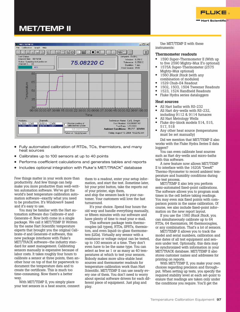
Few things matter in your work more thanproductivity. And few things can helpmake you more productive than well-writ-ten automation software. We’ve got theworld’s best temperature calibration auto-mation software—exactly what you needto be productive. It’s Windows® basedand it’s easy to use.
You may be familiar with the Hart au-tomation software duo Calibrate-it andGenerate-it. Now both come in a singlepackage. We call it MET/TEMP II! Writtenby the same Hart Scientific temperatureexperts that brought you the original Cali-brate-it and Generate-it software, thisnew package interfaces with Fluke’sMET/TRACK software—the industry stan-dard for asset management. Calibratingsensors manually is expensive because oflabor costs. It takes roughly four hours tocalibrate a sensor at three points, then an-other hour on top of that for paperwork todocument the temperature data and tocreate the certificate. This is much tootime-consuming. Now there’s a betterway.
With MET/TEMP II, you simply placeyour test sensors in a heat source, connect
them to a readout, enter your setup infor-mation, and start the test. Sometime later,hit your print button, take the reports outof your printer, sign them,and ship the sensors back to your cus-tomer. Your customers will love the fastturnaround.
It’s your choice. Spend four hours theold way and handle everything manually,or fifteen minutes with our software andhave plenty of time to read your e-mail.
This software package tests thermo-couples (all types), RTDs, SPRTs, thermis-tors, and even liquid-in-glass thermome-ters (LIGs). Virtually any sensor with aresistance or voltage output can be tested,up to 100 sensors at a time. They don’teven have to be the same type. You canselect as few as 1 or as many as 40 tem-peratures at which to test your sensors.Nobody makes more ultra-stable heatsources and thermometer readouts fortemperature calibration work than HartScientific. MET/TEMP II can use nearly ev-ery one of them. You don’t need to worryabout special software drivers for each dif-ferent piece of equipment. Just plug andplay.
Use MET/TEMP II with theseinstruments:
Thermometer readouts● 1590 Super-Thermometer II (With up
to five 2590 Mighty-Mux II’s optional)● 1575A Super-Thermometer (2575
Mighty-Mux optional)● 1560 Black Stack (with any
combination of modules)● 1529 Chub-E4 Readout● 1502, 1503, 1504 Tweener Readouts● 1523, 1524 Handheld Readouts● Fluke Hydra series dataloggers
Heat sources● All Hart baths with RS-232● All Hart dry-wells with RS-232,
including 9112 & 9114 furnaces● All Hart Metrology Wells● Fluke dry-block models 514, 515,
517, 518● Any other heat source (temperatures
must be set manually)Did we mention that MET/TEMP II also
works with the Fluke Hydra Series II dataloggers?
You can even calibrate heat sourcessuch as Hart dry-wells and micro-bathswith this software.
A new feature now allows MET/TEMPII to interface with the 1620A “DewK”Thermo-Hyrometer to record ambient tem-perature and humidity conditions duringthe test process.
MET/TEMP II also lets you performsemi-automated fixed-point calibrations.The software allows you to program soaktimes in the cell before taking readings.You may even mix fixed points with com-parison points in the same calibration. Ofcourse, we also include fixed-point infor-mation on the new report layout.
If you use the 1560 Black Stack, youcan simultaneously calibrate up to 64RTDs, 64 thermistors, 96 thermocouples,or any combination. That’s a lot of sensors.
MET/TEMP II allows you to track themodel and serial numbers, calibration anddue dates of all test equipment and sen-sors under test. Optionally, this data maybe synchronized with information in yourMET/TRACK database. MET/TEMP II alsostores customer names and addresses forprinting on reports.
With MET/TEMP II, you make your ownchoices regarding precision and through-put. When setting up tests, you specify therequired stability level at each set-point toensure that readings are taken only underthe conditions you require. You’ll get the
Temperature Calibration Equipment 97
● Fully automated calibration of RTDs, TCs, thermistors, and manyheat sources
● Calibrates up to 100 sensors at up to 40 points
● Performs coefficient calculations and generates tables and reports
● Includes optional integration with Fluke’s MET/TRACK® database
MET/TEMP II
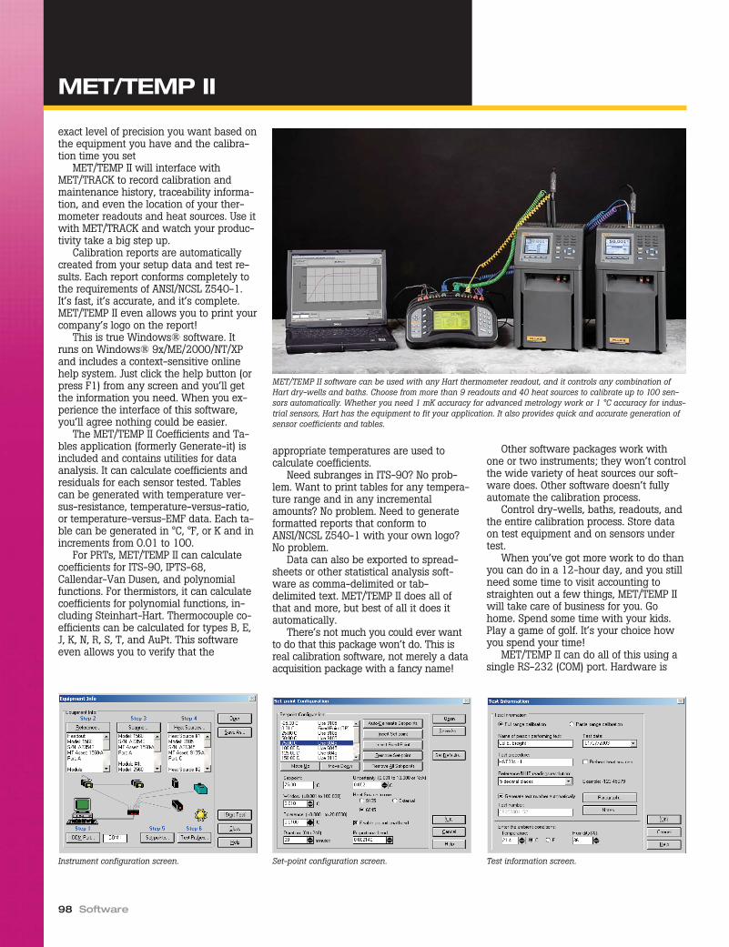
exact level of precision you want based onthe equipment you have and the calibra-tion time you set
MET/TEMP II will interface withMET/TRACK to record calibration andmaintenance history, traceability informa-tion, and even the location of your ther-mometer readouts and heat sources. Use itwith MET/TRACK and watch your produc-tivity take a big step up.
Calibration reports are automaticallycreated from your setup data and test re-sults. Each report conforms completely tothe requirements of ANSI/NCSL Z540-1.It’s fast, it’s accurate, and it’s complete.MET/TEMP II even allows you to print yourcompany’s logo on the report!
This is true Windows® software. Itruns on Windows® 9x/ME/2000/NT/XPand includes a context-sensitive onlinehelp system. Just click the help button (orpress F1) from any screen and you’ll getthe information you need. When you ex-perience the interface of this software,you’ll agree nothing could be easier.
The MET/TEMP II Coefficients and Ta-bles application (formerly Generate-it) isincluded and contains utilities for dataanalysis. It can calculate coefficients andresiduals for each sensor tested. Tablescan be generated with temperature ver-sus-resistance, temperature-versus-ratio,or temperature-versus-EMF data. Each ta-ble can be generated in °C, °F, or K and inincrements from 0.01 to 100.
For PRTs, MET/TEMP II can calculatecoefficients for ITS-90, IPTS-68,Callendar-Van Dusen, and polynomialfunctions. For thermistors, it can calculatecoefficients for polynomial functions, in-cluding Steinhart-Hart. Thermocouple co-efficients can be calculated for types B, E,J, K, N, R, S, T, and AuPt. This softwareeven allows you to verify that the
appropriate temperatures are used tocalculate coefficients.
Need subranges in ITS-90? No prob-lem. Want to print tables for any tempera-ture range and in any incrementalamounts? No problem. Need to generateformatted reports that conform toANSI/NCSL Z540-1 with your own logo?No problem.
Data can also be exported to spread-sheets or other statistical analysis soft-ware as comma-delimited or tab-delimited text. MET/TEMP II does all ofthat and more, but best of all it does itautomatically.
There’s not much you could ever wantto do that this package won’t do. This isreal calibration software, not merely a dataacquisition package with a fancy name!
Other software packages work withone or two instruments; they won’t controlthe wide variety of heat sources our soft-ware does. Other software doesn’t fullyautomate the calibration process.
Control dry-wells, baths, readouts, andthe entire calibration process. Store dataon test equipment and on sensors undertest.
When you’ve got more work to do thanyou can do in a 12-hour day, and you stillneed some time to visit accounting tostraighten out a few things, MET/TEMP IIwill take care of business for you. Gohome. Spend some time with your kids.Play a game of golf. It’s your choice howyou spend your time!
MET/TEMP II can do all of this using asingle RS-232 (COM) port. Hardware is
98 Software
MET/TEMP II
MET/TEMP II software can be used with any Hart thermometer readout, and it controls any combination ofHart dry-wells and baths. Choose from more than 9 readouts and 40 heat sources to calibrate up to 100 sen-sors automatically. Whether you need 1 mK accuracy for advanced metrology work or 1 °C accuracy for indus-trial sensors, Hart has the equipment to fit your application. It also provides quick and accurate generation ofsensor coefficients and tables.
Instrument configuration screen. Set-point configuration screen. Test information screen.

included to connect up to 6 interfaced in-struments to the PC. Additional null-mo-dem cables are required to connectinstruments to the hardware (not in-cluded). Don’t forget to order additionalcables! Don’t have an RS-232 (COM) porton your computer? No problem. Using aUSB to RS-232 converter, you can add avirtual COM port to any computer. Contactan Application Specialist for more detailsand recommendations.
In order to interface MET/TEMP II withthe MET/TRACK database, you must haveMET/TRACK v7.01 or later and you mustpurchase and apply a MET/TEMP II licenseto the MET/TRACK database (soldseparately).
Download a free working demo versionfrom our web site today! Remember tocheck our web site regularly to obtain thelatest Service Releases and updates for thesoftware including known bug fixes, newfeatures, and support for new instruments.Updates are always posted on our website and can typically be downloaded andinstalled in a few minutes.
Temperature Calibration Equipment 99
Report of CalibrationReport No: CE200206126-002
Page 1 of 1Temp Tech Co.
105 Celcius Drive
Out Town, USA
34567-8998
Model: 5614
Serial: 365232
Description: Probe, Secondary Standard
Calibration Range: Full
Received Condition: New
Current: 1.0 mA
Procedure: HST000 - 0
Customer: Our Customer
One Customer Way
Technology Drive
Any Town, USA 23456
Calibration Date: 6/3/2002
Recall Date: 6/3/2003
Temperature: 21 C
Humidity: 25%
Customer Order: 54543-544S
Technician: ________________________
Cal E. Breight
Approved By: ________________________
The above referenced instrument was calibrated by direct measurement of generated temperatures using the reference standards
listed in the "Test Equipment" table at the bottom of this report. The internal calibration coefficients and the data abtained are shown
on page 2. A Test Uncertainty Ratio (TUR) of at least 4:1 was maintained unless otherwise indicated. This calibration is traceable to
NIST or natural physical constants and is in compliance with ANSI/NCSL Z540-1 and MIL-STD 45662A.
Nominal
(Set-point)
(C)
Actual Value
(Reference)
(C)
UUT
(Test Sensor)
(Ohms)
Measurement
Uncertainty
(C)
Method of
Realization
-25.00 -24.9697 89.2564 0.050 COMP
0.01 0.0100 100.0235 0.010 TP
25.00 25.0155 110.2354 0.050 COMP
50.00 49.9895 123.5642 0.050 COMP
75.00 75.0045 132.2514 0.050 COMP
100.00 99.9692 138.2563 0.050 COMP
125.00 124.9835 145.0251 0.050 COMP
Test Equipment
Manufacturer Model Description Serial Number Recall Date
Hart Scientific, Inc. 1529 "Chub-E4" Thermometer 2-RTD/2-TC A23564 6/30/2002
Hart Scientific, Inc. 5614 Secondary Reference Temperature Std., 1/4"
x 12"
360984 1/17/2003
Hart Scientific, Inc. 5901 TPW 123456 2/1/2003
Hart Scientific, Inc. 9105 Drywell, Low-Temperature A23765 NCR
Notes: This test was performed in accordance with the test procedure indicated above.
This report shall not be reproduced except in full without written approval of Temp Tech Co..
MET/TEMP II software creates test reports that fully comply with ANSI/NCSL Z540-1 requirements. Among thefeatures included in each report are report numbers, pagination, test procedure numbers, test data, stated uncer-tainties, and test results shown as tolerances. Two locations are also available on the report for special notes.
MET/TEMP II
Ordering Information
9938 MET/TEMP II Software(package includes CD-ROM, RS-232 multiplexer box, adapter,and PC cable)
LIC-9938 MET/TRACK License2383 USB to RS-232 Adapter
Application note (literaturecode 3084747):
Calculating calibra-tion uncertaintiesin an automatedtemperature cali-bration system
Automation makescalibration easy.Now we do the samefor uncertaintyanalysis.
Go to www.hartscientific.com/publica-tions for a detailed application note.

Okay, you know about the benefits of ourMET/TEMP II software, but you didn’t or-der your Hart instruments with RS-232ports, or maybe you’ve made the mistakeof buying less capable products.
Well, you don’t need to worry, becausewe’ve got something for you, too! Our Ta-bleWare software package does almosteverything that MET/TEMP II’s Coefficientsand Tables Application does, but allowsyou to manually enter the data. It stillsaves you time and money on your calcu-lations, so it’s a great buy.
TableWare calculates coefficients forRTDs, thermistors, and thermocouples. Itsupports ITS-90, IPTS-68, Callendar-VanDusen, and polynomial equations, includ-ing standard thermocouple types. It calcu-lates coefficients using either direct orover-determined solutions and calculatesresiduals at each data point.
TableWare also generates tempera-ture-versus-resistance, temperature-ver-sus-ratio, and temperature-versus-EMFtables at increments down to 0.01. And itincludes functions for importing and ex-porting data and tables for use with otherdata analysis programs.
You simply enter or import the rawresistance or voltage data from your cali-brations. TableWare generates coeffi-cients, calculates residual values, andgenerates useful tables.
TableWare is reasonably priced andworks the way you do.
Ordering Information
9933 TableWare Software2383 USB to RS-232 Adapter
100 Software
● Calculates coefficients for RTDs, thermistors, and thermocouples
● Generates three types of temperature tables
● Easy-to-use, time-saving interface
● Outputs to ASCII text file or printed report
Input screen.
TableWare

Turn any Hart thermometer readout into areal-time data logger with one of Hart’sLogWare software packages. Whether youuse our 9934 LogWare with a single-channel thermometer readout or 9935LogWare II with one of Hart’s multi-chan-nel readouts, you’ll agree that this is the
easiest data acquisition program you’veever used.
LogWare lets you acquire data to yourPC graphically and store it to a text file. Italso performs statistical functions auto-matically on each data set.
LogWare was designed specifically fortemperature data acquisition. Set high andlow alarm conditions, program a delayedstart time, store a data log for a fixed num-ber of readings or length of time, programthe acquisition interval from 1 second to24 hours, and let the software record thedata you need the way you need it.
During a log session you can view thedata in a time/temperature trend graphwhile the data points are stored to a fileon your PC. Output the graph to yourprinter, view the test points from aspreadsheet, or review the pertinent logstatistics once your log is completed. WithLogWare II you can collect and view datafrom up to 96 probes.
With Hart’s 1524 Reference Thermom-eter and 1529 Chub-E4 thermometerreadouts, there’s even more you can do.
Both readouts store thousands of datapoints in multiple log sessions. LogWarelets you download your data into individ-ual log sessions and view each oneseparately.
Store readings from your freezers, ov-ens, chambers, and anywhere else youneed to record temperature, bring it backto your PC (through a standard serial cableor infrared dongle), and LogWare will sep-arate each log session into individual datasets. You don’t have to load the text fileinto your spreadsheet and try to figure outwhich data points went with which logsession. LogWare does all that for you.
LogWare also gives you the ability tomake configuration changes to your ther-mometer readout. Program your probe coef-ficients, write calibration data to yourmeter, set password-protected parameters,and access other tools specific to your ther-mometer readout all from your PC.
Get the most out of your readout withLogWare. If you don’t agree this is thebest temperature acquisition system foryour application, send it back and we’llrefund your money. Buy it today and try itout at no risk.
Temperature Calibration Equipment 101
● Turns any Hart thermometer readout into a real-time data logger
● Calculates statistics and displays customized graphs
● User-selectable alarms, delayed start times, and sample intervals
● Two versions for single-channel or multi-channel thermometerreadouts
Alarm settings screen.
Ordering Information
9934-S LogWare, Single Channel, SingleUser
9934-M LogWare, Single Channel, MultiUser
9935-S LogWare II, Multi Channel, SingleUser
9935-M LogWare II, Multi Channel, MultiUser
2383 USB to RS-232 Adapter
LogWare and LogWare II
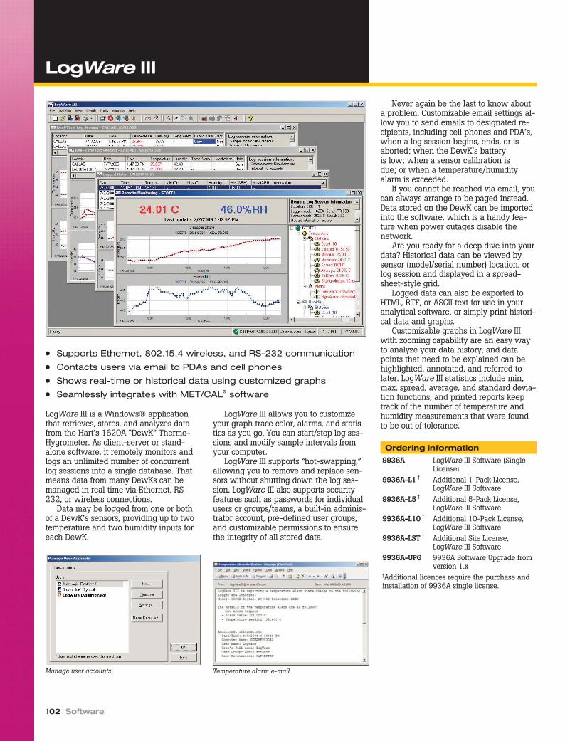
LogWare III is a Windows® applicationthat retrieves, stores, and analyzes datafrom the Hart’s 1620A “DewK” Thermo-Hygrometer. As client-server or stand-alone software, it remotely monitors andlogs an unlimited number of concurrentlog sessions into a single database. Thatmeans data from many DewKs can bemanaged in real time via Ethernet, RS-232, or wireless connections.
Data may be logged from one or bothof a DewK’s sensors, providing up to twotemperature and two humidity inputs foreach DewK.
LogWare III allows you to customizeyour graph trace color, alarms, and statis-tics as you go. You can start/stop log ses-sions and modify sample intervals fromyour computer.
LogWare III supports “hot-swapping,”allowing you to remove and replace sen-sors without shutting down the log ses-sion. LogWare III also supports securityfeatures such as passwords for individualusers or groups/teams, a built-in adminis-trator account, pre-defined user groups,and customizable permissions to ensurethe integrity of all stored data.
Never again be the last to know abouta problem. Customizable email settings al-low you to send emails to designated re-cipients, including cell phones and PDA’s,when a log session begins, ends, or isaborted; when the DewK’s batteryis low; when a sensor calibration isdue; or when a temperature/humidityalarm is exceeded.
If you cannot be reached via email, youcan always arrange to be paged instead.Data stored on the DewK can be importedinto the software, which is a handy fea-ture when power outages disable thenetwork.
Are you ready for a deep dive into yourdata? Historical data can be viewed bysensor (model/serial number) location, orlog session and displayed in a spread-sheet-style grid.
Logged data can also be exported toHTML, RTF, or ASCII text for use in youranalytical software, or simply print histori-cal data and graphs.
Customizable graphs in LogWare IIIwith zooming capability are an easy wayto analyze your data history, and datapoints that need to be explained can behighlighted, annotated, and referred tolater. LogWare III statistics include min,max, spread, average, and standard devia-tion functions, and printed reports keeptrack of the number of temperature andhumidity measurements that were foundto be out of tolerance.
Ordering information
9936A LogWare III Software (SingleLicense)
9936A-L1 † Additional 1-Pack License,LogWare III Software
9936A-L5 † Additional 5-Pack License,LogWare III Software
9936A-L10 † Additional 10-Pack License,LogWare III Software
9936A-LST † Additional Site License,LogWare III Software
9936A-UPG 9936A Software Upgrade fromversion 1.x
†Additional licences require the purchase andinstallation of 9936A single license.
102 Software
● Supports Ethernet, 802.15.4 wireless, and RS-232 communication
● Contacts users via email to PDAs and cell phones
● Shows real-time or historical data using customized graphs
● Seamlessly integrates with MET/CAL® software
Manage user accounts Temperature alarm e-mail
LogWare III

Temperature Calibration Equipment 103
Reprinted from Random NewsPrior to the start of any Olympic Games, aflame is passed from torch to torch in anunbroken chain from Athens, Greece, tothe hosting country. Similarly, you canimagine a value from a standard at a na-tional laboratory transferred in an unbro-ken chain of comparisons from onereference standard to another until thevalue from the national standard has beentransferred to a device in your ownlaboratory.
Traceability is defined as the “propertyof the result of a measurement or thevalue of a standard whereby it can be re-lated to stated references, usually nationalor international standards, through an un-broken chain of comparisons all havingstated uncertainties.” (Quite a mouthful forsome of us!) For purposes of addressingour myth, we point out two critical parts ofthis definition: “an unbroken chain ofcomparisons” (as illustrated by the Olym-pic flame) and “having stateduncertainties.”
The ISO Guide to the Expression of Un-certainty in Measurement (the “GUM”)gives general rules for expressing uncer-tainties and says that any documentationsupporting a claim of traceability for ameasurement result should include explic-itly stated uncertainties. Therefore, claimsof traceability and uncertainty calculationsare inseparable.
But be aware: it is the responsibility ofthe person or lab making the claim oftraceability to be able to support thatclaim. It’s not the responsibility of the na-tional lab. Traceability cannot be achievedsimply by following a particular procedureor by using a certain piece of equipment.Nor does sending equipment to a nationalor accredited lab guarantee traceability.
NIST, for example, says, “Although themeasurement results in a calibration ormeasurement certificate can be consideredto be ‘certified’ by NIST to be traceable toNIST reference standards at the time themeasurements were performed, NIST can-not ‘certify’ that those measurement re-sults are valid after an instrument orartifact or reference material has left NIST”(from NIST web site, emphasis added).NIST clearly makes the point that the re-sponsibility of verifying the continuing
validity of a result of a measurement be-longs to the user of that result.
So how do you “verify continuing va-lidity” and ensure traceability? NIST rec-ommends establishing your ownmeasurement assurance program, or“MAP.” A MAP involves characterizing thetransfer instrument, standard, or systemfor which traceability is desired and es-tablishing measurement assurance charts(indicating associated values anduncertainties.)
Take the example of a system in whichcalibrations of PRTs are performed in abath using an SPRT as the reference ther-mometer. The SPRT might be character-ized by monitoring its triple point of watervalue before and after each use of theSPRT. Using this data, you can establish ameasurement assurance chart that wouldallow trends to be analyzed and anychanges in the characteristics of the refer-ence to be captured.
At the same time, incorporate a checkstandard into the measurement process. Ameasurement assurance chart characteriz-ing the measurement system would allowthe tracking of any changes in the systemand the quantification of uncertainties inthe system.
With this MAP in place and the systemand transfer standard both characterized,you are now in a position to send yourreference out for calibration. When it re-turns with its new calibration certificate,you are able to quantifiably verify the in-tegrity of your calibration and measure-ment system by continuing your MAP. Thisprovides support to your claim of traceablemeasurement results. (After all, how canyou claim traceability if you can’t provethat your standard is behaving the samenow as it was at the time it wascalibrated?)
Your analysis of the data collected in aMAP should include an evaluation of theuncertainty associated with your measure-ment results and any changes that mayhave occurred to the transfer standardduring use (in our example, an SPRT).
For traceability to exist, many believethat a transfer instrument, standard, orsystem must continually produce results,that demonstrate a consistently quantifi-able uncertainty. A measurement assur-ance program is the tool for the job. It mayseem like a large investment of time andresources, but the investment is smallcompared to the cost of a recall or the lossof a customer.
Establishing traceability
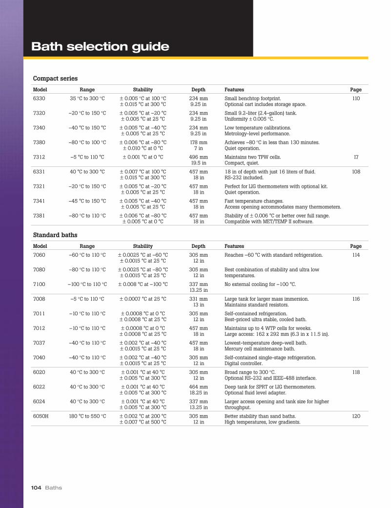
104 Baths
Compact series
Model Range Stability Depth Features Page
6330 35 °C to 300 °C ± 0.005 °C at 100 °C± 0.015 °C at 300 °C
234 mm9.25 in
Small benchtop footprint.Optional cart includes storage space.
110
7320 –20 °C to 150 °C ± 0.005 °C at –20 °C± 0.005 °C at 25 °C
234 mm9.25 in
Small 9.2-liter (2.4-gallon) tank.Uniformity ± 0.005 °C.
7340 –40 °C to 150 °C ± 0.005 °C at –40 °C± 0.005 °C at 25 °C
234 mm9.25 in
Low temperature calibrations.Metrology-level performance.
7380 –80 °C to 100 °C ± 0.006 °C at –80 °C± 0.010 °C at 0 °C
178 mm7 in
Achieves –80 °C in less than 130 minutes.Quiet operation.
7312 –5 °C to 110 °C ± 0.001 °C at 0 °C 496 mm19.5 in
Maintains two TPW cells.Compact, quiet.
17
6331 40 °C to 300 °C ± 0.007 °C at 100 °C± 0.015 °C at 300 °C
457 mm18 in
18 in of depth with just 16 liters of fluid.RS-232 included.
108
7321 –20 °C to 150 °C ± 0.005 °C at –20 °C± 0.005 °C at 25 °C
457 mm18 in
Perfect for LIG thermometers with optional kit.Quiet operation.
7341 –45 °C to 150 °C ± 0.005 °C at –40 °C± 0.005 °C at 25 °C
457 mm18 in
Fast temperature changes.Access opening accommodates many thermometers.
7381 –80 °C to 110 °C ± 0.006 °C at –80 °C± 0.005 °C at 0 °C
457 mm18 in
Stability of ± 0.006 °C or better over full range.Compatible with MET/TEMP II software.
Standard baths
Model Range Stability Depth Features Page
7060 –60 °C to 110 °C ± 0.0025 °C at –60 °C± 0.0015 °C at 25 °C
305 mm12 in
Reaches –60 °C with standard refrigeration. 114
7080 –80 °C to 110 °C ± 0.0025 °C at –80 °C± 0.0015 °C at 25 °C
305 mm12 in
Best combination of stability and ultra lowtemperatures.
7100 –100 °C to 110 °C ± 0.008 °C at –100 °C 337 mm13.25 in
No external cooling for –100 °C.
7008 –5 °C to 110 °C ± 0.0007 °C at 25 °C 331 mm13 in
Large tank for larger mass immersion.Maintains standard resistors.
116
7011 –10 °C to 110 °C ± 0.0008 °C at 0 °C± 0.0008 °C at 25 °C
305 mm12 in
Self-contained refrigeration.Best-priced ultra stable, cooled bath.
7012 –10 °C to 110 °C ± 0.0008 °C at 0 °C± 0.0008 °C at 25 °C
457 mm18 in
Maintains up to 4 WTP cells for weeks.Large access: 162 x 292 mm (6.3 in x 11.5 in).
7037 –40 °C to 110 °C ± 0.002 °C at –40 °C± 0.0015 °C at 25 °C
457 mm18 in
Lowest-temperature deep-well bath.Mercury cell maintenance bath.
7040 –40 °C to 110 °C ± 0.002 °C at –40 °C± 0.0015 °C at 25 °C
305 mm12 in
Self-contained single-stage refrigeration.Digital controller.
6020 40 °C to 300 °C ± 0.001 °C at 40 °C± 0.005 °C at 300 °C
305 mm12 in
Broad range to 300 °C.Optional RS-232 and IEEE-488 interface.
118
6022 40 °C to 300 °C ± 0.001 °C at 40 °C± 0.005 °C at 300 °C
464 mm18.25 in
Deep tank for SPRT or LIG thermometers.Optional fluid level adapter.
6024 40 °C to 300 °C ± 0.001 °C at 40 °C± 0.005 °C at 300 °C
337 mm13.25 in
Larger access opening and tank size for higherthroughput.
6050H 180 °C to 550 °C ± 0.002 °C at 200 °C± 0.007 °C at 500 °C
305 mm12 in
Better stability than sand baths.High temperatures, low gradients.
120
Bath selection guide

Temperature Calibration Equipment 105
Bath selection guide
Special application
Model Range Stability Depth Features Page
6054 50 °C to 300 °C ± 0.003 °C at 100 °C± 0.005 °C at 300 °C
610 mm24 in
Maintains constant fluid level. 122
6055 200 °C to 550 °C ± 0.003 °C at 200 °C± 0.01 °C at 550 °C
432 mm17 in
Includes LIG sighting channel.
7007 –5 °C to 110 °C ± 0.001 °C at 0 °C± 0.003 °C at 100 °C
610 mm24 in
Large, 7-inch-diameter working space.
7009 0 °C to 110 °C ± 0.0007 °C at 25 °C 331 mm13 in
Largest capacity with 4.8-cubic foot (167-liter)working area and 0.7 mK stability.
124
7015 0 °C to 110 °C ± 0.0007 °C at 25 °C 331 mm13 in
Ultrastable for maintaining resistors.Large access and workspace.Splash- and spill-resistant lid.
7108 20 °C to 30 °C ± 0.004 °C 203 mm8 in
Peltier cooling means no compressor and quieterperformance.Maintains standard resistors.
7911A2 0 °C ± 0.002 °C 203 mm8 in
Easy and affordable zero-point source for calibratingtemperature sensors.
126
Other
Item Description Page
Bath Accessories Stands, rods, and clamps to suspend and support your probes and thermometers 121
Bath Fluids Silicone oils, salt, and cold fluids in convenient, small quantities. 128
Rosemount Bath Controllers Model 7900 controller designed by Hart integrates the features of Hart’s 2100 controller and can beused in place of the Rosemount 915 controller with Rosemount-designed baths.
132
Hart Bath Controllers Model 2100 and 2200 controllers can be integrated with homemade baths or other heat sources toachieve performance levels approaching Hart baths.
133
Note: See page 152 for portable Micro-Baths.

During a European trip we visited a labstruggling through the lab accreditationprocess. The hold-up was their bath. Theyhad already tested baths from two manu-facturers. The first bath didn’t meet specsand the maker would not rectify the situa-tion, so the bath was returned. The secondbath maker delivered a working bath, butwhen the accreditation auditor tested thebath he downgraded the lab’s accuracyclass because they couldn’t meet the re-quired stability and uniformity levels.
Most bath manufacturers tell you as lit-tle as possible about their baths’ perfor-mance. In fact, one of our competitorsused to tell people that high bath stabilitywasn’t even necessary for accurate cali-brations. Some still don’t publish stabilityspecs, and some are so elusive about themeaning of their specs that you can onlyconclude they’ve got something to hide.
Lab accreditationAccreditation guidelines published byNVLAP specify that the temperature stabil-ity and uniformity of the bath fluid shouldbe at least 10 times better than the re-quired uncertainty of the sensor being cal-ibrated. If you’re testing a sensor with amodest specification of ± 0.1 °F over itswhole range, your bath must be stableand uniform to ± 0.01 °F. Translated toCelsius, this figure becomes ± 0.005 °C,and you find yourself in need of a bathwith performance to the third decimalplace at each of the temperatures youmust test. Several issues are involved inselecting a bath, and each item impactsyour calibrations.
StabilityStability is a measure of the bath’s controlperformance. How well does it maintain aconstant temperature? Short-term instabil-ity is normally seen as an oscillationaround the control point with its peaksdefined in a “2-sigma” or “± ” statement. Ifthe temperature of the bath fluid is chang-ing during your measurements, you can’tget reliable calibration results. Short-termstability is therefore absolutely crucial. Askabout short-term stability and defineshort-term as lasting at least 15 minutes.Less than that can prove very frustrating.
Long-term stability (over several hours,days, or weeks) is a convenience issue. Ifyour work requires an exact or absolutevalue, say 25.000 °C, and the bath haslong-term drift, you must readjust the con-trol set-point and wait for equilibration(attainment of short-term stability) beforeeach use. So you really need to know both
short-term and long-term stability beforeyou know if a bath will meet your needs.Long-term instability normally takes theform of drift in a single direction, but insome baths it may be seen as a long-termoscillation.
A bath’s stability will vary at differenttemperatures. Most baths perform best attemperatures close to ambient. The colderor hotter the set-point, the less stability.Too many sellers give you only one specat or near ambient. Some give a singlestability spec and don’t ever mention thatit applies only to one temperature or anarrow range. Ask about stability over thewhole range that interests you.
Bath fluid also affects stability. Thehigher a fluid’s viscosity and the lower itsheat capacity, the larger the effect on sta-bility. In addition to asking the tempera-ture, ask what fluid was used when thespec was taken. For example, at 37 °C abath will be more stable with water as themedium. If you’re going to use oil, expectsomewhat larger instability. If your oil hashigh viscosity at 37 °C, expect even greaterdegradation in stability.
UniformityA bath can have good stability but pooruniformity. The bath must be homogenousin temperature throughout the test zonewhere you’ll make your comparison mea-surements. When you place two or morethermometers in the fluid, they should beat the same temperature during your mea-surement. The uniformity spec defines thepeak value for this error source. The more
probes you’re testing, the larger the testzone, and the more important uniformitybecomes.
Uniformity depends mostly on the mix-ing of the bath fluid. Does the bath use acirculator pump for mixing? If it does, arethere thermal flow patterns in the baththat interfere with uniformity? Ask aboutboth vertical and horizontal gradients.
In a laminar flow bath (one where thefluid is stirred in a circular pattern), theremay be no horizontal gradient, but be-cause the fluid is not mixed vertically,there are gradients between differentdepths in the bath. This is a problem ifyour reference probe and the probes un-der test are not the same length. For ex-ample, if you’re testing 3-inch-long probesand your standard is a 19-inch SPRT,you’ve got a problem. You can only im-merse the test probes to 3 inches, but ifyou immerse the SPRT to only 3 inchesyou don’t have sufficient depth to avoidstem effects and light piping that will af-fect the measurement made by the SPRT.If you properly immerse the SPRT andyour bath suffers from vertical gradients,you won’t be measuring the temperatureat the 3-inch depth of your probes undertest.
Equilibration blocksAccreditation guidelines recommend theuse of a metal equilibration block to im-prove short-term stability during themeasurement. It’s certainly true that ablock can increase the stability of yourmeasurements.
106 Baths
Deviations from a central reference temperature taken in water with a 1/4-inch-diameter PRT at 25 °C.
Buying the right bath

However, a block can be inconvenient.The fixed location and diameter of itsholes eliminate the flexibility of a bath toreadily test any size or shape of thermom-eter. You’ll need a new block for eachprobe type. Placing the probes in theblock and the block in the bath is some-what less convenient than simply dippingthe probes directly in the liquid. Blocksalso oxidize, and silicone oil will thickenand stick in the bottom of the holes. Regu-lar cleaning is required to ensure contin-ued performance levels. If you’re testingmany probes at a time, a block may noteven work for you. It would be difficult toconstruct a block to properly test 20 ther-mometers at a time.
Evaluate your bath purchase on specifi-cations taken directly in the bath’s fluid. Ifyou’re given performance graphs, ask if ablock was used. In your lab you can alwaysadd a block for the most critical measure-ments. Remember: the bath that performsthe best without a block will also be the baththat performs the best with a block.
Temperature rangeThe advertised temperature range of abath is not necessarily the practical usablerange. For example, a bath with a pub-lished range of –80 °C to 150 °C can be abit misleading. The bath may operate overthat temperature range, but currentlythere’s no fluid to match that whole range.Those fluids that perform best at –80 °Cwill evaporate too rapidly long before theyget to 100 °C, much less 150 °C.
An oil bath with an advertised range of35 °C to 300 °C will be limited by the sili-cone oil you put in it. A good 300 °C oilwill be too viscous to deliver good perfor-mance below about 80 °C, so with thatfluid the bath’s range is 80 °C to 300 °C. Inanother example, a Hart salt bath worksquite well at 40 °C with the right fluid. Butsalt is molten only above 150 °C.
In addition to fluid, other factors me-chanically limit a bath’s range. These in-clude refrigeration, insulation, heatertypes, and other design issues. Refrigera-tion gases break down above 150 °C, thuslimiting the life of the system. If a refriger-ated bath is advertised with a higherrange, ask if you must remove the coolingcoil above a certain temperature. Somebaths are advertised with ranges from–80 °C to 300 °C in a single bath. How-ever, the refrigeration gases or coils mustbe removed before going to the higherend of the temperature range.
We could probably design a single baththat could operate from –100 °C to 500 °C.
Besides the high price for such a bath,there would be no point. You would haveto drain, clean, and refill the bath at leastthree times during a calibration run in or-der to cover that range. The best solution tocover –100 °C to 500 °C is at least threebaths with three different fluids. This wayeach bath design is optimized for perfor-mance in the range of the fluid you woulduse. You’ll get the best stability and unifor-mity while tripling your throughput.
Can you ask too many questions?It’s not likely that a manufacturer willhave a test file covering every temperatureand fluid combination that interests you,but you can look for representative num-bers. How many numbers will they giveyou? The more the better.
If a salesman says his bath’s stabilityspec of ± 0.005 °C applies to the wholerange, ask for a graph at several tempera-tures. If you’re buying a bath for use at300 °C and the maker can’t give you per-formance data above 100 °C, you need tobe skeptical.
If a salesman talks about “calibrationaccuracy” instead of bath performance,ask for specific stability and uniformitydata taken in the bath fluid. Finally, askfor a money-back guarantee of the perfor-mance. If you can’t get what you needfrom the bath when it’s in your lab, youneed to know your supplier will be therefor you.
Temperature Calibration Equipment 107
Buying the right bath
24.986
24.984
24.982
24.980
24.978
24.976
24.974
24.972
24.97010 20 30 40 50 60 70 80 90 100
Stability at 25°C
Hart Bath
Time (minutes)
Tem
per
atu
re
Competitor's Bath
Hart baths can achieve stability better than 1 mK for extended periods of time.
Bath fluid affects performanceHart determines its bath specifications byusing selected fluids for particular tem-peratures. Your application, however,may require different fluids over differenttemperatures. Considering that fluidcharacteristics change with temperature,some care must be taken to apply gen-eral specifications to your ownapplication.
For example, Hart often uses water tospec baths at 25 °C. The properties ofviscosity, thermal conductivity, and heatcapacity make water an ideal fluid at25 °C. However, if you want to cover arange from –5 °C to 110 °C, water justwon’t work. Hart’s 5010 silicone oil fluidwill more than adequately cover thatrange, but it may not perform as well aswater at 25 °C. Carefully testing the fluidyou use over the range you use can tellyou what you need to know for youruncertainty budget.
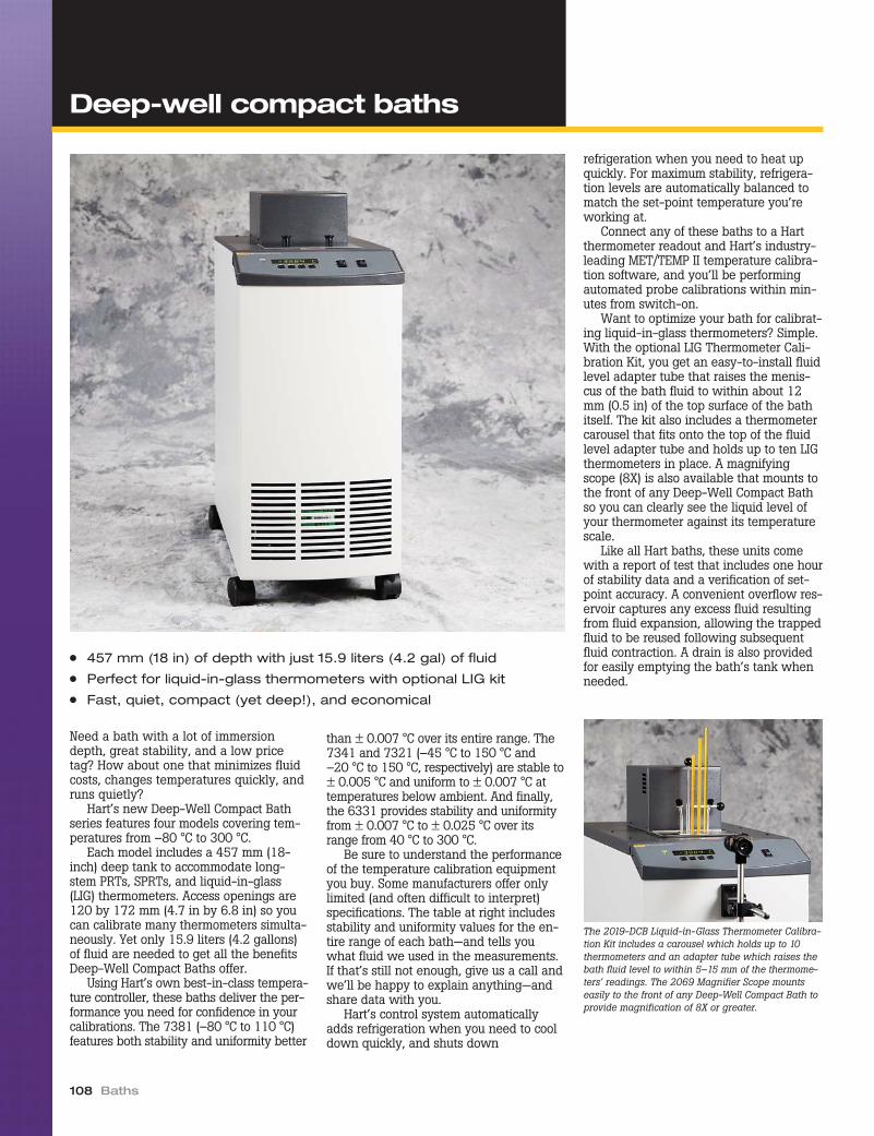
Need a bath with a lot of immersiondepth, great stability, and a low pricetag? How about one that minimizes fluidcosts, changes temperatures quickly, andruns quietly?
Hart’s new Deep-Well Compact Bathseries features four models covering tem-peratures from –80 °C to 300 °C.
Each model includes a 457 mm (18-inch) deep tank to accommodate long-stem PRTs, SPRTs, and liquid-in-glass(LIG) thermometers. Access openings are120 by 172 mm (4.7 in by 6.8 in) so youcan calibrate many thermometers simulta-neously. Yet only 15.9 liters (4.2 gallons)of fluid are needed to get all the benefitsDeep-Well Compact Baths offer.
Using Hart’s own best-in-class tempera-ture controller, these baths deliver the per-formance you need for confidence in yourcalibrations. The 7381 (–80 °C to 110 °C)features both stability and uniformity better
than ± 0.007 °C over its entire range. The7341 and 7321 (–45 °C to 150 °C and–20 °C to 150 °C, respectively) are stable to± 0.005 °C and uniform to ± 0.007 °C attemperatures below ambient. And finally,the 6331 provides stability and uniformityfrom ± 0.007 °C to ± 0.025 °C over itsrange from 40 °C to 300 °C.
Be sure to understand the performanceof the temperature calibration equipmentyou buy. Some manufacturers offer onlylimited (and often difficult to interpret)specifications. The table at right includesstability and uniformity values for the en-tire range of each bath—and tells youwhat fluid we used in the measurements.If that’s still not enough, give us a call andwe’ll be happy to explain anything—andshare data with you.
Hart’s control system automaticallyadds refrigeration when you need to cooldown quickly, and shuts down
refrigeration when you need to heat upquickly. For maximum stability, refrigera-tion levels are automatically balanced tomatch the set-point temperature you’reworking at.
Connect any of these baths to a Hartthermometer readout and Hart’s industry-leading MET/TEMP II temperature calibra-tion software, and you’ll be performingautomated probe calibrations within min-utes from switch-on.
Want to optimize your bath for calibrat-ing liquid-in-glass thermometers? Simple.With the optional LIG Thermometer Cali-bration Kit, you get an easy-to-install fluidlevel adapter tube that raises the menis-cus of the bath fluid to within about 12mm (0.5 in) of the top surface of the bathitself. The kit also includes a thermometercarousel that fits onto the top of the fluidlevel adapter tube and holds up to ten LIGthermometers in place. A magnifyingscope (8X) is also available that mounts tothe front of any Deep-Well Compact Bathso you can clearly see the liquid level ofyour thermometer against its temperaturescale.
Like all Hart baths, these units comewith a report of test that includes one hourof stability data and a verification of set-point accuracy. A convenient overflow res-ervoir captures any excess fluid resultingfrom fluid expansion, allowing the trappedfluid to be reused following subsequentfluid contraction. A drain is also providedfor easily emptying the bath’s tank whenneeded.
108 Baths
● 457 mm (18 in) of depth with just 15.9 liters (4.2 gal) of fluid
● Perfect for liquid-in-glass thermometers with optional LIG kit
● Fast, quiet, compact (yet deep!), and economical
The 2019-DCB Liquid-in-Glass Thermometer Calibra-tion Kit includes a carousel which holds up to 10thermometers and an adapter tube which raises thebath fluid level to within 5–15 mm of the thermome-ters’ readings. The 2069 Magnifier Scope mountseasily to the front of any Deep-Well Compact Bath toprovide magnification of 8X or greater.
Deep-well compact baths

Temperature Calibration Equipment 109
Deep-well compact baths
Specifications 6331 7321 7341 7381
Range 35 °C to 300 °C –20 °C to 150 °C –45 °C to 150 °C –80 °C to 110 °C
Stability ± 0.007 °C at 100 °C(oil 5012)
± 0.010 °C at 200 °C(oil 5017)
± 0.015 °C at 300 °C(oil 5017)
± 0.005°C at –20°C (ethanol)± 0.005°C at 25°C (water)
± 0.007°C at 150°C (oil 5012)
± 0.005°C at –45°C (ethanol)± 0.005°C at 25°C (water)
± 0.007°C at 150°C (oil 5012)
± 0.006°C at –80°C (ethanol)± 0.005°C at 0°C (ethanol)
± 0.005°C at 100°C (oil 5012)
Uniformity ± 0.007 °C at 100 °C(oil 5012)
± 0.017 °C at 200 °C(oil 5017)
± 0.025 °C at 300 °C(oil 5017)
± 0.007 °C at –20 °C (ethanol)± 0.00 7 °C at 2 5°C (water)
± 0.010°C at 150 °C (oil5012)
± 0.007 °C at –45 °C (ethanol)± 0.007 °C at 25 °C (water)
± 0.010 °C at 150 °C(oil 5012)
± 0.007 °C at –80 °C (ethanol)± 0.007 °C at 0 °C (ethanol)
± 0.007 °C at 100 °C(oil 5012)
Heating Time † 130 minutes, from 40 °C to300 °C (oil 5017)
120 minutes, from 25 °C to150 °C (oil 5012)
120 minutes, from 25 °C to150 °C (oil 5012)
60 minutes, from 25 °C to100 °C (oil 5012)
Cooling Time † 14 hours, from 300 °C to100 °C (oil 5017)
110 minutes, from 25 °C to–20 °C (ethanol)
130 minutes, from 25°C to–45°C (ethanol)
210 minutes, from 25 °C to–80 °C (ethanol)
Stabilization Time 15–20 minutes
Temperature Setting Digital display with push-button data entry
Set-Point Resolution 0.01 °; 0.00018 ° in high-resolution mode
Display Resolution 0.01 °
Digital SettingAccuracy
± 1 °C
Digital SettingRepeatability
± 0.01 °C
Access Opening 120 x 172 mm (4.7 x 6.8 in)
Depth 457 mm (18 in) without Liquid-in-Glass Thermometer Cal Kit482 mm (19 in) with Liquid-in-Glass Thermometer Cal Kit
Wetted Parts 304 stainless steel
Power† 115 V ac (± 10 %), 50/60 Hz,14.8 A or 230 V ac (± 10 %),
50/60 Hz, 7.4 A, specify
115 V ac (± 10 %), 60 Hz, 14A or 230 V ac (± 10 %), 50
Hz, 7 A, specify
115 V ac (± 10 %), 60 Hz, 16A or 230 V ac (± 10 %), 50
Hz, 8 A, specify
230 V ac (± 10 %), 50 or 60Hz, specify, 10 A
Volume 15.9 liters (4.2 gal)
Size ( HxWxD ) 1067 x 356 x 788 mm (940 mm from floor to tank access opening)[42 x 14 x 31 in (37 in from floor to tank access opening)]
Weight 41 kg (90 lb) 62 kg (137 lb) 68 kg (150 lb) 91 kg (200 lb)
Automation Package Interface-it software and RS-232 included (IEEE-488 optional)†Rated at nominal 115 V (or optional 230 V)
Ordering Information
6331 Deep-Well Compact Bath, 40 °Cto 300 °C
7321 Deep-Well Compact Bath,–20 °C to 150 °C
7341 Deep-Well Compact Bath,–45 °C to 150 °C
7381 Deep-Well Compact Bath,–80 °C to 110 °C
2012-DCB Spare Access Cover, Plastic,7321, 7341, 7381
2020-6331 Spare Access Cover, StainlessSteel, 6331
2019-DCB Liquid-in-Glass ThermometerCalibration Kit (includes bathadapter tube and thermometercarousel)
2069 8X Magnifier Scope, withmounts
2001-IEEE IEEE-488 Interface2027-DCBW TPW Holding Fixture (7321,
7341, 7381)2027-DCBM Mercury TP Holding Fixture
(7341)
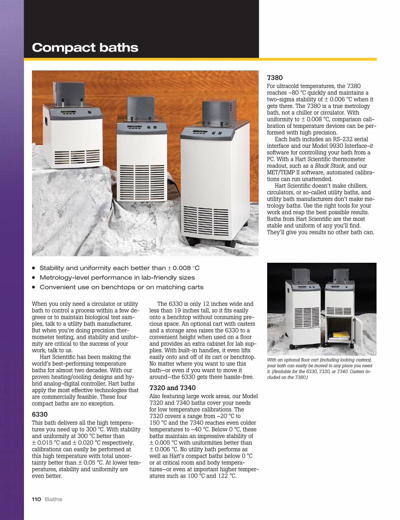
When you only need a circulator or utilitybath to control a process within a few de-grees or to maintain biological test sam-ples, talk to a utility bath manufacturer.But when you’re doing precision ther-mometer testing, and stability and unifor-mity are critical to the success of yourwork, talk to us.
Hart Scientific has been making theworld’s best-performing temperaturebaths for almost two decades. With ourproven heating/cooling designs and hy-brid analog-digital controller, Hart bathsapply the most effective technologies thatare commercially feasible. These fourcompact baths are no exception.
6330This bath delivers all the high tempera-tures you need up to 300 °C. With stabilityand uniformity at 300 °C better than± 0.015 °C and ± 0.020 °C respectively,calibrations can easily be performed atthis high temperature with total uncer-tainty better than ± 0.05 °C. At lower tem-peratures, stability and uniformity areeven better.
The 6330 is only 12 inches wide andless than 19 inches tall, so it fits easilyonto a benchtop without consuming pre-cious space. An optional cart with castersand a storage area raises the 6330 to aconvenient height when used on a floorand provides an extra cabinet for lab sup-plies. With built-in handles, it even liftseasily onto and off of its cart or benchtop.No matter where you want to use thisbath—or even if you want to move itaround—the 6330 gets there hassle-free.
7320 and 7340Also featuring large work areas, our Model7320 and 7340 baths cover your needsfor low temperature calibrations. The7320 covers a range from –20 °C to150 °C and the 7340 reaches even coldertemperatures to –40 °C. Below 0 °C, thesebaths maintain an impressive stability of± 0.005 °C with uniformities better than± 0.006 °C. No utility bath performs aswell as Hart’s compact baths below 0 °Cor at critical room and body tempera-tures—or even at important higher temper-atures such as 100 °C and 122 °C.
7380For ultracold temperatures, the 7380reaches –80 °C quickly and maintains atwo-sigma stability of ± 0.006 °C when itgets there. The 7380 is a true metrologybath, not a chiller or circulator. Withuniformity to ± 0.008 °C, comparison cali-bration of temperature devices can be per-formed with high precision.
Each bath includes an RS-232 serialinterface and our Model 9930 Interface-itsoftware for controlling your bath from aPC. With a Hart Scientific thermometerreadout, such as a Black Stack, and ourMET/TEMP II software, automated calibra-tions can run unattended.
Hart Scientific doesn’t make chillers,circulators, or so-called utility baths, andutility bath manufacturers don’t make me-trology baths. Use the right tools for yourwork and reap the best possible results.Baths from Hart Scientific are the moststable and uniform of any you’ll find.They’ll give you results no other bath can.
110 Baths
● Stability and uniformity each better than ± 0.008 °C● Metrology-level performance in lab-friendly sizes
● Convenient use on benchtops or on matching carts
With an optional floor cart (including locking casters),your bath can easily be moved to any place you needit. (Available for the 6330, 7320, or 7340. Casters in-cluded on the 7380.)
Compact baths

Temperature Calibration Equipment 111
Compact baths
Specifications 6330 7320 7340 7380
Range 35 °C to 300 °C –20 °C to 150 °C –40 °C to 150 °C –80 °C to 100 °C
Stability ± 0.005 °C at 100 °C (oil 5012)± 0.010 °C at 200 °C (oil 5017)± 0.015 °C at 300 °C (oil 5017)
± 0.005 °C at –20 °C(ethanol)
± 0.005 °C at 25 °C (water)± 0.007 °C at 150 °C
(oil 5012)
± 0.005 °C at –40 °C(ethanol)
± 0.005 °C at 25 °C (water)± 0.007 °C at 150 °C
(oil 5012)
± 0.006 °C at –80 °C(ethanol)
± 0.010 °C at 0 °C (ethanol)± 0.010 °C at 100 °C
(oil 5012)
Uniformity ± 0.007 °C at 100 °C (oil 5012)± 0.015 °C at 200 °C (oil 5017)± 0.020 °C at 300 °C (oil 5017)
± 0.005 °C at –20 °C(ethanol)
±0.005 °C at 25 °C (water)±0.010 °C at 150 °C
(oil 5012)
±0.006 °C at –40 °C (ethanol)±0.005 °C at 2 5 °C (water)
±0.010 °C at 150 °C(oil 5012)
±0.008 °C at –80 °C (ethanol)±0.012 °C at 0 °C (ethanol)
±0.012 °C at 100 °C(oil 5012)
Heating Time † 250 minutes, from 35 °C to300 °C (oil 5017)
80 minutes, from 25 °C to150 °C (oil 5012)
60 minutes, from 25°C to150°C (oil 5012)
25 minutes, from 25 °C to100 °C (oil 5010)
Cooling Time n/a 100 minutes, from 25°C to–20°C (oil 5012)
110 minutes, from 25°C to–40°C (ethanol)
130 minutes, from 25 °C to–80 °C (ethanol)
Stabilization Time 15–20 minutes
Temperature Setting Digital display with push-button data entry
Set-Point Resolution 0.01°; 0.00018° in high-resolution mode 0.01°
Display Resolution 0.01 °
Digital SettingAccuracy
± 0.5 °C
Digital SettingRepeatability
± 0.01 °C
Access Opening 94 x 172 mm (3.7 x 6.8 in) 86 x 114 mm (3.25 x 4.5 in)
Working Area 81 x 133 mm (3.2 x 5.25 in) 86 x 114 mm (3 x 4 in)
Depth 234 mm (9.25 in) 178 mm (7 in)
Wetted Parts 304 stainless steel
Power 115 V ac (±10 %), 50/60 Hz,7 A or 230 V ac (±10 %),50/60 Hz, 3.5 A, specify
115 V ac (±10 %), 60 Hz, 15 A or230 V ac (±10 %), 50 Hz, 8 A, specify, 1400 VA
115 V ac (±10 %) 60 Hz,16 A or 230 V ac (±10 %),
50 Hz, 8 A, specify
Volume 9.2 liters (2.4 gal) 4 liters (1 gal)
Size ( WxDxH ) 305 x 546 x 470 mm(12 x 21.5 x 18.5 in) off cart;
305 x 546 x 819 mm(12 x 21.5 x 32.25 in) on cart
305 x 622 x 584 mm (12 x 24.5 x 23 in) off cart;305 x 622 x 819 mm (12 x 24.5 x 32.25 in) on cart
305 x 610 x 762 mm(12 x 24 x 30 in)
Weight 19 kg (42 lb) 35.4 kg (78 lb) 52 kg (115 lb)
Automation Package Interface-it software and RS-232 included (IEEE-488 optional)†Rated at nominal 115 V (or optional 230 V)
Ordering Information
6330 Compact Bath, 35 °C to 300 °C
2020-6330 Spare Access Cover, SST, 6330
2076-6330 Floor Cart, 6330 (height:343 mm [13.5 in])
2001-IEEE IEEE-488 Interface
7320 Compact Bath, –20 °C to 150 °C
2020-7320 Spare Access Cover, SST,7320/7340
2076-7320 Floor Cart, 7320/7340 (height:229 mm [9 in])
2001-IEEE IEEE-488 Interface
7340 Compact Bath, –40 °C to 150 °C
2020-7320 Spare Access Cover, SST,7320/7340
2076-7320 Floor Cart, 7320/7340 (height:229 mm [9 in])
2001-IEEE IEEE-488 Interface
7380 Compact Bath, –80 °C to 100 °C
2020-7380 Spare Access Cover, SST, 7380
2125-C IEEE-488 Interface (RS-232 toIEEE-488 converter box)

Fluke’s Hart Scientific division is the recog-nized leader in the design and manufactureof temperature calibration baths, with moreHart baths in calibration laboratoriesworldwide than any other bath supplier.We’ve achieved this position through deliv-ering baths with a measurable difference.Hart baths were designed specifically formetrology, not adaptations of equipmentdesigned for biology and chemistry labora-tories. Hart baths provide performance youcan trust and here’s why.
Range of bathsFour types of baths are available: standardbaths, compact baths, deep-immersioncompact baths, and standard resistor baths.The wide range of baths means you’ll ab-solutely find a bath to meet your applica-tion needs and your budget, whetheryou’re working in a primary standards lab-oratory or an industrial workshop.
Standard baths, a favorite with Na-tional Metrology Institutes (NMI), are avail-able for the range –100 °C to 550 °C andoffer milli-Kelvin stability and uniformity.Hart standard baths have larger wellopenings than other baths. This makesthem an excellent choice for sensor manu-facturers and others that test large batchesof sensors or special probes of unusualsize and shape.
If you don’t need the performance of aHart standard bath, the Hart compact bathsare the perfect alternative with ranges from–80 °C to 300 °C, more portability, andsmaller fluid volumes. The deep-immersionversions offer a full 457 mm (18 in) of im-mersion depth with an optional fluid-leveladaptor for calibration of total and partial-immersion liquid-in-glass thermometers.
For maintaining your standard resistorsfor electrical or temperature calibrationwork, a Hart resistor bath will provide un-matched stability and uniformity and a
large working volume, up to 27.5 in x22 in x 13 in.
ControllersThe first step in evaluating a bath is tolook at its temperature controller. We de-signed our own proprietary control tech-nology to deliver stability to ± 0.0001 °Cwith user convenience and productivityfeatures. Our hybrid analog and digital de-sign is unique. Set-point resolution is0.01 °C (0.002 °C on some models), andour “Super-Tweak” resolution mode offsetsthe set-point so you can adjust the bathset-point to 0.00018 °! If you need a bathset to exactly 25.000 °C, a Hart bath getsyou there with less effort than any otherbath. Eight of your most frequently used
set-point temperatures are stored for quickrecall and faster bath setup. Temperaturecan be easily switched between Celsiusand Fahrenheit. Safety cutout tempera-tures are also set on the LED display.
Hart baths are each fitted with a high-stability PRT or thermistor as the controlsensor. Our controller uses special noise-rejection techniques to allow us to mea-sure the very tiny resistance changes re-quired for this level of bath stability. Inthis design we use current reversal tech-niques to cancel thermal EMF measure-ment errors. Custom, high-precision, low-coefficient resistors aid the short- andlong-term stability of the temperature set-ting, and advanced filtering techniquesforce out line noise along with stray EMIand RFI.
A proportional, integrating controlfunction directs power to the bath heaters.Factory tuning eliminates most overshootand allows the bath to achieve maximumstability within 10 to 15 minutes afterreaching the set-point temperature.
Other bath manufacturers use off-the-shelf process controllers, which just plaincan’t provide the low-noise, low-resis-tance measurement necessary for milli-Kelvin stability and uniformity over abath’s working range.
AutomationFor improved productivity, automation isessential. You can select from an RS-232interface or IEEE-488. The RS-232 pack-ages come complete with 9930 Interface-it software so you can immediately startcontrolling your bath from a PC withoutany software programming skills.
With optional 9938 MET/TEMP II soft-ware, connect any Hart bath with an RS-232 interface to a Hart thermometer read-out and you can perform fully automatedprobe calibrations.
112 Baths
Why a Hart bath?

Hart’s compact baths use an automaticcontrol for refrigeration power. However,the higher performance standard bathsuse a heating/cooling equilibrium designthat’s unique in the industry. A manualvalve adjusts the cooling power to prop-erly balance the refrigeration against theactive control of the resistance heaters.Hart’s standard bath interface packagesinclude automated valves to make theseadjustments automatically by your PC.
Heat-port technologyA major factor in Hart’s standard bath per-formance is our heat-port technology. Thecooling coil and the heater are sandwichedto the outside of the bath’s stainless steeltank. The tank bottom becomes the heatport with most of the heat entering and ex-iting the bath through a single location.Providing well-designed insulation aroundthe tank minimizes other heat leaks.
MixingFor mixing the bath fluid, Hart uses a care-fully balanced stirring mechanism. Thenumber of propellers and the pitch of theblades are adjusted to thoroughly mix thebath medium and eliminate both horizon-tal and vertical gradients. We don’t usecirculating pumps because the tubular in-let and outlet design cause thermal-flowpatterns in the bath that create unneces-sary gradients. Our mixing scheme and thesize and shape of our tanks all combine todeliver great performance.
All our baths use tanks made of heavy-gauge stainless steel that is fabricated andwelded in our own factory so we can con-trol quality. After more than 20 years wehaven’t had a single Hart bath weld de-velop a leak.
MaintenanceHart baths are easy to maintain becauseour stirrer motors last longer and there areno pumps to unclog or repair. Our tanksare easier to clean because they allow
100 % drainage of bath fluid. Since thestirrer motors are direct drive, you won’thave to buy a supply of belts just to per-form your calibrations.
These are the reasons we sell more tem-perature calibration baths than anybodyelse. And remember, if you don’t find a bathin the catalog to meet your exact needs, talkto us. Chances are we’ve built one.
Temperature Calibration Equipment 113
Why a Hart bath?
HEAT IN
HEAT OUT
STAINLESSSTEEL TANK
THERMAL INTEGRATOR
COOLING PLATECOOLING COIL
HEATER
STIR GUARD
PROPELLER
STIR MOTOR
OUTERSHELL
INSULATION
“Standard Bath” construction.

Do you need a bath that chills below–40 °C to temperatures as low as –60 °Cor even –100 °C? Would you like a baththat reaches those temperatures withoutusing any external coolants? Hart has avariety of baths that meet these tempera-ture requirements and give you the beststability in the industry.
These baths are completely self-con-tained. They require no auxiliary coolingfluids or devices to achieve their set-pointtemperatures. Using Hart’s unique “heat-port” design, stability at –100 °C is± 0.008 °C. No other company makes abath that can match a Hart bath’s perfor-mance, and Hart baths are backed by ourguarantee that if they don’t performexactly the way we say they will, we’ll
take them back. No arguments. No ifs,ands, or buts.
Automate each of these baths with aninterface package and Hart’s 9930 Inter-face-it software. If you want to completelyautomate the entire calibration process,see the description of Hart’s MET/TEMP IIsoftware package on page 97.
Forget commodity-like utility baths!They’re not designed for high performancecalibration needs. And be careful of com-panies that advertise performance specifi-cations they don’t meet. It’s easy to writedown numbers; it’s more difficult to meetthem with an instrument.
Remember, if our baths don’t performthe way we say they will, just send themback. Our equipment won’t disappoint you.
114 Baths
● Self-contained refrigeration—no LN2 or chiller required
● Temperatures as low as –100 °C in real metrology baths
● Best stability and uniformity available at –60 °C and below
● Large working areas for increased throughput
Test Well13.5" Deep
Stir MotorAdapter Stirreror Pump Motor
The 2016 fluid level adapter circulates fluid to the topof the bath access to give as much immersion aspossible for LIG thermometers.
Ordering Information
7060 Standard Bath, –60 °C to 110 °C7080 Standard Bath, –80 °C to 110 °C7100 Standard Bath, –100 °C to
110 °C2001-7060 Automation Package for 70602001-7080 Automation Package for 70802001-7100 Automation Package for 71002001-IEEE Add for IEEE-488 (requires Auto-
mation Package)2010 Access Cover, 127 x 254 mm
(5 x 10 in), Lexan2007 Access Cover, 127 x 254 mm
(5 x 10 in), Stainless Steel2016-7060 Fluid Level Adapter, 70602016-7080 Fluid Level Adapter, 70802019-7100 Fluid Level Adapter, 71002069 8X Magnifier Scope, with mounts
Really cold baths

Temperature Calibration Equipment 115
Really cold baths
Specifications 7060 7080 7100
Range –60 °C to 110 °C –80 °C to 110 °C –100 °C to 110 °C
Stability ± 0.0025 °C at –60 °C (methanol)± 0.002 °C at 0 °C (methanol)± 0.0015 °C at 25 °C (water)
± 0.003 °C at 100 °C (oil 5012)
± 0.0025 °C at –80 °C (methanol)± 0.0015 °C at 0 °C (methanol)± 0.0015 °C at 25 °C (water)
± 0.003 °C at 100 °C (oil 5012)
± 0.008 °C at –100 °C (methanol)
Uniformity ± 0.005 °C at –60 °C (methanol)± 0.005 °C at 0 °C (methanol)± 0.003 °C at 25 °C (water)
± 0.005 °C at 100 °C (oil 5012)
± 0.007 °C at –80 °C (methanol)± 0.005 °C at 0 °C (methanol)± 0.003 °C at 25 °C (water)
± 0.005 °C at 100 °C (oil 5012)
± 0.005 °C at –100 °C (methanol)
Temperature Setting Digital display with push-button data entry
Set-Point Resolution 0.01 °C; high-resolution mode, 0.00007 °C
Display Resolution 0.01 °C
Digital Setting Accuracy ± 1 °C
Digital SettingRepeatability
± 0.01 °C
Heaters 500 and 1000 Watts 350 and 700 Watts
Access Opening 127 x 254 mm (5 x 10 in) 98 mm diameter (3.8 in)
Depth 305 mm (12 in) 406 mm (16 in)
Wetted Parts 304 stainless steel
Power 230 V ac (± 10 %), 50 or 60 Hz, 13 A, single phase, specify frequency 230 V ac (± 10 %), 50 or 60 Hz, 12 A,specify frequency
Volume 27 liters (7.2 gallons) 18 liters (4.8 gallons)
Weight 159 kg (350 lb) 182 kg (400 lb)
Size ( HxWxD ) 1168 x 775 x 483 mm(46 x 30.5 x 19 in)
1270 x 813 x 483 mm(50 x 32 x 19 in)
Automation Package Interface-it software and an RS-232 computer interface are available for setting the bath temperature via an externalcomputer. For IEEE-488, add 2001-IEEE to the automation package.
Periodic bath testingAll calibration apparatus should either betested or calibrated. Calibration baths are nodifferent. Although the accuracy is often ofsecondary importance, bath instability andnon-uniformity directly affect calibrationuncertainties.
To ensure continued performance, thesebath characteristics should be tested period-ically. The tests should be carried out at all
temperatures commonly used and under typ-ical conditions.
Additionally, since the goal of the tests isto determine the contribution to uncertainty,these tests should be conducted only overthe “calibration zone” used in your process,not over the entire zone available. The testscan be conducted with several sensors orwith a single sensor moved from one loca-tion to the next.
Map the differences and include them inyour uncertainty analysis. In most cases,with a Hart bath, the values observed will besignificantly smaller than the publishedspecifications.

Hart Scientific’s temperature calibrationbaths are known around the world as thebest calibration baths made. If you’re look-ing for a cold bath, no one gives you morechoices than Hart.
These five baths operate at tempera-tures as low as –40 °C, and each one isbuilt using CFC-free refrigerants. Hart’sproprietary controller design and uniquetank construction produce bath stabilitiesto ± 0.001 °C or better. These baths are sostable and uniform that national labs usethem for comparison calibrations andfixed-point cell maintenance.
Each bath (except the 7011) is fullyautomatable with a bath interface packageand Hart’s MET/TEMP II automation softwarepackage described on page 97. When we
automate a bath, we automate it completelywith computer-controlled solenoid valves forprecision balancing of the heating and cool-ing system. MET/TEMP II performs all cali-bration tasks automatically, using your PC.
With a Hart cold bath, you can forgetexternal coolants. Internal refrigerationsystems are all that’s needed to reacheach bath’s coldest temperature. Most coldbaths may be ordered with an optionalpumping lid for supplying external coolingrequirements.
Each bath has unique characteristicsthat make it perfect for specific jobs.Some baths are excellent for SPRTs, someare great with thermistors, and some areperfect for maintaining triple point of wa-ter cells. A 7008IR bath can even be used
to maintain the temperature of ablackbody cone.
Regardless of your application, Hart hasa bath that gets the job done, and donebetter than anyone else can do it. Call ustoday and tell us about your application.
116 Baths
● Stability to ± 0.0007 °C
● Best digital temperature controller available
● “Super Tweak” function provides set-point resolution to 0.00003 °C
● Excellent for maintaining fixed-point cells
This Hart Model 7008-IR features a NIST-designedcone-shaped target.
Cold baths

Temperature Calibration Equipment 117
Cold baths
Specifications 7008 7040 7037 7012 7011
Range –5 °C to 110 °C –40 °C to 110 °C –10 °C to 110 °C
Stability ± 0.0007 °C at 25 °C(water)
± 0.001 °C at 25 °C(mineral oil)
± 0.002 °C at –40 °C (ethanol)± 0.0015 °C at 25 °C (water)
± 0.003 °C at 100 °C (oil 5012)
± 0.0008 °C at 0 °C (ethanol)± 0.0008 °C at 25 °C (water)
± 0.003 °C at 100 °C (oil 5012)
Uniformity ± 0.003 °C at 25 °C(water)
± 0.004 °C at 25 °C(mineral oil)
± 0.004 °C at –40 °C (ethanol)± 0.002 °C at 25 °C (water)
± 0.004 °C at 100 °C (oil 5012)
± 0.003 °C at 0 °C (ethanol)± 0.002 °C at 25 °C (water)
± 0.004 °C at 100 °C (oil 5012)
TemperatureSetting
Digital display with push-button data entry
Set-PointResolution
0.002 °C; high-resolution mode,
0.00003 °C
0.01 °C; high-resolution mode, 0.00007 °C 0.002 °C; high-resolution mode, 0.00003 °C
Display Resolution 0.01 °C
Digital SettingAccuracy
± 1 °C
Digital SettingRepeatability
± 0.01 °C ± 0.005 °C
Heaters 500 and 1000 Watts
Access Opening(call for customs)
324 x 184 mm(12.75 x 7.25 in)
127 x 254 mm(5 x 10 in)
162 x 292 mm(6.38 x 11.5 in)
127 x 254 mm(5 x 10 in)
Depth 331 mm (13 in) 305 mm (12 in) 457 mm (18 in) 305 mm (12 in)
Wetted Parts 304 stainless steel
Power 115 V ac (± 10 %), 60Hz, 14 A or 230 V ac,
50 or 60 Hz, 8 A,specify
115 V ac (± 10 %), 60 Hz, 16 A or 230 V ac(± 10 %), 50 or 60 Hz, 9 A
(specify voltage and frequency)
115 V ac (± 10 %), 60 Hz, 14 A or 230 V ac(± 10 %), 50 Hz, 7 A, specify
Volume 42 liters (11.2 gal) 27 liters (7.2 gal) 42 liters (11.2 gal) 27 liters (7.2 gal)
Weight 61 kg (135 lb) 63.5 kg (140 lb) 68 kg (150 lb) 56.7 kg (125 lb)
Size ( HxWxD ) 610 x 775 x 483 mm(24 x 30.5 x 19 in)
622 x 768 x 483 mm(24.5 x 30.25 x 19 in)
775 x 768 x 483 mm(30.5 x 30.25 x 19 in)
762 x 686 x 401 mm(30 x 27 x 15.8 in)
559 x 686 x 401 mm(22 x 27 x 15.8 in)
AutomationPackage
Interface-it software and RS-232 computer interface are available for setting the bath temperature via an external computer.For IEEE-488, add the 2001-IEEE to the automation package. (Interfaces not available for Model 7011.)
Ordering Information
7008 Standard Bath, –5 °C to 110 °C,high capacity
7011 Standard Bath, –10 °C to110 °C
7012 Standard Bath, –10 °C to110 °C, deep
7037 Standard Bath, –40 °C to110 °C, deep
7040 Standard Bath, –40 °C to110 °C
2001-IEEE Add for IEEE-488 (requires Au-tomation Package)
2007 Access Cover, 127 x 254 mm(5 x 10 in), Stainless Steel(7011, 7040)
2010 Access Cover, 127 x 254 mm(5 x 10 in), Lexan (7011, 7040)
2010-5 Access Cover, 162 x 292 mm(6.38 x 11.5 in), Lexan (7037)
2011 Access Cover, 184 x 324 mm(7.25 x 12.75 in), Lexan (7008)
2016-7008 Fluid Level Adapter, 70082016-7011 Fluid Level Adapter, 70112016-7012 Fluid Level Adapter, 70122016-7037 Fluid Level Adapter, 70372016-7040 Fluid Level Adapter, 70402071 Bath Cart, 7011, 7012
(312 mm [12.3 in] H)2073 Bath Cart, 7008, 7037, 7040
(216 mm [8.5 in] H)
2027-5901 TPW Holding Fixture (7012,7037)
2069 8X Magnifier Scope, withmounts
7008IR 7008, modified to accept anIR cone
2033 IR Cone (NIST design)

Comparison calibrations require a heatsource that’s stable and uniform, and formoderately high temperatures nothingprovides a better heat source than a Hartoil bath.
Hart oil baths are stable to ± 0.001 °Cand do not require calibration blocks oruse of special calibration techniques toachieve that stability. The specifications ofall Hart baths are “true” specifications rep-resenting the performance you can expectto achieve in your lab under your operat-ing conditions. Other companies advertisespecs that they know you will never seein your lab. When their baths fail to per-form, they blame it on you.
Hart baths are built using a unique tankdesign that guarantees the best uniformity
possible in a liquid bath. This, coupled withthe industry’s best-selling digital bath con-troller, achieves uncompromised perfor-mance and ease of use.
Not only does Hart’s digital controllerhave features like its “Super-Tweak” high-resolution mode so you can dial in the ex-act temperatures you want, it also lets youcompletely automate the calibration pro-cess using your PC and Hart’s 9938MET/TEMP II software (see page 97).
You’ll love these baths, and onceyou’ve got one you’ll never buy anythingelse. There’s a bath to match any temper-ature range, depth, price, and performanceyou need.
118 Baths
● Large-capacity tanks for higher productivity
● Calibrations up to 300 °C
● Built-in cooling coils for extended low range
● Stability to ± 0.001 °C
22
Uncertainty evaluation andstatistical process control with abathConsiderable emphasis is placed on un-certainty analysis and statistical processcontrol (SPC) in the calibration lab. Ifyou’re using a calibration bath in yourprocess, you may be wondering how toinclude the bath in the process evalua-tion. Basically, there are threeapproaches.
The first is to “calibrate” the bath toensure that it meets published specifica-tions and include the published specifi-cations with the “type B” uncertainties inyour evaluation just as you might do withany other instrument.
The second approach is to thoroughlytest the bath stability and uniformity,perform statistical analysis of the results’uncertainties, and include the resultswith the “type A” uncertainties in yourevaluation. This is often a better methodand will provide more realistic results.
The third avenue is to use a “checkstandard” instrument in the process insuch a way that the bath characteristicsare included in the check-standard data,which is evaluated statistically and in-cluded with the “type A” evaluation. Thisapproach is somewhat more time-con-suming but will provide realistic results.When used in conjunction with the sec-ond method above, the best results willbe obtained.
Hot baths

Temperature Calibration Equipment 119
Hot baths
Specifications 6020 6022 6024
Range 40 °C to 300 °C†
Stability ± 0.001 °C at 40 °C (water)± 0.003 °C at 100 °C (oil 5012)± 0.005 °C at 300 °C (oil 5017)
Uniformity ± 0.002 °C at 40 °C (water)± 0.004 °C at 100 °C (oil 5012)± 0.012 °C at 300 °C (oil 5017)
Temperature Setting Digital display with push-button data entry
Set-Point Resolution 0.01 °C; high-resolution mode, 0.00018 °C
Display Temperature Resolution 0.01 °C
Digital Setting Accuracy ± 1 °C
Digital Setting Repeatability ± 0.02 °C
Heaters 350 and 1050 watts
Access Opening(call for custom openings)
127 x 254 mm (5 x 10 in) 184 x 324 mm (7.25 x 12.75 in)
Depth 305 mm (12 in) 464 mm (18.25 in) 337 mm (13.25 in)
Wetted Parts 304 stainless steel
Power 115 V ac (± 10 %), 50/60 Hz, 10 A or 230 V ac (± 10 %), 50/60 Hz, 5 A, specify
Volume 27 liters (7.2 gallons) 42 liters (11.2 gallons)
Weight 32 kg (70 lb) 36 kg (80 lb)
Size ( HxWxD ) 648 x 406 x 508 mm(25.5 x 16 x 20 in)
813 x 406 x 508 mm(32 x 16 x 20 in)
699 x 483 x 584 mm(27.5 x 19 x 23 in)
Automation Package Interface-it software and RS-232 computer interface are available for setting bath temperature via remotecomputer. For IEEE-488, add the 2001-IEEE to the automation package.
†External cooling required for operation below 40 °C. Cooling coils are built into the bath walls. Tubing ports are accessible at the back of the bath for circulating chilledfluid or shop air to boost cooling.
Ordering Information
6020 Standard Bath, 40 °C to 300 °C6022 Standard Bath, 40 °C to 300 °C,
deep6024 Standard Bath, 40 °C to 300 °C,
high capacity2001-6020 Automation Package for 60202001-6022 Automation Package for 60222001-6024 Automation Package for 60242001-IEEE Add for IEEE-488 (requires Au-
tomation Package)
2007 Access Cover, 127 x 254 mm(5 x 10 in), SST (6020, 6022)
2009 Access Cover, 184 x 324 mm(7.25 x 12.75 in), Stainless Steel(6024)
2070 Bath Cart, 6020, 6022 (312 mm[12.3 in] H)
2072-2450 Bath Cart, 6024 (216 mm[8.5 in] H)
2023 Fast-Start Heater, 419 mm (16.5in) (6022)
2069 8X Magnifier Scope, withmounts

You’ll find more Hart baths in national cal-ibration labs than any other brand, andthere’s a reason for that. No one else canmatch the stability, uniformity, and perfor-mance of a Hart bath, and we absolutelyguarantee it.
This model is designed for high-tem-perature work—up to 550 °C. Most labsuse this as a salt bath for calibration ofthermocouples, RTDs, and SPRTs. In fact,this bath is so good you can even docomparison calibrations of SPRTs with it.The bath is stable to ± 0.005 °C or betterat 300 °C.
Hart is the only company that offerscomplete automated calibration softwarepackages that work with the bath inter-face option. Our optional software is notjust a data acquisition package; it actuallycontrols the calibration, including bathtemperatures.
Choose the model that most closelymatches your needs. These baths are com-patible with salt for higher temperaturesand also with oils for lower temperatures.
Hart sells a complete selection of saltand fluids for your bath. You can findthese on page 128. Salt baths offer betterperformance and less mess than sandbaths. SPRT comparison calibrations in asand bath aren’t reliable the way they arein a Hart salt bath.
All options, including the automationinterface package, are available for the6050H. It is the finest-quality salt bathyou can buy!
If you need to reach the maximum tem-perature possible in a salt bath, the Hart6050H goes to 550 °C and is 10 to 100times more stable than alternative calibra-tion devices.
It is 305 mm (12 in) deep and has a127 x 254 mm (5 x 10 in) well opening foreasy access. Ports in the rear of the bathaccess cooling coils if you want to cool thebath rapidly with external fluids.
120 Baths
● Eliminates messy sand baths
● Electronically adjustable temperature cutouts
● Stability of ± 0.008 °C at 550 °C
Ordering Information
6050H Standard Bath, 60 °C to 550 °C(includes cart)
2001-6050 Automation Package for 6050H2001-IEEE Add for IEEE-488 (requires
Automation Package)2014 Spare Access Cover5001 Bath Salt, 56.8 kg (125 lb)2023 Fast-Start Heater, 419 mm
(16.5 in)
Specifications
Range 180 °C to 550 °C
Stability ± 0.002 °C at 200 °C (salt)± 0.004 °C at 300 °C (salt)± 0.008 °C at 550 °C (salt)
Uniformity ± 0.005 °C at 200 °C (salt)± 0.020 °C at 550 °C (salt)
TemperatureSetting
Digital display with push-button data entry
Set-PointResolution
0.01 °C; high-resolutionmode, 0.00018 °C
DisplayTemperatureResolution
0.01 °C
Digital SettingAccuracy
± 1 °C
Digital SettingRepeatability
± 0.02 °C
Heaters 400, 1200, and 2000 Watts
AccessOpening
127 x 254 mm (5 x 10 in)
Depth 305 mm (12")
Wetted Parts 304 stainless steel
Power 230 V ac (± 10 %), 50/60Hz, 10 A
Volume 27 liters (7.1 gal), requires50 kg (112 lb) of bath salt
Weight 82 kg (180 lb)
Size ( HxWxD ) 724 x 518 x 622 mm(28.5 x 20.4 x 24.5 in)
AutomationPackage
Interface-it software and RS-232 computer interface areavailable for setting bathtemperature via remote com-puter. For IEEE-488, add the2001-IEEE to the automationpackage.
Really hot bath

Mechanical support for probesWhen setting up a new calibration bath,you need a way to suspend your probes inthe bath fluid. We recommend our modu-lar mechanical support systems. Made offine-quality steel and machined parts,these support components combine inhundreds of ways to solve almost anyprobe suspension problem.
Single probe kitOur single probe kit is a good way to getstarted. It has one medium clamp, one 10-inch rod, one bosshead, and one V-basefor holding one probe. (See photo below.)
Economy kitOur economy kit includes two V-bases,one 29-inch stainless steel rod, two 23-inch rods, five bossheads, two micro-clamps, and one medium clamp. This willbuild a bench-mounted frame for sus-pending one rod and three clamps over abath opening. Simply add to your setup asneeded. Choose from any of the listedaccessories.
Individual hardwareOur selection of clamps and stands pro-vides a simple way to hold probes andthermometers in baths during calibration.System components can be assembled ina number of ways to suit individual needs.Select clamps, rods, bossheads, and basesto fit your individual needs.
Temperature Calibration Equipment 121
Single Probe Kit.
Ordering Information
Selected kits Model
Single probe kit Includes: 1 medium clamp, 1 10-inch rod, 1bosshead, and 1 V-base
2051
Economy kit Includes: 2 V-bases, 1 29-inch stainless steel rod, 223-inch rods, 5 bossheads, 2 micro-clamps, and 1medium clamp
2050
Individual hardware
Micro-clamps Holds thermometers and probes with diameters to0.75 inch.
2055 (Pkg. of 2)
Medium clamp Holds diameters up to 1.75 inches. 2056 (Pkg. of 1)
Non-slip tape Increases grip on clamps and bossheads. 2057 (1 roll)
Stainless steelrods
Used to assemble supports, frameworks, or scaffolds. 2058 10" (Pkg. of 1)
2059 20" (Pkg. of 1)
2060 23" (Pkg. of 1)
2061 29" (Pkg. of 1)
Bossheads Clamps two rods at right angles. Also attaches clampsto rods.
2062 (Pkg. of 5)
Screw bases Holds one rod and is screwed to the surface of yourbench or bath lid. 2.5-inch-diameter base; screwsincluded.
2063 (Pkg. of 4)
V-base Holds one rod. Weighted for excellent stability. 2.2pounds (1 kg).
2064 (Pkg. of 1)
Large V-base Same as above but larger. Recommended for holdingSPRTs and large probes. 4.4 pounds (2 kg). (May betoo large for some baths.)
2065 (Pkg. of 1)
Bath accessories

The Hart Models 7007, 6054, and 6055have extra-deep wells for use with liquid-in-glass thermometers, SPRT calibrations,or other thermometry work requiring extratank depth. They were originally designedfor NIST.
Well depths vary from 17 to 24 inchesto eliminate stem conduction effects inprobes that require more than 12 inchesof immersion. Originally developed for anational standards lab, these baths areoptimized for the visual calibration of liq-uid-in-glass thermometers.
The 7007 is designed for the tempera-ture range of –5 °C to 110 °C, has built-inrefrigeration, is 24 inches deep, and co-mes with a removable polycarbonate
cover. The 6054 covers the temperaturerange of 50 °C to 300 °C, is also 24inches deep, and comes with a remov-able stainless steel cover. The 6055 isengineered for the temperature range of200 °C to 550 °C with salt and is 17inches deep. Specific size differences andvarious specifications are shown in thecomparison table.
The Model 6055, operating up to550 °C, uses molten salts with a pumpingsystem for maintaining the necessary con-sistent fluid level required for liquid-in-glass thermometer calibrations. A viewingchannel is built into the stainless steel topcover for a clear visual path to your glassthermometers.
The 6055 also has an optional ther-mometer carousel for holding several glassthermometers in the correct calibrationposition without exposing them to the hotsalts in the bath. The Model 2018 Carou-sel is completely constructed of stainlesssteel and has an elevated handle for rotat-ing your thermometers to the viewingposition.
These deep-well baths are built to thesame performance standards as all Hartbaths, which means you can’t find anotherbath that has better stability or uniformity.
Ordering Information
7007 Refrigerated Deep-Well Bath6054 Mid-Range Deep-Well Bath6055 Hi-Temp Deep-Well Bath2001-7007 Automation Package for 70072001-6054 Automation Package for 60542001-6055 Automation Package for 60552001-IEEE Add for IEEE-488 (requires Au-
tomation Package)2018 Carousel Holding Fixture for
60552069 LIG Telescope with Mounting,
8X magnification
122 Baths
● Constant liquid levels through concentric-tube design
● Special design for sighting LIG thermometers
● Depth up to 24 inches (61 cm)
● Optional interface packages control all settings
Model 2018 carousel for protecting your glassthermometers.
Deep-well baths

Temperature Calibration Equipment 123
Deep-well baths
Specifications 7007 6054 6055
Range –5 °C to 110 °C 50 °C to 300 °C 200 °C to 550 °C
Stability ± 0.001 °C at 0 °C (ethanol)± 0.003 °C at 100 °C (oil 5012)
± 0.003 °C at 100 °C (oil 5012)± 0.005 °C at 300 °C (oil 5017)
± 0.003 °C at 200 °C (salt)± 0.01 °C at 550 °C (salt)
Uniformity ± 0.004 °C at 0 °C (ethanol)± 0.007 °C at 100 °C (oil 5012)
± 0.007 °C at 100 °C (oil 5012)± 0.015 °C at 300 °C (oil 5017)
± 0.005 °C at 200 °C (salt)± 0.010 °C at 550 °C (salt)
Temperature Setting Digital display with push-button data entry
Set-Point Resolution 0.002 °C, high res. 0.00003 °C 0.01 °C, high res. 0.00018 °C
Display TemperatureResolution
0.01 °C
Digital Setting Accuracy ± 1 °C
Digital SettingRepeatability
± 0.005 °C ± 0.01 °C
Heaters 250 to 1000 W 250 to 1000 W 260 to 2080 W
Working Area 178 mm dia. (7 in) 196 mm dia. (7.7 in) 107 mm dia. (4.2 in)
Depth 610 mm (24 in) deep 610 mm deep (24 in) 432 mm deep (17 in)
Wetted Parts 304 stainless steel
Power 230 V ac (± 10 %), 50 or 60 Hz, 15 A(Specify frequency, contact Hart if CE
mark required.)
230 V ac (± 10 %), 50/60 Hz,15 A max
230 V ac (± 10 %), 50/60 Hz, 15 A
Volume 42 liters (11.2 gal) 50 liters (13.2 gal) 19.8 liters(5.2 gal, 43 kg [95 lb] of bath salt)
Size ( DxWxH ) 470 x 775 x 194 mm to workingsurface (18.5 x 30.5 x 47 in),
1397 mm (55 in) to top of stir motor,914 mm (36 in) to control panel
572 x 762 x 1219 mm to workingsurface (22.5 x 30 x 48 in), 1422 mm
(56 in) to top of stir motor box,914 mm (36 in) to control panel
572 x 775 x 1219 mm to workingsurface (22.5 x 30.5 x 48 in),
1524 mm (60 in) to top of stir motorbox, 914 mm (36 in) to control panel
Distance from Line ofSight to Top of Fluid
9.5 mm (3/8 in) 15.9 mm (5/8 in)
Automation Package Interface-it software and RS-232 computer interface are available for setting bath temperature via remote computer.For IEEE-488, add the 2001-IEEE to the automaton package.
Weight 70.8 kg (156 lb)
Viscosity mattersViscosity is a measure of resistance tofluid flow. The temperature homogeneity,or uniformity, within a bath is directly re-lated to the ability of the stirrer to circu-late the fluid around the tank. Anyresistance to that fluid circulation willimpede the mixing and transfer of heatthroughout the bath that is necessary toestablish temperature uniformity.
In general, the lower the viscosity,the better. Kinematic viscosity is mea-sured in centistokes (cs). Water at 20 °Chas a viscosity of about 1 cs. A viscosityof less than 10 cs will give good perfor-mance. As a rule of thumb, as viscositiesapproach 50 cs (less for a Micro-Bath),uniformity in particular can be degraded.Keeping probes close together canstretch the useful viscosity range of afluid.

Regardless of the size and number ofstandard resistors you have to maintain,Hart has a bath that will do the job foryou. Choose one of the three models de-scribed here or call us for information onother sizes.
Like all Hart baths, these resistor bathshave unbeatable stability and uniformity.No other baths limit long-term and short-term drift—as well as gradients—betterthan these baths. Hart’s proprietary con-troller senses temperature changes assmall as 0.00001 °C. This controller is theindustry’s best-selling temperature cali-bration controller for bath retrofits becauseit improves the stability of almost everyother poorly performing bath. So why notbuy the best to begin with?
Each bath can be delivered with anysize resistor rack you want (a standardmodel is included with each bath), andthe Model 7015 has several other specialfeatures that make your work easier.
7015The 7015 has a 95-liter tank and a tem-perature range of 0 °C to 50 °C. It’s stableto ± 0.0007 °C.
It has a one-piece stainless steel liddesigned to drain spills and splashes backinto the bath as you remove resistors. Ithas a large access opening to make han-dling large resistors, like the Thomas de-sign standard resistors, easier. The tankhas an electrically isolated resistor shelf.
This is truly a quality resistor bath, andit’s backed by Hart’s industry-leadingservice.
7009This is a large bath with a tank 27½inches long by 22 inches wide. It has atemperature range of 0 °C to 50 °C and astability of ± 0.0007 °C.
For a bath this size and with thesespecs, it is priced extremely well. TheModel 7009’s large tank can handle manyresistors of any size.
7108This is the quietest resistor bath you’veever heard. The 7108 uses thermoelectric(Peltier) modules to provide heating andcooling over its range from 20 °C to 30 °C.Without a compressor, noise is dramaticallyreduced. Power requirements are alsolower, so you save money running the bathand add less heat load to your lab.
124 Baths
● Three size options for any quantity of resistors
● Stability to ± 0.0007 °C
● Set-point resolution to 0.00003 °C
● Minimal long-term drift
Resistor baths

With a 51-liter (13.2-gal) tank, the7108 holds plenty of resistors. A large 14"x 14" (356 x 356 mm) access opening al-lows you to easily move resistors in and outof the bath. A resistor rack comes with eachunit that fits across the bottom of the tank.Made from hard-anodized perforated alu-minum, this rack maintains the necessaryelectrical isolation between your resistors.
Hart baths have been used in primarytemperature and electrical labs for years.Why shouldn’t they be? They’re the moststable baths in the world. Now they’reeven better. Try one.
Temperature Calibration Equipment 125
Resistor baths
Specifications 7015 7009 7108
Range 0 °C to 50 °C† 0 °C to 50 °C† 20 °C to 30 °C
Stability at 25 °C ± 0.0007 °C (water)± 0.001 °C (mineral oil 5011)
± 0.002 °C (water)± 0.004 °C (mineral oil 5011)
Uniformity ± 0.003 °C at 25 °C (water)± 0.005 °C at 25 °C (mineral oil 5011)
± 0.005 °C (water)± 0.008 °C (mineral oil 5011)
Temperature Setting Digital display with push-button data entry
Set-Point Resolution 0.001 °C; high-resolution mode, 0.00003 °C
Display Resolution 0.01 °C
Digital SettingAccuracy
± 1 °C ± 0.5 °C
Digital SettingRepeatability
± 0.01 °C
Heaters 500 and 1000 Watts Peltier heating/cooling
Cooling Capacity 100 to 200 Watts 100 W in ambient 23 °C
Access Opening 699 x 279 mm (27.5 x 11 in) 699 x 559 mm (27.5 x 22 in) 356 x 356 mm (14 x 14 in)
Bath ChamberDimensions ( HxWxD )(unobstructed space)
699 x 279 x 330 mm(27.5 x 11 x 13 in)
669 x 559 x 330 mm(27.5 x 22 x 13 in)
355 x 203 x 355 mm(14 x 8 x 14 in)
Depth 330 mm (13 in) 203 mm (8 in)
Wetted Parts 304 stainless steel Tank: 304 stainless steelResistor rack: hard-anodized, perforated
aluminum
Safety Cutout Factory-set high temperature n/a
Power 115 V ac (± 10 %), 60 Hz, 15 A or 230V ac, 50 or 60 Hz, 8 A, specify
230 V ac (± 10 %), 50 or 60 Hz, 12 A(specify frequency)
115 V ac (± 10 %), 50/60 Hz, 3 A or230 V ac (±10 %), 50/60 Hz, 1.6 A,
specify
Volume 95 liters (25 gallons) 167 liters (44 gallons) 51 liters (13.2 gallons)
Weight 141 kg (310 lb) 150 kg (330 lb) 35 kg (75 lb)
Size ( HxWxD ) 1219 x 1118 x 559 mm(48 x 44 x 22 in)
1092 x 1130 x 864 mm(43 x 44.5 x 34 in)
489 x 413 x 635 mm(19.25 x 22 x 25 in)
Automation Package Interface-it software and RS-232 computer interface are available for setting the bath temperature via an externalcomputer. (Both come standard with a 7108.) For IEEE-488, add the 2001-IEEE to the automation package.
†Although the 7015 and 7009 baths are capable of reaching higher temperatures, they are designed for use with standard resistors. Therefore, thesoft cutout of the instrument has been set at the factory to 50 °C to protect standard resistors placed in the bath.
Ordering Information
7015 Resistor Bath7009 Resistor Bath, high capacity7108 Resistor Bath, Peltier-cooled,
includes RS-2322001-7015 Automation Package for 70152001-7009 Automation Package for 70092001-IEEE Add for IEEE-488 (requires Au-
tomation Package)5011-18.9L Fluid, Mineral Oil, 18.9 L (5
gal.)5011-3.8L Fluid, Mineral Oil, 3.8 L (1 gal.)
Improving uniformityperformanceWant to reduce your bath uncertainties?Non-uniformity can be a significant factorin calibration uncertainty. Our uniformityspecs cover the entire working volume ofthe bath. The “working volume” is typi-cally one inch from all of the walls andthree inches below the fluid surface.
For better results, keep your probesclose together and adequately immersed.Bath uniformity is better within a smallportion of the bath than it is over the en-tire working volume. Leave about one-half inch of space around each probe topermit adequate fluid flow. Any morethan that is unnecessary.

Take a look at this easy and affordablezero-point source for calibrating tempera-ture sensors—the Hart Scientific 7911A2Constant Temperature Ice Bath.
Now you can attain lower uncertaintiesfrom a simple ice bath. Most people don’trealize just how much uncertainty a sta-tionary ice mixture in a typical ice bathcan have. Pockets of non-uniform temper-ature will wreak havoc on your calibrationuncertainties. With a stirred ice bath, theuniformity and stability can easily drop to± 0.002 °C. Now that’s more like it!
The 7911A2 has a 5-liter tank with adepth of 12 inches. This gives you an op-timal calibration zone of 2.5" diameter by8" deep—enough space to calibrate sev-eral probes at once, including odd-shaped or short probes. Think how manythermocouple cold junctions you couldput in this bath!
As with all Hart products, the model7911A2 Constant Temperature Ice Bath ismanufactured according to a proven de-sign using the best components.
The vacuum-insulated stainless steeldewar is used to give your ice-point realiza-tion longevity (a well-prepared ice bath canbe used for several hours without attention).
We use a Rosemount-designed “flowchute” stirring mechanism to saturate thebath water with air as it stirs. Having thesame concentration of air in the mixtureeach time increases the repeatability ofthe ice point.
Using pure distilled or demineralizedwater for bath fluid and ice, you’ll consis-tently produce a 0 °C calibration environ-ment with up to ± 0.002 °C accuracy.
For thermometer calibrations or for athermocouple cold junction temperaturesource, if you want the best ice bath re-sults, use the best equipment available—get the Hart 7911A2.
126 Baths
● Lower uncertainty zero-point (to ± 0.002 °C uniformity)
● Affordable—amazing price for this uniformity and stability
● Many probes can be checked/calibrated at once
Preparing an ice bathYou wouldn’t think that making a good,repeatable ice bath would be a difficultthing. Well, it’s not if you follow somesimple procedures, which you can findin the ASTM Standard Practice E563.Those are too detailed to cite here, buthere are some quick thoughts:
● By always following the sameprocedure and using the same sourcefor both water and ice, you’llimprove the repeatability of thetemperature you achieve.
● Remember that any impurities in theice and water you use will affect theice bath temperature. Pure distilled,demineralized, or deionized water isrecommended for realizing the trueice point temperature, 0 °C.
● Be sure to keep your bath containerclean by rinsing it with pure water.
22
Specifications
Uniformity ± 0.002 °C†
Stability ± 0.002 °C†
Optimal Temp.Zone
64 mm dia. x 203 mm D(2.5 x 8 in)
Size 185 mm dia. x 490 mm D(7 x 19 in)
Tank Capacity 5 Liters, 150 mm dia. x 300mm D (6 x 12 in)
Weight 13.5 lb (6.1 kg)
Power 115 V ac (± 10 %), 60 Hz,1 A or 230 V ac (± 10 %),50 Hz, 0.5 A
†based on a properly made ice bath mixture
Ordering Information
7911A2 Constant Temperature Ice Bath
Constant temperature ice bath

Reprinted from Random NewsHalocarbon, methanol, ethanol, siliconeoils, ethylene glycol, and Fluorinert arecommon bath fluids used at cold tempera-tures. Under ideal conditions, they makeexcellent heat transfer fluids for calibra-tions. But how are their heat transfercharacteristics affected by water and howdoes this occur?
When a bath is operated at low tem-peratures, moisture condenses on exposedcold metal surfaces. This moisture accu-mulates until gravity causes it to run ordrip into the bath fluid. Water may also beabsorbed directly into the fluid from thesurrounding air, particularly when ambi-ent conditions are high in humidity.
Small amounts of water in most bathfluids will usually not affect the bath’sperformance in any noticeable way. How-ever, as more water accumulates, thebath’s performance will deteriorate. Thewater converts to small ice crystals, theviscosity of the fluid increases, and the re-sult is a degradation in the stability anduniformity characteristics of the bath. Ob-viously, this is a bigger problem in areaswith higher humidity.
Condensed moisture affects various flu-ids in different ways. For example, ethyl-ene glycol (mixed in a 1:1 ratio withwater) is the least affected by an increasein water content. Alcohols such as ethanolor methanol absorb water and have a hightolerance for moisture in the short term,but will exhibit poorer performance aswater content continues to increase.
Silicone oils, on the other hand, do notabsorb water at all, which can allow exces-sive water to freeze on exposed cold metalsurfaces. When this occurs, the oil is some-what protected, but a new problem ariseswhen the ice formations act as a thermalbarrier or insulator and the conductivecharacteristics of the bath’s walls are com-promised. This can result in a bath failingto reach its lowest rated temperatures and,in severe cases, can impede or even com-pletely stop the stirring of the fluid.
So, what to do? Here are a fewsuggestions:● Always keep the bath’s access cover
in place, especially when operatingthe bath below room temperature. Theidea here is to prevent the wet roomair from circulating throughout thetank area and depositing its moisturein the bath.
● If the bath is equipped with a rubberfill-hole stopper, a hole may be drilledthrough the stopper through which ametal tube can be inserted to supplydry air or nitrogen. The pressure
should be adjusted just enough tomaintain a positive pressure flow.
● With oils, the water can be boiled offperiodically at 100°C.
● Alcohols must simply be replacedwhen they become saturated withwater.Maintaining the bath fluid (by keeping
it as dry and clean as possible) and fol-lowing moisture prevention techniqueswill help ensure your bath keeps runningat top performance.
Temperature Calibration Equipment 127
Ice Formation
Condensation
Avoid water problems incold baths

The bad news is there’s a lot to knowabout selecting a proper bath fluid—andthere’s a lot to understand about how tocorrectly use it. The good news is we’re inour fourth decade of working with a verywide variety of fluids and we’ve alreadydone a lot of the homework for you!
On the following pages you’ll find a list offluids (including granular bath salt) offeredby Hart Scientific. We offer most of them in avariety of different container sizes, so pleaseselect the packaging you prefer. (If you order100 liters in a one-liter size, you’ll get 100 separately packagedliters.) You’ll also find a chart, which graphi-cally indicates usable ranges and someother important facts about each fluid.
First, though, let’s get you acquaintedwith some of the important things to knowabout selecting and using various bathfluids.
Usable rangeHart Scientific defines the “usable range”of a bath fluid as the range of tempera-tures over which a fluid can safely providea good environment in which to comparethermometers. The ranges we define foreach fluid may be different than what the
manufacturers of those fluids specify.That’s simply because we’re taking theapplication (thermometer testing in baths)into account.
Range can be limited by viscosity, flashpoints, freeze points, boiling points, evap-oration rates, propensity to gel (or poly-merize), etc. Safety-related issues shouldnever be discounted.
Unfortunately, no magic fluid exists tocover extremely wide temperature ranges.We wish one did! Most fluids coversmaller ranges than we’d like. Ideally, youhave a separate bath for every commontemperature point you use – to eliminatefluid changes and time for baths to changetemperature and to maximize throughput.
ViscosityViscosity is a measure of a fluid’s resis-tance to flow—we often think of it simplyas “thickness.” Kinematic viscosity is theratio of absolute viscosity to density and ismeasured in “stokes” (at a specific temper-ature), which are commonly divided by100 to give us more helpful “centistokes.”The higher the number of centistokes, themore viscous (or thick) a fluid is. Viscosityis always stated at a specific temperature
(often at 25 °C) and increases as the fluid’stemperature decreases (and vice versa).
Bath fluids which are too viscous cre-ate strain on stirring and pumping mech-anisms and don’t adequately transferheat uniformly from temperature sourcesto thermometers.
Hart recommends using fluids with lessthan 50 centistokes viscosity, which is re-flected in the usable ranges we state foreach fluid. Less than 10 centistokes vis-cosity, however, is ideal. Low-uncertaintycalibrations require a homogeneous tem-perature within the “calibration zone” of abath. High-viscosity fluids promote un-wanted temperature gradients.
Flash pointsThis is the temperature at which an ade-quate mixture of fluid vapor and air willignite if in the presence of a spark orflame. (The vapor may even stop burningif the flame is removed.)
There are two ways to measure flashpoints. With the “open cup” method, nei-ther the fluid nor the air around it is en-closed, so there is a higher ratio of air tofluid vapor. With the “closed cup” method,the fluid, fluid vapor, and air are enclosed.Closed cup flash points are typically lowerthan open cup flash points.
Also, fluid manufacturers list flashpoints in various places. On MSDS, theflash point is often given non-specificallyto fit into a classification scheme used forhazard control. Actual product specifica-tion sheets usually give more specific in-formation. For example, the flash point ofone silicone oil is listed on its MSDS as“> 101.1 °C,” whereas a more specific“211 °C cc” is listed on its specificationsheet.
For Hart fluids that have flash points,we list the closed cup method and limitthe upper end of the fluid’s range toslightly below the flash point.
Heat capacitySpecific heat is the amount of heat re-quired to raise the temperature of a unit ofa substance by 1 °C. The higher the heatcapacity, the more difficult it is to raise afluid’s temperature, therefore it is bothslower and more stable.
Thermal conductivityThermal conductivity is a fluid’s ability totransfer heat from one molecule to an-other. The better the heat transfer, thequicker the fluid will heat or cool. Betterthermal conduction improves bathuniformity.
128 Baths
Bath fluids
ExpansionAll fluids have a coefficient of thermal ex-pansion. This coefficient tells how much afluid’s volume will change (expand or con-tract) with changes in temperature. Fluidexpansion has important ramifications forsafety, cleanliness, and care of equipment.If baths are filled too high with a fluid at alow temperature and then heated withoutregard to volume increase, they can obvi-ously spill. Also, if the fluid in a bath is al-lowed to run too low, it can leave bathheaters exposed, which can damage them.
Specific gravityThe specific gravity is the ratio of a fluid’sdensity to that of water. The higher thespecific gravity, the more dense (andheavy) a fluid is. If the fluid is too heavy, itmay not work well in a bath equippedwith a pump mechanism or circulator.
Vapor pressureVapor pressure is (at least for our purposeshere) the temperature at which the rate ofevaporation of that fluid equals the rate atwhich the fluid’s vapor is condensing backinto the fluid—i.e. the two are at equilib-rium. Raising the temperature increases afluid’s vapor pressure over ambient pres-sure, thereby driving vapor into the air.
Fluids that have low vapor pressures(such as alcohols and water) evaporatequickly and require frequent replenish-ment. Furthermore, rapid evaporation atthe fluid surface has a cooling effect onthe fluid, making temperature controlmore difficult, especially with an uncov-ered bath. Such fluids generally are onlysuitable for low temperature use. In somecases, vapors in the air can provide ahealth hazard and should be carefullyvented.
Gelling (polymerization)Here’s an area that can get people intotrouble! Given enough time, temperature,and catalysts, silicone oils will eventuallypolymerize. That is, they’ll suddenly turninto a molasses-like “goop,” doubling involume and making an unpleasant mess.
Oxidation is the root cause. While sili-cone oils may be used safely to near theirflash points, susceptibility to polymeriza-tion increases with use above their oxida-tion points, which we list for each siliconeoil.
To delay polymerization, limit a bath’stime above a fluid’s oxidation point, haveit idle below its vapor point when not be-ing used, keep contaminants out of the oil(including salts, other oils, and oxidizers),
and change your oil if it becomes too dark,too viscous, or too unstable intemperature.
WaterThere are a few things to understandabout water in non-water baths. First,never introduce water into a salt or hot oilbath as this can be extremely dangerous.
Second, water may condense in an oilbath being used at low temperatures, par-ticularly where there is high ambient hu-midity. The water can freeze to coolingsurfaces and cause bad stirring conditions.Occasionally the water needs to be boiledoff.
Lastly, alcohols absorb water. This isn’tall bad. In fact 5 % water in methanol willallow methanol to be used at –100 °C.Also, water that is absorbed will notfreeze onto cooling surfaces. However,when too much water is absorbed, the al-cohol becomes saturated and a slurryforms, impeding stability and uniformity.At that point, the fluid needs to bechanged.
VentilationAlways use good ventilation with bathsthat will prevent bath users from breath-ing fumes from bath fluids. Suction devicesthat open near the bath’s access openingand exit out of doors are best. Oil vaporcan settle on the surfaces of the eyeswhich causes some discomfort. Siliconeoils can create benzine and formaldehyde
as they break down at high tempera-tures—i.e. at about the flash point orabove. Keep baths sealed up as much aspossible to prevent fumes from cominginto the work space. This will help withsafety but will also increase the lifetime ofthe oil and improve performance of thebath.
SafetyNothing is more important when workingaround a bath than to follow good safetypractices. Here are some importantrecommendations:● Always wear appropriate personal
protective equipment. This mayinclude gloves, aprons, and faceshields of adequate covering andmaterial for the temperatures beingworked with.
● Understand the fluids you’re using.MSDS sheets from manufacturers canbe very helpful. Product specificationsheets from manufacturers ofteninclude helpful information not in theMSDS.
● Ventilate appropriately, as mentionedabove.
● Never mix fluids or put any chemicalsinto the fluid.
● Never put anything into bath fluidwhich could potentially cause aphysical or chemical reaction.
● Never allow water to come intocontact with hot salts or oils. (If a fire-
Temperature Calibration Equipment 129
Bath fluids
Specifications
Model # Fluid Usable Range§ FlashPoint†
5019 Halocarbon 0.8 Cold Bath Fluid –100 °C to 70 °C n/a5022 Dynalene HF/LO* –65 °C to 58 °C 60 °C5023 HFE Cold Bath Fluid –75 °C to 100 °C n/a5020 Ethylene Glycol (Mix 1:1 with
water)–30 °C to 90 °C n/a
5010 Silicone Oil Type 200.05 –40 °C to 130 °C 133 °C5012 Silicone Oil Type 200.10 –30 °C to 209 °C 211 °C5013 Silicone Oil Type 200.20 10 °C to 230 °C 232 °C5014 Silicone Oil Type 200.50 30 °C to 278 °C 280 °C5017 Silicone Oil Type 710 80 °C to 300 °C 302 °C5011 Mineral Oil 10 °C to 175 °C 177 °C5001 Bath Salt, 125 lb‡
Potassium Nitrate 53 %Sodium Nitrite 40 %Sodium Nitrate 7 %
180 °C to 550 °C n/a
§Atmospheric pressure affects the usable ranges of some fluids. The temperatures quoted are at sea level.†Flash point is the temperature at which a vapor (not the fluid) will ignite if exposed to an open flame. Whenthe flame is removed, the vapor will stop burning. (Open cup method.)*Electrical resistivity is greater than 20 MΩ-cm.‡125 lb bath salt fills a 30-liter (7.9-gallon) tank.
Material Safety Data Sheets available at www.hartscientific.com

extinguishing sprinkler system istriggered and sends water into saltand hot oil baths, the situation canbecome literally explosive.)
● Only place clean thermometers intobath fluids.
● Never operate a bath on or aroundcombustible materials. Keep the areaaround baths clean.
● Keep appropriate fire extinguishingequipment nearby.
● Ensure that all personnel who operatewith or near baths understand theprecautions that should be takenaround them and how to deal withemergencies.
● Abide by federal, state, and local lawsregarding the storage and disposal ofhazardous or flammable bath fluids.
● Do not use or store bath salt in oraround flammable materials. WhileHart 5001 Bath Salt is not flammable,it supports combustion of otherflammable materials such as wood orcardboard. Do not use bath salt forapplications outside of thermometercalibrations.
● Avoid using fluids above their flashpoints. Special safety considerationsshould be used for alcohols since theirflash points are typically below roomtemperatures.
130 Baths
Bath fluids
Ordering Information
5001 Bath Salt5001 Bath Salt, 125 lb (fills a 30 liter [7.9 gal] tank)5010 Silicone Oil5010-1L Silicone Oil Type 200.05, –40 °C to 130 °C, 1 liter (0.26 gal)5010-3.8L Silicone Oil Type 200.05, –40 °C to 130 °C, 3.8 LITERS (1 GAL)5010-18.9L Silicone Oil Type 200.05, –40 °C to 130 °C, 18.9 liters (5 gal)5011 Mineral Oil5011-1L Mineral Oil, 10 °C to 175 °C, 1 liter (0.26 gal)5011-3.8L Mineral Oil, 10 °C to 175 °C, 3.8 liters (1 gal)5011-18.9L Mineral Oil, 10 °C to 175 °C, 18.9 liters (5 gal)5012 Silicone Oil5012-1L Silicone Oil Type 200.10, –30 °C to 209 °C, 1 liter (0.26 gal)5012-3.8L Silicone Oil Type 200.10, –30 °C to 209 °C, 3.8 liters (1 gal)5012-18.9L Silicone Oil Type 200.10, –30 °C to 209 °C, 18.9 liters (5 gal)5013 Silicone Oil5013-1L Silicone Oil Type 200.20, 10 °C to 230 °C, 1 liter (0.26 gal)5013-3.8L Silicone Oil Type 200.20, 10 °C to 230 °C, 3.8 liters (1 gal)5013-18.9L Silicone Oil Type 200.20, 10 °C to 230 °C, 18.9 liters (5 gal)5014 Silicone Oil5014-1L Silicone Oil Type 200.50, 30 °C to 278 °C, 1 liter (0.26 gal)5014-3.8L Silicone Oil Type 200.50, 30 °C to 278 °C, 3.8 liters (1 gal)5014-18.9L Silicone Oil Type 200.50, 30 °C to 278 °C, 18.9 liters (5 gal)5017 Silicone Oil5017-1L Silicone Oil Type 710, 80 °C to 300 °C, 1 liter (0.26 gal)5017-3.8L Silicone Oil Type 710, 80 °C to 300 °C, 3.8 liters (1 gal)5017-18.9L Silicone Oil Type 710, 80 °C to 300 °C, 18.9 liters (5 gal)5019 Halocarbon Fluid5019-1L Halocarbon 0.8 Cold Bath Fluid, –100 °C to 70 °C, 1 liter (0.26 gal)5019-3.8L Halocarbon 0.8 Cold Bath Fluid, –100 °C to 70 °C, 3.8 liters (1 gal)5019-18.9L Halocarbon 0.8 Cold Bath Fluid, –100 °C to 70 °C, 18.9 liters (5 gal)5020 Ethylene Glycol5020-1L Ethylene Glycol (Mix 1:1 with Water), –30 °C to 90 °C, 1 liter (0.26 gal)5020-3.8L Ethylene Glycol (Mix 1:1 with Water), –30 °C to 90 °C, 3.8 liters (1 gal)5020-18.9L Ethylene Glycol (Mix 1:1 with Water), –30 °C to 90 °C, 18.9 liters (5 gal)5022 Dynalene HF/LO Fluid5022-1L Dynalene HF/LO, –65 °C to 58 °C, 1 liter (0.26 gal)5022-3.8L Dynalene HF/LO, –65 °C to 58 °C, 3.8 liters (1 gal)5022-18.9L Dynalene HF/LO, –65 °C to 58 °C, 18.9 liters (5 gal)5023 HFE Cold Bath Fluid5023-1L HFE Cold Bath Fluid, –75 °C to 100 °C, 1 liter (0.26 gal)5023-3.8L HFE Cold Bath Fluid, –75 °C to 100 °C, 3 liters (1 gal)5023-18.9L HFE Cold Bath Fluid, –75 °C to 100 °C, 18.9 liters (5 gal)

Temperature Calibration Equipment 131
Bath fluids
Can’t a single fluid cover my bath’s entire range?So, you want to cover the entire tempera-ture range of your bath with one fluid?That would be nice. Unfortunately for all ofus, this is often not possible.
All fluids have temperature range limitsfor a variety of reasons. The properties ofcertain fluids just don’t hold still over tem-perature. Not only do you have problemswith freezing and boiling, but viscosity
changes, evaporation, and flash points cre-ate limits for a fluid’s useful temperaturerange.
The result is that one fluid may notcover the range you need within a singlebath, leaving you with a choice betweeninconvenient fluid changes or multipletemperature-dedicated baths.

Hart’s bath controllers have long been rec-ognized as the finest in the world. They’rethe most popular retrofit controller in theindustry, and now they’re available forRosemount baths. The Model 7900 Con-troller installs easily and can replace theRosemount Model 915 for all Rosemountbath models.
This controller uses the same circuitry asHart’s 2100 Controller to achieve long-last-ing stabilities of ± 0.001 °C or better. Spe-cial noise-rejection techniques allow the7900 to measure the very tiny resistancechanges required for this level of stability.AC bridges are used within the controller tocancel thermal EMFs. Custom high-preci-sion resistors contribute to short- and long-term stability and advanced filtering tech-niques force out troublesome line noise.
The Model 7900 includes a specialcircuit that monitors the controller’s mi-croprocessor and automatically resets it ifits operations are interrupted. Two sepa-rate cutout systems are also included forkeeping your bath’s temperature withinits normal range.
A software cutout uses an adjustablehigh-temperature limit that can be easily
accessed through the front panel and setto match the requirements of your bathfluid. Should the control sensor measure atemperature beyond this upper limit, heat-ing is shut down. If the bath’s temperaturefalls below its normal operating range, theheaters are turned on and the LN2 coolingshut off. A second, independent hardwarecutout monitors the bath’s temperaturewith a thermocouple and shuts down allheating and LN2 cooling if the bath’s tem-perature rises above its range.
These cutout features, combined withthe superior reliability and long-term sta-bility performance of the 7900, allow youto run your system for as long as you likebetween shut-downs—365 days a year, ifyou wish. Your bath can be ready for youto take measurements the minute youwalk into your lab each day.
132 Baths
● All the features of the Hart 2100 Controller
● Installs easily
● Two independent over-temperature cutout circuits
22
Specifications
TemperatureControl Range
–100 °C to 550 °C
OptionalRanges
None
Stability ± 0.003 (± 0.001 typical)
StabilizationTime
30 minutes
DisplayAccuracy
± 1 °C
CoolingControl
LN2 – automatic
HeatingControl
2-position, firmware or usercontrolled
FirmwareHigh-TempCutout
Yes, volatile, programmable(independent of thecontroller)
HardwareHigh-TempCutout
Thermocouple controlled
Memory Non-volatile; 8 programma-ble set-points, each withramp and soak features
ProgrammableSoak Time
1 to 500 minutes
Control Sensor 100-ohm PRT;alpha = 0.00385
Interface RS-232 and IEEE standard
Software Interface-it
OperatingTemperature
5 °C to 50 °C
OperatingVoltage
115 V ac (± 10 %), 60 Hz
CE Mark Contact Hart
Current Rating 20 amps max.
Dimensions(WxHxD )
311 x 114 x 279 mm(12.25 x 4.5 x 11 in)
Weight 4 kg (9 lb)
Installation Freestanding or rackmounted with optionalhardware
Ordering Information
7900-B Controller, Rosemount-DesignedBaths, bottom stirred (includescontrol probe and thermocouplecutout)
7900-T Controller, Rosemount-DesignedBaths, top stirred (includes con-trol probe and thermocouplecutout)
Controller for Rosemount-designed baths

It’s no secret why Hart’s temperaturebaths are the most stable baths in theworld. In fact, right on page 112 of thiscatalog we explain that Hart baths useHart temperature controllers, and they’reflat out the best anywhere.
If you’re using a homemade bath—orworse, a bath built by one of our competi-tors—there’s a good chance you candrastically improve its performance byusing one of Hart’s two temperaturecontrollers.
The 2100 controller can sense and re-spond to temperature changes as low as0.00001 °C, which means you can enjoystabilities better than ± 0.001 °C in a me-chanically sound bath.
The 2100 has set-point resolution of0.002 °C using a thermistor input and0.01 °C using an RTD input. In high-resolu-tion mode you can adjust the set-point inincrements smaller than 0.0002 °C. Actualdisplay resolution is 0.01 °C.
Power output is provided on a standardIEC female power receptacle. An auxiliarypower output provides constant line volt-age to equipment accessories such asstirrers.
The 2200 controller is smaller andlighter than the 2100 and uses an RTD in-put to provide stabilities as good as± 0.015 °C. Resolution is 0.01 °C and tem-perature range is –100 °C to 800 °C.
If operated from any line power be-tween 100 and 230 V ac, 50 or 60 Hz, the2200 will supply up to 10 amps poweroutput on a standard IEC female powerreceptacle.
Both models are programmed using thefront-panel buttons and also come with anRS-232 interface.
Either of these benchtop controllerscan turn an average temperature bath intoa true calibration tool. Call us and tell usyour application. We’ll help you pick thebest controller for your situation.
Temperature Calibration Equipment 133
● Most stable temperature controllers available
● Resolution as high as 0.00018 °C● RS-232 interface included for automating applications
Specifications
TemperatureRange
2100: –100 °C to 670 °C2200: –100 °C to 800 °C
ControlStability
2100: ± 0.0005 °C to± 0.002 °C2200: ± 0.005 °C to ± 0.02 °C(depends on system design)
DisplayAccuracy †
(with probesshownbelow)
± 1.0 °C
DisplayResolution
0.01 °
Set-PointResolution
2100: 0.0002 ° in high-reso-lution mode2200: 0.01 °
Auxiliary andHeaterOutput
2100: 100–125 nominal V acor 230 nominal V ac (inter-nally switchable), 50/60 Hz,10 A max.2200: 100–230 V ac, 50/60Hz, 10 A max.
HeaterOutput
Solid-state relay
Dimensions(HxWxD )
2100: 72 x 172 x 250 mm(2.83 x 6.75 x 9.86 in)2200: 72 x 114 x 178 mm(2.85 x 4.5 x 7 in)
Probes 2620: RTD, 280 x 4.8 mm (11x 0.187 in), –100 to 550 °C2622: RTD, 229 x 4.8 mm (9 x0.187 in), –100 to 550 °C2624: RTD, 356 x 4.8 mm (14x 0.187 in), –100 to 550 °C2611: Thermistor, 229 x 5.5mm (9 x 0.218 in), –10 °C to110 °C (2100 controller only)5635: Type K thermocouple,406 x 4.7 mm (16 x 0.187 in),1100 °C for cutout
AutomationSoftware
Both models include Hart’s9930 Interface-it softwarepackage (see page 96)
†Performance is dependent on system designincluding the control sensor. Capabilities arebased on factory observed performance.
Ordering Information
2100-P Controller, PRT2100-T Controller, Thermistor2200 Controller, PRT2125 IEEE-488 Interface (2100 only)2611 Thermistor Probe5635-S Thermocouple Cutout Probe2620 RTD Probe, 11 in2622 RTD Probe, 9 in2624 RTD Probe, 14 in
22
Benchtop controllers

134 Industrial
Micro-Baths
Model Range Accuracy Description/Features Page
6102Micro-Bath
35 °C to 200 °C(95 °F to 392 °F)
± 0.25 °C World’s smallest calibration bath.Stability to ± 0.02 °C.Stirred 2.5-inch-diameter tank.
152
7102Micro-Bath
–5 °C to 125 °C(23 °F to 257 °F)
± 0.25 °C Portable bath to –5 °C.No refrigeration—solid-state cooling.Stability to ± 0.015 °C.
7103Micro-Bath
–30 °C to 125 °C(–22 °F to 257 °F)
± 0.25 °C Ultracold Micro-Bath reaches –30 °C.No refrigeration or external cooling needed.Stability to ± 0.03 °C.
Handheld dry-wells
Model Range Accuracy Description/Features Page
9100SHandheldDry-Well
35 °C to 375 °C(95 °F to 707 °F)
± 0.25 °C at 100 °C± 0.5 °C at 375 °C
World’s smallest dry-well.Fixed block with 4-inch well depth.Four hole patterns available.
164
9102SHandheldDry-Well
–10 °C to 122 °C(14 °F to 252 °F)
± 0.25 °C Handheld unit cools to –10 °C.Two 0.5-inch-diameter, removable sleeves.
Field dry-wells
Model Range Accuracy Description/Features Page
9009Dual-BlockCalibrator
–15 °C to 350 °C(5 °F to 662 °F)
Cold block: ± 0.2 °CHot block: ± 0.6 °C
Dual-block industrial dry-well.Each block has two wells with removable sleeves.Water- and air-tight enclosure.
160
9103Field Dry-Well
–25 °C to 140 °C(–13 °F to 284 °F)
± 0.25 °C Small, lightweight field calibrator reaches –25 °C.Stability to ± 0.02 °C.Calibrates up to six probes at once.
148
9140Field Dry-Well
35 °C to 350 °C(95 °F to 662 °F)
± 0.5 °C Portable field calibrator.Choose from four multi-hole, removable inserts.
9141Field Dry-Well
50 °C to 650 °C(122 °F to 1202 °F)
± 0.5 °C to 400 °C± 1 °C to 650 °C
High-temp field calibrator.Interface-it software and RS-232 included.Extremely small and fast for temperature range.
3125SurfaceCalibrator
35 °C to 400 °C(95 °F to 752 °F)
± 0.5 °C to 200 °C± 1.0 °C to 400 °C
Calibrates surface sensors.Plate stability of ± 0.3 °C.
176
Precision Infrared CalibratorsModel
4180 –15 °C to 120 °C(5 °F to 248 °F)
± 0.40 °C at –15 °C± 0.55 °C at 120 °C
Fast, portable and easy to useCorrect target size for most thermometersCalibration solutions from –15 °C to 500 °C (5 °F to 932 °F)Radiometrically calibrated for traceable and consistent results
171
4181 35 °C to 500 °C(95 °F to 932 °F)
± 0.35 °C at 35 °C± 1.60 °C at 500 °C
Infrared calibrators
Model Range Accuracy Description/Features Page
9132 50 °C to 500 °C(122 °F to 932 °F)
± 0.5 °C at 100 °C± 0.8 °C at 500 °C
Certifies most handheld pyrometers.Short heating and cooling times.
174
9133 –30 °C to 150 °C(–22 °F to 302 °F)
± 0.4 °C Calibrates at cold temperatures.Gets to desired temperature quickly.
Industrial calibrator selectionguide

Temperature Calibration Equipment 135
Industrial calibrator selectionguide
Metrology WellsModel Range Accuracy Description/Features Page
9170 –45 °C to 140 °C(–49 °F to 284 °F)
± 0.1 °C Best-performing industrial heat sources (accuracy, stability, uni-formity) in the world.Immersion depth to 203 mm (8 in).Optional ITS-90 reference input reads PRTs to ± 0.006 °C.Temperature range from –45 °C to 700 °C.
139
9171 –30 °C to 155 °C(–22 °F to 311 °F)
± 0.1 °C
9172 35 °C to 425 °C(95 °F to 797 °F)
± 0.1 °C at 100 °C± 0.15 °C at 225 °C± 0.2 °C at 425 °C
9173 50 °C to 700 °C(122 °F to 1292 °F)
± 0.2 °C at 425 °C± 0.25 °C at 660 °C
Field Metrology WellsModel Range Accuracy Description/Features Page
9142 –25 °C to 150 °C(–13 °F to 302 °F)
± 0.2 °C Full Range Lightweight, portable, and fastCool to –25 °C in 15 minutes and heat to 660 °C in 15 minutesBuilt-in two-channel readout for PRT, RTD, thermocouple,4-20 mA currentTrue reference thermometry with accuracy to ± 0.01 °COn-board automation and documentationMetrology performance in accuracy, stability, uniformity, andloading
144
9143 33 °C to 350 °C(91 °F to 662 °F)
± 0.2 °C Full Range
9144 50 °C to 660 °C(122 °F to 1220 °F)
± 0.35 °C at 50 °C± 0.35 °C at 420 °C± 0.5 °C at 660 °C
Zero point dry-wellModel Range Stability Description/Features Page
9101 0 °C(32 °F)
± 0.05 °C Solid-state cooling.Replaces messy ice baths—easy to operate.Three wells, each 6 inches deep.
170
Dual block dry-wellModel Range Stability Description/Features Page
9011Hot Block
50 °C to 670 °C(122 °F to 1238 °F)
± 0.15 °C at 100 °C± 0.65 °C at 600 °C
Combined ranges from –30 °C to 670 °C.1 unit – 2 blocks.Two independent temperature controllers (hot and cold side).Stability: ± 0.01 °C.Multi-hole inserts hold up to 8 probes at once.
162
Cold Block –30 °C to 140 °C(–22 °F to 284 °F)
± 0.25 °C (insert wells)± 0.65 °c (fixed wells)
Portable lab dry-wellsModel Range Stability Description/Features Page
9007 –40 °C to 140 °C(–40 °F to 284 °F)
± 0.15 °C –40 °C with solid-state Peltier cooling.Rugged truck-, plane-, and sea-worthy enclosure.
166
FurnacesModel Range Stability Description/Features Page
9150 Thermo-couple Furnace
150 °C to 1200 °C(302 °F to 2192 °F)
± 0.5 °C Benchtop thermocouple furnace.Interchangeable insert sleeves.Fast heating and cooling.
167
9112B Calibra-tion Furnace
300 °C to 1100 °C(572 °F to 2012 °F)
± 0.1 °C Standard block fits five probes.Accommodates long probes.Gradients less than ± 0.3 °C at 1000 °C.
168

Dozens of dry-well manufacturers aroundthe world are producing hundreds of dif-ferent models of dry-wells. How do youknow which will perform best and whichis best suited for your work? Here are tenimportant things to keep in mind.
Understand your needsThe remaining nine items will be prettyworthless to you without this one. Dry-wells have many characteristics. For youto know which ones will be most impor-tant to you, you need to understand howyou intend to use your dry-well.
Will it be in a lab environment or in thefield? What temperatures will you need?What kind of throughput do you need? Doyou want to maximize throughput throughspeed or through capacity? How accurateare the thermometers you’ll be testing inyour dry-well—i.e. how accurate does yourdry-well need to be? Will you rely on thedry-well’s display for a reference or will youuse an external thermometer? How long arethe thermometers you’ll be placing insidethe dry-well? Will you be calibrating shortor odd-shaped sensors that are betterserved in a liquid bath? Will you wish to au-tomate your dry-well calibrations? Et cetera.
Temperature rangeIdeally, your dry-wells cover all tempera-tures at which your thermometers needto be calibrated—with a little room tospare. If you have too much room tospare, you’re probably over-spending. Becareful when evaluating low-limit speci-fications. “–40 °C” is not the same as“–40 °C below ambient.”
ReliabilityThe more frequently you run your dry-well from one extreme end of its temper-ature range to the other, the shorter thelife of your dry-well will be. This is espe-cially true for “cold” dry-wells, which relyon thermo-electric cooling. The life ofthose devices is shortened by extremecycling and by excessive use at the highend of the dry-well’s range. If your appli-cation would require either of these us-age patterns, consider an additional unitfor high temperatures—or buy the ex-tended warranty option.
Watch for blocks and inserts made fromdegradable material. Copper, for example,has great thermal properties—except thatcopper inserts oxidize rapidly and flakeapart as a result of thermal history at ex-treme temperatures.
AccuracyFour things to know here. First, the inter-nal control sensor in your dry-well (whichfeeds your dry-well’s display) is fairly in-expensive and does not have the robustperformance characteristics of a good ref-erence thermistor or PRT (or noble-metalthermocouple, as the case may be). If it’san RTD (most are), it’s subject to shift frommechanical shock and may exhibit poorhysteresis. On the other hand, it may beperfectly adequate for your application.
Second, the control sensor and displaysystem were probably calibrated against ahigh-quality PRT. However, that PRT wasinserted into a particular well at a particu-lar depth and contains a particular sensorconstruction. The specific thermal and me-chanical characteristics of that PRT (sensorlength, sensor location, lead-wire conduc-tivity, etc.) were essentially “calibratedinto” your dry-well. So, unless you’re cali-brating an identically-constructed sensorinserted in the same place as the one thatcalibrated your dry-well, the accuracy ofyour display may not be quite what youthink it is.
Third, external references are generallymore accurate than internal references.External probes share with probes undertest a more common “point of view” of a
block’s temperature than does the internalcontrol sensor. But beware of built-inelectronics for external reference sensorsand how they are specified. Many havepoor resolution and do not accept calibra-tion constants for specific reference ther-mometers. Be sure also to consider boththe reference probe and the electronicsthat read it. A dry-well that has built-inelectronics is probably only specifying theaccuracy of reading the probe—not of theprobe itself.
Fourth, there’s a lot more to accuracythan the calibrated internal sensor or a cal-ibrated external reference. You also need toconsider—depending on your particular useof the dry-well—the next five items below(stability, axial gradients, radial gradients,loading effects, and hysteresis).
StabilityThe European Association of National Me-trology Institutes, in their documentEURAMET/Cg-13/V.01, defines “stability”as temperature variation “over a 30-min-ute period.” Be careful not to over-rely onyour dry-well’s display to indicate stabil-ity. The resolution of the display and thefiltering techniques it uses may limit itsability to show instability. And the stabil-ity of the control sensor has limited
136 Industrial
A large variety of dry-well calibrators from which to choose may make finding the right one for your applica-tions and use a little overwhelming. Read this article and find out what you should be considering for yournext calibrator purchase.
Selecting an industrialtemperature calibrator

relevance to the stability at the bottom ofwhatever well you’re using.
Also, remember that long-term stabilityor “drift,” in the control sensor requires thedry-well’s display to be periodically re-calibrated. How long should you wait be-tween re-calibrations? That depends onthe dry-well and how it is used. The bestadvice is to start with short calibration in-tervals (3-6 months) and then to lengthenthe intervals as the dry-well demonstratesability to “hold” its calibration.
Axial (or “vertical”) gradients(sweet spots)Because the top end of a dry-well is di-rectly (or most closely) exposed to the am-bient environment, the temperature at thatend of the dry-well is closer to ambienttemperature and less stable than is thebottom end of the well. It’s just physics.
According to EA guidelines, dry-wellsshould have a “zone of sufficient tempera-ture homogeneity of at least 40 mm (1.5in) in length.” Axial gradients create sig-nificant problems when comparing twoprobes inserted to different depths (shouldbe avoided!), when comparing two probesat the same depth but with different sen-sor constructions, and when comparing tothe displayed temperature a probe whichis at a different depth or of a different con-struction than the probe used to calibratethe display.
Axial gradients can be minimizedthrough design techniques such as blockmass and depth, insulation, multiple-zonecontrolling, and use of profiled orimbalanced heating. It can also be
measured, though it is difficult to separatea measurement of vertical gradients fromthe stem effects inherent in the probemaking the measurements.
Radial (or “well-to-well”) gradientsRadial gradients limit the usefulness ofcomparing a probe in one well to a probein another well. While the control sensorof the dry-well is measuring temperatureat one fixed location, temperatures mayvary within different measuring wells dueto variations in the distances betweenwells and heaters and in variations in holepatterns and how heat flows into andaround those holes. In some cases, thetemperature in a specific well may evendiffer depending on how the insert is ro-tated within the block. (To make sure weall understand terms the same way,“block” refers to the fixed mass of metal,usually containing or surrounded by heat-ing elements; “insert” refers to a metalmass that is removable from the fixedblock; and “well” or “hole” refers to theboring in either the insert or the well intowhich thermometers are introduced.)
To further complicate things, it is diffi-cult to compare a probe of one diameterin one well against a probe of another di-ameter in another well. Probes with morethermal conductivity draw more influencefrom the ambient environment into theblock. For that reason alone, large-diam-eter probes (10 mm [3/8 in] in diameter)are often ill-suited for calibration in dry-wells.
Loading effectsSpeaking of heat draw (or “heat suck” aswe call it in Utah), the more probes thatare inserted into a dry-well, the more heatthat will be drawn away from or into thedry-well, depending on its temperaturerelative to ambient. The displays of dry-wells are typically calibrated when loadedwith the one probe that is calibrating it.Adding more probes may cause a largerdifference between the control sensor andany one of the probes inside the block.Such effects are easily measured by add-ing probes and noting the change in read-ing to the first probe. Designcharacteristics of dry-wells (block mass,well depth, insulation, and multiple-zonetemperature control) can minimize loadingeffects, as can the use of small-diameterprobes. The deeper a probe is insertedinto a dry-well, the better also.
Temperature Calibration Equipment 137
Selecting an industrialtemperature calibrator
Radial orWell-to-WellGradients
Axial orVerticalGradients
Axial and radial gradients are important consider-ations in your calibration process.
Temperature Stability Measurement
100.100
100.105
100.110
100.115
100.120
100.125
100.130
100.135
100.140
100.145
0:00
0:01
0:02
0:03
0:04
0:05
0:07
0:08
0:09
0:10
0:11
0:13
0:14
0:15
0:16
0:17
0:19
0:20
0:21
0:22
0:23
0:24
0:26
0:27
0:28
0:29
0:30
0:32
0:33
0:34
0:35
Time
Tem
per
atu
reD
evia
tio
n, °
C 2 Sigma = ±0.009°C
Peak to Peak = 0.026°CPeak = 0.026°C / 2 = ±0.013°C
Don’t be afraid to ask for stability information and documentation to help in your decision making.

HysteresisHysteresis is the difference in a dry-well’sactual temperature resulting from the di-rection from which that temperature wasapproached. It is greatest at the mid-pointof a dry-well’s range. For example, a dry-well with a range of 35 °C to 600 °C willhave a different temperature at 300 °Cwhen 300 °C was approached from acolder temperature than when 300 °C wasapproached from a higher temperature. Itis a characteristic of the internal controlsensor used in the dry-well. The impact ofthis is eliminated when comparing a testprobe to a reference probe, but should beunderstood when comparing against theunit’s calibrated display.
Immersion depthProbe immersion errors (or “stem conduc-tion” errors) can be huge. They vary notonly with the dry-well, but with the probebeing placed in the dry-well. Differentprobes utilize different designs and con-struction techniques, including the sizeand location of the sensor within theprobe assembly and the type and size ofthe lead wires used in the probe. There-fore different probes have differentimmersion characteristics. These charac-teristics can be tested by noting thechange in readings from a probe at vari-ous depths within the same temperature.
Generally speaking, deeper wells do abetter job of eliminating the “stem effects”in probes due to inadequate immersion.Separate “top zone” temperature control ofa dry-well also helps minimize stem ef-fect. If you use probes that are too short toadequately reach the homogeneous mea-surement zone (usually at the bottom) ofthe dry-well, consider using a bath in-stead. At a minimum, be sure to compareit to another probe inserted to the samedepth in another well. (See illustration atleft)
FlexibilitySpeed issues aside at the moment, themost “flexible” dry-wells provide for a re-movable, multi-hole insert. Multi-hole
inserts can accommodate larger numbersof probes of varying sizes. Be sure whenconsidering the number of wells in a blockand the spacing between them, to con-sider the size of the hubs or handles of theprobes that will be used inside the well.While it may appear that two probes canfit snugly near each other in a block or in-sert, their handles may actually get in theway of each other.
FunctionalitySize, weight, speed, and capacity all in-volve important tradeoffs—against eachother—and against many of the perfor-mance characteristics just described. Forexample, a large, deep thermal mass mayprovide the most capacity, least gradients,and best stability, but it probably won’t bevery small, light, or fast. Generally speak-ing, the fastest, lightest dry-wells providethe poorest performance. High speed andhigh stability are also difficult to get in thesame block design.
This is why it’s important to under-stand how your dry-well will be used andthe characteristics of the probes you’ll becalibrating in it. In the end, it’s thoseprobes you’ll be calibrating which shouldmake the decision for you as to whether touse a bath, a metrology well, or a fielddry-well.
138 Industrial
Selecting an industrialtemperature calibrator
The availability of a variety of blocks or inserts can enhance the flexibility of your calibrator and allow for mul-tiple calibrations at one time.
ExternalReferenceThermometerProbe
ProbeUnderTest
Maximum accuracy for short probes can be obtained bycomparing to a similar probe at the same well depth.

Every once in a while, a new product co-mes around that changes the rules. It hap-pened when we introduced handheld dry-wells. It happened when we introducedMicro-Baths. Now we’ve combined bath-level performance with dry-well function-ality and legitimate reference thermometryto create Metrology Wells.
With groundbreaking new proprietaryelectronics from Fluke’s Hart Scientific Di-vision (patents pending), Metrology Wellslet you bring lab-quality performance intowhatever field environment you mightwork in. New analog and digital controltechniques provide stability as good as± 0.005 °C. And with dual-zone control,
axial (or “vertical”) uniformity is as good as± 0.02 °C over a 60 mm (2.36 in) zone.(That’s 60 mm!) Such performance doesn’texist anywhere else outside of fluid baths.
In short, there are six critical compo-nents of performance in an industrial heatsource (which the European metrologycommunity explains, for example, in thedocument EURAMET/Cg-13/V.01): cali-brated display accuracy, stability, axial(vertical) uniformity, radial (well-to-well)uniformity, impact from loading, and hys-teresis. We added a seventh in the form ofa legitimate reference thermometer inputand created an entirely new product cate-gory: Metrology Wells.
(By the way, Metrology Wells are theonly products on the market supported bypublished specifications addressing everyperformance category in the EA-10/13.Our specs aren’t just hopes or guidelines.They apply to every Metrology Well wesell.)
Display accuracyDry-wells are typically calibrated by in-serting a calibrated PRT into one of thewells and making adjustments to the cali-brator’s internal control sensor based onthe readings from the PRT. This has lim-ited value because the unique characteris-tics of the reference PRT, whichessentially become “calibrated into” thecalibrator, are often quite different fromthe thermometers tested by the calibrator.This is complicated by the presence of sig-nificant thermal gradients in the block andinadequate sensor immersion into blocksthat are simply too short.
Metrology Wells are different. Temper-ature gradients, loading effects, and hys-teresis have been minimized to make thecalibration of the display much moremeaningful. We use only traceable, ac-credited PRTs to calibrate Metrology Wellsand our proprietary electronics consis-tently demonstrate repeatable accuracymore than ten times better than our specs,which range from ± 0.1 °C at the mostcommonly used temperatures to ± 0.25 °Cat 661 °C.
For even better accuracy, MetrologyWells may be ordered with built-inelectronics for reading external PRTswith ITS-90 characterizations. (Seesidebar, Built in Reference Thermometry,on page 140.)
StabilityHeat sources from Hart have long beenknown as the most stable heat sources inthe world. It only gets better with Metrol-ogy Wells. Both low-temperature units(Models 9170 and 9171) are stable to± 0.005 °C over their full range. Even the700 °C unit (Model 9173) achieves stabil-ity of ± 0.03 °C. Better stability can onlybe found in fluid baths and primary fixed-point devices. The “off-the-shelf control-lers” used by most dry-well manufacturerssimply can’t provide this level ofperformance.
Axial uniformityThe EURAMET document suggests that dry-wells should include a zone of maximumtemperature homogeneity, which extendsfor 40 mm (1.54 in), usually at the bottom
Temperature Calibration Equipment 139
● Best-performing industrial heat sources (accuracy, stability,uniformity) in the world
● Immersion depth to 203 mm (8 in)
● Optional ITS-90 reference input reads PRTs to ± 0.006 °C
● Temperature range from –45 °C to 700 °C
Metrology Well calibrators
of a well. Metrology Wells, however, com-bine our unique electronics with dual-zonecontrol and more well depth than is foundin dry-wells to provide homogeneous zonesover 60 mm (2.36 in). Vertical gradients inthese zones range from ± 0.02 °C at 0 °C to± 0.4 °C at 700 °C.
What’s more, Metrology Wells actuallyhave these specifications published foreach unit, and we stand by them. We evenoffer a specially-constructed PRT for testingaxial uniformity (models 5662 and 5663).
Radial uniformityRadial uniformity is the difference in tem-perature between one well and anotherwell. For poorly designed heat sources, orwhen large-diameter probes are used,these differences can be very large. ForMetrology Wells, we define our specifica-tion as the largest temperature differencebetween the vertically homogeneouszones of any two wells that are each 6.4mm (0.25 in) in diameter or smaller. Thecold units (9170 and 9171) provide radialuniformity of ± 0.01 °C and the hot units(9172 and 9173) range from ± 0.01 °C to± 0.04 °C (at 700 °C).
LoadingLoading is defined as the change in tem-perature sensed by a reference thermome-ter inserted into the bottom of a well afterthe rest of the wells are filled with ther-mometers, too.
For Metrology Wells, loading effects areminimized for the same reasons that axialgradients are minimized. We use deeper
wells than found in dry-wells. And weutilize proprietary dual-zone controls.Loading effects are as minimal as± 0.005 °C in the cold units.
HysteresisThermal hysteresis exists far more in in-ternal control sensors than in good-qualityreference PRTs. It is evidenced by the dif-ference in two external measurements ofthe same set-point temperature when thattemperature is approached from two dif-ferent directions (hotter or colder) and isusually largest at the midpoint of a heatsource’s temperature range. It exists be-cause control sensors are typically de-signed for ruggedness and do not havethe “strain free” design characteristics ofSPRTs, or even most PRTs. For MetrologyWells, hysteresis effects range from0.025 °C to 0.07 °C.
Immersion depthImmersion depth matters. Not only does ithelp minimize axial gradient and loadingeffects, it helps address the unique immer-sion characteristics of each thermometertested in the heat source. Those character-istics include the location and size of theactual sensor within the probe, the widthand thermal mass of the probe, and thelead wires used to connect the sensor tothe outside world. Metrology Wells featurewell depths of 203 mm (8 in) in the Mod-els 9171, 9172, and 9173. The Model9170 is 160 mm (6.3 in) deep to facilitatetemperature of –45 °C.
Other great featuresA large LCD display, numeric keypad, andon-screen menus make use of MetrologyWells simple and intuitive. The displayshows the block temperature, built-in ref-erence thermometer temperature, cutouttemperature, stability criteria, and ramprate. The user interface can be configuredto display in English, French, or Chinese.
All four models come with an RS-232serial interface and the Model 9930, Inter-face-it software. All are also compatiblewith Model 9938 MET/TEMP II softwarefor completely automated calibrations ofRTDs, thermocouples, and thermistors.
Even without a PC, Metrology Wellshave four different preprogrammed cali-bration tasks that allow up to eight tem-perature set points with “ramp and soak”times between each. There is an auto-mated “switch test” protocol that zeros inon the “dead-band” for thermal switches.And a dedicated °C/ °F button allows foreasy switching of temperature units.
Any of six standard inserts may be or-dered with each unit, accommodating avariety of metric- and imperial-sizedprobe diameters. (See illustration at right.)And Metrology Wells are small enoughand light enough to go anywhere.
9170The Model 9170 achieves the lowest tem-peratures of the series, reaching –45 °C innormal room conditions. The 9170 is stableto ± 0.005 °C over its full temperature range(up to 140 °C) and has 160 mm (6.3 in) ofimmersion depth. With axial uniformity of± 0.02 °C and radial uniformity of ± 0.01 °C,this model delivers exceptional uncertaintybudgets and is perfect for a variety of phar-maceutical and other applications.
9171If you need more depth, the Model 9171provides 203 mm (8 in) of immersion overtemperatures from –30 °C all the way to155 °C with full-range stability of± 0.005 °C. Just like the 9170, this dry-well has exceptional axial and radial uni-formity. The display of the 9171 is cali-brated to an accuracy of ± 0.1 °C over itsfull range.
9172The Model 9172 provides temperaturesfrom 35 °C to 425 °C with a calibrateddisplay accurate to ± 0.2 °C at 425 °C. Inaddition to exceptional accuracy, the9172 is stable from ± 0.005 °C to± 0.01 °C, depending on temperature.
140 Industrial
Metrology Well calibrators
Built-in reference thermometry!Fluke’s Hart Scientific Division hasbeen making the world’s best ther-mometer readout devices for quitesome time. Our Super-Thermometer,Black Stack, and Tweener thermome-ters are well-known everywhere. Nowwe’re making our proprietary Tweenermeasurement circuitry available di-rectly in a heat source—our new Me-trology Wells.
This optionally built-in input ac-cepts 100-, 25-, and 10-ohm PRTs. Itreads thermometer probes accuratelyfrom ± 0.006 °C at 0 °C to ± 0.027 °Cat 661 °C, not including errors from theprobe. It is compatible with every PRTsold by Hart and connects to MetrologyWells via a 5-pin DIN connector.
Two things dramatically differenti-ate the Tweener circuit from the mea-surement electronics built into manydry-wells. First, it accepts unique ITS-90 characterization coefficients fromreference thermometers, which allowyou to take full advantage of the accu-racies of those thermometers. Second, itcomes with a traceable, accredited cali-bration, providing you full confidence inthe integrity of its measurements.
Nothing beats a Hart Metrology Wellfor industrial thermal performance. Andnothing beats a Tweener measurementfor built-in reference thermometry.

With 203 mm (8 in) of immersion, the9172 significantly reduces stem conduc-tion errors at high-temperatures.
9173For work between 50 °C and 700 °C, theModel 9173 provides unmatched perfor-mance. The 9173 has a display accuracyof ± 0.25 °C at 700 °C and an immersiondepth of 203 mm (8 in). Stability and uni-formity performance of this unit areenough to dramatically reduce uncertaintybudgets for calibrations of thermometersat high temperatures.
Of course, there’s still a place in theworld for dry-wells or “dry block” calibra-tors. In fact, Hart makes and will continueto make some of the best performing, por-table, fast dry-wells in the world. There’sstill nothing better for a quick test of in-dustrial temperature sensor performance.
We just can’t resist the urge, though, tokeep coming up with breakthrough prod-uct designs that can dramatically impactthe ways people work and the resultsthey see. For the absolute best perfor-mance in a portable temperature source,Metrology Wells raise the standard to anentirely new level.
Temperature Calibration Equipment 141
Metrology Well calibrators
The Metrology Well family consist of four models (Model 9170, 9171, 9172, and 9173) which,combined, cover a temperature range of -45 °C to 700 °C.
Metrology Well displays offer all the informa-tion needed to perform calibrations—controland reference probe temperatures, heatingand cooling status, set-point temperature, sta-bility criteria, and more.
1/4 in
1/4 in
3/8 in3/8 in
3/16 in
3/16 in
1/4 in
1/4 in
3/16 in
3/8 in
1/4 in
1/8 in
Insert “A”
Insert “B”
Insert “C”
Insert “D”
Insert “E”
Insert “F”
4 mm 3 mm
3 mm
6 mm 6 mm
4 mm
0.25 in6 mm
3 mm
3 mm4 mm
4 mm
0.25 in
6 mm
8 mm10 mm
4 mm
3 mm
1/4 in 1/4 in
1/4 in
1/4 in1/4 in
1/4 in

142 Industrial
Metrology Well calibrators
Specifications 9170 9171 9172 9173
Range (at 23 °C ambient) –45 °C to 140 °C(–49 °F to 284 °F)
–30 °C to 155 °C(–22 °F to 311 °F)
35 °C to 425 °C(95 °F to 797 °F)
50 °C to 700 °C†
(122 °F to 1292 °F)Display Accuracy ± 0.1 °C full range ± 0.1 °C: 35 °C to 100 °C
± 0.15 °C: 100 °C to 225 °C± 0.2 °C: 225 °C to 425 °C
± 0.2 °C: 50 °C to 425 °C± 0.25 °C: 425 °C to 660 °C
Stability ± 0.005 °C full range ± 0.005 °C: 35 °C to 100 °C± 0.008 °C: 100 °C to 225 °C± 0.01 °C: 225 °C to 425 °C
± 0.005 °C: 50 °C to 100 °C± 0.01 °C: 100 °C to 425 °C± 0.03 °C: 425 °C to 700 °C
Axial Uniformity (60 mm) ± 0.1 °C at –45 °C± 0.04 °C at –35 °C± 0.02 °C at 0 °C
± 0.07 °C at 140 °C
± 0.025 °C at –30 °C± 0.02 °C at 0 °C
± 0.07 °C at 155 °C
± 0.05 °C: 35 °C to 100 °C± 0.1 °C: 100 °C to 225 °C± 0.2 °C: 225 °C to 425 °C
± 0.1 °C: 50 °C to 100 °C± 0.25 °C: 100 °C to 425 °C± 0.4 °C: 425 °C to 700 °C
Radial Uniformity ± 0.01 °C full range ± 0.01 °C: 35 °C to 100 °C± 0.02 °C: 100 °C to 225 °C± 0.025 °C: 225 °C to 425 °C
± 0.01 °C: 50 °C to 100 °C± 0.025 °C: 100 °C to 425 °C± 0.04 °C: 425 °C to 700 °C
Loading Effect (with a 6.35mm reference probe andthree 6.35 mm probes)
± 0.02 °C at –45 °C± 0.005 °C at –35 °C± 0.01 °C at 140 °C
± 0.005 °C at –30 °C± 0.005 °C at 0 °C± 0.01 °C at 155 °C
± 0.01 °C full range ± 0.02 °C at 425 °C± 0.04 °C at 700 °C
Hysteresis 0.025 °C 0.04 °C 0.07 °CWell Depth 160 mm (6.3 in) 203 mm (8 in)Resolution 0.001 °CDisplay LCD, °C or °F, user-selectableKey Pad Ten key with decimal and +/- button. Function keys, menu key, and °C / °F key.Cooling Time 44 min: 23 °C to –45 °C
19 min: 23 °C to –30 °C19 min: 140 °C to 23 °C
30 min: 23 °C to –30 °C25 min: 155 °C to 23 °C
220 min: 425 °C to 35 °C100 min: 425 °C to 100 °C
235 min: 700 °C to 50 °C153 min: 700 °C to 100 °C
Heating Time 32 min: 23 °C to 140 °C45 min: –45 °C to 140 °C
44 min: 23 °C to 155 °C56 min: –30 °C to 155 °C
27 min: 35 °C to 425 °C 46 min: 50 °C to 700 °C
Size ( HxWxD ) 366 x 203 x 323 mm (14.4 x 8 x 12.7 in)Weight 14.2 kg (31.5 lb) 15 kg (33 lb) 13.2 kg (29 lb) 15 kg (33 lb)Power 115 V ac (± 10 %), or
230 V ac (± 10 %), 50/60 Hz, 550 W115 V ac (± 10 %), or
230 V ac (± 10 %), 50/60 Hz, 1025 WComputer Interface RS-232 Interface with 9930 Interface-it control software includedTraceable Calibration(NIST)
Data at –45 °C, 0 °C, 50 °C,100 °C, and 140 °C
Data at –30 °C, 0 °C,50 °C, 100 °C, and 155 °C
Data at 100 °C, 150 °C,250 °C, 350 °C, and 425 °C
Data at 100 °C, 200 °C,350 °C, 500 °C, and 660 °C
†Calibrated to 660 °C; reference thermometer recommended at higher temperatures.
Specifications Built-in Reference Input
Temperature Range –200 °C to 962 °C (–328 °F to 1764 °F)Resistance Range 0 Ω to 400 Ω, auto-rangingCharacterizations ITS-90 subranges 4, 6, 7, 8, 9, 10, and 11 Callendar-Van Dusen (CVD): R0, α, β, δResistance Accuracy 0 Ω to 20 Ω: 0.0005 Ω
20 Ω to 400 Ω: 25 ppmTemperature Accuracy(does not include probeuncertainty)
10 PRTs:± 0.013 °C at 0 °C
± 0.014 °C at 155 °C± 0.019 °C at 425 °C± 0.028 °C at 700 °C
25 and 100 PRTs:± 0.005 °C at –100 °C
± 0.007 °C at 0 °C± 0.011 °C at 155 °C± 0.013 °C at 225 °C± 0.019 °C at 425 °C± 0.027 °C at 661 °C
Resistance Resolution 0 Ω to 20 Ω: 0.0001 Ω20 Ω to 400 Ω: 0.001 Ω
Measurement Period 1 secondProbe Connection 4-wire with shield, 5-pin DIN connectorCalibration NVLAP accredited (built-in reference input only), NIST-traceable calibration provided

Temperature Calibration Equipment 143
Ordering Information - 9170
9170-X Metrology Well, –45 °C to140 °C, w/INSX
9170-X-R Metrology Well, –45 °C to140 °C, w/INSX, w/Built-InReference
9170-INSA Insert “A” 9170, Al, Misc Holes
9170-INSB Insert “B” 9170, Al, ComparisonHoles
9170-INSC Insert “C” 9170, Al, 0.25-inchHoles
9170-INSD Insert “D” 9170, Al, MetricComparison Holes
9170-INSE Insert “E” 9170, Al, Misc MetricHoles, w/0.25-inch Ref Hole
9170-INSF Insert “F” 9170, Al, MetricComparison Holes, w/0.25-inchRef Hole
9170-INSZ Insert “Z” 9170, Al, Blank
Ordering Information - 9171
9171-X Metrology Well, –30 °C to155 °C, w/INSX
9171-X-R Metrology Well, –30 °C to155 °C, w/INSX, w/Built-InReference
9171-INSA Insert “A” 9171, Al, Misc Holes
9171-INSB Insert “B” 9171, Al, ComparisonHoles
9171-INSC Insert “C” 9171, Al, 0.25-inchHoles
9171-INSD Insert “D” 9171, Al, ComparisonMetric Holes
9171-INSE Insert “E” 9171, Al, Misc MetricHoles, w/0.25-inch Ref Hole
9171-INSF Insert “F” 9171, Al, MetricComparison Holes, w/0.25-inchRef Hole
9171-INSZ Insert “Z” 9171, Al, Blank
Ordering Information - 9172
9172-X Metrology Well, 35 °C to 425 °C,w/INSX
9172-X-R Metrology Well, 35 °C to 425 °C,w/INSX, w/Built-In Reference
9172-INSA Insert “A” 9172, Brass, MiscHoles
9172-INSB Insert “B” 9172, Brass,Comparison Holes
9172-INSC Insert “C” 9172, Brass, 0.25-inch Holes
9172-INSD Insert “D” 9172, Brass, MetricComparison Holes
9172-INSE Insert “E” 9172, Brass, MiscMetric Holes, w/0.25-inch RefHole
9172-INSF Insert “F” 9172, Brass, MetricComparison Holes, w/0.25-inchRef Hole
9172-INSZ Insert “Z” 9172, Brass, Blank
Ordering Information - 9173
9173-X Metrology Well, 50 °C to 700 °C,w/INSX
9173-X-R Metrology Well, 50 °C to 700 °C,w/INSX, w/Built-In Reference
9173-INSA Insert “A” 9173, Al-Brnz, MiscHoles
9173-INSB Insert “B” 9173, Al-Brnz,Comparison Holes
9173-INSC Insert “C” 9173, Al-Brnz, 0.25-inch Holes
9173-INSD Insert “D” 9173, Al-Brnz,Comparison Metric Holes
9173-INSE Insert “E” 9173, Al-Brnz, MiscMetric Holes, w/0.25-inch RefHole
9173-INSF Insert “F” 9173, Al-Brnz, MetricComparison Holes, w/0.25-inchRef Hole
9173-INSZ Insert “Z” 9173, Al-Brnz, Blank
All Metrology Wells
X in the above model numbers to be replaced withA, B, C, D, E, or F as appropriate for the desired in-sert. See the illustration on page 141 and listingbelow.
9170-CASE Case, Carrying, 9170–3 Me-trology Wells
9170-DCAS Case, Transportation withWheels, 9170–3 MetrologyWells
Metrology Well calibrators

Recently, we introduced Metrology Wells,which provide the very best performancein portable temperature calibration. Thenew 914X Series Field Metrology Wellsextend high performance to the industrialprocess environment by maximizing porta-bility, speed, and functionality with littlecompromise to metrology performance.
Field Metrology Wells are packed withfunctionality and are remarkably easy touse. They are lightweight, small, andquick to reach temperature set points, yetthey are stable, uniform, and accurate.These industrial temperature loop calibra-tors are perfect for performing transmitterloop calibrations, comparison calibrations,or simple checks of thermocouple sensors.With the “process” option, there is noneed to carry additional tools into thefield. This optional built-in two-channelreadout reads resistance, voltage, and4–20 mA current with 24 volt loop power.It also has on-board documentation. Com-bined, the three models (9142, 9143, and9144—each with a “process” option) coverthe wide range of –25 °C to 660 °C.
High performance for the industrialenvironmentField Metrology Wells are designed for theindustrial process environment. Theyweigh less than 8.2 kg (18 lb) and have asmall footprint, which makes them easy totransport. Optimized for speed, Field Me-trology Wells cool to –25 °C in 15 minutesand heat to 660 °C in 15 minutes.
Field environment conditions are typi-cally unstable, having wide temperaturevariations. Each Field Metrology Well hasa built-in gradient-temperature compen-sation (patent pending) that adjusts con-trol characteristics to ensure stableperformance in unstable environments.In fact, all specifications are guaranteedover the environmental rangeof 13 °C to 33 °C.
Built-in features to address largeworkloads and commonapplicationsWhether you need to calibrate 4-20 mAtransmitters or a simple thermostaticswitch, a Field Metrology Well is the right
tool for the job. With three models cover-ing the range of –25 °C to 660 °C, thisfamily of Metrology Wells calibrates awide range of sensor types. The optionalprocess version (models 914X-X-P) pro-vides a built-in two-channel thermometerreadout that measures PRTs, RTDs,thermocouples, and 4-20 mA transmitterswhich includes the 24 V loop supply topower the transmitter.
Each process version accepts an ITS-90reference PRT. The built-in readout accu-racy ranges from ± 0.01 °C to ± 0.07 °Cdepending on the measured temperature.Reference PRTs for Field Metrology Wellscontain individual calibration constantsthat reside in a memory chip located in-side the sensor housing, so sensors maybe used interchangeably. The secondchannel is user-selectable for 2-, 3-, or 4-wire RTDs, thermocouples, or 4-20 mAtransmitters. For comparison calibration,don’t hassle with carrying multiple instru-ments to the field. Field Metrology Wellsdo it all as a single instrument.
Traditionally, calibrations of tempera-ture transmitters have been performed onthe measurement electronics, while thesensor remained uncalibrated. Studieshave shown, however, that typically 75 %of the error in the transmitter system(transmitter electronics and temperaturesensor) is in the sensing element. Thus, itbecomes important to calibrate the wholeloop—both electronics and sensor.
The process option of Field MetrologyWells makes transmitter loop calibrationseasy. The transmitter sensor is placed inthe well with the reference PRT and thetransmitter electronics are connected tothe front panel of the instrument. With24 V loop power, you are able to powerand measure the transmitter current whilesourcing and measuring temperature inthe Field Metrology Well. This allows forthe measurement of as-found and as-leftdata in one self-contained calibration tool.
All Field Metrology Wells allow for twotypes of automated thermostatic switch testprocedures—auto or manual setup. Autosetup requires the entry of only the nomi-nal switch temperature. With this entry, itwill run a 3-cycle calibration procedureand provide final results for the dead bandtemperature via the display. If you need tocustomize the ramp rate or run additionalcycles, the manual setup allows you to pro-gram and run the procedure exactly howyou would like. Both methods are fast andeasy and make testing temperatureswitches a virtual joy!
144 Industrial
● Lightweight, portable, and fast
● Cool to –25 °C in 15 minutes and heat to 660 °C in 15 minutes
● Built-in two-channel readout for PRT, RTD, thermocouple,4-20 mA current
● True reference thermometry with accuracy to ± 0.01 °C
● On-board automation and documentation
● Metrology performance in accuracy, stability, uniformity, and loading
Field Metrology Wells

Metrology performance for high-accuracy measurementsUnlike traditional dry-wells, Field MetrologyWells maximize speed and portability with-out compromising the six key metrology per-formance criteria laid out by the EuropeanAssociation of National Metrology Institutes:accuracy, stability, axial (vertical) uniformity,radial (well-to-well) uniformity, loading, andhysteresis. All criteria are important in en-suring accurate measurements in all calibra-tion applications.
Field Metrology Well displays are cali-brated with high-quality traceable and ac-credited PRTs. Each device (process andnon-process versions) comes with an IEC-17025 NVLAP-accredited calibration cer-tificate, which is backed by a robust un-certainty analysis that considerstemperature gradients, loading effects, andhysteresis. The 9142 and 9143 have adisplay accuracy of ± 0.2 °C over their fullrange, and the 9144 display accuracyranges from ± 0.35 °C at 420 °C to± 0.5 °C at ± 660 °C. Each calibration isbacked with a 4:1 test uncertainty ratio.
New control technology guarantees ex-cellent performance in extreme environmen-tal conditions. The 9142 is stable to± 0.01 °C over its full range and the mid-range 9143 is stable from ± 0.02 °C at 33 °Cand ± 0.03 °C at 350 °C. Even at 660 °C, the9144 is stable to ± 0.05 °C. But this is notall! Thermal block characteristics provide ra-dial (well-to-well) uniformity performance to± 0.01 °C. Dual-zone control helps thesetools achieve axial uniformity to ± 0.05 °C at40 mm (1.6 in).
Automation and documentationmake each unit a turnkey solutionSo you now have a precision calibration in-strument that has field-ready characteristics,accredited metrology performance, built-intwo-channel thermometry, and automa-tion—what else could you ask for? Howabout all this and a turnkey solution that willautomate and document the results?
The process versions of Field MetrologyWells have on-board non-volatile memoryfor documentation of up to 20 tests. Eachtest can be given a unique alphanumericID and will record block temperature, ref-erence temperature, UUT values, error,date, and time. Each test can be easilyviewed via the front panel or exported us-ing Model 9930 Interface-it software,which is included with each shipment. In-terface-it allows you to pull the raw datainto a calibration report or an ASCII file.
Operation is as easy as 1-2-3You’ll find Field Metrology Wells intuitiveand easy to use. Each unit is equippedwith a large, easy-to-read LCD display,function keys, and menu navigation
buttons. Its “SET PT.” button makes itstraightforward and simple to set theblock temperature. Each product has astability indicator that visually and audiblytells you the Field Metrology Wells is
Temperature Calibration Equipment 145
Field Metrology Wells
With the ability to measure a reference PRT, mA current, and source 24 V loop power, Field Metrology Wellscan automate and save up to 20 different tests.

stable to the selectable criteria. Each unitoffers pre-programmed calibration rou-tines stored in memory for easy recall, andall inputs are easily accessible via thefront panel of the instrument.
Never buy a temperature calibrationtool from a company that only dabbles inmetrology (or doesn’t even know theword). Metrology Wells from Fluke are de-signed and manufactured by the samepeople who equip the calibration labora-tories of the world’s leading temperaturescientists. These are the people aroundthe world who decide what a Kelvin is!We know a thing or two more about tem-perature calibration than the vast majorityof the world’s dry-well suppliers. Yes, theycan connect a piece of metal to a heaterand a control sensor. But we invite you tocompare all our specs against the few thatthey publish. (And by the way, we meetour specs!)
146 Industrial
Field Metrology Wells
Simplified schematic illustrating the airflow design(patents applied for) to minimize potential heat dam-age to sensor handles and transition junctions.
Field Metrology Wells are available in two versions for maximum speed and portability for the industrial envi-ronment. The standard version, pictured on the left, is our best field calibrator, and the process version, pic-tured on the right, is an all-in-one process calibration tool that reads electronic thermometers, automatescalibration, and documents the results.
Temperature Calibration Equipment 147
Field Metrology Wells
Base Unit Specifications
9142 9143 9144TemperatureRange at 23 °C
–25 °C to 150 °C(–13 °F to 302 °F)
33 °C to 350 °C(91 °F to 662 °F)
50 °C to 660 °C(122 °F to 1220 °F)
Display Accuracy ± 0.2 °C Full Range ± 0.2 °C Full Range ± 0.35 °C at 50 °C± 0.35 °C at 420 °C± 0.5 °C at 660 °C
Stability ± 0.01 °C FullRange
± 0.02 °C at 33 °C± 0.02 °C at 200 °C± 0.03 °C at 350 °C
± 0.03 °C at 50 °C± 0.05 °C at 420 °C± 0.05 °C at 660 °C
Axial Uniformityat 40 mm (1.6 in)
± 0.05 °C FullRange
± 0.04 °C at 33 °C± 0.1 °C at 200 °C± 0.2 °C at 350 °C
± 0.05 °C at 50 °C± 0.35 °C at 420 °C± 0.5 °C at 660 °C
Radial Uniformity ± 0.01 °C FullRange
± 0.01 °C at 33 °C± 0.015 °C at 200 °C± 0.02 °C at 350 °C
± 0.02 °C at 50 °C± 0.05 °C at 420 °C± 0.10 °C at 660 °C
Loading Effect(with a 6.35 mmreference probeand three 6.35mm probes)
± 0.006 °C FullRange
± 0.015 °C FullRange
± 0.015 °C at 50 °C± 0.025 °C at 420 °C± 0.035 °C at 660 °C
Hysteresis 0.025 °C 0.03 °C 0.1 °COperatingConditions
0 °C to 50 °C, 0 % to 90 % RH (non-condensing)
EnvironmentalConditions (for allspecificationsexcepttemperaturerange)
13 °C to 33 °C
Immersion (Well)Depth
150 mm (5.9 in)
Insert OD 30 mm (1.18 in) 25.3 mm (1.00 in) 24.4 mm (0.96 in)Heating Time 16 min: 23 °C to
140 °C23 min: 23 °C to
150 °C25 min: –25 °C to
150 °C
5 min: 33 °C to350 °C
15 min: 50 °C to660 °C
Cooling Time 15 min: 23 °C to–25 °C
25 min: 150 °C to–23 °C
32 min: 350 °C to33 °C
14 min: 350 °C to100 °C
35 min: 660 °C to50 °C
25 min: 660 °C to100 °C
Resolution 0.01 °Display LCD, °C or °F user-selectableSize (H x W x D) 290 mm x 185 mm x 295 mm (11.4 x 7.3 x 11.6 in)Weight 8.16 kg (18 lb) 7.3 kg (16 lb) 7.7 kg (17 lb)PowerRequirements
100 V to 115 V(± 10 %) 50/60 Hz,
635 W230 V (± 10 %)
50/60 Hz, 575 W
100 V to 115 V (± 10 %), 50/60 Hz,1400 W
230 V (± 10 %), 50/60 Hz, 1800 W
ComputerInterface
RS-232 and 9930 Interface-it control software included
-P Specifications
Built-in ReferenceThermometer ReadoutAccuracy (4-WireReference Probe) †
± 0.013 °C at -25 °C± 0.015 °C at 0 °C± 0.020 °C at 50 °C± 0.025 °C at 150 °C± 0.030 °C at 200 °C± 0.040 °C at 350 °C± 0.050 °C at 420 °C± 0.070 °C at 660 °C
Reference ResistanceRange
0 ohms to 400 ohms
Reference ResistanceAccuracy ‡
0 ohms to 42 ohms: ± 0.0025ohms42 ohms to 400 ohms: ± 60 ppmof reading
ReferenceCharacterizations
ITS-90, CVD, IEC-751, Resistance
Reference MeasurementCapability
4-wire
Reference ProbeConnection
6-pin Din with Infocon Technology
Built-in RTDThermometer ReadoutAccuracy
NI-120: ± 0.015 °C at 0 °CPT-100 (385): ± 0.02 °C at 0 °CPT-100 (3926): ± 0.02 °C at 0 °CPT-100 (JIS): ± 0.02 °C at 0 °C
RTD Resistance Range 0 ohms to 400 ohmRTD ResistanceAccuracy ‡
0 ohms to 25 ohms: ± 0.002 ohms25 ohms to 400 ohms: ± 80 ppmof reading
RTD Characterizations PT-100 (385),(JIS),(3926), NI-120,Resistance
RTD MeasurementCapability
4-wire RTD(2-,3-wire RTD w\ Jumpers only)
RTD Connection 4 terminal inputBuilt-in TCThermometer ReadoutAccuracy
Type J: ± 0.7 °C at 660 °CType K: ± 0.8 °C at 660 °CType T: ± 0.8 °C at 400 °CType E: ± 0.7 °C at 660 °CType R: ± 1.4 °C at 660 °CType S: ± 1.5 °C at 660 °CType L: ± 0.7 °C at 660 °CType N: ± 0.9 °C at 660 °C
TC Millivolt Range –10 mV to 75 mVVoltage Accuracy 0.025 % of reading + 0.01 mVInternal Cold JunctionCompensation Accuracy
± 0.35 °C (ambient of 13 °C to33 °C)
TC Connection Small connectorsBuilt-in mA ReadoutAccuracy
0.02 % of reading + 0.002 mA
mA Range Cal 4-22 mA, Spec 4-24 mAmA Connection 2 terminal inputLoop Power Function 24 V dc loop powerBuilt-in ElectronicsTemperature Coefficient(0 °C to 13 °C, 33 °C to50 °C)
± 0.005 % of range per °C
†The temperature range may be limited by the reference probe con-nected to the readout. The Built-In Reference Thermometer Readout Ac-curacy does not include the sensor probe accuracy. It does not includethe probe uncertainty or probe characterization errors.‡Measurement accuracy specifications apply within the operating rangeand assume 4-wires for PRTs. With 3-wire RTDs add 0.05 ohms to themeasurement accuracy plus the maximum possible difference betweenthe resistances of the lead wires.

148 Industrial
Ordering Information
Ordering Information for 91429142-X Field Metrology Well, –25 °C to 150 °C, w/9142-INSX9142-X-P Field Metrology Well, –25 °C to 150 °C, w/9142-INSX, w/Process ElectronicsX in the above model numbers to be replaced with A, B, C, D, E, or F as appropriate for the desired insert. Seethe inserts illustration and listing below.
9142-INSA Insert “A” 9142, Imperial Misc Holes9142-INSB Insert “B” 9142, Imperial Comparison Holes9142-INSC Insert “C” 9142, 0.25-inch Holes9142-INSD Insert “D” 9142, Metric Comparison Holes9142-INSE Insert “E” 9142, Metric Misc Holes w/0.25-inch Hole9142-INSF Insert “F” 9142, Metric Comparison Misc Holes w/0.25-inch Hole9142-INSZ Insert “Z” 9142, Blank
Ordering Information for 91439143-X Field Metrology Well, 33 °C to 350 °C, w/9143-INSX9143-X-P Field Metrology Well, 33 °C to 350 °C, w/9143-INSX, w/Process ElectronicsX in the above model numbers to be replaced with A, B, C, D, E, or F as appropriate for the desired insert. Seethe inserts illustration and listing below.
9143-INSA Insert “A” 9143, Imperial Misc Holes9143-INSB Insert “B” 9143, Imperial Comparison Holes9143-INSC Insert “C” 9143, 0.25-inch Holes9143-INSD Insert “D” 9143, Metric Comparison Holes9143-INSE Insert “E” 9143, Metric Misc Holes w/0.25-inch Hole9143-INSF Insert “F” 9143, Metric Comparison Misc Holes w/0.25-inch Hole9143-INSZ Insert “Z” 9143, Blank
Ordering Information for 91449144-X Field Metrology Well, 50 °C to 660 °C, w/9144-INSX9144-X-P Field Metrology Well, 50 °C to 660 °C, w/9144-INSX, w/Process ElectronicsX in the above model numbers to be replaced with A, B, C, D, E, or F as appropriate for the desired insert. Seethe inserts illustration and listing below.
9144-INSA Insert “A” 9144, Imperial Misc Holes9144-INSB Insert “B” 9144, Imperial Comparison Holes9144-INSC Insert “C” 9144, 0.25-inch Holes9144-INSD Insert “D” 9144, Metric Comparison Holes9144-INSE Insert “E” 9144, Metric Misc Holes w/0.25-inch Hole9144-INSF Insert “F” 9144, Metric Comparison Misc Holes w/0.25-inch Hole9144-INSZ Insert “Z” 9144, Blank
Ordering Information for All Field Metrology Wells9142-CASE Carrying Case, 9142-4 Field Metrology Wells
Field Metrology Wells

IntroductionDry-well calibrators are stable heatsources used in process and laboratoryenvironments for calibration of tempera-ture sensors. All heat sources introducemeasurement errors as a result of theirmechanical design and thermodynamicproperties. These effects can be quantifiedin an effort to determine the heatsources’s contribution to the measurementuncertainty. Fluke’s Hart Scientific Divisionhas developed Metrology Wells to reducethe errors typically seen in the usage ofdry-wells. Metrology Wells come with acalibrated control sensor and have an op-tion for a built-in thermometer readout.The Metrology Well’s uncertainty will sig-nificantly vary depending on mode of use.The uncertainties associated with eachmethod of use are discussed. The purposeof this application note is to help techni-cians and metrologists understand andquantify the measurement uncertaintywhen using Metrology Wells.
Uncertainties associated with theuse of Metrology Well and its built-in reference thermometer inputBest performance is usually realizedwhen Metrology Wells are used as stableheat sources and an external referencethermometer or the optional built-in ref-erence thermometer input is used as thereference standard. Typically, the majorsources of uncertainty are caused by im-perfect axial and radial uniformity, load-ing, instability, stem conduction,reference thermometer accuracy, and unitunder test characteristics.
Axial uniformityEach Metrology Well insert (removablesleeve with several drilled wells) is ex-posed to ambient environment at the topend and to a controlled temperature alonga portion of its length. The vertical gradi-ent in the insert is termed “axial unifor-mity.” Due to dissimilarities in constructionand length of temperature sensing ele-ments, one must consider the axial unifor-mity of Metrology Wells.
According to EA (European Accredita-tion) guideline 10/13, dry-wells shouldhave a “zone of sufficient temperaturehomogeneity of 40 mm” from the bottom of
the well. We recommend a zone of at least60 mm to cover sensor lengths of the unitsunder test (UUTs) and the reference stan-dard, which often needs at least 50 mm
Radial uniformityThe thermal gradient from one well to an-other is referred to as radial uniformity.Measurement errors caused from imperfectradial uniformity are attributed to the dis-tance between wells and heaters, thethermal properties of the insert material,and effects from uneven heat distributioncaused by non symmetrical loading.
Loading effectThe number of probes inserted into a Me-trology Well impacts the amount of heatdrawn away from or into a MetrologyWell. This is referred to as “loading effect,”which can be measured by insertingprobes into wells and noting the change
Temperature Calibration Equipment 149
Understanding the uncertainties
associated with Metrology Wells
Application Tip: Axial uniformity er-rors can often be improved beyond thespecification by aligning the centers ofthe sensing element of the referenceprobe and the UUT (see Figure 4).
Application Tip: Best results arefound when using a comparison insert(Insert B, D, or E) with a referenceprobe of the same diameter as theUUT and measuring directly acrossfrom the UUT.

in the reference reading. Metrology Welldesign characteristics, such as 203 mm (8in) of immersion and dual-zone control,help minimize the loading error.
StabilityStability over time affects calibrations.EURAMET/Cg-13/V.01defines stability asa temperature variation “over a 30-minuteperiod.” The Metrology Well display canhelp determine when stability is reached,but there can be a significant differencebetween the actual and indicated temper-ature during stabilization. The better prac-tice is to rely on the display of thethermometer readout, which offers moreresolution (see Figure 1).
Stem conduction errorStem conduction is heat flux along thelength of the thermometer stem. This af-fects both the reference thermometer andthe UUT (see Figure 2). Recommendeddepth of immersion for a probe is calcu-lated as follows: [20 x probe OD] + [lengthof the sensor] (see Figure 3). Because Me-trology Wells have deep immersion (160mm [6.3 in] to 203 mm [8 in]), the errorfrom stem conduction is usually a verysmall contributor to the over all uncertainty.
Reference probe, thermometerreadout, and UUT considerationsThere are many other sources of uncer-tainty to consider that result from the useof a reference probe, reference readout,UUTs, and their readouts. These errors in-clude reference probe and thermometerreadout calibration uncertainty or accu-racy, reference probe drift and hysteresis,reference probe self-heating, UUT short-term drift and hysteresis, and UUT readoutaccuracy. This paper does not go into de-tail on these contributors, but more infor-mation can be obtained by contactingFluke’s Hart Scientific Division atwww.hartscientific.com.
Uncertainties associated with theuse of a Metrology Well and itscalibrated control sensorMetrology Well control sensors come cali-brated with a traceable certificate of cali-bration and an accuracy statement whichallows the display to be used as a refer-ence standard. Many measurement errorscontribute to the uncertainty when usingthe Metrology Well in this manner.
Axial uniformityThe vertical gradients in Metrology Wellsare more apparent when using the cali-brated control sensor as the reference thanwhen using the external reference ther-mometer. This is because it’s not alwayspractical to align the sensing elements of
the control sensor (which is fixed in theblock) to the UUTs (see Figures 4 and 5).
Radial uniformityThe calibrated control sensor is fixed inthe block and is often not equidistant tothe UUTs from the heaters. Thus, radialuniformity is a contributing factor and isconsidered.
Loading effectErrors from loading typically are muchlarger when using the control sensor asthe reference standard as opposed to anexternal reference probe, because thecontrol sensor is isolated in the block anddoes not compensate for the loading of thewells in the insert.
150 Industrial
Stability
421.4
421.401
421.402
421.403
421.404
421.405
421.406
421.407
421.408
1M
in
3M
in
5M
in
7M
in
9M
in
11
Min
13
Min
15
Min
17
Min
19
Min
21
Min
23
Min
26
Min
28
Min
30
Min
Time
Te
mp
era
ture
(°C
)
Stability
Figure 1. The Metrology Well display can help determine when stability is reached, but a better practice is torely on the display of a reference thermometer with graphing functions (e.g. a 1523 Reference Thermometer).
HEAT
AMBIENT TYPICAL
HOT
Figure 2. Stem conduction
Understanding the uncertainties
associated with Metrology Wells
Application Tip: Stem conduction er-ror can be determined by immersingthe probe into a bath and noting itschange in temperature when raised atset increments. This is the best prac-tice in that each probe has uniquecharacteristics that contribute to stemconduction and should be evaluatedindividually.

Short-term and long-term driftEach Metrology Well control sensor has ashort- and long-term drift associatedwith its use. Drift will vary depending onuse and care of the Metrology Well. Sen-sor drift can be determined by regularcalibration or intermediate checks at afixed temperature.
HysteresisHysteresis is the difference in a MetrologyWell’s actual temperature resulting fromthe direction from which that temperaturewas approached. It is greatest at the mid-point of a Metrology Well’s range.
Control sensor calibrationMetrology Well control sensors are cali-brated and come with NIST-traceable re-ports of calibration. The accuracy of thecontrol sensor may vary from ±0.1 °C to±0.25 °C. The calibrated display becomesmost useful when it is used in the sameway it was calibrated—when the 6.35mm (0.25 in) hole is loaded with the UUTand readings are compared against thedisplay temperature.
Other considerationsThe errors from short-term drift, hyster-esis, and readout accuracy of the UUT ap-ply in the same way as when a MetrologyWell is used with an external reference.
For a complete article with example calcu-lations go towww.hartscientific.com/publications/
Temperature Calibration Equipment 151
Understanding the uncertainties
associated with Metrology Wells
CENTER LINE OF SENSORS
Figure 4. Aligning the centers of the sensing element of the referenceprobe and the UUT
CONTROLSENSOR CENTER
CENTER
Figure 5. The vertical gradients in Metrology Wells are more apparentwhen using the calibrated control sensor as the reference.
d
20d
Figure 3. Recommended depth forprobe immersion

Need portability and extreme stability?Hart Micro-Baths have both. We inventedthe Micro-Bath. And, while many havetried to duplicate it, none of them use pro-prietary Hart Scientific controllers, so noneof them deliver performance like a Hartbath. Micro-Baths can be used anywherefor any type of sensor. The 6102 weighsless than 4.5 kg (10 lb), with the fluid. It’slighter and smaller than most dry-wells,has a spill-proof lid, and is easier to carrythan your lunch. You can take it whereyou need to go without carts or excessiveeffort. Micro-Baths can even be trans-ported with the fluid in them.
Wherever you go with your Micro-Bath,you can count on its performance. Eachmodel is stable to ± 0.03 °C or better, de-pending on the fluid you use. Uniformity is± 0.02 °C or better for low uncertaintiesusing a reference thermometer. Displayaccuracy has been improved to ± 0.25 °Cfor quick calibrations without a referencethermometer. In short, you get the stabilityand precision of a liquid bath in a dry-well-sized package. Don’t be fooled bycompetitors who pour oil into a dry-well
and call it a bath. Hart Micro-Baths aremaximized for true fluid-bath performance.
With a 48 mm (1.9-inch) diameter,140 mm (5.5-inch) deep tank, a Micro-Bath can calibrate any type of sensor in-cluding short, square, or odd-shapedsensors. The problems of fit and immer-sion are virtually eliminated by using afluid medium rather than a dry-block cal-ibrator. Micro-Baths are perfect for liquid-in-glass and bimetal thermometers.
The 6102 has a temperature rangefrom 35 °C to 200 °C, the 7102 covers–5 °C to 125 °C, and the 7103 extendsfrom –30 °C to 125 °C. Stability, unifor-mity, and accuracy specifications cover theentire range for each bath, not just thebest temperature.
All Micro-Baths have RS-232 ports,come with our Interface-it software, andcan be used with Hart’s MET/TEMP II soft-ware (described on page 97). Also in-cluded are contacts to calibrate a thermalswitch, eight set-point memory storage,ramp-rate adjust, and over-temperaturesafety cutout.
You may have noticed we haven’ttouted our CFC-free refrigeration. Yes, coldMicro-Baths are CFC-free, and also com-pressor-free. That’s right—no heavy, noisycompressor to lug around. We achieve ourtemperature range and stability with onlyone moving part. This means more dura-bility and less weight.
Hart manufactures and sells tempera-ture calibration baths of every size andshape, and now we have the smallest andlightest baths in the industry to go withthe dozens of other models we make.
Look at the specs, price, and value ofthese portable instruments and you’llknow why Hart Scientific is the number-one company in this business.
152 Industrial
● World’s smallest portable calibration baths
● Calibrates sensors of any size or shape
● Stability to ± 0.015 °C
● Ranges from –30 °C to 200 °C
Micro-Baths

Temperature Calibration Equipment 153
Micro-Baths
Specifications 6102 7102 7103
Range 35 °C to 200 °C (95 °F to 392 °F) –5 °C to 125 °C (23 °F to 257 °F) –30 °C to 125 °C (–22 °F to 257 °F)
Accuracy ± 0.25 °C
Stability ± 0.02 °C at 100 °C (oil 5013)± 0.03 °C at 200 °C (oil 5013)
± 0.015 °C at –5 °C (oil 5010)± 0.03 °C at 121 °C (oil 5010)
± 0.03 °C at –25 °C (oil 5010)± 0.05 °C at 125 °C (oil 5010)
Uniformity ± 0.02 °C
Resolution 0.01 °C/°F
OperatingTemperature
5 °C to 45 °C
Heating Time 25 °C to 200 °C: 40 minutes 25 °C to 100 °C: 30 minutes 25 °C to 100 °C: 35 minutes
Cooling Time 200 °C to 100 °C: 35 minutes 25 °C to 0 °C: 30 minutes 25 °C to –25 °C: 45 minutes
Well Size 64 mm dia. x 140 mm deep (2.5 x 5.5 in) (working area is 48 mm [1.9 in] in diameter)
Size ( WxHxD ) 14 x 26 x 20 cm(5.5 x 10.38 x 8 in)
18 x 31 x 24 cm(7.2 x 12 x 9.5 in)
23 x 34 x 26 cm(9 x 13.2 x 10.5 in)
Weight 4.5 kg (10 lb) with fluid 6.8 kg (15 lb) with fluid 9.8 kg (22 lb) with fluid
Volume 0.75 L (1.6 pints) 0.75 L (1.6 pints) 1.0 L (2.11 pints)
Power 115 V ac (± 10 %), 2.3 A or 230 V ac(± 10 %), 1.1 A, switchable, 50/60 Hz,
270 W
115 V ac (± 10 %), 1.8 A or 230 V ac(± 10 %), 0.9 A, switchable, 50/60 Hz,
200 W
94–234 V ac (± 10 %), 50/60 Hz, 400 W
Computer Interface RS-232 included with free Interface-it software
NIST-TraceableCalibration
Data at 50 °C, 100 °C, 150 °C, and200 °C
Data at –5 °C, 25 °C, 55 °C, 90 °C, and121 °C
Data at –25 °C, 0 °C, 25 °C, 50 °C, 75 °C,100 °C, and 125 °C
Ordering Information - 6102
6102 Micro-Bath, 35 °C to 200 °C(includes a transport seal lid anda 2082-M test lid)
2082-M Spare test lid2083 76 mm (3 in) tank extension
adapter (affects stability, unifor-mity, and range at extremetemperatures)
5013-1L Silicone oil, type 200.20, 1 liter(usable range: 10 °C to 230 °C)
9310 Carrying Case3320 Spare Stir Bar, Micro-Bath
Ordering Information - 7102
7102 Micro-Bath, –5 °C to 125 °C(includes a transport seal lid anda 2082-P test lid)
2082-P Spare test lid2083 76 mm (3 in) tank extension
adapter (affects stability, unifor-mity, and range at extremetemperatures)
5010-1L Silicone oil, type 200.05, 1 liter(usable range: –40 °C to 130 °C)
9311 Carrying Case3320 Spare Stir Bar, Micro-Bath
Ordering Information - 7103
7103 Micro-Bath, –30 °C to 125 °C (in-cludes a transport seal lid and a2085 test lid)
2085 Spare test lid5010-1L Silicone oil, type 200.05, 1 liter
(usable range: –40 °C to 130 °C)9317 Carrying Case3320 Spare Stir Bar, Micro-Bath

Calibrating a loop is more than just4 mA to 20 mA—Eliminating sensorerrors in loop calibrationsTemperature plays an important role inmany industrial and commercial pro-cesses. Examples may include pharmaceu-tical sterilization, metal heat-treatment,cold storage verification, and atmosphericand oceanographic research. In all tem-perature measurement applications, thesensor strongly affects the results.
The majority of process temperaturemeasurements are performed using a sen-sor, commonly an RTD or thermocouple,connected to a transmitter. See Figure 1for a diagram of a typical temperaturemeasurement system.
Traditional process verification onlyconsiders calibration of the transmitter—ignoring the sensor. Although this methodis more time efficient and convenient thanperforming a loop calibration, traditionalprocess verification leaves out the sensorwhich is the largest contributor of error.
Rosemount Inc. uses the following ex-ample to help customer’s understand thesignificant performance improvement pos-sible when using a calibrated sensor. TheModel 644H Smart Temperature Transmit-ter uses a calibrated or matched sensor thathas unique calibration constants whichcharacterize its performance throughout itstemperature range. Table 1 shows the dif-ference in accuracy between two identicalIEC751 Pt100 sensors and the only differ-ence between the two sensors is the cali-bration of the probe.
Combining the capabilities of theFluke744 Documenting Process Calibratorwith Hart Scientific’s dry-wells or Micro-Baths gives you ability test the entire loop.Below are some examples of how to usethis equipment to get the most out of yourtemperature measurement and control loop.
Simply connect the Fluke 744 to a HartScientific dry-well or Micro-Bath by wayof a serial RS-232 interface cable (partnumber 211108). The 744 will control thedry-well to easily source the desired tem-perature with a single button press. Thisconnection is pictured in Figure 2 below.
Calibrating and adjusting 4-20 mAtransmitter loopsIn many process applications, the instru-mentation of choice for temperature
measurements is a transmitter that ac-cepts the output from the temperaturesensor and drives a 4-20 mA signal backto the PLC, DCS, or indicator. To test thistype of measurement loop, the RTD sensoris removed from the process and insertedinto the dry-block calibrator. The mA con-nections from the transmitter are con-nected directly to the Documenting
154 Industrial
Figure 1. Diagram of a typical process temperature measurement system
System Accuracy Comparison Measuring 150 °C Using A Pt100 (IEC751) RTD with atransmitter Span of 0 to 200 °C
Standard RTD Characterized RTD
Rosemount Model644H
± 0.15 °C Rosemount Model644H
± 0.15 °C
Standard RTD ± 1.05 °C Matched (Calibrated)RTD
± 0.18 °C
Total System ± 1.06 °C Total System ± 0.23 °C
Total System Accuracy calculated using RSS statistical method
Table 1.
Figure 2. Hart Scientific 9141 and Fluke 744 calibrat-ing a 4-20 mA transmitter and temperature sensor.
Eliminating sensor errors inloop calibrations

Process Calibrator. See Figure 2 for anexample of this test configuration.
Once connections are made, you canuse the Fluke 744 to set the test parame-ters for an automated test and collect asfound data. Figure 3 gives an example oftypical test data.
After collecting as found data, you canmake an adjustment at the zero and spanvalues to get the as left data. The zero(Lower Range Value, LRV) or span (UpperRange Value, URV) values are measuredby the 744. If you’re using a transmitterwith HART communication capabilities,the 744 can allow you to make these ad-justments directly. With an analog trans-mitter, you will need to mechanicallyadjust the zero and span when sourcingthe appropriate temperature values.
Calibrating and adjustingmeasurement systems usingcharacterized sensors and calibrationconstantsMore recent transmitter designs featurecorrection or linearization algorithms thatcan accommodate calibrated temperaturesensors. For example, Platinum RTDs typi-cally use the Callendar-Van Dusen (CVD)equation for linearizing the sensor’s out-put. Another method of reducing uncer-tainty in measurement systems is tocharacterize the temperature sensor, cal-culate correction coefficients, and loadthese correction coefficients into thetransmitter.
The Fluke 744 connected with a dry-well can collect the sensor resistance orvoltage information to characterize thesensor. Hart Scientific’s TableWare allowsyou to enter in the sensor data and calcu-lates the calibration coefficients (see Fig-ures 4 and 5). The coefficients calculatedfrom TableWare are then entered into the
transmitter. The transmitter is able tolinearize the data to match the character-istics of the probe.
SummaryUsing a dry-well in combination with aprocess calibrator allows measurementsystems to be verified and adjusted to op-timize measurement performance. By veri-fying the entire measurement system,unique characteristics of the sensor can becombined with the measurement electron-ics to minimize measurement error. Thiscan result in a significant reduction inmeasurement errors. The Fluke 744 Docu-menting Process Calibrator combined witha Hart Scientific dry-well makes this pro-cess faster and easier.
Temperature Calibration Equipment 155
Eliminating sensor errors inloop calibrations
Figure 4.
Figure 5.
Figure 6.
Figure 3.

If you’ve been using dry-well calibratorsfor field work, you know there’s a lot moreto a dry-well than its temperature rangeand stability. Size, weight, speed, conve-nience, and software are also significant.
Field dry-wells need to be portable,flexible, and suitable for high-volume cali-brations or certifications. If they’re not,you’ll soon forget about the great stuff thesales rep told you and realize what you’vereally bought.
At Hart Scientific, we use dry-wells ev-ery day in our manufacturing and
calibration work, and we know whatmakes a dry-well easy and productive touse—which is exactly how users describeour series of field dry-wells. These dry-wells work for you instead of the otherway around.
These three units beat every othercomparable dry-well in the industry inperformance, size, weight, convenience,ease of calibration, software, and price. Inaddition, the heating and cooling rate ofeach of these dry-wells is adjustable fromthe front panel, thermal switches can be
checked for actuation testing, and multi-ple-hole inserts are available for a varietyof probe sizes.
Hart dry-wells are easy to calibrate.You don’t even have to open the case.This means less maintenance costs andless down time when they do needcalibration.
Our Interface-it software lets you adjustset-points and ramp rates, log dry-wellreadings to a file, create an electronic stripchart, and perform thermal switch testingwith data collection. The software is writ-ten for Windows and has a great graphicalinterface. Regardless of whether you wantbasic software or a completely automatedcalibration system, we’ve got what youwant. Read about all our great packagesstarting on page 96.
Every dry-well we ship is tested at ourfactory, and every unit comes with a NIST-traceable calibration. There’s no extracharge for the report, because we considerit an essential ingredient in our qualityprogram. You shouldn’t have to pay extrafor calibration procedures we performanyway.
9103The 9103 covers below-ambient tempera-tures as low as –25 °C. The 9103 is stableto ± 0.02 °C, and its display is calibratedto an accuracy of ± 0.25 °C at all tempera-tures within its range. In just eight min-utes, 0 °C is reached, and 100 °C isreached in six minutes, so your time isspent calibrating—not waiting.
The 9103 reaches temperatures 50 °Cbelow ambient, so –25 °C is reached undernormal ambient conditions. Our competitorslike to advertise their units as reaching–45 °C when they really mean –45 °C be-low ambient, which typically means it willgo to –20 °C. Our unit does not require youto work in a walk-in freezer to achieve itsfull advertised range.
Choose one of three removable insertssized for probes from 1/16 inch to 1/2
156 Industrial
● Lightweight and very portable
● Accuracy to ± 0.25 °C
● RS-232 and Interface-it software included
● Easy to recalibrate
Interchangeable Insert Options
1/4" (6.35 mm)
3/16" (4.8 mm)1/8" (3.2 mm)
1/2" (12.7 mm)
1/16" (1.6 mm)
3/8' (9.5 mm) 3/8" (9.5 mm)
1/4" ( 6.35 mm)
3/16" (4.8 mm)
1/4" (6.35 mm)
Insert “A” Insert “B” Insert “C”
6 mm
Insert “D”
4 mm
6 mm
3 mm
3 mm
4 mm
When ordering, replace the “X” in the model number with the appropriate insert letter. Order additional inserts as your applications require.
Field dry-wells

inch in diameter. Insert A handles a fullrange of probe sizes with a single well ofeach size. Insert B features two wells eachof 3/8, 1/4, and 3/16 inches in diameterfor doing comparison calibrations. Insert Chas six 1/4-inch-diameter wells for multi-ple probe calibrations, and Insert D hasthree pairs of metric sized wells.
9140The 9140 has a temperature range of35 °C to 350 °C, and it reaches its maxi-mum temperature in 12 minutes. At sixpounds, it’s small enough to easily carry inone hand. It’s truly a unique innovation indry-wells.
The unit has a stability of ± 0.05 °C orbetter and a uniformity of at least 0.4 °C inthe largest-diameter wells and 0.1 °C inthe smaller wells. Despite its small size,this unit performs.
Use the display, calibrated to ± 0.5 °C, asyour reference, or use an external thermom-eter for maximum calibration accuracy. Withthree removable inserts to choose from, the9140 is as versatile as it is fast.
9141Here’s an upright unit you’re going to love.It does calibrations up to 650 °C, weighsonly eight pounds, and heats up to 650 °Cin only 12 minutes—12! This dry-welldoes everything but get legs and walk tothe job for you. (And we’re working onone that does that too.)
This four-inch-wide dry-well is amaz-ing. You can control all functions from thefront panel or hook it up to your PC withits built-in RS-232 port. And just like the9140, it works with all of our software de-scribed on page 96.
It has three removable well insertsavailable, an optional carrying case, aNIST-traceable calibration, and the bestprice in the industry.
Temperature Calibration Equipment 157
Specifications 9103 9140 9141
Range –25 °C to 140 °C (–13 °F to 284 °F)at 23 °C ambient
35 °C to 350 °C (95 °F to 662 °F) 50 °C to 650 °C (122 °F to 1202 °F)
Accuracy ± 0.25 °C (holes greater than 1/4"[6.35 mm]: ± 1 °C)
± 0.5 °C (holes greater than 1/4"[6.35 mm]: ± 1 °C)
± 0.5 °C to 400 °C; ± 1.0 °C to 650 °C(holes greater than 6.35 mm: ± 2 °C)
Stability ± 0.02 °C at –25 °C± 0.04 °C at 140 °C
± 0.03 °C at 50 °C± 0.05 °C at 350 °C
± 0.05 °C at 100 °C± 0.12 °C at 500 °C± 0.12 °C at 650 °C
Well-to-WellUniformity
± 0.1 °C between similarly sized wells ± 0.1 °C with similarly sized wells ± 0.1 °C below 400 °C, ± 0.5 °C above400 °C with similarly sized wells
Heating Times 18 minutes from ambient to 140 °C 12 minutes from ambient to 350 °C 12 minutes from ambient to 650 °C
Cooling Times 20 minutes from ambient to –25 °C 15 minutes from 350 °C to 100 °C 25 minutes from 650 °C to 100 °C
Stabilization Time 7 minutes
Immersion Depth 124 mm (4.875")
Inserts Insert A, B, C, or D included (specify when ordering)
Outside InsertDimensions
31.8 mm dia. x 124 mm (1.25 x 4.88 in) 28.5 mm dia. x 124 mm (1.12 x 4.88 in)
Computer Interface RS-232 included with free Interface-it software (Model 9930)
Power 115 V ac (± 10 %), 1.3 A or 230 V ac(± 10 %), 0.7 A, switchable, 50/60 Hz,
150 W
115 V ac (± 10 %), 4.4 A or 230 V ac(± 10 %), 2.2 A, switchable, 50/60 Hz,
500 W
115 V ac (± 10 %), 8.8 A or 230 V ac(± 10 %), 4.4 A, switchable, 50/60 Hz,
1000 W
Size ( WxHxD ) 143 x 261 x 245 mm(5.63 x 10.25 x 9.63 in)
152 x 86 x 197 mm(6 x 3.375 x 7.75 in)
109 x 236 x 185 mm(4.3 x 9.3 x 7.3 in)
Weight 5.7 kg (12 lb) 2.7 kg (6 lb) 3.6 kg (8 lb)
NIST-TraceableCertificate
Data at –25 °C, 0 °C, 25 °C, 50 °C, 75 °C,100 °C, and 140 °
Data at 50 °C, 100 °C, 150 °C, 200 °C,250 °C, 300 °C, and 350 °C
Data at 100 °C, 200 °C, 300 °C, 400 °C,500 °C, and 600 °C
Field dry-wells
Ordering Information
9103-X Dry-Well (specify X, X = A, B, C, or Dincluded insert)
3103-1 Insert, blank3103-2 Insert A3103-3 Insert B3103-4 Insert C3103-6 Insert D3103-Y Insert, custom 9011/91039316 Rugged Carrying Case
9140-X Dry-Well (specify X, X = A, B, C, or Dincluded insert)
3140-1 Insert, blank3140-2 Insert A3140-3 Insert B3140-4 Insert C3140-6 Insert D9308 Rugged Carrying Case
9141-X Dry-Well (specify X, X = A, B, C, or Dincluded insert)
3141-1 Insert, blank3141-2 Insert A3141-3 Insert B3141-4 Insert C3141-6 Insert D9309 Rugged Carrying Case

Reprinted from Random NewsIn the world of industrial temperature cali-bration, few instruments are as valuableas a good dry-well calibrator. Dry-wellsoffer portability, durability, accuracy, andstability for a wide range of industrial cali-bration applications. They are also veryconvenient, have a quick response, andare easy to use.
Because dry-wells can be so durableand reliable, we can sometimes forgethow important it is to invest in theirproper care and maintenance. A good dry-well calibrator can cost thousands of dol-lars to purchase, so a little time and effortto keep it in proper working condition isusually well worth it.
Over the years, our technicians haveencountered odd cases of service and re-pair ranging from simple misunderstand-ings of how a dry-well works to completemisuse and abuse. The following list ofDos and Don’ts were derived from theseactual cases, which we’ve lumped intofive categories.
First things first
Do...... read the User Guide and become fa-miliar with the instrument’s featuresand controller settings. Features varyfrom one dry-well to another. You may
discover the dry-well can do thingsthat may save you a lot of time....learn what “normal” operation of thedry-well is, so you can recognizewhether it is acting “abnormal.” Readthe instrument’s specifications to
understand the typical heating/coolingtimes, stability and accuracy specifica-tions, typical overshoot, etc....verify the dry-well is in spec beforeusing it, especially after it has beenshipped, transported, or has been instorage for a long period of time.... make periodic checks a part of yourroutine to ensure the dry-well is read-ing and controlling accurately....make sure the dry-well’s calibrationconstants match the values listed onthe most recent Report of Calibration ifit does not appear to be in spec.
Don’t......attempt to change any controller set-tings, such as Scan Rate, ProportionalBand, Approach, and Cut-out, withoutunderstanding what affect they haveon instrument performance....assume the dry-well readings are al-ways correct (see “periodic checks”above). Even though they are very du-rable and reliable, dry-wells can go outof calibration if not handled or caredfor properly.
Use as intended
Do......use the correct voltage supply. Somedry-wells come with “universal” powersupplies that can be used from 94 V acto 230 V ac, but many are still dedi-cated to a single voltage....allow adequate ventilation and airflow around the dry-well, especiallywhen operating at extreme tempera-tures. Placing other instruments or ob-jects too close to the dry-well cancause inadequate air flow and preventthe dry-well from performing well....remove any ice/frost build-up regu-larly when operating at cold tempera-tures. Set the dry-well to a “hot”temperature regularly to evaporate anymoisture that may be present in thewells.
Don’t......attach external devices such as cool-ing fans in an attempt to improve per-formance. Changing the air flow mayadversely affect the instrument’s cali-bration and stability....run a dry-well at sub-freezing tem-peratures for extended periods of time(to prevent ice/frost build-up).
Watch those inserts!
Do......clean any debris from sensors and in-serts prior to inserting them into wells.Inserts are designed to fit snugly tomaximize thermal conductivity. Even avery small particle can cause an insertto become stuck....regularly remove oxidation or otherbuild-up from inserts and wells. Use aScotch-Brite pad or other fine abrasivematerial to clean them....use the provided insert removal toolto remove inserts from the wells....use proper personal protective equip-ment when removing extremely hot orcold inserts....remove inserts and probes from thewells when storing the dry-well forlong periods....remove and dispose of any thermalgrease (if used) from inserts and wellsfrequently. (Note that dry-wells are de-signed to be used dry and the use ofthermal grease is not recommended.)Thermal grease can break down in ashort time and effectively glue the in-serts to the well.
Don’t......twist or rotate the dry-well’s block toaccommodate specific needs. This maycause the heater and/or internal sensorwires to break....drop, pound, or force inserts or sen-sors into the wells....introduce foreign objects into thewells, including food-yes, food.
...use inserts that are not made of thesame type of metal as the block, unlessspecified by the manufacturer. Dissimi-lar metals expand and contract at dif-ferent rates. Metals also melt at uniquetemperatures.
158 Industrial
A few dry-well dos anddon’ts...

Temperature Calibration Equipment 159
...attempt to use homemade inserts.Custom inserts are available and arerelatively inexpensive....use oil or other fluids to attempt to in-crease thermal conductivity. Many dry-wells do not have sealed wells, andthe fluids can leak into the dry-welland destroy the heaters, insulation,fans, and possibly the electronics.
Transportation
Do......use the handle provided to lift andcarry the dry-well.
...remove inserts, external sensors, andother objects from the wells duringtransport....use adequate packaging materialswhen shipping the dry-well. Considerusing a padded carrying case.
Don’t......drop, run over, or violently shake (orvibrate) the dry-well. Dry-wells may bedurable, but don’t push it (and remem-ber, the internal control sensor is stillsubject to mechanical shock)....immerse the dry-well in any fluids orliquids. It’s a dry-well.
Preventative maintenance andcalibration
Do......keep your dry-well clean. You cangenerally use compressed air to removedust, dirt, and other debris from thefans, electronics, and the wells. Re-member to protect yourself with appro-priate clothing and eye protection....clean your inserts and wells regu-larly, as mentioned above....calibrate the dry-well on a regular in-terval, if required....contact the nearest service center forinformation on how to get your dry-well serviced and/or calibrated bytrained, knowledgeable technicians.
Don’t......attempt to disassemble and repair thedry-well yourself. Most dry-wells con-tain non-serviceable parts.... change the controller’s calibrationconstants from the values indicated onthe most recent Report of Calibration....attempt to perform a calibration with-out becoming familiar with how to do itor without the proper equipment. Readthe appropriate sections of the UserGuide for more information on perform-ing calibrations.
A few dry-well dos anddon’ts...
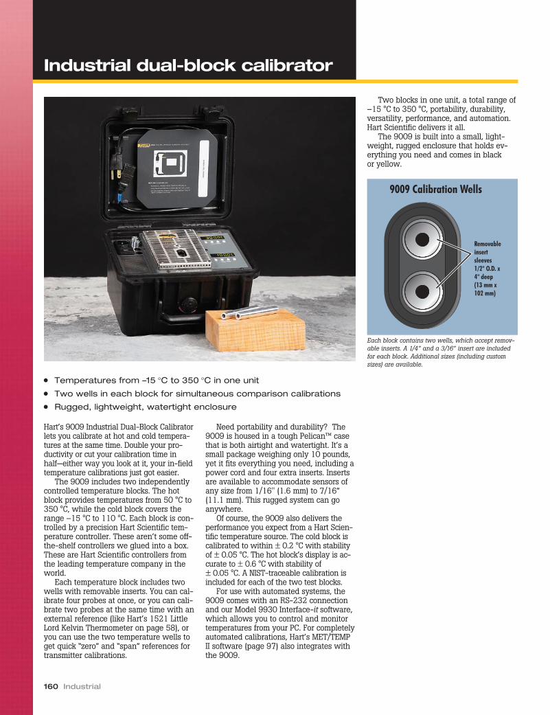
Hart’s 9009 Industrial Dual-Block Calibratorlets you calibrate at hot and cold tempera-tures at the same time. Double your pro-ductivity or cut your calibration time inhalf—either way you look at it, your in-fieldtemperature calibrations just got easier.
The 9009 includes two independentlycontrolled temperature blocks. The hotblock provides temperatures from 50 °C to350 °C, while the cold block covers therange –15 °C to 110 °C. Each block is con-trolled by a precision Hart Scientific tem-perature controller. These aren’t some off-the-shelf controllers we glued into a box.These are Hart Scientific controllers fromthe leading temperature company in theworld.
Each temperature block includes twowells with removable inserts. You can cal-ibrate four probes at once, or you can cali-brate two probes at the same time with anexternal reference (like Hart’s 1521 LittleLord Kelvin Thermometer on page 58), oryou can use the two temperature wells toget quick “zero” and “span” references fortransmitter calibrations.
Need portability and durability? The9009 is housed in a tough Pelican™ casethat is both airtight and watertight. It’s asmall package weighing only 10 pounds,yet it fits everything you need, including apower cord and four extra inserts. Insertsare available to accommodate sensors ofany size from 1/16" (1.6 mm) to 7/16”(11.1 mm). This rugged system can goanywhere.
Of course, the 9009 also delivers theperformance you expect from a Hart Scien-tific temperature source. The cold block iscalibrated to within ± 0.2 °C with stabilityof ± 0.05 °C. The hot block’s display is ac-curate to ± 0.6 °C with stability of± 0.05 °C. A NIST-traceable calibration isincluded for each of the two test blocks.
For use with automated systems, the9009 comes with an RS-232 connectionand our Model 9930 Interface-it software,which allows you to control and monitortemperatures from your PC. For completelyautomated calibrations, Hart’s MET/TEMPII software (page 97) also integrates withthe 9009.
Two blocks in one unit, a total range of–15 °C to 350 °C, portability, durability,versatility, performance, and automation.Hart Scientific delivers it all.
The 9009 is built into a small, light-weight, rugged enclosure that holds ev-erything you need and comes in blackor yellow.
160 Industrial
● Temperatures from –15 °C to 350 °C in one unit
● Two wells in each block for simultaneous comparison calibrations
● Rugged, lightweight, watertight enclosure
Removableinsertsleeves1/2" O.D. x4" deep(13 mm x102 mm)
9009 Calibration Wells
Each block contains two wells, which accept remov-able inserts. A 1/4” and a 3/16” insert are includedfor each block. Additional sizes (including customsizes) are available.
Industrial dual-block calibrator

Temperature Calibration Equipment 161
Industrial dual-block calibrator
Specifications Hot Block Cold Block
Range 50 °C to 350 °C (122 °F to 662 °F) –15 °C to 110 °C (5 °F to 230 °F)(–8 °C [18 °F] with hot block at 350 °C [662 °F])
Accuracy ± 0.6 °C ± 0.2 °C
Stability ± 0.05 °C
Well-to-Well Uniformity ± 0.1 °C
Display Resolution 0.1 °
Heating Times 30 minutes from 25 °C to 350 °C 15 minutes from 25 °C to 110 °C
Cooling Times 40 minutes from 350 °C to 100 °C 16 minutes from 25 °C to –15 °C
Stabilization Times 8 minutes
Well Depth 4" (102 mm)
Removable Inserts Two 6.4 mm (1/4 in) and two 4.8 mm (3/16 in) inserts included; see Ordering Information for other available inserts
Computer Interface RS-232 included with free Interface-it software
Power 115 V ac (± 10 %), 3 A, or230 V ac (± 10 %), 2 A, specify, 50/60 Hz, 280 W
Size ( HxWxD ) 178 x 267 x 248 mm (7 x 10.5 x 9.75 in)
Weight 4.5 kg (10 lb)
NIST-Traceable Calibration Data at 50 °C, 100 °C, 150 °C, 200 °C, 250 °C, 300 °C, and350 °C
Data at –8 °C, 0 °C, 25 °C, 50 °C, 75 °C, 100 °C, and110 °C
Ordering Information
9009-X Industrial Dual-Block Dry-Well (X= case color. Specify “B” for blackor “Y” for yellow.) Includes two1/4 in (6.4 mm) and two 3/16 in(4.8 mm) inserts.
3102-0 Insert, Blank3102-1 Insert, 1/16 in (1.6 mm)3102-2 Insert, 1/8 in (3.2 mm)3102-3 Insert, 3/16 in (4.8 mm)3102-4 Insert, 1/4 in (6.4 mm)3102-5 Insert, 5/16 in (7.9 mm)3102-6 Insert, 3/8 in (9.5 mm)3102-7 Insert, 7/16 in (11.1 mm)3102-8 Insert, 5/32 in (4 mm)
Maximum accuracyTo get the most accurate calibrations possi-ble from a dry-well calibrator, you shoulduse an external reference thermometer. If,however, you are not using an external ref-erence, there are a few important thingsyou should keep in mind.
First, you are using a reference. You’recomparing the reading of your test probeagainst the display of the dry-well. Thedry-well display is based on its own controlsensor, usually located at the bottom of thewell. Therefore, to make the best compari-son, your test probe should be inserted tothe same depth as the control sensor. Thiswas the method used when the dry-well’sdisplay was calibrated at the factory.
Second, your test probe should fit snuglyinto one of the test wells. Again, this is howit was originally calibrated at the factory. If
your probe is too loose, thermal contact ispoor and a large error has been introduced.Custom inserts are available to help solvethis problem.
Third, you should not introduce fluidsinto the wells of a dry-block in an attemptto improve thermal contact. It is too danger-ous. If thermal contact is so poor that you’rethinking about doing this, consider buyinga fluid bath instead. Micro-Baths are avail-able that are just as portable and easy touse as dry-wells.
The point is that the accuracy specs ofyour dry-well are based upon how themanufacturer calibrates it. If you’re relyingon those specs, you need to use the dry-well the same way they do—with a good,snug fit at the bottom of the well.

To give you the widest temperaturerange available in a dry-well calibrator,we’ve combined two of our most popularunits. The 9011 allows temperatureprobes to be calibrated from –30 °C to670 °C in a single unit.
The 9011 features two independentlycontrolled temperature wells, whichmakes calibrating RTDs andthermocouples faster than ever. Whilereadings are being taken at one tempera-ture, the other well can be ramping up ordown to the next point. Checking the zeroand span points of temperature transmit-ters is a breeze. The cold block can evenbe used as a zero-point reference for athermocouple making measurements inthe hot block.
The 9011 is a high-accuracy unit thatis capable of laboratory as well as fieldcalibrations. Stabilities to ± 0.02 °C arepossible, and display accuracy is betterthan ± 0.25 °C. Using multi-hole inter-changeable inserts, you can calibratemore probes at the same time. With asingle RS-232 port for both wells, you
can automate your calibration work andbe even more efficient. Add on Hart’s9938 MET/TEMP II software and totallyautomate your calibrations of RTDs,thermocouples, and thermistors.
Every dry-well we ship from the fac-tory includes a full NIST-traceable calibra-tion report with test data for each well ateach point. There’s no extra charge for thereport or the test readings from your unit.We also include your choice of multi-holeinserts. If you don’t find one that suits yourapplications, we’ll provide a blank sleeveor have a custom one made.
At Hart, we continually develop new in-dustrial calibration tools that make yourwork easier and better. We gave you thefirst handheld dry-well, the first Micro-Bath,and now we’re giving you the widest rang-ing dry-well available. Whatever your tem-perature application, Hart has a solution.
162 Industrial
● Combined ranges for calibrating from –30 °C to 670 °C; one unit—two blocks
● Two independent temperature controllers (hot and cold side)
● Stability to ± 0.02 °C
● Multi-hole wells calibrate up to eight probes simultaneously
1/4" (6.35 mm)
3/16" (4.8 mm)1/8" (3.2 mm)
1/2" (12.7 mm)
1/16" (1.6 mm)
3/8" (9.5 mm)
Insert “A”
3/8" (9.5 mm) 3/8" (9.5 mm)
1/4" (6.35 mm)
1/4" (6.35 mm) 3/16" (4.8 mm)
3/16" (4.8 mm)Insert “B”
1/4"(6.35 mm)
Insert “C”
Insert “D”4 mm
6 mm
3 mm
3 mm
4 mm
6 mm
Cold Block Hot Block
RemovableInsert Well1.45" (37 mm)I.D.
RemovableInsert Well1.25" (32 mm)I.D.
3/16"(4.8 mm)
1/4"(6.35 mm)
3/16"(4.8 mm)
1/8"(3.2 mm)
Cold block insert shown(Hot block “C” insertincludes eight 1/4" wells)
High-accuracy dual-wellcalibrator

Temperature Calibration Equipment 163
High-accuracy dual-wellcalibrator
Specifications Hot Block Cold Block
Range 50 °C to 670 °C (122 °F to 1238 °F) –30 °C to 140 °C (–22 °F to 284 °F)
Accuracy ± 0.2 °C at 50 °C± 0.4 °C at 400 °C
± 0.65 °C at 600 °C
± 0.25 °C (insert wells)± 0.65 °C (fixed wells)
Stability ± 0.02 °C at 100 °C± 0.06 °C at 600 °C
± 0.02 °C at –30 °C± 0.04 °C at 140 °C
Uniformity ± 0.2 °C (± 0.05 °C typical) ± 0.05 °C (insert wells)± 0.25 °C (fixed wells)
Well Depth 152 mm (6 in) 124 mm (4.875 in)
Heating Time to Max. 30 minutes 15 minutes
Cooling Times 120 minutes from 660 °C to 100 °C 30 minutes from 140 °C to –30 °C
Well Inserts 1 interchangeable well accommodates multi-hole insert 1 interchangeable well accommodates multi-hole insert,plus four outer wells, 1/4", 3/16", 3/16", and 1/8"
Computer Interface RS-232 interface included with Model 9930 Interface-it control software
Power 115 V ac (± 10 %), 8.8 A or 230 V ac (± 10 %), 4.4 A, switchable, 50/60 Hz, 1150 W
Size ( HxWxD ) 292 x 394 x 267 mm (11.5 x 15.5 x 10.5 in)
Weight 16.4 kg (36 lb)
NIST-TraceableCertificate(8 points)
Data at 50 °C, 100 °C, 200 °C, 300 °C, 400 °C, 500 °C,600 °C, and 660 °C
Data at –30 °C, 0 °C, 25 °C, 50 °C, 75 °C, 100 °C, 125 °C,and 140 °C
Ordering Information
9011-X High-Accuracy Dual-Well Calibrator(specify X, X = A, B, C, or D includedinsert)
3109-0 Insert, Blank (Hot Side)3109-1 Insert A, Miscellaneous (Hot Side)3109-2 Insert B, Comparison (Hot Side)3109-3 Insert C, Eight 1/4 in Wells (Hot
Side)3109-4 Insert D, Comparison - Metric (Hot
Side)3103-1 Insert, Blank (Cold Side)3103-2 Insert A, Miscellaneous (Cold Side)3103-3 Insert B, Comparison (Cold Side)3103-4 Insert C, Six 1/4 in Wells (Cold Side)3103-6 Insert D, Comparison - Metric (Cold
Side)3103-Y Insert, custom 9011/91032125-C IEEE-488 Interface (RS-232 to IEEE-
488 converter box)9319 Large Instrument Case
The sometimes subtle art of specsmanship“Specsmanship ” is the careful wording ofperformance specifications to provide theexpectation of better performance thanpractically achievable. We see this often aswe work with customers who are compar-ing our products against others. Hart’s phi-losophy is to provide meaningful, clearlywritten specifications that provide verifi-able and guaranteed performance. Unfortu-nately, all manufacturers don’t seem toshare our approach, particularly when itcomes to heat sources such as baths anddry-wells. Here are some terms to watchout for:
“Typical” or “best” - While “typical” or“best” specifications may provide useful in-formation, they offer no guarantee that theunit you buy is “typical” or capable of pro-viding the “best” performance as listed. Forcalibration applications, worst-case orguaranteed performance specifications arerequired that include all natural variationsin the product. “Typical” or “best” specifi-cations are fine if accompanied by a guar-anteed specification. If they’re not, be sureyou ask!
“Relative” accuracy - “Relative” accu-racy specs attempt to remove errors associ-ated with the test standards or referencethermometers used in a heat source. Thisassumes that references contribute nomeasurement errors—an impossibility!Some may argue that “relative” specs allow
the customer to add the error of their refer-ence to obtain a complete specificationunique to their situation. And we wouldagree, but the fact that the specification ex-cludes these errors is too often relegated tothe fine print and is simply misleading toless-informed readers. One thing’s for sure.You can’t directly compare “relative” specsto “absolute” specs, since the componentsof “relative” specs comprise a subset of thecomponents of “absolute” specs.
“Comprehensive evaluation reports”- Evaluation reports are a very importantmethod of determining the performance ofa unit or sample of units. Evaluation reportscan be misleading, however, if they areused to infer the performance of an entirepopulation of instruments, or more impor-tantly, the unit you are purchasing. Evalua-tion reports only provide informationregarding the units that were evaluatedand the conditions present during the eval-uation. It takes extensive engineering anal-ysis to use this information to produce aspecification of performance that applies toall units being produced. Be sure whateverspecs you rely on are the ones the manu-facturer guarantees and will stand behind.
If you ever have a question about Hart’sspecifications, please talk to us and we’llgladly help you understand the perfor-mance you can expect from our products.
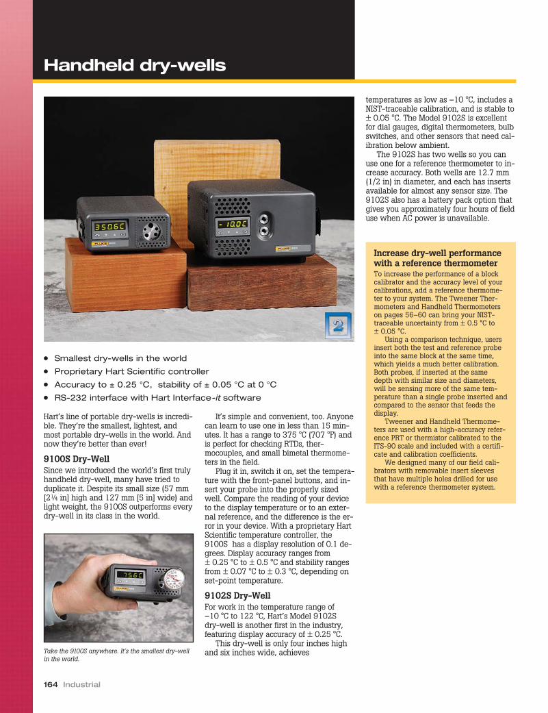
Hart’s line of portable dry-wells is incredi-ble. They’re the smallest, lightest, andmost portable dry-wells in the world. Andnow they’re better than ever!
9100S Dry-WellSince we introduced the world’s first trulyhandheld dry-well, many have tried toduplicate it. Despite its small size (57 mm[2¼ in] high and 127 mm [5 in] wide) andlight weight, the 9100S outperforms everydry-well in its class in the world.
It’s simple and convenient, too. Anyonecan learn to use one in less than 15 min-utes. It has a range to 375 °C (707 °F) andis perfect for checking RTDs, ther-mocouples, and small bimetal thermome-ters in the field.
Plug it in, switch it on, set the tempera-ture with the front-panel buttons, and in-sert your probe into the properly sizedwell. Compare the reading of your deviceto the display temperature or to an exter-nal reference, and the difference is the er-ror in your device. With a proprietary HartScientific temperature controller, the9100S has a display resolution of 0.1 de-grees. Display accuracy ranges from± 0.25 °C to ± 0.5 °C and stability rangesfrom ± 0.07 °C to ± 0.3 °C, depending onset-point temperature.
9102S Dry-WellFor work in the temperature range of–10 °C to 122 °C, Hart’s Model 9102Sdry-well is another first in the industry,featuring display accuracy of ± 0.25 °C.
This dry-well is only four inches highand six inches wide, achieves
temperatures as low as –10 °C, includes aNIST-traceable calibration, and is stable to± 0.05 °C. The Model 9102S is excellentfor dial gauges, digital thermometers, bulbswitches, and other sensors that need cal-ibration below ambient.
The 9102S has two wells so you canuse one for a reference thermometer to in-crease accuracy. Both wells are 12.7 mm(1/2 in) in diameter, and each has insertsavailable for almost any sensor size. The9102S also has a battery pack option thatgives you approximately four hours of fielduse when AC power is unavailable.
164 Industrial
● Smallest dry-wells in the world
● Proprietary Hart Scientific controller
● Accuracy to ± 0.25 °C, stability of ± 0.05 °C at 0 °C
● RS-232 interface with Hart Interface-it software
Take the 9100S anywhere. It’s the smallest dry-wellin the world.
22
Increase dry-well performancewith a reference thermometerTo increase the performance of a blockcalibrator and the accuracy level of yourcalibrations, add a reference thermome-ter to your system. The Tweener Ther-mometers and Handheld Thermometerson pages 56–60 can bring your NIST-traceable uncertainty from ± 0.5 °C to± 0.05 °C.
Using a comparison technique, usersinsert both the test and reference probeinto the same block at the same time,which yields a much better calibration.Both probes, if inserted at the samedepth with similar size and diameters,will be sensing more of the same tem-perature than a single probe inserted andcompared to the sensor that feeds thedisplay.
Tweener and Handheld Thermome-ters are used with a high-accuracy refer-ence PRT or thermistor calibrated to theITS-90 scale and included with a certifi-cate and calibration coefficients.
We designed many of our field cali-brators with removable insert sleevesthat have multiple holes drilled for usewith a reference thermometer system.
Handheld dry-wells
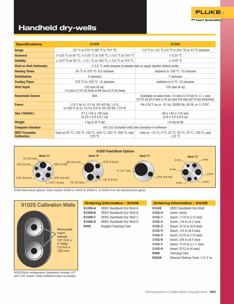
Temperature Calibration Equipment 165
Handheld dry-wells
Specifications 9100S 9102S
Range 35 °C to 375 °C (95 °F to 707 °F) –10 °C to 122 °C (14 °F to 252 °F) at 23 °C ambient
Accuracy ± 0.25 °C at 50 °C; ± 0.25 °C at 100 °C; ± 0.5 °C at 375 °C ± 0.25 °C
Stability ± 0.07 °C at 50 °C; ± 0.1 °C at 100 °C; ± 0.3 °C at 375 °C ± 0.05 °C
Well-to-Well Uniformity ± 0.2 °C with sensors of similar size at equal depths within wells
Heating Times 35 °C to 375 °C: 9.5 minutes ambient to 100 °C: 10 minutes
Stabilization 5 minutes 7 minutes
Cooling Times 375 °C to 100 °C: 14 minutes ambient to 0 °C: 10 minutes
Well Depth 102 mm (4 in);1.6 mm (1/16 in) hole is 89 mm (3.5 in) deep
102 mm (4 in)
Removable Inserts N/A Available in sizes from 1.6 mm (1/16 in) to 11.1 mm(7/16 in) [6.4 mm (1/4 in) and 4.8 mm (3/16 in) included]
Power 115 V ac (± 10 %), 55–65 Hz, 1.5 Aor 230 V ac (± 10 %), 0.8 A, 45–55 Hz, 175 W
94-234 V ac (± 10 %), 50/60 Hz, 60 W; or 12 VDC
Size ( HxWxD ) 57 x 125 x 150 mm(2.25 x 4.9 x 6.1 in)
99 x 140 x 175 mm(3.9 x 5.5 x 6.9 in)
Weight 1 kg (2 lb 3 oz) 1.8 kg (4 lb)
Computer Interface RS-232 included with free Interface-it software
NIST-TraceableCalibration
Data at 50 °C, 100 °C, 150 °C, 200 °C, 250 °C, 300 °C, and375 °C
Data at –10 °C, 0 °C, 25 °C, 50 °C, 75 °C, 100 °C, and122 °C
9100S fixed-block options. Order number 9100S-A, 9100S-B, 9100S-C, or 9100S-D for the desired block option.
Removableinsertsleeves1/2" O.D. x4" deep(13 mm x102 mm)
9102S Calibration Wells
9102S block configuration. Instrument includes 1/4"and 3/16" inserts. Order additional sizes as needed.
Ordering Information - 9100S
9100S-A HDRC Handheld Dry-Well A9100S-B HDRC Handheld Dry-Well B9100S-C HDRC Handheld Dry-Well C9100S-D HDRC Handheld Dry-Well D9300 Rugged Carrying Case
Ordering Information - 9102S
9102S HDRC Handheld Dry-Well3102-0 Insert, blank3102-1 Insert, 1/16 in (1.6 mm)3102-2 Insert, 1/8 in (3.2 mm)3102-3 Insert, 3/16 in (4.8 mm)3102-4 Insert, 1/4 in (6.4 mm)3102-5 Insert, 5/16 in (7.9 mm)3102-6 Insert, 3/8 in (9.5 mm)3102-7 Insert, 7/16 in (11.1 mm)3102-8 Insert, 5/32 in (4 mm)9308 Carrying Case9320A External Battery Pack, 115 V ac

This calibrator, designed for the U.S. Navy,covers temperatures from –40 °C to140 °C, delivers the performance you’llonly find in true lab standards, and comesin a totally portable case. If your work in-volves ocean vessels, aircraft, or servicetrucks, Hart’s Portable Lab Dry-Well wasdesigned for you.
The 9007 covers –40 °C to 140 °C. Noexternal cooling is needed, so you get–40 °C in normal ambient. Set-point accu-racy is ± 0.15 °C and stability is betterthan ± 0.02 °C.
This dry-well comes with a unique cal-ibration at the full, six-inch depth of thewell and at a three-inch depth for short
probes. Coefficients for each calibrationare stored in the dry-well and can be eas-ily selected from the top-panel controlbuttons to match the length of the probebeing tested.
Encased in an all-aluminum enclosurethat is durable, waterproof, and meets thestandards of MIL-T-28800, the 9007 co-mes with both RS-232 and IEEE-488 in-terface connections. A wide variety ofinserts are available covering probe diam-eters from 1/16 inch (1.6 mm) to 5/8 inch(15.9 mm).
166 Industrial
Portable lab dry-well
Specifications
Range –40 °C to 140 °C at 25 °C
Accuracy ± 0.15 °C
Stability ± 0.02 °C
Heating Times 25 °C to 140 °C: 20 min.
Cooling Times 25 °C to –40 °C: 25 min.
Stabilization 10 minutes
Test Wells 19 mm dia. x 152 mmdeep (3/4 x 6 in)
Communications RS-232 and IEEE-488
Enclosure Meets Type II, Class 3,Style D requirements ofMIL-T-28800
Power 115 V ac (± 10 %), 5 A or230 V ac (± 10 %), 2.4 A,switchable, 50/60 Hz,560 W
Size ( HxWxD ) 35.1 x 27.4 x 42.9 cm(13.8 x 10.8 x 16.9 in)
Weight 16.3 kg (36 lb)
NIST-TraceableCalibration
Data at –40 °C, 0 °C, 25 °C,75 °C, and 140 °C
● Designed for on-ship and on-the-go lab applications
● Covers –40 °C to 140 °C● Includes three-inch and six-inch calibration zones
Ordering Information
9007 Portable Lab Dry-Well, –40 °Cto 140 °C, 1/4 in (6.36 mm)insert
3107-2000 Blank insert3107-2063 1/16 in Insert (1.6 mm)3107-2125 1/8 in Insert (3.2 mm)3107-2156 5/32 in Insert (4 mm)3107-2188 3/16 in Insert (4.8 mm)3107-2250 1/4 in Insert (6.35 mm)3107-2313 5/16 in Insert (7.9 mm)3107-2375 3/8 in Insert (9.5 mm)3107-2500 1/2 in Insert (12.7 mm)3107-2625 5/8 in Insert (15.9 mm)3107-2901 1 User-Specified Hole3107-2902 2 User-Specified Holes
22

You told us you weren’t satisfied with thecompetition’s furnaces for checking indus-trial thermocouples. You said you wantedsomething new and more convenient touse—and you wanted it at a lower pricethan any other furnace available. Well,we’ve got what you asked for, and it’s theModel 9150 Thermocouple Furnace fromHart Scientific.
With a stability of ± 0.5 °C, it has a tem-perature range to 1200 °C and a display ac-curacy of ± 5 °C across its entire range.
With interchangeable temperatureblocks, you can check thermocouples as
small as 1/16 of an inch in diameter. The9150 works with 115 or 230 V ac power.
The 9150 Thermocouple Furnace usesHart’s own microprocessor-based control-ler for great stability and set-point accu-racy. It has a removable well insert forversatility. It has rapid cool-down andheat-up times. And it comes with an RS-232 port for connection to a PC.
You can now afford to check yourthermocouples with this excellent cost-ef-fective instrument. Why pay more for fea-tures you don’t need and can’t use? Eachunit is factory-calibrated and comes withtest data and a calibration traceable to NIST.
Ordering Information
9150-X Thermocouple Furnace (specifyX, X = A, B, C,or D includedinsert)
3150-2 Insert A3150-3 Insert B3150-4 Insert C3150-6 Insert D9315 Rugged Carrying Case
Temperature Calibration Equipment 167
● Low-cost thermocouple furnace
● NIST-traceable calibration included
● RS-232 port standard
1/4" (6.35 mm)
3/16" (4.8 mm)1/8" (3.2 mm)
1/2" (12.7 mm)
1/16" (1.6 mm)
3/8' (9.5 mm)
3/8" (9.5 mm)
3/8" (9.5 mm)
1/4" ( 6.35 mm)
1/4" (6.35 mm) 3/16" (4.8 mm)
3/16" (4.8 mm)
1/4" (6.35 mm)
Insert “A” Insert “B”
9150 Interchangeable Insert Options
Insert “C”
6 mm
Insert “D”
4 mm
6 mm
3 mm
3 mm
4 mm
Specifications
TemperatureRange
150 °C to 1200 °C(302 °F to 2192 °F)
DisplayResolution
0.1 ° to 999.9 °1 ° above 1000 °
Stability ± 0.5 °C
DisplayAccuracy
± 5 °C
Well Diameter 1.25 in (32 mm)
Well Depth 140 mm (5.5 in); (101 mm[4 in] removable insert plus38 mm [1.5 in] insulator)
Heating Time 35 minutes to 1200 °C
Cooling Time 140 minutes with block
Well-to-WellUniformity
± 2.5 °C(Insert “C” at 1200 °C)
Stabilization 20 minutes
Power 115 V ac (± 10 %), 10.5 Aor 230 V ac (± 10 %),5.2 A, switchable, 50/60 Hz,1200 W
Size ( HxWxD ) 315 x 208 x 315 mm(12.4 x 8.2 x 12.4 in)
Weight 13 kg (28 lb)
NIST-TraceableCalibration
Data at 150 °C, 300 °C,450 °C, 600 °C, 800 °C,1000 °C, and 1200 °C
Thermocouple furnace

Need the most accurate thermocouple cali-brations possible? The Hart Model 9112BThermocouple Furnace gives you a broadtemperature range to 1100 °C, stability upto ± 0.05 °C, and all at an excellent price.In addition, you can take advantage of op-tional MET/TEMP II software that com-pletely automates the furnace andcalibration processes.
Alternative calibration tools such as asand bath or fluidized alumina bath havebeen used for calibrations up to 700 °C butwith very poor comparative performance.Gradients of several degrees are commonin a sand bath, along with poor stability,resulting in low-accuracy calibrations.Sand baths are also known to create atroublesome dust problem. Why buy poorperformance and lab pollution?
Calibration furnaces are an excellentalternative to sand baths, especially forthermocouples, RTDs, and optical fiberprobes. With a five-hole standard blockand custom blocks available, the 9112Bdoesn’t limit the size and shape of sensorsyou can calibrate the way other furnaces
do. In addition, most calibration furnaceshave poor stability.
Automation softwareHart’s 9938 MET/TEMP II software lets youuse your PC to automate your calibrations.Not only does the software operate thefurnace, it also automates Hart readoutsalong with the calibration procedures.Read more about our software packagesstarting on page 96.
Unique engineeringThe 9112B employs a special heater de-sign for temperature uniformity and rapidheat rates. The heaters are embedded in arefractory ceramic-fiber material, forming atwo-piece heating assembly. A quartz tubelines the entire test zone of the furnace, in-sulating the isothermal block and yourwork from the high-power heater windingswhile supporting the block and furtherequalizing temperature distribution.
The isothermal block assembly is ma-chined from a high-nickel-content alloyfor good thermal conductivity and resis-tance to high-temperature oxidation. The
central block is sized for optimum balancebetween sufficient mass for good stabil-ity/uniformity and small enough mass forrapid heating/cooling and stabilization.The assembly makes use of two smalleralloy blocks as thermal barriers and heatsinks. Guide tubes connect the blocks andguide your probes to the heart of theblock. A thermal shield at the front of theassembly prevents heat loss at the front ofthe furnace.
Multiple probe calibrationsThe standard furnace block accepts up tofour probes under test and one referenceprobe. The four test holes take 1/4-inch-diameter probes, and the reference holeaccepts the slightly larger and typicalstandard type S thermocouple or an SPRT.Custom isothermal blocks can handle aspecific number of probes with differentdiameters and depths. Call our sales de-partment for a custom quote.
Microprocessor controlA microprocessor-based digital tempera-ture controller makes set-point adjust-ments fast and easy. Both set and actualtemperatures are simultaneously displayedfor your convenience. A fast push-buttonadjustment is used for manual temperaturesettings. The controller is factory tuned forbest performance between 300 °C and1100 °C when the tuning function is setfor automatic conformity to the set-pointrequirements. When using the furnace be-low 300 °C, controller adjustments aremade to achieve high stability.
The isothermal block design and thecontroller auto-tuning combine to give youmetrology-level performance. The “B”block delivers uniformity of ± 0.1 °C at thelow end and ± 0.3 °C or better at thehigh-temperature end.
The stability figures quoted in our speci-fication table are for mid-term to long-termstability. Short-term stability during a com-parison calibration is even better.
Wide-range and high-temperature cal-ibration work are now easier and more af-fordable due to Hart’s innovative 9112Bdesign. Thermocouples, RTDs, and othersensors are all calibrated with a greaterlevel of confidence and accuracy.
168 Industrial
● Combined stability and uniformity better than ± 0.4 °C
● RS-232 serial interface standard
● High capacity for simultaneous comparison calibrations
● CE compliant
Thermocouple calibrationfurnace

Specifications
Range 300 °C to 1100 °C(572 °F to 2012 °F)
Stability ± 0.05 °C at 300 °C± 0.1 °C at 700 °C± 0.1 °C at 1100 °C
Uniformity ± 0.05 °C at 300 °C± 0.2 °C at 700 °C± 0.3 °C at 1100 °C
HeatingRates
25 °C to 900 °C: 35 minutes900 °C to 1100 °C: 3 hours
CoolingRates
Nom. at 800 °C: ≥300 °C/hourNom. at 600 °C: ≥180 °C/hour
StabilizationTime
Typically 2 hours midrange,slower at low-temperature end(4 hours), faster at high-tem-perature end
Interface RS-232 included on all units
OutsideDimensions(HxWxD )
457 mm x 362 mm x 660 mm(18 in x 14.25 in x 26 in)
ThermalBlock
406 mm (16 in) immersion;includes four wells at 6.35 mm(1/4 in) and one well at7.11 mm (0.28 in)
Weight 33 kg (72.5 lb) with block
Power 230 V ac (± 10 %), 50/60 Hz,20 A, 3700 W
Heater 3700 W
NIST-TraceableCalibration
Data at 420 °C
Ordering Information
9112B-B Calibration Furnace (includesstandard 406 mm [16 in] block)Call for custom inserts.
Temperature Calibration Equipment 169
Thermocouple calibrationfurnace
16"
CutoutProbe
Back
Isothermal BlockQuartz Tube
Front
GuideTubes
ControlProbe
Sectional Side View

Have you been thinking about buying azero-point dry-well? Forget those ugly-looking units the competition makes. Youcan get a great looking and great perform-ing zero-point dry-well from Hart Scientific.
The Hart 9101 has three test wells forinserting more than one probe at a time.All three wells are stable to ± 0.005 °C.One well accommodates changeable in-serts for varying probe diameters.
The Model 9101 takes advantage ofthe latest solid-state cooling technologyrather than relying on older, less reliablesealed-water-cell devices. This eliminatesthe possibility that the sealed water cellwill freeze and burst while transportingthe unit to field locations. And our solid-state cooler is run by an adjustable elec-tronic controller that can be recalibrated inyour lab for convenient recertification.Simply place a certified standards ther-mometer in one of the wells and, ifneeded, tweak the 9101 controller untilthe standards thermometer reaches equi-librium at 0 °C.
Since the unit is completely self-contained and doesn’t require any usersettings, you can run it on demand for
instant access to an accurate, traceablezero point. Set it up with the referencejunction of a thermocouple for high-accu-racy thermocouple measurements.
Less costly than refrigerated baths,more accurate and less problematic thanice baths, and more durable and betterlooking than competitive units usingsealed-water cells, the Hart 9101 Zero-Point Dry-Well is a great choice for anycalibration lab!
170 Industrial
● Bath-quality stability in a portable ice-point reference
● Easy recalibration for long-term reliability
● Ready light frees user’s time and attention
● Solid-state cooling technology
Keep it clean!Be sure to keep those dry-well inserts and blocks clean. They’ll perform better and be eas-ier to use (not to mention they’ll look better). As needed, you should:● Clean off any oxidation that has built up in the dry-well block or on an insert. Oxidation
can make inserts difficult to remove. It can also cause probes not to fit properly. Thisoxidation occurs more rapidly at higher temperatures and in humid environments. It willclean up nicely with a Hart 2037 Dry-Well Cleaning Kit.
● Remove any foreign substances in the wells that can make operation difficult. Neverintentionally put a foreign substance into a dry-well. Not only can you make probes andinserts difficult to remove, but you may also cause damage to the unit. If you’re temptedto pour a fluid into a dry-well, stop. Give us a call and we’ll set you up with a properfluid bath.
● Clean probes before inserting them into the dry-well as a preventative measure.
Specifications
TemperatureRange
0 °C (32 °F)
Stability ± 0.005 °C
TotalInstrumentError
± 0.02 °C, typical;± 0.05 °C max. (18–25 °Cambient)
StabilizationTime
Approx. 30 minutes(the ready lamp indicatesstable control at 0 °C)
TemperatureCoefficient
± 0.005 °C/ °C amb.
Size ( HxWxD ) 311 x 216 x 146 mm(12.25 x 8.5 x 5.75 in)
Power 115 V ac (± 10 %), 1 A or230 V ac (± 10 %), 0.5 A,50/60 Hz, 125 W
WellDimensions
2 wells 6.4 mm dia. x 152mm D (0.25 x 6 in), 1 well7 mm dia. x 152 mm D(0.28 x 6 in). Includes oneset of telescoping inserts toprovide various smallerdiameters
Weight 5.4 kg (12 lb)
NIST-TraceableCalibration
Data at 0 °C
Ordering Information
9101 Zero-Point Dry-Well (includesone set of telescoping inserts toprovide various smallerdiameters)
2130 Spare Well-Sizing Tube Set9325 Rugged Carrying Case
Zero-point dry-well
22

Should your thermometer becalibrated by one of these?Business decisions costing thousands ofdollars are based on the results of yourmeasurements, so they had better beright! It can be very expensive to shutdown a line for repairs and maintenance,but it might be catastrophic if the shut-down is unplanned. To stand by yourmeasurements with confidence, youshould definitely have your thermometerscalibrated.
How to get consistent results:Even those infrared thermometers thatcannot be adjusted can benefit from a cal-ibration that demonstrates the consistencyand validity of your results. A trusted cali-bration means less worry, fewer questionsand more time being productive. To getmore reliable, traceable, and consistentresults, buy a precision infrared calibratorfrom Fluke’s Hart Scientific Division.
The 4180 Series of Precision InfraredCalibrators for infrared thermometers isfast, accurate, and easy to use. It comes
Temperature Calibration Equipment 171
● Fast, portable and easy to use
● Correct target size for most thermometers
● Calibration solutions from –15 °C to 500 °C (5 °F to 932 °F)
● Radiometrically calibrated for traceable and consistent results
4180 series precision infraredcalibrators
Application note, (literature code3187781):
InfraredTemperatue Cal-ibration 101
Infrared tempera-ture calibration isnot so hard whenyou are on theright wave length.View the neces-sary informationfor spot oncalibration.
Go to www.hartscientific.com/publica-tions for complete information.

with an accredited calibration from one ofthe world’s most trusted temperature cali-bration laboratories, sample calibrationprocedures for Fluke thermometers builtright in and everything you need to getstarted making high-quality infrared ther-mometer calibrations. This is the perfectsolution for any infrared thermometerwithin its temperature range.
The 4180 reaches temperatures from–15 °C to 120 °C and the 4181 has a tem-perature range from 35 °C to 500 °C. Uni-formity is important at these temperaturesbecause an infrared thermometer will“see” the entire target when placed at theappropriate calibration distance.
In addition, with accuracies as good as± 0.35 °C, the 4180 Series can meet itsspecifications without additional
emissivity-related corrections, leading tolegitimate test uncertainty ratios (TUR) asgood as 4:1. (See the sidebar below for in-formation about common pitfalls in infra-red calibrator accuracy and have a look atour Guide to Infrared Thermometer Cali-bration to get started quickly with yournew calibrator.
172 Industrial
4180 series precision infraredcalibrators
Common pitfalls in infrared thermometer calibration● If the target size is too small, the thermometer will not read the
right temperature. This problem, called size of source effect, isaddressed by the large, 152.4 mm (six in) target of the 4180series, which was designed to accommodate the field of viewand calibration geometry requirements of certain commoninfrared thermometers used in the field, lab and process control.
● Some people are misled by the accuracy statements on IRcalibrators because they are not familiar with the concept of
emissivity. Look for calibrators with a “radiometric calibration” sothat accuracy will be straightforward and uncomplicated byemissivity-related errors.
For more information on emissivity, size of source effect and radio-metric calibration, see Hart Scientific application note “Infrared Tem-perature Calibration 101” or choose a calibrator like the 4180 seriesthat you know has already addressed all of these issues.
Infraredthermometers haveperipheral vision.

Temperature Calibration Equipment 173
4180 series precision infraredcalibrators
Specifications 4180 4181
Temperature range(@ 23 °C ambient,0.95 emissivity )
–15 °C to 120 °C(5 °F to 248 °F)
35 °C to 500 °C(95 °F to 932 °F)
Display accuracy 1 ± 0.40 °C at –15 °C± 0.40 °C at 0 °C± 0.50 °C at 50 °C± 0.50 °C at 100 °C± 0.55 °C at 120 °C
± 0.35 °C at 35 °C± 0.50 °C at 100 °C± 0.70 °C at 200 °C± 1.20 °C at 350 °C± 1.60 °C at 500 °C
Stability ± 0.10 °C at –15 °C± 0.05 °C at 0 °C
± 0.10 °C at 120 °C
± 0.05 °C at 35 °C± 0.20 °C at 200 °C± 0.40 °C at 500 °C
Uniformity 2
(5.0 in dia of centerof target)
± 0.15 °C at –15 °C± 0.10 °C at 0 °C
± 0.25 °C at 120 °C
± 0.10 °C at 35 °C± 0.50 °C at 200 °C± 1.00 °C at 500 °C
Uniformity2(2.0 in dia of centerof target)
± 0.10 °C at -15 °C± 0.10 °C at 0 °C
± 0.20 °C at 120 °C
± 0.10 °C at 35 °C± 0.25 °C at 200 °C± 0.50 °C at 500 °C
Heating time 15 min: –15 °C to 120 °C14 min: 23 °C to 120 °C
20 min: 35 °C to 500 °C
Cooling time 15 min: 120 °C to 23 °C20 min: 23 °C to –15 °C
100 min: 500 °C to 35 °C40 min: 500 °C to 100 °C
Stabilization time 10 minutes 10 minutesNominal emissivity 3 0.95 0.95Thermometer emissivitycompensation
0.9 to 1.0
Target diameter 152.4 mm (6 in)Computer interface RS-232Power 115 V ac (± 10%), 6.3 A,
50/60 Hz, 630 W230 V ac (± 10%), 3.15 A,
50/60 Hz, 630 W
115 V ac (± 10%), 10 A,50/60 Hz, 1000 W
230 V a (± 10%), 5 A,50/60 Hz, 1000 W
Fuse(s) 115 V ac 6.3 A, 250 V, slow blow230 V ac 3.15 A, 250 V, T
115 V ac 10 A, 250 V, fast blow230 V ac 5 A, 250 V, F
Size ( HxWxD ) 356 mm x 241 mm x 216 mm(14 in x 9.5 in x 8.5 in)
356 mm x 241 mm x 216 mm(14 in x 9.5 in x 8.5 in)
Weight 9.1 kg (20 lb) 9.5 kg (21 lb)Safety EN 61010-1:2001, CAN/CSA C22.2 No. 61010.1-041For 8 μm to 14 μm spectral band thermometers with emissivity set between 0.9 and 1.02The uniformity specification refers to how IR thermometers with different spot sizes both focusedat the center of the target will measure the same temperature.3The target has a nominal emissivity of 0.95, however it is radiometrically calibrated to minimizeemissivity related uncertainties.
Ordering information
4180 Precision Infrared Calibrator,–15 °C to 120 °C
4181 Precision Infrared Calibrator, 35°C to 500 °C
4180-CASE Carrying Case, 4180 or 41814180-APRT 2-in Aperture, 4180 or 41814180-DCAS Case, Transportation with
wheels, 4180 or 4181Included accessoriesAccredited radiometric calibration report, tar-get cover, User Guide, Getting Started Guide,and 9930 Interface-it software with UserGuide

Whether you’re using in-line or handheldinfrared pyrometers, you need good cali-bration standards to verify their accuracy.Our new portable IR calibrators providestable blackbody targets for calibratingnoncontact IR thermometers from –30 °Cto 500 °C.
These new units feature a large, tem-perature controlled blackbody target witha diameter of 57 mm (2.25 in), which of-fers a large field of view area for opticalvariations in infrared thermometers. Theemissivity of the isothermal target is set at0.95 (± 0.02 %), and the target tempera-ture can be controlled in set-point incre-ments of 0.1 ° from –30 °C to 500 °C.
For even higher precision, a well is lo-cated directly behind the blackbody sur-face for contact calibration of theblackbody.
These units are as easy to use as “pointand shoot.” Simply set the desiredblackbody temperature from the conve-nient front panel control buttons, wait afew minutes for equilibrium, and point thegun at the target. The radiated energyfrom the blackbody is measured by your IRthermometer. Simply compare its reading
to the display on the blackbody and re-cord the difference.
9132For IR calibrations above normal ambi-
ent, the 9132 provides a stable blackbodytarget up to 500 °C (932 °F). With accuracyto ± 0.5 °C and stability to ± 0.1 °C, thisnew portable IR unit can certify mosthandheld pyrometers.
Short heating and cooling times meanyou won’t have to wait long to get yourwork done. From room temperature to500 °C the 9132 will be stable within 30minutes. You won’t find a more compact IRcalibrator.
9133If you’re calibrating IR guns at cold
temperatures, you’ll love our new 9133.With solid-state cooling technology, thisnew IR calibrator reaches –30 °C (22 °F) innormal ambient conditions. With a conve-niently located dry gas fitting on the frontbezel, ice build up on the target can beavoided. At the upper end of its range, the9133 provides stable temperatures to160 °C (320 °F).
With heating and cooling times ofabout 15 minutes from ambient to eitherextreme, the 9133 gets you to temperaturequickly and performs when it gets there.Compare your IR devices to the tempera-ture display—it’s factory calibrated to bewithin ± 0.4 °C (± 0.7 °F).
No other IR calibrators give you thislevel of precision in such compact pack-ages. Whatever your temperature applica-tion, trust a Hart product to solve it.
174 Industrial
● Certify IR pyrometers from –30 °C to 500 °C (–22 °F to 932 °F)
● Large 57 mm (2.25 in) blackbody target
● RTD reference well for high precision
● Small, compact design
Large target for calibrating all IR thermometer types.
The 9133 includes a quick-attach fitting on the frontbezel for dry air purging, which eliminates icebuildup on the target.
Portable IR calibrators

Temperature Calibration Equipment 175
Specifications 9133 9132
Temperature Range –30 °C to 150 °C at 23 °C ambient(–22 °F to 302 °F at 73 °F
ambient)
50 °C to 500 °C(122°F to 932°F)
Accuracy ± 0.4 °C (± 0.72 °F) ± 0.5 °C at 100 °C(± 0.9°F at 212°F)± 0.8 °C at 500 °C(± 1.4 °F at 932 °F)
Stability ± 0.1 °C (± 0.18 °F) ± 0.1°C at 100°C(± 0.18°F at 212°F)± 0.3°C at 500°C
(± 0.54°F at 932°F)
Target Size 57 mm (2.25 in)
Target Emissivity 0.95 (± 0.02 from 8 to 14 μm)
Resolution 0.1 °
Heating Time 15 minutes (25 °C to 150 °C) 30 minutes (50 °C to 500 °C)
Cooling Time 15 minutes (25 °C to –20 °C) 30 minutes (500 °C to 100 °C)
Computer Interface RS-232 I/O included with 9930 Interface-it software
Power 115 V ac (± 10 %), 1.5 A, or230 V ac (± 10 %), 1.0 A,
switchable, 50/60 Hz, 200 W
115 V ac (± 10 %), 3 A or230 V ac (± 10 %), 1.5 A,
switchable, 50/60 Hz, 340 W
Size ( HxWxD ) 152 x 286 x 267 mm(6 x 11.25 x 10.5 in)
102 x 152 x 178 mm(4 x 6 x 7 in )
Weight 4.6 kg (10 lb) 1.8 kg (4 lb)
NIST-Traceable ContactCalibration
Data at –30°C, 0°C, 25°C, 75°C,100°C, 125°C, and 150°C
Data at 50°C, 100°C, 200°C,250°C, 300°C, 400°C, and 500°C
Ordering Information
9132 Portable IR Calibrator, 500 °C9308 Rugged Carrying Case, 9132
9133 Portable IR Calibrator, –30 °C9302 Rugged Carrying Case, 9133
Portable IR calibrators

Surface probes are difficult to calibrate be-cause it’s hard to find a flat, heated sur-face that’s stable and uniform. Hart’s newModel 3125 Surface Dry-Well takes ad-vantage of our proprietary Model 2200Temperature Controller (page 133) andgives you the best possible conditions forcalibrating surface sensors.
Why buy a non-temperature calibrationdevice designed for test tube sterilizationor PC board repair when you can have atrue calibration instrument? The 3125 hasa uniform surface temperature andreaches temperatures as high as 400 °C.
The test surface is milled aluminum foran absolutely smooth and true calibrationwork area with maximum thermal conduc-tivity. The 12.25-square-inch test surfaceis large enough to calibrate more than onesensor at a time. The 3125 can be usedwith a reference surface sensor or PRT.
PRTs (3/16" diameter, such as the 5612on page 70) may be inserted through adrilled hole into the center of the block foruse as reference thermometers or for easyrecalibration of the unit’s display.
With an accuracy of ± 0.5 °C to 200 °Cand ± 1 °C to 400 °C, you can calibrate al-most any surface probe, thermistor, thinfilm sensor, RTD, thermocouple, ribbonsensor, or surface mount cutouts, fuses,and switches. Stability is within ± 0.3 °Cat 400 °C and uniformity within the centerthree inches of the surface is ± 0.6 °C at200 °C. Don’t buy “make-do” hot plateswhen you can have a legitimate calibra-tion tool.
176 Industrial
● Calibrates surface sensors up to 400 °C● Uses Hart 2200 Controller for excellent accuracy and stability
● NIST-traceable calibration included
Specifications
TemperatureRange
35 °C to 400 °C(95 °F to 752 °F)
DisplayAccuracy
± 0.5 °C to 200 °C± 1.0 °C to 400 °C
Stability ± 0.2 °C to 300 °C± 0.3 °C to 400 °C
Resolution 0.01 °
Uniformity ± 0.3 °C at 100 °C± 0.6 °C at 200 °C± 0.9 °C at 300 °C± 1.4 °C at 400 °C
Heating Time 25 °C to 400 °C: 22 minutes
Cooling Time 400 °C to 100 °C: 65minutes
StabilizationTime
8 minutes
Controller Hart Model 2200, micropro-cessor based, with RS-232(see page 133)
Readout °C or °F, switchable
Sensor RTD, 100Ω
Heater 325-watt, solid-statecontrolled
Surface Plate 6061 aluminum; top surfacemachine finished to 0.0008mm (0.000032 in), 96 mm(3.8 in) diameter accessible
Power 115 V ac (± 10 %), 2.8 A or230 V ac (± 10 %), 1.4 A,specify, 50/60 Hz, 325 W
Weight 3.2 kg (7 lb) with 2200Controller
NIST-TraceableCalibration
Data at 50 °C, 120 °C,190 °C, 260 °C, 330 °C, and400 °C
Ordering Information
3125 Surface Calibrator, (includes de-tachable Hart Model 2200Controller)
Surface calibrator

Temperature Calibration Equipment 177
Cool lab productsProduct Features Page9320A Battery Pack Provides 115 V ac or 12 V dc power portablility 1775121Bench-Top Temperature /Humidity Generator
Full range accuracy ± 0.5 %RH.Large working volume for optimal throughput.NIST-developed two-pressure principal.
178
And there’s more...Seminars Three seminars covering topics from industrial field calibrations to
primary standards lab calibrations.Each course mixes lectures, demonstrations, hands-on exercises, andquestion/answer sessions.Instructors include leading metrology experts with a wide variety ofapplications experience.
181
Cal Lab Services Calibration services for SPRTs, RTDs, thermocouples, and thermistors.Calibrations by fixed point and by comparison.Recalibrations of Hart dry-wells and thermometers.
186
Are you having trouble finding a poweroutlet? Hart's 9320A external batterypack solves your problem. Plug your 115V ac or 12 V dc powered calibrationequipment into the 9320A for hours ofuseful operation. Don't get caught half-way through your work, only to find yourbattery pack just ran out of power. Withthe 3-digit battery status display on thefront of the 9320A, you'll know how
much time you're battery's got even be-fore you start the job. The 9320A comeswith an ac charger that recharges thebattery pack from a standard wall outlet,and a dc charging cable to recharge theunit from the battery of a truck or car.What's more, you'll also get jumper ca-bles, a handy light, and an air compres-sor too! Don't be sorry. Get a 9320A ofyour own.
Ordering Information
9320A External Battery Pack● Powers 115 V ac or 12 V dc
products almost anywhere
● 3-digit battery status display
● Audible alarm signals overheatand under voltage conditions
Specifications
AC Output 115 ± 10 V ac RMS, 60Hz ± 4 Hz
Internal BatteryVoltage (nominal)
12 V dc
DC Power Socket(maximumcontinuous load)
12 A with automatic reset
Fuse (internal) 2 x 25 A or 1 x 50 A
Internal BatteryType
Sealed, AGM (absorbedglass mat) lead acid
Internal BatteryCapacity(minimum)
20 Ah
Internal BatteryCCA Rating
200 CCA
OperatingTemperatureRange
0 °C to 40 °C (32 °F to104 °F)
Air CompressorPressure
250 PSI
Nozzle Adapter(for aircompressor)
Two nozzle adapters, onesports needle adapter
Size ( HxWxD ) 24.1 cm x 40.8 cm x 20.3cm (9.5 x 16 x 8 in)
Weight 10.5 kg (23 lb)
Suggested Run Times
1502A Tweener 36 Hours
15231524
36 Hours
1529 Chub-E4Run Time
16 Hours
1620A DewK RunTime
36 Hours
9102S HandheldDry-Well RunTime
4 Hours
Other neat stuff selectionguide
External battery pack

Tired of outsourcing your humidity calibra-tions? Why not buy a temperature/hu-midity generator and calibrate yourhumidity probes, data loggers, and chartrecorders yourself? It’s simple with the5121 manufactured for Hart by ThunderScientific. The 5121 is a self-containedgenerator that measures and controls hu-midity with high accuracy to ± 0.5 % anda large working volume of 15" x 15" x 12"(381 x 381 x 305 mm). Not only does itcalibrate humidity probes but also entirechart recorders, data-loggers, and hy-grometers (if the probe is not detachable,which is often the case).
5121 uses a “two-pressure” generationprincipal, which was originally developed
by NIST and involves saturating a streamof air with water vapor at a known tem-perature and pressure. Relative humidityof the saturated air can be directly calcu-lated through the following formula:
%RHff
ee
PP
s
c
s
c
c
s
= ⋅ ⋅ ⋅100
To generate a known humidity, the5121 controls the pressure ratio (Pc/Ps),utilizing an enhancement factor ratio (fs/fc)and the effective degree of saturation(es/ec).
Humidity generated by this method isonly dependant upon precision measure-ments of temperature and pressure, so the
need to use an expensive chilled-mirrorhygrometer as a reference is eliminated,reducing the cost of ownership. The 5121generates RH with an accuracy of 0.5 %over the range –10 °C to 70 °C and10 %RH to 98 %RH. Chamber temperatureaccuracy is an amazing 0.06 °C. With thisperformance, you can calibrate ambient-measuring, temperature-probes!
To assist with your own calibration un-certainty analysis, be sure to visit the Hartwebsite and download a copy of the 5121series evaluation report that includes thedetailed temperature and humidity uncer-tainty analysis.
How about operating the 5121? It’s soeasy you’ll be performing humidity cali-brations minutes from switch-on. Thegenerator is supplied as standard with allthe equipment you’ll need. Simply connectthe generator to a clean, oil-free air sup-ply, fill up the water reservoir, and plug itin; then place your chart recorders, data-loggers, or humidity sensors into thechamber, close the door, and program thedesired temperature and humidity throughthe easy-to-use front panel display. You’llquickly be at set point and recording yourcalibration data! The front panel displayprovides loads of useful information, in-cluding chamber humidity and flow rates,as well as the saturation and chambertemperatures and pressures.
If you’re looking for improved produc-tivity in your humidity calibrations, tryControLog™ software, which allows you toprogram a series of humidity and temper-ature set-points, and automatically stepsthrough the set-points to maintain stablecalibration conditions for defined periodsof time. What could be easier?
The 5121 series is a favorite withmany national labs around the world, allbranches of the U.S. military, and most ofthe major humidity sensor manufacturers.
We use a 5121 at Hart for calibrationsupport of our environmental monitoringsystems around our cal labs and in manu-facturing. It performs reliably day-in andday-out. In fact, we like our 5121 somuch, we wanted to offer one to you. So,if you calibrate humidity systems, visitwith Hart and check out the 5121. You’llbe glad you did!
178 Other Neat Stuff
● Full range accuracy ± 0.5 %RH
● Large working volume for optimal throughput
● NIST-developed two-pressure principal
● RS-232 interface and ControLog automation software included
Benchtoptemperature/humiditygenerator

Specifications
RelativeHumidity Range
10 % to 98 %
RelativeHumidityResolution
0.02 %
RelativeHumidityAccuracy
± 0.5 %
ChamberTemperatureRange
–10 °C to 70 °C
ChamberTemperatureResolution
0.02 °
ChamberTemperatureUniformity
± 0.1 °C
ChamberTemperatureAccuracy
0.06 °C
Gas Flow RateRange
5 to 20 slpm
Gas Type Air or Nitrogen
Heating/CoolingRate
0.4 °C per minute
Interface RS-232, SoftwareControLog™ and HumiCalc®
included
ChamberDimensions
381 x 381 x 305 mm(15 x 15 x 12 in)
Power,Chamber
100/120 V at 15 A,50/60 Hz200/240 V at 8 A,50/60 Hz
Power,Compressor
100/120 V at 5 A,50/60 Hz200/240 V at 2.5 A,50/60 Hz
Air Supply Clean, oil-free, instrumentair at 175 psiG and 20slpm
Calibration NIST traceable temperature& humidity calibration withcertificate & data
Warranty 12-months, parts-and-labor
Ordering Information
5121 Humidity Generator, 2500ST(LT)(TPA)
Temperature Calibration Equipment 179
ControLog™ software can completely automate the operation of your 5121. Run a single set-point or quicklycreate a profile with a series of set-point/time values and let your 5121 run unattended. ControLog™ collectsdata and includes a report editor for semi-custom reports. It can operate your system in a variety of modes in-cluding %RH, Frost Point, Dew Point, PPMv, and PPMw.
HumiCalc® software makes simple work of complexhumidity conversions. A typical calculation requiresonly a temperature, a pressure, and one known hu-midity parameter. HumiCalc® then computes all thefinal humidity values for you and can export them toa spreadsheet.
Benchtoptemperature/humiditygenerator
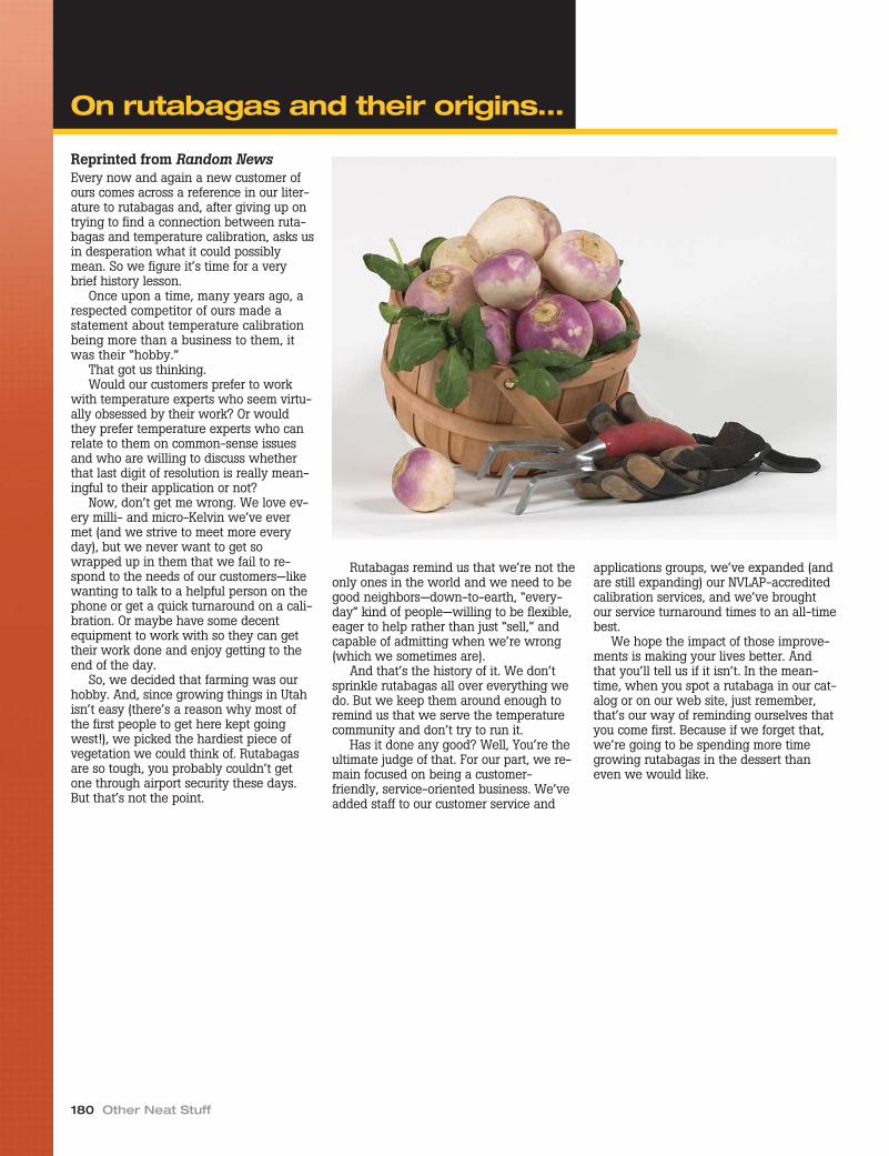
180 Other Neat Stuff
Reprinted from Random NewsEvery now and again a new customer ofours comes across a reference in our liter-ature to rutabagas and, after giving up ontrying to find a connection between ruta-bagas and temperature calibration, asks usin desperation what it could possiblymean. So we figure it’s time for a verybrief history lesson.
Once upon a time, many years ago, arespected competitor of ours made astatement about temperature calibrationbeing more than a business to them, itwas their “hobby.”
That got us thinking.Would our customers prefer to work
with temperature experts who seem virtu-ally obsessed by their work? Or wouldthey prefer temperature experts who canrelate to them on common-sense issuesand who are willing to discuss whetherthat last digit of resolution is really mean-ingful to their application or not?
Now, don’t get me wrong. We love ev-ery milli- and micro-Kelvin we’ve evermet (and we strive to meet more everyday), but we never want to get sowrapped up in them that we fail to re-spond to the needs of our customers—likewanting to talk to a helpful person on thephone or get a quick turnaround on a cali-bration. Or maybe have some decentequipment to work with so they can gettheir work done and enjoy getting to theend of the day.
So, we decided that farming was ourhobby. And, since growing things in Utahisn’t easy (there’s a reason why most ofthe first people to get here kept goingwest!), we picked the hardiest piece ofvegetation we could think of. Rutabagasare so tough, you probably couldn’t getone through airport security these days.But that’s not the point.
Rutabagas remind us that we’re not theonly ones in the world and we need to begood neighbors—down-to-earth, “every-day” kind of people—willing to be flexible,eager to help rather than just “sell,” andcapable of admitting when we’re wrong(which we sometimes are).
And that’s the history of it. We don’tsprinkle rutabagas all over everything wedo. But we keep them around enough toremind us that we serve the temperaturecommunity and don’t try to run it.
Has it done any good? Well, You’re theultimate judge of that. For our part, we re-main focused on being a customer-friendly, service-oriented business. We’veadded staff to our customer service and
applications groups, we’ve expanded (andare still expanding) our NVLAP-accreditedcalibration services, and we’ve broughtour service turnaround times to an all-timebest.
We hope the impact of those improve-ments is making your lives better. Andthat you’ll tell us if it isn’t. In the mean-time, when you spot a rutabaga in our cat-alog or on our web site, just remember,that’s our way of reminding ourselves thatyou come first. Because if we forget that,we’re going to be spending more timegrowing rutabagas in the dessert thaneven we would like.
On rutabagas and their origins…

Our seminars give you the skills you needto do your job better. The members of ourfaculty are the right people to learn frombecause they deal with tough temperaturemetrology questions on a daily basis.Whether you're a technician or a manager,these seminars will help you get ahead inyour career. You'll love each of ourcourses: Principles of Temperature Metrol-ogy, Advanced Topics in Temperature Me-trology, Infrared Temperature Metrology,and Product Training. Each course laststwo days. We sometimes offer two coursesin the same week, so check our website tosee if you can take two courses in just onevisit: www.hartscientific.com/seminars/in-dex.htm
Principles of TemperatureMetrology"It was one of the best training courses Ihave attended."
That's what Keith Decker from a com-pany that is a leader in the developmentof innovative therapies for serious ill-nesses, had to say about our TemperatureMetrology course. Come to our Principlesof Temperature Metrology course to expe-rience this training for yourself.
Topics for this course range from theselection and usage of calibration equip-ment to the theory behind good calibra-tions. This includes knowing how to useSPRTs and other high-accuracy standardsand how to keep your working standardsperforming at their highest levels. Are youworking on laboratory accreditation? Inthis course we also discuss accreditationand compliance, especially dealing withISO 17025 issues.
Not only will we cover actual calibrationtechniques, we'll show you how various in-struments such as readouts, dry-wells, andcalibration baths work and the principlesbehind why they work the way they do.You'll learn to choose the most cost-effec-tive approach for specific applications, andthen we'll get into enough basic uncer-tainty analysis to get your feet wet.
This course lasts two days. We some-times offer two courses in the same week,so check our website to see if you cantake two courses in just one visit:www.hartscientific.com/seminars/in-dex.htm
Advanced Topics in TemperatureMetrologyIt's one thing to follow a calibration proce-dure and quite another to design one orprovide technical support when things gowrong. If you really need to get training
that can improvethe way you work,attend our courseAdvanced Topics inTemperature Me-trology. We've gotthe right faculty inplace to answer allyour toughest tem-perature questions.That's becausethey know the the-ory and practice ofcalibrating every-thing you see on adaily basis. Someof them even de-signed the stuff!
This course cov-ers advanced tem-perature metrologytopics, includinginstruction on theITS-90, proceduredesign, mathemati-cal models, and se-rious uncertaintyanalysis. Bring yourquestions; we'llanswer them.
Attendeesshould have com-pleted Principles ofTemperature Me-trology or its equiv-alent previously.This course lasts two days. We sometimesoffer two courses in the same week, socheck our website to see if you can taketwo courses in just one visit:www.hartscientific.com/seminars/in-dex.htm
Infrared Temperature MetrologySo your customers want to use their infra-red thermometers and it's time to figureout how to deal with the mysteriesof IR thermometer calibration. Unfortu-nately, books written on the subject of in-frared thermometry might as well bewritten in a foreign language, so why notmake it easy on yourself and hear it allexplained in clear, understandable terms?
Our Infrared Temperature Metrologycourse covers the basics of using infraredthermometers, performing radiometric (IR)calibrations, and determining measure-ment uncertainties.
You'll get your questions answeredabout black bodies, grey bodies, size ofsource effect, emissivity, spot size, back-ground temperature effects, and apparent
temperature, to name a few. We'll discusswhat calibration means for infrared ther-mometers and how to do it right. Don'tmiss this chance to get ahead of the gameon the next big thing in temperaturecalibration.
This course lasts two days. We some-times offer two courses in the same week,so check our website to see if you cantake two courses in just one visit:www.hartscientific.com/seminars/in-dex.htm
Product TrainingIt's time to get the most out of your Hartproducts. While our seminars offer theory,demonstrations, hands-on exercises, andpanel discussions, Product Training pro-vides additional hands-on experience.
The course is broken into four sessionscovering thermometers, baths, dry-wells,and software. These sessions offer theperfect opportunity to learn to maximizethe advantages you get from Hart prod-ucts. You will leave knowing exactly howto use your favorite temperature
Temperature Calibration Equipment 181
Hart Scientific temperatureseminars

182 Other Neat Stuff
Hart Scientific temperatureseminars
Meet our facultyMingjian Zhao came to us in 1994 from the National Institute of Me-trology (NIM, China) where he worked as a researcher for seven years.He has published over 40 papers worldwide and has an MS degree inThermal Physics from Harbin Institute of Technology (P. R. China). Heis currently Hart’s director of primary standards engineering and anexpert in the design of thermometers and fixed points.
Tom Wiandt, Hart’s director of metrology, has been with us since1995. He has been key in achieving and maintaining our NVLAP ac-creditation in American Fork, Utah and UKAS accreditation in Norwich,England. His knowledge in temperature metrology is backed by hisexperience at Northrop Corporation, Southern California Edison, andthe US Air Force. He is a frequent speaker at MSC, NCSLI, and interna-tional metrology organizations. He is currently the ASTM chair forcommittee E20.07, Fundamentals in Thermometry.
Mike Hirst, one of the original founders of Hart Scientific, has workedin the engineering of high-performance temperature sources since1970, including dry-well calibrators, fixed-point furnaces, andbaths. He received his BS degree in design technology from BrighamYoung University.
Rick Walker has been with us since 1988 and has had a leadingrole in the development of a majority of Hart’s thermometerreadouts, including the Tweener, Black Stack, and Super-Thermometer. He holds an MS degree in electrical engineering.
Frank Liebmann has been with us since 2003. He is an expert ininfrared temperature measurement and works as an engineer in thedesign of IR thermometer calibrators and other temperaturecalibration equipment. Frank has a BS in Electrical Engineering fromthe University of Utah.
Ron Ainsworth, marketing manager for Hart Scientific, was formerlythe calibration laboratory manager and has been with the companysince 1999. He holds a BS in Physics from Brigham Young Universityand has published his research through TEMPMEKO, the American In-stitute of Physics, and NCSLI, where he is also a section coordinator.
How do I register?
Call us at…(801) 763-1600(800) 438-4278
Fax us at…(801) 763-1010
E-mail us at…[email protected]
or register online at…www.hartscientific.com
Remember, you can check our web sitefor dates and times of classes. Once youregister, we’ll send you the necessary visi-tor information on where to stay and howto get here. We’re located just 40 minutesfrom Salt Lake City International Airportwith plenty of inexpensive hotels nearby.
calibration products, how to achieve thebest results from them, and how to get themost productivity out of your calibrationwork.
An experienced product group expert atHart Scientific guides each product train-ing session. Enrollment is limited andyou're guaranteed to get all your questionsanswered.
Each session includes experience witha large number of products that representHart's entire line for that particular productgroup. In the thermometer session, for ex-ample, you'll get to work (and play) with aLittle Lord Logger, a DewK, a Chub-E4, aBlack Stack, and a Super-Thermometer.Likewise for the other sessions.
You just need to register to enjoy usingthe best temperature calibration productsin the world. Try them out and you'll un-derstand what we mean.
This course lasts two days. We some-times offer two courses in the same week,so check our website to see if you cantake two courses in just one visit:www.hartscientific.com/seminars.

Temperature Calibration Equipment 183
Hart Scientific temperatureseminars
Principles of TemperatureMetrology, course outlineA principles-based course in practicallab skills for comparison calibration ofthermistors, RTDs, thermocouples, andother thermometers.
Introduction to temperature• ITS-90 and other temperature scales• Traceability• Uncertainty• Calibration
Temperature sensors, indicators,and sources
• Types (advantages/disadvantages)• Characteristics• Sources of error• Effective (proper) use• Evaluation
Calibration systems
Measurement techniques andprocedures
Uncertainty budgets
Quality assurance• Check standards• Control charts• ANSI/NCSL Z540• ISO 17025• Accreditation• Audits• Lab inter-comparison
Types (advantages/disadvantages)CharacteristicsSources of errorEffective (proper) useEvaluation
Temperature Metrology, courseoutlineAn intermediate course in practical labskills for comparison calibration of thermis-tors, RTDs, thermocouples, and otherthermometers.
Introduction to temperaturemetrology
• Scales, ITS-90, and fixed points• Uncertainty and traceability
Thermometer types• SPRTs, PRTs, RTDs, and thermistors• Thermocouples—noble vs. base metal• Liquid-in-Glass—procedures for
accuracy• Reference thermometers
Components of uncertainty• Heat sources• Readouts
Common calibration techniques• Thermistors & PRTs• Thermocouples—ASTM, spool testing• LIG—ASTM—specific requirements
Optimizing your measurement• Test uncertainty ratios• Error budgeting• Profiling a heat source• Mathematics
Maintaining your standards• Frequency of calibration• Uncertainty analysis and SPC
Compliance issues• Reports, tables—pleasing the auditor• ISO/IEC17025, incorporating the new
reqirements
Infrared Temperature Metrology,course outline
IR thermometry theory• What is radiation?• IR spectrum• Radiation equations• Emissivity• Gray bodies• Size of source effect (SSE)• Background temperature and effect
Using the IR thermometer• Spectral response• Emissivity• Spot size• Background temperature and effect• Imagers
Using the IR calibrator• Plates vs. cavities• Emissivity (how to account for emissive
effects)• Reference IR thermometer• IR calibrator specifications• Spot size and target size• Background temperature and effect• Alignment
Uncertainty budget• Traceability• Reference IR thermometer• Measurement equation• Accuracy• Repeatability• Elements of an IR uncertainty budget• ASTM guidelines
Product Training, course outlineBath training
• Profile a bath to minimize uncertainty• Use different types of bath fluids• Use Hart bath controllers• Get the most from a refernce thermometer
You'll use…• Deep-well Compact Baths• Standard Baths
Dry-Well Training• Use all dry-well controller functions• recalibrate your own dry-well• Use a reference thermometer• Maximize dry-well productivity
You'll use…• Metrology Wells• Field Dry-Wells
Thermometer training• Use the menu systems for each readout• Match a probe to a readout• Select the best probe and handle it correctly• Avoid calibration pitfalls• Get the most productivity from your
readout
You'll use…• 1524 Reference Thermometer• 1529 Chub-E4• 1620A DewK• 1560 Black Stack
• 1590 Super-Thermometer II
Software training• Automate Control of your heat sources• Automate calibrations entirely• Generate probe data easily• Log temperature data and analyze it
You'll use…• 9930 Interface-it
• 9938 MET/TEMP II• 9933 TableWare
• 9935 LogWare II• 9936A LogWare III
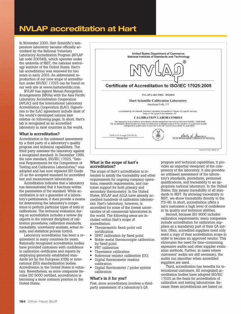
In November 2000, Hart Scientific’s tem-perature laboratory became officially ac-credited by the National VoluntaryLaboratory Accreditation Program (NVLAPlab code 200348), which operates underthe umbrella of NIST, the national metrol-ogy institute of the United States. Hart’slab accreditation was renewed for twoyears in early 2003. An abbreviated re-production of our new scope of accredita-tion under ISO/IEC 17025 can be found onour web site at www.hartscientific.com.
NVLAP has signed Mutual RecognitionArrangements (MRAs) with the Asia PacificLaboratory Accreditation Cooperation(APLAC) and the International LaboratoryAccreditation Cooperation (ILAC). Signato-ries to the ILAC agreement include most ofthe world’s developed nations (seesidebar on following page). In short, Hart’slab is recognized as an accreditedlaboratory in most countries in the world.
What is accreditation?Accreditation is the unbiased assessmentby a third party of a laboratory’s qualityprogram and technical capabilities. Thethird party assesses the laboratory againsta recognized standard. In December 1999,the new standard, ISO/IEC 17025, “Gen-eral Requirements for the Competence ofTesting and Calibration Laboratories,” wasadopted and has now replaced ISO Guide25 as the accepted standard for accreditedtest and measurement laboratories.
Accreditation indicates that a laboratoryhas demonstrated that it functions withinthe parameters of the standard. While ac-creditation is not a guarantee of a labora-tory’s performance, it does provide a meansfor determining the laboratory’s compe-tence to perform particular types of tests orcalibrations. The technical evaluation dur-ing an accreditation includes a review (byexperts in the relevant discipline) of cali-bration procedures, calibration standards,traceability, uncertainty analysis, actual re-sults, and statistical process control.
Laboratory accreditation has been a re-quirement in many countries for years.Nationally recognized accreditation bodieshave provided customers with confidencein calibration certificates and reports byemploying generally established stan-dards set by the European (CEN) or inter-national (ISO) standardization bodies.Accreditation in the United States is volun-tary. Nevertheless, as more companies be-come ISO 9000 certified, accreditation isbecoming a more common practice in theUnited States.
What is the scope of hart’saccreditation?The scope of Hart’s accreditation is in-tended to satisfy the traceability and otherrequirements for ongoing company opera-tions, research requirements, and cus-tomer support for both primary andsecondary thermometry. In the UnitedStates, NVLAP and A2LA have already ac-credited hundreds of calibration laborato-ries. Hart’s laboratory, however, isaccredited for some of the lowest uncer-tainties of all commercial laboratories inthe world. The following areas are in-cluded within Hart’s scope ofaccreditation:● Thermometric fixed-point cell
certification● SPRT calibration by fixed point● Noble-metal thermocouple calibration
by fixed point● PRT calibration● Thermistor calibration● Reference resistor calibration (DC)● Digital thermometer readout
calibration● Digital thermometer / probe system
calibration
What’s in it for you?First, since accreditation involves a third-party assessment of a laboratory’s QA
program and technical capabilities, it pro-vides an impartial viewpoint of the com-petency of the laboratory. It also providesan unbiased assessment of the labora-tory’s standards, procedures, personnelqualifications, and traceability to an ap-propriate national laboratory. In the UnitedStates, this means traceability of all stan-dards to NIST. By showing traceability toNIST, we show traceability directly to theITS-90. In short, accreditation offers alab’s customers a high level of confidencein its quality and technical abilities.
Second, because ISO 9000 includescalibration requirements, many companiesinclude accreditation for calibration sup-pliers as a mandatory part of their QA sys-tem. Often, accredited suppliers need onlyremit a copy of their accreditation scope inorder to become an approved vendor. Thiseliminates the need for time-consuming,expensive audits and other supplier evalu-ation methods. Further, in cases wherecustomers’ audits are still necessary, theaudits run smoother when accreditedsuppliers are used.
Third, accreditation has benefits for in-ternational customers. All recognized ac-creditation bodies have adopted ISO/IEC17025 as the basis for accreditation ofcalibration and testing laboratories. Be-cause these accreditations are based on
184 Other Neat Stuff
NVLAP accreditation at Hart

the same standards, countries may enterinto MRAs whereby an accreditation bodyin one country recognizes theaccreditations done by a fellow MRA sig-natory in another country. This has the ef-fect of easing some of the barriers thathave historically hindered the flow ofcalibrated instruments across borders.
What’s in it for us?Customer demand for laboratory accredi-tation has been rising for years. Withmany companies requiring their calibra-tion services suppliers to be accredited,this demand is starting to reach a criticallevel. By becoming accredited, Hart isbetter positioned to serve a wide varietyof customers. Additionally, the time andcosts associated with providing repetitiveaudits to numerous customers will de-cline with accreditation.
Perhaps the single greatest benefit ofaccreditation to Hart is the accreditationprocess itself. Hart employs some of theworld’s leading temperature metrologists.One such expert, Tom Wiandt, has donean outstanding job running our calibration
lab since 1996. However, the opportunityto receive evaluation and criticism fromindustry peers is extremely valuable. Boththe QA systems and the technical operat-ing procedures were thoroughly exam-ined. Issues were discussed andrecommendations made and implemented.While the lab was already excellent, it isnow the best it’s ever been, and we haveindependent confirmation that we arequalified to do what we say we can do.
In the end, accreditation benefits boththe accredited lab and its customers. Ourprocesses and systems have been vali-dated, our stated uncertainties scrutinized,
and our traceability examined. At thesame time, customers’ confidence in ourlab’s quality system and technical capabil-ities has been independently substanti-ated. The complete scope, ranges, anduncertainties of Hart’s accreditation areavailable for review on our web site atwww.hartscientific.com.
Take a look. We make the world’s finesttemperature calibration equipment, and weknow how to use it. We used it, in fact, toget our accreditation. Trust your critical cal-ibration work to an accredited laboratory.
Temperature Calibration Equipment 185
For the Scope of AccreditationUnder NVLAP Lab Code 200348-0
Signatory organizations to the ILAC MRA
Australia NATA www.nata.asn.auAustria BMWA [email protected] BeltestOBE/BK
OBELTEST.fgov.be
Brazil CGCRE www.inmetro.gov.brCanada SCC www.scc.caChina, HongKong
HKAS www.info.gov.hk/itc/hkas
China, People ’sRepublic of
CNAL www.cnal.org.cn
Chinese Taipei CNLA www.cnla.org.twCzech Republic CAI www.cai.czDenmark DANAK www.danak.dkFinland FINAS www.finas.fiFrance COFRAC www.cofrac.frGermany DACH [email protected] DAP www.dap.deGermany DAR www.dar.bam.deGermany DASMIN www.dasmin.deGermany DATech www.datech.deGermany DKD www.dkd.infoIndia NABL www.nabl-india.orgIndonesia BSN www.bsn.or.idIreland NAB www.nab.ieIsrael ISRAC www.israc.gov.ilItaly SINAL www.sinal.itJapan IAJapan www.nite.go.jp
Japan JAB www.jab.or.jpKorea, Republicof
KOLAS kolas.ats.go.kr
Netherlands RvA www.rva.nlNew Zealand IANZ www.ianz.govt.nzNorway NA www.justervesenet.no/naPortugal IPQ www.ipq.ptSingapore SAC www.sac-ccreditation.org.sgSlovakia SNAS www.snas.skSouth Africa SANAS www.sanas.co.zaSpain ENAC www.enac.esSweden Swedac www.swedac.seSwitzerland SAS www.sas.chThailand TISI www.tisi.go.thUnitedKingdom
UKAS www.ukas.com
USA A2LA www.a2la.orgUSA ICBO www.icboes.orgUSA NVLAP www.nist.gov/nvlapViet Nam VILAS vol.vnn.vn
NVLAP accreditation at Hart

American Fork, Utah labHart’s NVLAP accredited Metrology Labora-tory (lab code 200348) in American Fork,Utah provides temperature calibrations fromapproximately –200 °C to 1000 °C usingfixed-point and comparison methods. Ouraccredited uncertainties are among the low-est commercially available anywhere in theworld. Our prices are very competitive andour turn-around times are excellent. Our re-ports are comprehensive and include as-found and as-left data as well as pass/failcriteria (where applicable) and a concisestatement of the method used. Calibrationsperformed at Hart are traceable to NIST andmeet the new ISO 17025 requirements asdescribed in the following pages.
For fixed-point calibrations, we useHart fixed-point cells and apparatus, HartSPRTs as check standards, and conven-tional DC bridges with DC standard resis-tors. Our fixed-point calibration proceduresare based on CCT procedures, so you canbe confident that the technique is current,correct, and thorough.
For comparison calibrations, we useHart baths, Hart SPRTs, and Hart readouts.We use several different techniques tominimize uncertainties while maximizingefficiency to keep the costs as low as
possible without compromising quality. AllHart-manufactured instruments (exceptSPRTs and some thermocouples, whichcome uncalibrated) are certified beforethey are shipped to you. We don’t simplyprovide a “certificate of conformance” witha couple of NIST numbers like some othermanufacturers and then sock you with ahigh fee if you require a proper calibra-tion. We are the laboratory of choice formany of our customers because they knowthat they can depend on us for correct,complete, and on-time calibrations at rea-sonable prices.
Norwich, England labIn 2003, after extensive planning and asignificant capital investment, Hart Scien-tific opened a primary temperature cali-bration laboratory in Europe. This new labin Norwich, England, will service the pre-cision temperature calibration needs ofcustomers in Europe, the Middle East, andAfrica. The UK lab uses the same greatHart fixed point cells, furnaces, baths, andthermometers used in the American Fork,Utah lab. We even have similarly excellentmetrology experts in this lab. Watch for usto also have UKAS accreditation here soon,with similar uncertainties to that of Hart’sAmerican Fork, Utah lab!
186 Other Neat Stuff
Hart’s American Fork calibration crew:
Alison Shrimpling manages Hart’s new EuropeanPrimary Temperature Laboratory in Norwich, UK.
Calibration services

Temperature Calibration Equipment 187
Calibration services
SPRT calibration by ITS-90 fixed pointNVLAP accredited
All calibrations in this section include the following: (1) calibration at two levels of current and extrapolation to zero power, (2) ITS-90 deviationfunction coefficients and interpolation tables for the nominal current calibration and the zero-power calibration in W vs. T90, and (3) analysis forcompliance to ITS-90 criteria for a standard interpolating instrument of the ITS-90. This represents our best measurement capability(BMC) for SPRTs.Recommended when you absolutely must have the best uncertainty possible. Only Excellent SPRTs qualify.
Order No. TemperatureITS-90
Subranges Fixed Points Used1910-4-7 –200 °C to 660 °C 4, 7 comp at NBPLN2, TPHg, TPW, FPSn, FPZn, FPAl1910-4-8 –200 °C to 420 °C 4, 8 comp at NBPLN2, TPHg, TPW, FPSn, FPZn1910-4-9 –200 °C to 232 °C 4, 9 comp at NBPLN2, TPHg, TPW, FPIn, FPSn1910-5-7 –40 °C to 660 °C 5, 7 TPHg, TPW, MPGa, FPSn, FPZn, FPAl1910-5-10 –40 °C to 157 °C 5, 10 TPHg, TPW, MPGa, FPIn
1910-7 0 °C to 660 °C 7 TPW, FPSn, FPZn, FPAl1910-8 0 °C to 420 °C 8 TPW, FPSn, FPZn
SPRT calibration by ITS-90 fixed pointNVLAP accredited
All calibrations in this section include the following: (1) calibration at two levels of current and extrapolation to zero power, (2) ITS-90 deviationfunction coefficients and interpolation tables for the nominal current calibration and the zero-power calibration W vs. T90, and (3) analysis for com-pliance to ITS-90 criteria for a standard interpolating instrument of the ITS-90. Recommended for working standard SPRTs, when slightly larger un-certainties are acceptable.
Order No. TemperatureITS-90
Subranges Fixed Points Used1911-4-7 –200 °C to 660 °C 4, 7 comp at NBPLN2, TPHg, TPW, FPSn, FPZn, FPAl1911-4-8 –200 °C to 420 °C 4, 8 comp at NBPLN2, TPHg, TPW, FPSn, FPZn1911-4-9 –200 °C to 232 °C 4, 9 comp at NBPLN2, TPHg, TPW, FPIn, FPSn1911-5-7 –40 °C to 660 °C 5, 7 TPHg, TPW, MPGa, FPSn, FPZn, FPAl1911-5-10 –40 °C to 157 °C 5, 10 TPHg, TPW, MPGa, FPIn
1911-6 0 °C to 961°C 6 TPW, FPSn, FPZn, FPAl, FPAg1911-7 0 °C to 660 °C 7 TPW, FPSn, FPZn, FPAl1911-8 0 °C to 420 °C 8 TPW, FPSn, FPZn
SPRT calibration by ITS-90 fixed pointNVLAP accredited
All calibrations in this section include the following: (1) ITS-90 deviation function coefficients and interpolation table for the nominal current calibra-tion W vs. T90, and (2) analysis for compliance to ITS-90 criteria for a standard interpolating instrument of the ITS-90. This larger uncertainty SPRTcalibration is still better than most offered in the industry, and is easier on the wallet. Recommended for any SPRT.
Order No. TemperatureITS-90
Subranges Fixed Points Used1912-4-7 –200 °C to 660 °C 4, 7 comp at NBPLN2, TPHg, TPW, FPSn, FPZn, FPAl1912-4-8 –200 °C to 420 °C 4, 8 comp at NBPLN2, TPHg, TPW, FPSn, FPZn1912-4-9 –200 °C to 232 °C 4, 9 comp at NBPLN2, TPHg, TPW, FPIn, FPSn1912-5-8 –40 °C to 420 °C 5, 8 TPHg, TPW, MPGa, FPSn, FPZn1912-5-9 –40 °C to 232 °C 5, 9 TPHg, TPW, MPGa, FPIn, FPSn1912-5-10 –40 °C to 157 °C 5, 10 TPHg, TPW, MPGa, FPIn
1912-7 0 °C to 660 °C 7 TPW, FPSn, FPZn, FPAl1912-8 0 °C to 420 °C 8 TPW, FPSn, FPZn
Precision PRT calibration by ITS-90 fixed pointNVLAP accredited
All calibrations in this section include the following: (1) ITS-90 deviation function coefficients and interpolation tables for the nominal current cali-bration in resistance vs. T90. Recommended for high quality, secondary standard PRTs only. Hart models 5626, 5628, and 5624 qualify.
Order No. TemperatureITS-90
Subranges Fixed Points Used1913-4-7 –200 °C to 660 °C 4, 7 –197 °C, –100 °C, TPHg, TPW, MPIn, MPSn, MPZn, MPAl1913-4-8 –200 °C to 420 °C 4, 8 –197 °C, –100 °C, TPHg, TPW, MPIn, MPSn, MPZn1913-4-9 –200 °C to 232 °C 4, 9 –197 °C, –100 °C, TPHg, TPW, MPIn, MPSn1913-5-8 –40 °C to 420 °C 5, 8 TPHg, TPW, MPIn, MPSn, MPZn1913-5-9 –40 °C to 232 °C 5, 9 TPHg, TPW, MPIn, MPSn1913-6 0 °C to 961 °C 6 TPW, MPIn, MPSn, MPZn, MPAl, FPAg1913-7 0 °C to 660 °C 7 TPW, MPIn, MPSn, MPZn, MPAl1913-8 0 °C to 420 °C 8 TPW, MPIn, MPSn, MPZn,
Temperature Uncertainty (k=2)
–197 °C (LN2) 0.60 mK–38.8344 °C (TPHg) 0.35 mK
0.010 °C (TPW) 0.20 mK29.7646 °C (MPGa) 0.35 mK156.599 °C (FPIn) 0.70 mK231.928 °C (FPSn) 0.90 mK419.527 °C (FPZn) 1.2 mK660.323 °C (FPAl) 2.0mK961.78 °C (FPAg) 8.0 mK
Temperature Uncertainty (k=2)
–197 °C (LN2) 1.0 mK–38.8344 °C (TPHg) 0.8 mK
0.010 °C (TPW) 0.5 mK29.7646 °C (MPGa) 0.8 mK156.599 °C (FPIn) 1.5 mK231.928 °C (FPSn) 1.5 mK419.527 °C (FPZn) 1.8 mK660.323 °C (FPAl) 3.0 mK961.78 °C (FPAg) 10.0 mK
Temperature Uncertainty (k=2)
–197 °C (LN2) 2.0 mK–38.8344 °C (TPHg) 2.0 mK
0.010 °C (TPW) 2.0 mK29.7646 °C (MPGa) 2.0 mK156.599 °C (FPIn) 3.0 mK231.928 °C (FPSn) 4.0 mK419.527 °C (FPZn) 6.0 mK660.323 °C (FPAl) 8.0 mK961.78 °C (FPAg) 10.0 mK
Temperature Uncertainty (k=2)
–197 °C (LN2) 6.0 mK–100 °C 10.0 mK
–38.8344 °C (TPHg) 6.0 mK0.010 °C (TPW) 4.0 mK
156.599 °C (MPIn) 6.0 mK231.928 °C (MPSn) 6.0 mK419.527 °C (MPZn) 9.0 mK660.323 °C (MPAl) 14.0 mK961.78 °C (FPAg 20.0 mK

188 Other Neat Stuff
Calibration services
Precision PRT calibration by comparisonNVLAP accredited
All calibrations in this section include the following: (1) ITS-90 deviation function coefficients, and (2) interpolation table in 1-degree increments interms of resistance vs. T90. Recommended for high quality, secondary standard PRTs, where higher uncertainty is acceptable. Hart models 5608,5609, 5615, 5616, and 5618B qualify.
Order No. Temperature Comparison Points Used1922-4-R –200 °C to 500 °C –197.0 °C, –100 °C, –38.8 °C, 0.01 °C, 156.6 °C, 231.9 °C,
419.5 °C, 500 °C1922-4-8 –200 °C to 420 °C –197.0 °C, –100.0 °C, –38.8 °C, 0.01 °C, 156.6 °C, 231.9 °C,
419.5 °C1922-5-8 –40 °C to 420 °C –38.8 °C, 0.01 °C, 156.6 °C, 231.9 °C, 419.5 °C1922-5-9 –40 °C to 232 °C –38.8 °C, 0.01 °C, 156.6 °C, 231.9 °C1922-R 0 °C to 500 °C 0.01 °C, 156.6 °C, 231.9 °C, 419.5 °C, 500 °C1922-8 0 °C to 420 °C 0.01 °C, 156.6 °C, 231.9 °C, 419.5 °C
PRT (RTD) calibration by comparisonNVLAP accredited
All calibrations in this section include the following: (1) fitted results with an appropriate equation and (2) interpolation table in 1-degree incre-ments in terms of resistance vs. T90. Recommended for all industrial level PRT (RTD) probes. Hart models 5627A, 5622, and 5618B qualify.Order No. Temperature Comparison Points Used1923-4-R –200 °C to 500 °C –197.0 °C, –100.0 °C, –38.8 °C, 0.01 °C, 156.6 °C, 231.9 °C,
419.5 °C, 500 °C1923-4-8 –200 °C to 420 °C –197.0 °C, –100.0 °C, –38.8 °C, 0.01 °C, 156.6 °C, 231.9 °C,
419.5 °C1923-4-N –200 °C to 300 °C –197.0 °C, –100.0 °C, –38.8 °C, 0.01 °C, 156.6 °C, 231.9 °C,
300 °C1923-4-9 –200 °C to 232 °C –197.0 °C, –100.0 °C, –38.8 °C, 0.01 °C, 156.6 °C, 231.9 °C1923-5-8 –40 °C to 420 °C –38.8 °C, 0.01 °C, 156.6 °C, 231.9 °C, 419.5 °C1923-5-N –40 °C to 300 °C –38.8 °C, 0.01 °C, 156.6 °C, 231.9 °C, 300 °C1923-5-9 –40 °C to 232 °C –38.8 °C, 0.01 °C, 156.6 °C, 231.9 °C1923-N 0 °C to 300 °C 0.01 °C, 156.6 °C, 231.9 °C, 300 °C1923-9 0 °C to 232 °C 0.01 °C, 156.6 °C, 231.9 °C1923-10 0 °C to 157 °C 0.01 °C, 100 °C, 156.6 °C
Precision thermistor calibration by comparisonNVLAP accredited
All calibrations in this section include the following: (1) polynomial solution with coefficients in Steinhart-Hart or third order, and (2) bound interpo-lation table in 0.01- or 0.1-degree increments (depending upon span of calibration) in terms of resistance vs. T90. Order the 1925-A for secondarythermistors with 100 °C range, like the Hart 5610 & 5611 probes. The 1925-B&C calibrations are recommended for very high accuracy thermistorstandards like the Hart 5640-44 series probes.
Order No. Temperature Comparison Points Used Uncertainty (k=2)1925-A 100 °C span 6 points over span 6.0 mK1925-B 60 °C span 7 points over span 2.0 mK1925-C 100 °C span 11 points over span 2.5 mK1925-D 10 °C span 4 points over span 6.0 mK
Noble-metal thermocouple calibration by ITS-90 fixed point NVLAP accredited
All calibrations in this section include the following: (1) ITS-90 polynomial coefficients in accordance with NIST Monograph 175, and (2) boundinterpolation table in 1-degree increments in terms of EMF vs. T90. Recommended for high quality thermocouple standards. Order 1918-A for Au/Ptthermocouple standards, 1918-B for Type S and Type R standards.Order No. Temperature Fixed Points Used Uncertainty (k=2) Extrapolated Uncertainty (k=2)1918-B 0 °C to 1450 °C FPSn, FPZn, FPAl, FPAg
(Type S–R)0.15 °C 2 °C
Requirements for thermocouples: Must have very clean, unbroken (even uncracked) sheaths, have at least 20” long sheath length, and have at least36” lead length. Please call our customer service department for clarification if needed.
Temperature Uncertainty
–200 °C 25 mK–100 to –50 °C 25 mK
–50 to 0 °C 25 mK0.010 °C 25 mK
0 to 100 °C 25 mK100 to 300 °C 30 mK300 to 420 °C 35 mK420 to 500 °C 45 mK
Temperature Uncertainty
–200 °C 10 mK–100 to –50 °C 10 mK
–50 to 0 °C 8 mK0.010 °C 6 mK
0 to 200 °C 9 mK200 to 300 °C 12 mK300 to 400 °C 14 mK400 to 500 °C 16 mK

Temperature Calibration Equipment 189
Calibration services
Precision digital thermometer system calibration by comparisonNVLAP accredited
All calibrations in this section include as-found data, as-left system data, and adjustments. Sys-tems are calibrated as systems and not as individual components (probe and readout). Uncertain-ties are similar to those listed on the opposite page, depending on the system being calibrated.Consult Hart’s customer service group for temperature ranges not listed here. An additional fee ischarged for non-standard temperature points requested.Order No. Temperature Comparison Points Used1930-4-R –200 °C to 500 °C –197.0 °C, –38.8 °C, 0.01 °C, 231.9 °C, 419.5 °C, 500.0 °C1930-4-8 –200 °C to 420 °C –197.0 °C, –38.8 °C, 0.01 °C, 231.9 °C, 419.5 °C1930-D-8 –100 °C to 420 °C –100.0 °C, –38.8 °C, 0.01 °C, 231.9 °C, 419.5 °C1930-5-8 –40 °C to 420 °C –38.8 °C, 0.01 °C, 231.9 °C, 419.5 °C1930-5-9 –40 °C to 232 °C –38.8 °C, 0.01 °C, 156.6 °C, 231.9 °C1930-8 0 °C to 420 °C 0.01 °C, 231.9 °C, 419.5 °C1935-A 100 °C span 6 points over span1935-B 60 °C span 7 points over span1935-C 100 °C span 11 points over span
Fixed point cell direct comparisonNVLAP accredited
Comparison to a Hart working standard fixed-point cell. A comprehensive calibration report is in-cluded. (For Best Measurement Capability comparisons, please call Hart.)
Order No. ITS-90 Fixed Point Cell Uncertainty (k=2)
1904-Hg TPHg 0.25mK1904-Tpw TPW 0.10mK1904-Ga MPGa 0.10mK1904-In FPIn 0.70mK1904-Sn FPSn 0.80mK1904-Zn FPZn 1.00mK1904-Al FPAl 1.80mK1904-Ag FPAg 4.50mK
DC resistance calibrationNVLAP accredited
Your DC resistors are compared to Hart’s standard resistors. A comprehensive calibration report isincluded.
Order No. Resistance Range Uncertainty (k=2)1960 1 - 10 Ohm 0.35 ppm1960 10 - 100 Ohm 0.45 ppm1960 100 - 1000 Ohm 0.60 ppm1960 1000 - 10000 Ohm 0.70 ppm
Humidity Sensor Calibration
All calibrations in this section are traceable to NIST and include certificates compliant withANSI/NCSL Z540-1 and ISO Guide 17025. As-found data, as-left data, and adjustments areincluded.
Order No. Temp. Points RH Points1980-A 1 31980-B 1 51980-C 3 51980-D 5 5
Instrument Calibration
For recalibration of Hart Scientific thermometer readouts and dry-wells please call Hart Customerservice. If you are calling from within the USA, please call toll free (800) 438-4278 or (888) 538-4278. If you are calling from outside of the USA please call (801) 763-1600. Calibration of Hartthermometer readouts fall within Hart’s scope of accreditation.
ISO 17025 triggers changes incalibration intervalmanagementThe ISO 17025 views calibration intervalmanagement as the responsibility of thecustomer rather than the calibration sup-plier. As a result, when you contact us toarrange for recalibration of your instru-ments, our customer service representa-tive will ask you what interval you wishto set. If no interval is selected, the cali-bration report will show the due date as“Not Defined.”
In the case of new instruments, wewill set the initial interval based on man-ufacturer’s recommendations (includingour own if Hart is the manufacturer) un-less we are instructed otherwise. Re-member, although manufacturers mayprovide advice regarding calibration in-tervals, cal labs accredited under ISO17025 may not. You have the choice andresponsibility to determine the calibra-tion cycle for your instruments.
Should I get a “system” cal?Traditionally, readouts and probes arecalibrated individually. This is generallybest because the instruments are speci-fied individually, traceability is straight-forward, and it permitsinterchangeability.
However, in some circumstances sys-tem calibrations can prove beneficial. Forexample, if the probe and readout are“married” and are both stable performers,it is often faster and cheaper to havethem calibrated as a system rather thanindividually. As-found data is obtained intemperature units and traceability is es-tablished through the system. As long asinterchangeability is not required, thisapproach can prove beneficial whenused judiciously.

190 Index
!1502A Tweener PRT Readout . . . . . . . . . . . . . 571504 Tweener Thermistor Readout. . . . . . . . . 571523 Reference Thermometer, Handheld, 1
Channel . . . . . . . . . . . . . . . . . . . . . . . . 611523-CAL 1523 Accredited Calibration . . . . . 611523-CASE Case, 1523/1524 Readout and Probe
Carrying . . . . . . . . . . . . . . . . . . . . . . . . 611523-P1 1523 Bundled with 5616 PRT . . . . . 611523-P2 1523 Bundled with 5628 PRT . . . . . 611523-P3 1523 Bundled with 5627A PRT. . . . 611524 Reference Thermometer, Handheld, 2
Channel, Data Logger. . . . . . . . . . . . . . 611524-CAL 1524 Accredited Calibration . . . . . 611524-P1 1524 Bundled with 5616 PRT . . . . . 611524-P2 1524 Bundled with 5628 PRT . . . . . 611524-P3 1524 Bundled with 5627A PRT. . . . 611529 Chub-E4 Thermometer, 2 TC and 2
PRT/Thermistor inputs . . . . . . . . . . . . . 551529-R Chub-E4 Thermometer, 4
PRT/Thermistor inputs . . . . . . . . . . . . . 551529-T Chub-E4 Thermometer, 4 TC inputs. . 551560 Black Stack Readout Base Unit . . . . . . . 521575A Super-Thermometer . . . . . . . . . . . . . . 411590 Super-Thermometer II . . . . . . . . . . . . . . 411620A-H The “DewK” Thermo-Hygrometer,
High-Accuracy . . . . . . . . . . . . . . . . . . . 651620A-S The “DewK” Thermo-Hygrometer,
Standard-Accuracy. . . . . . . . . . . . . . . . 651621A-H The “DewK” Thermo-Hygrometer,
High-Accuracy Value Kit . . . . . . . . . . . 651621A-S The “DewK” Thermo-Hygrometer,
Standard-Accuracy Value Kit . . . . . . . . 651622A-H The “DewK” Thermo-Hygrometer, USB
Wireless High-Accuracy Value Kit . . . . 651622A-S The “DewK” Thermo-Hygrometer, USB
Wireless Standard-Accuracy Value Kit. 651922-4-R PRT (5608) Calibration, –200 °C to
500 °C, NVLAP Accredited . . . . . . . . . . 721923-4-7 PRT (5609) Calibration, –200 °C to
660 °C, NVLAP Accredited . . . . . . . . . . 721924-4-7 PRT (5609-9BND) Calibration, –200 °C
to 660 °C, NIST-traceable. . . . . . . . . . . 721925-A Accredited Thermistor Calibration, 0 °C
to 100 °C (23 °F to 212 °F). . . . . . . . . . 611929-2 System Verification, PRT with Readout,
Accredited . . . . . . . . . . . . . . . . . . . . . . 611929-5 System Verification, Thermistor with
Readout, Accredited . . . . . . . . . . . . . . . 611930 Precision Digital Thermometer System
Calibration by Comparison. . . . . . . . . . 721930 System Calibration, PRT with Readout,
Accredite . . . . . . . . . . . . . . . . . . . . . . . 611935 System Calibration, Thermistor with
Readout, Accredited . . . . . . . . . . . . . . . 612001-6020 Automation Package for 6020 . . 1192001-6022 Automation Package for 6022 . . 1192001-6024 Automation Package for 6024 . . 1192001-6050H Automation Package for 6050H
. . . . . . . . . . . . . . . . . . . . . . . . . . . . . . 1202001-6054 Automation Package for 6054 . . 1222001-6055 Automation Package for 6055 . . 1222001-7007 Automation Package for 7007 . . 1222001-7009 Automation Package for 7009 . . 1252001-7015 Automation Package for 7015 . . 1252001-7060 Automation Package for 7060 . . 1142001-7080 Automation Package for 7080 . . 1142001-7100 Automation Package for 7100 . . 1142001-IEEE Interface, IEEE-488 . . . 17, 109, 111,
114, 117, 119 - 120, 122, 125 . . . . .2007 Access Cover, 5 x 10 in, SST 114, 117, 119
2009 Access Cover, 184 x 324 mm (7.25 x 12.75in), Stainless Steel . . . . . . . . . . . . . . . 119
2010 Access Cover, 5 x 10 in, Lexan . . 114, 1172010-5 Access Cover, 6.38 x 11.5 in, Lexan
(7037) . . . . . . . . . . . . . . . . . . . . . . . . 1172011 Access Cover, 184 x 324 mm (7.25 x 12.75
in), Lexan . . . . . . . . . . . . . . . . . . . . . . 1172012-DCB Spare Access Cover, Plastic, 7321,
7341, 7381 . . . . . . . . . . . . . . . . . . . . 1092014 Spare Access Cover . . . . . . . . . . . . . . . 1202016-7008 Fluid Level Adapter, 7008 . . . . . 1172016-7011 Fluid Level Adapter, 701 . . . . . . 1172016-7012 Fluid Level Adapter, 701 . . . . . . 1172016-7037 Fluid Level Adapter, 7037 . . . . . 1172016-7040 Fluid Level Adapter, 7040 . . . . . 1172016-7060 Fluid Level Adapter, 7060 . . . . . 1142018 Carousel Holding Fixture for 6055 . . . . 1222019-7080 Fluid Level Adapter, 7080 . . . . . 1142019-7100 Fluid Level Adapter, 7100 . . . . . 1142019-DCB Liquid-in-Glass Thermometer
Calibration Kit . . . . . . . . . . . . . . . . . . 1092020-6330 Spare Access Cover, SST, 6330 . 1112020-6331 Spare Access Cover, Stainless Steel,
6331 . . . . . . . . . . . . . . . . . . . . . . . . . 1092020-7320 Spare Access Cover, SST, 7320/7340
111 . . . . . . . . . . . . . . . . . . .2020-7380 Spare Access Cover, SST, 7380 . 1112023 Fast-Start Heater, 16.5 in . . . . . 119 - 1202027-5901 TPW Holding Fixture (7012, 7037)
. . . . . . . . . . . . . . . . . . . . . . . . . . . . . . 1172027-DCBM Mercury TP Holding Fixture (7341)
. . . . . . . . . . . . . . . . . . . . . . . . . . . . . . 1092027-DCBW TPW Holding Fixture (7321, 7341,
7381) . . . . . . . . . . . . . . . . . . . . . . . . . 1092028 Dewar (for TPW ice bath) . . . . . . . . . . . . 152031A “Quick Stick” Immersion Freezer . . 15, 172033 IR Cone (NIST design) . . . . . . . . . . . . . 1172068-D Stand, Fixed-Point Cell, Black Delron. 242069 8X Magnifier Scope . . . 109, 114, 117, 1192069 LIG Telescope with Mounting, 8X
magnification . . . . . . . . . . . . . . . . . . . 1222070 Bath Cart, 6020, 6022 (312 mm 12.3 in
H) . . . . . . . . . . . . . . . . . . . . . . . . . . . . 1192071 Bath Cart, 7011, 7012 (312 mm 12.3 in
H) . . . . . . . . . . . . . . . . . . . . . . . . . . . . 1172072 Bath Cart, 6024 (216 mm 8.5 in H) . . 1192073 Bath Cart, 7008, 7037, 7040 (216 mm 8.5
in ) H . . . . . . . . . . . . . . . . . . . . . . . . . 1172076-6330 Floor Cart, 6330 (343 mm 13.5 in
H) . . . . . . . . . . . . . . . . . . . . . . . . . . . . 1112076-7320 Floor Cart, 7320/7340 (229 mm 9
in H) . . . . . . . . . . . . . . . . . . . . . . . . . 1112082-M Spare test lid . . . . . . . . . . . . . . . . . . 1532082-P Spare test lid . . . . . . . . . . . . . . . . . . 1532083 Tank extension adapter . . . . . . . . . . . . 1532085 Spare test lid . . . . . . . . . . . . . . . . . . . . 1532100-P Controller, PRT . . . . . . . . . . . . . . . . . 1332100-T Controller, Thermistor . . . . . . . . . . . 1332125 IEEE-488 Interface. . . . . . . . . . . . . 29, 1332125-C IEEE-488 Interface (RS-232 to IEEE-488
converter box) . . . . . . . . . . . 13, 111, 1632126 Comparison Block, 9114 . . . . . . . . . . . . 292127-9114 Alumina Block, 9114 . . . . . . . . . 292127-CB Block, Ceramic, Non-contaminating,
9115A/9116A . . . . . . . . . . . . . . . . . . . 292129 Spare Alumina Block, 5 wells . . . . . . . . 132130 Spare Well-Sizing Tube Set . . . . . . . . . 1702200-P Controller, PRT . . . . . . . . . . . . . . . . . 1332361 Spare Power Supply, 100 to 240 V ac . . 652362 Spare AC Adapter, 15 V . . . . . . . . . . . . . 552373-KLTC Adapter, Lemo to Universal TC (TC)
. . . . . . . . . . . . . . . . . . . . . . . . . . . . . . . 61
2373-LPRT Adapter, Lemo to Mini Grabbers (4-wire). . . . . . . . . . . . . . . . . . . . . . . . . . . 61
2380-X Miniature Thermocouple Connector . . 522381-X Standard Thermocouple Connector . . 522382 RTD/Thermistor Connector. . . . . . . . . . . 522383 USB to RS-232 Adapter . . . . . 96, 99 - 1012384-P INFO-CON Connector, PRT (Gray Cap),
Spare . . . . . . . . . . . . . . . . . . . . . . . . . . 612384-T INFO-CON Connector, TC (Blue Cap),
Spare . . . . . . . . . . . . . . . . . . . . . . . . . . 612505 Spare Connector. . . . . . . . . . . . . . . . . . . 572506 IEEE Option . . . . . . . . . . . . . . . . . . . . . . 572506-1529 IEEE Option . . . . . . . . . . . . . . . . . 552508 Serial Cable Kit. . . . . . . . . . . . . . . . . . . . 572513-1529 Rack-Mount Kit . . . . . . . . . . . . . . 552560 SPRT Module, 25Ω and 100Ω, 2-channel
. . . . . . . . . . . . . . . . . . . . . . . . . . . . . . . 522561 High-Temp PRT Module, 0.25Ω to 5Ω, 2-ch
52 . . . . . . . . . . . . . . . . . . . .2562 PRT Scanner Module, 8-channel . . . . . . 522563 Standards Thermistor Module, 2-channel
. . . . . . . . . . . . . . . . . . . . . . . . . . . . . . . 522564 Thermistor Scanner Module, 8-channel. 522565 Precision Thermocouple Module, 2-channel
52 . . . . . . . . . . . . . . . . . . . .2566 Thermocouple Scanner Module, 12-
channel . . . . . . . . . . . . . . . . . . . . . . . . 522567 SPRT Module, 1000Ω, 2-channel . . . . . 522568 PRT Scanner Module, 8-channel,
1000Ω . . . . . . . . . . . . . . . . . . . . . . . . . 522575 Multiplexer, 1575. . . . . . . . . . . . . . . . . . 412590 Multiplexer, 1590. . . . . . . . . . . . . . . . . . 412601 Plastic PRT Case. . . . . . . . . . . . . . . . . . . 722601 Probe Carrying Case . . . . . 74, 77 - 80, 852607 Protective Case for spare sensor . . . . . . 652609 Case, PRT, Plastic . . . . . . . . . . . 68 - 69, 902609 Plastic PRT Case. . . . . . . . . . . . . . . . . . . 722611 Thermistor Probe . . . . . . . . . . . . . . . . . 1332620 RTD Probe, 11 in . . . . . . . . . . . . . . . . . 1332622 RTD Probe, 9 in . . . . . . . . . . . . . . . . . . 1332624 RTD Probe, 14 in . . . . . . . . . . . . . . . . . 1332626-H Spare Sensor, high-accuracy . . . . . . . 652626-S Spare Sensor, standard-accuracy . . . . 652627-H Spare Sensor Kit, high-accuracy . . . . 652627-S Spare Sensor Kit, standard-accuracy . 652628 Cable, Sensor Extension, 7.6 m (25 ft) . . 652629 Cable, Sensor Extension, 15.2 m (50 ft) . 652633-232 Wireless Modem, RS-232 to wireless
. . . . . . . . . . . . . . . . . . . . . . . . . . . . . . . 652633-RF Wireless Option . . . . . . . . . . . . . . . . 652633-USB Wireless Modem, USB to wireless . 652940-9114 Cell Support Container, 9114 . . . 292940-9115 Cell Support Container, 9115 . . . 292940-9260 Container, Mini-Cell Support, 9260
. . . . . . . . . . . . . . . . . . . . . . . . . . . . . . . 342941 Mini Freeze-Point Cell Basket Adapter. . 292942-9260 Container, SST Mini-Cell Support,
9260 . . . . . . . . . . . . . . . . . . . . . . . . . . 343102-0 Insert, blank . . . . . . . . . . . . . . . . . . . 1653102-0 Insert, Blank . . . . . . . . . . . . . . . . . . . 1613102-1 Insert, 1/16 in (1.6 mm). . . . . . 161, 1653102-2 Insert, 1/8 in (3.2 mm). . . . . . . 161, 1653102-3 Insert, 3/16 in (4.8 mm). . . . . . 161, 1653102-4 Insert, 1/4 in (6.4 mm). . . . . . . 161, 1653102-5 Insert, 5/16 in (7.9 mm). . . . . . 161, 1653102-6 Insert, 3/8 in (9.5 mm). . . . . . . 161, 1653102-7 Insert, 7/16 in (11.1 mm) . . . . 161, 1653102-8 Insert, 5/32 in (4 mm) . . . . . . . 161, 1653103-1 Insert, blank . . . . . . . . . . . . . . . . . . . 1573103-1 Insert, Blank . . . . . . . . . . . . . . . . . . . 1633103-2 Insert A . . . . . . . . . . . . . . . . . . 157, 1633103-3 Insert B . . . . . . . . . . . . . . . . . . 157, 163
Index

Index 191
Index
3103-4 Insert C. . . . . . . . . . . . . . . . . . . . . . . 1573103-4 Insert C, Six 1/4 in Wells (Cold Side) 1633103-6 Insert D, Comparison - Metric (Cold Side)
. . . . . . . . . . . . . . . . . . . . . . . . . . . . . . 1633103-Y Insert, custom 9011/9103 . . . . 157, 1633107-2000 Blank insert . . . . . . . . . . . . . . . . 1663107-2063 1/16 in Insert (1.6 mm) . . . . . . . 1663107-2125 1/8 in Insert (3.2 mm) . . . . . . . . 1663107-2156 5/32 in Insert (4 mm) . . . . . . . . 1663107-2188 3/16 in Insert (4.8 mm) . . . . . . . 1663107-2250 1/4 in Insert (6.35 mm) . . . . . . . 1663107-2313 5/16 in Insert (7.9 mm) . . . . . . . 1663107-2375 3/8 in Insert (9.5 mm) . . . . . . . . 1663107-2500 1/2 in Insert (12.7 mm) . . . . . . . 1663107-2625 5/8 in Insert (15.9 mm) . . . . . . . 1663107-2901 Insert, 1 User-Specified Hole . . . 1663107-2902 Insert, 2 User-Specified Holes . . 1663109-0 Insert, Blank (Hot Side). . . . . . . . . . . 1633109-1 Insert A, Miscellaneous (Hot Side) . . 1633109-2 Insert B, Comparison (Hot Side) . . . . 1633109-3 Insert C, Eight 1/4 in Wells (Hot Side)
. . . . . . . . . . . . . . . . . . . . . . . . . . . . . . 1633109-4 Insert D, Comparison - Metric (Hot Side)
. . . . . . . . . . . . . . . . . . . . . . . . . . . . . . 1633110-1 Comparison Insert, Blank . . . . . . . . . . 323110-2 Comparison Insert A. . . . . . . . . . . . . . 323110-3 Comparison Insert B . . . . . . . . . . . . . . 323110-4 Comparison Insert C . . . . . . . . . . . . . . 323125 Surface Calibrator. . . . . . . . . . . . . . . . . 1763140-1 Insert, blank . . . . . . . . . . . . . . . . . . . 1573140-2 Insert A. . . . . . . . . . . . . . . . . . . . . . . 1573140-3 Insert B. . . . . . . . . . . . . . . . . . . . . . . 1573140-4 Insert C. . . . . . . . . . . . . . . . . . . . . . . 1573140-6 Insert D. . . . . . . . . . . . . . . . . . . . . . . 1573141-1 Insert, blank . . . . . . . . . . . . . . . . . . . 1573141-2 Insert A. . . . . . . . . . . . . . . . . . . . . . . 1573141-3 Insert B. . . . . . . . . . . . . . . . . . . . . . . 1573141-4 Insert C. . . . . . . . . . . . . . . . . . . . . . . 1573141-6 Insert D. . . . . . . . . . . . . . . . . . . . . . . 1573150-2 Insert A. . . . . . . . . . . . . . . . . . . . . . . 1673150-3 Insert B. . . . . . . . . . . . . . . . . . . . . . . 1673150-4 Insert C. . . . . . . . . . . . . . . . . . . . . . . 1673150-6 Insert D. . . . . . . . . . . . . . . . . . . . . . . 1673160-1 Comparison Insert, Blank . . . . . . . . . . 343160-2 Comparison Insert . . . . . . . . . . . . . . . 343160-3 Comparison Insert . . . . . . . . . . . . . . . 343320 Spare Stir Bar, Micro-Bath . . . . . . . . . . 1533560 Extended Communications Module . . . . 523901-11 TPW Bushing, 5901/5901A to 7.5 mm
. . . . . . . . . . . . . . . . . . . . . . . . . . . . . . . 153901-12 TPW Bushing, 5901/5901A to 5.56
mm (7/32 in) . . . . . . . . . . . . . . . . . . . . 153901-13 TPW Bushing, 5901/5901A to 6.35 mm
(1/4 in) . . . . . . . . . . . . . . . . . . . . . . . . . 153901-21 TPW Bushing, 5901C to 7.5 mm . . . 153901-22 TPW Bushing, 5901C to 5.56 mm (7/32
in). . . . . . . . . . . . . . . . . . . . . . . . . . . . . 153901-23 TPW Bushing, 5901C to 6.35 mm (1/4
in). . . . . . . . . . . . . . . . . . . . . . . . . . . . . 154180 Precision Infrared Calibrator, –15 °C to 120
°C . . . . . . . . . . . . . . . . . . . . . . . . . . . . 1734180 Precision Infrared Calibrator, 35 °C to 500
°C . . . . . . . . . . . . . . . . . . . . . . . . . . . . 1734180-APRT 2-in Aperture, 4180 or 4181 . . 1734180-CASE Carrying Case, 4180 or 4181 . . 1734180-DCAS Case, Transportation with wheels,
4180 or 4181. . . . . . . . . . . . . . . . . . . 1735001 Bath Salt, 125 lb.. . . . . . . . . . . . . 120, 1295010 Silicone Oil Type 200.05 . . . . . . . . . . . 1295010-1L Silicone oil, type 200.05, 1 liter . . . 1535011 Mineral Oil . . . . . . . . . . . . . . . . . . . . . . 1295011-18.9L Fluid, Mineral Oil, 18.9 L (5 gal.)125
5011-3.8L Fluid, Mineral Oil, 3.8 L (1 gal.) . . 1255012 Silicone Oil Type 200.10 . . . . . . . . . . . 1295013 Silicone Oil Type 200.20 . . . . . . . . . . . 1295013-1L Silicone oil, type 200.20, 1 liter . . . 1535014 Silicone Oil Type 200.50 . . . . . . . . . . . 1295017 Silicone Oil Type 710. . . . . . . . . . . . . . 1295019 Halocarbon 0.8 Cold Bath Fluid . . . . . . 1295020 Ethylene Glycol . . . . . . . . . . . . . . . . . . 1295022 Dynalene HF/LO . . . . . . . . . . . . . . . . . . 1295023 HFE Cold Bath Fluid . . . . . . . . . . . . . . . 1295121 Humidity Generator, 2500ST . . . . . . . . 1795313-001 Scanner, 20 channels . . . . . . . . . . 205313-002 Scanner, 10 channels . . . . . . . . . . 205313-003 IOTech 488 Interface Card . . . . . . . 205313-004 Windows Software . . . . . . . . . . . . 205340-1 Resistor, AC/DC Standard, 1Ω . . . . . . 375430-10 Resistor, AC/DC Standard, 10Ω . . . . 375430-100 Resistor, AC/DC Standard, 100Ω . . 375430-10K Resistor, AC/DC Standard, 10 KΩ . 375430-1K Resistor, AC/DC Standard, 1 KΩ. . . . 375430-200 Resistor, AC/DC Standard, 200Ω . . 375430-25 Resistor, AC/DC Standard, 25Ω . . . . 375430-400 Resistor, AC/DC Standard, 400Ω . . 375581 MI Bridge . . . . . . . . . . . . . . . . . . . . . . . . 205608-12-X Secondary Reference PRT, 12 in x
1/8 in, –200 to 500 °C. . . . . . . . . . . . . 725608-9-X Secondary Reference PRT, 9 in x 1/8
in, –200 to 500 °C . . . . . . . . . . . . . . . . 725609 -500-X Secondary Reference PRT, 500 mm
x 6 mm, –200 to 670 °C. . . . . . . . . . . . 725609-12-X Secondary Reference PRT, 12 in x
1/4 in, –200 to 670 °C. . . . . . . . . . . . . 725609-15-X Secondary Reference PRT, 15 in x
1/4 in, –200 to 670 °C. . . . . . . . . . . . . 725609-20-X Secondary Reference PRT, 20 in x
1/4 in, –200 to 670 °C. . . . . . . . . . . . . 725609-300-X Secondary Reference PRT, 300 mm
x 6 mm, –200 to 670 °C. . . . . . . . . . . . 725609-400-X Secondary Reference PRT, 400 mm
x 6 mm, –200 to 670 °C. . . . . . . . . . . . 725609-9BEND-X Secondary Standard PRT Bend
. . . . . . . . . . . . . . . . . . . . . . . . . . . . . . . 615609-9BND-X Secondary Reference PRT, 15 in x
1/4 in, 9 in bend, -200 °C to 670 °C . . 725610-6-X Thermistor Probe . . . . . . . . . . . 52, 855610-9-X Thermistor Probe . . . . . . . . 52, 61, 855611A-11X Silicone-Bead Probe . . . . . . . . . . 855611T-X Teflon Probe. . . . . . . . . . . . . . . . . . . 855615-12-X Secondary Standard PRT . . . . 52, 705615-6-X Secondary Standard PRT . . . . . 52, 705615-9-X Secondary Standard PRT . . . . . 52, 705616-12-X Secondary Reference PRT, 6.35 mm
x 298 mm (0.250 x 11.75 in), –200 to420 °C . . . . . . . . . . . . . . . . . . . . . . . . . 74
5616-6-X Secondary Standard PRT . . . . . . . . 615618B-12-X 305 mm (12 in) Small Diameter
Probe . . . . . . . . . . . . . . . . . . . . . . . . . . 775618B-6-X 152 mm (6 in) Small Diameter Probe
. . . . . . . . . . . . . . . . . . . . . . . . . . . . . . . 775618B-9-X 229 mm (9 in) Small Diameter Probe
. . . . . . . . . . . . . . . . . . . . . . . . . . . . . . . 775622-05-X Fast Response PRT . . . . . . . . . . . . 805622-10-X Fast Response PRT . . . . . . . . . . . . 805622-16-X Fast Response PRT . . . . . . . . . . . . 805622-32-X Fast Response PRT . . . . . . . . . . . . 805623B-6-X Freezer Probe . . . . . . . . . . . . . . . . 785624-20-X Probe, 1000 °C, 10 ohm PRT, 6.35
mm x 508 mm (0.25 x 20 in) . . . . . . . . 695626-12-X Secondary Standard PRT . . . . 52, 685626-15-S Secondary PRT . . . . . . . . . . . . . . . 625626-15-X High-temp PRT, 100Ω, 381 mm (15
in). . . . . . . . . . . . . . . . . . . . . . . . . . . . . 68
5626-20-X High-temp PRT, 100Ω, 508 mm (20in). . . . . . . . . . . . . . . . . . . . . . . . . . . . . 68
5627A-12-X Secondary PRT. . . . . . . . . . . . . . 795627A-6-X Secondary PRT. . . . . . . . . . . . . . . 795627A-9-X Secondary PRT. . . . . . . . . . . . . . . 795628-12-X Secondary Standard PRT . . . . 52, 685628-15-X Secondary Standard PRT . . . . 52, 685628-20-X High-temp PRT, 25.5Ω, 508 mm (20
in). . . . . . . . . . . . . . . . . . . . . . . . . . . . . 685635-S Thermocouple Cutout Probe . . . . . . . 1335640-X Standards Thermistor Probe. . . . . . . . 835641-X Standards Thermistor Probe. . . . . . . . 835642-X Standards Thermistor Probe. . . . . 52, 835643-X Standards Thermistor Probe. . . . . . . . 835644-X Standards Thermistor Probe. . . . . . . . 835649-20CX Type R TC, 20 in x 1/4 in, with
reference junction . . . . . . . . . . . . . . . . 905649-20CX Type R TC, 508 mm (20 in), with
reference junction . . . . . . . . . . . . . . . . 905649-20-X Type R TC, 508 mm (20 in) . . . . . 905649-25CX Type R TC, 635 mm (25 in), with
reference junction . . . . . . . . . . . . . . . . 905649-25-X Type R TC, 635 mm (25 in) . . . . . 905650-20CX Type S TC, 508 mm (20 in), with
reference junction . . . . . . . . . . . . . . . . 905650-20-X Type S TC, 508 mm (20 in) . . . . . 905650-25CX Type S TC, 635 mm (25 in), with
reference junction . . . . . . . . . . . . . . . . 905650-25-X Type S TC, 635 mm (25 in) . . . . . 905665-X Miniature Immersion Probe . . . . . . . . 855681-S SPRT 25.5Ω, 670 °C . . . . . . . . . . . . . . . 95683-S SPRT 25.5Ω, 480 °C . . . . . . . . . . . . . . . 95684-S SPRT 0.25Ω, 1070 °C . . . . . . . . . . . . . . 95685-S SPRT 2.5Ω, 1070 °C . . . . . . . . . . . . . . . 95686-B Glass Capsule SPRT, –260 °C to 232 °C
. . . . . . . . . . . . . . . . . . . . . . . . . . . . . . . 125698-25 25Ω Working Standard SPRT. . . . . . 105699-S Extended Range Metal-Sheath SPRT . 115699-S Extended Range PRT . . . . . . . . . . . . . 625900 Mercury Cell, Stainless Steel . . . . . . . . . 245901A-G TPW Cell, 12 mm ID with handle, glass
shell . . . . . . . . . . . . . . . . . . . . . . . . . . . 155901A-Q TPW Cell, 12 mm ID with handle,
quartz shell . . . . . . . . . . . . . . . . . . . . . 155901B Mini Pyrex® Triple Point of Water Cell 305901B-G TPW Cell, mini, glass shell. . . . . . . . 155901C-G TPW Cell, 13.6 mm ID, glass shell . . 155901C-Q TPW Cell, 14.4 mm ID, quartz shell . 155901D-G TPW Cell, 12 mm ID, glass shell . . . 155901D-Q TPW Cell, 12 mm ID, quartz shell . . 155901-ITST Isotopic Composition Analysis, TPW
Cell . . . . . . . . . . . . . . . . . . . . . . . . . . . . 155901-SMPL Water Sample, TPW Cell . . . . . . . 155904 Indium Cell, Traditional Quartz Glass . . . 245905 Tin Cell, Traditional Quartz Glass . . . . . . 245906 Zinc Cell, Traditional Quartz Glass . . . . . 245907 Aluminum Cell, Traditional Quartz Glass 245908 Silver Cell, Traditional Quartz Glass . . . . 245909 Copper Cell, Traditional Quartz Glass . . . 245914A Mini Quartz Indium Cell . . . . . . . . . 30, 345915A Mini Quartz Tin Cell . . . . . . . . . . . . 30, 345916A Mini Quartz Zinc Cell . . . . . . . . . . . 30, 345917A Mini Quartz Aluminum Cell . . . . . . 30, 345918A Mini Quartz Silver Cell . . . . . . . . . . . . . 305919A Mini Quartz Copper Cell . . . . . . . . . . . . 305924 Indium Cell, Open Quartz Glass . . . . . . . 245925 Tin Cell, Open Quartz Glass . . . . . . . . . . 245926 Zinc Cell, Open Quartz Glass . . . . . . . . . 245927A-L Aluminum Cell, Open Quartz Glass,
Long . . . . . . . . . . . . . . . . . . . . . . . . . . . 245927A-S Aluminum Cell, Open Quartz Glass,
Short . . . . . . . . . . . . . . . . . . . . . . . . . . 24

192 Index
Index
5928 Silver Cell, Open Quartz Glass . . . . . . . . 245929 Copper Cell, Open Quartz Glass . . . . . . . 245943 Gallium Cell, Metal Cased . . . . . . . . . . . 245943 Mini Metal Cased Gallium Cell . . . . . . . . 335944 Mini Metal Cased Indium Cell . . . . . 30, 345945 Mini Metal Cased Tin Cell . . . . . . . . 30, 345946 Mini Metal Cased Zinc Cell. . . . . . . . 30, 345947 Metal Cased Mini Aluminum Cell . . . . . . 345947 Mini Metal Cased Aluminum Cell . . . . . . 306020 Standard Bath, 20 °C to 300 °C . . . . . 1196022 Standard Bath, 20 °C to 300 °C, deep . 1196024 Standard Bath, 20 °C to 300 °C, high
capacity . . . . . . . . . . . . . . . . . . . . . . . 1196050H Standard Bath, 60 °C to 550 °C . . . . . 1206054 Mid-Range Deep-Well Bath . . . . . . . . . 1226055 Hi-Temp Deep-Well Bath. . . . . . . . . . . 1226102 Micro-Bath, 35 °C to 200 °C. . . . . . . . . 1536330 Compact Bath, 35 °C to 300 °C . . . . . . 1116331 Deep-Well Compact Bath, 40 °C to 300 °C
. . . . . . . . . . . . . . . . . . . . . . . . . . . . . . 1097007 Refrigerated Deep-Well Bath . . . . . . . . 1227008 Standard Bath, –5 °C to 110 °C, high
capacity . . . . . . . . . . . . . . . . . . . . . . . 1177008IR 7008, modified to accept an IR cone 1177009 Resistor Bath, high capacity. . . . . . . . . 1257011 Standard Bath, –10 °C to 110 °C . . . . . 1177012 Standard Bath, –10 °C to 110 °C, deep 1177012 TPW Maintenance Bat . . . . . . . . . . . . . . 157015 Resistor Bath . . . . . . . . . . . . . . . . . . . . 1257037 Standard Bath, –40 °C to 110 °C, deep 1177040 Standard Bath, –40 °C to 110 °C . . . . . 1177060 Standard Bath, –60 °C to 110 °C . . . . . 1147080 Standard Bath, –80 °C to 110 °C . . . . . 1147100 Standard Bath, –100 °C to 110 °C . . . . 1147102 Micro-Bath, –5 °C to 125 °C. . . . . . . . . 1537103 Micro-Bath, –30 °C to 125 °C. . . . . . . . 1537108 Resistor Bath, Peltier-cooled . . . . . . . . 1257196-13 LN2 Comparison Calibrator, 13 holes 357196-4 LN2 Comparison Calibrator, 4 holes . . 357312 TPW Maintenance Bath . . . . . . . . . . 15, 177320 Compact Bath, –20 °C to 150 °C . . . . . 1117321 Deep-Well Compact Bath, –20 °C to 150 °C
. . . . . . . . . . . . . . . . . . . . . . . . . . . . . . 1097340 Compact Bath, –40 °C to 150 °C . . . . . 1117341 Deep-Well Compact Bath, –45 °C to 150 °C
. . . . . . . . . . . . . . . . . . . . . . . . . . . . . . 1097380 Compact Bath, –80 °C to 100 °C . . . . . 1117381 Deep-Well Compact Bath, –80 °C to 110 °C
. . . . . . . . . . . . . . . . . . . . . . . . . . . . . . 109742A-1 Resistor, DC Standard, 1Ω . . . . . . . . . 36742A-10 Resistor, DC Standard, 10Ω . . . . . . . 36742A-100 Resistor, DC Standard, 100Ω . . 36, 41742A-100K Resistor, DC Standard, 100 KΩ . . 36742A-10K Resistor, DC Standard, 10 KΩ . . . . 36742A-10M Resistor, DC Standard, 10 MΩ. . . . 36742A-1K Resistor, DC Standard, 1 KΩ . . . . . . 36742A-1M Resistor, DC Standard, 1 MΩ . . . . . . 36742A-25 Resistor, DC Standard, 25Ω . . . . 36, 41742A-7002 Transit Case. . . . . . . . . . . . . . . . . 367900B Controller, Rosemount-Designed Baths,
bottom stirred. . . . . . . . . . . . . . . . . . . 1327900-T Controller, Rosemount-Designed Baths,
top stirred. . . . . . . . . . . . . . . . . . . . . . 1327911A2 Constant Temperature Ice Bath . . . . 1268508A Reference Multimeter . . . . . . . . . . . . . 628508A/01 Reference Multimeter with Front and
Rear 4 mm binding posts and rear inputratio measurement . . . . . . . . . . . . . . . . 62
8508ALEAD Lead kit . . . . . . . . . . . . . . . . . . . 629007 Portable Lab Dry-Well, –40 °C to 140 °C,
1/4 in (6.36 mm) insert . . . . . . . . . . . 1669009 Industrial Dual-Block Dry-Well . . . . . . 161
9011 High-Accuracy Dual-Well Calibrator . . 1639100S-A HDRC Handheld Dry-Well A . . . . . 1659100S-B HDRC Handheld Dry-Well B . . . . . . 1659100S-C HDRC Handheld Dry-Well C . . . . . . 1659100S-D HDRC Handheld Dry-Well D. . . . . . 1659101 Zero-Point Dry-Well. . . . . . . . . . . . . . . 1709102S HDRC Handheld Dry-Well . . . . . . . . . 1659103 Dry-Well . . . . . . . . . . . . . . . . . . . . . . . 1579103-6 Insert D. . . . . . . . . . . . . . . . . . . . . . . 1579112B Calibration Furnace (includes standard
406 mm 16 om block) . . . . . . . . . . . 1699114 Metrology Furnace . . . . . . . . . . . . . . . . . 299115A Sodium Heat Pipe Furnace. . . . . . . . . . 299116A Three-Zone Freeze-Point Furnace . . . . 299117 Annealing Furnace. . . . . . . . . . . . . . . . . 139132 Portable IR Calibrator, 500 °C . . . . . . . 1759133 Portable IR Calibrator, –30 °C . . . . . . . 1759140 Dry-Well . . . . . . . . . . . . . . . . . . . . . . . 1579141 Dry-Well . . . . . . . . . . . . . . . . . . . . . . . 1579142-CASE Carrying Case, 9142-4 Field
Metrology Wells . . . . . . . . . . . . . . . . . 1489142-INSA Insert “A” 9142, Imperial Misc Holes
. . . . . . . . . . . . . . . . . . . . . . . . . . . . . . 1489142-INSB Insert “B” 9142, Imperial Comparison
Holes . . . . . . . . . . . . . . . . . . . . . . . . . 1489142-INSC Insert “C” 9142, 0.25-inch Holes 1489142-INSD Insert “D” 9142, Metric Comparison
Holes . . . . . . . . . . . . . . . . . . . . . . . . . 1489142-INSE Insert “E” 9142, Metric Misc Holes
w/0.25-inch Hole. . . . . . . . . . . . . . . . 1489142-INSF Insert “F” 9142, Metric Comparison
Misc Holes w/0.25-inch Hole. . . . . . . 1489142-INSZ Insert “Z” 9142, Blank . . . . . . . . 1489142-X Field Metrology Well, –25 °C to 150 °C,
w/9142-INSX. . . . . . . . . . . . . . . . . . . 1489142-X-P Field Metrology Well, –25 °C to 150
°C, w/9142-INSX, w/Process Electronics. . . . . . . . . . . . . . . . . . . . . . . . . . . . . . 148
9143-INSA Insert “A” 9143, Imperial Misc Holes. . . . . . . . . . . . . . . . . . . . . . . . . . . . . . 148
9143-INSB Insert “B” 9143, Imperial ComparisonHoles . . . . . . . . . . . . . . . . . . . . . . . . . 148
9143-INSC Insert “C” 9143, 0.25-inch Holes 1489143-INSD Insert “D” 9143, Metric Comparison
Holes . . . . . . . . . . . . . . . . . . . . . . . . . 1489143-INSE Insert “E” 9143, Metric Misc Holes
w/0.25-inch Hole. . . . . . . . . . . . . . . . 1489143-INSF Insert “F” 9143, Metric Comparison
Misc Holes w/0.25-inch Hole. . . . . . . 1489143-INSZ Insert “Z” 9143, Blank . . . . . . . . 1489143-X Field Metrology Well, 33 °C to 350 °C,
w/9143-INSX. . . . . . . . . . . . . . . . . . . 1489143-X-P Field Metrology Well, 33 °C to 350 °C,
w/9143-INSX, w/Process Electronics. 1489144- INSZ Insert “Z” 9144, Blank . . . . . . . . 1489144-INSA Insert “A” 9144, Imperial Misc Holes
. . . . . . . . . . . . . . . . . . . . . . . . . . . . . . 1489144-INSB Insert “B” 9144, Imperial Comparison
Holes . . . . . . . . . . . . . . . . . . . . . . . . . 1489144-INSC Insert “C” 9144, 0.25-inch Holes 1489144-INSD Insert “D” 9144, Metric Comparison
Holes . . . . . . . . . . . . . . . . . . . . . . . . . 1489144-INSE Insert “E” 9144, Metric Misc Holes
w/0.25-inch Hole. . . . . . . . . . . . . . . . 1489144-INSF Insert “F” 9144, Metric Comparison
Misc Holes w/0.25-inch Hole. . . . . . . 1489144-X Field Metrology Well, 50 °C to 660 °C,
w/9144-INSX. . . . . . . . . . . . . . . . . . . 1489144-X-P Field Metrology Well, 50 °C to 660 °C,
w/9144-INSX, w/Process Electronics. 1489150 Thermocouple Furnace . . . . . . . . . . . . 167
9170-CASE Case, Carrying, 9170–3 MetrologyWells . . . . . . . . . . . . . . . . . . . . . . . . . 143
9170-DCAS Case, Transportation with Wheels,9170–3 Metrology Wells . . . . . . . . . . 143
9170-INSA Insert “A”, 9170 . . . . . . . . . . . . . 1439170-INSB Insert “B”, 9170 . . . . . . . . . . . . . 1439170-INSC Insert “C”, 9170 . . . . . . . . . . . . . 1439170-INSD Insert “D”, 9170 . . . . . . . . . . . . . 1439170-INSE Insert “E”, 9170 . . . . . . . . . . . . . 1439170-INSF Insert “F”, 9170 . . . . . . . . . . . . . 1439170-INSZ Insert “Z”, 9170 . . . . . . . . . . . . . 1439170-X Metrology Well, –45 °C to 140 °C,
w/INSX . . . . . . . . . . . . . . . . . . . . . . . . 1439170-X-R Metrology Well, –45 °C to 140 °C,
w/INSX, w/Built-In Reference . . . . . . 1439171-INSA Insert “A”, 9171 . . . . . . . . . . . . . 1439171-INSB Insert “B”, 9171 . . . . . . . . . . . . . 1439171-INSC Insert “C”, 9171 . . . . . . . . . . . . . 1439171-INSD Insert “D”, 9171 . . . . . . . . . . . . . 1439171-INSE Insert “E”, 9171 . . . . . . . . . . . . . 1439171-INSF Insert “F”, 9171 . . . . . . . . . . . . . 1439171-INSZ Insert “Z”, 9171 . . . . . . . . . . . . . 1439171-X Metrology Well, –30 °C to 155 °C,
w/INSX . . . . . . . . . . . . . . . . . . . . . . . . 1439171-X-R Metrology Well, –30 °C to 155 °C,
w/INSX, w/Built-In Reference . . . . . . 1439172-INSA Insert “A”, 9172 . . . . . . . . . . . . . 1439172-INSB Insert “B”, 9172 . . . . . . . . . . . . . 1439172-INSC Insert “C”, 9172 . . . . . . . . . . . . . 1439172-INSD Insert “D”, 9172 . . . . . . . . . . . . . 1439172-INSE Insert “E”, 9172 . . . . . . . . . . . . . 1439172-INSF Insert “F”, 9172 . . . . . . . . . . . . . 1439172-INSZ Insert “Z”, 9172 . . . . . . . . . . . . . 1439172-X Metrology Well, 35 °C to 425 °C, w/INSX
. . . . . . . . . . . . . . . . . . . . . . . . . . . . . . 1439172-X-R Metrology Well, 35 °C to 425 °C,
w/INSX, w/Built-In Reference . . . . . . 1439173-INSA Insert “A”, 9173 . . . . . . . . . . . . . 1439173-INSB Insert “B”, 9173 . . . . . . . . . . . . . 1439173-INSC Insert “C”, 9173 . . . . . . . . . . . . . 1439173-INSD Insert “D”, 9173 . . . . . . . . . . . . . 1439173-INSE Insert “E”, 9173 . . . . . . . . . . . . . 1439173-INSF Insert “F”, 9173 . . . . . . . . . . . . . 1439173-INSZ Insert “Z”, 9173 . . . . . . . . . . . . . 1439173-X Metrology Well, 50 °C to 700 °C, w/INSX
. . . . . . . . . . . . . . . . . . . . . . . . . . . . . . 1439173-X-R Metrology Well, 50 °C to 700 °C,
w/INSX, w/Built-In Reference . . . . . . 1439210 Mini TPW Maintenance Apparatus . 15, 30,
32 . . . . . . . . . . . . . . . . . . . .9230 Gallium Cell Maintenance System . . . . . 339260 Mini Fixed-Point Furnace. . . . . . . . . 30, 349300 Rugged Carrying Case . . . . . . . . . . . . . 1659301 Carrying Case. . . . . . . . . . . . . . . . . . . . . 579302 Case (holds 1560 and up to five modules
. . . . . . . . . . . . . . . . . . . . . . . . . . . . . . . 529302 Rugged Carrying Case . . . . . . . . . . . . . 1759303 Rugged Carrying Case . . . . . . . . . . . . . 1579308 Rugged Carrying Case . . . . . 157, 165, 1759310 Carrying Case. . . . . . . . . . . . . . . . . . . . 1539311 Carrying Case. . . . . . . . . . . . . . . . . . . . 1539315 Rugged Carrying Case . . . . . . . . . . . . . 1679316 Rugged Carrying Case . . . . . . . . . . . . . 1579317 Carrying Case. . . . . . . . . . . . . . . . . . . . 1539319 Large Instrument Case . . . . . . . . . . . . . 1639320A External Battery Pack . . . . . . . . . . . . 1779320A External Battery Pack, 115 VAC . 57, 1659322 Rugged Carrying Case . . . . . . . . . . . . . . 559325 Rugged Carrying Case . . . . . . . . . . . . . 1709328 Protective Case for 1620A and two sensors
. . . . . . . . . . . . . . . . . . . . . . . . . . . . . . . 659930 Interface-it Software . . . . . . . . . . . . . . . 96

Index 193
Index
9933 TableWare Software . . . . . . . . . . . . . . 1009934-M LogWare, Single Channel, Multi User 57,
101 . . . . . . . . . . . . . . . . . . .9934-S LogWare, Single Channel, Single User
. . . . . . . . . . . . . . . . . . . . . . . . . . . 57, 1019935-M LogWare II, Multi Channel, Multi User
. . . . . . . . . . . . . . . . . . . . . . . 52, 55, 1019935-S LogWare II, Multi Channel, Single User
. . . . . . . . . . . . . . . . . . . . 52, 55, 61, 1019936A LogWare III Software (Single License) 65,
102 . . . . . . . . . . . . . . . . . . .9936A-L1 1-Pack License, LogWare III Software
. . . . . . . . . . . . . . . . . . . . . . . . . . . . . . 1029936A-L5 5-Pack License, LogWare III Software
. . . . . . . . . . . . . . . . . . . . . . . . . . . . . . 1029936A-LST Site License, LogWare III Software
. . . . . . . . . . . . . . . . . . . . . . . . . . . . . . 1029936A-UPG 9936A Software Upgrade from
version 1.x . . . . . . . . . . . . . . . . . . . . . 1029938 MET/TEMP II Software . . . . . . . . . . . . . . 999963A-L10 10-Pack License, LogWare III
Software. . . . . . . . . . . . . . . . . . . . . . . 102
AA few dry-well dos and don’ts... . . . . . . . . . . 158Annealing Furnace. . . . . . . . . . . . . . . . . . . . . . 13Avoid water problems in cold baths . . . . . . . 127
BBath Accessories . . . . . . . . . . . . . . . . . . . . . . 121Bath Fluids. . . . . . . . . . . . . . . . . . . . . . . . . . . 128Bath Selection Guide . . . . . . . . . . . . . . . . . . . 104Benchtop Controllers . . . . . . . . . . . . . . . . . . . 133Benchtop Temperature/Humidity Generator . 178Built-In Reference Thermometry! . . . . . . . . . 140Buying the right bath. . . . . . . . . . . . . . . . . . . 106
CCalibration Services . . . . . . . . . . . . . . . . . . . . 186Choosing the right temperature readout . . . . . 39Chub-E4 Thermometer Readout . . . . . . . . . . . 53Cold Baths . . . . . . . . . . . . . . . . . . . . . . . . . . . 116Common pitfalls in infrared thermometer
calibration . . . . . . . . . . . . . . . . . . . . . 172Compact Baths . . . . . . . . . . . . . . . . . . . . . . . . 110Constant Temperature Ice Bath . . . . . . . . . . . 126Controller For Rosemount-Designed Baths . . 132
DDC Bridge. . . . . . . . . . . . . . . . . . . . . . . . . . . . . 20DC Resistance Standards . . . . . . . . . . . . . . . . . 36Deep-Well Baths . . . . . . . . . . . . . . . . . . . . . . 122Deep-Well Compact Baths . . . . . . . . . . . . . . . 108
EEliminating sensor errors in loop calibrations 154Establishing traceability . . . . . . . . . . . . . . . . 103Evaluating calibration system accuracy . . . . . . 44Extended Range Metal-Sheath SPRT . . . . . . . . 11External Battery Pack. . . . . . . . . . . . . . . . . . . 177
FFast Response PRTs . . . . . . . . . . . . . . . . . . . . . 80Field Dry-Wells . . . . . . . . . . . . . . . . . . . . . . . 156FLK80P1 80PK-1, Probe, Thermocouple, Beaded
Type K . . . . . . . . . . . . . . . . . . . . . . . . . 61FLK80P3 80PK-3A, Probe, Thermocouple, Surface
Measurement Type K . . . . . . . . . . . . . . 61FLUKETPAK TPAK, Meter Hanging Kit. . . . . . . 61Freeze-Point Furnaces . . . . . . . . . . . . . . . . . . . 28
GGallium Cell Maintenance Apparatus . . . . . . . . 33Glass Capsule SPRTs . . . . . . . . . . . . . . . . . . . . 12Guidelines for Hart product specifications . . . 194
HHandheld Dry-Wells . . . . . . . . . . . . . . . . . . . 164Handheld Thermometer Readouts . . . . . . . . . . 58Hart Scientific temperature seminars. . . . . . . 181High-Accuracy Dual-Well Calibrator . . . . . . . 162Hot Baths . . . . . . . . . . . . . . . . . . . . . . . . . . . . 118How accurate is that probe? . . . . . . . . . . . . . . 67How do I register? . . . . . . . . . . . . . . . . . . . . . 182How to Order . . . . . . . . . . . . . . . . . . . . . . . . . 195
IIndustrial Calibrator Selection Guide . . . . . . . 134Industrial Dual-Block Calibrator . . . . . . . . . . . 160INSU-5901 TPW Cell Insurance, one-year . . . 15Interface-It . . . . . . . . . . . . . . . . . . . . . . . . . . . 96International Temperature Scale of 1990 (ITS-90)
quick reference . . . . . . . . . . . . . . . . . . 45ITS-90 Fixed-Point Cells . . . . . . . . . . . . . . . . . 23
LLIC-9938 MET/TRACK License . . . . . . . . . . . . 99LN2 Comparison Calibrators . . . . . . . . . . . . . . . 35LogWare I and II . . . . . . . . . . . . . . . . . . . . . . 101
MMET/TEMP II . . . . . . . . . . . . . . . . . . . . . . . . . . 97Metrology Well Calibrators. . . . . . . . . . . . . . . 139Micro-Baths . . . . . . . . . . . . . . . . . . . . . . . . . . 152Mini Fixed-Point Cell Furnace . . . . . . . . . . . . . 34Mini Fixed-Point Cells . . . . . . . . . . . . . . . . . . . 30Mini TPW Maintenance Apparatus. . . . . . . . . . 32
NNVLAP accreditation. . . . . . . . . . . . . . . . . . . . 184NVLAP Accreditation at Hart . . . . . . . . . . . . . 184
OOrdering. . . . . . . . . . . . . . . . . . . . . . . . . . . . . 195Other Neat Stuff Selection Guide . . . . . . . . . . 177
PPortable IR Calibrators . . . . . . . . . . . . . . . . . . 174Portable Lab Dry-Well . . . . . . . . . . . . . . . . . . 166Precision Freezer PRT . . . . . . . . . . . . . . . . . . . 78Precision Industrial PRTs . . . . . . . . . . . . . . . . . 79Primary Standards Selection Guide . . . . . . . . . . 4PRT temperature vs. resistance table. . . . . . . . 46
QQuartz-Sheath SPRT. . . . . . . . . . . . . . . . . . . . . . 8
RReally Cold Baths. . . . . . . . . . . . . . . . . . . . . . 114Really Hot Bath . . . . . . . . . . . . . . . . . . . . . . . 120Reference Multimeter. . . . . . . . . . . . . . . . . . . . 62Reference table: letter-designated thermocouple
tolerances. . . . . . . . . . . . . . . . . . . . . . . 91Registration . . . . . . . . . . . . . . . . . . . . . . . . . . 182Resistor Baths . . . . . . . . . . . . . . . . . . . . . . . . 124rutabagas. . . . . . . . . . . . . . . . . . . . . . . . . . . . 180
SSecondary Reference Temperature Standards . 70Secondary Reference Thermistor Probes . . . . . 84Secondary Standard PRTs . . . . . . . . . . . . . . . . 68Selecting an industrial temperature calibrator136
Sensible temperature specifications. . . . . . . . . 76Small Diameter Industrial PRT . . . . . . . . . . . . . 77Software Selection Guide. . . . . . . . . . . . . . . . . 96SPRT . . . . . . . . . . . . . . . . . . . . . . . . . . 8, 10 - 12Standard AC/DC Resistors . . . . . . . . . . . . . . . . 37stem conduction errors . . . . . . . . . . . . . . . . . . 81Super-Thermometer Readouts . . . . . . . . . . . . . 40Surface Calibrator . . . . . . . . . . . . . . . . . . . . . 176
TTableWare . . . . . . . . . . . . . . . . . . . . . . . . . . . 100Temperature conversion table . . . . . . . . . . . . . 92The Black Stack Thermometer Readout . . . . . . 48The DewK Thermo-Hygrometer. . . . . . . . . . . . 63Thermistor Standards Probes . . . . . . . . . . . . . . 82Thermistors: the under appreciated temperature
standards . . . . . . . . . . . . . . . . . . . . . . . 86Thermocouple Calibration Furnace . . . . . . . . 168Thermocouple EMF and sensitivity chart . . . . . 47Thermocouple Furnace . . . . . . . . . . . . . . . . . 167Thermocouples 101... or, maybe... 401!. . . . . . 88Thermometer Probe Selection Guide . . . . . . . . 66Thermometer Readout Selection Guide . . . . . . 38TPW and ratio . . . . . . . . . . . . . . . . . . . . . . . . . 18TPW Maintenance Bath . . . . . . . . . . . . . . . . . . 17Traceability . . . . . . . . . . . . . . . . . . . . . . . . . . . 26Traceability and thermometric fixed-point cells
. . . . . . . . . . . . . . . . . . . . . . . . . . . . . . . 26Triple Point Of Water Cells. . . . . . . . . . . . . . . . 14Tweener Thermometer Readouts. . . . . . . . . . . 56Type R and S Thermocouple Standards . . . . . . 90
UUltra High-Temp PRT. . . . . . . . . . . . . . . . . . . . 69Understanding the uncertainties . . . . . . . . . . 149
VVSMOW . . . . . . . . . . . . . . . . . . . . . . . . . . . . . . 14
WWhat are stem conduction errors and how can
they create errors in calibration? . . . . . 81Why a Hart bath?. . . . . . . . . . . . . . . . . . . . . . 112Why buy primary standards from Hart? . . . . . . . 6Why did my temperature sensor fail calibration?
. . . . . . . . . . . . . . . . . . . . . . . . . . . . . . . 93Why use Fluke metal freeze-point cells? . . . . . 21Working Standard SPRT. . . . . . . . . . . . . . . . . . 10
YY8508 Rack-Mount Kit . . . . . . . . . . . . . . . . . . 62Y8508S Rack-Mount Slide Kit . . . . . . . . . . . . . 62
ZZero-Point Dry-Well. . . . . . . . . . . . . . . . . . . . 170

194
Not all manufacturers list the same speci-fications for similar products. Worse, notall manufacturers mean the same thingwhen they do. To help explain our specs,we offer the following guidelines. (Sincethese are “guidelines” and not completeexplanations, please contact us if you’dlike any additional explanation.)
Thermometer probesCalibration uncertainty - This is the un-certainty with which a thermometer wascalibrated and does not include all as-pects of a thermometer’s performance.This specification can sometimes be im-proved by limiting the calibration of thethermometer to a narrower range or bycalibrating it with fixed-point devices.
Stability or repeatability - Manythermometers include a stability specseparate from calibration uncertainty andlong-term drift. This value includes all theuncertainties other than calibration un-certainty and long-term drift.
Probe accuracy - For some probes,calibration uncertainty and short-termstability have been combined. This is theuncertainty of the thermometer withoutconsidering long-term drift effects.
Drift rate - With use, particularly athigh temperatures, resistance thermome-ters drift. Oxidation and handling are twoof the biggest causes. Some drift effectscan be reversed through annealing. Driftspecs are usually limited by a givenamount of time at high temperatures.With proper handling and less exposureto extreme temperatures, drift can bemuch less than the specification.
Immersion - The immersion require-ment of a thermometer is difficult to state.The requirement changes with the me-dium in which the thermometer is im-mersed, the amount of thermal contactwith the medium, and the difference be-tween the medium’s temperature andambient temperature. Our specificationsare therefore general guidelines assum-ing use in a typical fluid bath or in a dry-well with excellent thermal contact intypical ambient conditions.
Thermometer readoutsTemperature range - Because thermom-eter readouts are really ohm- or voltme-ters, their “temperature” range is limitedto their resistance or voltage range. Thetemperature ranges provided are guide-lines. In most cases, the temperaturerange of the probe becomes the real lim-iting factor.
Resistance (voltage) accuracy - The“accuracy” of a readout is best stated bythe accuracy with which it reads resis-tance or voltage. This is because all mea-surements are made in resistance orvoltage and then translated into tempera-ture using a user-selected conversionmethod. (The conversion algorithms inHart readouts have been validated; nosignificant errors result from the mathe-matics in the conversion.) Readouts typi-cally have different accuracies fordifferent resistance or voltage ranges.The temperature and type of probe beingused must be considered when comput-ing the accuracy of the readout. Our specis for one year, based on a rectangularprobability distribution.
Temperature accuracy - These num-bers are guidelines only and do not in-clude the accuracy of the probe. Becausereadouts do not measure temperature di-rectly, their true accuracy can only bestated in terms of resistance or voltage.To determine temperature accuracy, thetype and temperature of the probe mustbe considered.
Operating temperature range - Theaccuracy of a resistance device dependson ambient temperatures. Accuracy spec-ifications assume the unit is within itsoperating temperature range. A readoutoperating in the center of this range ismore accurate than one operating on theedge, but both will meet the given speci-fications. Readouts will function outsidethe range but with less accuracy.
BathsStability - All stability numbers are “2-sigma” figures. This means that two timesthe standard deviation of a bath’s tem-perature (over at least 30 minutes) willfall within the stated specification. Be-cause bath stability varies with tempera-ture and the fluid being used, thesevariables are also specified.
Uniformity - This is defined as thelargest two-minute-average temperaturedifference found between two locationswithin the bath’s working area (which isdefined as 1 inch from the bottom andsides of the bath and 3 inches below thefluid’s surface). Limiting work to an evensmaller area can further reduce the tem-perature differences experienced duringcalibration. Uniformity is heavily depend-ent on the fluid being used. Our specsreference fluids that might commonly beused at the temperatures in question.
Digital setting accuracy - The controlprobes used in fluid baths are not cali-brated and are accurate to 0.5 °C or1.0 °C. (External references are preferredfor determining a bath’s temperature.)Most baths, however, include set-pointresolution to less than 0.001 °C.
Dry-wellsAccuracy - The control sensors—andtherefore the displays—of industrial cali-brators are calibrated using a calibratedreference thermometer. Reliance on thisaccuracy depends on using the calibratorin a similar fashion to how it was cali-brated—using 6.35 mm (1/4 in) (in mostcases) probes inserted snugly to the bot-tom of the well.
Stability - Stability numbers are “2-sigma” figures. This means that two timesthe standard deviation of a dry-well’stemperature (over at least 30 minutes)will fall within the specification.
Well-to-well uniformity - This is themaximum temperature difference be-tween two wells, assuming probes ofsimilar size (less than 6.35 mm [1/4 in])and construction are inserted to the fullimmersion depth of the dry-well.
Certificates and reportsCalibrated thermometer probes comewith a report of calibration including dataat various temperatures, depending onthe instrument. Whether or not the reportof calibration comes from Hart (and wastherefore an accredited calibration underHart’s NVLAP scope) or from the ther-mometer’s manufacturer (and thereforemay not have been an accredited cal) de-pends on the model of the probe andwhether it is being purchased new or be-ing sent to Hart for recalibration. Consultthis catalog, and if you have remainingquestions, contact Hart’s service group.
All Hart thermometer readouts,whether new instruments or recalibratedinstruments, come with a Hart NVLAP re-port of calibration with data at a numberof resistance or millivolt values, depend-ing on the instrument. All Hart dry-wellsand Micro-Baths, new or recalibrated,come with a Hart report of calibrationthat does not fall within Hart’s NVLAPscope and includes data at a number oftemperatures, depending on the instru-ment. All Hart fluid baths come with a re-port of test that does not fall within Hart’sNVLAP scope and includes stability data.
Guidelines for Hart productspecifications
Contacting Hart
Toll-FreePhone:
(800) 438-4278(800) GET-HART(U.S. only)
RegularPhone: (801) 763-1600Email: [email protected]
Fax: (801) 763-1010Internet: www.hartscientific.comRegular
Mail:Fluke Corporation,Hart Scientific Division799 East Utah Valley DriveAmerican Fork, UT 84003-9775
Outside the U.S., please contact your localrepresentative. If you’re not sure who thatis, contact us directly (see list above) andwe’ll be happy to point you in the rightdirection.
Application assistanceWe know how to measure temperature andwe know how to calibrate thermometers, soput our knowledge to work for you! Call us,email us, fax us… whatever. No matter howstrange your application, our applicationsspecialists are ready to discuss your needsand provide recommendations.
Pricing, delivery, and quotesCurrent price lists are available on request.Depending on the product, you should allowanywhere from one week to 90 days for de-livery. Custom orders may take longer. Yourlocal distributor (outside the U.S.) or our Ap-plications Specialists in American Fork canprovide quotes with pricing and delivery forspecific requests.
SpecificationsWe reserve the right to change any speci-fication published in this catalog withoutnotice. Since the catalog is published atinfrequent intervals, these changes are re-flected in current product user manuals.All products will conform to specificationseffective at the time of order.
Purchase ordersWe require written purchase orders prior toshipment, but can schedule production forsome items as soon as we have a PO num-ber. Note: due to ISO/IEC Guide 17025 re-quirements, we do not begin any calibrationthat falls within the scope of our NVLAP ac-creditation without a written PO in hand,which we can review in its entirety. Pleasemail, email, or fax your PO to the above ad-dress or number.
ShippingWe quote and ship F.O.B. American Fork,Utah, so shipping charges are prepaid by usand added to your invoice. We also use thecarrier of our choice, which may be UPS, FedEx, an air express carrier, or anyone else webelieve handles our product well. If you wishto specify a carrier or wish to have the ship-ping charges billed direct to you throughyour carrier, that’s fine—just send us all theappropriate information before we ship.
Some fixed-point cells must be hand-car-ried and cannot be shipped. You may pickthese up yourself or we will deliver them andbill you for the cost of delivery. These ar-rangements need to be made at the time ofordering.
Along with shipping charges, we prepayand add insurance unless you specifically re-quest us not to—but then you accept all riskof shipping damage. (When Hart is paying for
shipping charges and not billing thecustomer—such as for in-warranty service re-turns—we self-insure against shippingdamage.)
Items returned to Hart from outside theU.S. for service should not be subject to im-port duties when we return them to you—provided you returned them to us correctly.Consequently, if we are billed for duties, wewill pass the charge through to you.
WarrantyAll products are warranted for parts and la-bor for one year, except where longer war-ranties are indicated by our warrantysymbols:
Please be careful with your temperatureinstruments. Metal-sheathed thermometerscan be as susceptible to mechanical shock asare quartz-sheathed thermometers. And evendry-wells, which include embedded controlPRTs, are susceptible to mechanical shock. Itdoesn’t have to look damaged to bedamaged.
Here’s what our warranty does not in-clude. We don’t include consequential dam-age or damage from abuse, misuse, orneglect. We don’t include shipping charges(except the cost of returning a warranty toyou). And we don’t warrant calibrations oncean instrument has left our control. Remem-ber—particularly with thermometers!—wewarrant parts and labor. We do not warrantcalibrations.
195
Hart Service
22 33
How to order

Fluke Corporation,Hart Scientific Division799 E. Utah Valley DriveAmerican Fork, UT 84003-9775 U.S.A.Tel: (801) 763-1600Fax: (801) 763-1010www.hartscientific.com
Fluke Corporation,Hart Scientific Division Fluke Europe B.V.PO Box 1186, 5602 BD Eindhoven, The NetherlandsTel: +31 (0) 40 2676 403Fax: +31 (0) 40 2676 404E-mail: [email protected]
All other countries:Tel: +1 (801) 763-1600Fax: +1 (801) 763-1010
©2008 Fluke Corporation. Specifications subject to change without notice. Printed in U.S.A. 11/2008 2066445 C-EN-N Rev F
Modification of this document is not permitted without written permission from Fluke Corporation.
Fluke. Keeping your world up and running.®
Fluke Precision Measurement
Fluke Precision Measurement provides the broadest range available of calibrators, standards, software, service, training and support solutions.
Temperature calibration• Temperature and humidity calibration • Calibration software• Services and training
Electrical calibration • DC/LF electrical calibration• Power calibration • Calibration software• Time and frequency • RF calibration• Services and training
Pressure and flow calibration • Pressure and flow calibration • Calibration software • Services and training
For details about electrical, temperature, pressure and flow calibration products and services visit Fluke on the web at:
www.fluke.com/fpmcat