State-of-the-art transfer radiometer for testing and calibration of FLIR test equipment
13
State-of-the-Art Transfer Radiometer for Testing and Calibration of FLIR Test Equipment Zvi Kopolovich, Yorain Naor, Dario Cabib, Todd Johnson, Eyal Sapir CI Systems Inc. 4 Skyline Drive Hawthorne, NY 10532 USA 1. ABSTRACT State-of-the-art FLIR performance has reached an NETD of a few hundredths of a degree. The test systems designed to test these FLIR's project images which have accuracies, stabilities and uniformities of hundredths of a degree as well so that these FLIR's can be tested accurately for their true performance. Traditionally, FLIR test systems are tested in one of two ways: 1) Thermometric calibration of the blackbody source and bar target used to generate a projected pattern. 2) Radiomnetric calibration of the image projected by the entire test system. While in the thermometric calibration only one component of the test system is calibrated (the blackbody/target combination) , the radiometric method calibrates the radiation, which is projected to the Unit Under Test (UUT). For older FLIR test systems, where the performance of the calibration was non-critical (in fact accuracies of several tenths of a degree were acceptable) , both methods were acceptable in principle. If the optical performance of the FLIR test system was significantly degraded (for example the transmission of the collimator or emissivity of the blackbody or target) , the thermometric method was typically not acceptable and radiometric calibration would have to be performed. For newer FLIR test systems, a systems—level test and calibration should be used to correct for any change in emissivity of the source, the transmission of the collimator and the thermal calibration of the source itself. This paper discusses and presents the performance of a radiometer which would be required to perform these system—level tests as defined above. O-8194-0668-6/91/$4.oQ SPIE Vol. 1540 Infrared Technology XVII (1991)! 565
Transcript of State-of-the-art transfer radiometer for testing and calibration of FLIR test equipment
State-of-the-Art Transfer Radiometer for Testing and Calibration
of FLIR Test Equipment
Zvi Kopolovich, Yorain Naor, Dario Cabib, Todd Johnson, Eyal SapirCI Systems Inc.4 Skyline Drive
Hawthorne, NY 10532USA
1. ABSTRACT
State-of-the-art FLIR performance has reached an NETD of a fewhundredths of a degree. The test systems designed to test theseFLIR's project images which have accuracies, stabilities anduniformities of hundredths of a degree as well so that these FLIR'scan be tested accurately for their true performance.
Traditionally, FLIR test systems are tested in one of two ways:1) Thermometric calibration of the blackbody source and bar
target used to generate a projected pattern.2) Radiomnetric calibration of the image projected by the
entire test system.
While in the thermometric calibration only one component of thetest system is calibrated (the blackbody/target combination) , theradiometric method calibrates the radiation, which is projected tothe Unit Under Test (UUT).
For older FLIR test systems, where the performance of thecalibration was non-critical (in fact accuracies of several tenthsof a degree were acceptable) , both methods were acceptable inprinciple. If the optical performance of the FLIR test system wassignificantly degraded (for example the transmission of thecollimator or emissivity of the blackbody or target) , thethermometric method was typically not acceptable and radiometriccalibration would have to be performed.
For newer FLIR test systems, a systems—level test and calibrationshould be used to correct for any change in emissivity of thesource, the transmission of the collimator and the thermalcalibration of the source itself.
This paper discusses and presents the performance of a radiometerwhich would be required to perform these system—level tests asdefined above.
O-8194-0668-6/91/$4.oQ SPIE Vol. 1540 Infrared Technology XVII (1991)! 565
2 • INTRODUCTION
A FLIR test system is basically a projector of very preciselycontrolled infrared radiation, spatially modulated by specialpatterns, which allow quality testing of the FLIR image.
Transfer radiometry, or the art of testing and calibrating FLIRtest systems and infrared sources by radiometric methods dates backto the efforts that were made both in the Navy1 and in commercialcompanies to establish standard methods for the measurement of thetemperature of infrared sources. The theoretical problems connectedwith IR source emissivity, background radiation, and systemstability were analyzed thoroughly by R.C. Anderson.2 CI Systemshas worked3 on the calibration of high temperature sources and hasshown that a stable and accurate spectroradiometer, combined withthe appropriate software, can be a very useful tool to calibrateinfrared sources radiometrically.
The main difficulty in infrared measurements stems from the factthat every object emits infrared radiation, and therefore theenvironment plays an important role, as both a reference foraccurate measurements and a source of spurious signals. It is for
. this reason that all the work being done using radiometry as ameans of temperature measurement, includes precautions to preventunknown signals from affecting the measuring system.
This paper describes the results of work performed with aspectroradiometer, which was recently modified to test thestability, uniformity and accuracy of radiance differentials ofstate-of--the-art FLIR test systems. These results show thatimportant information is gained by the radiometric tests, which isnot otherwise available with traditional contact temperatureprobes.We took the straightforward approach that since the FLIR testsystem is actually an infrared scene generator, we must have ameans of analyzing this scene radiometrically, and also of testinghow well controlled this radiation is in every part of the scene.In order to do this we first review the parameters of FLIR's andFLIR test systems. Then we analyze the important parameters of thespectroradiometer that are essential for the measurements of thetest system itself. Finally, we show the results of stabilitymeasurements performed on an existing specially modifiedspectroradiometer; from these results, conclusions can be drawn onwhether and to what extent the radiometer is adequate for testingthe FLIR test system itself.
3. PRESENT PERFORMANCE OF FLIR TEST SYSTEMS
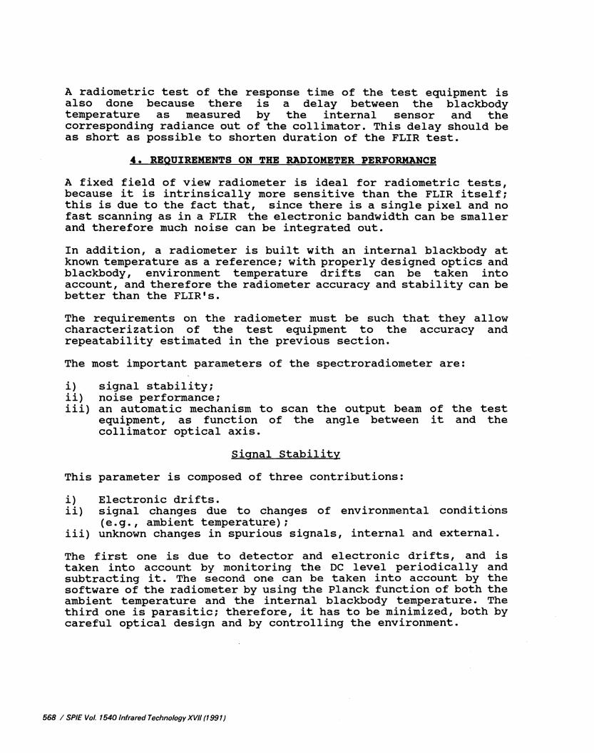
FLIR test systems have improved over the last years to keep abreastof the improvement of the FLIRs themselves. A modern FLIR testsystem is basically described in Fig.l.
566 / SPIE Vol. 1540 Infrared Technology XW/ (1991)
It is composed of an accurate extended area blackbody source withtarget patterns. The source temperature is very accuratelycontrolled with respect to the background temperature. The sourceis placed on the focal plane of a collimator, which collects theblackbody radiation and projects it in a parallel beam towards theUUT, to simulate an object at infinity.
It is obvious that the accuracy, resolution, stability anduniformity of the FLIR test system must be significantly betterthan the performance of the FLIR itself, in order for the tests tobe useful.
But how do we know whether a FLIR test system is up to the job thatit has been designed for? As the tests become more and moredemanding, the importance of this question increases as well.
Since the radiometer's main task is the measurement of the radiantoutput of the test equipment, the most important parameters of theFLIR to be considered here are the MRTD and the uniformity ofresponse. NRTD figures of state—of—the--art FLIR'S are below onetenth of a degree for the lowest spatial frequencies, while theuniformity is of the order of 5% to 10% over its field of view.
Test equipment must be able to project scenes that areapproximately one order of magnitude more precise than FLIRperformance; therefore the accuracy and stability of the effectivetemperature differential between the blackbody emitter and thebackground must be of the order of 5 maillidegrees.
In practice, however, state—of—the—art test equipment does notreach better performance than ten mnillidegrees or slightly higher,due to technological limitations. For example, since thereflectivity of the best extended area blackbodies is near 3%, achange of half a degree in ambient temperature causes aninstability of O.Ol5C in the output of the test equipment.
The uniformity of the beam across the collimating aperture of thetest system is less important but it is sometimes tested becausethis aperture is usually larger than the aperture of the FLIR, andtherefore its uniformity ensures repeatability of the measurementswhen taking the FLIR out and in the test set up. The requirement onthis parameter should be of the order of 10 millidegrees.
SPIE Vol. 1540 Infrared Technology XVII (1991) / 567
A radioraetric test of the response tune of the test equipment isalso done because there is a delay between the blackbodyteitperature as measured by the internal sensor and thecorresponding radiance out of the collimator. This delay should beas short as possible to shorten duration of the FLIR test.
4. REQUIREMENTS ON THE RADIOMETER PERFORMANCE
A fixed field of view radioiteter is ideal for radiornetric tests,because it is intrinsically more sensitive than the FLIR itself;this is due to the fact that, since there is a single pixel and nofast scanning as in a FLIR the electronic bandwidth can be smallerand therefore much noise can be integrated out.
In addition, a radiometer is built with an internal blackbody atknown temperature as a reference; with properly designed optics andblackbody, environment temperature drifts can be taken intoaccount, and therefore the radiometer accuracy and stability can bebetter than the FLIR's.
The requirements on the radiometer must be such that they allowcharacterization of the test equipment to the accuracy andrepeatability estimated in the previous section.
The most important parameters of the spectroradiometer are:
i) signal stability;ii) noise performance;iii) an automatic mechanism to scan the output beam of the test
equipment, as function of the angle between it and thecollimator optical axis.
Signal Stability
This parameter is composed of three contributions:
i) Electronic drifts.ii) signal changes due to changes of environmental conditions
(e .g . , ambient temperature);iii) unknown changes in spurious signals, internal and external.
The first one is due to detector and electronic drifts, and istaken into account by monitoring the DC level periodically andsubtracting it. The second one can be taken into account by thesoftware of the radiometer by using the Planck function of both theambient temperature and the internal blackbody temperature. Thethird one is parasitic; therefore, it has to be minimized, both bycareful optical design and by controlling the environment.
568 / SPIE Vol. 1540 Infrared Technology XVII (1991)
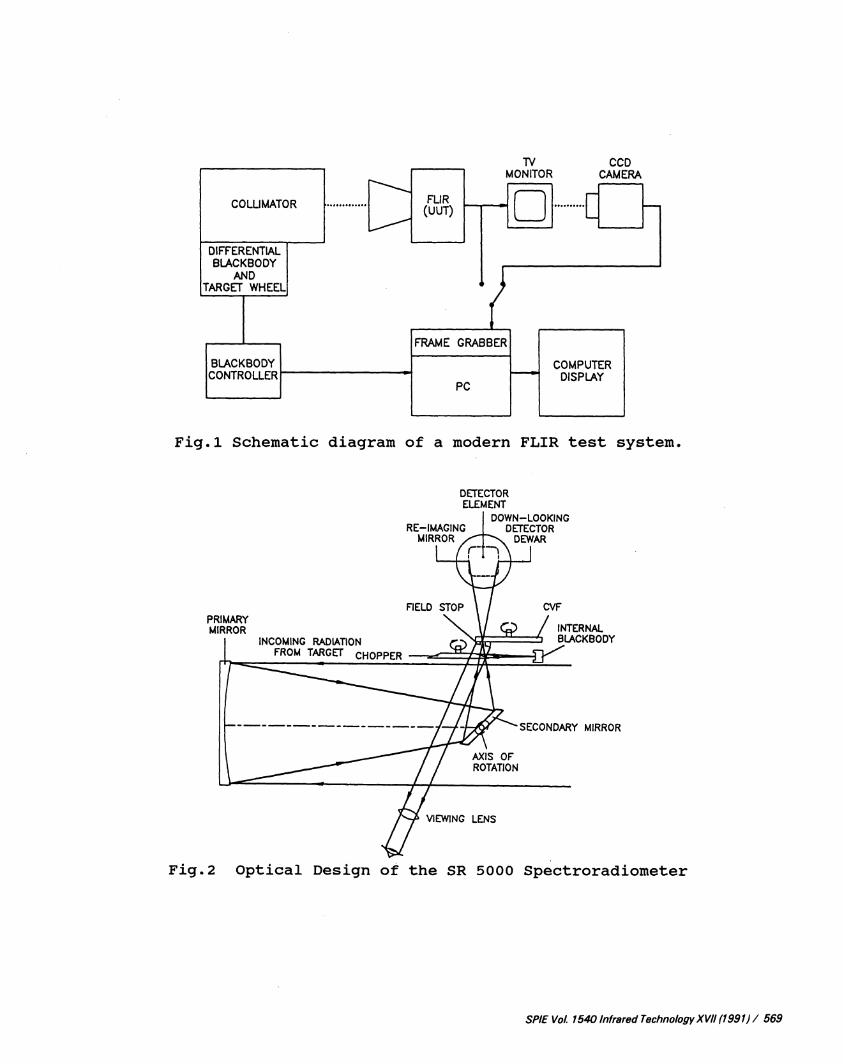
Fig.l Schematic diagram of a modern FLIR test system.
DETECTORELEMENT
DOWN—LOOKINGDETECTOR
DEWAR
MIRROR
VIEWING LENS
Fig.2 Optical Design of the SR 5000 Spectroradiometer
SPIE Vol. 1540 Infrared Technology XVII (1991)! 569
PRIMARYMIRROR
INCOMING RADIATIONFROM TARGET
CVF
INTERNALBLACKBODY
All the contributions together, after the appropriate corrections,should add up to no n*tore than a few millidegrees when integratingthe signal over a few minutes. (The integration is needed in orderto get the accuracies required.
Noise Performance
Noise is a type of short term instability, which limits theresolution of the temperature measurements. In a detector limitedsystem, as we are with an MCT detector, measuring room temperatureobjects, the main contribution to the noise equivalent power comesfrom the detector D* and its size. In equivalent temperature unitsthe noise depends also on the optics. A typical number we shouldstrive for is 1 millidegree or better.
A typical NET figure of the state—of-the-art spectroradiometers is0.5 madegree for 1Hz bandwidth.
Scanning the Output Beam
Scan of the output beam can be done in two different ways for twodifferent tests:
i) translation of the radiometer parallel to the optical axis;this is to test the uniformity of the collimated beam. It isimportant to get repeatable results when the FLIR's apertureis smaller than the collimator aperture;
ii) scanning the field of view of the radiometer; this is to testthe uniformity of the source and the radiometric scene on thefocal plane of the collimator.
5. RADIOMETER DESIGN AND TESTING CONCEPT
In this section we will show the testing concept of a FLIR testequipment and focus only on the most important features of therequired radiometer. In the next sections we will give somemeasurement results and conclusions.
Testing Concept
The idea is to calibrate the spectroradioineter with a veryaccurately ktiown blackbody without using the test equipmentcollimator. This is to avoid the influence of the collimator'sparameters (e .g. , reflectivity of the mirrors) on the calibration.After calibration, the radiometer is placed in front of the testequipment, in place of the FLIR, and its signals are recorded.Measurements as a function of time, wavelength, field of view andposition are performed in order to characterize the test equipment.
Radiometer DesignFig.2 shows the optical design of the specially modified
570 / SPIE Vol. 1540 Infrared Technology XVII (1991)
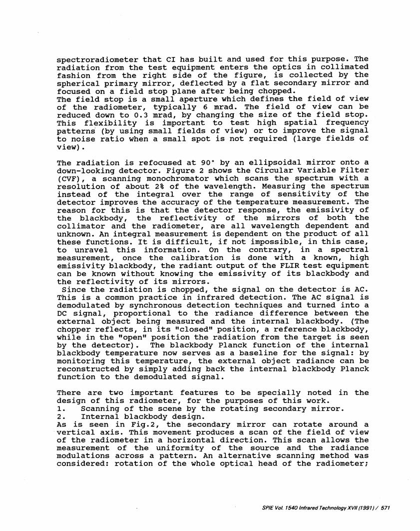
spectroradioiueter that CI has built and used for this purpose. Theradiation from the test equipment enters the optics in collimatedfashion from the right side of the figure, is collected by thespherical primary mirror, deflected by a flat secondary mirror andfocused on a field stop plane after being chopped.The field stop is a small aperture which defines the field of viewof the radiometer, typically 6 mrad. The field of view can bereduced down to 0.3 mrad, by changing the size of the field stop.This flexibility is important to test high spatial frequencypatterns (by using small fields of view) or to improve the signalto noise ratio when a small spot is not required (large fields ofview).
The radiation is refocused at 900 by an ellipsoidal mirror onto adown—looking detector. Figure 2 shows the Circular Variable Filter(CVF) , a scanning monochromator which scans the spectrum with aresolution of about 2% of the wavelength. Measuring the spectruminstead of the integral over the range of sensitivity of thedetector improves the accuracy of the temperature measurement. Thereason for this is that the detector response, the emissivity ofthe blackbody, the reflectivity of the mirrors of both thecollimator and the radiometer, are all wavelength dependent andunknown. An integral measurement is dependent on the product of allthese functions. It is difficult, if not impossible, in this case,to unravel this information. On the contrary, in a spectralmeasurement, once the calibration is done with a known, highemissivity blackbody, the radiant output of the FLIR test equipmentcan be known without knowing the emissivity of its blackbody andthe reflectivity of its mirrors.Since the radiation is chopped, the signal on the detector is AC.This is a common practice in infrared detection. The AC signal isdemodulated by synchronous detection techniques and turned into aDC signal, proportional to the radiance difference between theexternal object being measured and the internal blackbody. (Thechopper reflects, in its "closed" position, a reference blackbody,while in the "open" position the radiation from the target is seenby the detector) . The blackbody Planck function of the internalblackbody temperature now serves as a baseline for the signal: bymonitoring this temperature, the external object radiance can bereconstructed by simply adding back the internal blackbody Planckfunction to the demodulated signal.
There are two important features to be specially noted in thedesign of this radiometer, for the purposes of this work.1. Scanning of the scene by the rotating secondary mirror.2. Internal blackbody design.As is seen in Fig.2, the secondary mirror can rotate around avertical axis. This movement produces a scan of the field of viewof the radiometer in a horizontal direction. This scan allows themeasurement of the uniformity of the source and the radiancemodulations across a pattern. An alternative scanning method wasconsidered: rotation of the whole optical head of the radiometer;
SPIE Vol. 1540 Infrared Technology XVII (1991) / 571
however, the rotation of the secondary mirror is more similar tothe way the detector array of the FLIR receives the radiation frommany directions in the FLIR's field of view, and thereforepreferable. Another important reason for scanning the source by therotation of the secondary mirror is the simplicity of the method.The spectroradiometer with the scanning ability does not requireany extra scanning mechanism. The position of the secondary mirrorcan be fully controlled through the same computer and software thatcontrols the measurement.
Internal Blackbody DesignThere are two basic designs for internal reference blackbody of aninfrared radiometer: one which is controlled at a fixedtemperature, higher than room temperature; and one which is leftfloating at room temperature, but is continuously monitored.
Here we discuss possible errors of temperature measurements in bothdesigns and compare between the two. The signal in volts is ingeneral related to the radiation reaching the detector, by thefollowing expression:
V=K[W—W] (1)
where:
V signal in volts.K response function of the spectroradiorneter in Volts/Watt.W power received on the detector when the chopper is open.
Wc power received on the detector when the chopper is closed.
If we examine more carefully all the contributions to W, we canwrite:
Wc[P(TIBB)E+(l€)P(Tinterior) ]PcH+(lPcH)P(TcH) (2)
Where:
P(T) Planck function at temperature T.
TIBBtemperature of the reference (internal)blackbody.
6 emissivity of the internal blackbody..1-6 reflectance of the internal blackbody.
Tinterior• temperature of the interior of the optical
. unit.PCH
reflectance of the chopper blades.
1PCH ernissivity of the chopper blades.
TCHtemperature of the chopper blades.
(Note that some of the parameters are wavelength dependent)
572 / SPIE Vol. 1540 Infrared Technology XVII (1991)
and by substituting (2) in (1) we get:
V=K{W—[ (P(TIBB) €+(l••E)P(T.t.) ) PCH+(1PCH)P(TCH) 1 ) (3)
Since the signal in all subsequent data processing is assumed to be
V=K[WP(TIBB) ) (4)
the error in volts is the difference between Eq. (3) and (4):
e=K[ (PCH)P(TIBB)(6)PCHP(Tinterior)(lPCHYP(TCH)) (5)
If the temperature of the reference blackbody, the chopper bladesand the interior of the optical unit are all equal, the error is
e=K[l—6pCH)--(l—e)pCH—(l-pCH)]P(TIBB)=O (6)
which means no error at all. This condition is close to beingfulfilled when the instrument uses a floating ambient temperatureblackbody, and when it is in thermal equilibrium,because then TIBB
Tinterior and TCH are all equal.
Let us now examine the major drawback expected in a typicalradiometer with an elevated temperature reference blackbody: thefact that the calculated temperature is affected by ambienttemperature drifts. The meaning of this effect is as follows.Suppose we measure a perfectly stable source: if the ambienttemperature changes during the measurement, the signal will drift;this drift will be interpreted as a change in the temperature ofthe target, since the assumption is that the reference temperatureis constant. For a transfer radiometry application a drift due totemperature changes is of crucial importance, while the accuracy isless important.
As an example for both inaccuracy and drift errors we will use thefollowing typical values:
Taient = 25 C = Tinterior = TCH
W = P(30C); TIBB = 40°C
= '; CH =By substituting these values into Equation (5) we obtain:
e=K[P(40C)—P(25C)]O.059l (7)
SPIEVol. 1540 Infrared Technology XVII (1991) / 573
which is equivalent, around 1Oj, to an inaccuracy of about O.9C inthe calculation of the source teiaperature. This can be seen bynoting that: [P(40C)-P(25C)JO.0591=P(30.9C)-P(30C).
In the same manner, by using the same figures with an ambienttemperature of 22°C, we get an accuracy error of 1.07°C. Thus, thecalculated temperature this time will be 3l.07C which means a driftof the calculated signal by O.l7C!
6. RESULTS
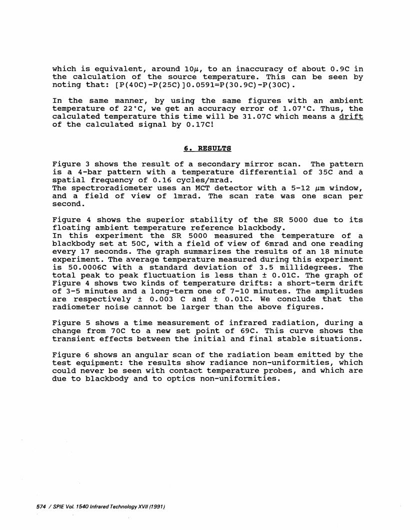
Figure 3 shows the result of a secondary mirror scan. The patternis a 4-bar pattern with a temperature differential of 35C and aspatial frequency of 0.16 cycles/mrad.The spectroradiometer uses an MCT detector with a 5—12 m window,and a field of view of lmrad. The scan rate was one scan persecond.
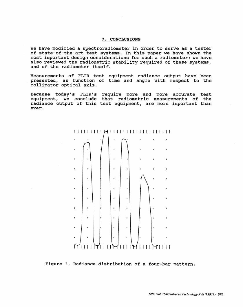
Figure 4 shows the superior stability of the SR 5000 due to itsfloating ambient temperature reference blackbody.In this experiment the SR 5000 measured the temperature of ablackbody set at 50C, with a field of view of 6mrad and one readingevery 17 seconds. The graph summarizes the results of an 18 minuteexperiment. The average temperature measured during this experimentis 50.0006C with a standard deviation of 3.5 millidegrees. Thetotal peak to peak fluctuation is less than O.O1C. The graph ofFigure 4 shows two kinds of temperature drifts: a short-term driftof 3-5 minutes and a long-term one of 7-10 minutes. The amplitudesare respectively 0.003 C and O.O1C. We conclude that theradiometer noise cannot be larger than the above figures.
Figure 5 shows a time measurement of infrared radiation, during achange from 70C to a new set point of 69C. This curve shows thetransient effects between the initial and final stable situations.
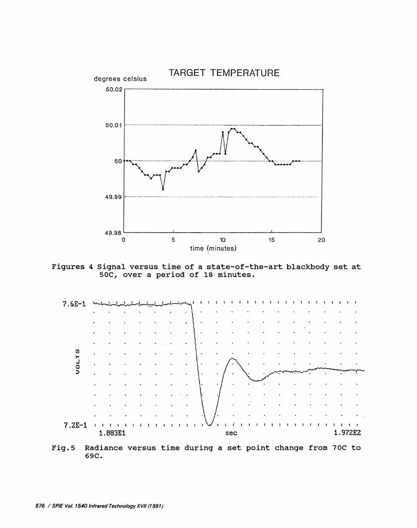
Figure 6 shows an angular scan of the radiation beam emitted by thetest equipment: the results show radiance non—uniformities, whichcould never be seen with contact temperature probes, and which aredue to blackbody and to optics non—uniformities.
574 / SPIE VoL 1540 Infrared Technology XVII (1991)
7. CONCLUSIONS
We have modified a spectroradiometer in order to serve as a testerof state—of-'the--art test systems. In this paper we have shown themost important design considerations for such a radiometer; we havealso reviewed the radiometric stability required of these systems,and of the radiometer itself.
Measurements of FLIR test equipment radiance output have beenpresented, as function of time and angle with respect to thecollimator optical axis.
Because today's FLIR'sequipment, we concluderadiance output of thisever.
require more and more accuratethat radiometric measurements oftest equipment, are more important
testthethan
111111111 1—i 11111111111111 11111
1111
Figure 3. Radiance distribution of a four-bar pattern.
SPIE Vol. 1540 Infrared Technology XVII (1991) / 575
II
degrees celsiusTARGET TEMPERATURE
20time (minutes)
Figures 4 Signal versus time of a state-of-the--art blackbody set at50C, over a period of 18 minutes.
7.6E—i.
J0
?.2E—1 ' I 1 1
1M83EiI I I I I
Fig5 Radiance versus time during a set point change from 70C to69C.
576 / SPIE Vol. 1540 Infrared Technology XVII (1991)
0 5 10 15
I I I I I I I I I I I I I I I I I I I I
I I I I I I I I I I I I I I I I I I I I I I I I
Sec 119?2E2
I I I I I I I I I I I I I I I I
0)
0
6.7E—1
I I
Fig. 6 Radiance versus angle scan out of the test equipmentcollimator showing otherwise unseen non—uniformities
8. REFERENCES
1. J.B. Nackinnon, G.A. Welter, SPIE Proc. Vol. 416, 1983, p.9.
2. R.C. Anderson, SPIE Proc., Vol. 308, 1981, p.92.
3. A. Daniels, D. Cabib, Z. Kopolovich, R.A. Buckwald, SPIE Proc.Vol.9, 1988, p.246.
SPIE Vol. 1540 Infrared Technology XVII (1991) / 577
I I I I I I I I I I I
1.183E1 sec 35øE1I I I I I I I I I