Calculation of the heeling moment generated on a ship's hull ...
8
Scienfic Journals Zeszyty Naukowe of the Marime University of Szczecin Akademii Morskiej w Szczecinie Zeszyty Naukowe Akademii Morskiej w Szczecinie 68 (140) 9 2021, 68 (140), 9–16 ISSN 1733-8670 (Printed) Received: 30.09.2021 ISSN 2392-0378 (Online) Accepted: 06.10.2021 DOI: 10.17402/482 Published: 31.12.2021 Calculation of the heeling moment generated on a ship’s hull during turning maneuver based on measurements of the angle of heel as a function of time Zbigniew Szozda 1 , Piotr Nowakowski 2 1 https://orcid.org/0000-0002-8467-244X 2 https://orcid.org/0000-0002-3869-2247 Maritime University of Szczecin 1-2 Wały Chrobrego St., 70-500 Szczecin, Poland e-mail: { 1 z.szozda; 2 p.nowakowski}@am.szczecin.pl corresponding author Keywords: ship stability criteria, ship’s heel due to turning, ship heeling moments, ship’s centrifugal force, stability criterion due to turning, stability failure JEL Classification: C6, C8, O3, Y9 Abstract Ships' stability criterion due to turning is not up-to-date and requires amendments. Redesigning the criterion should be based on scientific research, but there is a lack of accurate procedures and formulas enabling the calculation of the heeling moment caused by centrifugal forces as a function of time. Measurements of a ships’ heel caused by turning on a model-scale or full-scale may provide a basis for such an analysis. This paper cre- ates such a procedure, including appropriate formulas, leading to the extraction of the heeling moment caused by centrifugal force from other heeling moments acting on a ship during turning. One model-scale experiment is described in detail, and the results of the calculations are presented. The paper concludes that it is possible to extract this moment as a function of time and presents an example of such a calculation. Introduction The heel of a ship caused by turning maneuvers may be dangerous in some circumstances and may even lead to fatal accidents. This phenomenon may be classified as a stability failure mode. The most tragic example is the capsizing of the Ro-Ro pas- senger ferry SEWOL in 2014, which caused about 300 fatalities (Kee et al., 2017; The Guardian, 2017). Other recent examples are described in (Voytenko, 2015; 2017; MAIB, 2016). The stability criterion for passenger ships that takes into account this stability failure mode is giv- en in the 2008 Intact Stability Code (IMO, 2008). In 2011, the delegation of the United Kingdom criticized the present form of this criterion and pro- posed refining the criterion in the framework of the International Maritime Organization (IMO, 2012). The proposal was supported by the Maritime Safety Committee; however, the Sub-committee on Stabil- ity and Load Lines and on Fishing Vessels Safety – the technical body responsible for ships’ stability at the time – discussed the issue for two years before eventually noting that appropriate knowledge was not gathered and that the committee was overloaded with other more urgent agenda items; thus, it decid- ed to cease work on this problem. Before beginning future work on revising this criterion, a better understanding of the forces and moments acting on a hull during turning maneuvers
-
Upload
khangminh22 -
Category
Documents
-
view
7 -
download
0
Transcript of Calculation of the heeling moment generated on a ship's hull ...
Scientific Journals Zeszyty Naukoweof the Maritime University of Szczecin Akademii Morskiej w Szczecinie
Zeszyty Naukowe Akademii Morskiej w Szczecinie 68 (140) 9
2021, 68 (140), 9–16 ISSN 1733-8670 (Printed) Received: 30.09.2021 ISSN 2392-0378 (Online) Accepted: 06.10.2021 DOI: 10.17402/482 Published: 31.12.2021
Calculation of the heeling moment generated on a ship’s hull during turning maneuver based on measurements of the angle of heel as a function of time
Zbigniew Szozda1, Piotr Nowakowski21 https://orcid.org/0000-0002-8467-244X2 https://orcid.org/0000-0002-3869-2247
Maritime University of Szczecin 1-2 Wały Chrobrego St., 70-500 Szczecin, Poland e-mail: {1z.szozda; 2p.nowakowski}@am.szczecin.pl corresponding author
Keywords: ship stability criteria, ship’s heel due to turning, ship heeling moments, ship’s centrifugal force, stability criterion due to turning, stability failureJEL Classification: C6, C8, O3, Y9
AbstractShips' stability criterion due to turning is not up-to-date and requires amendments. Redesigning the criterion should be based on scientific research, but there is a lack of accurate procedures and formulas enabling the calculation of the heeling moment caused by centrifugal forces as a function of time. Measurements of a ships’ heel caused by turning on a model-scale or full-scale may provide a basis for such an analysis. This paper cre-ates such a procedure, including appropriate formulas, leading to the extraction of the heeling moment caused by centrifugal force from other heeling moments acting on a ship during turning. One model-scale experiment is described in detail, and the results of the calculations are presented. The paper concludes that it is possible to extract this moment as a function of time and presents an example of such a calculation.
Introduction
The heel of a ship caused by turning maneuvers may be dangerous in some circumstances and may even lead to fatal accidents. This phenomenon may be classified as a stability failure mode. The most tragic example is the capsizing of the Ro-Ro pas-senger ferry SEWOL in 2014, which caused about 300 fatalities (Kee et al., 2017; The Guardian, 2017). Other recent examples are described in (Voytenko, 2015; 2017; MAIB, 2016).
The stability criterion for passenger ships that takes into account this stability failure mode is giv-en in the 2008 Intact Stability Code (IMO, 2008). In 2011, the delegation of the United Kingdom
criticized the present form of this criterion and pro-posed refining the criterion in the framework of the International Maritime Organization (IMO, 2012). The proposal was supported by the Maritime Safety Committee; however, the Sub-committee on Stabil-ity and Load Lines and on Fishing Vessels Safety – the technical body responsible for ships’ stability at the time – discussed the issue for two years before eventually noting that appropriate knowledge was not gathered and that the committee was overloaded with other more urgent agenda items; thus, it decid-ed to cease work on this problem.
Before beginning future work on revising this criterion, a better understanding of the forces and moments acting on a hull during turning maneuvers

Zbigniew Szozda, Piotr Nowakowski
10 ScientificJournalsoftheMaritimeUniversityofSzczecin68(140)
is required. One possible way forward is to per-form a series of tests and measurements of a ship’s performance during turning in terms of its heeling moments and angles of heel as a function of time.
Here, ten model-scale tests were performed in the Ship Handling Research and Training Centre in Iława, Poland, in order to gain experience in this respect and possibly facilitate future research. One of the tests is presented in detail in this paper. The tests were aimed at extracting information from measurements, followed by calculating the heeling moment caused by centrifugal forces during the turning of the model.
Presentation of a single test
The model tests were performed on Silm Lake, Iława, Poland. A model passenger ship on a 1:16 scale was used, as shown in the photo in Figure 1. The main parameters of the model are presented below. More information about the experiment may be found in (IMO, 2013; Szozda, 2014; 2015).
Figure 1. The model used during the tests
Main parameters of the model:• Length on the water line – LW = 11.529 m;• Breadth – B = 1.78 m;• Block coefficient – CB = 0.687.
An example of one test in terms of the mod-el’s heel measured as a function of time φ = φ(t) is
shown in Figure 2 (original results of the measure-ments before refinement, which contain inaccuracies caused by the inclinometer performance).
The measurement during one test consisted of four stages, as shown in Figure 2. Each stage is described as follows:1. Stage 1. The model sails with an initial speed
directly forward in an upright position.2. Stage 2. The rudder is put to one side, and the
model begins to turn and heel.3. Stage 3. After the model reaches the stable phase
of turning (the heel does not change over time, and the trajectory is similar to a circle – the end of phase 2), weight is shifted from one side to anoth-er in order to verify possible changes in the initial metacentric height during the turn.
4. Stage 4. The model is forced to roll and roll decay is measured.Stage 2 and stage 4 were used for the purposes of
this paper (see Step 2 and Step 3 in Section Steps of the experiment). Stage 2 is actually a function that shows how the heel changed over time after the rud-der was put to one side. This enables calculating the angular velocity ω (the first derivative) and angular acceleration ε (the second derivative).
Mathematical model of the heel in turn
One degree of freedom linear equation (formulas (1) and (3)) was used as the mathematical model of the ship behavior in terms of the heel caused by turn-ing. It was assumed that the angular acceleration ε observed at a particular time was caused by the total heeling moment, which may be divided into four separate elements (Dudziak, 2008):1. Heeling moment caused by the rudder – MR.2. Heeling moment generated on the hull’s wetted
surface:2.1. Moment caused by the centrifugal force – MH.2.2. Restoring moment – Mres.2.3. Damping moment – Md.
1 2 3 4
t [s]
φ [deg] 5
3
1
‒3
‒5
‒7
Figure 2. Angle of heel measured as a function of time in one test
Calculation of the heeling moment generated on a ship’s hull during turning maneuver...
Zeszyty Naukowe Akademii Morskiej w Szczecinie 68 (140) 11
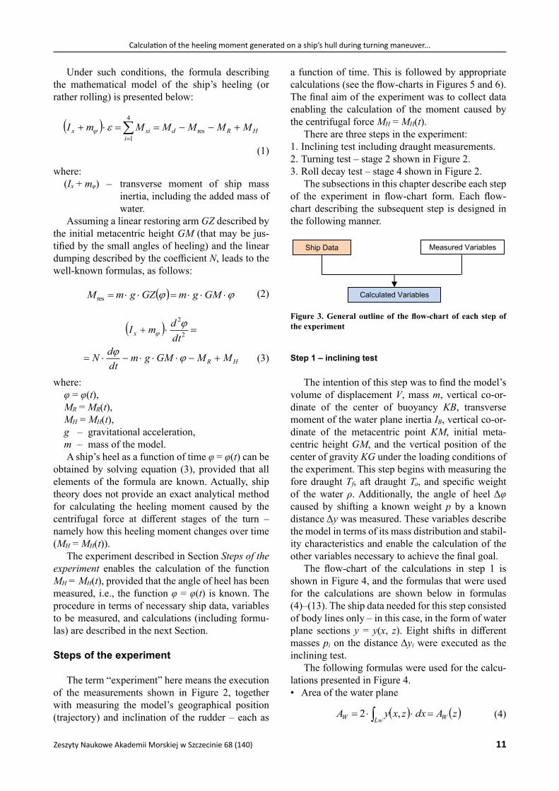
Under such conditions, the formula describing the mathematical model of the ship’s heeling (or rather rolling) is presented below:
4
1res
iHRdxix MMMMMmI
(1)
where:(Ix + mφ) – transverse moment of ship mass
inertia, including the added mass of water.
Assuming a linear restoring arm GZ described by the initial metacentric height GM (that may be jus-tified by the small angles of heeling) and the linear dumping described by the coefficient N, leads to the well-known formulas, as follows:
GMgmGZgmM res
(2)
HR
x
MMGMgmdtdN
dtdmI
2
2
(3)
where:φ = φ(t),MR = MR(t),MH = MH(t),g – gravitational acceleration,m – mass of the model.A ship’s heel as a function of time φ = φ(t) can be
obtained by solving equation (3), provided that all elements of the formula are known. Actually, ship theory does not provide an exact analytical method for calculating the heeling moment caused by the centrifugal force at different stages of the turn – namely how this heeling moment changes over time (MH = MH(t)).
The experiment described in Section Steps of the experiment enables the calculation of the function MH = MH(t), provided that the angle of heel has been measured, i.e., the function φ = φ(t) is known. The procedure in terms of necessary ship data, variables to be measured, and calculations (including formu-las) are described in the next Section.
Steps of the experiment
The term “experiment” here means the execution of the measurements shown in Figure 2, together with measuring the model’s geographical position (trajectory) and inclination of the rudder – each as
a function of time. This is followed by appropriate calculations (see the flow-charts in Figures 5 and 6). The final aim of the experiment was to collect data enabling the calculation of the moment caused by the centrifugal force MH = MH(t).
There are three steps in the experiment:1. Inclining test including draught measurements.2. Turning test – stage 2 shown in Figure 2.3. Roll decay test – stage 4 shown in Figure 2.
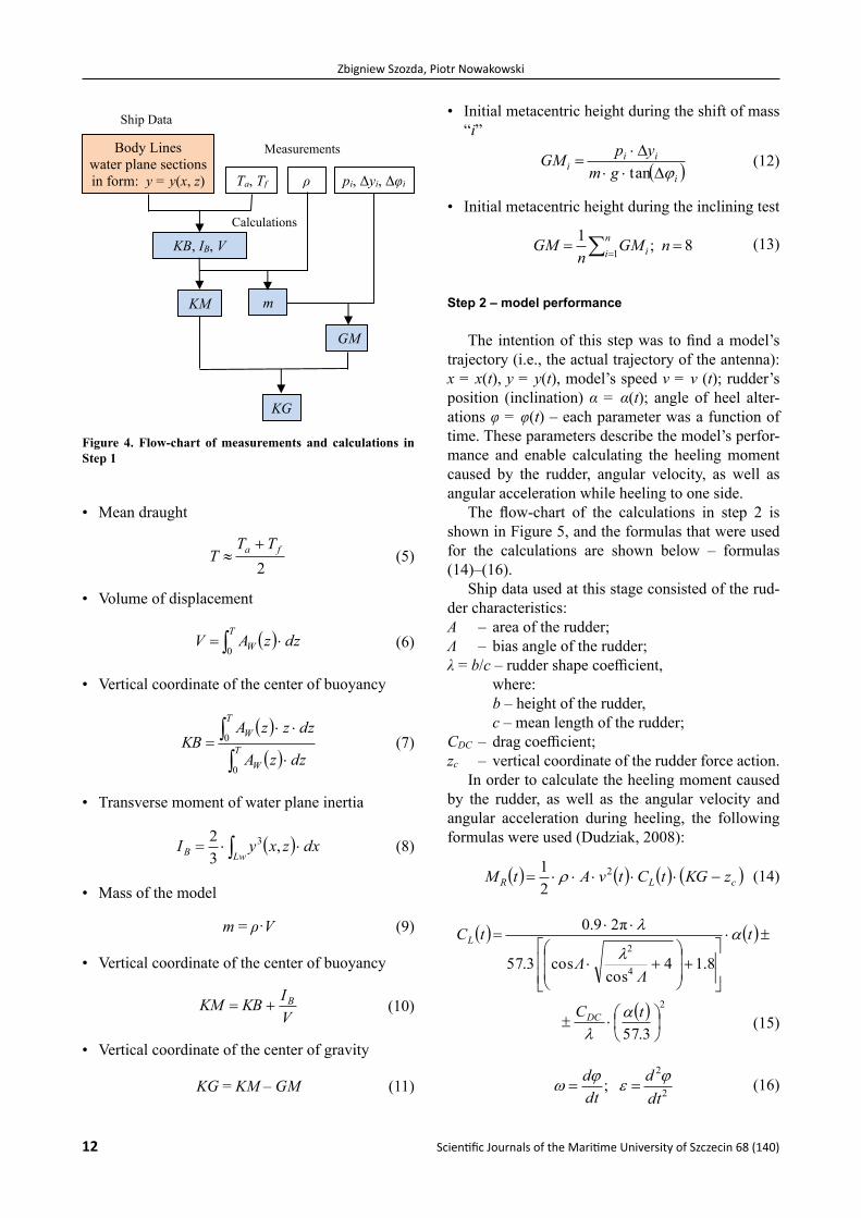
The subsections in this chapter describe each step of the experiment in flow-chart form. Each flow-chart describing the subsequent step is designed in the following manner.
Ship Data Measured Variables
Calculated Variables
Figure 3. General outline of the flow-chart of each step of the experiment
Step 1 – inclining test
The intention of this step was to find the model’s volume of displacement V, mass m, vertical co-or-dinate of the center of buoyancy KB, transverse moment of the water plane inertia IB, vertical co-or-dinate of the metacentric point KM, initial meta-centric height GM, and the vertical position of the center of gravity KG under the loading conditions of the experiment. This step begins with measuring the fore draught Tf, aft draught Ta, and specific weight of the water ρ. Additionally, the angle of heel Δφ caused by shifting a known weight p by a known distance Δy was measured. These variables describe the model in terms of its mass distribution and stabil-ity characteristics and enable the calculation of the other variables necessary to achieve the final goal.
The flow-chart of the calculations in step 1 is shown in Figure 4, and the formulas that were used for the calculations are shown below in formulas (4)–(13). The ship data needed for this step consisted of body lines only – in this case, in the form of water plane sections y = y(x, z). Eight shifts in different masses pi on the distance Δyi were executed as the inclining test.
The following formulas were used for the calcu-lations presented in Figure 4.• Area of the water plane
zAdxzxyA WLwW ,2
(4)
Zbigniew Szozda, Piotr Nowakowski
12 ScientificJournalsoftheMaritimeUniversityofSzczecin68(140)
• Mean draught
2
fa TTT
(5)
• Volume of displacement
T
W dzzAV0
(6)
• Vertical coordinate of the center of buoyancy
T
W
TW
dzzA
dzzzAKB
0
0
(7)
• Transverse moment of water plane inertia
LwB dxzxyI ,
32 3
(8)
• Mass of the model
m = ρ·V (9)
• Vertical coordinate of the center of buoyancy
VIKBKM B
(10)
• Vertical coordinate of the center of gravity
KG = KM ‒ GM (11)
• Initial metacentric height during the shift of mass “i”
iii
i gmypGM
tan
(12)
• Initial metacentric height during the inclining test
8;11
nGMn
GM ni i
(13)
Step 2 – model performance
The intention of this step was to find a model’s trajectory (i.e., the actual trajectory of the antenna): x = x(t), y = y(t), model’s speed v = v (t); rudder’s position (inclination) α = α(t); angle of heel alter-ations φ = φ(t) – each parameter was a function of time. These parameters describe the model’s perfor-mance and enable calculating the heeling moment caused by the rudder, angular velocity, as well as angular acceleration while heeling to one side.
The flow-chart of the calculations in step 2 is shown in Figure 5, and the formulas that were used for the calculations are shown below – formulas (14)–(16).
Ship data used at this stage consisted of the rud-der characteristics:A – area of the rudder;Λ – bias angle of the rudder;λ = b/c – rudder shape coefficient,
where: b – height of the rudder, c – mean length of the rudder;
CDC – drag coefficient;zc – vertical coordinate of the rudder force action.
In order to calculate the heeling moment caused by the rudder, as well as the angular velocity and angular acceleration during heeling, the following formulas were used (Dudziak, 2008):
cLR zKGtCtvAtM 2
21
(14)
2
4
2
3.57
8.14cos
cos3.57
π29.0
tC
t
ΛΛ
tC
DC
L
(15)
2
2
;dtd
dtd
(16)
Calculations
KM
Body Lines water plane sections in form: y = y(x, z) Ta, Tf pi, Δyi, Δφi ρ
KB, IB, V
m
KG
GM
Measurements
Ship Data
Figure 4. Flow-chart of measurements and calculations in Step 1

Calculation of the heeling moment generated on a ship’s hull during turning maneuver...
Zeszyty Naukowe Akademii Morskiej w Szczecinie 68 (140) 13
Step 3 – model’s moment of inertia and damping
The intention of this step was to find the mod-el’s transverse moment of mass inertia, including the added mass of water (Ix + mφ) and damping coeffi-cient N. These describe additional characteristics of the model and enable the calculation of the moment caused by damping and, most importantly, the sum of all heeling moments acting on the model during a turn (left part of equation 3).
The flow-chart of the calculations in step 3 is shown in Figure 6, and the formulas used for the calculations are shown below in formulas (17) and (18).
The following formulas were used for calcula-tions (Dudziak, 2008):
GMVgT
mIx
2
π2
(17)
mIGMgmN xi
i
1ln
π1
(18)
The execution of all measurements, together with the calculations described above, led to a situation
Calculations
Calculations
A, Λ, λ, CDC, zc x = x(t), y = y(t) α = α(t)
MR = MR(t)ω = ω(t)ε = ε(t)
φ = φ(t)v = v(t)
Measurements
MeasurementsShip Data
V [m/s]
t [s]
0 5 10 15 20 25 30 35 40 45
Figure 5. Flow-chart of measurements and calculations in Step 2
Calculations
From Step 1 V, m, GM
Decay Rolling Test (phase 4 in Figure 1)
Tφ, φi/φi+1
(Ix + mφ)
N
Measurements
Ship Data
Figure 6. Flow-chart of measurements and calculations in Step 3

Zbigniew Szozda, Piotr Nowakowski
14 ScientificJournalsoftheMaritimeUniversityofSzczecin68(140)
where the heeling moment caused by the centrifugal force MH(t) was the only unknown variable in equa-tion (3); therefore, this equation may be rewritten in the following form:
tMGMgm
dtdN
dtdmItM
R
xH
2
2
(19)
Results of calculations
The particulars of the ship model shown in Fig-ure 1 and all measured variables in line with the pro-cedure described in the previous chapter were used for the calculations. The angle of heel φ = φ(t) was measured with a frequency of ten times per second. A special calculation sheet was developed in Excel.
The first task was to calculate the first and second derivatives of the heeling angle (angular velocity ω
and acceleration ε, respectively). Directly calculat-ing the original curve obtained from the measure-ment gave results that were very difficult to analyze due to the precision of the inclinometer and small angles of heel; therefore, the measurements had to be adjusted to obtain reasonable results. This was performed manually because attempts to use high-er-order polynomials did not lead to the expected results. The results are shown in Figure 7.
The final effect in terms of the heeling moments as a function of time, including MH(t), is shown in Figure 8.
It can be seen that the damping moment was very small compared with other heeling moments and can be neglected in future calculations (Table 1 and Figure 9). This is unsurprising because the angular velocity of the model’s “rolling” during a turn was very small. The value of the heeling moment pro-duced by the rudder was significant during the first stage of turning (first three seconds in the case of
0.2
–0.3
–0.8
–1.3
–1.8
–2.3
–2.8
0 5 15 20 25 30 35 40 45 50t [s]
φoriginal
φadjusted
dφdt
d2φdt2
φ [deg], dφdt
d2φdt2
[deg/s], [deg/s2]
Figure 7. Measured (original) and adjusted angle of heel, together with the angular velocity and acceleration
800
600
400
200
0
–200
–400
–600
–800
–1000
0 5 15 20 25 30 35 40 45 50
t [s]
10
Md
MR
MH
MresM [Nm]
Figure 8. Heeling moments calculated using equations (1) and (3)
Calculation of the heeling moment generated on a ship’s hull during turning maneuver...
Zeszyty Naukowe Akademii Morskiej w Szczecinie 68 (140) 15
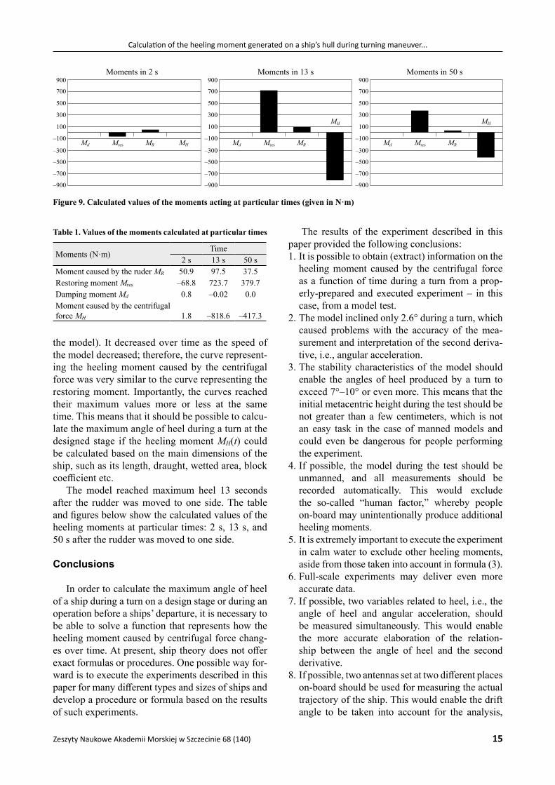
the model). It decreased over time as the speed of the model decreased; therefore, the curve represent-ing the heeling moment caused by the centrifugal force was very similar to the curve representing the restoring moment. Importantly, the curves reached their maximum values more or less at the same time. This means that it should be possible to calcu-late the maximum angle of heel during a turn at the designed stage if the heeling moment MH(t) could be calculated based on the main dimensions of the ship, such as its length, draught, wetted area, block coefficient etc.
The model reached maximum heel 13 seconds after the rudder was moved to one side. The table and figures below show the calculated values of the heeling moments at particular times: 2 s, 13 s, and 50 s after the rudder was moved to one side.
Conclusions
In order to calculate the maximum angle of heel of a ship during a turn on a design stage or during an operation before a ships’ departure, it is necessary to be able to solve a function that represents how the heeling moment caused by centrifugal force chang-es over time. At present, ship theory does not offer exact formulas or procedures. One possible way for-ward is to execute the experiments described in this paper for many different types and sizes of ships and develop a procedure or formula based on the results of such experiments.
The results of the experiment described in this paper provided the following conclusions:1. It is possible to obtain (extract) information on the
heeling moment caused by the centrifugal force as a function of time during a turn from a prop-erly-prepared and executed experiment – in this case, from a model test.
2. The model inclined only 2.6° during a turn, which caused problems with the accuracy of the mea-surement and interpretation of the second deriva-tive, i.e., angular acceleration.
3. The stability characteristics of the model should enable the angles of heel produced by a turn to exceed 7°–10° or even more. This means that the initial metacentric height during the test should be not greater than a few centimeters, which is not an easy task in the case of manned models and could even be dangerous for people performing the experiment.
4. If possible, the model during the test should be unmanned, and all measurements should be recorded automatically. This would exclude the so-called “human factor,” whereby people on-board may unintentionally produce additional heeling moments.
5. It is extremely important to execute the experiment in calm water to exclude other heeling moments, aside from those taken into account in formula (3).
6. Full-scale experiments may deliver even more accurate data.
7. If possible, two variables related to heel, i.e., the angle of heel and angular acceleration, should be measured simultaneously. This would enable the more accurate elaboration of the relation-ship between the angle of heel and the second derivative.
8. If possible, two antennas set at two different places on-board should be used for measuring the actual trajectory of the ship. This would enable the drift angle to be taken into account for the analysis,
Mres MR MHMd
Moments in 2 s900
700
500
300
100
–100
–300
–500
–700
–900
Mres MR
MH
Md
Moments in 13 s900
700
500
300
100
–100
–300
–500
–700
–900
Mres MR
MH
Md
Moments in 50 s900
700
500
300
100
–100
–300
–500
–700
–900
Figure 9. Calculated values of the moments acting at particular times (given in N·m)
Table 1. Values of the moments calculated at particular times
Moments (N·m)Time
2 s 13 s 50 sMoment caused by the ruder MR 50.9 97.5 37.5Restoring moment Mres –68.8 723.7 379.7Damping moment Md 0.8 –0.02 0.0Moment caused by the centrifugal force MH 1.8 –818.6 –417.3
Zbigniew Szozda, Piotr Nowakowski
16 ScientificJournalsoftheMaritimeUniversityofSzczecin68(140)
which may be an important factor not analyzed in this exercise.
Acknowledgments
The author wishes to express thanks to the Director and employees of the Iława Ship Han-dling Research and Training Center, in particular to Prof. L. Kobyliński, for their support and making the model available for the turning tests.
References
1. Dudziak, J. (2008) Teoria okrętu. Gdańsk: Fundacja Pro-mocji Przemysłu Okrętowego i Gospodarki Morskiej (in Polish).
2. IMO (2008) International Code on Intact Stability, 2008 IS Code, 2009 Edition, Resolution MSC.267(85). London: In-ternational Maritime Organization.
3. IMO (2012) Document SLF 55/12. Development of amend-ments to the criterion for maximum angle of heel in turns of the 2008 IS Code. Revised Proposals for Amending the 2008 IS Code, the Royal Institution of Naval Architects. London: International Maritime Organization.
4. IMO (2013) Document SDC 1/14/1, Development of amend-ments to the criterion for maximum angle of heel in turns of the 2008 IS Code, Proposal for the Structure of the Criterion for Maximum Angle of Heel in Turns of the 2008 IS Code. London: International Maritime Organization.
5. Kee, D., Jun, G.T., Waterson, P. & Haslam, R. (2017) A systematic analysis of South Korea Sewol ferry accident – Striking a balance between learning and accountability. Applied Ergonomics 59, Part B, pp. 504–516, doi: 10.1016/ j.apergo.2016.07.014.
6. MAIB (2016) Report on the investigation into the listing, flooding and grounding of Hoegh Osaka., Bramble Bank, The Solent, UK on 3 January 2015. Southampton: Marine Accident Investigation Branch (Report No. 6/2016).
7. Szozda, Z. (2014) The need of the revision of passen-ger ships’ stability criterion on account of turning. Trans-Nav the International Journal on Marine Navigation and Safety of Sea Transportation 8(3), pp. 393–399, doi: 10.12716/1001.08.03.10.
8. Szozda, Z. (2015) Wykorzystanie pomiarów do modelowa-nia przechyłu spowodowanego zwrotem w kontekście kry-terium bezpieczeństwa statków pasażerskich. TTS Technika Transportu Szynowego 12, pp. 1490–1495 (in Polish).
9. The Guardian (2017) South Korean ferry in which hundreds died raised after three years. [Online] 22 March. Available from: www.theguardian.com/world/2017/mar/22/south-ko-rean-ferry-in-which-hundreds-died-raised-after-three-years [Accessed: September 29, 2021].
10. Voytenko, M. (2015) Greek trawler capsized and sank, 7 missing. [Online] Available from: https://www.fleetmon.com/maritime-news/2015/9159/greek-trawler-capsized-and -sank-7-missing/ [Accessed: September 29, 2021].
11. Voytenko, M. (2017) MOSVIK critically listed, part of car-go lost, Kiel locks closed. [Online] 14 July. Available from: https://www.fleetmon.com/maritime-news/2017/18779/misvik-critically-listed-part-cargo-lost-kiel-lock [Accessed: September 29, 2021].
Cite as: Szozda, Z., Nowakowski, P. (2021) Calculation of the heeling moment generated on a ship’s hull during turning maneuver based on measurements of the angle of heel as a function of time. Scientific Journals of the Maritime University of Szczecin, Zeszyty Naukowe Akademii Morskiej w Szczecinie 68 (140), 9–16.