Calculating the Load Distribution and Contact Stress of ... - MDPI
19
Citation: Zhang, Y.; Wang, G.; Pan, X.; Li, Y. Calculating the Load Distribution and Contact Stress of the Disposable Harmonic Drive under Full Load. Machines 2022, 10, 96. https://doi.org/10.3390/ machines10020096 Academic Editor: Hui Ma Received: 27 November 2021 Accepted: 24 January 2022 Published: 26 January 2022 Publisher’s Note: MDPI stays neutral with regard to jurisdictional claims in published maps and institutional affil- iations. Copyright: © 2022 by the authors. Licensee MDPI, Basel, Switzerland. This article is an open access article distributed under the terms and conditions of the Creative Commons Attribution (CC BY) license (https:// creativecommons.org/licenses/by/ 4.0/). machines Article Calculating the Load Distribution and Contact Stress of the Disposable Harmonic Drive under Full Load Yuxin Zhang, Guanglin Wang, Xudong Pan and Yuefeng Li * School of Mechatronics Engineering, Harbin Institute of Technology, Harbin 150001, China; [email protected] (Y.Z.); [email protected] (G.W.); [email protected] (X.P.) * Correspondence: [email protected] Abstract: Mechanical equipment that will not be reused is defined as disposable machinery. Dispos- able harmonic drives (HDs) are commonly used in the field of aerospace and are sensitive to payloads. Reasonable calculation of the gear strength is essential for structural design. A method of calculating the contact characteristics of HDs under full load by combining a surface contact model with a three-dimensional finite element model (FEM) is proposed in this work. The mathematical model was established for calculating the no-load backlash of conventional and disposable harmonic gears after assembly. Afterward, the tooth load distribution and surface contact stress were determined using the Hertz contact theory. Finally, ABAQUS software was used to establish the FEM of the disposable HD, and the results were compared with those obtained from the theoretical model. The results revealed that the disposable harmonic gear can realize short-term transmission under full load. Keywords: disposable harmonic gears; backlash; load distribution; contact stress 1. Introduction Conventional mechanical systems, equipment, or devices that are long-running and repeatedly used are referred to as conventional machinery. However, in some special instance, some kinds of machinery are abandoned after being used only once. This kind of machinery is defined as disposable machinery in this paper. This type of equipment always takes full load or short-time overload as the normal working conditions and has an extremely short service life (from a few minutes to a few dozen minutes). As the typical disposable machinery in the field of aerospace, disposable electric actuators often adopt the form of harmonic gear transmission. A harmonic gear drive is composed of three basic components—an internal tooth rigid wheel, an external tooth flexible wheel, and an elliptical wave generator assembled in the flexible wheel. The drive transmits motion and power through the radial periodic elastic deformation of the flexible wheel [1]. With the increasing demand for payloads in the aerospace industry, disposable harmonic gears that can be used under full load have gradually gained attention. The short-term ultimate carrying capacity and dynamic performance of disposable harmonic gears have become research hotspots [2]. Multiple teeth come into contact simultaneously in disposable HDs, and studies focused on the contact performance of disposable HDs are essential for ensuring the strength requirements. Many papers have discussed the load distribution and stress associated with gear transmission. Harmonic gears adopt the straight tooth profile. In addition, harmonic gear transmissions also have the characteristics of a large number of simultaneous meshing teeth and a thin rim structure. Therefore, the research results on the contact performance of spur gears with a high contact ratio and thin rim can be referred to. Vivet [3] analyzed the contact characteristics of face-milled spiral bevel gears based on the beam theory and the Hertz contact theory. Thomas et al. [4] proposed a new coordinate system and search method to predict the tooth root bending stress in asymmetric spur gears. Using the Hertz contact principle and a finite element model (FEM), Mohammed et al. [5] determined the Machines 2022, 10, 96. https://doi.org/10.3390/machines10020096 https://www.mdpi.com/journal/machines
-
Upload
khangminh22 -
Category
Documents
-
view
0 -
download
0
Transcript of Calculating the Load Distribution and Contact Stress of ... - MDPI
�����������������
Citation: Zhang, Y.; Wang, G.; Pan,
X.; Li, Y. Calculating the Load
Distribution and Contact Stress of the
Disposable Harmonic Drive under
Full Load. Machines 2022, 10, 96.
https://doi.org/10.3390/
machines10020096
Academic Editor: Hui Ma
Received: 27 November 2021
Accepted: 24 January 2022
Published: 26 January 2022
Publisher’s Note: MDPI stays neutral
with regard to jurisdictional claims in
published maps and institutional affil-
iations.
Copyright: © 2022 by the authors.
Licensee MDPI, Basel, Switzerland.
This article is an open access article
distributed under the terms and
conditions of the Creative Commons
Attribution (CC BY) license (https://
creativecommons.org/licenses/by/
4.0/).
machines
Article
Calculating the Load Distribution and Contact Stress of theDisposable Harmonic Drive under Full LoadYuxin Zhang, Guanglin Wang, Xudong Pan and Yuefeng Li *
School of Mechatronics Engineering, Harbin Institute of Technology, Harbin 150001, China;[email protected] (Y.Z.); [email protected] (G.W.); [email protected] (X.P.)* Correspondence: [email protected]
Abstract: Mechanical equipment that will not be reused is defined as disposable machinery. Dispos-able harmonic drives (HDs) are commonly used in the field of aerospace and are sensitive to payloads.Reasonable calculation of the gear strength is essential for structural design. A method of calculatingthe contact characteristics of HDs under full load by combining a surface contact model with athree-dimensional finite element model (FEM) is proposed in this work. The mathematical model wasestablished for calculating the no-load backlash of conventional and disposable harmonic gears afterassembly. Afterward, the tooth load distribution and surface contact stress were determined usingthe Hertz contact theory. Finally, ABAQUS software was used to establish the FEM of the disposableHD, and the results were compared with those obtained from the theoretical model. The resultsrevealed that the disposable harmonic gear can realize short-term transmission under full load.
Keywords: disposable harmonic gears; backlash; load distribution; contact stress
1. Introduction
Conventional mechanical systems, equipment, or devices that are long-running andrepeatedly used are referred to as conventional machinery. However, in some specialinstance, some kinds of machinery are abandoned after being used only once. This kindof machinery is defined as disposable machinery in this paper. This type of equipmentalways takes full load or short-time overload as the normal working conditions and has anextremely short service life (from a few minutes to a few dozen minutes). As the typicaldisposable machinery in the field of aerospace, disposable electric actuators often adoptthe form of harmonic gear transmission. A harmonic gear drive is composed of threebasic components—an internal tooth rigid wheel, an external tooth flexible wheel, andan elliptical wave generator assembled in the flexible wheel. The drive transmits motionand power through the radial periodic elastic deformation of the flexible wheel [1]. Withthe increasing demand for payloads in the aerospace industry, disposable harmonic gearsthat can be used under full load have gradually gained attention. The short-term ultimatecarrying capacity and dynamic performance of disposable harmonic gears have becomeresearch hotspots [2]. Multiple teeth come into contact simultaneously in disposable HDs,and studies focused on the contact performance of disposable HDs are essential for ensuringthe strength requirements.
Many papers have discussed the load distribution and stress associated with geartransmission. Harmonic gears adopt the straight tooth profile. In addition, harmonic geartransmissions also have the characteristics of a large number of simultaneous meshingteeth and a thin rim structure. Therefore, the research results on the contact performanceof spur gears with a high contact ratio and thin rim can be referred to. Vivet [3] analyzedthe contact characteristics of face-milled spiral bevel gears based on the beam theory andthe Hertz contact theory. Thomas et al. [4] proposed a new coordinate system and searchmethod to predict the tooth root bending stress in asymmetric spur gears. Using the Hertzcontact principle and a finite element model (FEM), Mohammed et al. [5] determined the
Machines 2022, 10, 96. https://doi.org/10.3390/machines10020096 https://www.mdpi.com/journal/machines

Machines 2022, 10, 96 2 of 19
influence of rotational speed on the contact stress of spur gears. Wen et al. [6] established animproved model for calculating the contact stress of standard gears and tip-relieved gearsbased on the precise tooth profile equations. Many scholars [7–10] have researched theinfluence of a high contact ratio on the transmission performance of spur gears. Li [11,12]used a three-dimensional FEM to obtain the tooth load distribution and contact model ofa thin-rimmed gear. The study found that the rim and web account for about 70% of thetotal thin-rimmed gear deformation, and the rim thickness has a significant influence onthe stress. Ravivarman et al. [13] used an FEM to analyze the tooth load, contact stress,and tooth surface wear of a high contact ratio gear. Wang et al. [14] designed a newtype of internal gear transmission with a high contact ratio. Compared to the traditionalstructure, the drive led to significant reductions in the contact stress and bending stress.Considering the time-varying mesh stiffness, gear backlash, static transmission error, andother parameters, Huang et al. [15] established a nonlinear dynamic model of a high contactratio gear with multiple clearances. Jia et al. [16] proposed a tooth-profile modificationscheme to reduce the contact stress and transmission error. Sun et al. [17] proposed anew parabolic profile modification method for a China bearing reducer and calculated thecontact characteristics. Rama et al. [18] determined the tooth load-carrying capacity of thehigh contact ratio asymmetric gear drive using wire-cut electrical discharge machining.Huangfu et al. [19] evaluated the contact characteristics of thin-rimmed gear transmissionsand performed tooth modification aimed at reducing surface wear.
In recent years, the contact model of conventional harmonic gears has been investi-gated. The deformation of the flexible wheel is the basis of the research on the contactcharacteristics of HDs. Ma et al. [20] established a dedicated micro-displacement platformwith a pair of laser displacement sensors and analyzed the influence of driving speed onthe deformation of the flexible wheel through experiments. Based on Ivanov’s empiricalformula for the distribution of meshing force between gear teeth, Dong simplified the flexi-ble wheel to a uniform thickness shell without gear teeth and calculated the deformationand stress on different sections of the flexible wheel [21]. He proposed an optimal designmethod for the involute tooth profile based on the meshing force given by the dynamicmeshing simulation [22]. On the basis of the above research, Chen et al. [23] established afinite element model of the flexible wheel combining a variable cross-section shell elementand a beam element and analyzed the deformation and stress of the flexible wheel underthe combined action of the wave generator and the transmission torque [23]. Then, theystudied the telescopic deformation of the neutral layer of the flexible wheel under theaction of different wave generators [24,25]. Using an FEM, Kayabasi [26] studied the stressand strain of the flexible wheel in an HD, which can be used to determine the maximumstress and optimize the structure of a wheel. Chen [27] discussed the parametric designof a double circular-arc tooth profile and the influence on the backlash of the HD. Theresults of the study had instructive significance for the subsequent research on the contactstrength of harmonic gears. Le [28] established the mechanical model of the flexible wheeland calculated the space dynamic meshing force of the harmonic flexible wheel accordingto the beam element theory. Zou [29] used the boundary conditions obtained from theempirical formula to establish a harmonic gear transmission face-contact FEM. The resultsrevealed that the deformation and stress associated with the cross-section of the shortflexible wheel change geometrically with increased load, but the distributions of the abovetwo increments remained unchanged. Through an FEM, Sahoo [30] confirmed that thesecondary contact of the tooth surface occurs in involute HDs. Routh [31] assessed thesecondary tooth surface contact in involute harmonic gears based on the assumption of anelliptic cam and the occurrence of an ellipse pitch curve after assembly. Furthermore, Sahooet al. [32] determined the load distribution associated with tooth pair contact in involuteHDs. Yang et al. [33] analyzed the axial load of the flexible wheel in double circular-arcHDs and proposed methods for reducing the effect of the partial axial load. Sahoo et al. [34]combined an FEM and experiments to analyze the stress distribution of the flexible wheelin novel split-cam HDs.

Machines 2022, 10, 96 3 of 19
Harmonic gear transmission has the characteristics of high precision, a large transmis-sion ratio, small size, and light weight, and its basic design theory has evolved. Disposablemachinery is an emerging concept. Compared to general harmonic gears, disposableharmonic gear transmissions for high-load operations have a higher power–weight ratioand an extremely low service life. At present, the research on harmonic gears is mainlyoriented toward the requirements of conventional mechanical applications. Moreover, theresearch on the contact characteristics of disposable HDs is still in its infancy. Based on theresearch of thin rim spur gears and harmonic gears, the contact performance of disposableharmonic gear transmissions is discussed in this paper. Considering the cost and versatilityof disposable machinery in disposable applications, the involute tooth profile with simplerprocessing technology was selected for this study. The rest of this paper is organized asfollows. In Section 2, the mathematical model of no-load harmonic assembly is presented,and the no-load backlash curves of two types of HDs are discussed. In Section 3, the contactmodel of harmonic gears is established, and the load distribution of flexible wheels iscalculated. Then, based on the load contribution, an analysis of the contact stress of twoflexible wheels under full load is presented in Section 4. The finite element analysis of HDsfor determining the contact characteristics of disposable harmonic gears is presented inSection 5, and the results are compared with the theoretical results. The conclusions of thisstudy are summarized in Section 6.
2. Calculation of Backlash Generated for HDs with No Load2.1. Design Scheme of Disposable Harmonic Gears
Harmonic drives are composed of three components—a flexible wheel, a rigid wheel,and a wave generator. Under conventional service conditions, after bearing alternatingloads, the flexible wheel becomes the component to most prone fatigue failure in HDs. Atpresent, the long cup flexible wheel structure is generally adopted in order to reduce thestress concentration at the bottom of the cup and prolong the service life. However, thisstructure cannot meet the requirements of the small size and light weight of disposableHDs. Considering that disposable harmonic gears have very high requirements for theultimate carrying capacity and structural size, a straight cylinder flexible wheel with acomplex wave harmonic drive was adopted in this study. The straight cylinder flexiblewheel can be regarded as a thin-rimmed external gear, which has the characteristics of asimple structure and convenient processing. In addition, the smaller axial size can enablethe harmonic drive to carry greater torque and reduce the torsional backlash caused bycylinder deformation. Therefore, the complex-wave HD structure is more suitable for full-load applications of disposable harmonic gears. The two types of flexible wheel structuresare shown in Figure 1.
Compared to other structures, the elliptical cam wave generator ensures the goodperformance of HDs and is easily processed. Under the action of a wave generator, themiddle plane of the flexible wheel will produce radial displacement ω(ϕ), circumferentialdisplacement υ(ϕ), and axial displacement u(ϕ) at polar angle ϕ with no load after assembly.For the conventional harmonic drive, the axial displacement can be ignored (see Figure 2).However, the disposable flexible wheel does not include a cylindrical structure and thetotal length of the flexible wheel is equal to the tooth width. After assembly, the disposableflexible wheel is all contained within the width of the wave generator (ϕ1 = ϕ). Therefore,only the radial displacement can be considered after assembly for the disposable HD (seeFigure 3).

Machines 2022, 10, 96 4 of 19Machines 2022, 10, x FOR PEER REVIEW 4 of 20
(a) (b)
Figure 1. Structure of two kinds of flexible wheels: (a) the conventional flexible wheel; (b) the dis-posable flexible wheel.
Figure 2. Deformation of the conventional flexible wheel with no load after assembly.
Based on the elliptic characteristics, the polar coordinate of point H on the middle plane of the flexible wheel shell at polar angle φ can be expressed as follows [35]:
( ) ( )2* * 20 0= 4 sinm mr m r mϕρ ω ω ϕ+ −
(1)
where rm represents the middle-plane radius of the flexible wheel rim, *0ω denotes the
radial deformation coefficient of the flexible wheel, and m is the gear module. The radial deformation of this point is
( )2* * 2( ) 0 04 sinm m mr m r m rϕω ω ω ϕ= + − −
(2)
Figure 1. Structure of two kinds of flexible wheels: (a) the conventional flexible wheel; (b) thedisposable flexible wheel.
Machines 2022, 10, x FOR PEER REVIEW 4 of 20
(a) (b)
Figure 1. Structure of two kinds of flexible wheels: (a) the conventional flexible wheel; (b) the dis-posable flexible wheel.
Figure 2. Deformation of the conventional flexible wheel with no load after assembly.
Based on the elliptic characteristics, the polar coordinate of point H on the middle plane of the flexible wheel shell at polar angle φ can be expressed as follows [35]:
( ) ( )2* * 20 0= 4 sinm mr m r mϕρ ω ω ϕ+ −
(1)
where rm represents the middle-plane radius of the flexible wheel rim, *0ω denotes the
radial deformation coefficient of the flexible wheel, and m is the gear module. The radial deformation of this point is
( )2* * 2( ) 0 04 sinm m mr m r m rϕω ω ω ϕ= + − −
(2)
Figure 2. Deformation of the conventional flexible wheel with no load after assembly.
Based on the elliptic characteristics, the polar coordinate of point H on the middleplane of the flexible wheel shell at polar angle ϕ can be expressed as follows [35]:
ρ(ϕ) =
√(rm + ω∗0 m
)2 − 4rmω∗0 m sin2 ϕ (1)
where rm represents the middle-plane radius of the flexible wheel rim, ω∗0 denotes theradial deformation coefficient of the flexible wheel, and m is the gear module.
The radial deformation of this point is
ω(ϕ) =
√(rm + ω∗0 m
)2 − 4rmω∗0 m sin2 ϕ− rm (2)
Machines 2022, 10, 96 5 of 19Machines 2022, 10, x FOR PEER REVIEW 5 of 20
Figure 3. Deformation of the disposable flexible wheel with no load after assembly.
The circumferential deformation of the conventional flexible wheel is
( ) ( ) ( )* 2 4 30( )
1 1 3 3sin cos sin cos sin cos4 32 2 2m md r m e e rϕϕ
υ ω ϕ ω ϕ ϕ ϕ ϕ ϕ ϕ ϕ ϕ ϕ ϕ = − = − + − − − − − − (3)
where e indicates the eccentricity of the ellipse, which can be expressed as follows: *0*0
2 m
m
r me
r mωω
=+
(4)
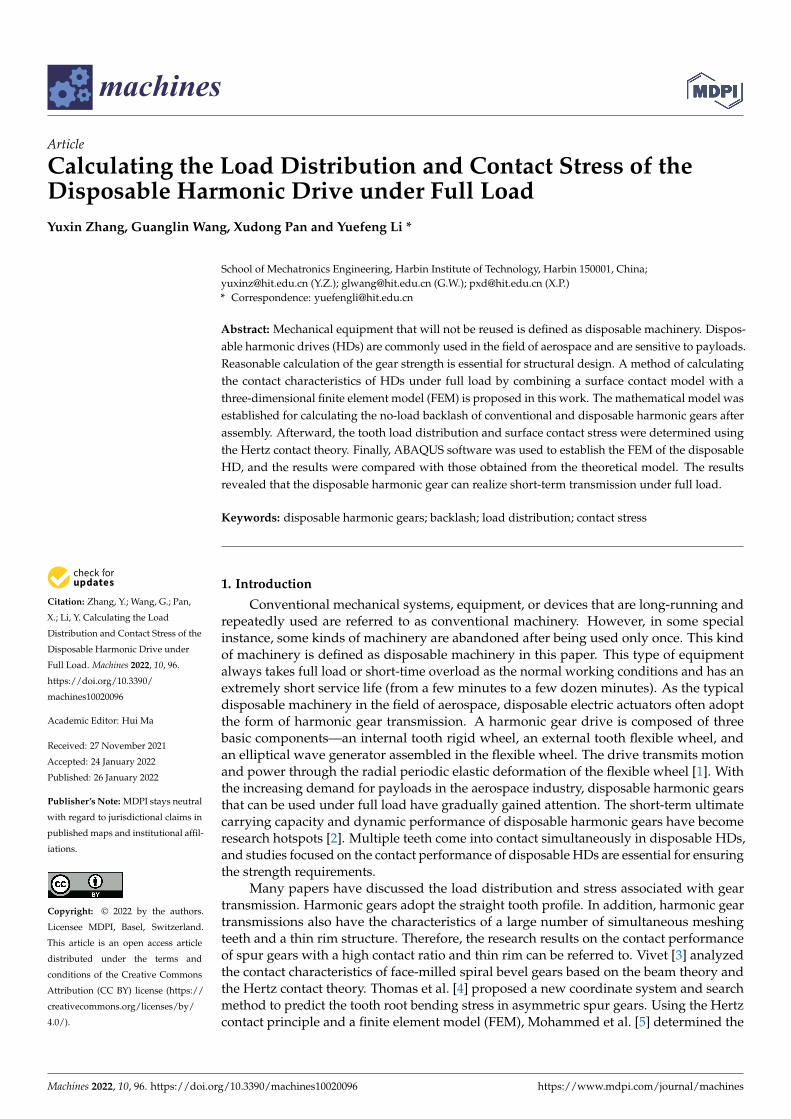
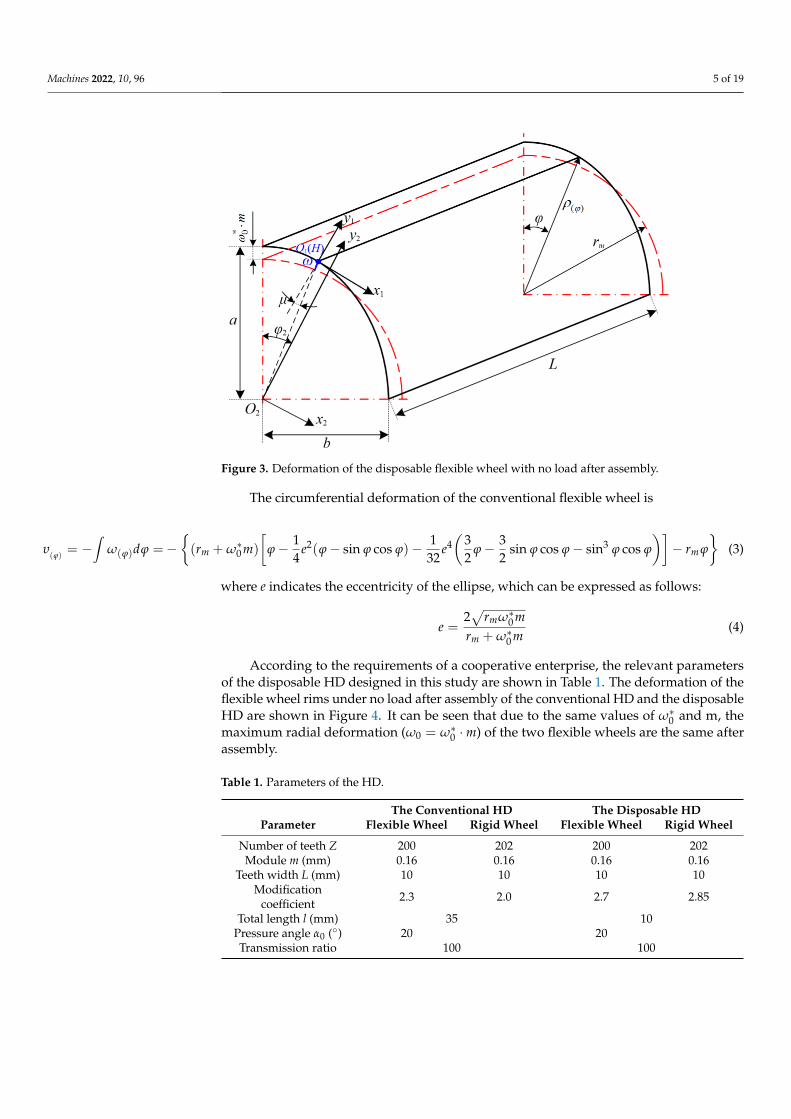
According to the requirements of a cooperative enterprise, the relevant parameters of the disposable HD designed in this study are shown in Table 1. The deformation of the flexible wheel rims under no load after assembly of the conventional HD and the disposable HD are shown in Figure 4. It can be seen that due to the same values of *
0ω and m, the maximum radial deformation ( *
0 0= mω ω ⋅ ) of the two flexible wheels are the same after assembly.
Table 1. Parameters of the HD.
The Conventional HD The Disposable HD Parameter Flexible Wheel Rigid Wheel Flexible Wheel Rigid Wheel
Number of teeth Z 200 202 200 202 Module m (mm) 0.16 0.16 0.16 0.16
Teeth width L (mm) 10 10 10 10 Modification coefficient 2.3 2.0 2.7 2.85
Total length l (mm) 35 10 Pressure angle α0 (°) 20 20 Transmission ratio 100 100
Figure 3. Deformation of the disposable flexible wheel with no load after assembly.
The circumferential deformation of the conventional flexible wheel is
υ(ϕ)
= −∫
ω(ϕ)dϕ =−{(rm + ω∗0 m)
[ϕ− 1
4e2(ϕ− sin ϕ cos ϕ)− 1
32e4(
32
ϕ− 32
sin ϕ cos ϕ− sin3 ϕ cos ϕ
)]− rm ϕ
}(3)
where e indicates the eccentricity of the ellipse, which can be expressed as follows:
e =2√
rmω∗0 mrm + ω∗0 m
(4)
According to the requirements of a cooperative enterprise, the relevant parametersof the disposable HD designed in this study are shown in Table 1. The deformation of theflexible wheel rims under no load after assembly of the conventional HD and the disposableHD are shown in Figure 4. It can be seen that due to the same values of ω∗0 and m, themaximum radial deformation (ω0 = ω∗0 ·m) of the two flexible wheels are the same afterassembly.
Table 1. Parameters of the HD.
The Conventional HD The Disposable HDParameter Flexible Wheel Rigid Wheel Flexible Wheel Rigid Wheel
Number of teeth Z 200 202 200 202Module m (mm) 0.16 0.16 0.16 0.16
Teeth width L (mm) 10 10 10 10Modification
coefficient 2.3 2.0 2.7 2.85
Total length l (mm) 35 10Pressure angle α0 (◦) 20 20Transmission ratio 100 100
Machines 2022, 10, 96 6 of 19Machines 2022, 10, x FOR PEER REVIEW 6 of 20
(a) (b)
Figure 4. (a) The deformation of the conventional flexible wheel rim; (b) the deformation of the disposable flexible wheel rim.
The included angle between the vector radius and the curvature radius passing through point H can be calculated with
( ) ( )
( )( )
1arctan arctan =m m
dr r d
ϕϕ
ϕ ϕ
ωρ ρμρ ω ϕ
′ ′= =
+ (5)
The rotation angles of the characteristic curve of the flexible wheel and the symmet-rical axis of the corresponding rigid wheel tooth are defined as follows:
1
, the conventional HD
, the disposable HDmrϕυ
ϕϕ
ϕ
+=
(6)
12
2 2
ZZ Z
πϕ ϕ= + (7)
where Z1 and Z2 represent the number of teeth of the flexible wheel and the rigid wheel, respectively.
The rotation angle of the vector radius at point H on the middle plane of the flexible wheel rim to the symmetrical axis of the rigid wheel tooth is given by
2 1ϕ ϕ ϕΔ = − (8)
For the conventional harmonic drive,
( ) ( )* 2 4 310
2 2
1 1 1 3 31 sin cos sin cos sin cos4 32 2 2m m
m
Z r m e e rZ Z rπϕ ϕ ω ϕ ϕ ϕ ϕ ϕ ϕ ϕ ϕ ϕ ϕ
Δ = − − + + − − − − − − (9)
For the disposable harmonic drive,
1
2 2
1 ZZ Zπϕ ϕ
Δ = − −
(10)
2.2. Calculation of the Backlash Associated with the Involute Profile Harmonic Gear under No load Figure 5 shows the contact tooth pair between the flexible wheel and the rigid wheel
at polar angle φ after assembly under no load.
Figure 4. (a) The deformation of the conventional flexible wheel rim; (b) the deformation of thedisposable flexible wheel rim.
The included angle between the vector radius and the curvature radius passingthrough point H can be calculated with
µ(ϕ) = arctanρ′
ρ(ϕ)= arctan
ρ′
rm + ω(ϕ)=
1rm
dω(ϕ)
dϕ(5)
The rotation angles of the characteristic curve of the flexible wheel and the symmetricalaxis of the corresponding rigid wheel tooth are defined as follows:
ϕ1 =
{ϕ +
υϕ
rm, the conventional HD
ϕ, the disposable HD(6)
ϕ2 =Z1
Z2ϕ +
π
Z2(7)
where Z1 and Z2 represent the number of teeth of the flexible wheel and the rigid wheel,respectively.
The rotation angle of the vector radius at point H on the middle plane of the flexiblewheel rim to the symmetrical axis of the rigid wheel tooth is given by
∆ϕ = ϕ2 − ϕ1 (8)
For the conventional harmonic drive,
∆ϕ = πZ2− ϕ
(1− Z1
Z2
)+ 1
rm
{(rm + ω∗0 m)
[ϕ− 1
4 e2(ϕ− sin ϕ cos ϕ)− 132 e4( 3
2 ϕ− 32 sin ϕ cos ϕ− sin3 ϕ cos ϕ
)]− rm ϕ
}(9)
For the disposable harmonic drive,
∆ϕ =π
Z2− ϕ
(1− Z1
Z2
)(10)
2.2. Calculation of the Backlash Associated with the Involute Profile Harmonic Gear under No Load
Figure 5 shows the contact tooth pair between the flexible wheel and the rigid wheelat polar angle ϕ after assembly under no load.

Machines 2022, 10, 96 7 of 19Machines 2022, 10, x FOR PEER REVIEW 7 of 20
Figure 5. Engagement diagram of harmonic contact tooth pair. Two cases of flexible wheel teeth under assembly and load are included.
In Figure 5, the red and black dash-dotted lines represent the middle plane of the flexible wheel rim before and after assembly, respectively. The elliptical black solid lines express the inner and outer layers of the flexible wheel rim after assembly. In addition, the red dash-dotted tooth profile curve and the black solid tooth profile curve indicate the position of the flexible wheel tooth before and after assembly, respectively. The blue dashed tooth profile curve represents the meshing position of the flexible wheel after loading.
The motion trajectory of contact point K on the tooth profile of the flexible wheel relative to the tooth of the rigid wheel is given as follows:
( ) ( ) ( ) ( )
( ) ( ) ( ) ( )
1 0 1 1
1 0 1 1
1sin sin cos2
1cos cos sin2
K m K m K
K m K m K
x r r r S
y r r r S
ω ϕ ϕ μ ϕ μ
ω ϕ ϕ μ ϕ μ
= − + Δ + − Δ − − Δ − = + Δ + − Δ − + Δ −
(11)
where ω0 indicates the maximum radial deformation of the flexible wheel after assembly ( *
0 0= mω ω ⋅ ). rk1 represents the radius of the circle associated with the point on the flexible tooth profile without deformation. SK1 denotes the tooth thickness of the flexible wheel tooth profile passing point K and can be expressed as follows:
1 11 1 0 1
1 1
2 tan2 inv inv2
KK K K
XS rZ Z
απ α α
= + + −
(12)
Figure 5. Engagement diagram of harmonic contact tooth pair. Two cases of flexible wheel teethunder assembly and load are included.
In Figure 5, the red and black dash-dotted lines represent the middle plane of theflexible wheel rim before and after assembly, respectively. The elliptical black solid linesexpress the inner and outer layers of the flexible wheel rim after assembly. In addition,the red dash-dotted tooth profile curve and the black solid tooth profile curve indicate theposition of the flexible wheel tooth before and after assembly, respectively. The blue dashedtooth profile curve represents the meshing position of the flexible wheel after loading.
The motion trajectory of contact point K on the tooth profile of the flexible wheelrelative to the tooth of the rigid wheel is given as follows:{
xK1 = −[(rm + ω0) sin ∆ϕ + (rK1 − rm) sin(∆ϕ− µ)− 1
2 SK1 cos(∆ϕ− µ)]
yK1 = (rm + ω0) cos ∆ϕ + (rK1 − rm) cos(∆ϕ− µ) + 12 SK1 sin(∆ϕ− µ)
(11)
where ω0 indicates the maximum radial deformation of the flexible wheel after assembly(ω0 = ω∗0 ·m). rk1 represents the radius of the circle associated with the point on the flexible

Machines 2022, 10, 96 8 of 19
tooth profile without deformation. SK1 denotes the tooth thickness of the flexible wheeltooth profile passing point K and can be expressed as follows:
SK1 = 2rK1
(π
2Z1+
2X1 tan αK1
Z1+ invα0 − invαK1
)(12)
where X1 is the modification coefficient of the flexible wheel, α0 represents the pressureangle of the pitch circle, and αK1 denotes the pressure angle of the flexible tooth profile atpoint K. The normal backlash at contact point K can be expressed as follows:
Ds = xK1 −12
SK2 (13)
Furthermore, the corresponding circumferential backlash at contact point K in themeshing area with no load is determined with
Dn =
(xK1 −
12
SK2
)cos αK2 (14)
where SK2 is the tooth thickness at the tooth profile of the rigid wheel conjugated to point Kof the flexible wheel, and αK2 indicates the pressure angle at the tooth profile of the rigidwheel conjugated to point K of the flexible wheel. The relationship between the backlashand the polar angle of the involute harmonic gear drive is determined from Equation (14),as shown in Figure 6.
Machines 2022, 10, x FOR PEER REVIEW 8 of 20
where X1 is the modification coefficient of the flexible wheel, α0 represents the pressure angle of the pitch circle, and αK1 denotes the pressure angle of the flexible tooth profile at point K. The normal backlash at contact point K can be expressed as follows:
1 2
12s K KD x S= −
(13)
Furthermore, the corresponding circumferential backlash at contact point K in the meshing area with no load is determined with
1 2 2
1 cos2n K K KD x S α = −
(14)
where SK2 is the tooth thickness at the tooth profile of the rigid wheel conjugated to point K of the flexible wheel, and αK2 indicates the pressure angle at the tooth profile of the rigid wheel conjugated to point K of the flexible wheel. The relationship between the backlash and the polar angle of the involute harmonic gear drive is determined from Equation (14), as shown in Figure 6.
Figure 6. Backlash under no load of two kinds of HDs.
On the basis of Equations (11)–(14), the no-load backlash of the HDs is related to parameters Δφ and rm. As shown in Figure 6, the minimum no-load backlash of the con-ventional HD occurs near the polar angle of φ = 5°. However, since the disposable flexi-ble wheel structure does not contain a cylinder and has a thinner rim, the minimum no-load backlash of the disposable HD occurs at the midline of the major axis and is lower than that of the conventional HD. The difference between backlash distribution directly affects the load distribution and contact characteristics of the harmonic drive.
3. Load Distribution Calculation of the Harmonic Flexible Wheel For a certain polar angle φ, a pair of HD teeth mesh with each other, as shown in
Figure 6. After the transmission system is loaded, both the flexible wheel shell and the meshing tooth pair are elastically deformed. When the rigid wheel is fixed, an additional angle β for compensating the above two deformations is generated by the flexible wheel to ensure the meshing of the flexible wheel and the rigid wheel. Sufficiently large β val-ues allow for the elimination of the clearance between adjacent pairs of teeth, thereby resulting in simultaneous contact between multiple pairs of gear teeth.
Figure 6. Backlash under no load of two kinds of HDs.
On the basis of Equations (11)–(14), the no-load backlash of the HDs is related toparameters ∆ϕ and rm. As shown in Figure 6, the minimum no-load backlash of theconventional HD occurs near the polar angle of ϕ = 5◦. However, since the disposableflexible wheel structure does not contain a cylinder and has a thinner rim, the minimumno-load backlash of the disposable HD occurs at the midline of the major axis and is lowerthan that of the conventional HD. The difference between backlash distribution directlyaffects the load distribution and contact characteristics of the harmonic drive.
Machines 2022, 10, 96 9 of 19
3. Load Distribution Calculation of the Harmonic Flexible Wheel
For a certain polar angle ϕ, a pair of HD teeth mesh with each other, as shown inFigure 6. After the transmission system is loaded, both the flexible wheel shell and themeshing tooth pair are elastically deformed. When the rigid wheel is fixed, an additionalangle β for compensating the above two deformations is generated by the flexible wheel toensure the meshing of the flexible wheel and the rigid wheel. Sufficiently large β valuesallow for the elimination of the clearance between adjacent pairs of teeth, thereby resultingin simultaneous contact between multiple pairs of gear teeth.
Based on the deformation coordinates, and considering the simultaneous engagementof multiple pairs of teeth comprising the harmonic gear, the mathematical models of twokinds of harmonic gears was established as follows:
For the conventional HD,
δK + δr + DK − RK · β = 0 (15)
For the disposable HD,δK + DK − RK · β = 0 (16)
δK =N
∑i=1
λKi · Fi (17)
where δK represents the total elastic deformation of the contact teeth in the meshing area,and δr denotes the elastic deformation in the circumferential direction of the flexible wheelshell under load. Furthermore, DK denotes the backlash at contact point K of the tooth pairin the meshing area with no load, and RK represents the load radius of the tooth pair in themeshing area at contact point K. β, i, and N indicate the additional angles of the contacttooth pair in the meshing area required for compensating the deformation, serial numberof the contact tooth in the meshing area, and number of contact teeth in the meshing area,respectively. In addition, λKi represents the total flexibility caused by the unit of the i-thcontact tooth pair, and Fi is the load acting on the i-th contact tooth pair.
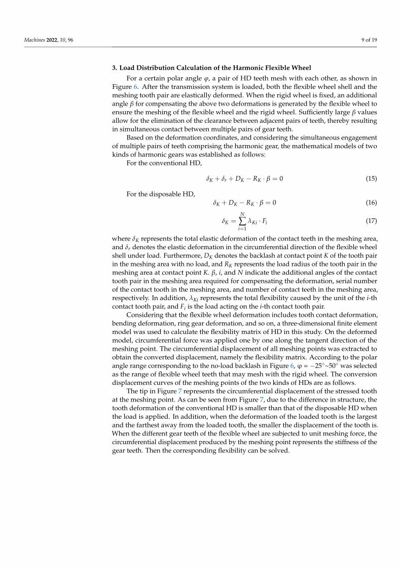
Considering that the flexible wheel deformation includes tooth contact deformation,bending deformation, ring gear deformation, and so on, a three-dimensional finite elementmodel was used to calculate the flexibility matrix of HD in this study. On the deformedmodel, circumferential force was applied one by one along the tangent direction of themeshing point. The circumferential displacement of all meshing points was extracted toobtain the converted displacement, namely the flexibility matrix. According to the polarangle range corresponding to the no-load backlash in Figure 6, ϕ = −25◦~50◦ was selectedas the range of flexible wheel teeth that may mesh with the rigid wheel. The conversiondisplacement curves of the meshing points of the two kinds of HDs are as follows.
The tip in Figure 7 represents the circumferential displacement of the stressed toothat the meshing point. As can be seen from Figure 7, due to the difference in structure, thetooth deformation of the conventional HD is smaller than that of the disposable HD whenthe load is applied. In addition, when the deformation of the loaded tooth is the largestand the farthest away from the loaded tooth, the smaller the displacement of the tooth is.When the different gear teeth of the flexible wheel are subjected to unit meshing force, thecircumferential displacement produced by the meshing point represents the stiffness of thegear teeth. Then the corresponding flexibility can be solved.
Machines 2022, 10, 96 10 of 19Machines 2022, 10, x FOR PEER REVIEW 10 of 20
(a) (b)
Figure 7. (a) The conversion displacement of the conventional flexible wheel; (b) the conversion displacement of the disposable flexible wheel.
The elastic deformation in the circumferential direction of the flexible wheel shell can be expressed as follows:
1
N
r i ii
Fδ ξ=
= ⋅
(18)
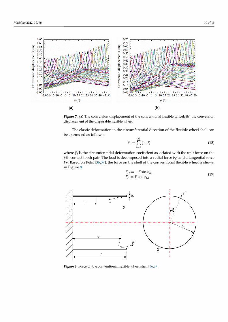
where ξi is the circumferential deformation coefficient associated with the unit force on the i-th contact tooth pair. The load is decomposed into a radial force FQ and a tangential force FP. Based on Refs. [36,37], the force on the shell of the conventional flexible wheel is shown in Figure 8.
1
1
sincos
Q K
P K
F FF F
αα
= −
= (19)
Figure 8. Force on the conventional flexible wheel shell [36,37].
The radial, circumferential, and axial displacement under load can be determined with
Figure 7. (a) The conversion displacement of the conventional flexible wheel; (b) the conversiondisplacement of the disposable flexible wheel.
The elastic deformation in the circumferential direction of the flexible wheel shell canbe expressed as follows:
δr =N
∑i=1
ξi · Fi (18)
where ξi is the circumferential deformation coefficient associated with the unit force on thei-th contact tooth pair. The load is decomposed into a radial force FQ and a tangential forceFP. Based on Refs. [36,37], the force on the shell of the conventional flexible wheel is shownin Figure 8.
FQ = −F sin αK1FP = F cos αK1
(19)
Machines 2022, 10, x FOR PEER REVIEW 10 of 20
(a) (b)
Figure 7. (a) The conversion displacement of the conventional flexible wheel; (b) the conversion displacement of the disposable flexible wheel.
The elastic deformation in the circumferential direction of the flexible wheel shell can be expressed as follows:
1
N
r i ii
Fδ ξ=
= ⋅
(18)
where ξi is the circumferential deformation coefficient associated with the unit force on the i-th contact tooth pair. The load is decomposed into a radial force FQ and a tangential force FP. Based on Refs. [36,37], the force on the shell of the conventional flexible wheel is shown in Figure 8.
1
1
sincos
Q K
P K
F FF F
αα
= −
= (19)
Figure 8. Force on the conventional flexible wheel shell [36,37].
The radial, circumferential, and axial displacement under load can be determined with
Figure 8. Force on the conventional flexible wheel shell [36,37].
Machines 2022, 10, 96 11 of 19
The radial, circumferential, and axial displacement under load can be determined with
ωF = − η·r2m
2πB
∞∑
n=2,4,6···
(lFl
)n( xl)n (2n−3)(4n2−1)
n(n−1) f(n)
(FP sin nϕ + nFQ cos nϕ
)υF = η·r2
m2πB
∞∑
n=2,4,6···
(lFl
)n( xl)n (2n−3)(4n2−1)
n2(n−1) f(n)
(FP cos nϕ− nFQ sin nϕ
)
uF = 0
(20)
η =rm
l(21)
f(n) = α5n5 − α4n4 − α3n3 + α2n2 − α1n− α0 (22)
α5 = 1− 2η2(1− 2ν) + η4, α4 = 1 + η2(η2 − 2ν), α3 = 1
4[9 + 2η2(11− 18ν) + η4],
α2 = 14[7− 2η2(3 + ν) + η4], α1 = 1
4[5 + 2η2(7− 10ν)
], α0 = 3
4[1− 2η2(1− ν)
].
(23)
where l, lF, and B represent the total length of the flexible shell, the distance from the radialcomponent of the load to the edge of the flexible shell, and the flexural strength of theflexible shell, respectively. Furthermore, E1 is the elastic modulus of the flexible wheelmaterial, hδ denotes the thickness of the flexible shell, and ν1 is the Poisson’s ratio of theflexible wheel material.
The deformation of all contact points in the meshing area can be expressed in matrixform, as follows:{
[λ][F] + [ξ][F] + [D]− [RK]β = 0, conventional HD
[λ][F] + [D]− [RK]β = 0, disposable HD(24)
where [λ] is an n × n order flexibility matrix, [F] indicates an n × 1 load column vector, and[ζ] represents an n × n order coefficient matrix corresponding to the flexible wheel shellcircumferential deformation. Moreover, [D] denotes an n × 1 backlash column vector withno load, and [RK] represents an n × 1 contact load radius column vector.
The harmonic gear is in balance when transmitting the torque. Moreover, the sum ofthe torque generated by the load at each contact point in the meshing area is the same asthe total torque applied to the transmission system.
N
∑i=1
FiRKi cos αKi = T (25)
Let Hi = RKi cos αKi; Equation (25) can be expressed as a matrix, as follows:
[H]T [F] = T (26)
The load distribution model of the HD can be obtained by solving Equations (24) and(26). The specific solution process is as follows:
Step 1—Suppose that only a pair of gear teeth with the smallest no-load backlash isengaged, and the other gear teeth are not in contact. Record the number of meshing teethn = 1, and the tooth pair number in the meshing area i = 1. Solve the initial load F1 and thecompensation rotation angle β1.
Step 2—Gradually increase the number of meshing teeth, solve Equations (24) and(26), and obtain the corresponding compensation rotation angle β2 . . . . . . βn.
Step 3—When βn < 0 or βn > βn−1, stop the calculation. The last set of results thatmeet the constraints is the load distribution [F].
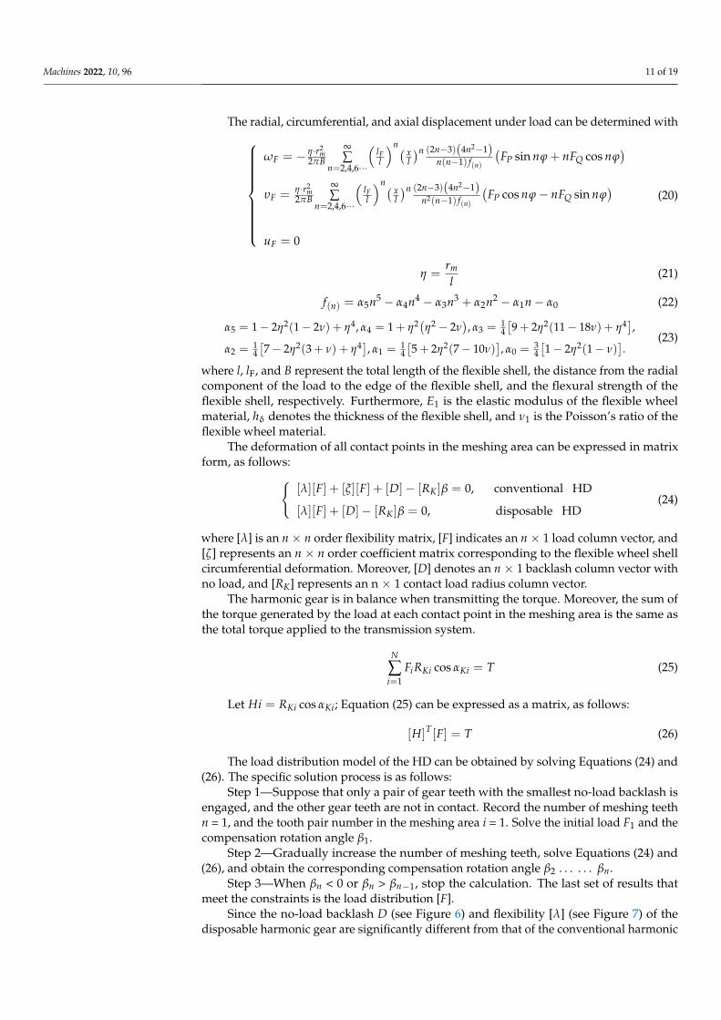
Since the no-load backlash D (see Figure 6) and flexibility [λ] (see Figure 7) of thedisposable harmonic gear are significantly different from that of the conventional harmonic
Machines 2022, 10, 96 12 of 19
gear, the load distributions of the two HDs under full load 80N·m are also different (seeFigure 9). When the flexible wheel is loaded, contact occurs first at the position withthe smallest backlash under the action of torsional deformation, and the contact forceincreases with the increase in the external load. Therefore, the maximum contact force ofthe HD occurs at the position with the smallest no-load backlash. It can be seen that at themaximum contact load, the disposable HD is lower than that of the conventional HD. Inaddition, there are certain differences between the meshing areas of the two HDs. Afterbeing loaded, the conventional flexible wheel is distorted due to the torsional deformationof the cylinder, which affects the backlash distribution. Therefore, the load distributioncurve of the conventional flexible wheel under load is not completely symmetrical, whichis consistent with the conclusion of [28]. The contact stress of the HD is discussed below.
Machines 2022, 10, x FOR PEER REVIEW 12 of 20
Since the no-load backlash D (see Figure 6) and flexibility [λ] (see Figure 7) of the disposable harmonic gear are significantly different from that of the conventional har-monic gear, the load distributions of the two HDs under full load 80N∙m are also differ-ent (see Figure 9). When the flexible wheel is loaded, contact occurs first at the position with the smallest backlash under the action of torsional deformation, and the contact force increases with the increase in the external load. Therefore, the maximum contact force of the HD occurs at the position with the smallest no-load backlash. It can be seen that at the maximum contact load, the disposable HD is lower than that of the conven-tional HD. In addition, there are certain differences between the meshing areas of the two HDs. After being loaded, the conventional flexible wheel is distorted due to the tor-sional deformation of the cylinder, which affects the backlash distribution. Therefore, the load distribution curve of the conventional flexible wheel under load is not completely symmetrical, which is consistent with the conclusion of [28]. The contact stress of the HD is discussed below.
Figure 9. Harmonic transmission load distribution of the two HDs.
4. Tooth Surface Contact Stress Calculation of the Harmonic Flexible Wheel According to the Hertz contact theory, tooth contact in gear transmission can be
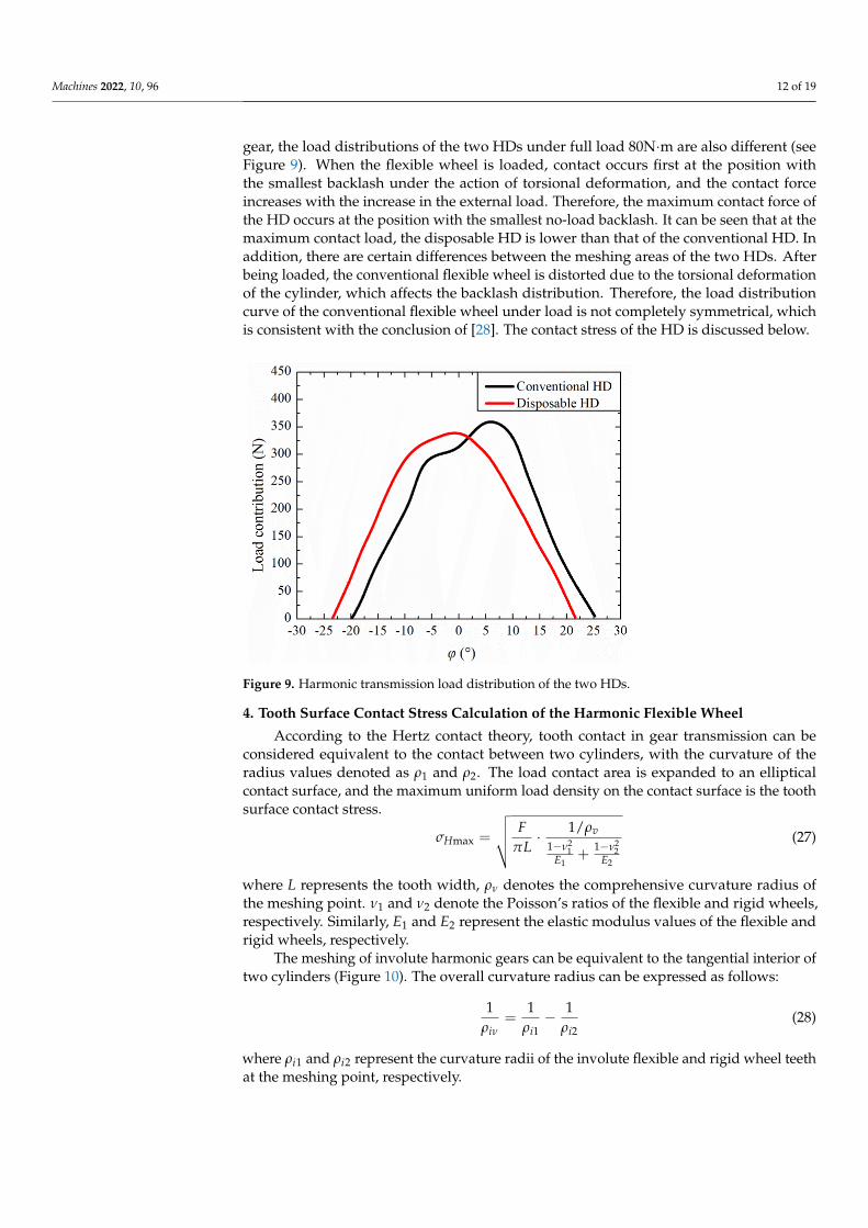
considered equivalent to the contact between two cylinders, with the curvature of the radius values denoted as ρ1 and ρ2. The load contact area is expanded to an elliptical contact surface, and the maximum uniform load density on the contact surface is the tooth surface contact stress.
max 2 21 2
1 2
1=1 1
vH
FL
E E
ρσν νπ
⋅− −+
(27)
where L represents the tooth width, ρν denotes the comprehensive curvature radius of the meshing point. ν1 and ν2 denote the Poisson’s ratios of the flexible and rigid wheels, respectively. Similarly, E1 and E2 represent the elastic modulus values of the flexible and rigid wheels, respectively.
The meshing of involute harmonic gears can be equivalent to the tangential interior of two cylinders (Figure 10). The overall curvature radius can be expressed as follows:
1 2
1 1 1= -i i iνρ ρ ρ
(28)
where ρi1 and ρi2 represent the curvature radii of the involute flexible and rigid wheel teeth at the meshing point, respectively.
Figure 9. Harmonic transmission load distribution of the two HDs.
4. Tooth Surface Contact Stress Calculation of the Harmonic Flexible Wheel
According to the Hertz contact theory, tooth contact in gear transmission can beconsidered equivalent to the contact between two cylinders, with the curvature of theradius values denoted as ρ1 and ρ2. The load contact area is expanded to an ellipticalcontact surface, and the maximum uniform load density on the contact surface is the toothsurface contact stress.
σHmax =
√√√√ FπL· 1/ρv
1−ν21
E1+
1−ν22
E2
(27)
where L represents the tooth width, ρν denotes the comprehensive curvature radius ofthe meshing point. ν1 and ν2 denote the Poisson’s ratios of the flexible and rigid wheels,respectively. Similarly, E1 and E2 represent the elastic modulus values of the flexible andrigid wheels, respectively.
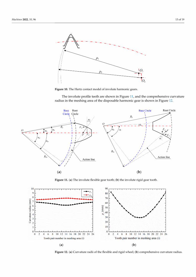
The meshing of involute harmonic gears can be equivalent to the tangential interior oftwo cylinders (Figure 10). The overall curvature radius can be expressed as follows:
1ρiν
=1
ρi1− 1
ρi2(28)
where ρi1 and ρi2 represent the curvature radii of the involute flexible and rigid wheel teethat the meshing point, respectively.
Machines 2022, 10, 96 13 of 19Machines 2022, 10, x FOR PEER REVIEW 13 of 20
Figure 10. The Hertz contact model of involute harmonic gears.
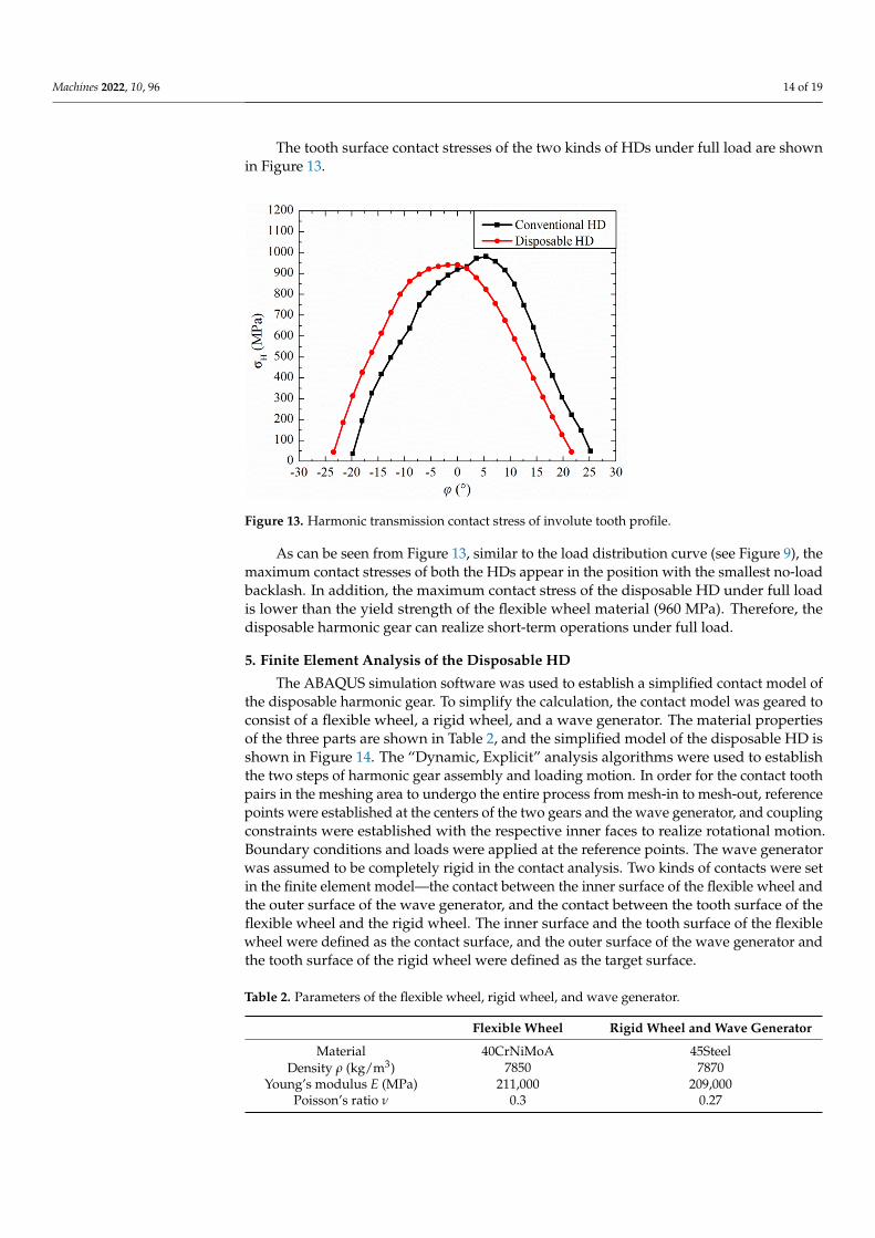
The involute profile teeth are shown in Figure 11, and the comprehensive curvature radius in the meshing area of the disposable harmonic gear is shown in Figure 12.
(a) (b)
Figure 11. (a) The involute flexible gear tooth; (b) the involute rigid gear tooth.
(a) (b)
Figure 12. (a) Curvature radii of the flexible and rigid wheel; (b) comprehensive curvature radius.
The tooth surface contact stresses of the two kinds of HDs under full load are shown in Figure 13.
Figure 10. The Hertz contact model of involute harmonic gears.
The involute profile teeth are shown in Figure 11, and the comprehensive curvatureradius in the meshing area of the disposable harmonic gear is shown in Figure 12.
Machines 2022, 10, x FOR PEER REVIEW 13 of 20
Figure 10. The Hertz contact model of involute harmonic gears.
The involute profile teeth are shown in Figure 11, and the comprehensive curvature radius in the meshing area of the disposable harmonic gear is shown in Figure 12.
(a) (b)
Figure 11. (a) The involute flexible gear tooth; (b) the involute rigid gear tooth.
(a) (b)
Figure 12. (a) Curvature radii of the flexible and rigid wheel; (b) comprehensive curvature radius.
The tooth surface contact stresses of the two kinds of HDs under full load are shown in Figure 13.
Figure 11. (a) The involute flexible gear tooth; (b) the involute rigid gear tooth.
Machines 2022, 10, x FOR PEER REVIEW 13 of 20
Figure 10. The Hertz contact model of involute harmonic gears.
The involute profile teeth are shown in Figure 11, and the comprehensive curvature radius in the meshing area of the disposable harmonic gear is shown in Figure 12.
(a) (b)
Figure 11. (a) The involute flexible gear tooth; (b) the involute rigid gear tooth.
(a) (b)
Figure 12. (a) Curvature radii of the flexible and rigid wheel; (b) comprehensive curvature radius.
The tooth surface contact stresses of the two kinds of HDs under full load are shown in Figure 13.
Figure 12. (a) Curvature radii of the flexible and rigid wheel; (b) comprehensive curvature radius.
Machines 2022, 10, 96 14 of 19
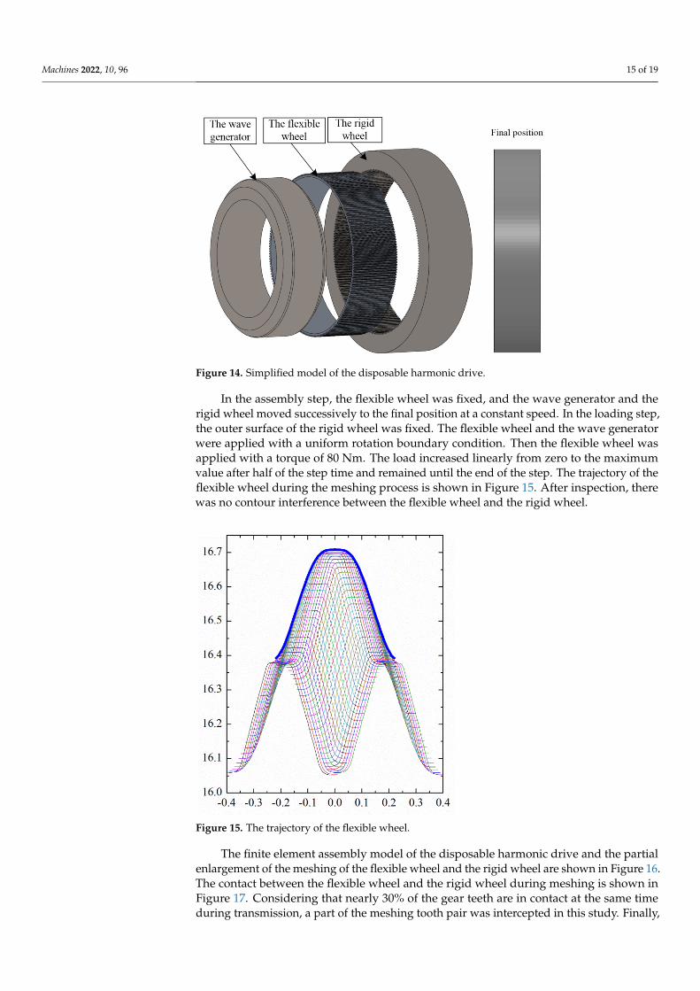
The tooth surface contact stresses of the two kinds of HDs under full load are shownin Figure 13.
Machines 2022, 10, x FOR PEER REVIEW 14 of 20
Figure 13. Harmonic transmission contact stress of involute tooth profile.
As can be seen from Figure 13, similar to the load distribution curve (see Figure 9), the maximum contact stresses of both the HDs appear in the position with the smallest no-load backlash. In addition, the maximum contact stress of the disposable HD under full load is lower than the yield strength of the flexible wheel material (960 MPa). Therefore, the disposable harmonic gear can realize short-term operations under full load.
5. Finite Element Analysis of the Disposable HD The ABAQUS simulation software was used to establish a simplified contact model
of the disposable harmonic gear. To simplify the calculation, the contact model was geared to consist of a flexible wheel, a rigid wheel, and a wave generator. The material properties of the three parts are shown in Table 2, and the simplified model of the dis-posable HD is shown in Figure 14. The “Dynamic, Explicit” analysis algorithms were used to establish the two steps of harmonic gear assembly and loading motion. In order for the contact tooth pairs in the meshing area to undergo the entire process from mesh-in to mesh-out, reference points were established at the centers of the two gears and the wave generator, and coupling constraints were established with the respective inner faces to realize rotational motion. Boundary conditions and loads were applied at the reference points. The wave generator was assumed to be completely rigid in the contact analysis. Two kinds of contacts were set in the finite element model—the contact between the inner surface of the flexible wheel and the outer surface of the wave gener-ator, and the contact between the tooth surface of the flexible wheel and the rigid wheel. The inner surface and the tooth surface of the flexible wheel were defined as the contact surface, and the outer surface of the wave generator and the tooth surface of the rigid wheel were defined as the target surface.
Figure 13. Harmonic transmission contact stress of involute tooth profile.
As can be seen from Figure 13, similar to the load distribution curve (see Figure 9), themaximum contact stresses of both the HDs appear in the position with the smallest no-loadbacklash. In addition, the maximum contact stress of the disposable HD under full loadis lower than the yield strength of the flexible wheel material (960 MPa). Therefore, thedisposable harmonic gear can realize short-term operations under full load.
5. Finite Element Analysis of the Disposable HD
The ABAQUS simulation software was used to establish a simplified contact model ofthe disposable harmonic gear. To simplify the calculation, the contact model was geared toconsist of a flexible wheel, a rigid wheel, and a wave generator. The material propertiesof the three parts are shown in Table 2, and the simplified model of the disposable HD isshown in Figure 14. The “Dynamic, Explicit” analysis algorithms were used to establishthe two steps of harmonic gear assembly and loading motion. In order for the contact toothpairs in the meshing area to undergo the entire process from mesh-in to mesh-out, referencepoints were established at the centers of the two gears and the wave generator, and couplingconstraints were established with the respective inner faces to realize rotational motion.Boundary conditions and loads were applied at the reference points. The wave generatorwas assumed to be completely rigid in the contact analysis. Two kinds of contacts were setin the finite element model—the contact between the inner surface of the flexible wheel andthe outer surface of the wave generator, and the contact between the tooth surface of theflexible wheel and the rigid wheel. The inner surface and the tooth surface of the flexiblewheel were defined as the contact surface, and the outer surface of the wave generator andthe tooth surface of the rigid wheel were defined as the target surface.
Table 2. Parameters of the flexible wheel, rigid wheel, and wave generator.
Flexible Wheel Rigid Wheel and Wave Generator
Material 40CrNiMoA 45SteelDensity ρ (kg/m3) 7850 7870
Young’s modulus E (MPa) 211,000 209,000Poisson’s ratio ν 0.3 0.27
Machines 2022, 10, 96 15 of 19Machines 2022, 10, x FOR PEER REVIEW 15 of 20
Figure 14. Simplified model of the disposable harmonic drive.
Table 2. Parameters of the flexible wheel, rigid wheel, and wave generator.
Flexible Wheel Rigid Wheel and Wave Generator Material 40CrNiMoA 45Steel
Density ρ(kg/m3) 7850 7870 Young’s modulus E(MPa) 211000 209,000
Poisson’s ratio ν 0.3 0.27
In the assembly step, the flexible wheel was fixed, and the wave generator and the rigid wheel moved successively to the final position at a constant speed. In the loading step, the outer surface of the rigid wheel was fixed. The flexible wheel and the wave generator were applied with a uniform rotation boundary condition. Then the flexible wheel was applied with a torque of 80 Nm. The load increased linearly from zero to the maximum value after half of the step time and remained until the end of the step. The trajectory of the flexible wheel during the meshing process is shown in Figure 15. After inspection, there was no contour interference between the flexible wheel and the rigid wheel.
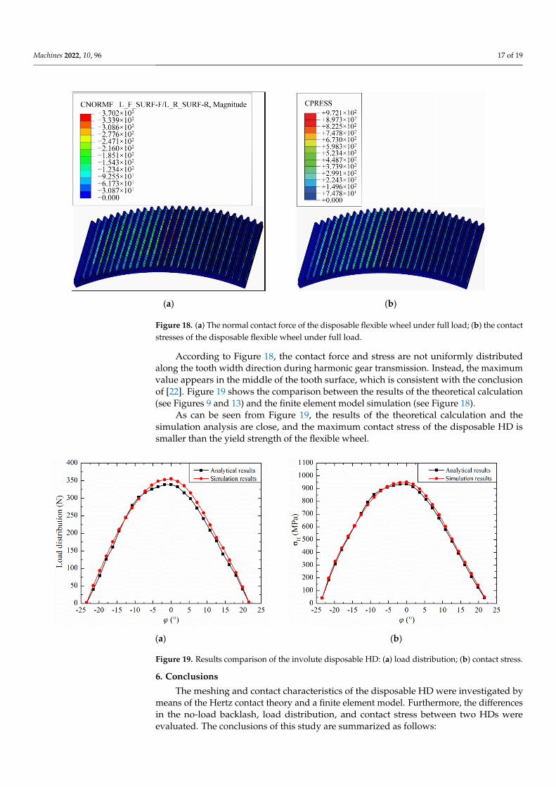
The finite element assembly model of the disposable harmonic drive and the partial enlargement of the meshing of the flexible wheel and the rigid wheel are shown in Fig-ure 16. The contact between the flexible wheel and the rigid wheel during meshing is shown in Figure 17. Considering that nearly 30% of the gear teeth are in contact at the same time during transmission, a part of the meshing tooth pair was intercepted in this study. Finally, the normal contact forces (CNORMF) and tooth surface contact stresses (CPRESS) of the tooth pair after a complete meshing cycle was output (see Figure 18).
Figure 14. Simplified model of the disposable harmonic drive.
In the assembly step, the flexible wheel was fixed, and the wave generator and therigid wheel moved successively to the final position at a constant speed. In the loading step,the outer surface of the rigid wheel was fixed. The flexible wheel and the wave generatorwere applied with a uniform rotation boundary condition. Then the flexible wheel wasapplied with a torque of 80 Nm. The load increased linearly from zero to the maximumvalue after half of the step time and remained until the end of the step. The trajectory of theflexible wheel during the meshing process is shown in Figure 15. After inspection, therewas no contour interference between the flexible wheel and the rigid wheel.
Machines 2022, 10, x FOR PEER REVIEW 16 of 20
Figure 15. The trajectory of the flexible wheel.
Figure 16. Finite element assembly model and the partial enlargement of the meshing area of the disposable HD.
Figure 15. The trajectory of the flexible wheel.
The finite element assembly model of the disposable harmonic drive and the partialenlargement of the meshing of the flexible wheel and the rigid wheel are shown in Figure 16.The contact between the flexible wheel and the rigid wheel during meshing is shown inFigure 17. Considering that nearly 30% of the gear teeth are in contact at the same timeduring transmission, a part of the meshing tooth pair was intercepted in this study. Finally,

Machines 2022, 10, 96 16 of 19
the normal contact forces (CNORMF) and tooth surface contact stresses (CPRESS) of thetooth pair after a complete meshing cycle was output (see Figure 18).
Machines 2022, 10, x FOR PEER REVIEW 16 of 20
Figure 15. The trajectory of the flexible wheel.
Figure 16. Finite element assembly model and the partial enlargement of the meshing area of the disposable HD.
Figure 16. Finite element assembly model and the partial enlargement of the meshing area of thedisposable HD.
Machines 2022, 10, x FOR PEER REVIEW 17 of 20
Figure 17. Meshing contact diagram of partial tooth pairs during transmission.
(a) (b)
Figure 18. (a) The normal contact force of the disposable flexible wheel under full load; (b) the contact stresses of the disposable flexible wheel under full load.
According to Figure 18, the contact force and stress are not uniformly distributed along the tooth width direction during harmonic gear transmission. Instead, the maxi-mum value appears in the middle of the tooth surface, which is consistent with the con-clusion of [22]. Figure 19 shows the comparison between the results of the theoretical calculation (see Figures 9 and 13) and the finite element model simulation (see Figure 18).
As can be seen from Figure 19, the results of the theoretical calculation and the sim-ulation analysis are close, and the maximum contact stress of the disposable HD is smaller than the yield strength of the flexible wheel.
Figure 17. Meshing contact diagram of partial tooth pairs during transmission.
Machines 2022, 10, 96 17 of 19
Machines 2022, 10, x FOR PEER REVIEW 17 of 20
Figure 17. Meshing contact diagram of partial tooth pairs during transmission.
(a) (b)
Figure 18. (a) The normal contact force of the disposable flexible wheel under full load; (b) the contact stresses of the disposable flexible wheel under full load.
According to Figure 18, the contact force and stress are not uniformly distributed along the tooth width direction during harmonic gear transmission. Instead, the maxi-mum value appears in the middle of the tooth surface, which is consistent with the con-clusion of [22]. Figure 19 shows the comparison between the results of the theoretical calculation (see Figures 9 and 13) and the finite element model simulation (see Figure 18).
As can be seen from Figure 19, the results of the theoretical calculation and the sim-ulation analysis are close, and the maximum contact stress of the disposable HD is smaller than the yield strength of the flexible wheel.
Figure 18. (a) The normal contact force of the disposable flexible wheel under full load; (b) the contactstresses of the disposable flexible wheel under full load.
According to Figure 18, the contact force and stress are not uniformly distributedalong the tooth width direction during harmonic gear transmission. Instead, the maximumvalue appears in the middle of the tooth surface, which is consistent with the conclusionof [22]. Figure 19 shows the comparison between the results of the theoretical calculation(see Figures 9 and 13) and the finite element model simulation (see Figure 18).
As can be seen from Figure 19, the results of the theoretical calculation and thesimulation analysis are close, and the maximum contact stress of the disposable HD issmaller than the yield strength of the flexible wheel.
Machines 2022, 10, x FOR PEER REVIEW 18 of 20
(a) (b)
Figure 19. Results comparison of the involute disposable HD: (a) load distribution; (b) contact stress.
6. Conclusions The meshing and contact characteristics of the disposable HD were investigated by
means of the Hertz contact theory and a finite element model. Furthermore, the differ-ences in the no-load backlash, load distribution, and contact stress between two HDs were evaluated. The conclusions of this study are summarized as follows:
(1) The minimum no-load backlash of the disposable HD occurs at the long axis center of the wave generator. In addition, the minimum and maximum no-load back-lashes of the disposable HD in the meshing area are smaller than those of the conven-tional HD.
(2) Due to different structures, the flexibility of the disposable HD is higher than that of the conventional HD. The load distribution and contact stress of the disposable HD are smaller in the meshing area.
(3) The maximum contact stress of the disposable HD is smaller than the yield strength of the flexible wheel. The disposable harmonic gear can be used for short-time operations under full load.
Author Contributions: Conceptualization, G.W., Y.L. and X.P.; methodology, Y.Z.; software, Y.Z.; validation, Y.Z. and Y.L.; writing—original draft preparation, Y.Z.; writing—review and editing, Y.L. and X.P.; visualization, X.P. and G.W.; funding acquisition, Y.L. All authors have read and agreed to the published version of the manuscript.
Funding: This research was funded by the National Natural Science Foundation of China, grant number 51875117, and the Fundamental Research Funds for the Central Universities, grant num-ber LH2020E035.
Institutional Review Board Statement: Not applicable.
Informed Consent Statement: Not applicable.
Data Availability Statement: The data presented in this study are available upon request from the corresponding author. The data are not publicly available due to copyright issues.
Conflicts of Interest: The authors declare no conflict of interest.
References 1. Taghirad, H.D.; Be’langer, P.R. Modeling and Parameter Identification of Harmonic Drive Systems. J. Dyn. Syst.-T 1998, 120,
439–444.
Figure 19. Results comparison of the involute disposable HD: (a) load distribution; (b) contact stress.
6. Conclusions
The meshing and contact characteristics of the disposable HD were investigated bymeans of the Hertz contact theory and a finite element model. Furthermore, the differencesin the no-load backlash, load distribution, and contact stress between two HDs wereevaluated. The conclusions of this study are summarized as follows:
Machines 2022, 10, 96 18 of 19
(1) The minimum no-load backlash of the disposable HD occurs at the long axis center ofthe wave generator. In addition, the minimum and maximum no-load backlashes ofthe disposable HD in the meshing area are smaller than those of the conventional HD.
(2) Due to different structures, the flexibility of the disposable HD is higher than that ofthe conventional HD. The load distribution and contact stress of the disposable HDare smaller in the meshing area.
(3) The maximum contact stress of the disposable HD is smaller than the yield strength ofthe flexible wheel. The disposable harmonic gear can be used for short-time operationsunder full load.
Author Contributions: Conceptualization, G.W., Y.L. and X.P.; methodology, Y.Z.; software, Y.Z.;validation, Y.Z. and Y.L.; writing—original draft preparation, Y.Z.; writing—review and editing, Y.L.and X.P.; visualization, X.P. and G.W.; funding acquisition, Y.L. All authors have read and agreed tothe published version of the manuscript.
Funding: This research was funded by the National Natural Science Foundation of China, grantnumber 51875117, and the Fundamental Research Funds for the Central Universities, grant numberLH2020E035.
Institutional Review Board Statement: Not applicable.
Informed Consent Statement: Not applicable.
Data Availability Statement: The data presented in this study are available upon request from thecorresponding author. The data are not publicly available due to copyright issues.
Conflicts of Interest: The authors declare no conflict of interest.
References1. Taghirad, H.D.; Be’langer, P.R. Modeling and Parameter Identification of Harmonic Drive Systems. J. Dyn. Syst.-T 1998, 120,
439–444. [CrossRef]2. Ma, D.; Rao, P.; Yan, S. Kinematics Analysis of Meshed Teeth Pairs of Harmonic Drive Gears Considering the Load Effect Using
Computer Vision. In Proceedings of the Automation and Robotics of the 5th International Conference on Control, Beijing, China,19–22 April 2019; pp. 212–217.
3. Vivet, M.; Mundo, D.; Tamarozzi, T.; Desmet, W. An analytical model for accurate and numerically efficient tooth contact analysisunder load, applied to face-milled spiral bevel gears. Mech. Mach. Theory 2018, 130, 137–156. [CrossRef]
4. Thomas, B.; Sankaranarayanasamy, K.; Ramachandra, S. Search method applied for gear tooth bending stress prediction innormal contact ratio asymmetric spur gears. Proc. Inst. Mech. Eng. Part C J. Mech. Eng. Sci. 2018, 232, 203–210. [CrossRef]
5. Mohammed, J.K.; Khdir, Y.K.; Kasab, S.Y. Contact stress analysis of spur gear under the different rotational speed by theoreticaland finite element method. Acad. J. Nawroz Univ. 2018, 7, 213–222. [CrossRef]
6. Wen, Q.; Du, Q.; Zhai, X. An analytical method for calculating the tooth surface contact stress of spur gears with tip relief. Int. J.Mech. Sci. 2019, 151, 170–180. [CrossRef]
7. Sato, T.; Umezawa, K.; Ishikawa, J. Effects of contact ratio and profile correction of spur gears on the rotational vibration. Trans.JSME Sec. C 1983, 49, 448–455. [CrossRef]
8. Liou, C.H.; Lin, H.H.; Oswald, F.B. Effect of contact ratio on spur gear dynamic load with no tooth profile modifications. J. Mech.Des. 1996, 118, 439–443. [CrossRef]
9. Lin, H.H.; Lee, C.W.; Oswaid, F.B.; Townsend, D.P. Townsend, Computer-aided design of high-contact-ratio gears for minimumdynamic load and stress. J. Mech. Des. 1993, 115, 171–178. [CrossRef]
10. Kahraman, A.; Blankenship, G.W. Gear dynamics experiments, part-2: Effect of involute contact ratio. Power Transm. Gearing Conf.1996, 88, 381–396.
11. Li, S.T. Gear contact model and loaded tooth contact analysis of a three-dimensional, thin-rimmed gear. J. Mech. Des. 2002, 124,511–517. [CrossRef]
12. Li, S.T. Deformation and Bending Stress Analysis of a Three-dimensional, Thin-rimmed Gear. J. Mech. Des. 2002, 124, 129–135.[CrossRef]
13. Ravivarman, R.; Palaniradja, K.; Sekar, R.P. Evolution of balanced root stress and tribological properties in high contact ratio spurgear drive. Mech. Mach. Theory 2018, 126, 491–513. [CrossRef]
14. Wang, Y.; Ren, S.; Li, Y. Design and manufacturing of a novel high contact ratio internal gear with a circular arc contact path. Int.J. Mech. Sci. 2019, 153, 143–153. [CrossRef]
15. Huang, K.; Yi, Y.; Xiong, Y. Nonlinear dynamics analysis of high contact ratio gears system with multiple clearances. J. Braz. Soc.Mech. Sci. Eng. 2020, 42, 98. [CrossRef]

Machines 2022, 10, 96 19 of 19
16. Jia, C.; Fang, Z. Design and analysis of double-crowned high-contact-ratio cylindrical gears considering the load sharing of themulti-pair contact. Mech. Mach. Theory 2019, 131, 92–114. [CrossRef]
17. Sun, X.; Han, L.; Wang, J. Tooth modification and loaded tooth contact analysis of China Bearing Reducer. Proc. Inst. Mech. Eng.Part C J. Mech. Eng. Sci. 2019, 233, 6240–6261. [CrossRef]
18. Rama, T.; Clement, C.D. Study on the quality and tooth root load carrying capacity of the high contact ratio asymmetrical geartooth machined using WCEDM process. Mater. Manuf. Process. 2020, 35, 1352–1361.
19. Yifan, H.F.; Zhao, Z.F.; Ma, H. Effects of tooth modification on the dynamic characteristics of thin-rimmed gears under surfacewear. Mech. Mach. Theory 2020, 150, 103870.
20. Donghui, M.; Jianing, W.; Liu, T. Deformation analysis of the flexspline of harmonic drive gears considering the driving speedeffect using laser sensors. Sci. China Technol. Sci. 2017, 60, 1175–1187.
21. Dong, H.M. Elastic deformation characteristic of the flexible wheel in harmonic drive. In ASME/IFToMM International Conferenceon Reconfigurable Mechanisms and Robots (ReMAR); IEEE: London, UK, 2009; pp. 363–369.
22. Dong, H.M.; Zhu, Z.D.; Zhou, W.D. Dynamic Simulation of Harmonic Gear Drives Considering Tooth Profiles ParametersOptimization. J. Comput. 2012, 7, 1429–1436. [CrossRef]
23. Chen, X.X.; Lin, S.Z.; Xing, J.Z. Deformation of flexible wheel under transmission force in harmonic drive. Adv. Mat. Res. 2010,97–101, 3536–3539.
24. Chen, X.X.; Liu, Y.S.; Xing, J.Z. A novel method based on mechanical analysis for the stretch of the neutral line of the flexiblewheel cup of a harmonic drive. Mech. Mach. Theory 2014, 76, 189–196. [CrossRef]
25. Chen, X.X.; Liu, Y.S.; Xing, J.Z. Neutral line of flexible wheel in harmonic driver. J. Mech. Eng. 2014, 50, 1–19. [CrossRef]26. Kayabasi, O.; Erzincanli, F. Shape optimization of tooth profile of a flexible wheel for a HD by finite element modeling. Mater.
Des. 2007, 28, 441–447. [CrossRef]27. Chen, X.; Liu, Y.; Xing, J. The parametric design of double-circular-arc tooth profile and its influence on the functional backlash of
HD. Mech. Mach. Theory 2014, 73, 1–24. [CrossRef]28. Le, K.X.; Quan, Y.X.; Zhou, G.R. Theoretical calculation of space dynamic meshing loads in harmonic gear drive. J. Zhejiang Univ.
1995, 2, 219–229.29. Zou, C.; Tao, T.; Jiang, G. Deformation and stress analysis of short flexible wheel in the HD system with load. In Proceedings of
the 2013 IEEE International Conference on Mechatronics and Automation, Takamatsu, Japan, 4–7 August 2013; pp. 676–680.30. Sahoo, V.; Maiti, R. Evidence of secondary tooth contact in HD, with involute toothed gear pair, through experimental and finite
element analyses of stresses in flex-gear cup. Proc. Inst. Mech. Eng. Part C J. Mech. Eng. Sci. 2018, 232, 341–357. [CrossRef]31. Routh, B.; Maiti, R.; Ray, A.K. An investigation on secondary force contacts of tooth pairs in conventional HDs with involute
toothed gear set. Proc. Inst. Mech. Eng. Part C J. Mech. Eng. Sci. 2016, 230, 622–638. [CrossRef]32. Yang, C.; Hu, Q.; Liu, Z. Analysis of the Partial Axial Load of a Very Thin-Walled Spur-Gear (Flexible wheel) of a HD. Int. J. Precis.
Eng. Man. 2020, 30, 1–13.33. Sahoo, V.; Maiti, R. Load sharing by tooth pairs in involute toothed HD with conventional wave generator cam. Meccanica 2018,
53, 373–394. [CrossRef]34. Sahoo, V.; Mahanto, B.S.; Maiti, R. Stresses in flex gear of a novel HD with and without pay load. Aust. J. Mech. Eng. 2020, 1, 1–15.
[CrossRef]35. Xie, J.R. The meshing analysis method of the harmonic gear drive with the elliptical cam wave generator. Opt. Precis. Eng. 1980, 3,
33–40.36. Kokhanovskii, G.I.; Polenov, V.S.; Spiridonov, V.V. Calculating the stress and strain state of the flexible wheel of a wave toothed
transmission. Sov. Appl. Mech. 1973, 9, 1355–1358. [CrossRef]37. Polenov, V.S. Investigation of the stress-strain state of flexible elements in wave drives. Sov. Appl. Mech. 1981, 17, 34–39. [CrossRef]