Procedures for the Derivation of Equilibrium Partitioning ... - EPA

DERIVATION OF A REFINED EQUATION FOR CALCULATING THE
ULTIMATE LOAD OF REINFORCED CONCRETE WALLS
MAGDY ABDEL MOHSEN1, TAMER ALAFANDY
2
ABSTRACT
The current paper aimed to studying available equations for calculation of
vertical ultimate load of reinforced concrete (RC) walls subjected to bending in one
direction according to different codes including Egyptian Code (ECP203-07) and
comparing the results obtained by this equations with those obtained from 24 loading
tests of reinforced concrete walls having different dimensions, cross sections,
reinforcement and slenderness ratios. From this comparison we found that existing
equations given by different codes do not give accurate estimation of vertical capacity
of walls and consequently a new accurate and practical equation has been developed
and give very close results compared to experimental ones.
KEYWORDS: Concrete, Experimental Tests, Load Bearing Walls, Ultimate Load .
1. INTRODUCTION
There is big discrepancy between different codes for calculation of ultimate
vertical capacity of reinforced concrete walls. For example the ACI318-08 and
ECP203-07 Codes neglects the effect of reinforcement in the wall. British and Euro
Codes design RC walls as columns taking into consideration the presence of
reinforcement. When comparing the results obtained from different codes with those
obtained from experimental it has been found that there is a big difference of values
1Assist. Prof., Al-Azhar University
2Assist. Prof, Housing and Building Research Center
Email: [email protected]
- 1 -
obtained by different codes. A modification for one of the equations available for
design of RC columns has been done to be used for design of RC walls and this
equations give a very accurate and close to the experimental ones.
2. CURRENT EQUATIONS USED FOR CALCULATING ULTIMATE LOADS
OF RC WALLS
2.1 American Code ACI318-08:
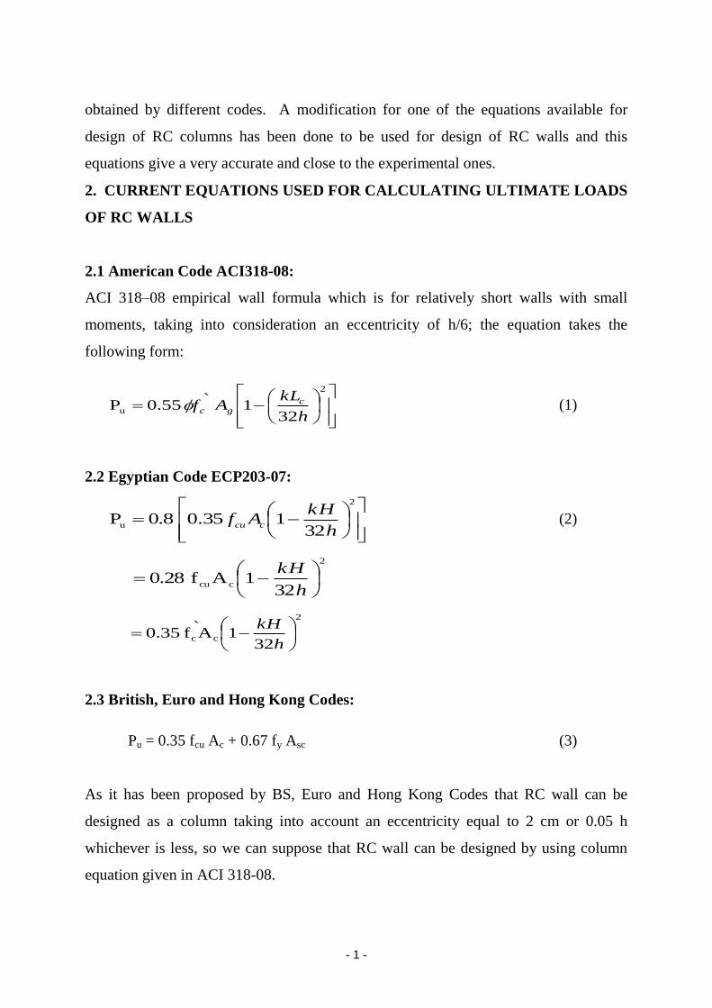
ACI 318–08 empirical wall formula which is for relatively short walls with small
moments, taking into consideration an eccentricity of h/6; the equation takes the
following form:
2
u32
1` 0.55 Ph
kLAf c
gc (1)
2.2 Egyptian Code ECP203-07:
2
u32
135.0 0.8 Ph
kHAf
ccu (2)
32
1Af0.28
2
ccu
h
kH
32
1A`f0.35
2
cc
h
kH
2.3 British, Euro and Hong Kong Codes:
Pu = 0.35 fcu Ac + 0.67 fy Asc (3)
As it has been proposed by BS, Euro and Hong Kong Codes that RC wall can be
designed as a column taking into account an eccentricity equal to 2 cm or 0.05 h
whichever is less, so we can suppose that RC wall can be designed by using column
equation given in ACI 318-08.

- 2 -
2.4 ACI 318-08 Tied Column Equation:
Pu= 0.8 [0.85 `cf (Ag-Ast) + fy Ast] (4)
For tied column =0.65
Pu = 0.442 `cf (Ag-Ast) + 0.52fy Ast (4-1)
Taking into account that `cf = 0.8 fcu
Equation (4) then becomes
Pu= 0.3536 fcu (Ag-Ast) + 0.52 fy Ast (4-2)
If we did not take into account accidental eccentricity equation (4) takes the two
following forms:
Pu= 0.5525 f`c (Ag-Ast) + 0.65 fy Ast (5)
Pu= 0.442 fcu (Ag-Ast) + 0.65 fy Ast (6)
As a suggestion for our new equation the factor 0.5 were used instead of 0.5525 or
0.442, so the proposed equation takes the form
Pu= 0.5 fcu (Ag-Ast) + 0.65 fy Ast (7)
Based on equation (7) the ultimate load of 24 tests of RC walls in one way in plane
action with an eccentricity h/6 and hinged conditions at top and bottom of the panel for
different parameters that influence the ultimate strength, which include aspect ratio
(h/L), slenderness ratio (h/t) and amounts of steel in vertical and horizontal direction
(v, h).
Typical arrangement of reinforcement is shown in Fig 1. Details of reinforcement and
yield strength of bars are shown Table 2. The load was uniformly distributed over the
length of the panel an applied at eccentricity equal to one six of the panel thickness.
The panel reinforcement was placed in two layers, symmetrically, on the two faces for
effective resistance to eccentric loading.

- 3 -
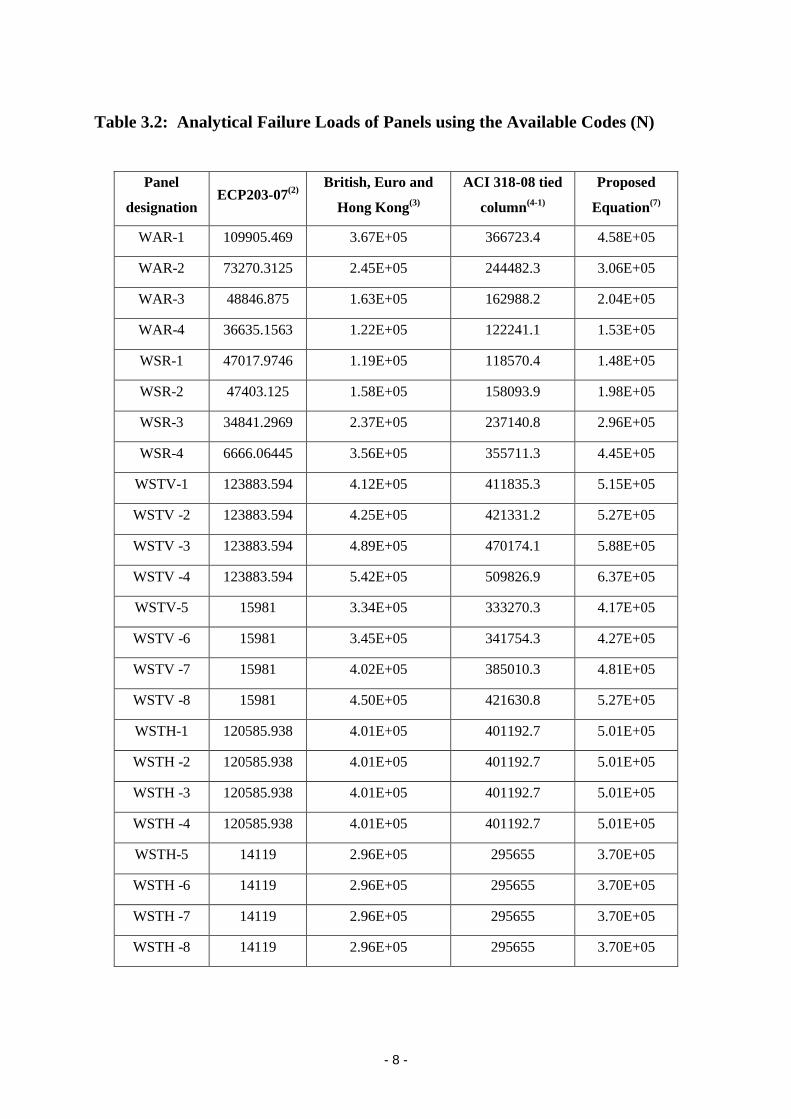
Calculated ultimate loads of RC panels using the different mentioned equations given
by different codes and by the new proposed equation are given in Table 3. From the
Table it is very clear that no one of the equations given by different codes match well
with the experimental results and only the new proposed equation gives an excellent
prediction of the ultimate load of RC panels. Also the proposed equation predicted
values have very strong correlation with the experimental ones as the coefficient of
correlation Rsqr = 0.953 which is almost equal to unity.
The maximum difference of the experimental values from those obtained by the
proposed equation is 18.7% and 45%, other values are practically equal and by the
ACI equation is 37% to 93% and by ACI column equation is 1% to 80% also this
difference for BS and Euro Codes are in the range of 5% to 80% and for the Egyptian
Code of Practice is 400% to 3100%.
F. 1. Arrangement of Reinforcement in Panels
L=900 mm
h=
60
0 m
m
10 mm
Sectional front elevation
2 mm bars 11 nos. on each face
3 mm bars 4 nos. on each face
Sectional plan
50m
m
Sectional side view
t=50mm
2 mm bars 11 nos.
3 mm bars 4 nos.
2 mm bars 11 nos. equally spaced 10mmcover

- 4 -
Table 1: Effective Length factors for Load -bearing walls
1- Walls braced top and bottom against translation and
(a) Restrained against rotation at one both ends (top and/or bottom) 0.80
(b) Not restrained against rotation at either end 1.0
2- For walls not braced against lateral transition 2.5

- 5 -
Table 2.1: details of tested panels
Variable
Considered
Panel
designation
Size of panel
hLt
(mm)
h/L h/t fcu
(MPa)
(a) WAR Series
Aspect
ratio
WAR-1 600×900×50 0.67 12 22.33
WAR-2 600×600×50 1 12 22.33
WAR-3 600×400×50 1.5 12 22.33
WAR-4 600×300×50 2 12 22.33
(b) WSR Series
Slenderness
ratio
WSR-1 450×300×50 1.50 9 21.67
WSR-2 600×400×50 1.50 12 21.67
WSR-3 900×600×50 1.50 18 21.67
WSR-4 1350×900×50 1.50 27 21.67
(c) WSTV-I Series
Vertical
reinforcement
WSTV-1 600×900×50 0.67 12 25.17
WSTV -2 600×900×50 0.67 12 25.17
WSTV -3 600×900×50 0.67 12 25.17
WSTV -4 600×900×50 0.67 12 25.17
(d) WSTV-II Series
Vertical
reinforcement
WSTV-5 1200×800×50 1.50 24 22.83
WSTV -6 1200×800×50 1.50 24 22.83
WSTV -7 1200×800×50 1.50 24 22.83
WSTV -8 1200×800×50 1.50 24 2.83
(e) WSTH-I Series
Horizontal
reinforcement
WSTH-1 600×900×50 0.67 12 24.50
WSTH -2 600×900×50 0.67 12 24.50
WSTH -3 600×900×50 0.67 12 24.50
WSTH -4 600×900×50 0.67 12 24.50
(f) WSTH-II Series
Horizontal
reinforcement
WSTH-5 1200×800×50 1.50 24 20.17
WSTH -6 1200×800×50 1.50 24 20.17
WSTH -7 1200×800×50 1.50 24 20.17
WSTH -8 1200×800×50 1.50 24 20.17

- 6 -
Table 2.2: details of tested panels
Variable
Considered
Panel
designation
Vertical Steel Horizontal Steel
Failure
Load
(kN)
Bars
in
one
layer
fy
(MPa)
(%)
Bars
in
one
layer
fy
(MPa)
(%)
(a) WAR Series
Aspect
ratio
WAR-1 2-
11a
297 0.173 3-4 286 0.199 484.27
WAR-2 2-7 297 0.173 3-4 286 0.199 314.8
WAR-3 2-5 297 0.173 3-4 286 0.199 198.29
WAR-4 2-4 297 0.173 3-4 286 0.199 147.4
(b) WSR Series
Slenderness
ratio
WSR-1 2-4 297 0.165 3-3 286 0.199 214.18
WSR-2 2-5 297 0.165 3-4 286 0.199 254.1
WSR-3 2-7 297 0.165 3-6 286 0.199 298.92
WSR-4 2-11 297 0.165 3-9 286 0.199 373.65
(c) WSTV-I Series
Vertical
reinforcement
WSTV-1 2-11 297 0.173 3-4 286 0.199 N/A
WSTV -2 3-10 286 0.331 3-4 286 0.199 534.07
WSTV -3 4-9 581 0.528 3-4 286 0.199 583.52
WSTV -4 5-10 570 0.845 3-4 286 0.199 704.14
(d) WSTV-II Series
Vertical
reinforcement
WSTV-5 2-10 297 0.177 3-8 286 0.199 338.73
WSTV -6 3-9 286 0.335 3-8 286 0.199 398.56
WSTV -7 4-8 581 0.528 3-8 286 0.199 463.28
WSTV -8 5-9 570 0.856 3-8 286 0.199 503.1
(e) WSTH-I Series
Horizontal
reinforcement
WSTH-1 2-11 297 0.173 3-4 286 0.199 N/A
WSTH -2 2-11 297 0.173 4-4 581 0.352 538.10
WSTH -3 2-11 297 0.173 4-5 581 0.440 528.11
WSTH -4 2-11 297 0.173 5-4 570 0.507 528.11
(f) WSTH-II Series
Horizontal
reinforcement
WSTH-5 2-10 297 0.176 3-8 286 0.199 N/A
WSTH -6 2-10 297 0.176 4-8 581 0.352 348.74
WSTH -7 2-10 297 0.176 4-10 581 0.440 343.74
WSTH -8 2-10 297 0.176 5-8 570 0.507 348.74

- 7 -
Table 3.1: Analytical Failure Loads of Panels using the Available Codes(N)
ACI318-
08(1)
L Pv h k t fy fcu Panel
designation
11910.94 900 1.73E-03 600 1 50 297 22.33 WAR-1
7940.625 600 1.73E-03 600 1 50 297 22.33 WAR-2
5293.75 400 1.73E-03 600 1 50 297 22.33 WAR-3
3970.313 300 1.73E-03 600 1 50 297 22.33 WAR-4
4254.551 300 1.65E-03 450 1 50 297 21.67 WSR-1
5293.75 400 1.65E-03 600 1 50 297 21.67 WSR-2
6316.406 600 1.65E-03 900 1 50 297 21.67 WSR-3
3992.871 900 1.65E-03 1350 1 50 297 21.67 WSR-4
11910.94 900 1.73E-03 600 1 50 297 25.17 WSTV-1
11910.94 900 3.31E-03 600 1 50 286 25.17 WSTV -2
11910.94 900 5.28E-03 600 1 50 581 25.17 WSTV -3
11910.94 900 8.45E-03 600 1 50 570 25.17 WSTV -4
5390 800 1.77E-03 1200 1 50 297 22.83 WSTV-5
5390 800 3.35E-03 1200 1 50 286 22.83 WSTV -6
5390 800 5.28E-03 1200 1 50 581 22.83 WSTV -7
5390 800 8.56E-03 1200 1 50 570 22.83 WSTV -8
11910.94 900 1.73E-03 600 1 50 297 24.5 WSTH-1
11910.94 900 1.73E-03 600 1 50 297 24.5 WSTH -2
11910.94 900 1.73E-03 600 1 50 297 24.5 WSTH -3
11910.94 900 1.73E-03 600 1 50 297 24.5 WSTH -4
5390 800 1.76E-03 1200 1 50 297 20.17 WSTH-5
5390 800 1.76E-03 1200 1 50 297 20.17 WSTH -6
5390 800 1.76E-03 1200 1 50 297 20.17 WSTH -7
5390 800 1.76E-03 1200 1 50 297 20.17 WSTH -8
- 8 -
Table 3.2: Analytical Failure Loads of Panels using the Available Codes (N)
Proposed
Equation(7)
ACI 318-08 tied
column(4-1)
British, Euro and
Hong Kong(3)
ECP203-07
(2) Panel
designation
4.58E+05 366723.4 3.67E+05 109905.469 WAR-1
3.06E+05 244482.3 2.45E+05 73270.3125 WAR-2
2.04E+05 162988.2 1.63E+05 48846.875 WAR-3
1.53E+05 122241.1 1.22E+05 36635.1563 WAR-4
1.48E+05 118570.4 1.19E+05 47017.9746 WSR-1
1.98E+05 158093.9 1.58E+05 47403.125 WSR-2
2.96E+05 237140.8 2.37E+05 34841.2969 WSR-3
4.45E+05 355711.3 3.56E+05 6666.06445 WSR-4
5.15E+05 411835.3 4.12E+05 123883.594 WSTV-1
5.27E+05 421331.2 4.25E+05 123883.594 WSTV -2
5.88E+05 470174.1 4.89E+05 123883.594 WSTV -3
6.37E+05 509826.9 5.42E+05 123883.594 WSTV -4
4.17E+05 333270.3 3.34E+05 15981 WSTV-5
4.27E+05 341754.3 3.45E+05 15981 WSTV -6
4.81E+05 385010.3 4.02E+05 15981 WSTV -7
5.27E+05 421630.8 4.50E+05 15981 WSTV -8
5.01E+05 401192.7 4.01E+05 120585.938 WSTH-1
5.01E+05 401192.7 4.01E+05 120585.938 WSTH -2
5.01E+05 401192.7 4.01E+05 120585.938 WSTH -3
5.01E+05 401192.7 4.01E+05 120585.938 WSTH -4
3.70E+05 295655 2.96E+05 14119 WSTH-5
3.70E+05 295655 2.96E+05 14119 WSTH -6
3.70E+05 295655 2.96E+05 14119 WSTH -7
3.70E+05 295655 2.96E+05 14119 WSTH -8

- 9 -
Table 4: Ratios between Experimental and Analytical Failure Loads
Exp/(7) Exp/(6) Exp/(4-2) Exp/(3) Exp/(2) Exp/(1) Experimental
(kN)
Panel
designation
1.06 1.20 1.320532 1.32 4.406241 40.65759 484.27 WAR-1
1.03 1.17 1.287619 1.29 4.29642 39.64423 314.8 WAR-2
9.73E-01 1.10 1.216591 1.22 4.05942 37.45738 198.29 WAR-3
9.65E-01 1.09 1.205813 1.20 4.023458 37.12554 147.4 WAR-4
1.45 1.63 1.806353 1.80 4.555279 50.34139 214.18 WSR-1
1.29 1.45 1.607273 1.61 5.360406 48 254.1 WSR-2
1.01 1.14 1.260517 1.26 8.579474 47.32438 298.92 WSR-3
8.40E-01 9.51E-01 1.050431 1.05 56.05256 93.57928 373.65 WSR-4
N/A N/A N/A N/A N/A N/A N/A WSTV-1
1.01 1.15 1.267578 1.26 4.311063 44.83862 534.07 WSTV -2
9.93E-01 1.12 1.241072 1.19 4.710228 48.99027 583.52 WSTV -3
1.10 1.25 1.381136 1.30 5.683884 59.11709 704.14 WSTV -4
8.13E-01 9.20E-01 1.016382 1.02 21.1958 62.84416 338.73 WSTV-5
9.33E-01 1.06 1.166218 1.15 24.93962 73.94434 398.56 WSTV -6
9.63E-01 1.09 1.203292 1.15 28.98942 85.95176 463.28 WSTV -7
9.55E-01 1.08 1.193224 1.12 31.48113 93.33952 503.1 WSTV -8
N/A N/A N/A N/A N/A N/A N/A WSTH-1
1.07 1.21 1.341026 1.34 4.461631 45.16941 538.10 WSTH -2
1.05 1.19 1.31635 1.32 4.379532 44.33824 528.11 WSTH -3
1.05 1.19 1.31635 1.32 4.379532 44.33824 528.11 WSTH -4
N/A N/A N/A N/A N/A N/A N/A WSTH-5
9.44E-01 1.07 1.179551 1.18 24.70005 64.7013 348.74 WSTH -6
9.30E-01 1.05 1.162639 1.16 24.34592 63.77365 343.74 WSTH -7
9.44E-01 1.07 1.179551 1.18 24.70005 64.7013 348.74 WSTH -8

- 10 -
CONCLUSIONS
According the discussion mentioned above, it is clear that all the existing formulas for
predicting ultimate load of RC wall are not correct at all and a new much more
accurate equation is proposed which is working properly.
REFERENCES
[1] S. Madina Saheb and Prakash Desayi, “Ultimate Strength of RC Wall Panels in
One Way in Plane Action”, ASCE, JSED, Vol. 115, No. 10, October, 1989
[2] Jack C McCormac, James K Nelson, "Reinforced Concrete Design",7th
edition,
2006
[3] ACI 318-08 Metric Units
[4] Reinforced Concrete Code of Practice, Housing Dept. May 2008, Hong Kong
[5] British Code of Practice of Reinforced Concrete
[6] Euro Code of Practice of Reinforced Concrete
LIST OF SYMBOLS
Pu = Ultimate Load
= 0.7
Lc = vertical distance between supports
h = overall thickness of wall
k = effective length factor determined in accordance with the values given in
Table 1.
f`c = cylinder strength
Ag = gross sectional area of wall section
fcu = Cube strength
Ac = gross sectional area of wall cross section
H = vertical distance between supports
fy = steel yield strength
Asc = area of reinforcement steel
Ast = area of reinforcing steel
= 0.65 for tied column

- 11 -
:مخلص البحث
للحوائط الخرسانية المعرضة لألنحناء األقصىيهدف البحث إلى دراسة المعادالت الخاصة لحساب الحمل الرأسي
42واحد طبقا لألكواد المختلفة بما فيها الكود المصري ومقارنة نتائج هذه المعادالت مع القيم الناتجة من اتجاهفي
.قطاعات وتسليح ونسبة نحافة مختلفة تجربة تحميل لحوائط خرسانية بأبعاد و
للحوائط ى ومن هذه المقارنة تم الخلوص إلى أن المعادالت الحالية ال تعطي قيما دقيقة للحمل الرأسي األقص
ووجد أنها تعطي نتائج ى الخرسانية ومن ثم تم استنتاج معادلة دقيقة وعملية في نفس الوقت لحساب الحمل األقص
.العملية من قيم التجارب المعملية قريبة جداً من الناحية
Copyright © 2022 FDOKUMEN