Appendix A Derivation of OTA GBW Requirement
22
Appendix A Derivation of OTA GBW Requirement The small signal model for an SC amplifier in hold mode is shown in Figure A.1, where the OTA is represented with a single pole model consisting of and The capacitance is the sum of the OTA output capacitance and the external load capacitance. The capacitance at the OTA input is represented with and the output conductance with This circuit is used to find out the settling time constant using a pulsed current source as the excitation signal. The small signal analysis yields the following transfer function: where The output voltage for a current impulse with total integrated charge Q can be written (in partial fraction form) as 233
-
Upload
khangminh22 -
Category
Documents
-
view
4 -
download
0
Transcript of Appendix A Derivation of OTA GBW Requirement

Appendix ADerivation of OTA GBW Requirement
The small signal model for an SC amplifier in hold mode is shown in Figure A.1, where theOTA is represented with a single pole model consisting of and The capacitanceis the sum of the OTA output capacitance and the external load capacitance. The capacitance atthe OTA input is represented with and the output conductance with
This circuit is used to find out the settling time constant using a pulsed current source asthe excitation signal. The small signal analysis yields the following transfer function:
where The output voltage for a current impulse with total integrated chargeQ can be written (in partial fraction form) as
233

234 CIRCUIT TECHNIQUES FOR LOW-VOLTAGE AND HIGH-SPEED ADCS
The corresponding time domain expression is obtained with the inverse Laplace transform, giving
from where the settling time constant can be identified as
Since is large compared to the time constant can be approximated with
A well-known relation states that the gain-bandwidth product of a single-pole OTA is
Substituting this to (A.5) yields
When the last term resulting from the feed-forward path is ignored in (A.3), the output settles toN-bit accuracy in the time period T if
which leads to the following requirement for the GBW:
The GBW can also be expressed in terms of the feedback factor andthe effective load capacitance [239], resulting in

Appendix BOptimum Input Capacitance
In this appendix an optimum value, which minimizes the settling time of an SC amplifier, willbe derived for OTA input transistor gate capacitance. In strong inversion the transconductanceof a MOS transistor is given by
Using the gate capacitance it can be rewritten as
The capacitance in Appendix A is now Again, from Appendix A the settling timeconstant (A.7) becomes
Finding the minimum time constant yields the optimum gate capacitance, which is given by
When the same analysis is repeated, assuming that the transistor is biased in the weak inver-sion, where the transconductance is given by
the settling time constant becomes
Now there is no optimum gate capacitance, but the settling time increases with (i.e. with Wwhen L is fixed).
235

236 CIRCUIT TECHNIQUES FOR LOW-VOLTAGE AND HIGH-SPEED ADCS
In velocity saturation the transconductance is given by
which results in the following settling time constant:
Again, there is no optimum gate capacitance. As opposed to the weak inversion case, the settlingtime now decreases with increasing (i.e with increasing W when L is fixed).
Appendix CSaturation Voltage
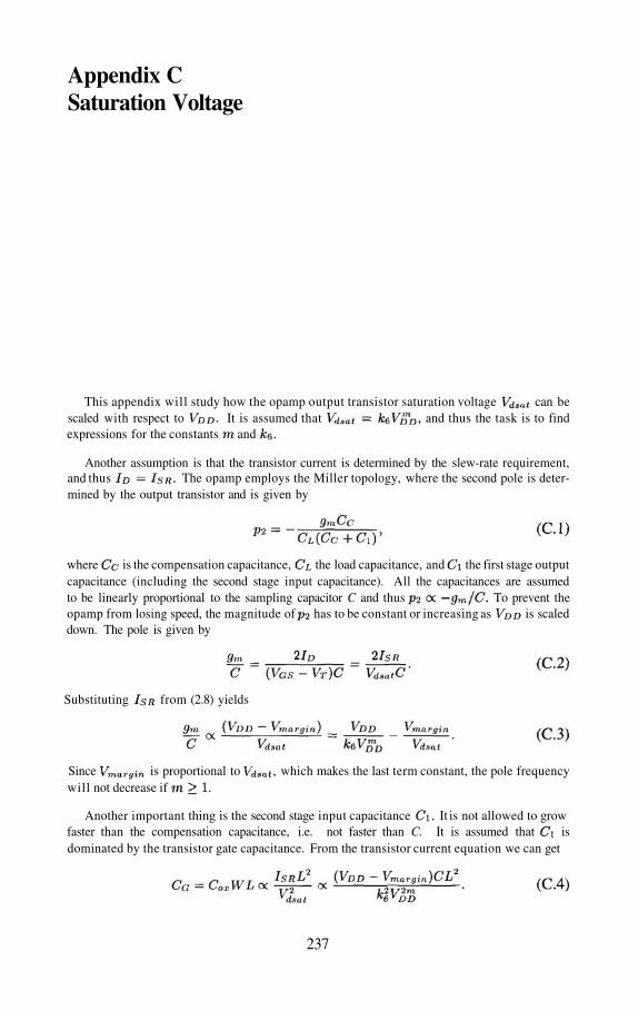
This appendix will study how the opamp output transistor saturation voltage can bescaled with respect to It is assumed that and thus the task is to findexpressions for the constants and
Another assumption is that the transistor current is determined by the slew-rate requirement,and thus The opamp employs the Miller topology, where the second pole is deter-mined by the output transistor and is given by
where is the compensation capacitance, the load capacitance, and the first stage outputcapacitance (including the second stage input capacitance). All the capacitances are assumedto be linearly proportional to the sampling capacitor C and thus To prevent theopamp from losing speed, the magnitude of has to be constant or increasing as is scaleddown. The pole is given by
Substituting from (2.8) yields
Since is proportional to which makes the last term constant, the pole frequencywill not decrease if
Another important thing is the second stage input capacitance It is not allowed to growfaster than the compensation capacitance, i.e. not faster than C. It is assumed that isdominated by the transistor gate capacitance. From the transistor current equation we can get
237

238 CIRCUIT TECHNIQUES FOR LOW-VOLTAGE AND HIGH-SPEED ADCS
For a given technology (fixed L) must be 0.5 or less, which conflicts with the earlier require-ment. If L scales linearly with the supply voltage, then which, together with the earlierrequirement, results in
So, it was wrong to assume that in the case of a fixed technology the output transistor sizeand current are always constrained by the slew rate. Writing the expression for the second poleagain yields
If is now allowed to grow as fast as possible by making it proportional to C, then willbe constant and the current wi l l need to be increased faster than required by the slew rate.
The above analysis is made for a Miller opamp, but the results are applicable to other opamptopologies as well. For example, in the folded cascode opamp the non-dominant pole is deter-mined by the of the cascode transistor and parasitic capacitances that are proportional to thegate capacitance. Thus, an analysis of it would yield similar results.

References
[1] M. Waltari, L. Sumanen, T. Korhonen, K. Halonen, “A Self-Calibrated Pipeline ADCwith 200MHz IF-sampling Frontend,” 2002 IEEE International Solid-Slate CircuitsConference Digest of Technical Papers, pp. 314–315, Feb. 2002.
[2] M. Waltari, K. Halonen, “Bootstrapped switch without bulk effect in standard CMOStechnology,” IEE Electronics Letters, vol. 38, no. 12, pp. 555–557, Jun. 6, 2002.
[3] M. Waltari, K. Halonen, “1-V 9-Bit Pipelined Switched-Opamp ADC,” IEEE J. Solid-State Circuits, vol. 36, pp. 129–134, Jan. 2001.
[4] M. Waltari, K. Halonen, “1.0-Volt, 9-bit Pipelined CMOS ADC,” in proc 26th EuropeanSolid-State Circuits Conference, pp. 360–363, Sep. 2000.
[5] L. Sumanen, M. Waltari, K. Halonen, “A 10-bit 200 MS/s CMOS Parallel Pipeline A/DConverter,” IEEE J. Solid-State Circuits, vol. 36, pp. 1048–1055, Jul. 2001.
[6] L. Sumanen, M. Waltari, K. Halonen, “A 10-bit 200 MS/s CMOS Parallel Pipeline A/DConverter,” in proc 26th European Solid-State Circuits Conference, pp. 440–443, Sep.2000.
[7] M. Waltari, K. Halonen, “Fully differential switched opamp with enhanced commonmode feedback,” IEE Electronics Letters, vol. 34, no. 23, pp. 2181–2182, Nov. 12,1998.
[8] M. Waltari, K. Halonen, “An 8-bit Low-Voltage Pipelined ADC Utilizing Switched-Opamp Technique,” in Proceedings of the 25th European Solid-State Circuits Confer-ence, pp. 174–177, Sep. 1999.
[9] M. Waltari, K. Halonen, “Timing Skew Insensitive Switching for Double-Sampled Cir-cuits,” in proc IEEE International Symposium on Circuits and Systems, vol. II, pp. 61–64,May 1999.
[10] M. Waltari, K. Halonen, “A 220-MSample/s CMOS Sample-and-Hold Circuit UsingDouble-Sampling,” Analog Integrated Circuits and Signal Processing, vol. 18, pp. 21–31, Jan. 1999.
239

240 CIRCUIT TECHNIQUES FOR LOW-VOLTAGE AND HIGH-SPEED ADCS
[11] M. Waltari, K. Halonen, “A 10-bit 220-MSample/s CMOS Sample-and-Hold Circuit,”in proc. IEEE International Symposium on Circuits and Systems, vol. I, pp. 253-256,May 1998.
[12] M. Waltari, K. Halonen, “A 10-bit, 130-Msample/s CMOS Sample-and-Hold circuit,”in proc. NORCHIP’97, pp. 31–35, 1997.
[13] M. Waltari, K. Halonen, “Reference Voltage Driver for Low-Voltage CMOS A/D Con-verters,” in proc IEEE International Conference on Electronics, Circuits and Systems,pp. 28–31, Dec. 2000.
[14] M. Waltari, J. Pirkkalaniemi, L. Sumanen, M. Kosunen, K. Halonen, “A 14-Bit, 40-MS/sDAC with Current Mode Deglitcher,” in proc. NORCHIP’01, pp. 210–215, Nov. 2001.
[15] J. Pirkkalaniemi, M. Waltari, L. Sumanen, M. Kosunen, K. Halonen, “A 14-Bit, 40-MS/sDAC with Current Mode Deglitcher,” IEEE International Symposium on Circuits andSystems, vol. I, pp. 121–124, May 2002.
[16] International Technology Roadmap for Semiconductors, Semiconductor Industry Asso-ciation, 1999.
[17] K. Bult, “Analog Design in Deep Sub-Micron CMOS,” in Proceedings of the 26thEuropean Solid-State Circuits Conference, pp. 11–17, Sep. 2000.
[18] R. Castello, P. R. Gray, “Performance Limitations in Switched-Capacitor Filters,” IEEETrans. Circuits and Systems, vol. CAS-32, pp. 865–876, Sep. 1985.
[19] G. Groenewold, “Optimal Dynamic Range Integrators,” IEEE Trans. Circuits andSystems–I, vol. 39, pp. 614–627, Aug. 1992.
[20] A-J. Annema, “Analog Circuit Performance and Process Scaling,” IEEE Trans. Circuitsand Systems–II, vol. 46, pp. 711–725, Jun. 1999.
[21] F. Maloberti, F. Francesconi, P. Malcovati, O. J. A. P. Nys, “Design Considerations onLow-Voltage Low-Power Data Converters,” IEEE Trans. Circuits and Systems–I, vol.42, pp. 653–863, Nov. 1995.
[22] R. Castello, F. Montecchi, F. Rezzi, A. Baschirotto, “Low-VoltageAnalog Filters,” IEEETrans. Circuits and Systems–I, vol. 42, pp. 827–840, Nov. 1995.
[23] A. Matsuzawa, “Low-Voltage and Low-Power Circuit Design for Mixed Analog/DigitalSystems in Portable Equipment,” IEEE J. Solid-State Circuits, vol. 29, pp. 470–480,Apr. 1994.
[24] B. J. Hosticka, W. Brockherde, D. Hammerschmidt, R. Kokozinski, “Low-VoltageCMOS Analog Circuits,” IEEE Trans. Circuits and Systems–I, vol. 42, pp. 864–872,Nov. 1995.
[25] E. A. Vittoz, “Low-Power Design: WAys to Approach the Limits,” in Dig. Tech. PapersInternational Solid-State Circuits Conference, pp. 14–18, Feb. 1994.
[26] SOI CMOS Technology, devices and circuits for low-power low-voltage analog andmicrowave applications, Euro Practice Analog Training Course, 1999.

REFERENCES 241
[27] K-Y. Toh, P-K. Ko, R. G. Meyer, “An Engineering Model for Short-Channel MOSDevices,” IEEE J. Solid-State Circuits, vol. 23, pp. 950–958, Aug. 1988.
[28] W. Sansen, “Analog Circuit Design inScaled CMOS Technology,” in Symposium onVLSI Circuits Dig. of Tech. Papers, pp. 8–11, 1996.
[29] W. Sansen, M. Steyaert, V. Peluso, E. Peeters, “Toward Sub 1V Analog IntegratedCircuits in Submicron Standard CMOS Technologies,” in Dig. Tech. Papers InternationalSolid-State Circuits Conference, pp. 186–187, Feb. 1998.
[30] K. B. Lakshmikumar, R. A. Hadaway, M. A. Copeland, “Characterization and Modellingof Mismatch in MOS Transistors for Precision Analog Design,” IEEE J. Solid-StateCircuits, vol. SC-21, pp. 1057–1066, Dec. 1986.
[31] M. J. Pelgrom, A. C. J. Duinmaijer, A. P. Welbers, “Matching Properties of MOS Tran-sistors,” IEEE J. Solid-State Circuits, vol. 24, pp. 1433–1440, Oct. 1989.
[32] M.Steyaert, K. Uyttenhove, “Speed-Power-Accuracy Trade-off In high-speed Analog-to-digital converters: Now and in the future ...,” in Workshop on Advances in AnalogCircuit Design, April 2000
[33] M. Steyaert, V. Peluso, J. Bastos, P. Kinget, W. Sansen, “Custom Analog Low PowerDesign: The problem of low voltage and mismatch,” in Proc. IEEE Custom IntegratedCircuits Conference, pp. 285-292, 1997.
[34] J. Crols, M. Steyaert, “Switched-opamp: an approach to realize full CMOS switchedcapacitor circuits at very low power supply voltages,” IEEE J. Solid-State Circuits, vol.29, pp. 936–924, Aug. 1994.
[35] R. van de Plassche, Integrated Analog-to-Digital and Digital-to-Analog Converters,Kluwer Academic Publishers, 1994.
[36] B. Razavi, Principles of Data Conversion System Design, IEEE Press, 1995.
[37] S. Lindfors, CMOS Baseband Integrated Circuit Techniques for Radio Receivers, Doc-toral Thesis, Helsinki University of Technology, Jul. 2000.
[38] M. Sauerwald, “Effects of Aperture Time and Jitter in a Sampled Data System,” NationalSemiconductor Corporation, Application note AD-03, 1994.
[39] M. Shinagawa, Y. Akazawa, T. Wakimoto, “Jitter Analysis of High-Speed SamplingSystems,” IEEE J. Solid-State Circuits, vol. 25, pp. 220–224, Feb. 1990.
[40] R. Gregorian, G. C. Temes, Analog MOS Integrated Circuits for Signal Processing, JohnWiley & Sons, Inc. 1986.
[41] K. R. Stafford, P. R. Gray, R. A. Blanchard, “A Complete Monolithic Sample/HoldAmplifier,” IEEE J. Solid-State Circuits, vol. SC-9, pp. 381–387, Dec. 1974.
[42] M. Nayebi, B. A. Wooley, “A 10-bit Video BiCMOS Track-and-Hold Amplifier,” IEEEJ. Solid-State Circuits, vol. 24, pp. 1507–1516, Dec. 1989.
[43] K. Kattmann, J. Barrow, “A Technique for Reducing Differential Nonlinearity Errors inFlash A/D Converters,” in Dig. Tech. Papers International Solid-State Circuits Confer-ence, pp. 170–171, Feb. 1991.
242 CIRCUIT TECHNIQUES FOR LOW-VOLTAGE AND HIGH-SPEED ADCS
[44] K. Bult, A. Buchwald, “An Embedded 240-mW 10-b 50-MS/s CMOS ADC in 1mm2,”IEEE J. Solid-State Circuits, vol. 32, pp. 1887–1895, Dec. 1997.
[45] H. Kimura, A. Matsuzawa, T. Nakamura, S. Sewada, “A 10-b 300-MHz Interpolated-Parallel A/D Converter,” IEEE J. Solid-State Circuits, vol. 28, pp. 438–446, Apr. 1993.
[46] M. Choi, A. A. Abidi, “A 6b 1.3GSample/s A/D Converter in CMOS,” in Dig.Tech. Papers International Solid-State Circuits Conference, pp. 126–127, Feb. 2001.
[47] G. Geelen, “A 6b l.lGSample/s CMOS A/D Converter,” in Dig. Tech. Papers Interna-tional Solid-State Circuits Conference, pp. 128–129, Feb. 2001.
[48] A. G. Dingwall, V. Zazzu, “An 8-MHz CMOS subranging 8-Bit A/D converter,” IEEEJ. Solid-State Circuits, vol. SC-20, pp. 1138–1143, Dec. 1985.
[49] R. C. Taft, M. R. Tursi, “A 100-MS/s 8-b CMOS Subranging ADC with SustainedParametric Performance from 3.8 V Down to 2.2 V,” IEEE J. Solid-State Circuits, vol.36, pp. 331–338, Mar. 2001.
[50] H. van der Ploeg, G. Hoogzaad, H. A. H. Termeer, M. Vertregt, R. L. J. Rooves, “A 2.5V12b 54MSample/s CMOS ADC in in Dig. Tech. Papers InternationalSolid-State Circuits Conference, pp. 132–133, Feb. 2001.
[51] B. Nauta, A. G. W. Venes, “A 70-MS/s 110-mW 8-b CMOS Folding and InterpolatingA/D Converter,” IEEE J. Solid-State Circuits, vol. 30, pp. 1302–1308, Dec. 1995.
[52] A. G. W. Venes, R. J. van de Plassche, “An 80-MHz, 80-mW 8-b CMOS Folding A/DConverter with Distributed Track-and-Hold Preprocessing,” IEEE J. Solid-State Circuits,vol. 31, pp. 1846–1853, Dec. 1996.
[53] P. Vorenkamp, R. Roovers, “A 12-b, 60-MSample/s Cascaded Folding and InterpolatingADC,” IEEE J. Solid-State Circuits, vol. 32, pp. 1876–1886, Dec. 1997.
[54] M.-J. Choe, B.-S. Song, K. Bacrania, “A 13-b 40-MSample/s CMOS Pipelined FoldingADC with Background Offset Trimming,” IEEE J. Solid-State Circuits, vol. 35, pp.1781–1790, Dec. 2000.
[55] Y.-T. Wang, B. Razavi, “An 8-Bit 150-MHz CMOS A/D Converter,” IEEE J. Solid-StateCircuits, vol. 35, pp. 308–317, Mar. 2000.
[56] M. P. Flynn, B. Sheahan, “A 400-Msample/s. 6-b CMOS Folding and InterpolatingADC,” IEEE J. Solid-State Circuits, vol. 33, pp. 1132–1938, Dec. 1998.
[57] S. H. Lewis, P. R. Gray, “A Pipelined 5-Msample/s 9-bit Analog-to-Digital Converter,”IEEE J. Solid-State Circuits, vol. sc-22, pp. 954–961, Dec. 1987.
[58] D. Macq, P. G. A. Jespers, “A 10-Bit Pipelined Switched-Current A/D Converter,” IEEEJ. Solid-State Circuits, vol. 29, pp. 967–971, Aug. 1994.
[59] C.-Y. Wu, C.-C. Chen, J.-J. Cho, “A CMOS Transitor-Only 8-b 4.5-Ms/s PipelinedAnalog-to-Digital Conveter Using Fully-Differential Current-Mode Circuit Tech-niques,” IEEE J. Solid-State Circuits, vol. 30, pp. 522–532, May 1995.
[60] B. Ginetti, P. Jespers, “A 1.5 MS/s 8-bit Pipelined RSD A/D Converter,” ESSCIRC Dig.Tech. Papers, pp. 137–140, Sep. 1990.

REFERENCES 243
[61] B. Ginetti, P. G. A. Jespers, A. Vandemeulebroecks, “A CMOS 13-b cyclic RSD A/Dconverter,” IEEE J. Solid-State Circuits, vol. 27, pp. 957–965, Jul. 1992.
[62] S. H. Lewis, H. S. Fetterman, G. F. Gross, Jr., R. Ramachandran, T. R. Viswanathan, “A10-b 20-Msample/s Analog-to-Digital Converter,” IEEE J. Solid-State Circuits, vol. 27,pp. 351–358, Mar. 1992.
[63] E. G. Soenen, R. L. Geiger, “An Architecture and An Algorithm for Fully Digital Cor-rection of Monolithic Pipelined ADC’s,” IEEE Trans. Circuits and Systems–II, vol. 42,pp. 143–153, Mar. 1995.
[64] S. Sutarja, P. Gray, “A Pipelined 13-bit, 250-ks/s, 5-V Analog-to-Digital Converter,”IEEE J. Solid-State Circuits, vol. 23, pp. 1316–1323, Dec. 1988.
[65] P. C. Yu, H.-S. Lee, “A Pipelined A/D Conversion Technique with Near-Inherent Mono-tonicity,” IEEE Trans. Circuits and Systems–II, vol. 42, pp. 500–502, Jul. 1995.
[66] P. C. Yu, H.-S. Lee, “A 2.5-V, 12-b, 5-MSample/s Pipelined CMOS ADC,” IEEE J.Solid-State Circuits, vol. 31, pp. 1854–1861, Dec. 1996.
[67] P. W. Li, M. J. Chin, P. R. Gray, R. Castello, “A Ratio-Independent Algorithmic Analog-to-Digital Conversion Technique,” IEEE J. Solid-State Circuits, vol. SC-19, pp. 828–836,Dec. 1984.
[68] B.-S. Song, M. F. Tompsett, K. R. Lakshmikumar, “A 12-bit 1-Msample/s CapacitorError-Avaraging Pipelined A/D Converter,” IEEE J. Solid-State Circuits, vol. 23, pp.1324–1333, Dec. 1988.
[69] H.-S, Chen, B.-S. Song, K. Bacrania, “A 14-b 20-MSamples/s CMOS Pipelined ADC,”IEEE J. Solid-State Circuits, vol. 36, pp. 997–1001, Jun. 2001.
[70] Y. Chiu, “Inherently Linear Capacitor Error-Avaraging Techniques for Pipelined A/DConversion,” IEEE Trans. Circuits and Systems–II, vol. 47, pp. 229–232, Mar. 2000.
[71] T. B. Cho, P.R. Gray, “A 10 b, 20 Msample/s, 35 mW Pipeline A/D Converter,” IEEE J.Solid-State Circuits, vol. 30, pp. 166–172, Mar. 1995.
[72] D. W. Cline, P. R. Gray, “A Power Optimized 13-b 5 Msamples/s Pipelined Analog-to-Digital Converter in CMOS,” IEEE J. Solid-State Circuits, vol. 31, pp. 294–303,Mar. 1996.
[73] W. Yang, D. Kelly, I. Mehr, M. T. Sayuk, L. Singer, “A 3-V 340-mW 14-b 75-Msample/sCMOS ADC With 85-dB SFDR at Nyquist Input,” IEEE J. Solid-State Circuits, vol. 36,pp. 1931–1936, Dec. 2001.
[74] S. H. Lewis, “Optimizing the Stage Resolution in Pipelined, Multistage, Analog-to-Digital Converters for Video-Rate Applications,” IEEE Trans. Circuits and Systems–II,vol. 39, pp. 516–523, Aug. 1992.
[75] P. T. F. Kwok, H. C. Luong, “Power Optimization for Pipeline Analog-to-Digital Con-verters,” IEEE Trans. Circuits and Systems–II, vol. 46, pp. 549–553, May 1999.
[76] L. A. Singer, T. L. Brooks, “A 14-Bit 10-MHz Calibration-Free CMOS Pipelined A/DConverter,” Symposium on VLSI Circuits Digest of Technical Papers, pp. 94–95, 1996.

244 CIRCUIT TECHNIQUES FOR LOW-VOLTAGE AND HIGH-SPEED ADCS
[77] S.-U. Kwak, B.-S. Song, K. Bacrania, “A 15-b, 5-Msample/s Low-Spurious CMOSADC,” IEEE J. Solid-State Circuits, vol. 32, pp. 1866–1875, Dec. 1997.
[78] H.-S. Lee, D. A. Hodges, P. R. Gray, “A Self-Calibrating 15 Bit CMOS A/D Converter,”IEEE J. Solid-State Circuits, vol. SC-19, pp. 813–819, Dec. 1984.
[79] Y.-M. Lin, B. Kim, P. R. Gray, “A 13-b 2.5-MHz Self-Calibrated Pipelined A/D Converterin CMOS,” IEEE J. Solid-State Circuits, vol. 26, pp. 628–635, Apr. 1991.
[80] S.-H. Lee, B.-S. Song, “Digital-Domain Calibration for Multistep Analog-to-DigitalConverters,” IEEE J. Solid-State Circuits, vol. 27, pp. 1679–1688, Dec. 1992.
[81] A. N. Karanicolas, H.-S. Lee, K. L. Bacrania, “A 15-b 1-Msample/s Digitally Self-Calibrated Pipeline ADC,” IEEE J. Solid-State Circuits, vol. 28, pp. 1207–1215, Dec.1993.
[82] M. K. Mayes, S. W. Chin, “A 200 mW, 1 Msample/s, 16-b Pipelined A/D Converter withOn-Chip 32-b Microcontroller,” IEEE J. Solid-State Circuits, vol. 31, pp. 1862–1872,Dec. 1996.
[83] G.-C. Ahn, H.-C. Choi, S.-I. Lim, S.-H. Lee, C.-D. Lee, “A 12-b, 10-MHz, 250-mWCMOS A/D Converter,” IEEE J. Solid-State Circuits, vol. 31, pp. 2030–2035, Dec. 1996.
[84] I. E. Opris, L. D. Lewicki, B. C. Wong, “A Single-Ended 12-bit 20 Msample/s Self-Calibrating Pipeline A/D Converter,” IEEE J. Solid-State Circuits, vol. 33, pp. 1898–1903, Dec. 1998.
[85] J. M. Ingino, B. A. Wooley, “A Contunuously Calibrated 12-b, 10-MS/s, 3.3-V A/DConverter,” IEEE J. Solid-State Circuits, vol. 33, pp. 1920–1931, Dec. 1998.
[86] U.-K. Moon, B.-S. Song, “Background Digital Calibration Techniques for PipelinedADC’s,” IEEE Trans. Circuits and Systems–II, vol. 44, pp. 102–109, Feb. 1997.
[87] O. E. Erdogan, P. J. Hurst, S. H. Lewis, “A 12-b Digital-Background-Calibrated Algo-rithmic ADC with –90-dB THD,” IEEE J. Solid-State Circuits, vol. 34, pp. 1812–1820,Dec. 1999.
[88] T.-H. Shu, B.-S. Song, K. Bacrania, “A 13-b 10-Msample/s ADC Digitally Calibratedwith Oversampling Delta-Sigma Converter,” IEEE J. Solid-State Circuits, vol. 30, pp.443–452, Apr. 1995.
[89] I. Galton, “Digital Cancellation of D/A Converter Noise in Pipelined A/D Converters,”IEEE Trans. Circuits and Systems–II, vol. 47, pp. 185–196, Mar. 2000.
[90] W. C. Black, Jr., D. A. Hodges, “Time Interleaved Converter Arrays,” IEEE J. Solid-StateCircuits, vol. SC-15, pp. 1022–1029, Dec. 1980.
[91] C. S. G. Conroy, D. W. Cline, P. R. Gray, “An 8-b 85-MS/s Parallel Pipeline A/DConverter in CMOS,” IEEE J. Solid-State Circuits, vol. 28, pp. 447–454, Apr.1993.
[92] M. Yotsuyanagi, T. Etoh, K. Hirata, “A 10-b 50-MHz Pipelined CMOS A/D Converterwith S/H,” IEEE J. Solid-State Circuits, vol. 28, pp. 292–300, Mar. 1993.

REFERENCES 245
[93] K. Nakamura, M. Hotta, L. R. Carley, D. J. Allstot, “An 85 mW, 10 b, 40 Msample/sCMOS Parallel-Pipelined ADC,” IEEE J. Solid-State Circuits, vol. 30, pp. 173–183,Mar. 1995.
[94] K. Nagaraj, H. S. Fetterman, J. Anidjar, S. H. Lewis, R. G. Renninger, “A 250-mW, 8-b,52-Msamples/s Parallel-Pipelined A/D Converter with Reduced Number of Amplifiers,”IEEE J. Solid-State Circuits, vol. 32, pp. 312–320, Mar. 1997.
[95] W. Bright, “8b 75MSample/s 70mW Parallel Pipelined ADC Incorporating Double Sam-pling,” ISSCC Dig. Tech. Papers, pp. 146–147, Feb. 1998.
[96] K. Y. Kim, N. Kusayanagi, A. A. Abidi, “A 10-b, 100-MS/s CMOS A/D Converter.”IEEE J. Solid-State Circuits, vol. 32, pp. 302–311, Mar. 1997.
[97] K. C. Dyer, D. Fu, S. H. Lewis, P. J. Hurst, “An Analog Background Calibration Tech-nique for Time-Interleaved Analog-to-Digital Converters,” IEEE J. Solid-State Circuits,vol. 33, pp. 1912–1919, Dec. 1998.
[98]D. Fu, K. C. Dyer, S. H. Lewis, P. J. Hurst, “A Digital Background Calibration Techniquefor Time-Interleaved Analog-to-Digital Converters,” IEEE J. Solid-State Circuits, vol.33, pp. 1904–1911, Dec. 1998.
[99] T. Matsuura, T. Nara, T. Komatsu, E. Imaizumi, T. Matsutsuru, R. Horita, H. Katsu, S.Suzumura, K. Sato, “A 240-Mbps, 1-W CMOS EPRML Read-Channel LSI Chip Usingan Interleaved Subranging Pipeline A/D Converter,” IEEE J. Solid-State Circuits, vol.33, pp. 1840–1850, Nov. 1998.
[100] M. K. Mayes, S. W. Chin, L. L. Stoian, “A Low-power 1 MHz, 25 mW 12-Bit Time-Interleaved Analog-to-Digital Converter,” IEEE J. Solid-State Circuits, vol. 31, pp. 169–178, Feb. 1996.
[101] S. Lindfors, T Rahkonen, M. Waltari, “Digital Correction of Clock Skew in ParallelA/D Converters,” Prestudy report for Correction of Dynamic Errors in Data Converters(EXSITE research program), Sep. 2000.
[102] A. M. Abo, P. R. Gray, “A 1.5-V, 10-bit, 14-MS/s CMOS Pipeline Analog-to-DigitalConverter,” IEEE J. Solid-State Circuits, vol. 34, pp. 599–606, May 1999.
[103] B. Razavi, “ A 200-MHz 15-mW BiCMOS Sample-and-Hold Amplifier with 3 V Sup-ply,” IEEE J. Solid-State Circuits, vol. 30, pp. 1326–1332, Dec. 1995.
[104] P. Vorenkamp, J. P. M. Verdaasdonk, “Fully Bipolar, 120-Msample/s 10 -b Track-and-Hold Circuit,” IEEE J. Solid-State Circuits, vol. 27, pp. 988–992, Jul. 1992.
[105] B. Prégardier, U. Langmann, W. J. Hillery, “A 1.2-GS/s Silicon Bipolar Track&HoldIC,” IEEE J. Solid-State Circuits, vol. 31, pp. 1336–1339, Sep. 1996.
[106] T. Baumheinrich, B. Prégardier, U. Langmann, “A 1-GSample/s 10-b Full Nyquist Sili-con Bipolar Track&Hold IC,” IEEE J. Solid-State Circuits, vol. 32, pp. 1951–1960, Dec.1997.
[107] C. Fiocchi, U. Gatti, F. Maloberti, “A l0b 250MHz BiCMOS Track and Hold,” in 1997IEEE International Solid-State Circuits Conference, Dig. Tech. Pap, pp. 144–145, 1997.
246 CIRCUIT TECHNIQUES FOR LOW-VOLTAGE AND HIGH-SPEED ADCS
[108] A. N. Karanicolas, “A 2.7-V 300-MS/s Track-and-Hold Amplifier,” IEEE J. Solid-StateCircuits, vol. 32, pp. 1961–1967, Dec 1997.
[109] B. Razavi, “Design of a 100-MHz 10-mW 3-V Sample-and-Hold Amplifier in DigitalBipolar Technology,” IEEE J. Solid-State Circuits, vol. 30, pp. 724–730, Jul. 1995.
[110] K. Hadidi, M. Sasaki, T. Watanabe, D. Muramatsu, T. Matsumoto, “A 103MHz Open-Loop Full CMOS Highly-Linear Sample-and-Hold Amplifier,” in proc European Solid-State Circuits Conference, pp. 396–399, 1997.
[111] B. Razavi, “Design of Sample-and-Hold Amplifiers for High-Speed Low-Voltage A/DConverters,” in proc IEEE 1997 Custom Integrated Circuits Conference, pp. 59–66,1997.
[112] P. J. Lim, B. A. Wooley, “A High-Speed Sample-and-Hold Technique Using a MillerHold Capacitance,” IEEE J. Solid-State Circuits, vol. 26, pp. 643–651, Apr. 1991.
[113] “Applications of the CA3080 High-Performance Operational Transconductance Ampli-fiers,” Harris Semiconductor Application Note 6668, Nov. 1996.
[114] L. Dai, R. Harjani, “CMOS Switched-Opamp Based Sample-and-Hold Circuit,” in Proc.IEEE International Symposium on Circuits and Systems 1998, vol. I, pp. 476–479.
[115] M. Ishikawa, T. Tsukahara, “An 8-bit 50-MHz CMOS Subranging A/D Converter withPipelined Wide-Band S/H,” IEEE J. Solid-State Circuits, vol. 24, pp. 1485–1491, Dec.1989.
[116] L. Schillaci, A. Baschirotto, R. Castello, “A 3-V 5.4-mW BiCMOS Track&Hold Circuitwith Sampling Frequency up to 150 MHz,” IEEE J. Solid-State Circuits, vol. 32, pp.926–932, Jul. 1997.
[117] F.-J. Wang, G. C. Temes, “A Fast Offset-Free Sample-and-Hold Circuit,” in proc IEEE1988 Custom Integrated Circuits Conference, pp. 5.6.1–5.6.3, 1997.
[118] G. Nicollini, P. Confalonieri, D. Senderowicz, “A Fully Differential Sample-and-HoldCircuit for High-Speed Applications,” IEEE J. Solid-State Circuits, vol. 24, pp. 1461–1465, Oct. 1989.
[119] K. Y. Kim, A 10-bit, 100 MS/s Analog-to-Digital Converter in CMOS, Ph.D.Dissertation, University of California, Los Angeles, 1996.
[120] M. de Wit, “Sample and hold circuitry and methods,” U.S. Patent 5 170 075, TexasInstruments Inc., Dec. 8, 1992.
[121] B. J. Sheu, C. Hu, “Switch-Induced Error Voltage on a Switched Capacitor,” IEEE J.Solid-State Circuits, vol. sc-19, pp. 519–525, Aug. 1984.
[122] W. B. Wilson, H. Z. Massoud, E. J. Swanson, R. T. George, Jr., R. B. Fair, “Measurementand Modelling of Charge Feedthrough in n-Channel MOS Analog Switches,” IEEE J.Solid-State Circuits, vol. sc-20, pp. 1206–1213, Dec. 1985.
[123] B. J. Sheu, J-H. Shieh, M. Patil, “Modeling Charge Injection in MOS Analog Switches,”IEEE Trans. Circuits and Systems, vol. cas-34, pp. 214–216, Feb. 1987.

REFERENCES 247
[124] G. Wegmann, E .A. Vittoz, F. Rahali, “Charge Injection in Analog MOS Switches,”IEEE J. Solid-State Circuits, vol. sc-22, pp. 1091–1097, Dec. 1987.
[125] Manual, University of California, Berkeley, 1996.
[126] D. G. Haigh, B. Singh, “A switching scheme for switched capacitor filters which reducesthe effect of parasitic capacitances associated with switch control terminals,” in Proc.IEEE International Symposium on Circuits and Systems, pp. 586–589, 1983.
[127] P. E. Allen, D. R. Holberg, CMOS Analog Circuit Design, Holt, Rinehart and Winston,1987.
[128] S. S. Lum, W. C. Rempfer, “Circuits and Methods for Compensating Non-Linear Capac-itances to Minimize Harmonic Distortion,” U.S. Patent 5 763 924, Linear TechnologyCorporation, Jun. 9, 1998.
[129] T. B. Cho, Low-Power, Low-Voltage Analog-to-Digital Conversion Techniques usingPipelined Architectures, Ph.D. Dissertation, University of California, Berkeley, 1995.
[130] Y. Nakagome, H. Tanaka, K. Takeuchi, E. Kume, Y. Watanabe, T. Kaga, Y. Kawamoto, F.Murai, R. Izawa, D. Hisamoto, T. Kisu, T. Nishida, E. Takeda, K. Itoh, “An Experimental1.5-V 64-Mb DRAM,” IEEE J. Solid-State Circuits, vol. 26, pp. 465–478, Apr. 1991.
[131] C-Y. Wu, W-S. Wey, T-C Yu, “A 1.5 V CMOS Balanced Differential Switched-CapacitorFilter with Internal Clock Boosters,” in Proc. IEEE International Symposium on Circuitsand Systems, pp. 1025–1028, 1995.
[132] L. Singer, T. L. Brooks, “Two-Phase Bootstrapped CMOS Switch Drive Technique andCircuit,” U.S. Patent 6 118 326, Analog Devices Inc., Sep. 12, 2000.
[133] A. M. Abo, P. R. Gray, “A 1.5V, 10-bit, 14MS/s CMOS Pipeline Analog-to-DigitalConverter,” 1998 Symposium on VLSI Circuits Digest of Technical Papers, pp. 166–169.
[134] M. Dessouky, A. Kaiser, “Input switch configuration for rail-to-rail operation of switchedopamp circuits,” Electronics Letters, vol. 35, no. 1, pp. 8–10, Jan 1999.
[135] D. J. Sauer, “Constant Impedance Sampling Switch for an Analog to Digital Converter,”U.S. Patent 5 500 612, David Sarnoff Research Center Inc., Mar. 19, 1996.
[136] J. L. Gorecki, “Dynamic Input Sampling Switch for CDACS,” U.S. Patent 5 084 634,Burr-Brown Corporation, Jan. 28, 1992.
[137] J. R. Naylor, M. A. Shill, “Bootstrapped FET Sampling Switch,” U.S. Patent 5 172 019,Burr-Brown Corporation, Dec. 15, 1992.
[138] T. L. Brooks, D. H. Rebertson, D. F. Kelly, A. D. Muro, S. W. Harston, “A CascadedSigma-Delta A/D Converter with 1.25 MHz Signal Bandwidth and 89 dB SNR,” IEEEJ. Solid-State Circuits, vol. 32, pp. 1896–1906, Dec. 1997.
[139] L. Singer, T. L. Brooks, “Two-Phase Bootstrapped CMOS Switch Drive Technique andCircuit,” U.S. Patent 6 060 937, Analog Devices Inc., May 9, 2000.
[140] J. Blake, A. Gribben, C. Price, “Back Gate Switched Sample and Hold Circuit,” U.S.Patent 5 422 583, Jun. 6, 1995.

248 CIRCUIT TECHNIQUES FOR LOW-VOLTAGE AND HIGH-SPEED ADCS
[141] J. Steensgaard “Bootstrapped Low-Voltage Analog Switches,” in Proc. IEEE Interna-tional Symposium on Circuits and Systems, vol. II, pp. 29–32, 1999.
[142] H. Pan, M. Segami, M. Choi, J. Cao, A. Abidi, “A 3.3-V 12-b 50-MS/s A/D Converterin CMOS with over 80-dB SFDR,” IEEE J. Solid-State Circuits, vol. 35, pp.1769–1780, Dec. 2000.
[143] M. Dessouky, A. Kaiser, “Very Low-Voltage Digital-Audio Modulator with 88-dBDynamic Range Using Local Switch Bootstrapping,” IEEE J. Solid-State Circuits, vol.36, pp. 349–355, Mar. 2001.
[144] H. O. Johansson, C. Svensson, “Time Resolution of NMOS Sampling Switches Usedon Low-Swing Signals,” IEEE J. Solid-State Circuits, vol. 33, pp. 237–245, Feb. 1998.
[145] H. C. Yang, D. J. Allstot, “Considerations for Fast Settling Operational Amplifiers,”IEEE Trans. Circuits and Systems, vol. 37, pp. 326–334, Mar. 1990.
[146] A. A. Abidi, “High-Frequency Noise Measurements on FET’s with Small Dimensions,”IEEE Trans, Electron Devices, vol. 33, pp. 1801–1805, Nov. 1986.
[147] D. P. Triantis, A. N. Birbas, D. Kondis, “Thermal Noise Modeling for Short-ChannelMOSFET’s,” IEEE Trans. Electron Devices, vol. 43, pp. 1950–1955, Nov. 1996.
[148] G. Knoblinger, P. Klein, M. Tiebout, “A New Model for Thermal Channel Noise of Deep-Submicron MOSFETS and its Appliction in RF-CMOS Design,” IEEE J. Solid-StateCircuits, vol. 36, pp. 831–837, May 2001.
[149] T. C. Choi, R. T. Kaneshiro, W. Brodersen, P. R. Gray, W. B. Jett, M. Wilcox, “High-Frequency CMOS Switched-Capacitor Filters for Communications Application,” IEEEJ. Solid-State Circuits, vol. SC-18, pp. 652–664, Dec. 1983.
[150] J. H. Huijsing, F. Tol, “Monolithic Operational Amplifier Design with Improved HFBehavior,” IEEE Journal of Solid-State Circuits, vol. 11, pp. 323–327, Apr. 1976.
[151] W. Sansen, Z. Y. Chang, “Feedforward Compensation Techniques for High-FrequencyCMOS Amplifiers,” IEEE Journal of Solid-State Circuits, vol. 25, pp. 1590–1595, Dec.1990.
[152] F. Op’t Eynde, W. Sansen, “A CMOS Wideband Amplifier with 800 MHz Gain-Bandwidth,” IEEE 1991 Custom Integrated Circuits Conference, pp. 9.1.1–9.1.4, 1991.
[153] S. Setty, C. Toumazou, “Feedforward Compensation Techniques in the Design of LowVoltage Opamps and OTAs,” IEEE International Symposium on Circuits and Systems,vol. I, pp. 464–467, 1998.
[154] B. Y. Kamath, R. G. Meyer, P. R. Gray, “Relationship Between Frequency Response andSettling Time of Operational Amplifiers,” IEEE Journal of Solid-State Circuits, vol. 9,pp. 347–352, Dec. 1974.
[155] R. E. Vallee, E. I. El-Masry, “A Very High-Frequency CMOS Complementary FoldedCascode Amplifier,” IEEE Journal of Solid-State Circuits, vol. 29, pp. 130–133, Feb.1994.
[156] D. A Johns, K. Martin, Analog Integrated Circuit Design, John Wiley and Sons, 1997.

REFERENCES 249
[157] A. A. Abidi, “On the Operation of Cascode Gain Stages,” IEEE J. Solid-State Circuits,vol. 23, pp. 1434–1437, Dec. 1988.
[158] L. Sumanen, M. Waltari, K. Halonen, “A Low Power A/D Converter for WCDMATestbed,” in proc NORCHIP’98, pp. 125–130, Nov. 1998.
[159] A. Pärssinen, J. Jussila, J. Ryynänen, L. Sumanen, K. Halonen, “A 2-GHz Wide-BandDirect Conversion Receiver for WCDMA Applications,” IEEE J. Solid-State Circuits,vol. 34, pp. 1893–1903, Dec. 1999.
[160] B. J. Hosticka, “Improvement of the Gain of MOS Amplifiers,” IEEE J. Solid-StateCircuits, vol. 14, pp. 1 1 1 1 – 1 1 1 4 , Dec. 1979.
[161] E. Säckinger, W. Guggenbühl, “A High-Swing, High-Impedance MOS Cascode Circuit,”IEEE J. Solid-State Circuits, vol. 25, pp. 289–297, Feb. 1990.
[162] U. Gatti, F. Maloberti, G. Torelli, “A Novel CMOS Linear Transcoductance Cell forContinuous-Time Filters,” IEEE International Symposium on Circuits and Systems, pp.1173–1176, 1990.
[163] S. Zarabadi, M. Ismail “High density integrated circuit with high output impedance,”U.S. Patent 5 337 021, Aug. 9, 1994.
[164] K. Bult, G. J. G. M. Geelen, “A Fast-Settling CMOS Op Amp for SC Circuits with 90-dBDC Gain,” IEEE J. Solid-State Circuits, vol. 25, pp. 1379–1384, Dec. 1990.
[165] D. Flandre, A. Viviani, J-P. Eggermont, B. Gentinne, P. G. A. Jespers, “Improved Syn-thesis of Gain-Boosted Regulated-Cascode CMOS Stage Using Symbolic Analysis andgm/ID Methodology,” IEEE J. Solid-State Circuits, vol. 32, pp. 1006–1012, Jul. 1997.
[166] A. M. Marques, V. Peluso, M. S. J. Steyaert, W. Sansen, “A 15-b Resolution 2-MHzNyquist Rate ADC in a CMOS Technology,” IEEE J. Solid-State Circuits,vol. 33, pp. 1065–1075, Jul. 1998.
[167] A. A. Abidi, “An analysis of bootstrapped gain enhancement techniques,” IEEE J. Solid-State Circuits, vol. 22, pp. 1200–1204, Dec. 1987.
[168] C. A. Laber, P. R. Gray, “A Positive-Feedback Transconductance Amplifier with Appli-cations to High-Frequency, High-Q CMOS Switched-Capacitor Filters,” IEEE J. Solid-State Circuits, vol. 23, pp. 1370–1378, Dec. 1988.
[169] B. J. Hosticka, “Dynamic CMOS Amplifiers,” IEEE J. Solid-State Circuits, vol. 15, pp.887–894, Oct. 1980.
[170] K. Nagaraj, T. R. Viswanathan, K. Singhal, J. Vlach, “Switched-Capacitor Circuits withReduced Sensitivity to Amplifier Gain,” IEEE Trans. Circuits and Systems, vol. cas-34,pp. 571–574, May 1987.
[171] P. C. Yu, H-S. Lee, “A High-Swing 2-V CMOS Operational Amplifier with Replica-AmpGain Enhancement,” IEEE J. Solid-State Circuits, vol. 28, pp. 1265–1272, Dec. 1993.
[172] A. R. Feldman, B. E. Boser, P. R. Gray, “A 13-Bit, 1.4-MS/s Sigma-Delta Modulator forRF Baseband Channel Applications,” IEEE J. Solid-State Circuits, vol. 33, pp. 1462–1469, Dec. 1998.

250 CIRCUIT TECHNIQUES FOR LOW-VOLTAGE AND HIGH-SPEED ADCS
[173] B. K. Ahuja, “An Improved Frequency Compensation Technique for CMOS OperationalAmplifiers,” IEEE J. Solid-State Circuits, vol. 18, pp. 629–633, Dec. 1983.
[174] D. B. Ribner, M. A. Copeland, “Design Techniques for Cascoded CMOS Op Amps withImproved PSRR and Common-Mode Input Range,” IEEE J. Solid-State Circuits, vol.19, pp. 919–925, Dec. 1984.
[175] R. Hogervorst, J. H. Huijsing, Design of Low-Voltage, Low-Power Operational AmplifierCells, Kluwer Academic Publishers, 1996.
[176] M. Gustavsson, CMOS A/D Converters for Telecommunications, Ph.D. Thesis,
Linköping University, 1998.
[177] D. Senderowicz, S. F. Dreyer, J. H. Huggins, C. F. Rahim, C. A. Laber, “A Family ofDifferential NMOS analog Circuits for a PCM Codec Filter Chip,” IEEE J. Solid-State
Circuits, vol. 17, pp. 1014–1023, Dec. 1982.
[178] T. H. Lee, A. Hajimiri, “Oscillator Phase Noise: A Tutorial,” IEEE J. Solid-State Circuits,
vol. 35, pp. 326–336, Mar. 2000.
[179] S. Lindfors, A. Pärssinen, J. Ryynänen, K. Halonen, “A Novel Technique For NoiseReduction in CMOS Subsamplers,” IEEE International Symposium on Circuits and
Systems, vol. I, pp. 257–260, May 1998.
[180] A. Hajimiri, S. Limotyrakis, T. H. Lee, “Jitter and Phase Noise in Ring Oscillators,”IEEE J. Solid-State Circuits, vol. 34, pp. 790–804, Jun. 1999.
[181] T. C. Weigandt, B. Kim, P. R. Gray, “Analysis of Timing Jitter in CMOS Ring Oscilla-tors,” IEEE International Symposium on Circuits and Systems, pp. 27–30, May 1994.
[182] T. C. Choi, R. W. Brodersen, “Considerations for High-Frequency Switched-CapacitorLadder Filters,” IEEE Trans. Circuits and Systems, vol. cas-27, pp. 545–552, Jun 1980.
[183] D. Senderowicz, G. Nicollini, S. Pernici, A. Nagari, P. Confalonieri, C. Dallavalle,“Low-Voltage Double-Sampled Converters,” IEEE J. Solid-State Circuits, vol. 32,pp. 1907–1909, Dec. 1997.
[184] S. Bazarjani, M. Snelgrove, “A 40 MHz Double-Sampled SC Bandpass Modulator,”in Proc. IEEE International Symposium on Circuits and Systems, 1997, pp. 73–76.
[185] A. Baschirotto, “A 40MHz CMOS Sample&Hold operating at 1.2V,” in proc. 24th Eu-ropean Solid-State Circuits Conference, pp. 248–251, 1998.
[186] Y-C Jenq, “Digital Spectra of Nonuniformly Sampled Signals: Fundamentals and High-Speed Waveform Digitizers,” IEEE Trans. Instrumentation and Measurement, vol. 37,pp. 245–251, Jun. 1988.
[187] J. J. F. Rijns, H. Wallinga, “Spectral Analysis of Double-Sampling Switched-CapacitorFilters,” IEEE Trans. Circuits and Systems, vol. cas-38, pp. 1269–1279, Nov. 1991.
[188] M. Gustavsson, N. N. Tan, “A Global Passive Sampling Technique for High-SpeedSwitched-Capacitor Time-Interleaved ADCs,” IEEE Trans. Circuits and Systems—II,vol. 47, pp. 821–831, Sep. 2000.

REFERENCES 251
[189] M. Steyaert, J. Crols, S. Gogaert, “Switched-opamp, a technique for realizing full CMOSswitched-capacitor filters at very low-voltages,” in proc. 19th European Solid-State Cir-cuit Conference, pp. 178–181, Sep. 1993.
[190] A. Baschirotto, R. Castello, F. Montecchi, “Design strategy for low-voltage SC circuits,”IEE Electronics Letters, vol. 30, pp. 378–379, Mar. 3, 1994.
[191] A. Baschirotto, R. Castello, “A 1-V 1.8-MHz CMOS Switched-Opamp SC Filter withRail-to-Rail Output Swing,” IEEE J. Solid-State Circuits, vol. 32, pp. 1979–1986, Dec.1997.
[192] V. Peluso, M. S. J. Steyaert, W. Sansen, “A Modulator with 12-bDynamic Range Using the Switched-Opamp Technique,” IEEE J. Solid-State Circuits,vol. 32, pp. 943–95l, Jul. 1997.
[193] V. Peluso, P. Vancorenland, A. M. Marques, M. S. Steyaert, W. Sansen, “A 900-mV Low-Power A/D Converter with 77-dB Dynamic Range,” IEEE J. Solid-State Circuits,vol. 33, pp. 1887–1897, Dec. 1998.
[194] S. Crapanzano, D. A. Johns, “2V fully differential SC integrator in standard CMOS,”IEE Electronics Letters, vol. 31, no. 23, pp. 1995–1996, Nov. 9, 1995.
[195] V. S.-L. Cheung, H. C. Luong, W.-H. Ki, “A 1-V CMOS Switched-Opamp Switched-Capacitor Pseudo-2-Path Filter,” IEEE J. Solid-State Circuits, vol. 36, pp. 14–22, Jan.2001.
[196] A. Baschirotto, R. Castello, “A 1-V 1.8-MHz CMOS Switched-Opamp SC Filter withRail-to-Rail Output Swing,” 1997 IEEE International Solid-State Circuits Conference,Dig. Tech. Pap., pp. 58–59, Feb. 1997.
[197] V. Peluso, P. Vancorenland, M. Steyaert, W. Sansen, “900mV differential class AB OTAfor switched opamp applications,” IEE Electronics Letters, vol. 33, no. 17, pp. 1455–1456, Aug. 14, 1997.
[198] R. J. Baker, H. W. Li, D. E. Boyce, CMOS Circuit Design, Layout and Simulation, IEEEPress, 1998.
[199] J. Sauerbrey, R. Thewes, “Ultra Low Voltage Switched Opamp Modulator forPortable Applications,” IEEE 2001 Custom Integrated Circuits Conference, pp. 35–38,2001.
[200] A. Baschirotto, R. Castello, “A 1V CMOS fully-differential swtched-opamp bandpassmodulator,” in Proceedings of the 23th European Solid-State Circuits Conference,
pp. 152–155, 1997.
[201] S. Karthikeyan, S. Mortezapour, A. Tammineedi, E. K. F. Lee, “Low-Voltage AnalogCircuit Design Based on Biased Inverting Opamp Configuration,” IEEE Trans. Circuitsand Systems–II, vol. 47, pp. 176–184, Mar. 2000.
[202] S. Mortezapour, E. K. F. Lee, “A 1-V, 8-Bit Succesive Approximation ADC in StandardCMOS Process,” IEEE J. Solid-State Circuits, vol. 35, pp. 642–646, Apr. 2000.
[203] A. Baschirotto, R. Castello, G. P. Montagna, “Active series switch for switched-opampcircuits,” IEE Electronics Letters, vol. 34, no. 14, pp. 1365–1366, Jul. 9, 1998.

252 CIRCUIT TECHNIQUES FOR LOW-VOLTAGE AND HIGH-SPEED ADCS
[204] S. Karthikeyan, A. Tamminneedi, C. Boecker, E. K. F. Lee, “Design of Low-VoltageFront-End Interface for Switched-Opamp Circuis,” IEEE Trans. Circuits and Systems–II, vol. 48, pp. 722–726, Jul. 2001.
[205] E. Bidari, M. Keskin, F. Maloberti, U. Moon, J. Steensgaard, G. C. Temes, “Low -voltageswitched-capacitor circuits,” IEEE International Symposium on Circuits and Systems,vol. V, pp. 445–448, May 2000.
[206] L. Wang, S. H. K. Embabi, E. Sanchez-Sinencio, “1.5V 5.0MHz Switched CapacitorCircuits in CMOS Without Voltage Bootstrapper,” in proc IEEE 2001 CustomIntegrated Circuits Conference, pp. 2.4.1–2.4.4, 2001.
[207] M. Keskin, U.-K. Moon, G. C. Temes, “A 1-V, 10-MHz Clock-Rate, 13-Bit CMOSModulator Using Unity-Gain-Reset Opamps,” in Proceedings of the 27th European
Solid-State Circuits Conference, pp. 532–535, 2001.
[208] J. Ramírez-Angulo, R. G. Carvajal, J. Tombs, A. Torralba, “Simple technique for opampcontinuous 1V supply operation,” IEE Electronics Letters, vol. 35, no. 4, pp. xxx–yyy,Feb. 18, 1999.
[209] D. R. Welland, “Transconductance amplifiers and exponential variable gain amplifiersusing the same,” U.S. Patent 5 451 901, Sep. 19, 1995.
[210] R. Ahola, S. Lindfors, J. Routama, K. Halonen, “A Novel Phase Detector with No DeadZone and a Chargepump with Very Wide Output Voltage Range,” in Proceedings of the24th European Solid-State Circuits Conference, pp. 352–355, 1998.
[211] F. You, S. H. K. Embabi, J. F. Duque-Carillo, E. Sanchez-Sinencio, “An Improved TailCurrent Source for Low Voltage Applications,” IEEE J. Solid-State Circuits, vol. 32, pp.1173–1179, Aug. 1997.
[212] K. Gulati, H.-S. Lee, “A High-Swing Telescopic Operational Amplifier,” IEEE J. Solid-State Circuits, vol. 33, pp. 2010–2019, Dec. 1998.
[213] H. Neuteboom,B. M. J. Kup, M. Jansens, “A DSP-Based Hearing Instrument IC,” IEEEJ. Solid-State Circuits, vol. 32, pp. 1790–1806, Nov. 1997.
[214] H. Banba, H. Shiga, S. Umezawa, T. Miyaba, T. Tanzawa, S. Atsumi, K. Sakui, “A CMOSBandgap Reference Circuit with Sub-1-V Operation,” IEEE J. Solid-State Circuits, vol.34, pp. 670–674, May 1999.
[215] Y. Jiang, E. K. F. Lee, “Design of Low-Voltage Bandgap Reference Using Tran-simpedance Amplifier,” IEEE Trans. Circuits and Systems–II, vol. 47, pp. 552–555,Jun. 2000.
[216] P. Malcovati, F. Maloberti, C. Fiocchi, M. Pruzzi, “Curvature-Compensated BiCMOSBandgap with 1 -V Supply Voltage,” IEEE J. Solid-State Circuits, vol. 36, pp. 1076–1081,Jul. 2001.
[217] IEEE-STD-1241-2000 – Standard for Terminology and Text Methods for Analog-to-Digital Converters
[218] IEEE-STD-1057-1994 – Standard for Digitizing Waveform Recorders

REFERENCES 253
[219] J. Blair, “Histogram Measurement of ADC Nonlinearities Using Sine Waves,” IEEETrans. Instrum. Meas., vol. 43, pp. 373–383, Jun. 1994.
[220] B. E. Peetz, A. S. Muto, J. M. Neil, “Measuring Waveform Recorder Performance,”Hewlett-Packard Journal, pp. 21–29, Nov. 1982.
[221] B. E. Peetz, “Dynamic Testing of Waveform Recorders,” IEEE Trans. Instrum. Meas.,vol. IM-32, pp. 12–17, Mar. 1983.
[222] J. Doernberg, H.-S. Lee, D. A. Hodges, “Full-Speed Testing of A/D Converters,” IEEEJ. Solid-State Circuits, vol. SC-19, pp. 820–827, Dec. 1984.
[223] M. Vanden Bossche, J. Schoukens, J. Renneboog, “Dynamic Testing and Diagnostics ofA/D Converters,” IEEE Trans. Circuits and Systems, vol. CAS-33, pp. 775–785, Aug.1986.
[224] J. Yuan, C. Svensson, “New Single-Clock CMOS Latches and Flipflops with ImprovedSpeed and Power Savings,” IEEE J. Solid-State Circuits, vol. 32, pp. 62–69, Jan. 1997.
[225] L. Sumanen, M. Waltari, V. Hakkarainen, K. Halonen, “CMOS Dynamic Comparatorsfor Pipeline A/D Converters,” accepted in ISCAS’02, May 2002.
[226] R. Jewett, K. Poulton, K.-C. Hsieh, J. Doernberg, “A 12b 128MSample/s ADC with0.05LSB DNL,” ISSCC Dig. Tech. Papers, pp. 138–139, Feb. 1997.
[227] A. R. Bugeja, B-S. Song, “A Self-Trimming 14-b 100-MS/s CMOS DAC,” IEEE J.Solid-State Circuits, vol. 35., pp. 1841–1852, Dec. 2000.
[228] G. A. M. Van der Plas, J. Vandenbussche, W. Sansen, M. S. J. Steyaert, G. G. E. Gielen, “A14-bit Intrinsic Accuracy Random Walk CMOS DAC,” IEEE J. Solid-State Circuits,vol. 34., pp. 1708–1718, Dec. 1999.
[229] K.-C. Hsieh, T. A. Knotts, G. L. Baldwin, T. Hornak, “A 12-bit 1-Gword/s GaAs Digital-to-Analog Converter System,” IEEE J. Solid-State Circuits, vol. SC-22., pp. 1048–1055,Dec. 1987.
[230] A. R. Bugeja, B-S. Song, P. L. Rakers, S. F. Gillig, “A 14-b, 100-MS/s CMOS DACDesigned for Spectral Performance,” IEEE J. Solid-State Circuits, vol. 34., pp. 1719–1732, Dec. 1999.
[231] D. G. Nairn, A. Biman, “A Comparative Analysis of Switched-Current Circuits,” IEEETrans. Circuits Systs. II, vol. 43, pp. 733–743, Nov. 1996.
[232] D. W. J. Groeneveld, H. J. Schouwenaars, H. A. H. Termeer, C. A. A. Bastiaansen, “ASelf-Calibration Technique for Monolithic High-Resolution D/A Converters,” IEEE J.Solid-State Circuits, vol. 24., pp. 1517–1522, Dec. 1989.
[233] G. Wegmann, E. A. Vittoz, “Analysis and Improvenments of Accurate Dynamic CurrentMirrors,” IEEE J. Solid-State Circuits, vol. 25., pp. 699–706, Jun. 1990.
[234] J. B. Hughes, K. W. Moulding, A Switched-Current Technique for High Perfor-mance,” IEE Electronics Letters, vol. 29, no. 16, pp. 1400–1401, Aug 1993.
[235] D. G. Nairn, “A High-Linearity Sampling Technique for Switched-Current Circuits,”IEEE Trans. Circuits Systs. II, vol. 43, pp. 49–52, Jan. 1996.

254 CIRCUIT TECHNIQUES FOR LOW-VOLTAGE AND HIGH-SPEED ADCS
[236] S. Hadri, B. Leung, “Impedance Boosting Techniques Based on BiCMOS Technology,”IEEE J. Solid-State Circuits, vol. 28., pp. 157–161, Feb. 1993.
Cyclic Analog-to-Digital Converters,” IEEE Trans. Circuits Syst. II, vol. 45, pp. 28–40,Jan. 1998.
[238] V. Koifman, Y. Afek, J. Shor, “Circuit Methods for the Integration of Low Voltage (1.1–1.8V) Analog Functions on System-on-a-Chip IC’s in a Single-Poly CMOS Processes,”in proc. ISLPED’99, pp. 60–63, Aug. 1999.
[239] L. Sumanen, M. Waltari, K. Halonen, “A Pipeline A/D Converter for WCDMA Testbed,”Analog Integrated Circuits and Signal Processing, vol. 22, pp. 41–50, Jan. 2000.