TECHNICAL REQUIREMENT DOCUMENT FOR SMART ...
254
Israel Electric Corporation Page 1 ISRAEL ELECTRIC CORPORATION (IECo) TECHNICAL REQUIREMENT DOCUMENT FOR SMART METER PROJECT Date: 07/2021 Status: Final
-
Upload
khangminh22 -
Category
Documents
-
view
1 -
download
0
Transcript of TECHNICAL REQUIREMENT DOCUMENT FOR SMART ...

Israel Electric Corporation Page 1
ISRAEL ELECTRIC CORPORATION
(IECo)
TECHNICAL
REQUIREMENT DOCUMENT FOR SMART
METER PROJECT
Date: 07/2021
Status: Final

Technical Requirement Document for Smart Meter Project
Israel Electric Corporation Page 2
Table of Contents
1 INTRODUCTION ............................................................................................................ 12
Background 12
Scope 12
Business vision 13
High-level bidder expectations 13
How to Read this Document 14 1.5.1 Document Structure 14 1.5.2 Requirements Format 15 1.5.3 Requirements Scoring 16
2 TECHNICAL REQUIREMENTS FOR THE AMI SYSTEM .......................................................... 17
Architectural Requirements 17
Requirements on Communication Interfaces 19 2.2.1 Ilocal_meter 20 2.2.2 Ilocal_DC 23 2.2.3 IDC_meter 24 2.2.4 IHES_meter 25 2.2.5 IHES_DC 27 2.2.6 Icustomer_meter 28 2.2.7 Communication unit for mobile communication 29 2.2.8 Requirements regarding PLC network quality 31
AMI Business Processes 31 2.3.1 Roadmap for business processes implementation 47
AMI System Use Cases 52
Documentation Requirements 60
3 TECHNICAL REQUIREMENTS FOR THE SMART METERS ...................................................... 63
Norms & Regulations 63 3.1.1 General Norms for metering equipment 63 3.1.2 Climatic conditions 64 3.1.3 Durability & Reliability 65 3.1.4 Metrology 65 3.1.5 Safety 68 3.1.6 Electromagnetic compatibility 69
Hardware Requirements 70 3.2.1 Electrical Ratings 70 3.2.2 Meter Casing 70 3.2.3 Seals 72 3.2.4 Markings 73 3.2.5 Terminal block 78 3.2.6 Meter mounting 80 3.2.7 Power supply 82 3.2.8 User interface 83 3.2.9 Real Time Clock 87 3.2.10 Breaker 88 3.2.11 Memory 89
Software Requirements 90 3.3.1 Data exchange & data model 90 3.3.2 Firmware 92
4 TECHNICAL REQUIREMENTS FOR THE DATA CONCENTRATORS .......................................... 93
Norms & Regulation Related Requirements 93 4.1.1 Climatic conditions 93 4.1.2 Durability & Reliability 94 4.1.3 Safety 94
Technical Requirement Document for Smart Meter Project
Israel Electric Corporation Page 3
4.1.4 Electromagnetic Compatibility 95
Hardware Requirements 96 4.2.1 Electrical Ratings 96 4.2.2 Casing 96 4.2.3 Seals 97 4.2.4 Markings 97 4.2.5 Power supply 98 4.2.6 Real Time Clock 99 4.2.7 Memory 99 4.2.8 Connection & Communication 100
Functional/Software Requirements 100 4.3.1 Data exchange & data model 100 4.3.2 Monitoring and Network Management 103 4.3.3 Synchronization 105 4.3.4 Firmware 106
5 TECHNICAL REQUIREMENTS FOR THE HEAD-END-SYSTEM............................................... 107
General Requirements 107
HES Integration Requirements 110
6 MASS PRODUCTION REQUIREMENTS ............................................................................ 112
General 112
HASS/Aging Test 114
Final Factory Verification Tests before shipping 115
Packaging requirements 116
Series Production and Acceptance Test 116
7 FAILURE MANAGEMENT REQUIREMENTS FOR METERS IN OPERATION ............................... 121
8 TECHNICAL REQUIREMENTS FOR PORTABLE TEST PC AND DIAGNOSTIC TOOLS................. 124
9 CYBER SECURITY REQUIREMENTS ................................................................................ 126
AMI System Security Requirements 126
Cyber Requirements for Smart Meters 137
DC Security Requirements 147
HES Security Requirements 157
Cyber Security Additional and Optional Requirements 166
10 E2E INTEGRATION AND FUNCTIONAL DESCRIPTION ....................................................... 172
Business goals 172
Business guidelines and IT principles 174
System architecture 174
Data management 181
Non-functional requirements 183 10.5.1 Delivery & implementation 183 10.5.2 Methodology & standards 184 10.5.3 Usability 186 10.5.4 Reliability 187 10.5.5 Safety 188 10.5.6 Scalability 189 10.5.7 Performance 189 10.5.8 Flexibility/interoperability 190
11 PROJECT DELIVERY EXPECTATIONS .............................................................................. 191
SAFe 191
Definition of business processes and/or use cases 191

Technical Requirement Document for Smart Meter Project
Israel Electric Corporation Page 4
Bidder roles within the project 192
Project timelines 194
Scope clarification 194
Transition to maintenance & operations 194
Expected plans as part of this tender 196
12 ADDITIONAL REQUIREMENTS FOR THE BIDDER ............................................................. 198
13 KPI FOR THE SMART METERING PROJECT ...................................................................... 206
General 206
Preparatory Phase 206
System Deployment Phase 206 13.3.1 Pilot & Ramp-up 206 13.3.2 Deployment & Operation 207
Post Deployment Phase 210 13.4.1 Stabilization and Operational Acceptance 210
PLC FILTERS ...................................................................................................... 211
A.1 Overview of needed filter types 211
A.2 Technical details 211 A.2.1 Technical details 1 Ph, 40 dB, 40A PLC filter 211 A.2.2 Technical details 1 Ph, 40 dB, 65A PLC filter 211 A.2.3 Technical details 1 Ph, 40 dB, 80A PLC filter 212 A.2.4 Technical details 3 Ph, 40 dB, 65A PLC filter 212 A.2.5 Technical details 3 Ph, 40 dB, 80A PLC filter 212
A.3 Mechanical details 213
A.4 Label 213
A.5 Safety 213
ENERGY REGISTERS MEASUREMENT METHOD ....................................................... 214
B.1 Dual and single Energy metering method modes 214
B.2 Energy Registers 214 B.2.1 Vector metering 215 B.2.2 Arithmetic metering 217 B.2.3 Use case example table for vector and arithmetic metering 219 B.2.4 Testability 220 B.2.5 Functional requirements from data model 220 B.2.6 Functional requirements in favour of Meter Data Management System 220
SPECIFICATIONS REGARDING CURRENT INSTRUMENT TRANSFORMERS .................. 222
C.1 Type of Current Instrument Transformers in Scope 222
C.2 Required Documents for Evaluation of Technical Proposal 222
C.3 Quality Control 224
C.4 Quality Assurance 225
C.5 Preliminary Batch for Approving Delivery 225
C.6 General 225 C.6.1 Scope 225 C.6.2 Standards and Codes 226 C.6.3 Relevant Regulations and Standards 227 C.6.4 Environmental Conditions 227
C.7 Technical Requirements 227 C.7.1 Electrical Requirements 227 C.7.2 General Construction Requirements 228
C.8 Tests 231 C.8.1 Type Tests 231 C.8.2 Routine Tests 231

Technical Requirement Document for Smart Meter Project
Israel Electric Corporation Page 5
C.8.3 Special Tests 231 C.8.4 Acceptance Tests 231
C.9 Warranty 232
C.10 Official Company Symbol 233
C.11 Summary of Data for Measuring Current Transformers 234
PACKAGING REQUIREMENTS FOR COMPONENTS ................................................... 237
D.1 Packaging 237 D.1.1 General 237 D.1.2 Primary Packaging 239 D.1.3 Secondary Packaging 240
D.2 Shipment Documents 240
D.3 Handling of DDP goods 241
D.4 Official Company Symbol 241
HASS REQUIREMENTS ........................................................................................ 242
E.1 HASS general definition 242
E.2 IECo HASS requirements 243 E.2.1 Thermal cycling tests 243 E.2.2 Vibration and free fall tests 243
METERS AND DC RAM REQUIREMENTS ................................................................. 245
F.1 Definitions 245
F.2 RAM Requirements 245
F.3 RAM Declaration 246
F.4 Reliability Demonstration 247
OFF THE SHELF PRODUCT DECLARATION ............................................................. 248
PROVISIONING TEST ......................................................................................... 250
METROLOGY REPORT FORMAT ............................................................................. 252
I.1 1Ph 252
I.2 3Ph 252
I.3 CT 253

Technical Requirement Document for Smart Meter Project
Israel Electric Corporation Page 6
Index of Tables
Table 1-1 Requirements format used in this document ................................................................. 15 Table 3-1: Special Days .............................................................................................................. 91 Table 7-1: Standard failure management requirements per IECo ................................................... 122 Table 11-1: Expected plans ....................................................................................................... 196 Table 13-1: Deployment KPIs .................................................................................................... 208 Table 13-2: Operations KPI's ..................................................................................................... 208 Table 13-3: Stabilization KPIs .................................................................................................... 210 Table 13-4: Thermal cycling tests .............................................................................................. 243 Table 13-5: Vibration test ......................................................................................................... 243 Table 13-6: Free fall test .......................................................................................................... 244 Table 13-7: Contents of Initial and Final provision tests ................................................................ 244
Index of Figures
Figure 1-1: Technical requirements scope ..................................................................................... 12 Figure 2-1 Example AMI Architecture of the MOACH project .......................................................... 17 Figure 2-2: Overview frequency bands in Israel ............................................................................. 29 Figure 2-3: Roadmap for business processes implementation as part of the new IECo’s AMI system .... 49 Figure 2-4: Serial and parallel implementation of BPs ..................................................................... 50 Figure 2-5: Business processes implementation principles ............................................................... 50 Figure 3-1: Example of single-phase direct connected meter nameplate ........................................... 74 Figure 3-2: Example of three-phase direct and CT connected meter nameplate ................................. 74 Figure 3-3: Example of Meter face and nameplate ......................................................................... 75 Figure 3-4: Connection diagram for single phase meter: L N N L’, (‘British Standard’) ........................ 77 Figure 3-5: Connection diagram for three phase meter, 4-wire meter: L1 L1’ L2 L2’ L3 L3’ N N’ , (‘DIN
Standard’) ................................................................................................................................ 77 Figure 3-6: Connection diagram for three phase CT meter 4-wire meter: L1 U1 L1’ L2 U2 L2’ L3 U3 L3’ N N’ , (‘DIN Standard’) .................................................................................................................. 77 Figure 3-7: Example of mounting bracket ..................................................................................... 81 Figure 3-8: ToU Table 2010 ........................................................................................................ 91 Figure 10-1: Simplified System Architecture ................................................................................ 174 Figure 10-2: Data Model Levels ................................................................................................. 182 Figure 10-3: Data Quality Criteria .............................................................................................. 182 Figure 13-1: Smart Metering Project Phases ................................................................................ 206 Figure 13-2: Installation method (illustration only) ...................................................................... 226 Figure 13-3: Cold and hot stress tests ........................................................................................ 242 Figure 13-4: Difference between HALT and HASS in stress margins ................................................ 242

Technical Requirement Document for Smart Meter Project
Israel Electric Corporation Page 7
Acronyms and abbreviations
Acronym/abbreviation Definition
1Ph Single phase
3Ph Three phase
AES Advanced Encryption Standard
AMI Advanced Metering Infrastructure
BP Business Process
COSEM Companion Specification for Energy Metering
CT Instrument Current Transformers
CV Curriculum Vitae
DC Data Concentrator
DFT Design For Testability
DLMS Device Language Message Specification
DSO Distribution System Operator
EAL Evaluation Assurance Level
ECDSA Elliptic Curve Digital Signature Algorithm
EMC Electromagnetic Compatibility
E-meter Electricity Smart Meter
EN European Standards
ESB Enterprise Service Bus
eSIM embedded Subscriber Information Module
eUICC Embedded Universal Integrated Circuit Card
FAT Factory Acceptance test
FCC Federal Communications Commission
FRB Failure Review Board
GCF Global Certification Forum
GMAC Galois Message Authentication Code
GMC Galois/Counter Model
G3PLC Generation 3 – PLC: An OFDM PLC specification maintained by the G3PLC Alliance.
GUI Graphical User Interface
HDLC High-Level Data Link Control
HES Head End System
HHU Hand Held Unit
HLD High :Level Design
HLS High Level Security
HSM Hardware Security Module
IAM Identity Access Management
Technical Requirement Document for Smart Meter Project
Israel Electric Corporation Page 8
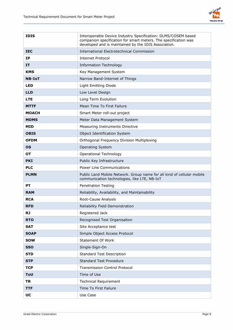
IDIS Interoperable Device Industry Specification: DLMS/COSEM based
companion specification for smart meters. The specification was developed and is maintained by the IDIS Association.
IEC International Electrotechnical Commission
IP Internet Protocol
IT Information Technology
KMS Key Management System
NB-IoT Narrow Band-Internet of Things
LED Light Emitting Diode
LLD Low Level Design
LTE Long Term Evolution
MTTF Mean Time To First Failure
MOACH Smart Meter roll-out project
MDMS Meter Data Management System
MID Measuring Instruments Directive
OBIS Object Identification System
OFDM Orthogonal Frequency Division Multiplexing
OS Operating System
OT Operational Technology
PKI Public Key Infrastructure
PLC Power Line Communications
PLMN Public Land Mobile Network. Group name for all kind of cellular mobile communication technologies, like LTE, NB-IoT
PT Penetration Testing
RAM Reliability, Availability, and Maintainability
RCA Root-Cause Analysis
RFD Reliability Field Demonstration
RJ Registered Jack
RTO Recognised Test Organisation
SAT Site Acceptance test
SOAP Simple Object Access Protocol
SOW Statement Of Work
SSO Single-Sign-On
STD Standard Test Description
STP Standard Test Procedure
TCP Transmission Control Protocol
ToU Time of Use
TR Technical Requirement
TTF Time To First Failure
UC Use Case

Technical Requirement Document for Smart Meter Project
Israel Electric Corporation Page 9
UI User Interface
UX User Experience
UDP User Datagram Protocol
VA Vulnerability Assessment
VEE Validation, Estimation, Editing
WELMEC EUROPEAN Cooperation in Legal Metrology (originally Western European Legal Metrology Cooperation)
XML eXtensible Mark-up Language
Terms and definitions
Term Definition
Contracting Entity Israel Electric Company
Contractor The party delivering products and/or services to the contracting authority and as such the successful bidder.
Field devices Components of the AMI solutions that are deployed in the field: E-meters and Data Concentrators.
Bidder The party answering this RFP and as such applying to become contractor.
Referenced norms
Reference Title
EN 50065 Signalling on low-voltage electrical installations in the frequency range 3 kHz
to 148,5 kHz
EN 50470-1 Electricity metering equipment (a.c.) - Part 1: General requirements, tests and
test conditions – Metering equipment (class indexes A, B and C)
EN 50470-3 Electricity metering equipment (a.c.) - Part 3: Particular requirements – Static
meters for active energy (class indexes A, B and C)
EN 55022 Information technology equipment – Radio disturbance characteristics – Limits
and methods of measurement
IEC 60068-2-1 Environmental testing - Part 2-1: Tests - Test A: Cold
IEC 60068-2-2 Environmental testing - Part 2-2: Tests - Tests B: Dry heat
IEC 60068-2-14 Environmental testing - Part 2-14: Tests - Test N: Change of temperature
IEC 60068-2-30 Environmental testing - Part 2-30: Tests - Test Db: Damp heat, cyclic (12 h +
12 h cycle)
IEC 60068-2-78 Environmental testing - Part 2-78: Tests - Test Cab: Damp heat, steady state
Technical Requirement Document for Smart Meter Project
Israel Electric Corporation Page 10
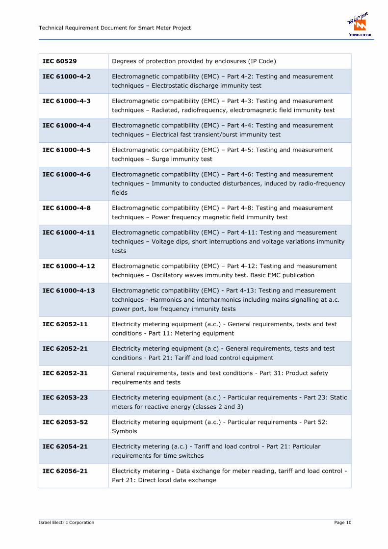
IEC 60529 Degrees of protection provided by enclosures (IP Code)
IEC 61000-4-2 Electromagnetic compatibility (EMC) – Part 4-2: Testing and measurement
techniques – Electrostatic discharge immunity test
IEC 61000-4-3 Electromagnetic compatibility (EMC) – Part 4-3: Testing and measurement
techniques – Radiated, radiofrequency, electromagnetic field immunity test
IEC 61000-4-4 Electromagnetic compatibility (EMC) – Part 4-4: Testing and measurement
techniques – Electrical fast transient/burst immunity test
IEC 61000-4-5 Electromagnetic compatibility (EMC) – Part 4-5: Testing and measurement
techniques – Surge immunity test
IEC 61000-4-6 Electromagnetic compatibility (EMC) – Part 4-6: Testing and measurement
techniques – Immunity to conducted disturbances, induced by radio-frequency
fields
IEC 61000-4-8 Electromagnetic compatibility (EMC) – Part 4-8: Testing and measurement
techniques – Power frequency magnetic field immunity test
IEC 61000-4-11 Electromagnetic compatibility (EMC) – Part 4-11: Testing and measurement
techniques – Voltage dips, short interruptions and voltage variations immunity
tests
IEC 61000-4-12 Electromagnetic compatibility (EMC) – Part 4-12: Testing and measurement
techniques – Oscillatory waves immunity test. Basic EMC publication
IEC 61000-4-13 Electromagnetic compatibility (EMC) - Part 4-13: Testing and measurement
techniques - Harmonics and interharmonics including mains signalling at a.c.
power port, low frequency immunity tests
IEC 62052-11 Electricity metering equipment (a.c.) - General requirements, tests and test
conditions - Part 11: Metering equipment
IEC 62052-21 Electricity metering equipment (a.c) - General requirements, tests and test
conditions - Part 21: Tariff and load control equipment
IEC 62052-31 General requirements, tests and test conditions - Part 31: Product safety
requirements and tests
IEC 62053-23 Electricity metering equipment (a.c.) - Particular requirements - Part 23: Static
meters for reactive energy (classes 2 and 3)
IEC 62053-52 Electricity metering equipment (a.c.) - Particular requirements - Part 52:
Symbols
IEC 62054-21 Electricity metering (a.c.) - Tariff and load control - Part 21: Particular
requirements for time switches
IEC 62056-21 Electricity metering - Data exchange for meter reading, tariff and load control -
Part 21: Direct local data exchange

Technical Requirement Document for Smart Meter Project
Israel Electric Corporation Page 11
IEC 62056-7-6 Electricity metering data exchange - - The DLMS/COSEM suite – Part 7-6 -
The 3-layer, connection-oriented HDLC based communication profile
IEC 62056-8-5 Electricity metering data exchange - The DLMS/COSEM suite - Part 8-5:
Narrow-band OFDM G3-PLC communication profile for neighbourhood
networks.
IEC 62056-9-7 Electricity metering data exchange - The DLMS/COSEM suite - Part 9-7:
Communication profile for TCP-UDP/IP networks
IEC TR 62059-21 Electricity metering equipment - Dependability - Part 21: Collection of meter
dependability data from the field
IEC 62059-31-1 Electricity metering equipment - Dependability - Part 31-1: Accelerated
reliability testing - Elevated temperature and humidity
IEC 62059-41 Electricity metering equipment - Dependability - Part 41: Reliability prediction
FCC Part-15 (Title
47 CFR Part 15)
FCC Part-15 Rules: Unlicensed RF Devices (TITLE 47—Telecommunication,
CHAPTER I—FEDERAL COMMUNICATIONS COMMISSION, SUBCHAPTER A—
GENERAL, PART 15—RADIO FREQUENCY DEVICES)
IEC 11770-1 Information technology — Security techniques — Key management — Part 1:
Framework
Latest version of referenced norm applies, unless explicitly stated differently.

Technical Requirement Document for Smart Meter Project
Israel Electric Corporation Page 12
1 INTRODUCTION
Background
The Israel Electric Corporation is preparing for the rollout of a new generation of Smart meters from
2024 onwards. This document will form part of the tendering specifications for equipment suppliers that
will meet the technical requirements for deployment in Israel specific to IECo. This document describes:
The technical requirements for Smart metering associated devices (e.g. meters, DCs, current
instrument transformers) of the AMI solution selected by IECo.
The integration requirements of the smart meters with the peripheral systems within IECo and
additional services to be developed, resulting in successful end-to-end processes, which go
beyond an MDM solution.
The requirements for end-to-end co-ordination and implementation by the bidder.
Scope
This document is part of the tender documentation for the AMI system mass rollout planned by IECo.
The document formally specifies the technical requirements related to the AMI system, including system
architecture and protocols, business processes, use cases, cyber security, integration and IT landscape,
key components (HES, DC, E-meters, and current instrument transformers) and communication
interfaces. Regulation, security, and functionality applicable to the AMI system are main drivers of the
requirements stated in this specification.
Figure 1-1: Technical requirements scope
Technical Requirement Document for Smart Meter Project
Israel Electric Corporation Page 13
Business vision
To successfully perform a mass smart meter roll-out, customer-facing & technical processes need to be
aligned. In the past years IECo has performed a roll-out of ~50k smart meters within Israel to learn
from the challenges of a smart meter roll-out and to define the requirements for the large-scale
implementation.
Smart meter deployments are reaching critical mass where AMI data can be harvested to deliver benefits
in different business areas. That means the integration of metering processes with different business
processes & systems is crucial to align the different processes within different internal departments and
with external stakeholders.
As part of the project IECo would like to achieve a high-level of integration of AMI data within the core
business processes. This means improving existing business processes of meter data integration, but
also introducing services that are currently not available within IECo.
A successful project goes beyond the roll-out of smart meters, IECo expects a large improvement of the
end-to-end processes and truly unlocking the value of AMI data. The vision is to create this value in
multiple areas, among which:
Increased efficiency of IECo’s processes
Improved security & quality of supply
Improved customer experience and public image
Allowing the introduction of potential new services
High-level bidder expectations
IECo is looking for a bidder to achieve its business vision. The bidder will take the end-to-end co-
ordination of the smart meter roll-out and the design & integration of services within the IECo business
processes and system landscape. This means the bidder is the single & main contractor and
accountable for the services delivered. Any potential subcontractors, working for the bidder,
will perform their services under the accountability of the bidder.
IECo is planning to deploy approximately 300k meters per year. IECo doesn’t want to wait until the end
of the full deployment to start unlocking the value of AMI data, and expects them to be available as soon
as possible. IECo understands it might not fully unlock all value for its processes when the roll-out
doesn’t have a critical mass yet for certain services, but there shouldn’t be a limitation that the
integration of business processes and/or corresponding system architecture won’t be ready.

Technical Requirement Document for Smart Meter Project
Israel Electric Corporation Page 14
How to Read this Document
1.5.1 Document Structure
This document consists on the following sections:
Section 1 – Introduction (current section)
Section 2 – Technical Requirements for the AMI System (applying for the end-2-end system)
Section 3 – Technical Requirements for the Smart Meters
Section 4 – Technical Requirements for the Data Concentrators
Section 5 – Technical Requirements for the Head-End-System
Section 6 – Mass Production Requirements for the Smart Meters
Section 7 – Failure Management Requirements for Meters in Operation
Section 8 – Technical Requirements for Portable Test PC
Section 9 – Cyber Security Requirements
Section 10 – Functional Description
Section 11 – Project Delivery Expectations
Section 12 – Additional Requirements for the Bidder
Section 13 – KPIs for the Smart Metering Project
This document further contains the following Appendices:
Appendix A – PLC Filters: This appendix contains the requirements regarding the PLC filters that the
bidder must provide in this project
Appendix B – Energy Registers Measurement Method: This appendix contains more information
regarding the applicable metering methods and energy registers
Appendix C – Specifications regarding current instrument transformers: This appendix contains the
requirements regarding the different types of current instrument transformers that the bidder must
provide in this project
Appendix D – Packaging Requirements for smart meters: This appendix contains requirement related to
packaging of components to be delivered to IECo
Appendix E – HASS Requirements: This appendix contains additional requirements related to “Highly
accelerated stress screen” (HASS) tests
Appendix F – Meters and DC RAM requirements
Appendix G – Off the Shelf Product Declaration
Appendix H - Provisioning Test
Appendix I – Metrology report format: This appendix provides formats for the metrology reports
Technical Requirement Document for Smart Meter Project
Israel Electric Corporation Page 15
1.5.2 Requirements Format
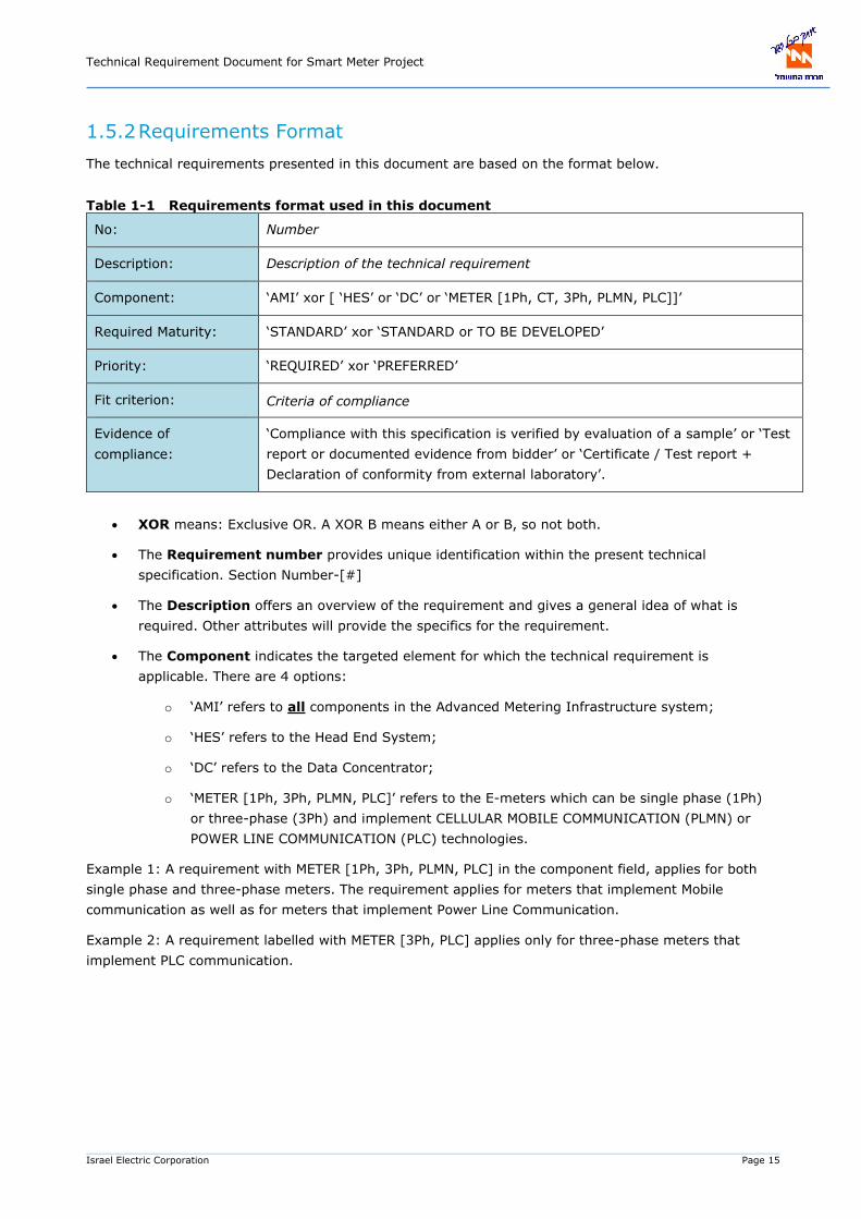
The technical requirements presented in this document are based on the format below.
Table 1-1 Requirements format used in this document
No: Number
Description: Description of the technical requirement
Component: ‘AMI’ xor [ ‘HES’ or ‘DC’ or ‘METER [1Ph, CT, 3Ph, PLMN, PLC]]’
Required Maturity: ‘STANDARD’ xor ‘STANDARD or TO BE DEVELOPED’
Priority: ‘REQUIRED’ xor ‘PREFERRED’
Fit criterion: Criteria of compliance
Evidence of
compliance:
‘Compliance with this specification is verified by evaluation of a sample’ or ‘Test
report or documented evidence from bidder’ or ‘Certificate / Test report +
Declaration of conformity from external laboratory’.
XOR means: Exclusive OR. A XOR B means either A or B, so not both.
The Requirement number provides unique identification within the present technical
specification. Section Number-[#]
The Description offers an overview of the requirement and gives a general idea of what is
required. Other attributes will provide the specifics for the requirement.
The Component indicates the targeted element for which the technical requirement is
applicable. There are 4 options:
o ‘AMI’ refers to all components in the Advanced Metering Infrastructure system;
o ‘HES’ refers to the Head End System;
o ‘DC’ refers to the Data Concentrator;
o ‘METER [1Ph, 3Ph, PLMN, PLC]’ refers to the E-meters which can be single phase (1Ph)
or three-phase (3Ph) and implement CELLULAR MOBILE COMMUNICATION (PLMN) or
POWER LINE COMMUNICATION (PLC) technologies.
Example 1: A requirement with METER [1Ph, 3Ph, PLMN, PLC] in the component field, applies for both
single phase and three-phase meters. The requirement applies for meters that implement Mobile
communication as well as for meters that implement Power Line Communication.
Example 2: A requirement labelled with METER [3Ph, PLC] applies only for three-phase meters that
implement PLC communication.

Technical Requirement Document for Smart Meter Project
Israel Electric Corporation Page 16
Required maturity:
o STANDARD means: Product(s) that are available at the time of responding to the tender,
comply to this requirement.
o STANDARD or TO BE DEVELOPED means: STANDARD, or a development will be done (or
will be allowed) after award of the contract (during the implementation phase of the
project).
Priority:
o ‘REQUIRED’ indicates a requirement the bidder must comply with. Non-compliance will
result in exclusion.
o ‘PREFERRED’ indicates a requirement that is very important, but not mandatory.
Solutions that comply with these technical requirements are awarded with points
contributing to the evaluation of the tender.
The Fit criterion provides insight on the criteria to be used to verify the requirement
compliance.
The Evidence of compliance prescribes how the bidder shall prove compliance to the
requirement.
1.5.3 Requirements Scoring
Regarding the scoring of requirements, numerous requirements are included in scoring sheets. The
following types of requirements can be included in the scoring:
Requirements with the priority label ‘PREFERRED’
Requirements with priority label ‘REQUIRED’ and required maturity label ‘STANDARD or TO BE
DEVELOPED’. In this case, the bidder must clearly indicate if this feature/requirement is already
available and implemented, or if he has to develop this. In the first case, the bidder will receive
more points.

Technical Requirement Document for Smart Meter Project
Israel Electric Corporation Page 17
2 TECHNICAL REQUIREMENTS FOR THE AMI SYSTEM
Architectural Requirements
The AMI architecture of the MOACH project is sketched in Figure 2-1. On the residential side, the meter
setup consists of an electricity meter (E-meter). Depending on the communication used, the E-meter
communicates directly with the head-end system (HES), or the end-to-end communication is facilitated
via a data concentrator device in the neighbourhood network.
Figure 2-1 Example AMI Architecture of the MOACH project

Technical Requirement Document for Smart Meter Project
Israel Electric Corporation Page 18
No: 2.1-1
Description: The AMI system architecture shall consist of a Head End System (HES), point to point connected E-meters and E-meters that communicate via Data Concentrators
(DCs).
Component: AMI
Required Maturity: STANDARD
Priority: REQUIRED
Fit criterion: The system architecture similar as described in section 2.1 and drawn in Figure 2-1
shall be implemented.
Evidence of
compliance:
Documented evidence from bidder.
No: 2.1-2
Description: The AMI system shall be scalable up to 4.2 million E-meters.
Component: AMI
Required Maturity: STANDARD
Priority: REQUIRED
Fit criterion: The system shall comprise in total ~3,000,000 single and three phase E-meters
throughout Israel. The system shall be scalable: It shall be possible to manage up to 4.2 million E-meters in Israel.
Evidence of
compliance:
Test report or documented evidence from bidder.
No: 2.1-3
Description: The system shall provide network topology and connectivity information.
Component: AMI
Required Maturity: STANDARD or TO BE DEVELOPED
Priority: REQUIRED
Fit criterion: The system shall provide, for its segment of the LV network:
Topology information (including number of switch/nodes to each G3-PLC meter).
Communication status of each meter. Integration with the peripheral systems.
Evidence of
compliance:
Test report or documented evidence from bidder.

Technical Requirement Document for Smart Meter Project
Israel Electric Corporation Page 19
The following interfaces are present to facilitate data exchange between the system components:
Ilocal_meter: This interface is used for communicating with an external device during on-site
maintenance or installation of the meters.
IHES_meter: This interface is used for the communication between the E-meter and the head-end
system (HES). The application protocol used on this interface is the DLMS/COSEM protocol. The
‘Annexure B2 - MOACH DLMS COSEM profile for communication interfaces’ companion specification is
used to further fine-tune the use of the DLMS/COSEM application protocol. Direct communication
with the HES is applied via a public mobile telecommunication network. LTE (4G) is the selected
communication technology. However, in cases where LTE (4G) communication is not available,
fallback to GPRS shall be used.
IDC_meter: This is the communication interface between the E-meter and the Data Concentrator (DC).
The lower layers of the protocol stack are based on G3-PLC; the meters and the DCs shall be G3-PLC
certified. Again, on the application layer DLMS/COSEM is used with Annexure B2 - MOACH DLMS
COSEM profile for communication interfaces as the companion specification.
IHES_DC: This is the interface between the DC and the HES. The application protocol that is used
between the HES and the DC may not be based on DLMS/COSEM. In this case proprietary application
protocols can be used (e.g. web services). On the lower layers of the protocol stack, communication
with the HES is applied via a public mobile telecommunication network. LTE (4G) is the preferred
communication. In cases where 4G communication is not available, fallback to GPRS shall be used.
Icustomer_meter: Unidirectional communication interface for data exchange from meter and customer.
Requirements on Communication Interfaces
No: 2.2-1
Description: The AMI system components shall implement a defined set of communication
interfaces.
Component: AMI
Required Maturity: STANDARD
Priority: REQUIRED
Fit criterion: The communication interfaces as indicated in Figure 2-1 shall be implemented:
IHES_meter: Communication interface for data exchange between HES and meter
directly.
IHES_DC: Communication interface for data exchange between HES and DC. IDC_meter: Communication interface for data exchange between DC and meter.
Ilocal_DC: Interface for local configuration and troubleshooting on DC. Ilocal_meter: Interface for local configuration and troubleshooting on E-meter. Ilocal_meter: Unidirectional communication interface for data exchange from meter and customer.
If any other communication interface is implemented on the field devices, it shall be disabled. Bidder shall inform contracting entity on any additional interface.
Technical Requirement Document for Smart Meter Project
Israel Electric Corporation Page 20
Evidence of
compliance:
Test report or documented evidence from bidder.
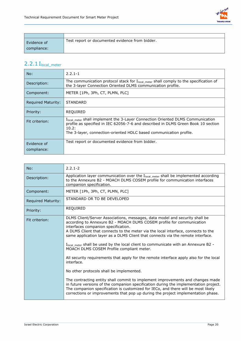
2.2.1 Ilocal_meter
No: 2.2.1-1
Description: The communication protocol stack for Ilocal_meter shall comply to the specification of the 3-layer Connection Oriented DLMS communication profile.
Component: METER [1Ph, 3Ph, CT, PLMN, PLC]
Required Maturity: STANDARD
Priority: REQUIRED
Fit criterion: Ilocal_meter shall implement the 3-Layer Connection Oriented DLMS Communication profile as specified in IEC 62056-7-6 and described in DLMS Green Book 10 section
10.2: The 3-layer, connection-oriented HDLC based communication profile.
Evidence of
compliance:
Test report or documented evidence from bidder.
No: 2.2.1-2
Description: Application layer communication over the Ilocal_meter shall be implemented according
to the Annexure B2 - MOACH DLMS COSEM profile for communication interfaces companion specification.
Component: METER [1Ph, 3Ph, CT, PLMN, PLC]
Required Maturity: STANDARD OR TO BE DEVELOPED
Priority: REQUIRED
Fit criterion: DLMS Client/Server Associations, messages, data model and security shall be according to Annexure B2 - MOACH DLMS COSEM profile for communication interfaces companion specification. A DLMS Client that connects to the meter via the local interface, connects to the
same application layer as a DLMS Client that connects via the remote interface. Ilocal_meter shall be used by the local client to communicate with an Annexure B2 - MOACH DLMS COSEM Profile compliant meter.
All security requirements that apply for the remote interface apply also for the local
interface. No other protocols shall be implemented. The contracting entity shall commit to implement improvements and changes made in future versions of the companion specification during the implementation project. The companion specification is customized for IECo, and there will be most likely
corrections or improvements that pop up during the project implementation phase.

Technical Requirement Document for Smart Meter Project
Israel Electric Corporation Page 21
Evidence of
compliance:
Test report or documented evidence from bidder.
No: 2.2.1-3
Description: The meter shall have a local optical interface and the physical properties of this interface shall be standardized.
Component: METER [1Ph, 3Ph, CT, PLMN, PLC]
Required Maturity: STANDARD
Priority: REQUIRED
Fit criterion: The physical properties of this interface are compliant with the specifications in IEC 62056-21 section 4.3.
The optical interface and meter shall also function properly in a high ambient light environment of at least 80k lux.
Detachment strength of at least 5 Newton between probe and port, while the probe is touching the port.
Detachment strength of at least 1.5 Newton between probe and port, while the probe is 2mm away from the port.
The optical ports shall be interoperable with Reallin probes. Upon winning the tender the specifications of these probes will be supplied.
This port shall be located on the front panel of the meter, and be fully accessible.
The baud rate shall be 9600 bit/s
Evidence of
compliance:
Test report or documented evidence from bidder. (DLM/COSEM or IDIS certificate
shall include HLDC interface testing. )
No: 2.2.1-4
Description: Tools (software) for local configuration and troubleshooting via Ilocal_meter shall be delivered as part of the solution and should be integrated with IECo NADAV/Lab/HHU application.
Component: METER [1Ph, 3Ph, CT, PLMN, PLC]
Required Maturity: STANDARD or TO BE DEVELOPED
Priority: REQUIRED
Fit criterion: 1. A tool (software) for local configuration and troubleshooting shall be available.
This tool supports at least the following functions: read out of registers and load
profiles, configuration of all configurable parameters, troubleshooting, firmware upgrade, breaker operation and clock configuration.
2. Requirements for NADAV application based PC/ tablet driver tool: Reading meters current billing data and billing profile (last 4 entries) and
general meter data
Meter parameters configuration (TOU, DST and etc.)
Synchronize meter's clock
Driver will be based on Windows OS version for which Microsoft provides
support.
The communication will be based on a RS232 optical adapter with
optional way to choose comport.

Technical Requirement Document for Smart Meter Project
Israel Electric Corporation Page 22
Support firmware upgrade
3. Requirements for PAAMON application based HHU driver: Reading meters current billing data and billing profile (last 4 entries) and
general meter data
Meter's parameters configuration (TOU, DST and etc.)
Synchronize meter's clock
Support firmware upgrade
Driver will be based for Android for business 10 operating system
The communication will be based on a RS232 optical adapter with
optional way to choose comport.
4. Events, Load Profile, Monthly Billing, Daily Billing, General Data – all should be able to be collected both using android & windows drivers.
5. As LP/Daily billing can consist of a lot of data – The driver should provide the ability to collect partial data.
Output file:
The file’s data general structure should be in DLMS COSEM OBIS standard.
All data will be in one structure, including the communication result field. Communication error codes: No error: 0.Error: Error code in OBIS-Error Code structure.
The interface structure for meter reading will be an API
Each OBIS field code will contain the field value as well.
Active energy import total register example:
< CaptureObject> < ClassId>3</ClassId>
< OBIS>0100010800FF</OBIS>
< Data>750298</Data>
< AttributeIndex>2</AttributeIndex>
< DataIndex>0</DataIndex>
/< CaptureObject>
The required data:
Date and time
Active energy import registers:
total, rate1, rate2, rate3, rate4, accumulating max peak demand,
monthly max peak demand, monthly max peak demand date and time.
Active energy export registers:
total, rate1, rate2, rate3, rate4, accumulating max peak demand,
monthly max peak demand, monthly max peak demand date and time.
Reactive energy import registers:
total, rate1, rate2, rate3, rate4, accumulating max peak demand,
monthly max peak demand, monthly max peak demand date and time.
Reactive energy export registers:
total, rate1, rate2, rate3, rate4, accumulating max peak demand,
monthly max peak demand, monthly max peak demand date and time.
requirements are for 45 daily billings, 15 monthly readings, load profile,
events.
Technical data:
Meter serial number.
Meter code.
Current table name Holidays
Current table name TOU (TIME OF USE)
Meter clock
Meter version
Load profile status YES/NO
Technical Requirement Document for Smart Meter Project
Israel Electric Corporation Page 23
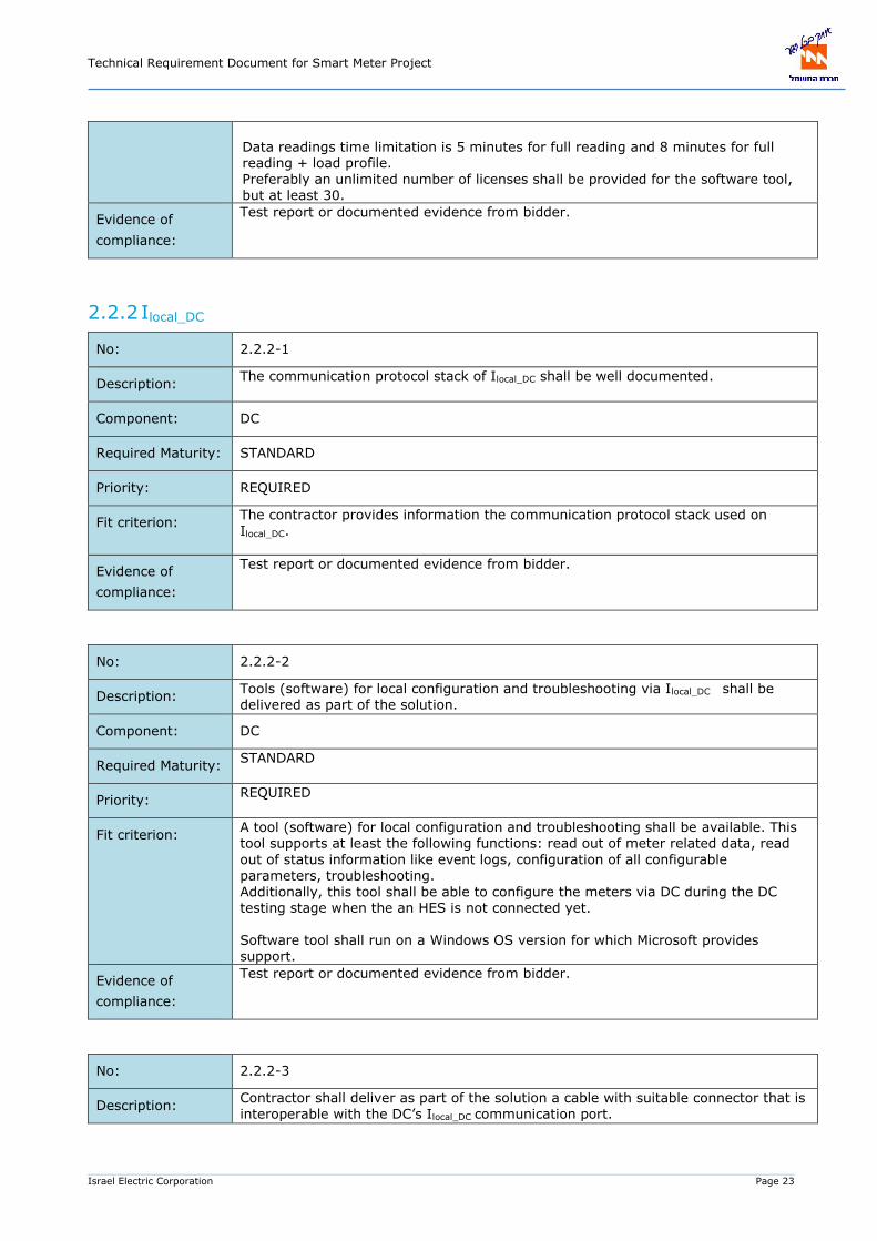
Data readings time limitation is 5 minutes for full reading and 8 minutes for full reading + load profile. Preferably an unlimited number of licenses shall be provided for the software tool, but at least 30.
Evidence of
compliance:
Test report or documented evidence from bidder.
2.2.2 Ilocal_DC
No: 2.2.2-1
Description: The communication protocol stack of Ilocal_DC shall be well documented.
Component: DC
Required Maturity: STANDARD
Priority: REQUIRED
Fit criterion: The contractor provides information the communication protocol stack used on Ilocal_DC.
Evidence of
compliance:
Test report or documented evidence from bidder.
No: 2.2.2-2
Description: Tools (software) for local configuration and troubleshooting via Ilocal_DC shall be delivered as part of the solution.
Component: DC
Required Maturity: STANDARD
Priority: REQUIRED
Fit criterion: A tool (software) for local configuration and troubleshooting shall be available. This tool supports at least the following functions: read out of meter related data, read
out of status information like event logs, configuration of all configurable parameters, troubleshooting. Additionally, this tool shall be able to configure the meters via DC during the DC testing stage when the an HES is not connected yet.
Software tool shall run on a Windows OS version for which Microsoft provides support.
Evidence of
compliance:
Test report or documented evidence from bidder.
No: 2.2.2-3
Description: Contractor shall deliver as part of the solution a cable with suitable connector that is interoperable with the DC’s Ilocal_DC communication port.
Technical Requirement Document for Smart Meter Project
Israel Electric Corporation Page 24
Component: DC
Required Maturity: STANDARD
Priority: REQUIRED
Fit criterion: Contractor shall deliver compatible cables. The number of cables will be aligned between contracting entity and contractor. If Ilocal_DC communication port is implemented as an ethernet port (RJ-45) on the DC side, the contractor is dismissed from the obligation to provide these cables.
Evidence of
compliance:
Test report or documented evidence from bidder.
2.2.3 IDC_meter
No: 2.2.3-1
Description: The communication protocol stack of the IDC_meter shall be based on open standards and use DLMS/COSEM on top of G3-PLC communication.
Component: DC, METER [1Ph, 3Ph, CT, PLC]
Required Maturity: STANDARD
Priority: REQUIRED
Fit criterion: The communication stack is based on DLMS/COSEM in the application layer.
The DLMS communication profile as specified in IEC 62056-8-4:
The DLMS communication profile as specified in IEC 62056-8-5: Narrow Band OFDM G3-PLC communication profile for neighbourhood networks shall be implemented for G3-PLC meters.
Evidence of
compliance:
Test report or documented evidence from bidder.
No: 2.2.3-2
Description: Application layer communication over the IDC_meter shall be according to the Annexure B2 - MOACH DLMS COSEM Profile for communication interfaces companion specification.
Component: DC, METER [1Ph, 3Ph, CT, PLC]
Required Maturity: STANDARD OR TO BE DEVELOPED
Priority: REQUIRED
Fit criterion: Associations, messages, data model and security shall comply with the Annexure B2 - MOACH DLMS COSEM Profile for communication interfaces companion specification.
IDC_meter shall be used by the DC to communicate with an Annexure B2 - MOACH DLMS COSEM Profile compliant meter that implements the Annexure B2 - MOACH DLMS COSEM profile.

Technical Requirement Document for Smart Meter Project
Israel Electric Corporation Page 25
No other protocols shall be implemented.
The contracting entity shall commit to implement improvements and changes made in future versions of the companion specification during the implementation project. The companion specification is customized for MOACH, and there will be most likely corrections or improvements that pop up during the project implementation phase.
Evidence of
compliance:
Test report or documented evidence from bidder.
No: 2.2.3-3
Description: AMI components that implement the IDC_meter interface shall be able to operate both in the CENELEC A and FCC bands.
Component: DC, METER [1Ph, 3Ph, CT, PLC]
Required Maturity: STANDARD or TO BE DEVELOPED
Priority: REQUIRED
Fit criterion: The AMI system components that implement the IDC-meter interface can be configured to use either the CENELEC A or FCC bands for G3-PLC devices.
Evidence of
compliance:
Certificate / Test report + Declaration of conformity from external laboratory: G3-PLC certificate.
No: 2.2.3-4
Description: AMI components that implement the IDC_meter shall be certified products.
Component: DC, METER [1Ph, 3Ph, CT, PLC]
Required Maturity: STANDARD
Priority: REQUIRED
Fit criterion: AMI components that implement the IDC_meter shall be certified G3-PLC products.
It is not sufficient to use certified platforms; the complete product shall be certified.
Evidence of
compliance:
Certificate / Test report + Declaration of conformity from external laboratory: G3-PLC certificate that shows that the product is certified.
2.2.4 IHES_meter
No: 2.2.4-1
Description: The communication protocol stack for IHES_meter shall comply to the specification of the ‘DLMS/COSEM over IP networks communication profile.’
Component: HES, METER [1Ph, 3Ph, CT, PLMN]
Required Maturity: STANDARD
Priority: REQUIRED

Technical Requirement Document for Smart Meter Project
Israel Electric Corporation Page 26
Fit criterion: The communication protocol stack for IHES_meter shall comply to the specification of
the DLMS/COSEM over IP networks communication profile, as specified in IEC 62056-9-7: Communication profile for TCP-UDP/IP networks and described in DLMS Green Book 10, section 10.3
Evidence of
compliance:
Test report or documented evidence from bidder.
No: 2.2.4-2
Description: Application layer communication over the IHES_meter shall be implemented according to the Annexure B2 - MOACH DLMS COSEM Profile for communication interfaces
companion specification.
Component: METER [1Ph, 3Ph, CT, PLMN]
Required Maturity: STANDARD OR TO BE DEVELOPED
Priority: REQUIRED
Fit criterion: DLMS Client/Server Associations, messages, data model and security shall be
according to Annexure B2 - MOACH DLMS COSEM Profile for communication interfaces companion specification. IHES_meter shall be used by the HES to communicate with an Annexure B2 - MOACH DLMS COSEM Profile compliant meter that implements the Annexure B2 - MOACH DLMS COSEM ‘Mobile Network’ profile.
Evidence of
compliance:
Test report or documented evidence from bidder.
No: 2.2.4-3
Description: The communication unit in the E-meter shall support LTE (4G) communication technology.
Component: METER [1Ph, 3Ph, CT, PLMN]
Required Maturity: STANDARD
Priority: REQUIRED
Fit criterion: The communication unit supports LTE (4G). Fall-back to GPRS technology in case of unavailability of 4G shall be supported.
Evidence of
compliance:
Test report or documented evidence from bidder.
No: 2.2.4-4
Description: The communication unit of the E-meter shall by default be equipped with an internal antenna.
Component: METER [1Ph, 3Ph, CT, PLMN]
Required Maturity: STANDARD

Technical Requirement Document for Smart Meter Project
Israel Electric Corporation Page 27
Priority: REQUIRED
Fit criterion: The device has an antenna for the supported mobile communication technologies. The antenna is located within the housing of the E-meter.
The modem/antenna should be certified for use in the Israeli market.
Evidence of
compliance:
Test report or documented evidence from bidder.
No: 2.2.4-5
Description: The communication unit of the E-meter shall have the option to connect an external antenna. The external antennas are delivered as part of the solution.
Component: METER [1Ph, 3Ph, CT, PLMN]
Required Maturity: STANDARD
Priority: REQUIRED
Fit criterion: The E-meter shall have an option to connect an external antenna. The external antennas are delivered as part of the solution. The external antenna connector
should be a female SMA connector. The length of the cable of the antenna and the number of external antennas will be agreed upon between contractor and contracting entity.
Evidence of
compliance:
Test report or documented evidence from bidder.
2.2.5 IHES_DC
No: 2.2.5-1
Description: The communication protocol stack of IHES_DC shall be based on standardized technologies and well documented.
Component: HES, DC
Required Maturity: STANDARD
Priority: REQUIRED
Fit criterion: The IHES-DC shall be based on open, international standards. The contractor provides documentation about the standards and technologies used on this system interface (Webservices, XML, SOAP). The communication shall be TCP-IP based.
Evidence of
compliance:
Test report or documented evidence from bidder. The bidder describes how this interface is implemented. The bidder describes the communication protocol stack that is used on this interface.
No: 2.2.5-2
Description: The communication unit in the DC shall support ETHERNET.
Component: DC
Technical Requirement Document for Smart Meter Project
Israel Electric Corporation Page 28
Required Maturity: STANDARD
Priority: REQUIRED
Fit criterion: The communication unit shall implements ETHERNET (RJ45) for connectivity with an external firewall (provided by IECo) that will be installed in close proximity of the DC.
Note: the communication with the central systems shall be provided via this external firewall, i.e. this firewall will be provided with 4G-LTE communication technology.
Evidence of
compliance:
Test report or documented evidence from bidder.
2.2.6 Icustomer_meter
No: 2.2.6-1
Description: The meter shall have a local consumer information interface. The physical properties
of this interface shall be according to the DSMR v5.0.2 P1 Companion Standard. This document can be found here: https://www.netbeheernederland.nl/_upload/Files/Slimme_meter_15_a727fce1f1.pdf
Component: METER [1Ph, 3Ph, PLMN, PLC]
Required
Maturity:
STANDARD OR TO BE DEVELOPED
Priority: REQUIRED
Fit criterion: The physical properties of this interface are compliant with the specifications in DSMR v5.0.2 P1 Companion Standard
Evidence of
compliance:
Test report or documented evidence from bidder.
No: 2.2.6-2
Description: Application layer communication over the Icustomer_meter shall be according to the Annexure B2 - MOACH DLMS COSEM Profile for communication interfaces companion specification.
Component: DC, METER [1Ph, 3Ph, CT, PLC]
Required Maturity: STANDARD OR TO BE DEVELOPED
Priority: REQUIRED
Fit criterion: Messages and data model shall comply with the Annexure B2 - MOACH DLMS COSEM Profile for communication interfaces companion specification. Icustomer_meter shall be used for unidirectional data exchange from meter to customer with an MOACH DLMS COSEM Profile compliant meter that implements the Annexure B2 - MOACH DLMS COSEM profile.
No other protocols shall be implemented. The contracting entity shall commit to implement improvements and changes made in future versions of the companion specification during the implementation project.

Technical Requirement Document for Smart Meter Project
Israel Electric Corporation Page 29
The companion specification is customized for IECo, and there will be most likely
corrections or improvements that pop up during the project implementation phase.
Evidence of
compliance:
Test report or documented evidence from bidder. Compliance with this specification is verified by evaluation of a sample.
2.2.7 Communication unit for mobile communication
The following requirements apply for the communication unit for mobile communication in both E-meters
and DC’s.
No: 2.2.7-1
Description: The communication unit of the device shall support cellular mobile communication
frequencies used by the Israel telecommunication providers.
Component: DC, METER [1Ph, 3Ph, CT, PLMN]
Required Maturity: STANDARD
Priority: REQUIRED
Fit criterion: The communication unit shall support the frequency bands used in Israel. See Figure
2-2. The communication unit shall support Data Roaming between MNOs.
Evidence of
compliance:
Certificate / Test report + Declaration of conformity from external laboratory: The bidder provides a GCF certification of the modem by a GCF Recognised Test Organisation (RTO).
Figure 2-2: Overview frequency bands in Israel
No: 2.2.7-2
Description: The communication unit of the device shall be an exchangeable module.
Component: DC, METER [1Ph, 3Ph, CT, PLMN]
Required Maturity: STANDARD
Priority: PREFERRED
Fit criterion: The communication unit shall support exchangeability.
Evidence of
compliance:
Test report or documented evidence from bidder.
No: 2.2.7-3
Band B8 B3 B8 B1 B1 B3 B8 B20 B28 B3 B28
Frequency 900 1800 900 2100 2100 1800 900 800 700 1800 700
UL (MHz) 880-915 1710-1785 880-915 1920-1980 1920-1980 1710-1785 880-915 832-862 703-748 1710-1785 703-748
DL (MHz) 925-960 1805-1880 925-960 2110-2170 2110-2170 1805-1880 925-960 791-821 758-803 1805-1880 758-803
2G 3G 4G-LTE 4G-NB
Technical Requirement Document for Smart Meter Project
Israel Electric Corporation Page 30
Description: The Contractor shall be responsible for transportation of SIM cards to the cellular
meter manufacturer.
Component: METER [1Ph, 3Ph, CT, PLMN]
Required Maturity: STANDARD
Priority: REQUIRED
Fit criterion: For each draw order for cellular meters, and before manufacture of the meters, the Contractor shall be responsible to collect SIM cards from IECo and transport them to the cellular meter manufacturer. The cellular meters manufacturer shall insert the SIM cards received, into the communication modules during the meters manufacturing process, so that the meters will be delivered with the SIM cards already installed.
Evidence of
compliance:
Commitment from bidder.
No: 2.2.7-4
Description: The communication unit of the device shall be compatible with eSIM/eUICC.
Component: DC, METER [1Ph, 3Ph, CT, PLMN]
Required Maturity: STANDARD OR TO BE DEVELOPED
Priority: PREFERRED (without scoring)
Fit criterion: The contracting entity shall be able to switch from one telecom provider to another. This feature is possible if eSIMs/eUICC are deployed. The communication unit shall
be compatible with eSIMs/eUICC. If eSIM is offered, IECo can supply the relevant information.
Evidence of
compliance:
Test report or documented evidence from bidder.
No: 2.2.7-5
Description: The communication unit of the device shall be configurable.
Component: DC, METER [1Ph, 3Ph, CT, PLMN]
Required Maturity: STANDARD OR TO BE DEVELOPED
Priority: REQUIRED
Fit criterion: There shall be a GUI to configure the modem of the device. The GUI can be part of the meter software.
Evidence of
compliance:
Test report or documented evidence from bidder.
No: 2.2.7-6
Description: Communication technology usage.

Technical Requirement Document for Smart Meter Project
Israel Electric Corporation Page 31
Component: DC, METER [1Ph, 3Ph, CT, PLMN]
Required Maturity: STANDARD
Priority: REQUIRED
Fit criterion: The bidder should bring at least 20% of the required meters with cellular communication technology. The remaining 80% of meters can use either cellular or G3-PLC technology, as long as the bidder can comply to the required KPIs.
Evidence of
compliance:
Test report or documented evidence from bidder.
2.2.8 Requirements regarding PLC network quality
No: 2.2.8-1
Description: Tools for evaluating the quality of the PLC network
Component: PLC network
Required Maturity: STANDARD
Priority: REQUIRED
Fit criterion: The bidder shall be able to provide tools to analyse and evaluate, in the field, the quality of the PLC network (e.g. determine noise level and sources of noise)
Evidence of
compliance:
Documented evidence of the bidder describing the tools that he will offer.
No: 2.2.8-2
Description: Availability of PLC filters
Component: PLC Filter
Required Maturity: STANDARD
Priority: REQUIRED
Fit criterion: The bidder shall be able to deliver PLC filters to improve the data communication
quality in the PLC network. The details regarding the PLC-filters can be found in Appendix A (in this document).
Evidence of
compliance:
Documented evidence from the bidder describing the PLC filters he will offer.
AMI Business Processes
The AMI system shall support the business processes of IECo.
Notice that the business processes not only encompasses AMI system requirements but also E2E
services to/from SAP IS-U or SAP PM. The requirements mentioned in this section focus on the AMI
system part, while the integration requirements are stated in chapter 10.
Technical Requirement Document for Smart Meter Project
Israel Electric Corporation Page 32
The AMI system shall support the following business processes (BPs):
No: 2.3-1
Description: The AMI system shall support ‘BP1: Commissioning of the meter’.
Component: AMI
Required Maturity: STANDARD OR TO BE DEVELOPED
Priority: REQUIRED
Fit criterion: The AMI system supports the process of integrating installed meter devices into the
system.
This process can be decomposed in the following steps:
1. Physical installation in the LV grid.
2. Connection to the communication network. To HES directly or via
DC/gateway (depending on the adopted communication technology).
3. Registration of meters
‘BP1: Commissioning of the meter’ implementation encompasses the support of the
following Use Cases (UCs):
UC1: Meter registration (refer to requirement 2.4-1)
UC3: Provide Meter reading (refer to requirement 2.4-4)
This business process shall be implemented in conjunction with ‘BP16: Manage
meter configurations’ (refer to requirement 2.3-16).
Details on ‘BP1: Commissioning of the meter’ are aligned between Contracting entity
and Contractor.
The selection of communication technology will depend on an up-front
communication survey done by IECo.
Evidence of
compliance:
Test report or documented evidence from bidder.
The bidder shall describe how this business process is implemented, including a
work flow which describes it in detail.
No: 2.3-2
Description: The AMI system shall support ‘BP2: Update meter master data’.
Component: AMI
Required Maturity: STANDARD OR TO BE DEVELOPED
Priority: REQUIRED
Fit criterion: The AMI system supports the process of updating meter master data, which refers
to the default configuration of the meter when it is installed for the first time. This

Technical Requirement Document for Smart Meter Project
Israel Electric Corporation Page 33
information is stored in the MDMS and integrated with SAP, GIS and WFM (see
chapter 10).
‘BP2: Update meter master data’ implementation encompasses the support of the
following Use Cases (UCs):
UC1: Meter registration (refer to requirement 2.4-1)
UC9: Power quality reporting (refer to requirements 2.4-10 and 2.4-11)
Details on ‘BP2: Update meter master data’ are aligned between Contracting entity
and Contractor.
Evidence of
compliance:
Test report or documented evidence from bidder.
The bidder shall describe how this business process is implemented, including a
work flow which describes it in detail.
No: 2.3-3
Description: The AMI system shall support ‘BP3: Remove meter’.
Component: AMI
Required Maturity: STANDARD OR TO BE DEVELOPED
Priority: REQUIRED
Fit criterion: The AMI system supports the process of removing a meter from the field. Before the
meter is removed, the last billing data has to be collected and all events/logs have
to be read (even locally/manually if, for commissioning or maintenance reasons, the
meter does not allow the remote option). For PLC-based meters, the MDMS/HES
executes the corresponding actions to remove the meter from the DC database
permanently after making sure that: all required meter data has been collected
completely and consistently. For LTE-based meters, ceasing of provision from
communication systems (cellular network core) takes place.
This business process shall be implemented in conjunction with ‘BP8: Metering data
validation’ (refer to requirement 2.3-8).
‘BP3: Remove meter’ implementation encompasses the support of the following Use
Cases (UCs):
UC2: Provide billing data (refer to requirements 2.4-2 and 2.4-3)
UC3: Provide meter reading (refer to requirement 2.4-4)
UC7: Meter supervision (refer to requirement 2.4-8 and system integrations
with SAP)
Details on ‘BP3: Remove meter’ are aligned between Contracting entity and
Contractor.
Evidence of
compliance:
Test report or documented evidence from bidder.
Technical Requirement Document for Smart Meter Project
Israel Electric Corporation Page 34
The bidder shall describe how this business process is implemented, including a
work flow which describes it in detail.
No: 2.3-4
Description: The AMI system shall support ‘BP4: Switching supplier’.
Component: AMI
Required Maturity: STANDARD OR TO BE DEVELOPED
Priority: REQUIRED
Fit criterion: The AMI system supports the process of switching consumer from Energy Supplier.
If the consumer switches from supplier, the actual billing data has to be collected so
that the old supplier can make up the final bill. The new supplier has to get the
actual meter reads. This business process shall be implemented in conjunction with
‘BP8: Metering data validation’ (refer to requirement 2.3-8).
‘BP4: Switching supplier’ implementation encompasses the support of the following
Use Cases (UCs):
UC2: Provide billing data (refer to requirements 2.4-2 and 2.4-3)
UC3: Provide meter reading (refer to requirement 2.4-4)
Details on ‘BP4: Switching supplier’ are aligned between Contracting entity and
Contractor.
Evidence of
compliance:
Test report or documented evidence from bidder.
The bidder shall describe how this business process is implemented, including a
work flow which describes it in detail.
No: 2.3-5
Description: The AMI system shall support ‘BP5: Switching customer’.
Component: AMI
Required Maturity: STANDARD OR TO BE DEVELOPED
Priority: REQUIRED
Fit criterion: Consumers who move to house need a bill based on the last consumption. The
meter can disconnect the premises from the grid until the new consumer moves in.
This process is supported by the AMI system.
‘BP5: Switching customer’ implementation encompasses the support of the following
Use Cases (UCs):
UC2: Provide billing data (refer to requirements 2.4-2 and 2.4-3)
Technical Requirement Document for Smart Meter Project
Israel Electric Corporation Page 35
UC3: Provide meter reading (refer to requirement 2.4-4)
UC6: Disconnect/Reconnect (optional) (refer to requirement 2.4-7)
Details on ‘BP5: Switching customer’ are aligned between Contracting entity and
Contractor.
Evidence of
compliance:
Test report or documented evidence from bidder.
The bidder shall describe how this business process is implemented, including a
work flow which describes it in detail.
No: 2.3-6
Description: The AMI system shall support ‘BP6: Initiate, execute and close field activities’.
Component: AMI
Required Maturity: STANDARD OR TO BE DEVELOPED
Priority: REQUIRED
Fit criterion: The AMI system supports the process of maintenance of the LV network, including
AMI components maintenance (e.g. meter, DC, etc.). The events related to
operation of the breaker can be collected afterwards.
‘BP6: Initiate, execute and close field activities’ implementation encompasses the
support of the following Use Cases (UCs):
UC6: Disconnect/Reconnect (refer to requirement 2.4-7)
UC7: Meter supervision (refer to requirement 2.4-8)
UC9: Power quality reporting (refer to requirements 2.4-10 and 2.4-11)
Details on ‘BP6: Initiate, execute and close field activities’ are aligned between
Contracting entity and Contractor.
Evidence of
compliance:
Test report or documented evidence from bidder.
The bidder shall describe how this business process is implemented, including a
work flow which describes it in detail.
No: 2.3-7
Description: The AMI system shall support ‘BP7: Metering data acquisition’.
Component: AMI
Required Maturity: STANDARD OR TO BE DEVELOPED
Priority: REQUIRED

Technical Requirement Document for Smart Meter Project
Israel Electric Corporation Page 36
Fit criterion: Meter readings (consumption registers) can be collected for other reasons than for
billing purposes, e.g. on customer request. Meter reads can be collected on demand
or scheduled (in MDMS, HES, DC, or in meter). This process is supported by the AMI
system.
‘BP7: Metering data acquisition’ implementation encompasses the support of the
following Use Cases (UCs):
UC3: Provide meter reading (refer to requirement 2.4-4)
Details on ‘BP7: Metering data acquisition’ are aligned between Contracting entity
and Contractor.
Evidence of
compliance:
Test report or documented evidence from bidder.
The bidder shall describe how this business process is implemented, including a
work flow which describes it in detail.
No: 2.3-8
Description: The AMI system shall support ‘BP8: Metering data validation’.
Component: AMI
Required Maturity: STANDARD OR TO BE DEVELOPED
Priority: REQUIRED
Fit criterion: The AMI system shall support the process of validating metering data. Validation is
implemented in the MDMS, based on the profile status bits as set in the meter
(invalid entries, clock adjusted, incorrect meter configuration, mismatch between
load profile,register data, exceed maximal contracted consumption, etc.). It
comprises also the management of gaps of information in terms of meter data
collection (remotely or locally). Management includes detecting, trying to fetch the
data from the field device, and estimating.
This is a business process to be applied as regular basis, which includes the
implementation of VEE method(s).
Below, common triggering conditions considered by IECo to enable VEE process are
listed:
When at MDMS level it is diagnoses that there is no possibility to get the
data from the meter (e.g. in case of absence of information in the meter or
meter removal).
When there is a request from the billing system to get the meter reading,
and AMI fails to collect it from the meter.
When it is the time to reporting meter data for meters that are subjected to
an agreement to provide meter data at the end of the month+7days.
If real data comes available after the estimate, the real data should
overwrite the estimate.

Technical Requirement Document for Smart Meter Project
Israel Electric Corporation Page 37
‘BP8: Metering data validation’ implementation encompasses the support of the
following Use Cases (UCs):
UC2: Provide billing data (refer to requirements 2.4-2 and 2.4-3)
UC3: Provide meter reading (refer to requirement 2.4-4)
Details on ‘BP8: Metering data validation’ are aligned between Contracting entity
and Contractor.
Evidence of
compliance:
Test report or documented evidence from bidder.
The bidder shall describe how this business process is implemented, including a
work flow which describes it in detail. It will include a description of the triggering
conditions implemented to enable VEE process, and a detailed description of the VEE
method itself.
No: 2.3-9
Description: The AMI system shall support ‘BP9: Managing distributed generation’.
Component: AMI
Required Maturity: STANDARD OR TO BE DEVELOPED
Priority: REQUIRED
Fit criterion: In order to get insight in production / consumption, meter readings for energy
import / export are done. Load management operations are also included within the
scope of managing distributed generation. This process is supported by the AMI
system.
‘BP9: Managing distributed generation’ implementation encompasses the support of
the following Use Cases (UCs):
UC3: Provide meter reading (refer to requirement 2.4-4)
Details on ‘BP9: Managing distributed generation’ are aligned between Contracting
entity and Contractor.
Evidence of
compliance:
Test report or documented evidence from bidder.
The bidder shall describe how this business process is implemented, including a
work flow which describes it in detail.
No: 2.3-10
Description: The AMI system shall support ‘BP10: EV and smart charging integration’.
Component: AMI
Required Maturity: STANDARD OR TO BE DEVELOPED

Technical Requirement Document for Smart Meter Project
Israel Electric Corporation Page 38
Priority: REQUIRED
Fit criterion: In order to get insight in consumption, meter readings for energy import are done.
Load management operations are also included within the scope of EV and smart
charging integration. This process is supported by the AMI system.
‘BP10: EV and smart charging integration’ implementation encompasses the support
of the following Use Cases (UCs):
UC3: Provide meter reading (refer to requirement 2.4-4)
Details on ‘BP10: EV and smart charging integration’ are aligned between
Contracting entity and Contractor.
The bidder must explain how his AMI solution supports DER and EV integration.
Evidence of
compliance:
Test report or documented evidence from bidder.
The bidder shall describe how this business process is implemented, including a
work flow which describes it in detail.
No: 2.3-11
Description: The AMI system shall support ‘BP11: Meter to bill’.
Component: AMI
Required Maturity: STANDARD OR TO BE DEVELOPED
Priority: REQUIRED
Fit criterion: The AMI system supports the process of collecting data that is used to establish the
invoices for the customers. At the end of a billing period, the AMI system provides
the consumption data for the different tariffs. For valid billing data, the consumption
data must be correctly time-stamped.
For external suppliers who are IECo customers, they are billed according to load
profile data. This data is collected from the DWH daily. This is also considered part
of the scope of this business process.
NOTE: Nowadays, IECo uses customer billing periods spread all over the month.
Most of the household customers are billed once per two months.
‘BP11: Meter to bill’ implementation encompasses the support of the following Use
Cases (UCs):
UC2: Provide billing data (refer to requirements 2.4-2 and 2.4-3)
UC4: Apply Tariffs (refer to requirement 2.4-5)
UC5: Clock Synchronisation (refer to requirement 2.4-6)
Details on ‘BP11: Meter to bill’ are aligned between Contracting entity and
Contractor.
Technical Requirement Document for Smart Meter Project
Israel Electric Corporation Page 39
Evidence of
compliance:
Test report or documented evidence from bidder.
The bidder shall describe how this business process is implemented, including a
work flow which describes it in detail.
No: 2.3-12
Description: The AMI system shall support ‘BP12: Handling notification & events / Fraud
Detection’.
Component: AMI
Required Maturity: STANDARD OR TO BE DEVELOPED
Priority: REQUIRED
Fit criterion: The AMI system supports the process of supervising any events which could
compromise the meter and the system. The AMI system shall detect attempts of
fraud (based on energy consumption trends for individual consumers, meter events,
and other relevant information) and generate alarms for specific events on the
meter.
‘BP12: Handling notification & events / Fraud Detection’ implementation
encompasses the support of the following Use Cases (UCs):
UC3: Provide meter reading (refer to requirement 2.4-4)
UC7: Meter supervision (refer to requirement 2.4-8)
Details on ‘BP12: Handling notification & events / Fraud Detection’ are aligned
between Contracting entity and Contractor.
Evidence of
compliance:
Test report or documented evidence from bidder.
The bidder shall describe how this business process is implemented, including a
work flow which describes it in detail.
No: 2.3-13
Description: The AMI system shall support ‘BP13: Transformer metering / load (Energy)
Balancing’.
Component: AMI
Required Maturity: STANDARD OR TO BE DEVELOPED
Priority: REQUIRED
Fit criterion: The AMI system supports the implementation of methods/algorithms using smart
meter data to determine loading frequently enough with the aim of monitoring and

Technical Requirement Document for Smart Meter Project
Israel Electric Corporation Page 40
alert of imbalance, to determine a plan to correct the load balance, and to advise
system planners and engineers. It can be also used as input for fraud detection.
‘BP13: Transformer metering / load (Energy) Balancing’ implementation
encompasses the support of the following Use Cases (UCs):
UC3: Provide meter reading (refer to requirement 2.4-4)
Details on ‘BP13: Transformer metering / load (Energy) Balancing’ are aligned
between Contracting entity and Contractor.
Evidence of
compliance:
Test report or documented evidence from bidder.
The bidder shall describe how this business process is implemented, including a
work flow which describes it in detail.
No: 2.3-14
Description: The AMI system shall support ‘BP14: Load Management’.
Component: AMI
Required Maturity: STANDARD OR TO BE DEVELOPED
Priority: REQUIRED
Fit criterion: Load management can be done for network balancing purposes or to prevent that
consumers connect load above their contracted power. Thresholds can be
programmed in the meter and if thresholds exceed, the breaker opens.
‘BP14: Load Management’ implementation encompasses the support of the following
Use Cases (UCs):
UC8: Power limitation (refer to requirement 2.4-9)
Details on ‘BP14: Load Management’ are aligned between Contracting entity and
Contractor.
Evidence of
compliance:
Test report or documented evidence from bidder.
The bidder shall describe how this business process is implemented, including a
work flow which describes it in detail.
No: 2.3-15
Description: The AMI system shall support ‘BP15: Load Profiling’.
Component: AMI
Required Maturity: STANDARD OR TO BE DEVELOPED
Priority: REQUIRED

Technical Requirement Document for Smart Meter Project
Israel Electric Corporation Page 41
Fit criterion: The AMI system supports processing of historical consumption data to be used to
predict future consumption of groups of consumers. This includes load profile (LP)
estimation and validation, managed by the MDMS.
‘BP15: Load Profiling’ implementation encompasses the support of the following Use
Cases (UCs):
UC3: Provide meter reading (refer to requirement 2.4-4)
Details on ‘BP15: Load Profiling’ are aligned between Contracting entity and
Contractor.
Evidence of
compliance:
Test report or documented evidence from bidder.
The bidder shall describe how this business process is implemented, including a
work flow which describes it in detail.
No: 2.3-16
Description: The AMI system shall support ‘BP16: Manage meter configurations’.
Component: AMI
Required Maturity: STANDARD OR TO BE DEVELOPED
Priority: REQUIRED
Fit criterion: The AMI system supports the process of managing configurations (e.g. tariff tables,
thresholds, etc.) in the meters remotely without need of accessing locally the meter.
This will be managed from the MDMS/HES.
‘BP16: Manage meter configurations’ implementation encompasses the support of
the following Use Cases (UCs):
UC4: Apply Tariffs (e.g. renew tariff table) (refer to requirement 2.4-5)
UC5: Clock synchronisation (e.g. update meter time) (refer to requirement
2.4-6)
UC8: Power limitation (e.g. set thresholds) (refer to requirement 2.4-9)
UC9: Power quality reporting (refer to requirements 2.4-10 and 2.4-11)
UC14: Measurement method (vector/arithmetic method) (refer to
requirement 2.4-16)
UC15: Meter display configuration (refer to requirement 2.4-17)
UC16: Event Configuration (refer to requirement 2.4-18)
AMI system shall implement the capability to fix configuration of ‘not-aligned’
meters (with wrong configuration, not consistent, etc.). The AMI system shall
implement the capability for mass meter configuration updates, for example in case
that a new TOU configuration is introduced to the energy market.
Technical Requirement Document for Smart Meter Project
Israel Electric Corporation Page 42
AMI will include a tool to prepare configuration files for the meters such as TOU,
Special days, DST and display.
Details on ‘BP16: Manage meter configurations’ are aligned between Contracting
entity and Contractor.
Evidence of
compliance:
Test report or documented evidence from bidder.
The bidder shall describe how this business process is implemented, including a
work flow which describes it in detail.
No: 2.3-17
Description: The AMI system shall support ‘BP17: Provide customer feedback regarding
consumption’.
Component: AMI
Required Maturity: STANDARD OR TO BE DEVELOPED
Priority: REQUIRED
Fit criterion: The AMI system supports the process of providing readings directly to the customer
and any third party designated by the consumer with the aim of running demand
response services, taking ‘online’ energy-saving decisions and effective integration
of distributed energy resources.
Refer to section 2.2.6 Icustomer-meter for more detail about local consumer information
interface.
‘BP17: Provide customer feedback regarding consumption’ implementation
encompasses the support of the following Use Cases (UCs):
UC3: Provide meter reading (refer to requirement 2.4-4)
UC11: Provide Consumer information (refer to requirement 2.4-13)
Details on ‘BP17: Provide customer feedback regarding consumption’ are aligned
between Contracting entity and Contractor.
Evidence of
compliance:
Test report or documented evidence from bidder.
The bidder shall describe how this business process is implemented, including a
work flow which describes it in detail.
No: 2.3-18
Description: The AMI system shall support ‘BP18: Operational reporting & Communication
Network Fault Management’.
Component: AMI
Required Maturity: STANDARD OR TO BE DEVELOPED

Technical Requirement Document for Smart Meter Project
Israel Electric Corporation Page 43
Priority: REQUIRED
Fit criterion: The AMI system shall support the process of identifying, avoiding and solve
communication problems in the network that can hamper the performance of the
AMI system. This is linked with reporting on events from the field and
communication performance between AMI system components.
Fault management analysis is performed by the MDMS. Field activities will only be
initiated in case that the issue cannot be managed remotely. If an issue can be
managed remotely, the system set a specific alarm to indicate the required action to
solve the issue remotely.
In case field activity is required, aggregation should be made to
structure/segment/DC level.
‘BP18: Operational reporting & Communication Network Fault Management’
implementation encompasses the support of the following Use Cases (UCs):
UC7: Meter supervision (refer to requirement 2.4-8)
UC9: Power quality reporting (refer to requirements 2.4-10 and 2.4-11)
UC12: Communication supervision & System wide fault overview (refer to
requirement 2.4-14)
Details on ‘BP18: Operational reporting & Communication Network Fault
Management’ are aligned between Contracting entity and Contractor.
Evidence of
compliance:
Test report or documented evidence from bidder.
The bidder shall describe how this business process is implemented, including a
work flow which describes it in detail.
No: 2.3-19
Description: The AMI system shall support ‘BP19: Power Quality Monitoring’.
Component: AMI
Required Maturity: STANDARD OR TO BE DEVELOPED
Priority: REQUIRED
Fit criterion: The AMI system shall support the process of recording and publishing of power
quality parameters like voltage sags and swells (and their durations), and related
events. In addition, the AMI system shall support the configuration of those quality
parameters.
This process is managed from the MDMS.
‘BP19: Power Quality Monitoring’ implementation encompasses the support of the
following Use Cases (UCs):
UC9: Power quality reporting (refer to requirements 2.4-10 and 2.4-11)

Technical Requirement Document for Smart Meter Project
Israel Electric Corporation Page 44
Details on ‘BP19: Power Quality Monitoring’ are aligned between Contracting entity
and Contractor.
Evidence of
compliance:
Test report or documented evidence from bidder.
The bidder shall describe how this business process is implemented, including a
work flow which describes it in detail.
No: 2.3-20
Description: The AMI system shall support ‘BP20: Outage management’.
Component: AMI
Required Maturity: STANDARD OR TO BE DEVELOPED
Priority: REQUIRED
Fit criterion: The AMI system shall support the process of being alerted about outages and act on
it, by analysing outage information. This means that AMI provides data on duration
of outages and can alert management system if an outage occurs.
This process is managed from the MDMS. Information related to LV network outages
will be forwarded to an external system (ADMS).
‘BP20: Outage management’ implementation encompasses the support of the
following Use Cases (UCs):
UC7: Meter supervision (refer to requirement 2.4-8)
UC9: Power quality reporting (refer to requirements 2.4-10 and 2.4-11)
Details on ‘BP20: Outage management’ are aligned between Contracting entity and
Contractor.
Evidence of
compliance:
Test report or documented evidence from bidder.
The bidder shall describe how this business process is implemented, including a
work flow which describes it in detail.
No: 2.3-21
Description: The AMI system shall support ‘BP21: Remote Firmware Upgrade’.
Component: AMI
Required Maturity: STANDARD OR TO BE DEVELOPED
Priority: REQUIRED
Technical Requirement Document for Smart Meter Project
Israel Electric Corporation Page 45
Fit criterion: The AMI system supports the process of upgrading new firmware in an AMI device,
like smart meters and data concentrators.
Firmware upgrade process is managed from MDMS, which will use the HES for
upgrading remotely the firmware of DC and meters connected to it.
Massive meter firmware upgrade shall be supported.
‘BP21: Remote Firmware Upgrade’ implementation encompasses the support of the
following Use Cases (UCs):
UC3: Provide meter reading (refer to requirement 2.4-4). This is considered
optional, to perform before smart meter firmware upgrade.
UC10: Firmware upgrade (refer to requirement 2.4-12)
Details on ‘BP21: Remote Firmware Upgrade’ are aligned between Contracting entity
and Contractor. The AMI system shall implement the capability to fix firmware of
‘not-aligned’ meters.
Evidence of
compliance:
Test report or documented evidence from bidder.
The bidder shall describe how this business process is implemented, including a
work flow which describes it in detail.
No: 2.3-22
Description: The AMI system shall support ‘BP22: Prepayment’.
Component: AMI
Required Maturity: STANDARD OR TO BE DEVELOPED
Priority: REQUIRED
Fit criterion: The AMI system supports prepayment schemes implemented in the IT system.
‘BP22: Prepayment’ implementation encompasses the support of the following Use
Cases (UCs):
UC6: Disconnect/Reconnect (refer to requirement 2.4-7)
UC13: Prepayment (refer o requirement 2.4-15)
Details on ‘BP22: Prepayment’ are aligned between Contracting entity and
Contractor.
Evidence of
compliance:
Test report or documented evidence from bidder.
The bidder shall describe how this business process is implemented, including a
work flow which describes it in detail.
No: 2.3-23

Technical Requirement Document for Smart Meter Project
Israel Electric Corporation Page 46
Description: The AMI system shall support ‘BP23: Business Intelligence processes’.
Component: AMI
Required Maturity: STANDARD OR TO BE DEVELOPED
Priority: REQUIRED
Fit criterion: The AMI system supports the process of collection, integration, analysis and
prestation of business information to support better business decision making.
‘BP23: Business Intelligence processes’ implementation encompasses the support of
the following Use Cases (UCs):
UC2: Provide billing data (refer to requirements 2.4-2 and 2.4-3)
UC3: Provide meter reading (refer to requirement 2.4-4)
UC7: Meter supervision (refer to requirement 2.4-8)
UC9: Power quality reporting (refer to requirements 2.4-10 and 2.4-11)
UC11: Provide Consumer information (refer to requirement 2.4-13)
UC12: Communication supervision & System wide fault overview (refer to
requirement 2.4-14)
Details on ‘BP23: Business Intelligence processes’ are aligned between Contracting
entity and Contractor.
Evidence of
compliance:
Test report or documented evidence from bidder.
The bidder shall describe how this business process is implemented, including a
work flow which describes it in detail.

Technical Requirement Document for Smart Meter Project
Israel Electric Corporation Page 47
2.3.1 Roadmap for business processes implementation
Together with the list of business processes described in the previous section, a roadmap for guiding
their implementation has also been defined. The objective is to establish certain basis for the
prioritization on the integration of the different business processes and the consequent smart metering
functionality applicable to the new AMI system to be deployed by IECo in the incoming years. This
section refers to the list of main AMI processes to be implemented; please be aware that chapter 10 also
provides business processes and E2E integration beyond the HES/MDMS, which must be seen in addition
to the processes and use cases described here.
The defined roadmap considers two main periods of implementation of business processes:
1ST PERIOD (MOACH PROJECT) 2024 – 2026
2ND PERIOD (GOING FURTHER, EXPLOITING POTENTIAL AMI CAPABILITIES) 2026 - 2029
Commonly, in the investment plans for AMI, a technology life of 15-20 years is expected. In a 3-year
time perspective, which is the planning established for the MOACH project, the new AMI system itself will
be already installed. This means that the deployment finalization is scheduled by the end of 2026.
The first period of business processes implementation encompasses the MOACH project duration and
should focus on warranting the continuity without interruption of the basic metering operations and
ensuring also the communication with the customer/consumer. This means that basic functionality, for
example related to billing processes, needs to be enabled with high priority to avoid any interruption in
the basic services to be provided to the customer. In addition, this period will be the time to provide AMI
system certain degree of maturity, by including and validating certain advanced smart metering
functionalities. It will allow IECo to learn and get confidence on the newly deployed AMI system and
being prepared to approach the implementation of more complex business processes.
Based on this criteria, the following business processes have been included in this period of
implementation:
BP1: Commissioning of the meter
BP2: Update meter master data
BP3: Remove meter
BP4: Switching supplier
BP5: Switching customer
BP6: Initiate, execute and close field activities
BP7: Metering data acquisition
BP8: Metering data validation
BP11: Meter to bill
BP12: Handling notification & events / Fraud Detection
BP16: Manage meter configurations
BP17: Provide customer feedback regarding consumption
BP18: Operational reporting & Communication Network Fault Management
BP20: Outage management

Technical Requirement Document for Smart Meter Project
Israel Electric Corporation Page 48
BP21: Remote Firmware Upgrade
BP22: Prepayment
After the AMI deployment finalization by the end of 2026, the subsequent implementation of business
processes by IECo will focus on exploiting potential capabilities of the AMI system. From then on, the
integration of new functionalities is expected to be mainly related to opportunities/limitations related to
the upgrade of internal systems in the meter and adjacent systems such as software systems, operating
systems, and communication systems of IECo.
Therefore, at the second period, the main drivers will be the resources and strategy of IECo to develop
their own advanced functionalities and their ambition to obtain the most useful information from the
smart meters and the AMI system itself for operation, planning and maintenance purposes. In this
sense, the following business processes have been selected for being implemented in this period:
BP9: Managing distributed generation
BP10: EV and smart charging integration
BP13: Transformer metering / load (Energy) Balancing
BP14: Load Management
BP15: Load Profiling
BP19: Power Quality Monitoring
BP23: Business Intelligence processes
Below illustrated in Figure 2-3 are the two periods defined for the business processes implementation.
Business processes appear differentiated by colours, to identify the existing maturity degree of
implementation considering the current MENIV AMI system: in green are the business processes fully
implemented, in yellow those that are partially and in blue those that are not implemented at all.
In this sense, it is important to point out that those business processes that already exist in the MENIV
AMI system will be maintained and shall be improved by the bidder to support new challenges that will
come up during this project.
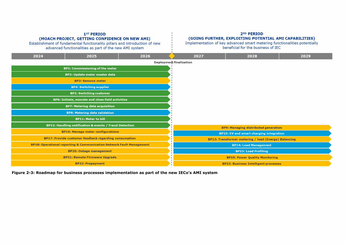
Figure 2-3: Roadmap for business processes implementation as part of the new IECo’s AMI system

Some relevant aspects when planning the implementation of business processes in each period need to
be considered. As part of the implementation roadmap a decision must be made on the implementation
principles with regards to a sequence of activities. The integration between the different business
processes, and within the respective business processes in a period, will go in series or parallel
depending on available resources, preparation of logistics and project management capabilities and
capacity.
Figure 2-4: Serial and parallel implementation of BPs
Below illustrated in Figure 2-5 are the business processes implementation principles. All business process
implementations have to follow a defined process, in which all personnel involved is trained. The
implementation process will be subject to continuous improvement as part of a Quality Management Plan
and should be a subject in joint IECo and solution provider project meetings. Existing BPs should be
operational all the time, excluding short periods of time caused by operational reasons.
Figure 2-5: Business processes implementation principles

This implementation per busines process can be divided into two main stages:
BP implementation planning
BP implementation
The stage of “BP implementation planning” comprises activities focused on the evaluation of the existing
business process implementation (maturity degree, integration efforts, etc.), the prioritization with
regards to other BPs in the same period (common use cases and smart metering functionalities), and the
communication to all personnel involved to make the preparations required. The main goal of this stage
is to ensure that everything is ready before starting the business process implementation.
The second stage, “BP implementation”, encompasses the following list of activities:
1. Coordination phase. Ensure that all personnel who is required to be involved in the business
process implementation is informed and prepared.
2. BP implementation. Execution task.
3. Implementation control. Control of the business process implementation from different
perspectives: operational, resourcing, quality, etc.
4. Validation phase: Intermediate phase for validating partial business process implementation
before going for the full implementation.
5. Stabilization phase. Final approval period, monitoring the performance of the implemented
business process as part of the new AMI System.
6. Closing phase. BP implementation process with the solution provider is concluded.
All the above-mentioned activities will be made in joint by IECo and the solution provider. Business
processes and new functions are expected to be delivered in an agile way-of-working, which is further
described in chapter 11.
Notice that for every business process, as indicated in the requirements 2.3-1 to 2.3-23, the bidder shall
describe how the business process is implemented, including a work flow which describes it in detail.
Business processes need to be designed to handle both ‘happy’ flows and ‘non-happy’ flows.
So when a business process fails, the step at the failure happens shall be easily tracked, facillitating the
failure identification by the user. To that aim, business process failures shall be tracked by implementing
a specific self-discovery mechanism that helps to understand the reason of failure. For analysis
purposes, the user will be able to create a report that shows statistical data regarding: the business
process, total number of executions, number of successful executions, number of failures from each
error type, etc.

AMI System Use Cases
The AMI system shall implement the following system Use Cases (UCs):
No: 2.4-1
Description: The AMI system shall support meter registration in the MDMS after a meter is installed in the field (‘UC1: Meter registration’).
Component: AMI
Required Maturity: STANDARD OR TO BE DEVELOPED
Priority: REQUIRED
Fit criterion: The AMI system supports seamless installation of smart meters. After installation, a
message from the meter is sent (e.g. triggered by connection to telecommunication network) to indicate that the meter is installed successfully. For LTE-based meters
this message is directly send to the MDMS/HES while for PLC-based meters this message is send to the DC and the DC will forward this to the MDMS/HES. The message contains all data needed in the system to identify the meter in the MDMS. Details are aligned between Contracting entity and Contractor, so that the meter registration supports the Contracting entities provisioning process.
Linking the metering point ID to the meter ID is not part of this system use case.
Evidence of
compliance:
Test report or documented evidence from bidder. The bidder shall describe how this system use case is implemented and what (if any) on site actions are needed on the meter to trigger the registration as ‘active’ meter in the MDMS.
No: 2.4-2
Description: The AMI system shall provide energy consumption data for billing purposes (‘UC2: Provide billing data’).
Component: AMI
Required Maturity: STANDARD OR TO BE DEVELOPED
Priority: REQUIRED
Fit criterion: The AMI system provides cumulative meter readings to the MDMS to support the ‘meter to bill process’. Consumption data is time stamped and comes with applicable status information. At least data (load profile and consumption data) for billing shall be available. Monthly billing data shall be stored in the E-meter for the last 15 months.
In addition to periodic meter readings for billing, providing data to settle the bill in the following cases shall also be supported:
customer move-in/move-out change of energy supplier meter replacement
Details are aligned between Contracting entity and Contractor, so that the use case supports the Contracting entity’s part of the ‘meter to bill’ process.
Evidence of
compliance:
Test report or documented evidence from bidder. The bidder shall describe how this system use case is implemented.
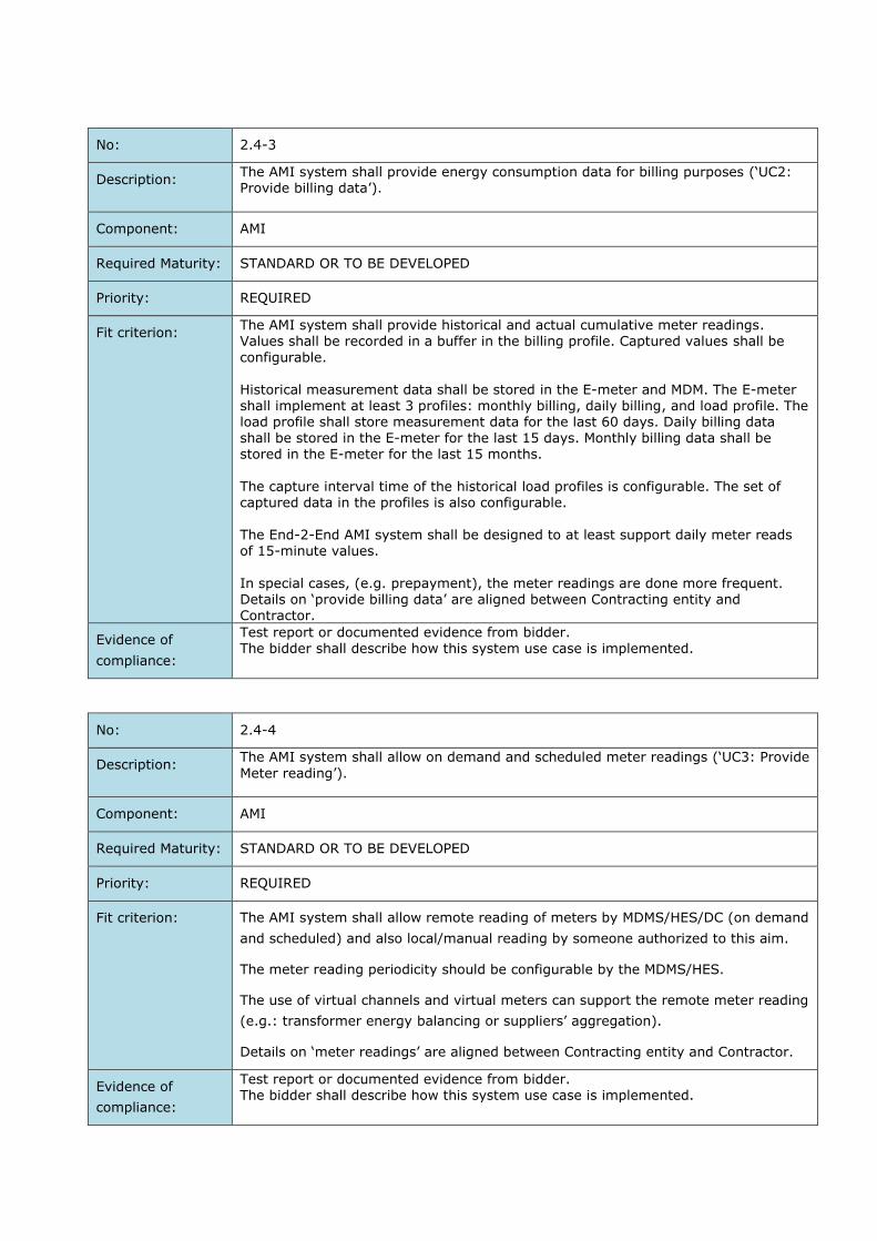
No: 2.4-3
Description: The AMI system shall provide energy consumption data for billing purposes (‘UC2: Provide billing data’).
Component: AMI
Required Maturity: STANDARD OR TO BE DEVELOPED
Priority: REQUIRED
Fit criterion: The AMI system shall provide historical and actual cumulative meter readings. Values shall be recorded in a buffer in the billing profile. Captured values shall be
configurable.
Historical measurement data shall be stored in the E-meter and MDM. The E-meter shall implement at least 3 profiles: monthly billing, daily billing, and load profile. The load profile shall store measurement data for the last 60 days. Daily billing data shall be stored in the E-meter for the last 15 days. Monthly billing data shall be stored in the E-meter for the last 15 months.
The capture interval time of the historical load profiles is configurable. The set of captured data in the profiles is also configurable. The End-2-End AMI system shall be designed to at least support daily meter reads of 15-minute values.
In special cases, (e.g. prepayment), the meter readings are done more frequent. Details on ‘provide billing data’ are aligned between Contracting entity and Contractor.
Evidence of
compliance:
Test report or documented evidence from bidder. The bidder shall describe how this system use case is implemented.
No: 2.4-4
Description: The AMI system shall allow on demand and scheduled meter readings (‘UC3: Provide
Meter reading’).
Component: AMI
Required Maturity: STANDARD OR TO BE DEVELOPED
Priority: REQUIRED
Fit criterion: The AMI system shall allow remote reading of meters by MDMS/HES/DC (on demand
and scheduled) and also local/manual reading by someone authorized to this aim.
The meter reading periodicity should be configurable by the MDMS/HES.
The use of virtual channels and virtual meters can support the remote meter reading
(e.g.: transformer energy balancing or suppliers’ aggregation).
Details on ‘meter readings’ are aligned between Contracting entity and Contractor.
Evidence of
compliance:
Test report or documented evidence from bidder. The bidder shall describe how this system use case is implemented.

No: 2.4-5
Description: The AMI system shall implement a Time of Use tariff system (‘UC4: Apply Tariffs’).
Component: AMI
Required Maturity: STANDARD OR TO BE DEVELOPED
Priority: REQUIRED
Fit criterion: The E-meter holds a Time of Use (ToU) tariff table and counts energy in separate
registers for each tariff.
Via the MDMS/HES, the ToU tariff table can be updated and activated. Activation can
be done immediately or scheduled.
The actual tariff code is available in the MDM via the HES.
At least 4 tariffs shall be supported.
The AMI will support the use of two different ToU tables. One of the ToU tables can
be assigned to any specific meter.
Details on the ToU tariff system are aligned between Contracting entity and Contractor.
Evidence of
compliance:
Test report or documented evidence from bidder. The bidder shall describe how this system use case is implemented.
No: 2.4-6
Description: The AMI system shall keep clocks of all system components synchronised with a reliable external clock (‘UC5: Clock Synchronisation’).
Component: AMI
Required Maturity: STANDARD OR TO BE DEVELOPED
Priority: REQUIRED
Fit criterion: The AMI system shall implement a clock synchronisation scheme that guarantees accurate time stamping of energy measurement data and supervision data (e.g.
system events).
The clock in AMI components shall not deviate more than 7 seconds. Details on clock synchronisation are aligned between Contracting entity and Contractor.
Evidence of
compliance:
Test report or documented evidence from bidder. The bidder shall describe how this system use case is implemented (e.g. via NTP server)
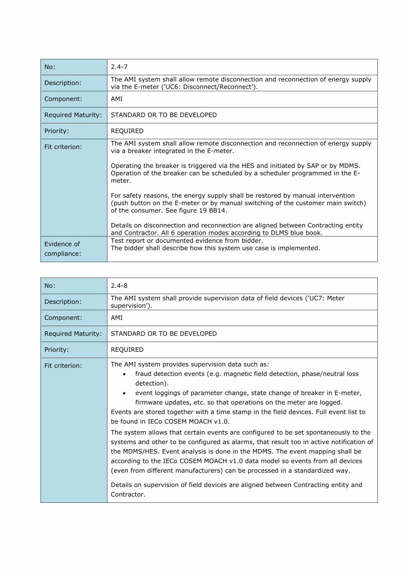
No: 2.4-7
Description: The AMI system shall allow remote disconnection and reconnection of energy supply via the E-meter (‘UC6: Disconnect/Reconnect’).
Component: AMI
Required Maturity: STANDARD OR TO BE DEVELOPED
Priority: REQUIRED
Fit criterion: The AMI system shall allow remote disconnection and reconnection of energy supply
via a breaker integrated in the E-meter. Operating the breaker is triggered via the HES and initiated by SAP or by MDMS. Operation of the breaker can be scheduled by a scheduler programmed in the E-
meter. For safety reasons, the energy supply shall be restored by manual intervention
(push button on the E-meter or by manual switching of the customer main switch) of the consumer. See figure 19 BB14. Details on disconnection and reconnection are aligned between Contracting entity and Contractor. All 6 operation modes according to DLMS blue book.
Evidence of
compliance:
Test report or documented evidence from bidder. The bidder shall describe how this system use case is implemented.
No: 2.4-8
Description: The AMI system shall provide supervision data of field devices (‘UC7: Meter
supervision’).
Component: AMI
Required Maturity: STANDARD OR TO BE DEVELOPED
Priority: REQUIRED
Fit criterion: The AMI system provides supervision data such as:
fraud detection events (e.g. magnetic field detection, phase/neutral loss
detection).
event loggings of parameter change, state change of breaker in E-meter,
firmware updates, etc. so that operations on the meter are logged.
Events are stored together with a time stamp in the field devices. Full event list to
be found in IECo COSEM MOACH v1.0.
The system allows that certain events are configured to be set spontaneously to the
systems and other to be configured as alarms, that result too in active notification of
the MDMS/HES. Event analysis is done in the MDMS. The event mapping shall be
according to the IECo COSEM MOACH v1.0 data model so events from all devices
(even from different manufacturers) can be processed in a standardized way.
Details on supervision of field devices are aligned between Contracting entity and
Contractor.

Evidence of
compliance:
Test report or documented evidence from bidder. The bidder shall describe how this system use case is implemented.
No: 2.4-9
Description: The AMI system shall support load limitation via the E-meters (‘UC8: Power
limitation’).
Component: AMI
Required Maturity: STANDARD OR TO BE DEVELOPED
Priority: REQUIRED
Fit criterion: The AMI system shall support limitation of load via the E-meters. The MDM via the HES allows programming of the load thresholds in the E-meters (Import Active Power Threshold and Export Active Power Threshold). Exceeding the threshold results in interruption of the energy supply via the breaker
in the E-meter. Details on load limitation are aligned between Contracting entity and Contractor.
Evidence of
compliance:
Test report or documented evidence from bidder. The bidder shall describe how this system use case is implemented.
No: 2.4-10
Description: The AMI system shall provide quality of supply data (‘UC9: Power quality reporting’).
Component: AMI
Required Maturity: STANDARD OR TO BE DEVELOPED
Priority: REQUIRED
Fit criterion: The AMI system provides quality of supply data. This data is measured by the E-
meters and published by the HES.
The following quality of supply data shall at least be available:
Recording and publishing of power quality parameters like voltage sags and
swells, and their durations.
Recording and publishing of outages and their duration.
Power quality events can be configured to raise alarms, so that HES is notified
instantly.
Details on quality of supply reporting are aligned between Contracting entity and Contractor.
Voltage level of the sag and/or swell and its duration will be configurable, by default it will be considered when +/- 5% V and above 30 sec.
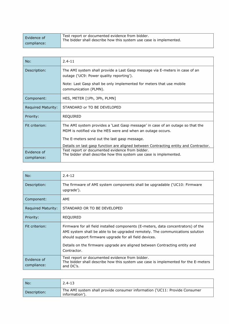
Evidence of
compliance:
Test report or documented evidence from bidder. The bidder shall describe how this system use case is implemented.
No: 2.4-11
Description: The AMI system shall provide a Last Gasp message via E-meters in case of an
outage (‘UC9: Power quality reporting’).
Note: Last Gasp shall be only implemented for meters that use mobile
communication (PLMN).
Component: HES, METER [1Ph, 3Ph, PLMN]
Required Maturity: STANDARD or TO BE DEVELOPED
Priority: REQUIRED
Fit criterion: The AMI system provides a ‘Last Gasp message’ in case of an outage so that the
MDM is notified via the HES were and when an outage occurs.
The E-meters send out the last gasp message.
Details on last gasp function are aligned between Contracting entity and Contractor.
Evidence of
compliance:
Test report or documented evidence from bidder. The bidder shall describe how this system use case is implemented.
No: 2.4-12
Description: The firmware of AMI system components shall be upgradable (‘UC10: Firmware
upgrade’).
Component: AMI
Required Maturity: STANDARD OR TO BE DEVELOPED
Priority: REQUIRED
Fit criterion: Firmware for all field installed components (E-meters, data concentrators) of the
AMI system shall be able to be upgraded remotely. The communications solution
should support firmware upgrade for all field devices.
Details on the firmware upgrade are aligned between Contracting entity and
Contractor.
Evidence of
compliance:
Test report or documented evidence from bidder. The bidder shall describe how this system use case is implemented for the E-meters and DC’s.
No: 2.4-13
Description: The AMI system shall provide consumer information (‘UC11: Provide Consumer information’).
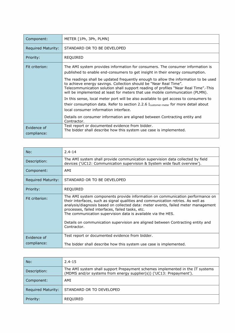
Component: METER [1Ph, 3Ph, PLMN]
Required Maturity: STANDARD OR TO BE DEVELOPED
Priority: REQUIRED
Fit criterion: The AMI system provides information for consumers. The consumer information is
published to enable end-consumers to get insight in their energy consumption.
The readings shall be updated frequently enough to allow the information to be used to achieve energy savings. Collection should be “Near Real Time”. Telecommunication solution shall support reading of profiles “Near Real Time”. This
will be implemented at least for meters that use mobile communication (PLMN).
In this sense, local meter port will be also available to get access to consumers to
their consumption data. Refer to section 2.2.6 Icustomer-meter for more detail about
local consumer information interface.
Details on consumer information are aligned between Contracting entity and Contractor.
Evidence of
compliance:
Test report or documented evidence from bidder. The bidder shall describe how this system use case is implemented.
No: 2.4-14
Description: The AMI system shall provide communication supervision data collected by field devices (‘UC12: Communication supervision & System wide fault overview’).
Component: AMI
Required Maturity: STANDARD OR TO BE DEVELOPED
Priority: REQUIRED
Fit criterion: The AMI system components provide information on communication performance on their interfaces, such as signal qualities and communication retries. As well as analysis/diagnosis based on collected data: meter events, failed meter management processes, failed interfaces, failed tasks, etc. The communication supervision data is available via the HES.
Details on communication supervision are aligned between Contracting entity and Contractor.
Evidence of
compliance:
Test report or documented evidence from bidder. The bidder shall describe how this system use case is implemented.
No: 2.4-15
Description: The AMI system shall support Prepayment schemes implemented in the IT systems (MDMS and/or systems from energy supplier(s)) (‘UC13: Prepayment’).
Component: AMI
Required Maturity: STANDARD OR TO DEVELOPED
Priority: REQUIRED

Fit criterion: The AMI system implements support for prepayment schemes implemented in the IT
system.
The MDM via the HES triggers actions on the E-meters that result from prepayment
schemes. The consumer is disconnected or reconnected to the electricity supply by
the HES switching of the breaker if the prepayment schemes prescribes this.
The available credit can also trigger load limitation via the meter.
The prepayment support shall not affect the meter hardware.
Daily data collection will be applied for all meters including those users with a
prepayment contract. For prepayment, SAP will request meter reading on a daily
basis. The meter reading periodicity should be configurable by the MDMS/HES.
Details on prepayment support are aligned between Contracting entity and
Contractor.
Evidence of
compliance:
Test report or documented evidence from bidder. The bidder shall describe how this system use case is implemented.
No: 2.4-16
Description: The AMI system shall support changing the configuration in the meter for the Measurement method (vector/arithmetic method) (‘UC14: Measurement method’).
Component: AMI
Required Maturity: STANDARD OR TO DEVELOPED
Priority: REQUIRED
Fit criterion: The AMI system implements support for changing the Measurement method.
The E-meter implements different measurement methods: vector method and
arithmetic method, that can be configurable from remote (HES/DC). By default, the
measurement method will be vectorial.
Switching between vectorial and arithmetical is enabled by function and not by firmware. Details on changing measurement method support are aligned between Contracting entity and Contractor.
Evidence of
compliance:
Test report or documented evidence from bidder. The bidder shall describe how this system use case is implemented.
No: 2.4-17
Description: The AMI system shall support changing the configuration in the meter for the Meter display (‘UC15: Meter display configuration’).
Component: AMI
Required Maturity: STANDARD OR TO DEVELOPED
Priority: REQUIRED

Fit criterion: The AMI system implements support for changing the Meter Display.
The E-meters implements different modes of display configuration, that can be configurable from local or remote (MDMS/HES/DC). Details on changing meter display support are aligned between Contracting entity
and Contractor.
Evidence of
compliance:
Test report or documented evidence from bidder. The bidder shall describe how this system use case is implemented.
No: 2.4-18
Description: The AMI system shall support changing the meter configuration to switch between
the two options to notify Events (‘UC16: Event Configuration’).
Component: AMI
Required Maturity: STANDARD OR TO DEVELOPED
Priority: REQUIRED
Fit criterion: The AMI system implements support for changing the event notification
configuration.
The E-meter implements two options to notify events: spontaneously (communicated automatically from the meter to the MDMS/HES via DC if applicable) and/or upon request from the MDMS/HES (logged). The spontaneous and/or logged event notification is configurable in the meter per event from local or remote (MDMS/HES/DC).
Details on changing events support are aligned between Contracting entity and Contractor.
Evidence of
compliance:
Test report or documented evidence from bidder. The bidder shall describe how this system use case is implemented.
Documentation Requirements
No: 2.5-1
Description: The bidder is required to submit specific documentation in English and referring
to the specific plant where the proposed components are manufactured.
Component: Meter [1Ph, 3Ph, CT, PLMN, PLC, DC]
Required Maturity: STANDARD
Priority: REQUIRED
Fit criterion: The Bidder is required to submit, with the technical proposal, the following documentation: A copy of a certificate of type (pattern) approval including test report from
an Accredited Laboratory that proves compliance with IEC 62052-11, IEC 62053-21 and IEC 62053-22,

Or alternatively, a Certificate / Declaration of conformity including test report from a valid Notified Body listed on NANDO website that proves
compliance with EN 50470-1, EN 50470-3 and a Certificate / Declaration of conformity including test report from an Accredited Laboratory that proves compliance with IEC 62053-23 or IEC 62053-24.
EN 50470-1 and EN 50470-3 MID Certificate shall be accepted only if performed and signed by an MID notified body from the list provided at NANDO website with 2014/32/EU Measuring Instruments Directive legislation.:
https://ec.europa.eu/growth/tools-databases/nando/index.cfm?fuseaction=directive.notifiedbody&dir_id=154161 Accredited laboratories are: NMI, OFGEM, NATA, KEMA, PTB, METAS or IECEE Certified Body Test List: https://test.iecee.org/dyn/www/f?p=106:41:0
RAM (Reliability, Availability, and Maintainability) Declaration - Further
details about the RAM declaration are provided in Appendix F. Calibration certificates and traceability charts for all relevant test and
calibration equipment. The manufacturer shall attach with the technical offer a complete
description of the meter with all its properties and its detailed relation to each item of this specification.
A signed “Off the shelf product declaration”, see Appendix G.
Evidence of
compliance:
Requested documentation provided by the bidder
No: 2.5-2
Description: The bidder is required to submit specific documentation in English and referring
to the specific plant where the proposed components are manufactured.
Component: Meter [1Ph, 3Ph, CT, PLMN, PLC, DC]
Required Maturity: STANDARD
Priority: REQUIRED
Fit criterion: The bidder is required to submit, with the technical proposal, the following documentation:
A copy of a certificate of compliance with ISO 9001:2015 issued by a Certification Body (CB) which is qualified by an Accreditation Body.
The certificate shall bear the logo of the CB and of its Accreditation Body and/or the logo of the IAF MLA.
The certificate shall be valid on the date set for submission of the proposal.
The certificate shall be valid for the scope of activities specified in the request for proposal.
Evidence of
compliance:
Requested documentation provided by the bidder.
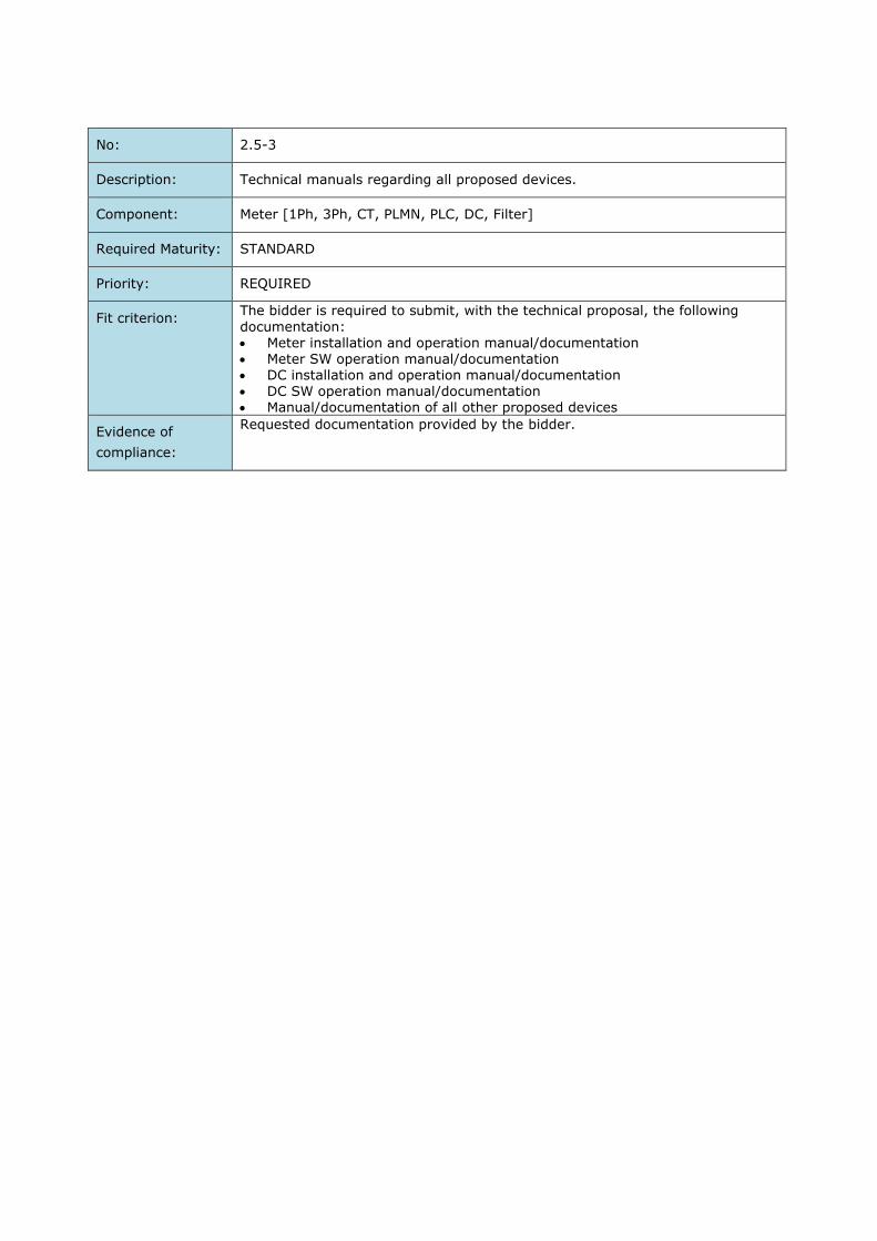
No: 2.5-3
Description: Technical manuals regarding all proposed devices.
Component: Meter [1Ph, 3Ph, CT, PLMN, PLC, DC, Filter]
Required Maturity: STANDARD
Priority: REQUIRED
Fit criterion: The bidder is required to submit, with the technical proposal, the following
documentation: Meter installation and operation manual/documentation Meter SW operation manual/documentation DC installation and operation manual/documentation
DC SW operation manual/documentation Manual/documentation of all other proposed devices
Evidence of
compliance:
Requested documentation provided by the bidder.
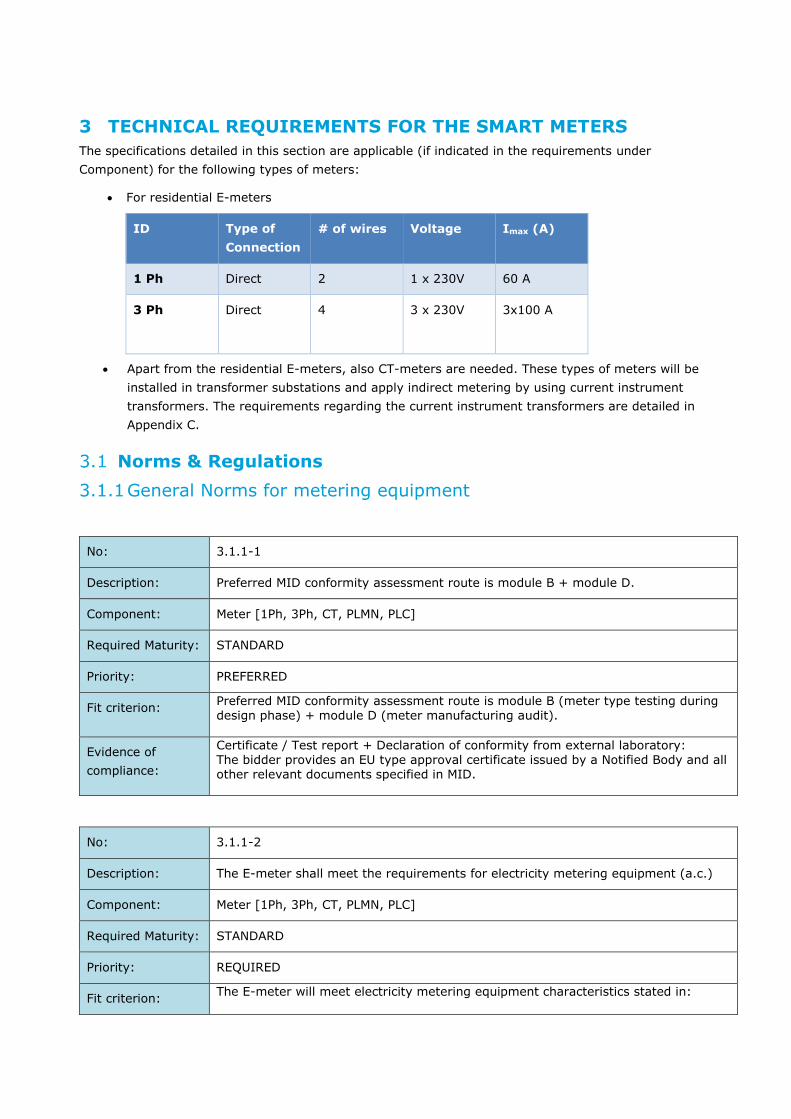
3 TECHNICAL REQUIREMENTS FOR THE SMART METERS
The specifications detailed in this section are applicable (if indicated in the requirements under
Component) for the following types of meters:
For residential E-meters
ID Type of
Connection
# of wires Voltage Imax (A)
1 Ph Direct 2 1 x 230V 60 A
3 Ph Direct 4 3 x 230V
3x100 A
Apart from the residential E-meters, also CT-meters are needed. These types of meters will be
installed in transformer substations and apply indirect metering by using current instrument
transformers. The requirements regarding the current instrument transformers are detailed in
Appendix C.
Norms & Regulations
3.1.1 General Norms for metering equipment
No: 3.1.1-1
Description: Preferred MID conformity assessment route is module B + module D.
Component: Meter [1Ph, 3Ph, CT, PLMN, PLC]
Required Maturity: STANDARD
Priority: PREFERRED
Fit criterion: Preferred MID conformity assessment route is module B (meter type testing during design phase) + module D (meter manufacturing audit).
Evidence of
compliance:
Certificate / Test report + Declaration of conformity from external laboratory: The bidder provides an EU type approval certificate issued by a Notified Body and all other relevant documents specified in MID.
No: 3.1.1-2
Description: The E-meter shall meet the requirements for electricity metering equipment (a.c.)
Component: Meter [1Ph, 3Ph, CT, PLMN, PLC]
Required Maturity: STANDARD
Priority: REQUIRED
Fit criterion: The E-meter will meet electricity metering equipment characteristics stated in:

• IEC 62052-11: General requirements, tests and test conditions - Metering equipment
• IEC 62053-21: Particular requirements, static meters for active energy • IEC 62053-23: Particular requirements, static meters for reactive energy
(classes 2 and 3) • IEC 62053-24: Particular requirements, static meters for reactive energy
(classes 0.5S, 1S, 2, and 3)
The E-meter is compliant with the specified electricity metering equipment (a.c.)
requirements. Alternative accepted standards are EN 50740-1, 3 respectively.
Evidence of
compliance:
Certificate / Test report + Declaration of conformity from external laboratory: The bidder provides a documented test report from an Accredited Laboratory that proves compliance with IEC 62052-11(or EN 50470-1), IEC 62053-21(or EN 50740-
3) and IEC 62053-23. The Laboratory must be an MID notified body.
No: 3.1.1-3
Description: The E-meter shall meet the requirements for immunity in the frequency range of the
CENELEC-A band as well as in FCC band.
Components: Meter [1Ph, 3Ph, CT, PLC]
Required Maturity: STANDARD or TO BE DEVELOPED
Priority: REQUIRED
Fit criterion: EN 50065 and FCC Part-15 compliance implies that the E-meter meets the specified requirements in terms of frequency bands and electromagnetic disturbances,
immunity requirements, low voltage decoupling filters and equipment impedance.
Evidence of
compliance:
Certificate / Test report + Declaration of conformity from external laboratory:
The bidder provides a documented test report from an Accredited Laboratory that proves compliance with EN 50065 and FCC Part-15.
3.1.2 Climatic conditions
No: 3.1.2-1
Description: The E-meter shall withstand the specified climatic conditions without damage or
degradation.
Component: Meter [1Ph, 3Ph, CT, PLMN]
Required maturity: STANDARD
Priority: REQUIRED
Fit criterion: The E-meter shall withstand the specified climatic conditions for indoor meters as defined in IEC 62052-11 (section 8) without damage or degradation. On top of these, the climatic conditions in Israel requires a specified operating range of at least -10 °C to 65 °C, without damage or degradation. The test report gives an overview of the performed tests and the test results to prove that the meter can withstand the specified climatic conditions without damage
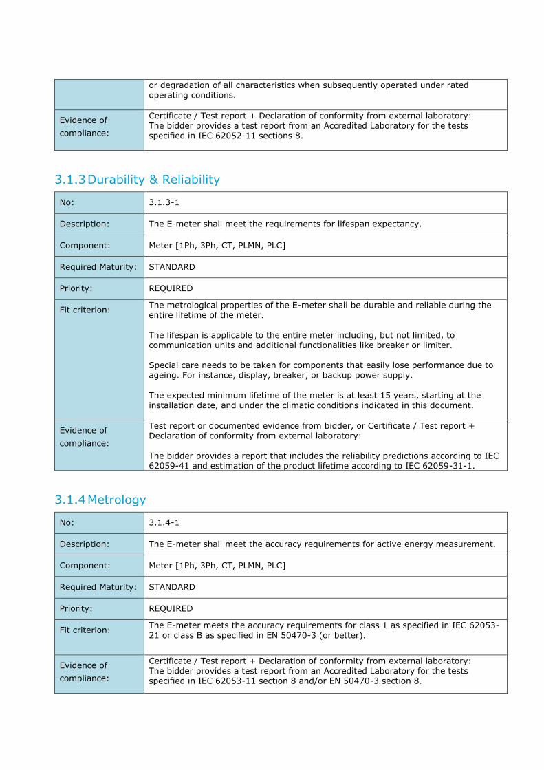
or degradation of all characteristics when subsequently operated under rated operating conditions.
Evidence of
compliance:
Certificate / Test report + Declaration of conformity from external laboratory: The bidder provides a test report from an Accredited Laboratory for the tests specified in IEC 62052-11 sections 8.
3.1.3 Durability & Reliability
No: 3.1.3-1
Description: The E-meter shall meet the requirements for lifespan expectancy.
Component: Meter [1Ph, 3Ph, CT, PLMN, PLC]
Required Maturity: STANDARD
Priority: REQUIRED
Fit criterion: The metrological properties of the E-meter shall be durable and reliable during the entire lifetime of the meter.
The lifespan is applicable to the entire meter including, but not limited, to communication units and additional functionalities like breaker or limiter. Special care needs to be taken for components that easily lose performance due to ageing. For instance, display, breaker, or backup power supply.
The expected minimum lifetime of the meter is at least 15 years, starting at the
installation date, and under the climatic conditions indicated in this document.
Evidence of
compliance:
Test report or documented evidence from bidder, or Certificate / Test report + Declaration of conformity from external laboratory:
The bidder provides a report that includes the reliability predictions according to IEC 62059-41 and estimation of the product lifetime according to IEC 62059-31-1.
3.1.4 Metrology
No: 3.1.4-1
Description: The E-meter shall meet the accuracy requirements for active energy measurement.
Component: Meter [1Ph, 3Ph, CT, PLMN, PLC]
Required Maturity: STANDARD
Priority: REQUIRED
Fit criterion: The E-meter meets the accuracy requirements for class 1 as specified in IEC 62053-21 or class B as specified in EN 50470-3 (or better).
Evidence of
compliance:
Certificate / Test report + Declaration of conformity from external laboratory: The bidder provides a test report from an Accredited Laboratory for the tests specified in IEC 62053-11 section 8 and/or EN 50470-3 section 8.
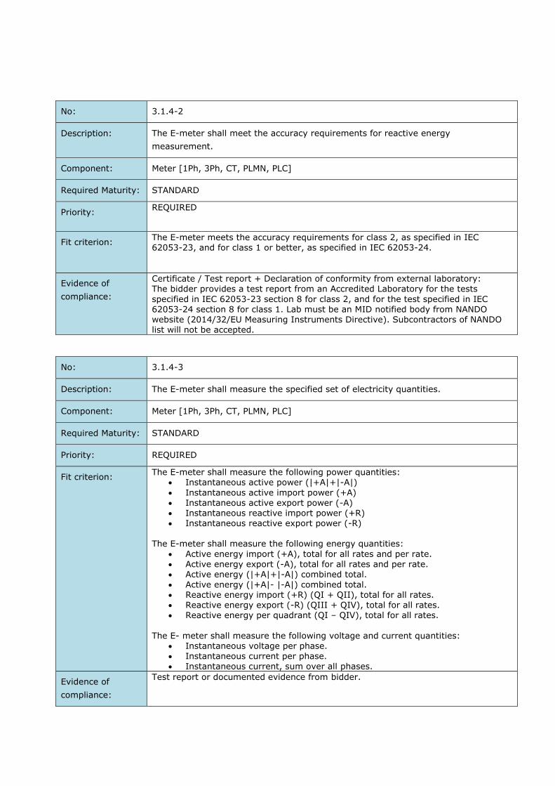
No: 3.1.4-2
Description: The E-meter shall meet the accuracy requirements for reactive energy
measurement.
Component: Meter [1Ph, 3Ph, CT, PLMN, PLC]
Required Maturity: STANDARD
Priority: REQUIRED
Fit criterion: The E-meter meets the accuracy requirements for class 2, as specified in IEC
62053-23, and for class 1 or better, as specified in IEC 62053-24.
Evidence of
compliance:
Certificate / Test report + Declaration of conformity from external laboratory: The bidder provides a test report from an Accredited Laboratory for the tests
specified in IEC 62053-23 section 8 for class 2, and for the test specified in IEC 62053-24 section 8 for class 1. Lab must be an MID notified body from NANDO website (2014/32/EU Measuring Instruments Directive). Subcontractors of NANDO list will not be accepted.
No: 3.1.4-3
Description: The E-meter shall measure the specified set of electricity quantities.
Component: Meter [1Ph, 3Ph, CT, PLMN, PLC]
Required Maturity: STANDARD
Priority: REQUIRED
Fit criterion: The E-meter shall measure the following power quantities:
Instantaneous active power (|+A|+|-A|)
Instantaneous active import power (+A) Instantaneous active export power (-A) Instantaneous reactive import power (+R) Instantaneous reactive export power (-R)
The E-meter shall measure the following energy quantities:
Active energy import (+A), total for all rates and per rate. Active energy export (-A), total for all rates and per rate. Active energy (|+A|+|-A|) combined total.
Active energy (|+A|- |-A|) combined total. Reactive energy import (+R) (QI + QII), total for all rates. Reactive energy export (-R) (QIII + QIV), total for all rates. Reactive energy per quadrant (QI – QIV), total for all rates.
The E- meter shall measure the following voltage and current quantities:
Instantaneous voltage per phase. Instantaneous current per phase. Instantaneous current, sum over all phases.
Evidence of
compliance:
Test report or documented evidence from bidder.
No: 3.1.4-4
Description: The E-meter shall measure apparent energy.
Component: Meter [1Ph, 3Ph, CT, PLMN, PLC]
Required Maturity: STANDARD or TO BE DEVELOPED
Priority: REQUIRED
Fit criterion: The E-meter shall measure the apparent energy:
Apparent energy import (+VA) Apparent energy export (-VA)
Evidence of
compliance:
Test report or documented evidence from bidder.
No: 3.1.4-5
Description: Measurement method to determine the net energy flow
Component: Meter [3Ph, CT, PLMN, PLC]
Required Maturity: STANDARD or TO BE DEVELOPED
Priority: REQUIRED
Fit criterion: The measurement method to determine the net energy flow can be either the
algebraic sum of the energy in the 3 separate phases (algebraic method) or the sum of the energy for all 3 phases together (vectorial method). The vectorial method sums the net energy flow over all phases (with maintaining the sign per phase) before the net result is stored in a register (resulting in net import or net export). The algebraic method sums consumption with the same sign separately and stores the outcome in the appropriate register(s).
The meter shall use by default the vectorial measurement method but shall have an option to switch to the algebraic measurement method. By default, the measurement method will be vectorial. Switching between vectorial and arithmetical is enabled by function and not by firmware. In Appendix B there is a description of the energy metering method modes.
Evidence of
compliance:
Certificate / Test report + Declaration of conformity from external laboratory: The bidder provides a test report from an Accredited Laboratory that includes test cases with simultaneous import and export on different phases, using both the algebraic and vectorial measurement methods.

3.1.5 Safety
No: 3.1.5-1
Description: The E-meter shall comply with the product safety requirements for electricity metering equipment.
Component: Meter [1Ph, 3Ph, CT, PLMN, PLC]
Required maturity: STANDARD
Priority: REQUIRED
Fit criterion: The meter shall comply with the IEC 62052-31:
Protection against electrical shock (protective class II) Protection against mechanical hazards
Resistance to mechanical stresses (IK02 or better per IEC 62262) Protection against spread of fire Equipment temperature limits and resistance to heat Protection against penetration of dust and water (at least IP51) Protection against liberated gases and substances explosion and implosion –
Batteries and battery charging (only if relevant) Components and sub-assemblies (only if relevant)
Hazards resulting from application – Reasonably foreseeable misuse Risk assessment
Evidence of
compliance:
Certificate / Test report + Declaration of conformity from external laboratory: The bidder provides a documented test report from an Accredited Laboratory to prove compliance with the relevant specifications of IEC 62052-31.
For safety specifications which are also covered in EN 50470-1 or -3, a test report according to that standard can also be accepted.
No: 3.1.5-2
Description: The E-meter shall withstand a free fall test
Component: Meter [1Ph, 3Ph, CT, PLMN, PLC]
Required maturity: STANDARD
Priority: REQUIRED
Fit criterion: The meter shall withstand a free fall test according to IEC 60068-2-32 (including Amendment 2). In short: 1-meter high vertical fall, followed by a full functional and visual test. The meter shall be placed in two positions: vertical and rotated 90
degrees horizontally.
For meters packed in a common box, the test conditions are as follows: height 500 mm; number of falls 50. For a single unpacked meter (without its terminal cover), the test conditions are as follows: height 500 mm; number of falls 2.
Evidence of
compliance:
Certificate / Test report + Declaration of conformity from external laboratory: The bidder provides a documented test report from an Accredited Laboratory (according to ISO17025) to prove compliance with the relevant specifications of IEC 60068-2-32. IECo may conduct its own free fall test to verify.

3.1.6 Electromagnetic compatibility
No: 3.1.6-1
Description: The E-meter shall provide electromagnetic compatibility (EMC).
Components: Meter [1Ph, 3Ph, CT, PLMN, PLC]
Required Maturity: STANDARD
Priority: REQUIRED
Fit criterion: The E-meter will meet the electromagnetic compatibility (EMC) criteria stated in IEC 62052-11 section 9.3.
The E-meter is compliance with the specified electromagnetic compatibility (EMC) criteria.
Evidence of
compliance:
Certificate / Test report + Declaration of conformity from external laboratory: The bidder provides a documented test report from an Accredited Laboratory that proves compliance with IEC 62052-11 section 9.3.
No: 3.1.6-2
Description: The meter shall be protected against external continuous magnetic flux levels
Components: Meter [1Ph, 3Ph, CT, PLMN, PLC]
Required Maturity: STANDARD or TO BE DEVELOPED
Priority: PREFERRED
Fit criterion: 1. The meter shall be protected against external continuous magnetic flux levels of
up to 1.5kG.
2. IECo requires that there shall be a flag at events log when magnetic flux value exceeds the value stated at IEC 62052-11, paragraph 9.3.12. The event log shall include a date+ time stamps of on/off event triggering. Event shall be triggered and logged if duration of influence is at least 15 sec. The manufacturer shall take measures so as not to flood the event log buffer.
Evidence of
compliance:
Certificate / Test report + Declaration of conformity from external laboratory:
The bidder provides a documented test report from an Accredited Laboratory that proves compliance with IEC 62052-11 section 9.3.12. + evaluation and approval by IECo of a sample using neodymium DC magnet.

Hardware Requirements
3.2.1 Electrical Ratings
No: 3.2.1-1
Description: The 3Ph meter shall comply to defined electrical ratings.
Component: METER [3Ph, CT, PLMN, PLC]
Required Maturity: STANDARD
Priority: REQUIRED
Fit criterion: The electrical ratings for the 3Ph meter are as follows:
Reference voltage Un: 3x230V (400V) Maximum current for direct connection meters Imax: 3x100A or higher
Reference current for CT meters: 3x 100/5 A". Reference frequency: 50Hz Number of wires: 4 (3 phases and neutral)
Evidence of
compliance:
Test report or documented evidence from bidder.
No: 3.2.1-2
Description: The 1Ph meter shall comply to defined electrical ratings.
Component: METER [1Ph, PLMN, PLC]
Required Maturity: STANDARD
Priority: REQUIRED
Fit criterion: The electrical ratings for the 1Ph meter are as follows:
Maximum current Imax: 60A or higher Reference frequency: 50Hz Number of wires: 2
Evidence of
compliance:
Test report or documented evidence from bidder.
3.2.2 Meter Casing
No: 3.2.2-1
Description: The meters should be of robust construction, compact, all insulated indoor pattern, with wall mounting case, with front connections and insulated terminal block with extended terminal cover.
Component: METER [1Ph, 3Ph, CT, PLMN, PLC]
Required Maturity: STANDARD
Priority: REQUIRED

Fit criterion: The materials used in the construction of the meters are to be of the highest quality and selected particularly to meet the duties required of them. Workmanship and
general finish are to be of the highest class throughout.
Evidence of
compliance:
Compliance with this specification is verified by evaluation of a sample.
No: 3.2.2-2
Description: The maximum dimensions of the meter casing of the 3Ph meter and the CT meter
shall not exceed specific dimensions.
Component: METER [3Ph, CT, PLMN, PLC]
Required Maturity: STANDARD
Priority: REQUIRED
Fit criterion: The maximum dimensions for meter casing are:
Height: 320 mm (including terminal cover)
Width: 180 mm (between bottom mounting holes axes)
Depth: 140 mm
Evidence of
compliance:
Compliance with this specification is verified by evaluation of a sample.
No: 3.2.2-3
Description: The maximum dimensions of the meter casing of the 1Ph meter shall not exceed
specific dimensions.
Component: METER [1Ph, PLMN, PLC]
Required Maturity: STANDARD
Priority: REQUIRED
Fit criterion: The maximum dimensions for meter casing are:
Height: 180 mm (including terminal cover)
Width: 90 mm (between bottom mounting holes axes)
Depth: 140 mm
Evidence of
compliance:
Compliance with this specification is verified by evaluation of a sample.

3.2.3 Seals
No: 3.2.3-1
Description: The seals applied on the E-meter shall prevent intruding into the E-meter and tampering.
Component: METER [1Ph, 3Ph, CT, PLMN, PLC]
Required Maturity: STANDARD
Priority: REQUIRED
Fit criterion: The E-meter is protected by seals in order to prevent intruding into the E-meter and tampering with the E-meter without removing the seals or damaging the meter casing.
All separate covers are protected by independent seals, for example: The meter cover The terminal cover Communication module cover
1. The meter shall be sealed in such a way to show and confirm the initial calibration performed on the meter. The metrological mark shall contain
calibration date, calibration equipment and operator info. 2. The meter base and cover could be either ultrasonically welded or
permanently glued together to prevent access to internal components. 3. Alternatively, screw(s) securing the meter cover to the base shall be either
unidirectional, or be featured by sheared head, so as to be irremovable. 4. In case of screws solution seal(s) of the same type made of tin-coated
electrolyte copper and crimped on a galvanized or stainless-steel cable
("rope") shall seal the meter cover to its base. 5. The seal shall be adjacent as much as possible to the screw, which is to be
sealed, and the surplus cable ends shall be cut adjacent to the sealing.
6. The seals shall be "sunk" into slits at the meter housing, in order to prevent user wounding from sharp edges.
Evidence of
compliance:
Compliance with this specification is verified by evaluation and approval by IECo of a sample.
No: 3.2.3-2
Description: The input voltage connection (link), if any, shall not be available for opening using
conventional means and shall be protected to prevent opening.
Component: METER [1Ph, 3Ph, PLMN, PLC]
Required Maturity: STANDARD
Priority: REQUIRED
Fit criterion: The meters will be supplied to IECo with the link, if any, closed and checked for continuity. There shall not be access to internal parts of the meter through the terminals.
Evidence of
compliance:
Compliance with this specification is verified by evaluation of a sample.

3.2.4 Markings
No: 3.2.4-1
Description: The markings on the meter shall be compliant with international standards.
Component: METER [1Ph, 3Ph, CT, PLMN, PLC]
Required Maturity: STANDARD
Priority: REQUIRED
Fit criterion: The marking on the meter shall be compliant with IEC 62052-11 (section 6.2), and IEC 62052-31 (section 5). All characteristics that have a standard symbol defined in IEC 62053-52 are marked
accordingly. The markings are logically grouped on the front side of the meter so that they can easily be read when the meter is installed in a meter cabinet. Additional information should include at least the following: Manufacturing country
Official IECo logo Encircled code number consisting of 3 or 4 digits. The code number will be given
to the Bidder who is awarded the order IECo meter serial number – unique and different for each meter
(appropriate numbers will be given by IECo). The 6-digit serial number shall be marked with digits at least 4 mm high height. Added to the 6-digit serial number are two digits to reflect the year of manufacture.
Barcode with IECo serial number and code number. The marking shall be done in code 128C with 12 digits; the first four digits for the meter code and 8 digits for the serial number + year of manufacture, adding leading zeros if necessary.
The minimum height of the bar-code mark shall be 10mm in medium density. The bar-code coding and readability shall be checked and confirmed by IECo. The result shall be at least 95% and light reflection at least 80%.
The communication mode (e.g. PLC, cellular) should be marked on the nameplate, with the relevant logo (IDIS, DLMS/COSEM, G3-PLC).
Exact marking shall be agreed between IECo and the contractor. Examples of
nameplates are shown in Figure 3-1, Figure 3-2, and Figure 3-3.
Evidence of
compliance:
Compliance with this specification is verified by evaluation of a sample. DLMS/COSEM, IDIS and G3-PLC certificated issued by the corresponding official user associations.
Figure 3-1: Example of single-phase direct connected meter nameplate
Figure 3-2: Example of three-phase direct and CT connected meter nameplate

Figure 3-3: Example of Meter face and nameplate
No: 3.2.4-2
Description: Markings shall be durable.
Component: METER [1Ph, 3Ph, CT, PLMN, PLC]
Required Maturity: STANDARD
Priority: REQUIRED
Fit criterion: The bidder provides proof of durability of the markings based upon the test described in IEC 62052-31 (section 5.2.2).
Evidence of
compliance:
Compliance with this specification is verified by evaluation of a sample and the Test report or documented evidence from bidder.
No: 3.2.4-3
Description: The connection diagram for the single-phase meter is shown in the terminal cover.
Component: METER [1Ph, PLMN, PLC]
Required Maturity: STANDARD or TO BE DEVELOPED
Priority: REQUIRED
Fit criterion: A connection diagram compliant to IEC 62052-11 (section 6.3) is shown in the
terminal cover.
The connection diagram shall comply with Figure 3-4 for the single-phase meter.
The sequence is: L N N L' (‘British Standard’).
Evidence of
compliance:
Compliance with this specification is verified by evaluation of a sample.
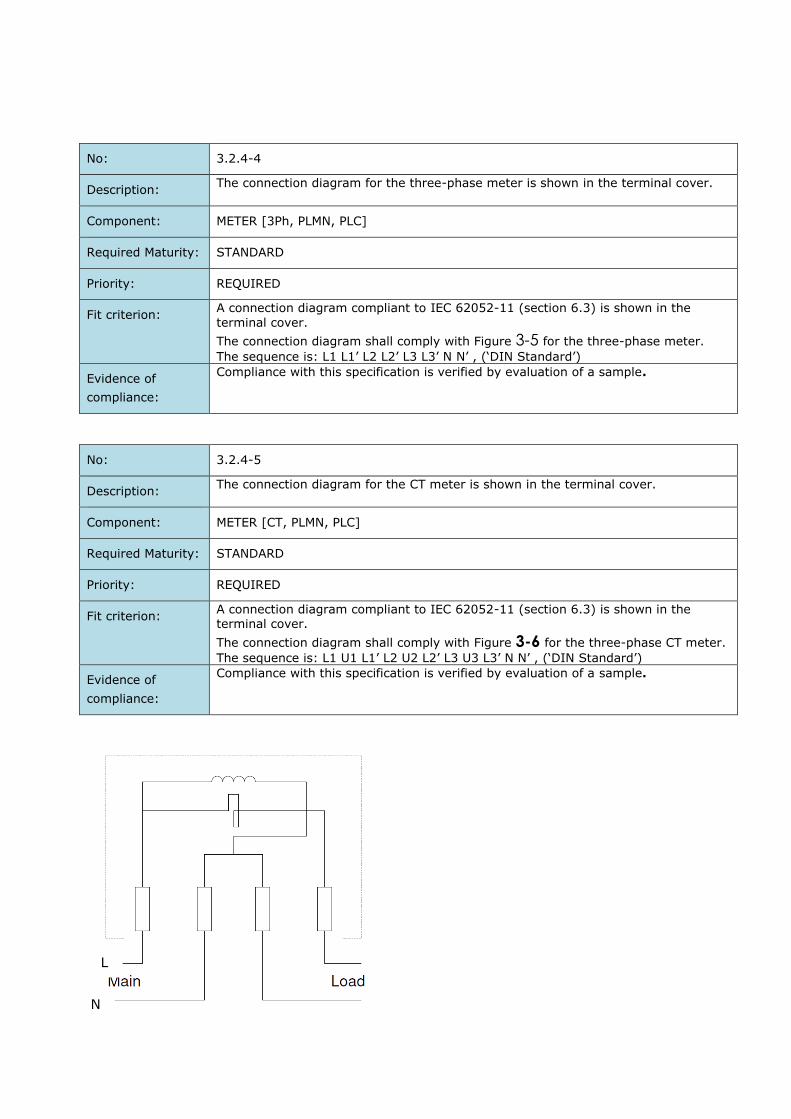
No: 3.2.4-4
Description: The connection diagram for the three-phase meter is shown in the terminal cover.
Component: METER [3Ph, PLMN, PLC]
Required Maturity: STANDARD
Priority: REQUIRED
Fit criterion: A connection diagram compliant to IEC 62052-11 (section 6.3) is shown in the
terminal cover.
The connection diagram shall comply with Figure 3-5 for the three-phase meter.
The sequence is: L1 L1’ L2 L2’ L3 L3’ N N’ , (‘DIN Standard’)
Evidence of
compliance:
Compliance with this specification is verified by evaluation of a sample.
No: 3.2.4-5
Description: The connection diagram for the CT meter is shown in the terminal cover.
Component: METER [CT, PLMN, PLC]
Required Maturity: STANDARD
Priority: REQUIRED
Fit criterion: A connection diagram compliant to IEC 62052-11 (section 6.3) is shown in the terminal cover.
The connection diagram shall comply with Figure 3-6 for the three-phase CT meter.
The sequence is: L1 U1 L1’ L2 U2 L2’ L3 U3 L3’ N N’ , (‘DIN Standard’)
Evidence of
compliance:
Compliance with this specification is verified by evaluation of a sample.
L
N
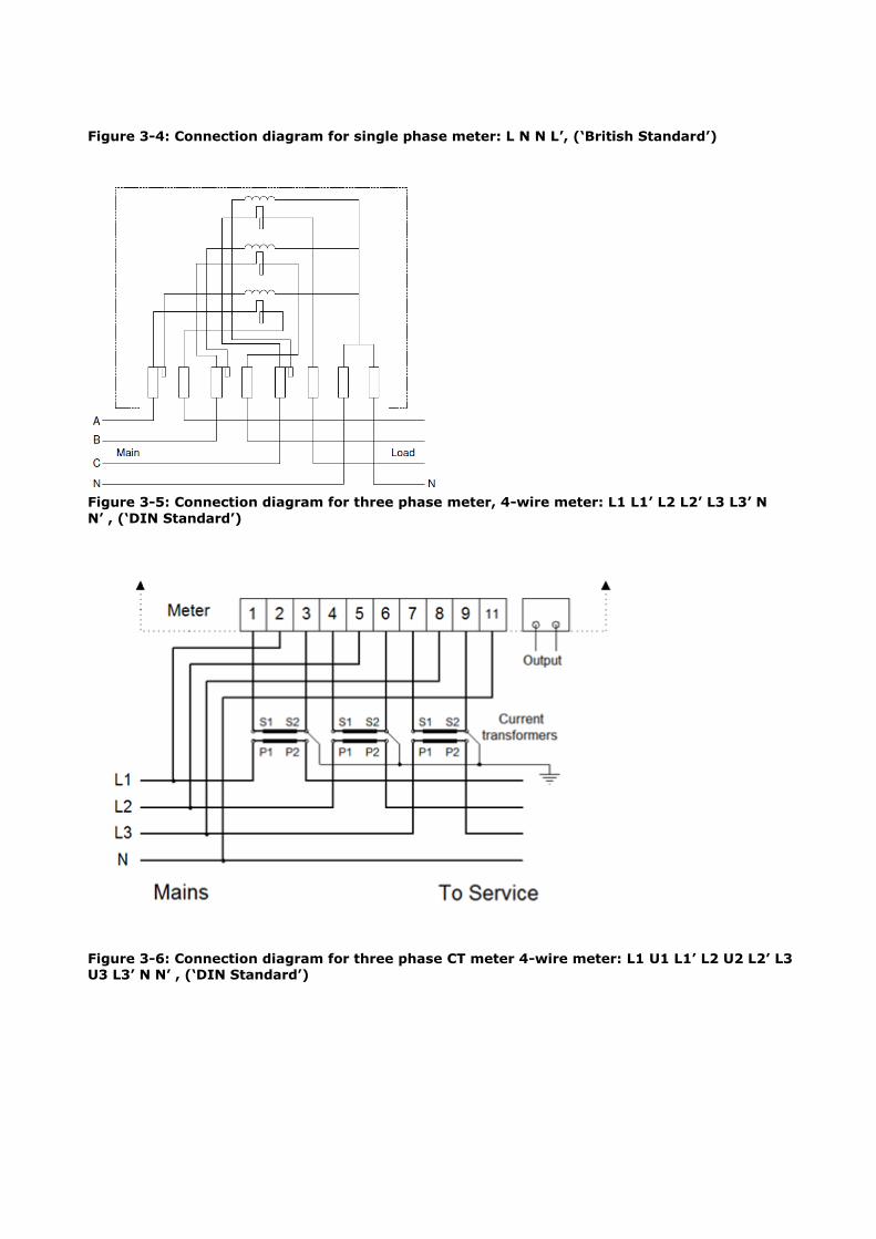
Figure 3-4: Connection diagram for single phase meter: L N N L’, (‘British Standard’)
Figure 3-5: Connection diagram for three phase meter, 4-wire meter: L1 L1’ L2 L2’ L3 L3’ N
N’ , (‘DIN Standard’)
Figure 3-6: Connection diagram for three phase CT meter 4-wire meter: L1 U1 L1’ L2 U2 L2’ L3 U3 L3’ N N’ , (‘DIN Standard’)

3.2.5 Terminal block
No: 3.2.5-1
Description: The terminals of the 1Ph meter shall follow the sequence: L N N L' (‘British Standard’).
Component: METER [1Ph, PLMN, PLC]
Required Maturity: STANDARD or TO BE DEVELOPED
Priority: REQUIRED
Fit criterion: The connection sequence shall comply with Figure 3-4. The sequence is: L N N L'
(‘British Standard’) in accordance with BS 7856:1996
Evidence of
compliance:
Compliance with this specification is verified by evaluation of a sample.
No: 3.2.5-2
Description: The terminals of the 3Ph meter shall follow the sequence: L1 L1’ L2 L2’ L3 L3’ N N’ , (‘DIN Standard’). The terminals of the CT meter shall follow the sequence: L1 U1 L1’ L2 U2 L2’ L3 U3 L3’ N N’.
Component: METER [3Ph, CT, PLMN, PLC]
Required Maturity: STANDARD
Priority: REQUIRED
Fit criterion: The terminals of the 3Ph meter shall follow the sequence: L1 L1’ L2 L2’ L3 L3’ N N’ , (‘DIN Standard’).
The terminals of the CT meter shall follow the sequence: L1 U1 L1’ L2 U2 L2’ L3 U3 L3’ N N’.
Evidence of
compliance:
Compliance with this specification is verified by evaluation of a sample.
No: 3.2.5-3
Description: Terminal screws shall be of sufficient quality and allow installation of meters.
Component: METER [1Ph, 3Ph, CT, PLMN, PLC]
Required Maturity: STANDARD
Priority: REQUIRED
Fit criterion: For single-phase and poly-phase meters for direct connection the screw
diameter must be at least M6 The tightening torque to ensure a good connection shall be less than 3 Nm. This
value shall be specified by the manufacturer. With a value of 1.5 times the value specified by the manufacturer, with a
minimum of 3.5 Nm, it should be possible to tighten and loose the screws 25 times without damage.
The terminal screws must be made either of Steel 8,8 and be Nickel plated (5 microns minimum) or made of brass and be protected against corrosion.
There shall be no galvanic couple between the screws, terminals, and copper conductor/thimble. Joined alloys potential difference must not exceed 0.15V (refer to ASTM G82 Standard).
The screw bottom must be chamfered, without rough edges. The meters must be supplied with all terminal screws fully inserted into the
terminals and tightened enough to prevent being loosened due to vibrations during transportation.
Evidence of
compliance:
Compliance with this specification is verified by evaluation of a sample.
No: 3.2.5-4
Description: Terminal blocks shall be of heavy-duty type.
Component: METER [1Ph, 3Ph, CT, PLMN, PLC]
Required Maturity: STANDARD
Priority: REQUIRED
Fit criterion: Each terminal shall have two screws associated to it. The terminal blocks shall be made either of Steel 8,8 and be Nickel plated (5
microns minimum), or made of brass and be protected against corrosion. There shall be no galvanic couple between the screws, terminals, and copper
conductor. Joined alloys potential difference must not exceed 0.15V (refer to ASTM G82 Standard).
Evidence of
compliance:
Compliance with this specification is verified by evaluation of a sample.
No: 3.2.5-5
Description: The terminals shall ensure robust connection of the wires.
Component: METER [1Ph, 3Ph, CT, PLMN, PLC]
Required Maturity: STANDARD
Priority: REQUIRED
Fit criterion: Connection of wires to the terminals of the meter shall always be reliable and save.
For direct meters each terminal must be provided with two screws to tighten copper conductor/thimble directly (so-called "pillar-bar-type" terminal), or by means of lift-clip which pinches a conductor (so-called "lift-type" terminal).
For single-phase meters for direct connection the bore diameter for external
cable connection shall be at least 8.0 -0.22 mm in accordance with ISO 286-1, 282-2 tolerances specifications.
For poly-phase meters for direct connection the bore diameter for external cable connection shall be at least 9.0 -0.22 mm in accordance with ISO 286-1, 282-2 tolerances specifications.
For CT-connected meters only pillar bar-type terminals shall be accepted. The bore diameter for external cable connection shall allow easy accommodation of 2
mm2 and 4 mm2 wires.
The terminals are designed so that wrong/improper connection is reduced to a minimum. Following cases are taken in consideration, but not limited to these:
Possibility to connect wires to the wrong side of the clamping unit Possibility to connect wires beside the screws Degradation of clamping force after wire connection
Evidence of
compliance:
Compliance with this specification is verified by evaluation of a sample.
No: 3.2.5-6
Description: The terminals shall have a cover.
Component: METER [1Ph, 3Ph, CT, PLMN, PLC]
Required Maturity: STANDARD
Priority: REQUIRED
Fit criterion: The terminal cover shall be of the extended type made of non-breakable, self-
extinguishing insulating material Class V-2 according to IEC 60695-11-10. The cover shall be extended type with free space for the connecting cables of:
o At least 40 mm for single-phase direct and CT connected meters. o At least 60 mm for three-phase meters.
The cover shall be firmly attached to the case with one or two screws. The cover shall be packed for shipping unscrewed, together with the meter. The screw/s, however, shall be inserted into their places in the cover.
The screws shall be protected from slip out from the cover when not tightened. After the meter is mounted, no access to the installation screws as well as
terminals or cables shall be possible without breaking the seal or the cover itself.
The connection diagram of the meter with terminals marking shall be attached to or stamped on the inner side of the cover.
The cover and the screws must be sealable.
Evidence of
compliance:
Compliance with this specification is verified by evaluation of a sample.
3.2.6 Meter mounting
No: 3.2.6-1
Description: Mounting brackets to allow easy mounting are required.
Component: METER [3Ph, PLMN, PLC]
Required Maturity: STANDARD
Priority: REQUIRED
Fit criterion: Mounting brackets to allow easy mounting are required for all meter model types, except for single-phase meters. The mounting bracket could be integral part of the meter base, slide-out, reversible or a clip-on accessory. The distance between the top of the meter case to the center of the extended mounting hole shall be 10-15 mm.

The mounting bracket should be of sufficient strength not to separate/break under the weight of the meter
The mounting hole shall enable mounting on a screw with diameter of 4-5 mm. The mounting hole shall be accessible for a screwdriver from the meter front side.
Examples of the mounting bracket are shown below in Figure 3-7.
Evidence of
compliance:
Compliance with this specification is verified by evaluation of a sample.
Figure 3-7: Example of mounting bracket
No: 3.2.6-2
Description: The meter shall have mounting holes
Component: METER [1ph, 3Ph, CT, PLMN, PLC]
Required Maturity: STANDARD
Priority: REQUIRED
Fit criterion: For single phase direct meters: The mounting holes spacing shall be in accordance with BS 7856:1996, The top mounting hole (hanging point) is optional.
For three phase meters (direct and CT connected): The meter shall have two bottom holes for its fixing by means of 5 mm diameter screws. The bottom holes must be covered by the terminal cover after its setting and sealing.
Evidence of
compliance:
Compliance with this specification is verified by evaluation of a sample.

3.2.7 Power supply
No: 3.2.7-1
Description: The polyphase meter shall function when connected to any one phase.
Component: METER [3Ph, CT, PLMN, PLC]
Required Maturity: STANDARD
Priority: REQUIRED
Fit criterion: The polyphase E-meter is operational when connected between any line and the neutral line.
Evidence of
compliance:
Compliance with this specification is verified by evaluation of a sample.
No: 3.2.7-2
Description: The polyphase meter shall function with only the neutral disconnected, or with 1 or 2 phases disconnected with the neutral still connected. The errors in energy measurement shall not exceed the limits allowed in the standards regarding single phase energizing.
Component: METER [3Ph, PLMN, PLC]
Required Maturity: STANDARD
Priority: REQUIRED
Fit criterion: The polyphase E-meter is operational with only the neutral disconnected, or with 1 or 2 phases disconnected with the neutral still connected.
Evidence of
compliance:
Compliance with this specification is verified by evaluation of a sample.
No: 3.2.7-3
Description: The polyphase meter shall withstand overvoltage between the phase and the neutral.
Component: METER [3Ph, CT, PLMN, PLC]
Required Maturity: STANDARD
Priority: REQUIRED
Fit criterion: Meters shall withstand the following tests:
1. If a voltage of up to 400 V rms is applied between the phase and neutral, the meter shall not be damaged, and continue to operate properly when the over-voltage condition is removed.
2. "Worst case test" scenario is when inputs over-voltage been applied upon all three phases (for three-phase meters) during two hours simultaneously. There shall not be any change of the meter metrological features when over-
voltage is removed.

3. The meter must run for two hours at Uth, and immediately afterwards for two hours at Un. The meter error values before and after the test will be
compared. The test load is Un, Ib and PF=1.
Evidence of
compliance:
Compliance with this specification is verified by evaluation of a sample.
No: 3.2.7-4
Description: The meter shall have a back-up power supply that maintains meter functions.
Component: METER [1Ph, 3Ph, CT, PLMN, PLC]
Required Maturity: STANDARD
Priority: REQUIRED
Fit criterion: The E-meter contains a back-up power supply that can maintain the following
functions while the meter is not powered via the mains:
Allow the E-meter to register complete power failures (in non-volatile memory),
Keep the RTC running The back-up power supply meets the specifications in IEC 62052-21 sections 7.1.6
and 7.1.7.
Evidence of
compliance:
Test report or documented evidence from bidder.
3.2.8 User interface
3.2.8.1 Meter display
No: 3.2.8.1-1
Description: The E-meter shall have a digital display.
Component: METER [1Ph, 3Ph, CT, PLMN, PLC]
Required Maturity: STANDARD
Priority: REQUIRED
Fit criterion: The display is compliant with IEC 62052-11 (section 5.6).
Evidence of
compliance:
Test report or documented evidence from bidder.
No: 3.2.8.1-2
Description: It shall be possible to perform a display test.

Component: METER [1Ph, 3Ph, CT, PLMN, PLC]
Required Maturity: STANDARD
Priority: REQUIRED
Fit criterion: It is possible to trigger a display test in order to verify the proper functioning of the display.
Evidence of
compliance:
Compliance with this specification is verified by evaluation of a sample.
No: 3.2.8.1-3
Description: The meter display shall be able to show measurement values in auto-scroll mode.
Component: METER [1Ph, 3Ph, CT, PLMN, PLC]
Required Maturity: STANDARD
Priority: REQUIRED
Fit criterion: (Measurement) values are indicated by: Value field: The value field should support at least 6 digits with digit height of at
least 8 mm, with leading zeros if necessary. Energy measurement values are by
default shown with 0 decimals. Value identification: Reduced OBIS codes are used to identify the values. Fields
A, B and F of the OBIS code are not shown. Unit of the displayed value. The units (e.g. kWh, kVAh, kVArh, W, A, ...) are
placed adjacent to the value. The order for each display item shall be programmable The interval for auto-scrolling shall be configurable.
Format for energy – 6 digits with no decimals – 000000 - >999999 then roll over
Format for Max Demand – 3 digits with 1 decimal – 000.0 to 999.9 Format for Cumulative Max demand – 5 digits with 1 decimal -00000.0 to
99999.9 Format Date & Time: DD/MM/YY 24 h
The values are shown in auto-scroll mode. Exact set of values are aligned between Contracting entity and Contractor.
Evidence of
compliance:
Test report or documented evidence from bidder. Alternatively, the display roll-over can be checked by evaluating a sample. For this purpose the samples should be
delivered with the register values of 999998 so that roll-over can be verified.
No: 3.2.8.1-4
Description: The display shall permanently show status information when the meter is powered.
Component: METER [1Ph, 3Ph, CT, PLMN, PLC]
Required Maturity: STANDARD
Priority: REQUIRED

Fit criterion: The display shows at least the following status items: Disconnector status indicator (Disconnected / ‘Ready for Reconnection’)
Indication per phase that voltage is present Instantaneous energy direction (import or export) Active tariff Negative consumption flag (the flag shall be removed after reading) Failure indication and code (if any) Battery
These items are permanently shown on the display (not in scroll mode). In case text is used to display the disconnector status, the text message and the register value are shown simultaneously or alternating.
Evidence of
compliance:
Test report or documented evidence from bidder.
No: 3.2.8.1-5
Description: The meter shall have a manual scroll mode.
Component: METER [1Ph, 3Ph, CT, PLMN, PLC]
Required Maturity: STANDARD
Priority: REQUIRED
Fit criterion: By pressing the button on the meter, a consumer accesses the manual scroll mode. The same button is used to visualize the next item of the ‘display list for manual scroll mode’.
After a period of inactivity, the meter returns to automatic scroll mode.
The exact set of values shown in manual-scroll mode are aligned between contracting entity and contractor.
Evidence of
compliance:
Test report or documented evidence from bidder.
No: 3.2.8.1-6
Description: The default display language shall be English.
Component: METER [1Ph, 3Ph, CT, PLMN, PLC]
Required Maturity: STANDARD
Priority: REQUIRED
Fit criterion: If text messages on the display are used, then the display language is English.
Evidence of
compliance:
Test report or documented evidence from bidder.
No: 3.2.8.1-7

Description: The E-meter shall indicate the reception of the communication signal with distinguished signal strength levels.
Component: METER [1Ph, 3Ph, CT, PLMN]
Required Maturity: STANDARD
Priority: REQUIRED
Fit criterion: The E-meter indicates whether the signal level of the network is enough for good
communication. This is done by displaying signal strength levels. In addition, the signal level indication will be updated periodically. The signal level indication must be made visible on the display.
Evidence of
compliance:
Test report or documented evidence from bidder.
No: 3.2.8.1-8
Description: High resolution display mode
Component: METER [1Ph, 3Ph, CT, PLMN, PLC]
Required Maturity: STANDARD or TO BE DEVELOPED
Priority: REQUIRED
Fit criterion: The meter shall have a high-resolution display mode of at least 10wh/varh for dial
test /accuracy testing. Changing to this mode shall occur by the meter push buttons
and/or software for at least 60 minutes. It shall not be possibility to enter the high-resolution display mode unauthorized. The meter shall reset to normal at power off.
Evidence of
compliance:
Compliance with this specification is also verified by evaluation of a sample.
3.2.8.2 Push button
No: 3.2.8.2-1
Description: The E-meter shall have at least one push button.
Component: METER [1Ph, 3Ph, CT, PLMN, PLC]
Required Maturity: STANDARD
Priority: REQUIRED
Fit criterion: The meter shall have at least one push button to at least trigger the following functions:
Scroll through menu (manual scroll mode)
To safely reconnect the breaker
Evidence of
compliance:
Compliance with this specification is verified by evaluation of a sample.

3.2.8.3 Test output
No: 3.2.8.3-1
Description: An optical test output (flashing LED indicator) shall be available.
Component: METER [1Ph, 3Ph, CT, PLMN, PLC]
Required Maturity: STANDARD
Priority: REQUIRED
Fit criterion: An optical test output for active energy is present on the meter. The test output complies with IEC 62052-11 (section 5.8).
In case multiple optical test outputs are available (e.g. one for active and one for reactive energy), then markings on the nameplate indicate the function of each
optical output. The ratio (energy/pulse) shall also be indicated on the nameplate.
Evidence of
compliance:
The bidder provides a test report from an Accredited Laboratory that proves that the optical test output complies with IEC 62052-11 (section 5.8).
3.2.9 Real Time Clock
No: 3.2.9-1
Description: The RTC clock of the E-meter shall be accurate.
Component: METER [1Ph, 3Ph, CT, PLMN, PLC]
Required Maturity: STANDARD
Priority: REQUIRED
Fit criterion: The clock shall not deviate more than 0.5 seconds per 24 hours. (According to IEC 62054-21 Electricity metering (a.c.) Tariff and Load Control Part 21: Requirements for time switches, Clause 7.5.2.2 Requirements for crystal-controlled time switches)
Evidence of
compliance:
Test report or documented evidence from bidder.
No: 3.2.9-2
Description: The E-meter shall handle daylight savings time.
Component: METER [1Ph, 3Ph, CT, PLMN, PLC]
Required Maturity: STANDARD
Priority: REQUIRED
Fit criterion: The E-meter autonomously switches to daylight savings time according to Israeli law:
DST Entry: the Friday before the last Sunday of March DST Exit: the last Sunday of October
Or: The DST can be (locally) configured via a table for at least 4 years ahead
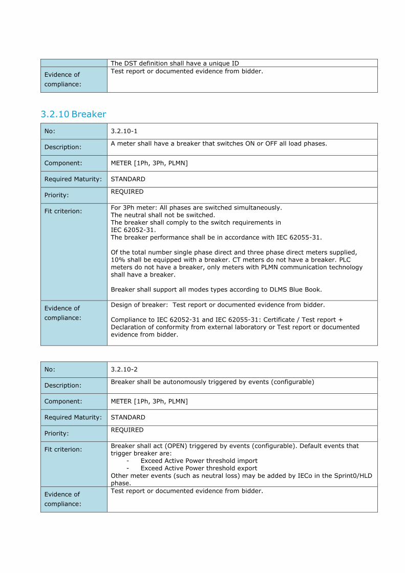
The DST definition shall have a unique ID
Evidence of
compliance:
Test report or documented evidence from bidder.
3.2.10 Breaker
No: 3.2.10-1
Description: A meter shall have a breaker that switches ON or OFF all load phases.
Component: METER [1Ph, 3Ph, PLMN]
Required Maturity: STANDARD
Priority: REQUIRED
Fit criterion: For 3Ph meter: All phases are switched simultaneously. The neutral shall not be switched. The breaker shall comply to the switch requirements in IEC 62052-31. The breaker performance shall be in accordance with IEC 62055-31.
Of the total number single phase direct and three phase direct meters supplied, 10% shall be equipped with a breaker. CT meters do not have a breaker. PLC meters do not have a breaker, only meters with PLMN communication technology shall have a breaker. Breaker shall support all modes types according to DLMS Blue Book.
Evidence of
compliance:
Design of breaker: Test report or documented evidence from bidder. Compliance to IEC 62052-31 and IEC 62055-31: Certificate / Test report + Declaration of conformity from external laboratory or Test report or documented evidence from bidder.
No: 3.2.10-2
Description: Breaker shall be autonomously triggered by events (configurable)
Component: METER [1Ph, 3Ph, PLMN]
Required Maturity: STANDARD
Priority: REQUIRED
Fit criterion: Breaker shall act (OPEN) triggered by events (configurable). Default events that trigger breaker are:
- Exceed Active Power threshold import - Exceed Active Power threshold export
Other meter events (such as neutral loss) may be added by IECo in the Sprint0/HLD phase.
Evidence of
compliance:
Test report or documented evidence from bidder.

3.2.11 Memory
No: 3.2.11-1
Description: When the meter is not powered, the data in the meters shall stay in non-volatile memory for a minimum specified period.
Component: METER [1Ph, 3Ph, CT, PLMN, PLC]
Required Maturity: STANDARD
Priority: REQUIRED
Fit criterion: When powered up again after a power down, the E-meter must become operational with no loss of data or configuration settings.
The meter complies with the minimum retention time of 12 months for measurement data, as specified in IEC 62052-11 (section 5.7) This applies also to other data, at least: Event-logs Power quality logs The meter will not lose configuration data needed for a functioning of the meter, at
least: Security parameters. Communication settings.
Evidence of
compliance:
Test report or documented evidence from bidder.
No: 3.2.11-2
Description: The meter shall have sufficient memory capacity.
Component: METER [1Ph, 3Ph, CT, PLMN, PLC]
Required Maturity: STANDARD or TO BE DEVELOPED
Priority: REQUIRED
Fit criterion: The E-meter shall have sufficient memory for at least 3 profiles: monthly billing, daily billing, and load profile. The load profile shall store measurement data for the
last 60 days. Daily billing data shall be stored in the E-meter for the last 15 days. Monthly billing data shall be stored in the E-meter for the last 15 months. The capture interval time of the historical load profiles is configurable. The set of captured data in the profiles is also configurable.
The End-2-End AMI system shall be designed to at least support daily meter reads of 15-minute values. In special cases, (e.g. prepayment), the meter readings are done more frequent.
Evidence of
compliance:
Test report or documented evidence from bidder.

Software Requirements
3.3.1 Data exchange & data model
No: 3.3.1-1
Description: The Annexure B2 - MOACH DLMS COSEM PROFILE for mobile communication
interfaces shall be implemented.
Component: METER [1Ph, 3Ph, CT, PLMN]
Required Maturity: STANDARD OR TO BE DEVELOPED
Priority: REQUIRED
Fit criterion: The meter implements the Annexure B2 - MOACH DLMS COSEM PROFILE for
communication interfaces for Mobile communication.
Evidence of
compliance:
Test report
No: 3.3.1-2
Description: The Annexure B2 - MOACH DLMS COSEM PROFILE for communication interfaces MOACH Smart Meters – G3-PLC communication, shall be implemented.
Component: METER [1Ph, 3Ph, CT, PLC]
Required Maturity: STANDARD OR TO BE DEVELOPED
Priority: REQUIRED
Fit criterion: The meter implements the Annexure B2 - MOACH DLMS COSEM PROFILE for communication interfaces MOACH Smart Meters for G3-PLC communication.
Evidence of
compliance:
Test report
No: 3.3.1-3
Description: The E-meter shall have a Time of Use (ToU) table implementation
Component: METER [1Ph, 3Ph, CT, PLMN, PLC]
Required Maturity: STANDARD OR TO BE DEVELOPED
Priority: REQUIRED
Fit criterion: The E-meter holds a Time of Use (ToU) tariff table and counts energy in separate registers for each tariff.
It shall be remotely configurable and robust to communication failures.
The general definitions of the ToU structure are according to Figure 3-8.
IECo preserves the right and shall test, ability to modify ToU configuration, for up to four tariffs per day.
The ToU table below shall be programmed through configuration file or via its communication interface to arriving meters.

IECo requires that it shall be possible to re-program ToU table as defined in IECo requirements.
The meter shall input and store any ToU table covering at least 12 seasons per year, at least 4 tariffs per season, 3 day types per season, calculation of Maximum demand for each of the 4 tariffs, and 18 points for definition of
"special days" and holidays (Table 3-1, Israel calendar - in accordance with
17 special days per year), at least 3 types of days, at least 24 tariff change points per day (rates: high, medium #1, medium #2, low) indicating the beginning of tariff and the beginning and dates of day light saving time period. There should be at least space for 100 special days in the total to cover 6 years of special days.
Evidence of
compliance:
Test report or documented evidence from bidder. Special days implementation is to be agreed upon between the parties before implementation.
Table 3-1: Special Days # Holiday Name Day Type Date Day of week
1 Pesach Holiday evening 22-4-2024
2 Pesach Holiday 23-4-2024
3 Pesach 2 Holiday evening 28-4-2024
4 Pesach 2 Holiday 29-4-2024
5 Atzmaout Holiday evening 13-5-2024
6 Atzmaout Holiday 14-5-2024
7 Shavuot Holiday evening 11-6-2024
8 Shavuot Holiday 12-6-2024
9 Rosh-Hashana Holiday evening 2-10-2024
10 Rosh-Hashana Holiday 3-10-2024
11 Rosh-Hashana Holiday 4-10-2024
12 Yom-Kippur Holiday evening 11-10-2024 Friday
13 Yom-Kippur Holiday 12-10-2024 Saturday
14 Sukkoth Holiday evening 16-10-2024
15 Sukkoth Holiday 17-10-2024
16 Simchat Torah Holiday evening 23-10-2024
17 Simchat Torah Holiday 24-10-2024
Figure 3-8: ToU Table 2010

3.3.2 Firmware
No: 3.3.2-1
Description: The legally relevant (=metrological) firmware shall be separated from the other
part(s) and cannot be upgraded.
Component: METER [1Ph, 3Ph, CT, PLMN, PLC]
Required Maturity: STANDARD
Priority: REQUIRED
Fit criterion: The metrological (= legally relevant) firmware cannot be upgraded and has its own
version number and checksum. The version number of the metrological firmware is accessible via the display.
Evidence of
compliance:
Test report or documented evidence from bidder. Compliance with this specification is verified by evaluation of a sample.
No: 3.3.2-2
Description: Updates of legally non-relevant firmware shall not affect the operation of the E-meter or stored data.
Component: METER [1Ph, 3Ph, CT, PLMN, PLC]
Required Maturity: STANDARD
Priority: REQUIRED
Fit criterion: The legally non-relevant part(s) of the firmware, including the firmware of the communication components, has the possibility to be updated. During an update, the execution of measurements by the metrological part is not impacted. Data
stored in the E-meter is not impacted by a firmware upgrade, nor does a firmware update result in configuration changes.
Evidence of
compliance:
Test report or documented evidence from bidder.

4 TECHNICAL REQUIREMENTS FOR THE DATA CONCENTRATORS
Norms & Regulation Related Requirements
4.1.1 Climatic conditions
No: 4.1.1-1
Description: The DC shall withstand specified temperature ranges without damage or
degradation.
Component: DC
Required maturity: STANDARD
Priority: REQUIRED
Fit criterion: The DC will meet the following environmental characteristics, according to the criteria stated in IEC 60068-2-1 (cold), IEC 60068-2-2 (dry heat) and IEC 60068-2-14 (temperature variation):
Operating temperature range: -10ºC to 65ºC The test report gives an overview of the performed tests and the test results to
prove that the DC can withstand the specified temperature ranges without damage or degradation of all characteristics when subsequently operated under rated operating conditions.
Evidence of
compliance:
Test report or documented evidence from bidder or
Certificate / Test report + Declaration of conformity from external laboratory*: The bidder provides a test report for the tests specified in IEC 60068-2-1, IEC 60068-2-2, and IEC 60068-2-14.
* In this case, self-certification is allowed.
No: 4.1.1-2
Description: The DC shall withstand specified humidity ranges without damage or degradation.
Component: DC
Required maturity: STANDARD
Priority: REQUIRED
Fit criterion: The DC will meet the following environmental characteristics, according to the criteria stated in IEC 60068-2-78 (damp heat):
Humidity range: 5% to 95%. The DC is suited for the specified relative humidity conditions for operation under condensing humidity.
Evidence of
compliance:
Test report or documented evidence from bidder or Certificate / Test report + Declaration of conformity from external laboratory*: The bidder provides a test report for the tests specified in IEC 60068-2-78. * In this case, self-certification is allowed.

4.1.2 Durability & Reliability
No: 4.1.2-1
Description: The DC shall meet the requirements for lifespan expectancy.
Component: DC
Required Maturity: STANDARD
Priority: REQUIRED
Fit criterion: The expected minimum lifetime of the DC is at least 15 years, starting at the installation date, and under the climatic conditions indicated in this document.
The lifespan is applicable to the entire DC including, but not limited, to communication units and additional functionalities. Special care needs to be taken for components that easily lose performance due to ageing. For instance, backup power supply.
Evidence of
compliance:
Test report or documented evidence from bidder, or Certificate / Test report +
Declaration of conformity from external laboratory. The bidder provides a report which includes reliability predictions and estimation of the product lifetime in such a detail that ensure that predictions methods are clearly reported, and they justify accordingly the stated values.
4.1.3 Safety
No: 4.1.3-1
Description: The DC shall be marked in accordance to relevant Israeli
Parliament/Council/Commission Decisions, Directives, and Regulations.
Component: DC
Required Maturity: STANDARD
Priority: REQUIRED
Fit criterion: The DC shall be marked in accordance to relevant Israeli Parliament/Council/Commission Decisions, Directives, and Regulations, related to low voltage electrical equipment.
Evidence of
compliance:
Certificate / Test report + Declaration of conformity from external laboratory.
The bidder provides relevant declaration of conformity for the DC offered.
No: 4.1.3-2
Description: The DC shall provide the specified protection degree against water and dust.
Component: DC
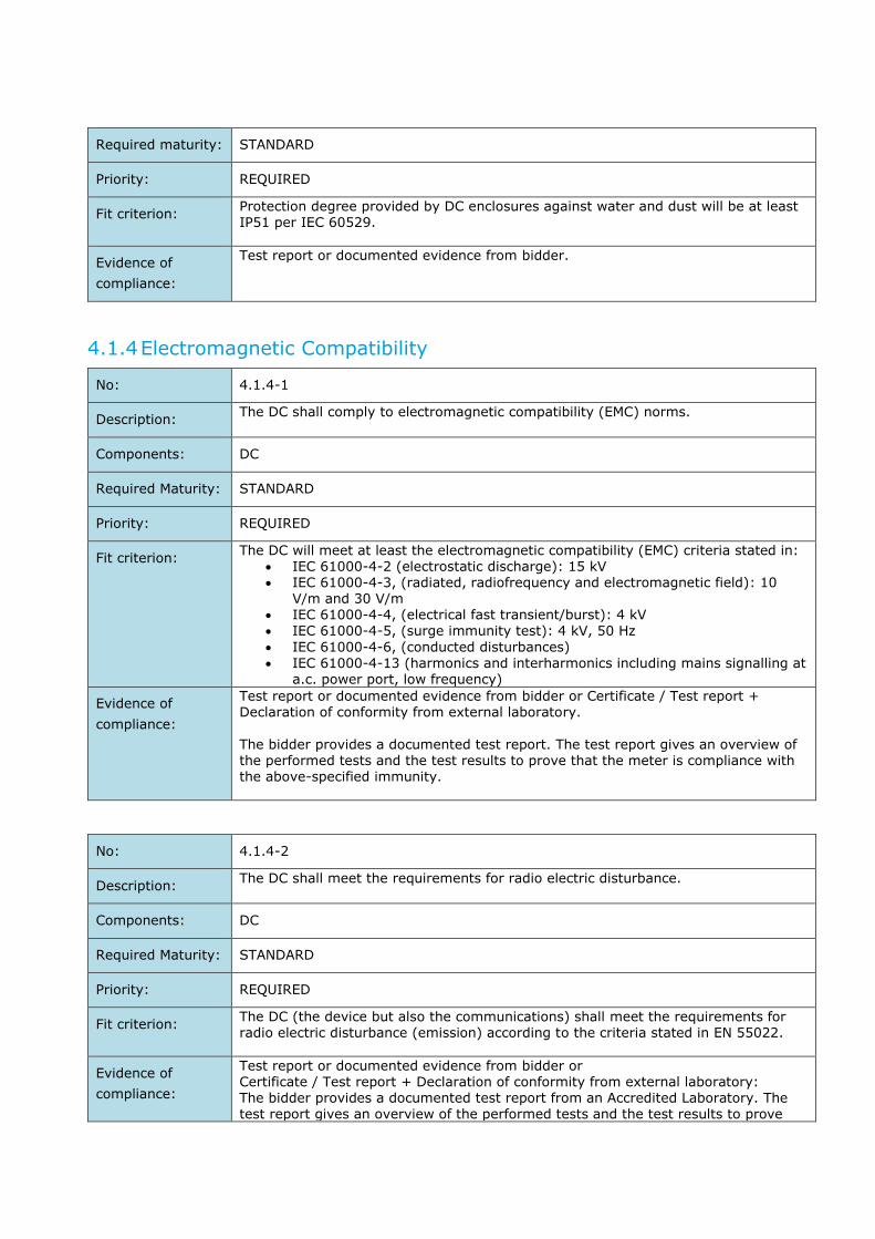
Required maturity: STANDARD
Priority: REQUIRED
Fit criterion: Protection degree provided by DC enclosures against water and dust will be at least IP51 per IEC 60529.
Evidence of
compliance:
Test report or documented evidence from bidder.
4.1.4 Electromagnetic Compatibility
No: 4.1.4-1
Description: The DC shall comply to electromagnetic compatibility (EMC) norms.
Components: DC
Required Maturity: STANDARD
Priority: REQUIRED
Fit criterion: The DC will meet at least the electromagnetic compatibility (EMC) criteria stated in:
IEC 61000-4-2 (electrostatic discharge): 15 kV IEC 61000-4-3, (radiated, radiofrequency and electromagnetic field): 10
V/m and 30 V/m IEC 61000-4-4, (electrical fast transient/burst): 4 kV IEC 61000-4-5, (surge immunity test): 4 kV, 50 Hz
IEC 61000-4-6, (conducted disturbances)
IEC 61000-4-13 (harmonics and interharmonics including mains signalling at a.c. power port, low frequency)
Evidence of
compliance:
Test report or documented evidence from bidder or Certificate / Test report + Declaration of conformity from external laboratory.
The bidder provides a documented test report. The test report gives an overview of the performed tests and the test results to prove that the meter is compliance with the above-specified immunity.
No: 4.1.4-2
Description: The DC shall meet the requirements for radio electric disturbance.
Components: DC
Required Maturity: STANDARD
Priority: REQUIRED
Fit criterion: The DC (the device but also the communications) shall meet the requirements for radio electric disturbance (emission) according to the criteria stated in EN 55022.
Evidence of
compliance:
Test report or documented evidence from bidder or Certificate / Test report + Declaration of conformity from external laboratory: The bidder provides a documented test report from an Accredited Laboratory. The test report gives an overview of the performed tests and the test results to prove

that the meter is compliance with the specified radio electric disturbance characteristics.
Hardware Requirements
4.2.1 Electrical Ratings
No: 4.2.1-1
Description: The DC shall comply to defined electrical ratings.
Component: DC
Required Maturity: STANDARD
Priority: REQUIRED
Fit criterion: The electrical ratings for the DC are as follows:
Reference voltage Un: 230V/400V Maximum consumption Pmax: 10W (peak power consumed by the DC when
it is in operation and transmitting information in the worst case) Reference frequency: 50Hz Number of wires: 2 (any phase and neutral) or 4 (3 phases and neutral)
Evidence of
compliance:
Test report or documented evidence from bidder.
4.2.2 Casing
No: 4.2.2-1
Description: The maximum dimensions of the casing of the DC shall not exceed specific
dimensions.
Component: DC
Required Maturity: STANDARD
Priority: PREFERRED
Fit criterion: The maximum dimensions for DC casing are:
Height: 290 mm
Width: 210 mm
Depth: 130 mm
Evidence of
compliance:
Compliance with this specification is verified by evaluation of a sample.
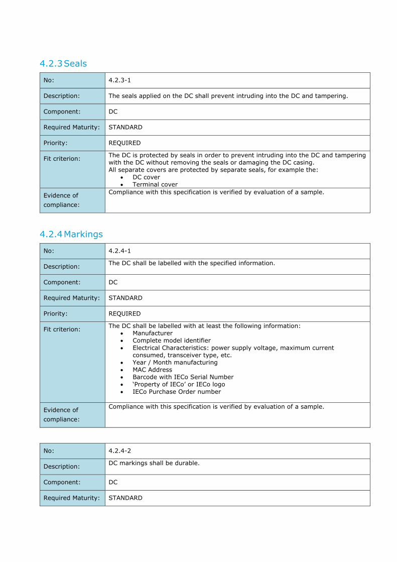
4.2.3 Seals
No: 4.2.3-1
Description: The seals applied on the DC shall prevent intruding into the DC and tampering.
Component: DC
Required Maturity: STANDARD
Priority: REQUIRED
Fit criterion: The DC is protected by seals in order to prevent intruding into the DC and tampering with the DC without removing the seals or damaging the DC casing. All separate covers are protected by separate seals, for example the:
DC cover Terminal cover
Evidence of
compliance:
Compliance with this specification is verified by evaluation of a sample.
4.2.4 Markings
No: 4.2.4-1
Description: The DC shall be labelled with the specified information.
Component: DC
Required Maturity: STANDARD
Priority: REQUIRED
Fit criterion: The DC shall be labelled with at least the following information:
Manufacturer Complete model identifier
Electrical Characteristics: power supply voltage, maximum current consumed, transceiver type, etc.
Year / Month manufacturing MAC Address Barcode with IECo Serial Number ‘Property of IECo’ or IECo logo
IECo Purchase Order number
Evidence of
compliance:
Compliance with this specification is verified by evaluation of a sample.
No: 4.2.4-2
Description: DC markings shall be durable.
Component: DC
Required Maturity: STANDARD
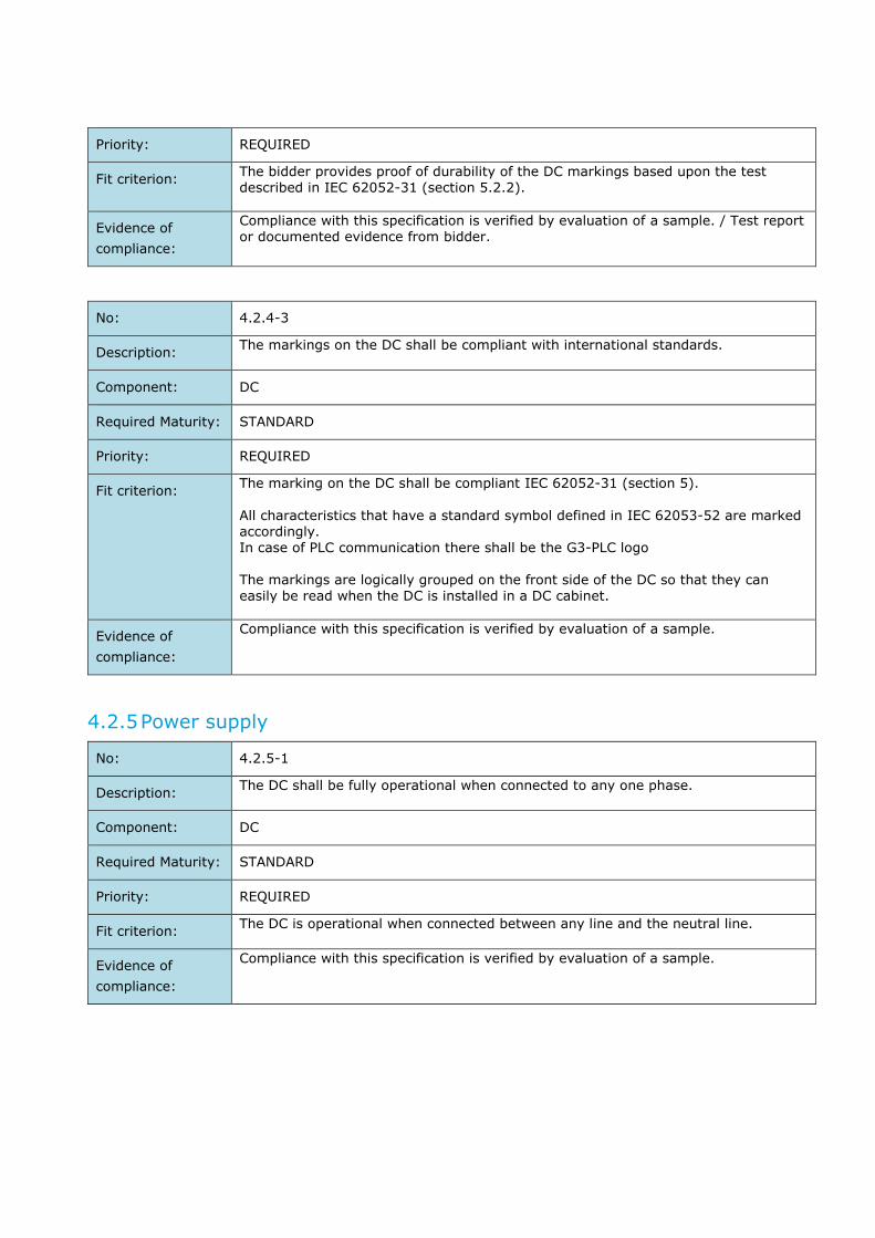
Priority: REQUIRED
Fit criterion: The bidder provides proof of durability of the DC markings based upon the test described in IEC 62052-31 (section 5.2.2).
Evidence of
compliance:
Compliance with this specification is verified by evaluation of a sample. / Test report or documented evidence from bidder.
No: 4.2.4-3
Description: The markings on the DC shall be compliant with international standards.
Component: DC
Required Maturity: STANDARD
Priority: REQUIRED
Fit criterion: The marking on the DC shall be compliant IEC 62052-31 (section 5).
All characteristics that have a standard symbol defined in IEC 62053-52 are marked accordingly. In case of PLC communication there shall be the G3-PLC logo The markings are logically grouped on the front side of the DC so that they can easily be read when the DC is installed in a DC cabinet.
Evidence of
compliance:
Compliance with this specification is verified by evaluation of a sample.
4.2.5 Power supply
No: 4.2.5-1
Description: The DC shall be fully operational when connected to any one phase.
Component: DC
Required Maturity: STANDARD
Priority: REQUIRED
Fit criterion: The DC is operational when connected between any line and the neutral line.
Evidence of
compliance:
Compliance with this specification is verified by evaluation of a sample.
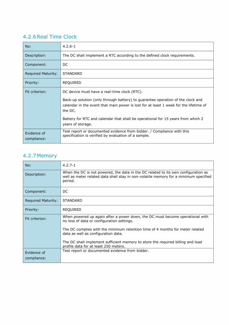
4.2.6 Real Time Clock
No: 4.2.6-1
Description: The DC shall implement a RTC according to the defined clock requirements.
Component: DC
Required Maturity: STANDARD
Priority: REQUIRED
Fit criterion: DC device must have a real-time clock (RTC).
Back-up solution (only through battery) to guarantee operation of the clock and
calendar in the event that main power is lost for at least 1 week for the lifetime of
the DC.
Battery for RTC and calendar that shall be operational for 15 years from which 2
years of storage.
Evidence of
compliance:
Test report or documented evidence from bidder. / Compliance with this specification is verified by evaluation of a sample.
4.2.7 Memory
No: 4.2.7-1
Description: When the DC is not powered, the data in the DC related to its own configuration as well as meter related data shall stay in non-volatile memory for a minimum specified period.
Component: DC
Required Maturity: STANDARD
Priority: REQUIRED
Fit criterion: When powered up again after a power down, the DC must become operational with no loss of data or configuration settings. The DC complies with the minimum retention time of 4 months for meter related
data as well as configuration data.
The DC shall implement sufficient memory to store the required billing and load profile data for at least 250 meters.
Evidence of
compliance:
Test report or documented evidence from bidder.

4.2.8 Connection & Communication
No: 4.2.8-1
Description: The DC shall comply to defined meter connection & communication requirements.
Component: DC
Required Maturity: STANDARD
Priority: REQUIRED
Fit criterion: Each DC shall be able to support communication with at least 250 meters.
Each DC shall be able to communicate with first meter distant at least 150 m
without peripheral equipment (such as repeater, amplifier). Filters are not
considered as peripheral equipment.
DC with integrated CT are not accepted.
Evidence of
compliance:
Test report or documented evidence from bidder.
No: 4.2.8-2
Description: DC communication with external firewall
Component: DC
Required Maturity: STANDARD
Priority: REQUIRED
Fit criterion: Together with the DC a local external firewall (provided by IECo) will be installed in
close proximity with the DC.
The connection and communication between the DC and external firewall shall apply
the “plug-and-play” principle, i.e. an ethernet connection is established between the
DC and external firewall and the DC will have a network connection and be
reacheable by the HES.
Evidence of
compliance:
Test report or documented evidence from bidder.
Functional/Software Requirements
4.3.1 Data exchange & data model
No: 4.3.1-1
Description: For configuration and data exchange with the E-meters, the DC shall support the defined E-meter data model.

Component: DC
Required Maturity: STANDARD or TO BE DEVELOPED
Priority: REQUIRED
Fit criterion: The DC shall be compatible with the E-meter data model defined in the “Annexure B2 - MOACH DLMS COSEM Profile for communication interfaces companion specification”. The DC shall be able to read/write E-meter data according to the access rights as
defined by the E-meter data model in the mentioned IECo’s specification. Any action that can be done locally on the meter shall also be possible to perform via the DC.
Evidence of
compliance:
Test report or documented evidence from bidder.
No: 4.3.1-2
Description: Implemented DC-HES communication interface solution shall be made available to IECo.
Component: DC
Required Maturity: STANDARD
Priority: REQUIRED
Fit criterion: The bidder will provide comprehensive information about the DC-HES communication interface solution implemented on the side of the DC. This information will include, at least but not limited to:
Supported communication protocols/services
Description of supported functionality (e.g. DC/meter events logging and reporting, monitoring and network management, remote DC/meter firmware update, profile meter readings reporting, etc.)
All this information will be made available for IECo.
Evidence of
compliance:
Test report or documented evidence from bidder.
No: 4.3.1-3
Description: DC shall respond and send data to HES/MDMS on-demand or periodically according to configurable schedule.
Component: DC
Required Maturity: STANDARD
Priority: REQUIRED
Fit criterion: DC will respond and send data to HES/MDMS per configurable scheduled requests or direct requests from the HES/MDMS. There shall be a pull and a push mechanism between the DC and the HES.
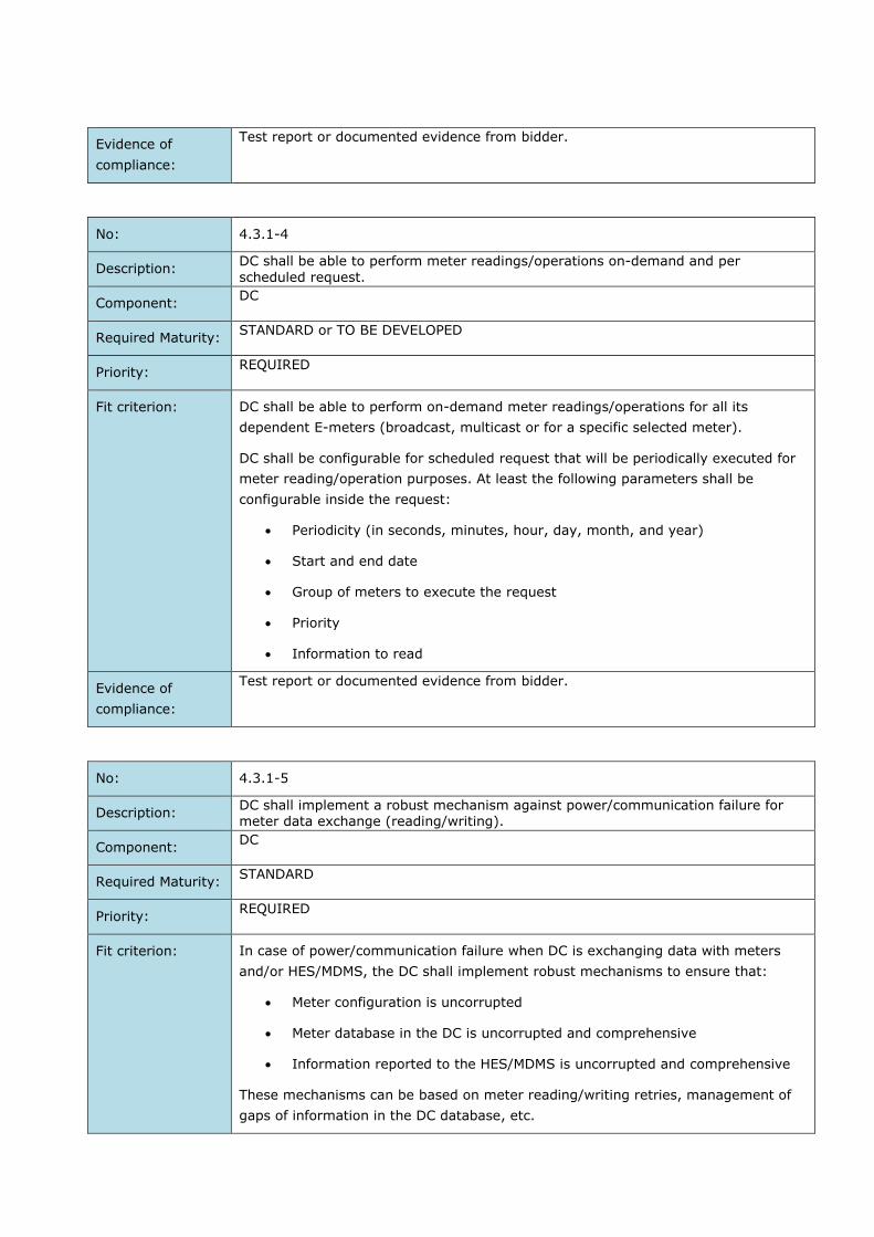
Evidence of
compliance:
Test report or documented evidence from bidder.
No: 4.3.1-4
Description: DC shall be able to perform meter readings/operations on-demand and per
scheduled request.
Component: DC
Required Maturity: STANDARD or TO BE DEVELOPED
Priority: REQUIRED
Fit criterion: DC shall be able to perform on-demand meter readings/operations for all its
dependent E-meters (broadcast, multicast or for a specific selected meter).
DC shall be configurable for scheduled request that will be periodically executed for
meter reading/operation purposes. At least the following parameters shall be
configurable inside the request:
Periodicity (in seconds, minutes, hour, day, month, and year)
Start and end date
Group of meters to execute the request
Priority
Information to read
Evidence of
compliance:
Test report or documented evidence from bidder.
No: 4.3.1-5
Description: DC shall implement a robust mechanism against power/communication failure for meter data exchange (reading/writing).
Component: DC
Required Maturity: STANDARD
Priority: REQUIRED
Fit criterion: In case of power/communication failure when DC is exchanging data with meters
and/or HES/MDMS, the DC shall implement robust mechanisms to ensure that:
Meter configuration is uncorrupted
Meter database in the DC is uncorrupted and comprehensive
Information reported to the HES/MDMS is uncorrupted and comprehensive
These mechanisms can be based on meter reading/writing retries, management of
gaps of information in the DC database, etc.

Evidence of
compliance:
Test report or documented evidence from bidder.
No: 4.3.1-6
Description: DC shall never alter the data from the meter.
Component: DC
Required Maturity: STANDARD
Priority: REQUIRED
Fit criterion: The DC will never under any circumstances alter the data from the meter.
In case of corrupted or uncompleted data, there will be a retry mechanism. If
unsuccessful there should be a notification.
Evidence of
compliance:
Test report or documented evidence from bidder.
4.3.2 Monitoring and Network Management
No: 4.3.2-1
Description: The DC shall support Automatic Meter Registration (Plug & Play mechanism).
Component: DC
Required Maturity: STANDARD
Priority: REQUIRED
Fit criterion: DC shall automatically discover meters on installation (when a new meter is
physically installed and connected to the communication network).
In this sense, DC shall keep updated HES/MDMS.
The DC shall provide the status of the keys & communication.
Evidence of
compliance:
Test report or documented evidence from bidder.
No: 4.3.2-2
Description: DC will be identified unambiguously by the HES/MDMS.
Component: DC
Required Maturity: STANDARD

Priority: REQUIRED
Fit criterion: DC shall allow to be managed by HES/MDMS, as a unique device identified by a
unique DC identifier parameter.
Evidence of
compliance:
Test report or documented evidence from bidder.
No: 4.3.2-3
Description: The DC shall be able to automatically detect the network topology.
Component: DC
Required Maturity: STANDARD
Priority: REQUIRED
Fit criterion: The DC shall be able to automatically detect the network topology, including
repeaters. The DC shall be able to detect number of communication switching
(transmit/receive) with a specific meter. Any change in network topology scheme
will be detected and reported for the users in order to analyse the problematics
points in the network.
Evidence of
compliance:
Test report or documented evidence from bidder.
No: 4.3.2-4
Description: The DC shall provide some statistics about communication quality.
Component: DC
Required Maturity: STANDARD
Priority: REQUIRED
Fit criterion: The DC shall provide some statistics about communication quality, at least but not
limited to:
Size of transmitted/received data chunks
Lost data
Communication between DC and meters (e.g. latency time between DC and
meters, total number of readable meters in terms of communication, etc.)
Communication between DC and HES
The statistics should be able to be exported for reporting purposes and
available to the HES.
Evidence of
compliance:
Test report or documented evidence from bidder.

4.3.3 Synchronization
No: 4.3.3-1
Description: The DC shall allow to be synchronized by the HES.
Component: DC
Required Maturity: STANDARD
Priority: REQUIRED
Fit criterion: The data-time of the DC will allow to be synchronized on-demand or per scheduled
request from HES.
Evidence of
compliance:
Test report or documented evidence from bidder.
No: 4.3.3-2
Description: The DC shall be able to synchronize all its dependent meters.
Component: DC
Required Maturity: STANDARD
Priority: REQUIRED
Fit criterion: The DC will be able to synchronize all dependent meters once per day per scheduled
request, on-demand and manually by accessing local web client in the DC.
Evidence of
compliance:
Test report or documented evidence from bidder.
No: 4.3.3-3
Description: The DC shall handle daylight savings time.
Component: DC
Required Maturity: STANDARD OR TO BE DEVELOPED
Priority: REQUIRED
Fit criterion: The DC autonomously switches to daylight savings time according to Israeli law:
DST Entry: the Friday before the last Sunday of March DST Exit: the last Sunday of October
Or: The DST can be (locally) configured via a table for at least 4 years ahead. The DST definition shall have a unique ID.
Evidence of
compliance:
Test report or documented evidence from bidder.

4.3.4 Firmware
No: 4.3.4-1
Description: DC shall support robust remote and local firmware upgrade.
Component: DC
Required Maturity: STANDARD
Priority: REQUIRED
Fit criterion: DC shall support remote firmware upgrade. Firmware transmission shall be initiated
by the HES/MDMS.
DC shall support also local firmware upgrade, by direct connection.
Firmware updates for DC shall be robust to power and communication failures. In
case of power/communication failure during DC firmware upgrade process, the DC
will ensure that its firmware version remains uncorrupted (keeping the existing one
and/or trying to start/continue with the DC firmware upgrade process when
communication is restored).
Evidence of
compliance:
Test report or documented evidence from bidder.
No: 4.3.4-2
Description: DC shall support robust remote meter firmware upgrade.
Component: DC
Required Maturity: STANDARD
Priority: REQUIRED
Fit criterion: DC shall be capable to perform remote meter firmware upgrade, for a single meter
or for multiple meters via multicast or broadcast request.
DC shall implement a robust mechanism against power/communication failure for
the meter firmware upgrade. The mechanism shall allow that the meter firmware
upgrade process is restarted/continued when communication is restored or aborted
in case of reiterative communication problems.
Evidence of
compliance:
Test report or documented evidence from bidder.

5 TECHNICAL REQUIREMENTS FOR THE HEAD-END-SYSTEM
The HES interfaces with the E-meters (PLMN) and the DC’s to execute the system use cases as described
in section 2.4.
General Requirements
No: 5.1-1
Description: The HES shall implement a GUI to support an actual view on the status of the AMI system.
Component: HES
Required Maturity: STANDARD or TO BE DEVELOPED
Priority: REQUIRED
Fit criterion: The HES shall implement a GUI to support management and viewing on the status
of the AMI system. It includes at least: smart meter information, data concentrators information network information such as topology and communication status.
All the operations and actions will be done directly through the MDM, further details can be found in the integration section.
Details on this requirement will be aligned between Contractor and Contracting Entity.
Evidence of
compliance:
Test report or documented evidence from bidder.
No: 5.1-2
Description: The HES shall implement a web-based GUI.
Component: HES
Required Maturity: STANDARD or TO BE DEVELOPED
Priority: PREFERRED
Fit criterion: The HES shall implement a web-based GUI to support management and viewing on the status of the AMI system.
Web-based GUI is accessible via standard browser. Details on this requirement will be aligned between Contractor and Contracting Entity.
No specific tooling needs to be installed on client’s PC.
Evidence of
compliance:
Test report or documented evidence from bidder.

No: 5.1-3
Description: For configuration and data exchange with the E-meters, the HES shall support the defined E-meter data model.
Component: DC
Required Maturity: STANDARD or TO BE DEVELOPED
Priority: REQUIRED
Fit criterion: The HES shall be compatible with the E-meter data model defined in the “Annexure
B2 - MOACH DLMS COSEM Profile for communication interfaces companion specification”. The HES shall be able to read/write E-meter data according to the access rights as
defined by the E-meter data model in the mentioned IECo’s specification. Any action that can be done locally on the meter shall also be possible to perform
via the HES.
Evidence of
compliance:
Test report or documented evidence from bidder.
No: 5.1-4
Description: HES shall be able to acquire meter data automatically (scheduled) and on-demand.
Component: HES
Required Maturity: STANDARD
Priority: REQUIRED
Fit criterion: HES shall be able to acquire E-meter data automatically (scheduled).
Additionally, it shall be possible to perform on-demand E-meter data requests
triggered by the HES.
The E-meter data collected by the HES will be processed by the MDMS, according to
the business processes and use cases stated in sections 2.3 and 2.4.
Evidence of
compliance:
Test report or documented evidence from bidder.
No: 5.1-5
Description: HES shall never alter the data from the meter.
Component: HES
Required Maturity: STANDARD
Priority: REQUIRED
Fit criterion: The HES will never, under any circumstances, alter the data from the meter.
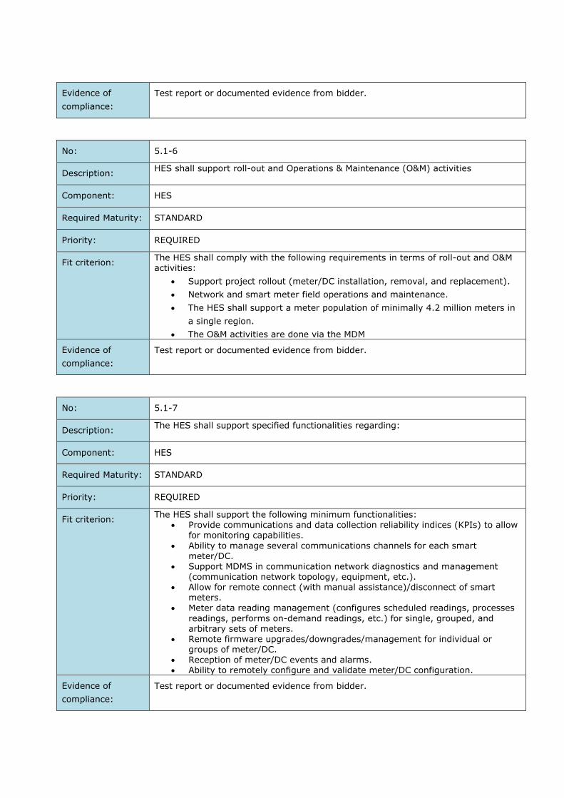
Evidence of
compliance:
Test report or documented evidence from bidder.
No: 5.1-6
Description: HES shall support roll-out and Operations & Maintenance (O&M) activities
Component: HES
Required Maturity: STANDARD
Priority: REQUIRED
Fit criterion: The HES shall comply with the following requirements in terms of roll-out and O&M activities:
Support project rollout (meter/DC installation, removal, and replacement).
Network and smart meter field operations and maintenance.
The HES shall support a meter population of minimally 4.2 million meters in
a single region.
The O&M activities are done via the MDM
Evidence of
compliance:
Test report or documented evidence from bidder.
No: 5.1-7
Description: The HES shall support specified functionalities regarding:
Component: HES
Required Maturity: STANDARD
Priority: REQUIRED
Fit criterion: The HES shall support the following minimum functionalities:
Provide communications and data collection reliability indices (KPIs) to allow for monitoring capabilities.
Ability to manage several communications channels for each smart meter/DC.
Support MDMS in communication network diagnostics and management (communication network topology, equipment, etc.).
Allow for remote connect (with manual assistance)/disconnect of smart
meters. Meter data reading management (configures scheduled readings, processes
readings, performs on-demand readings, etc.) for single, grouped, and arbitrary sets of meters.
Remote firmware upgrades/downgrades/management for individual or groups of meter/DC.
Reception of meter/DC events and alarms. Ability to remotely configure and validate meter/DC configuration.
Evidence of
compliance:
Test report or documented evidence from bidder.

HES Integration Requirements
The AMI solution shall integrate in the IT landscape. In the Contracting Entity’s IT environment, systems
exchange data via an Enterprise System Bus. The AMI solution interfaces with the ESB at the HES.
No: 5.2-1
Description: The contractor shall provide all necessary software applications needed to fully operate the AMI system.
Component: HES
Required Maturity: STANDARD or TO BE DEVELOPED
Priority: REQUIRED
Fit criterion: The contractor shall provide all necessary software applications needed to fully
operate the AMI system, such as but not limited to: HES related software. Troubleshooting tools. Configuration tools for field devices. Software applications for authentication of field devices. Monitoring dashboards
Evidence of
compliance:
Test report or documented evidence from bidder.
The bidder shall provide a list of software applications that will be delivered in the
AMI project.
No: 5.2-2
Description: The HES shall be supplied as a fully operational software solution and shall be integrated on the existing virtualized hardware infrastructure of the contracting entity.
Component: HES
Required Maturity: STANDARD or TO BE DEVELOPED
Priority: REQUIRED
Fit criterion: The HES shall be installed on the existing virtualized hardware infrastructure (server park) of the contracting entity.
Regarding operating systems: The software shall run on either: RedHat Enterprise Linux
Windows Server (Version that still receives active support from Microsoft)
Regarding DBMS: Oracle databases are used.
Evidence of
compliance:
Test report or documented evidence from bidder.
No: 5.2-3

Description: The AMI system shall be integrated in the contracting entities IT landscape via a
webservice interface on the HES.
Component: HES
Required Maturity: STANDARD or TO BE DEVELOPED
Priority: REQUIRED
Fit criterion: The bidder shall offer a web services interface to integrate the AMI system into the
contracting entities IT landscape.
The web services shall provide the interface for other systems to interact with the
HES. From the ESB perspective, the web service interface of the HES is the entry
point to the AMI system.
The solution shall comply to the MDMS web services to interact with the MDMS.
The web service interface shall facilitate the AMI use cases as described in section 0.
The contractor aligns with the provider of the MDMS on the design and details of the
web services and the interface with the ESB.
Evidence of
compliance:
Test report or documented evidence from bidder. The bidder shall describe its
approach to this integration.

6 MASS PRODUCTION REQUIREMENTS
General
No: 6.1-1
Description: The E-meter shall meet the quality requirements for mass production.
Component: Meter [1Ph, 3Ph, CT, PLMN, PLC]
Required Maturity: STANDARD
Priority: REQUIRED
Fit criterion: The contractor/bidder shall have an internal system in order to be able to trace
components that are included in the construction of an E-meter device. If
subcontractors are used for E-meters, this requirement also applies to them. The
contractor/bidder shall describe its tracing system.
The contractor/bidder shall describe how it ensures that the E-meters are of such a
quality that they are not disapproved when controlled by IECo or any other third
party authorized by IECo.
IECo experts may ask to visit the contractor/bidder's plant at the technical
evaluation stage or later: i.e. an IECo representative, at IECo sole discretion, may
visit and inspect the active production line being used to manufacture and assemble
the meters in order to assure the suitability and compatibility of the new (or
renewed) meter deliveries with all the requirements of this specification at any stage
of the contract.
Evidence of
compliance:
Test report or documented evidence from bidder:
The bidder provides a document describing its internal quality system to trace
components and E-meter production. Periodical audits/verification processes may be
performed by IECo or by a third party authorized by IECo after signing of contract.
No: 6.1-2
Description: Meter manufacturer and integrator shall propose certain Design For Testability (DFT)
technology.
Component: Meter [1Ph, 3Ph, CT, PLMN, PLC]
Required Maturity: STANDARD
Priority: REQUIRED
Fit criterion: It is mandatory to implement some DFT technology (as considered by industry and
the scientific community). Technology encompasses: meter hardware, firmware, and
test bench nail bed software.

E-meter must be provided with a declaration indicating the number of electronic
components covered by the DFT technology.
The manufacturer must specify which DFT technology is used, and what its
functional coverage (percentage) of logic and analoge signals scenarios.
Evidence of
compliance:
Test report or documented evidence from bidder:
The bidder provides a document declaring and describing how DFT technology
requirements specified by IECo are fulfilled and which technology from which
company is used.
No: 6.1-3
Description: Proposed DFT technology will be evaluated by IECo and scored accordingly.
Component: Meter [1Ph, 3Ph, CT, PLMN, PLC]
Required Maturity: STANDARD
Priority: PREFERRED
Fit criterion: IECo will use known estimations for various DFT technologies to evaluate and
validate the provided information, such as:
ICT/FCT (e.g. SPEA technology);
JTAG boundary scan;
ATPG, SDD, path delay;
Memory redundancy repair process;
Power domain blocks.
IECo may evaluate other standard DFT methods not included in the previous list. To
that aim, bidder will provide all needed information to detail its DFT technology
implementation.
Evidence of
compliance:
Test report or documented evidence from bidder:
The bidder provides a document declaring and describing how DFT technology
requirements specified by IECo are fulfilled.

HASS/Aging Test
No: 6.2-1
Description: The mass production of E-meters will be optionally subjected to HASS testing
procedures.
Component: Meter [1Ph, 3Ph, CT, PLMN, PLC]
Required Maturity: STANDARD
Priority: PREFERRED
Fit criterion: IECo does not require to perform HASS testing compulsorily; however, the
contractor/bidder that includes HASS testing as part of its offer will obtain higher
scoring.
When a batch of particular meter types from particular production line is submitted
to IECo for the first time, a sample of 100 meters from that batch shall be subjected
to HASS testing.
HASS can be performed either at contractor/bidder's premises or at a third-party
laboratory authorized by IECo.
Details about the scope of the required HASS tests are exhibited in Appendix E.
If more than one meter failed during the required HASS testing, contractor/bidder
must perform Root cause analysis and suggest corrective actions for IECo approval.
After the corrective actions are approved and implemented the HASS test must be
successfully repeated.
Evidence of
compliance:
Test report or documented evidence from bidder:
The bidder provides a document describing HASS testing procedures that will be
followed for each item related to: thermal cycling tests, vibration, and free fall tests,
requested by IECo. The bidder provides a declaration of conformity based on full
quality assurance, whereby he undertakes to fully comply with the obligations laid
down by the requirements stated by IECo. Periodical audits/verification processes
may be performed by IECo or by a third party authorized by IECo after signing of
contract.
No: 6.2-2
Description: The mass production of E-meters shall be subjected to mandatory routine Aging
Test when no HASS testing is implemented.
Component: Meter [1Ph, 3Ph, CT, PLMN, PLC]
Required Maturity: STANDARD
Priority: REQUIRED

Fit criterion: In the event that the bidder does not provide evidence of compliance for the
required HASS testing (check requirement no. 6.2-1) when a batch of a particular
type of meters from a particular production line is submitted to IECo for the first
time, and also during subsequent mass production specified aging tests (accelerated
life tests) shall be performed mandatorily as a minimum requirement.
In this case, 100% of meters of each delivery must undergo aging test before final
factory verification tests, under the following conditions: powered 3x230V L-N,
during 8 hours at least, at extended temperatures (at highest rated operating
temperature at least) in order to demonstrate its reliability and long service life. The
test shall be carried out per IEC 62059-41 methodology (check requirement 3.1.3-
1).
Evidence of
compliance:
Test report or documented evidence from bidder:
The bidder provides a document describing aging test procedures that will be
followed for every E-meter delivered to IECo. The bidder provides a declaration of
conformity based on full quality assurance, whereby he undertakes to fully comply
with the obligations laid down by the requirements stated by IECo. Periodical
audits/verification processes may be performed by IECo or by a third party
authorized by IECo after signing of contract.
Final Factory Verification Tests before shipping
No: 6.3-1
Description: The mass production of E-meters shall be subjected to Final Factory Verification
Tests.
Component: Meter [1Ph, 3Ph, CT, PLMN, PLC]
Required Maturity: STANDARD
Priority: REQUIRED
Fit criterion: Accuracy, AC voltage and functionality tests results including initial calibration data
of each shipped meter shall be sent to the Meter Test Station Department of IECo
prior to each shipment, for purpose of metrology normalcy.
The manufacturer must state whether accuracy test is performed on the meters with
closed or open voltage links. If the meters are calibrated with open voltage links,
quality control routine must be implemented to ensure correct meter functionality
after their sealing (closed links).
Metrology report required format including required test points are exhibited in
Appendix I.
The results of tests that are performed on samples at the manufacturer plant for
Manufacturer's quality inspection purposes shall also be provided in the same
format.

Evidence of
compliance:
Test report or documented evidence from bidder:
The bidder provides a document describing Final Factory Verification Test procedures
that will be followed for mass E-meter production. The bidder provides a declaration
of conformity based on full quality assurance, whereby he undertakes to fully
comply with the obligations laid down by the requirements stated by IECo. Periodical
audits/verification processes may be performed by IECo or by a third party
authorized by IECo after signing of contract.
Packaging requirements
No: 6.4-1
Description: The shipment of E-meters shall be subjected to a set of packaging requirements
stated by IECo.
Component: Meter [1Ph, 3Ph, CT, PLMN, PLC]
Required Maturity: STANDARD
Priority: REQUIRED
Fit criterion: General packaging conditions, including primary and secondary packaging
requirements, shipment documentation and handling of DDP goods, which are
exhibited in Appendix D, shall be implemented for the shipment of E-meters.
Evidence of
compliance:
Test report or documented evidence from bidder:
The bidder provides a declaration of conformity based on full quality assurance,
whereby he undertakes to fully comply with the obligations laid down by the
requirements stated by IECo. Periodical audits/verification processes may be
performed by IECo or by a third party authorized by IECo after signing of contract.
Series Production and Acceptance Test
No: 6.5-1
Description: E-meters shall be manufactured and calibrated in homogeneous production series
and supplied in batches.
Component: Meter [1Ph, 3Ph, CT, PLMN, PLC]
Required Maturity: STANDARD
Priority: REQUIRED
Fit criterion: The batches on appropriate pallets will be grouped for shipping in standard
containers, trucks, or other simultaneously shipped aggregate platforms. An
inspection shall follow the “serial quality” approach regarding units of such
containers or trucks.

Evidence of
compliance:
Test report or documented evidence from bidder:
The bidder provides a declaration of conformity based on full quality assurance,
whereby he undertakes to fully comply with the obligations laid down by the
requirements stated by IECo. Periodical audits/verification processes may be
performed by IECo or by a third party authorized by IECo after signing of contract.
No: 6.5-2
Description: E-meters must be manufactured under ISO 9001(2015) over a whole contract
period.
Component: Meter [1Ph, 3Ph, CT, PLMN, PLC]
Required Maturity: STANDARD
Priority: REQUIRED
Fit criterion: Valid ISO 9001(2015) approval certificate issued by a Certification Body (CB) which
is a qualified by an Accreditation Body (AB) must be available at any stage of the
contract.
Evidence of
compliance:
Test report or documented evidence from bidder:
The bidder provides a declaration of conformity based on full quality assurance,
whereby he undertakes to fully comply with the obligations laid down by the
requirements stated by IECo. Periodical audits/verification processes may be
performed by IECo or by a third party authorized by IECo after signing of contract.
No: 6.5-3
Description: Acceptance lot-by-lot inspection shall be performed at IECo premises.
Component: Meter [1Ph, 3Ph, CT, PLMN, PLC]
Required Maturity: STANDARD
Priority: REQUIRED
Fit criterion: Acceptance lot-by-lot inspection by attributes will be performed at the Meter Test
Station (IECo premises) according to IEC62058-11, ISO2859-1 and IEC62058-31.
Lot for the acceptance inspection will be defined as cumulative quantity of batches
that have been delivered to IECo Metering Unit premises within one container or
truck. Alternatively, IECo may define a lot at its sole discretion.
Inspection level II will be used. Single sampling plan for normal inspection, AQL=1
will be used regarding non-critical nonconformities (as per table 4 in IEC62058-31).
For critical nonconformities (as per Table 4 in IEC62058-31), single sampling plan
for normal inspection with acceptance number 0 will be used.
If lot will be rejected next lots will be tested according to Double sampling plan for
normal inspection.

Other meter's attributes may be tested for conformity. Failures in these tests will be
considered as non-critical nonconformities.
Regarding nonconforming meters, applicable procedures are given by IEC62058-11
and shall be continued by the following measures. In case of rejection the whole lot
will be replaced by reshipping, or arresting on the place with 100% revision before
presenting for re-inspection. The Contractor will be responsible for bearing all
associated costs. The Contractor will be notified by phone/e-mail. Rejection of 5 or
more lots upon the same order delivery will be considered as Contractor’s failure,
and will lead to legal action.
The results of the acceptance tests will be reported to the IECo Import Department
that will notify the manufacturer about the acceptance tests failure.
The nonconforming meters within a lot in quantities, which are still within
acceptance criteria, will be subject to replacement if claimed by the Purchaser.
In order to prevent any holdback in IECo to install newly purchased meters due to
rejected lots, the Manufacturer will be obligated to expedite extra deliveries, above
and beyond the agreed timetable.
If 3 or more meters delivered according to the same order are found with a same
failure caused by production failure, or wrong meter construction, or component
failure, which affects normal operation of the meter, the failure will be considered as
"serial failure" and will lead to legal action. The same approach is to any field failure
of rate ≥ 0.5% of total field installed meter. Along with the legal actions, in case of
"serial failure" the winning Bidder is requested to provide:
Root cause analysis submission to IECo within 30 days
Uninstallation of entire meter population of the problematic batches and
replacement.
The winning Bidder is required to inform IECo regarding similar to the provided to
IECo meters' failures at other customers.
Evidence of
compliance:
Test report or documented evidence from bidder:
The bidder provides a declaration of conformity based on full quality assurance,
whereby he undertakes to fully comply with the obligations laid down by the
requirements stated by IECo. Periodical audits/verification processes may be
performed by IECo or by a third party authorized by IECo after signing of contract.
No: 6.5-4
Description: During the life cycle of the meters IECo may conduct periodical Type Test
procedures.
Component: Meter [1Ph, 3Ph, CT, PLMN, PLC]
Required Maturity: STANDARD
Priority: REQUIRED

Fit criterion: During the life cycle of the meters IECo may conduct from time to time and at its
sole discretion number of tests detailed in IEC 62052 series for Type Test (mainly
IEC 62052-11, IEC 62052-21 and IEC 62052-31), in order to ascertain the stability
of the meter metrology characteristics. If the meters fail to comply with the test
requirements, the manufacturer will assume responsibility.
IECo representative, at IECo sole discretion, may visit and inspect the active
production line being used to manufacture and assemble the meters in order to
assure the suitability and compatibility of the new meter deliveries with all the
requirements of this specification at any stage of the contract.
Evidence of
compliance:
Test report or documented evidence from bidder:
The bidder provides a declaration of conformity based on full quality assurance,
whereby he undertakes to fully comply with the obligations laid down by the
requirements stated by IECo. Periodical audits/verification processes may be
performed by IECo or by a third party authorized by IECo after signing of contract.
No: 6.5-5
Description: The awarded bidder must send to IECo the meters, DC, CTs, Filters, FW ( if
applicable ), analysing PLC tool as preliminary (preproduction) series for a
Conformity of Compliance agree to time table.
Component: Meter [1Ph, 3Ph, CT, PLMN, PLC] , DC , CTs , Filter , FW ( if applicable ), analysing
PLC tool.
Required Maturity: STANDARD
Priority: REQUIRED
Fit criterion: The awarded bidder must send following IECo order:
20 meters for each type,
10 DCs for each type ,
5 CTs for each type,
6 Filters for each type, 10 FWs ( if applicable ),
1 analyzing PLC tool
as first preliminary (preproduction) series for a Conformity of Compliance according to accepted time table.
The equipment described above must be in its final version, manufactured or
assembled in the same plant where the remaining equipment will be produced, tested with the same equipment that will be used in the course of manufacturing, and packed in the same form that the future goods will be supplied.
The smart metering equipment (described above) delivery must be accompanied by the data reading software, and the files described in sections 2.2.1-4, 2.2.2-2, D.2, C.3
After approval of first preliminary (preproduction) series the awarded bidder must send to the IECo the smart metering equipment as second preliminary (preproduction) series, for end-to-end testing of the smart metering equipment with the AMI system of the awarded bidder. This time by quantity of:
2 full pallets of poly-phase meters for each type. 1 full pallet of single-phase meters for each type. 10 DCs for each type , 1 full pallet of CTs for each type,

5 Filters for each type, 10 FWs ( if applicable ).
100% inspection will be applied to these batches.
If the goods and the packing of the preliminary series are found to be in full compliance with IECo requirements they will be approved by IECo, and issue of further withdrawal orders will be permitted.
Evidence of
compliance:
The bidder declares that he has understood this requirement, and agrees to comply with this requirement.
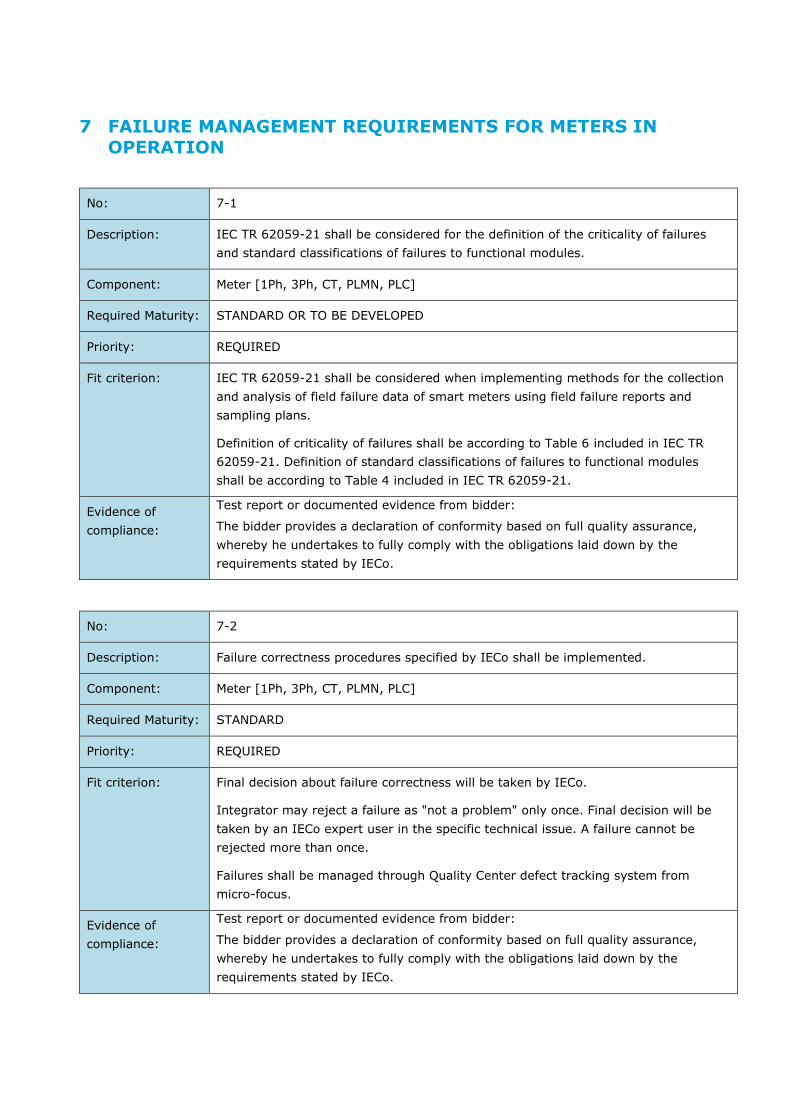
7 FAILURE MANAGEMENT REQUIREMENTS FOR METERS IN OPERATION
No: 7-1
Description: IEC TR 62059-21 shall be considered for the definition of the criticality of failures
and standard classifications of failures to functional modules.
Component: Meter [1Ph, 3Ph, CT, PLMN, PLC]
Required Maturity: STANDARD OR TO BE DEVELOPED
Priority: REQUIRED
Fit criterion: IEC TR 62059-21 shall be considered when implementing methods for the collection
and analysis of field failure data of smart meters using field failure reports and
sampling plans.
Definition of criticality of failures shall be according to Table 6 included in IEC TR
62059-21. Definition of standard classifications of failures to functional modules
shall be according to Table 4 included in IEC TR 62059-21.
Evidence of
compliance:
Test report or documented evidence from bidder:
The bidder provides a declaration of conformity based on full quality assurance,
whereby he undertakes to fully comply with the obligations laid down by the
requirements stated by IECo.
No: 7-2
Description: Failure correctness procedures specified by IECo shall be implemented.
Component: Meter [1Ph, 3Ph, CT, PLMN, PLC]
Required Maturity: STANDARD
Priority: REQUIRED
Fit criterion: Final decision about failure correctness will be taken by IECo.
Integrator may reject a failure as "not a problem" only once. Final decision will be
taken by an IECo expert user in the specific technical issue. A failure cannot be
rejected more than once.
Failures shall be managed through Quality Center defect tracking system from
micro-focus.
Evidence of
compliance:
Test report or documented evidence from bidder:
The bidder provides a declaration of conformity based on full quality assurance,
whereby he undertakes to fully comply with the obligations laid down by the
requirements stated by IECo.

No: 7-3
Description: Service Level Agreement between IECo and integrator shall be established
complying with IECo requirements.
Component: Meter [1Ph, 3Ph, CT, PLMN, PLC]
Required Maturity: STANDARD OR TO BE DEVELOPED
Priority: REQUIRED
Fit criterion: For smart meters some standard failures apply for meter failures (hardware,
firmware and software tools). There are defined failures for the ‘infancy stage’ and
for the ‘mature stage’. The ‘infancy stage’ will comprise failures that arise during the
first 1,5 years from installation. ‘Mature stage’ will continue after ‘infancy’ stage. On
the other hand, there are failures that exist in 100% of meters and failures existing
only in a small number of meters and evolving over time.
The Service Level Agreement between IECo and integrator shall comply to what it is
indicated in Table 7-1.
Evidence of
compliance:
Test report or documented evidence from bidder:
The bidder provides a declaration of conformity based on full quality assurance,
whereby he undertakes to fully comply with the obligations laid down by the
requirements stated by IECo.
Table 7-1: Standard failure management requirements per IECo
No Standard failure criticality (IECo
terminology)
% of meters installed or at
storage
Perform Root-Cause Analysis
or replace meter
Response time (work hours)
Resolution time
(work days)
Infancy stage (≤1,5 years from installation)
1 Critical firmware/software failure (critical)
≥ 0.5 ≤ 0.5
RCA Fix
24 5
2 Critical hardware
failure (critical)
≥ 0.5 ≤ 0.5
RCA
And replace meter
24 10 or extend
with IECo approval only
3 Major failure (high)
≥ 0.5
≤ 0.5
Hardware: RCA and replace
meter
Replace meter Software: Always RCA and fix
24 5 IECo may
postpone schedule
4 Minor failure
(medium) *
≥ 0.5 ≤ 0.5
Hardware:
No RCA replace
24 45
5 Minor failure (low) *
≥ 0.5 ≤ 0.5
Hardware: No RCA
24 45

IECo may postpone
schedule
Mature stage (>1,5 years from installation)
1 Critical
firmware/software failure (critical)
≥ 0.5 ≤ 0.5
RCA
Fix
24 10
2 Critical hardware failure
(critical)
≥ 0.5 ≤ 0.5
RCA And replace
meter
24 15 or extend with IECo
approval only
3 Major failure (high)
≥ 0.5
≤ 0.5
Hardware: RCA and replace meter
Replace meter
Software: always RCA and fix
24 10 IECo may postpone
schedule
4 Minor failure
(medium) *
≥ 0.5 ≤ 0.5
Hardware:
No RCA replace
24 45
5 Minor failure (low) *
≥ 0.5 ≤ 0.5
Hardware: No RCA
24 45 IECo may postpone schedule
* Notice that IEC TR 62059-21 does not include ‘medium’ and ‘low’ classification, they are stated as ‘minor’.

8 TECHNICAL REQUIREMENTS FOR PORTABLE TEST PC AND DIAGNOSTIC TOOLS
No: 8-1
Description: Minimal technical (physical) specifications for portable PC for laboratory for meters/DC configuration
Component: Portable PC
Required Maturity: STANDARD or TO BE DEVELOPED
Priority: REQUIRED
Fit criterion: The bidder shall provide two (2) laptops that meets, at least, the following
requirements: Recent CPU (i.e. Intel core i5 or later) Minimum screen size 15.6 inch 8 GB RAM or more 500 GB SSD or more USB-ports: at least 2x USB3.0 Integrated Bluetooth
Integrated LAN-card Integrated WiFi-card Graphic Card: either Intel or Nvidia GeForce
The laptop shall be a ruggedized model.
Evidence of
compliance:
The tender agrees to comply to this requirement and is able to deliver such laptops
No: 8-2
Description: Portable PC – Operating System
Component: Portable PC
Required Maturity: STANDARD or TO BE DEVELOPED
Priority: REQUIRED
Fit criterion: The portable PC shall come pre-installed with a recent Windows (64 bit) version still receiving official support from Microsoft. The portable PC shall include installed and activated MS Office package.
Evidence of
compliance:
The tender agrees to comply to this requirement and is able to deliver such laptops
No: 8-3
Description: Portable PC – Warranty
Component: Portable PC
Required Maturity: STANDARD or TO BE DEVELOPED

Priority: REQUIRED
Fit criterion: The warranty for the laptops shall be provided by a company located in Israel.
Evidence of
compliance:
The tender agrees to comply to this requirement.
No: 8-4
Description: Additional software and software licences
Component: Portable PC
Required Maturity: STANDARD or TO BE DEVELOPED
Priority: REQUIRED
Fit criterion: The laptops shall be pre-installed with all software tools to:
Locally configure the meters Locally configure the DCs Troubleshooting software for meters and DCs Troubleshooting software for diagnosing the PLC
All software licences (from the bidder and potential subcontractors) should be for unlimited time duration
Evidence of
compliance:
The tender agrees to comply to this requirement.
No: 8-5
Description: Test equipment for testing and diagnosing of PLC
Component: Portable PC
Required Maturity: STANDARD or TO BE DEVELOPED
Priority: REQUIRED
Fit criterion: Features of remote diagnostics that shall be suitable for proposed PLC protocol.
Minimum required features: Signal-Power (dBm)
Signal-Noise-Ratio (SNR) Attenuation Power spectrum; differentiation of noise A local tool/facility for readout of data and log file Facility for local reconfiguration of the DC
Availability of GUI map/flowchart/diagram which shows the status of all meters connected to the DC
Evidence of
compliance:
The tender describes his solution in detail, and agrees to comply to this
requirement.
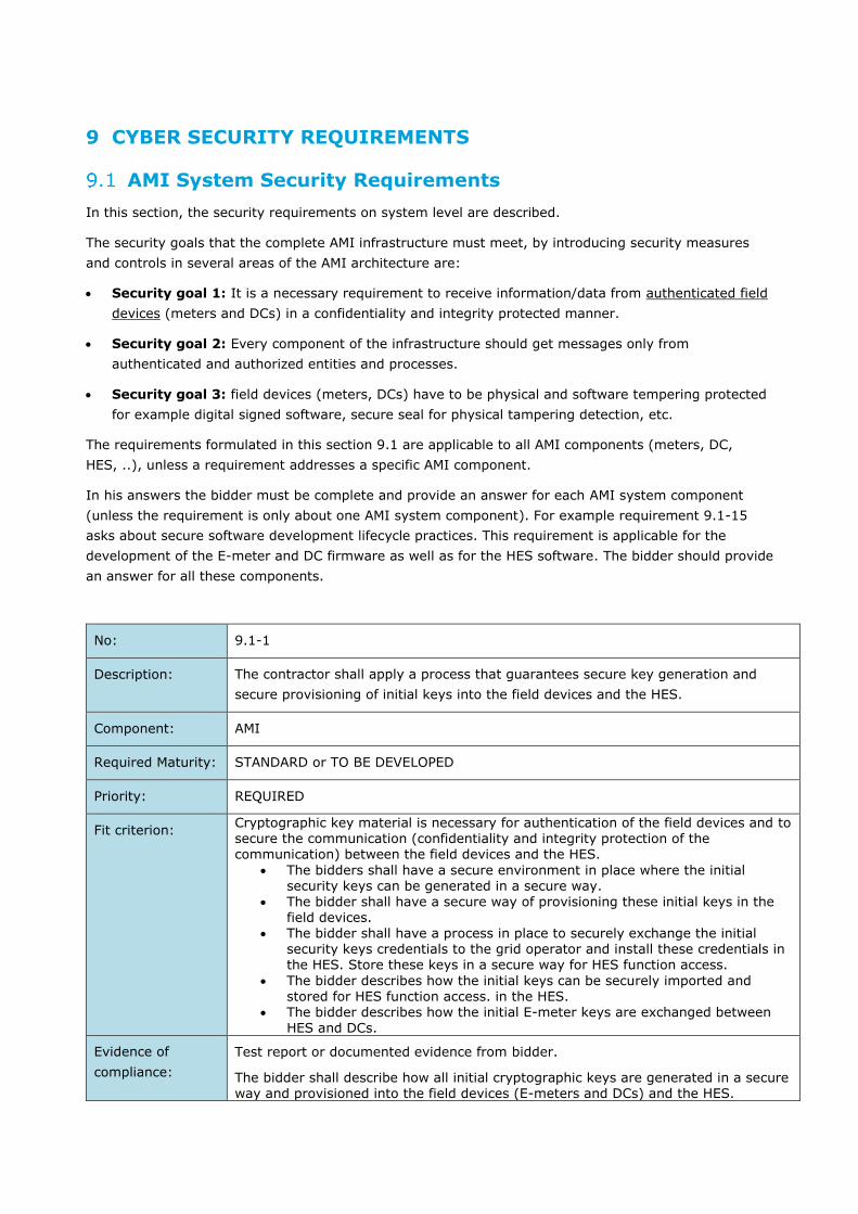
9 CYBER SECURITY REQUIREMENTS
AMI System Security Requirements
In this section, the security requirements on system level are described.
The security goals that the complete AMI infrastructure must meet, by introducing security measures
and controls in several areas of the AMI architecture are:
Security goal 1: It is a necessary requirement to receive information/data from authenticated field
devices (meters and DCs) in a confidentiality and integrity protected manner.
Security goal 2: Every component of the infrastructure should get messages only from
authenticated and authorized entities and processes.
Security goal 3: field devices (meters, DCs) have to be physical and software tempering protected
for example digital signed software, secure seal for physical tampering detection, etc.
The requirements formulated in this section 9.1 are applicable to all AMI components (meters, DC,
HES, ..), unless a requirement addresses a specific AMI component.
In his answers the bidder must be complete and provide an answer for each AMI system component
(unless the requirement is only about one AMI system component). For example requirement 9.1-15
asks about secure software development lifecycle practices. This requirement is applicable for the
development of the E-meter and DC firmware as well as for the HES software. The bidder should provide
an answer for all these components.
No: 9.1-1
Description: The contractor shall apply a process that guarantees secure key generation and
secure provisioning of initial keys into the field devices and the HES.
Component: AMI
Required Maturity: STANDARD or TO BE DEVELOPED
Priority: REQUIRED
Fit criterion: Cryptographic key material is necessary for authentication of the field devices and to secure the communication (confidentiality and integrity protection of the communication) between the field devices and the HES.
The bidders shall have a secure environment in place where the initial security keys can be generated in a secure way.
The bidder shall have a secure way of provisioning these initial keys in the field devices.
The bidder shall have a process in place to securely exchange the initial security keys credentials to the grid operator and install these credentials in the HES. Store these keys in a secure way for HES function access.
The bidder describes how the initial keys can be securely imported and stored for HES function access. in the HES.
The bidder describes how the initial E-meter keys are exchanged between HES and DCs.
Evidence of
compliance:
Test report or documented evidence from bidder.
The bidder shall describe how all initial cryptographic keys are generated in a secure way and provisioned into the field devices (E-meters and DCs) and the HES.

No: 9.1-2
Description: All initial master keys and working keys shall be unique per field device.
Component: AMI
Required Maturity: STANDARD OR TO BE DEVELOPED
Priority: REQUIRED
Fit criterion: All initial master keys and working keys shall be randomly generated (and stored)
per field device. This applies for keys that are used in supporting communication layers as well as
application layer.
Evidence of
compliance:
Test report or documented evidence from bidder.
The bidder shall describe how security keys are generated and stored.
No: 9.1-3
Description: Key renewals shall be done in a secure way.
Component: AMI
Required Maturity: STANDARD OR TO BE DEVELOPED
Priority: REQUIRED
Fit criterion: It shall be possible to renew working keys for protecting data exchange between the system components. This shall be done in a secure way.
Evidence of
compliance:
Test report or documented evidence from bidder. The bidder provides information
on the key renewal process that is applied to renew the working keys in field
devices.
No: 9.1-4
Description: Crypto mechanisms and key management mechanisms shall be based on open standards or protocols.
Component: AMI
Required Maturity: STANDARD or TO BE DEVELOPED
Priority: REQUIRED
Fit criterion: The used cryptographic algorithms and key management mechanisms shall be
publicly available and based on open STANDARDs, such as IEC 62056. The cryptographic algorithms and protocols as required in the “IECo DLMS COSEM Profile for communication interfaces. MOACH Smart Meters” shall be supported.
Evidence of
compliance:
Test report or documented evidence from bidder.
The bidder shall provide a list of all implemented cryptographic algorithms and key management mechanism and indicate on which standards they are based.

No: 9.1-5
Description: All security requirements related to communication interfaces are active when the
field devices leave the factory (security by default).
Component: AMI
Required Maturity: STANDARD or TO BE DEVELOPED
Priority: REQUIRED
Fit criterion: All AMI components shall have a default configuration (i.e. when they leave the factory) that enforces secure communication.
That is, all communication protocols supported on the AMI components shall be
configured in such a way that secure communication is guaranteed.
Evidence of
compliance:
Test report or documented evidence from bidder:
The bidder describes the default communication configuration of AMI components and indicates how communication security is guaranteed.
Additionally, compliance with this specification is verified by evaluation of a sample
(for meters and DC).
No: 9.1-6
Description: Secure key export shall be possible for local troubleshooting on field devices
Component: AMI
Required Maturity: STANDARD or TO BE DEVELOPED
Priority: REQUIRED
Fit criterion: For E-meter and DC troubleshooting, in the field or in an in-house lab environment,
expert tools will be used. For meter installation, and in some cases meter reading after installation, a hand-held unit (HHU) will be used. These tools will make a connection with the devices (E-meters and DCs). The tools must have the valid keys in order to be able to communicate with the devices. Therefore, it must be possible to securely provision these tools with the E-meter
keys and DC keys. The tools should protect the keys by reliable encryption method. To this end, it must be possible to extract the keys from the HES DB and securely
transport the keys to the tools. Exported keys should be marked in the HES DB as being exported and time period of export key validity. The bidder provides detailed information describing how dedicated tools (for installation, maintenance and troubleshooting) can be integrated with his HES so
that a secure provisioning of cryptographic keys to these tools is accomplished.
Evidence of
compliance:
Test report or documented evidence from bidder.

No: 9.1-7
Description: The end-to-end security of the firmware, between the manufacturer(s) and its field components, shall be guaranteed.
Component: AMI
Required Maturity: STANDARD or TO BE DEVELOPED
Priority: REQUIRED
Fit criterion: End-to-end security shall be provided for the firmware of the E-meters and the Data
concentrators. The bidder shall explain:
How he foresees to securely exchange new firmware with IECo. How the E-meters and DCs will verify the integrity and authenticity of the
new firmware.
Evidence of
compliance:
Test report or documented evidence from the bidder.
No: 9.1-8
Description: Secured versioning – All AMI firmware or software components shall have unique
version numbers.
Component: AMI
Required Maturity: STANDARD or TO BE DEVELOPED
Priority: REQUIRED
Fit criterion: The bidder shall identify each firmware or software release with a unique version number for all AMI components during the lifecycle.
Evidence of
compliance:
Test report or documented evidence from bidder.
The bidder shall describe the version number policy.
No: 9.1-9
Description: Password complexity for local accounts on each component in the system
Component: AMI
Required Maturity: STANDARD or TO BE DEVELOPED
Priority: REQUIRED
Fit criterion: If passwords are used on a AMI component in the system, then the guidelines for strong passwords should be applied. This means:
Password must be six or more characters long.
Password must contain characters from three of the following four categories:
o Uppercase characters A-Z (Latin alphabet) o Lowercase characters a-z (Latin alphabet) o Digits 0-9

o Special characters (!, $, #, %, etc.)
Evidence of
compliance:
Test report or documented evidence from bidder.
No: 9.1-10
Description: Hide passwords during typing
Component: AMI
Required Maturity: STANDARD or TO BE DEVELOPED
Priority: REQUIRED
Fit criterion: 1. Password characters will be hidden on the screen as you type
2. Do not allow the user to enable the Show Passwords feature
Evidence of
compliance:
Technical documentation or documented evidence from the bidder.
No: 9.1-11
Description: Handling of default accounts
Component: AMI
Required Maturity: STANDARD or TO BE DEVELOPED
Priority: REQUIRED
Fit criterion: The bidder must notify IECo of any default accounts present in any of the AMI
components.
For these default account is must be possible to either:
Disable or delete the default account or
Change the password of the default account (and optionally rename the
default account)
Evidence of
compliance:
Technical documentation or documented evidence from the bidder.
No: 9.1- 21
Description: Secure communication between system components.
Component: AMI
Required Maturity: STANDARD or TO BE DEVELOPED
Priority: REQUIRED

Fit criterion: If a system (like the HES) is implemented as a distributed system, it shall be possible that the sub-system components communicate in a secure way with each
other.
Evidence of
compliance:
Documented evidence from the bidder. The bidder describes how the sub-components of a system can securely communicate with each other.
No: 9.1-13
Description: Equipment/ Components from the project cannot be connected to the Internet
Component: AMI
Required Maturity: STANDARD or TO BE DEVELOPED
Priority: REQUIRED
Fit criterion: At each stage of the project: development, testing, installation and maintenance No
component of the system will be connected to the Internet for any purpose
Evidence of
compliance:
Company policy, contract, and NDA agreement.
No: 9.1-14
Description: Configuration backup.
Component: AMI
Required Maturity: STANDARD or TO BE DEVELOPED
Priority: REQUIRED
Fit criterion: For configuration files and rules - backup should be performed whenever a
significant change is made to them.
Evidence of
compliance:
Technical documentation or documented evidence from the bidder.
No: 9.1-15
Description: Apply Secure Software Development lifecycle pratices.
Component: AMI, HES, DC, METERS [1Ph, 3Ph, CT, PLMN, PLC]
Required Maturity: STANDARD or TO BE DEVELOPED
Priority: REQUIRED
Fit criterion: The bidder shall apply secure software development lifecycle practices which include
for example:
1. Compliance with secure development best practice
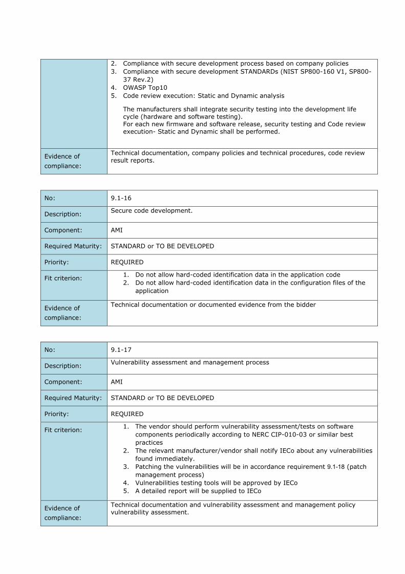
2. Compliance with secure development process based on company policies
3. Compliance with secure development STANDARDs (NIST SP800-160 V1, SP800-
37 Rev.2)
4. OWASP Top10
5. Code review execution: Static and Dynamic analysis
The manufacturers shall integrate security testing into the development life cycle (hardware and software testing). For each new firmware and software release, security testing and Code review
execution- Static and Dynamic shall be performed.
Evidence of
compliance:
Technical documentation, company policies and technical procedures, code review result reports.
No: 9.1-16
Description: Secure code development.
Component: AMI
Required Maturity: STANDARD or TO BE DEVELOPED
Priority: REQUIRED
Fit criterion: 1. Do not allow hard-coded identification data in the application code
2. Do not allow hard-coded identification data in the configuration files of the
application
Evidence of
compliance:
Technical documentation or documented evidence from the bidder
No: 9.1-17
Description: Vulnerability assessment and management process
Component: AMI
Required Maturity: STANDARD or TO BE DEVELOPED
Priority: REQUIRED
Fit criterion: 1. The vendor should perform vulnerability assessment/tests on software
components periodically according to NERC CIP-010-03 or similar best
practices
2. The relevant manufacturer/vendor shall notify IECo about any vulnerabilities
found immediately.
3. Patching the vulnerabilities will be in accordance requirement 18-19. (patch
management process)
4. Vulnerabilities testing tools will be approved by IECo
5. A detailed report will be supplied to IECo
Evidence of
compliance:
Technical documentation and vulnerability assessment and management policy
vulnerability assessment.

No: 9.1-18
Description: Patch management process.
Component: AMI
Required Maturity: STANDARD or TO BE DEVELOPED
Priority: REQUIRED
Fit criterion: 1. If vulnerabilities exist, immediately report to IECo
2. Supply patches to amend the vulnerabilities:
a. Critical severity – Within one week from finding the vulnerability
b. High severity – Within one month from finding the vulnerability
c. Low severity – Within the following quarter from finding the vulnerability
3. The supplier is required to check the patch in an operating environment and
make sure there is no operational impairment.
Evidence of
compliance:
Technical documentation and patch management policy.
No: 9.1-19
Description: Compliance with international and Israeli laws, regulations, standards, and
procedures.
Component: AMI
Required Maturity: STANDARD or TO BE DEVELOPED
Priority: REQUIRED
Fit criterion: The vendor should supply official information about compatibility with the
international and Israeli cybersecurity laws and standards like:
1. ISO27001/2
2. NIST 800-64
3. NIST 800-53
4. DLMS Green Book Ed.10
5. NIST SP800-160 V1
6. NIST SP800-37 Rev.2
7. IEC 62056
8. NERC CIP-010-03
Evidence of
compliance:
Technical documentation, company policies, technical and managerial procedures.
No: 9.1-20
Description: Technical documents and cyber solution architecture.
Component: AMI, HES, DC, METERS [1Ph, 3Ph, CT, PLMN, PLC], IHD

Required Maturity: STANDARD or TO BE DEVELOPED
Priority: REQUIRED
Fit criterion: The vendor will provide a unified cyber architecture document and drawings:
1. Design documents 2. SOW 3. HLD
4. LLD 5. SAT and FAT
Evidence of
compliance:
Technical documentation and cyber architecture document.
No: 9.1-21
Description: Vulnerability Assessment Audits & Penetration tests should be done by external independent company.
Component: AMI, HES, DC, METERS [1Ph, 3Ph, CT, PLMN, PLC], IHD
Required Maturity: STANDARD or TO BE DEVELOPED
Priority: REQUIRED
Fit criterion: The penetration tests (including physical, network and application security tests) shall provide details, among other things about:
The feasibility to tamper with the device and retrieve E-meter cryptographic keys
The feasibility to tamper unnoticed with other security relevant settings
If there are still any backdoors present implemented by the E-meter vendor
If the functionality of the development interface (e.g. JTAG) is still present. It there are still other communication interfaces and protocols implemented
than the ones allowed. The feasibility of attack vectors success according to business process and
use cases risk assessment that has been done by IECo (the document will be supplied as part of the process)
These penetration tests shall be executed by an independent professional security
lab. The security lab shall not be affiliated to the bidder, nor have been involved at any stage in the product design.
Evidence of
compliance:
Certificate / Test report / Declaration of conformity from external laboratory. The bidder provides an overview of all penetration tests that have been executed on their components.
No: 9.1-22
Description: Sharing of security test results.
Component: AMI
Required Maturity: STANDARD or TO BE DEVELOPED
Priority: REQUIRED
Fit criterion: Under NDA, the vendor/ manufacturer is willing to share the results of their security testing.
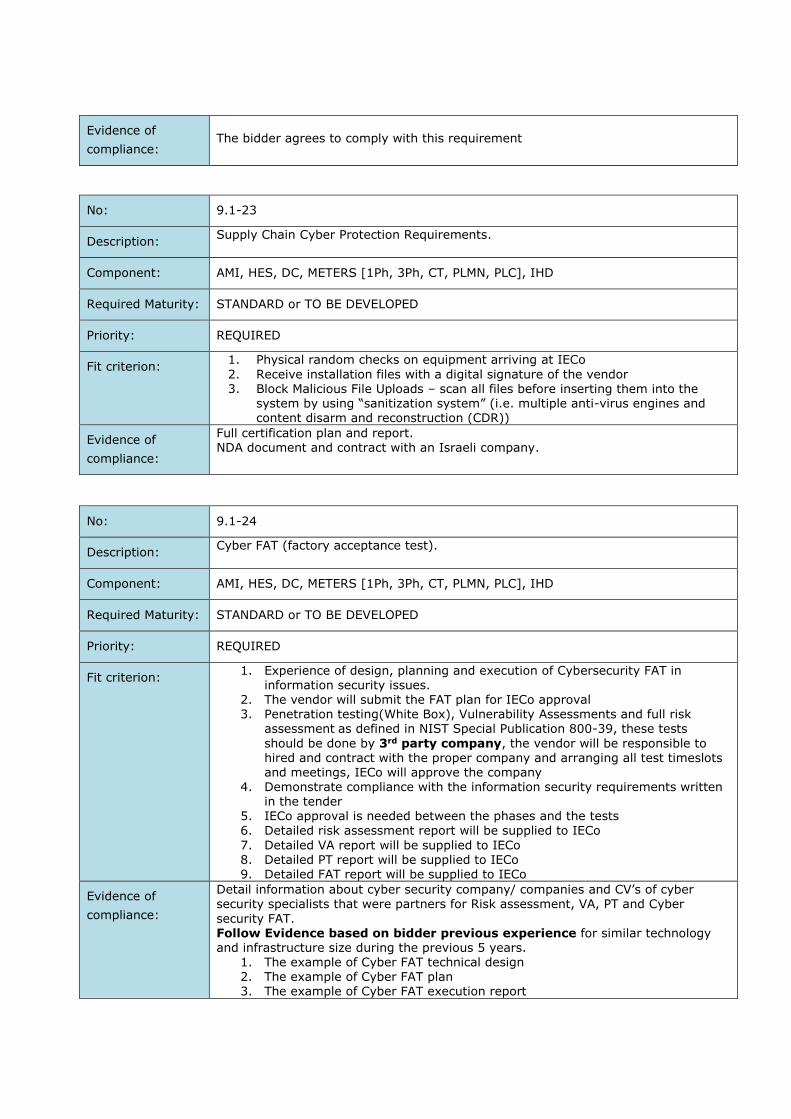
Evidence of
compliance:
The bidder agrees to comply with this requirement
No: 9.1-23
Description: Supply Chain Cyber Protection Requirements.
Component: AMI, HES, DC, METERS [1Ph, 3Ph, CT, PLMN, PLC], IHD
Required Maturity: STANDARD or TO BE DEVELOPED
Priority: REQUIRED
Fit criterion: 1. Physical random checks on equipment arriving at IECo
2. Receive installation files with a digital signature of the vendor 3. Block Malicious File Uploads – scan all files before inserting them into the
system by using “sanitization system” (i.e. multiple anti-virus engines and content disarm and reconstruction (CDR))
Evidence of
compliance:
Full certification plan and report. NDA document and contract with an Israeli company.
No: 9.1-24
Description: Cyber FAT (factory acceptance test).
Component: AMI, HES, DC, METERS [1Ph, 3Ph, CT, PLMN, PLC], IHD
Required Maturity: STANDARD or TO BE DEVELOPED
Priority: REQUIRED
Fit criterion: 1. Experience of design, planning and execution of Cybersecurity FAT in
information security issues. 2. The vendor will submit the FAT plan for IECo approval 3. Penetration testing(White Box), Vulnerability Assessments and full risk
assessment as defined in NIST Special Publication 800-39, these tests
should be done by 3rd party company, the vendor will be responsible to hired and contract with the proper company and arranging all test timeslots and meetings, IECo will approve the company
4. Demonstrate compliance with the information security requirements written in the tender
5. IECo approval is needed between the phases and the tests
6. Detailed risk assessment report will be supplied to IECo
7. Detailed VA report will be supplied to IECo 8. Detailed PT report will be supplied to IECo 9. Detailed FAT report will be supplied to IECo
Evidence of
compliance:
Detail information about cyber security company/ companies and CV’s of cyber security specialists that were partners for Risk assessment, VA, PT and Cyber
security FAT. Follow Evidence based on bidder previous experience for similar technology and infrastructure size during the previous 5 years.
1. The example of Cyber FAT technical design 2. The example of Cyber FAT plan 3. The example of Cyber FAT execution report

4. Examples of full risk assessment reports and Gap analysis reports done by
the bidder at least during the previous 5 years for similar technology and
size infrastructure
No: 9.1-25
Description: Cyber SAT (site acceptance test).
Component: AMI, HES, DC, METERS [1Ph, 3Ph, CT, PLMN, PLC], IHD
Required Maturity: STANDARD or TO BE DEVELOPED
Priority: REQUIRED
Fit criterion: Experience of design, planning and execution of Cybersecurity SAT in
information security issues. The vendor will submit the SAT plan for IECo approval
Penetration testing(White Box), Vulnerability Assessments and full risk assessment as defined in NIST Special Publication 800-39, these tests should be done by an Israeli 3rd party company, the vendor will be responsible to hired and contract with the proper company and arranging all test timeslots and meetings, IECo will approve the company
Demonstrate compliance with the information security requirements written in
the tender IECo approval is needed between the phases and the tests Detailed risk assessment report will be supplied to IECo Detailed VA report will be supplied to IECo Detailed PT report will be supplied to IECo Detailed SAT report will be supplied to IECo
The vendor will correct the gaps from the cyber SAT
Evidence of
compliance:
Detail information about cyber security company/ companies and CV’s of cyber security specialists that were partners for Risk assessment, VA, PT and Cyber security SAT. Follow Evidence based on bidder previous experience for similar technology and infrastructure size during the previous 5 years.
1. The example of Cyber SAT technical design 2. The example of Cyber SAT plan 3. The example of Cyber SAT execution report
4. Examples of full risk assessment reports and Gap analysis reports done by
the bidder at least during the previous 5 years for similar technology and
size infrastructure
5. NDA document and contract with an Israeli company
No: 9.1-26
Description: Check content and files “in the center of the network” before transferring them to
Meters and DC’s
Component: AMI
Required Maturity: STANDARD or TO BE DEVELOPED
Priority: REQUIRED
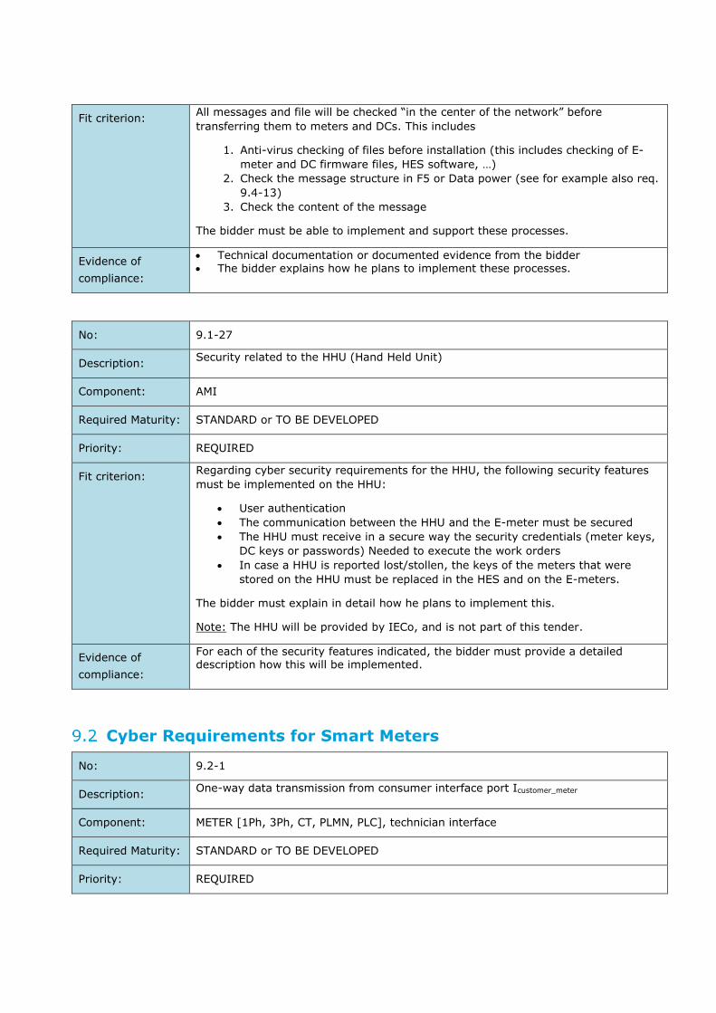
Fit criterion: All messages and file will be checked “in the center of the network” before
transferring them to meters and DCs. This includes
1. Anti-virus checking of files before installation (this includes checking of E-
meter and DC firmware files, HES software, …)
2. Check the message structure in F5 or Data power (see for example also req.
9.4-13)
3. Check the content of the message
The bidder must be able to implement and support these processes.
Evidence of
compliance:
Technical documentation or documented evidence from the bidder The bidder explains how he plans to implement these processes.
No: 9.1-27
Description: Security related to the HHU (Hand Held Unit)
Component: AMI
Required Maturity: STANDARD or TO BE DEVELOPED
Priority: REQUIRED
Fit criterion: Regarding cyber security requirements for the HHU, the following security features
must be implemented on the HHU:
User authentication
The communication between the HHU and the E-meter must be secured
The HHU must receive in a secure way the security credentials (meter keys,
DC keys or passwords) Needed to execute the work orders
In case a HHU is reported lost/stollen, the keys of the meters that were
stored on the HHU must be replaced in the HES and on the E-meters.
The bidder must explain in detail how he plans to implement this.
Note: The HHU will be provided by IECo, and is not part of this tender.
Evidence of
compliance:
For each of the security features indicated, the bidder must provide a detailed description how this will be implemented.
Cyber Requirements for Smart Meters
No: 9.2-1
Description: One-way data transmission from consumer interface port Icustomer_meter
Component: METER [1Ph, 3Ph, CT, PLMN, PLC], technician interface
Required Maturity: STANDARD or TO BE DEVELOPED
Priority: REQUIRED

Fit criterion: The bidder shall provide a Uni-directional consumer interface port, based on optical decoupling. A technical description must be provided that the communication is
indeed one-way.
Evidence of
compliance:
The bidder explains how the consumer interface port is physically implemented.
No: 9.2-2
Description: The meter should log all technical information about all technician operations
performed in the field and send it to a central log management system.
Component: METER [1Ph, 3Ph, CT, PLMN, PLC], technician interface
Required Maturity: STANDARD or TO BE DEVELOPED
Priority: REQUIRED
Fit criterion: Detailed technical description.
Evidence of
compliance:
Technical documentation.
No: 9.2-3
Description: Security on the PLC-layer.
Component: METER [PLC]
Required Maturity: STANDARD or TO BE DEVELOPED
Priority: REQUIRED
Fit criterion: The information security measures provided at the PLC communication level should
be specified against the following cyber-attacks:
1. Man in the middle
2. Impersonation
Evidence of
compliance:
Technical documentation
No: 9.2-4
Description: The vendor shall implement a rogue infrastructure association prevention
mechanism.
Component: METER [PLMN]
Required Maturity: STANDARD or TO BE DEVELOPED
Priority: REQUIRED

Fit criterion: The E-meters shall only access and authenticate the mobile network provided by IECo. The bidder provides a detailed technical description of the mechanisms in
place (implemented in his meters) to protect against rogue infrastructure attacks.
Evidence of
compliance:
Technical information documentation.
No: 9.2-5
Description: The vendor shall specify other communication protocols, apart from DLMS/COSEM,
implemented on the meters and the information security measures on them.
Component: METER [1Ph, 3Ph, CT, PLMN, PLC]
Required Maturity: STANDARD or TO BE DEVELOPED
Priority: REQUIRED
Fit criterion: Detailed technical description.
Evidence of
compliance:
Technical documentation.
No: 9.2-6
Description: All key material shall be securely stored in the E-meter.
Component: METER [1Ph, 3Ph, CT, PLMN, PLC]
Required Maturity: STANDARD or TO BE DEVELOPED
Priority: REQUIRED
Fit criterion: Key material is securely stored on the E-meter. It should not be possible to read out
any key via any of the interfaces on the E-meter. Secure (key) storage on the E-meter is preferably implemented by using a microprocessor with dedicated storage for a unique key per meter (or per processor) inside the microprocessor chip. This unique key is used to secure the DLMS/COSEM communication keys.
Evidence of
compliance:
Documented evidence from bidder: The bidder explains how this is implemented on his E-meters, include a detailed description of the technology used for key material protection.
No: 9.2-7
Description: Messages within a DLMS association shall be protected with dedicated keys.
Component: METER [1Ph, 3Ph, CT, PLMN, PLC]
Required Maturity: STANDARD or TO BE DEVELOPED
Priority: REQUIRED

Fit criterion: The meter uses dedicated keys per association. This shall be implemented according to DLMS/COSEM in accordance with the IEC 62056-5-3 standard.
Evidence of
compliance:
Certified test report or documented evidence from bidder and technical description of the solution.
No: 9.2-8
Description: The E-meter shall only accept associations from the defined DLMS clients.
Component: METER [1Ph, 3Ph, CT, PLMN ,PLC]
Required Maturity: STANDARD or TO BE DEVELOPED
Priority: REQUIRED
Fit criterion: Only the following Application Associations shall be implemented on the E-meters:
Public Client Management Client Secure Client
Evidence of
compliance:
Test report or documented evidence from the bidder. Compliance with this specification is verified by the evaluation of a sample.
No: 9.2-9
Description: The E-meter shall only accept HLS mechanism id 5 authentication during Association
Establishment, except for the public client.
Component: METER [1Ph, 3Ph, CT, PLMN, PLC]
Required Maturity: STANDARD or TO BE DEVELOPED
Priority: REQUIRED
Fit criterion: For the management client, the pre-established client and secure client:
The E-meter shall only accept associations that use the HLS mech_id = 5 (HLS AES-GMAC) authentication mechanism.
Association requests with any other authentication mechanism shall be rejected.
Evidence of
compliance:
Test report or documented evidence from bidder.
No: 9.2-10
Description: The meters shall by default apply secure DLMS/COSEM communication.
Component: METER [1Ph, 3Ph, CT, PLMN, PLC]
Required Maturity: STANDARD or TO BE DEVELOPED
Priority: REQUIRED

Fit criterion: The security policy of the meters should be configured on the factory in a way to permit only secure/ protected communication:
This means that for the Management (Client) Association and the Pre-established client the security policy will require:
Authenticated and encrypted requests Authenticated and encrypted responses
For the Secure Client, the security policy will require:
Authenticated and encrypted requestsAuthenticated and encrypted responses
Evidence of
compliance:
Test report or documented evidence from the bidder. Compliance with this specification is verified by evaluation of a sample.
No: 9.2-11
Description: Data model and Access Rights
Component: METER [1Ph, 3Ph, CT, PLMN, PLC]
Required Maturity: STANDARD or TO BE DEVELOPED
Priority: REQUIRED
Fit criterion: The E-meter shall implement the access rights as defined by the data model in the “IECo DLMS COSEM Profile for communication interfaces. MOACH Smart Meters”.
Evidence of
compliance:
Test report or documented evidence from the bidder. Compliance with this specification is verified by the evaluation of a sample.
No: 9.2-12
Description: Allowed interfaces on the E-meter
Component: METER [1Ph, 3Ph, CT, PLMN, PLC]
Required Maturity: STANDARD or TO BE DEVELOPED
Priority: REQUIRED
Fit criterion: Only the E-meter interfaces as described in section 2.1 shall be present. That is the Ilocal_meter, IHES_meter ,and IDC_meter, and Imeter_customer Apart from this, also push buttons as described in section 3.2.8.2 shall be present.
No other interfaces and push buttons than those specified shall be present.
Evidence of
compliance:
Test report or documented evidence from the bidder.
No: 9.2-13

Description: Data and configuration parameters in the E-meter shall be protected against tampering.
Component: METER [1Ph, 3Ph, CT, PLMN, PLC]
Required Maturity: STANDARD or TO BE DEVELOPED
Priority: REQUIRED
Fit criterion: It shall not be possible to change any configuration parameter in an unauthorized
way, e.g. by tampering with the meter. The E-meter implements protection mechanisms in order to preserve the confidentiality and integrity of data stored locally in the equipment.
Evidence of
compliance:
Documented evidence from bidder. The bidder explains how this is implemented on
his E-meters
The bidder provides a penetration test document indicating that it is impossible to change any configuration parameter in an unauthorized way by tampering with the meter.
No: 9.2-14
Description: Disable developer interfaces.
Component: METER [1Ph, 3Ph, CT, PLMN, PLC]
Required Maturity: STANDARD or TO BE DEVELOPED
Priority: REQUIRED
Fit criterion: The E-meter shall have all debug ports on its circuit board (such as JTAG) disabled so that they cannot be used to read from or write to memory.
Evidence of
compliance:
Test report or documented evidence from the bidder. Penetration test report indicating that this functionality is disabled.
No: 9.2-15
Description: The E-meter must implement security suite 0.
Component: METER [1Ph, 3Ph, CT, PLMN, PLC]
Required Maturity: STANDARD OR TO BE DEVELOPED
Priority: REQUIRED
Fit criterion: Regarding the security suites and algorithms, the E-meter must support the following algorithms for the Management Client, Pre-Established Client and the Reading and Secure Client:
Authenticated Encryption: AES-GCM-128
Key Wrap: AES-128 key wrap
Evidence of
compliance:
Test report or documented evidence from the bidder.

No: 9.2-16
Description: No other cryptographic algorithms, with weaker security, than those currently specified, shall be implemented.
Component: METER [1Ph, 3Ph, CT, PLMN, PLC]
Required Maturity: STANDARD or TO BE DEVELOPED
Priority: REQUIRED
Fit criterion: Cryptographic algorithms with weaker security than those specified in req. no. 9.2-9, 9.2-15, 9.5-1 or 9.5-5 shall not be implemented in the E-meter.
Evidence of
compliance:
Test report or documented evidence from the bidder.
No: 9.2-17
Description: It shall not be possible to disable the logging functionality of the meter.
Component: METER [1Ph, 3Ph, CT, PLMN, PLC]
Required Maturity: STANDARD or TO BE DEVELOPED
Priority: REQUIRED
Fit criterion: In order to be able to guarantee the integrity of the meter, it shall not be possible to disable the logging functionality of the meter.
Evidence of
compliance:
Test report or documented evidence from the bidder.
No: 9.2-18
Description: The following security events shall be implemented, and logged in the E-meter
Component: METER [1Ph, 3Ph, CT, PLMN, PLC]
Required Maturity: STANDARD or TO BE DEVELOPED
Priority: REQUIRED
Fit criterion: At least the following events shall be implemented:
Terminal cover removed Terminal cover closed Meter cover removed Meter cover closed
Strong magnetic DC field detected No strong magnetic DC field anymore
Evidence of
compliance:
Compliance with this specification is verified by the evaluation of a sample. Test report or documented evidence from the bidder. The bidder describes which security/fraud detection-related events are
implemented.

No: 9.2-19
Description: The vendor must ensure that there is a security mechanism against manipulating
the meter and using it as a pivoting vector (A network bridge).
Component: METER [1Ph, 3Ph, CT, PLMN, PLC]
Required Maturity: STANDARD or TO BE DEVELOPED
Priority: REQUIRED
Fit criterion: Detailed technical description.
Evidence of
compliance:
Technical documentation.
No: 9.2-20
Description: Security events and logging
Component: METER [1Ph, 3Ph, CT, PLMN, PLC]
Required Maturity: STANDARD or TO BE DEVELOPED
Priority: REQUIRED
Fit criterion: The meters shall implement the management of events, error and alarms as
described in the “IECo DLMS COSEM Profile for communication interfaces. MOACH
Smart Meters” so that IECo can decide and configure which events the meters should send to the HES or DC.
Evidence of
compliance:
Technical documentation.
No: 9.2-21
Description: The vendor must ensure that there is a security mechanism against manipulating
the meter and using it as a pivoting vector (A network bridge).
Component: METER [1Ph, 3Ph, CT, PLMN, PLC]
Required Maturity: STANDARD or TO BE DEVELOPED
Priority: REQUIRED
Fit criterion: Detailed technical description.
Evidence of
compliance:
Technical documentation.
No: 9.2-22
Description: Secure and reliable clock synchronization

Component: METER [1Ph, 3Ph, CT, PLMN, PLC]
Required Maturity: STANDARD or TO BE DEVELOPED
Priority: REQUIRED
Fit criterion: It is important that the clock of the meters is synchronized with the clock of other
AMI components (e.g. the HES or MDMS). To this end, the meters will receive clock
information from another system component.
For both PLMN-based and PLC-based meters, the bidder explains the options for
receiving clock information and how these messages will be secured.
Evidence of
compliance:
Detailed technical description from the bidder.
No: 9.2-23
Description: E-meter firmware authenticity and integrity protection.
Component: METER [1Ph, 3Ph, CT, PLMN, PLC]
Required Maturity: STANDARD or TO BE DEVELOPED
Priority: REQUIRED
Fit criterion: It must be possible to verify (by IECo) the authenticity and integrity of new E-
meter firmware before uploading this new firmware to the meters. The E-meters must also be able to verify the authenticity and integrity of the
new firmware, and must be able to verify that the new firmware is applicable for the device (e.g. device type/version check)
Evidence of
compliance:
Documented evidence from the bidder. The bidder explains how this is implemented in his E-meters and how IECo can
verify the authenticity and integrity of the new firmware before uploading the new firmware.
No: 9.2-24
Description: A secure boot mechanism shall be implemented on the E-meter
Component: METER [1Ph, 3Ph, CT, PLMN, PLC]
Required Maturity: STANDARD or TO BE DEVELOPED
Priority: REQUIRED
Fit criterion: During rebooting of the E-meter, the integrity and authenticity of the firmware is verified before reloading the firmware
Evidence of
compliance:
Documented evidence from the bidder.
The bidder explains in detail how the secure boot mechanism is implemented

No: 9.2-25
Description: Vulnerability Assessment Audits & Penetration tests by external independent security lab.
Component: METER [1Ph, 3Ph, CT, PLMN, PLC]
Required Maturity: STANDARD or TO BE DEVELOPED
Priority: REQUIRED
Fit criterion: The penetration tests (including physical, network and application security tests)
shall provide details, among other things about: The feasibility to tamper with the device and retrieve E-meter cryptographic
keys The feasibility to tamper unnoticed with other security relevant settings
If there are still any backdoors present implemented by the E-meter vendor If the functionality of the development interface (e.g. JTAG) is still present. It there are still other communication interfaces and protocols implemented
than the ones allowed. These penetration tests shall be executed by an independent professional security lab. The security lab shall not be affiliated to the bidder, nor have been involved at any stage in the product design.
Evidence of
compliance:
Example Report, Certificate / Test report + Declaration of conformity from external
laboratory. The bidder provides an overview of all penetration tests that have been executed on their meters.
No: 9.1-26
Description: The E-meter must be security suite 1 ready.
Component: METER [1Ph, 3Ph, CT, PLMN, PLC]
Required Maturity: STANDARD or TO BE DEVELOPED
Priority: REQUIRED
Fit criterion: The E-meter will have the appropriate resources and capabilities to support security suite 1: CPU, Memory, Storage, Bandwidth and network, firmware, etc.
Evidence of
compliance:
Technical documentation, Certificate / Test report + Declaration of conformity from external laboratory.
No: 9.2-27
Description: Use up-to-date software versions and advanced programming languages.
Component: METER [1Ph, 3Ph, CT, PLMN, PLC]
Required Maturity: STANDARD or TO BE DEVELOPED
Priority: REQUIRED
Fit criterion: 1. There is no use of outdated software versions without support and/or End of
life

2. There is no use of outdated programming languages without support and/or End of life
Evidence of
compliance:
Test report or documented evidence from the bidder.
No: 9.2-28
Description: The E-meter should support manually or automatic changing/renewing meter keys.
Component: METER [1Ph, 3Ph, CT, PLMN, PLC]
Required Maturity: STANDARD or TO BE DEVELOPED
Priority: REQUIRED
Fit criterion: An operator shall be able to change/renew the E-meter keys in a secure way. New keys should be transferred to meter in an encrypted way according to the IEC 62056
standard. The result of process should be detail logged.
Evidence of
compliance:
Certified test report, documented evidence from bidder: The bidder explains how this is implemented on his E-meters, include a detailed description of the technology used for key material protection.
DC Security Requirements
No: 9.3-1
Description: All key material related to connected E-meters shall be securely stored in the DC.
Component: DC
Required Maturity: STANDARD or TO BE DEVELOPED
Priority: REQUIRED
Fit criterion: Key material is securely stored on the DC. It shall not be possible to read out any keys.
Evidence of
compliance:
Test report or documented evidence from bidder:
The bidder explains how this is implemented on his DCs.
No: 9.3-2
Description: All DC specific security credentials, including passwords, shall be securely stored in the DC.
Component: DC
Required Maturity: STANDARD or TO BE DEVELOPED
Priority: REQUIRED

Fit criterion: DC specific security credentials, including passwords, are securely stored on the DC.
Evidence of
compliance:
Test report or documented evidence from bidder: The bidder explains how this is implemented on his DCs.
No: 9.3-3
Description: Integrated security element (security chip) in the DC
Component: DC
Required Maturity: STANDARD or TO BE DEVELOPED
Priority: REQUIRED
Fit criterion: The DC should use dedicated secure hardware for keys and cryptographic processes protection:
The key that is used for master and working key encryption and decryption will be stored in dedicated secure memory and not exportable.
Cryptographic processes will be done by a dedicated CPU. The security element in the DC shall be certified according to the common criteria,
at least level EAL 4.
Evidence of
compliance:
Dedicated secure hardware technical documentation Security test report from bidder and the secure hardware manufacturer. Security test report from the DC manufacturer
Or (if available): Certificate / Test report / Declaration of conformity from external laboratory.
No: 9.3-4
Description: Integrated security element (security chip) in the DC.
Component: DC
Required Maturity: STANDARD or TO BE DEVELOPED
Priority: PREFERRED
Fit criterion: The DC should use dedicated secure hardware for keys and cryptographic processes protection:
The key that is used for master and working key encryption and decryption will be stored in dedicated secure memory and not exportable.
Cryptographic processes will be done by a dedicated CPU. The security element in the data concentrator should be certified according to the common criteria, preferably level EAL 5+ or better.
Evidence of
compliance:
Dedicated secure hardware technical documentation Security test report from bidder and the secure hardware manufacturer. Security test report from the DC manufacturer

Or (if available): Certificate / Test report / Declaration of conformity from external laboratory.
No: 9.3-5
Description: RBAC – Implement Role-Based Access Control for the DC.
Component: DC
Required Maturity: STANDARD or TO BE DEVELOPED
Priority: REQUIRED
Fit criterion: 1. User type
a. Technician – Malfunction handling and maintenance
b. Administrator – In addition to Technician permissions, will be
responsible of other users, permissions, and configuration
management (e.g., version upgrades)
c. Application user – for application services
2. Security alerts on user activities such as permission addition/modifications
with an emphasis on administrator users.
Evidence of
compliance:
Technical documentation.
No: 9.3-6
Description: Password complexity for local accounts on DC.
Component: DC
Required Maturity: STANDARD or TO BE DEVELOPED
Priority: REQUIRED
Fit criterion: Password must be six or more characters long.
Password must contain characters from three of the following four categories:
o Uppercase characters A-Z (Latin alphabet) o Lowercase characters a-z (Latin alphabet) o Digits 0-9
o Special characters (!, $, #, %, etc.)
Evidence of
compliance:
Test report or documented evidence from bidder.
No: 9.3-7
Description: Messages within a DLMS association shall be protected with dedicated keys.
Component: DC
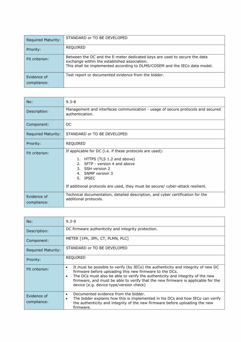
Required Maturity: STANDARD or TO BE DEVELOPED
Priority: REQUIRED
Fit criterion: Between the DC and the E-meter dedicated keys are used to secure the data exchange within the established association. This shall be implemented according to DLMS/COSEM and the IECo data model.
Evidence of
compliance:
Test report or documented evidence from the bidder.
No: 9.3-8
Description: Management and interfaces communication - usage of secure protocols and secured
authentication.
Component: DC
Required Maturity: STANDARD or TO BE DEVELOPED
Priority: REQUIRED
Fit criterion: If applicable for DC (i.e. if these protocols are used):
1. HTTPS (TLS 1.2 and above)
2. SFTP - version 4 and above
3. SSH version 2
4. SNMP version 3
5. IPSEC
If additional protocols are used, they must be secure/ cyber-attack resilient.
Evidence of
compliance:
Technical documentation, detailed description, and cyber certification for the additional protocols.
No: 9.3-9
Description: DC firmware authenticity and integrity protection.
Component: METER [1Ph, 3Ph, CT, PLMN, PLC]
Required Maturity: STANDARD or TO BE DEVELOPED
Priority: REQUIRED
Fit criterion: It must be possible to verify (by IECo) the authenticity and integrity of new DC
firmware before uploading this new firmware to the DCs. The DCs must also be able to verify the authenticity and integrity of the new
firmware, and must be able to verify that the new firmware is applicable for the device (e.g. device type/version check)
Evidence of
compliance:
Documented evidence from the bidder. The bidder explains how this is implemented in his DCs and how IECo can verify
the authenticity and integrity of the new firmware before uploading the new firmware.
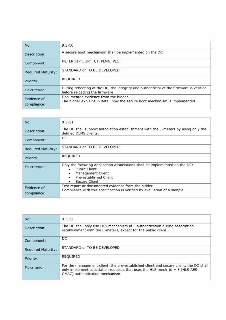
No: 9.3-10
Description: A secure boot mechanism shall be implemented on the DC
Component: METER [1Ph, 3Ph, CT, PLMN, PLC]
Required Maturity: STANDARD or TO BE DEVELOPED
Priority: REQUIRED
Fit criterion: During rebooting of the DC, the integrity and authenticity of the firmware is verified
before reloading the firmware
Evidence of
compliance:
Documented evidence from the bidder.
The bidder explains in detail how the secure boot mechanism is implemented
No: 9.3-11
Description: The DC shall support association establishment with the E-meters by using only the
defined DLMS clients.
Component: DC
Required Maturity: STANDARD or TO BE DEVELOPED
Priority: REQUIRED
Fit criterion: Only the following Application Associations shall be implemented on the DC:
Public Client Management Client Pre-established Client Secure Client
Evidence of
compliance:
Test report or documented evidence from the bidder. Compliance with this specification is verified by evaluation of a sample.
No: 9.3-12
Description: The DC shall only use HLS mechanism id 5 authentication during association establishment with the E-meters, except for the public client.
Component: DC
Required Maturity: STANDARD or TO BE DEVELOPED
Priority: REQUIRED
Fit criterion: For the management client, the pre-established client and secure client, the DC shall only implement association requests that uses the HLS mech_id = 5 (HLS AES-GMAC) authentication mechanism.

Evidence of
compliance:
Test report or documented evidence from the bidder. Compliance with this specification is verified by evaluation of a sample.
No: 9.3-13
Description: The DC shall by default apply secure DLMS/COSEM communication.
Component: DC
Required Maturity: STANDARD or TO BE DEVELOPED
Priority: REQUIRED
Fit criterion: The security policy of the meters should be configured in the factory in a way to permit only secure/ protected communication: This means that for the Management (Client) Association and the Pre-established association the security policy will require:
Authenticated and encrypted requests Authenticated and encrypted responses
For the Secure Client, the security policy will require:
Authenticated and encrypted requests Authenticated and encrypted responses
Evidence of
compliance:
Test report or documented evidence from the bidder. Compliance with this specification is verified by evaluation of a sample.
No: 9.3-14
Description: For communication and data exchange with the E-meters, the DC will support the defined E-meter data model and access rights.
Component: DC
Required Maturity: STANDARD or TO BE DEVELOPED
Priority: REQUIRED
Fit criterion: The DC shall implement the access rights as defined by the E-meter data model in the “IECo DLMS COSEM Profile for communication interfaces. MOACH Smart Meters”
and according to the IEC 62056 standard.
Evidence of
compliance:
Test report or documented evidence from bidder. Compliance with this specification is verified by evaluation of a sample.
No: 9.3-15
Description: DC shall implement ‘Session Locking’.
Component: DC

Required Maturity: STANDARD or TO BE DEVELOPED
Priority: REQUIRED
Fit criterion: The DC shall lock a (user) session or logout the user, and prevent further access to the DC, after a certain (configurable) time of inactivity in a session. Details on this requirement will be aligned between Contractor and Contracting
Entity.
Evidence of
compliance:
Test report or documented evidence from bidder.
The bidder describes how the DC fulfils this requirement.
No: 9.3-16
Description: Secure and reliable clock synchronization.
Component: DC
Required Maturity: STANDARD or TO BE DEVELOPED
Priority: REQUIRED
Fit criterion: It is important that the clock of the DCs is synchronized with the clock of other AMI
components (e.g. the HES or MDMS). To this end, the DCs will receive clock
information from another system component.
The bidder explains the options for the DCs to receive clock information and how
these messages will be secured.
Evidence of
compliance:
Test report or documented evidence from bidder.
No: 9.3-17
Description: Network connectivity.
Component: DC
Required Maturity: STANDARD or TO BE DEVELOPED
Priority: REQUIRED
Fit criterion: 1. DC will be supplied without a cellular modem
2. DC will be supplied with an available ethernet port for external FW
connectivity
Evidence of
compliance:
Test report or documented evidence from the bidder.
No: 9.3-18
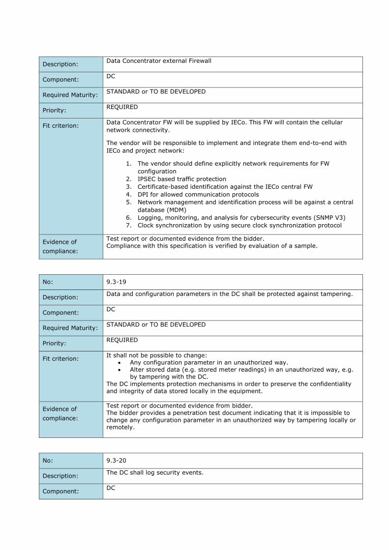
Description: Data Concentrator external Firewall
Component: DC
Required Maturity: STANDARD or TO BE DEVELOPED
Priority: REQUIRED
Fit criterion: Data Concentrator FW will be supplied by IECo. This FW will contain the cellular
network connectivity.
The vendor will be responsible to implement and integrate them end-to-end with
IECo and project network:
1. The vendor should define explicitly network requirements for FW
configuration
2. IPSEC based traffic protection
3. Certificate-based identification against the IECo central FW
4. DPI for allowed communication protocols
5. Network management and identification process will be against a central
database (MDM)
6. Logging, monitoring, and analysis for cybersecurity events (SNMP V3)
7. Clock synchronization by using secure clock synchronization protocol
Evidence of
compliance:
Test report or documented evidence from the bidder. Compliance with this specification is verified by evaluation of a sample.
No: 9.3-19
Description: Data and configuration parameters in the DC shall be protected against tampering.
Component: DC
Required Maturity: STANDARD or TO BE DEVELOPED
Priority: REQUIRED
Fit criterion: It shall not be possible to change:
Any configuration parameter in an unauthorized way. Alter stored data (e.g. stored meter readings) in an unauthorized way, e.g.
by tampering with the DC.
The DC implements protection mechanisms in order to preserve the confidentiality and integrity of data stored locally in the equipment.
Evidence of
compliance:
Test report or documented evidence from bidder. The bidder provides a penetration test document indicating that it is impossible to
change any configuration parameter in an unauthorized way by tampering locally or remotely.
No: 9.3-20
Description: The DC shall log security events.
Component: DC
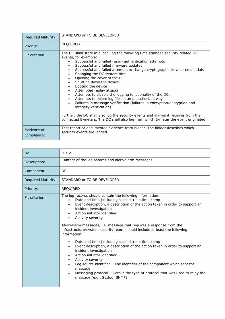
Required Maturity: STANDARD or TO BE DEVELOPED
Priority: REQUIRED
Fit criterion: The DC shall store in a local log the following time stamped security related DC events, for example:
Successful and failed (user) authentication attempts Successful and failed firmware updates
Successful and failed attempts to change cryptographic keys or credentials Changing the DC system time Opening the cover of the DC Shutting down the device Booting the device Attempted replay attacks Attempts to disable the logging functionality of the DC.
Attempts to delete log files in an unauthorized way
Failures in message verification (failures in encryption/decryption and integrity verification)
Further, the DC shall also log the security events and alarms it receives from the connected E-meters. The DC shall also log from which E-meter the event originated.
Evidence of
compliance:
Test report or documented evidence from bidder. The bidder describes which security events are logged.
No: 9.3-21
Description: Content of the log records and alert/alarm messages
Component: DC
Required Maturity: STANDARD or TO BE DEVELOPED
Priority: REQUIRED
Fit criterion: The log records should contain the following information:
Date and time (including seconds) – a timestamp
Event description, a description of the action taken in order to support an
incident investigation
Action initiator identifier
Activity severity
Alert/alarm messages, i.e. message that requires a response from the
infrastructure/system security team, should include at least the following
information:
Date and time (including seconds) – a timestamp
Event description, a description of the action taken in order to support an
incident investigation
Action initiator identifier
Activity severity
Log source identifier – The identifier of the component which sent the
message
Messaging protocol – Details the type of protocol that was used to relay the
message (e.g., Syslog, SNMP)

Evidence of
compliance:
Test report or documented evidence from bidder. The bidder describes the structure of the log records and alert/alarm messages
No: 9.3-22
Description: It shall not be possible to disable the logging functionality of the DC.
Component: DC
Required Maturity: STANDARD or TO BE DEVELOPED
Priority: REQUIRED
Fit criterion: In order to be able to guarantee the integrity of the DC, it shall not be possible to disable the logging functionality of the DC.
Evidence of
compliance:
Test report or documented evidence from bidder.
No: 9.3-23
Description: Critical DC events shall trigger alarm.
Component: DC
Required Maturity: STANDARD or TO BE DEVELOPED
Priority: REQUIRED
Fit criterion: Critical events shall trigger alarms. The criteria for a critical event are defined and configurable. Details on the set alarms will be aligned between contracting entity and contractor.
Evidence of
compliance:
Test report or documented evidence from bidder.
No: 9.3-24
Description: Vulnerability Assessment Audits & Penetration tests shall be provided.
Component: DC
Required Maturity: STANDARD or TO BE DEVELOPED
Priority: REQUIRED
Fit criterion: The penetration tests (including physical, network and application security tests) shall provide details, amongst other topics about:

The feasibility to tamper with the DC and retrieve E-meter and DC specific cryptographic keys.
The feasibility to tamper unnoticed with other security relevant settings It there are still other communication interfaces and protocols implemented
on the DC apart from the ones specified and documented by the bidder (no backdoors).
If the functionality of the development interface (e.g. JTAG) is still present.
Evidence of
compliance:
Test report or documented evidence from bidder. The bidder provides an overview of all penetration tests that have been executed on their DCs.
No: 9.3-25
Description: Protection application interfaces.
Component: DC
Required Maturity: STANDARD or TO BE DEVELOPED
Priority: REQUIRED
Fit criterion: For the communication between the DC and the HES, the DC is required to support APIs, based on XML \ SOAP so that the content can be verified and filtered by the F5 or DataPower
Evidence of
compliance:
Documented evidence from the bidder.
No: 9.3-26
Description: Use up-to-date software versions and advanced programming languages.
Component: DC
Required Maturity: STANDARD or TO BE DEVELOPED
Priority: REQUIRED
Fit criterion: 1. There is no use of outdated software versions without support and End of
life 2. There is no use of outdated programming languages without support and
End of life
Evidence of
compliance:
Test report or documented evidence from the bidder.
HES Security Requirements
No: 9.4-1
Description: HES should:

1. Protect based on encryption: payload and authentication process.
2. Decrypt the message that comes from the meters.
Component: HES
Required Maturity: STANDARD or TO BE DEVELOPED
Priority: REQUIRED
Fit criterion: All cryptographic operation must be done by HES in secure way, like: secure
authentication tag rendering and payload rendering HES will not store and use encryption keys as clear text. Keys will be stored in a secure way.
The symmetric keys will be stored in a DB in encrypted way Authentication process with DB should be certificate based mutual
authentication. The HES shall have an integrated secure key management system (KMS).
Evidence of
compliance:
Detailed processes description, technical documentation, and security test report Certificate and/or test report of the security module.
Done by external laboratory.
No: 9.4-2
Description: The HES shall support a key life cycle model of basic key management services.
Component: HES
Required Maturity: STANDARD or TO BE DEVELOPED
Priority: REQUIRED
Fit criterion: The HES shall support a key life cycle model of basic key management services as
described in ISO/IEC 11770-1:2010.
At least the following key management services shall be supported by the HES in a
secure way:
Key generation
Key registration (associating a key with an entity, e.g. with an E-meter or DC)
Key storage
Key backup and restore
Key archival
Evidence of
compliance:
Test report or documented evidence from bidder.
The bidder must explain in detail how his KMS implements these basic key
management services.
Detailed processes description, technical documentation, and security test report
Done by external laboratory.
No: 9.4-3
Description: Meter key export from KMS in HES.
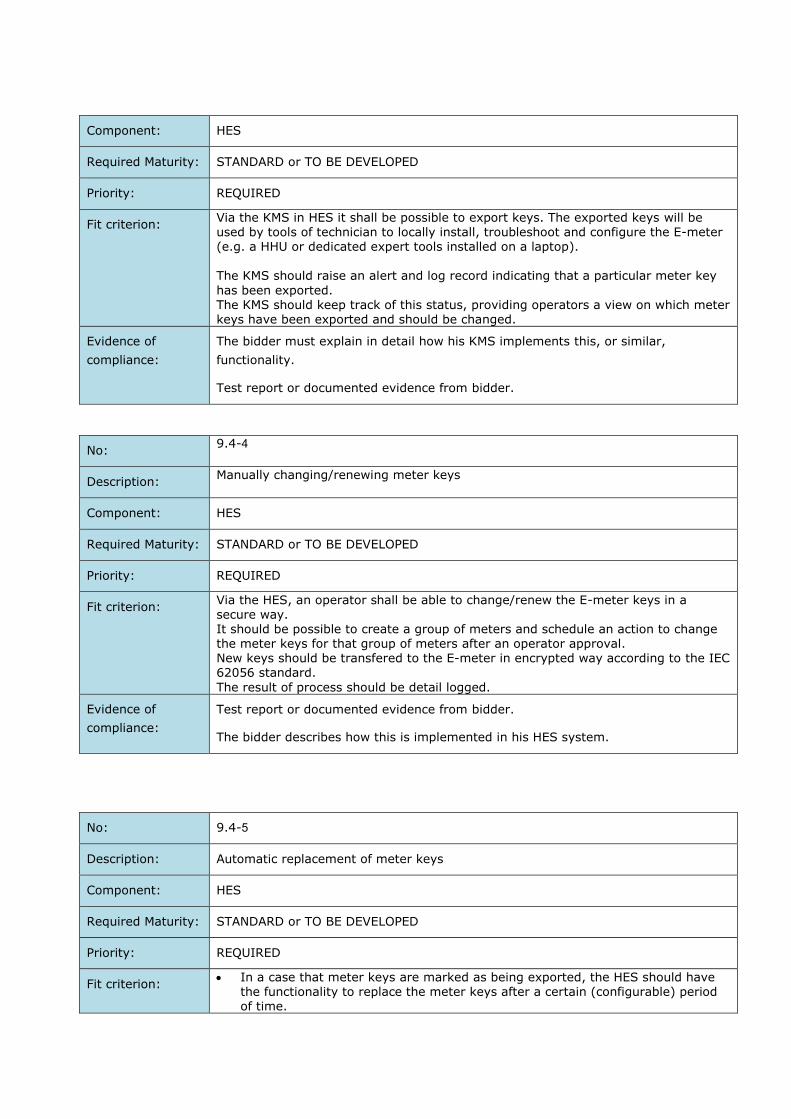
Component: HES
Required Maturity: STANDARD or TO BE DEVELOPED
Priority: REQUIRED
Fit criterion: Via the KMS in HES it shall be possible to export keys. The exported keys will be used by tools of technician to locally install, troubleshoot and configure the E-meter (e.g. a HHU or dedicated expert tools installed on a laptop). The KMS should raise an alert and log record indicating that a particular meter key
has been exported. The KMS should keep track of this status, providing operators a view on which meter keys have been exported and should be changed.
Evidence of
compliance:
The bidder must explain in detail how his KMS implements this, or similar,
functionality.
Test report or documented evidence from bidder.
No: 9.4-4
Description: Manually changing/renewing meter keys
Component: HES
Required Maturity: STANDARD or TO BE DEVELOPED
Priority: REQUIRED
Fit criterion: Via the HES, an operator shall be able to change/renew the E-meter keys in a secure way. It should be possible to create a group of meters and schedule an action to change the meter keys for that group of meters after an operator approval. New keys should be transfered to the E-meter in encrypted way according to the IEC 62056 standard.
The result of process should be detail logged.
Evidence of
compliance:
Test report or documented evidence from bidder.
The bidder describes how this is implemented in his HES system.
No: 9.4-5
Description: Automatic replacement of meter keys
Component: HES
Required Maturity: STANDARD or TO BE DEVELOPED
Priority: REQUIRED
Fit criterion: In a case that meter keys are marked as being exported, the HES should have
the functionality to replace the meter keys after a certain (configurable) period of time.
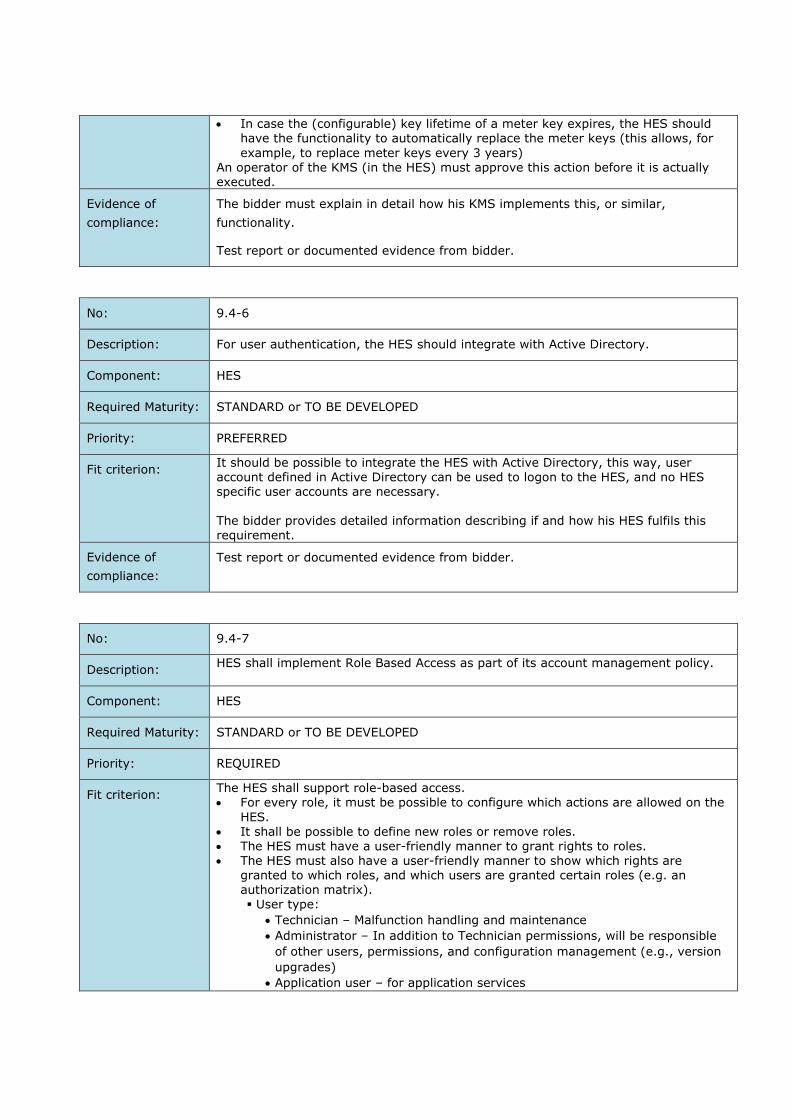
In case the (configurable) key lifetime of a meter key expires, the HES should have the functionality to automatically replace the meter keys (this allows, for
example, to replace meter keys every 3 years) An operator of the KMS (in the HES) must approve this action before it is actually executed.
Evidence of
compliance:
The bidder must explain in detail how his KMS implements this, or similar,
functionality.
Test report or documented evidence from bidder.
No: 9.4-6
Description: For user authentication, the HES should integrate with Active Directory.
Component: HES
Required Maturity: STANDARD or TO BE DEVELOPED
Priority: PREFERRED
Fit criterion: It should be possible to integrate the HES with Active Directory, this way, user account defined in Active Directory can be used to logon to the HES, and no HES specific user accounts are necessary. The bidder provides detailed information describing if and how his HES fulfils this requirement.
Evidence of
compliance:
Test report or documented evidence from bidder.
No: 9.4-7
Description: HES shall implement Role Based Access as part of its account management policy.
Component: HES
Required Maturity: STANDARD or TO BE DEVELOPED
Priority: REQUIRED
Fit criterion: The HES shall support role-based access. For every role, it must be possible to configure which actions are allowed on the
HES.
It shall be possible to define new roles or remove roles. The HES must have a user-friendly manner to grant rights to roles. The HES must also have a user-friendly manner to show which rights are
granted to which roles, and which users are granted certain roles (e.g. an authorization matrix). User type:
Technician – Malfunction handling and maintenance
Administrator – In addition to Technician permissions, will be responsible
of other users, permissions, and configuration management (e.g., version
upgrades)
Application user – for application services
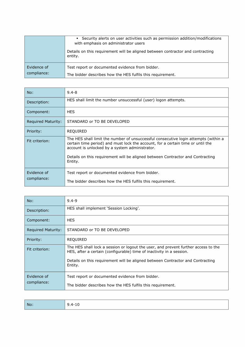
Security alerts on user activities such as permission addition/modifications
with emphasis on administrator users
Details on this requirement will be aligned between contractor and contracting entity.
Evidence of
compliance:
Test report or documented evidence from bidder.
The bidder describes how the HES fulfils this requirement.
No: 9.4-8
Description: HES shall limit the number unsuccessful (user) logon attempts.
Component: HES
Required Maturity: STANDARD or TO BE DEVELOPED
Priority: REQUIRED
Fit criterion: The HES shall limit the number of unsuccessful consecutive login attempts (within a certain time period) and must lock the account, for a certain time or until the account is unlocked by a system administrator. Details on this requirement will be aligned between Contractor and Contracting
Entity.
Evidence of
compliance:
Test report or documented evidence from bidder.
The bidder describes how the HES fulfils this requirement.
No: 9.4-9
Description: HES shall implement ‘Session Locking’.
Component: HES
Required Maturity: STANDARD or TO BE DEVELOPED
Priority: REQUIRED
Fit criterion: The HES shall lock a session or logout the user, and prevent further access to the HES, after a certain (configurable) time of inactivity in a session.
Details on this requirement will be aligned between Contractor and Contracting Entity.
Evidence of
compliance:
Test report or documented evidence from bidder.
The bidder describes how the HES fulfils this requirement.
No: 9.4-10

Description: HES shall implement Concurrent Session Control.
Component: HES
Required Maturity: STANDARD or TO BE DEVELOPED
Priority: REQUIRED
Fit criterion: The HES shall limit the number of concurrent sessions, per user (e.g. that access the HES via a web client), to a definable maximum number. Details on this requirement will be aligned between Contractor and Contracting Entity.
Evidence of
compliance:
Test report or documented evidence from bidder.
The bidder describes how the HES fulfils this requirement.
No: 9.4-11
Description: Clock synchronization.
Component: HES
Required Maturity: STANDARD or TO BE DEVELOPED
Priority: REQUIRED
Fit criterion: 1. A synchronization mechanism that allows synchronizing the component’s
clock against the central time server by using the NTP protocol.
2. Need a detailed specification of the mechanism type and protection means
3. Need a detailed specification of the accuracy of the supportive system
4. Time offset support
Evidence of
compliance:
Test report or documented evidence from bidder.
No: 9.4-12
Description: Communication between HES and the MDC application.
Component: HES
Required Maturity: STANDARD or TO BE DEVELOPED
Priority: REQUIRED
Fit criterion: The communication between HES and the MDC application server should be based
on protocols that allow content filtering by the F5 or DataPower that is implemented
today in IECo, such as:
XML
JSON
REST API
Etc.

Evidence of
compliance:
Test report or documented evidence from the bidder.
No: 9.4- 31
Description: Secure communication.
Component: HES
Required Maturity: STANDARD or TO BE DEVELOPED
Priority: REQUIRED
Fit criterion: A certificate based identification between HES and the F5/Data power is required.
Evidence of
compliance:
Test report or documented evidence from bidder.
No: 9.4-14
Description: Software authenticity and integrity, and HES system integrity
Component: HES
Required Maturity: STANDARD or TO BE DEVELOPED
Priority: REQUIRED
Fit criterion: It shall be possible for IECo to verify the authenticity and integrity of the HES
software (or software parts, like patches) before installing these on the system.
It shall be possible, on the HES, to detect and prevent malwares
The HES shall log alerts on:
o Addition of software/hardware components to the HES
o Configuration modifications
o Installation/Removal of files from the HES
Evidence of
compliance:
Technical documentation.
No: 9.4- 51
Description: The HES shall log security events.
Component: HES
Required Maturity: STANDARD or TO BE DEVELOPED
Priority: REQUIRED
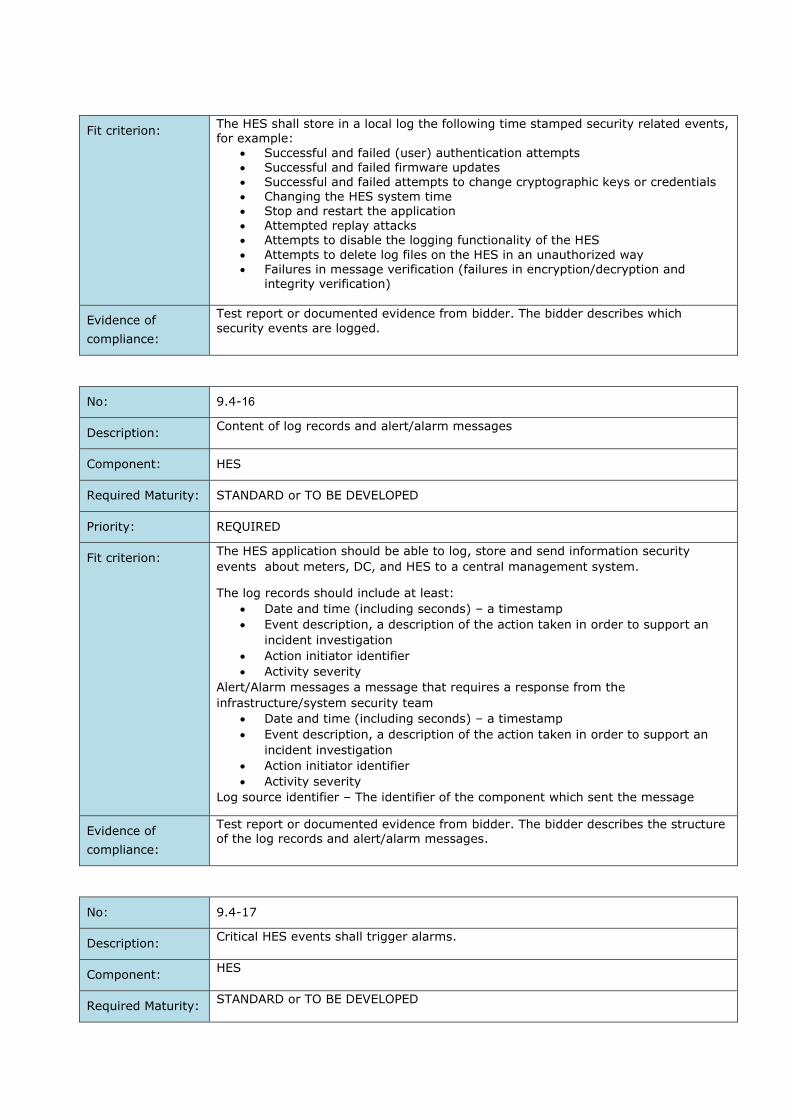
Fit criterion: The HES shall store in a local log the following time stamped security related events, for example:
Successful and failed (user) authentication attempts Successful and failed firmware updates Successful and failed attempts to change cryptographic keys or credentials Changing the HES system time Stop and restart the application Attempted replay attacks Attempts to disable the logging functionality of the HES
Attempts to delete log files on the HES in an unauthorized way Failures in message verification (failures in encryption/decryption and
integrity verification)
Evidence of
compliance:
Test report or documented evidence from bidder. The bidder describes which
security events are logged.
No: 9.4- 61
Description: Content of log records and alert/alarm messages
Component: HES
Required Maturity: STANDARD or TO BE DEVELOPED
Priority: REQUIRED
Fit criterion: The HES application should be able to log, store and send information security
events about meters, DC, and HES to a central management system.
The log records should include at least:
Date and time (including seconds) – a timestamp
Event description, a description of the action taken in order to support an
incident investigation
Action initiator identifier
Activity severity
Alert/Alarm messages a message that requires a response from the
infrastructure/system security team
Date and time (including seconds) – a timestamp
Event description, a description of the action taken in order to support an
incident investigation
Action initiator identifier
Activity severity
Log source identifier – The identifier of the component which sent the message
Evidence of
compliance:
Test report or documented evidence from bidder. The bidder describes the structure of the log records and alert/alarm messages.
No: 9.4-17
Description: Critical HES events shall trigger alarms.
Component: HES
Required Maturity: STANDARD or TO BE DEVELOPED

Priority: REQUIRED
Fit criterion: Critical events shall trigger alarms. The criteria for a critical event are defined and configurable. Details on the set alarms will be aligned between contracting entity and contractor.
Evidence of
compliance:
Test report or documented evidence from bidder.
No: 9.4- 81
Description: It shall not be possible to disable the logging functionality of the HES.
Component: HES
Required Maturity: STANDARD or TO BE DEVELOPED
Priority: REQUIRED
Fit criterion: In order to be able to guarantee the integrity of the HES, it shall not be possible to
disable the logging functionality of the HES.
Evidence of
compliance:
Test report or documented evidence from bidder.
No: 9.4-19
Description: HES shall support integration with external logging server.
Component: HES
Required Maturity: STANDARD or TO BE DEVELOPED
Priority: REQUIRED
Fit criterion: The HES shall support integrations with dedicated external logging servers (e.g.
syslog servers). The bidder indicates how his HES fulfils this requirement.
Evidence of
compliance:
Test report or documented evidence from bidder.
No: 9.4-20
Description: Protection of the audit logs.
Component: HES
Required Maturity: STANDARD or TO BE DEVELOPED

Priority: REQUIRED
Fit criterion: The HES shall protect audit/log files and records against unauthorized access, modification, and deletion.
Evidence of
compliance:
Test report or documented evidence from bidder.
The bidder describes how the HES fulfils this requirement.
No: 9.4- 12
Description: Availability of the audit functionality.
Component: HES
Required Maturity: STANDARD or TO BE DEVELOPED
Priority: REQUIRED
Fit criterion: The HES shall provide a warning if the generation of audit records fails, and take appropriate measures (e.g. overwriting the oldest audit records, stop generating
audit records, etc.)
Evidence of
compliance:
Test report or documented evidence from bidder.
The bidder describes how the HES fulfils this requirement.
Cyber Security Additional and Optional Requirements
IECo is required to prepare for the integration of technologies, tools and additional Cybersecurity layers
in the near future such as security suite 1 and 2, digital signature, HSM, FW’s, etc. The MOACH project
infrastructure should be able to support these optional requirements.
The Bidder must submit for the following optional requirements a separate price quote and timeline,
for implementation for each requirement individually. IECo will have the sole right to activate any or all
of these optional requirements.
These options shall not be considered in IECo's evaluation.
No: 9.5-1
Description: The E-meter and DC must support security suite 1.
Component: METER [1Ph, 3Ph, CT, PLMN, PLC]
Required Maturity: STANDARD or TO BE DEVELOPED
Priority: REQUIRED
Fit criterion: Regarding the security suites and algorithms, the E-meter and DC must support the following algorithms for the Management Client and the Pre-Established Client:
Authenticated Encryption: AES-GCM-128 Key Wrap: AES-128 key wrap
For the Secure Client: Authenticated Encryption: AES-GCM-128 ECDSA digital signature with P-256 (with SHA-256)
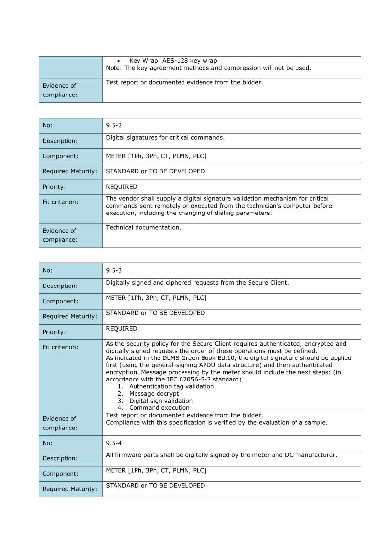
Key Wrap: AES-128 key wrap Note: The key agreement methods and compression will not be used.
Evidence of
compliance:
Test report or documented evidence from the bidder.
No: 9.5-2
Description: Digital signatures for critical commands.
Component: METER [1Ph, 3Ph, CT, PLMN, PLC]
Required Maturity: STANDARD or TO BE DEVELOPED
Priority: REQUIRED
Fit criterion: The vendor shall supply a digital signature validation mechanism for critical
commands sent remotely or executed from the technician's computer before execution, including the changing of dialing parameters.
Evidence of
compliance:
Technical documentation.
No: 9.5-3
Description: Digitally signed and ciphered requests from the Secure Client.
Component: METER [1Ph, 3Ph, CT, PLMN, PLC]
Required Maturity: STANDARD or TO BE DEVELOPED
Priority: REQUIRED
Fit criterion: As the security policy for the Secure Client requires authenticated, encrypted and digitally signed requests the order of these operations must be defined. As indicated in the DLMS Green Book Ed.10, the digital signature should be applied first (using the general-signing APDU data structure) and then authenticated encryption. Message processing by the meter should include the next steps: (in accordance with the IEC 62056-5-3 standard)
1. Authentication tag validation 2. Message decrypt 3. Digital sign validation
4. Command execution
Evidence of
compliance:
Test report or documented evidence from the bidder. Compliance with this specification is verified by the evaluation of a sample.
No: 9.5-4
Description: All firmware parts shall be digitally signed by the meter and DC manufacturer.
Component: METER [1Ph, 3Ph, CT, PLMN, PLC]
Required Maturity: STANDARD or TO BE DEVELOPED

Priority: REQUIRED
Fit criterion: The meter and DC manufacturer shall digitally sign every firmware part. To this end:
The digital signature algorithm defined in DLMS security suite 1 (ECDSA with P-256 and SHA-256) shall be used.
The public key used to verify the signature shall be pre-provisioned in the component.
The meter and DC shall only accept a new firmware if the verification of the firmware succeeds.
Evidence of
compliance:
Certified Test report or documented evidence from the bidder.
No: 9.5-5
Description: The supplier shall clarify readiness to support the defined security suite 2.
Component: METER [1Ph, 3Ph, CT, PLMN, PLC]
Required Maturity: STANDARD or TO BE DEVELOPED
Priority: PREFERRED
Fit criterion: To be future-proof, the meter should be able to support the algorithms specified in security suite 2. Specifically, the E-meter should be able to support the following algorithms:
Authenticated Encryption: AES-GCM-256
ECDSA with P-384 Hash: SHA-384
Key Wrap: AES-256 key wrap
Evidence of
compliance:
Test report or documented evidence from the bidder.
No: 9.5-6
Description: The DC shall support digitally signed and ciphered requests for the Secure Client.
Component: DC
Required Maturity: STANDARD or TO BE DEVELOPED
Priority: REQUIRED
Fit criterion: As the security policy for the Secure Client requires authenticated, encrypted and digitally signed requests, the order of these operations must be defined. As indicated in the DLMS Green Book Ed.10, the digital signature should be applied first (using the general-signing APDU data structure) and then authenticated encryption.
Evidence of
compliance:
Test report or documented evidence from the bidder. Compliance with this specification is verified by evaluation of a sample.
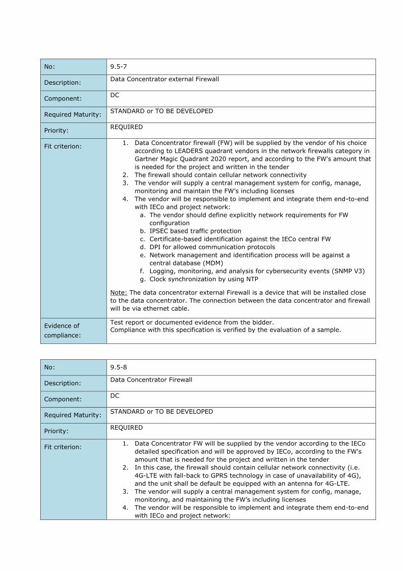
No: 9.5-7
Description: Data Concentrator external Firewall
Component: DC
Required Maturity: STANDARD or TO BE DEVELOPED
Priority: REQUIRED
Fit criterion: 1. Data Concentrator firewall (FW) will be supplied by the vendor of his choice
according to LEADERS quadrant vendors in the network firewalls category in
Gartner Magic Quadrant 2020 report, and according to the FW's amount that
is needed for the project and written in the tender
2. The firewall should contain cellular network connectivity
3. The vendor will supply a central management system for config, manage,
monitoring and maintain the FW’s including licenses
4. The vendor will be responsible to implement and integrate them end-to-end
with IECo and project network:
a. The vendor should define explicitly network requirements for FW
configuration
b. IPSEC based traffic protection
c. Certificate-based identification against the IECo central FW
d. DPI for allowed communication protocols
e. Network management and identification process will be against a
central database (MDM)
f. Logging, monitoring, and analysis for cybersecurity events (SNMP V3)
g. Clock synchronization by using NTP
Note: The data concentrator external Firewall is a device that will be installed close
to the data concentrator. The connection between the data concentrator and firewall
will be via ethernet cable.
Evidence of
compliance:
Test report or documented evidence from the bidder. Compliance with this specification is verified by the evaluation of a sample.
No: 9.5-8
Description: Data Concentrator Firewall
Component: DC
Required Maturity: STANDARD or TO BE DEVELOPED
Priority: REQUIRED
Fit criterion: 1. Data Concentrator FW will be supplied by the vendor according to the IECo
detailed specification and will be approved by IECo, according to the FW's
amount that is needed for the project and written in the tender
2. In this case, the firewall should contain cellular network connectivity (i.e.
4G-LTE with fall-back to GPRS technology in case of unavailability of 4G),
and the unit shall be default be equipped with an antenna for 4G-LTE.
3. The vendor will supply a central management system for config, manage,
monitoring, and maintaining the FW’s including licenses
4. The vendor will be responsible to implement and integrate them end-to-end
with IECo and project network:

a. The vendor should define explicitly network requirements for FW
configuration
b. IPSEC based traffic protection
c. Certificate-based identification against the IECo central FW
d. DPI for allowed communication protocols
e. Network management and identification process will be against a
central database (MDM)
f. Logging, monitoring, and analysis for cybersecurity events (SNMP
v3)
g. Clock synchronization by using NTP
Note: The data concentrator external Firewall is a device that will be installed close
to the data concentrator. The connection between the data concentrator and firewall
will be via ethernet cable.
Evidence of
compliance:
Test report or documented evidence from the bidder. Compliance with this specification is verified by the evaluation of a sample.
No: 9.5-9
Description: All cryptographic operations in the HES should be implemented with the support of a
Hardware security module (HSM):
Component: HES
Required Maturity: STANDARD or TO BE DEVELOPED
Priority: REQUIRED
Fit criterion: All cryptographic operations must be done by a hardware security module
(HSM), This includes: o Decrypting messages that comes from the meters o Encrypting messages that to be sent to the meters o DLMS/COSEM authentication tag rendering o Digitally signing of critical commands
The HES shall have an integrated secure key management system (KMS). The core of this KMS is a cryptographic module that is at least FIPS 140-2 level 3 certified or Common Criteria EAL 4+ certified.
HES will not store and use encryption keys as clear text. Keys will be stored securely based on the HSM hardware. The symmetric keys (meter keys, DC keys, …) will be stored in a DB in an encrypted way and decrypted by HSM with help of a unique key stored in the HSM
Authentication process with HSM should be certificate-based mutual authentication.
No: 9.5-10
Description: Installation and configuration of cyber components in the project.
Component: AMI
Required Maturity: STANDARD or TO BE DEVELOPED
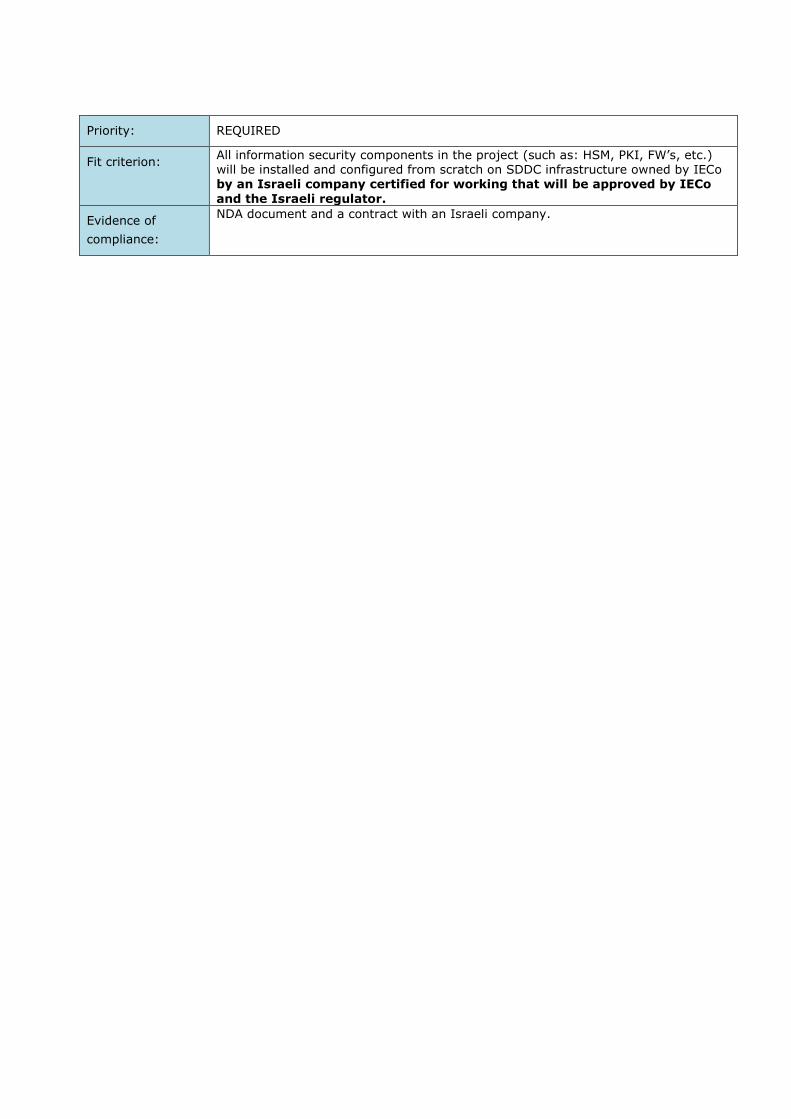
Priority: REQUIRED
Fit criterion: All information security components in the project (such as: HSM, PKI, FW’s, etc.) will be installed and configured from scratch on SDDC infrastructure owned by IECo by an Israeli company certified for working that will be approved by IECo
and the Israeli regulator.
Evidence of
compliance:
NDA document and a contract with an Israeli company.

10 E2E INTEGRATION AND FUNCTIONAL DESCRIPTION
The following chapter describes the business goals and systems impacted by the project.
Business goals
Beyond the smart meter implementation IECo has defined a set of business goals to achieve, for which
IECo requires the services of the bidder. These business goals are expected to be implemented at project
go-live, though can iteratively be developed to gradually create business value over time.
1. Improved billing accuracy and reduced electricity misuse
Standard asset registration throughout all IECo systems (processes & data)
Standard metering data acquisition & data validation processes
Creation & maintenance of smart tariff structures
Standard meter-to-bill processes
Standard cash collection processes (incl. disconnection/connection processes)
Anomaly detection processes for e.g. technical failures or fraud analysis
Standard processes to follow-up on anomaly detections
2. Improved customer satisfaction
Offering of different and customised products to B2C and B2B customers
Standard bill presentment and visualisations via different (digital) channels
Personal analysis and energy mgmt. advice to e.g. reduce energy usage and next best actions
Proactive alerts to customers (e.g. warnings for unexpected higher usage)
Creation of different types of marketing campaigns
Process of changing ToU and similar updates via customer and/or solution provider interaction
Ability for home assistant services directly connected to the meter
Standard services for collective billing and/or community-based platforms
3. Improved productivity of the field force: scheduling processes and field worker utilisation
Standard and optimised scheduling activities for metering services by the field force
Standard integrations for internal and external field force services (e.g. information provisioning,
updates on master data, feedback-loop for transactional data)
4. Increased worker safety and decrease of EH&S costs
Standard information provisioning of EH&S risks to the field force, tailored to the situation
Simplified logging of EH&S risks & issues found
Reduction of the amount of site visits needed
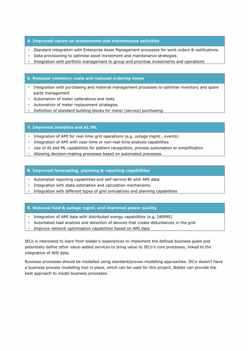
5. Improved return on investments and maintenance activities
Standard integration with Enterprise Asset Management processes for work orders & notifications
Data provisioning to optimise asset investment and maintenance strategies
Integration with portfolio management to group and prioritise investments and operations
6. Reduced inventory costs and reduced ordering times
Integration with purchasing and material management processes to optimise inventory and spare
parts management
Automation of meter calibrations and tests
Automation of meter replacement strategies
Definition of standard building blocks for meter (service) purchasing
7. Improved analytics and AI/ML
Integration of AMI for real-time grid operations (e.g. outage mgmt., events)
Integration of AMI with near-time or non-real-time analysis capabilities
Use of AI and ML capabilities for pattern recognition, process automation or simplification
Allowing decision-making processes based on automated processes
8. Improved forecasting, planning & reporting capabilities
Automated reporting capabilities and self-service BI with AMI data
Integration with state estimation and calculation mechanisms
Integration with different types of grid simulations and planning capabilities
9. Reduced load & outage mgmt. and improved power quality
Integration of AMI data with distributed energy capabilities (e.g. DERMS)
Automated load analysis and detection of devices that create disturbances in the grid
Improve network optimisation capabilities based on AMI data
IECo is interested to learn from bidder’s experiences to implement the defined business goals and
potentially define other value-added services to bring value to IECo’s core processes, linked to the
integration of AMI data.
Business processes should be modelled using standard/proven modelling approaches. IECo doesn’t have
a business process modelling tool in place, which can be used for this project. Bidder can provide the
best approach to model business processes.

Business guidelines and IT principles
IECo values clear business guidelines and IT principles, which need to be adhered to in the project. The
most relevant ones for this project are:
Integration: The more integrated the future process models and architecture will be, the more
efficient it will be. It must be possible to add new services without disruption of existing functionality.
Standardisation of business processes, data models and architectural components will greatly support
standard integrations
Data provisioning: A considerable rise of the amount of data is expected, via internal & external
sources. New policies & procedures are required to make full use of this data and allow data-driven
decision-making (availability, quality, security, and ability to combine)
Simplification: Reduction of complexity and redundancy on application, service, and infrastructure
level, allowing to share processes & data across the company
Security-by-design: Security controls have been built into to architecture and business risks are
considered when designing solutions. Information security and cyber resilience need to be managed
throughout
Build-to-operate: The development of the system architecture and services focuses on scalability,
usability, performance, and interoperability
System architecture
The MDMS will integrate with multiple (already available) peripheral systems. A simplified system
architecture is shown below.
Figure 10-1: Simplified System Architecture
The following systems are expected to be used in the future system architecture:
MDMS – Meter Data Management System
AS-IS Existing system – Honeywell Eiserver 9.1.
Standard MDUS integration with SAP IS-U.
Additional integrations for data warehouse, SIEM, cellular communication
provisioning (PVNO) and infrastructure configuration tooling.
TO-BE It is our expectation that during the project the Honeywell Eiserver 9.1 will be
upgraded to the latest Honeywell Connexo Suite. This upgrade is part of the project
and scope for the bidder
The Honeywell MDC will stay integrated with the Honeywell MDM. In parallel the
bidder’s HES needs to be connected via a separate integration with the MDM
Existing MDM functions need to be extended to meet the new requirements
CRM – Customer Relationship Management
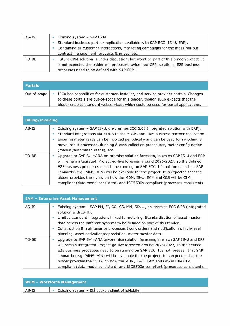
AS-IS Existing system – SAP CRM.
Standard business partner replication available with SAP ECC (IS-U, ERP).
Containing all customer interactions, marketing campaigns for the mass roll-out,
contract management, products & prices, etc.
TO-BE Future CRM solution is under discussion, but won’t be part of this tender/project. It
is not expected the bidder will propose/provide new CRM solutions. E2E business
processes need to be defined with SAP CRM.
Portals
Out of scope IECo has capabilities for customer, installer, and service provider portals. Changes
to these portals are out-of-scope for this tender, though IECo expects that the
bidder enables standard webservices, which could be used for portal applications.
Billing/invoicing
AS-IS Existing system – SAP IS-U, on-premise ECC 6.08 (integrated solution with ERP).
Standard integrations via MDUS to the MDMS and CRM business partner replication.
Ensuring meter reads can be invoiced periodically and can be used for switching &
move in/out processes, dunning & cash collection procedures, meter configuration
(manual/automated reads), etc.
TO-BE Upgrade to SAP S/4HANA on-premise solution foreseen, in which SAP IS-U and ERP
will remain integrated. Project go-live foreseen around 2026/2027, so the defined
E2E business processes need to be running on SAP ECC. It’s not foreseen that SAP
Leonardo (e.g. PdMS, AIN) will be available for the project. It is expected that the
bidder provides their view on how the MDM, IS-U, EAM and GIS will be CIM
compliant (data model consistent) and ISO5500x compliant (processes consistent).
EAM – Enterprise Asset Management
AS-IS Existing system – SAP PM, FI, CO, CS, MM, SD, …, on-premise ECC 6.08 (integrated
solution with IS-U).
Limited standard integrations linked to metering. Standardisation of asset master
data across the different systems to be defined as part of this tender.
Construction & maintenance processes (work orders and notifications), high-level
planning, asset activation/depreciation, meter master data.
TO-BE Upgrade to SAP S/4HANA on-premise solution foreseen, in which SAP IS-U and ERP
will remain integrated. Project go-live foreseen around 2026/2027, so the defined
E2E business processes need to be running on SAP ECC. It’s not foreseen that SAP
Leonardo (e.g. PdMS, AIN) will be available for the project. It is expected that the
bidder provides their view on how the MDM, IS-U, EAM and GIS will be CIM
compliant (data model consistent) and ISO5500x compliant (processes consistent).
WFM – Workforce Management
AS-IS Existing system – Blå cockpit client of isMobile.

Integration with SAP PM (work orders, custom dev.), SAP IS-U (meter reads,
custom dev.) and MDMS.
Integration with field force, detailed planning of meter installations and/or
removals, physical meter reads, etc.
TO-BE It is expected that the Blå cockpit will stay in place. The large custom developments
for maintenance activities (SAP PM) or meter deployment (SAP IS-U) might need to
be revised to configurable standard processes.
GIS – Geographical Information System
AS-IS Existing system – ESRI
Standard integrations to call the GUI/representation function of ESRI from e.g.
MDMS and asset integration for grid data. Premises are being created in GIS
(currently not the meters) and linked with the MDM. Additional SAP CS order
integration, linked to the IS-U processes
XYZ co-ordinates of the (smart) meters, connectivity/topology information, phase
information (L1, L2, L3).
TO-BE ESRI will remain in place during the project. It is expected that the bidder provides
their view on how the MDM, IS-U, EAM and GIS will be CIM compliant (data model
consistent) and ISO5500x compliant (processes consistent).
SCADA/ADMS – Control centre real-time systems
AS-IS Existing system – a SCADA/ADMS solution is in place
No integration for smart meter data and SCADA/ADMS yet
Real-time monitoring & control, alarming/events, outage management
TO-BE It is expected that the MDMS (or potential other systems) can send external
alarms/events to the SCADA/ADMS solution (e.g. for larger outages on LV level
when multiple meters in the same area suddenly don’t have energy).
BI/Analytics – Business Intelligence
AS-IS Existing system – DWH, SAS Viya
There is a periodic update from the MDMS towards a DWH, which syncs with SAS
Viya (3-step approach). Data can be made available from different source systems
(near) real-time data collection & mapping, analytics, and insights/reports to
provide (automated) triggers to the transactional systems
TO-BE An optimised integration of the BI/Analytics is needed to realise the expected
business value. IECo is discussing potential new data collection processes, storage,
analytics, and insights; these discussions are out of scope of this tender. It is
expected to keep SAS Viya in the to-be solution, though the bidder should show its
competence with multiple BI/Analytics solutions (on-premise).
Integration layer
AS-IS IECo has a complex system architecture with multiple integration technologies.
Most integrations are using SOAP, some JSON. TIBCO Staffware, IBM WebSphere
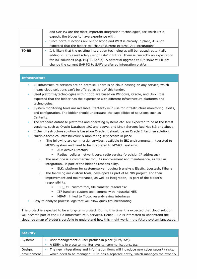
and SAP PO are the most important integration technologies, for which IECo
expects the bidder to have experience with.
Since portal functions are out of scope and WFM is already in place, it is not
expected that the bidder will change current external API integrations.
TO-BE It is likely that the existing integration technologies will be reused, potentially
adding RES to avoid solely using SOAP in future. There is currently no expectation
for IoT solutions (e.g. MQTT, Kafka). A potential upgrade to S/4HANA will likely
change the current SAP PO to SAP’s preferred integration platform.
Infrastructure
All infrastructure services are on-premise. There is no cloud hosting on any service, which
means cloud solutions can’t be offered as part of this tender.
Used platforms/technologies within IECo are based on Windows, Oracle, and Unix. It is
expected that the bidder has the experience with different infrastructure platforms and
technologies.
System monitoring tools are available. Centerity is in use for infrastructure monitoring, alerts,
and configuration. The bidder should understand the capabilities of solutions such as
Centerity.
The standard database platforms and operating systems etc. are expected to be at the latest
versions, such as Oracle Database 19C and above, and Linux Servers Red Hat 8.3 and above.
If the infrastructure solution is based on Oracle, it should be an Oracle Enterprise solution.
Multiple technical infrastructure & monitoring servicesare in place
o The following are commercial services, available in IEC environments, integrated to
MENIV system and need to be integrated to MOACH systems:
AD: Active Directory
Radius: cellular network core, radio service (provision IP addresses)
o The next one is a commercial tool, its improvement and maintenance, as well as
integration, is part of the bidder's responsibility.
ELK: platform for system/server logging & analysis Elastic, Logstash, Kibana
o The following are custom tools, developed as part of MENIV project, and their
improvement and maintenance, as well as integration, is part of the bidder's
responsibility.
IEC_util: custom tool, file transfer, resend csv
ITF handler: custom tool, comms with industrial HES
MBAM: linked to Tibco, resend/review interfaces
Easy to analyze process logs that will allow quick troubleshooting
This project is expected to be a long-term project. During this time it is expected that cloud solution
will become part of the IECo infrastructure & services. Hence IECo is interested to understand the
cloud roadmap of bidder’s portfolio to understand how this might work in the future system landscape.
Security
Systems User management & user profiles in place (IDM/IAM).
A SIEM is in place to monitor events, communications, etc.
Design,
development
The new integrations and information flows will introduce new cyber security risks,
which need to be managed. IECo has a separate entity, which manages the cyber &

information security. It is expected that the bidder, besides PM & architecture, will
provide a technical counterpart with in-depth knowledge in security design.
Other
Peripheral
systems
PVNO (cellular communication provisioning) is highly relevant for the smart meter
communication, since IECo operates its own network.
Key extraction tooling for maintenance purposes is in place.
Separate (custom) system solutions are available for large industrial customers at
meter data gathering, but this data should follow similar E2E system integrations.
No: 10.3-1
Description: Upgrade of the Honeywell Eiserver 9.1
Component: MDM
Required Maturity: STANDARD or TO BE DEVELOPED
Priority: REQUIRED
Fit criterion: It is expected that the bidder will perform the upgrade of the existing Honeywell Eiserver 9.1 to the latest Connexo version, before 2028. Honeywell is still the vendor of the MDM. Honeywell, as the vendor, is needed to perform some activities,
but the bidder will ensure the upgrade is done during the project. The bidder can propose if the upgrade should be at the beginning of the project or after a certain time when the first meters and functions have been rolled-out. IECo would like to see quick roll-out of the new meters, but also wants to enable the
latest services. The final decision will be made by IECo (and the bidder) in the Sprint0/HLD phase, the pricing given should reflect to allow both scenarios (1 price
for the different scenarios) Additional items need to be taken into account:
The current Eiserver 9.1 doesn’t have a standard CIM-based integration to the HES. When the Eiserver 9.1 will be used by the bidder a new & complex interface between the Honeywell MDM and bidder’s HES needs to be developed (integration either via flat-file CSV, SOAP or JSON)
Idem for CIM-compatibility upwards to peripheral systems the Eiserver 9.1 might not offer all required functionality
The Connexo suite is expected to offer standard CIM interfaces to the HES and upwards to peripheral systems, ensuring smoother integration and less complex developments
Evidence of
compliance:
Confirmation of the bidder that the upgrade of Eiserver 9.1 towards the latest
Connexo Suite is in scope of the project. The chosen scenario by IECo (and the
bidder) is part of the cost estimations (1 price for the different scenarios).
As part of the project delivery plan a clear explanation on how and when the
upgrade is being performed.
No: 10.3-2
Description: HES interface integrations.
Component: HES

Required Maturity: STANDARD or TO BE DEVELOPED
Priority: REQUIRED
Fit criterion: It is expected that the bidder’s HES will need to be connected to the Honeywell MDM (irrelevant of which version of the Honeywell system bidder needs to interface with)
Evidence of
compliance:
Documented evidence from bidder on how the integration of the bidder’s HES with
Honeywell’s MDM will be developed & maintained.
No: 10.3-3
Description: CIM compliancy and ISO 5500x compliancy.
Component: Systems
Required Maturity: STANDARD or TO BE DEVELOPED
Priority: REQUIRED
Fit criterion: The bidder has proven experience regarding implementation of the CIM standards and the ISO 5500x standards for E2E processes. The bidder provides his view on how the MDM, IS-U, EAM and GIS can be made CIM compliant.
Evidence of
compliance:
The bidder can prove his experience regarding the CIM standards and ISO 5500x
standards.
The bidder can prove that he has experience with (different) MDM, SAP IS-U, SAP
PM and ESRI GIS
No: 10.3-4
Description: Availability of data towards BI/Analytics solutions.
Component: Systems
Required Maturity: STANDARD or TO BE DEVELOPED
Priority: PREFERRED
Fit criterion: Although the development of the specific BI/Analytics solution is out of scope for this tender, it is expected that the bidder shows how the data of the different
platforms in scope can be made available to a BI/Analytics solution.
Evidence of
compliance:
The bidder describes with how data can be made available to BI/Analytics solutions
and how additional value can be generated for IECo.
No: 10.3-5
Description: Experience regarding system architecture and different types of integration
technologies.
Component: Systems

Required Maturity: STANDARD or TO BE DEVELOPED
Priority: REQUIRED
Fit criterion: The bidder must bring experience to the project to design/develop TIBCO Staffware, IBM WebSphere and SAP PO/PI/SCP
Evidence of
compliance:
The bidder can prove that he has experience with these type of integrations and
provides these services within the project
No: 10.3-6
Description: Experience in IoT-like protocols and integrations.
Component: Systems
Required Maturity: STANDARD or TO BE DEVELOPED
Priority: PREFERRED
Fit criterion: Although there are currently no IoT use case, it might be advantageous (for the future) if the bidder has experience with IoT protocols and integrations, specifically MQTT and Kafka.
Evidence of
compliance:
The bidder indicates if he has the required experience, and presents some evidence
on how e.g. MQTT/Kafka could help with data streaming platforms.
No: 10.3-7
Description: Experience with different infrastructure platforms.
Component: Systems
Required Maturity: STANDARD
Priority: REQUIRED
Fit criterion: The bidder must have experience with different infrastructure platforms, specifically Windows, Oracle, and Unix. The bidder has experience with system virtualization
(VMware) and different technical monitoring system to manage & optimize infrastructure services
Evidence of
compliance:
The bidder can prove that he has the necessary experience.
No: 10.3-8
Description: Experience in security architecture and design.
Component: Systems
Required Maturity: STANDARD or TO BE DEVELOPED
Priority: REQUIRED
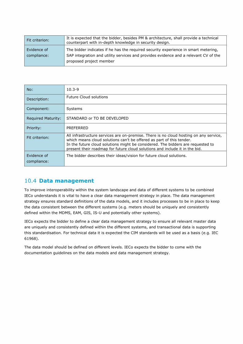
Fit criterion: It is expected that the bidder, besides PM & architecture, shall provide a technical counterpart with in-depth knowledge in security design.
Evidence of
compliance:
The bidder indicates if he has the required security experience in smart metering,
SAP integration and utility services and provides evidence and a relevant CV of the
proposed project member
No: 10.3-9
Description: Future Cloud solutions
Component: Systems
Required Maturity: STANDARD or TO BE DEVELOPED
Priority: PREFERRED
Fit criterion: All infrastructure services are on-premise. There is no cloud hosting on any service, which means cloud solutions can’t be offered as part of this tender. In the future cloud solutions might be considered. The bidders are requested to present their roadmap for future cloud solutions and include it in the bid.
Evidence of
compliance:
The bidder describes their ideas/vision for future cloud solutions.
Data management
To improve interoperability within the system landscape and data of different systems to be combined
IECo understands it is vital to have a clear data management strategy in place. The data management
strategy ensures standard definitions of the data models, and it includes processes to be in place to keep
the data consistent between the different systems (e.g. meters should be uniquely and consistently
defined within the MDMS, EAM, GIS, IS-U and potentially other systems).
IECo expects the bidder to define a clear data management strategy to ensure all relevant master data
are uniquely and consistently defined within the different systems, and transactional data is supporting
this standardisation. For technical data it is expected the CIM standards will be used as a basis (e.g. IEC
61968).
The data model should be defined on different levels. IECo expects the bidder to come with the
documentation guidelines on the data models and data management strategy.

Figure 10-2: Data Model Levels
IECo would like to understand bidder’s perspective on how to create and maintain high data quality to
enable usability and smooth processes.
Figure 10-3: Data Quality Criteria
The IECo reference data model needs to be updated to ensure the data model is properly defined across
all systems. IECo expects the bidder to provide the updated data model as part of this project.
No: 10.4-1
Description: Data management strategy & data model.
Component: Systems
Required Maturity: STANDARD or TO BE DEVELOPED
Priority: PREFERRED
Fit criterion: IECo expects the bidder to define a clear data management strategy to ensure all
relevant master data are uniquely and consistently defined within the different
systems, and transactional data is supporting this standardisation.

For technical data it is expected the CIM standards will be used as a basis (e.g. IEC
61968).
Evidence of
compliance:
The bidder describes his experience regarding the development of data models and
his experience with the CIM standards (IEC 61968).
No: 10.4-2
Description: Guidelines regarding data models and data management strategy.
Component: Systems
Required Maturity: STANDARD or TO BE DEVELOPED
Priority: PREFERRED
Fit criterion: The bidder shall provide documentation guidelines on the data models and data management strategy.
Evidence of
compliance:
The bidder describes his approach on how data management & data governance will
be put in place during the project to ensure consistent data models, quality
monitoring, correction processes and business/IT process alignment. Bidder shows
how he has managed this at 2 other utility customers
No: 10.4-3
Description: Development of an updated data model.
Component: Systems
Required Maturity: STANDARD or TO BE DEVELOPED
Priority: REQUIRED
Fit criterion: The bidder shall develop and provide an updated data model as part of this project.
Evidence of
compliance:
The bidder agrees to comply to this requirement.
Non-functional requirements
The following expectations are set for the non-functional requirements of the E2E processes
10.5.1 Delivery & implementation
IECo expects an agile project organisation, likely based on SAFe. The large amount of internal IECo
stakeholders, need for iterative design & development of business processes, data models and system
architecture, and the expectation to gradually introduce business value during project implementation
are some of the drivers for which IECo sees an agile project organisation as the preferred approach.
IECo expects a Sprint 0 (or high-level design) phase, in which, among others, following activities are
expected:

1. Drafting of expected Features for the project and first prioritisation
2. Defining the first E2E business processes, which are must-have at the start of the roll-out
(partly already existing)
3. Defining the key elements of the data model, which are a must-have at roll-out start
4. Agreeing on system architecture and expected versioning & initial integrations
5. Planning of required security requirements
6. Defining the User Stories, relevant for Increment 1 (potentially more User Stories)
7. Ensuring business continuity
The potential roles of the bidder in comparison with IECo will be described further down this document,
though as additional roles IECo would expect agile coaching and driving the agile project organisation
forward as expected roles for the bidder.
IECo has experience with agile way-of-working, but would like to have the option to use the preferred
tooling of the bidder (e.g. Jira of similar tooling).
10.5.2 Methodology & standards
IECo expects the bidder to show their experience in PMP project management (or equivalent). The
proposed project management should show strong experience in meter roll-out, metering processes and
system integration.
For documentation standards, IECo is currently using LLD (low-level design) and interface documents.
IECo expects that these existing documentation standards won’t be sufficient for the project to be
successful. IECo would like to understand the documentation approach of the bidder to ensure clear
documentation of requirements & deliverables, (automated) test cases and transition to maintenance &
operations. IECo would expect that documentation will be created on multiple levels, and not only in Jira
or similar tooling.
It would help if business process & architecture design follows standards like BPMN 2.0 & ArchiMate 3.1,
but IECo would like understand bidder’s vision on the modelling approach.
The bidder will working following a DTP development platform, which ensures that configuration changes
and developments are being dealt with in a structured manner.
The bidder will create user manuals for the new functions created.
No: 10.5.2-1
Description: Experience in PMP project management.
Component: Project delivery
Required Maturity: STANDARD
Priority: REQUIRED
Fit criterion: The bidder has the necessary experience and skills in PMP (or equivalent) project management and the key resources for the delivery (e.g. Product Manager & RTE) have strong project management skills.
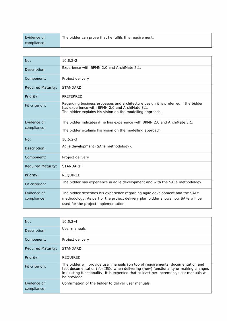
Evidence of
compliance:
The bidder can prove that he fulfils this requirement.
No: 10.5.2-2
Description: Experience with BPMN 2.0 and ArchiMate 3.1.
Component: Project delivery
Required Maturity: STANDARD
Priority: PREFERRED
Fit criterion: Regarding business processes and architecture design it is preferred if the bidder has experience with BPMN 2.0 and ArchiMate 3.1.
The bidder explains his vision on the modelling approach.
Evidence of
compliance:
The bidder indicates if he has experience with BPMN 2.0 and ArchiMate 3.1.
The bidder explains his vision on the modelling approach.
No: 10.5.2-3
Description: Agile development (SAFe methodology).
Component: Project delivery
Required Maturity: STANDARD
Priority: REQUIRED
Fit criterion: The bidder has experience in agile development and with the SAFe methodology.
Evidence of
compliance:
The bidder describes his experience regarding agile development and the SAFe
methodology. As part of the project delivery plan bidder shows how SAFe will be
used for the project implementation
No: 10.5.2-4
Description: User manuals
Component: Project delivery
Required Maturity: STANDARD
Priority: REQUIRED
Fit criterion: The bidder will provide user manuals (on top of requirements, documentation and
test documentation) for IECo when delivering (new) functionality or making changes in existing functionality. It is expected that at least per increment, user manuals will be provided
Evidence of
compliance:
Confirmation of the bidder to deliver user manuals

10.5.3 Usability
IECo expects that users can work from 1 system and don’t need to switch between systems
unnecessarily (one-stop-shop). Any user activity should be reversible, including operational errors that
will use interfaces. Fixes should be mainly done via existing user interfaces, instead of backend
alterations. This means that end-users should be able to work from the different systems independently,
e.g.:
1. MDM
2. SAP ECC (via the SAP GUI)
3. ESRI GIS
4. BI/Analytics
5. SCADA/ADMS
6. WFM
It is not expected that cockpits (like SAP Fiori or UI5) will be developed as part of this tender. It is also
not expected that internal/external portals will be designed/developed as part of this tender.
When there are integrations of different systems for the user to successfully complete their tasks, the
end-users shouldn’t see/realise they might be working in and/or using different systems.
When UI extensions are needed to enable E2E processes and have an intuitive user experience these
extensions should be made in such a way that it doesn’t conflict with future system upgrades, patches,
and related software/hardware upgrades.
No: 10.5.3-1
Description: Requirement regarding response time for UI/UX (user experience)
Component: Systems
Required Maturity: STANDARD or TO BE DEVELOPED
Priority: REQUIRED
Fit criterion: Response times of the UI/UX should be as follows:
1. Loading data on screen, information mgmt., forms, response on actions: all
<1s
2. Simple reports: all <10s
3. Complex reports: <30s
IECo doesn’t have standard UI/UX guidelines for the design, so IECo would like to
use bidder’s experiences on intuitive designs of the UI/UX when required to
develop/configure as such. It is expected to have as little clicks as possible and
provide user support

Evidence of
compliance:
The bidder indicates if these values are realistic.
The bidder describes his ideas and experience regarding the design and
development of ergonomic user interfaces.
10.5.4 Reliability
The new HES and potential other systems need to meet the requirements for (critical) infrastructure
components, allowing back-up/restore processes and potentially failover/fallback mechanisms. The
requirements for the HES will follow the requirements of the existing Honeywell Eiserver 9.1. The
integrations towards other systems and definition of potentially new systems will follow IECo’s
guidelines. Interfaces between system components and interfaces to external systems should have built-
in confirmations and retry mechanisms. The sending systems should retry several (configurable) number
of times if confirmation was not received. These guidelines will further be discussed upon awarding.
IECo would like to understand how the proposed system(s) of the bidder can meet reliability
requirements and which experiences or expectations the bidder has to ensure reliability.
IECo expects the bidder to document how the systems & interfaces will meet the reliability requirements.
No: 10.5.4-1
Description: System Reliability
Component: Systems
Required Maturity: STANDARD or TO BE DEVELOPED
Priority: REQUIRED
Fit criterion: The systems should have a high-availability and should be set up taking reliability
issues into account. This means:
24/7 availability of the systems involved
Redundancy in place of hardware & software, including failover/fallback
mechanisms (e.g. cluster setup active-active or active-passive)
Recovery Point Objective = 0, Recovery Time Objective = 0,5-2h
System back-up and restore
Confirmation & resend mechanisms of interfaces to the system
Interface monitoring services, integrated in the existing IEC services
Clear KPIs for system reliability available (e.g. MTBF, MTTR)
Upgrades & patches can be performed without system downtime
Clear description on how the bidder performs configuration management
(methods, procedures, etc.)

Evidence of
compliance:
The bidder indicates if the systems he provides support a high-availability and
reliable setup and shows how this is being achieved.
No: 10.5.4-2
Description: Data storage & archiving
Component: Systems
Required Maturity: STANDARD or TO BE DEVELOPED
Priority: REQUIRED
Fit criterion: Data that is stored in the system on a regular basis should be accessible and
available for retrieval for no less than 7 years from the time it has been recorded
Data backup in IECo is done by utilizing commvault Storage Manager for System
Backup and Recovery. The suggested solution must comply with this method or
provide an alternative method for backup procedure
Evidence of
compliance:
The bidder indicates if the systems he provides support a high-availability and
reliable setup.
No: 10.5.4-3
Description: Data correction
Component: Systems
Required Maturity: STANDARD or TO BE DEVELOPED
Priority: REQUIRED
Fit criterion: Mistakes in data inputs will happen, which means the processes & systems need to
support correction processes via the UI/UX. Even when data and/or process inputs
impact multiple systems, the design of the system should allow corrections using
these interfaces. It is not envisioned that correction processes need to be done via
IT and database updates.
End user should have the ability to the and fix data (in)consistency.
Evidence of
compliance:
The bidder confirms that the solutions provided will allow data corrections and will
show this also as part of their tests
10.5.5 Safety
IECo has high regard for the safety of its own personnel and external contractors. The mass roll-out of
smart meters will create many additional site visits, which enhances the risk of safety incidents. IECo

would like to understand from the bidder which processes they have in place to improve safety and
mitigate the increased safety risks due to the nature of the project. The bidder will work together with
the main supplier(s) of the field force as part of this project for the mass roll-out
It is expected that employees of the bidder, working at IECo premises, will follow a (standard) safety
training provided by IECo.
10.5.6 Scalability
IECo expects to roll-out 3M smart meters in total, of which ~500k might be in the existing MDC/MDM
and ~2.5M will be installed using the bidder’s HES and other solutions. Due to potential growth the
system architecture, interfaces and all components should be sized for 4.2M meters. IECo expects the
bidder to show the performance for 3M meters and towards 4.2M meters.
It is expected that meter roll-out would have 300k meters/year, evenly distributed over the days/months
of the year. This would mean that processes like meter install should at least accommodate ~1000/day,
but preferable more.
No: 10.5.6-1
Description: Scalability
Component: Systems
Required Maturity: STANDARD or TO BE DEVELOPED
Priority: REQUIRED
Fit criterion: The systems should support a smart meter park of approximately 3M to 4.2M
meters.
The bidder should have experience with smart meter projects of similar size and
complexity.
Evidence of
compliance:
The bidder indicates if he has the required experience, and presents some evidence.
10.5.7 Performance
The most performance demanding process is expected to be the meter reading towards billing/invoicing
process. For 3M (4.2M) meters, with an expected billing rate of:
1. Every two months for standard meters (80%)
2. Every day for prepayment (10%)
3. Every month for other (10%)
Besides standard meter reads there will be additional meter reads for switching/moving processes,
meter change and other metering processes. IECo has extended the existing MDUS with customer
specific fields, still following the standard, but with extra data fields added for premise and additional
device data. The time needed to get the E2E automated meter read process from a trigger in SAP IS-U
towards the “ready for billing” should not be limited by interfaces between the HES/MDM and SAP. This

should be solely driven by the non-functional expectations of the communications from the smart meter
to the HES/MDM.
For meter install, when meter master data is being replicated between different core systems, like MDM,
SAP, and GIS, IECo expect a near-instant data exchange to guarantee compliancy across the systems.
Also when firmware upgrades and configuration changes take place the system should stay performant.
When alarms are created, which are relevant for the SCADA/ADMS, IECo expects the generation of these
alarms in 10s (starting at event recognition HES/MDM).
Data downloads towards the DWH and data collectors should be defined in such a way that they don’t
interfere with operational processes and timely deliver the data needed for required business actions.
10.5.8 Flexibility/interoperability
It is expected to build/maintain a modular approach of systems to allow new capabilities being added by
either extending a current system or introducing a new system with these capabilities. To allow such an
architecture, the bidder should support that point-2-point integrations are generally non-existing (except
e.g. within an ERP package when SAP uses BDOC). Integrations will go via an integration layer.

11 PROJECT DELIVERY EXPECTATIONS
The following chapter describes IECo’s expectation on project delivery and role of the bidder
SAFe
IECo expects an agile delivery framework for this project. SAFe is designed to continuously help the
business & IT stakeholders and more efficiently deliver value on a regular and predictable schedule. It
provides a knowledge-base of proven, integrated principles and practices to support enterprise agility.
IECo has experience with agile way-of-working, though not in every aspect of the smart metering
implementation. This means that IECo expects the bidder to bring agile coaching and ensure the project
team works in a consistent way.
It is expected that many different stakeholders are interested in the different deliverables. An agile
approach, following SAFe, provides insight in the portfolio to be realised and provides a good basis to
plan the right stakeholder discussions at the right time.
Definition of business processes and/or use cases
One of the key elements for the project is to create clarity in the new business processes to be defined
and underlying data models and architectural components. IECo expects that an approach and first
views will be presented by the bidder during this tender process. As part of a “Sprint 0” the portfolio will
be further refined. IECo expects the bidder to drive the definition of the end-to-end business processes
and requirements to data models and architectural components, including ensuring business continuity.
When defining the E2E business processes, bidder should be aware of that IECo would like to have one
way of business process definition of the typical metering processes within the HES/MDM and the E2E
business processes with peripheral systems.
No: 11.2-1
Description: Business processes and use case definition.
Component: Systems
Required Maturity: STANDARD or TO BE DEVELOPED
Priority: PREFERRED
Fit criterion: The bidder shall:
Present an approach and first view regarding the business processes, data
models and architectural components
Drive the definition of the end-to-end business processes and requirements
to data models and architectural components.
The bidder must show the necessary experience in this field
Evidence of
compliance:
The bidder indicates if he has the required experience, and presents some evidence.

Bidder roles within the project
IECo expects the bidder to take co-ordination of the smart meter roll-out and the design & integration of
services within the IECo business processes and system landscape. This means the bidder is the single &
main contractor and accountable for the services delivered. Any potential subcontractors, working for the
bidder, will perform their services under the accountability of the bidder.
IECo has internal development departments, an internal infrastructure & security organisation and
existing framework partners for specific integrations and/or systems. It is expected that these different
teams will be part of the overall project team, not at bidder’s cost. The bidder will be the overall
responsible co-ordinator to drive the end-to-end business processes, data models linked to smart
meters, functional & technical design, architecture & infrastructure, security, etc. The bidder will drive
the “master project plan”. The bidder also facilitates necessary project meetings and an agile way-of-
working. IECo expects the bidder to make the overall project plan, including the expectations for the 3rd
parties.
IECo will provide the necessary (counterpart) roles for this project, but would like to understand bidder’s
view on which roles are expected.
IECo expects the bidder to be able to configure/develop the Honeywell HES/MDMS. IECo expects the
bidder to configure/develop SAP, ESRI and other peripheral systems in the system landscape, including
the different integration technologies used, and challenge the existing internal departments & external
framework agreement partners with their developments.
When the upgrade to the latest Honeywell Connexo Suite will be made, IECo expects the bidder to bring
its experience with upgrades and potential migrations. IECo then also expects what, according to the
bidder, is the best approach to upgrade to Connexo, at the "start" of the project or in the "end" of the
project, and to understand from the bidder what the impact is on the project processes for both
alternatives, though no additional pricing for the different scenarios will be accepted.
It is expected that bidder will infuse some IECo employees in the DevOps teams for IECo to bring
specific knowhow to the development teams and the bidder to bring delivery and transition-2-
maintenance knowhow to IECo.
It is expected that most project activities will be performed on-site in Israel due to the secure nature of
many activities. Expert roles can be fulfilled differently, but the System Integrator (SI) should have clear
local presence and delivery experience.
Expected project roles for the bidder are (not limited to):
1. Program manager (counterpart, stakeholder)
2. Co-product manager (supporting IECo, who is in the lead)
3. RTE (delivery lead)
4. Development manager
5. Co-product owners (supporting IECo)
6. Scrum masters
7. System architect
8. Solution architects (architecture, infrastructure, security, development, …)
9. Developers
10. Testers (not acceptance test)
11. DevOps
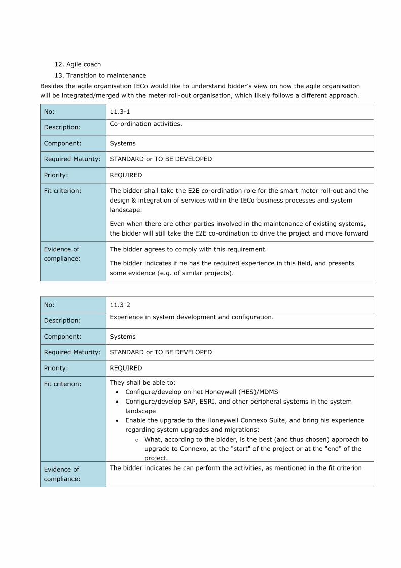
12. Agile coach
13. Transition to maintenance
Besides the agile organisation IECo would like to understand bidder’s view on how the agile organisation
will be integrated/merged with the meter roll-out organisation, which likely follows a different approach.
No: 11.3-1
Description: Co-ordination activities.
Component: Systems
Required Maturity: STANDARD or TO BE DEVELOPED
Priority: REQUIRED
Fit criterion: The bidder shall take the E2E co-ordination role for the smart meter roll-out and the
design & integration of services within the IECo business processes and system
landscape.
Even when there are other parties involved in the maintenance of existing systems,
the bidder will still take the E2E co-ordination to drive the project and move forward
Evidence of
compliance:
The bidder agrees to comply with this requirement.
The bidder indicates if he has the required experience in this field, and presents
some evidence (e.g. of similar projects).
No: 11.3-2
Description: Experience in system development and configuration.
Component: Systems
Required Maturity: STANDARD or TO BE DEVELOPED
Priority: REQUIRED
Fit criterion: They shall be able to:
Configure/develop on het Honeywell (HES)/MDMS
Configure/develop SAP, ESRI, and other peripheral systems in the system
landscape
Enable the upgrade to the Honeywell Connexo Suite, and bring his experience
regarding system upgrades and migrations:
o What, according to the bidder, is the best (and thus chosen) approach to
upgrade to Connexo, at the "start" of the project or at the "end" of the
project.
Evidence of
compliance:
The bidder indicates he can perform the activities, as mentioned in the fit criterion

Project timelines
IECo is planning to deploy approximately 300k meters per year. IECo doesn’t want to wait until the end
of the full deployment to start unlocking the value of AMI data, and expects them to be available as soon
as possible. IECo understands it might not fully unlock all value for its processes when the roll-out
doesn’t have a critical mass yet for certain services, but there shouldn’t be a limitation that the
integration of business processes and/or corresponding system architecture won’t be ready.
Scope clarification
IECo is looking for the best plan to achieve the business goals and create the highest value for its
business processes. As such IECo would truly like to understand bidder’s views on the leading practices
and integrations of smart meters with IECo’s core business processes. It is possible that IECo will limit
several of the scope items to ensure that IECo business & IT stakeholders are ready to fully use the new
functionality. This will be discussed (potentially) during the orals and afterwards. IECo wants to give the
bidder the full opportunity to show how IECo can best create its business value using the smart meters
and its data.
Transition to maintenance & operations
No: 11.6-1
Description: Transition plans to maintenance & operations.
Component: Systems
Required Maturity: STANDARD or TO BE DEVELOPED
Priority: REQUIRED
Fit criterion: The bidder shall develop clear transition plans for each increment and/or delivery to
the production environment (e.g. configuration, patches). This should include at a
minimum:
Successful go/no-go meeting for the upgrades, including acceptance of
maintenance organisation(s) and operations
Clarification of known issues (open points, scope questions and bugs)
Finished documentation of the deliverables (release notes, test reports,
design documentation, unless otherwise agreed for e.g. patches)
Successful demo sessions and user manuals with the relevant stakeholders
Training plan and delivery of training session for IT maintenance group and
system end users from IECo. (estimated in about 100 users of devices,
HES/MDM, WFM, etc). For specific details for training plans for devices,
cybersecurity and HES/MDM, see req. 12-6,12-7 and 12-8.
Evidence of
compliance:
The bidder agrees to comply with this requirement.
The bidder can present some evidence (e.g. of similar projects) that he has done
such activities before.

No: 11.6-2
Description: Maintenance plan after warranty support
Component: Systems
Required Maturity: STANDARD or TO BE DEVELOPED
Priority: REQUIRED
Fit criterion: The bidder shall develop clear plan for maintenance of the system after transition
period is over. This should include at a minimum:
Level of support (availability)
Language of support
Criticality of issues and response time
Link to Quality System of IECo (HP Quality Center)
Escalation procedure
Upgrade planning
Operating system upgrades
System extension requirements
Response to ad-hoc request from IECo
Evidence of
compliance:
The bidder agrees to comply with this requirement.
The bidder can present some evidence (e.g. of similar projects) that he has done
such activities before.

Expected plans as part of this tender
As part of the tender IECo expects the bidder to address the following plans:
Table 11-1: Expected plans
Expected plans
Project delivery Scope, project organisation, PMO, resource plan, training plan for
meters, DCs, and HES, project schedule/timelines, critical path &
dependencies, risk & issue management, changes/revision process,
project progress reports, monthly SteerCo and relevant reports,
documentation guidelines, assumptions, …
System architecture &
infrastructure
Applications, integrations, infrastructure, plan to adjust the existing
system architecture, …
Configuration &
development
Required configuration & developments, UI/UX designs, AI/ML
integration, …
Data management Defining the data model, master/slave, …
Integration Which integrations, technologies, …
Conversion (partial) When upgrading towards to latest Connexo Suite potential migration is
needed in the existing HES/MDMS (Eiserver 9.1) and potential
conversions are needed to update data in GIS/SAP PM for meter master
data
Cyber & information
security, business
continuity
Security-by-design, integration within IECo security framework,
policies, …
Transition to
maintenance
Post go-live support, training the maintenance teams, expected SLA,
ability to reproduce errors in dev/test environments, potential data
updates via scripts/programs, …
Test & cut-over Unit test, integration test, cut-over, handover to acceptance test
Provisioning test as described in Appendix H.
UAT are not in scope and will be performed by another party. IECo
expects the end-to-end co-ordination and (some) counterparts for
design, configuration & development to remain during these activities.
IECo would expect the bidder to provide demo sessions to the relevant
stakeholders for new/changed functionality.
Transition period There will be a transition required from the current MDM/MDC provider
and system integrator to the new bidder. Description of transition plan
Maintenance period after
warranty period
Expected maintenance plan for the period defined in general conditions
Internal & external communications (e.g. communications plan), change management (e.g.
organisational impact/changes) and supporting functions like finance and procurement are not in scope
of this tender.
No: 11.7-1
Description: Requirement regarding project approach and project plans.
Component: Project delivery

Required Maturity: STANDARD or TO BE DEVELOPED
Priority: PREFERRED
Fit criterion: The bidder shall be able to provide the foreseen project approach including the
underlying project plans as described above.
It is allowed to provide these plans in one document or in different documents as
long as it is clear to IECo how the different topics have been addressed.
Evidence of
compliance:
The bidder agrees to comply with this requirement and will deliver the requested
plans. It will play an important role in the validation of the project approach and E2E
accountability and business value creation.
No: 11.7-2
Description: Progress measurements.
Component: Project delivery
Required Maturity: STANDARD or TO BE DEVELOPED
Priority: PREFERRED
Fit criterion: The bidder shall provide clear insights in the day-to-day progress of the project (e.g.
via JIRA reports)
The bidder shall provide clear overviews in risks & issue management, potential
change/revision requests, progress reporting, explanation for schedule delays
The bidder shall provide clear SteerCo documentation, besides the day-to-day
reporting
Evidence of
compliance:
Confirmation of the tenderer with the fit criteria
The tenderer provides templates on how the different reports (day-to-day,
aggregation, SteerCo) could look like

12 ADDITIONAL REQUIREMENTS FOR THE BIDDER
No: 12-1
Description: Presence in Israel.
Component: Project delivery
Required Maturity: STANDARD
Priority: REQUIRED
Fit criterion: The bidder must confirm that the project delivery will be managed locally in Israel
on IECo’s premises (including project work).
Evidence of
compliance:
The bidder agrees to comply with this requirement.
No: 12-2
Description: Accountability for the project implementation.
Component: Project delivery
Required Maturity: STANDARD or TO BE DEVELOPED
Priority: REQUIRED
Fit criterion: The bidder should confirm the end-to-end accountability of the project
implementation. In case certain areas can’t be covered the bidder will provide a
clear reasoning for this and present their mitigation plan (with potentially a
subcontractor).
Evidence of
compliance:
The bidder agrees to comply with this requirement, indicates which areas can’t be
covered and provides his suggested mitigation plan.
No: 12-3
Description: Project team and CVs of key resources.
Component: Project delivery
Required Maturity: STANDARD
Priority: PREFERRED
Fit criterion: The bidder must provide a clear org. chart on how the project will be delivered,
including presenting the project team. We understand that a project team can
slightly change between this tender phase and project start, but 75% of the team
should be available for the project.

Before project start (but not part of the tendering process) IECo wants to interview
the proposed resources to validate knowhow/experiences and see if there is a good
“click” with the IECo project team. These interviews are relevant for the key
resources (e.g. Product Manager, RTE, System Architect, Security Architect, Roll-out
co-ordination), not for all developers/testers, etc.
It is possible that after the interview IECo will object to the specific resource and a
different person needs to be proposed by the bidder.
When resources will need to be replaced by the bidder during the contract, IECo
shall be able to approve/disapprove the proposed resource. In case of disapproval,
the bidder will present a different proposal.
The bidder needs to provide the CVs for the critical roles. It is possible to share
multiple CVs for a role if this would help showing the required skills.
Evidence of
compliance:
The bidder confirms the envisioned project team, its availability and provides the
relevant CVs.
Bidder also confirms that IECo can object/refuse specific resources for the
critical/vital positions and will provide a different resource
No: 12-4
Description: Result-driven and limitation of changes
Component: Project delivery
Required Maturity: STANDARD or TO BE DEVELOPED
Priority: REQUIRED
Fit criterion: For the E2E process integration IECo has defined the vision and goals to achieve,
allowing the bidder to provide the best solution to achieve these goals. There might
be minor deviations when going into details of the process implementation. IECo
expects the bidder to bring their leading practices and challenge IECo to use these
as much as possible. IECo also expects that the bidder confirms the
configuration/development of these goals without going into a continuous change
request approach.
A clear change request process needs to be in place, but this is merely for changing
business visions, changing regulatory changes the bidder couldn’t be aware of and
similar items.
IECo doesn’t allow an approach by the bidder to go for many change requests
during the project, as a standard way-of-working. When the developments are in
line with the agreed business vision/processes it is expected to be in scope.
The specific change request process is described in the general conditions and
agreement documents. IECo and bidder will agree in an hourly rate for a certain
amount of hours (called work hours bank) as described in those documents.

Evidence of
compliance:
The bidder agrees to realise the business goals/vision without going into detailed
change request discussions.
No: 12-5
Description: Manual meter reads for smart meters.
Component: Project delivery
Required Maturity: STANDARD
Priority: REQUIRED
Fit criterion: There is a separate project within IECo to manage meter reads when the reading
infrastructure can’t be used. There will be new integrations with the MDM to ensure
these meter reads are properly received. For this tender we expect 2 new medium
interfaces to be developed to/from this system (main goal of this requirements is
that readings done with the HHU can be transferred to the system).
Evidence of
compliance:
The bidder agrees these 2 new medium bidirexional interfaces are in the
estimations, including potential discussions with the other project team.
No: 12-6
Description: Training requirements for HES/MDM and WFM components
Component: Project delivery
Required Maturity: STANDARD
Priority: REQUIRED
Fit criterion: The number of participants for the training will be up to 20 IECo person for
HES/MDM and 20 IECo person for WFM.
The training will be held at IECo premises or remotely (except where explicit
mentioned), to be agreed between bidder and IECo.
The training language will be only in English or Hebrew.
Two weeks prior of starting the training, the awarded vendor will sent detailed
syllabus including detailed daily time table of the relevant study contents.
Trainings will be held according to the progress of the project, and will be held in the
following points in time:
Before first release is going to be put on production– 4 training days on test
environment at IECo premises.
After first version is installed in production environment and it is interfacing
with the devices and external systems connected to it:

o 1st cycle of 4 training days at IECo premises
o 2nd cycle of 4 training days at IECo premises
o 3rd cycle of 4 training days at IECo premises (optional)
The content of the training will be agreed between bidder and IECo, focusing
in hand-ons experience from IECo when using the system.
After each release to production environment
o 2 training days remotely (can be consecutive or not consecutive
days, according to IEC request)
After Hotfix
o 1/2 training day, remotely
Training for WFM system shall have a duration up to 5 working days, to be agreed
between bidder and IECo
There should be an option, by IECo demand, for extra training (up to additional 10
workdays) for each device.
Training will include hands-on training prepared in advance, and done in test
environment.
Training will include step-by step documentation (user manual) of every action that
needs to be done manually by the operator.This documentation will be embedded in
the built-in help menu of the product/products and will include IECo specific content
if applicable.
Evidence of
compliance:
Delivery of training plan.
No: 12-7
Description: Training requirements for devices
Component: Project delivery
Required Maturity: STANDARD
Priority: REQUIRED
Fit criterion: Required training per each device and model (Meter / DC / Other) is 5 workdays
(workday: Sunday to Thursday).
The training per each device will also include training on the supplied software for
each device.
There should be an option, by IECo demand, for extra training (up to additional 5
workdays) for each device.

The number of participants for the training per each device will be up to 15 IECo
persons.
The training will be a face to face session held in IECo premises. IECo will supply the
necessary environment: classroom and teaching aids such as: projector, board and
etc. (In case there will be a problem with frontal study due to COVID19 then a
remote study should be considered as alternative)
The training will include supplying full documentation of the training and necessary
documentation per each device and software such as: user manuals, technical
sheets and etc.
The training language will be only in English or Hebrew.
Two weeks prior of starting the training, the awarded vendor will sent detailed
syllabus including detailed daily time table of the relevant study contents.
The instructors of the training should be an AMI professionals, with deep knowledge
and understanding of all the details of the equipment
Evidence of
compliance:
Delivery of training plan.
No: 12-8
Description: Training requirements for cybersecurity
Component: Project delivery
Required Maturity: STANDARD
Priority: REQUIRED
Fit criterion: The training will generally be delivered for at least 15 days
The number of participants for the training will be up to 15 IECo persons
The training will include supplying full documentation of the training and necessary
documentation
The training will be a face to face session held in IECo premises. IECo will supply the
necessary environment: classroom and teaching aids such as projector, board, etc.
(In case there will be a problem with frontal study due to COVID19 then a remote
study should be considered as an alternative)
Two weeks prior to starting the training, the awarded vendor will be sent a detailed
syllabus including a detailed daily timetable of the relevant study contents.
The training language will be only in English or Hebrew.
The training should include the following topics:
1) E-Meters Security

a) Hardware architecture.
i) Overview
ii) Cryptography operation protection
iii) Encryption keys protection
iv) P1/consumer port one-way protection/security
v) Firmware update process protection
b) Software architecture
i) Overview
ii) External interfaces and protocols overview
iii) External interfaces security
iv) Software hardening
v) Cryptography operations protection
vi) Encryption keys protection
vii) Firmware signing control
c) Authentication processing
i) Overview
ii) Technician local access
iii) IHD user access
d) Authorization processing
i) Overview
ii) Role-based access
e) Secure logs and alerts mechanisms
2) Data Concentrator security
a) Hardware architecture.
i) Overview.
ii) Cryptography operation protection
iii) Encryption keys protection
iv) Firmware update process protection
b) Software architecture
i) Overview
ii) External interfaces and protocols overview
iii) External interfaces security

iv) Software hardening
v) Cryptography operations protection
vi) Encryption keys protection.
c) Authentication processing
i) Overview
ii) Password policy enforcement
iii) Password protection.
iv) Technician local access
v) Technician remote access
d) Authorization processing
i) Overview
ii) Role-based access
3) HES security
a) Software architecture.
i) Overview
ii) Key Management System overview
iii) Keys generation overview.
iv) External interfaces and protocols overview
v) External interfaces security
vi) Software hardening
vii) Cryptography operations protection
viii) Encryption keys protection
ix) Keys export protection
x) Automatic and manual keys enrolment
b) Authentication processing
i) Overview.
c) Authorization processing
i) Overview
ii) Role-based access
4) General
a) System integration overview
b) Secure zoning and segmentation principles
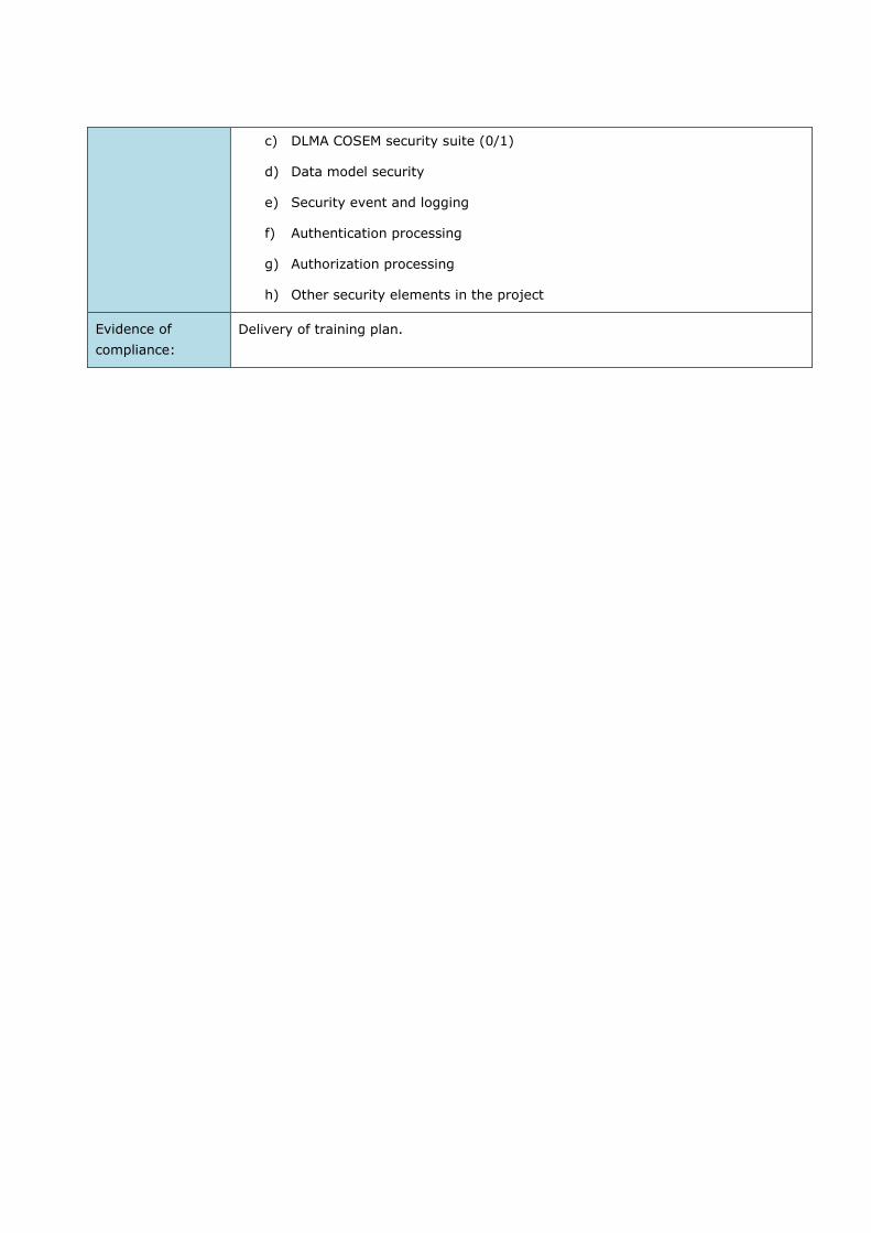
c) DLMA COSEM security suite (0/1)
d) Data model security
e) Security event and logging
f) Authentication processing
g) Authorization processing
h) Other security elements in the project
Evidence of
compliance:
Delivery of training plan.

13 KPI FOR THE SMART METERING PROJECT
General
The smart metering project is a large and complex investment which combines new technology that will
impact operational processes, installation and logistics and integration between systems. The technology
will be procured from a solution provider, while IECo will do the installation of smart metering
components.
A smart metering project organization includes several roles needed to manage the project and
interfaces to adjacent projects and processes, e.g. the MDMS project and integrations.
To secure the right focus from project management and to secure commitment towards objectives, KPI’s
have been prepared. The bidder must provide a dashboard to monitor all KPI’s, or provide the raw data
for such a dashboard.
The smart metering project is designed into three phases; 1) the preparatory phase, 2) the system
deployment phase and 3) the stabilization phase. Each of the project phases should be broken into
manageable stages. The major milestones are included to the timeline together with the focus, actions
and deliverables for each of the stages. All KPI's will be measured End to END.
Figure 13-1: Smart Metering Project Phases
The project will have three distinct phases:
1. Preparatory phase.
2. System Deployment phase. 3. Post Deployment phase.
Preparatory Phase
The project team needs to cover the relevant subjects and IECo business areas that needs to be planned
for and contracted. This phase will require resources sufficient in capacity, but also resources that know
IECo operations, infrastructure and culture. No specific KPI’s or deliverables have been defined for this
phase.
System Deployment Phase
The project team will in this phase have two focus areas; a) to manage installation resources and
logistics, and b) to follow up deployment, verify, commission and approve stages. This stage will require
resources sufficient to execute on installation and to follow up the deliverables and to operate the
system after commissioning. Relevant are:
Pilot & Ramp-up
Deployment& Operation
13.3.1 Pilot & Ramp-up
For the pilot and ramp-up phase a number of deliverables and activities can be defined. No specific KPI’s
have been defined for this stage.

IECo will perform an Operational Acceptance test after finalisation of this phase and before start of the
deployment phase. Bidder will support this test.
13.3.2 Deployment & Operation
For the deployment and operation phase a number of deliverables, activities and KPI’s can be defined:
For the deployment phase the KPI’s as shown in Table 13-1 are defined.
Pilot & Ramp-up
Focus: Installing systems, integrating and test/verify roll-out processes (incl logistics), conclude on Area/Stages for roll-out. Deliverables /activities:
Prepare for acceptance tests
Technical test Integration test System integration pilot Installation and operations pilot (linked to procurement strategy) Logistics Conclude on Area/Stages for roll-out
Deployment & Operation
System Deployment Phase
Deployment & Operations
Focus: Mass roll-out, commissioning stages, IEC system operations (hand-over depends on procurement strategy and contract), and continuous improvement.
Deliverables /activities:
Logistics Installation Stage approvals Stage commissioning (depends on procurement strategy) Improve processes (stabilization and change may start already here; depends on
strategy and contract)
Pilot & Ramp-up
System Deployment Phase

Table 13-1: Deployment KPIs
For the Operations phase the KPIs as shown in Table 13-2 are defined.
Table 13-2: Operations KPI's
No KPI Frequency Target KPI Definition
5. On-demand
meter readings
Weekly >95% Total number of on-demand functionalities successfully tested weekly
/ (total number of on-demand functionalities tested weekly) X 100%
6. Metering
performance
(Billing)
Daily >90% 90% of the data originated in one day (from 00:00 to 12:00:00) must
be stored and available in the Central Database, no later than 5 hours
after the end of the analyzed day (05:00 AM).
7. Metering
performance
(Billing)
Daily >95% 95% of the data originated in one day (from 00:00 to 23:59:59) must
be stored and available in the Central Database, no later than 7 hours
after the end of the analyzed day (07:00 AM).
8. Metering
performance
(Billing)
Daily >98% 98% of the data originated in one day (from 00:00 to 23:59:59) must
be stored and available in the Central Database, no later than 24
hours after the end of the analyzed day.
9. Metering
performance
(Billing)
Daily >99% 99% of the data originated in one day (from 00:00 to 23:59:59) must
be stored and available in the Central Database, no later than 5 days
after the end of the analyzed day.
10. Metering
performance
(Billing)
Monthly 100% 100% of the data originated in a calendar month must be stored and
available in the Central Database, at the latest, after seven running
days after the end of the analyzed month. 100% of data should exist
after execution of the VEE process (Validation, Estimation, Editing
process).
11. Metering
performance
(Load Profile)
Daily >90% 90% of the data originated in one day (from 00:00 to 23:59:59) must
be stored and available in the Central Database, no later than 7 hours
after the end of the analyzed day (07:00 AM).
No KPI Frequency Target KPI Definition
1. Manpower
deployed
Weekly >99% Total manpower deployed on ground / total manpower that should be
deployed on ground X 100%
2. Deployment
progress
Weekly >99% Total cumulative number of smart meters installed / total number of
smart meters to be installed up until that point in time X 100%
3. Smart meter
installation
success
Weekly >97% Number of smart meters registered in the AMI within 24 hours after
installation / total number of smart meters installed X 100%
4. Training
completion
Monthly >90% Total number of employees trained in the period / total number of
employees scheduled for training in the period X 100%

12. Metering
performance
(Load Profile)
Daily >97% 97% of the data originated in one day (from 00:00 to 23:59:59) must
be stored and available in the Central Database, no later than 24
hours after the end of the analyzed day.
13. Metering
performance
(Load Profile)
Daily >99% 99% of the data originated in one day (from 00:00 to 23:59:59) must
be stored and available in the Central Database, no later than 5 days
after the end of the analyzed day.
14. Metering
performance
(Load Profile)
Monthly 100% 100% of the data originated in a calendar month must be stored and
available in the Central Database, at the latest, after seven running
days after the end of the analyzed month. 100% of data should exist
after execution of the VEE process (Validation, Estimation, Editing
process).
15. Events and
Alarms
Monitoring
performance
Daily >95% 95% of the (AMI) Events and Alarms originated in one day (from
00:00 to 23:59:59) must be stored and available in the Central
Database, no later than 24 hours after the end of the analyzed day.
16. Events and
Alarms
Monitoring
performance
Daily >99% 99% of the (AMI) Events and Alarms originated in one day (from
00:00 to 23:59:59) must be stored and available in the Central
Database, no later than 5 days after the end of the analyzed day.
17. Disconnections1 Daily >90% 90% of the disconnections or limitations to Clients and / or Users in
one day (from 00:00 to 23:59:59) must be carried out successfully
within 1 hour of the disconnection request.
18. Disconnections1 Daily >98% 98% of the disconnections or limitations to Clients and / or Users in
one day (from 00:00 to 23:59:59) must be carried out successfully
within 3 hours of the disconnection request.
19. Reconnections1 Daily >90% 90% of the reconnections of Clients and / or Users in one day (from
00:00 to 23:59:59) must be carried out successfully within 15 minutes
of the reconnection request.
20. Reconnections1 Daily >98% 98% of the reconnections of Clients and / or Users in one day (from
00:00 to 23:59:59) must be carried out successfully within 30 minutes
of the reconnection request.
21. Firmware update Monthly >99% 99% of the firmware upgrade send to the meters in 30 days must be
carried out successfully.
22. Reporting Daily
Weekly
Monthly
100% Once the interval period as mentioned in the KPI’s has elapsed, the
data as mentioned in the KPI must be available in the data warehouse,
through information platforms or digital applications, within a period of
no more than one hour.
23. Reporting Daily 100% Provide up to date reports for maintenance in the field by 6 AM daily.
1 Note that disconnections are done massively in the morning of working days (can be thousands of simultaneous disconnection requests) and
reconnections are spread over the day and can be done at any time that the customer filled his credit

Post Deployment Phase
The project will in this phase follow up on the system operation, standardization of processes and to
close potential open issues. This phase is foreseen to be the less resource demanding. From a timing
perspective this is into the future, and is less likely to include a detailed plan further than best practice.
Relevant are:
Stabilization and Operational Acceptance
13.4.1 Stabilization and Operational Acceptance
For the stabilization and operational acceptance phase a number of deliverables, activities and KPI’s can
be defined.
For the stabilization phase the KPIs as shown in are defined.
Table 13-3: Stabilization KPIs
System shall comply with the above mentioned KPIs and the performance requested in 10.5.6 for the
whole contract duration, including maintenance period.
No KPI Frequency Target KPI Definition
24. Defects
resolution
success
Monthly >90% Number of defects resolved within target resolution duration / (total
number of defects resolved + total number of defects not resolved and
past target resolution duration) X 100%
25. Affected
Devices
Monthly <2% Number of affected devices by cybersecurity incidents / total devices
deployed and connected X 100%
26. Response time Weekly >90% Total number of CONTRACTOR’s responses within 24 hours after
receiving written requests / total number of written requests X 100%
Stabilization
Focus: Final approval period, monitoring the performance of the deployed Smart Metering System Deliverables /activities:
Final approval period, conclude contract
Verify stable operations Clean-up and tuning (remaining) Standardize tools and methods Secure repeatability in operations, maintain quality and effectiveness Transfer to line operations
Post Deployment Phase

PLC FILTERS
A.1 Overview of needed filter types
The following types of PLC filters are needed (more technical details for each filter type can be found
below):
1 phase, 40 dB attenuation, 40 A
1 phase, 40 dB attenuation, 65 A
1 phase, 40 dB attenuation, 80 A
3 phase, 40 dB attenuation, 65 A
3 phase, 40 dB attenuation, 80 A
A.2 Technical details
A.2.1 Technical details 1 Ph, 40 dB, 40A PLC filter
Operating Voltage: nominal 230V.
Operating Frequency: 50Hz.
Operating Temperature Range: -10ºC to +50ºC.
Operating Current at ambient temp: 40A.
Attenuation Level: min. 35dB @ 36kHz-40kHz. 40dB @ 41kHz-90kHz.
In case of neutral connection, it should be solidly connected (without introducing any impedance
on neutral path).
Filter's response curve (attenuation vs. frequency) should be provided in a datasheet.
A.2.2 Technical details 1 Ph, 40 dB, 65A PLC filter
Operating Voltage: nominal 230V.
Operating Frequency: 50Hz.
Operating Temperature Range: -10ºC to +50ºC.
Operating Current at ambient temp: 65A.
Attenuation Level: min. 35dB @ 36kHz-40kHz. 40dB @ 41kHz-90kHz.
In case of neutral connection, it should be solidly connected (without introducing any impedance
on neutral path).
Filter's response curve (attenuation vs. frequency) should be provided in a datasheet.

A.2.3 Technical details 1 Ph, 40 dB, 80A PLC filter
Operating Voltage: nominal 230V.
Operating Frequency: 50Hz.
Operating Temperature Range: -10ºC to +50ºC.
Operating Current at ambient temp: 80A.
Attenuation Level: min. 35dB @ 36kHz-40kHz. 40dB @ 41kHz-90kHz.
In case of neutral connection, it should be solidly connected (without introducing any impedance
on neutral path).
Filter's response curve (attenuation vs. frequency) should be provided in a datasheet.
A.2.4 Technical details 3 Ph, 40 dB, 65A PLC filter
Operating three phase Voltage: nominal 400V.
Operating Frequency: 50Hz.
Operating Temperature Range: -10ºC to +50ºC.
Operating Current at ambient temp: 3x65A.
Attenuation Level: min. 35dB @ 36kHz-40kHz. 40dB @ 41kHz-90kHz.
In case of neutral connection, it should be solidly connected (without introducing any impedance
on neutral path).
Filter's response curve (attenuation vs. frequency) should be provided in a datasheet.
A.2.5 Technical details 3 Ph, 40 dB, 80A PLC filter
Operating three phase Voltage: nominal 400V.
Operating Frequency: 50Hz.
Operating Temperature Range: -10ºC to +50ºC.
Operating Current at ambient temp: 3x80A.
Attenuation Level: min. 35dB @ 36kHz-40kHz. 40dB @ 41kHz-90kHz.
In case of neutral connection, it should be solidly connected (without introducing any impedance
on neutral path).
Filter's response curve (attenuation vs. frequency) should be provided in a datasheet.

A.3 Mechanical details
Filter's dimensions in mm:
o For the 1 Ph Filters: Maximum 200L × 110W × 100H.
o For the 3 Ph Filters: Maximum 250L × 150W × 100H.
Terminal: min. 35mm² cable insertion with two screws. screw diameter should be at least M6.
Filter's case should consist of insulated material, to avoid any grounding connections.
The tightening torque to ensure a good connection shall be less than 3 Nm. This value shall be
specified by the manufacturer.
With a value of 1.5 times the value specified by the manufacturer, with a minimum of 3.5 Nm, it
should be possible to tighten and loose the screws 25 times without damage.
The screw bottom must be chamfered, without rough edges. The pinching screws must be made
either of Steel 8,8 and be Nickel plated (5 micron min), or made of brass and be protected
against corrosion.
In any case, there should be no galvanic couple between the screws, terminals, and copper
conductor/thimble. Alloys potential difference must not exceed 0.15V (refer ASTM G82
Standard).
The filters must be supplied with all terminal screws fully inserted into the terminals, and
tightened enough to prevent being loosened due to vibrations during transportation.
The construction of the terminals must protect the screws from dropping off or into the filter
terminals when loosing.
A.4 Label
The label shall include bar-code mark done in code 128C with 12 digits, the first four digits are for the
filter distinguishing code, that will be given for each type, 2 digits are for manufacturing year and 6
digits are for the serial number, adding leading zeros if necessary.
Thus, the bar-code and serial number should be in a format CCCCYYNNNNNN
A.5 Safety
Protection against electric shock according to IEC 61140 or similar known standard.
Ingress Protection: Class IP20 (finger proof), according to IEC 60529.
Case: Self-extinguishing class V-2, according to IEC 60695-11-10.
IECo experts may ask to visit the manufacturer's plant at the technical stage of proposal evaluation or
later in order to observe the filters production / testing processes.
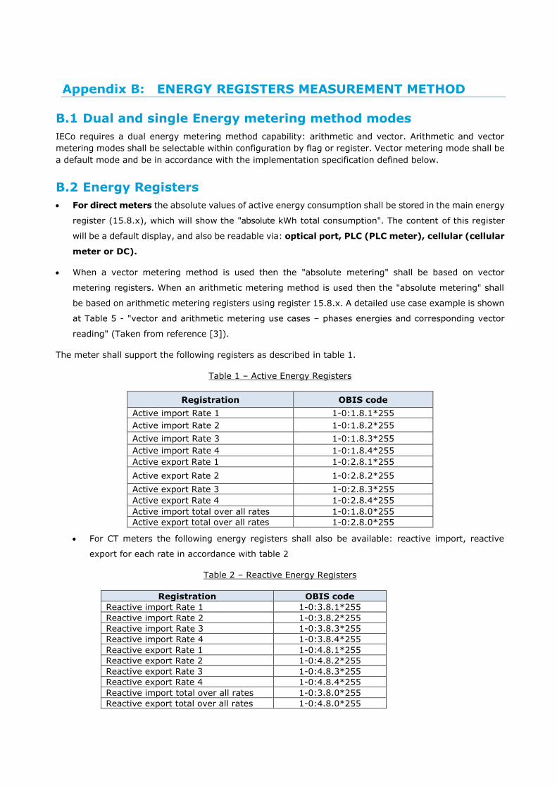
ENERGY REGISTERS MEASUREMENT METHOD
B.1 Dual and single Energy metering method modes
IECo requires a dual energy metering method capability: arithmetic and vector. Arithmetic and vector
metering modes shall be selectable within configuration by flag or register. Vector metering mode shall be
a default mode and be in accordance with the implementation specification defined below.
B.2 Energy Registers
For direct meters the absolute values of active energy consumption shall be stored in the main energy
register (15.8.x), which will show the "absolute kWh total consumption". The content of this register
will be a default display, and also be readable via: optical port, PLC (PLC meter), cellular (cellular
meter or DC).
When a vector metering method is used then the "absolute metering" shall be based on vector
metering registers. When an arithmetic metering method is used then the "absolute metering" shall
be based on arithmetic metering registers using register 15.8.x. A detailed use case example is shown
at Table 5 - "vector and arithmetic metering use cases – phases energies and corresponding vector
reading" (Taken from reference [3]).
The meter shall support the following registers as described in table 1.
Table 1 – Active Energy Registers
Registration OBIS code
Active import Rate 1 1-0:1.8.1*255
Active import Rate 2 1-0:1.8.2*255
Active import Rate 3 1-0:1.8.3*255
Active import Rate 4 1-0:1.8.4*255
Active export Rate 1 1-0:2.8.1*255
Active export Rate 2 1-0:2.8.2*255
Active export Rate 3 1-0:2.8.3*255
Active export Rate 4 1-0:2.8.4*255
Active import total over all rates 1-0:1.8.0*255
Active export total over all rates 1-0:2.8.0*255
For CT meters the following energy registers shall also be available: reactive import, reactive
export for each rate in accordance with table 2
Table 2 – Reactive Energy Registers
Registration OBIS code
Reactive import Rate 1 1-0:3.8.1*255
Reactive import Rate 2 1-0:3.8.2*255
Reactive import Rate 3 1-0:3.8.3*255
Reactive import Rate 4 1-0:3.8.4*255
Reactive export Rate 1 1-0:4.8.1*255
Reactive export Rate 2 1-0:4.8.2*255
Reactive export Rate 3 1-0:4.8.3*255
Reactive export Rate 4 1-0:4.8.4*255
Reactive import total over all rates 1-0:3.8.0*255
Reactive export total over all rates 1-0:4.8.0*255
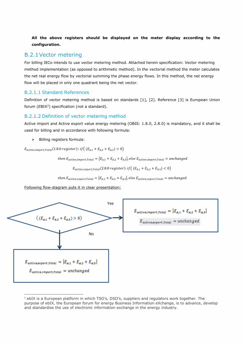
All the above registers should be displayed on the meter display according to the
configuration.
B.2.1 Vector metering
For billing IECo intends to use vector metering method. Attached herein specification: Vector metering
method implementation (as opposed to arithmetic method). In the vectorial method the meter calculates
the net real energy flow by vectorial summing the phase energy flows. In this method, the net energy
flow will be placed in only one quadrant being the net vector.
B.2.1.1 Standard References
Definition of vector metering method is based on standards [1], [2]. Reference [3] is European Union
forum (EBIX2) specification (not a standard).
B.2.1.2 Definition of vector metering method
Active import and Active export value energy metering (OBIS: 1.8.0, 2.8.0) is mandatory, and it shall be
used for billing and in accordance with following formula:
Billing registers formula:
𝐸𝑎𝑐𝑡𝑖𝑣𝑒,𝑖𝑚𝑝𝑜𝑟𝑡,𝑇𝑜𝑡𝑎𝑙(1.8.0 𝑟𝑒𝑔𝑖𝑠𝑡𝑒𝑟): 𝑖𝑓( (𝐸𝐴,1 + 𝐸𝐴,2 + 𝐸𝐴,3) > 0)
𝑡ℎ𝑒𝑛 𝐸𝑎𝑐𝑡𝑖𝑣𝑒,𝑖𝑚𝑝𝑜𝑟𝑡,𝑇𝑜𝑡𝑎𝑙 = |𝐸𝐴,1 + 𝐸𝐴,2 + 𝐸𝐴,3|, 𝑒𝑙𝑠𝑒 𝐸𝑎𝑐𝑡𝑖𝑣𝑒,𝑖𝑚𝑝𝑜𝑟𝑡,𝑇𝑜𝑡𝑎𝑙 = 𝑢𝑛𝑐ℎ𝑎𝑛𝑔𝑒𝑑
𝐸𝑎𝑐𝑡𝑖𝑣𝑒,𝑒𝑥𝑝𝑜𝑟𝑡,𝑇𝑜𝑡𝑎𝑙(2.8.0 𝑟𝑒𝑔𝑖𝑠𝑡𝑒𝑟): 𝑖𝑓( (𝐸𝐴,1 + 𝐸𝐴,2 + 𝐸𝐴,3) < 0)
𝑡ℎ𝑒𝑛 𝐸𝑎𝑐𝑡𝑖𝑣𝑒,𝑒𝑥𝑝𝑜𝑟𝑡,𝑇𝑜𝑡𝑎𝑙 = |𝐸𝐴,1 + 𝐸𝐴,2 + 𝐸𝐴,3|, 𝑒𝑙𝑠𝑒 𝐸𝑎𝑐𝑡𝑖𝑣𝑒,𝑒𝑥𝑝𝑜𝑟𝑡,𝑇𝑜𝑡𝑎𝑙 = 𝑢𝑛𝑐ℎ𝑎𝑛𝑔𝑒𝑑
Following flow-diagram puts it in clear presentation:
2 ebIX is a European platform in which TSO’s, DSO’s, suppliers and regulators work together. The
purpose of ebIX, the European forum for energy Business Information eXchange, is to advance, develop and standardise the use of electronic information exchange in the energy industry.
Yes
No

Fig. 1: flow diagram definition of active {import, export} billing registers
Comment: flow diagram is not an implementation. It is standard definition derived from
formula. References [1]-[2] are the standards
B.2.1.3 Load profile vector metering
Same flow-diagram as Fig. 1, and above formula must be applied to the load profile channels at periodic
level with the exception that instead of unchanged value, 𝐸𝑎𝑐𝑡𝑖𝑣𝑒,𝑖𝑚𝑝𝑜𝑟𝑡/𝑒𝑥𝑝𝑜𝑟𝑡,𝑇𝑜𝑡𝑎𝑙shall be set to zero as
reflecting periodic differential energy rather than accumulative energy. IECo enables either incremental
or differential periodic metering. The definition changes accordingly.
B.2.1.4 Reactive vector metering
Reactive import and Reactive export value energy metering (OBIS: 3.8.0, 4.8.0) is mandatory, and its
corresponding load profile channels shall be used for following objectives, and not for billing, and in
accordance with following formula. On Fig. 1, and in above formula the following replacements must
occur:
Table 3: Active to Reactive parameters mapping in vector method definition of reactive energy
Active Energy parameter Reactive Energy parameter 𝐸𝑎𝑐𝑡𝑖𝑣𝑒,𝑖𝑚𝑝𝑜𝑟𝑡,𝑇𝑜𝑡𝑎𝑙(1.8.0 𝑟𝑒𝑔𝑖𝑠𝑡𝑒𝑟) 𝐸𝑟𝑒𝑎𝑐𝑡𝑖𝑣𝑒,𝑖𝑚𝑝𝑜𝑟𝑡,𝑇𝑜𝑡𝑎𝑙(3.8.0 𝑟𝑒𝑔𝑖𝑠𝑡𝑒𝑟)
𝐸𝑎𝑐𝑡𝑖𝑣𝑒,𝑒𝑥𝑝𝑜𝑟𝑡,𝑇𝑜𝑡𝑎𝑙(2.8.0 𝑟𝑒𝑔𝑖𝑠𝑡𝑒𝑟) 𝐸𝑟𝑒𝑎𝑐𝑡𝑖𝑣𝑒,𝑒𝑥𝑝𝑜𝑟𝑡,𝑇𝑜𝑡𝑎𝑙(4.8.0 𝑟𝑒𝑔𝑖𝑠𝑡𝑒𝑟)
𝐸𝑎𝑐𝑡𝑖𝑣𝑒,𝑖𝑚𝑝𝑜𝑟𝑡,𝑇𝑜𝑡𝑎𝑙 𝐸𝑟𝑒𝑎𝑐𝑡𝑖𝑣𝑒,𝑖𝑚𝑝𝑜𝑟𝑡,𝑇𝑜𝑡𝑎𝑙
𝐸𝑎𝑐𝑡𝑖𝑣𝑒,𝑒𝑥𝑝𝑜𝑟𝑡,𝑇𝑜𝑡𝑎𝑙 𝐸𝑟𝑒𝑎𝑐𝑡𝑖𝑣𝑒,𝑒𝑥𝑝𝑜𝑟𝑡,𝑇𝑜𝑡𝑎𝑙
𝐸𝐴,1 𝐸𝑅,1
𝐸𝐴,2 𝐸𝑅,2
𝐸𝐴,3 𝐸𝑅,3
Reactive energy usage (is required for):
Table 4: implementations that require reactive energy load profile import/export channels
No. Usage Comments
1 Compute Power Factor (PF) as a mandate to oblige consumers
to improve PF.
Primary usage
2 Visualize reactive energy on a display, not use it for billing Primary usage
3 Use reactive load profile for AI application that identifies premise loads and perform remote predictive maintenance
4 Premise measurement: Use reactive load profile for AI application that identifies consumer fraud detection, phase polarity reversal, phase disconnects, and abnormal super-consumption
5 Same as 4) only for electric grid measurement.
Comment: Currently reactive load profile is required from the meter but the read data is in
accordance with the data model.
Definition: Same reactive vector metering formula as specified in above formula for active metering, except
following changes:
1) OBIS 3.8.0 reactive import register
2) OBIS 4.8.0 reactive export
3) The parameters must be replaced according to table 3 above.

B.2.1.5 Load profile formula
Channels are matching OBIS registers 3.8.0, 4.8.0. Same flow-diagram as Fig. 1 must be applied to the
load profile on periodic level, with exception that periodic value is zero when corresponding register value
is unchanged. IECo enables either incremental or differential periodic metering. The definition changes
accordingly.
Same reactive vector metering formula as specified in above formula for active metering, except following
changes:
1) OBIS 3.8.0 reactive import register
2) OBIS 4.8.0 reactive export
3) The parameters must be replaced according to table 3 above.
B.2.2 Arithmetic metering
When configuration is set to Arithmetic metering then for billing IECo intends to use arithmetic metering
method. Attached herein specification: "Arithmetic metering" method implementation (as opposed to
vector method). In the arithmetic method the meter calculates the energy flow by arithmetic summing the
phase energy flows. In this method, the energy flow from load to grid is placed in export register.
B.2.2.1 Standard References
Definition of arithmetic metering method is based on standards [1], [2]. Reference [3] is European Union
forum (EBIX3) specification (not a standard).
B.2.2.2 Definition of arithmetic metering method
Active import and Active export value energy metering (OBIS: 1.8.0, 2.8.0) is mandatory, and it shall be
used for billing and in accordance with following formula:
Billing registers formula:
𝐸𝑎𝑐𝑡𝑖𝑣𝑒,𝑖𝑚𝑝𝑜𝑟𝑡,𝑇𝑜𝑡𝑎𝑙(1.8.0 𝑟𝑒𝑔𝑖𝑠𝑡𝑒𝑟): ∑ 𝐸𝐴,𝑖𝑎𝑙𝑙 𝑝ℎ𝑎𝑠𝑒𝑠 𝑖 𝑤ℎ𝑒𝑟𝑒 𝐸𝐴,𝑖>0
𝐸𝑎𝑐𝑡𝑖𝑣𝑒,𝑒𝑥𝑝𝑜𝑟𝑡,𝑇𝑜𝑡𝑎𝑙(2.8.0 𝑟𝑒𝑔𝑖𝑠𝑡𝑒𝑟) = ∑ 𝐸𝐴,𝑖𝑎𝑙𝑙 𝑝ℎ𝑎𝑠𝑒𝑠 𝑖 𝑤ℎ𝑒𝑟𝑒 𝐸𝐴,𝑖<0
Where:
∑i − mean "sum over all i such that <condition> is maintained"
𝐸𝐴,𝑖 > 0 means energy flowing from electric grid to load/customer
𝐸𝐴,𝑖 < 0 means energy flowing from load/customer to electric grid
3 ebIX is a European platform in which TSO’s, DSO’s, suppliers and regulators work together. The
purpose of ebIX, the European forum for energy Business Information eXchange, is to advance, develop and standardise the use of electronic information exchange in the energy industry.
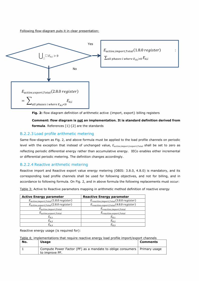
Following flow-diagram puts it in clear presentation:
Fig. 2: flow diagram definition of arithmetic active {import, export} billing registers
Comment: flow diagram is not an implementation. It is standard definition derived from
formula. References [1]-[2] are the standards
B.2.2.3 Load profile arithmetic metering
Same flow-diagram as Fig. 2, and above formula must be applied to the load profile channels on periodic
level with the exception that instead of unchanged value, 𝐸𝑎𝑐𝑡𝑖𝑣𝑒,𝑖𝑚𝑝𝑜𝑟𝑡/𝑒𝑥𝑝𝑜𝑟𝑡,𝑇𝑜𝑡𝑎𝑙 shall be set to zero as
reflecting periodic differential energy rather than accumulative energy. IECo enables either incremental
or differential periodic metering. The definition changes accordingly.
B.2.2.4 Reactive arithmetic metering
Reactive import and Reactive export value energy metering (OBIS: 3.8.0, 4.8.0) is mandatory, and its
corresponding load profile channels shall be used for following objectives, and not for billing, and in
accordance to following formula. On Fig. 2, and in above formula the following replacements must occur:
Table 3: Active to Reactive parameters mapping in arithmetic method definition of reactive energy
Active Energy parameter Reactive Energy parameter 𝐸𝑎𝑐𝑡𝑖𝑣𝑒,𝑖𝑚𝑝𝑜𝑟𝑡,𝑇𝑜𝑡𝑎𝑙(1.8.0 𝑟𝑒𝑔𝑖𝑠𝑡𝑒𝑟) 𝐸𝑟𝑒𝑎𝑐𝑡𝑖𝑣𝑒,𝑖𝑚𝑝𝑜𝑟𝑡,𝑇𝑜𝑡𝑎𝑙(3.8.0 𝑟𝑒𝑔𝑖𝑠𝑡𝑒𝑟)
𝐸𝑎𝑐𝑡𝑖𝑣𝑒,𝑒𝑥𝑝𝑜𝑟𝑡,𝑇𝑜𝑡𝑎𝑙(2.8.0 𝑟𝑒𝑔𝑖𝑠𝑡𝑒𝑟) 𝐸𝑟𝑒𝑎𝑐𝑡𝑖𝑣𝑒,𝑒𝑥𝑝𝑜𝑟𝑡,𝑇𝑜𝑡𝑎𝑙(4.8.0 𝑟𝑒𝑔𝑖𝑠𝑡𝑒𝑟)
𝐸𝑎𝑐𝑡𝑖𝑣𝑒,𝑖𝑚𝑝𝑜𝑟𝑡,𝑇𝑜𝑡𝑎𝑙 𝐸𝑟𝑒𝑎𝑐𝑡𝑖𝑣𝑒,𝑖𝑚𝑝𝑜𝑟𝑡,𝑇𝑜𝑡𝑎𝑙
𝐸𝑎𝑐𝑡𝑖𝑣𝑒,𝑒𝑥𝑝𝑜𝑟𝑡,𝑇𝑜𝑡𝑎𝑙 𝐸𝑟𝑒𝑎𝑐𝑡𝑖𝑣𝑒,𝑒𝑥𝑝𝑜𝑟𝑡,𝑇𝑜𝑡𝑎𝑙
𝐸𝐴,1 𝐸𝑅,1
𝐸𝐴,2 𝐸𝑅,2
𝐸𝐴,3 𝐸𝑅,3
Reactive energy usage (is required for):
Table 4: implementations that require reactive energy load profile import/export channels
No. Usage Comments
1 Compute Power Factor (PF) as a mandate to oblige consumers to improve PF.
Primary usage
Yes
No
ራ ⬚⬚
𝐸𝐴,𝑖 > 0
𝐸𝑎𝑐𝑡𝑖𝑣𝑒,𝑖𝑚𝑝𝑜𝑟𝑡,𝑇𝑜𝑡𝑎𝑙(1.8.0 𝑟𝑒𝑔𝑖𝑠𝑡𝑒𝑟) :
∑ 𝐸𝐴,𝑖𝑎𝑙𝑙 𝑝ℎ𝑎𝑠𝑒𝑠 𝑖 𝑤ℎ𝑒𝑟𝑒 𝐸𝐴,𝑖>0
𝐸 (2.8.0 𝑟𝑒𝑔𝑖𝑠𝑡𝑒𝑟)
𝐸𝑎𝑐𝑡𝑖𝑣𝑒,𝑒𝑥𝑝𝑜𝑟𝑡,𝑇𝑜𝑡𝑎𝑙(2.8.0 𝑟𝑒𝑔𝑖𝑠𝑡𝑒𝑟)
= ∑ 𝐸𝐴,𝑖𝑎𝑙𝑙 𝑝ℎ𝑎𝑠𝑒𝑠 𝑖 𝑤ℎ𝑒𝑟𝑒 𝐸𝐴,𝑖<0

2 Visualize reactive energy on a display, not use it for billing Primary usage
3 Use reactive load profile for AI application that identifies premise loads and perform remote predictive maintenance
4 Premise measurement: Use reactive load profile for AI application that identifies consumer fraud detection, phase polarity reversal, phase disconnects, and abnormal super-consumption
5 Same as 4) only for electric grid measurement.
Comment: Currently reactive load profile is required from the meter but the read data is in
accordance with the data model.
Definition: Same reactive arithmetic metering formula as specified in above formula for active metering,
except following changes:
1) OBIS 3.8.0 reactive import register
2) OBIS 4.8.0 reactive export
3) The parameters must be replaced according to table 3 above.
B.2.2.5 Load profile formula
Channels are matching OBIS registers 3.8.0, 4.8.0. Same flow-diagram as Fig. 2 must be applied to the
load profile on periodic level, with exception that periodic value is zero when corresponding register value
is unchanged. IECo enables either incremental or differential periodic metering. The definition changes
accordingly.
Same reactive arithmetic metering formula as specified in above formula for active metering, except
following changes:
1) OBIS 3.8.0 reactive import register
2) OBIS 4.8.0 reactive export
3) The parameters must be replaced according to table 3 above.
B.2.3 Use case example table for vector and arithmetic metering
The following table lists use cases and the required outcome vector and arithmetic metering result
Table 5: vector and arithmetic metering use cases – phases energies and corresponding vector reading (Taken from reference [3])
Absolute
(Arithmetic)
Absolute
(Vector)
Vector
Default metering mode
Arithmetic
|Import| +|Export|
|Import| +|Export|
Export Import Export Import Phase T Wh)
Phase S
(Wh)
Phase R
(Wh)
Period index
4 0 0 0 2 2 -1 -1 2 1
16 0 0 0 8 8 -8 4 4 2

B.2.4 Testability
IECo preserves the right to validate over meter samples submitted to IECo correct "vector and arithmetic
metering" implementation. Test segments are derived (implied) from "metering methods" following valid
standard and regulatory documentation [1]-[4] bellow.
Table 6: test cases
no Test description (for arithmetic in arithmetic mode and for vector in vector mode)
Comments
1 Test billing registers "Active import, export" under various conditions where simultaneous Active import, Active export energy flows exist
As compared to reference meter or power standard
2 Test load profile channels "Active import, export" under various conditions where simultaneous Active import, Active export energy flows exist
-"-
3 Test billing registers "Reactive import, export" under various conditions where
simultaneous Reactive import, Reactive export energy flows exist
-"-
4 Test load profile channels "Reactive import, export" under various conditions where simultaneous Reactive import, Reactive export energy flows exist
-"-
B.2.5 Functional requirements from data model
All above changes must be transparent to data model and all software tools, systems. No change of operation of these systems must occur. An event notifying that transition to specific vector/arithmetic mode must occur.
B.2.6 Functional requirements in favour of Meter Data Management
System
Regarding Meter configuration for Arithmetic and Vector metering: In order to manage this configuration from MDM, IECo requires the following information in MDM:
B.2.6.1 General firmware requirements:
a. Specific events are created in the meter during the transition from one metering method (arithmetic/vector) to the other (vector/arithmetic)
b. The transition from one metering mode to the other must be performed via configuration and not change of firmware version in accordance with section 1 above.
B.2.6.2 Regarding PLC meter
a. Configuration of the meter to change the metering method shall be performed via
using B09/B05/B12 and coordination of system with IECo. Metering method configuration must be specified to IECo and become available in MDMs.
10 4 0 4 3 7 4 3 -3 3
8 4 4 0 6 2 -4 2 -2 4
13 9 0 9 2 11 -2 4 7 5
51 17 4 13 21 30
Total

b. Reading ability of the meter configuration of metering method, must be enabled and
be included in S06 or S6B. Manufacturer must notify IECo which port taken.
B.2.6.3 Regarding Cellular meter
a. Configuration of the meter to change the metering method must be specified to IECo and become available in MDMs.
b. Reading the meter configuration of metering method must be available via OBIS register. This need to be included in general data reading
References: [1] IEEE 1459 -2010: IEEE Standard Definitions for the Measurement of Electric Power Quantities Under Sinusoidal, Nonsinusoidal, Balanced, or Unbalanced Conditions [2] DIN 40110-1, 3: QUANTITIES USED IN ALTERNATING CURRENT THEORY; TWO-LINE CIRCUITS
[3] "Smart meter reading method", European union document by Regulatory organization "European forum for energy Business Information eXchange" (EBIX), 2017. [4] "Power Definitions and the Physical Mechanism of Power Flow", IEEE, chapter 4, Prof. Alexander Eigeles Emanuel.

SPECIFICATIONS REGARDING CURRENT
INSTRUMENT TRANSFORMERS
C.1 Type of Current Instrument Transformers in Scope
The following type of current instrument transformers are in scope of this specification:
Rated Primary
Current
Accuracy Class Rated Burden Highest Voltage
for Equipment
Type
1000 A 0.2S 5 VA 0.72 kV Solid Core
1000 A 0.5 5 VA 0.72 kV Outdoor Split Core
1000 A 0.5 5 VA 0.72 kV Indoor Split Core
C.2 Required Documents for Evaluation of Technical Proposal
In order to show compliance with this specification, the bidder is required to submit the following
documents in ENGLISH, in the required format and form, and on a schedule as required herein:
A Reference list of Electricity Utilities to whom commercial quantities of the transformers have
been supplied during the last 3 years. The list shall include the name of the utility, the country,
the quantity of supplied items - detailed by types and date of supply.
The manufacturer shall have a Quality Management System (QMS) having a certificate
evidencing compliance with the requirements of the valid edition of ISO 9001, on the date
specified for submission of the proposal.
o Approval of conformance with the ISO 9001 requirements, as indicated in clause above,
shall be in a form of a certificate issued by a Certification Body (CB) which is accredited
by an Accreditation Body (AB).
o The certificate should bare the logo of the CB and of its AB and/or the logo of the IAF.
o The certificate shall be valid at least on the last date set for technical clarifications of the
proposal.
o The certificate shall be valid for the scope of activities requested in the request for
proposal.
Five (5) samples of each proposed transformers type. The samples will be subjected to tests at
IECo laboratories, at their sole discretion, to prove compliance with this specification.
A list of the active equipment in manufacturer’s laboratory, as a proof to its ability to perform
Routine Tests on each unit of the proposed transformer, according to section C.8.2, in this
specification.
The type tests' reports and results as performed in an accredited laboratory on the provided
sample transformer or similar type of the transformer, in which all the relevant tests have
successfully passed. Refer specifically to section C.8.1 of this specification. The type tests should
have been performed within the last 10 years from the date of the tender publication.
o Remark: In the context of this paragraph, a "similar type" means a CT which:
Has the same constructions;
Is manufactured at the same plant, with the same technology and the same
materials;

Is designed to operate at the same environmental conditions.
The routine tests report and results as performed on the proposed transformer, in which all the
relevant tests have successfully passed. Refer specifically to section C.8.2 of this specification.
A copy of the Quality Assurance Manual and the Quality Control System as per section C.3 and
C.4 in this specification.
A copy of the following documents and drawings:
o Drawings of construction, detailed dimensions as per section C.7.2 of this specification,
clearly stating. All dimensions shall be in Metric Units.
o Drawing of the rating plate markings (nameplate drawings).
o Details of construction like bolts or screws and terminals with their tightening torques.
o Definition of each Insulation Material used for manufacturing the transformers.
o Instructions for installation, handling, use and maintenance.
o Complete and filled-in Summary of Data of this specification per transformer type.
(section C.10).
Besides the Quality Assurance Certificate requested above, the bidder shall submit copies of:
o Design of Control Procedures (as applicable).
o List of qualified suppliers of the main parts, components and raw materials (as
applicable).
The manufacturer statement that the proposed transformers comply with the requirements of
this specification and if there are deviations, the manufacturer has to clearly state them for the
Purchaser's knowledge.
Definition:
CB – An independent external body authorized to confirm that the bidder / supplier's Management
System conforms to the requirements specified in the standard, by issuing a certificate. The CB should
be accredited to certify by an AB.
AB – An independent body, being a member of the International Accreditation Forum Multilateral
Arrangement – IAF MLA, having authority to formally approve, by means of document, the competence
of a certification body to provide certification services.

C.3 Quality Control
The Bidder/Supplier shall submit with its proposal a preliminary Inspection and Test Plan (I&T Plan)
which is applied during the production of the equipment.
Inspection and Test certificates as required in the Specification and the applicable Standards, shall
be submitted immediately following their generation. The certificates shall be original, signed by the
Bidder/Supplier and contain actual measured values. The generation of certificates, including those
generated by subcontractors and sub-suppliers, shall bear no extra cost to purchaser.
An Inspection and Test Plan including witnesses and hold points shall be mutually agreed between
the Purchaser and the Bidder/Supplier. Any subsequent alteration to this program shall require the
Purchaser agreement prior to start of any work affected by these alterations.
The Bidder/Supplier shall prepare and submit a schedule for the Routine tests, according to the
requirements of this specification before the testing.
Any equipment non-conforming with drawings’ specifications or any other purchase order
requirements, which are considered by the Contractor as “acceptable as is” or "for repair”, shall be
submitted to the Purchaser for approval, with their recommended disposition. All such non-
conformances shall be approved by the Purchaser (IECo) in writing, and a copy of the approval shall
accompany each shipment.
All Materials used in the manufacturing of the equipment shall conform to the Specification,
approved drawings and accepted Standards.
The Bidder/Supplier shall submit 1 (one) copy of:
o Manufacturing Quality Plan
o Procedures’ Quality Control.
o The Following documentation as applicable:
Special process procedures.
Non-Conformances and Deviation Control Procedures.
Electrical testing Procedures as per applicable Standards.
Certificates of Mechanical and Electrical Tests, complying with this specification.
Inspection and Test Reports.
Any change in the materials used in the manufacturing of the equipment and/or by subcontractors
and/or technology shall be reported in written to the Purchaser. The purchaser reserves the right to
accept or reject the change.
Deviation from Specifications:
Any deviation/change from specification suggested/made by the Bidder/Supplier, shall appear in a separate chapter of the proposal:
o 'Deviations/Changes/Comments'.
o The chapter will include the suggested/made deviations from the specification and their reasons
o The Purchaser reserves the right to accept or reject the proposed deviations /changes. In the last case, it will be a sufficient reason to reject the bid.

Remark: If Bidder/Supplier has not stated any deviation/change the purchaser will consider the
proposal as its conforming to the requirements of this specification.
C.4 Quality Assurance
The Manufacturer’s Quality Assurance Program shall meet the requirements described in the Quality
Assurance System.
The Purchaser shall have the right to audit and comment on Manufacturer’s Quality Assurance
System regardless of whether it was previously audited by a certifying agency or any other body.
The Bidder/Supplier shall be responsible for assuring that his Quality Assurance/Quality Control
program and his subcontractor’s as well, including their organizations, procedures, personal
qualifications, etc. indeed meets IECo’s quality requirements.
C.5 Preliminary Batch for Approving Delivery
IECo demands from the awarded Bidder/Supplier to ship to IECo a preliminary batch, which consists
of 5 units of each type of transformer.
IECo at their own judgments will perform tests as specified in section C.8 of this specification. Should
any of the transformers fail to pass the performed tests, IECo reserves the right to reject the whole
order.
Awarded Bidder/Supplier will send the remaining of the order, only after the Bidder/Supplier receives
written authorization from IECo's Import Department, in portions as defined by IECo's Import
Department.
The certificates' QMS should be valid for the whole period of the current supply.
C.6 General
C.6.1 Scope
This specification applies to: A Measuring Current Transformer (hereinafter called "CT") for low
voltage system, 50 Hz.
CT shall be used for Electricity Meters at existing transformation stations.

Figure 13-2: Installation method (illustration only)
CT for indoor and outdoor installation shall be used in environmental conditions as described in
section C.6.4.
Each unit shall be supplied complete with appurtenances and accessories as specified herein, to form
a complete unit which will achieve and assure safe and reliable operation with best overall
performance.
C.6.2 Standards and Codes
Standards and codes referenced in this Specification, and in supplements to this Specification, form
an integral part of this Specification unless otherwise indicated. All such standards and codes
referred to the most current issue, including all amendments, supplements etc., as of the date of the
Contract, unless otherwise indicated.
The Equipment that is provided under this specification including all appurtenances and accessories,
shall be designed, fabricated, inspected, tested and preserved to the extent indicated and to the
standards and codes as specified herein. All component parts not so specified shall be designed,
fabricated, inspected, tested and preserved, as applicable, to currently recognized Industrial and / or
Supplier’s Standards, so as to insure their fitness for use and for the purpose they are designed.
The Bidder/Supplier may propose Standards and codes as alternates for, or additions to those
specified herein. The information about of each proposed standard and code, if any, shall be included
with the proposal. In the case IECo acceptance of such alternates or additions to standards and
codes, manufacturer remains responsible for assuring that the design, and the equipment supplies
by others, which conform to IEC Standards and DIN Standards are completely compatible.

C.6.3 Relevant Regulations and Standards
The CTs must comply with:
o IEC Publications 61869-1 and 61869-2
o IEC Standard 61000-4-8, actual edition. EMC. Testing and measurement techniques – Power
frequency magnetic field immunity test.
o DIN 42600-1 and - DIN 42600-2
o IEC Publication 60695-11-10
If the requirements of the present specification differ from those of the above-mentioned standards,
the requirements of this specification shall take precedence.
C.6.4 Environmental Conditions
C.6.4.1 Environmental Conditions for Indoor Installation
The maximum ambient air temperature is 50 C and its average value measured over a period of 24
hr. is up to 35C. The minimum ambient air temperature is -5C. Maximum temperature difference
between day and night: 25C.
The installation altitude does not exceed 1000m.
The average value of the relative humidity, measured during a period of 24 hr. does not exceed
95%. The average value of the humidity does not exceed 90%, for a period of one month.
C.6.4.2 Environmental Conditions for Outdoor Installation
The maximum ambient air temperature is 50 °C and its average value measured over a period of 24
hr. is up to 35 °C. The minimum ambient air temperature is -10 °C. Maximum temperature
difference between day and night: 25 °C.
The installation altitude does not exceed 2000 m.
The maximum value of the relative humidity does not exceed 95%. The average annual value of the
humidity does not exceed 70%. The average value of the humidity for a period of one month does
not exceed 90%
Long summer periods with solar radiation of up to 1120 W/m2.
C.7 Technical Requirements
C.7.1 Electrical Requirements
Rated insulation level: 0.72 kV, according to IEC Publication 61869-1 clause 5.2, table 2.
Rated primary current: 1000 Amps
Rated secondary current: 5 Amps.
Rated frequency is 50 Hz
Rated output: 5 VA at PF=0.8. 7.5 VA and 10 VA values may be considered during samples
evaluation.

Instrument security factor: FS = 10 or smaller.
Accuracy classes:
o 0.2S (for solid core) or better according to IEC Publication 61869-2 Clause 5.6.201 and Table
202.
o 0.5 or better according to IEC Publication 61869-2 Clause 5.6.201 and Table 201.
Extended current ratings: 1.2 In.
C.7.2 General Construction Requirements
C.7.2.1 MCT, accuracy class 0.2S
The CT must have the casing made of double insulating thermoplastic material
o The limit of temperature rise for winding shall be 75K, according to table 5 in clause 6.4 of
IEC standard 61869-1.
o The casing must be heat and impact resistant.
o The casing must be of self-extinguishing classes HB40 and V-0 according to IEC 60695-11-
10.
o The casing should have a uniform surface. Significant apertures (larger than 0.3 mm) or
cavities on the surface are not acceptable
Dimensions:
o Height up to 140 mm
o Width up to 120 mm
o Depth up to 45 mm
Note: round transformer shape with outer diameter of up to 120 mm is also acceptable
The aperture should be located in the center of the CTs
The aperture should be suitable for cables from 70 up to 80 mm diameter. The aperture should
be such that cables with diameter larger than 80 mm will not fit.
Secondary terminals shall have two pinch screws for each terminal. The screws shall withstand the
tightening torque of at least 4.0 Nm. The screws shall be made of nickel plated or passivated brass.
The terminals shall be suitable for 10 mm2 ferrules.
C.7.2.2 MCT, accuracy class 0.5, in outdoor design
The cast insulating material must be durable for the intensive UV irradiation and for the tropical
environmental conditions.
The class of insulation shall be E or B (class E preferable), according to table 5 in clause 6.4.1 of IEC
Publication 61869-1.
The cast insulating material must be heat and impact resistant.

The casing must be of self-extinguishing classes HB40 and V-0 according to IEC Publication 60695-
11-10.
The cast insulating material should have a uniform surface. Any cavities on the surface are not
acceptable.
Overall dimensions:
o Height (a): ≤ 200 mm;
o Width (b): ≤ 145 mm;
o Depth (c): ≤ 60 mm
The aperture should be either round with 60-70 mm diameter or rectangular with (60-70 mm) / (60-
80 mm) dimensions. Slight deviations can be accepted after samples evaluation.
Each Secondary terminal shall have two pinch screws, or alternatively 4-6 mm2 copper secondary
conductors of 12 m length shall come out from inside the mould.
Each terminal shall ensure good contact pressure on pin-shaped or fork/spade tongue connector of
secondary wire of 4-6 mm2, according to DIN 46237 (if applicable).
The manufacturer shall indicate the recommended maximum tightening torque of the secondary
terminal’s screws in Nm (if applicable).
The screws shall be made of nickel plated or passivated brass (if applicable).
A protective terminals cover confirming with IP65 class according to IEC publication 60529 shall be
provided (if applicable). Provision shall be made for the cover sealing (if applicable).
C.7.2.3 MCT, accuracy class 0.5, in indoor design
The CT's case insulating material of the must be durable for the tropical environmental conditions.
The class of insulation shall be E or B (class E prefer), according to table 5 in clause 6.4.1 of IEC
Publication 61869-1.
The case insulating material must be heat and impact resistant.
The casing must be of self-extinguishing classes HB40 and V-0 according to IEC Publication 60695-
11-10.
The case insulating material should have the uniform surface. The significant apertures (larger than
0.3 mm) or cavities on the surface are not acceptable.
Overall dimensions:

o Height (a): ≤ 200 mm;
o Width (b): ≤ 145 mm;
o Depth (c): ≤ 60 mm.
The aperture should be either round with 60-70 mm diameter or rectangular with (60-70 mm) / (60-
80 mm) dimensions. Slight deviations can be accepted after samples evaluation.
Each Secondary terminal shall have two pinch screws.
Each terminal shall ensure good contact pressure on pin-shaped or fork/spade tongue connector of
secondary wire of 6 mm2, according to DIN 46237.
The manufacturer shall indicate the recommended maximum tightening torque of the secondary
terminal screws in Nm.
The screws shall be made of nickel plated or passivated brass.
A protective terminals cover shall be provided. Provision shall be made for the cover sealing
C.7.2.4 Markings
Terminals shall be marked as per IEC Publication 61869-1 and 61869-2. The polarity markings P1,
P2 and secondary terminals markings S1 and S2 shall be placed on the top surface of CT and be
clear and readable.
The rating label shall bear all the data as per IEC Publication 61869-2 clauses 6.13.201 and
6.13.202, including serial number, and IECo catalog number. It will be steadily fixed on the top
surface of the CT (e.g. with acrylic adhesive). The terminals block IP value shall be clearly indicated.
The rating label shall include bar-code mark done in code 128C with 12 digits, the first four (4) digits
are for the CT distinguishing code, that will be given by IECo for each type, 2 digits are for
manufacturing year and 6 digits are for the serial number, adding leading zeros if necessary:
CCCCYYNNNNNN, and the IECo logo as per section C.11.
The rating label shall be protected against environmental impacts.
C.7.2.5 Installation and Maintenance
Bidder/Supplier shall submit with the proposal maintenance, cleaning, storage, handling and installation
instructions, taking into consideration the service conditions.

C.8 Tests
C.8.1 Type Tests
Type test of CT should be performed according to IEC Publications 61869-1 Clause 7.2 and 61869-2
Clause 7.2 as specified:
Temperature-rise test according to IEC Publication 61869-2 Clause 7.2.2.
Impulse voltage withstand test on primary terminals according to IEC Publication 61869-2 Clause
7.2.3.
Test for accuracy according to IEC 61869-2 Publication Clauses 7.2.6.
Short-time current tests according to IEC Publication 61869-2 Clause 7.2.201.
The bidder shall provide the necessary test reports
C.8.2 Routine Tests
Each CT individually, shall be routine tested according to IEC Publication 61869-2 Clause 7.3 as specified
hereinafter, by the Bidder/Supplier prior to shipment. The test reports shall be submitted to the
Israel Electric Corp, attached to the CT.
Power-frequency voltage withstand test on primary terminals according to IEC Publication
61869-1 Clause 7.3.1.
Power frequency withstand test on secondary terminals according to IEC Publication 61869-1 Clause
7.3.4.
Test for accuracy according to IEC Publication 61869-2 Clause 7.3.5.
Determination of the secondary winding resistance (Rct) according to IEC Publication 61869-2
Clause 7.3.201
Test for rated knee point e.m.f (Ek) and exciting current at Ek according to IEC Publication
61869-2 clause 7.3.203.
Verification of markings according to IEC Publication 61869-1 Clause 7.3.6.
Inter-turn overvoltage test according to IEC Publication 61869-2 clause 7.3.204.
C.8.3 Special Tests
The IECo may make a special request for additional routine tests and additional special tests to evaluate
the workmanship of the CT.
Any CT subjected to special tests shall be performed by manufacturer and approved by IECo.
C.8.4 Acceptance Tests
The routine test results as per the above section C.8.2 will be compared with the limits given in standard
IEC 61869-2 and will serve as the acceptance criteria.
Verification of dimensions:

The tolerance on height (1.5 + 0.008h) mm. The tolerance on width (0.2 + 0.01w) mm.
IECo will carry out acceptance tests in order to approve the conformance of the purchased transformers
to this specification by using one of the following inspection methods:
1. 100% inspection, when all shipped transformers will be tested. Each consignment of delivered transformers will be considered as a batch. A batch containing more critically defective transformers than the number in the below-cited table will be considered as a rejected batch.
Batch Size Permitted number of defective
transformers
Up to 89 0
90 – 149 1
150 – 249 2
250 – 349 3
350 – 449 4
2. Sampling inspection is specified with risks of Bidder/Supplier and Purchaser, using standardized inspection plans, chosen from ISO 2859-1, ISO2859-2 tables and which will be notified to the awarded Bidder/Supplier. For this purpose: AQL = 1.0 %, LQ = 5 %, α=3%, β=10%. Failure to pass the inspection plan, all the transformers of the rejected batch will be replaced, and the supplier will bear the costs of shipment of the replacement batch.
Repeated rejections will lead to disqualification of a Bidder/Supplier.
C.9 Warranty
All the units will have a Manufacturer warranty for a period of 3 years, from the date of delivery to IECo.
The warranty shall include the replacement of any unit that failed to pass the tests performed by IECo,
according to any part of section C.8 of this specification.
The supplier will bear the costs of shipment of any replaced unit.

C.10 Official Company Symbol
SYMBOL DESIGN: The symbol basic design is a positive square.
It is important to keep the proportions in of the form in order to get the right performance.
REMARK: The square dimensions in the drawing are for proportional reference only.
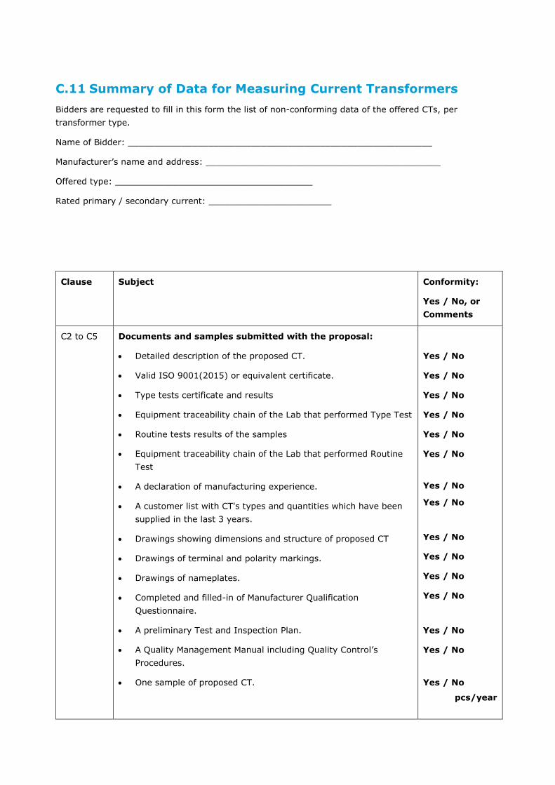
C.11 Summary of Data for Measuring Current Transformers
Bidders are requested to fill in this form the list of non-conforming data of the offered CTs, per
transformer type.
Name of Bidder: _________________________________________________________
Manufacturer’s name and address: ____________________________________________
Offered type: _____________________________________
Rated primary / secondary current: _______________________
Clause Subject Conformity:
Yes / No, or
Comments
C2 to C5 Documents and samples submitted with the proposal:
Detailed description of the proposed CT.
Valid ISO 9001(2015) or equivalent certificate.
Type tests certificate and results
Equipment traceability chain of the Lab that performed Type Test
Routine tests results of the samples
Equipment traceability chain of the Lab that performed Routine
Test
A declaration of manufacturing experience.
A customer list with CT's types and quantities which have been
supplied in the last 3 years.
Drawings showing dimensions and structure of proposed CT
Drawings of terminal and polarity markings.
Drawings of nameplates.
Completed and filled-in of Manufacturer Qualification
Questionnaire.
A preliminary Test and Inspection Plan.
A Quality Management Manual including Quality Control’s
Procedures.
One sample of proposed CT.
Yes / No
Yes / No
Yes / No
Yes / No
Yes / No
Yes / No
Yes / No
Yes / No
Yes / No
Yes / No
Yes / No
Yes / No
Yes / No
Yes / No
Yes / No
pcs/year
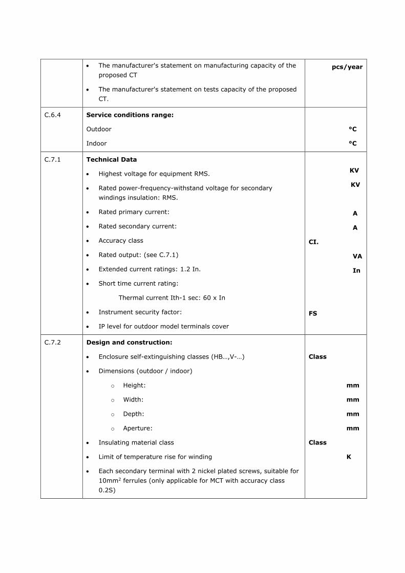
The manufacturer's statement on manufacturing capacity of the
proposed CT
The manufacturer's statement on tests capacity of the proposed
CT.
pcs/year
C.6.4 Service conditions range:
Outdoor
Indoor
°C
°C
C.7.1 Technical Data
Highest voltage for equipment RMS.
Rated power-frequency-withstand voltage for secondary
windings insulation: RMS.
Rated primary current:
Rated secondary current:
Accuracy class
Rated output: (see C.7.1)
Extended current ratings: 1.2 In.
Short time current rating:
Thermal current Ith-1 sec: 60 x In
Instrument security factor:
IP level for outdoor model terminals cover
KV
KV
A
A
CI.
VA
In
FS
C.7.2 Design and construction:
Enclosure self-extinguishing classes (HB…,V-…)
Dimensions (outdoor / indoor)
o Height:
o Width:
o Depth:
o Aperture:
Insulating material class
Limit of temperature rise for winding
Each secondary terminal with 2 nickel plated screws, suitable for
10mm2 ferrules (only applicable for MCT with accuracy class
0.2S)
Class
mm
mm
mm
mm
Class
K

Each secondary terminal with 2 nickel plated screws suitable for
4 – 6 mm2 fork connector (only applicable for MCT with accuracy
class 0.5, outdoor / indoor)
Protective terminals sealable cover
Markings & IECo logo
12 digits Bar-Code including CT code and s/n
Packaging and Labels
Conformity with Proposal Documents:
Bidder hereby certifies that he agrees to all provisions of the Proposal Documents unless exceptions are
specifically and clearly listed in the Proposal and identified as exceptions.
Bidder’s printed terms and conditions are not considered specific exceptions.
Any exceptions, or non-conformity which Bidder has taken, are listed in this page.
Bidder hereby certifies that he agrees to all conditions of the Covered Letter of Israel Electric Corporation
Limited, which accompanied the Proposal Documents
Signature of Bidder _________________ Date of Proposal _________________

PACKAGING REQUIREMENTS FOR COMPONENTS
The packaging requirements shall apply to meters (all types), current instrument transformers (see
Appendix C), Data Concentrators, PLC Filters, and Firewall components.
D.1 Packaging
D.1.1 General
Types of Pallets:
Contractors supplying goods to IECo's stores are to pack them on any one of the following types of
pallet:
a) Pallet with dimensions: 1,000*800 mm, acc. to DIN-15146, part 2 standard.
b) Pallet of any other dimensions suitable for the size and weight of the goods, and allowing easy
offloading of goods, where proposed by Bidder, are subject to receipt of IECo's approval in
advance.
Instructions for arrangement of goods on pallets:
Height: The height of the goods packed on the pallet, incl. pallet, is to be no more than 1,050
mm.
Weight: The weight of the goods packed on the pallet, incl. pallet, is to be no more than 250 kg.
10
50
-1
00
250 ±20100 -10
800 -40
11
0 +
10
15
0 -
10
150 -10
1200 -200
KMKM
Cardboard Hood Polyethylene Hood
(All dimensions are in mm)
Maximum gross weight: 250 kg. Note:

The wooden pallet should be treated and protected against woodworms and other vermin.
The cardboard and polyethylene hood design could be in any of the following forms:
a. Both the cardboard and polyethylene hoods could be opened at the bottom;
b. The cardboard hood could be an inverted box, and be easily separated from the base, either manually or with a box cutter;
c. The polyethylene hood could be a close-fitting cover, and be easily separated from the base, either manually or with a cutter;
If options "b" or "c" are used, then a separation line – about 10 mm above the pallet – should be clearly marked.
The pallet shall also carry a unique label (for example, "Pallet 1 out of 24") to distinguish it in the
total shipment. An impact detector ("ShockWatch") label shall be attached to the cardboard hood of
several pallets in each container, to warn of possible rough handling during shipment, transport and
storage.
The packaging will protect the goods against shock and vibration, preventing damage due to the
road conditions during transportation. The electrical and mechanical properties shall not be affected
by these disturbances.
Each pallet may contain up to 300 meters. The actual number of goods on each pallet shall be
agreed with the I.E.Co.
Goods should be packed together in a group box such that the weight of the group box will not
exceed 10 kg. This box shall be marked – on the front (wide side) and on the narrow side –
with the manufacturer name, device type, device code, I.E.Co catalog number, production serial
numbers (or these numbers' lot borders), serial number bar-codes (or barcodes' borders), IMEI
numbers including barcode for cellular equipment (if applicable, depending on component type),
manufacturing year, the sign “FRAGILE” and the Israel Electric Co. logo.
The boxes shall prevent, as much as possible, penetration of dust during long storage period. The
boxes must be designed for multiple use and be robust, with wall thickness of at least 4 mm.
For shipping the group boxes shall be close packed by stockpiles of suitable quantities on pallets. The
serial numbers sequence (without partition) shall be kept in each stockpile. A stockpile will be
protected against moisture by a polyethylene hood, covered with a cardboard cover (hood), and
fixed onto the pallet by parallel polypropylene bands, using protection angle bars at the corners. The
hood shall be marked – on the front (wide side), on the narrow side and on the top – with I.E.Co
logo, the manufacturer's name, device type, device code, I.E.Co catalog number, production serial
numbers' borders, serial number bar-codes borders, IMEI numbers including barcode for cellular
equipment (if applicable, depending on component type), manufacturing year, the I.E.Co order
number, the sign “FRAGILE”.
Specific for meters (of all types):
o Each meter must be packed, together with its not tightened terminal cover in an individual
cardboard box, which can be opened and re-closed without need of adhesives. Measures
should be taken to prevent the cover from "self-tightening" during transportation. The
screws, however, shall be inserted into their places in the cover.
o The box shall prevent, as much as possible, penetration of dust during long storage period.
The box must be designed for multiple use and be robust, with wall thickness of at least 4
mm.

Freight of more than 50 kg, is to be delivered in suitable packaging, allowing offloading with suitable
means.
Quantity: The quantity of goods on each pallet (in units or according to secondary packages) is to be
stated, according to each type.
Mixed freight: The same or different types of freight may be packed on pallets. Preferably same
types of freight are to be packed on each pallet. For freight of small quantities, different types of
freight may be packed on one pallet, provided that each type is packed in a separate secondary
package, whilst the lighter freight shall be on top.
Arrangement of pallets: The heaviest goods or goods with biggest quantity are to be packed on the
bottom of the pallet, provided they are not breakable or fragile goods.
Maintaining Equilibrium: The weight of the packages is to be divided evenly on the pallet.
Freight Stability: Freight packed on pallets is to be wrapped with "Shrink" nylon or tied with bands to
prevent any movement of freight on the pallet.
Use of supports: Wooden or Cardboard supports are to be mounted on all corners of the package,
such that the final package will take a cubic and more stable form.
Pallet boundaries: Freight is not to protrude outside of the pallet boundaries.
Packed freight on pallet must be arranged such that a 3 cm boundary is left on each side, between
the freight and outer edges of the pallet.
For circular freight (reels / spools), appropriate wedges are to mounted on pallets to prevent sliding
or rolling of freight.
Cleaning: The freight is to be clean and free of contaminating substances.
Secondary Package: Weight of each secondary package may be up to 10 kg. In the event heavier
secondary packages are inevitable, freight must include suitable lifting apparatus / device (hook or
handle).
D.1.2 Primary Packaging
General terms:
Wooden boxes shall be used in the following cases:
o where requirements exist for freight to be hermetically closed for preservation or storage in
special conditions.
o for goods of irregular dimensions not able to be packed on pallets.
o where requirements exist for protection of freight.
The dimensions of the bottom layer of the wooden box shall allow access of forklift for easy
transportation and offloading.
Wooden boxes shall be specially made to fit the dimensions, weight and offloading of the freight
required, proposed by the Contractor and approved by IECo.

Freight requirements for wooden boxes:
Wooden boxes may contain similar or different items packed in secondary packages as defined
herein.
Storage period, terms of storage and technical requirements shall dictate whether freight needs to
be preserved.
Marking of the packed freight shall be according to common practice.
Secondary packages are not to be packed too tightly, allowing easy handling of each secondary
package inside box.
Package dimensions are to be according to the freight's weight and size.
Mixed freight: The same or different types of freight may be packed in wooden boxes. Preferably
same types of freight are to be packed together in box. For freight of small quantities, different types
of freight may be packed on one pallet, provided that each type shall be packed in a separate
secondary package, whilst the lighter freights shall be on top.
Arrangement of pallets: The heaviest goods or goods with biggest quantity shall be packed on the
bottom of the pallet, provided they are not breakable or fragile goods.
Secondary Package: Weight of each secondary package may be up to 10 kg. In the event heavier
secondary package are inevitable, freight must include suitable lifting apparatus / device (hook or
handle).
D.1.3 Secondary Packaging
Secondary packaging shall be according to size of goods, dimensions of secondary packaging shall
allow loading of packages on to pallets or wooden boxes, accordingly, such that several secondary
packages may be loaded together on pallets or boxes.
Secondary Package: Weight of each secondary package may be up to 10 kg. In the event heavier
secondary package are inevitable, freight must include suitable lifting apparatus / device (hook or
handle).
Goods of especially small volume in large quantities, are to be packed in suitable bags, with the
quantity stated on the outside of the package.
Fragile goods are to be padded and include suitable partitions between items.
D.2 Shipment Documents
The Manufacturer shall attach one set of the Bill of materials to the shipment.
The Manufacturer shall submit detailed storage instructions for storage (if necessary). Such
information shall be available to the Purchaser in ample time to prepare the required facilities.
If applicable, each shipment shall be accompanied by certification attesting the conformance of the
shipment to the specifications. Certificate shall contain routine test results identifiable to the
acceptance criteria and the items shipped. Documentation shall be submitted in English.

If applicable, the certificates shall include the signature and name of the entity performing the tests
and shall be subject to the review and acceptance of IECo.
D.3 Handling of DDP goods
On arrival at the Israeli Port the Goods on the pallets shall be offloaded from containers (if so delivered)
and loaded by the Supplier at Supplier's risk and cost onto open trucks for transportation to IECo stores.
D.4 Official Company Symbol
SYMBOL DESIGN: The symbol basic design is a positive square.
It is important to keep the proportions in of the form in order to get the right performance.
REMARK: The square dimensions in the drawing are for proportional reference only.

HASS REQUIREMENTS
E.1 HASS general definition
HASS stands for "Highly accelerated stress screen" tests, and is performed in order to identify design
weaknesses, improve product reliability and reduce life cycle.
HASS screens are performed in the same type of chamber that is used for HALT. The vibration in HASS is
randomly applied over a broad frequency range producing energy to 10,000 Hz in 6 degrees of freedom.
HASS is performed after termination of design cycle during manufacturing cycle.
Figure 13-3: Cold and hot stress tests
Figure 13-4: Difference between HALT and HASS in stress margins

E.2 IECo HASS requirements
HASS required by IECo involves the following tests:
E.2.1 Thermal cycling tests
Table 13-4: Thermal cycling tests
No Feature Work point Criteria
1 Initial functional and metrology
tests
Refer to Table 1-1to Table
1-1Table 13-7. Verify that
all meters pass.
All meters pass
2 standard IEC 62059-31-1
3 low temperature ≤ −5℃
4 high temperature ≥ 65℃
5 Rate of temperature change 5-10℃ per minute
7 Dwell time One hour
8 Total duration At least five working days –
24 hours/day
9 Final functional and metrology tests Refer to Table 1-1Table
13-7. Compare results
including numeric results.
If no more than one meter
failure is occurring than
HASS test is considered
pass
E.2.2 Vibration and free fall tests
A sample of the meters that passed Thermal cycling shall be subjected to either Vibration or Free fall
test.
E.2.2.1 Vibration test
Vibration test shall be performed on a sample of 30 meters out of the meters that passed Thermal
cycling tests.
Table 13-5: Vibration test
No Feature Work point
1 Initial functional and metrology tests Refer to Table 1-1to Table 1-1Table 13-7. Verify
that all meters pass.
2 Standard IEC 62052-11, 5.2.2
IEC 600068-2-6
3 Final functional and metrology tests Refer to Table 1-1Table 13-7. Compare results
including numeric results.

E.2.2.2 Free fall test
Free fall test shall be performed on a sample of 5 meters out of the meters that passed Thermal cycling
test.
Table 13-6: Free fall test
No Feature Work point
1 Initial functional and metrology tests Refer to Table 1-1to Table 1-1Table 13-7.
Verify that all meters pass.
2 standard IEC 60068-2-32
3 Test conditions 0.5-meter height
in any two axes
unpacked meter, without terminal cover
number of falls 2.
4 Final functional and metrology tests Refer to Table 1-1Table 13-7. Compare results
including numeric results.
Table 13-7: Contents of Initial and Final provision tests
No Main chapter Description
1 display LCD display, LED indicator
2 Communication LTE, optical probe, PLC
3 Error Handling and Alarm Handling
4 Contactor open/close
5 RTC Compare with reference time
6 Push button
7 Energy registers Read them
8 Visual inspection
9 Automatic acceptance test If include some or all of above do not repeat
twice

METERS AND DC RAM REQUIREMENTS
F.1 Definitions
The following definitions are valid for all Reliability, Availability, and Maintainability (RAM) purposes in the
Specification for meters and DCs.
The RAM parameters are characteristics of the meter/ DC design and production only when they are
properly used and maintained.
a. Failure – Failure is any event where a meter/DC has stopped functioning, or exceeds its
specification limits, and requires repair or replacement.
b. Failure Rate – The failure rate of a meter/DC is the number of failures per operating time unit.
The system failure rate for the meter/DC will mean the sum of the failure rates of its components,
i.e.
= 1 + 2 + 3 + … + n.
c. MTTF – MTTF is the mean time between the meter/DC installation and operation, and the first
failure.
d. Reliability – Reliability is a design characteristic defining the ability of a product to perform
satisfactorily. Reliability is the probability that a meter will perform without failures, for a pre-
defined period of time, when used under stated conditions (at IECo site). MTTF is a reliability
parameter, in accordance with definitions of IEC 60050-192.
e. Life Length – Life length of a meter/DC is the time until the first failure in operation.
f. Maintenance – Maintenance is any action taken to replace a faulty meter/DC with a properly
working one, after a failure, and test the operable condition of a replaced meter.
g. Maintainability – Maintainability is a design characteristic defining the ability of an item to be
replaced quickly and checked for its operable condition after a failure
F.2 RAM Requirements
The Bidder is required to provide IECo with meters/DC with the following RAM properties:
Reliability
Operational TTF (time to first failure): At least 15 years.
Operational service life time: At least 15 years, without the need for maintenance or recalibration.
Maintainability – The meter/DC will be “preventive maintenance” free for its entire life length.
F.3 RAM Declaration
A RAM Declaration shall be provided for each of the meter/DC components. The following RAM information
shall be submitted to IECo with the technical proposal:
The Bidder shall state:
1) The minimum guaranteed MTTF
2) The life length values of the proposed meters/DC, when operated within their specified environmental
extreme conditions, as per the Specifications.
3) The sum rate and these components values as predicted and verified (tested) will be reflected at
MTTF state.
4) The historical RAM field data of proposed meters/DC, for all installed meters/DC (identical to the ones
proposed), at all sites, supplied during the last 5 years. The RAM report should include specific model
type, and years of the collected data.
5) Reliability prediction report according to IEC 62059-41.
6) Information about RAM activities and optimization in the manufacturing plants concerning the proposed
meters/DC including:
a) Criticality (long supply time, high price, short life length, high failure rate, single supply source,
sensitive or vulnerable materials, etc.
b) Latent failure rate ( ), and induced failure rate (caused by human).
c) Turn Around Time (door to door).
d) Quantity in service.
e) Recommended “probability of no shortage” (spares availability) on shelf.
f) Cost
The Bidder shall state the rationales for his above-mentioned declarations
(usage/tests/analysis/estimation).
total

F.4 Reliability Demonstration
IECo has the privilege to exercise a Reliability Field Demonstration (RFD) concerning the supplied
meter/DC during the technical evaluation stage. The purpose of the RFD is to verify that the meters meet
the reliability requirement.
If carried out, the RFD will be conducted in accordance with the following principles:
1) The RFD shall be objective, quantitative and based on data collection from returned faulty meters (see
IEC 60300-3-2 Application Guide, IEC 62059-21).
2) The Bidder has nothing to do in the RFD, except to participate in the Failure ReviewBoard (FRB).
However, the Bidder has to do his best in his plant in the following areas, in order to supply to IECo
with reliable meters, and this to pass the RFD with high probability:
a) Design and Development
b) Parts, materials, and components
c) Manufacturing Processes
d) Quality Assurance and Control
e) Tests and inspections
f) Sub Bidders, Suppliers, and Vendors supervision
g) Packaging, Handling, Storage, and Transportation (PHST)
3) The FRB is the only body entitled to classify failures as “Relevant”, or “Non-relevant” for the purpose
of the RFD.
4) The Bidder is responsible for productive agency of RFD results.
5) The RFD shall be ended with either ACCEPT, or REJECT result.
6) The meaning of REJECT result is violation of the specification, and the contract will deal with such a
situation.
7) The RFD will be framed in accordance with standard reliability test methods.

OFF THE SHELF PRODUCT DECLARATION
An "off-the shelf product declaration, is a formal statement, signed by senior manufacturer officer, such
as VP sales, at which the manufacturer guarantees by statement, that the proposed product is an off-the-
shelf product, sold as such to other utilities, and not tailor made product. Minor adaptations to IECo spec,
are enabled through firmware, only after IECo enables them.
Bidder’s Off The Shelf Product Declaration & Undertaking:
Statement of Compliance
I, the undersigned, ___________ [name of Bidder’s authorized signatory], in my capacity as
____________ [title or position of authorized signatory] of
_____________ [name of Bidder] (the “Bidder”), do hereby declare as follows:
1. The Bidder has received the Tender Documents and has carefully read all their contents;
2. The Bidder undertakes to comply with the terms and conditions of the tendering process, as set forth
in the Tender Documents;
3. The Bidder represents and warrants that it is capable of supplying the Products and rendering all the
Services within the time frames detailed in the Tender Documents and undertakes to abide by them.
4. The Meters and the software and all other services proposed by the Bidder hereunder will be
provided in accordance with the requirements set forth in the Tender Documents;
5. All representations, warranties, proposals and descriptions made by the Bidder are true, accurate and
complete;
6. Our Proposal shall be binding upon us in accordance with the terms and conditions set out in the
Tender Documents.
7. The Meter (and SW ) that is proposed in this tender is Off the Shelf Products and complying with the
requirements defined below:
7.1. Is completely defined (design, construction and performance) by a formal technical specification.
7.2. Is manufactured in accordance with formal production drawings, processes and procedures which
govern all stages and aspects of the manufacturing process.
7.3. Have successfully passed all qualification tests and the environmental tests in particular.
7.4. Is manufactured with strict adherence to the prescribed quality assurance procedures, which have
to include in-process inspection procedures.
7.5. "Similar" meter type in accordance with IEC 62052-11, section 3.1.8.2, is currently manufactured
with at least 400 units installed/at electrical power utilities at the last two years and the
accumulated operational data proves high reliability indicating the Product is mature.
7.6. Is regularly checked for reliability by field data collection, collation and corrective action taken
when needed.

7.7. Is accompanied by a complete set of manufacturing drawings and procedures, reliability
prediction, user manuals and maintenance manuals.
Bidder's Information
Bidder’s Full Name:
Bidder’s Address
Street:
City State / Province Zip/Postal Code
Country
Bidder's Contact Information
Telephones:
Fax:
e-mail:
Signature ____________________ Date:____________________

PROVISIONING TEST
No Scope of provision validation work
1 All system versions relating to the HLD contents shall be validated with defined and agreed
provisioning –tests in the development (DEV) environment. The result of these tests shall
be available to IECo.
At least a single Dead-Or-Alive (DOA) test must be executed in the TEST environment prior
to release.
2 New functionality testing and regular regression testing must be executed before
submission
3 Each provisioning testing program shall be presented to IECo for approval. Testing will
commence only after approval is received from IECo.
A Standard STP, STD documentation shall be provided to IECo as a-priory and be approved
by IECo prior to execution of said test programs.
STP – Standard Test Procedure
STD – Standard Test Description
4 Each provisioning testing program, and including version release, shall be backed-up with a
standard test program report (STR).
5 A new version shall only be accepted by IECo if the Dead-Or-Alive test suit was passed
successfully by IECo E2E acceptance test validation team.
6 Provisioning testing must be performed by the integrator validation team. According to the
IECo requirements they must hire an Israeli team from a known software validation
company.
No Bugs Issuing policy (by all involved parties)
7 Any issues that are identified during testing by the integration team, and remaining
outstanding issues, shall be identified and logged within the "Quality Center" system. Within
the “Quality Center" system the issue shall be identified according to QC defects tracking
specification.
8 Critical and High priority issues (as defined in Chapter 7 of this Smart Metering Tender)
shall be resolved within a period defined by and according to chapter 7 of this tender (High,
Critical, Medium, Low).
9 An ‘issue board’ meeting shall be held approximately every two weeks. The presence of a
nominated “Integrator” coordinator is required at all issue board meetings.
Effort will be made to reach mutual agreement on issue's details. In case of a dispute, the
issue decision is determined by IECo expert users.
10 Reject conduct: an issue cannot be modified to “Not a problem” twice.
11 Latency: the integrator must react, in writing, to each high priority issue within two work
days.
12 Information from the integrator to the IECo End-to-End validation automation team must be
provided on-demand. Contents to be defined by IECo.

13 IECo requires that the integrator has exceptional knowledge of installation of software such
as "MDM", "WFM system", and shall assist the E2E validation on-demand.
No Global
14 At every validation the final mandate is by IECo, although effort is made to reach
agreement.
15 The final E2E and quality validation responsibility is by IECo
16 There shall be no multiplication of duties to a single validation job title, payment is per
single job title. The following personnel is required:
Team leader.
Senior testing person that is not a team-leader
Junior testing person.
The team must be hired in Israel, speak fluent Hebrew, and stay at IECo facilities if possible
due to COVID-19 pandemic.
17 There shall be a result oriented payment section for each milestone.
Not withstanding the milestone objective – IECo has a bonus/penalty payment mechanism.
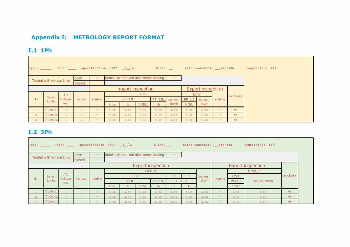
METROLOGY REPORT FORMAT
I.1 1Ph
I.2 3Ph
open √ √
closed
PF=0.5L PF=1.0
Imax Ib 0.05Ib Ib 0.05Ib
1 YY000001 √ √ √ x.xx x.xx x.xx x.xx x.xx x.xx x.xx √ OK
2 YY000002 √ √ √ x.xx x.xx x.xx x.xx x.xx x.xx x.xx √ OK
3 YY000003 √ √ √ x.xx x.xx x.xx x.xx x.xx x.xx x.xx √ OK
starting
Error Error
startingPF=1.0 dial test
1kWh
dial test
1kWh
Type:______ Code: ____ specification:230V _(__)A Class:__ Meter constant:___imp/kWh temperature:TT℃ humidity:HH%
Tested with voltage linkscontinuity checked after meter sealing
Import inspection Export inspection
conclusionNo.
Serial
Number
AC
Voltage
test
no load
open √ √
closed
R T RST
PF=0.5L PF=1.0
Imax Ib 0.05Ib Ib Ib Ib 0.05Ib
1 YY000001 √ √ √ x.xx x.xx x.xx x.xx x.xx x.xx x.xx √ x.xx x.xx OK
2 YY000002 √ √ √ x.xx x.xx x.xx x.xx x.xx x.xx x.xx √ x.xx x.xx OK
3 YY000003 √ √ √ x.xx x.xx x.xx x.xx x.xx x.xx x.xx √ x.xx x.xx OK
starting
Error, %
RST
dial test 1kWhPF=1.0 PF=1.0
Import inspection Export inspection
conclusionNo.
Serial
Number
AC
Voltage
test
no load starting
Error, %
dial test
1kWh
Type:_____ Code: ____ specification:230V _(__)A Class:__ Meter constant:___imp/kWh temperature:TT℃ humidity:HH%
Tested with voltage linkscontinuity checked after meter sealing

I.3 CT
R T RST R T RST
PF=0.5L PF=1.0 PF=0.5L PF=1.0
Imax In 0.02In In In In 0.02In Imax In 0.02In In In In 0.02In
1 YY000001 √ √ √ x.xx x.xx x.xx x.xx x.xx x.xx x.xx √ x.xx x.xx √ x.xx x.xx x.xx x.xx x.xx x.xx x.xx √ x.xx x.xx OK
2 YY000002 √ √ √ x.xx x.xx x.xx x.xx x.xx x.xx x.xx √ x.xx x.xx √ x.xx x.xx x.xx x.xx x.xx x.xx x.xx √ x.xx x.xx OK
3 YY000003 √ √ √ x.xx x.xx x.xx x.xx x.xx x.xx x.xx √ x.xx x.xx √ x.xx x.xx x.xx x.xx x.xx x.xx x.xx √ x.xx x.xx OK
PF=1.0 PF=1.0starting
Error, %
starting
Error, %
starting
Error, %
dial test 10kWh (primary)
RST dial test
10kVarh
(primary)
dial test
10kVarh
(primary)
No.Serial
Number
AC
Voltage
test
no load starting
Error, %
RST dial test
10kWh
(primary)
PF=1.0 PF=1.0
Type:_____ Code: ____ specification:230V _(__)A Class:__ (act), _._ (react) Meter constant:____imp/kWh, imp/kVarh temperature:TT℃ humidity:HH%
Active Energy Import inspection Active Energy Export inspection Reactive Energy Import inspection Reactive Energy Export inspection
conclusion