Calculating Density For Use In Fan Systems - AMCA
52
Density Calculations: Calculating Density For Use In Fan Systems AMCA insite ™ Webinar Series | AMCA International | www.amca.org
-
Upload
khangminh22 -
Category
Documents
-
view
0 -
download
0
Transcript of Calculating Density For Use In Fan Systems - AMCA

Density Calculations: Calculating Density For Use In Fan Systems
AMCA insite™ Webinar Series | AMCA International | www.amca.org

Scott Arnold
Content Manager, AMCA International
Webinar Moderator
• Joined AMCA in 2017
• Leads development and publication of technical articles, white papers and educational materials.
• Editor-in-chief of the award-winning AMCA inmotionmagazine.

TODAY’S WEBINAR SPONSORS

TODAY’S WEBINAR SPONSORS

TODAY’S WEBINAR SPONSORS

Introductions & Guidelines• Participation Guidelines:
• Audience will be muted during the webinar.
• Questions can be submitted anytime via the GoToWebinar platform and will be addressed at the end of the presentation.
• Reminder: This webinar is being recorded!
• To earn PDH credit for today, please stay clicked onto the webinar for the entire hour.
• A post-webinar evaluation will be emailed to everyone within one day, and it must be completed to qualify for today’s PDH credit.
• Every person that wants to receive PDH credit must be individually registered. If people are watching in a group and want credit, please contact Lisa Cherney ([email protected]) for a group sign-in sheet.

Q & ATo submit questions:
- From the attendee panel on the side of the screen, select the “Questions” drop down option.
- Type your question in the box, starting with the name of the presenter for whom your question is for.
- Click “Send”.

AMCA International has met the standards and requirements of the Registered Continuing Education Program. Credit earned on completion of this program will be reported to RCEP at RCEP.net. A certificate of completion will be issued to each participant. As such, it does not include content that may be deemed or construed to be an approval or endorsement by the RCEP.
Attendance for the entire presentation
AND a completed evaluation are required
for PDH credit to be issued.

COPYRIGHT MATERIALS
This educational activity is protected by U.S. and International copyright laws. Reproduction,
distribution, display and use of the educational activity without written permission of the presenter is
prohibited.
© AMCA International 2020

William HowarthConsultant, Ventilation & Fan Consulting Service International
• Independent Consultant since 2017
• 30-yrs Fan Engineering & Sales at Illinois Blower and Hartzell Fan
• Instructor NC Industrial Ventilation Conference
• Member US delegation for ISO Technical Committee 117 Fans
• ASHRAE Member

Density Calculations: Calculating Density For Use In Fan SystemsPurpose and Learning Objectives
The purpose of this presentation is to educate engineers, system designers, and fan application specialists on the calculations required to determine air or gas density.
At the end of this presentation you will be able to:
1. Describe the makeup of standard air.
2. Identify factors that determine gas density.
3. Calculate gas density for temperature, elevation, or pressure change.
4. Calculate gas density for gas other than air.
5. Combine multiple factors to calculate gas density.
6. Explain the impact of gas density of fan and system performance.
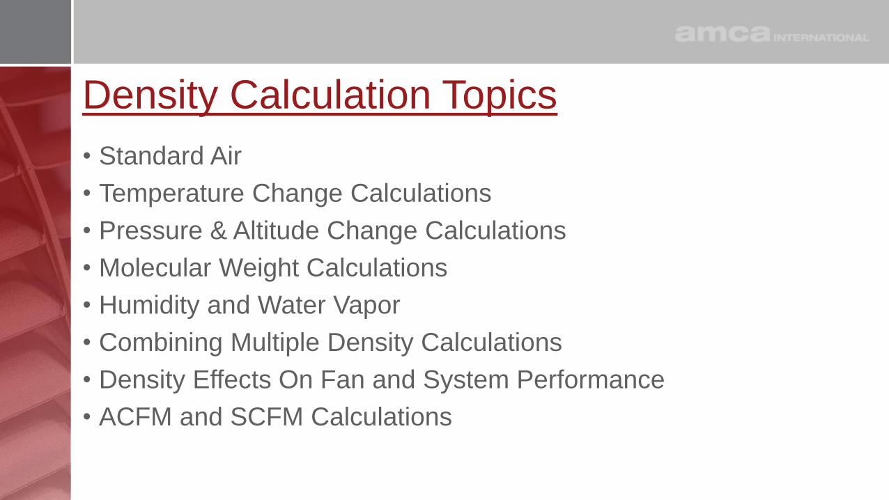
Density Calculation Topics
• Standard Air
• Temperature Change Calculations
• Pressure & Altitude Change Calculations
• Molecular Weight Calculations
• Humidity and Water Vapor
• Combining Multiple Density Calculations
• Density Effects On Fan and System Performance
• ACFM and SCFM Calculations

Standard Air Recipe (Ingredients)
• Gas make up (by volume)• 78% Nitrogen (N2)
• 21% Oxygen (O2)
• 0.9% Argon (Ar)
• 0.04% Carbon Dioxide (CO2)
• Pinch of other trace gases
• Gasses have different molecular weights and the percentages determine overall gas weight
• Molecular weight of standard air • 28.965 grams/mole
Gas Cst %
Mole
Weight MW % Cst Wt.
N2 78.08% 28.014 75.52% 21.87
O2 20.94% 31.998 23.14% 6.70
Ar 0.93% 39.948 1.29% 0.37
CO2 0.04% 44.01 0.06% 0.02
Ne 0.002% 20.18 0.001% 0.00
100.00% 100.00% 28.96
Mole Weight air ~28.965

Standard Air Recipe (Pressurize and Heat)
• Gas make up (by volume)• 78% N2, 21% O2, 0.9% Ar, 0.04%
CO2, and trace gases
• Pressure (atmospheric or system)
• 29.921 in Hg, 14.696 psi, 101.325 kPa, 760mm Hg
• Temperature basis for standard air
• 70°F, 21°C, 530R, 294K(Dry air or 68°F 20°C with 50% Relative Humidity)
• Density is mass/unit volume
• Add gases to one cubic foot
• Weight will be 0.075 pounds
• 0.075 pounds mass/cubic foot
• Standard Air Density:
0.075 lbm/ft3, 1.2 kg/m3

Standard Air Uses and Changes
• Standard Air → standard density
• Reference gas for:• Fan Catalogs
• Performance test results
• Rating tables
• Data sets
• STP - Standard Temperature and Pressure
• Standard air in nature is rare
• Fans handle actual air or gas
• Change the recipe → change the density → Change the Factor
• Temperature
• Pressure
• Ingredient gas mix
Temperature Factor
Pressure Factor
Gas (MW) Factor
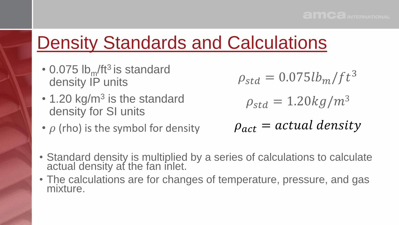
Density Standards and Calculations
• 0.075 lbm/ft3 is standard density IP units
• 1.20 kg/m3 is the standard density for SI units
• 𝜌 (rho) is the symbol for density
𝜌𝑠𝑡𝑑 = 0.075𝑙𝑏𝑚/𝑓𝑡3
𝜌𝑠𝑡𝑑 = 1.20𝑘𝑔/𝑚3
𝜌𝑎𝑐𝑡 = 𝑎𝑐𝑡𝑢𝑎𝑙 𝑑𝑒𝑛𝑠𝑖𝑡𝑦
• Standard density is multiplied by a series of calculations to calculate actual density at the fan inlet.
• The calculations are for changes of temperature, pressure, and gas mixture.
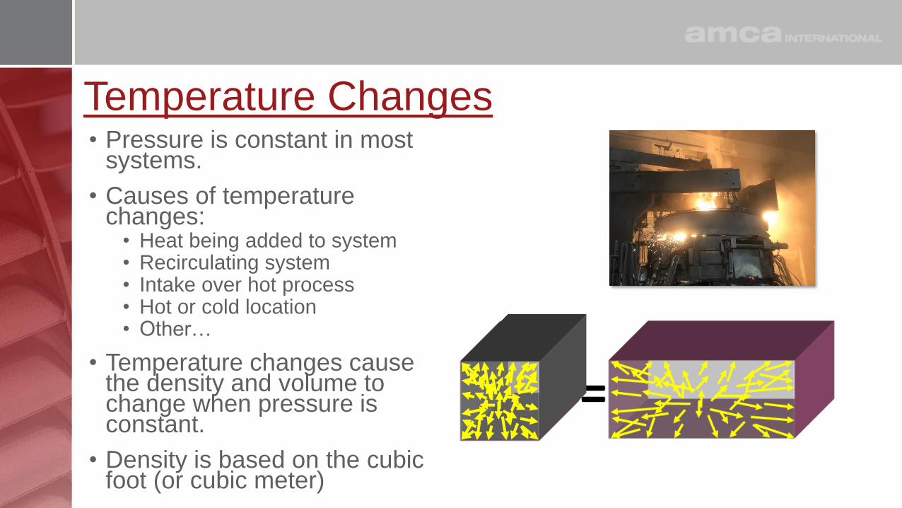
Temperature Changes• Pressure is constant in most
systems.
• Causes of temperature changes:
• Heat being added to system• Recirculating system• Intake over hot process• Hot or cold location• Other…
• Temperature changes cause the density and volume to change when pressure is constant.
• Density is based on the cubic foot (or cubic meter)
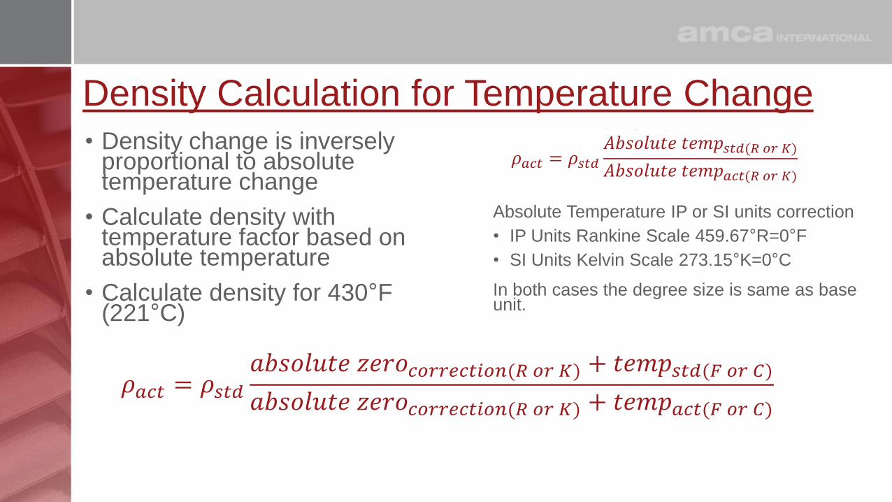
Density Calculation for Temperature Change• Density change is inversely
proportional to absolute temperature change
• Calculate density with temperature factor based on absolute temperature
• Calculate density for 430°F (221°C)
Absolute Temperature IP or SI units correction
• IP Units Rankine Scale 459.67°R=0°F
• SI Units Kelvin Scale 273.15°K=0°C
In both cases the degree size is same as base unit.
𝜌𝑎𝑐𝑡 = 𝜌𝑠𝑡𝑑𝐴𝑏𝑠𝑜𝑙𝑢𝑡𝑒 𝑡𝑒𝑚𝑝𝑠𝑡𝑑(𝑅 𝑜𝑟 𝐾)
𝐴𝑏𝑠𝑜𝑙𝑢𝑡𝑒 𝑡𝑒𝑚𝑝𝑎𝑐𝑡(𝑅 𝑜𝑟 𝐾)𝜌𝑎𝑐𝑡 = 0.075
𝑙𝑏𝑚𝑓𝑡3
∗530°𝑅
𝐴𝑏𝑠𝑜𝑙𝑢𝑡𝑒 𝑡𝑒𝑚𝑝𝑎𝑐𝑡(𝑅 𝑜𝑟 𝐾)𝜌𝑎𝑐𝑡 = 0.075
𝑙𝑏𝑚𝑓𝑡3
∗𝐴𝑏𝑠𝑜𝑙𝑢𝑡𝑒 𝑡𝑒𝑚𝑝𝑠𝑡𝑑(𝑅 𝑜𝑟 𝐾)
𝐴𝑏𝑠𝑜𝑙𝑢𝑡𝑒 𝑡𝑒𝑚𝑝𝑎𝑐𝑡(𝑅 𝑜𝑟 𝐾)𝜌𝑎𝑐𝑡 = 0.075
𝑙𝑏𝑚𝑓𝑡3
∗530°𝑅
890°𝑅𝜌𝑎𝑐𝑡 = 0.075
𝑙𝑏𝑚𝑓𝑡3
∗ 0.596𝜌𝑎𝑐𝑡 = 0.045𝑙𝑏𝑚𝑓𝑡3
𝜌𝑎𝑐𝑡 = 0.075𝑙𝑏𝑚𝑓𝑡3
∗𝑎𝑏𝑠𝑜𝑙𝑢𝑡𝑒 𝑧𝑒𝑟𝑜𝑐𝑜𝑟𝑟𝑒𝑐𝑡𝑖𝑜𝑛(𝑅 𝑜𝑟 𝐾) + 𝑡𝑒𝑚𝑝𝑠𝑡𝑑(𝐹 𝑜𝑟 𝐶)
𝑎𝑏𝑠𝑜𝑙𝑢𝑡𝑒 𝑧𝑒𝑟𝑜𝑐𝑜𝑟𝑟𝑒𝑐𝑡𝑖𝑜𝑛(𝑅 𝑜𝑟 𝐾) + 𝑡𝑒𝑚𝑝𝑎𝑐𝑡(𝐹 𝑜𝑟 𝐶)𝜌𝑎𝑐𝑡 = 0.075
𝑙𝑏𝑚𝑓𝑡3
∗273𝑐𝑜𝑟𝑟𝑒𝑐𝑡𝑖𝑜𝑛(𝐾) + 𝑡𝑒𝑚𝑝𝑠𝑡𝑑(𝐶)
𝑎𝑏𝑠𝑜𝑙𝑢𝑡𝑒 𝑧𝑒𝑟𝑜𝑐𝑜𝑟𝑟𝑒𝑐𝑡𝑖𝑜𝑛(𝐾) + 𝑡𝑒𝑚𝑝𝑎𝑐𝑡(𝐶)𝜌𝑎𝑐𝑡 = 0.075
𝑙𝑏𝑚𝑓𝑡3
∗273𝑐𝑜𝑟𝑟𝑒𝑐𝑡𝑖𝑜𝑛(𝐾) + 21𝑠𝑡𝑑(𝐶)
𝑎𝑏𝑠𝑜𝑙𝑢𝑡𝑒 𝑧𝑒𝑟𝑜𝑐𝑜𝑟𝑟𝑒𝑐𝑡𝑖𝑜𝑛(𝐾) + 𝑡𝑒𝑚𝑝𝑎𝑐𝑡(𝐶)𝜌𝑎𝑐𝑡 = 0.075
𝑙𝑏𝑚𝑓𝑡3
∗273𝑐𝑜𝑟𝑟𝑒𝑐𝑡𝑖𝑜𝑛(𝐾) + 21𝑠𝑡𝑑(𝐶)
273𝑐𝑜𝑟𝑟𝑒𝑐𝑡𝑖𝑜𝑛(𝐾) + 𝑡𝑒𝑚𝑝𝑎𝑐𝑡(𝐶)𝜌𝑎𝑐𝑡 = 0.075
𝑙𝑏𝑚𝑓𝑡3
∗273𝑐𝑜𝑟𝑟𝑒𝑐𝑡𝑖𝑜𝑛(𝐾) + 21𝑠𝑡𝑑(𝐶)
273𝑐𝑜𝑟𝑟𝑒𝑐𝑡𝑖𝑜𝑛(𝐾) + 221𝑎𝑐𝑡(𝐶)𝜌𝑎𝑐𝑡 = 0.075
𝑙𝑏𝑚𝑓𝑡3
∗294°𝐾
494°𝐾𝜌𝑎𝑐𝑡 = 0.075
𝑙𝑏𝑚𝑓𝑡3
∗ 0.595𝜌𝑎𝑐𝑡 = 0.045𝑙𝑏𝑚𝑓𝑡3
𝜌𝑎𝑐𝑡 = 1.20𝑘𝑔
𝑚3∗𝑎𝑏𝑠𝑜𝑙𝑢𝑡𝑒 𝑧𝑒𝑟𝑜𝑐𝑜𝑟𝑟𝑒𝑐𝑡𝑖𝑜𝑛(𝑅 𝑜𝑟 𝐾) + 𝑡𝑒𝑚𝑝𝑠𝑡𝑑(𝐹 𝑜𝑟 𝐶)
𝑎𝑏𝑠𝑜𝑙𝑢𝑡𝑒 𝑧𝑒𝑟𝑜𝑐𝑜𝑟𝑟𝑒𝑐𝑡𝑖𝑜𝑛(𝑅 𝑜𝑟 𝐾) + 𝑡𝑒𝑚𝑝𝑎𝑐𝑡(𝐹 𝑜𝑟 𝐶)𝜌𝑎𝑐𝑡 = 1.20
𝑘𝑔
𝑚3∗
273𝑐𝑜𝑟𝑟𝑒𝑐𝑡𝑖𝑜𝑛(𝐾) + 𝑡𝑒𝑚𝑝𝑠𝑡𝑑(𝐶)
𝑎𝑏𝑠𝑜𝑙𝑢𝑡𝑒 𝑧𝑒𝑟𝑜𝑐𝑜𝑟𝑟𝑒𝑐𝑡𝑖𝑜𝑛(𝐾) + 𝑡𝑒𝑚𝑝𝑎𝑐𝑡(𝐶)𝜌𝑎𝑐𝑡 = 1.20
𝑘𝑔
𝑚3∗
273𝑐𝑜𝑟𝑟𝑒𝑐𝑡𝑖𝑜𝑛(𝐾) + 21𝑠𝑡𝑑(𝐶)
𝑎𝑏𝑠𝑜𝑙𝑢𝑡𝑒 𝑧𝑒𝑟𝑜𝑐𝑜𝑟𝑟𝑒𝑐𝑡𝑖𝑜𝑛(𝐾) + 𝑡𝑒𝑚𝑝𝑎𝑐𝑡(𝐶)𝜌𝑎𝑐𝑡 = 1.20
𝑘𝑔
𝑚3∗
273𝑐𝑜𝑟𝑟𝑒𝑐𝑡𝑖𝑜𝑛(𝐾) + 21𝑠𝑡𝑑(𝐶)
273𝑐𝑜𝑟𝑟𝑒𝑐𝑡𝑖𝑜𝑛(𝐾) + 𝑡𝑒𝑚𝑝𝑎𝑐𝑡(𝐶)𝜌𝑎𝑐𝑡 = 1.20
𝑘𝑔
𝑚3∗273𝑐𝑜𝑟𝑟𝑒𝑐𝑡𝑖𝑜𝑛(𝐾) + 21𝑠𝑡𝑑(𝐶)
273𝑐𝑜𝑟𝑟𝑒𝑐𝑡𝑖𝑜𝑛(𝐾) + 221𝑎𝑐𝑡(𝐶)𝜌𝑎𝑐𝑡 = 1.20
𝑘𝑔
𝑚3∗294°𝐶
494°𝐶𝜌𝑎𝑐𝑡 = 1.20
𝑘𝑔
𝑚3∗ 0.595𝜌𝑎𝑐𝑡 = 0.71𝑘𝑔
𝑚3𝜌𝑎𝑐𝑡 = 𝜌𝑠𝑡𝑑
𝑎𝑏𝑠𝑜𝑙𝑢𝑡𝑒 𝑧𝑒𝑟𝑜𝑐𝑜𝑟𝑟𝑒𝑐𝑡𝑖𝑜𝑛(𝑅 𝑜𝑟 𝐾) + 𝑡𝑒𝑚𝑝𝑠𝑡𝑑(𝐹 𝑜𝑟 𝐶)
𝑎𝑏𝑠𝑜𝑙𝑢𝑡𝑒 𝑧𝑒𝑟𝑜𝑐𝑜𝑟𝑟𝑒𝑐𝑡𝑖𝑜𝑛(𝑅 𝑜𝑟 𝐾) + 𝑡𝑒𝑚𝑝𝑎𝑐𝑡(𝐹 𝑜𝑟 𝐶)
𝜌𝑎𝑐𝑡 = 𝜌𝑠𝑡𝑑𝐴𝑏𝑠𝑜𝑙𝑢𝑡𝑒 𝑡𝑒𝑚𝑝𝑠𝑡𝑑(𝑅 𝑜𝑟 𝐾)
𝐴𝑏𝑠𝑜𝑙𝑢𝑡𝑒 𝑡𝑒𝑚𝑝𝑎𝑐𝑡(𝑅 𝑜𝑟 𝐾)
𝜌𝑎𝑐𝑡 = 𝜌𝑠𝑡𝑑𝑎𝑏𝑠𝑜𝑙𝑢𝑡𝑒 𝑧𝑒𝑟𝑜𝑐𝑜𝑟𝑟𝑒𝑐𝑡𝑖𝑜𝑛(𝑅 𝑜𝑟 𝐾) + 𝑡𝑒𝑚𝑝𝑠𝑡𝑑(𝐹 𝑜𝑟 𝐶)
𝑎𝑏𝑠𝑜𝑙𝑢𝑡𝑒 𝑧𝑒𝑟𝑜𝑐𝑜𝑟𝑟𝑒𝑐𝑡𝑖𝑜𝑛(𝑅 𝑜𝑟 𝐾) + 𝑡𝑒𝑚𝑝𝑎𝑐𝑡(𝐹 𝑜𝑟 𝐶)
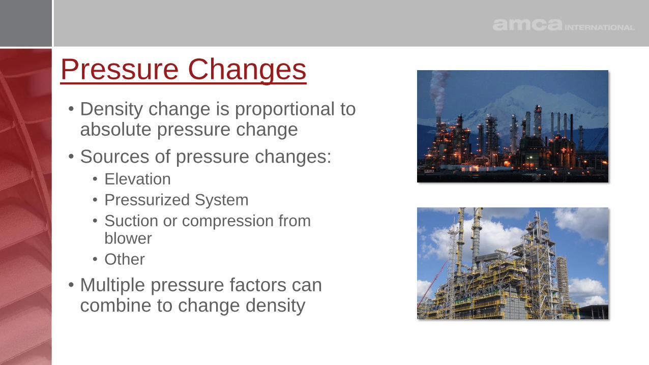
Pressure Changes
• Density change is proportional to absolute pressure change
• Sources of pressure changes:• Elevation
• Pressurized System
• Suction or compression from blower
• Other
• Multiple pressure factors can combine to change density
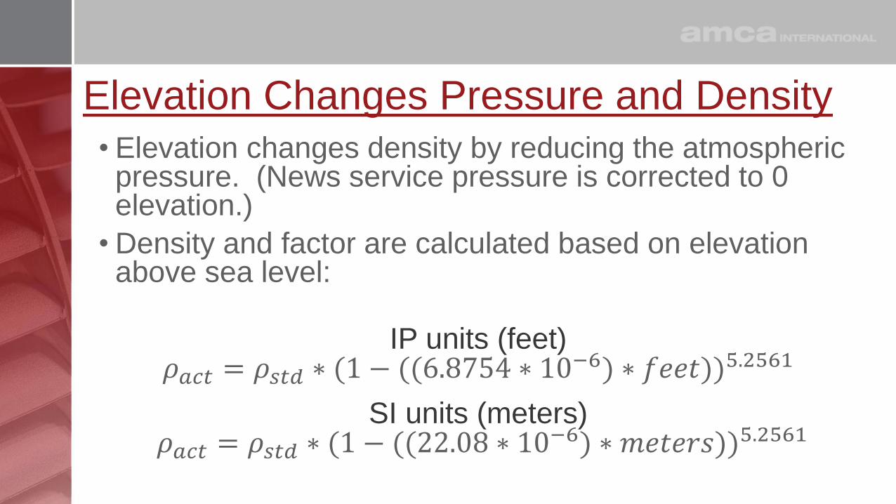
Elevation Changes Pressure and Density
• Elevation changes density by reducing the atmospheric pressure. (News service pressure is corrected to 0 elevation.)
• Density and factor are calculated based on elevation above sea level:
IP units (feet)𝜌𝑎𝑐𝑡 = 𝜌𝑠𝑡𝑑 ∗ (1 − ((6.8754 ∗ 10−6) ∗ 𝑓𝑒𝑒𝑡))5.2561
SI units (meters)𝜌𝑎𝑐𝑡 = 𝜌𝑠𝑡𝑑 ∗ (1 − ((22.08 ∗ 10−6) ∗ 𝑚𝑒𝑡𝑒𝑟𝑠))5.2561
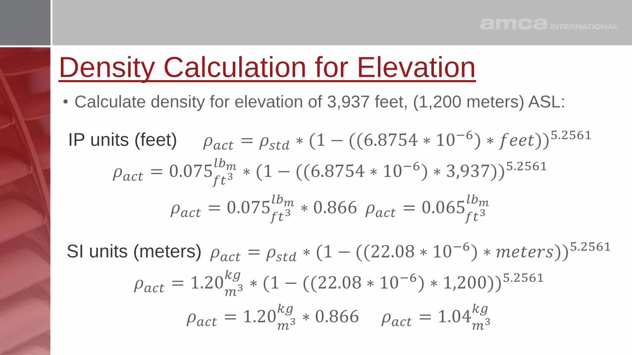
Density Calculation for Elevation• Calculate density for elevation of 3,937 feet, (1,200 meters) ASL:
IP units (feet) 𝜌𝑎𝑐𝑡 = 𝜌𝑠𝑡𝑑 ∗ (1 − ((6.8754 ∗ 10−6) ∗ 𝑓𝑒𝑒𝑡))5.2561
𝜌𝑎𝑐𝑡 = 0.075𝑓𝑡3𝑙𝑏𝑚 ∗ (1 − ((6.8754 ∗ 10−6) ∗ 3,937))5.2561
𝜌𝑎𝑐𝑡 = 0.075𝑓𝑡3𝑙𝑏𝑚 ∗ 0.866 𝜌𝑎𝑐𝑡 = 0.065
𝑓𝑡3𝑙𝑏𝑚
SI units (meters) 𝜌𝑎𝑐𝑡 = 𝜌𝑠𝑡𝑑 ∗ (1 − ((22.08 ∗ 10−6) ∗ 𝑚𝑒𝑡𝑒𝑟𝑠))5.2561
𝜌𝑎𝑐𝑡 = 1.20𝑚3𝑘𝑔
∗ (1 − ((22.08 ∗ 10−6) ∗ 1,200))5.2561
𝜌𝑎𝑐𝑡 = 1.20𝑚3𝑘𝑔
∗ 0.866 𝜌𝑎𝑐𝑡 = 1.04𝑚3𝑘𝑔

Local Atmospheric Pressure Calculation for Elevation
• Calculate local Barometric Pressure for elevation of 3,937 feet, (1,200 meters) ASL:
IP units (Feet & PSI)
𝑃𝑏(𝑎𝑐𝑡) = 𝑃𝑏(𝑠𝑡𝑑) ∗ (1 − ((6.8754 ∗ 10−6) ∗ 𝑓𝑒𝑒𝑡))5.2561
𝑃𝑏(𝑎𝑐𝑡) = 14.696 𝑃𝑆𝐼 ∗ (1 − ((6.8754 ∗ 10−6) ∗ 3,937))5.2561
𝑃𝑏(𝑎𝑐𝑡) = 14.696 𝑃𝑆𝐼 ∗ 0.866 𝑃𝑏(𝑎𝑐𝑡) = 12.72 𝑃𝑆𝐼
SI units (meters & kPa)
𝑃𝑏(𝑎𝑐𝑡) = 𝑃𝑏(𝑠𝑡𝑑) ∗ (1 − ((22.08 ∗ 10−6) ∗ 𝑚𝑒𝑡𝑒𝑟𝑠))5.2561
𝑃𝑏(𝑎𝑐𝑡) = 101.32 𝑘𝑃𝑎 ∗ (1 − ((22.08 ∗ 10−6) ∗ 1,200))5.2561
𝑃𝑏(𝑎𝑐𝑡) = 101.32 𝑘𝑃𝑎 ∗ 0.866 𝑃𝑏(𝑎𝑐𝑡) = 87.99 𝑘𝑃𝑎
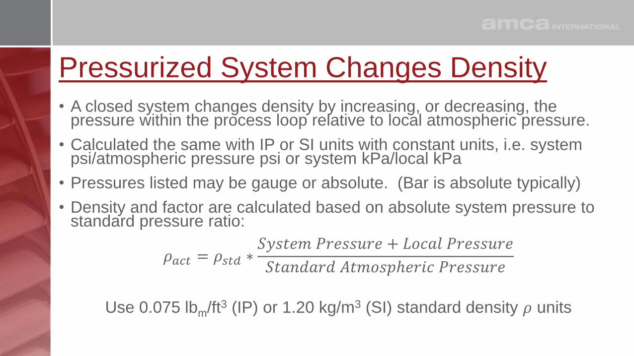
Pressurized System Changes Density
• A closed system changes density by increasing, or decreasing, the pressure within the process loop relative to local atmospheric pressure.
• Calculated the same with IP or SI units with constant units, i.e. system psi/atmospheric pressure psi or system kPa/local kPa
• Pressures listed may be gauge or absolute. (Bar is absolute typically)
• Density and factor are calculated based on absolute system pressure to standard pressure ratio:
𝜌𝑎𝑐𝑡 = 𝜌𝑠𝑡𝑑 ∗𝑆𝑦𝑠𝑡𝑒𝑚 𝑃𝑟𝑒𝑠𝑠𝑢𝑟𝑒 + 𝐿𝑜𝑐𝑎𝑙 𝑃𝑟𝑒𝑠𝑠𝑢𝑟𝑒
𝑆𝑡𝑎𝑛𝑑𝑎𝑟𝑑 𝐴𝑡𝑚𝑜𝑠𝑝ℎ𝑒𝑟𝑖𝑐 𝑃𝑟𝑒𝑠𝑠𝑢𝑟𝑒
Use 0.075 lbm/ft3 (IP) or 1.20 kg/m3 (SI) standard density 𝜌 units

Density Calculation for System Pressure (IP)
• Calculate density for system at 34.65 PSIG, (238.9 kPa(g))
• Use local atmospheric pressure from earlier local atmospheric pressure calculation (12.72 PSI, 87.99 kPa)
𝜌𝑎𝑐𝑡 = 𝜌𝑠𝑡𝑑 ∗𝑆𝑦𝑠𝑡𝑒𝑚 𝑃𝑟𝑒𝑠𝑠𝑢𝑟𝑒 + 𝐿𝑜𝑐𝑎𝑙 𝑃𝑟𝑒𝑠𝑠𝑢𝑟𝑒
𝑆𝑡𝑎𝑛𝑑𝑎𝑟𝑑 𝐴𝑡𝑚𝑜𝑠𝑝ℎ𝑒𝑟𝑖𝑐 𝑃𝑟𝑒𝑠𝑠𝑢𝑟𝑒
𝜌𝑎𝑐𝑡 = 0.075𝑓𝑡3𝑙𝑏𝑚 ∗
34.64 𝑃𝑆𝐼 + 12.72 𝑃𝑆𝐼
14.696 𝑃𝑆𝐼
𝜌𝑎𝑐𝑡 = 0.075𝑓𝑡3𝑙𝑏𝑚 ∗ 3.22 𝜌𝑎𝑐𝑡 = 0.242
𝑓𝑡3𝑙𝑏𝑚
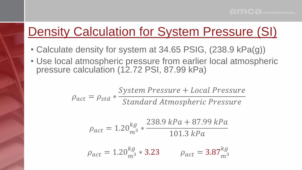
Density Calculation for System Pressure (SI)
• Calculate density for system at 34.65 PSIG, (238.9 kPa(g))
• Use local atmospheric pressure from earlier local atmospheric pressure calculation (12.72 PSI, 87.99 kPa)
𝜌𝑎𝑐𝑡 = 𝜌𝑠𝑡𝑑 ∗𝑆𝑦𝑠𝑡𝑒𝑚 𝑃𝑟𝑒𝑠𝑠𝑢𝑟𝑒 + 𝐿𝑜𝑐𝑎𝑙 𝑃𝑟𝑒𝑠𝑠𝑢𝑟𝑒
𝑆𝑡𝑎𝑛𝑑𝑎𝑟𝑑 𝐴𝑡𝑚𝑜𝑠𝑝ℎ𝑒𝑟𝑖𝑐 𝑃𝑟𝑒𝑠𝑠𝑢𝑟𝑒
𝜌𝑎𝑐𝑡 = 1.20𝑚3𝑘𝑔
∗238.9 𝑘𝑃𝑎 + 87.99 𝑘𝑃𝑎
101.3 𝑘𝑃𝑎
𝜌𝑎𝑐𝑡 = 1.20𝑚3𝑘𝑔
∗ 3.23 𝜌𝑎𝑐𝑡 = 3.87𝑚3𝑘𝑔

Suction on Inlet Changes Density• Suction in the inlet of the blower changes density by decreasing the
pressure at the inlet of the blower relative to local atmospheric pressure, (rarefication).
• Calculated the same with IP or SI units with constant units, i.e. suction pressure inches H2O/atmospheric pressure inches H2O or system mm H2O /local mm H2O
• Density and factor are calculated based on absolute system pressure to standard pressure ratio:
𝜌𝑎𝑐𝑡 = 𝜌𝑠𝑡𝑑 ∗𝐿𝑜𝑐𝑎𝑙 𝑃𝑟𝑒𝑠𝑠𝑢𝑟𝑒 − 𝑎𝑏𝑠(𝑆𝑢𝑐𝑡𝑖𝑜𝑛 𝑃𝑟𝑒𝑠𝑠𝑢𝑟𝑒)
𝑆𝑡𝑎𝑛𝑑𝑎𝑟𝑑 𝐴𝑡𝑚𝑜𝑠𝑝ℎ𝑒𝑟𝑖𝑐 𝑃𝑟𝑒𝑠𝑠𝑢𝑟𝑒
Use 0.075 lbm/ft3 (IP) or 1.20 kg/m3 (SI) standard density 𝜌 units

Density Calculation for Suction on Inlet (IP)
• Calculate density for suction on inlet of -30in H2O, (762mm H2O)
• Use local atmospheric pressure from earlier local atmospheric pressure calculation (12.72 PSI, 87.99 kPa)
𝜌𝑎𝑐𝑡 = 𝜌𝑠𝑡𝑑 ∗𝐿𝑜𝑐𝑎𝑙 𝑃𝑟𝑒𝑠𝑠𝑢𝑟𝑒 − 𝑎𝑏𝑠(𝑆𝑢𝑐𝑡𝑖𝑜𝑛 𝑃𝑟𝑒𝑠𝑠𝑢𝑟𝑒)
𝑆𝑡𝑎𝑛𝑑𝑎𝑟𝑑 𝐴𝑡𝑚𝑜𝑠𝑝ℎ𝑒𝑟𝑖𝑐 𝑃𝑟𝑒𝑠𝑠𝑢𝑟𝑒
𝜌𝑎𝑐𝑡 = 0.075𝑓𝑡3𝑙𝑏𝑚 ∗
(12.72 𝑃𝑆𝐼 ∗ 27.7 Τ𝑖𝑛 𝐻2𝑂 𝑃𝑆𝐼) − 𝑎𝑏𝑠(−30𝑖𝑛 𝐻2𝑂)
(14.696 𝑃𝑆𝐼 ∗ 27.7 Τ𝑖𝑛 𝐻2𝑂 𝑃𝑆𝐼)
𝜌𝑎𝑐𝑡 = 0.075𝑓𝑡3𝑙𝑏𝑚 ∗
322.1𝑖𝑛 𝐻2𝑂
406.8𝑖𝑛 𝐻2𝑂
= 0.075𝑓𝑡3𝑙𝑏𝑚 ∗ 0.792 = 0.059
𝑓𝑡3𝑙𝑏𝑚

Density Calculation for Suction on Inlet (SI)• Calculate density for suction on inlet of -30in H2O, (762mm H2O)
• Use local atmospheric pressure from earlier local atmospheric pressure calculation (12.72 PSI, 87.99 kPa)
𝜌𝑎𝑐𝑡 = 𝜌𝑠𝑡𝑑 ∗𝐿𝑜𝑐𝑎𝑙 𝑃𝑟𝑒𝑠𝑠𝑢𝑟𝑒 − 𝑎𝑏𝑠(𝑆𝑢𝑐𝑡𝑖𝑜𝑛 𝑃𝑟𝑒𝑠𝑠𝑢𝑟𝑒)
𝑆𝑡𝑎𝑛𝑑𝑎𝑟𝑑 𝐴𝑡𝑚𝑜𝑠𝑝ℎ𝑒𝑟𝑖𝑐 𝑃𝑟𝑒𝑠𝑠𝑢𝑟𝑒
𝜌𝑎𝑐𝑡 = 1.20𝑚3𝑘𝑔
∗(87.99 𝑘𝑃𝑎 ∗ 102 Τ𝑚𝑚 𝐻2𝑂 𝑘𝑃𝑎) − 𝑎𝑏𝑠(−762𝑚𝑚 H2O)
(101.3 𝑘𝑃𝑎 ∗ 102 Τ𝑚𝑚 𝐻2𝑂 𝑘𝑃𝑎)
𝜌𝑎𝑐𝑡 = 1.20𝑚3𝑘𝑔
∗8,210𝑚𝑚 𝐻
2𝑂
10,332𝑚𝑚𝐻2𝑂
= 1.20𝑚3𝑘𝑔
∗ 0.795 = 0.954𝑚3𝑘𝑔

Standard Versus Local (Actual)• Calculating factors requires use of:
• Standard Density
• Actual Local Density
• Standard Atmospheric Pressure
• Local Atmospheric Pressure
• Local or standard unit in denominator should be consistent with the reference value
𝜌𝑎𝑐𝑡 = 𝜌𝑠𝑡𝑑 ∗𝐿𝑜𝑐𝑎𝑙 𝑃𝑟𝑒𝑠𝑠𝑢𝑟𝑒 − 𝑎𝑏𝑠(𝑆𝑢𝑐𝑡𝑖𝑜𝑛 𝑃𝑟𝑒𝑠𝑠𝑢𝑟𝑒)
𝑆𝑡𝑎𝑛𝑑𝑎𝑟𝑑 𝐴𝑡𝑚𝑜𝑠𝑝ℎ𝑒𝑟𝑖𝑐 𝑃𝑟𝑒𝑠𝑠𝑢𝑟𝑒

Gas Make Up Changes Density
• Some systems handle gases that are not air
• Common Systems using other gases:
• Refinery and Nitrogen Blowers
• High Temperature Ammonia Injection Blower
• Mechanical Vapor Recompression Steam System
• Other
• The molecular weight of the gas combined with temperature and pressure determines the density

Calculating the Gas Molecular Weight• The molecular weight of air was
calculated 28.965 kg/mole
• Gas mixture is provided by specifier
• Calculation is based on the constituent gases and their percentage volume in the mix and individual molecular weight
Name Gas Cst %
Carbon Dioxide CO2 15.700%
Chloride Cl 0.001%
Hydrogen Chloride HCl 0.206%
Water H2O 10.300%
Nitrogen N2 73.100%
Oxygen O2 0.700%
100.0%
Name Gas Cst % Mole Wt.
Carbon Dioxide CO2 15.700% 44.01
Chloride Cl 0.001% 35.45
Hydrogen Chloride HCl 0.206% 36.46
Water H2O 10.300% 18.016
Nitrogen N2 73.100% 28.014
Oxygen O2 0.700% 31.998
100.0%
Name Gas Cst % Mole Wt. MW %
Carbon Dioxide CO2 15.700% 44.01 6.91
Chloride Cl 0.001% 35.45 0.00
Hydrogen Chloride HCl 0.206% 36.46 0.08
Water H2O 10.300% 18.016 1.86
Nitrogen N2 73.100% 28.014 20.48
Oxygen O2 0.700% 31.998 0.22
100.0%
Name Gas Cst % Mole Wt. MW % Cst Wt.
Carbon Dioxide CO2 15.700% 44.01 6.91 23.39%
Chloride Cl 0.001% 35.45 0.00 0.00%
Hydrogen Chloride HCl 0.206% 36.46 0.08 0.25%
Water H2O 10.300% 18.016 1.86 6.28%
Nitrogen N2 73.100% 28.014 20.48 69.32%
Oxygen O2 0.700% 31.998 0.22 0.76%
100.0% 100.0%
Name Gas Cst % Mole Wt. MW % Cst Wt.
Carbon Dioxide CO2 15.700% 44.01 6.91 23.39%
Chloride Cl 0.001% 35.45 0.00 0.00%
Hydrogen Chloride HCl 0.206% 36.46 0.08 0.25%
Water H2O 10.300% 18.016 1.86 6.28%
Nitrogen N2 73.100% 28.014 20.48 69.32%
Oxygen O2 0.700% 31.998 0.22 0.76%
100.0% ---------- 100.0%
Gas Combination Mole Weight: 29.54 ----------
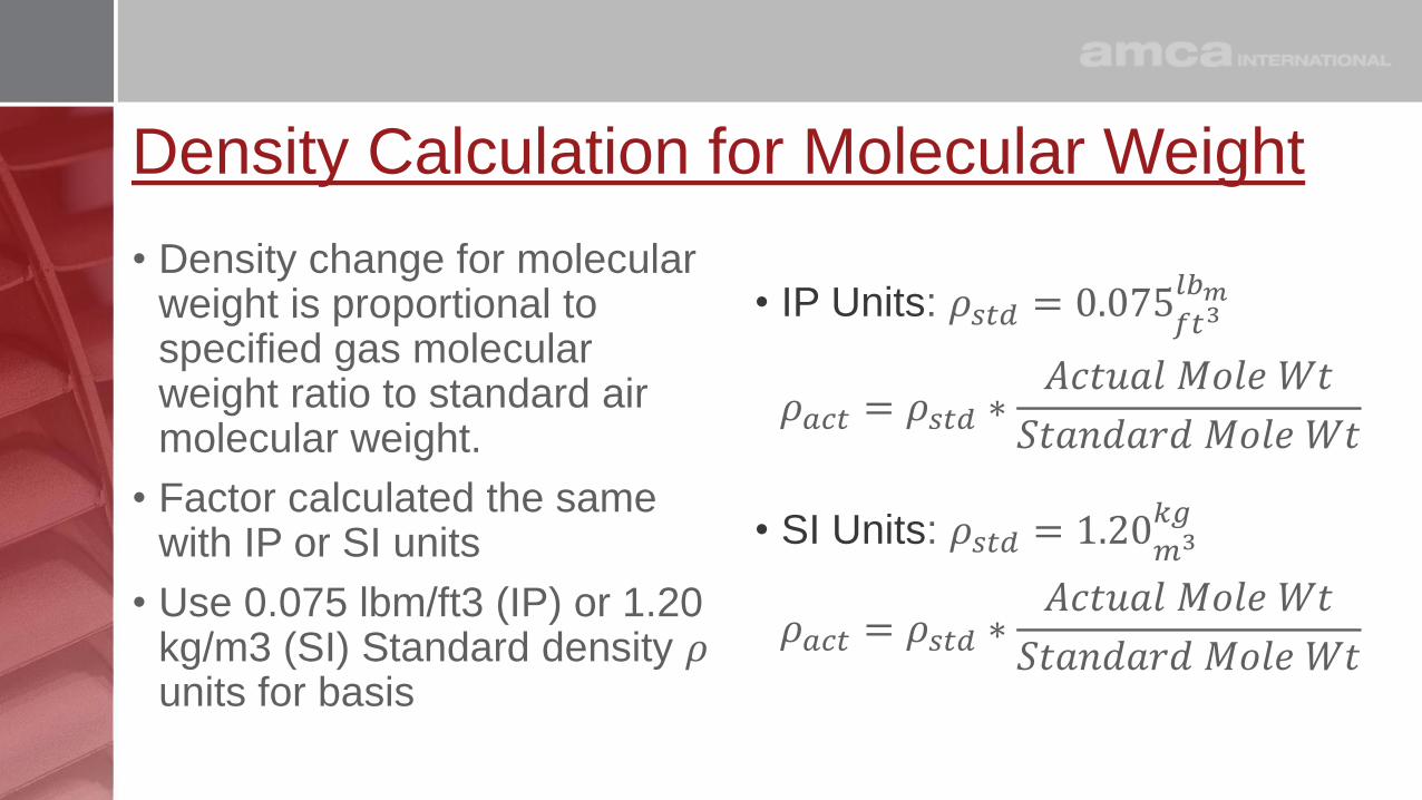
Density Calculation for Molecular Weight
• Density change for molecular weight is proportional to specified gas molecular weight ratio to standard air molecular weight.
• Factor calculated the same with IP or SI units
• Use 0.075 lbm/ft3 (IP) or 1.20 kg/m3 (SI) Standard density 𝜌units for basis
• IP Units: 𝜌𝑠𝑡𝑑 = 0.075𝑓𝑡3𝑙𝑏𝑚
𝜌𝑎𝑐𝑡 = 𝜌𝑠𝑡𝑑 ∗𝐴𝑐𝑡𝑢𝑎𝑙 𝑀𝑜𝑙𝑒 𝑊𝑡
𝑆𝑡𝑎𝑛𝑑𝑎𝑟𝑑 𝑀𝑜𝑙𝑒 𝑊𝑡
• SI Units: 𝜌𝑠𝑡𝑑 = 1.20𝑚3𝑘𝑔
𝜌𝑎𝑐𝑡 = 𝜌𝑠𝑡𝑑 ∗𝐴𝑐𝑡𝑢𝑎𝑙 𝑀𝑜𝑙𝑒 𝑊𝑡
𝑆𝑡𝑎𝑛𝑑𝑎𝑟𝑑 𝑀𝑜𝑙𝑒 𝑊𝑡

Density Calculation for Molecular Weight
𝜌𝑎𝑐𝑡 = 0.075𝑓𝑡3𝑙𝑏𝑚 ∗
29.54 𝑘𝑔/𝑚
28.965 𝑘𝑔/𝑚
𝜌𝑎𝑐𝑡 = 0.075𝑓𝑡3𝑙𝑏𝑚 ∗1.020
𝜌𝑎𝑐𝑡 = 0.0765𝑓𝑡3𝑙𝑏𝑚
𝜌𝑎𝑐𝑡 = 1.20𝑚3𝑘𝑔
∗29.54 𝑘𝑔/𝑚
28.965 𝑘𝑔/𝑚
𝜌𝑎𝑐𝑡 = 1.20𝑚3𝑘𝑔
∗1.020
𝜌𝑎𝑐𝑡 = 1.224𝑚3𝑘𝑔
• Calculate density for the actual Refinery gas stream at standard temperature and pressure
• Gas stream molecular weight calculated 29.54 kg/m

Air and Water Vapor Mixtures• Humidity (water vapor in the air)
is lighter than standard air.• Mole Weight Standard Air 28.965
• Mole Weight H2O 18.016
• Water vapor displaces some of the air in mixture and density is lower.
• Humidity calculations also use the barometric pressure.
• Psychrometrics, calculating the density of gas-vapor mixtures (humidity) is complex.

Air and Water Vapor Mixtures
• AMCA Calculation requires:• Local barometric pressure
• Dry bulb temperature
• Wet bulb temperature
• Often temperature and relative humidity are available
• When precise density is required with humidity it must be calculated in detail
• Density can be approximated for temperature and relative humidity…
Density Per Cubic Foot (Lb./Ft.3) of Air at Relative Humidity and 0 Feet Elevation
Temp. °FTemp.
(°C)
Relative Humidity %
0% 10% 20% 30% 40% 50% 60% 70% 80% 90% 100%
32 (0) 0.0808 0.0808 0.0808 0.0807 0.0807 0.0807 0.0807 0.0807 0.0806 0.0806 0.0806
36 (2) 0.0801 0.0801 0.0801 0.0801 0.0801 0.0800 0.0800 0.0800 0.0800 0.0799 0.0799
40 (4) 0.0795 0.0795 0.0795 0.0794 0.0794 0.0794 0.0794 0.0793 0.0793 0.0793 0.0793
60 (16) 0.0764 0.0764 0.0763 0.0763 0.0762 0.0762 0.0761 0.0761 0.0760 0.0760 0.0759
68 (20) 0.0753 0.0752 0.0752 0.0751 0.0750 0.0750 0.0749 0.0748 0.0748 0.0747 0.0746
70 (21) 0.0750 0.0749 0.0749 0.0748 0.0747 0.0746 0.0746 0.0745 0.0744 0.0744 0.0743
72 (22) 0.0747 0.0746 0.0746 0.0745 0.0744 0.0743 0.0743 0.0742 0.0741 0.0740 0.0740
76 (24) 0.0742 0.0741 0.0740 0.0739 0.0738 0.0737 0.0737 0.0736 0.0735 0.0734 0.0733
80 (27) 0.0736 0.0735 0.0734 0.0733 0.0732 0.0731 0.0730 0.0729 0.0728 0.0727 0.0727
84 (29) 0.0731 0.0730 0.0729 0.0727 0.0726 0.0725 0.0724 0.0723 0.0722 0.0721 0.0720
88 (31) 0.0725 0.0724 0.0723 0.0722 0.0720 0.0719 0.0718 0.0717 0.0716 0.0714 0.0713
92 (33) 0.0720 0.0719 0.0717 0.0716 0.0715 0.0713 0.0712 0.0710 0.0709 0.0708 0.0706
96 (36) 0.0715 0.0713 0.0712 0.0710 0.0709 0.0707 0.0706 0.0704 0.0703 0.0701 0.0699
100 (38) 0.0710 0.0708 0.0706 0.0705 0.0703 0.0701 0.0699 0.0698 0.0696 0.0694 0.0693
110 (43) 0.0697 0.0695 0.0693 0.0691 0.0688 0.0686 0.0684 0.0681 0.0679 0.0677 0.0675
120 (49) 0.0685 0.0682 0.0679 0.0676 0.0673 0.0670 0.0667 0.0665 0.0662 0.0659 0.0656
130 (54) 0.0674 0.0670 0.0666 0.0662 0.0658 0.0655 0.0651 0.0647 0.0643 0.0639 0.0635
140 (60) 0.0663 0.0658 0.0653 0.0648 0.0643 0.0638 0.0633 0.0628 0.0623 0.0618 0.0614
150 (66) 0.0652 0.0645 0.0639 0.0633 0.0627 0.0621 0.0614 0.0608 0.0602 0.0596 0.0590
160 (71) 0.0641 0.0633 0.0626 0.0618 0.0610 0.0602 0.0595 0.0587 0.0579 0.0571 0.0564
170 (77) 0.0631 0.0621 0.0612 0.0602 0.0592 0.0583 0.0573 0.0564 0.0554 0.0544 0.0535
180 (82) 0.0621 0.0609 0.0597 0.0586 0.0574 0.0562 0.0550 0.0538 0.0526 0.0514 0.0503
190 (88) 0.0612 0.0595 0.0579 0.0562 0.0546 0.0529 0.0513 0.0496 0.0480 0.0463 0.0447
200 (93) 0.0602 0.0585 0.0567 0.0550 0.0532 0.0515 0.0497 0.0480 0.0462 0.0444 0.0427
To convert values to kg/m3 multiply value by 16.0185

Density with Relative Humidity TableDensity Per Cubic Foot (Lb./Ft.3) of Air at Relative Humidity and 0 Feet Elevation
Temp. °F
Temp. (°C)
Relative Humidity %
0% 10% 20% 30% 40% 50% 60% 70% 80% 90% 100%
32 (0) 0.0808 0.0808 0.0808 0.0807 0.0807 0.0807 0.0807 0.0807 0.0806 0.0806 0.0806
36 (2) 0.0801 0.0801 0.0801 0.0801 0.0801 0.0800 0.0800 0.0800 0.0800 0.0799 0.0799
40 (4) 0.0795 0.0795 0.0795 0.0794 0.0794 0.0794 0.0794 0.0793 0.0793 0.0793 0.0793
60 (16) 0.0764 0.0764 0.0763 0.0763 0.0762 0.0762 0.0761 0.0761 0.0760 0.0760 0.0759
68 (20) 0.0753 0.0752 0.0752 0.0751 0.0750 0.0750 0.0749 0.0748 0.0748 0.0747 0.0746
70 (21) 0.0750 0.0749 0.0749 0.0748 0.0747 0.0746 0.0746 0.0745 0.0744 0.0744 0.0743
72 (22) 0.0747 0.0746 0.0746 0.0745 0.0744 0.0743 0.0743 0.0742 0.0741 0.0740 0.0740
76 (24) 0.0742 0.0741 0.0740 0.0739 0.0738 0.0737 0.0737 0.0736 0.0735 0.0734 0.0733
80 (27) 0.0736 0.0735 0.0734 0.0733 0.0732 0.0731 0.0730 0.0729 0.0728 0.0727 0.0727
84 (29) 0.0731 0.0730 0.0729 0.0727 0.0726 0.0725 0.0724 0.0723 0.0722 0.0721 0.0720
88 (31) 0.0725 0.0724 0.0723 0.0722 0.0720 0.0719 0.0718 0.0717 0.0716 0.0714 0.0713
92 (33) 0.0720 0.0719 0.0717 0.0716 0.0715 0.0713 0.0712 0.0710 0.0709 0.0708 0.0706
96 (36) 0.0715 0.0713 0.0712 0.0710 0.0709 0.0707 0.0706 0.0704 0.0703 0.0701 0.0699
100 (38) 0.0710 0.0708 0.0706 0.0705 0.0703 0.0701 0.0699 0.0698 0.0696 0.0694 0.0693
110 (43) 0.0697 0.0695 0.0693 0.0691 0.0688 0.0686 0.0684 0.0681 0.0679 0.0677 0.0675
120 (49) 0.0685 0.0682 0.0679 0.0676 0.0673 0.0670 0.0667 0.0665 0.0662 0.0659 0.0656
130 (54) 0.0674 0.0670 0.0666 0.0662 0.0658 0.0655 0.0651 0.0647 0.0643 0.0639 0.0635
140 (60) 0.0663 0.0658 0.0653 0.0648 0.0643 0.0638 0.0633 0.0628 0.0623 0.0618 0.0614
150 (66) 0.0652 0.0645 0.0639 0.0633 0.0627 0.0621 0.0614 0.0608 0.0602 0.0596 0.0590
160 (71) 0.0641 0.0633 0.0626 0.0618 0.0610 0.0602 0.0595 0.0587 0.0579 0.0571 0.0564
170 (77) 0.0631 0.0621 0.0612 0.0602 0.0592 0.0583 0.0573 0.0564 0.0554 0.0544 0.0535
180 (82) 0.0621 0.0609 0.0597 0.0586 0.0574 0.0562 0.0550 0.0538 0.0526 0.0514 0.0503
190 (88) 0.0612 0.0595 0.0579 0.0562 0.0546 0.0529 0.0513 0.0496 0.0480 0.0463 0.0447
200 (93) 0.0602 0.0585 0.0567 0.0550 0.0532 0.0515 0.0497 0.0480 0.0462 0.0444 0.0427
To convert values to kg/m3 multiply value by 16.0185
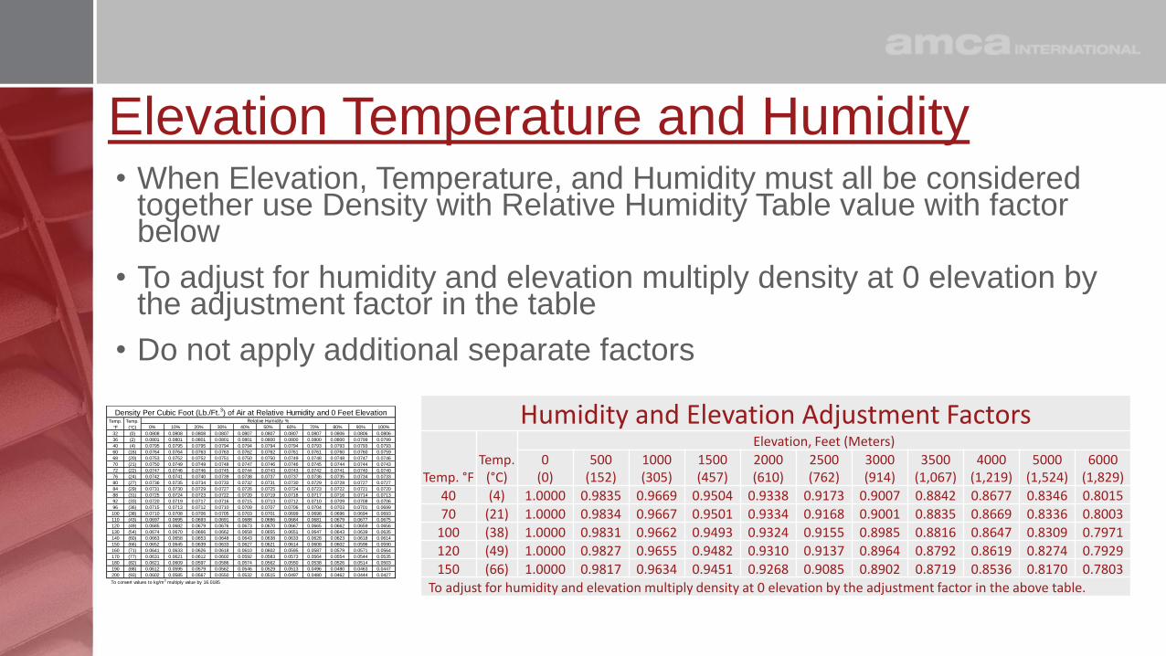
Elevation Temperature and Humidity • When Elevation, Temperature, and Humidity must all be considered
together use Density with Relative Humidity Table value with factor below
• To adjust for humidity and elevation multiply density at 0 elevation by the adjustment factor in the table
• Do not apply additional separate factors
Humidity and Elevation Adjustment Factors
Temp. °FTemp.
(°C)
Elevation, Feet (Meters)
0(0)
500(152)
1000(305)
1500(457)
2000(610)
2500(762)
3000(914)
3500(1,067)
4000(1,219)
5000(1,524)
6000(1,829)
40 (4) 1.0000 0.9835 0.9669 0.9504 0.9338 0.9173 0.9007 0.8842 0.8677 0.8346 0.8015
70 (21) 1.0000 0.9834 0.9667 0.9501 0.9334 0.9168 0.9001 0.8835 0.8669 0.8336 0.8003
100 (38) 1.0000 0.9831 0.9662 0.9493 0.9324 0.9155 0.8985 0.8816 0.8647 0.8309 0.7971
120 (49) 1.0000 0.9827 0.9655 0.9482 0.9310 0.9137 0.8964 0.8792 0.8619 0.8274 0.7929
150 (66) 1.0000 0.9817 0.9634 0.9451 0.9268 0.9085 0.8902 0.8719 0.8536 0.8170 0.7803
To adjust for humidity and elevation multiply density at 0 elevation by the adjustment factor in the above table.
0% 10% 20% 30% 40% 50% 60% 70% 80% 90% 100%
32 (0) 0.0808 0.0808 0.0808 0.0807 0.0807 0.0807 0.0807 0.0807 0.0806 0.0806 0.0806
36 (2) 0.0801 0.0801 0.0801 0.0801 0.0801 0.0800 0.0800 0.0800 0.0800 0.0799 0.0799
40 (4) 0.0795 0.0795 0.0795 0.0794 0.0794 0.0794 0.0794 0.0793 0.0793 0.0793 0.0793
60 (16) 0.0764 0.0764 0.0763 0.0763 0.0762 0.0762 0.0761 0.0761 0.0760 0.0760 0.0759
68 (20) 0.0753 0.0752 0.0752 0.0751 0.0750 0.0750 0.0749 0.0748 0.0748 0.0747 0.0746
70 (21) 0.0750 0.0749 0.0749 0.0748 0.0747 0.0746 0.0746 0.0745 0.0744 0.0744 0.0743
72 (22) 0.0747 0.0746 0.0746 0.0745 0.0744 0.0743 0.0743 0.0742 0.0741 0.0740 0.0740
76 (24) 0.0742 0.0741 0.0740 0.0739 0.0738 0.0737 0.0737 0.0736 0.0735 0.0734 0.0733
80 (27) 0.0736 0.0735 0.0734 0.0733 0.0732 0.0731 0.0730 0.0729 0.0728 0.0727 0.0727
84 (29) 0.0731 0.0730 0.0729 0.0727 0.0726 0.0725 0.0724 0.0723 0.0722 0.0721 0.0720
88 (31) 0.0725 0.0724 0.0723 0.0722 0.0720 0.0719 0.0718 0.0717 0.0716 0.0714 0.0713
92 (33) 0.0720 0.0719 0.0717 0.0716 0.0715 0.0713 0.0712 0.0710 0.0709 0.0708 0.0706
96 (36) 0.0715 0.0713 0.0712 0.0710 0.0709 0.0707 0.0706 0.0704 0.0703 0.0701 0.0699
100 (38) 0.0710 0.0708 0.0706 0.0705 0.0703 0.0701 0.0699 0.0698 0.0696 0.0694 0.0693
110 (43) 0.0697 0.0695 0.0693 0.0691 0.0688 0.0686 0.0684 0.0681 0.0679 0.0677 0.0675
120 (49) 0.0685 0.0682 0.0679 0.0676 0.0673 0.0670 0.0667 0.0665 0.0662 0.0659 0.0656
130 (54) 0.0674 0.0670 0.0666 0.0662 0.0658 0.0655 0.0651 0.0647 0.0643 0.0639 0.0635
140 (60) 0.0663 0.0658 0.0653 0.0648 0.0643 0.0638 0.0633 0.0628 0.0623 0.0618 0.0614
150 (66) 0.0652 0.0645 0.0639 0.0633 0.0627 0.0621 0.0614 0.0608 0.0602 0.0596 0.0590
160 (71) 0.0641 0.0633 0.0626 0.0618 0.0610 0.0602 0.0595 0.0587 0.0579 0.0571 0.0564
170 (77) 0.0631 0.0621 0.0612 0.0602 0.0592 0.0583 0.0573 0.0564 0.0554 0.0544 0.0535
180 (82) 0.0621 0.0609 0.0597 0.0586 0.0574 0.0562 0.0550 0.0538 0.0526 0.0514 0.0503
190 (88) 0.0612 0.0595 0.0579 0.0562 0.0546 0.0529 0.0513 0.0496 0.0480 0.0463 0.0447
200 (93) 0.0602 0.0585 0.0567 0.0550 0.0532 0.0515 0.0497 0.0480 0.0462 0.0444 0.0427
Density Per Cubic Foot (Lb./Ft.3) of Air at Relative Humidity and 0 Feet Elevation
To convert values to kg/m3 multiply value by 16.0185
Temp.
°F
Temp.
(°C)
Relative Humidity %

Humidity Above 200°F (93°C)
• Water Vapor above 200°F is steam and density should be calculated based on mixture molecular weight
• In boiler and steam process units there is typically little air compared to the water vapor
• Water, H2O, mole weight is 18.0 compared to standard air at 28.965
• Water vapor and steam are less dense than standard air
• Density of known water vapor air mixtures or all water vapor can be calculated
Gas Cst % Mole Weight MW % Cst Wt.
Air 10.00% 28.965 2.90 15.156%
H2O 90.00% 18.016 16.21 84.844%
100.00% 19.11 Mole Weight
𝜌𝑎𝑐𝑡 = 𝜌𝑠𝑡𝑑 ∗19.11 𝑘𝑔/𝑚
28.965 𝑘𝑔/𝑚
𝜌𝑎𝑐𝑡 = 𝜌𝑠𝑡𝑑𝐴𝑏𝑠𝑜𝑙𝑢𝑡𝑒 𝑡𝑒𝑚𝑝𝑠𝑡𝑑(𝑅 𝑜𝑟 𝐾)
𝐴𝑏𝑠𝑜𝑙𝑢𝑡𝑒 𝑡𝑒𝑚𝑝𝑎𝑐𝑡(𝑅 𝑜𝑟 𝐾)

Density Calculation Steam 200°F (93°C)
• Calculate density for 10% air 90% water vapor at 212°F and standard pressure
• The condensate side of a steam system pressure may be below atmospheric pressure due to condensation of the vapor
𝜌𝑎𝑐𝑡 = 𝜌𝑠𝑡𝑑 ∗𝐴𝑐𝑡𝑢𝑎𝑙 𝑀𝑜𝑙𝑒 𝑊𝑡
𝑆𝑡𝑎𝑛𝑑𝑎𝑟𝑑 𝑀𝑜𝑙𝑒 𝑊𝑡∗𝑎𝑏𝑠𝑜𝑙𝑢𝑡𝑒 𝑧𝑒𝑟𝑜𝑐𝑜𝑟𝑟𝑒𝑐𝑡𝑖𝑜𝑛(𝑅 𝑜𝑟 𝐾) + 𝑡𝑒𝑚𝑝𝑠𝑡𝑑(𝐹 𝑜𝑟 𝐶)
𝑎𝑏𝑠𝑜𝑙𝑢𝑡𝑒 𝑧𝑒𝑟𝑜𝑐𝑜𝑟𝑟𝑒𝑐𝑡𝑖𝑜𝑛(𝑅 𝑜𝑟 𝐾) + 𝑡𝑒𝑚𝑝𝑎𝑐𝑡(𝐹 𝑜𝑟 𝐶)
𝜌𝑎𝑐𝑡 = 0.075𝑓𝑡3𝑙𝑏𝑚 ∗
19.11𝑘𝑔/𝑚
28.965 𝑘𝑔/𝑚∗460𝑐𝑜𝑟𝑟𝑒𝑐𝑡𝑖𝑜𝑛(𝑅) + 70°𝐹
460𝑐𝑜𝑟𝑟𝑒𝑐𝑡𝑖𝑜𝑛(𝑅) + 212°𝐹
𝜌𝑎𝑐𝑡 = 0.075𝑓𝑡3𝑙𝑏𝑚 ∗
19.11𝑘𝑔/𝑚
28.965 𝑘𝑔/𝑚∗530°𝐹
672°𝐹= 0.075
𝑓𝑡3𝑙𝑏𝑚 ∗ 0.660 ∗0.789 = 0.075
𝑓𝑡3𝑙𝑏𝑚 ∗ 0.520 = 0.039
𝑓𝑡3𝑙𝑏𝑚

Combining Multiple Density Changes• Many systems will have
multiple factors effecting density
• Specifications often have density miscalculated. Check the density if possible
• Steam Gland Exhaust Blowers
• Gas Constituents (MW)• Suction on inlet• System Pressure• Elevation
• Previous calculations all multiplied to standard density
𝜌𝑠𝑡𝑑 = 0.075𝑓𝑡3𝑙𝑏𝑚= 1.20
𝑚3𝑘𝑔
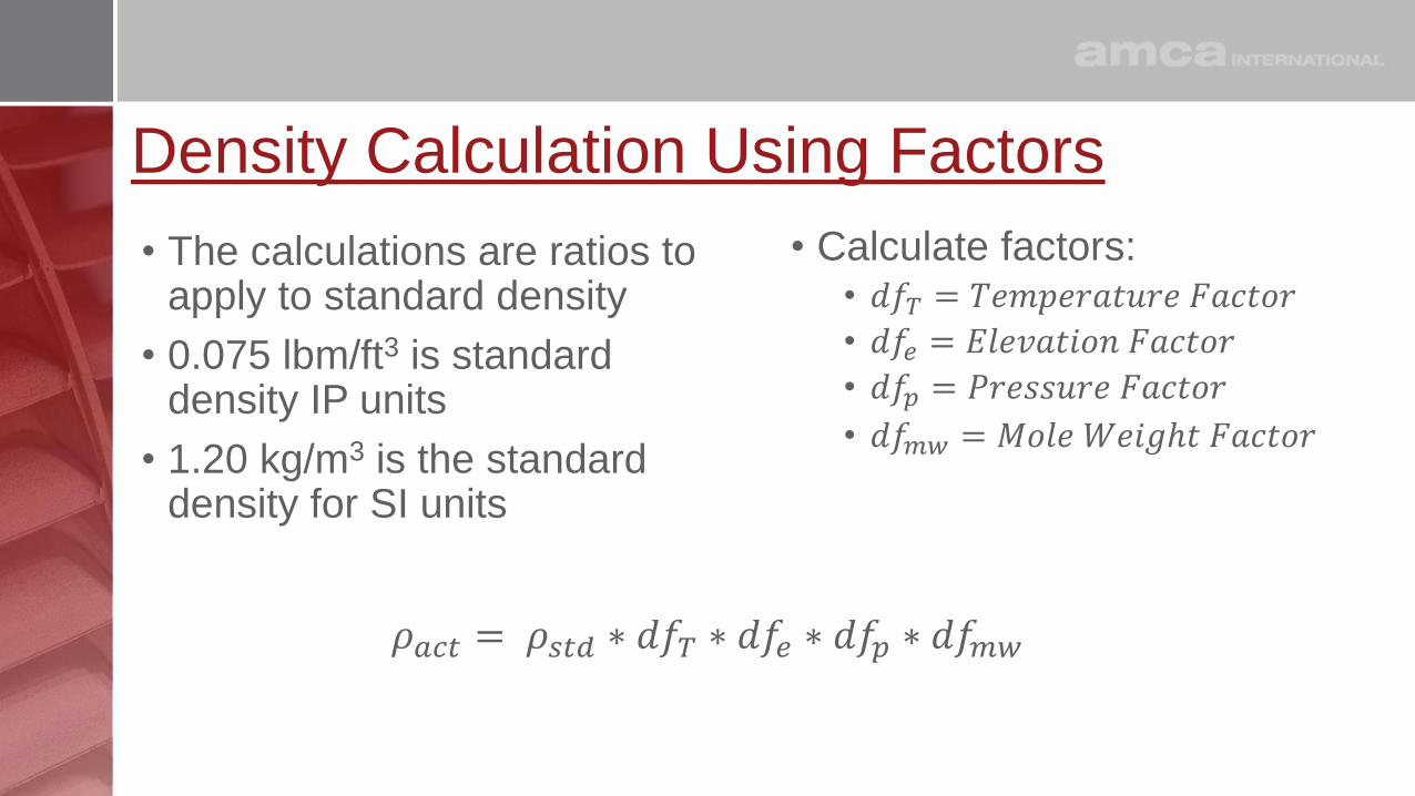
Density Calculation Using Factors
• The calculations are ratios to apply to standard density
• 0.075 lbm/ft3 is standard density IP units
• 1.20 kg/m3 is the standard density for SI units
• Calculate factors:• 𝑑𝑓𝑇 = 𝑇𝑒𝑚𝑝𝑒𝑟𝑎𝑡𝑢𝑟𝑒 𝐹𝑎𝑐𝑡𝑜𝑟
• 𝑑𝑓𝑒 = 𝐸𝑙𝑒𝑣𝑎𝑡𝑖𝑜𝑛 𝐹𝑎𝑐𝑡𝑜𝑟
• 𝑑𝑓𝑝 = 𝑃𝑟𝑒𝑠𝑠𝑢𝑟𝑒 𝐹𝑎𝑐𝑡𝑜𝑟
• 𝑑𝑓𝑚𝑤 = 𝑀𝑜𝑙𝑒 𝑊𝑒𝑖𝑔ℎ𝑡 𝐹𝑎𝑐𝑡𝑜𝑟
𝜌𝑎𝑐𝑡 = 𝜌𝑠𝑡𝑑 ∗ 𝑑𝑓𝑇 ∗ 𝑑𝑓𝑒 ∗ 𝑑𝑓𝑝 ∗ 𝑑𝑓𝑚𝑤

Calculating Density Factors
𝑑𝑓𝑇 = 𝑇𝑒𝑚𝑝𝑒𝑟𝑎𝑡𝑢𝑟𝑒 𝐹𝑎𝑐𝑡𝑜𝑟 =𝑎𝑏𝑠𝑜𝑙𝑢𝑡𝑒 𝑧𝑒𝑟𝑜𝑐𝑜𝑟𝑟𝑒𝑐𝑡𝑖𝑜𝑛(𝑅 𝑜𝑟 𝐾) + 𝑡𝑒𝑚𝑝𝑠𝑡𝑑(𝐹 𝑜𝑟 𝐶)
𝑎𝑏𝑠𝑜𝑙𝑢𝑡𝑒 𝑧𝑒𝑟𝑜𝑐𝑜𝑟𝑟𝑒𝑐𝑡𝑖𝑜𝑛(𝑅 𝑜𝑟 𝐾) + 𝑡𝑒𝑚𝑝𝑎𝑐𝑡(𝐹 𝑜𝑟 𝐶)
𝑑𝑓𝑒 = 𝐸𝑙𝑒𝑣𝑎𝑡𝑖𝑜𝑛 𝐹𝑎𝑐𝑡𝑜𝑟 (𝐼𝑃) = (1 − ((6.8754 ∗ 10−6) ∗ 𝑓𝑒𝑒𝑡))5.2561
𝑑𝑓𝑒 = 𝐸𝑙𝑒𝑣𝑎𝑡𝑖𝑜𝑛 𝐹𝑎𝑐𝑡𝑜𝑟 (𝑆𝐼) = (1 − ((22.08 ∗ 10−6) ∗ 𝑓𝑒𝑒𝑡))5.2561
𝑑𝑓𝑝 = 𝑃𝑟𝑒𝑠𝑠𝑢𝑟𝑒 𝐹𝑎𝑐𝑡𝑜𝑟 =𝑆𝑦𝑠𝑡𝑒𝑚 𝑃𝑟𝑒𝑠𝑠𝑢𝑟𝑒 + 𝐿𝑜𝑐𝑎𝑙 𝑃𝑟𝑒𝑠𝑠𝑢𝑟𝑒
𝑆𝑡𝑎𝑛𝑑𝑎𝑟𝑑 𝐴𝑡𝑚𝑜𝑠𝑝ℎ𝑒𝑟𝑖𝑐 𝑃𝑟𝑒𝑠𝑠𝑢𝑟𝑒
𝑑𝑓𝑚𝑤 = 𝑀𝑜𝑙𝑒 𝑊𝑒𝑖𝑔ℎ𝑡 𝐹𝑎𝑐𝑡𝑜𝑟 =𝐴𝑐𝑡𝑢𝑎𝑙 𝑀𝑜𝑙𝑒 𝑊𝑡
𝑆𝑡𝑎𝑛𝑑𝑎𝑟𝑑 𝑀𝑜𝑙𝑒 𝑊𝑡
𝜌𝑎𝑐𝑡 = 𝜌𝑠𝑡𝑑 ∗ 𝑑𝑓𝑇 ∗ 𝑑𝑓𝑒 ∗ 𝑑𝑓𝑝 ∗ 𝑑𝑓𝑚𝑤

Standard Tables for Density Factors
• Tables for density factors for temperature and elevation combined provide quick factor for use with standard air
• Values can be used with IP or SI units
𝜌𝑎𝑐𝑡 = 𝜌𝑠𝑡𝑑 ∗ 𝑑𝑓𝑇 ∗ 𝑑𝑓𝑒
𝜌𝑠𝑡𝑑 = 0.075𝑓𝑡3𝑙𝑏𝑚= 1.20
𝑚3𝑘𝑔
• Table does not include humidity
0
(0)
300
(91)
600
(183)
1,000
(305)
1,500
(457)
2,000
(610)
2,500
(762)
3,000
(914)
4,000
(1,219)
6,000
(1,829)
-40 (-40) 1.26 1.25 1.24 1.22 1.20 1.18 1.15 1.13 1.09 1.020 (-18) 1.15 1.14 1.13 1.11 1.09 1.07 1.05 1.04 1.00 0.9316 (-9) 1.11 1.10 1.09 1.07 1.06 1.04 1.02 1.00 0.96 0.9032 (0) 1.08 1.07 1.05 1.04 1.02 1.00 0.99 0.97 0.93 0.8750 (10) 1.04 1.03 1.02 1.00 0.99 0.97 0.95 0.93 0.90 0.8470 (21) 1.00 0.99 0.98 0.97 0.95 0.93 0.91 0.90 0.87 0.8186 (30) 0.97 0.96 0.95 0.94 0.92 0.90 0.89 0.87 0.84 0.78100 (38) 0.95 0.94 0.93 0.91 0.90 0.88 0.87 0.85 0.82 0.76125 (52) 0.91 0.90 0.89 0.87 0.86 0.84 0.83 0.81 0.78 0.73150 (66) 0.87 0.86 0.85 0.84 0.82 0.81 0.79 0.78 0.75 0.70212 (100) 0.79 0.78 0.77 0.76 0.75 0.73 0.72 0.71 0.68 0.64300 (149) 0.70 0.69 0.68 0.67 0.66 0.65 0.64 0.63 0.60 0.56400 (204) 0.62 0.61 0.60 0.59 0.58 0.57 0.56 0.55 0.53 0.50500 (260) 0.55 0.55 0.54 0.53 0.52 0.51 0.50 0.50 0.48 0.44600 (316) 0.50 0.49 0.49 0.48 0.47 0.47 0.46 0.45 0.43 0.40700 (371) 0.46 0.45 0.45 0.44 0.43 0.43 0.42 0.41 0.40 0.37800 (427) 0.42 0.42 0.41 0.41 0.40 0.39 0.38 0.38 0.36 0.34900 (482) 0.39 0.39 0.38 0.38 0.37 0.36 0.36 0.35 0.34 0.311,000 (538) 0.36 0.36 0.36 0.35 0.34 0.34 0.33 0.33 0.31 0.29
Temperature and Elevation Density Factors (dft & dfe)Elevation, Feet (Meters)
Temp.
°F
Temp.
(°C)
Adapted from ASHRAE Handbook—2009 Fundamentals
0.075 lbm/ft3 (1.2 kg/m3) standard air density at 68°F (20°C), 50% relative humidity, and 29.92 in. Hg (101.325 kPa).

Density Impact Through The Fan And System• What happens as density
changes:• Mass changes through system
• Resistance through system changes proportionally to mass change
• Volume through the system remains constant
• Mass through fan changes• Performance of fan changes
proportionally to mass change in two ways:
• Volume through fan remains constant
• Pressure developed by the fan• Power consumed by the fan
• Pressure is constant in most systems.
0
5
10
15
20
25
30
0 2,500 5,000 7,500 10,000 12,500 15,000 17,500 20,000
0
25
50
75
100
125
150
V.4.0AC
Pr
es
su
re
Po
we
r
Airflow

ACFM and SCFM
• ACFM – Actual Cubic Feet Per Minute (m3/hr)
• SCFM – Standard Cubic Feet Per Minute (nm3/hr)
𝐴𝐶𝐹𝑀 ≠ 𝑆𝐶𝐹𝑀• Conversion of SCFM is based on temperature elevation, and pressure
factors• Some SCFM temperature conversions are based on 60°F or 0°C
• Divide SCFM by Density factors for temperature, elevation, and pressure
𝐹𝑙𝑜𝑤𝐴𝑐𝑡 =𝐹𝑙𝑜𝑤𝑆𝑡𝑑 𝐵𝑎𝑠𝑖𝑠
𝑑𝑓𝑇 ∗ 𝑑𝑓𝑒 ∗ 𝑑𝑓𝑝
≠

SCFM Conversion System Effects• When converting SCFM to
ACFM The System resistance must be:
• Corrected to resistance at actual density
• Calculated for new flow value of Actual Volume
• Confirmed with the specifier
• The resistance of the system will vary directly with the density
• The resistance will vary as the square of the change in volume
• Combine changes to develop actual system point
𝑃𝑟𝑒𝑠𝑠𝐴𝑐𝑡 = 𝑃𝑟𝑒𝑠𝑠𝑆𝑡𝑑 𝐵𝑎𝑠𝑖𝑠 ∗𝐷𝑒𝑛𝑠𝑖𝑡𝑦𝐴𝑐𝑡𝐷𝑒𝑛𝑠𝑖𝑡𝑦𝑆𝑡𝑑
∗𝐹𝑙𝑜𝑤𝐴𝑐𝑡
𝐹𝑙𝑜𝑤𝑆𝑡𝑑 𝐵𝑎𝑠𝑖𝑠
2

Resources• AMCA International: www.amca.org
• AMCA Publications: www.amca.org/store (available for purchase)
> 201-02 (R2011) – Fans and Systems
• ANSI/AMCA Standards: www.amca.org/store (available for purchase)
> 210-16 / ASHRAE 51-16: Laboratory Methods of Testing Fans for Certified Aerodynamic Performance Rating
> 803-02 (R2008): Industrial Process/Power Generation Fans: Site Performance Test Standard
• American Conference of Governmental Industrial Hygienists: www.acgih.org
> Industrial ventilation: A manual of recommended practice for design (30th ed.; 2019)

AMCA SPEAKERS NETWORK
• Related presentations available on:• Fans, fan testing, field testing, and fan efficiency
• AMCA certification and Fan Energy Index
• System effect and field work
• Ventilation-system design and commissioning
• Fan, blower, and system troubleshooting
• Many more topics available!
To request an on-location or online presentation by Bill or any other AMCA Speakers Network presenter for your organization, go to amca.org/educate and click on “Outreach Activities.”

Thank you for your time!
To receive PDH credit for today’s program, you must complete the online evaluation, which will be sent via email following this webinar.
If you viewed the webinar as a group and only one person registered for the webinar link, please email Lisa Cherney ([email protected]) for a group sign-in sheet today. Completed sheets must be returned to Lisa by tomorrow, July 15.
PDH credits and participation certificates will be issued electronically within 30 days, once all attendance records are checked and online evaluations are received.
Attendees will receive an email at the address provided on your registration, listing the credit hours awarded and a link to a printable certificate of completion.

Questions?

THANK YOU TO OUR SPONSORS!

NEXT PROGRAM
Join us for our next AMCA insite Pop-Up Webinar:
- Wednesday, July 29
- 2:00-3:00pm CDT
- TOPIC: 2019 California Building Code (Life Safety Damper Requirements)
- Presenter: Daniel Benton, Regional Sales Manager, AMCA Member Company
>> For additional webinar dates go to: www.amca.org/webinar