Bull Electrical-jun03.qxd - Elektron.si
59
-
Upload
khangminh22 -
Category
Documents
-
view
3 -
download
0
Transcript of Bull Electrical-jun03.qxd - Elektron.si


Copyright 2003, Wimborne Publishing Ltd (408 Wimborne Road East, Ferndown, Dorset, BH22 9ND, UK)
and TechBites Interactive Inc.,
(PO Box 857, Madison, Alabama 35758, USA)
All rights reserved.
WARNING! The materials and works contained within EPE Online — which are made available by Wimborne Publishing Ltd and Maxfield & Montrose Interactive Inc — are copyrighted. You are permitted to make a backup copy of the downloaded file and one (1) hard copy of such materials and works for your personal use. International copyright laws, however, prohibit any further copying or reproduction of such materials and works, or any republication of any kind. Maxfield & Montrose Interactive Inc and Wimborne Publishing Ltd have used their best efforts in preparing these materials and works. However, Maxfield & Montrose Interactive Inc and Wimborne Publishing Ltd make no warranties of any kind, expressed or implied, with regard to the documentation or data contained herein, and specifically disclaim, without limitation, any implied warranties of merchantability and fitness for a particular purpose. Because of possible variances in the quality and condition of materials and workmanship used by readers, EPE Online, its publishers and agents disclaim any responsibility for the safe and proper functioning of reader-constructed projects based on or from information published in these materials and works. In no event shall Maxfield & Montrose Interactive Inc or Wimborne Publishing Ltd be responsible or liable for any loss of profit or any other commercial damages, including but not limited to special, incidental, consequential, or any other damages in connection with or arising out of furnishing, performance, or use of these materials and works.

CoIour CCTV camera, 8mm lens, 12V d.c. 200mA 582x628Resolution 380 lines Automatic aperture lens Mirror function PALBack Light Compensation MLR, 100x40x40mm. Ref EE2 £69
Built-in Audio .15lux CCD camera 12V d.c. 200mA 480 liness/n ratio >48db 1v P-P output 110x60x50mm. Ref EE1 £99
Metal CCTV camera housings for internal or external use. Madefrom aluminium and plastic they are suitable for mounting bodycameras in. Available in two sizes 1 – 100x10x170mm and 2 –100x70x280mm. Ref EE6 £22 EE7 £26 multi-position brackets.Ref EE8 £8
Excellent quality multi-purposeTV/TFT screen, works as just aLCD colour monitor with any of our CCTV cameras or as aconventional TV. Ideal for use in boats and caravans 49.7MHz-91.75MHz VHF channels 1-5,168.25MHz-222.75MHz VHFchannels 6-12, 471.25MHz-869.75MHz, Cable channels112.325MHz-166.75MHz Z1-Z7, Cable channels 224.25MHz-446.75MHz Z8-Z35 5” colour screen. Audio output 150mW.Connections, external aerial, earphone jack, audio/video input,12V d.c. or mains, Accessories supplied Power supply, Remotecontrol, Cigar lead power supply, Headphone Stand/bracket. 5”model £139 Ref EE9, 6” model £149. Ref EE10
Fully cased lR light source suitable for CCTV applications. The unitmeasures 10x10x150mm, is mains operated and contains 54 infra-red LEDs. Designed to mount on a standard CCTV camera bracket.The unit also contains a daylight sensor that will only activate theinfra red lamp when the light level drops below a preset level. Theinfrared lamp is suitable for indoor or exterior use, typical useagewould be to provide additional IR illumination for CCTV cameras.£49. Ref EE11
This device is mains operated and designed to be used with astandard CCTV camera causing it to scan. The black clips can bemoved to adjust the span angle, the motor reversing when itdetects a clip. With the clips removed the scanner will rotateconstantly at approx 2.3rpm. 75x75x80mm £23. Ref EE12
Colour CCTV Camera measures 60x45mm and has a built in lightlevel detector and 12 IR LEDs .2 lux 12 IR LEDs 12V d.c. BracketEasy connect leads £69. Ref EE15
A high quality external colour CCTV camera with built in Infra-redLEDs measuring 60x60x60mm Easy connect leads colourWaterproof PAL 1/4’ CCD 542x588 pixels 420 lines .05 lux 3.6mmF2 78 deg lens 12V d.c. 400mA Built in light level sensor. £99. RefEE13
A small compact colour CCTV camera measuring just35x28x30mm (camera body) Camera is supplied complete withmounting bracket, built in lR, microphone and easy connect leads.Built in audio Built in IR LEDs Colour 380 line resolution PAL 0.2us +18db sensitivity. Effective pixels 628x582 Power source 6-12Vd.c. Power consumption 200mW £36. Ref EE16
Complete wireless CCTV sytem with video. Kit comprises pinholecolour camera with simple battery connection and a receiver withvideo output. 380 lines colour 2.4GHz 3 lux 6-12V d.c. manualtuning Available in two versions, pinhole and standard. £79(pinhole) Ref EE17, £79 (standard). Ref EE18
Small transmitter designed to transmit audio and video signals on2.4GHz. Unit measures 45x35x10mm.ldeal for assembly intocovert CCTV systems Easy connect leads Audio and video input12V d.c. Complete with aerial Selectable channel switch £30. RefEE19
2.4GHz wireless receiver Fully cased audio and video 2.4GHzwireless receiver 190x140x30mm, metal case, 4 channel, 12V d.c.Adjustable time delay, 4s, 8s, 12s, 16s. £45. Ref EE20
Colour pinhole cctv camera module with audio Compact colourpinhole camera measuring just 20x20x20mm, built-in audio andeasy connect leads PAL CMOS sensor 6-9V d.c. Effective Pixels628x582 Illumination 2 lux Definition >240 Signal/noise ratio>40db Power consumption 200mW £35. Ref £35
Self-cocking pistol plcr002 crossbow with metal body. Self-cockingfor precise string alignment Aluminium alloy construction High tecfibre glass limbs Automatic safety catch Supplied with three boltsTrack style for greater accuracy. Adjustable rearsight 50lbdrawweight 150ft sec velocity Break action 17” string 30m range£21.65 Ref PLCR002 INFRA-RED FILM 6” square piece offlexible infra-red film that will only allow IR light through. Perfect forconverting ordinary torches, lights, headlights etc to infra-redoutput only using standard light bulbs Easily cut to shape. 6”square £15. Ref IRF2 or a 12” sq for £29 IRF2A NEW 12V 12”SQUARE SOLAR PANEL Kevlar backed, 3watt output. Copperstrips for easy solder connections £14.99. Ref 15P42 PACK OF 4JUST £39.95. REF 15P42SP
Dummy CCTV cameras These motorised cameras will work either on2 AA batteries or with a standard DC adapter (not supplied) They havea built in movement detector that will activate the camera if movementis detected causing the camera to ‘pan’ Good deterrent. Camerameasures 20cm high, supplied with rawl plugs and fixing screws.Camera also has a flashing red LED built in. £9.95. Ref CAMERAB
POWERSAFE DEEP CYCLE BATTERIES
6V 100AH NOW ONLY £19 EACH
12V 51AH NOW ONLY £29.95 EACH
We also have some used 2.3AH 12V (same as above) these aretested and in good condition and available at an extremely goodprice for bulk buyers, box of 30 just £49.99. Ref SLB23C
Aiptek Pocket DV Up to 2000 still pics before requiring downloadl!The all new Pocket DV, it’s amazing . . . such advanced technology,such a tiny size – you will be the envy of your friends!! This camerawill take up to 3.5 minutes of Video and Audio, up to 2000 digitalstill pictures or 30 minutes of voice recording! Then just connect itto your PC via the USB cable (Supplied) and after transferring thedata you can start all over again!! £69. Ref POCKETDV
The smallest PMR446 radios currently available(54x87x37mm).These tiny handheld PMR radios not only lookgreat, but they are user friendly & packed with features includingVOX, Scan & Dual Watch. Priced at £59.99 PER PAlR they areexcellent value for money. Our new favourite PMR radios! Standby:– 35 hours Includes: – 2 x Radios, 2 x Belt Clips & 2 x Carry Strap£59.95 Ref ALAN1 Or supplied with 2 sets of rechargeablebatteries and two mains chargers £84.99. Ref Alan2
Beltronics BEL55O Euroradarand GATSO detector ClaimedDetection Range: GATSO up 400m. Radar & Laser guns up to 3miles. Detects GATSO speed cameras at least 200 metres away,plenty of time to adjust your speed £319. Ref BEL550
Fully Portable – Use anywhere Six automatic programmer for fullbody pain relief, shoulder pain, back/neck pain, aching joints,rheumatic pain, sports injuries EFFECTIVE DRUG FREE PAINRELIEF TENS (Transcutaneous Electrical Nerve Stimulation) unitsare widely used in hospitals, clinics throughout the UnitedKingdom for effective drug free pain relief. This compact unit isnow approved for home use. TENS works by stimulating nervesclose to the skin releasing endorphins (natures anesthetics) andhelping to block the pain signals sent to the brain. Relief can beginwithin minutes, and a 30 minute treatment can give up 12 hoursrelief or more. TheTENS mini Microprocessors offer six types ofautomatic programme for shoulder pain, back/neck pain, achingjoints, Rheumatic pain, migraines headaches, sports injuries,period pain. ln fact all over body treatment. Will not interfere withexisting medication. Not suitable for anyone with a heartpacemaker. Batteries supplied. £19.95 Ref TEN327 Spare pack ofelectrodes £5.99. Ref TEN327X
SHOP ONLINE
AT
WWW.BULLNET.CO.UK
BULL GROUP LTDUNIT D, HENFIELD BUSINESS PARK,
HENFIELD, SUSSEX BN5 9SLTERMS: CASH, PO OR CHEQUE WITH ORDER
PLUS £5.50 P&P (UK) PLUS VAT.24 HOUR SERVICE £7.50 (UK) PLUS VAT.
OVERSEAS ORDERS AT COST PLUS £3.50
(ACCESS/VISA/SWITCH ACCEPTED)
’phone: 01273 491490 Fax 491813

ISSN 0262 3617PROJECTS . . . THEORY . . . NEWS . . .COMMENTS . . . POPULAR FEATURES . . .
VOL. 32. No. 6 JUNE 2003Cover illustration by jgr22
Everyday Practical Electronics, June 2003 377
© Wimborne Publishing Ltd 2003. Copyright in alldrawings, photographs and articles published inEVERYDAY PRACTICAL ELECTRONICS is fullyprotected, and reproduction or imitations in whole orin part are expressly forbidden.
Our July 2003 issue will be published on Thursday,12 June 2003. See page 379 for details Readers Services Editorial and Advertisement Departments 387
www.epemag.wimborne.co.ukEPE Online: www.epemag.com
PPrroojjeeccttss aanndd CCiirrccuuiittssFIDO PEDOMETER by Mike Boyden 388Keeping track of how far you’ve walked!PRACTICAL RADIO CIRCUITS – Part 1. Introduction, 398 Simple Receivers and Headphone Amp by Raymond HaighDispelling the mysteries of radio. A new series featuring a variety ofpractical circuits for the set builder and experimenterBACK TO BASICS – Part 5. Mini Theremin; Twilight Switch 410by Bart Trepak. Concluding our illustration of how transistors cancreate useful designsINGENUITY UNLIMITED 423Car Alarm Battery SaverPICRONOS L.E.D. WALL CLOCK by John Becker 424Ancient and modern techniques display timely brilliance on a grand scale!
SSeerriieess aanndd FFeeaattuurreessTECHNO TALK by Andy Emmerson 395Powerline comms – boon or bogey?CIRCUIT SURGERY by Alan Winstanley and Ian Bell 406More about reading circuit diagramsNEW TECHNOLOGY UPDATE by Ian Poole 414Adding silicon to Li-Ion battery electrodes improves chargelevel performanceINTERFACE by Robert Penfold 418MSCOMM voltage levels, and batch countingNET WORK – THE INTERNET PAGE surfed by Alan Winstanley 433Crediting PayPal
RReegguullaarrss aanndd SSeerrvviicceessEDITORIAL 387SHOPTALK with David Barrington 392The essential guide to component buying for EPE projectsPLEASE TAKE NOTE PIC Toolkit TK3 V1.42 introduced 392NEWS – Barry Fox highlights technology’s leading edge 396Plus everyday news from the world of electronicsBACK ISSUES Did you miss these? Many now on CD-ROM! 415CD-ROMS FOR ELECTRONICS 420A wide range of CD-ROMs for hobbyists, students and engineersREADOUT John Becker addresses general points arising 431PRINTED CIRCUIT BOARD AND SOFTWARE SERVICE 434PCBs for EPE projects. Plus EPE project softwareDIRECT BOOK SERVICE 436A wide range of technical books available by mail order, plus more CD-ROMsADVERTISERS INDEX 440
FREE SUPPLEMENT EPE PIC TUTORIAL V2 – Part 3 between pages 408 and 409Concluding the enhanced revision of our highly acclaimed series of 1998, plusa brief look at some advanced concepts and two other PIC families

NO ONE DOES IT BETTERDON'T MISS AN
ISSUE – PLACE YOURORDER NOW!
Demand is bound to be high
JULY 2003 ISSUE ON SALE THURSDAY, JUNE 12
Everyday Practical Electronics, June 2003 379
NEXT MONTHEPE MINI METALDETECTORBeat frequency oscillator (b.f.o.) metal detectors werevery popular in the ’60s and ’70s, soon after the adventof the first commercial transistors. Some models soldthousands of times over. But these quickly went out offashion as superior induction balance (i.b.) and pulseinduction (p.i.) designs appeared on the market.However, b.f.o. metal detectors still have significantadvantages in the areas of cost and ease ofconstruction, and may be better suited to certainapplications, such as pipe-finding or probing. Also, theyare particularly well suited to miniaturisation. It is thislast feature, especially, which is exploited in this design– a miniature b.f.o. metal detector which may be wornon the wrist – and, for good measure, a pinpointer,which is used to pinpoint items found with a largerdetector.While the performance of the EPE Mini is nothing to write home about, it is sufficiently sensitive to be of genuineuse. It will easily detect an old Victorian penny at 55mm, and a tiny 15mm diameter coin at 35mm. It willdiscriminate between ferrous and non-ferrous metals (e.g. iron and copper), thus giving a good indication as towhether a “noble” metal has been found, or just a rusty piece of iron.The EPE Mini has many potential uses. It may be used for detecting treasure (we hope!) during idle moments inthe school grounds or on the beach. It may be used as a pipe-finder or cable locator. It may also be optimised todetect very small items, such as small nails and screws in furniture.Besides this, the EPE Mini may well be the first metal detector to be worn on the wrist. Despite its diminutive sizeit is easy to build, with just eight standard size components mounted on its miniature printed circuit board.
PRACTICAL RADIOCIRCUITSPart 2 of our new radio circuits series looks at regenerationor “Q” multiplication. A simple “Q” multiplier project isdescribed which can be added to the MK484 TRF Receiverfeatured in Part 1 to improve its performance. This isfollowed by a design for a classic two transistor mediumwave reflex receiver together with full constructionaldetails.In order to provide these projects with loudspeaker outputan easy-to-build speaker amplifier is also fully described,this circuit uses just five components, including thespeaker, to give up to 1W r.m.s. output.Plus three more practical circuits.
LOW RANGE OHMMETERADAPTOR MK2Taking measurements of low resistance components andprinted circuit board tracks below 10 is a commonrequirement in electronics. However, most multimeters arenot able to measure low resistances accurately as theirresolution is inadequate.This article presents an adaptor that can be connected tomost multimeters to enable low resistance readings to betaken. The operation of the adaptor is based on the circuitpublished in EPE September 1995, but provides improvedtemperature stability.The exact accuracy of the design (i.e. lower limit) dependssimply on the quality of the meter used with the adaptor. Anormal digital meter should be able to register valuesdown to about 0·01.

PO Box 6935, BISHOPS STORTFORD, Herts. CM23 4WP
ADD £2.00 P&P to all orders (or 1st Class Recorded £4, Next day(Insured £250) £7, Europe £5.00, Rest of World £10.00). We accept allmajor credit cards. Make cheques/PO's payable to Quasar Electronics.Prices include 17.5% VAT. MAIL ORDER ONLYFREE CATALOGUE with order or send 2 x 1st class stamps (refundable) for details of over 150 kits & publications.
FACTORPUBLICATIONS
ANIMAL SOUNDS Cat, dog, chicken & cow. Idealfor kids farmyard toys & schools. SG10M £5.95 3 1/2 DIGIT LED PANEL METER Use for basicvoltage/current displays or customise to measuretemperature, light, weight, movement, sound lev-els, etc. with appropriate sensors (not supplied).Various input circuit designs provided. 3061KT£13.95 IR REMOTE TOGGLE SWITCH Use any TV/VCRremote control unit to switch onboard 12V/1A relayon/off. 3058KT £10.95SPEED CONTROLLER for any common DC motor upto 100V/5A. Pulse width modulation gives maximumtorque at all speeds. 5-15VDC. Box provided. 3067KT£12.95 3 x 8 CHANNEL IR RELAY BOARD Control eight 12V/1Arelays by Infra Red (IR) remote control over a 20m range insunlight. 6 relays turn on only, the other 2 toggle on/off. 3 oper-ation ranges determined by jumpers. Transmitter case & allcomponents provided. Receiver PCB 76x89mm. 3072KT£52.95
PC CONTROLLED RELAY BOARDConvert any 286 upward PC into a dedicated auto-matic controller to independently turn on/off up toeight lights, motors & other devices around thehome, office, laboratory or factory. Each relay outputis capable of switching 250VAC/4A. A suite of DOSand Windows control programs are provided to-gether with all components (except box and PCcable). 12VDC. PCB 70x200mm. 3074KT £31.95 2 CHANNEL UHF RELAY SWITCH Contains thesame transmitter/receiver pair as 30A15 below plusthe components and PCB to control two240VAC/10A relays (also supplied). Ultra brightLEDs used to indicate relay status. 3082KT £27.95TRANSMITTER RECEIVER PAIR 2-button keyfobstyle 300-375MHz Tx with 30m range. Receiverencoder module with matched decoder IC.Components must be built into a circuit like kit 3082above. 30A15 £14.95 PIC 16C71 FOUR SERVO MOTOR DRIVERSimultaneously control up to 4 servo motors. Software &all components (except servos/control pots) supplied.5VDC. PCB 50x70mm. 3102KT £15.95 UNIPOLAR STEPPER MOTOR DRIVER for any5/6/8 lead motor. Fast/slow & single step rates.Direction control & on/off switch. Wave, 2-phase &half-wave step modes. 4 LED indicators. PCB50x65mm. 3109KT £14.95 PC CONTROLLED STEPPER MOTOR DRIVERControl two unipolar stepper motors (3A max. each)via PC printer port. Wave, 2-phase & half-wave stepmodes. Software accepts 4 digital inputs from exter-nal switches & will single step motors. PCB fits in D-shell case provided. 3113KT £17.95 12-BIT PC DATA ACQUISITION/CONTROL UNITSimilar to kit 3093 above but uses a 12 bit Analogue-to-Digital Converter (ADC) with internal analoguemultiplexor. Reads 8 single ended channels or 4 dif-ferential inputs or a mixture of both. Analogue inputsread 0-4V. Four TTL/CMOS compatible digitalinput/outputs. ADC conversion time <10uS. Software(C, QB & Win), extended D shell case & all compo-nents (except sensors & cable) provided. 3118KT£52.95 LIQUID LEVEL SENSOR/RAIN ALARM Will indi-cate fluid levels or simply the presence of fluid. Relayoutput to control a pump to add/remove water when itreaches a certain level. 1080KT £5.95 AM RADIO KIT 1 Tuned Radio Frequency front-end, single chip AM radio IC & 2 stages of audioamplification. All components inc. speaker provid-ed. PCB 32x102mm. 3063KT £10.95 DRILL SPEED CONTROLLER Adjust the speedof your electric drill according to the job at hand.Suitable for 240V AC mains powered drills up to
700W power. PCB: 48mm x 65mm. Box provided.6074KT £17.95 3 INPUT MONO MIXER Independent level con-trol for each input and separate bass/treble controls.Input sensitivity: 240mV. 18V DC. PCB: 60mm x185mm 1052KT £16.95 NEGATIVE\POSITIVE ION GENERATORStandard Cockcroft-Walton multiplier circuit. Mainsvoltage experience required. 3057KT £10.95 LED DICE Classic intro to electronics & circuitanalysis. 7 LED’s simulate dice roll, slow down & landon a number at random. 555 IC circuit. 3003KT £9.95 STAIRWAY TO HEAVEN Tests hand-eye co-ordi-nation. Press switch when green segment of LEDlights to climb the stairway - miss & start again!Good intro to several basic circuits. 3005KT £9.95 ROULETTE LED ‘Ball’ spins round the wheel,slows down & drops into a slot. 10 LED’s. Good introto CMOS decade counters & Op-Amps. 3006KT£10.95 12V XENON TUBE FLASHER TRANSFORMERsteps up a12V supply to flash a 25mm Xenon tube.Adjustable flash rate. 3163KT £13.95 LED FLASHER 1 5 ultra bright red LED’s flash in7 selectable patterns. 3037MKT £5.95 LED FLASHER 2 Similar to above but flash insequence or randomly. Ideal for model railways.3052MKT £5.95 INTRODUCTION TO PIC PROGRAMMING.Learn programming from scratch. Programminghardware, a P16F84 chip and a two-part, practical,hands-on tutorial series are provided. 3081KT£21.95 SERIAL PIC PROGRAMMER for all 8/18/28/40pin DIP serial programmed PICs. Shareware soft-ware supplied limited to programming 256 bytes(registration costs £14.95). 3096KT £10.95 ATMEL 89Cx051 PROGRAMMER Simple-to-use yet powerful programmer for the Atmel89C1051, 89C2051 & 89C4051 uC’s. Programmerdoes NOT require special software other than aterminal emulator program (built into Windows).Can be used with ANY computer/operating sys-tem. 3121KT £24.95 3V/1·5V TO 9V BATTERY CONVERTER Replaceexpensive 9V batteries with economic 1.5V batter-ies. IC based circuit steps up 1 or 2 ‘AA’ batteries togive 9V/18mA. 3035KT £5.95 STABILISED POWER SUPPLY 3-30V/2.5AIdeal for hobbyist & professional laboratory. Veryreliable & versatile design at an extremely reason-able price. Short circuit protection. Variable DCvoltages (3-30V). Rated output 2.5 Amps. Largeheatsink supplied. You just supply a 24VAC/3Atransformer. PCB 55x112mm. Mains operation.1007KT £16.95.
STABILISED POWER SUPPLY 2-30V/5A As kit1007 above but rated at 5Amp. Requires a24VAC/5A transformer. 1096KT £27.95. MOTORBIKE ALARM Uses a reliable vibrationsensor (adjustable sensitivity) to detect movementof the bike to trigger the alarm & switch the outputrelay to which a siren, bikes horn, indicators orother warning device can be attached. Auto-reset.6-12VDC. PCB 57x64mm. 1011KT £11.95 Box2011BX £7.00 CAR ALARM SYSTEM Protect your car fromtheft. Features vibration sensor, courtesy/boot lightvoltage drop sensor and bonnet/boot earth switchsensor. Entry/exit delays, auto-reset and adjustablealarm duration. 6-12V DC. PCB: 47mm x 55mm1019KT £11.95 Box 2019BX £8.00 PIEZO SCREAMER 110dB of ear piercing noise.Fits in box with 2 x 35mm piezo elements built intotheir own resonant cavity. Use as an alarm siren orjust for fun! 6-9VDC. 3015KT £10.95 COMBINATION LOCK Versatile electronic lockcomprising main circuit & separate keypad forremote opening of lock. Relay supplied. 3029KT£10.95 ULTRASONIC MOVEMENT DETECTOR Crystallocked detector frequency for stability & reliability. PCB75x40mm houses all components. 4-7m range.Adjustable sensitivity. Output will drive externalrelay/circuits. 9VDC. 3049KT £13.95 PIR DETECTOR MODULE 3-lead assembledunit just 25x35mm as used in commercial burglaralarm systems. 3076KT £8.95 INFRARED SECURITY BEAM When the invisibleIR beam is broken a relay is tripped that can be usedto sound a bell or alarm. 25 metre range. Mainsrated relays provided. 12VDC operation. 3130KT£12.95 SQUARE WAVE OSCILLATOR Generatessquare waves at 6 preset frequencies in factors of 10from 1Hz-100KHz. Visual output indicator. 5-18VDC.Box provided. 3111KT £8.95 PC DRIVEN POCKET SAMPLER/DATA LOG-GER Analogue voltage sampler records voltagesup to 2V or 20V over periods from milli-seconds tomonths. Can also be used as a simple digitalscope to examine audio & other signals up toabout 5KHz. Software & D-shell case provided.3112KT £18.95 20 MHz FUNCTION GENERATOR Square, tri-angular and sine waveform up to 20MHz over 3ranges using ‘coarse’ and ‘fine’ frequency adjust-ment controls. Adjustable output from 0-2V p-p. ATTL output is also provided for connection to afrequency meter. Uses MAX038 IC. Plastic casewith printed front/rear panels & all componentsprovided. 7-12VAC. 3101KT £69.95
X
SSUURRVVEEIILLLLAANNCCEEHigh performance surveillance bugs. Room transmitters supplied with sensitive electret microphone & battery holder/clip. All transmit-ters can be received on an ordinary VHF/FM radio between 88-108MHz. Available in Kit Form (KT) or Assembled & Tested (AS).
RROOOOMM SSUURRVVEEIILLLLAANNCCEE MTX - MINIATURE 3V TRANSMITTER Easy to build & guar-anteed to transmit 300m @ 3V. Long battery life. 3-5V operation.Only 45x18mm. B 3007KT £6.95 AS3007 £11.95MRTX - MINIATURE 9V TRANSMITTER Our best selling bug.Super sensitive, high power - 500m range @ 9V (over 1km with18V supply and better aerial). 45x19mm. 3018KT £7.95 AS3018£12.95HPTX - HIGH POWER TRANSMITTER High performance, 2stage transmitter givesgreater stability & higher qual-ity reception. 1000m range 6-12V DC operation. Size70x15mm. 3032KT £9.95AS3032 £18.95 MMTX - MICRO-MINIATURE 9V TRANSMITTER The ultimatebug for its size, performance and price. Just 15x25mm. 500mrange @ 9V. Good stability. 6-18V operation. 3051KT £8.95AS3051 £14.95 VTX - VOICE ACTIVATED TRANSMITTER Operates onlywhen sounds detected. Low standby current. Variable trigger sen-sitivity. 500m range. Peaking circuit supplied for maximum RF out-put. On/off switch. 6V operation. Only 63x38mm. 3028KT £12.95AS3028 £24.95HARD-WIRED BUG/TWO STATION INTERCOM Each stationhas its own amplifier, speaker and mic. Can be set up as either ahard-wired bug or two-station intercom. 10m x 2-core cable sup-plied. 9V operation. 3021KT £15.95 (kit form only) TRVS - TAPE RECORDER VOX SWITCH Used to automati-cally operate a tape recorder (not supplied) via its REMOTE sock-et when sounds are detected. All conversations recorded.Adjustable sensitivity & turn-off delay. 115x19mm. 3013KT £9.95AS3013 £21.95
TTEELLEEPPHHOONNEE SSUURRVVEEIILLLLAANNCCEE MTTX - MINIATURE TELEPHONE TRANSMITTER Attachesanywhere to phone line. Transmits only when phone is used!Tune-in your radio and hear both parties. 300m range. Uses lineas aerial & power source. 20x45mm. 3016KT £8.95 AS3016£14.95 TRI - TELEPHONE RECORDING INTERFACE Automaticallyrecord all conversations. Connects between phone line & taperecorder (not supplied). Operates recorders with 1.5-12V batterysystems. Powered from line. 50x33mm. 3033KT £9.95 AS3033£18.95 TPA - TELEPHONE PICK-UP AMPLIFIER/WIRELESSPHONE BUG Place pick-up coil on the phone line or near phoneearpiece and hear both sides of the conversation. 3055KT £11.95AS3055 £20.95
HHIIGGHH PPOOWWEERR TTRRAANNSSMMIITTTTEERRSS 1 WATT FM TRANSMITTER Easy to construct. Delivers acrisp, clear signal. Two-stage circuit. Kit includes microphone andrequires a simple open dipole aerial. 8-30VDC. PCB 42x45mm.1009KT £12.95 4 WATT FM TRANSMITTER Comprises three RFstages and an audio preamplifier stage. Piezoelectricmicrophone supplied or you can use a separate preampli-fier circuit. Antenna can be an open dipole or GroundPlane. Ideal project for those who wish to get started in thefascinating world of FM broadcasting and want a goodbasic circuit to experiment with. 12-18VDC. PCB44x146mm. 1028KT. £22.95 AS1028 £34.95 15 WATT FM TRANSMITTER (PRE-ASSEMBLED &TESTED) Four transistor based stages with Philips BLY88 in final stage. 15 Watts RF power on the air. 88-108MHz. Accepts open dipole, Ground Plane, 5/8, J, orYAGI antennas. 12-18VDC. PCB 70x220mm. SWS meterneeded for alignment. 1021KT £99.95 SIMILAR TO ABOVE BUT 25W Output. 1031KT £109.95
3300--iinn--OONNEEEElleeccttrroonniicc PPrroojjeeccttss LLaabbBBAARRGGAAIINN
BBUUYY!!!!Great introduction to electronics. Ideal for the budding electron-ics expert! Build a radio, burglar alarm, water detector, morsecode practice circuit, simple computer circuits, and much more!NO soldering, tools or previous electronics knowledge required.Circuits can be built and unassembled repeatedly.Comprehensive 68-page manual with explanations, schematicsand assembly diagrams. Suitable for age 10+. Excellent forschools. Requires 2 x AA batteries.Order Code EPL030 ONLY £14.95 (phone for bulk discounts).130, 300 and 500-in-ONE also available.
PPRROOJJEECCTT KKIITTSSOur electronic kits are supplied complete with all components, high quality PCBs
(NOT cheap Tripad strip board!) and detailed assembly/operating instructions
2 x 25W CAR BOOSTER AMPLIFIER Connects tothe output of an existing car stereo cassette player,CD player or radio. Heatsinks provided. PCB76x75mm. 1046KT. £24.95 3-CHANNEL WIRELESS LIGHT MODULATORNo electrical connection with amplifier. Light modu-lation achieved via a sensitive electret microphone.Separate sensitivity control per channel. Powerhanding 400W/channel. PCB 54x112mm. Mainspowered. Box provided. 6014KT £24.95 12 RUNNING LIGHT EFFECT Exciting 12 LEDlight effect ideal for parties, discos, shop-windows &eye-catching signs. PCB design allows replacementof LEDs with 220V bulbs by inserting 3 TRIACs.Adjustable rotation speed & direction. PCB54x112mm. 1026KT £15.95; BOX (for mains opera-tion) 2026BX £9.00 DISCO STROBE LIGHT Probably the most excit-ing of all light effects. Very bright strobe tube.Adjustable strobe frequency: 1-60Hz. Mains powered.PCB: 60x68mm. Box provided. 6037KT £28.95
SOUND EFFECTS GENERATOR Easy to build.Create an almost infinite variety of interesting/unusu-al sound effects from birds chirping to sirens. 9VDC.PCB 54x85mm. 1045KT £8.95 ROBOT VOICE EFFECT Make your voicesound similar to a robot or Darlek. Great fun fordiscos, school plays, theatre productions, radiostations & playing jokes on your friends whenanswering the phone! PCB 42x71mm. 1131KT£8.95 AUDIO TO LIGHT MODULATOR Controls intensi-ty of one or more lights in response to an audio input.Safe, modern opto-coupler design. Mains voltageexperience required. 3012KT £8.95 MUSIC BOX Activated by light. Plays 8 Christmassongs and 5 other tunes. 3104KT £7.95 20 SECOND VOICE RECORDER Uses non-volatile memory - no battery backup needed.Record/replay messages over & over. Playback asrequired to greet customers etc. Volume control &built-in mic. 6VDC. PCB 50x73mm.3131KT £12.95 TRAIN SOUNDS 4 selectable sounds : whistleblowing, level crossing bell, ‘clickety-clack’ & 4 insequence. SG01M £6.95
Full details of all X-FACTOR PUBLICATIONS can be found inour catalogue. N.B. Minimum order charge for reports and plansis £5.00 PLUS normal P.&P.
SUPER-EAR LISTENING DEVICE Complete plans tobuild your own parabolic dish microphone. Listen to distantvoices and sounds through open windows and even walls!Made from readily available parts. R002 £3.50 LOCKS - How they work and how to pick them. This factfilled report will teach you more about locks and the art oflock picking than many books we have seen at 4 times theprice. Packed with information and illustrations. R008 £3.50 RADIO & TV JOKER PLANSWe show you how to build three different circuits for disrupt-ing TV picture and sound plus FM radio! May upset yourneighbours & the authorities!! DISCRETION REQUIRED.R017 £3.50 INFINITY TRANSMITTER PLANS Complete plans forbuilding the famous Infinity Transmitter. Once installed on thetarget phone, device acts like a room bug. Just call the targetphone & activate the unit to hear all room sounds. Great forhome/office security! R019 £3.50 THE ETHER BOX CALL INTERCEPTOR PLANS Grabstelephone calls out of thin air! No need to wire-in a phonebug. Simply place this device near the phone lines to hear theconversations taking place! R025 £3.00 CASH CREATOR BUSINESS REPORTS Need ideas formaking some cash? Well this could be just what you need!You get 40 reports (approx. 800 pages) on floppy disk thatgive you information on setting up different businesses. Youalso get valuable reproduction and duplication rights so thatyou can sell the manuals as you like. R030 £7.50
!"#$%$&'()&*+,)%!)*-(-$,' ((%$'(%."#$%$&'()&*+,)%!)*-
()#&(+',+(&/(&,+0$),',,(%#''1,,%,+02 3(%)&,,*+% **%
1,3*)#-(+$,*+ *4 $&(3* +'*$/%
PPRROODDUUCCTT FFEEAATTUURREECOMPUTER TEMPERATURE DATA LOGGERPC serial port controlled 4-channel temperaturemeter (either deg C or F). Requires no externalpower. Allows continuous temperature data logging ofup to four temperature sensors located 200m+ frommotherboard/PC. Ideal use for old 386/486 comput-ers. Users can tailor input data stream to suit theirpurpose (dump it to a spreadsheet or write your ownBASIC programs using the INPUT command to grabthe readings). PCB just 38mm x 38mm. Sensors con-nect via four 3-pin headers. 4 header cables suppliedbut only one DS18S20 sensor.Kit software available free from our website.ORDERING: 3145KT £23.95 (kit form);AS3145 £29.95 (assembled);Additional DS18S20 sensors £4.95 each
ww
w.Q
uasarEle
ctronic
s.com
Credit C
ard S
ale
s:
08
71
7
17
7
16
8
380 Everyday Practical Electronics, June 2003

ww
w.Q
uasarEle
ctronic
s.com
Credit C
ard S
ale
s:
08
71
7
17
7
16
8
ABC Mini ‘Hotchip’ BoardCurrently learning aboutmicrocontrollers? Need to dosomething more than flash a LEDor sound a buzzer? The ABC Mini‘Hotchip’Board is based on Atmel’sAVR 8535 RISC technology andwill interest both the beginner andexpert alike. Beginners will find thatthey can write and test a simpleprogram, using the BASICprogramming language, within anhour or two of connecting it up.
Experts will like the power and flexibility of the ATMEL microcontroller,as well as the ease with which the little Hot Chip board can be“designed-in” to a project.The ABC Mini Board ‘Starter Pack’ includesjust about everything you need to get up and experimenting rightaway. On the hardware side, there’s a pre-assembled micro controllerPC board with both parallel and serial cables for connection to yourPC.Windows software included on CD-ROM features an Assembler,BASIC compiler and in-system programmer The pre-assembledboards only are also available separately.
Enhanced ‘PICALL’ ISP PIC ProgrammerKit will program virtually ALL 8 to 40 pin*serial and parallel programmed PIC micro-controllers. Connects to PC parallel port.Supplied with fully functional pre-registered PICALL DOS and WINDOWSAVR software packages, all componentsand high quality DSPTH board. Alsoprograms certain ATMEL AVR, SCENIXSX and EEPOM 24C devices. New devices can be added to thesoftware as they are released.Blank chip auto detect feature for super-fast bulk programming. Hardware now supports ISP programming.*A 40 pin wide ZIF socket is required to program 0·3in. devices (OrderCode AZIF40 @ £15.00).
Order Ref Description inc. VAT ea3144KT Enhanced ‘PICALL’ ISP PIC Programmer £59.95AS3144 Assembled Enhanced ‘PICALL’ ISP
PIC Programmer £64.95AS3144ZIF Assembled Enhanced ‘PICALL’ ISP PIC
Programmer c/w ZIF socket £79.95
Order Ref Description inc. VAT ea3122KT ATMEL AVR Programmer £24.95AS3122 Assembled 3122 £34.95
ATMEL AVR ProgrammerPowerful programmer for AtmelAT90Sxxxx (AVR) micro controller fam-ily. All fuse and lock bits are program-mable. Connects to serial port. Can beused with ANY computer and operat-ing system. Two LEDs to indicate pro-gramming status. Supports 20-pin DIPAT90S1200 & AT90S2313 and 40-pin
DIP AT90S4414 & AT90S8515 devices. NO special softwarerequired – uses any terminal emulator program (built intoWindows). The programmer is supported by BASCOM-AVR BasicCompiler software (see website for details).
Order Ref Description inc. VATe3108KT Serial Port Isolated I/O Controller Kit £54.95
AS3108 Assembled Serial Port Isolated I/O Controller £64.95
Order Ref Description inc. VAT eaABCMINISP ABC MINI Starter Pack £64.95ABCMINIB ABC MINI Board Only £39.95
Advanced 32-bit Schematic Captureand Simulation Visual Design Studio
Serial Port Isolated I/O ControllerKit provides eight relay outputscapable of switching 4 amps at mainsvoltages and four optically isolateddigital inputs. Can be used in a varietyof control and sensing applicationsincluding load switching, externalswitch input sensing, contact closureand external voltage sensing.Programmed via a computer serial port, it is compatible with ANYcomputer & operating system. After programming, PC can bedisconnected. Serial cable can be up to 35m long, allowing‘remote’ control. User can easily write batch file programs tocontrol the kit using simple text commands. NO special softwarerequired – uses any terminal emulator program (built intoWindows). All components provided including a plastic case withpre-punched and silk screened front/rear panels to give aprofessional and attractive finish (see photo).
Atmel 89Cx051 and 89xxx programmers also available.
PC Data Acquisition & Control UnitWith this kit you can use a PCparallel port as a real worldinterface. Unit can be connected to amixture of analogue and digitalinputs from pressure, temperature,movement, sound, light intensity,weight sensors, etc. (not supplied) tosensing switch and relay states. Itcan then process the input data anduse the information to control up to 11 physical devices such asmotors, sirens, other relays, servo motors & two-stepper motors.FEATURES: 8 Digital Outputs: Open collector, 500mA, 33V max. 16 Digital Inputs: 20V max. Protection 1K in series, 5·1V Zener to
ground. 11 Analogue Inputs: 0-5V, 10 bit (5mV/step.) 1 Analogue Output: 0-2·5V or 0-10V. 8 bit (20mV/step.)All components provided including a plastic case (140mm x 110mm x35mm) with pre-punched and silk screened front/rear panels to give aprofessional and attractive finish (see photo) with screen printed front& rear panels supplied. Software utilities & programming examplessupplied.
Order Ref Description inc. VAT eae3093KT PC Data Acquisition & Control Unit £99.95
AS3093 Assembled 3093 £124.95
See opposite page for orderinginformation on these kits
Everyday Practical Electronics, June 2003 381

H.P. 8460A Signal Generator, AM/FM, 500kHz-512MHz£250KENWOOD CS4025 Oscilloscope, dual trace, 20MHz. £125LEADER LBO523 Oscilloscope, dual trace, 35MHz £140GOULD OS300 Oscilloscope, dual trace, 20MHz . . . £95NATIONAL PANASONIC VP7705A Distortion Analyser. . . . . . . . . . . . . . . . . . . . . . . . . . . . . . . . . . . . . . . £125
KENWOOD VT176 Millivoltmeter 2-channel . . . . . . . £50KENWOOD FL140 Wow & Flutter Meter. . . . . . . . . . £50KENWOOD FL180A Wow & Flutter Meter . . . . Used £75. . . . . . . . . . . . . . . . . . . . . . . . . . . . . . . . . Unused £125BIRD 43 Watt Meter . . . . . . . . . . . . . . . . . . . . . . . . . £75Elements for the above. . . . . . . . . . . . . . . . . . . . . . . £25
MARCONI 893C AF Power Meter, Sinad Measurement . . . . . . . . . . . . . . . . . . . . . . .Unused £100, Used £60
MARCONI 893B, No Sinad . . . . . . . . . . . . . . . . . . .£30MARCONI 2610 True RMS Voltmeter, Autoranging,5Hz-25MHz . . . . . . . . . . . . . . . . . . . . . . . . . . . . . .£195GOULD J3B Sine/Sq Osc., 10Hz-100kHz,low distortion . . . . . . . . . . . . . . . . . . . . . . . . . .£75-£125AVO 8 Mk. 6 in Every Ready case, with leads etc. . .£80Other AVOs from . . . . . . . . . . . . . . . . . . . . . . . . . . .£50GOODWILL GVT427 Dual Ch AC Millivoltmeter,10mV-300V in 12 ranges, Freq. 10Hz-1MHz . .£100-£125SOLARTRON 7150 DMM 6½-digitTru RMS-IEEE . . . . . . . . . . . . . . . . . . . . . . . . .£95-£150SOLARTRON 7150 Plus . . . . . . . . . . . . . . . . . . . .£200
HIGH QUALITY RACAL COUNTERS9904 Universal Timer Counter, 50MHz . . . . . . .£509916 Counter, 10Hz-520MHz . . . . . . . . . . . . . .£759918 Counter, 10Hz-560MHz, 9-digit . . . . . . . .£50WAYNE KERR B424 Component Bridge . . . .£125RACAL/AIM 9343M LCR Databridge.Digital Automeasurement of R, C, L, Q, D . . .£200HUNTRON TRACKER Model 1000 . . . . . . . .£125FLUKE 8050A 4·5 Digit. 2A. True RMS . . . . . .£75FLUKE 8010A 3·5 Digit. 10A . . . . . . . . . . . . . .£50FLUKE 8012A 3·5 Digit. 2A . . . . . . . . . . . . . . .£40
Portable Appliance TesterMegger Pat 2 ONLY
H.P. 6012B DC PSU 0-60V, 0-50A, 1000W .£1000FARNELL AP60/50 1KW Autoranging . . . . .£1000FARNELL H60/50 0·60V 0-50A . . . . . . . . . . .£750FARNELL H60/25 0-60V, 0·25A . . . . . . . . . . .£400Power Supply HPS3010, 0-30V, 0-10A . . . . .£140FARNELL Dual PSU XA35-2T, 0-35V, 0-2A, TwiceOMD l.c.d. Display . . . . . . . . . . . . . . . . . . . . .£180FARNELL L30-2 0-30V, 0-2A . . . . . . . . . . . . .£80FARNELL L30-1 0-30V, 0-1A . . . . . . . . . . . . .£60Many other Power Supplies available
OSCILLOSCOPESTEKTRONIX TDS350 dual trace, 200MHz, 1G/S . .Unused £1500TEKTRONIX TDS320 dual trace, 100MHz, 500M/S . . . . . .£1200TEKTRONIX TDS310 dual trace, 50MHz, 200M/S . . . . . . . .£950LECROY 9400A dual trace, 175MHz, 5G/S . . . . . . . . . . . . .£750HITACHI VC6523, d/trace, 20MHz, 20M/S, delay etc.Unused £500PHILIPS PM3092 2+2-ch., 200MHz, delay etc., £800 as new £950PHILIPS PM3082 2+2-ch., 100MHz, delay etc., £700 as new £800TEKTRONIX TAS465 dual trace, 100MHz, delay etc. . . . . . .£750TEKTRONIX 2465B 4-ch., 400MHz, delay cursors etc . . . .£1500TEKTRONIX 2465 4-ch., 300MHz, delay cursors etc. . . . . . .£900TEKTRONIX 468 Dig. Storage, dual trace, 100MHz, delay . . .£450TEKTRONIX 466 Analogue Storage, dual trace, 100MHz . . . .£250TEKTRONIX 485 dual trace, 350MHz, delay sweep . . . . . . .£550TEKTRONIX 475 dual trace, 200MHz, delay sweep . . . . . . .£350TEKTRONIX 465B dual trace, 100MHz, delay sweep . . . . . .£325TEKTRONIX 2215 dual trace, 60MHz, delay sweep . . . . . . .£250PHILIPS PM3065 2+1-ch., 100MHz, dual TB/delay autoset .£375PHILIPS PM3055 2+1-ch., 60MHz, dual TB/delay autoset . .£275PHILIPS PM3217 dual trace, 50MHz delay . . . . . . . . .£200-£250GOULD OS1100 dual trace, 30MHz delay . . . . . . . . . . . . . .£125HAMEG HM303.6 dual trace, 35MHz component tester
as new . . . . . . . . . . . . . . . . . . . . . . . . . . . . . . . . . . . . . . .£240HAMEG HM303 dual trace, 30MHz component tester . . . . . . .£200Many other Oscilloscopes available
MARCONI 2022E Synth AM/FM Sig Gen10kHz-1·01GHz l.c.d. display etc . . . . . . . . . . . . . . .£525-£750
H.P. 8657A Synth sig gen, 100kHz-1040MHz . . . . . . . . . . .£2000H.P. 8656B Synth sig gen, 100kHz-990MHz . . . . . . . . . . . .£1350H.P. 8656A Synth sig gen, 100kHz-990MHz . . . . . . . . . . . . .£995R&S APN62 Synth, 1Hz-260kHz sig. gen.,balanced/unbalanced output, l.c.d. display . . . . . . . . . . . . . . .£425PHILIPS PM5328 sig gen, 100kHz-180MHz with
200MHz, freq. counter, IEEE . . . . . . . . . . . . . . . . . . . . . . .£550RACAL 9081 Synth AM/FM sig g en, 5MHz-520MHz . . . . . .£250H.P. 3325A Synth function gen, 21MHz . . . . . . . . . . . . . . . . .£600MARCONI 6500 Amplitude Analyser . . . . . . . . . . . . . . . . . .£1500H.P. 4192A Impedance Analyser . . . . . . . . . . . . . . . . . . . . .£5000H.P. 4275A LCR Meter, 10kHz-10MHz . . . . . . . . . . . . . . . .£2750H.P. 8903A Distortion Analyser . . . . . . . . . . . . . . . . . . . . . .£1000WAYNE KERR 3245 Inductance Analyser . . . . . . . . . . . . .£2000H.P. 8112A Pulse Generator, 50MHz . . . . . . . . . . . . . . . . . .£1250MARCONI 2440 Frequency Counter, 20GHz . . . . . . . . . . . .£1000H.P. 5350B Frequency Counter, 20GHz . . . . . . . . . . . . . . . .£2000H.P. 5342A 10Hz-18GHz Frequency Counter . . . . . . . . . . . .£800H.P. 1650B Logic Analyser, 80-channel . . . . . . . . . . . . . . . .£1000MARCONI 2035 Mod Meter, 500kHz-2GHz . . . . . . . . . . . . . £750
H.P. 6063B DC Electronic Load, 3-240V/0-10A, 250W . . . . . POAH.P. 66312A PSU, 0-20V/0-2A . . . . . . . . . . . . . . . . . . . . . . . £400H.P. 66311B PSU, 0-15V/0-3A . . . . . . . . . . . . . . . . . . . . . . . £400H.P. 66309D PSU Dual, 0-15, 0-3A/0-12, 0-1·5A. . . . . . . . . . £750H.P. 6632B PSU, 0-20V/0-5A . . . . . . . . . . . . . . . . . . . . . . . . £500H.P. 6623A PSU, triple output ranging from 0-7V 0-5A to
0-20V 0-4A. . . . . . . . . . . . . . . . . . . . . . . . . . . . . . . . . . . . . £850H.P./AGILENT 34401A DMM 6½ digit . . . . . . . . . . . . . £400/£450H.P. 3478A DMM 5½ digit. . . . . . . . . . . . . . . . . . . . . . . . . . . £275FLUKE 45 DMM dual display . . . . . . . . . . . . . . . . . . . . . . . . £400KEITHLEY 2010 DMM 7½ digit . . . . . . . . . . . . . . . . . . . . . . £950KEITHLEY 617 Programmable Electrometer. . . . . . . . . . . . £1250H.P. 4338B Milliohmmeter. . . . . . . . . . . . . . . . . . . . . . . . . . £1500RACAL Counter type 1999 2·6GHz. . . . . . . . . . . . . . . . . . . £500H.P. Counter type 53131A 3GHz. . . . . . . . . . . . . . . . . . . . . £850H.P./AGILENT 33120A Func. Gen/ARB, 100Hz-15MH. . . . . . . . . . . . . . . . . . . . . . . . . . . . . . . . . . . . . . . . . £900/£1000
SONY/TEKTRONIX AFG320 Arbitary Func. Gen . . . . . . . . £1250H.P. 8904A Syn. Function Gen, DC-600kHz . . . . . . . £1000/£1250BLACK STAR JUPITOR 2010 Func. Gen, 0·2Hz-2MHz with
frequency counter . . . . . . . . . . . . . . . . . . . . . . . . . . . . . . . £140H.P. 8116A Pulse Generator, 1mH-50MHz . . . . . . . . . . . . . £1950H.P. 8657B Syn Sig. Gen, 0·1-2080MHz . . . . . . . . . . . . . . . £2500CO-AXIAL SWITCH, 1·5GHz . . . . . . . . . . . . . . . . . . . . . . . . . £40IEEE CABLES . . . . . . . . . . . . . . . . . . . . . . . . . . . . . . . . . . . . £10
H.P. 8561B 50Hz-6·5GHz . . . . . . . . . . . . . . . . . . . . . . . . . .£5000H.P. 8560A 50Hz-2·9GHz synthesised . . . . . . . . . . . . . . . .£5000H.P. 8594E 9kHz-2·9GHz . . . . . . . . . . . . . . . . . . . . . . . . . .£4500H.P. 8591E 1MHz-1·8GHz, 75 Ohm . . . . . . . . . . . . . . . . . .£2750H.P. 853A with 8559A 100kHz-21GHz . . . . . . . . . . . . . . . .£1750H.P. 8558B with Main Frame, 100kHz-1500MHz . . . . . . . . . .£750H.P. 3585A 20Hz-40MHz . . . . . . . . . . . . . . . . . . . . . . . . . .£2500H.P. 3580A 5Hz-50kHz . . . . . . . . . . . . . . . . . . . . . . . . . . . . .£600ADVANTEST R4131B 10kHz-3·5GHz . . . . . . . . . . . . . . . .£2750EATON/AILTECH 757 0·001-22GHz . . . . . . . . . . . . . . . . . . .£750MARCONI 2382 100Hz-400MHz, high resolution . . . . . . . .£2000MARCONI 2370 30Hz-110MHz . . . . . . . . . . . . . . . . . .from £500H.P. 182 with 8557 10kHz-350MHz . . . . . . . . . . . . . . . . . . . .£500H.P. 141T SYSTEMS8553 1kHz-110MHz . . . . . . . . . . . . . . . . . . . . . . . . . . . . . . .£5008554 500kHz-1250MHz . . . . . . . . . . . . . . . . . . . . . . . . . . . .£7508555 10MHz-18GHz . . . . . . . . . . . . . . . . . . . . . . . . . . . . . .£1000H.P. 8443 Tracking Gen/Counter, 110MHz . . . . . . . . . . . . . .£250H.P. 8444 OPT 059 . . . . . . . . . . . . . . . . . . . . . . . . . . . . . . .£750B&K 2033R Signal Analyser . . . . . . . . . . . . . . . . . . . . . . . .£650H.P. 8754A Network Analyser, 4MHz-1300MHz . . . . . . . . .£1250H.P. 3557A Network Analyser, 5Hz-200MHz . . . . . . . . . . . .£3000H.P. 53310A Mod Domain Analyser Opt 001/003 . . . . . . . .£5000ONO SOKKI CF300 Portable FFT Analyser . . . . . . . . . . . .£1500H.P. 8720C Microwave Network Analyser, 50MHz-20GHz £12,500
TEKTRONIX 2445A4-ch 150MHz delay,,cursors etc. Supplied
with 2 Tektronix probes.
ONLY
TEKTRONIX 2232 Digital Storage Scope.Dual Trace, 100MHz, 100M/S with probes . . . .£525CIRRUS CRL254 Sound Level Meterwith Calibrator 80-120dB, LEQ . . . . . . . . . . .£95BECKMAN HD110 Handheld 3½ digit DMM, 28ranges, with battery, leads and carrying case .£30WAYNE KERR B424 Component Bridge . . . .£50RACAL 9300 True RMS Voltmeter, 5Hz-20MHzusable to 60MHz, 10V-316V . . . . . . . . . . . . .£50RACAL 9300B, as above . . . . . . . . . . . . . . .£75
H.P. 3312A Function Gen., 0·1Hz-13MHz,AM/FM Sweep/Tri/Gate/Brst etc. . . . . . . . . .£300FARNELL AMM255 Automatic MoMeter, 1·5MHz-2GHz, unused . . . . . . . . . . .£300FARNELL DSG1 Low Frequency Syn Sig. Gen.,0·001Hz-99·99kHz, low distortion, TTL/Square/Pulse Outputs etc. . . . . . . . . . . . . . . .£95FLUKE 8060A Handheld True RMS, DMM,4½ digit . . . . . . . . . . . . . .As new £150, used £95H.P. 3310A Function Gen., 0·005Hz-5MHz,Sine/Sq/Tri/Ramp/Pulse . . . . . . . . . . . . . . . .£125FARNELL LFM4 Sine/Sq Oscillator, 10Hz-1MHz,low distortion, TTL output, Amplitude Meter .£125H.P. 545A Logic Probe with 546A LogicPulser and 547A Current Tracer . . . . . . . . . . .£90FLUKE 77 Multimeter, 3½-digit, handheld . . .£60FLUKE 77 Series 11 . . . . . . . . . . . . . . . . . . .£70HEME 1000 L.C.D. Clamp Meter, 00-1000A,in carrying case . . . . . . . . . . . . . . . . . . . . . . .£60
BLACK STAR ORION PAL/TV Colour PatternGenerator . . . . . . . . . . . . . . . . . .from £75-£125THURLBY/THANDER TG210 Function Generator,0·002Hz-2MHz, TTL etc. . . . . . . . . . . . . .£80-£95THURLBY THANDAR P.S.U. PL320QMD, 0V-32V,0A-2A Twice (late colours) . . . . . . . . . . . . . .£200
Datron 1061AHigh Quality 6½ digit BenchMultimeterTrue RMS/4 wire/Current Converter
Racal Receiver RA177250kHz-30MHz
Used Equipment – GUARANTEED. Manuals suppliedThis is a VERY SMALL SAMPLE OF STOCK. SAE or Telephone for lists.
Please check availability before ordering.CARRIAGE all units £16. VAT to be added to Total of Goods and Carriage
SSTTEEWWAARRTT ooff RREEAADDIINNGG111100 WWYYKKEEHHAAMM RROOAADD,, RREEAADDIINNGG,, BBEERRKKSS.. RRGG66 11PPLL
TTeelleepphhoonnee:: ((00111188)) 99226688004411.. FFaaxx:: ((00111188)) 99335511669966wwwwww..sstteewwaarrtt--ooff--rreeaaddiinngg..ccoo..uukk
Callers welcome 9am-5.30pm Monday to Friday (other times by arrangement)
££442255
FARNELL DTV12-14 OSCILLOSCOPE.Dual trace, 12MHz TV, coupling .ONLY
FARNELL LF1 SINE/SQ OSCILLATOR.10Hz-1MHz. ONLY
££118800
££222255
££225500
SPECIAL OFFERS ££7755
££7755
SSPPEECCTTRRUUMM AANNAALLYYSSEERRSS
382 Everyday Practical Electronics, June 2003
JUST IN
RADIO COMMUNICATIONS TEST SETSMARCONI 2955/2955R . . . . . . . . . . . . . . . . . . . . . . .From £1000ROHDE & SCHWARZ CMT 0·1-1000MHz . . . . . . . . . . . . . .£1500SCHLUMBERGER 4040 . . . . . . . . . . . . . . . . . . . . . . . . . . . .£750

www.ultimalamps.com
HOW TO ORDER:
Ultima Lamps, Akhter House, Perry Road,Harlow, Essex, CM18 7PN
Tel: 01279 821222 Fax: 01279 821300
Email: [email protected]
All Prices Include VAT
(Ultima Lamps is a division of Ultima Networks PLC)
10 Year LifeRunning at 3hrs a day.
5 x BrightnessSaverLamps need only one fifth of
the electricity to generate the same
brightness as a traditional bulb.
80% Less PowerBecause they need less power than a
traditional bulb, so you save 80% on
your electricity costs.
Help The Environmentuse less electricity and do something
to help preserve the world's
resources.
Type of Fitting: BC = Standard Bayonet, ES = Standard Screw, SBC = small bayonet, SES = small screw Dim = Dimensions H = Height D = Diameter
ENERGY SAVING LAMPS2U
Energy Bright Dim (mm) Ultima Type ofused -ness H D RRP Price Fitting
15w 75w 162 40 £4.99 £2.49 BC/ES
9w 45w 135 40 £4.99 £2.49 BC/ES
3U
Energy Bright Dim (mm) Ultima Type ofused -ness H D RRP Price Fitting
24w 120w 178 54 £7.99 £3.99 BC
18w 100w 158 54 £7.99 £3.99 BC
4U Full Spiral
LOWEST PRICES
Large Spiral Traditional Bulb
Candle Reflector Large Global On the Web: Visit www.ultimalamps.com
By Phone: Using your credit card or switch card number.Our lines are open 9am - 5.30pm, Monday to Friday.
By Fax: Fax your order through on 01279 821300 with fullpayment details.
By Post: You may post an order to the address below. Weadvise you not to send cash in the post. If you do, pleasesend it by registered mail.
Payment Method: You may pay by cheque or postalorder. We also accept payment by Access, Mastercard,Visa, Delta Card and Switch. Please note that we will adda 2% surcharge for processing credit card orders.
Post and Packing: Post and Packing is FREE on allorders over £100 (UK Mainland only - orders outside UK onrequest). We charge £5.95 P&P on all orders under £100.Dimensions are approximate and for guidance only.Please make cheques payable to Ultima Networks PLC
Energy Bright Dim (mm) Ultima Type ofused -ness H D RRP Each Fitting
9w 45w 135 60 £5.99 £2.99 BC
13w 65w 150 65 £6.99 £3.49 BC
Energy Bright Dim (mm) Ultima Type ofused -ness H D RRP Price Fitting
85w 425w 258 88 £29.99 £15.99 BC
Energy Bright Dim (mm) Ultima Type ofused -ness H D RRP Price Fitting
25w 125w 145 62 £7.99 £3.99 BC
20w 100w 130 62 £7.99 £3.99 BC
15w 75w 110 49 £7.99 £3.99 BC/ES
11w 60w 110 49 £7.99 £3.99 BC/ES
9w 45w 106 37 £8.99 £4.50 BC/SBCES/SES
Energy Bright Dim (mm) Ultima Type ofused -ness H D RRP Price Fitting
65w 325w 255 72 £19.99 £9.99 BC
30w 150w 178 54 £9.99 £4.99 BC
Energy Bright Dim (mm) Ultima Type ofused -ness H D RRP Price Fitting
9w 45w 142 41 £5.99 £2.99 BC/SBCES/SES
7w 35w 142 41 £5.99 £2.99 BC/SBCES/SES
Energy Bright Dim (mm) Ultima Type ofused -ness H D RRP Price Fitting
20w 100w 165 97 £9.99 £4.99 BC
13w 65w 112 63 £7.99 £3.99 BC
Energy Bright Dim (mm) Ultima Type ofused -ness H D RRP Each Fitting
24w 100w 172 120 £8.99 £4.99 BC
FROM£2.49
FROM£4.99
FROM£2.99
FROM£3.99
FROM£4.99
FROM£3.99
FROM£15.99
FROM£2.99
FROM£3.99
15w 9w
65w 30w
9w 7w 20w 13w
25w 9w
13w 9w
24w 18w

MICRO PEsTSCAREROur latest design – The ultimatescarer for the garden. Usesspecial microchip to give randomdelay and pulse time. Easy tobuild reliable circuit. Keeps pets/pests away from newly sown areas,play areas, etc. uses power sourcefrom 9 to 24 volts.RANDOM PULSESHIGH POWER DUAL OPTION Plug-in power supply £4.99
KIT 867. . . . . . . . . . . . . . . . . . . . . . . . . . . . .£19.99KIT + SLAVE UNIT. . . . . . . . . . . . . . . . . . . .£32.50
WINDICATORA novel wind speed indicator with LED readout. Kit comescomplete with sensor cups, and weatherproof sensing head.Mains power unit £5.99 extra.
KIT 856. . . . . . . . . . . . . . . . . . . . . . . . . . . . .£28.00
135 Hunter Street, Burton-on-Trent, Staffs. DE14 2STTel 01283 565435 Fax 546932http://www.magenta2000.co.ukE-mail: [email protected] Prices include V.A.T. ADD £3.00 PER ORDER P&P. £6.99 next day
MAIL ORDER ONLY CALLERS BY APPOINTMENT
EPE MICROCONTROLLERP.I. TREASURE HUNTER
The latest MAGENTA DESIGN – highlystable & sensitive – with I.C. control of alltiming functions and advanced pulseseparation techniques. High stability
drift cancelling Easy to build
& use No ground
effect, worksin seawater
Detects gold,silver, ferrous &non-ferrousmetals
Efficient quartz controlledmicrocontroller pulse generation.
Full kit with headphones & allhardware
KIT 847 . . . . . . . . .£63.95
Stepping Motors
MD100..Std 100 step..£9.99
MD200...200 step...£12.99
MD24...Large 200 step...£22.95
MOSFET MkII VARIABLE BENCHPOWER SUPPLY 0-25V 2·5ABased on our Mk1 design andpreserving all the features, butnow with switching pre-regulator for much higher effi-ciency. Panel meters indicateVolts and Amps. Fully variabledown to zero. Toroidal mainstransformer. Kit includespunched and printed case andall parts. As featured in April1994 EPE. An essential pieceof equipment.
Kit No. 845 . . . . . . . .£64.95
EE250
PIC PIPE DESCALERSIMPLE TO BUILD SWEPTHIGH POWER OUTPUT FREQUENCYAUDIO & VISUAL MONITORINGAn affordable circuit which sweepsthe incoming water supply withvariable frequency electromagneticsignals. May reduce scale formation,dissolve existing scale and improvelathering ability by altering the waysalts in the water behave.Kit includes case, P.C.B., coupling coil and all components.High coil current ensures maximumeffect. L.E.D. monitor.
KIT 868 ....... £22.95 POWER UNIT......£3.99
DUAL OUTPUT TENS UNITAs featured in March ’97 issue.Magenta have prepared a FULL KIT for this.excellent new project. All components, PCB, hardware and electrodes are included.Designed for simple assembly and testing andproviding high level dual output drive.
KIT 866. . Full kit including four electrodes £32.90
Set of4 spare
electrodes£6.50
1000V & 500V INSULATIONTESTER
Superb new design. Regulatedoutput, efficient circuit. Dual-scalemeter, compact case. Reads up to200 Megohms.Kit includes wound coil, cut-outcase, meter scale, PCB & ALLcomponents.KIT 848. . . . . . . . . . . . £32.95
SIMPLE PICPROGRAMMER
KIT 857... £12.99
Includes PIC16F84 chipdisk, lead, plug, p.c.b.,
all components andinstructions
Extra 16F84 chips £3.84Power Supply £3.99
EEPPEETTEEAACCHH--IINN22000000Full set of top quality NEWcomponents for this educa-tional series. All parts asspecified by EPE. Kit includesbreadboard, wire, croc clips,pins and all components forexperiments, as listed inintroduction to Part 1.*Batteries and tools not included.
TEACH-IN 2000 -
KIT 879 £44.95MULTIMETER £14.45
SPACEWRITERAn innovative and exciting project.Wave the wand through the air andyour message appears. Programmableto hold any message up to 16 digits long.Comes pre-loaded with “MERRY XMAS”. Kitincludes PCB, all components & tube plusinstructions for message loading.
KIT 849 . . . . . . . . . . . .£16.99
SUPER BATDETECTOR
1 WATT O/P, BUILT INSPEAKER, COMPACT CASE
20kHz-140kHzNEW DESIGN WITH 40kHz MIC.
A new circuit using a ‘full-bridge’ audioamplifier i.c., internalspeaker, andheadphone/tape socket.The latest sensitivetransducer, and ‘doublebalanced mixer’ give astable, high perfor-mance superheterodyne design.
KIT 861 . . . . . . . . . . .£24.99ALSO AVAILABLE Built & Tested. . . £39.99
12V EPROM ERASERA safe low cost eraser for up to 4 EPROMS at atime in less than 20 minutes. Operates from a12V supply (400mA). Used extensively for mobilework - updating equipment in the field etc. Also ineducational situations where mains supplies arenot allowed. Safety interlock prevents contactwith UV.
KIT 790 . . . . . . . . . . . .£29.90
Keep pets/pests away from newlysown areas, fruit, vegetable andflower beds, children’s play areas,patios etc. This project producesintense pulses of ultrasound whichdeter visiting animals.
ULTRASONIC PEsT SCARER
UP TO 4 METRES RANGE
LOW CURRENT DRAIN
KIT INCLUDES ALL COMPONENTS, PCB & CASE
EFFICIENT 100V TRANSDUCER OUTPUT
COMPLETELY INAUDIBLE TO HUMANS
KIT 812. . . . . . . . . . . . . . . . . . . . . . . . . . . . . . £15.00
TENS UNIT
NOW
WITH PIC16C84
EEPPROM
CHIP & SOFTW
ARE DISK
68000 DEVELOPMENTTRAINING KIT
KIT 621£99.95
ON BOARD 5V REGULATOR
PSU £6.99 SERIAL LEAD £3.99
NEW PCB DESIGN 8MHz 68000 16-BIT BUS MANUAL AND SOFTWARE 2 SERIAL PORTS PIT AND I/O PORT OPTIONS 12C PORT OPTIONS
EPE PROJECT PICSProgrammed PICs for *EPE Projects
12C508/9 – £3.90; 16F627/8 – £4.9016C84/16F84/16C71 – £5.90
16F876/877 – £10.00All inc. VAT and Postage
(*Some projects are copyright)
384 Everyday Practical Electronics, June 2003

SUPER UPGRADE FROM V1 18, 28 AND 40-PIN CHIPS READ, WRITE, ASSEMBLE & DISASSEMBLE PICS SIMPLE POWER SUPPLY OPTIONS 5V-20V ALL SWITCHING UNDER SOFTWARE CONTROL MAGENTA DESIGNED PCB HAS TERMINAL PINS AND
OSCILLATOR CONNECTIONS FOR ALL CHIPS INCLUDES SOFTWARE AND PIC CHIP
KIT 878 . . . £22.99 with 16F84 . . . £29.99 with 16F877
PIC 16F84 LCD DISPLAY DRIVER
MAGENTA BRAINIBOT I & II
INCLUDES 1-PIC16F84 WITH DEMOPROGRAM SOFTWARE DISK, PCB,INSTRUCTIONS AND 16-CHARAC-TER 2-LINE
LCD DISPLAY
Kit 860 ££1199..9999Power Supply £3.99
FULL PROGRAM SOURCE CODESUPPLIED – DEVELOP
YOUR OWN APPLICATION!
Another super PIC project from Magenta. Supplied with PCB, industry standard 2-LINE ×16-character display, data, all components, and software to include in your own programs.Ideal development base for meters, terminals, calculators, counters, timers – Just waitingfor your application!
PIC 16F84 MAINS POWER 4-CHANNELCONTROLLER & LIGHT CHASER
ZERO VOLT SWITCHING HARD-FIRED TRIACS OPTO ISOLATED 5 Amp WITH SOURCE CODE 12 KEYPAD CONTROL SPEED & DIMMING POT.
EASILY PROGRAMMED
Kit 855 ££3399..9955
Tel: 01283 565435 Fax: 01283 546932 E-mail: [email protected]
All prices include VAT. Add £3.00 p&p. Next day £6.99
EEPPEE PPIICC TTuuttoorriiaallAt last! A Real, Practical, Hands-On Series Learn Programming from scratch using PIC16F84 Start by lighting l.e.d.s and do 30 tutorials to
Sound Generation, Data Display, and a SecuritySystem.
PIC TUTOR Board with Switches, l.e.d.s, and onboard programmer
PIC TOOLKIT V2
PIC TUTOR BOARD KITIncludes: PIC16F84 Chip, TOP Quality PCB printed withComponent Layout and all components* (*not ZIF Socket orDisplays). Included with the Magenta Kit is a disk with Testand Demonstration routines.KIT 870 .... £27.95, Built & Tested .... £42.95Optional: Power Supply – £3.99, ZIF Socket – £9.99LCD Display ........... £7.99 LED Display ............ £6.99Reprints Mar/Apr/May 98 – £3.00 set 3
SUPER PIC PROGRAMMER READS, PROGRAMS, AND VERIFIES WINDOWS SOFTWARE PIC16C AND 16F – 6X, 7X, AND 8X USES ANY PC PARALLEL PORT USES STANDARD MICROCHIP HEX FILES OPTIONAL DISASSEMBLER SOFTWARE (EXTRA) PCB, LEAD, ALL COMPONENTS, TURNED-PIN
SOCKETS FOR 18, 28, AND 40 PIN ICs
SEND FOR DETAILEDINFORMATION – ASUPERB PRODUCT ATAN UNBEATABLE LOWPRICE.
Kit 862 ££2299..9999Power Supply £3.99DISASSEMBLER SOFTWARE £11.75
PIC STEPPING MOTOR DRIVER
8-CHANNEL DATA LOGGER
INCLUDES PCB,PIC16F84 WITH DEMO PROGRAM,SOFTWARE DISC,INSTRUCTIONSAND MOTOR.
Kit 863 ££1188..9999FULL SOURCE CODE SUPPLIEDALSO USE FOR DRIVING OTHERPOWER DEVICES e.g. SOLENOIDS
Another Magenta PIC project. Drives any 4-phase unipolar motor – up to24V and 1A. Kit includes all components and 48 step motor. Chip is pre-programmed with demo software, then write your own, and re-programthe same chip! Circuit accepts inputs from switches etc and drives motor inresponse. Also runs standard demo sequence from memory.
As featured in Aug./Sept. ’99 EPE. Full kit with Magenta redesigned PCB – LCD fits directly on board. Use as Data Logger or as a test bed for many other 16F877 projects. Kit includes programmed chip, 8 EEPROMs, PCB, case and all components.
KIT 877 £49.95 inc. 8 × 256K EEPROMS
NEW!
PIC Real TimeIn-Circuit Emulator
Icebreaker uses PIC16F877 in circuit debugger Links to Standard PC Serial Port (lead supplied) Windows
TM(95+) Software included
Works with MPASM and MPLAB Microchip software 16 x 2 L.C.D., Breadboard, Relay, I/O devices and patch leads supplied
As featured in March ’00 EPE. Ideal for beginners AND advanced users.Programs can be written, assembled, downloaded into the microcontroller and run at fullspeed (up to 20MHz), or one step at a time.Full emulation means that all I/O ports respond exactly and immediately, reading anddriving external hardware.Features include: Reset; Halt on external pulse; Set Breakpoint; Examine and Changeregisters, EEPROM and program memory; Load program, Single Step with display ofStatus, W register, Program counter, and user selected ‘Watch Window’ registers.
KIT 900 . . . £34.99POWER SUPPLY £3.99 STEPPING MOTOR 100 STEP £9.99
THE LATEST TOOLKIT BOARD – 8, 18, 28 AND 40-PIN CHIPSMAGENTA DESIGNED P.C.B. WITH COMPONENT LAYOUT AND EXTRASL.C.D., BREADBOARD AND PIC CHIP INCLUDEDALL TOP QUALITY COMPONENTS AND SOFTWARE SUPPLIED
KIT 880 . . . £34.99 with 16F84 . . . £39.99 with 16F877
EPE PIC TOOLKIT 3NEW
Full kit with ALL hardwareand electronics
As featured in EPE Feb ’03 –KIT 910
Seeks light, beeps, avoidsobstacles
Spins and reverses when‘cornered’
Uses 8-pin PIC ALSO KIT 911 – As 910
PLUS programmable from PCserial port – leads and soft-ware CD provided
KIT 910 £16.99 KIT 911 £24.99
Everyday Practical Electronics, June 2003 385
NEW
Editorial Offices:EVERYDAY PRACTICAL ELECTRONICS EDITORIALWIMBORNE PUBLISHING LTD., 408 WIMBORNE ROAD EAST,FERNDOWN, DORSET BH22 9NDPhone: (01202) 873872. Fax: (01202) 874562.Email: [email protected] Site: www.epemag.wimborne.co.ukEPE Online (downloadable version of EPE): www.epemag.comEPE Online Shop: www.epemag.wimborne.co.uk/shopdoor.htmSee notes on Readers’Technical Enquiries below – we regretlengthy technical enquiries cannot be answered over the tele-phone.Advertisement Offices:EVERYDAY PRACTICAL ELECTRONICS ADVERTISEMENTSMILL LODGE, MILL LANE, THORPE-LE-SOKEN, ESSEX CO16 0ED Phone/Fax: (01255) 861161 Email: [email protected]
Editor: MIKE KENWARDDeputy Editor: DAVID BARRINGTONTechnical Editor: JOHN BECKERBusiness Manager: DAVID J. LEAVERSubscriptions: MARILYN GOLDBERGAdministration: FAY KENWARDEditorial/Admin: (01202) 873872Advertisement Manager:PETER J. MEW, Frinton (01255) 861161Advertisement Copy Controller:PETER SHERIDAN, (01202) 873872On-Line Editor: ALAN WINSTANLEYEPE Online (Internet version) Editors:CLIVE (MAX) MAXFIELD and ALVIN BROWN
READERS’TECHNICAL ENQUIRIESE-mail: [email protected] are unable to offer any advice on the use,purchase, repair or modification of commercialequipment or the incorporation or modificationof designs published in the magazine. Weregret that we cannot provide data or answerqueries on articles or projects that are morethan five years old. Letters requiring a personalreply must be accompanied by a stampedself-addressed envelope or a self-addressed envelope and international replycoupons.
PROJECTS AND CIRCUITSAll reasonable precautions are taken to ensurethat the advice and data given to readers isreliable. We cannot, however, guarantee it andwe cannot accept legal responsibility for it.A number of projects and circuits published inEPE employ voltages than can be lethal. Youshould not build, test, modify or renovateany item of mains powered equipmentunless you fully understand the safetyaspects involved and you use an RCDadaptor.
COMPONENT SUPPLIESWe do not supply electronic components orkits for building the projects featured, thesecan be supplied by advertisers (see Shoptalk).We advise readers to check that all partsare still available before commencing anyproject in a back-dated issue.
ADVERTISEMENTSAlthough the proprietors and staff ofEVERYDAY PRACTICAL ELECTRONICS takereasonable precautions to protect the interestsof readers by ensuring as far as practicablethat advertisements are bona fide, the maga-zine and its Publishers cannot give any under-takings in respect of statements or claimsmade by advertisers, whether these advertise-ments are printed as part of the magazine, orin inserts.The Publishers regret that under no circum-stances will the magazine accept liability fornon-receipt of goods ordered, or for latedelivery, or for faults in manufacture.
TRANSMITTERS/BUGS/TELEPHONEEQUIPMENTWe advise readers that certain items of radiotransmitting and telephone equipment whichmay be advertised in our pages cannot belegally used in the UK. Readers should checkthe law before buying any transmitting ortelephone equipment as a fine, confiscation ofequipment and/or imprisonment can resultfrom illegal use or ownership. The laws varyfrom country to country; readers should checklocal laws.
AVAILABILITYCopies of EPE are available on subscription anywherein the world (see opposite), from all UK newsagents(distributed by COMAG) and from the followingelectronic component retailers: Omni Electronics andYebo Electronics (S. Africa). EPE can also be pur-chased from retail magazine outlets around the world.An Internet on-line version can be purchased anddownloaded for just $10.99US (approx £7) per yearavailable from www.epemag.com
SUBSCRIPTIONSSubscriptions for delivery direct to any address in theUK: 6 months £15.50, 12 months £29.50, two years£54; Overseas: 6 months £18.50 standard air service or£27.50 express airmail, 12 months £35.50 standard airservice or £53 express airmail, 24 months £66 standardair service or £101 express airmail.Online subscriptions, for downloading the magazine viathe Internet, $10.99US (approx £7) for one year avail-able from www.epemag.com.Cheques or bank drafts (in £ sterling only) payable toEveryday Practical Electronics and sent to EPE Subs.Dept., Wimborne Publishing Ltd. 408 Wimborne RoadEast, Ferndown, Dorset BH22 9ND. Tel: 01202 873872.Fax: 01202 874562. Email: [email protected] via the Web at: http://www.epemag.wimborne.co.uk.Subscriptions start with the next available issue. We acceptMasterCard, Amex, Diners Club, Switch or Visa. (For pastissues see the Back Issues page.)BINDERSBinders to hold one volume (12 issues) are availablefrom the above address. These are finished in bluep.v.c., printed with the magazine logo in gold on thespine. Price £6.95 plus £3.50 p&p (for overseas readersthe postage is £6.00 to everywhere except Australiaand Papua New Guinea which cost £10.50). Normallysent within seven days but please allow 28 days fordelivery – more for overseas.Payment in £ sterling only please. Visa, Amex, DinersClub, Switch and MasterCard accepted. Send, fax orphone your card number, card expiry date and cardsecurity code (the last 3 digits on or just under the sig-nature strip), with your name, address etc. Or order onour secure server via our UK web site. Overseas cus-tomers – your credit card will be charged by the cardprovider in your local currency at the existingexchange rate.
Everyday Practical Electronics, June 2003 387
VOL. 32 No. 6 JUNE 2003
SOMETHING FOR NOTHING . . .When I was a young lad most enthusiasts’ first experience of electronics was to build a
radio set. Magazines like Boys Own would show constructional projects for crystal sets orone valve radios and later for simple transistor designs. In those days electronics was notthe wide ranging hobby it is now, and until Practical Electronics was launched in 1964hobbyists were served only by wireless magazines.
There was always something exciting about building your first radio and receiving sta-tions from around the world – many of the early designs included a short-wave band. I wellremember receiving the World Service broadcast from a transmitter near my home on a“set” consisting of a block of wood, a razor blade, lead from a pencil and a pair of ex-armyheadphones, that was really something for nothing.
In this issue Raymond Haigh starts a new series on Radio Circuits which we hope willrecapture the excitement for some readers. There is even a crystal set to build and, over thecourse of the series, a wide range of other sets building up to a superhet design. Of course,there is no longer the incentive of saving money by making your own receiver that thereonce was – in those days a number of suppliers advertised kits for a wide range of radio sets– but construction is still very educational and that, teamed with the pride of having built ityourself, is part of what our hobby is all about.
. . . AND YOUR KICKS FOR FREE!As I write, I note with some satisfaction how helpful our readers are to each other.
Requests for information on our Chat Zone are quickly met with all sorts of help and advicefrom around the globe. It is great to see that this freely offered help is still part of our hobby.However, I also note that some people seem to be happy to use that assistance without asmuch as a “Thank You”.
It would be sad if the advice were not so forthcoming in future because a certain sectionof readers simply take it for granted. A while ago an overseas reader asked about some high-ly unusual aspect of high power electronics and then started berating the Chat Zone becausehe had received no replies. He seemed to feel that we should have a range of experts in everyfield to provide instant assistance.
It is, of course, not quite like that, we are a hobbyist magazine run by enthusiasts andhelped by fellow enthusiasts who are often willing to give their time and knowledge to helpfellow readers. If you receive such help from another reader or even from a freelance EPEcontributor, it costs nothing to say thanks – let us retain some old world courtesy, or instillit where it has waned.
388 Everyday Practical Electronics, June 2003
removed from the calculations, furtherincreasing the complexity and potential forerror. The term g refers to the accelerationexerted on an object at the surface of theearth, which is approximately 9·81ms–2.
More recently, a mathematical linkbetween the vertical acceleration of thehuman hip joint and stride length has beenestablished. By combining microcon-trollers and accelerometers using MEMS(Micro Electrical Mechanical Systems)technology – see Teach-in 2002, Aug ’02 –commercial pedometers started to emerge.
The developments combined to reduceerrors to about 8%, which is the sort ofaccuracy that commercial units now offer.However, the author considered the cost ofusing an accelerometer as rather excessive,as was purchasing a Global PositioningSystem (GPS) system.
It was then discovered that Armypersonnel are trained to take a compass
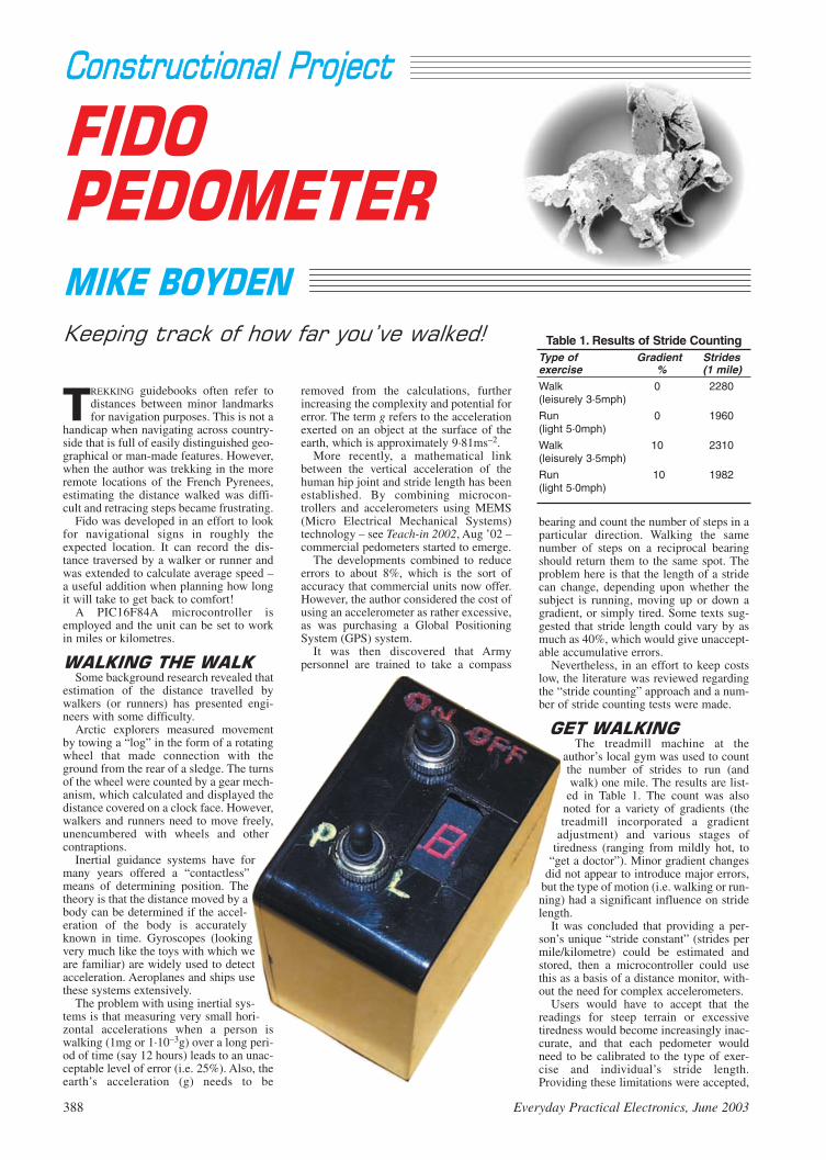
TREKKING guidebooks often refer todistances between minor landmarksfor navigation purposes. This is not a
handicap when navigating across country-side that is full of easily distinguished geo-graphical or man-made features. However,when the author was trekking in the moreremote locations of the French Pyrenees,estimating the distance walked was diffi-cult and retracing steps became frustrating.
Fido was developed in an effort to lookfor navigational signs in roughly theexpected location. It can record the dis-tance traversed by a walker or runner andwas extended to calculate average speed –a useful addition when planning how longit will take to get back to comfort!
A PIC16F84A microcontroller isemployed and the unit can be set to workin miles or kilometres.
Some background research revealed that
estimation of the distance travelled bywalkers (or runners) has presented engi-neers with some difficulty.
Arctic explorers measured movementby towing a “log” in the form of a rotatingwheel that made connection with theground from the rear of a sledge. The turnsof the wheel were counted by a gear mech-anism, which calculated and displayed thedistance covered on a clock face. However,walkers and runners need to move freely,unencumbered with wheels and othercontraptions.
Inertial guidance systems have formany years offered a “contactless”means of determining position. Thetheory is that the distance moved by abody can be determined if the accel-eration of the body is accuratelyknown in time. Gyroscopes (lookingvery much like the toys with which weare familiar) are widely used to detectacceleration. Aeroplanes and ships usethese systems extensively.
The problem with using inertial sys-tems is that measuring very small hori-zontal accelerations when a person iswalking (1mg or 1·10–3g) over a long peri-od of time (say 12 hours) leads to an unac-ceptable level of error (i.e. 25%). Also, theearth’s acceleration (g) needs to be
bearing and count the number of steps in aparticular direction. Walking the samenumber of steps on a reciprocal bearingshould return them to the same spot. Theproblem here is that the length of a stridecan change, depending upon whether thesubject is running, moving up or down agradient, or simply tired. Some texts sug-gested that stride length could vary by asmuch as 40%, which would give unaccept-able accumulative errors.
Nevertheless, in an effort to keep costslow, the literature was reviewed regardingthe “stride counting” approach and a num-ber of stride counting tests were made.
The treadmill machine at the
author’s local gym was used to countthe number of strides to run (andwalk) one mile. The results are list-
ed in Table 1. The count was alsonoted for a variety of gradients (thetreadmill incorporated a gradient
adjustment) and various stages oftiredness (ranging from mildly hot, to
“get a doctor”). Minor gradient changesdid not appear to introduce major errors,
but the type of motion (i.e. walking or run-ning) had a significant influence on stridelength.
It was concluded that providing a per-son’s unique “stride constant” (strides permile/kilometre) could be estimated andstored, then a microcontroller could usethis as a basis of a distance monitor, with-out the need for complex accelerometers.
Users would have to accept that thereadings for steep terrain or excessivetiredness would become increasingly inac-curate, and that each pedometer wouldneed to be calibrated to the type of exer-cise and individual’s stride length.Providing these limitations were accepted,
Table 1. Results of Stride CountingType of Gradient Stridesexercise % (1 mile)Walk 0 2280(leisurely 3·5mph)
Run 0 1960(light 5·0mph)
Walk 10 2310(leisurely 3·5mph)
Run 10 1982(light 5·0mph)

a unit offering about 10% accuracy wasconsidered achievable and acceptable,given the simplicity of design.
The next problem was to reliably detect
and count strides. After a little experimen-tation it was found that two opposing tiltswitches, S1 and S2, pointing downwardsby about 10 degrees, could be made totrack the cycle of a leg movement.
Referring to the full circuit diagram inFig.1, the tilt switches are connectedrespectively to the RA0 and RA1 pins of aPIC16F84A on one side and to the 0V lineon the other. The pins are biassed normal-ly-high via resistors R1 and R2, and l.e.d.sD1 and D2.
As illustrated in Fig.2, when the knee israised the conductive fluid in switch S1 isforced momentarily onto its contacts,closing them, so applying logic 0 to pinRA0. Pin RA1 remains at logic 1. As thefoot is placed down, both S1 and S2 open,and both RA0 and RA1 are set at logic 1.As the knee is raised in the last part of thestride then S1 opens and RA0 goes tologic 1, but S2 closes, with RA1 atlogic 0.
The prototype was taken to the localgym for testing, where it was found byexperimentation that the detection unitoperated best when strapped to the leftupper calf. Note that the software onlyallows the unit to function in this position.
The software verifies the correct switchclosure sequence and also includes sometime delays. These are necessary to reducethe sensitivity of the system and curtail thenumber of “bad reads” due to the equiva-lent of contact bounce.
For simplicity and cost effectiveness, asingle 7-segment l.e.d. display was usedfor all of the display and control interfac-ing, using a cyclic technique to display thevarious factors. A sounder, WD1, is includ-ed to signal each valid step when in theLearn mode – this improved the setting-upprocedure. The mode of operation is select-ed by means of a 3-way toggle switch, S3.
The main computation undertaken by
Fido requires distance and elapsed time tobe known.
Time: Fido’s clock rate is set by a 20msinterrupt generated by a TMR0 overflow.Although this would not be accurateenough for daily time keeping, it is accu-rate enough for this application. The 20ms“ticks” are counted and eventually used toincrement a “6-minute”, 16-bit timer-counter (Ttimehi, Ttimelo).
Distance: If Fido is to work in milesthen the number of strides recorded tocomplete one mile is entered into Fido dur-ing the Learn mode. Once the calibrationdistance has been walked, a switch adjust-ment ensures that the number of strides(the stride constant) is stored in the PIC’snon-volatile Data EEPROM. (The softwareis written to store the stride value for everystride that is taken after the first 255strides.) The value placed into the EEP-ROM is calculated from:
Stride Constant = Strides Counted / ten
The Stride Constant is subtracted fromthe 16-bit stride counter (distlo, disthi) tosee if 0·1 of a mile has been walked. If it
has, then this is then used to increment a“0·1 mile”, 16-bit Total Distance counter(Tdisthi, Tdistlo).
Distance is recorded and displayed bymeans of a number of incrementing deci-mal counters.
Average speed is calculated at each
6-minute interval and a “snapshot” of theDistance Counter is stored in Tdisthi1 andTdistlo1. The average speed is then derived from:
Average speed (miles/hour)= 0·1 mile counter/ 6-minute counteri.e.(Tdisthi1, Tdistlo1) / (Ttimehi, Ttimelo)
Hence the average speed displayed is theaverage since the time that Fido wasswitched on. If the walker stops for lunch,and Fido is left on, the average speed willbe seen to steadily fall. If the average speedis required “per leg” of a journey, thensimply record the distance together withaverage speed and turn off Fido, therebyresetting the unit in readiness for the nextphase of your walk.
A “standard” library of 16-bit unsignedinteger mathematical functions fromMicrochip’s website (www.microchip.com)were used in this application. “Invalid” divi-sions (i.e. 1 / 0 or 2 / 3) are returned as 0,rather than the true math-ematical results of infini-ty or a fraction.Mathematically, Fido hasa maximum capability ofapproximately 6,500miles and 270 days! Areset of the unit is forcedif the distance exceeds99·9 units, but the timehas no restrictions.
Although Fido com-
putes and displays dis-tance immediately, thefirst computed value of
speed is only available for display sixminutes after turning Fido on. Distanceand average speed values displayed in thefirst 0·5 miles should be treated with cau-tion as the small reading errors represent asignificant proportion of the initial mea-sured values. The errors rapidly diminishas the time and distance measurementsincrease.
The measurement technique assumesthat most of the movement is a genuinewalking or running motion, hence theerrors contributed by a few “stumbles” aregreatly reduced when averaged against thenumber of strides that equate to a mile forindividual walkers.
Software for this design is available on
3·5-inch disk (Disk 6) from the EditorialOffice – a nominal handling charge applies(see the EPE PCB Service page. It is alsoavailable for free download from the EPEftp site. The easiest way into this is via thehome page www.epemag.wimborne.co.uk. Click the top link saying ftp site(downloads), then take the pathpub/PICS/Fido.
Fido is constructed on a single printed
circuit board (p.c.b.) whose full-size tracklayout and component positions are shown
Everyday Practical Electronics, June 2003 389
B15VTO6V
MCLR
PIC16F84IC1
+VE
GND
DI0/RB7
CLK/RB6
RB5
RB4
RB3
RB2
RB1
INT/RB0
TOCKI/RA4
RA3
RA2
RA1
RA0
OSC2/CLK OUT
OSC1/CLK IN
18
17
16
15
14
13
12
11
10
9
8
7
6
5
4
3
2
1
R1470Ω 470Ω
R2
R3 R41k1k
R51k
S1
S2
LEG
SENSORFORWARD
BACKWARDSENSOR
LEG
C115p
C2
X120MHz
15p
LEARN
MEASURE
DISTANCE/SPEED
D31N4148
R6 R7220Ω 220Ω
C4220n
C310µ
10
11
13
7
2
1
8
3 14
MCLRDI0/RB7CLK/RB6GND
1N4001D4
D1 D2
a a
a
a
k k
k
k
S3
POLE
ON/OFF
+
X2
S4
TB1
WD1+
*
*SEE TEXT
A
B
C
Fig.1. Complete circuit diagram for the Fido Pedometer.
LOGIC 0
LOGIC 1 LOGIC 1
LOGIC 1
LOGIC 1
LOGIC 0
S1
S1
S1
S2 S2
S2
LEG FORWARD LEG VERTICAL LEG BACKWARDS
Fig.2. Fido’s logic (with or without hairy legs!).
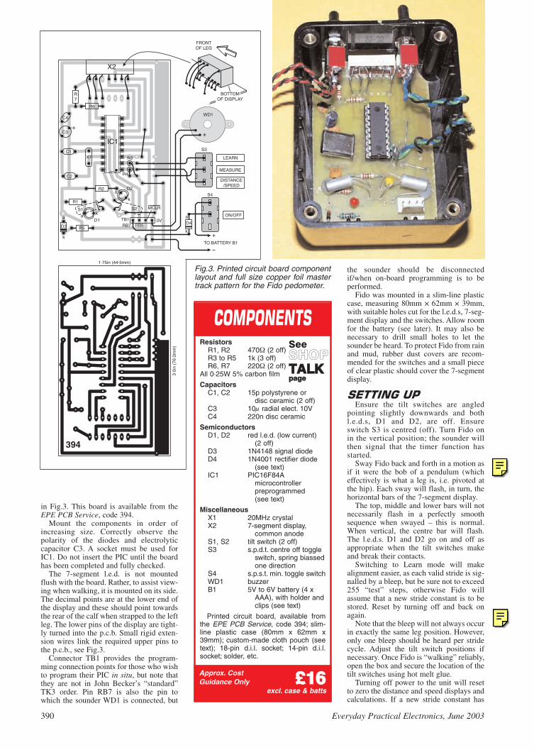
390 Everyday Practical Electronics, June 2003
in Fig.3. This board is available from theEPE PCB Service, code 394.
Mount the components in order ofincreasing size. Correctly observe thepolarity of the diodes and electrolyticcapacitor C3. A socket must be used forIC1. Do not insert the PIC until the boardhas been completed and fully checked.
The 7-segment l.e.d. is not mountedflush with the board. Rather, to assist view-ing when walking, it is mounted on its side.The decimal points are at the lower end ofthe display and these should point towardsthe rear of the calf when strapped to the leftleg. The lower pins of the display are tight-ly turned into the p.c.b. Small rigid exten-sion wires link the required upper pins tothe p.c.b., see Fig.3.
Connector TB1 provides the program-ming connection points for those who wishto program their PIC in situ, but note thatthey are not in John Becker’s “standard”TK3 order. Pin RB7 is also the pin towhich the sounder WD1 is connected, but
the sounder should be disconnectedif/when on-board programming is to beperformed.
Fido was mounted in a slim-line plasticcase, measuring 80mm × 62mm × 39mm,with suitable holes cut for the l.e.d.s, 7-seg-ment display and the switches. Allow roomfor the battery (see later). It may also benecessary to drill small holes to let thesounder be heard. To protect Fido from rainand mud, rubber dust covers are recom-mended for the switches and a small pieceof clear plastic should cover the 7-segmentdisplay.
Ensure the tilt switches are angled
pointing slightly downwards and bothl.e.d.s, D1 and D2, are off. Ensureswitch S3 is centred (off). Turn Fido onin the vertical position; the sounder willthen signal that the timer function hasstarted.
Sway Fido back and forth in a motion asif it were the bob of a pendulum (whicheffectively is what a leg is, i.e. pivoted atthe hip). Each sway will flash, in turn, thehorizontal bars of the 7-segment display.
The top, middle and lower bars will notnecessarily flash in a perfectly smoothsequence when swayed – this is normal.When vertical, the centre bar will flash.The l.e.d.s. D1 and D2 go on and off asappropriate when the tilt switches makeand break their contacts.
Switching to Learn mode will makealignment easier, as each valid stride is sig-nalled by a bleep, but be sure not to exceed255 “test” steps, otherwise Fido willassume that a new stride constant is to bestored. Reset by turning off and back onagain.
Note that the bleep will not always occurin exactly the same leg position. However,only one bleep should be heard per stridecycle. Adjust the tilt switch positions ifnecessary. Once Fido is “walking” reliably,open the box and secure the location of thetilt switches using hot melt glue.
Turning off power to the unit will resetto zero the distance and speed displays andcalculations. If a new stride constant has
C3
C4
X1C1
C2
IC1
R2
R1
D3 R5
D1aa
a
k
k
k
D2
R7
R6
X2
R4
R3
S2S1
+
D4a
k
MCLR
0VRB6RB7
TO BATTERY B1
LEARN
DISTANCE/SPEED
MEASURE
TB1ON/OFF
S3
S4
+
+
WD1
BOTTOMOF DISPLAY
FRONTOF LEG
1.75in (44.5mm)
3.0i
n (7
6.2m
m)
Approx. CostGuidance Only ££1166
excl. case & batts
ResistorsR1, R2 470 (2 off)R3 to R5 1k (3 off)R6, R7 220 (2 off)
All 0·25W 5% carbon film
CapacitorsC1, C2 15p polystyrene or
disc ceramic (2 off)C3 10 radial elect. 10VC4 220n disc ceramic
SemiconductorsD1, D2 red l.e.d. (low current)
(2 off)D3 1N4148 signal diodeD4 1N4001 rectifier diode
(see text)IC1 PIC16F84A
microcontrollerpreprogrammed(see text)
MiscellaneousX1 20MHz crystalX2 7-segment display,
common anode S1, S2 tilt switch (2 off)S3 s.p.d.t. centre off toggle
switch, spring biassed one direction
S4 s.p.s.t. min. toggle switchWD1 buzzerB1 5V to 6V battery (4 x
AAA), with holder andclips (see text)
Printed circuit board, available fromthe EPE PCB Service, code 394; slim-line plastic case (80mm x 62mm x39mm); custom-made cloth pouch (seetext); 18-pin d.i.l. socket; 14-pin d.i.l.socket; solder, etc.
SeeSSHHOOPPTTAALLKKppaaggee
Fig.3. Printed circuit board componentlayout and full size copper foil mastertrack pattern for the Fido pedometer.
394
EPE Online
Note that the circuit boards used in EPE Online projects are available from the EPE Online Store at www.epemag.com (also note that the codes for the boards in the online store are prefixed with 7000, so a board with a code of say 256 will appear as 7000256 in the online store).
EPE Online
Note that you can purchase pre-programmed PIC microcontrollers for our PIC projects (see the “ShopTalk” page in the associated issue of the Magazine for more details). Alternatively, if you wish to program the PIC yourself, you can find the code files by bouncing over to the EPE Online Library (visit www.epemag.com, click in the “Library” link in the top navigation, then on the “Project Code Files” link).

been entered using Learn mode then thiswill be remembered despite power beingturned off.
The unit can only be used on the left leg.Changing orientation would requirechanges to be made to the software, a mat-ter on which no advice is offered.
The 7-segment display will not be read-able from a normal standing position, so itis necessary to make a strap-on pouch toallow Fido to be lifted out and read whenrequired. The author’s arrangement isshown in Fig.4. The pouch is sewn to aloop of 50mm wide elastic. The walkingboot is passed through the elastic hoop andFido is slipped into the pouch at the top ofthe calf just below the knee joint.
Note that as the calf muscle is rounded,so Fido points slightly “inward” whenviewed from above. This is normal, butcheck that Fido does not significantly shiftfrom this position, especially whenrunning.
Part of the design criteria for Fido
assumed that it might be used in ruggedand remote locations, where constant bat-tery changes would not be welcome. Whenwalking, the prototype consumed an aver-age of 27mA, but by using low currentl.e.d.s and “flashing” the display wheneverpossible, this was reduced to an average of13mA.
The plastic case is sized to house fourAAA alkaline batteries rated at1200mA/hr. No battery duration problemshave been experienced in the prototype,despite constant testing over a period oftwo months.
It should be noted that the PIC16F84Ahas a maximum supply voltage limit of5·5V, whereas four AAA cells willnominally deliver 6V. Consequently, it isrecommended that a 1N4001 rectifier
diode should be inserted in the positiveline between switch S4 and the p.c.b. todrop the voltage reaching the PIC by about0·6V.
When first switched on, if Fido is not
upright the display will remain blank andthe timing function will be disabled. Whenupright, the centre bar of the display willflash and a short bleep from the sounder willindicate that the unit is now functioning.
Slip Fido into its pouch situated on theleft calf and walk with Mode switch S3 inposition A (centre). As progress is made,each of the horizontal bars of the 7-seg-ment display will flash as each stage of avalid walk cycle is detected. When station-ary and vertical, the middle bar will flash atabout 1Hz.
Next, Mode switch S3 can be tested. It isa 3-position (centre-off) toggle switch.Position A is “spring return loaded”. Itsfunctions are shown in Table 2.
Display Mode (S3-A)Only when Fido is in the vertical posi-
tion (middle bar flickering) can switchposition S3-A be “pulsed”. This will trig-ger a display cycle on the single digit 7-segment display, showing progress (dis-tance covered) and average speed.
If Fido has been calibrated in miles, theletter P (progress) is displayed first, fol-lowed by the miles units, then a decimalpoint (a dash) followed by tenths of a mile.After a short pause, the letter A (averagespeed) is displayed and the average speedin miles/hour is shown in the same formatas distance. If the distance or speedexceeds 9·9 then the tens of miles digit willautomatically appear.
Once a display cycle is completed, theunit will return to measure mode.
Measure Mode (S3-B)When switch position S3-B is selected
(centre), Fido silently counts strides anddisplays each stage of a valid leg move-ment by flashing the top, middle and lowerbars of the 7-segment display. Every mile(or kilometre) is signalled with a longbleep from the sounder.
Learn Mode (S3-C)Fido has been programed with a default
value of stride constant (2280 strides/mile,level ground, walking), but it will probablybe necessary to readjust this constant. Tomake the adjustment, Learn mode needs tobe selected by setting the Mode switch toposition S3-C.
A distance of one mile, or one kilometre,should now be walked or run. The displaywill show the normal “descending bars”indicating a valid stride, but this will beaccompanied by a bleep and the letter L onthe display.
To avoid the accidental selection ofLearn mode (and hence entering incorrectdata), Fido will only commence remember-ing the stride count after 255 strides havebeen completed. When more than 255strides have been recorded, each stride willbe followed by two bleeps to indicate thatFido is now recording a “live” stride con-stant value.
Once the standard distance has beencovered, switch to normal walk mode(Measure – S3-B) and walk a few paces.Check the descending bars are visibleagain and no bleep is present. Switch Fidooff, wait a couple of seconds to let capaci-tor C3 discharge, and then switch back on.Henceforth only the new stride constantwill be used (until such time as you mightchoose to change it, in the same way as justdescribed).
If possible, “train” Fido in the type ofterrain in which it will be used. A “standard
Everyday Practical Electronics, June 2003 391
Table 2. Mode Switch S3 FunctionsPosition Mode Function Display ToneA Display Display distance/ P0-0 A0-0 ... Silent
average speedB Measure Measure distance Descending Every mile/km
speed barsC Learn Learn strides per L and bars < 255 strides
mile/km descending 1 bleep> 255 strides
2 bleepsFido’s “collar”, worn around the left upper calf.
12in (30cm) OF 1 / IN (38mm) WIDE ELASTIC1 2
SOFT CLOTH OR COTTON SLIGHTLYOVERSIZED TO PROTECT TOP OF FIDO
ELASTICSTITCHEDTO CLOTH
HERE
Fig.4. Construction of Fido’s “pooch pouch and collar”!

mile” can be determined by driving a cardown a safe road (i.e. also suitable forpedestrians) for one mile (or 0·62 miles forkilometres), as shown on the car’smileometer. Walk back to the start of themile with Fido set to Learn mode. Save thenew stride constant, restart Fido and thenwalk back to the car.
The display may show 0·9 miles whencoincident with the position of the car.Walk until it shows 1·0 miles, whichshould be an indication of the error andshould be no more than 10%, say 170yards. Getting standard distances in roughcountry can be more difficult and perhapsordnance survey maps can be of assistancehere.
Both a gym treadmill and the above pro-cedure have been used for calibrating theprototype. Tests showed an accuracy towithin 10% for distances greater than 1·0miles.
The conversion between miles and kilo-metres is:
Miles to kilometres multiply by 1·609Kilometres to miles multiply by 0·621
Fido can potentially record any repeti-
tive leg movement providing the set-up andcalibration are adjusted. Experiments arecurrently underway to adapt Fido to
measure the “stroke rate” and performanceprofile of club standard rowers.
Although this design is simply PIC-
based, readers may be interested to read
about the ADXL202 accelerometer device,in particular Using the ADXL202 inPedometer Applications, Harvey Weinberg,via www.Parallex.com. ADXL202device information is available fromwww.Analog.com.
392 Everyday Practical Electronics, June 2003
PICronos L.E.D. Wall ClockThe first observation one makes when scanning down the parts list for the
PICronos L.E.D. Wall Clock is that quite a cash saving can be made if read-ers approach some of our components advertisers and do a bit of “arm-twist-ing” and negotiate a special “bulk discount” on the ultrabright l.e.d.s. If youorder 200, as the author did, they should certainly be able to offer you a goodprice, and possibly include different colours as well.
It is important that constructors keep to the specified semiconductordevices for the Clock. The L293DN 16-pin Half-H driver chip (also referred toas a stepper motor driver i.c.) was purchased from Rapid Electronics (01206 751166 or www.rapidelectronics.co.uk), code 82-0192. The “D”denotes it is a 16-pin device. Do not use other L293 device types as they maynot have the same characteristics – for instance, the L293E has 20 pins andcannot be used. (Check out the Texas web site at: www.ti.com.)
The 7-stage Darlington line driver type ULN2004A was also ordered fromthe above company, code 82-0622. It is also listed by RS Components (01536 444079 or rswww.com, credit card only – a p&p charge will be made),code 652-825. RS also supplied the rail-to-rail LMC6484 quad op.amp, code310-925.
For those readers unable to program their own PICs, a ready-programmedPIC16F877-4 microcontroller can be purchased from Magenta Electronics( 01283 565435 or www.magenta2000.co.uk) for the inclusive price of £10each (overseas add £1 p&p). The software is available on a 3·5in. PC-com-patible disk (Disk 6) from the EPE Editorial Office for the sum of £3 each (UK),to cover admin costs (for overseas charges see page 434). It is also availablefor free download from the EPE ftp site, which is most easily accessed via theclick-link option on the home page when you enter the main web site atwww.epemag.wimborne.co.uk. On entry to the ftp site take the pathpub/PICS/PICronos.
The large circular printed circuit board for the Clock is available from theEPE PCB Service, code 395 (see page 434).
Fido PedometerApart from the PIC microcontroller and associated software, only the tilt
switches called for in the Fido Pedometer project are likely to cause any realconcern.
Due to the robust treatment of Fido, when taken for “walkies”, and thedangerous toxic nature of mercury, we feel readers should make everyendeavour to keep well clear of using mercury-filled tilt switches. Instead, werecommend readers use one of the hermetically sealed non-mercury types. Asuitable switch is “currently listed” by Maplin ( 0870 2263 6000 orwww.maplin.co.uk), code DP50E.
The above company also supplied the sub-miniature centre-off, biassedone way, toggle switch (code FH02C) and a suitable waterproof toggle switchcover (two needed – code JR79L). The plastic box is left to individual choice.
For those readers unable to program their own PICs, a ready-programmedPIC16F84A microcontroller can be purchased from Magenta Electronics( 01283 565435 or www.magenta2000.co.uk) for the inclusive price of£5.90 each (overseas add £1 p&p). The software is available on a 3·5in. PC-compatible disk (Disk 6) from the EPE Editorial Office for the sum of £3 each(UK), to cover admin costs (for overseas charges see page 434). It is alsoavailable for free download from the EPE ftp site, which is most easilyaccessed via the click-link option on the home page when you enter the mainweb site at www.epemag.wimborne.co.uk. On entry to the ftp site take thepath pub/PICS/FidoPed.
The printed circuit board is available from the EPE PCB Service, code 394(see page 434). The 7-segment common anode display should be in abun-dant supply, but you will need to check the pinout arrangement before makinga purchase.
Back-To-Basics 5 – Mini Theremin/Twilight SwitchThe only item that readers will experience problems finding for the Mini
Theremin, one of this month’s Back-To-Basics projects, is the specified TokoRD7 i.f. transformer, which is usually used in radio receivers.
Having had problems in the recent past trying to locate sources for Tokocoils, it is fortuitous that the author (Raymond Haigh) of the new PracticalRadio Circuits series has given us the names of two stockists. They are: JABElectronic Components, Dept EPE, PO Box 5774, Birmingham, B44 8JP( 0121 682 7045 or www.jabdog.com – they appear to only deal with mailorders) and Sycom, Dept EPE, PO Box 148, Leatherhead, Surrey, KT229YW ( 01372 372587 or www.sycomcomp.co.uk). We also understandfrom Raymond that the main UK Toko supplier is Coils-UK ( 01753 549502or www.coils-uk.com), but that they are only into “bulk orders”.
All the semiconductor devices for both of this month’s projects should bewidely stocked by our components advertisers. They should also carry theORP12 light-dependent resistor or its derivative used in the concludingTwilight Switch.
Practical Radio Circuits – 1No difficulties should be encountered in obtaining components for the
Practical Radio Circuits series of projects and any that could possibly causeconcern will be highlighted each month.
We “kick-off” the series with a simple Crystal Set Radio, a TRF Receiverand a single transistor Headphone Amplifier. The Crystal Set and TRFReceiver both use the same polythene dielectric tuning capacitor and ferriterod coil.
The tuning capacitor will normally be found listed as a miniature “transistorradio” type and is currently stocked by ESR Components ( 0191 251 4363or www.esr.co.uk), code 896-110 and Sherwood Electronics (see ad. onpage 440), code CT9. The ferrite rod for the aerial/tuning coil should be easyto come by, it is certainly listed by Sherwood (code FR1) and we note WCNSupplies ( 023 8066 0700) are offering a 140mm x 10mm rod, with a coil(unwanted).
For the 26s.w.g. enamelled copper wire, the author obtained a 50g (2oz)reel from JAB Electronic Components ( 0121 682 7045 or www.jab-dog.com). We also understand J. Birkett Supplies ( 01522 520767) stock50g reels. Most suppliers only sell “large” reels.
The MK484 radio i.c. is stocked by ESR Components (see above) andRapid Electronics ( 01206 751166 or www.rapidelectronics.co.uk),code 82-1026. Any point-contact germanium diode should prove suitable forthe detector in the Crystal Set; e.g. the OA47, OA90 and OA91, and anysilicon signal diode can be used for D1 and D2 in the TRF Receiver, e.g.1N4148, 1N914, 1N916.
The two small printed circuit boards are obtainable from the EPE PCBService, codes 392 (TRF Rec.) and 393 (Headphone), see page 434.
PLEASE TAKE NOTEToolkit TK3 (Oct/Nov ’01)Version V1.42 of the TK3 programming software is now on our ftp site. Ithas had the following facilities added: Recognition of Macro functions Use of LOCAL in the context of Macro addresses in relation to HIGH
and LOW functions Recognition of IFDEF and ENDIF functions Calculator for PIC Baud rate register values
EPE Online
Note that the circuit boards used in EPE Online projects are available from the EPE Online Store at www.epemag.com (also note that the codes for the boards in the online store are prefixed with 7000, so a board with a code of say 256 will appear as 7000256 in the online store).
EPE Online
Note that you can purchase pre-programmed PIC microcontrollers for our PIC projects as described on this “Shop Talk” page. Alternatively, if you wish to program the PIC yourself, you can find the code files by bouncing over to the EPE Online Library (visit www.epemag.com, click in the “Library” link in the top navigation, then on the “Project Code Files” link).

Programming PICs the Easy WayProgramming PICs the Easy Way is the title of a new 208 page book by PeterBrunning which is now included in our PIC Training & Development System. Thisnew book provides a very fast start for any newcomer to PIC programming whoneeds to rapidly get to the situation where he or she can write their ownprogrammes. This book starts with four very simple experiments where theprogrammes are written out in full detail so that the basic programming conceptsare understood. In the rest of the book each chapter sets a specific task whichcreates a real life PIC controlled circuit. The complexity of the programming forthese projects is hidden away in ready made subroutines. So although the readeris working in PIC assembly language it is used as if it were a high level language.This has the great advantage of allowing a newcomer to create their owncomplex programmes in the shortest time with the minimum amount of typing,while retaining all the advantages of working in PIC assembly language.
Projects:- Traffic Lights Controller, Simple Text Messages, Using the Keypad,Creating a Siren Sound, Realistic Dice Machine, Freezer Thaw Warning Device,Voltage Measurement and Temperature Measurement.
For readers with very little electronics experience appendix E introducesresistors, capacitors, diodes, transistors, MOSFETs and logic circuits.
The software suite has been updated to include the library routines and asystem which allows break points to be placed in the programme in theactual PIC so that hardware problems can be more easily located.
Our PIC training and development system now consists of ouruniversal mid range PIC programmer, a 208 page easy programmingbook, a 306 page book covering the PIC16F84, a 262 page bookintroducing the PIC16F877 family, and a suite of programmes to run ona PC. Two ZIF sockets and an 8 pin socket allow most mid range 8, 18,28 and 40 pin PICs to be programmed. The plugboard is wired with a 5volt supply.The software is an integrated system comprising a text editor,assembler disassembler, simulator and programming software. Theprogramming is performed at normal 5 volts and then verified with plusand minus 10% applied to ensure that the device is programmed with agood margin and not poised on the edge of failure. The DC versionrequires a 15 to 20 volt supply with a 2.1mm plug which is not included(UK plugtop supply £8.95). The battery version requires two PP3batteries which are not included.
Order Code P404:-Universal mid range PIC programmer module
+ Book Programming PICs the Easy Way+ Book Experimenting with PIC Microcontrollers+ Book Experimenting with the PIC16F877 (2nd edition)+ Universal mid range PIC software suite+ PIC16F84, 16F628 and 16F872 test PICs . . . . . . . . .£179.91
UK Postage (2 day) and insurance . . . . . . . . . . . . . . . . . . . .£ 9.00(Europe postage & Insurance . . . £16.50. Rest of world . £32.50)
Order Code P405:-Universal mid range PIC programmer module
+ Book Programming PICs the Easy Way+ Universal mid range PIC software suite+ PIC16F628 and PIC16F872 test PICs . . . . . . . . . . . .£129.91
UK Postage and insurance . . . . . . . . . . . . . . . . . . . . . . . . . £ 7.50
138 The Street, Little Clacton, Clacton-on-sea,Essex, CO16 9LS. Tel 01255 862308
Mail order address:
PIC Training & Development System Experimenting with PIC MicrosThis book introduces the PIC16F84 and PIC16C711.We begin with four simple experiments, which are thesame as in the easy programming book but this timeusing the PIC16F84. Then we study the basic principlesof PIC programming, learn about the 8 bit timer, how todrive the liquid crystal display, create a real time clock,experiment with the watchdog timer, sleep mode, beepsand music, including a rendition of Beethoven’s FürElise. Finally there are two projects to work through,using the PIC16F84 to create a sinewave generator andinvestigating the power taken by domestic appliances.In the space of 24 experiments, two projects and 56exercises the book works through from absolutebeginner to experienced engineer level.
The best way to get the PIC programming languageinto your memory is to laboriously type everyprogramme out in full so there are no short cuts in thisbook. However, we do understand that problems cropup where a typing error causes too much heart ache. Ifyou do get stuck visit our web site, follow theinstructions and we will email you the correct text.
Ordering InformationTelephone with Visa, Mastercard or Switch, or sendcheque/PO to have your order immediately processed.Despatch is usually within 2 days of order beingreceived unless we are out of stock. All prices includeVAT if applicable. Postage must be added to all orders.Please state DC or battery version. If not stated batteryversion will be assumed.
Hardware requiredOur PIC Training and Development System uses DOSbased software which will run on any modern PC with a386 processor or better. It is optimised for use withWindows 98. For other Windows systems the softwareshould be run directly from DOS. Our website containsfull information about Windows XP which also applies ingeneral terms to Windows 2000 and Windows NT.
Please visit our website for full information:-www.brunningsoftware.co.uk
Experimenting with the PIC16F877This book starts with the simplest of experiments to give us abasic understanding of the PIC16F877 family. Then we look atthe 16 bit timer, efficient storage and display of text messages,simple frequency counter, use a keypad for numbers, letters andsecurity codes, and examine the 10 bit A/D converter.
The 2nd edition has two new chapters. The PIC16F627 isintroduced as a low cost PIC16F84. We use the PIC16F627 asa step up switching regulator, and to control the speed of a DCmotor with maximum torque still available. Then we study how touse a PIC to switch mains power using an optoisolated triacdriving a high current triac.
394 Everyday Practical Electronics, June 2003

IF you thought PLC stands for publiclimited company, you’d be right. But tosome it means power line communica-
tions as well, also known as PLT (powerline telecommunications). Although someelectricity companies see PLC as an idealway of providing Internet service downyour power feed (and making mega moneyat the same time), others consider the ideanothing short of abominable. So what’s allthe fuss about?
The notion is very simple. The coppercables that supply mains electricity to yourhome could deliver bandwidth by thebucketload as well to provide low costbroadband connections for Internettersfrustrated by its lacking availability in theirneck of the woods. With governmentsbanging the broadband drum and usersyearning for low-cost bandwidth, it’s hard-ly surprising that power companies scentmoney in this opportunity.
Hardware vendors are equally keen toassist the electricity industry apply lever-age to its existing assets and proclaim theeffectiveness of their solutions most elo-quently. The technology is cost-effective, itneeds no new wires and everyone wants it.Or so you might believe.
Communicating over electricity mains
uses the existing supply (110V, 230V, etc.)wiring to carry information as well as ener-gy. This concept can be applied to localarea networking (using internal wiringwithin the home or workplace) or foraccess to the public network (over thefeeders that connect consumers’ premisesto the local substation).
As a commercial proposition, it is thelatter opportunity that is exercising theminds of the power companies. With thedelays and uncertainties of unbundling theEuropean and US local loops and the stag-nation surrounding broadband fixed wire-less access, powerline technology isattracting considerable attention as a localaccess technology.
Before detailing the underlying technol-ogy, first we need to see what’s fuellingthis feeding frenzy. Power generation anddistribution is a highly competitive busi-ness and utilities would dearly like to tapinto new revenue streams.
A key imponderable remains, howev-er, and it could prove a major stumblingblock. The issue is electromagnetic com-patibility (EMC); power lines carryingdata signals are likely to radiate, inter-fering with broadcast signals. Beancounters make little of the issue and ven-dors argue that interference problemscan be overcome. Others are less confi-dent and are putting their faith inexisting regulations against undesirabletransmissions.
Debate has been mainly theoretical butwith tests underway now, many bodies willbe observing the results. If these are suc-cessful and interference can be contained,major deployment of the technology isforecast to follow.
Commercial applications for powerline
communication include high-speedInternet access, entertainment distribution,voice telephony and fax using Voice overInternet Protocol (VoIP), building automa-tion, meter reading and remote surveil-lance for building security and healthcare.
Data rates are not spectacular, however.Although products available currentlywork at up to 2Mbit/s, once several usersare sharing the same data stream thesespeeds will drop significantly. Higherspeeds are promised in future, though, andthe vendor that spoke of individual net-work connections of 2·5Gbit/s has still notprovided substantiation of this claim after18 months.
A data concentrator installed at theneighbourhood substation is the transferpoint for data streams between the localsupply mains and the main telecommuni-cations trunk network. The mains-voltagedistribution network carries the databetween here and consumers’ homes oroffices, where an adapter breaks out thevoice and data signals and feeds them bycoaxial cable to the user’s PC, telephoneand other applications. In general the max-imum distance between transformer andconsumer is up to half a mile.
Carrier frequencies for transmitting thisdata lie in the region 9kHz to 30MHz, thesame part of the spectrum as used for avariety of radio communications.Implementations use a variety of spreadspectrum and fast frequency hopping tech-niques, with either frequency division oramplitude modulation.
Power lines are a harsh environment fordata transmission; impulsive noise andvoltage spikes from electrical appliances,switching operations and distant lightningstrikes can wipe out low-level signals.Modulation levels can be increased butthen signals begin to leak out; radiationfrom street lamps during trials inManchester gave rise to concerns over datasecurity as well as fuelling opposition tofurther pollution of the airwaves.Powerline communications are anathemato broadcasters and listeners, not to men-tion government, amateur and CB users ofthe radio spectrum.
But is it legal? Or better stated, does itmatter? Legitimate users of the radio spec-trum think so. Radio Netherlands haswarned that interference levels, even toreception of strong domestic signals, willbe so high that the whole concept will have
to be re-thought. Otherwise many urbandwellers will lose the opportunity to listento foreign radio stations on AM radio.
The Radio Society of Great Britain hasalso voiced its concern, noting thatGerman approval for powerline communi-cation systems, strongly opposed by radiousers in that country, allow higher levels ofemission than those cited in the UK as a“worst case” for acceptable interference. Itconcludes there is a European agenda toprovide cheap wideband data systems andthat the technical arguments for preserva-tion of the h.f. spectrum appear to beignored.
However, given the recent success oflegal appeals under human rights legisla-tion, it is likely that any significant inter-ference to citizens’ ability to listen toauthorised broadcast stations would befound unconstitutional and would lead toeffective action against the “jammers”.
Just think back to the early 1980s and thehijacking of the airwaves for citizens’ bandradio, the largest manifestation of masslawbreaking the country has ever seen.Rather than prosecute the malefactors, thesupine government of the day saw fit tolegalise the use of the 27MHz band for CBuse, forcing the existing users of the fre-quency to swallow the cost of buying newequipment on different frequencies. If theBritish government gives in that easily toindividuals, how likely is it to resist privatecompanies with vested interests?
Scottish Hydro-Electric is due to begin
full-scale commercial trials this summer ofits broadband service over power lines,naming Stonehaven in Scotland and “atown in Hampshire”. Pricing for triallists isstated to be around £25-£30 a month,although this was not finalised at the timeof writing.
Don’t hold your breath for powerlinecommunications to reach your home by theend of the year though; the company mayhave legal action on its hands if the systemcauses interference. It cannot be forgotteneither that high-profile trials in Britain andGermany by suppliers such as Nortel/Norweb, Siemens and Rhine-WestphalianElectricity have failed on account of regu-latory issues and slow sales.
The truth is that powerline communica-tion faces an uncertain future.Superficially attractive, its deploymentmay turn out to be unviable and technical-ly problematic. A report from UBSWarburg and the Smith Group argues thatit will come so late that it will “miss theboat” and by the time manufacturers haveequipment that meets EMC regulations,the rollout of ADSL will be at an advancedstage. This may be unduly optimistic forADSL but only time can tell.
395 Everyday Practical Electronics, June 2003
TTEECCHHNNOO--TALK ANDY EMMERSON
Powerline Comms – Boon or Bogey?Broadband delivered over mains wiring? Andy Emmerson investigates

June 2003 – Special PIC Supplement
This special 16-page supplement is available for free download from the EPE Online website. All you have to do is bounce over to www.epemag.com and click on the “Library” link in the main navigation.

NNeewwss .. .. .. A roundup of the latest EverydayNews from the world of
electronics
396 Everyday Practical Electronics, June 2003
Controlling MagicBarry Fox
MODERN TV, recorder and satellite settop boxes are routinely updated with newoperating software sent over the air or byphone line in the small hours without theowner knowing it. New features appear inthe morning as if by magic. But the remotecontrol often cannot control them.
Thomson (owner of RCA) has theanswer. Thomson will now provideremotes that have an infra-red sensor eyeas well as the usual IR transmitter; and theset-top box will have an infra-red transmit-ter as well as the usual sensor. After the settop box has been updated, instructionsappear on screen telling the owner to pointthe remote at the box and wait a few sec-onds while it loads new control codes intoits memory. The remote then matches theset-top box again.
EPE Benefits EOCSDON Bray, Hon Editor of the ElectronicsOrgan Constructors Society has written tothank us for Editorial mention. We areindeed pleased to help publicise the EOCS,and have been doing so from time to timefor many years.
He says that the EOCS has acquired sev-eral new members recently and at least onejoined as result of our last mention. He alsosays that the EOCS magazine shows thatthere is a considerable interest in PIC pro-gramming, which of course we know fullwell!
For more information about the EOCS,contact Trevor Hawkins, Hon Secretary,EOCS, 23 Blenheim Road, St Albans,Herts AL1 4NS. Tel: 01727 857344.
THE British-born founder of TexasInstruments, Sir Cecil Green, died on
11 April 2003 aged 102 in a hospital at LaJolla, California. He had pneumonia.
He was the last of the four founders anda philanthropist who donated more than$200 million to education and medicalinstitutions around the world.
On 6 Dec 1941 he joined EugeneMcDermott, J. Erik Jonsson and H. BatesPeacock to purchase Dallas-basedGeophysical Service Inc., which performedseismic explorations for petroleum. DuringWW2, GSI branched into other areas, includ-ing the manufacture of submarine-detectiondevices and airborne radar systems.
In 1951 the company changed its nameto Texas Instruments. In 1952 TI enteredthe semiconductor business by licensingShockley’s work at Bell Labs, putting it atthe front of the chip business. Green dis-covered that foreign competitors were farsmarter at adopting TI’s innovations thanUS competitors. He is quoted as havingsaid “Our aggressiveness, in effect, set theJapanese up in business”.
Cecil Howard Green was born nearManchester, England, emigrated as a childto Canada, then San Francisco. He wasawarded an honorary knighthood in 1991.He leaves no immediate survivors.
For more information browse www.theregister.co.uk/content/3/30282.htmland www.washingtonpost.com/wp-dyn/articles/A1993-2003Apr13.html.
RACE FOR EPSOMSUNDAY 22 June 2003 is the starting date-line for the Radio and Electronics Fair to beheld at Epsom Grandstand, Surrey, from10am to 5pm. After the success of the lastrally in 2002, the organisers have beenencouraged to stage another. The Fair hasbecome the number one event for the region.
It is a one day event and will consist ofprivate and trade stalls with added attrac-tions throughout the day, amongst whichwill be a Bring and Buy sale. Also, onbehalf of the RSGB, a NationalConstruction Contest will be held, with atrophy. Morse testing facilities will beavailable as well. There will also be a dis-play of military vehicles by VMARS(Vintage and Amateur Radio Society), plusa WW2 operations room talking station!
Refreshments are available, and furtherentertainment will be provided by KenMackintosh and his 17-member band.
Booking contact: Brian Cannon G8DIU,38 Sandringham Road, Worcester Park,Surrey KT4 8UJ. Tel/fax 01737 279108.Email: [email protected].
FOUNDER OFTI DIES
DATA LOGGING METER WAVETEK Meterman Test Tools latestDMM 38XR range offers optional real-time data logging by PC. The 38XR is atrue r.m.s. meter which measures volts,amps and ohms, as well as temperature,capacitance, frequency and 4-20mA loopcurrent percentage.
The clear 10,000 count display with0·25% accuracy includes an analoguebargraph. Features include buttons forMin/Max/Avg, Data Hold, Peak Hold andRelative functions, as well as for a neonbacklight for use in dim environments.
The meter can be used for data acqui-sition using any standard PC runningWindows. The software stores data forretrieval and further analysis, includinginterfacing with Excel.
The Meterman 38XR is offered at asuggested retail price of £99.
For more information browsewww.metermantesttools.com or [email protected].
PICO CATAS you are no doubt aware, Pico specialis-es in the field of virtual instruments for dataacquisition. They say that they have alwaysbeen recognised for providing innovativelow-cost alternatives to traditional testequipment and data acquisition products.
For many years Pico have generously sup-ported EPE’s innovative readers by awardingprizes to the best Ingenuity Unlimited designseach year. They also supported our recentTeach-In 2002 series. Teachers will be inter-ested to know that Pico place a heavy empha-sis on scopes and loggers for Education.
We thoroughly recommend that you get acopy of Pico’s latest catalogue – over 40pages of full-colour glossy A4 – detailingtheir entire range of products and accessories.
For further information contact PicoTechnology Ltd., Dept. EPE, The MillHouse, Cambridge Street, St Neots, CambsPE19 1QB. Tel: 01480 396395. Fax: 01480396296. Email: [email protected]. Web:www.picotech.com.
WCN BARGAINS“100’s of bargains inside” proclaims WCNSupplies’ latest catalogue, issue 17. In its44 A4-sized pages there is a vast array ofproducts on offer, ranging from batteries,connectors and fans, through buggies andpaintball (yes indeed!), passive and activeelectronic components, to meters and tools.
To get your copy of this catalogue, con-tact WCN Supplies, Dept EPE, The OldGrain Store, Rear of 62 Rumbridge Street,Totton, Southampton SO40 9DS.
Tel/Fax: 023 8066 0700.Email: [email protected]: www.wcnsupplies.com.

(V. Poulsen), and by mechanical alterna-tors (E. Alexanderson). Semiconductorsnow play an increasing role, but valves arestill used in high-power transmitters.
As their name suggests, the waves com-prise an electric and a magnetic fieldwhich are aligned at right angles to one
another. The electric field isformed by the rapid voltage fluctu-ations (oscillations) in the aerial.Current fluctuations create themagnetic field.
Electromagnetic waves cannot,
by themselves, convey any informa-tion. They are essentially radio fre-quency carriers, and arrangementshave to be made for the audio fre-quency speech and music signals tohitch a ride. This is done by modu-lating the radio frequency carrierwith the audio frequency signals.
If the amplitude of the carrier isvaried in sympathy with the signal,the process is known as amplitudemodulation (a.m.), and typicalwaveforms are depicted in Fig.1.1.Varying the carrier frequency is, ofcourse, known as frequency modu-lation (f.m.).
Marconi's Morse signals weretransmitted by simply switchingthe carrier on and off. It was R. A.Fessenden who, in 1906, used acarbon microphone (said to bewater cooled) to directly modulatethe radio frequency (50kHz) out-put of an alternator and be the firstto transmit speech and music.
The oscillations produced by the
transmitter are fed to an aerial sys-tem in order to radiate the electro-magnetic energy. The lower thefrequency the longer the wave-length and the bigger the aerial.
Aerial designs vary, but thedipole adopted by Hertz in 1886 isstill deployed at high, very high
physicist who first demonstrated the exis-tence of electromagnetic waves in 1886.
Before the valve era, radio frequencyoscillations were generated by using anelectrical discharge to shock-excite a tunedcircuit (H. Hertz and G. Marconi), by thenegative resistance of an electric arc
T owards the end of the 19th century,sending a radio signal a few hun-dred yards was considered a major
achievement. At the close of the 20th, manwas communicating with space probes atthe outermost edge of the solar system.
No other area of science and technologyhas affected the lives of peoplemore completely. And because itis so commonplace and afford-able, it is accepted without a sec-ond thought. The millions whoenjoy it, use it, even those whoselives depend upon it, often havelittle more than a vague notion ofhow it works.
This series of articles will viewthe technology in a historicalperspective and try to dispel itsmysteries. The main purpose,however, is to present a variety ofpractical circuits for set buildersand experimenters. And, witheconomy in mind, basic compo-nents and assemblies are repeatedin different receivers.
Radio uses electromagnetic
waves to transport speech, musicand data over vast distances at thespeed of light.
The electromagnetic waves aregenerated by making an electriccurrent oscillate at frequenciesranging from 10kHz (ten thou-sand Hertz) to more than 100GHz(one-hundred thousand millionHertz).
The lowest frequencies areused for submarine communica-tions because of their ability topenetrate water to a considerabledepth: the highest mainly forsatellite communications. Mostradio listeners are served by theportion of the spectrum extendingfrom 150kHz to 110MHz.
Frequency of oscillation ismeasured in Hertz in honour ofHeinrich Rudolf Hertz, the
Part 1: Introduction, Simple Receivers and a Headphone Amp.
398 Everyday Practical Electronics, June 2003
Fig.1.1. Modulation and detection: (A) Radio frequencycarrier wave. (B) Audio frequency signal. (C) Carrier wavemodulated by audio signal. Average value of imposed audiosignal voltage is zero. (D) Diode detector, D, working intoload resistor, R, rectifies the modulated carrier wave.Reservoir capacitor, C, removes residual radio frequenciesand enables the audio frequency output voltage to approachits peak value. (E) Recovered audio frequency signal.
MODULATED CARRIERWAVE INPUT
RECOVERED AUDIO FREQUENCYSIGNAL OUTPUTC R
Da k
A)
B)
C)
D)
E)
RESIDUAL RADIO FREQUENCIES REMOVEDBY SHUNTING ACTION OF CAPACITOR, C

Everyday Practical Electronics, June 2003 399
IMPORTANT EVENTS1831In published papers and a letter deposited with the RoyalSociety (opened in 1937), Michael Faraday tentatively proposeselectromagnetic wave theory.1864James Clerk Maxwell's mathematical analysis of Faraday's workpublished in his paper: A Dynamical Theory of the Electro-mag-netic Field.1888Heinrich Rudolf Hertz uses a crude spark transmitter andreceiver to demonstrate the existence of electromagnetic waves.1889Sir Oliver Lodge lectures on the need to tune the transmitter toreceiver, a condition he called “syntony”.1893Sir Oliver Lodge uses an invention of Edouard Branley's as asensitive detector of electromagnetic waves. (The coherer).1901Guglielmo Marconi transmits radio signals across the Atlantic.1904Sir John Ambrose Fleming patents the diode valve.1906Dr Reginald Fessenden modulates a carrier wave and broad-casts speech and music. Dr Lee de Forest makes a patent appli-cation for his triode valve, the first electronic amplifying device.1913Major Edwin Howard Armstrong invents the regenerative receiver.1918Armstrong invents the superheterodyne receiver.1921Armstrong invents the super regenerative receiver and W. G.Cady uses quartz crystals to stabilize oscillators.1933Armstrong demonstrates his system of frequency modulatedradio transmission.1947John Bardeen, Walter Brattain and Dr William Shockley developthe transistor at the Bell Telephone Laboratories.
and ultra high frequencies. The elevated wire and earth arrange-ment used by Marconi in the 1890's is still used for the radiationof low and medium frequencies.
Transmitter powers range from the miserly one or two watts,radiated by amateurs who specialize in low power communication,to the two-million watts output from some medium wave broad-cast transmitters.
Radiation from the transmitter reaches the receiver by either theground wave (line of sight or diffraction around the earth's curva-ture), or the sky wave (reflected between the ionosphere and thesurface of the earth. Propagation path is frequency dependant: byground wave up to 500kHz, then gradually shifting to sky waveuntil, above 30MHz, the waves are no longer reflected back by theionosphere and escape out into space.
Solar radiation has a profound effect on the charged particles whichmake up the ionosphere, and propagation conditions vary between nightand day, seasonally, and according to the eleven-year sunspot cycle.
Reception involves three essential functions: picking up the
energy radiated by transmitters, selecting one station from all therest, and extracting the modulation from the carrier wave in orderto make the transmitted speech or music audible to the listener.
Receiving aerials respond to either the electric or the magnetic field
radiated by the transmitter. Sets that use telescopic rod or wire aerialspick up the electric field. Receivers that have loop aerials, i.e., a coilwound on a frame or a ferrite rod, respond to the magnetic field.
Portable receivers usually incorporate both: long and mediumwaves (150kHz to 1·6MHz) are covered by a loop with a ferriterod core, and the v.h.f. f.m. band (88MHz to 108MHz) and short-wave bands by a telescopic aerial.
In order to select one station from the thousands that are spread
across the radio frequency spectrum, the receiver has to be tuned tothe carrier frequency of the transmitter.
Sir Oliver Lodge was stressing the importance of tuning, a con-dition he called “syntony”, as early as 1889, and he patented hissystem in 1897. This is one of the most fundamental patents inradio, and his method is still universally adopted.
Lodge's invention exploits the way an inductor (coil) and capac-itor combination resonate at a particular frequency. If the capacitoris connected in parallel with the inductor (see Fig.1.2a) the circuitpresents a high impedance at its resonant frequency and a lowerimpedance at all others.
Connecting the capacitor in series with the inductor (Fig.1.2b)results in a low impedance at resonance and a higher impedance atother frequencies. If the inductor or the capacitor (usually thecapacitor) is made variable, it is possible to tune the circuit acrossa range of frequencies.
Sharpness of tuning depends mainly on resistive and other loss-es in the inductor or coil: the lower these losses the sharper thetuning. Resistive and dielectric losses in the capacitor also affectperformance, but, with modern tuning components, these are usu-ally so small they can be ignored.
The ability of the coil to resonate sharply, i.e., be more selective, isknown as its “Q” factor: the sharper the resonance the higher the Q.
Resonant tuned circuits magnify signal voltages, a phenomenonthat is crucial to radio reception. If a signal of the same frequencyas the resonant frequency of the tuned circuit is applied to thecoil/capacitor combination, its voltage will be increased in pro-portion to the Q of the coil. With a Q of 100, a 1mV signal will bemagnified to 100mV or 0·1V. We will be returning to this later.
With amplitude modulated signals (a.m.) the process of recov-
ering the modulation is essentially one of rectification. In Fig.1.1d,diode, D, rectifies the incoming radio frequency carrier wave andcapacitor, C, shunts residual radio frequencies to ground (earth)leaving only the audio frequency modulation. Capacitor, C, alsoexhibits a reservoir action enabling the audio frequency voltage toapproach its peak value.
The diode and, indeed, any other a.m. demodulator, is called adetector, a hang-over from the earliest days of radio when glasstubes filled with metal filings were used to simply detect the pres-ence of electromagnetic waves.
In 1889, whilst working on the protection of telegraph equip-ment from lightning, Sir Oliver Lodge noticed that metal surfaces,separated by a minute air gap, would fuse when an electrical dis-charge occurred close by. He used the phenomenon to detect elec-tromagnetic waves, and called devices of this kind coherers.
About this time, Edouard Branley discovered that a spark in thevicinity of a mass of metal particles lowered their resistance.Lodge found this arrangement to be more sensitive and, in 1893,adapted it for use as a detector.
Subsequently, J. A. Flemming's diode valve, patented in 1904,and crude semiconductor devices, were used as rectifiers in orderto demodulate signals.
A)
B)
Fig.1.2. Basic tuned circuits. Combining an inductor (coil) and acapacitor produces a circuit which resonates at one particularfrequency. The resonant frequency can be varied by changingthe amount of inductance or capacitance (usually the latter).Thetuning of all radio receivers and transmitters depends upon thisphenomenon.
PARALLEL TUNED CIRCUITPresents a high impedanceat its resonant frequency anda lower impedance at otherfrequencies.
SERIES TUNED CIRCUITPresents a low impedance atits resonant frequency and ahigher impedance at otherfrequencies.

The most popular of the semiconductor
detectors was the “crystal” or “cat'swhisker” which consisted of a short lengthof springy brass wire touching a crystal ofgalena (lead sulphide). Adjustment of thepoint of contact was critical, but these crys-tal detectors could be more sensitive thanFlemming's diode valve. They were muchless expensive.
The modern equivalent of the crystaldetector is the point contact germaniumdiode. Here, a gold-plated wire contacts awafer of germanium, the assembly beingenclosed within a glass tube. These diodesare still used to demodulate the signals inmost domestic a.m. radios.
The simplest receiver, known as a
Crystal Set, consists of nothing more thana coil, tuning capacitor, diode detector, anda pair of earphones.
A typical circuit diagram for a CrystalSet Radio is given in Fig.1.3, where induc-tor or coil L1 is tuned by variable capacitorVC1 to the transmitter frequency. DiodeD1 demodulates the signal, which is fedstraight to the earphones. There is noamplification.
A long (at least 20 metres), high (7metres or more) aerial and a good earth (aburied biscuit tin or a metre of copper pipedriven into damp ground) are required inorder to ensure audible headphone recep-tion. The earphones originally used withthese receivers had an impedance ofaround 4000 ohms and were very sensitive(and heavy and uncomfortable). They areno longer available, but a crystal earpiece,which relies on the piezoelectric effect,will give acceptable results. Low imped-ance “Walkman” type earphones are NOTsuitable.
Quite apart from the absence of amplifi-
cation, two factors seriously limit the per-formance of crystal receivers.
Germanium diodes become increasinglyreluctant to conduct as the applied voltagefalls below 0·2V, and this makes the receiv-er insensitive to weak signals. Silicondiodes have a threshold of around 0·6V,and are, therefore, unsuitable for circuits ofthis kind.
The earphone loading imposes heavydamping on the tuned circuit, reducingits Q and, hence, its selectivity, i.e. itsability to separate signals. With such lowselectivity insensitivity can be a bless-ing, and crystal sets are normally onlycapable of receiving a single, strongtransmission on the long and mediumwavebands. (They will sometimesreceive more than one if a shortwave coilis fitted).
The aerial and diode can be connected totappings on the tuning coil in order toreduce damping, but the improvement inselectivity is usually at the expense ofaudio output.
When valves cost a week's wages andhad to be powered by large dry batteriesand lead/acid accumulators, the construc-tion of simple receivers of this kind couldbe justified. With high performance tran-sistors now costing only a few pence orcents, crystal sets are now regarded as“nostalgic pieces”.
Some readers may, however, wish tobuild one out of curiosity, or for the novel-ty of having a receiver that does not requirea power supply. Moreover, the componentsrequired are all used in more complexreceivers to be described later.
Ferrite loop aerial L1 and polythene
dielectric variable capacitor VC1 form thetuned circuit. Point contact germaniumdiode D1 demodulates the signal; capacitorC1 bypasses residual r.f. (radio frequen-cies) to earth and also exhibits a reservoiraction, enabling the a.f. (audio frequency)output to approach its peak value. The
recovered audio signal is fed directly to acrystal earpiece.
Signal voltages induced in the ferrite loopaerial by the radiated magnetic field aremuch too weak to produce an output fromthe detector, and the component is used heresimply as a tuning coil. The ferrite core does,however, reduce the number of turnsrequired for the coil winding, thereby reduc-ing its resistance and increasing its Q factor.
400 Everyday Practical Electronics, June 2003
CRYSTAL SETResistor
RX 4k7 0·25W 5% (onlyrequired if set is connected toamplifier)
CapacitorsC1 10n disc ceramic.VC1 5p to 140p (minimum)
polythene dielectric variable capacitor (see text)
SemiconductorsD1 0A47 germanium diode
MiscellaneousL1 ferrite rod, 100mm (4in.)
× 9mm/10mm (3/8in.) dia., with coil (see text)
Crystal earpiece and jack socket tosuit.; plastic control knob; plastic insulat-ed flexible cable for aerial wire, down-lead and earth connection, 30 metres(100 ft) minimum; buried biscuit tin or 1metre (3ft) of copper pipe for earth sys-tem; 50gm (2oz) reel of 26s.w.g.(25a.w.g.) enamelled copper wire, fortuning coil; card and glue for coil former;multistrand connecting wire; crocodileclips or terminals (2 off), for aerial andearth lead connection; solder etc.
Approx. CostGuidance Only ££44
excl. earpiece & wire
HEADPHONE AMPLIFIERIF SET CONNECTED TO
RX 4k7. ONLY REQUIRED
EARPIECETO CRYSTAL
ABOVE THE GROUNDLOCATED 7 METRES (20 FT)20 METRES (60 FT) OF WIRELONG WIRE AERIAL: AT LEAST
L1
(25 A.W.G.)26 S.W.G.
100t
(SEE TEXT)EFFECTIVE EARTH
D1OA47
a k
VC15p TO140p
C110n
RX
a kOA47
Fig.1.3.This simplest of radio receiversuses a germanium diode as the “cat’swhisker” crystal detector.
The author’s Crystal Set “knock-up” on a wooden baseboard. This uses two screwterminals for the Aerial and Earth wire connections instead of croc. clips.
max

The circuit is simple enough to be
assembled on the work bench, and a print-ed circuit board layout is not given. Thecomponents and the various interwiringconnections are illustrated in Fig.1.4.
Full construction and winding details for
the ferrite tuning/aerial coil L1 are shownin Fig.1.5. The coil is made from 26s.w.g.(25a.w.g.) enamelled copper wire, closewound on a cardboard former. This sameferrite tuning coil forms the loop aerial inthe following TRF Receiver.
The r.f. bypass capacitor C1 can, in prac-tice, be omitted with no noticeable reduction
in performance. However, if the set is to beconnected to either the headphone amplifier(Fig.1.10) or speaker amplifier describednext month, this component, together withdiode load resistor, RX, must be included.
Audio frequency amplification after
the diode detector will permit the use oflow impedance Walkman type earphonesor even loudspeaker operation. It will do
nothing, however, to overcome thediode's insensitivity to weak signals. Forthis we must have radio frequency ampli-fication of the signals picked up by theaerial before they reach the detector.(The standard circuit for a transistorportable receiver has three stages ofradio frequency amplification ahead ofthe diode).
Everyday Practical Electronics, June 2003 401
100 TURNS OF 26SWG (25AWG)ENAMELLED COPPER WIRE,CLOSE WOUND
9mm ( / in)DIAMETER x100mm (4in)FERRITE ROD
3 8ENDS OF WINDINGSECURED BYNARROW STRIPS OFMASKING TAPE
THIN CARD ROLLED AROUND ROD TOMAKE A FORMER 60mm (2 / IN) LONG BY13mm ( / in) DIAMETER. APPLY GLUE TOCARD WHILST ROLLING.
3 81 2
Fig.1.5. Construction and windingdetails for the ferrite rod tuning/aerialcoil L1. This loop aerial is also used inthe TRF Receiver.
CRYSTALEARPIECE
JACK PLUGAND
SOCKET
L1
a k
L1
(25 A.W.G.)26 S.W.G.
100t
D1
RXC1
DIODE LOAD RESISTOR, RX, IS ONLYREQUIRED IF CRYSTAL RECEIVER ISCONNECTED TO HEADPHONE AMPLIFIER.
TO EARTH, BISCUIT TIN OR 1M COPPERPIPE IN DAMP GROUND. CONNECTION TOCENTRAL HEATING PIPEWORK WILL OFTENSUFFICE.
TO AERIAL, AT LEAST 20 METRES(60FT) OF WIRE MOUNTED 7 METRES(20FT) MINIMUM ABOVE THE GROUND
VC1A
G
O
Fig.1.4. The components and various interwiring connections for the simple crystalset. This circuit is easily “lashed-up” on the workbench and no circuit board layoutis given. The author’s demonstration set is shown in the heading photograph.
Receivers with tuned circuits and ampli-fication, at signal frequency, ahead of thedetector stage were known, during thevalve era, as tuned radio frequency, ort.r.f., receivers.
This arrangement was adopted byFerranti when they designed their popularZN414 radio i.c. Introduced in 1972, thechip relied upon a then new manufacturingtechnique developed byBell Laboratories andknown as collector diffu-sion isolation.
No bigger than a singletransistor, and requiring apower supply of only 1·5V,the device enabled trulyminiature receivers to bebuilt, one of which wasfeatured on the BBCTV science programme,Tomorrow's World. Thechip is still produced, but ina plastic package instead ofthe original metal case andwith the type numberMK484.
The chip's internal architecture, in block
form, is depicted in Fig.1.6. The very highimpedance input stage minimizes dampingon the tuned circuit, enabling it to maintain ahigh Q factor and, consequently, reasonableselectivity. This is followed by three stagesof radio frequency amplification ahead of atwo transistor detector or demodulator.
Chip characteristics and pinout detailsare also listed with the block diagramFig.1.6. Internal capacitors impose the lowfrequency operating limit, and the perfor-mance of the transistors determines thetail-off at high frequencies.
MK484 Specification . . .Supply Voltage 1·1V to 1·8V
(via external load resistor)
Current Drain 0·3mA to 0·5mA(affected by signal level)
Frequency range 150kHz to 3MHz(peaks at 1MHz)
Input Impedance 1·5 megohms
Output Impedance 500 ohms
Sensitivity better than 100V
Power Gain 70dB
Internal Component Count:10 Transistors15 Resistors
4 Capacitors
R.F.AMP
R.F.AMP
R.F.AMP
R.F.AMP DET.
INPUT2
1OUTPUT
3GROUND
123
OUTPUTINPUT
GROUND
Fig.1.6. Block diagram showing the internal arrangement ofthe MK484 radio i.c.
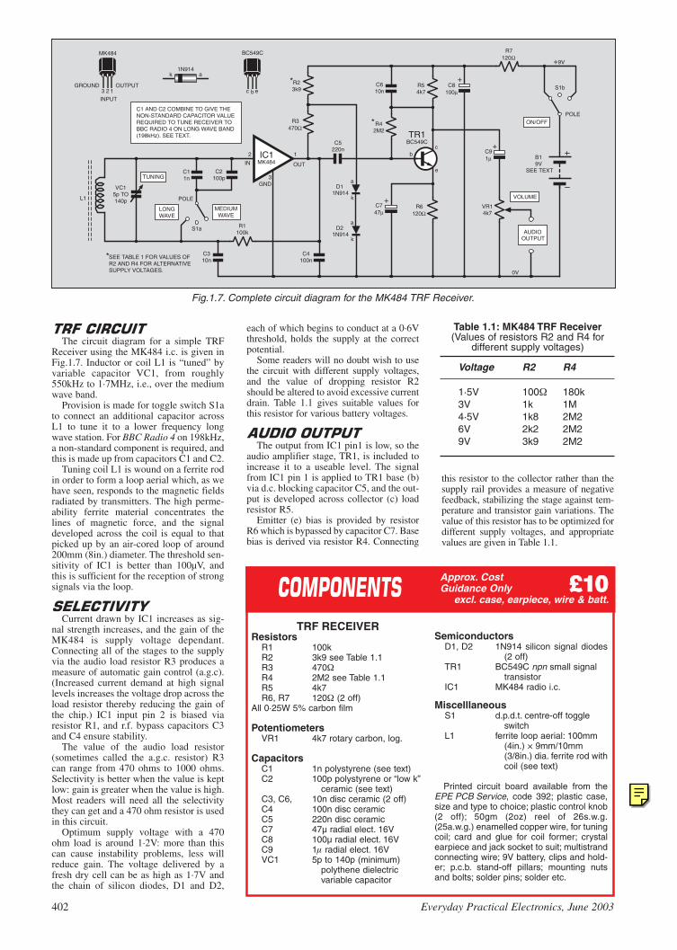
402 Everyday Practical Electronics, June 2003
Approx. CostGuidance Only ££1100
excl. case, earpiece, wire & batt.
TRF RECEIVERResistors
R1 100kR2 3k9 see Table 1.1R3 470R4 2M2 see Table 1.1R5 4k7R6, R7 120 (2 off)
All 0·25W 5% carbon film
PotentiometersVR1 4k7 rotary carbon, log.
CapacitorsC1 1n polystyrene (see text)C2 100p polystyrene or “low k”
ceramic (see text)C3, C6, 10n disc ceramic (2 off)C4 100n disc ceramicC5 220n disc ceramicC7 47µ radial elect. 16VC8 100µ radial elect. 16VC9 1 radial elect. 16VVC1 5p to 140p (minimum)
polythene dielectric variable capacitor
Table 1.1: MK484 TRF Receiver(Values of resistors R2 and R4 for
different supply voltages)
Voltage R2 R4
1·5V 100 180k3V 1k 1M4·5V 1k8 2M26V 2k2 2M29V 3k9 2M2
The circuit diagram for a simple TRF
Receiver using the MK484 i.c. is given inFig.1.7. Inductor or coil L1 is “tuned” byvariable capacitor VC1, from roughly550kHz to 1·7MHz, i.e., over the mediumwave band.
Provision is made for toggle switch S1ato connect an additional capacitor acrossL1 to tune it to a lower frequency longwave station. For BBC Radio 4 on 198kHz,a non-standard component is required, andthis is made up from capacitors C1 and C2.
Tuning coil L1 is wound on a ferrite rodin order to form a loop aerial which, as wehave seen, responds to the magnetic fieldsradiated by transmitters. The high perme-ability ferrite material concentrates thelines of magnetic force, and the signaldeveloped across the coil is equal to thatpicked up by an air-cored loop of around200mm (8in.) diameter. The threshold sen-sitivity of IC1 is better than 100µV, andthis is sufficient for the reception of strongsignals via the loop.
Current drawn by IC1 increases as sig-
nal strength increases, and the gain of theMK484 is supply voltage dependant.Connecting all of the stages to the supplyvia the audio load resistor R3 produces ameasure of automatic gain control (a.g.c).(Increased current demand at high signallevels increases the voltage drop across theload resistor thereby reducing the gain ofthe chip.) IC1 input pin 2 is biased viaresistor R1, and r.f. bypass capacitors C3and C4 ensure stability.
The value of the audio load resistor(sometimes called the a.g.c. resistor) R3can range from 470 ohms to 1000 ohms.Selectivity is better when the value is keptlow: gain is greater when the value is high.Most readers will need all the selectivitythey can get and a 470 ohm resistor is usedin this circuit.
Optimum supply voltage with a 470ohm load is around 1·2V: more than thiscan cause instability problems, less willreduce gain. The voltage delivered by afresh dry cell can be as high as 1·7V andthe chain of silicon diodes, D1 and D2,
SemiconductorsD1, D2 1N914 silicon signal diodes
(2 off)TR1 BC549C npn small signal
transistorIC1 MK484 radio i.c.
MiscelllaneousS1 d.p.d.t. centre-off toggle
switchL1 ferrite loop aerial: 100mm
(4in.) × 9mm/10mm (3/8in.) dia. ferrite rod withcoil (see text)
Printed circuit board available from theEPE PCB Service, code 392; plastic case,size and type to choice; plastic control knob(2 off); 50gm (2oz) reel of 26s.w.g.(25a.w.g.) enamelled copper wire, for tuningcoil; card and glue for coil former; crystalearpiece and jack socket to suit; multistrandconnecting wire; 9V battery, clips and hold-er; p.c.b. stand-off pillars; mounting nutsand bolts; solder pins; solder etc.
bc
e
B19V
123OUTPUT
INPUT
GROUND
ak1N914
D11N914
D21N914 AUDIO
OUTPUT
TUNING
VOLUME
a
a
k
k
VC15p TO140p
C11n
C2100p
LONGWAVE
MEDIUMWAVE
R1100k
C310n
C4100n
IC1MK484
2 1
3
R23k9
R3470Ω
*
*
*
SEE TEXT
C5220n
C610n
R42M2
R54k7
C747µ
R6120Ω
+
+
+
C8100µ
R7120Ω
C91µ
VR14k7
S1b
ON/OFFPOLE
S1a
POLE
TR1BC549C
BC549C
ebc
C1 AND C2 COMBINE TO GIVE THENON-STANDARD CAPACITOR VALUEREQUIRED TO TUNE RECEIVER TOBBC RADIO 4 ON LONG WAVE BAND(198kHz). SEE TEXT.
SEE TABLE 1 FOR VALUES OFR2 AND R4 FOR ALTERNATIVESUPPLY VOLTAGES.
MK484
+9V
0V
IN
GND
OUT
L1
Fig.1.7. Complete circuit diagram for the MK484 TRF Receiver.
each of which begins to conduct at a 0·6Vthreshold, holds the supply at the correctpotential.
Some readers will no doubt wish to usethe circuit with different supply voltages,and the value of dropping resistor R2should be altered to avoid excessive currentdrain. Table 1.1 gives suitable values forthis resistor for various battery voltages.
The output from IC1 pin1 is low, so the
audio amplifier stage, TR1, is included toincrease it to a useable level. The signalfrom IC1 pin 1 is applied to TR1 base (b)via d.c. blocking capacitor C5, and the out-put is developed across collector (c) loadresistor R5.
Emitter (e) bias is provided by resistorR6 which is bypassed by capacitor C7. Basebias is derived via resistor R4. Connecting
this resistor to the collector rather than thesupply rail provides a measure of negativefeedback, stabilizing the stage against tem-perature and transistor gain variations. Thevalue of this resistor has to be optimized fordifferent supply voltages, and appropriatevalues are given in Table 1.1.
EPE Online
Note that the circuit boards used in EPE Online projects are available from the EPE Online Store at www.epemag.com (also note that the codes for the boards in the online store are prefixed with 7000, so a board with a code of say 256 will appear as 7000256 in the online store).

Headphone and loudspeaker amplifierswill, in most cases, be connected across thesame battery power supply, and resistor R7and capacitor C8 decouple the tuner circuitin order to prevent instability. Bypass capac-itor C6 connected across collector load R5is also included to avoid instability. Audiooutput is taken from the collector of transis-tor TR1 and connected to the Volume con-trol VR1, via d.c. blocking capacitor C9.
A crystal earpiece can be connected inplace of the volume control but the output,especially when weaker signals are beingreceived, will be barely adequate. With thisarrangement there is no need for resistorR7, and provision is made, on the printedcircuit board, for it to be shorted out (seeFig.1.9).
If you have not already made up the
“tuning coil” for the Crystal Set, construc-tion of the TRF Receiver should com-mence with the winding of the ferrite loopaerial as detailed earlier in Fig.5 and asfollows. Wind thin card (a postcard isideal) around a 100mm (4in.) length of9mm (3/8in.) diameter ferrite rod until an
overall diameterof 13mm (1/2in.)is achieved. Applyadhesive as thecard is wound on.
Coil L1 consists of 100 turns of 26s.w.g.(25a.w.g.) enamelled copper wire closewound, i.e. with turns touching. Secure thestart and finish of the winding with thinstrips of masking tape wound tightlyaround the former. The task of producing aneat coil can be eased by slightly spacingthe turns as they are wound on and repeat-edly pushing them together with the thumbas the winding proceeds.
The inductance of this loop winding ishigher than normal in order to ensure fullMedium Wave coverage with the specifiedtuning capacitor (medium wave loops usu-ally comprise about sixty turns on a 9mm(3/8in.) dia. rod). Longer rods, which willincrease signal pick-up, may be used if alarger receiver can be tolerated.
Use rubber bands, strips of card or woodor plastic blocks to secure ferrite loopaerials. Do not use metal mounts as thesecan form a shorted turn and dramaticallyreduce efficiency.
Most of the TRF Receiver components
are assembled on a small printed circuitboard (p.c.b.). The topside component lay-out, off-board interwiring and a full-sizeunderside copper foil master are shown inFig.1.8. This board is available from theEPE PCB Service, code 392. How to con-nect an earpiece directly to the Receiverp.c.b. is illustrated in Fig.1.9.
Insert and solder in position the resistorsand capacitors first and the semiconductorslast. The 3-pin MK484 radio i.c. must bemounted close to the board to preventinstability: leave just sufficient lead lengthfor the application of a miniature crocodileclip as a heat shunt whilst soldering.
Take care to remove all traces of theenamel from the ends of the coil winding inorder to ensure a good connection. Solderpins, inserted at the lead-out points, willsimplify the task of off-board wiring.
392
1.65in (41.9mm)1.
12in
(28
. 4m
m)
R1
R3
R6
R2
R7
R5
R4
C4
C5
D2
D1C3
C9
C8
C7
C6
IC1 TR1
INGND OUT
e b c+ +
+a
a
k
k VOLUME
TUNING
0V
L1
C2
C1TO
BATTERY
AUDIO TOAMPLIFIER
VC1 S1a S1b
VR1
+
A G O
V
V
Fig.1.8. Printed circuit board component layout, interwiringto off-board components and full-size underside board cop-per track master.
Fig.1.9. Connecting a crystal earpiece, via socket, directly tothe p.c.b. in place of the Volume control. Note the “shorting”link wire.
R3 R2
R7
R5
R4
C5
D2
D1
C9
C8
C6
TR1e b c +
+a
a
k
AUDIOOUTPUT
TO BATTERYVIA S1b
SOCKET TOSUIT CRYSTAL
EARPIECE
LINK SHORTSOUT R7
(Polythene dielectric type)
Some retailers supply extenders for thestubby spindle. If an extender has to befabricated, use a 6mm diameter tubularstand-off bolted to the central hole in thespindle (bolt is usually 2mm). Grip thecapacitor spindle when tightening bolt. Donot tighten against internal end stop.
Secure capacitors to bracket or frontpanel with two bolts driven into threadedholes in its front plate. Bolts (usually 2mm)must not extend through the thicknessof the front plate.
Twin-gang capacitor lead-outs are usual-ly thin metal strips. Moving vanes (the stripoften marked ‘G’) should be connected toground or the 0V rail. Strips for the fixedvanes, normally used to tune the aerial andoscillator circuits in a superhet receiver, areoften marked “A” and “O”. One or bothshould be connected to the “hot” end of thesimple receiver’s tuning coil.
Internal trimmers should be set to mini-mum capacitance when a variable is usedwith simple receivers. Twin-gang polyvari-cons have two trimmers. Four-gang unitshave four trimmers.
For complete coverage of the mediumwave band with this ferrite loop aerial, thevariable capacitor should have a 5pF mini-mum capacitance and a maximum capaci-tance of at least 140pF. The aerial tuningsection of most polythene dielectric vari-ables, as used in transistor portables,should be suitable.
If necessary, both sections (aerial and oscil-lator) can be connected in parallel to ensurethe necessary maximum capacitance. Thiswill, however, double the minimum capaci-tance and slightly curtail coverage at the highfrequency end of the band.
Everyday Practical Electronics, June 2003 403
A G O

The single transistor HeadphoneAmplifier circuit illustrated in Fig.1.10, willensure an acceptable output via Walkmantype ’phones. The audio input signal is cou-pled to the base of transistor TR1 via d.c.blocking capacitor C1. Base bias resistorsR1 and R2, fix the standing collector currentat around 4mA. Emitter bias is provided byR3, which is bypassed by C3.
Walkman type ’phones form transistorTR1’s collector load, both earpieces beingwired in series to produce an impedance of64 ohms. Bypass capacitor C2 acts as ahigh frequency shunt across the ’phoneleads. This measure avoids instability prob-lems and is particularly necessary when theamplifier is used with some of the moresensitive receivers to be described later inthe series.
Bypass capacitor C4 ensures stabilitywhen tuner and amplifier stages are pow-ered by the same battery, particularly whenbattery impedance rises as it becomesexhausted. On/off control, S1b, is one halfof a two-pole, centre-off, toggle switch.
All parts, except the ’phone socket and
battery, are assembled on a small p.c.b. andthe component layout, off-board wiringand full-size copper foil master are given inFig.1.11. This board is available from theEPE PCB Service, code 393.
Follow the assembly sequence suggestedfor the TRF radio board. Again, solder pinsat the lead-out points will ease the task ofoff-board wiring.
Wiring the output to the tip and centrering on the jack socket will result in theseries connection of the earpieces and pro-duce a nominal 64 ohm load for transistorTR1.
Check the two p.c.b.s for poor soldered
joints and bridged tracks. Check theorientation of electrolytic capacitors andsemiconductors.
Make sure the off-board wiring has beencorrectly routed and, if all is in order, con-
nect the battery powersupply. Current con-sumption of thetuner/amp with a 9Vsupply and resistorsR2 and R4 as speci-fied in Table 1.1should be approxi-mately 2·5mA.
Readers who arekeen to minimize bat-tery drain couldreduce bias resistor,R2, in Fig.1.10. to4·7k or less. This
HEADPHONE AMPLIFIERResistors
R1 39kR2 5k8
(see text)R3 150
CapacitorsC1 1µ radial elect. 16VC2 100n disc ceramicC3 47µ radial elect. 16VC4 100µ radial elect. 16V
SemiconductorsTR1 BC549C npn small
signal transistor
MiscellaneousS1 d.p.d.t. centre-off toggle
switch (see text)
Printed circuit board available from theEPE PCB Service, code 393; jack sock-et to suit ’phones; multistrand connect-ing wire; 9V battery, clips and holder;p.c.b. stand-off pillars; solder pins; solderetc.
SeeSSHHOOPPTTAALLKKppaaggee
1.3in (33 mm)
1.05
in (
26. 7
mm
)
393
'GROUND' SIDEOF AUDIO INPUT
AUDIO INPUTFROM RECEIVER
VR1 SLIDER
TO BATTERYVE VIA S1b+
TO BATTERY VE
SOCKET FORHEADPHONES
R2
R1
R3
C2
C1
C3
C4
TR1e
b
c
++
+
Fig.1.11. Headphone Amplifier printed circuit board compo-nent layout, wiring details and full-size copper foil master.
bc
eB19V
SEE TEXT
S1b
ON/OFFPOLETR1
BC549CBC549C
AUDIOINPUT
PHONES
9V VE TO+RADIO P.C.B.
C4100µ
C347µ
+
+
+
R139k
C2100n
C11µ
R25k8
R3150Ω
0V
ebc
Fig.1.10. Circuit diagram for a single transistor HeadphoneAmplifier.
will lower the standing current drawn by the Headphone Amplifier atthe expense of maximum undistorted output.
The add-on amplifier stage will permit low-impedance Walkmantype ’phones to be used with the Crystal Set (Fig.3). A Volume con-trol is unnecessary: simply connect a 4700 ohm resistor (RX) to act asa diode load in place of the ’phones, and link receiver to amplifier viad.c. blocking capacitor, C1.
Performance of the MK484 TRF Receiver and Headphone
Amplifier combination is far superior to the simple Crystal Set.The MK484 is, moreover, sufficiently sensitive to operate from aferrite-cored loop and an external wire aerial and earth are notrequired.
Selectivity is barely adequate, and very powerful signals tend tospread across the dial. Rotating the ferrite loop aerial to null out theoffending station will, however, usually effect a cure. (Loop aerialsare directional and signal pick-up falls to a minimum when the axis ofthe coil is pointing towards the transmitter).
Although the circuit will permit the clear reception of a number ofstations, sensitivity is not sufficient for the reception of weak signals.A simple add-on circuit, which will transform the performance of thereceiver and make it as selective and sensitive as a commercial super-het, will be described next month.
Next month’s article will also include an amplifier for readers whowant loudspeaker operation, and a design for another simple, but highperformance, medium and long wave receiver using individualtransistors.
Approx. CostGuidance Only ££66
excl. ’phones
404 Everyday Practical Electronics, June 2003
EPE Online
Note that the circuit boards used in EPE Online projects are available from the EPE Online Store at www.epemag.com (also note that the codes for the boards in the online store are prefixed with 7000, so a board with a code of say 256 will appear as 7000256 in the online store).
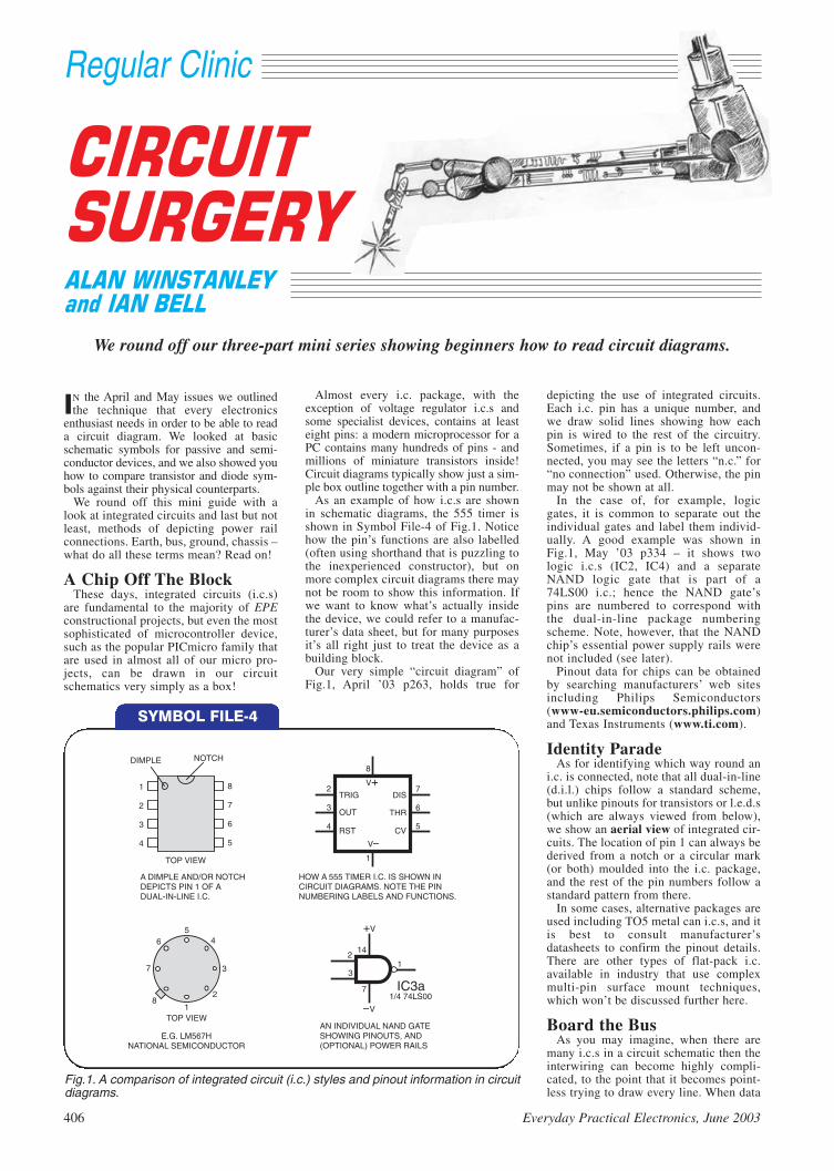
Almost every i.c. package, with theexception of voltage regulator i.c.s andsome specialist devices, contains at leasteight pins: a modern microprocessor for aPC contains many hundreds of pins - andmillions of miniature transistors inside!Circuit diagrams typically show just a sim-ple box outline together with a pin number.
As an example of how i.c.s are shownin schematic diagrams, the 555 timer isshown in Symbol File-4 of Fig.1. Noticehow the pin’s functions are also labelled(often using shorthand that is puzzling tothe inexperienced constructor), but onmore complex circuit diagrams there maynot be room to show this information. Ifwe want to know what’s actually insidethe device, we could refer to a manufac-turer’s data sheet, but for many purposesit’s all right just to treat the device as abuilding block.
Our very simple “circuit diagram” ofFig.1, April ’03 p263, holds true for
Regular Clinic
406 Everyday Practical Electronics, June 2003
IN the April and May issues we outlinedthe technique that every electronics
enthusiast needs in order to be able to reada circuit diagram. We looked at basicschematic symbols for passive and semi-conductor devices, and we also showed youhow to compare transistor and diode sym-bols against their physical counterparts.
We round off this mini guide with alook at integrated circuits and last but notleast, methods of depicting power railconnections. Earth, bus, ground, chassis –what do all these terms mean? Read on!
A Chip Off The BlockThese days, integrated circuits (i.c.s)
are fundamental to the majority of EPEconstructional projects, but even the mostsophisticated of microcontroller device,such as the popular PICmicro family thatare used in almost all of our micro pro-jects, can be drawn in our circuitschematics very simply as a box!
depicting the use of integrated circuits.Each i.c. pin has a unique number, andwe draw solid lines showing how eachpin is wired to the rest of the circuitry.Sometimes, if a pin is to be left uncon-nected, you may see the letters “n.c.” for“no connection” used. Otherwise, the pinmay not be shown at all.
In the case of, for example, logicgates, it is common to separate out theindividual gates and label them individ-ually. A good example was shown inFig.1, May ’03 p334 – it shows twologic i.c.s (IC2, IC4) and a separateNAND logic gate that is part of a74LS00 i.c.; hence the NAND gate’spins are numbered to correspond withthe dual-in-line package numberingscheme. Note, however, that the NANDchip’s essential power supply rails werenot included (see later).
Pinout data for chips can be obtainedby searching manufacturers’ web sitesincluding Philips Semiconductors(www-eu.semiconductors.philips.com)and Texas Instruments (www.ti.com).
Identity ParadeAs for identifying which way round an
i.c. is connected, note that all dual-in-line(d.i.l.) chips follow a standard scheme,but unlike pinouts for transistors or l.e.d.s(which are always viewed from below),we show an aerial view of integrated cir-cuits. The location of pin 1 can always bederived from a notch or a circular mark(or both) moulded into the i.c. package,and the rest of the pin numbers follow astandard pattern from there.
In some cases, alternative packages areused including TO5 metal can i.c.s, and itis best to consult manufacturer’sdatasheets to confirm the pinout details.There are other types of flat-pack i.c.available in industry that use complexmulti-pin surface mount techniques,which won’t be discussed further here.
Board the BusAs you may imagine, when there are
many i.c.s in a circuit schematic then theinterwiring can become highly compli-cated, to the point that it becomes point-less trying to draw every line. When data
We round off our three-part mini series showing beginners how to read circuit diagrams.
SYMBOL FILE-4
1
1
1
1
2
2
2
2
3
3
3
3
4
4
4
5
5
56
6
67
7
78
8
8DIMPLE NOTCH
TOP VIEW
TOP VIEW
A DIMPLE AND/OR NOTCHDEPICTS PIN 1 OF ADUAL-IN-LINE I.C.
TRIG
OUT
RST
DIS
THR
CV
V
V
V+
HOW A 555 TIMER I.C. IS SHOWN INCIRCUIT DIAGRAMS. NOTE THE PINNUMBERING LABELS AND FUNCTIONS.
E.G. LM567HNATIONAL SEMICONDUCTOR
+V
14
7 IC3a1/4 74LS00
AN INDIVIDUAL NAND GATESHOWING PINOUTS, AND(OPTIONAL) POWER RAILS
Fig.1. A comparison of integrated circuit (i.c.) styles and pinout information in circuitdiagrams.
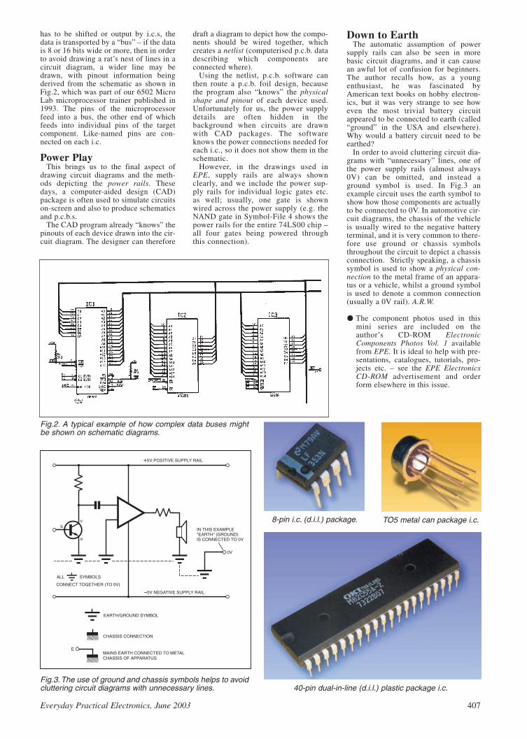
draft a diagram to depict how the compo-nents should be wired together, whichcreates a netlist (computerised p.c.b. datadescribing which components areconnected where).
Using the netlist, p.c.b. software canthen route a p.c.b. foil design, becausethe program also “knows” the physicalshape and pinout of each device used.Unfortunately for us, the power supplydetails are often hidden in thebackground when circuits are drawnwith CAD packages. The softwareknows the power connections needed foreach i.c., so it does not show them in theschematic.
However, in the drawings used inEPE, supply rails are always shownclearly, and we include the power sup-ply rails for individual logic gates etc.as well; usually, one gate is shownwired across the power supply (e.g. theNAND gate in Symbol-File 4 shows thepower rails for the entire 74LS00 chip –all four gates being powered throughthis connection).
has to be shifted or output by i.c.s, thedata is transported by a “bus” – if the datais 8 or 16 bits wide or more, then in orderto avoid drawing a rat’s nest of lines in acircuit diagram, a wider line may bedrawn, with pinout information beingderived from the schematic as shown inFig.2, which was part of our 6502 MicroLab microprocessor trainer published in1993. The pins of the microprocessorfeed into a bus, the other end of whichfeeds into individual pins of the targetcomponent. Like-named pins are con-nected on each i.c.
Power PlayThis brings us to the final aspect of
drawing circuit diagrams and the meth-ods depicting the power rails. Thesedays, a computer-aided design (CAD)package is often used to simulate circuitson-screen and also to produce schematicsand p.c.b.s.
The CAD program already “knows” thepinouts of each device drawn into the cir-cuit diagram. The designer can therefore
Down to EarthThe automatic assumption of power
supply rails can also be seen in morebasic circuit diagrams, and it can causean awful lot of confusion for beginners.The author recalls how, as a youngenthusiast, he was fascinated byAmerican text books on hobby electron-ics, but it was very strange to see howeven the most trivial battery circuitappeared to be connected to earth (called“ground” in the USA and elsewhere).Why would a battery circuit need to beearthed?
In order to avoid cluttering circuit dia-grams with “unnecessary” lines, one ofthe power supply rails (almost always0V) can be omitted, and instead aground symbol is used. In Fig.3 anexample circuit uses the earth symbol toshow how those components are actuallyto be connected to 0V. In automotive cir-cuit diagrams, the chassis of the vehicleis usually wired to the negative batteryterminal, and it is very common to there-fore use ground or chassis symbolsthroughout the circuit to depict a chassisconnection. Strictly speaking, a chassissymbol is used to show a physical con-nection to the metal frame of an appara-tus or a vehicle, whilst a ground symbolis used to denote a common connection(usually a 0V rail). A.R.W.
The component photos used in thismini series are included on theauthor’s CD-ROM ElectronicComponents Photos Vol. 1 availablefrom EPE. It is ideal to help with pre-sentations, catalogues, tutorials, pro-jects etc. – see the EPE ElectronicsCD-ROM advertisement and orderform elsewhere in this issue.
Everyday Practical Electronics, June 2003 407
Fig.2. A typical example of how complex data buses mightbe shown on schematic diagrams.
bc
e
+5V POSITIVE SUPPLY RAIL
5V NEGATIVE SUPPLY RAIL
IN THIS EXAMPLE"EARTH" (GROUND)IS CONNECTED TO 0V
0V
ALL SYMBOLS
CONNECT TOGETHER (TO 0V)
EARTH/GROUND SYMBOL
CHASSIS CONNECTION
MAINS EARTH CONNECTED TO METALCHASSIS OF APPARATUS
E
Fig.3. The use of ground and chassis symbols helps to avoidcluttering circuit diagrams with unnecessary lines. 40-pin dual-in-line (d.i.l.) plastic package i.c.
8-pin i.c. (d.i.l.) package. TO5 metal can package i.c.

410 Everyday Practical Electronics, June 2003
case, however, the two oscillators use aninductive tap to generate the feedback,which is applied to the transistor bases viacapacitors C1 and C3.
The first oscillator frequency is variableand the second is fixed. The frequency ofoscillation depends on the values of theinductors and their tuning capacitors C2and C4. In the case of the variable oscilla-tor around TR1, it is also governed by theadditional capacitance of the player’s handclose to a metal plate or aerial. The induc-tance values are adjustable so that the fre-quencies of both oscillators can be tunedas required.
As the hand is moved closer to the plate,this capacitance increases causing a corre-sponding decrease in the frequency of theoscillator. The changes in capacitance areminute, however, resulting in only verysmall changes in frequency.
The outputs of two oscillators are
mixed, resulting in both sum and differ-ence frequencies. If the two basic frequen-cies are close enough, the resultant beatfrequencies will be in the audio range. Theinteresting thing is that although the origi-nal frequencies are high and well above theaudio range, a small change in one of themproduces a large change in the audio beatfrequency producing a very sensitiveinstrument with a wide pitch range.
The outputs from the oscillators are cou-pled by resistors R3 and R4 to capacitorC5 and into the mixer stage around TR3.
in a completely different way and does noteven require the musician to touch theinstrument to play it!
All the notes are produced using theinteraction of just two oscillators and theinstrument can only play one note at atime. As well as the standard musicaltones, all other frequencies in between canalso be produced, gliding between them inresponse to hand movements.
This provides some interesting soundsbut also makes the instrument quite diffi-cult to play. This is even more true of thesimplified version described here – profes-sional Theremins also have a controlenabling the signal to be muted by the per-former so that the notes do not have toglide from one pitch to the next.
The operation of a Theremin is based on
two high frequency tuned circuit oscilla-tors running at almost identical frequen-cies. This type of oscillator was discussedin the Metal Detector project in Part Twoof this series (March ’03).
Referring to the circuit diagram shownin Fig.30, the oscillators are based aroundtransistors TR1 and TR2. Note that in this
DESPITE their obvious uses in ampli-fying the sound of conventionalacoustic musical instruments, tran-
sistors have had a great impact in terms ofthe actual generation of musical notes andrhythms.
This is especially true since integratedcircuits (which are comprised of manytransistors) were first introduced, enablinginstruments such as electronic organs andsynthesisers to be produced. These canproduce sounds which mimic conventionalinstruments and are played selecting therequired notes by pressing switches nor-mally arranged as a piano keyboard.
In such instruments, each note may begenerated by its own oscillator, or by amaster oscillator and many divider stagesto obtain the lower notes. Notes are thenprocessed by filters and envelope shaperswhich tailor the waveform to produce therequired sound, and fed to an amplifier andloudspeaker.
One instrument that differs radically
from keyboard instruments is theTheremin, named after its inventor LeonTheremin. A Theremin produces the notes
Part Five
Fig.30. Complete circuit diagram for the Mini Theremin.

The resistors have relatively high values toprevent the oscillators from interactingundesirably and locking together. Themixer also amplifies the resultant frequen-cies and drives the piezo transducer WD1.
Frequencies above the audio range arelargely attenuated by the capacitance of thetransducer, leaving only the audio tone beatfrequency. However, if the output is to beconnected to an external amplifier in placeof WD1, a 2200pF capacitor should beconnected in parallel with resistor R6 asthe signal could otherwise cause interfer-ence in radio equipment.
The circuit is powered by a 9V battery,supplied via switch S1. Capacitors C6 andC7 are included to ensure a low impedancesupply at both low and high frequencies.The current consumption is about 1mA.
The complete circuit is built on a small
piece of stripboard having 19 holes × 8strips, as shown in Fig.31. Before startingconstruction, the tracks should be cut in theplaces indicated using a 2·5mm drill, or thespecial tool available for this.
Two wire links are also required andthese can be made from discarded compo-nent leads. As with all projects in thisseries, the layout applies to the specifiedtransistors and if substitutes are used, careshould be taken as pinouts may differ.
Inductors L1 and L2 are small i.f. (inter-mediate frequency) transformers normallyused in radio receivers and the types speci-fied do not have integral capacitors. Thecans have solder lugs enabling these to besoldered to fix them, although in this appli-cation the lugs do not fit into the pitch of thestripboard so they are simply bent up under-neath the component before it is mounted.
WD1 is a piezo sounder (not to be con-fused with a piezo buzzer which containsan integral drive circuit) and this may beconnected either way around.
The “tuning” plate should consist of asmall piece of aluminium or copper-cladp.c.b. laminate, measuring about 40mm ×50mm, connected to the circuit by a shortwire. Alternatively, this can take the formof a short aerial 10cm to 15cm long con-nected to the same point on the circuit.
If the unit is to be mounted in a box, aplastic case with a battery compartmentwould be most suitable.
When finished, the circuit must be tuned
for correct operation by adjusting theinductor cores so that both oscillators areworking at around the same frequency.
Only use a plastic blade for adjusting thecores – a metal tool could damage them.
It is best to set one core to about its mid-position and adjust the other until a whistleis heard from the sounder. Bringing yourhand near the sensor plate will then resultin a lower pitch sound. Alternatively thecircuit may be adjusted beyond this pointso that the frequency rises as your handapproaches the sensor.
Apart from its undoubted(?) musicalapplications, the unit could find uses as arudimentary proximity alarm to detect thepresence of people or animals, although thestability of this simple circuit is not idealfor such applications.
Everyday Practical Electronics, June 2003 411
Approx. CostGuidance Only ££66
excl. case & batt.
ResistorsR1, R3, R5 1M8 (3 off)R2, R4 220k (2 off)R6 4k7
All 0·25W 5% carbon film
CapacitorsC1, C3,
C5, C6 1n disc ceramic, 2·5mm pitch (4 off)C2, C4 100p disc ceramic, 2·5mm pitch (2 off)C7 10 radial elect. 16V
SemiconductorsTR1, TR2 2N3904 npn transistor (2 off)TR3 BC558 pnp transistor
MiscellaneousL1, L2 Toko RD7 inductor (2 off)S1 s.p.s.t. min. toggle switchWD1 piezo sounder
Stripboard, 19 holes x 8 strips; PP3 battery and clip; plasticcase to suit; copper-clad p.c.b. laminate or aluminium place,approx. 40mm x 50mm (see text); connecting wire; solder, etc.
SeeSSHHOOPPTTAALLKKppaaggee
Fig.31. Stripboard component layout, interwiring and detailsof breaks required in the underside copper tracks.
Component layout on the completed circuit board.
Finished Mini Theremin showing wiring to the “tuning” plate and piezoelectricsounder. The tuning plate is an off-cut from a piece of copper-clad board.

412 Everyday Practical Electronics, June 2003
THIS circuit is designed to switch ona low-power lamp when it getsdark and switch it off again at
sunrise. It could, for example, be used asa burglar deterrent to give the impres-sion that a house is occupied, or to lighta path or porch during the hours ofdarkness.
With a slight modification, it could alsobe used as a medicine cupboard alarm togive a warning when it has been opened or,by changing the sensor, as a temperaturecontroller (thermostat).
Referring to the circuit diagram in Fig.32,
light dependent resistor (l.d.r.) R1 is used asthe light sensor. In bright conditions, itsresistance is around 2k rising to over 20kin low light and over 1M in darkness.
Transistors TR1 and TR2 form a com-plementary Schmitt trigger circuit that hastwo switching thresholds. Assuming bothTR1 and TR2 are on, resistors R4 and R5are connected across the power supply as apotential divider. They set the voltageapplied to the base of TR1 at just under 3V,assuming a 9V supply.
With the l.d.r. in darkness, the voltage atits junction with preset VR1 will be abovethat on TR1’s base. The sensor voltage isapplied to TR1’s emitter via resistors R2and R3. Capacitor C1 smooths out fluctua-tions in light intensity during daylight con-ditions, such as caused by shadows movingacross the l.d.r., or illumination by carheadlights at night.
During darkness, the voltage from the
l.d.r. will be sufficient to cause transistorTR3 to be turned on via TR1 and TR2. Asa result, l.e.d. D1 is switched on, via ballastresistor R7.
As the light level increases, the resis-tance of the l.d.r. falls so that the input volt-age to the circuit also falls. Once it fallsbelow 2V, TR1 begins to switch off. Thiscauses TR2 to switch off raising the voltage
on TR1’s base, causing both transistors toswitch off rapidly. With TR2 off, TR3 alsoswitches off, as does l.e.d. D1.
With falling light levels, the l.d.r. resis-tance increases and the voltage at TR1’semitter rises. However, since TR2 is off,the threshold voltage will now be deter-mined only by R4 and R5 (about 3V withthe component values given). The inputlevel will therefore have to rise above thisvalue before TR1 can switch on and thecircuit revert to its former state with allthree transistors on.
It will be seen that there is a differencebetween the brightness levels at which thecircuit switches on and off. This property iscalled hysteresis and is useful as it givesthe circuit a “snap” action, switching onand off rapidly even if the input is chang-ing slowly. It also prevents the lampswitching on and off as the thresholds areapproached. Note that altering the value ofR6 will vary the hysteresis.
Transistor TR3’s collector load, com-
prising l.e.d. D1 and R7, could be replacedby, or used in conjunction with, an opto-isolated triac or a relay to switch on amains lamp, as shown in Fig.33b andFig.33c.
Note that the mains voltage existing atthe output of both these circuits is dan-gerous and these two options should onlybe built under competent supervision.Suitable insulation, earthing and fusearrangements must be provided.
The opto-triac type MOC3020 can han-dle output currents up to 100mA, i.e. amaximum of 23W of 230V a.c. mainspower. The typical maximum size of mainsdriven lamp that can be used with it is thusapproximately 15W.
With relay control, the maximum lamppower is limited only by the rating of therelay contacts.
A problem that could be encountered ifa mains lamp is fitted is that of the circuitoscillating. When the light level falls, thelight will switch on and the ambientbrightness will increase causing the lampto switch off again. The large hysteresisshould help to prevent this but it is impor-tant that the sensor is positioned so that itcannot “see” the light from the lamp.
µ
Fig.32. Circuit diagram for the light sensitive Twilight Switch.
Fig.33. Circuit details for alternative output options.
ResistorsR1 ORP12 light dependent
resistorR2 100kR3 470kR4 22kR5, R6 10k (2 off)R7 1k
All 0·25W 5% carbon film
CapacitorC1 47 radial elect. 16V
SemiconductorsD1 red l.e.d.TR1 BC558 pnp transistorTR2, TR3 2N3904 npn transistor
(2 off)
MiscellaneousS1 s.p.s.t. min. toggle switchVR1 47k skeleton preset
potentiometerWD1 piezo buzzer
Stripboard, 14 holes x 7 strips; PP3battery and clip; case to suit (see text);relay (optional), 12V coil with mains con-tacts, opto-triac (optional) MOC3020 orM0C3040, 12V Buzzer (optional); con-necting wire; solder, etc.
Approx. CostGuidance Only ££66
excl. case, relay, opto-triac & batt.
SeeSSHHOOPPTTAALLKKppaaggee

A simple thermostat could be built by
replacing the l.d.r. with an n.t.c. thermistor(negative temperature coefficient – resistancefalls with increases in temperature).Depending on the resistance of the type used,the value of VR1 may need to be altered.
By connecting a buzzer across l.e.d. D1and R7, and transposing the l.d.r. and pre-set VR1, a simple medicine cupboardalarm can be made. In this case TR3 willswitch on when the ambient light levelincreases (i.e. when the cupboard door isopened) and switch off when it is dark.
The response delay can be removed ifrequired by omitting capacitor C1.
The circuit may be built on a piece of
stripboard measuring 14 holes by 7 strips
as shown in Fig.34. Before assembling andsoldering the components on the board, thetracks should be cut in the places indicatedby means of a 2·5mm drill or the tool avail-able for this purpose.
Take care to ensure that the transistors,l.e.d. and electrolytic capacitor C1 areinserted the correct way around. There isalso one link required which can be madefrom a piece of discarded resistor lead.
It is also important to connect the buzzer(if used) correctly. These components oftenhave the polarity indicated by the lead withred being positive. Note that a unit with aninternal oscillator is required.
The l.d.r. (or thermistor) is not polaritysensitive and may be connected either wayaround.
The mains switching options must NOTbe built on the stripboard but as a separate
unit and connected to the control circuit bysuitable leads. To ensure safety with themains switching option, the complete cir-cuit must be mounted in an earthed metalcase with a suitable mains input plug andoutlet socket for the lamp. A fuse and fuse-holder should be included, rated to suit thelamp used.
Do not adjust the circuit with the mainsconnected or operate the unit with the boxopen. If the circuit is used to control amains lamp, the l.e.d. will be superfluousbut may be retained.
Setting up consists of adjusting preset VR1so that the circuit switches at the requiredlight level. This may be simulated by shield-ing the l.d.r. and adjusting VR1 accordinglyand is best done before C1 is soldered intothe circuit so that the unit responds immedi-ately to changes in light levels.
Everyday Practical Electronics, June 2003 413
Fig.34. Component layout, wiring and copper break details. Completed prototype Twilight Switch.
Innovative Products Imaginative Solutions
Robotics, Control & Electronics Technology
Robot Arms
BEAM Robots
Visit our site www.totalrobots.comor Phone us on 020 8823 9220
ProgrammableMobile Robots
Innovative Products Imaginative Solutions
Embedded InternetSolutions
RapidDevelopment
Micro-Controllers
I2C and SerialLCD Modules
Visit our site www.trcontrolsolutions.comor Phone us on 020 8823 9230

BATTERY technology is an increasinglyimportant part of today’s electronics
scene. It was not many years ago whenNickel Cadmium cells were the onlyrechargeable types on the market. Bytoday’s standards they were inefficient interms of energy storage density.Additionally the cadmium they containedmade them difficult to dispose of in anenvironmentally friendly manner.
Since then technology has moved onsignificantly. Nickel Metal Hydride cellsarrived. These cells provided an improve-ment in performance, but probably moreimportant they were more environmental-ly friendly. However, a significant leap inperformance has been made by the intro-duction of Lithium Ion or Li-Ion cells.This technology offers a significantimprovement in performance, enablingmuch higher levels of charge to be storedin a given volume or battery weight.
Even these new cells, though, areundergoing further development toimprove their performance. Develop-ments at the Sandia Labs in Californiapromise to give improvements of up to400% according to Jim Wang, Manager ofthe Analytical Materials ScienceDepartment at Sandia.
Li-Ion CellsLike many other types of cell, Lithium
Ion cells consist of a positive electrode, anegative electrode and a separator. Thecathode or positive electrode consists oflithium metal oxide. The other metal inthis oxide may be a variety of metals. Onethat is often used is cobalt. The anode ornegative electrode is made from activatedcarbon. Between these two electrodesthere is a physical separator to ensure thatthe two electrodes do not touch, and italso acts as an electrolyte to provide aconduction path between the electrodes.
In the charge-discharge cycle a compli-cated chemical reaction occurs where thelithium in the positive electrode is ionisedduring the charge process, ions moving tothe other electrode. During the dischargepart of the cycle, ions move to the positiveelectrode and return it to its originalstructure.
Lithium-Ion cells offer many advan-tages over previous types of cell. Theyhave a long cycle life, and they offerapproximately two and a half times theenergy density of Nickel Cadmium. Whencompared to Nickel Metal Hydride, theyoffer approximately twice the energy den-sity. Their voltage is higher than the othertwo technologies. At 3·6 volts it is threetimes that of the other commonly used
414 Everyday Practical Electronics, June 2003
whilst also still being able to expandwithout distorting the overall anodeassembly.
Development ProcessIn reaching its conclusions about the
new material’s performance, Wang andother researchers at Sandia took amethodical approach that spanned threeyears. First they produced compositepowders with varying silicon-to-carbonratios and microstructures. Then they pro-duced electrodes from the resultant pow-ders and evaluated their performance byelectrochemical measurements. They thenexamined structural changes in the elec-trodes during cycling to understand thelithium transfer mechanism and materialsphase changes to further improve the newmaterial.
According to Greg Roberts, a PostDoctoral team member at Sandia, theresearch and development focused on thereplacement of graphite electrodes inrechargeable lithium batteries and this hastaken many forms over the years. Heexplained that possible replacement candi-dates included non-graphitic carbons, inter-metallics, oxides, nitrides, and composites.
While each material has unique advan-tages and disadvantages that need to beconsidered when designing a battery for aspecific application, Roberts said the sili-con/graphite electrode materials arepromising for applications that requirehigh capacities delivered at low-to-mod-erate rates.
Sandia researchers acknowledge thatthere are some potential problems withthe new material. The complete elimina-tion of fading of long-term cycling capac-ity in the silicon-based electrodes may notbe possible, though it is possible that itcan be minimised by the design of the car-bon-silicon composite microstructure.
The research team are confident that thesilicon/graphite electrode materials haveopened the door for future breakthroughs.“We believe that only other silicon-con-taining electrode materials can competewith the large capacities that our sili-con/graphite composites have demon-strated,” Wang said.
ImpactIt is anticipated that the discovery will
have wide-ranging impact on a variety ofconsumer and defence applications as theuse of Li-Ion batteries is now widespreadand there is always a great demand forincreased battery life. Mobile phone andlaptop computer users will welcome anyimprovements in battery life.
forms of cell. This is a major advantage inmany applications where the 1·2 voltsprovided by both Nickel Cadmium andNickel Metal Hydride is normally toolow. Additionally the self discharge char-acteristic of these cells is very low.However, one of the major advantages isthat they offer a competitive cost whencompared to the other technologies.
Their major disadvantage is that theymust not be electrically stressed.Overcharging them destroys them veryquickly. To overcome this, battery man-agement systems are always employedwith these cells.
ImprovementsThe developments that have been
undertaken at Sandia not only promisemore powerful batteries, but also onesthat last longer. It is found that when Li-Ion batteries are cycled through a charge-discharge cycle they loose a small amountof capacity each time.
To overcome this problem, Sandia haveadded silicon to the anode structure. Thesilicon on its own offers more than 10times the capacity potential of graphite,but is hampered by a rapid capacity lossduring the battery cycling phase. Whensmall particles of silicon are combinedwithin a graphite matrix, however, thelarge capacities are retained.
The silicon on its own is not suitable forconstructing anodes and therefore a mixof the two materials is used. The marriageof silicon and graphite may improve thespecific capabilities of commercialgraphite anode materials up to 400%, saidJim Wang.
The silicon graphite composites can beproduced using a simple milling process.This is a standard production methodolo-gy that is common within industry. Thismeans that it is relatively easy to imple-ment and no new processes or handlingtechniques are required.
In a conventional cell, one lithium ion isabsorbed between each six carbon atoms.In the new cell technology each siliconatom holds four lithium ions. This is a 24-fold increase in capacity per atom.
There are a number of problems to beovercome. The silicon anode needs a verylarge surface area. In addition to this itmust be physically able to cope with thedoubling in size that the silicon undergoeswhen it absorbs that vast amount oflithium.
Both these problems have been over-come by using small silicon particles in amatrix of graphite. This allows the siliconto present a sufficiently high surface area
New TechnologyUpdate

BBAACCKK IISSSSUUEESSFEB ’02
PROJECTS PIC Spectrum Analyser GuitarPractice Amp HT Power Supply VersatileCurrent Monitor.FEATURES Teach-In 2002 – Part 4 IngenuityUnlimited Russian Space Shuttle Revisited Circuit Surgery Interface New TechnologyUpdate Net Work – The Internet Page.
MAR ’02PROJECTS MK484 Shortwave Radio PICVirus Zapper RH Meter PIC Mini-Enigma.FEATURES Teach-In 2002 – Part 5 IngenuityUnlimited Programming PIC Interrupts–1 CircuitSurgery Practically Speaking New TechnologyUpdate Net Work – The Internet Page.
APR ’02PROJECTS Electric Guitar Tuner PICControlled Intruder Alarm Solar Charge and Go Manual Stepper Motor Controller.FEATURES Teach-In 2002 – Part 6 Interface Programming PIC Interrupts–2 Circuit Surgery Ingenuity Unlimited New Technology Update Net Work – The Internet Page FREE GiantOp.Amp Data Chart.
MAY ’02PROJECTS PIC Big-Digit Display Simple AudioCircuits – 1 Freezer Alarm Washing ReadyIndicator.FEATURES Teach-In 2002 – Part 7 IngenuityUnlimited Practically Speaking New TechnologyUpdate Circuit Surgery Net Work – The InternetPage.
JUNE ’02PROJECTS Biopic Heartbeat Monitor Frequency Standard Generator Simple AudioCircuits – 2 World Lamp.FEATURES Teach-In 2002 – Part 8 Interface New Technology Update Circuit Surgery Ingenuity Unlimited Net Work – The InternetPage.
JULY ’02PROJECTS EPE StyloPIC Infra-RedAutoswitch Simple Audio Circuits – 3 RotaryCombination Lock.FEATURES Teach-In 2002 – Part 9 PracticallySpeaking Using The PIC’s PCLATH Command Ingenuity Unlimited Circuit Surgery NewTechnology Update Net Work–The Internet Page.
AUG ’02 Photocopies only PROJECTS PIC World Clock Pickpocket AlarmBig-Ears Buggy Simple Audio Circuits – 4.FEATURES Teach-In 2002 – Part 10 UsingSquare Roots with PICs Ingenuity Unlimited Evolutionary Electronics Interface CircuitSurgery Net Work – The Internet Page.
SEPT ’02 Photocopies only PROJECTS Freebird Glider Control PortableTelephone Tester EPE Morse Code Reader Vinyl to CD Preamplifier.FEATURES Circuit Surgery New TechnologyUpdate Practically Speaking Net Work Flowcode for PICmicro Logic Gate InverterOscillators Net Work – The Internet Page.
OCT ’02 Photocopies onlyPROJECTS EPE Bounty Treasure Hunter ICTester Headset Communicator PIC-PocketBattleships.FEATURES Circuit Surgery New TechnologyUpdate Logic Gate Inverter Oscillators – 2 Interface Network – The Internet Page UsingTK3 With Windows XP and 2000.
NOV ’02 Photocopies only PROJECTS EPE Hybrid Computer – 1 TuningFork and Metronome Transient Tracker PICAXEProjects–1 (Egg Timer – Dice Machine – QuizGame Monitor).FEATURES Practically Speaking IngenuityUnlimited Circuit Surgery New TechnologyUpdate Net Work – The Internet Page.
DEC ’02PROJECTS Versatile PIC Flasher EPE HybridComputer – 2 Door Defender PICAXE Projects– 2 (Temperature Sensor – Voltage Sensor – VUIndicator).FEATURES Electronic Paper Alternative Usesfor Transistors Interface Circuit Surgery NewTechnology Update Ingenuity Unlimited NetWork – The Internet Page 2002 Annual Index.
JAN ’03PROJECTS EPE Minder F.M. Frequency Surfer Wind Speed Meter PICAXE Projects–3 (ChaserLights).FEATURES Who Really Invented The Transistor TechnoTalk Circuit Surgery Practically Speaking New Technology Update Computer GOTOs Ingenuity Unlimited Net Work – The Internet Page.
FEB ’03PROJECTS Wind Tunnel Brainibot Buggy Back To Basics–1 (Hearing Aid, Audio PowerAmplifier) Tesla High Voltage Transformer.FEATURES In The Bag Techno Talk CircuitSurgery New Technology Update Interface Ingenuity Unlimited Net Work – The Internet Page.
MAR ’03PROJECTS Wind-Up Torch Mk II 200kHzFunction Generator Driver Alert Back-To-Basics–2 (Metal Detector, Simple Timer).FEATURES Ingenuity Unlimited PracticallySpeaking Techno Talk New Technology Update Circuit Surgery Peak LCR Component AnalyserReview Net Work – The Internet Page.
APR ’03PROJECTS Atmospherics Monitor IntelligentGarden Lights Controller Back-To-Basics–3(Touch Light, Plant Watering Reminder) EarthResistivity Logger–Part 1.FEATURES Ingenuity Unlimited Techno Talk New Technology Update Circuit Surgery Interface Network – The Internet Page SPECIALSUPPLEMENT – EPE PIC Tutorial V2–Part 1.
MAY ’03PROJECTS Super Motion Sensor EarthResistivity Logger – Part 2 Door Chime Back-To-Basics–4 (Live Wire Detector, Medium WaveRadio).FEATURES Ingenuity Unlimited Techno Talk Practically Speaking Circuit Surgery Net Work– The Internet Page SPECIAL SUPPLEMENT –EPE PIC Tutorial V2 – Part 2.
We can supply back issues of EPE by post, most issues from the past three years are available. An EPE index for the last five years is also available atwww.epemag.wimborne.co.uk or see order form below. Alternatively, indexes are published in the December issue for that year. Where we are unable toprovide a back issue a photocopy of any one article (or one part of a series) can be purchased for the same price. Issues from Nov. 98 are available on CD-ROM – see next page – and issues from the last six months are also available to download from www.epemag.com.
BACK ISSUES ONLY £3.50 each inc. UK p&p.Overseas prices £4 each surface mail, £5.50 each airmail.
We can also supply issues from earlier years: 1998 (except Jan. to May, July, Sept., Nov., Dec.), 1999(except Aug., Dec.), 2000 (except Feb.), 2001 (except May, Sept., Oct.), 2002 (except Aug. to Nov.)Where we do not have an issue a photocopy of any one article or one part of a series can be provided atthe same price.
OORRDDEERR FFOORRMM – BACK ISSUES – PHOTOCOPIES– INDEXES
Send back issues dated . . . . . . . . . . . . . . . . . . . . . . . . . . . . . . . . . . . . . . . . . . . . . . . . . . . . . . . . . . . . . . . . . . .
Send photocopies of (article title and issue date) . . . . . . . . . . . . . . . . . . . . . . . . . . . . . . . . . . . . . . . . . . . . . . . . .
Send copies of last five years indexes (£3.50 for five inc. p&p – Overseas £4 surface, £5.50 airmail)
Name . . . . . . . . . . . . . . . . . . . . . . . . . . . . . . . . . . . . . . . . . . . . . . . . . . . . . . . . . . . . . . . . . . . . . . . . . . . . . . . . . . . .
Address . . . . . . . . . . . . . . . . . . . . . . . . . . . . . . . . . . . . . . . . . . . . . . . . . . . . . . . . . . . . . . . . . . . . . . . . . . . . . . . . . .
. . . . . . . . . . . . . . . . . . . . . . . . . . . . . . . . . . . . . . . . . . . . . . . . . . . . . . . .Tel: . . . . . . . . . . . . . . . . . . . . . . . . . . . . .
I enclose cheque/P.O./bank draft to the value of £ . . . . . . . . . . . . . . . . . . . . . . . . . . . . . . . . . . . . . . . . . . . . . . . .
Please charge my Visa/Mastercard/Amex/Diners Club/Switch £ . . . . . . . . Switch Issue No. . . . . . . . . .
Card No. . . . . . . . . . . . . . . . . . . . . . . . . . . . . . . . . . . . . . . . . . . . . . . . . . . . . . . . . . . . . . . . . . . . . . . . . . . . . . . . . . .
Card Expiry Date . . . . . . . . . . . . Card Security Code . . . . . . . . . . (The last 3 digits on or just under the signature strip)
SEND TO: Everyday Practical Electronics, Wimborne Publishing Ltd., 408 Wimborne Road East, Ferndown, Dorset BH22 9ND.Tel: 01202 873872. Fax: 01202 874562.
E-mail: [email protected] On-line Shop: www.epemag.wimborne.co.uk/shopdoor.htmPayments must be in £ sterling – cheque or bank draft drawn on a UK bank. Normally supplied within seven days of receipt of order.
Send a copy of this form, or order by letter if you do not wish to cut your issue.M06/03
Everyday Practical Electronics, June 2003 415
DDIIDD YYOOUU MMIISSSS TTHHEESSEE??

SSTTOORREE YYOOUURR BBAACCKK IISSSSUUEESS OONN MMIINNII CCDD--RROOMMSS
A great way to buy EPE Back Issues – our mini CD-ROMs containback issues from our EPE Online website plus bonus articles, all therelevant PIC software and web links. Note: no free gifts are included.
All this for just £14.45 each including postage and packing.
VOL 1 CONTENTSBACK ISSUES – November 1998 to June 1999
VOL 2 CONTENTSBACK ISSUES – July 1999 to December 1999
VOL 3 CONTENTSBACK ISSUES – January 2000 to June 2000
VOL 4 CONTENTSBACK ISSUES – July 2000 to Dec. 2000
VOL 5 CONTENTSBACK ISSUES – January 2001 to June 2001
VOL 6 CONTENTSBACK ISSUES – July 2001 to December 2001
VOL 7 CONTENTSBACK ISSUES – Jan 2002 to June 2002
VOL 8 CONTENTSBACK ISSUES – July 2002 to December 2002
WHAT IS INCLUDEDAll volumes include the full editorial content of everylisted issue, plus all the available PIC Project Codesfor the PIC projects published in those issues.Note that no advertisements are included in Volumes 1 and2; from Volume 5 onwards the available relevant software forInterface articles is also included.
EXTRA ARTICLES – ON ALL VOLUMESBASIC SOLDERING GUIDE – Alan Winstanley’s internationallyacclaimed fully illustrated guide. UNDERSTANDING PASSIVE COMPO-NENTS – Introduction to the basic principles of passive components.HOW TO USE INTELLIGENT L.C.Ds, By Julyan Ilett – An utterly practi-cal guide to interfacing and programming intelligent liquid crystal displaymodules. PhyzzyB COMPUTERS BONUS ARTICLE 1 – Signed andUnsigned Binary Numbers. By Clive “Max” Maxfield and Alvin Brown.PhyzzyB COMPUTERS BONUS ARTICLE 2 – Creating an EventCounter. By Clive “Max” Maxfield and Alvin Brown. INTERGRAPHCOMPUTER SYSTEMS 3D GRAPHICS – A chapter from Intergraph’sbook that explains computer graphics technology in an interesting andunderstandable way with full colour graphics.
EXTRA ARTICLE ON VOL 1 & 2. THE LIFE & WORKS OF KONRADZUSE – a brilliant pioneer in the evolution of computers. A bonus articleon his life and work written by his eldest son, including many previouslyunpublished photographs.
BACK ISSUES MINI CD-ROM ORDER FORM
Please send me ........ (quantity) BACK ISSUES CD-ROM VOL 1Please send me ........ (quantity) BACK ISSUES CD-ROM VOL 2Please send me ........ (quantity) BACK ISSUES CD-ROM VOL 3Please send me ........ (quantity) BACK ISSUES CD-ROM VOL 4Please send me ........ (quantity) BACK ISSUES CD-ROM VOL 5Please send me ........ (quantity) BACK ISSUES CD-ROM VOL 6Please send me ........ (quantity) BACK ISSUES CD-ROM VOL 7Please send me ........ (quantity) BACK ISSUES CD-ROM VOL 8
Price £14.45 each – includes postage to anywhere in the world.
Name . . . . . . . . . . . . . . . . . . . . . . . . . . . . . . . . . . . . . . . . . . . .
Address . . . . . . . . . . . . . . . . . . . . . . . . . . . . . . . . . . . . . . . . . .
. . . . . . . . . . . . . . . . . . . . . . . . . . . . . . . . . . . . . . . . . . . . . . . .
. . . . . . . . . . . . . . . . . . . . . . . . . . Post Code . . . . . . . . . . . . .
I enclose cheque/P.O./bank draft to the value of £ . . . . . . . . .
Please charge my Visa/Mastercard/Amex/Diners Club/Switch
£ . . . . . . . . . . . . . . . . . . . . . . . . . . . . . . . . . . . . . . . . . . . . . . .
Card No. . . . . . . . . . . . . . . . . . . . . . . . . . . . . . . . . . . . . . . . . .
Card Security Code . . . . . . . . . . (The last 3 digits on or just under the signature strip)
Expiry Date . . . . . . . . . . . . . . . . . . Switch Issue No. . . . . . . .
SEND TO: Everyday Practical Electronics,Wimborne Publishing Ltd.,
408 Wimborne Road East, Ferndown, Dorset BH22 9ND.Tel: 01202 873872. Fax: 01202 874562.E-mail: [email protected]
Payments must be by card or in £ Sterling – cheque or bankdraft drawn on a UK bank.
Normally supplied within seven days of receipt of order.Send a copy of this form, or order by letter if you do not wish to cut your issue.
Order on-line fromwww.epemag.wimborne.co.uk/shopdoor.htm
or www.epemag.com (USA $ prices)or by phone, Fax, E-mail or Post
416 Everyday Practical Electronics, June 2003
NOTE: These mini CD-ROMs aresuitable for use on any PC with a
CD-ROM drive. They require AdobeAcrobat Reader (available free from
the Internet –www.adobe.com/acrobat)
ONLY££1144..4455 each
including VATand p&p
VVOOLL 88NNOOWW AAVVAAIILLAABBLLEE

CONTROL of and reading from the serialport handshake lines has been
covered in recent Interface articles. Thesoftware side of things is reasonablystraightforward using the MSCOMMActiveX control, and interfacing circuitsto the handshake lines is also reasonablysimple.
The only slight complication in the hard-ware is the use of nominal signal voltagesof ±12V for all RS232C lines including thehandshake types. In most cases it is possi-ble to drive RS232C inputs from ordinary5V logic levels provided short cables of nomore than two metres or so are used.
There is no guarantee that it will workreliably with all RS232C ports, but italways seems to. There is no risk of any-thing being damaged, so there is no harmin trying. If it fails to work, the port mustbe driven at the proper signal voltages vialine drivers.
Stepping DownDriving ordinary logic inputs from an
RS232C output is a different matter. Thesignal voltages are nominally plus andminus 12V, but can be somewhat higherin practice. The output potentials do fallsignificantly under heavy loading, andthe output current is limited to about20mA. Even so, drive voltages well out-side the limits for most logic chips areproduced.
Stating that normal logic inputs shouldnot be driven from serialport outputs will sometimesbring a response or two fromreaders who say they havetried it and it works. A fewlogic devices are designed tohave compatibility with seri-al outputs as well as stan-dard 5V logic types, and it isobviously all right to usethese with RS232C ports.
Some logic chips mightactually work when drivendirect from a serial port, withtheir input protection circuitsclipping the inputs at safelevels. However, relying onprotection circuits to preventa project from being zappedis not really an approach thatcan be recommended. Thelong-term reliability of suchan arrangement is far fromcertain.
Although it might actuallywork with some chips, it willdestroy others or cause themto malfunction. Trying todirectly drive expensivechips would be foolhardyand probably costly as well. Itis much better to use linereceivers that provide thenecessary voltage reductions.
There are special line receiver chipsavailable, but a simple common emitterswitching circuit such as the one shownin Fig.1 will usually suffice. It has to beborne in mind that there is an inversionthrough this circuit, and through any nor-mal line driver and receiver circuits. Thisshould not cause any major problems,and where necessary it is just a matter ofwriting the software to take the inversioninto account.
The MAX202 chip is a good choice if linedrivers are required. This chip operatesfrom a single 5V supply from which itgenerates supplies of ±10V using a simpleswitching power supply.
As can be seen from the circuit of Fig.2,no inductors are required. The supplies
are generated using four capacitors andelectronic switches in essentially thesame arrangements used with the popu-lar ICL7660 supply chip. Capacitors C2 toC5 must be high quality componentssuch as tantalum types. Two line driversare provided, together with two linereceivers.
Count On ItOne of the most common requests from
readers used to be circuits for what is gen-erally termed batch counting. In otherwords, a counter of the type that is usedfor counting products as they roll off theend of a production line. This type ofthing has many other uses, such as lapcounting for model racing cars and count-ing the number of pages produced by aprinter. MSCOMM makes it easy to counttransitions on the serial port handshakeinputs, as it can generate an event oneach one.
The difficult part of batch counting isfinding a means of reliably detectingobjects as they pass. Generating a basicsignal is often quite straightforward, butspurious pulses tend to be a problem.These are more or less guaranteed toappear with simple mechanical sensingvia a microswitch due to contact bounce.For one reason or another, spurious puls-es often occur with other types of sensingsuch as optical and magnetic types. Agrossly excessive count is produced
unless these pulses are filteredout.
A monostable circuit is oneof the most simple but effec-tive methods of removingswitching glitches. A simple“switch-debouncing” circuit,based on a 555 timer, is shownin Fig.3. A low-power versionof the 555 is specified, but thecircuit will work just as wellwith the standard device,albeit with a higher currentconsumption.
The circuit uses the timerchip (IC1) in the standardmonostable mode, and it istriggered when switch S1 clos-es. In practice S1 is amicroswitch that is activatedby each object as it passes by.
The timing components areresistor R1 and capacitor C2.These set the pulse duration atjust under 250 milliseconds,but other pulse times can beobtained by altering the valueof capacitor C2. The pulseduration is proportional to thevalue of this component.
Spurious pulses might trig-ger the circuit and produceextra output pulses if thepulse duration is too short.
418 Everyday Practical Electronics, June 2003
INTERFFAACCEERobert Penfold
MSCOMM VOLTAGE LEVELS, AND BATCH COUNTING
Fig.2. The Maxim MAX202 RS232 transceiver chip provides twoproper line drivers and receivers.
Fig.1. A simple but effective line receivercircuit.

Objects might slip though uncounted ifthe pulse duration is too long. It oftenrequires some experimentation in orderto find a suitable pulse length.
Optical CountMechanical sensors are cheap and reli-
able but are not well suited to all applica-tions. The usual alternative is some sort ofoptical sensor and Fig.4 shows a typicalcircuit diagram for a simple light sensorcircuit; this is essentially the same circuitas Fig.3. As before, a monostable based ona 555 timer is used to remove any glitchesand produce a “clean” output pulse.
The circuit is triggered by a potentialdivider circuit that has resistor R2 andpreset potentiometer VR1 as the upperarm and the collector-to-emitter resis-tance of phototransistor TR1 as the lowerarm. Under standby conditions the sen-sor is in relatively dark conditions and ittherefore exhibits a high resistance.
Consequently, the voltage fed to pin 2of IC1 is well above the trigger threshold,which is one third of the supply voltage.A suitably large increase in the light levelreceived by TR1 results in a large fall in itscollector-to-emitter resistance, and thevoltage fed to pin 2 of IC1 then falls belowthe trigger level, instigating the outputpulse at IC1 pin 3.
Preset VR1 enables the sensitivity of thecircuit to be varied, with lower values giv-ing higher light threshold levels. TR1 canbe practically any phototransistor, andinexpensive types should be perfectly suit-able. Note that Fig.4 correctly shows noconnection to the base (b) terminal of TR1.The circuit will also work quite well usingmost light-dependent resistors (l.d.r.s),including the ORP12 and near equivalents.
On ReflectionOne way of using this type of sensor is
to have a light source positioned next to
TR1 so that light is reflected from thecounted objects and back onto TR1. Thiswill only work properly if the objectsbeing counted are suitably reflective.The alternative is to have the lightsource directed at TR1, with the objectsblocking the light as they pass. With thissecond method the two arms of thepotential divider circuit should beswapped, so that the voltage falls belowthe trigger level when TR1 is in darkconditions.
In some cases it will be possible to usethe ambient light as the light source. In alap counter for a model racetrack forexample, TR1 could be mounted in thetrack and aimed upwards. The model carwould then cast a shadow over TR1 eachtime it passed over it, and with presetVR1 at a suitable setting this should pro-duce reliable triggering. A bit of trial anderror will be needed in order to find asuitable setting for VR1, but there will
usually be a fairly wide range of accept-able settings.
SoftwareAn extremely simple program is all that
is needed for lap/batch counting. Theform is equipped with a label having alarge font size, and this is used to displaythe count.
A command button labelled “RESET” isalso, needed, and operating this will resetthe count to zero. The MSCOMMActiveX control must also be added to theform. The following simple routine is allthat is needed to provide the countingaction:
Dim counter As Variant
Private Sub Command1_Click()Label1.Caption = 0End Sub
Private Sub Form_Load()MSComm1.PortOpen = TrueEnd Sub
Private Sub MSComm1_OnComm()If (MSComm1.CommEvent =
comEvCTS) Thencounter = counter + 1Label1.Caption = counter \ 2End IfEnd Sub
The first line of the program simplydefines “counter” as a global variable.The routine for the form opens the serialport, and the routine for the MSCOMMcontrol then waits for transitions on theCTS handshake input.
When a transition is detected, the valuestored in “counter” is incremented byone. There is one pulse but two transi-tions per object, so the value in counter isdivided by two before being transferredto the caption of the label.
Note that the division is provided bythe backslash (\) character so that any dec-imals are stripped from the value. Thismeans that the first transition is effective-ly ignored, and the displayed count isincremented by one on every secondtransition. This avoids having the counterbriefly read “0·5”, “1·5”, “2·5”, etc. Theroutine for the command button simplysets the caption at “0” when the button isleft-clicked.
A high frequency on the CTS lineseems to overload the program, causingerratic operation. It works well in batchcounting and similar applicationswhere the input frequency is very low,and will usually be just a fraction of oneHertz. Fig.5 shows an example of theprogram in operation.
Using a suitable interface it should bepossible to use the handshake inputs inother low frequency counting applica-tions, such as a heart rate monitor, whichis something that will be covered nexttime.
Everyday Practical Electronics, June 2003 419
Fig.3. A monostable is a simple buteffective means of switch debouncing.
Fig.4. Circuit diagram for a light-activat-ed sensor that includes a monostableto remove spurious pulses.
Fig.5. Screen shot of the batch counterprogram in operation.
Everyday Practical Electronics is published on the second Thursday of each month and distributed S.O.R. by COMAGMake sure of your copy of EPE each month – cut out or photostat this form, fill it in and hand it to your newsagent.
NEWSAGENTS ORDER FORMPlease reserve/deliver a copy of EverydayPractical Electronics for me each month
Signed .......................................................................................................................................................................................
Name and Address ...................................................................................................................................................................
................................................................................................................................ Post Code ................................................
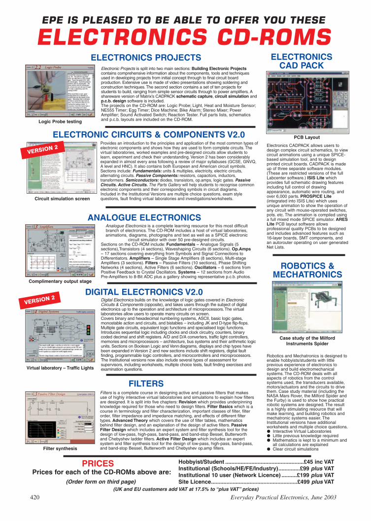
Prices for each of the CD-ROMs above are:(Order form on third page)
Hobbyist/Student ...................................................£45 inc VATInstitutional (Schools/HE/FE/Industry)..............£99 plus VATInstitutional 10 user (Network Licence) ..........£199 plus VATSite Licence........................................................£499 plus VAT
Complimentary output stage
Virtual laboratory – Traffic Lights
Digital Electronics builds on the knowledge of logic gates covered in ElectronicCircuits & Components (opposite), and takes users through the subject of digitalelectronics up to the operation and architecture of microprocessors. The virtuallaboratories allow users to operate many circuits on screen.Covers binary and hexadecimal numbering systems, ASCII, basic logic gates,monostable action and circuits, and bistables – including JK and D-type flip-flops.Multiple gate circuits, equivalent logic functions and specialised logic functions.Introduces sequential logic including clocks and clock circuitry, counters, binarycoded decimal and shift registers. A/D and D/A converters, traffic light controllers,memories and microprocessors – architecture, bus systems and their arithmetic logicunits. Sections on Boolean Logic and Venndiagrams, displays and chip types havebeen expanded inVersion 2 and new sections include shift registers, digital faultfinding, programmable logic controllers, and microcontrollers and microprocessors.The Institutional versions now also include several types of assessment forsupervisors, including worksheets, multiple choice tests, fault finding exercises andexamination questions.
(UK and EU customers add VAT at 17.5% to “plus VAT’’ prices)
Analogue Electronics is a complete learning resource for this most difficultbranch of electronics. The CD-ROM includes a host of virtual laboratories,animations, diagrams, photographs and text as well as a SPICE electronic
circuit simulator with over 50 pre-designed circuits.Sections on the CD-ROM include: Fundamentals – Analogue Signals (5sections),Transistors (4 sections), Waveshaping Circuits (6 sections). Op.Amps– 17 sections covering everything from Symbols and Signal Connections toDifferentiators. Amplifiers – Single Stage Amplifiers (8 sections), Multi-stageAmplifiers (3 sections). Filters – Passive Filters (10 sections), Phase ShiftingNetworks (4 sections), Active Filters (6 sections). Oscillators – 6 sections fromPositive Feedback to Crystal Oscillators. Systems – 12 sections from AudioPre-Amplifiers to 8-Bit ADC plus a gallery showing representative p.c.b. photos.
Filters is a complete course in designing active and passive filters that makesuse of highly interactive virtual laboratories and simulations to explain how filtersare designed. It is split into five chapters: Revision which provides underpinningknowledge required for those who need to design filters. Filter Basics which is acourse in terminology and filter characterization, important classes of filter, filterorder, filter impedance and impedance matching, and effects of different filtertypes. Advanced Theory which covers the use of filter tables, mathematicsbehind filter design, and an explanation of the design of active filters. PassiveFilter Design which includes an expert system and filter synthesis tool for thedesign of low-pass, high-pass, band-pass, and band-stop Bessel, Butterworthand Chebyshev ladder filters. Active Filter Design which includes an expertsystem and filter synthesis tool for the design of low-pass, high-pass, band-pass,and band-stop Bessel, Butterworth and Chebyshev op.amp filters.Filter synthesis
FILTERS
ANALOGUE ELECTRONICS
Logic Probe testing
ELECTRONICS PROJECTS
DIGITAL ELECTRONICS V2.0
PRICES
Electronic Projects is split into two main sections: Building Electronic Projectscontains comprehensive information about the components, tools and techniquesused in developing projects from initial concept through to final circuit boardproduction. Extensive use is made of video presentations showing soldering andconstruction techniques. The second section contains a set of ten projects forstudents to build, ranging from simple sensor circuits through to power amplifiers. Ashareware version of Matrix’s CADPACK schematic capture, circuit simulation andp.c.b. design software is included.The projects on the CD-ROM are: Logic Probe; Light, Heat and Moisture Sensor;NE555 Timer; Egg Timer; Dice Machine; Bike Alarm; Stereo Mixer; PowerAmplifier; Sound Activated Switch; Reaction Tester. Full parts lists, schematicsand p.c.b. layouts are included on the CD-ROM.
ELECTRONICSCAD PACK
Electronics CADPACK allows users todesign complex circuit schematics, to viewcircuit animations using a unique SPICE-based simulation tool, and to designprinted circuit boards. CADPACK is madeup of three separate software modules.(These are restricted versions of the fullLabcenter software.) ISIS Lite whichprovides full schematic drawing featuresincluding full control of drawingappearance, automatic wire routing, andover 6,000 parts. PROSPICE Lite(integrated into ISIS Lite) which usesunique animation to show the operation ofany circuit with mouse-operated switches,pots. etc. The animation is compiled usinga full mixed mode SPICE simulator. ARESLite PCB layout software allowsprofessional quality PCBs to be designedand includes advanced features such as16-layer boards, SMT components, andan autorouter operating on user generatedNet Lists.
PCB Layout
VERSION 2
ELECTRONIC CIRCUITS & COMPONENTS V2.0Provides an introduction to the principles and application of the most common types ofelectronic components and shows how they are used to form complete circuits. Thevirtual laboratories, worked examples and pre-designed circuits allow students tolearn, experiment and check their understanding. Version 2 has been considerablyexpanded in almost every area following a review of major syllabuses (GCSE, GNVQ,A level and HNC). It also contains both European and American circuit symbols.Sections include: Fundamentals: units & multiples, electricity, electric circuits,alternating circuits. Passive Components: resistors, capacitors, inductors,transformers. Semiconductors: diodes, transistors, op.amps, logic gates. PassiveCircuits. Active Circuits. The Parts Gallery will help students to recognise commonelectronic components and their corresponding symbols in circuit diagrams.Included in the Institutional Versions are multiple choice questions, exam stylequestions, fault finding virtual laboratories and investigations/worksheets.Circuit simulation screen
VERSION 2
ROBOTICS &MECHATRONICS
Robotics and Mechatronics is designed toenable hobbyists/students with littleprevious experience of electronics todesign and build electromechanicalsystems. The CD-ROM deals with allaspects of robotics from the controlsystems used, the transducers available,motors/actuators and the circuits to drivethem. Case study material (including theNASA Mars Rover, the Milford Spider andthe Furby) is used to show how practicalrobotic systems are designed. The resultis a highly stimulating resource that willmake learning, and building robotics andmechatronic systems easier. TheInstitutional versions have additionalworksheets and multiple choice questions.Interactive Virtual LaboratoriesLittle previous knowledge requiredMathematics is kept to a minimum and
all calculations are explainedClear circuit simulations
Case study of the MilfordInstruments Spider
420 Everyday Practical Electronics, June 2003

Prices for each of the CD-ROMs above are:(Order form on next page)
Hobbyist/Student £45 inc VATInstitutional (Schools/HE/FE/Industry) £99 plus VAT
Flowcode Institutional £70 plus VATInstitutional 10 user (Network Licence) £249 plus VATSite Licence £599 plus VAT
(UK and EU customers add VAT at 17.5% to “plus VAT’’ prices)
PRICES
VERSION 2 PICmicro MCUDEVELOPMENT BOARD
Suitable for use with the three software packageslisted below.
This flexible development board allows students to learnboth how to program PICmicro microcontrollers as well asprogram a range of 8, 18, 28 and 40-pin devices. Forexperienced programmers all programming software isincluded in the PPP utility that comes with the developmentboard. For those who want to learn, choose one or all of thepackages below to use with the Development Board. Makes it easier to develop PICmicro projects Supports low cost Flash-programmable PICmicro
devices Fully featured integrated displays – 13 individual l.e.d.s,
quad 7-segment display and alphanumeric l.c.d. display Supports PICmicro microcontrollers with A/D converters Fully protected expansion bus for project work All inputs and outputs available on screw terminal
connectors for easy connection
ASSEMBLY FOR PICmicro V2(Formerly PICtutor)
Assembly for PICmicro microcontrollers V2.0(previously known as PICtutor) by JohnBecker contains a complete course inprogramming the PIC16F84 PICmicromicrocontroller from Arizona Microchip. Itstarts with fundamental concepts andextends up to complex programs includingwatchdog timers, interrupts and sleep modes.The CD makes use of the latest simulationtechniques which provide a superb tool forlearning: the Virtual PICmicro micro-controller. This is a simulation tool thatallows users to write and execute MPASMassembler code for the PIC16F84microcontroller on-screen. Using this youcan actually see what happens inside thePICmicro MCU as each instruction isexecuted which enhances understanding. Comprehensive instruction through 39tutorial sections Includes Vlab, a VirtualPICmicro microcontroller: a fully functioningsimulator Tests, exercises and projectscovering a wide range of PICmicro MCUapplications Includes MPLAB assembler Visual representation of a PICmicroshowing architecture and functions
Expert system for code entry helps first timeusers Shows data flow and fetch executecycle and has challenges (washingmachine, lift, crossroads etc.) ImportsMPASM files.
‘C’ FOR PICmicroVERSION 2
The C for PICmicro microcontrollers CD-ROM is designed for students andprofessionals who need to learn how toprogram embedded microcontrollers in C.The CD contains a course as well as all thesoftware tools needed to create Hex codefor a wide range of PICmicro devices –including a full C compiler for a wide rangeof PICmicro devices.Although the course focuses on the use ofthe PICmicro microcontrollers, this CD-ROM will provide a good grounding in Cprogramming for any microcontroller. Complete course in C as well as Cprogramming for PICmicro microcontrollers Highly interactive course Virtual CPICmicro improves understanding
Includes a C compiler for a wide range ofPICmicro devices Includes full IntegratedDevelopment Environment IncludesMPLAB software Compatible with mostPICmicro programmers Includes acompiler for all the PICmicro devices.
FLOWCODE FOR PICmicroFlowcode is a very high level languageprogramming system for PICmicromicrocontrollers based on flowcharts.Flowcode allows you to design and simulatecomplex robotics and control systems in amatter of minutes.Flowcode is a powerful language that usesmacros to facilitate the control of complexdevices like 7-segment displays, motorcontrollers and l.c.d. displays. The use ofmacros allows you to control theseelectronic devices without getting boggeddown in understanding the programminginvolved.Flowcode produces MPASM code which iscompatible with virtually all PICmicroprogrammers. When used in conjunctionwith the Version 2 development board thisprovides a seamless solution that allowsyou to program chips in minutes.Requires no programming experience Allows complex PICmicro applications to bedesigned quickly Uses internationalstandard flow chart symbols (ISO5807) Full on-screen simulation allows debuggingand speeds up the development process Facilitates learning via a full suite ofdemonstration tutorials Produces ASMcode for a range of 8, 18, 28 and 40-pindevices Institutional versions includevirtual systems (burglar alarms, car parksetc.).
HARDWARE
£145 including VAT and postage
12V 500mA plug-top PSU (UK plug) £725-way ‘D’ type connecting cable £5
Minimum system requirements for theseitems: Pentium PC running Windows 98,
NT, 2000, ME, XP; CD-ROM drive;64MB RAM; 10MB hard disk space.
Virtual PICmicro Burglar Alarm Simulation
SOFTWARESuitable for use with the Development Board shown above.
Everyday Practical Electronics, June 2003 421

TEACH-IN 2000 – LEARN ELECTRONICS WITH EPEEPE’s own Teach-In CD-ROM, containsthe full 12-part Teach-In series by JohnBecker in PDF form plus the Teach-Ininteractive software covering all aspectsof the series. We have also added AlanWinstanley’s highly acclaimed BasicSoldering Guide which is fully illustratedand which also includes Desoldering.The Teach-In series covers: ColourCodes and Resistors, Capacitors,Potentiometers, Sensor Resistors, Ohm’sLaw, Diodes and L.E.D.s, Waveforms,Frequency and Time, Logic Gates,Binary and Hex Logic, Op.amps,Comparators, Mixers, Audio and SensorAmplifiers, Transistors, Transformers andRectifiers, Voltage Regulation, Integration, Differentiation, 7-segment Displays, L.C.D.s,Digital-to-Analogue.Each part has an associated practical section and the series includes a simple PCinterface so you can use your PC as a basic oscilloscope with the various circuits.A hands-on approach to electronics with numerous breadboard circuits to try out.
£12.45 including VAT and postage. Requires Adobe Acrobat (available free fromthe Internet – www.adobe.com/acrobat).FREE WITH EACH TEACH-IN CD-ROM – Electronics Hobbyist Compendium 80-pagebook by Robert Penfold. Covers Tools For The Job; Component Testing; OscilloscopeBasics.
MODULAR CIRCUIT DESIGN Contains a range of tried and tested analogue and digital circuit modules, together with theknowledge to use and interface them. Thus allowing anyone with a basic understanding of circuit symbols todesign and build their own projects. Version 3 includes data and circuit modules for a range of popular PICs; includesPICAXE circuits, the system which enables a PIC to be programmed without a programmer, and without removing itfrom the circuit. Shows where to obtain free software downloads to enable BASIC programming.Essential information for anyone undertaking GCSE or “A’’ level electronics or technology and for hobbyists who wantto get to grips with project design. Over seventy different Input, Processor and Output modules are illustrated and fullydescribed, together with detailed information on construction, fault finding and components, including circuit symbols,pinouts, power supplies, decoupling etc.
Single User £19.95 inc. VAT. Multiple User £34 plus VAT(UK and EU customers add VAT at 17.5% to “plus VAT’’ prices)
Minimum system requirements for these CD-ROMs: Pentium PC, CD-ROM drive, 32MB RAM, 10MB hard disk space. Windows 95/98/NT/2000/ME/XP, mouse, sound card, web browser.
CD-ROM ORDER FORMElectronic ProjectsElectronic Circuits & Components V2.0Analogue Electronics Version required:Digital Electronics V2.0 Hobbyist/StudentFilters InstitutionalElectronics CAD Pack Institutional 10 userRobotics & Mechatronics Site licenceAssembler for PICmicro‘C’ for PICmicroFlowcode for PICmicroDigital Works 3.0
PICmicro Development Board (hardware)Development Board UK plugtop power supplyDevelopment Board 25-way connecting lead
Teach-In 2000 + FREE BOOKElectronic Components PhotosElectronics In Control – Single UserElectronics In Control – Multiple UserModular Circuit Design – Single UserModular Circuit Design – Multiple User
Full name: . . . . . . . . . . . . . . . . . . . . . . . . . . . . . . . . . . . . . . . . . . . . . . . . . . . . . . . . . . . . . . . . . . . . . .
Address: . . . . . . . . . . . . . . . . . . . . . . . . . . . . . . . . . . . . . . . . . . . . . . . . . . . . . . . . . . . . . . . . . . . . . . . .
. . . . . . . . . . . . . . . . . . . . . . . . . . . . . . . . . . . . . . . . . . . . . . . . . . . . . . . . . . . . . . . . . . . . . . . . . . . . . .
. . . . . . . . . . . . . . . . . . . . . . . . . . . .Post code: . . . . . . . . . . . . . . . .Tel. No: . . . . . . . . . . . . . . . . . . . .
Signature: . . . . . . . . . . . . . . . . . . . . . . . . . . . . . . . . . . . . . . . . . . . . . . . . . . . . . . . . . . . . . . . . . . . . . . .
I enclose cheque/PO in £ sterling payable to WIMBORNE PUBLISHING LTD for £ . . . . . . . . . . . . . . Please charge my Visa/Mastercard/Amex/Diners Club/Switch: £ . . . . . . .Card expiry date: . . . . . . .
Card No: . . . . . . . . . . . . . . . . . . . . . . . . . . . . . . . . . . . . . . . . . . . . . . . . . . . Switch Issue No. . . . . . . . . .
Card Security Code . . . . . . . . . . (The last 3 digits on or just under the signature strip)
ORDERINGALL PRICES INCLUDE UK
POSTAGE
Student/Single User/Standard Versionprice includes postage to most
countries in the worldEU residents outside the UK add £5 for
airmail postage per order
Institutional, Multiple User and DeluxeVersions – overseas readers add £5 to thebasic price of each order for airmail postage(do not add VAT unless you live in an EU(European Union) country, then add 17½%VAT or provide your official VAT registrationnumber).
Send your order to:Direct Book Service
Wimborne Publishing Ltd408 Wimborne Road East
Ferndown, Dorset BH22 9NDTo order by phone ring
01202 873872. Fax: 01202 874562Goods are normally sent within seven days
E-mail: [email protected]
Online shop:www.epemag.wimborne.co.uk/shopdoor.htm
Note: The software on each version isthe same, only the licence for use varies.
ELECTRONICCOMPONENTS PHOTOS
A high quality selection of over 200 JPGimages of electroniccomponents. Thisselection of highresolution photos can beused to enhanceprojects andpresentations or to helpwith training andeducational material.They are royalty free foruse in commercial orpersonal printed projects, and can also beused royalty free in books, catalogues,magazine articles as well as worldwide webpages (subject to restrictions – see licence forfull details).Also contains a FREE 30-day evaluation ofPaint Shop Pro 6 – Paint Shop Pro imageediting tips and on-line help included!
Price £19.95 inc. VAT
Please send me:
VERSION 3
ELECTRONICS IN CONTROLTwo colourful animated courses for students on one CD-ROM. These cover Key Stage 3 and GCSE syllabuses. KeyStage 3: A pictorial look at the Electronics section featuring animations and video clips. Provides an ideal introductionor revision guide, including multi-choice questions with feedback. GCSE: Aimed at the Electronics in many Design &Technology courses, it covers many sections of GCSE Electronics. Provides an ideal revision guide with HomeworkQuestions on each chapter. Worked answers with an access code are provided on a special website.
Single User £29 inc. VAT. Multiple User £39 plus VATStudent copies (available only with a multiple user copy) £6 plus VAT
(UK and EU customers add VAT at 17.5% to “plus VAT’’ prices)
Sine wave relationship values
FREE BOOK
WITH TEACH-IN
2000 CD-ROM
Digital Works Version 3.0 is a graphicaldesign tool that enables you to constructdigital logic circuits and analyze theirbehaviour. It is so simple to use that it willtake you less than 10 minutes to make yourfirst digital design. It is so powerful that youwill never outgrow its capability Softwarefor simulating digital logic circuits Createyour own macros – highly scalable Createyour own circuits, components, and i.c.s Easy-to-use digital interface Animationbrings circuits to life Vast library of logicmacros and 74 series i.c.s with data sheetsPowerful tool for designing and learning.Hobbyist/Student £45 inc. VAT.Institutional £99 plus VAT.Institutional 10 user £199 plus VAT.Site Licence £499 plus VAT.
Counterproject
DIGITAL WORKS 3.0
422 Everyday Practical Electronics, June 2003

INGENUITYUNLIMITEDOur regular round-up of readers' own circuits. We pay between£10 and £50 for all material published, depending on lengthand technical merit. We're looking for novel applications andcircuit designs, not simply mechanical, electrical or softwareideas. Ideas must be the reader's own work and must nothave been submitted for publication elsewhere. Thecircuits shown have NOT been proven by us. IngenuityUnlimited is open to ALL abilities, but items for consideration inthis column should be typed or word-processed, with a briefcircuit description (between 100 and 500 words maximum) andfull circuit diagram showing all relevant component values.Please draw all circuit schematics as clearly as possible.Send your circuit ideas to: Ingenuity Unlimited, WimbornePublishing Ltd., 408 Wimborne Road East, Ferndown DorsetBH22 9ND. (We do not accept submissions for IU via E-mail.)Your ideas could earn you some cash and a prize!
WWIINN AA PPIICCOO PPCC BBAASSEEDDOOSSCCIILLLLOOSSCCOOPPEE WWOORRTTHH ££558866
100MS/s Dual Channel Storage Oscilloscope 50MHz Spectrum Analyser Multimeter Frequency MeterSignal GeneratorIf you have a novel circuit idea which would beof use to other readers then a Pico TechnologyPC based oscilloscope could be yours.Every 12 months, Pico Technology will beawarding an ADC200-100 digital storageoscilloscope for the best IU submission. Inaddition, a DrDAQ Data Logger/Scope worth£69 will be presented to the runner up.
Everyday Practical Electronics, June 2003 423
MY new car alarm locks to the steeringwheel, preventing the car from being
steered, as well as providing a vibration-trig-gered alarm in a plastic housing (this deafensthe thief inside the car, not the neighboursoutside!). It is armed and disarmed by enter-ing a code on a keypad. The user “teaches”the code to the alarm, which is rememberedas long as the internal batteries remain live –which is not that long, due to the high currentdrain!
On delivery, disappointment followed theopening of the box. Unlike the cataloguedescription, there was no lead to take powerat 12V from the cigarette-lighter (accessory)socket. “We forgot to tell you, we changedthe design”, said Customer Services. No, Ididn’t ask for a refund, I’m an EPE reader!Consequently, the circuit in Fig.1 was devel-oped, to economise on batteries.
Switching between the power from a leadplugged into the accessory socket and thatfrom the internal batteries is seamless, pre-venting loss of code memory. This evenworks at the most critical time if a would-be
thief triggers the alarm and then pulls out theplug in the hope of cutting the power. Theinternal batteries (well rested and not deplet-ed) see that the alarm continues to sound andscares off the thief. In normal operation, theinternal batteries are only required to keep thememory alive whilst the car is underway withthe alarm removed and safely stowed behindthe seat.
Circuit DetailsPlenty of decoupling surrounds the three-
terminal 6V regulator IC1, this is a harshenvironment. Electrolytic capacitors are notgood at handling pulses, so paralleled discceramics are used to get rid of short spikes.
The use of a Zener diode, D1, following theregulator may seem strange. However, if theregulator fails closed-circuit, 12V appearswhere only 6V is expected but Zener diodeD1 conducts, clamps the voltage and blowsthe ultra-fast closely-rated fuse FS1. Ofcourse this is catastrophic, the regulator mustbe replaced and even a 5W Zener might sac-rifice itself. With a low-current fuse and lack
of space, though, the use of a full-blown(pun?!) thyristor crowbar is not justified.
While the regulated 6V is present, the p-channel MOSFET TR1 is held off via diodeD3 and the alarm is powered via diode D2.On loss of the 12V input, D3 isolates the gate(g) of TR1 from all influences other than thatof resistor R1. This resistor pulls the gate ofTR1 low, which turns the device on andallows the internal batteries to take over andpower the alarm. Decoupling and a bit of sup-ply reservoir is thrown in, using capacitorsC5 and C6 for good measure.
Diodes D2 to D4 stop “back-feeding” ofinternal battery power that would otherwisecontinue to hold TR1 turned of. Resistor R2keeps any static charge off the gate (justbeing over-cautious!). This is easy work forthe electrically-big MOSFET and the alarmdrains little current, so no heatsinks wereneeded. There was room inside the alarm caseto fit the components “ugly” style, held inplace by hot-melt polythene glue.
Godfrey Manning G4GLM,Edgware, Middx.
Car Alarm Battery Saver – UUnn--nnoobbbblleedd!!
µ
µ
µ
Fig.1. Circuit diagram for the Car Alarm Battery Saver.

424 Everyday Practical Electronics, June 2003
intrigued by the thought of designing onethat embraced both old and new technolo-gies – old in the form of l.e.d.s for the dis-play rather than a liquid crystal screen, andnew in the form of a PIC microcontroller(inevitably!).
Making some sketches, he ended updesigning the circuit and printed circuitboard for one over a weekend! With refine-ments, and after further discussions withFernando, plus a lot of programming time,the clock presented here is that same one.Its achievement turned out to be a realexercise in multiplexing.
Whilst the design is not exactly the sameas Fernando’s ideal, which also included
some peripheral features, it verymuch sticks to a similar
concept. It has thefeatures shown
in Panel 1.
PORTUGUESE reader Fernando Bentesde Jesus emailed us during theAutumn of 2002, saying that his
favourite electronically-controlled wallclock had “ticked its last tock” and that itcould not be revived. He asked if we knewof anyone who might be interested todesign a replacement.
Questioning him further, he explainedthat in essence his “dream clock” consistedof 60 light emitting diodes, arranged in a cir-cle having a diameter of 24 centimetres, anddisplayed the seconds count. In the centrewere eight digits with each segment com-prised of several l.e.d.s. These displayedhours, minutes and calendar information.
Thinking about the possibil-ity of designing a clockalong these lines,the authorbecame
The use of multiplexing in this design
was essential, to cut down on the currentconsumption and the number of logic gatedevices that would otherwise have beenrequired. Additionally, heavy use is madeof matrixed arrays. The most significantexample of this is in the circle of 60 l.e.d.s.,whose array structure is shown in Fig.1.
In this matrix, applying positive power(e.g. +5V) to one of the eight horizontalconnections (numbered 9 to 16) allowscurrent to flow through any of the l.e.d.s inthat row if its cathode (k) is taken low (e.g.to 0V) via a suitable ballast resistor. Thecathodes are also mutually connected ingroups of eight columns (numbered 1 to8). By selecting which row and column areactivated, any one (or more) of the l.e.d.scan be turned on.
For instance, applying power betweenconnections 9 and 1 will cause current toflow through the top left l.e.d., D1. So thatnone of the other l.e.d.s in the other rowsare turned on, their anode row connectionsare held at 0V. Similarly, to prevent otherl.e.d.s in a column being turned on, theircathode connections are held positive.
Crystal controlled Circular display having diameter of
9·8 inches (250mm) Inner ring of 60 l.e.d.s displaying both
seconds and minutes Outer ring of 12 l.e.d.s displaying
hours in conventional (analogue) 12-hour format
Inner zone of 100 l.e.d.s in 4-digit7-segment numerical format, cyclical-ly displaying hours (24-hour format)and minutes, months and days ofmonth, and temperature in degreesCelsius to one decimal place
Three switches provide adjustment forall display values, and for the precisecalibration of the timing accuracy tocompensate for normal manufacturingtolerance in the controlling crystal’soscillating rate
Powered at 9V to 12V d.c. via a mainssupply adaptor, with battery back-up
Current consumption only 65mA(thanks to heavy multiplexing ofl.e.d.s)
Adjustable brilliance of the l.e.d.numerals to suit personal taste
PICronos shownapproximatelyhalf full size.
Part One

In theory, eight rows and eight columns cancontrol 64 l.e.d.s. In this clock, though, only60 l.e.d.s need to be controlled. Thus the lastfour positions of the matrix are left unused.
The other notations alongside each rowand column (e.g. RC7 and R2/RD0) referto the control points as shown later inFig.5.
Multiplex control is used on this matrix.The 60 l.e.d.s are jointly used to show notonly a seconds count but also a minutescount. This is achieved by first selectingthe matrix co-ordinates for the seconds,turning on the required l.e.d. for a briefperiod, and then selecting the matrix co-ordinates for the minutes, and turning onthat required l.e.d. for the same period. Thealternating between the two matrix selec-tions is so fast (around 400Hz) that bothl.e.d.s appear to be on at the same time.
A second matrix is used for the l.e.d.s ofthe analogue hours display, as shown inFig.2. Seven lines basically control thismatrix, although it too is multiplexed bythe control source, in conjunction with the7-segment digits, i.e. as part of a 5-waymultiplex switching format.
The basic l.e.d. for-mat of a 7-segmentdigit is shown inFig.3, and matrix dia-gram in Fig.4. Eachof the four digits isidentically arranged.Three l.e.d.s are con-nected in series foreach of the horizontalsegments (segmentletters A, G and D),and four l.e.d.s are inseries for each of thevertical segments (F,B, E and C). Differentvalues of ballast resis-tor (R13 to R19) areused for the verticaland horizontal seg-ments to achieveequal brilliance.
All four digits aremultiplexed. Thereare four currentsource connections,each made to the pri-mary anodes of allseven segments inone digit. The final
cathodes of the like-lettered segments ofall four digits are connected together (e.g.A to A, B to B). The seven connectionpaths control current sinking from thesegments.
As with the matrix displays, any digitand any of its segments can be turned on asrequired, in this case using 11 control lines(four source plus seven sink). Again multi-plexing is used in the control sequence sothat each digit appears to be activesimultaneously.
The control circuit diagram is shown in
Fig.5. A PIC16F877 microcontroller, IC1,is the principal component, routing themany multiplex and matrix voltages asrequired. The PIC is operated at3·2768MHz, as set by crystal X1.
The circuit should be read in conjunc-tion with the previous illustrations. Forexample, the matrix display for the minutesand seconds l.e.d.s D1 to D60 that is shownin Fig.1 is represented by the block dia-gram connected to PIC pins RD0 to RD7(Port D) and RC0 to RC7 (Port C). Port Cprovides the current source for the matrixrows, and Port D sinks the current from thematrix columns, via ballast resistors R2 toR9.
Port E is primarily used to provide thepower source, via ballast resistors R10 toR12, for the hours matrix in Fig.2, Theconnection to switch S3 at resistor R11 isdiscussed later, as are the functions ofswitches S1 and S2.
The function of Port B is two-fold. In itsfirst role, via pins RB0 to RB3, it providescurrent sinking from the hours matrix fedfrom Port E. Secondly it controls the gatingof the digital display segments via IC4.
Everyday Practical Electronics, June 2003 425
D1 TO D8
R6/RD4
D9 TO D16
D17 TO D24
D25 TO D32
D33 TO D40
D41 TO D48
D49 TO D56
D57 TO D60
RC7
RC6
RC5
RC4
RC3
RC2
RC1
RC0
9
10
11
12
13
14
15
16
R2/RD0 R3/RD1 R4/RD2 R5/RD3 R7/RD5 R8/RD6 R9/RD71 2 3 4 5 6 7 8
a
k
a
k
a
k
a
k
a
k
a
k
a
k
a
k
a
k
a
k
a
k
a
k
a
k
a
k
a
k
a
k
a
k
a
k
a
k
a
k
a
k
a
k
a
k
a
k
a
k
a
k
a
k
a
k
a
k
a
k
a
k
a
k
a
k
a
k
a
k
a
k
a
k
a
k
a
k
a
k
a
k
a
k
a
k
a
k
a
k
a
k
a
k
a
k
a
k
a
k
a
k
a
k
a
k
a
k
a
k
a
k
a
k
a
k
a
k
a
k
Fig.1. Matrixed array for the l.e.d.s that display minutes andseconds.
a a aa
k k kk
a a aa
k k kk
a a aak k kk
a a aak k kk
a a aa
k k kk
a a aa
k k kk
a a aak k kk
R18
R13
R14
R19
R16
R17
R15
x4 x4 x4x4x4 x4 x4x4
x4 x4 x4x4x4 x4 x4x4
x3 x3 x3x3
x3 x3 x3x3
x3 x3 x3x3
DIGIT 1 DIGIT 2 DIGIT 3 DIGIT 4
A
F
B
G
E
C
D
D73 TO D97 D98 TO D122 D123 TO D147 D148 TO D172
A1 A2 A3 A4
470Ω
470Ω
470Ω
360Ω
360Ω
360Ω
360Ω
Fig.4. Interconnections between the four 7-segment digits. The x3 and x4 notations indicate the number of l.e.d.s in a segment.
1
2
3
4
a
k
a
k
a
k
a
k
a
k
a
k
a
k
a
k
a
k
a
k
a
k
a
k
5 6 7RB0 RB1 RB2 RB3
D61 TO D64
D65 TO D68
D69 TO D72
R10/RE0
R11/RE1
R12/RE2
Fig.2. L.E.D. matrix for hours.
a
ka
ka
k
DIGIT 1 - D73 TO D97
DIGIT 2 - D98 TO D122
DIGIT 3 - D123 TO D147
DIGIT 4 - D148 TO D172
A
B
G
F
C
D
a
k
a
k
a
k
a
k
a ka k a k
a ka k a k
a
k
a
k
a
k
a
k
a
k
a
k
a
k
a
k
a
ka ka k a k
E
Fig.3. Basic format of a 7-segmentdigit.

426 Everyday Practical Electronics, June 2003
bc e
B1
9V
RA
0/A
N0
RA
1/A
N1
RA
2/A
N2/
VR
EF
RA
3/A
N3/
VR
EF+
RA
4/T
OC
K1
RA
5/A
N4/
SS
RE
0/A
N5/
RD
RE
1/A
N6/
WR
RE
2/A
N7/
CS
OS
C1/
CLK
IN
OS
C2/
CLK
OU
T
MC
LR
+V
E+
VE
GN
DG
ND
PS
P0/
RD
0
PS
P1/
RD
1
PS
P2/
RD
2
PS
P3/
RD
3
PS
P4/
RD
4
PS
P5/
RD
5
PS
P6/
RD
6
PS
P7/
RD
7
T1O
SO
/T1C
KI/R
C0
T1O
SI/C
CP
2/R
C1
CC
P1/
RC
2
SC
K/S
CL/
RC
3
SD
I/SD
A/R
C4
SD
O/R
C5
TX
/CK
/RC
6
RX
/DT
/RC
7
INT
/RB
0
RB
1
RB
2
PG
M/R
B3
RB
4
RB
5
PG
CLK
/RB
6
PG
DA
/RB
7
12 3 4 5 6 7 8 9 10
11 12
13 14
15 16 17 1819 20 21 22 23 24 25 2627 28 29 30
3132
33 34 35 36 37 38 39 40
IC1
PIC
16F
877
R11
R12
R10
R1
1k
X1
3.27
68M
Hz
C1
C2
10p
10p
10k
R22
C3
C4
C6
TO C8
100n
100n
100n
IC2
78L0
5IN
CO
M
OU
T
D17
81N
4001
D17
91N
4001
470Ω
470Ω
470Ω
470Ω
470Ω
470Ω
R13
R14
R15
R16
R17
R18
R19
360Ω
360Ω
360Ω
360Ω
D61 TO
D72
HO
UR
S
a
a
k
k
INT
ER
NA
LD
IOD
E
x7
IC4
SE
CO
ND
S/M
INU
TE
S
D1
TO
D60
470Ω
R2
TO
R9
VC
C1
VC
C2
IC5
L293
DN
EN
1/2
EN
3/4
GN
D
1Y2Y 3Y 4Y
1A2A 3A 4A
x4 G
ND
GN
DG
ND
a k a k
R20 1k
D17
3
D17
4
R21
750Ω
VR
110
k
IN
AD
J.
OU
T
LM31
7IC
3
C5
100n
CLK
DA
TAM
CLR
0V
TO
IC7c
(PIN
14)
(TE
MP
ER
AT
UR
E)
D17
51N
4148
10k
R23
BA
CK
UP
BA
TT
ER
Y
AA
BB
C
C
D
D
EE
F
F
G
G
A2
A3
A4
A1
x4
ULN
2004
A
168
6 11 14 3
45
1213
7 10 15 2 1 9
ak7 6 3 1 2 5 4
89
10 11 14 16 15 12 13
3 2 1
4 5 6 7
TB
1
+12
V
0V0V
0V
S1
S3
S2
a
a
a
k
k
k
+5V
+9V
+12
V
1 2 3 4 5 6 7 8
910
1112
1314
1516
CO
LON
*
*
* *
SE
E T
EX
T
Fig.5. Main control circuit for the PICronos L.E.D. Wall Clock.

Device IC4 is a type ULN2004A andcontains seven Darlington transistorswhich have open-collector outputs. Theschematic diagram for one of the transis-tors is given in Fig.6.
The input to the base of the first transis-tor in the pair has an internal current-limit-ing resistor (10k5) which allows thedevice to be controlled without the use ofan external ballast resistor. The input isalso protected against negative-voltages byan internal diode.
The open-collector output from the pairis also provided with internal protectiondiodes, to make the device suitable for usewith inductive loads. Strictly speaking theyare not needed in this design, but they havebeen connected anyway.
The Darlingtons are controlled by Port B(RB0 to RB6), and their outputs sink cur-rent from the digital display segments viaresistors R13 to R19.
The anodes of the digital displays are indi-rectly controlled by Port A (RA1 to RA4).Because RA4 has an open-collector output,it is biased to the +5V line via resistor R23.
The digital displays are powered at avoltage higher than the 5V that supplies thePIC. This enables the brilliance of the dis-plays to be more readily placed under exter-nal control, as discussed shortly. An inter-face is required to enable the 5V controlvoltage from the PIC to select the paththrough which the higher voltage, up toaround 12V, is routed to the display anodes.
The interface device used is the L293DN
type previously chosen for the author’s PICBig Digit display (electro-mechanical dig-its) of May ’02 (so too was theULN2004A). Its internal functions andtruth table are illustrated in Fig.7. Althoughnot shown, this device also has internalprotection diodes, between the outputs andthe two power rails. They are irrelevant tothis circuit as the device is not controllinginductive loads.
The L293DN requires two positivepower supplies. One needs to be suited tothe voltage level swing at the device’sinputs, in this case a supply of +5V is fedto VCC1 at pin 16. The output needs thesecond power source to be suited to theoutput voltage required by the circuit beingcontrolled. It is supplied via VCC2 at pin 8.
The design is intended to be powered by
an external supply capable of deliveringbetween about 9V and 12V d.c. at about65mA, via a mains-power adaptor forexample. It is recommended that the sup-ply should be capable of delivering at least100mA to provide plenty of “headroom”.Whilst a current of 65mA may seem lowfor a circuit having nearly 200 l.e.d.s, it isthe multiplexing technique that hasenabled a low current consumption to beachieved.
Two power supply inputs are provided,via diodes D178 and D179. The connectionfor the main power supply is via diodeD178. The other path is intended for con-nection of a back-up battery, of 9V at about30mA maximum. This enables the clock tocontinue running in the event of a powerfailure at the main source, but without thel.e.d. digits being active.
If a backup battery capable of being kepton permanent trickle charge is used, a suit-able charging resistor could be connectedacross diode D179. Its value should bechosen to suit the battery concerned (referto its data sheet).
The principal incoming power supply isdirectly connected to the input of adjustablevoltage regulator IC3. This is an LM317device whose output voltage is controllableby potentiometer VR1 in conjunction withfeedback resistor R20. Its purpose is toallow the brilliance of the 7-segmenteddigits to be varied, and that of the two l.e.d.sD173 and D174. These two form the“colon” between digits 2 and 3. It is a stat-ic colon and is not under PIC control.
Note that the brilliance of the l.e.d.s inthe two rings (D1 to D72) is fixed.
If the variable brilliance facility is notneeded, omit VR1, R20 and IC3. Then linkthe IN and OUT pads of IC3’s position.
It is worth noting that although redl.e.d.s were used throughout in the proto-type, it might be beneficial to make thosein the outer hours ring a different colour
(e.g. bright green or blue) so that they standout better from the inner ring when seenfrom a distance.
When purchasing the l.e.d.s rememberthat considerable cost savings can be madeby buying in bulk. The author paid 6p perl.e.d. by buying 200, even though fewer areactually required. L.E.D.s can be bought ateven lower prices from some suppliers, butbefore buying ensure that their pin spacingand diameter is consistent with the spacingallowed on the board.
For the sake of readers who may wish tomodify parts of the software to suit theirown needs, resistor R1, diode D175 andconnector TB1 allow the PIC to be pro-grammed by a suitable external program-mer, such as the author’s Toolkit TK3 ofOct/Nov ’01, to which readers are referredfor more information (also see later). R1and D175 should be retained even if theprogramming option is not required,although TB1 may be omitted.
A temperature sensing and display facil-
ity has been included. Its analogue circuitdiagram is shown in Fig.8.
Temperature sensing is performed by thefamiliar LM35CZ. This basically outputs avoltage that varies by 10mV per degreeCelsius. It is used in a configuration givenin the device’s data sheet, with which twodiodes are used in series between thedevice’s negative terminal and the 0V line.
This allows the device to output a volt-age relative to negative temperatures.However, it is fully agreed with Fernandothat anyone experiencing sub-zero temper-atures where this clock is placed shouldemigrate to a warmer climate. With this inmind, the clock has not been tested for neg-ative temperatures!
The lower-cost LM35DZ could be usedinstead without circuit modification if thenegative temperature option is not needed.It is worth considering though, whetheryou might like to have the sensor outdoorsso you know how cold it is there on a win-ter’s day while you are warm and snug!
If the latter technique is used, it might beworthwhile adding the resistors and capac-itors (RT, CT1, CT2) shown in Fig.9.These help to keep the input signals stablefor long cable lengths, and should bemounted at the board end. They will need
Everyday Practical Electronics, June 2003 427
b
b
c
ce
e7k2
3k
10k5
INPUT
COM.
OUTPUT
E
a
a k
k
k
a
ULN2004A
Fig.6. Single Darlington within IC4.
3A
EN
4A
3,4
10
9
15
11
14
3Y
4Y
1A
EN
2A
1,2
2
1
7
3
6
1Y
2Y
INPUTS OUTPUT
A EN Y
H H H
L H L
X L Z
H = HIGHL = LOWX = IRRELEVANTZ = HIGH IMPEDANCE
OUTPUT (OFF)
Fig.7. Schematic functions and truthtable for IC5.
T.P.2
T.P.1SEE TEXTOR VR2 + R30a ONLYEITHER R30 ONLY
1%
0V
+5V
VR222k
22µ
22µ
C10
C9
10k
R2933k1%
33k 22k
R32
R30aR30
1%10k
1%10k
R28
R27
R26
R24
1%10k
10k
1%
1%10kR25
18kR31
1N4148D177
1N4148D176
IC6
+
LM35CZOUT
a
a
k
k
+
+
+
+
++N.C.IC7d
IC7c
IC7b
IC7a
LMC6484LMC6484
LMC6484
LMC6484
9
10
8
13
12
14
VOUTTO IC1
RA0
6
5
7
11
3
2
1
4
Fig.8. Temperature sensing circuit.

428 Everyday Practical Electronics, June 2003
D1
a
a
aa
a
a
a
a
a
a
a
a
a
a
a
a
a
a
a
a
a
a
a
a
a
a
a
a
a
aa
a
aaa
a
aa
a
a
a
a
a
a
a
a
a
a
a
a
a
aa
a
a
a
a
a
a a a a
a a a a
a a a a
a a a a
a a
a
a a
a a a a
a a a a
a a a a
a
aa
a a a
a a a a
a a a
a
a
a
a a a a
a a a a
a a a a
a a a a
a a a a
a a a a
a a a
a
a
a
a a a a
a a a a
a a a a
a a a a
a a a a
a a a a
a a a a
a
a
a
a
a
a
a
a
aa
a
a
a
a
k
k
kk
k
k
k
k
k
k
k
k
k
k
k
k
k
k
k
k
k
k
k
k
k
k
k
k
k
kk
kk
kkkk
k
k
k
k
k
k
k
k
k
k
k
k
k
k
k
k
k
k
k
k
k k k k
k k k k
k k k k
k k k k
k k
k
k k
k k k k
k k k k
k k k k
k
k
k
k k k
k k k k
k k k
k
k
k
k k k k
k k k k
k k k k
k k k k
k k k k
k k k k
k k k
k
k
k
k k k k
k k k k
k k k k
k k k k
k k k k
k k k k
k k k k
k
k
k
k
k
kk
kk
k
k
k
k
k
k
D2D3
D4
D5
D61
D6
D7
D8
D9
D10
D62
D11
D12
D13
D14
D15 D63
D16
D17
D18
D19
D20
D21
D22
D23
D24
D64
D25
D26
D27
D28D29
D65
D30
D66
D31
D32
D33
D34
D35
D36
D37
D38
D67
D39
D40
D41
D68
D42
D43
D44
D45D69
D46
D47
D48
D49
D50
D70
D51
D52
D53
D54 D55
D56
D57D58
D59
D71
D60
D72
D73TOD79
D98TO
D122
D123TO
D147
D148TO
D172
D173
D174
C5
R20
C7
VR1
IC3IC5
IN ADJOUT
D176
C9 C8
C10
+
+
+R31
D177
R25
R24
R26
R30
R29
R30a
VR2
R31R27
R28
IC7IC6OUT
T.P.1
T.P.2
T.P.3
R21
R1
D175
R23R22
R12C6
C1
C2
R32
X1
R2
R3
R11
R10
S3
IC1
R5R4
R9R8R7R6
C4
D179
C3
D178
IC2
IN
COM
OUT
+12V
+9V
IC4
R19R18R17R16R15R14R13
S1
S2
0V
TB1MCLRDATACLK0V
ResistorsR1, R20 1k (2 off)R2 to R13,
R16, R19 470(14 off)
R14, R15,R17, R18 360 (4 off)
R21 750R22, R23,
R32 10k (3 off)R24 to R28 10k 1% 0·25W (5 off)R29, R30 33k 1% 0·25W (2 off)R30a 22k (see text)R31 18k
All 0·25W 5% except where stated.
PotentiometerVR1 10k min. round presetVR2 22k (or 25k) min. round
preset (see text)
CapacitorsC1, C2 10p disc ceramic, 0·5mm
pitch (2 off)C3 to C8 100n disc ceramic,
0·5mm pitch (6 off)C9, C10 22 radial elect. 10V (2 off)
SemiconductorsD1 to D60,
D73 toD174 red l.e.d., 5mm dia.
ultrabright (162 off)D61 to D72 red l.e.d., 5mm dia, ultra-
bright (see text) (12 off)D175 to
D179 1N4148 signal diode (5 off)D178,
D179 1N4001 rectifier diode (2 off)IC1 PIC16F877-4 microcontroller,
pre-programmed (see text)IC2 78L05 +5V 100mA
voltage regulatorIC3 LM317 adjustable
voltage regulator
IC4 ULN2004A 7-way Darlington line driver
IC5 L293DN 16-pin Half-H driverIC6 LM35CZ temperature sensorIC7 LMC6484 quad op.amp,
rail-to-rail
MiscellaneousS1 to S3 min. push-to-make
switch, p.c.b. mounting(3 off)
TB1 1mm pin-header, 4-way (optional)
Printed circuit board, available from theEPE PCB Service, code 395; 22s.w.g.tinned copper wire, solid (for link wires); 14-pin d.i.l. socket; 16-pin d.i.l. socket (2 off);40-pin d.i.l. socket; 1mm terminal pins or pinheaders; connecting wire; solder, etc.
SeeSSHHOOPPTTAALLKKppaaggee
Approx. CostGuidance Only ££4455
excl. batts
Fig.10. Component layoutfor the PICronos L.E.D.Wall Clock
N.B. Reduced scale. Fullsize is 9·8in. x 9·8in.(248·5mm x 248·5mm).
EPE Online
Note that the circuit boards used in EPE Online projects are available from the EPE Online Store at www.epemag.com (also note that the codes for the boards in the online store are prefixed with 7000, so a board with a code of say 256 will appear as 7000256 in the online store).
EPE Online
Note that you can purchase pre-programmed PIC microcontrollers for our PIC projects (see the “ShopTalk” page in the associated issue of the Magazine for more details). Alternatively, if you wish to program the PIC yourself, you can find the code files by bouncing over to the EPE Online Library (visit www.epemag.com, click in the “Library” link in the top navigation, then on the “Project Code Files” link).
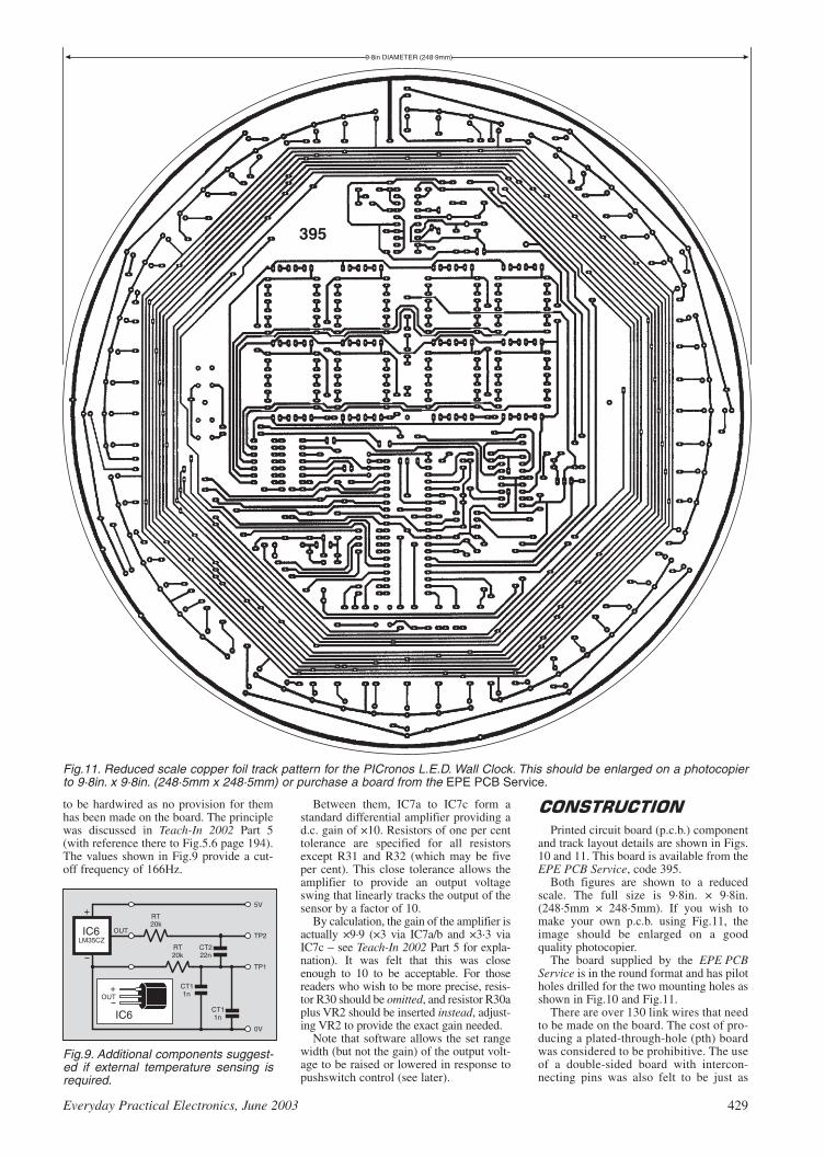
Everyday Practical Electronics, June 2003 429
to be hardwired as no provision for themhas been made on the board. The principlewas discussed in Teach-In 2002 Part 5(with reference there to Fig.5.6 page 194).The values shown in Fig.9 provide a cut-off frequency of 166Hz.
Between them, IC7a to IC7c form astandard differential amplifier providing ad.c. gain of ×10. Resistors of one per centtolerance are specified for all resistorsexcept R31 and R32 (which may be fiveper cent). This close tolerance allows theamplifier to provide an output voltageswing that linearly tracks the output of thesensor by a factor of 10.
By calculation, the gain of the amplifier isactually ×9·9 (×3 via IC7a/b and ×3·3 viaIC7c – see Teach-In 2002 Part 5 for expla-nation). It was felt that this was closeenough to 10 to be acceptable. For thosereaders who wish to be more precise, resis-tor R30 should be omitted, and resistor R30aplus VR2 should be inserted instead, adjust-ing VR2 to provide the exact gain needed.
Note that software allows the set rangewidth (but not the gain) of the output volt-age to be raised or lowered in response topushswitch control (see later).
Printed circuit board (p.c.b.) componentand track layout details are shown in Figs.10 and 11. This board is available from theEPE PCB Service, code 395.
Both figures are shown to a reducedscale. The full size is 9·8in. × 9·8in.(248·5mm × 248·5mm). If you wish tomake your own p.c.b. using Fig.11, theimage should be enlarged on a goodquality photocopier.
The board supplied by the EPE PCBService is in the round format and has pilotholes drilled for the two mounting holes asshown in Fig.10 and Fig.11.
There are over 130 link wires that needto be made on the board. The cost of pro-ducing a plated-through-hole (pth) boardwas considered to be prohibitive. The useof a double-sided board with intercon-necting pins was also felt to be just as
RT20k
CT222n
CT11n
1nCT1
RT20k
5V
0V
TP2
TP1
IC6
IC6
+
+
LM35CZOUT
OUT
Fig.9. Additional components suggest-ed if external temperature sensing isrequired.
9.8in DIAMETER (248.9mm)
Fig.11. Reduced scale copper foil track pattern for the PICronos L.E.D. Wall Clock. This should be enlarged on a photocopierto 9·8in. x 9·8in. (248·5mm x 248·5mm) or purchase a board from the EPE PCB Service.
395

taxing in construction as inserting linkwires.
Make the link wire connections first,especially noting that some go under d.i.l.(dual-in-line) i.c. positions. The links arebest made using solid tinned copper wireof 24 s.w.g. (a roll of which should be partof anyone’s toolkit).
Next insert all the d.i.l. i.c. sockets. Donot insert the i.c.s themselves, or the tem-perature sensor, until the board has beenfully checked for poor soldering, incorrectcomponent positioning, and the correct-ness of the power supply has been deter-mined. Regulator IC3 can be mounted withits back against the board to keep theboard’s profile low.
Next insert the resistors, diodes (but notl.e.d.s), capacitors and voltage regulators inorder of ascending size. Ensure the correctorientation of the semiconductors and elec-trolytic capacitors.
Finally, insert the l.e.d.s. Note that thosein the two “rings” all have their cathodes (k)pointing towards the centre. Those in thehorizontal segments all have their cathodesto the right, while the cathodes of those inthe vertical segments all face downwards.
To assist in the best alignment of thel.e.d.s, initially just solder one leg of eachso that it is easier to re-position a mis-placed one by having to unsolder only one
lead. The l.e.d.s will have small spigotsclose to the body end of each lead, allow-ing their insertion depth to be maintainedconsistently.
Those who have good quality printedcircuit board assembly frames with clip-onfoam “lids” will find the entire p.c.b.assembly far easier than those who do not.The author’s frame accepts p.c.b.s of 10in× 18in (254mm × 457mm) and thePICronos board was designed to just fit it.
It may be of interest to know that theauthor has used this frame for over 20years and it considerably assists in theassembly of all the boards he designs.
It is strongly recommended that if you donot have an assembly frame, you should buyone. But only get a good quality one – thoseat the cheaper end of the selection mayprove more trouble than they are worth, asthe author once found to his detriment.Those in the professional class are the best.
Using this frame, assembly of thePICronos board took around four hours.
The author did not provide the clockwith an enclosure and no recommendationfor using one is offered.
The software for the clock is available
on a 3·5in disk (Disk 6) from the EPEEditorial office (a small handling charge
applies), or as a free download from theEPE ftp site. The easiest way into the latteris via the main EPE website page atwww.epemag.wimborne.co.uk. and clickon the ftp site link at the top. Then click ondown through folders PUB, PICS and theninto the PICronos folder.
There are two files – ASM (source codein TASM grammar) and HEX (in standardMPASM format). The HEX file is the codefile to be sent directly to the PIC via a suit-able programmer (e.g. TK3). It containsembodied configuration and dataEEPROM values.
For those whose programmers cannothandle embedded data, the configurationvalues must be set separately. The valuesare XT crystal, WDT off, POR on. Allother factors should be off. Data EEPROMvalues can be set by switches during clockadjustment and calibration, as discussednext month. Note that unexpected displayresults may occur until the values havebeen set.
Pre-programmed PICs can also be pur-chased – for details of this and on obtain-ing the software disk, read this month’sShoptalk page.
In the final part next month, the clock’s
software and setting-up are discussed.
430 Everyday Practical Electronics, June 2003
!" #$%"&' (
!)*' +,-. (/ 00 (
!.'1"'*$ 20.-3 40-(
5"1 $' 13*1330 00, 3(((
65'(
71%8!& (
"9": +;
!"#$%"&" '(()
;<=><>?@A?@>(5<=><>?@BCD>(;333(((4333((
*
+! ",-
!.,,-"-"
"" " /
,0
!1))) 2+"3&4+
5

REVERED CHEERS FOR ALANDear EPE,Readers everywhere will surely be sad to see
the retirement of Alan Winstanley from IU. Overthe years, Alan gave the column a common lookand feel, and a lighthearted touch, that made it apleasure to read. It was Alan and IU who intro-duced me to constructional articles, and I knowthat there are others whose “careers” in elec-tronics were profoundly influenced by him andthe column.
So a big thank you Alan, and long live IU.Rev. Thomas Scarborough,
South Africa, via email
Three cheers for Alan, indeed, Thomas. It isthe end of a significant era and Alan’s seat willbe hard to fill. It is colleague Dave Barringtonand I who shall be attempting to continue whereAlan left off.
Keep those IUs coming in folks – we want toshare your ideas with others!
BOAT ALARMDear EPEIn Graham Johnston’s Letter of the Month,
March ’03, he suggested an idea for a boatalarm that sent a message to his mobile phone.This is a good idea, one which a friend of minethought of about three years ago (although notjust for a boat). I designed the electronics forhim and he went on to patent the idea (which hestill holds). These devices are on the market toprotect houses, boats, cars and industrial sites,the latter use radio PIRs and can protect a site ofvast area.
I think EPE is invaluable and have gainedmost of my electronic knowledge from it. Thisbrought about the confidence that I had whenmy friend asked me if I would be able to helphim. I undertook the task not knowing whether Ihad bitten off more than I could chew but I sur-prised myself and went even further than he hadasked. I put that down to reading EPE on a reg-ular basis for years.
Keep up the good work guys and if by chanceGraham or anyone else wants one of thesedevices they could contact my friend RogerClifford at [email protected].
Michael Read,via email
Thanks Michael for the kind words and theinformation, plus Roger’s address.
Enjoy your electronics – and EPE!
UNPIC-ING DOSDear EPE,I am currently using PIC Basic PRO and a
John Morrison designed software/program-mer to develop PIC software. The solutionhas served me well, but the limitations of theDOS environment are getting painful. Canyou recommend a suitable replacement forboth the development and the programmingwhich are completely Windows compatibleand allow 18, 28 and 40 pin PICs to beprogrammed?
I am an avid reader of EPE and enjoy it thor-oughly. I feel, however, that there could be moredetail in your circuit descriptions. In terms of thecircuit detail, it might help if I explained that Iam a qualified but not practicing electronics
LETTER OF THE MONTH Dear EPE,Thanks again for some really great articles and
projects. The Earth Resistively Logger (Apr/May’03) has some really great potential and is cer-tainly timely, given all the attention archaeologyis given across our country. It is these kinds ofprojects that stimulate ideas across disciplinesand in my humble opinion, help us as a collectivewhole move to the next big idea.
I’ve been thinking of how I could use the unitfor more than one thing, and I came across anidea that might work. I wonder if it could beadapted to use with a seismograph(www.njsas.org/projects/tidal_forces/mag-netic_gravimeter/baker/), as I think that alongwith the ground waves common with earth-quakes a possible resistivity change caused bymicro movement of the surrounding earth struc-ture may also occur.
What I find is a need for a simple serial portdatalogger that will collect and display ±5·0Vd.c. changes in voltage levels collected by myexisting seismograph and associated ADC, plusoutput from the ER unit. I currently use a smalltest software application from Iguana Labs(www.iguanalabs.com/adc2051.htm), and itworks ok for a single input, but if a way couldbe found to develop a simple serial port data-logger to use inputs from both the ER systemand the seismo, and then generate a comparisonchart, it could be interesting and a logical exten-sion of the ER idea.
Do you think there be any value in a simpleserial port reader application capable of
simultaneously reading, comparing, and dis-playing data inputs on COM1 and COM2?
I like the projects in EPE. I’ve been work-ing on mixing and matching a couple of pro-ject circuits – nothing unique – andimagineering other possible uses for thingsI’m doing with your circuits. Thanks for thewonderful work you are doing; lots of folkslook at your magazine but not all write oracknowledge.
Dave Mynatt,Manchaca, Texas, USA
Nice to hear from you again Dave. Let usknow when you find anything interesting!
Regarding seismo – yes, I have in mind todo a solid-state one at some time (I did amechanical unit many years back). It woulduse data logging techniques along the lines ofER. But I do not know if it would be of use toarchaeologists to have seismic conditionsrecorded at the same time. In the UK it is rarefor us to be knowingly shaken (or stirred!).The aim of my ER is to show relative differ-ences in sub-surface conditions, not theirabsolute values.
Twin serial input via COM1 and COM2 – itseems that multiplexing data into one serialport will be just as good. In fact on my forth-coming Weather Centre, I’m multiplexing ninedata sources into one output. Another goodreason for not using two COMs ports is thatmany PCs are now being produced with onlyCOM1, with USB as the second option.
Everyday Practical Electronics, June 2003 431
RREEAADDOOUUTTJJoohhnn BBeecckkeerr aaddddrreesssseess ssoommeeooff tthhee ggeenneerraall ppooiinnttss rreeaaddeerrss
hhaavvee rraaiisseedd.. HHaavvee yyoouu aannyytthhiinnggiinntteerreessttiinngg ttoo ssaayy??
DDrroopp uuss aa lliinnee!!
WIN A DIGITALMULTIMETER
A 31/2 digit pocket-sized l.c.d. multime-ter which measures a.c. and d.c. volt-age, d.c. current and resistance. It canalso test diodes and bipolar transistors.
Every month we will give a DigitalMultimeter to the author of the best
Readout letter.
Email: [email protected]
All letters quoted here have previously been replied to directly.
PATTING ERDear EPE,Earth Resistivity Logger (Apr/May ’03) – a
brilliant project, I’ve been playing in this area ofsurveying for years but never with this level ofsophistication!
Project built and running exactly as described.Multiple pats on the back all round!
Barry Benson, via email
Thank you Barry, that’s great news! I am real-ly pleased to hear it. A lot of effort and fieldwork has gone into producing ER. All the best –tell us when you find the next long-lost Romancity!
INDUCTIVE SURVEYINGDear EPE,Maybe the Earth Resistivity Logger could be
combined with an Induced Polarization (IP)instrument. I believe that IP uses the sameground probes but inject a current at several dif-ferent frequencies. The signal is ON+, OFF,ON–, OFF, over the timed period. When the sig-nal is shut off IP instruments read the voltagewhile it is decaying. The measurements are oftime domain and also frequency domain.Interfacing ER to a GPS handset would also beuseful.
Here is a link that deals with IP: www.geop.ubc.ca/ubcgif/tutorials/resip/ip.html.
Neil Pagel,via email
I’ve looked at the IP site you quote, Neil. It’sinteresting but I’m not sure how the techniquemight benefit amateur archeologists. Readers –your opinions please!
I’m currently in the middle of doing a PICinterface for use with GPS and things like ERand magnetometry – stick around!
SONIC FISHDear EPEJust a word on the Babel Fish letter in
Readout April ’03 and hoping it wasn’t intendedas a joke . . . I remember one of the gadgets inmy boyhood. The Tandy 75-in-1 kit was a SonicFish Caller – simply a low frequency oscillator,with the loudspeaker waterproofed and suspend-ed in the water. It claimed that fish were attract-ed to the sound and that professional fishermenused similar devices. I was never interested infish, but did try it once in a newt-pond. It didn’twork – just like most of my projects.
Nigel Rushbrook,via email
Well, Nigel, there was humour in what wasbeing said by those who offered comments, but itwas not intended to be a commemoration ofApril 1st! The questioner was really looking fora circuit for a form of depth sounder. Years agoI designed one for use when scuba diving, butthe special transducer was too expensive to offerthe design for publication.
Better luck with future projects you build!

432 Everyday Practical Electronics, June 2003
technician. I qualified about 15 years ago andreally have not used my skills (with the excep-tion of some PIC programming) for the past 10years. So I use EPE to keep in touch not onlywith modern technology but also with some ofthe principles which, like my hair, are getting alittle grey now.
I am always thinking about what currents areflowing and what voltages I would expect at cer-tain points in the circuit and what would happenif we used a different value capacitor here, etc.I’m sure I get it wrong a lot so it would be use-ful to know the correct answer. It would also behelpful to know alternative components whichcould be used (e.g. a 2N3904 where a BC108 issuggested). I appreciate I may be asking a lot andthe above may be beyond the scope of EPE, butI hope feedback of any kind is not completelyuseless.
Simon Smyth,Dublin, via email
Well Simon, feedback is always welcome.Taking your first comment first – you could gothe full hog and get Microchip’s own system(browse www.microchip.com) or consider myToolkit TK3 of Oct/Nov ’01. Various advertisersalso do good programming facilities, as manyreaders will confirm – browse the adverts. Textsof TK3 are available from our Online Shop viawww.epemag.wimborne.co.uk, or on our PICResources CD-ROM advertised in this issue.
I appreciate what you are suggesting, but itwould be complex for us to add that extra info asdesigns are from the readership who don’t usu-ally give us that degree of detail. This is why weperiodically publish tutorials such as our Teach-In series every two years, and of course ourmonthly Circuit Surgery. Regarding substitutes,we try to ensure that components are readilyavailable and prefer readers to use those speci-fied by the author.
STEPPING RIGHTDear EPE,I’m trying to develop a machine which needs
several stepper motors and a couple of sensors tomake it operate. I’m thinking of controlling(been advised) said machine with a PIC micro-controller. I’m also relatively new to electron-ics/engineering so I need to know before buyingif a PIC is the right way to approach controllingmy machine.
I have programmed in BBC Basic a long timeago and would welcome any advice on whichprogramming languages are now availableand/or would be easiest, viz a PIC. I also have anAcorn RISC PC as well as a Windows PC.Which would be best to use?
John Amps,via email
It’s a matter of portability, John – it can beportable with a PIC, but not with a PC. Certainlya PIC is the route I would take.
With your previous programming experienceyou should have no difficulty learning aboutusing PICs. The rest is then just down to you asan electronics designer, and your ability to thinkstraight on software writing!
In terms of PCs I only use Windows and can-not comment on other systems.
PIC16F62x AND ADCDear EPE,I have recently been working on a circuit
requiring analogue to digital conversion. Havingseen the PIC16F627 in the Maplin cataloguewith pins labelled AN, I had been planning onusing this. I have since read the Microchipdatasheet for this PIC, and from this understandthese pins to be only comparator pins and notstrictly A/D. I therefore changed to thePIC16C710, and have written the program tosuit.
Since this will be my first PIC project I wouldrather use a Flash PIC. So I then looked aroundfor methods of programming PICs and discov-ered EPE. Upon reading the April issue I found
the Intelligent Garden Lights Controller wasusing the PIC16F627, and from what I can tell itis being used for ADC. Could you please tell mehow this PIC can be used in this way?
Joe Dowsett,via email
Disappointingly, Joe, you are right about thePIC16F627 not providing true ADC. In theGarden unit, the PIC’s comparator can only beset to one of 16 different analogue input triggerlevels, which is very limited. However, thePIC16F87x family have true ADC, providing1024 levels of conversion. Read Part 3 of my PICTutorial V2 in this current issue.
UPGRADING ATMOSPHERICSMONITOR
Dear EPE,Regarding my Atmospherics Monitor (April
’03), during late March/early April atmosphericpressure was very high at 1024mb to 1030mb.Under these conditions, Russian beacons above9kHz become audible. I have re-worked the aerialinput and the first IC1a stage of the monitor. Thismodification provides a better signal-to-noisefloor, improving the resolution of atmosphericsignals. The frequency response curve peaks at7kHz, rolling off steeply above, and provides again lift at 2kHz. The modification is as follows:
Amend C5 to 100nF Completely remove C7 Amend C2 to 22nF and fit 10k resistor in
parallel with it Remove link wire connecting between strip-
board tracks C and I at column 3 and replaceby a 220k resistor
Amend R2 to 390k Amend R3 to 470k Amend R5 to 3k3 Amend R6 to 39k Add a 47pF capacitor between stripboard
tracks F and B in column 1 (between coil wirehole and track to collector of TR1/IC1 pin 5)
After modifying the circuit, the bias will needre-adjustment. With power supply at 9·0V, setVR1 for 4·5V at IC1 output pin 7.
Brian Lucas,Jersey, via email
Thanks Brian. Readers, this is the same infor-mation as was placed on our Chat Zone in lateMarch.
A few of you have commented that PIC sub-jects are dominant in Readout. That’s becausemost letters received are about PICs. If you wantother matters covered please write to us aboutthem.
AUTOMATED SURVEYINGThe following are extracts from a series of
threads that appeared towards the end ofMarch on our Chat Zone following publicationof the Earth Resistivity Logger, started off byRobin Turk:
Robin Turk: I am an archaeology student inUCC Ireland. I was interested to see the EarthResistivity Logger in EPE but I am interestedin making an automated system for surveyingan area, i.e. some kind of radio controlled vehi-cle for positioning and inserting the probes inthe correct positions on the grid and subse-quently logging the reading and moving on tothe next position.
This would avoid the tedious and time con-suming process of positioning probes etc. Theactual mechanics of positioning the probes andinserting them would be relatively simple(some probe configurations would be easierthan others) but I would need a relatively accu-rate way to make the device follow a grid pat-tern over the area to be surveyed. I wasthinking maybe GPS or something. I would begrateful for any ideas on the matter!
John Becker: A fascinating subject is this“seeing beneath the soil” and what has beenproved with my own tests and the surveys byfriend Nick Tile (who has professional experi-ence of seismic surveying on land and at sea)encourage me to take the subject further. Thenext step is probe-less surveying using magne-tometry – early field tests on the prototypehave started. I have a further idea for remotesensing for a later investigation (following afair bit of research).
Robin Turk: Thanks for cool plan, John. Ihad another look at Anthony Clarke’s SeeingBeneath the Soil book the other day andrealised that he and others had done work insemi-automated surveys and continuous traceprobing methods. In fact using an automatedroving device one could achieve an almostcontinuous trace using either separate probes(in any configuration) with a short distancebetween each movement, or with probesattached to wheels or tracks (as Miguel sug-gests below and Clarke used in his design)using the twin electrode method. I look for-ward to a design for a magnetometry surveyingdevice. It would be nice to be able to incorpo-rate this into a rover as well!
BWTS: The roving logger could have a sim-ple representation of the ground to be coveredstored in its memory. This representation couldbe as simple as a rectangle. Each time youwant it to go over a piece of ground you enterthe dimensions of the rectangle. The loggerthen trundles off probing every so many metres(or feet if you prefer) in let’s say the X direc-tion. Getting to the end of one length it turns 90degrees, let’s say right to avoid confusion,takes a “step” forward in let’s say the Y direc-tion, turns another 90 degrees right so it’s nowfacing the direction it came in from.
It repeats the process until it gets to the endof another length and this time turns left, takesa “step”, turns left again and repeats the wholething until it has gone as far in the Y directionas you specified in the first place.
This would avoid the need for external sen-sors or GPS if the ground to be covered wasrelatively clear of trees and so on. The hard-ware would be kept to a minimum and the onlyinput you would have to make would be the Xand Y dimensions.
Robin Turk: Yes this method would beprobably the simplest but it would rely heavilyon the accuracy of the measurement of the dis-tance travelled by the rover. These errorswould get progressively worse the further ittravelled. There would also be problems inachieving an accurate 90 degree turn withoutthe use of some kind of inertial guidance sys-tem, although a relatively straight line couldprobably be achieved by use of a gyro.
Max: I think GPS at its most accurate canonly pinpoint its location to within about 20cm(I think – but that’s plenty accurate enough forits normal uses!), a most accurate way wouldprobably be to use ultrasonic or infra-red sens-ing to judge the vehicle’s position to somefixed markers at the edges of the area beingsurveyed. It would be a lot easier (and cheap-er) than GPS, but would probably need someserious hardware/software to control it, butthen I guess it would take a lot of complicatedinterfacing to get something to interface with aGPS handheld thingy (a technical term).
A fascinating set of chats (of which therewere more, but no space here). As a post-script, by the time you read this I hope tohave a GPS input for ER Logger completed.Stay tuned!

WHEN setting up a business that will sell products via theInternet, one of the first obstacles to overcome is that of credit
card processing. Much has been written over the past few yearsabout the perils of buying over the Internet: consumers are warnedabout using only “secure” web sites and not sending credit cardnumbers through ordinary email.
So far so good, but for the uninitiated Internet user there is stillplenty that can go wrong. Faced with the prospect of saving money(lots of money, sometimes), then, when it comes to buying a juicy-looking bargain online, a fool and his money are soon parted, andfools can get their fingers burned very easily. A number of usershave been the victims ofInternet fraud, losing thousandsof pounds through bogus websites created by fraudsters.
There is a flip side to allthis: when opening up anonline shop, it is probably theowner of the business that facesthe greatest challenges fromcredit card fraud. Flinging openhis virtual shop window, ordersarrive literally through theether, sent by customers whomthe business will never meet inperson. However, when thingsgo wrong the online store facesthe risk of losing both thegoods as well as the money.
Problems start when thetrader sends out the merchan-dise in good faith, only to learna month later that the creditcard number had actually beenstolen or forged. The creditcard company might havecharged an innocent person’saccount, which then has to berefunded.
This cash is clawed back from the trader who is compelled toprovide the refund (called a chargeback in the trade). This is badnews because the trader has then lost both the goods as well as thecash. Too many chargebacks, and the trader risks losing his mer-chant account altogether. Security and online vetting procedures aretightening all the time to help avoid this.
In the UK, a trader (merchant) first needs an “Internet merchant
account” to be able to receive credit card (CC) payments online. Inpractice these accounts are usually arranged via the trader’s bank. Inaddition there are a number of online credit card processing organ-isations including Netbanx, SecPay, Secure Trading and WorldPay(which in the UK is now part of RBS/Natwest) all of whom canprocess credit cards for a fee.
Add in standard bank charges as well, and the online businesscould see no less than three percentages deducted from every deal.Things are somewhat different in the USA where a trader’s creditcard processing business can be sub-contracted out to any numberof competing independent sales organisations.
In view of the almost paranoid risk of chargebacks, money laun-dering, fraud and theft, it is not surprising that many UK traders areforced to jump through hoops before acquiring an Internet merchant
account. Some alternatives include using a CC processing company(e.g. WorldPay or Netbanx) to handle the transaction in its entirety, i.e.paying a net amount directly into the trader’s bank account. It costsmoney to set up, the interest rates are higher and (worse still) the trad-er has to wait up to four weeks before receiving his cash, rendering thistype of “bureau account” completely unfeasible for many Internettraders who would have to send out the goods but wait a month fortheir cash to arrive.
So the viable trading alternatives start to run out. One very tempt-
ing option is to use Paypal (https://www.paypal.com) to handle allonline credit card transactions. The online auctioneer eBay
(www.ebay.com) now ownsthis American credit card pro-cessing and payment compa-ny, which is why Paypal hasbeen heavily integrated intoeBay’s checkout system.
On the surface, Paypalappears to be the perfect solu-tion to almost every trader’scredit card processingrequirements. Paypal claimsthere are 20 million users inover 30 countries that entrustcredit card payment process-ing to them. Its account-basedsystem lets you send orreceive money using a creditcard or cheque (checking)account.
It is free to open a Paypalaccount. “Members” can signup online in a simple-lookingprocess but finer detailsbecome apparent the deeperyou dig. In order to validateyour details, Paypal makes a$1.95 test transaction to a des-ignated credit card account: a
nice little earner. A Member ID number is printed alongside thetransaction details that appear on the credit card statement, whichhas to be entered back into the Paypal web site. That is how Paypalconfirms your details and you then become a verified member.
By upgrading to a Premier account and entering your bankaccount details, you suddenly gain the ability to accept credit cardpayments, because Paypal can process the CC transaction for youand pay the balance straight into your bank account. More accu-rately, Paypal actually pays the cash into your Paypal member’saccount, from where you can withdraw it into your designated bankaccount. Paypal deal in several currencies including US$, Sterlingand Euros.
Apart from one glitch when Mastercard locked up my credit cardfollowing a series of “suspicious looking” $1 Paypal payments, Ihave purchased a number of items using Paypal without any prob-lems. Other users have not been so lucky, especially when they relyon Paypal for their business income. As long as you are mindful ofthe pitfalls, Paypal may or may not be an ideal solution for the bud-ding Internet start-up or small enterprise.
Next month I’ll look in more detail at Paypal, and also show youhow you can set up a simple online shop for yourself, using Paypal’sselling tools to handle payments. If you have any comments on thistopic, you can email me at [email protected].
SURFING THE INTERNET
! "
Everyday Practical Electronics, June 2003 433
Paypal is an account-based online payment system that lets yousend or receive money online.

PROJECT TITLE Order Code CostHosepipe Controller JUNE ’01 301 £5.14Magfield Monitor (Sensor Board) 302 £4.91Dummy PIR Detector 303 £4.36PIC16F87x Extended Memory Software only – –Stereo/Surround Sound Amplifier JULY ’01 304 £4.75Perpetual Projects Uniboard–1 305 £3.00
Solar-Powered Power Supply & Voltage Reg.MSF Signal Repeater and Indicator
Repeater Board 306 £4.75Meter Board 307 £4.44
PIC to Printer Interface 308 £5.39Lead/Acid Battery Charger AUG ’01 309 £4.99Shortwave Loop Aerial 310 £5.07Digitimer – Main Board 311 £6.50
– R.F. Board 312 £4.36Perpetual Projects Uniboard–2
L.E.D. Flasher –– Double Door-Buzzer 305 £3.00Perpetual Projects Uniboard–3 SEPT ’01 305 £3.00
Loop Burglar Alarm, Touch-Switch Door-Lightand Solar-Powered Rain Alarm
L.E.D. Super Torches – Red Main 313 Set £6.10 – Display Red 314
– White L.E.D. 315 £4.28Sync Clock Driver 316 £5.94Water Monitor 317 £4.91Camcorder Power Supply OCT ’01 318 £5.94PIC Toolkit Mk3 319 £8.24Perpetual Projects Uniboard–4. Gate Sentinel, Solar- 305 £3.00
powered Bird Scarer and Solar-Powered RegisterTeach-In 2002 Power Supply NOV ’01 320 £4.28Lights Needed Alert 321 £5.39Pitch Switch 322 £5.87Capacitance Meter – Main Board (double-sided) 323
Set £12.00 – Display Board (double-sided) 324PIC Toolkit TK3 – Software only – –4-Channel Twinkling Lights DEC ’01 325 £6.82Ghost Buster – Mic 326 Set £5.78
– Main 327PIC Polywhatsit – Digital 328 Set £7.61
– Analogue 329Forever Flasher JAN ’02 330 £4.44Time Delay Touch Switch 331 £4.60PIC Magick Musick 332 £5.87Versatile Bench Power Supply 333 £5.71PIC Spectrum Analyser FEB ’02 334 £7.13Versatile Current Monitor 335 £4.75Guitar Practice Amp 336 £5.39PIC Virus Zapper MAR ’02 337 £4.75RH Meter 338 £4.28PIC Mini-Enigma – Software only – –Programming PIC Interrupts – Software only – –PIC Controlled Intruder Alarm APR ’02 339 £6.50PIC Big Digit Display MAY ’02 341 £6.02Washing Ready Indicator 342 £4.75Audio Circuits–1 – LM386N-1 343 £4.28
– TDA7052 344 £4.12– TBA820M 345 £4.44– LM380N 346 £4.44– TDA2003 347 £4.60– Twin TDA2003 348 £4.75
World Lamp JUNE ’02 340 £5.71Simple Audio Circuits–2 – Low, Med and High
Input Impedance Preamplifiers (Single Trans.) 349 £4.60Low-Noise Preamplifier (Dual Trans.) 350 £4.75Tone Control 351 £4.60Bandpass Filter 352 £4.75
Frequency Standard Generator – Receiver 353 £4.12– Digital 354 £6.82
Biopic Heartbeat Monitor 355 £5.71Simple Audio Circuits – 3 JULY ’02
– Dual Output Power Supply 356 £4.60– Crossover/Audio Filter 357 £4.44
Infra-Red Autoswitch 358 £4.91EPE StyloPIC 359 £6.50Rotary Combination Lock – Main Board 360 £5.39
– Interface Board 361 £4.91Using the PIC’s PCLATH Command – Software only – –
434 Everyday Practical Electronics, June 2003
EPE PRINTED CIRCUIT BOARD SERVICEOrder Code Project Quantity Price.....................................................................................Name ...........................................................................Address .....................................................................................................................................................
Tel. No. .........................................................................
I enclose payment of £................ (cheque/PO in £ sterling only) to:
Everyday Practical Electronics
MasterCard, Amex, DinersClub, Visa or Switch
Card No. ................................................................................
Card Exp. Date ............................... Switch Issue No ...........
Card Security Code ..............(The last 3 digits on or just under the signature strip)
Signature ..............................................................................
NOTE: You can also order p.c.b.s by phone, Fax, Email or via ourInternet site on a secure server:
http://www.epemag.wimborne.co.uk/shopdoor.htm
PROJECT TITLE Order Code Cost
Big-Ears Buggy AUG ’02 362 £5.71PIC World Clock 363 £5.39Simple Audio Circuits–4 – Low Freq. Oscillator 364 £4.44
– Resonance Detector 365 £4.28Vinyl-To-CD Preamplifier SEPT ’02 366 £5.71Freebird Glider Control 367 £4.91Morse Code Reader 368 £5.23Headset Communicator OCT ’02 369 £4.75EPE Bounty Treasure Hunter 370 £4.77Digital I.C. Tester 371 £7.14PIC-Pocket Battleships – Software only – –Transient Tracker NOV ’02 372 £4.75PICAXE Projects–1: Egg Timer; Dice Machine;
Quiz Game Monitor (Multiboard) 373 £3.00Tuning Fork & Metronome 374 £5.39EPE Hybrid Computer – Main Board double- 375 £18.87
– Atom Board sided 376 £11.57PICAXE Projects–2: Temperature Sensor;D DEC ’02
Voltage Sensor; VU Indicator (Multiboard) 373 £3.00Versatile PIC Flasher 377 £5.07PICAXE Projects–3: Chaser LightsD JAN ’03 373 £3.00
6-Channel Mains Interface 381 £5.08EPE Minder – Transmitter 378 £4.75
– Receiver 379 £5.39Wind Speed Monitor 380 £5.08Tesla Transformer FEB ’03 382 £5.07Brainibot Buggy 383 £3.00Wind Tunnel 384 £6.02200kHz Function Generator MAR ’03 385 £6.34Wind-Up Torch Mk II 386 £4.75Driver Alert 387 £6.35Earth Resistivity Logger APR ’03 388 £6.02Intelligent Garden Lights Controller 389 £3.96PIC Tutorial V2 – Software only – –Door Chime MAY ’03 390 £5.07Super Motion Sensor 391 £5.55Radio Circuits–1 JUNE ’03
MK484 TRF Receiver 392 £4.44Headphone Amp. 393 £4.28
Fido Pedometer 394 £4.91PICronos L.E.D. Wall Clock 395 £14.65
EEPPEE SSOOFFTTWWAARREE
PPCCBB SSEERRVVIICCEE
Printed circuit boards for most recent EPE constructional projects are available fromthe PCB Service, see list. These are fabricated in glass fibre, and are fully drilled androller tinned. All prices include VAT and postage and packing. Add £1 per board forairmail outside of Europe. Remittances should be sent to The PCB Service,Everyday Practical Electronics,Wimborne Publishing Ltd., 408 Wimborne RoadEast, Ferndown, Dorset BH22 9ND. Tel: 01202 873872; Fax 01202 874562;Email: [email protected]. On-line Shop: www.epemag.wimborne.co.uk/shopdoor.htm. Cheques should be crossed and made payable toEveryday Practical Electronics (Payment in £ sterling only).NOTE: While 95% of our boards are held in stock and are dispatched withinseven days of receipt of order, please allow a maximum of 28 days for delivery– overseas readers allow extra if ordered by surface mail.Back numbers or photostats of articles are available if required – see the BackIssues page for details. We do not supply kits or components for our projects.
Please check price and availability in the latest issue.A number of older boards are listed on our website.
Boards can only be supplied on a payment with order basis.
Software programs for EPE projects marked with a single asterisk areavailable on 3·5 inch PC-compatible disks or free from our Internet site. Thefollowing disks are available: PIC Tutorial (Mar-May ’98); PIC Tutorial V2(Apr-June ’03); EPE Disk 1 (Apr ’95-Dec ’98); EPE Disk 2 (1999); EPEDisk 3 (2000); EPE Disk 4 (2001); EPE Disk 5 (2002); EPE Disk 6 (Jan2003 issue to current cover date – excl. Earth Resistivity); EPE EarthResistivity Logger (Apr-May ’03); EPE Teach-In 2000; EPE Spectrum;EPE Interface Disk 1 (October ’00 issue to current cover date). Thesoftware for these projects is on its own CD-ROM. The 3·5 inch disks are£3.00 each (UK), the CD-ROMs are £6.95 (UK). Add 50p each for overseassurface mail, and £1 each for airmail. All are available from the EPE PCBService. All files can be downloaded free from our Internet FTP site:ftp://ftp.epemag.wimborne.co.uk.

EPE PIC Tutorial V2 complete demonstration software,John Becker, April, May, June ’03
PIC Toolkit Mk3 (TK3 hardware construction details),John Becker, Oct ’01
PIC Toolkit TK3 for Windows (software details), JohnBecker, Nov ’01
Plus these useful texts to help you get the most out of yourPIC programming:
How to Use Intelligent L.C.D.s, Julyan Ilett, Feb/Mar ’97 PIC16F87x Microcontrollers (Review), John Becker,
April ’99 PIC16F87x Mini Tutorial, John Becker, Oct ’99 Using PICs and Keypads, John Becker, Jan ’01 How to Use Graphics L.C.D.s with PICs, John Becker,
Feb ’01 PIC16F87x Extended Memory (how to use it),
John Becker, June ’01 PIC to Printer Interfacing (dot-matrix), John Becker,
July ’01 PIC Magick Musick (use of 40kHz transducers),
John Becker, Jan ’02 Programming PIC Interrupts, Malcolm Wiles, Mar/Apr ’02 Using the PIC’s PCLATH Command, John Waller,
July ’02 EPE StyloPIC (precision tuning musical notes),
John Becker, July ’02 Using Square Roots with PICs, Peter Hemsley, Aug ’02 Using TK3 with Windows XP and 2000, Mark Jones,
Oct ’02 PIC Macros and Computed GOTOs, Malcolm Wiles,
Jan ’03 Asynchronous Serial Communications (RS-232),
John Waller, unpublished Using I2C Facilities in the PIC16F877, John Waller,
unpublished Using Serial EEPROMs, Gary Moulton, unpublished Additional text for EPE PIC Tutorial V2,
John Becker, unpublished
BECOME A PIC WIZARD WITH THE HELP OF EPE!
EPE PIC RESOURCES CD-ROMORDER FORM
Please send me ........ (quantity) EPE PIC RESOURCES CD-ROM
Price £14.45 each – includes postage to anywhere in the world.
Name . . . . . . . . . . . . . . . . . . . . . . . . . . . . . . . . . . . . . . . . . . . .
Address . . . . . . . . . . . . . . . . . . . . . . . . . . . . . . . . . . . . . . . . . .
. . . . . . . . . . . . . . . . . . . . . . . . . . . . . . . . . . . . . . . . . . . . . . . .
. . . . . . . . . . . . . . . . . . . . . . . . . . . . . . . . . . . . . . . . . . . . . . . .
. . . . . . . . . . . . . . . . . . . . . . . . . . Post Code . . . . . . . . . . . . .
I enclose cheque/P.O./bank draft to the value of £ . . . . . . . . .
Please charge my Visa/Mastercard/Amex/Diners Club/Switch
£ . . . . . . . . . . . . . . . . . . . . . . . . . . . . . . . . . . . . . . . . . . . . . . .
Card No. . . . . . . . . . . . . . . . . . . . . . . . . . . . . . . . . . . . . . . . . .
Card Security Code . . . . . . . . . . (The last 3 digits on or just under the signature strip)
Expiry Date . . . . . . . . . . . . . . . . . . Switch Issue No. . . . . . . .
SEND TO: Everyday Practical Electronics,Wimborne Publishing Ltd.,
408 Wimborne Road East, Ferndown, Dorset BH22 9ND.Tel: 01202 873872. Fax: 01202 874562.Email: [email protected]
Payments must be by card or in £ Sterling – cheque or bankdraft drawn on a UK bank.
Normally supplied within seven days of receipt of order.Send a copy of this form, or order by letter if you do not wish to cut your issue.
Order on-line fromwww.epemag.wimborne.co.uk/shopdoor.htm
or www.epemag.com (USA $ prices)or by Phone, Fax, Email or Post.
EPE PICRESOURCES
CD-ROMA companion to the EPE PICTutorial V2 series of Supplements(EPE April, May, June 2003)
Contains the following Tutorial-relatedsoftware and texts:
NOTE: The PDF files on this CD-ROM are suitable touse on any PC with a CD-ROM drive. They requireAdobe Acrobat Reader – included on the CD-ROM
ONLY££1144..4455
INCLUDINGVAT and P&P
Everyday Practical Electronics, June 2003 435

PRACTICAL REMOTE CONTROL PROJECTSOwen BishopProvides a wealth of circuits and circuit modules for use inremote control systems of all kinds; ultrasonic, infra-red,optical fibre, cable and radio. There are instructions forbuilding fourteen novel and practical remote control pro-jects. But this is not all, as each of these projects providesa model for building dozens of other related circuits by sim-ply modifying parts of the design slightly to suit your ownrequirements. This book tells you how.
Also included are techniques for connecting a PC to aremote control system, the use of a microcontroller inremote control, as exemplified by the BASIC Stamp, andthe application of ready-made type-approved 418MHzradio transmitter and receiver modules to remote controlsystems.
DISCOVERING ELECTRONIC CLOCKSW. D. PhillipsThis is a whole book about designing and making elec-tronic clocks.You start by connecting HIGH and LOW logicsignals to logic gates.You find out about and then build andtest bistables, crystal-controlled astables, counters,decoders and displays. All of these subsystems arecarefully explained, with practical work supportedby easy to follow prototype board layouts.
Full constructional details, including circuit diagrams anda printed circuit board pattern, are given for a digitalelectronic clock. The circuit for the First Clock is modifiedand developed to produce additional designs which includea Big Digit Clock, Binary Clock, Linear Clock, Andrew’sClock (with a semi-analogue display), and a Circles Clock.All of these designs are unusual and distinctive.
This is an ideal resource for project work in GCSEDesign and Technology: Electronics Product, and for
project work in AS-Level and A-Level Electronics andTechnology.
DOMESTIC SECURITY SYSTEMSA. L. BrownThis book shows you how, with common sense andbasic do-it-yourself skills, you can protect your home. Italso gives tips and ideas which will help you to maintainand improve your home security, even if you alreadyhave an alarm. Every circuit in this book is clearlydescribed and illustrated, and contains components thatare easy to source. Advice and guidance are based onthe real experience of the author who is an alarminstaller, and the designs themselves have been rigor-ously put to use on some of the most crime-riddenstreets in the world.
The designs include all elements, including sensors,-detectors, alarms, controls, lights, video and door entrysystems. Chapters cover installation, testing, maintenanceand upgrading.
MICROCONTROLLER COOKBOOKMike JamesThe practical solutions to real problems shown in this cook-book provide the basis to make PIC and 8051 devices real-ly work. Capabilities of the variants are examined, and waysto enhance these are shown. A survey of common interfacedevices, and a description of programming models, lead onto a section on development techniques. The cookbookoffers an introduction that will allow any user, novice or expe-rienced, to make the most of microcontrollers.
A BEGINNER’S GUIDE TO TTL DIGITAL ICsR. A. PenfoldThis book first covers the basics of simple logic circuits ingeneral, and then progresses to specific TTL logic inte-grated circuits. The devices covered include gates, oscilla-tors, timers, flip/flops, dividers, and decoder circuits. Somepractical circuits are used to illustrate the use of TTLdevices in the “real world’’.
PRACTICAL ELECTRONICS CALCULATIONS ANDFORMULAEF. A. Wilson, C.G.I.A., C.Eng., F.I.E.E., F.I.E.R.E., F.B.I.M.Bridges the gap between complicated technical theory,and “cut-and-tried’’ methods which may bring success indesign but leave the experimenter unfulfilled. A strongpractical bias – tedious and higher mathematics have beenavoided where possible and many tables have beenincluded.
The book is divided into six basic sections: Units andConstants, Direct-Current Circuits, Passive Components,Alternating-Current Circuits, Networks and Theorems,Measurements.
WINDOWS XP EXPLAINEDN. Kantaris and P. R. M. OliverIf you want to know what to do next when confronted withMicrosoft’s Windows XP screen, then this book is for you. Itapplies to both the Professional and Home editions.The book was written with the non-expert, busy person inmind. It explains what hardware requirements you need inorder to run Windows XP successfully, and gives anoverview of the Windows XP environment.The book explains: How to manipulate Windows, and how touse the Control Panel to add or change your printer, and con-trol your display; How to control information using WordPad,Notepad and Paint, and how to use the Clipboard facility totransfer information between Windows applications; How tobe in control of your filing system using Windows Explorerand My Computer; How to control printers, fonts, characters,multimedia and images, and how to add hardware and soft-ware to your system; How to configure your system to com-municate with the outside world, and use Outlook Expressfor all your email requirements; How to use the WindowsMedia Player 8 to play your CDs, burn CDs with yourfavourite tracks, use the Radio Tuner, transfer your videos toyour PC, and how to use the Sound Recorder and MovieMaker; How to use the System Tools to restore your systemto a previously working state, using Microsoft’s Website toupdate your Windows set-up, how to clean up, defragmentand scan your hard disk, and how to backup and restore yourdata; How to successfully transfer text from those old butcherished MS-DOS programs.
INTRODUCING ROBOTICS WITH LEGO MINDSTORMSRobert PenfoldShows the reader how to build a variety of increasinglysophisticated computer controlled robots using the bril-liant Lego Mindstorms Robotic Invention System (RIS).Initially covers fundamental building techniques andmechanics needed to construct strong and efficientrobots using the various “click-together’’ componentssupplied in the basic RIS kit. Explains in simple termshow the “brain’’ of the robot may be programmed onscreen using a PC and “zapped’’ to the robot over aninfra-red link. Also, shows how a more sophisticatedWindows programming language such as Visual BASICmay be used to control the robots.
Detailed building and programming instructions pro-vided, including numerous step-by-step photographs.
MORE ADVANCED ROBOTICS WITH LEGOMINDSTORMS – Robert Penfold
Shows the reader how to extend the capabilities of thebrilliant Lego Mindstorms Robotic Invention System(RIS) by using Lego’s own accessories and some simplehome constructed units. You will be able to build robotsthat can provide you with ‘waiter service’ when you clapyour hands, perform tricks, ‘see’ and avoid objects byusing ‘bats radar’, or accurately follow a line marked on
the floor. Learn to use additional types of sensors includ-ing rotation, light, temperature, sound and ultrasonic andalso explore the possibilities provided by using an addi-tional (third) motor. For the less experienced, RCX codeprograms accompany most of the featured robots.However, the more adventurous reader is also shownhow to write programs using Microsoft’s VisualBASICrunning with the ActiveX control (Spirit.OCX) that is pro-vided with the RIS kit.
Detailed building instructions are provided for the fea-tured robots, including numerous step-by-step pho-tographs. The designs include rover vehicles, a virtualpet, a robot arm, an ‘intelligent’ sweet dispenser and acolour conscious robot that will try to grab objects of aspecific colour.
PIC YOUR PERSONAL INTRODUCTORY COURSESECOND EDITION John MortonDiscover the potential of the PIC micro- controller through graded projects – this book couldrevolutionise your electronics construction work!
A uniquely concise and practical guide to getting upand running with the PIC Microcontroller. The PIC isone of the most popular of the microcontrollers that aretransforming electronic project work and productdesign.
Assuming no prior knowledge of microcontrollers andintroducing the PICs capabilities through simple projects,this book is ideal for use in schools and colleges. It is theideal introduction for students, teachers, technicians andelectronics enthusiasts. The step-by-step explanationsmake it ideal for self-study too: this is not a reference book– you start work with the PIC straight away.
The revised second edition covers the popular repro-grammable EEPROM PICs: P16C84/16F84 as well asthe P54 and P71 families.
INTRODUCTION TO MICROPROCESSORSJohn CrispIf you are, or soon will be, involved in the use ofmicroprocessors, this practical introduction is essentialreading. This book provides a thoroughly readable intro-duction to microprocessors. assuming no previousknowledge of the subject, nor a technical or mathemat-ical background. It is suitable for students, technicians,engineers and hobbyists, and covers the full range ofmodern microprocessors.
After a thorough introduction to the subject, ideas aredeveloped progressively in a well-structured format. Alltechnical terms are carefully introduced and subjectswhich have proved difficult, for example 2’s comple-ment, are clearly explained. John Crisp covers the com-plete range of microprocessors from the popular 4-bitand 8-bit designs to today’s super-fast 32-bit and 64-bitversions that power PCs and engine managementsystems etc.
436 Everyday Practical Electronics, June 2003
DIRECT BOOK SERVICECircuits and Design
160 pages £6.49Order code BP413
194 pages, A4 spiral bound £17.50Order code DEP1
192 pages £17.95Order code NE25
240 pages £21.99Order code NE26
142 pages £5.45Order code BP332
256 pages £5.49Order code BP53
270 pages £13.99Order code NE36
EEPPEE TTEEAACCHH--IINN22000000 CCDD--RROOMM
The whole of the 12-part Teach-In 2000 series by JohnBecker (published in EPE Nov ’99 to Oct 2000) is nowavailable on CD-ROM. Plus the Teach-In 2000 interac-tive software covering all aspects of the series andAlan Winstanley’s Basic Soldering Guide (includingillustrations and Desoldering).
Teach-In 2000 covers all the basic principles of elec-tronics from Ohm’s Law to Displays, including Op.Amps,Logic Gates etc. Each part has its own section on the inter-active software where you can also change componentvalues in the various on-screen demonstration circuits.
The series gives a hands-on approach to electronicswith numerous breadboard circuits to try out, plus a sim-ple computer interface which allows a PC to be used asa basic oscilloscope.
ONLY £12.45 including VAT and p&p
222 pages £18.99Order code NE31
288 pages – large format £14.99Order code BP901
Covers the Vision Command System
NNOOTTEE:: AALLLL PPRRIICCEESS IINNCCLLUUDDEE UUKK PPOOSSTTAAGGEE
298 pages £14.99Order code BP902
Order code Teach-In CD-ROM
Computing & Robotics
268 pages £7.99Order code BP514
FREE Electronics Hobbyist Compendiumbook with Teach-In 2000 CD-ROM
The books listed havebeen selected by EverydayPractical Electronics edi-torial staff as being ofspecial interest to every-one involved in electronicsand computing. They aresupplied by mail orderdirect to your door. Fullordering details are givenon the last book page.
All prices include UKpostage
FOR A FURTHERSELECTION OF BOOKS
SEE THE NEXT TWOISSUES OF EPE

ELECTRONICS MADE SIMPLEIan SinclairAssuming no prior knowledge, Electronics Made Simplepresents an outline of modern electronics with an empha-sis on understanding how systems work rather than ondetails of circuit diagrams and calculations. It is ideal forstudents on a range of courses in electronics, includingGCSE, C&G and GNVQ, and for students of othersubjects who will be using electronic instruments andmethods.
Contents: waves and pulses, passive components,active components and ICs, linear circuits, block andcircuit diagrams, how radio works, disc and tape record-ing, elements of TV and radar, digital signals, gatingand logic circuits, counting and correcting, micro-processors, calculators and computers, miscellaneoussystems.
SCROGGIE’S FOUNDATIONS OF WIRELESSAND ELECTRONICS – ELEVENTH EDITIONS. W. Amos and Roger AmosScroggie’s Foundations is a classic text for anyone work-ing with electronics, who needs to know the art and craftof the subject. It covers both the theory and practicalaspects of a huge range of topics from valve and tubetechnology, and the application of cathode ray tubes toradar, to digital tape systems and optical recordingtechniques.
Since Foundations of Wireless was first published over 60years ago, it has helped many thousands of readers tobecome familiar with the principles of radio and electronics.The original author Sowerby was succeeded by Scroggie inthe 1940s, whose name became synonymous with this clas-sic primer for practitioners and students alike. Stan Amos,one of the fathers of modern electronics and the author ofmany well-known books in the area, took over the revision ofthis book in the 1980s and it is he, with his son, who haveproduced this latest version.
GETTING THE MOST FROM YOUR MULTIMETERR. A. PenfoldThis book is primarily aimed at beginners and those of lim-ited experience of electronics. Chapter 1 covers the basicsof analogue and digital multimeters, discussing the relativemerits and the limitations of the two types. In Chapter 2various methods of component checking are described,including tests for transistors, thyristors, resistors, capaci-tors and diodes. Circuit testing is covered in Chapter 3,with subjects such as voltage, current and continuitychecks being discussed.
In the main little or no previous knowledge or experienceis assumed. Using these simple component and circuittesting techniques the reader should be able to confident-ly tackle servicing of most electronic projects.
PRACTICAL ELECTRONIC FILTERS Owen Bishop This book deals with the subject in a non-mathematicalway. It reviews the main types of filter, explaining in simpleterms how each type works and how it is used.
The book also presents a dozen filter-based projectswith applications in and around the home or in theconstructor’s workshop. These include a number of audioprojects such as a rythm sequencer and a multi-voicedelectronic organ.
Concluding the book is a practical step-by-step guide todesigning simple filters for a wide range of purposes, withcircuit diagrams and worked examples.
PREAMPLIFIER AND FILTER CIRCUITSR. A. PenfoldThis book provides circuits and background informationfor a range of preamplifiers, plus tone controls, filters,mixers, etc. The use of modern low noise operationalamplifiers and a specialist high performance audio pre-amplifier i.c. results in circuits that have excellent perfor-mance, but which are still quite simple. All the circuitsfeatured can be built at quite low cost (just a few poundsin most cases). The preamplifier circuits featuredinclude: Microphone preamplifiers (low impedance, highimpedance, and crystal). Magnetic cartridge pick-uppreamplifiers with R.I.A.A. equalisation. Crystal/ceramicpick-up preamplifier. Guitar pick-up preamplifier. Tapehead preamplifier (for use with compact cassettesystems).
Other circuits include: Audio limiter to prevent over-loading of power amplifiers. Passive tone controls. Activetone controls. PA filters (highpass and lowpass). Scratchand rumble filters. Loudness filter. Mixers. Volume andbalance controls.
ELECTRONIC PROJECTS FOR EXPERIMENTERS R. A. PenfoldMany electronic hobbyists who have been pursuing theirhobby for a number of years seem to suffer from the dread-ed “seen it all before’’ syndrome. This book is fairly andsquarely aimed at sufferers of this complaint, plus anyother electronics enthusiasts who yearn to try something abit different.
The subjects covered include:- Magnetic field detector,Basic Hall effect compass, Hall effect audio isolator, Voicescrambler/descrambler, Bat detector, Bat style echo loca-tion, Noise cancelling, LED stroboscope, Infra-red “torch’’,Electronic breeze detector, Class D power amplifier, Straingauge amplifier, Super hearing aid.
PRACTICAL FIBRE-OPTIC PROJECTS R. A. PenfoldWhile fibre-optic cables may have potential advantagesover ordinary electric cables, for the electronicsenthusiast it is probably their novelty value that makesthem worthy of exploration. Fibre-optic cables provide aninnovative interesting alternative to electric cables, but inmost cases they also represent a practical approach tothe problem. This book provides a number of tried andtested circuits for projects that utilize fibre-optic cables.
The projects include:- Simple audio links, F.M. audio link,P.W.M. audio links, Simple d.c. links, P.W.M. d.c. link,P.W.M. motor speed control, RS232C data links, MIDI link,Loop alarms, R.P.M. meter.
All the components used in these designs are readilyavailable, none of them require the constructor to take outa second mortgage.
ELECTRONIC MUSIC ANDMIDI PROJECTS R. A. Penfold Whether you wish to save money, boldly go where nomusician has gone before, rekindle the pioneering spirit,
138 pages £5.45Order code BP371
188 pages £5.49Order code BP299
92 pages £4.49Order code BP309
BOOK ORDERING DETAILSAll prices include UK postage. For postage to Europe (air) and the rest of the world (surface)please add £2 per book. For the rest of the world airmail add £3 per book. CD-ROM prices includeVAT and/or postage to anywhere in the world. Send a PO, cheque, international money order (£sterling only) made payable to Direct Book Service or card details, Visa, Mastercard, Amex,Diners Club or Switch to:
DIRECT BOOK SERVICE, WIMBORNE PUBLISHING LTD.,408 WIMBORNE ROAD EAST, FERNDOWN, DORSET BH22 9ND.
Books are normally sent within seven days of receipt of order, but please allow 28 days for deliv-ery – more for overseas orders. Please check price and availability (see latest issue of EverydayPractical Electronics) before ordering from old lists.
For a further selection of books see the next two issues of EPE.Tel 01202 873872 Fax 01202 874562. Email: [email protected]
Order from our online shop at: www.epemag.wimborne.co.uk/shopdoor.htm
or simply have fun building some electronic music gad-gets, the designs featured in this book should suit yourneeds. The projects are all easy to build, and some are sosimple that even complete beginners at electronic projectconstruction can tackle them with ease. Stripboard lay-outs are provided for every project, together with a wiringdiagram. The mechanical side of construction has largelybeen left to the individual constructors to sort out, simplybecause the vast majority of project builders prefer to dotheir own thing.
None of the designs requires the use of any testequipment in order to get them set up properly. Whereany setting up is required, the procedures are verystraightforward, and they are described in detail.
Projects covered: Simple MIDI tester, Message grab-ber, Byte grabber, THRU box, MIDI auto switcher,Auto/manual switcher, Manual switcher, MIDI patchbay,MIDI controlled switcher, MIDI lead tester, Programchange pedal, Improved program change pedal, Basicmixer, Stereo mixer, Electronic swell pedal, Metronome,Analogue echo unit.
VIDEO PROJECTS FOR THE ELECTRONICSCONSTRUCTORR. A. Penfold Written by highly respected author R. A. Penfold, this bookcontains a collection of electronic projects specially designedfor video enthusiasts. All the projects can be simply con-structed, and most are suitable for the newcomer to projectconstruction, as they are assembled on stripboard.
There are faders, wipers and effects units which will addsparkle and originality to your video recordings, an audiomixer and noise reducer to enhance your soundtracks anda basic computer control interface. Also, there’s a usefulselection on basic video production techniques to get youstarted.
Circuits include: video enhancer, improved video enhancer,video fader, horizontal wiper, improved video wiper, negativevideo unit, fade to grey unit, black and white keyer, verticalwiper, audio mixer, stereo headphone amplifier, dynamicnoise reducer, automatic fader, pushbutton fader, computercontrol interface, 12 volt mains power supply.
Project Building
132 pages £5.45Order code BP374
138 pages £4.95Order code PC116
Everyday Practical Electronics, June 2003 437
BOOK ORDER FORMFull name: ...............................................................................................................................................
Address: ..................................................................................................................................................
.................................................................................................................................................................
.................................................................................................................................................................
.............................................. Post code: ........................... Telephone No: .............................................
Signature: ................................................................................................................................................
I enclose cheque/PO payable to DIRECT BOOK SERVICE for £ ...................................................
Please charge my card £ .................................................................. Card expiry date....................
Card Number ........................................................................................... Switch Issue No.....................
Card Security Code ......................................... (the last three digits on or just under the signature strip)
Please send book order codes: ..............................................................................................................
.................................................................................................................................................................Please continue on separate sheet of paper if necessary
If you do not wish to cut your magazine, send a letter or copy of this form
400 pages £21.99Order code NE27
96 pages £4.49Order code BP239
199 pages £13.99Order code NE23
Theory andReference
124 pages £4.95Order code PC115
NEW LOW PRICE
NEW LOW PRICE

If you want your advertisements to be seen by the largest readership at the most economical price our classified and semi-displaypages offer the best value. The prepaid rate for semi-display space is £8 (+VAT) per single column centimetre (minimum 2·5cm).The prepaid rate for classified adverts is 30p (+VAT) per word (minimum 12 words).All cheques, postal orders, etc., to be made payable to Everyday Practical Electronics. VAT must be added. Advertisements, togetherwith remittance, should be sent to Everyday Practical Electronics Advertisements, Mill Lodge, Mill Lane, Thorpe-le-Soken, Essex CO160ED. Phone/Fax (01255) 861161.For rates and information on display and classified advertising please contact our Advertisement Manager, Peter Mew as above.
Everyday Practical Electronics reaches twice asmany UK readers as any other UK monthly hobbyelectronics magazine, our sales figures prove it.We have been the leading monthly magazine inthis market for the last eighteen years.
VCE ADVANCED ENGINEERINGELECTRONICS AND ICT
HNC AND HND ELECTRONICSNVQ ENGINEERING AND IT
PLEASE APPLY TO COLLEGE FORNEXT COURSE DATE
FULL PROSPECTUS FROM
BTEC ELECTRONICSTECHNICIAN TRAINING
LONDON ELECTRONICS COLLEGE(Dept EPE) 20 PENYWERN ROAD
EARLS COURT, LONDON SW5 9SUTEL: (020) 7373 8721
438 Everyday Practical Electronics, June 2003
CLASSIFIED
Miscellaneous
Why tolerate when you can automate?An extensive range of 230V X-10 productsand starter kits available. Uses proven PowerLine Carrier technology, no wires required.
Products Catalogue available Online.
Worldwide delivery.
Laser Business Systems Ltd.E-Mail: [email protected]
http://www.laser.comTel: (020) 8441 9788Fax: (020) 8449 0430
X-10 Home AutomationWe put you in control
FREE PROTOTYPE PRINTED CIRCUITBOARDS! Free prototype p.c.b. with quantityorders. Call Patrick on 028 9073 8897 fordetails. Agar Circuits, Unit 5, East BelfastEnterprise Park, 308 Albertbridge Road, BelfastBT5 4GX.PRINTED CIRCUIT BOARDS – QUICKSERVICE. Prototype and production artworkraised from magazines or draft designs at lowcost. PCBs designed from schematics.Production assembly, wiring and software pro-gramming. For details contact Patrick at AgarCircuits, Unit 5, East Belfast Enterprise Park,308 Albertbridge Road, Belfast, BT5 4GX.Phone 028 9073 8897, Fax 028 9073 1802,Email [email protected]. ELECTRONICS KITS, TOOLS,pocket money prices. S.A.E. for free catalogue.SIR-KIT Electronics, 52 Severn Road, Clacton,CO15 3RB. www.geocities.com/sirkituk.VALVES AND ALLIED COMPONENTS INSTOCK – please ring for free list. Valve equip-ment repaired. Geoff Davies (Radio). Phone01788 574774.BUILD A COMMUNICATIONS RECEIV-ER! Fascinating projects from £10.50. Free cat-alogue, 33p sae. QRP, 27 Amberley Street,Bradford, W. Yorkshire, BD3 8QZ.30 WATT 2030 BRIDGE mono module com-plete with heatsinks. 1-4 @ £17.63 each, 5+ @£16.02 each. FCAV. Tel: 01594 564552, Fax01594 564556.COMPONENTS AND COMPONENT KITSfor Everyday Practical Electronics projects, andmore! Visit www.metastable.electronics.btinternet.co.uk.
TTOOTTAALLRROOBBOOTTSSTTOOTTAALLRROOBBOOTTSSROBOTICS, CONTROL &
ELECTRONICS TECHNOLOGYHigh quality robot kits and components
UK distributor of the OOPic microcontroller
Secure on-line orderingRapid delivery
Highly competitive prices
Visit www.totalrobots.com
TTeell:: 00220088 882233 99222200
BOWOOD ELECTRONICS LTDContact Will Outram for your
Electronic ComponentsEmail: [email protected]
Web: www.bowood-electronics.co.uk7 Bakewell Road, Baslow, Derbyshire DE45 1RE
Tel/Fax: 01246 583777Send 41p stamp for catalogue
EEPPEE NNEETT AADDDDRREESSSSEESSEPE FTP site: ftp://ftp.epemag.wimborne.co.ukAccess the FTP site by typing the above into your web browser, or by setting up an FTPsession using appropriate FTP software, then go into quoted sub-directories:PIC-project source code files: /pub/PICSPIC projects each have their own folder; navigate to the correct folder and open it, then
fetch all the files contained within. Do not try to download the folder itself!EPE text files: /pub/docsBasic Soldering Guide: solder.txtIngenuity Unlimited submission guidance: ing_unlt.txtNew readers and subscribers info: epe_info.txtNewsgroups or Usenet users advice: usenet.txtNi-Cad discussion: nicadfaq.zip and nicad2.zipWriting for EPE advice: write4us.txtYou can also enter the FTP site via the link at the top of the main page of our home site at:http://www.epemag.wimborne.co.ukShop now on-line: www.epemag.wimborne.co.uk/shopdoor.htm
LUV-IT-ELECTRONICSCOMPONENTS AUCTIONS
June 21st/22ndSUSSEX – INDOORS
SEE WEB SITE: www.luv-it-electronics.co.ukor phone 01843 570905
FREE PARKING – NO CHILDREN
Custom Wound to Specification 1VA-50kVA Single Phase 100VA-100kVA + 3 Phase A.C. and D.C. Chokes H.T. Transformers up to 5kV Transformer Kits with Pre-wound Primaries Air-Cored Coils up to 1m Diameter Transformer Rectifiers Motor Generators for Frequency Conversion Fast Delivery, Quality Products
Visit www.jemelec.com for detailsJemelec, Unit 7, Shirebrook Business Park,
Mansfield, NG20 8RN
TRANSFORMERS
Tel: 0870 787 1769

EELLEECCTTRROONNIICCSS SSUURRPPLLUUSS CCLLEEAARRAANNCCEE SSAALLEEA DIGITAL HANDHELD LCR METER. Measuring inductance, capacitance,resistance. LCD display. Range 2mH to 20H inductance. 2000pF to 200Fcapacitance. 200 ohm to 20 megohm resistance. Brand new with test leadsand manual. £44.00. P&P £4.12V D.C.TO 240V A.C. 300 WATT POWER INVERTER. Ideal for use in yourcaravan, car, boat, to run TV, lighting, fridges, recharge your mobile phone,etc. Compact size, brand new and boxed, fully guaranteed. £49.50, p&p£6.50.MAGNETIC CREDIT CARD READER. Keyboard and lap top display system.part of point-of-sale unit. Cost over £150. Our price £13.50. Carriage £7. Twounits for £35 including carriage.DOUBLE-GANG 365+365pF TUNING CAPACITOR. Plessey, size 1½in. x1¼in. with slow motion drive, 1½in. long spindle. £5.00 each. P&P £1. Two for£10.00 post free.
THE ELECTRONICS SURPLUS TRADER – This is a listing of new first class com-ponents and electronics items at below trade prices. Includes manufacturers’ surplusand overstocks. Also obsolete semiconductors, valves and high voltage caps andcomponents. Electronic components and books. Send for the catalogue FREE.
(Dept E) CHEVET BOOKS AND SUPPLIES157 Dickson Road, BLACKPOOL FY1 2EUTel: (01253) 751858. Fax: (01253) 302979
Email: [email protected] Telephone Orders Accepted
Callers welcome Tuesday, Thursday, Friday and Saturday 10 am to 6 pm
250 ¼ watt metal/carbon film resistors £130 5mm red l.e.d.s £130 BCY71 £130 BCY72 £130 BFX30 £130 BC640 £130 BC558 £110 OC42 Military spec £2.5030 2N4393 £110 555 Timer chips £1
TO3 FINNED HEATSINK, 2in. x 2½in.2 for £1.100k LOG POTS. ¼in. spindle, militaryspec. 2 for £1.1 MEG LOG POTS. ¼in. spindle, militaryspec. 2 for £1.SINGLE-SIDED COPPER CLAD BOARD.Size approx. 10in. x 4in. 2 for £3.
VALVE ITEMSVALVE BASES. Octal B7G B9A. 50p each.HIGH VOLTAGE CAPACITORS. 0·1F 1000V wkg mixeddielectric axial. 0·05F 600V wkg axial. 0·68F 800V wkgMyler dipped axial. All 60p each. 1F 250V wkg axial type, 10for £2.00.HIGH VOLTAGE ELECTROLYTICS. 10F 250V wkg axial.22F wkg axial. 47F 385V wkg radial. All 50p each.HIGH VOLTAGE ELECTROLYTICS. 32 + 32F 450V wkg.£5 each.VINTAGE CARBON ONE WATT RESISTORS. Usefulvalues. Pack of 50 £3.00.VINTAGE CARBON ½ WATT RESISTORS. Pack of 50£2.25.FILAMENT TRANSFORMERS. 6·3V 1·5 amp. mains input,£5.95. P&P £2.00. 6·3V lamp £4.95. P&P £2.00.MH84 MULLARD VALVE DATA AND EQUIVALENTSHANDBOOK. Over 300 pages of valve data, base connec-tions, characteristics and operating conditions for MullardValves and their equivalent makes. Facsimile reprint £16.50.P&P £3.50.
MAINS TRANSFORMERSTYPE A. Mains input, output 230V at 45mA, 6·3V at 1½ amp.TYPE B. Mains input, output 215V at 100mA, 1·3V at 2 amp.£9.50. P&P £4.50.
SQUIRESMODEL & CRAFT TOOLS
A COMPREHENSIVE RANGE OF MINIATURE HAND ANDPOWER TOOLS AND AN EXTENSIVE RANGE OF
ELECTRONIC COMPONENTSFEATURED IN A FULLY ILLUSTRATED
624 PAGE MAIL ORDER CATALOGUE
2003 ISSUESAME DAY DESPATCH
FREE POST AND PACKAGINGCatalogues: FREE OF CHARGE to addresses in the UK.Overseas: CATALOGUE FREE, postage at cost charged
to credit card
SHOP EXTENSION NOW OPENSquires, 100 London Road,
Bognor Regis, West Sussex, PO21 1DDTEL: 01243 842424FAX: 01243 842525
NN.. RR.. BBAARRDDWWEELLLL LLTTDD ((EEsstt.. 11994488))100 Signal Diodes 1N4148 . . . . . . . . . . . . . . . . . . .£1.0075 Rectifier Diodes 1N4001 . . . . . . . . . . . . . . . . . .£1.0050 Rectifier Diodes 1N4007 . . . . . . . . . . . . . . . . . .£1.0010 W01 Bridge Rectifiers . . . . . . . . . . . . . . . . . . . .£1.0010 555 Timer I.C.s . . . . . . . . . . . . . . . . . . . . . . . . .£1.004 741 Op Amps . . . . . . . . . . . . . . . . . . . . . . . . . .£1.0050 Assorted Zener Diodes 400mW . . . . . . . . . . . .£1.0012 Assorted 7-segment Displays . . . . . . . . . . . . . .£1.0035 Assorted l.e.d.s, various shapes, colours & sizes £1.0025 5mm l.e.d.s, red or green or yellow . . . . . . . . . .£1.0025 3mm l.e.d.s, red or green or yellow . . . . . . . . . .£1.0075 5mm l.e.d.s, green, 6·5mm legs . . . . . . . . . . . .£1.0050 Axial l.e.d.s, 2mcd red Diode Package . . . . . . .£1.0025 Asstd. High Brightness l.e.d.s, var cols . . . . . . .£1.0020 BC182L Transistors . . . . . . . . . . . . . . . . . . . . . .£1.0025 BC212L Transistors . . . . . . . . . . . . . . . . . . . . . .£1.0030 BC237 Transistors . . . . . . . . . . . . . . . . . . . . . . .£1.0020 BC327 Transistors . . . . . . . . . . . . . . . . . . . . . . .£1.0030 BC328 Transistors . . . . . . . . . . . . . . . . . . . . . . .£1.0030 BC547 Transistors . . . . . . . . . . . . . . . . . . . . . . .£1.0020 BC547B Transistor . . . . . . . . . . . . . . . . . . . . . .£1.0030 BC548 Transistors . . . . . . . . . . . . . . . . . . . . . . .£1.0030 BC549 Transistors . . . . . . . . . . . . . . . . . . . . . . .£1.0025 BC557 Transistors . . . . . . . . . . . . . . . . . . . . . . .£1.0030 BC558 Transistors . . . . . . . . . . . . . . . . . . . . . . .£1.0030 BC559 Transistors . . . . . . . . . . . . . . . . . . . . . . .£1.0020 2N3904 Transistors . . . . . . . . . . . . . . . . . . . . . .£1.00100 1nf 50V wkg Axial Capacitors . . . . . . . . . . . . . .£1.00100 4N7 50V wkg Axial Capacitors . . . . . . . . . . . . .£1.00
80 Asstd capacitors electrolytic- . . . . . . . . . . . . . . . . . . .£1.0080 Asstd. capacitors 1nF to 1F . . . . . . . . . . . . . . . . . . .£1.00200 Asstd. disc ceramic capacitors . . . . . . . . . . . . . . . . . .£1.0050 Asstd. Skel Presets (sm, stand, cermet) . . . . . . . . . . .£1.0050 Asstd. RF chokes (inductors) . . . . . . . . . . . . . . . . . . .£1.0050 Asstd. grommets . . . . . . . . . . . . . . . . . . . . . . . . . . . .£1.0010 Asstd. crystals – plug in . . . . . . . . . . . . . . . . . . . . . . .£1.008 Asstd. dil switches . . . . . . . . . . . . . . . . . . . . . . . . . . .£1.0020 Miniature slide switches sp/co . . . . . . . . . . . . . . . . . .£1.008 Asstd. push-button switches, multi-bank, multi-pole . .£1.0030 Asstd. dil sockets up to 40 way . . . . . . . . . . . . . . . . . .£1.0010 TV coax plugs, plastic . . . . . . . . . . . . . . . . . . . . . . . .£1.0040 metres very thin connecting wire, red . . . . . . . . . . . . .£1.0020 1in. glass reed switches . . . . . . . . . . . . . . . . . . . . . . .£1.00100 Any one value ¼W 5% cf resistors range 1R to 10M .£0.4510 7812 Voltage Regulators . . . . . . . . . . . . . . . . . . . . . .£1.00300 Asstd. resistors, ¼W/½W, mostly on tapes . . . . . . . . . .£1.00
288 Abbeydale Road, Sheffield S7 1FLPhone (local rate): 0845 166 2329
Fax: 0114 255 5039e-mail: [email protected] Web: www.bardwells.co.uk
Prices include VAT.Postage £1.6544p stamp for lists or disk
POs, Cheques and Credit Cards accepted
DDIIGGIITTAALLTTEESSTT MMEETTEERRBuilt-in transistor test socket
and diode test position.DC volts 200mV to 1000V.
AC volts 200V to 750V.DC current 200mA to 10A.Resistance 200 ohms to
2000K ohms.
£5.99 incl. VAT
SEE OUR WEB PAGES FORMORE COMPONENTS AND
SPECIAL OFFERSwww.bardwells.co.uk
Everyday Practical Electronics, June 2003 439