Bull Electrical-jan03.qxd - Dynamic DNS
60
-
Upload
khangminh22 -
Category
Documents
-
view
0 -
download
0
Transcript of Bull Electrical-jan03.qxd - Dynamic DNS

Copyright 2003, Wimborne Publishing Ltd (408 Wimborne Road East, Ferndown, Dorset, BH22 9ND, UK)
and TechBites Interactive Inc.,
(PO Box 857, Madison, Alabama 35758, USA)
All rights reserved.
WARNING! The materials and works contained within EPE Online — which are made available by Wimborne Publishing Ltd and Maxfield & Montrose Interactive Inc — are copyrighted. You are permitted to make a backup copy of the downloaded file and one (1) hard copy of such materials and works for your personal use. International copyright laws, however, prohibit any further copying or reproduction of such materials and works, or any republication of any kind. Maxfield & Montrose Interactive Inc and Wimborne Publishing Ltd have used their best efforts in preparing these materials and works. However, Maxfield & Montrose Interactive Inc and Wimborne Publishing Ltd make no warranties of any kind, expressed or implied, with regard to the documentation or data contained herein, and specifically disclaim, without limitation, any implied warranties of merchantability and fitness for a particular purpose. Because of possible variances in the quality and condition of materials and workmanship used by readers, EPE Online, its publishers and agents disclaim any responsibility for the safe and proper functioning of reader-constructed projects based on or from information published in these materials and works. In no event shall Maxfield & Montrose Interactive Inc or Wimborne Publishing Ltd be responsible or liable for any loss of profit or any other commercial damages, including but not limited to special, incidental, consequential, or any other damages in connection with or arising out of furnishing, performance, or use of these materials and works.

CoIour CCTV camera, 8mm lens, 12V d.c. 200mA 582x628Resolution 380 lines Automatic aperture lens Mirror function PALBack Light Compensation MLR, 100x40x40mm. Ref EE2 £69
Built-in Audio .15lux CCD camera 12V d.c. 200mA 480 liness/n ratio >48db 1v P-P output 110x60x50mm. Ref EE1 £99
Metal CCTV camera housings for internal or external use. Madefrom aluminium and plastic they are suitable for mounting bodycameras in. Available in two sizes 1 – 100x10x170mm and 2 –100x70x280mm. Ref EE6 £22 EE7 £26 multi-position brackets.Ref EE8 £8
Excellent quality multi-purposeTV/TFT screen, works as just aLCD colour monitor with any of our CCTV cameras or as aconventional TV. Ideal for use in boats and caravans 49.7MHz-91.75MHz VHF channels 1-5,168.25MHz-222.75MHz VHFchannels 6-12, 471.25MHz-869.75MHz, Cable channels112.325MHz-166.75MHz Z1-Z7, Cable channels 224.25MHz-446.75MHz Z8-Z35 5” colour screen. Audio output 150mW.Connections, external aerial, earphone jack, audio/video input,12V d.c. or mains, Accessories supplied Power supply, Remotecontrol, Cigar lead power supply, Headphone Stand/bracket. 5”model £139 Ref EE9, 6” model £149. Ref EE10
Fully cased lR light source suitable for CCTV applications. The unitmeasures 10x10x150mm, is mains operated and contains 54 infra-red LEDs. Designed to mount on a standard CCTV camera bracket.The unit also contains a daylight sensor that will only activate theinfra red lamp when the light level drops below a preset level. Theinfrared lamp is suitable for indoor or exterior use, typical useagewould be to provide additional IR illumination for CCTV cameras.£49. Ref EE11
This device is mains operated and designed to be used with astandard CCTV camera causing it to scan. The black clips can bemoved to adjust the span angle, the motor reversing when itdetects a clip. With the clips removed the scanner will rotateconstantly at approx 2.3rpm. 75x75x80mm £23. Ref EE12
Colour CCTV Camera measures 60x45mm and has a built in lightlevel detector and 12 IR LEDs .2 lux 12 IR LEDs 12V d.c. BracketEasy connect leads £69. Ref EE15
A high quality external colour CCTV camera with built in Infra-redLEDs measuring 60x60x60mm Easy connect leads colourWaterproof PAL 1/4’ CCD 542x588 pixels 420 lines .05 lux 3.6mmF2 78 deg lens 12V d.c. 400mA Built in light level sensor. £99. RefEE13
A small compact colour CCTV camera measuring just35x28x30mm (camera body) Camera is supplied complete withmounting bracket, built in lR, microphone and easy connect leads.Built in audio Built in IR LEDs Colour 380 line resolution PAL 0.2us +18db sensitivity. Effective pixels 628x582 Power source 6-12Vd.c. Power consumption 200mW £36. Ref EE16
Complete wireless CCTV sytem with video. Kit comprises pinholecolour camera with simple battery connection and a receiver withvideo output. 380 lines colour 2.4GHz 3 lux 6-12V d.c. manualtuning Available in two versions, pinhole and standard. £79(pinhole) Ref EE17, £79 (standard). Ref EE18
Small transmitter designed to transmit audio and video signals on2.4GHz. Unit measures 45x35x10mm.ldeal for assembly intocovert CCTV systems Easy connect leads Audio and video input12V d.c. Complete with aerial Selectable channel switch £30. RefEE19
2.4GHz wireless receiver Fully cased audio and video 2.4GHzwireless receiver 190x140x30mm, metal case, 4 channel, 12V d.c.Adjustable time delay, 4s, 8s, 12s, 16s. £45. Ref EE20
Colour pinhole cctv camera module with audio Compact colourpinhole camera measuring just 20x20x20mm, built-in audio andeasy connect leads PAL CMOS sensor 6-9V d.c. Effective Pixels628x582 Illumination 2 lux Definition >240 Signal/noise ratio>40db Power consumption 200mW £35. Ref £35
Self-cocking pistol plcr002 crossbow with metal body. Self-cockingfor precise string alignment Aluminium alloy construction High tecfibre glass limbs Automatic safety catch Supplied with three boltsTrack style for greater accuracy. Adjustable rearsight 50lbdrawweight 150ft sec velocity Break action 17” string 30m range£21.65 Ref PLCR002 INFRA-RED FILM 6” square piece offlexible infra-red film that will only allow IR light through. Perfect forconverting ordinary torches, lights, headlights etc to infra-redoutput only using standard light bulbs Easily cut to shape. 6”square £15. Ref IRF2 or a 12” sq for £29 IRF2A NEW 12V 12”SQUARE SOLAR PANEL Kevlar backed, 3watt output. Copperstrips for easy solder connections £14.99. Ref 15P42 PACK OF 4JUST £39.95. REF 15P42SP
Dummy CCTV cameras These motorised cameras will work either on2 AA batteries or with a standard DC adapter (not supplied) They havea built in movement detector that will activate the camera if movementis detected causing the camera to ‘pan’ Good deterrent. Camerameasures 20cm high, supplied with rawl plugs and fixing screws.Camera also has a flashing red LED built in. £9.95. Ref CAMERAB
POWERSAFE DEEP CYCLE BATTERIES
6V 100AH NOW ONLY £19 EACH
12V 51AH NOW ONLY £29.95 EACH
We also have some used 2.3AH 12V (same as above) these aretested and in good condition and available at an extremely goodprice for bulk buyers, box of 30 just £49.99. Ref SLB23C
Aiptek Pocket DV Up to 2000 still pics before requiring downloadl!The all new Pocket DV, it’s amazing . . . such advanced technology,such a tiny size – you will be the envy of your friends!! This camerawill take up to 3.5 minutes of Video and Audio, up to 2000 digitalstill pictures or 30 minutes of voice recording! Then just connect itto your PC via the USB cable (Supplied) and after transferring thedata you can start all over again!! £69. Ref POCKETDV
The smallest PMR446 radios currently available(54x87x37mm).These tiny handheld PMR radios not only lookgreat, but they are user friendly & packed with features includingVOX, Scan & Dual Watch. Priced at £59.99 PER PAlR they areexcellent value for money. Our new favourite PMR radios! Standby:– 35 hours Includes: – 2 x Radios, 2 x Belt Clips & 2 x Carry Strap£59.95 Ref ALAN1 Or supplied with 2 sets of rechargeablebatteries and two mains chargers £84.99. Ref Alan2
Beltronics BEL55O Euroradarand GATSO detector ClaimedDetection Range: GATSO up 400m. Radar & Laser guns up to 3miles. Detects GATSO speed cameras at least 200 metres away,plenty of time to adjust your speed £319. Ref BEL550
Fully Portable – Use anywhere Six automatic programmer for fullbody pain relief, shoulder pain, back/neck pain, aching joints,rheumatic pain, sports injuries EFFECTIVE DRUG FREE PAINRELIEF TENS (Transcutaneous Electrical Nerve Stimulation) unitsare widely used in hospitals, clinics throughout the UnitedKingdom for effective drug free pain relief. This compact unit isnow approved for home use. TENS works by stimulating nervesclose to the skin releasing endorphins (natures anesthetics) andhelping to block the pain signals sent to the brain. Relief can beginwithin minutes, and a 30 minute treatment can give up 12 hoursrelief or more. TheTENS mini Microprocessors offer six types ofautomatic programme for shoulder pain, back/neck pain, achingjoints, Rheumatic pain, migraines headaches, sports injuries,period pain. ln fact all over body treatment. Will not interfere withexisting medication. Not suitable for anyone with a heartpacemaker. Batteries supplied. £19.95 Ref TEN327 Spare pack ofelectrodes £5.99. Ref TEN327X
SHOP ONLINE
AT
WWW.BULLNET.CO.UK
BULL ELECTRICALUNIT D, HENFIELD BUSINESS PARK,
HENFIELD, SUSSEX BN5 9SLTERMS: CASH, PO OR CHEQUE WITH ORDER
PLUS £5.50 P&P (UK) PLUS VAT.24 HOUR SERVICE £7.50 (UK) PLUS VAT.
OVERSEAS ORDERS AT COST PLUS £3.50
(ACCESS/VISA/SWITCH ACCEPTED)
’phone: 01273 491490 Fax 491813

ISSN 0262 3617PROJECTS . . . THEORY . . . NEWS . . .COMMENTS . . . POPULAR FEATURES . . .
VOL. 32. No. 3 MARCH 2003Cover illustration by jgr22
Everyday Practical Electronics, March 2003 161
© Wimborne Publishing Ltd 2003. Copyright in alldrawings, photographs and articles published inEVERYDAY PRACTICAL ELECTRONICS is fullyprotected, and reproduction or imitations in whole orin part are expressly forbidden.
Our April 2003 issue will be published on Thursday,13 March 2003. See page 163 for details Readers Services Editorial and Advertisement Departments 171
www.epemag.wimborne.co.ukEPE Online: www.epemag.com
PPrroojjeeccttss aanndd CCiirrccuuiittssWIND-UP TORCH MK II by Thomas Scarborough 172A new twist for providing light without a battery!DRIVER ALERT by Josh Arkell, Adam Wolley and Max Horsey 184A thinking time reaction tester – award winning design in the YoungElectronic Designer Awards 2002200kHz FUNCTION GENERATOR by Andy Flind 197Versatile test gear that generates sine, square and triangle-wave outputs,with controllable amplitudeINGENUITY UNLIMITED hosted by Alan Winstanley 217Random Dooorbell; Headphone Amplifier; Low Battery Indicator;Pico Prize WinnersBACK TO BASICS – Part 2. Metal Detector; Simple Timer 220by Bart Trepak. Illustrating how transistors can create useful designs
SSeerriieess aanndd FFeeaattuurreessTECHNO TALK by Andy Emmerson 176Bendy Batteries for Flexible PowerCIRCUIT SURGERY by Alan Winstanley and Ian Bell 182Surface Mount Reworking; Bleeder Resistors; More on MotorsNET WORK – THE INTERNET PAGE surfed by Alan Winstanley 205Buy Now on eBayLCR PASSIVE COMPONENT ANALYSER by Andy Flind 206An appreciative examination of Peak’s new handheld analyser formeasuring resistors, capacitors and inductorsPRACTICALLY SPEAKING by Robert Penfold 210Constructor’s guide to mounting loudspeakers, resonators and metersin the front panels of enclosuresNEW TECHNOLOGY UPDATE by Ian Poole 215Printed plastic transistors and organic l.e.d.s could provide trulyflexible display screens
RReegguullaarrss aanndd SSeerrvviicceessEDITORIAL 171NEWS – Barry Fox highlights technology’s leading edge 178Plus everyday news from the world of electronicsREADOUT John Becker addresses general points arising 191BACK ISSUES Did you miss these? Many now on CD-ROM! 194SHOPTALK with David Barrington 219The essential guide to component buying for EPE projectsCD-ROMS FOR ELECTRONICS 212A wide range of CD-ROMs for hobbyists, students and engineersDIRECT BOOK SERVICE 224A wide range of technical books available by mail order, plus more CD-ROMsPRINTED CIRCUIT BOARD AND SOFTWARE SERVICE 227PCBs for EPE projects. Plus EPE project softwareELECTRONICS MANUALS 228Essential reference works for hobbyists, students and service engineersADVERTISERS INDEX 232

NO ONE DOES IT BETTERDON'T MISS AN
ISSUE – PLACE YOURORDER NOW!
Demand is bound to be high
APRIL 2003 ISSUE ON SALE THURSDAY, MARCH 13
Everyday Practical Electronics, March 2003 163
NEXT MONTHEPE PIC TUTORIAL V2
Quite simply the best low-cost way to learn about using PIC microcontrollers! Three Special EPESupplements to be published in the April, May and June issues contain the revised edition of the highly-acclaimed series published in 1998 and which has enabled many thousands of readers to understand anduse PICs in their own electronic designs.Using the EPE Toolkit TK3 hardware and software (Oct/Nov ’01) as the demonstration platform, the seriesassumes that you have no prior knowledge of PICs and leads you “by the hand”, showing how each of the PIC’scommands can be used, and encouraging you to experiment with them. At the simplest level you are shown howto just turn on an l.e.d., but we progress to show how switches can be monitored, sound generated, matrixed7-segment l.e.d. displays used, liquid crystal alphanumeric displays controlled, and a real-time clock controlprogram written.The demonstrations are based around the PIC16F84, the simplest device in the PIC family through which tolearn. In Part Three we also examine some of the simpler differences between this PIC16F8x family device andthe more sophisticated PIC16F62x and PIC16F87x families. We also illustrate some of the more advanced PICprogramming techniques available, such as binary coded decimal conversion, multiplication, division, analogue-to-digital conversion, and data EEPROM reading and writing for all three families.By the end of the series you should be well equipped to conceive of a design and to program a PIC so that it willdo what you’ve always wanted to achieve!
BACK TO BASICS – two moresimple, easy to build projects
PLUS
ATMOSPHERICS MONITORTune in and listen to the sounds of the heavens inturmoil – Whistles, Pings, Chirps, Chinks, Clinks,Tweaks, Risers and even the exotic Dawn Chorus, allcreated by the electrical activity of lightning when astorm is in progress, even when it’s on the other sideof the globe!
EARTH RESISTIVITY LOGGERHelp your local archaeological society to “seebeneath the soil” and discover the hidden mysteriesof our ancestors. This data logging design is basedon the well-established principle of transmitting anelectrical frequency into the soil via simple metalprobes, retrieving it at a distance via two otherprobes, and storing it for further analysis.The data is stored into an on-board non-volatileserial memory (EEPROM) capable of holding16384 data samples, representing a survey gridtypically comprised of 128 columns and 128 rows –a vast amount of survey data!Stored data can be transferred to a PC-compatiblecomputer and saved to disk as often as requiredwithout affecting its on-board retention.FREE Windows-based software allows the surveydata to be analysed in full or in selected blocks, asintensity-graded colour or monochrome gridsquares, or as graphical signal amplitudewaveforms, with zoom option. The data files arecompatible with Windows Excel graphing andanalysis software.
FREE
SPECIA
L
SUPPLE
MENT

PO Box 6935, BISHOPS STORTFORD, Herts. CM23 4WP
ADD £2.00 P&P to all orders (or 1st Class Recorded £4, Next day(Insured £250) £7, Europe £5.00, Rest of World £10.00). We accept allmajor credit cards. Make cheques/PO's payable to Quasar Electronics.Prices include 17.5% VAT. MAIL ORDER ONLYFREE CATALOGUE with order or send 2 x 1st class stamps (refundable) for details of over 150 kits & publications.
FACTORPUBLICATIONS
ANIMAL SOUNDS Cat, dog, chicken & cow. Idealfor kids farmyard toys & schools. SG10M £5.95 3 1/2 DIGIT LED PANEL METER Use for basicvoltage/current displays or customise to measuretemperature, light, weight, movement, sound lev-els, etc. with appropriate sensors (not supplied).Various input circuit designs provided. 3061KT£13.95 IR REMOTE TOGGLE SWITCH Use any TV/VCRremote control unit to switch onboard 12V/1A relayon/off. 3058KT £10.95SPEED CONTROLLER for any common DC motor upto 100V/5A. Pulse width modulation gives maximumtorque at all speeds. 5-15VDC. Box provided. 3067KT£12.95 3 x 8 CHANNEL IR RELAY BOARD Control eight 12V/1Arelays by Infra Red (IR) remote control over a 20m range insunlight. 6 relays turn on only, the other 2 toggle on/off. 3 oper-ation ranges determined by jumpers. Transmitter case & allcomponents provided. Receiver PCB 76x89mm. 3072KT£52.95
PC CONTROLLED RELAY BOARDConvert any 286 upward PC into a dedicated auto-matic controller to independently turn on/off up toeight lights, motors & other devices around thehome, office, laboratory or factory. Each relay outputis capable of switching 250VAC/4A. A suite of DOSand Windows control programs are provided to-gether with all components (except box and PCcable). 12VDC. PCB 70x200mm. 3074KT £31.95 2 CHANNEL UHF RELAY SWITCH Contains thesame transmitter/receiver pair as 30A15 below plusthe components and PCB to control two240VAC/10A relays (also supplied). Ultra brightLEDs used to indicate relay status. 3082KT £27.95TRANSMITTER RECEIVER PAIR 2-button keyfobstyle 300-375MHz Tx with 30m range. Receiverencoder module with matched decoder IC.Components must be built into a circuit like kit 3082above. 30A15 £14.95 PIC 16C71 FOUR SERVO MOTOR DRIVERSimultaneously control up to 4 servo motors. Software &all components (except servos/control pots) supplied.5VDC. PCB 50x70mm. 3102KT £15.95 UNIPOLAR STEPPER MOTOR DRIVER for any5/6/8 lead motor. Fast/slow & single step rates.Direction control & on/off switch. Wave, 2-phase &half-wave step modes. 4 LED indicators. PCB50x65mm. 3109KT £14.95 PC CONTROLLED STEPPER MOTOR DRIVERControl two unipolar stepper motors (3A max. each)via PC printer port. Wave, 2-phase & half-wave stepmodes. Software accepts 4 digital inputs from exter-nal switches & will single step motors. PCB fits in D-shell case provided. 3113KT £17.95 12-BIT PC DATA ACQUISITION/CONTROL UNITSimilar to kit 3093 above but uses a 12 bit Analogue-to-Digital Converter (ADC) with internal analoguemultiplexor. Reads 8 single ended channels or 4 dif-ferential inputs or a mixture of both. Analogue inputsread 0-4V. Four TTL/CMOS compatible digitalinput/outputs. ADC conversion time <10uS. Software(C, QB & Win), extended D shell case & all compo-nents (except sensors & cable) provided. 3118KT£52.95 LIQUID LEVEL SENSOR/RAIN ALARM Will indi-cate fluid levels or simply the presence of fluid. Relayoutput to control a pump to add/remove water when itreaches a certain level. 1080KT £5.95 AM RADIO KIT 1 Tuned Radio Frequency front-end, single chip AM radio IC & 2 stages of audioamplification. All components inc. speaker provid-ed. PCB 32x102mm. 3063KT £10.95 DRILL SPEED CONTROLLER Adjust the speedof your electric drill according to the job at hand.Suitable for 240V AC mains powered drills up to
700W power. PCB: 48mm x 65mm. Box provided.6074KT £17.95 3 INPUT MONO MIXER Independent level con-trol for each input and separate bass/treble controls.Input sensitivity: 240mV. 18V DC. PCB: 60mm x185mm 1052KT £16.95 NEGATIVE\POSITIVE ION GENERATORStandard Cockcroft-Walton multiplier circuit. Mainsvoltage experience required. 3057KT £10.95 LED DICE Classic intro to electronics & circuitanalysis. 7 LED’s simulate dice roll, slow down & landon a number at random. 555 IC circuit. 3003KT £9.95 STAIRWAY TO HEAVEN Tests hand-eye co-ordi-nation. Press switch when green segment of LEDlights to climb the stairway - miss & start again!Good intro to several basic circuits. 3005KT £9.95 ROULETTE LED ‘Ball’ spins round the wheel,slows down & drops into a slot. 10 LED’s. Good introto CMOS decade counters & Op-Amps. 3006KT£10.95 12V XENON TUBE FLASHER TRANSFORMERsteps up a12V supply to flash a 25mm Xenon tube.Adjustable flash rate. 3163KT £13.95 LED FLASHER 1 5 ultra bright red LED’s flash in7 selectable patterns. 3037MKT £5.95 LED FLASHER 2 Similar to above but flash insequence or randomly. Ideal for model railways.3052MKT £5.95 INTRODUCTION TO PIC PROGRAMMING.Learn programming from scratch. Programminghardware, a P16F84 chip and a two-part, practical,hands-on tutorial series are provided. 3081KT£21.95 SERIAL PIC PROGRAMMER for all 8/18/28/40pin DIP serial programmed PICs. Shareware soft-ware supplied limited to programming 256 bytes(registration costs £14.95). 3096KT £10.95 ATMEL 89Cx051 PROGRAMMER Simple-to-use yet powerful programmer for the Atmel89C1051, 89C2051 & 89C4051 uC’s. Programmerdoes NOT require special software other than aterminal emulator program (built into Windows).Can be used with ANY computer/operating sys-tem. 3121KT £24.95 3V/1·5V TO 9V BATTERY CONVERTER Replaceexpensive 9V batteries with economic 1.5V batter-ies. IC based circuit steps up 1 or 2 ‘AA’ batteries togive 9V/18mA. 3035KT £5.95 STABILISED POWER SUPPLY 3-30V/2.5AIdeal for hobbyist & professional laboratory. Veryreliable & versatile design at an extremely reason-able price. Short circuit protection. Variable DCvoltages (3-30V). Rated output 2.5 Amps. Largeheatsink supplied. You just supply a 24VAC/3Atransformer. PCB 55x112mm. Mains operation.1007KT £16.95.
STABILISED POWER SUPPLY 2-30V/5A As kit1007 above but rated at 5Amp. Requires a24VAC/5A transformer. 1096KT £27.95. MOTORBIKE ALARM Uses a reliable vibrationsensor (adjustable sensitivity) to detect movementof the bike to trigger the alarm & switch the outputrelay to which a siren, bikes horn, indicators orother warning device can be attached. Auto-reset.6-12VDC. PCB 57x64mm. 1011KT £11.95 Box2011BX £7.00 CAR ALARM SYSTEM Protect your car fromtheft. Features vibration sensor, courtesy/boot lightvoltage drop sensor and bonnet/boot earth switchsensor. Entry/exit delays, auto-reset and adjustablealarm duration. 6-12V DC. PCB: 47mm x 55mm1019KT £11.95 Box 2019BX £8.00 PIEZO SCREAMER 110dB of ear piercing noise.Fits in box with 2 x 35mm piezo elements built intotheir own resonant cavity. Use as an alarm siren orjust for fun! 6-9VDC. 3015KT £10.95 COMBINATION LOCK Versatile electronic lockcomprising main circuit & separate keypad forremote opening of lock. Relay supplied. 3029KT£10.95 ULTRASONIC MOVEMENT DETECTOR Crystallocked detector frequency for stability & reliability. PCB75x40mm houses all components. 4-7m range.Adjustable sensitivity. Output will drive externalrelay/circuits. 9VDC. 3049KT £13.95 PIR DETECTOR MODULE 3-lead assembledunit just 25x35mm as used in commercial burglaralarm systems. 3076KT £8.95 INFRARED SECURITY BEAM When the invisibleIR beam is broken a relay is tripped that can be usedto sound a bell or alarm. 25 metre range. Mainsrated relays provided. 12VDC operation. 3130KT£12.95 SQUARE WAVE OSCILLATOR Generatessquare waves at 6 preset frequencies in factors of 10from 1Hz-100KHz. Visual output indicator. 5-18VDC.Box provided. 3111KT £8.95 PC DRIVEN POCKET SAMPLER/DATA LOG-GER Analogue voltage sampler records voltagesup to 2V or 20V over periods from milli-seconds tomonths. Can also be used as a simple digitalscope to examine audio & other signals up toabout 5KHz. Software & D-shell case provided.3112KT £18.95 20 MHz FUNCTION GENERATOR Square, tri-angular and sine waveform up to 20MHz over 3ranges using ‘coarse’ and ‘fine’ frequency adjust-ment controls. Adjustable output from 0-2V p-p. ATTL output is also provided for connection to afrequency meter. Uses MAX038 IC. Plastic casewith printed front/rear panels & all componentsprovided. 7-12VAC. 3101KT £69.95
X
SSUURRVVEEIILLLLAANNCCEEHigh performance surveillance bugs. Room transmitters supplied with sensitive electret microphone & battery holder/clip. All transmit-ters can be received on an ordinary VHF/FM radio between 88-108MHz. Available in Kit Form (KT) or Assembled & Tested (AS).
RROOOOMM SSUURRVVEEIILLLLAANNCCEE MTX - MINIATURE 3V TRANSMITTER Easy to build & guar-anteed to transmit 300m @ 3V. Long battery life. 3-5V operation.Only 45x18mm. B 3007KT £6.95 AS3007 £11.95MRTX - MINIATURE 9V TRANSMITTER Our best selling bug.Super sensitive, high power - 500m range @ 9V (over 1km with18V supply and better aerial). 45x19mm. 3018KT £7.95 AS3018£12.95HPTX - HIGH POWER TRANSMITTER High performance, 2stage transmitter givesgreater stability & higher qual-ity reception. 1000m range 6-12V DC operation. Size70x15mm. 3032KT £9.95AS3032 £18.95 MMTX - MICRO-MINIATURE 9V TRANSMITTER The ultimatebug for its size, performance and price. Just 15x25mm. 500mrange @ 9V. Good stability. 6-18V operation. 3051KT £8.95AS3051 £14.95 VTX - VOICE ACTIVATED TRANSMITTER Operates onlywhen sounds detected. Low standby current. Variable trigger sen-sitivity. 500m range. Peaking circuit supplied for maximum RF out-put. On/off switch. 6V operation. Only 63x38mm. 3028KT £12.95AS3028 £24.95HARD-WIRED BUG/TWO STATION INTERCOM Each stationhas its own amplifier, speaker and mic. Can be set up as either ahard-wired bug or two-station intercom. 10m x 2-core cable sup-plied. 9V operation. 3021KT £15.95 (kit form only) TRVS - TAPE RECORDER VOX SWITCH Used to automati-cally operate a tape recorder (not supplied) via its REMOTE sock-et when sounds are detected. All conversations recorded.Adjustable sensitivity & turn-off delay. 115x19mm. 3013KT £9.95AS3013 £21.95
TTEELLEEPPHHOONNEE SSUURRVVEEIILLLLAANNCCEE MTTX - MINIATURE TELEPHONE TRANSMITTER Attachesanywhere to phone line. Transmits only when phone is used!Tune-in your radio and hear both parties. 300m range. Uses lineas aerial & power source. 20x45mm. 3016KT £8.95 AS3016£14.95 TRI - TELEPHONE RECORDING INTERFACE Automaticallyrecord all conversations. Connects between phone line & taperecorder (not supplied). Operates recorders with 1.5-12V batterysystems. Powered from line. 50x33mm. 3033KT £9.95 AS3033£18.95 TPA - TELEPHONE PICK-UP AMPLIFIER/WIRELESSPHONE BUG Place pick-up coil on the phone line or near phoneearpiece and hear both sides of the conversation. 3055KT £11.95AS3055 £20.95
HHIIGGHH PPOOWWEERR TTRRAANNSSMMIITTTTEERRSS 1 WATT FM TRANSMITTER Easy to construct. Delivers acrisp, clear signal. Two-stage circuit. Kit includes microphone andrequires a simple open dipole aerial. 8-30VDC. PCB 42x45mm.1009KT £12.95 4 WATT FM TRANSMITTER Comprises three RFstages and an audio preamplifier stage. Piezoelectricmicrophone supplied or you can use a separate preampli-fier circuit. Antenna can be an open dipole or GroundPlane. Ideal project for those who wish to get started in thefascinating world of FM broadcasting and want a goodbasic circuit to experiment with. 12-18VDC. PCB44x146mm. 1028KT. £22.95 AS1028 £34.95 15 WATT FM TRANSMITTER (PRE-ASSEMBLED &TESTED) Four transistor based stages with Philips BLY88 in final stage. 15 Watts RF power on the air. 88-108MHz. Accepts open dipole, Ground Plane, 5/8, J, orYAGI antennas. 12-18VDC. PCB 70x220mm. SWS meterneeded for alignment. 1021KT £99.95 SIMILAR TO ABOVE BUT 25W Output. 1031KT £109.95
3300--iinn--OONNEEEElleeccttrroonniicc PPrroojjeeccttss LLaabbBBAARRGGAAIINN
BBUUYY!!!!Great introduction to electronics. Ideal for the budding electron-ics expert! Build a radio, burglar alarm, water detector, morsecode practice circuit, simple computer circuits, and much more!NO soldering, tools or previous electronics knowledge required.Circuits can be built and unassembled repeatedly.Comprehensive 68-page manual with explanations, schematicsand assembly diagrams. Suitable for age 10+. Excellent forschools. Requires 2 x AA batteries.Order Code EPL030 ONLY £14.95 (phone for bulk discounts).130, 300 and 500-in-ONE also available.
PPRROOJJEECCTT KKIITTSSOur electronic kits are supplied complete with all components, high quality PCBs
(NOT cheap Tripad strip board!) and detailed assembly/operating instructions
2 x 25W CAR BOOSTER AMPLIFIER Connects tothe output of an existing car stereo cassette player,CD player or radio. Heatsinks provided. PCB76x75mm. 1046KT. £24.95 3-CHANNEL WIRELESS LIGHT MODULATORNo electrical connection with amplifier. Light modu-lation achieved via a sensitive electret microphone.Separate sensitivity control per channel. Powerhanding 400W/channel. PCB 54x112mm. Mainspowered. Box provided. 6014KT £24.95 12 RUNNING LIGHT EFFECT Exciting 12 LEDlight effect ideal for parties, discos, shop-windows &eye-catching signs. PCB design allows replacementof LEDs with 220V bulbs by inserting 3 TRIACs.Adjustable rotation speed & direction. PCB54x112mm. 1026KT £15.95; BOX (for mains opera-tion) 2026BX £9.00 DISCO STROBE LIGHT Probably the most excit-ing of all light effects. Very bright strobe tube.Adjustable strobe frequency: 1-60Hz. Mains powered.PCB: 60x68mm. Box provided. 6037KT £28.95
SOUND EFFECTS GENERATOR Easy to build.Create an almost infinite variety of interesting/unusu-al sound effects from birds chirping to sirens. 9VDC.PCB 54x85mm. 1045KT £8.95 ROBOT VOICE EFFECT Make your voicesound similar to a robot or Darlek. Great fun fordiscos, school plays, theatre productions, radiostations & playing jokes on your friends whenanswering the phone! PCB 42x71mm. 1131KT£8.95 AUDIO TO LIGHT MODULATOR Controls intensi-ty of one or more lights in response to an audio input.Safe, modern opto-coupler design. Mains voltageexperience required. 3012KT £8.95 MUSIC BOX Activated by light. Plays 8 Christmassongs and 5 other tunes. 3104KT £7.95 20 SECOND VOICE RECORDER Uses non-volatile memory - no battery backup needed.Record/replay messages over & over. Playback asrequired to greet customers etc. Volume control &built-in mic. 6VDC. PCB 50x73mm.3131KT £12.95 TRAIN SOUNDS 4 selectable sounds : whistleblowing, level crossing bell, ‘clickety-clack’ & 4 insequence. SG01M £6.95
Full details of all X-FACTOR PUBLICATIONS can be found inour catalogue. N.B. Minimum order charge for reports and plansis £5.00 PLUS normal P.&P.
SUPER-EAR LISTENING DEVICE Complete plans tobuild your own parabolic dish microphone. Listen to distantvoices and sounds through open windows and even walls!Made from readily available parts. R002 £3.50 LOCKS - How they work and how to pick them. This factfilled report will teach you more about locks and the art oflock picking than many books we have seen at 4 times theprice. Packed with information and illustrations. R008 £3.50 RADIO & TV JOKER PLANSWe show you how to build three different circuits for disrupt-ing TV picture and sound plus FM radio! May upset yourneighbours & the authorities!! DISCRETION REQUIRED.R017 £3.50 INFINITY TRANSMITTER PLANS Complete plans forbuilding the famous Infinity Transmitter. Once installed on thetarget phone, device acts like a room bug. Just call the targetphone & activate the unit to hear all room sounds. Great forhome/office security! R019 £3.50 THE ETHER BOX CALL INTERCEPTOR PLANS Grabstelephone calls out of thin air! No need to wire-in a phonebug. Simply place this device near the phone lines to hear theconversations taking place! R025 £3.00 CASH CREATOR BUSINESS REPORTS Need ideas formaking some cash? Well this could be just what you need!You get 40 reports (approx. 800 pages) on floppy disk thatgive you information on setting up different businesses. Youalso get valuable reproduction and duplication rights so thatyou can sell the manuals as you like. R030 £7.50
!"#$%$&'()&*+,)%!)*-(-$,' ((%$'(%."#$%$&'()&*+,)%!)*-
()#&(+',+(&/(&,+0$),',,(%#''1,,%,+02 3(%)&,,*+% **%
1,3*)#-(+$,*+ *4 $&(3* +'*$/%
PPRROODDUUCCTT FFEEAATTUURREECOMPUTER TEMPERATURE DATA LOGGERPC serial port controlled 4-channel temperaturemeter (either deg C or F). Requires no externalpower. Allows continuous temperature data logging ofup to four temperature sensors located 200m+ frommotherboard/PC. Ideal use for old 386/486 comput-ers. Users can tailor input data stream to suit theirpurpose (dump it to a spreadsheet or write your ownBASIC programs using the INPUT command to grabthe readings). PCB just 38mm x 38mm. Sensors con-nect via four 3-pin headers. 4 header cables suppliedbut only one DS18S20 sensor.Kit software available free from our website.ORDERING: 3145KT £23.95 (kit form);AS3145 £29.95 (assembled);Additional DS18S20 sensors £4.95 each
ww
w.Q
uasarEle
ctronic
s.com
Credit C
ard S
ale
s:
08
71
7
17
7
16
8
164 Everyday Practical Electronics, March 2003

MICRO PEsTSCAREROur latest design – The ultimatescarer for the garden. Usesspecial microchip to give randomdelay and pulse time. Easy tobuild reliable circuit. Keeps pets/pests away from newly sown areas,play areas, etc. uses power sourcefrom 9 to 24 volts.RANDOM PULSESHIGH POWER DUAL OPTION Plug-in power supply £4.99
KIT 867. . . . . . . . . . . . . . . . . . . . . . . . . . . . .£19.99KIT + SLAVE UNIT. . . . . . . . . . . . . . . . . . . .£32.50
WINDICATORA novel wind speed indicator with LED readout. Kit comescomplete with sensor cups, and weatherproof sensing head.Mains power unit £5.99 extra.
KIT 856. . . . . . . . . . . . . . . . . . . . . . . . . . . . .£28.00
135 Hunter Street, Burton-on-Trent, Staffs. DE14 2STTel 01283 565435 Fax 546932http://www.magenta2000.co.ukE-mail: [email protected] Prices include V.A.T. ADD £3.00 PER ORDER P&P. £6.99 next day
MAIL ORDER ONLY CALLERS BY APPOINTMENT
EPE MICROCONTROLLERP.I. TREASURE HUNTER
The latest MAGENTA DESIGN – highlystable & sensitive – with I.C. control of alltiming functions and advanced pulseseparation techniques. High stability
drift cancelling Easy to build
& use No ground
effect, worksin seawater
Detects gold,silver, ferrous &non-ferrousmetals
Efficient quartz controlledmicrocontroller pulse generation.
Full kit with headphones & allhardware
KIT 847 . . . . . . . . .£63.95
Stepping Motors
MD100..Std 100 step..£9.99
MD200...200 step...£12.99
MD24...Large 200 step...£22.95
MOSFET MkII VARIABLE BENCHPOWER SUPPLY 0-25V 2·5ABased on our Mk1 design andpreserving all the features, butnow with switching pre-regulator for much higher effi-ciency. Panel meters indicateVolts and Amps. Fully variabledown to zero. Toroidal mainstransformer. Kit includespunched and printed case andall parts. As featured in April1994 EPE. An essential pieceof equipment.
Kit No. 845 . . . . . . . .£64.95
EE247
PIC PIPE DESCALERSIMPLE TO BUILD SWEPTHIGH POWER OUTPUT FREQUENCYAUDIO & VISUAL MONITORINGAn affordable circuit which sweepsthe incoming water supply withvariable frequency electromagneticsignals. May reduce scale formation,dissolve existing scale and improvelathering ability by altering the waysalts in the water behave.Kit includes case, P.C.B., coupling coil and all components.High coil current ensures maximumeffect. L.E.D. monitor.
KIT 868 ....... £22.95 POWER UNIT......£3.99
DUAL OUTPUT TENS UNITAs featured in March ’97 issue.Magenta have prepared a FULL KIT for this.excellent new project. All components, PCB, hardware and electrodes are included.Designed for simple assembly and testing andproviding high level dual output drive.
KIT 866. . Full kit including four electrodes £32.90
Set of4 spare
electrodes£6.50
1000V & 500V INSULATIONTESTER
Superb new design. Regulatedoutput, efficient circuit. Dual-scalemeter, compact case. Reads up to200 Megohms.Kit includes wound coil, cut-outcase, meter scale, PCB & ALLcomponents.KIT 848. . . . . . . . . . . . £32.95
SIMPLE PICPROGRAMMER
KIT 857... £12.99
Includes PIC16F84 chipdisk, lead, plug, p.c.b.,
all components andinstructions
Extra 16F84 chips £3.84Power Supply £3.99
EEPPEETTEEAACCHH--IINN22000000Full set of top quality NEWcomponents for this educa-tional series. All parts asspecified by EPE. Kit includesbreadboard, wire, croc clips,pins and all components forexperiments, as listed inintroduction to Part 1.*Batteries and tools not included.
TEACH-IN 2000 -
KIT 879 £44.95MULTIMETER £14.45
SPACEWRITERAn innovative and exciting project.Wave the wand through the air andyour message appears. Programmableto hold any message up to 16 digits long.Comes pre-loaded with “MERRY XMAS”. Kitincludes PCB, all components & tube plusinstructions for message loading.
KIT 849 . . . . . . . . . . . .£16.99
SUPER BATDETECTOR
1 WATT O/P, BUILT INSPEAKER, COMPACT CASE
20kHz-140kHzNEW DESIGN WITH 40kHz MIC.
A new circuit using a ‘full-bridge’ audioamplifier i.c., internalspeaker, andheadphone/tape socket.The latest sensitivetransducer, and ‘doublebalanced mixer’ give astable, high perfor-mance superheterodyne design.
KIT 861 . . . . . . . . . . .£24.99ALSO AVAILABLE Built & Tested. . . £39.99
12V EPROM ERASERA safe low cost eraser for up to 4 EPROMS at atime in less than 20 minutes. Operates from a12V supply (400mA). Used extensively for mobilework - updating equipment in the field etc. Also ineducational situations where mains supplies arenot allowed. Safety interlock prevents contactwith UV.
KIT 790 . . . . . . . . . . . .£29.90
Keep pets/pests away from newlysown areas, fruit, vegetable andflower beds, children’s play areas,patios etc. This project producesintense pulses of ultrasound whichdeter visiting animals.
ULTRASONIC PEsT SCARER
UP TO 4 METRES RANGE
LOW CURRENT DRAIN
KIT INCLUDES ALL COMPONENTS, PCB & CASE
EFFICIENT 100V TRANSDUCER OUTPUT
COMPLETELY INAUDIBLE TO HUMANS
KIT 812. . . . . . . . . . . . . . . . . . . . . . . . . . . . . . £15.00
TENS UNIT
NOW
WITH PIC16C84
EEPPROM
CHIP & SOFTW
ARE DISK
68000 DEVELOPMENTTRAINING KIT
KIT 621£99.95
ON BOARD 5V REGULATOR
PSU £6.99 SERIAL LEAD £3.99
NEW PCB DESIGN 8MHz 68000 16-BIT BUS MANUAL AND SOFTWARE 2 SERIAL PORTS PIT AND I/O PORT OPTIONS 12C PORT OPTIONS
EPE PROJECT PICSProgrammed PICs for *EPE Projects
12C508/9 – £3.90; 16F627/8 – £4.9016C84/16F84/16C71 – £5.90
16F876/877 – £10.00All inc. VAT and Postage
(*Some projects are copyright)
168 Everyday Practical Electronics, March 2003

SUPER UPGRADE FROM V1 18, 28 AND 40-PIN CHIPS READ, WRITE, ASSEMBLE & DISASSEMBLE PICS SIMPLE POWER SUPPLY OPTIONS 5V-20V ALL SWITCHING UNDER SOFTWARE CONTROL MAGENTA DESIGNED PCB HAS TERMINAL PINS AND
OSCILLATOR CONNECTIONS FOR ALL CHIPS INCLUDES SOFTWARE AND PIC CHIP
KIT 878 . . . £22.99 with 16F84 . . . £29.99 with 16F877
PIC 16F84 LCD DISPLAY DRIVER
MAGENTA BRAINIBOT I & II
INCLUDES 1-PIC16F84 WITH DEMOPROGRAM SOFTWARE DISK, PCB,INSTRUCTIONS AND 16-CHARAC-TER 2-LINE
LCD DISPLAY
Kit 860 ££1199..9999Power Supply £3.99
FULL PROGRAM SOURCE CODESUPPLIED – DEVELOP
YOUR OWN APPLICATION!
Another super PIC project from Magenta. Supplied with PCB, industry standard 2-LINE ×16-character display, data, all components, and software to include in your own programs.Ideal development base for meters, terminals, calculators, counters, timers – Just waitingfor your application!
PIC 16F84 MAINS POWER 4-CHANNELCONTROLLER & LIGHT CHASER
ZERO VOLT SWITCHING HARD-FIRED TRIACS OPTO ISOLATED 5 Amp WITH SOURCE CODE 12 KEYPAD CONTROL SPEED & DIMMING POT.
EASILY PROGRAMMED
Kit 855 ££3399..9955
Tel: 01283 565435 Fax: 01283 546932 E-mail: [email protected]
All prices include VAT. Add £3.00 p&p. Next day £6.99
EEPPEE PPIICC TTuuttoorriiaallAt last! A Real, Practical, Hands-On Series Learn Programming from scratch using PIC16F84 Start by lighting l.e.d.s and do 30 tutorials to
Sound Generation, Data Display, and a SecuritySystem.
PIC TUTOR Board with Switches, l.e.d.s, and onboard programmer
PIC TOOLKIT V2
PIC TUTOR BOARD KITIncludes: PIC16F84 Chip, TOP Quality PCB printed withComponent Layout and all components* (*not ZIF Socket orDisplays). Included with the Magenta Kit is a disk with Testand Demonstration routines.KIT 870 .... £27.95, Built & Tested .... £42.95Optional: Power Supply – £3.99, ZIF Socket – £9.99LCD Display ........... £7.99 LED Display ............ £6.99Reprints Mar/Apr/May 98 – £3.00 set 3
SUPER PIC PROGRAMMER READS, PROGRAMS, AND VERIFIES WINDOWS SOFTWARE PIC16C AND 16F – 6X, 7X, AND 8X USES ANY PC PARALLEL PORT USES STANDARD MICROCHIP HEX FILES OPTIONAL DISASSEMBLER SOFTWARE (EXTRA) PCB, LEAD, ALL COMPONENTS, TURNED-PIN
SOCKETS FOR 18, 28, AND 40 PIN ICs
SEND FOR DETAILEDINFORMATION – ASUPERB PRODUCT ATAN UNBEATABLE LOWPRICE.
Kit 862 ££2299..9999Power Supply £3.99DISASSEMBLER SOFTWARE £11.75
PIC STEPPING MOTOR DRIVER
8-CHANNEL DATA LOGGER
INCLUDES PCB,PIC16F84 WITH DEMO PROGRAM,SOFTWARE DISC,INSTRUCTIONSAND MOTOR.
Kit 863 ££1188..9999FULL SOURCE CODE SUPPLIEDALSO USE FOR DRIVING OTHERPOWER DEVICES e.g. SOLENOIDS
Another Magenta PIC project. Drives any 4-phase unipolar motor – up to24V and 1A. Kit includes all components and 48 step motor. Chip is pre-programmed with demo software, then write your own, and re-programthe same chip! Circuit accepts inputs from switches etc and drives motor inresponse. Also runs standard demo sequence from memory.
As featured in Aug./Sept. ’99 EPE. Full kit with Magenta redesigned PCB – LCD fits directly on board. Use as Data Logger or as a test bed for many other 16F877 projects. Kit includes programmed chip, 8 EEPROMs, PCB, case and all components.
KIT 877 £49.95 inc. 8 × 256K EEPROMS
NEW!
PIC Real TimeIn-Circuit Emulator
Icebreaker uses PIC16F877 in circuit debugger Links to Standard PC Serial Port (lead supplied) Windows
TM(95+) Software included
Works with MPASM and MPLAB Microchip software 16 x 2 L.C.D., Breadboard, Relay, I/O devices and patch leads supplied
As featured in March ’00 EPE. Ideal for beginners AND advanced users.Programs can be written, assembled, downloaded into the microcontroller and run at fullspeed (up to 20MHz), or one step at a time.Full emulation means that all I/O ports respond exactly and immediately, reading anddriving external hardware.Features include: Reset; Halt on external pulse; Set Breakpoint; Examine and Changeregisters, EEPROM and program memory; Load program, Single Step with display ofStatus, W register, Program counter, and user selected ‘Watch Window’ registers.
KIT 900 . . . £34.99POWER SUPPLY £3.99 STEPPING MOTOR 100 STEP £9.99
THE LATEST TOOLKIT BOARD – 8, 18, 28 AND 40-PIN CHIPSMAGENTA DESIGNED P.C.B. WITH COMPONENT LAYOUT AND EXTRASL.C.D., BREADBOARD AND PIC CHIP INCLUDEDALL TOP QUALITY COMPONENTS AND SOFTWARE SUPPLIED
KIT 880 . . . £34.99 with 16F84 . . . £39.99 with 16F877
EPE PIC TOOLKIT 3NEW
Full kit with ALL hardwareand electronics
As featured in EPE Feb ’03 –KIT 910
Seeks light, beeps, avoidsobstacles
Spins and reverses when‘cornered’
Uses 8-pin PIC ALSO KIT 911 – As 910
PLUS programmable from PCserial port – leads and soft-ware CD provided
KIT 910 £16.99 KIT 911 £24.99
Everyday Practical Electronics, March 2003 169
NEW

Editorial Offices:EVERYDAY PRACTICAL ELECTRONICS EDITORIALWIMBORNE PUBLISHING LTD., 408 WIMBORNE ROAD EAST,FERNDOWN, DORSET BH22 9NDPhone: (01202) 873872. Fax: (01202) 874562.Email: [email protected] Site: www.epemag.wimborne.co.ukEPE Online (downloadable version of EPE): www.epemag.comEPE Online Shop: www.epemag.wimborne.co.uk/shopdoor.htmSee notes on Readers’Technical Enquiries below – we regretlengthy technical enquiries cannot be answered over the tele-phone.Advertisement Offices:EVERYDAY PRACTICAL ELECTRONICS ADVERTISEMENTSMILL LODGE, MILL LANE, THORPE-LE-SOKEN, ESSEX CO16 0ED Phone/Fax: (01255) 861161 Email: [email protected]
Editor: MIKE KENWARDDeputy Editor: DAVID BARRINGTONTechnical Editor: JOHN BECKERBusiness Manager: DAVID J. LEAVERSubscriptions: MARILYN GOLDBERGAdministration: FAY KENWARDEditorial/Admin: (01202) 873872Advertisement Manager:PETER J. MEW, Frinton (01255) 861161Advertisement Copy Controller:PETER SHERIDAN, (01202) 873872On-Line Editor: ALAN WINSTANLEYEPE Online (Internet version) Editors:CLIVE (MAX) MAXFIELD and ALVIN BROWN
READERS’TECHNICAL ENQUIRIESE-mail: [email protected] are unable to offer any advice on the use,purchase, repair or modification of commercialequipment or the incorporation or modificationof designs published in the magazine. Weregret that we cannot provide data or answerqueries on articles or projects that are morethan five years old. Letters requiring a personalreply must be accompanied by a stampedself-addressed envelope or a self-addressed envelope and international replycoupons.
PROJECTS AND CIRCUITSAll reasonable precautions are taken to ensurethat the advice and data given to readers isreliable. We cannot, however, guarantee it andwe cannot accept legal responsibility for it.A number of projects and circuits published inEPE employ voltages than can be lethal. Youshould not build, test, modify or renovateany item of mains powered equipmentunless you fully understand the safetyaspects involved and you use an RCDadaptor.
COMPONENT SUPPLIESWe do not supply electronic components orkits for building the projects featured, thesecan be supplied by advertisers (see Shoptalk).We advise readers to check that all partsare still available before commencing anyproject in a back-dated issue.
ADVERTISEMENTSAlthough the proprietors and staff ofEVERYDAY PRACTICAL ELECTRONICS takereasonable precautions to protect the interestsof readers by ensuring as far as practicablethat advertisements are bona fide, the maga-zine and its Publishers cannot give any under-takings in respect of statements or claimsmade by advertisers, whether these advertise-ments are printed as part of the magazine, orin inserts.The Publishers regret that under no circum-stances will the magazine accept liability fornon-receipt of goods ordered, or for latedelivery, or for faults in manufacture.
TRANSMITTERS/BUGS/TELEPHONEEQUIPMENTWe advise readers that certain items of radiotransmitting and telephone equipment whichmay be advertised in our pages cannot belegally used in the UK. Readers should checkthe law before buying any transmitting ortelephone equipment as a fine, confiscation ofequipment and/or imprisonment can resultfrom illegal use or ownership. The laws varyfrom country to country; readers should checklocal laws.
AVAILABILITYCopies of EPE are available on subscription anywherein the world (see opposite), from all UK newsagents(distributed by COMAG) and from the followingelectronic component retailers: Omni Electronics andYebo Electronics (S. Africa). EPE can also be pur-chased from retail magazine outlets around the world.An Internet on-line version can be purchased anddownloaded for just $10.99US (approx £7) per yearavailable from www.epemag.com
SUBSCRIPTIONSSubscriptions for delivery direct to any address in theUK: 6 months £15.50, 12 months £29.50, two years£54; Overseas: 6 months £18.50 standard air service or£27.50 express airmail, 12 months £35.50 standard airservice or £53 express airmail, 24 months £66 standardair service or £101 express airmail.Online subscriptions, for downloading the magazine viathe Internet, $10.99US (approx £7) for one year avail-able from www.epemag.com.Cheques or bank drafts (in £ sterling only) payable toEveryday Practical Electronics and sent to EPE Subs.Dept., Wimborne Publishing Ltd. 408 Wimborne RoadEast, Ferndown, Dorset BH22 9ND. Tel: 01202 873872.Fax: 01202 874562. Email: [email protected] via the Web at: http://www.epemag.wimborne.co.uk.Subscriptions start with the next available issue. We acceptMasterCard, Amex, Diners Club, Switch or Visa. (For pastissues see the Back Issues page.)BINDERSBinders to hold one volume (12 issues) are availablefrom the above address. These are finished in bluep.v.c., printed with the magazine logo in gold on thespine. Price £6.95 plus £3.50 p&p (for overseas readersthe postage is £6.00 to everywhere except Australiaand Papua New Guinea which cost £10.50). Normallysent within seven days but please allow 28 days fordelivery – more for overseas.Payment in £ sterling only please. Visa, Amex, DinersClub, Switch and MasterCard accepted. Send, fax orphone your card number, card expiry date and cardsecurity code (the last 3 digits on or just under the sig-nature strip), with your name, address etc. Or order onour secure server via our UK web site. Overseas cus-tomers – your credit card will be charged by the cardprovider in your local currency at the existingexchange rate.
Everyday Practical Electronics, March 2003 171
VOL. 32 No. 3 MARCH 2003
OOPS!Another electronics magazine bites the dust. I have to say that I can’t really understand
why Poptronics, the American hobby electronics magazine formed from the merger ofPopular Electronics and Electronics Now a couple of years ago, has now ceased publication.In a country the size of America and with a subscription list of over 30,000 readers it seemsthat something was not being managed too well. It is, of course, a great pity to lose yetanother hobbyist magazine, even if its title was rather odd! We believe there is now just onehobbyist title in the USA, one in Australia and nothing in other English-speaking countriesaround the world, except, of course, imported magazines like EPE.
Even the famous Wireless World – now, of course, Electronics World – seems to have lostits way in the UK and is a poor shadow of its former self, selling much less than half thenumber of copies of EPE on the newsstands. At one time there were also a number of newweb-based electronics magazines springing up, but they too seem to have fallen by the way-side (even though our own EPE Online edition remains very popular around the world).Having tried to link to some of them recently I was dismayed to find a number of unavail-able sites or sites that had not been updated in the last year or so. Like a lot of web-basedbusinesses, there does not seem to be the financial input to keep these sites going. Havingsaid that, there are some excellent sites being run by hobbyists or engineers for their ownenjoyment and for the furtherance of knowledge, so it is worth doing a bit of huntingaround. Alan Winstanley’s Net Work Links page (click on this at the top of the Home pageon the EPE UK website) gives hundreds of links – everything from Aaron’s Home page toZetex and Zoom.
I’m pleased to say that our readers seem to be as keen on EPE as ever – just look at ourletters page or our Chat Zone to see what I mean.
OOPS!We can all make mistakes, of course, and I must apologise if I misled you last month. Our
Next Month item (page 83 Feb ’03 issue) incorrectly showed the Function Generator pro-ject as being 200MHz instead of 200kHz, although the accompanying text made the true fig-ure clear. We apologise for the misleading heading, it just shows that once a basic mistakelike that has been made how difficult it is to spot afterwards. Until, that is, the magazinecomes back from the printers when everyone notices it straight away.
I can, however, recommend the design to you. Andy Flind always produces excellent pro-jects and this 200kHz Function Generator is no exception – see page 197 for full details.

The Wind-up Torch uses no batteries –not even rechargeables – and while its gen-erator is not cheap if bought new, itpromises to pay for itself within a mere 48hours continuous use through savings onbatteries (about 15 hours if a surplus motoris used). In addition to this, the white l.e.d.should last hundreds of times longer thanany filament bulb.
Great store was put into producing an
enduring design – that is, one that could berepeated in five or ten years’ time. Thismeant a deliberate choice to steer clear ofsome cutting-edge technology and moreunique components. While the final circuitis very simple on the face of it, it is acarefully balanced whole, and the resultof many different options having beenevaluated.
In early experiments, the authorachieved just three seconds of light withcapacitors as the power reservoir. A num-ber of tricks were used to increase this per-formance many times over.
First, a suitable power generator wasneeded. After testing various motor “fami-lies”, a 12V four-phase unipolar steppermotor was chosen, which offered goodvoltage at low revs. Coming in a close sec-ond was a 100V 12·5r.p.m. (about 3·5W)synchronous motor – a rare bird indeed!Unipolar stepper motors, on the otherhand, are commonly available, and with alittle searching may be obtained for a verysmall outlay.
advantages of this are the vastly improvedwinding times and brighter light. On “highbeam”, it offers well over a minute of ser-vice off one period of winding, while as areading light it offers about ten minutes.These times may be substantiallyincreased (see following).
With rapid spinning of the generator’sspindle in one’s fingers, less than 15% ofthe total period of service is spent windingthe torch on “high beam”, while as a read-ing light, this reduces to about 3% (seeFig.1). This is assuming that a chargealready exists in the power “reservoir”(two memory backup “super-capacitors”),and that these are not being charged fromempty.
In the author’s subjective assessment,
“high beam” offers a brightness of about35 lux at two metres – that is, almost asmuch light as a 40W incandescent light-bulb in a 10m2 room. While this may notseem very bright, it is perfectly adequatefor walking on a footpath at night, lightingup the way seven to ten metres in front.Moreover, at one metre’s distance this may
be multiplied by four, so that the torch isstrikingly bright at close quarters.
SEVERAL years ago, the author’sworst torch nightmare came true. Hewas walking on a dirt track on a
remote tropical island as darkness wasfalling, when a violent storm overtookhim. He pulled out a small krypton torch,which quickly faded and died – and foundhimself lost in complete darkness in afrightening storm. Thus the idea for aWind-up Torch was born!
The Wind-up Torch MkII described here
is a successor to the original Wind-upTorch (EPE, October 2000). Virtuallyevery aspect of the original circuit was re-assessed, and most aspects redesigned.
The new version also has one complete-ly new feature, namely a visual indicationof full charge, which spares the user fromany unnecessary winding. The new versionsports the following improvements:
30% smaller size; 120% brighter light;500% faster winding.
Its periods of service, however, areshorter than the original torch. The
READING LIGHTWINDING TIME = 3%
CEILING = D2 VOLTAGE 2.1V+
HIGH BEAMWINDING TIME = 15%
POWER RESERVOIR = 0.11F
V(CHARGE)
t (MINUTES)109876543210
3.33.5
4
4.5
5
5.5
6
6.5
7
7.5
88.3
Fig.1. Charge versus time graph.
172 Everyday Practical Electronics, March 2003
0

The power reservoir of the originaldesign, which comprised two 1F (Farad)memory backup “super-capacitors” in par-allel, was replaced with two smaller 0·22Fsuper-capacitors in series, together with a“piggy-back” 4,700µF capacitor (to beexplained later), making up about 0·1F inall. The most important consequence ofwiring the two super-capacitors in series isthat their voltage rating is thereby doubled,so that their charge may be taken muchhigher than in the original design (the rea-son for this is explained below). Not least,two 0·22F capacitors in series may becharged far more quickly than two 1Fcapacitors in parallel.
With regard to voltage regulation, a suit-
able regulator needed to deal with widelyfluctuating input voltages, to provide (ide-ally) a selection of output voltages, andcontinue to function with just a fraction of1mA output current.
A suitable three-pin adjustable linearregulator was not to be found – at least notone that could cope well with the verysmall output current in particular – and theauthor wished to steer clear of proprietarypackages with many pins. After trying sev-eral options, two fixed micropower linearvoltage regulators were chosen, namely theLP2950CZ-5.0, and the LP2950CZ-3.3.These devices should be commonly avail-able, and a number of suitable substitutesexist.
The obvious alternative would have beena switching regulator, and these were givenserious consideration. However, while theypotentially offer better performance, theywere finally ruled out. Several factors wereconsidered – among them cost, componentcount, and present and future availability.In the final analysis, the real difference tothe design would have been five or ten sec-onds’ light on “high beam”.
The l.e.d. which was used in the originaldesign – rated 0·4 candelas – was replacedwith a more recent 5·6 candela white l.e.d.with a narrower viewing angle. However,while recent white l.e.d.s are extraordinari-ly bright, they are not normally brightenough to be practicable as a torch exceptat short distances. Therefore a number of
tricks were used, both to increase light out-put, and to do so with minimum currentdrain.
Two 10× magnifying lenses were used tofocus the beam, and this produced abrighter beam than a white l.e.d. wouldever seem to offer. The light was alsopulsed, thereby significantly conservingpower. Also, a very low power circuit wasused to pulse it.
The generator is a standard 12V four-
phase unipolar stepper motor. These arecommonly found in old 51/4in. disk dri-ves, as well as fax machines and printers.The power consumption rating of theselected motor should be 5W or more,and this may be estimated by choosing amotor of about 40mm diameter, and30mm deep.
The motor selected can make a signifi-cant difference to the torch’s windingtimes. The author selected an old (1982)
stepper motor, which turned out four timesas much power as some modern equiva-lents of the same size! A rough and readyindication of a higher power output may bea stiffer feel when turning the spindle (thatis, higher detent torque – say 5mNm ormore).
Most four-phase unipolar stepper motors
have either five or six leads. Four of theseare connected to each of the four phases (orwindings) inside the motor – the other oneor two are “common” leads.
It is not difficult to discover which arethe common leads. In the case of five leads,this is frequently a wire on one or the otherside of a ribbon cable. If you systematical-ly measure the resistances across the vari-ous wires with a multimeter, you will findthat one wire is consistently involvedwhere the lowest resistance is measured.This is the common lead.
In the case of six wires, the commonleads are usually at the centre of two rowsof three. In the same way, systematicallymeasure the resistances across the variouswires. In this case, two wires will beconsistently involved where the lowestresistances are measured – these are the
common leads. Ignore any measurementswhich show an open circuit (infiniteresistance).
The complete circuit diagram for the
Wind-Up Torch MkII is shown in Fig.2.Current from each of the motor’s fourphases is full-wave rectified (REC1 toREC4), to charge capacitors C1 to C3. A6·2V 1W Zener diode, D2, is used to limitthe voltage across the capacitors, and anultrabright red l.e.d. (not a green l.e.d.),D1, in series with Zener diode D2 serves toshow when charging is complete.
This permits a maximum charge ofabout 8·3V across charge capacitors C1 toC3. While this could be raised as high as11V, the internal resistance of the super-capacitors and the modest voltage pro-duced by the stepper motor would makethis awkward in practice.
The power supply, Zener diode D2,together with red l.e.d. D1, limits the
charge on the capacitors. As, in practice,D1 is not likely to carry more than 5mA, itwas not felt necessary to include a ballastresistor in series with the l.e.d. CapacitorC4 serves to stabilise the output of the reg-ulators IC1 and IC2.
The regulators IC1 and IC2 are switchedin and out of circuit by means of a double-pole, three-position slide switch. The rea-son why their IN terminals as well as theirOUT terminals are switched out of circuitis that this saves up to 1mW power. Whilethis may not seem much, it becomesimportant especially for retaining a chargeon capacitors C1 to C3 when the torch isswitched off.
This arrangement enables one to switchon and re-charge the torch without needingto charge again from “flat”. On the otherhand, the power lost through the Zenerdiode and bridge rectifiers is close to nilonce the charge on C1 to C3 has dropped to5V or less.
While in some circuits one would needto be careful that capacitor C4 should not“reverse dump” its charge throughregulators IC1 and IC2, in the presentcircuit C4 always discharges more quick-ly than C1 to C3, so that no such dangerexists.
Everyday Practical Electronics, March 2003 173
+- +- +-+-
OUT
M112V UNIPOLAR STEPPER MOTOR
IC1LP2950CZ-5.0
COM
IN OUT
IC2LP2950CZ-3.3
COM
IN
REC1W005M
REC2W005M
REC3W005M
REC4W005M
D1
C3
C4
4700µ
470µ
N.C.
N.C.
N.C.
N.C.
+
+
+
+*C20F225.5V
*C10F225.5V
a
a
a
k
k
kD26.2V1W
COM A B C D
C51n
Rx Dxak
R14M7
D35.6cd
WHITEL.E.D.
S1a S1b
IC3a40106
IC3b40106
5 6
14
7
3 4
1 2
9 8
11 10
13 12
UNUSED INVERTERS
*SEE TEXT
* *
Fig.2. Complete circuit diagram for the Wind-Up Torch Mk II.

174 Everyday Practical Electronics, March 2003
Turning again to the power reservoir, if
the constructor should wish to build aWind-up Torch with very long life, thevalue of the super-capacitors will need tobe raised. It is recommended values notlarger than 0·47F each for C1 and C2. If alarger power reservoir should be preferred,the author wishes the constructor manyhappy hours of winding!
Initial charging may be helped along bywiring a PP3 9V battery across the capaci-tors, with a “turbo” pushbutton (push-to-make) to charge. Even if the battery shouldgo completely flat, the torch would still beon standby for use at any time.
A charge versus time graph, using two0·22F capacitors in series, is shown inFig.1. By extrapolation, one may obtain arough idea as to the periods of servicewhen C1 to C2 capacitance is increased ordecreased. About 8·3V was found to beideal for the graph’s “ceiling”. However,this may be altered by changing the valueof Zener diode D2. It must not, under anycircumstances, have a higher voltage rat-ing than 8·2V.
Capacitor C3 has a vital function, in thatit serves to reduce charge times by abouttwo-thirds. Super-capacitors typically havean internal resistance of 30 to 70 ohms,which is very high. Therefore, they are farmore reluctant to charge than ordinarycapacitors, and need every encouragementto charge. Capacitor C3, on the other hand,has an internal resistance some 1,000 timesless than C1/C2, therefore it charges muchmore rapidly, and to a higher voltage thanC1/C2.
Thus, whenever the stepper motor slowsor comes to a stop as it is turned back andforth, the higher charge on C3 is dumpedinto C1 and C2. Also, C3 bridges the rip-ples from the motor far more quickly thanC1 and C2 are able to do.
In order to conserve power, l.e.d. D3 is
pulsed with a 50% duty cycle, while thesupply voltage is raised to 5V on “highbeam” – which is 1·4V above the l.e.d.’srated voltage. A white l.e.d. will endure ahigher voltage if it is pulsed – the author’sendured sustained testing at 10V (seeCircuit Surgery, EPE Nov ’02, for details),but if in doubt use a ballast resistor inseries with it.
It might be asked, at this point, why thecircuit could not be run at the l.e.d.’s ratedvoltage, namely 3·6V – without pulsing thel.e.d. On the face of it, this would seem tomake for a simpler circuit and a brighterlight. However, in practice this does notwork – while the 50% duty cycle leads tofar more than the expected doubling of thetorch’s periods of service. This is duemainly to two factors:
First, due to persistence of vision, theeye “sees” pulsed light for much longerthan its actual duration. This may be wit-nessed by looking briefly into a light-bulb,then looking away at a blank wall. Theimage of the light-bulb persists.
Second, if current drain is reduced, thecapacitors retain their charge longer, evenif the voltage is raised by thirty or fortypercent, as it is in the present design. Thesefactors combined lead to much longer lifethan the 50% duty cycle would suggest.
Finally, the values of resistor R1 andcapacitor C5 – being the timing elementsof a very low power “clock generator” topulse l.e.d. D3 – are chosen so as to givethe maximum perceived light output withminimum power consumption, while alsoseeking to avoid too great a sensitivity todamp, which would be the case if the valueof R1 were too high. Also, the value of C issmall, and that of R high, so as to conservepower.
The duty cycle of the l.e.d. may bechanged so as to produce more light, by theaddition of Rx (try 10M to begin) andseries diode Dx (a 1N4148 would suit). Ifthe diode is reversed, less light is produced,and power saving is increased.
The Wind-Up Torch MkII is built on a
small printed circuit board, measuringjust 58mm × 36mm. The topside compo-nent layout and full-size underside cop-per foil are shown in Fig.3. This board is
available from the EPE PCB Service,code 386.
Two components require special hand-ling, namely IC3 and the white l.e.d. D3,which are both static sensitive. Dischargeyour body to earth before handling. Allcomponents should be of a high grade,since loss of power through low-gradecomponents will lead to a less efficienttorch – in some cases quite markedly.
Begin construction by soldering in posi-tion the solder pins and the dual-in-line(d.i.l.) socket. Some of the pins are insertedfrom the front of the p.c.b. – that is, they pro-trude from the rear or copper side, so thatswitch S1, l.e.d. D1, and the stepper motorleads may be more easily wired up from theback. Pins for l.e.d. D1 may be omitted if itis to be soldered directly to the p.c.b.
Next, solder the resistor(s) and bridgerectifiers, then the diodes and capacitors inposition. Keep long legs for white l.e.d.D3, to allow for later adjustment when thelenses are fitted.
Completed prototype circuit board. In the final version, the red charge indicatorl.e.d. is mounted off-board on the case.
2.3in (58.0mm)
1.4i
n (3
6.0m
m)
a
k
ak
+
-
+
-
+
-
+
-
+
+
+
+
REC4 REC3 REC2 REC1
IC3C3
C2
C1
D2
D3
C5
C4
Rx
R1
Dx
a k
IC2
IC1ak
D C B A COM
FLATD1
TO MOTOR M1
S1b S1a
S1
IN
IN
OUT
OUT
COM
386
Fig.3. Printed circuit board component layout, wiring details and full-size copper foilmaster pattern for the Wind-Up Torch Mk II.

The regulators IC1 and IC2 are solderedto the double-pole three-position slideswitch S1 as shown in Fig.3. This reducesthe number of wires in the enclosure, andmakes for a simpler and smaller p.c.b.
Carefully ascertain the polarity of l.e.d.D1 before soldering, since this is notalways immediately obvious with ultra-bright l.e.d.s. (the “flat” on the plasticencapsulation is the cathode (k)). Finally,wire up the stepper motor, switch S1, andl.e.d. D1, and insert IC3 in the d.i.l. socket.
Motor M1 and switch S1 are mounted at
one end of the case and on one side panel,while a suitable hole is prepared for the lens-es at the other end. Take note of the positionof white l.e.d. D3 in relation to the lenses,since it is situated off-centre on the p.c.b.
The p.c.b. is slotted into the case in frontof the motor as shown in the photographs(its edges may need filing for an easy fit).Make its position a temporary arrangementuntil you have carried out tests to see how
far the lens should be from the white l.e.d.With two lenses of 10× magnification, adistance of just 10mm or 20mm betweenthe tip of the white l.e.d. and the closestlens should be required.
The author adjusted the width of thebeam to about 300mm on a wall at a dis-tance of one metre. This seemed to repre-sent a good compromise between beamwidth and brightness.
Switch S1 to High Beam, then briskly
wind the torch until red l.e.d. D1 illumi-nates, indicating a full charge (the motor’sspindle may be turned in two directions).Once l.e.d. D1 shines brightly, do not windany further.
Because capacitors C1 to C3 have noresidual charge to begin with, a vigorouswind of up to a minute may at first berequired. After this, charge times will beconsiderably shorter (in a best case aboutfive seconds, depending on the motorused). The torch may also be given small
in-between winds, which will keep it goingalmost effortlessly – and it may be woundwhen switched off.
If the torch is likely to be exposed tosevere weather, the constructor might wishto omit the d.i.l. socket and solder IC3 direct-ly to the p.c.b., and coat the p.c.b. with epoxyresin. The torch could be virtually complete-ly sealed by using magnetic reed switches inplace of S1 inside the case, with a slidingmagnet outside as the “on/off” toggle. Suchmeasures would be advisable especiallywhere there might be a risk of damp or con-densation inside the torch, since very smallcurrents flow on the p.c.b.
Everyday Practical Electronics, March 2003 175
Approx. CostGuidance Only ££2200
excl. motor
Resistors R1 4M7 Rx 3M3 to 10M
(see text)All 0·25W 10% carbon film
CapacitorsC1, C2 0F22 min. p.c.b.
mounting memoryback-up elect. 5·5V,vertical (2 off)
C3 4700µ radial elect. 16VC4 470µ radial elect. 10VC5 1n tubular foil
polystyrene
SemiconductorsREC1 to W005M 1A bridge
REC4 rectifier (4 off)D1 3mm ultra-bright red l.e.d.D2 6·2V 1W Zener diodeD3 5·6cd 20° viewing angle
white l.e.d.IC1 LP2950CZ-5·0 linear
micropower regulatorIC2 LP2950CZ-3·3 linear
micropower regulatorIC3 40106 Hex Schmitt
inverterDx 1N4148 signal diode
MiscellaneousM1 12V four-phase unipolar
stepper motor(recommended min.ratings 5W powerconsumption, 5mNm detent torque)
S1 2-pole 3-position slideswitch
Printed circuit board available fromthe EPE PCB Service, code 386; ABSplastic enclosure (internal dimensions107mm x 57mm x 32mm, 2mm walls),14-pin dual-in-line (d.i.l.) socket; 10×magnifying lenses (2 off); link wire;solder pins; solder, etc.
SeeSSHHOOPPTTAALLKKppaaggee
Prototype 12V four-phaseunipolar stepper motorfrom an old 51/4in. diskdrive (circa 1982).
The micropoweredregulators (IC1 andIC2) wired directlyacross the slideswitch contacts.
Internal component layout inside thetorch. Note that the lens barrel is
positioned off-centre at one end ofthe case, over the board-mounted
white l.e.d.
General appearance of the completedtorch.
EPE Online
Note that the circuit boards used in EPE Online projects are available from the EPE Online Store at www.epemag.com (also note that the codes for the boards in the online store are prefixed with 7000, so a board with a code of say 256 will appear as 7000256 in the online store).

IMAGINE what you could do with low-cost, paper-thin batteries. As a manu-facturer you could embed them in cred-
it and identity cards, in baggage labels, inprice and product tags, in contactless carpark and travel tickets, in novelty greetingscards and in all manner of toys and games.As a hobbyist you could squeeze a powersource into radio-controlled models andmany other projects where standard batter-ies are out of the question.
Applications both novel and convention-al stand to benefit from cheaper, lighterbatteries. The same technology wouldreduce the size and weight of all manner ofportable and mobile devices, such as note-book computers and personal digital assis-tants, as well as space satellites.
Computerised clothing, wearable com-puters and disposable cell phones are fur-ther applications touted for this ultra-thinbattery technology but the first use is asmart electronic credit card with a built-inbattery and microprocessor from a firmthat won market consultancy Frost &Sullivan’s Market Engineering Award forSmart Card and Payment Solutions in2002.
The company is PrivaSys and according
to Joan Ziegler, CEO and co-founder of thecard manufacturer, trials have taken placewith their SecurSys battery-powered cardssome time in the fourth quarter of 2002with several US credit and debit cardissuers.
The PIN-activated card protects card-holders’ credit information through the useof secure card numbers that are createddynamically for each purchase. When con-sumers need to pay, they tap their personalidentification number into the keypad. Amicroprocessor chip on the card generatesa random number that is visible on thel.c.d. display and is also transmitted to thecard’s magnetic stripe.
The one-time code is converted into theconsumer’s actual card number at the cardissuer’s mainframe computer after it hasbeen swiped through the point-of-sale ter-minal and sent up line. This, says PrivaSys,entirely eliminates unauthorised cloning or“skimming”, one of the key methods ofcounterfeiting credit and debit cards. Thenumber display allows cardholders to usethe cards to make purchases by telephoneor over the Internet.
Key enabler for these cards is the drypolymer battery, which itself is nearly thethickness of a credit card and fits betweenthe laminated outside layers of a card. Thesupplier is Leading Edge Technologies,
Lakeland, Florida and the company isquoted as aiming for a price of 10 cents orless per unit once production volumesenter the millions. Battery life is stated tobe three to five years, depending on use,and contacts on the card allow it to berecharged.
Outside the world of credit cards the big
name in tiny batteries is the Power Papercompany of Israel, whose product of thesame name works exactly like a traditionalbattery but is nearly as thin as a piece ofpaper. Power Paper cells make an idealreplacement for watch or calculator batter-ies but unlike these button cells are justhalf a millimetre thick.
The cell is made up of five ink-like lay-ers of material – a collector and cathodelayer on one side, a collector and anodelayer on the other and an electrolyte core.This not only provides the cells with theirflexibility, but also produces a dry batterythat eliminates the need for a hermeticallysealed metal case. It’s “green” too; allingredients are non-toxic and safe, permit-ting disposal without endangering theenvironment.
A one-square inch printed cell will pro-vide 1·5V output voltage with a capacity of15mAh and a shelf-life of more than twoyears. They can be used in multiple combi-nations for greater power and voltagerequirements in any shape or size.
A rechargeable version is plannedalthough the first production of PowerPaper batteries will be targeted at dispos-able products, such as travel cards, carpark season tickets, greeting cards, toysand industrial tags. Standard silkscreenprinting presses are used to print the bat-teries onto paper and other substrates, giv-ing amazing versatility.
They can also be integrated with printedcircuits, RFID patch antennas andmicrochips, enabling them to performfunctions such as controlling prescriptiondrug injections, monitoring smart tags andlabels or transmitting radio frequencyidentification label information over longdistances.
Another promising niche market is inmedical applications, such as braceletsthat monitor temperature and providehealth readings, prescription labels thatread directions aloud to patients andremind them to take their medication,powered transdermal patches that deliv-er medication and combined microsen-sors and readouts on disposable stripsfor performing complex diagnosis athome.
Unlike other batteries, Power Paper’s
energy cell is open and requires no casing tohold chemicals. It can be printed, pasted, orlaminated onto paper, plastic, and othermedia. The actual power source is a zinc andmanganese dioxide based cathode andanode, both fabricated from proprietary inks.As these are dry, the metal casing needed inconventional batteries to contain activechemicals is unnecessary. No special produc-tion equipment is required, nor does PowerPaper require to be made under clean-roomconditions, lowering manufacturing costs.
Power Paper expects to form a broad rangeof joint ventures and licensing agreementswith companies wishing to integrate the tech-nology into their manufacturing process anddeals have already been announced. GraphicSolutions, Inc., of Burr Ridge, Illinois, USAwill use the technology to enhance its existingbusiness making printed circuitry, electrolu-minescent products, antennas for r.f. tags,labels, nameplates and panels.
Consumer applications are possible too.The thin, flexible batteries might sooncome plastered on cardboard or plastic sur-faces, producing novelty packaging itemslike cereal boxes that twinkle with light.
New battery materials do not stop here
either. Another thin and flexible (but intrin-sically more expensive) battery technologyuses lithium polymer and offers morepower. One model, developed by aresearch team of the Korea Institute ofScience and Technology, uses polyacry-lonitrile as an electrolyte and is aimed atuse in portable computers.
In the USA researchers at The JohnHopkins University have developed a poly-mer-based all-plastic battery that is recharge-able and environmentally friendly. This hasmilitary and space applications but can alsobe cost-effective in small consumer devices,such as hearing aids and wristwatches.
In the longer term batteries may becommercialised using “cages” of the purecarbon variant known as buckminster-fullerene (“buckyball”) to contain lithiumand fluorine or methanol. Japan’s NECCorporation has developed a fuel cell bat-tery of this kind that can power a notebookcomputer for days rather than hours.
Devices such as these employ nano-tubes, stringy supermolecules that makehair-thin tubes, but these no longer have tobe made of carbon, as scientists at PurdueUniversity, USA, have demonstrated withnanotubes formed from synthetic organicmolecules. For these, however, we willhave to wait rather longer.
176 Everyday Practical Electronics, March 2003
TTEECCHHNNOO--TALK ANDY EMMERSON
Bendy Batteries For Flexible PowerUltra-thin batteries are making smart cards smarter and could add major new
functionality to travel tickets, ID tags and greetings cards.

NNeewwss .. .. .. A roundup of the latest EverydayNews from the world of
electronics
178 Everyday Practical Electronics, March 2003
The warning comes from the MedicalDevices Agency which has been studyingthe effects of all kinds of radio transmittersin hospitals. The MDA fears its findingshave so far passed largely unnoticed.“Most of the resistance to Tetra has comefrom concerns over the possible healtheffects” says Andy Smith, author of theMDA’s reports. “We are only looking atinterference”.
Wireless network devices of the 802.11type used in the new Microsoft Tablet PCcaused few problems because they workwith between 30mW and 100mW. Butradio handsets interfered with medicalequipment, when around three metresaway.
The MDA tested medical devices withthe new Tetra communications system nowbeing adopted by the emergency servicesin Europe, Africa, Asia, Asia Pacific andLatin America, and found that Tetra inter-fered with more of them and more serious-ly than cellphones.
The Terrestrial Trunked Radio System isan ETSI (European TelecommunciationsStandards Institute) standard. It works likea cellphone system but pulses digital dataat 17·6Hz, which is much slower than acellphone (217Hz). This makes the signalmore robust. Also because Tetra operateson its own frequencies (400MHz instead of900MHz and 1800MHz for cellphones)there is no risk of busy lines. Police, fire,ambulance and paramedic services in near-ly 50 countries are now signed up to useTetra and have started field trials.
Alarming PulseTetra’s low data pulse rate is more likely
to cause interference than a cellphonebecause it is harder to filter. The MDAfound it made infusion pumps soundalarms, while cardiac monitors went hay-wire and ventilators had to be shut downand re-booted to clear corrupt software. Apatient alarm was unaffected by a cell-phone but it sounded when a Tetra handsetcame close. A printer started up of its ownaccord.
Motorola says that because of interfer-ence risks it offers an option calledTransmit Inhibit. The Tetra radio can onlyreceive calls, not transmit. The MDA is not
convinced this is a good solution because,like a cellphone, the Tetra handset needs tohandshake with the nearest base station totransmit emergency messages and let thenetwork know where it is to receive mes-sages reliably.
Through the RoofSays Andy Smith of the MDA “Our next
project will be to test the effect of Tetrabase stations on hospital roofs. The anten-nae will have to focus the radio beam tight-ly so that it does not hit the ground for60m. This means it may have direct line ofsight through a window and into a ward.Hospitals are getting worried about this”.
Sean Brennan is a consultant to thehealth industry, and recalls what happenedbefore hospitals fully understood the
TETRA SAFETY IN QUESTIONCould the new Tetra system of 2-way radios disrupt hospital life-saving
equipment? Barry Fox highlights the question.
IF you are going into hospital, keep your fingers crossed that no-one from theemergency services comes close to any medical equipment on which your life
depends. The new Tetra system two-way radios that they are just starting to use areeven more likely to upset pacemakers, confuse defibrillators, blank out electronicthermometers and stop ventilators, than the cellphones which are rigorouslybanned from most hospitals.
effects of interference. “I was working in ahospital when the emergency services wereusing old fashioned walkie-talkies on theroof above the operating theatre. Theyinterfered with the morphine drip and wewere scraping patients off the ceiling”.
Taking a TabletThe MDA says it will also have to study
plans to fit Tablet PCs with cell-phone radiomodules as well as wireless network trans-ceivers, to provide seamless communica-tion as staff leave and re-enter the building.Doctors carrying Tablets will have toremember to disable the cellphone moduleevery time they come in from outside.
Also the Outside Broadcast trucks usedby TV news crews now rely on speechlinks which cause serious interference.Until further research is done, the MDAcan only advise that the OB vehicles are“parked as far away as possible”.
Despite repeated requests for comment,the DoH could not say how the MDA’sfindings would affect its Tetra procurementplans and safety policies.
MICROCHIP’S LATEST MPLAB
MICROCHIP’S new 32-bit MPLAB Integrated Development Environment (IDE)provides the ability to edit, compile, debug and emulate embedded PIC micro-controller designs. Available at no cost, the software provides increased codewriting efficiency, intuitive graphical user interface, easier interfacing of thirdparty tools, USB to MPLAB In-Circuit Debugger 2 interface, faster operatingspeed and full memory emulation.
MPLAB IDE currently supports Microchip’s PIC16 and PIC18 microcontrollerfamilies. The software is downloadable from Microchip’s website atwww.microchip.com/1010/pline/tools/picmicro/devenv/mplabi/index.htm.
The software is also available on CD-ROM. Contact Microchip Ltd, MicrochipHouse, Dept EPE, 505 Eskdale Road, Winnersh Triangle, Wokingham, BerksRG41 5TU.Tel: 0118 921 5858. Fax: 0118 921 5835.Web: www.microchip.com.

Everyday Practical Electronics, March 2003 179
WEBBED ROBOTSAND GPS
TOTAL Robots Ltd have sent us brief details of an amazing wayin which a robot buggy can be controlled – wirelessly from anhtml web page! They’ve called the application an R/C Net Roverand it uses their TR2 Rover Kit, two wireless control modules(WCMs), an OOPic microcontroller and a SitePlayer module.The latter is an embedded web server coprocessor encapsulat-ed in a tiny module that enables you to easily communicate withconnected devices via Ethernet over a LAN or WAN (Local andWide Area Networks).
In the example application (that can be found at www.totalrobots.com/examples/example17.htm), a simple web pagerunning on SitePlayer is used to take control of an autonomousmobile robot. Once the operator has finished controlling therobot it can be returned to autonomous control by a click of themouse.
John Taylor of Total Robots comments that you could “add awireless web cam to this arrangement and you could controlyour home security robot whilst you’re away on holiday in anoth-er country!”.
In a separate communication, Total Robots tell us that theirassociate company TR Control Solutions has announced a newGPS (global positioning system) designed specifically for usewith PIC microcontrollers, or any micro capable of RS232 or I2Ccommunication.
Raw GPS data selected from 24 satellites orbiting the Earth isreceived by the GPM and stored within its internal registers. Thisdata can very easily be accessed by an attached PIC. The reg-isters are updated once per second and hold data for latitude,longitude, altitude, heading, speed, and the satellites detected.
In addition, the GPM features an on-board fully configurable 4-line TTL I/O port and a 4-line analogue input port with automat-ic measurement, which can be controlled by the connectedmicro. An auxiliary connection is also provided that delivers anaccurate one pulse-per-second signal and raw NMEA 0183data.
For more information on Total Robots Ltd browse www.totalrobots.com or tel: 020 8823 9220. For TR Control Solutionsbrowse www.trcontrolsolutions.com, or tel: 020 8823 9230.Please mention EPE if you are phoning!
HOW MANY TERRESTRIALTV CHANNELS?
That’s the 16 and 64 QAM questionraised by Barry Fox.
THE Independent Television Commission has confirmed that theBBC and commercial TV stations can continue to transmit Digital
Terrestrial TV in different standards. This maintains the UK’s dubiousdistinction of being the first and only country in the world to broadcastdigital terrestrial TV in two different standards.
The UK launched a standard definition DTTV service in late 1998 –with a mix of pay services from a new company called On Digital, andfree services from the BBC (which carries no advertising) and com-mercial stations ITV, Channel 4 and Channel 5 (which are funded byadverts). On Digital gave away over a million set-top boxes but view-ers with old antennae or in fringe reception areas got poor pictures.
The encryption system was hacked and many viewers bought piratesmart cards to watch pay programmes for free. After confusinglychanging its name to ITV Digital, the company ran out of cash and shutdown in April 2002.
According to the BBC’s post-mortem: “Only 40% of the potentialaudience was able to receive without a new aerial and half of those hadreception problems”.
In August 2002 the UK government regulator, the IndependentTelevision Commission, tried to salvage something from the mess bygiving ITV Digital’s terrestrial frequencies to Freeview, a newly-formed consortium of the BBC, Rupert Murdoch’s BskyB and trans-mitter operator Crown Castle. Freeview started broadcasting aroundtwo dozen free programmes on October 30th.
To try and improve reception, Freeview changed the transmissionsystem from 64 QAM to 16 QAM, and reduced the number ofprogrammes.
The 64 QAM (quadrature amplitude modulation) system switchesthe transmitter signal through 64 steps, to turn the 8MHz TV channelsused in Europe into 24Mbps data pipes, each carrying six or sevenstandard definition TV programmes. The penalty is that the signal iseasily spoiled by interference. The 16 QAM signal switches through16 steps and is much more robust. But it reduces the data rate to18Mbps, so there is room for only four TV programmes per channel.
The UK’s commercial stations, ITV, C4 and C5, are however stick-ing with 64 QAM because it gives them room for more programmesand they hope eventually to launch new pay channels. The ITC hasallowed the split standard because receivers can decode either 16 or 64QAM.
Some viewers are now getting clear pictures from 16 QAM pro-grammes and erratic reception from 64 QAM stations. Channel-hop-ping can be slower as the receiver self-adjusts. The BBC and Freeviewfear that these problems – coming hot on the heels of the problemswith ITV Digital – will turn UK viewers off the whole idea of digitalterrestrial.
Says Peter Davies, Director of Strategy at the BBC: “I tried a bed-room portable with a set-stop aerial. It got 16 QAM BBC channels butnot the 64 QAM commercials. We think the ITC will see the effect andmake everyone change to 16 QAM. It is clearly in the consumer’sinterests. No other country is using mixed mode transmission”.
Counters ITC spokesman Philip Candice: “The differences are cer-tainly not entirely due to the use of different transmission modes.”
MINI JIGSAWMINICRAFT’S new Mini Jigsaw kit may well provide you with a tool thatenables you to be adventurous in your attempt to both construct somethinggreat and to keep domestic harmony. The MB5481 Mini Jigsaw is said tobe “the ideal solution for cutting intricate shapes and finer detail”.The kit comes complete with a wide range of accessories and includes alightweight and compact precision jigsaw and variable speed trans-former. It features a powerful 100W motor for greater cutting efficiency,and an adjustable shoe for cutting 45° and 90° angles. It comes in ahandy carrying and storage case, and includes six blades, three of whichcan be used for cutting wood, and three for cutting metal and plastic.
For more information contact Roto Zip UK Ltd., Dept EPE, 1 & 2Enterprise City, Meadowfield Avenue, Spennymoor, Co Durham DL166JF. Tel: 01388 420535. Fax: 01388 817182. Web: www.minicraft.co.uk.

PROTEUS 6 UPGRADELABCENTER Electronics tell us that they have released version 6of Proteus, their integrated schematic capture, simulation andp.c.b. design environment. They comment that Proteus remains theonly EDA system on the market that can co-simulate microcon-troller software within a SPICE mixed mode circuit simulation.
Proteus 6 has been under development for over two years andoffers increased functionality and ease of use in all areas of thepackage. Some of the major features include: Completely new look and feel with docking toolbars. Integration of p.c.b. package library viewing into schematic
capture. Completely new p.c.b. packaging tool. Enhanced track editing facilities. New connectivity and design rule check listings. Thousands of new library parts. Full multiple undo/redo functionality.Proteus VSM is compatible with compilers from leading ven-
dors such as IAR, Keil, Crownhill Associates, Bytecraft and CCS.Further information and downloads are available from
www.labcenter.co.uk. Also see Labcenter’s advert in this issue.Labcenter Electronics, Dept EPE, 53-55 Main Street, Grassington,North Yorks BD23 5AA. Tel: 01756 753440. Fax: 01756 752857.
DONATED PIC SOFTWARE ARTICLESEPE reader John Waller is a dedicated PIC programmer, havinginitially learned how to use PIC microcontrollers through our PICTutorial of Mar-May ’98. He is currently engrossed in designing aPIC controlled system for use with a digitally controlled modelrailway. As part of that system he is using a PIC16F877 and itsinter-integrated-circuit (I2C) facilities, together with RS232 serialcommunication protocol.
John has kindly presented us with two articles, one on each ofthese subjects, which we have now put up on our ftp site in the PICTricks folder.
The I2C protocol uses two wires (clock and data) to pass messagesbetween i.c.s. Several PIC types are furnished with hardware to han-dle synchronous serial protocol. In the PIC16F877, the hardware iscalled master-slave serial port (MSSP) protocol, whereby two portpins are dedicated to the clock and data lines, and various flags andbuffers are provided to interface between hardware and software.
In his I2C article, which is accompanied by software example files(ASM), John describes the use of MSSP in both master and slaveroles, both with and without interrupts. Several example PIC pro-grams are given for one-way transfer, both master to slave (“send”)and slave to master (“read”). The complex operations, comprisingtwo sets of software and two sets of hardware operating together, areexplained in detail with diagrams and text. The programs may berun with a minimum of hardware at both master and slave end.
In his second article, John briefly introduces the concept ofasynchronous serial communications and the history of how itevolved into the RS232 format in use today. The RS232 format isthen described in its most common form, showing how data istransmitted and received. A sample program is given using thePIC16F877 to transmit and receive RS232 data to and from amodel train command station.
The articles can be accessed via our home page at www.epemag.wimborne.co.uk. Take the click-link at the top of the Home pagethat says FTP Site (Downloads) and then take the path PUB/PICS/PIC Tricks. In the PIC Tricks folder are two sub-folders holdingJohn’s material, I2C Bus Text Article and RS232 Text Article.
We express our appreciative thanks to John for providing thesedetailed software discussions and examples.
FML KITSTHE latest “flyer” from FML Electronics has arrived in whichthey highlight the fact that they have kits of components for manyEPE projects, listing those published in the November, December’02 and January ’03 issues.
FML also have a catalogue and Bargain Lists for other items,and say that official orders from schools, trade and governmentetc. are welcome, as are cheques, postal orders and credit/debitcards. Trading is by mail order only.
For more information contact FML Electronics, Dept EPE,Freepost NEA 3627, Bedale, North Yorks DL8 2BR. Tel: 01677425840.
www.antex.co.uk2 Westbridge Industrial Estate Tavistock
Devon PL19 8DE Tel 01822 613565
180 Everyday Practical Electronics, March 2003

mobiles are available, maybe you couldhave a go. It’s up to you.
ReworkingIf the specialist gear isn’t available, the
next best thing is to try using the veryfinest soldering iron tip (bit) available,applied for a fraction of a second to bothpads and use a solder sucker to remove theentire l.e.d. chip and solder. Replace it,perhaps using silver solder, even morequickly – and the right way round ofcourse!
A number of so-called surface mount“rework” tools are available. Most high-end systems use blasts of hot air or gasinstead of applying heat conducted througha tip: the hot air provides a clean source ofdistributed heat, because contamination ofthe solder pads and components is a majorconcern. Also, the use of a dirty, flux-ladentip can prove unsatisfactory in this line ofwork. In fact, SM components themselvesmay have a surprisingly short shelf life,because oxidation of the connections overtime may prevent them from being sol-dered properly.
The high-end rework units made byWeller, for example, for industrial use costthousands of pounds but a competitively-priced range of solder-ing and desolderingequipment is availablefrom Antex (www.antex.co.uk) whoseweb site shows anSMT Rework systemfor just £235 + VAT(see photo). The Antexunit is especiallyworth looking at if youonly need to handlethe occasional surfacemount repair.
You’ll have to digdeep to find Weller onthe web – see www.c o o p e r t o o l s . c o m .Search the web includ-ing the major compo-nent dealers too, athttp:/ /rswww.comand www.farnell.com. ARW.
Regular Clinic
182 Everyday Practical Electronics, March 2003
We look at surface mount reworking and round off our earlier itemdiscussing electric motors.
On the Surface“Can you give me some advice on sol-
dering l.e.d.s within cellular phones? Iwish to change them for another colour butI have no soldering experience.
I purchased a couple of broken ones topractise with. I wondered if there was acertain temperature or tip size needed?Any information will be appreciated.” B.R.by email.
The cellphone (mobile phone) is a mira-cle of miniaturisation, made possible dueto the use of large-scale integrated surfacemount technology (SMT), low power chipsand multilayer printed circuit boards.Nearly 20 years ago in the February 1984issue of Everyday Electronics, the thenEditor Fred Bennett described in his leaderthe advent of “SMA” – surface mountassembly – adding the comforting note forfearful constructors that “lead bending andcropping will remain essential operationsfor the home constructor, for far enoughinto the future as makes no difference.”Time has proved Fred right, because in ourhobby we are still deeply involved with theuse of ordinary discrete components,which is just as well, given the dexterityand equipment needed to use surfacemount devices (SMDs) effectively.
Hands Off!There are lots of reasons why you
shouldn’t try to change the l.e.d.s in yourhandset. Your cellphone will use surfacemount l.e.d.s on a transparent carrier toilluminate the keyboard and l.c.d. The tinychips (SMD parts are often called “chips”,even if they are discrete parts such as resis-tors or capacitors) are extremely difficult tohandle without the necessary specialistequipment. It may be hard or impossible toremove them without damaging the boardirreparably.
Furthermore, unless you know what tolook for, you may have problems decipher-ing the SM l.e.d. polarity, though youcould try a test with a suitable diodechecker. Therefore I can’t recommendexperimenting on your mobile phone incase you wreck it or invalidate the warran-ty, but in the USA where disposable
Bleeder Resistors“Can you explain the meaning of the
term ‘bleeder resistor’”? Thanks fromMahmoud Darweesh in the EPE ChatZone message board (www.epemag.wimborne.co.uk).
It is simply the term used to describe aresistor that is placed across a circuit, usu-ally to discharge a voltage. An example isshown in Fig.1, which shows a classic wayof connecting a mains-rated X-class sup-pressor capacitor across a mains supply.The capacitor helps prevent mains-bornevoltage spikes from damaging the circuit.
In a typical mains appliance, imaginewhat would happen if the mains supply
A surface-mount rework station by Antex, with special tips,temperature controller and digital display.
Fig.1. A bleeder resistor R1 will dis-charge the high voltage across thesuppressor capacitor C1.

moving magnetic fields circulating in thestator surrounding it? The answer is toswitch the rotor’s magnetic fields aroundinstead.
A d.c. supply can be connected to thecoils (which form the armature) that arecarried by the rotor, by using a set ofbrushes. These connect to the armature’swindings via a series of copper segmentscalled the commutator which are fittedaround the rotor. Thus an external d.c. volt-age can be applied to the motor that willpower the armature windings through thecommutator and brushes.
In the simplest form, the commutatorreverses the direction of current flowingthrough the armature during rotation, caus-ing the armature windings to be “pushed”and then “pulled”, and it is this alternatingaction that causes the d.c. motor to spin.The way that the armature windings arewired to the commutator means that just asone winding is being disconnected, thenext winding is being powered, therebymaintaining the momentum of the motorwhich will run at a constant speed.
Cruise ControlMost readers will have, at some time,
taken a small d.c. model motor apart, mar-velling at the feats of Chinese miniatureengineering that went into its productionand wondering why it didn’t always workagain when re-assembled!
When examining the innards, you willdoubtless have noticed two small ferritemagnets held together with steel keepers.These create a stationary North-Southmagnetic field that surrounds the armature.Doubtless too you will have seen thebrushes (often just a set of simple sprungcopper contacts) that connect the armatureto the outside world.
It is relatively simple to control the d.c.motor’s speed just by varying the d.c. volt-age, which is a big advantage over induc-tion motors that need complex controllers(for example, see the a.c. inverter/ frequen-cy controller of the EPE Wind Tunnel in
were disconnected and the mains plugremoved from its socket: since the capacitorcharges up to the peak voltage, there couldbe up to 340V peak a.c. (240V × 2) presentacross the capacitor, so anyone handling theplug could receive a very nasty jolt. Thebleeder resistor R1 has a nominal 470kvalue (say 220 kilohms upwards) and willquickly discharge the capacitor to preventshock. The resistor must also be suitablymains-rated, meaning that several resistorsin series should be used if necessary, toaccommodate the voltage.
In Fig. 2 a typical voltage regulator isdrawn which has an electrolytic capacitorC1 on the input, to act as a filter andsmoothing capacitor. A bleeder resistor R1will discharge C1 when the power is turnedoff.
One problem worth remembering is thatwhen a capacitive load is placed on the out-put, then a voltage can still remain acrossthe output of the regulator, even after theinput voltage is removed! So if the outputterminal then has a higher potential than itsinput, the regulator will be reverse-biased,and possibly damaged.
In the circuit diagram of Fig.3, a rectifierdiode D1 is included to protect the regula-tor against this event. It bypasses the regu-lator and shorts the capacitor C1 to a lowervoltage. ARW.
More on MotorsThe subject of electric motors is a query
that often pops up in the Circuit Surgerymailbag. It is always useful for hobbyiststo know the basic differences betweentypes of electric motor, especially if theyare considering adapting one to function ina particular project.
In December 2002’s issue, we outlinedthe operation of induction motors, andexplained how a “capacitor start” motoroperates. This month, a little later thanplanned, and again without delving toomuch into the associated electrical engi-neering, we explain the basic operation ofd.c. electric motors. Everyone has used d.c.motors in models, toys, robotics and more– and a modern motor vehicle containsdozens of them.
If we need to use a motor on a d.c. sup-ply then an a.c.-only induction motor pre-sents us with a problem. Its inner rotorbehaves like a series of spinning “barmagnets” (poles) because currents areinduced into them by the stator’s circulat-ing fields. Thus the rotor is magneticallyattracted and moved around, which pro-vides the rotation effect. As the appliedfields are alternating in nature, the rotormust inherently spin. In the case of a d.c.motor, though, without an alternatingfield being present in the stator to forcethe rotation, we are stuck – literally!
D.C. Motors – Inner SpinThere are other ways of creating the
motor effect by using d.c. voltages. Forinstance, we could do away with the statorand replace it with a fixed magnetic field,e.g. derived from permanent magnets. Thismeans that the magnetic field surroundingthe rotor is stationary.
If the rotor now carries copper windingsthat are electrically powered, they can form“electromagnets” which are the “poles” ofthe motor. But how to make the rotor of ad.c. motor spin round, if there are no
the February 2003 issue). Remote-controlmodel vehicles use simple resistors,switched in series via a servo, to controlthe vehicle’s speed, but the power wastedin the resistor makes this a very inefficienttechnique. It is fairly simple to build aPWM (pulse width modulation) circuitusing, say a 555 and power transistor, thatwill supply variable power levels to d.c.motors, or you could use a variable voltageregulator instead.
However, a simple “unintelligent”controller will eventually result in themotor stalling under load at low speeds.More advanced methods are availablethat take account of the back-e.m.f. gen-erated by the motor, to ensure good lev-els of torque at lower speeds. Somemotors provide a feedback output thatcan be utilised by external controllers tomaintain power.
Taking The FieldBy replacing the permanent magnets on
the outside of the motor with a set of elec-trical coils or windings, a magnetic field isproduced – hence the term field windings.You may find these on intermediate tolarger size d.c. motors.
Now, by wiring the field in series withthe d.c. supply to the motor’s armature, aseries-wound motor is created. These pro-duce a very high start-up torque that iscapable of driving a heavy mechanicalload. A 12V car starter motor is anexample, and these will draw 200 to 300amps during start-up.
A shunt-wound motor has its field wind-ing in parallel with (shunted by) the maind.c. supply to the armature, and they areuseful in applications needing just a steadyconstant torque (e.g. an electric pump). Acompound-wound motor has the best fea-tures of series and shunt wound types inone unit, i.e. steady running with a highstart-up torque available.
As we know, a small permanent magnetmotor can spin either way dependingwhich way the supply is connected (to thearmature). When a separate field windingexists, then if either the field or the arma-ture currents are reversed, the direction ofrotation can be switched, but if you changeboth the field and the armature suppliestogether, the motor will continue in thesame direction as before – so in theory ad.c. motor can be successfully run from analternating supply.
What is called a universal motor is usu-ally a single-phase series-wound motorthat is capable of running on either alter-nating or direct currents. Many powerdrills (both a.c. mains and rechargeable d.ctypes), kitchen food mixers and countlessother power tools use brush-type d.c. oruniversal motors in their construction.Motors fitted with brushes have to over-come the friction they exhibit, and as weall know, the screech of a brush-typemotor can be very noisy given their fairlysmall size.
The other main drawback, of course, isthe high levels of radio-frequency interfer-ence (RFI) that can be created, and thosesparking brushes don’t help! A ceramiccapacitor is usually hard-wired across thearmature somewhere to help reduce elec-trical noise. ARW We will be continuing our item on the
use of MOSFETs in the coming months.
Everyday Practical Electronics, March 2003 183
µ
Fig.2. In this circuit, R1 is used to dis-charge the filter/smoothing capacitorC1.
Fig.3. In this circuit, protection againstreverse polarity across IC1 is providedby rectifier diode D1.

184 Everyday Practical Electronics, March 2003
cannot predict which l.e.d.s are going tolight. An inexpensive 7-segment decoderi.c. is also employed in order to reduce thenumber of outputs required of the PIC, andto simplify programming.
The full circuit diagram for the DriverAlert is shown in Fig.3. The PIC, IC1, usedis a type PIC16F627. This is one of themore recent PICs and has a built in oscilla-tor, is flash reprogramable, and availablefor a remarkably low price.
The Reset pin (4) of IC1 is made posi-tive by resistor R1 in order for the PIC tofunction normally. If a reset is requiredthen switch S1 can be pressed, pulling pin4 to 0V for a moment.
This reset function is rarely required andso the switch was mounted on the copperside of the printed circuit board (p.c.b.) in
Any button is pressed to activate themachine.
A number 1 appears, meaning “Test 1”.After a random delay a single l.e.d. lightsup in any position, or two lights in anyposition, or all three lights appear.
You have to press the appropriate buttonaccording to the number of lights thatappear. Since thelights may be in anyposition, a littlethought is needed topress the correct but-ton, and it is mainlythis thinking timewhich is affected byalcohol etc.
The machine offersthe user five attempts,and displays the reac-tion time after eachtry. After the five attempts, the averagetime is calculated and displayed. If youattempt to press a button before a lightappears or try to press two buttons, the sys-tem flashes and then resets, indicating“cheat”.
The basic block diagram is shown in
Fig.2. At the heart of the system is a PICmicrocontroller i.c., this controls the l.e.d.sand displays, and provides a “fairlyrandom” sequence to ensure that the user
REACTION times are affected by manyfactors, such as alcohol, drugs,general medical conditions and
tiredness. It seemed a good idea, therefore,to devise a circuit to test reaction times.
Unfortunately, during extensive testsusing volunteers who consumed largequantities of beer, it was found that sheerreaction time is not greatly affected – par-ticularly if the person is poised waiting forsomething to happen.
This is quite unlike driving a car, whereanything can happen at any time, and soconcentration and thinking times are criti-cal. Using a dual 7-segment display, theproject described here tests the “driver’s”ability to concentrate, think and react. Thebeer tests now provided more dramaticresults. How thinking/reaction timeincreased progressively with the numberof cans of lager consumed is shown inFig.1.
A mobile phone test was also devised,and, surprisingly it was found that speakingon a mobile phone, including a hands-freeunit gave similar results to drinking fourcans of lager. The results for several peopleare also illustrated by the graphs in Fig1.
The Driver Alert allows drivers to test
their own thinking/reaction time. It con-sists of three buttons labelled 1, 2 and 3,three lights and a dual 7-segment display.
Fig.1. Two thinking/reaction graphs showing a student’s time against cans of beer drunk, and results for four 14-year-olds withand without being on a mobile ’phone.
*Developed by Josh and Adam, the designwon them the Under 15 Award in last year’sYoung Electronic Designer Awards (YEDA)competition. The text is by Max.
Fig.2. Basic system block diagram.
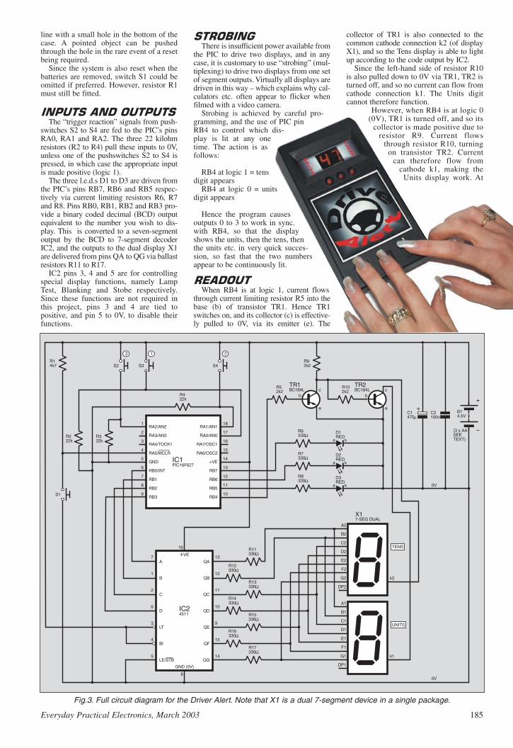
line with a small hole in the bottom of thecase. A pointed object can be pushedthrough the hole in the rare event of a resetbeing required.
Since the system is also reset when thebatteries are removed, switch S1 could beomitted if preferred. However, resistor R1must still be fitted.
The “trigger reaction” signals from push-
switches S2 to S4 are fed to the PIC’s pinsRA0, RA1 and RA2. The three 22 kilohmresistors (R2 to R4) pull these inputs to 0V,unless one of the pushswitches S2 to S4 ispressed, in which case the appropriate inputis made positive (logic 1).
The three l.e.d.s D1 to D3 are driven fromthe PIC’s pins RB7, RB6 and RB5 respec-tively via current limiting resistors R6, R7and R8. Pins RB0, RB1, RB2 and RB3 pro-vide a binary coded decimal (BCD) outputequivalent to the number you wish to dis-play. This is converted to a seven-segmentoutput by the BCD to 7-segment decoderIC2, and the outputs to the dual display X1are delivered from pins QA to QG via ballastresistors R11 to R17.
IC2 pins 3, 4 and 5 are for controllingspecial display functions, namely LampTest, Blanking and Stobe respectively.Since these functions are not required inthis project, pins 3 and 4 are tied topositive, and pin 5 to 0V, to disable theirfunctions.
There is insufficient power available from
the PIC to drive two displays, and in anycase, it is customary to use “strobing” (mul-tiplexing) to drive two displays from one setof segment outputs. Virtually all displays aredriven in this way – which explains why cal-culators etc. often appear to flicker whenfilmed with a video camera.
Strobing is achieved by careful pro-gramming, and the use of PIC pinRB4 to control which dis-play is lit at any onetime. The action is asfollows:
RB4 at logic 1 = tensdigit appears
RB4 at logic 0 = unitsdigit appears
Hence the program causesoutputs 0 to 3 to work in sync.with RB4, so that the displayshows the units, then the tens, thenthe units etc. in very quick succes-sion, so fast that the two numbersappear to be continuously lit.
When RB4 is at logic 1, current flows
through current limiting resistor R5 into thebase (b) of transistor TR1. Hence TR1switches on, and its collector (c) is effective-ly pulled to 0V, via its emitter (e). The
collector of TR1 is also connected to thecommon cathode connection k2 (of displayX1), and so the Tens display is able to lightup according to the code output by IC2.
Since the left-hand side of resistor R10is also pulled down to 0V via TR1, TR2 isturned off, and so no current can flow fromcathode connection k1. The Units digitcannot therefore function.
However, when RB4 is at logic 0(0V), TR1 is turned off, and so its
collector is made positive due toresistor R9. Current flows
through resistor R10, turningon transistor TR2. Current
can therefore flow fromcathode k1, making the
Units display work. At
Everyday Practical Electronics, March 2003 185
Ω
Ω
Ω
Ω
Ω
Ω
Ω
Ω
Ω
Ω
µ
Fig.3. Full circuit diagram for the Driver Alert. Note that X1 is a dual 7-segment device in a single package.

186 Everyday Practical Electronics, March 2003
the same time, current cannot flow fromk2 (remember that TR1 is turned off)and so the Tens display will notfunction.
Decoupling of the supply is providedby capacitors C1 and C2, and an AA bat-tery pack provides the necessary 4·5Vsupply.
Most of the Driver Alert components are
mounted on a small single-sided printedcircuit board and the topside componentlayout together with a full-size undersidecopper foil master are shown in Fig.4. Thisboard is available from the EPE PCBService, code 387.
The circuit board has been designed sothat the 7-segment dual display can behoused directly on the p.c.b., as can thel.e.d.s, although in the prototype the l.e.d.sare front panel mounted and lead-off wirestaken to the board. The reaction pushswitch-es (S2 to S4) are also front panel mounted.The optional Reset “click” switch S1 is sol-dered on the p.c.b. copper side.
Begin construction by fitting the d.i.l.sockets required for IC1 and IC2 as shownin Fig.4, noting that IC1 is “upside-down”.Fit s.i.l. sockets for the 7-segment dualdisplay, followed by the required wirelinks, the two longest of which should beinsulated. Note that these two links are sol-dered underneath the display X1.
Next fit the resistors followed by the twotransistors, ensuring that their flat edges areas shown. Also ensure that TR1 and TR2 are
BC184L (not BC184 – withoutthe L); other 184s have differentpinouts.
Capacitors C1 and C2should be soldered in, notingthat C1 is electrolytic and somust be fitted the correct wayround. Its positive (+) side isnearer the positive batterysupply connection. If the cir-cuit is to be housed in thecase as listed, then C1 mustbe fitted so that it can be bentover against the p.c.b. toreduce its height.
The l.e.d.s (D1 to D3) maybe housed directly on thep.c.b. or via connecting wires.If using wires, note that thethree cathode (k) sides areconnected together and so asingle wire may be used as inthe prototype. Also fit con-necting wires for the push-switches S2 to S4.
Reset switch S1 may beomitted as described earli-er, but if a Reset option isrequired, then a p.c.b.pushbutton switch may bedirectly housed on thecopper side of the boardso that it can be operat-ed via a small holedrilled in the underside of the case.
Finally, connect colour-coded wiresfor the battery pack and fit the dual
common cathode 7-segment display; thedecimal point of the display indicates thebottom side.
Fig.4. Driver Alert printed circuit board component layout and full-size underside copper foil master pattern. The Reset switchS1 is soldered on the track side and a small access hole drilled in the underside of the case.
Topside printed circuit board component layout.
3in. (76mm) x 4·5in. (115mm)
387

A range of cases with display cutouts is
available, and some are supplied with redfilters that provide much greater contrastfor the display. Begin by checking how thep.c.b. will fit so that the display is visible,noting that the p.c.b. will be fitted with thecomponents facing towards the front sur-face of the case. Self-adhesive p.c.b.mounts can be employed to support the cir-cuit board, but do not fasten until alldrilling is complete.
Drill the necessary holes for the l.e.d.sand pushswitches as shown in Fig.5. Acardboard cutout was made to partly maskthe cutout for the dual 7-segment display.
A small hole also needs to be drilled inthe base of the case, so that it lines up withReset switch S1’s actuating button.
The wiring from the p.c.b. to the l.e.d.sand switches is also shown in Fig.5. Thel.e.d.s all share a common cathode connec-tion and so a single wire can be used toconnect their shorter leads to the circuitboard. Likewise, the pushbutton switchesshare a single connection. Connect thewires with care, noting that the switchesare out of sequence.
The circuit operates on a supply of 2V to
5·5V, and so a set of three AA cells (4·5V) issuggested. In the prototype, the battery com-partment was designed for four AA cells, buthas provision for three, by soldering the con-necting lead to the appropriate spring clip.
It is not acceptable to power the circuitfrom four standard AA cells since the total
voltage supplied will be above the 5·5Vmaximum acceptable by the PIC. If re-chargeable cells are employed, then thevoltage supplied by four in series will beabout 4·8V, and so would be acceptable.
The program for this design was written
in BASIC using the software requiredwhen programming PICAXE devices, suchas those in the PICAXE Projects series inthe Nov, Dec ’02 and Jan ’03 issues.However, the program was too long to fitinto a PICAXE, and so a standard
Everyday Practical Electronics, March 2003 187
Approx. CostGuidance Only ££2211
excl. batts & case
ResistorsR1 4k7R2 to R4 22k (3 off)R5, R9
R10 2k2 (3 off)R6 to R8,
R11 to R17 330 (10 off)All 0·25W 5% carbon film
CapacitorsC1 470 radial elect. 35VC2 100n ceramic disc
SemiconductorsD1 to D3 5mm red l.e.d. (3 off)TR1, TR2 BC184L npn transistor
(2 off)IC1 PIC16F627
microcontroller,pre-programmed(see text)
IC2 4511B BCD to7-segmentdecoder/driver
X1 7-segment dual display,common cathode
MiscellaneousS1 p.c.b. mounting, click-
effect, switch(push-to-make) – seetext
S2 to S4 pushbutton switch,push-to-make (3 off)
B1 4·5V battery pack(3 x AA – see text)
Printed circuit board available fromthe EPE PCB Service, code 387; plastichandheld case, with display window andbattery compartment, case size 180mmx 100mm x 44mm approx.; 16-pin d.i.l.socket; 18-pin d.i.l. socket; s.i.l. socketstrip for display; panel mounting l.e.d.clip (3 off); self-adhesive p.c.b. mountingpillars; multi-coloured connecting wire;solder etc.
SeeSSHHOOPPTTAALLKKppaaggee
Fig.5. Interwiring details from the printed circuit board to front panel switches,l.e.d.s and to the battery pack.
Completed unit showing the optional Reset switch on the board copper side.
Cardboard mask behind display window.
EPE Online
Note that the circuit boards used in EPE Online projects are available from the EPE Online Store at www.epemag.com (also note that the codes for the boards in the online store are prefixed with 7000, so a board with a code of say 256 will appear as 7000256 in the online store).
EPE Online
Note that you can purchase pre-programmed PIC microcontrollers for our PIC projects (see the “ShopTalk” page in the associated issue of the Magazine for more details). Alternatively, if you wish to program the PIC yourself, you can find the code files by bouncing over to the EPE Online Library (visit www.epemag.com, click in the “Library” link in the top navigation, then on the “Project Code Files” link).

PIC16F627 was used instead, program-ming it from the hex code produced by theBASIC assembly software.
This hex file can be used by readers toprogram their own PIC16F627 devices,using their own PIC programmer hard-ware. It should be noted, however, thatreaders who wish to modify the BASICprogram to suit their own requirementsneed to use the software that is availablefrom Tech-Supplies, Dept EPE, 4 OldDairy Business Centre, Melcombe Road,Bath BA2 3LR (this software is not avail-able from EPE).
The BASIC and hex files are availablefor free download from the EPE ftp site.This is most easily accessed via the mainpage of the EPE web site atwww.epemag.wimborne.co.uk. At the topis a click-link saying FTP site (down-loads), click it then click on PUB and thenon PICS, in which screen you will find theDriver Alert folder.
The software can also be obtained on3·5-inch disk (Disk 6) from the Editorialoffice. There is a nominal handlingcharge to cover admin costs. Details are
given on the EPEPCB Service page,and in this month’sShoptalk, which alsogives details aboutobtaining prepro-grammed PICs.
It is now time to
insert the i.c.s, notingthat they are static sen-sitive and so youshould touch an earth-ed metal object beforehandling each i.c. Notealso that they faceopposite ways – ensurethat each notch or dot isas shown in Fig.4. ThePIC16F627 must, ofcourse, first be pro-grammed either by
downloading the hex file, or by buying aready-programmed chip (see Shop Talk).
Commence testing by switching on andpressing any switch button. The number 1should appear, indicating your first go. Ifyou do nothing, the number 99 appears,showing that you took longer than the timeallowed. The machine then moves on togo-number 2.
If you respond correctly to the numberof l.e.d.s displayed, then your time isshown on the displays. Note that when youmultiply the reading by ten, your time is inmilliseconds. Hence a display of 56 indi-cates 560 milliseconds. After go-number 5,the display flashes the average score beforeswitching off.
After five practice goes, you should beable to achieve a time of under 600 mil-liseconds. In trials, some people achievedtimes of under 200 milliseconds. Alcoholetc. will, of course, affect your score, andusing a mobile phone will also have a sig-nificant effect – even a hands-free type, seegraphs in Fig.1
Note that “switching off” is not a physi-cal switch off of the power supply. Rather,
the PIC is told to SLEEP. In this mode itplaces itself into a low power condition, inwhich it typically consumes only about15A.
188 Everyday Practical Electronics, March 2003
Adam and Josh receiving their awards (£500 and a trophy)from HRH Prince Andrew for winning the Best Under 15project at last year’s YEDA prizegiving ceremony.
Instruction panel for glueing to rear ofunit.
!"# $% &'(
)*% & &+ , -. &(/ 0& 0 (
.%1 %*" 20 .-3& & &&40 -&(
5 1"% 13 '*1 3& 3 & 00 &0 , 3& (((
% *% 65% (
71#8$ & (
9 : ;
!"#$%$ &''(
;<=><>?@A?@>(5<=><>?@BCD>( ;333(((4333((

PIC Training & Development SystemThe best place to start learning about microcontrollers is the PIC16F84. This iseasy to understand and very popular with construction projects. Then continue onusing the more sophisticated PIC16F877 family.
The heart of our system is a real book which lies open on your desk while youuse your computer to type in the programme and control the hardware. Start withfour very simple programmes. Run the simulator to see how they work. Test themwith real hardware. Follow on with a little theory.....
Our complete PIC training and development system consists of our universalmid range PIC programmer, a 306 page book covering the PIC16F84, a 262 pagebook introducing the PIC16F877 family, and a suite of programmes to run on aPC. The module is an advanced design using a 28 pin PIC16F872 to handle thetiming, programming and voltage switching requirements. The module has twoZIF sockets and an 8 pin socket which between them allow most mid range 8, 18,28 and 40 pin PICs to be programmed.The plugboard is wired with a 5 volt supply.The software is an integrated system comprising a text editor, assemblerdisassembler, simulator and programming software. The programming isperformed at normal 5 volts and then verified with plus and minus 10% applied toensure that the device is programmed with a good margin and not poised on theedge of failure. Requires two PP3 batteries which are not supplied.
Universal mid range PIC programmer module+ Book Experimenting with PIC Microcontrollers+ Book Experimenting with the PIC16F877 (2nd edition)+ Universal mid range PIC software suite
.....+ PIC16F84 and PIC16F872 test PICs. . . . . . £157.41UK Postage and insurance. . . . . . . . . . . . . . . £ 7.50(Europe postage & Insurance. . £13.00. Rest of world. . £24.00)
Experimenting with PIC MicrocontrollersThis book introduces the PIC16F84 and PIC16C711, and is the easy wayto get started for anyone who is new to PIC programming. We begin withfour simple experiments, the first of which is explained over ten and a halfpages assuming no starting knowledge except the ability to operate aPC. Then having gained some practical experience we study the basicprinciples of PIC programming, learn about the 8 bit timer, how to drivethe liquid crystal display, create a real time clock, experiment with thewatchdog timer, sleep mode, beeps and music, including a rendition ofBeethoven’s Für Elise. Finally there are two projects to work through,using the PIC16F84 to create a sinewave generator and investigating thepower taken by domestic appliances. In the space of 24 experiments, twoprojects and 56 exercises the book works through from absolutebeginner to experienced engineer level.
Ordering InformationTelephone with Visa, Mastercard or Switch, or send cheque/PO forimmediate despatch. All prices include VAT if applicable. Postage must beadded to all orders. UK postage £2.50 per book, £1.00 per kit, maximum£7.50. Europe postage £3.50 per book, £1.50 per kit. Rest of World £6.50 perbook, 2.50 per kit.Web site:- www.brunningsoftware.co.uk
138 The Street, Little Clacton, Clacton-on-sea,Essex, CO16 9LS. Tel 01255 862308
Mail order address:
Learn About Microcontrollers NEW 32 bit PC AssemblerExperimenting with PC Computers with its kit is theeasiest way ever to learn assembly languageprogramming. If you have enough intelligence tounderstand the English language and you can operatea PC computer then you have all the necessarybackground knowledge. Flashing LEDs, digital toanalogue converters, simple oscilloscope, chargingcurves, temperature graphs and audio digitising.Kit now supplied with our 32 bit assembler with 84 pagesupplement detailing the new features and including7 experiments PC to PIC communication. FlashingLEDs, writing to LCD and two way data using 3 wiresfrom PC’s parallel port to PIC16F84.
Book Experimenting with PCs ............... £21.50Kit 1a ‘made up’ with software .............. £52.00Kit 1u ‘unmade’ with software ............... £45.00
C & C++ for the PCExperimenting with C & C++ Programmes teaches us toprogramme by using C to drive the simple hardwarecircuits built using the materials supplied in the kit. Thecircuits build up to a storage oscilloscope usingrelatively simple C techniques to construct aprogramme that is by no means simple. Whenapproached in this way C is only marginally moredifficult than BASIC and infinitely more powerful.C programmers are always in demand. Ideal forabsolute beginners and experienced programmers.
Book Experimenting with C & C++ ........ £24.99Kit CP2a ‘made up’ with software ......... £32.51Kit CP2u ‘unmade’ with software .......... £26.51Kit CP2t ‘top up’ with software .............. £12.99
The KitsThe assembler and C & C++ kits contain the prototypingboard, lead assemblies,components and programmingsoftware to do all the experiments. The ‘made up’ kitsare supplied ready to start. The ‘top up’ kit is for readerswho have already purchased kit 1a or 1u. The kits donot include the book.
Hardware requiredAll systems in this advertisement assume you havea PC (386 or better) and a printer lead. The experimentsrequire no soldering.
Experimenting with the PIC16F877The second PIC book starts with the simplest of experiments togive us a basic understanding of the PIC16F877 family. Then welook at the 16 bit timer, efficient storage and display of textmessages, simple frequency counter, use a keypad for numbers,letters and security codes, and examine the 10 bit A/D converter.
The 2nd edition has two new chapters. The PIC16F627 isintroduced as a low cost PIC16F84. We use the PIC16F627 asa step up switching regulator, and to control the speed of a DCmotor with maximum torque still available. Then we study how touse a PIC to switch mains power using an optoisolated triacdriving a high current triac.
190 Everyday Practical Electronics, March 2003
PIC INTERRUPTS AND PCLATHDear EPE,I’m grateful to John Waller for drawing my
attention (in private correspondence) to a pointthat isn’t fully covered in my Programming PICInterrupts articles in EPE Mar/Apr ’02, andwhich may cause confusion.
In any program that’s longer than 2K bytes it’slikely that PCLATH is having to be manipulated inorder that CALL and GOTO instructions end up inthe right places. If the program also uses interrupts,then the program’s ISR will need to preserve andrestore PCLATH as part of the program’s context.Having saved PCLATH, the ISR should then resetit for its own use, as explained in the article. Untilthe ISR has done this, it is not safe to use anyCALL or GOTO instructions in the ISR itself,because at the time the interrupt is taken PCLATHmay be wrongly set to address the ISR’s code. Thisrestriction includes the GOTO ISR instructionwhich is often assembled into Page 0 location 4,the interrupt vector.
To re-emphasise, if PCLATH bits 4 and 3 maybe non-zero when an interrupt occurs, then aGOTO ISR instruction in page 0 location 4 can-not be used as the first instruction of the ISR. Codemust be assembled in contiguous locations start-ing at location 4 to preserve the context, includingPCLATH, and then reset PCLATH, before anyCALL or GOTO instructions can be used. It’ssomewhat analogous to the Bank switching dis-cussion following Experiment 2 in my article,except that here the problem is to do with the Pageselect bits, not the Bank select bits.
This issue doesn’t arise on 16x8x processors,which have a maximum of 2K program memoryand which ignore the setting of bits 4 and 3 ofPCLATH.
For readers who would like more details, a newtest program, intproga.asm, can be downloadedfrom the /pub/PICS/Interrupts directory of theEPE ftp site, together with instructions on how torun it in the file intproga.txt. This test programillustrates the effect of getting an interrupt whenPCLATH is non-zero, and how to fix it.
Malcolm Wiles, via email
Thanks Malc, the code is now on our ftp site.
TELE FEEDINGDear EPE,I am trying to design a small animal feeder for
a project, I wish to use this in conjunction withthe telephone lines so that I can call up the feed-er and tell it to turn a set amount of degrees toexpose the food. I need to design a p.c.b. thatwill connect to the telephone line to tell a smallstepper motor to move. Help in this area wouldbe much appreciated.
Norman Blair, via email
So sorry Norman but we cannot help on thisas it is illegal to connect anything to a telephoneline that has not been fully approved for suchuse – permission that would never be granted toa DIY project. Ask via our Chat Zone if anyoneknows of a way round it – counting the numberof phone bell rings for instance (though the ani-mals might occasionally get second helpings onsome days, of course!). When necessary I use afeeder that’s motor driven and opens food flapsat set intervals (not PIC controlled though!).
LETTER OF THE MONTH UNIFIED PIC RESOURCES
Dear EPE,First may I say how much I enjoy your mag-
azine. I remember getting a glimpse of the firstissue, via my cousin, when I was in my teens.The thing that inspired me was all the projectsthat allowed me to build things I simply couldnot get in the shops. Today things are very dif-ferent – there is not much you can’t buy cheap-er than you can build it now.
I have to confess to a long period of not sub-scribing to your mag. As for many others, as Iprogressed up to management, I found less timeto spend on my hobby. Happily, I was maderedundant four years ago and decided to “returnto my roots”. I became a contractor and soonfound that despite umpteen years of not keepingin touch with developments, things had hardlychanged in many areas. People were still usingthe 2N3055! I’ve now moved into analogueASIC design and I’m loving every minute of it.
At the time of being made redundant I startedsubscribing to EPE and other electronics maga-zines. First impressions were – where did allthis digital stuff come from?! In particular PICs.I’m an analogue person, so digits doesn’t comethat easy. There was a quantum leap requiredand I soon invested in a PIC development sys-tem. It sat on the shelf for quite a while. Thatquantum leap looked too high a hurdle.
Eventually, I decided to give it a try. I startedsurfing the web and found a very simple flash-ing l.e.d. project. What’s more, it worked! Therethen followed a series of simple projects – step-per motor control, via RS232 (ahhh, RS232,another old friend!) – a multi-channel voltmeterwith output to my PC via RS232. Suddenly, I’ma PIC junky!
I’m at that time of life where money isn’treally a problem. What is a problem is an atten-tion span of 30 minutes and a still sizeable holein my knowledge. It’s not the hardware – it’sthis cursed software. I’ve got plenty of ideas Iwant to build, but how to interface them to myPC? What I’d like to see from a magazine likeEPE is some guidance. You have some excellentarticles by John Becker and other regular con-tributors, the problem is that some of the impor-tant ones got missed. Have you thought ofproducing tutorial CDs? For example, a starterCD for PICs. Some simple projects utilizingspecial features of the PIC. Also, how to get
started in Visual Basic. Basic control panelsand interfacing via the COMs and parallelports, ditto for C++.
I draw a parallel with my other hobby –photography. Here the wonders of usingPhotoshop was a major hurdle. The magazineI subscribe to has regular Video tutorialsshowing exactly what to do. They also sellCDs that cover a variety of topics.
I guess you could argue that if I took out aregular subscription, I wouldn’t miss stuff.However, trawling through back issues to findthat article I think I saw is not as efficient ashaving it all in one place – the CD.
Finally, here is an idea I have for a new pro-ject. A friend recently had his boat brokeninto. What would have been really neat wouldhave been an intruder detector (not difficult)that sent a message to his mobile telling himthat it had happened (ergh! Mobile knowledgerequired!).
It would not stop an intruder – boats areoften left in remote places anyway, but at leastthe owner would know about it quickly andknow that he had to go and sort things out.(The high power ultrasonic sounder wouldhave disintegrated the intruder and would needto be cleared up before a smell started todevelop!) I’m currently surfing for more infor-mation on interfacing to mobiles. Any ideas?
Hope this has helped you understand whatsome of us oldies are looking for.
Graham Johnston, via email
Thanks Graham for your kind commentsabout us – I’m pleased you’ve found arenewed interest in electronics. In my manyyears enjoying electronics I too have seenmany changes.
In fact we are probably producing a CD withthe type of info you suggest, to accompany myrevision of the EPE PIC Tutorial of Mar-May’98. All sorts of PIC related projects and articleswill be on it. Also, are you aware that we domini CDs, each of which holds six past issues?They are advertised in our pages each month.
Your boat alarm idea is interesting but notsomething I would wish to take on. Quotingyour letter here, though, might inspire a readerto design one. No, I don’t know about interfac-ing to mobiles (and I hate the darn things –don’t people ever talk face-to-face these days?).
Everyday Practical Electronics, March 2003 191
RREEAADDOOUUTTJJoohhnn BBeecckkeerr aaddddrreesssseess ssoommeeooff tthhee ggeenneerraall ppooiinnttss rreeaaddeerrss
hhaavvee rraaiisseedd.. HHaavvee yyoouu aannyytthhiinnggiinntteerreessttiinngg ttoo ssaayy??
DDrroopp uuss aa lliinnee!!
WIN A DIGITALMULTIMETER
A 31/2 digit pocket-sized l.c.d. multime-ter which measures a.c. and d.c. volt-age, d.c. current and resistance. It canalso test diodes and bipolar transistors.
Every month we will give a DigitalMultimeter to the author of the best
Readout letter.
Email: [email protected]
All letters quoted here have previously been replied to directly.
CUTTING ACRYLIC SHEETDear EPE,Referring to Raymond Haigh’s Tesla
Transformer of Feb ’03, I was intrigued by histip for using the back of a Stanley knife blade(I assume this is a standard No. 1992 blade)for scoring acrylic sheet, so I’ve just tried itout. I found it very difficult to hold either aStanley 99 retractable blade knife or a Stanley199A fixed blade knife at the correct angle toscore the sheet. But more importantly, if one’shand slipped then a severe injury would occurto either one’s index finger or little finger,depending on how the knife was being held.
For many years I have used the Stanley lami-nate cutting blade No. 5194 which fits theStanley knives mentioned above and is muchsafer as the knife is held conventionally. Theblade is intended for cutting SRBP type lami-nates such as Formica, Paxolin and Veroboard,but it works well on acrylic sheet. I also have aWickes acrylic sheet knife which works evenbetter, but I don’t know if this is still available.
Barry Taylor, via email
Thank you Barry, your concern is noted andre-broadcast. I wish I had known this informa-tion when cutting the acrylic sides for my WindTunnel of Feb ’03.
192 Everyday Practical Electronics, March 2003
PIC TRAINING COURSESDear EPE,In reply to Dave Williams’ letter in Readout
Dec ’02 regarding PIC training courses, couldyou pass on the following to your readers? Wecurrently teach PIC microcontroller technologyas part of a National Diploma in Electrical/Electronic Engineering courses in Bracknell andWokingham College. In the course, which is twohours per week over two years, we cover thefollowing:
1. The basics of binary and hexadecimal arith-metic and appropriate conversions.
2. Programming the PIC using a BASIC crosscompiler that I have developed.
3. Development of programs to illustrate I/Ocapability of the PIC.
4. Development of programs using PICassembler (using MPLAB), covering logic andarithmetic instructions, indirect addressing,loops and timing loops, all in assembler.
5. Developing programming techniques suchas moving data, moving averages, also inassembler.
6. Development of programs to handle the PICtimers.
7. Development of programs to handle codetranslation necessary for 7-segment displays.
In addition, students are taught how to drive,for example, discrete A to D and D to A convert-ers when the facilities are not within the PICbeing employed.
The course is very practical with approximate-ly half the lessons devoted to practical program-ming. The hardware we use was developed in theCollege but is fairly standard and in general weuse either the faithful PIC16F84 or PIC16F876.All the teaching material is produced usingPowerPoint and with handouts covering almostall aspects of the course. The course could easi-ly be adapted to the needs of any specific cus-tomer and I would be pleased to discuss trainingneeds with anyone who would like to contact me.
Dr Alan R Fuller,Head of Engineering and CAD,
Bracknell and Wokingham College
Thanks Alan. Searching the Web via Google, Ifind that your web and telephone details arewww.bracknell.ac.uk, and 01344 460200.
MORE PIC COURSESDear EPE,In Readout of Dec ’02, Dave Williams asks
about PIC training courses. Although I do notformally run such courses, having used PICs in99% of my designs, I have at times assisted com-panies to develop/use/program PICs in their ownproducts. Such projects can be seen atwww.StephenAlsop.co.uk under S&SProducts.
EPE is a really good professional magazinewith an excellent balance of projects and exper-tise. It is a pleasure to receive it each month.
Stephen Alsop,via email
Thank you for the link Stephen, and your kindcomment!
PORTABLE PIC PROGRAMMERDear EPE,I’ve had an idea for a possible project. I made
a controller for an oven that we use for work,using a PIC16F877. It works very well but Iwanted to add some features (mainly implement-ed in software). All of your recent projects fea-ture the in-circuit programming connector. Ioverlooked this feature on my circuit but the nextrevision will have this in place. However, itwould not be of much use to me as I do not havea computer at work.
Since the circuit is now “plumbed in”, itwould require a bit of tinkering to swap the PIC.I thought it would be real nice to have a portablePIC program transferer. Trouble is, I wouldn’thave the faintest idea how to implement thisidea. I think it would need the big guns such asyourself to work out a solution. I suppose it
would have to emulate a PIC being programmedwhen being loaded from the programmer, and toemulate a programmer when transferring theprogram to the destination PIC.
This is just an idea, to stimulate the grey mat-ter, but it would make a nice gadget I think.
Gerard Galvin, via email
Thanks Gerard, it’s certainly scope forthought, but my immediate reaction is that notenough people would find it of interest as mosthave PCs where their PIC programming is done.
At its simplest, what would be needed is aportable board running from a battery and hav-ing a PIC that would accept code from the PCand store it in onboard memory (serial EEP-ROM). This board would then be taken to thelocation at which your main PIC is being used incircuit, and that PIC would then be programmedfrom the portable board.
That would be fine if the destination had beenset up to allow +5V programming in its configu-ration, but most will not have (none of minehave). Otherwise additional chips would beneeded to generate the +14V programming volt-age (the front end of TK3 for instance).
I could certainly do one if enough readers areinterested – tell me if you are!
STACKING UPDear EPE,I have recently run into a PIC programming
problem that arises from PICs having a Stack ofonly eight levels. As the Stack can neither bewritten to nor read from, this is a severe limita-tion. Does anyone know how this can be over-come?
As an aside, having a character (alphanumer-ic) l.c.d. connected to the circuit being developedis an invaluable aid when debugging, in beingable to view the values of variables at criticallocations.
John Waller, via email
JW and I have frequent private chats via emailabout PIC programming (and other things!) andwe have discussed this particular matter andcannot conceive a solution. The problem is thatcomplex programs might ideally have many nest-ed calls to tables and sub-routines and each callplaces return address data on the Stack. If morethan eight calls are nested, the Stack simplyoverwrites earlier calls, resulting in program“crashes” because the return address data iswrong. So, to echo JW, does anyone know of asolution if many nested calls are otherwise theideal requirement?
Like John, I too depend on an l.c.d. when writ-ing code. It was an horrendous task when Irecently programmed a giant l.e.d. clock that willbe published soon (PICronos). Extreme multi-plexing techniques control nearly 200 l.e.d.s andthere were no spare PIC pins left to monitor themultiplexing on an l.c.d.
FLANGING AND CHATTINGDear EPE,I am a Year 11 GCSE pupil at The Hayling
School in Hampshire. As part of my GCSEElectronics coursework I have chosen to designand make a guitar Flanger pedal. The finisheddesign should be able to create a professionalsounding Flange effect; have Depth, Speed andResonance controls; be strong enough to with-stand being kicked and stamped on, as happenson stage.
I would be very grateful for any informationyou may have about Flanger pedals as electronicdesigns.
Michael Sinden,via email
Apart from including the facility in my PICPolywhatsit of Dec ’01, Michael, it’s not some-thing that we have done for many years. One ofthe problems is that the so-called “bucketbrigade” chips (CCDs – charge coupleddevices), that used to be widely available andmade such designs really practical, are now hard
to find. I briefly explain the flanging principle inthe Polywhatsit text, and copies are available atthe usual Back Issue prices. I suggest you alsoask readers via our Chat Zone if they can offeradvice.
On the subject of the Chat Zone, I have recent-ly been surprised to be told by a couple of read-ers that they regularly use the web and our ftpdownload site, but were unaware of our ChatZone until I mentioned it. This is a type of “bul-letin board” where you can chat with other read-ers about anything related to electronics andallied computing subjects.
It’s all very informal and you don’t need pass-words to get into it. Simply to go to our homepage at www.epemag.wimborne.co.uk. At thetop of the page are several click-links. Click onthe one that says Chat Zone (Message Board)and then scroll down and read the entries madeby other readers, just by clicking on the subjecttitles. You can readily join in the discussions tooif you wish, and even start your own subject thatother readers can join in with.
There is a lot benefit that people can gain fromthis facility, both from a general interest point ofview and the possibility of being offered solu-tions to problems – it can’t be guaranteed you’llget the information you want, but it’s well worthasking questions if you have any. Note though,that if you have technical queries relating to ourpublished projects, you should send those tome at the Editorial office, via [email protected].
REAL-TIME CLOCKSDear EPE,In response to Andrew Jarvis’ Letter of the
Month, Jan ’03, a good method of keeping trackof date and time when the power is off is byusing a dedicated real-time clock chip such asthe Dallas Semiconductor DS1302. This uses astandard 32kHz watch crystal and will run foryears on a lithium coin cell. It comes in an 8-pinpackage and has a simple 3-wire interface toaccess its registers. Data sheet and applicationnotes are downloadable from www.maxim-ic.com. It is available from most of the usualsources and is quite inexpensive (about £2.20).
David Sharp,via email
Thanks David.
METRIC MUDDLEDear EPE,You were kind enough to publish a letter of
mine some months ago, regarding “failures inour educational system”.
I was recently dismayed by what I have alsocome across in the basic skills testing beingoffered to anyone encouraged to test themselves.
I was most concerned to see some questions inwhich metric rules appear and one is asked toindicate the lengths for some lines, which oughtto be, for example, either 75mm or 7·5cm, butsuch an answer is not permitted. The choices are,for example, 71/2 (7 and one half centimetres).
In the sixties I was Metrication officer for mythen employer, and we were taught never to mixfractions in a metric environment. There is noplace for such an answer as required in the basicskills testing I refer to. What is even more wor-rying is that when I pointed the error out to thetutors, no one could see any problem.Regretfully, my tutors were in the private sector.When I asked within a regular college teachingprofession, all the engineering lecturers instantlysaw the error.
We are still not thinking metric after fortyyears of teaching. Surely only the Brits couldfoul up a perfectly good decimal system. Theproblem highlighted was only one of many in theexam.
Name withheld on request
Thanks for the comments – it is a disturbingsituation. I note from the information you sentthat the college intends to correct the testappropriately.

A Complete range of regulated inverters to power 220V and 240V ACequipment via a car, lorry or boat battery. Due to their high performance(>90%) the inverters generate very little heat. The high stability of theoutput frequency (+/-1%) makes them equally suitable to powersensitive devices.
These inverters generate a modified sine wave, which are considerably superior to the square waves which are produced bymost other inverters. Due to this superior feature they are capable of powering electrical equipment such as TV,s, videos,desktop & notepad computers, microwave ovens, electrical lamps, pumps, battery chargers, etc.Low Battery AlarmThe inverters give an audible warning signal when the battery voltage is lower than 10.5V (21V for the 24V version). The inverterautomatically shuts off when the battery voltage drops below 10V (20V for the 24V version). Fuse protected input circuitry.
A COMPLETE RANGE OF
INVERTERS150W TO 2500W - 12V & 24V
WWWWWW.BKELEC.COM/INVERTERS.HTM.BKELEC.COM/INVERTERS.HTM
Order Code
651.581651.578651.582651.585651.583651.593651.587651.597651.602651.605651.589651.599
Power
150W Continuous150W Continuous300W Continuous300W Continuous600W Continuous600W Continuous
1000W Continuous1000W Continuous1500W Continuous1500W Continuous2500W Continuous2500W Continuous
Voltage
12V24V12V24V12V24V12V24V12V24V12V24V
Price
£36.39£36.39£50.64£50.64
£101.59£101.59£177.18£177.18£314.52£314.52£490.54£490.54
All prices are inclusive of V.A.T. Carriage £6.00 Per Order
For Full Specifications View our web site at:-B.K. ELECTRONICS UNIT 1, COMET WAY, SOUTHEND-ON-SEA, ESSEX. SS2 6TRTEL.: +44(0)1702-527572 FAX.:+44(0)1702-420243
Many uses include:- * Fetes * Fairgrounds * Airshows * Picnics *Camping * Caravans * Boats * Carnivals * Field Research and *Amateur Radio field days * Powering Desktop & Notepad Computers.
DELIVERY CHARGES ARE £6-00 PER ORDER. OFFICIALORDERS FROM SCHOOLS, COLLEGES, GOVT. BODIES, PLC,SETC. PRICES ARE INCLUSIVE OF V.A.T. SALES COUNTER. VISAAND ACCESS ACCEPTED BY POST, PHONE OR FAX, OR EMAILUS AT [email protected] ALTERNATIVELY SEND CHEQUEOR POSTAL ORDERS MADE PAYABLE TO BK ELECTRONICS.
ILLUSTRATION SHOWN IS 651.583 600W VERSION
REF D4
20% discount for EPEreaders
Temperature controlled soldering stations
Vann Draper Electronics LtdThe test & measurement specialists
www.vanndraper.co.ukGrundig, Kenwood, Hitachi, Fluke, Avo and more.
Use this coupon for your order
Please supply me:
........ SL20 soldering station(s) at £55 inc. vat & del
........ SL30 soldering station(s) at £65 inc. vat & del
........ Extra 0·8mm bit(s) at £1.88 inc vat & del
........ 1·6mm bit(s) at £1.88 inc vat & del
........ 3·2mm bit(s) at £1.88 inc vat & del
Name:
Address:
Tel No:
Total £Cheques payable to Vann Draper Electronics Ltdor debit my visa, mastercard or switch card:
Card type:
Card No:
Expiry date: Switch Issue No:
Signature:
Overseas readers can still obtain this discount but carriagecharges vary according to country. Please telephone, fax, emailor write to Vann Draper.
Vann Draper is offering over 20% discount for a limited period to readers ofEveryday Practical Electronics on their temperature controlled soldering stations.
The SL20 bar graph display soldering station normally sells at £69.33 and is available toreaders of EPE at only £55 fully inclusive of vat & delivery.
The SL30 digital display version is normally priced at £81.08 but for readers of EPE theprice is just £65 fully inclusive.
Both soldering stations feature 24V 48W elements for rapid heating and have full electronictemperature control between 150°C and 420°C (SL20), 160°C and 480°C (SL30).
The SL20 and SL30 are supplied ready to use complete with a 48W iron, 0·8mm long lifebit, mains lead, operating instructions and a 12 month guarantee.
To order, simply post the coupon to: Vann Draper Electronics Ltd, atStenson House, Stenson, Derby DE73 1HL. Alternatively – Tel 01283 704706 Fax 01283 704707 Email [email protected]
Everyday Practical Electronics, March 2003 193

BBAACCKK IISSSSUUEESSNOV ’01
PROJECTS Capacitance Meter Pitch Switch Lights Needed Alert Teach-In 2002 Power Supply.FEATURES Teach-In 2002 – Part 1 PracticallySpeaking Circuit Surgery New TechnologyUpdate Ingenuity Unlimited Net Work – TheInternet Page Free 16-page Supplement – PICToolkit TK3 For Windows.
DEC ’01PROJECTS Ghost Buster PIC Polywhatsit Twinkling Lights Mains Failure Alarm.FEATURES Teach-In 2002 – Part 2 Marconi –The Father of Radio Interface IngenuityUnlimited Circuit Surgery New TechnologyUpdate Net Work – The Internet Page 2001Annual Index.
JAN ’02PROJECTS PIC Magick Musick Time DelayTouch Switch Versatile Bench Power Supply Forever Flasher.FEATURES Teach-In 2002 – Part 3 PracticallySpeaking Ingenuity Unlimited New TechnologyUpdate Circuit Surgery Net Work – The InternetPage.
FEB ’02PROJECTS PIC Spectrum Analyser GuitarPractice Amp HT Power Supply VersatileCurrent Monitor.FEATURES Teach-In 2002 – Part 4 IngenuityUnlimited Russian Space Shuttle Revisited Circuit Surgery Interface New TechnologyUpdate Net Work – The Internet Page.
MAR ’02PROJECTS MK484 Shortwave Radio PICVirus Zapper RH Meter PIC Mini-Enigma.FEATURES Teach-In 2002 – Part 5 IngenuityUnlimited Programming PIC Interrupts–1 CircuitSurgery Practically Speaking New TechnologyUpdate Net Work – The Internet Page.
APR ’02PROJECTS Electric Guitar Tuner PICControlled Intruder Alarm Solar Charge and Go Manual Stepper Motor Controller.FEATURES Teach-In 2002 – Part 6 Interface Programming PIC Interrupts–2 Circuit Surgery Ingenuity Unlimited New Technology Update Net Work – The Internet Page FREE GiantOp.Amp Data Chart.
MAY ’02PROJECTS PIC Big-Digit Display Simple AudioCircuits – 1 Freezer Alarm Washing ReadyIndicator.FEATURES Teach-In 2002 – Part 7 IngenuityUnlimited Practically Speaking New TechnologyUpdate Circuit Surgery Net Work – The InternetPage.
JUNE ’02PROJECTS Biopic Heartbeat Monitor Frequency Standard Generator Simple AudioCircuits – 2 World Lamp.FEATURES Teach-In 2002 – Part 8 Interface New Technology Update Circuit Surgery Ingenuity Unlimited Net Work – The InternetPage.
JULY ’02PROJECTS EPE StyloPIC Infra-RedAutoswitch Simple Audio Circuits – 3 RotaryCombination Lock.FEATURES Teach-In 2002 – Part 9 PracticallySpeaking Using The PIC’s PCLATH Command Ingenuity Unlimited Circuit Surgery NewTechnology Update Net Work–The Internet Page.
AUG ’02PROJECTS PIC World Clock Pickpocket AlarmBig-Ears Buggy Simple Audio Circuits – 4.FEATURES Teach-In 2002 – Part 10 UsingSquare Roots with PICs Ingenuity Unlimited Evolutionary Electronics Interface CircuitSurgery Net Work – The Internet Page.
SEPT ’02PROJECTS Freebird Glider Control PortableTelephone Tester EPE Morse Code Reader Vinyl to CD Preamplifier.FEATURES Circuit Surgery New TechnologyUpdate Practically Speaking Net Work Flowcode for PICmicro Logic Gate InverterOscillators Net Work – The Internet Page.
OCT ’02 Photocopies onlyPROJECTS EPE Bounty Treasure Hunter ICTester Headset Communicator PIC-PocketBattleships.FEATURES Circuit Surgery New TechnologyUpdate Logic Gate Inverter Oscillators – 2 Interface Network – The Internet Page UsingTK3 With Windows XP and 2000.
NOV ’02 Photocopies onlyPROJECTS EPE Hybrid Computer – 1 TuningFork and Metronome Transient Tracker PICAXEProjects–1 (Egg Timer – Dice Machine – QuizGame Monitor).FEATURES Practically Speaking IngenuityUnlimited Circuit Surgery New TechnologyUpdate Net Work – The Internet Page.
DEC ’02PROJECTS Versatile PIC Flasher EPE HybridComputer – 2 Door Defender PICAXE Projects– 2 (Temperature Sensor – Voltage Sensor – VUIndicator).FEATURES Electronic Paper Alternative Usesfor Transistors Interface Circuit Surgery NewTechnology Update Ingenuity Unlimited NetWork – The Internet Page 2002 Annual Index.
JAN ’03PROJECTS EPE Minder F.M. Frequency Surfer Wind Speed Meter PICAXE Projects–3 (ChaserLights).FEATURES Who Really Invented The Transistor TechnoTalk Circuit Surgery PracticallySpeaking New Technology Update ComputerGOTOs Ingenuity Unlimited Net Work – TheInternet Page.
FEB ’03PROJECTS Wind Tunnel Brainibot Buggy Back To Basics–1 (Hearing Aid, Audio PowerAmplifier) Tesla High Voltage Transformer.FEATURES In The Bag Techno Talk CircuitSurgery New Technology Update Interface Ingenuity Unlimited Net Work – The Internet Page.
We can supply back issues of EPE by post, most issues from the past three years are available. An EPE index for the last five years is also available atwww.epemag.wimborne.co.uk or see order form below. Alternatively, indexes are published in the December issue for that year. Where we are unable toprovide a back issue a photocopy of any one article (or one part of a series) can be purchased for the same price. Issues from Nov. 98 are available on CD-ROM – see next page – and issues from the last six months are also available to download from www.epemag.com.
BACK ISSUES ONLY £3.50 each inc. UK p&p.Overseas prices £4 each surface mail, £5.50 each airmail.
We can also supply issues from earlier years: 1998 (except Jan. to May, July, Sept., Nov., Dec.), 1999(except Aug., Dec.), 2000 (except Feb.), 2001 (except May, Sept., Oct.), 2002 (except Oct., Nov.) Wherewe do not have an issue a photocopy of any one article or one part of a series can be provided at thesame price.
OORRDDEERR FFOORRMM – BACK ISSUES – PHOTOCOPIES– INDEXES
Send back issues dated . . . . . . . . . . . . . . . . . . . . . . . . . . . . . . . . . . . . . . . . . . . . . . . . . . . . . . . . . . . . . . . . . . .
Send photocopies of (article title and issue date) . . . . . . . . . . . . . . . . . . . . . . . . . . . . . . . . . . . . . . . . . . . . . . . . .
Send copies of last five years indexes (£3.50 for five inc. p&p – Overseas £4 surface, £5.50 airmail)
Name . . . . . . . . . . . . . . . . . . . . . . . . . . . . . . . . . . . . . . . . . . . . . . . . . . . . . . . . . . . . . . . . . . . . . . . . . . . . . . . . . . . .
Address . . . . . . . . . . . . . . . . . . . . . . . . . . . . . . . . . . . . . . . . . . . . . . . . . . . . . . . . . . . . . . . . . . . . . . . . . . . . . . . . . .
. . . . . . . . . . . . . . . . . . . . . . . . . . . . . . . . . . . . . . . . . . . . . . . . . . . . . . . .Tel: . . . . . . . . . . . . . . . . . . . . . . . . . . . . .
I enclose cheque/P.O./bank draft to the value of £ . . . . . . . . . . . . . . . . . . . . . . . . . . . . . . . . . . . . . . . . . . . . . . . .
Please charge my Visa/Mastercard/Amex/Diners Club/Switch £ . . . . . . . . Switch Issue No. . . . . . . . . .
Card No. . . . . . . . . . . . . . . . . . . . . . . . . . . . . . . . . . . . . . . . . . . . . . . . . . . . . . . . . . . . . . . . . . . . . . . . . . . . . . . . . . .
Card Expiry Date . . . . . . . . . . . . Card Security Code . . . . . . . . . . (The last 3 digits on or just under the signature strip)
SEND TO: Everyday Practical Electronics, Wimborne Publishing Ltd., 408 Wimborne Road East, Ferndown, Dorset BH22 9ND.Tel: 01202 873872. Fax: 01202 874562.
E-mail: [email protected] On-line Shop: www.epemag.wimborne.co.uk/shopdoor.htmPayments must be in £ sterling – cheque or bank draft drawn on a UK bank. Normally supplied within seven days of receipt of order.
Send a copy of this form, or order by letter if you do not wish to cut your issue.M03/03
194 Everyday Practical Electronics, March 2003
DDIIDD YYOOUU MMIISSSS TTHHEESSEE??

SSTTOORREE YYOOUURR BBAACCKK IISSSSUUEESS OONN MMIINNII CCDD--RROOMMSS
A great way to buy EPE Back Issues – our mini CD-ROMs containback issues from our EPE Online website plus bonus articles, all therelevant PIC software and web links. Note: no free gifts are included.
All this for just £14.45 each including postage and packing.
VOL 1 CONTENTSBACK ISSUES – November 1998 to June 1999 (all the projects,features, news, IUs etc. from all eight issues). Note: No advertise-ments are included. PIC PROJECT CODES – All the availablecodes for the PIC based projects published in these issues.
VOL 2 CONTENTSBACK ISSUES – July 1999 to December 1999 (all the projects,features, news, IUs, etc. from all six issues). Note: No advertisementsare included. PIC PROJECT CODES – All the available codes for thePIC-based projects published in these issues.
VOL 3 CONTENTSBACK ISSUES – January 2000 to June 2000 (all the projects, features,news, IUs, etc. from all six issues). PIC PROJECT CODES – All theavailable codes for the PIC-based projects published in these issues.
VOL 4 CONTENTSBACK ISSUES – July 2000 to Dec. 2000 (all the projects, features,news, IUs etc. from all six issues). PROJECT CODES – All the availablecodes for the programmable projects in these issues.
VOL 5 CONTENTSBACK ISSUES – January 2001 to June 2001 (all the projects, features,news, IUs etc. from all six issues). PROJECT CODES – All the availablecodes for the programmable projects in these issues, including those forInterface.
VOL 6 CONTENTSBACK ISSUES – July 2001 to December 2001 (all the projects,features, news, IUs etc. from all six issues). PROJECT CODES – All theavailable codes for the programmable projects in these issues, includingthose for Interface.
VOL 7 CONTENTSBACK ISSUES – Jan 2002 to June 2002 (all the projects, features,news, IUs etc. from all six issues). PROJECT CODES – All the availablecodes for the programmable projects in these issues, including those forInterface.
EXTRA ARTICLES – ON ALL VOLUMESBASIC SOLDERING GUIDE – Alan Winstanley’s internationallyacclaimed fully illustrated guide. UNDERSTANDING PASSIVE COMPO-NENTS – Introduction to the basic principles of passive components.HOW TO USE INTELLIGENT L.C.Ds, By Julyan Ilett – An utterly practi-cal guide to interfacing and programming intelligent liquid crystal displaymodules. PhyzzyB COMPUTERS BONUS ARTICLE 1 – Signed andUnsigned Binary Numbers. By Clive “Max” Maxfield and Alvin Brown.PhyzzyB COMPUTERS BONUS ARTICLE 2 – Creating an EventCounter. By Clive “Max” Maxfield and Alvin Brown. INTERGRAPHCOMPUTER SYSTEMS 3D GRAPHICS – A chapter from Intergraph’sbook that explains computer graphics technology in an interesting andunderstandable way with full colour graphics.
EXTRA ARTICLE ON VOL 1 & 2. THE LIFE & WORKS OF KONRADZUSE – a brilliant pioneer in the evolution of computers. A bonus articleon his life and work written by his eldest son, including many previouslyunpublished photographs.
BACK ISSUES MINI CD-ROM ORDER FORM
Please send me ........ (quantity) BACK ISSUES CD-ROM VOL 1Please send me ........ (quantity) BACK ISSUES CD-ROM VOL 2Please send me ........ (quantity) BACK ISSUES CD-ROM VOL 3Please send me ........ (quantity) BACK ISSUES CD-ROM VOL 4Please send me ........ (quantity) BACK ISSUES CD-ROM VOL 5Please send me ........ (quantity) BACK ISSUES CD-ROM VOL 6Please send me ........ (quantity) BACK ISSUES CD-ROM VOL 7
Price £14.45 each – includes postage to anywhere in the world.
Name . . . . . . . . . . . . . . . . . . . . . . . . . . . . . . . . . . . . . . . . . . . .
Address . . . . . . . . . . . . . . . . . . . . . . . . . . . . . . . . . . . . . . . . . .
. . . . . . . . . . . . . . . . . . . . . . . . . . . . . . . . . . . . . . . . . . . . . . . .
. . . . . . . . . . . . . . . . . . . . . . . . . . Post Code . . . . . . . . . . . . .
I enclose cheque/P.O./bank draft to the value of £ . . . . . . . . .
Please charge my Visa/Mastercard/Amex/Diners Club/Switch
£ . . . . . . . . . . . . . . . . . . . . . . . . . . . . . . . . . . . . . . . . . . . . . . .
Card No. . . . . . . . . . . . . . . . . . . . . . . . . . . . . . . . . . . . . . . . . .
Card Security Code . . . . . . . . . . (The last 3 digits on or just under the signature strip)
Expiry Date . . . . . . . . . . . . . . . . . . Switch Issue No. . . . . . . .
SEND TO: Everyday Practical Electronics,Wimborne Publishing Ltd.,
408 Wimborne Road East, Ferndown, Dorset BH22 9ND.Tel: 01202 873872. Fax: 01202 874562.E-mail: [email protected]
Payments must be by card or in £ Sterling – cheque or bankdraft drawn on a UK bank.
Normally supplied within seven days of receipt of order.Send a copy of this form, or order by letter if you do not wish to cut your issue.
Order on-line fromwww.epemag.wimborne.co.uk/shopdoor.htm
or www.epemag.com (USA $ prices)or by phone, Fax, E-mail or Post
Everyday Practical Electronics, March 2003 195
ONLY££1144..4455 each
including VATand p&p
VVOOLL 77NNOOWW AAVVAAIILLAABBLLEE
NOTE: These mini CD-ROMs aresuitable for use on any PC with a
CD-ROM drive. They require AdobeAcrobat Reader (available free from
the Internet –www.adobe.com/acrobat)

Everyday Practical Electronics, March 2003 197
The required range of control voltage isapplied by the panel mounted Frequencycontrol VR3 with minimum and maximumvalues adjustable with presets VR2 andVR4 for the desired frequency range. Notethat the frequency rises as the control volt-age is lowered and vice-versa, whichexplains why preset VR4, Set High Freq.,is at the bottom.
ranges are of the 2 to 20, 20 to 200 type,giving a good range to either side of nom-inal decade steps. Four switched amplituderanges cover 0V to 10mV up to 0 to 10V,these figures being the peak-to-peak volt-age of the output waveforms. Functiongenerators usually have outputs calibratedas pk-pk values because the r.m.s. value ofa signal depends on its waveform as wellas amplitude.
The full circuit diagram is shown in
Fig.1. Starting with the power supply, thisis of the dual rail type. The very low out-put frequencies require d.c. coupling in theoutput circuit, which in turn makes a cir-cuit using separate positive and negativesupplies about a central 0V or groundmuch simpler to design.
Transformer T1 has a 15V-0V-15V100mA centre-tapped output, which afterrectification by REC1 produces raw posi-tive and negative supplies of about 22Veach across capacitors C1 and C3. Thevoltage regulators IC1 and IC2 reducethese to plus and minus 12V.
Since the supply voltages must besymmetrical to avoid a d.c. offset voltageat the output an adjustable regulator isused for IC2, which can be trimmed withpreset VR1 to achieve this. These regula-tors are 1A and 1·5A types which candissipate the small amount of internallygenerated heat without additionalheatsinks. Their outputs have the usualdecoupling capacitors, C5 to C8, and thel.e.d. D1 indicates when the unit ispowered.
Most of the waveform generation is car-
ried out by IC3, an 8038 dedicated wave-form generator chip. The output frequencyis determined by the voltage applied to theFrequency Sweep input at pin 8 and thevalue of the capacitor connected betweenthe negative supply rail and pin 10.
ONE of the most useful facilities inthe electronic experimenter’s work-shop is an ability to generate a.c.
test signals of various waveforms, frequen-cies and amplitudes. This is where thisFunction Generator project comes in, the“function” in the name referring to thewaveform of its output signal.
The Generator can be used for testing ordriving many circuits, from below audioup to a couple of hundred kilohertz, andmay even be used as a variable speed clockfor logic circuit testing. It has sine, squareand triangle-wave outputs plus a separate0V to +5V squarewave output for logicdriving. This may also be used with a“sync” input when, for example, inspect-ing low-level signals on an oscilloscope.
Where a sinewave output is required
two function generator i.c.s are generallyavailable, these being the industry standard8038 and the more recent MaximMAX038. The latter can operate at fre-quencies above 20MHz but is still fairlyexpensive. Also, it’s sheer speed can makeit difficult to work with, especially for theless experienced constructor.
For audio and general purpose work atlower frequencies the older 8038 has muchto recommend it. Various claims have beenmade for its maximum operating frequen-cy, up to 1MHz in fact, but 300kHz is morecommon and the author has tended toregard 100kHz as “top whack” to date.
However, this design operates up to200kHz and the results at this frequencyare quite acceptable for most purposes. Itsmaximum output can be seen in theaccompanying oscilloscope screen shots.Even the squarewave remains quite good,with rise and fall times of around 0·5s. Atthe other end of the scale it offers ultra-lowfrequencies which may be found useful,right down to one cycle in twenty seconds.
As with many commercially availablegenerators of this type the frequency
Screen shots showing sine, triangleand square waveforms at 200kHz.

198 Everyday Practical Electronics, March 2003
Approx. CostGuidance Only ££4477
excluding case
ResistorsR1 1k5R2, R4 220 (2 off)R3, R23, R27 1k (3 off)R5, R8 to R11,R19, R20, R22 10k (8 off)
R6, R7, R16 6k8 (3 off)R12, R15, R18 4k7 (3 off)R13 5k6R14 3k3R17 39kR21 12kR24 100R25 12R26 150R28, R31 3k9 (2 off)R29, R30,R32, R33 47 (4 off)
All 0·5W 1% metal film
PotentiometersVR1, VR2, VR5 1k 22-turn cermet preset (top adjust) (3 off)VR3 10k rotary carbon, linearVR4 50k 22-turn cermet preset (top adjust)VR6, VR7 100k 22-turn cermet preset (top adjust) (2 off)VR8 10k rotary carbon, linear
CapacitorsC1, C3 470 radial elect. 63V (2 off)C2, C4 to C6,C9, C10, C11,C19 to C22 100n resin-dipped ceramic (11 off)
C7, C8 470F radial elect. (2 off)C12 180p polystyrene (150p + 33p, see text)C13 2n2 polystyrene 5% or betterC14 22n polystyrene 5% or betterC15 220n polyester layerC16 22 radial elect. 35VC17 22 radial elect. 35VC18 220 radial elect. 35V
SemiconductorsD1 5mm red l.e.d.D2 IN4148 signal diodeREC1 W02 bridge rectifier, 200V 1·5ATR1, TR3, TR4 BC184L npn silicon transistor (3 off)TR2, TR5 BC214L pnp silicon transistor (2 off)IC1 LM7912 1A 12V negative voltage regulatorIC2 LM317T 1·5A variable positive regulatorIC3 ICL8038 waveform generatorIC4 LM393N dual comparatorIC5 EL2045CN op.amp, Elantec
MiscellaneousT1 230V a.c. mains transformer, with
15V-0V-15V 100mA secondaryS1 d.p.d.t. toggle switch, rated at 250V a.c.S2 1-pole 12-way rotary switchS3 2-pole 3-way rotary switchS4 1-pole 4-way rotary switchSK1, SK2 50 ohm BNC chassis socket (2 off)
Printed circuit board available from the EPE PCB Service,code 385; two-piece plastic instrument case with aluminiumfront and back panels, case size 205mm x 140mm x 110mm;aluminium base plate, size 175mm x 100mm; 8-pin d.i.l.socket (2 off); 14-pin d.i.l. socket; panel mounting l.e.d. clip;control knob (5 off – one with aluminium skirt); nuts, washersand bolts; rubber sleeving; connecting wire; solder pins;solder etc.
SeeSSHHOOPPTTAALLKKppaaggeeSeven frequency ranges are provided, in decade steps, by rotary
switch S2 with associated capacitors C12 to C18. Some of thesecapacitors can be obtained in 1% tolerance, others may have to be5% or 10%, and for the bottom two ranges electrolytics are used.These are notoriously inaccurate, so where these ranges are to beprovided it helps if a capacitance meter is available to pick onesreasonably close to the correct value.
The top range is set with capacitor C11, which is slightly lowerthan the expected value to compensate for stray capacitance in thecircuit. The value shown proved to be about right in the prototype.
Although the 8038 is capable of quite good waveform linearitywithout adjustment, some worthwhile improvement can beachieved by external trimming. Presets VR5, VR6 and VR7 areprovided for minimising sinewave distortion. The sinewave outputis taken from pin 2 and the triangle output from pin 3.
The squarewave output is usually taken from pin 9. This is an
“open-collector” output which requires a pull-up resistor to thepositive supply so the speed of the rising edge depends to someextent on the value of this resistor. A sufficiently low value wasfound to result in some distortion of the sinewave output duringdevelopment of this project so it was decided not to use it.Instead, the triangle output at IC3 pin 3 is fed to the inputs ofthe LM393 dual comparator IC4 at pin 3 and pin 5, via resistorsR10 and R11.
One of the comparator outputs, from pin 1, is taken to theWaveform selector switch S3. The other, pin 7, drives the base oftransistor TR1 which gives a 0V to +5V squarewave output fromSK1 for driving logic circuits. This output may also be used forsynchronising external equipment such as oscilloscopes whenworking with low level signals.
A couple of minor precautions are included in this part of thecircuit to minimise breakthrough of the squarewave into the otherwaveforms. Resistors R10 and R11 eliminate a problem of feed-back which appeared to be from the inputs of IC4 back into the tri-angle waveform, and use of a two-pole switch for the waveformselector S3 allows the squarewave signal from resistor R17 to be“grounded” through S3b when not selected.
The three signals, Square, Triangle and Sinewave, all have dif-
ferent peak-to-peak amplitudes at this point. Op.amp IC5 has again set by resistors R20 and R21 so that the sinewave leaves it at10V pk-pk, then the two resistors R16 and R17 are used to atten-uate the other two signals in conjunction with resistor R19 toobtain the same pk-pk level.
Op.amp IC5 is an Elantec EL2045 which is a high-speed type.A TL071 can be used here, but the faster component offers lessdistortion of the triangle and squarewave signals at high fre-quencies. Potentiometer VR8 provides variable control of theoutput amplitude with decade ranges added by the attenuatornetwork built around Amplitude Range switch S4 and resistorsR22 to R26.
Finally, a buffer stage using transistors TR2 to TR5 and resistorsR27 to R33 gives the circuit a 50-ohm output. The complementarydesign of this stage minimises quiescent current and keeps distor-tion to a minimum, even at high frequencies.
EPE Online
Note that the circuit boards used in EPE Online projects are available from the EPE Online Store at www.epemag.com (also note that the codes for the boards in the online store are prefixed with 7000, so a board with a code of say 256 will appear as 7000256 in the online store).

Everyday Practical Electronics, March 2003 199
P P
P
P
bc e
bc e
bc e
b
ce
b
ce
+
+
+
+
+-
+
+
+
a k
S1a S1b
ON
/OF
F
230V 0V
0V15V
15V
IN
IN
AJD
.
CO
M
OU
T
OU
T
L N E
+
+
ak
R32
47Ω
R33
47Ω
SE
TLO
WF
RE
Q.
SE
TH
IGH
FR
EQ
.
OU
TP
UT
FR
EQ
UE
NC
YS
INE
AD
J.
SIN
EA
DJ.
DU
TY
CY
CLE
AD
J.
SE
T VE
+
230V
AC
MA
INS
INP
UT
T1
15V
-0V
-15V
100m
A
RE
C1
WO
2
IC2
LM31
7T
C3
470µ
C4
100n
R1
1k5
VR
11k
C8
470µ
C6
100n
C1
470µ
C2
100n
C5
100n
C7
470µ
D1
RE
D
R3
1k
VR
21k R4
220Ω
VR
310
kLI
N
R5
10k
VR
450
k
C9
100n
C10
100n
IC1
LM79
12
64
5
2 3 12 1
1011
814 13 9 7
N.C
.N
.C.
N.C
.N
.C.
N.C
.
N.C
.
SQ
UA
RE
OU
T
F.M
. BIA
S
FR
EQ
. SW
EE
P
VD
DT
IMIN
GC
AP
AC
ITO
R
SIN
EW
AV
E A
DJ.
SIN
EW
AV
E A
DJ.
TR
IAN
GLE
OU
T
SIN
EW
AV
E O
UT
FR
EQ
.A
DJ.
DU
TY
CY
CLE
AD
J.
VC
C
IC3
ICL8
038
VR
51k
R6
6k8
R7
6k8
R8
10k
R9
10k
VR
610
0k
VR
710
0k
C12
180p
C11
100n
C13
2n2
C14
22n
C15
220n
C16
22µ
C17
22µ
C18
220µ
R10
10k
R11
10k
R12
4k7
R13
5k6
R14
3k3
R15
4k7
R16
6k8
R17
39k
R18
4k7
5 V
OLT
LOG
ICO
UT
PU
T
TR
1B
C18
4L
C19
100n
C20
100n
IC4a
LM39
3N
IC4b
LM39
3N
D2
1N41
48
71
3 2 5 6
48
C21
100n
C22
100n
R19
10k
R20
10k
R21
12k
VR
810
kLI
N
R22
10k
R23 1k
R24
100Ω
R25
12Ω
R26
150Ω
R27 1k
IC5
EL2
045C
N7
3 2
4
6T
R2
BC
214L
TR
3B
C18
4L
TR
4B
C18
4L
TR
5B
C21
4L
R28
3k9
R29
47Ω
R30
47Ω
R31
3k9
R2
220Ω
100k
10k 1k
100
10
1
0.1
S2
FR
EQ
.R
AN
GE
(H
z)
S3a S3b
WA
VE
FO
RM
OU
TP
UT
AM
PLI
TU
DE
RA
NG
E
V x
1
mV
x 1
mV
x 1
0
mV
x 1
00S
4
AM
PLI
TU
DE
AD
JUS
T
PO
WE
R
+12
V
+12
V
0V
0V
0V
12V
12V
SK
2
SK
1
*
* SE
E T
EX
T
W
W
W W
W
W
W
W
1
2
3A C
7
8
9
A1
23
4
1 23
45
67A
Fig.1. Complete circuit diagram for the 200kHz Function Generator.

Only construct this project if you are
competently experienced at constructingmains powered circuits, or are super-vised by someone who is suitably quali-fied. Readers are reminded that thevoltages involved can KILL.
Most of the components for the 200kHzFunction Generator are mounted on asingle-sided printed circuit board. The top-side component layout and full-size under-side copper foil master is shown in Fig.2.This board is available from the EPE PCBService, code 385.
The author prefers to use solder pins forexternal connections to the board as theseare then more robust and may be madefrom the component side of the board.Where these pins are used it is generallyadvisable to fit them first as some insertionforce is usually necessary. There are 22 ofthem in total.
Following this the two wire links shouldbe fitted, then the resistors and diode D2,the eleven 100n capacitors, the i.c. socketsand bridge rectifier REC1 which shouldhave its positive output situated at topright. After this, the six presets should befitted followed by the four electrolyticcapacitors all of which have their positivesides towards the top of the board. None ofthe i.c.s should be fitted yet as these will beadded during testing.
Always remember to disconnect
the unit from the mains before mak-ing any adjustments. Do not comeinto contact with the 230V a.c. inputto the transformer.
Normally the author recommendsinitial testing with a current-limitedbench power supply but this is a bit dif-ficult with a dual supply rail design sothis project was just connected to itstransformer (T1) and powered up, test-ing each part of the circuit in turn. It isassumed that a DVM and an oscillo-scope will be available as a functiongenerator is usually used in conjunc-tion with a ’scope anyway.
The first check is to connect thetransformer and power it up. Around22V d.c. should be present with respectto ground or 0V, positive at the top ofcapacitor C4 and negative at the bottomof C2.
If these voltages appear correct IC1can be fitted and on powering the boardagain the regulated negative 12Vshould appear at the bottom of C5. Itshould also appear at pin 4 of the sock-ets for IC4 and IC5, and pin 11 of thesocket for IC3.
Next IC2 should be fitted. This timethe regulated positive voltage should bepresent at the top of capacitor C6 andon pin 8 of IC4’s socket, pin 7 for IC5,and pin 6 for IC3. It probably won’t beexactly 12V, but it can now be adjustedto approximately this value with presetVR1.
Frequency control VR3 should now
be temporarily connected along with a22nF 1% capacitor across the two con-nection points for switch S2. All ofthese points can be readily identifiedfrom the connections diagram shown in
Fig.3. IC3 should now be inserted into itssocket.
When the circuit is now powered up, thesinewave (around 5V pk-pk) and trianglewave (8V pk-pk) should be present at theirconnection points for switch S3. The 22nFcapacitor is the value for 200Hz to 2kHz,so Frequency control VR3 should give arange somewhere around this, though itmay not be accurate until the presets VR2and VR4 have been adjusted.
Next IC4 can be fitted. Both outputsof this, pins 1 and 7, should producesquarewaves with an amplitude of about20V pk-pk. If transistor TR1 is now fitted,the 5V pk-pk squarewave output shouldappear from the connections for socketSK1. Note that this swings between ground(0V) and +5V, not symmetrically about 0Vas the other waveforms will.
If IC5 is now fitted and an oscilloscopeused to view its output (pin 6, but helpfully
200 Everyday Practical Electronics, March 2003
Layout of components on the completed circuit board.
C1
REC1
C2
C4
C6C3
C5
C7
C8
IC1
IC2IN
INCOM
OUT
OUT
ADJ
R1
R2
R3
R4
R5
R6
R7
R8
R9
R10
R11
R13
R12
R15
R14
R17
R16
R18
R19
R20
R21
R27
R29
R28
R30
R31
R32
R33
VR1
VR2
VR4
VR5 VR6
VR7
C11
C9
C10
C19C
20
C21
C22
IC3
IC4
IC5
TR2
TR3
TR5
TR4
TR1
D2
+
+
+
+
+
W
W
W
W
W W
b
bb
b
b
c
c
c
c
ce
e
e
e
e
SK2
SK1
S2
VR3
D1ak
S3
S3S3
S3
S3
VR8/S4
385
Fig.2. Printed circuit board topside components layout and full-size underside copperfoil master for the 200kHz Function Generator.
122mm (4·8in.) x 65mm (2·6in.)

it also appears at the connection point forthe top of amplitude control VR8), connect-ing the input (the connection point immedi-ately above it) to any of the three waveformoutputs for S3 should produce the appropri-ate output waveform at about 10V pk-pk.The last stage of testing is to fit the remain-ing four transistors, taking care with typeand orientation as there are two pnp and twonpn types, and to connect the output fromIC5 directly to the input to this stage (theconnection point for the pole of S4). Whenthe input to IC5 is connected to each wave-form as before, it should appear at the finaloutput, connection point for SK2, with a10V pk-pk amplitude.
This completes the board testing. It maybe found that IC1 to IC3 run very slightlywarm, this is normal.
The resistors (R22 to R26) for the out-
put attenuator are soldered directly toswitch S4 as shown in the wiring dia-gram Fig.3. This also shows the connec-tions of the frequency range capacitorsC12 to C18 to frequency range switchS2, though these are shown positioned
radially for clarity. In fact there is notroom for this, so they are assembledpointing backwards from the switch,using a piece of fairly thick tinned cop-per wire soldered to an unused switchconnection (position 11) for their com-mon or negative connection point. Thisshould be clear from the photographs.
Frequency switch S2 is a single-pole 12-way switch with its limiting device set togive seven ways. Although C12 is shown asa single component in the circuit diagram itactually consists of a 150pF and a 33pFcapacitor connected in parallel, this com-bined value being selected for the correctrange by trial and error after the rest of thecircuit was complete and fully adjusted.
Everyday Practical Electronics, March 2003 201
Frequency range capacitors mounteddirectly on the switch tags.
Amplitude range resistors mounteddirectly across the switch tags.
12
3
12A4
S25
7 8 9
10
11
6
C18
C17C16
++
C13
C14
C15
C12
R25
R26
R22
R23 R24
1
1
2
2
3
3
12
12
A
A
4
4
VR8
OUTPUTAMPLITUDE
RANGE
OUTPUTAMPLITUDE
S4
5
7 8 9
10
11
6 a k
T10V
0V
230V 15V
15V
OUTPUT
SK2SK1
5-VOLTLOGIC
OUTPUT
S3a
S3b
WAVEFORMFREQ. RANGE
D1
POWER VR3
FREQUENCY
S1
ON/OFF
MAINS INPUT
LE
N
EARTHCONNECTION
TO REARPANEL
W
W
Fig.3. Interwiring details from thep.c.b. to off-board components.

202 Everyday Practical Electronics, March 2003
All the switches and potentiome-
ters were assembled on the casefront panel and interconnectionsbetween them completed before connec-tion to the board. The two output socketsare BNC types as these are generally morereliable especially with heavy usage. Theauthor has experienced problems with thecheaper phono sockets in this type ofapplication in the past.
In the prototype the board and trans-former are mounted on a small alu-minium plate which was first drilled tofit onto the mounting points providedin the case. Four nuts were used asspacers to provide clearancebetween the board and this plate,with some insulation tape beneathit as further precaution againstaccidental contact.
The mains Earth is connectedto a solder terminal under one ofthe transformer mounting screwsfrom which another connection ismade to the circuit “ground” onthe p.c.b. A wire from here carriesthe earthing to the rear metal plateof the case. The front metal panel isearthed via the two socket earth con-nections. This panel also earths the metalcases of VR3 and VR8. If an all-plasticcase is used it would be advisable to con-nect these to 0V.
Although not used in the prototype, it isrecommended that a fuse should be used inthe Live mains lead prior to switch S1a,having a suggested value of 100mA, slowblow. Mount the fuseholder in the rearpanel, near to the mains cable input (whichshould be via a locking cable grommet).
The incoming mains connectionsmust be insulated with sleeving, so thatit is impossible to come into contactwith mains voltage whilst working onthe unit. Remaining connections aremade as shown in Fig.3, some usingshort lengths of ribbon cable for a neaterappearance.
The project is now ready for final
adjustment, where the preset resistors aretrimmed to obtain the optimum perfor-mance. Before commencing the 1kHz fre-quency range (using C14, 22n 1%) shouldbe selected with switch S2, and Frequencycontrol VR3 should be set to around mid-travel so that the unit is operating at about1kHz.
Preset VR1 should have previously beenset to give a positive supply of about 12V,and the remaining presets VR2, VR4, VR5,
VR6 and VR7 should all be set to abouthalf travel. Multi-turn types seem to besupplied already set to this, but if doubtexists they can be turned in one directionuntil a “click” is heard and then turnedback again for half their total number ofturns.
The triangle output waveform should beselected with S3 and the project allowed afew minutes to settle to its normal operat-ing temperature following power-up. Thefirst adjustment consists of connecting ameter between ground (0V) and the outputof IC5 (pin 6), and carefully adjusting pre-set VR1 to obtain an average d.c. voltageof zero at this point, i.e. no d.c. offset inthe output waveform.
Sinewave adjustment is carried outusing presets VR5, VR6 and VR7. PresetsVR6 and VR7 adjust the shapes of the pos-itive and negative output half cyclesrespectively, clockwise rotation givingthem a more “pointed” shape, and anti-clockwise a more “rounded” one. PresetVR5 has less effect but actually adjustsboth duty cycle and frequency to a smallextent.
Connect an oscilloscope to the output at
Internal layout of the 200kHz Function Generator showing the mains transformerand p.c.b. mounted on the aluminium base plate.
IN OUT
0V(COM)
0V(COM)
FUNCTIONGENERATOR
1kHz APPROX10V P-P
TWIN-TFILTER
DVMA.C. VOLTS
ANDMILLIVOLTS
Fig.5. Connection details for setting up and using the notchfilter. The filter “lash-up” in use is shown on the left.
22n1%
22n1%
22n1%
22n1%
6k81%
6k81%
6k81%
6k81%
IN
IN
OUT
OUT
0V (COM)
0V (COM)
0V (COM)
0V (COM)
22n 22n
22n22n
6k86k86k8
6k8
SK1 and adjust VR6 and VR7 for the bestsinewave shape. Presets VR6 and VR7interact to some extent so repeated adjust-ment will be required.
Better results can be obtained by filter-
ing out the fundamental sinewave andadjusting presets VR6, VR7 and VR5 for a
Fig.4. Twin-T NotchFilter circuit diagramand construction

minimum of harmonic and distortion prod-ucts in the remaining signal. The circuitshown in Fig.4 is a “twin-T” notch filterwith a center frequency close to 1kHz thatcan be temporarily constructed and used asshown in Fig.5.
It is difficult to set the optimum pointsby viewing the filter output with an oscil-loscope due to the complexity of the wave-forms from it but measuring the r.m.s. out-put with a millivoltmeter makes the jobstraightforward. The ideal would be ananalogue millivoltmeter since adjustmentsof this kind are always easier withanalogue indication, but it can be done suc-cessfully using a DVM set to an a.c. milli-volt range.
The procedure is as follows. The FunctionGenerator should be connected as shown inFig.5, with the sinewave output selected byswitch S3 and maximum output voltage(10V pk-pk) set with S4 and VR8.
Frequency control VR3 should be adjust-ed for minimum output or “null” from thefilter, i.e. to the filter’s working frequency.Next preset VR6 should be adjusted for min-imum output, then VR7, and these adjust-ments should be repeated successively untilno further improvement can be obtained.Following this VR3 and VR5 should beadjusted similarly for minimum output.These two sets of adjustments should berepeated until no further improvement ispossible, at which point the project shouldhave optimum sinewave purity.
On the prototype it proved possible toreduce the harmonics and distortion prod-ucts from the 10V pk-pk output to around10mV r.m.s. on the DVM and just over50mV pk-pk on the ’scope, or around0·5%. The action of VR3 is a little coarsefor the final stages of this procedure so, ifthe constructor prefers, a fine-tuningadjustment can be temporarily added asshown in Fig.6.
This leaves just presets VR2 and VR4 tobe set up for minimum and maximum fre-quencies respectively. Frequency controlVR3 should be set close to minimum, sayten percent above it, and VR2 adjusted togive 200Hz. The procedure is then repeatedfor the other end of VR3’s travel where VR4is adjusted to give 2kHz. There is some inter-action betweenthese two adjust-ments so it wouldbe wise to repeatthem a few times.
C a l i b r a t i o npoints for the con-trols can bemarked on thefront panel in theusual way. Notethat the action ofamplitude controlVR8 is not lineardue to the loadingeffect of the attenu-
ator network that follows it. After this theproject is complete and ready to go.
Function generators have many uses in
the electronic workshop of which just afew can be mentioned here to give an idea.Squarewaves are useful for testing rise andfall times of circuits, and to some extentfrequency response. They can also be usedfor driving logic.
Sinewaves are useful for testing frequen-cy response, especially of filters. Trianglewaves are also sometimes useful for testingfrequency response, and for testing audioamplifiers as pure sinewaves actuallysound quite quiet to the ear.
The author finds triangle waveformsmore useful than sinewaves when check-ing for “crossover distortion” in class Bamplifier outputs, as used internally bymost op.amps. In general, the wide rangeof output level, frequency and waveformshapes should prove invaluable to exper-imenters, and the ultra-low frequencyranges obtainable from this project mayalso prove useful to those working withbiological and environmental monitoringcircuits.
Everyday Practical Electronics, March 2003 203
VR3(10k LIN)
100K LINEAR
100k
FREQUENCY
FREQ.FINE
ADJUST
TO PCBTO PCB
Fig.6. Temporary addition of a FineFrequency control.
Name ..................................................................................................
Address ...............................................................................................
Post code ......................... Tel. ...........................................................
SUBSCRIPTION ORDER FORM
I enclose payment of £ ............. (cheque/PO in £ sterling only),
payable to Everyday Practical Electronics
My card number is: .......................................................................Please print clearly, and check that you have the number correct
Signature .........................................................................................
Card Security Code .................. (The last 3 digits on or just under the signature strip)
Card Ex. Date ......................................... Switch Issue No. .............
Subscriptions can only start with the next available issue.For back numbers see the Back Issues page.
EARTH RESISTIVITY LOGGER – 1
ATMOSPHERICS MONITOR
GARDEN LIGHTS CONTROLLER
Annual subscription rates:6 Months: UK £15.50, Overseas £18.50 (standard air service),
£27.50 (express airmail)1 Year: UK £29.50, Overseas £35.50 (standard air service)
£53 (express airmail)2 Years: UK £54.00, Overseas £66.00 (standard air service)
£101 (express airmail)To: Everyday Practical Electronics,
Wimborne Publishing Ltd., 408 Wimborne Road East, Ferndown, Dorset BH22 9NDTel: 01202 873872 Fax: 01202 874562
E-mail: [email protected] from our online shop at:
www.epemag.wimborne.co.uk/shopdoor.htm
NEXT MONTH WE MOVE TWIXT HEAVEN AND EARTH TO BRINGYOU AN IRRESISTIBLE ISSUE – SO ORDER YOUR COPY NOW!
TAKE ADVANTAGE NOW!
PLUS:
If you do not wish to cut your issue, send a letter or copy of this form.

MANY years ago, a friend of the writer advertised an item for salein the small ads. of his local newspaper. His philosophy was
that he only needed one person to say yes, and it was sold. If youhave something for sale – almost anything, in fact – then there is agood chance of finding at least one person who will say “yes” whenyou offer it for sale online.
Head over to www.ebay.co.uk (or www.ebay.com then find yourregional site), and discover eBay, which ranks as the world’s largestonline auction house. It offers an enormous variety of objectsoffered for sale from individuals as well as enterprises: the writer’slocal photographic shop sells off all its secondhand digital camerasvia eBay.
This month’s Net Work guides you through the stages of becom-ing “an excellent ebayer A+++++” – whatever that means (readon!). eBay describes itself as “one of the safer places to tradeonline” which implies that it won’t be 100% secure at all times, butthere are many security measures in place to help avoid fraud.However, you do need to exercise your judgment to decide howauthentic the offers for sale actually are, and one important way isto judge from the feedback that is posted online after a sale is com-pleted (see later).
Anyone over 18 can register for free to buy at eBay, which can bea rather tortuous process of creating usernames, passwords andreminder phrases. It can take many attempts to find a suitable user-name, but after registering and responding to eBay’s automatedemails, you can bid for goods on sale. There’s something to caterfor almost every interest or hobby.
From the buyer’s point of view, eBay offers sellers several waysto sell items on the web site. The easiest method is the fixed “BuyIt Now” price – simply click it and the price you see is the priceyou’ll pay. This is convenient but it is often not the cheapest way topurchase an item.
Usually, sellers will enter
their items into an online auc-tion for up to ten days. eBayoperates a system it calls“proxy bidding”. In a tradition-al English auction, bidders justoffer a price – for instance, ifthey bid £1 million for an auto-graphed copy of Net Work (yesplease) then they would paythat if they won the auction,even if the next bidder belowonly offered 20p (more likely).
However, eBay’s proxy bid-ding works differently and pro-tects buyers from overspending(or typing in too many zeros!).Bids are raised in fixed incre-ments (say 50p or £1 or £2,depending on the product value).
You simply enter a single bidshowing the maximum you areprepared to pay. eBay thenmaintains the bidding for you inthe stated increments, until yourmaximum bid is reached.
For example, if you bid amaximum of £160 for an
oscilloscope that is currently listed at £140, eBay will enter your bidat £142 and raise each bid by £2 (the stated increment) until £160is reached, after which you’ll lose if you are outbid by someonewho bids more than that. However, if the rest of the bidding stops atsay £154, you win the auction but you only pay £156, not £160.
Easy really. If you are the winning bidder at that time, eBayemails you to tell you, and if you are subsequently outbid, then, likethe finest of auctioneers, eBay implores you to bid again.
The so-called “Dutch Auction” is an option eBay offers for sell-
ing multiple units of the same product (e.g. 50 hard drives to be soldoff separately). This system harks back to the selling of tulip bulbsin Holland, where the auction price was progressively lowered, notincreased, as the auction proceeded.
The idea was that those who definitely needed to buy bulbs wouldbid a high price early on, which guaranteed their consignment of bulbsor flowers. The rest would be sold at a gradually lowered price to alevel that the more reluctant bidder found attractive. Thus, the rest ofthe crowd got their cheaper tulips at a knockdown price, but withoutthe guaranteed supply that the early higher bidders enjoyed.
Anyone over 18 with a credit card and bank account can sell oneBay who will charge sellers a small commission, which in the UKis deducted by direct debit a few weeks later. Sellers can also decidea reserve price if desired, and those sellers with HTML skills cancreate their own mini web page to advertise goods, including hyper-links to images. Some sellers have built an entire cottage industrybased on selling their wares through eBay then nipping to the PostOffice with their products.
Bear in mind that buyers enter into legal contracts in the UK
when they win an auction, and sellers have obligations todescribe the goods fully andaccurately. eBay has a feedbacksystem in which buyers can ratesellers and vice versa – typicalbuyers’ comments include“Excellent eBayer! Will buyagain A+++”.
So, if goods turn out to bedodgy, badly packaged or mis-represented (which is unlikely,but not 100% impossible),buyers can give the seller ablack mark as a warning toothers. Similarly if a buyerbounces a cheque, the sellercan register this in the feed-back system. By checking thefeedback for previous auctions,you can gain confidence ofhow genuine the bids or auc-tions actually are.
In the writer’s experience,eBay has proved to be a valuableway of recycling useful itemsthat are too good to throw away.And you only need one person tosay “yes” after all.
If you have a particular topicthat you think should be “aired” onNet Work, email your suggestionto [email protected].
SURFING THE INTERNET
!" #
Everyday Practical Electronics, March 2003 205
Screenshot from the eBay auction web site.

206 Everyday Practical Electronics, March 2003
Electronic Design says that one of themost important aspects of the design isthe purity of the sinewave signals usedfor testing reactive components, and thatthese signals are generated by the PICand then shaped by 5th-order Chebyshevfilters constructed with op.amps. TwoLPV324 quad op.amps can be seenaccompanied by plenty of passive com-ponents so they are probably these fil-ters. Several other i.c.s bring the totalcount to nine.
The two control buttons and the dis-play are mounted directly to the oppositeside of the board and even the battery, aminiature 12V alkaline type, fits betweentwo contacts at each end of a rectangularhole cut into the p.c.b. The assembledunit is very light and robust and wouldprobably survive the odd fall from theworkbench although such testing is notrecommended!
A quick inspection of the interiorrevealed a surprisingly high componentcount, nearly all of the surface-mounttype, laid out on a single neat printed cir-cuit board – see photograph. There is a“PSU corner” with two i.c.s, some elec-trolytics and an inductor, set a short dis-tance apart from most of the rest of thecomponents.
The heart of the unit is, not surprising-ly, one of the PIC family, in this case aPIC16F873 accompanied by an 8MHzcrystal. Jeremy Siddons of Peak
THE Atlas LCR Passive ComponentAnalyser is the latest item of testequipment to be produced by Peak
Electronic Design, and is claimed to testand measure all types of passive compo-nents including resistors, capacitors andinductors. It complements their AtlasComponent Analyser which tests mosttypes of discrete semiconductors, such asdiodes, transistors and various f.e.t.devices. The author reviewed this sometime ago and found it so useful that it hasbeen in regular use in the workshop eversince, so the opportunity to review thisnew product from Peak was welcomedwith much enthusiasm.
TASK FORCE . . .Inductance Range: 1H to 10HCapacitance Range: 1pF to 10,000FResistance range: 1 to 2MBasic Accuracy: 1%Test Signals: 1V, 3mA max
The Atlas LCR arrived in a stout card-board box accompanied by a small manualand a folded sheet of paper describing theprocedure for “probe compensation”. Firstimpressions were of the similarity to theearlier unit since it even uses the sameplastic case, but this time it is moulded inbright yellow plastic, pleasing to the eyeand, more important for such a smalldevice, easy to locate on an untidy work-bench!
The display is again a 2-line by 16-char-acter l.c.d., but is smaller than that used onthe earlier unit. It’s actually easier to readhowever since it is of the greenish varietywhich have better contrast and a widerviewing angle than the silver types. Theprobes are small clip-on types in red andblack, attached to a short screened leadfrom the case with tiny plugs and sockets.
!
The Atlas LCR Passive Component Analyser from Peak Electronic Design.

The Atlas LCR is so simple to use that
there is a risk that purchasers may simplynot bother to read the manual! Howevertwo points should be noted before com-mencing use.
The first concerns probe compensationwhich should be done if measurementsare to be accurate. This is probably whyPeak includes the separate sheet describ-ing the procedure, since it is repeated inthe manual.
The probes and their leads have someresistance, capacitance and induc-tance of their own and thisprocedure enables theunit to read the valuesof these and storethem in non-volatileRAM in the PIC forsubtraction fromsubsequent readings.The procedure isfully automatic andtakes just seconds tocomplete, indeed theproverbial child ofthree could do it!
It does not need tobe carried out everytime the unit is used,and a quick check as towhether it is required canbe made at any time bytaking readings for open-circuit and short-circuitedprobes.
The other essential observation is that
damage could be caused by connectingthe probes to an external potential. Thisobviously includes charged capacitors, soit is most important to ensure that these,especially electrolytic types, are fully dis-charged before testing.
In most cases momentarily bridgingthe connections with a metal object issufficient, though a large, well-chargedelectrolytic or high-voltage type is per-haps better discharged through a resistorto avoid pyrotechnic displays and possi-ble damage to the capacitor!
The manual is small, concise and very
easy to follow and provides plenty ofinteresting information regarding themeasurement techniques employed andthe criteria used in deciding what type ofcomponent the unit is connected to. It iswell worth taking the small amount oftime required to read it in order to under-stand how some of these decisions aretaken.
For instance, some 230V solenoid coilsfrom the author’s collection were interpret-ed as resistors. The reason for this becameobvious when it was understood that any-thing with a resistance greater than 1k willnot be recognised as an inductor!
Small capacitors and inductors are test-ed with a.c. signals of 1kHz, 15kHz or200kHz, the appropriate frequency beingselected automatically. Resistors andlarger capacitors are tested using a d.c.technique. The type of measurement usedcan usually be found by scrolling throughthe displays.
Using the Atlas LCR is simplicity itself.
A press of the left-hand button produces abrief message about due date for the nextfull calibration (more on this later) followedby a five-second countdown during whichthe probes can be placed against the con-nections of the component to be tested. Ifthe probes are already connected anotherpress of the button cancels this countdownand analysis commences immediately.
After a few more seconds, the type ofcomponent and its value are displayed andpresses of the right-hand button will scrollthrough the test frequency used, and in thecase of inductance, the d.c. resistance of thecomponent. The measurement procedurecan be repeated at any time by another pressof the left-hand button. The unit powersdown automatically after a few seconds, butcan be switched off manually if required byholding downthe right-handbutton.
The authorspent a mosti n t e r e s t i n gcouple of hoursputting this littleunit through itspaces on a largenumber of com-ponents rangingfrom moderntypes to, frankly,old junk! Mostpeople involvedwith electronicswill have a digital
voltmeter at the very least and most ofthese can measure resistance, but they tendnot to be so accurate for low values so the
Atlas LCR will have uses inthis area.
In addition it displaysthe resistor’s inductance
for values below 10ohms, which may besignificant in the caseof the wirewoundtypes which thesesometimes are. Infact, Peak warn thatsuch types may foolthe Atlas into indi-cating that the com-ponent is an induc-tor, but nothing inthe author’s collec-tion managed tocause this!
One resistor thatconsistently read as afew picofarads of
capacitance was foundto be open-circuit, the first
demonstration of the obviously false read-ings that usually result from a poor con-nection or faulty component. The authorhas four 20k resistors of 0·01% tolerance.These all produced an indication of 20·06k,an error – assuming they are still accurate– of less than 0·3%, well within theclaimed 1% accuracy of the Atlas.
Some DVMs these days can also mea-
sure capacitance but their ranges tend to belimited and probe inconsistencies wouldmake low-value readings unreliable. TheAtlas LCR, by contrast, automatically cov-ers a huge capacitance range, from half apicofarad to 10,000F.
It really does measure low values accu-rately, a 2·7pF ceramic capacitor waschecked with no problems at all. Air-spaced tuning capacitors were also easy totest and could even be set to precise valuesquite readily, which might have its uses.
Everyday Practical Electronics, March 2003 207
Layout of components,mostly surface mount devices,
on the printed circuit board.
“Astonishingly, this little unit seems topack most of the punch of a largeand very expensive automated LCDbridge into its tiny plastic case.”
“It is definitely the most useful addi-tion made to the author’s workshopequipment in a very long time, andcan be thoroughly recommended . . .”
Resistance measurement readout.

208 Everyday Practical Electronics, March 2003
More to the point it can measure both max-imum and minimum values of those littlepreset trimming capacitors which neverseem to be clearly marked.
The inter-track capacitance of stripboardcan be measured, which is useful as it isoften sufficient to cause problems in somecircuits, and even a home-made capacitorof a few picofarads made by twisting twopieces of wire together was readilymeasurable.
A bunch of 1% tolerance capacitors allproduced the expected results, but this rais-es a new possibility. Capacitors of this tol-erance are occasionally required in designsbut they seem to be increasingly hard tofind and expensive. With this instrument tohand a bunch of cheaper types could bechecked to find an accurate one.
At the other end of the scale Peak statethat since testing of electrolytics is donewith no more than 1V of test voltage it isunnecessary to observe polarity. Theauthor tested some twice, reversing thepolarity of the probe connections, andreceived consistent readings both ways. Acouple of really big electrolytics were test-ed, one of 22,000F, twice the officialmaximum range. The “analysis” took a lit-tle longer than usual, but up came a clearreading, “21·22mF” (millifarads).
Finally, the unit was tested with a wide
selection of inductors. This is where it real-ly comes into its own.
Inductors rarely seem to bear any usefulmarkings, and are the most difficult of thepassive components to measure. The tradi-tional method is an “inductance bridge”,but these are less common than DVMs and
much more difficult to operate. AutomatedLCR measuring instruments are availablebut are generally very expensive and oftenrequire the user to decide what the compo-nent actually is.
Items tested with the Atlas by the authorincluded r.f. coils, from three turns of thickwire on a small former, probably from aVHF radio, which measured at 0·8H, tocoils of many turns on ferrite rods. The pri-maries of transformers measuring severalhenries were tried, along with lots of smallchokes and inductors intended for use inthings like filters and small switch-modepower supplies.
As a long-time enthusiast of metaldetector design, the author has a collec-tion of experimental air-cored coils oflarge cross-section used in the design ofsearch heads. All of these were unfailing-ly recognised as inductors and their val-ues and d.c. resistances were clearlyindicated.
A couple of the smaller inductors withvalues of a few millihenries were alsochecked on an old Marconi TF2000Universal Bridge, an instrumentrenowned in its day for accuracy, and theresults corresponded accurately withthose from the Atlas. It should be saidthat operating the bridge was far moretricky and time-consuming than using theAtlas, since a “null” had to be foundusing a combination of four controls anda range switch, with the value being readfrom two of them.
A far cry from just connecting and press-ing a button! It is probably safe to say that,with the introduction of the Atlas LCR,Peak have put an end to the difficulties ofinductance measurement.
In addition to the standard probes sup-
plied with the Atlas LCR, Peak plan tooffer a range of extras in the near future.Tweezers for simple testing of leadless sur-face mount components are already avail-able and details of more accessories will,we understand, be released just as thisissue of EPE appears on the bookstalls.
A carrying case is available, which maybe useful to those in the service industries.A re-calibration service is also availablefor anyone needing guaranteed accuracy,and certification of this to recognised stan-dards can be supplied where required.
Astonishingly, this little unit seems to
pack most of the punch of a large and veryexpensive automated LCR bridge into itstiny plastic case. For anyone requiring aquick and simple means of measuringresistors, capacitors and inductors of alltypes to a basic accuracy of 1%, it repre-sents superb value with its ease of use, lowcost, and ready availability.
It is definitely the most useful additionmade to the author’s workshop equipmentin a very long time, and can be thoroughlyrecommended to any fellow enthusiastswishing to make such measurements.
Available directly from Peak, the AtlasLCR Passive Component Analyser costs£79, including VAT and p&p. For furtherdetails contact: Peak Electronic DesignLtd., Dept EPE, Atlas House, Kiln Lane,Harpur Hill Industrial Estate, Buxton,Derbyshire, SK17 9JL. Phone 0129870012. Fax 01298 70046.
Web: www.peakelec.co.uk.Email: [email protected].
Checking-out the value of a suspect electrolytic capacitor. Checking the inductance of a metal detector pulse inductionsearch coil.
NEWSAGENTS ORDER FORMPlease reserve/deliver a copy of EverydayPractical Electronics for me each month
Signed .......................................................................................................................................................................................
Name and Address ...................................................................................................................................................................
................................................................................................................................ Post Code ................................................Everyday Practical Electronics is published on the second Thursday of each month and distributed S.O.R. by COMAG
Make sure of your copy of EPE each month – cut out or photostat this form, fill it in and hand it to your newsagent.

PRACTICALLY SPEAKINGRobert Penfold looks at the Techniques of Actually Doing It!
210 Everyday Practical Electronics, March 2003
THE majority of electronic compo-nents are easily fitted into a project.
It is just a matter of soldering them ontoa circuit board, or drilling a hole in thecase, securing the component in placeusing the mounting nut, and hard wiringit to the rest of the unit.
A few components are a bit moreawkward, and miniature loudspeakerscertainly fall into this category. Theseare used not used in projects as fre-quently as in the past, but they are stillneeded for any project that will produceanything more than simple “beeping”alarm sounds.
Sound AdviceOn picking up one of these miniature
loudspeakers for the first time it soonbecomes apparent that something ismissing. There is no built-in mountingbracket of any kind, and no obviousway of fixing the component to the frontpanel – see Fig.1.
The main use for miniature loud-speakers in the world of commercialelectronics is in small portable radios.The standard technique for mountingthem on the front panel is outlined inFig.2. In effect, the printed circuit boardis used as a mounting bracket thattraps the loudspeaker in position. Thespacers are often moulded into plasticcases, and the board is then held inplace using self-tapping screws.
It would be possible to use the sametechnique in a home constructed gad-get, but in practice it can be a bit awk-ward to implement. It is not too difficultto improvise a mounting bracket madefrom about 18s.w.g. to 20s.w.g. steel,and something along the lines of Fig.3usually does the job quite well.
Aluminium is not well suited to thistask as it lacks the springiness neededto keep the loudspeaker firmly trappedin place. Steel is not easily bent unless
the correct tools are available, so it isbest to use a fairly thin strip of thingauge material.
The most popular method of fittingloudspeakers is to simply glue them inplace, but this has to be done verycarefully. The adhesive must be appliedto the raised outer rim on the front of
the component, taking care not tosmear or trail any onto the diaphragm.While adhesive on the diaphragm isunlikely to prevent the loudspeakerfrom working, it could seriouslydegrade the audio quality.
Traditionally the diaphragm is madefrom a paper based material, but plas-tic and even metal foil are also used formodern loudspeakers. All these materi-als are easily damaged, so handleloudspeakers carefully and avoidtouching the diaphragm. A quick settingepoxy adhesive, Superglue, or anygeneral-purpose adhesive should dothe job well.
UndercoverAnother slightly awkward aspect of
loudspeakers is that a grille is neededso that the sound waves can passthough the case but the diaphragm isprotected. Simply mounting the loud-speaker behind a cutout in the frontpanel is not a good idea as it leavesthe loudspeaker exposed. Sooner orlater it is almost certain to be dam-aged. One option is to glue someloudspeaker fret or cloth behind thecutout and then glue the loudspeakeronto this.
Special fret and cloth materials arenot widely available these days, but oneof the larger electronic component cat-alogues should have something suit-able. Loudspeaker cloth should beavailable from retailers that specialisein loudspeaker and hi-fi components.However, it might be necessary to buyquite a large piece, making this optioneconomically unviable.
Fig.2. Normal commercial method of mounting a loudspeaker. The spacers areoften moulded into the case, and the circuit board is then secured in positionusing self-tapping screws.
Fig.3. A loudspeaker can be held in place using a steel bracket.
Fig.1. Miniature loudspeakers, such as those shown here, normally lack a built-inmounting bracket.

Some types of expanded aluminiummake a good alternative to loudspeak-er fret. This material is used in a varietyof applications such as car bodyworkrepairs and flower arranging. It is avail-able from some do-it-yourself storesand craft shops.
Whatever material is used, it is gen-erally best to choose one that has afairly fine pattern. Only small pieces areneeded in this application, and onehaving a coarse pattern can producesome odd looking results.
GrillingA simple alternative is to drill a neat
grille of holes in the front panel. Gettingreally neat results is more difficult thanyou might expect, so it is essential towork as accurately as possible. Makingthe grille is quicker using just a fewlarge holes, but this still leaves theloudspeaker vulnerable to damage.
At the other extreme, a large numberof small holes can produce a very neatlooking grille, but it can be very timeconsuming to drill all the holes. Also,with some plastic cases the grille wouldbe physically weak.
It is best to use around 20 holes of nomore than about 5mm in diameter. Thedesign of Fig.4 works well with loud-speakers of around 50mm to 75mm indiameter. The holes can be anythingfrom about 4mm to 5·5mm in diameter.
Mark the positions of the holes andcentre-punch them as carefully andaccurately as possible. Drill small holesinitially, again working as accurately aspossible. Holes of about 1mm or 2mmdiameter will do for the guide holes.Then drill them out to the required finaldiameter. Deburr the holes to producethe neatest possible results, and thenthe loudspeaker can be fitted.
LoadingThese days most miniature loud-
speakers have an impedance of 8ohms. At one time they were availablewith various impedances from 8 ohmsto about 80 ohms, and the higherimpedance types were much used inprojects. If you build an old design thatrequires a high impedance loudspeak-er it is not a good idea to substitute an8 ohm unit unless you know exactlywhat you are doing.
In some cases alow impedanceloudspeaker willwork after a fashion,but with rather lowefficiency. Also,there is a risk thatthe lower loadimpedance willcause an excessiveoutput current toflow. A miniature 64ohm loudspeaker isstill available, andthis is a betterchoice. It shouldwork well enough inplace of 25 ohm to80 ohm units.
On the face of it,there is no problemin substituting asmaller loudspeaker than the one spec-ified in the parts list. In most cases thisis perfectly all right, but it is necessaryto be slightly wary about power ratings.
Most of the really small loudspeakershave quite low power ratings. In somecases the rating is a mere 100 milli-watts, and many small output stagescan supply substantially higher powers.It is unlikely that an excessive drivepower would burn out the coil, but theaudio quality would be very poor. Thereis also a slight risk of the loudspeakerliterally tearing itself apart.
ResonatorsCeramic resonators have largely
replaced loudspeakers in simple audioalarm and alert applications. These aremostly cased (like the resonator on theright in Fig.5) and have provision for acouple of small mounting bolts. Thismakes them relatively easy to dealwith, since no grille is required. A singlesmall hole in the front of the case actsas the grille!
The correct way of mounting a casedresonator is to fit it on the rear surfaceof the front panel. This requires a largemounting hole to accommodate thebody of the component, plus two smallholes for the mounting bolts.
This method tends to be a bit awk-ward, because all sorts of odd diame-ters are needed for the main mountinghole. This hole has to be cut very accu-rately if the finished unit is to look rea-sonably neat.
A simpler method is to mount theresonator on the front surface of thepanel. Three small mounting holes arethen required. There are two holesfor the mounting bolts and one topermit the connecting leads to passthrough to the interior of the case. Theresonator itself can be used as a sort oftemplate when marking the positions ofthe three holes.
Most ceramic resonators have redand black insulation on the connectingleads, suggesting that the componentis polarised and must be connected theright way round. The colours of theleads are presumably used as a meansof indicating the phasing of the compo-nent, but this is not relevant in normalapplications. The two leads can be con-nected either way round.
The mounting holes in the smallerresonators are often very small, makingit difficult to obtain suitably smallmounting bolts. A simple way aroundthe problem is to carefully drill out themounting holes to a slightly largerdiameter. Take due care though, or theplastic casing might split.
Some projects use uncased res-onators (as on the left in Fig.5), andthese are mainly used where only lowvolume levels are sufficient. They aremostly just glued to the inside of thecase, with the latter effectively acting asan extension to the resonator.
Most are now supplied with flyingleads, but some require the constructorto connect a couple of leads. One con-nects to the inner disc and the otherconnects to the outer ring. Tin the twoconnection points with solder prior tomaking the connections and also tinthe ends of the leads. Give thecomponent time to cool between eachapplication of the soldering iron, and tryto complete the two connections asquickly as possible. This should ensurethat the resonator does not becomeoverheated.
MetersMost panel meters require a large
cut-out to accommodate the rear sec-tion of the unit, and four small holes forthe built-in mounting bolts. The retail-er’s catalogue usually provides drillingand cutting details. At about 38mm indiameter, the main cutout can be awk-ward unless a suitable hole cutting toolis available. If not, cut just inside theperimeter of the required hole usingsomething like a coping saw or a minia-ture round file. Then enlarge the cutoutto precisely the required size using alarge round or half-round file.
Panel meters of the “cheap andcheerful” variety often require oddshaped main cutouts. These can be cutroughly to size using a coping saw, etc.,and then carefully enlarged to the cor-rect size and shape using a file.
Alternatively, drill a hole that just fitswithin the cutout, and then file this outto the correct size and shape. Some ofthese low-cost meters lack the built-inmounting bolts or any obvious meansof fixing them to the panel. It’s then timeto reach for the glue again.
Everyday Practical Electronics, March 2003 211
Fig.4. Drilling a matrix of small holesproduces a simple but effective grilledesign.
Fig.5. A ceramic resonator (left) and a cased resonator (right).

Prices for each of the CD-ROMs above are:(Order form on third page)
Hobbyist/Student ...................................................£45 inc VATInstitutional (Schools/HE/FE/Industry)..............£99 plus VATInstitutional 10 user (Network Licence) ..........£199 plus VATSite Licence........................................................£499 plus VAT
Complimentary output stage
Virtual laboratory – Traffic Lights
Digital Electronics builds on the knowledge of logic gates covered in ElectronicCircuits & Components (opposite), and takes users through the subject of digitalelectronics up to the operation and architecture of microprocessors. The virtuallaboratories allow users to operate many circuits on screen.Covers binary and hexadecimal numbering systems, ASCII, basic logic gates,monostable action and circuits, and bistables – including JK and D-type flip-flops.Multiple gate circuits, equivalent logic functions and specialised logic functions.Introduces sequential logic including clocks and clock circuitry, counters, binarycoded decimal and shift registers. A/D and D/A converters, traffic light controllers,memories and microprocessors – architecture, bus systems and their arithmetic logicunits. Sections on Boolean Logic and Venndiagrams, displays and chip types havebeen expanded inVersion 2 and new sections include shift registers, digital faultfinding, programmable logic controllers, and microcontrollers and microprocessors.The Institutional versions now also include several types of assessment forsupervisors, including worksheets, multiple choice tests, fault finding exercises andexamination questions.
(UK and EU customers add VAT at 17.5% to “plus VAT’’ prices)
Analogue Electronics is a complete learning resource for this most difficultbranch of electronics. The CD-ROM includes a host of virtual laboratories,animations, diagrams, photographs and text as well as a SPICE electronic
circuit simulator with over 50 pre-designed circuits.Sections on the CD-ROM include: Fundamentals – Analogue Signals (5sections),Transistors (4 sections), Waveshaping Circuits (6 sections). Op.Amps– 17 sections covering everything from Symbols and Signal Connections toDifferentiators. Amplifiers – Single Stage Amplifiers (8 sections), Multi-stageAmplifiers (3 sections). Filters – Passive Filters (10 sections), Phase ShiftingNetworks (4 sections), Active Filters (6 sections). Oscillators – 6 sections fromPositive Feedback to Crystal Oscillators. Systems – 12 sections from AudioPre-Amplifiers to 8-Bit ADC plus a gallery showing representative p.c.b. photos.
Filters is a complete course in designing active and passive filters that makesuse of highly interactive virtual laboratories and simulations to explain how filtersare designed. It is split into five chapters: Revision which provides underpinningknowledge required for those who need to design filters. Filter Basics which is acourse in terminology and filter characterization, important classes of filter, filterorder, filter impedance and impedance matching, and effects of different filtertypes. Advanced Theory which covers the use of filter tables, mathematicsbehind filter design, and an explanation of the design of active filters. PassiveFilter Design which includes an expert system and filter synthesis tool for thedesign of low-pass, high-pass, band-pass, and band-stop Bessel, Butterworthand Chebyshev ladder filters. Active Filter Design which includes an expertsystem and filter synthesis tool for the design of low-pass, high-pass, band-pass,and band-stop Bessel, Butterworth and Chebyshev op.amp filters.Filter synthesis
FILTERS
ANALOGUE ELECTRONICS
Logic Probe testing
ELECTRONICS PROJECTS
DIGITAL ELECTRONICS V2.0
PRICES
Electronic Projects is split into two main sections: Building Electronic Projectscontains comprehensive information about the components, tools and techniquesused in developing projects from initial concept through to final circuit boardproduction. Extensive use is made of video presentations showing soldering andconstruction techniques. The second section contains a set of ten projects forstudents to build, ranging from simple sensor circuits through to power amplifiers. Ashareware version of Matrix’s CADPACK schematic capture, circuit simulation andp.c.b. design software is included.The projects on the CD-ROM are: Logic Probe; Light, Heat and Moisture Sensor;NE555 Timer; Egg Timer; Dice Machine; Bike Alarm; Stereo Mixer; PowerAmplifier; Sound Activated Switch; Reaction Tester. Full parts lists, schematicsand p.c.b. layouts are included on the CD-ROM.
ELECTRONICSCAD PACK
Electronics CADPACK allows users todesign complex circuit schematics, to viewcircuit animations using a unique SPICE-based simulation tool, and to designprinted circuit boards. CADPACK is madeup of three separate software modules.(These are restricted versions of the fullLabcenter software.) ISIS Lite whichprovides full schematic drawing featuresincluding full control of drawingappearance, automatic wire routing, andover 6,000 parts. PROSPICE Lite(integrated into ISIS Lite) which usesunique animation to show the operation ofany circuit with mouse-operated switches,pots. etc. The animation is compiled usinga full mixed mode SPICE simulator. ARESLite PCB layout software allowsprofessional quality PCBs to be designedand includes advanced features such as16-layer boards, SMT components, andan autorouter operating on user generatedNet Lists.
PCB Layout
VERSION 2
ELECTRONIC CIRCUITS & COMPONENTS V2.0Provides an introduction to the principles and application of the most common types ofelectronic components and shows how they are used to form complete circuits. Thevirtual laboratories, worked examples and pre-designed circuits allow students tolearn, experiment and check their understanding. Version 2 has been considerablyexpanded in almost every area following a review of major syllabuses (GCSE, GNVQ,A level and HNC). It also contains both European and American circuit symbols.Sections include: Fundamentals: units & multiples, electricity, electric circuits,alternating circuits. Passive Components: resistors, capacitors, inductors,transformers. Semiconductors: diodes, transistors, op.amps, logic gates. PassiveCircuits. Active Circuits. The Parts Gallery will help students to recognise commonelectronic components and their corresponding symbols in circuit diagrams.Included in the Institutional Versions are multiple choice questions, exam stylequestions, fault finding virtual laboratories and investigations/worksheets.Circuit simulation screen
VERSION 2
ROBOTICS &MECHATRONICS
Robotics and Mechatronics is designed toenable hobbyists/students with littleprevious experience of electronics todesign and build electromechanicalsystems. The CD-ROM deals with allaspects of robotics from the controlsystems used, the transducers available,motors/actuators and the circuits to drivethem. Case study material (including theNASA Mars Rover, the Milford Spider andthe Furby) is used to show how practicalrobotic systems are designed. The resultis a highly stimulating resource that willmake learning, and building robotics andmechatronic systems easier. TheInstitutional versions have additionalworksheets and multiple choice questions.Interactive Virtual LaboratoriesLittle previous knowledge requiredMathematics is kept to a minimum and
all calculations are explainedClear circuit simulations
Case study of the MilfordInstruments Spider
212 Everyday Practical Electronics, March 2003

Prices for each of the CD-ROMs above are:(Order form on next page)
Hobbyist/Student £45 inc VATInstitutional (Schools/HE/FE/Industry) £99 plus VAT
Flowcode Institutional £70 plus VATInstitutional 10 user (Network Licence) £249 plus VATSite Licence £599 plus VAT
(UK and EU customers add VAT at 17.5% to “plus VAT’’ prices)
PRICES
VERSION 2 PICmicro MCUDEVELOPMENT BOARD
Suitable for use with the three software packageslisted below.
This flexible development board allows students to learnboth how to program PICmicro microcontrollers as well asprogram a range of 8, 18, 28 and 40-pin devices. Forexperienced programmers all programming software isincluded in the PPP utility that comes with the developmentboard. For those who want to learn, choose one or all of thepackages below to use with the Development Board. Makes it easier to develop PICmicro projects Supports low cost Flash-programmable PICmicro
devices Fully featured integrated displays – 13 individual l.e.d.s,
quad 7-segment display and alphanumeric l.c.d. display Supports PICmicro microcontrollers with A/D converters Fully protected expansion bus for project work All inputs and outputs available on screw terminal
connectors for easy connection
ASSEMBLY FOR PICmicro V2(Formerly PICtutor)
Assembly for PICmicro microcontrollers V2.0(previously known as PICtutor) by JohnBecker contains a complete course inprogramming the PIC16F84 PICmicromicrocontroller from Arizona Microchip. Itstarts with fundamental concepts andextends up to complex programs includingwatchdog timers, interrupts and sleep modes.The CD makes use of the latest simulationtechniques which provide a superb tool forlearning: the Virtual PICmicro micro-controller. This is a simulation tool thatallows users to write and execute MPASMassembler code for the PIC16F84microcontroller on-screen. Using this youcan actually see what happens inside thePICmicro MCU as each instruction isexecuted which enhances understanding. Comprehensive instruction through 39tutorial sections Includes Vlab, a VirtualPICmicro microcontroller: a fully functioningsimulator Tests, exercises and projectscovering a wide range of PICmicro MCUapplications Includes MPLAB assembler Visual representation of a PICmicroshowing architecture and functions
Expert system for code entry helps first timeusers Shows data flow and fetch executecycle and has challenges (washingmachine, lift, crossroads etc.) ImportsMPASM files.
‘C’ FOR PICmicroVERSION 2
The C for PICmicro microcontrollers CD-ROM is designed for students andprofessionals who need to learn how toprogram embedded microcontrollers in C.The CD contains a course as well as all thesoftware tools needed to create Hex codefor a wide range of PICmicro devices –including a full C compiler for a wide rangeof PICmicro devices.Although the course focuses on the use ofthe PICmicro microcontrollers, this CD-ROM will provide a good grounding in Cprogramming for any microcontroller. Complete course in C as well as Cprogramming for PICmicro microcontrollers Highly interactive course Virtual CPICmicro improves understanding
Includes a C compiler for a wide range ofPICmicro devices Includes full IntegratedDevelopment Environment IncludesMPLAB software Compatible with mostPICmicro programmers Includes acompiler for all the PICmicro devices.
FLOWCODE FOR PICmicroFlowcode is a very high level languageprogramming system for PICmicromicrocontrollers based on flowcharts.Flowcode allows you to design and simulatecomplex robotics and control systems in amatter of minutes.Flowcode is a powerful language that usesmacros to facilitate the control of complexdevices like 7-segment displays, motorcontrollers and l.c.d. displays. The use ofmacros allows you to control theseelectronic devices without getting boggeddown in understanding the programminginvolved.Flowcode produces MPASM code which iscompatible with virtually all PICmicroprogrammers. When used in conjunctionwith the Version 2 development board thisprovides a seamless solution that allowsyou to program chips in minutes.Requires no programming experience Allows complex PICmicro applications to bedesigned quickly Uses internationalstandard flow chart symbols (ISO5807) Full on-screen simulation allows debuggingand speeds up the development process Facilitates learning via a full suite ofdemonstration tutorials Produces ASMcode for a range of 8, 18, 28 and 40-pindevices Institutional versions includevirtual systems (burglar alarms, car parksetc.).
HARDWARE
£145 including VAT and postage
12V 500mA plug-top PSU (UK plug) £725-way ‘D’ type connecting cable £5
Minimum system requirements for theseitems: Pentium PC running Windows 98,
NT, 2000, ME, XP; CD-ROM drive;64MB RAM; 10MB hard disk space.
Virtual PICmicro Burglar Alarm Simulation
SOFTWARESuitable for use with the Development Board shown above.
Everyday Practical Electronics, March 2003 213

TEACH-IN 2000 – LEARN ELECTRONICS WITH EPEEPE’s own Teach-In CD-ROM, containsthe full 12-part Teach-In series by JohnBecker in PDF form plus the Teach-Ininteractive software covering all aspectsof the series. We have also added AlanWinstanley’s highly acclaimed BasicSoldering Guide which is fully illustratedand which also includes Desoldering.The Teach-In series covers: ColourCodes and Resistors, Capacitors,Potentiometers, Sensor Resistors, Ohm’sLaw, Diodes and L.E.D.s, Waveforms,Frequency and Time, Logic Gates,Binary and Hex Logic, Op.amps,Comparators, Mixers, Audio and SensorAmplifiers, Transistors, Transformers andRectifiers, Voltage Regulation, Integration, Differentiation, 7-segment Displays, L.C.D.s,Digital-to-Analogue.Each part has an associated practical section and the series includes a simple PCinterface so you can use your PC as a basic oscilloscope with the various circuits.A hands-on approach to electronics with numerous breadboard circuits to try out.
£12.45 including VAT and postage. Requires Adobe Acrobat (available free fromthe Internet – www.adobe.com/acrobat).FREE WITH EACH TEACH-IN CD-ROM – Electronics Hobbyist Compendium 80-pagebook by Robert Penfold. Covers Tools For The Job; Component Testing; OscilloscopeBasics.
MODULAR CIRCUIT DESIGN Contains a range of tried and tested analogue and digital circuit modules, together with theknowledge to use and interface them. Thus allowing anyone with a basic understanding of circuit symbols todesign and build their own projects. Version 3 includes data and circuit modules for a range of popular PICs; includesPICAXE circuits, the system which enables a PIC to be programmed without a programmer, and without removing itfrom the circuit. Shows where to obtain free software downloads to enable BASIC programming.Essential information for anyone undertaking GCSE or “A’’ level electronics or technology and for hobbyists who wantto get to grips with project design. Over seventy different Input, Processor and Output modules are illustrated and fullydescribed, together with detailed information on construction, fault finding and components, including circuit symbols,pinouts, power supplies, decoupling etc.
Single User £19.95 inc. VAT. Multiple User £34 plus VAT(UK and EU customers add VAT at 17.5% to “plus VAT’’ prices)
Minimum system requirements for these CD-ROMs: Pentium PC, CD-ROM drive, 32MB RAM, 10MB hard disk space. Windows 95/98/NT/2000/ME/XP, mouse, sound card, web browser.
CD-ROM ORDER FORMElectronic ProjectsElectronic Circuits & Components V2.0Analogue Electronics Version required:Digital Electronics V2.0 Hobbyist/StudentFilters InstitutionalElectronics CAD Pack Institutional 10 userRobotics & Mechatronics Site licenceAssembler for PICmicro‘C’ for PICmicroFlowcode for PICmicroDigital Works 3.0
PICmicro Development Board (hardware)Development Board UK plugtop power supplyDevelopment Board 25-way connecting lead
Teach-In 2000 + FREE BOOKElectronic Components PhotosElectronics In Control – Single UserElectronics In Control – Multiple UserModular Circuit Design – Single UserModular Circuit Design – Multiple User
Full name: . . . . . . . . . . . . . . . . . . . . . . . . . . . . . . . . . . . . . . . . . . . . . . . . . . . . . . . . . . . . . . . . . . . . . .
Address: . . . . . . . . . . . . . . . . . . . . . . . . . . . . . . . . . . . . . . . . . . . . . . . . . . . . . . . . . . . . . . . . . . . . . . . .
. . . . . . . . . . . . . . . . . . . . . . . . . . . . . . . . . . . . . . . . . . . . . . . . . . . . . . . . . . . . . . . . . . . . . . . . . . . . . .
. . . . . . . . . . . . . . . . . . . . . . . . . . . .Post code: . . . . . . . . . . . . . . . .Tel. No: . . . . . . . . . . . . . . . . . . . .
Signature: . . . . . . . . . . . . . . . . . . . . . . . . . . . . . . . . . . . . . . . . . . . . . . . . . . . . . . . . . . . . . . . . . . . . . . .
I enclose cheque/PO in £ sterling payable to WIMBORNE PUBLISHING LTD for £ . . . . . . . . . . . . . . Please charge my Visa/Mastercard/Amex/Diners Club/Switch: £ . . . . . . .Card expiry date: . . . . . . .
Card No: . . . . . . . . . . . . . . . . . . . . . . . . . . . . . . . . . . . . . . . . . . . . . . . . . . . Switch Issue No. . . . . . . . . .
Card Security Code . . . . . . . . . . (The last 3 digits on or just under the signature strip)
ORDERINGALL PRICES INCLUDE UK
POSTAGE
Student/Single User/Standard Versionprice includes postage to most
countries in the worldEU residents outside the UK add £5 for
airmail postage per order
Institutional, Multiple User and DeluxeVersions – overseas readers add £5 to thebasic price of each order for airmail postage(do not add VAT unless you live in an EU(European Union) country, then add 17½%VAT or provide your official VAT registrationnumber).
Send your order to:Direct Book Service
Wimborne Publishing Ltd408 Wimborne Road East
Ferndown, Dorset BH22 9NDTo order by phone ring
01202 873872. Fax: 01202 874562Goods are normally sent within seven days
E-mail: [email protected]
Online shop:www.epemag.wimborne.co.uk/shopdoor.htm
Note: The software on each version isthe same, only the licence for use varies.
ELECTRONICCOMPONENTS PHOTOS
A high quality selection of over 200 JPGimages of electroniccomponents. Thisselection of highresolution photos can beused to enhanceprojects andpresentations or to helpwith training andeducational material.They are royalty free foruse in commercial orpersonal printed projects, and can also beused royalty free in books, catalogues,magazine articles as well as worldwide webpages (subject to restrictions – see licence forfull details).Also contains a FREE 30-day evaluation ofPaint Shop Pro 6 – Paint Shop Pro imageediting tips and on-line help included!
Price £19.95 inc. VAT
Please send me:
VERSION 3
ELECTRONICS IN CONTROLTwo colourful animated courses for students on one CD-ROM. These cover Key Stage 3 and GCSE syllabuses. KeyStage 3: A pictorial look at the Electronics section featuring animations and video clips. Provides an ideal introductionor revision guide, including multi-choice questions with feedback. GCSE: Aimed at the Electronics in many Design &Technology courses, it covers many sections of GCSE Electronics. Provides an ideal revision guide with HomeworkQuestions on each chapter. Worked answers with an access code are provided on a special website.
Single User £29 inc. VAT. Multiple User £39 plus VATStudent copies (available only with a multiple user copy) £6 plus VAT
(UK and EU customers add VAT at 17.5% to “plus VAT’’ prices)
Sine wave relationship values
FREE BOOK
WITH TEACH-IN
2000 CD-ROM
Digital Works Version 3.0 is a graphicaldesign tool that enables you to constructdigital logic circuits and analyze theirbehaviour. It is so simple to use that it willtake you less than 10 minutes to make yourfirst digital design. It is so powerful that youwill never outgrow its capability Softwarefor simulating digital logic circuits Createyour own macros – highly scalable Createyour own circuits, components, and i.c.s Easy-to-use digital interface Animationbrings circuits to life Vast library of logicmacros and 74 series i.c.s with data sheetsPowerful tool for designing and learning.Hobbyist/Student £45 inc. VAT.Institutional £99 plus VAT.Institutional 10 user £199 plus VAT.Site Licence £499 plus VAT.
Counterproject
DIGITAL WORKS 3.0
214 Everyday Practical Electronics, March 2003

ONLY a relatively few years ago cathoderay tubes were the only viable option
for large displays. Now there is a wholevariety of different types of display thatcan be used. This can be seen by the factthat the new types of display are beingused in high volumes. Laptop computersare an example of this, and flat screens arenow being used for television screens, eventhough they are still expensive.
Although there have recently been manydevelopments in display technology, newand interesting ideas for the future areappearing. When these ideas come tofruition they will enable displays that arefar more flexible (literally) in their use andenable them to meet requirements thatmight not have been conceived only a yearor two ago.
Xerox ResearchIn one development, researchers at the
Xerox Research Centre in Canada havedeveloped a new stable inkjet printableconductive organic polymer suitable forprinting circuits onto plastic substrates.This is the plastic equivalent of etching cir-cuits on silicon wafers.
This provides the possibility of creatingplastic transistors as an alternative to thesilicon, germanium, and gallium arsenideones that reign supreme today, providingthe possibility of ushering in a whole newgeneration of products. These may includeportable, poster-like television screens andmonitors made of a single sheet of flexibleplastic.
The new research was presented by BengOng, a research fellow from Xerox, at theAutumn meeting of the Materials ResearchSociety that took place in BostonMassachusetts, USA at the beginning ofDecember 2002. In the research, Ong saidthat the development process involvedidentifying the structural features that wereresponsible for the limitations in existingmaterials and then formulating new designrules to overcome the limitations. Finallythe new materials were synthesised.
The new material that has been devel-oped has some key properties. Like othermaterials that have been developedbefore this polymer can be used in whatcan be termed as the printing process togenerate plastic circuits.
However, the key attribute that the newmaterial posseses is that it is stable in airand does not oxidise. Most of the previ-ously known semiconductor polymerstended to become unstable in the pres-ence of oxygen, as a result the researchteam has concentrated on designingnovel semiconductor polymers that areoxidation resistant. This is an essential
Everyday Practical Electronics, March 2003 215
New TechnologyUpdate
the new development is likely to have avery good chance of succeeding.
Conventional silicon semiconductor fab-rication technology is both sophisticatedand capital intensive. Other forms of con-ventional semiconductor fabrication areeven more costly. They all use high tem-perature vacuum systems and complex andexacting photolithographic processes com-bined with ultra-clean environments.
In contrast the new process is very muchlower cost. It uses simple low cost pattern-ing techniques instead of the photolithog-raphy. The process also uses solventprocessable organic or polymer materialsand this enables common printing process-es to be used under ambient conditions.
In fact, fabrication of plastic transistorcircuits using an ink jet type printerenables them to be produced using a lowwaste process with a direct write capabili-ty and this leads to high manufacturingproductivity. As a result of these advan-tages plastic transistors will be muchcheaper to produce than conventional tran-sistors. Currently silicon semiconductortechnology costs around $10,000 a squaremetre to produce. The new plastic transis-tors will be only a small fraction of this.
Whilst they will not be able to offer thehigh transistor densities of silicon semi-conductors, they will nevertheless findmany new applications in view of theircost, low weight, and their true flexibility –it will actually be possible to bend them.
Other Interest andPossibilities
Whilst the printed organic transistors areable to provide considerable improvementsin display electronics, they themselves arenot able to emit light. However one of thedevelopments that Xerox are talking aboutfor the future is printed organic light emit-ting diodes. These would enable completeprinted displays to be made. These dis-plays would undoubtedly be very cheap toproduce.
This is likely to be very successfulbecause liquid crystal displays used todayare very expensive. Even though these dis-plays do not require the high performanceof many of the fastest semiconductor i.c.sthey still require the expensive productiontechniques. This makes them very costly –a factor that can be seen very easily whenlooking at the cost of large liquid crystaldisplays.
Beyond this there are several other possi-ble applications. These include their use inXerox’s colour toners, and they might alsobe applicable in some areas of biotechnol-ogy and for personal care applications
requirement if low cost manufacture is tobe able to proceed.
In his presentation, Ong described boththe design and the properties of his newmaterial. It is one of the polythiophenefamily of organic polymers which offersignificantly improved performance overthe currently established ones.Additionally, the experimental organicsemiconductor material developed by thegroup is a second generation smeticliquid crystal.
As a measure of the electron speed perunit electric field, the field effect transistormobility was measured and figures werefound to be up to 0·12 square centimetresper volt second. This is around an order ofmagnitude greater than any other polymermaterials that have been measured usingthe same device architecture.
A further measure of the effectiveness ofthe semiconductor material is the value ofthe on-off ratio. This has been found to bewithin the range 106 to 107 to 1, an enor-mous value. Also the devices containingthe material exhibit little bias stress, hys-teresis of instability in air. In fact the com-bination of the two areas of developmenthas enabled this remarkable result to beachieved.
TransistorsAlthough plastic transistors do not have
the performance or the sub-micron sizes oftheir silicon counterparts, they are stillmore than adequate for use in many appli-cations such as large area displays for usein television screens, electronic paper andmany more. The transistors still requirefurther development before they can enterproduction, but it is anticipated that thisshould occur in the next three to five years.
At this point it is likely that many newapplications will be seen, and ideas that arecurrently being thought of include radiofrequency identification tags for productsecurity and stock control, and they couldalso be used in electronic smart cards.
Eventually Xerox see that some new andrevolutionary applications might includeroll-up television screens or electronicpaper that could be used to display data,but be handled in exactly the same way astoday’s conventional paper.
ManufactureOne of the major factors determining
the success or failure is the manufactur-ing cost associated with it. High manu-facturing costs will result in the develop-ment only being applicable to a smallspecialist market. However if costs arelow, and particularly if they are lowerthan existing equivalent processes then

INGENUITYUNLIMITEDOur regular round-up of readers' own circuits. We pay between£10 and £50 for all material published, depending on lengthand technical merit. We're looking for novel applications andcircuit designs, not simply mechanical, electrical or softwareideas. Ideas must be the reader's own work and must nothave been submitted for publication elsewhere. Thecircuits shown have NOT been proven by us. IngenuityUnlimited is open to ALL abilities, but items for consideration inthis column should be typed or word-processed, with a briefcircuit description (between 100 and 500 words maximum) andfull circuit diagram showing all relevant component values.Please draw all circuit schematics as clearly as possible.Send your circuit ideas to: Ingenuity Unlimited, WimbornePublishing Ltd., 408 Wimborne Road East, Ferndown DorsetBH22 9ND. (We do not accept submissions for IU via E-mail.)Your ideas could earn you some cash and a prize!
WWIINN AA PPIICCOO PPCC BBAASSEEDDOOSSCCIILLLLOOSSCCOOPPEE WWOORRTTHH ££558866
100MS/s Dual Channel Storage Oscilloscope 50MHz Spectrum Analyser Multimeter Frequency MeterSignal GeneratorIf you have a novel circuit idea which would beof use to other readers then a Pico TechnologyPC based oscilloscope could be yours.Every 12 months, Pico Technology will beawarding an ADC200-100 digital storageoscilloscope for the best IU submission. Inaddition, a DrDAQ Data Logger/Scope worth£69 will be presented to the runner up.
Everyday Practical Electronics, March 2003 217
THE Random Doorbell circuit diagramshown in Fig.1 plays about 17 million
tunes, thus employing about one componentfor every one million tunes played! Low fre-quency oscillators IC1a to IClc provide eightpossible combinations of notes, while timerIC1d plays a sequence of about eight notesevery time pushbutton switch S1 is pressed –resulting in 88 tunes. (There are bound to besome world hits in there)!
The circuit is based on a HEX Schmittinverter IC1. Four inverters are wired as RCoscillators, with three of these (IC1a to IC1c)modulating the fourth (IC1e). Gate IC1d pro-vides a timer, which plays a sequence ofabout eight notes, while the remaining invert-er (IC1f) isolates the piezo transducer WD1from the carefully balanced circuit.
On BalanceThe circuit strikes a balance between
playing too many notes at too fast a tempo(which would approach “white noise”) andplaying too few notes at too slow a tempo(which would tend towards monotony). Thisbalance is fixed by resistors R2 to R4.Presets VR1 to VR3, with correct adjust-ment, ensure that all of the notes are playedin tune. These may be used to select majoror minor scales, arpeggios, or any othersuch combination of notes.
Switch S1 may be replaced with a tiltswitch or a lever-operated microswitch forvarious applications. Inset diagram Fig.2shows how the sound may be amplified to alevel that should be hard to ignore. Note thatsince the circuit is carefully balanced, onlythe HEF40106BP (Philips) should be used forIC1, and the supply voltage and componentvalues should not at first be altered.
On CallThe author built a unit for friends, who
claimed that they often didn’t hear a multi-tune doorbell they had, since they had grownaccustomed to the sound. Since the installa-tion of the Random Doorbell, they said, theyhad not missed it once. As the circuit playscontinuously in the background (that is, with-out being heard) so that when the pushbuttonis pressed, a small slice of its continual
Random Doorbell – PPiieecceess ooff EEiigghhtt
activity is played out loud, for this reason theuse of a mains adapter is advisable.
Rev. Thomas Scarborough, South Africa.
+12VFROM MAINS
ADAPTER
0V
+
+
++
+
R1390k
VR120k
VR220k
VR320k
R2330k
R3220k
R4150k
C110µ
C210µ
C310µ
C410µ
C61000µ
IC1a
IC1b
IC1c
IC1d
IC1fIC1e
HEF40106
HEF40106
HEF40106
HEF40106
HEF40106HEF40106
1
14
2
3 4
5 6
9 8
S1
7
ak
D11n4148
C522n
11 10 13 12
R622k
PIEZOTRANSDUCER
WD1
+
R538k
BELLPUSH
Fig.1. Circuit diagram for the RandomDoorbell.
g
d
s
+12V
0V
FROM IC1fPIN 12
LS185W
Ω
R7225W
Ω
Fig.2. Adding a simple MOSFET ampli-fier stage.
WHY NOTSEND US YOURCIRCUIT IDEA?
Earn some extra cashand possibly a prize!
39k

218 Everyday Practical Electronics, March 2003
Headphone Amplifier –PPuusshhbbuuttttoonn CCoonnttrrooll
ADESIRE to listen to music late at night, anda hi-fi amplifier with no headphone out-
put, prompted the design of the HeadphoneAmplifier circuit shown in Fig.2. It is intend-ed to deliver 100mW into 32 ohms when dri-ven by line-level signals (1V peak); thisallows musical peaks, and dips in the head-phone impedance, to be handled without clip-ping, but most headphones will produce ade-quate volume levels with a few milliwatts.The circuit diagram shows a single audiochannel, components marked with an aster-isk (*) are duplicated for the second channel.
The power amplifier is of a conventionaldesign, with voltage gain given by (1 + R6/R7). IC3 is a dual NE5532 op.amp withexcellent noise and distortion performance,but it cannot drive headphones directly, so adiscrete output stage built around transistors
TR2 and TR3 is added. Current source TR1,resistors R8 toR10, and diodes D6, D7 pro-vide stable biasing for the output transistors.These do not require heatsinks, and the pres-ence of diodes D6 and D7 minimises theeffect of ambient temperature on the quies-cent current.
A pushbutton volume control system isimplemented using IC2, which is a DS1666-10 digital potentiometer (available from RSComponents) that simulates a single-ganglog. law 10k pot. The DS1666 was chosenbecause it has a simple control interface, andalso because it has a VBIAS pin (12) that can beheld at a negative voltage so that analoguesignals of either polarity can be controlled.
The chip’s “wiper” (VW) can be “moved”between the VH and VL terminals (pins 10and 9). The CS input pin 4 must be held lowin order to vary the setting. Then, a pulse atthe INC input (pin 3) moves VW by one step:towards VH if the U/ D input pin 2 is high,and towards VL if U/ D is low. An oscillator
based on Schmitt trigger IC1b provides theclock pulses.
When one of the non-latching switches S1or S2 are closed, the CS input is pulled lowafter a debouncing delay determined by R4and C2, the U/ D input is held at the appro-priate logical level by D3 and/or R3, andclock pulses are gated to the INC pin via ICla,to increase or decrease the volume.
To avoid the bulk and stray fields of atransformer in the enclosure, the amplifierwas powered by a separate plug-in 12V mainsadapter. Designing with op.amps is simplerwith symmetrical supplies, so after pre-regu-lation by TR4, a negative rail was generatedby two ICL7660SCPA d.c.-d.c. convertersIC4 and IC5 connected in parallel to reduceoutput impedance, with final regulation pro-vided by a couple of three-terminal regula-tors, IC6 and IC7. Light-emitting diode D10provides a power-on indication.
Mike Toohey,Manchester.
Ω
Ω
Ω
Ω
Ω
Ω
Ω
µ
µ
µ
µµ
µ
µ
µ
µ
µ
Ω
Fig.3. Circuit diagram for the Headphone Amplifier(only one channel shown – duplicate * items).

Everyday Practical Electronics, March 2003 219
Low Battery Indicator – LLooww--ggllooww
ASIMPLE add-on circuit that can be connected to most occasionallyused 9V battery-powered equipment to give a low battery warning
is shown in Fig.4. It is simply connected to the circuit so that it is pow-ered up when the main circuit is turned on.
With a new battery, the l.e.d. D1 should light briefly. This periodwill get progressively longer until the l.e.d. fails to extinguish, whichshows that the battery needs replacement.
The circuit therefore doubles as a power-on indication to show thatthere is a battery fitted. It also has advantages over many other similardesigns as it only lights the l.e.d. briefly when the battery is good butgives a permanent warning of a bad battery,and it does not place a large current burden onthe battery either.
Resistors R1 and R2 make up a voltagedivider, which needs to be set so that the out-put is just under 0·6V when the battery needsreplacement (i.e. it is greater than 0·6V for agood battery). This is used to charge thecapacitor C1 and is fed into the base of tran-sistor TR1. When the base goes above 0·6V,TR1 conducts and takes the base of TR2,which is normally held high by resistor R3,low. This therefore turns off the l.e.d. that isconnected to TR2.
The circuit may be modified for other bat-tery voltages. Adjust the value of R2 tochange the final battery voltage and changeC1 to change the time delay. The transistorsare not critical and may be substituted foralternatives, but an hFE of 150 or greater isessential.
The l.e.d. current of about 10mA gives agood indication of the battery status. A highefficiency l.e.d. could be used.
Lyn Jones,Abergavenny,
Gwent.
PICO PRIZE WINNERSIt’s time to decide the lucky winners of superb PC-based Oscilloscopes, generously donated
to Everyday Practical Electronics by Pico Technology, to whom we extend our appreciationfor sponsoring the column once again. There is more information about Pico’s range of PC-based test equipment by visiting their web site at http://www.picotech.com, or see their adver-tisement elsewhere in this issue.
EPE Editor Mike Kenward and host Alan Winstanley considered all Ingenuity Unlimited entriespublished over the last twelve months, and the lucky prizewinners were finalised as follows:
Winner – receives a superb Pico ADC200-10 Digital Storage Oscilloscope worth £586.Fluid Finder by Rev. Thomas Scarborough, Fresnaye, South Africa (EPE December 2002).
Runner-Up – a Pico DrDAQ Data Logger/Scope worth £69.Single-Cylinder Ignition by Damien Maguire, Greystones, Ireland (EPE February 2003).
Fig.4. Circuitdiagram for asimple add-onLow BatteryIndicator.
Wind-Up Torch Mk IIAfter testing various motors for the Wind-up Torch Mk II project, the author
settled for a 12V four-phase unipolar stepper motor. This was salvaged froman old 5¼in. disk drive – they can also be found in fax machines and printers.
Brand new motors can prove expensive, so constructors might like to lookfor an “almost-new” cast-off motor from one of our component advertisers.You are on your own on this one! One word of warning, not all “steppers” willlive up to the recommended 5W minimum power consumption laid down bythe designer.
A small problem came up when we researched a source for IC1, theLP2950CZ linear, low-dropout, voltage regulator, as there seems to be someconfusion as to whether it is being discontinued by the supplier, RSComponents. However, we appear to have a choice of three: the LP2950CZ-5.0, code 648-567 (used in model); LP2950ACZ-5, code 411-826 andLM2931AZ-5.0, code 177-3759. The LP2950CZ-3.3 for IC2 is coded 177-3771. With both IC1 and IC2, equivalents should work, on condition that theyare micro-power regulators and ideally in a TO92 package.
The HEX inverter, with Schmitt trigger, type CD4016BCN, also came fromthe above mentioned company, code 345-5324. Although the author recom-mends the CD version for IC3, other 4016 i.c.s should work in this circuit.
You can order RS components through any bona-fide stockists, includingsome of our advertisers. Alternatively, you can order direct (credit card only)from RS on 01536 444079 or on the web at rswww.com. A post and pack-ing charge will be made.
The 0·22F miniature, vertical p.c.b. mounting, memory back-up capacitor isfrom the RS SD gold series and carries the stock code 377-372. We under-stand virtually any high intensity white l.e.d. should work in this circuit. Aftermuch searching, we have discovered that Knightlight (email: [email protected], web:www.knightlight.co.uk or fax 023 9243 9103) are ableto supply a 6800mcd ultrabright white l.e.d. for the sum of £1.50 each, plus 50p(UK only) p&p. Quote code YZ-WB5S20Y. Cheques payable to Knightlight. Alsotry Solar Energy Alliance ( 01502 51532 or www.solarenergyalliance.com) for their Superbright 6800mcd (code SBW01 £1.99) and Hyperbright7000mcd (code HBW01 £2.29) white l.e.d.s. Add 50p (UK only) p&p.
The small printed circuit board is obtainable from the EPE PCB Service,code 386 (see page 227). Finally, before wiring up the 2-pole 3-way slider typeswitch, check the contact arrangement as it may differ from the author’s.
200kHz Function GeneratorWe have found only a single listing for the Elantec high speed, low power,
op.amp type EL2045CN used in the 200kHz Function Generator project.This
was from RS Components, code 112-383. Any bona-fide RS stockist will beable to order it for you.You can, if you wish, order direct (mail order) from themon 01536 444079 or on the web at rswww.com. A post and handlingcharge will be made. The TL071 op.amp has been used in the unit, but with areduced performance.You could possibly use the EL2044 device, but this hasnot been tried in the prototype.
Polystyrene capacitors seem to be disappearing from component shelves,particularly in the higher values (22nF) one per cent types, and they also tendto be fairly expensive, so you will need to shop around for “best price”. It mayeven be easier to go for polyester types as they are widely stocked and tendto be a bit cheaper.
The 8038 waveform/function generator chip is very common now and mostof our components advertisers should be able to supply. As the mains trans-former is mounted off-board, almost any miniature chassis-mounting type witha 15V-0V-15V 100mA rated secondary winding should be able to handle thiscircuit’s requirements.The printed circuit board is available from the EPE PCBService, code 385 (see page 227).
Driver AlertMost of the parts for the Driver Alert project came from Rapid Electronics
( 01206 751166 or www.rapidelectronics.co.uk). If you wish to use thesame handheld case, with battery compartment and display window cutout,this is coded 30-2474.The separate AA cell clips are coded 30-2464 and a tilt-ing foot is 30-2480.
The 7-segment, common cathode dual display is a Kingbright DC56-11SRWA “super red” device, Rapid code 57-0139. Pinout connections runalong the top and bottom of the display package. If you want to use identicallow-profile pushbutton switches, these are coded 78-1520.
A programmed PIC16F627 microcontroller can be purchased (mail orderonly) from M. P. Horsey, Electronics Dept, Radley College, Abingdon,Oxon, OX14 2HR, for the inclusive sum of £5.90 each (overseas add £1 p&p).Make cheques payable to Radley College.
The software is available on a 3·5in. PC-compatible disk (EPE Disc 6) fromthe EPE Editorial Office for the sum of £3 each (UK), to cover admin costs (foroverseas charges see page 227). It is also available for free download fromthe EPE ftp site.
The printed circuit board is available from the EPE PCB Service, code 387.
Back To Basics 2 – Metal Detector/Simple TimerSome constructors may experience a small problem in finding the miniature
100H radial inductor used in the Metal Detector, one of this month’s Back ToBasics Pt 2 projects. The rest of the components for both the Metal Detectorand the Simple Timer look as though they are all “off-the-shelf” items.
The author’s inductor came from his “spares box” and we are not sure of itsorigin, it appears to be a Toko device. We have found two possible inductorsthat you can use, one from Maplin ( 0870 264 6000 or www.maplin.co.uk)code AH32K, and the other from RS, code 250-264. For details of ordering thelatter device, see earlier comments.
EPE Online
Note that the circuit boards used in EPE Online projects are available from the EPE Online Store at www.epemag.com (also note that the codes for the boards in the online store are prefixed with 7000, so a board with a code of say 256 will appear as 7000256 in the online store).
EPE Online
Note that you can purchase pre-programmed PIC microcontrollers for our PIC projects as described on this “Shop Talk” page. Alternatively, if you wish to program the PIC yourself, you can find the code files by bouncing over to the EPE Online Library (visit www.epemag.com, click in the “Library” link in the top navigation, then on the “Project Code Files” link).

220 Everyday Practical Electronics, March 2003
of the oscillation in the electrical circuitdepends only on the value of the inductanceand capacitance.
The circuit has its own natural frequen-cy to which it is said to be tuned and thiscan be altered by changing the value ofeither the capacitor or the inductor. Therate at which the oscillation decaysdepends on the losses in the circuit, whichoccur mainly in the inductor.
To keep the swing going, it is necessaryto give it a little push every now and againto replace the losses. This is also true in theelectrical circuit where the current will besmaller in each successive oscillationcycle.
The trick, as every parent and childknows, is to apply a push of sufficientforce at precisely the correct time when theswing is moving in the right direction.Otherwise, instead of the swing amplitudebeing increased, it will be reduced further.
In an electronic circuit, a transistor can beused to replace the losses but since a tran-sistor can only conduct in one direction, it isessential that it switches on when the cur-rent in the tuned circuit is flowing in thesame direction as the transistor can conduct.For the rest of the time it must remain off sothat it will not add to the losses of the tunedcircuit and stop it oscillating.
There are a number of ways of doing
this, but they are mostly variations on twothemes and use either a tap on the induc-tive or on the capacitive arm of the tuned
words, the voltage on the capacitor willbe changed into a current in the inductor.As this current decays, a voltage will begenerated which will recharge the capac-itor with the opposite polarity. When it isso charged, it will discharge again intothe inductor causing an oscillation in thevoltage and current in the circuit asshown.
Of course, this cannot and does not goon indefinitely. There is a loss of energywith each charge and discharge cycle andso the process eventually ends. This isillustrated by the waveform in Fig.12.
The process can be likened to a child’s
swing, where supplying an initial push willcause the swing to oscillate between itstwo extremes. At the top of the swing, theenergy will be potential energy and thiswill be converted to kinetic energy as theswing falls back again, reaching a maxi-mum at the bottom of its excursion beforeclimbing to the other peak, convertingback to potential energy again.
For as long as there is energy availablethis will continue, but because of losses inthe system (air resis-tance, friction, gravi-ty etc.) the size ofeach successiveexcursion will bereduced until theswing eventuallycomes to rest. Thesame is true with theelectrical equivalentwhere resistance inthe circuit and lossesin the dielectric andthe inductor core willcause the oscillationsto decay.
Just as the frequen-cy of the swing isdetermined solely byits length and mass,and not the initialpush, so the frequency
METAL detectors were firstemployed by the military for usein mine clearance, but are now
used in less warlike applications, such asDIY to find buried pipes and nails, or find-ing buried treasure. The device to bedescribed here is intended for the first ofthese (DIY, not mine clearance!) and candetect a small nail at a distance of aboutone centimetre, and larger objects such aspipes about 3cm from the sensor.
There are many ways to detect the pres-ence of metals and virtually all of themdepend on the metal object changing someparameter of an inductor, which the circuitthen detects and produces an audible out-put. The inductor normally forms part of atuned circuit oscillator and the resultingchange alters the frequency or amplitudeof the oscillation. To understand the cir-cuit, we must therefore understand tunedcircuits and how oscillators work.
A tuned circuit basically consists of a
capacitor and an inductor connected inparallel, as shown in Fig.12. A capacitorstores energy in the form of an electriccharge which manifests itself as a voltagedifferential across the capacitor. An induc-tor, on the other hand, stores energy in theform of a magnetic field due to the currentflowing in the coil.
When a charged capacitor is connectedto an inductor as in Fig.12, the capacitorwill discharge into the inductor, causingthe energy to be transferred to it. In other
Part Two
Fig.12. “Ringing” in a tuned circuit asthe charge decays.
µ
Ω
Fig.13. Metal Detector circuit diagram.

circuit to provide a small signal to cue thetransistor to switch on at the correct time.
Winding inductors with a tap is moredifficult than winding one without andsince ready-wound inductors without a tapare widely available, the second versionhas been chosen. This is simply formed byreplacing the single tuning capacitor bytwo series-connected capacitors wheretheir junction forms the required tap.
This type of oscillator is known as aColpitts oscillator and is shown builtaround transistor TR1 in Fig.13.(Incidentally, the version with a tappedinductor is known as a Hartley oscillator.)The tuned circuit consists of inductor L1and the two series connected capacitors C1and C2. It is coupled to the transistor’s basecircuit by capacitor C3 to avoid upsettingthe transistor’s d.c. bias, which is providedvia resistor R1.
Positive feedback from the emitter isapplied to the capacitive tap via VR1,which allows control of the amount offeedback. Note that positive feedback (i.e.in phase with the signal) is required tomake the circuit oscillate. This contrastswith the negative feedback (discussed andused in Part 1) where the feedback signal isout of phase with the incoming signal).
This circuit produces a sinewave signalwith a frequency determined by the values
of inductor L1 and capacitors C1 and C2.When a metal object is introduced into thevicinity of L1, its inductance changes andso do the losses in its core. Effectively, thelatter now consists of the inductor’s ferritecore material, which is designed to have alow loss, and the metal object, which willnot be so good.
This results in a change in the frequencyand also a change in the amplitude of theoscillation. Either of these can be detectedand used to indicate the presence of a metalobject. The changes in frequency are nor-mally very small and special techniqueshave to be used to detect them, but theamplitude is much easier to work on andcan be made to give an unambiguous signalon a light emitting diode (l.e.d.).
To make the amplitude of the oscillation
easier to determine, the signal output at thecollector of TR1 is first a.c. coupled bycapacitor C4 and then half-wave rectifiedby the diode D1. A sufficiently high oscil-lation amplitude causes transistor TR2 toturn on, providing sufficient current viaresistor R4 to TR3 so that it then conducts,causing l.e.d. D2 to be turned on.
By adjusting the positive feedback viapreset VR1, sensitivity of the circuit can beset so that it will cease oscillating when inclose proximity to a piece of metal, socausing the l.e.d. be turned off.
Ideally, VR1 should be set at the veryminimum position where the circuit justoscillates and the oscillation amplitudetherefore progressively reduces as the coilapproaches, until it finally reaches zero.This would cause thel.e.d. brightness toreduce as the circuitapproaches the metal.
In practice, the cir-cuit response shouldnot be made too sen-sitive since tempera-ture changes couldadversely affect theoscillator, resulting inthe circuit failing torestart when movedaway from the metalobject.
In use, when theinductor is passedover a wall or piece ofwood, the l.e.d. willnormally be on.However, if the coilcomes into closeproximity to a nail or
screw head, the l.e.d. will turn off, givingan indication of the presence of metal inthe material.
The small size of the coil specifiedenables the position to be closely pin-pointed. Larger objects such as pipes inwalls will give an indication when they arefurther away or buried deeper in the wall.
The circuit is constructed on a small
piece of stripboard having 9 strips by 17holes. The component layout and track cut-ting details are shown in Fig.14. Pay par-ticular attention to the orientation of thetransistors and diodes. Note that resistorR2 and diode D1 are mounted vertically onthe board.
When the circuit has been assembledand checked, a 9V battery should be con-nected and VR1 adjusted so that the l.e.d.just lights when there are no metal objectsin close proximity to L1. Bringing L1 closeto a nail or other metal object should causethe l.e.d. to be turned off and no furtheradjustment of VR1 should be necessary.
The completed unit including the batterycan be mounted in a small plastic case withthe position of L1 marked externally to aidin determining the position of the hiddennails. Alternatively, the coil could bemounted outside and the leads passed intothe box through two small holes drilled atthe correct pitch.
The battery, which is normally metalcased, should be kept away from the coil.An on/off switch should also be connectedin series with the positive battery lead if acase is used.
Everyday Practical Electronics, March 2003 221
Approx. CostGuidance Only ££55
excl. case and battery
ResistorsR1 470kR2 4k7R3 1kR4 10kR5 220
All 0·25W 5% carbon film
PotentiometerVR1 1k skeleton preset
CapacitorsC1 to C4 100n ceramic disc, 5mm
pitch (4 off)
SemiconductorsD1 1N4148 signal diodeD2 red l.e.d.TR1, TR3 2N3904 npn transistor
(2 off)TR2 BC558 pnp transistor
MiscellaneousL1 100H Inductor, radial leadsStripboard, 17 holes x 9 strips; PP3
battery and clip; case to suit; connectingwire; solder, etc.
SeeSSHHOOPPTTAALLKKppaaggee
Fig.14. Metal Detector stripboard component layout anddetails of copper track breaks.

222 Everyday Practical Electronics, March 2003
NOWADAYS, timers normally consistof digital circuits driving liquidcrystal displays (l.c.d.s) that not
only show how the time is passing, but alsoenable the user to set the time requiredaccurately using the display.
A stable high frequency crystal oscilla-tor is used as a timebase and pulses fromthis are counted to determine when theselected number of seconds, minutes oreven hours have passed. Indeed using thesetechniques and a large enough counter,time delays of days, months or even yearscan be accurately achieved.
There are, however, many applications,such as timing how long your breakfasteggs need to boil, or your tea to brew toachieve perfection, which do not requiresuch long delays or indeed such accuracyand these can be achieved in a much sim-pler manner. A capacitor can be charged byconnecting it to a battery and by limitingthe charging current by means of a resistor,the time taken to charge it up can beincreased to obtain the delay required.
When a capacitor is charged through a
resistor, the initial charging current isdetermined by the supply voltage and thevalue of the resistor. As the capacitorcharges, the voltage across it will rise whilethe voltage across the resistor will fall. Thecharging current will therefore fall as thecapacitor charges, resulting in the charac-teristic exponential curve of capacitor volt-age against time, shown in Fig.15.
The voltage across the capacitor risesquickly at first but then the rate of riseslows. As the capacitor voltage approachesthe supply, it changes more slowly. It istherefore difficult to determine when thecapacitor has become fully charged.
For this reason, when using this config-uration in a timer, it is best to decide onsome other arbitrary voltage level and saythat when the voltage across the capacitorreaches that level, the timing period haselapsed.
Clearly, it is best to choose a voltagelevel where the voltage is changingrelatively quickly because any errors in
measuring it will onlyresult in smallerchanges in the timeperiod and thereforesmaller timing errors.
Any noise superim-posed on the input ofthe sensing circuit, forexample, causing it totrigger at a slightlyhigher or lower volt-age, will have asmaller effect on thetimed period. Thiswould indicate utilis-ing the earlier portionof the curve of Fig.15,by choosing a lowerend voltage. From thepoint of view ofachieving a relativelylong delay while using reasonably low val-ues of capacitor and resistor however, ahigher end voltage would be preferable andso a compromise solution is required.
With the capacitor charging to 9V anend voltage of around 6V would representa good compromise as around this voltage,the capacitor voltage is still rising fairlyquickly while still having taken a relativelylong time to reach this level.
Because the time taken to reach 6V willalso depend to a large extent on the supplyvoltage, which could vary as the batteryages, it is better to set the end voltage as afraction of the supply rather than anabsolute value such as 6V. The final circuit,therefore, measures the voltage across thecapacitor and when this equals about two-thirds of the supply voltage, the timingperiod is ended.
Once the voltage across the capacitor
has reached the required level, some formof indication is required and this shouldoperate until the user switches it off. Abistable device is therefore required andthe indicator can be an l.e.d. or an audibledevice. An l.e.d. is cheaper but an audioindicator is much better as it will attractattention even when the user is not watch-ing the timer. A piezo buzzer was thereforechosen. This type of device differs from asimple piezo sounder in that it contains aninternal oscillator and requires only a d.c.voltage to produce sound.
The circuit diagram of the Simple Timeris shown in Fig.16 and uses transistor TR1to detect the voltage across capacitor C1.At the moment that the circuit is switchedon by switch S1, a positive-going pulsethrough C1 will immediately take the emit-ter (e) of TR1 to +9V, so holding TR1turned off.
The capacitor now has equal voltage onboth sides, and so is effectively in a dis-charged state. The voltage differentialacross C1, though, will increase as currentflows from the emitter/C1 junction through
preset VR1 and resistor R1 to the 0V line,and so the voltage at TR1’s emitter falls.
The base (b) voltage of TR1 is set atroughly one third of the supply voltage bythe potential divider formed by resistors R2and R3. When the emitter voltage of TR1falls to 0·6V below the base voltage, TR1will switch on.
Fig.15. Capacitor charging through aresistor.
µ
Ω
Fig.16. Circuit diagram for the Simple Timer.
ResistorsR1 470kR2 220kR3 100kR4 1MR5 1kR6 100
All 0·25W 5% carbon film.
Potentiometer1M min. open skeleton
preset (see text)
CapacitorsC1 100 radial elect. 16VC2 100n ceramic disc,
2·5mm pitch
SemiconductorsTR1, TR3 2N3904 npn transistor
(2 off)TR2 BC558 pnp transistor
MiscellaneousS1 s.p.d.t. min slide switchWD1 12V piezo buzzer
Stripboard, 13 holes x 7 strips; PP3battery and connector; box to suit; con-necting wire; solder, etc.
Approx. CostGuidance Only ££55
excl. case and battery
SeeSSHHOOPPTTAALLKKppaaggee

Its collector current will supply basecurrent to TR2 causing TR3 to conduct, sosupplying a larger base current to TR2.This causes both these transistors to con-duct heavily, switching on buzzer WD1and indicating that the set time has elapsed.The buzzer will continue sounding untilTR2 and TR3 are switched off by switch-ing off the supply.
The time delay depends on the values ofC1, VR1, R1. With the values shown, aperiod of 86 to 270 seconds was obtainedwith the test model, although this will varywith other units due to component valuetolerances.
If changing the values, note that elec-trolytic capacitors leak current. This effectcan be considered as a high value resistorconnected in parallel with the capacitorthrough which it continuously dischargeswhile being charged. If the charging resis-tance is too high, the capacitor may not beable to charge due to the leakage current.Good quality capacitors typically havelower leakage currents.
Another timing error could occur if thecapacitor is not in a discharged state beforetiming commences as any residual chargefrom a previous run would mean that the volt-age reached the required value earlier thanrequired. Consequently, switch S1 is wired sothat resistor R6 is connected across C1 to dis-charge it when the power is switched off.
Note that the timing value will be affect-ed by temperature changes, the base-emit-ter voltage of TR1 falling by about 2mVfor each degree Celsius rise.
The circuit, with the exception of the on/off
switch, buzzer and resistor R6, are assembledon a small piece of stripboard measuring 7strips by 13 holes, as shown in Fig.17.
Before assembling and soldering thecomponents to the board, two of the stripsshould be cut in places indicated by meansof a 2·5mm drill or the tool available forthis purpose. Note that three of the resistors(R1, R2 and R4) are mounted verticallyand one link is required between the tracks.Resistor R6 is wired between the board andswitch S1 as shown.
Take care to ensure that the transistors,capacitor C1 and the buzzer are insertedthe correct way around. Pinouts for thetransistors may differ if other transistortypes are used.
Potentiometer VR1 could be replaced bya panel mounted linear type and calibratedby marking a scale on the front panel if the
unit is mounted in a case. No suggestionsfor case types are offered for any of theprojects in this series.
In the next issue a Touch Light and a
Plant Watering Reminder are described,again using just three transistors.
Everyday Practical Electronics, March 2003 223
Fig.17. SimpleTimer stripboardcomponent layoutand details of trackbreaks.
EEPPEE BBIINNDDEERRSSKEEP YOUR MAGAZINES SAFE – RING US NOW!
This ring binder uses a special system to allow the issues to be easily removed and re-insertedwithout any damage. A nylon strip slips over each issue and this passes over the four rings in thebinder, thus holding the magazine in place.
The binders are finished in hard-wearing royal blue p.v.c. with the magazine logo in gold on thespine. They will keep your issues neat and tidy but allow you to remove them for use easily.
The price is £6.95 plus £3.50 post and packing. If you order more than one binder add £1postage for each binder after the initial £3.50 postage charge (overseas readers the postage is£6.00 each to everywhere except Australia and Papua New Guinea which costs £10.50 each).
Send your payment in £’s sterling cheque or PO (Overseas readers send £ sterling bankdraft, or cheque drawn on a UK bank or pay by card), to Everyday Practical Electronics,Wimborne Publishing Ltd, 408 Wimborne Road East, Ferndown, Dorset BH22 9ND.Tel: 01202 873872. Fax: 01202 874562.
E-mail: [email protected]. Web site: http://www.epemag.wimborne.co.ukOrder on-line from www.epemag.wimborne.co.uk/shopdoor.htm
We also accept card payments. Mastercard, Visa, Amex, Diners Club or Switch. Send your cardnumber, card expiry date and Card Security Code (the last three digits on or just below thesignature strip) plus Switch Issue No. with your order.

PRACTICAL REMOTE CONTROL PROJECTSOwen BishopProvides a wealth of circuits and circuit modules for use inremote control systems of all kinds; ultrasonic, infra-red,optical fibre, cable and radio. There are instructions forbuilding fourteen novel and practical remote control pro-jects. But this is not all, as each of these projects providesa model for building dozens of other related circuits by sim-ply modifying parts of the design slightly to suit your ownrequirements. This book tells you how.
Also included are techniques for connecting a PC to aremote control system, the use of a microcontroller inremote control, as exemplified by the BASIC Stamp, andthe application of ready-made type-approved 418MHzradio transmitter and receiver modules to remote controlsystems.
DISCOVERING ELECTRONIC CLOCKSW. D. PhillipsThis is a whole book about designing and making elec-tronic clocks.You start by connecting HIGH and LOW logicsignals to logic gates.You find out about and then build andtest bistables, crystal-controlled astables, counters,decoders and displays. All of these subsystems arecarefully explained, with practical work supportedby easy to follow prototype board layouts.
Full constructional details, including circuit diagrams anda printed circuit board pattern, are given for a digitalelectronic clock. The circuit for the First Clock is modifiedand developed to produce additional designs which includea Big Digit Clock, Binary Clock, Linear Clock, Andrew’sClock (with a semi-analogue display), and a Circles Clock.All of these designs are unusual and distinctive.
This is an ideal resource for project work in GCSEDesign and Technology: Electronics Product, and for
project work in AS-Level and A-Level Electronics andTechnology.
DOMESTIC SECURITY SYSTEMSA. L. BrownThis book shows you how, with common sense andbasic do-it-yourself skills, you can protect your home. Italso gives tips and ideas which will help you to maintainand improve your home security, even if you alreadyhave an alarm. Every circuit in this book is clearlydescribed and illustrated, and contains components thatare easy to source. Advice and guidance are based onthe real experience of the author who is an alarminstaller, and the designs themselves have been rigor-ously put to use on some of the most crime-riddenstreets in the world.
The designs include all elements, including sensors,-detectors, alarms, controls, lights, video and door entrysystems. Chapters cover installation, testing, maintenanceand upgrading.
MICROCONTROLLER COOKBOOKMike JamesThe practical solutions to real problems shown in this cook-book provide the basis to make PIC and 8051 devices real-ly work. Capabilities of the variants are examined, and waysto enhance these are shown. A survey of common interfacedevices, and a description of programming models, lead onto a section on development techniques. The cookbookoffers an introduction that will allow any user, novice or expe-rienced, to make the most of microcontrollers.
A BEGINNER’S GUIDE TO TTL DIGITAL ICsR. A. PenfoldThis book first covers the basics of simple logic circuits ingeneral, and then progresses to specific TTL logic inte-grated circuits. The devices covered include gates, oscilla-tors, timers, flip/flops, dividers, and decoder circuits. Somepractical circuits are used to illustrate the use of TTLdevices in the “real world’’.
PRACTICAL ELECTRONICS CALCULATIONS ANDFORMULAEF. A. Wilson, C.G.I.A., C.Eng., F.I.E.E., F.I.E.R.E., F.B.I.M.Bridges the gap between complicated technical theory,and “cut-and-tried’’ methods which may bring success indesign but leave the experimenter unfulfilled. A strongpractical bias – tedious and higher mathematics have beenavoided where possible and many tables have beenincluded.
The book is divided into six basic sections: Units andConstants, Direct-Current Circuits, Passive Components,Alternating-Current Circuits, Networks and Theorems,Measurements.
WINDOWS XP EXPLAINEDN. Kantaris and P. R. M. OliverIf you want to know what to do next when confronted withMicrosoft’s Windows XP screen, then this book is for you. Itapplies to both the Professional and Home editions.The book was written with the non-expert, busy person inmind. It explains what hardware requirements you need inorder to run Windows XP successfully, and gives anoverview of the Windows XP environment.The book explains: How to manipulate Windows, and how touse the Control Panel to add or change your printer, and con-trol your display; How to control information using WordPad,Notepad and Paint, and how to use the Clipboard facility totransfer information between Windows applications; How tobe in control of your filing system using Windows Explorerand My Computer; How to control printers, fonts, characters,multimedia and images, and how to add hardware and soft-ware to your system; How to configure your system to com-municate with the outside world, and use Outlook Expressfor all your email requirements; How to use the WindowsMedia Player 8 to play your CDs, burn CDs with yourfavourite tracks, use the Radio Tuner, transfer your videos toyour PC, and how to use the Sound Recorder and MovieMaker; How to use the System Tools to restore your systemto a previously working state, using Microsoft’s Website toupdate your Windows set-up, how to clean up, defragmentand scan your hard disk, and how to backup and restore yourdata; How to successfully transfer text from those old butcherished MS-DOS programs.
INTRODUCING ROBOTICS WITH LEGO MINDSTORMSRobert PenfoldShows the reader how to build a variety of increasinglysophisticated computer controlled robots using the bril-liant Lego Mindstorms Robotic Invention System (RIS).Initially covers fundamental building techniques andmechanics needed to construct strong and efficientrobots using the various “click-together’’ componentssupplied in the basic RIS kit. Explains in simple termshow the “brain’’ of the robot may be programmed onscreen using a PC and “zapped’’ to the robot over aninfra-red link. Also, shows how a more sophisticatedWindows programming language such as Visual BASICmay be used to control the robots.
Detailed building and programming instructions pro-vided, including numerous step-by-step photographs.
MORE ADVANCED ROBOTICS WITH LEGOMINDSTORMS – Robert Penfold
Shows the reader how to extend the capabilities of thebrilliant Lego Mindstorms Robotic Invention System(RIS) by using Lego’s own accessories and some simplehome constructed units. You will be able to build robotsthat can provide you with ‘waiter service’ when you clapyour hands, perform tricks, ‘see’ and avoid objects byusing ‘bats radar’, or accurately follow a line marked on
the floor. Learn to use additional types of sensors includ-ing rotation, light, temperature, sound and ultrasonic andalso explore the possibilities provided by using an addi-tional (third) motor. For the less experienced, RCX codeprograms accompany most of the featured robots.However, the more adventurous reader is also shownhow to write programs using Microsoft’s VisualBASICrunning with the ActiveX control (Spirit.OCX) that is pro-vided with the RIS kit.
Detailed building instructions are provided for the fea-tured robots, including numerous step-by-step pho-tographs. The designs include rover vehicles, a virtualpet, a robot arm, an ‘intelligent’ sweet dispenser and acolour conscious robot that will try to grab objects of aspecific colour.
PIC YOUR PERSONAL INTRODUCTORY COURSESECOND EDITION John MortonDiscover the potential of the PIC micro- controller through graded projects – this book couldrevolutionise your electronics construction work!
A uniquely concise and practical guide to getting upand running with the PIC Microcontroller. The PIC isone of the most popular of the microcontrollers that aretransforming electronic project work and productdesign.
Assuming no prior knowledge of microcontrollers andintroducing the PICs capabilities through simple projects,this book is ideal for use in schools and colleges. It is theideal introduction for students, teachers, technicians andelectronics enthusiasts. The step-by-step explanationsmake it ideal for self-study too: this is not a reference book– you start work with the PIC straight away.
The revised second edition covers the popular repro-grammable EEPROM PICs: P16C84/16F84 as well asthe P54 and P71 families.
INTRODUCTION TO MICROPROCESSORSJohn CrispIf you are, or soon will be, involved in the use ofmicroprocessors, this practical introduction is essentialreading. This book provides a thoroughly readable intro-duction to microprocessors. assuming no previousknowledge of the subject, nor a technical or mathemat-ical background. It is suitable for students, technicians,engineers and hobbyists, and covers the full range ofmodern microprocessors.
After a thorough introduction to the subject, ideas aredeveloped progressively in a well-structured format. Alltechnical terms are carefully introduced and subjectswhich have proved difficult, for example 2’s comple-ment, are clearly explained. John Crisp covers the com-plete range of microprocessors from the popular 4-bitand 8-bit designs to today’s super-fast 32-bit and 64-bitversions that power PCs and engine managementsystems etc.
224 Everyday Practical Electronics, March 2003
DIRECT BOOK SERVICECircuits and Design
160 pages £6.49Order code BP413
194 pages, A4 spiral bound £17.50Order code DEP1
192 pages £17.95Order code NE25
240 pages £21.99Order code NE26
142 pages £5.45Order code BP332
256 pages £5.49Order code BP53
270 pages £13.99Order code NE36
EEPPEE TTEEAACCHH--IINN22000000 CCDD--RROOMM
The whole of the 12-part Teach-In 2000 series by JohnBecker (published in EPE Nov ’99 to Oct 2000) is nowavailable on CD-ROM. Plus the Teach-In 2000 interac-tive software covering all aspects of the series andAlan Winstanley’s Basic Soldering Guide (includingillustrations and Desoldering).
Teach-In 2000 covers all the basic principles of elec-tronics from Ohm’s Law to Displays, including Op.Amps,Logic Gates etc. Each part has its own section on the inter-active software where you can also change componentvalues in the various on-screen demonstration circuits.
The series gives a hands-on approach to electronicswith numerous breadboard circuits to try out, plus a sim-ple computer interface which allows a PC to be used asa basic oscilloscope.
ONLY £12.45 including VAT and p&p
222 pages £18.99Order code NE31
288 pages – large format £14.99Order code BP901
Covers the Vision Command System
NNOOTTEE:: AALLLL PPRRIICCEESS IINNCCLLUUDDEE UUKK PPOOSSTTAAGGEE
298 pages £14.99Order code BP902
Order code Teach-In CD-ROM
Computing & Robotics
268 pages £7.99Order code BP514
FREE Electronics Hobbyist Compendiumbook with Teach-In 2000 CD-ROM
The books listed havebeen selected by EverydayPractical Electronics edi-torial staff as being ofspecial interest to every-one involved in electronicsand computing. They aresupplied by mail orderdirect to your door. Fullordering details are givenon the last book page.
All prices include UKpostage
FOR A FURTHERSELECTION OF BOOKS
SEE THE NEXT TWOISSUES OF EPE

Testing, Theory and ReferenceBebop To The Boolean Boogie
By Clive (call me Max) MaxfieldSpecially imported by EPE –
Excellent value
An Unconventional Guide to ElectronicsFundamentals, Components and Processes
This book gives the “big picture’’ of digitalelectronics. This indepth, highly readable, up-to-the-minute guide shows you how electronicdevices work and how they’re made. You’ll dis-cover how transistors operate, how printed cir-cuit boards are fabricated, and what theinnards of memory ICs look like. You’ll alsogain a working knowledge of Boolean Algebra and Karnaugh Maps, andunderstand what Reed-Muller logic is and how it’s used. And there’smuch, MUCH more (including a recipe for a truly great seafood gumbo!).
Hundreds of carefully drawn illustrations clearly show the important pointsof each topic. The author’s tongue-in-cheek British humor makes it a delightto read, but this is a REAL technical book, extremely detailed and accurate. Agreat reference for your own shelf, and also an ideal gift for a friend or familymember who wants to understand what it is you do all day. . . .470 pages – large format £26.95
BEBOP BYTES BACK (and theBeboputer Computer Simulator)CD-ROMClive (Max) Maxfield and Alvin Brown
This follow-on to Bebop to the Boolean Boogieis a multimedia extravaganza of informationabout how computers work. It picks upwhere “Bebop I’’ left off, guiding youthrough the fascinating world of computerdesign . . . and you’ll have a few chuckles,if not belly laughs, along the way. In additionto over 200 megabytes of mega-cool multi-media, the CD-ROM contains a virtual micro-computer, simulating the motherboard andstandard computer peripherals in an extremelyrealistic manner. In addition to a wealth of technicalinformation, myriad nuggets of trivia, and hundreds of carefully drawn illus-trations, the CD-ROM contains a set of lab experiments for the virtual micro-computer that let you recreate the experiences of early computer pioneers. Ifyou’re the slightest bit interested in the inner workings of computers, thendon’t dare to miss this!Over 800 pages in Adobe Acrobat format £21.95
DIGITAL ELECTRONICS – A PRACTICAL APPROACHWith FREE Software: Number One Systems – EASY-PCProfessional XM and Pulsar (Limited Functionality)Richard MonkCovers binary arithmetic, Boolean algebra and logic gates, combination logic,sequential logic including the design and construction of asynchronous andsynchronous circuits and register circuits. Together with a considerable prac-tical content plus the additional attraction of its close association withcomputer-aided design including the FREE software.
There is a ‘blow-by-blow’ guide to the use of EASY-PC Professional XM (aschematic drawing and printed circuit board design computer package). Theguide also conducts the reader through logic circuit simulation using Pulsarsoftware. Chapters on p.c.b. physics and p.c.b. production techniques makethe book unique, and with its host of project ideas make it an ideal companionfor the integrative assignment and common skills components required byBTEC and the key skills demanded by GNVQ. The principal aim of the bookis to provide a straightforward approach to the understanding of digitalelectronics.
Those who prefer the ‘Teach-In’ approach or would rather experiment withsome simple circuits should find the book’s final chapters on printed circuitboard production and project ideas especially useful.250 pages £19.99
OSCILLOSCOPES – FIFTH EDITIONIan Hickman
Oscilloscopes are essential tools for checking circuit operation and diag-nosing faults, and an enormous range of models are available.
This handy guide to oscilloscopes is essential reading for anyone who hasto use a ’scope for their work or hobby; electronics designers, technicians,anyone in industry involved in test and measurement, electronics enthusi-asts . . . Ian Hickman’s review of all the latest types of ’scope currently avail-able will prove especially useful for anyone planning to buy – or even build –an oscilloscope.
The contents include a description of the basic oscillscope; Advanced real-time oscilloscope; Accessories; Using oscilloscopes; Sampling oscilloscopes;Digital storage oscilloscopes; Oscilloscopes for special purposes; Howoscillocopes work (1): the CRT; How oscilloscopes work (2): circuitry; Howoscilloscopes work (3): storage CRTs; plus a listing of Oscilloscope manufac-turers and suppliers.288 pages £20.99
EDA – WHERE ELECTRONICS BEGINSBy Clive “Max’’ Maxfield and Kuhoo Goyal Edson
“Did you ever wonder how the circuit boards and silicon chips inside yourpersonal computer or cell phone were designed? This book walks youthrough the process of designing a city on an alien planet and compares it todesigning an electronic system. The result is a fun, light-hearted and enter-taining way to learn about one of the most important – and least understood– industries on this planet.’’
EDA, which stands for electronic design automation, refers to the softwaretools (computer programs) used to design electronic products. EDA actuallyencompasses a tremendous variety of tools and concepts. The aim of thisbook is to take a 30,000-foot view of the EDA world. To paint a “big picture’’that introduces some of the most important EDA tools and describes how theyare used to create integrated circuits, circuit boards and electronic systems.To show you how everything fits together without making you want to bangyour head against the nearest wall.SPECIALLY IMPORTED BY EPE – EXCELLENT VALUE £29.9598 pages – Large format £14.95 while stocks last
DIGITAL GATES AND FLIP-FLOPSIan R. SinclairThis book, intended for enthusiasts, students and technicians, seeks to estab-lish a firm foundation in digital electronics by treating the topics of gates andflip-flops thoroughly and from the beginning.
Topics such as Boolean algebra and Karnaugh mapping are explainend,demonstrated and used extensively, and more attention is paid to the subjectof synchronous counters than to the simple but less important ripple counters.
No background other than a basic knowledge of electronics is assumed,and the more theoretical topics are explained from the beginning, as also aremany working practices. The book concludes with an explanation of micro-processor techniques as applied to digital logic.200 pages £9.95
UNDERSTANDING ELECTRONIC CONTROL SYSTEMSOwen BishopOwen Bishop has produced a concise, readable text to introduce a wide rangeof students, technicians and professionals to an important area of electronics.Control is a highly mathematical subject, but here maths is kept to a minimum,with flow charts to illustrate principles and techniques instead of equations.
Cutting edge topics such as microcontrollers, neural networks and fuzzycontrol are all here, making this an ideal refresher course for those working inIndustry. Basic principles, control algorithms and hardwired control systemsare also fully covered so the resulting book is a comprehensive text and wellsuited to college courses or background reading for university students.
The text is supported by questions under the headings Keeping Up and TestYour Knowledge so that the reader can develop a sound understanding andthe ability to apply the techniques they are learning.228 pages £17.99
HOW ELECTRONIC THINGS WORK – AND WHAT TO DO WHEN THEY DON’TRobert Goodman
You never again have to be flummoxed, flustered or taken for a ride by apiece of electronics equipment. With this fully illustrated, simple-to-use guide,you will get a grasp on the workings of the electronic world that surrounds you– and even learn to make your own repairs.
You don’t need any technical experience. This book gives you: Clear expla-nations of how things work, written in everyday language. Easy-to-follow, illus-trated instructions on using test equipment to diagnose problems. Guidelinesto help you decide for or against professional repair. Tips on protecting yourexpensive equipment from lightning and other electrical damage. Lubricationand maintenance suggestions.
Covers: colour TVs, VCRs, radios, PCs, CD players, printers, telephones,monitors, camcorders, satellite dishes, and much more!394 pages £21.99
VINTAGE RADIOS – COLLECTING SERVICING RESTORINGTony Thompson
The essential guide to collecting, repairing and restoring vintage valveradios. These receivers are becoming ever more popular as collectibles, thisis a good thing because it means that a very large piece of technological his-tory is being reclaimed when at one time many thought it lost forever. If youlook around, you will find plenty of valve radio sets just waiting for a lovingrestoration. They may not yet be the most highly prized, and they are unlike-ly to be in top condition, but they can be yours and, if you develop the skillsoutlined in this book, you will possess radio receivers to be proud of.
The book covers radio history, styling, faultfinding, chassis and cabinetrestoration, types of set.124 pages spiral bound £13.95
Order code BEB1
Order code BEB2 CD-ROM
Order code NE28
Order code NE37
Order code PC106
Order code MGH3
Order codeTT1
Order code NE35
Order code EDA1
ON SALE 50% OFF
FREESOFTWARE
Everyday Practical Electronics, March 2003 225
CD-ROM
All prices include
UK P&P

PRACTICAL ELECTRONIC FILTERS Owen Bishop This book deals with the subject in a non-mathematicalway. It reviews the main types of filter, explaining in simpleterms how each type works and how it is used.
The book also presents a dozen filter-based projectswith applications in and around the home or in theconstructor’s workshop. These include a number of audioprojects such as a rythm sequencer and a multi-voicedelectronic organ.
Concluding the book is a practical step-by-step guide todesigning simple filters for a wide range of purposes, withcircuit diagrams and worked examples.
PREAMPLIFIER AND FILTER CIRCUITSR. A. PenfoldThis book provides circuits and background information for arange of preamplifiers, plus tone controls, filters, mixers, etc.The use of modern low noise operational amplifiers and aspecialist high performance audio preamplifier i.c. results incircuits that have excellent performance, but which are stillquite simple. All the circuits featured can be built at quite lowcost (just a few pounds in most cases). The preamplifier cir-cuits featured include: Microphone preamplifiers (lowimpedance, high impedance, and crystal). Magnetic cartridgepick-up preamplifiers with R.I.A.A. equalisation.Crystal/ceramic pick-up preamplifier. Guitar pick-up preampli-fier. Tape head preamplifier (for use with compact cassettesystems).
Other circuits include: Audio limiter to prevent over-loading of power amplifiers. Passive tone controls. Activetone controls. PA filters (highpass and lowpass). Scratchand rumble filters. Loudness filter. Mixers. Volume andbalance controls.
HOW TO USE OP.AMPS E. A. Parr This book has been written as a designer’s guide coveringmany operational amplifiers, serving both as a sourcebook of circuits and a reference book for design calcula-tions. The approach has been made as non-mathematicalas possible.
PIC YOUR PERSONAL INTRODUCTORY COURSESECOND EDITION John MortonDiscover the potential of the PIC micro- controller through graded projects – this book couldrevolutionise your electronics construction work!
A uniquely concise and practical guide to getting upand running with the PIC Microcontroller. The PIC isone of the most popular of the microcontrollers that aretransforming electronic project work and productdesign.
Assuming no prior knowledge of microcontrollers andintroducing the PIC’s capabilities through simple pro-jects, this book is ideal for use in schools and colleges.It is the ideal introduction for students, teachers, tech-nicians and electronics enthusiasts. The step-by-stepexplanations make it ideal for self-study too: this is nota reference book – you start work with the PIC straightaway.
The revised second edition covers the popular repro-grammable EEPROM PICs: P16C84/16F84 as well asthe P54 and P71 families.
ELECTRONIC PROJECTS FOR EXPERIMENTERS R. A. PenfoldMany electronic hobbyists who have been pursuing theirhobby for a number of years seem to suffer from the dread-ed “seen it all before’’ syndrome. This book is fairly andsquarely aimed at sufferers of this complaint, plus anyother electronics enthusiasts who yearn to try something abit different. No doubt many of the projects featured herehave practical applications, but they are all worth a try fortheir interest value alone.
The subjects covered include:- Magnetic field detector,Basic Hall effect compass, Hall effect audio isolator, Voicescrambler/descrambler, Bat detector, Bat style echo loca-tion, Noise cancelling, LED stroboscope, Infra-red “torch’’,Electronic breeze detector, Class D power amplifier, Straingauge amplifier, Super hearing aid.
ELECTRONIC PROJECT BUILDING FOR BEGINNERS R. A. PenfoldThis book is for complete beginners to electronic projectbuilding. It provides a complete introduction to the practicalside of this fascinating hobby, including the following top-ics:
Component identification, and buying the right parts;resistor colour codes, capacitor value markings, etc; adviceon buying the right tools for the job; soldering; making easywork of the hard wiring; construction methods, includingstripboard, custom printed circuit boards, plain matrixboards, surface mount boards and wire-wrapping; finishingoff, and adding panel labels; getting “problem’’ projects towork, including simple methods of fault-finding.
In fact everything you need to know in order to get start-ed in this absorbing and creative hobby.
PRACTICAL FIBRE-OPTIC PROJECTS R. A. PenfoldWhile fibre-optic cables may have potential advantagesover ordinary electric cables, for the electronics
138 pages £5.45Order code BP371
188 pages £5.49Order code BP299
92 pages £4.49Order code BP309
270 pages £13.99Order code NE36
BOOK ORDERING DETAILSAll prices include UK postage. For postage to Europe (air) and the rest of the world (surface)please add £2 per book. For the rest of the world airmail add £3 per book. CD-ROM prices includeVAT and/or postage to anywhere in the world. Send a PO, cheque, international money order (£sterling only) made payable to Direct Book Service or card details, Visa, Mastercard, Amex,Diners Club or Switch to:
DIRECT BOOK SERVICE, WIMBORNE PUBLISHING LTD.,408 WIMBORNE ROAD EAST, FERNDOWN, DORSET BH22 9ND.
Books are normally sent within seven days of receipt of order, but please allow 28 days for deliv-ery – more for overseas orders. Please check price and availability (see latest issue of EverydayPractical Electronics) before ordering from old lists.
For a further selection of books see the next two issues of EPE.Tel 01202 873872 Fax 01202 874562. Email: [email protected]
Order from our online shop at: www.epemag.wimborne.co.uk/shopdoor.htm
160 pages Temporarily out of print
enthusiast it is probably their novelty value that makesthem worthy of exploration. Fibre-optic cables provide aninnovative interesting alternative to electric cables, but inmost cases they also represent a practical approach tothe problem. This book provides a number of tried andtested circuits for projects that utilize fibre-optic cables.
The projects include:- Simple audio links, F.M. audio link,P.W.M. audio links, Simple d.c. links, P.W.M. d.c. link,P.W.M. motor speed control, RS232C data links, MIDI link,Loop alarms, R.P.M. meter.
All the components used in these designs are readilyavailable, none of them require the constructor to take outa second mortgage.
ELECTRONIC MUSIC ANDMIDI PROJECTS R. A. Penfold Whether you wish to save money, boldly go where nomusician has gone before, rekindle the pioneering spirit,or simply have fun building some electronic music gad-gets, the designs featured in this book should suit yourneeds. The projects are all easy to build, and some are sosimple that even complete beginners at electronic projectconstruction can tackle them with ease. Stripboard lay-outs are provided for every project, together with a wiringdiagram. The mechanical side of construction has largelybeen left to the individual constructors to sort out, simplybecause the vast majority of project builders prefer to dotheir own thing.
None of the designs requires the use of any testequipment in order to get them set up properly. Whereany setting up is required, the procedures are verystraightforward, and they are described in detail.
Projects covered: Simple MIDI tester, Message grab-ber, Byte grabber, THRU box, MIDI auto switcher,Auto/manual switcher, Manual switcher, MIDI patchbay,MIDI controlled switcher, MIDI lead tester, Programchange pedal, Improved program change pedal, Basicmixer, Stereo mixer, Electronic swell pedal, Metronome,Analogue echo unit.
Circuits andDesign
Project Building
132 pages £5.45Order code BP374
138 pages £10.95Order code PC116
135 pages Temporarily out of print
226 Everyday Practical Electronics, March 2003
BOOK ORDER FORMFull name: ...............................................................................................................................................
Address: ..................................................................................................................................................
.................................................................................................................................................................
.................................................................................................................................................................
.............................................. Post code: ........................... Telephone No: .............................................
Signature: ................................................................................................................................................
I enclose cheque/PO payable to DIRECT BOOK SERVICE for £ ...................................................
Please charge my card £ .................................................................. Card expiry date....................
Card Number ........................................................................................... Switch Issue No.....................
Card Security Code ......................................... (the last three digits on or just under the signature strip)
Please send book order codes: ..............................................................................................................
.................................................................................................................................................................Please continue on separate sheet of paper if necessary
If you do not wish to cut your magazine, send a letter or copy of this form
RADIO BYGONESWe also carry a selection of books
aimed at readers of EPE’s sister magazineon vintage radio Radio Bygones. Thesebooks include the Comprehensive RadioValve Guides (five books with a Free copyof the Master Index) for just £15. AlsoJonathan Hill’s excellent Radio Radio, acomprehensive book with hundreds ofphotos depicting the development of theBritish wireless set up to the late 1960s.
The three volumes of our own WirelessFor the Warrior by Louis Meulstee are alsoavailable. These are a technical history ofradio communication equipment in theBritish Army from pre-war through to the1960s.
For details see the shop on our UK website at www.epemag.wimborne.co.uk orcontact us for a list of Radio Bygonesbooks.

PROJECT TITLE Order Code CostDoorbell Extender: Transmitter MAR ’01 292 £4.20
Receiver 293 £4.60Trans/Remote 294 £4.28Rec./Relay 295 £4.92
EPE Snug-bug Heat Control for Pets APR ’01 296 £6.50Camcorder Mixer MAY ’01 299 £6.34PIC Graphics L.C.D. Scope 300 £5.07Hosepipe Controller JUNE ’01 301 £5.14Magfield Monitor (Sensor Board) 302 £4.91Dummy PIR Detector 303 £4.36PIC16F87x Extended Memory Software only – –Stereo/Surround Sound Amplifier JULY ’01 304 £4.75Perpetual Projects Uniboard–1 305 £3.00
Solar-Powered Power Supply & Voltage Reg.MSF Signal Repeater and Indicator
Repeater Board 306 £4.75Meter Board 307 £4.44
PIC to Printer Interface 308 £5.39Lead/Acid Battery Charger AUG ’01 309 £4.99Shortwave Loop Aerial 310 £5.07Digitimer – Main Board 311 £6.50
– R.F. Board 312 £4.36Perpetual Projects Uniboard–2
L.E.D. Flasher –– Double Door-Buzzer 305 £3.00Perpetual Projects Uniboard–3 SEPT ’01 305 £3.00
Loop Burglar Alarm, Touch-Switch Door-Lightand Solar-Powered Rain Alarm
L.E.D. Super Torches – Red Main 313 Set £6.10 – Display Red 314
– White L.E.D. 315 £4.28Sync Clock Driver 316 £5.94Water Monitor 317 £4.91Camcorder Power Supply OCT ’01 318 £5.94PIC Toolkit Mk3 319 £8.24Perpetual Projects Uniboard–4. Gate Sentinel, Solar- 305 £3.00
powered Bird Scarer and Solar-Powered RegisterTeach-In 2002 Power Supply NOV ’01 320 £4.28Lights Needed Alert 321 £5.39Pitch Switch 322 £5.87Capacitance Meter – Main Board (double-sided) 323
Set £12.00 – Display Board (double-sided) 324PIC Toolkit TK3 – Software only – –4-Channel Twinkling Lights DEC ’01 325 £6.82Ghost Buster – Mic 326 Set £5.78
– Main 327PIC Polywhatsit – Digital 328 Set £7.61
– Analogue 329Forever Flasher JAN ’02 330 £4.44Time Delay Touch Switch 331 £4.60PIC Magick Musick 332 £5.87Versatile Bench Power Supply 333 £5.71PIC Spectrum Analyser FEB ’02 334 £7.13Versatile Current Monitor 335 £4.75Guitar Practice Amp 336 £5.39PIC Virus Zapper MAR ’02 337 £4.75RH Meter 338 £4.28PIC Mini-Enigma – Software only – –Programming PIC Interrupts – Software only – –PIC Controlled Intruder Alarm APR ’02 339 £6.50PIC Big Digit Display MAY ’02 341 £6.02Washing Ready Indicator 342 £4.75Audio Circuits–1 – LM386N-1 343 £4.28
– TDA7052 344 £4.12– TBA820M 345 £4.44– LM380N 346 £4.44– TDA2003 347 £4.60– Twin TDA2003 348 £4.75
World Lamp JUNE ’02 340 £5.71Simple Audio Circuits–2 – Low, Med and High
Input Impedance Preamplifiers (Single Trans.) 349 £4.60Low-Noise Preamplifier (Dual Trans.) 350 £4.75Tone Control 351 £4.60Bandpass Filter 352 £4.75
Frequency Standard Generator – Receiver 353 £4.12– Digital 354 £6.82
Biopic Heartbeat Monitor 355 £5.71
Everyday Practical Electronics, March 2003 227
EPE PRINTED CIRCUIT BOARD SERVICEOrder Code Project Quantity Price.....................................................................................Name ...........................................................................Address .....................................................................................................................................................
Tel. No. .........................................................................
I enclose payment of £................ (cheque/PO in £ sterling only) to:
Everyday Practical Electronics
MasterCard, Amex, DinersClub, Visa or Switch
Card No. ................................................................................
Card Exp. Date ............................... Switch Issue No ...........
Card Security Code ..............(The last 3 digits on or just under the signature strip)
Signature ..............................................................................
NOTE: You can also order p.c.b.s by phone, Fax, Email or via ourInternet site on a secure server:
http://www.epemag.wimborne.co.uk/shopdoor.htm
PROJECT TITLE Order Code CostSimple Audio Circuits – 3 JULY ’02
– Dual Output Power Supply 356 £4.60– Crossover/Audio Filter 357 £4.44
Infra-Red Autoswitch 358 £4.91EPE StyloPIC 359 £6.50Rotary Combination Lock – Main Board 360 £5.39
– Interface Board 361 £4.91Using the PIC’s PCLATH Command – Software only – –Big-Ears Buggy AUG ’02 362 £5.71PIC World Clock 363 £5.39Simple Audio Circuits–4
Low Freq. Oscillator 364 £4.44Resonance Detector 365 £4.28
Vinyl-To-CD Preamplifier SEPT ’02 366 £5.71Freebird Glider Control 367 £4.91Morse Code Reader 368 £5.23Headset Communicator OCT ’02 369 £4.75EPE Bounty Treasure Hunter 370 £4.77Digital I.C. Tester 371 £7.14PIC-Pocket Battleships – Software only – –Transient Tracker NOV ’02 372 £4.75PICAXE Projects–1: Egg Timer; Dice Machine;
Quiz Game Monitor (Multiboard) 373 £3.00Tuning Fork & Metronome 374 £5.39EPE Hybrid Computer – Main Board double- 375 £18.87
– Atom Board sided 376 £11.57PICAXE Projects–2: Temperature Sensor;D DEC ’02
Voltage Sensor; VU Indicator (Multiboard) 373 £3.00Versatile PIC Flasher 377 £5.07PICAXE Projects–3: Chaser LightsD JAN ’03 373 £3.00
6-Channel Mains Interface 381 £5.08EPE Minder – Transmitter 378 £4.75
– Receiver 379 £5.39Wind Speed Monitor 380 £5.08Tesla Transformer FEB ’03 382 £5.07Brainibot Buggy 383 £3.00Wind Tunnel 384 £6.02200kHz Function Generator MAR ’03 385 £6.34Wind-Up Torch Mk II 386 £4.75Driver Alert 387 £6.35
EEPPEE SSOOFFTTWWAARREE
PPCCBB SSEERRVVIICCEE
Printed circuit boards for most recent EPE constructional projects are available fromthe PCB Service, see list. These are fabricated in glass fibre, and are fully drilled androller tinned. All prices include VAT and postage and packing. Add £1 per board forairmail outside of Europe. Remittances should be sent to The PCB Service,Everyday Practical Electronics,Wimborne Publishing Ltd., 408 Wimborne RoadEast, Ferndown, Dorset BH22 9ND. Tel: 01202 873872; Fax 01202 874562;Email: [email protected]. On-line Shop: www.epemag.wimborne.co.uk/shopdoor.htm. Cheques should be crossed and made payable toEveryday Practical Electronics (Payment in £ sterling only).NOTE: While 95% of our boards are held in stock and are dispatched withinseven days of receipt of order, please allow a maximum of 28 days for delivery– overseas readers allow extra if ordered by surface mail.Back numbers or photostats of articles are available if required – see the BackIssues page for details. We do not supply kits or components for our projects.
Please check price and availability in the latest issue.A number of older boards are listed on our website.
Boards can only be supplied on a payment with order basis.
Software programs for EPE projects marked with a single asterisk areavailable on 3·5 inch PC-compatible disks or free from our Internet site. Thefollowing disks are available: PIC Tutorial (Mar-May ’98); PIC Toolkit Mk2V2·4d (May-Jun ’99); EPE Disk 1 (Apr ’95-Dec ’98); EPE Disk 2 (1999);EPE Disk 3 (2000); EPE Disk 4 (2001); EPE Disk 5 (2002); EPE Disk 6(Jan 2003 issue to current cover date); EPE Teach-In 2000; EPESpectrum; EPE Interface Disk 1 (October ’00 issue to current cover date).The software for these projects is on CD-ROM. The 3·5 inch disks are£3.00 each (UK), the CD-ROMs are £6.95 (UK). Add 50p each for overseassurface mail, and £1 each for airmail. All are available from the EPE PCBService. All files can be downloaded free from our Internet FTP site:ftp://ftp.epemag.wimborne.co.uk.

WWHHEETTHHEERR EELLEECCTTRROONNIICCSS IISS YYOOUURR HHOOBBBBYYOORR YYOOUURR LLIIVVEELLIIHHOOOODD .. .. ..
YYOOUU NNEEEEDD TTHHEE MMOODDEERRNN EELLEECCTTRROONNIICCSS MMAANNUUAALLaanndd tthhee EELLEECCTTRROONNIICCSS SSEERRVVIICCEE MMAANNUUAALL
TTHHEE MMOODDEERRNN EELLEECCTTRROONNIICCSS MMAANNUUAALL ((CCDD--RROOMM VVEERRSSIIOONN OONNLLYY))
The essential referencework for everyone
studying electronics
EEVVEERRYYTTHHIINNGG YYOOUU NNEEEEDD TTOO GGEETTSSTTAARRTTEEDD AANNDD GGOO FFUURRTTHHEERR IINN EELLEECCTTRROONNIICCSS!!The revised CD-ROM edition of the Modern Electronics BaseManual (MEM) contains practical, easy-to-follow information on thefollowing subjects:
BASIC PRINCIPLES: Electronic Components and theirCharacteristics (16 sections from Resistors and Potentiometers toCrystals, Crystal Modules and Resonators); Circuits Using PassiveComponents (10 sections); Power Supplies; The AmateurElectronics Workshop; The Uses of Semiconductors; DigitalElectronics (6 sections); Operational Amplifiers; Introduction toPhysics, including practical experiments; Semiconductors(5 sections) and Digital Instruments (3 sections).
CIRCUITS TO BUILD: There's nothing to beat the satisfaction ofcreating your own projects. From basic principles, like solderingand making printed circuit boards, to the tools needed forcircuit-building, the Modern Electronics Manual and itsSupplements describe clearly, with appropriate diagrams, how toassemble a radio, loudspeaker circuits, amplifiers, car projects,
a computer interface, measuring instruments, workshopequipment, security systems, medical and musical circuits, etc.The Base Manual describes 12 projects including a Thereminand a Simple TENS Unit.
ESSENTIAL DATA: Extensive tables on diodes, transistors,thyristors and triacs, digital and linear i.c.s.
EXTENSIVE GLOSSARY: Should you come across a technicalword, phrase or abbreviation you're not familiar with, simply lookup the glossary included in the Manual and you'll find acomprehensive definition in plain English.
The Manual also covers Safety and provides web links tocomponent and equipment Manufacturers and Suppliers.The most comprehensive reference work ever produced at a priceyou can afford, the CD-ROM edition of THE MODERNELECTRONICS MANUAL provides you with all the essentialinformation you need.
TTHHEE MMOODDEERRNN EELLEECCTTRROONNIICCSS MMAANNUUAALL (MEM – CD-ROM version only)Revised CD-ROM Edition of Basic Work: Contains over 800 pages of information in Adobe Acrobat format. Edited by John Becker.Regular Supplements: Additional CD-ROMs each containing approximately 500 pages of additional information on specific areas ofelectronics are available for £19.95 each. Information on the availability and content of each Supplement CD-ROM will be sent to you.Presentation: CD-ROM suitable for any modern PC. Requires Adobe Acrobat Reader which is included on the MEM CD-ROM.
Price of the Basic Work: £29.95 POST FREE.
NEW
CD-ROM VERSION
OF THE
MODERN ELECTRONICS
MANUAL
AVAILABLE NOW
ONLY
££2299..9955
Over 800 pages
In-depth theory
Projects to build
Detailed assembly instructions
Full components checklists
Extensive data tables
Manufacturers’ web links
Easy-to-use Adobe Acrobat
format
Clear and simple layout
Comprehensive subject range
Professionally written
Regular Supplements
OORRDDEERR BBOOTTHH MMAANNUUAALLSS TTOOGGEETTHHEERR AANNDD SSAAVVEE ££2200AA mmaassss ooff wweellll--oorrggaanniisseedd aanndd cclleeaarrllyy eexxppllaaiinneedd iinnffoorrmmaattiioonn iiss bbrroouugghhtt ttoo yyoouu bbyy eexxppeerrtt eeddiittoorriiaall
tteeaammss wwhhoossee ccoommbbiinneedd eexxppeerriieennccee eennssuurreess tthhee wwiiddeesstt ccoovveerraaggeeRReegguullaarr SSuupppplleemmeennttss ttoo tthheessee uunniiqquuee ppuubblliiccaattiioonnss,, kkeeeepp yyoouu aabbrreeaasstt ooff tthhee llaatteesstt tteecchhnnoollooggyy aanndd
tteecchhnniiqquueess iiff rreeqquuiirreedd

EELLEECCTTRROONNIICCSS SSEERRVVIICCEE MMAANNUUAALL(PRINTED VERSION ONLY)
EEVVEERRYYTTHHIINNGG YYOOUU NNEEEEDD TTOO KKNNOOWW TTOO GGEETT SSTTAARRTTEEDD IINNRREEPPAAIIRRIINNGG AANNDD SSEERRVVIICCIINNGG EELLEECCTTRROONNIICC EEQQUUIIPPMMEENNTTSAFETY: Be knowledgeable about Safety Regulations, Electrical Safety and First Aid.
UNDERPINNING KNOWLEDGE: Specific sections enable you to Understand Electricaland Electronic Principles, Active and Passive Components, Circuit Diagrams, CircuitMeasurements, Radio, Computers, Valves and Manufacturers' Data, etc.
PRACTICAL SKILLS: Learn how to identify Electronic Components, Avoid StaticHazards, Carry Out Soldering and Wiring, Remove and Replace Components.
TEST EQUIPMENT: How to Choose and Use Test Equipment, Assemble a Toolkit, SetUp a Workshop, and Get the Most from Your Multimeter and Oscilloscope, etc.
SERVICING TECHNIQUES: The regular Supplements include vital guidelines on how toService Audio Amplifiers, Radio Receivers, TV Receivers, Cassette Recorders, VideoRecorders, Personal Computers, etc.
TECHNICAL NOTES: Commencing with the IBM PC, this section and the regularSupplements deal with a very wide range of specific types of equipment – radios, TVs,cassette recorders, amplifiers, video recorders etc..
REFERENCE DATA: Detailing vital parameters for Diodes, Small-Signal Transistors,Power Transistors, Thyristors, Triacs and Field Effect Transistors. Supplements includeOperational Amplifiers, Logic Circuits, Optoelectronic Devices, etc.
The essential work forservicing and repairingelectronic equipmentAround 900 pagesFundamental principlesTroubleshooting techniquesServicing techniquesChoosing and using test
equipmentReference dataEasy-to-use formatClear and simple layoutVital safety precautionsProfessionally writtenRegular SupplementsSturdy gold blocked ring-binder
EELLEECCTTRROONNIICCSS SSEERRVVIICCEE MMAANNUUAALL(ESM – Printed version only)Basic Work: Contains around 900 pages of information. Edited by Mike Tooley BARegular Supplements: Unlike a book or encyclopedia, this Manual is a living work –continuously extended with new material. If requested, Supplements are sent to you onapproval approximately every three months. Each Supplement contains around 160 pages– all for only £23.50+£2.50 p&p.You can, of course, return any Supplement (within tendays) which you feel is superfluous to your needs.You can also purchase a range of pastSupplements to extend your Base Manual on subjects of particular interest to you.Presentation: Durable looseleaf system in large A4 format
Price of the Basic Work: £29.95(to include a recent Supplement FREE).
POSTAGE CHARGES FOR ESMMEM CD-ROM POST FREE TO ALL COUNTRIES(Note we use the VAT portion of the MEM CD-ROM payment
to pay for overseas postage)
Price PER ESM PRINTED MANUALPostal Region Surface Air
Mainland UK FREE –Scottish Highlands,
UK Islands & Eire £7 each –Europe (EU) – £23 eachEurope (Non-EU) £23 each £30 eachUSA & Canada £28 each £39 eachFar East & Australasia £35 each £43 eachRest of World £28 each £52 each
Please allow four working days for UK delivery.NOTE: Surface mail can take over 10 weeks to some parts of
the world. Each ESM weighs about 4kg when packed.
ORDER FORMSimply complete and return the order form with your
payment to the following address:
Wimborne Publishing Ltd, Dept.Y3, 408 Wimborne Road East, Ferndown, Dorset BH22 9ND
We offer a 30 day MONEY BACK GUARANTEEon ESM – see the panel above for details.
mem-cd
PLEASE send me
THE MODERN ELECTRONICS MANUAL (CD-ROM version only)
ELECTRONICS SERVICE MANUAL plus a FREE SUPPLEMENT (Printed version only)I enclose payment of £29.95 (for one Manual) or £39.90 for both Manuals (saving £20 byordering both together) plus postage if applicable.I also require the appropriate ESM Supplements four times a year. These are billedseparately and can be discontinued at any time. (Please delete if not required.)
FULL NAME . . . . . . . . . . . . . . . . . . . . . . . . . . . . . . . . . . . . . . . . . . . . . . . . . . . . . . . . . . . . .
ADDRESS . . . . . . . . . . . . . . . . . . . . . . . . . . . . . . . . . . . . . . . . . . . . . . . . . . . . . . . . . . . . . .
. . . . . . . . . . . . . . . . . . . . . . . . . . . . . . . . . . . . . . . . . . . . . . . . . . . . . . . . . . . . . . . . . . . . . . .
. . . . . . . . . . . . . . . . . . . . . . . . . . . . . . . . . . . . . . . . . . . .POSTCODE . . . . . . . . . . . . . . . . .
SIGNATURE . . . . . . . . . . . . . . . . . . . . . . . . . . . . . . . . . . . . . . . . . . . . . . . . . . . . . . . . . . . . .
I enclose cheque/PO in UK pounds payable to Wimborne Publishing Ltd.
Please charge my Visa/Mastercard/Amex/Diners Club/Switch Switch Issue No . . . . .
Card No . . . . . . . . . . . . . . . . . . . . . . . . . . . . . . . . . . . . . . . . . . . . . . . . . . . . . . . . . . . . . . . .
Card Exp. Date . . . . . . . . . . Card Security Code . . . . . . . . . .(The last 3 digits on or just under the signature strip)
(PLEASE PRINT)
££2200OOFFFFBuy both Manuals and save £20.
DON’T MISSTHIS!
Our 30 day money back guarantee gives you complete peace of mind. If you are not entirely happy with the Electronics ServiceManual, for whatever reason, simply return it to us in good condition within 30 days and we will make a full refund of yourpayment – no small print and no questions asked. All we ask is that you pay the return postage. (Overseas buyers also have topay our overseas postage charge). Sorry, but we can only make exchanges on the Modern Electronics Manual (CD-ROM
version) if the CD-ROM is faulty, we cannot offer a money back guarantee on this product as the content can be printed out.
Wimborne Publishing Ltd., Dept Y3, 408 Wimborne Road East, Ferndown, Dorset BH22 9ND. Tel: 01202 873872. Fax: 01202 874562.Online shop: www.epemag.wimborne.co.uk/shopdoor.htm
Guarantee


![[William Bull (Firm) materials] - Wikimedia Commons](https://static.fdokumen.com/doc/165x107/633233565696ca4473031c93/william-bull-firm-materials-wikimedia-commons.jpg)